(page 151 of 166)

Salty 26

< Back to Salty

Friday

Tying up one loose end from earlier in the week, I installed the discharge hose for the cabin bilge pump.

Throughout the boat–including around the bilge pump hoses in the settee locker–I installed wire tie mounts, planning ahead for running wiring and for securing other installations as required.  The special adhesive required (based on experience) plenty of cure time before applying any loads to the mounts, so whenever I could I liked to get these glued in well in advance.  This is just a representation of the mounts that I located throughout the boat in planned wiring areas.

wiremounts1-32516

Among other places, I installed two larger mounts in the locker beneath the cabin sole, so that later int eh day I could install a strap to hold the icebox reservoir in place.  I kept the strap intentionally loose enough to allow the jug to be removed as needed.

Using my cardboard template as a guide, I prepared the base plywood panel for the front of the electronics locker.  I left it long on the aft end while I test-fit it and marked where it overlapped the angled panel, and then I cut the aft end to the corresponding angle.

With the panels’ sizing and shaping complete, I cut pieces of 1/4″ teak plywood to cover the substrate, letting the teak run wild over the edges to allow for later trimming, except at the two sharply-angled sides, where I pre-cut the teak to the correct angle and, when gluing the veneer to the substrate, carefully aligned this section on both pieces.  I laminated the teak to the plywood with waterproof wood glue, and clamped the pieces securely for several hours before continuing.

While the panels were in the clamps, I worked on other loose ends, starting with the engine control cables.  I installed these now so that I could wrap up work in the starboard cockpit locker with the fuel tank, since access to the back side of the controls was best right now, while the fuel fill hose and vent were not installed.    The existing control unit was in good condition, so I purchased new cables and, using the old cable ends saved from the originals, I reconnected the throttle and gear cables to the back of  the control.  I had to put the gear cable on the opposite side from original, since the new engine’s transmission was “pull for forward, push for reverse”.  SImilarly, the throttle cable clamp system needed to be inverted for the new engine from how it’d been originally, as the new engine required a “pull to advance”.

This video shows the full action in both directions:  first clutch into forward, then full throttle; back to neutral, then the same in reverse. Wicked excitin’.

Now that the control cables were in place, I could install a new fuel fill hose.  First, though, I wanted to test the fuel in the tank for water.  Earlier, I’d determined that the fuel (and tank) looked clean and good, but now with some thieving paste spread on a stick, I checked the tank for the presence of water.  The first photo shows the stick after applying the paste, and the second shows it after I’d inserted it in the tank.  Had there been any water present, the green paste would have turned bright purple.

I installed new fuel fill hose with new clamps, and a new vent hose as well.  The fuel supply line would come later.

By now, the glue had had ample cure time, so I unclamped the electronics panels and trimmed the excess teak flush with a router and sanding where necessary.  Then, I cut a strip of solid teak to trim out the angle at the aft side of the main panel, covering the only exposed plywood end grain.

I temporarily installed the backrest once more to determine exactly the space available on the large panel so we could lay out the desired installations.  Allowing for the support cleat  at the top, and the overlap of the cushion, the space was fairly constrained, but offered enough room for what the owner intended.

On the angled panel, I went ahead and prepared mounting holes for a red LED night light, and two power outlets–a USB plug and a standard cigarette lighter-type outlet.  Later, I’d install a small battery monitor display here as well, and there’d be room for other mounts or installations later on .


Total time billed on this job today:  7.25 hours

0600 Weather Observation:
20°, freezing drizzle.  Forecast for the day:  Freezing drizzle and rain, eventually turning to rain, temperature slowly rising into the 30s

Salty 25

< Back to Salty

Thursday

The built-in icebox had been draining into the bilge, which the owner didn’t like, and he suggested adding a small container in the bilge, into which the icebox could drain naturally; the jug could be easily emptied as needed.    To this end, I chose a container size that would fit easily in the storage area beneath the cabin sole and be easy to maneuver, and added a hose fitting to the cap to connect the icebox hose.  I’d add a simple means of securing the jug later, but I’d need to glue in some anchor points.

In the engine room, I added a support clamp for the bilge pump hose, to hold the hose clear of the engine beds, and also secured the waste tank hose beneath the engine pan so it didn’t droop down into the sump.

I led a new 1″ hose from the cockpit bilge pump into the bilge sump, equipping this hose with a suction strainer as well, then completed the bilge pump discharge to its overboard fitting.    Later (not shown), I added a hose support clamp at the forward end of the pump to keep the suction hose clear of the nearby battery box.

I’d be turning to the new wiring soon, and before I got to that I wanted to be sure the electric panel locations were ready.  I knew I’d need to modify the existing openings in the angled panels at the aft end of the cabin, so I used my paper templates to prepare two teak panels to cover the area, and laid out and cut out the openings in the new panels to accept the chosen six-position service panels.

With the panels and openings prepared, I could trace out the new opening on the existing panels and cut out what was needed.

To match the existing interior woodwork, I finished the new teak with teak oil, applying a few coats over the balance of the day.

electpanel10--32416

Meanwhile, I continued work on the tiller varnish–coat #3.

tiller1--32416

The mast wiring was to be rerouted outside the mast base and through a new deck fitting, and, wanting to drill and properly prepare the mounting hole, I worked on layout now.  Ideally, I would have liked to have the wire come into the boat in a hidden area, like within the port locker forward of the galley, but this was simply too far outboard and away from the mast to be practical.  The closest possible location is represented by the through hull nut placed on the deck aft of the solar vent, and the corresponding area below would be to the right of the solar vent inlet–any closer to centerline would be exposed in the main passageway.  Unfortunately, this location wasn’t going to work.

However, there was already a teak cover, left over from the old wiring installation, that would hide the area in the center of the passageway, so I thought the fitting could be installed there, directly ahead of the mast, and then the wires routed through the existing trim system below.    This would also help me hide the old–now filled–mast wiring locations, and kept the mast wiring conduit close to the spar and out of harm’s way.    So from some 3/16″ thick fiberglass sheeting that I had on hand, I built a little panel that could cover (cosmetically) the old patched holes, and also give me a mounting location for the new 1-1/4″ through hull that would serve as the main wiring conduit.  Afterwards, I applied some primer to the new panel to prepare it for paint before installation.

With my electronics locker concept winning approval from the owner, I moved forward with the actual construction.  Using my rough cardboard mockup as a guide, I scribed the shape of the area on each of the two panel sections, and used this to create–over a series of test-fits and adjustments–the after angled panel first.    To support the panel now and in the final construction, I added a hardwood cleat on the bottom shelf, and later, with the plywood panel in place and properly plumbed, added a second cleat on the overhead to hold the panel vertically,  For now, I left the end of the panel to run wild, as the front panel would overlap it and I needed to complete some additional layout before I could make the final cut.  This was the structural part of the new panel, made from 12mm marine plywood; when all the cuts were done, I’d cover it, and the front panel, with teak plywood.

The front panel was to be flush with the edge of the molded shelf and, at the forward end, with the molded galley cabinet.  The final panel thickness was to be 3/4″, so support cleats and layout lines needed to reflect this when I transferred the layout marks aft to the angled panel.   Also, the angle at the forward end, where the panel would meet the galley, wasn’t necessarily a plumb line, so I glued together a simple jig at the same angle, and used it, along with another piece of wood cut at an angle on top, to mark the aft end appropriately.

From there, I could cut and install (with epoxy and, to hold it while the epoxy cured, some dabs of hot glue) an upper support cleat along the overhead.  The bottom edge of the panel would feature a hinge that would secure it to the existing cabinet, but for layout purposes I glued in some temporary support blocks.

With the inner edge of the front panel thus determined, I could now mark the angled aft panel at the correct spot top and bottom, and cut the end on an angle so the front panel could pass over it.  This angle (which mirrored the angle of the molded electrical panel area) turned out to be 45°.

With the cardboard version of the front panel in place, I could scribe its edges, and I’d use it to prepare the structural front panel next time.

electlocker10--32416

Total time billed on this job today:  7.25 hours

0600 Weather Observation:
25°, clouds and flurries.  Forecast for the day:  Chance of snow or sleet, high around 33°

Salty 24

< Back to Salty

Wednesday

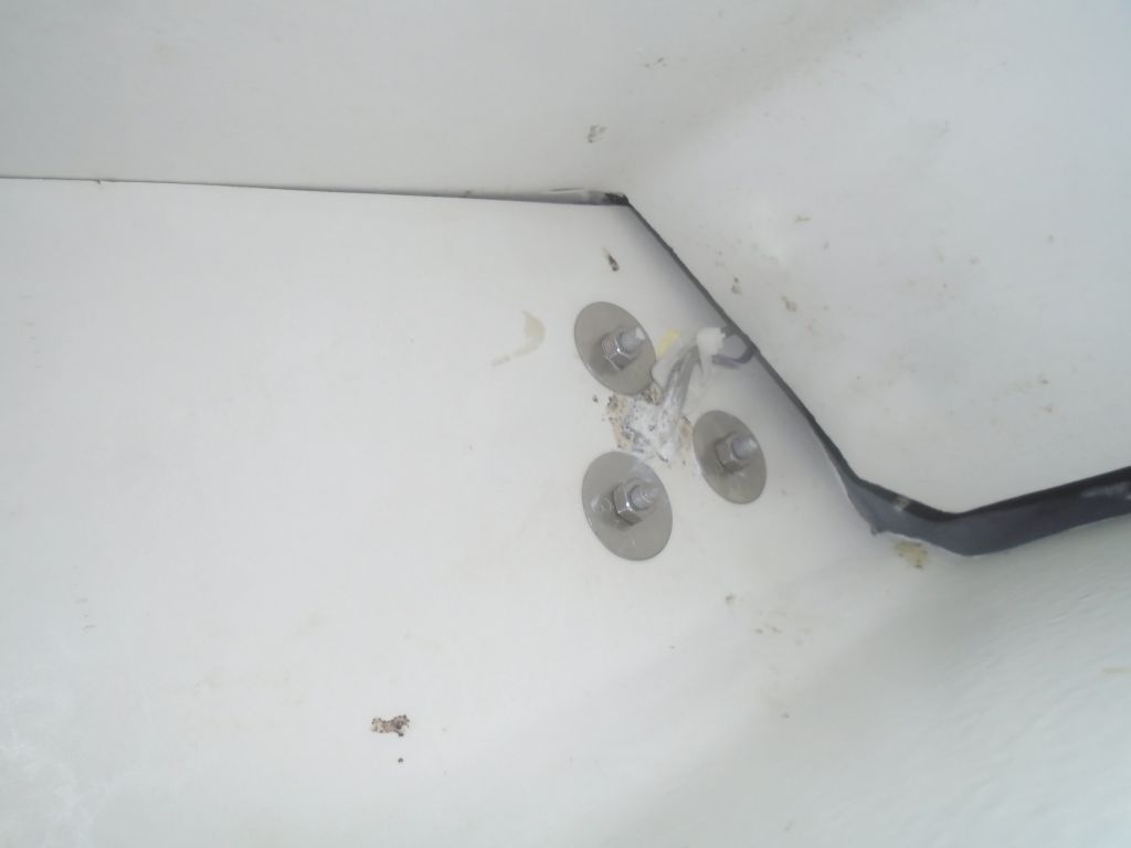
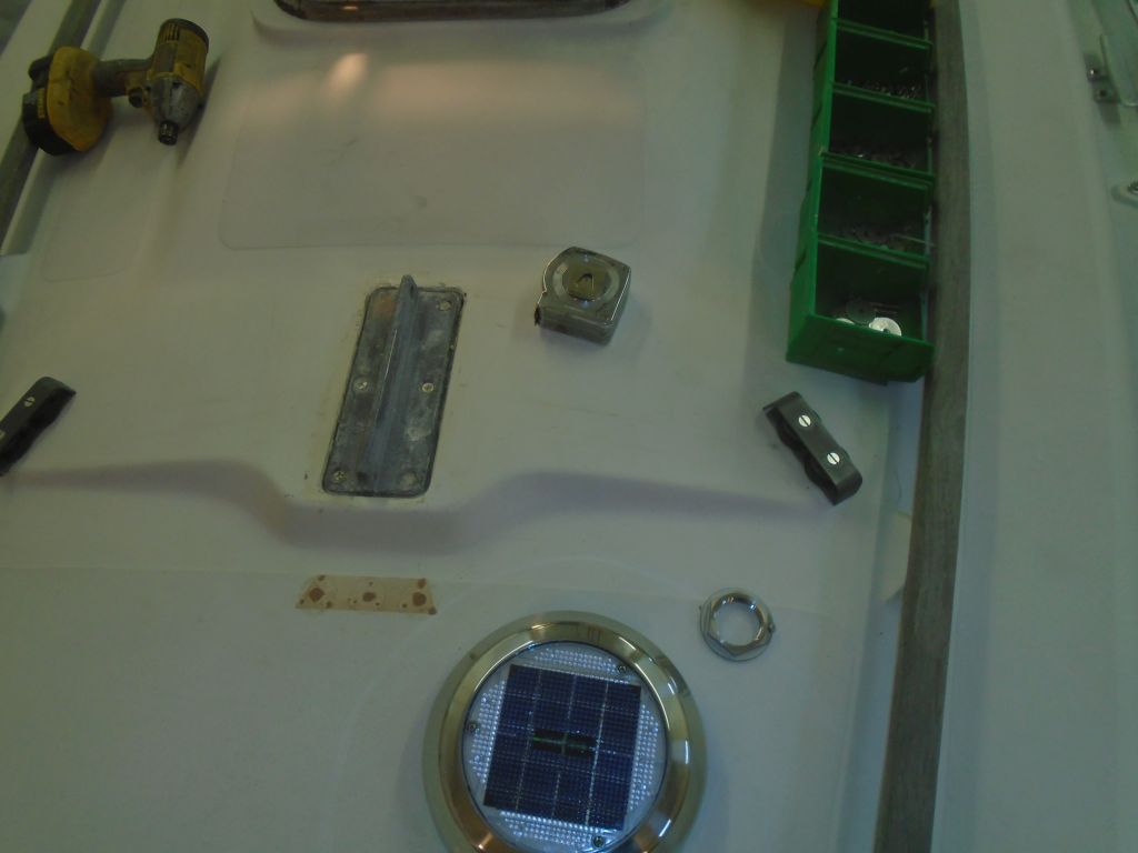
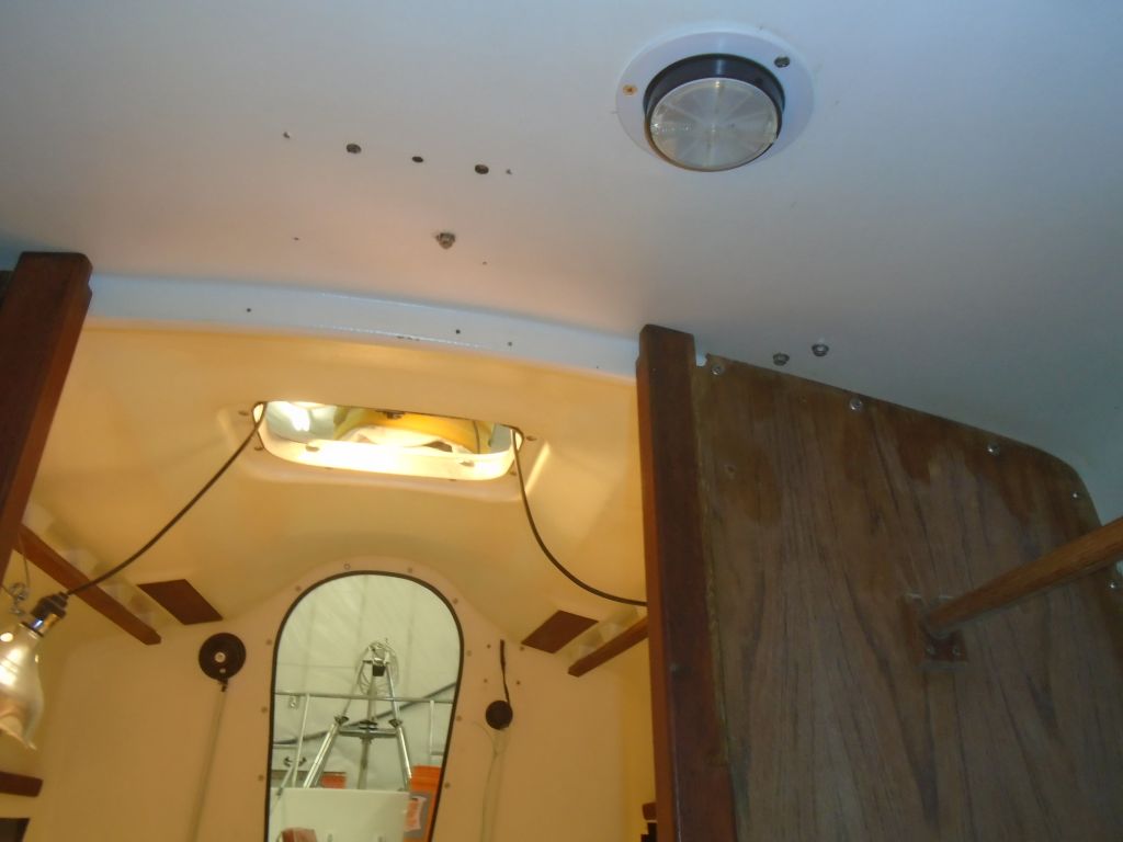
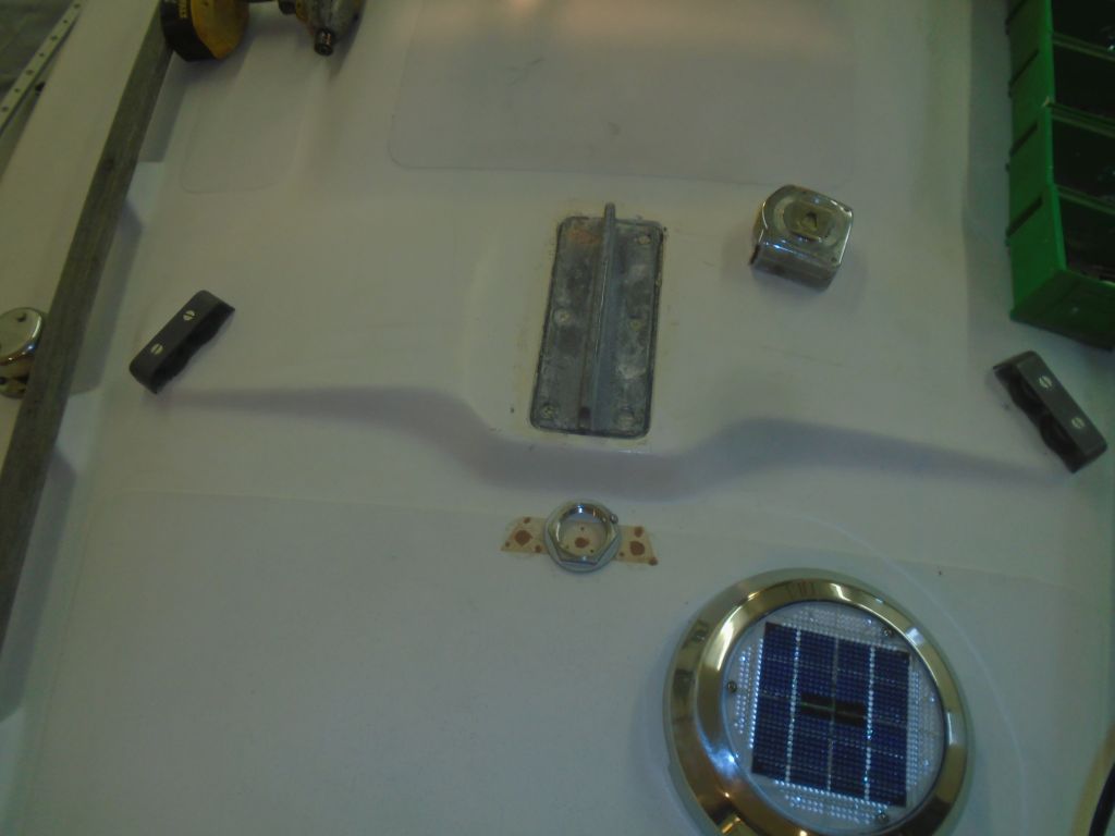
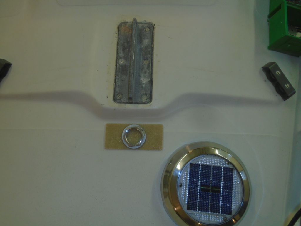
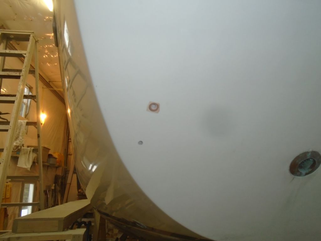
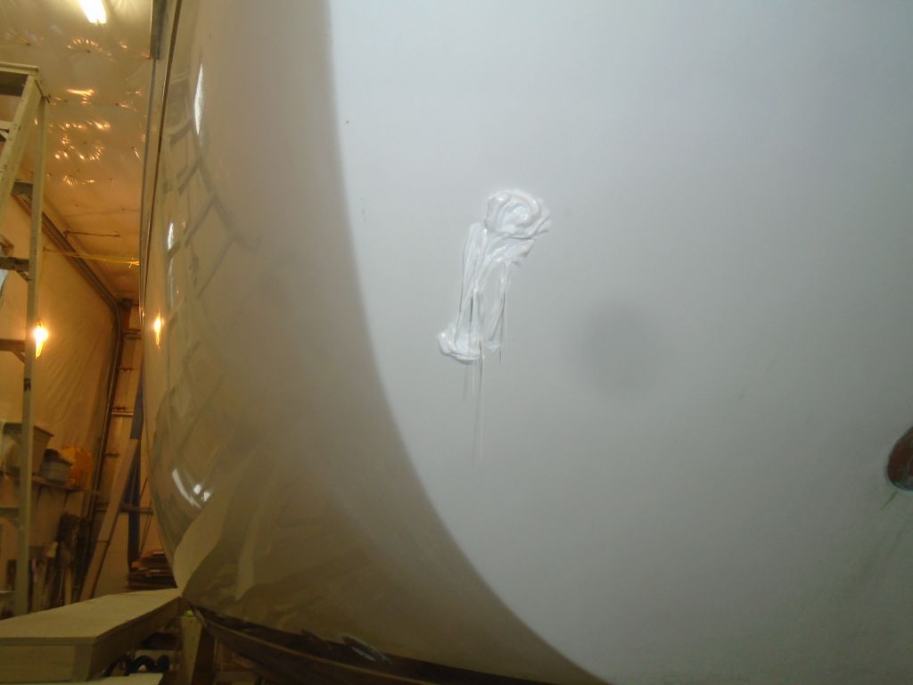
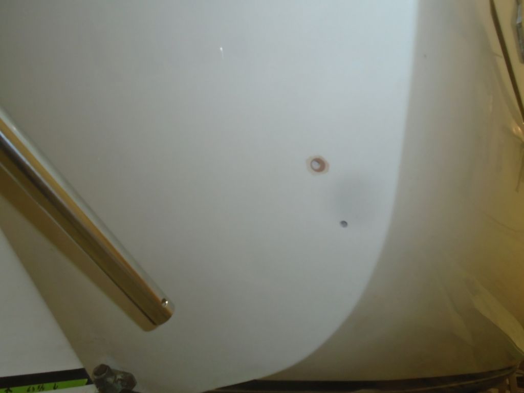
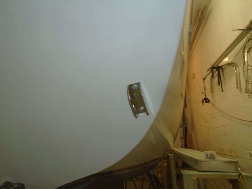
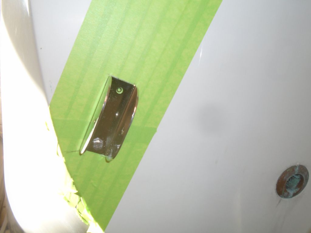
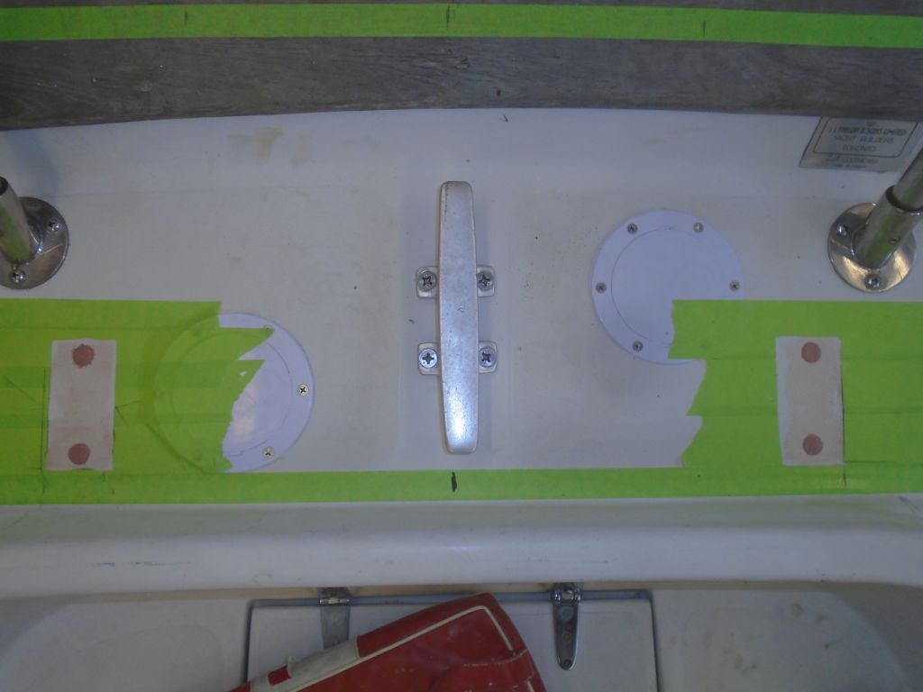
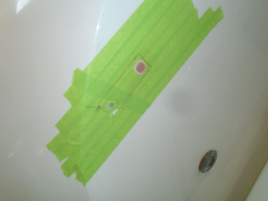
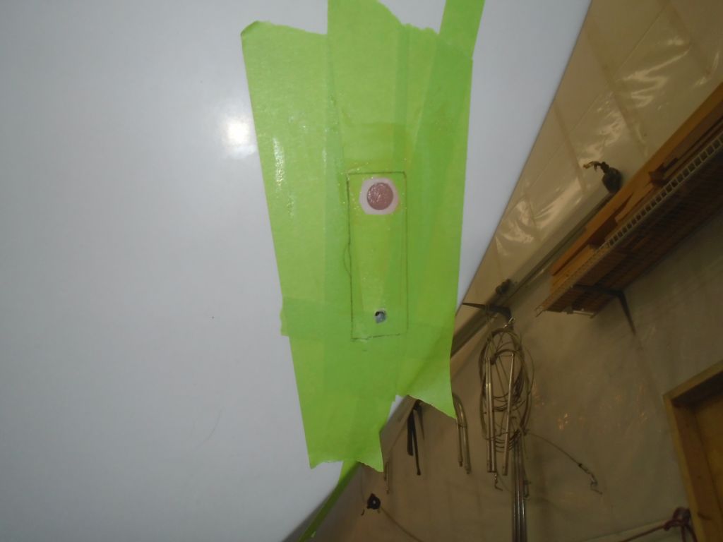
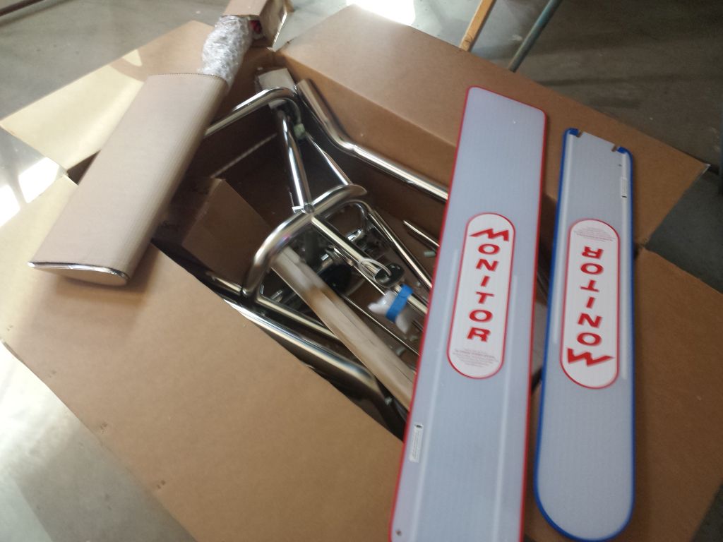
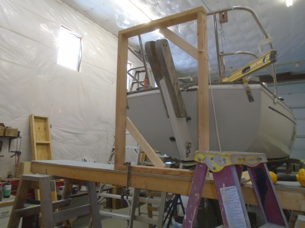
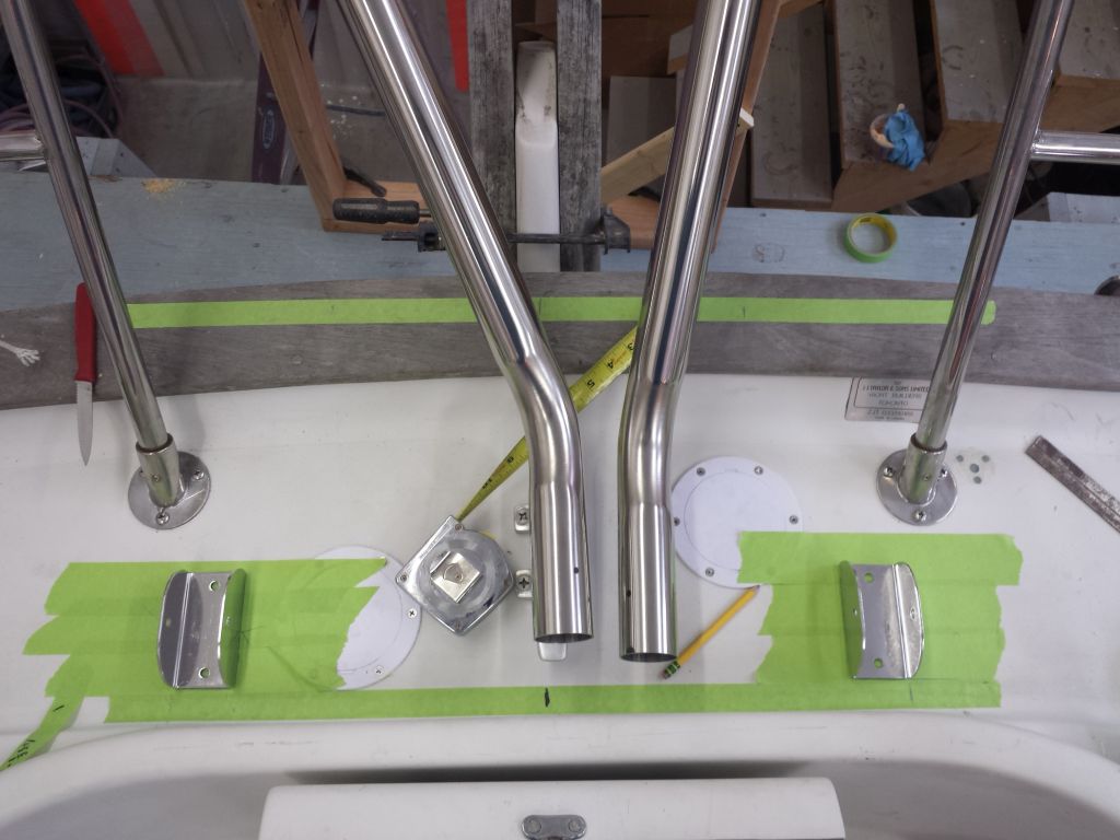
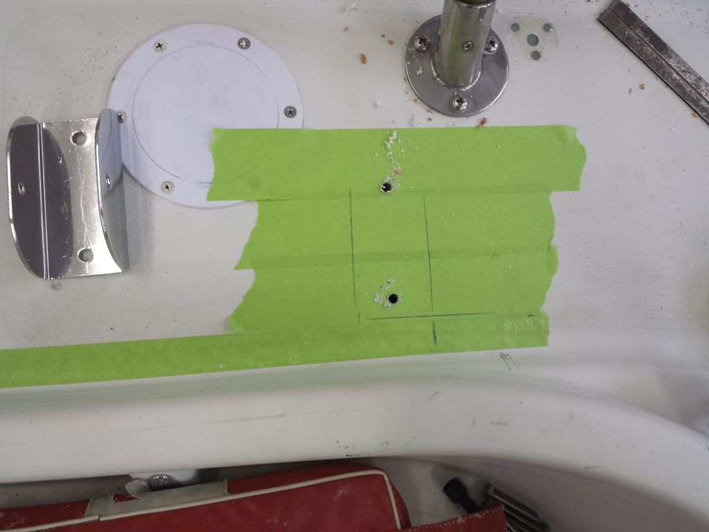
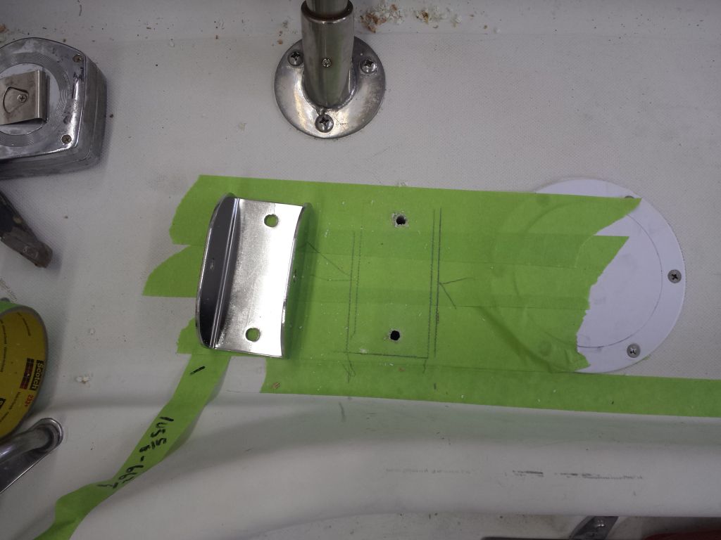
Now that my epoxy-filled bolt holes were ready for further work, I could get on with the final installation of the Monitor frame.  I started with the deck brackets, and went through all the usual steps to prepare the bolt holes and install the brackets:  drill, tap, countersink, apply sealant, bolt, clean up.  Because of the way the top framing tubes worked on this particular installation, I decided to add 1/2″ fiberglass backing plates beneath the deck brackets; it just seemed prudent, particularly since part of the bracket fell over an uncored section of the poop deck.   (Oops, I didn’t get all the masking tape off the bottoms of the holes…)

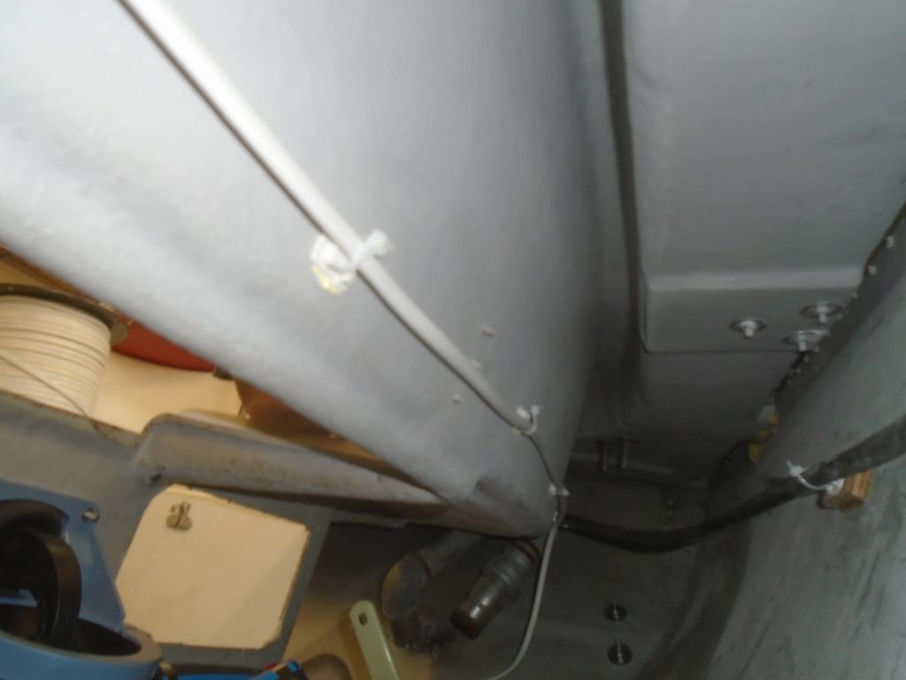
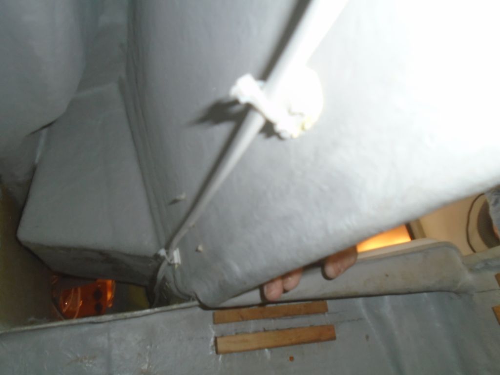
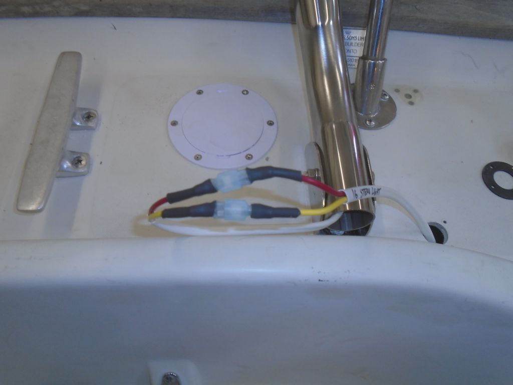
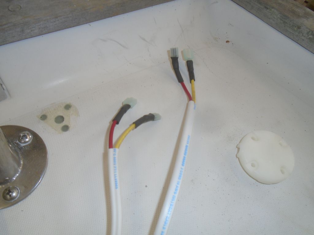
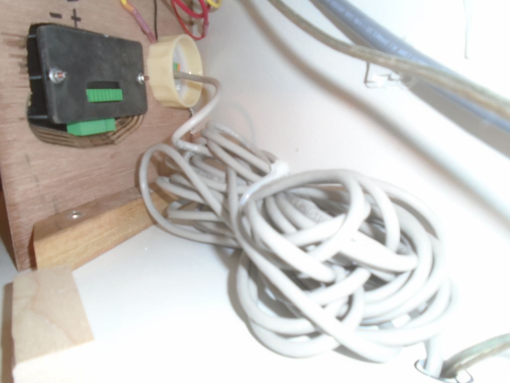
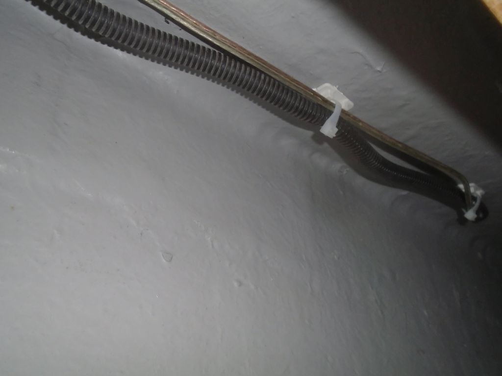
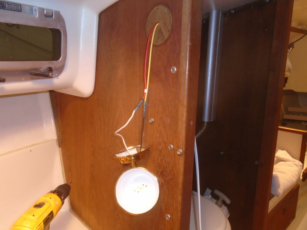
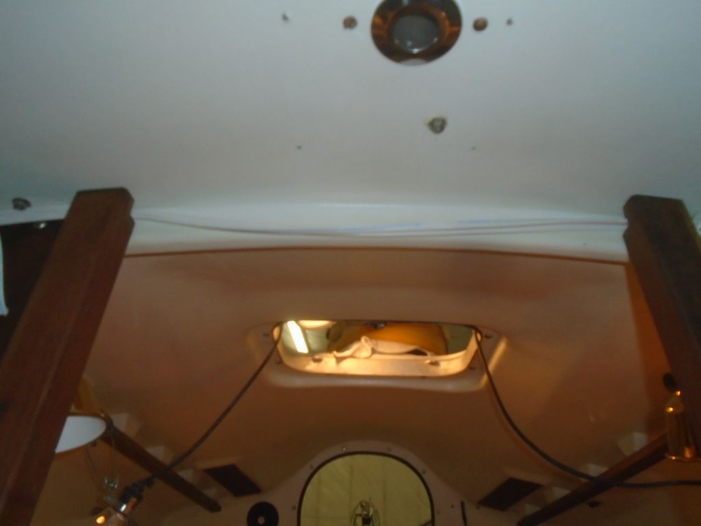
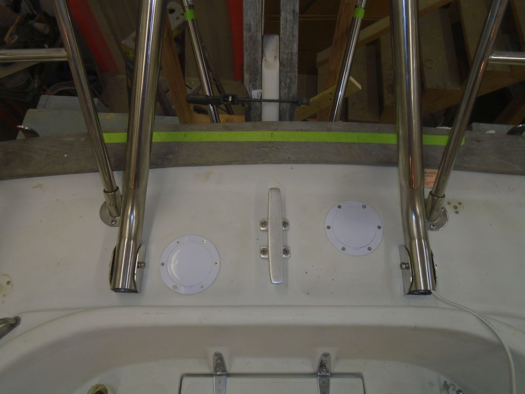
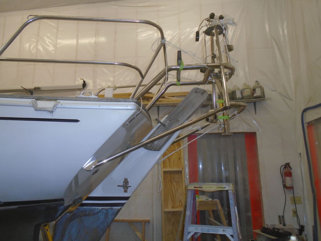
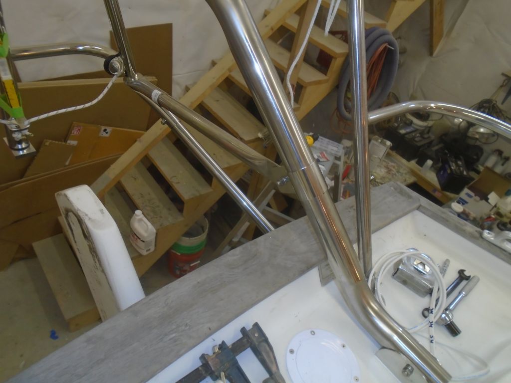
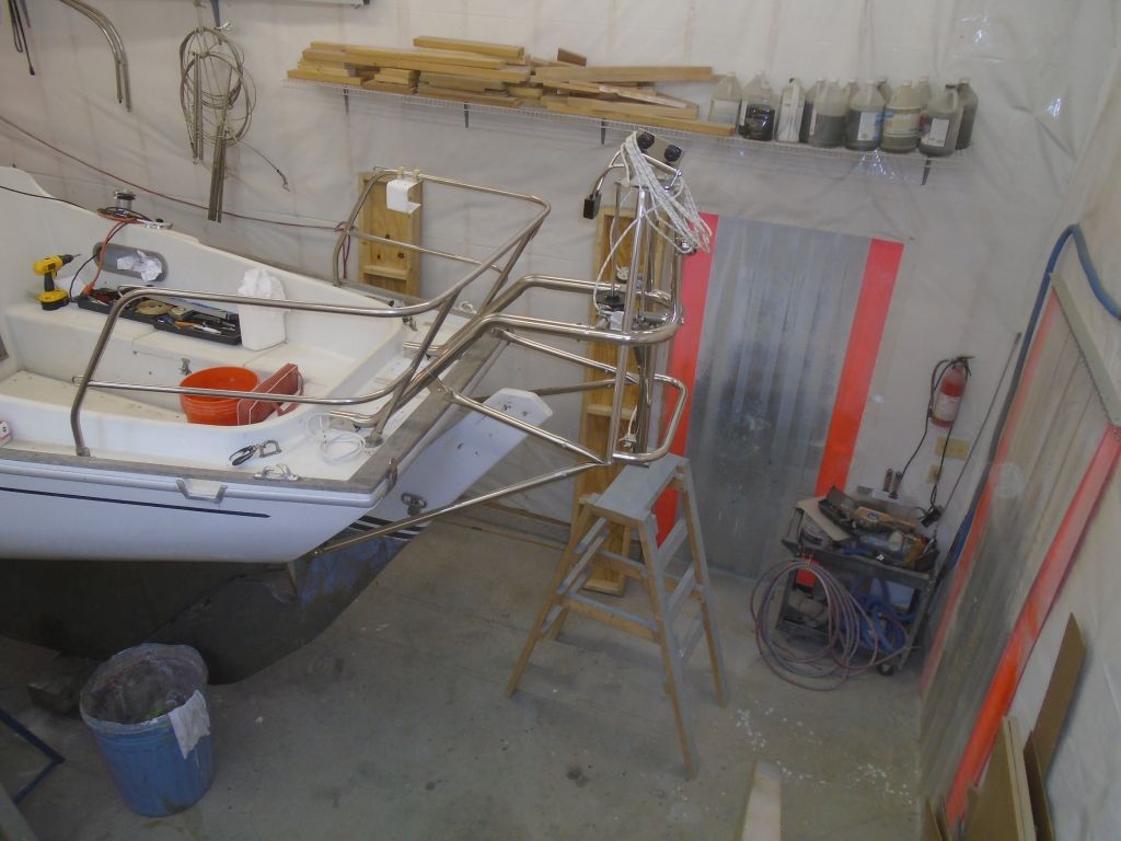
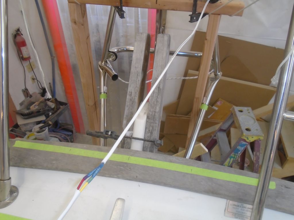
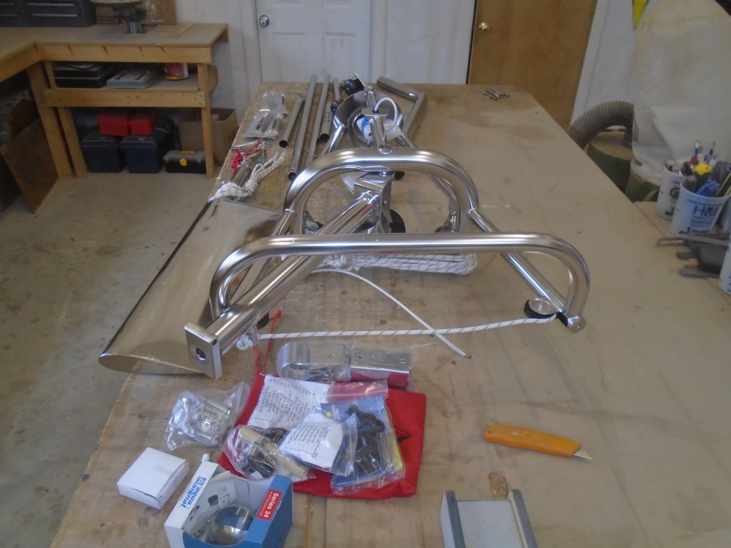
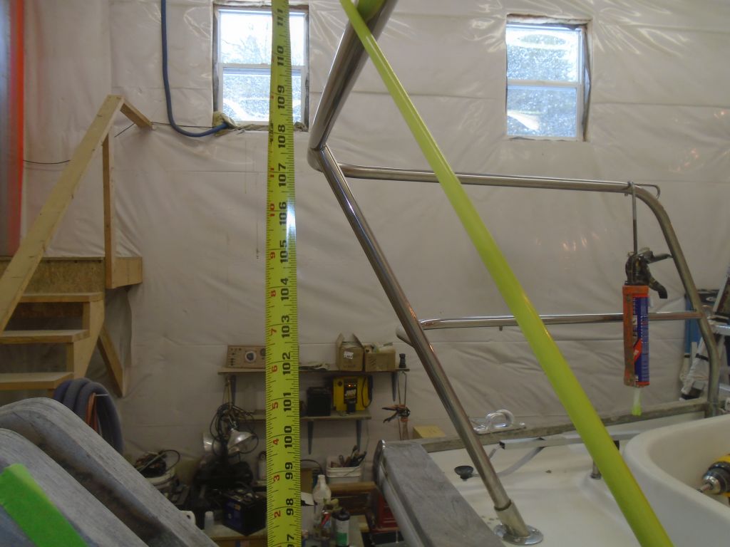
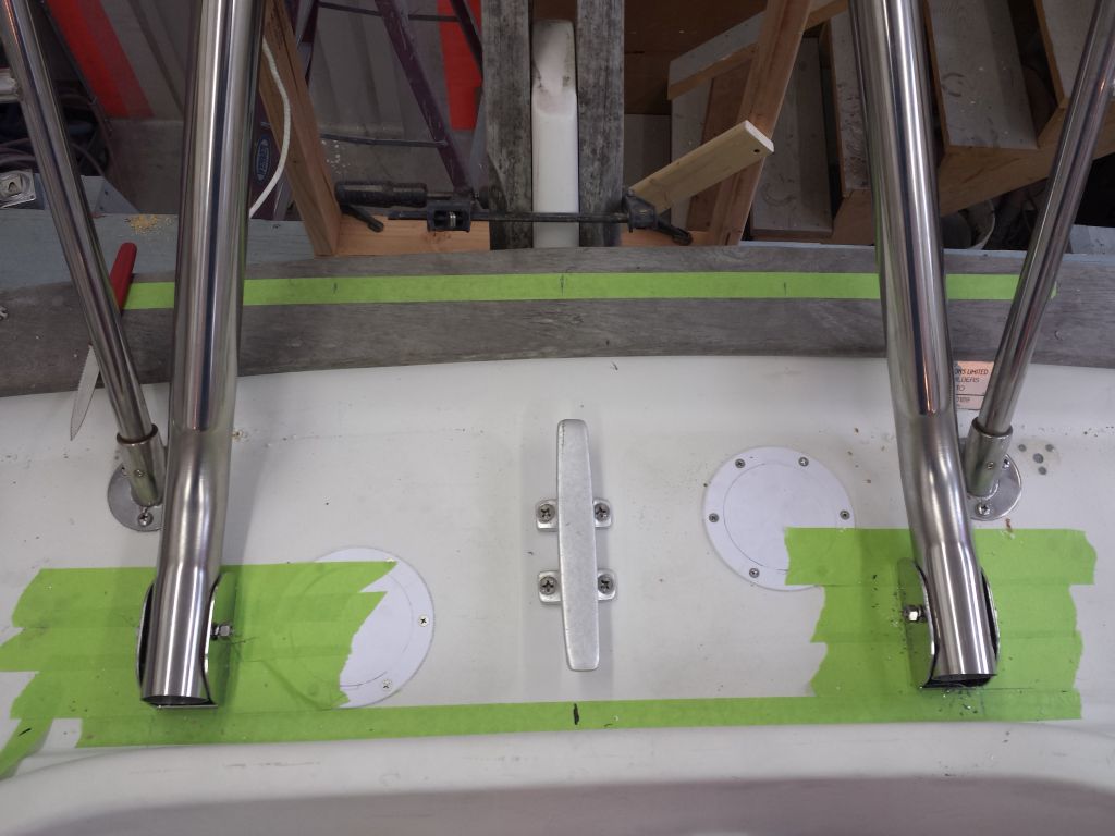
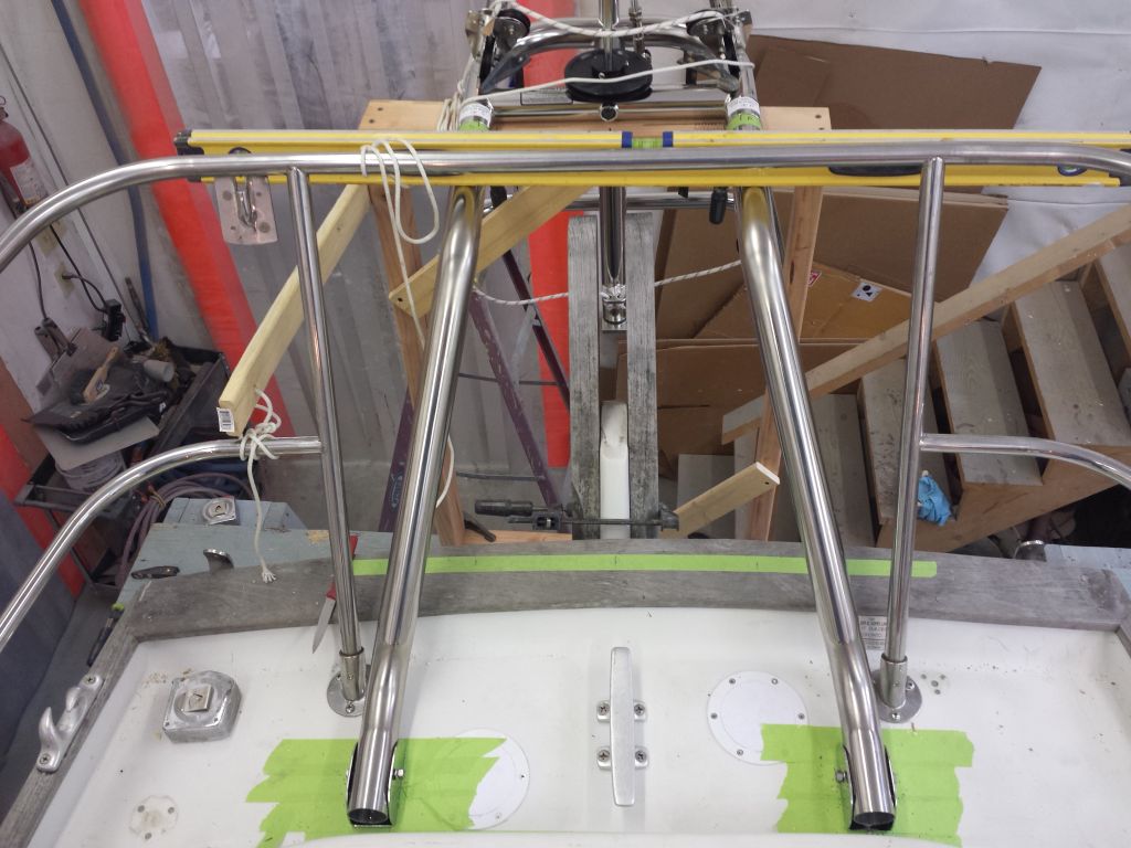
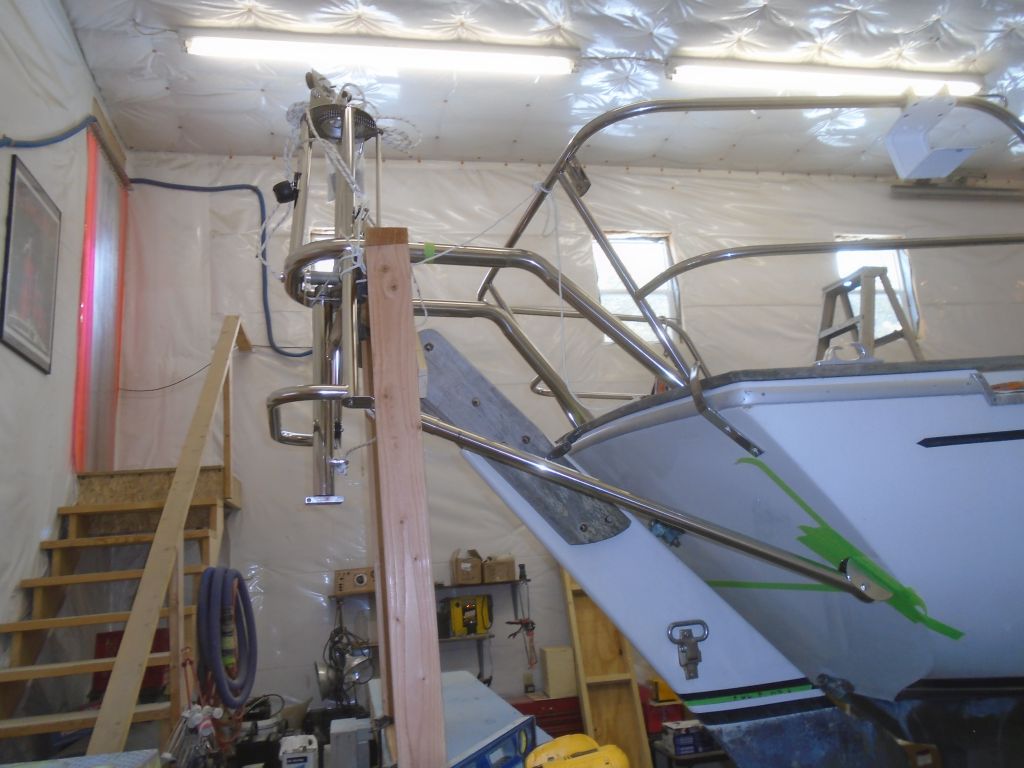
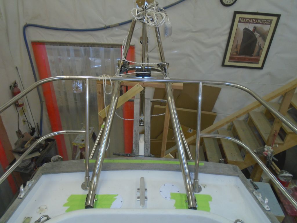
With these brackets now permanently in place, I installed the two top frame tubes, which were ready for their last installation since I’d already drilled the pin/bolt holes at the frame end, and secured the metal compression spacers within.  I led the stern light wire through the port tube as required.   At this time the Monitor frame was still secured to and supported by my wooden framework behind the boat.  During the several times I’d installed and removed these tubes during earlier steps, I’d found the fit to be extremely dry–tight–so for the final installation I added some waterproof grease to ease the way.  Once I’d twisted the tubes in all the way and to the correct orientation, I put in the bolts at the frame end, and also at the deck bracket end, but for the moment I left the bolts untightened.

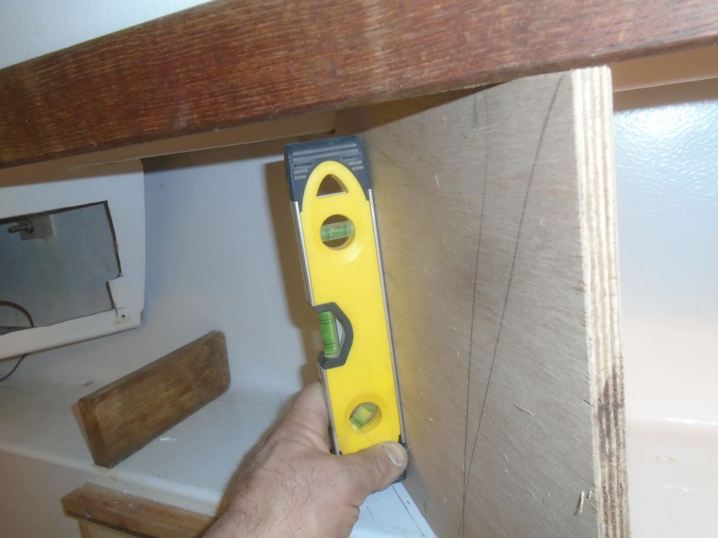
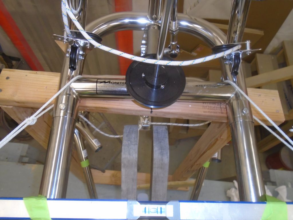
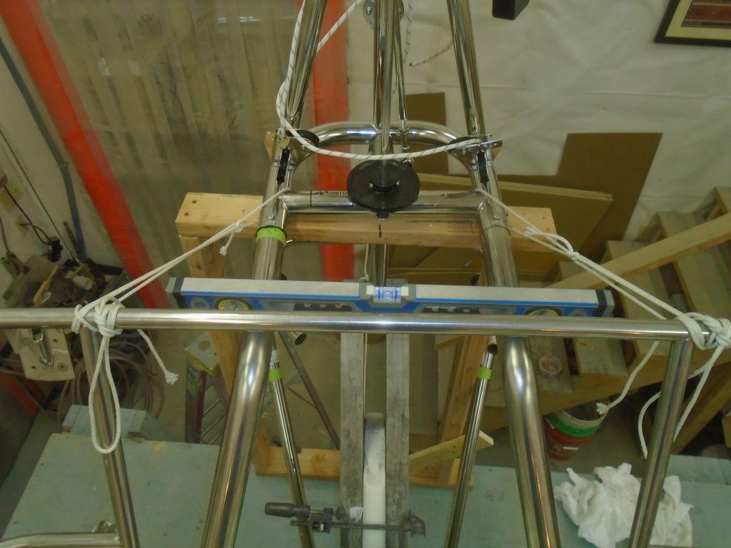
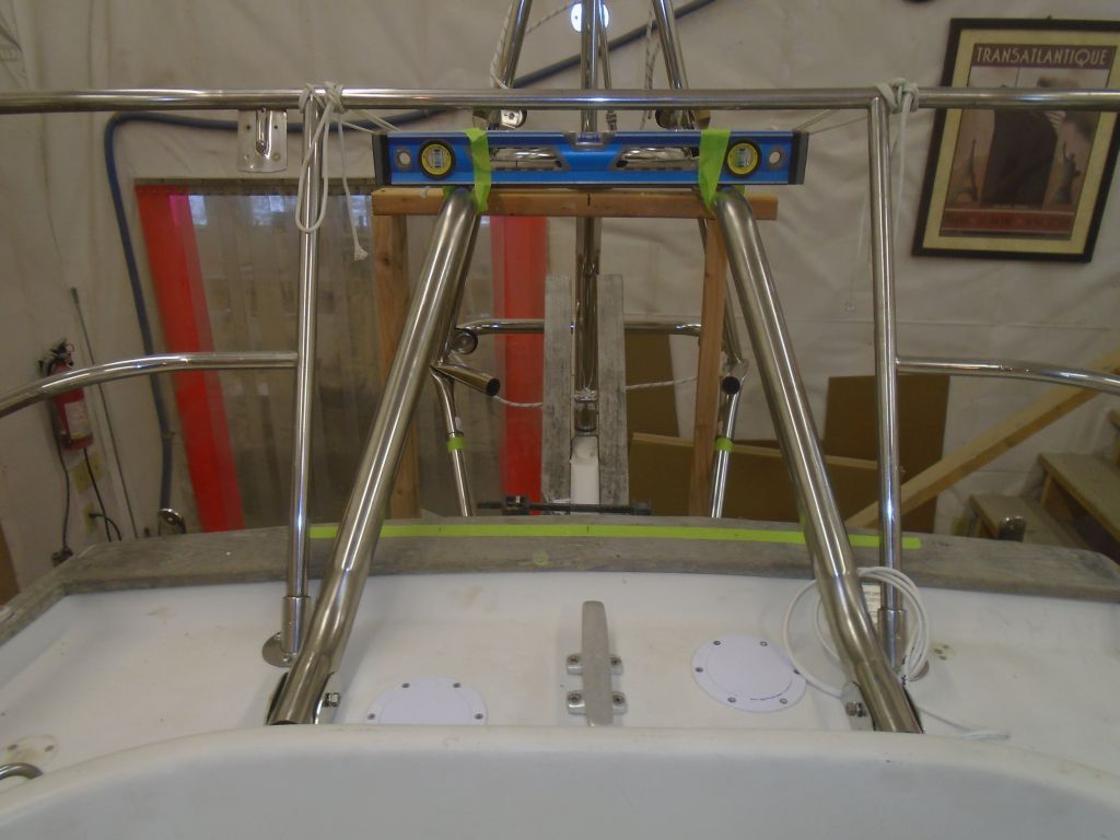
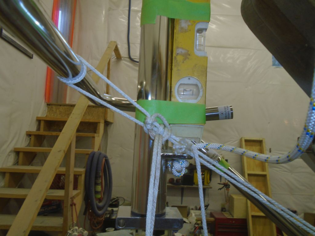
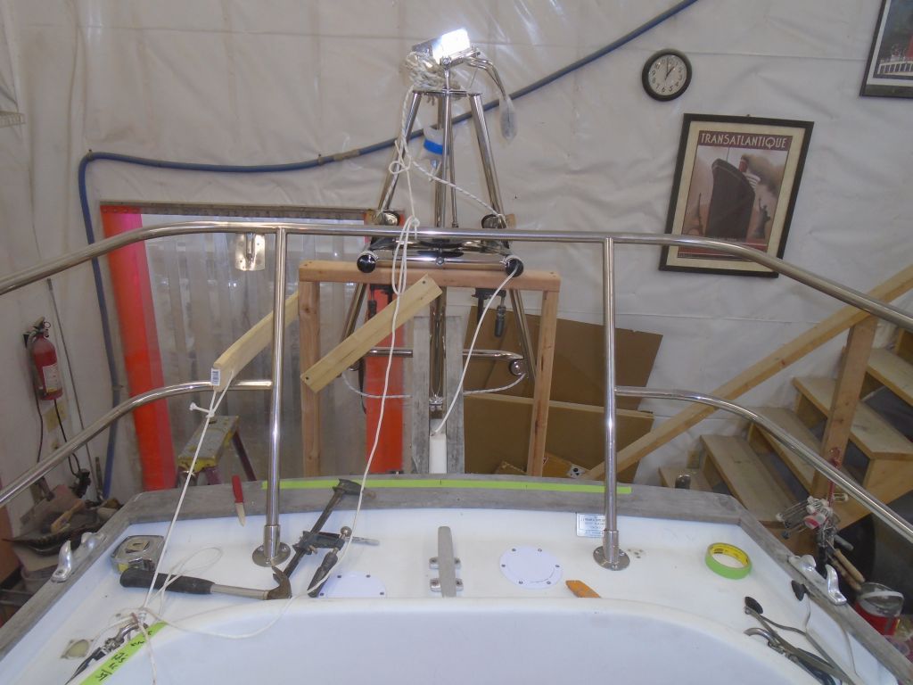
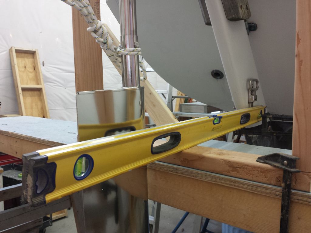
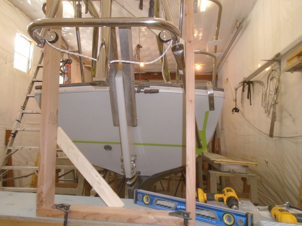
Now, with some lines running between the frame and the pulpit, I adjusted the Monitor frame till it was level side to side, which process also lifted it just clear of the wooden framework so I could remove that now for the last time, along with the staging so I could clear the way behind the boat for the lower frame installation.  I taped a level in place on the upper frame tubes so I’d have a constant reference as I worked on the lower supports.

Down on the ground, I installed another level on the pendulum arm, and with a line running forward to the rudder I adjusted the frame till it was level in the fore and aft direction as well.  With the frame now properly aligned in all directions, I went ahead and tightened the bolts on the upper frame tubes–at both the deck bracket and the Monitor frame itself.

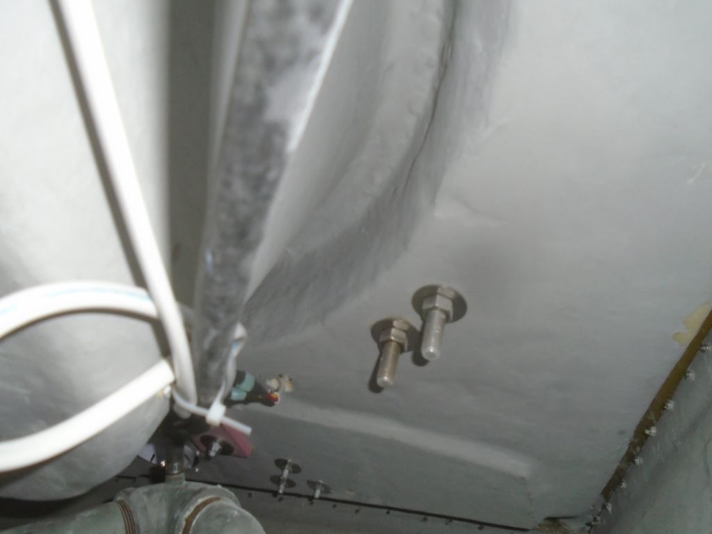
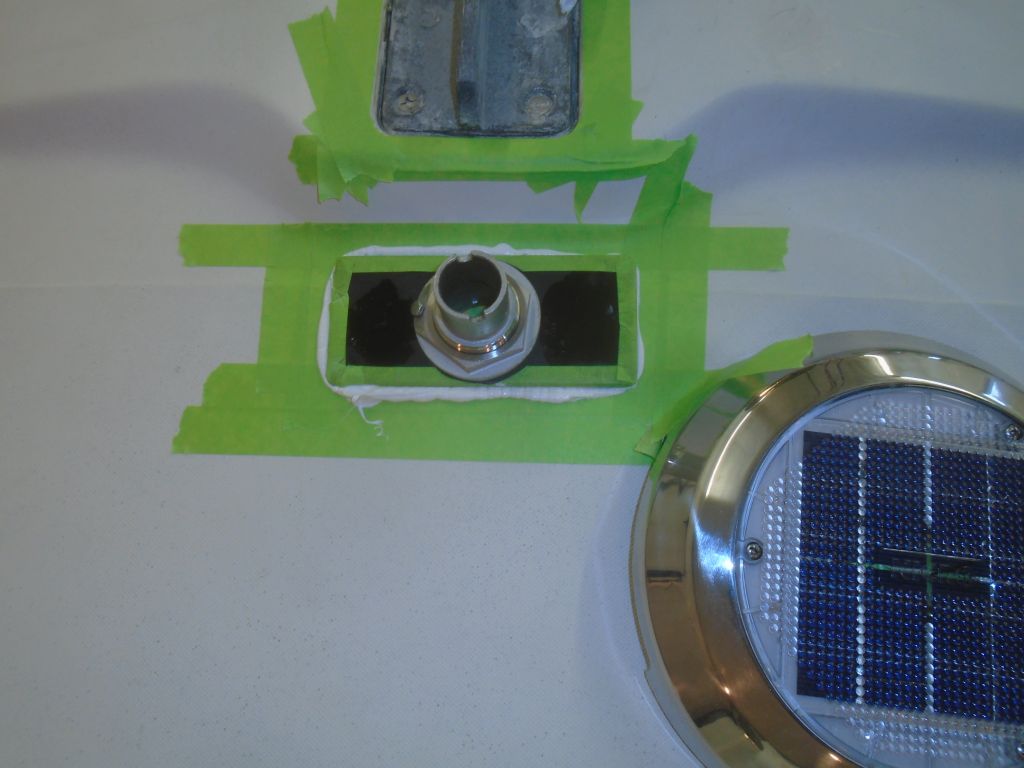
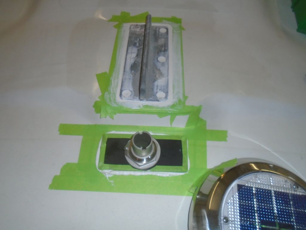
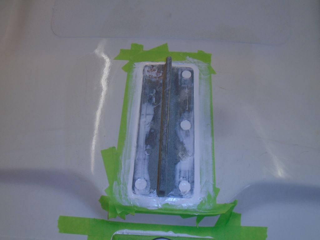
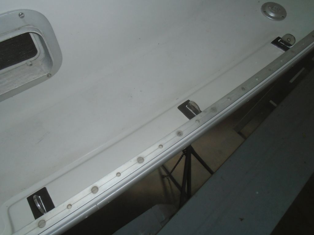
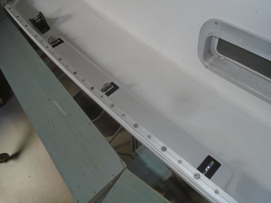
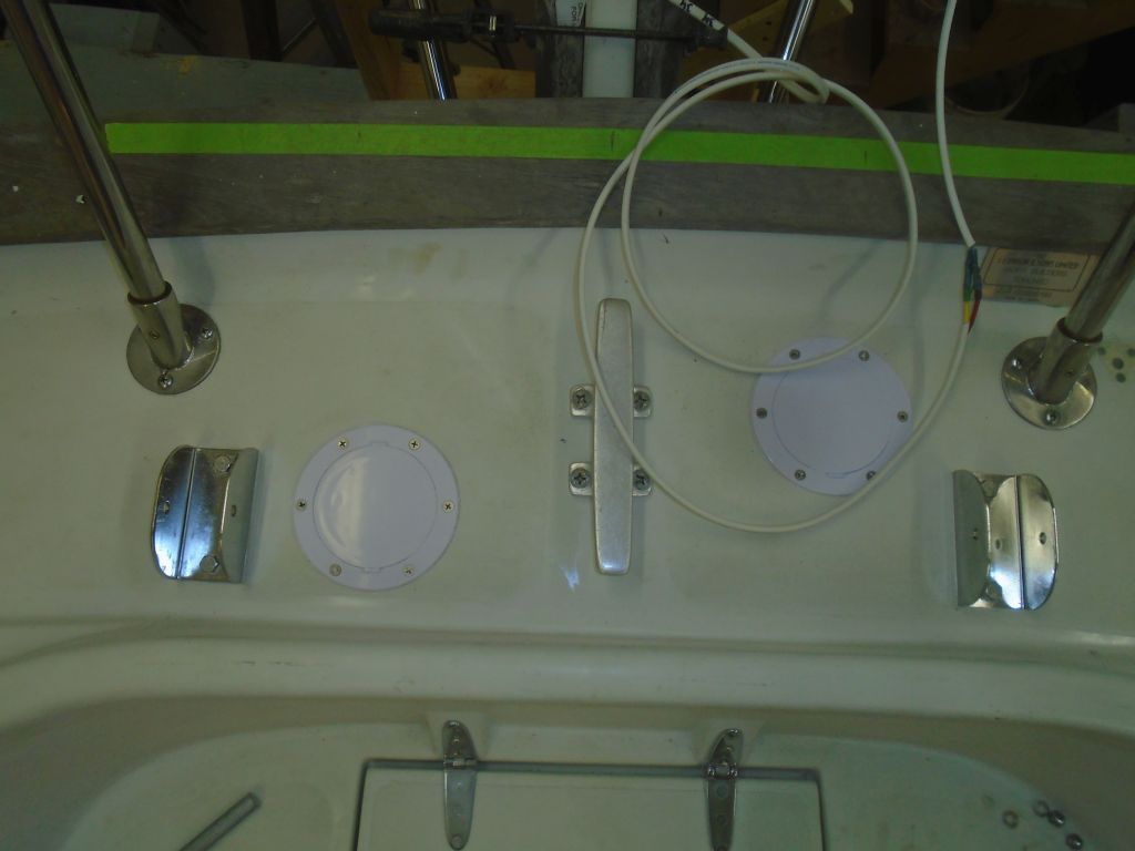
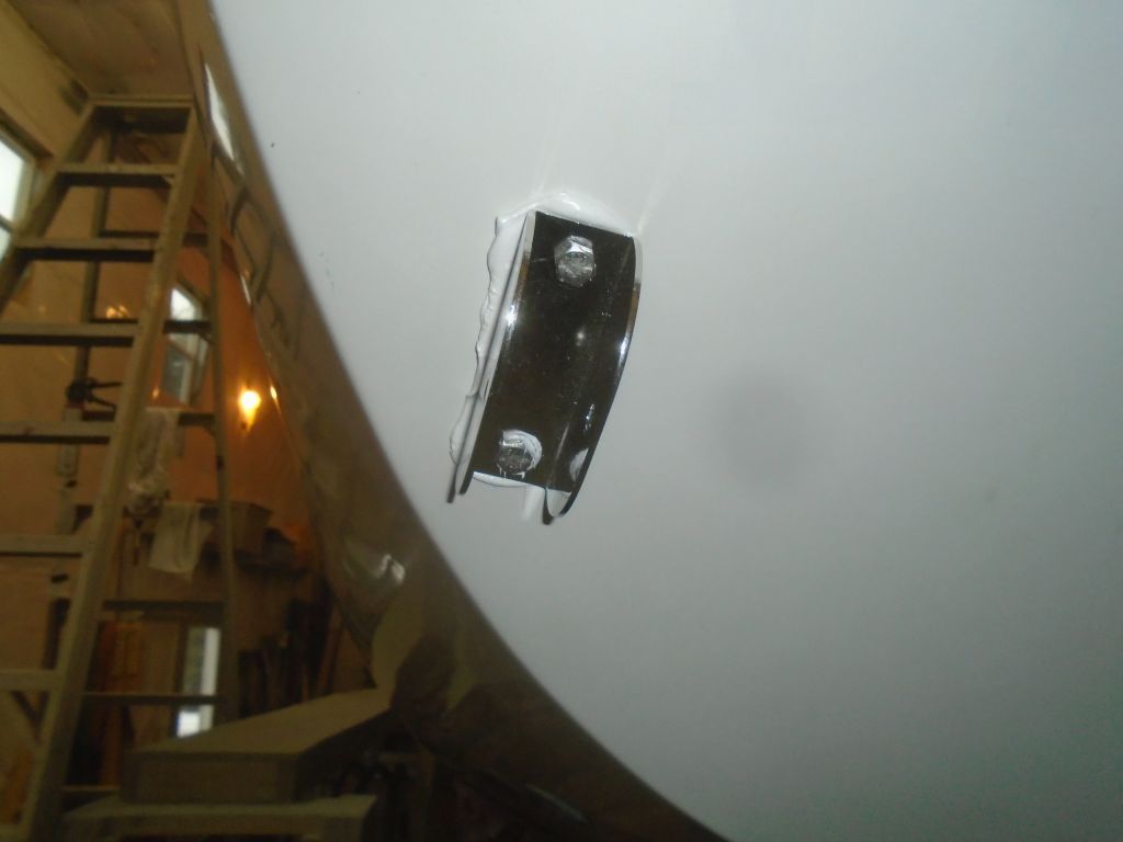
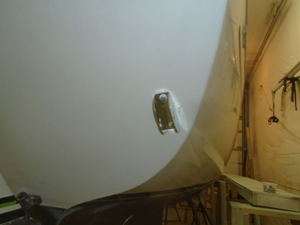
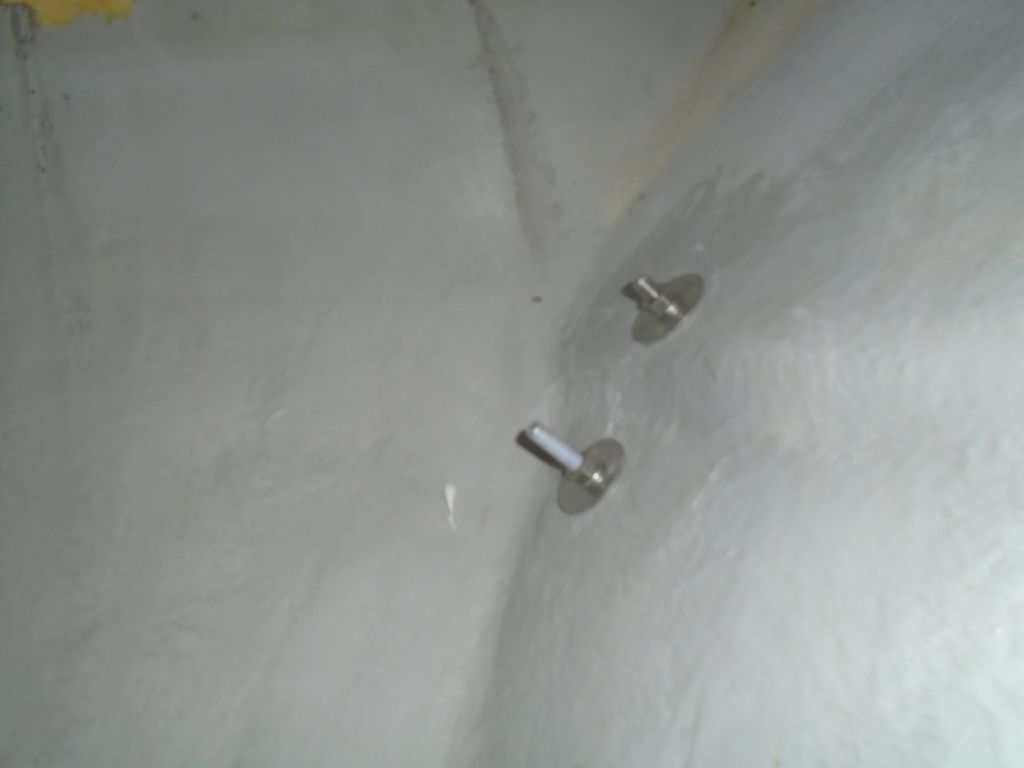
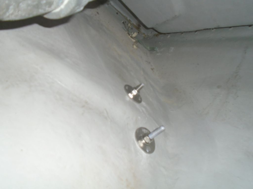
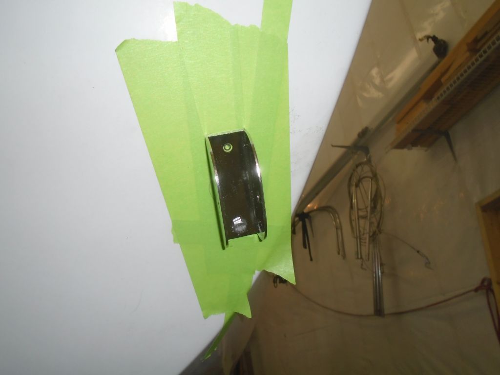
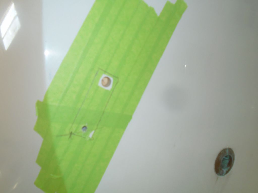
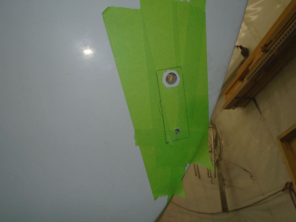
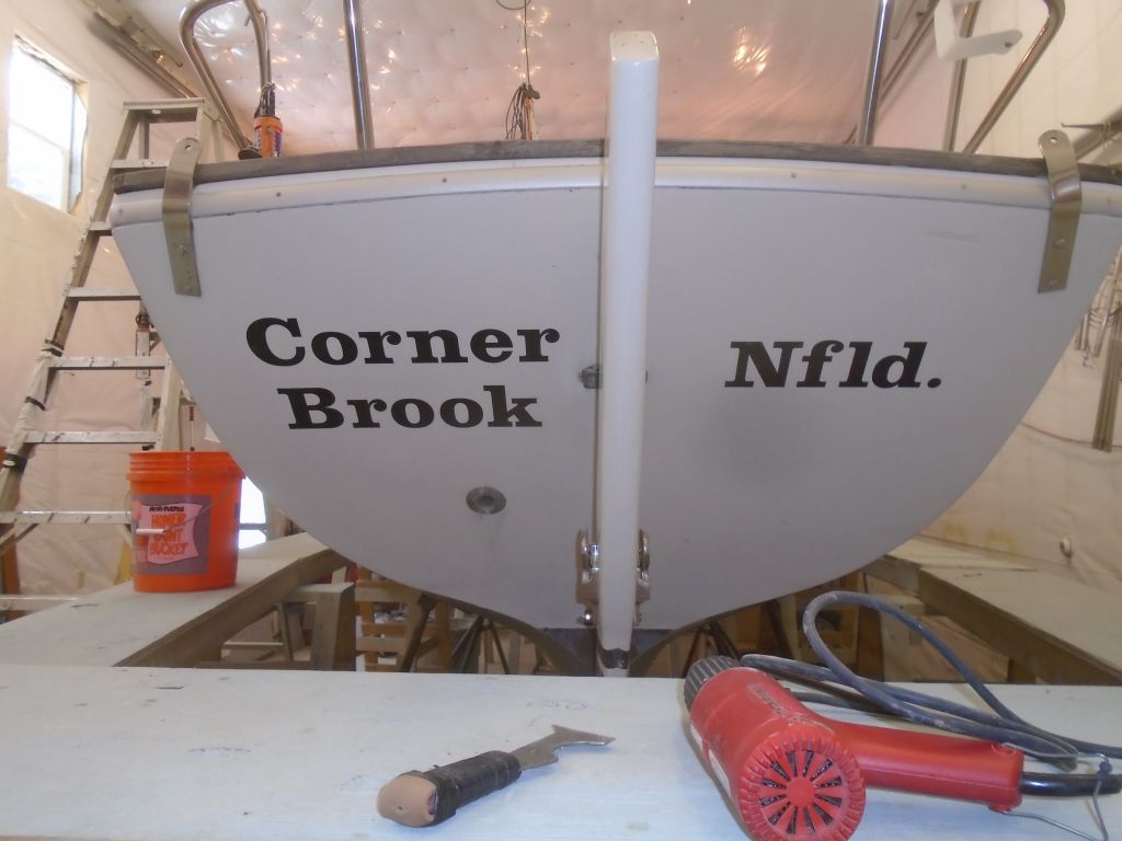
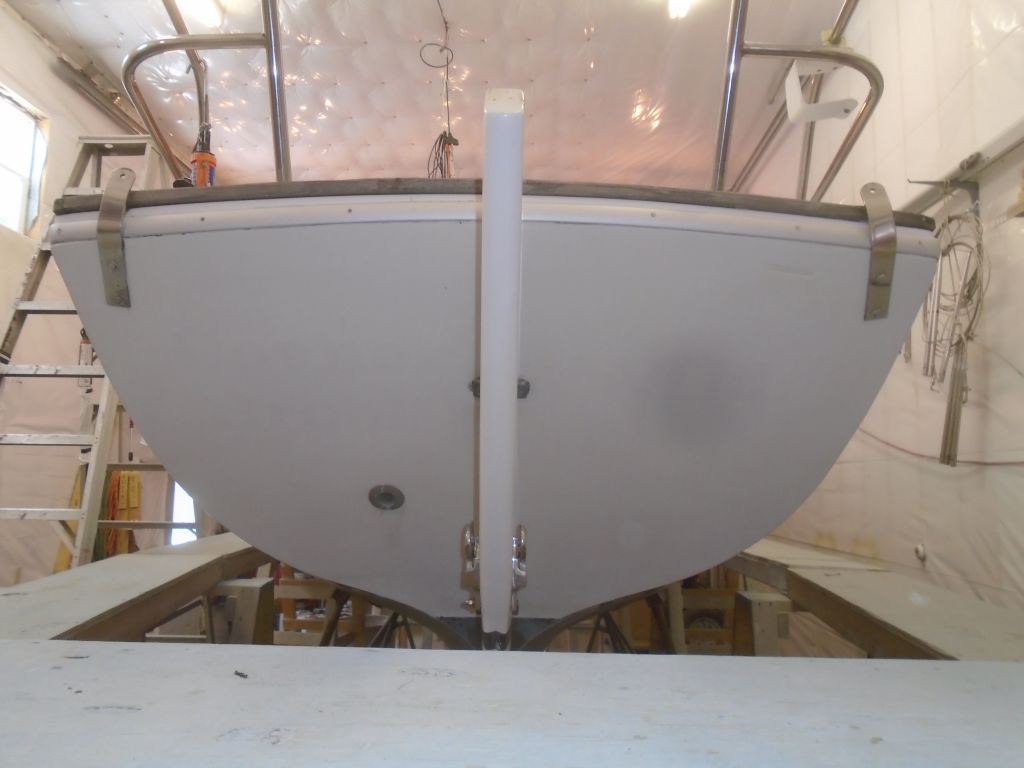
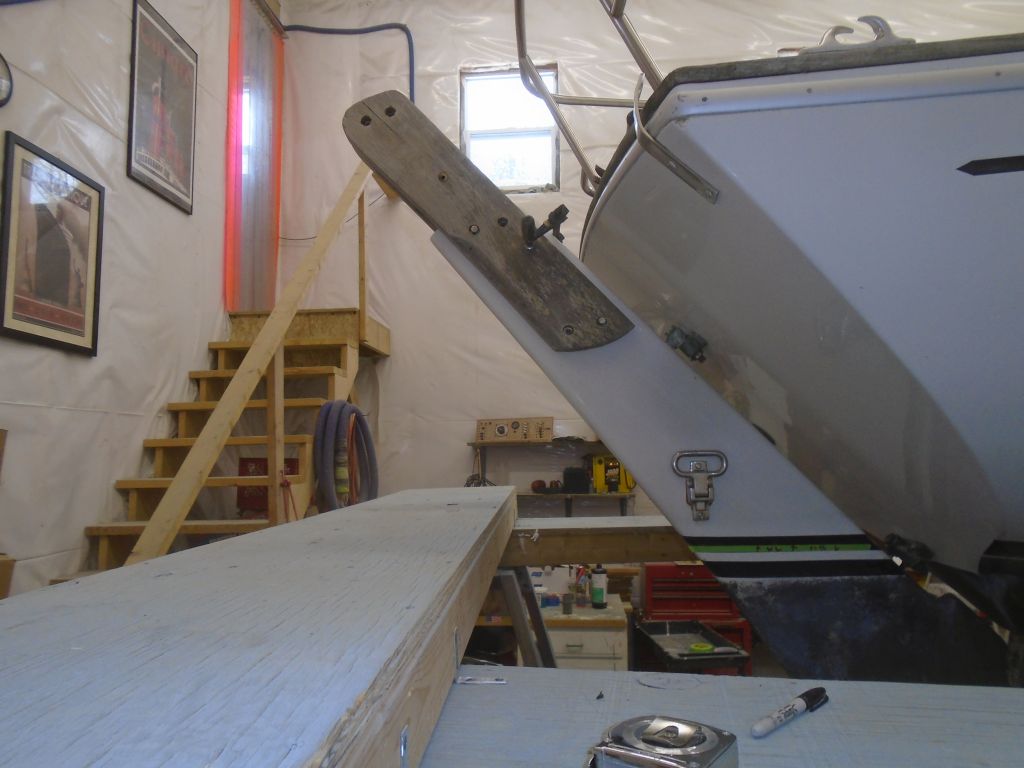
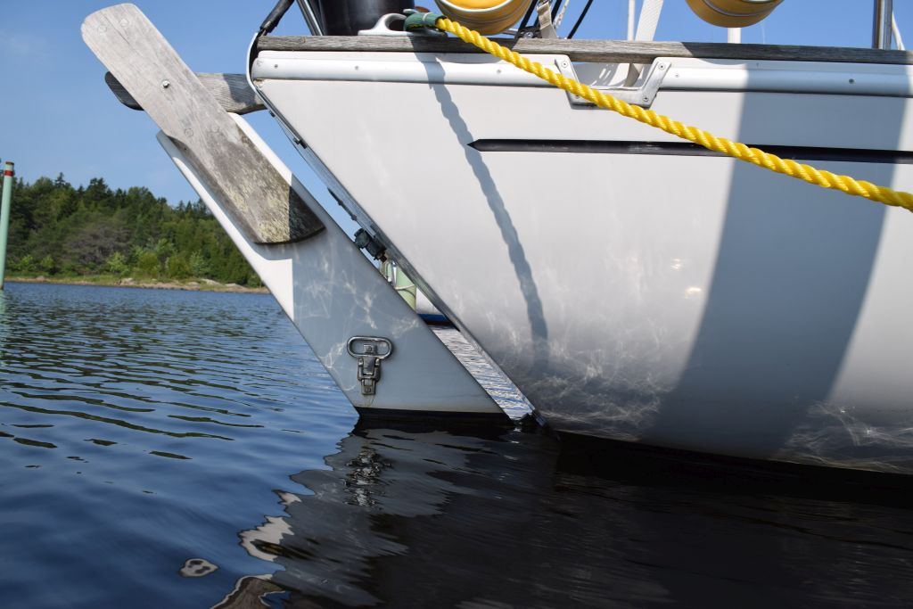
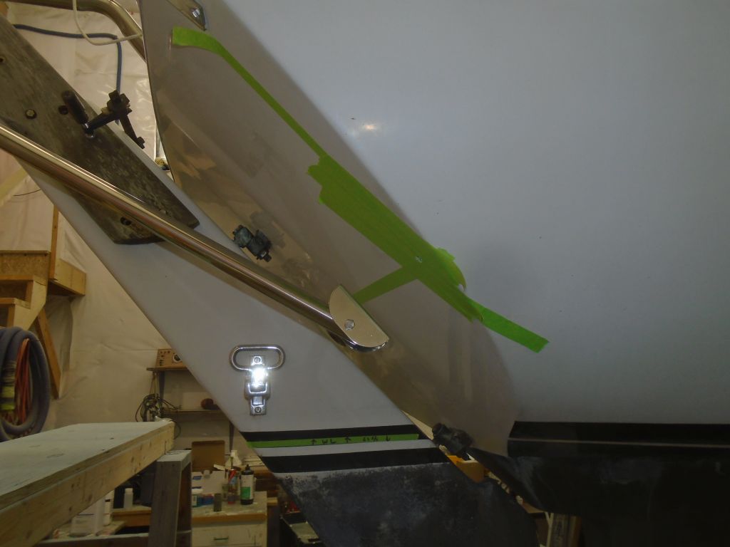
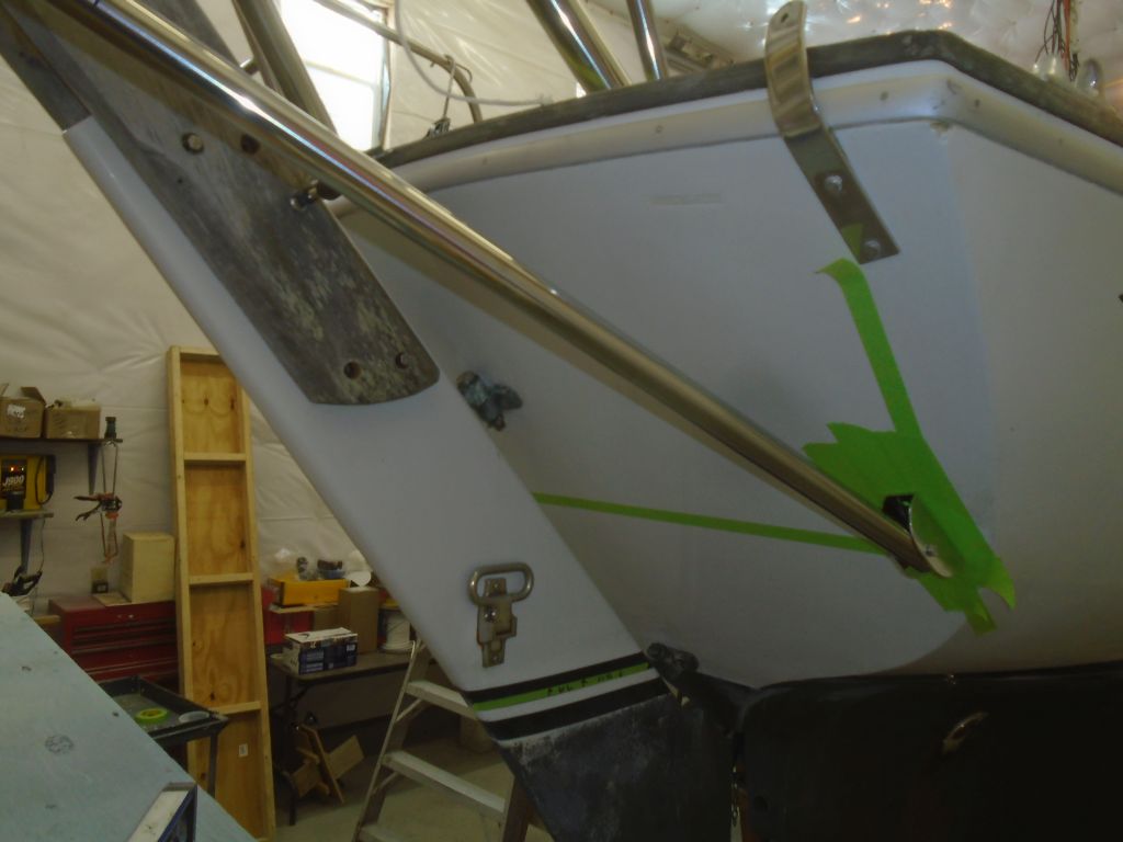
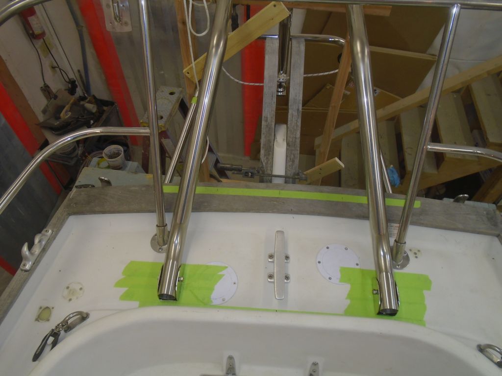
From the ground, I prepared and installed the two hull brackets on the transom.

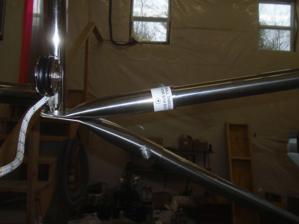
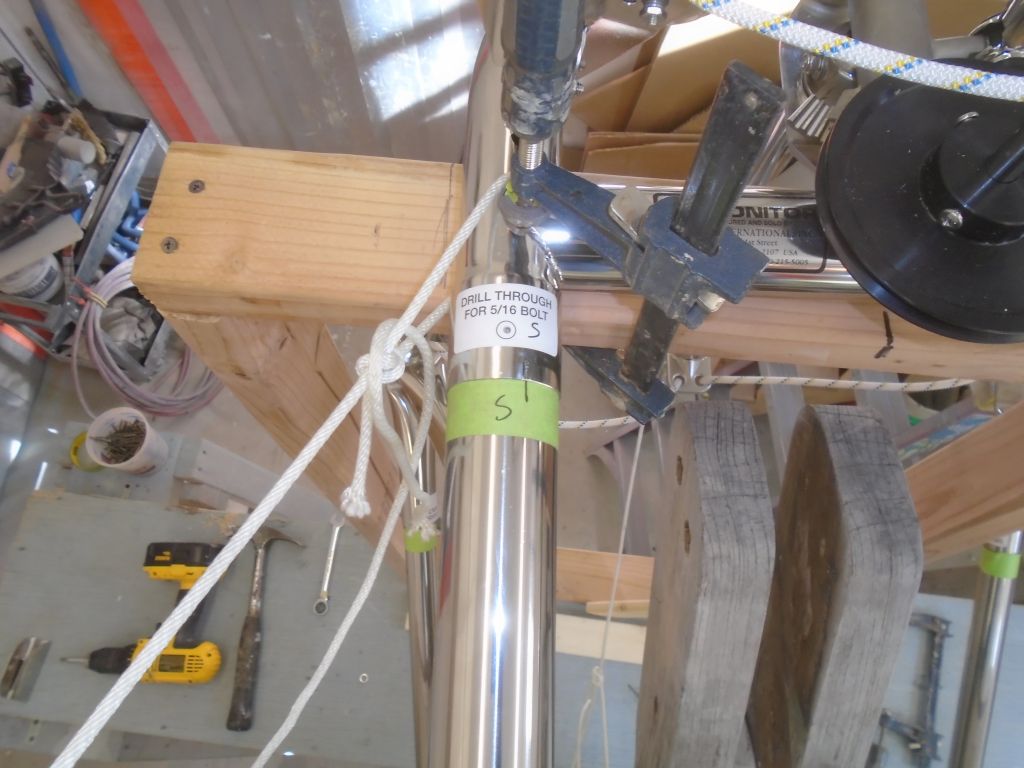
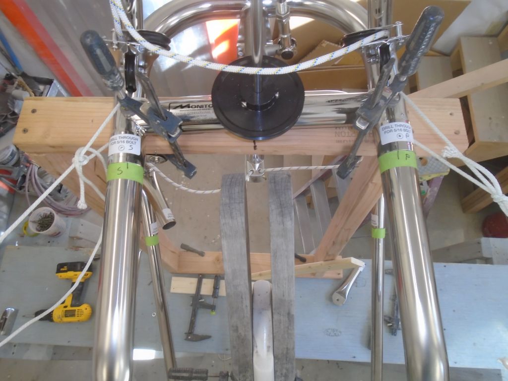
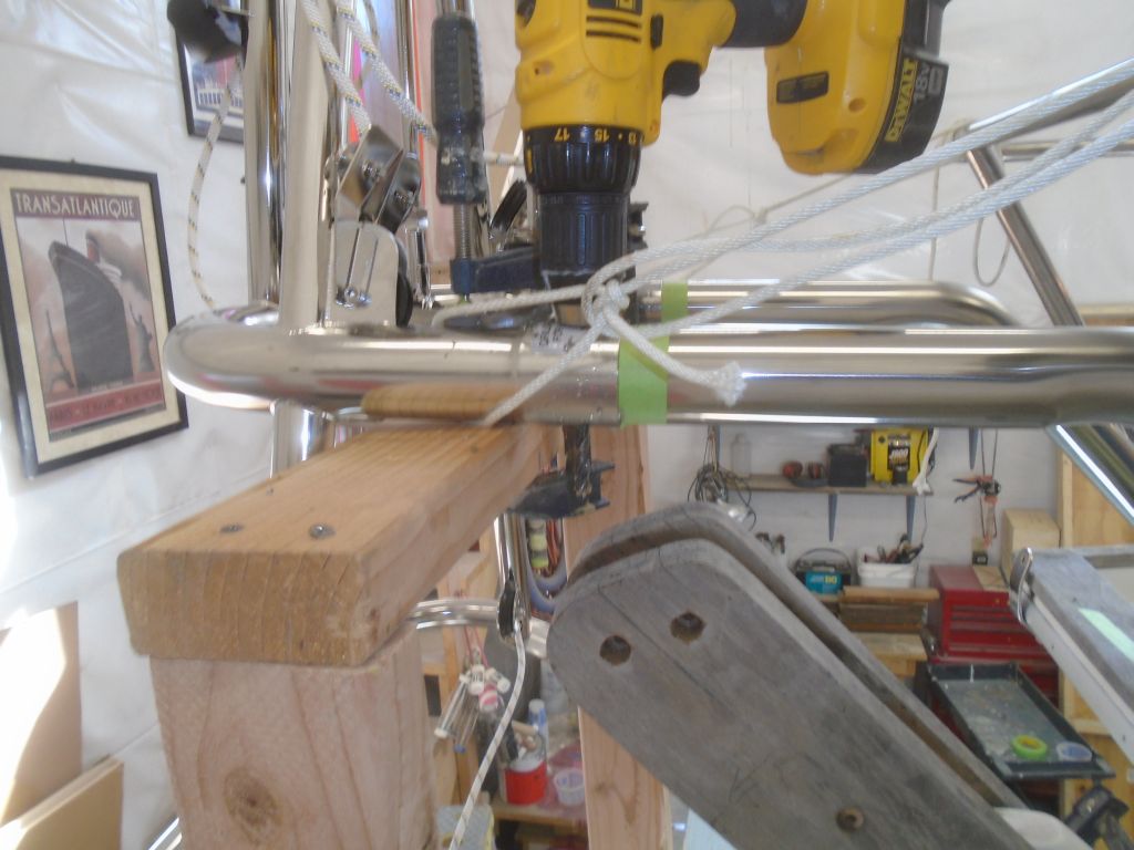
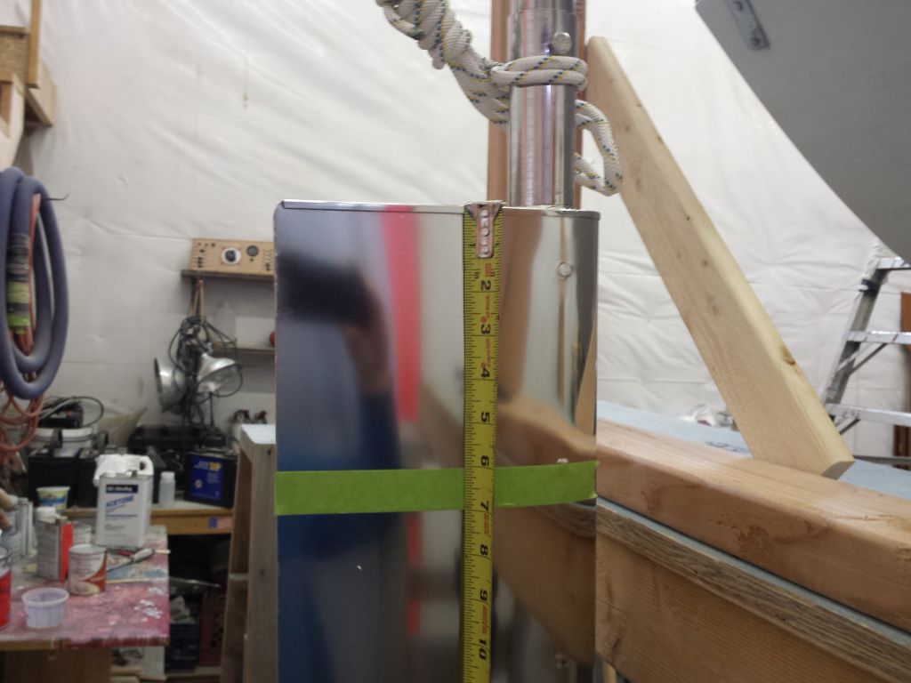
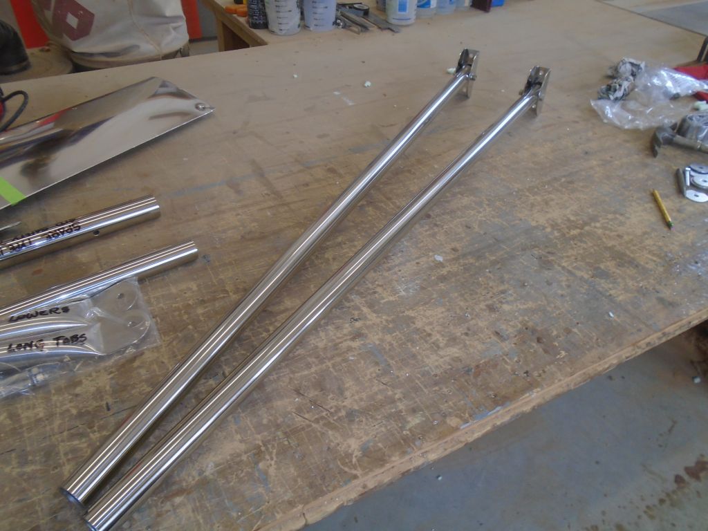
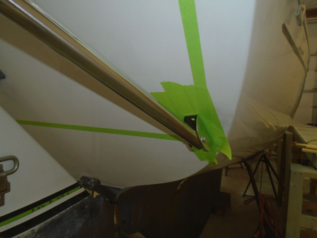
I’d already cut the lower support tubes to length during the initial setup, but now I checked them again; they still fit the way they should.  So with the tubes fully inserted at the top end, into the mounting sleeve at the Monitor frame, and secured with their bolt at the hull bracket, I prepared to drill the bolt holes at the top end, which would pin the tubes in place at the frame and ultimately hold everything rigidly.

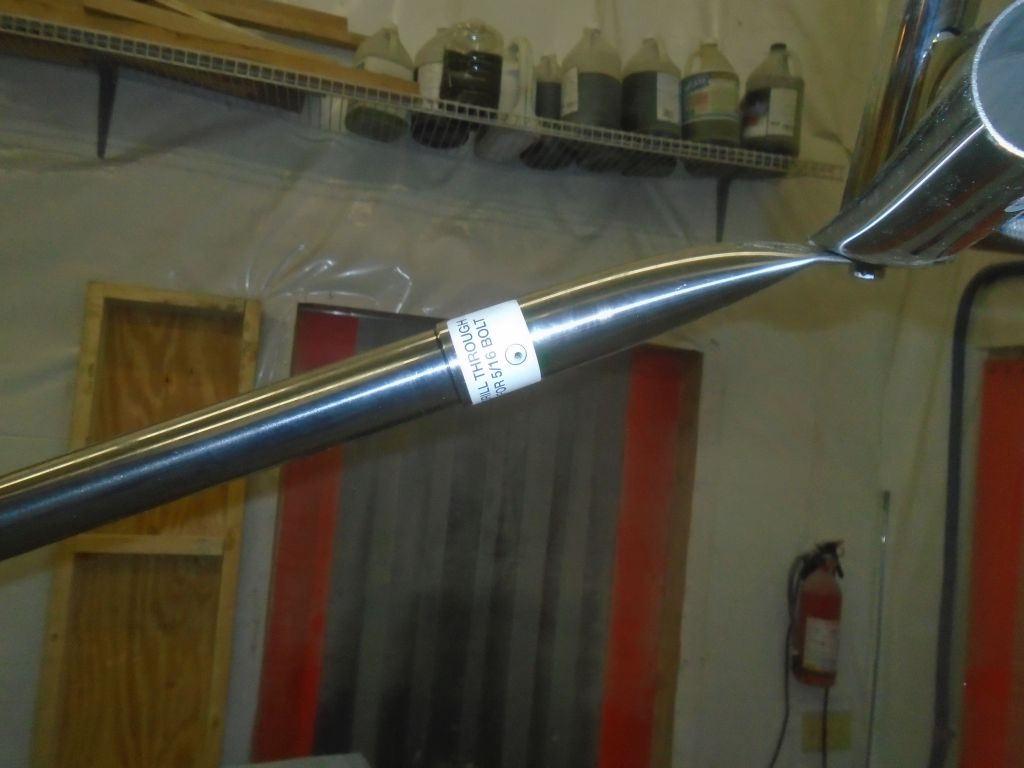
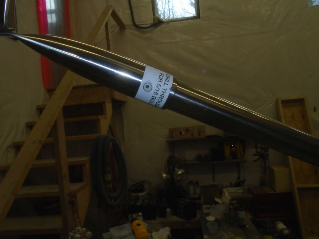
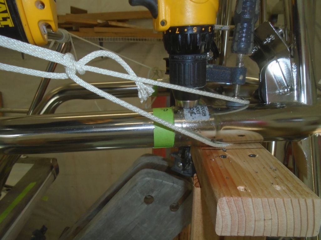
Drilling these 5/16″ through holes in the stainless tubing–there were eight locations requiring it on this installation (including the deck brackets and upper tubes, plus the diagonal supports that would come later)–was the most challenging part of the installation.  The instructions rather breezily indicated that drilling stainless was “easy”.  Well, it’s certainly possible, but “easy” is not an adjective I’d have chosen under any circumstances in the real world and under the less-than-ideal conditions found in the midst of an installation on a boat like this.  The issue was less with the physics of drilling the tubing (which isn’t that bad, honestly, if one does it right) and more of the fact that access and drilling position (likely to be the case on nearly any installation in the field) made the job much more difficult, or at the very least extremely time-consuming and taxing.

Every installation is bound to be different, but on this installation, the nature of the frame position and how it all interacted with the boat meant that for me, I felt I had to choose to drill all these bolt holes while the framework was in place on the boat, since nothing held the frame rigidly through the process (in fact, it was only after I finally installed the diagonal braces–the very last step–that the frame became rigid and immobile on its own.  This was largely because of the way this frame worked on this particular boat, with very long support members that allowed movement till braced together).  So since the bolt location was critical, I didn’t feel comfortable trying to remove the tubes and do the drilling down on the bench, where it probably would have been much easier.  But even a slight mis-step in the position or angle of one of these holes could throw off the whole carefully-aligned installation, so drilling the tubes in place seemed the smartest–if least easy–option.

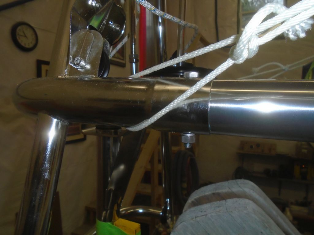
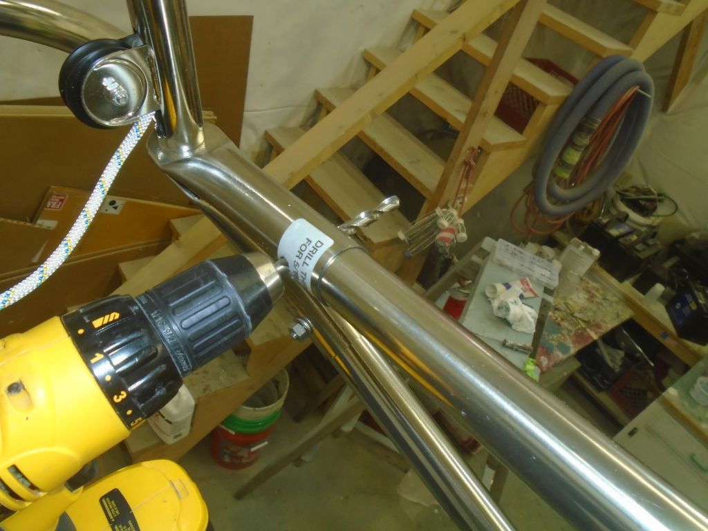
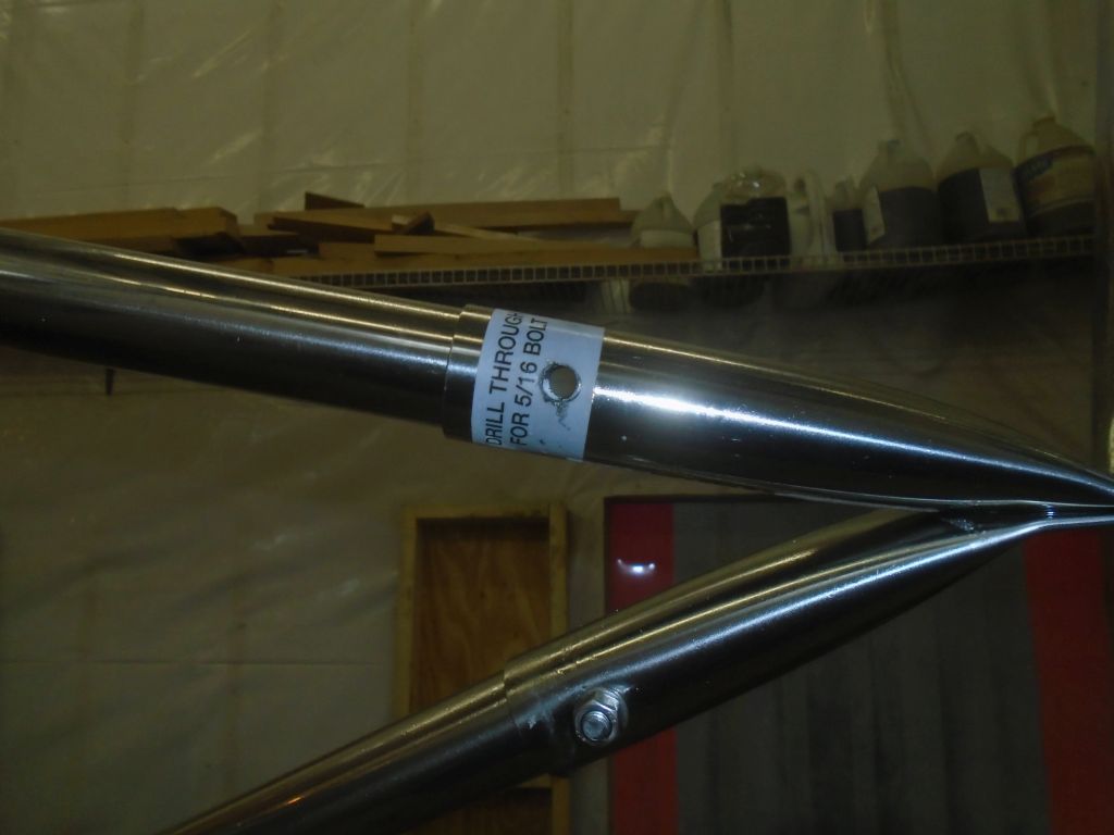
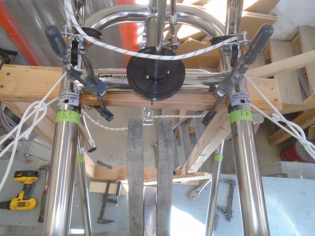
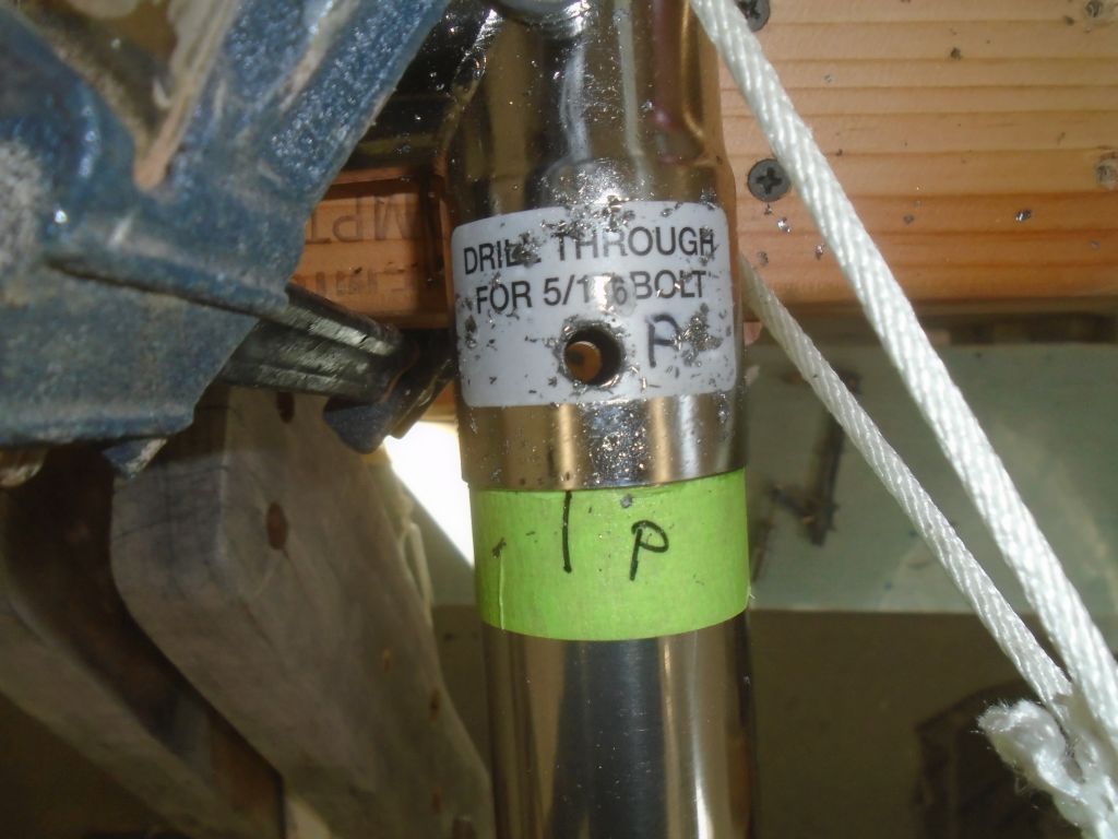
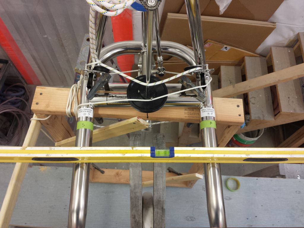
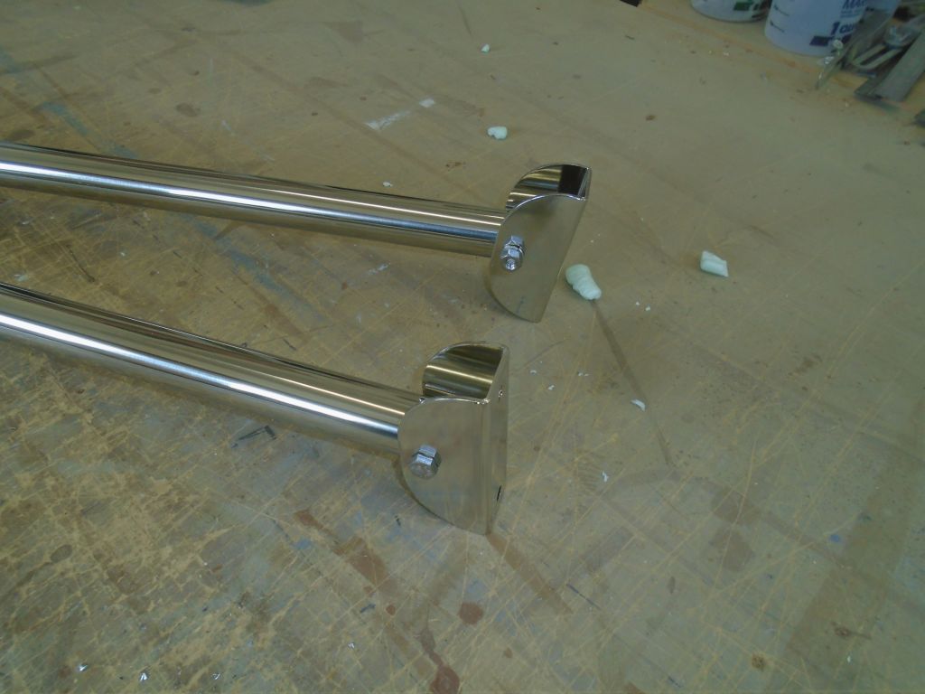
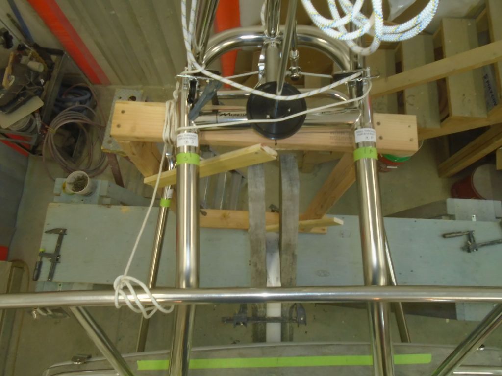
The bolt holes at hand now were at the top end of the lower braces, where they slipped into the sleeves that were bolted to the bottom of the Monitor frame.  These pieces came with the bolting locations well marked with labels, and with a small pilot hole on one side to start the process.  All very helpful.  But there were still four layers of stainless to drill through.  If I were to do this again, I’d probably pre-drill the sleeve first, down on the bench.  (Actually, I’m not sure why the manufacturer couldn’t provide the sleeves with the holes completely pre-drilled on both sides.  This would make marking and drilling much easier in the field.)

In any event, I’d probably try to drill the sleeve first, given the lessons learned this time around, which would then allow me to mark both sides of the tube where it needed to be drilled, and therefore much easier to remove the tube and do the drilling somewhere down-hand where it would be quicker and less taxing to drill.  But now, I needed to drill through the sleeve and tube with it in place.

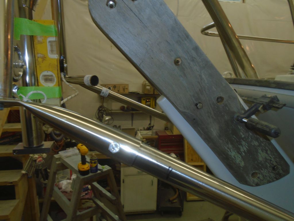
I’d started the installation the other day with one new 5/16″ bit on hand, and several used ones available.   Drilling the first sets of holes (in the tubes where they met the deck brackets, and then the tops of the upper tubes where they met the frame) hadn’t been too bad, as my bit was still good, and the drilling position was suitable for the pressure and patience required to get through the stainless.  I’d ordered several new bits in the meantime (they’d be here later in the day), but for now I didn’t have them, and I needed to continue.  So a duller bit didn’t help, but again, the toughest part of the drilling was because I was standing on a ladder, with limited access to the hole for the drill and operator (me), and no ability to drill down-hand.  So, frankly, it was simply long and tiring to drill these holes.  It would have been nice if it’d taken half as long, as keeping up the pressure on the drill was exhausting after a time.

None of this is to complain.  Stainless steel is what it is.  The installation process and instructions (not to mention the quality and sheer beauty of this windvane) were all second-to-none.  Perhaps my experience will make the process easier on someone else, and certainly will on me if I get the chance to install another one of these.  Scanmar, the builder of Monitors, clearly has listened to–and implemented–scores of owner/installer-based suggestions, changes, and recommendations over the years, and the overall process seemed pretty well-tuned.  Yet still, each individual case presents its own challenges and specifics.

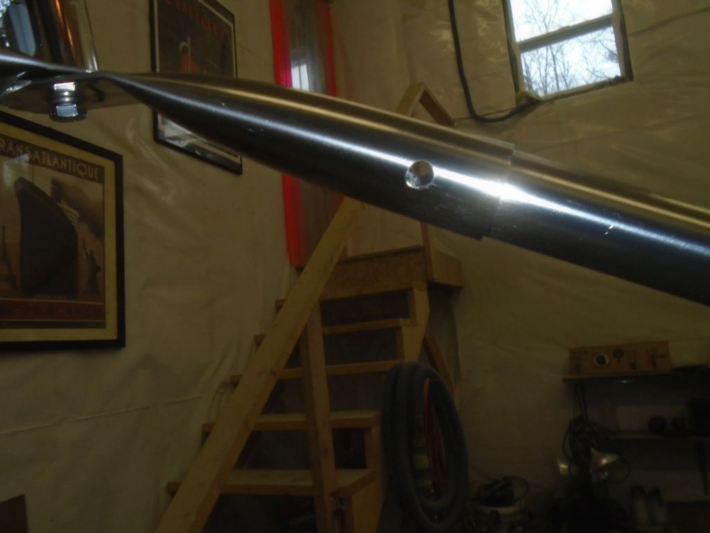
In any event, I got the next pair of holes drilled, not without effort, but in the end being done was all that mattered.

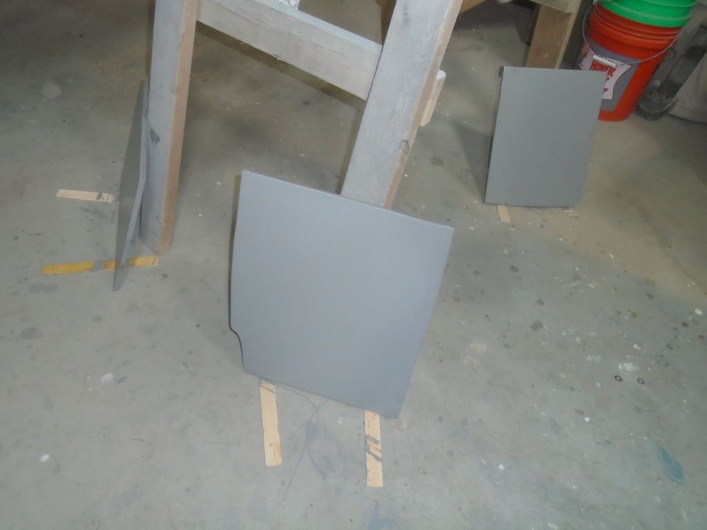
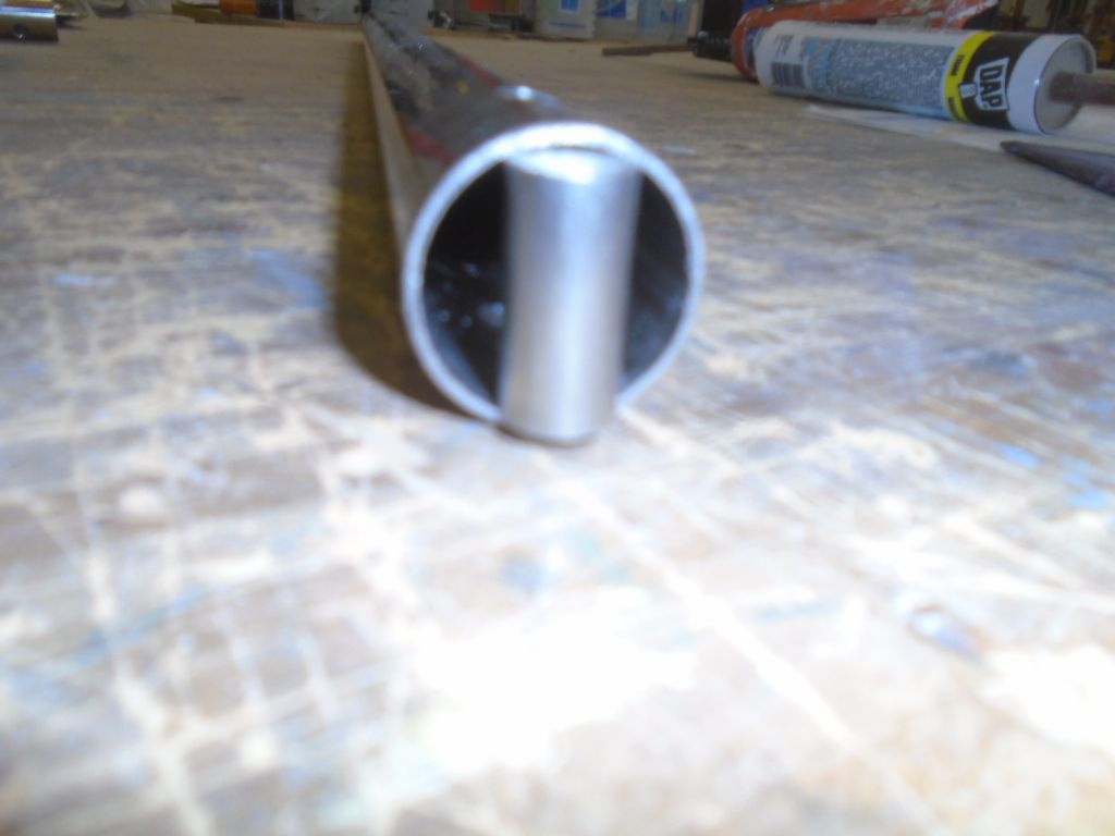
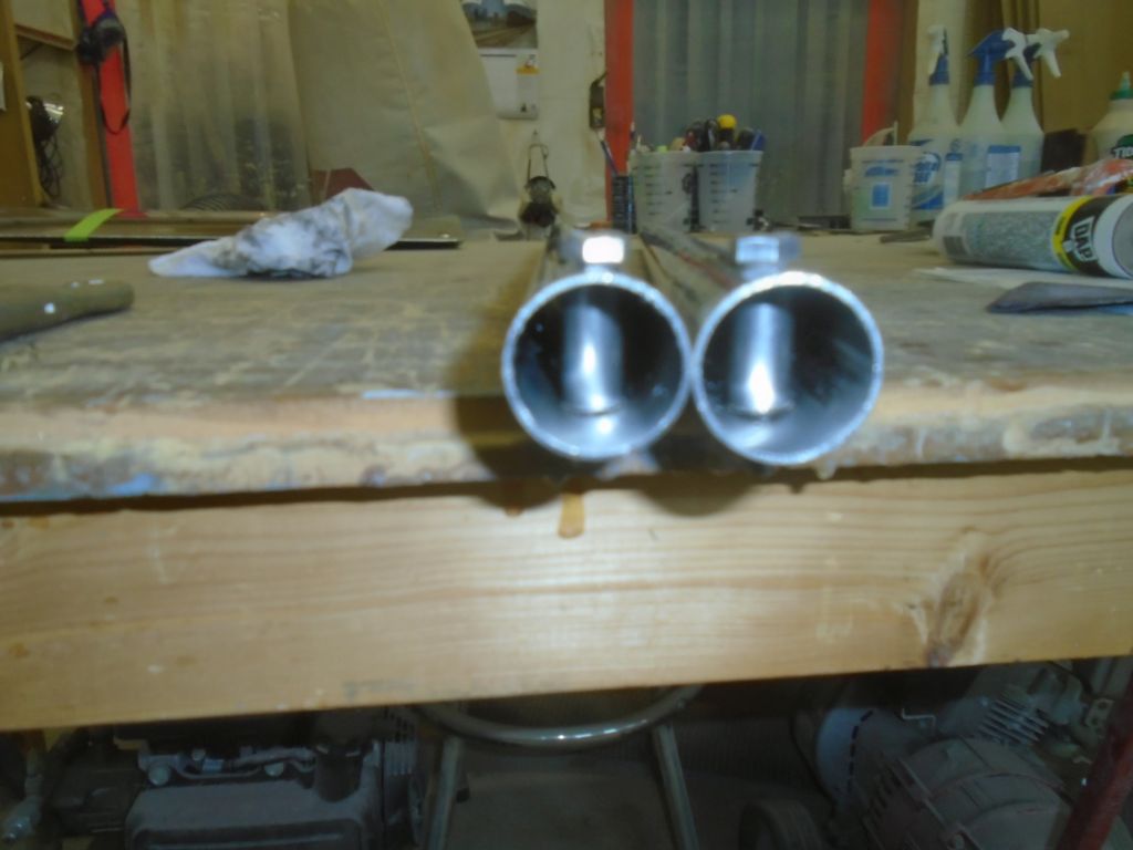
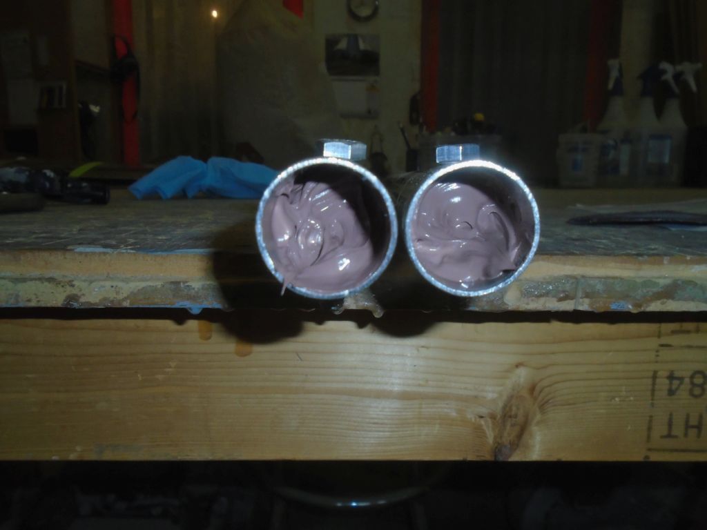
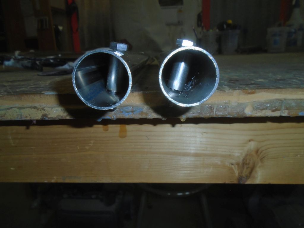
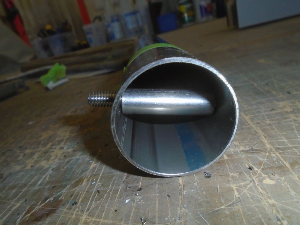
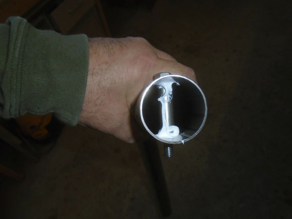
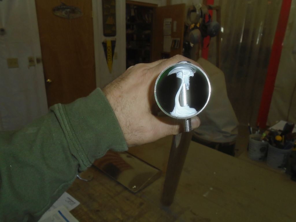
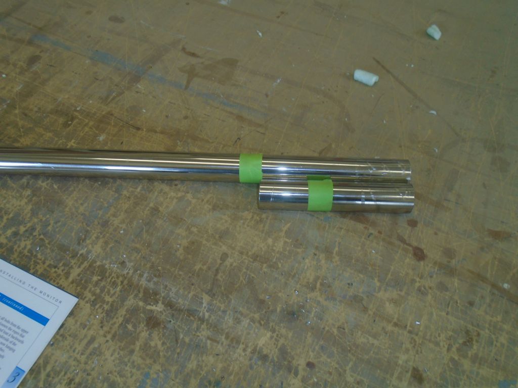
I removed the two lower tubes and, down on the bench, prepared to install the compression sleeves within.  Here I ran into another small problem:  the compression sleeves were just slightly too long to fit into the end of the tube.  Maybe there was a burr there from cutting the tube to length, or maybe the sleeves were just a bit too long, but I had to shorten them a bit (I did this by grinding them down on an inverted belt sander).  Once the compression sleeves fit, I installed them (holding them in place with the bolts themselves) and used some quicker-drying sealant (just latex caulk in this case–all it does is hold the sleeves in place) to secure them, accelerating the dry time with a heat gun since I wanted to continue the installation.  Once I felt that the sleeves wouldn’t move, I reinstalled the lower tubes on the boat, and put in the bolts loosely.

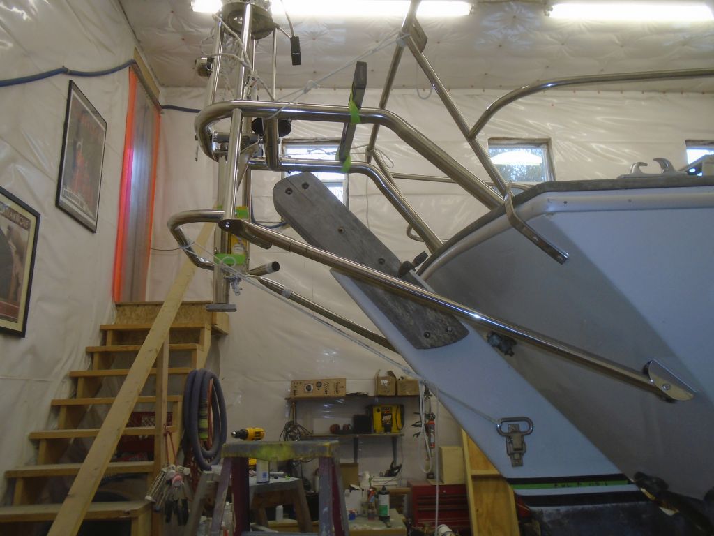
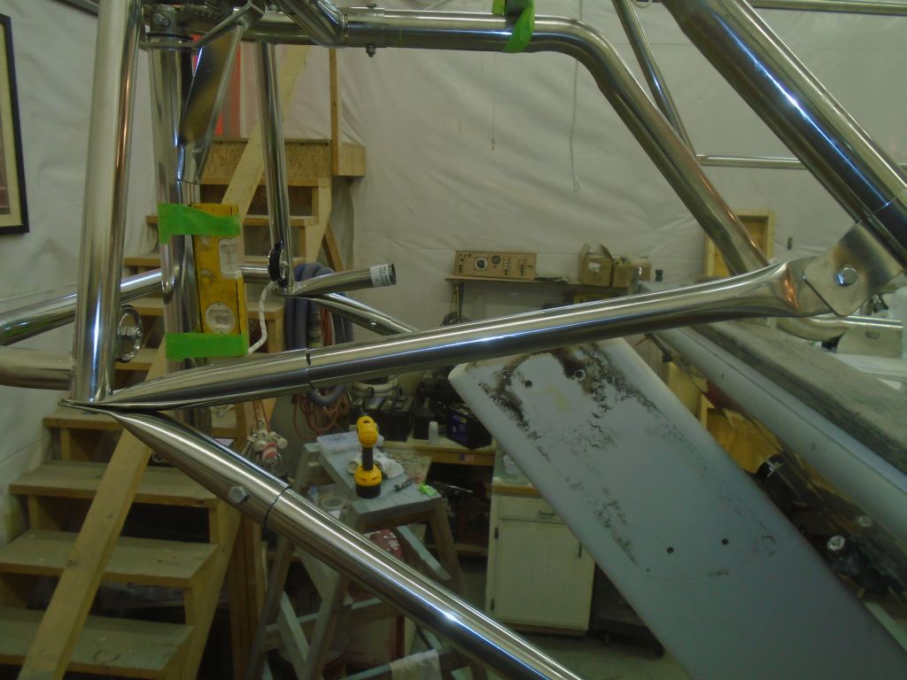
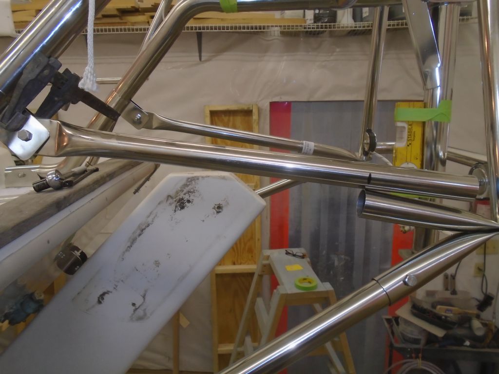
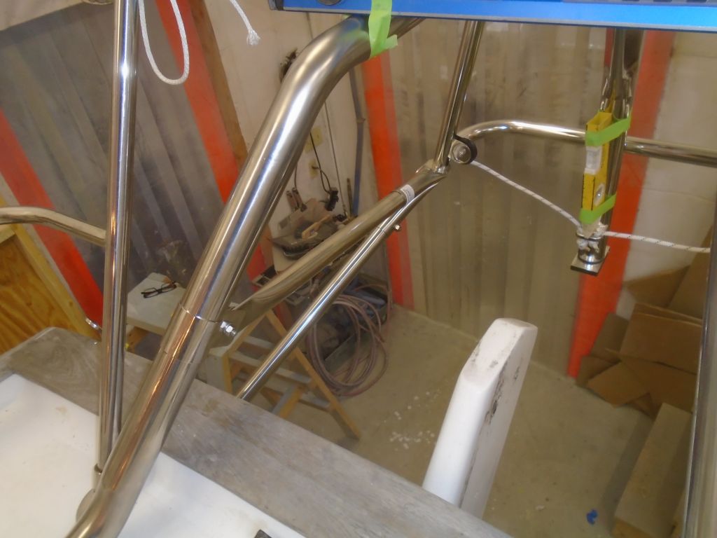
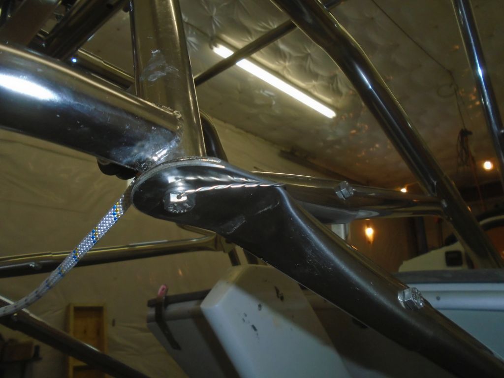
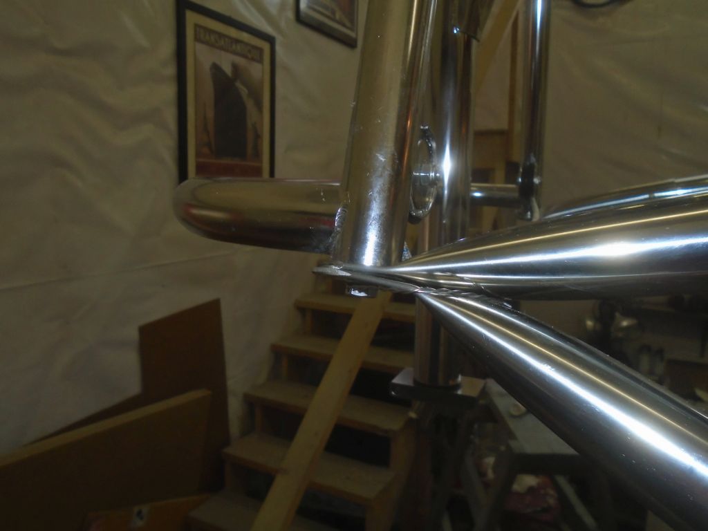
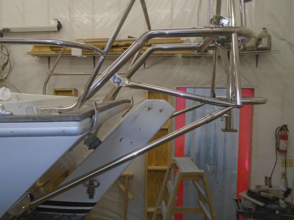
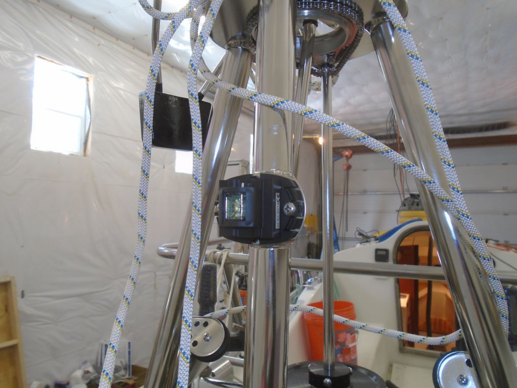
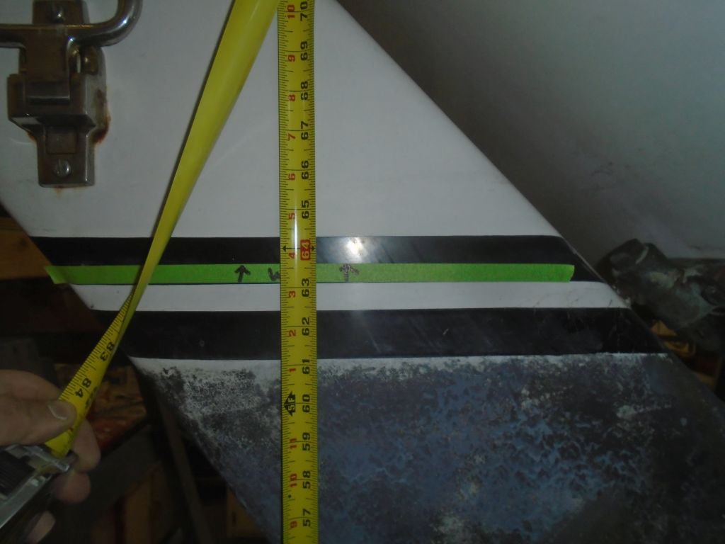
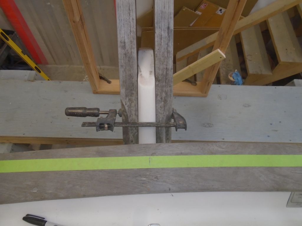
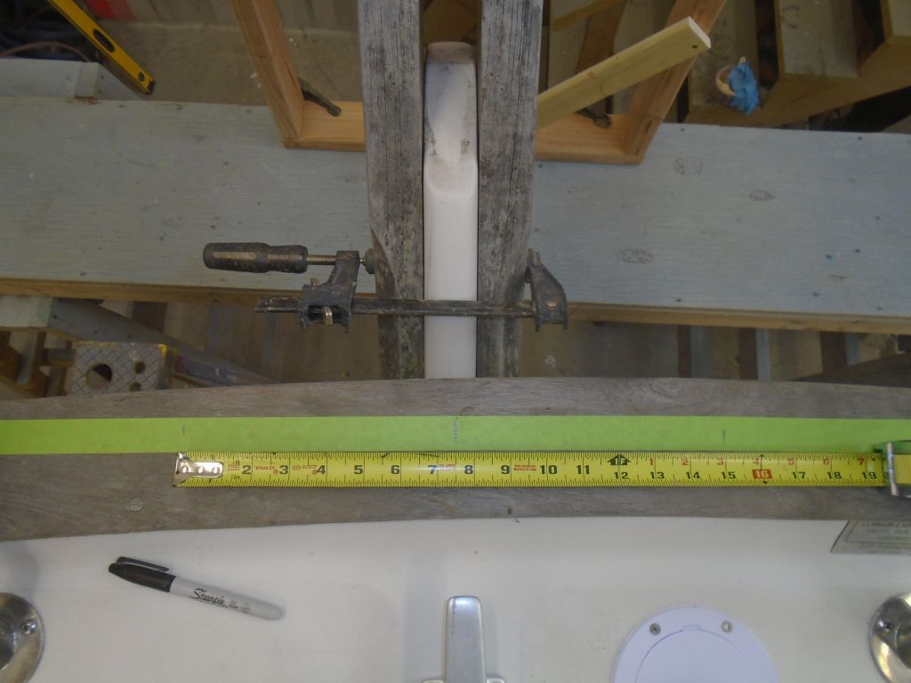
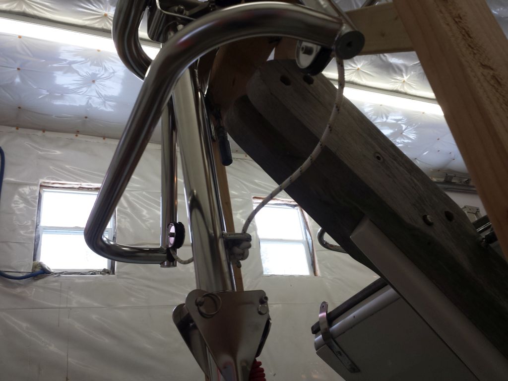
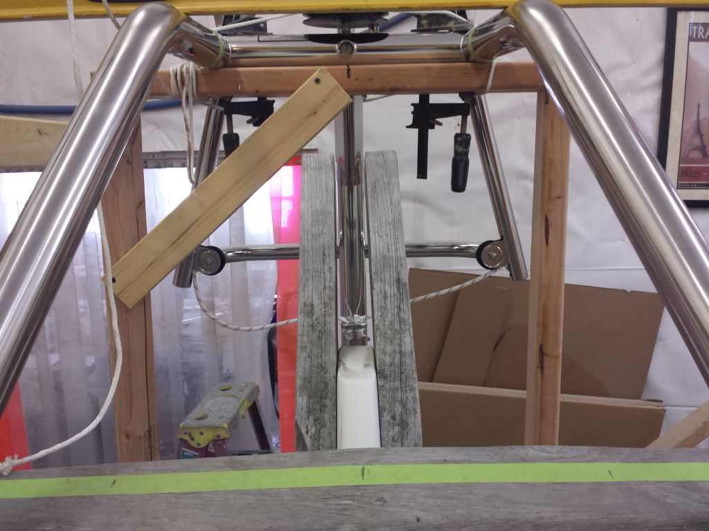
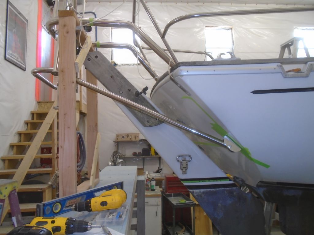
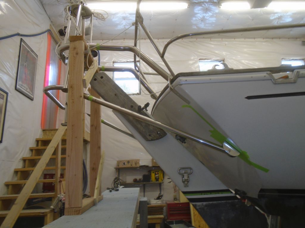
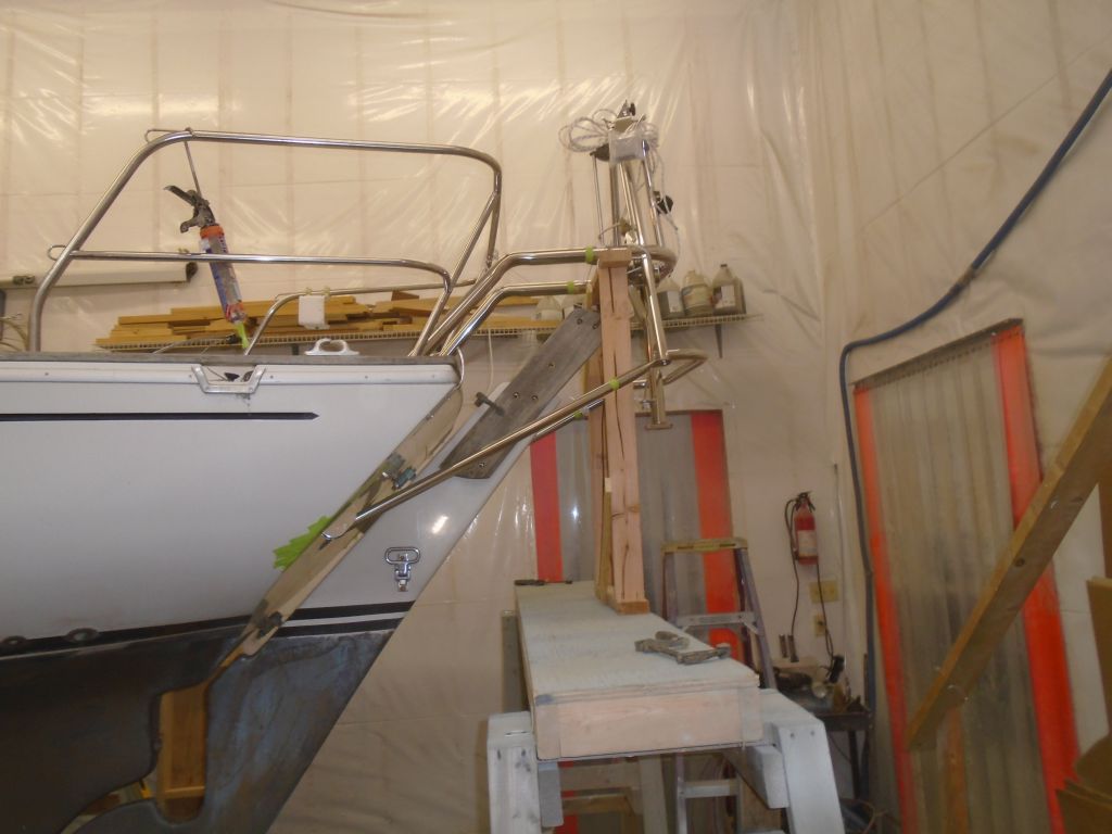
Now that the four main support components were in place, I could move on to the diagonal supports, which were critical in this installation since all the other members were so long, and oddly arranged by requirement, that the frame couldn’t be truly rigid till the diagonals pinned it all together.    Because the sleeves for the frame end of the diagonals shared the bolt at the lower end of the frame with the lower tubes, I’d already installed the sleeves during an earlier part of the installation (they fit above the lower sleeves), so those were already where they needed to be.  The other end of the diagonal braces would fit into a clamping bracket that fit around the large upper support tubes.    I could have installed those brackets just about anywhere on the upper tubes, but I chose a location that triangulated the braces nicely and simply looked right to me, and, with the clamps in the same place on both sides, measured and cut the diagonal tubes to fit as required.

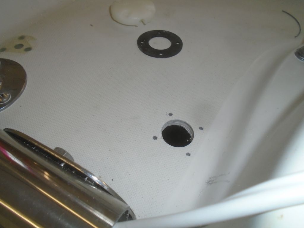
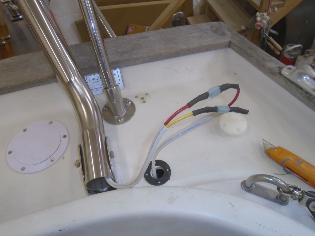
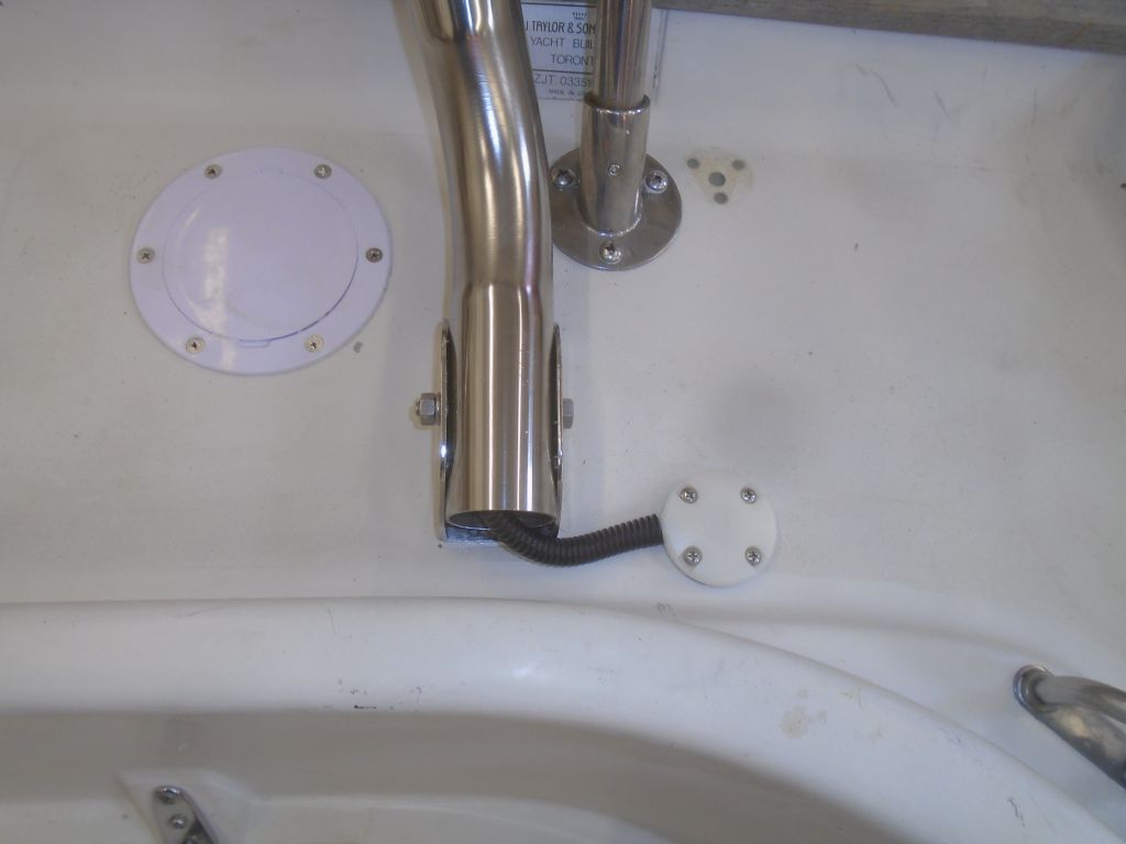
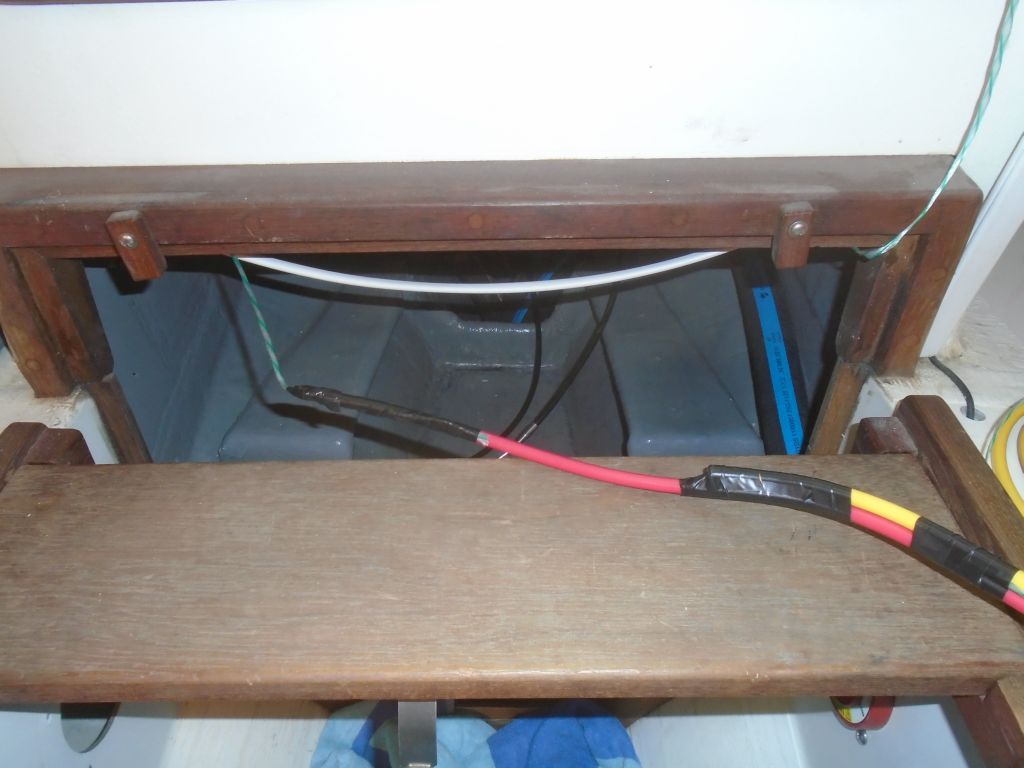
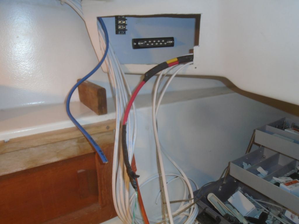
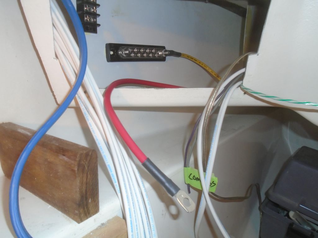
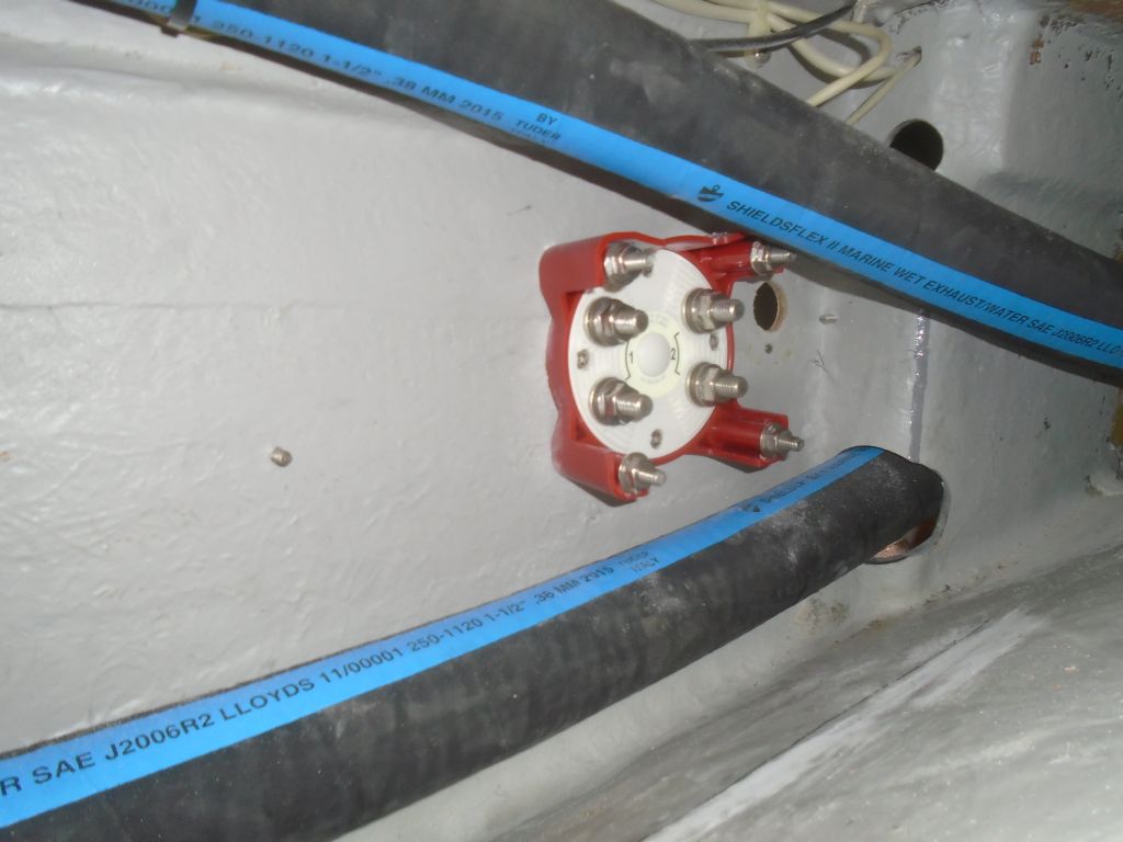
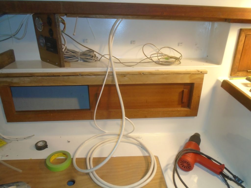
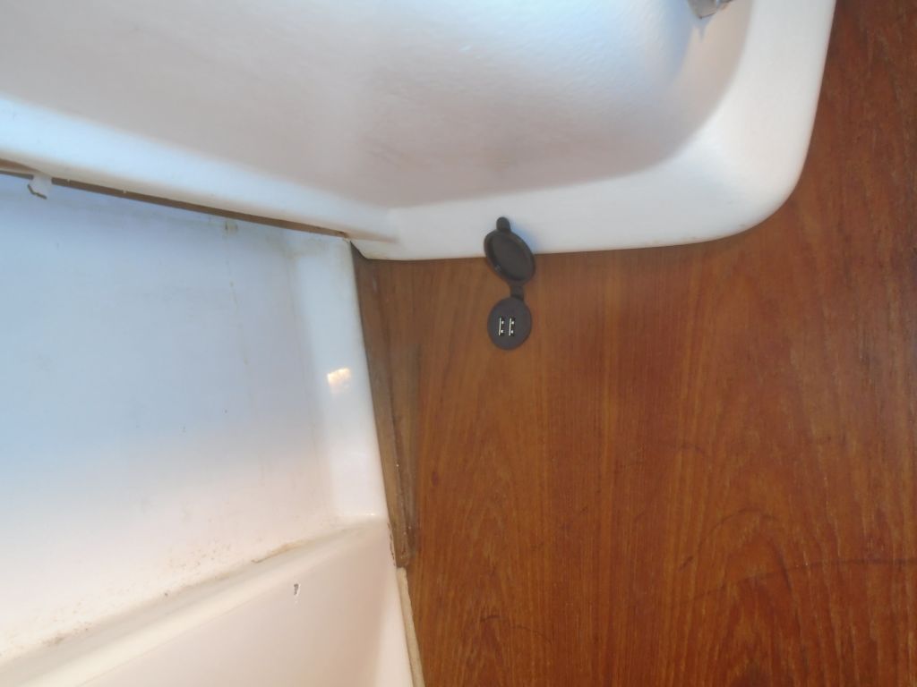
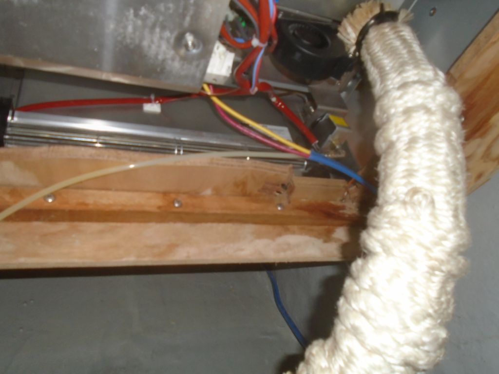
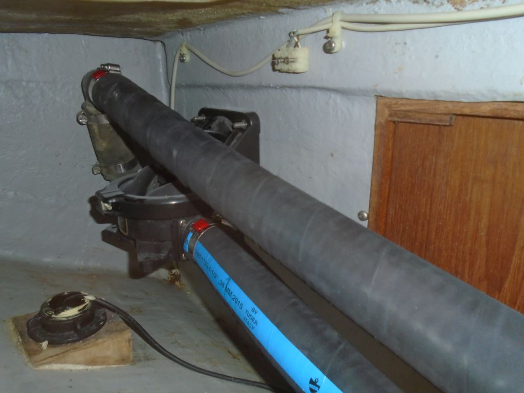
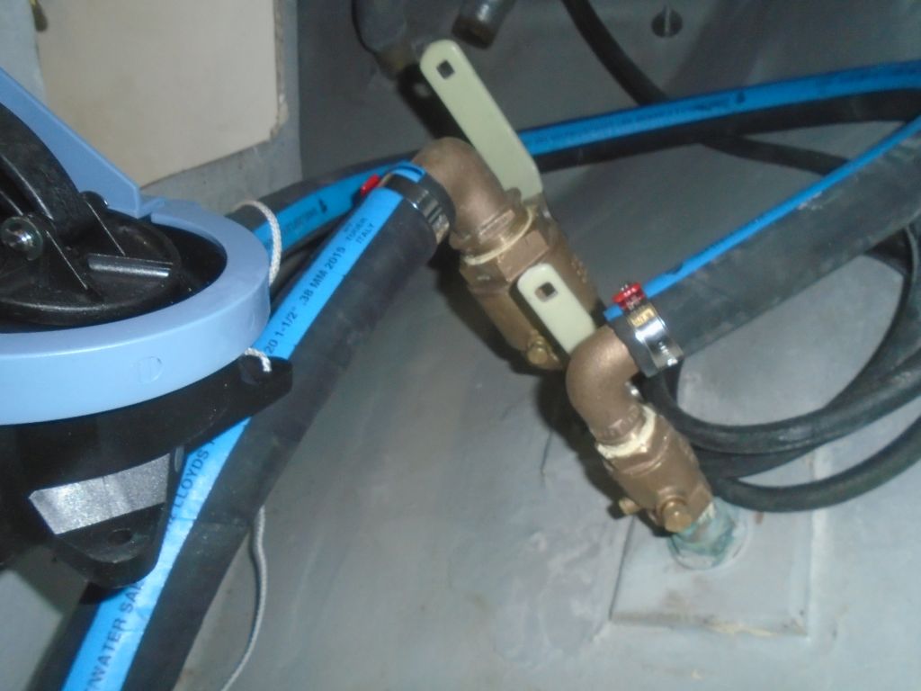
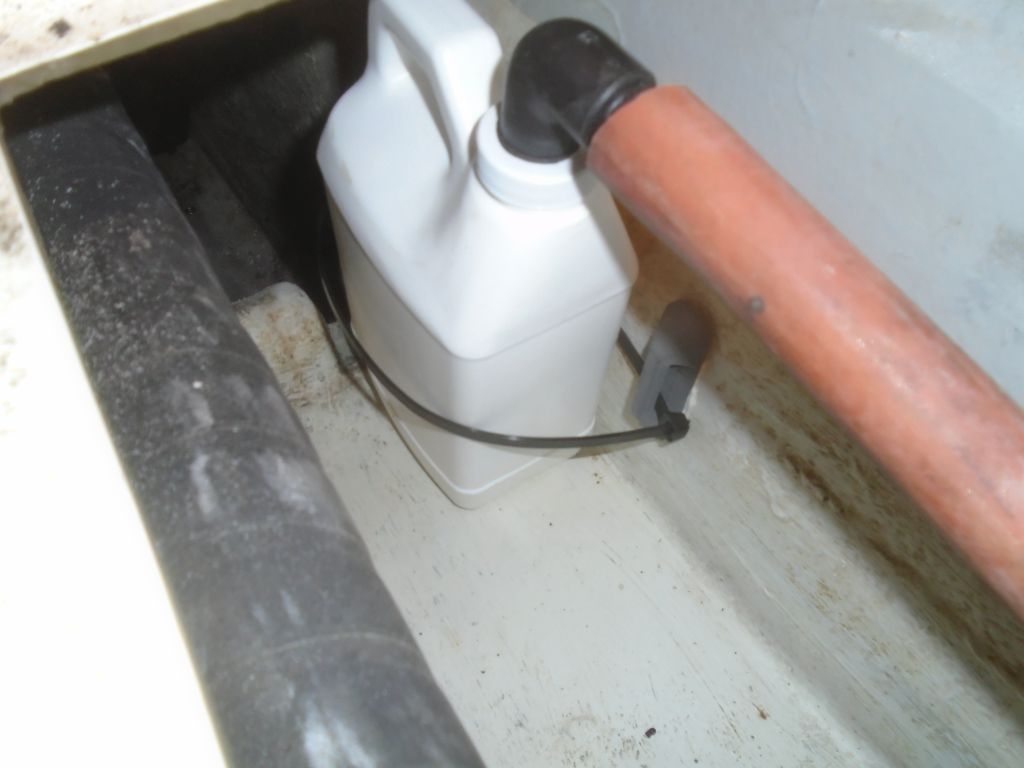
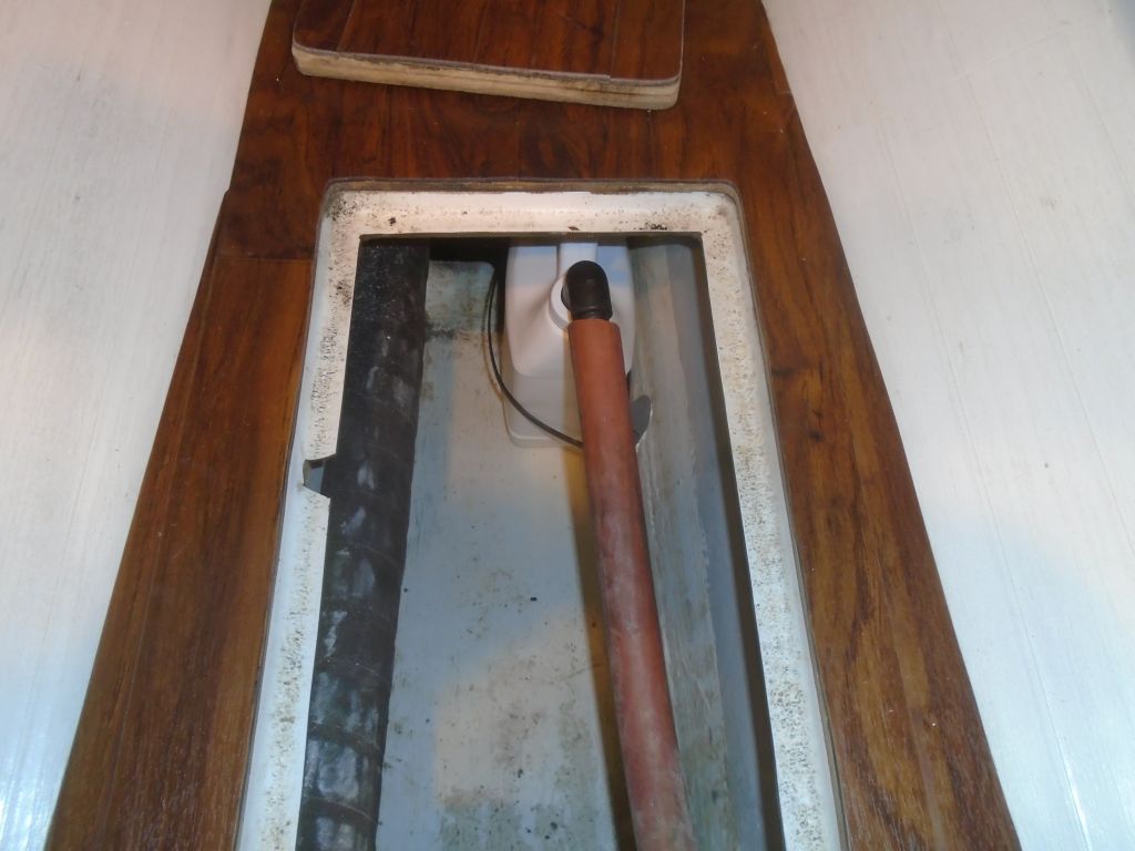
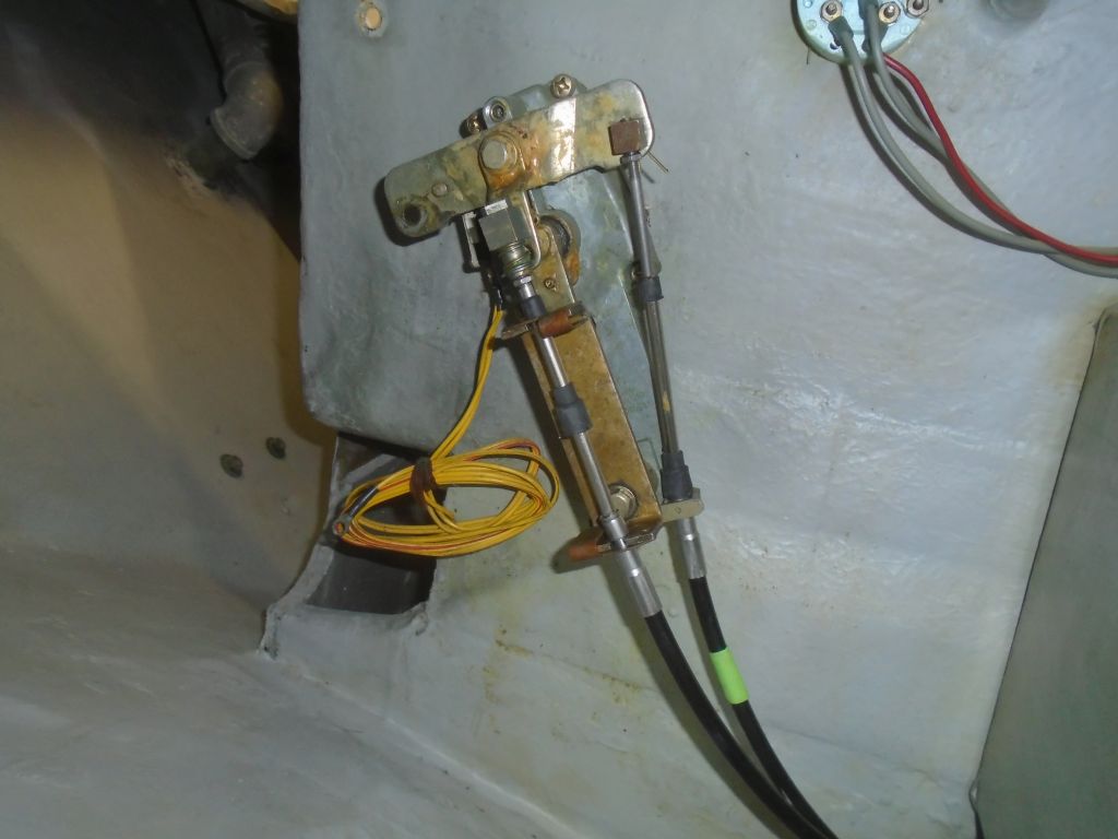
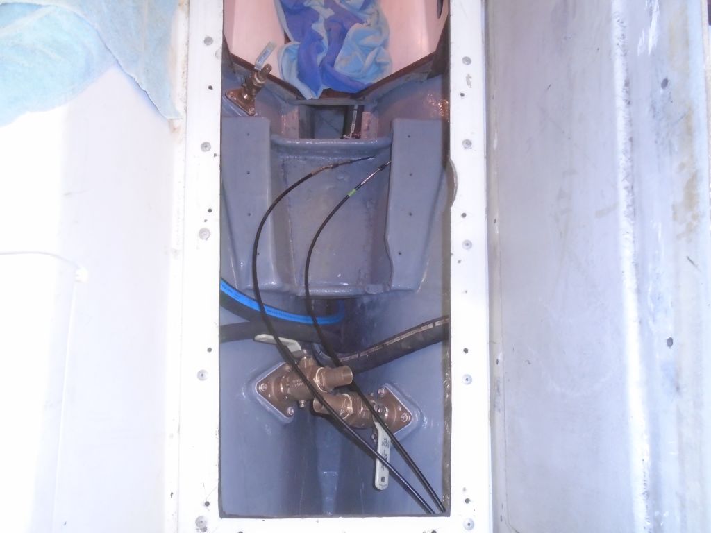
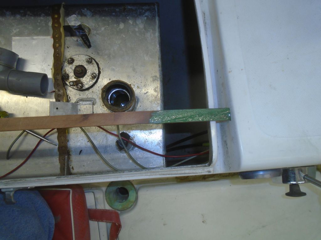
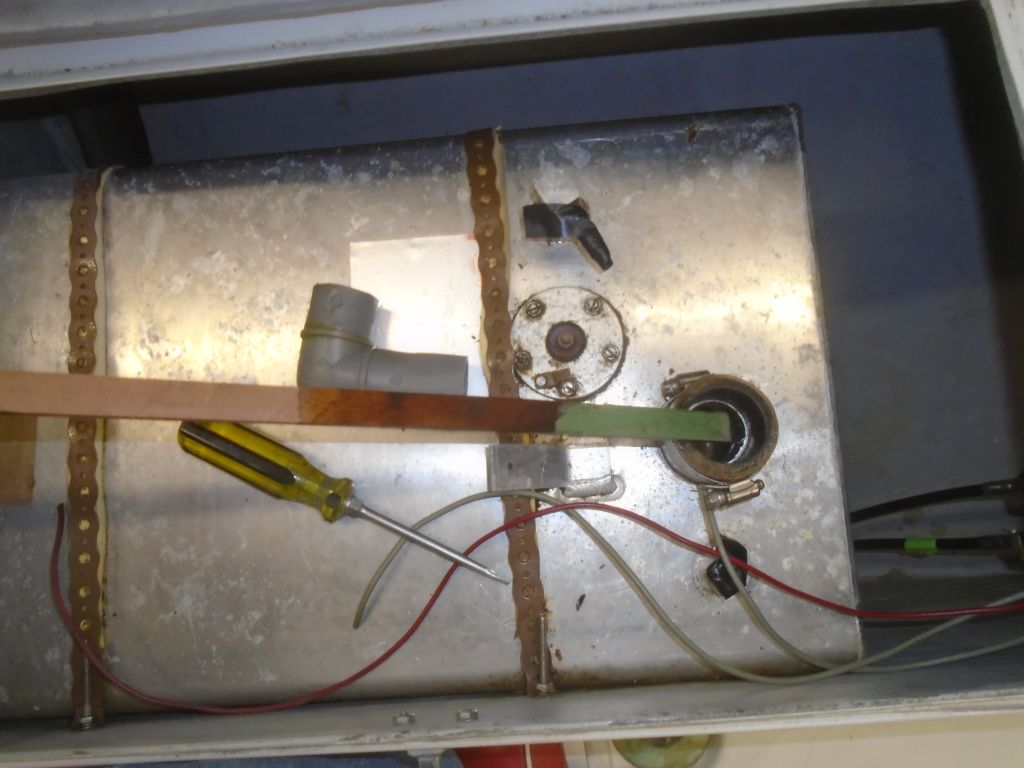
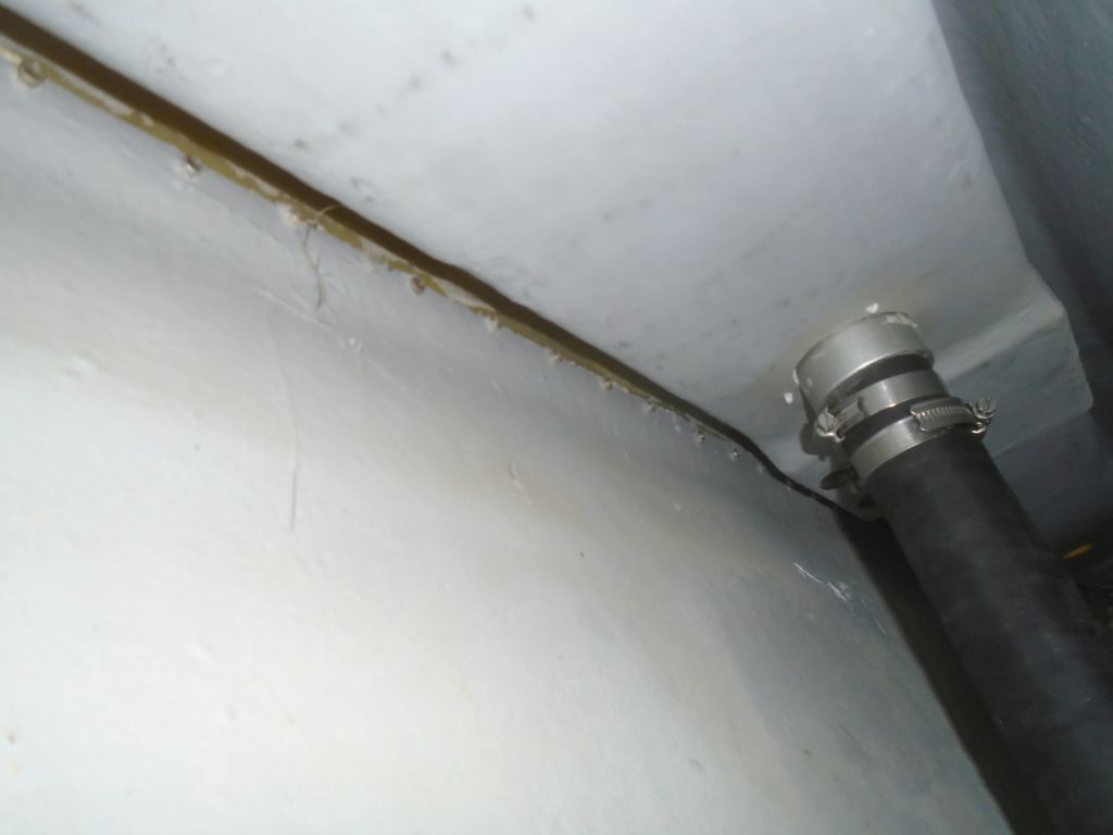
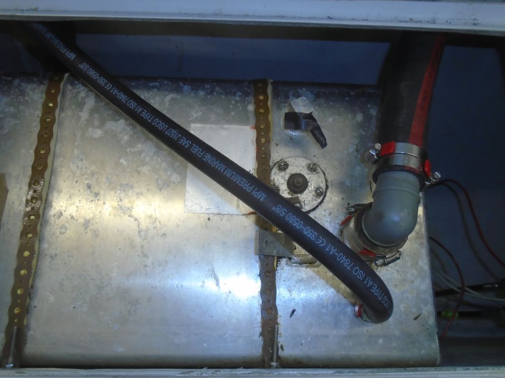
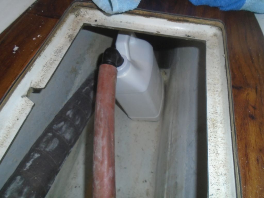
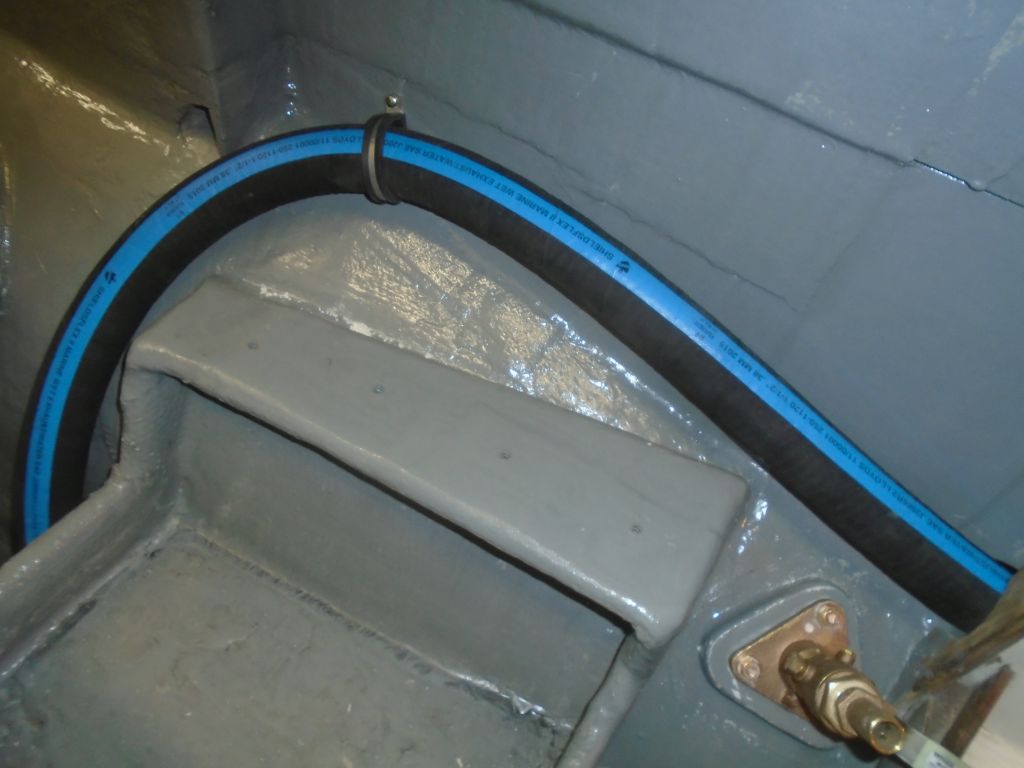
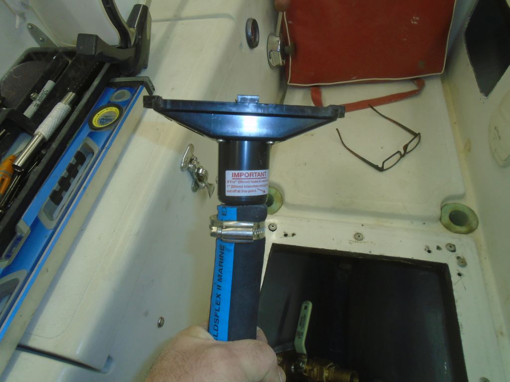
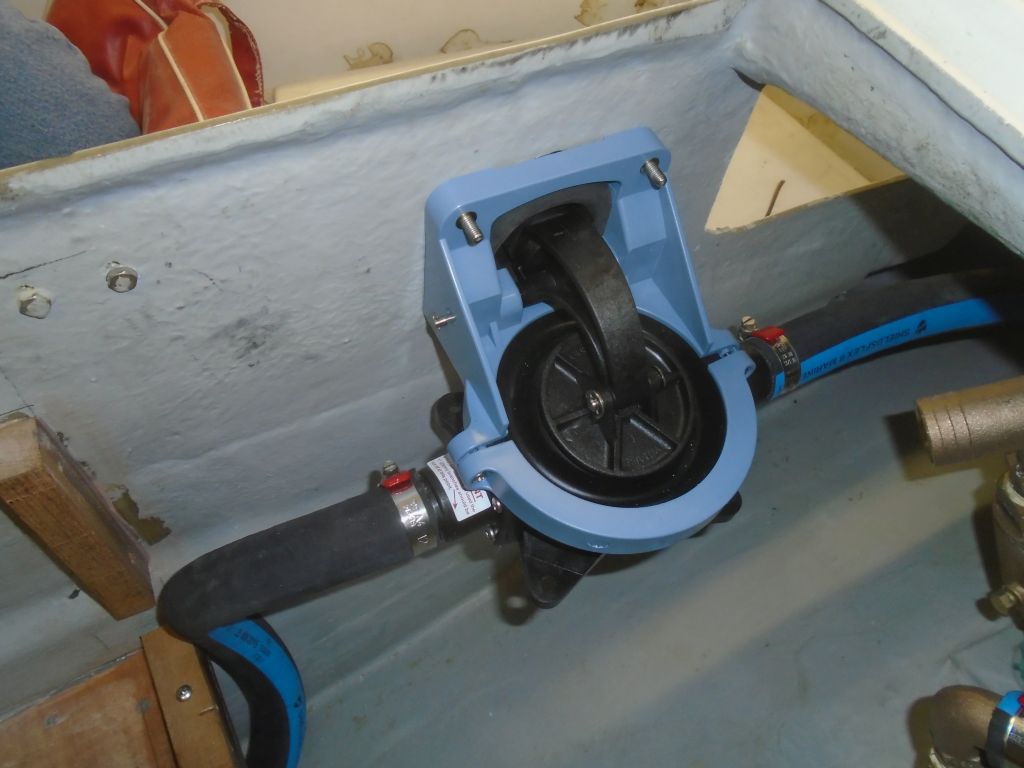
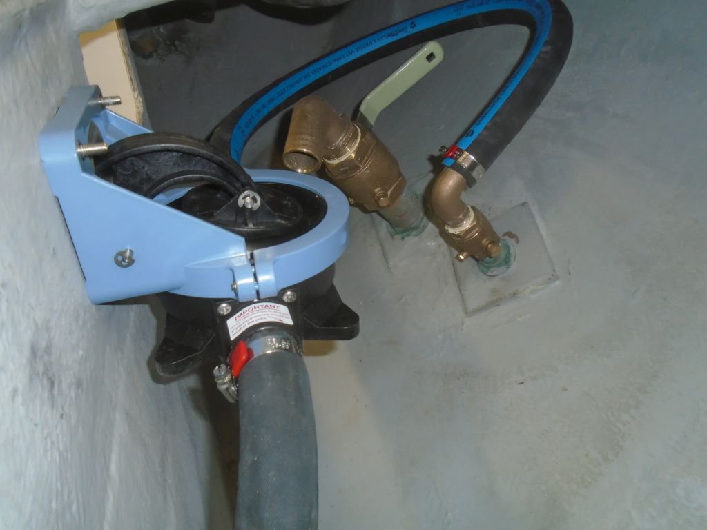
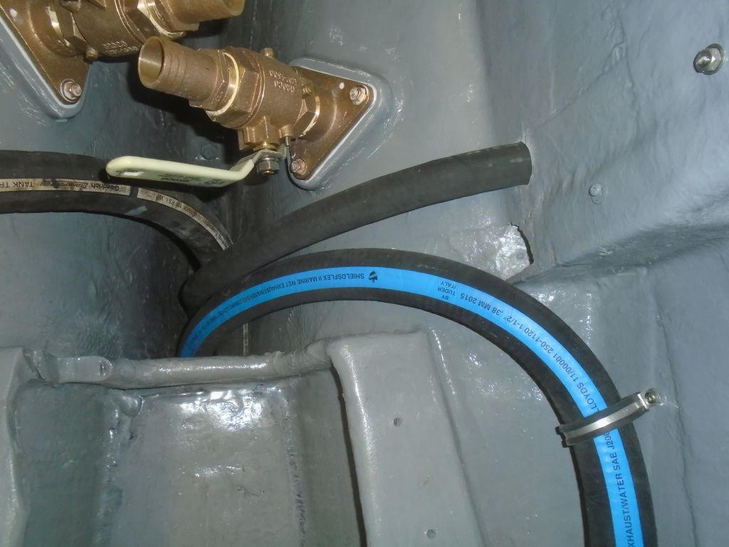
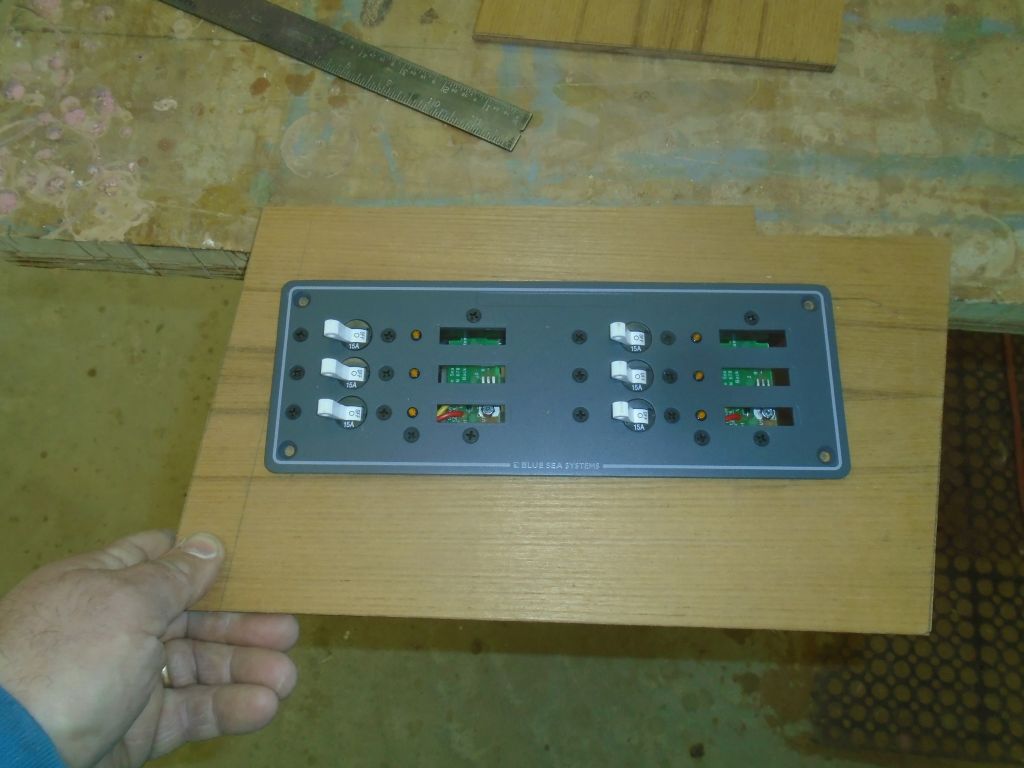
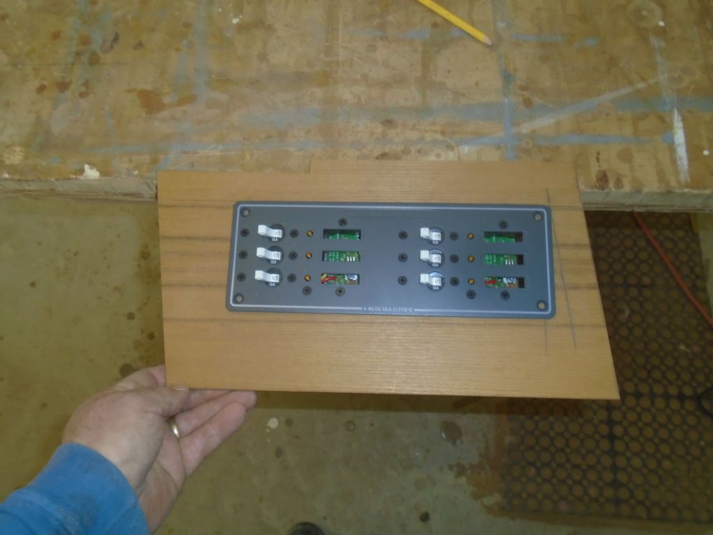
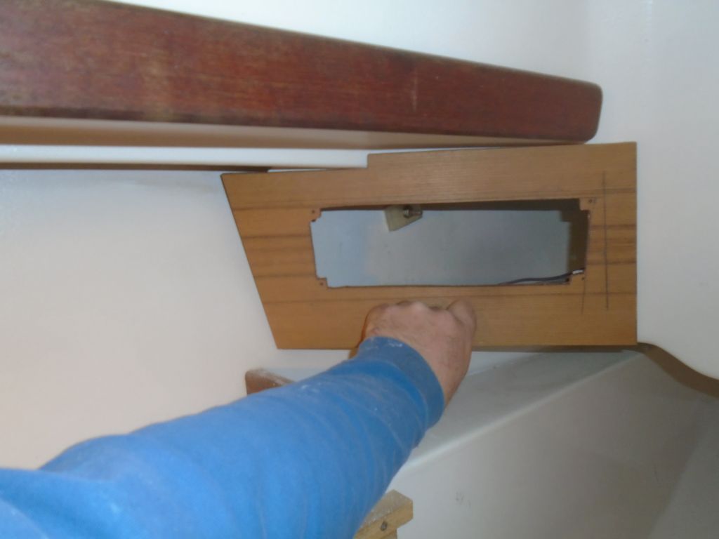
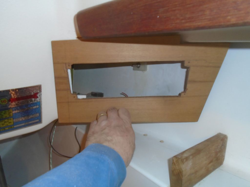
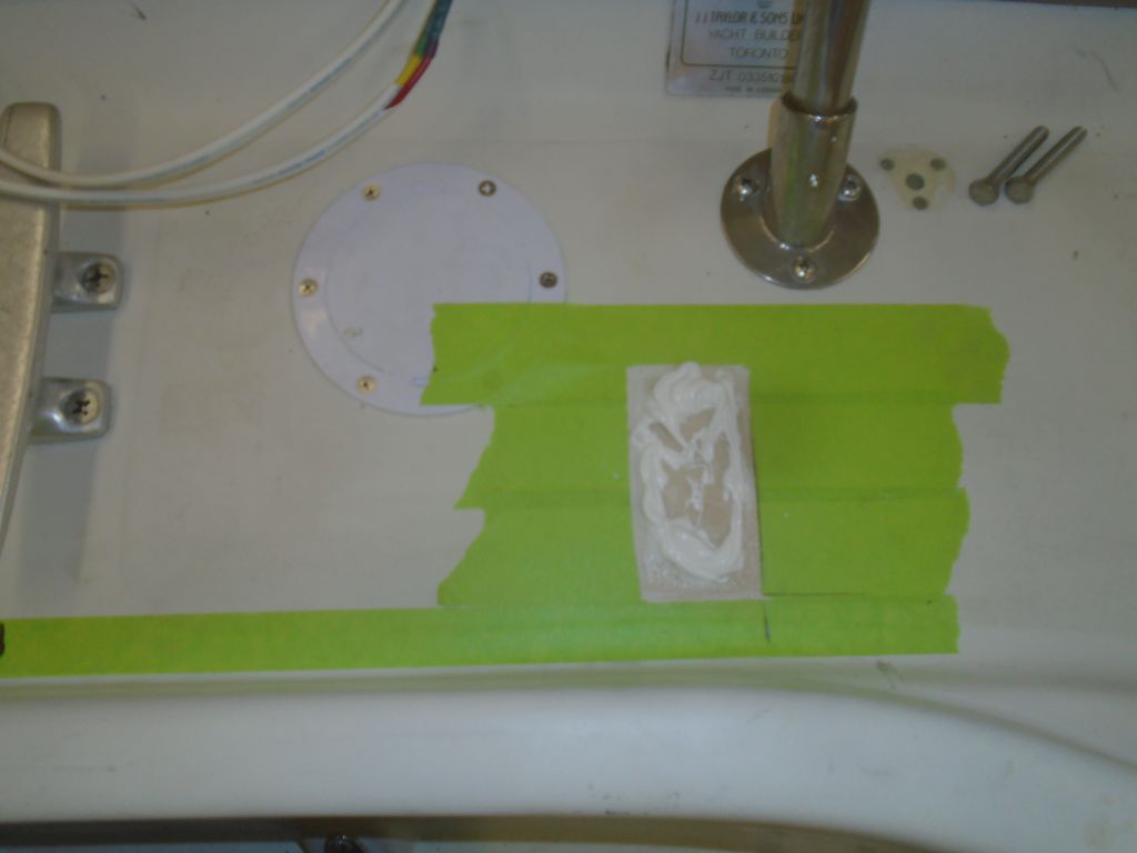
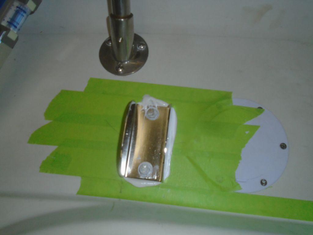
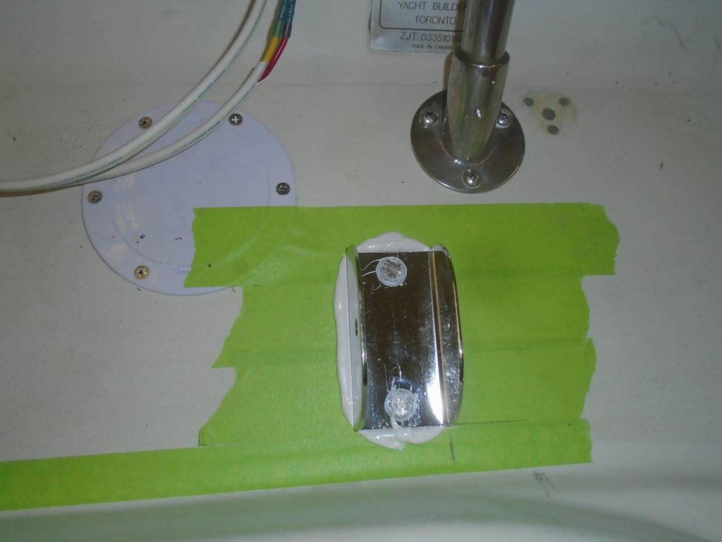
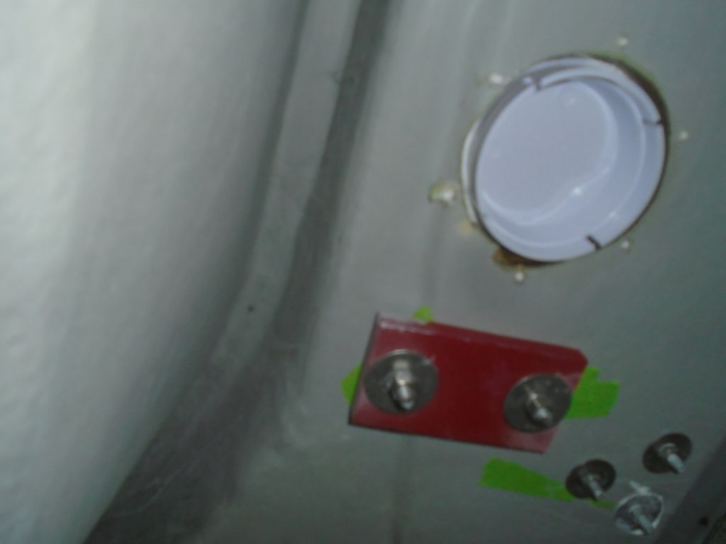
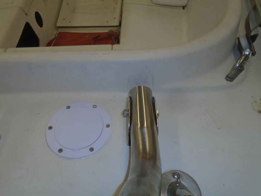
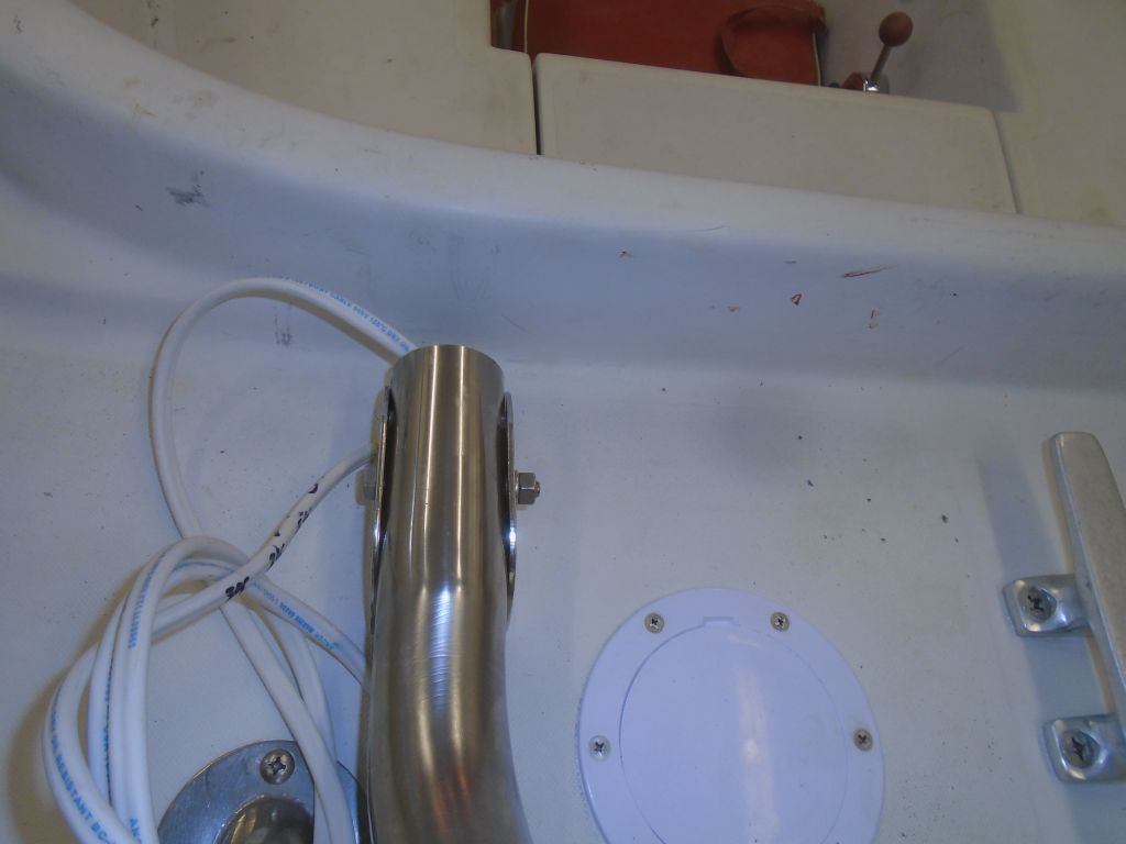
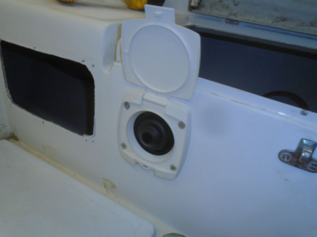
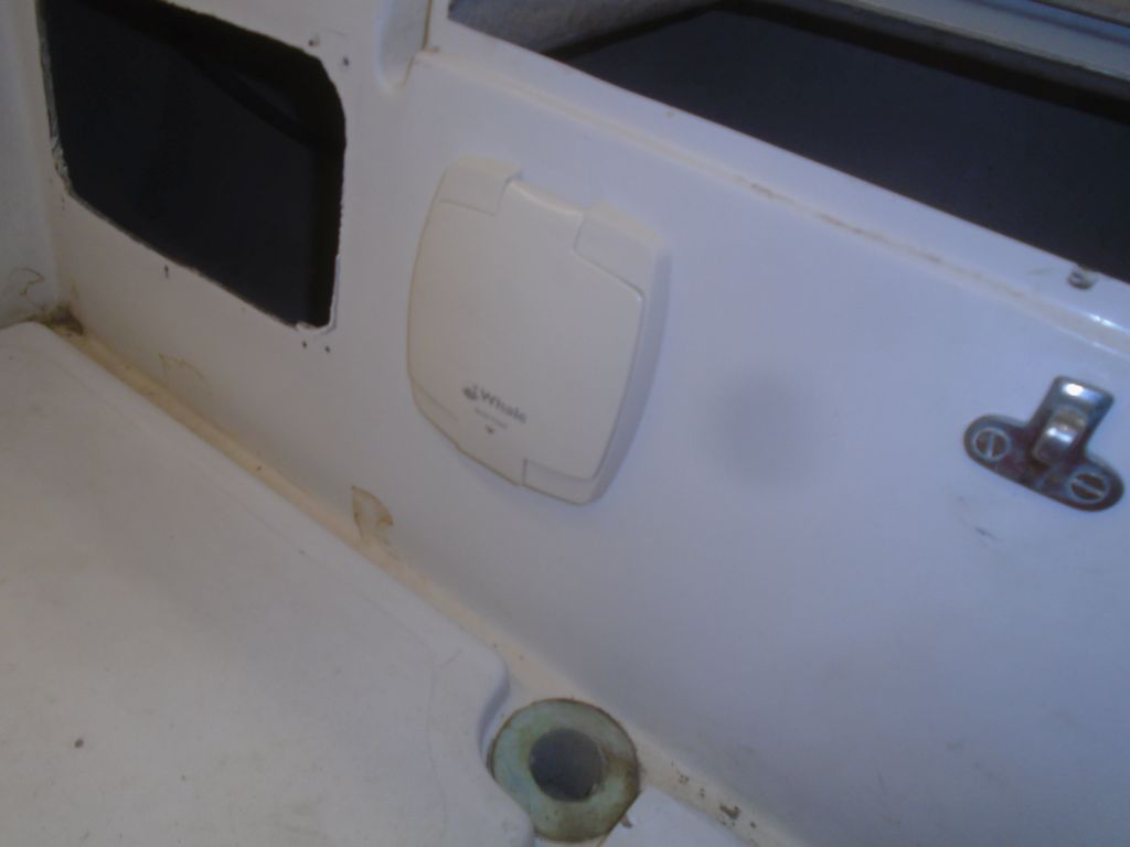
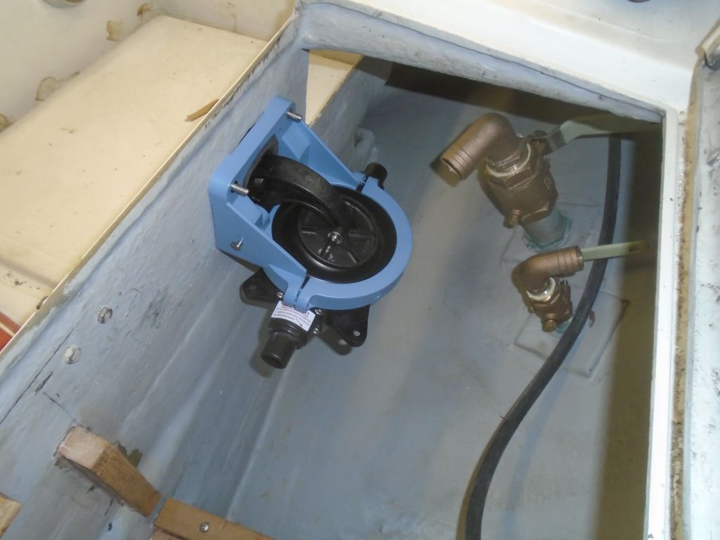
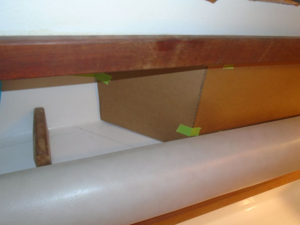
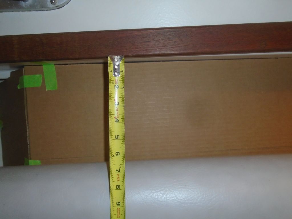
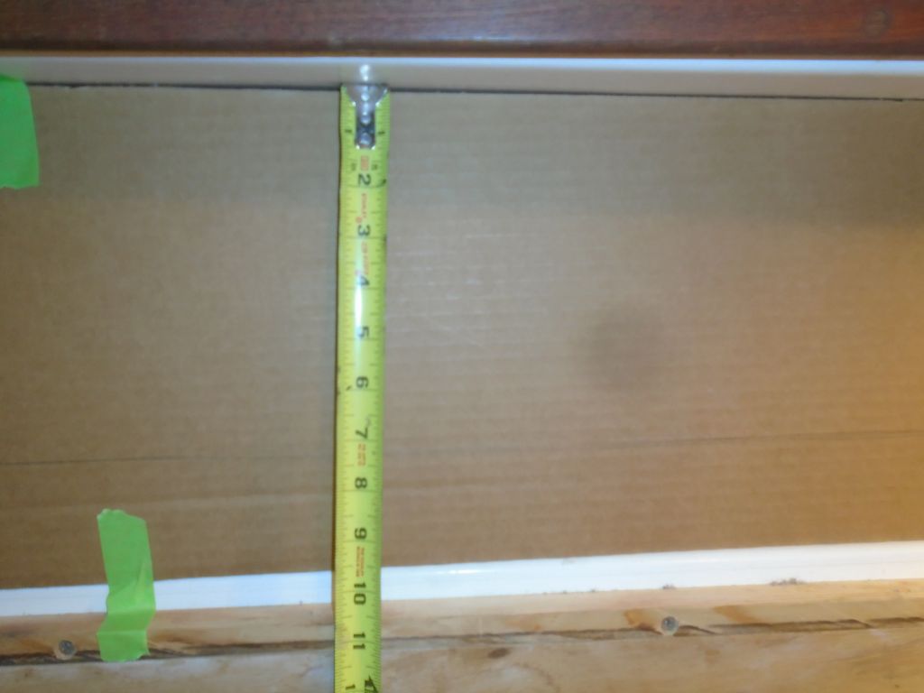
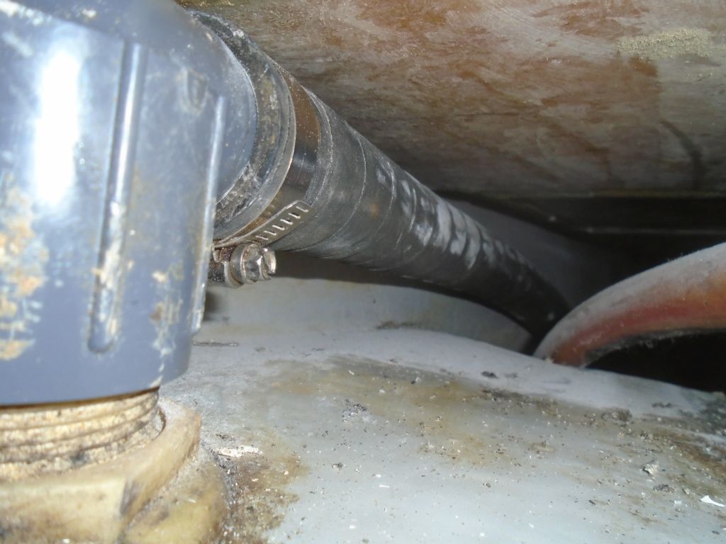
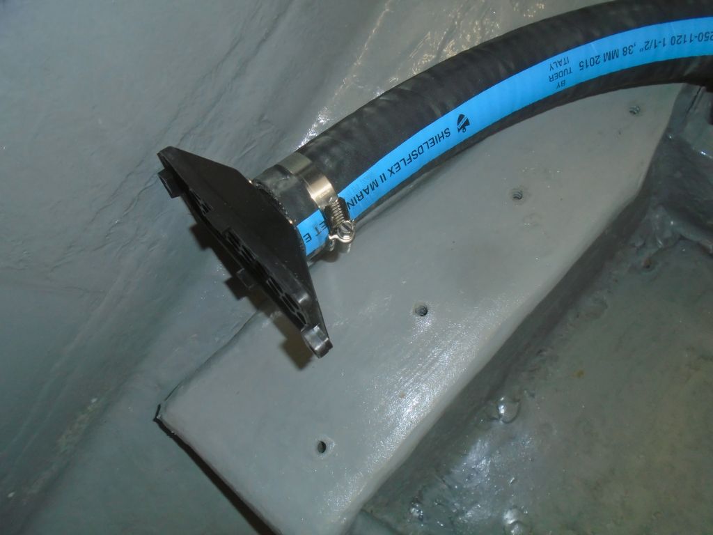
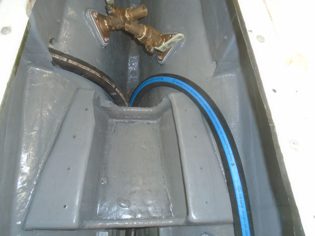
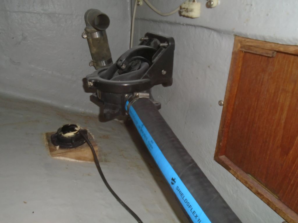
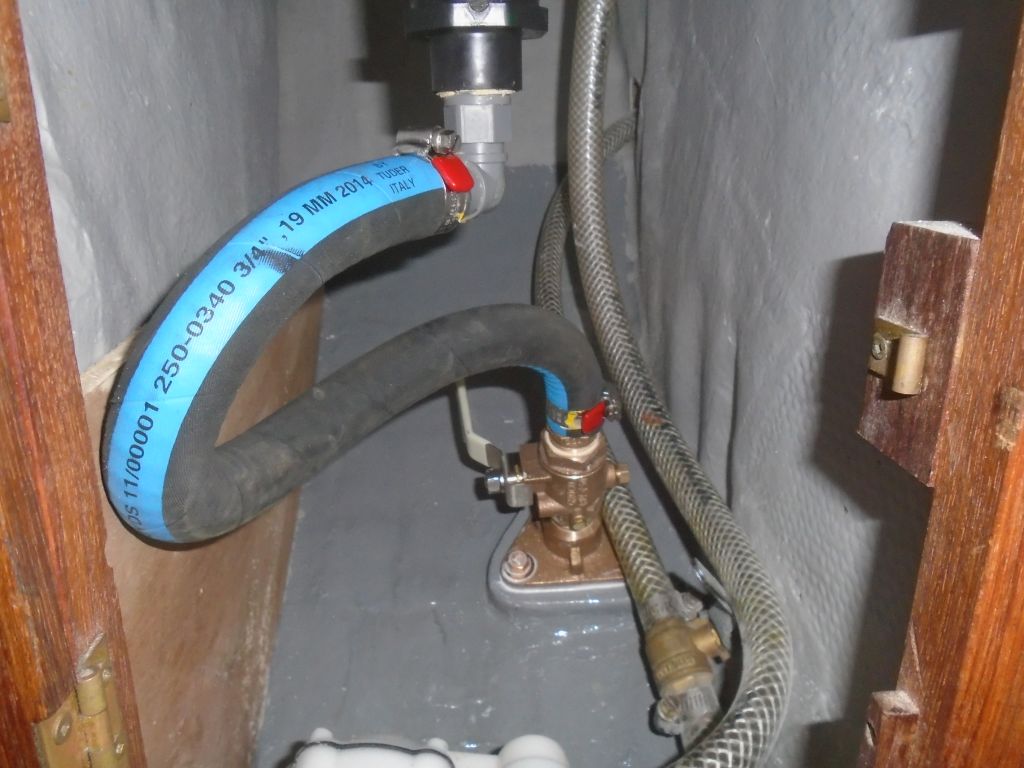
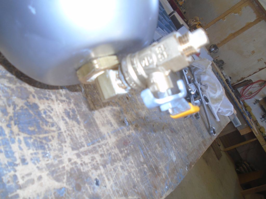
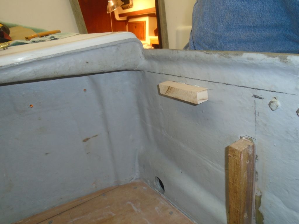
There were two more bolt holes to drill through the diagonal sleeves, but at this point in the day–early afternoon–I didn’t yet have my new drill bits, and I wasn’t going to attempt these holes with the now-dull bits I had on hand.  So briefly, I shifted gears and began the installation of the cockpit-mounted bilge pump, which I’d laid out and prepared the opening for a little earlier.  There was no reason not to install it now, and in fact I wanted to get the hoses run and in place, so I completed the basic pump installation, but fortunately my delivery containing the drill bits arrived just before I finished, so I got back to the Monitor installation.

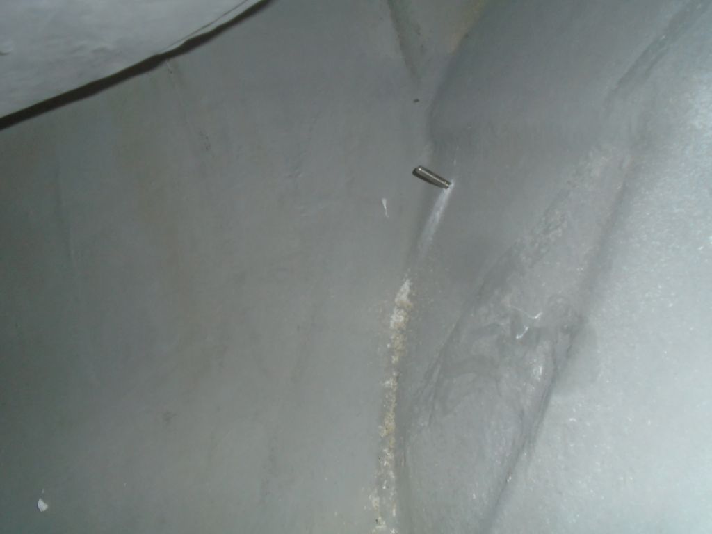
The marks and pilot holes for the diagonal brace bolts were on the inside of the frame, and to drill these holes in place was awkward.  Again, perhaps I could have or should have removed the braces for the drilling, but I felt the alignment and position  was too critical to risk this, so I drilled them in place.  This was laborious, but I’ll spare the details and move on to the happy moment when the drill came through the other side of the second (and final!!!)  hole.  As with the other installations, I could then remove the diagonal tubes, install the compression inserts (I also had to sand these down to fit within the tube), and reinstall the braces permanently.

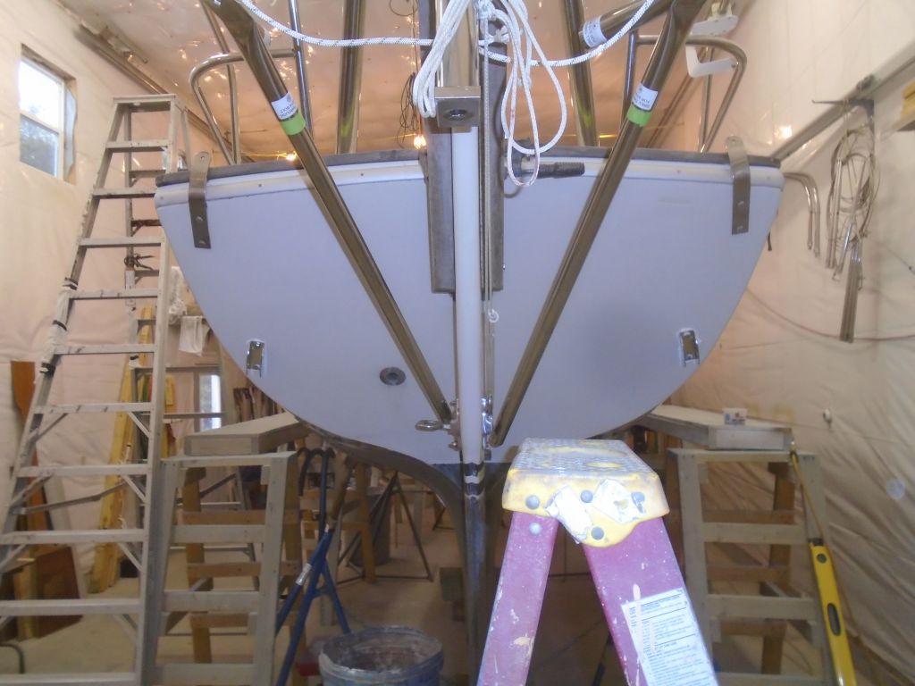
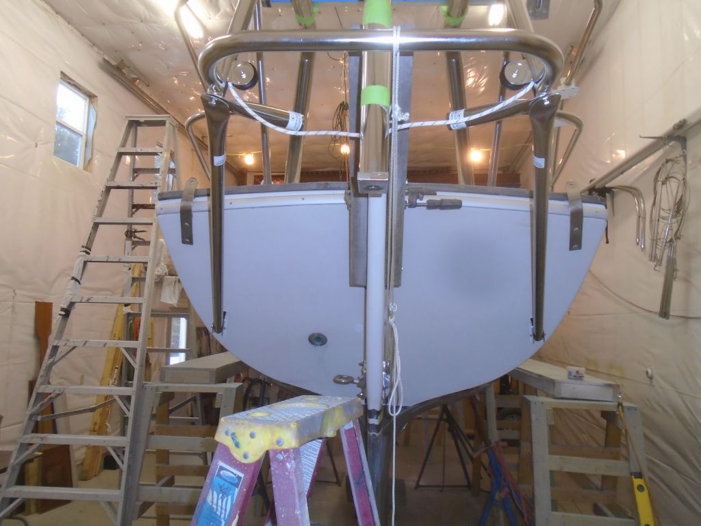
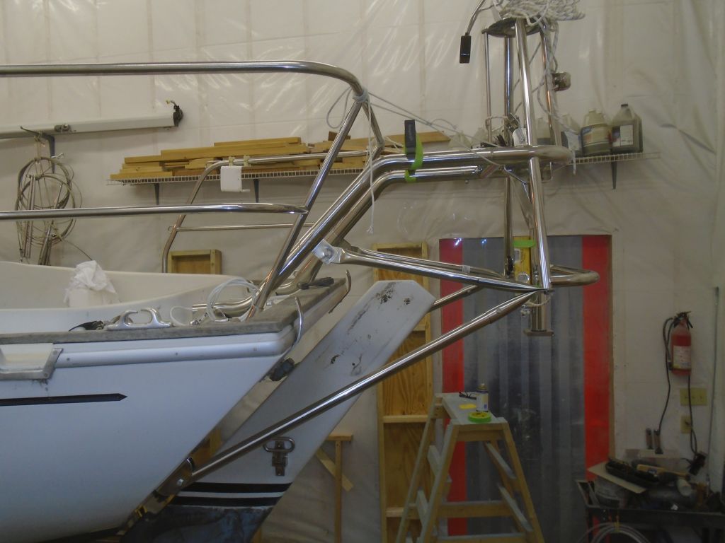
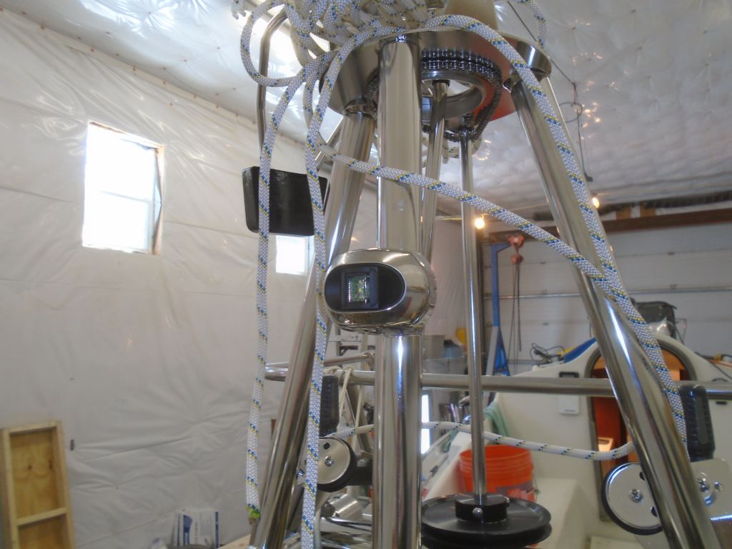
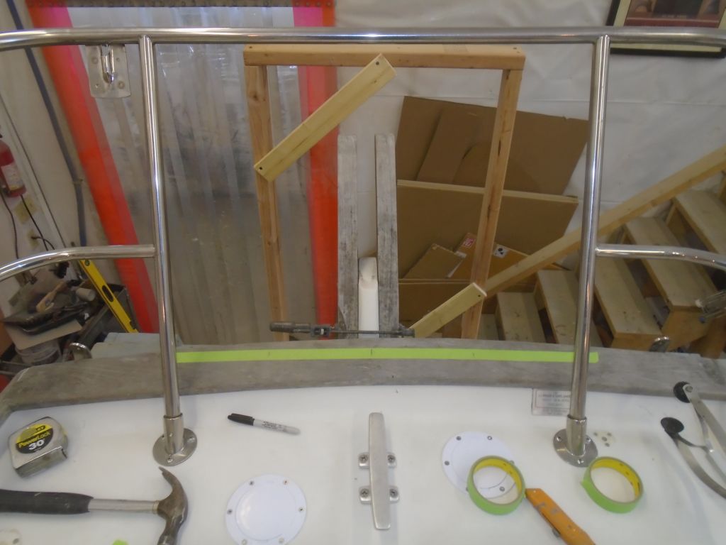
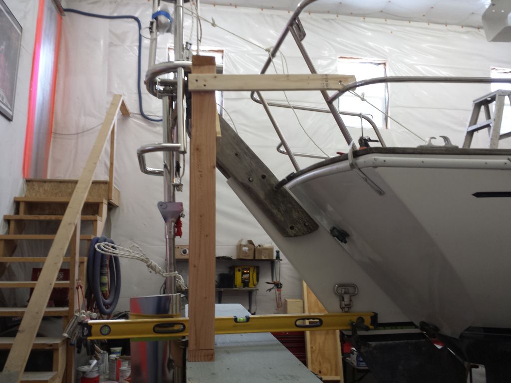
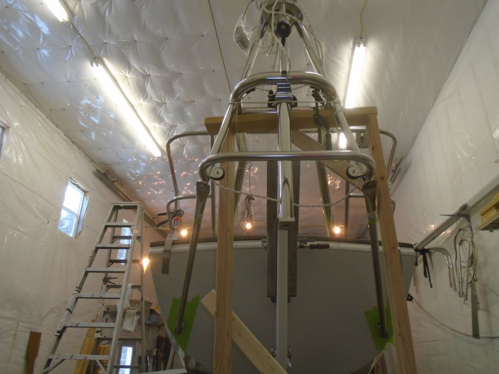
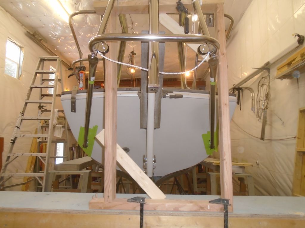
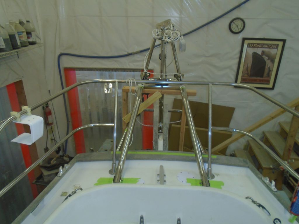
At this point, I could–and did–tighten all the bolts securely, which finally allowed me to remove the control lines, as the frame was now extremely strong and rigid thanks to the diagonal braces.  At the bottom end of the frame, through the special bolts-with-a-hole-in-their-heads, I installed mousing wire supplied in the installation kit to secure these bolts to the frame and prevent them from loosening.

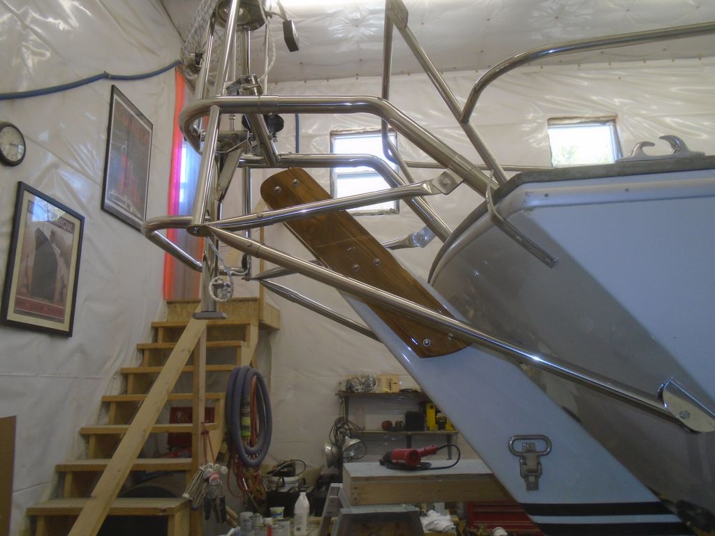
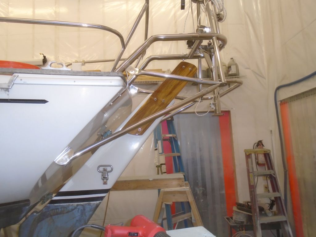
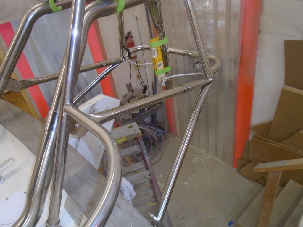
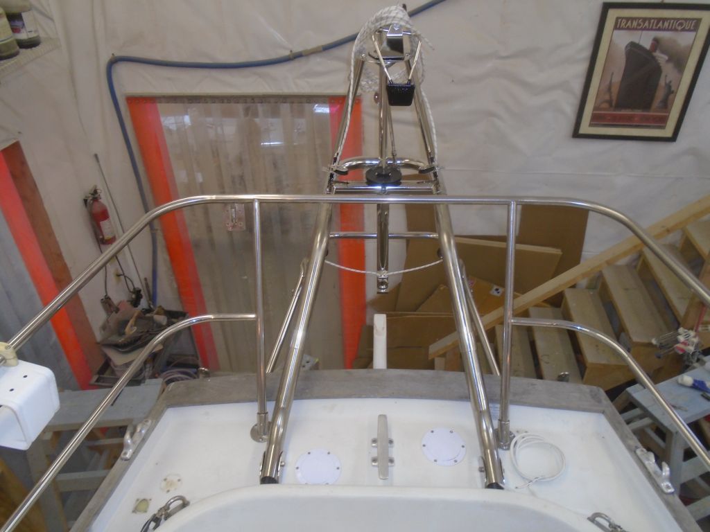
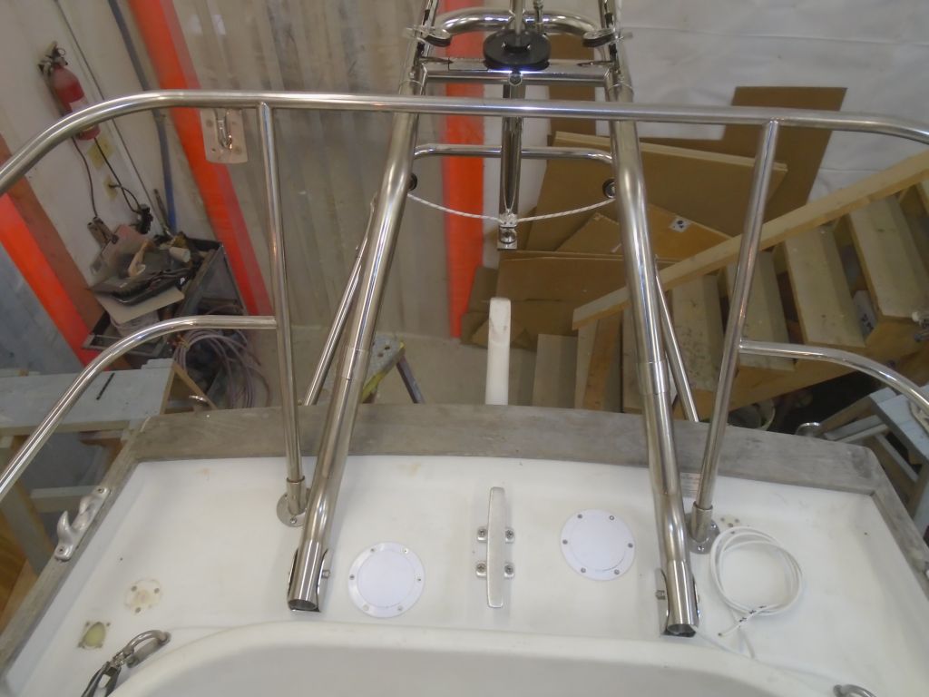
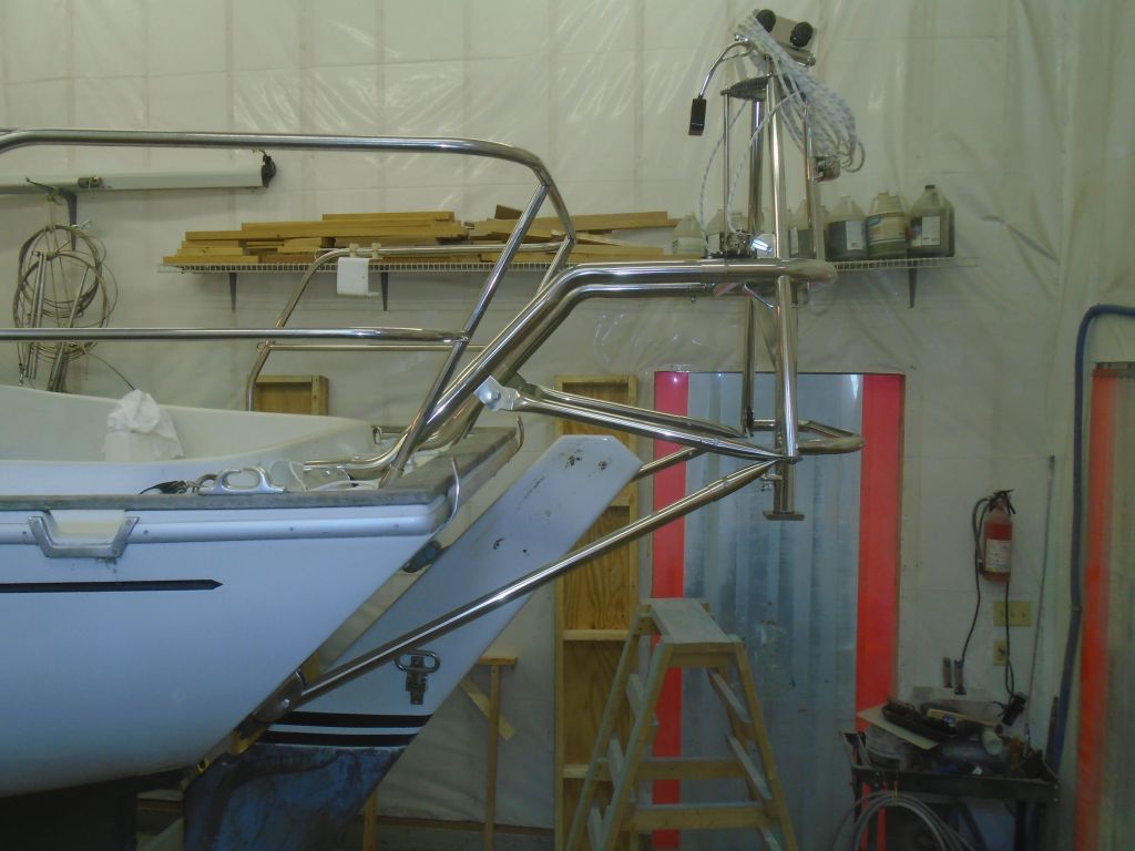
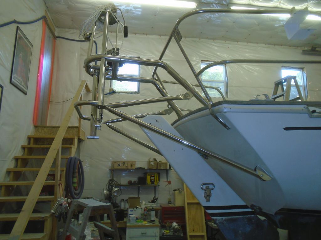
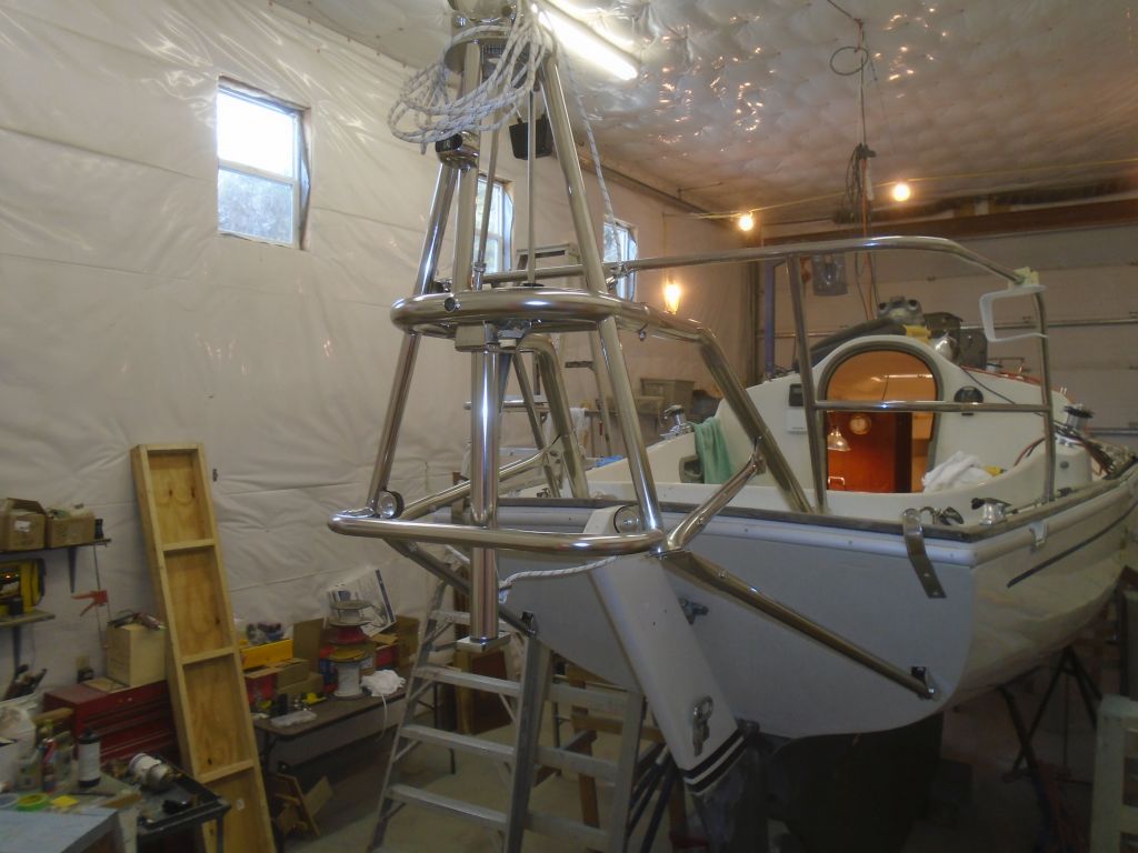
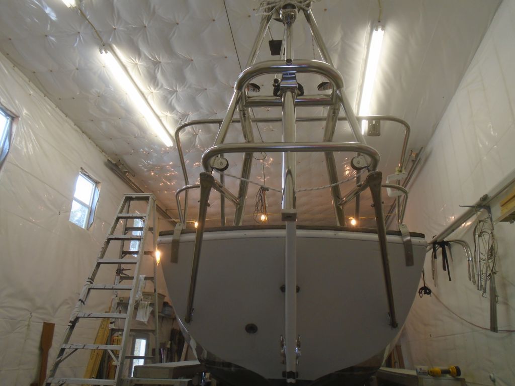
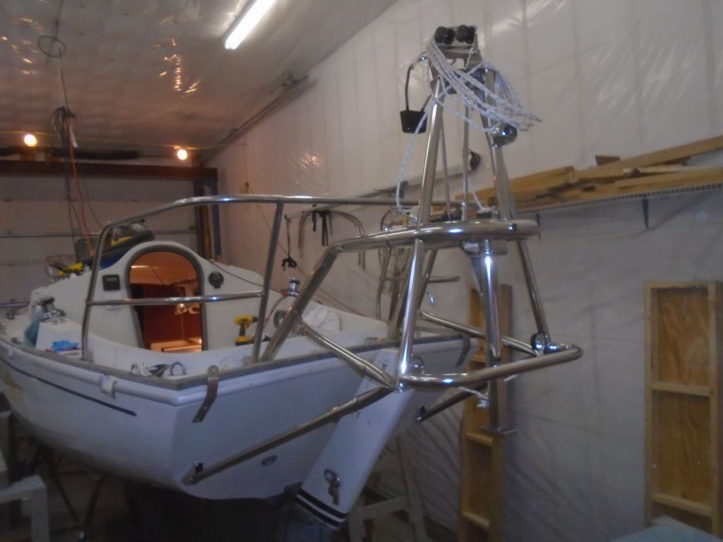
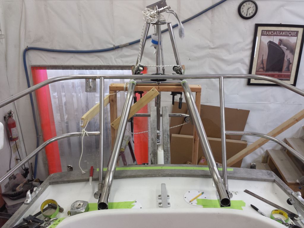
This completed the basic installation, other than running the pendulum lines forward to the tiller (eventually), so I celebrated by taking lots of pictures of the completed frame and knocking off a little early.

Total time billed on this job today:  7.25 hours

0600 Weather Observation:
32°, cloudy.  Forecast for the day:  clouds, mid-40s

Salty 23

< Back to Salty

Tuesday

Before I could truly finalize the Monitor installation, I needed to properly prepare various fastener holes for the mounting brackets, which meant disassembling everything; I couldn’t complete the diagonal braces (which would run between the bottom of the Monitor frame and the upper support tubes) till I could properly and permanently install the main support tubes.

But before going down that road, there were a few more things I could and should do first, starting with drilling holes through the main support members at the windvane frame itself, in two pre-marked (at the factory) locations.  This would ultimately pin the upper support tubes to the frame.  All the frame and support members would eventually be pinned like this, and I’d do the remaining drilling and pinning later, but this set was the most critical, and the upper tubes weren’t going to change their position at all, nor did I want them to, and I also had to install inserts within the tubes that would prevent compression when the tubes were bolted together though the new holes.  So while the upper tubes were in this position, I drilled through the two required locations with a 5/16″ bit.

The locations of the upper brace brackets were already marked on the masking tape on deck, as were the lower brace brackets,   So now, I could remove the support tubes so I could finalize the hull and deck bracket installations.  With the windvane frame supported by and secured to the wooden framework I’d built, I removed all the support tubes as needed, then unbolted the brackets and made final hole preparations by boring out the locations with a 5/8″ bit to remove any core.  I found that the two forward holes on the deck brackets were actually in an area of solid fiberglass, just forward of the transition to the plywood core, so as it turned out I’d not needed to overbore those two holes, but who knew.

The upper set of holes on the transom brackets were in a section of the transom cored with plywood; I knew this because I could see the outline of it from inside.  The lower holes were in solid fiberglass, but with the upper holes properly marked based on the bracket position, I overbored the holes to remove the core from the upper locations.

Preparations complete, I filled the new voids with thickened epoxy, leaving it to cure overnight, after which I’d be able to complete the installation.

Down on the bench, I installed the stainless steel inserts in the two main support tubes, using some sealant to hold them in place.  I kept them aligned by running through the bolts that I’d eventually use to secure the frame and tubes.  I set them aside for now.  I’d have to repeat this process with other frame support members later.

This windvane came with an LED sternlight built into the upper part of the frame, and the light was wired through one of the upper supports.  With the extra-long upper support tube on this boat, the wire length supplied from the factory (which would have been adequate for most installations) was not long enough to extend all the way through the tube, so while things were disconnected I added a wire extension that I could run through the whole tube during final installation.  Then, secured the light fixture to its welded bracket (it had been shipped pre-wired, but not bolted in plate, presumably to prevent damage during shipment).  The light came with a little stainless steel cover that I snapped on afterwards.

That was it for the Monitor for the moment, and I wrapped up the morning with a new coat of varnish on the tiller and rudder cheeks.

The owner asked me to build an enclosed locker above the port settee for various electronics mounting, and through various discussions we’d arrived at a raw concept.  Before beginning to lay out the ideas in a mockup, I wanted to see how the new electrical service panels were going to fit in the two locations at the aft end of the cabin, where the originals had been located, since the panel layout might affect certain aspects of the electronics locker.

The new panels–one per side–were slimmer than the originals, and so to cover the old holes I’d need to build some covers for the original surface.  I made simple patterns of each side (of course they weren’t symmetrical from side to side), which I’d use later to make veneer panels.  Then, on the port side, I taped in a representation of the panel’s outside dimensions so that I could see how, or if, it affected any decisions we might make about the electronics locker.

The rough idea for the new locker was to mirror the angle of the electrical panel at the aft side, leaving a little nook for securing and charging the usual small devices of today, then extending forward to the galley with a flat panel suitable for flush-mounting things like a VHF radio, stereo, and other things.  So I measured the angle and reproduced it on the forward side of that little wooden fiddle, choosing a more or less arbitrary starting point by eye, to leave some space between the fiddle and the new panel for storage of small items.  From there, it was a pretty simple matter to cut some cardboard into the rough shapes required to produce a 3D representation of at least the first run at the new locker.

The backrest was going to have an impact on the amount of usable space on the new locker panel, and would also enclose securely the little shelf at the aft end, so I placed it in position to determine how it affected things.  It did create a very nice, cozy area to place a camera, phone, or other handheld device, but effectively reduced the height of the flat panel by a few inches.  For now, I didn’t try to construct a panel that might span between the electrical panel on the left (aft) and the new angled panel on the right (forward), but the angles involved would make it tricky to shape, and the overall size of the new electrical panel on the aft angle meant that any depth available behind such a connector would be pretty minimum, perhaps an inch or so, in order to clear the panel.

With these basics in place, we had something to work with, and I could make changes as needed from here based on the owner’s feedback.

Now I moved on to several smaller jobs, starting with replacing a round access panel into the holding tank beneath the cabin sole.  The existing deck plate was missing its screw-in cover–no one knew where it was–so I bought a new one,  Of course the cover from the new deck plate was a slightly different size from the existing ring, so I had to remove the whole ring and replace it with the new one.  One should never expect the easiest way to actually work.  Meanwhile, I reconnected the waste tank pumpout hose, which led aft through the engine room and up to a deck plate.

With new hose freshly on hand, I began to replumb the cabin-mounted bilge pump, and started with its new suction line, which ran through the engine room on the port side and down into the sump beneath.   I installed a filter on the bottom of the hose and led the end forward, where I reconnected it to the existing pump.  I thought it best to run these lines now, while I still had the best engine room access, rather than fight them around the engine later.  I’d planned and expected to continue with the discharge line, which would run back aft to the new through hull valve, but the lengths of hose I’d planned to use, and which I’d previously determined I had on hand (and thought was adequate) turned out to be a little too short to make the run, so I had to order a longer length, delaying the completion of this pump’s plumbing for a bit.  I also planned to work on the new cockpit-mounted pump in the immediate future.

Continuing with the sort of stream-of-consciousness knock-off-the-list jobs that seemed to be making up my afternoon, I reinstalled the galley sink in new sealant, and installed a new drain hose to the new through hull.

Thinking ahead to some of the engine’s ancillary systems, and looking to fill a final void in the day, I prepared the new raw water strainer for installation by securing two 90° pipe elbows to the housing, ready for hose connection.

filter1-32216

Finally, I prepared the new fuel filter for installation, first by installing the special and required adapter fittings into the filter housing, then a pair of 5/16″ brass elbows for the fuel hose.

filter3-32216

To make maintenance easier, particularly in tight spaces, I liked to add a valve to the drain fitting on the filter bowl.  In this case, with limited headroom, I planned to mount the filter as low as possible, to leave room for cartridge replacement from above, so I installed the drain valve on a 90° elbow off the bottom of the bowl, replacing the original drain plug.

Total time billed on this job today:  7.5 hours

0600 Weather Observation:
20°, clear, 6-8″ new snow from yesterday.  Forecast for the day:  Sunny, high around 40.

Salty 22

< Back to Salty

Monday

I started the day with another light sanding on the rudder cheeks and tiller, preparing them for their next coats of varnish.  I’d intended to get back to this later, but it didn’t happen.

To finish up the main construction of the battery box in the cockpit locker, I had to build a top–a simple-enough proposition complicated by the fact that the locker and the box’s position within were not neat and square, and the height of the box meant that I couldn’t access the inner part of the lid for basic patterning and fitting.  So I started with a narrow strip of cardboard so I could scribe the shape at the forward end, which was the most critical cut to make.  I transferred this to a slightly oversized piece of plywood, and with the back side of the box removed, and a temporary cleat on the inboard edge of the locker to hold the top, I could finalize the shape of the top along the two locker edges–both of which required various contours and shaping–before marking the two straight cuts at the plywood edges of the box.  It just took several rounds and ups and downs from the shop to eventually complete the new top.

After making some reference marks inside the locker, and with the top in place, I prepared and installed with epoxy some hardwood cleats to support the top on the two locker edges, and a second pair of cleats slightly above, into which slots the top would slide.  This would hold these two edges securely, and I’d install some sort of latch to complete the security of the top.

Meanwhile, I permanently secured the aft support cleat on the battery platform with epoxy, and added a little cleat to the inside of the back panel, just for ease of installation and alignment purposes.  This cleat would rest on the shelf cleat and help the user install the back panel whenever it was necessary.

Next on my agenda was the new Monitor windvane, which installation I looked forward to, though I knew it’d likely present some challenges.  When the unit arrived several weeks earlier, I’d taken the time to remove all the packing material–of which there was a huge trash bag full–so now I could more easily remove and lay out all the frame and support pieces on the bench for inspection.

I’d already read through the extensive instruction manual once, but now I did so again, now with more attention to the specifics of this boat.   I also reviewed the photos available of other Contessa 26 installations available on the Scanmar website.

The first–and main–challenge was to somehow position the frame where it needed to be, suspended in mid-air.  The manual suggested lines, but that wouldn’t work in this case because the frame would actually be mostly above deck level, and also had to be so far aft in order to clear the outboard rudder–which, with the strong transom rake and low topsides of this boat, probably made it one of the more challenging overall installations.  All along, I’d been thinking that I wanted to build a wooden framework to support the windvane during the installation, and now I prepared to move forward with that idea.

Before beginning the installation steps, I had two small details to deal with.  First, I removed the old hailport from the  transom, which the owner had requested, and to ensure that it wouldn’t end up beneath any of the frame pieces (it didn’t, but that’s neither here nor there).  Then, to ensure proper clearance and positioning of the vane, I temporarily installed the old rudder cheeks just to give me the ultimate top/aft point of the rudder, which would ultimately be the defining point of the vane’s positioning.  The rudder, and the space between the cheeks, would also be the ideal centerline for the vane.

The final position of the windvane depended on the actual waterline:  the center of the main frame tube was supposed to be 42″ above the boat’s waterline, which, with the overall dimensions of the various parts of the vane, would position the vane’s paddle in the correct position, with approximately six inches of the paddle above the waterline.  There was a fairly clear idea of the actual waterline on the boat in the form of a scum line–it was (as past experience with sisterships suggested) well higher than the factory’s DWL–and the owner provided me with key photos showing the boat in the water, which confirmed what the scum line suggested.  Working from the photo, and from the actual line on the boat, I marked the waterline position with masking tape.  This mark was 63-5/8″ from the floor in this case, and now I could add the required 42″ to this to achieve the from-floor measurement of 105-5/8″ to the center of the main frame tube.

Now, working through a series of calculations based on the existing height of a staging platform that I set up behind the boat, and using the bottom portion of the vane’s frame as a support point (15″ below the main tube), I constructed a simple frame from 2x4s that, when added to the staging platform, would support the vane at the correct final height.  On deck, using the center of the rudder as my guide, I made some basic marks to show the centerline and the centers of the main windvane support tubes (15″ on center, or 7-1/2″ on each side).  As it turned out, I needed only the visual key of the rudder itself in this case, which was a far better centerline indicator than any measurement.

With my supporting framework secured to the staging platform, I moved the whole arrangement to roughly where I though the vane would want to be–as close to the top corner of the rudder cheeks as possible.

Next, I could rest the windvane frame itself on the platform and see how I did.  I clamped the vane to the top support,  and added a couple safety lines to secure the whole arrangement.  The center of the tube was right where it should have been, or possibly just a touch higher, which is the direction I wanted to err anyway.


I temporarily installed the vane paddle, and, with a level, extended the waterline mark aft so I could put some corresponding tape on the paddle and confirm that the vane’s position was correct and in accordance with the supplied drawing for this boat.  It was.

Starting with the large upper support tubes, I worked through the installation steps as required.  ON this boat, the upper tubes were deck-mounted, and featured a bent shape to accommodate the vane’s position relative to the boat.  Based on where I had the vane positioned vis-a-vis the rudder, I could shorten the tubes a bit, something that was encouraged (as necessary) by the manual with the ultimate goal of keeping the vane as close to the boat as possible–or, more specifically, no further away than strictly necessary,  So with the mounting brackets temporarily in place, and the support tubes set in, I marked the excess length and also marked for a through-bolt that would secure the tubes to the mounts.  With these basics, I could temporarily secure the mounts to the deck; I’d have to come back and properly prepare the mounting holes and ultimately secure the mounts with sealant, but for now I secured them directly to the deck with tapped holes.  With the tubes cut to length, and the through-pin holes drilled, I secured everything in place temporarily.  Throughout this process, I strove to ensure that the vane was level in both directions, and properly centered on the rudder.

Sometime later, I’d have to drill holes through the vane end of these tubes to secure them there, but for now I was ready to continue with fitting the two lower braces, which would run between the bottom of the frame and the transom.  The provided tubes were pre-drilled at the end to fit into the brackets–something that was normally done for the upper tubes as well, except in cases like this where the final mounting position couldn’t be pre-determined–and would fit into a socket end at the frame, which bolted right to the bottom of the frame in a threaded hole.  Using various guidance from the manual and mounting diagram for this boat, as well as photos of other installations, I determined that the lower tubes as provided were overlong, so once I figured that out I could start to position the brackets on the hull, and from there determine the final length of the tubes.

Starting with the starboard side, I held the pieces in place as needed to determine where the bracket should mount (the tube should angle down about 15° from the frame, and outboard the same amount–with the extra guidance of about 45″ between bracket centers, according to the diagram.  These criteria helped me determine roughly where that bracket should be, though none of the dimensions were absolute,  Then I could figure out where to cut the tube, which I did next, and dry fit it in place so I could begin to secure the bracket on the hull.  For now, I drilled and tapped the lower bracket hole to accept a 5/16″ bolt.  The upper hole was blocked by the tube itself, and I marked the position of the bracket so that later I could return and prepare the second hole.

I repeated the process on the port side, though I first had to modify my wooden support frame a bit, as it blocked access to the point on the frame where the tube needed to go.  I’d used an arbitrary piece of lumber to determine the width of my wooden frame, and this was just a bit too wide.  I cut another vertical support and installed it further inboard, then removed the offending piece for clear access to the vane’s frame base.

I could have just cut off the second tube at the same length as the first, but because boats are frequently asymmetrical, I thought it’d be better to go through the various dry-fitting steps as I did before, though this t ime I had a known point on the transom for the bracket.  As it happened the tube ended up exactly the same length, and before long I had it temporarily installed as well.

These four tubes formed the main support structure for the vane, but there was also a pair of diagonal supports that I’d install between the bottom of the vane (where the lower tubes attached) and the upper support tubes.  But it was the end of the day, and I’d continue with that next time.  Though I’d felt like the installation process had gotten off to a slow start–intangibles like layout and instruction-reading somehow seem like anti-progress, though I know they’re not–I was pleased with the vane’s installation status by the end of the day, and there was no doubt that it was an impressive and artful piece of hardware.

Total time billed on this job today:  8.5 hours

0600 Weather Observation:
Snow, moderate.  Forecast for the day:  snow, 3-6″ predicted, ending in the afternoon and clearing.

Salty 21

< Back to Salty

Saturday/Sunday

Over the weekend, I continued with daily coats of varnish on the new rudder cheeks, lightly sanding between coats, as always.

varnish1-31916
Saturday (4th coat)
tiller12-32016
Sunday (5th coat)

Meanwhile, I worked on the new tiller.  Now that the lamination was fully complete, I removed the clamps, leaving me with a messy-looking blank that  I could transform into the final shape.  The side that had faced down on the gluing jig was mostly smooth, but covered in epoxy squeezeout.  To begin, I laid out the old tiller on top of the blank to determine its relative position (which I’d previously marked, come to that), and then I cut off the rough ends of the blank, where the blank had extended off the jig and left ragged squeezerout.  This  left me with one smooth surface from which I could dimension and clean up the tiller blank.

Starting with the epoxy side down, I ran the tiller through the planer a number of times, alternating sides and cleaning up the surface and smoothing it on both sides till it was bare wood and dimensioned to the correct thickness, or about 1-5/8″, according to the original tiller.

Then, I traced out the final shape of the tiller, using the original, and cut the blank accordingly.

The tip of the original tiller was tapered down over the final foot or so of the tiller length for a comfortable hand hold, and I made some reference marks on the new blank to show the extent of this taper so I could pare down the end as needed.  I took care of this quickly with a sander, then sanded the whole blank clean and smooth, rounding all corners but focusing especially on the tip end to smooth and contour it pleasingly.

I drilled the hole for the tiller pin, then, after cleaning the blank, applied a sealer coat of varnish.

tiller13-32016

Total time billed on this job today:  2 hours

0600 Weather Observation:
15°, clear.  Forecast for the day:  Sunny, high 35°

Nomad 23

< Back to Nomad

Sunday

The adhesive securing the new pilothouse panel had cured to the point that I could remove the clamps and continue work.

Next, I reinstalled two pieces of the original corner trim, solid teak that I’d sanded back to bare wood.  I still needed to bung the screw holes.  With the trim back in place, I resecured the vinyl trim along the top edge,  then applied a quick sealer coat of varnish to the new panel and trim, bringing it to the same state as the remaining interior woodwork.

Total time billed on this job today:  .75 hours

0600 Weather Observation:
15°, clear.  Forecast for the day:  Sunny, high about 35°

Nomad 22

< Back to Nomad

Saturday

With a new sheet of 1/4″ teak plywood now on hand, I could turn to replacing the damaged pilothouse panel that I’d removed earlier.  The original panel had been badly damaged by water over the years, and was unsalvageable.  However, I saved what I could it it to use as the beginnings of a pattern for the new panel, and now, starting with a sheet of cardboard, I laid out the remnants to form the first rough (yet as accurate as possible) pattern for the panel.  There was enough of the old panel for a good start, as it provided the overall dimensions required.  Most of the top edge was missing, and the narrow strip above the window was separate.  Though the photo shows the narrow strip aligned near the forward (left) edge of the panel, later I determined that it actually belonged at the aft end, but this was of no matter, as it turned out, at this stage.  I didn’t cut out the window opening, but did create a few slots within the tracing of the window so I could clamp the pattern in place once in the boat.

In the boat, I clamped the cardboard in place, and noted and marked any modifications required.  It was only the top edge that required changing, and I scribed a new line there to demark the area I needed to enlarge just slightly for the best fit.  I also marked the after edge accurately so I could increase the length of the final panel slightly over the length of the pattern.  With the pattern clamped in place, I could trace the actual window opening from outside, which would provide me with a more accurate position for the opening that I’d use later.

Back on the bench, Iald out the pattern on my sheet of plywood, and traced the outline, making the changes required by the pattern.  Once I’d traced the panel outline, I removed the cardboard and cut out the window opening that I’d marked in the boat, then transferred this to the plywood as well.  I left the window uncut during the initial tracing so that the pattern couldn’t warp or bend and possibly throw off the more critical outward dimensions.

I thought it’d be best to play it safe and await final cutting of the window opening till the real panel had been test-fit, so I cut about an inch or so inside the tracing, so that I could finalize the window opening once the panel was in the boat.  The plywood was very expensive.  Up in the boat, I clamped the panel in place through the window opening, pleased with the overall fit of the panel.    Once more, I traced the window opening from outside, so that I could remove the panel to the bench and make the final cut.

With the window opening now cut to the exact size, I test-fit the panel once more.

After final preparations, I glued in the new panel with polyurethane adhesive, clamping it securely all around the window opening, which was more than enough to press the panel into the adhesive, and left it to cure.

Now seemed like a good time to prepare the window for reinstallation soon as well.  I had to remove the old sealant from around the mounting flange, so I clamped the window to the bench and scraped off the old sealant with a putty knife and scraper till the flange was clean and ready for new sealant during installation.

Total time billed on this job today:  3 hours

0600 Weather Observation:
15°, clear.  Forecast for the day:  Sunny, high 34°

Salty 20

< Back to Salty

Friday

I got right back into things with the final two through hulls–the cockpit scuppers.  I’d previously cut the through hull necks to length, so I started with a dry fit to drill the bolt holes through the flange and hull.  While I had the flanges in place, I  test-fit the valves to check for clearances and to see if I could spin on the valves after the flanges were installed, or if I needed to pre-assemble them.   There was room to install both valves after the fact, and other clearances were OK (something I’d just assumed till now since the old valves were similarly arranged, but…), so I could move on with the installation.  I removed the hardware and prepared the area for final installation.

Following the usual steps that I detailed with the other fittings, I installed the final two through hulls and flange bases.

Before continuing, I wanted to address the Cutless bearing while I still had clear access to the inside of the stern tube.  The existing bearing was in fair condition, but I wanted to replace it while all other engine-related components were being refreshed.  Of course the bearing was set flush to the end of the bronze stern tube where it protruded from the deadwood, so there was no way to grab it there and twist it out.   I removed the set screws.

During some preliminary inspection earlier, I’d determined that I could (hopefully) push the bearing out from inside, and I happened to have a length of steel pipe on hand that fit the stern tube perfectly, something apparently left over from a similar situation in the past.   So now, while I had the most open access possible. I tried this method.  At first nothing happened; I didn’t wail on the pipe because I didn’t want to cause a bigger problem, so my first blows were tentative, and after a time I went beneath to check, but the bearing hadn’t moved a bit.  This was worrisome, but back inside I marked the pipe when it was all the way in against the bearing, for reference to see if I moved the bearing at all,

After some time, and additional blows with a heavy mallet, I thought I felt something give, and I went down to confirm it before I continued (to make sure it was the “right” something that gave).  Success!  The bearing was coming out.

cutless3-31716

This was a relief since I didn’t relish the alternative ways I might have to get the bearing out.  While the bearing had some life left, leaving it as is didn’t seem like a prudent approach, so I was glad that it hadn’t been that tough to remove in the end.  Back inside, I hammered the bearing out the rest of the way, and noted its size so I could order the replacement.

cutless4-31716

Back to the through hulls, I installed the valves and tailpieces to complete the installation.  I aligned the valves so the handles on each side could operate fully without interfering with the other valve and also remaining clear of the scupper hoses and their eventual path.

In the port cockpit locker, I installed the valves and tailpieces for the two bilge pump outlets, facing the 90° tailpiece for the cabin-mounted bilge pump (the larger fitting) towards from whence its hose would run.  Imagining how the discharge hose from the new cockpit pump might need to lead, I set up the 90° tailpiece for that pump (the smaller valve) facing towards the outside of the hull, so the hose could run easily from the pump around in a semi-circle to the valve.  Because these valves were above the waterline, after a discussion the owner and I had determined it was OK to reinstall new valves on the existing stems despite its being “wrong”.

plumbing1-31816

I took this opportunity to reinstall hoses up forward, connecting the existing head intake and discharge lines to their new fittings.  While I was at it, I also reconnected the water tank fill, and reinstalled the galley stove vent pipe.

Because I’d soon be at the point to start reinstalling many of these systems, I checked existing stock of hose in various required sizes, and ordered whatever I needed for the bilge pumps and engine exhaust.

The laminated tiller was cured, and I unclamped it from the jig so I could finish up the additional laminations required at the butt end.  Had the bend been more severe, I might have left it in the clamps longer, but for this easy curve I’d no concerns after 24 hours.

Ignoring for now most of the mess on the tiller, I cleaned up (sanded) the bonding surface at the butt end where I ‘d be adding new laminations, and, after checking the position and layout with the old tiller and making reference marks, completed final preparations and cleanup before glued the additional six strips in place.

With some new hardware arrivals on hand, I turned to the deck once more, and installed new tank vent fittings in the head, as well as new deck plates aft to accommodate cowl vents.  I left the vents off in safekeeping for now.  I went through all the usual steps for installing the plates; you must know them by now.

It seemed a good time also to install the chainplate deck covers,  At each location, I applied sealant fairly heavily, then pressed the appropriate cover in place.  Because I relied on the sealant itself to secure the plates in place, I left the squeezeout for now, and would clean it up once it cured.  As I pressed down, I could hear the good sound of air pockets popping as the sealant got pressed into the gaps around the chainplate in its slot, just what I wanted.  Once cleaned up, I thought these would look pretty nice.

The next step on the battery box was to actually build the box, or the sides, whatever seems appropriate.  Now, I didn’t really want the box to be any taller than it had to be, since headroom was at a premium, but neither did I want to cut it at all close with the batteries, terminals, terminal fuses, and so forth.  This is when one starts to distrust templates.  Despite having the actual battery measurements on hand, and a template built to those dimensions plus some, I had to look at some past projects to see just how oversized the battery template actually was, mainly to see if I could build the box basically just as high as the template, or if I needed some extra room to be safe.  Eventually I determined that the template was generously sized and allowed plenty of adjustment room as it stood, so I chose to make the sides of the box 11-1/2″ tall, or just barely taller than the template.

With this determined, making the two sides was mainly a matter of cutting rough blanks–first for the outboard side, then for the second side–and fitting them to whatever contours the sides of the locker had to offer–a straightforward, if time-consuming, process of scribing and cutting.  These sides would be for basic protection and shelter only, and would not provide the actual restraint for the batteries within, so I planned to install them with screws and no glue, to keep the whole box removable should better access be required, and to ease installation of the batteries.

At length, I had both pieces in place and screwed together with various hardwood cleats as required.  The cleat on the battery platform along the edge of the after panel would be permanent, and later I planned to epoxy it in place, since this cleat, in addition to holding the aft panel, would also form part of the battery restraint.  All I needed now was a top, and a means of securing the batteries.

Finally, I sanded, cleaned, and revarnished (3rd coat) the new rudder cheeks.  I continued to apply varnish to all sides, including the “down” side, as the additional protection even on these hidden areas would help prolong varnish life on the external parts.  I didn’t worry about mussing the varnish on these back sides where they rested on the sticks because the coating here was just for protection and not appearance.

varnish1-31816

Total time billed on this job today:  8.25 hours

0600 Weather  Observation:
32°, mostly clear.  Forecast for the day:  chance of showers or thundershowers, high 45° but dropping with a cold front later

Salty 19

< Back to Salty

Thursday

To complete preparations to the laminating jig for the tiller, I installed with dabs of hot glue little sections of plastic on each of the wooden supports, which would prevent the tiller from sticking to the clamping blocks.  I covered the bench with plastic, and prepared all the teak laminations by solvent-washing with acetone.

tiller1-31716

Afterwards, I applied epoxy adhesive to the strips and clamped them securely in the jig, using a mallet to ensure they were flat and even on the jig surface.  I scraped off most of the epoxy squeezeout and left the assembly to cure.

Before moving on, I lightly sanded and varnished again the new rudder cheeks.

cheeks1-31716

I’d been waiting for a while for two missing and critical parts for the through hull installation–the flange bases for the cockpit scuppers. Eventually, I located two at another supplier and ordered them, as their absence was holding me up.  So with these due later in the day, I turned to the through hull preparations, starting with a dry fit of all the bronze through hull fittings so I could cut the stems to the required length in each case.  Since I had one of the three 1-1/2″ bases that I needed, I could cut all the stems now.  Inserting the through hulls from outside, I taped them in place to hold them while  I worked inside.

At each fitting, I marked where the stem came through the hull and backing block, then tested how far I could thread on the flange base.  Any gap between the two would require that I cut off some excess length in order to tightly thread the assembly together.  All of the fittings would require modification, though the three 3/4″ fittings almost might have worked as is, but I wasn’t about to chance it.  In this way I marked each through hull in turn.  In order to fully thread the stem into the bases, plus a little extra to ensure that I didn’t come close to bottoming out, I needed to remove about 3/4″ on each of the larger through hull stems, and about 1/4″ – 3/8″ on the smaller ones, just to be safe.

Threading on the through hull nuts, which I’d use to clean up the cut threads, I marked each fitting and cut off the excess with a cutting wheel.  I tried to grind a small bevel at the top of the cut, and I cleaned up the threads with the through hull nut and a little sandpaper as needed till I could easily thread on the base, which ensured that it would work as planned when I was actually installing the fittings.  I’d already marked each through hull as to its location.

Now I taped the newly-shortened through hulls back in place–this time just on the four that I planned to install right away, while awaiting my final two bases–and, from inside, threaded on the bases tightly enough so I could align the base and drill the bolt holes through the hull.  I drilled one hole, inserted a temporary bolt, and then the next, ensuring that the alignment would all work out later:  one does not want to find that there’s a slight misalignment once the fitting is gooped up.  I did this for each fitting.  Then, outside the boat, I milled countersinks at each hole to allow the machine screw head to sit flush with the hull.

While preparing the bolt holes, I’d noted where I wanted the valve handles to be to allow for access and clearance, so down on the bench I pre-assembled the valves onto the bases for each of these four fittings (head intake and discharge; sink drain; engine intake).   Access was tight enough in several of the locations that I didn’t want to have to use unwieldy wrenches to try and spin these valves on tightly and into the correct orientation in place.  Only one of the valves required a 90° tailpiece, and I’d noted the correct orientation of this as well so I could pre-install it in the direction it needed to be to match up with its existing hose, for the head discharge.

After final preparations and cleanup, I installed the four fittings, following the same procedure for each one, but I didn’t try to document each step on each fitting because the job was time-sensitive and messy.  But the photos below show the basic sequence, though they may not all show the same exact fitting.

For each fitting, I heavily applied adhesive sealant to the through hull flange and neck, and pressed it into the hole.  The sealant was fairly stiff, but still required some tape to ensure the fitting wouldn’t fall out when I started the threads inside.    Now, inside the boat, I applied more sealant around the through hull neck and the perimeter of the mounting flange area, including around the bolt holes, and carefully threaded on the flange base (with valves pre-attached in this case).  I threaded the base on till it was nearly tight, then aligned it properly with the bolt holes and installed temporary bolts from inside, to hold the alignment.

Back outside, I gooped up the necks and heads of the 5/16″ bronze flathead machine screws, and inserted them into the bolt holes, pushing out the temporary bolts on the inside in the process.  Once I had all three bolts installed, I used a special tool (not shown here) to tighten the through hull securely into the flange within, and tightly against the hull on the outside.

Scampering back into the boat, I installed washers and nuts on the through bolts, and tightened them before cleaning up excess sealant from around the flange and, finally, continuing back outside where I cleaned up excess sealant there as well.

With all four fittings installed (the two new bases arrived, but too late in the day to install), I cut off the excess bolt length inside, and the job was done.  The thinner removed a little of the gray paint in a few areas while I was cleaning up sealant, revealing a bit of the white primer beneath, so that’s what the white streaks are.

I’d finish up the two cockpit scupper fittings next time.

Total time billed on this job today:  7.25 hours

0600 Weather Report:
Drizzle and fog, 35°.  Forecast for the day:  partial clearing, high in the 50s, chance of a thunderstorm

Older posts Newer posts