Monday
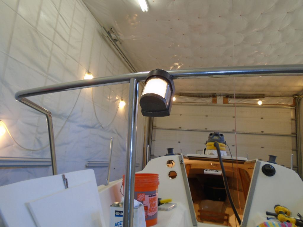
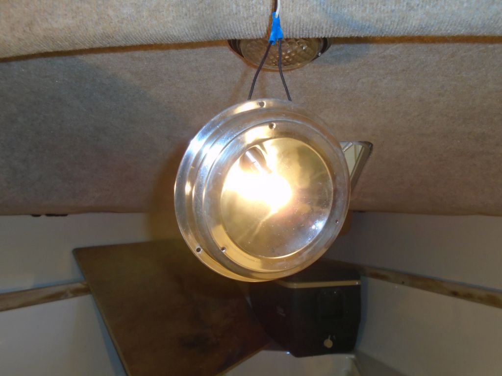
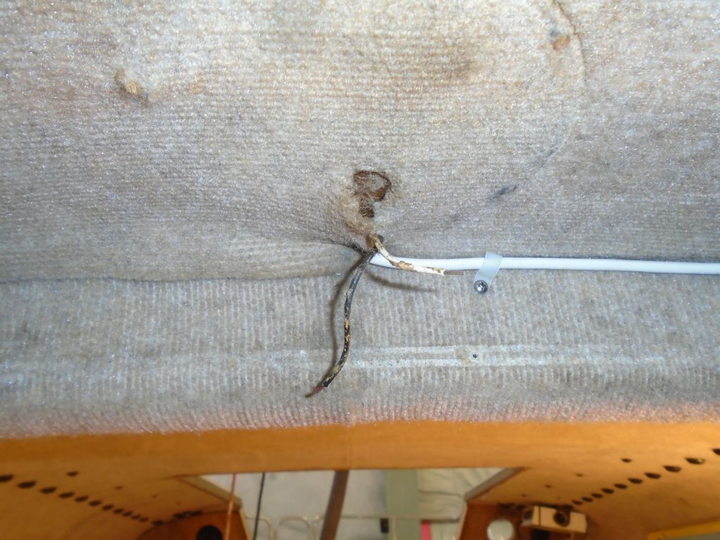
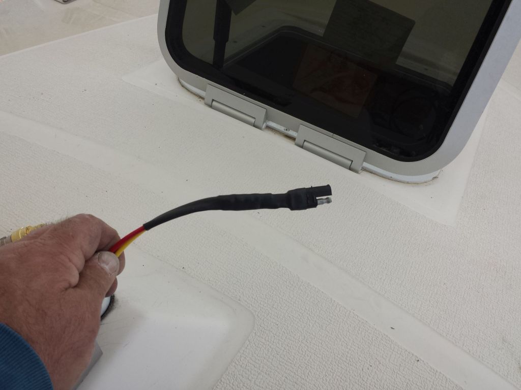
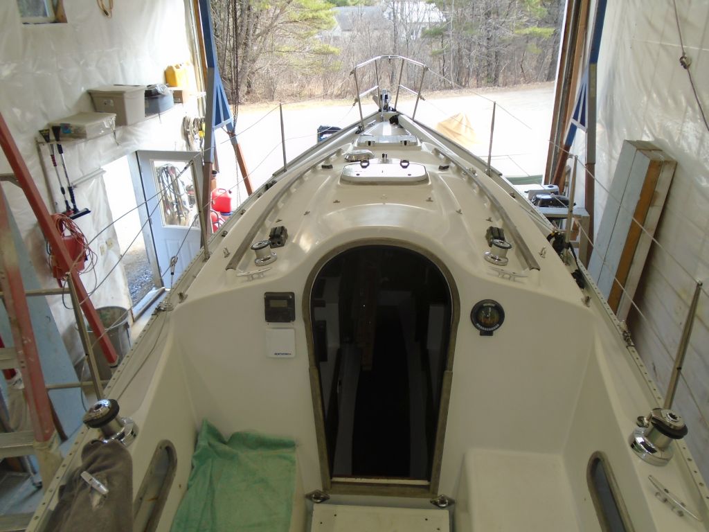
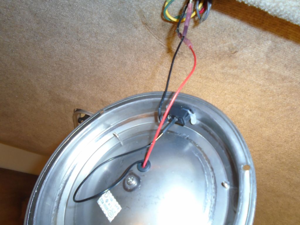
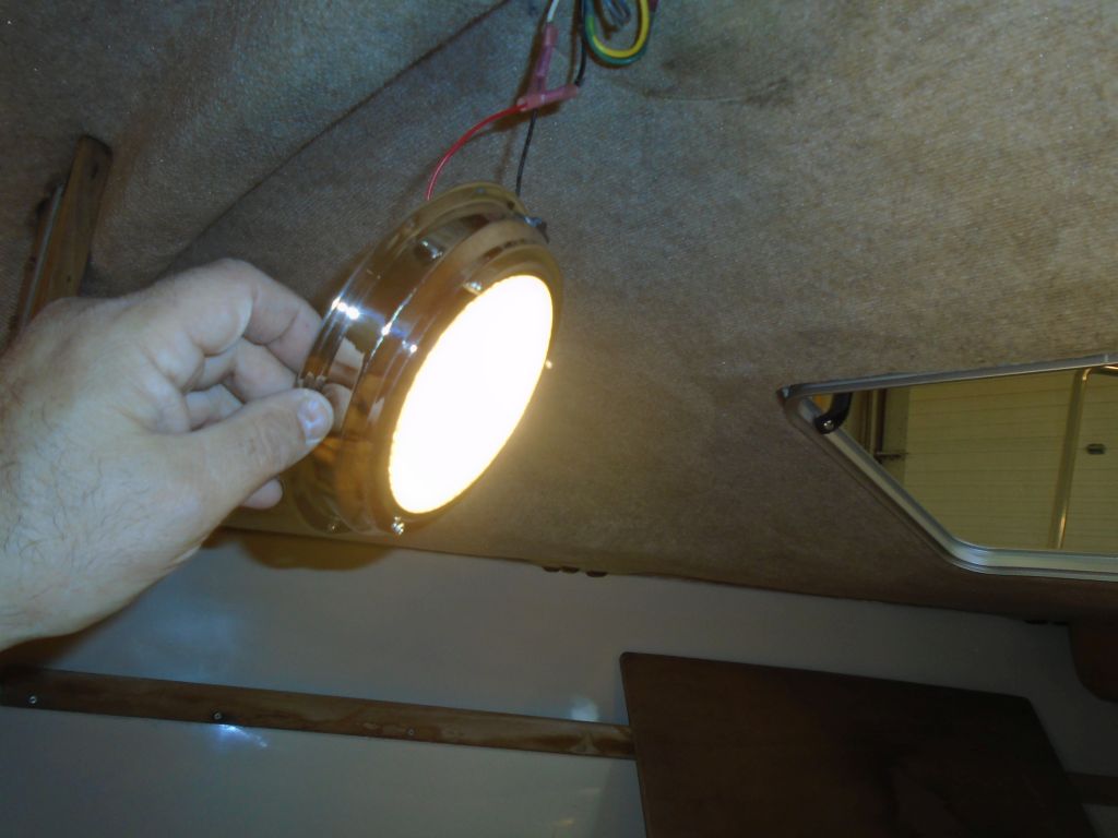
Back at work after a long weekend, I found various new supplies on hand that I’d ordered earlier, so I got started with what I thought would be the simplest task: installing the new 6″ light fixture in the forward cabin, which I’d ordered after finding that the original was rusted and inoperable. Double-checking, I powered up the boat’s circuits and used a meter again on the exposed wires, getting the appropriate reading, so I connected the wires from the light fixture, only to find that it didn’t work. It took a few moments for me to realize that (silly me) I’d assumed that the red wire coming off the light was positive, and the black negative. As it happened, the wiring convention on this fixture was backwards, which a simple glance at the way the wires ran through the switch would have revealed, but one becomes quite conditioned to normal wire colors and their supposed meanings.
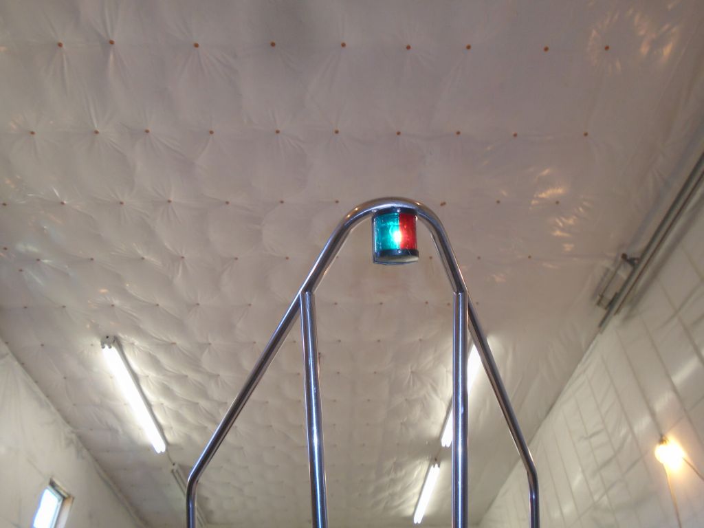
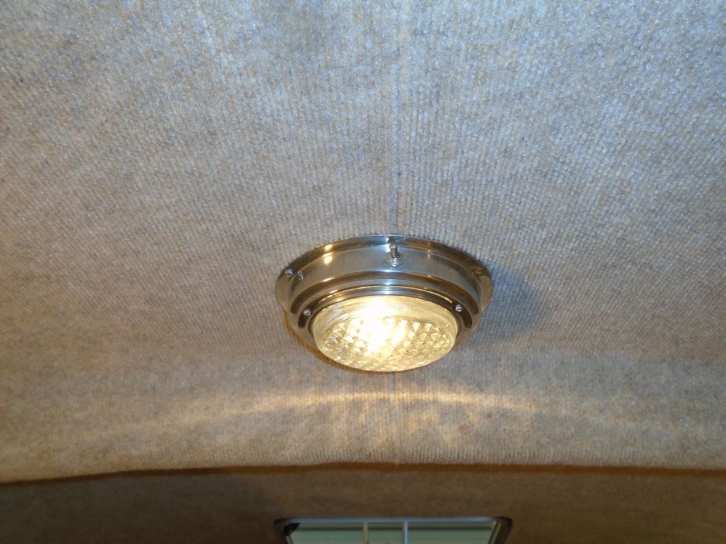
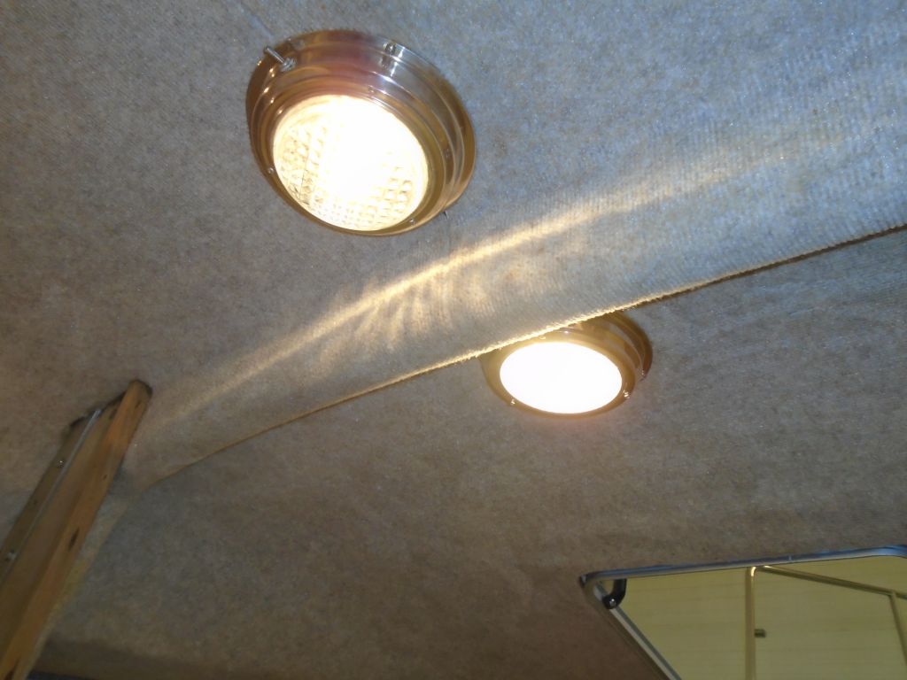
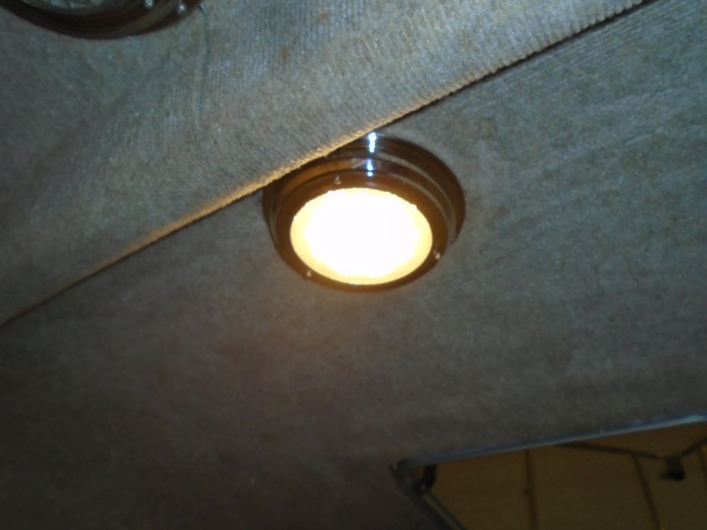
With the wiring reversed, the light operated, and I secured it to the overhead with screws, as per the original. This fixture also hid the wiring passing through the deck to the mast lighting.
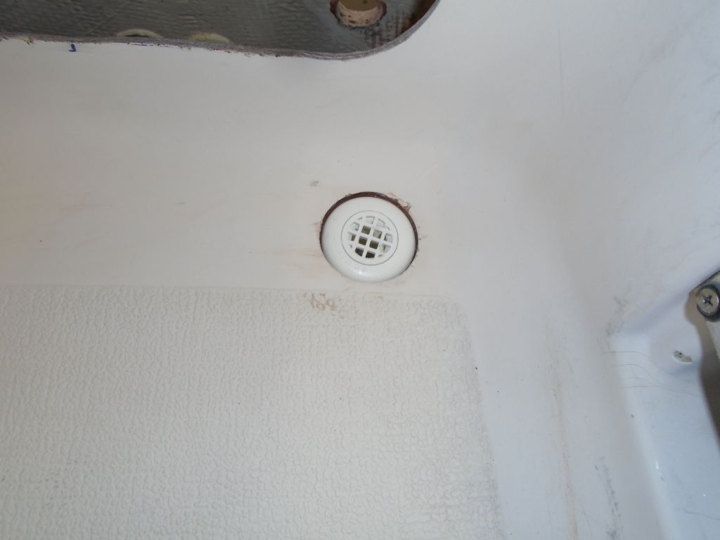
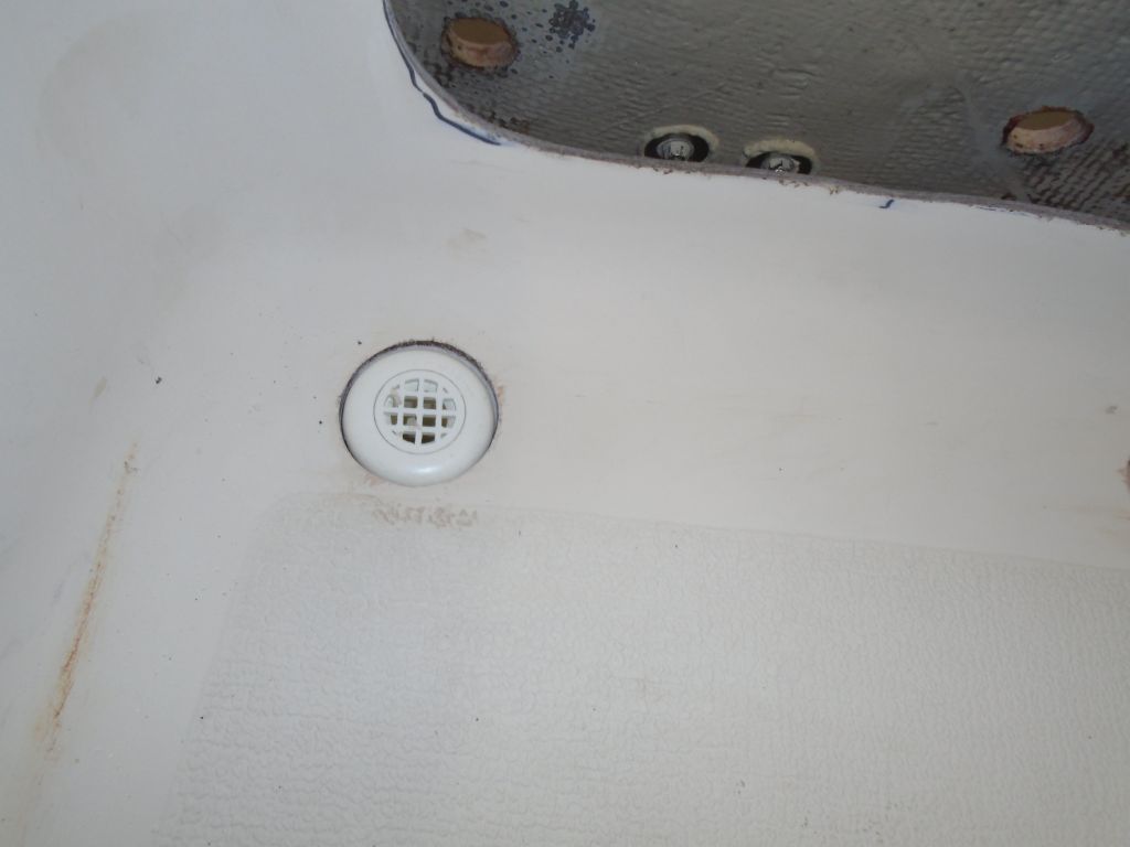
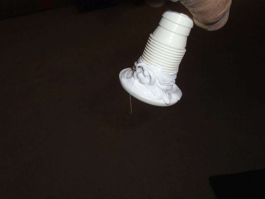
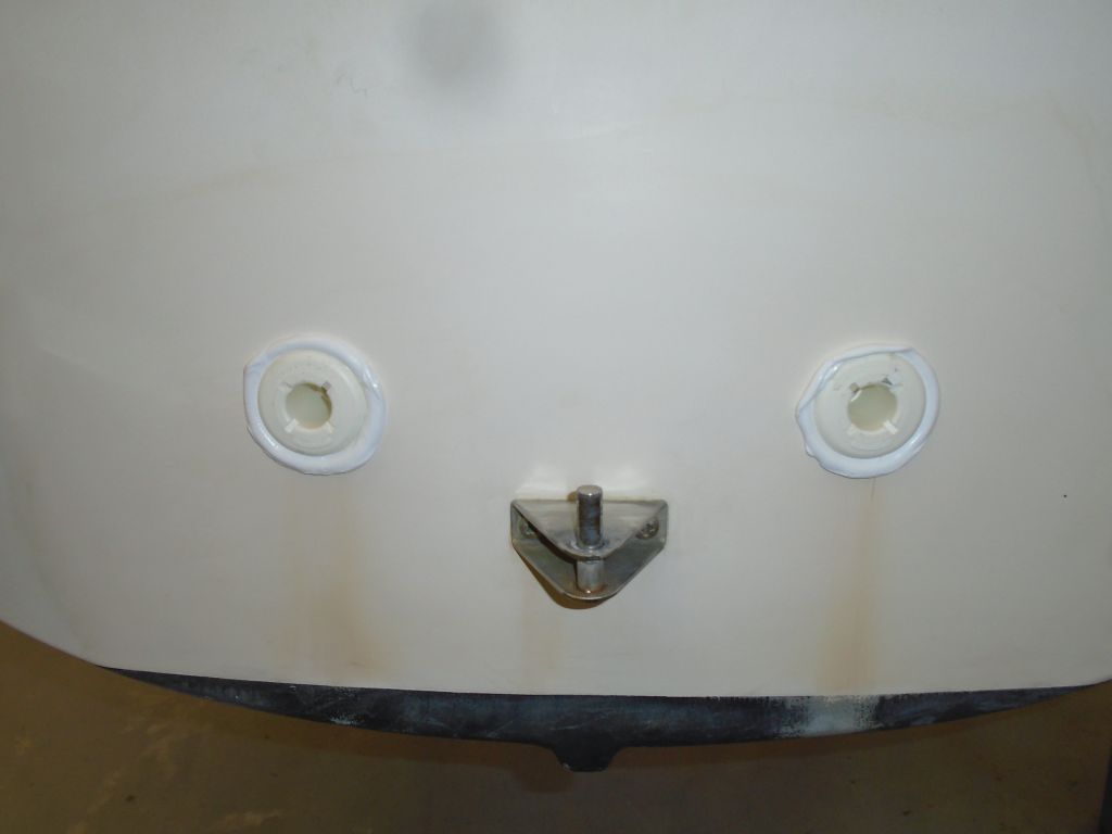
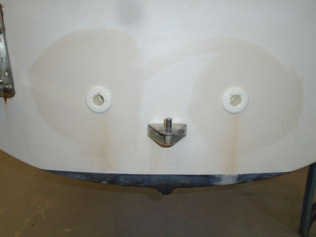
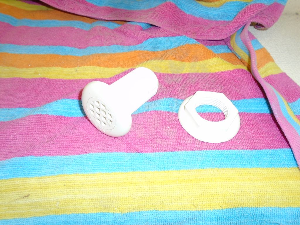
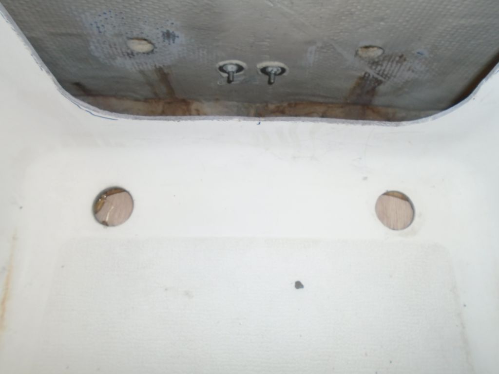
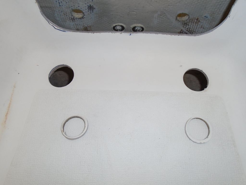
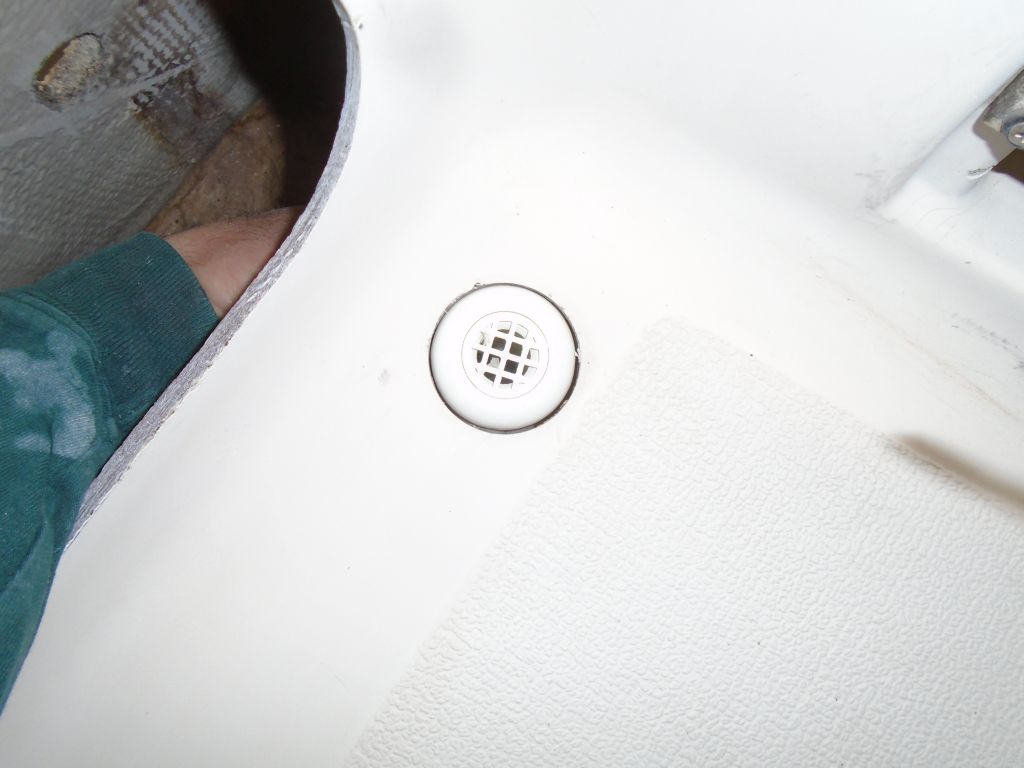
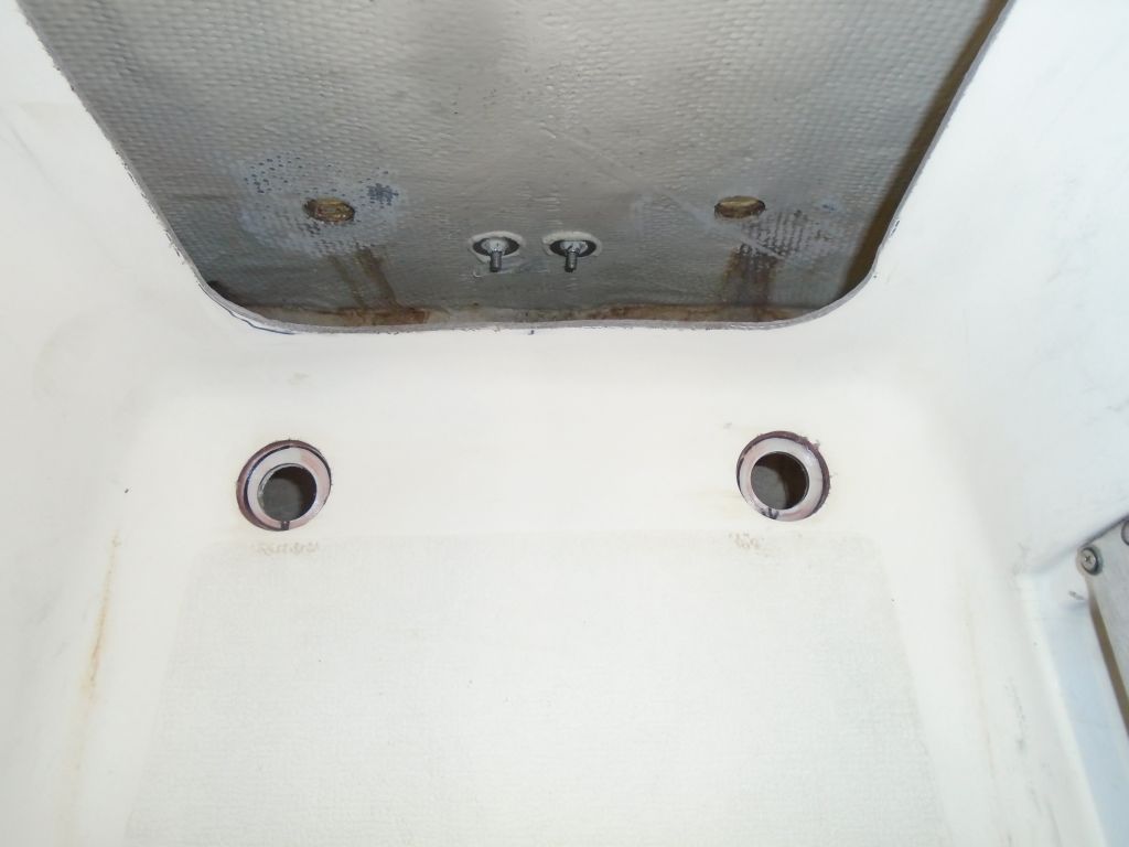
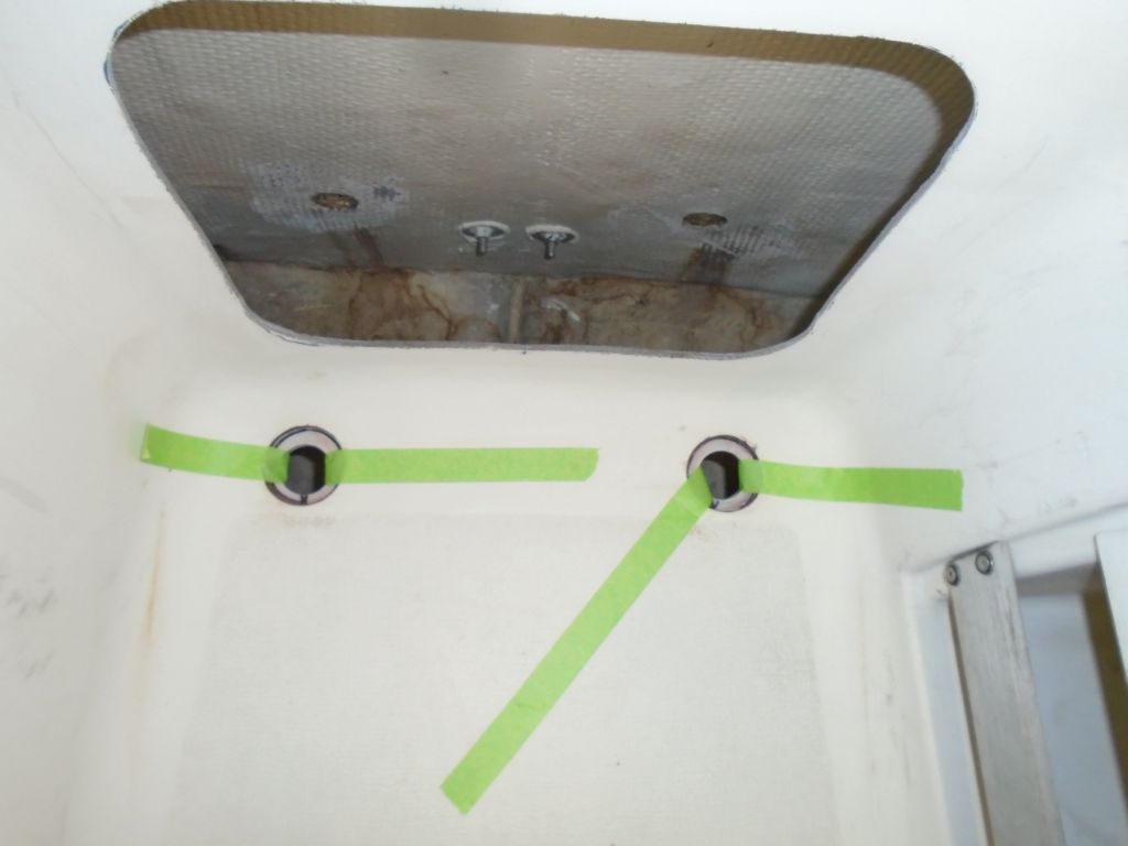
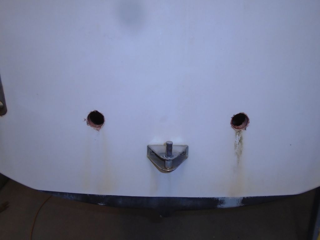
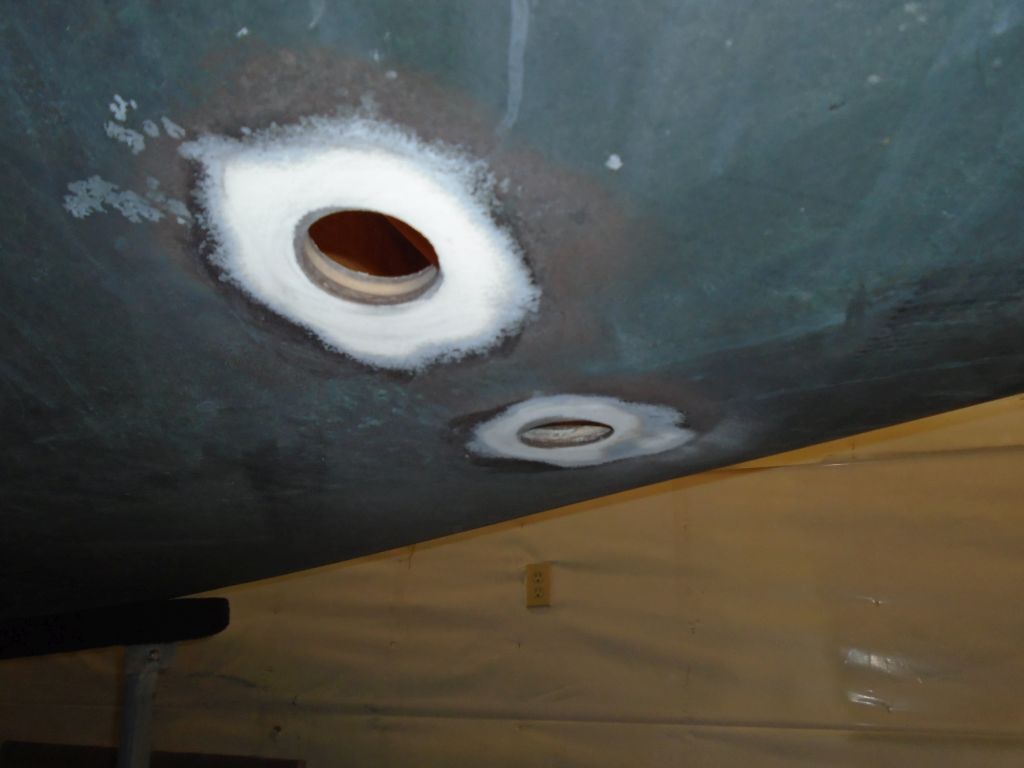
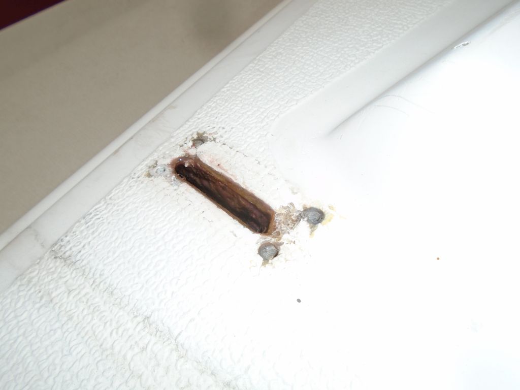
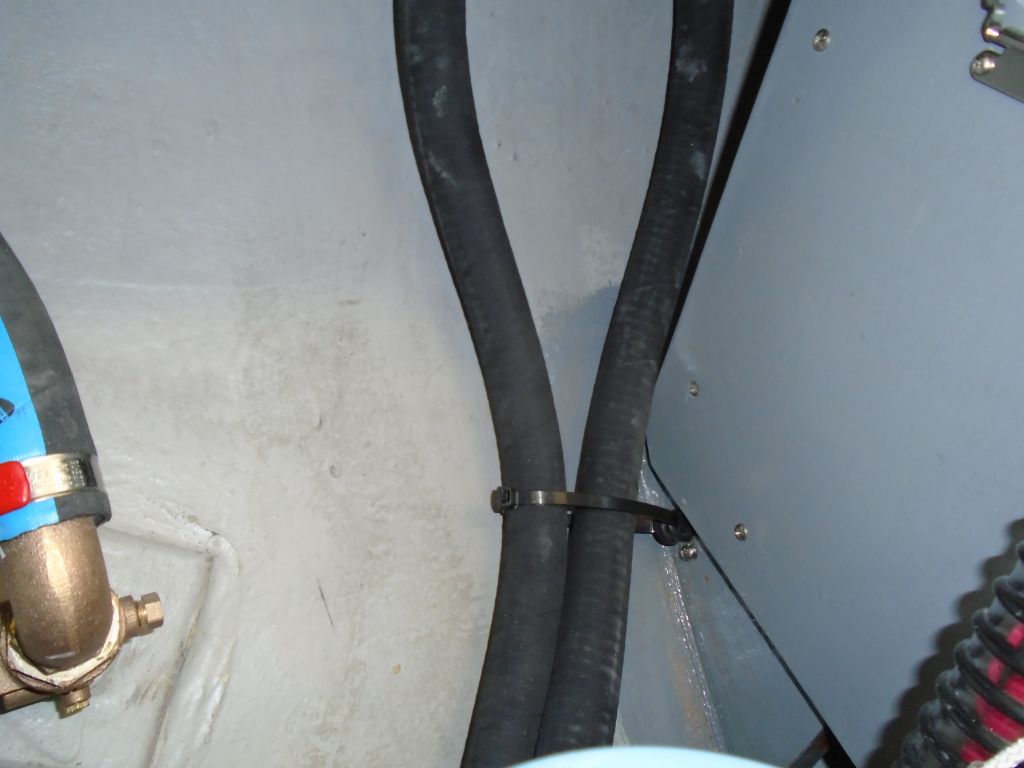
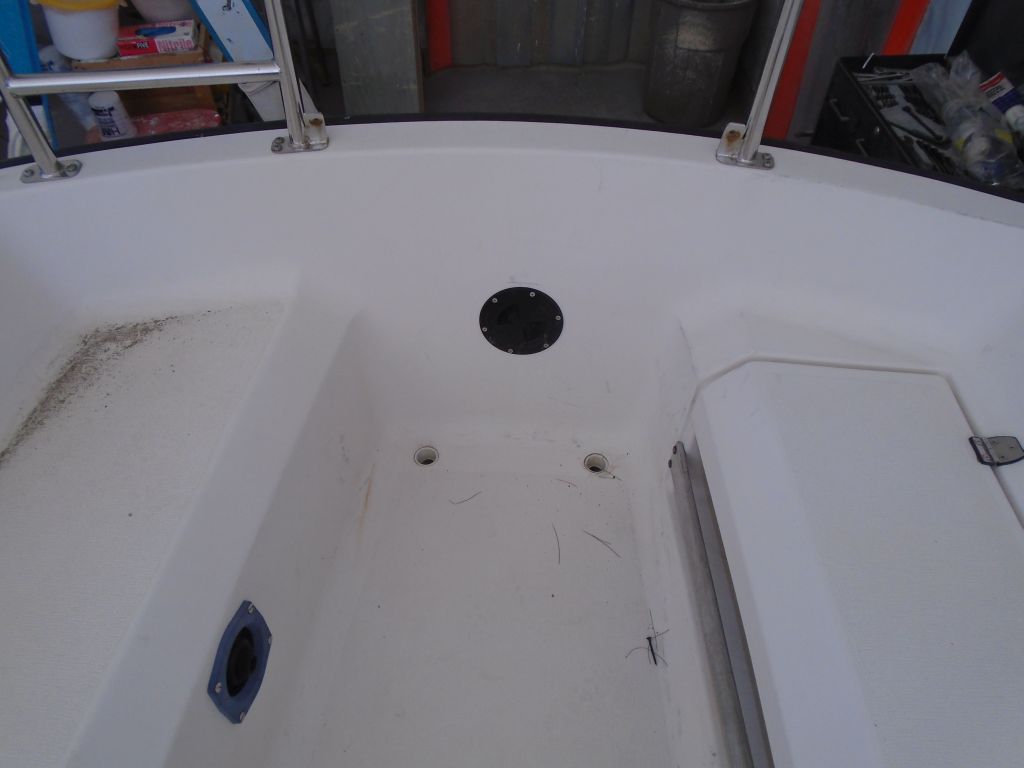
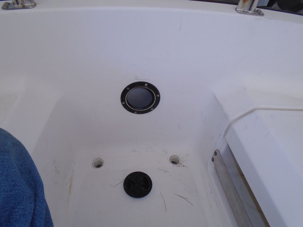
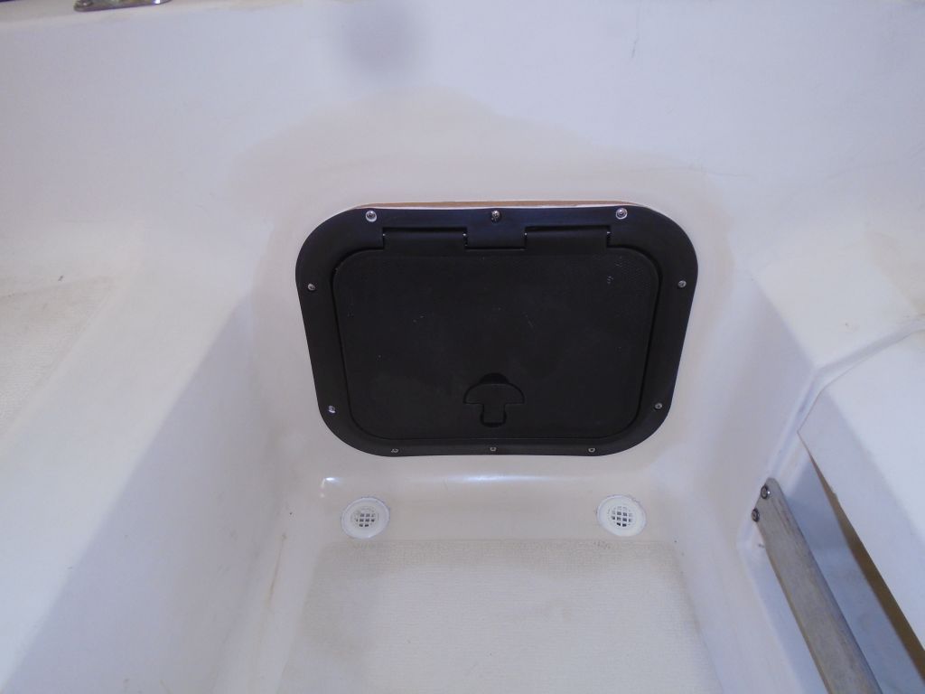
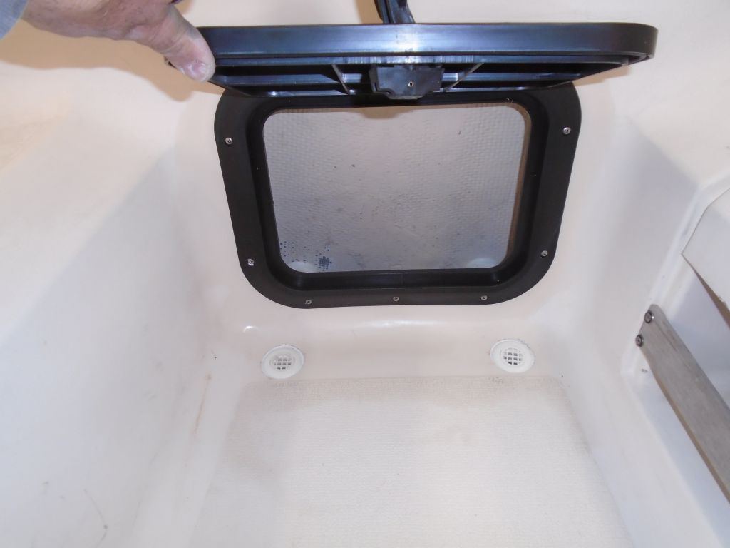
Next, I turned to the scuppers. All parts were now on hand, so I completed the installation by installing the screened cockpit fittings along with elbows and hose adapters so I could lead hoses the short distance to the transom outlets. I debated crossing the hoses but found that I could get short lengths on to keep the drainage as short and direct as possible. Before final installation, I cut off excess thread length from the cockpit fittings to keep the elbows as close to the cockpit as possible. I installed the cockpit fittings in beds of sealant in their newly-built recesses.
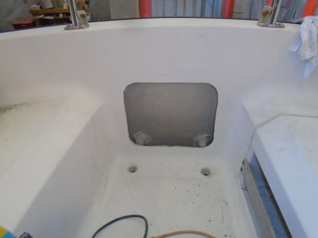
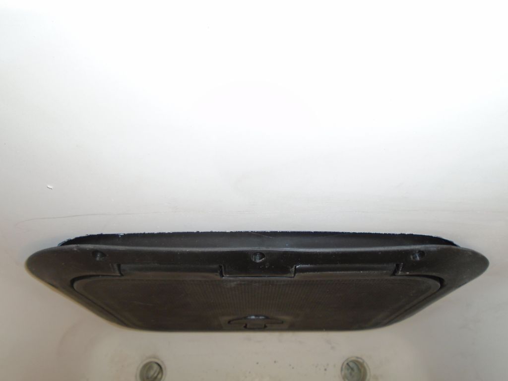
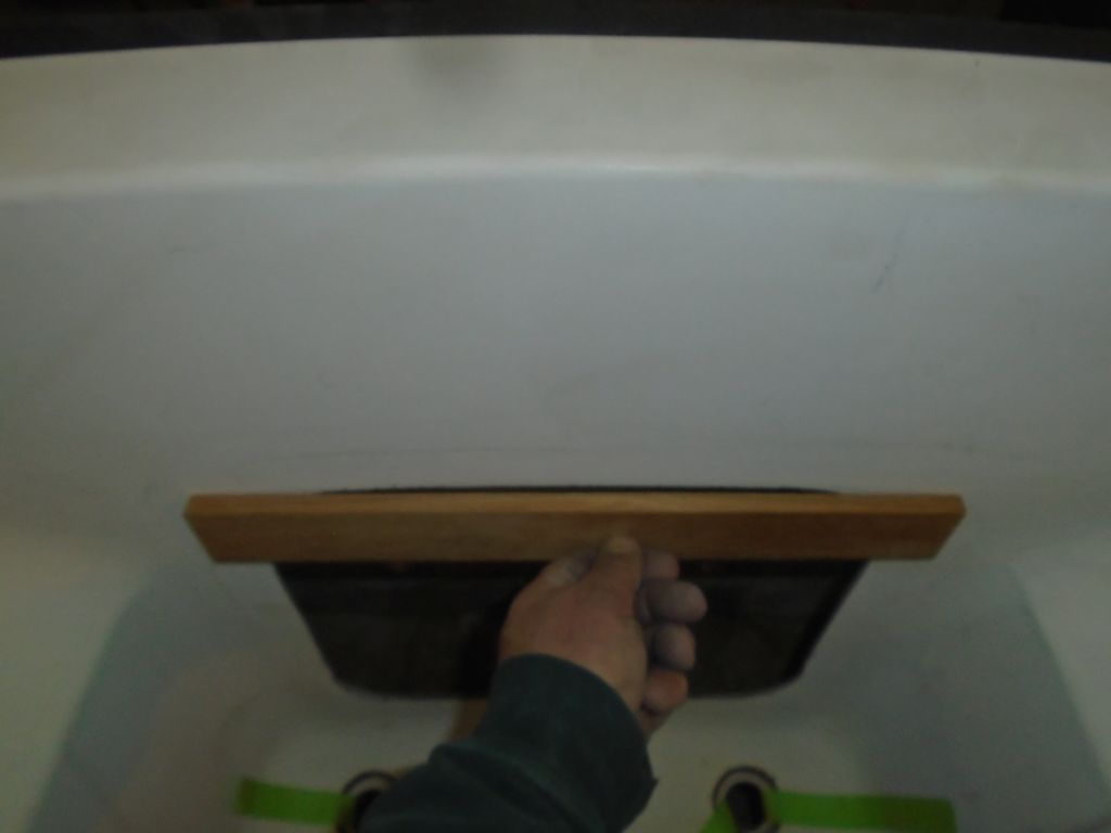
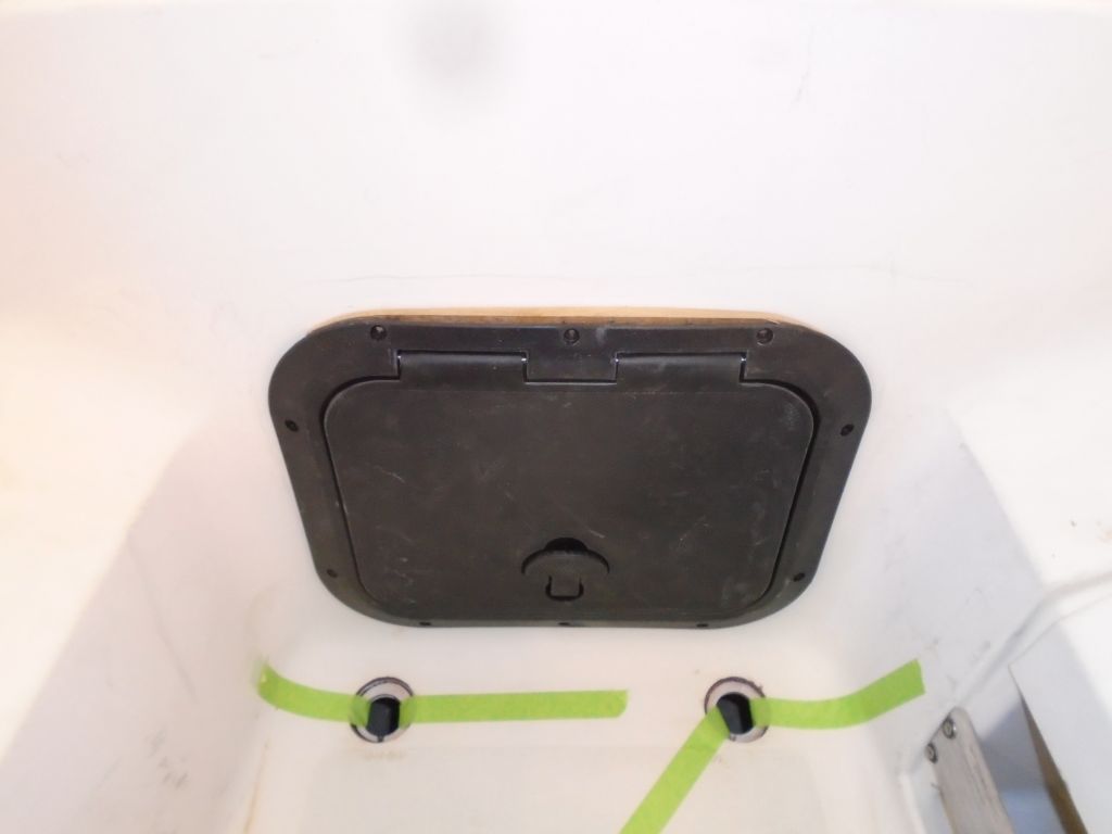
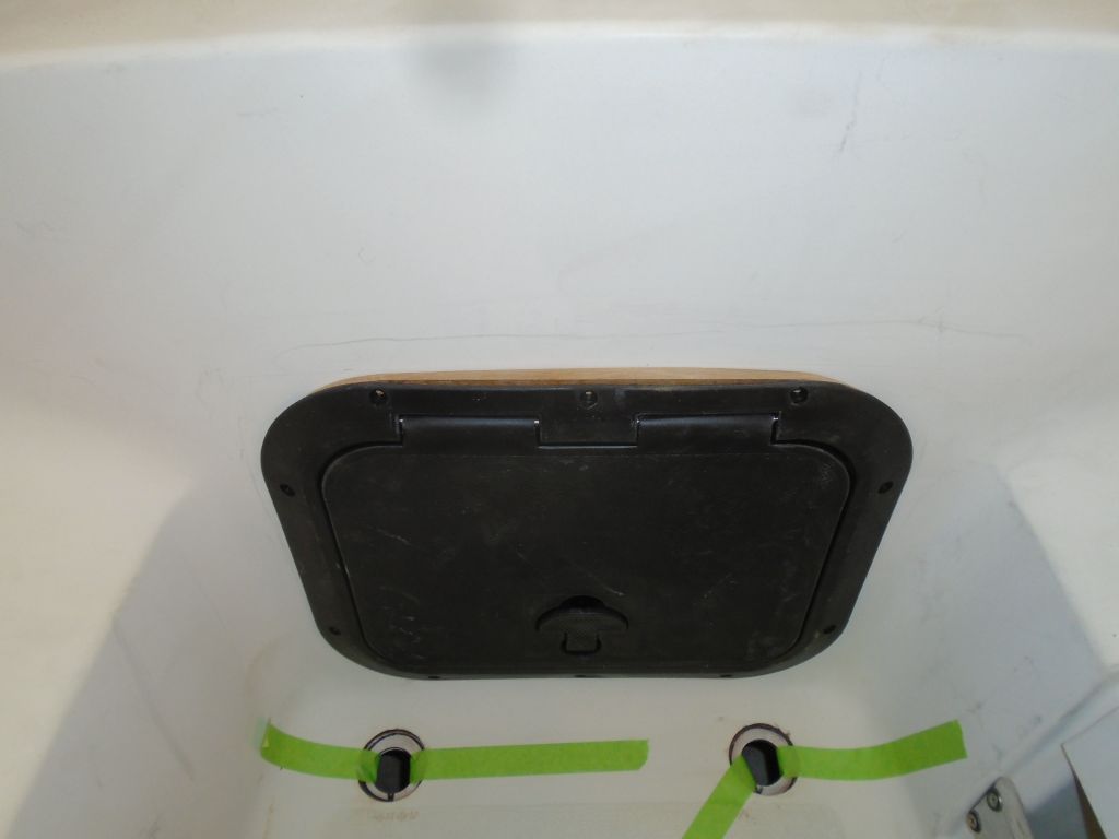
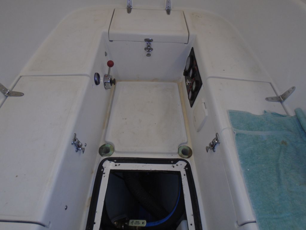
Afterwards, I installed the plastic access hatch with machine screws and sealant.
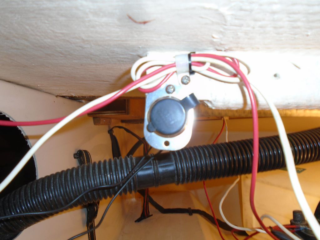
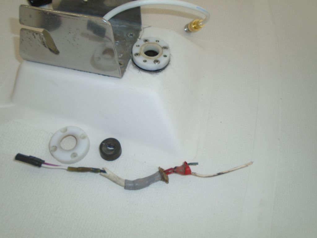
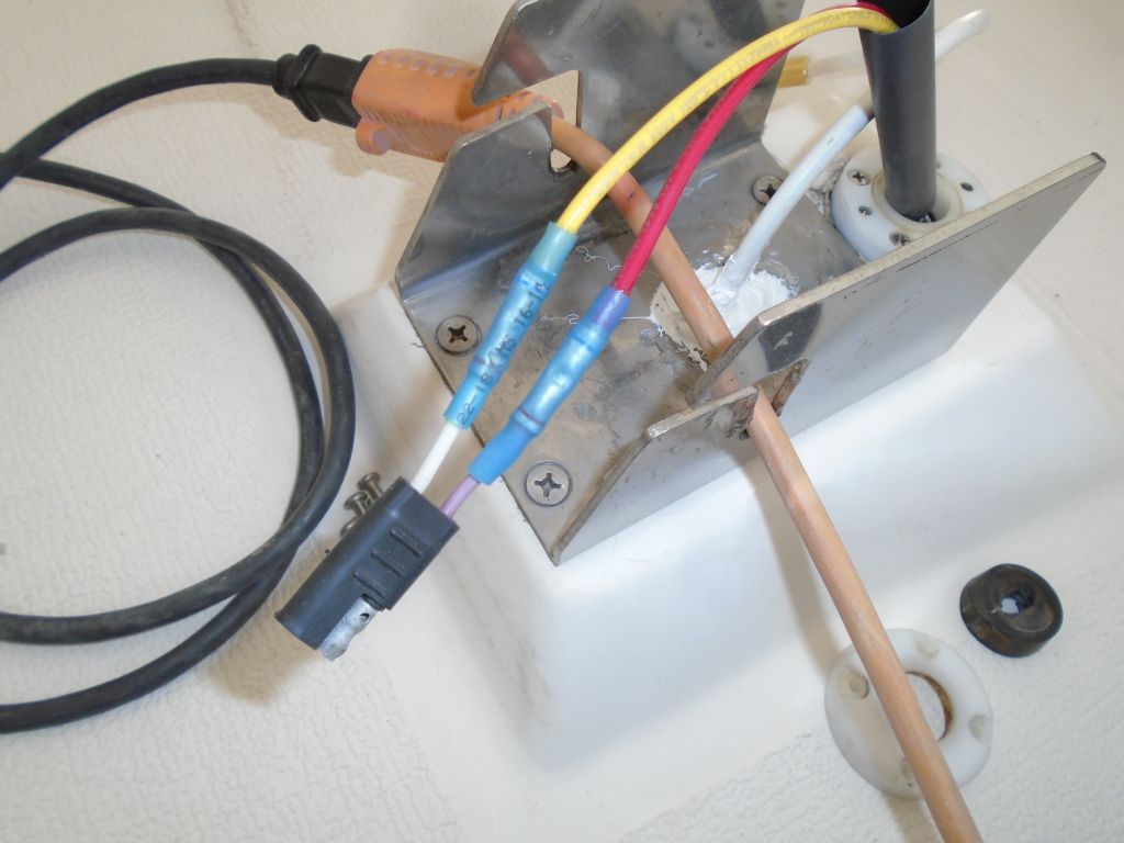
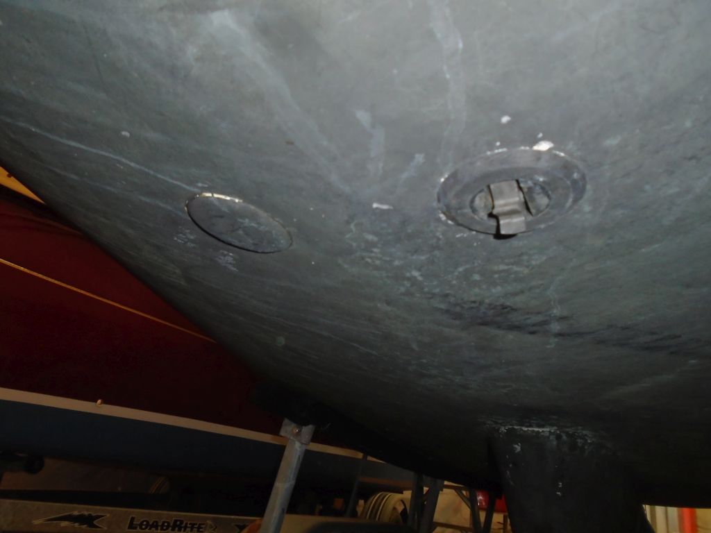
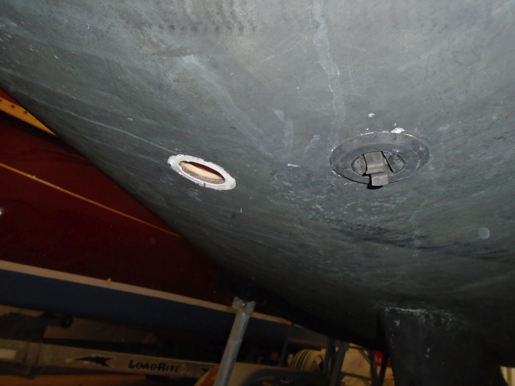
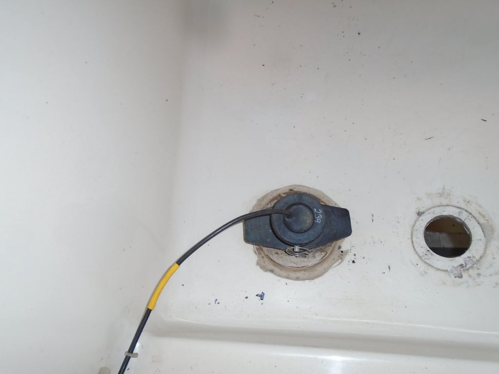
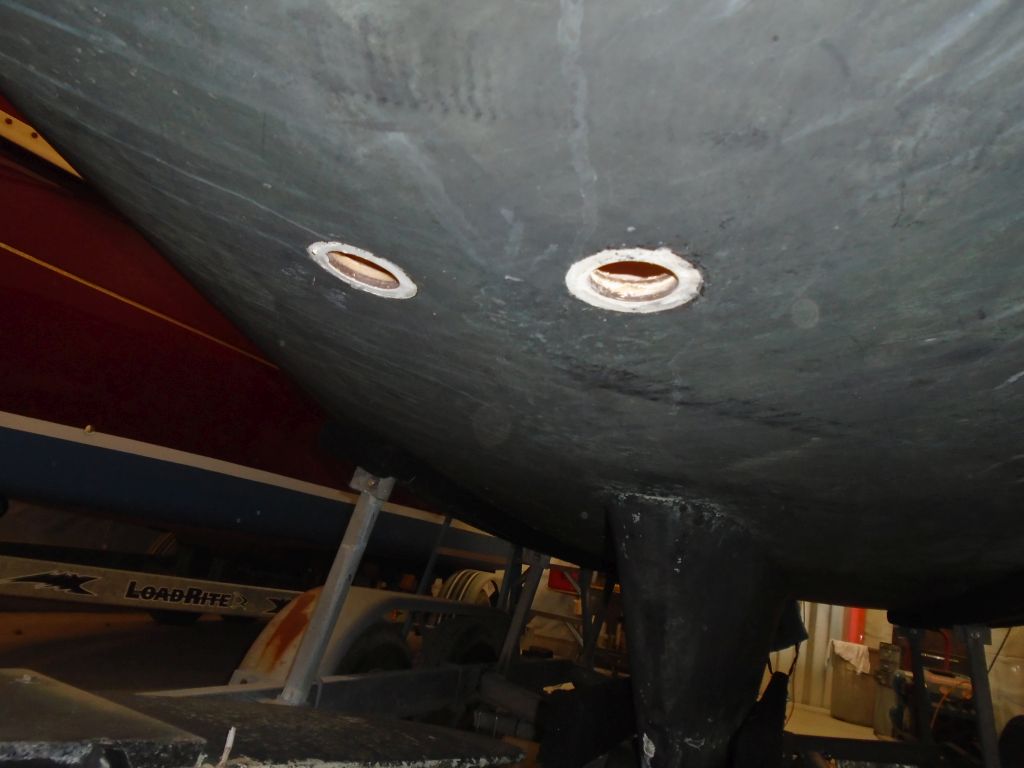
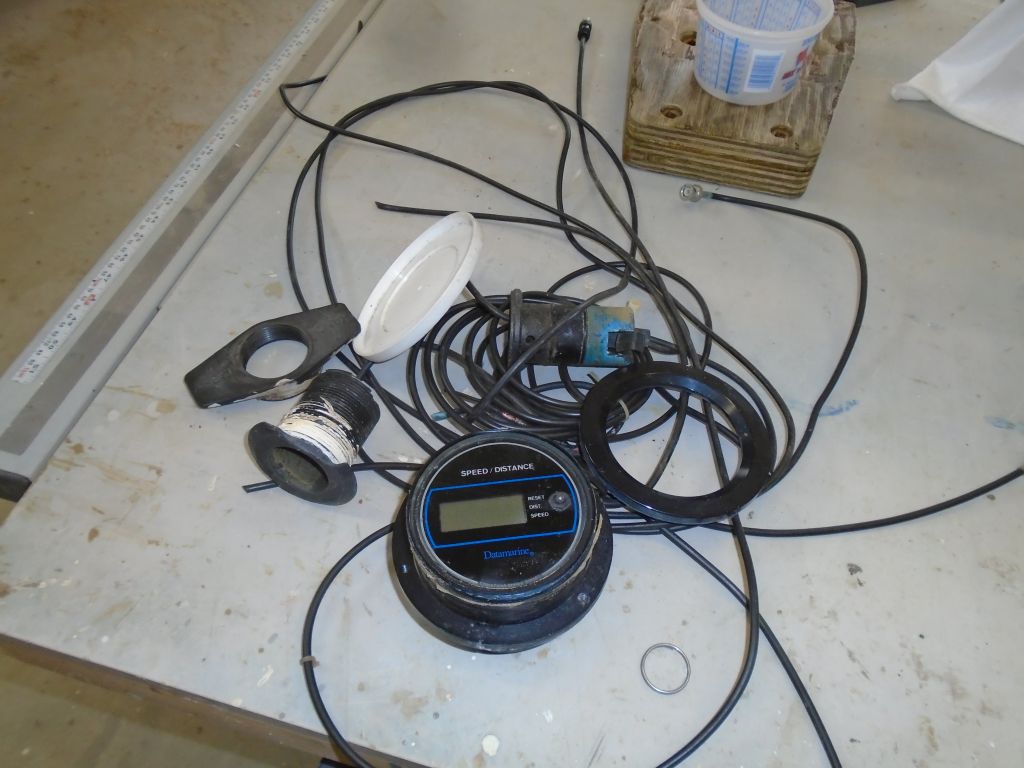
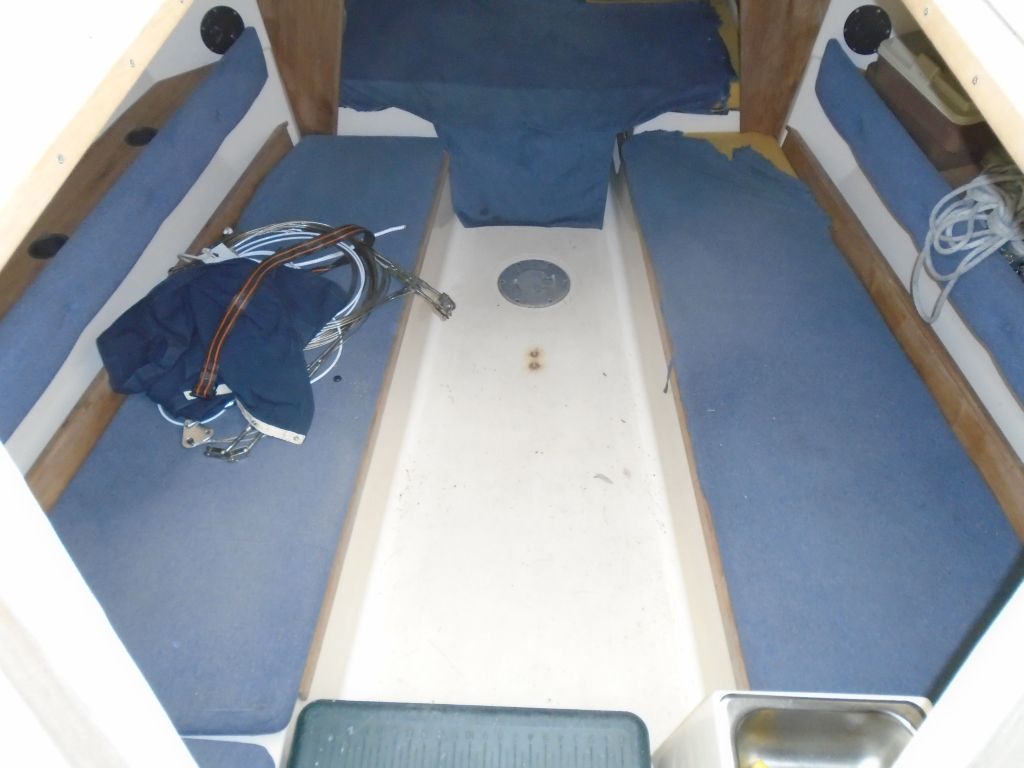
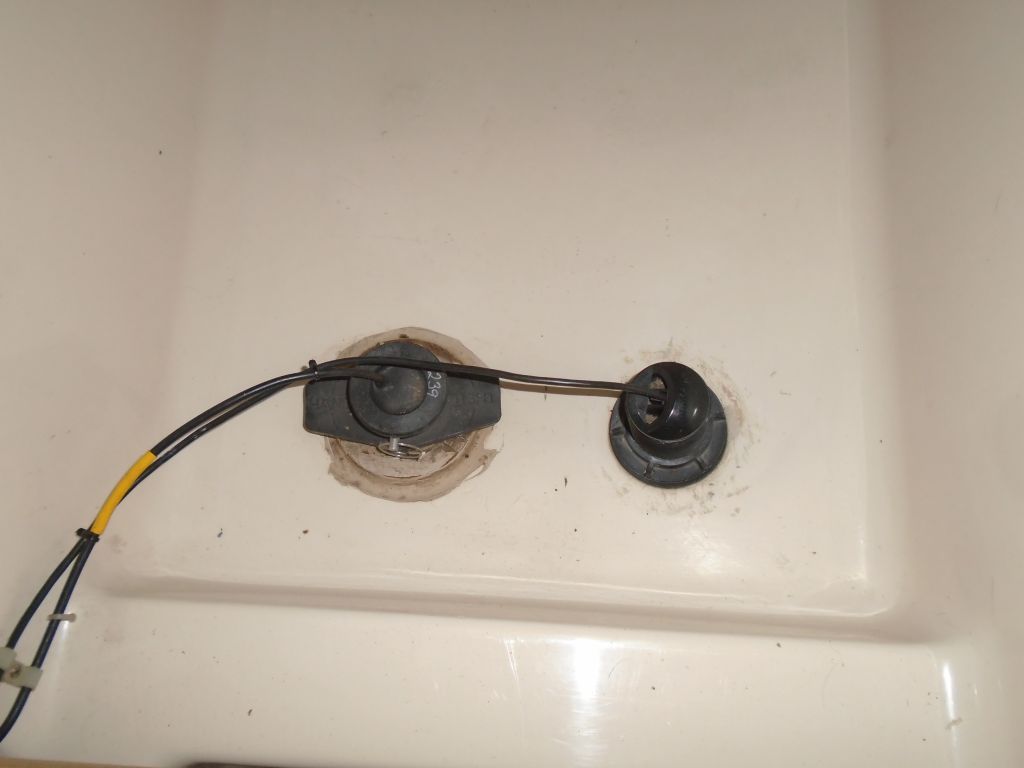
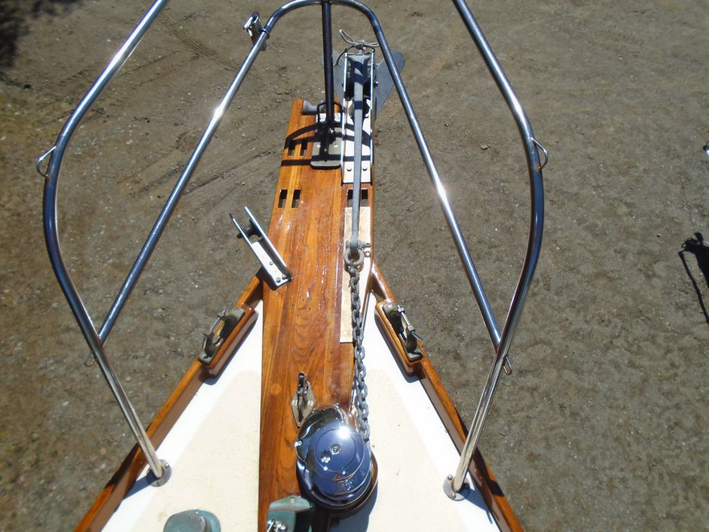
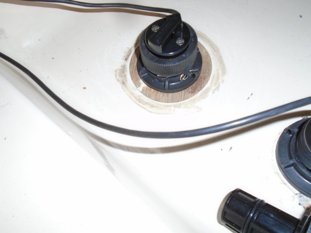
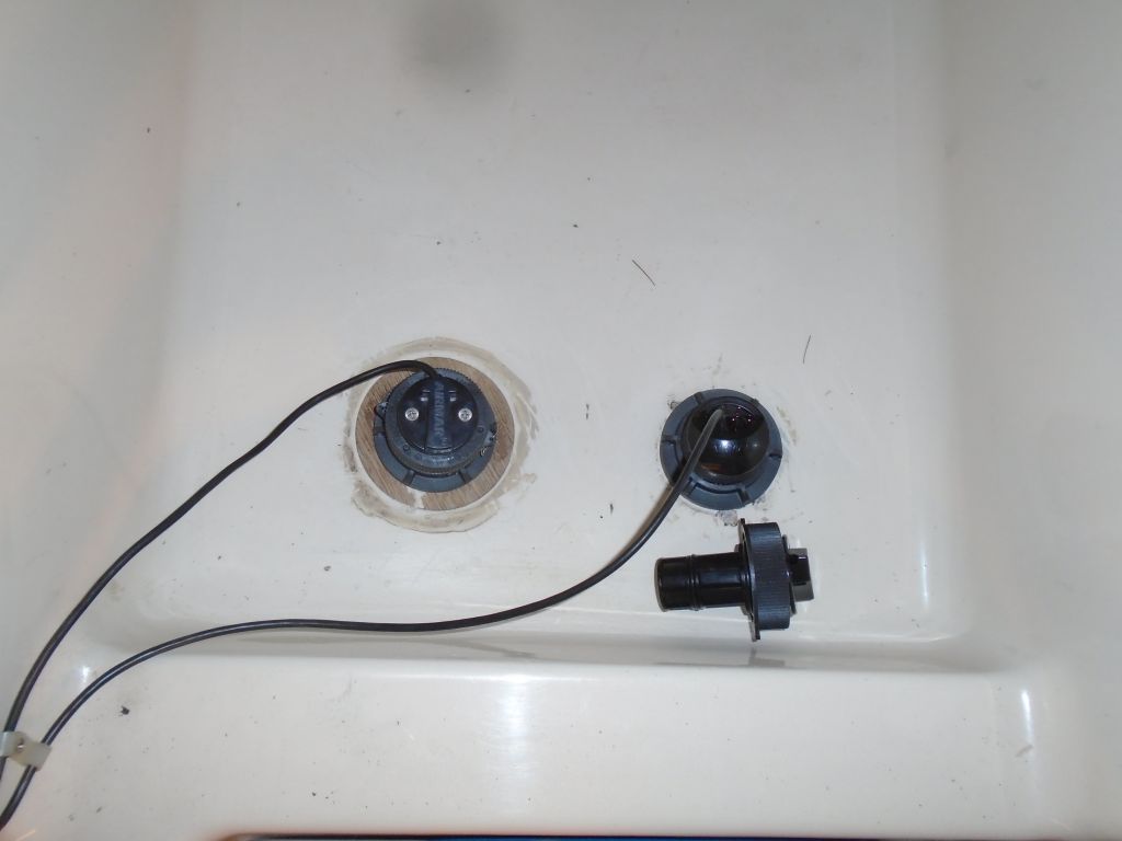
Before it slipped my mind, I went ahead and installed the knotmeter impeller in its new through hull–the impeller was removable from inside for cleaning, ostensibly. I’d left this out during initial through hull installation and until the sealant had had adequate cure time.
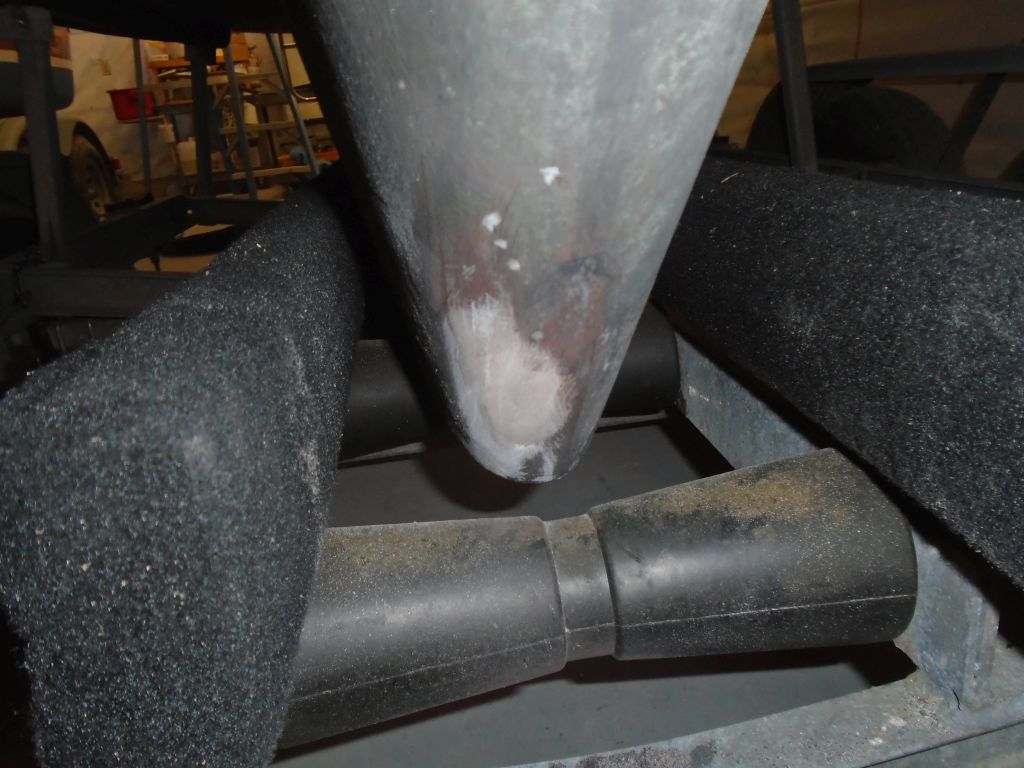
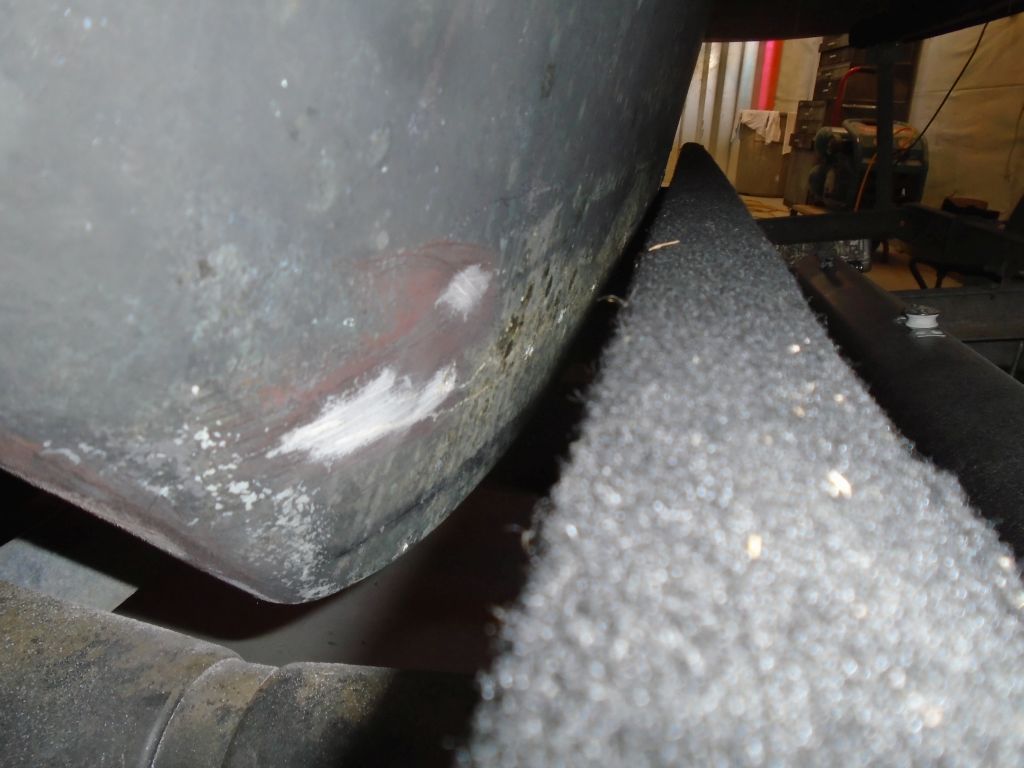
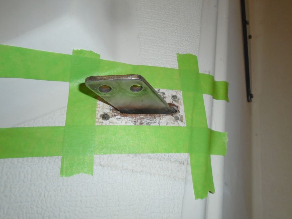
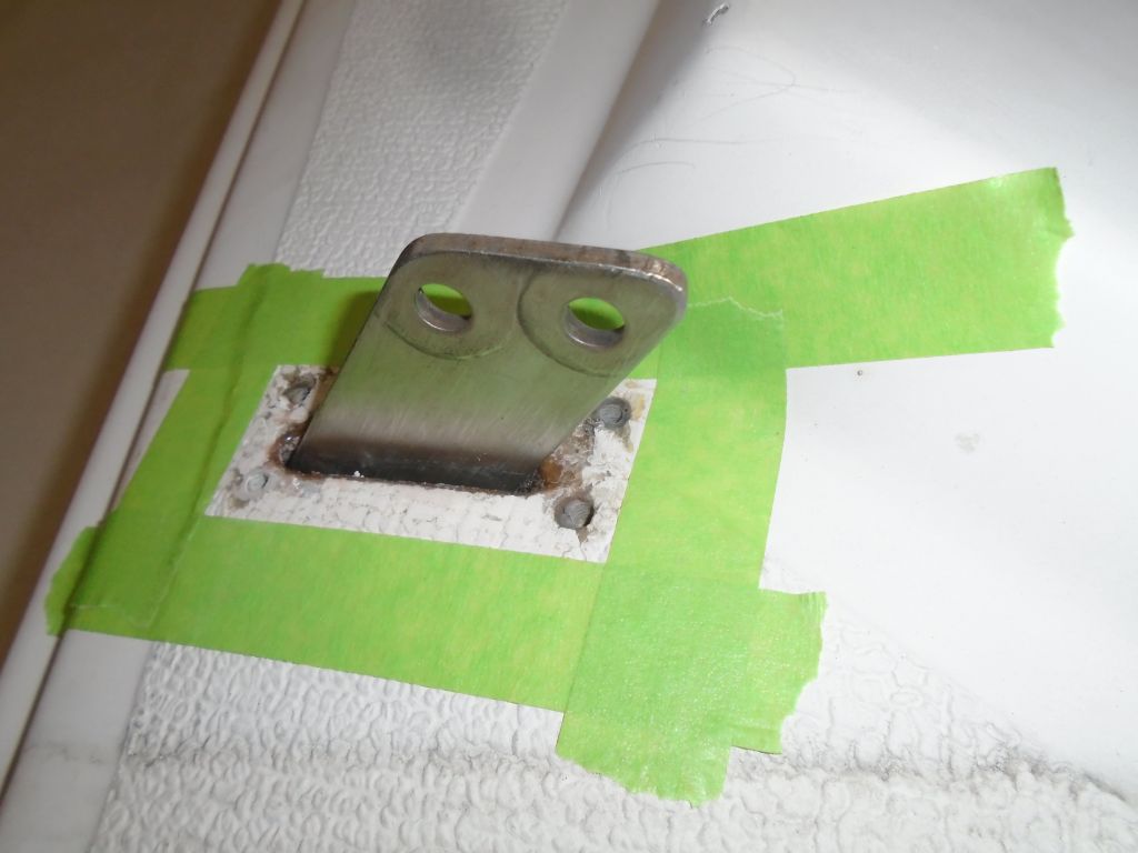
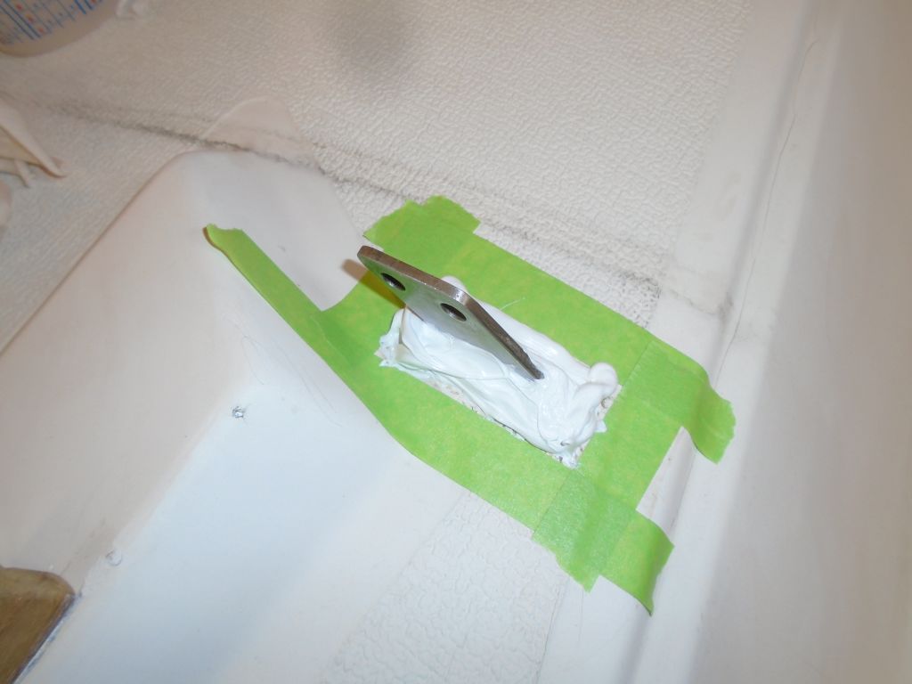
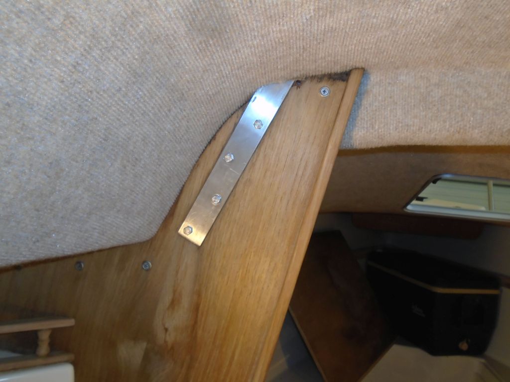
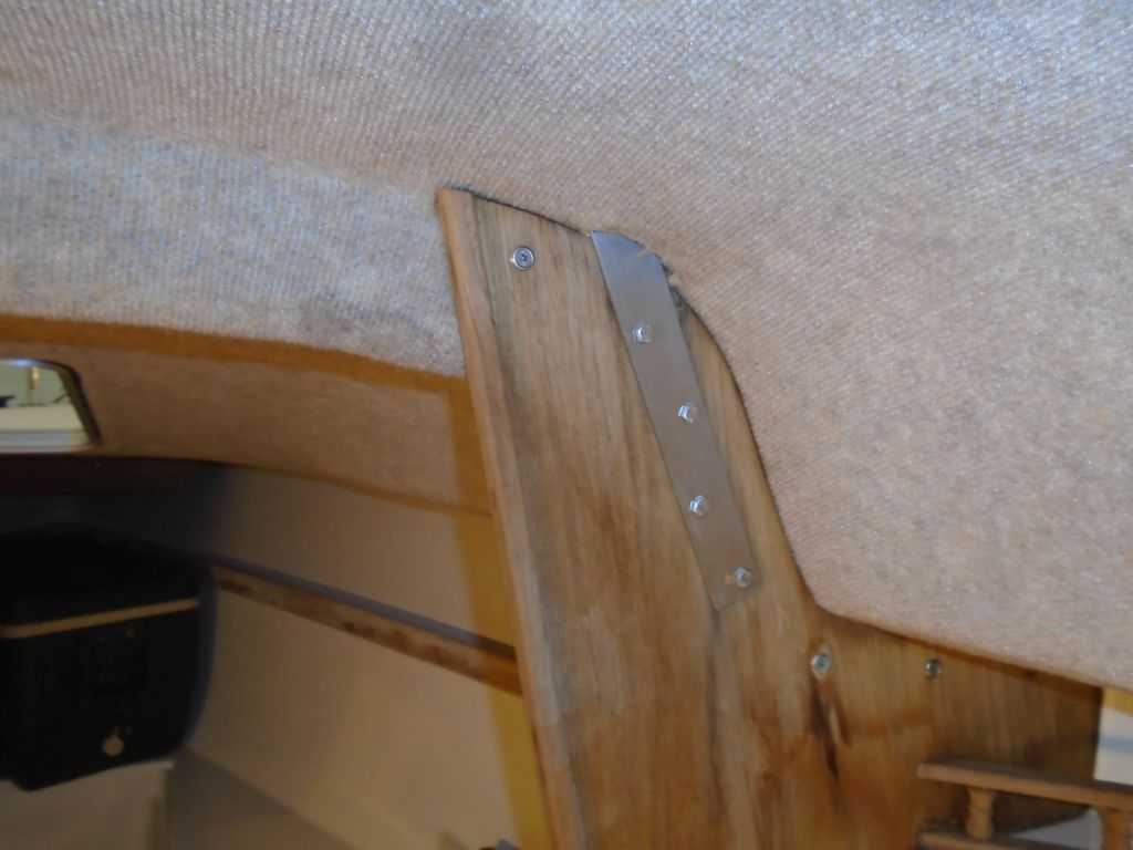
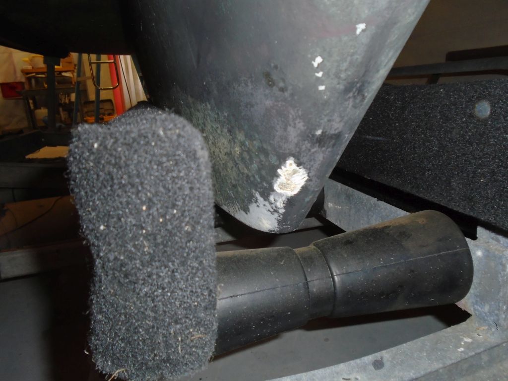
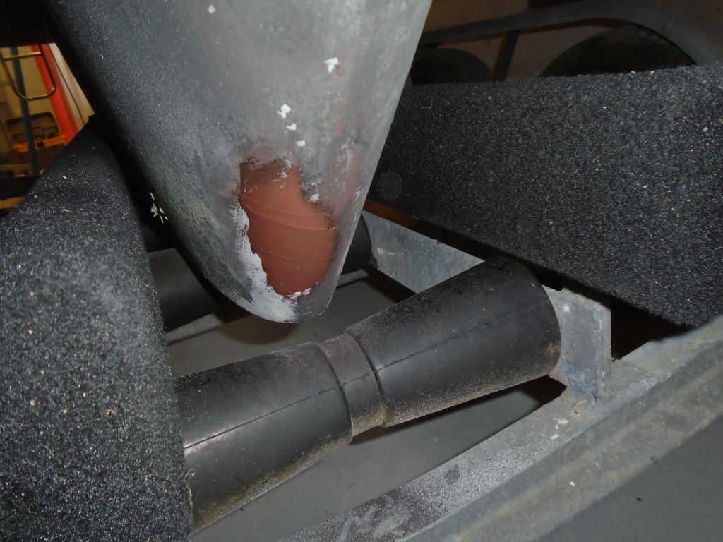
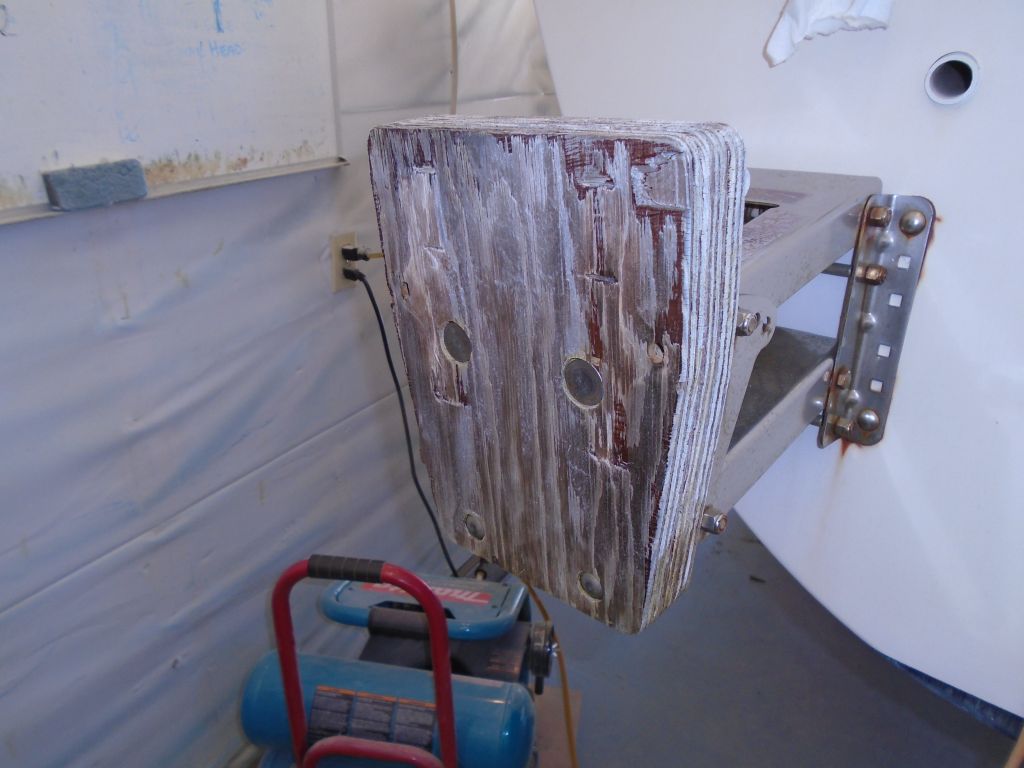
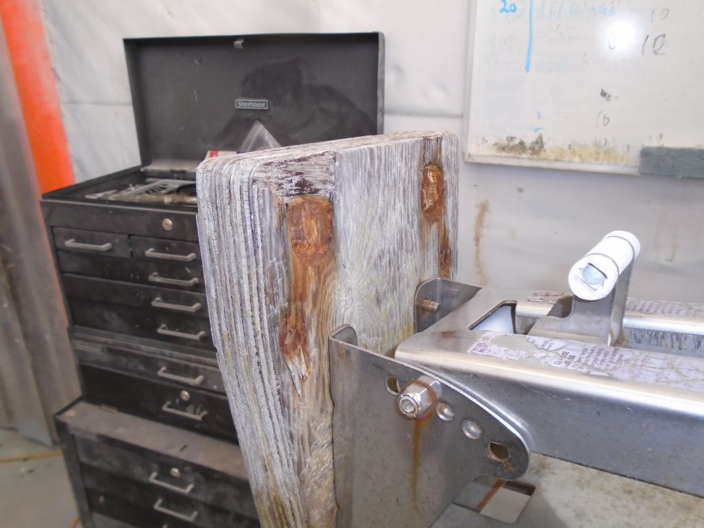
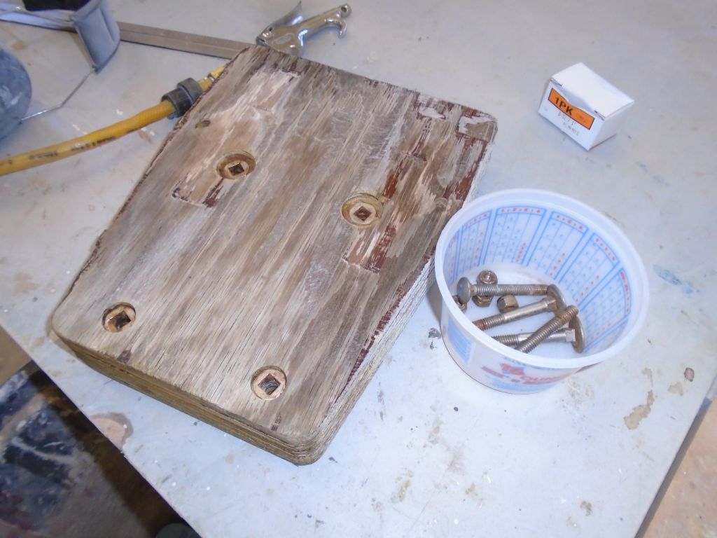
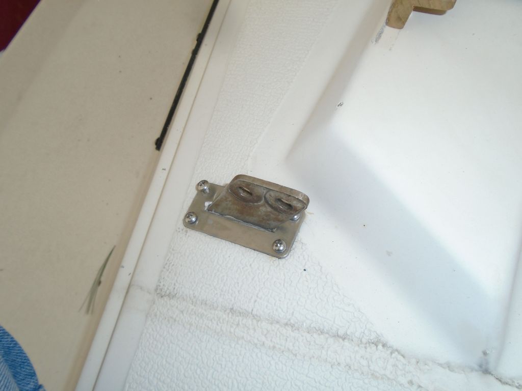
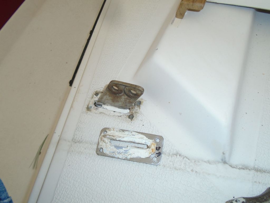
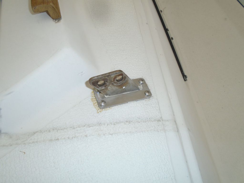
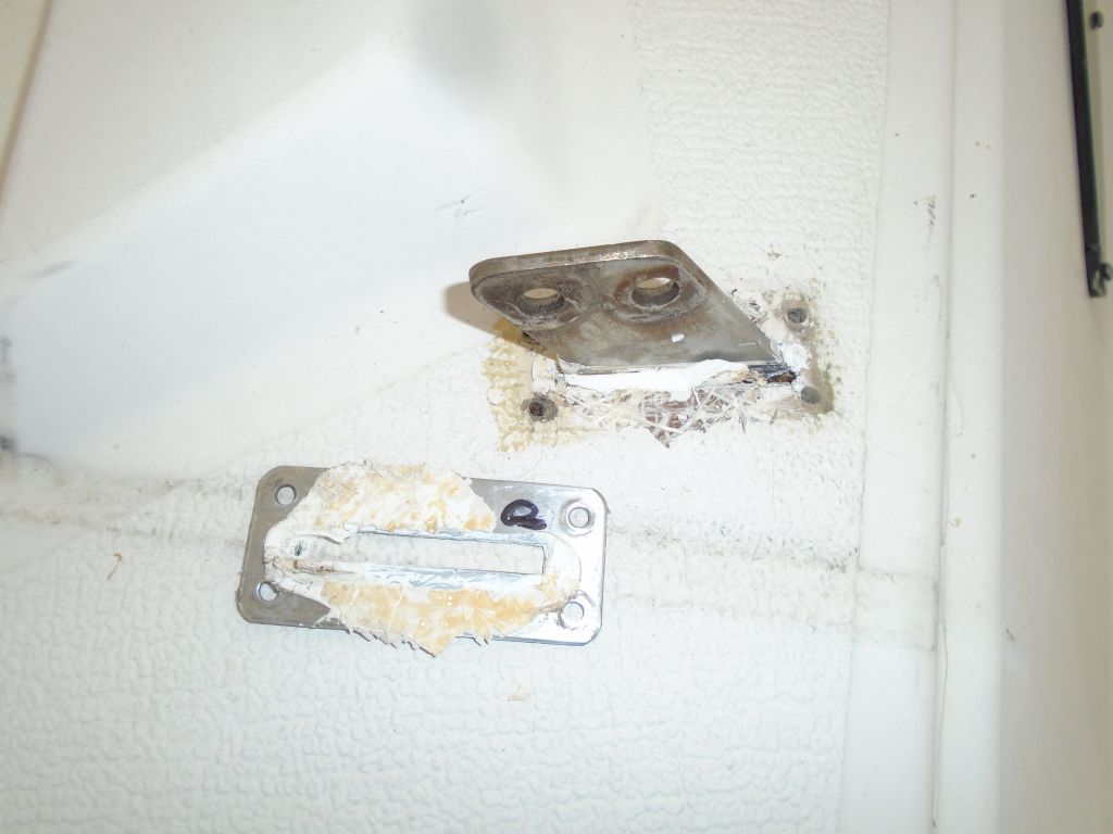
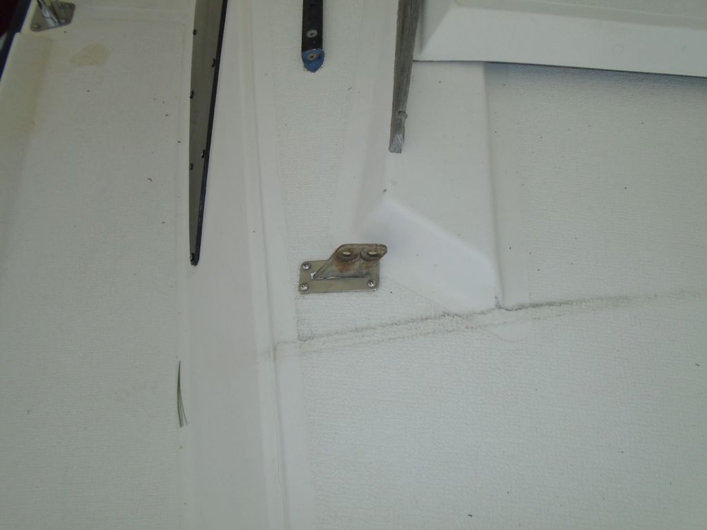
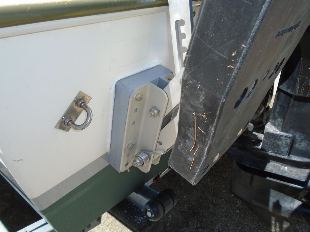
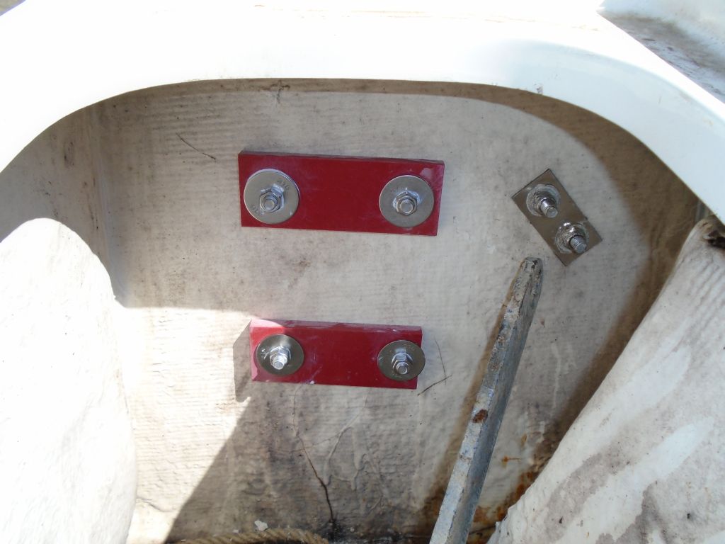
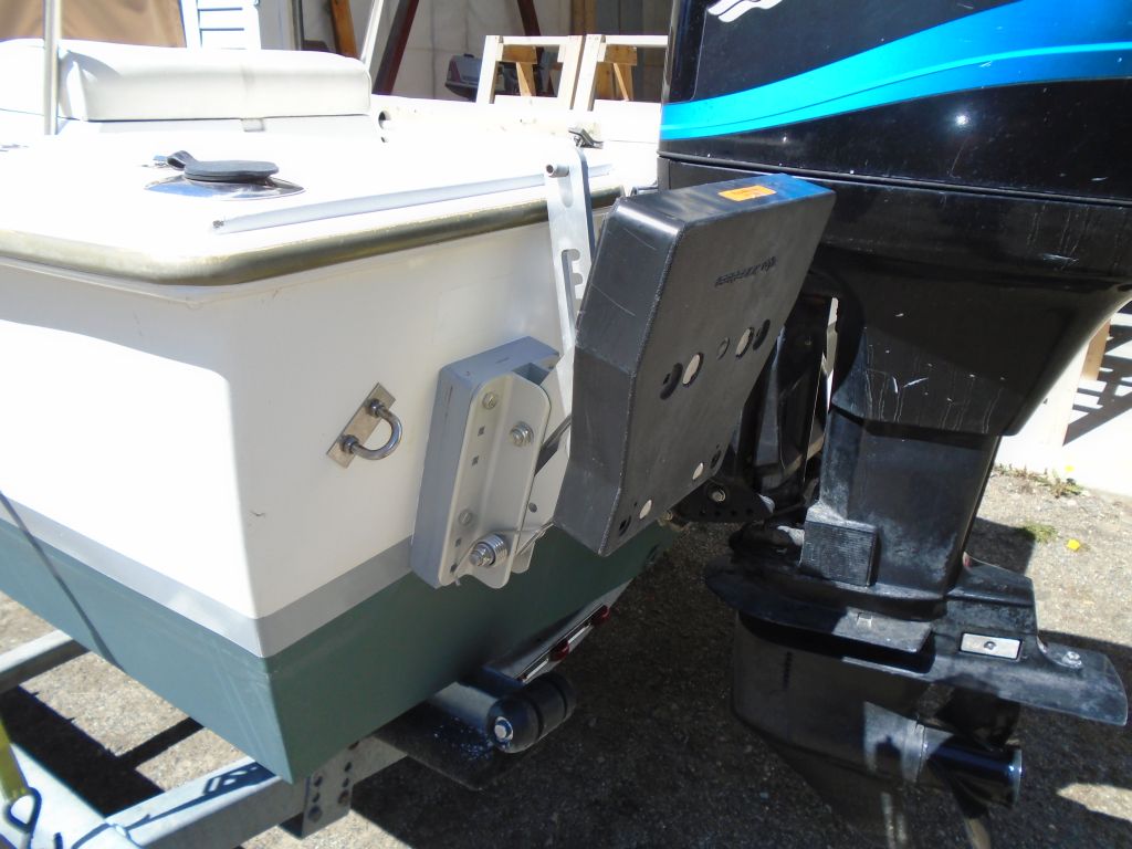
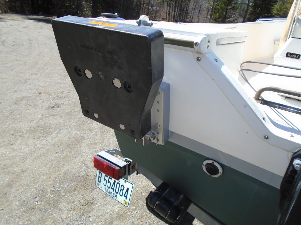
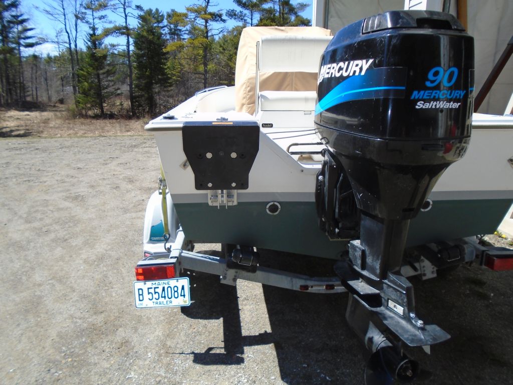
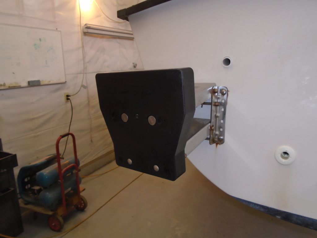
The new outboard motor bracket pad had arrived, and I installed it.
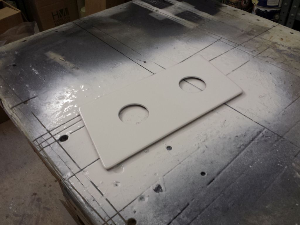
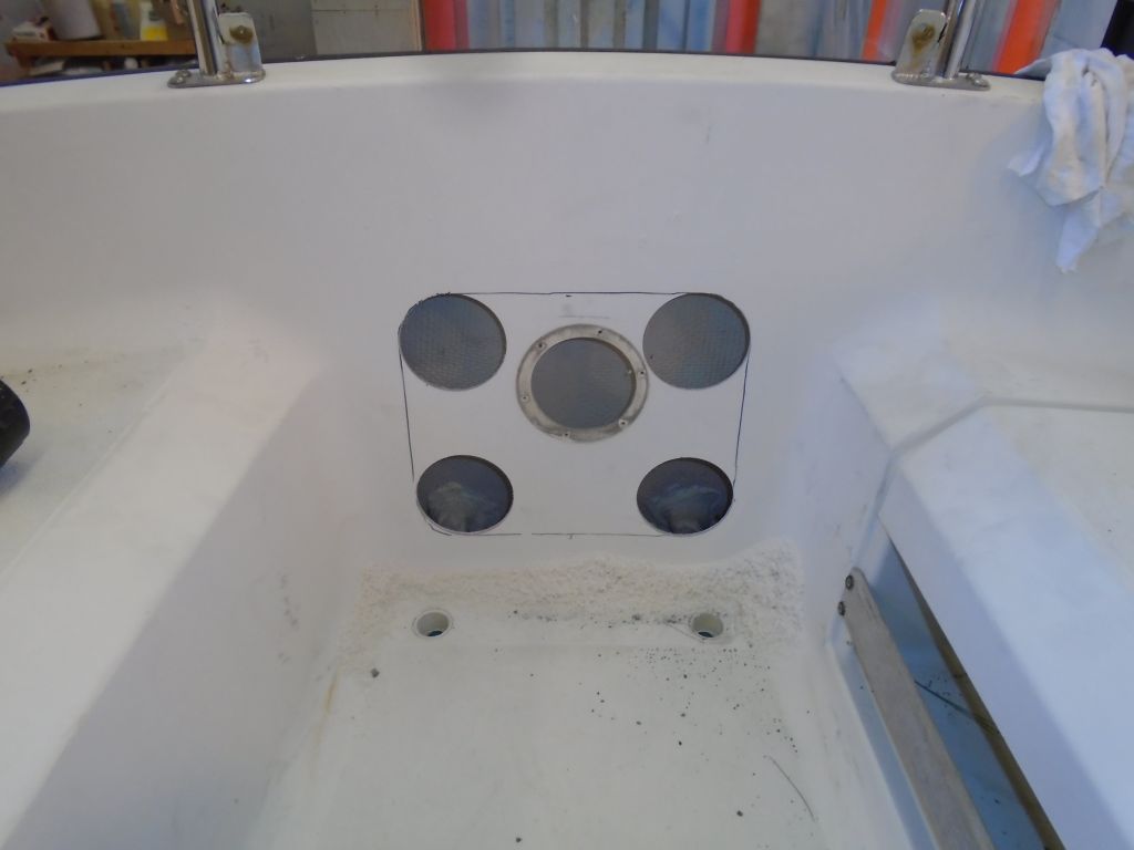
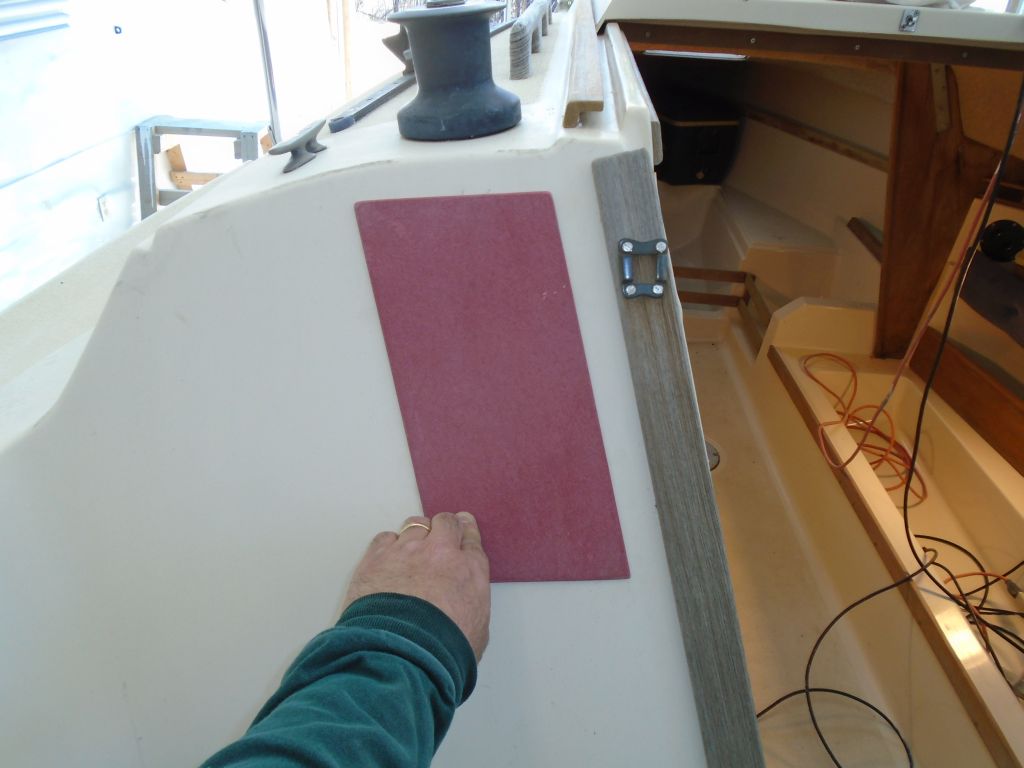
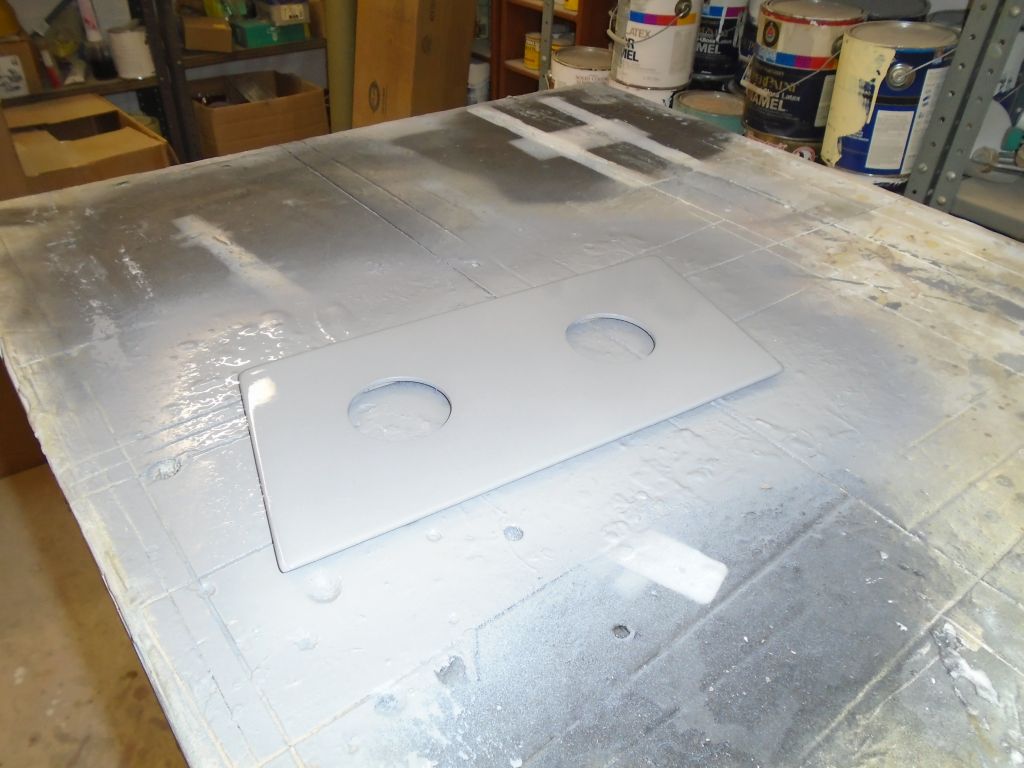
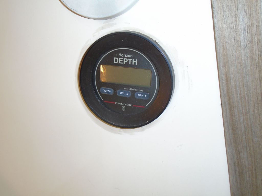
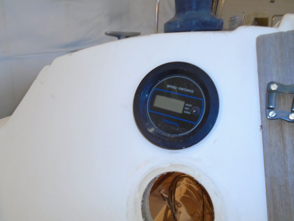
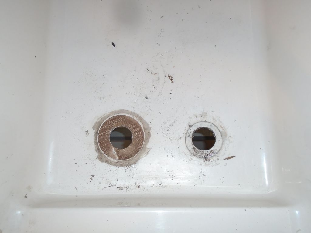
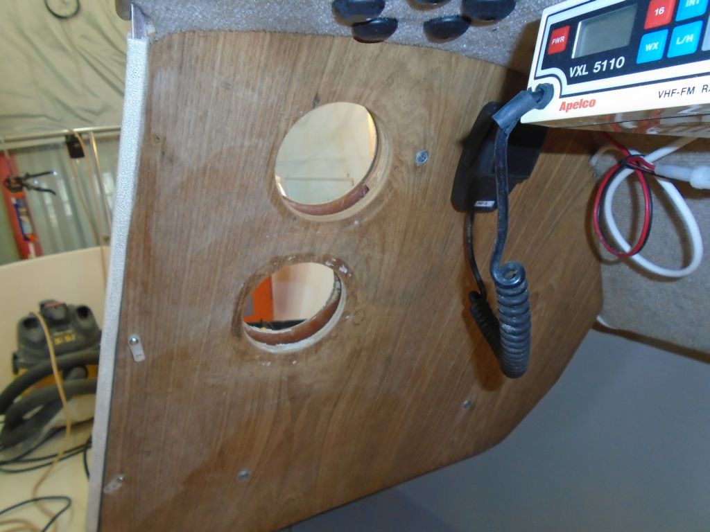
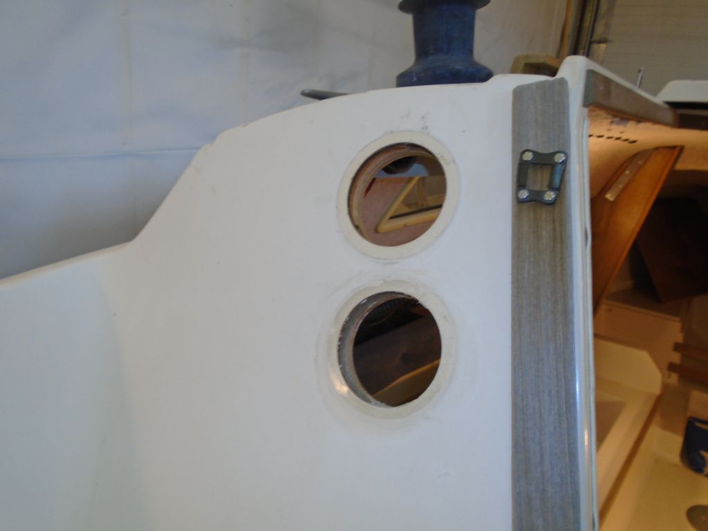
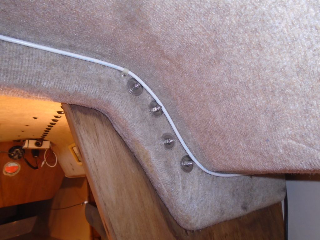
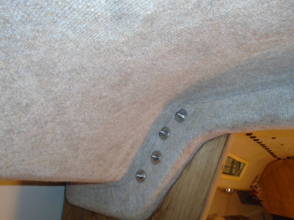
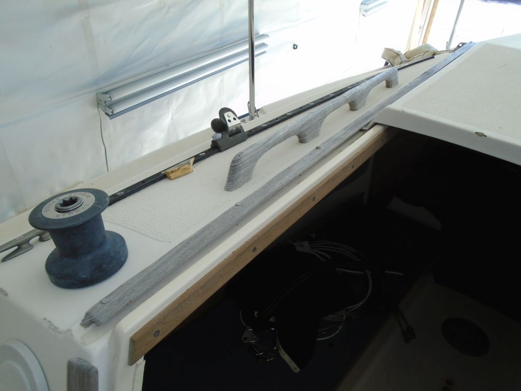
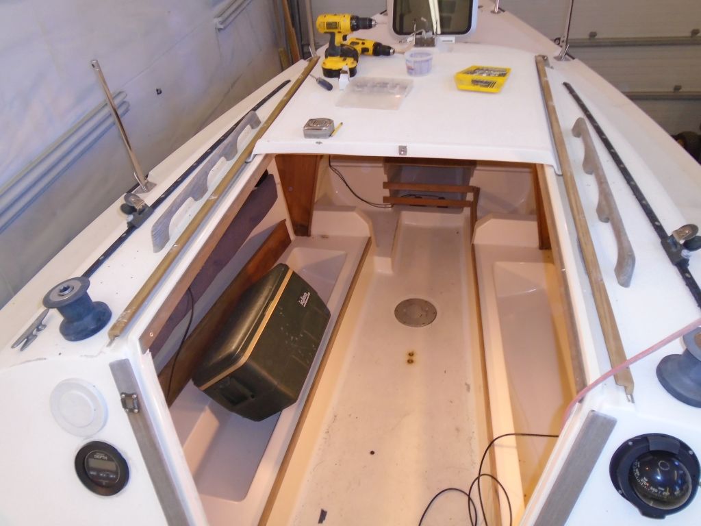
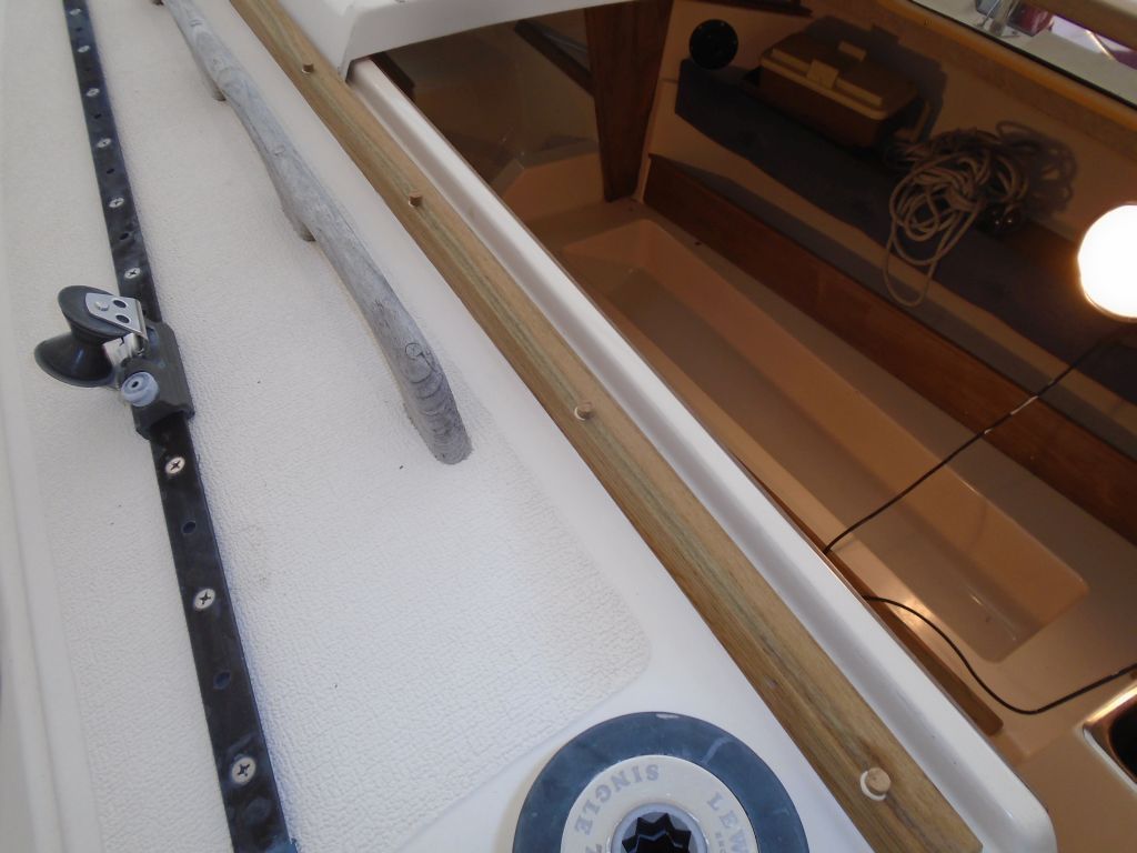
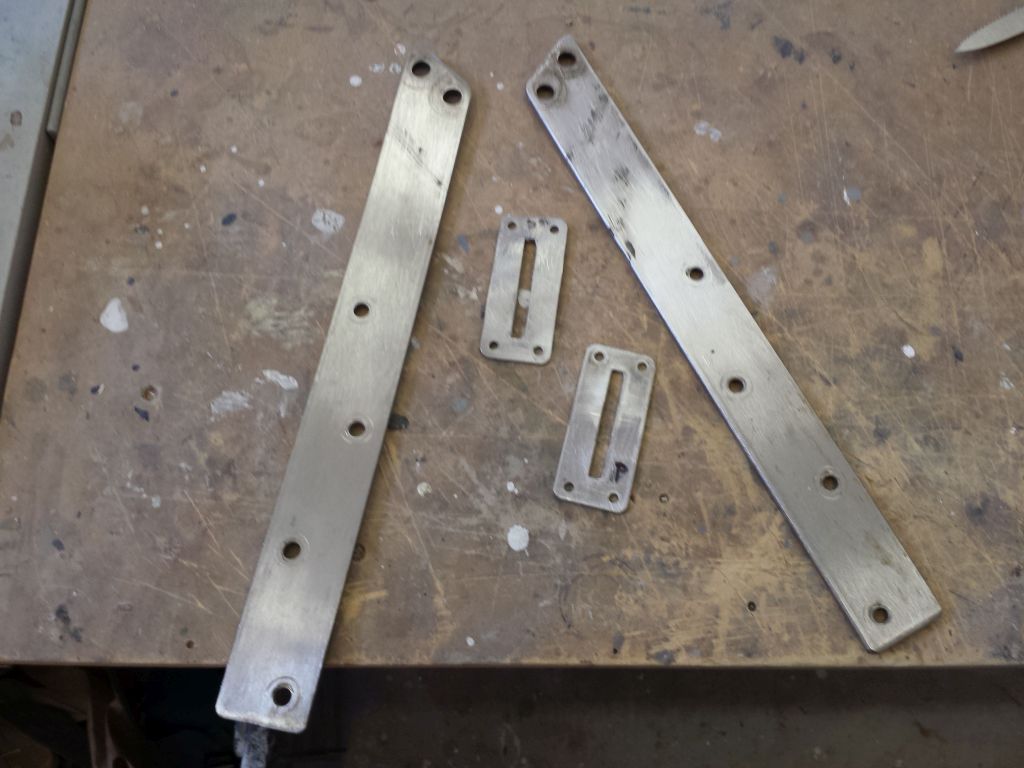
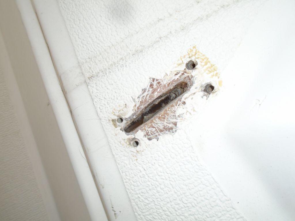
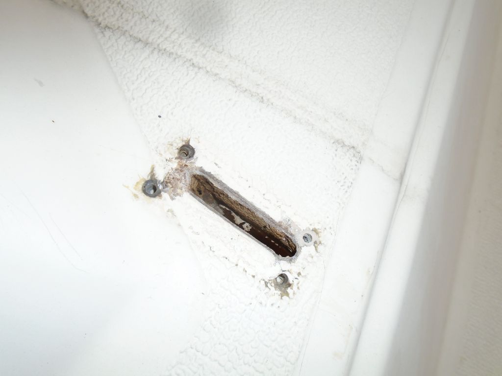
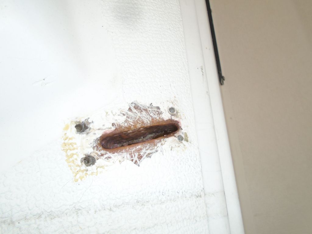
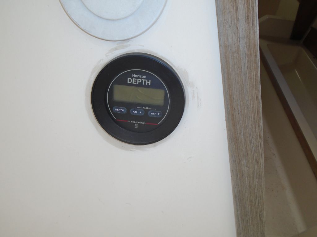
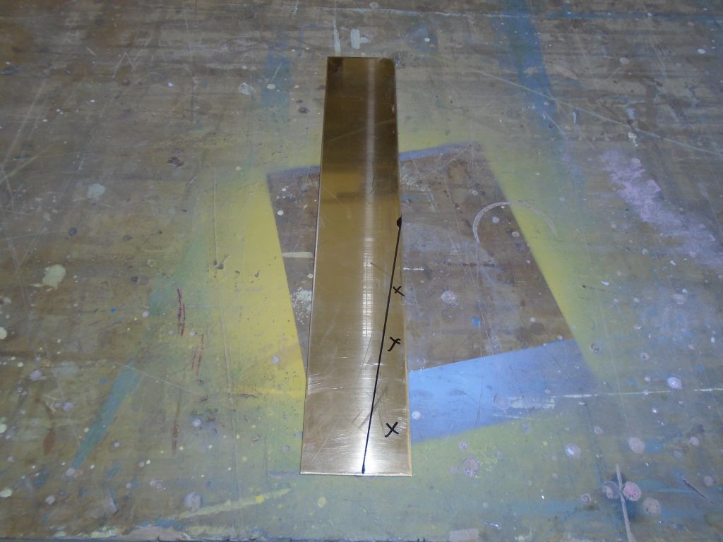
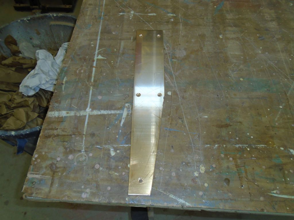
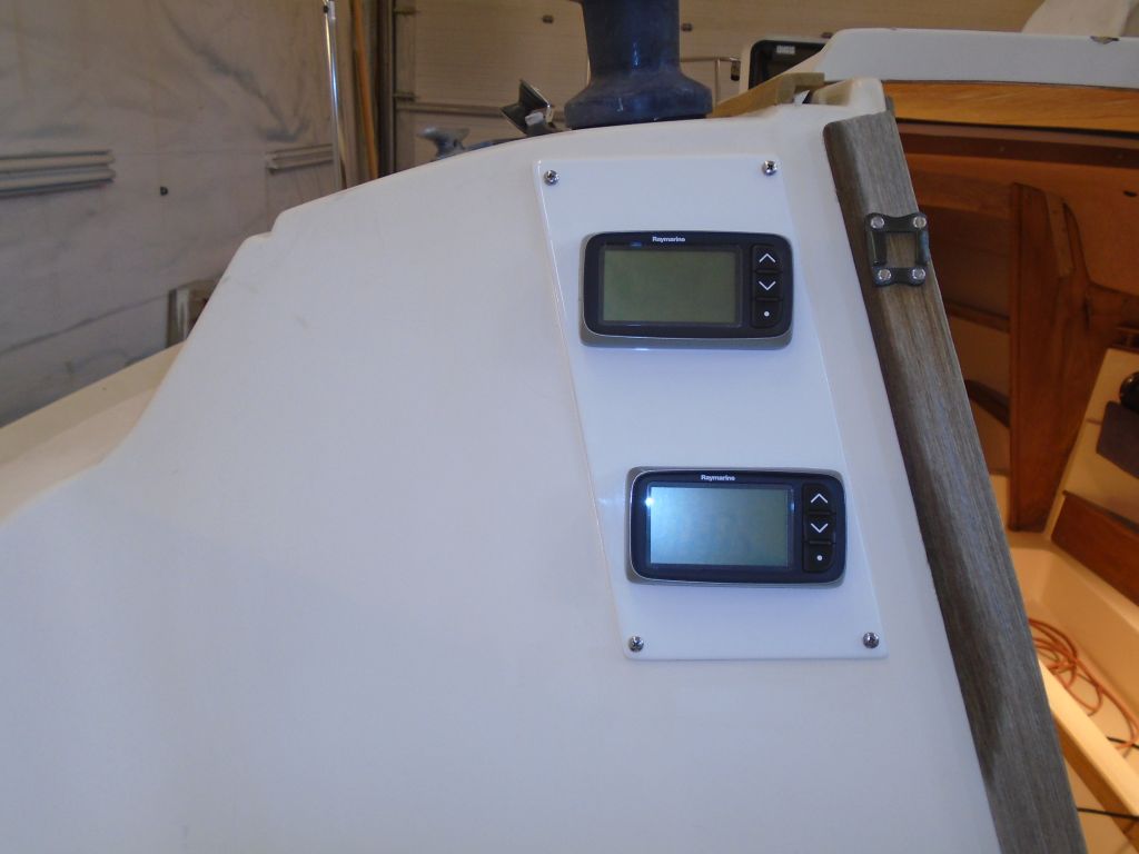
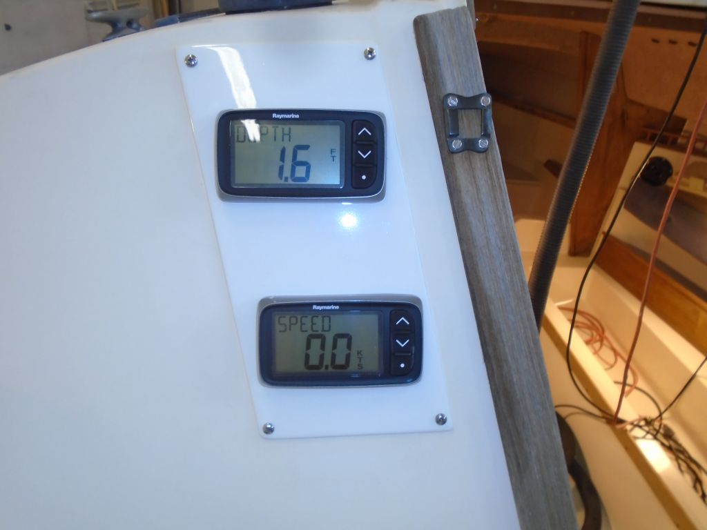
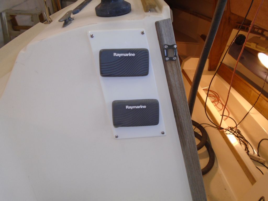
My new cover plate for the instrument installation was complete, the new paint having had several days’ cure time, so I installed it over the old openings with screws and sealant, centering the new instrument holes over the old ones for access within.
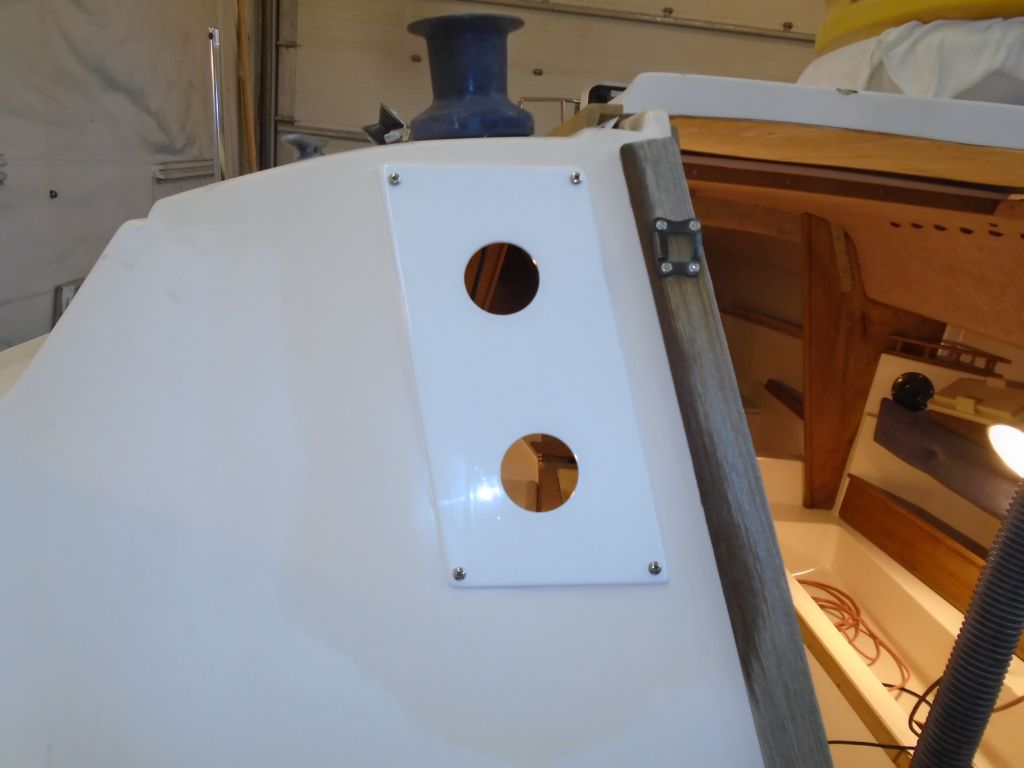
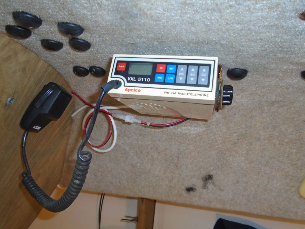
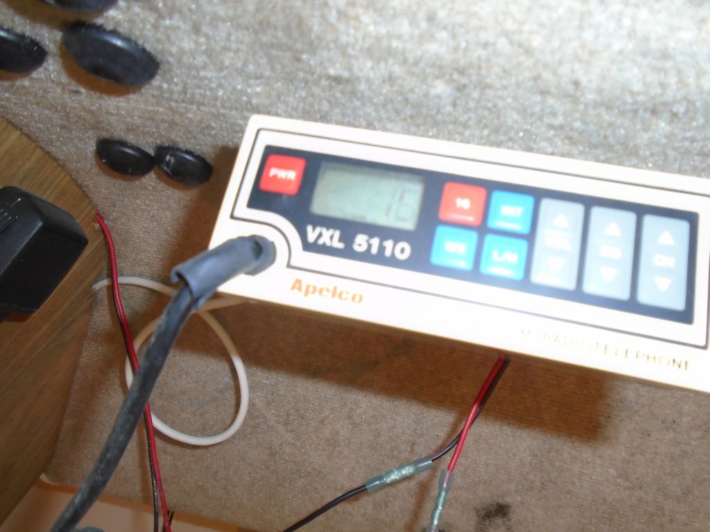
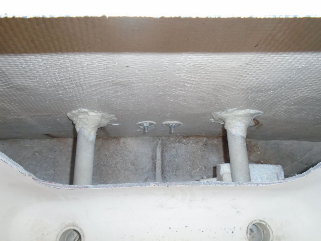
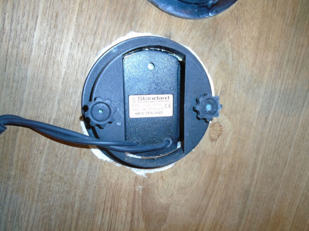
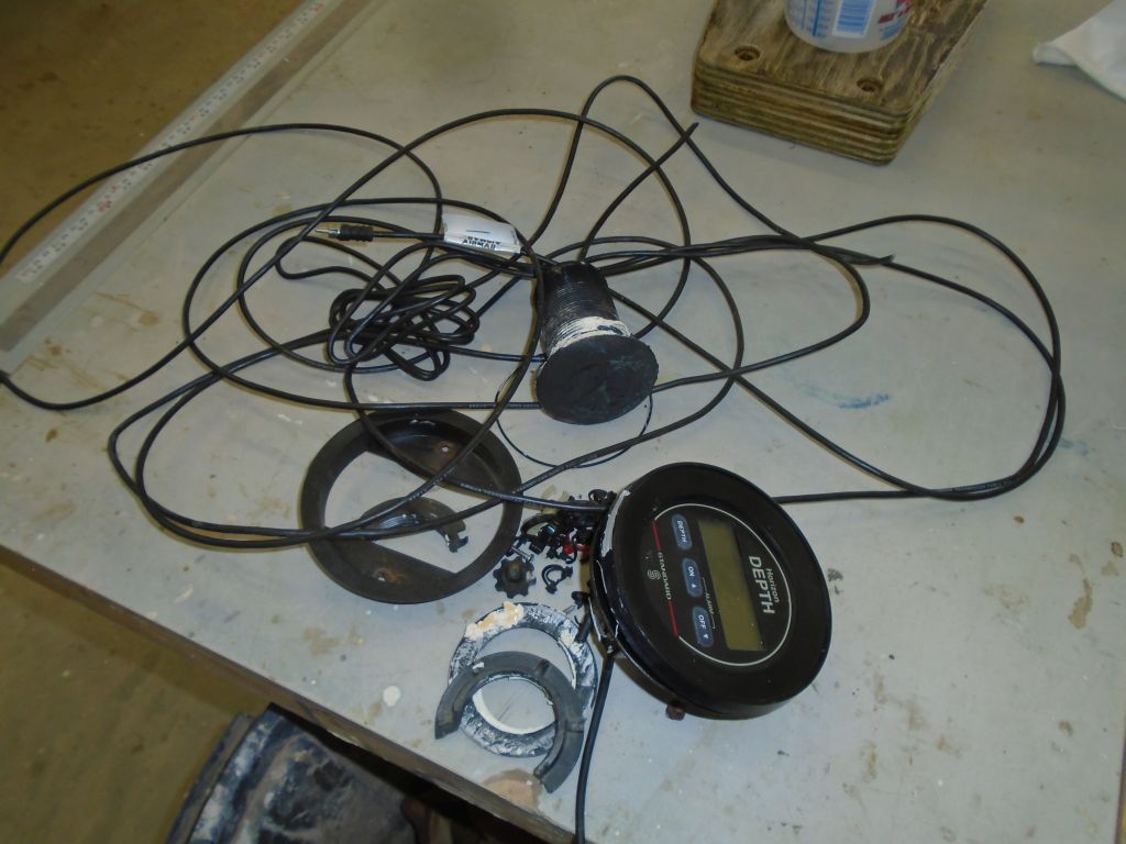
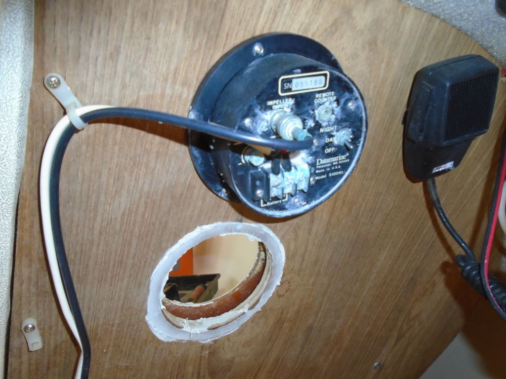
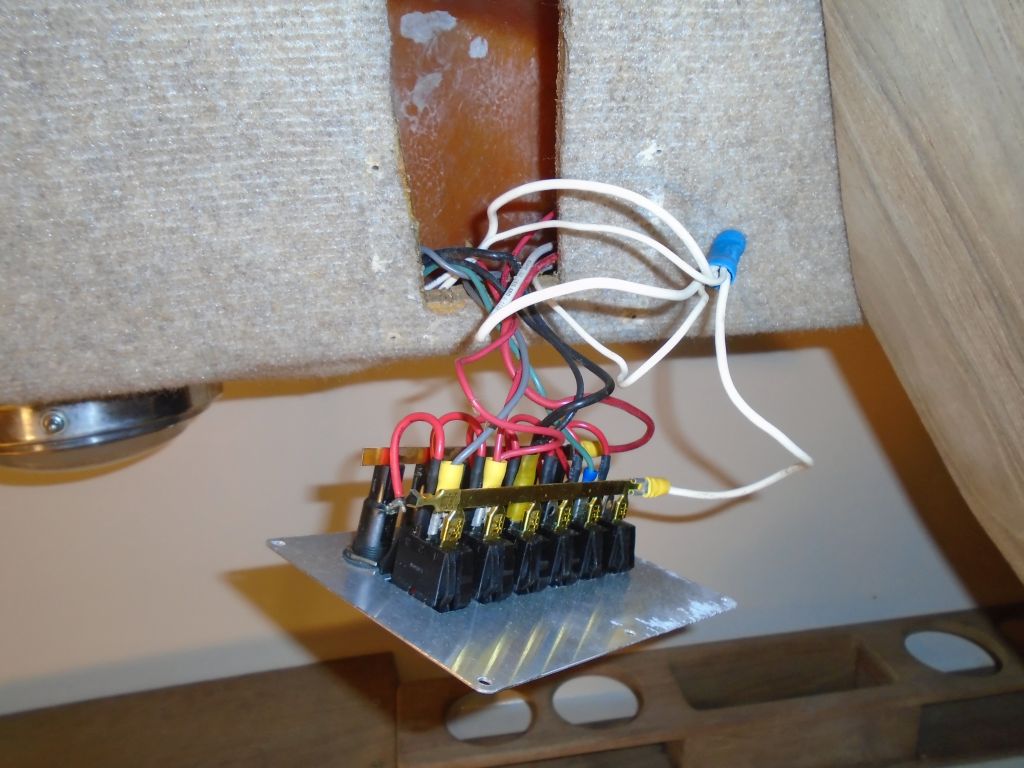
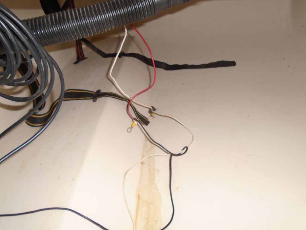
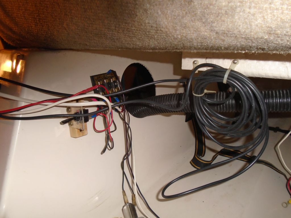
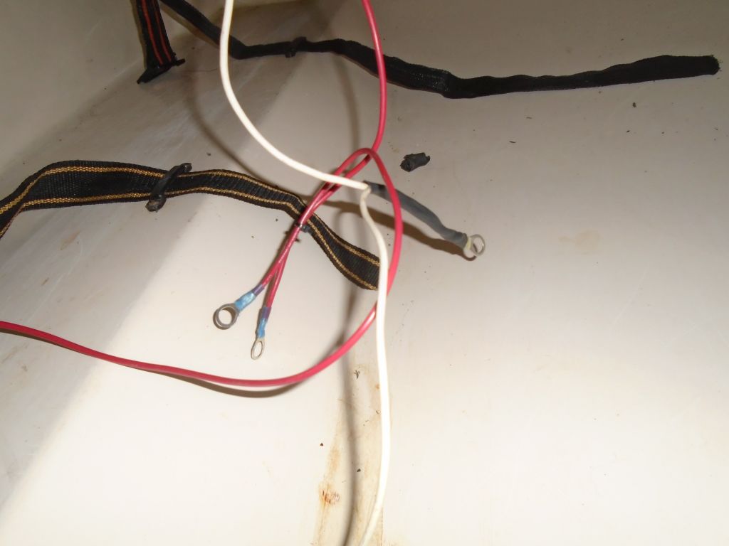
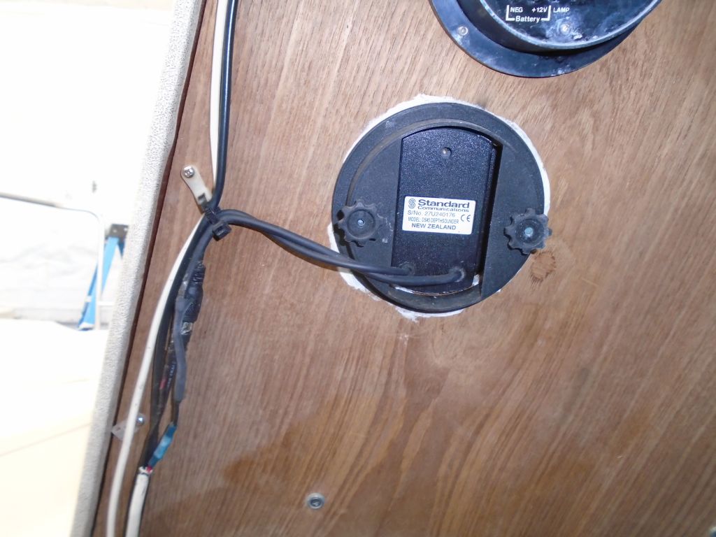
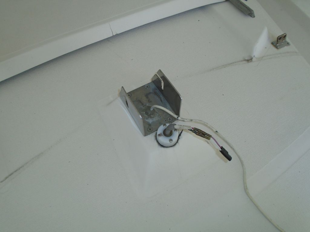
Now I installed the two new instruments, securing them with the supplied clamps from behind, and made up the final wiring connections–power and transducer cables in each case. I found I could run these wires through a space between the fiberglass bulkhead and the wooden interior of the bulkhead for a clean appearance.
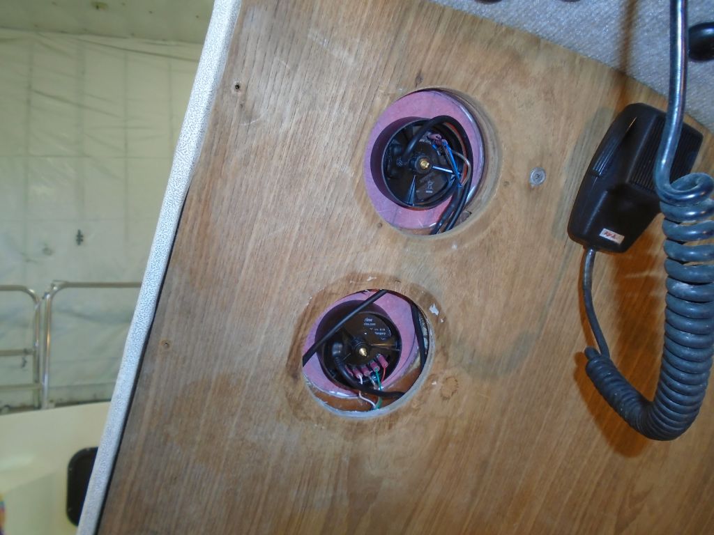
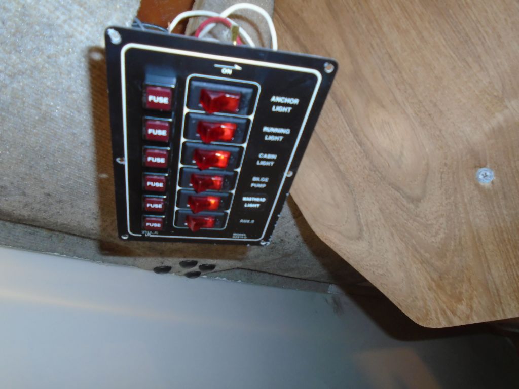
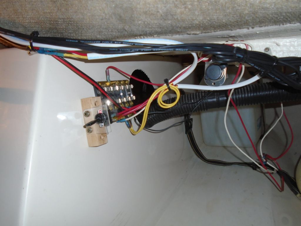
During an earlier wiring session, I’d run wire blanks from the nearby fuse panel for these instruments, and now I made up the final connections and secured the excess transducer cables out of the way beneath the cockpit. The instruments tested operational.
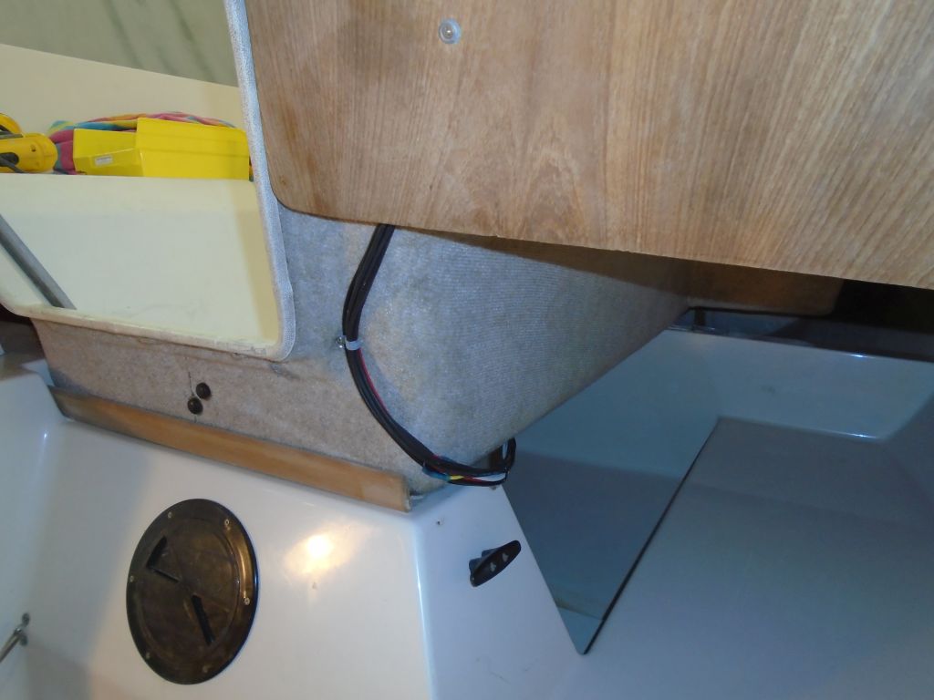
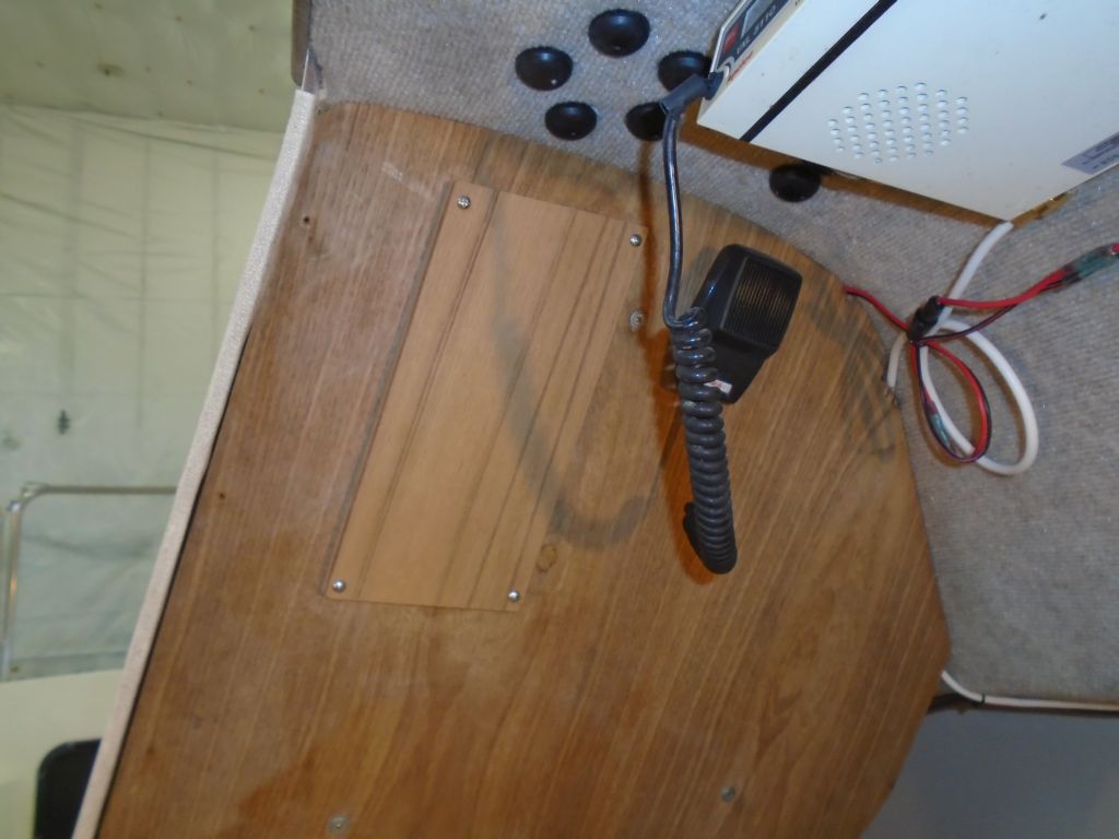
To complete the installation, I installed a teak cover over the interior side of the instruments. I had to build the original plywood cover out slightly to clear the wiring leads at the back of the instruments, but otherwise it was a clean interior appearance with no exposed instrument wires.
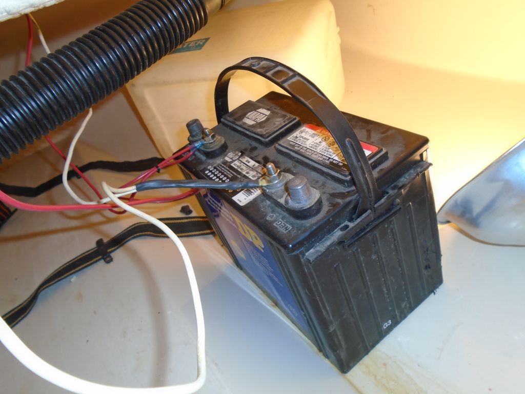
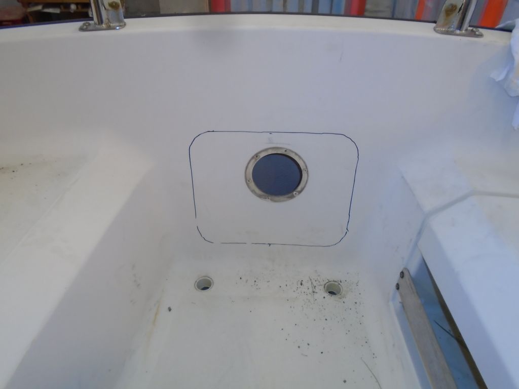
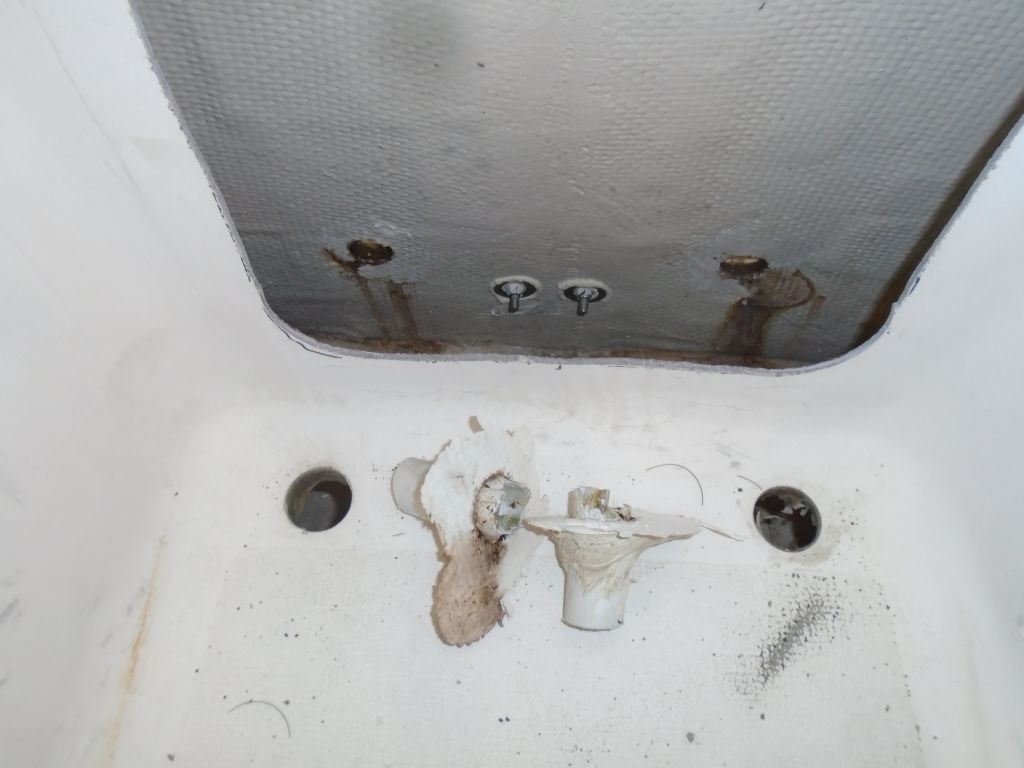
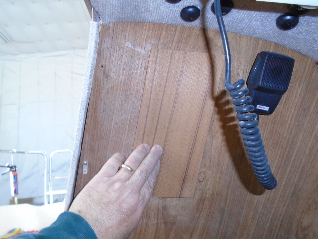
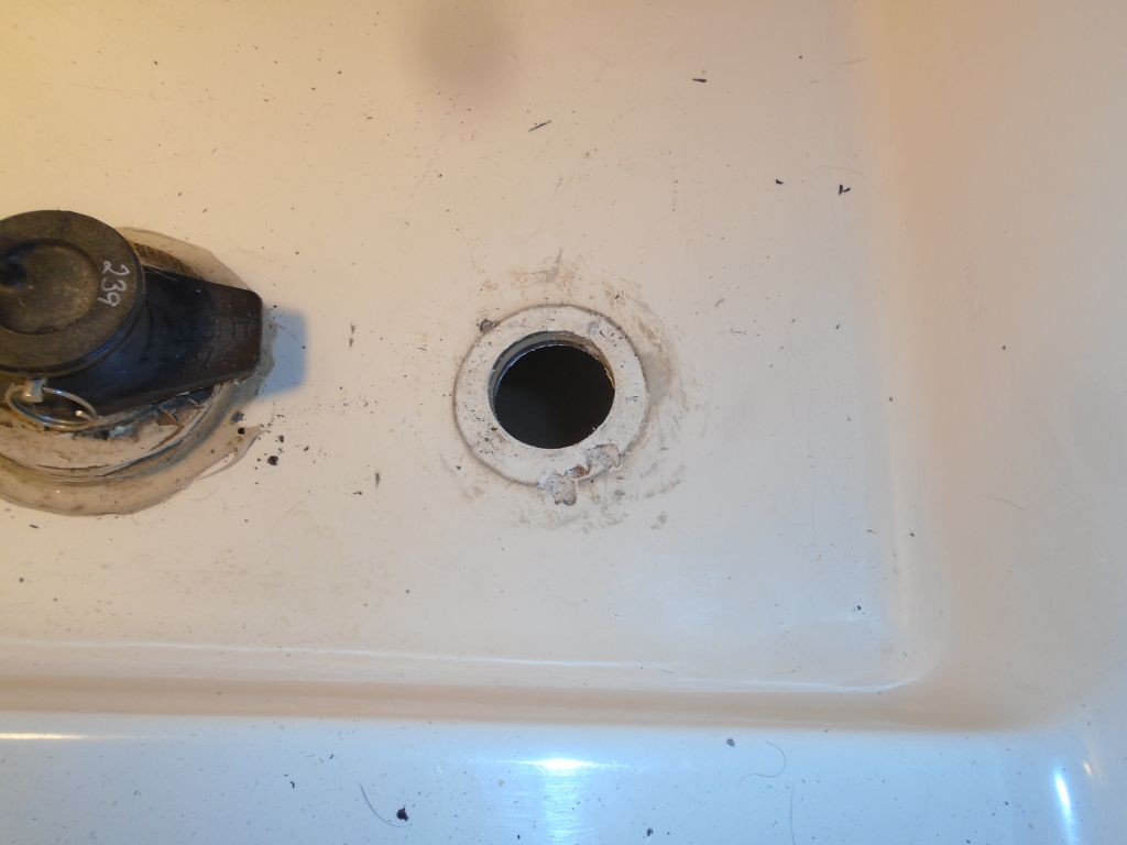
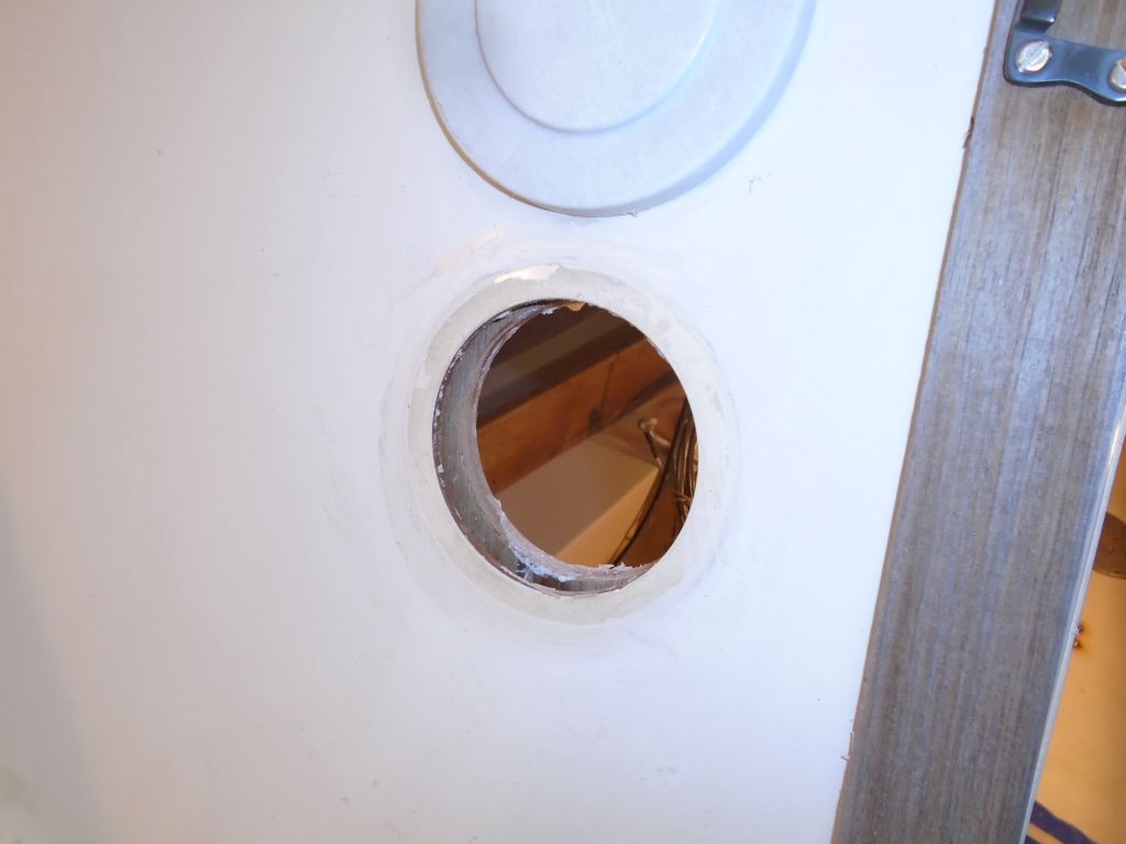
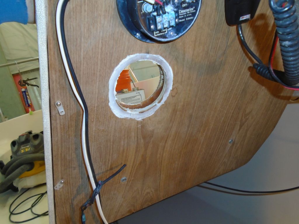
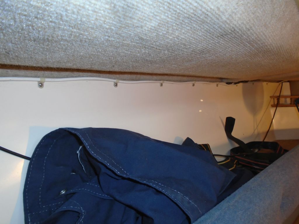
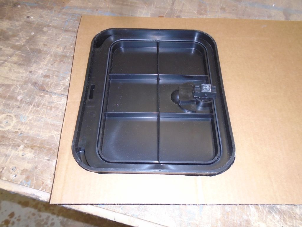
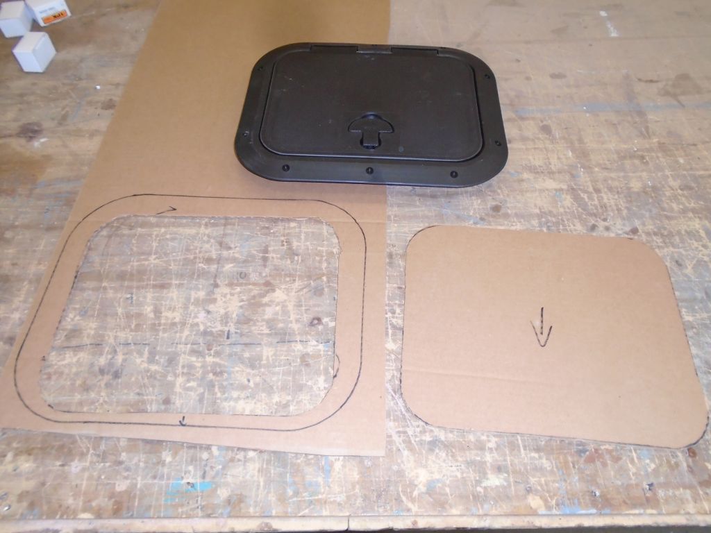
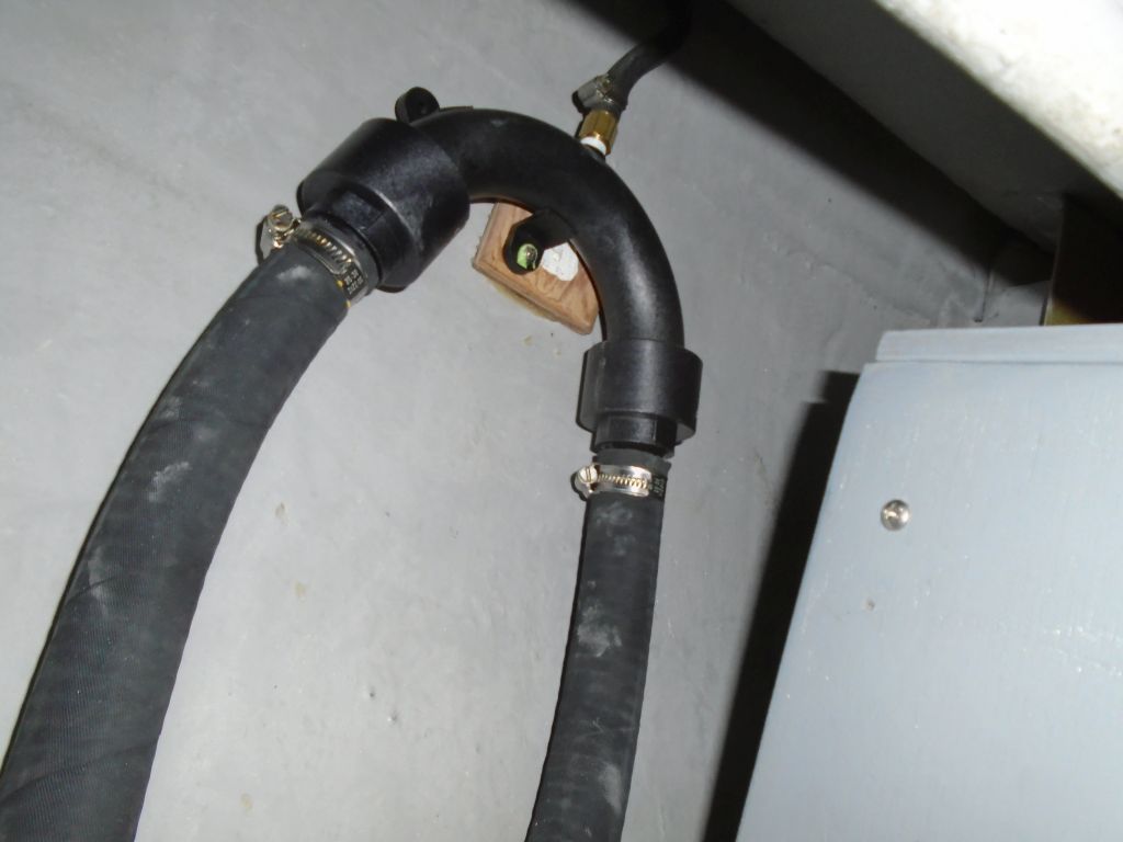
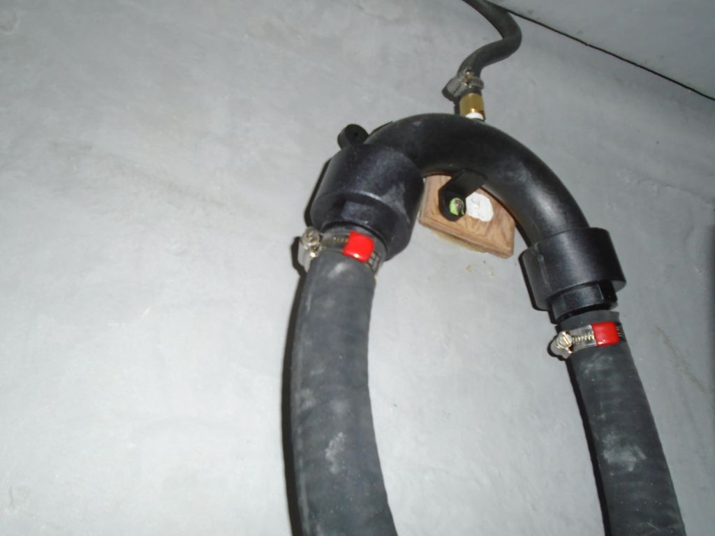
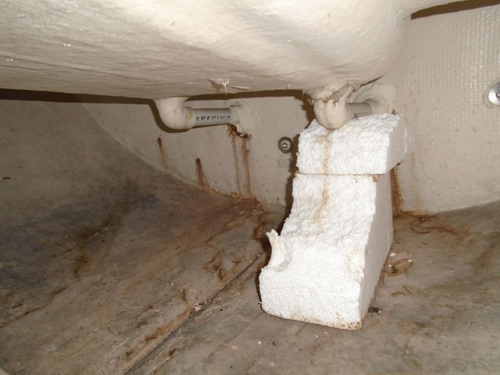
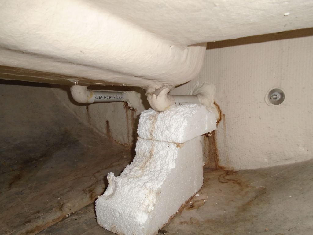
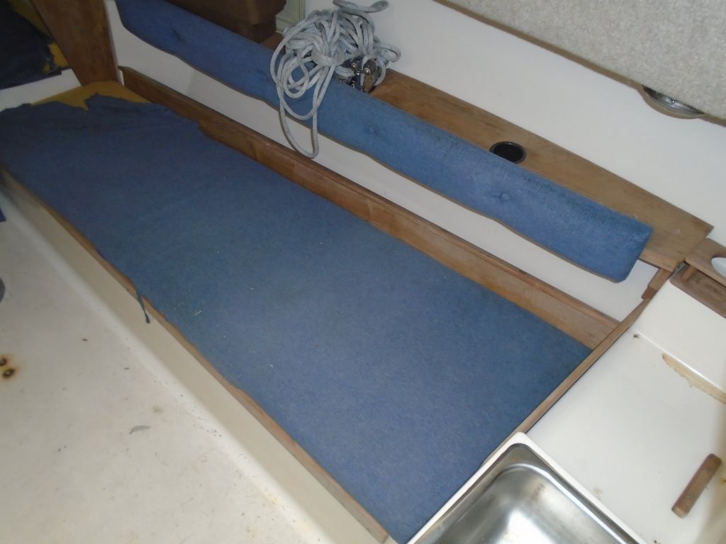
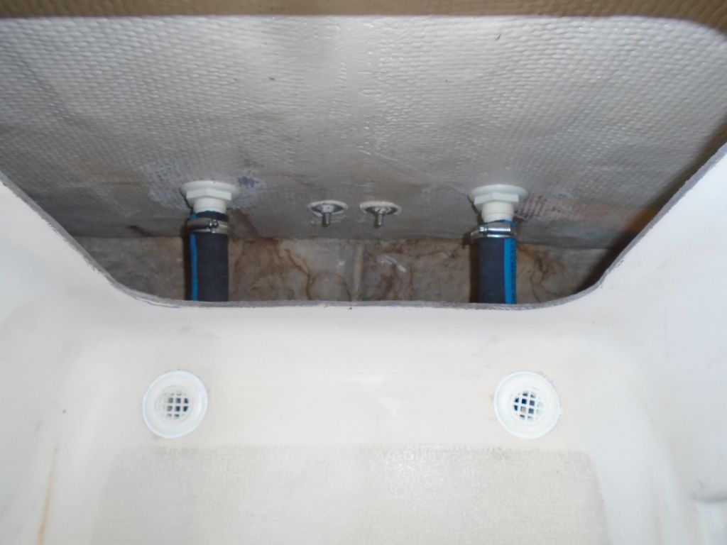
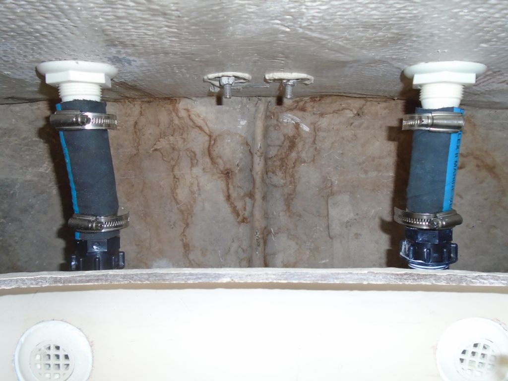
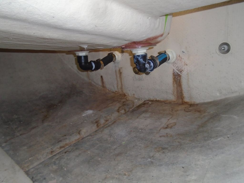
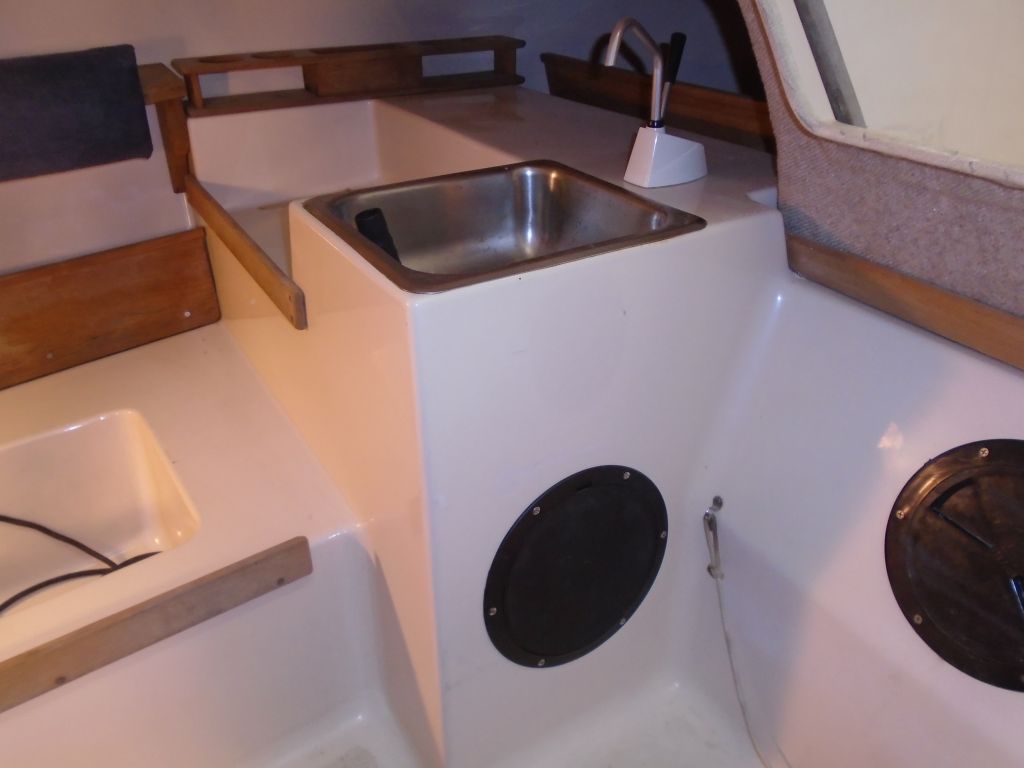
To access the underside of the galley sink and its supply faucet, I had to cut an access hole from the cabin, which I did now that I had the new access port on hand.

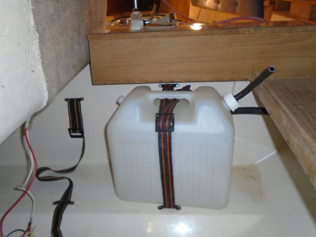
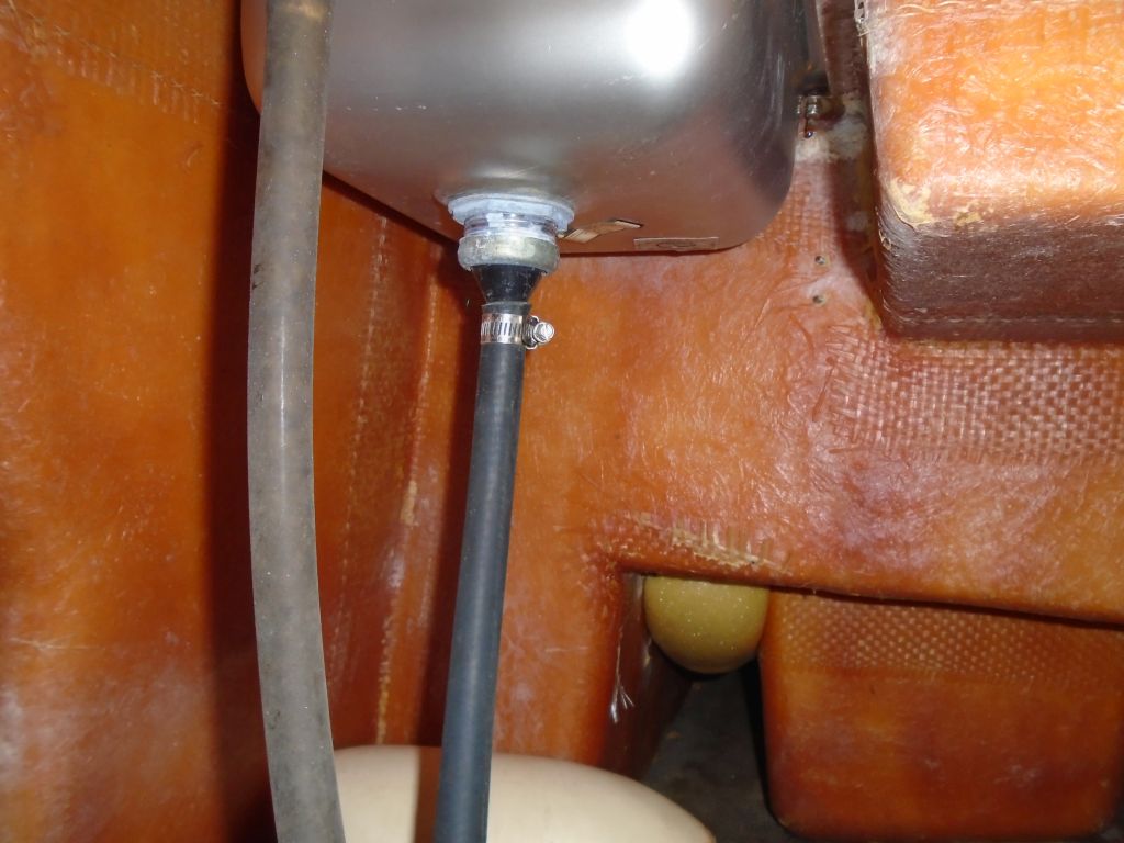
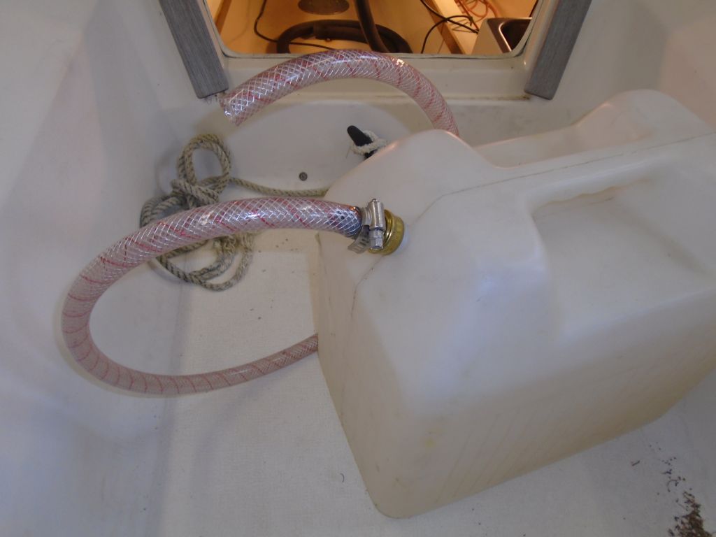
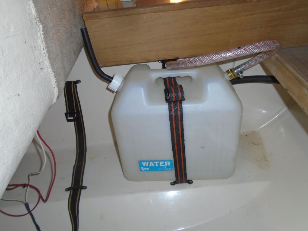
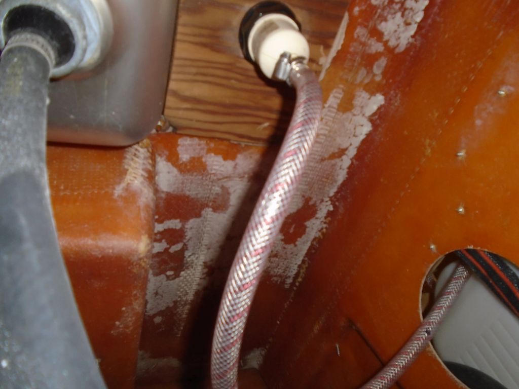
The supply fitting on the portable water tank was broken, and lacked a dip tube/hose to actually draw water from the tank, so I replaced the fitting with a new one that I luckily happened to have on hand, and fitted in a flexible dip tube to the bottom of the tank. Then, I led a new supply hose between the tank and the sink faucet, and, to wrap up the work, installed the new plastic inspection port in the opening beneath the sink.
Total time billed on this job today: 5.75 hours
0600 Weather Observation:
41°, clouds and showers. Forecast for the day: showers and rain, 40s