Monday
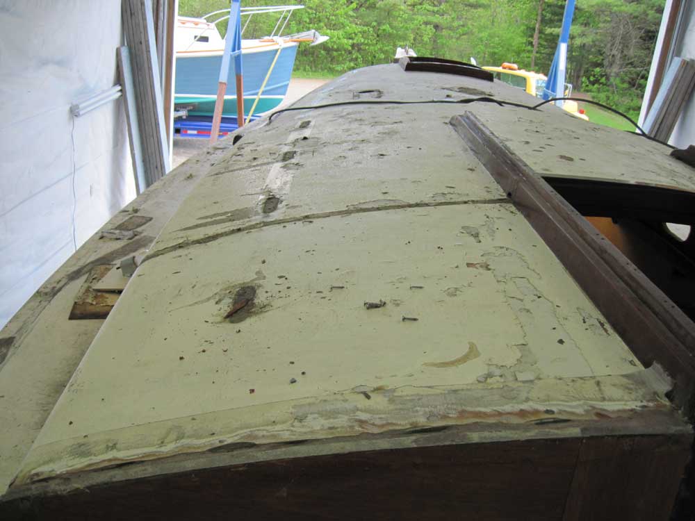
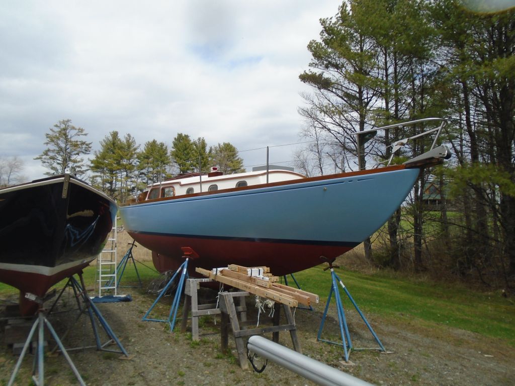
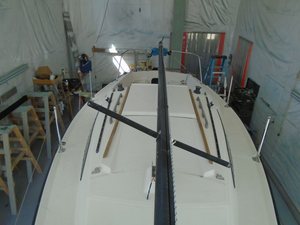
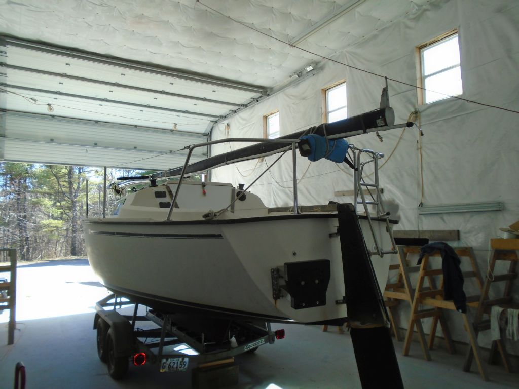
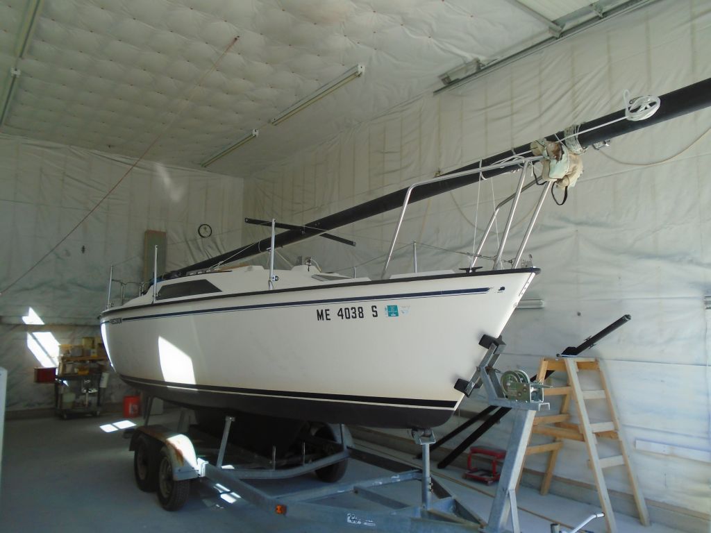
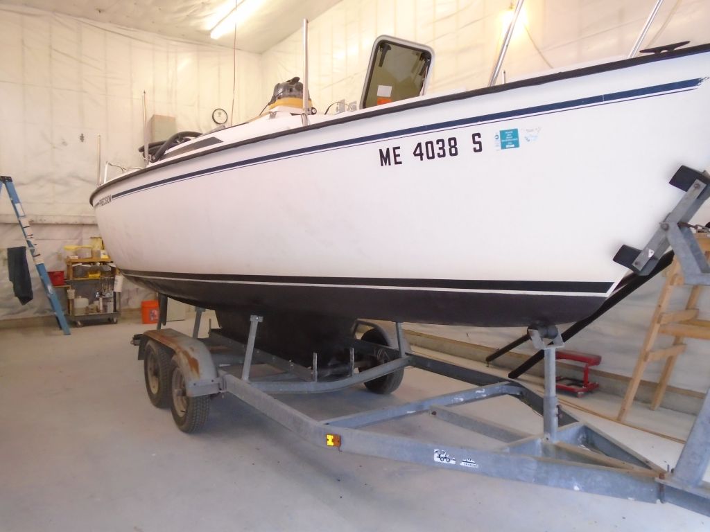
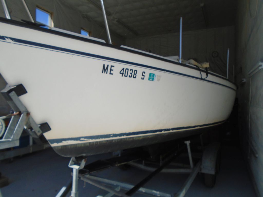
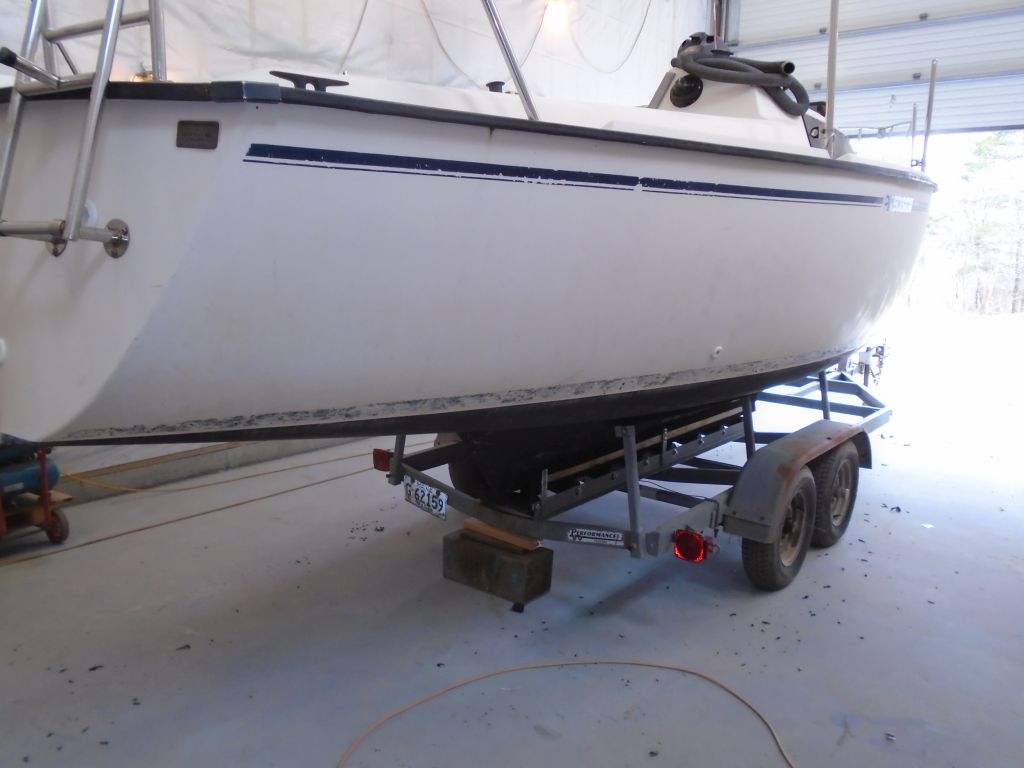
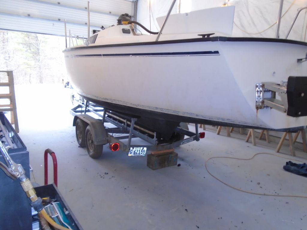
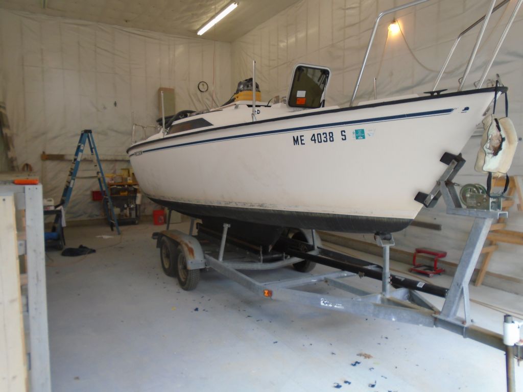
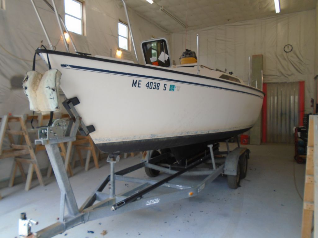
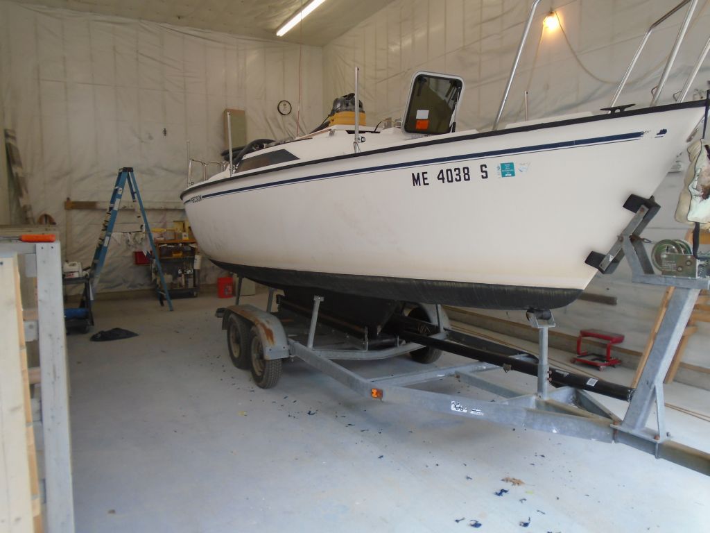
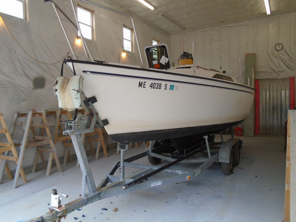
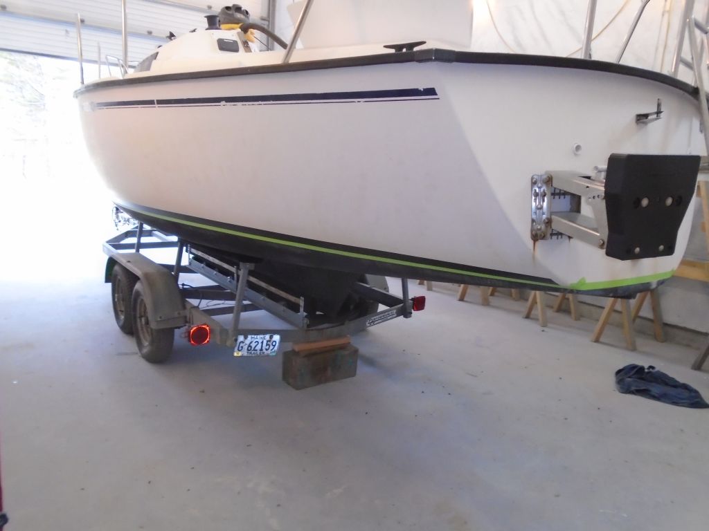
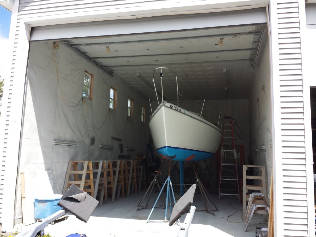
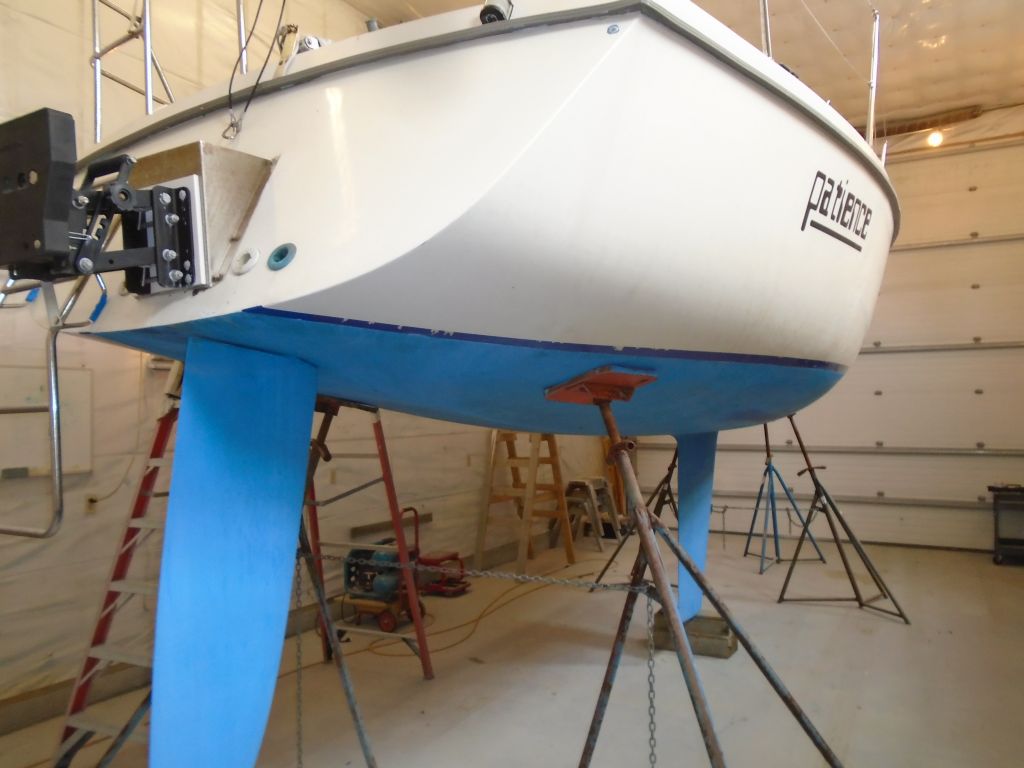
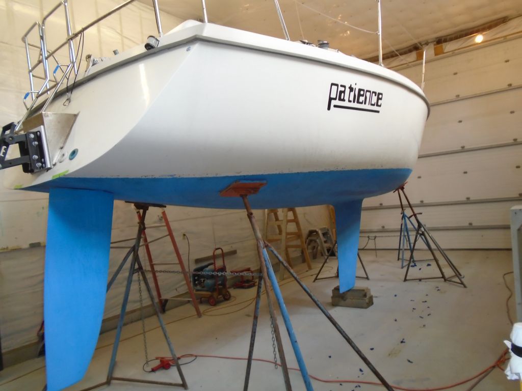
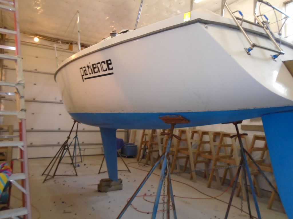
Patience was back for another round of small-ish maintenance and upgrade projects. To begin, I’d moved the boat indoors a few days earlier.
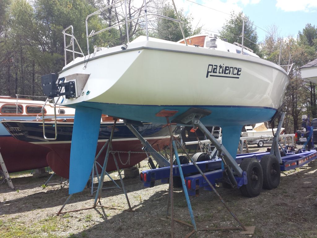
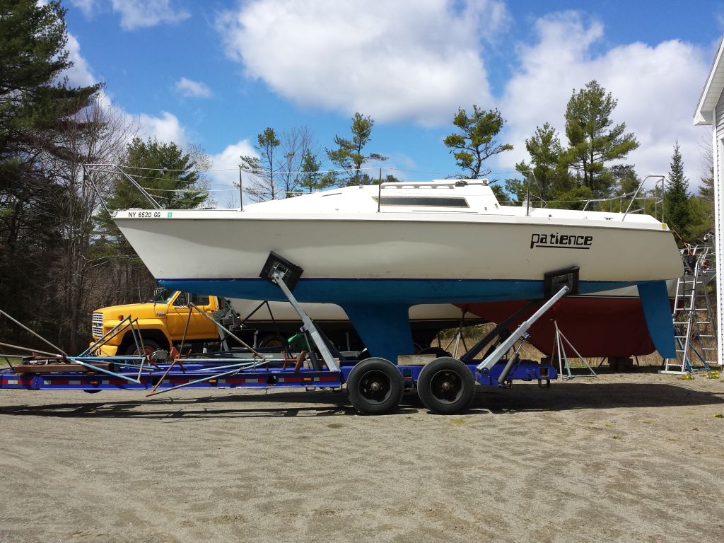
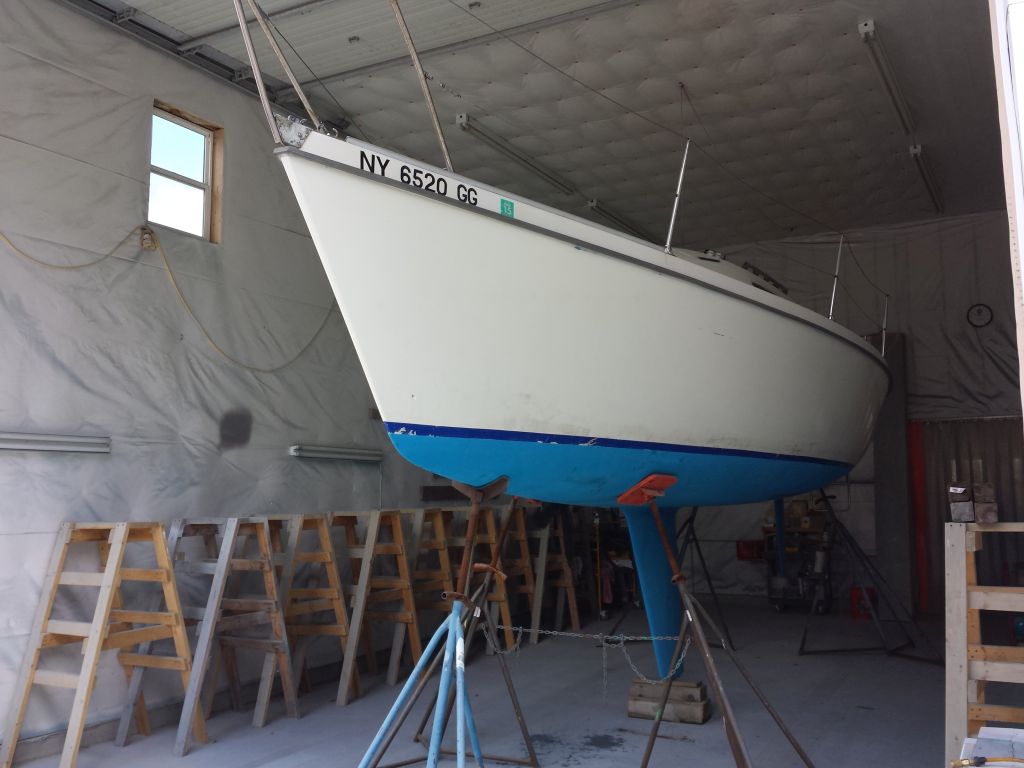

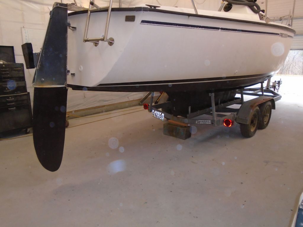
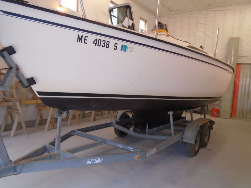
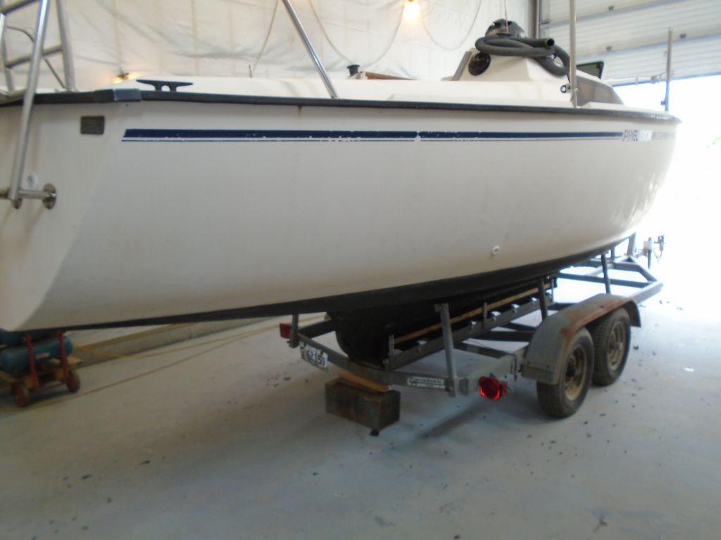
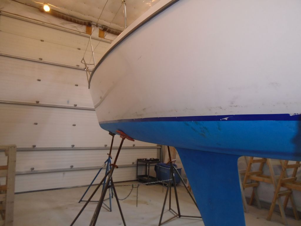
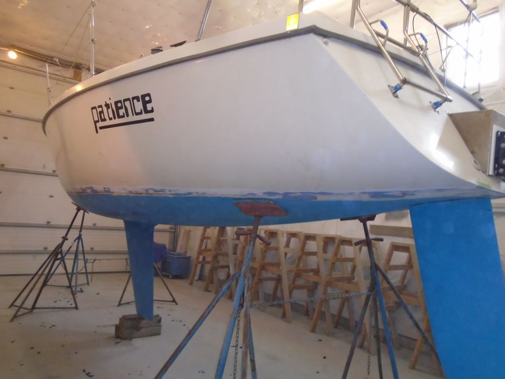
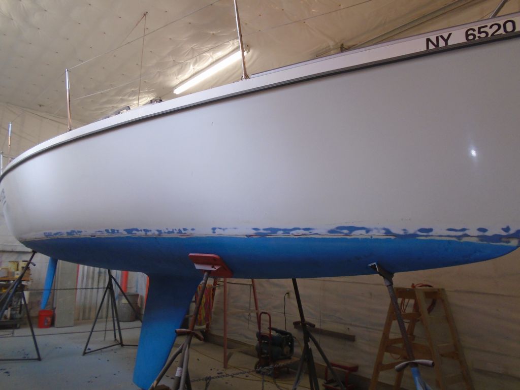
With a short laundry list of jobs on the work list, including replacing some deck hardware, replacing the cabin sole, and patching an old through hull, I decided to start with arguably the most significant project: a new boottop and striping arrangement. The existing boottop was a length of 2″ vinyl tape just above the waterline, and was in poor condition. Additionally, the waterline was rather oddly arranged at the aft end, and I hoped to redo it more accurately.
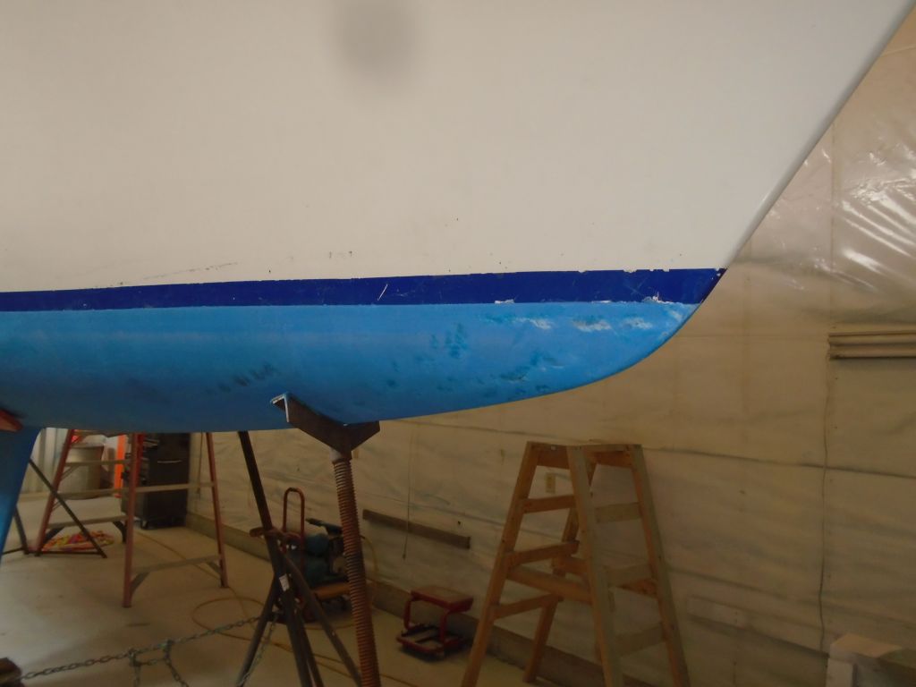
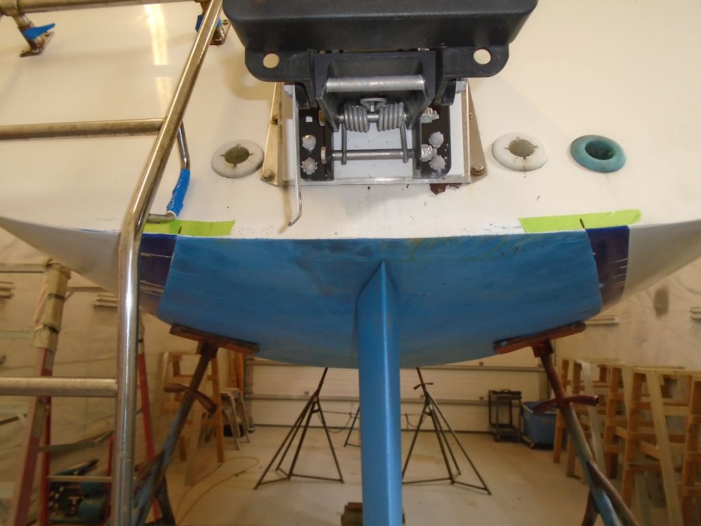
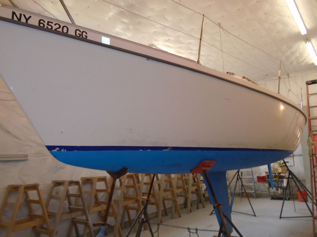


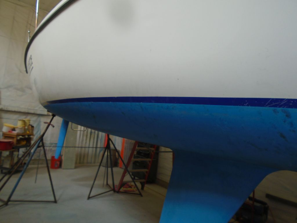
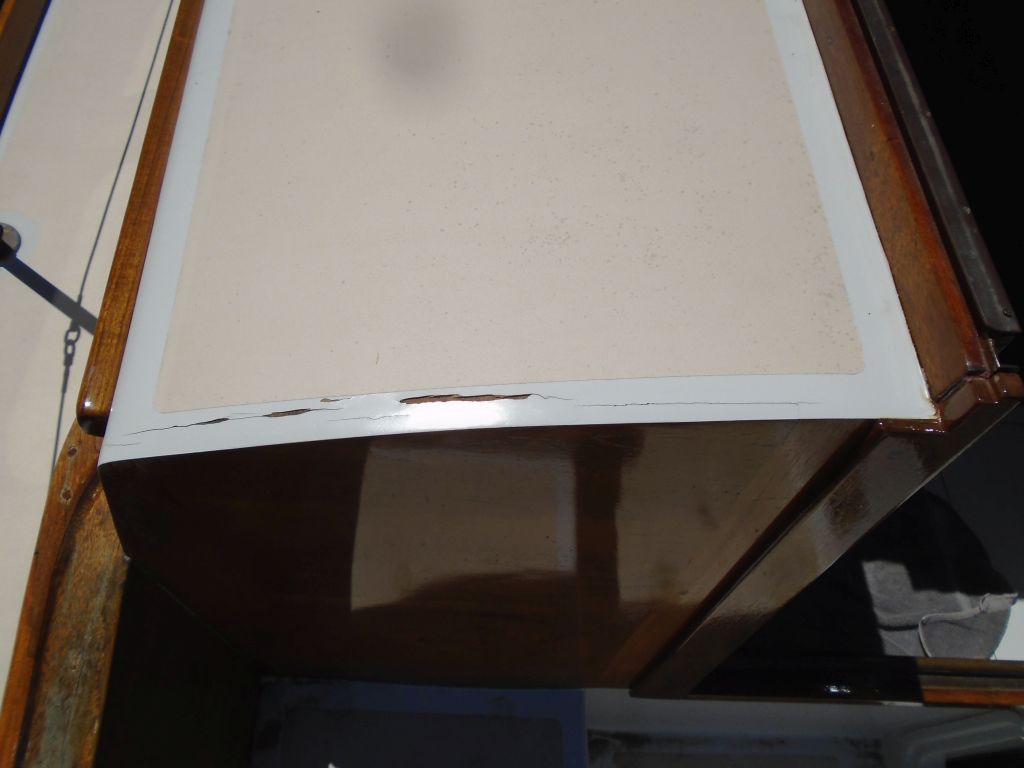
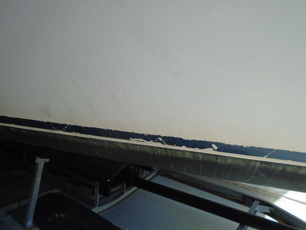
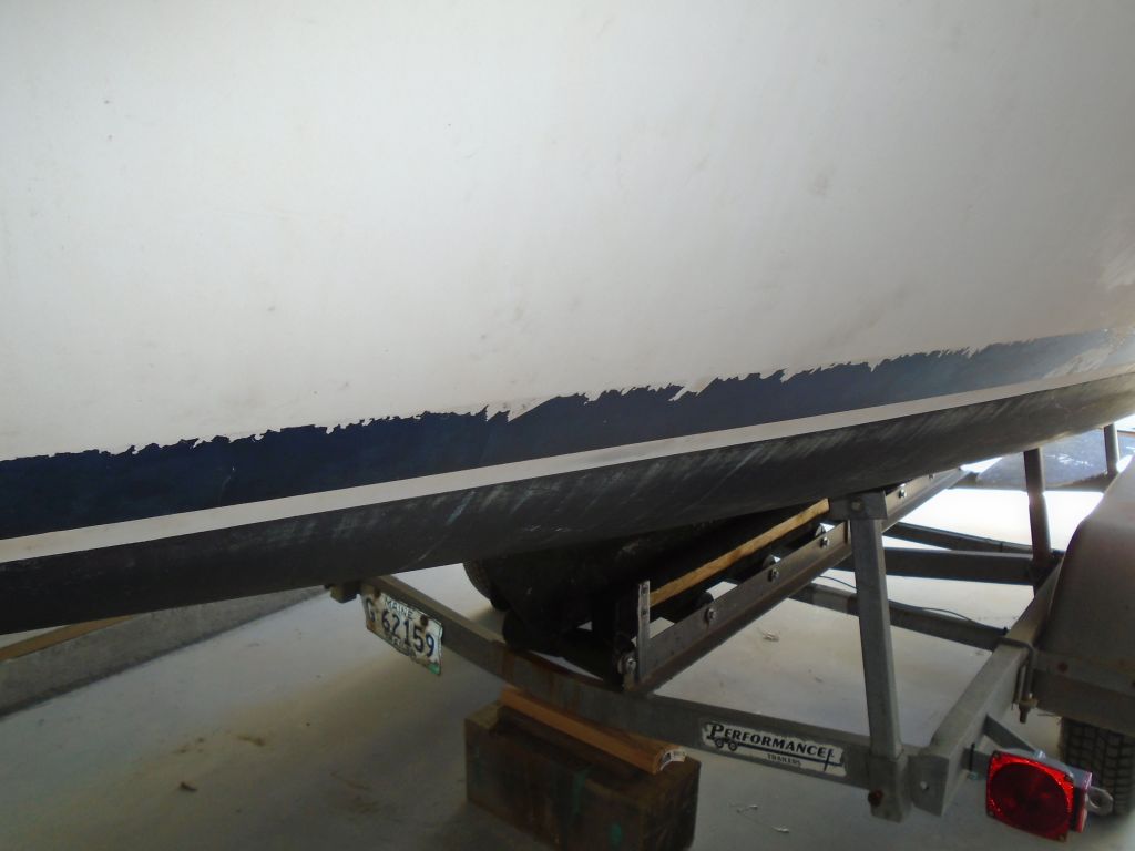
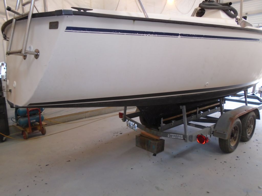
A light scum line indicated the actual waterline, which over most of the boat looked to be mostly in a good position about 2″ below the top of the antifouling paint, so I made a couple reference marks for future reference. Then, I removed the old vinyl with a heat gun; the old material was scarred and scratched, and didn’t pull off cleanly.
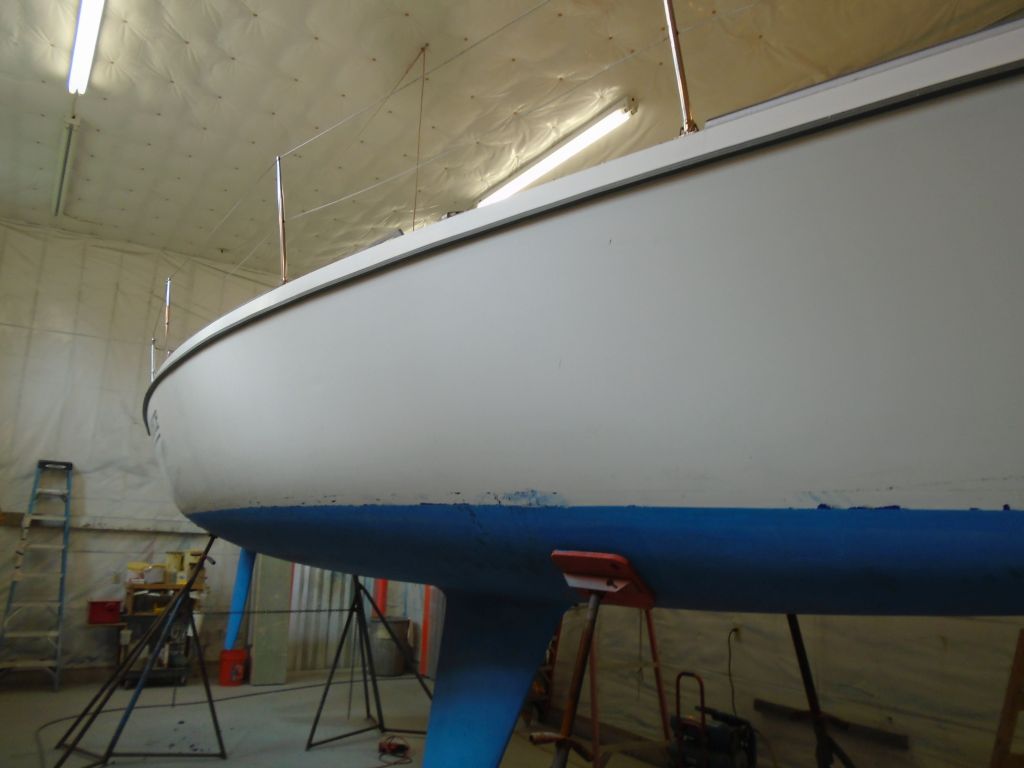
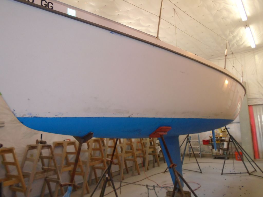
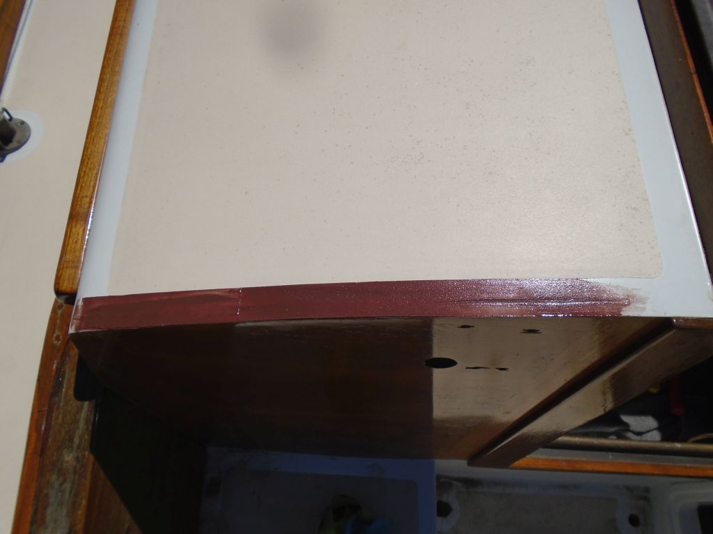
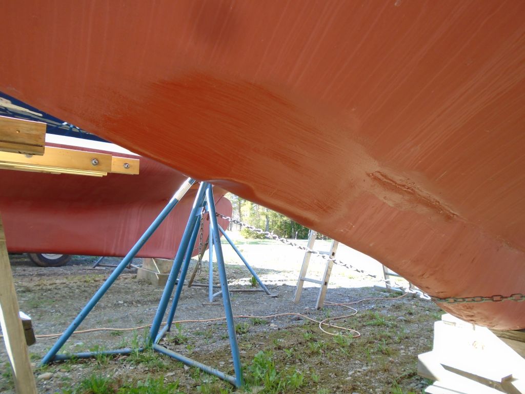
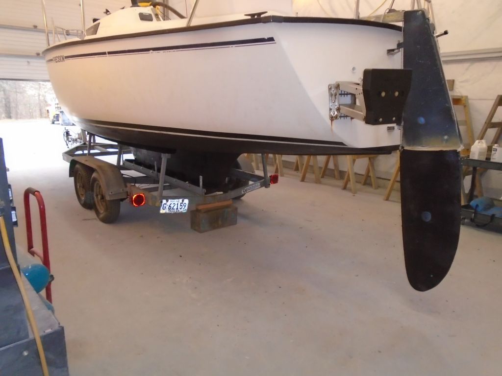
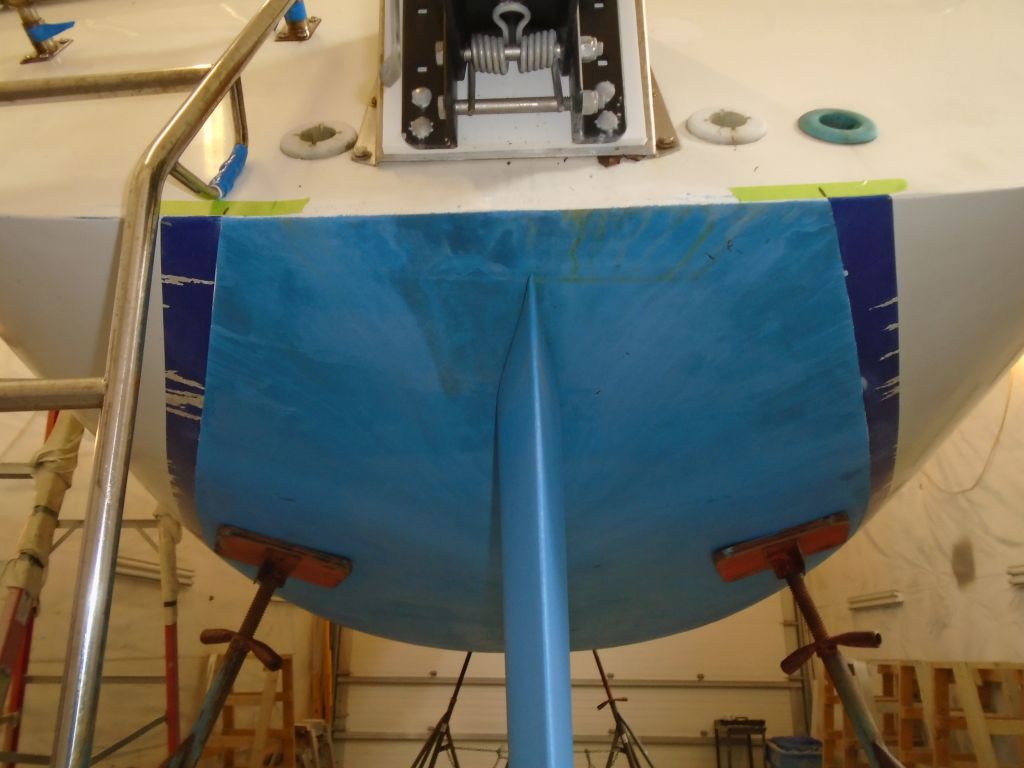
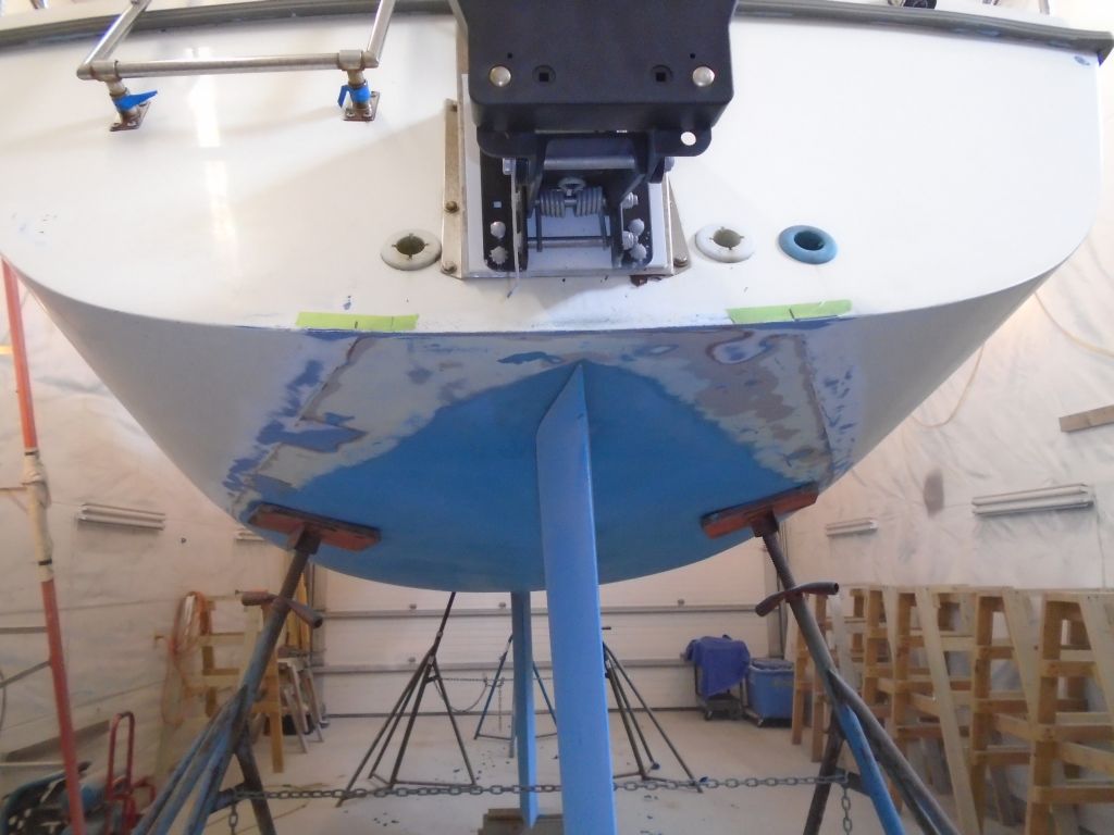
The new plan called for a double stripe in two colors and spaced a bit above the top of the bottom paint, and with the condition of the paint and the position of the existing line at the aft I’d have to repaint that lower band in the hull color anyway (white), so to remove the rest of the adhesive I used a sander, cleaning off the remnants and preparing the lower part of the stripe area for new layout and paint. I also sanded down into the antifouling a bit to clean up that edge and give me a good taping area, and more substantially at the stern quarters where I thought the new lines might take rather a different path.
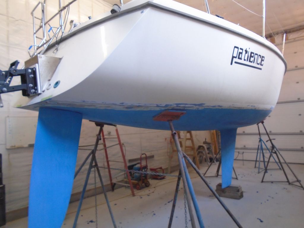

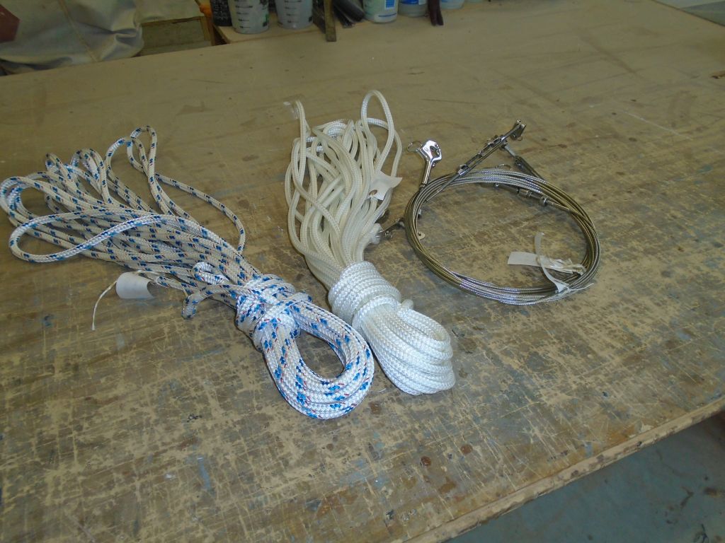
There’d be more sanding ahead as I started the layout for the new striping, which would take the top edge further up the hull than the original stripe (or my sanding line), but I’d get to that in due course and as needed. Meanwhile, I ordered various materials and hardware for the work ahead.
Total time billed on this job today: 4 hours
0600 Weather Observation:
40°, windy, cloudy. Forecast for the day: Mostly cloudy, windy, maybe a shower, high around 50