Side Project: Companionway Sea Hood. Total Project Time: 24.5 hours
9/26/16 (1 hour)
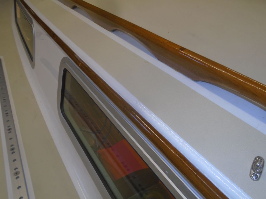
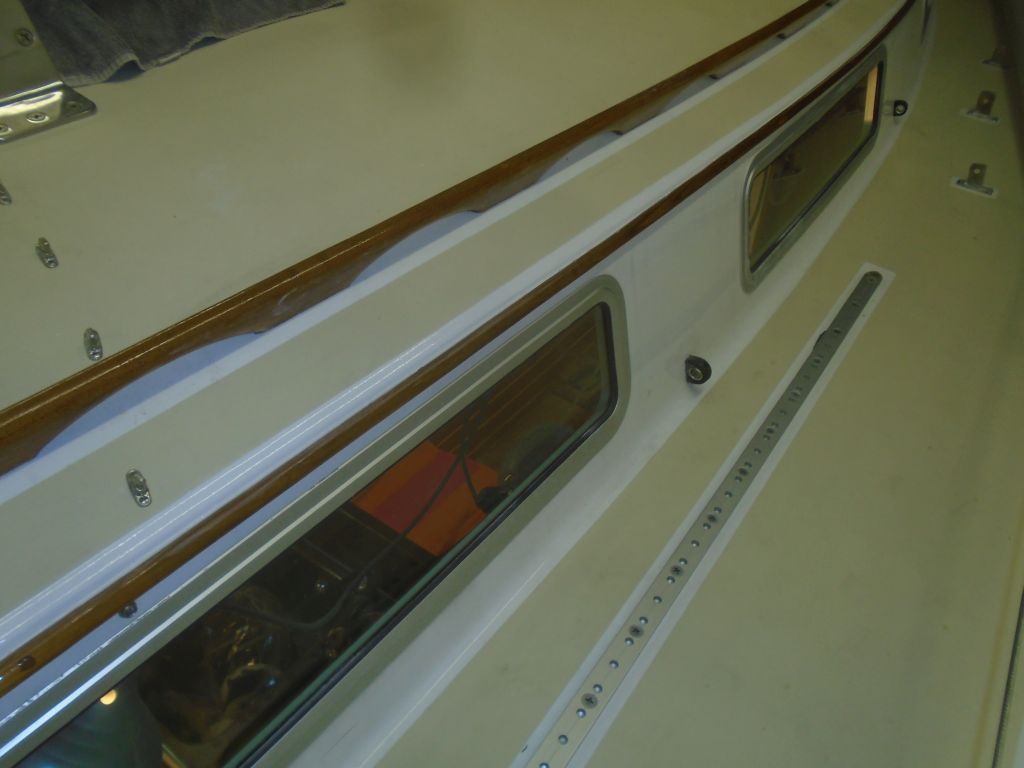
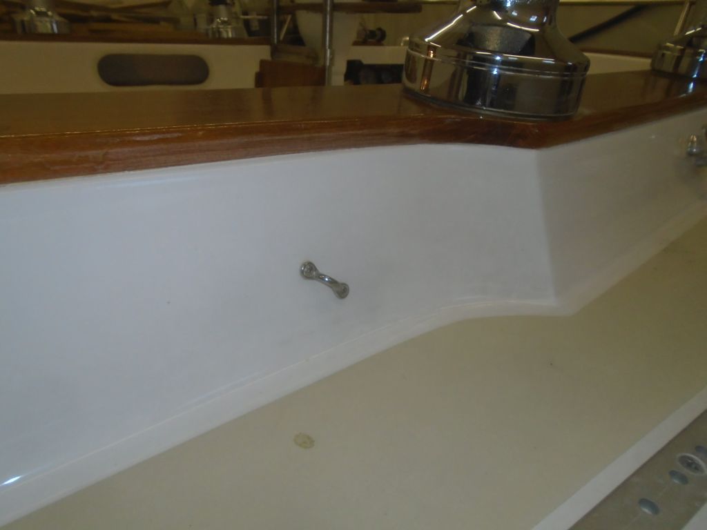
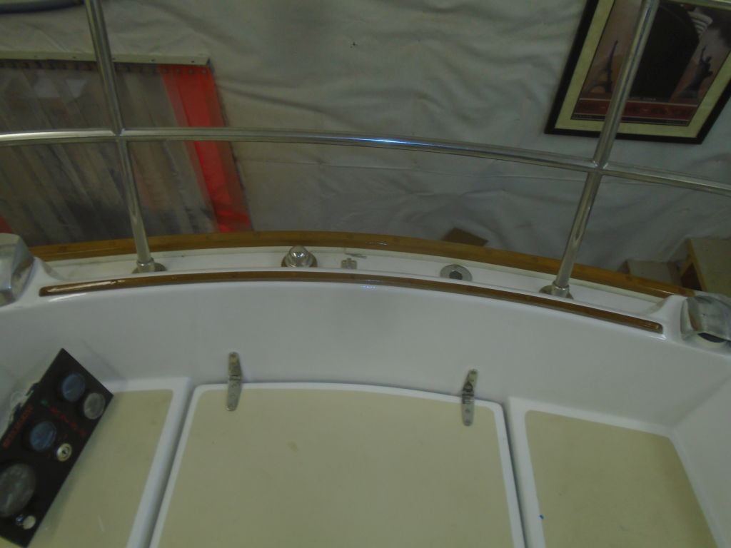
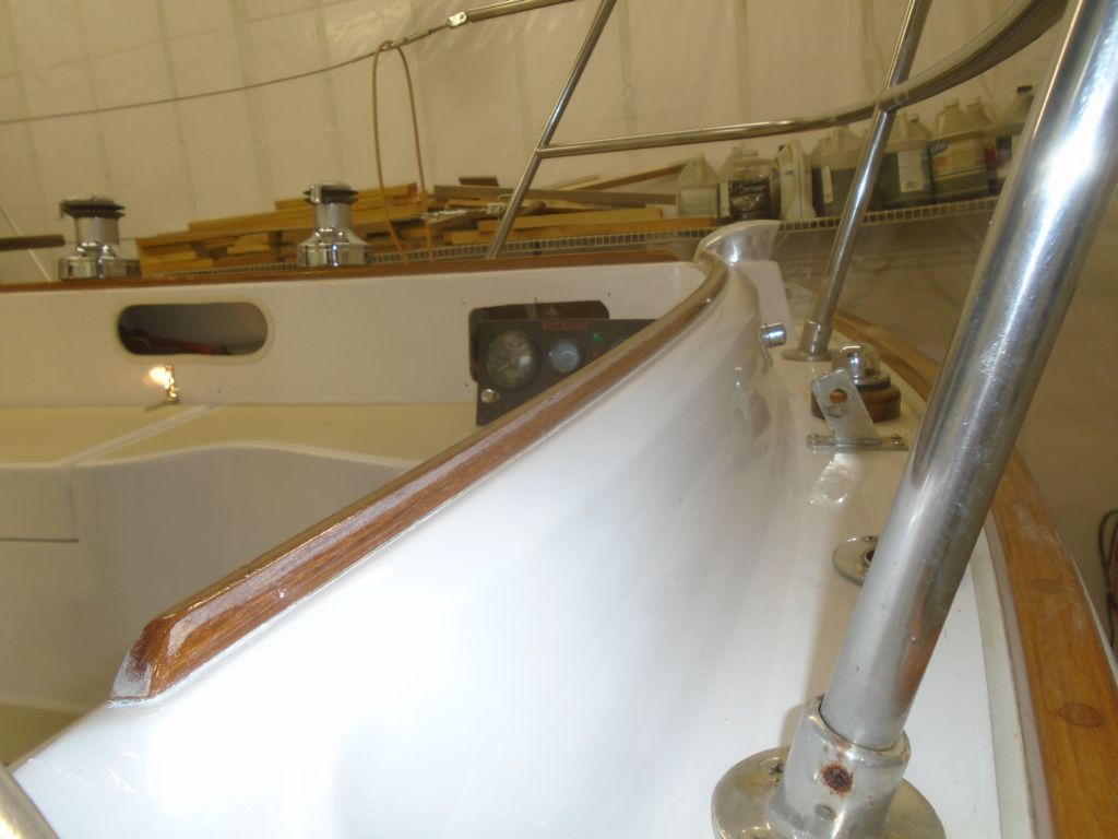
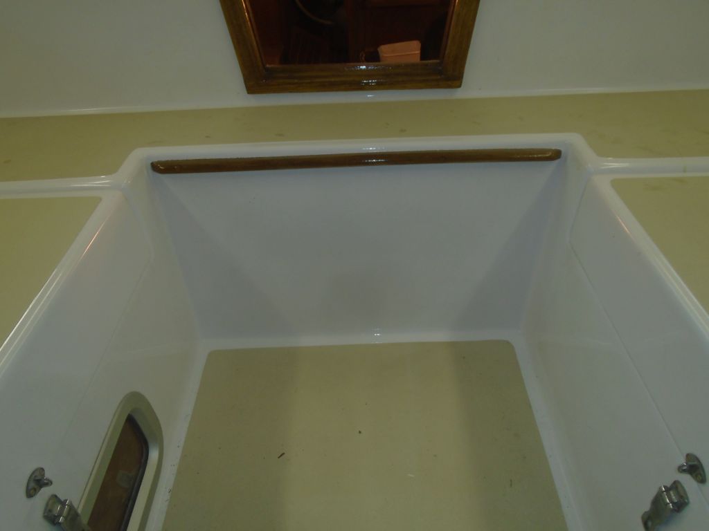
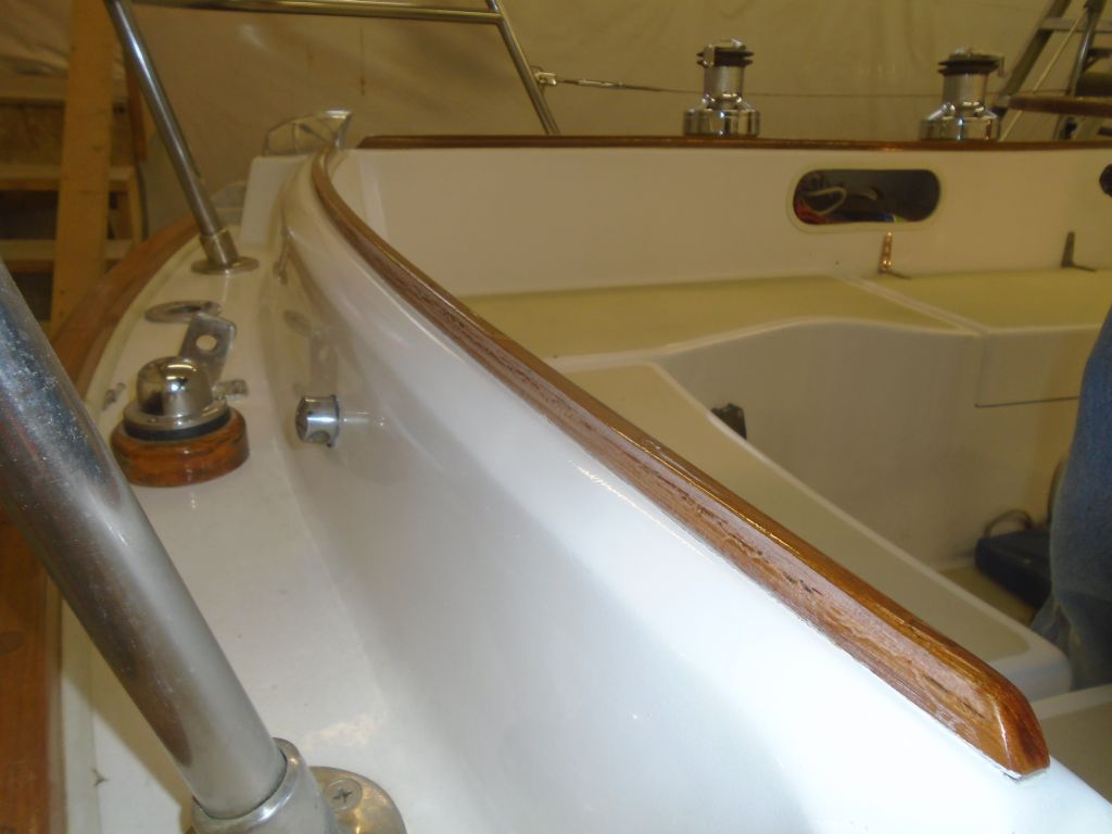
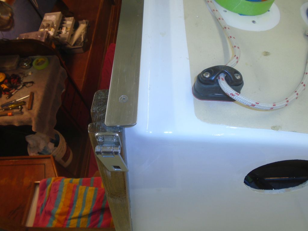
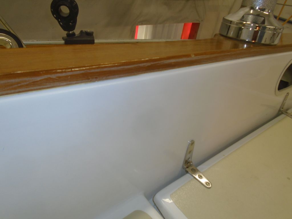
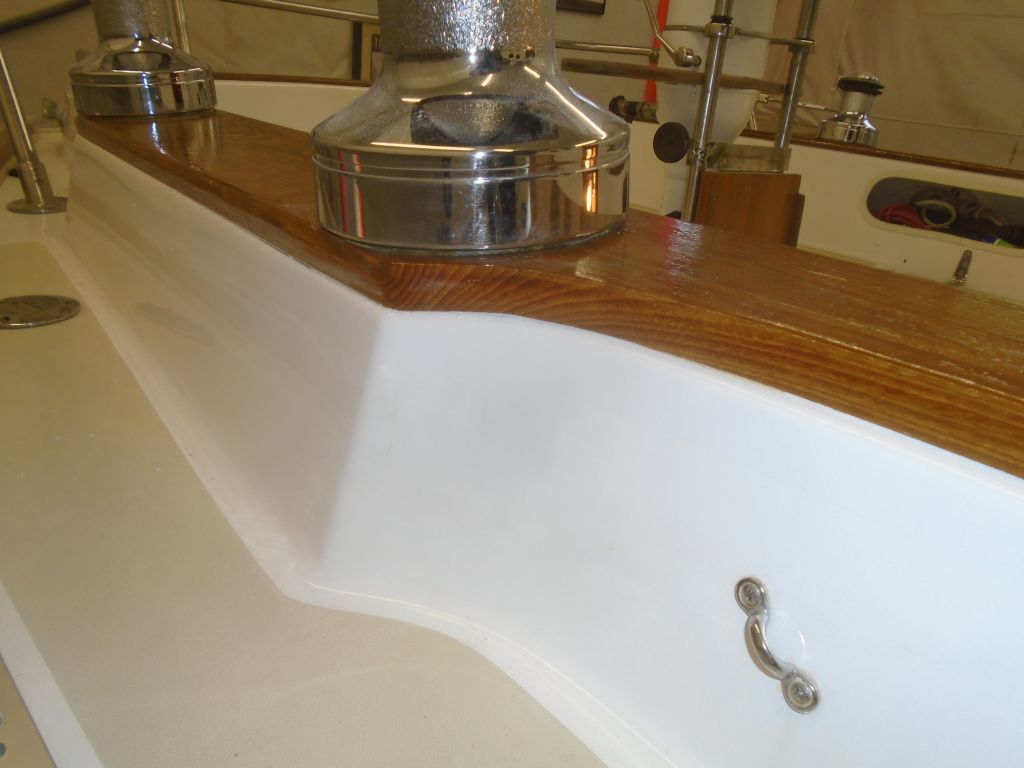
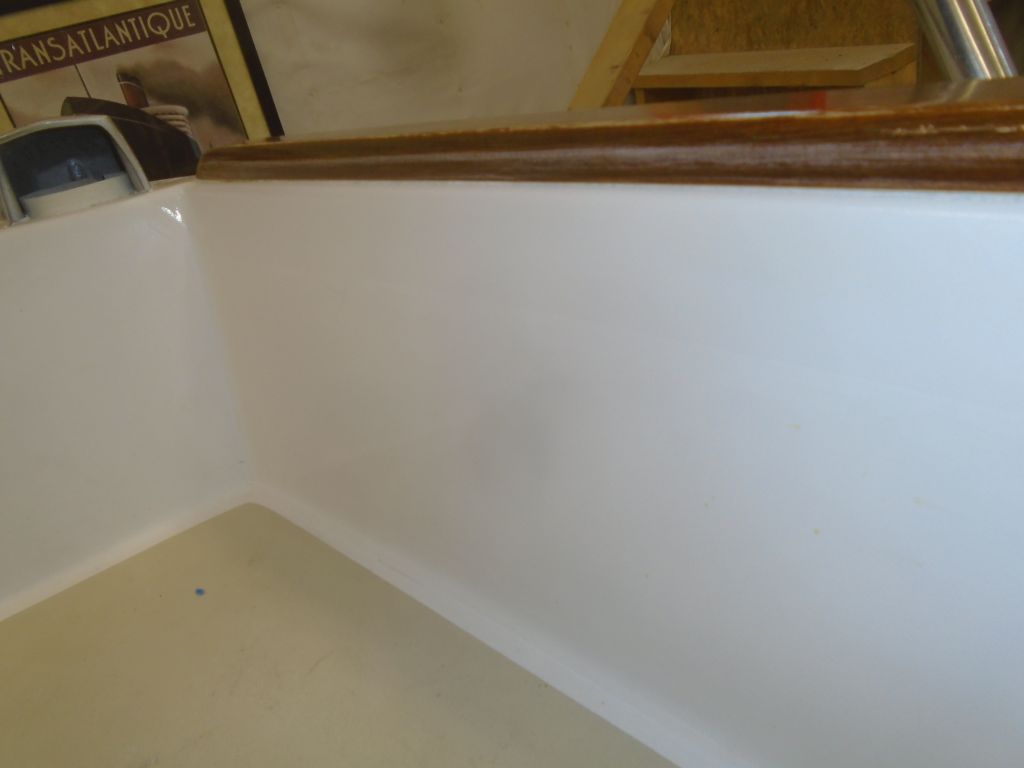
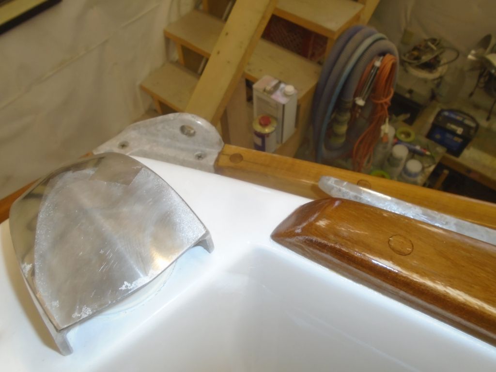
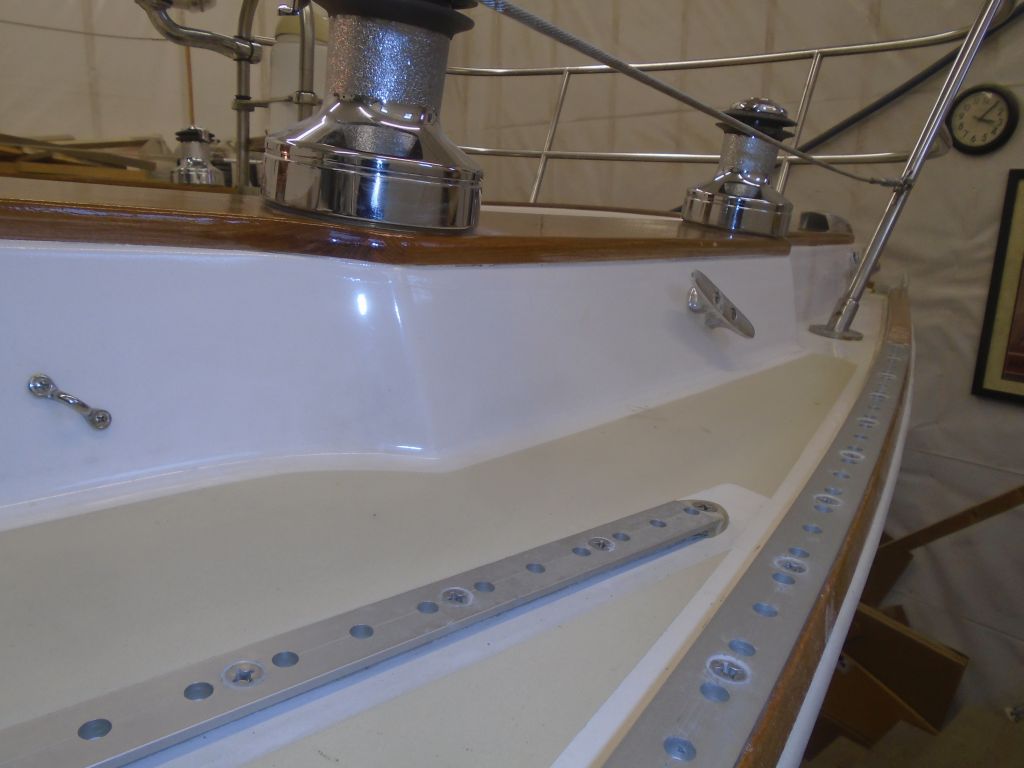
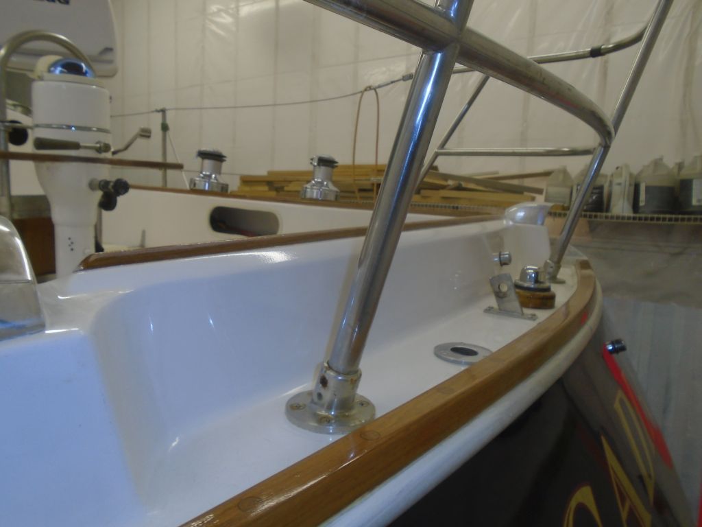
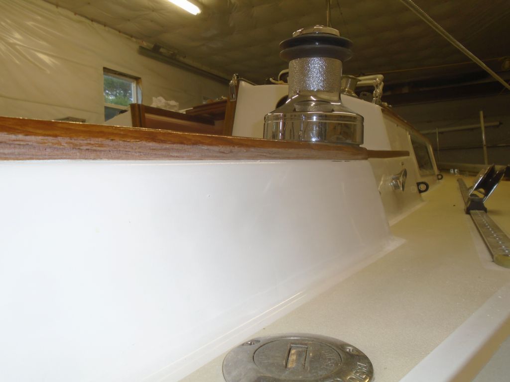
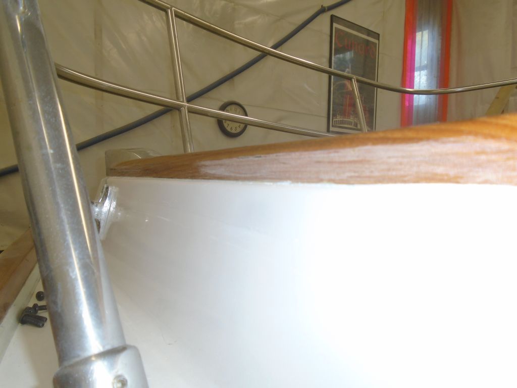
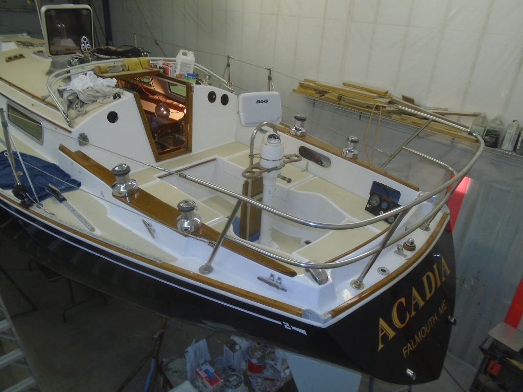
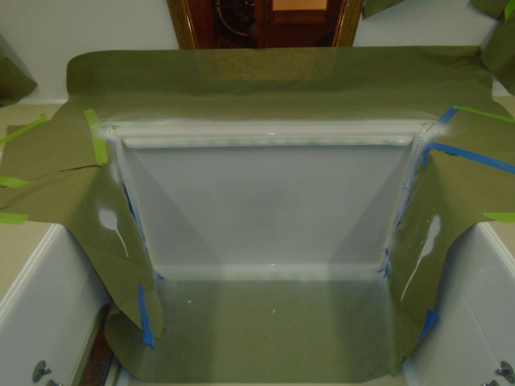
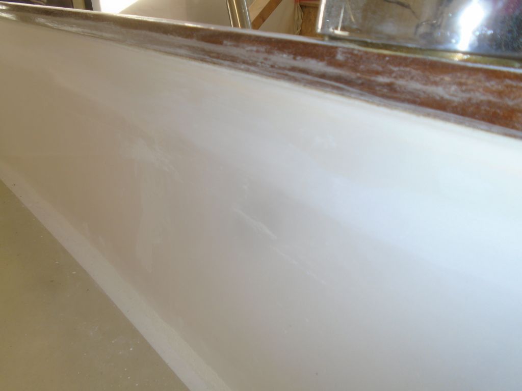
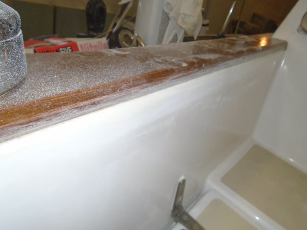
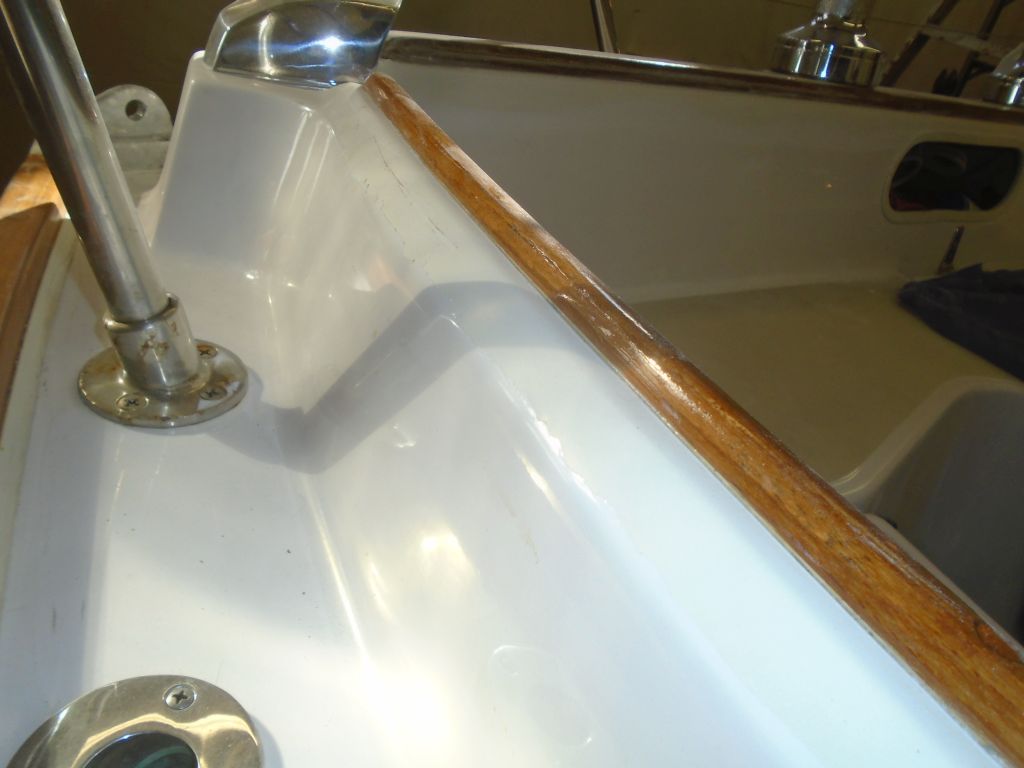
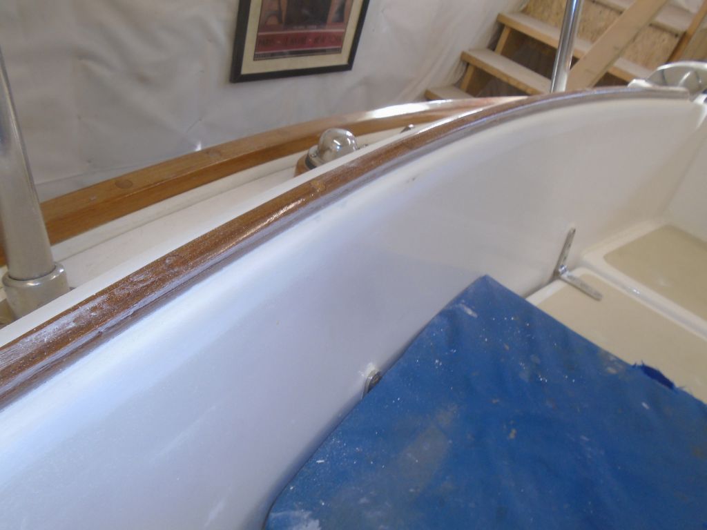
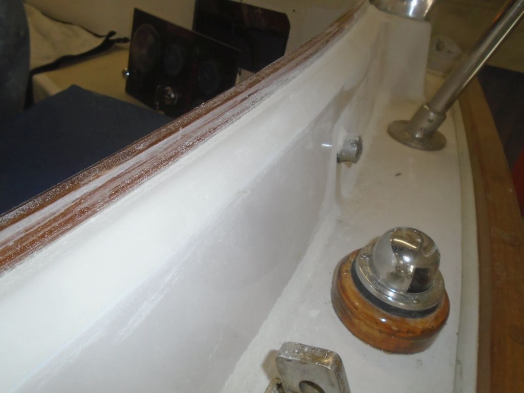
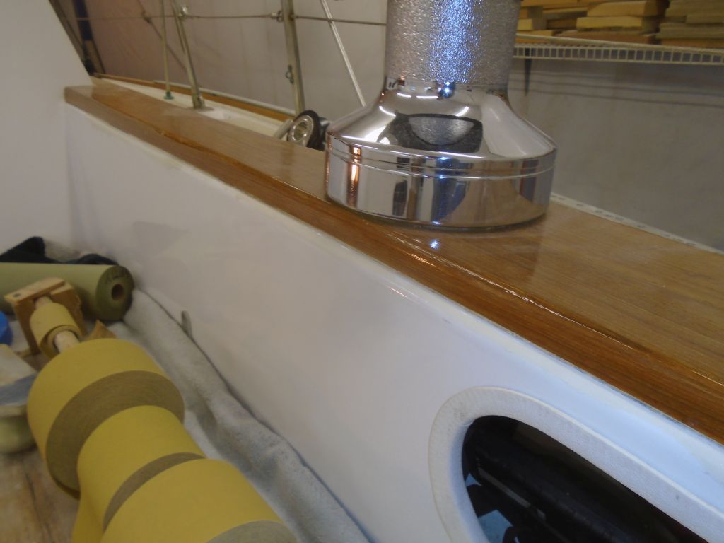
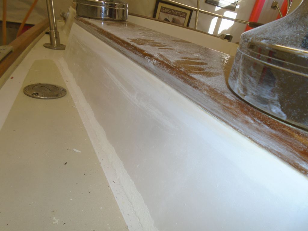
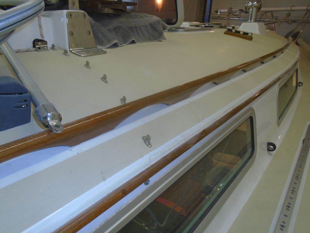
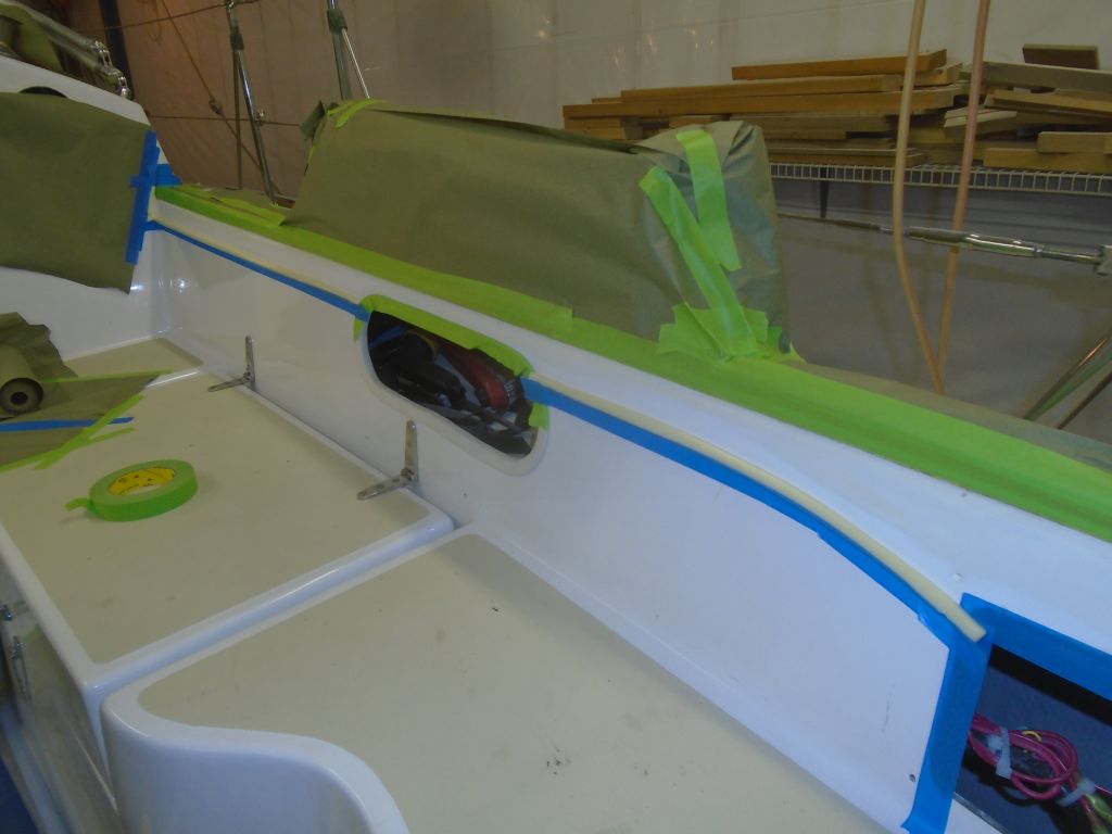
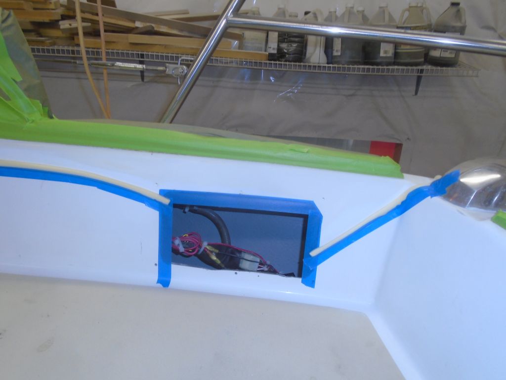
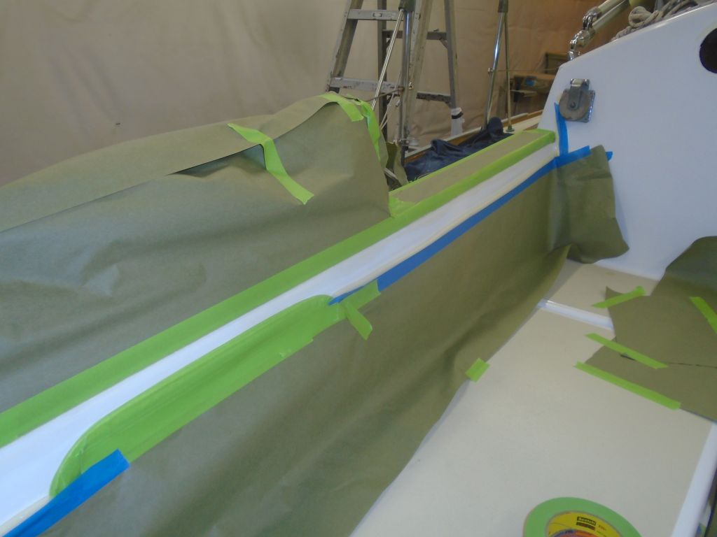
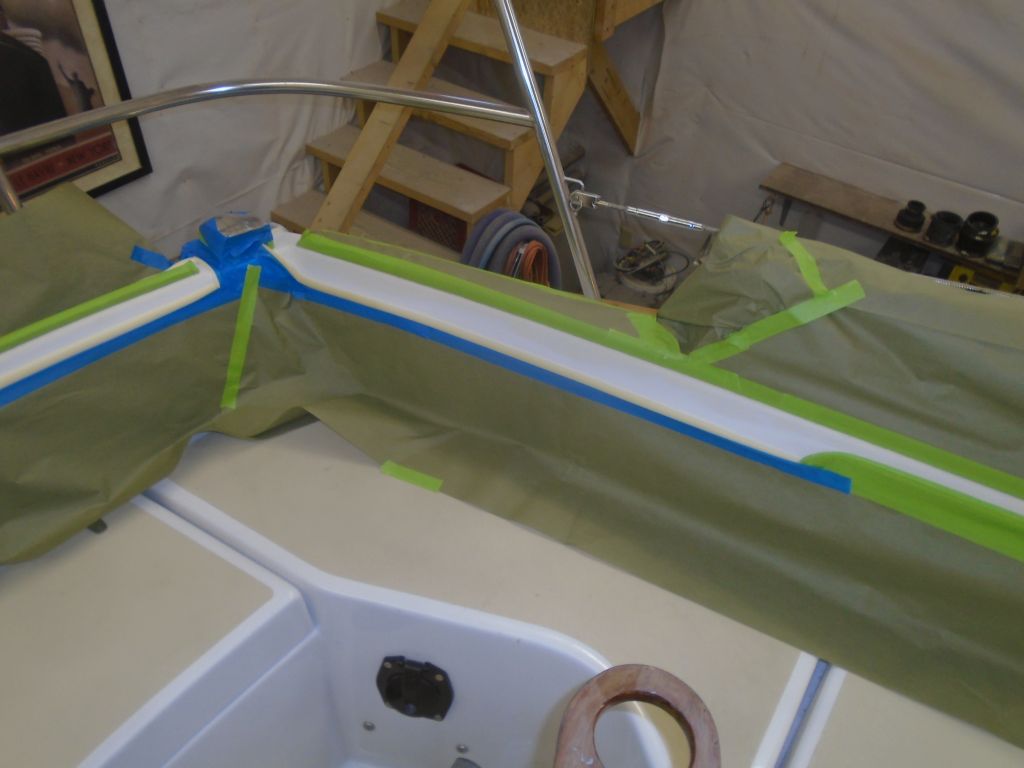
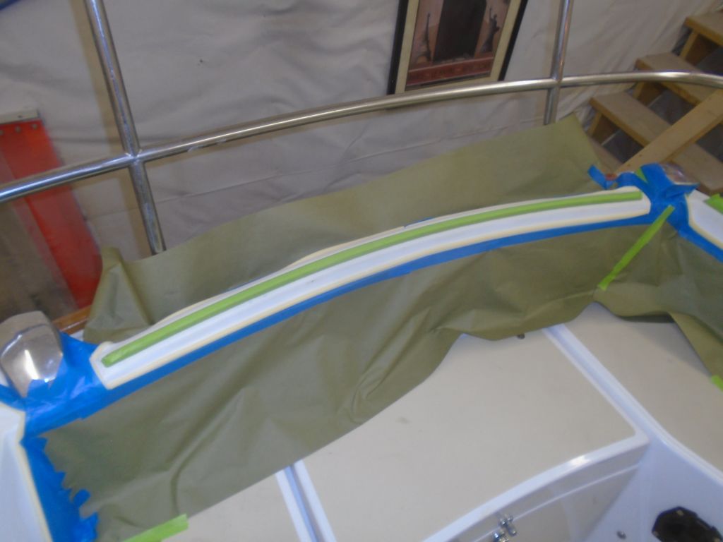
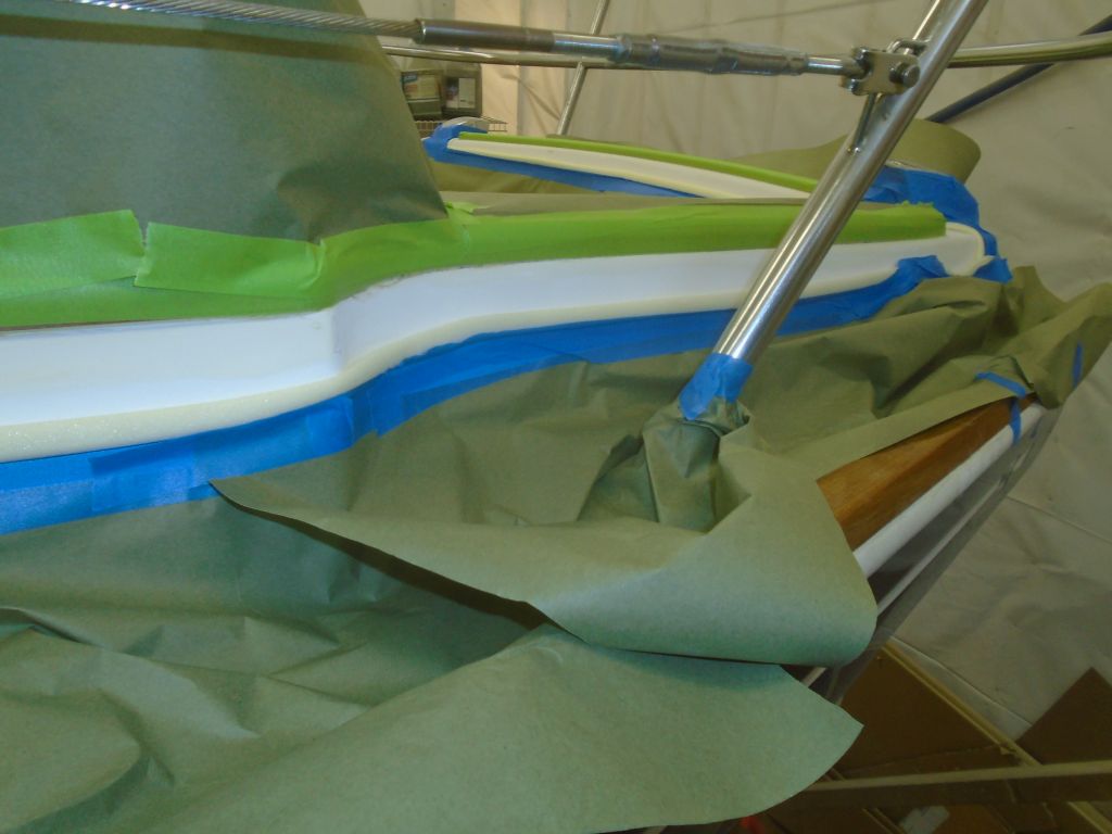
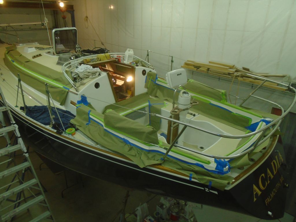
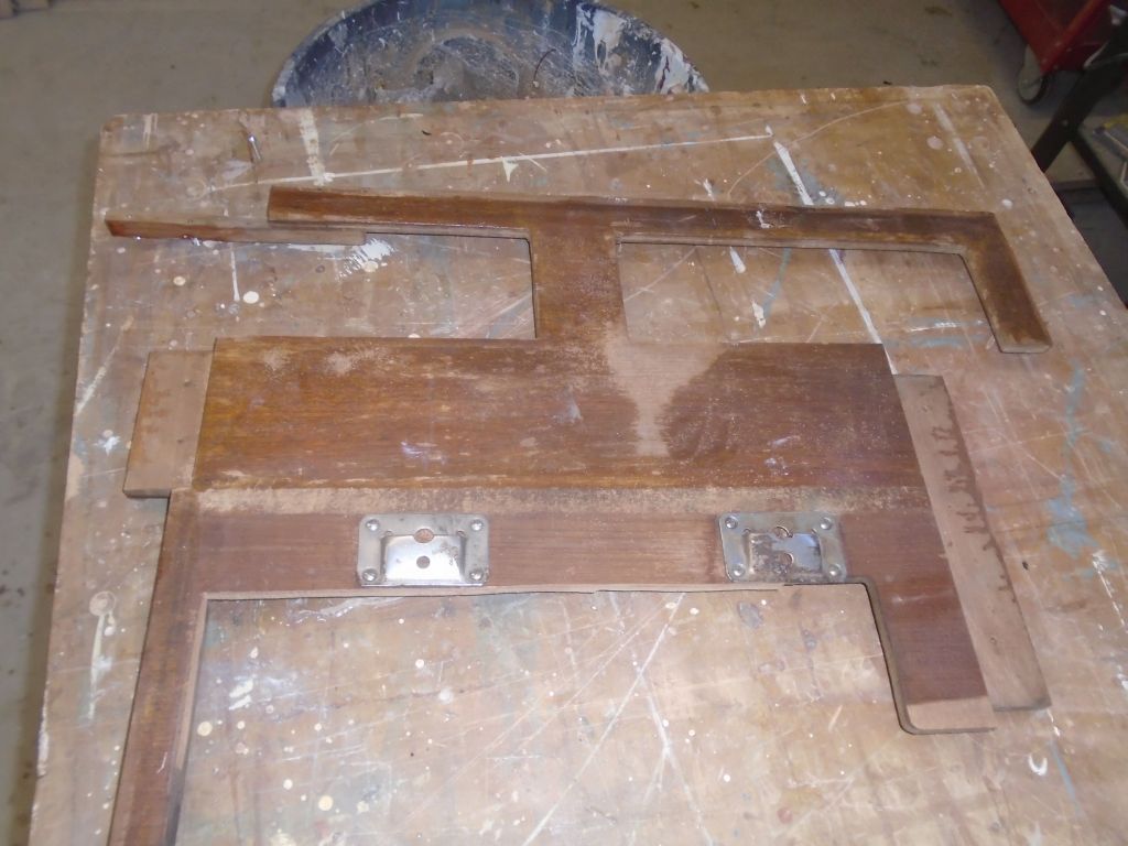
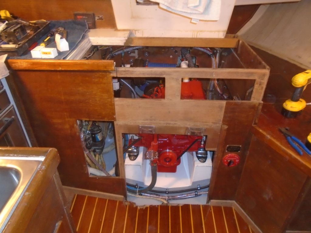
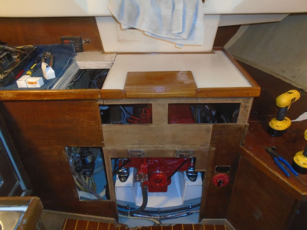
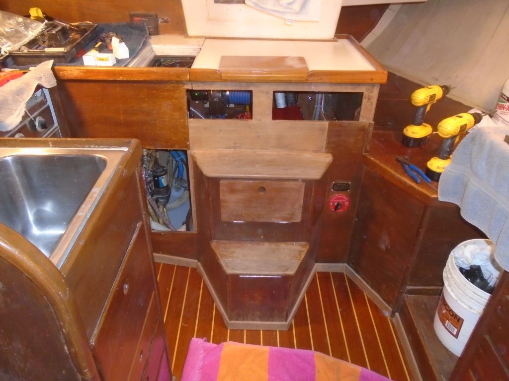
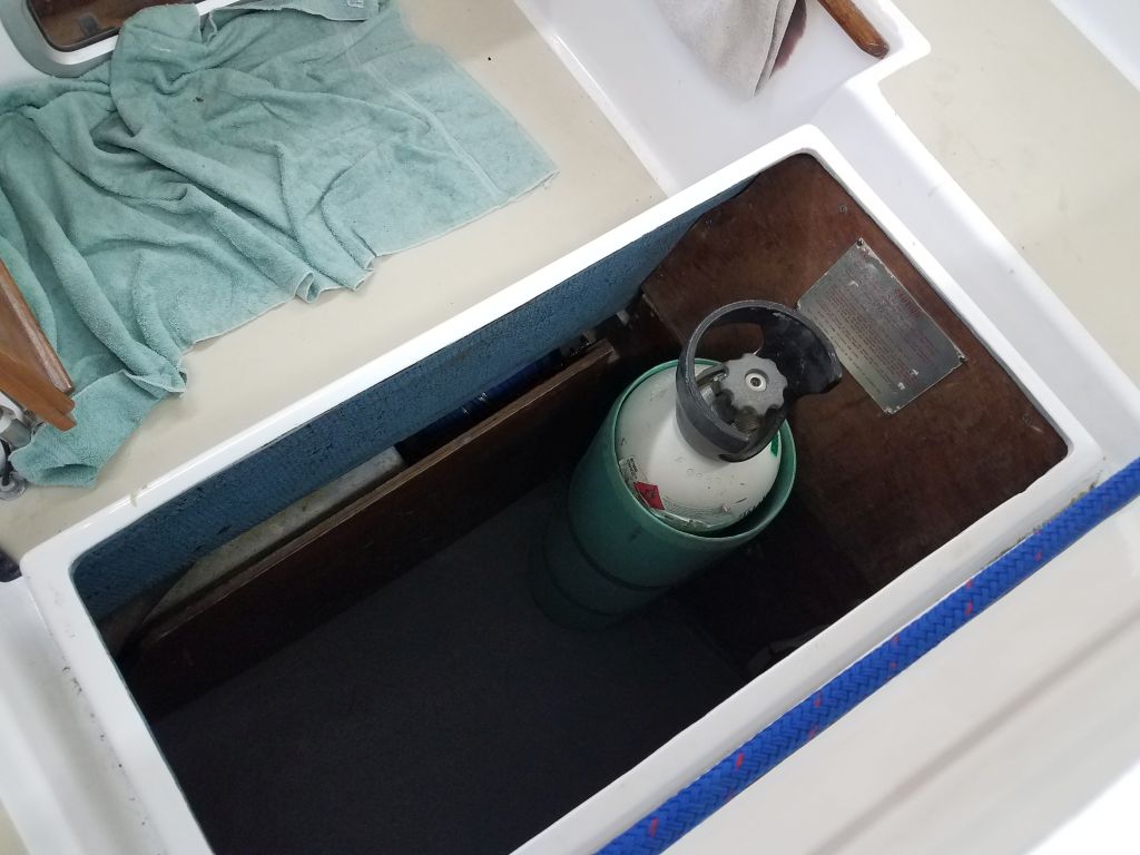
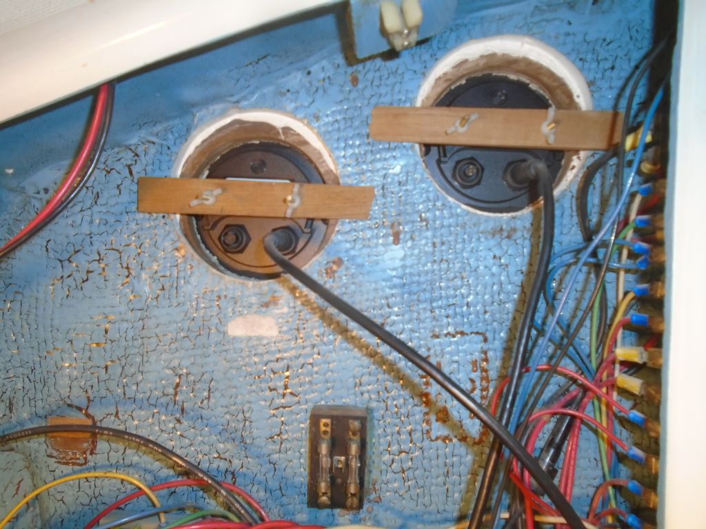
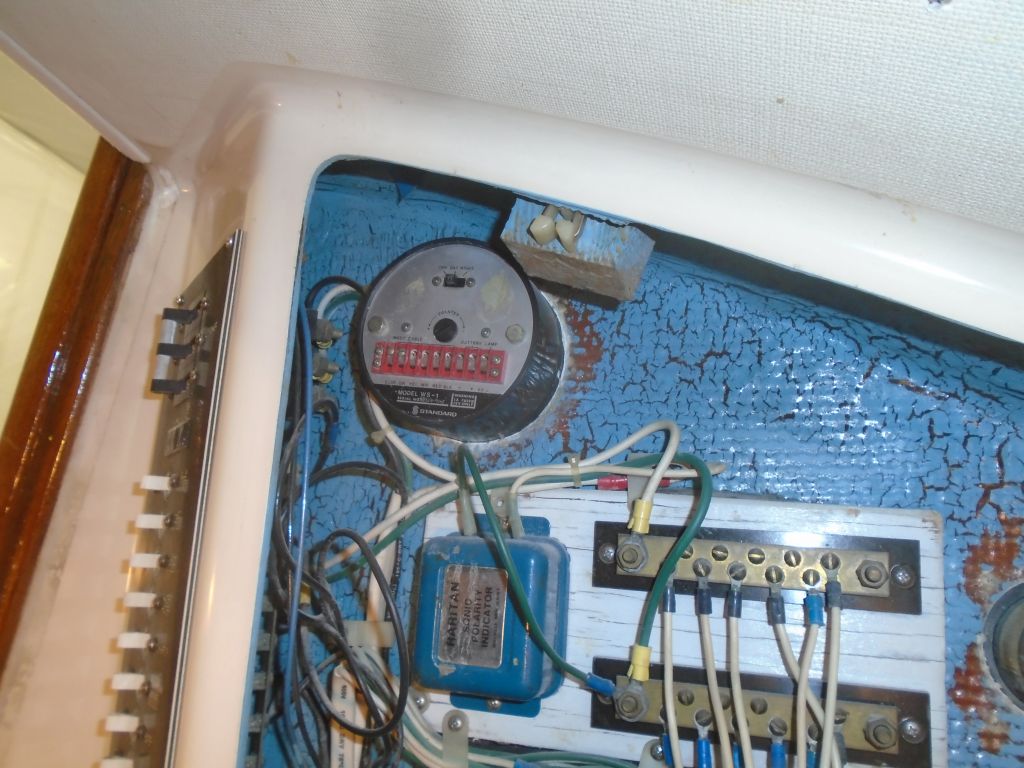
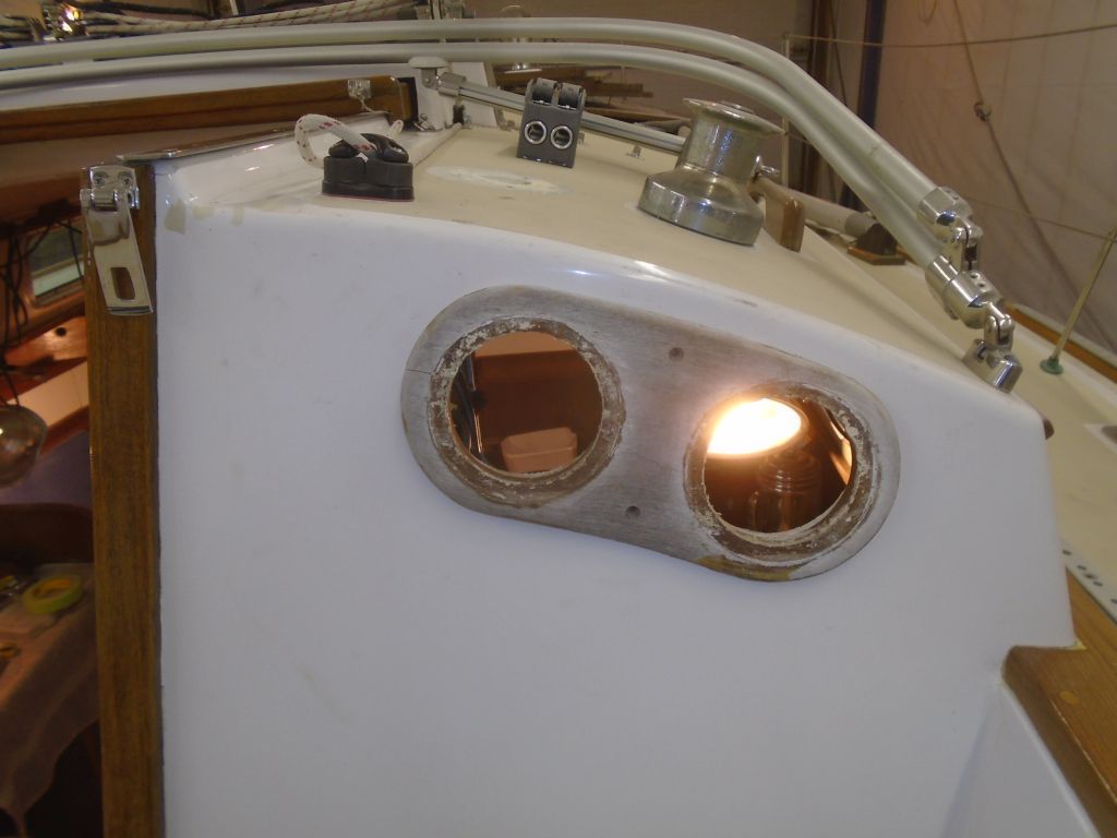
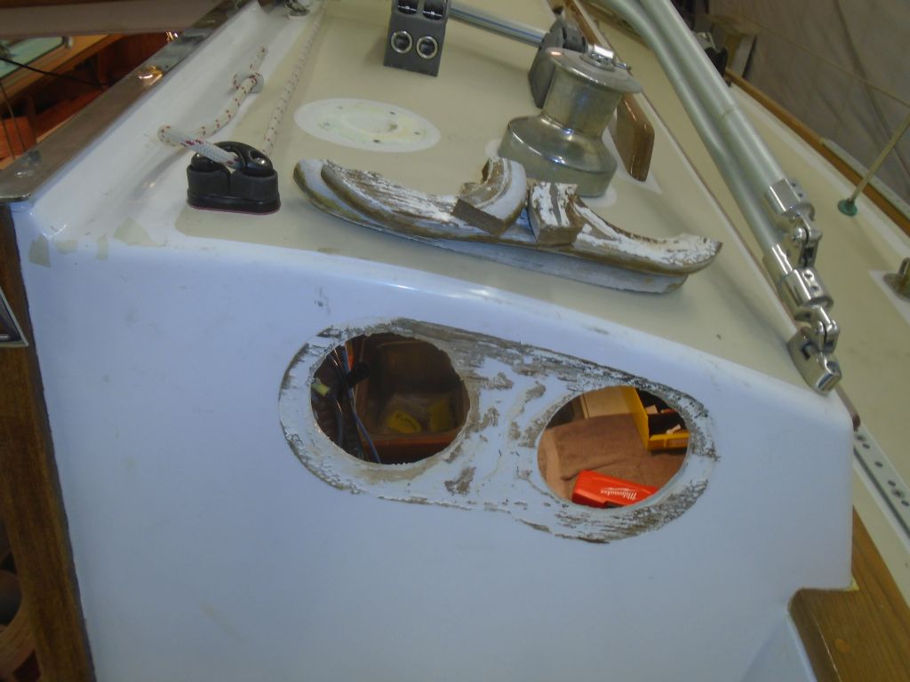
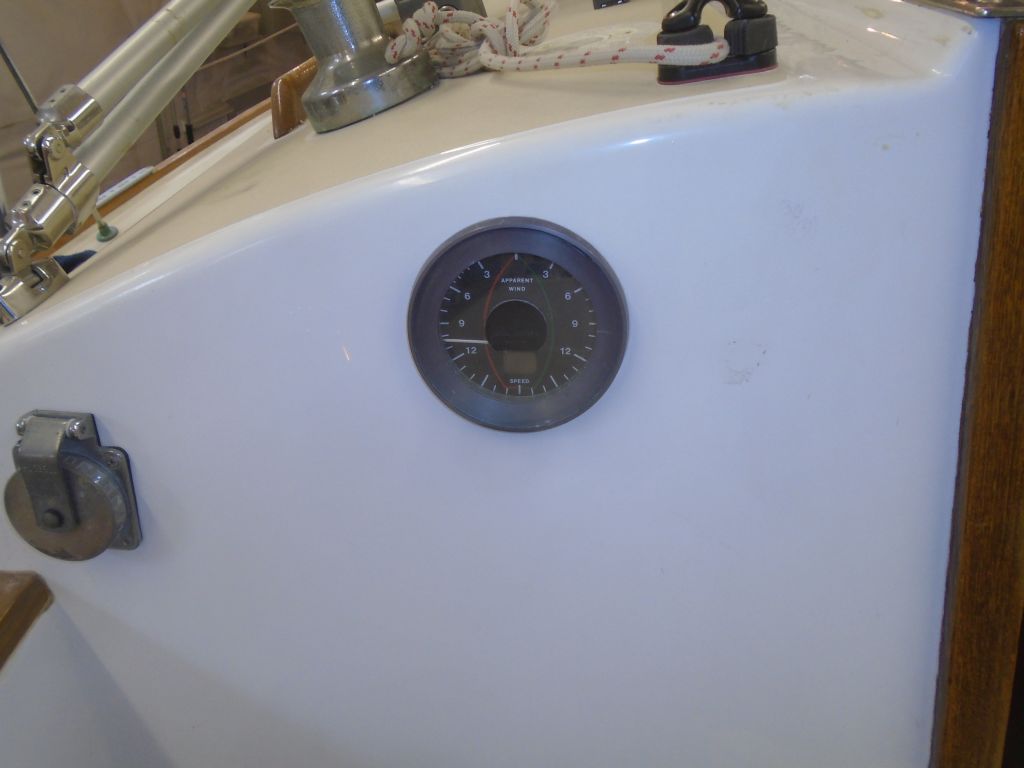
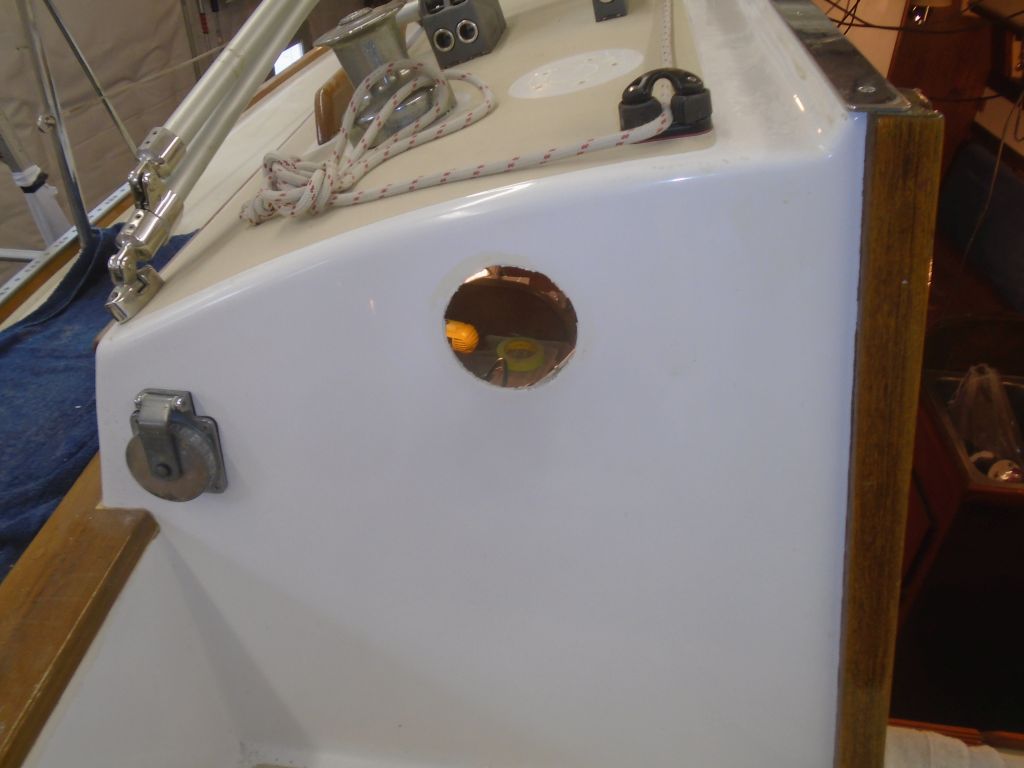
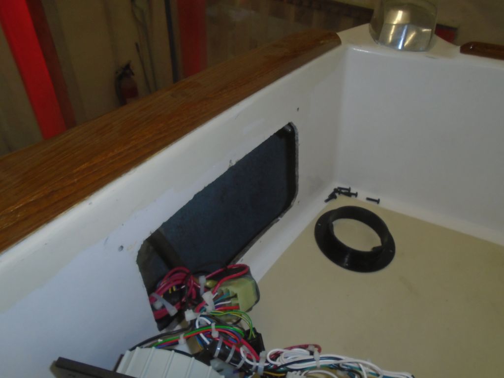
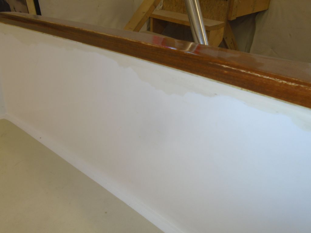
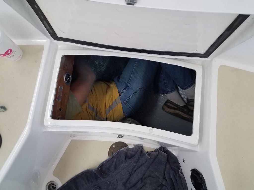
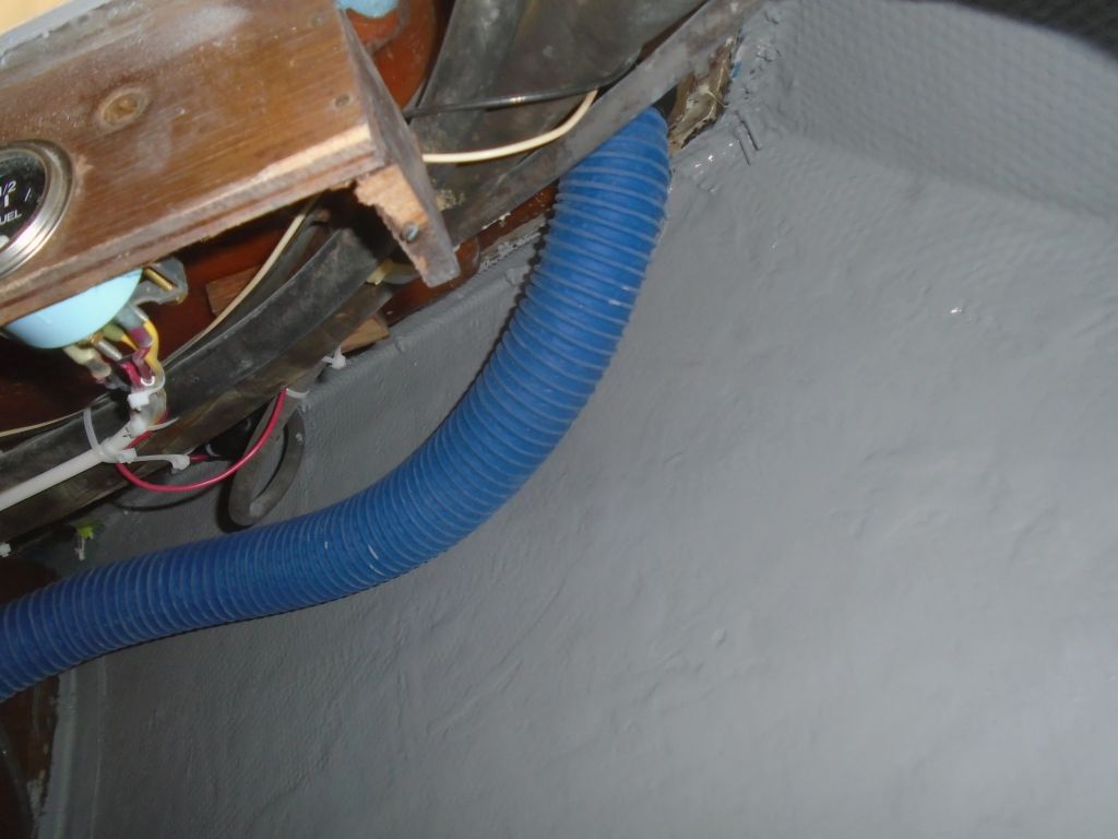
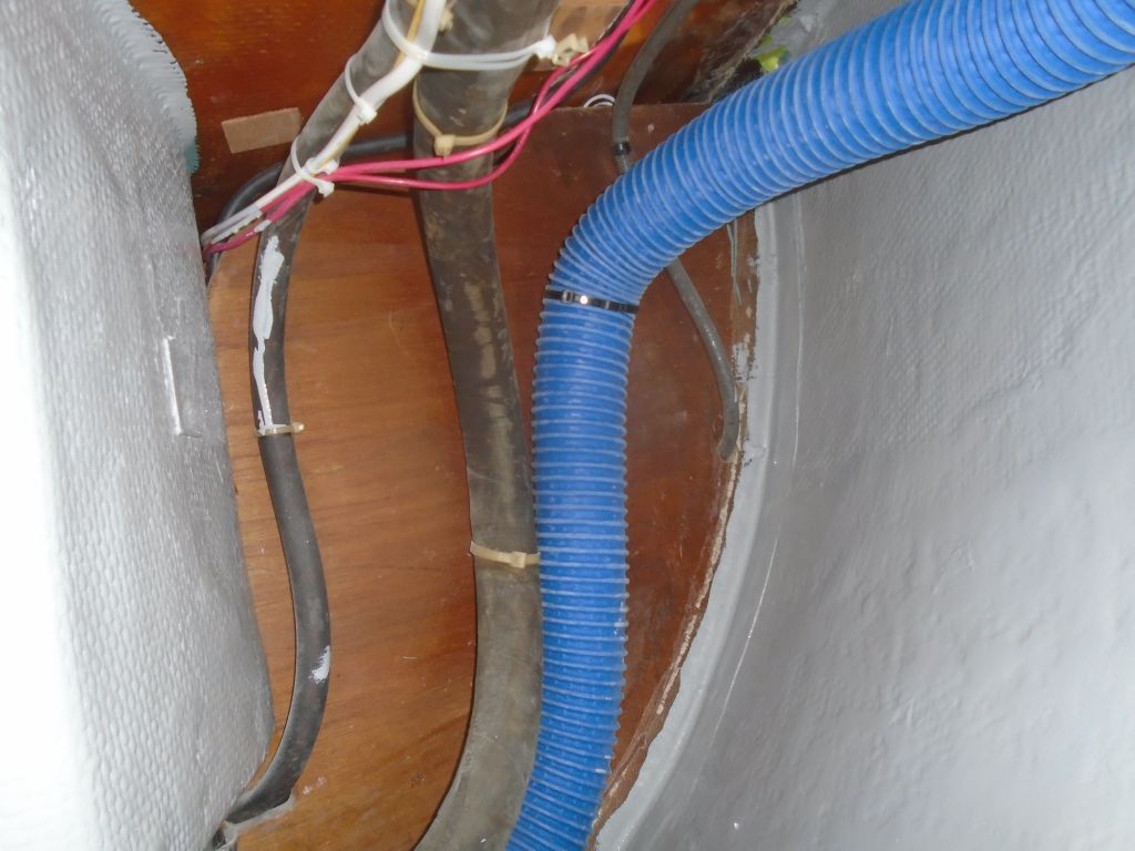
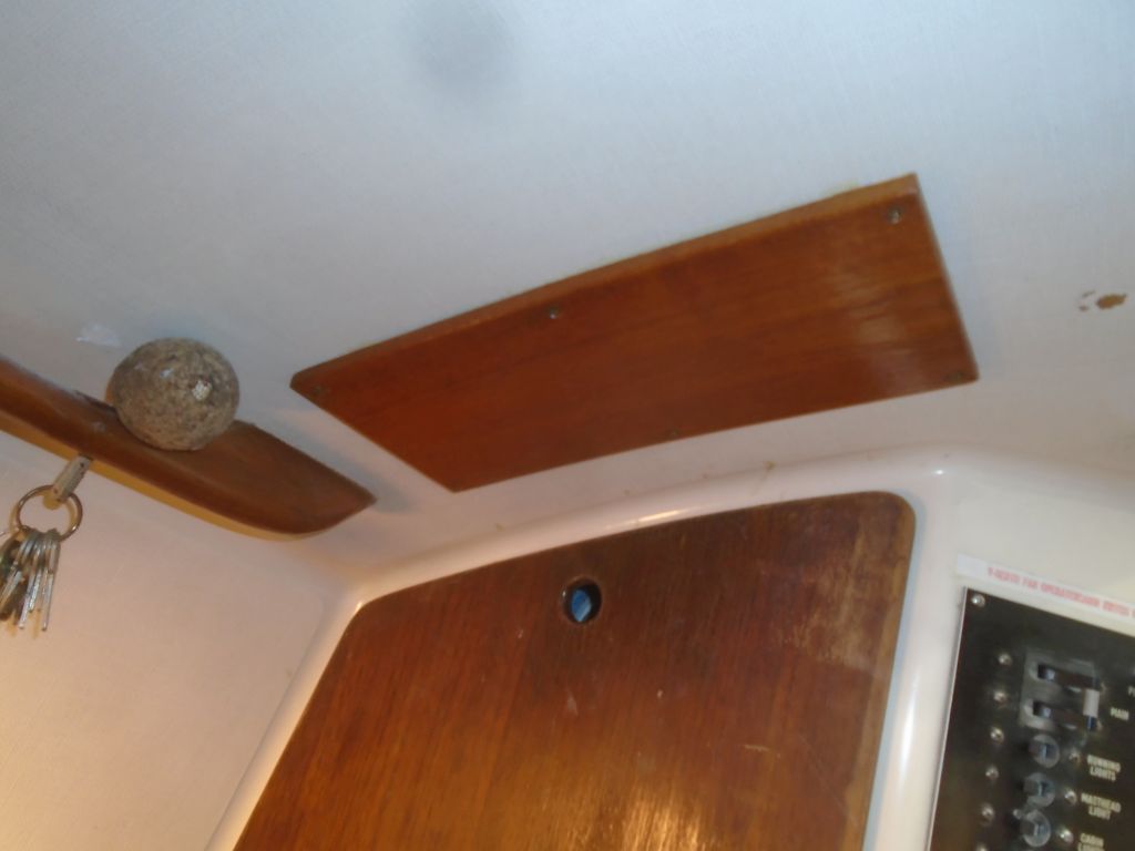
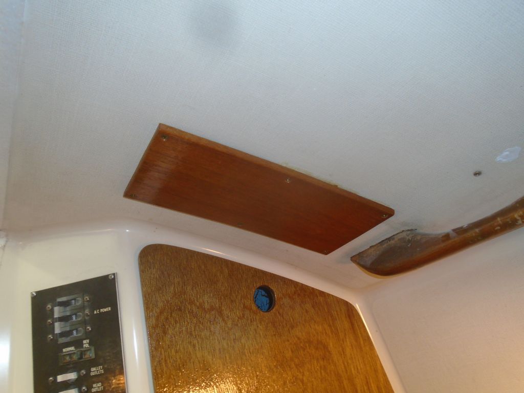
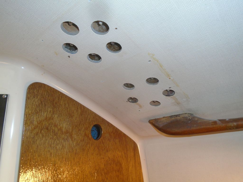
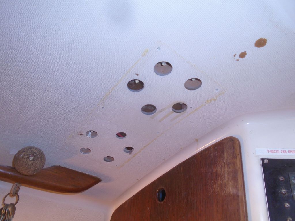
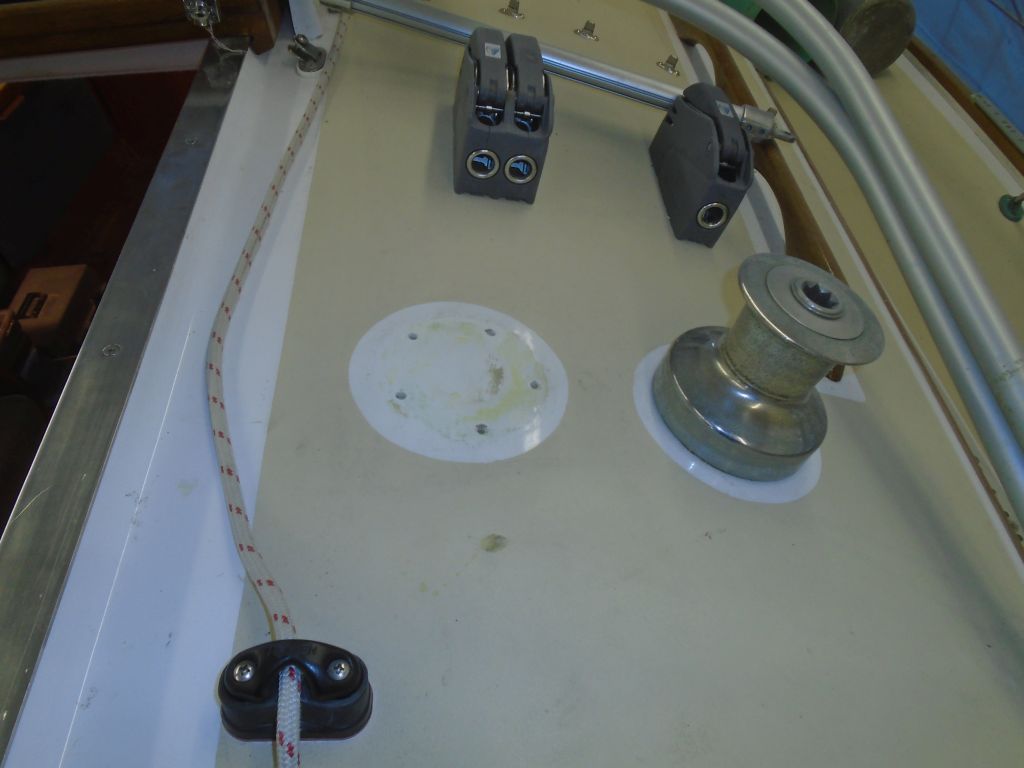
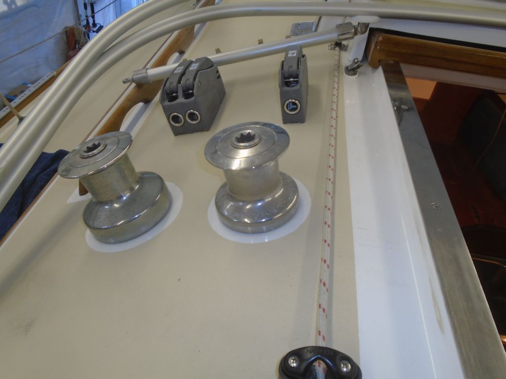
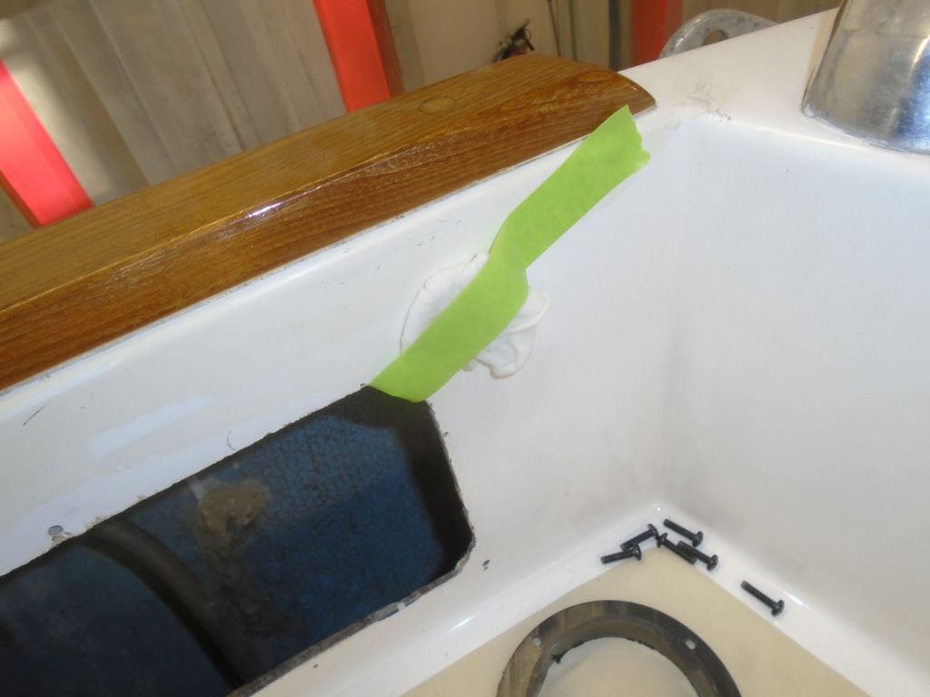
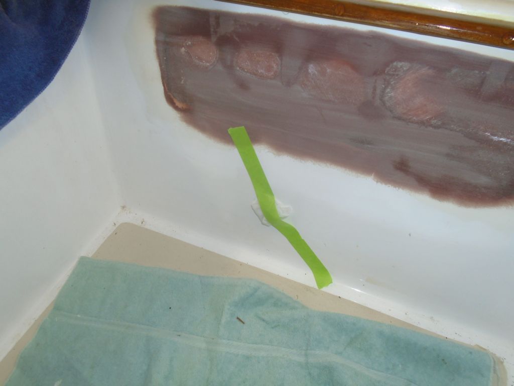
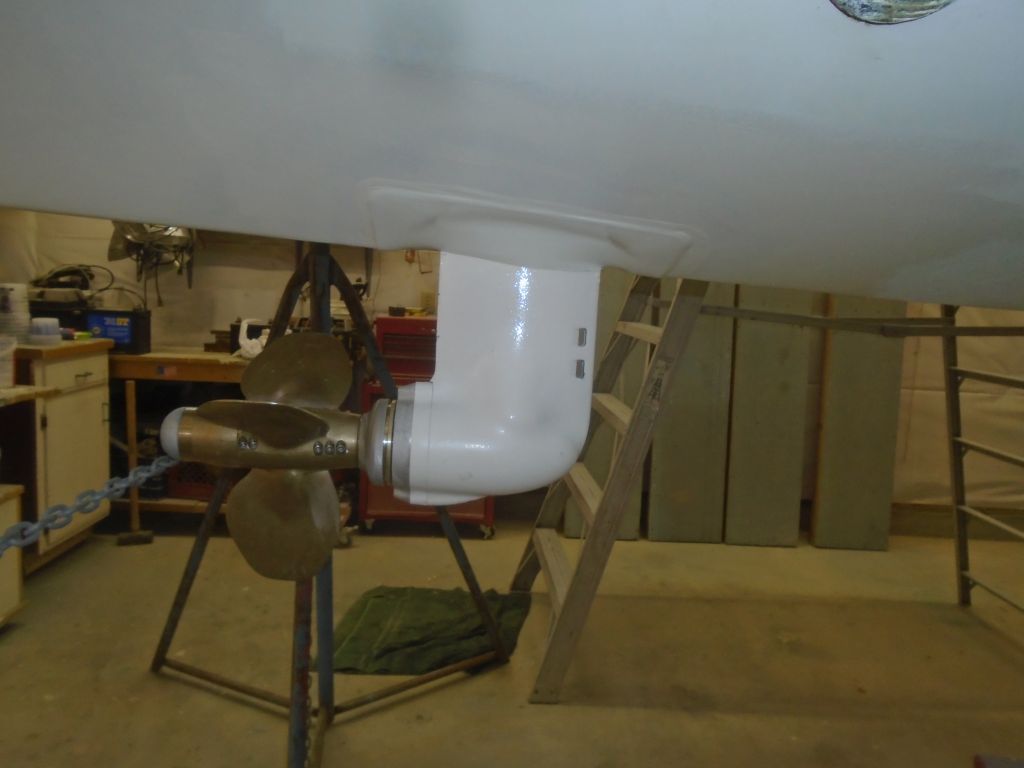
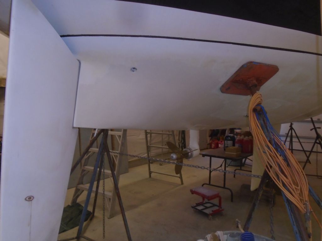
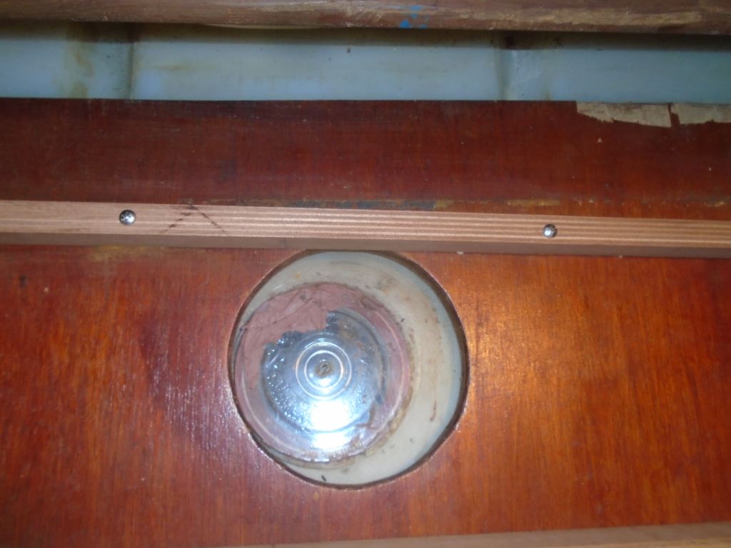
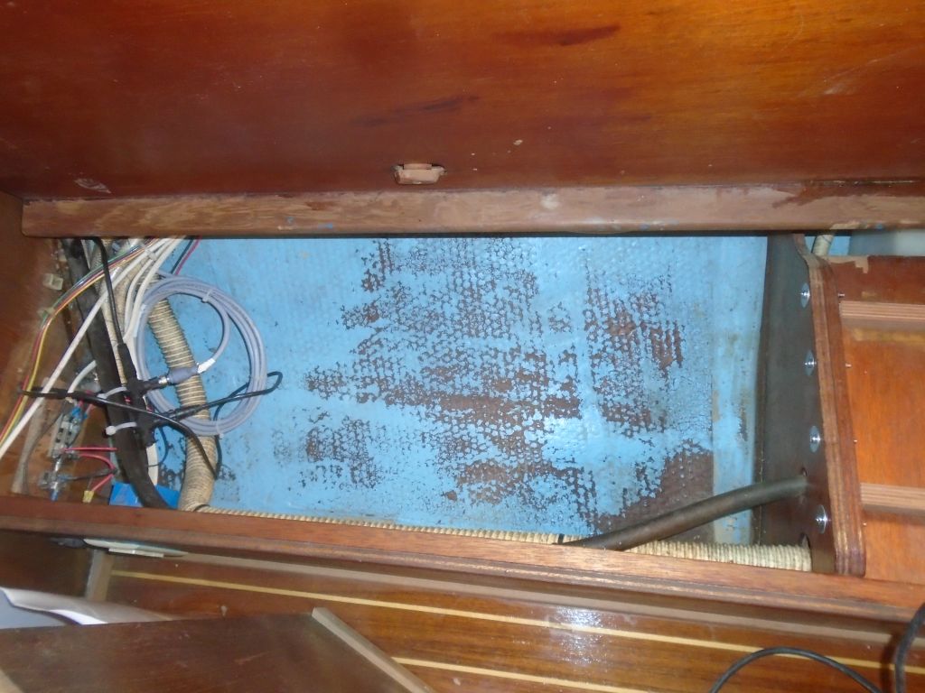
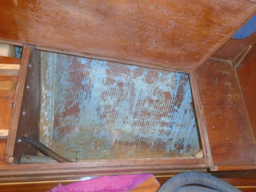
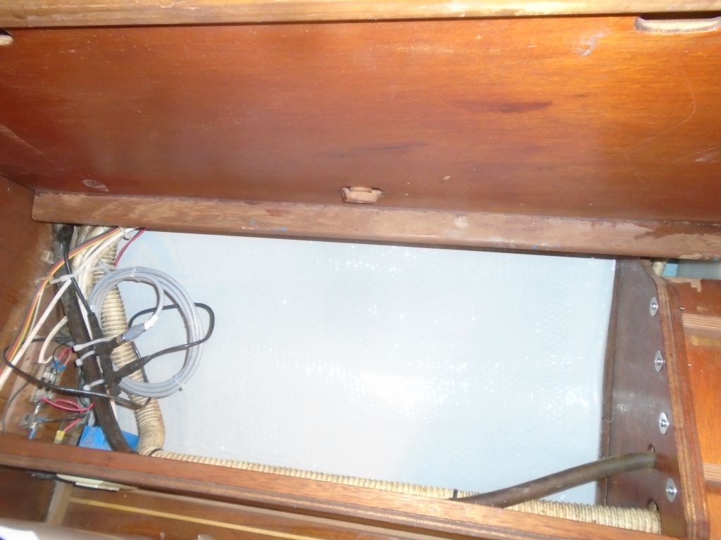
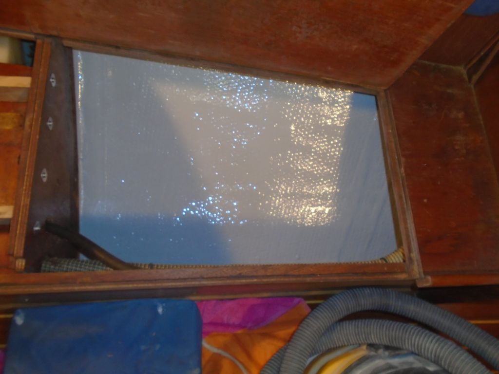
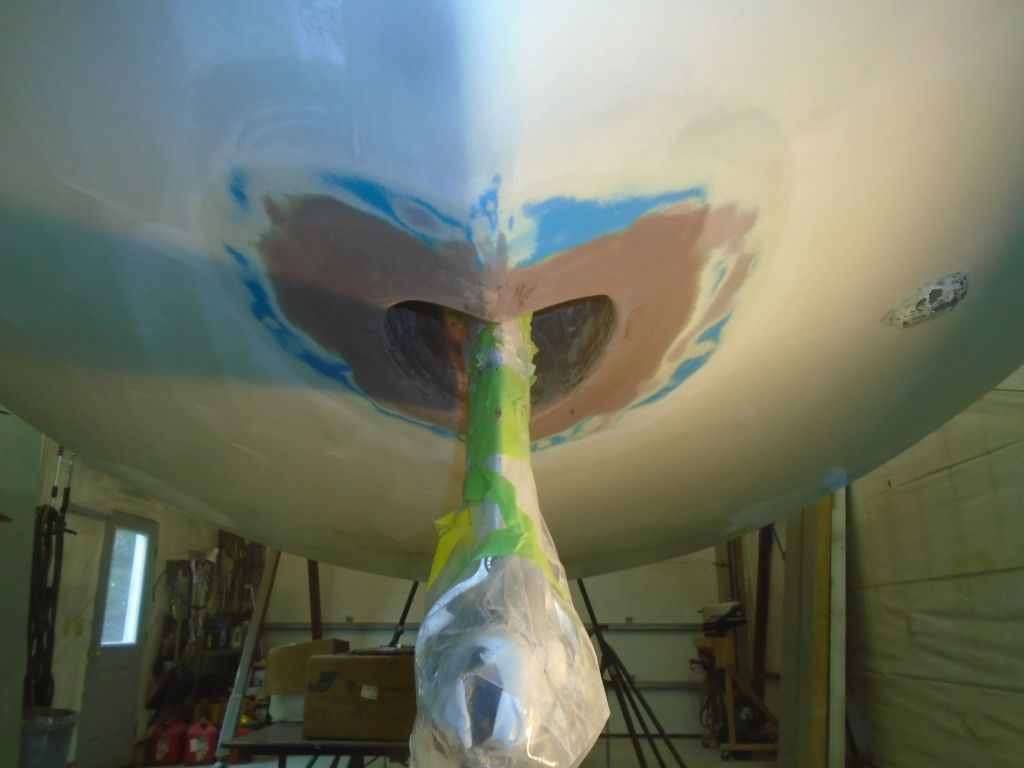
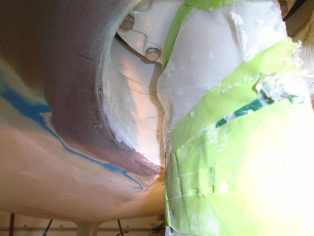
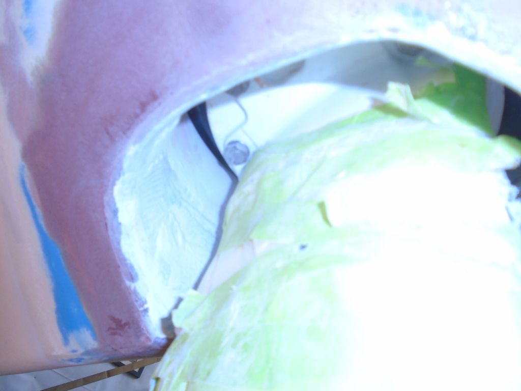
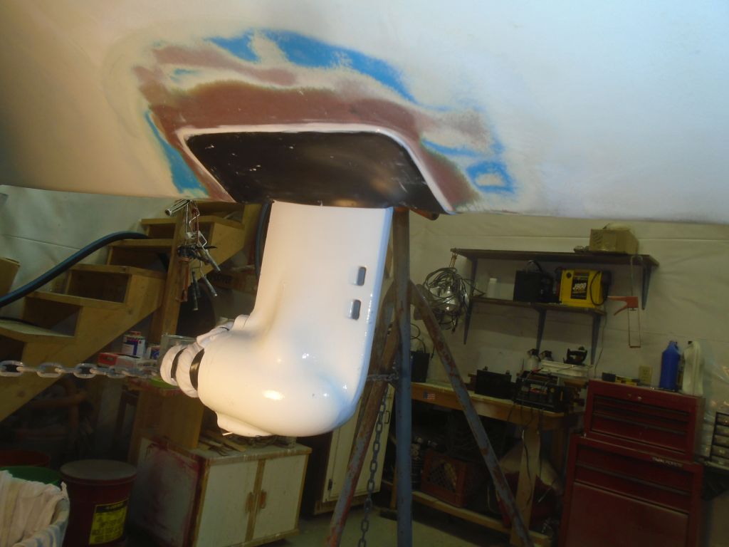
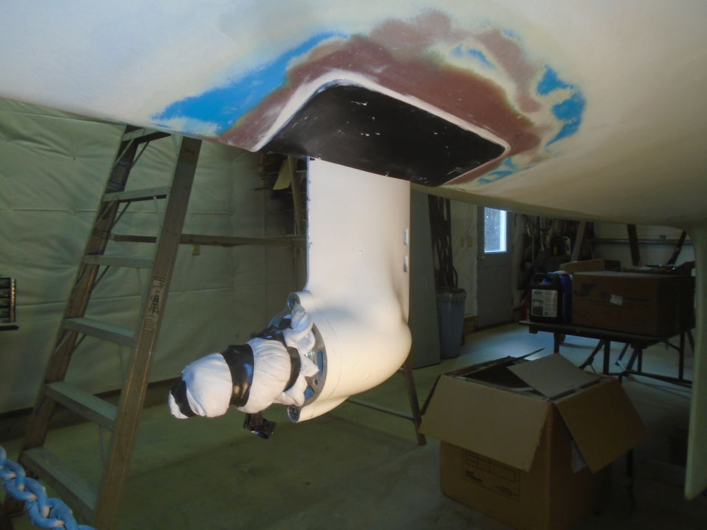
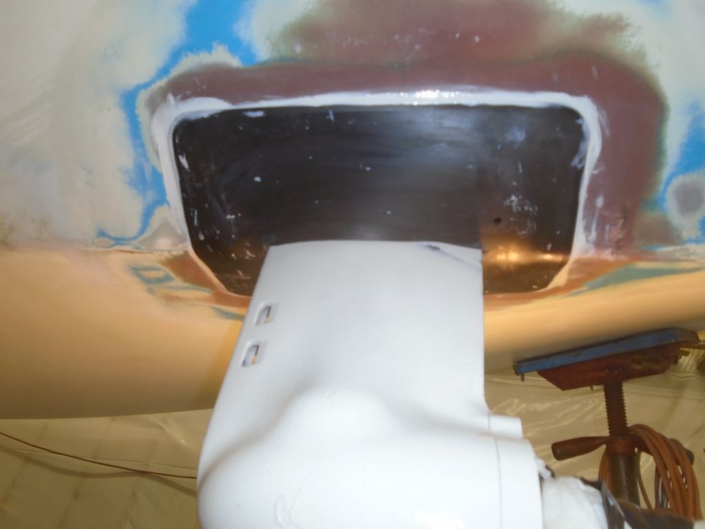
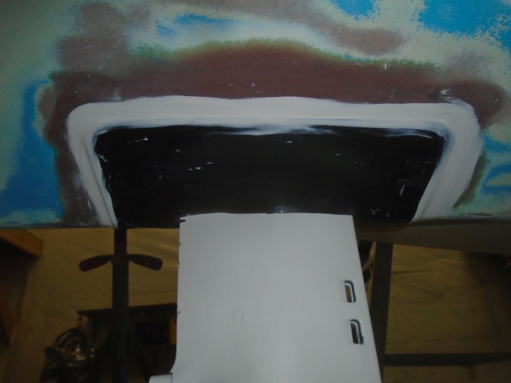
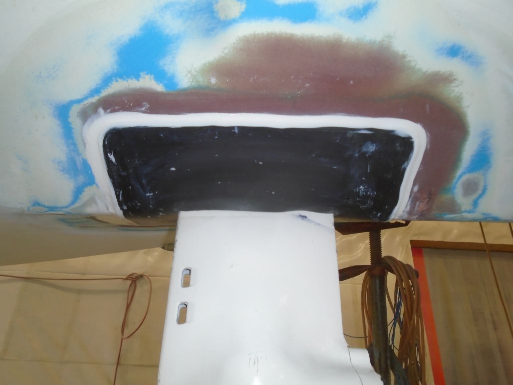
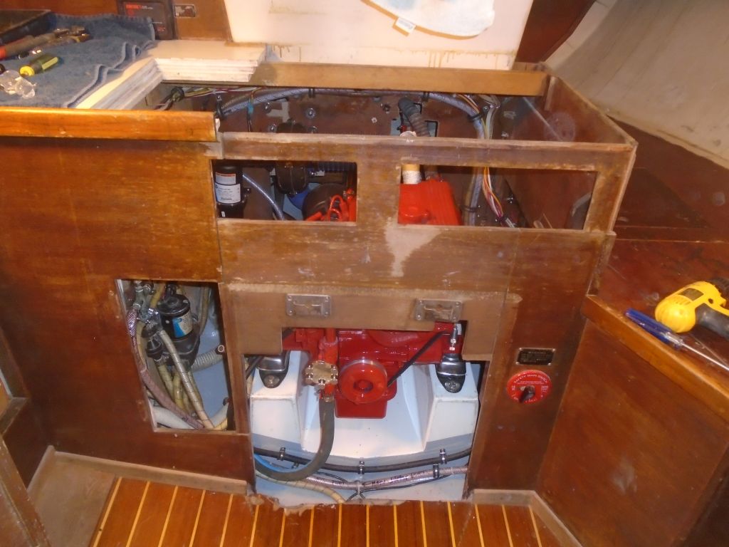
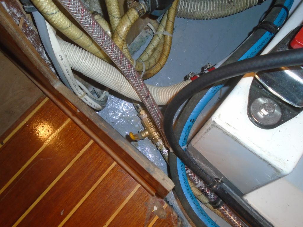
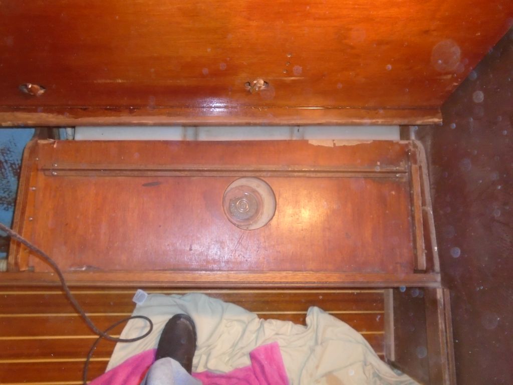
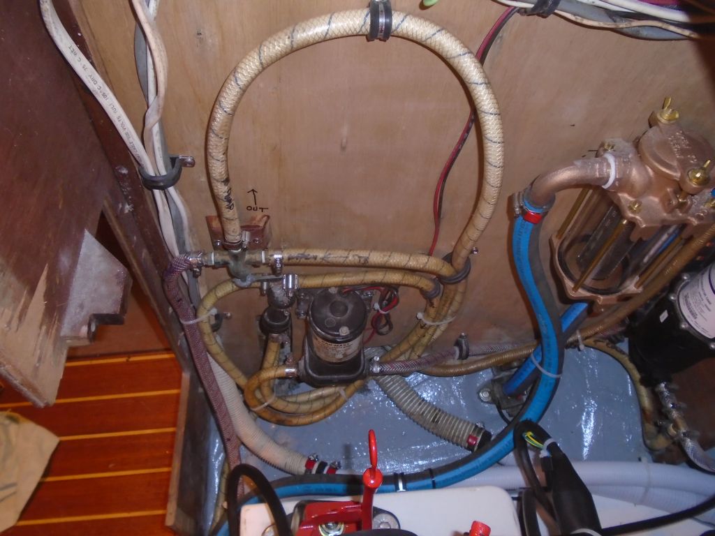
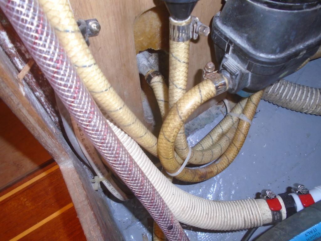
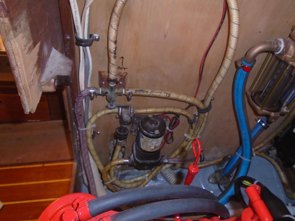
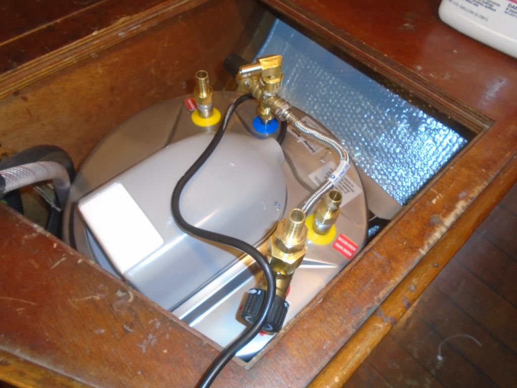
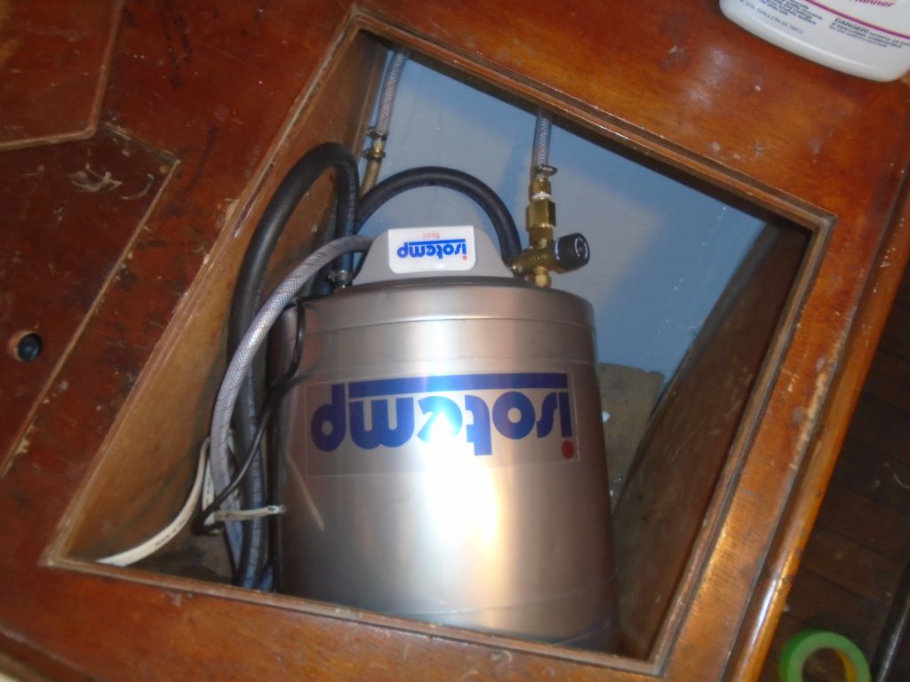
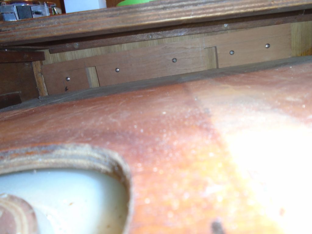
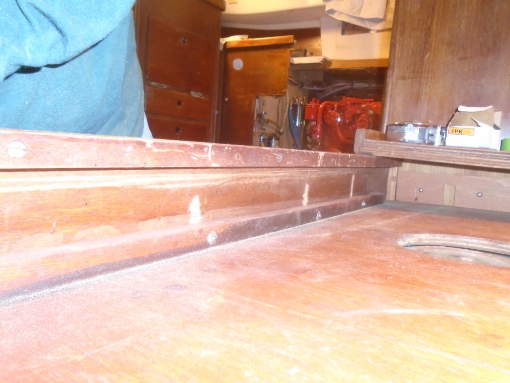
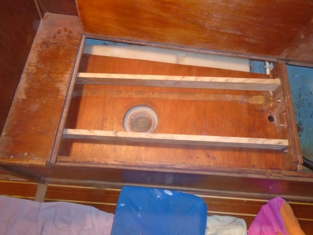
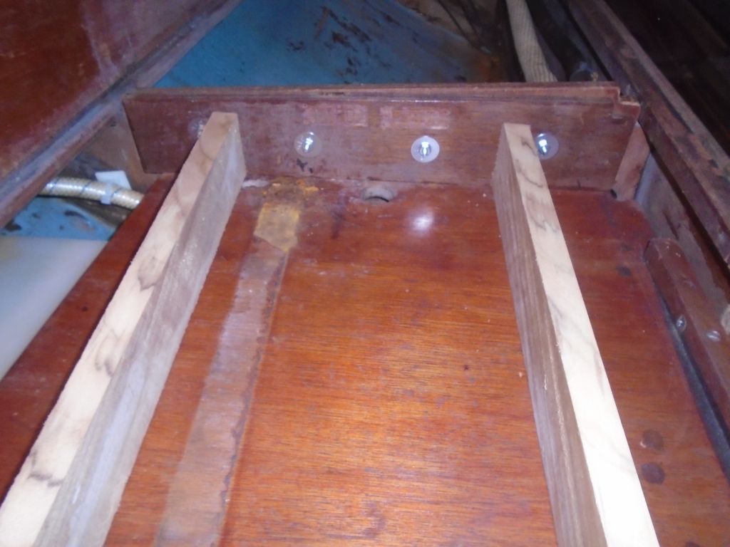
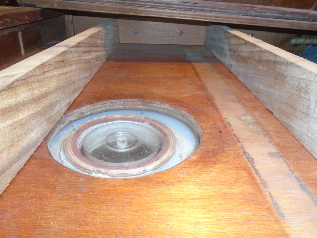
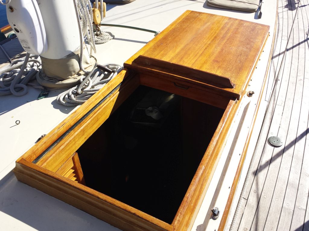
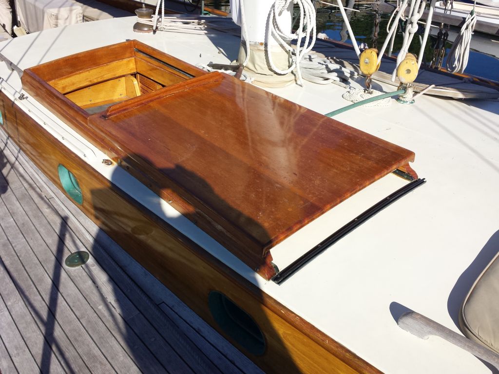
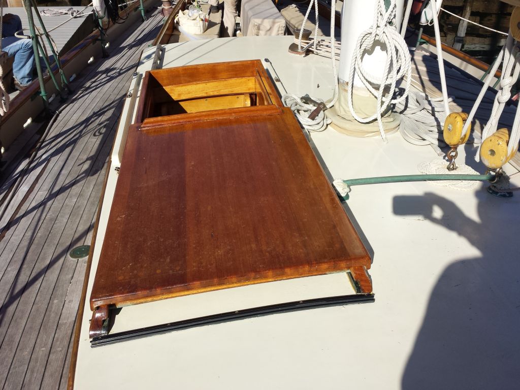
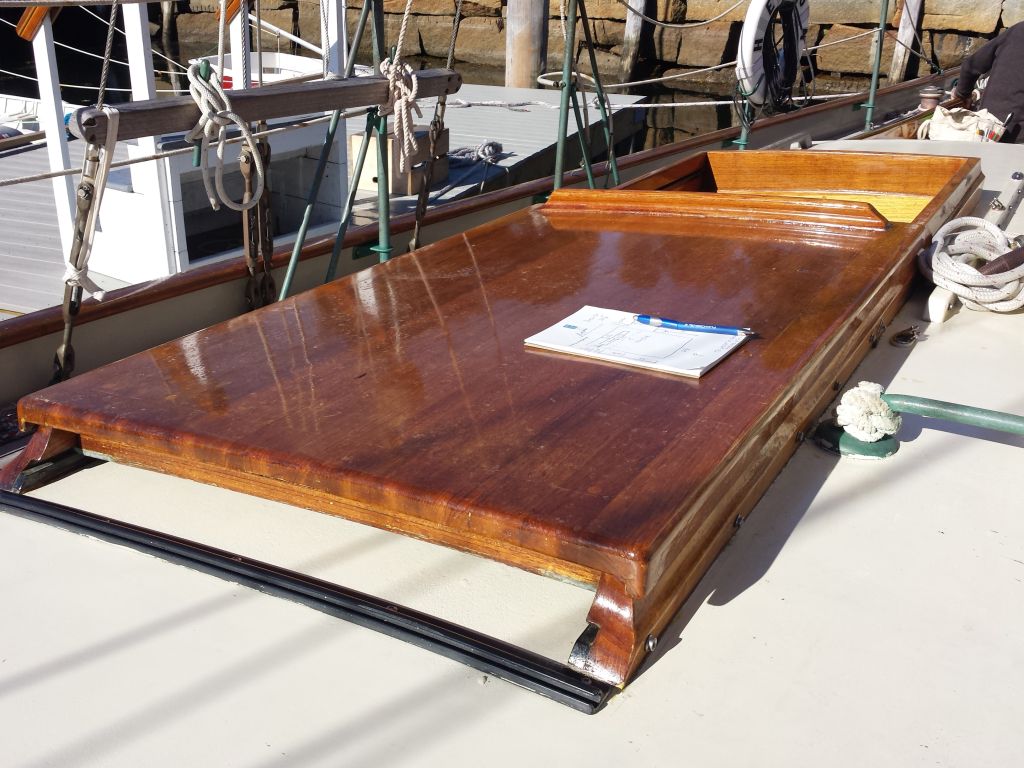
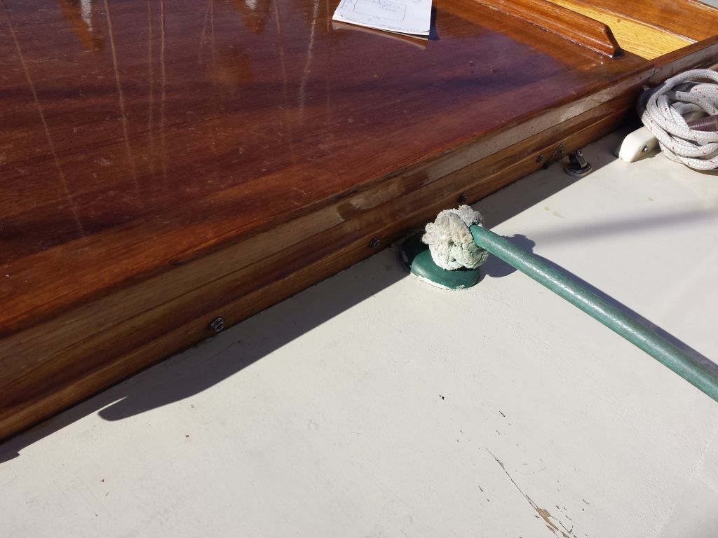
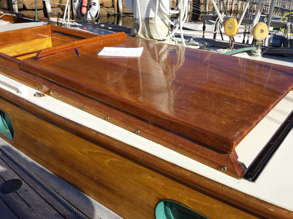
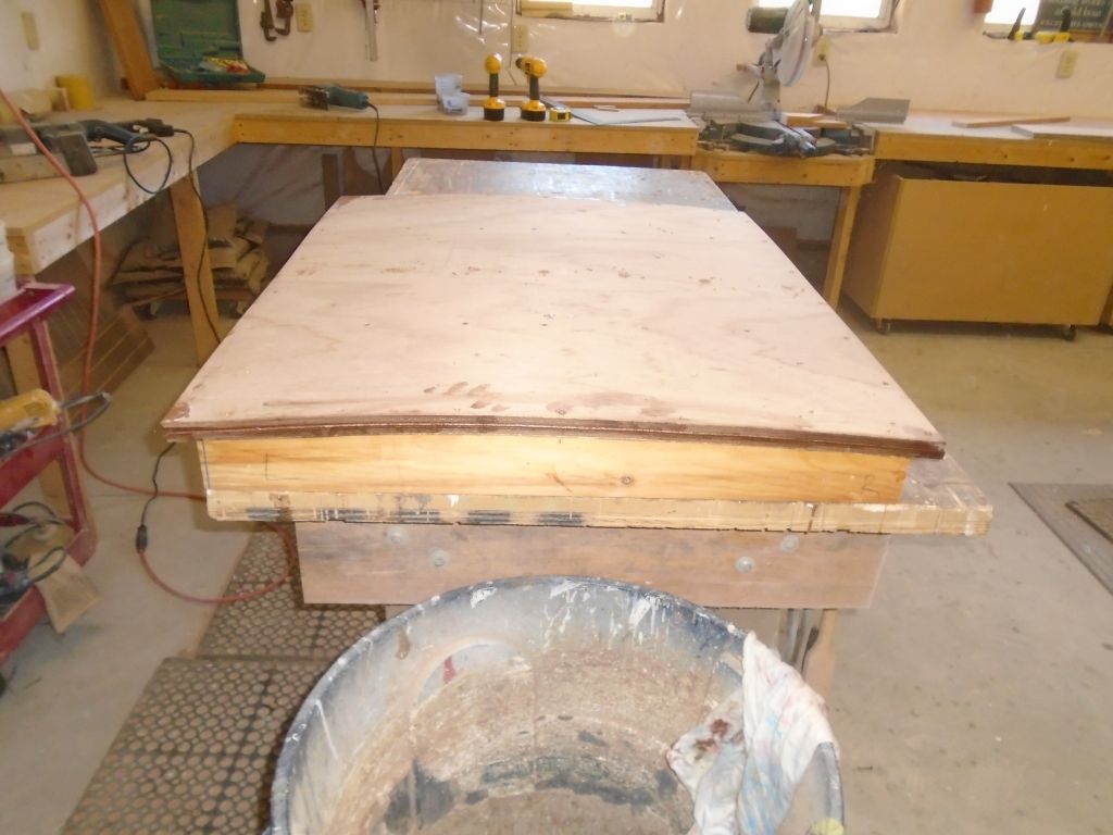
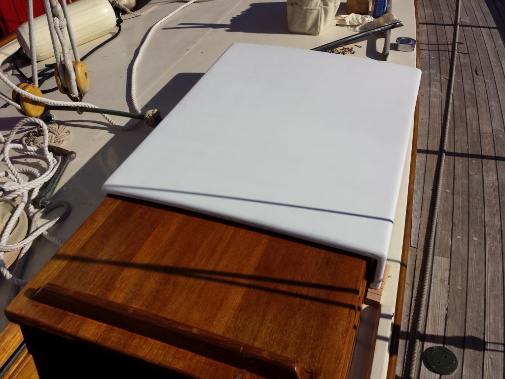
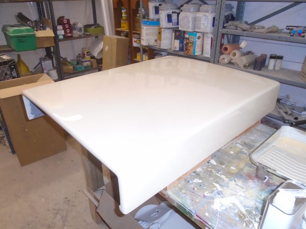
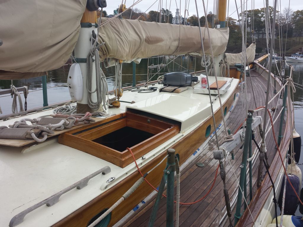
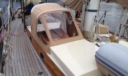
Working on a referral from my canvas subcontractor, I visited a local day charter schooner to look at the possibility of building a wooden sea hood over an existing companionway slide, and to facilitate effective attachment of a canvas spray dodger used when at sea. In the past, there’d been a canvas hood fitted, but with canvas upgrades in process, the owner had decided to look into a fixed sea hood instead. These photos show the original sliding hatch.
The design called for a simple structure, lightly cambered on top for strength and appearance, and to be secured to the wooden companionway rails in a removable way, There were some severe space restrictions at the outboard forward end, which limited the overall width of the new sea hood, and once we’d discussed the specifics, I took many detailed measurements of the hatch and rails so I could later convert them to a new structure back at the shop. The sea hood would be utilitarian in nature, fiberglassed and painted to match the appearance of the cabin top. My understanding was the dodger and sea hood were installations used mainly during deliveries offshore, and not on a regular basis.
10/5/16 (4 hours)
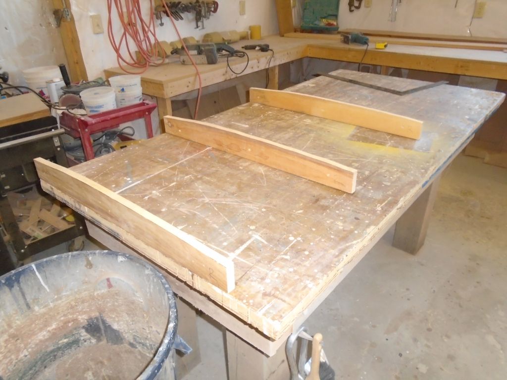
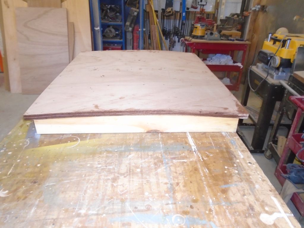
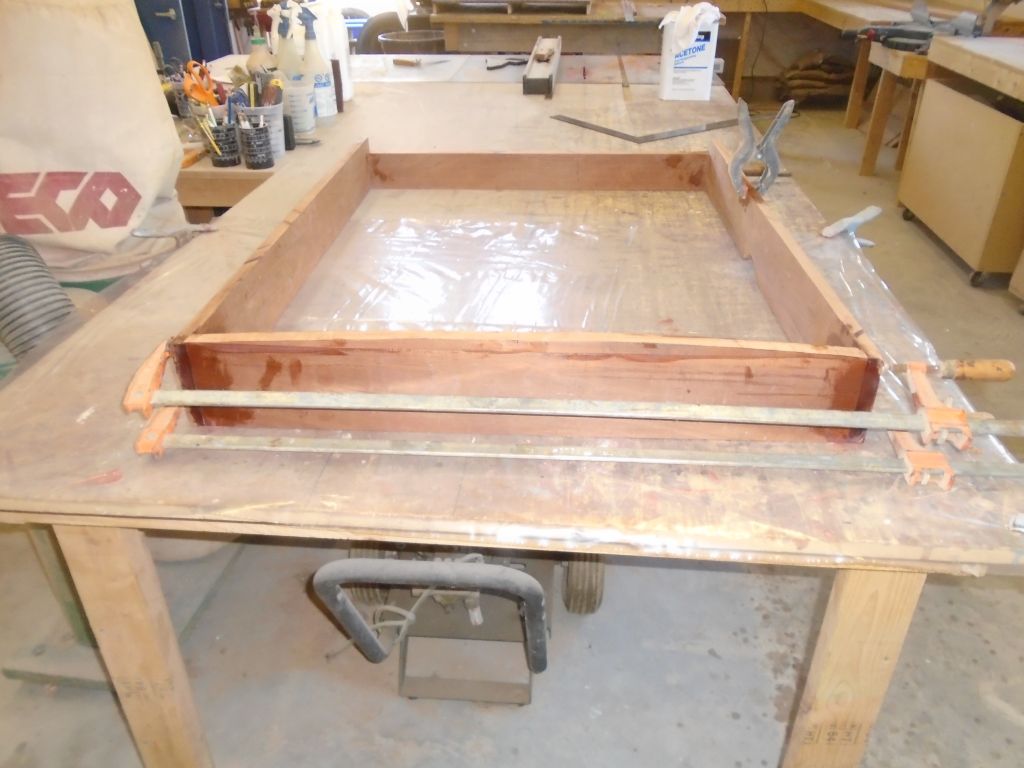
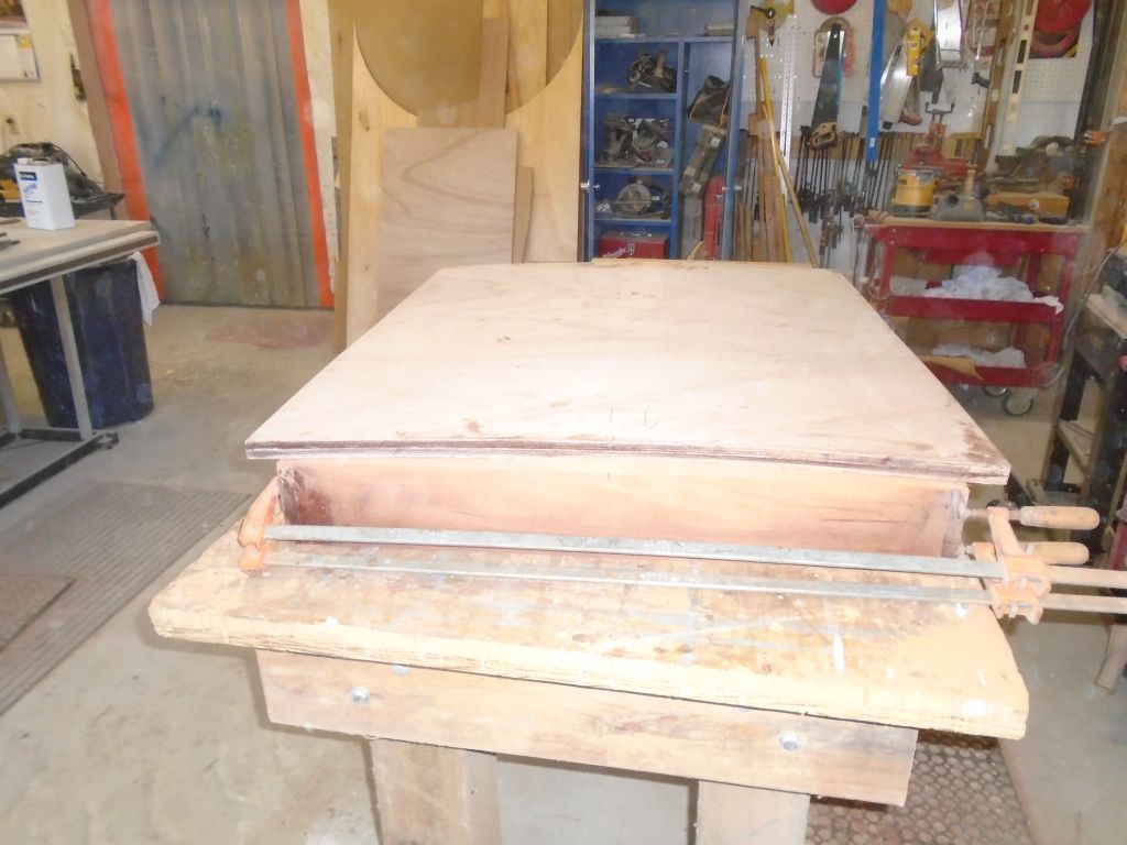
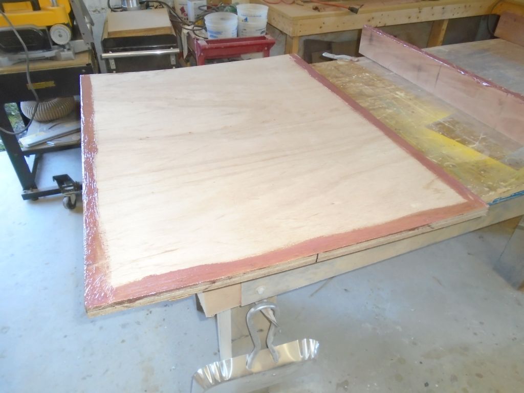
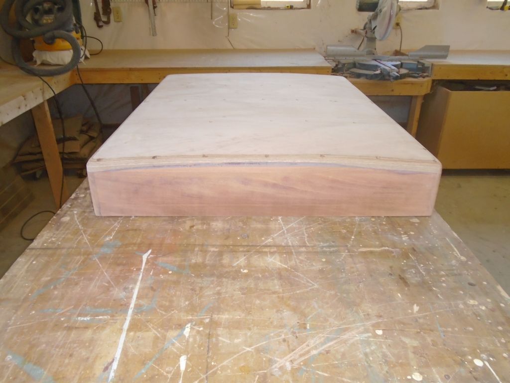
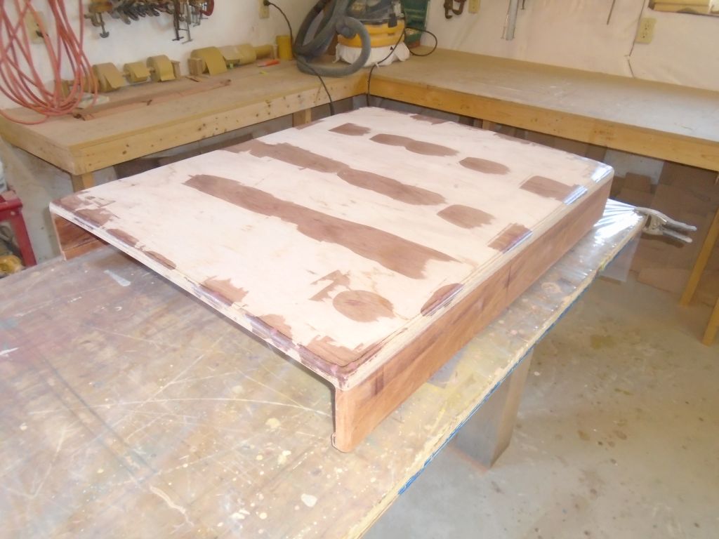
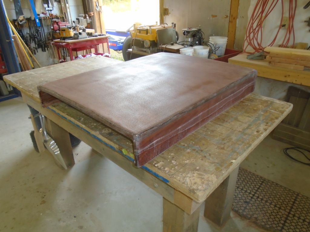
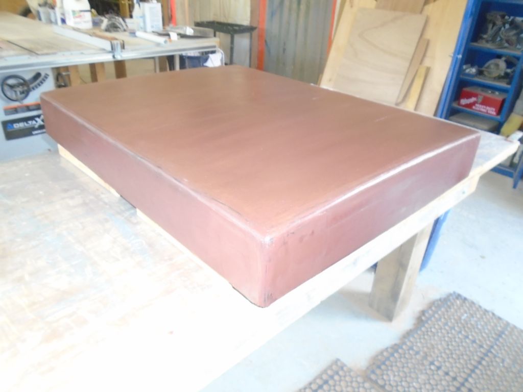
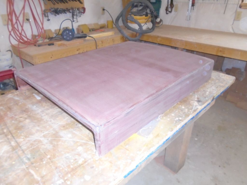
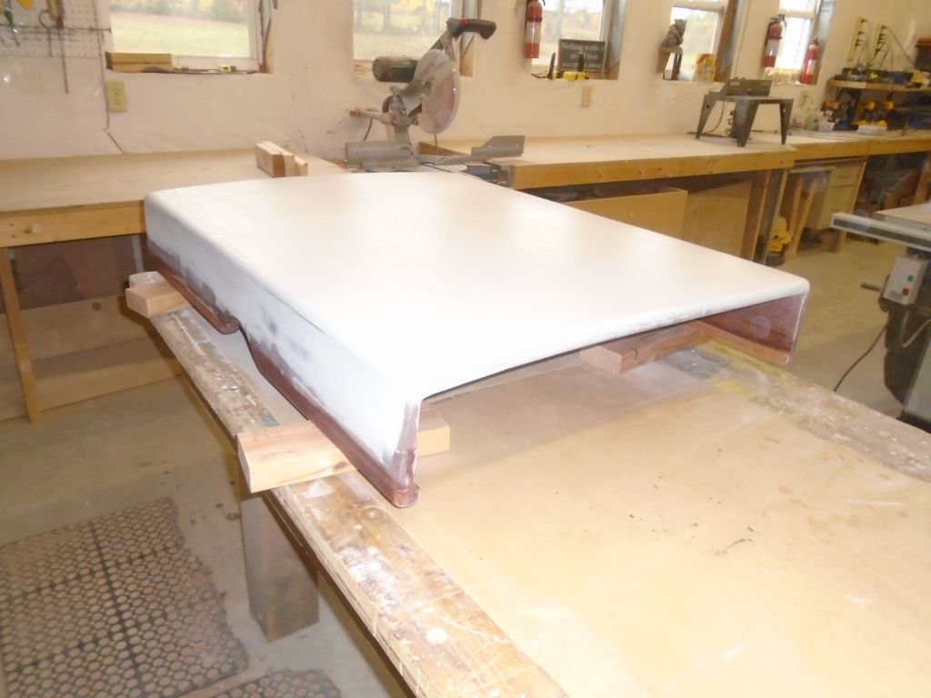
Later, back at the shop, I began construction by building the top. I prepared two oversize blanks of 12mm marine plywood, then, using epoxy adhesive, laminated them together over a simple formwork that I prepared from scrap lumber and secured directly to my bench. I cut the supporting frames with a 1/2″ camber over their width; the sliding hatch itself featured about 1/4″ camber. Because the whole arrangement would be fiberglassed and painted, I used screws to clamp the two plywood layers onto the formwork and to themselves while the epoxy cured.
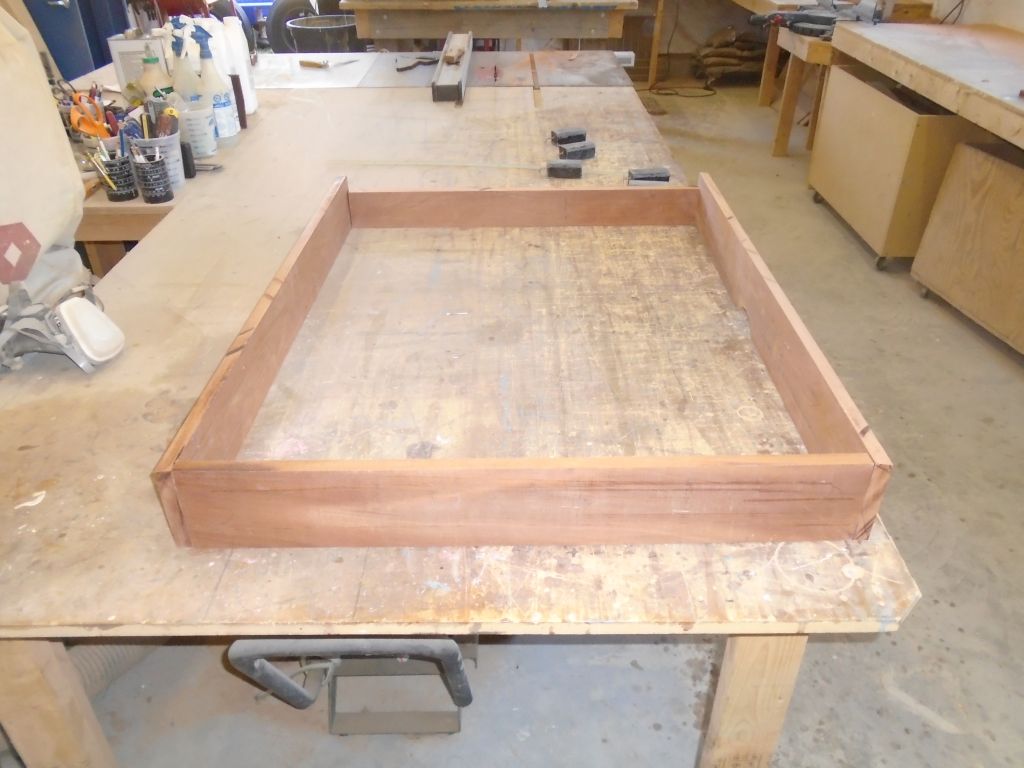
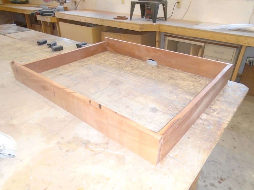
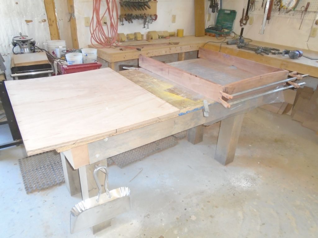
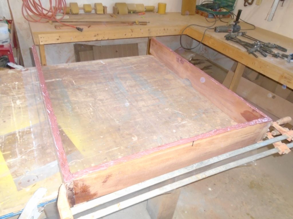
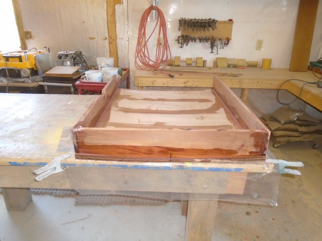
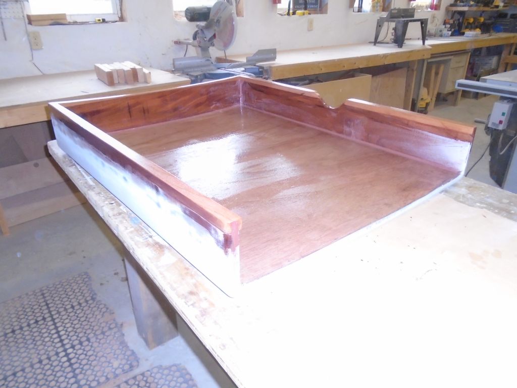
Carefully consulting my measurements and determining the final dimensions of the sea hood frame (i.e. sides and front), I prepared three pieces of mahogany and milled them to 3/4″ thickness. On the port side, I created an opening to clear an obstruction on the deck (which I”d measured for earlier), and angled the top edges slightly to approximate the shape of the cambered top. Then, I glued the sides together with epoxy adhesive, clamping the arrangement securely while the epoxy cured.
10/6/16 (3 hours)
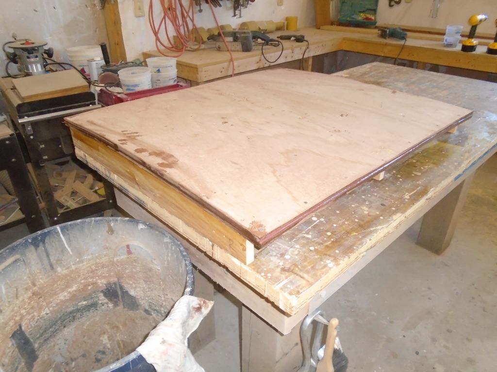
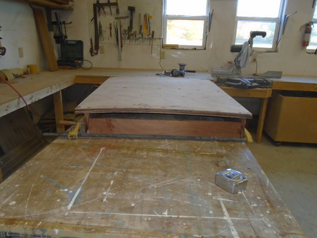
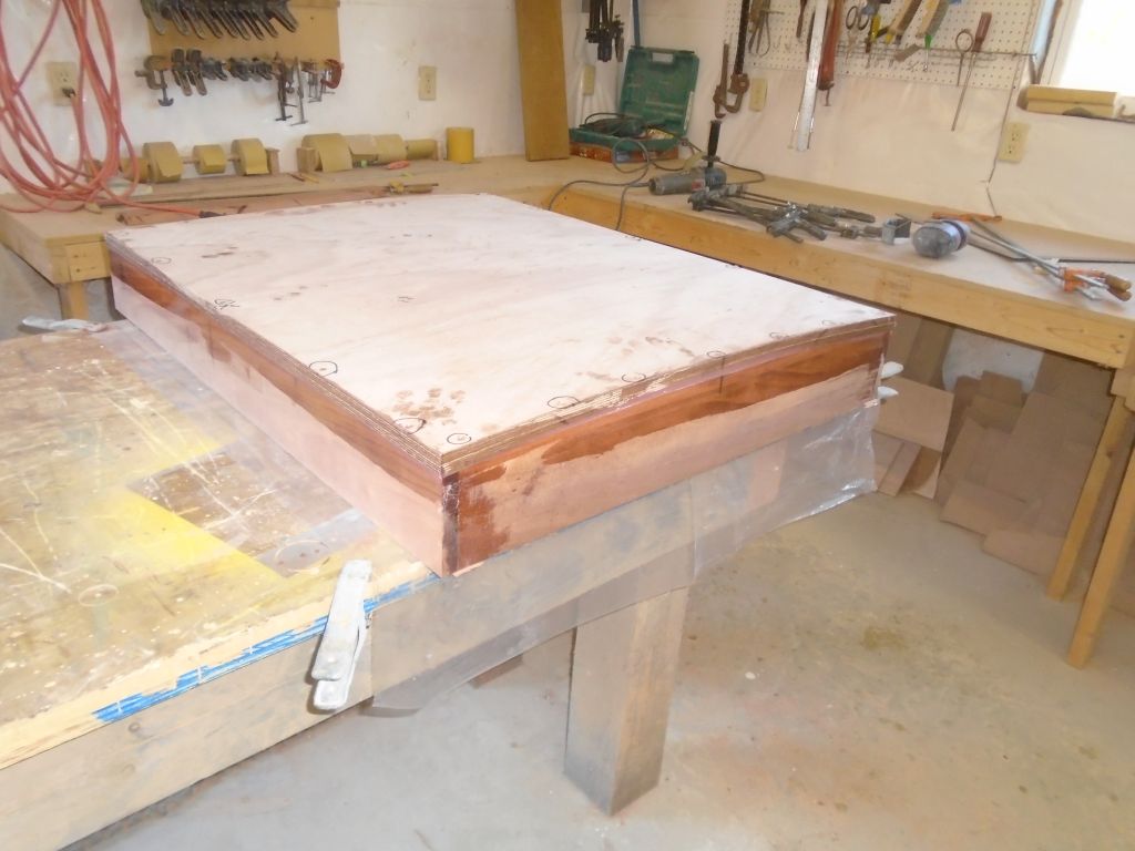
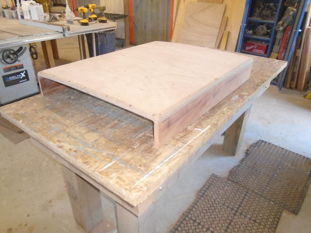
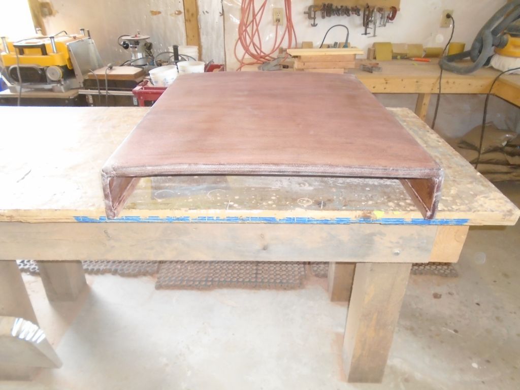
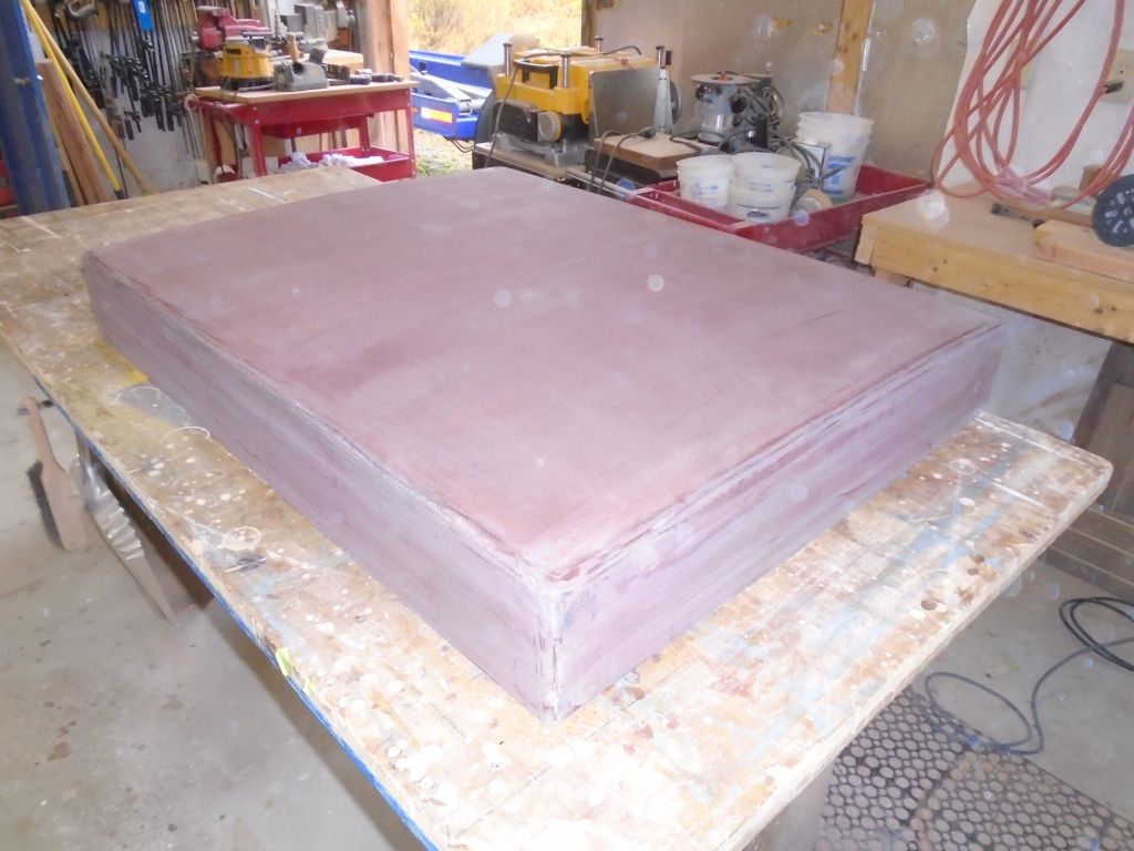
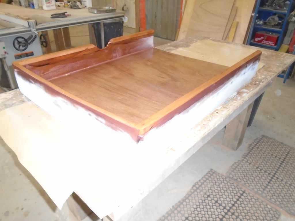
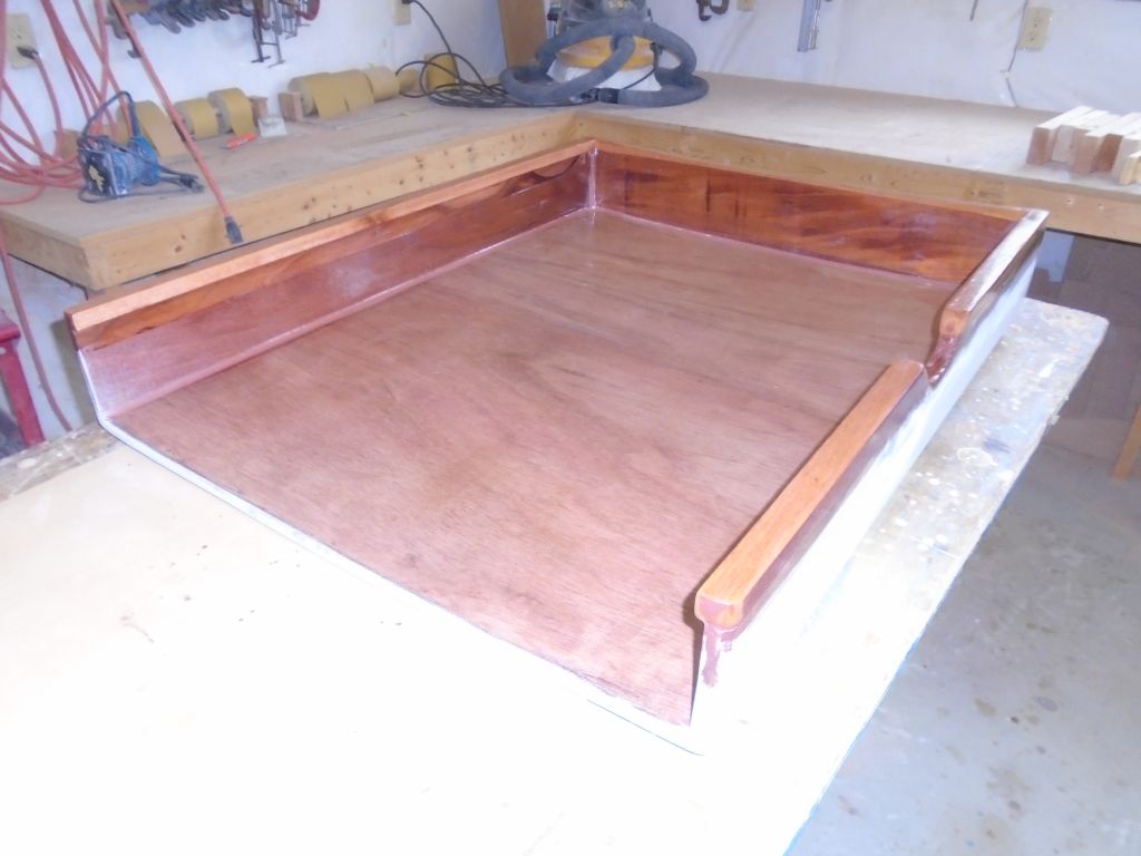
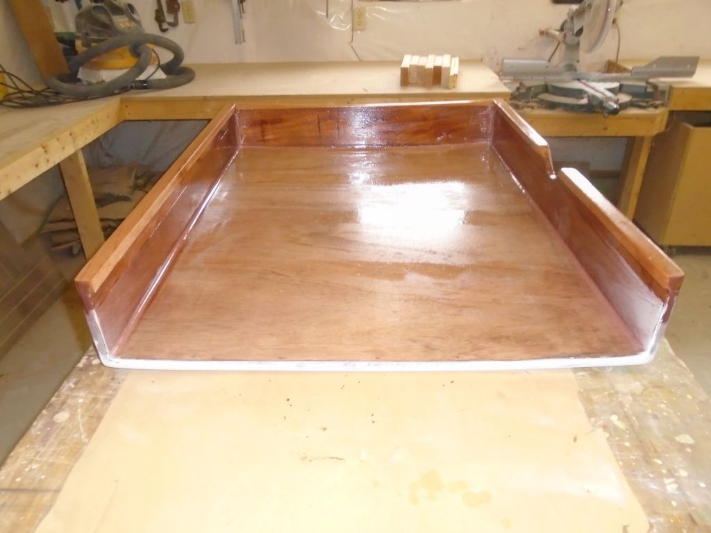
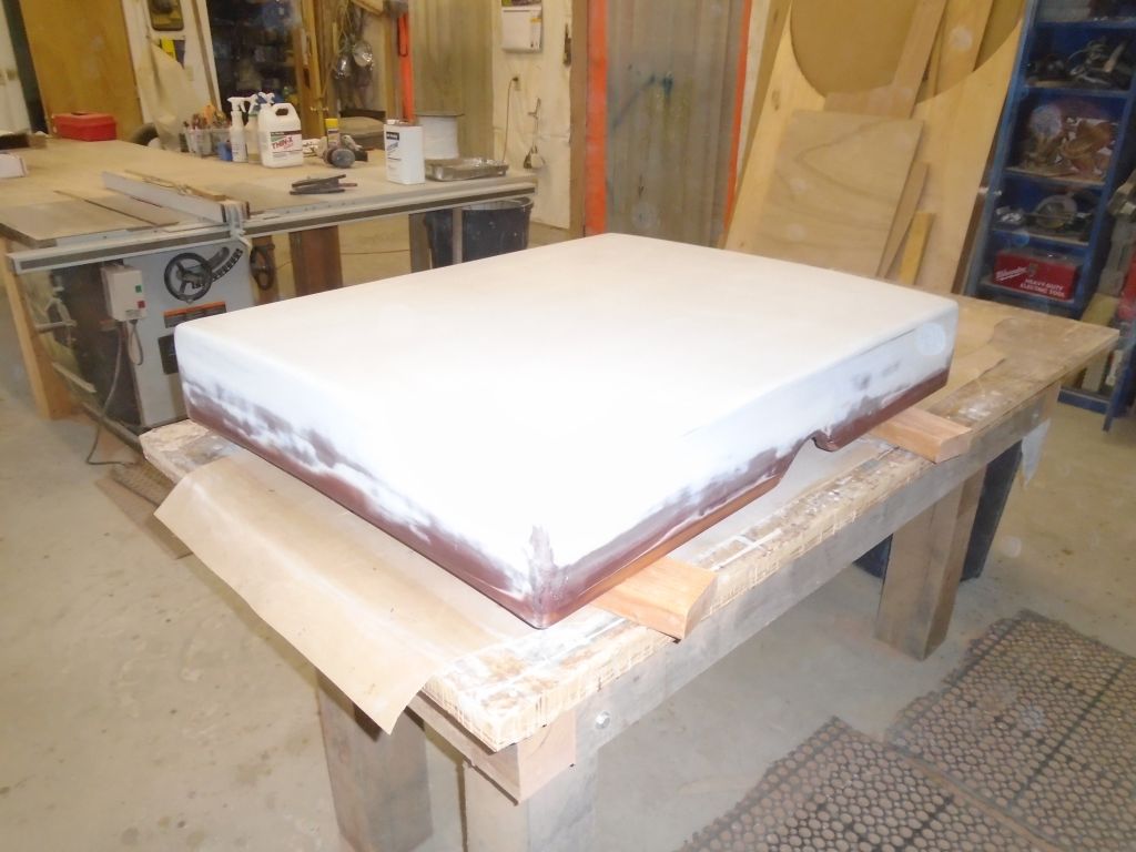
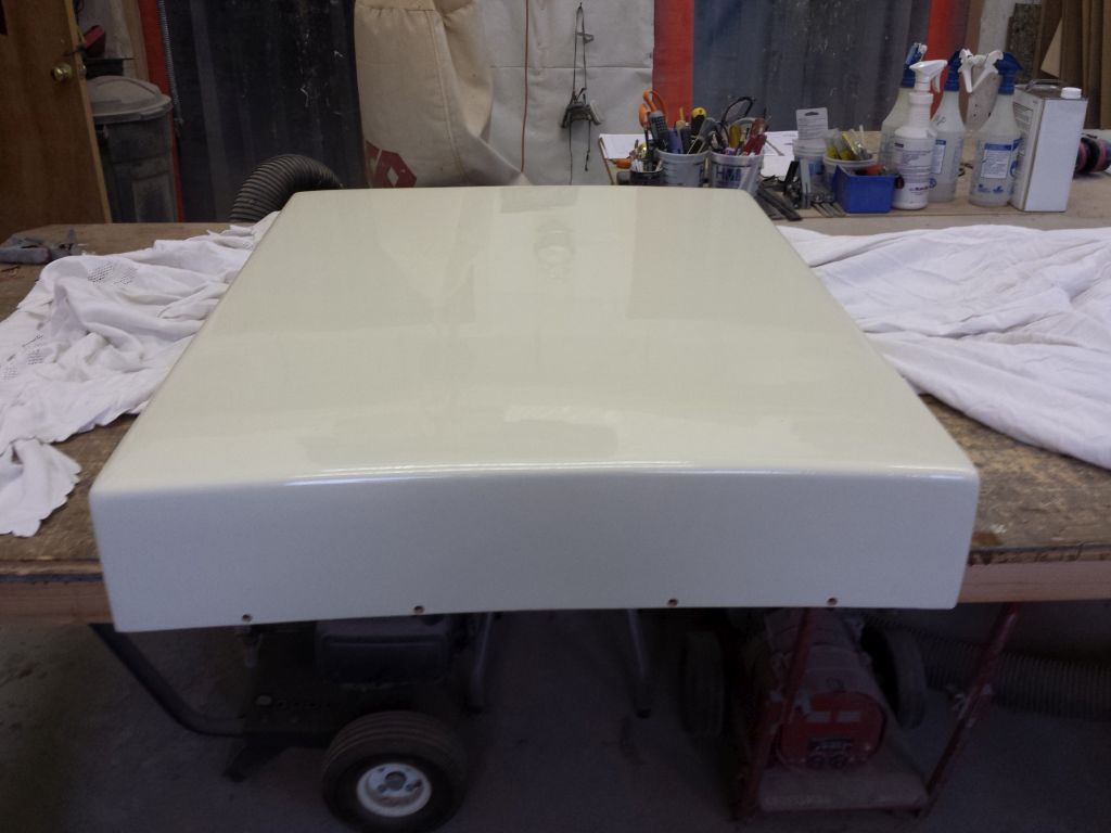
The epoxy had cured for both the framework and laminated top, so to continue construction I began by resizing the top to its final dimensions. I’d left two edges of the lamination flat and square during construction–keeping protruding edges or excess epoxy from interfering–so that now I had these edges against which to work and trim the top square and to size. In several steps, I eventually trimmed the top to fit the way I wanted it, at which point I secured it to the side frames with epoxy and temporary screws to hold it in place.
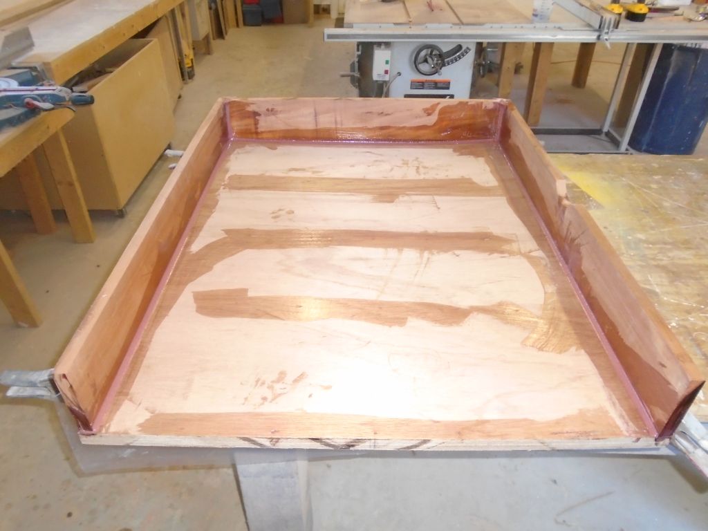
Once the top was secured, I flipped the assembly over and formed epoxy fillets on the inside, along all the seams, for extra strength and improved appearance.
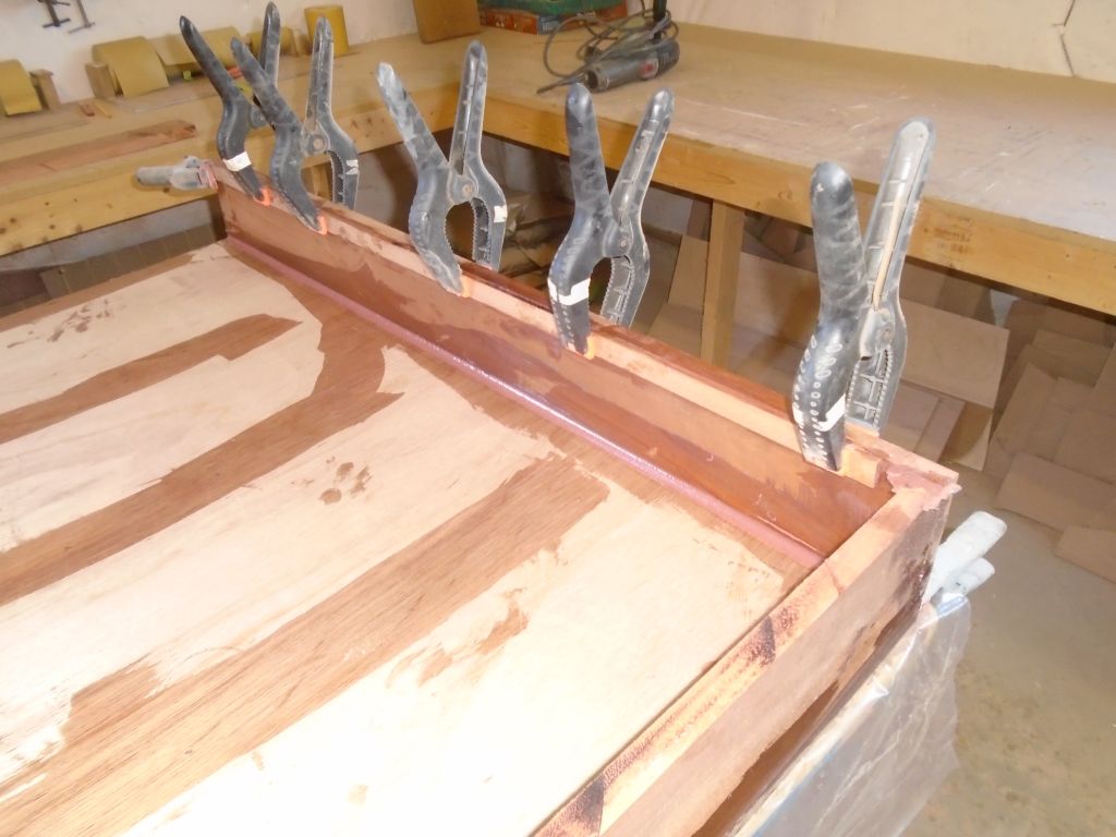
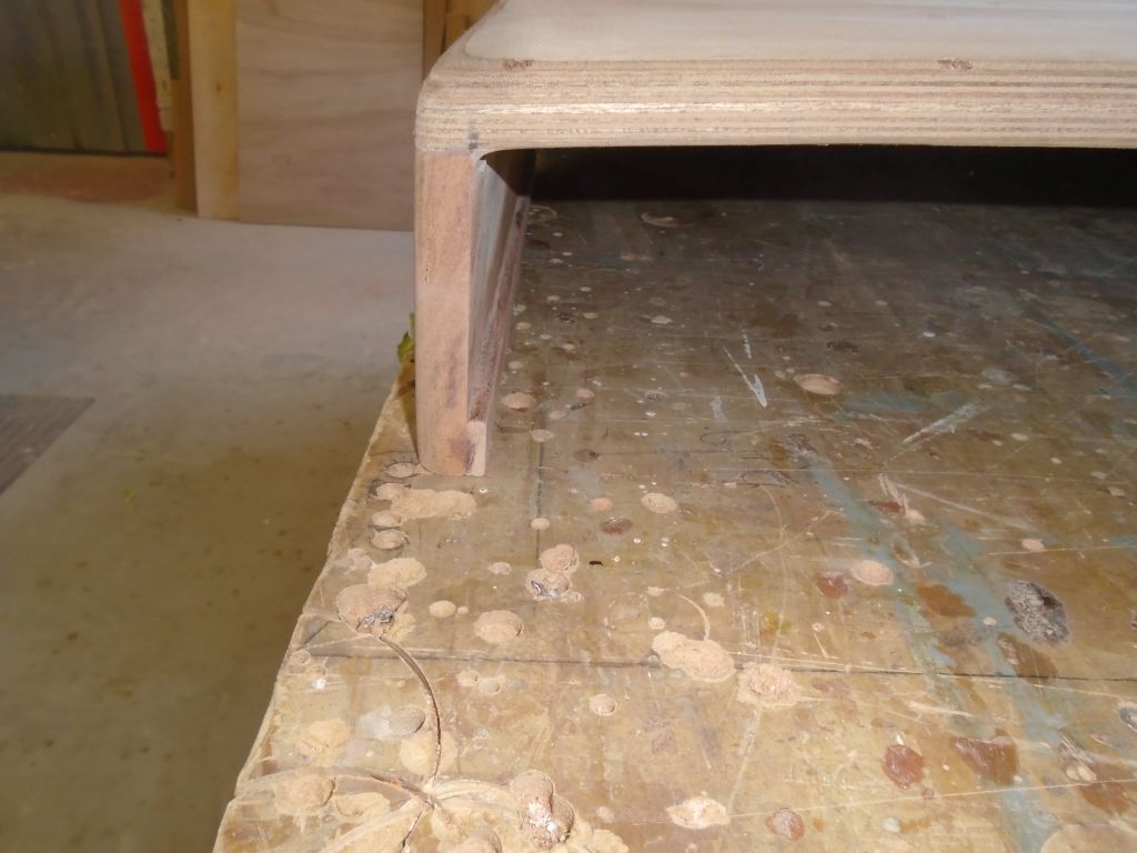
To hold the bulk of the frame just slightly off the companionway rails (as required for sliding top clearance), I installed narrow 1/4″ thick by 1″ wide strips of mahogany along the bottom edges of the side frames, secured with epoxy adhesive and clamps.
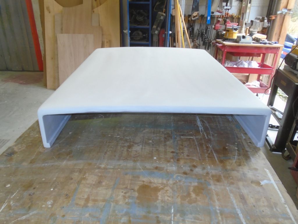
10/7/16 (3 hours)
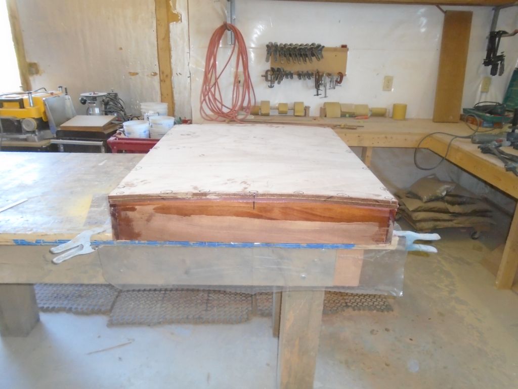
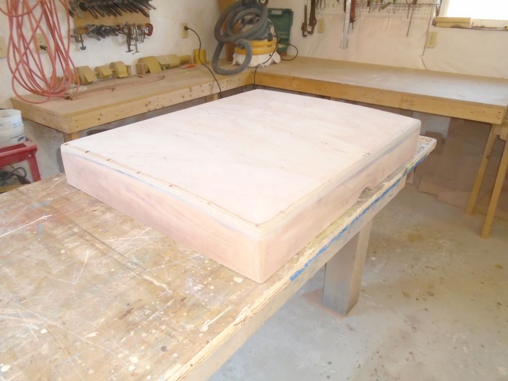
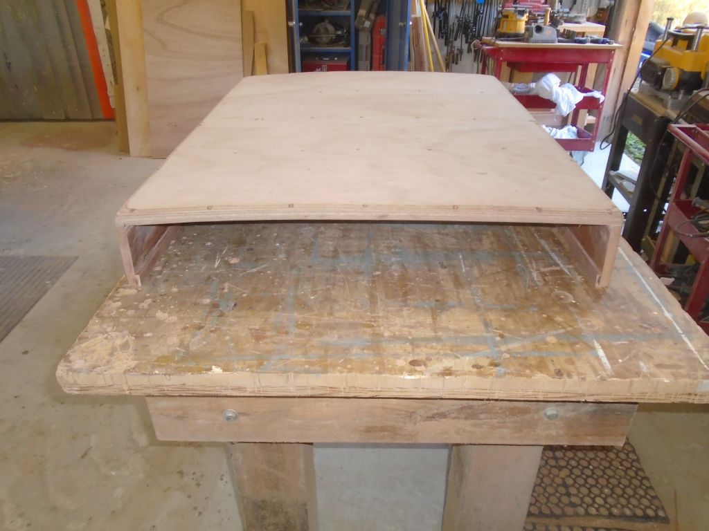
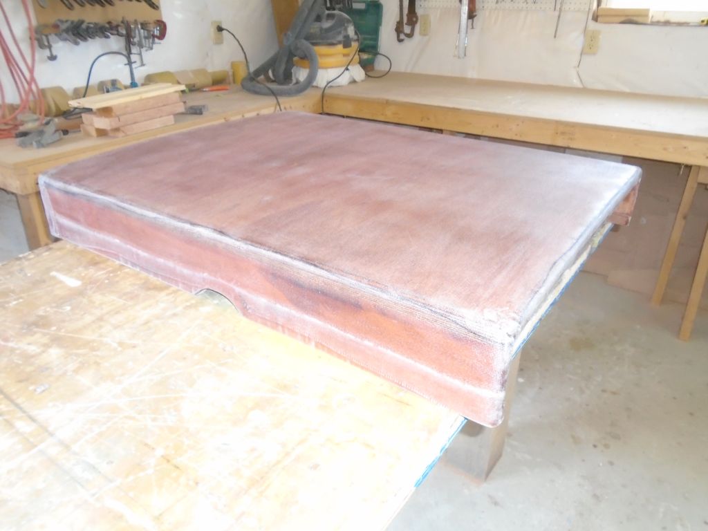
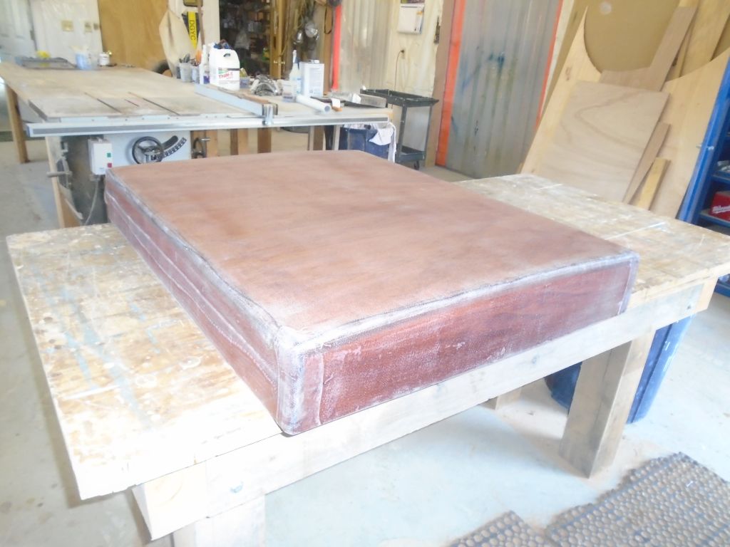
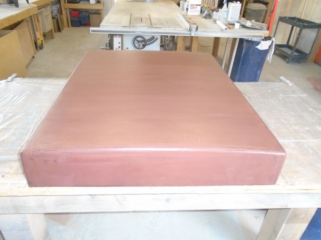
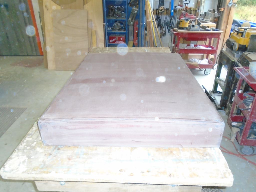
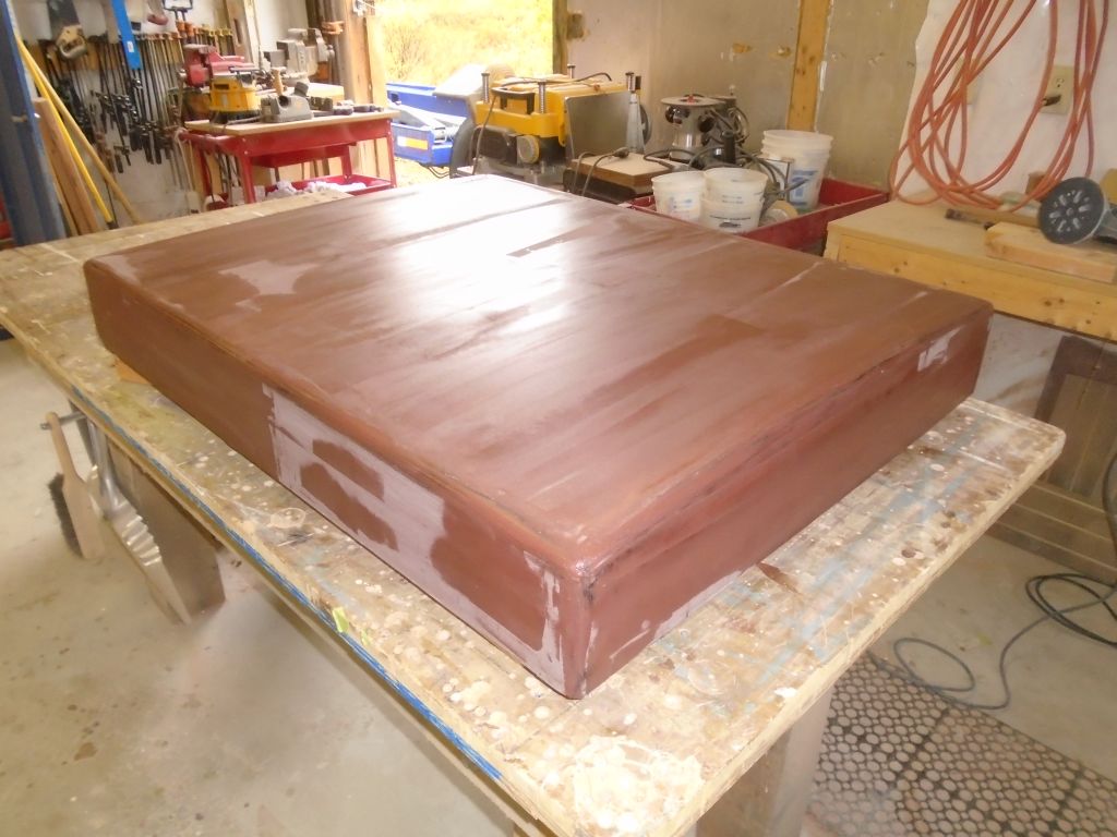
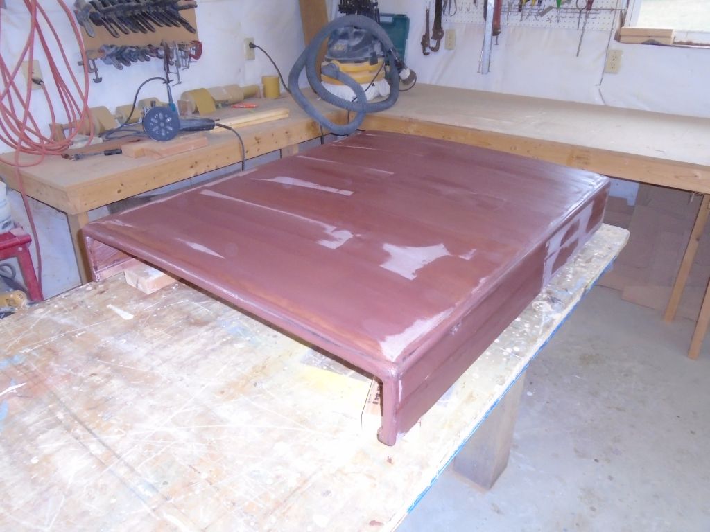
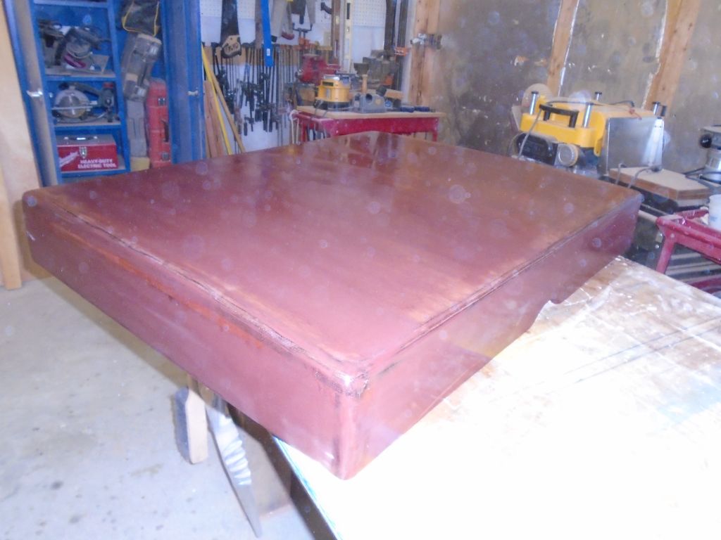
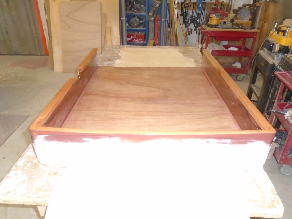
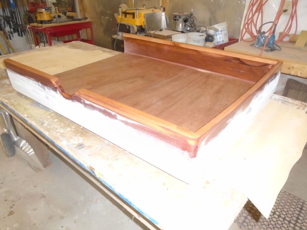
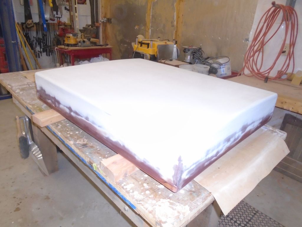
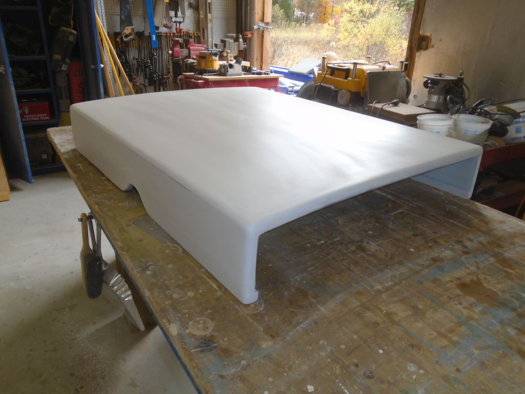
Now that all the epoxy was cured, I removed the clamps and screws and shaped the top, routing a large radius on the top corners as well as on the four corners of the frame. Then, I sanded the assembly smooth to prepare for fiberglass.
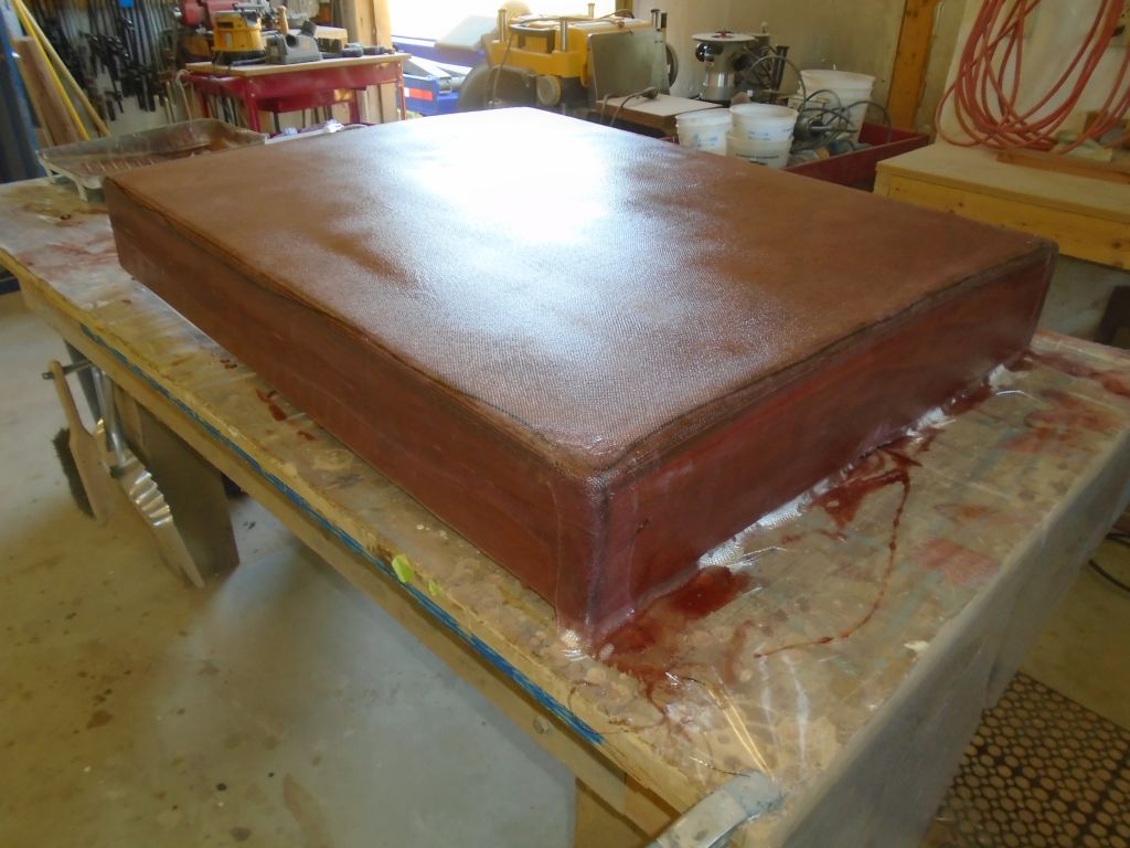
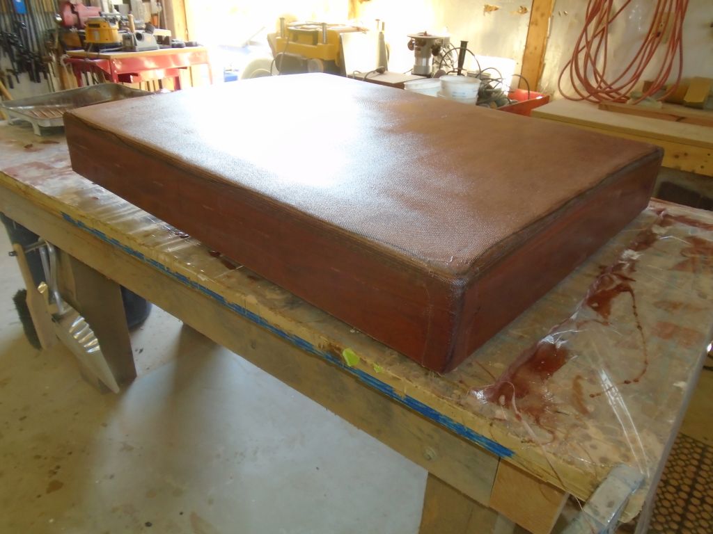
After cleaning the surfaces thoroughly, I began by filling the screw holes left over from assembly with a thickened epoxy mixture. Then, I installed a layer of 10 oz. cloth set in epoxy resin. I let the cloth run wild over the bottom edges of the frame, but later, when the epoxy was green and semi-solid, I trimmed off the excess with a sharp knife.
10/8/16 (0.75 hours)
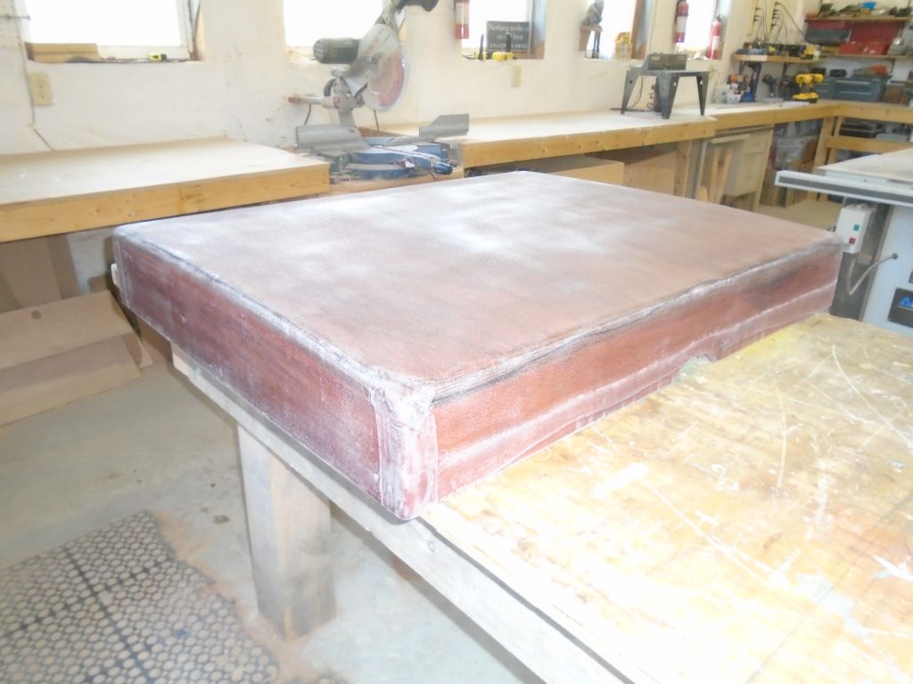
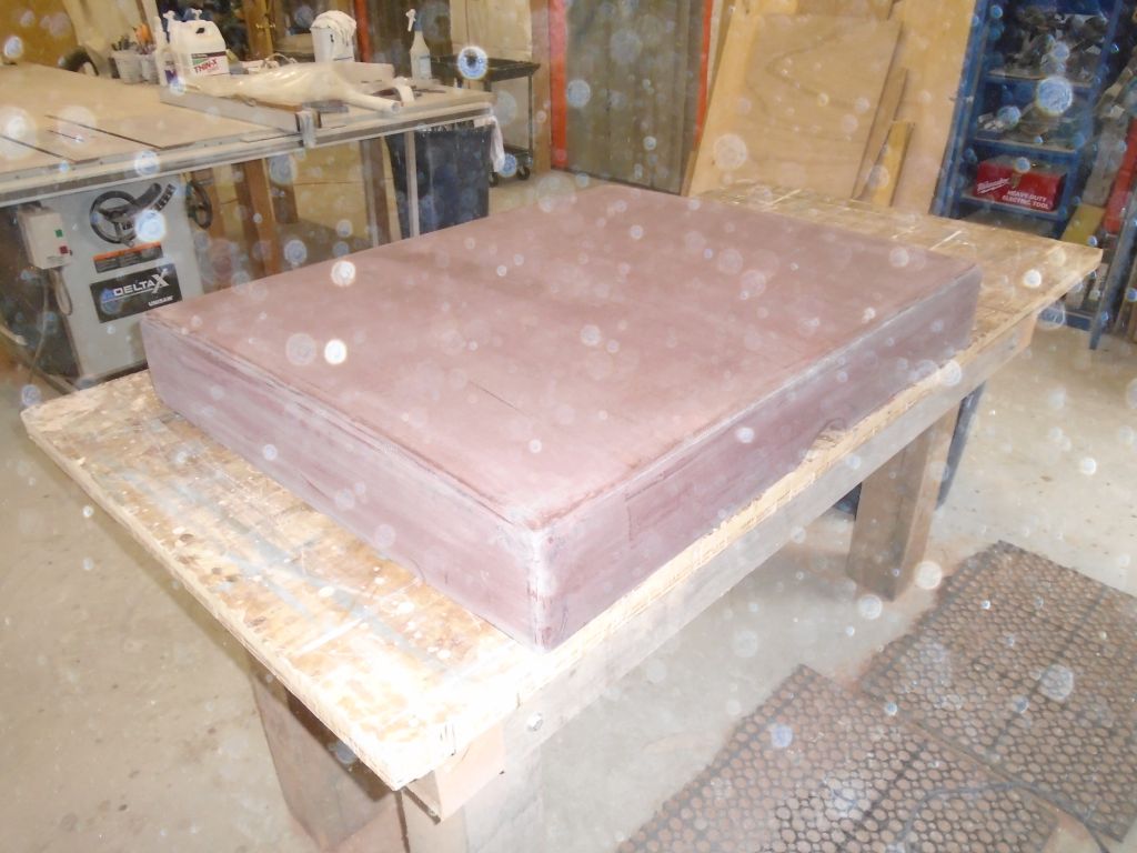
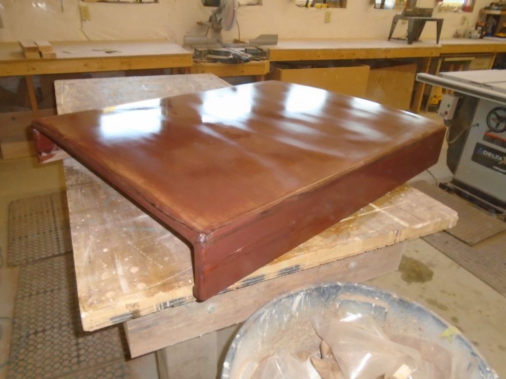
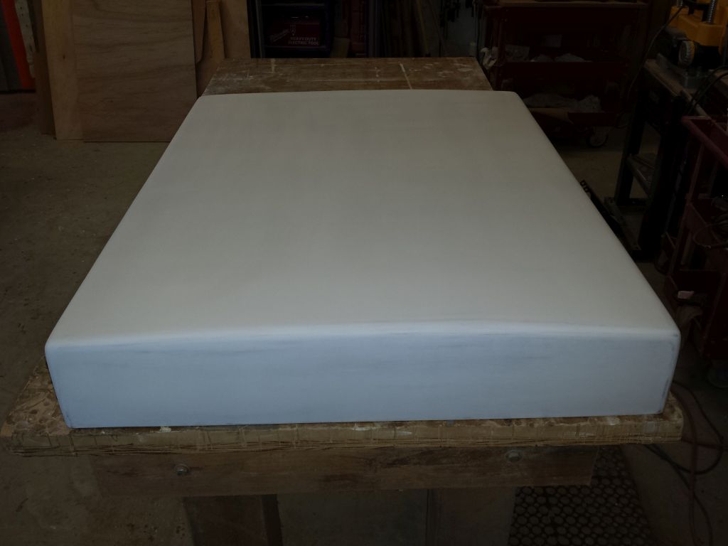
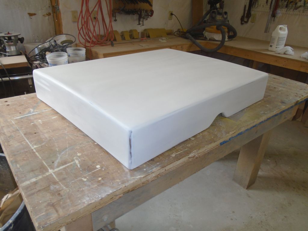
After a light water wash, I lightly sanded the fiberglassed piece to remove vestiges of rough edges and otherwise prepare the surface for additional epoxy treatment.
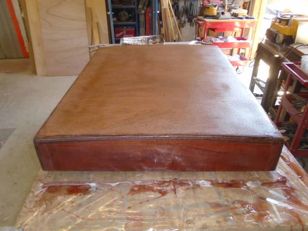
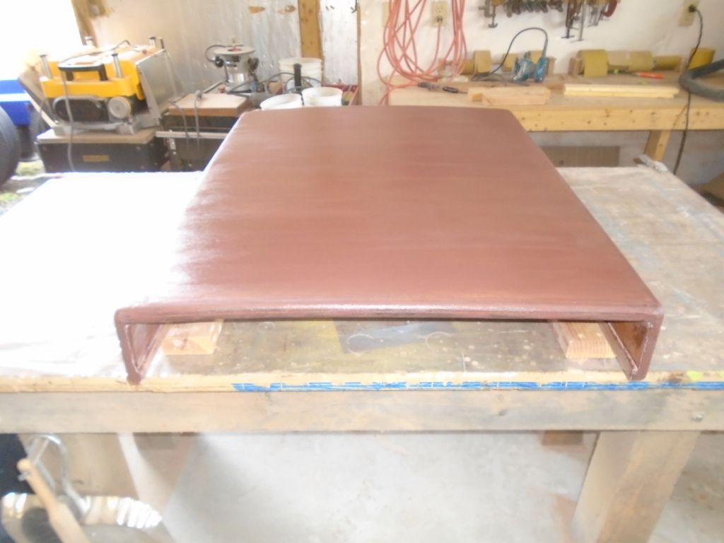
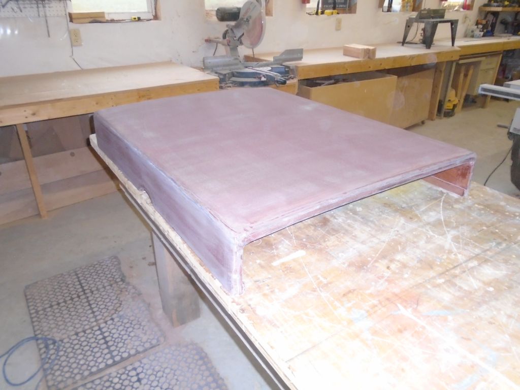
To fill the weave of the cloth, and smooth out any imperfections between sections of cloth, I applied a skim coat of epoxy fairing compound over the entire piece.
10/9/16 (0.75 hours)
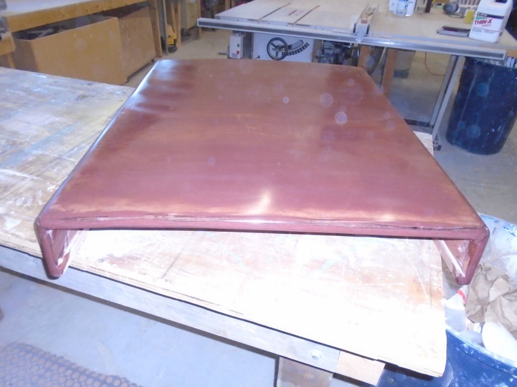
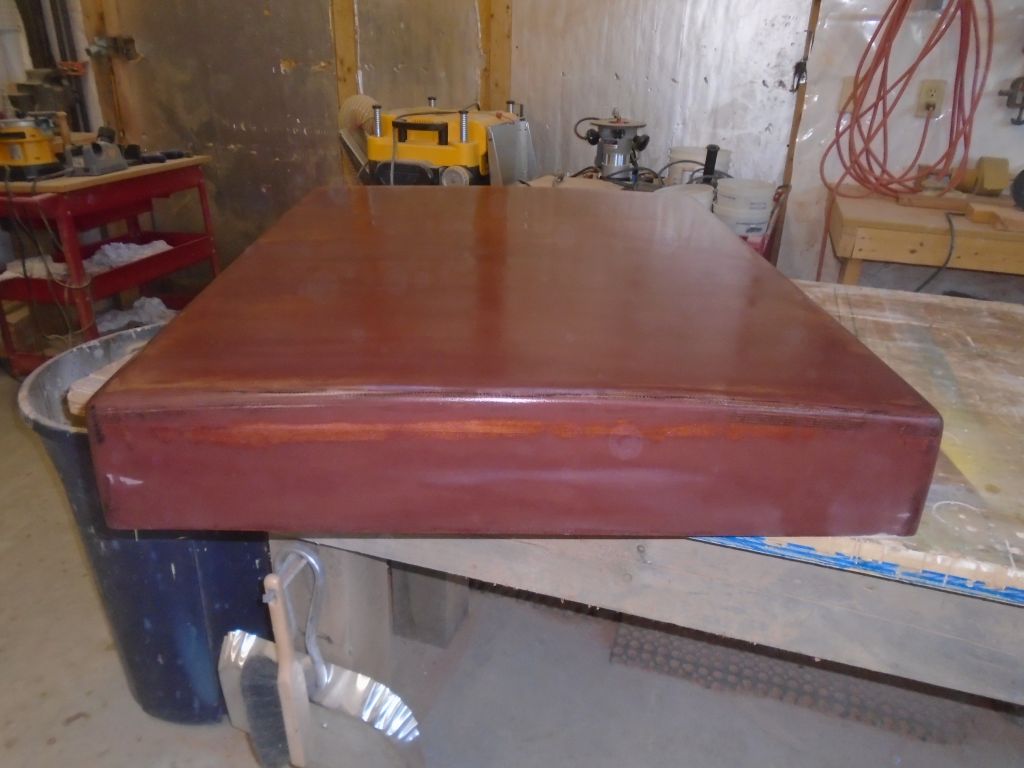
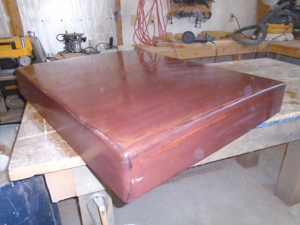
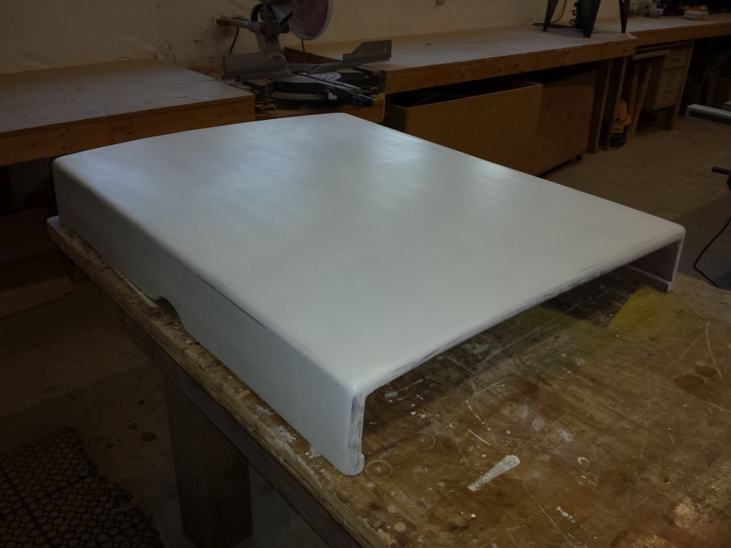
With the first round of fairing compound cured, I water-washed and sanded the piece, smoothing the surface and removing any excess fairing compound. The first round of filler had done a good job, but as anticipated, there were various low spots requiring minor additional attention.
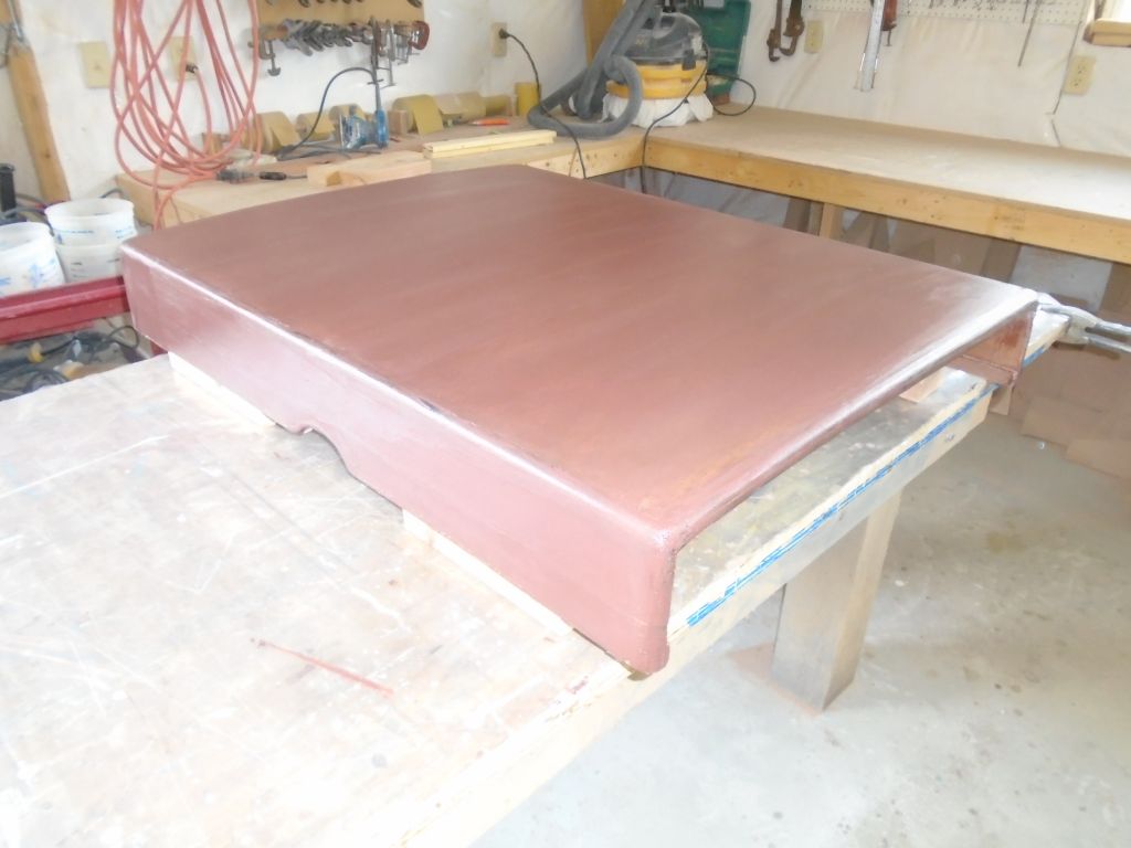
After cleanup, I applied a second round of fairing compound as needed: a very light coat to fill any remaining cloth weave or shallow lows.
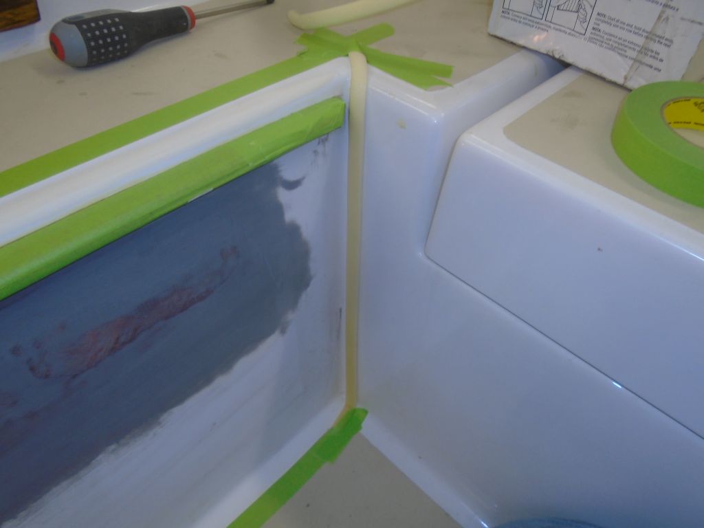
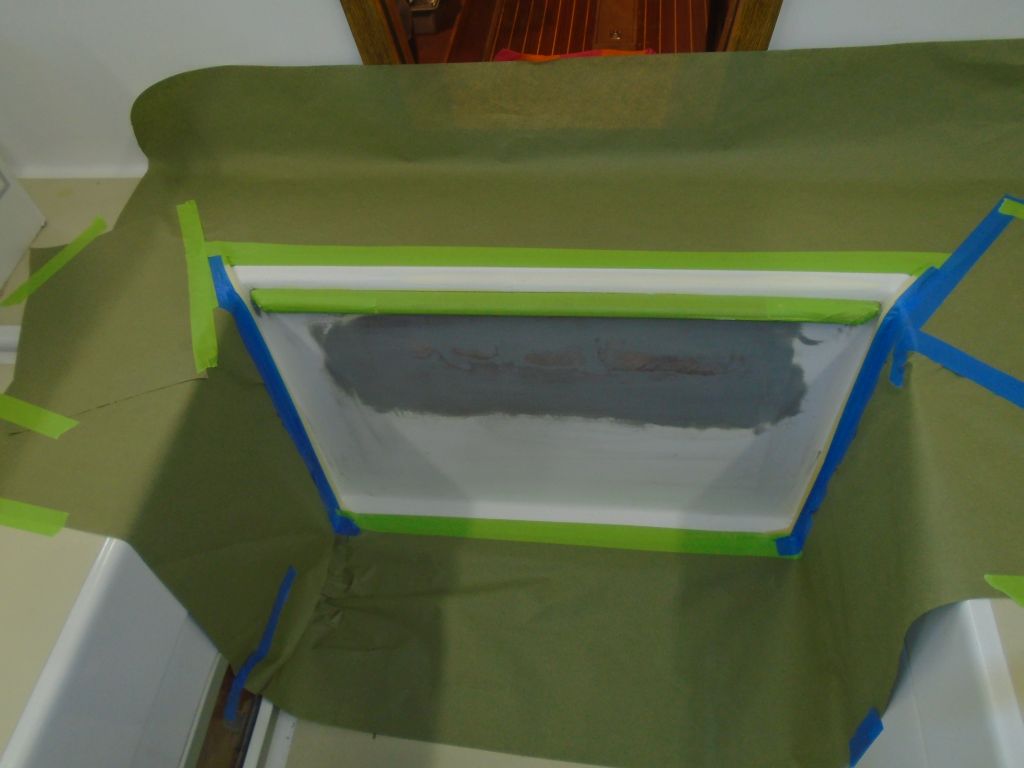
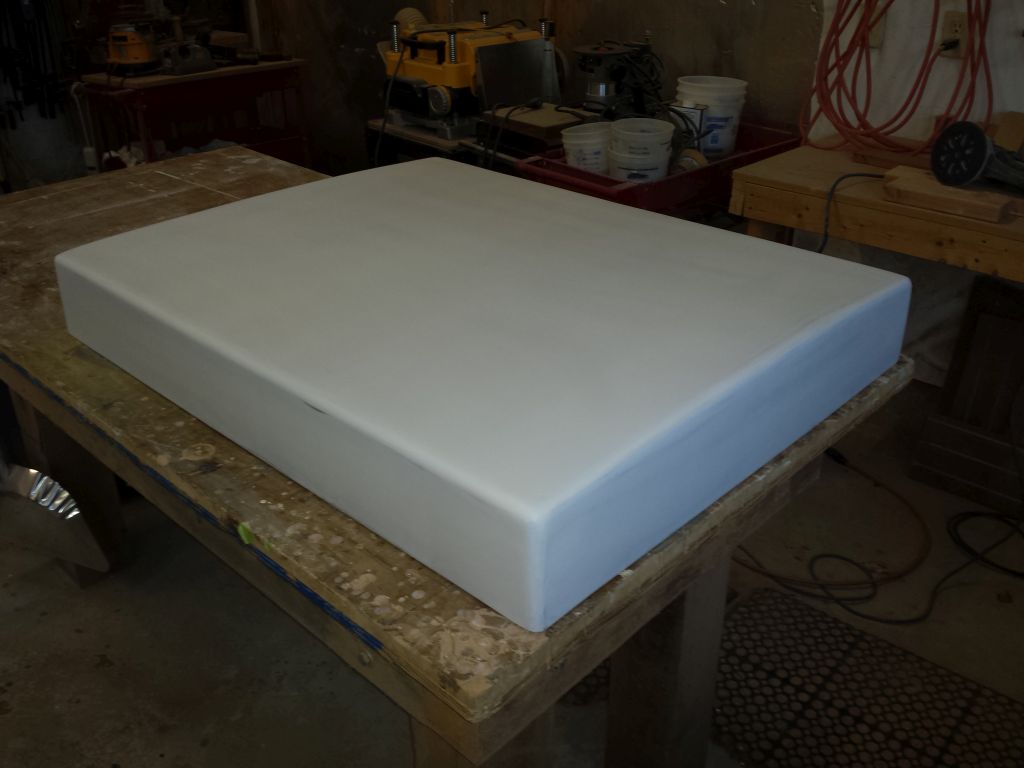
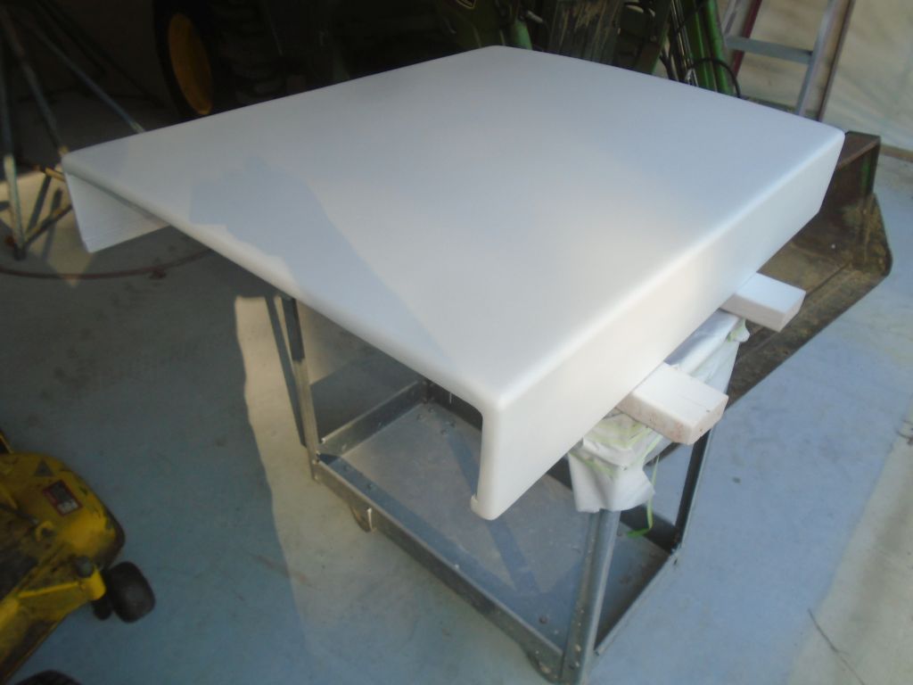
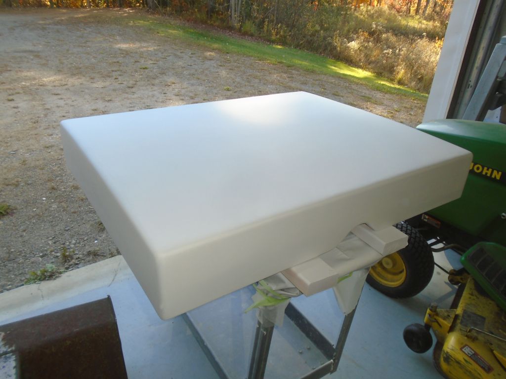
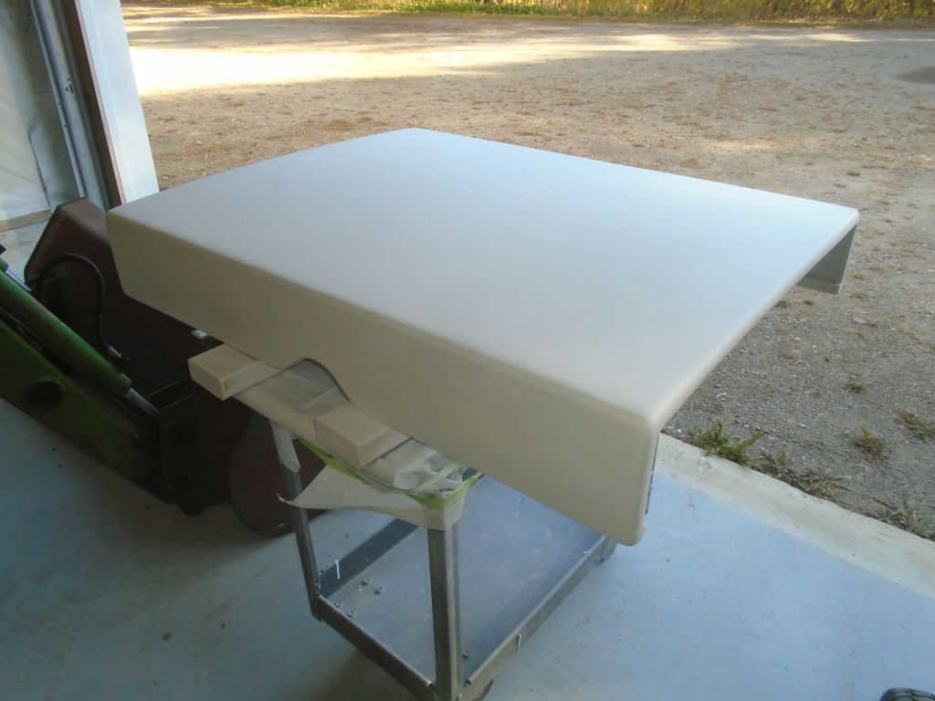
10/10/16 (2 hours)
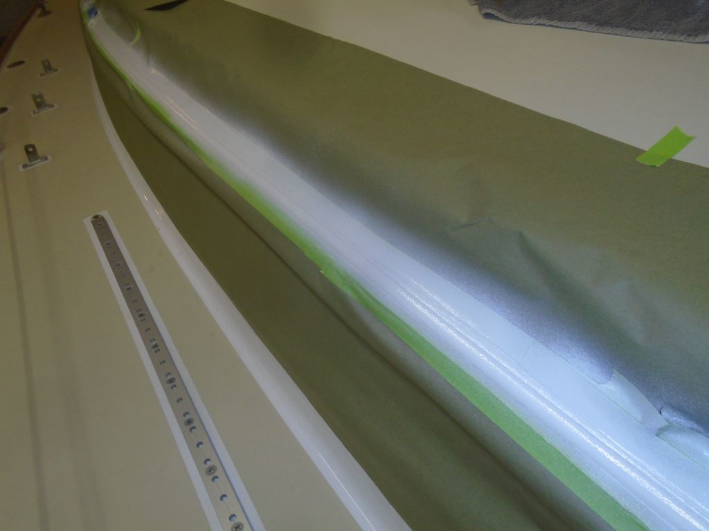
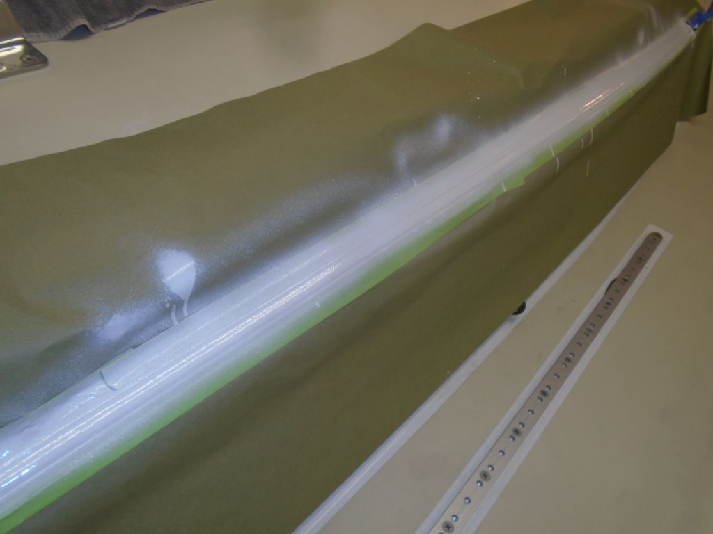
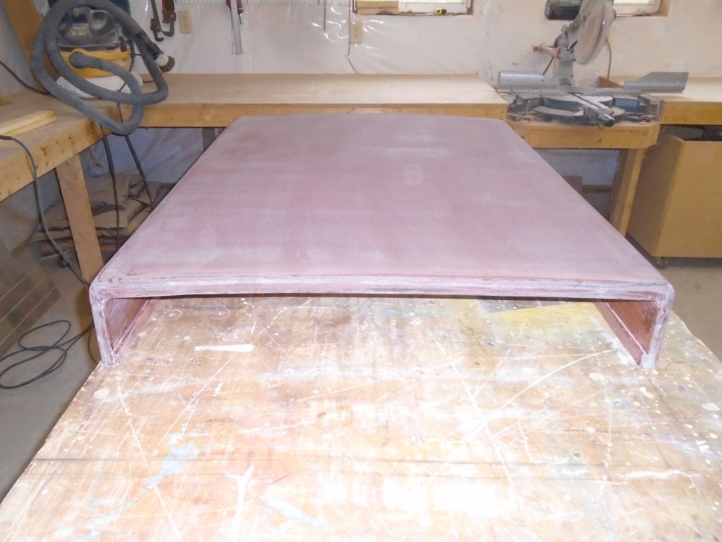
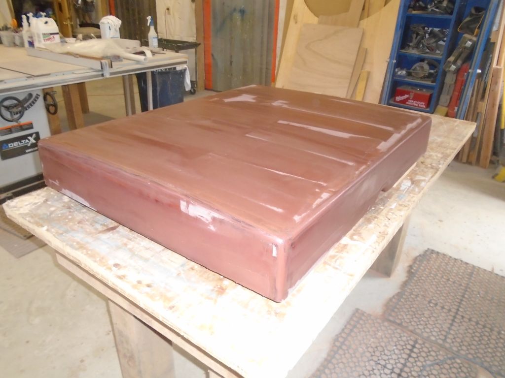
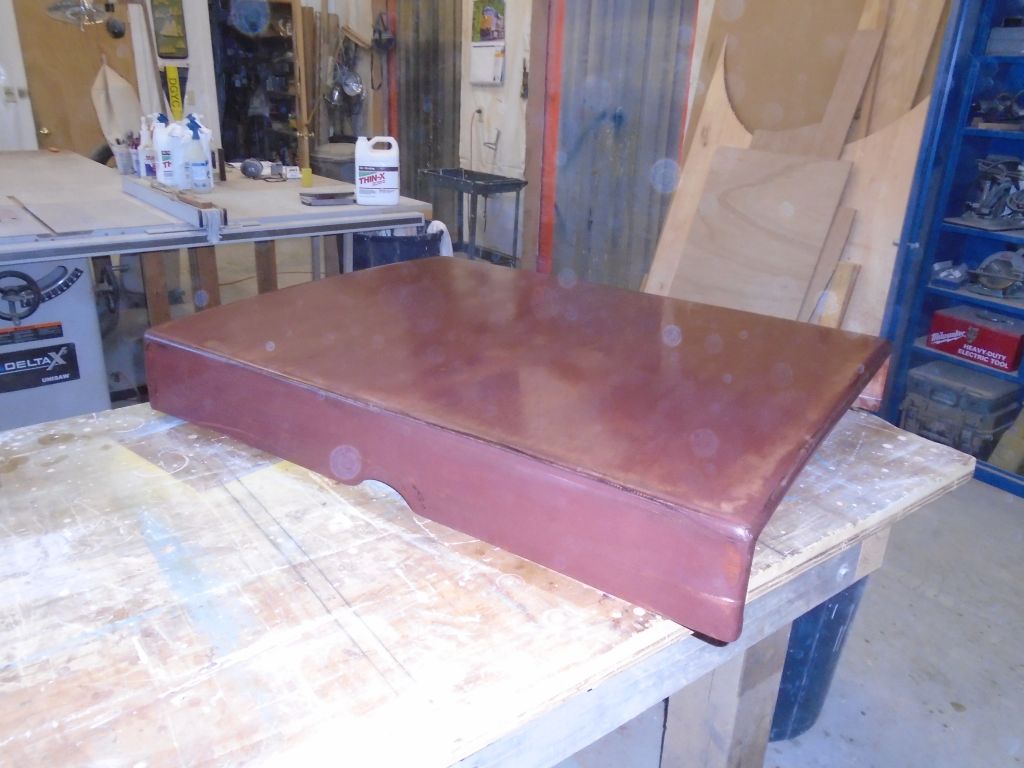
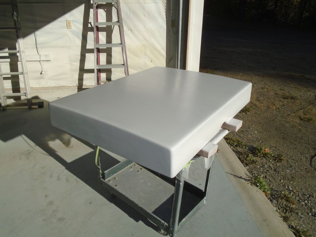
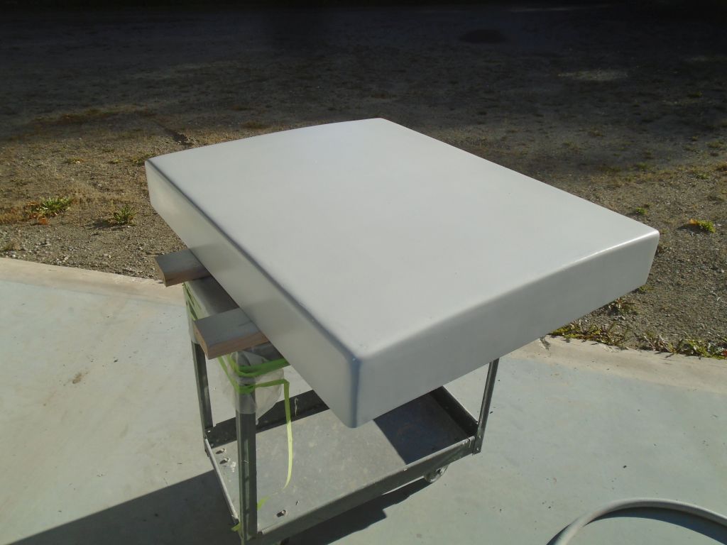
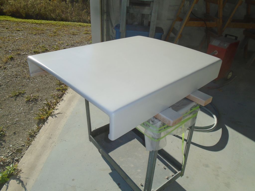
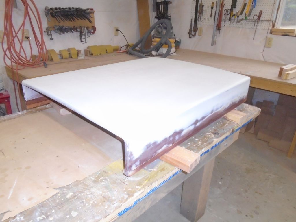
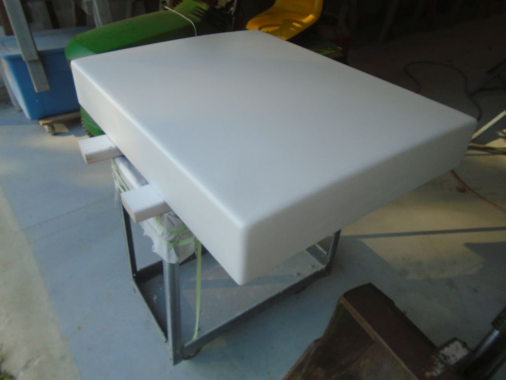
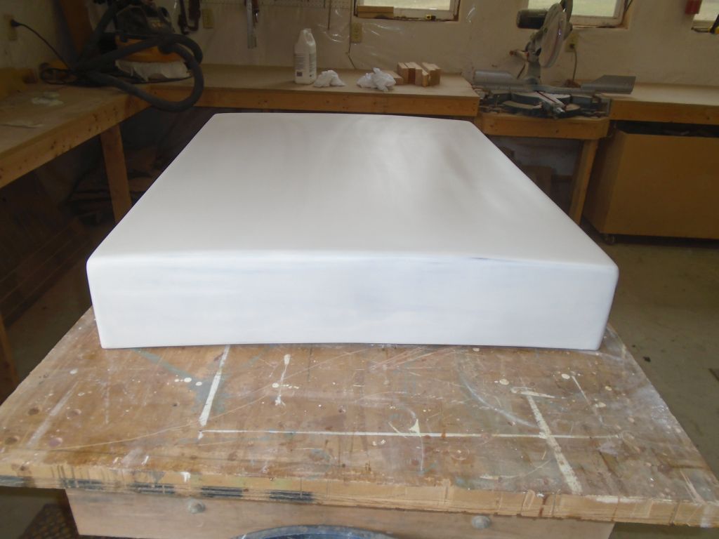
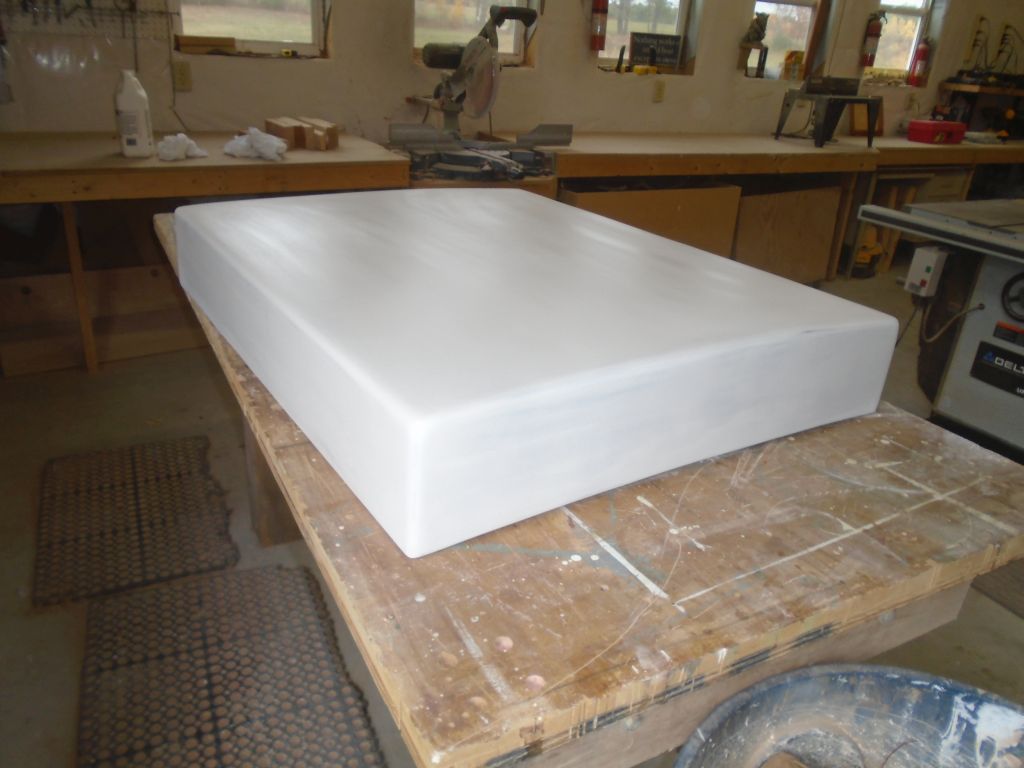
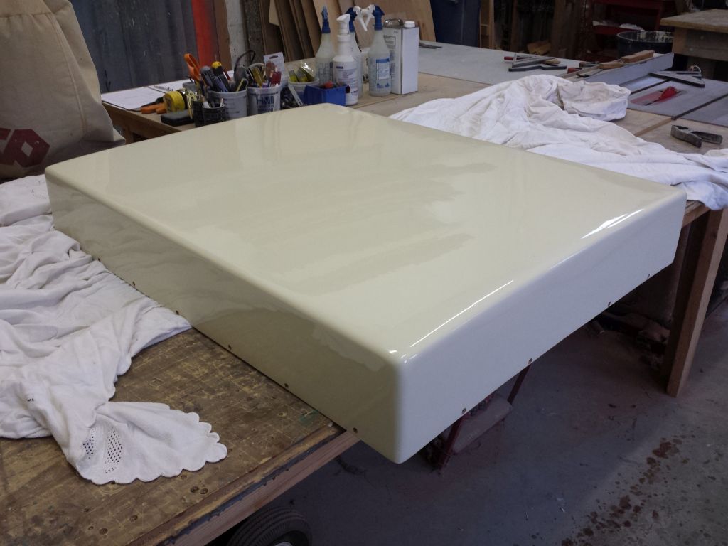
Once more, I lightly sanded the piece, smoothing the final layer of fairing compound and preparing the surface for primer. Afterwards, I vacuumed and solvent-washed to clean the piece.
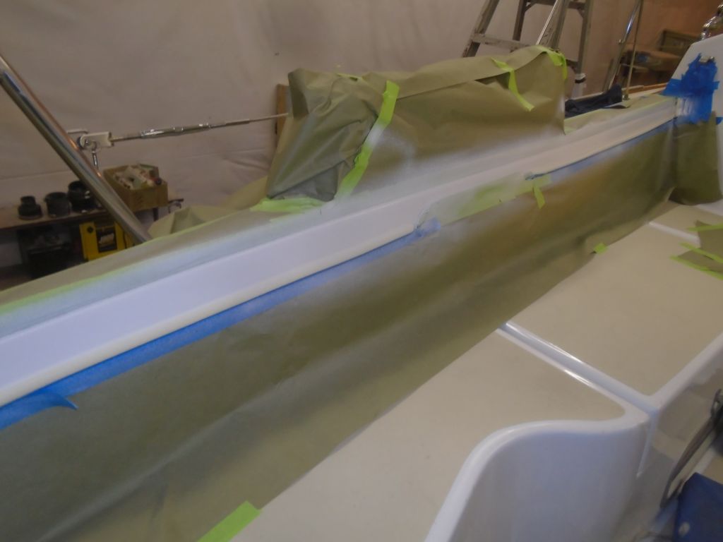
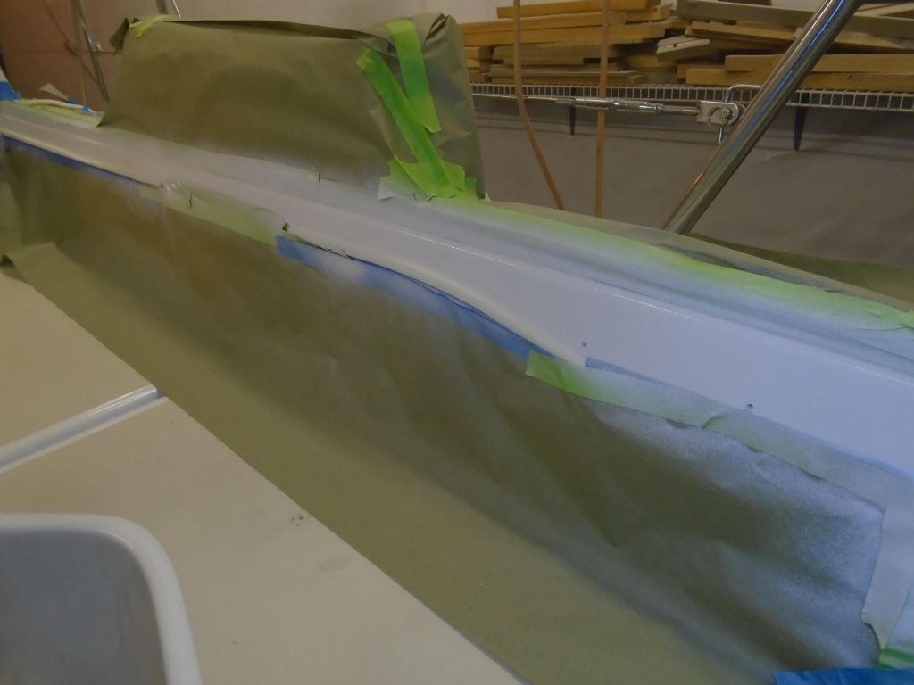
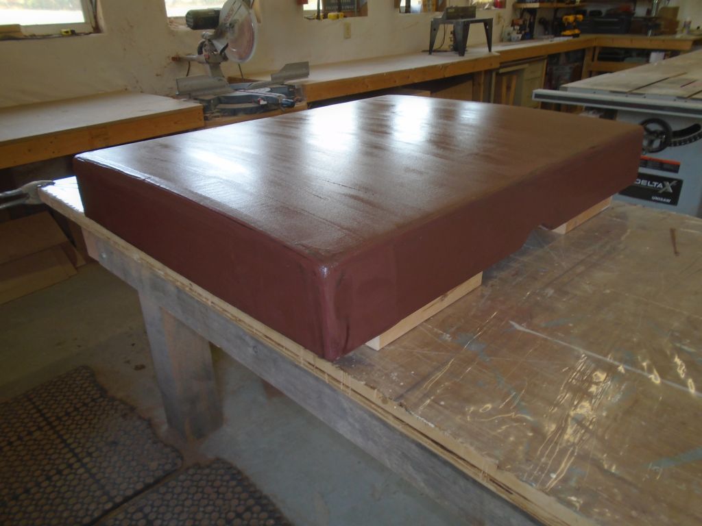
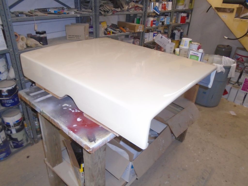
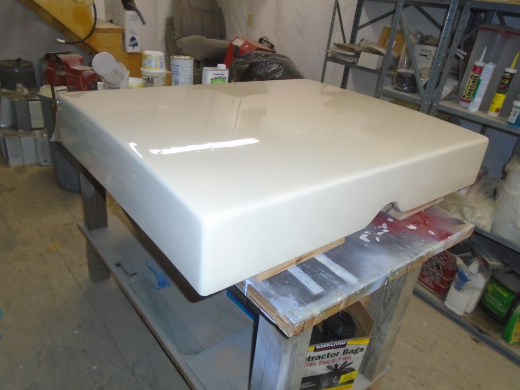
Later, I spray-applied three coats of white epoxy-based primer, which highlighted a few areas requiring minor additional attention, but otherwise the finished hood looked pretty good.
10/11/16 ( 2.5 hours)
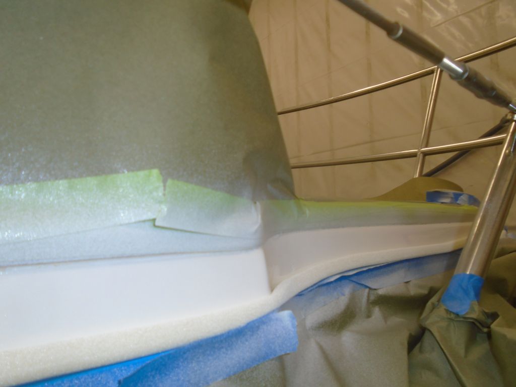
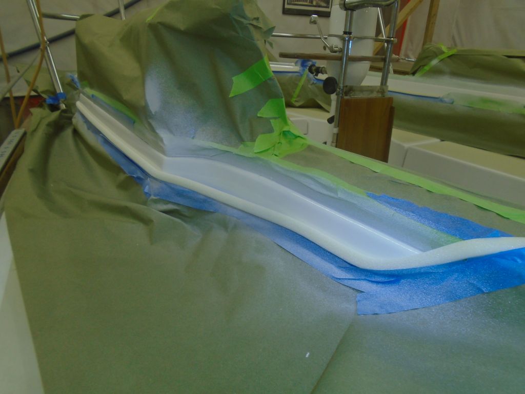
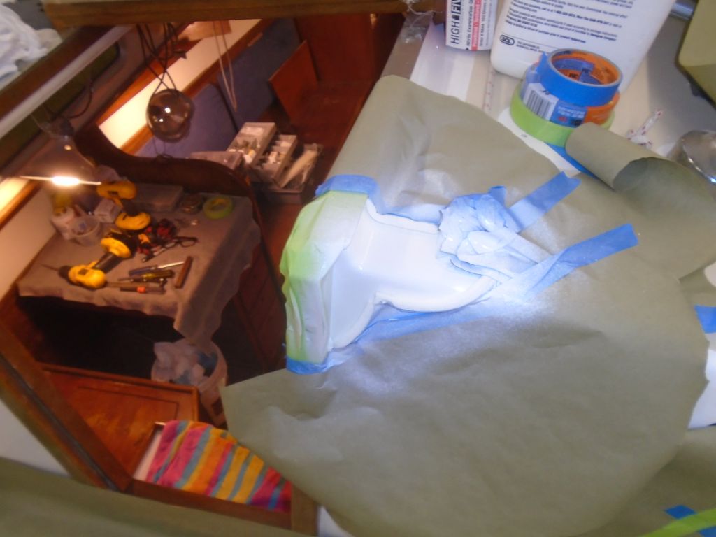
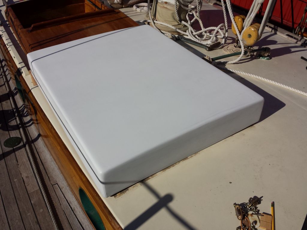
Before departing to perform a test-fitting on the boat, I lightly sanded the fresh primer, and cleaned up the hood.
Once at the boat, I placed the hood over the companionway, and checked its fit all around. The cutout for the nearby traveler support worked out well, and I scribed the deck camber on the forward end of the new hood so I could make that cut back at the shop. To my dismay, I found that the companionway was taller at the aft end than at the forward end, which required that I add some height to the sides of the sea hood for clearance at the aft end. Despite my measurements all over during the initial viewing, I’d apparently failed to notice this. I shimmed up the hatch accordingly and noted the extra (5/8″).
Back at the shop later, I removed the little add-on internal extensions from the inside of the hatch sides, then prepared and epoxied in place pieces of mahogany to add the height required all around, plus a little. I kept the outboard edge flush with the sides, but extended the new piece 1/4″ or so inwards, obviating the add-on extension. I clamped the extensions securely while the epoxy cured.
10/18/16 (1.75 hours)
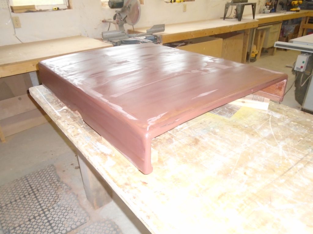
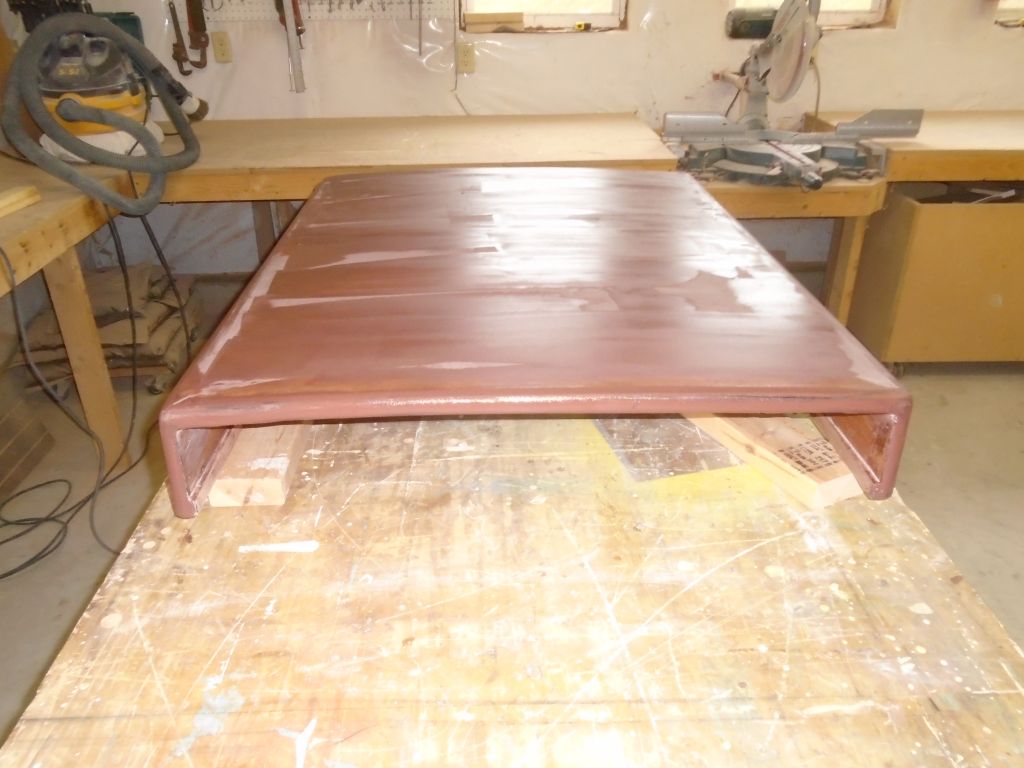
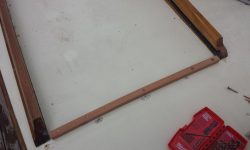
Over the course of a few separate days, working with the cure time of epoxy, I completed final shaping of the piece as needed, including marking and cutting the curve on the forward end to match the deck camber that I’d marked on the boat during the test-fit. Then, after final preparations, I epoxy-coated the inside of the box, as well as the new work on the sides. Later, when the epoxy had cured, I completed the final sanding to prepare the piece for new primer.
10/19/16 – 10/27/16 (2.5 hours)
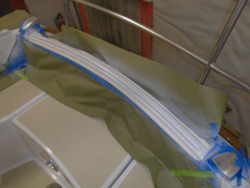
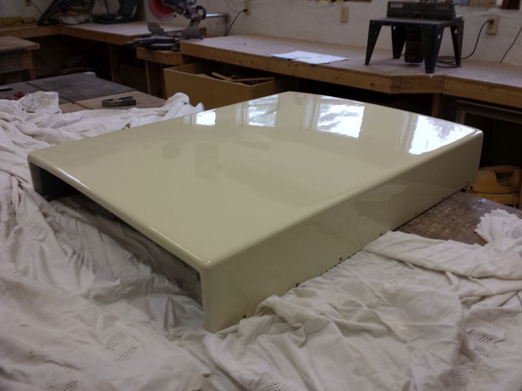
With all preparations complete, I sprayed on three additional coats of epoxy primer.
The next day, once the primer had cured sufficiently, I sanded the whole piece to prepare for finish paint.
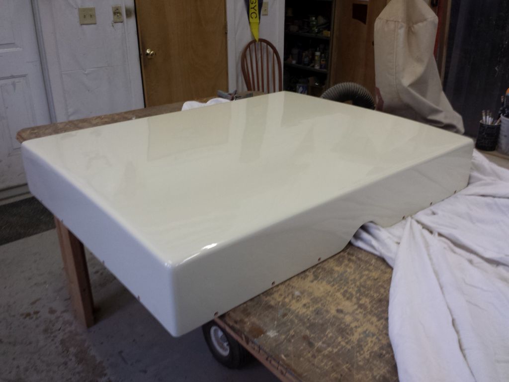
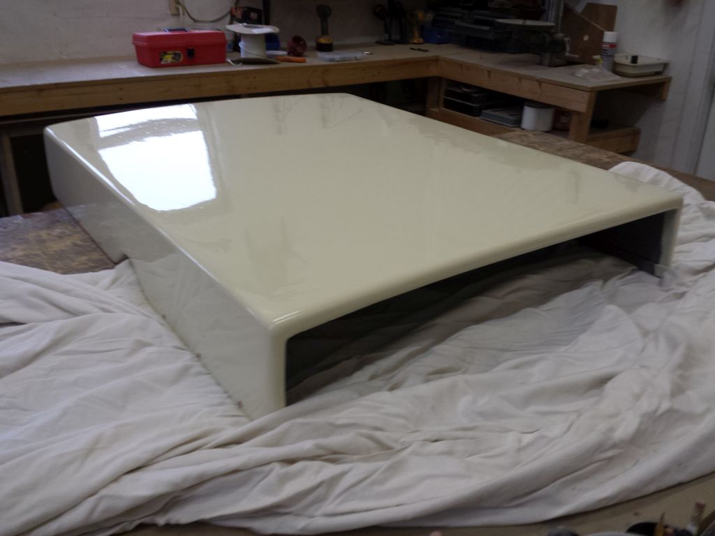
The boatowner had provided me with a can of brushable 2-part paint, which I used for the finish coats–three total, since the second coat didn’t turn out as I’d hoped. Whether from the age of the paint–it was of indeterminate age, though the cans were unopened–or from other factors, I found that each coat of paint required more cure time than I’d expected, which drew out the whole finishing process longer than it should have. But the third coat was satisfactory, and completed just in time too, as it turned out.
10/29/16 (2 hours)
With a weather window at hand, the boat’s departure schedule for her sail south was advanced unexpectedly, but fortunately the sea hood was ready enough–it was only the second day after I’d finished the third coat of paint) . Unfortunately, the excess time it’d taken to complete the topcoats, along with the quickened schedule, meant that I’d not had any time to paint the interior side of the sea hood as I’d hoped, though I’d primed it earlier.
To prepare for installation, I marked and drilled screw holes through the three sides, countersinking the holes to accept bronze flathead screws. The long sides would screw directly to the teak companionway hatch frames on the boat; the forward end required a small cleat, which I cut and shaped as needed, and which I’d install on the deck once at the boat.
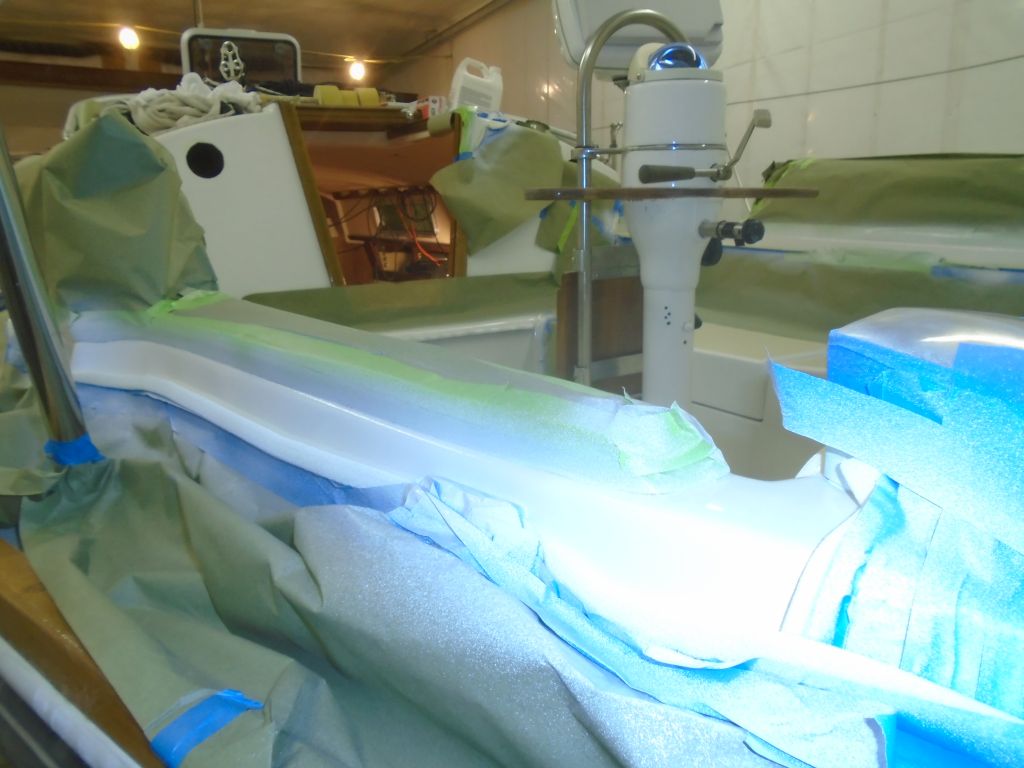
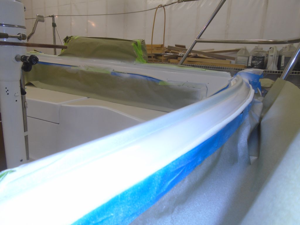
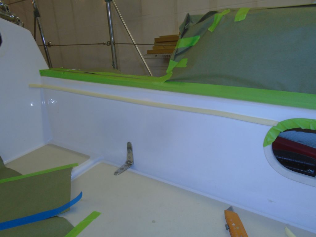
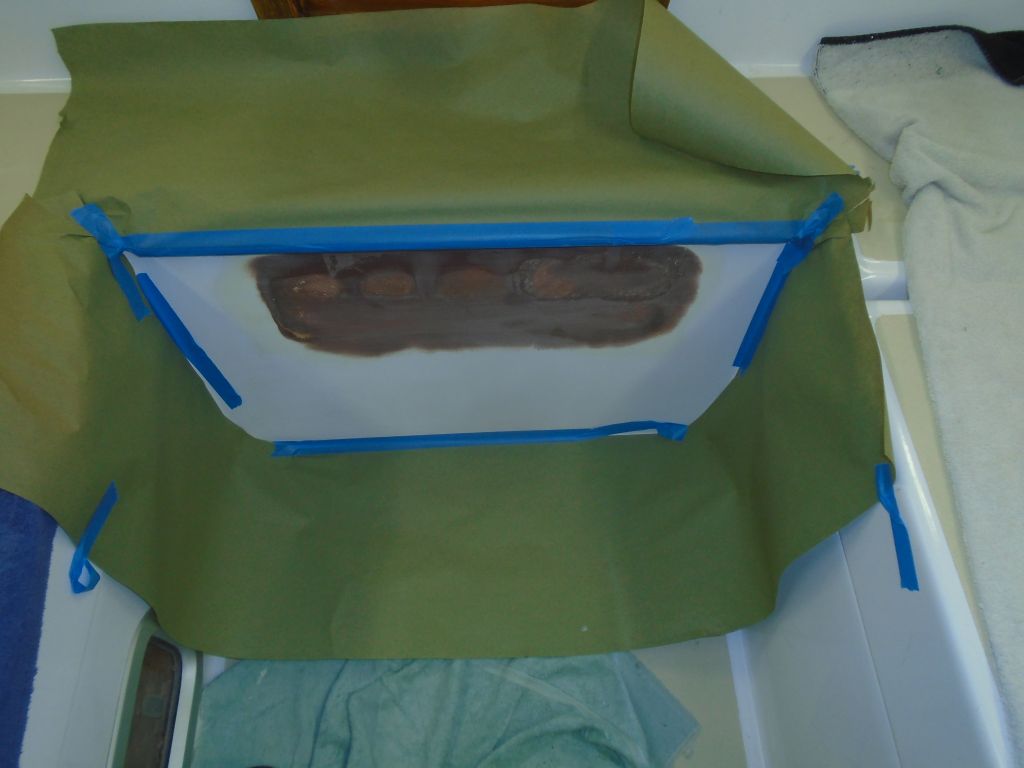
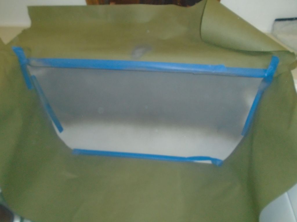
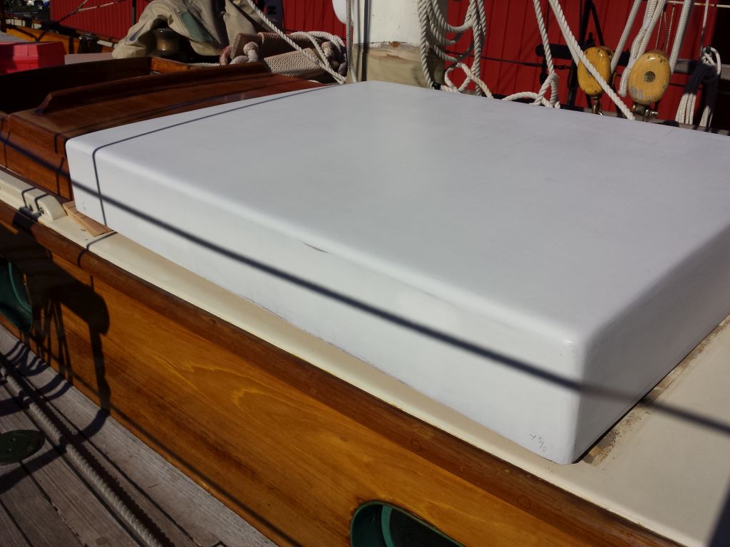
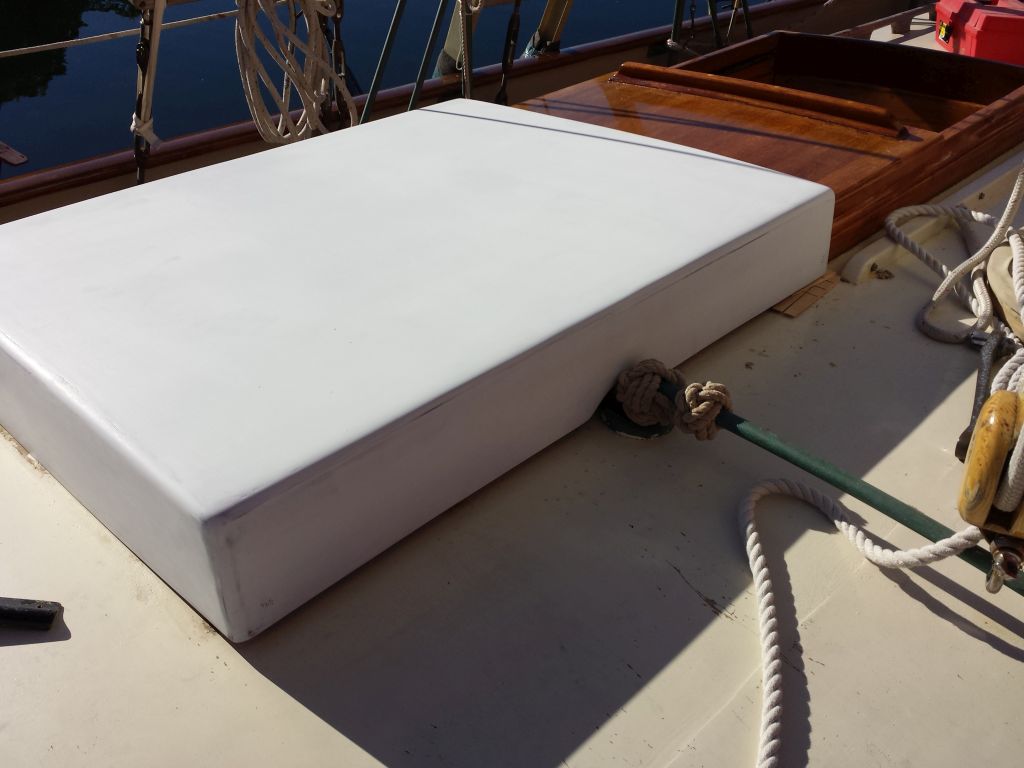
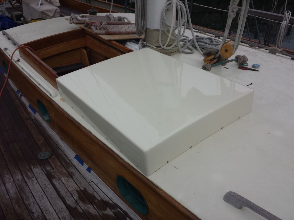
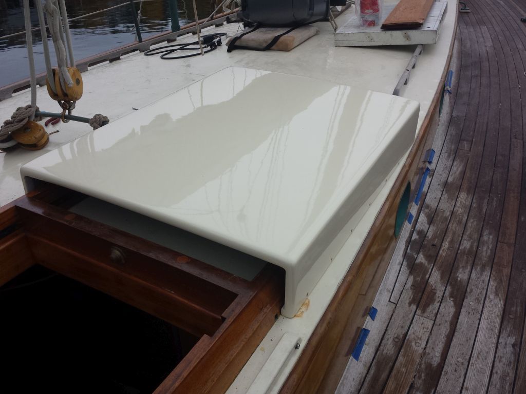
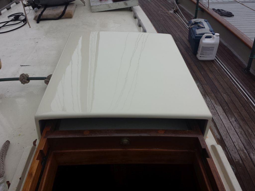
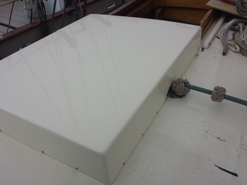
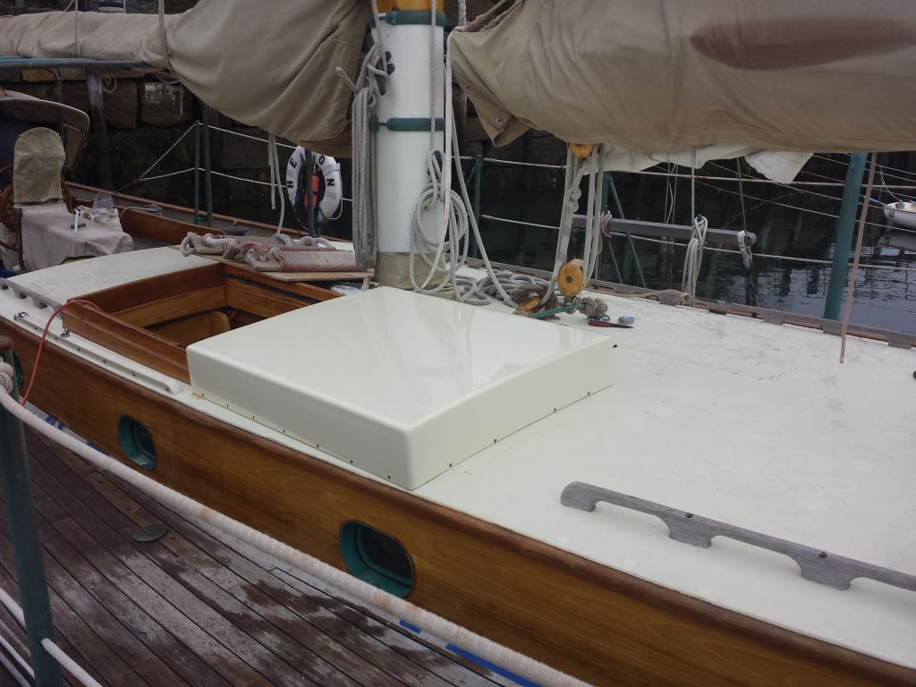
Installation was quick. I started with the support cleat at the forward end, which I fastened to the deck with bronze screws and sealant.
Then, I installed the hood, predrilling the holes into the support cleat and side rails as needed and fastening it down with bronze screws all around. With the boat in the throes of last-minute departure preparations, the sliding companionway hatch was not on the boat at the time of installation, but since the sea hood was designed for easy removal that would pose no problem later as there was no sealant used in its installation (other than the forward support cleat). With the main purpose of the sea hood being to help support a spray dodger over the hatch (as well as provide its own protection), the installation was now ready for the canvas contractor to finish his template and construction.
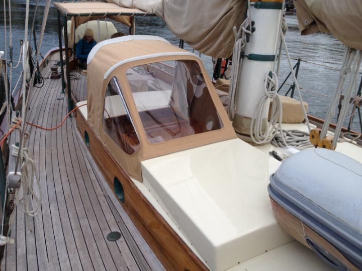
Here it is the next day with the new dodger complete and installed.
Total project time: 24.5 hours