Tuesday
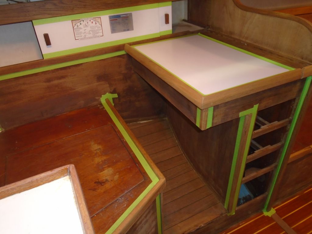
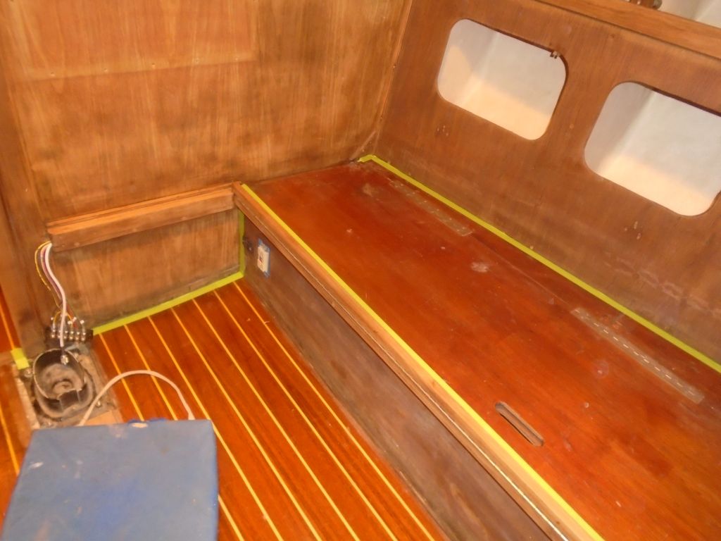
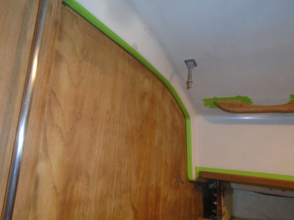
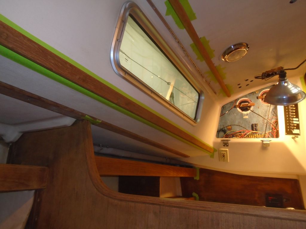
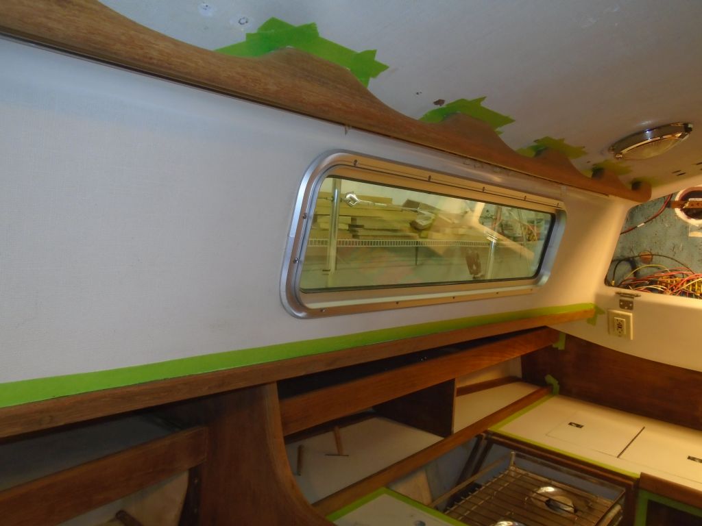
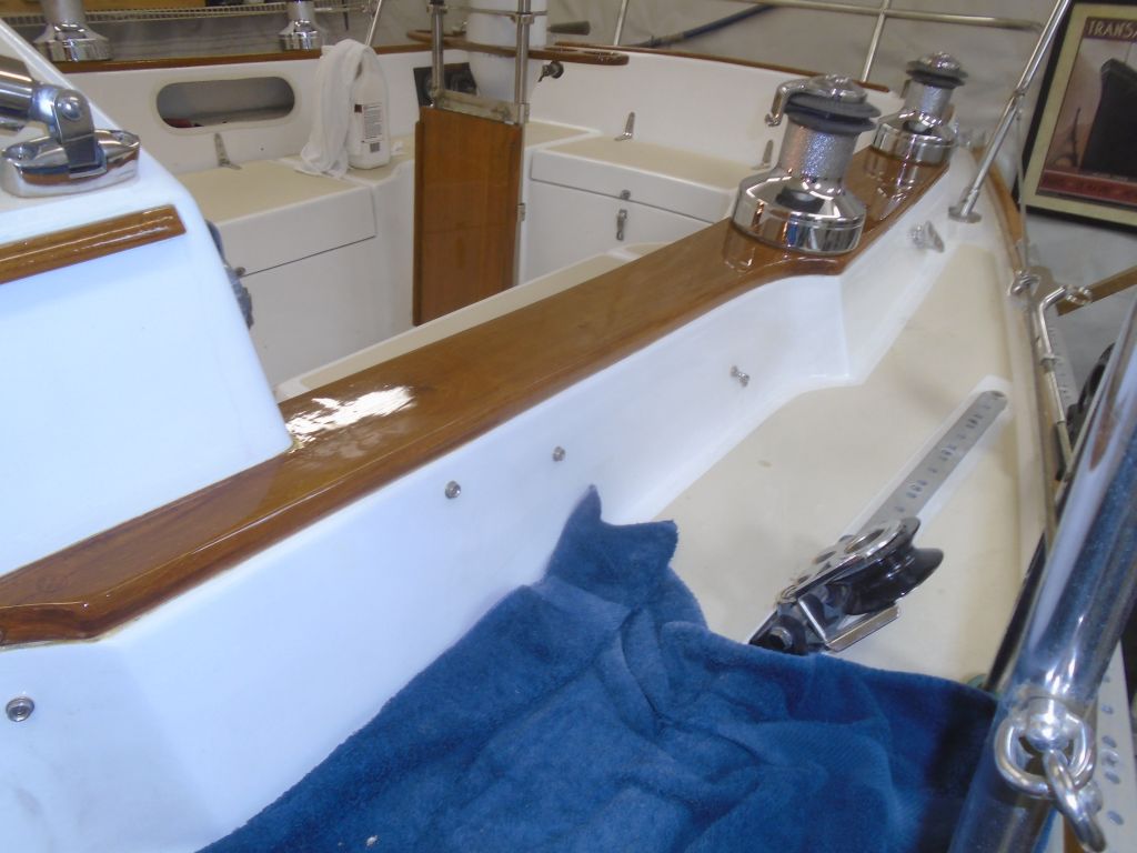
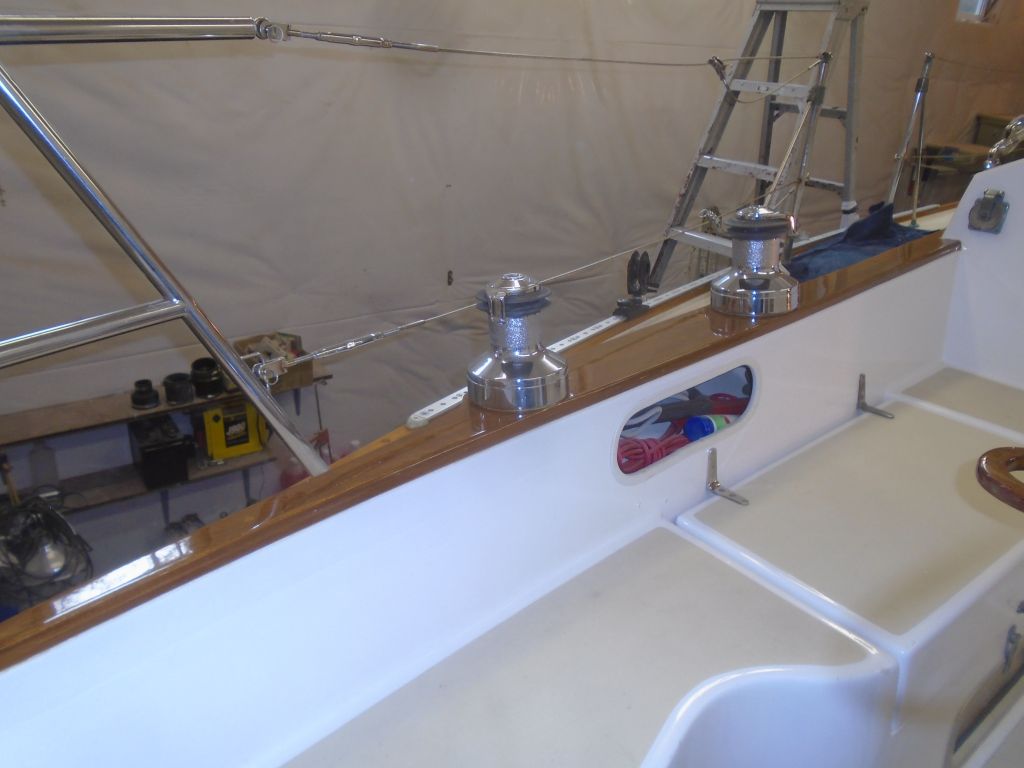
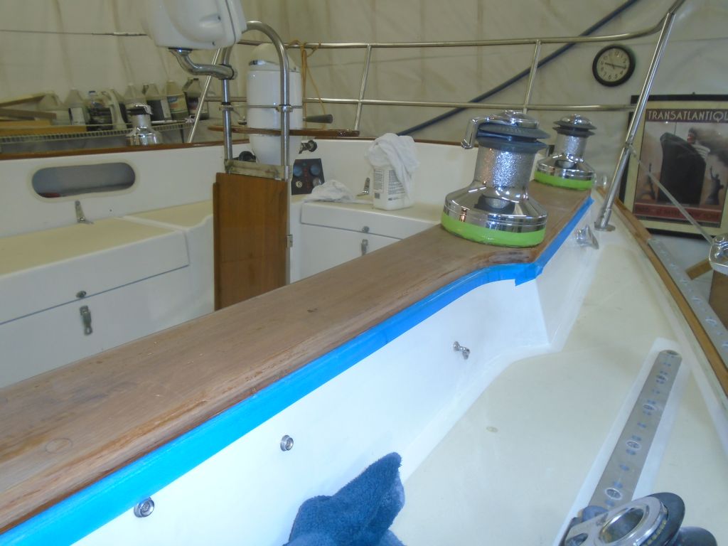
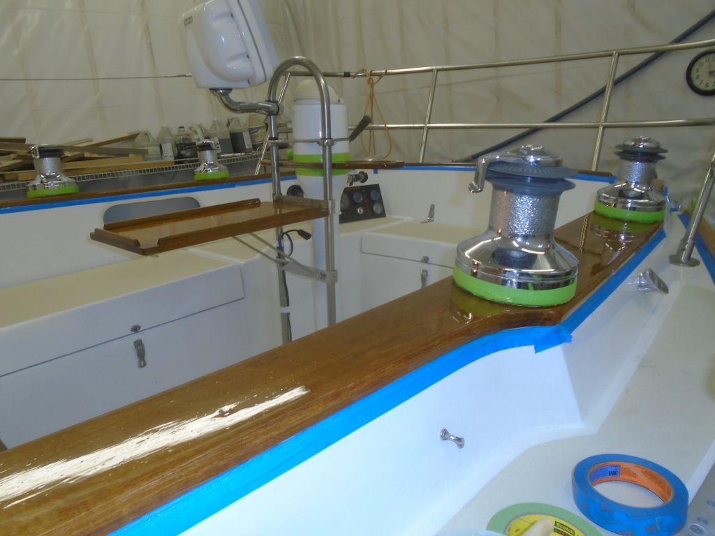
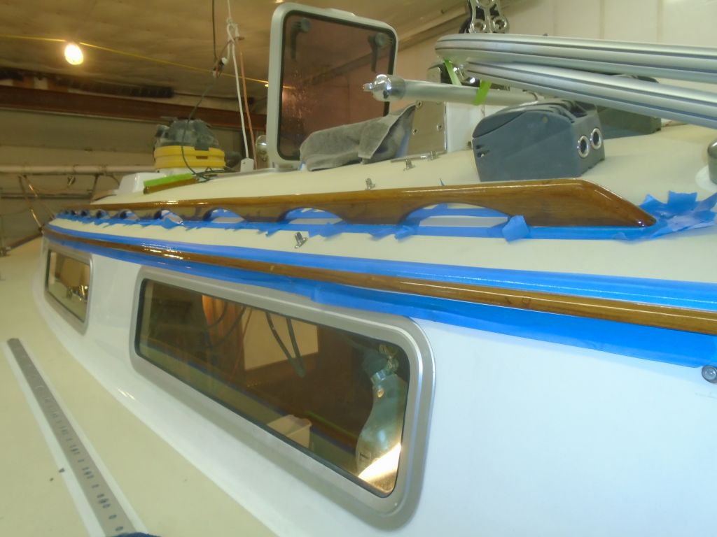
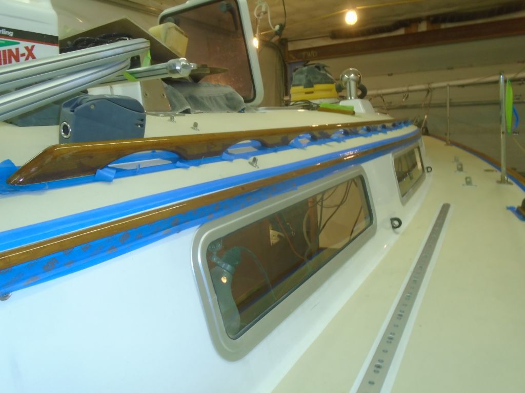
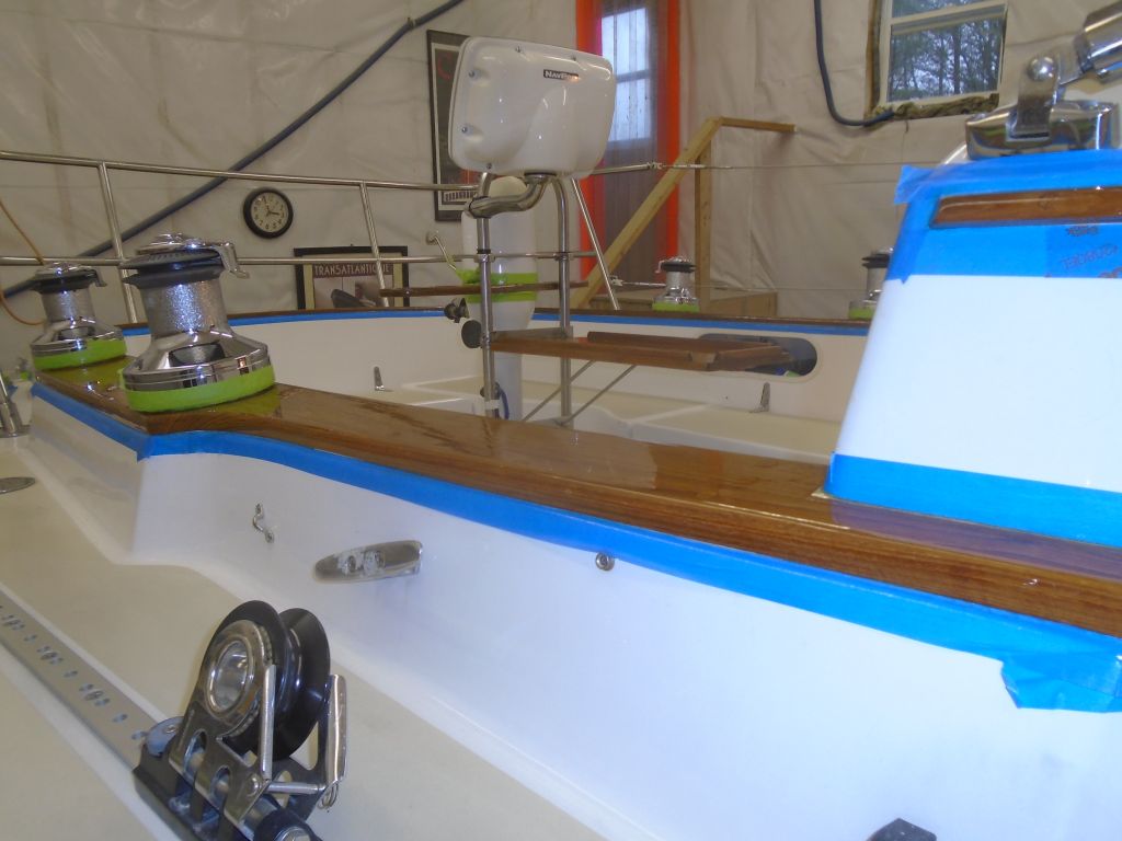
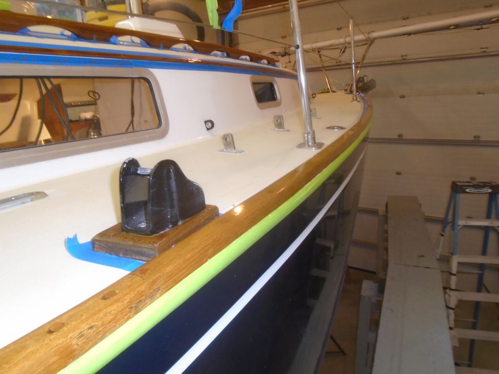
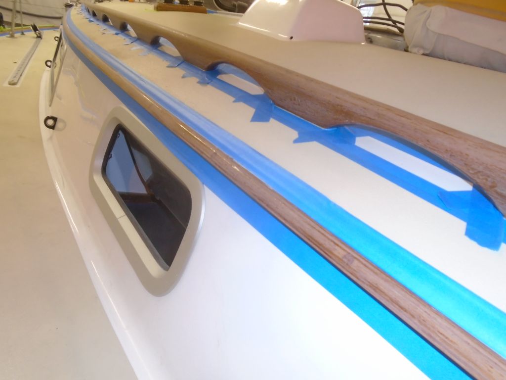
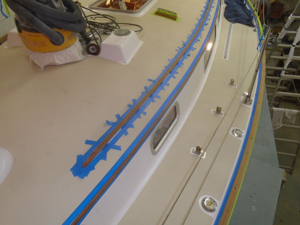
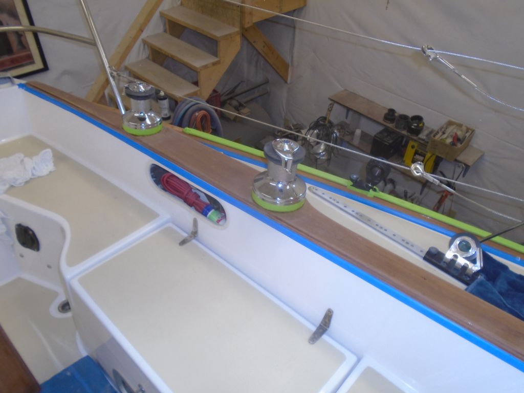
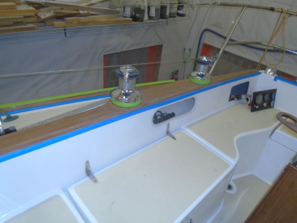
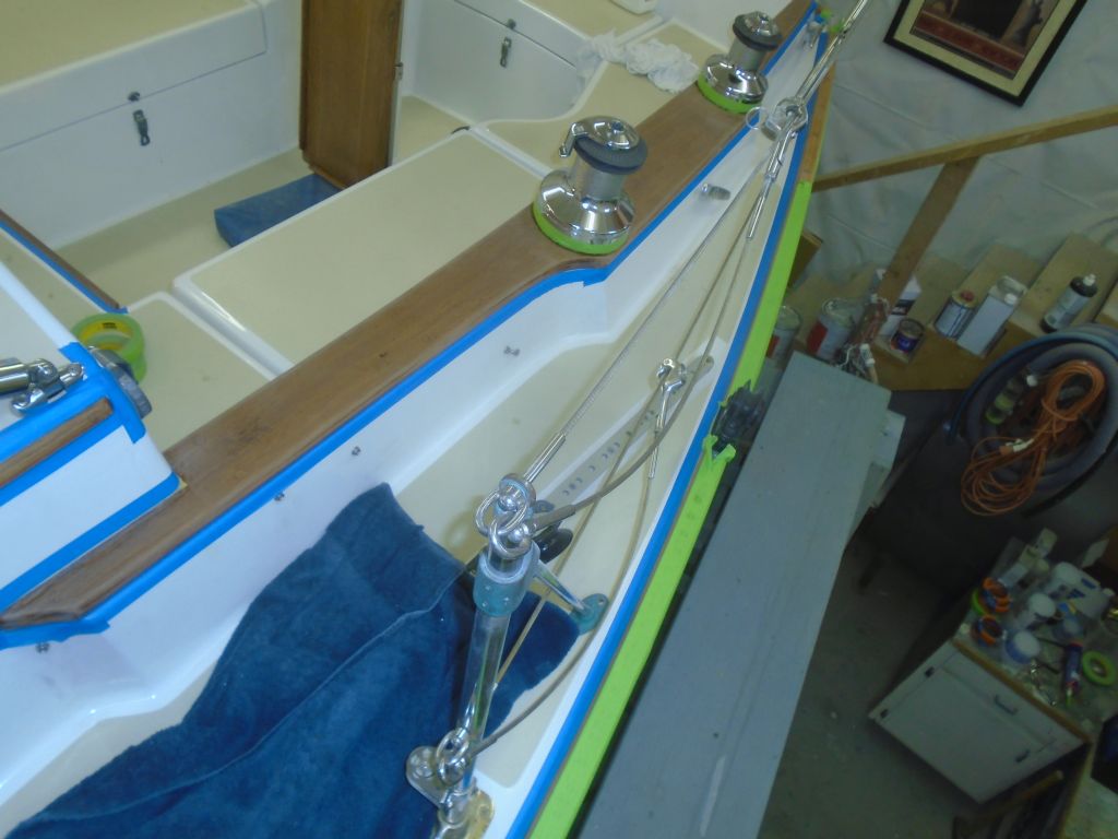
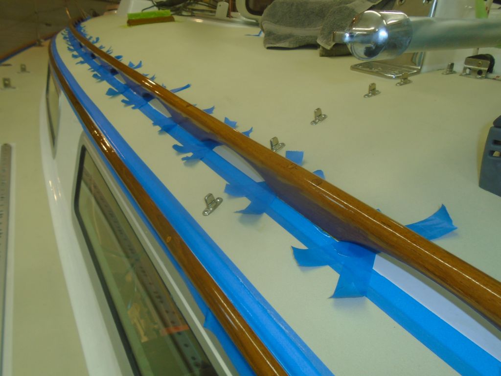
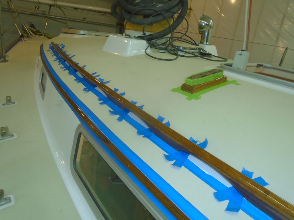
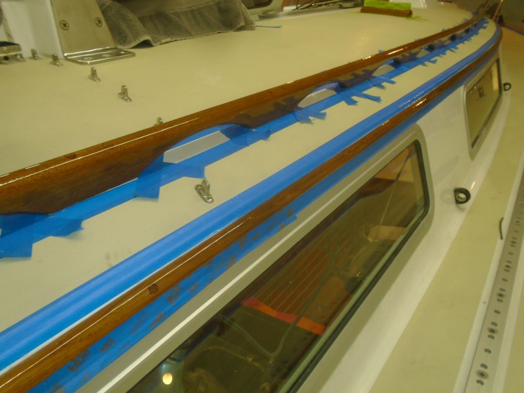
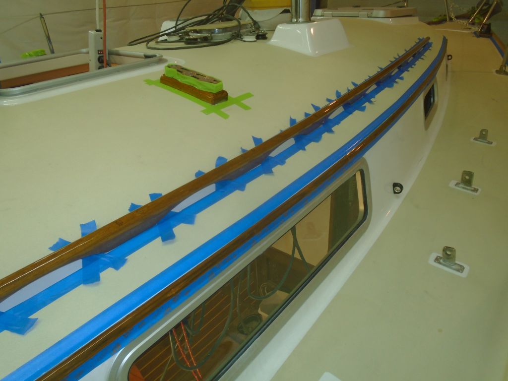
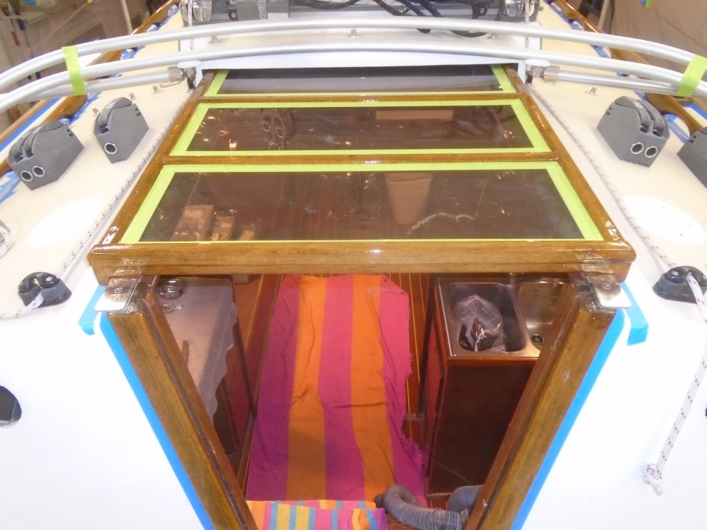
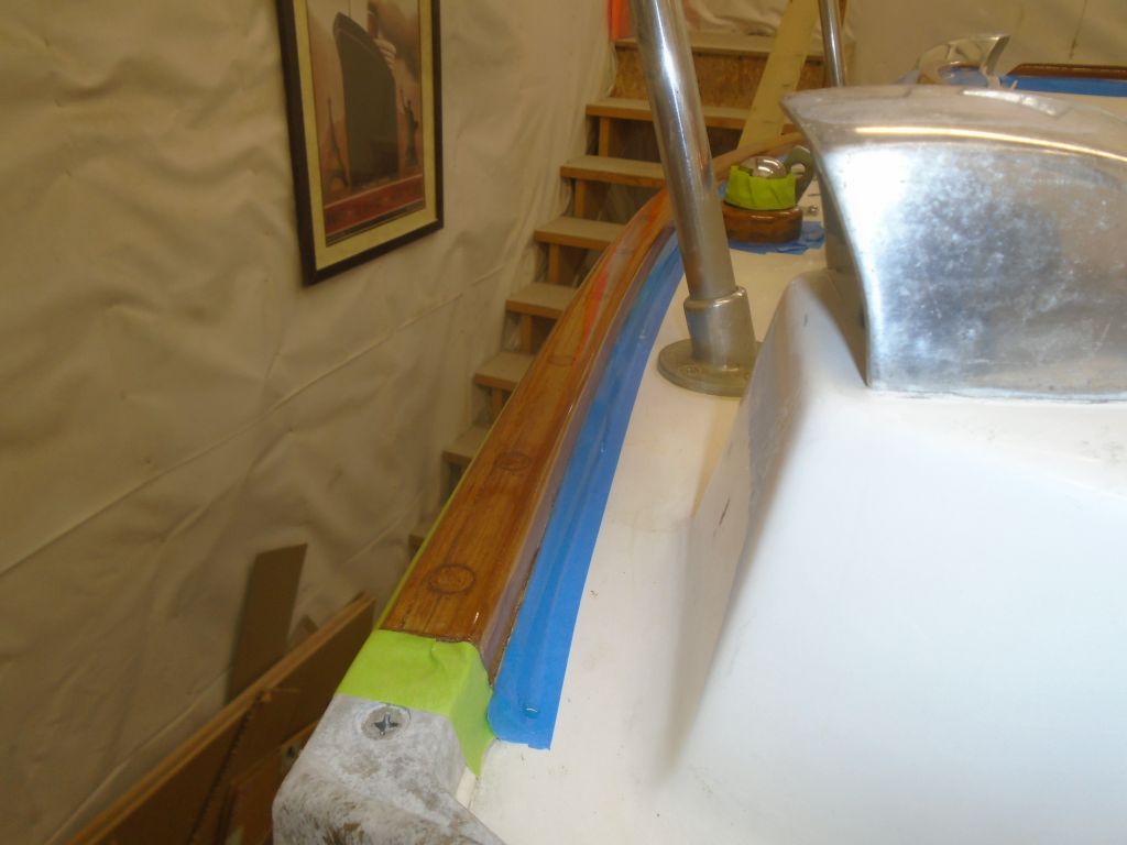
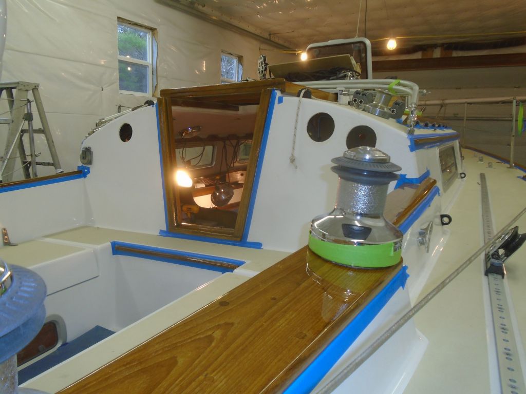
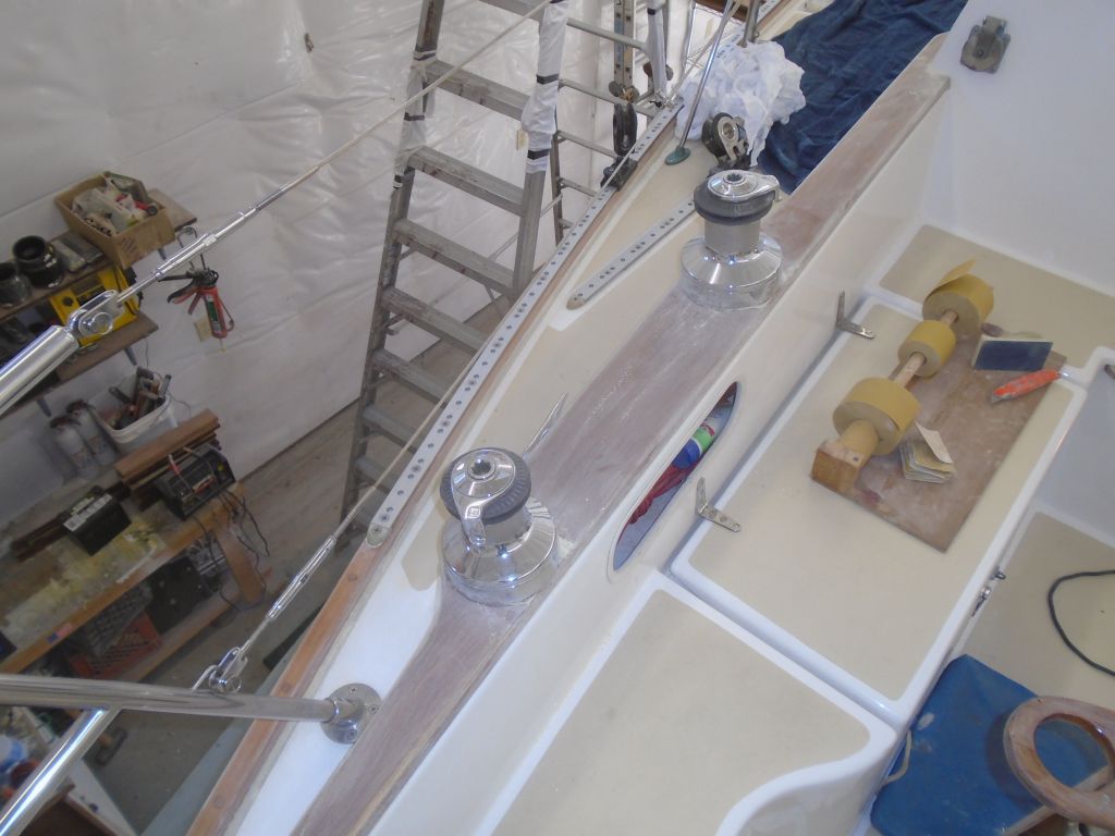
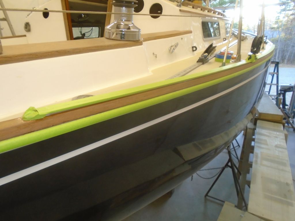
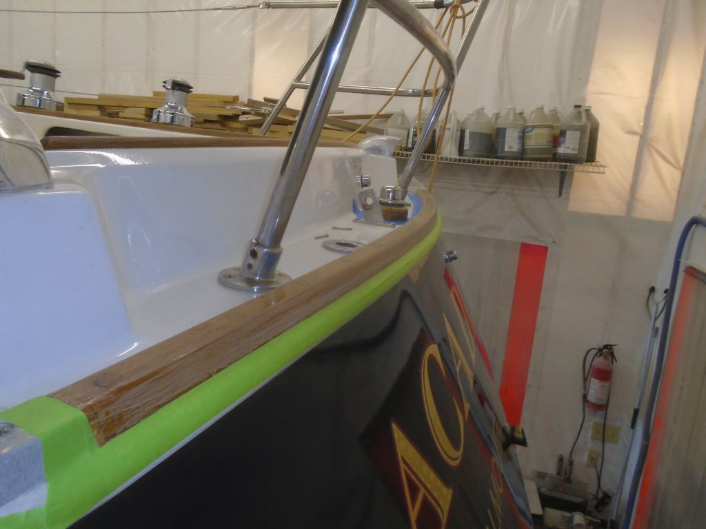
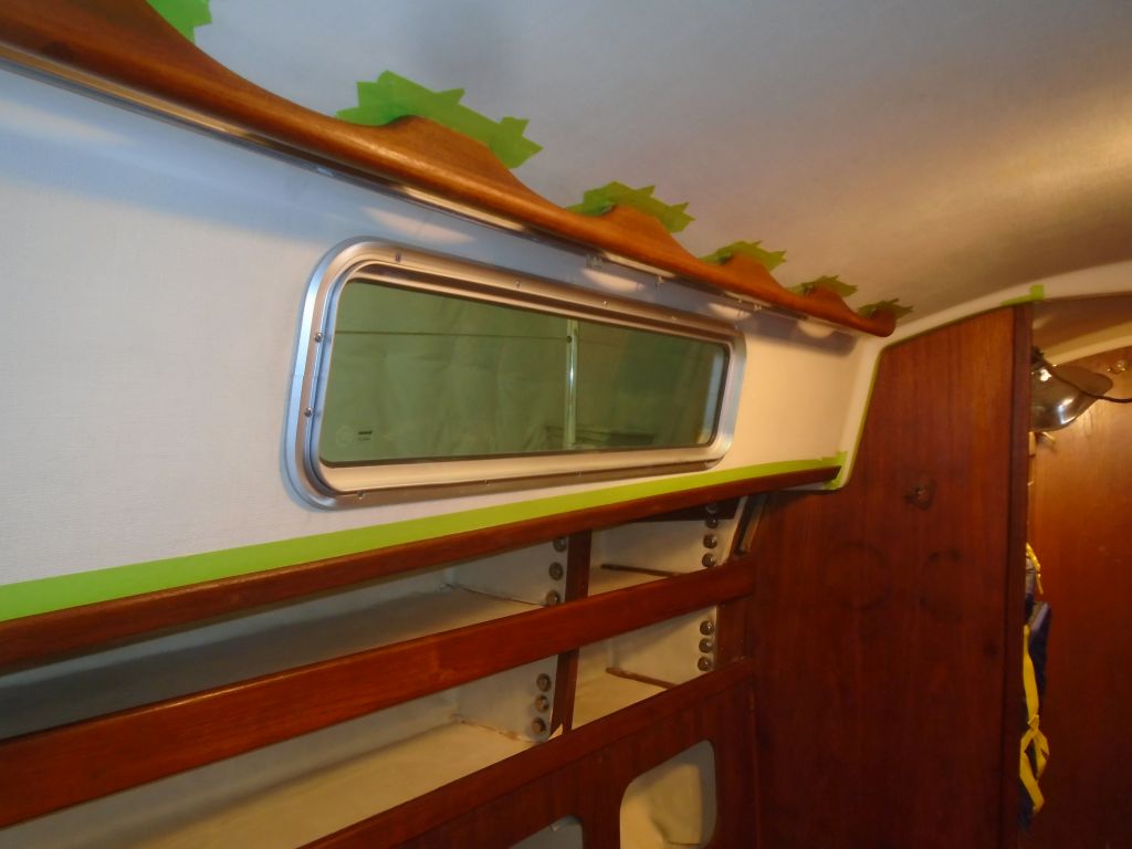
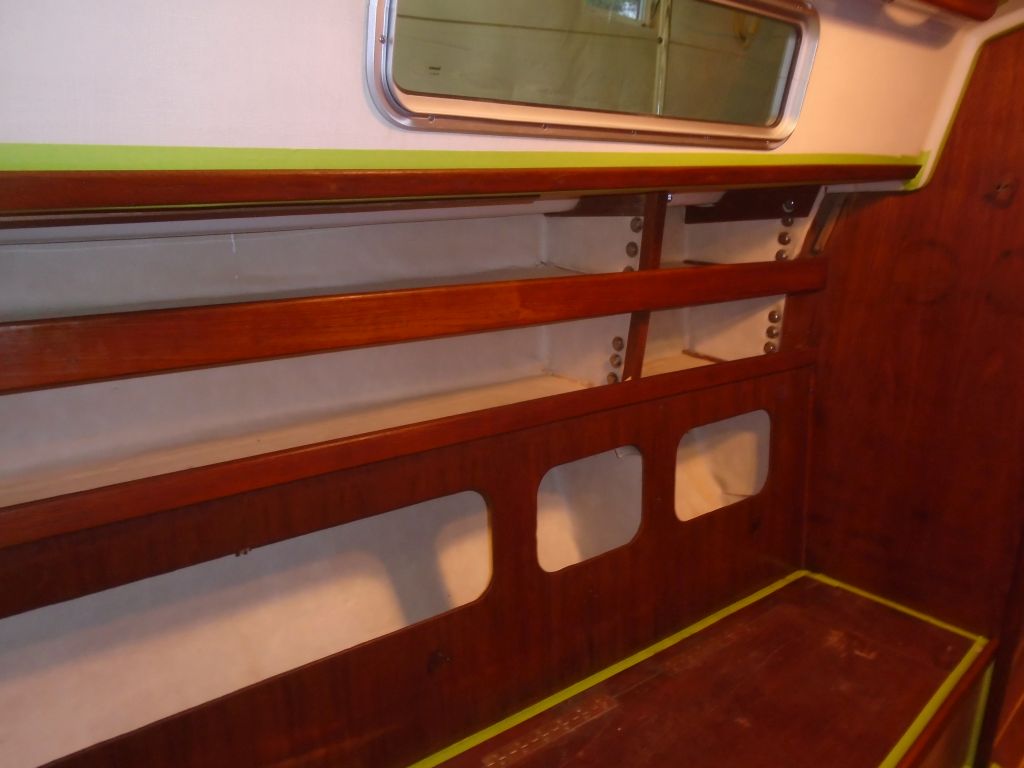
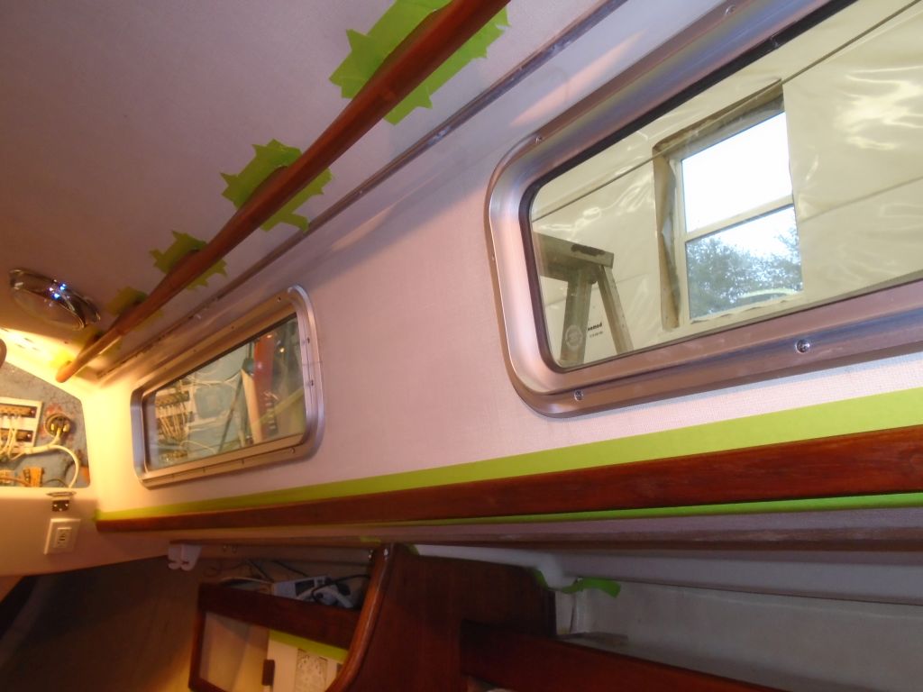
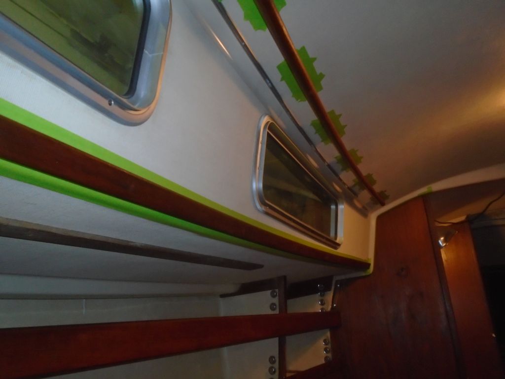
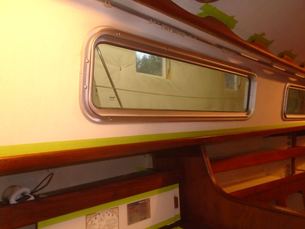
I quickly finished up the masking on the port side, and made other final preparations for beginning the varnish in the cabin.
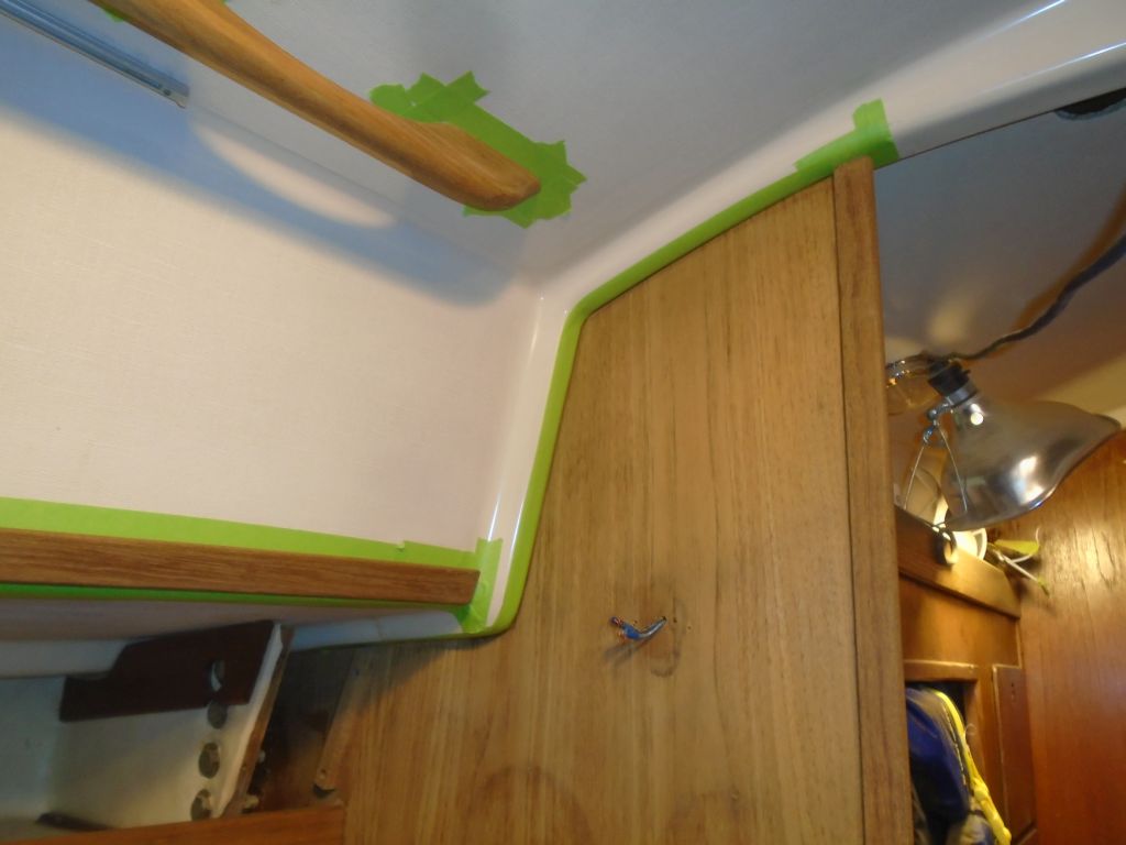
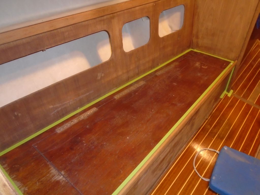
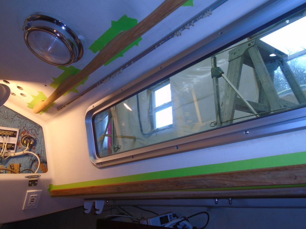
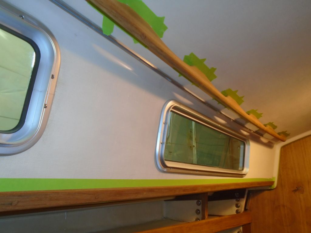
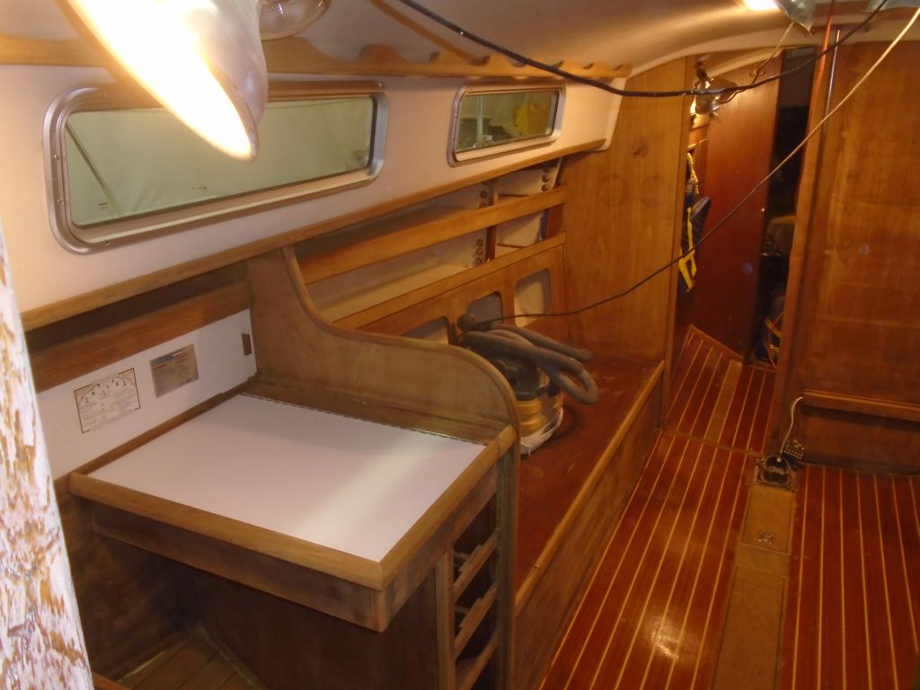
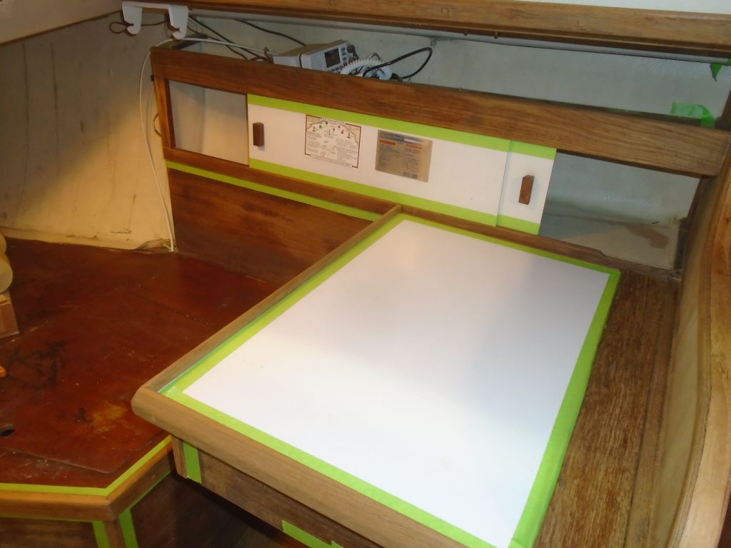
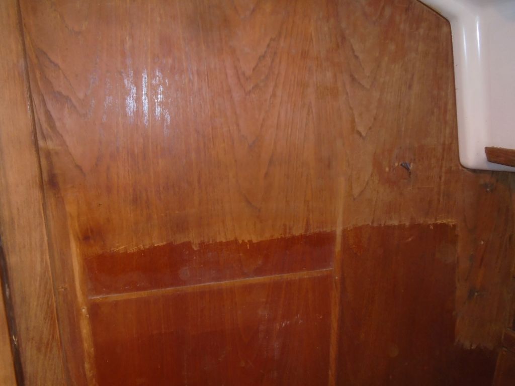
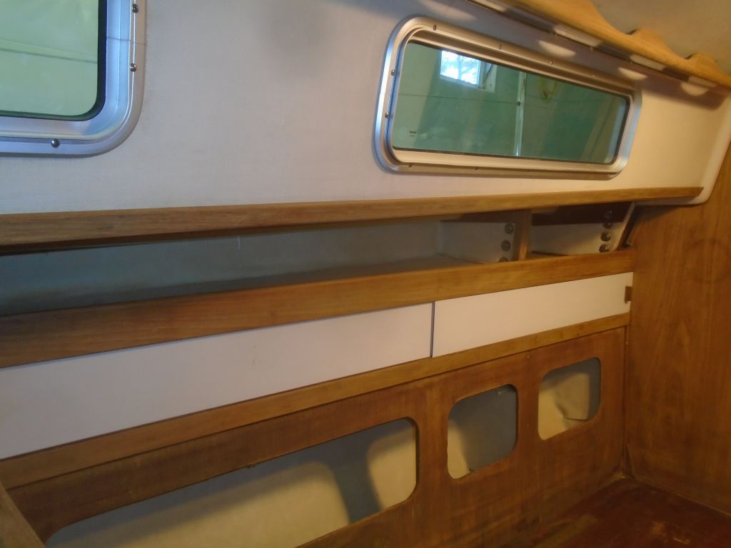
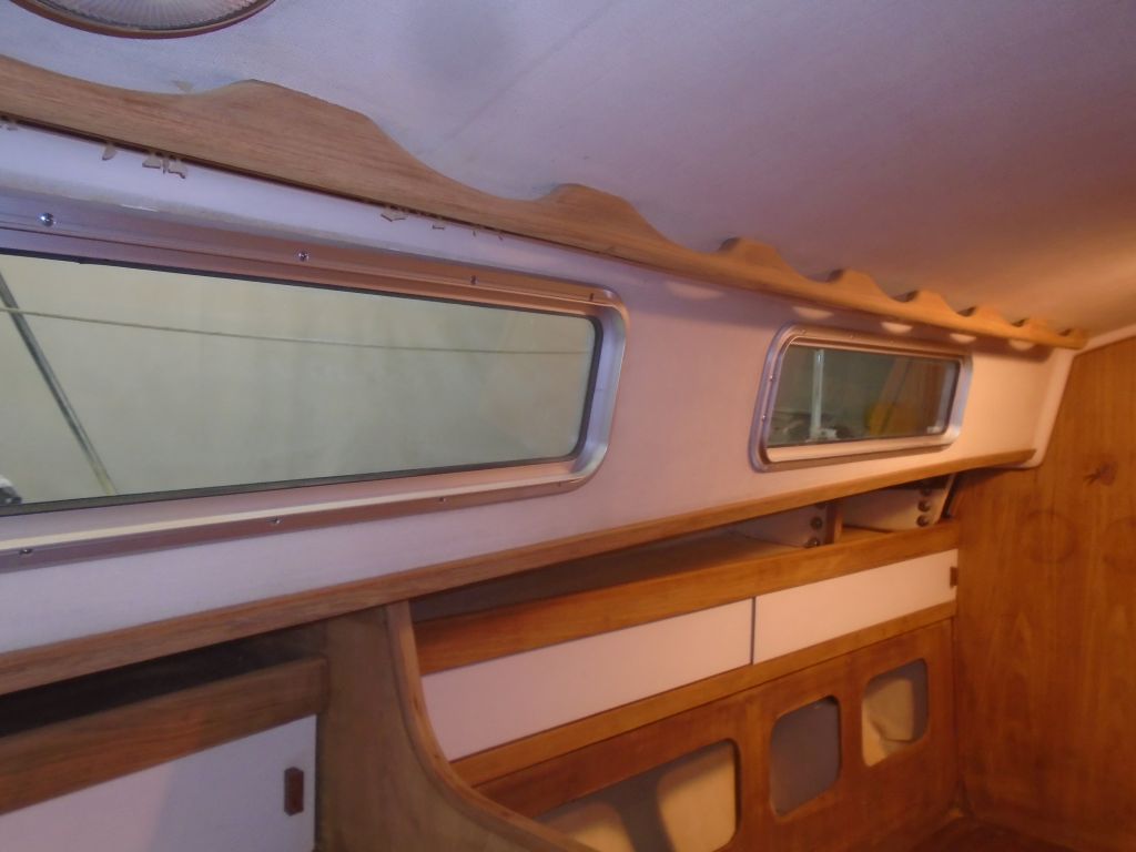
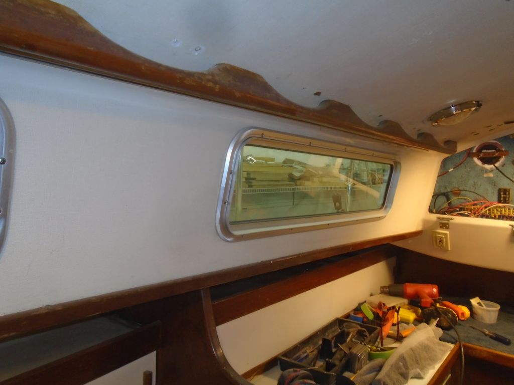
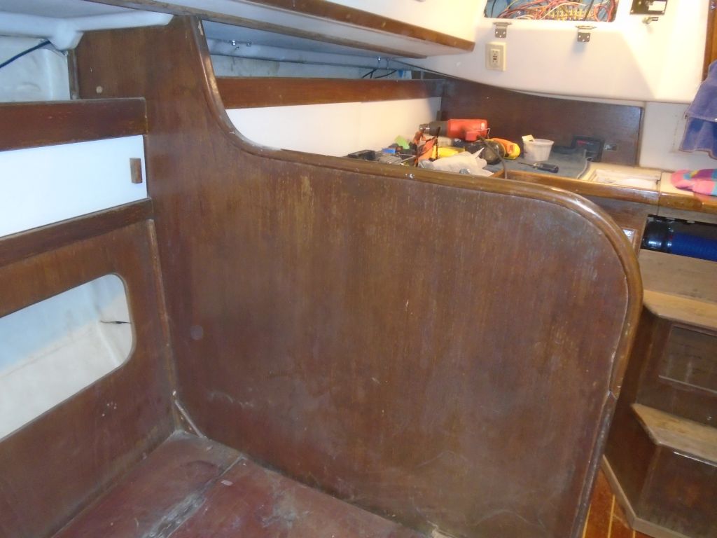
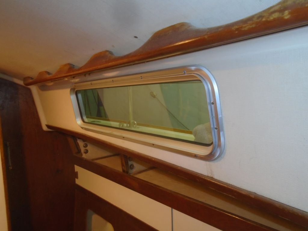
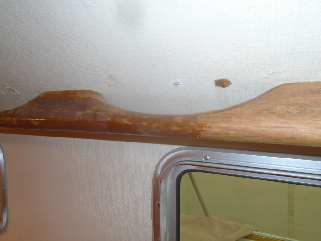
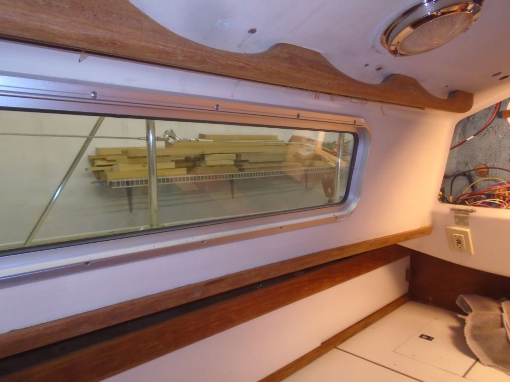
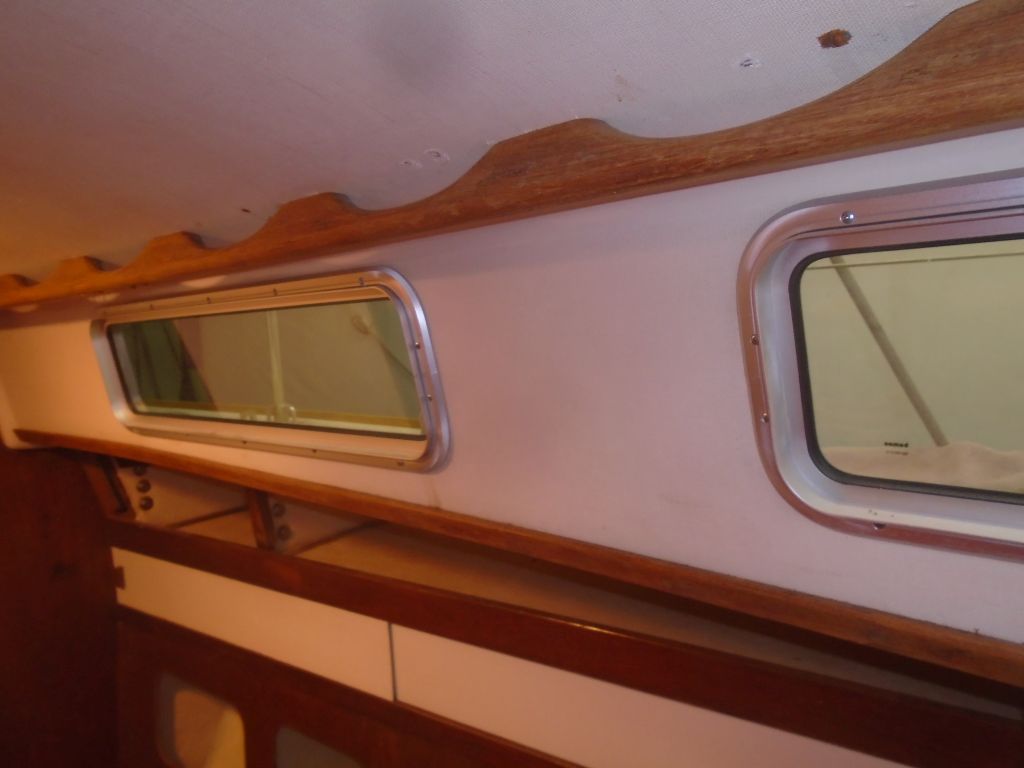
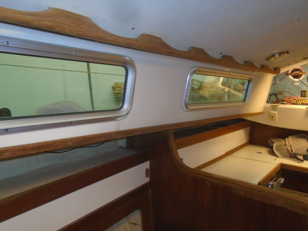
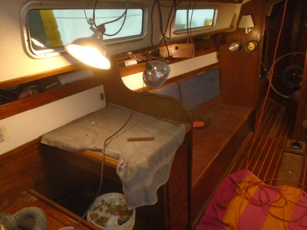
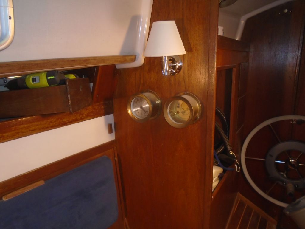
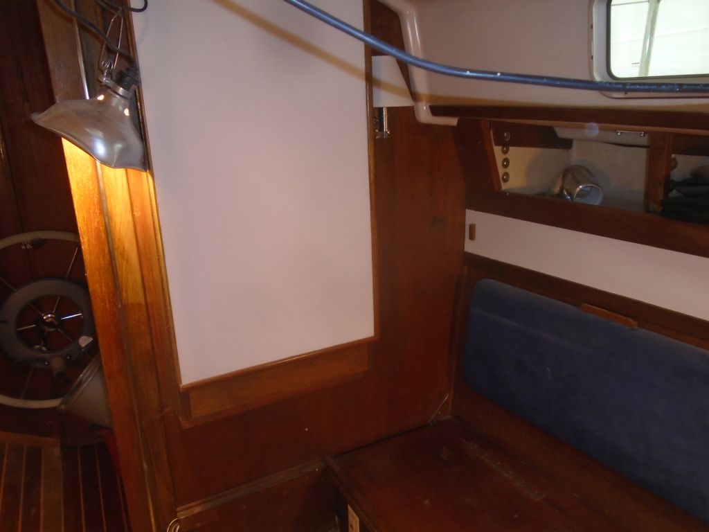
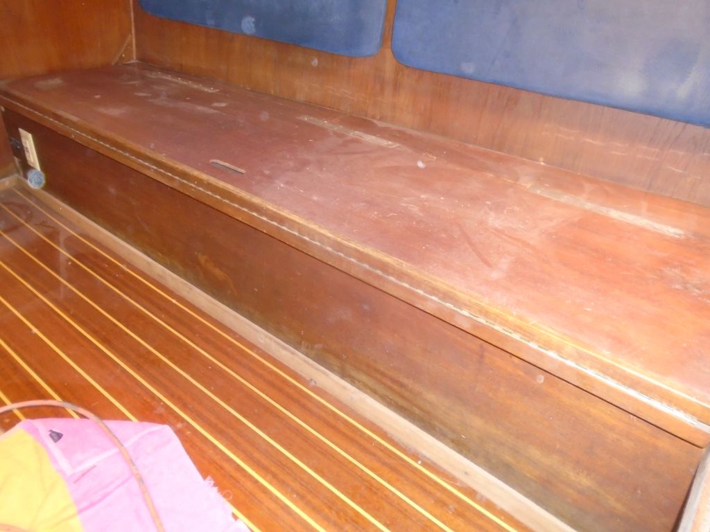
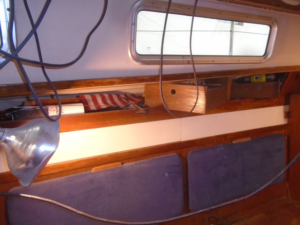
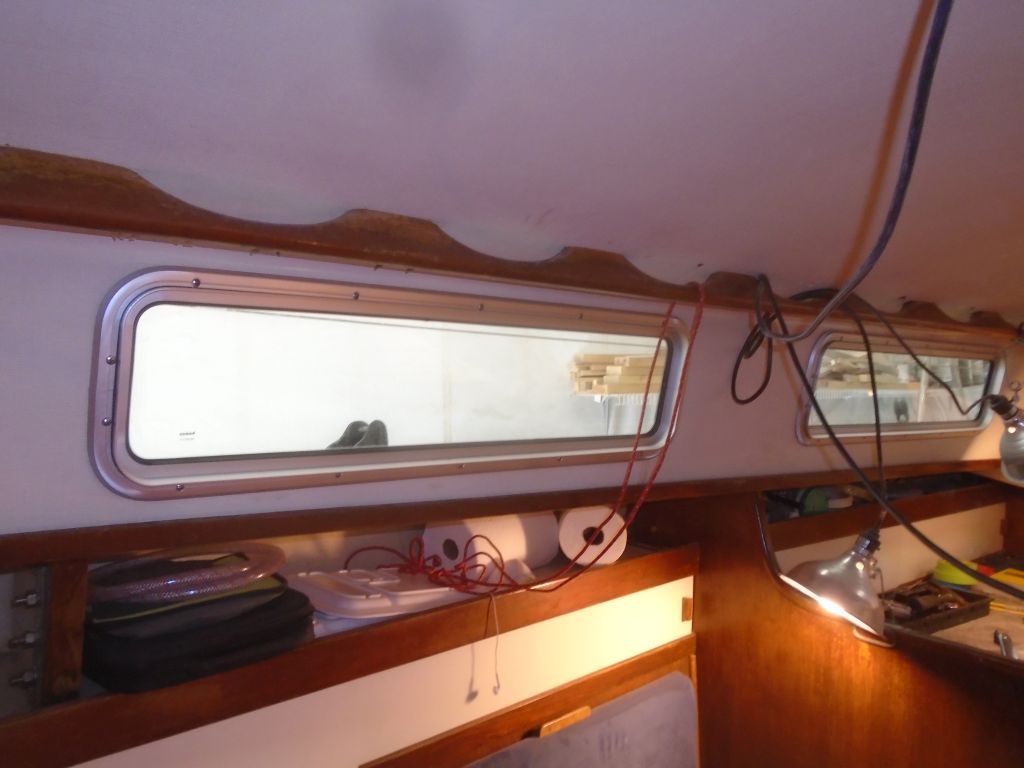
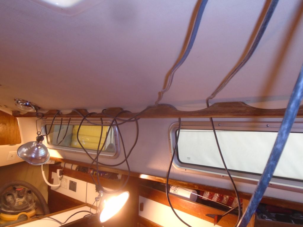
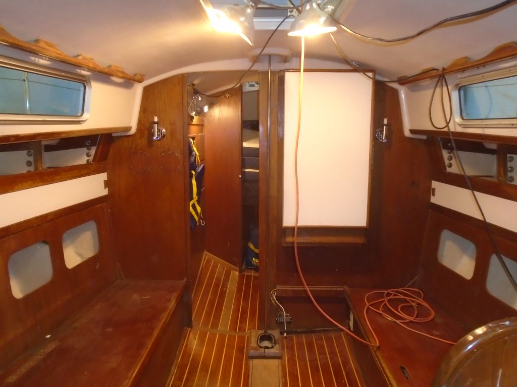
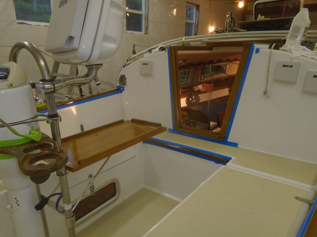
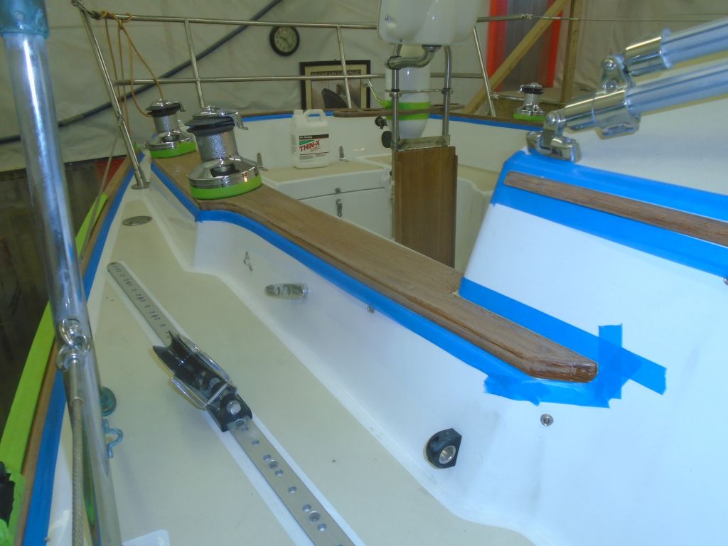
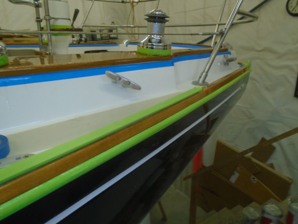
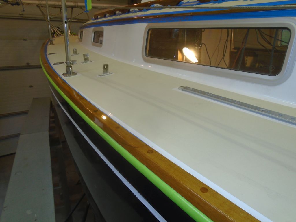
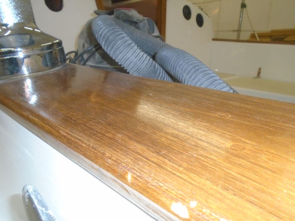
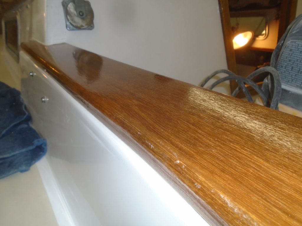
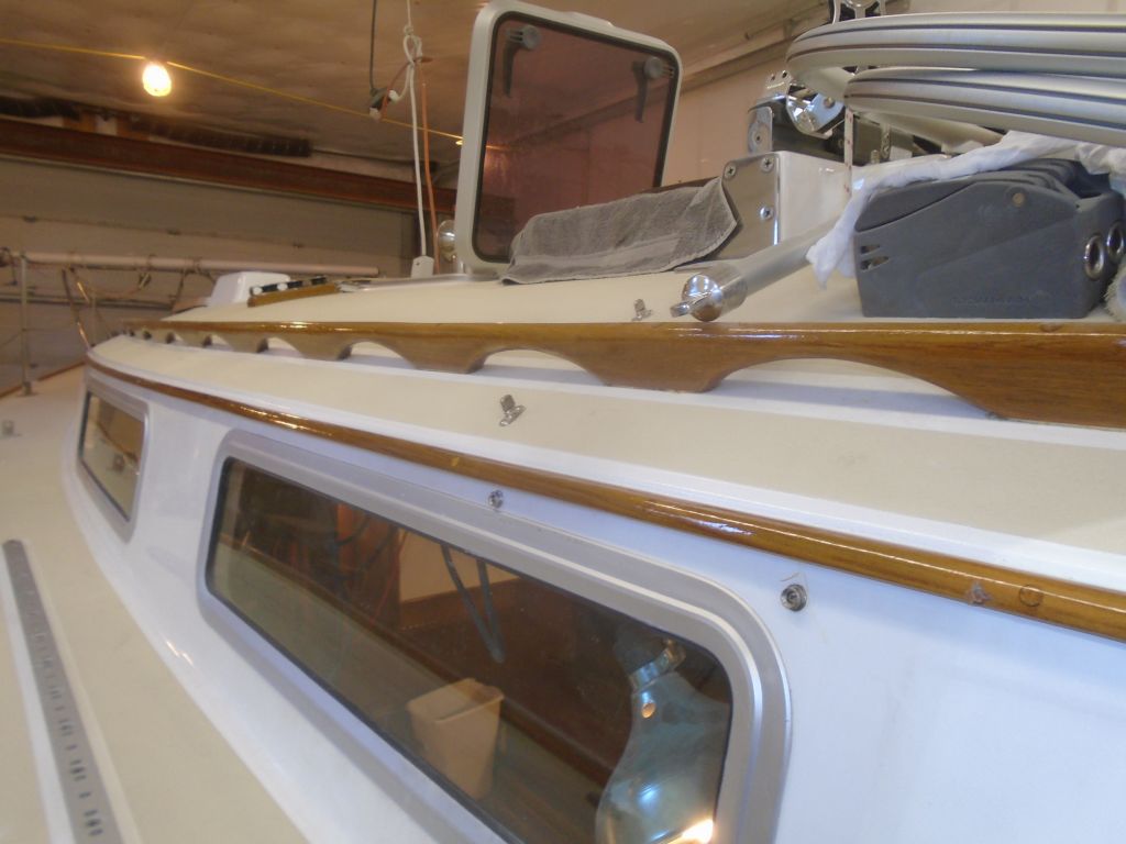
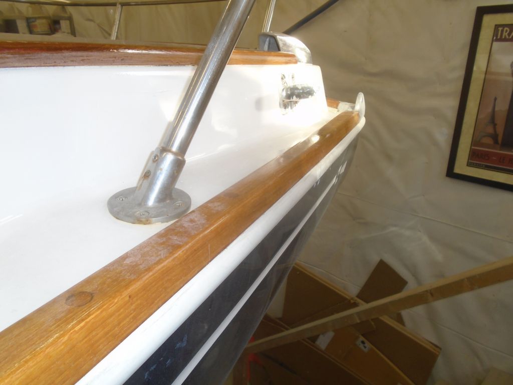
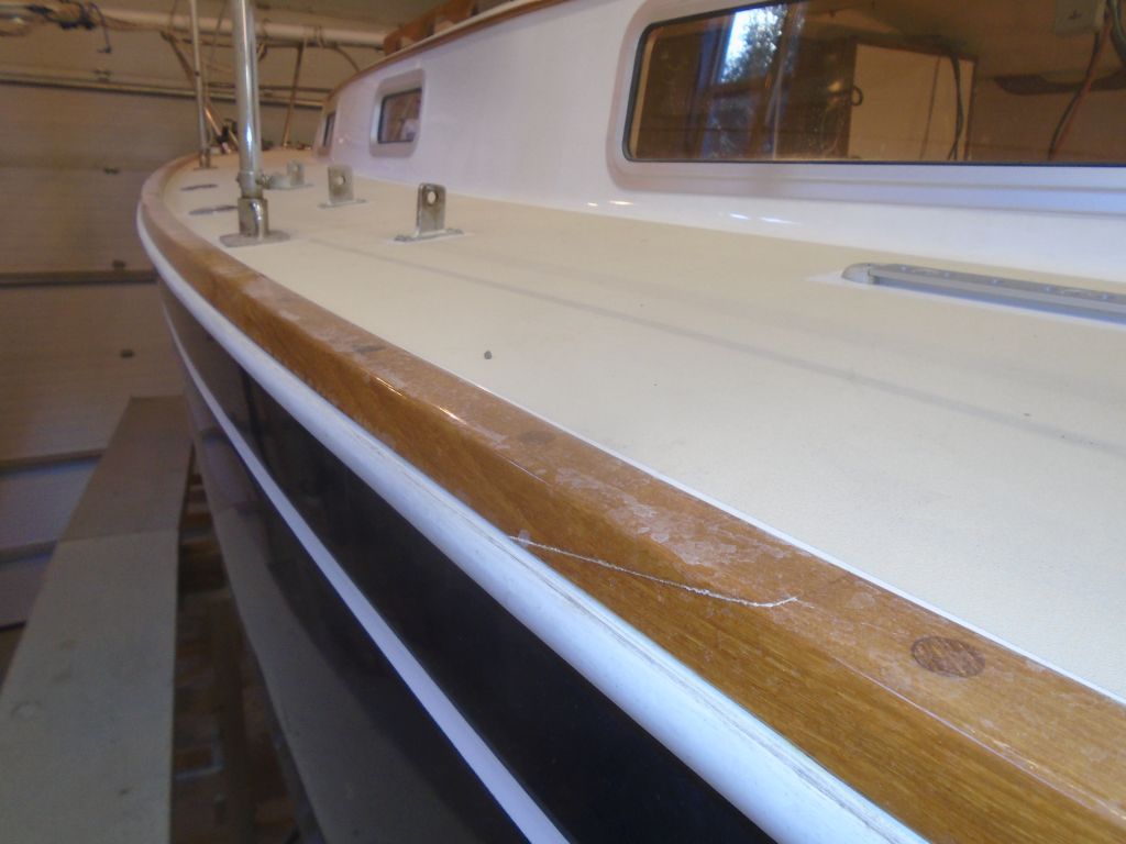
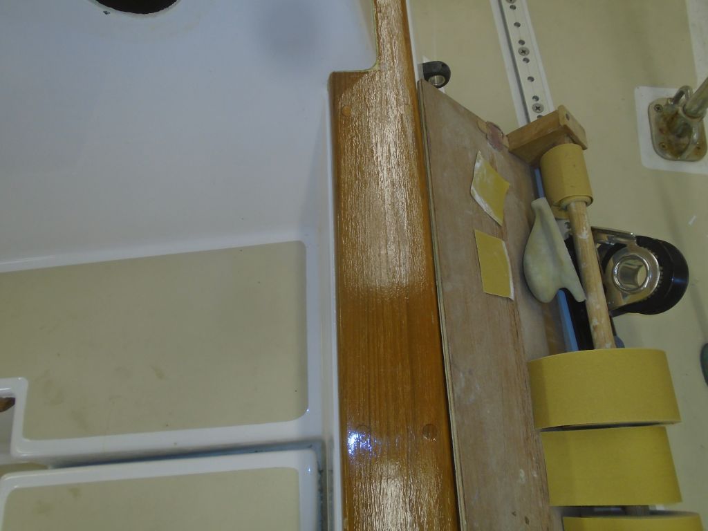
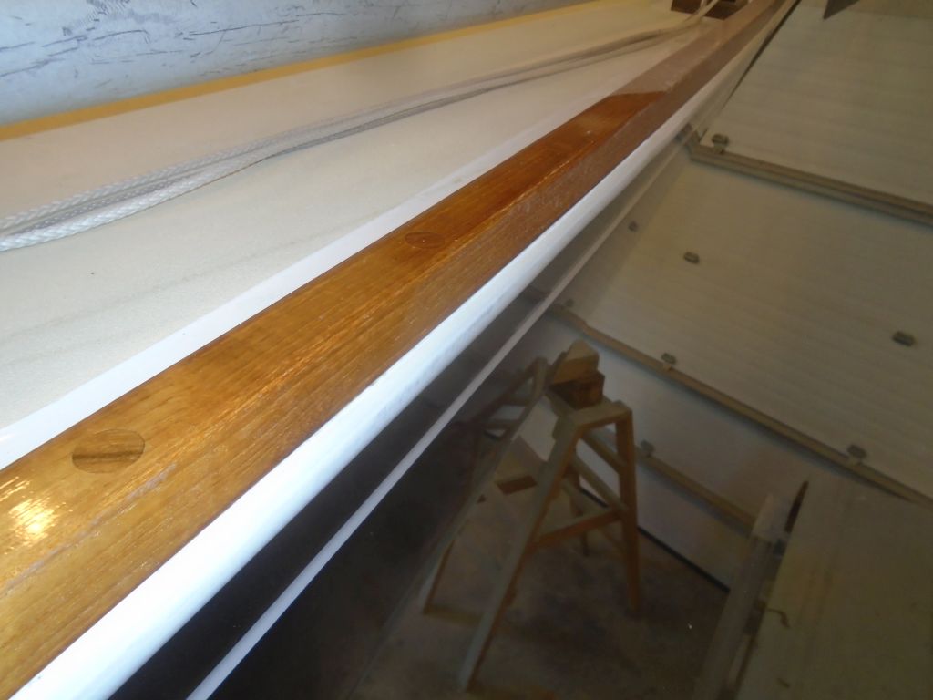
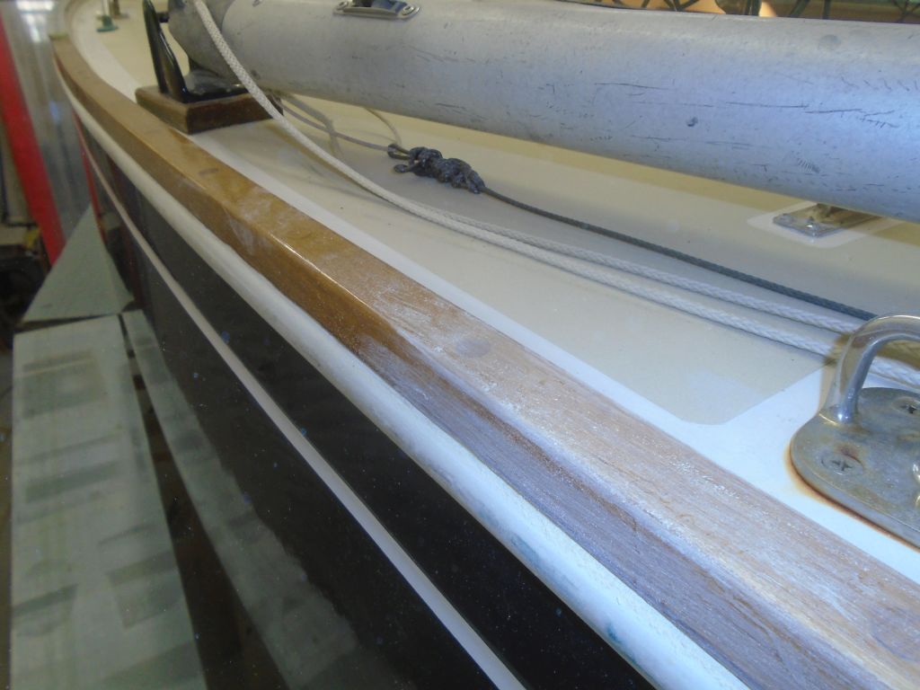
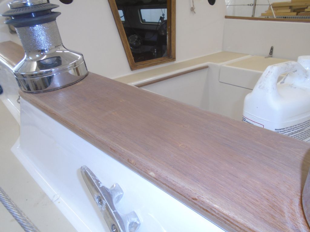
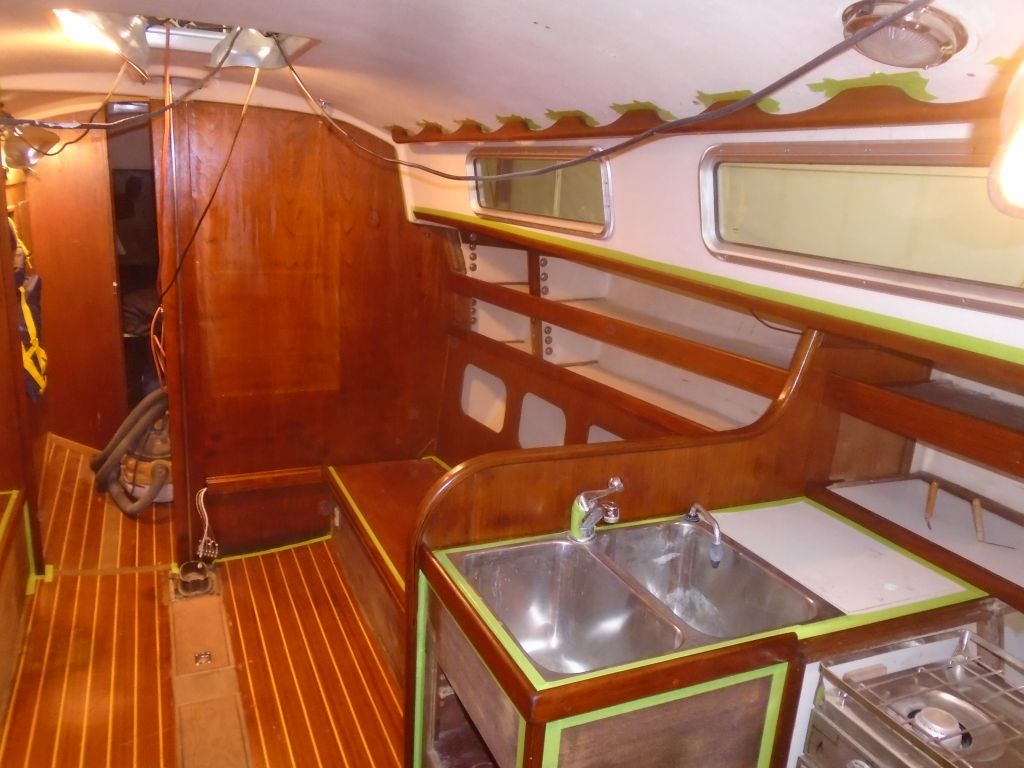
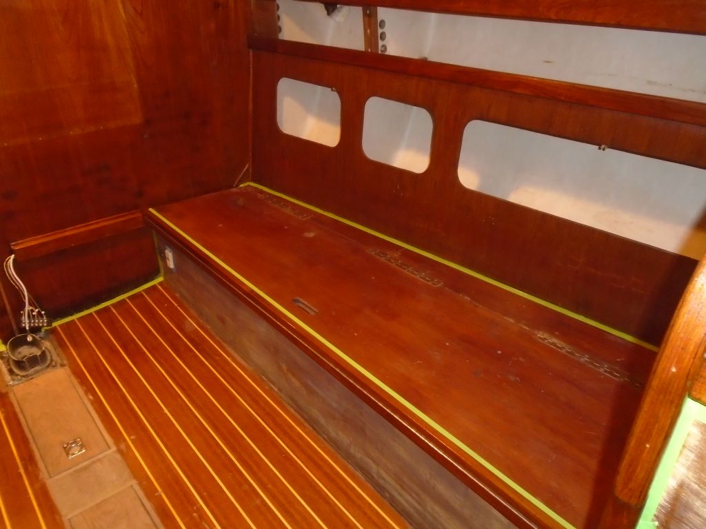
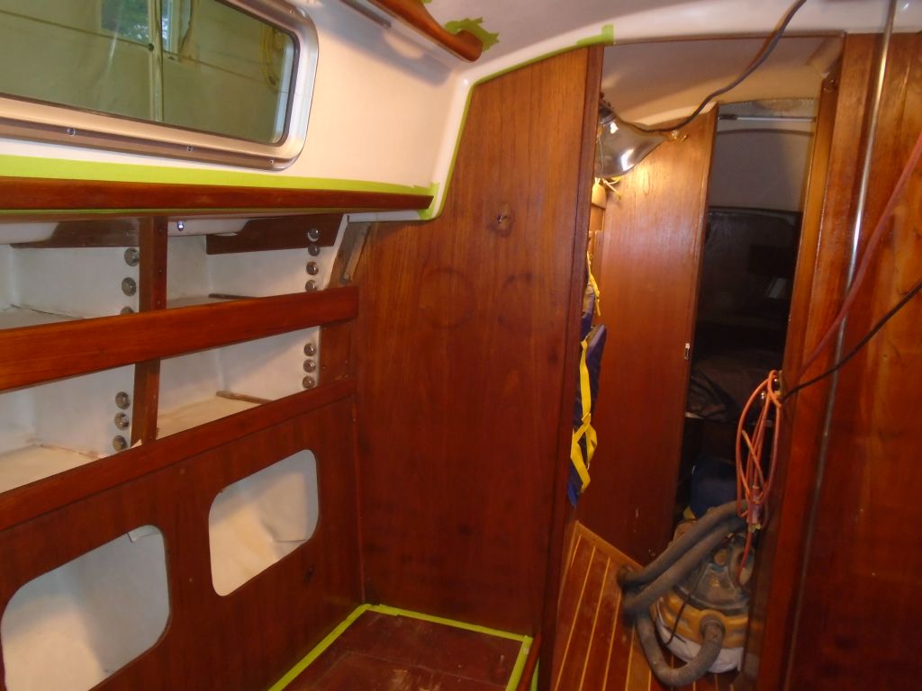
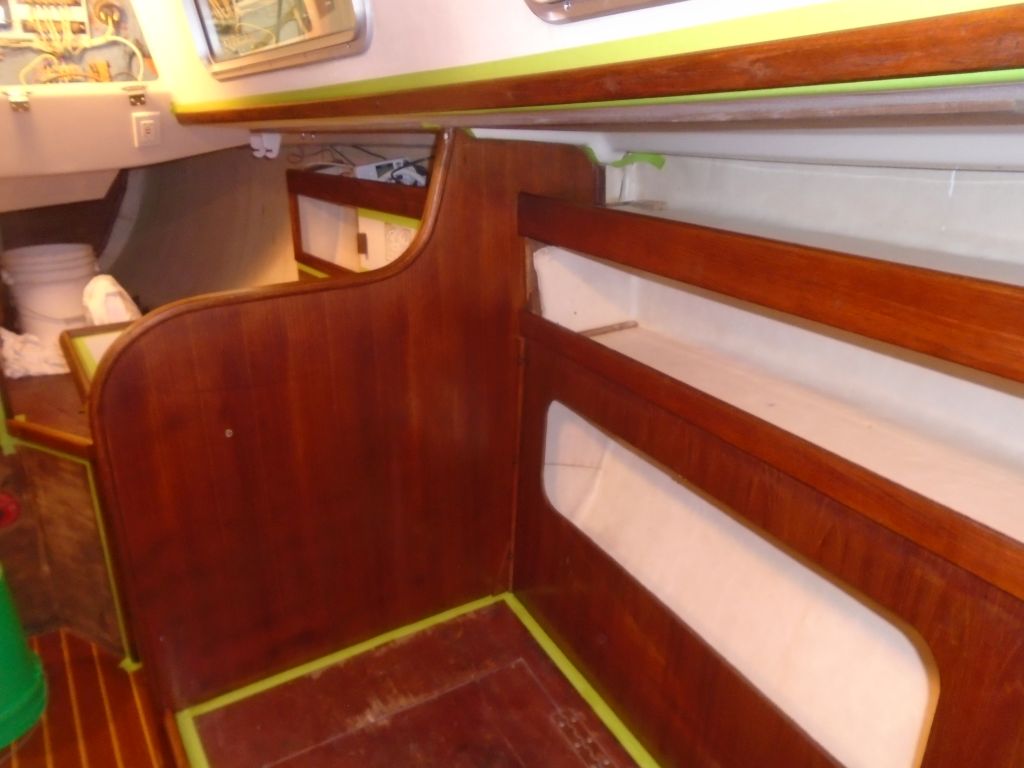
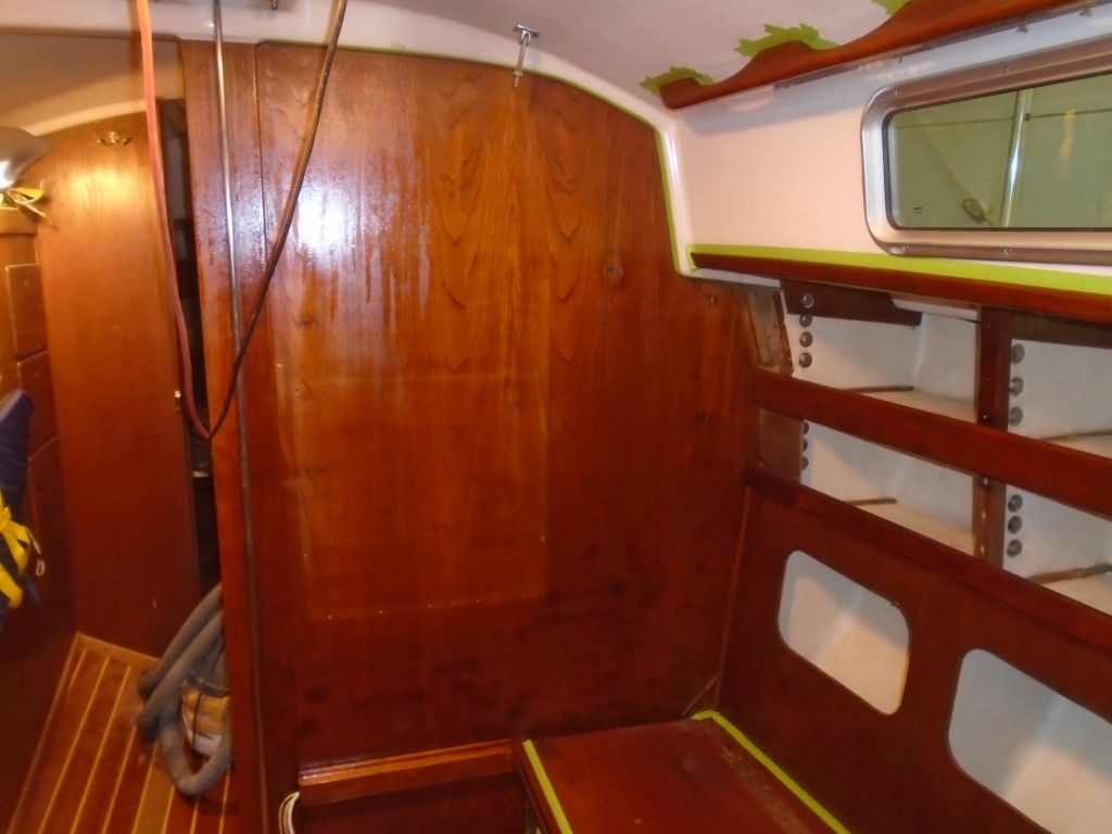
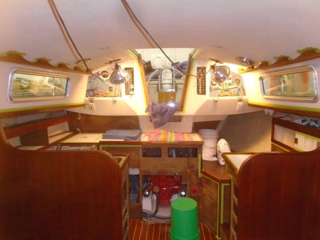
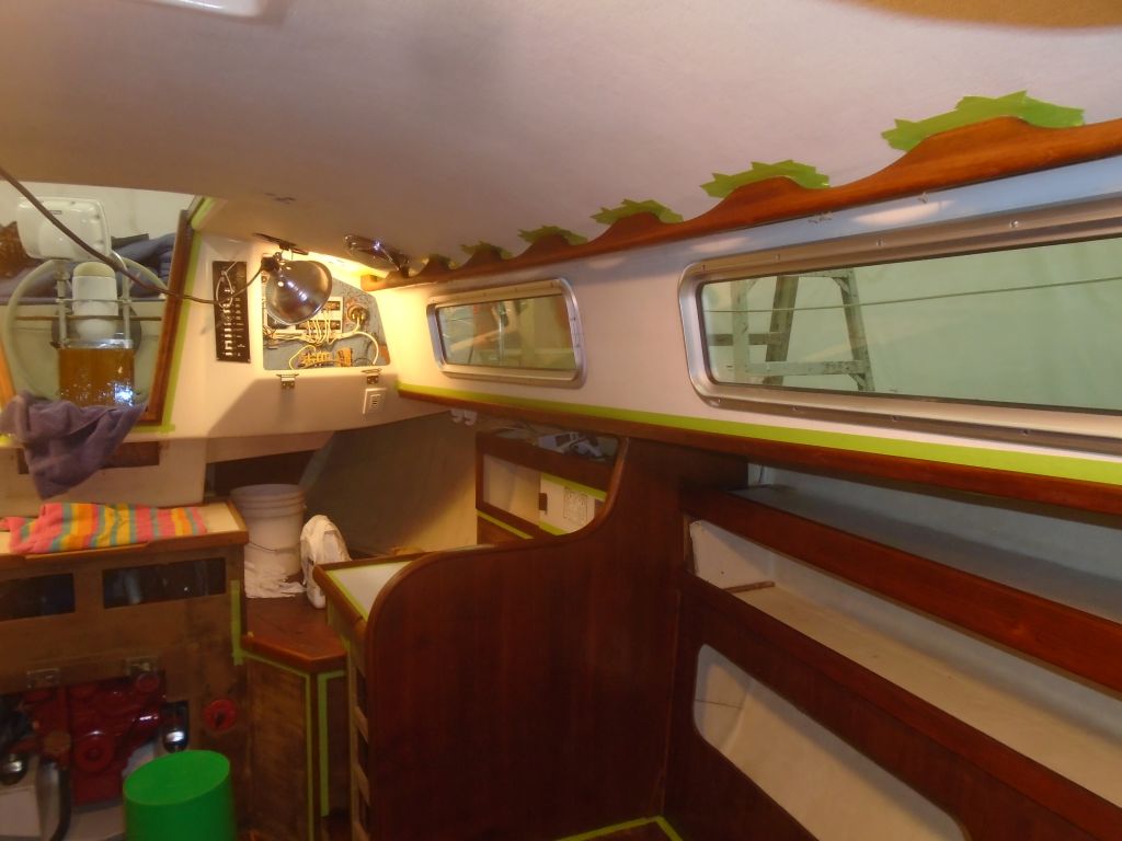
Afterwards, I applied a sealer coat of thinned varnish to all the trim and other bare wood. This brought out the wood’s color nicely and gave a hint how the cabin would look when complete.


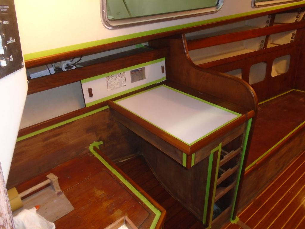


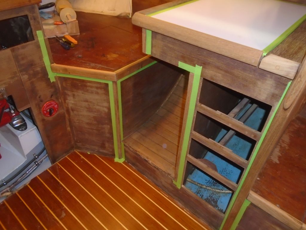
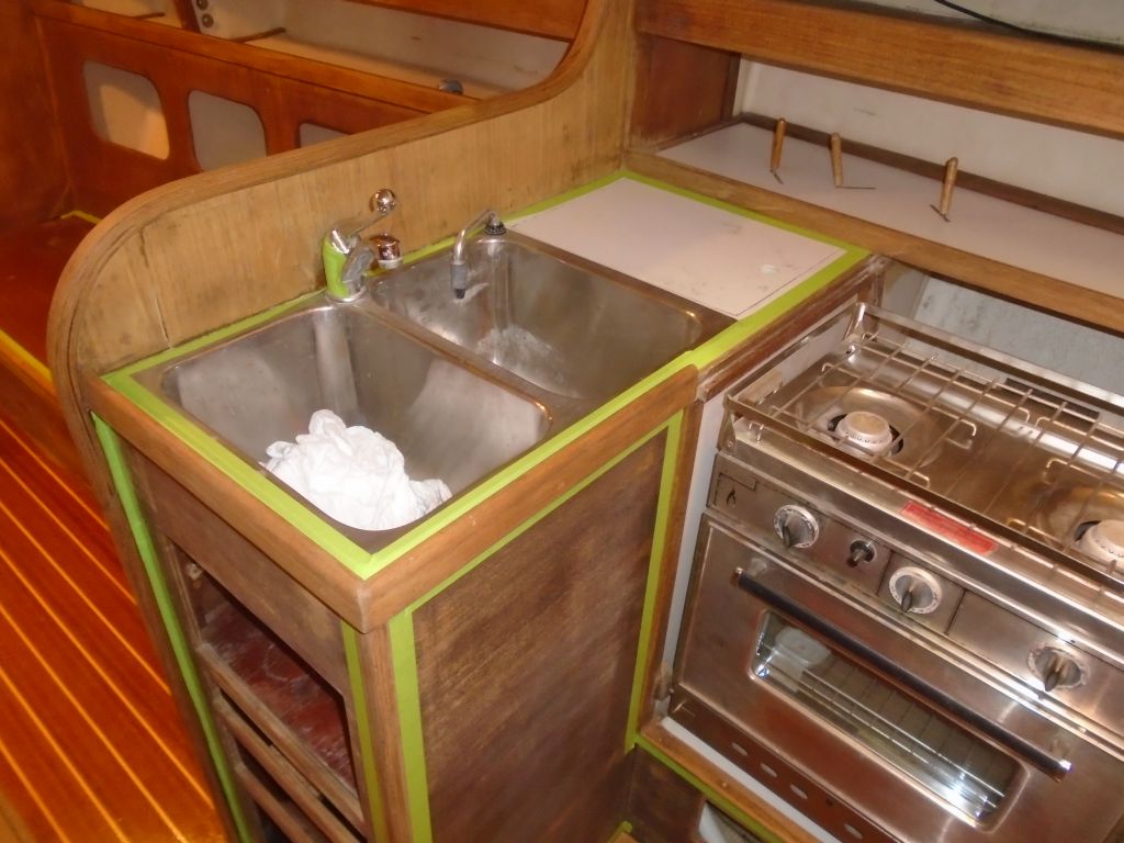
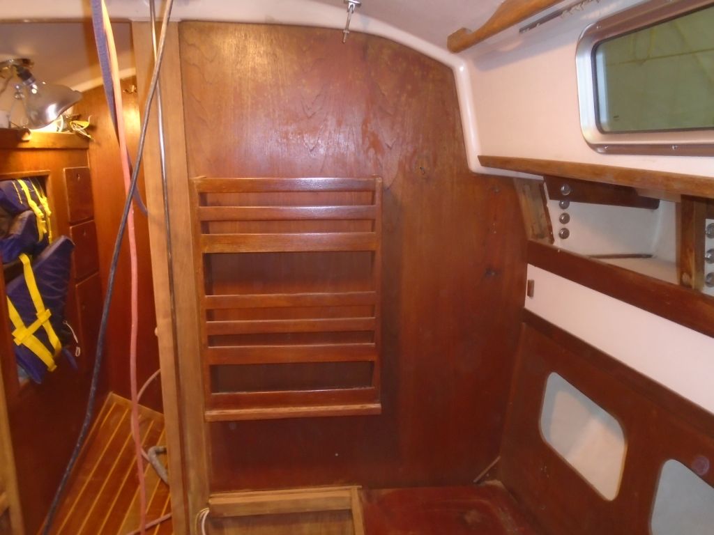
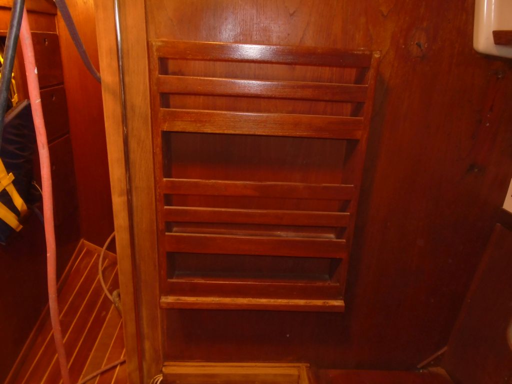
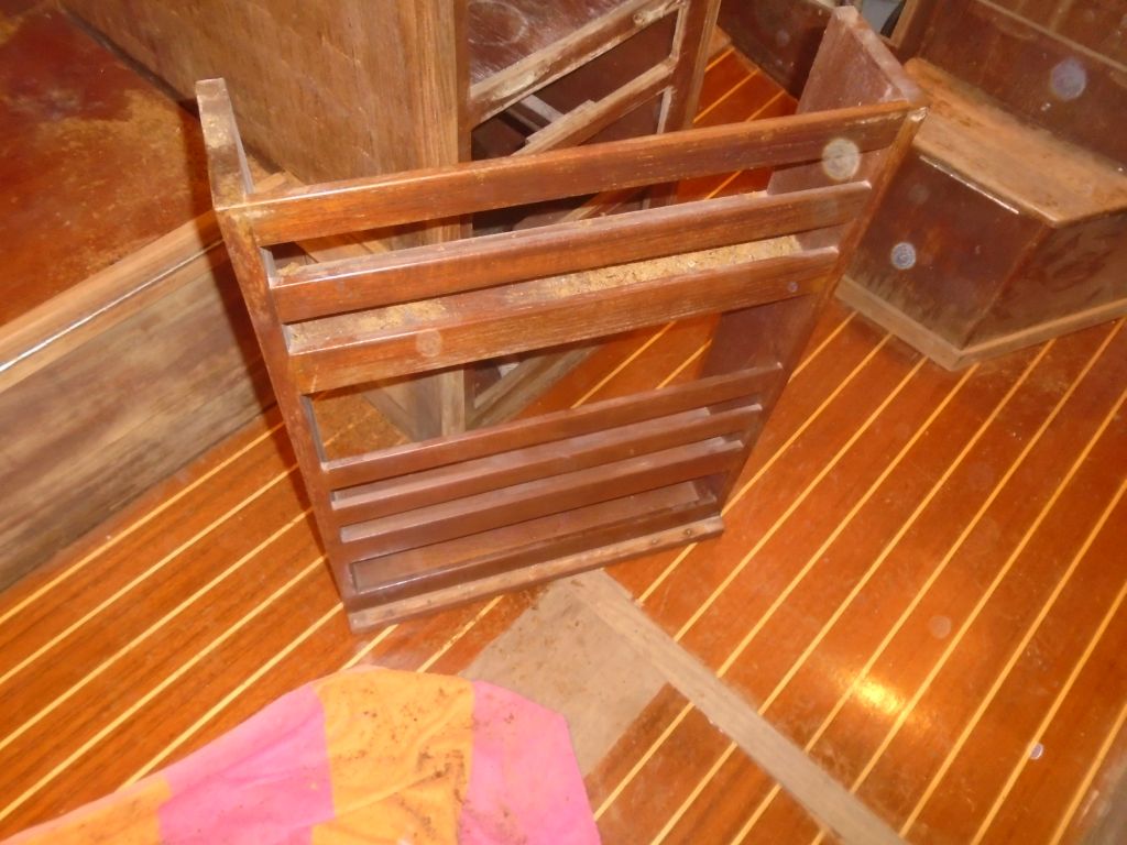
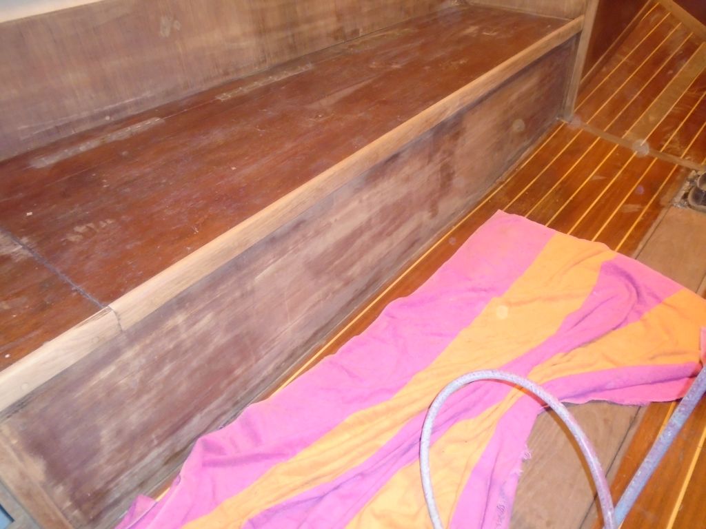
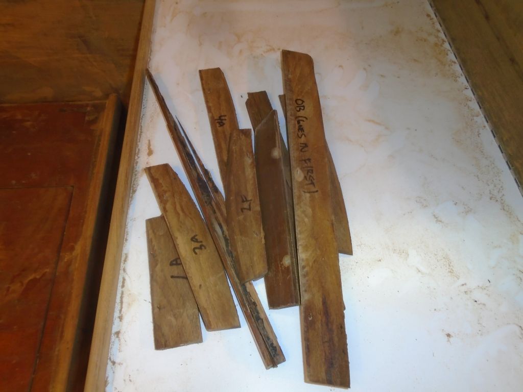
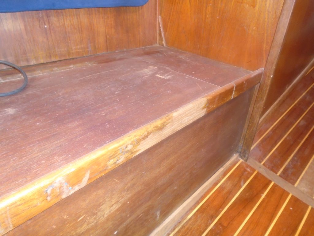
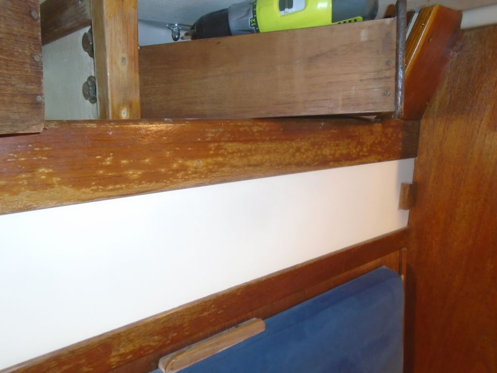
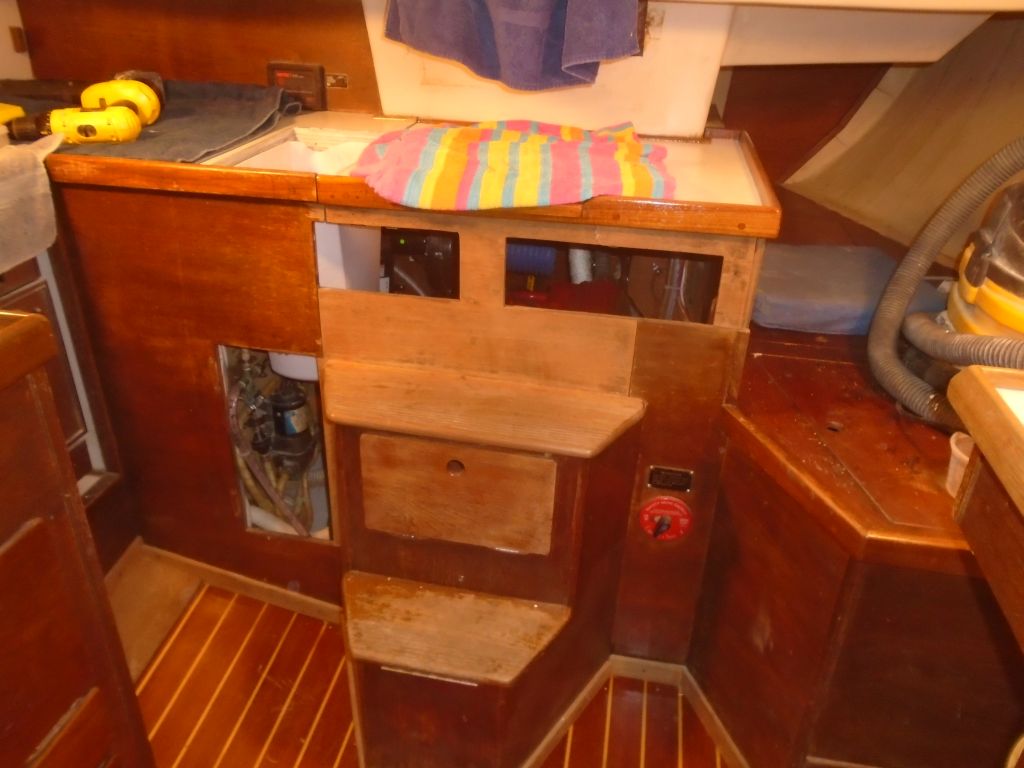
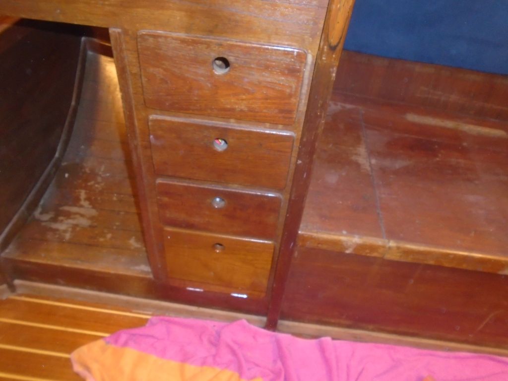
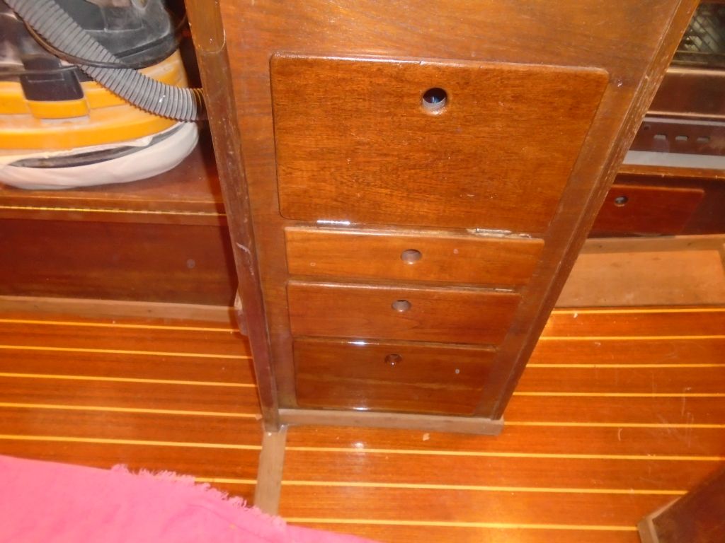
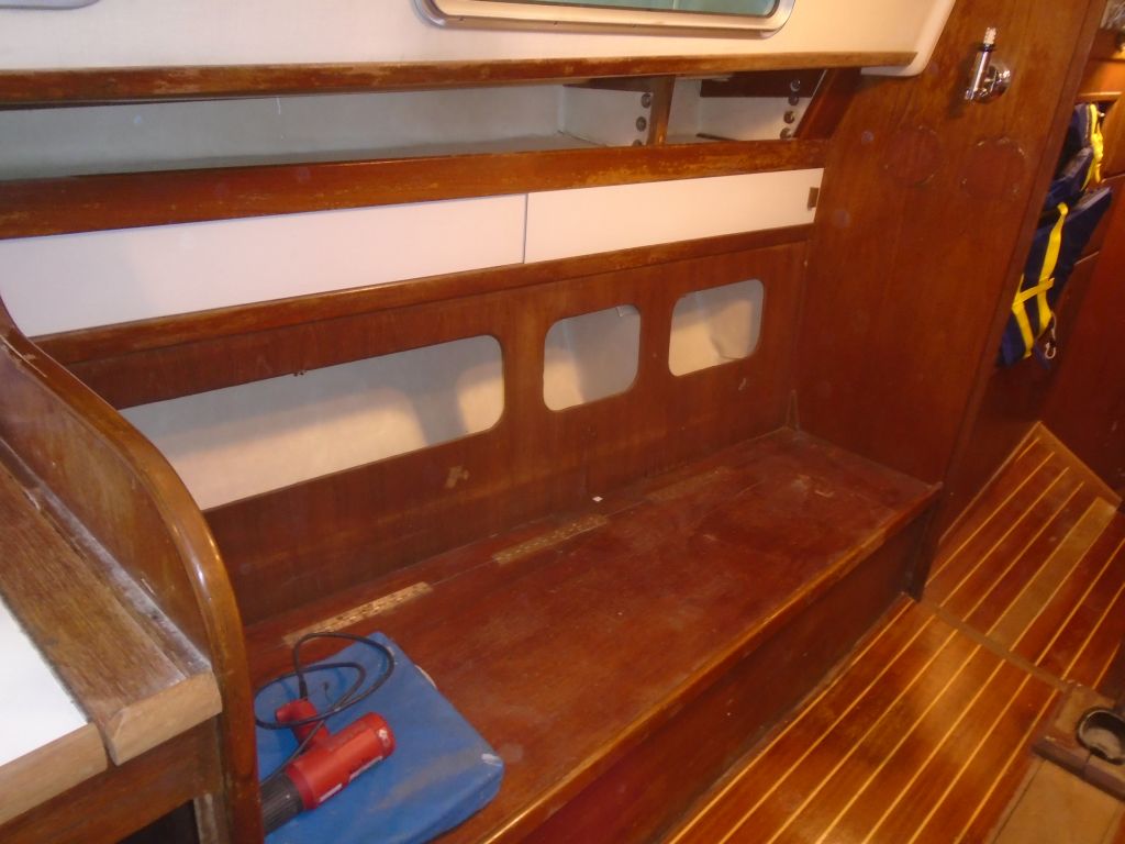
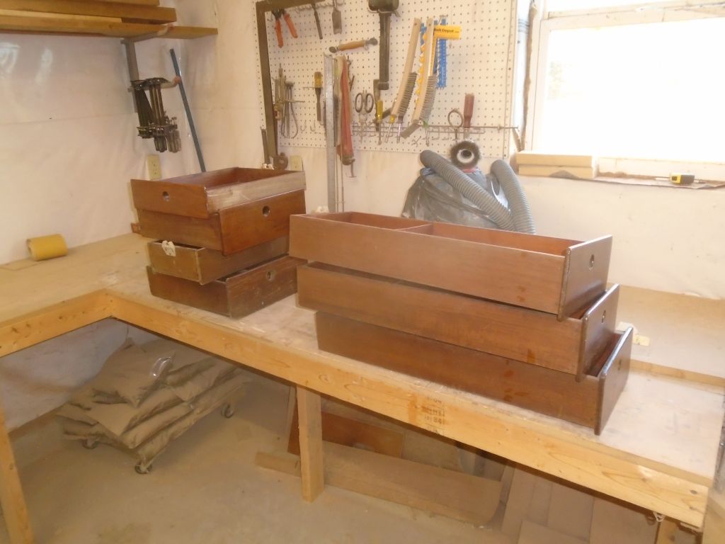
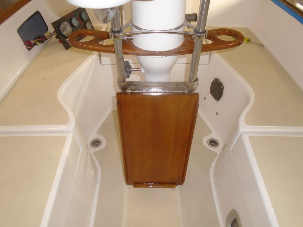
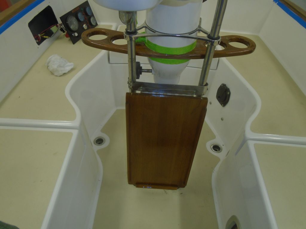
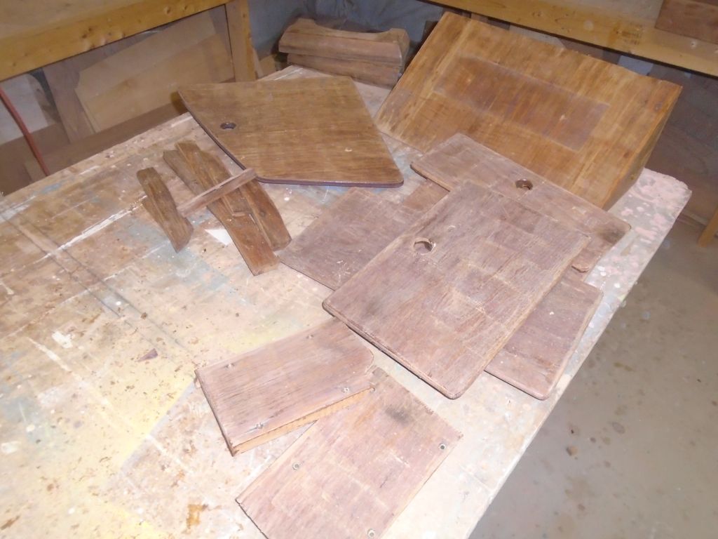
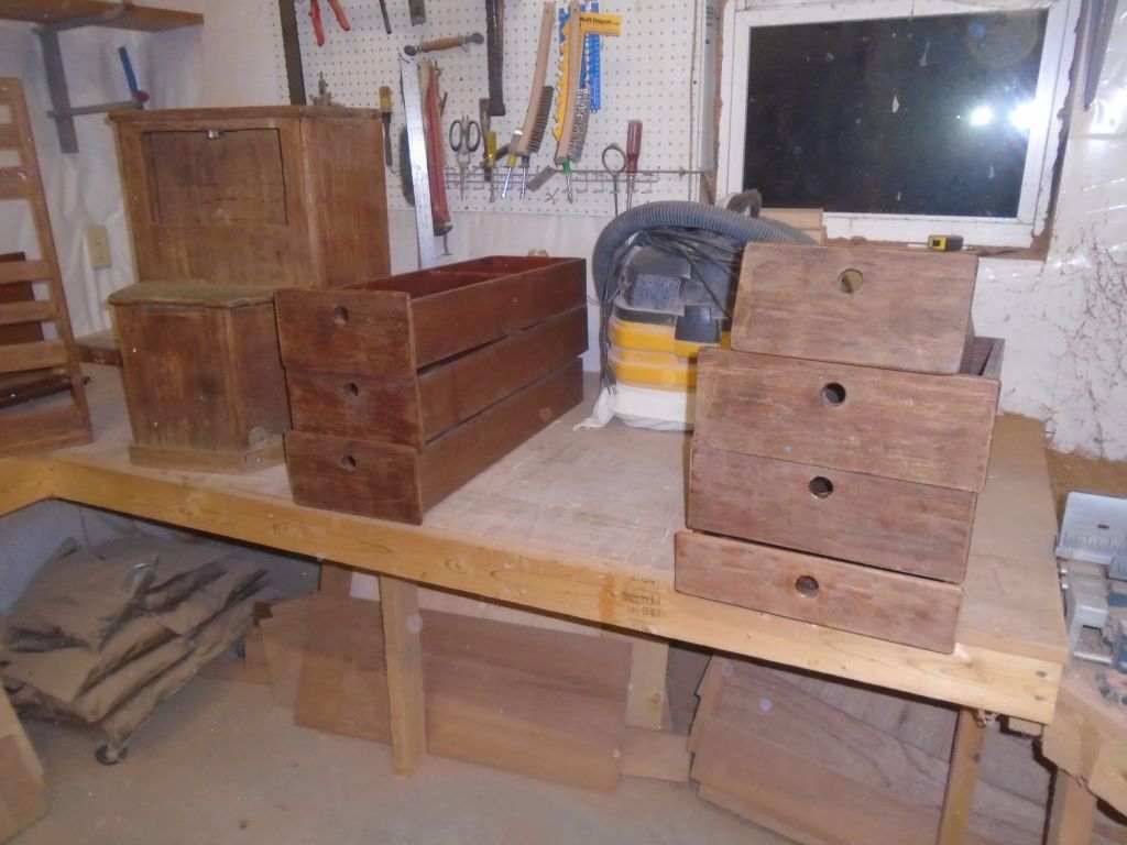
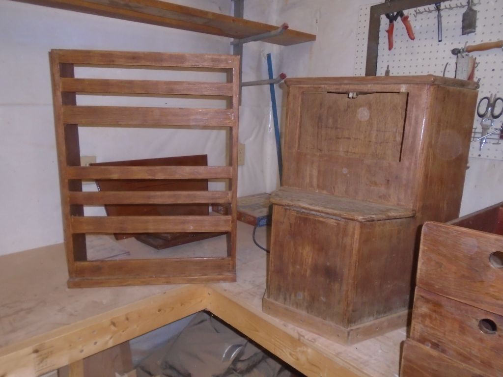
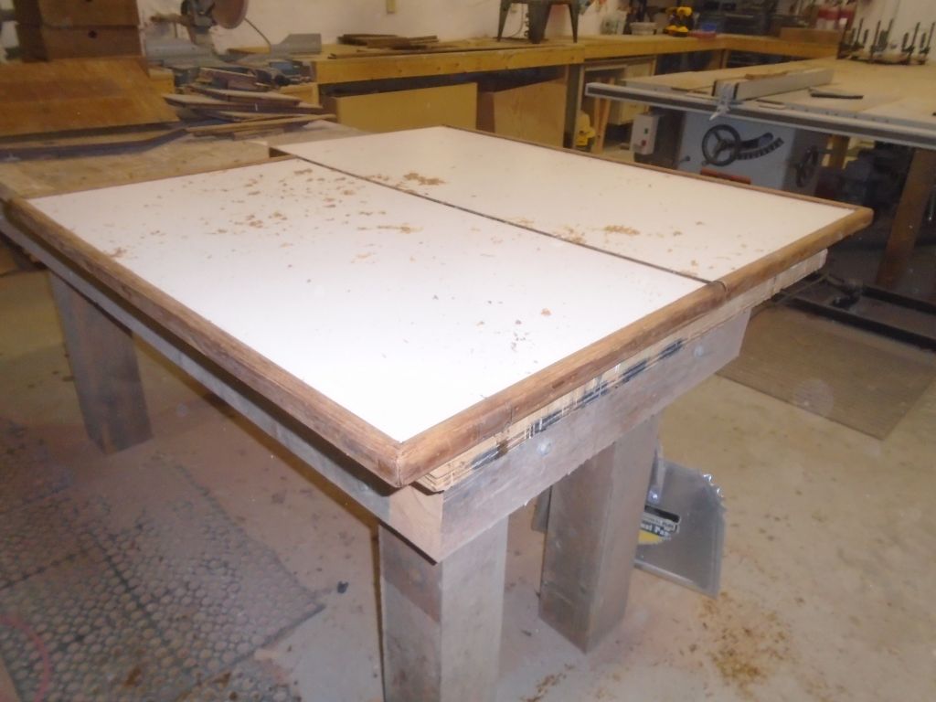
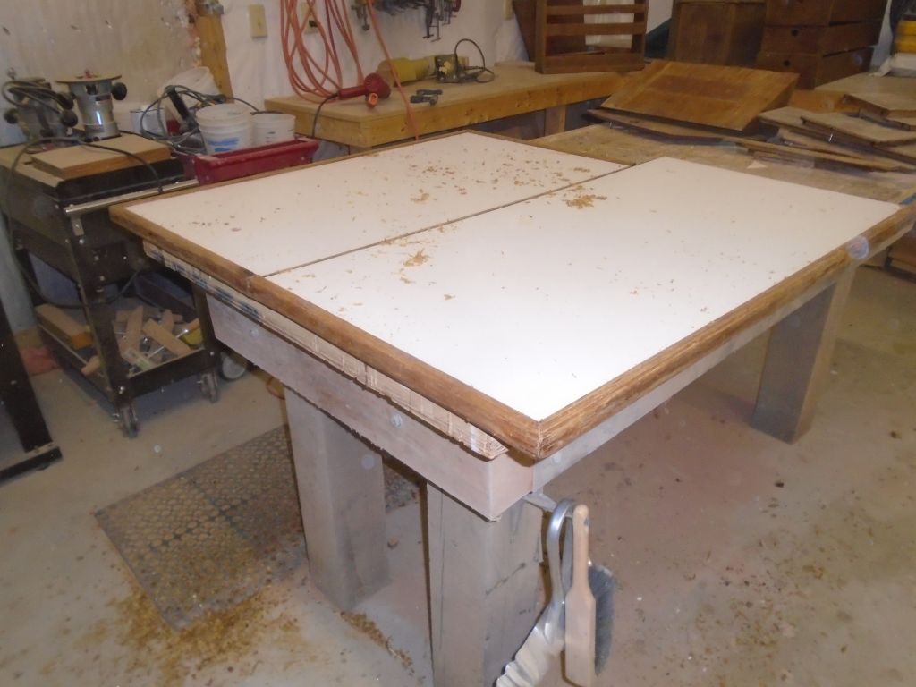
During the rest of the day, I focused on the myriad small pieces trying to tie me to the ground (I paraphrase; bonus points if you can see what I did there), including various doors and drawers as well as the cabin table and companionway steps. Most of this trim would require stripping and sanding, though there were two doors that had been refinished earlier and would only require a light sanding and revarnishing.
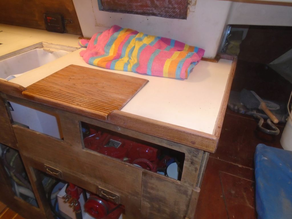
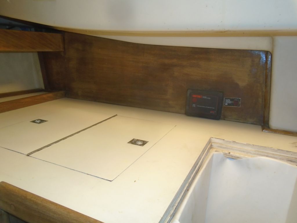
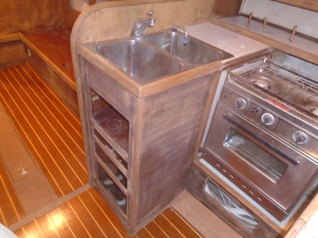
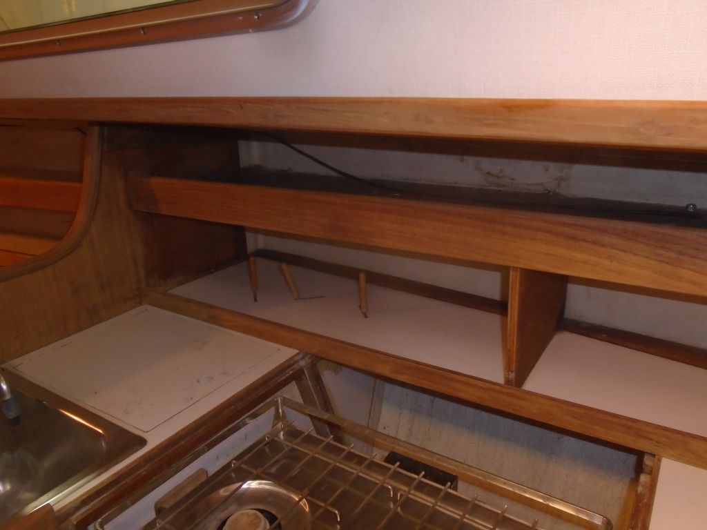
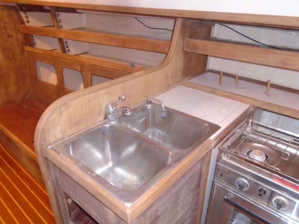
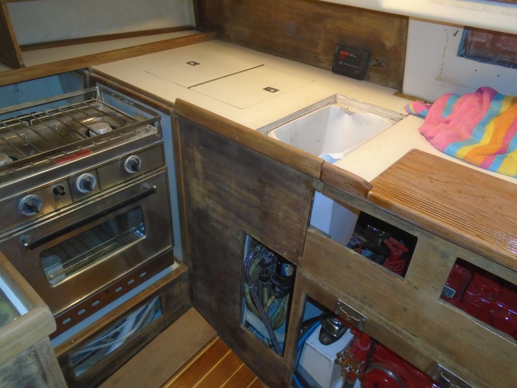
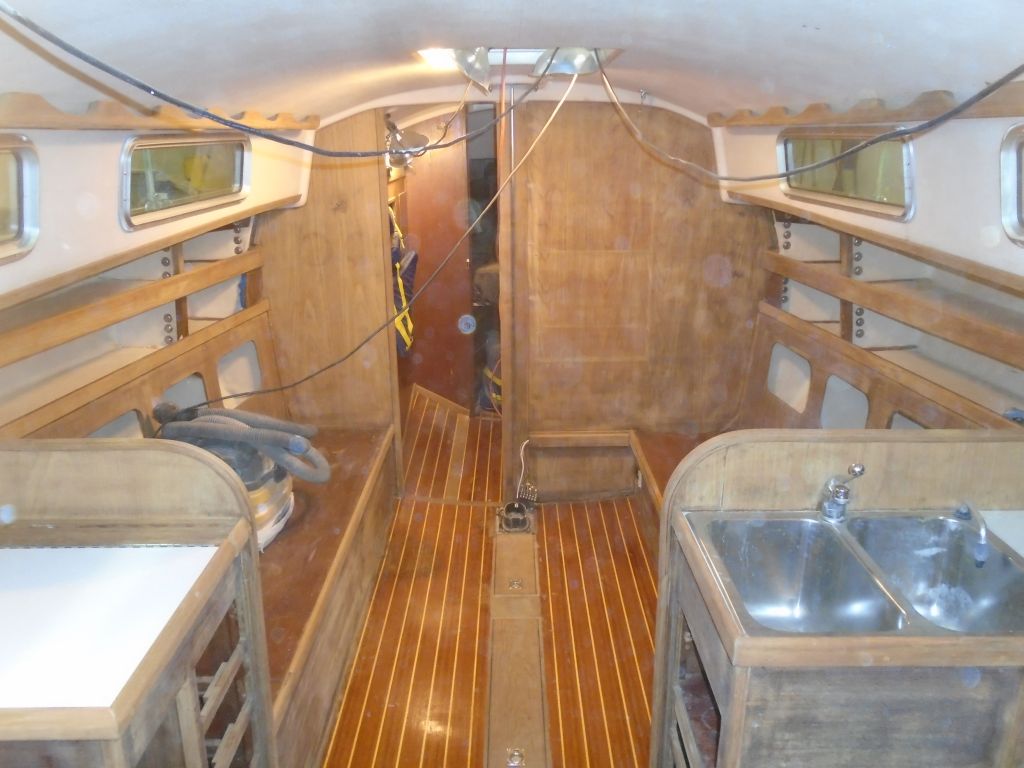
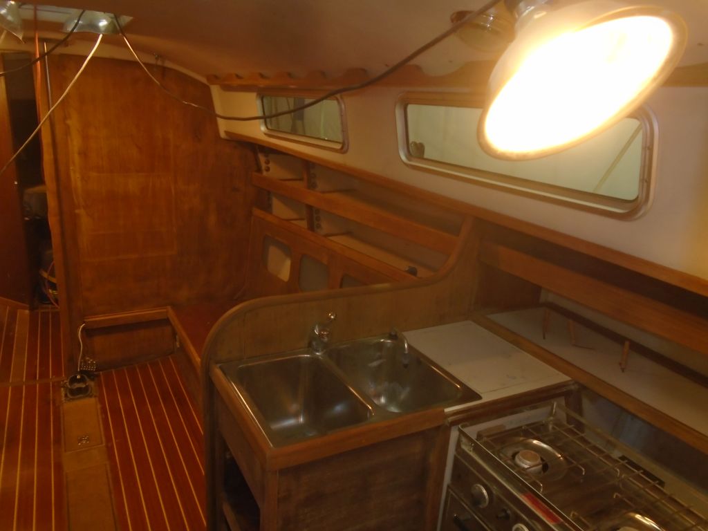
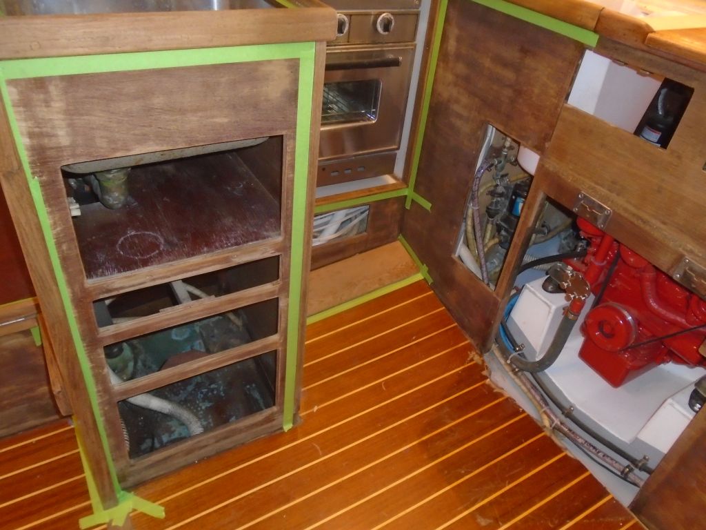
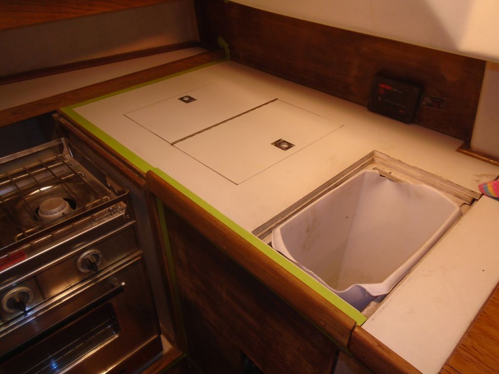
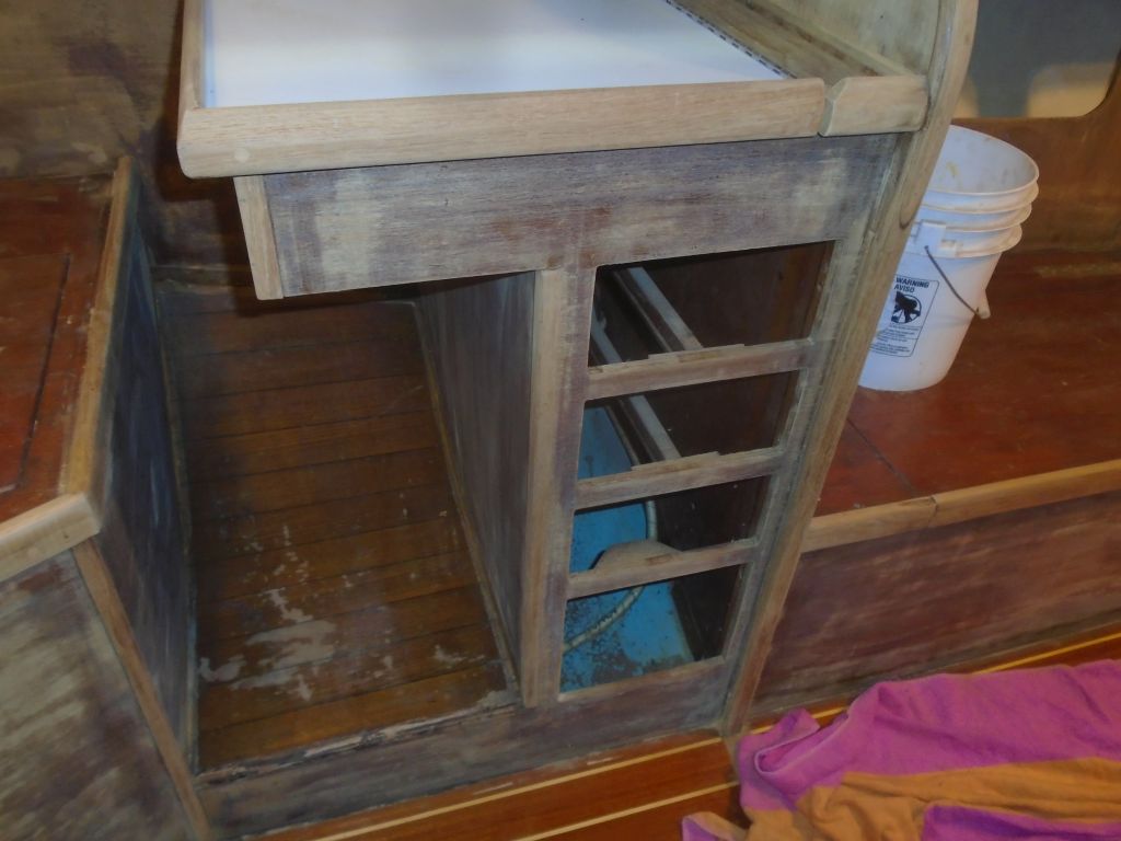
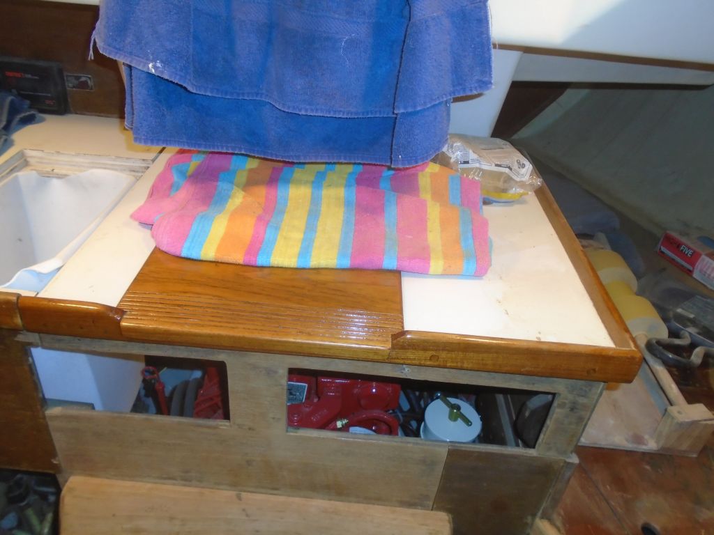
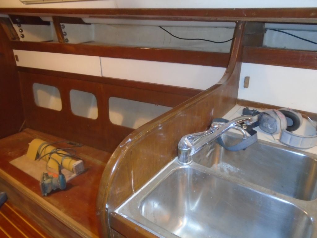
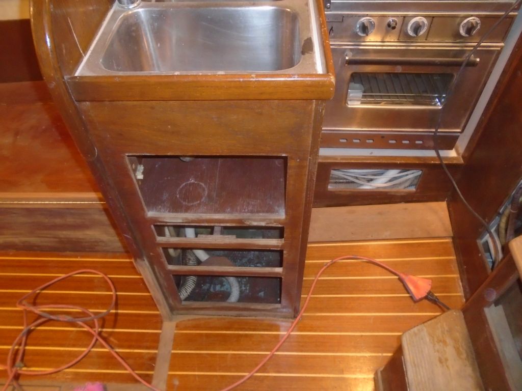
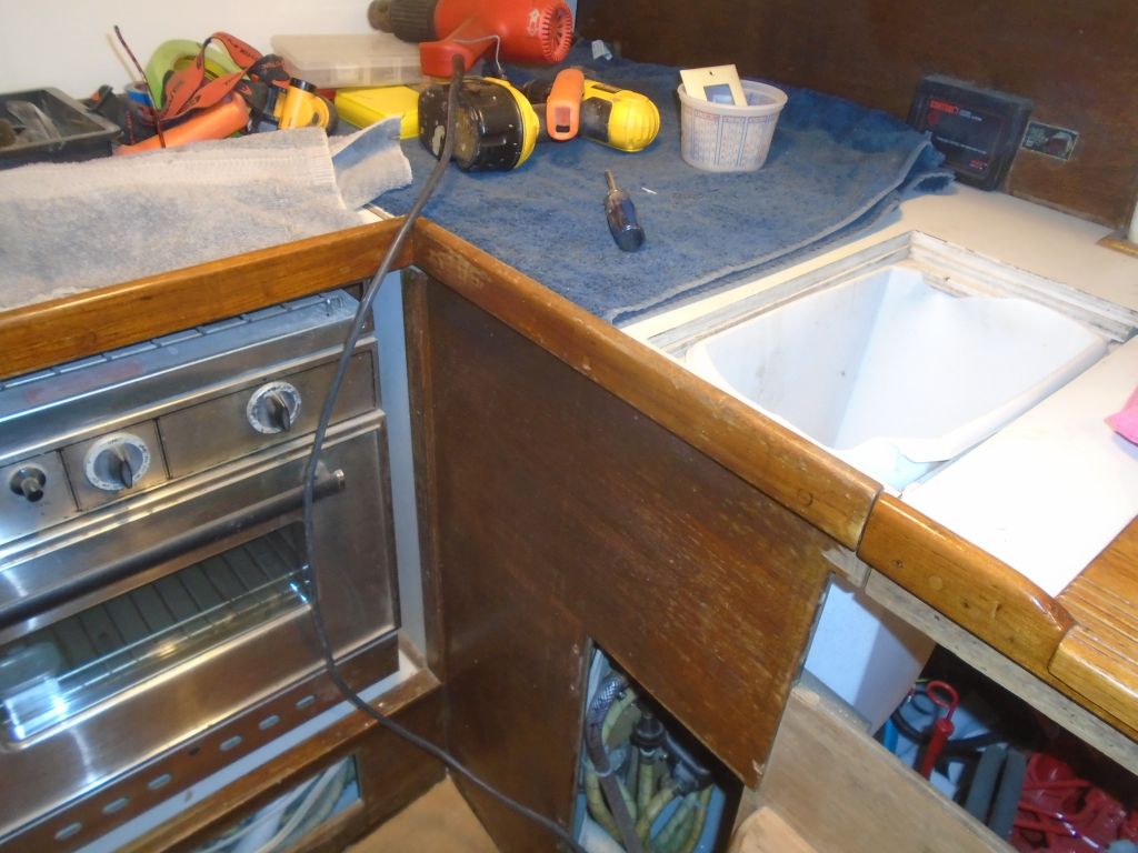
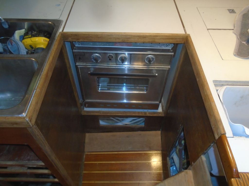
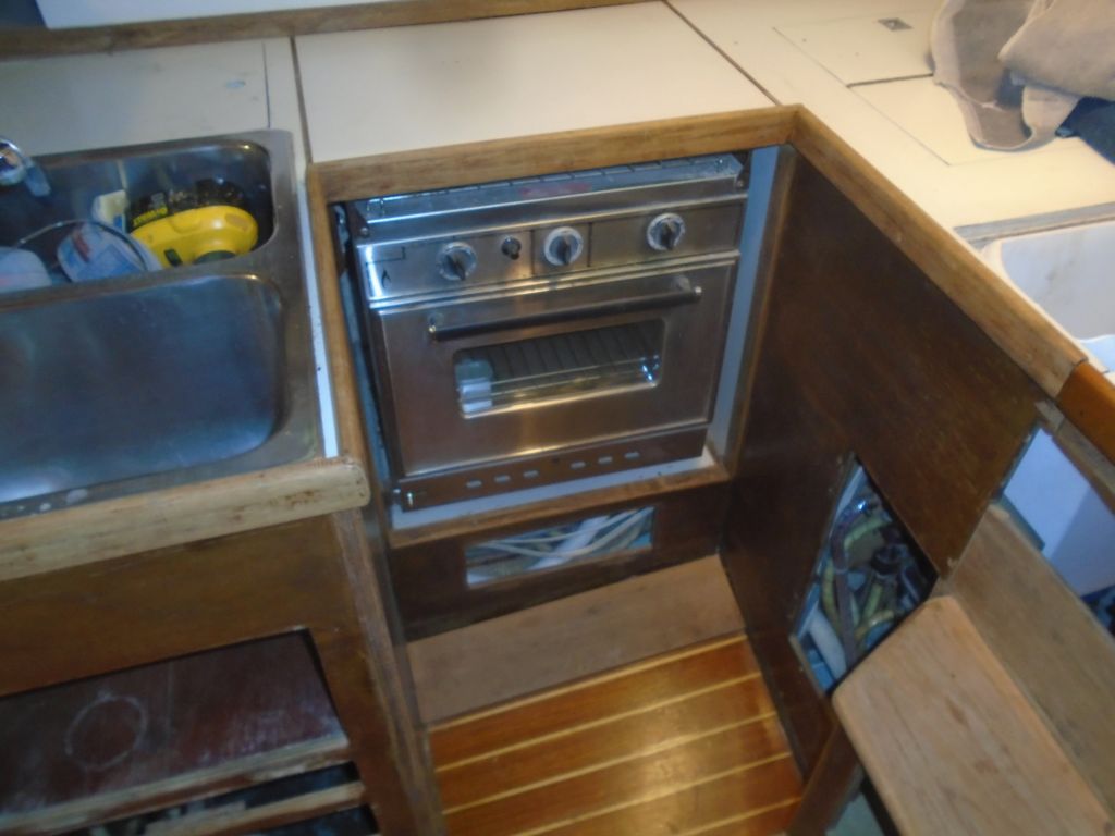
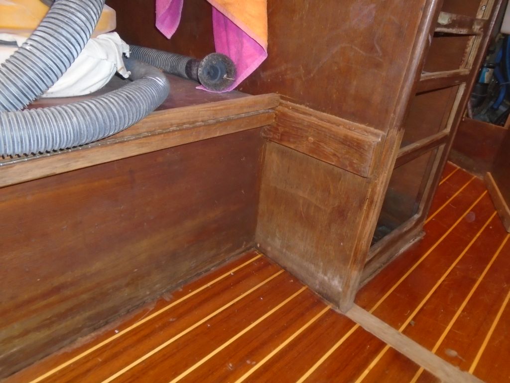
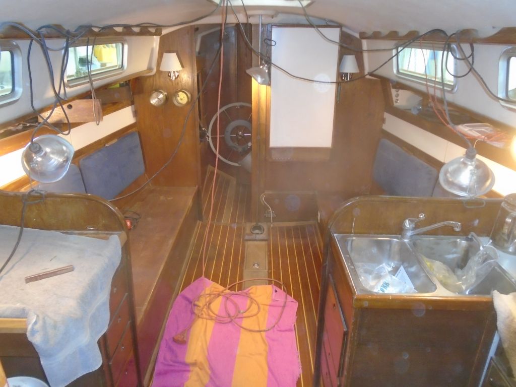
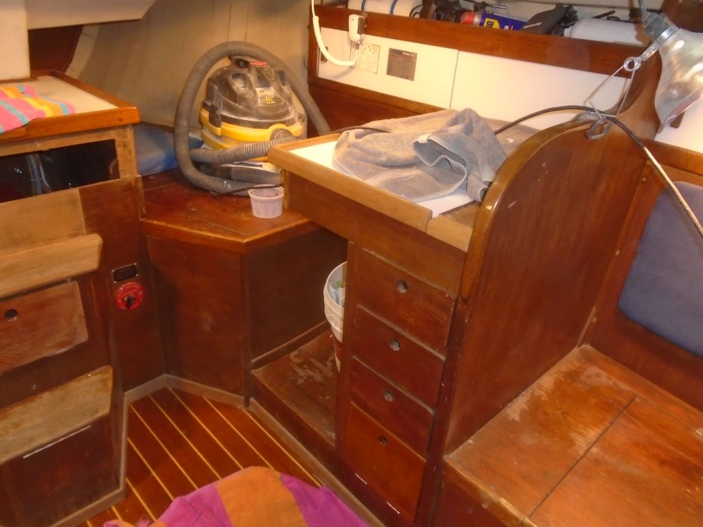
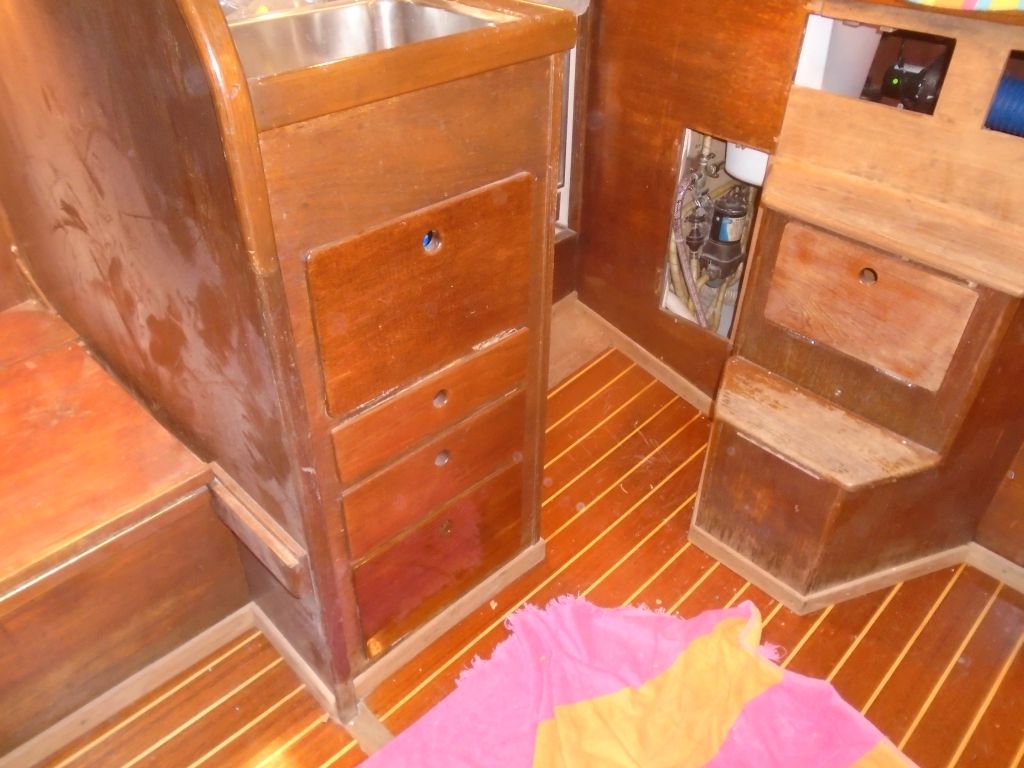
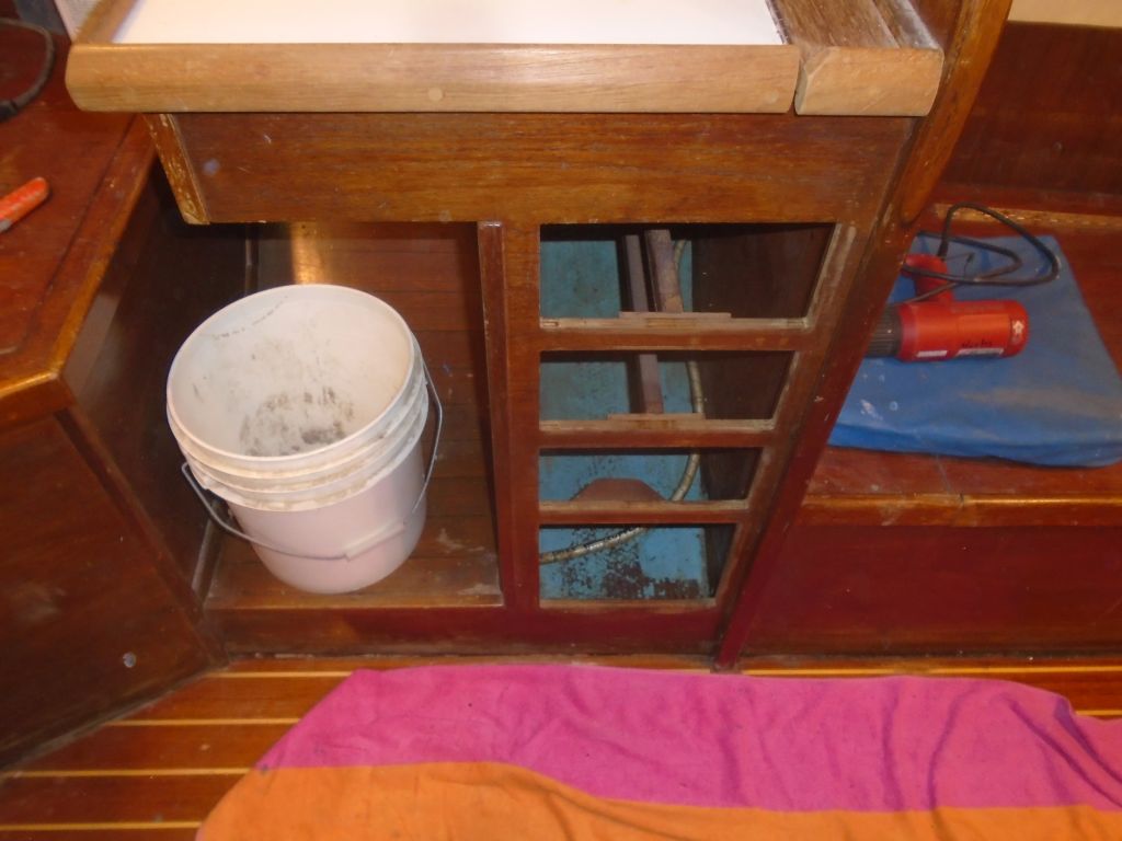
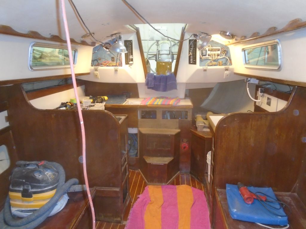
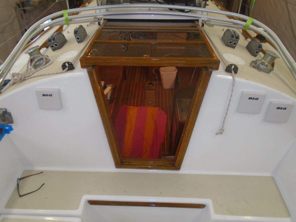
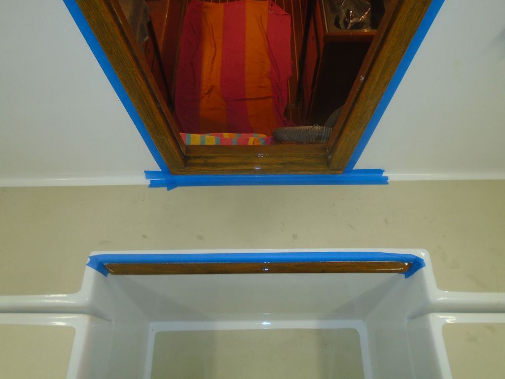
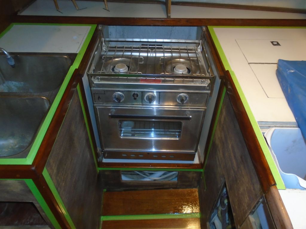
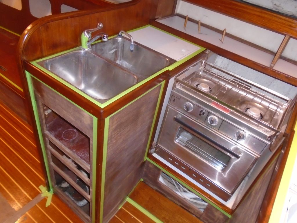
There were a few things requiring additional attention first. The flat hatch that fit over the trash container in the galley countertop was damaged along its edges, where the thin overlay had broken away over the years, and rather than attempt to repair the original hatch, I chose to make a new one from some leftover teak on hand. I milled the new piece, matching the original dimensions and rabbet details, and set the new hatch aside for sanding.

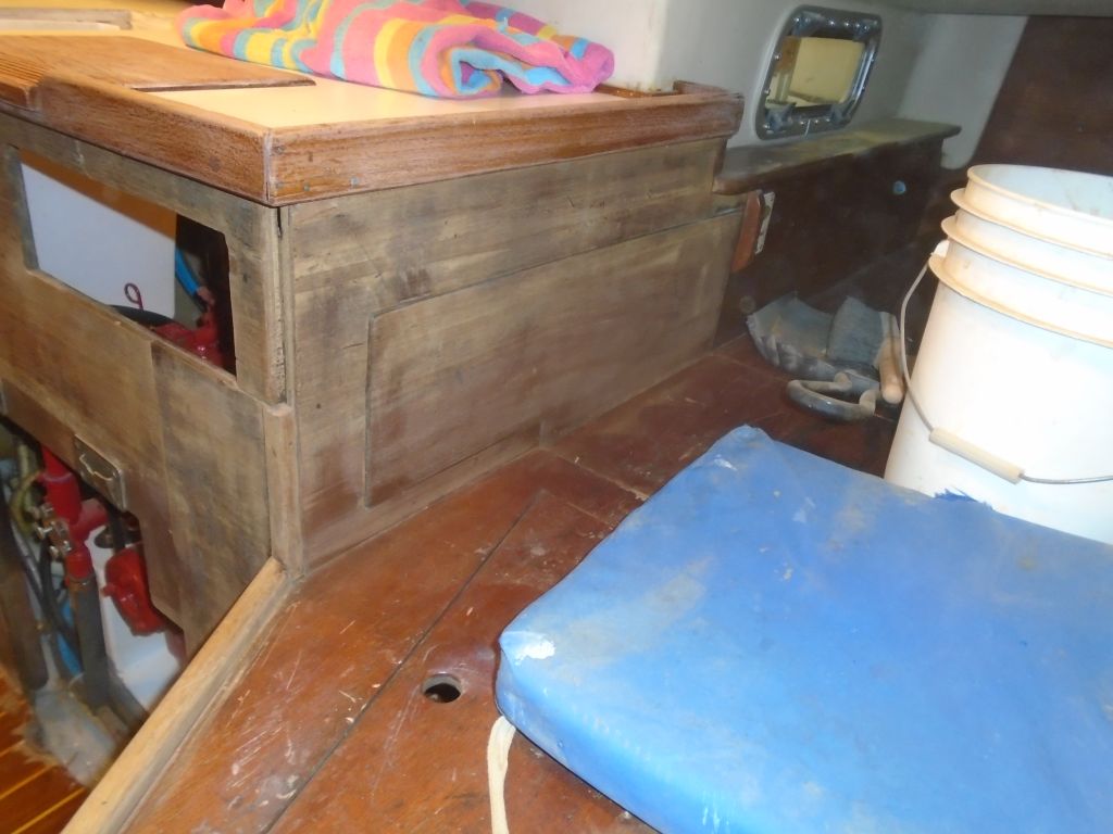
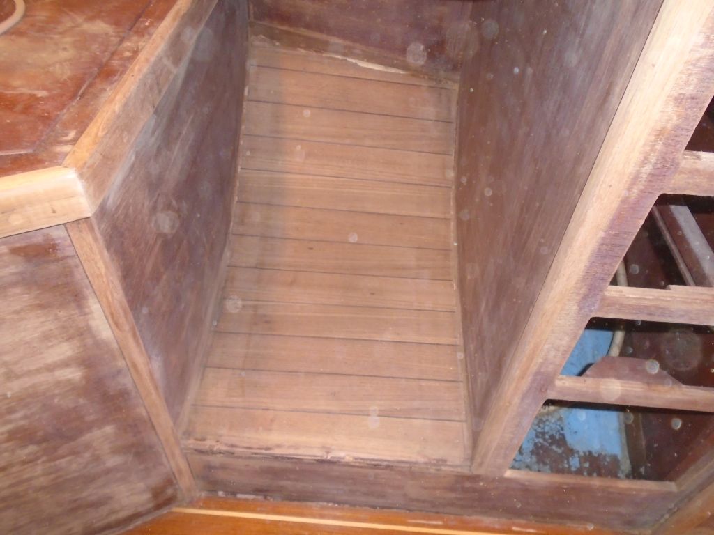
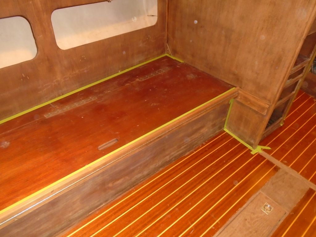
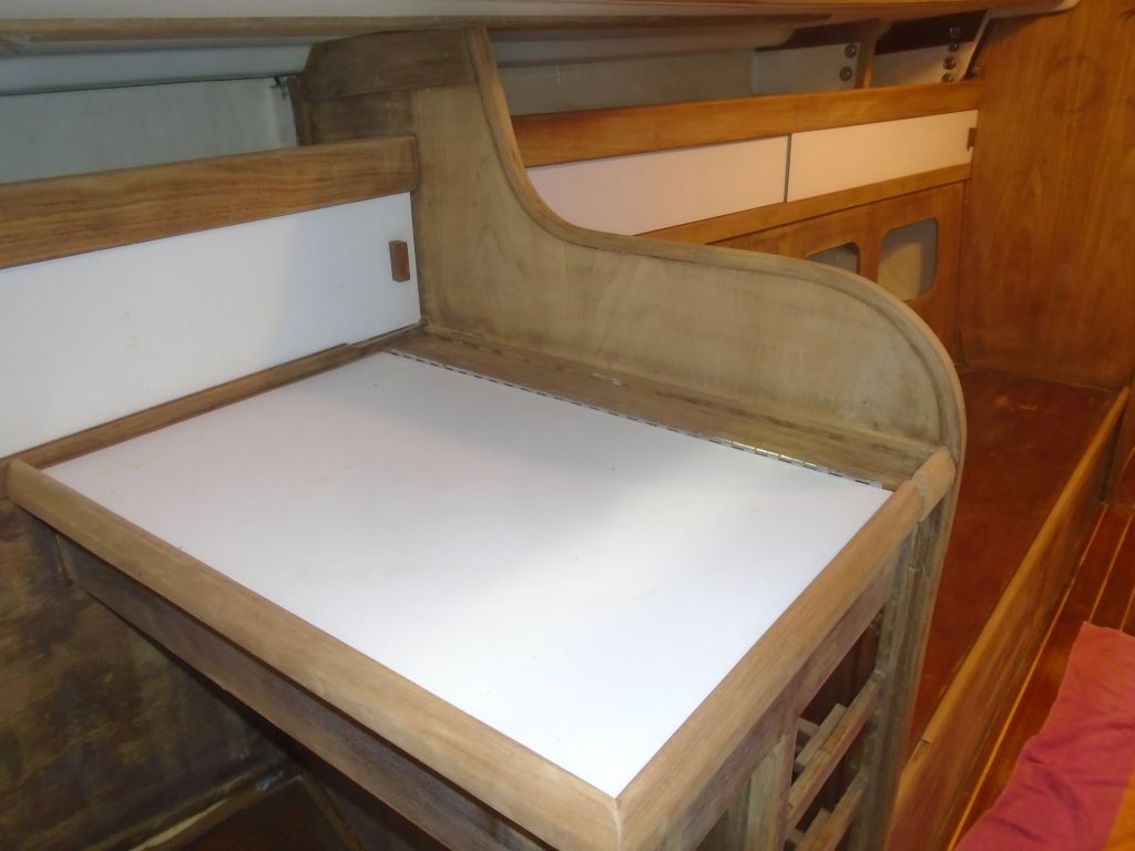
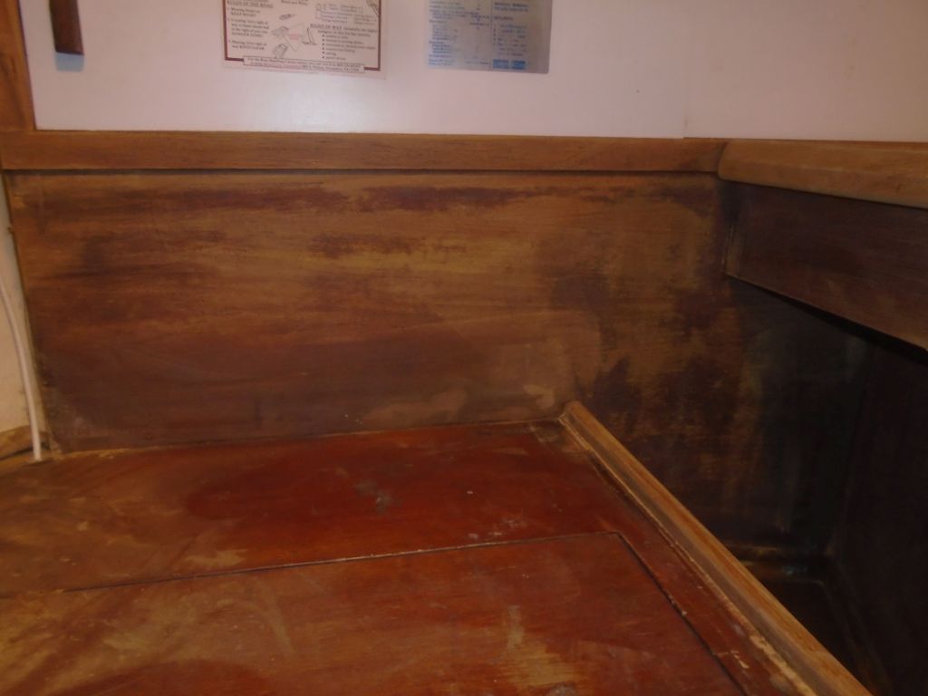
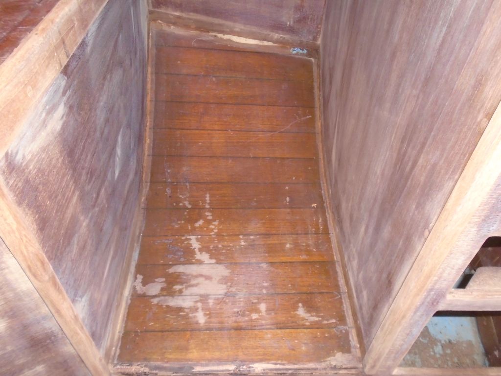
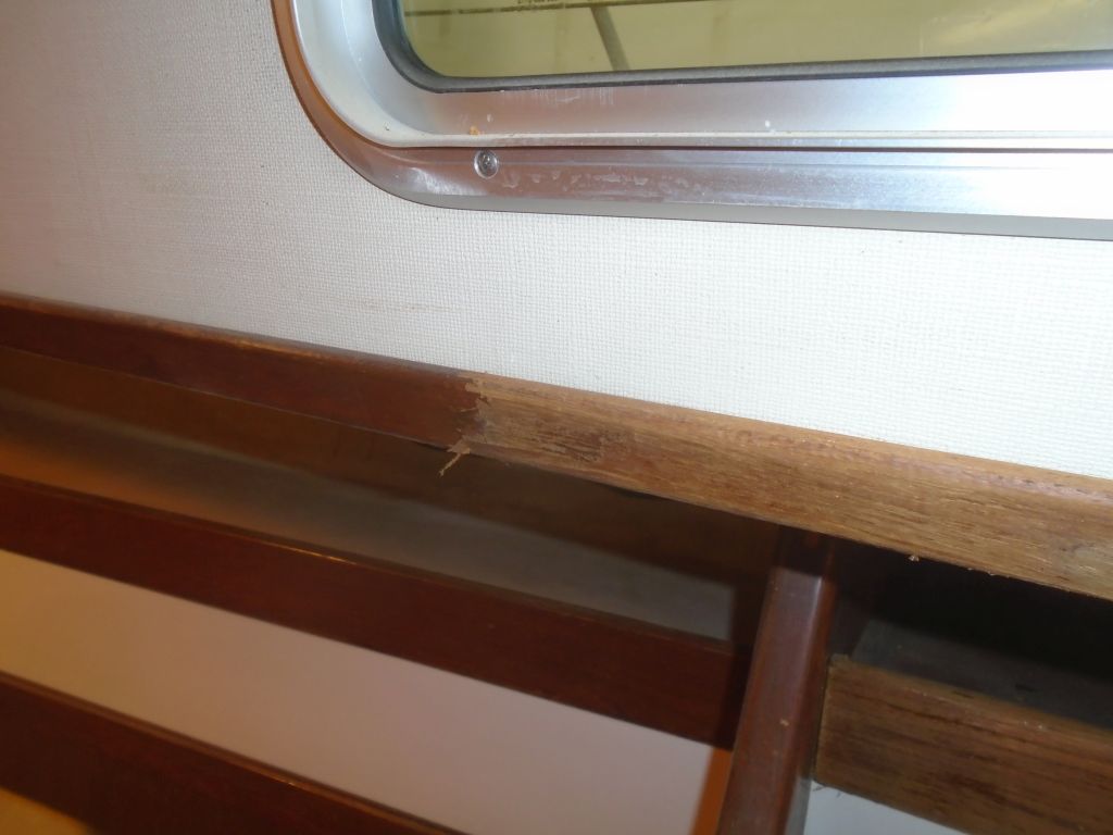
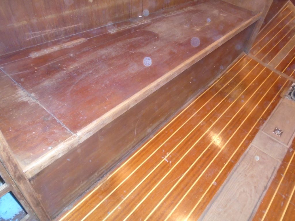
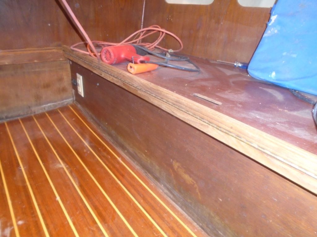
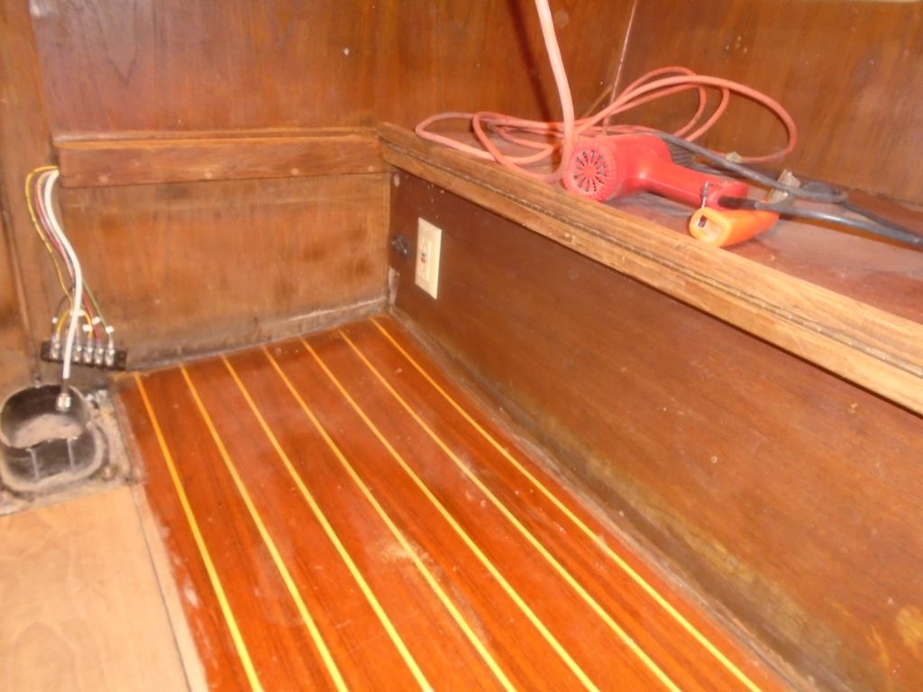
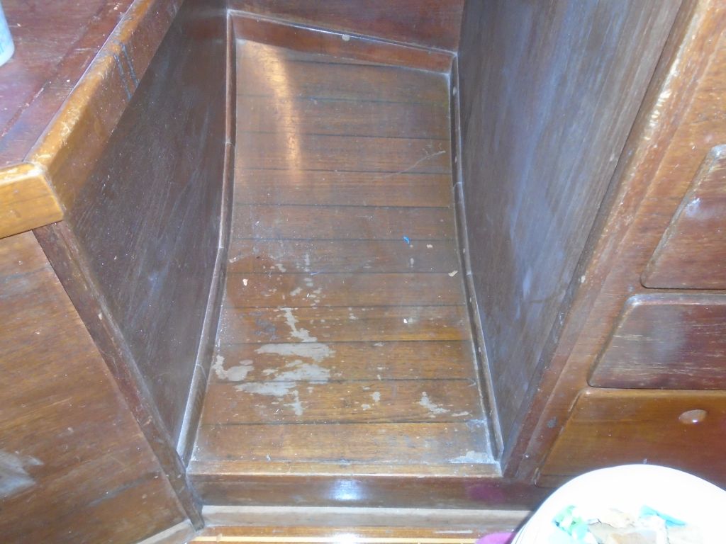
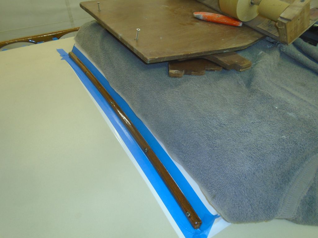
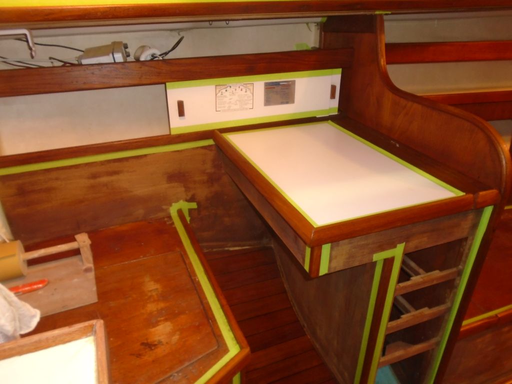
The edge trim from the nav station cabin sole had broken when I removed it, so I milled a replacement piece–left overlong for now–from some new teak.

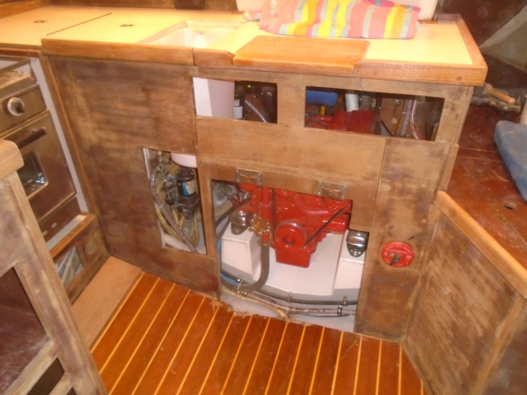
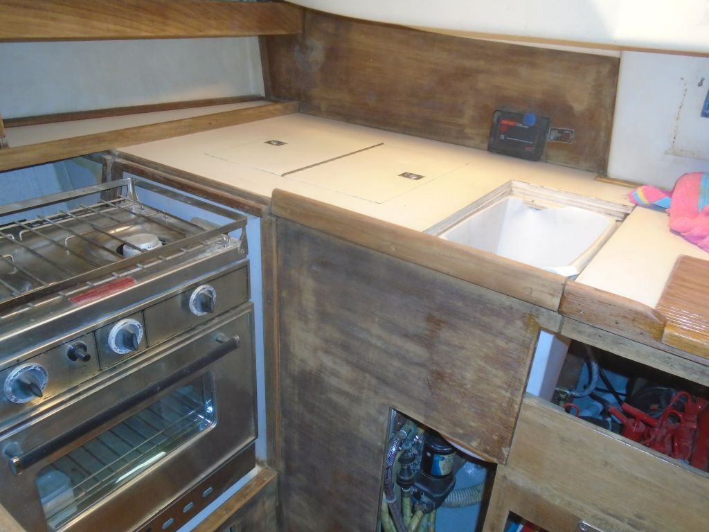
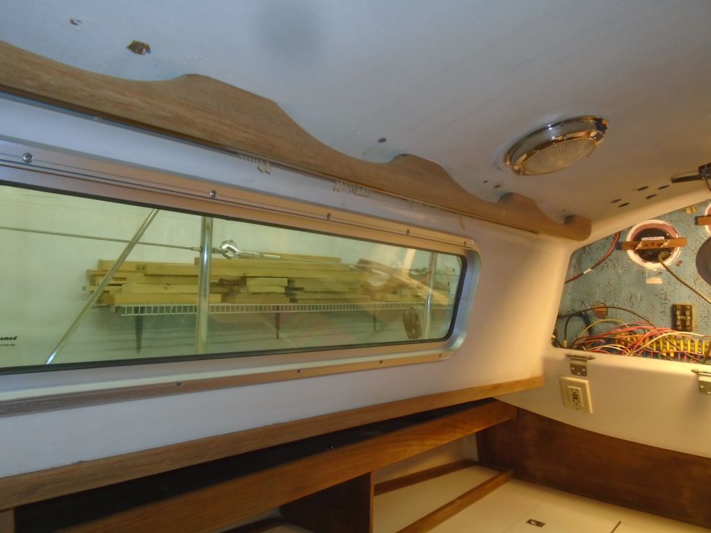
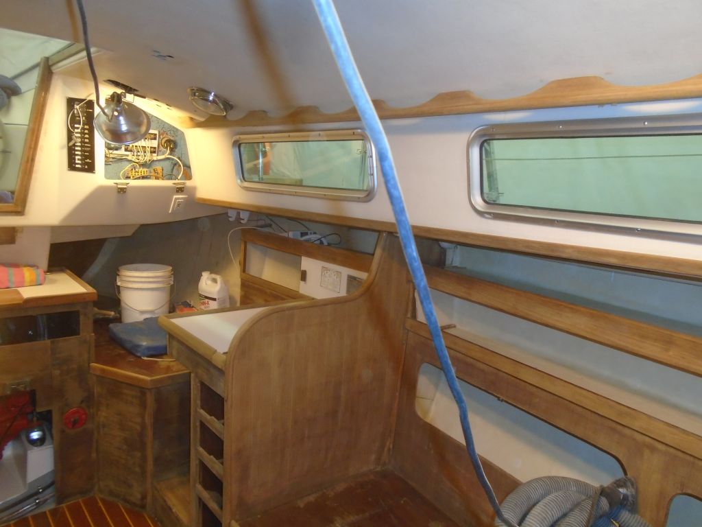
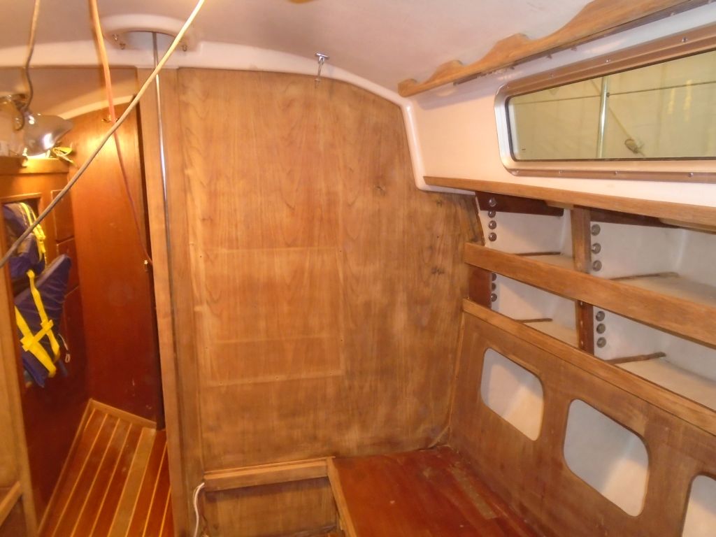
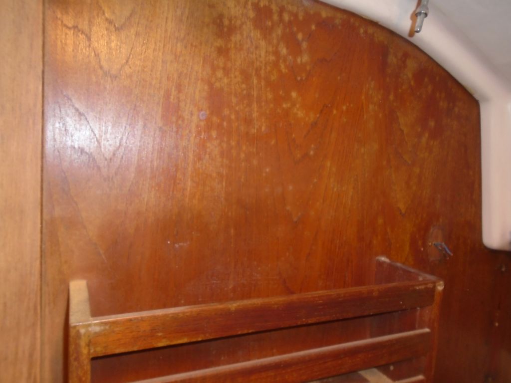
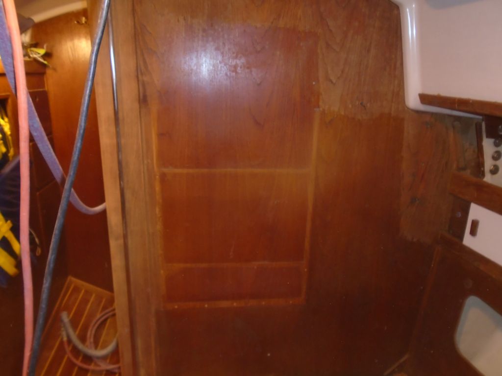
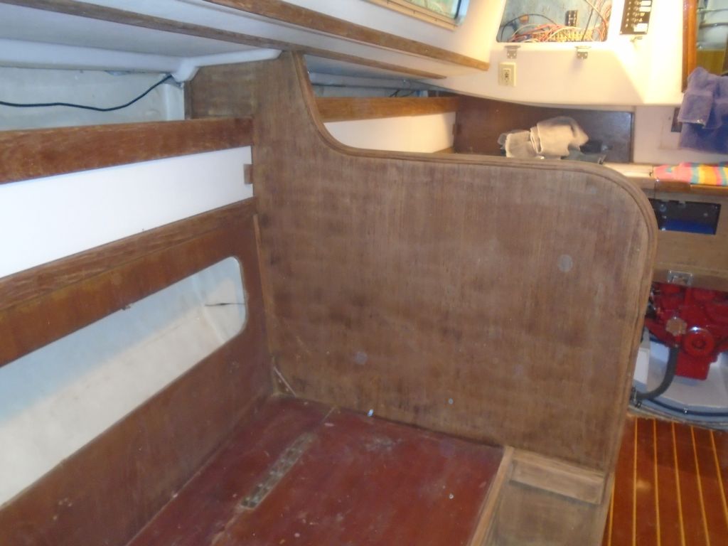
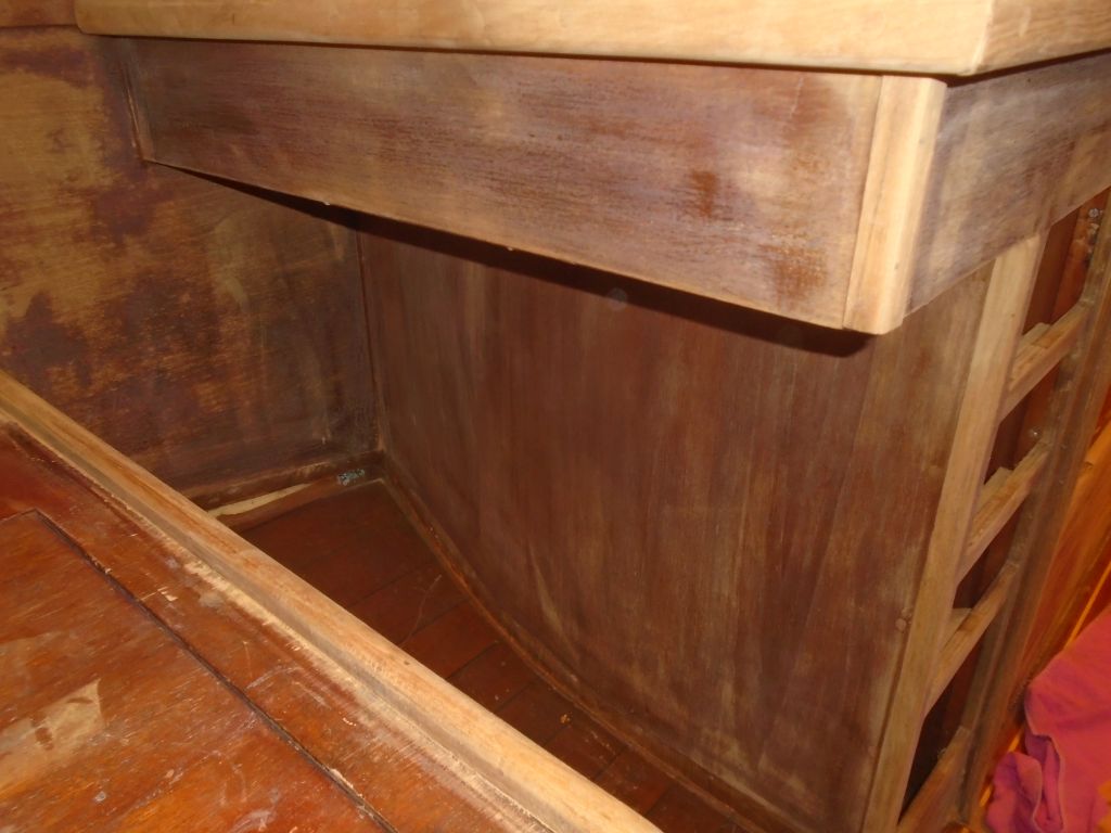
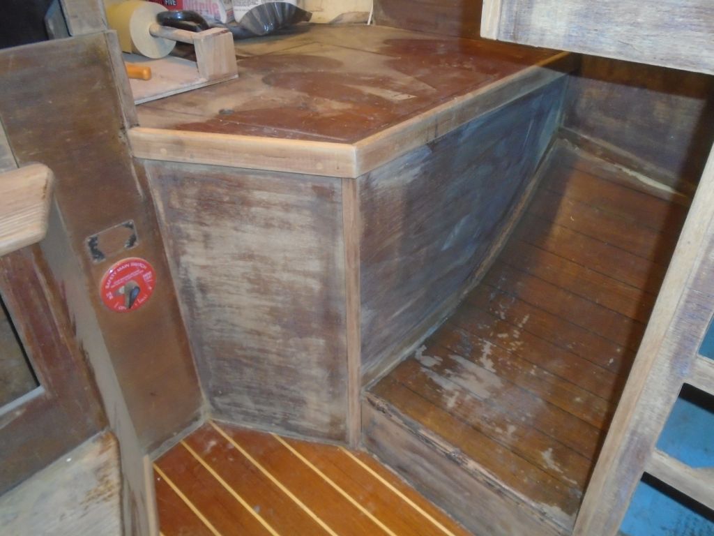
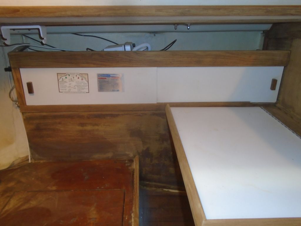
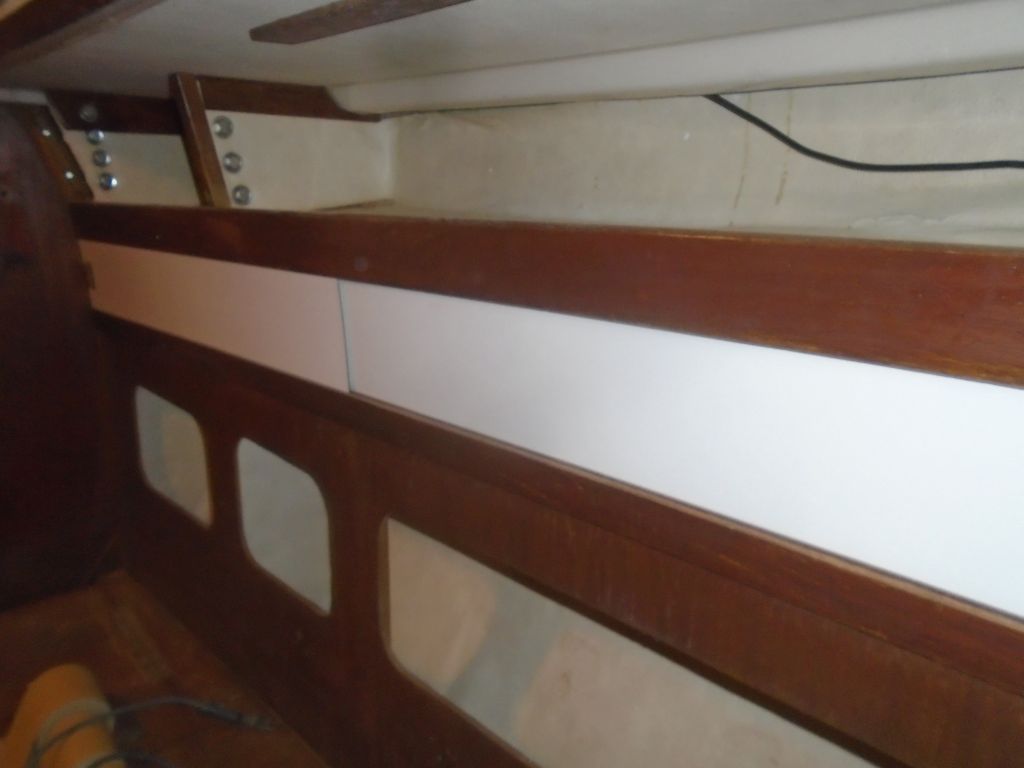
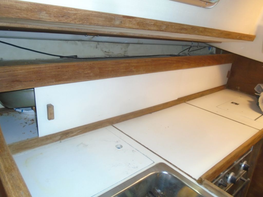
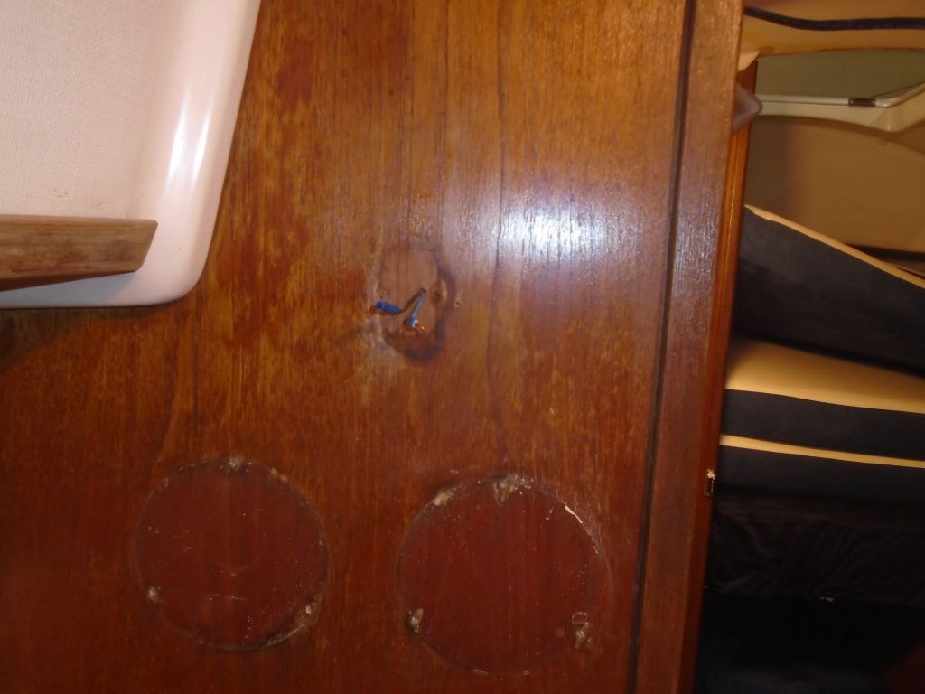
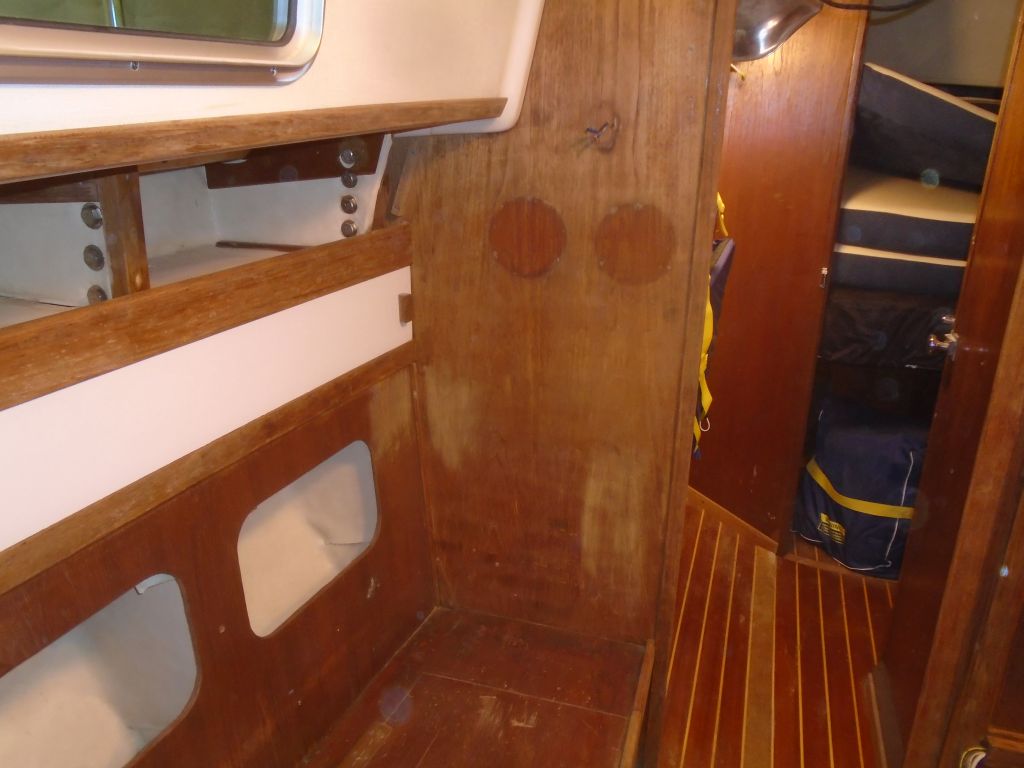
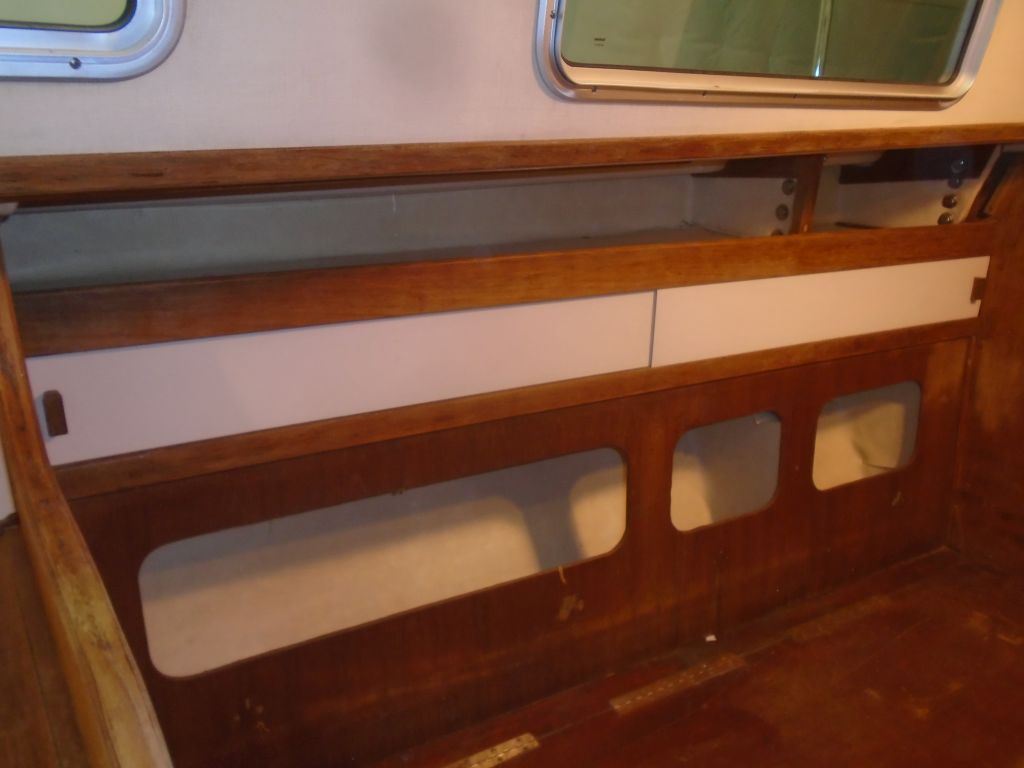
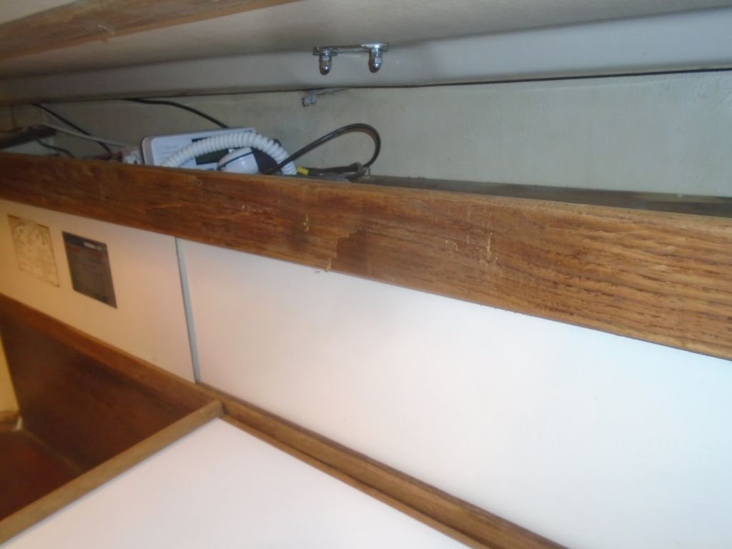
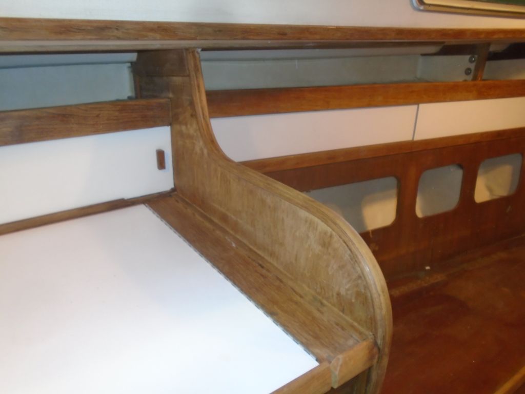
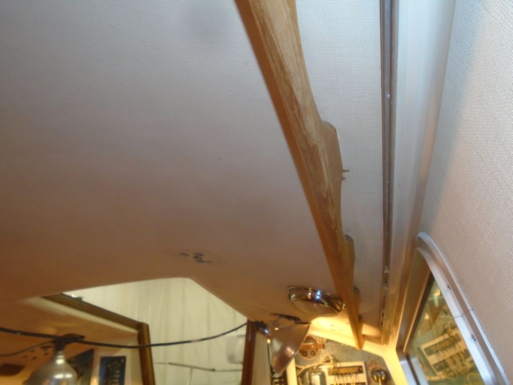
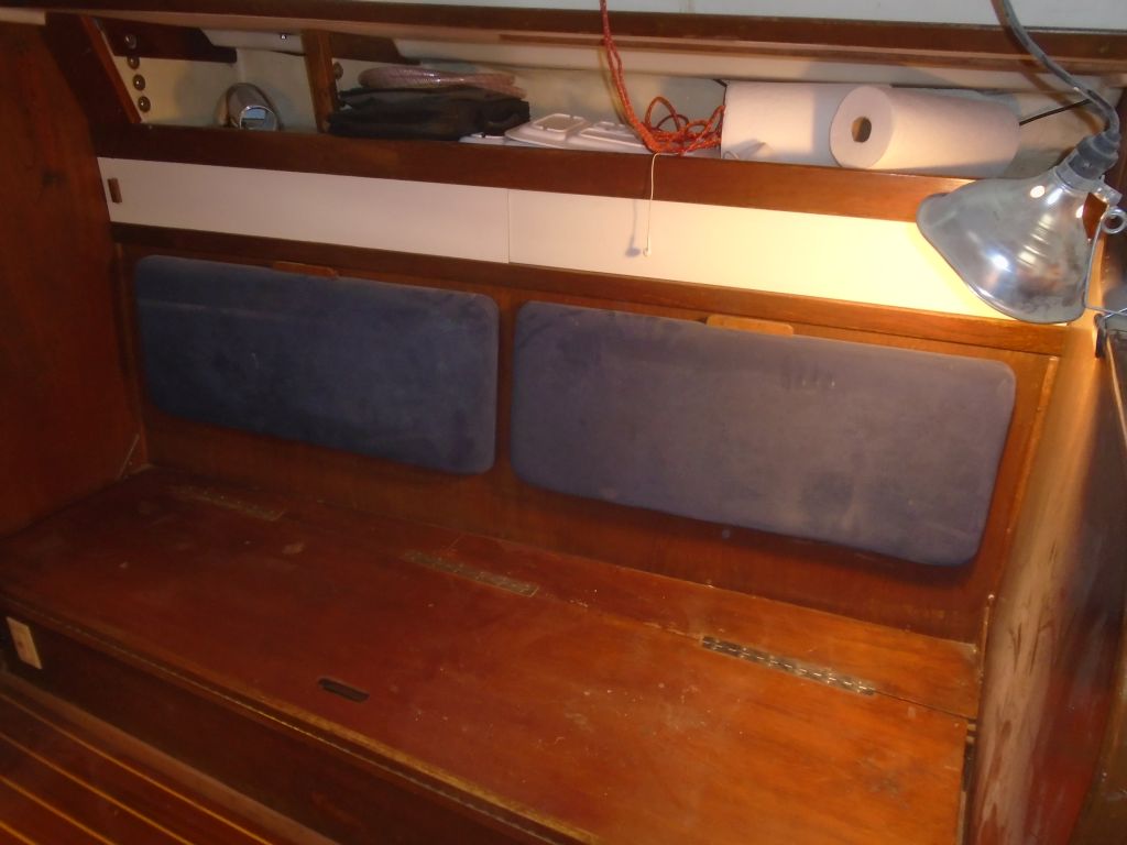
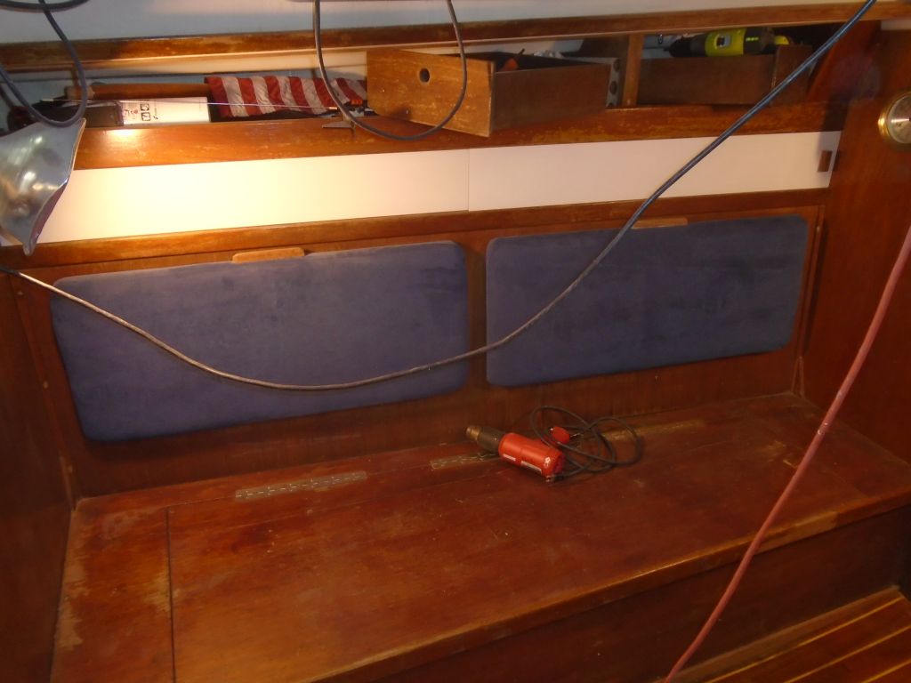
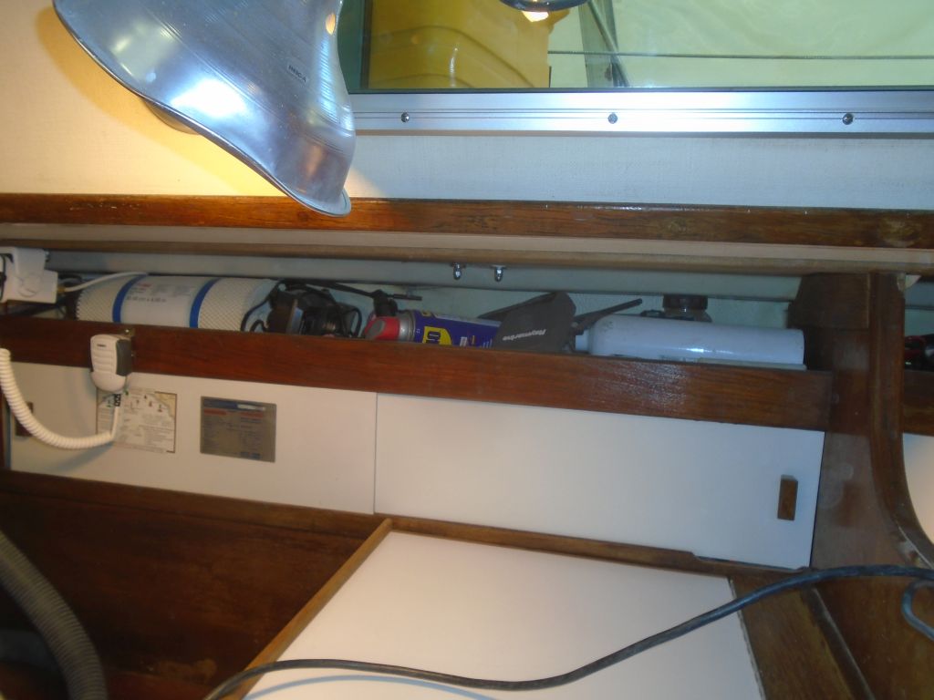
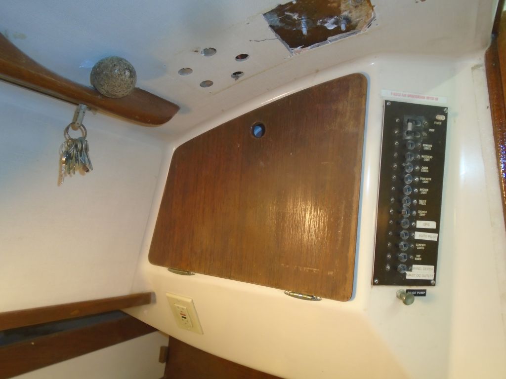
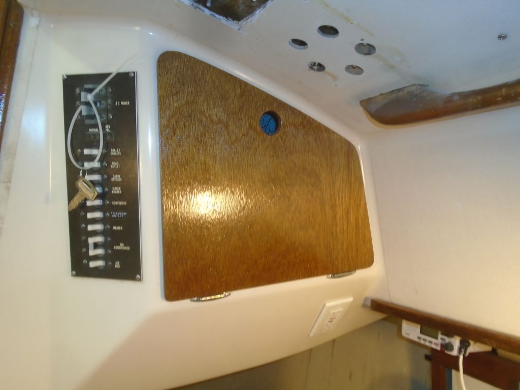
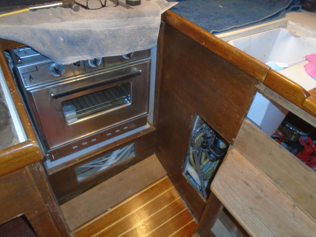
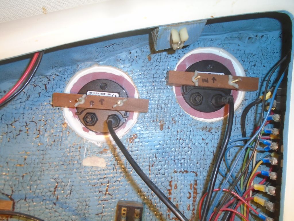
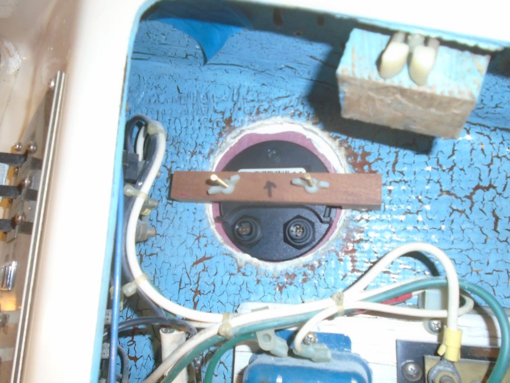
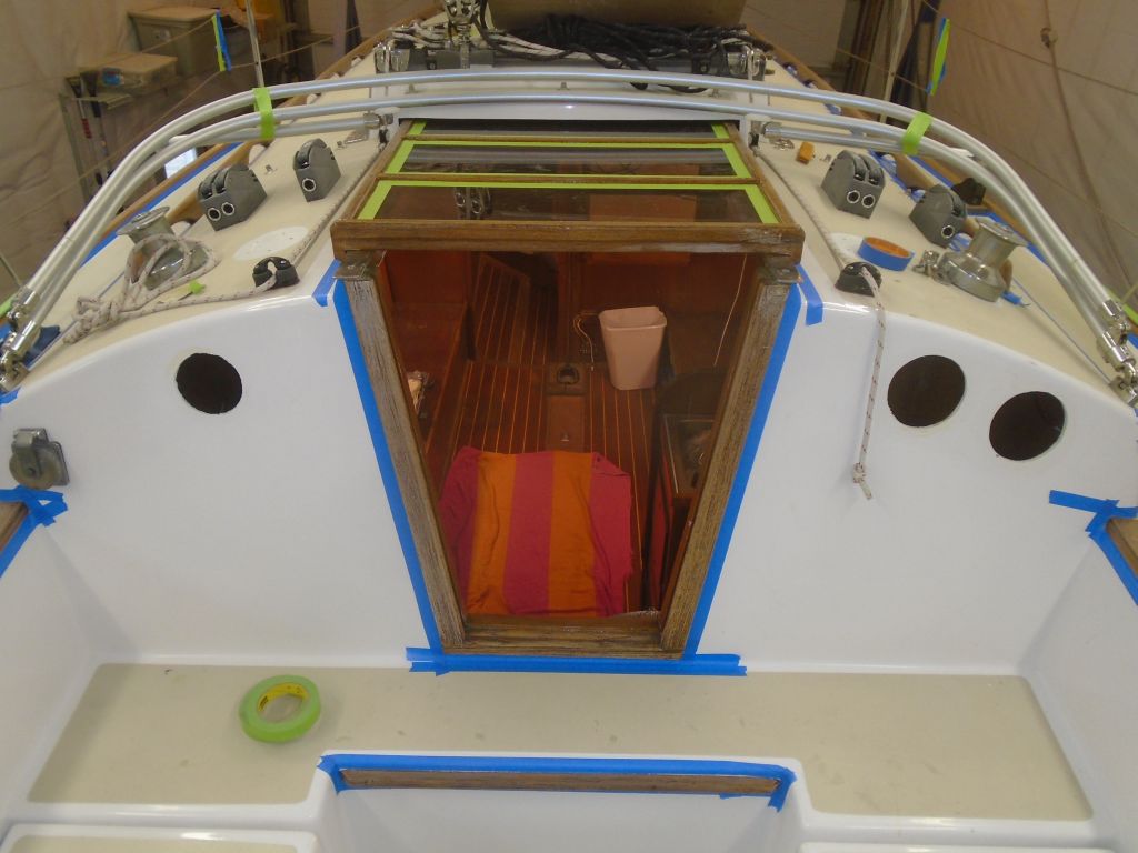
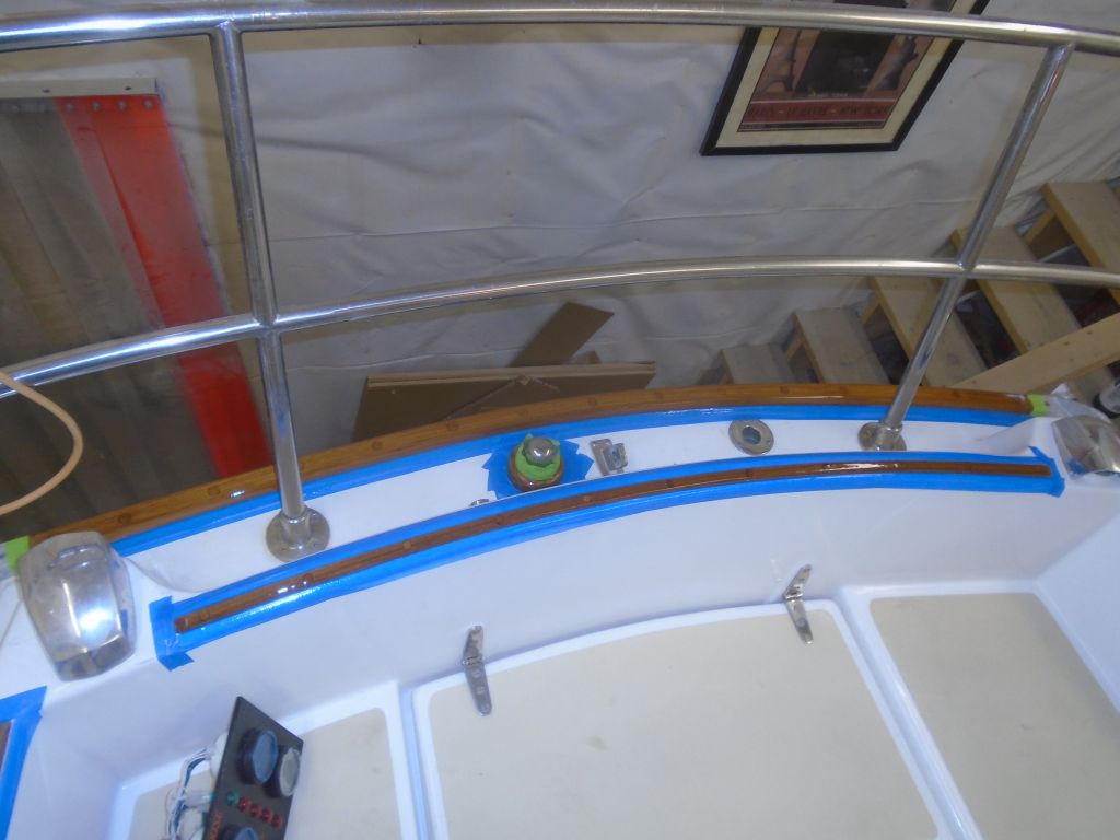
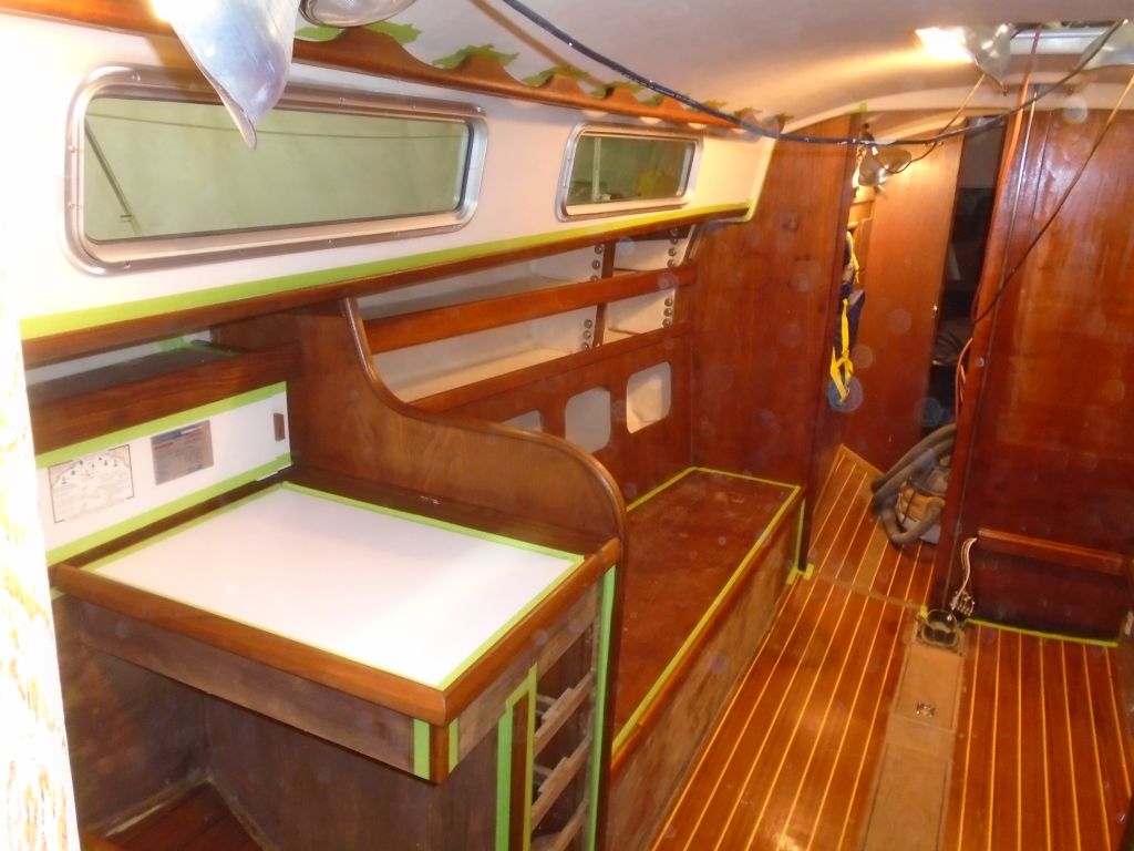
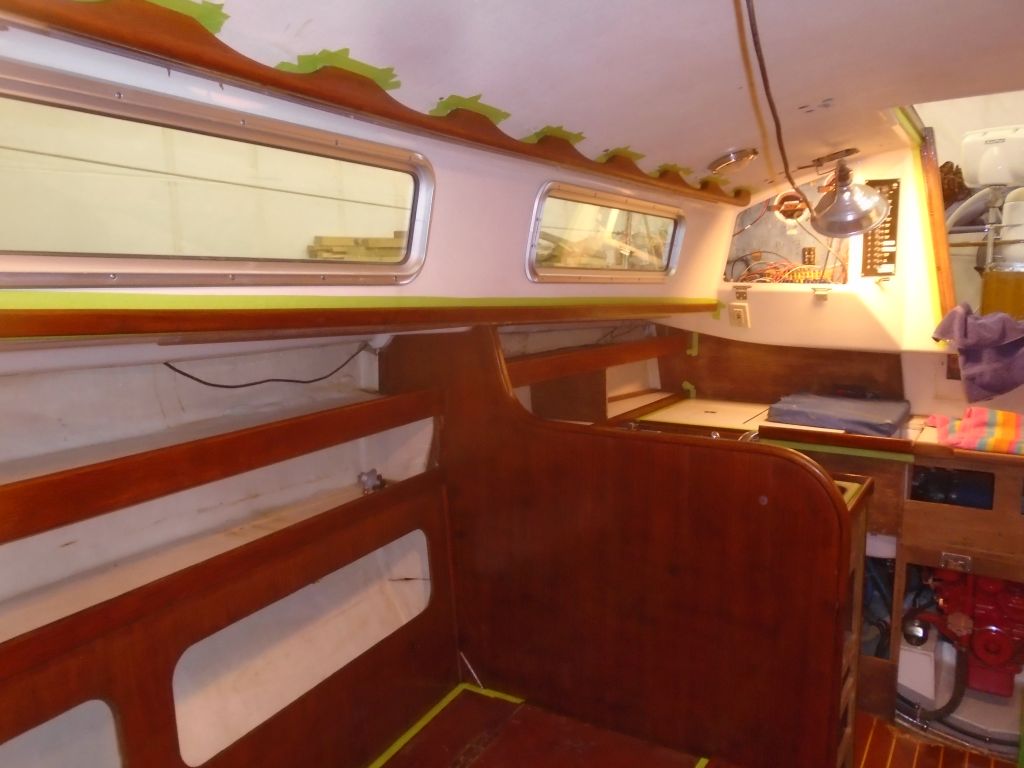
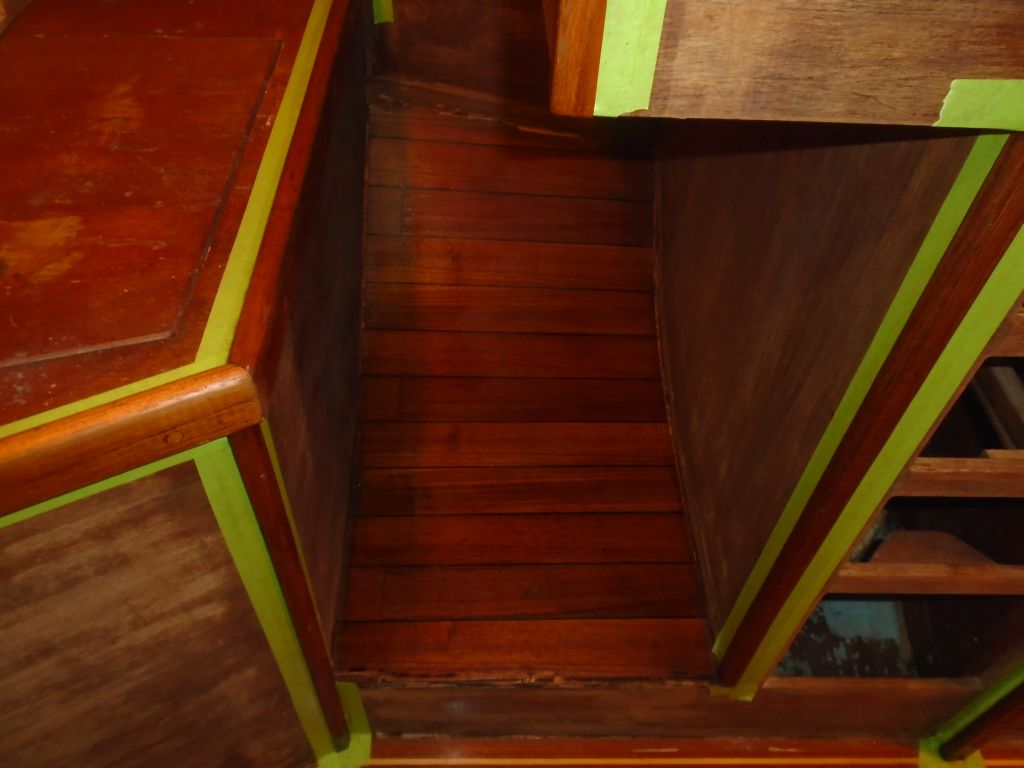
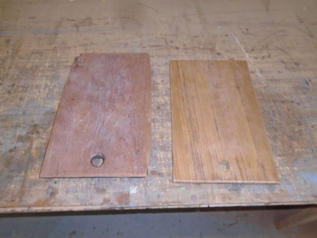
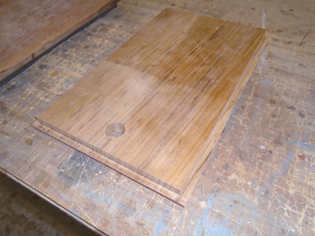
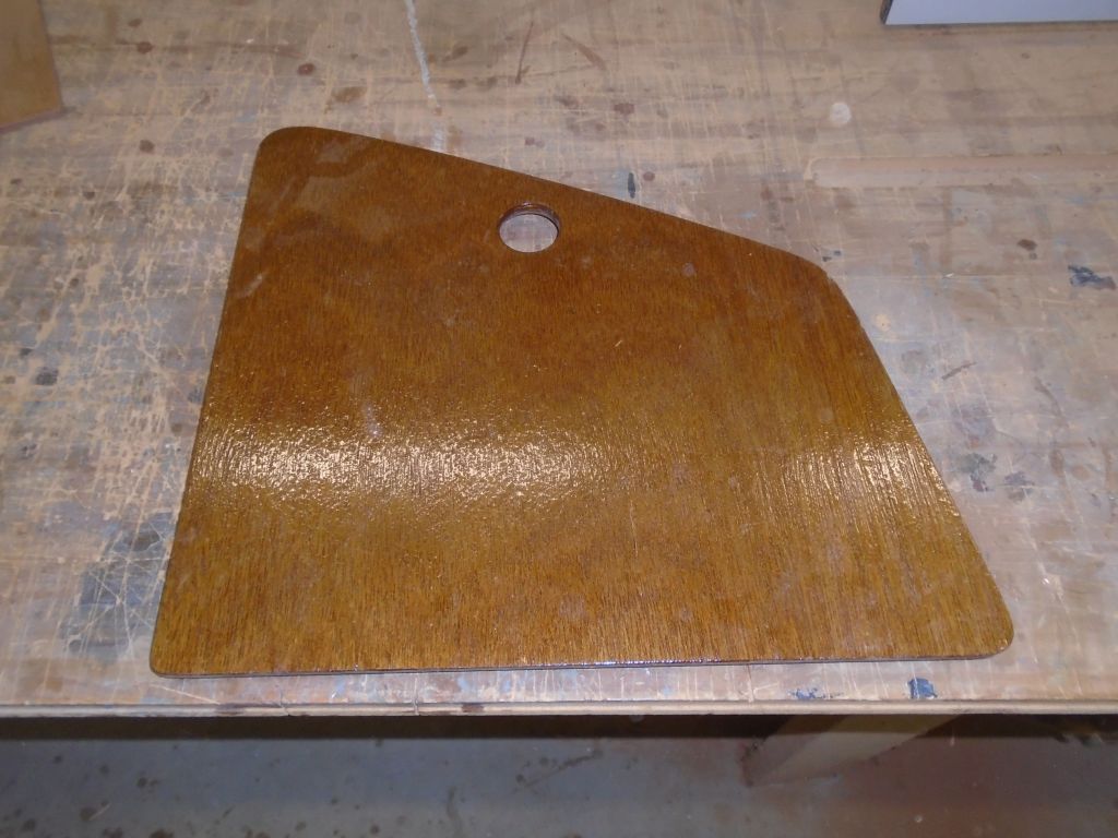
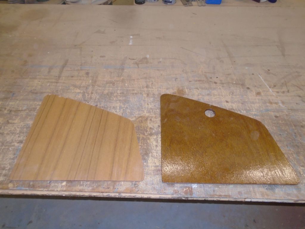
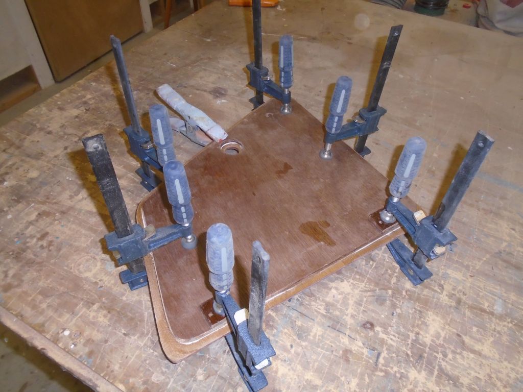
One of the two large hatches covering the electrical access openings at the aft end of the cabin liner had been replaced sometime in the past with a piece of structural plywood, which worked fine and looked OK for what it was, but the grain and overall appearance left something to be desired and didn’t match the original on the opposite side (though frankly that was nothing special either, though it would look better once refinished). So from a section of 1/4″ teak plywood that I had on hand, I cut out a new hatch, using the old one as a template. To make it easier to fit the new hatch, and create the overlay detail, I trimmed the rabbeted part of the original hatch away, then glued the remaining section to the back of my new teak. This would require only minor modification to the hinge risers now before the panel should fit easily into place.

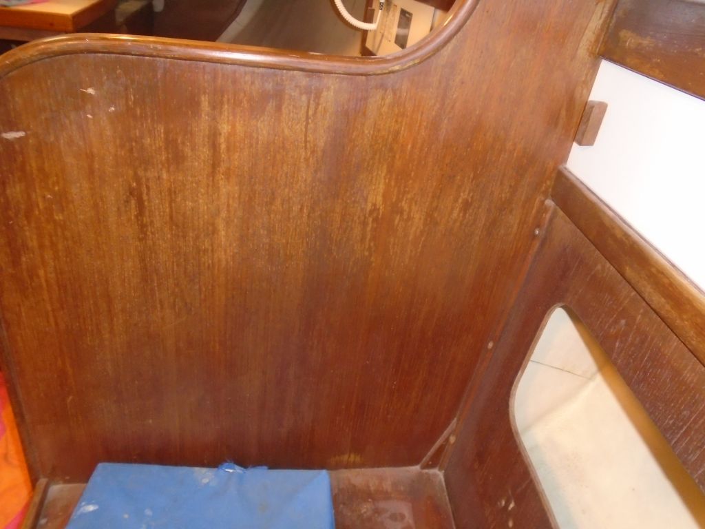
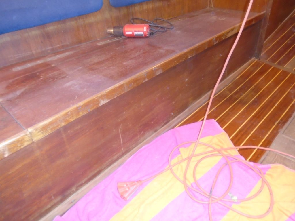
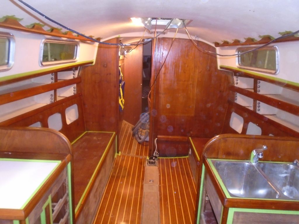
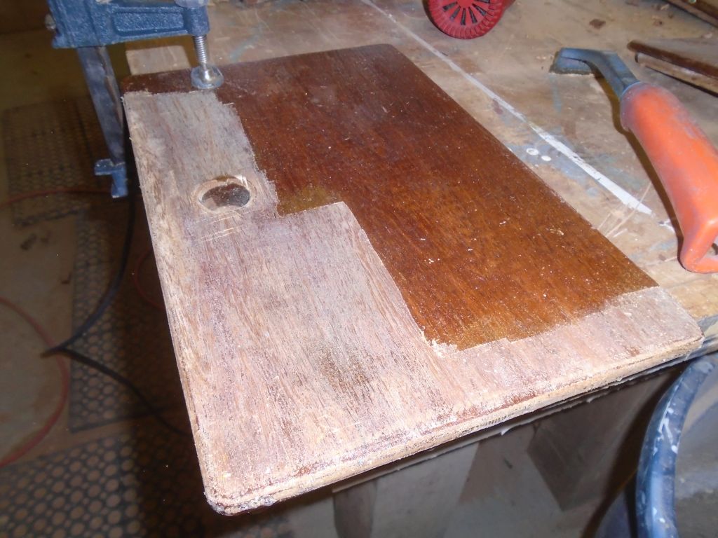
Now I used heat gun and scraper to strip the old finish off the rest of the doors, hatches, small trim bits, table, companionway steps, and drawer fronts as required. The old finishes were all over the place, from minimal to thick and drippy, and everything in between. This took up the rest of the afternoon. Next: sanding.

Total time billed on this job today: 7.5 hours
0600 Weather Observation:
26°, cloudy. Forecast for the day: showers, then rain, 40