(page 106 of 167)

Dharma Rose 12

Monday

I removed the glue blocks from the scupper through hull pads, then, after a light sanding, applied a little more epoxy to clean up the fillets as needed, only for visual reasons.

I spent the rest of the day working on the abandoned waste tank, starting with making cardboard patterns of the forward and after ends, so I could close off the openings to the short remaining (and hidden) sections of the old tank fore and aft.  Once I had fine-tuned the patterns as needed, I cut out the shapes from 1/4″ fiberglass prefab sheeting, which I first sanded to remove the smooth factory finish.  (While I was at it, I also pre-sanded a number of other prefab sheets I planned to use soon on other parts of the project.)

At the aft end, I wanted to incorporate a drain into the new compartment.  This meant running a tube through the old section of the tank beneath the battery compartment and out into the deep bilge beyond, and this would require a hole at the aft end of the compartment.  At the moment, there was no access to the back side of this area given the existing hatches and openings, but the owner had expressed an interest in creating a new access hatch directly below the companionway, just forward of the engine room, to get into the forwardmost portion of the bilge there, which space was otherwise basically inaccessible.  As it happened, a hatch in this area was just what I needed to create the thru-drain, so I marked out a square opening of appropriate and about maximum dimensions and cut out the cabin sole with a thin blade.

With some measurements, I could determine roughly where the drain had to exit the bulkhead, so, using my new access hatch, I transferred the measurements and drilled a hole large enough for the 1″ diameter fiberglass tubing I planned to use for the drain. Running the pipe through the space and the new hole at the aft end, I found that I couldn’t get the pipe down to the very bottom of the newly-created space, as the inaccessible small area below the battery shelf still contained the original bottom of the old tank (other than what I’d removed from the forward end), and I saw no reason to take heroic efforts for this little drain, so I compromised by running the pipe  through the new little bulkhead as low as I could get it, which was slightly off to one side and an inch or so above the bottom.  There was no particular reason the new bilge space should collect water anyway, but at least the drain would prevent any serious water build-up.

Before lunch break, I installed epoxy fillets around the two new fiberglass bulkheads, to glue them in place, seal the edges, and provide a good clean basis for tabbing that would permanently secure them later.  I spread some of the epoxy around on the nearby hull to prepare it for the tabbing and smooth any inconsistencies in the old laminate.

First thing in the afternoon, I prepared two layers of tabbing for all the sides of each bulkhead, then wet out and installed the new tabbing in epoxy resin.  I added some light cloth around the mouth of the drain tube to help secure it and close off the opening, not worrying much about any material that protruded as I could sand it smooth later.

Grateful to have the ends of the new compartment closed off, I used the remaining part of the day to prepare the rest of the space for new glasswork by applying fillets and smoothing in new epoxy compound over the sides and bottom of the compartment as needed, sealing up the remaining concrete around the lead ballast keel and easing transitions between the various surfaces.  While I might need to clean up a few areas a second time, this application gave me the basis needed so I could hopefully get the glasswork done next time.

Finally, at the very end of the day, I prepared two fiberglass cleats that I epoxied below the cabin sole inside the new hatch opening, which would allow me to reinstall the hatch  over the opening.

Total time billed on this job today:  7.5 hours

0600 Weather Observation:  10°, clear.  Forecast for the day:  Sunny, 27°

Dharma Rose 11

Friday

I spent the first part of the day working once more on the space formerly known as the waste tank.  After the major dismantling, there remained a need to further clean up the space with solvent wash and additional sanding, mainly to prepare the surfaces for new work.  In the process, I found I could scrape and chip out more of the remaining concrete, and probably could have spent the rest of my days chipping here and there and making progress, but I chose a happy medium, leaving the material that resisted my immediate efforts and seeking mainly to achieve a reasonable clean and sound substrate.

While I was at it, I lightly sanded the interior patches over the abandoned waste system through hulls on the starboard side, and prepared the site leftover from the old waste tank inlet opening (located beneath the v-berth sole on centerline) for eventual patching.

After sanding the surfaces to the extent necessary for now, leaving them relatively clean and smooth, I thoroughly cleaned up the newly-opened space as well as the entire interior of the boat to remove the final residues of dust and debris from the work and allow me to reclaim the space as a habitable area conducive to continued work.

With lingering dampness around the remaining concrete at the edges and aft end of the space, I felt it prudent to leave things for now and let it continue to dry out for a couple days before proceeding with rebuilding and epoxy work.

Meanwhile, back outside I sanded the exterior patchwork over the waste tank through hulls, smoothing and bringing it flush with the adjacent surfaces, then, after cleaning, applied a coat of fairing compound over the patches.

I installed two layers of fiberglass over the abandoned waste tank inlet hole beneath the forward cabin sole.

Now I prepared to install the backing pads for the cockpit scupper through hulls.  The hull was already prepared inside and out, so I solvent-washed the areas as needed and dry-fit the pads to check their fit and alignment with the existing through hull holes.  Since the hull here was nearly vertical, and the pads were heavy, I worried that they would slip while the adhesive was curing, so I carefully aligned each pad the way I wanted it, and aligned with the holes as needed, and hot-glued little support blocks beneath the pads to hold them in place.

I permanently installed the backing pads in heavy epoxy adhesive, which not only secured the pads but also made up the space between the tops of the pads and the hull to account for the curvature.  I cleaned up the excess adhesive and left the blocks to cure fully.

Not wanting to jiggle the boat unnecessarily  and possibly upset the positioning of the backing pads, I chose to spend the remaining afternoon working off the boat, preparing the engine and related parts for installation later.  There are several changes I liked to make to the basic engine to make it not only easier to install for me, but easier to work on going forward.

The cover plate for the raw water impeller was conveniently located on the front of the engine, a vast improvement over the designs of many other engines, but was secured with six tiny screws, making accessing the impeller in an emergency less convenient.  I did notice on this engine that the screws were a little different than in the past, now incorporating a hex head as well as screwdriver slot, which was definitely an improvement over the plain panhead screws that I’d seen on these covers in the past, but still I preferred fasteners that one could undo quickly by hand.  I replaced the original fasteners with knurled stainless steel ones.  These particular fasteners also had a 2.5mm Allen socket, so I included a T-handle wrench that could be used if needed to loosen the screws.  I’d secure that by the impeller once the engine was in the boat.

The fussy little clamps for the throttle and gear control cables frustrate me to no end regardless of what I do, but replacing the slotted fasteners with something a bit more positive always helped with installation.  I like socket-head fasteners (5/32″ in this case) instead of other kinds of screws, and replaced the four screws accordingly.  I also marked the wrench sizes nearby.

I loosened the fasteners where I’d later install the positive and negative battery cables, and marked wrench sizes on the engine nearby.  On this boat, where access to the side of the engine was tight and unnecessarily difficult once the engine was in place, I’d go so far as to pre-install the batter cables before dropping the engine into the boat, but that would come soon enough.

It sure would be nice if these two fasteners were the same size.

On previous installations, I’d found that the way the engine wiring harness plug came secured from the factory got in the way of clear access to that corner of the engine, so now I removed the cable clamp holding it below the throttle control cable bracket, releasing the harness so I could align it as I pleased and, more importantly, clearing access to the engine mount beneath.

A happy installer makes for an efficient installation and a happy owner.

I received the narrow 11-1/2″ mounting center mounts for the aft side of the engine from my engine supplier, who had sent them at my request earlier in the week.  All I had to do was send back the 14″ original mounts from the engine.  Lifting the engine from its shipping crate with my crane, I unbolted the original mounts and installed the replacements in their stead.  These mounts would allow the engine to sit properly on the new foundations in the narrow hull.

During the layout of the foundations, and the adjustment of the after mounts to the narrower width, I noticed on the engine drawings that the narrow mount centers were slightly closer to the aft end of the engine (the reference point being the face of the transmission coupling), about 1/4″ further aft than the 14″ mounts.  This wasn’t a big change, but it was enough for me to note pending arrival of the actual mounts, and also enough that I didn’t want to rely on the template alone in order to physically mark and mount the flexible mounts before engine installation.  I’d marked and drilled the new holes in my template for the narrower aft mounts using the same transverse layout line that I’d originally used for the 14″ mounts, and only afterwards had I noticed the discrepancy on the drawing.  For shame.

Now, I could hold the old (14″) mount directly against the newly-installed 11-1/2″ mount and determine that indeed the new mounting center was just slightly aft of the original (on top here).  It’s always good to confirm measurements physically.

This wouldn’t affect anything I’d done, but I’d either wait to mark the bolting locations till I put the engine in the boat itself, or make another basic template with the correct centers first.

I specified my usual Racor fuel filter for this installation, and, as is my habit, I replaced the drain plug on the bottom of the metal bowl with a valve to make draining more convenient.  In this case, with tight space, I had to use a 90° elbow first to allow the valve to be oriented horizontally, since there wasn’t enough clearance otherwise.  To avoid leaks if the valve handle was operated inadvertently, I installed a plug at the end.

The ball valves I specified for the new scuppers arrived with an add-on zerk fitting to allow lubrication of the ball and help avoid unwanted stiffness over time–a good addition, I thought, particularly on little-operated valves like scupper drains since even good ball valves can become stuck if not well-used.  As directed, I replaced the bronze drain plugs on the two valves with the zerk fittings, which would allow the user to install waterproof grease at will.

Total time billed on this job today:  7.25 hours

0600 Weather Observation:  25°, snow shower.  Forecast for the day:  Clearing, around 30° but dropping in the afternoon

Dharma Rose 10

Thursday

After solvent-washing inside and out the two forward through hull openings awaiting patching, I masked over the holes from outside and installed a thickened epoxy mix flush from the inside, which I allowed to partially cure before applying two layers of fiberglass over the whole area.

Later, once the epoxy had cured enough to continue work from outside, I removed the masking tape and applied three layers of fiberglass to each hole.

While this was going on, and in between steps, I worked on the through hull pads for the cockpit scuppers.  In this case, the owner requested that I not bolt the through hull assemblies all the way through the hull, my normal and preferred method of installation, but that I consider instead blind-bolting the flanges to the pads before installation.  I agreed because I felt this was an acceptable alternative when the backing pad is permanently glued to the hull, as I always did and planned to do in this case as well.

Using the appropriate drill bit, I drilled through the fiberglass pads at each of the three bolt locations on the flange bases.  Then, from beneath, I tapped threads into each hole to accept the 5/16″ bronze machine screws.  I used a hand tap because my drill wouldn’t hold the tap securely enough to mill through the dense, hard G10.  Once the holes were tapped, I milled countersinks in the bottom to accept the screw heads, then dry-fit everything to ensure that I could install the flange over the protruding threads after the fact, since I didn’t want the bronze in place till after I’d glued the pad to the hull later.  I repeated the process with the second fitting, ensuring throughout the process that the flange was properly centered over the hole in the backing pad to later accept the threaded through hull.

Finally, I backed out the screws a bit, then applied some thickened epoxy adhesive to the threads and in the counterbore before re-tightening the bolts securely, all to help hold the bolts from spinning now or later (even though they probably wouldn’t spin with the bolts tightened securely through the tapped holes).  After removing excess epoxy, I left the pads to cure.

Now I turned to the waste tank removal–or repurposing, as it were, since the tank was just a built-in (and poorly at that) void in the bilge above the keel.  After determining roughly what was going on beneath the cabin sole, and how much clearance there was, I marked out a cut line in the sole that would allow me to remove it and access the tank, which was located a few inches beneath with its own fiberglass cover.  The only access at the moment was through a 12″ hatch in the sole.

Using a cutting wheel on my grinder, and finishing the corners with a saw, I removed the cabin sole in one piece.  I’d reuse this later once the work beneath was completed.

With the tank top now fully exposed (at least as much exposed as it ever could be), I used the grinder again to cut away the top close to the hull on each side, after which I could remove the top to expose the tank beneath.  This revealed a mess of brittle, damaged, and loose fiberglass that apparently had once covered the ballast cavity directly below, but had clearly failed long before.  The old tabbing was completely breached along one side, and the disaster of concrete and whatever else the builders used around and above the lead ballast pig was partially visible through breaks in the fiberglass.

I used a comfy supplied air mask whenever I sand, grind, or cut fiberglass in a major way, and I kept the gear on throughout the entire round of work on this tank, so fortunately I was spared whatever biohazard fumes might arise from the tank and the sludgy contents I discovered and now had to remove.  It’s glamorous work, this.  I pulled out loose fiberglass, some sort of maybe-fibrous material from beneath the tabbing (unidentifiable and intermashed with concrete and other contents) and so forth till I’d gotten down to the crumbly loose concrete mess above the lead pig.  I had to bail out the aft part of the tank, which for unknown and clearly ignorant reasons extended aft beneath the battery storage area, through a small screw-in deck plate located in the battery floor.  I’d seal off this ridiculous void later, during reconstruction.

Continuing, I worked to remove the loose concrete, using whatever means worked, including putty knife, chisel, hands (mostly), and hammer.  Most of the material was like wet gravel in consistency, and there was plenty of it.  As I went, I used the grinder and cutoff wheel to further cut back the fiberglass edges where needed, once it had become exposed as I removed the concrete.  In this way, I eventually worked my way down to the top of the lead ballast and/or sound, solid concrete and whatever surrounding it.

After wiping out some final detritus, I used an aggressive sanding disc to remove most of the remaining fiberglass edges where I’d cut, and to clean up most of the area in at least an initial way.  There’d be more prep work ahead, but the worst was done.  There are ways to build tankage safely and successfully into bilges and hulls, but this wasn’t one of those ways.

Total time billed on this job today:  8 Hours

0600 Weather Observation:  16°, clouds.  Forecast for the day:  Sunny, 34°

Dharma Rose 9

Wednesday

To begin, I lightly sanded the new fiberglass on the engine  foundations, smoothing any rough edges and preparing the area for the next steps, including another alignment test for the engine template, but for the moment I continued with some other tasks.

Back to the port chainplates.  To open the tight access panel, I screwed a small handle temporarily to the top and pulled it out without issue, exposing the two chainplate knees and chainplates beyond.  While I could see and reach the chainplates as is, I couldn’t get into the narrow locker opening with both arms and shoulders at once, which I needed to do in order to manipulate the wrenches, so I removed the outer panel from the locker to improve access.

Once more, I was happy to find that, although tight and only just barely possible, it was indeed possible to remove the after (i.e. center) chainplate without removing the main bulkhead, breaking the two-for-two streak from past Contessa 26 jobs.  Reinstallation later would be challenging, but still possible (I thought…I hoped).  It didn’t take long to remove the six bolts from the two chainplates, after which I pulled them up from above decks.

Fortunately, these two remaining chainplates were in similar (good) condition, and with all six now out and exposed I spent some time cleaning them up to remove the old sealant and prepare them for reinstallation, which I’d do a little later once I got the fasteners I needed.

With the new engine foundations in and available for me to stand or kneel on in the engine room, it was the best and most convenient time to remove the old Cutless bearing from the stern tube.  With just a little scraping on the outside of the tube, I exposed the two little setscrews that were securing the existing bearing, and removed them without issue.

From inside, I used a length of steel pipe that just fit within the stern tube to hammer out the old bearing.  After a few tentative taps on the pipe–not wanting to overdo it–I checked outside and was happy to find that the bearing had moved a little, so I proceeded with more vigor as required till I pushed the old bearing completely out.  Afterwards, I measured up the stern tube and bearing and ordered a replacement bearing, along with the new packing box to replace the old grease-filled one.

The next task to take care of while engine room access was as good as it would get was to install the two new  through hulls for the cockpit scuppers.  I’d already ordered and received the new bronze hardware.  I discovered I’d mistakenly ordered through hulls with a hose barb instead of the plain threaded versions, so that would delay final installation slightly while I waited for the replacement order, but in the meantime there was plenty I could do to prepare, starting with the fiberglass backing pads for the flange bases.  I cut and shaped these from 3/4″ G10 leftover from the engine foundations.

I’d already prepared the hull at the scupper openings inside the boat, but outside I sanded away the paint and old sealant from around the holes, and, since the old holes were a little undersized, used a drum sander to open up the holes as needed to fit the new through hulls.

While I was at it, I prepared the two old holding tank through hull openings on the starboard bow for patching, grinding out circular dish-shaped areas around each hole so I could patch with fiberglass.

Total time billed on this job today:  6.75 hours

0600 Weather Observation:  15°, clear.  Forecast for the day:  Sunny, 30°

Dharma Rose 8

Tuesday

The epoxy work on the newly installed foundation platforms required light sanding to clean it up and prepare for the next steps.

Next, I made basic paper patterns of the tabbing needed to secure the foundations to the hull–top and bottom on both sides.

After finalizing the patterns’ shapes and trimming the excess paper, I used the patterns to cut three layers of 1708 fiberglass for each set of tabbing.  I slightly stepped back the tabbing size on the areas on the hull, mainly for a nicer appearance when all was said and done, but let all the tabbing run to the edge of the patterns where it would rest on or beneath the foundation platforms themselves.

After final preparations and cleanup, I installed all the tabbing in epoxy resin, starting with the bottom sections, with their more difficult access, and continuing to the top sections.

Leaving the new fiberglass to cure, I changed directions and started work on accessing and removing the chainplates for inspection and to determine whether replacement or other work would be required.  From past experiences, I knew that I’d probably have to remove the galley bulkheads on each side in order to gain access to the center (main or upper) set of chainplates, which knees tended to be uncomfortably close to the plywood bulkheads.  This would require various dismantling and disconnecting of things, including wiring bundles, miscellaneous and sub-cover panels within the lockers (particularly on the port side opposite the head), and more, so I set about the task.

Starting on the “easier” starboard side, I began by removing the water fill line, and then removed the longitudinal cover panel behind, exposing the two forward sets of chainplates on that side.  The aftermost set was accessible separately through a small locker above the galley and posed no particular access problems.  I found a big rodent’s nest behind the panel.  The chainplates looked good where visible, but since problems can occur where the chainplate runs through the deck slot, I proceeded with removal.

Removing the forwardmost chainplate, with the ground wire attached, posed no problem, though one of the nuts was galled and eventually broke the bolt during removal (which was a preferred outcome to having to cut or otherwise remove the bolt).

At the after location (i.e. the middle, or upper, chainplate) in this case I found that I could just slip a wrench into the narrow space between the bulkhead and upper chainplate in order to remove the nuts, so for the moment at least I didn’t have to remove the bulkhead.  I hoped I’d be able to reinstall the nut similarly through the narrow space, and would by all means try rather than go through the effort of removing the bulkhead.

I removed the aftermost chainplate from the galley locker without issue, and from on deck removed all three plates, which came forth reluctantly thanks to whatever sort of bedding compound was around the slots.

Down on the bench, I scraped off the excess sealant, and was pleased to see that all three chainplates were in apparently excellent condition with no corrosion observed.  With some minor cleanup they could go right back in, I thought.

Turning to the port side, I removed the screws securing the longitudinal cover panel over the two forward sets of chainplates, but the panel was so tight in its place that I couldn’t budge it to pull it out, with no room even to pry it from an edge.  It was growing late, and I decided that continued efforts to remove the panel would be best handled fresh in the morning, so instead I removed the more easily accessible aftermost chainplate above the galley sink, which was also in good condition like its counterparts to starboard.

Total time billed on this job today:  7.5 hours

0600 Weather Observation:  32°, clouds, spitting snow.  Forecast for the day:  Sun, 29°

Dharma Rose 7

Monday

Now that the rough templates for the new engine foundations were in place, and the basic positions of the four flex mounts marked accordingly, I removed the engine template, and used one of the mounts to mark outlines at all four locations, using the rough marks I’d made to align the mounts.   This gave me what I needed to I could plan the final shape and size of the foundation platforms, leaving ample room around the mount bases to allow for position adjustments, while eliminating excess material where possible.  Then, I removed the rough pine templates from the boat and down to the bench so I could prepare the actual pieces.

I sanded off the smooth, shiny factory surface from the sheet of 3/4″ G10 I’d purchased for the foundations, then cut out the pine patterns along the marks I’d made earlier, and used these to mark and ultimately cut the fiberglass.  Then, I marked the rough shapes of the bevels on the outboard edges of the foundations, where they met the hull, and shaped these areas as needed.

After a test-fit, I cleaned up the cut edges and rounded the edges and corners of the new foundations.

I wanted to be sure that the final foundations didn’t end up any higher than needed; if anything, I preferred they ended up low, since it was easier to add height than deal with an overage.  I also had to leave room for the fiberglass tabbing that would ultimately secure the foundations, so I made new reference marks about 1/4″ vertically below the originals, and I’d align the fiberglass foundations with these new marks.

Using a level to ensure side-to-side alignment, I tacked the foundations in place along my reference lines, adding a little support beneath to help support the weight.  I started with the starboard piece, then, once it was set, prepared level braces across to the other side so I could install the port piece properly according to the first piece.

Once all the glue set up the arrangement was quite rigid, and I removed the top cross braces and levels to clear the way for the next step, which was to replace the engine template and shaft string to check, once more, that the new foundations were where they needed to be.  Keeping in mind that the platforms were about 1/4″ lower than their final designed height, I confirmed that the position and basic alignment was in keeping with expectations.

Finally, I applied epoxy fillets to the top edges to secure the foundations permanently and fill small gaps at the edge.  I chose to leave the underside of the platforms for later, once I could clear the braces beneath and improve access all around  I used more of the epoxy to smooth out the slots leftover from the original foundations and otherwise prepare the overall area for fiberglass, which would be the next step.

Total time billed on this job today:  5 hours

0600 Weather Observation:  32°, clear overhead with fog.  Forecast for the day:  Clouds and sun, low 40s

Dharma Rose 6

Friday

I had a short day planned, but wanted to make good progress in the engine room first.  I planned to build the new engine foundations from 3/4″ G10 composite sheeting, an almost foolishly strong and hard fiberglass and epoxy product that’s overkill for almost every proposed situation, but provides the durability and piece of mind one might consider useful in something like an engine bed. G10 is also heavy and difficult to work, and therefore machining tasks are best kept to a minimum.

To template the position and shape, of the new foundation pieces, as well as continue to check the overall engine alignment and proposed placement accurately, I chose to build basic mockups of the foundations from some scrap pine lumber that was light as a feather after more than 12 years aging in my shop, and easy to work to boot.

With the engine template suspended in the engine room over the taut shaft alignment string, I fine-tuned the position as needed, getting it as level and accurate as possible.  Because of the suspension’s propensity to sway the whole template a bit aft, I used a handy bitter end of  string to pull the template forward to my desired position, and checked and adjusted again till the template, still level, allowed the string to pass through the centers of the forward and aft template holes.

To help with basic positioning throughout the process, I used a metal straightedge to transfer and make reference marks from the centers of the mounting studs to the sides of the engine compartment.   Then, with a small steel rule held tightly to the bottoms of the forward mounts, I transferred their heights to the hull side, making tick marks on each side.   I re-checked the level each time, since the whole template was easily knocked out of position in its dangling lines.

The tight confines of the compartment and the way the engine template hung over the curvature of the hull prohibited clear access to the after mounts, so to help mark their position I first removed the two forward mounts, re-checked level and position, then managed to get some rough marks aft where the mounts contacted the hull.  I couldn’t manipulate the little ruler and pencil like I did forward, but in this case the after mounting bases just touched the hull at their outboard sides, which was enough for me to get reference marks that would serve the required purpose.

Once I had all four mounts’ locations marked, I removed the template and string for now to open up access to the space, and darkened the four tick marks with a pen before connecting them on each side with a flexible steel rule; the lines turned out more or less straight since the hull curvature here was transverse more than longitudinal.  These lines gave me the reference for where the flat engine foundations needed to be.  To help with overall dimensioning, I made rough marks to correspond with the flex mounts’ positions and lengths on each side.  I didn’t want the new foundations to be any longer than strictly necessary, to aid all future access to the engine and the space, but also needed to account for some necessary wiggle room to allow the engine to be properly positioned fore and aft as dictated by the vagaries of the installation when the time came.

From scrap pine board, I made two pieces 24″ long and whatever its width was (about 6″).  The width at this stage was unimportant, and the length was just a starting point; similarly, the inelegant ends would eventually be massaged into something more situationally- and aesthetically appropriate.  I cut as steep a bevel on the outboard side of each piece as possible, and knocked off the after corners of each board so that the two sides together wouldn’t interfere with one another.  After a couple brief test fits and some minor reshaping with a sander to allow the templates to fit more or less closely against the hull on each side, I tacked them in place with some hot glue along the lines I’d marked earlier, striving to force them level in the process.

The starboard forward end ended up a bit higher than I’d planned, accounting for the slight off-ness [sic] of the level, but that didn’t matter for these purposes, as my goal, other than checking the basic positioning for later, was just to provide simple templates from which I could more easily and efficiently shape the granite-like G10 material later, and the minor discrepancy didn’t affect the shape of the mockups (nor of the final fiberglass) at all.  The time for ultimate accuracy would be during the final and permanent installation later.

With the rough cutting complete, and the boards tacked in place, I glued the little triangular offcuts from the aft end beneath each side to help support the boards from beneath, again holding the inboard edges of the board level while I did so.  Afterwards, I restrung the alignment string from the shaft, this time working just a little harder to ensure its accuracy.

Test-fitting the engine template again, I immediately saw that I needed to provide clearance at the aft end for the down-hanging plywood board that provided the shaft centerline mark (and also happened to correspond to the transmission width and depth for this engine), so I carefully cut out some extra material with a handsaw to allow a proper fit.  Then, I installed the template and made whatever adjustments were necessary to properly position it.

I was pleased to see that the engine fit well on the mockup foundation, particularly at the difficult and tight after end.  I was running out of time in my self-shortened day, but before knocking off I made reference marks as much as possible to show the positions of the four flex mounts; again, reaching the after mounts was virtually impossible given the shape of the template–which, we must not forget, represents the overall size of the largest dimensions of the engine and transmission together, and is not necessarily representative of the actual shape thereof–but I managed to get some scribble marks in there that would be enough to allow me to determine where to mark and cut the foundation mockups to their final desired shape next time.

Total time billed on this job today:  3 hours

0600 Weather Observation:  25°, mostly clear.  Forecast for the day:  Mainly sunny, 40°

Dharma Rose 5

Thursday

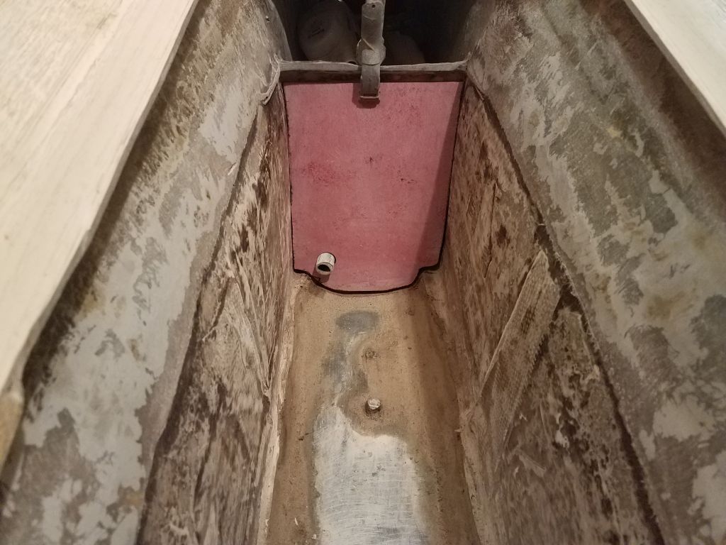
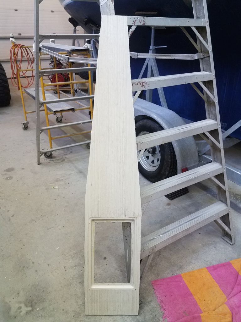
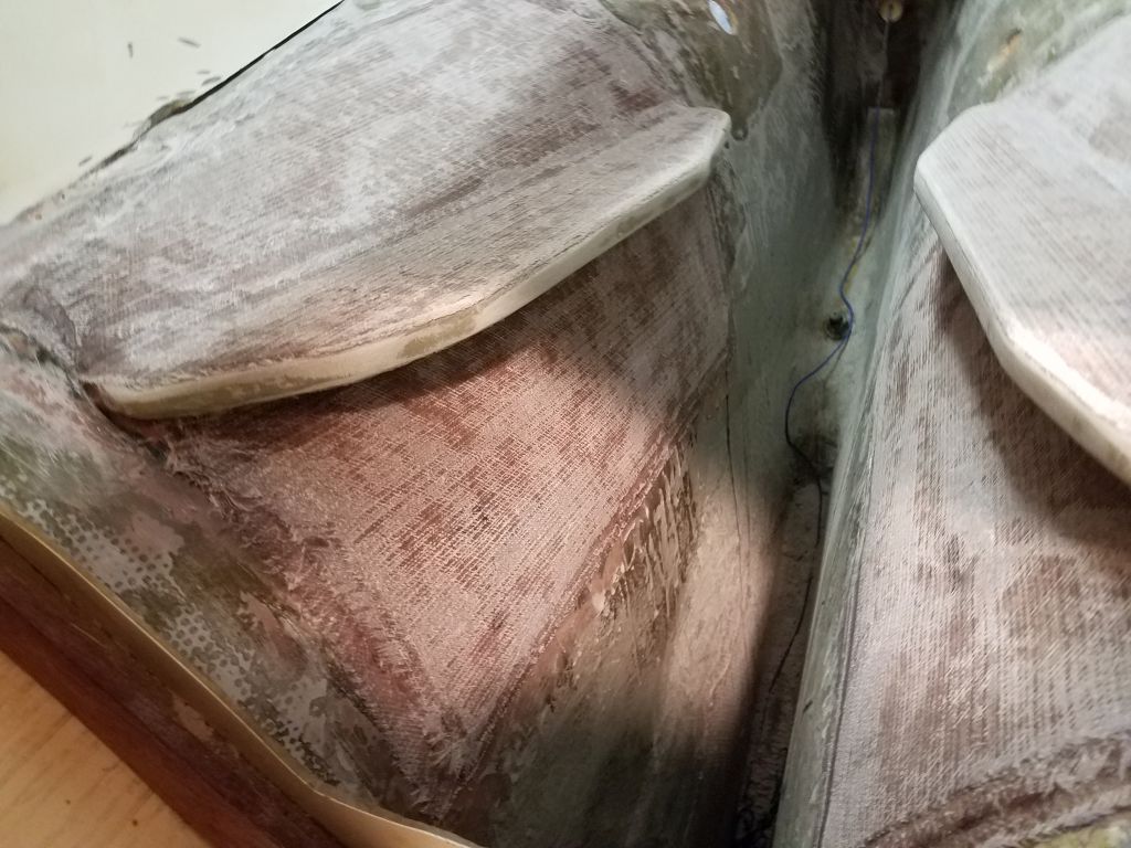
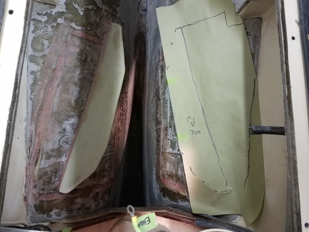
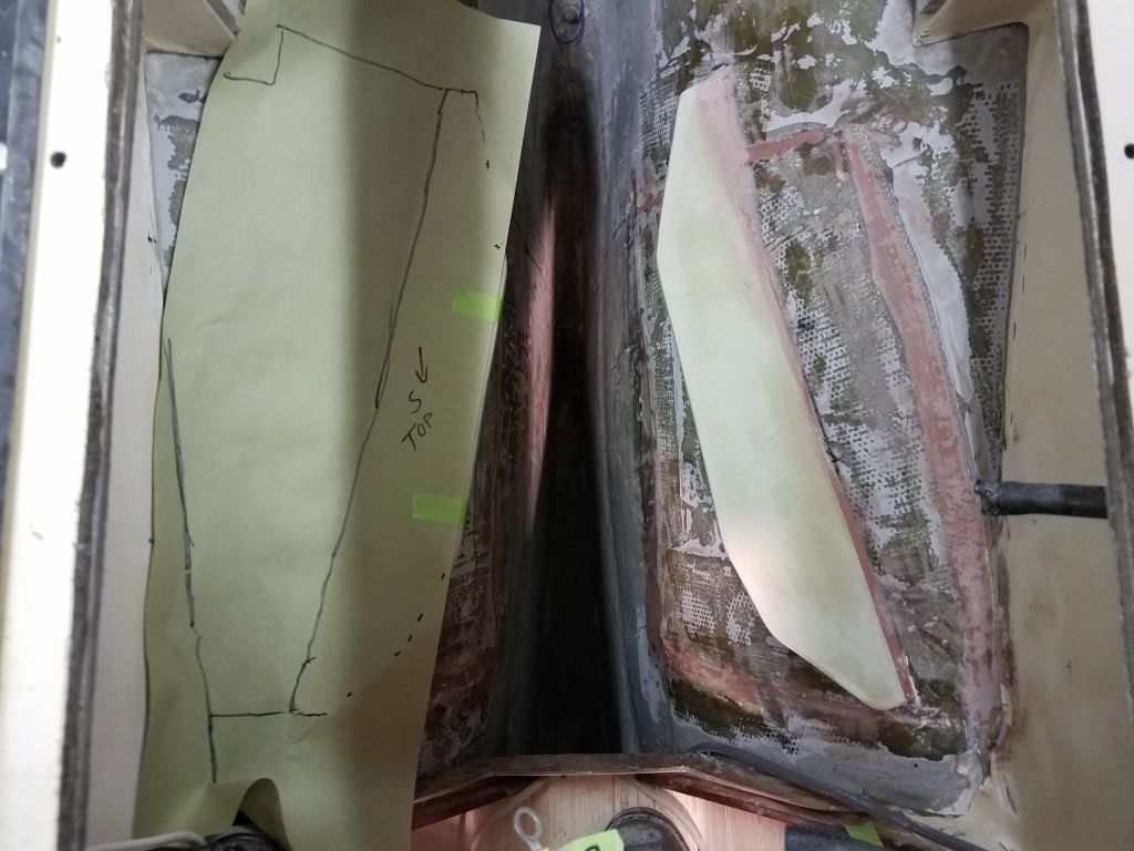
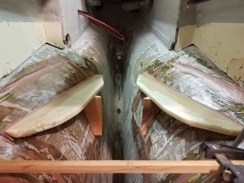
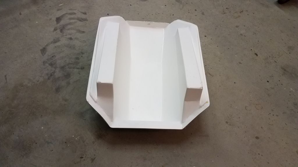
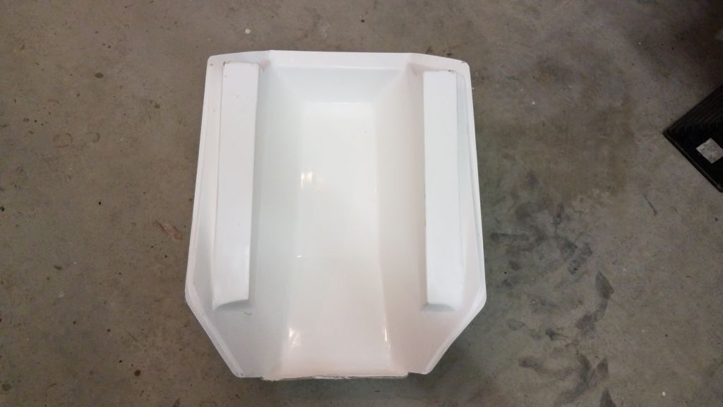
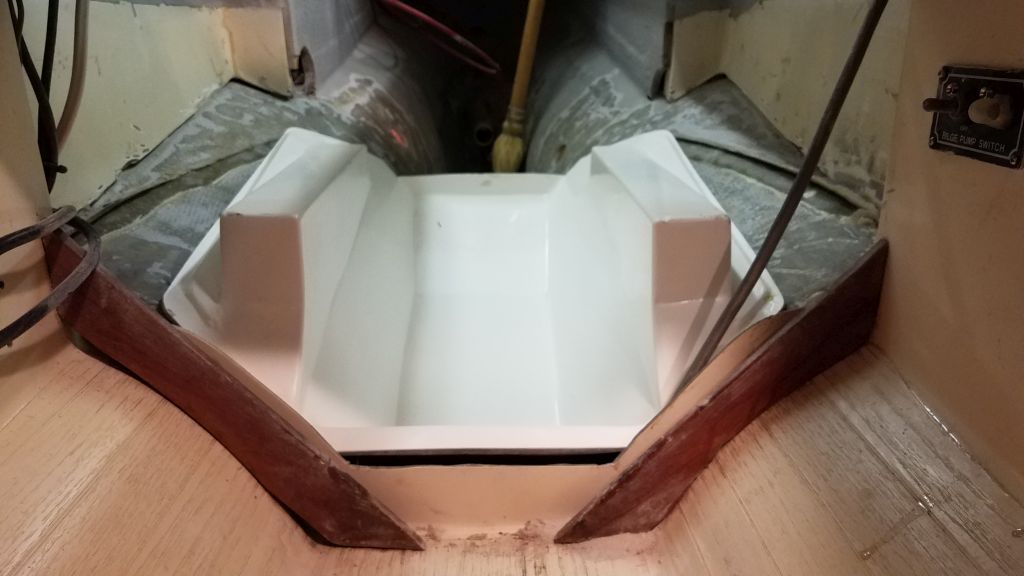
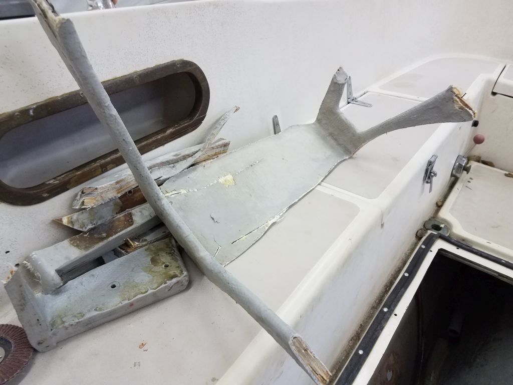
Before leaving the shop for a meeting in mid-morning, I spent an hour or so trying out the pre-fabricated engine foundation and drip pan that the owner had purchased from the original Contessa 26 builders in England.  It was a nice-looking, clean fabrication that would streamline engine installation if it worked properly on this Canadian JJ Taylor version of the Contessa, which had some key differences in engine placement that I worried might make the pan a non-starter.

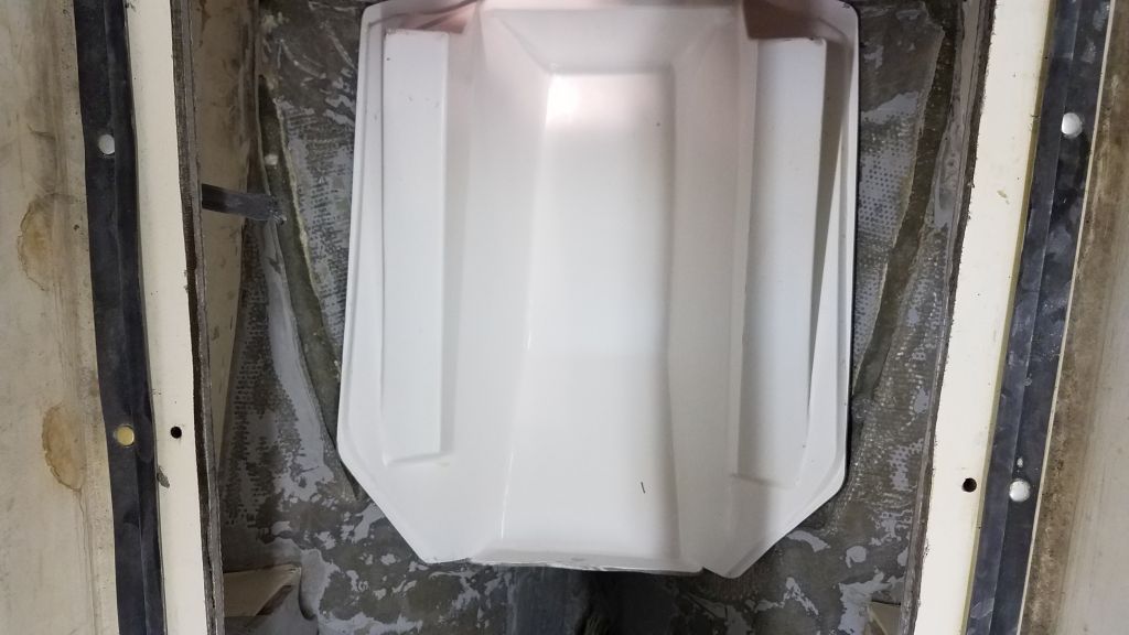
As it happened, the molded pan fit the hull well enough, but despite its clean fit to the hull shape itself, I could tell immediately that the pan was sitting far too high, and while modifying the pan was a possibility, the height difference at first glance appeared significant, given my knowledge of about where the engine needed to be, plus the way the shaft tube and foundation pan visually aligned (or not) in their respective locations.

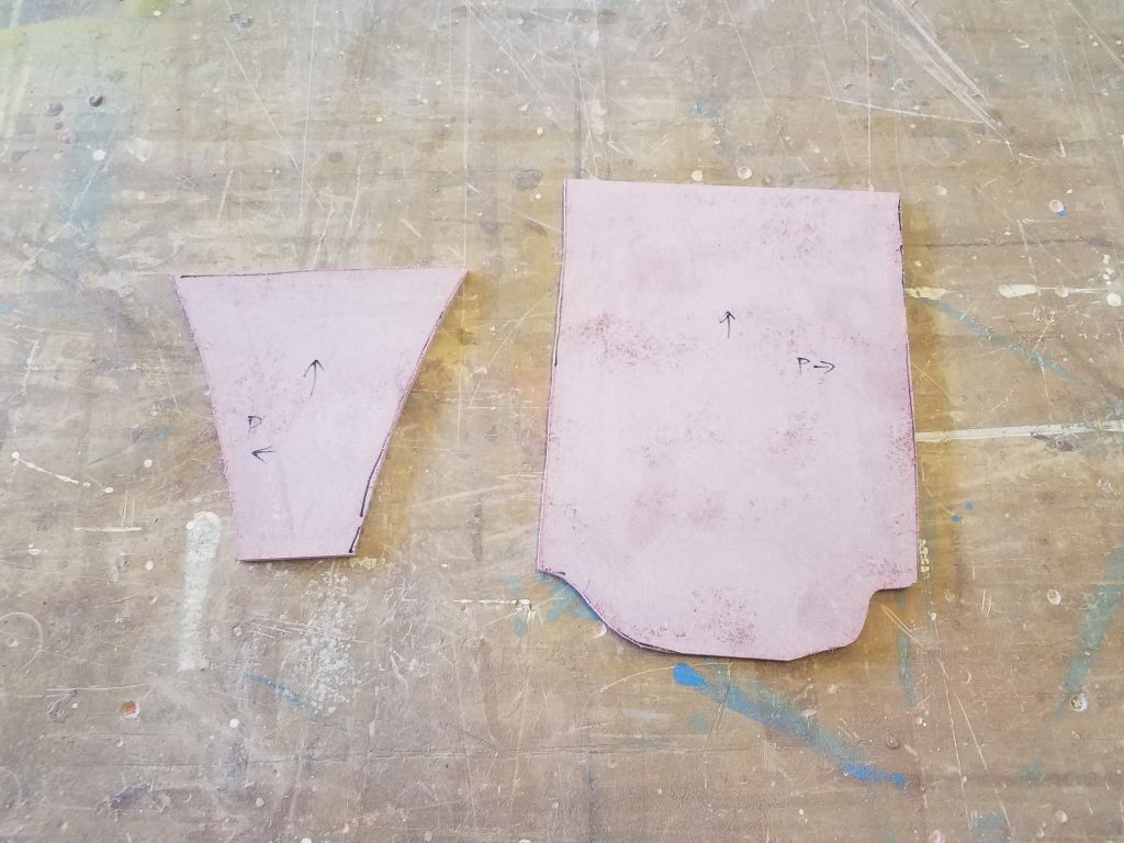
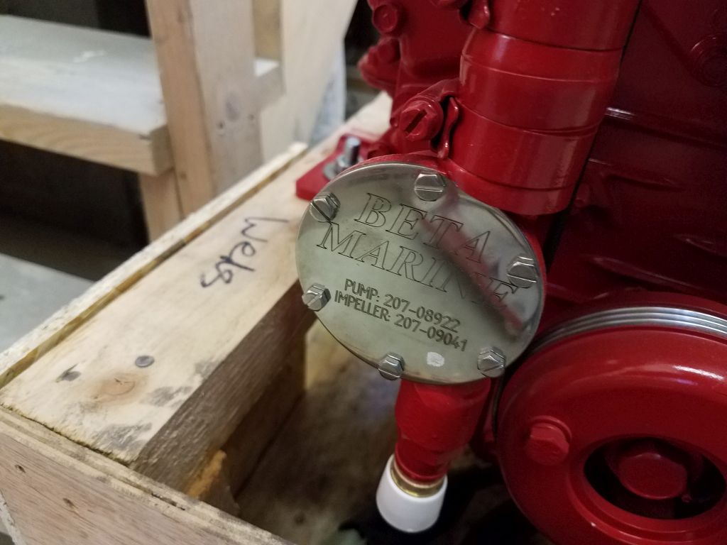
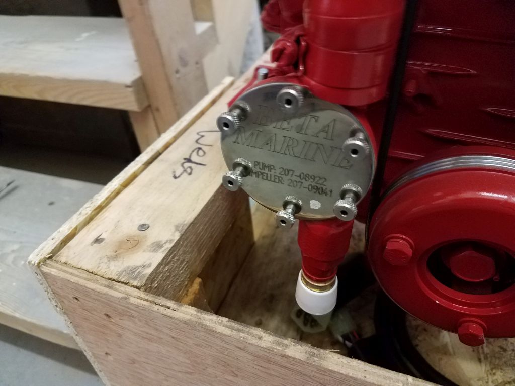
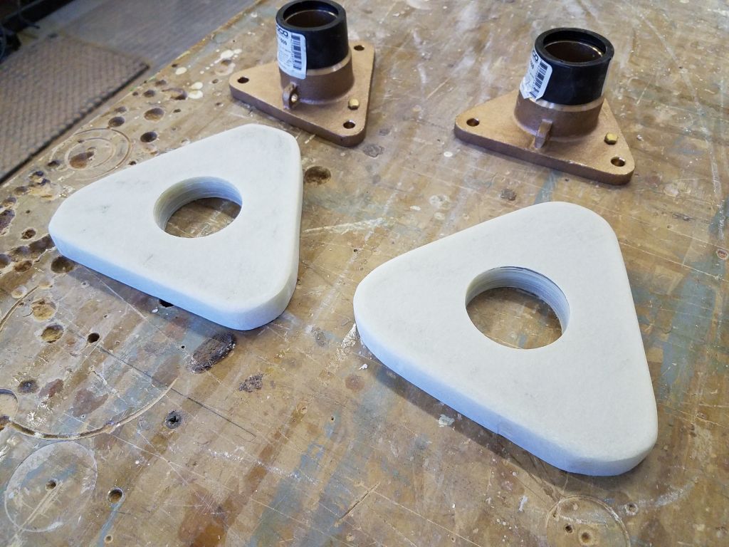
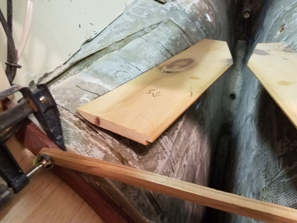
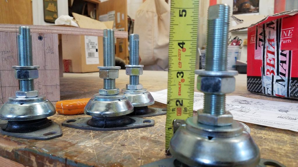
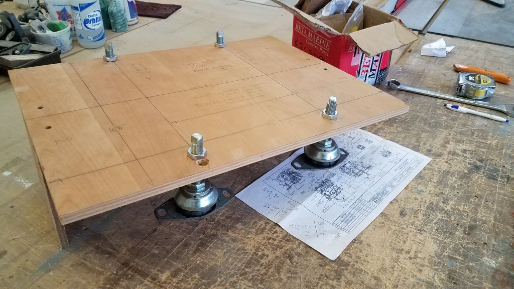
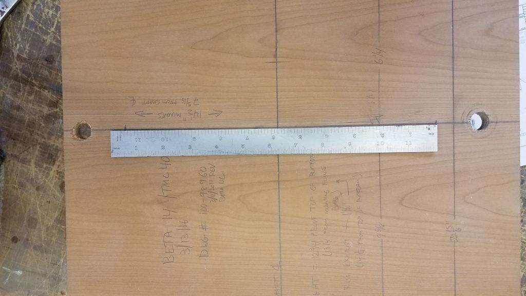
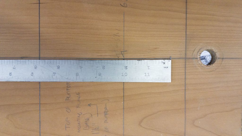
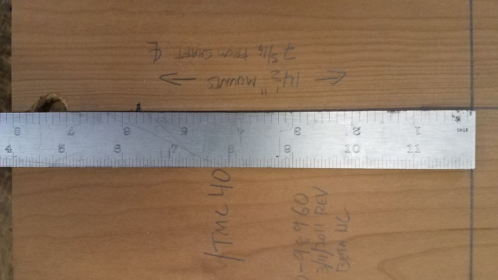
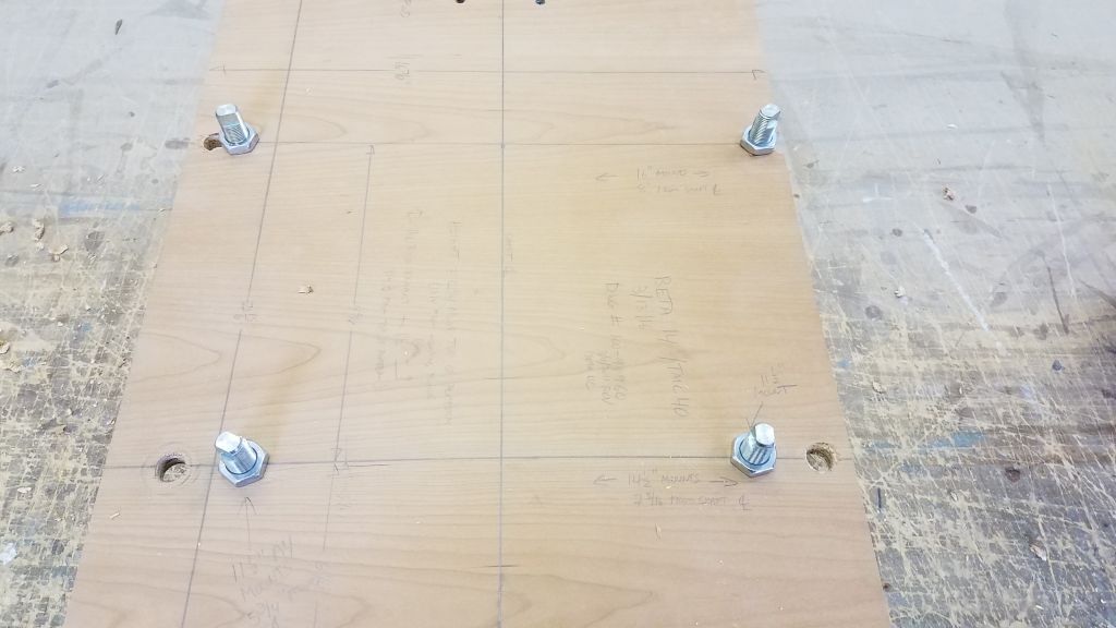
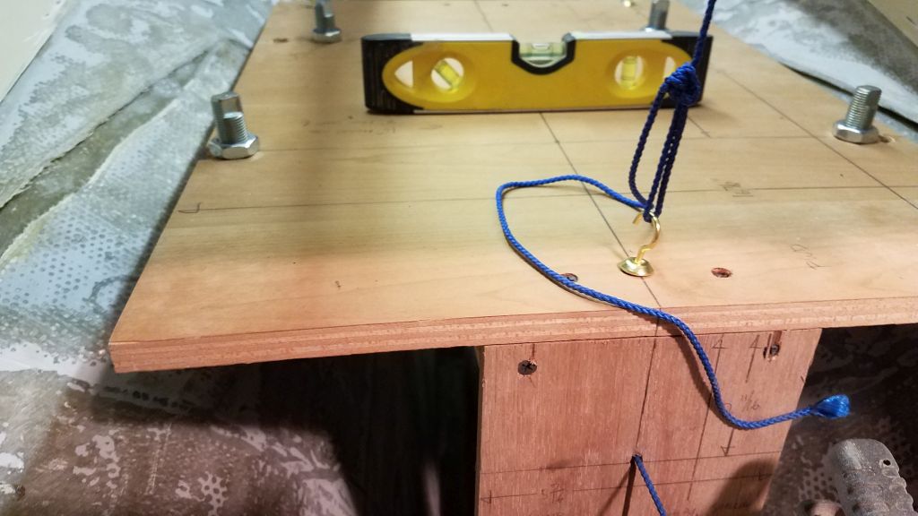
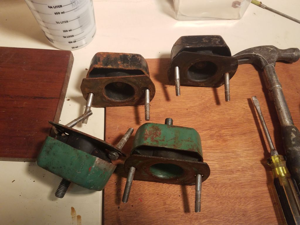
I retrieved from storage my plywood template for the Beta 14, which I built previously for another job a couple years before, and double-checked that the dimensions of the new engine hadn’t changed at all by reviewing the latest version of the Beta measured drawing, which still corresponded with the one I used to build the template in 2016.  I set the flexible engine mounts to a mid-range 3″ height (as measured beneath the template base, which is representative of the base of the steel engine mounts themselves), as this would allow adjustment in either direction within the recommended adjustment limits of the mounting studs.  I used a thick flat washer to simulate the height of the split locker washer that I’d use during the final engine installation so as to keep the adjustment height of the mounts as close to the real thing as possible. Then, I bolted the mounts to the template, using holes I’d bored for the 14-1/2″ mounting centers on this engine.

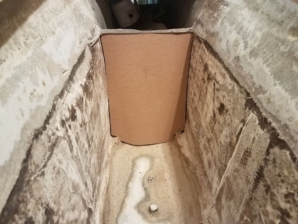
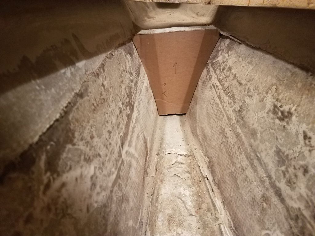
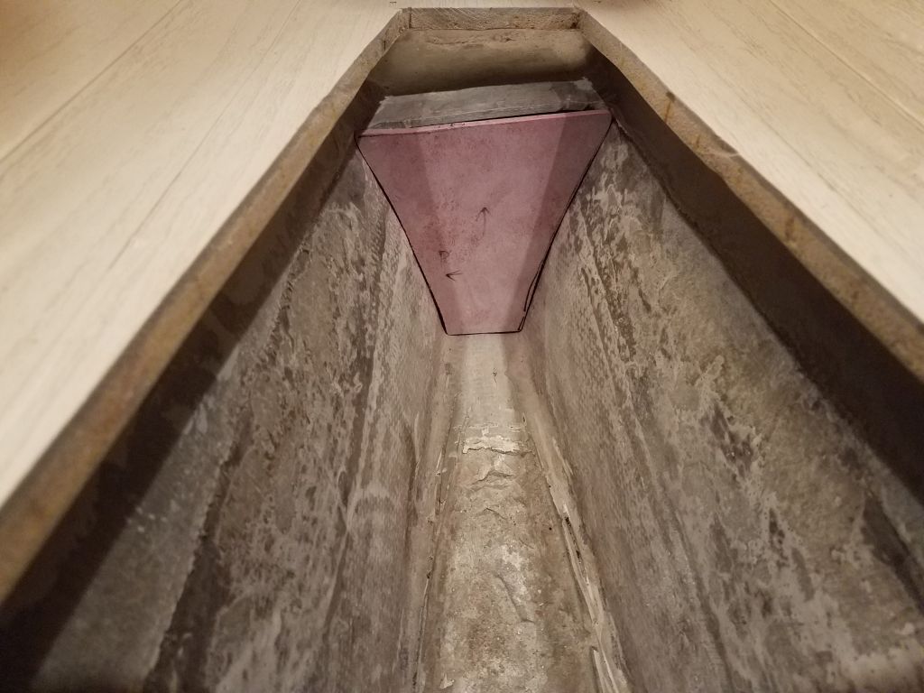
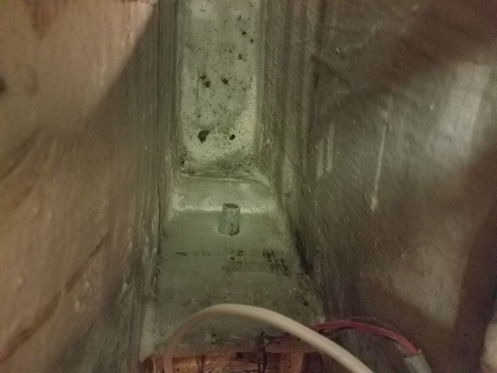
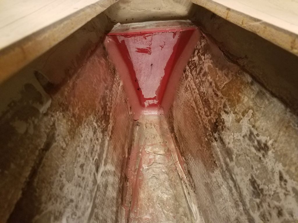
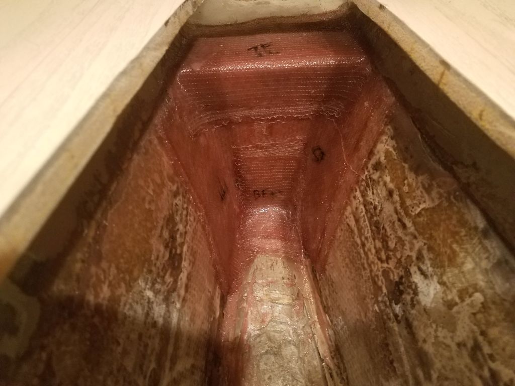
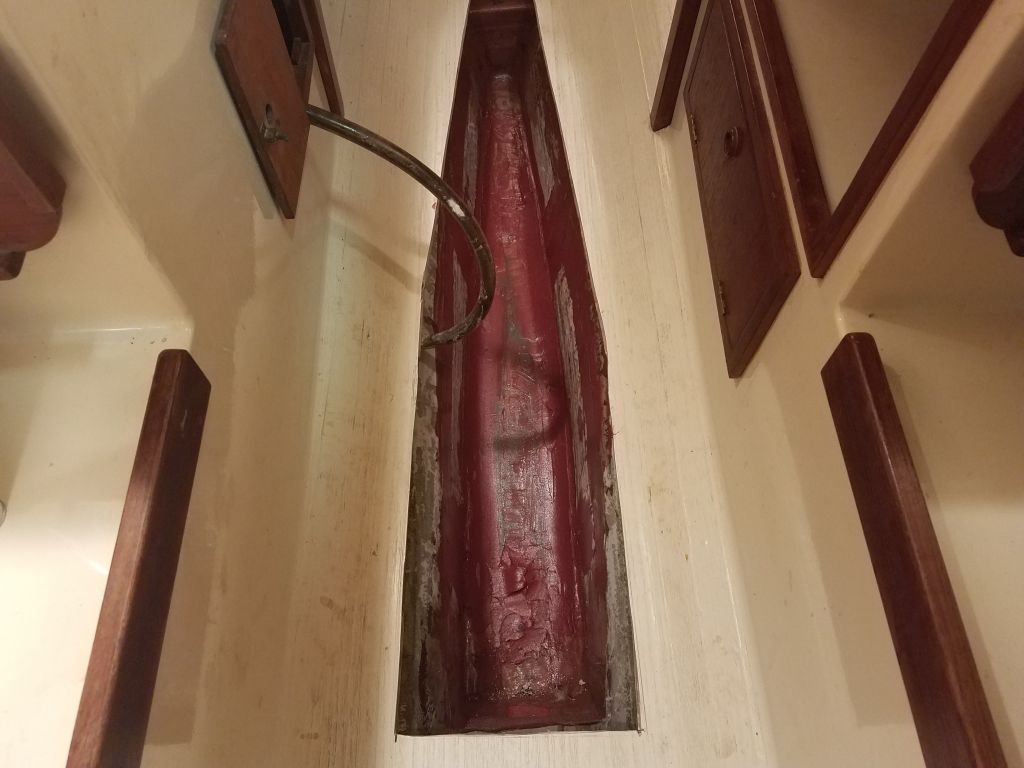
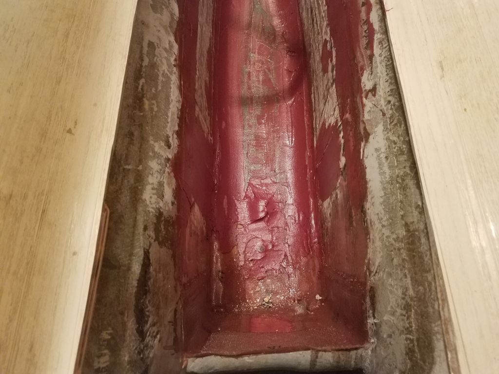
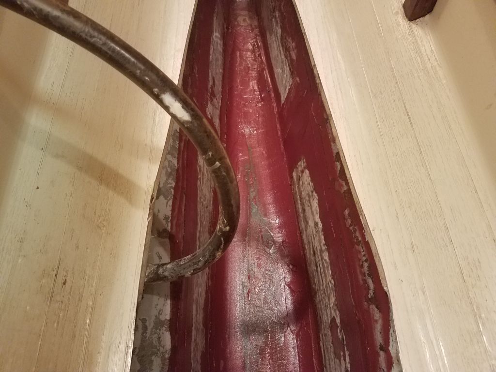
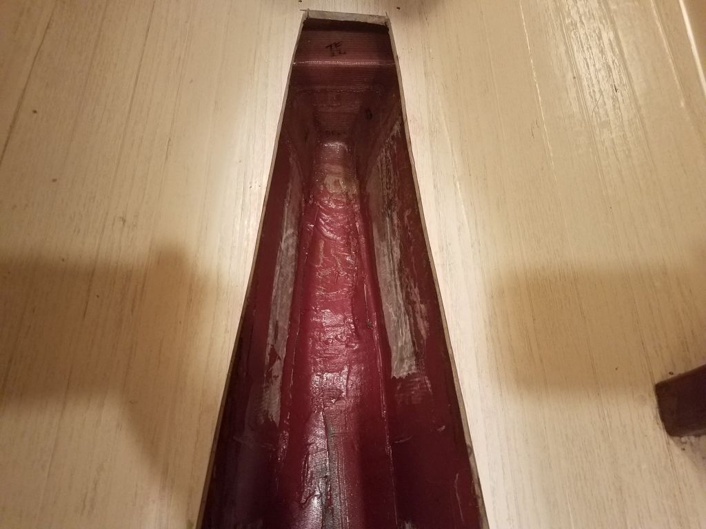
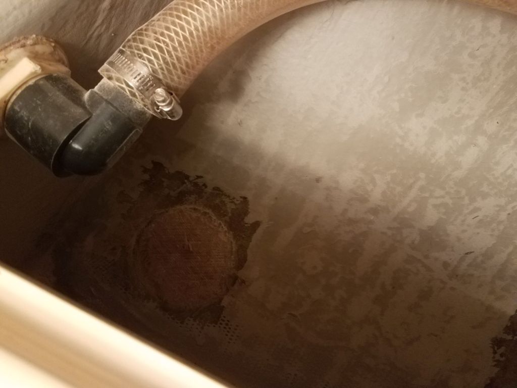
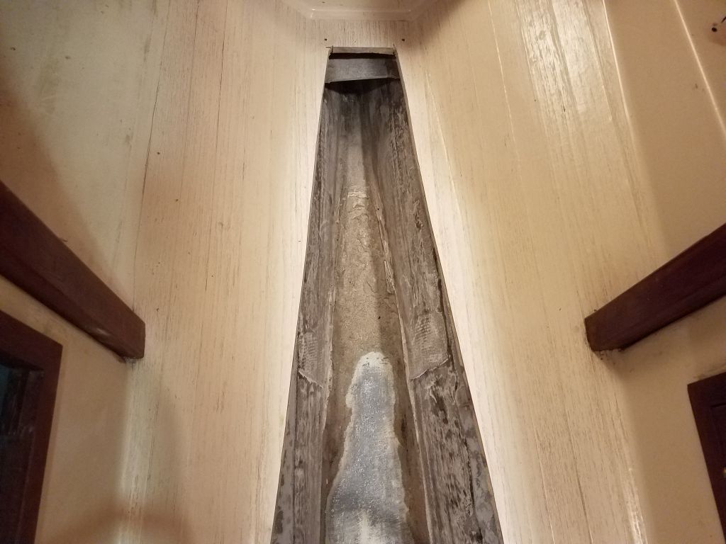
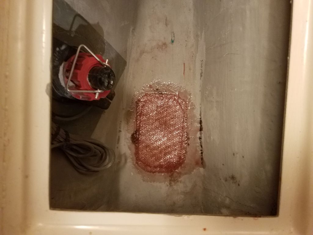
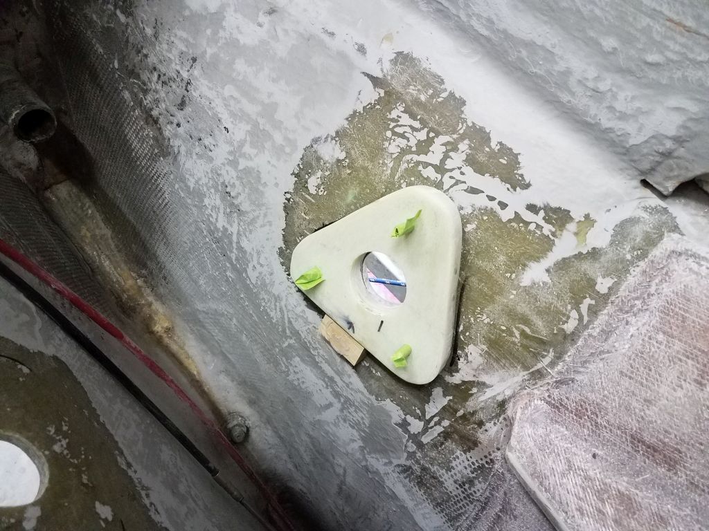
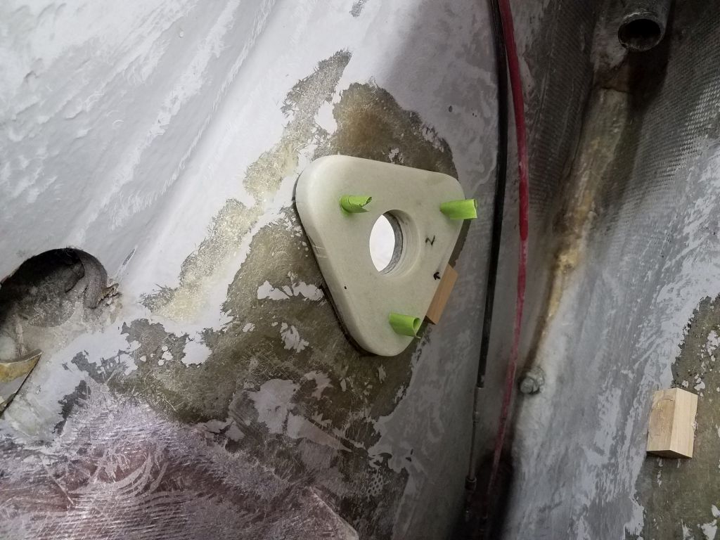
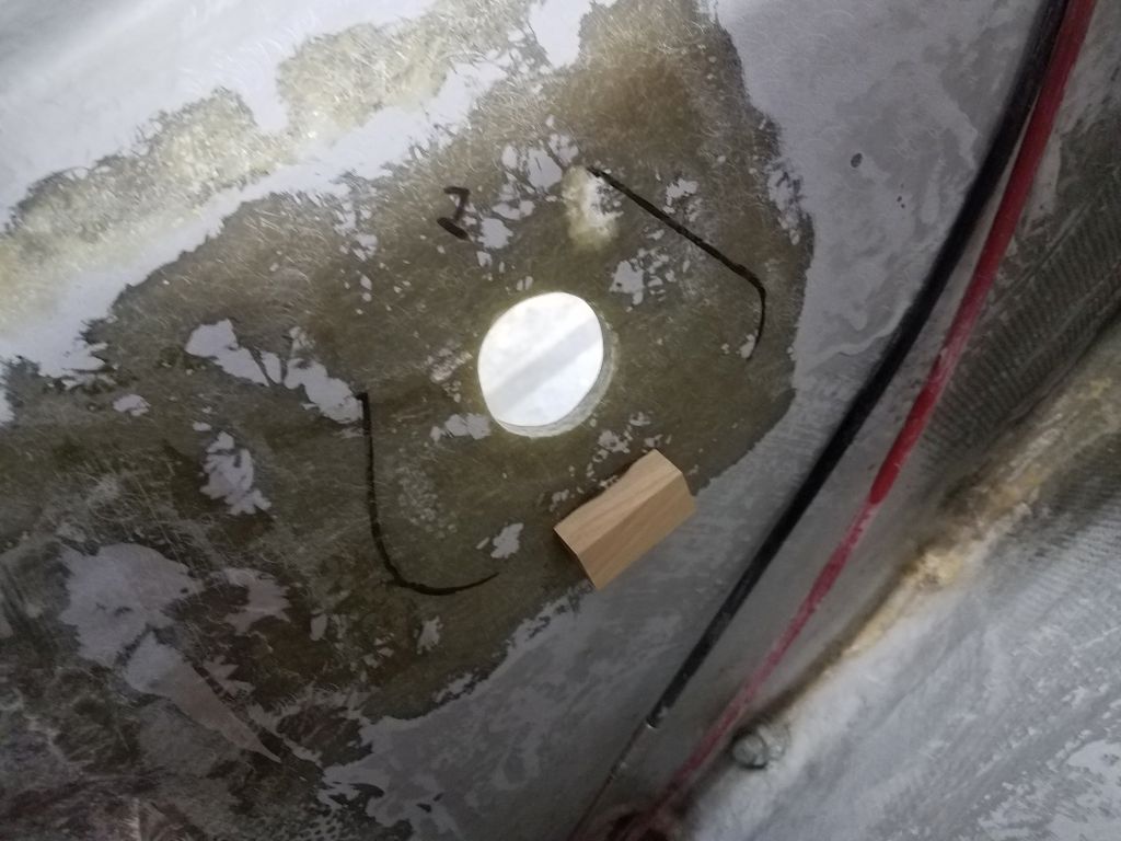
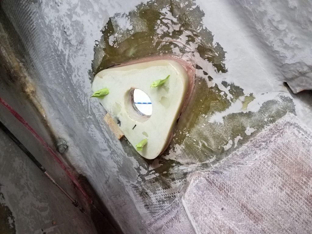
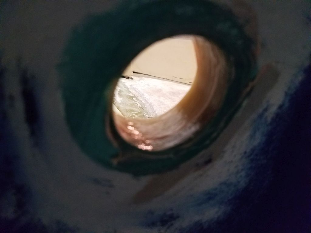
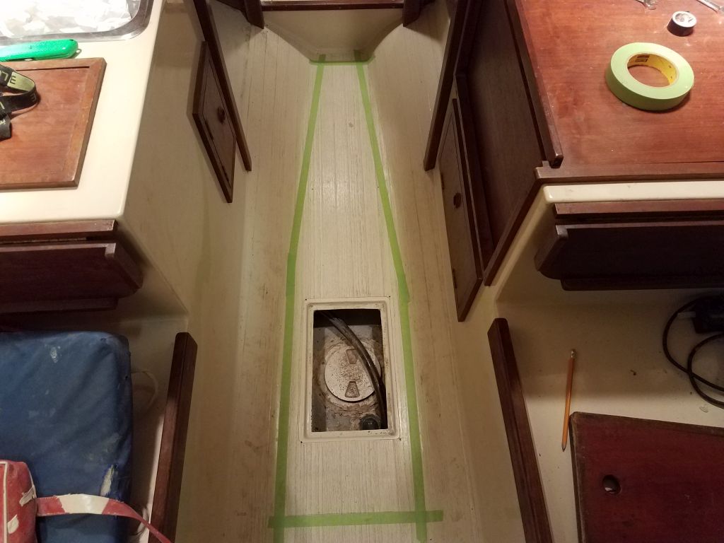
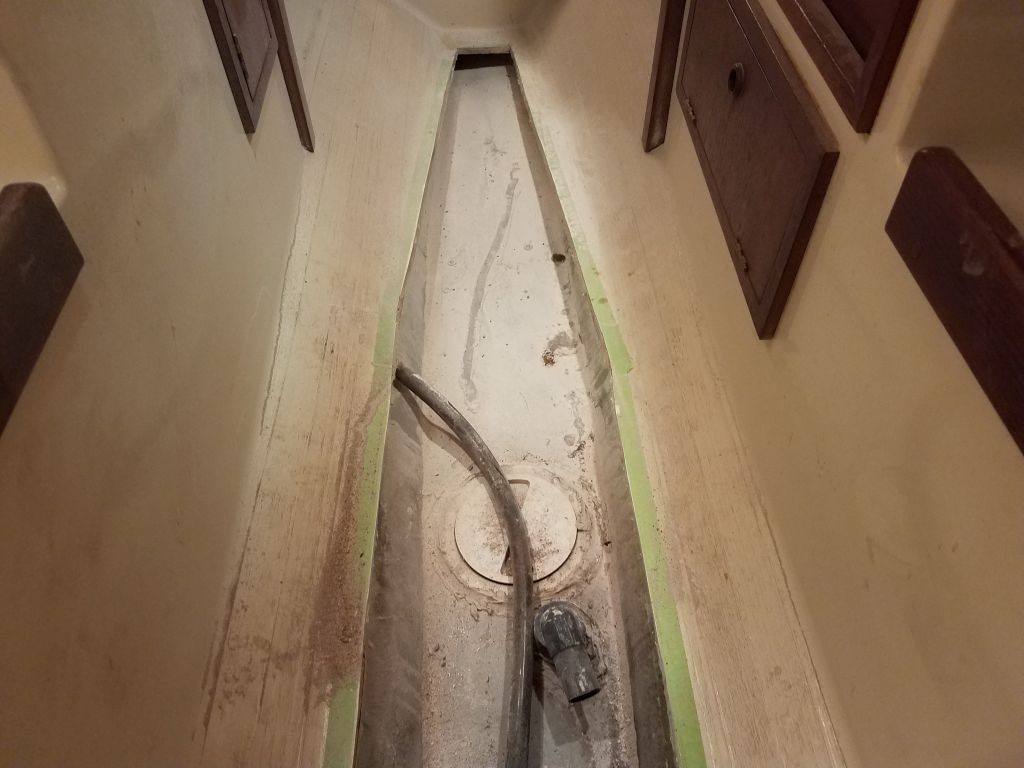
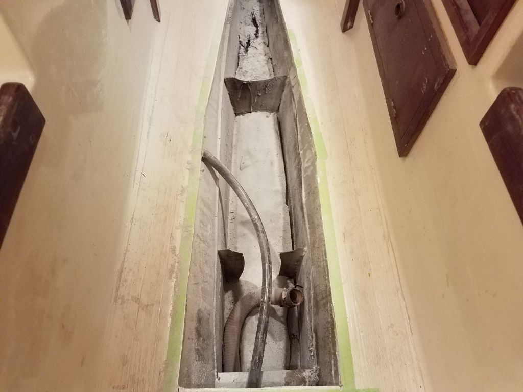
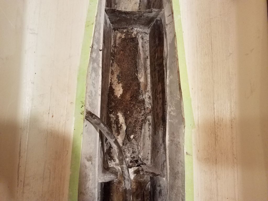
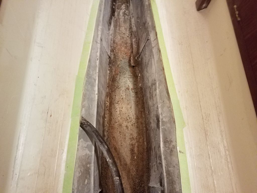
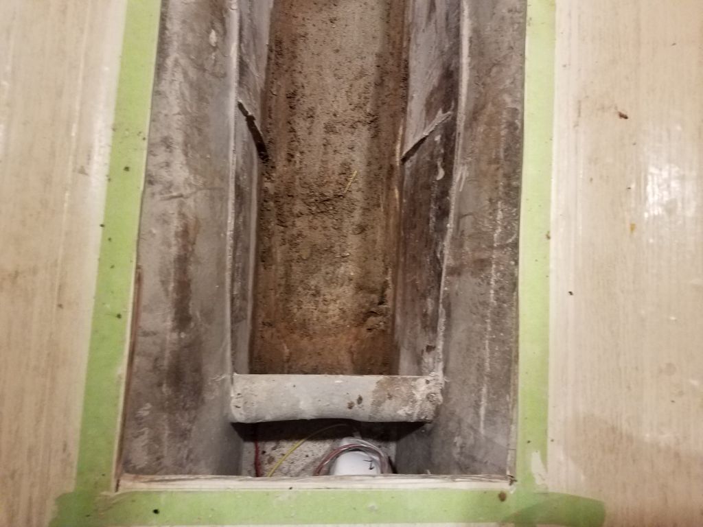
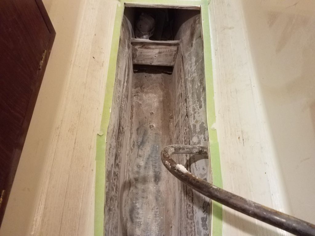
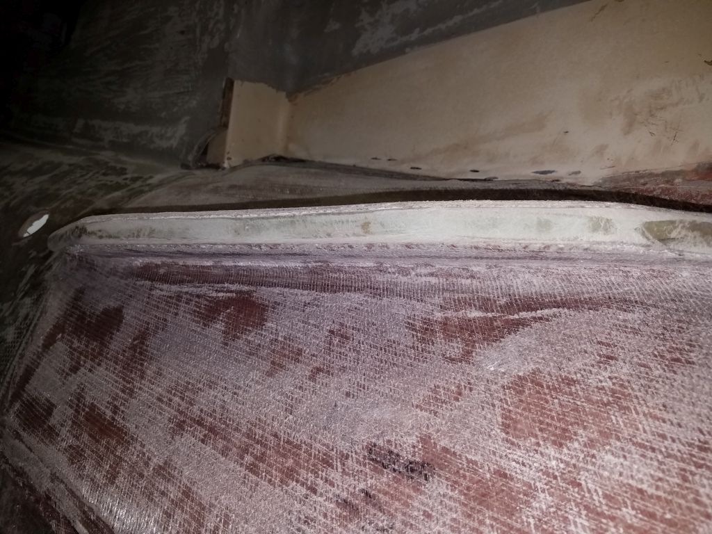
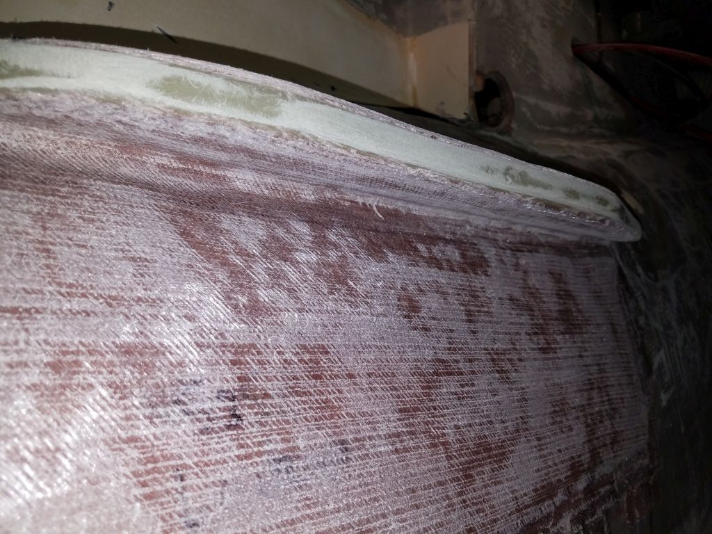
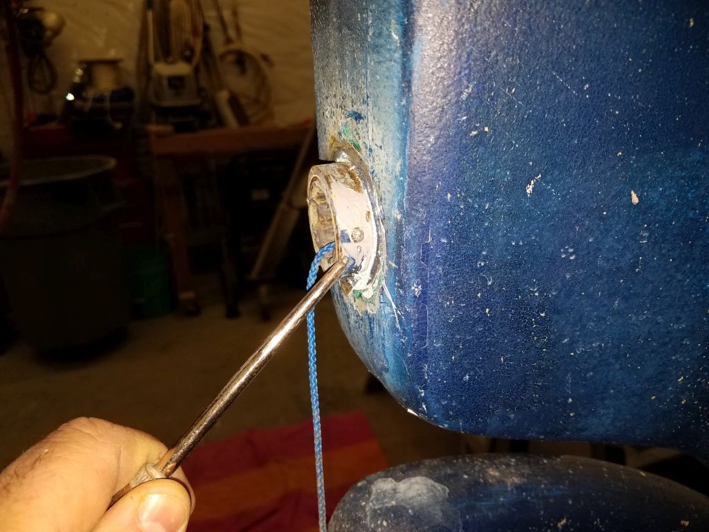
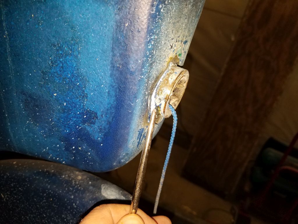
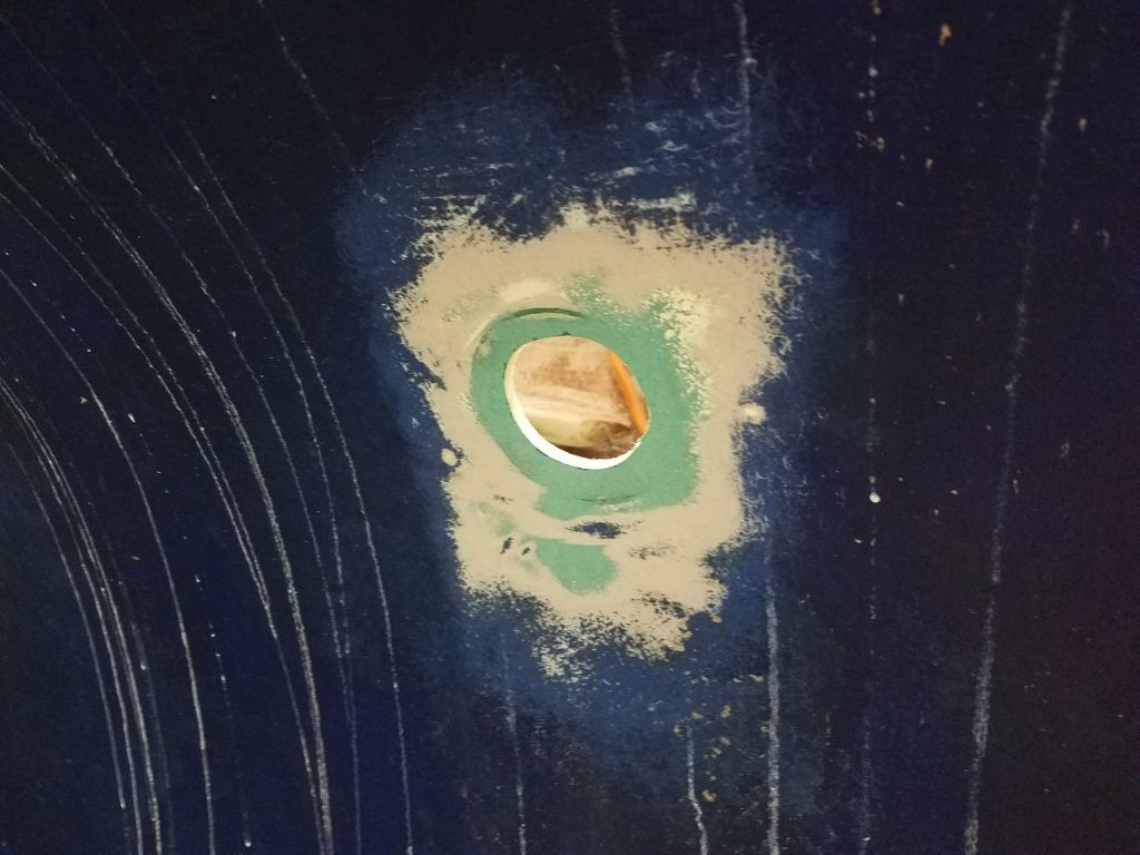
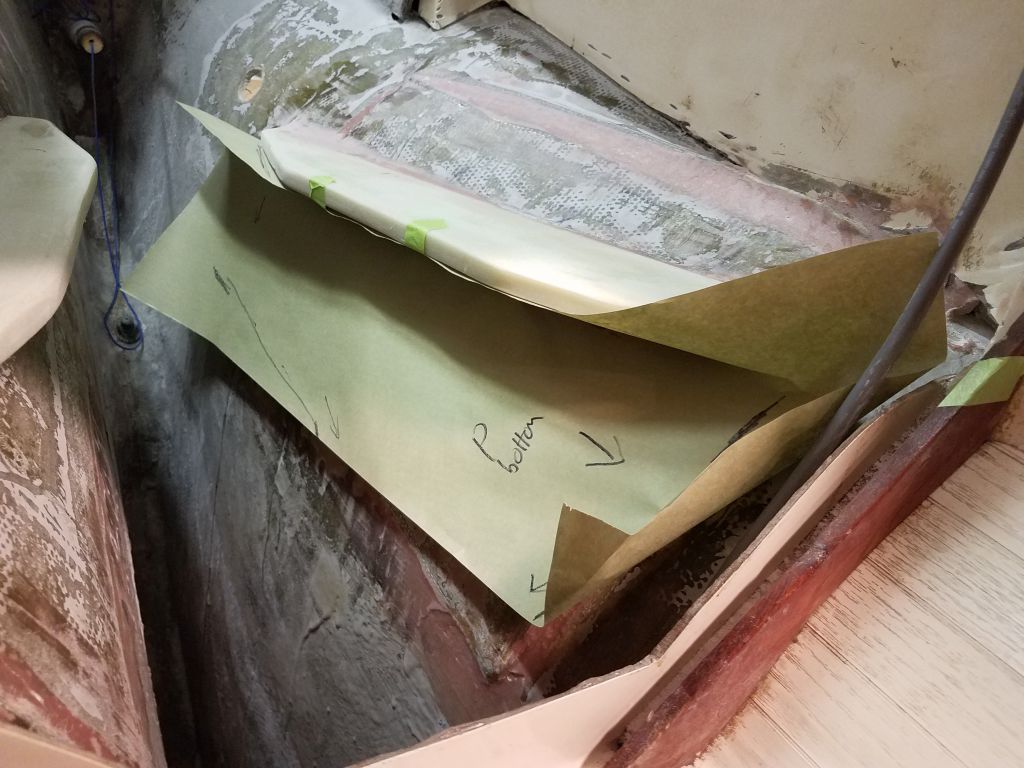
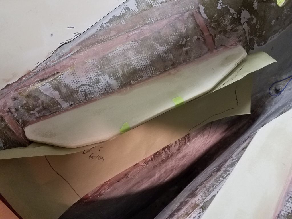
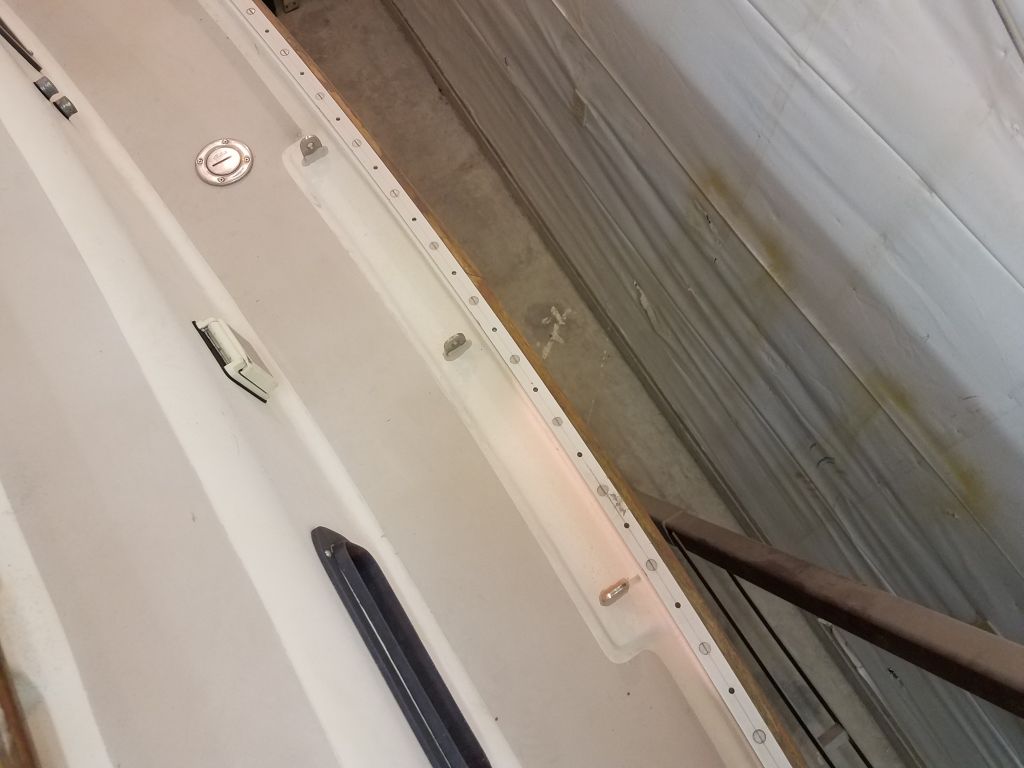
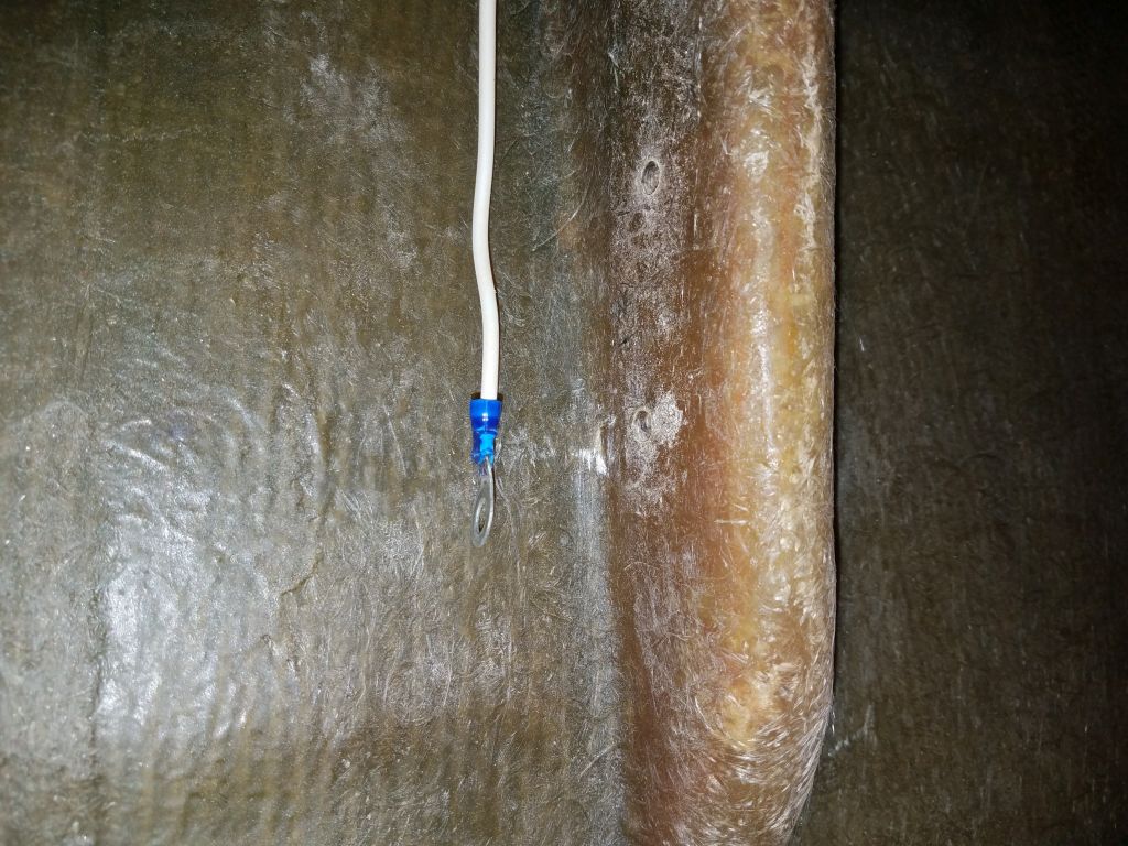
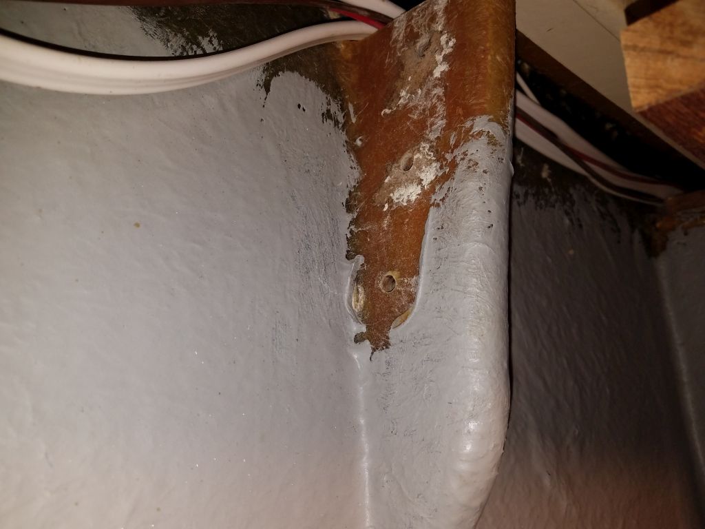
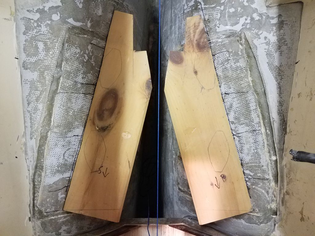
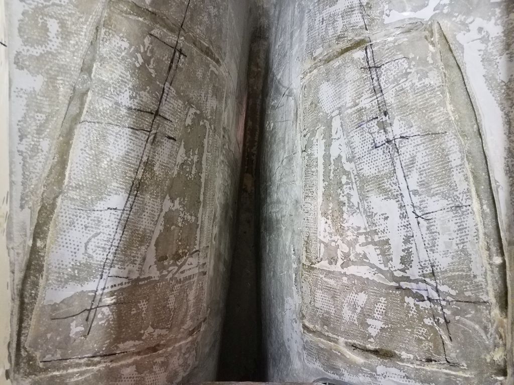
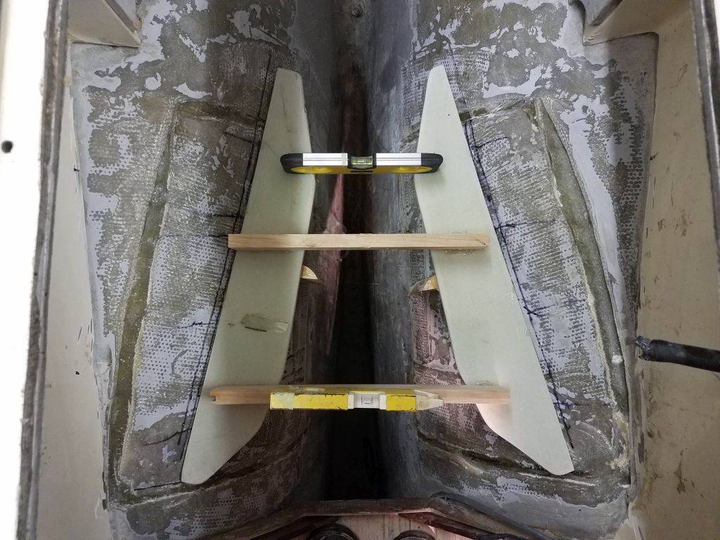
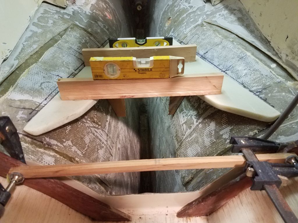
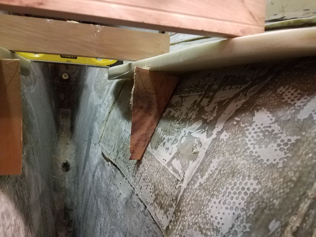
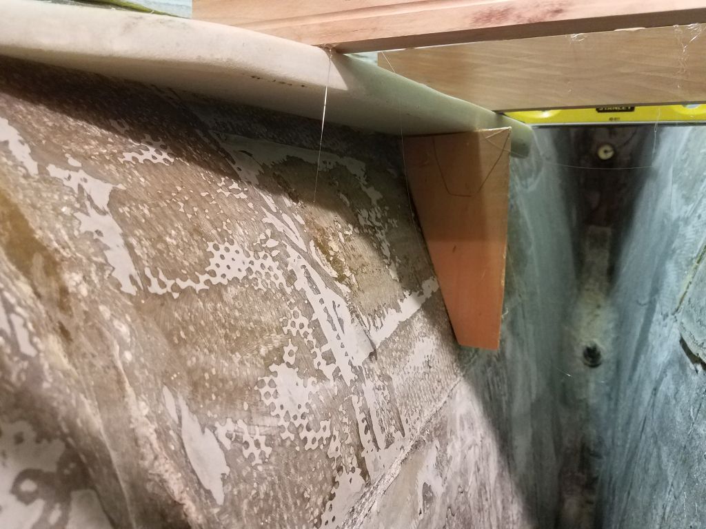
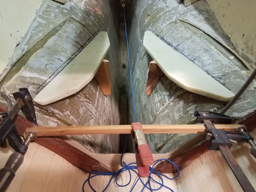
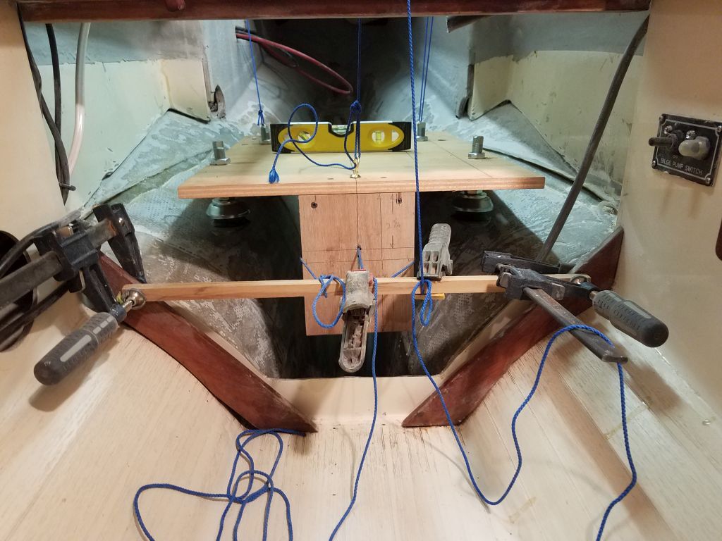
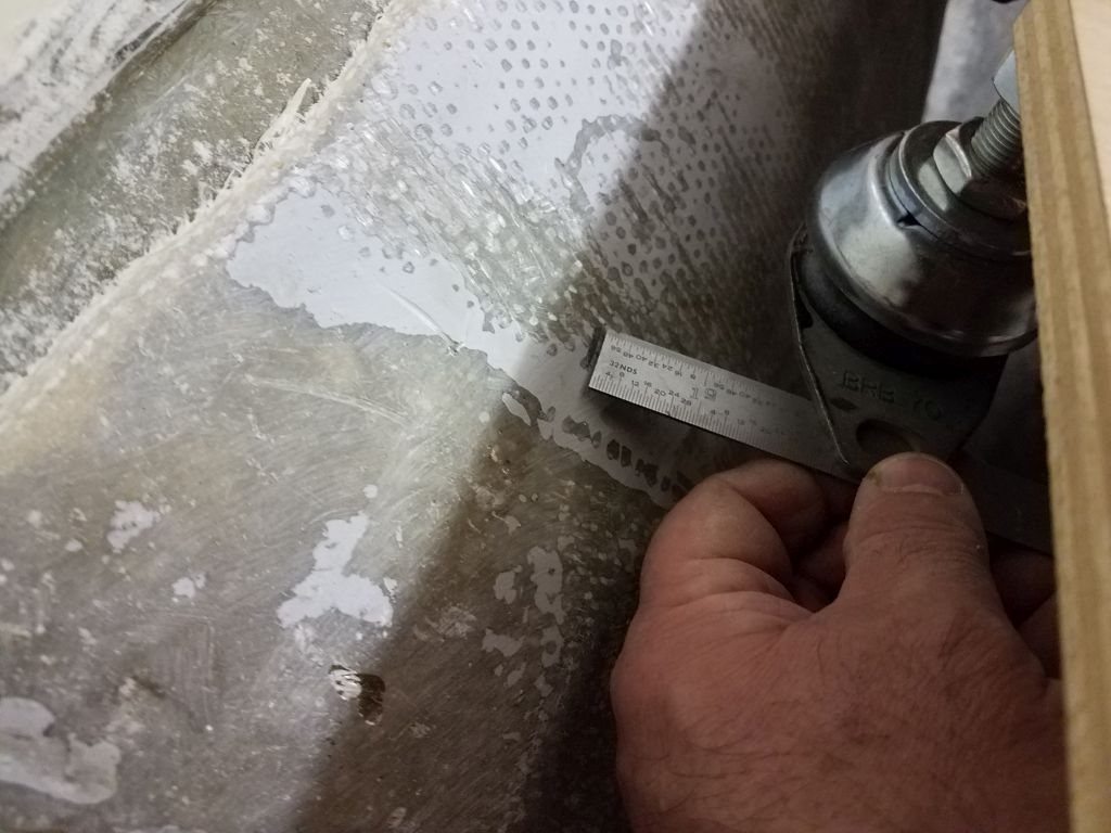
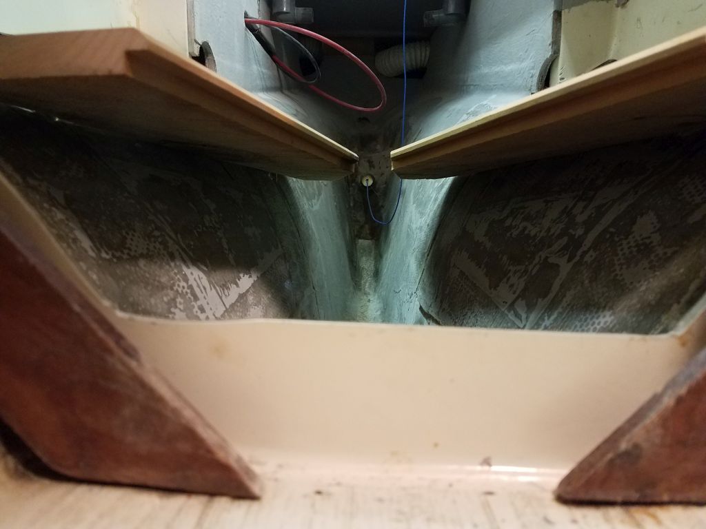
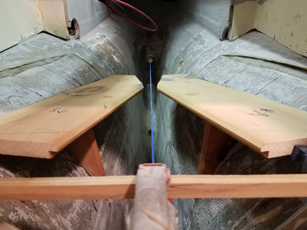
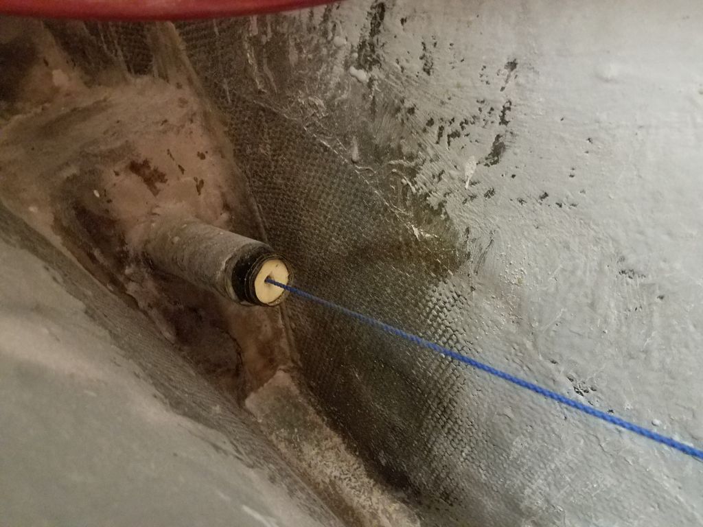
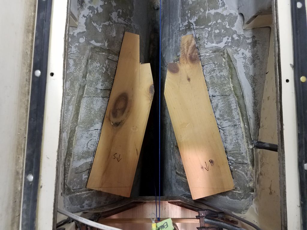
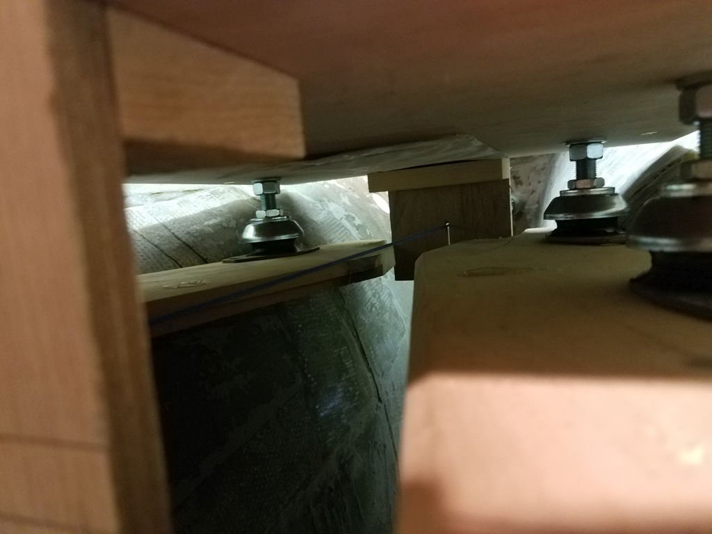
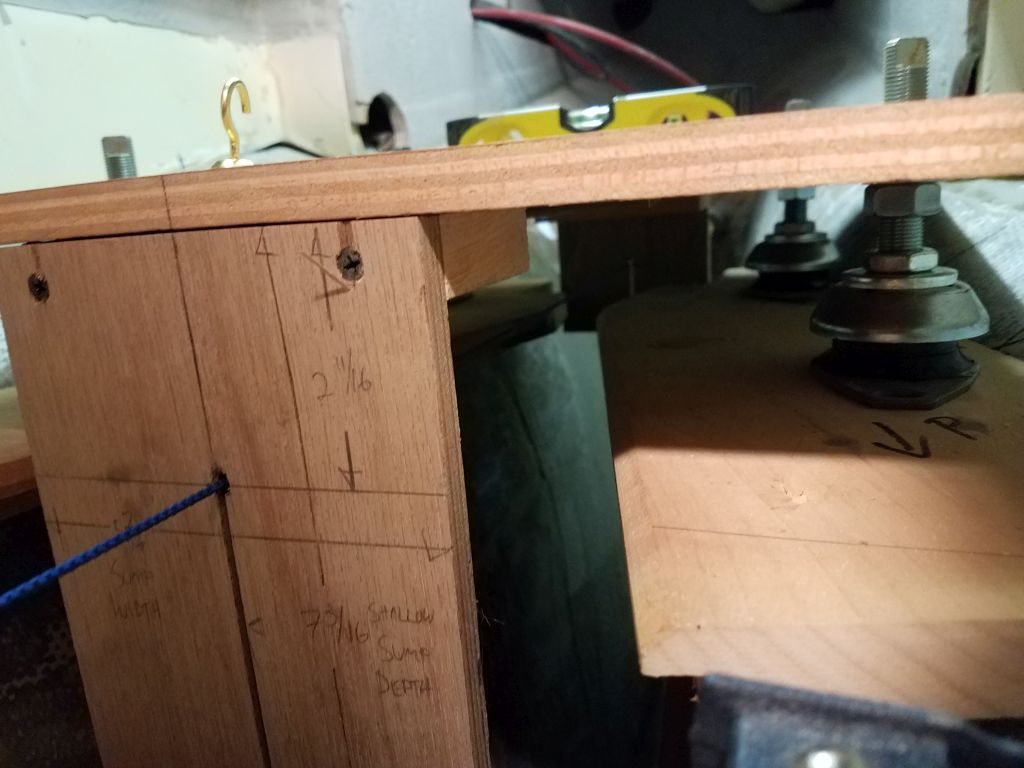
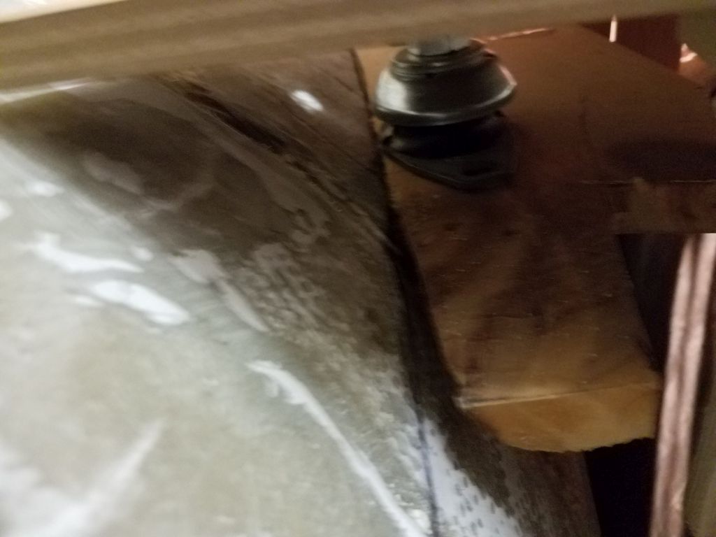
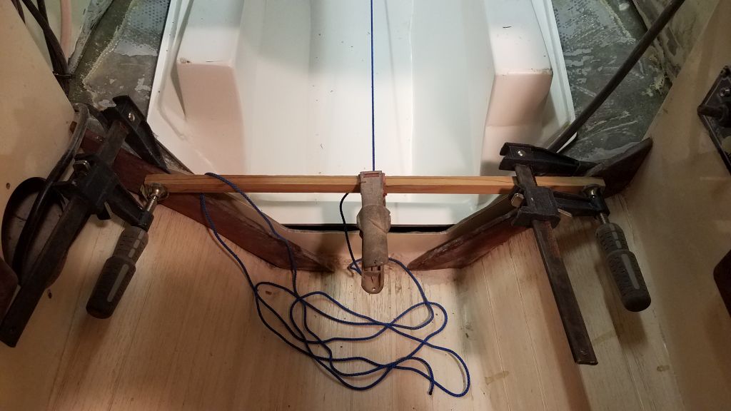
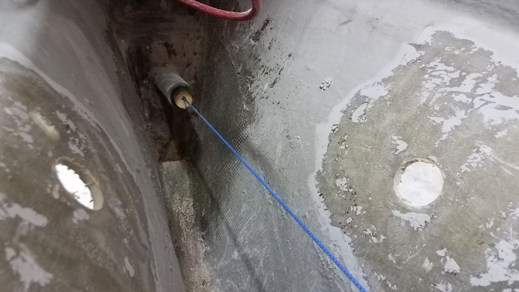
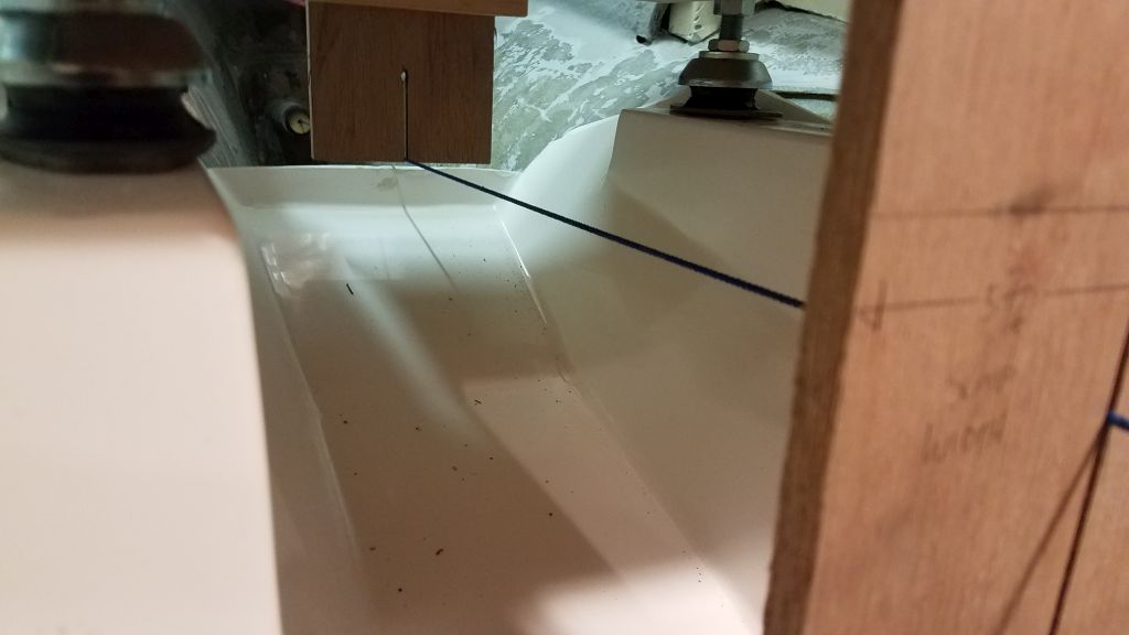
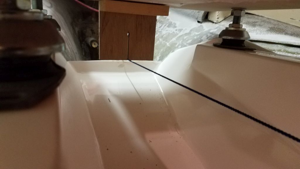
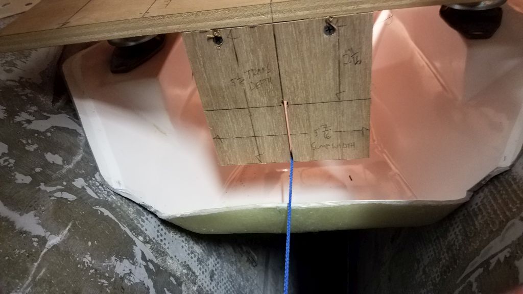
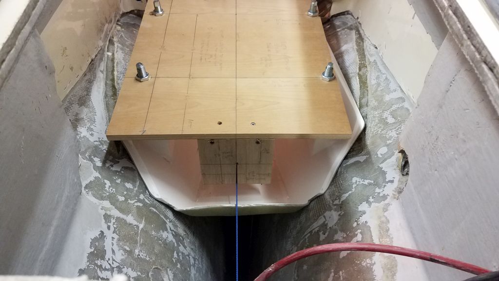
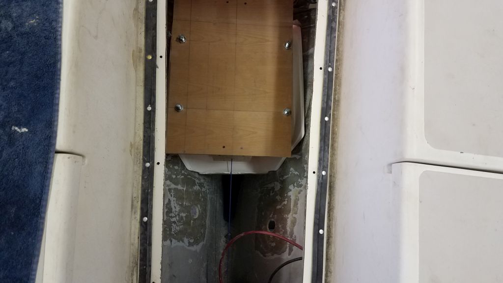
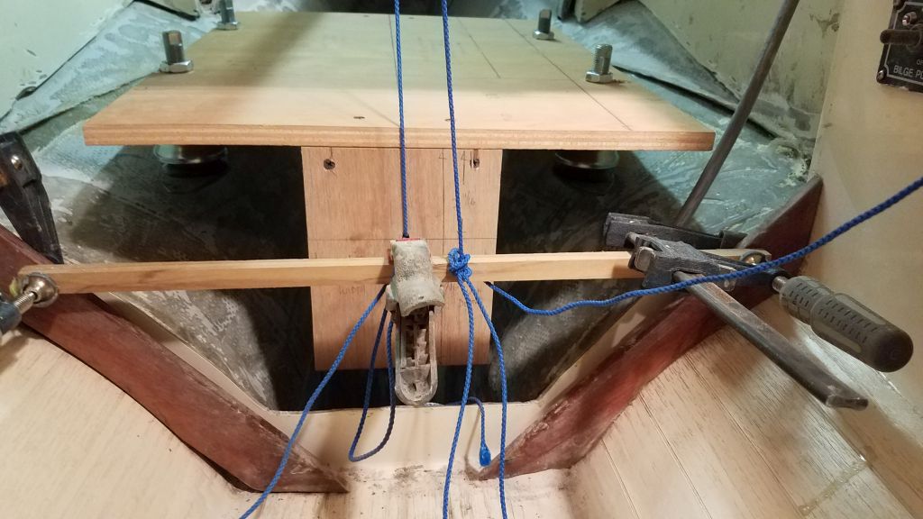
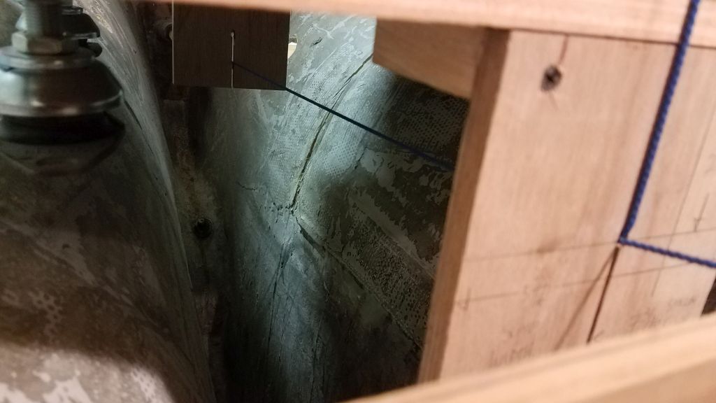
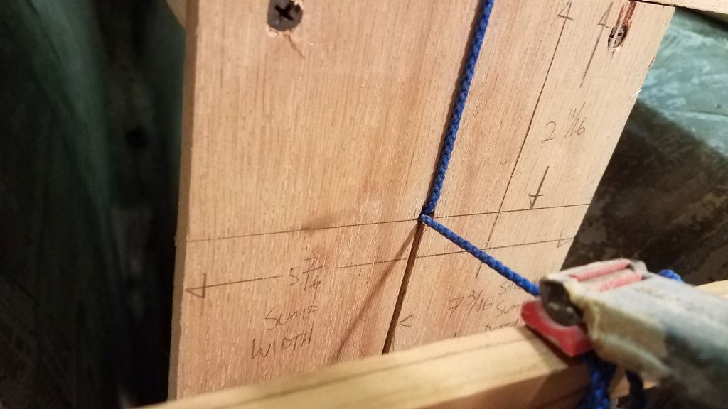
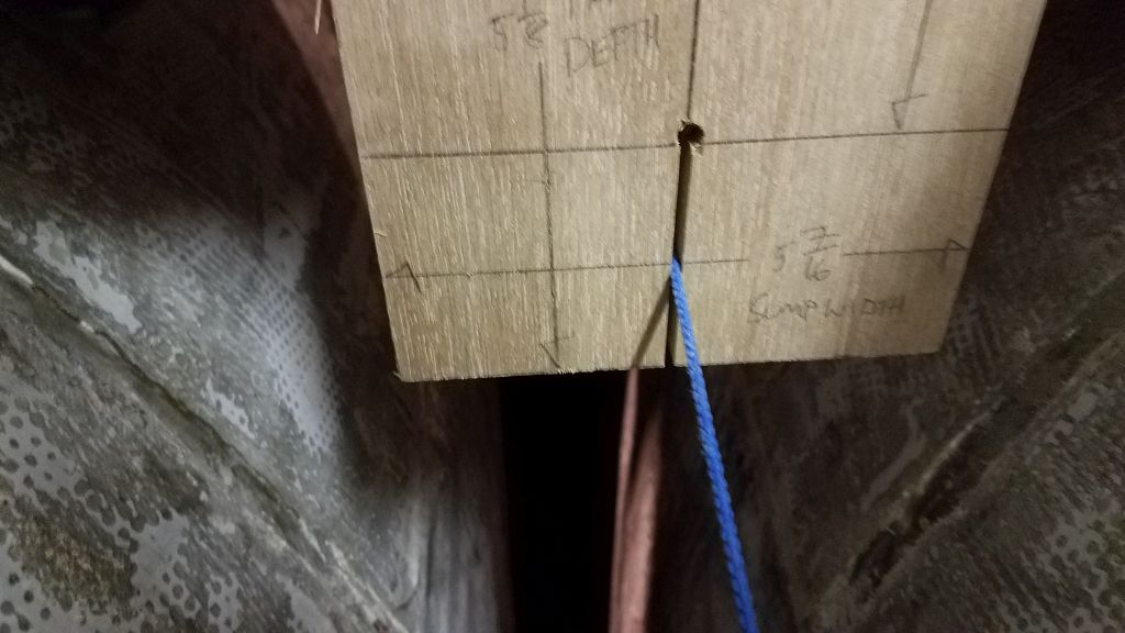
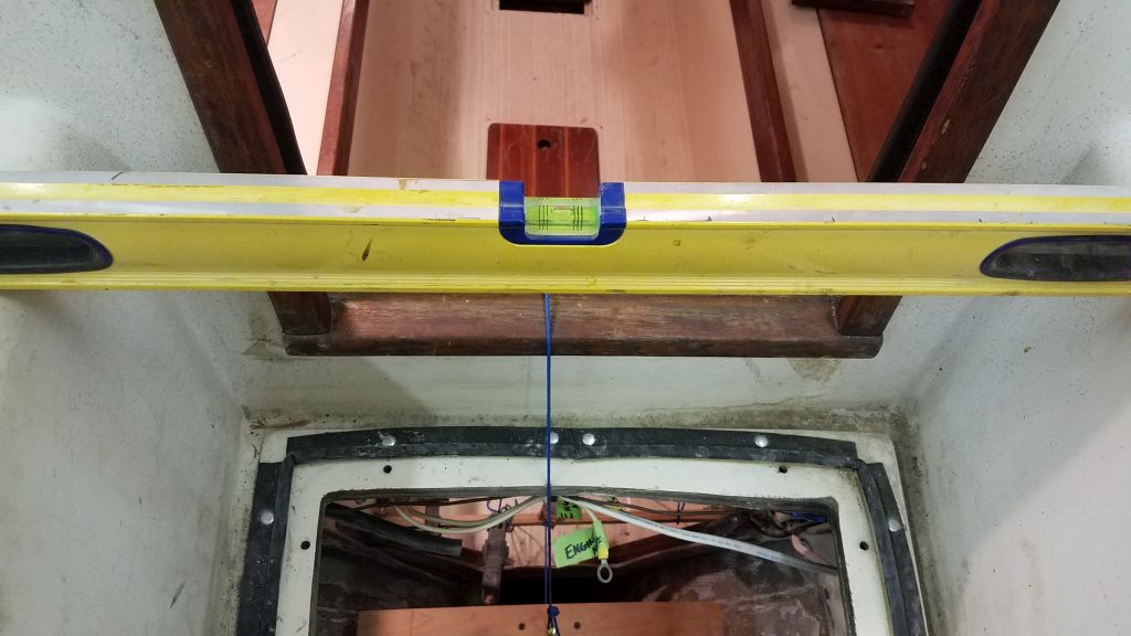
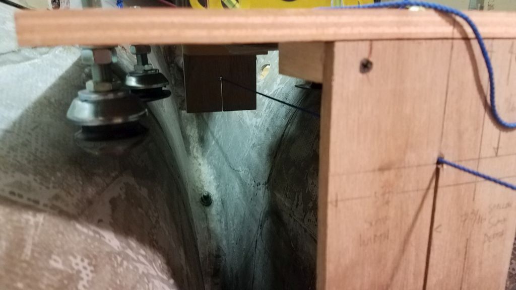
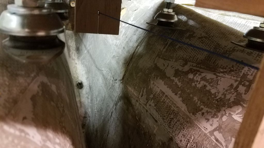
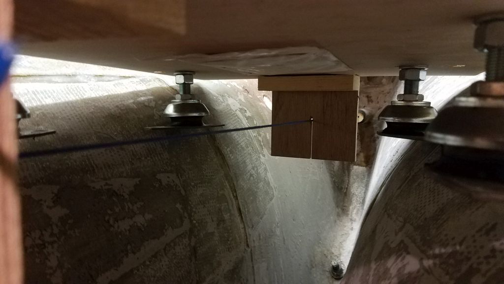
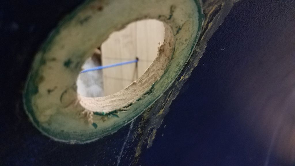
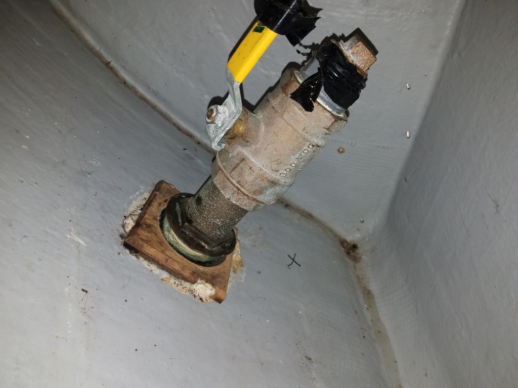
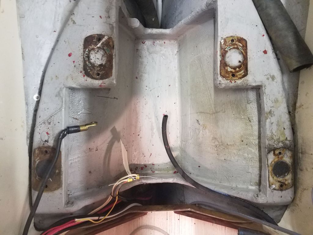
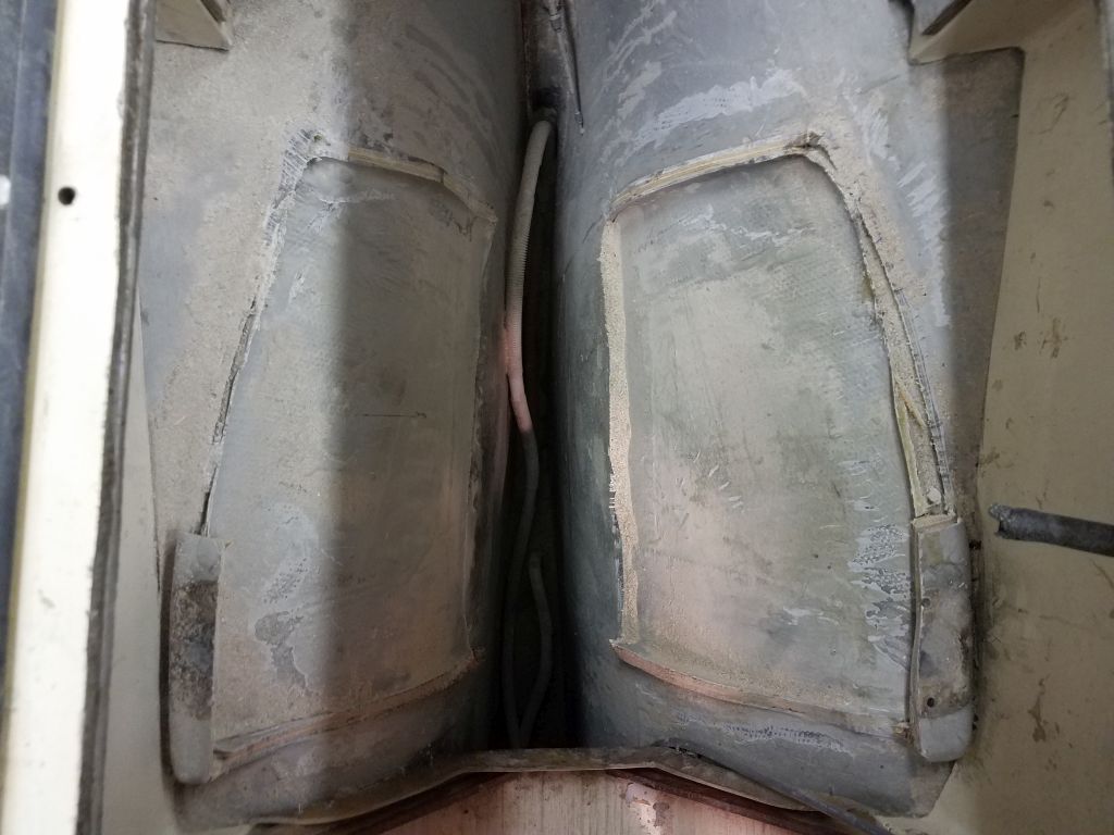
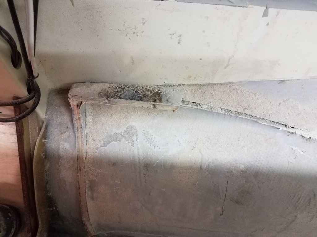
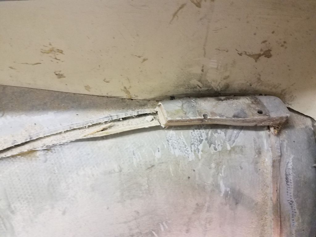
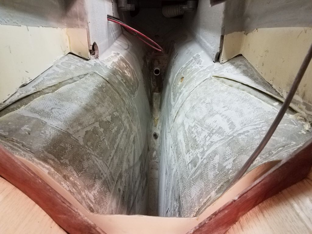
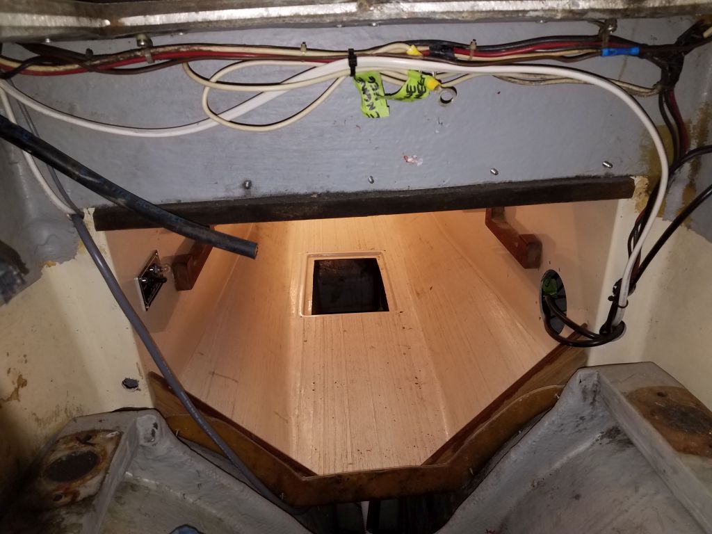
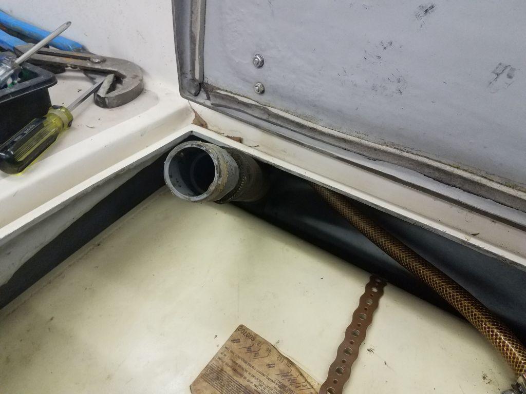
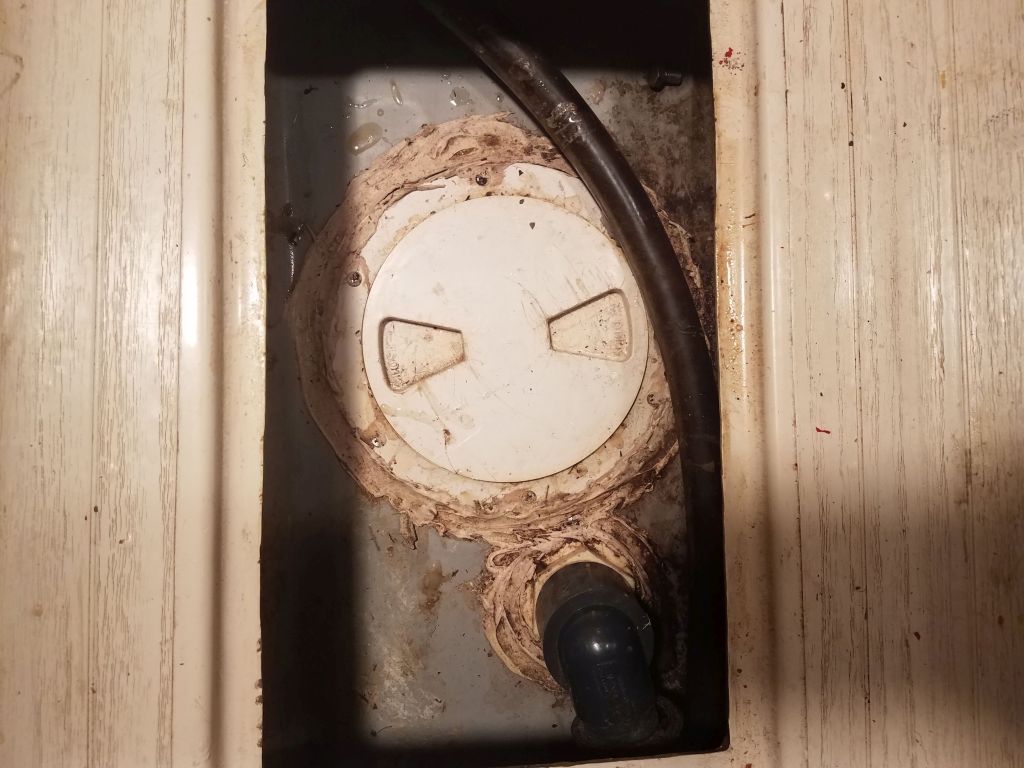
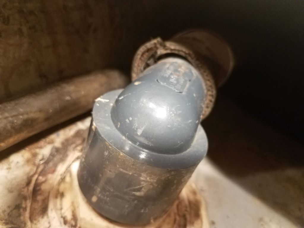
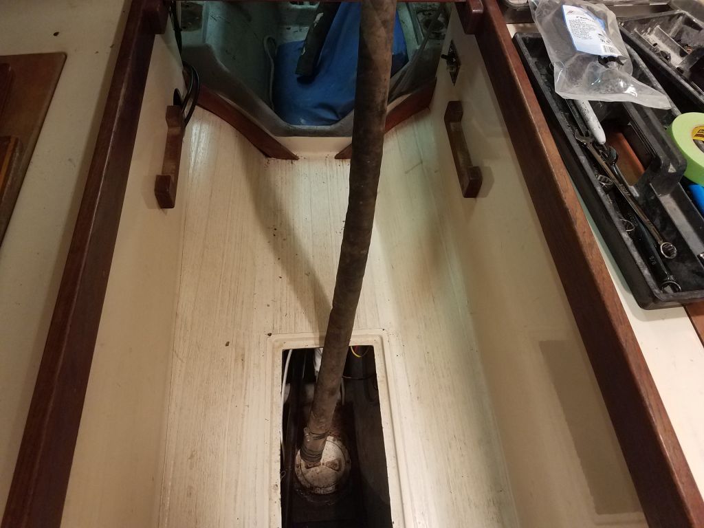
To start to get a rough sense of where things were, and a reality check for the engine pan, I set up an alignment string through the stern tube, holding it centered in the tube at each end with a wooden plug and securing the string tightly inside the boat after aligning it by eye through the center of the stern tube and plugs.  The string represents, of course, the centerline and plane of the propeller shaft, the one critical reference point from which all engine placement follows.  It was clear once more that the fiberglass pan was much too high, though the closeness of the string to the upturned aft end of the drip platform was the least of my concerns–though it did highlight just how misaligned the molding was in this boat.

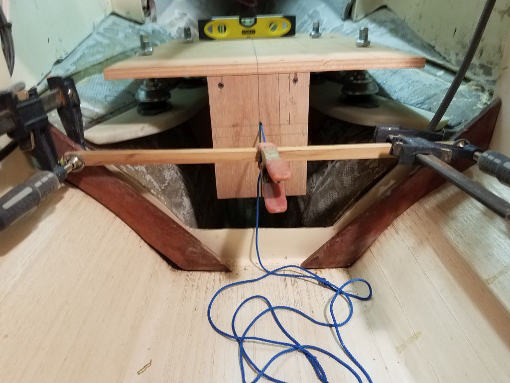
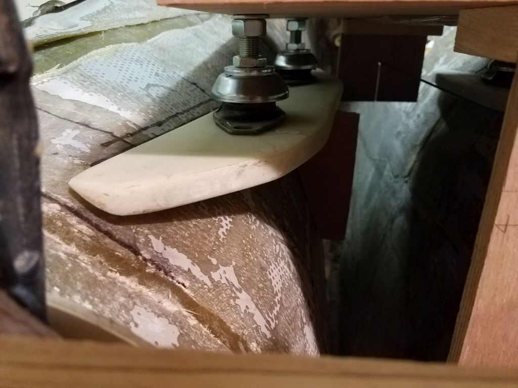
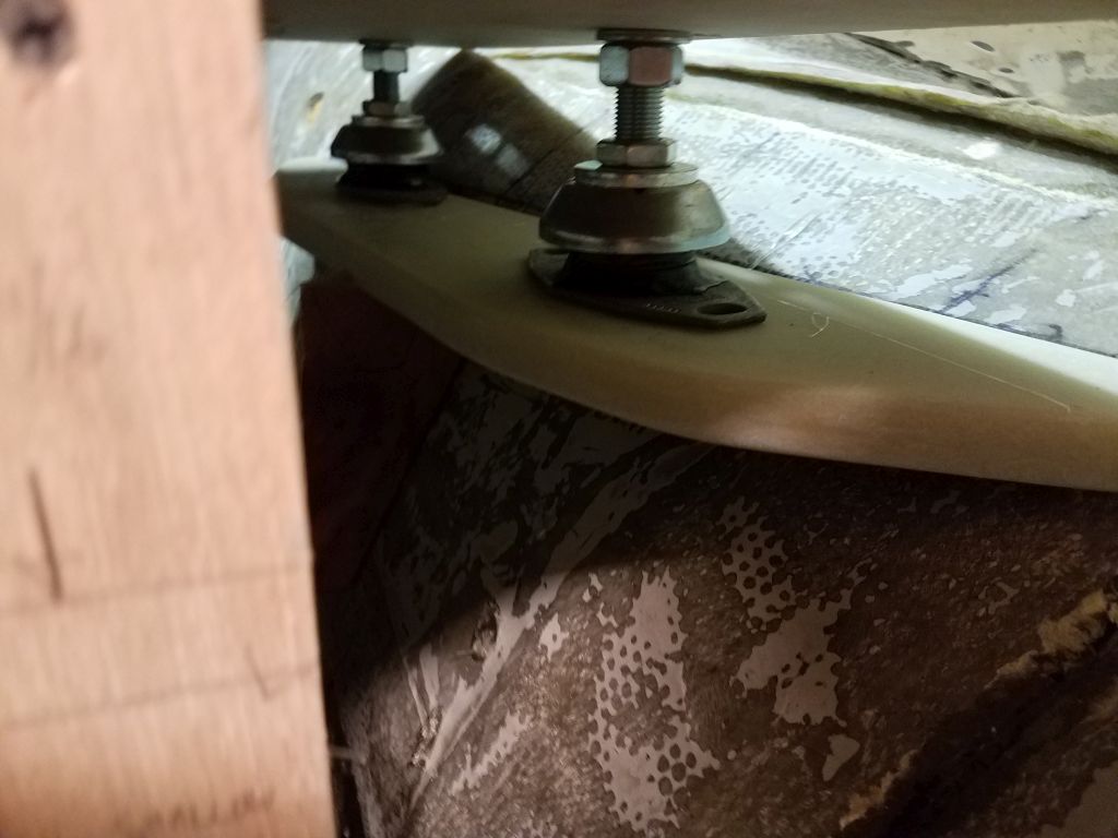
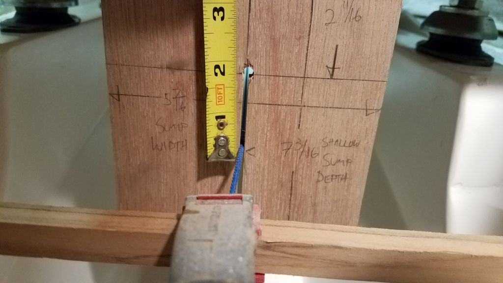
I set the engine template atop the engine foundation and checked its placement vis-a-vis the alignment string.  At the forward end, as currently placed and adjusted, the string was 1-3/4″ below where it should have been (i.e. the engine was 1-3/4″ too high), while at the aft end it was even worse, as the string was nearly 3″ below its proper location (i.e. the engine was 3″ too high at the aft end).  This was a pity, since otherwise the template fit so nicely on the prefab bed.

I could adjust the engine mounts down by 1/2″ or so, but of course that wouldn’t even begin to make up the large discrepancy.  And while I’d not discounted it completely yet, I was skeptical that I’d be able to modify the existing pan enough to make up the large difference in height and basic placement.

At issue, I believed, was a fundamental difference in the longitudinal placement of the engine in a Canadian boat versus the original English version.  Though I’d never been aboard an English boat, various photos and other information, some of which went back to early project discussions with the owner in April, suggested that the engine in the English boats was substantially further forward, perhaps a foot further, which extended the engine room into the cabin beneath the companionway steps.  Given the shape of the hull, if I could have slid the foundation a foot forward, it would have ended up also substantially lower, making for a good fit–as indeed it seems to be in the English boats.

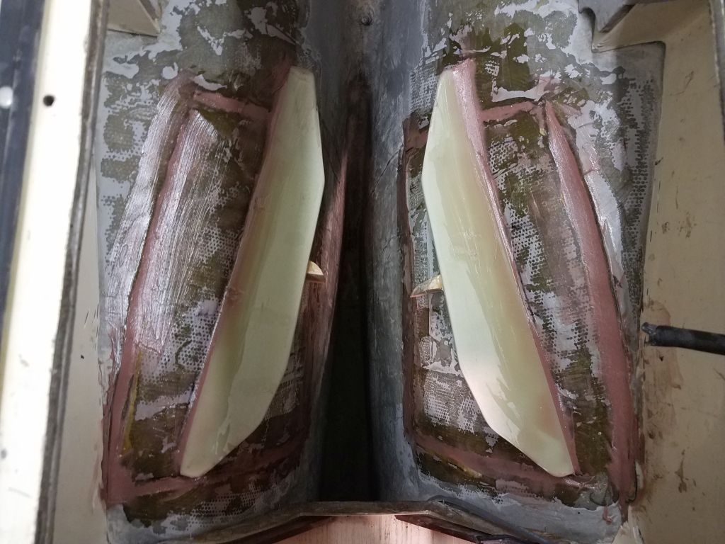
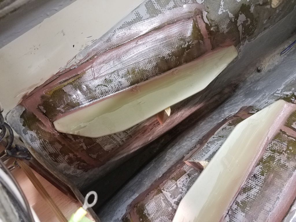
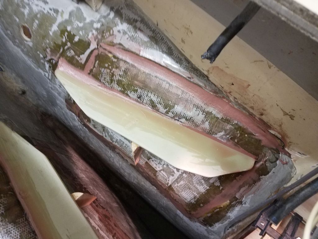
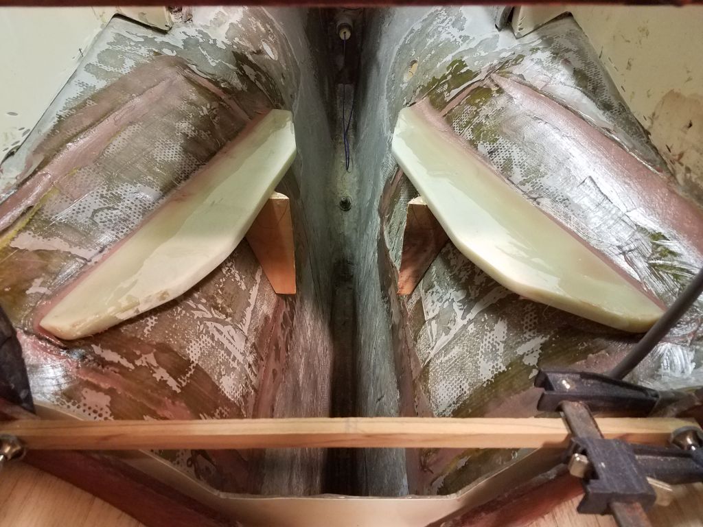
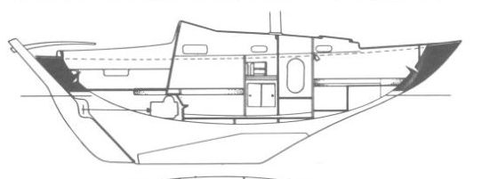
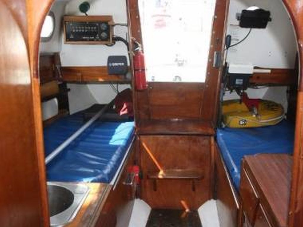
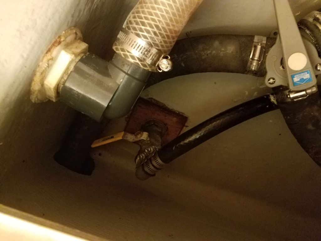
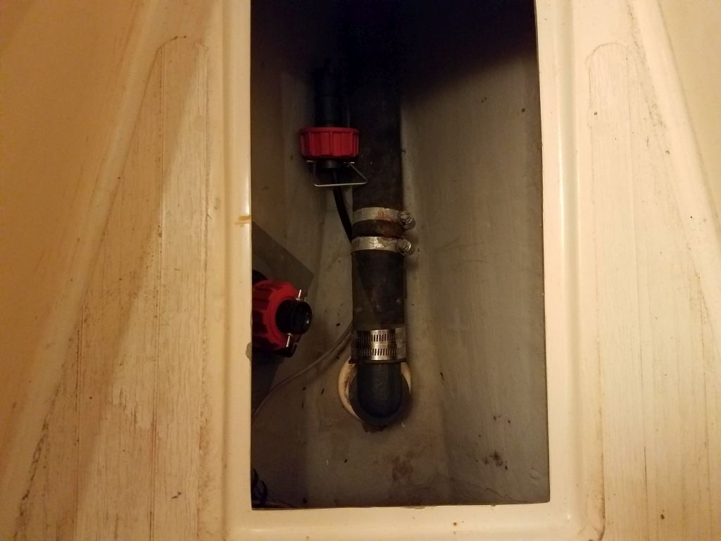
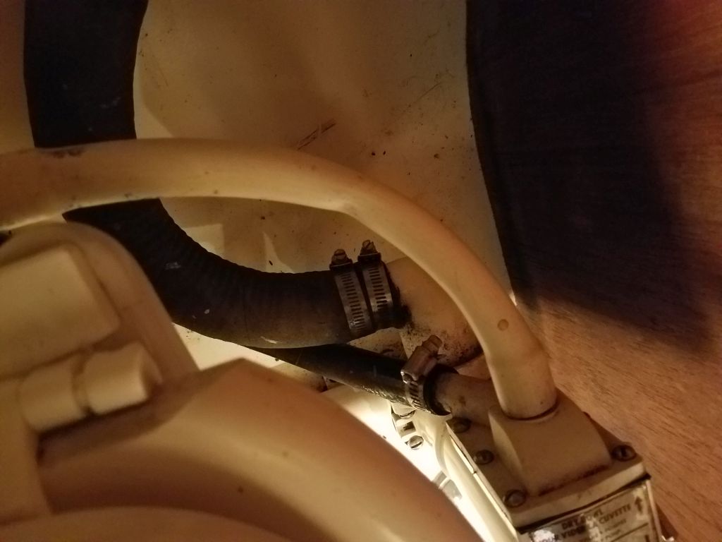
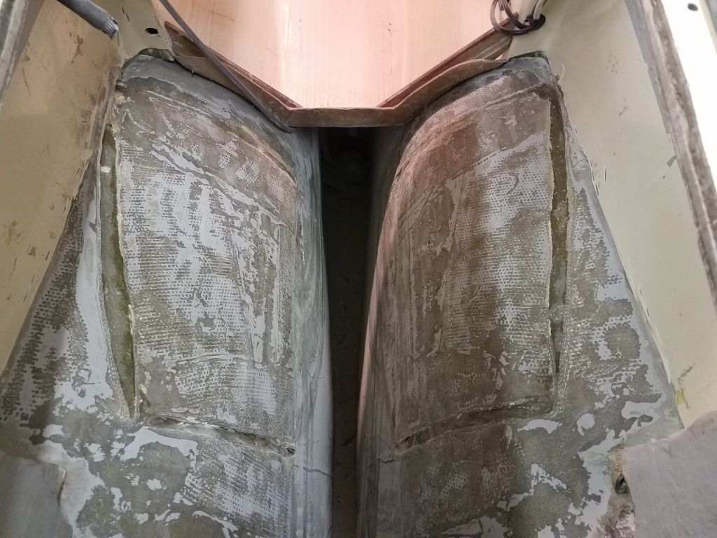
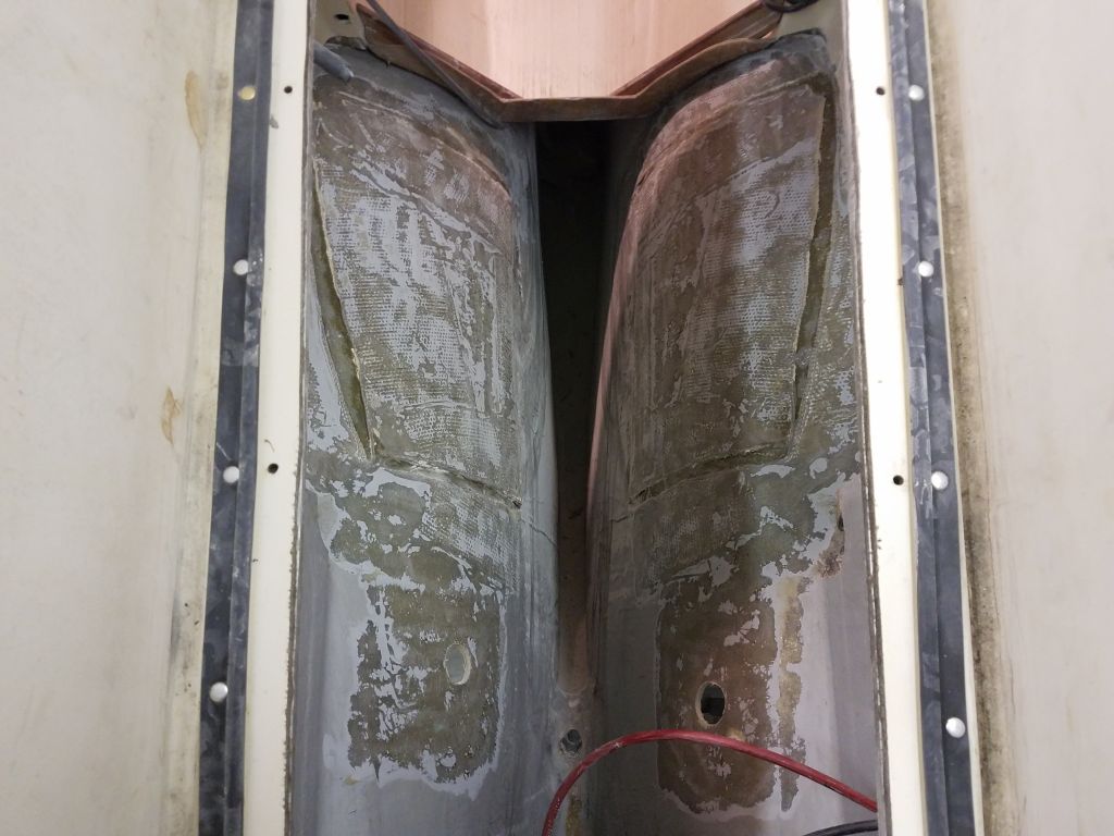
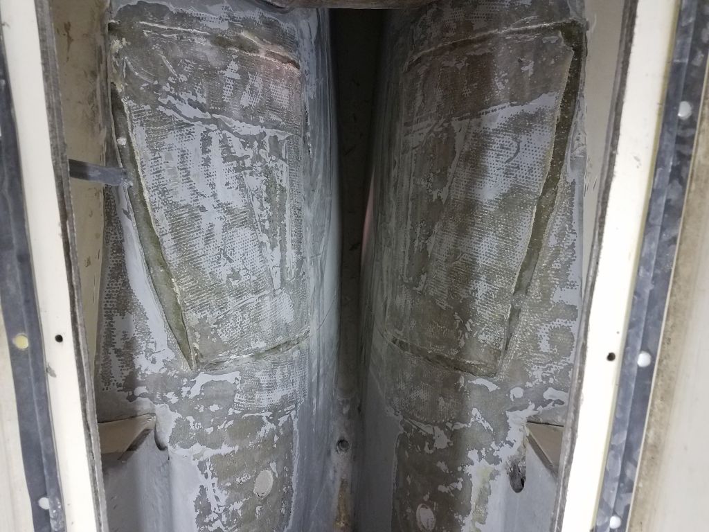
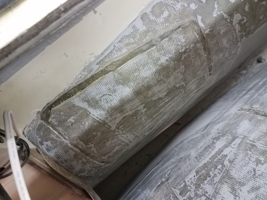
This series of images shows how the engine room is arranged in an English Contessa 26.  In the Canadian version, the entire engine is well aft of the companionway bulkhead, and this key difference is why the molded pan ended up not being a feasible installation in this boat.

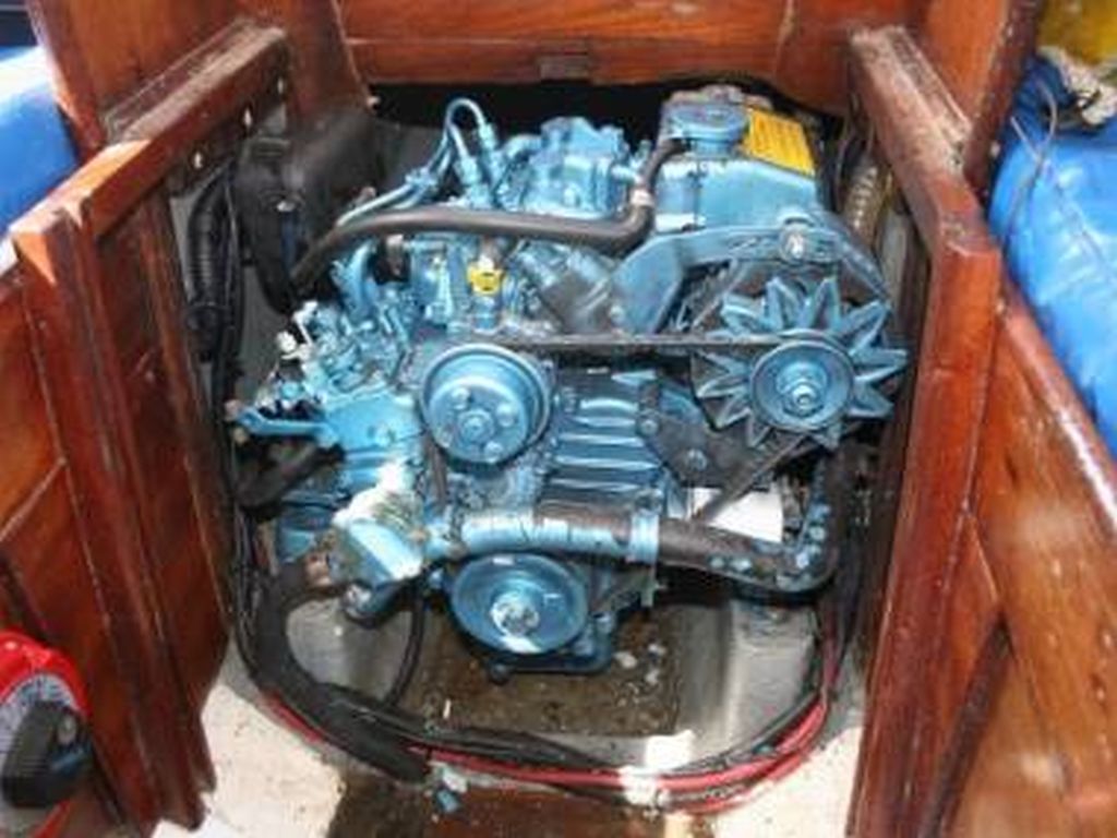
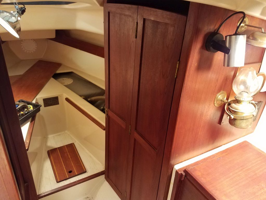
This photo, which the owner sent me some time back, shows the actual engine pan in an English Contessa, complete with Beta 14 atop.  A nice fit…but this also clearly shows how far forward the engine is by comparison.

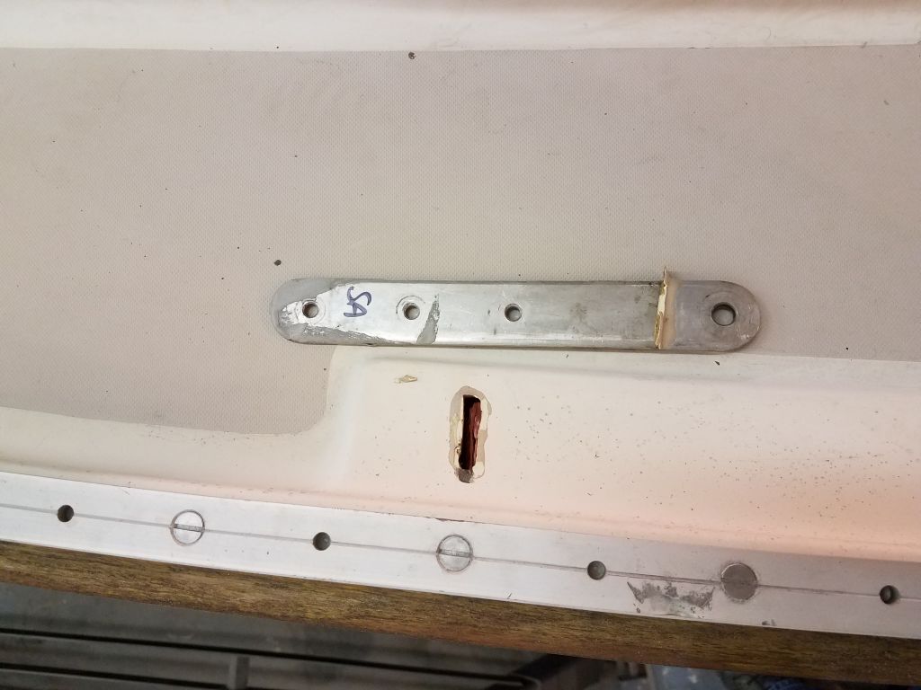
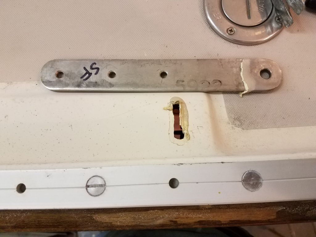
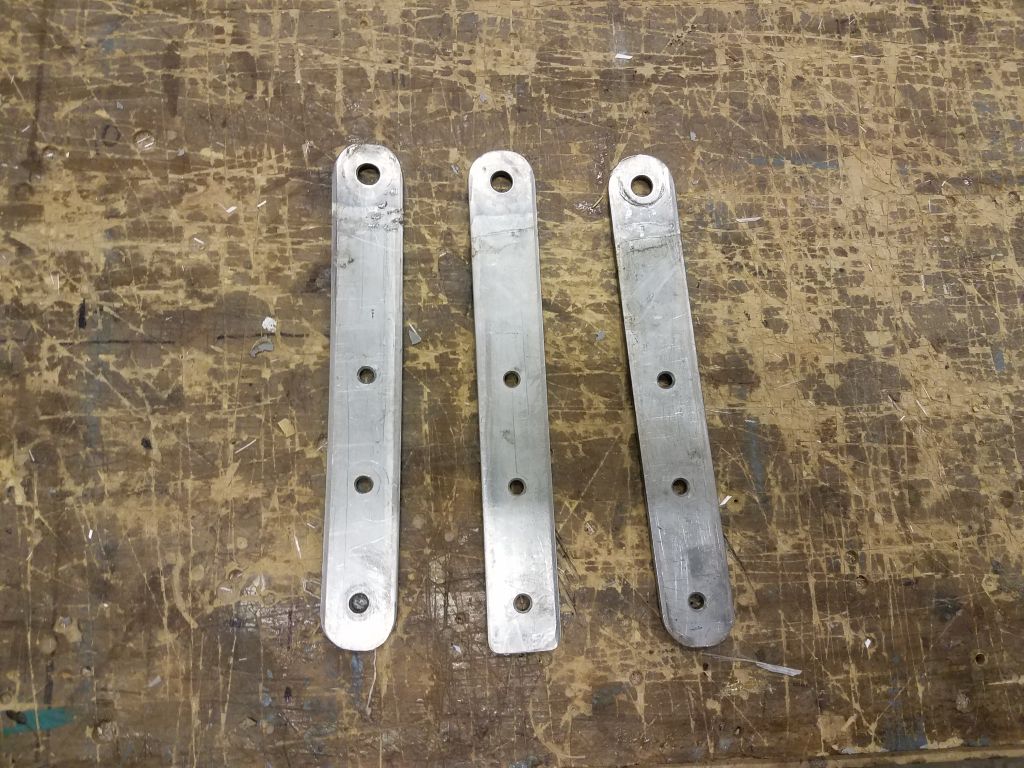
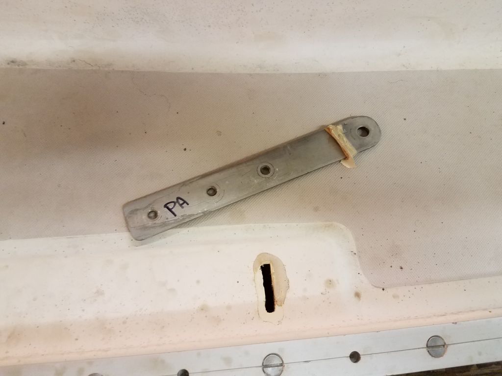
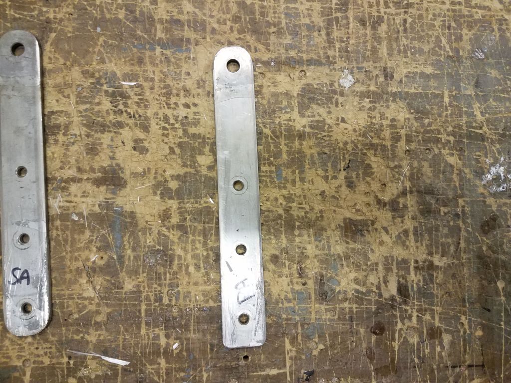
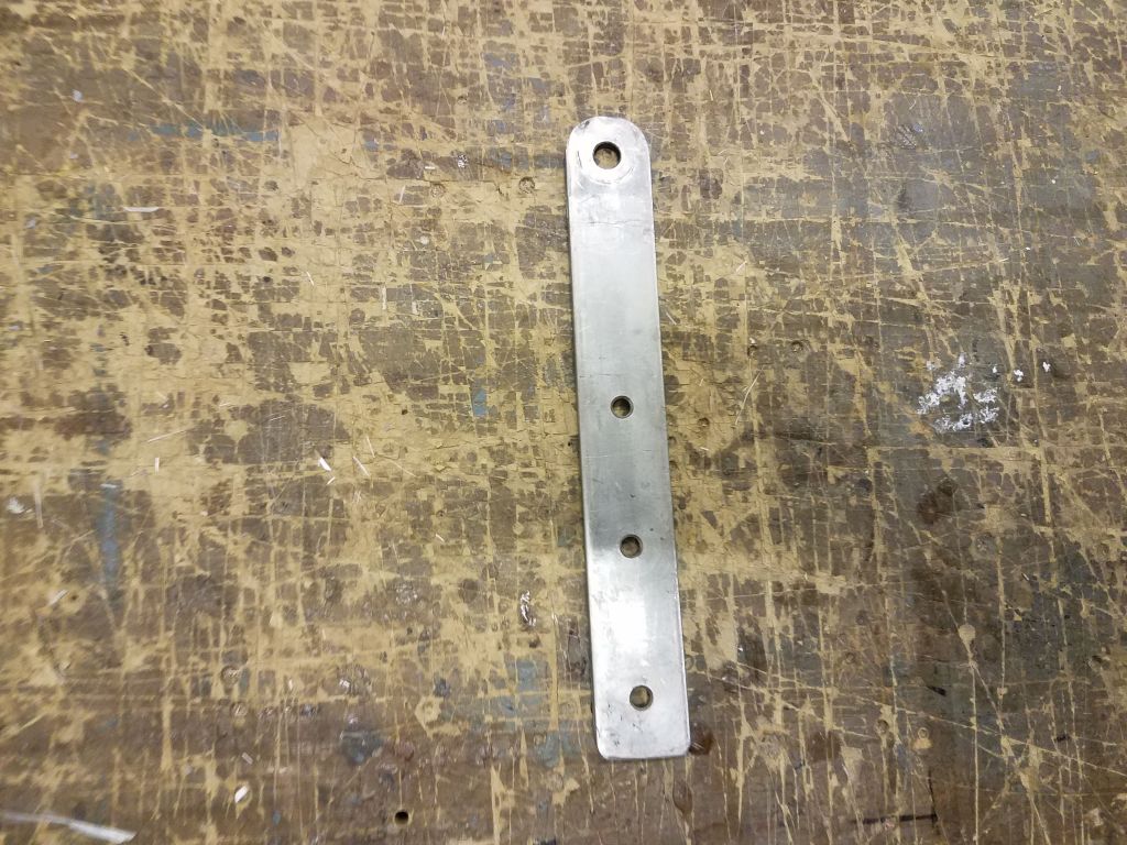
In arriving at these various conclusions, I also spent some time reviewing two other Canadian Contessa 26s that I repowered with Beta Marine engines, one, Equinox, in 2007, and the other, Salty,  in 2016.  Even these two ostensibly identical boats had key differences in their engine placements, and even with intensive review I still couldn’t put my finger on exactly what was different, other than Salty’s engine beds and engine were quite a bit higher for some reason; since the shafts both seemed to exit the deadwood in the same place in the aperture, the only thing that could be different and lead to a couple-inch difference in engine height might be the angle of the stern tube itself.  In any event, these differences led to individual challenges in each case, and frankly this was all neither here nor there other than to help solidify my next notions.

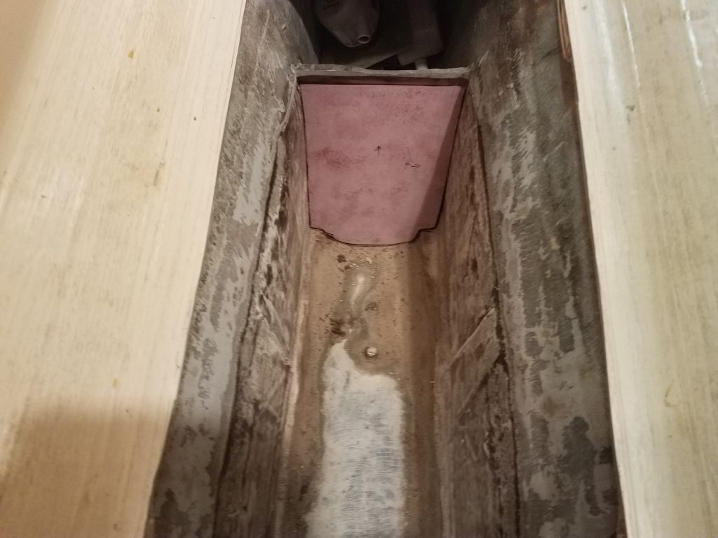
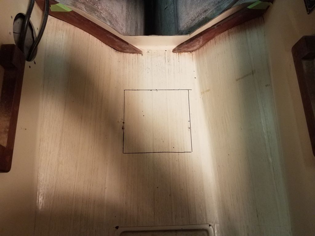
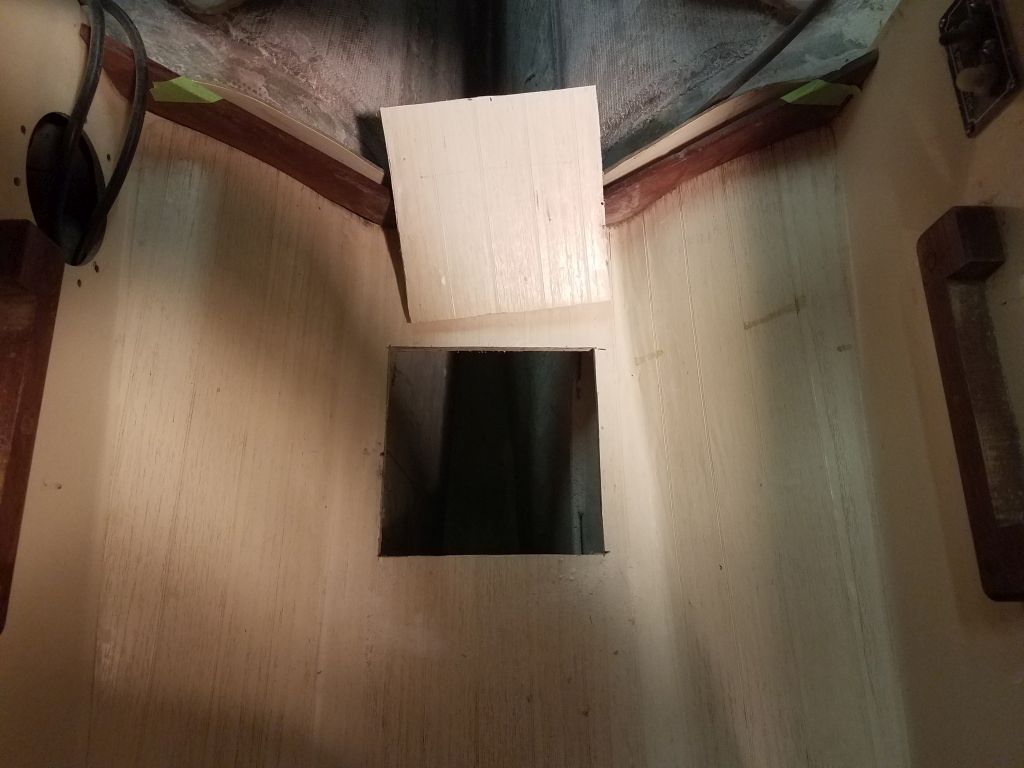
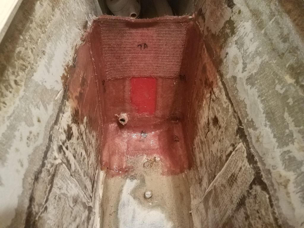
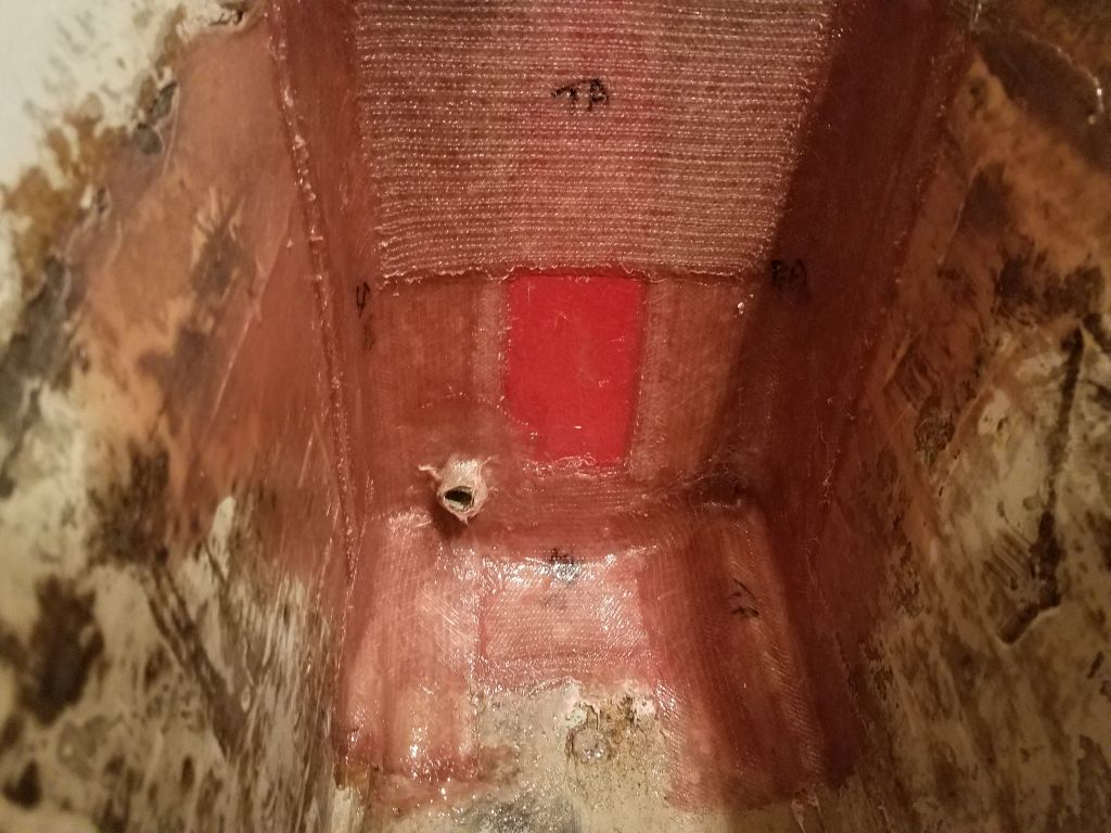
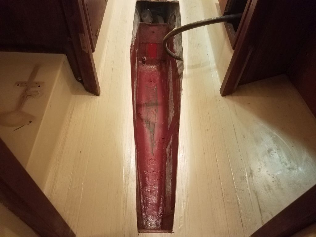
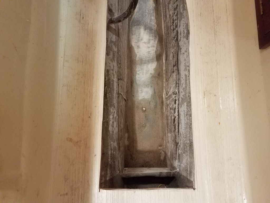
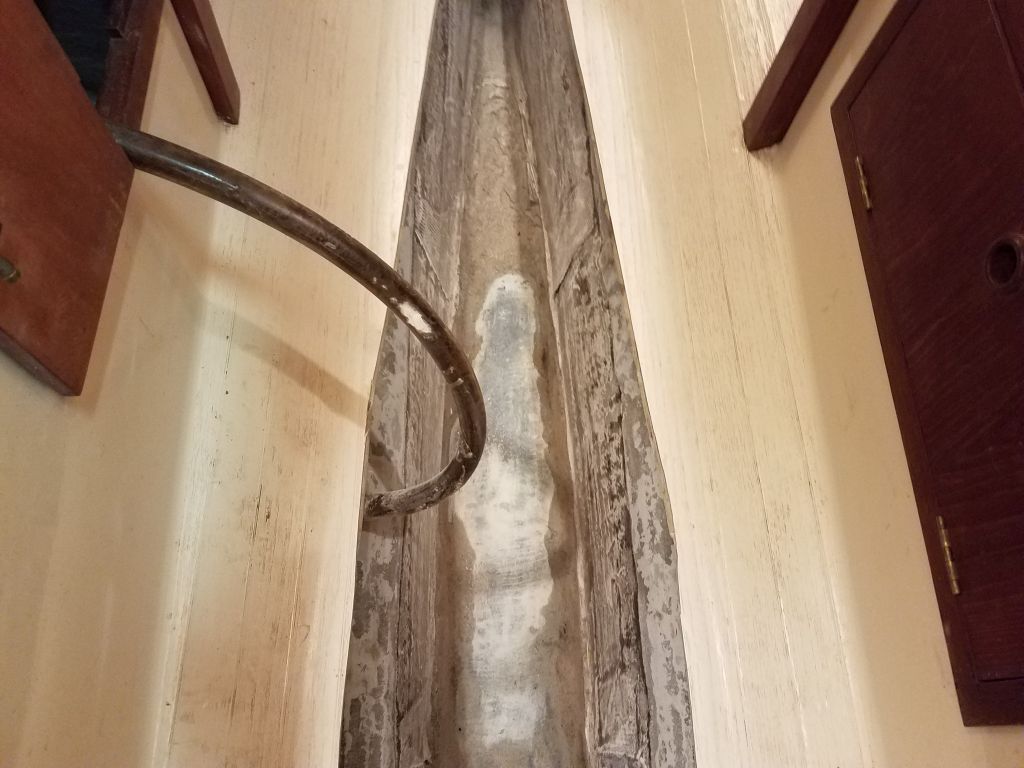
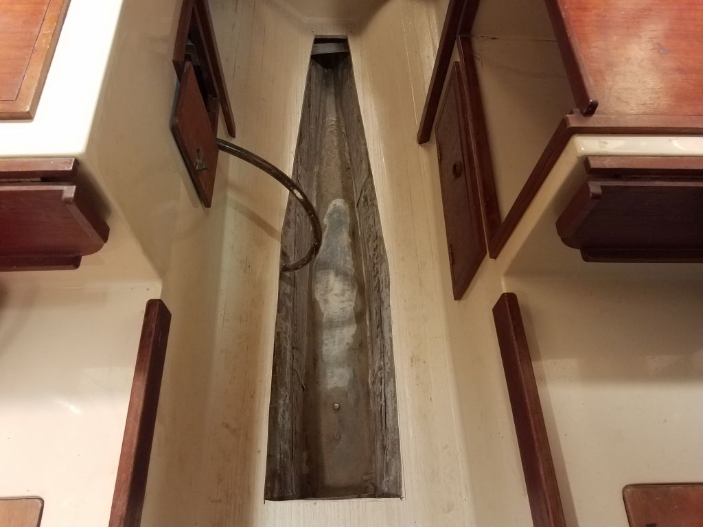
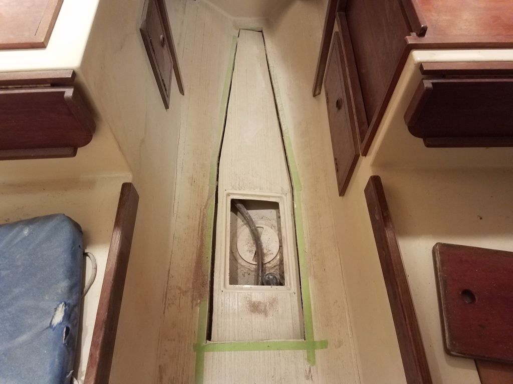
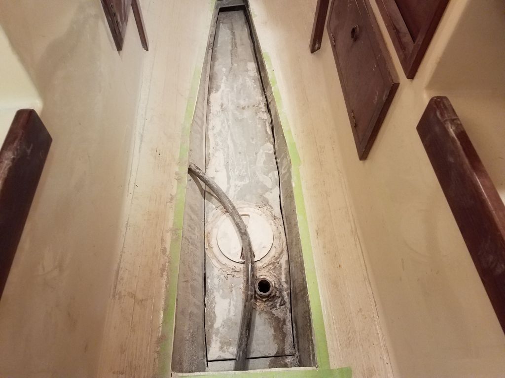
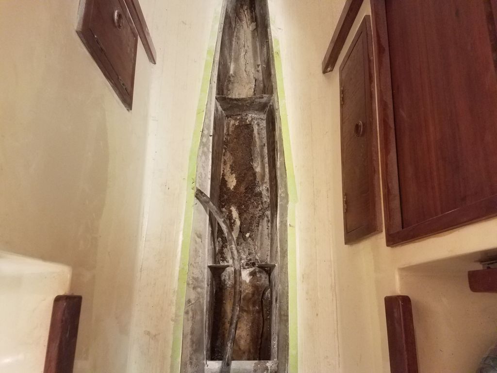
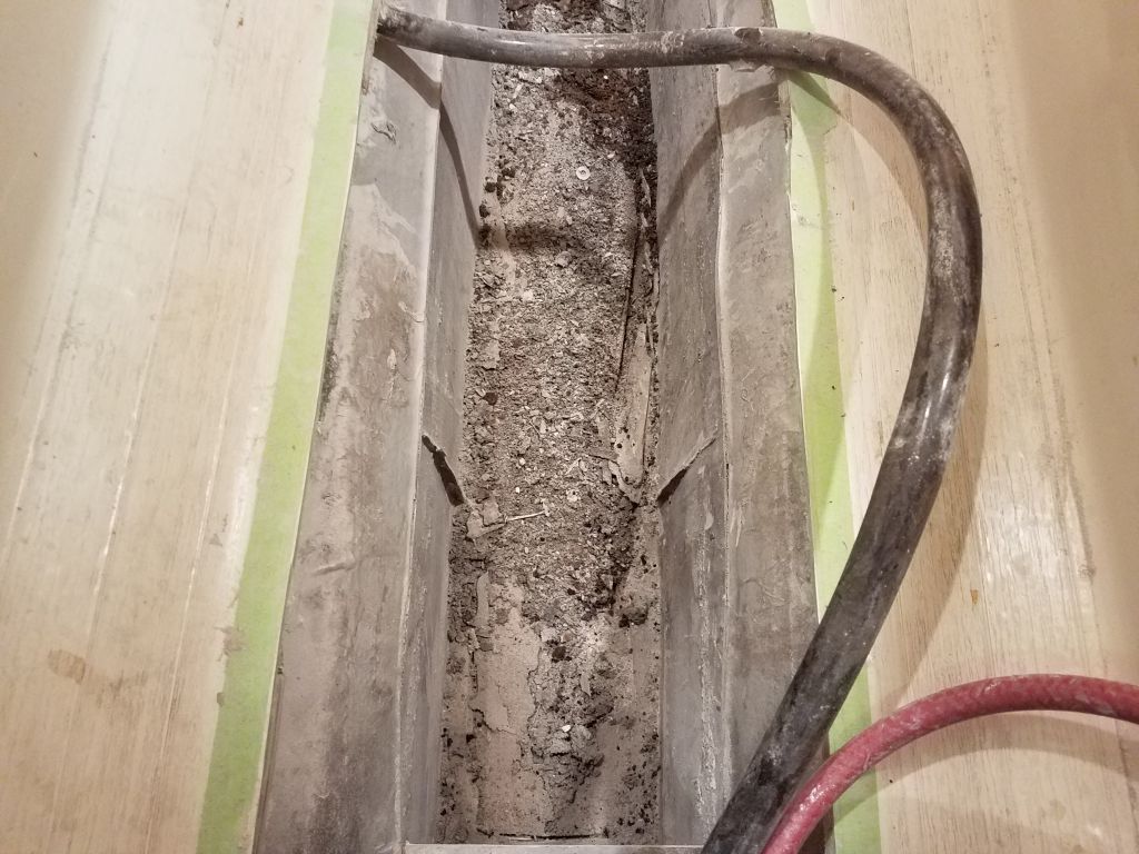
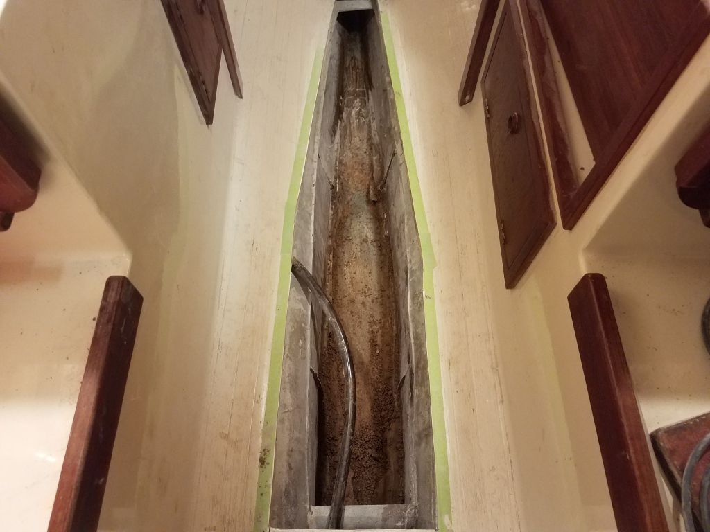
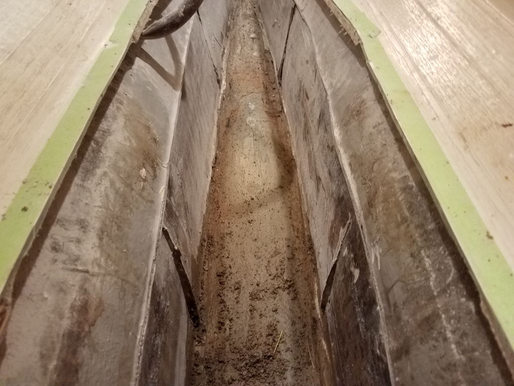
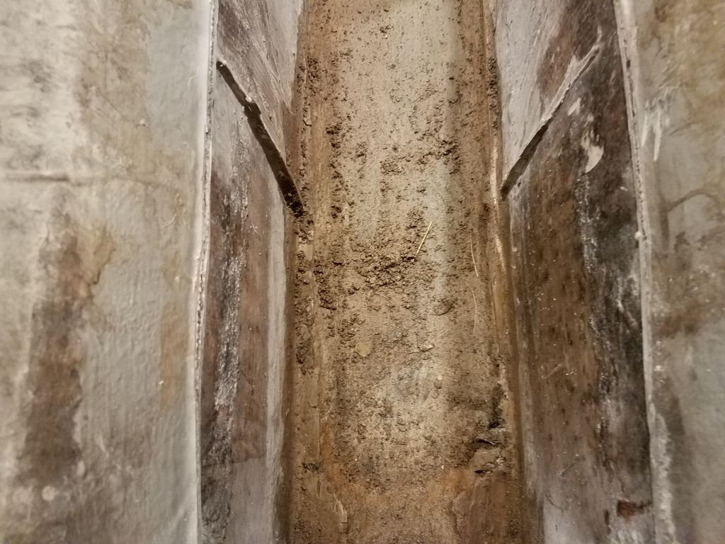
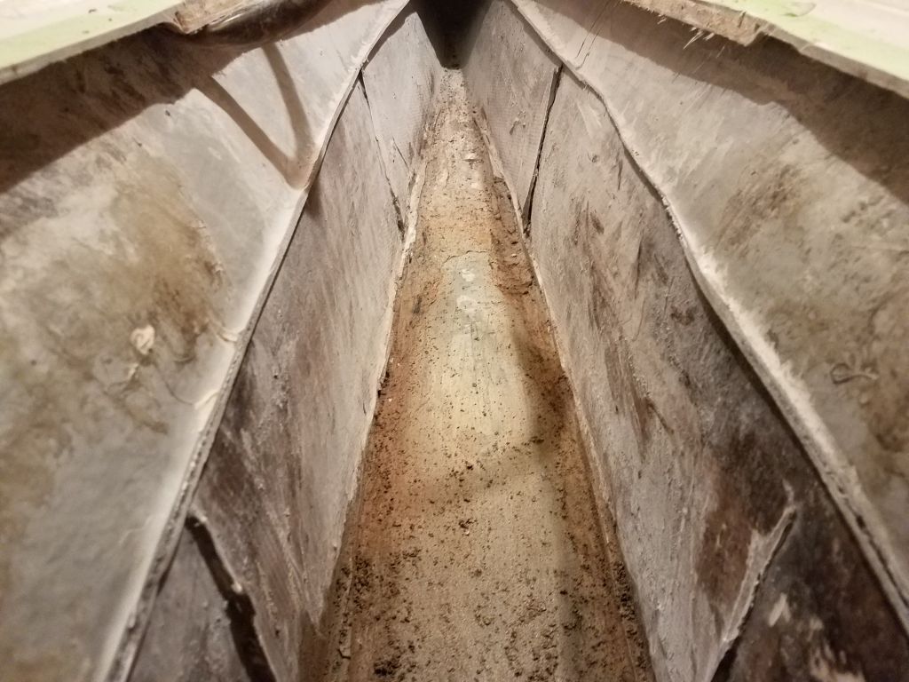
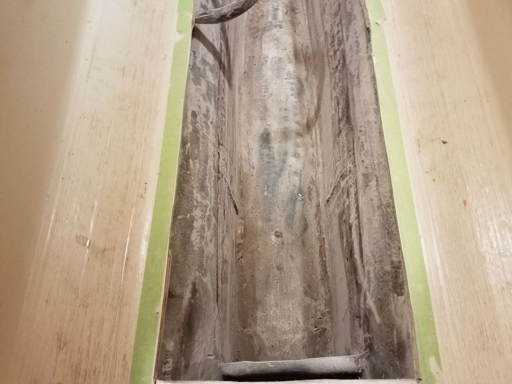
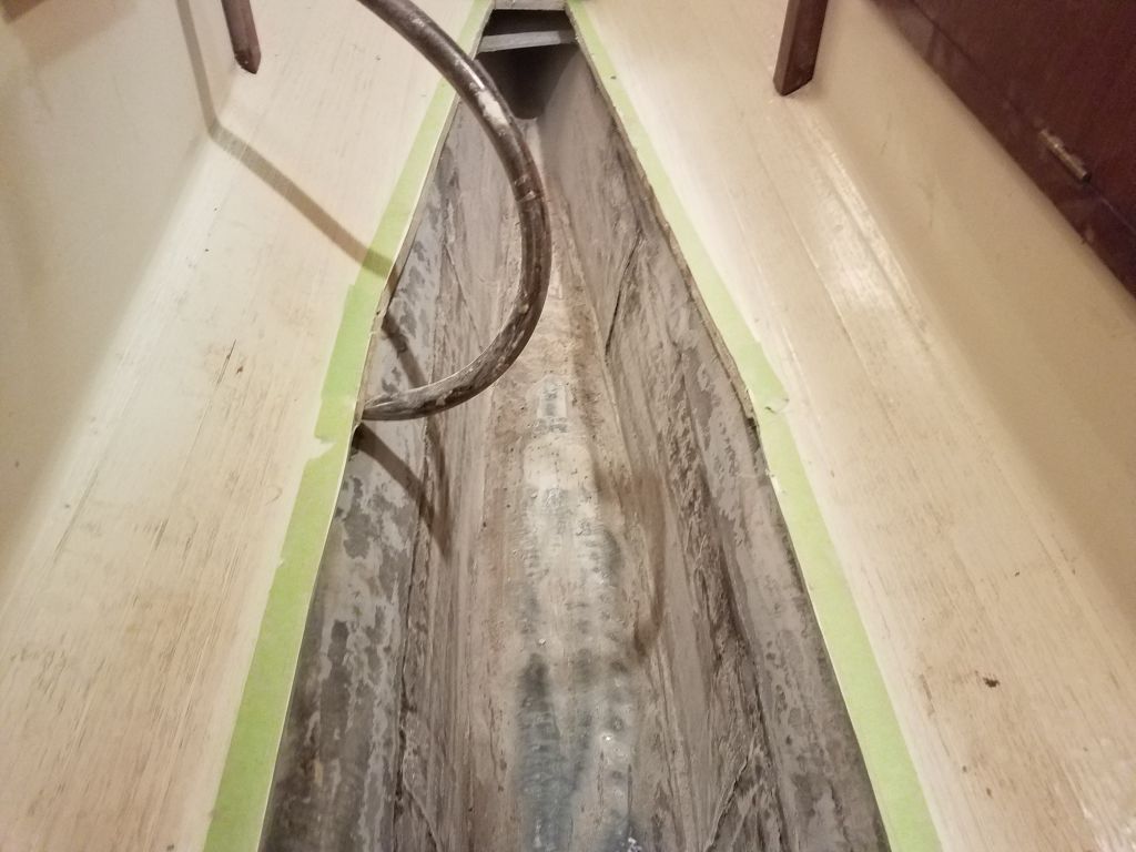
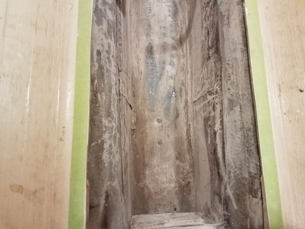
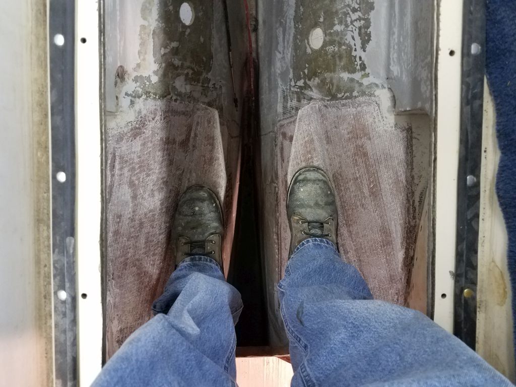
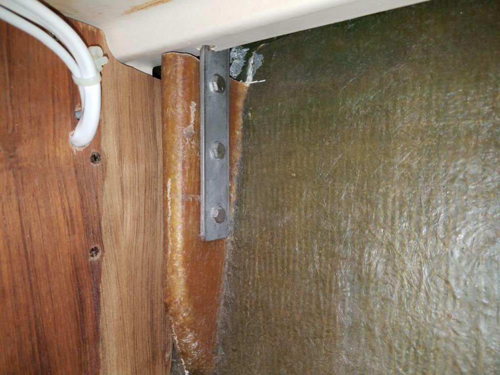
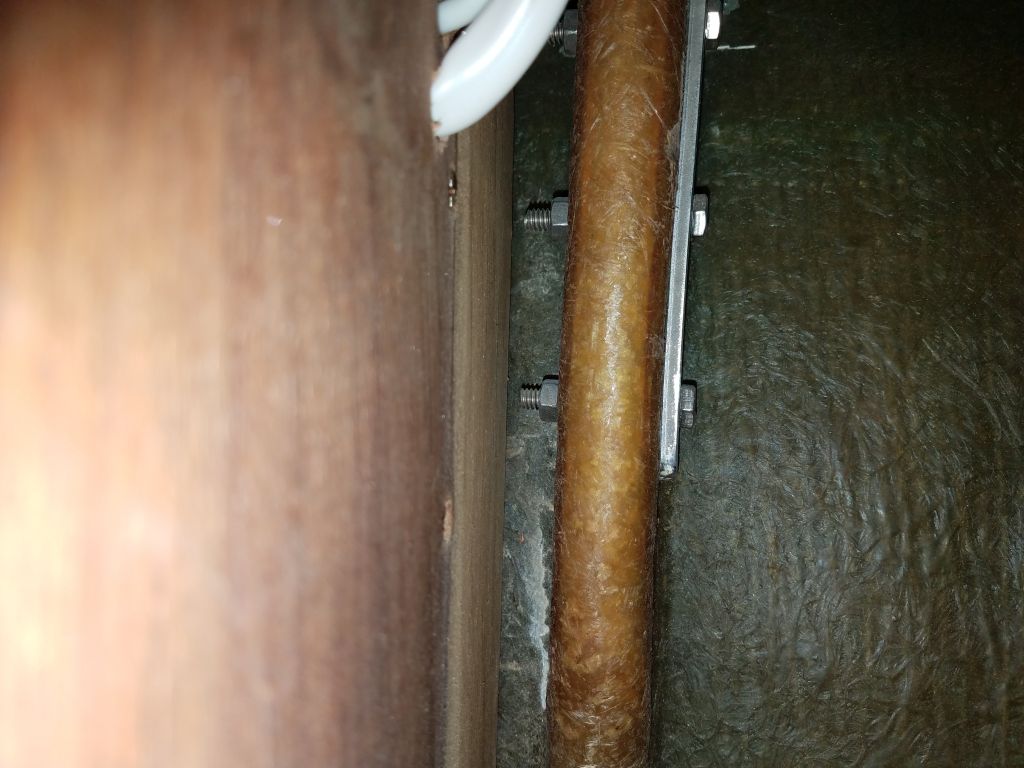
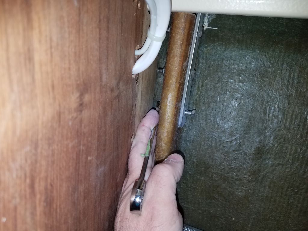
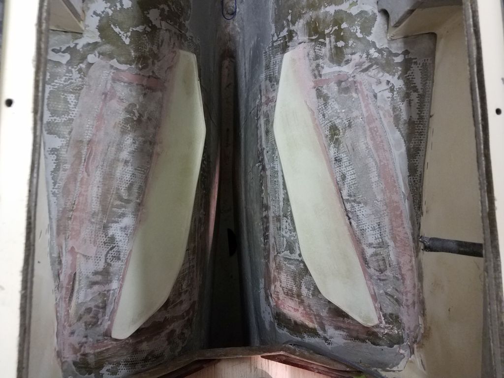
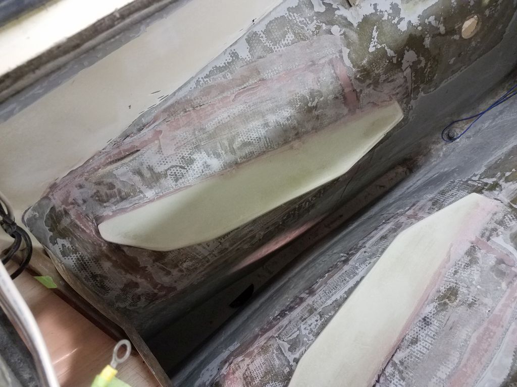
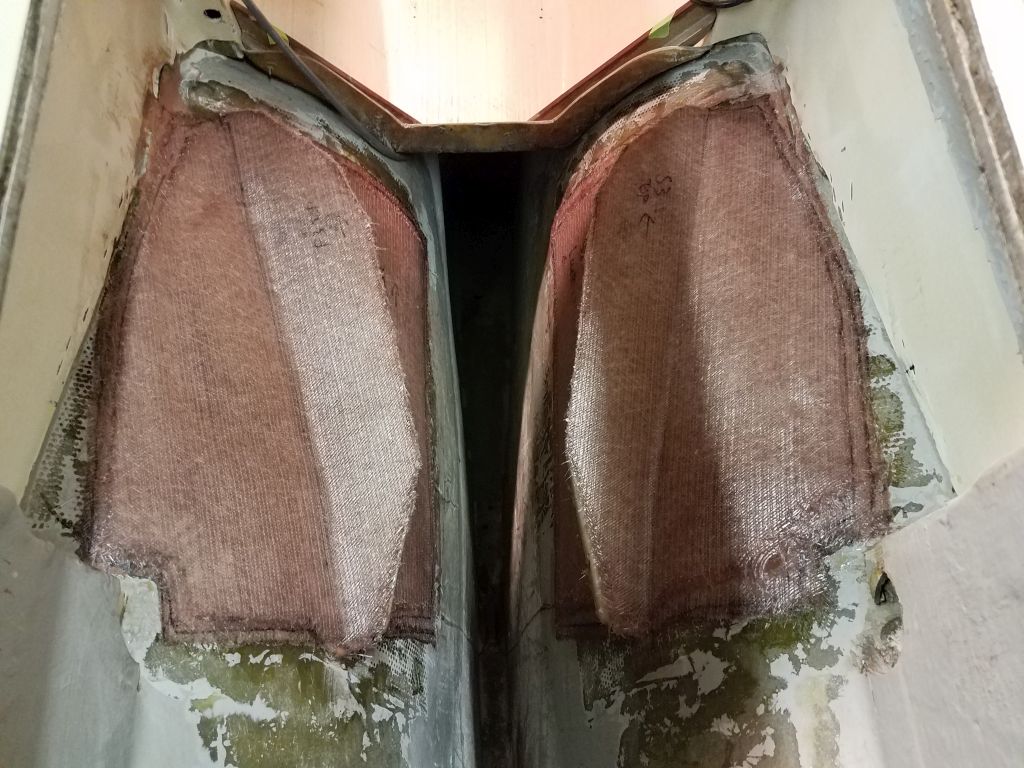
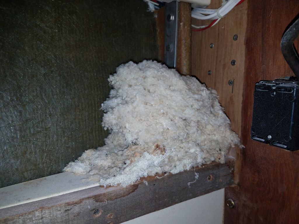
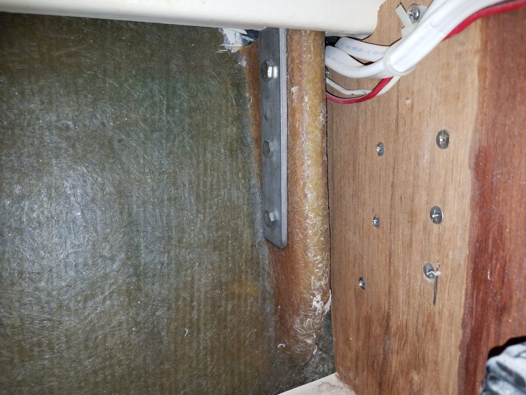
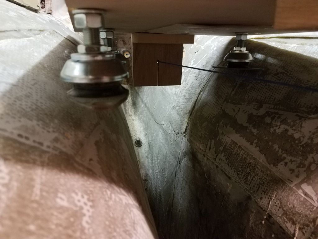
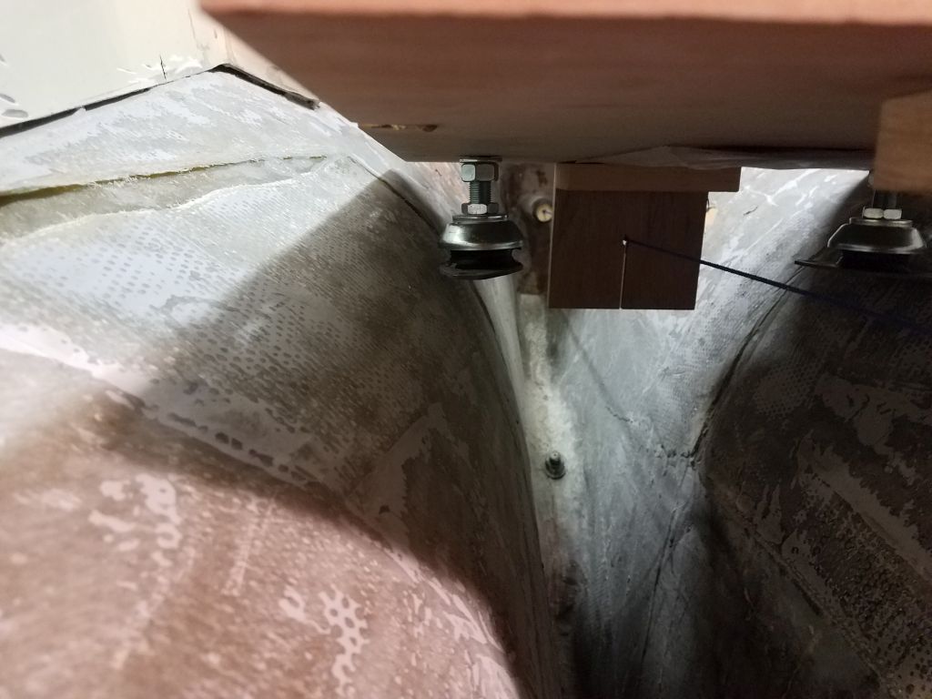
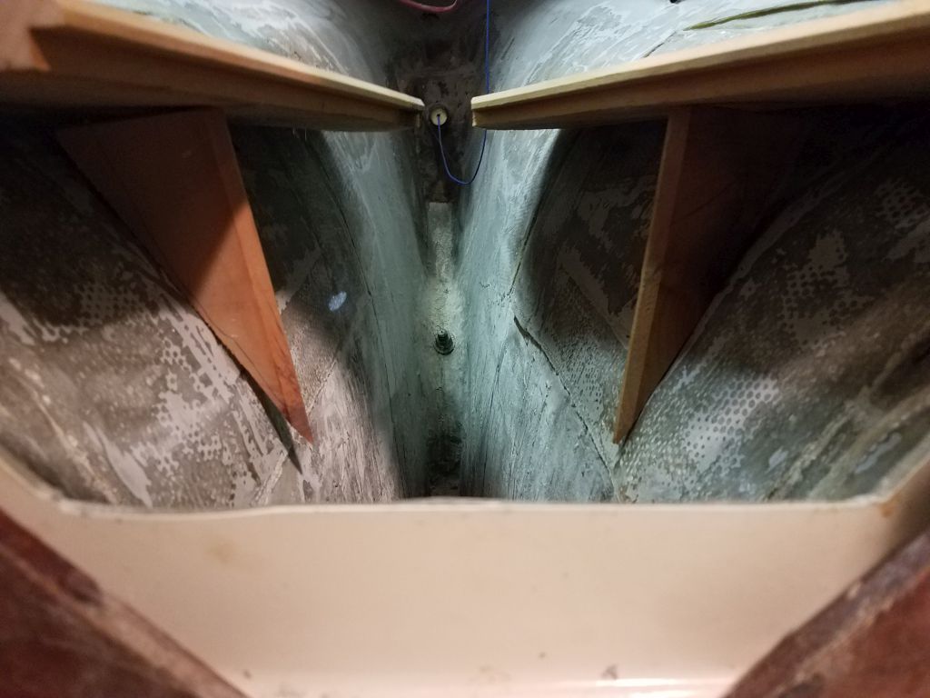
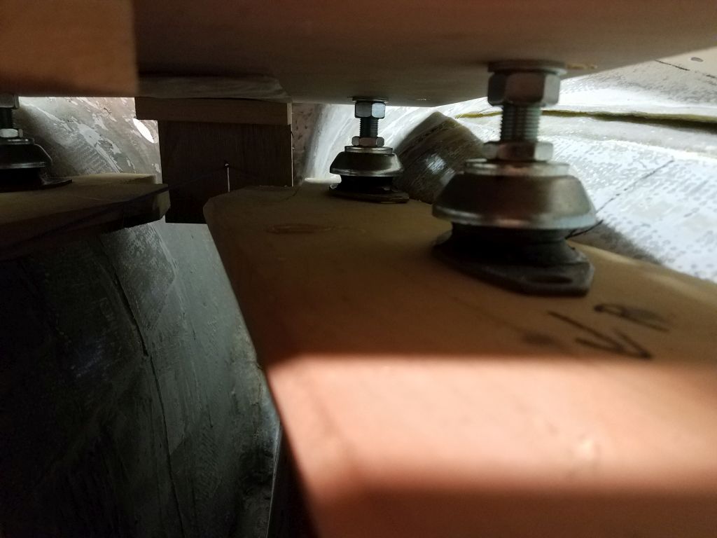
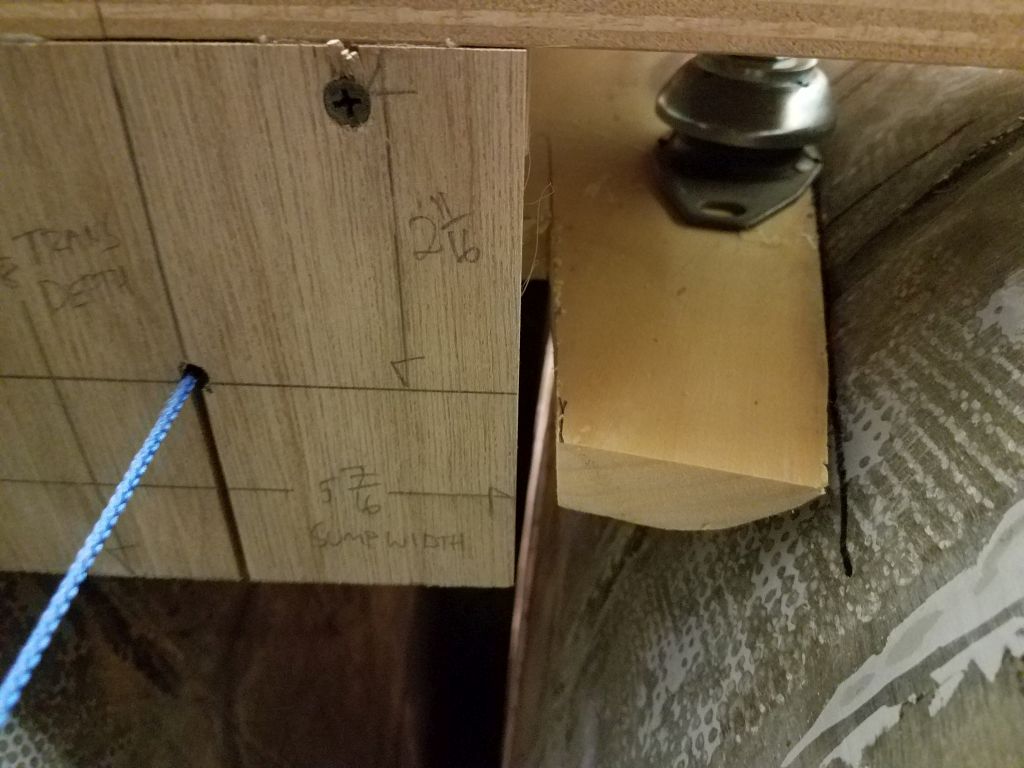
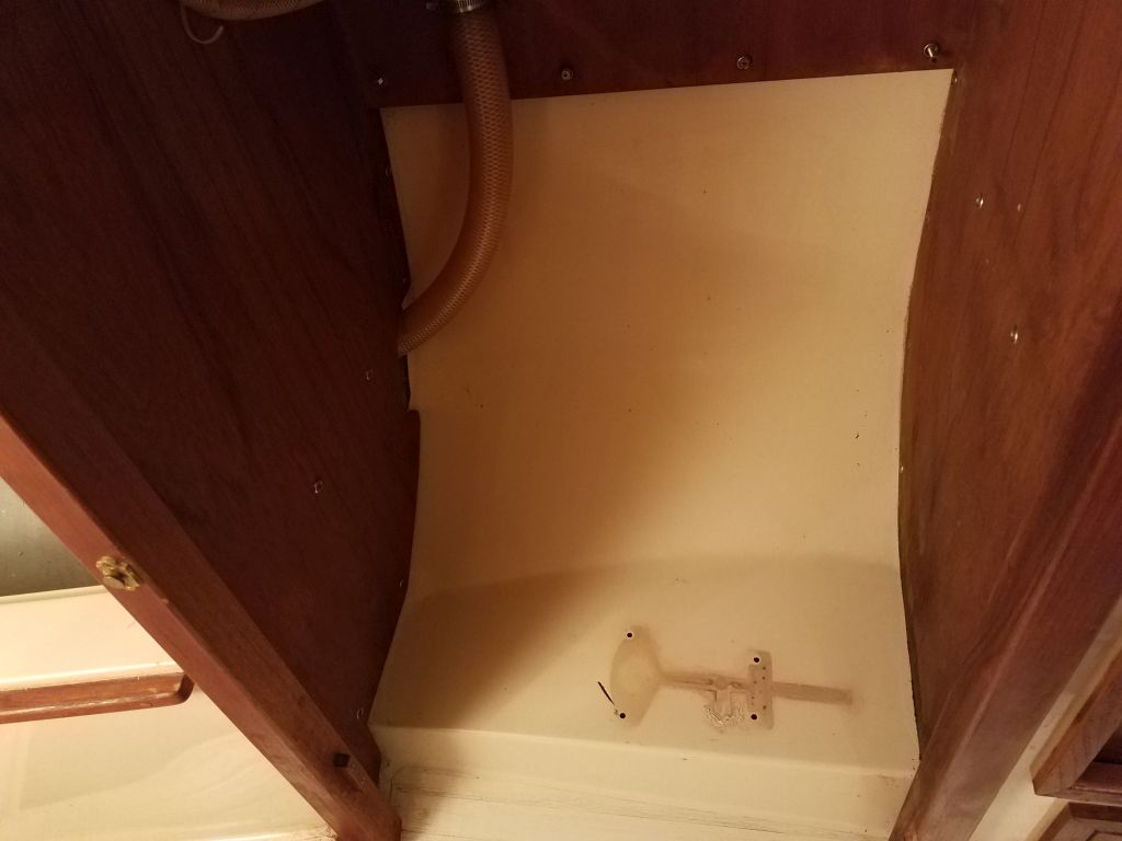
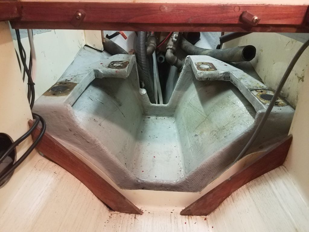
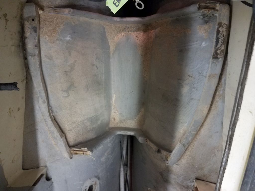
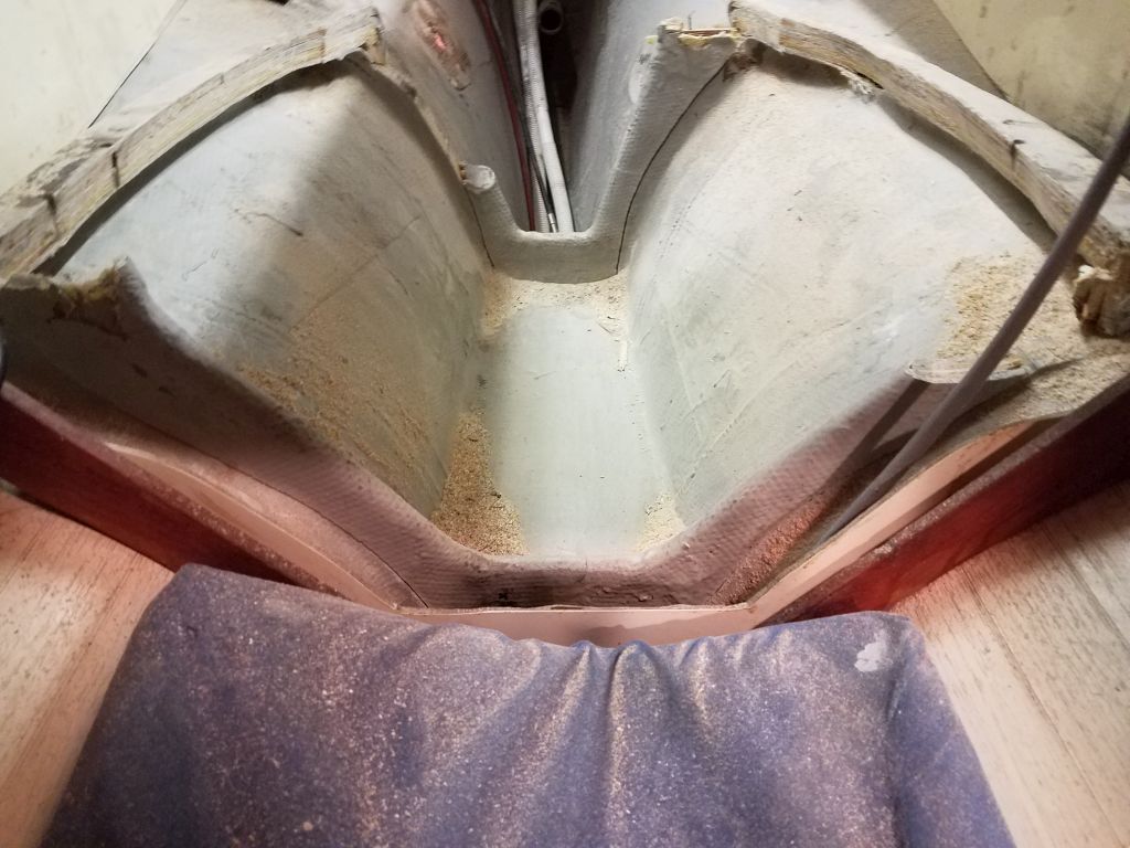
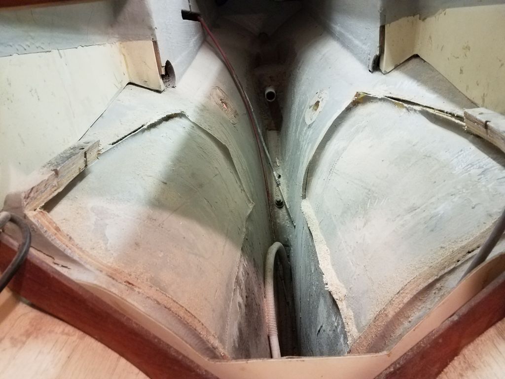
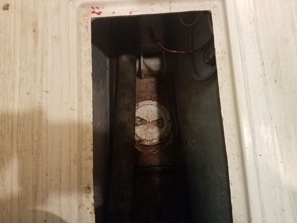
My next notions, as it were, were to check how the engine fit in the bare compartment, to identify or confirm my thoughts on how the after set of mounts would work in the space.  So I removed the fiberglass pan, and set up the template in the engine room, holding it as necessary for the moment with some rough strings.  My immediate goal was to determine how the after mounts would fit, or not fit, as the case would be, at their current 14-1/2″ width.  I suspected based on the general appearance of things that they’d be too wide, and indeed the flex mounts contacted the hull much too high up, and didn’t allow the template to move down to where it needed to be with the shaft alignment string.

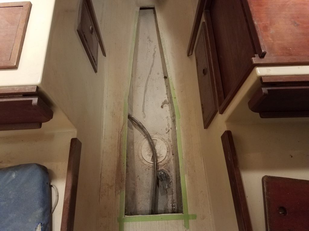
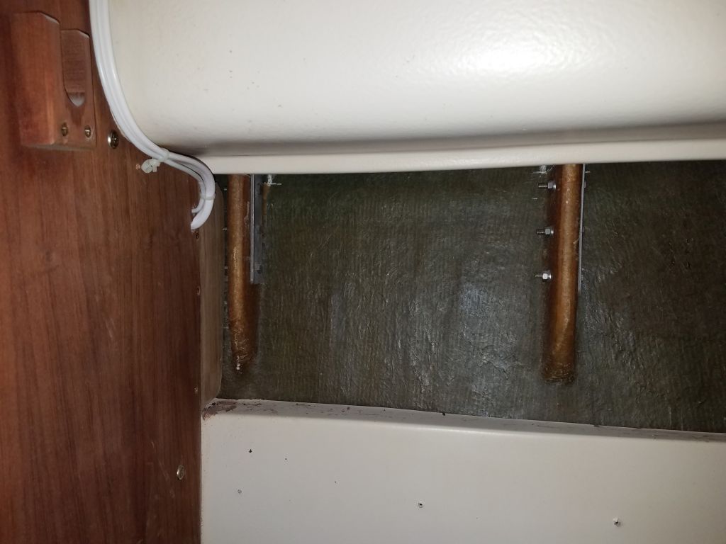
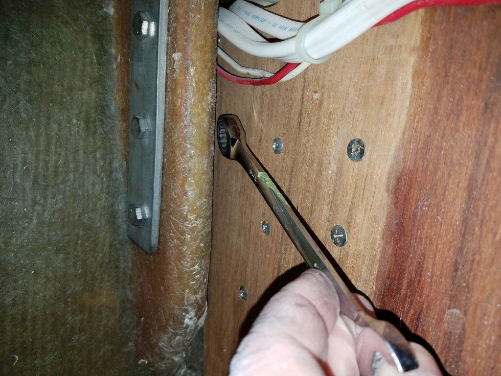
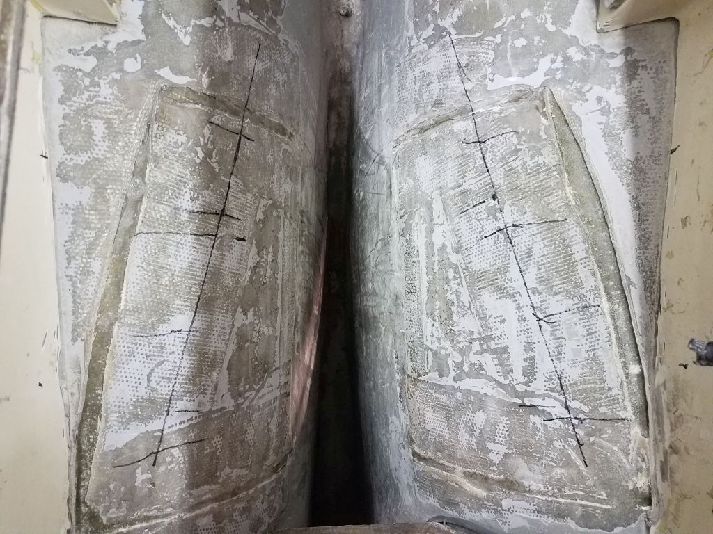
To deal with this (actually completely expected) issue, I removed the template and after set of flex mounts, then laid out, marked, and drilled new holes for the after mounts at 11-1/2″ centers, or the so-called Atomic 4 mount.  Since the steel engine mounts were bolted on, and could be swapped at will, I planned to order a set of the narrow mounts for the aft end, which would reduce the width in the engine room to a workable point.

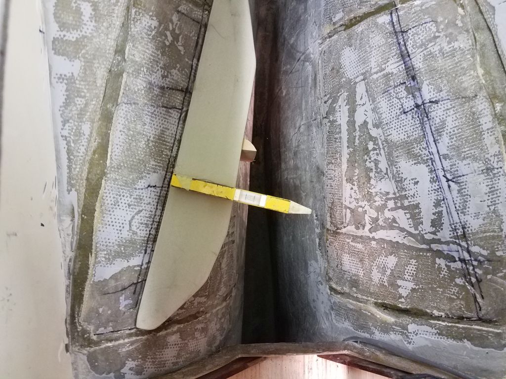
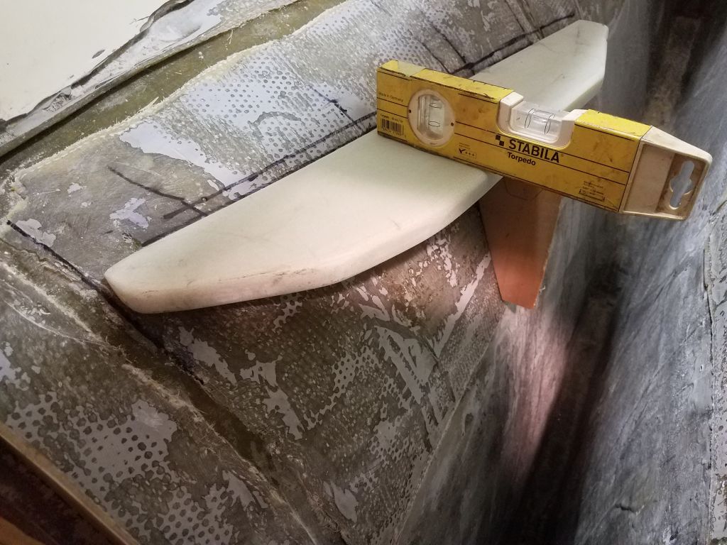
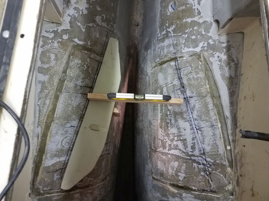
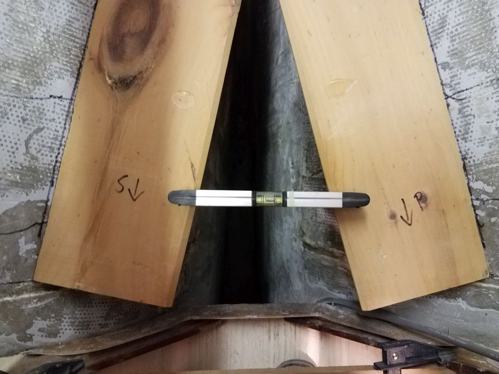
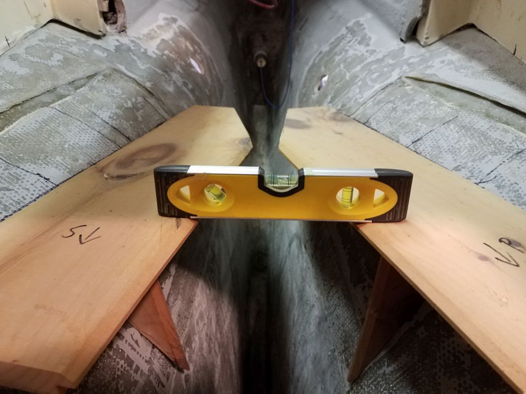
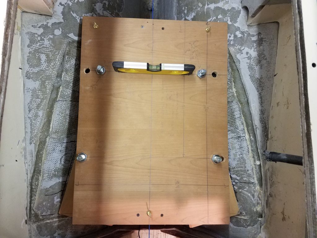
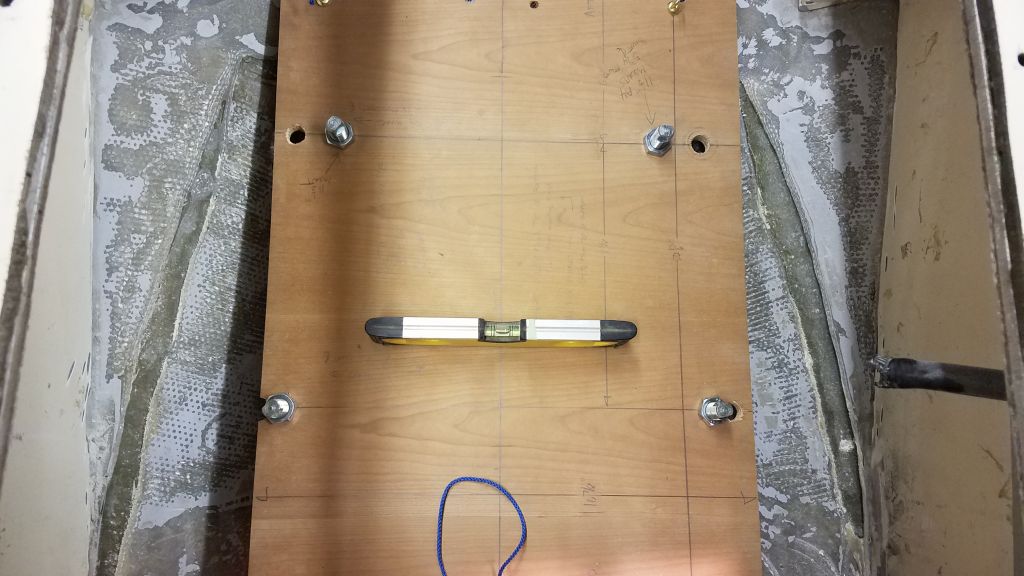
Before continuing, I double-checked the boat’s level from side to side, since now I was starting to approach more critical measurements and alignment procedures.  Even though I’d adjusted the boat earlier, I wanted to be sure none of the machinations of engine removal and other work had shaken things out of alignment, but things still looked good, so I could proceed.

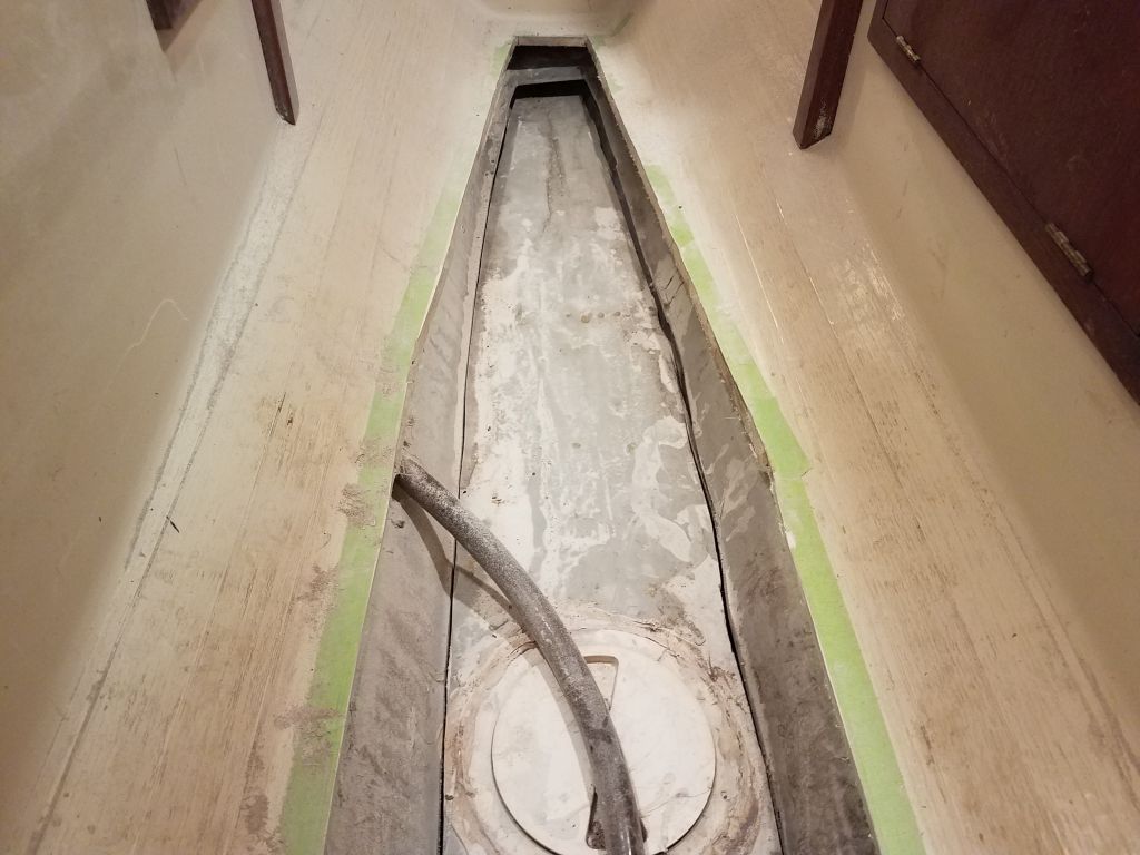
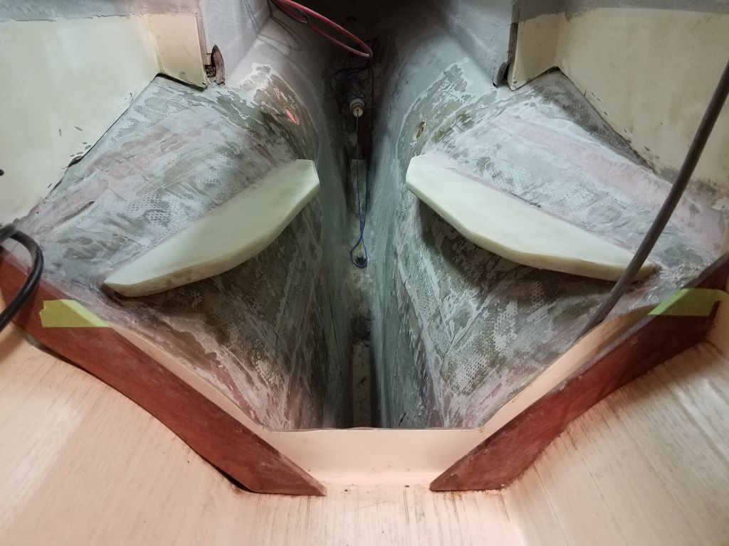
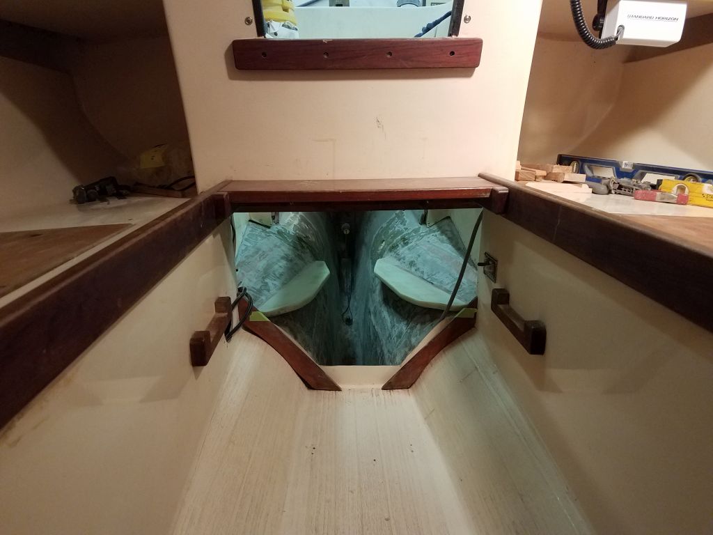
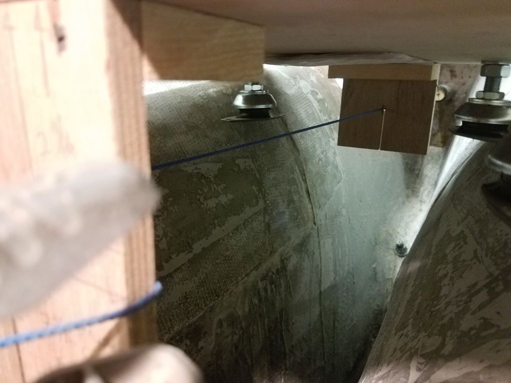
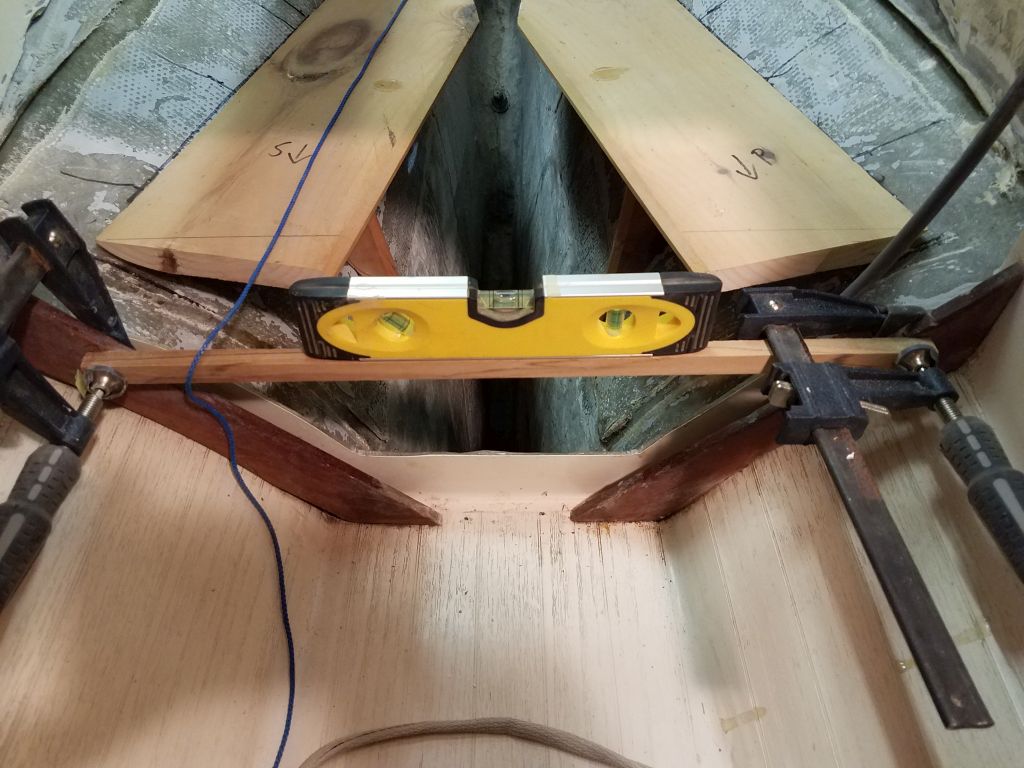
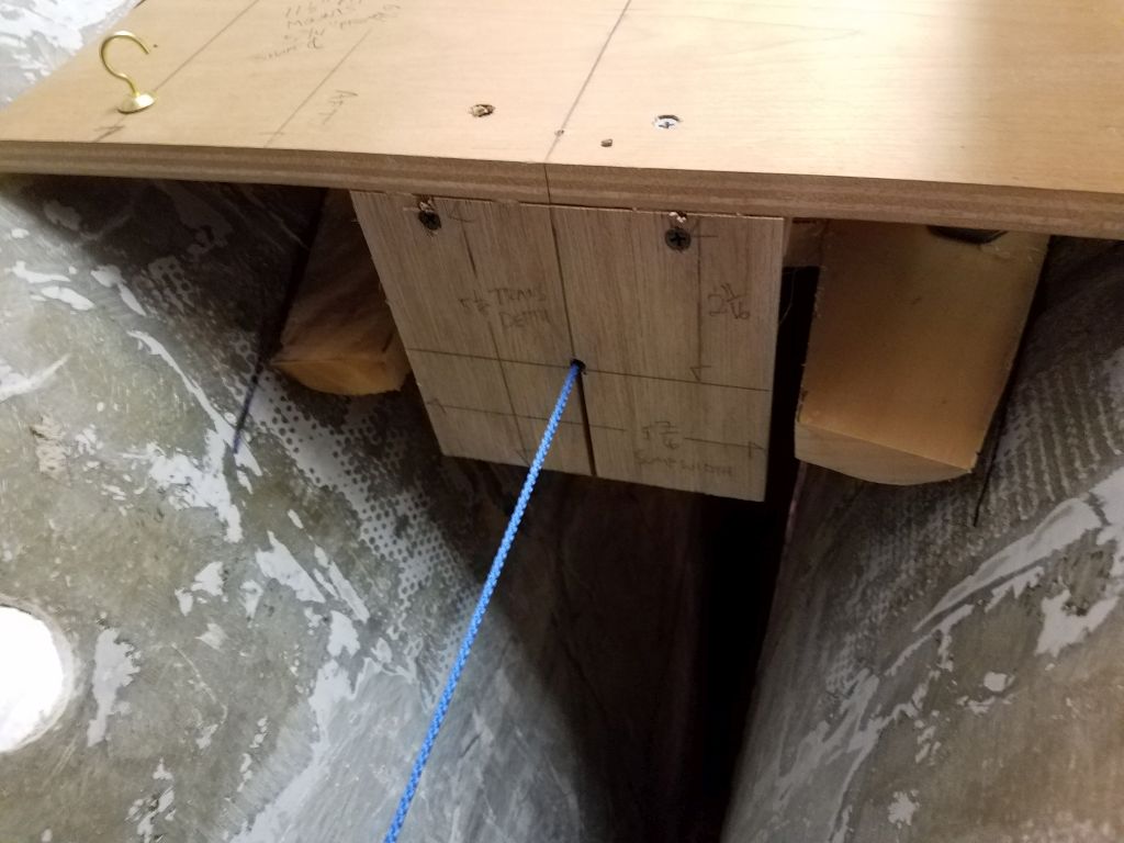
Once more I hung the engine template in the engine room with strings from above–a not-so-ideal means, but good enough for now, and simple and quick.  With a few height adjustments, I eventually got the engine string through the two centers fore and aft as needed, and within a reasonable tolerance for the purpose at the moment.  Even with the narrow aft mounting centers, there was just barely enough room there for the dangling flex mounts, given the indelible contours of the hull shape.  I had room to move the engine a bit fore and aft as needed, and the way the support strings were it tended to pull the template aft a bit, so I felt like I had a workable (just) solution at hand.  This is a small boat with a sensual, but confining, shape.

At this point I completely abandoned any pretense at considering the use of the prefab engine foundation, since if nothing else this exercise had shown that full-width mounting centers simply couldn’t work with this engine position, and perhaps this kept open the door for the owner to resell the molding to someone with an English boat.  When considering modifying the template in the early stages, my concern was doing irreversible damage to the foundation that would render it completely useless to anyone, especially when I had grave doubts of any modifications’ effectiveness to begin with, so I was grateful to move on in a new direction and set aside the prefab–though I certainly would have liked it to work here, as it would have been a nice and convenient means of installing the foundations rather than starting from scratch.

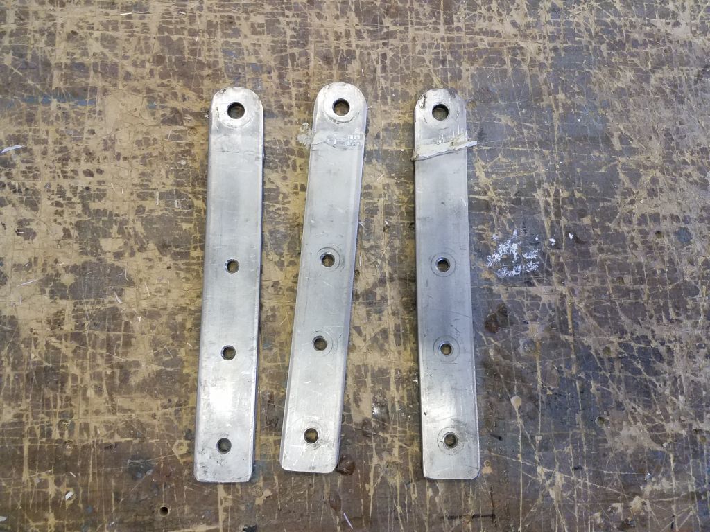
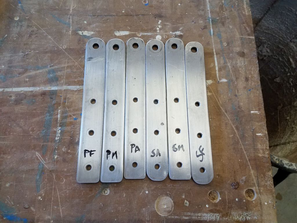
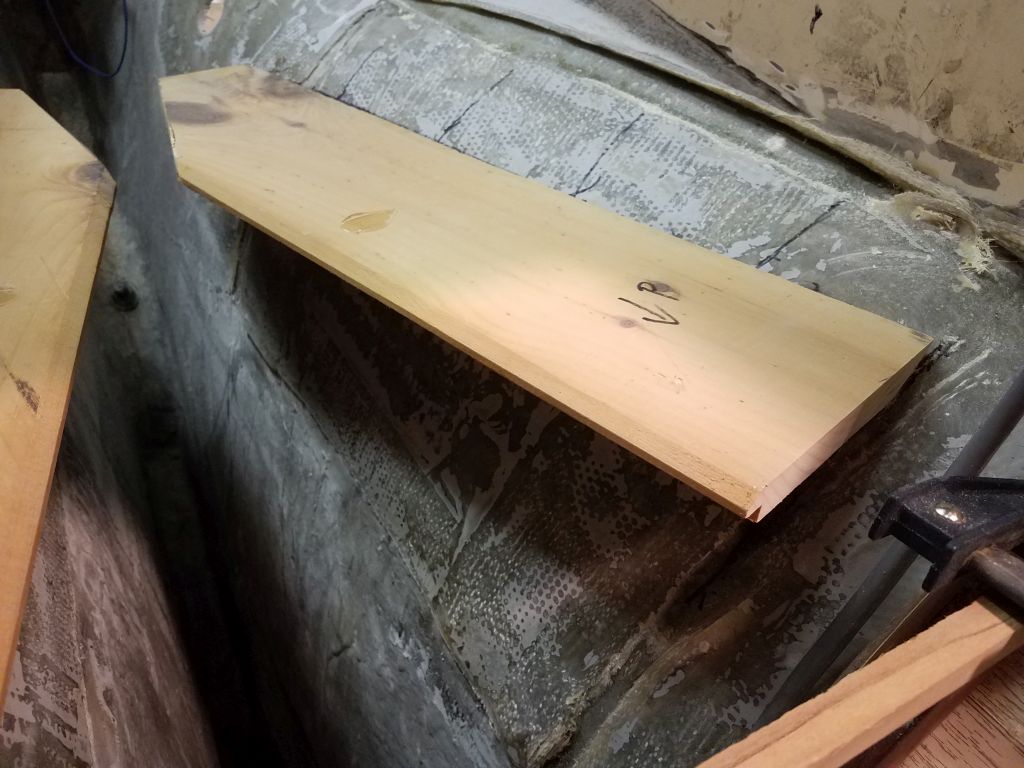
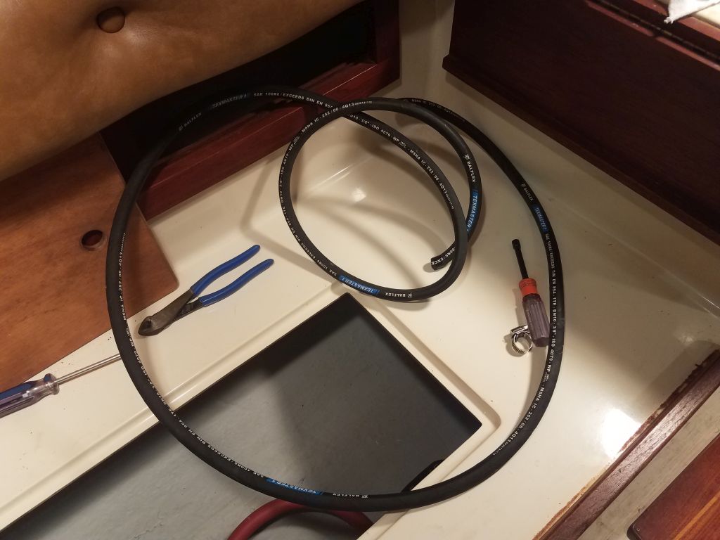
I ordered materials from which I’d build the new foundations, and left things for the day.

Total time billed on this job today:  6.5 hours

0600 Weather Observation:  36°, cloudy.  Forecast for the day:  Mainly cloudy, windy, snow showers, around 40°

Dharma Rose 4

Wednesday

Still in removal mode, I turned to the head system.  In addition to the soon-to-come job of opening up the old waste tank in the bilge area, the owner also planned to remove all the existing hoses and equipment related to the system, with simpler waste management plans for the future.  We had a brief discussion mid-morning to consider last-minute alternatives for the system, but ultimately stayed true to the original plan.

As in most older boats, the head system was pretzeled with multiple hoses, vents, a Y-valve, and just a complexity of old, cracked hoses.  The hose to the direct overboard discharge through hull had been removed and that fitting plugged at some point in the past.

First, I removed a bifold door that closed off the head compartment, which would help open up the space for the various work ahead throughout the project.  This was straightforward except that one of the brass screws (the last one…always the last one) sheared half its head off at the slot on the first turn of the screwdriver, but once I reinstalled another screw to to the work of holding the hinge in place, I found there was enough of the head left to allow me to carefully remove the screw.

With the space opened up as much as possible, I started removing the old hoses.  Not unexpectedly, but still to my dismay, I got one gush of (ahem) water out of the hose when I removed it from the fitting at the base of the marine toilet, but fortunately this was just a leftover in one of the low points of the hose and therefore a containable amount.  The rest of the hoses, once this initial gush spewed forth, proved to be acceptably dry, and I had no issues removing the remaining hoses.

The toilet was secured to the molded fiberglass interior liner with four (please?) lag screws  stainless steel bolts installed through the molded fiberglass interior liner conveniently at some comfy work station at the factory in 1984 before the boat was assembled, but the builders thoughtlessly provided no access to the nuts for the (surely) unthinkable possibility that the head might someday require removal.  Fortunately for me, the base of the toilet was plastic, so it was an easy task to cut through the plastic just beneath the bolt heads, and then sever the bolt heads with the saw while remaining clear of the fiberglass platform itself.  I actually only needed to cut through the most accessible two, after which I manhandled the toilet away from the remaining two bolts, tearing through the plastic like so much toilet tissue.  (Later I cut off the remaining bolt heads easily).

Gurgling forth a ghastly final gush, (which photo I’ll spare you, dear reader), the toilet surrendered with a whimper and I happily deposited the old toilet down on the shop floor, reunited with its long-suffering hoses.

If one can’t keep a sense of humor while working with old toilet systems, all hope is lost.

Moving on, I removed the two through hulls associated with the toilet–intake and discharge–so I could patch their now-unneeded holes.  Here, I found that I could partially unwind the through hull nuts beneath the threaded-on ball valves, which exposed enough of the through hull shanks so I could easily cut through with a saw to remove the fittings.

Where one of the hoses had entered the waste tank, centerline beneath the v-berth sole, I removed an interestingly-installed fitting there, the exact likes of which I’d not seen previously.  Here, a normal plastic/Marelon-type mushroom through hull fitting had been installed upside down on top of the tank, splooshed into a pile of sealant and screwed to the tank through the mushroom head, then covered with the through hull’s normal nut.  The removal was otherwise unremarkable.

Later in the day, I ground clean the inside of the hull in way of the two through hulls, removing remnants of sealant, gelcoat, and wooden backing block to prepare these areas for patching.

With a basic incompatibility born from a differently-shaped new engine and vastly different engine mounts, the existing engine foundations required removal, a job best gotten over with.  I studied the existing foundations for a time, trying to figure out cutting angles, which tools I needed, and how, indeed, best to approach the removal, since the process would remove the very means I might have otherwise used to support myself in the space for the task.

The basic problem, other than access itself, was that the very wide foundations spread so far up the curvature of the hull, and against the nearby longitudinal bulkheads, as to make cutting access to the tabbing challenging.  So I essentially started by cutting what I could, and what was generally easy–the forward and after portions that curved down towards the drip pan–and also removed some of the inner width of the flat top surface to allow better (or any) access to the tabbing within the tight curvature beneath.  I left the drip pan intact at first since it provided at least a semi-foothold for access.  I used a reciprocating saw with a carbide blade for much of the initial demolition.

Continuing, I cut what I could with the saw, stopping as the blade got too close to the bulkheads and their respective tabbing, and cleaning up some of the earlier cuts, but then I had to switch to a small grinder equipped with a cutting wheel, which worked fine but was tough to control since the access was not ideal no matter where I tried to set myself up.  And even still, the forwardmost corners of the old foundations were so tight against the bulkheads that I just couldn’t really get in there from any angle to cut the old tabbing.  Still, through these various means I managed to remove the bulk of the existing foundations, which, it must be said, were quite durable.  This process left little narrow pieces of plywood still stuck between the remnants of tabbing, but later I pried out the wood since it made further cutting and grinding next to impossible.

With some effort, mainly with hammer and chisel, I finally freed the last little corners of the old foundations at the forward end enough that I could turn to the grinder with an angle flap disc to remove the remains of all the tabbing, as well as to remove most of the gelcoat from the engine room (and scupper through hull locations).  I might sand some more once I determined where the new engine foundations would lie (the owner had purchased and provided a prefab engine foundation from the Contessa builder in England), but for now the bulk of the prepwork in the engine room was done, other than a continuing cleanup of the deep, deep (and still directly inaccessible) bilge beneath, which contained some water and various debris from now and in the past.

Total time billed on this job today:  5.5 hours

0600 Weather Observation:   32°, cloudy, drizzle and show showers.  Forecast for the day:  Mainly cloudy, high 30s

Dharma Rose 3

Tuesday

With the engine out, my next goal was to clean out the rest of the engine room, inasmuch as required for the scope of work.  In this case, since I’d be replacing all engine-related components (exhaust, battery wiring, raw water, and so forth), basically everything in the compartment could go, along with the scupper hoses and through hulls, as these were also on the list to replace with new.

To begin, I removed the four flexible engine mounts, which were secured with bolts through the fiberglass engine foundation.  Fortunately, these were stainless steel bolts in good condition, and other than the usual access issues the bolts came out with ease thanks to the clean, well-maintained, freshwater engine room.

The existing raw water hoses and related components, at 1/2″ and 3/8″ hoses and pipe fittings, were sized too small for the new engine, which would require a 3/4″ water intake, so I removed all the old materials for now, reserving them for some later use if possible.  The existing through hull would accept the proper pipe nipple at the top, so I removed the existing one so I could adapt the system to the 3/4″ hose required.

Next, I removed extraneous wiring from the engine room, where it ran through the forward portions above and below the little opening from the cabin.  In order to clear the way for new wiring, as well as for the new work in the engine room, which would involve removing the old engine foundations and installing new ones, I removed all the old batter cables, setting them aside for later assessment, as well as the cabin-mounted battery switch, from which I removed the other ends of the various cables. As needed, I labeled existing wiring for ease of re-connection, since most of the boat’s wiring was outside the scope of my work now.

In the way that so many things are connected in any boat project, now I turned to the old waste system, since  I wanted to get rid of the old pumpout hose, which ran beneath the engine pan, through the battery compartment under the cabin sole, and to the keel-mounted, built-in waste tank.  Removing this tank, repurposing the space, and removing all the related waste lines and components was part of my job scope.

The waste pumpout hose ran from a deck fitting outboard of the cockpit on the starboard side, through the fuel tank locker, into the engine room, and then beneath the engine and cabin sole to the tank.  The hose was supported at the forward end of the engine foundation with a metal strap, which was bolted to the foundation.  Of course the access to the screw slot on the forward site was so tight as to nearly prohibit all possible access, so unscrewing one tiny bolt required multiple trips up and down to the toolbox for various tight-access screwdrivers and the like, and then a frustrating many minutes manipulating in the tight space before I finally released the bolt and the strap, freeing the hose.

Access to the hose connection beneath the deck fitting was tight and non-visual, outboard and above the fuel tank, but after releasing the hose clamp (blindly with a small socket and ratchet), I found to my immense pleasure that the hose was secured to a plastic threaded fitting, and the threaded fitting was actually loose so I could easily unthread it, making removal of the hose in that tight space far easier than anticipated.  I just had to cut the hose a bit out from where it exited into the engine room, which freed the hose for rotation, and then I pulled that 3′ length out of the opening in the bulkhead.

While I was in there, I cut off the excess lengths of fuel supply and return hose, which I planned to replace (and possibly the tank, though we’ll see).  Access to the clamps was fussy and I didn’t want to waste the time right now, but I’d return later to remove the cut ends and prepare for the new installation.

Now, with the remaining length of hose for leverage, I could twist the hose free from the plastic fitting located at the tank itself, and then remove the hose and throw it away.

Removing the waste hose from the fuel tank area opened up enough access beyond so that I could see how and where the wiring harness for the engine panel was pinched, and thus I was able to remove that as well.

The aft end of the engine room was a tangle of scupper hoses and valves, exhaust hose and muffler, and ventilation hoses.  I made some space by pulling out a second length of ventilation hose into the lazarette, and then while I was in there decided to remove the exhaust hose from the metal gooseneck fitting secured to the transom outlet.  Again, this connection was located in a blind area, visible only by camera, and with tight access (and previous experiences) I feared the worst.  Fortunately, I released the hose clamps without issue, and then managed to pull free the exhaust hose with nary a whimper, perhaps the only time in my experience where the hose wasn’t completely stuck to the nipple.  This freed the whole length of hose and the plastic muffler assembly, and I could remove the whole assembly at once.

With the muffler and hoses out of the way in the engine room, I could access and remove the old stuffing box and hose.  This was an unusual greased packing gland, which type I knew of but hadn’t seen in practice for many, many years.

The scupper hoses didn’t put up too much of a fight when I removed them, and afterwards with a bit of elbow grease I removed the threaded elbows and old valves from the through hulls.  I didn’t have such easy luck with the through hull nuts themselves, which proved too tight for me to easily remove given the weird angles and, in the main, the tight access that simply didn’t allow the shoulder room for me to get in there properly.  The large cockpit hatch might look in the pictures to make for a convenient and roomy access to the space, but in reality it’s too tight to allow easy access for head and shoulders for tasks like unwrenching large nuts.  In the end, I simply cut through the nuts on one side with a metal cutting wheel on my grinder, and removed the old fittings easily from there.  After a long only semi-productive day with myriad unrelated distractions, from snow outside to deal with to some inner workings of this website, and other things that need no mention here, this seemed a good time to call it a day, so I did.

Total time billed on this job today:  5.5 hours

0600 Weather Observation:   32°, snow, an inch or two down so far.  Forecast for the day:  Snow, maybe changing to or mixing with rain (we’ll see).


Older posts Newer posts