Monday
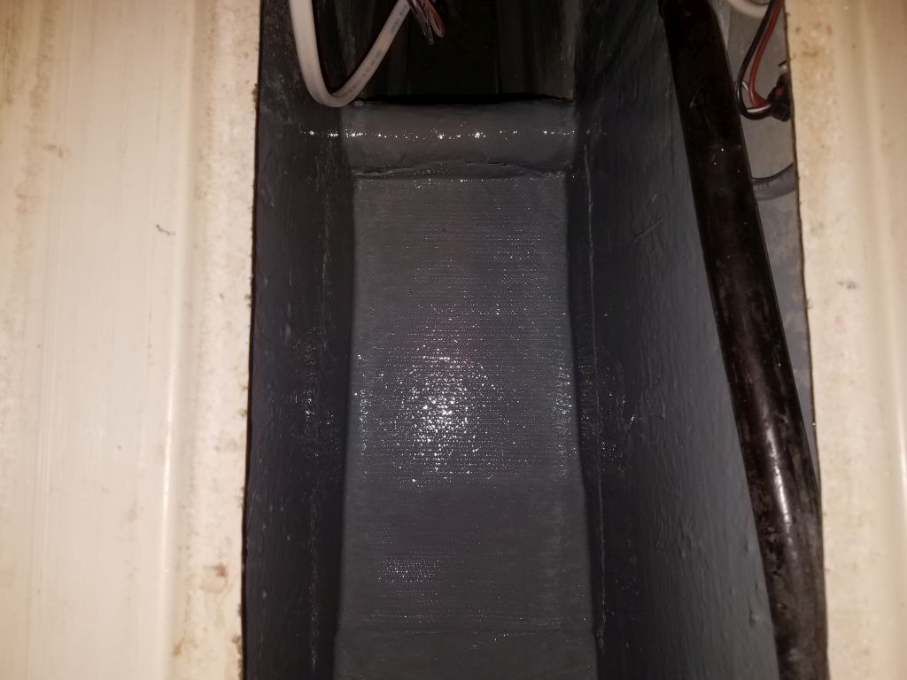
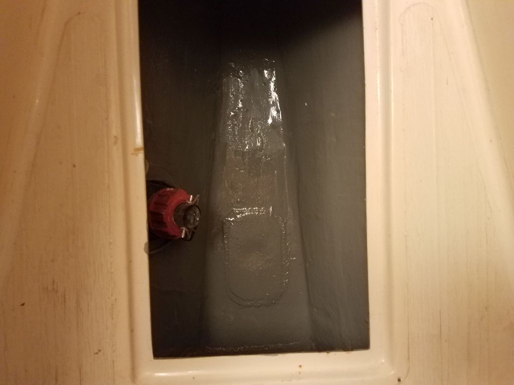
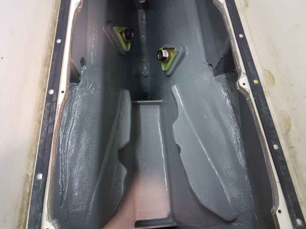
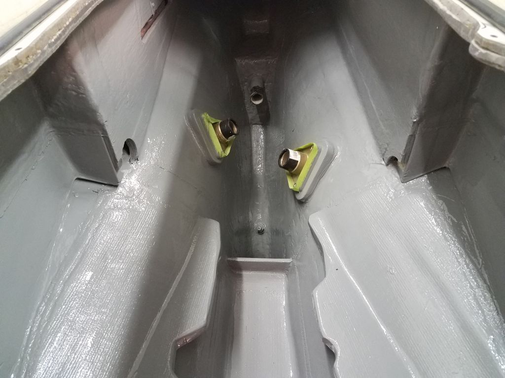
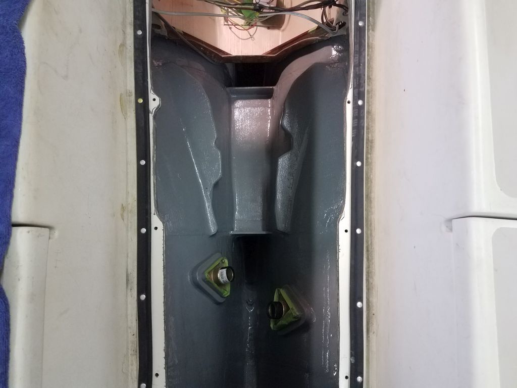
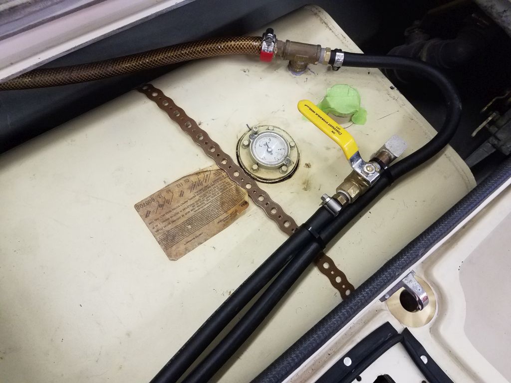
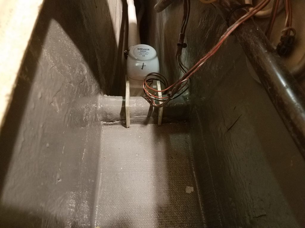
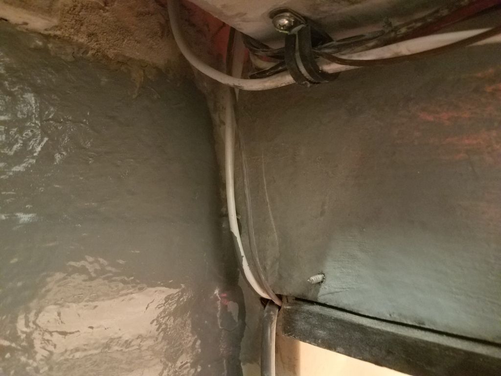
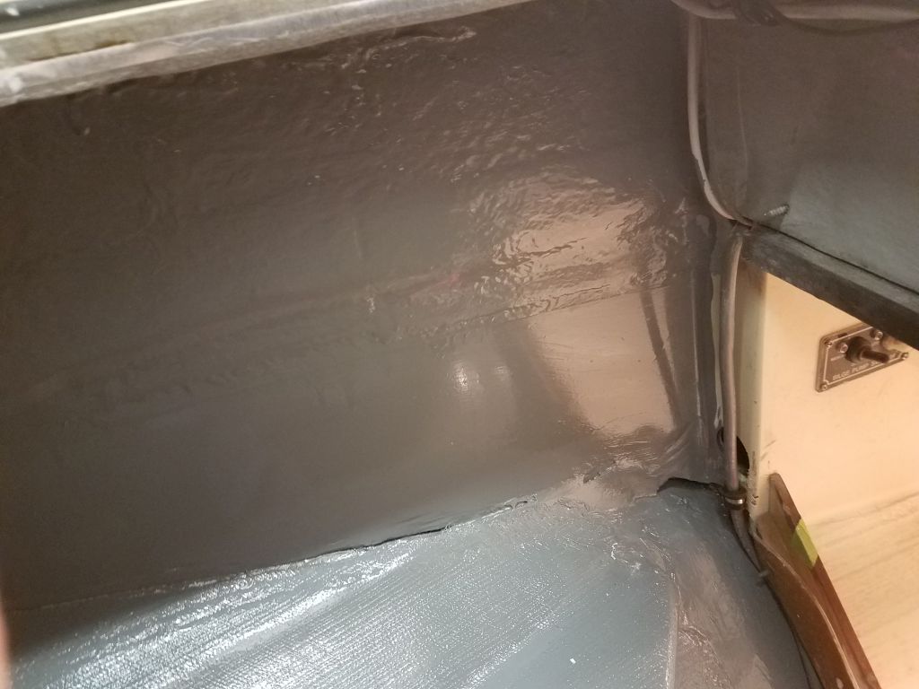
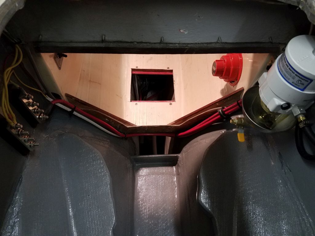
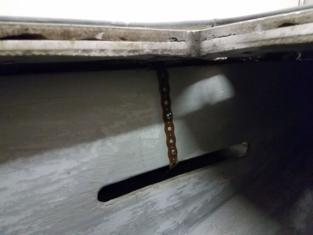
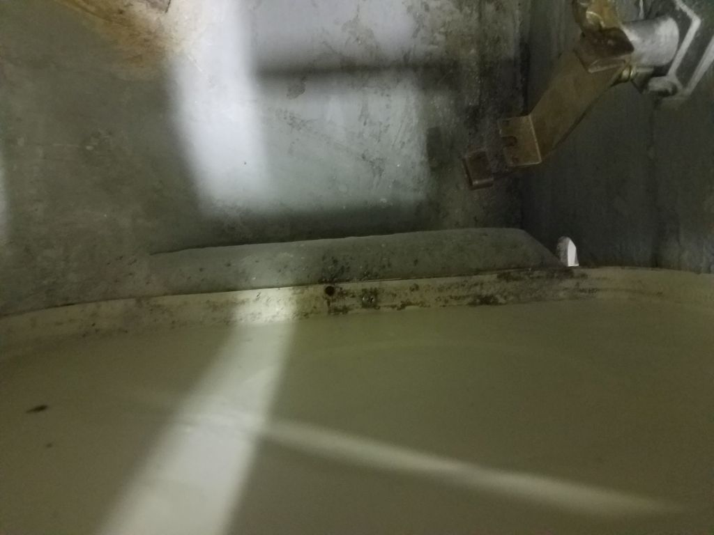
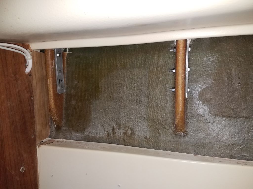
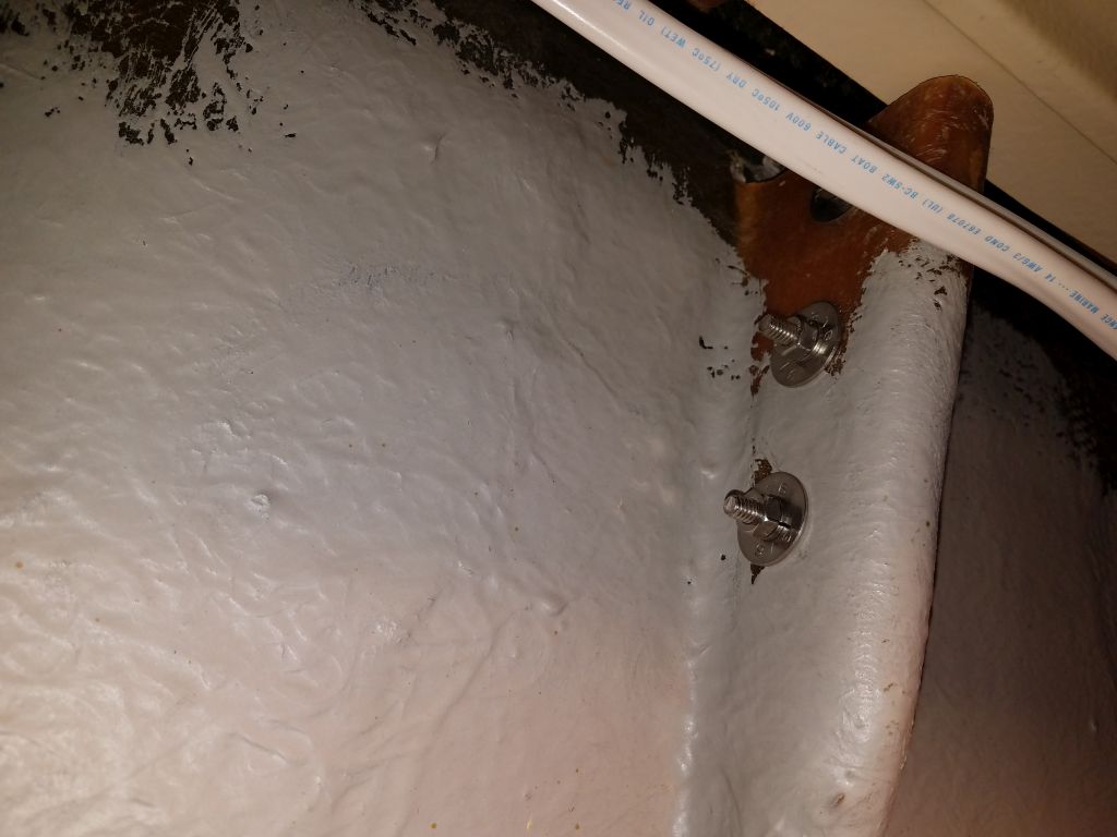
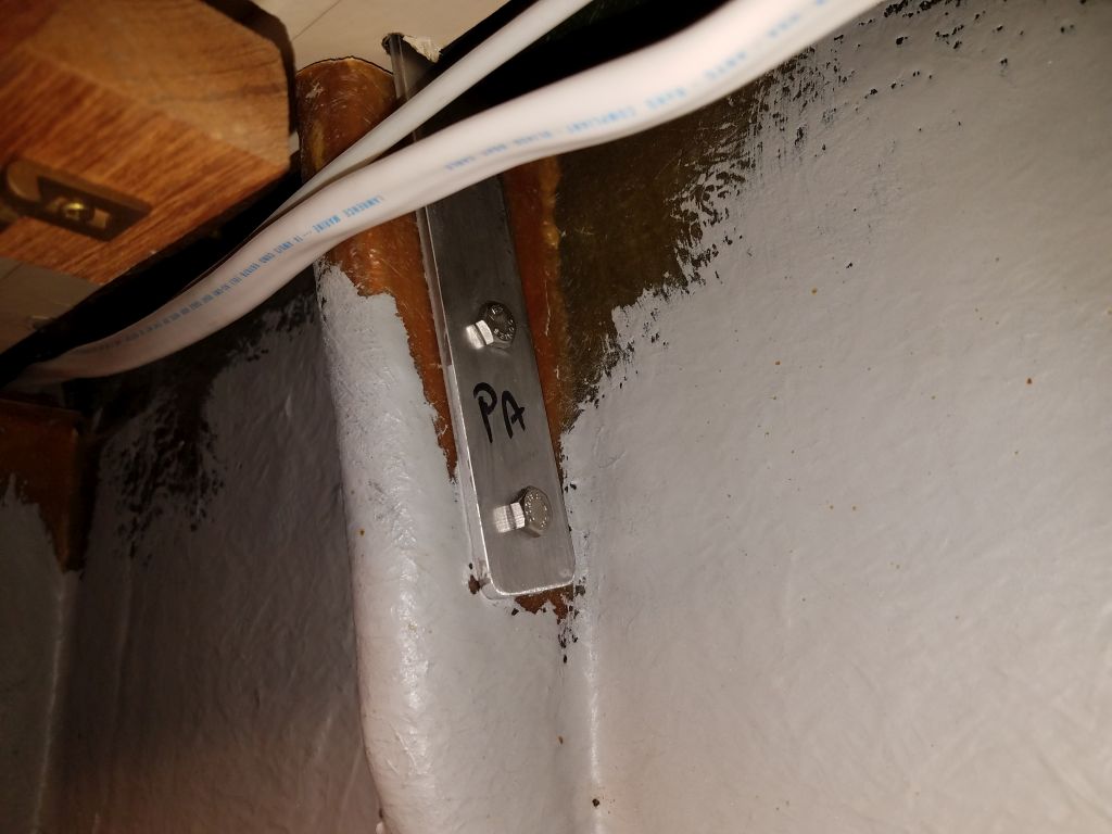
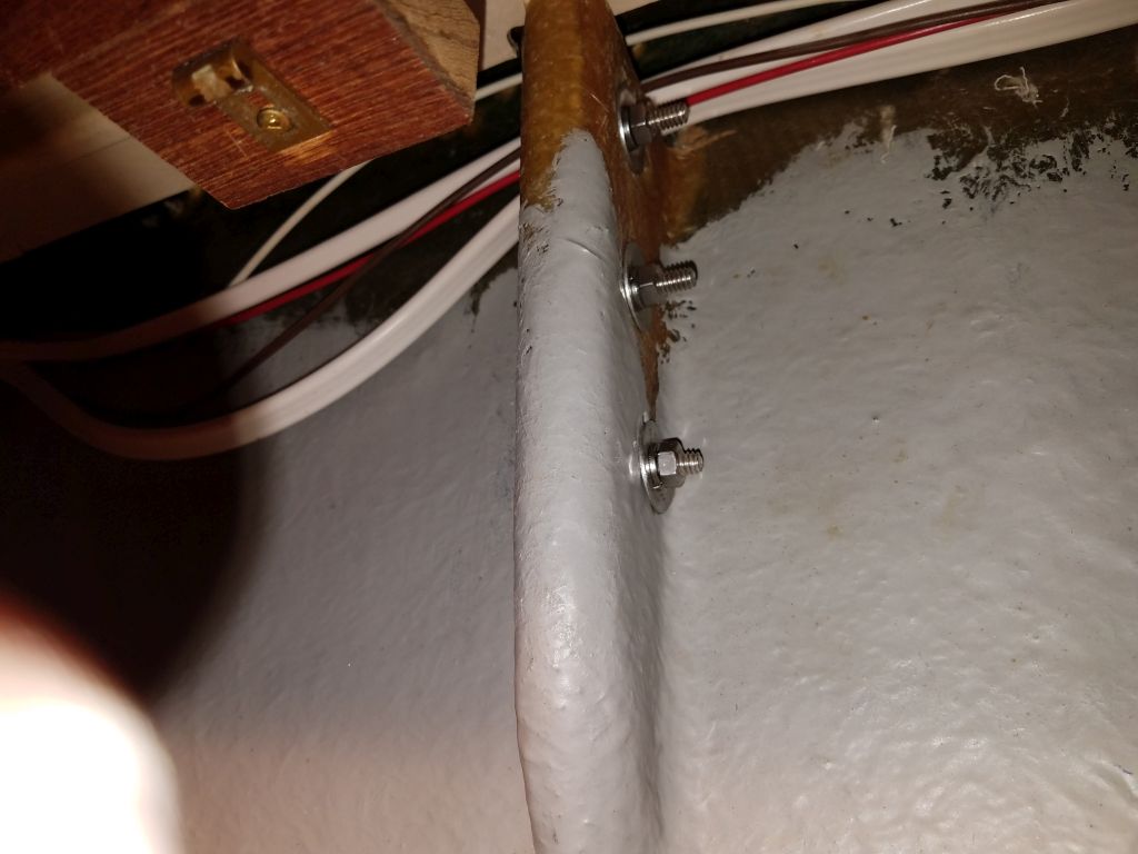
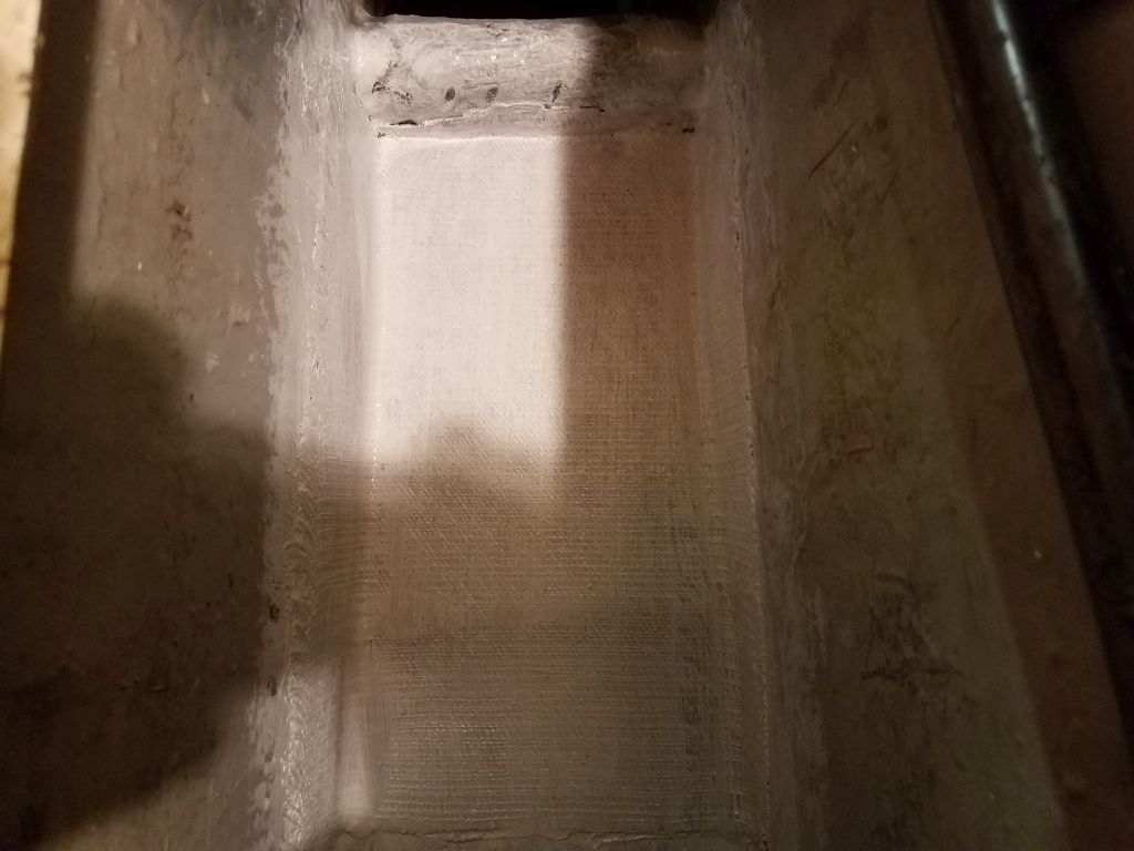
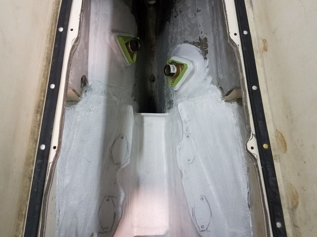
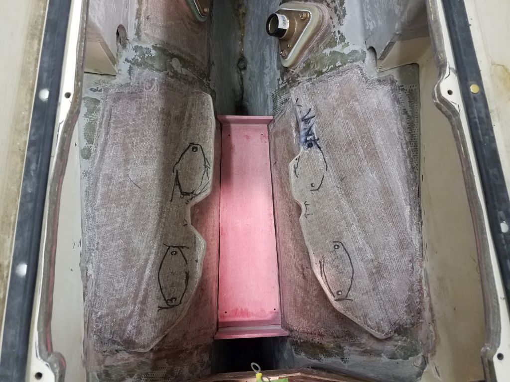
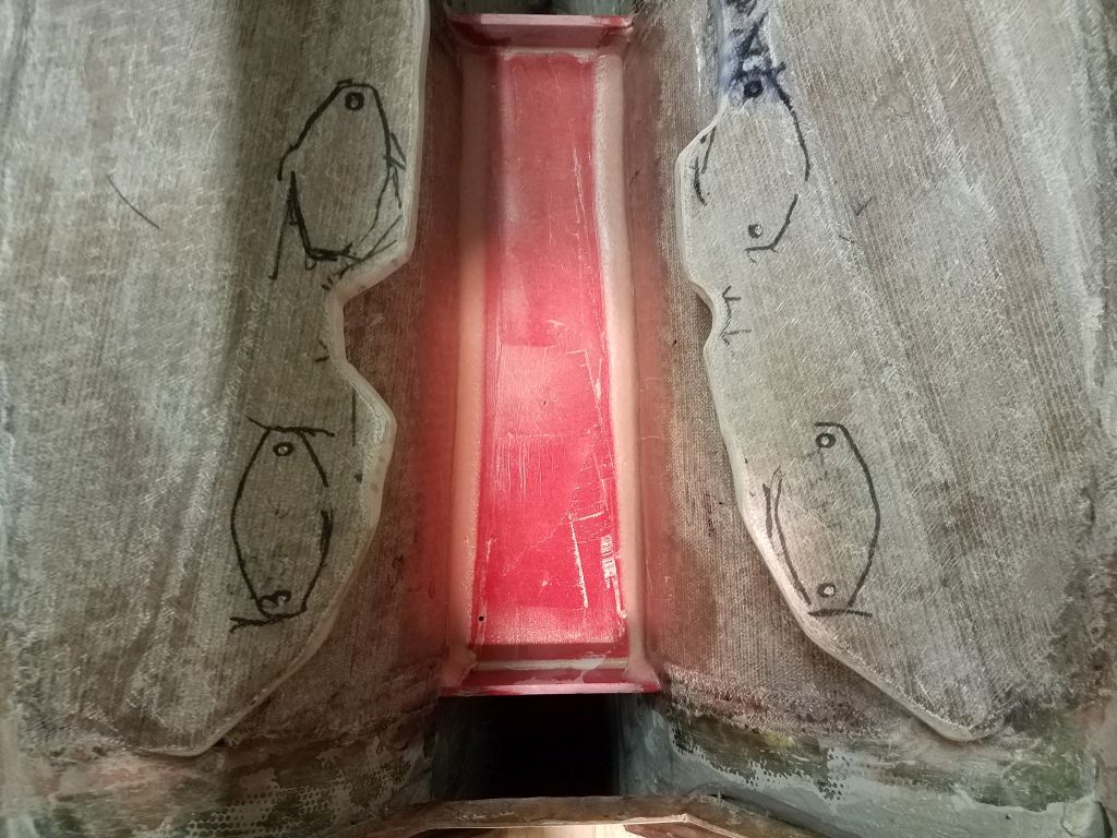
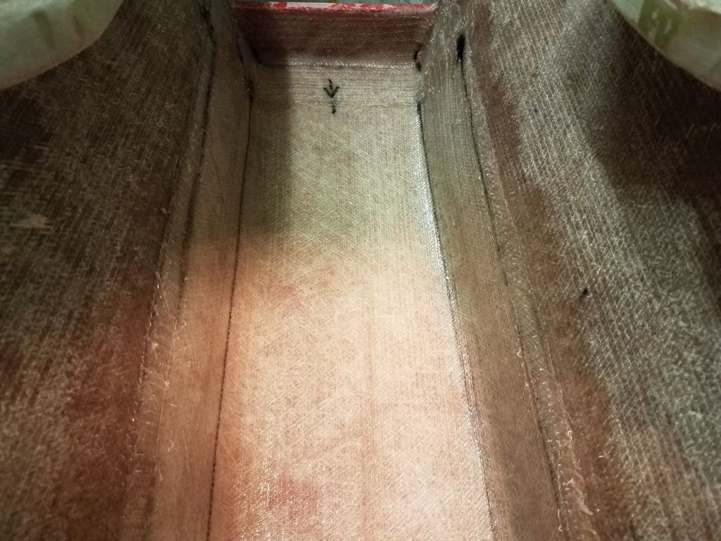
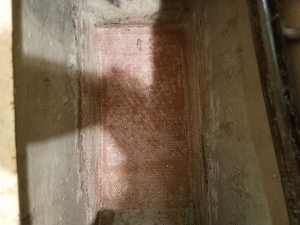
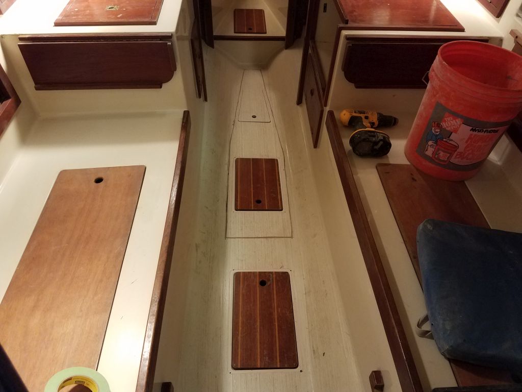
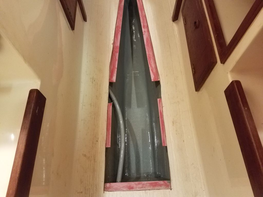
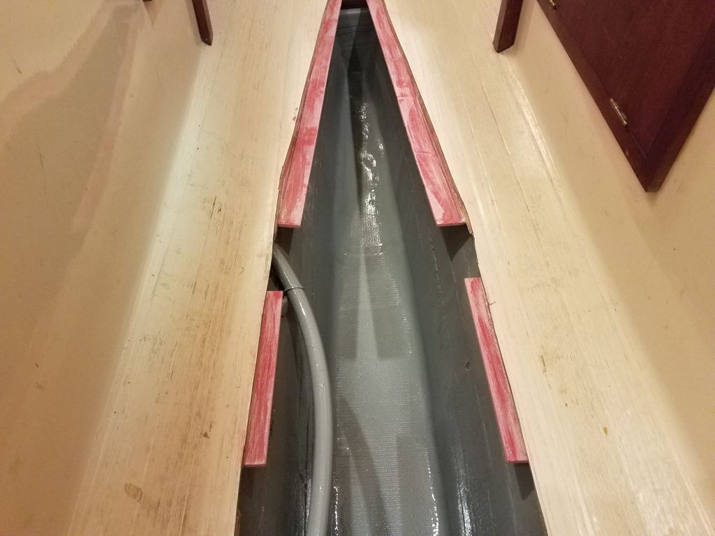
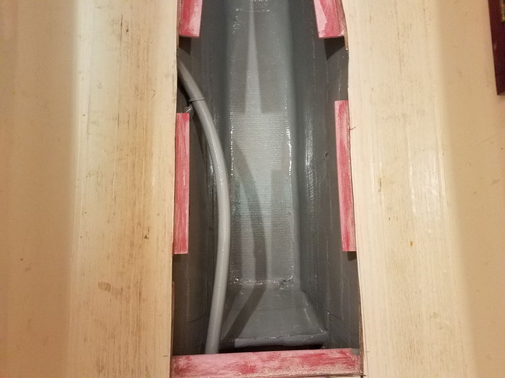
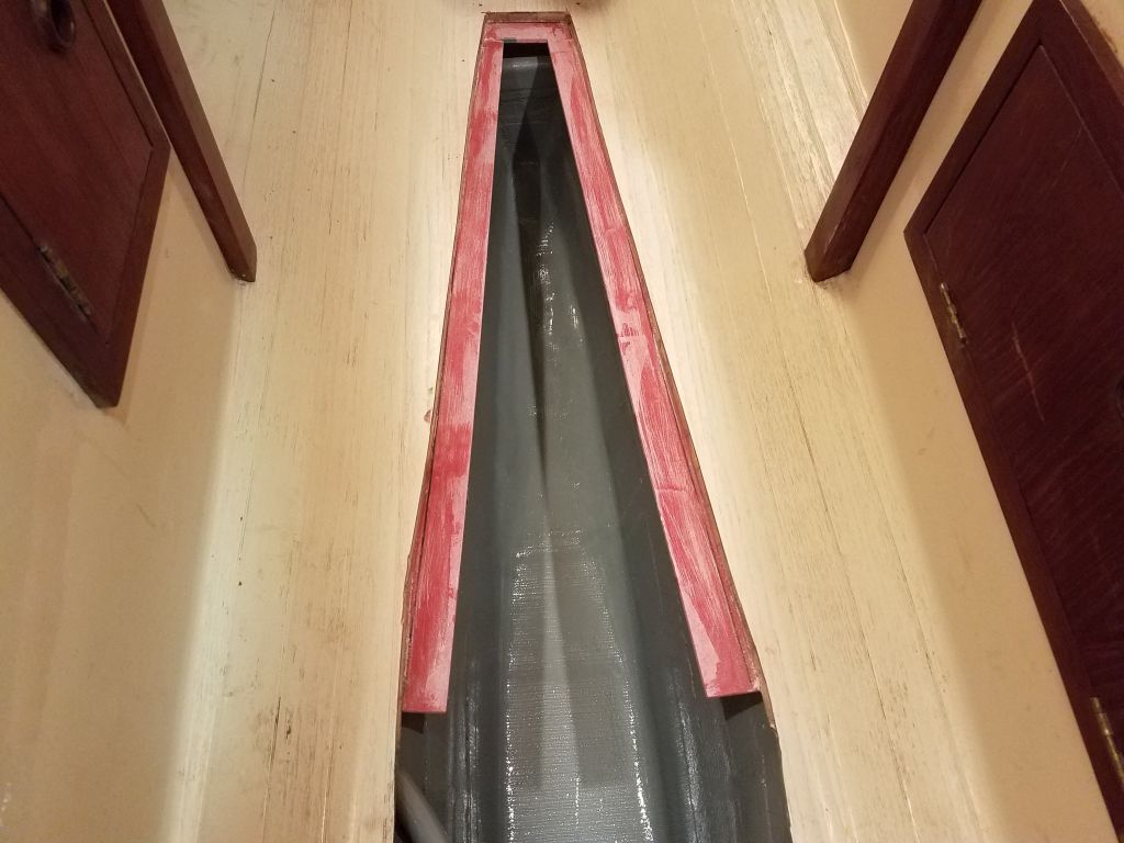
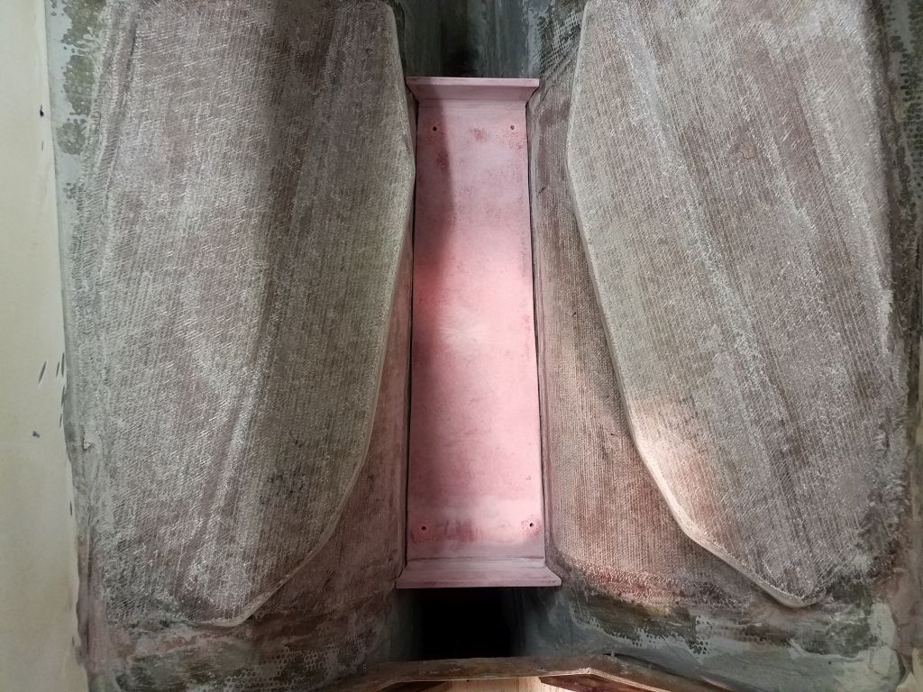
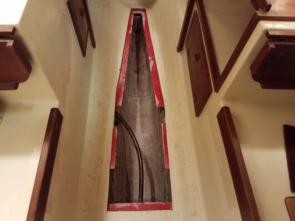
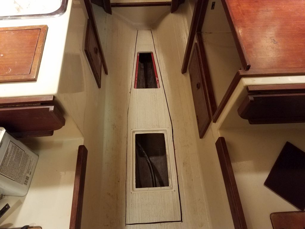
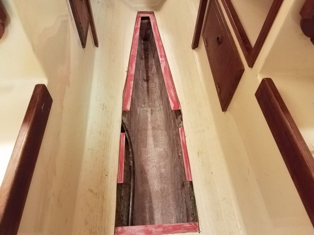
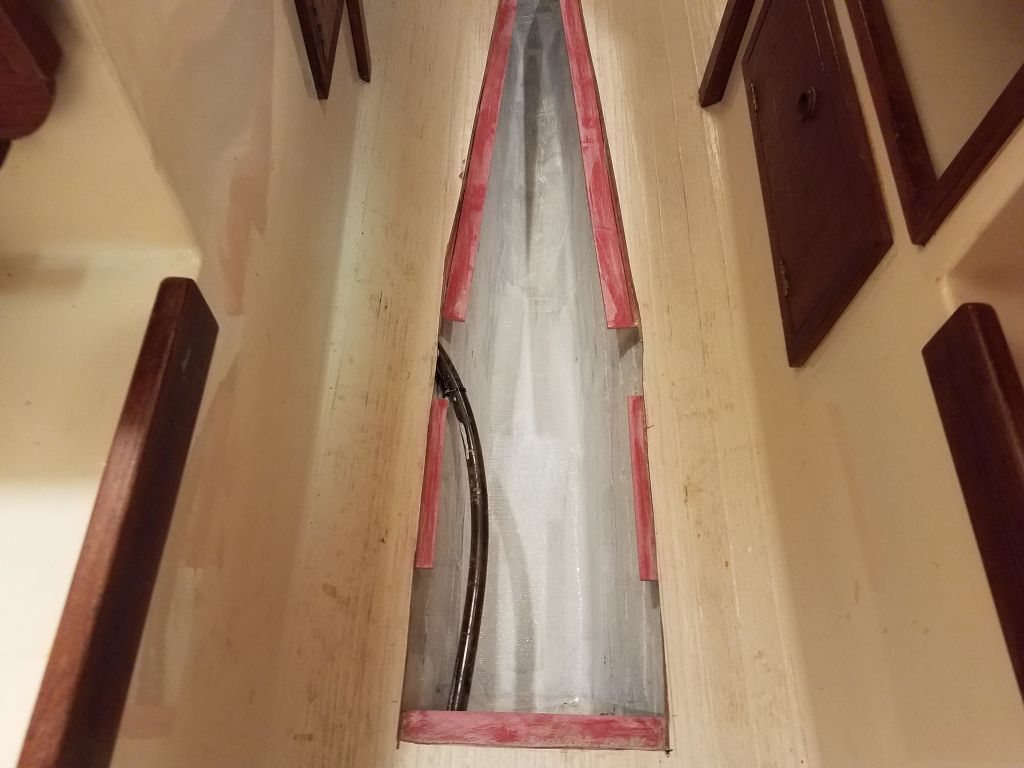
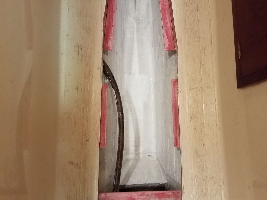
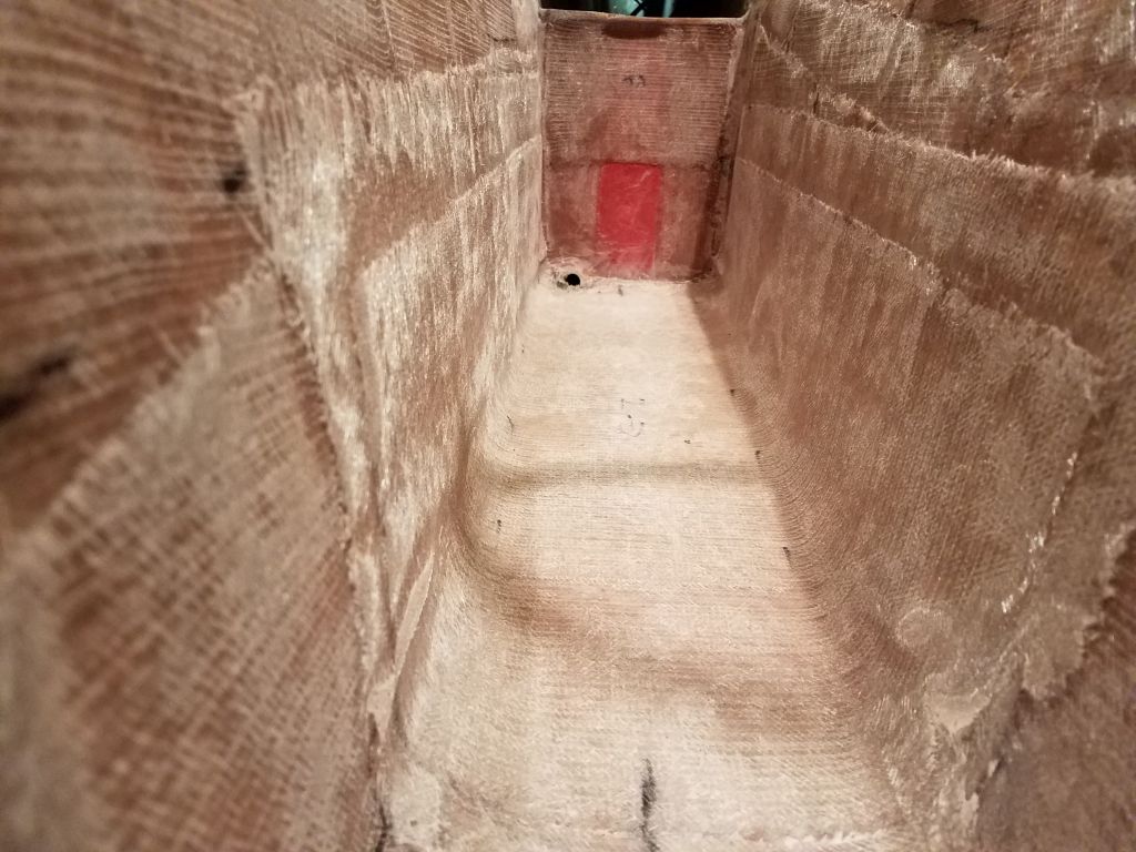
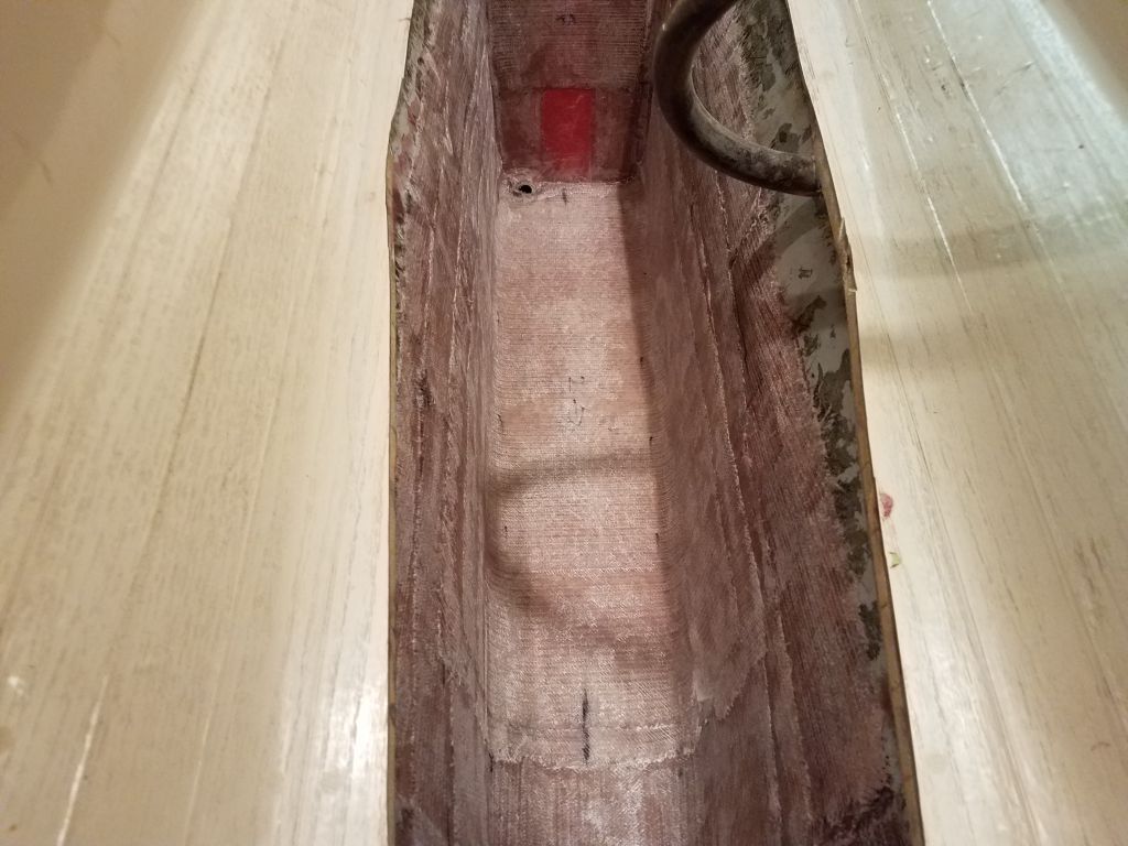
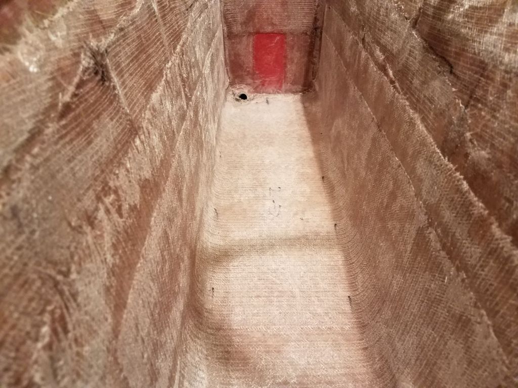
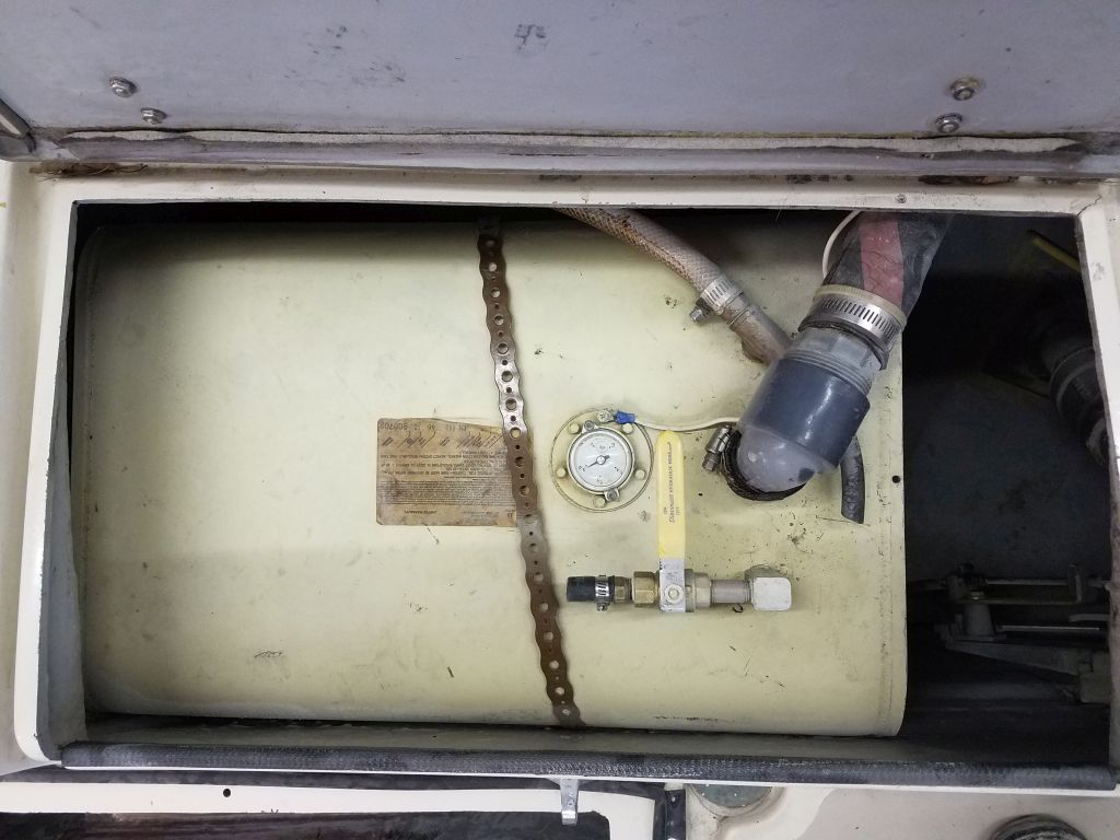
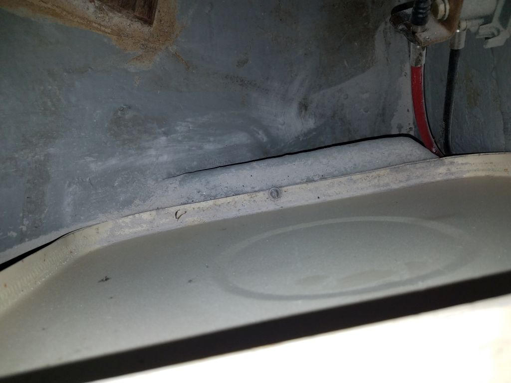
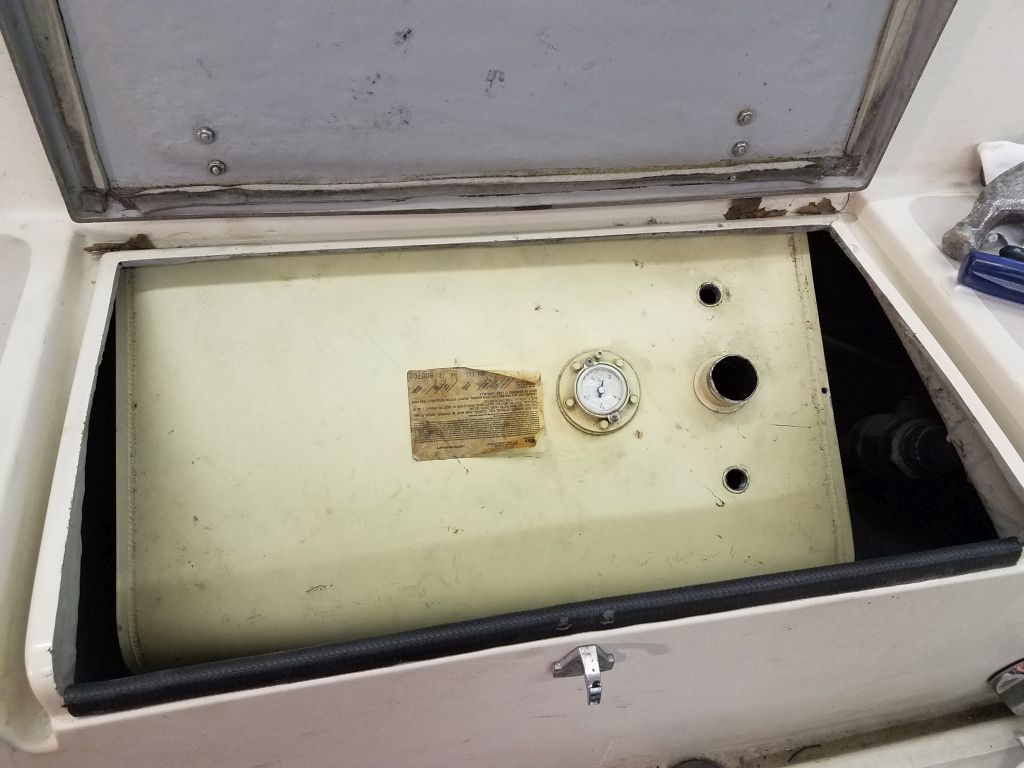
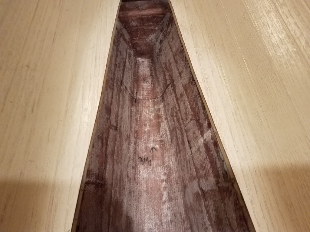
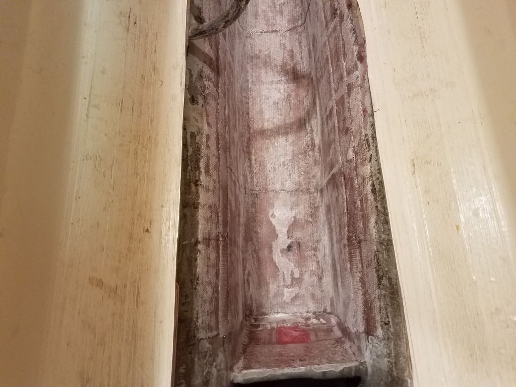
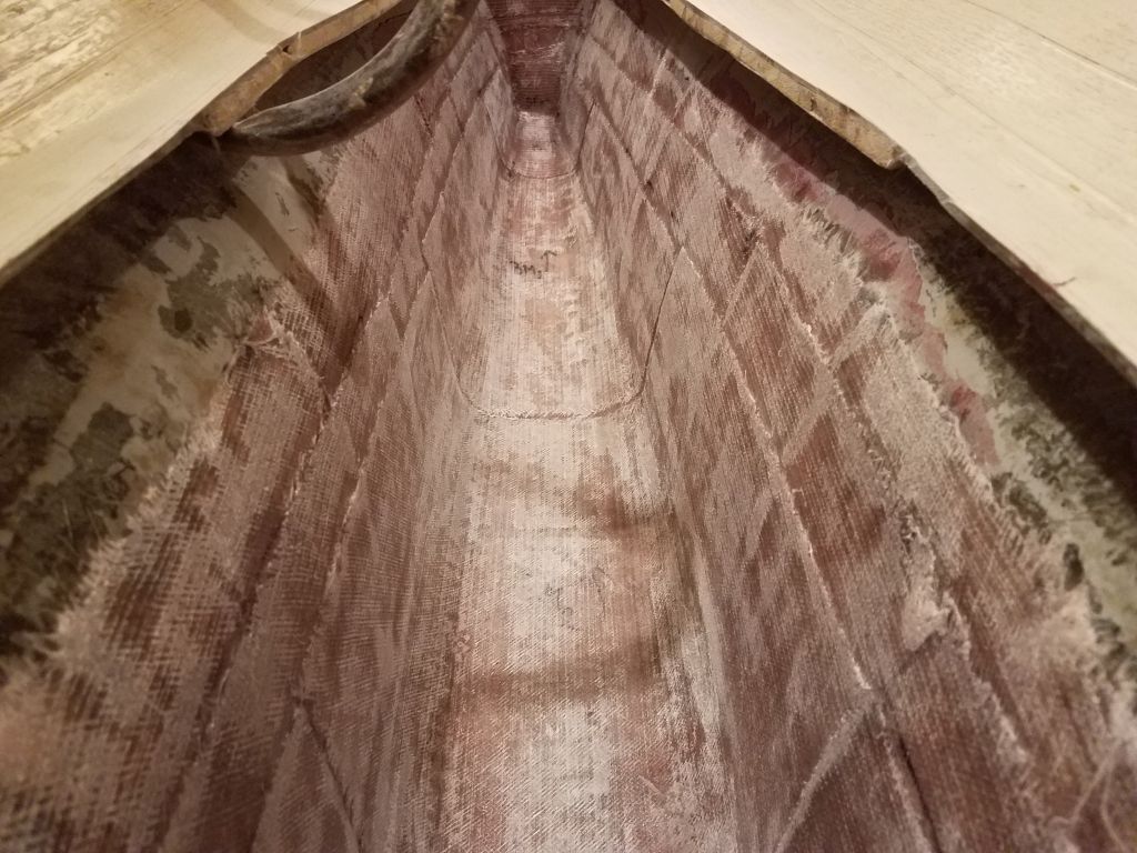
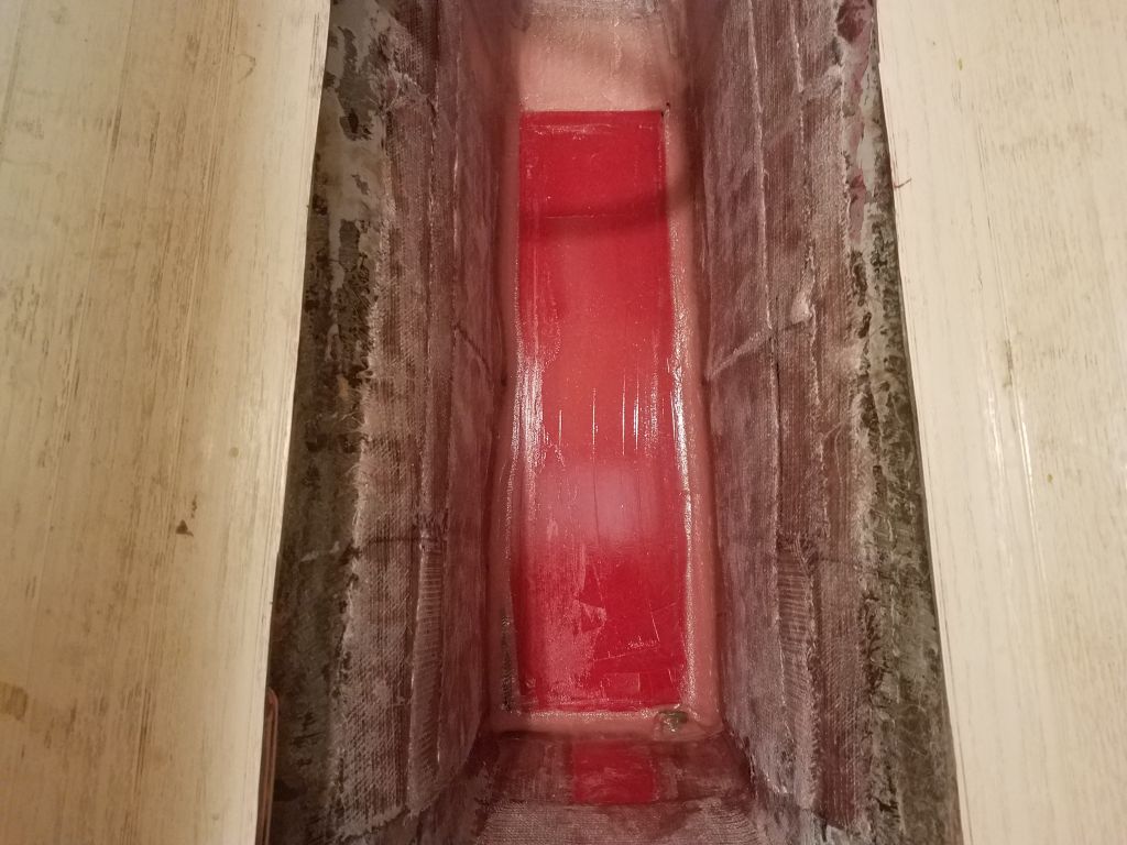
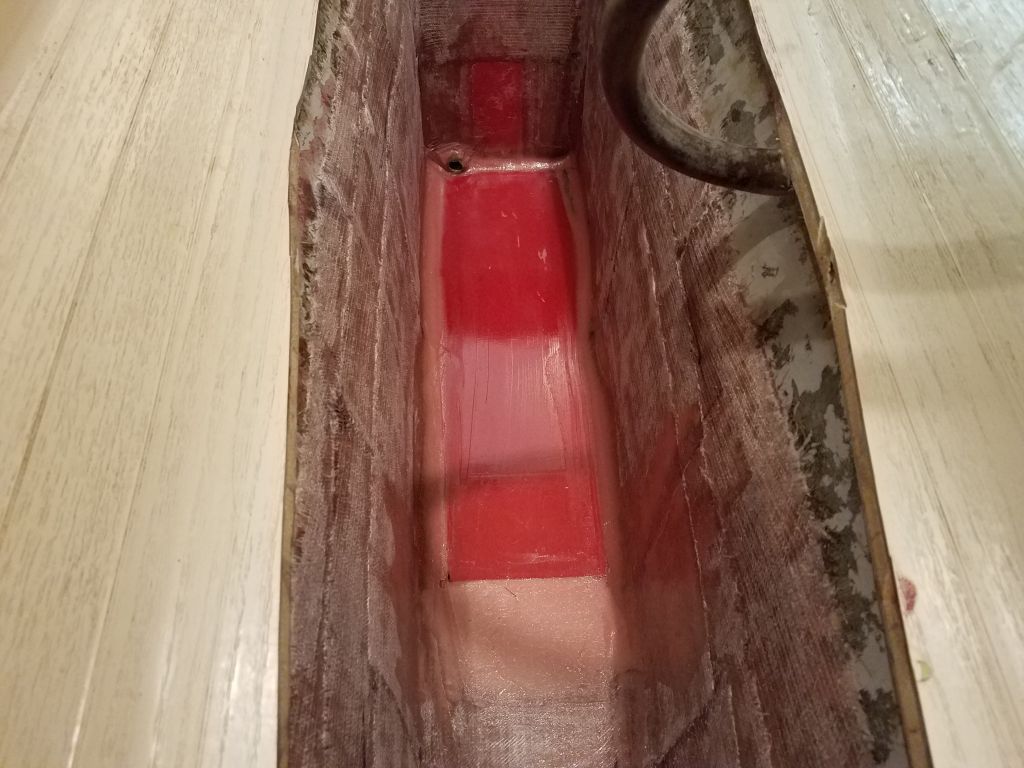
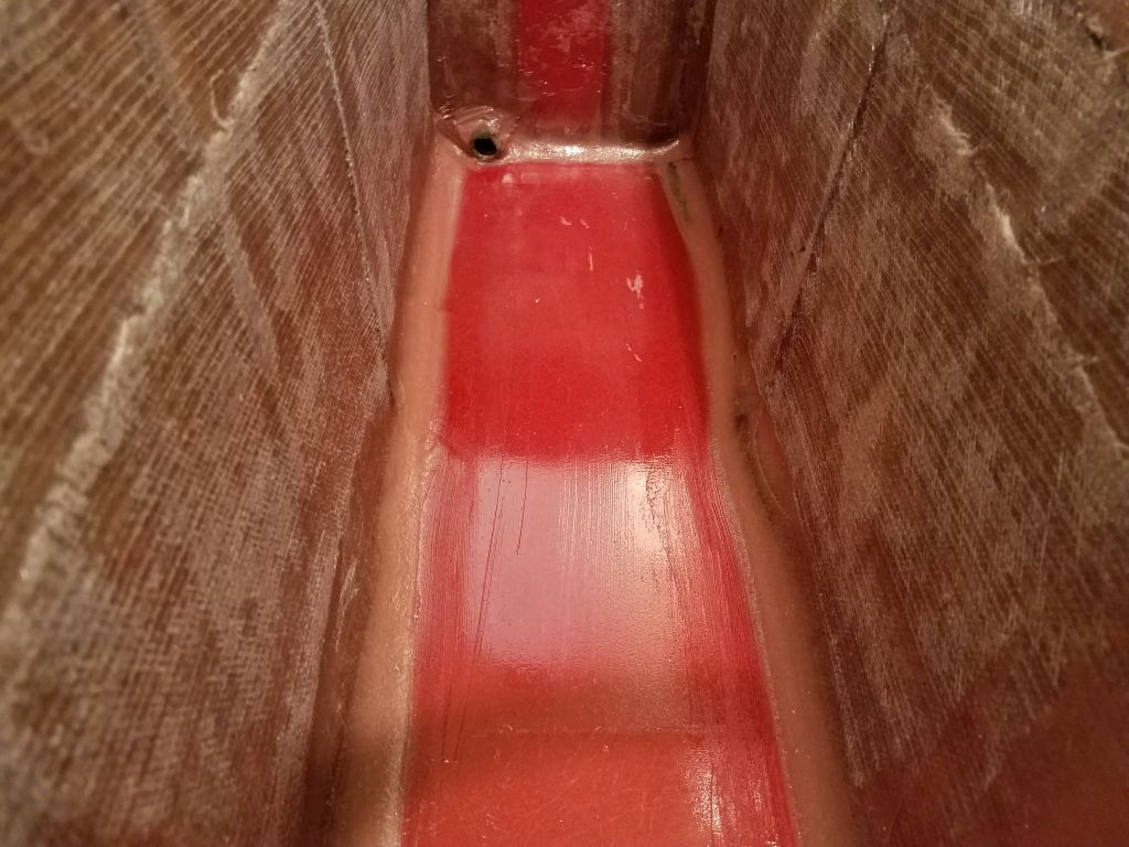
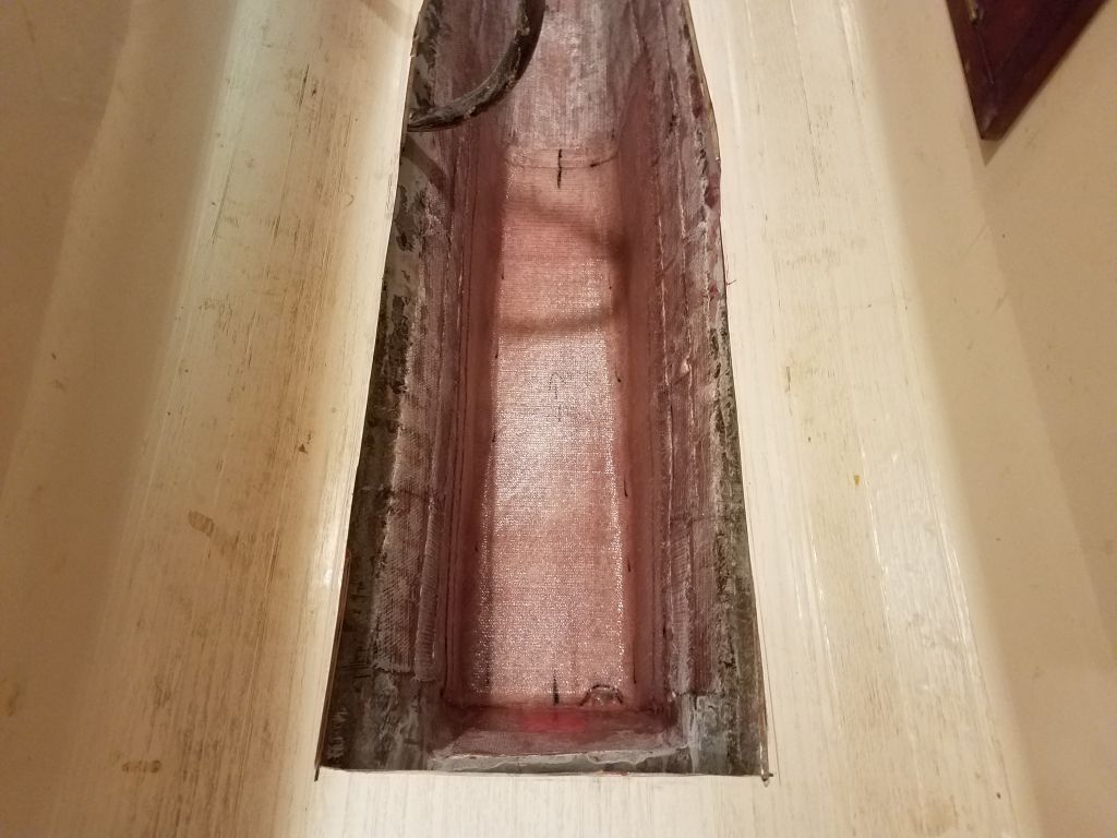
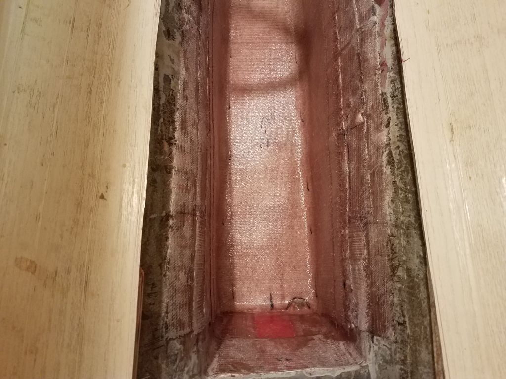
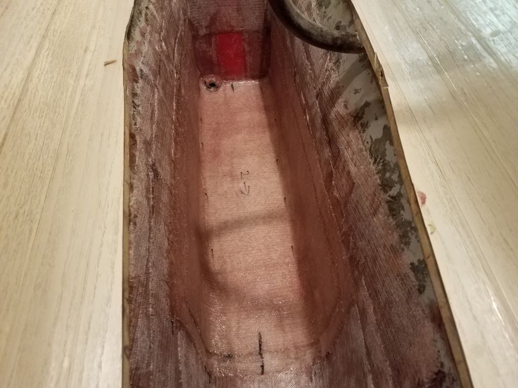
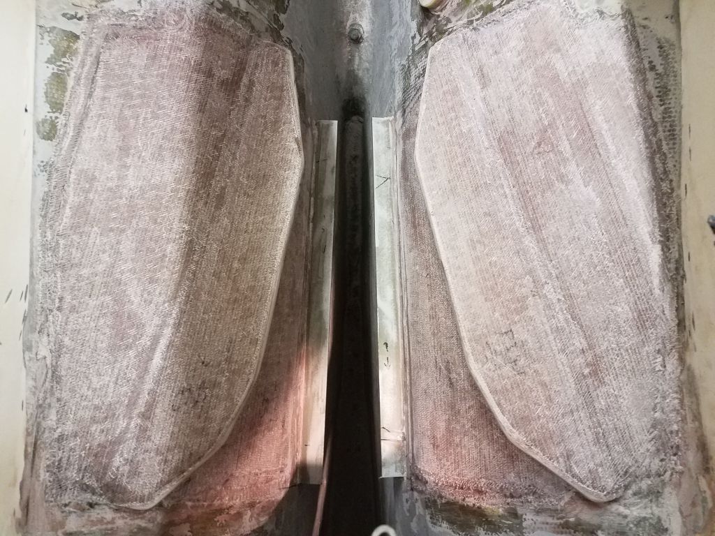
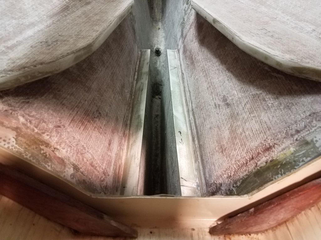
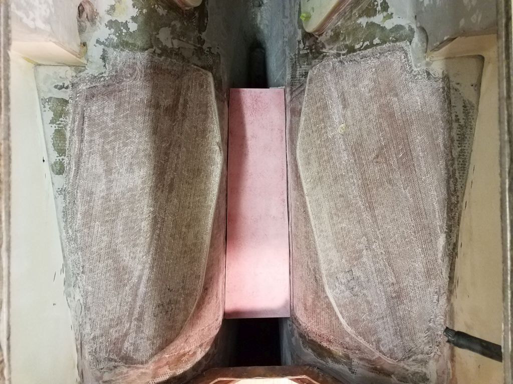
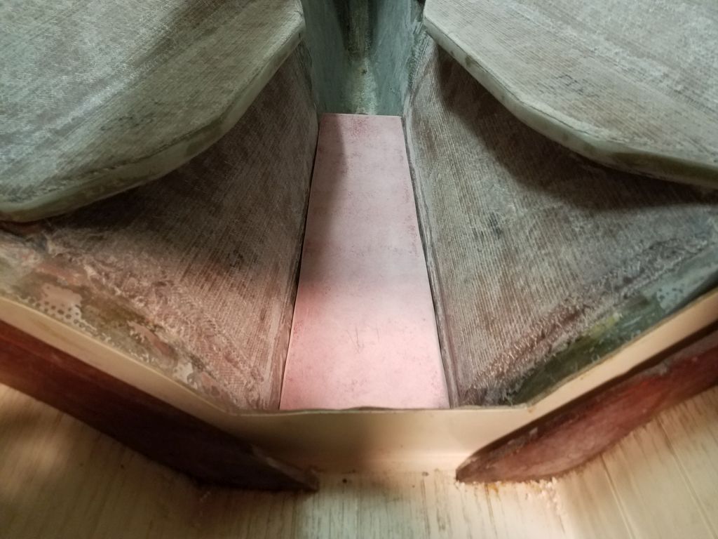
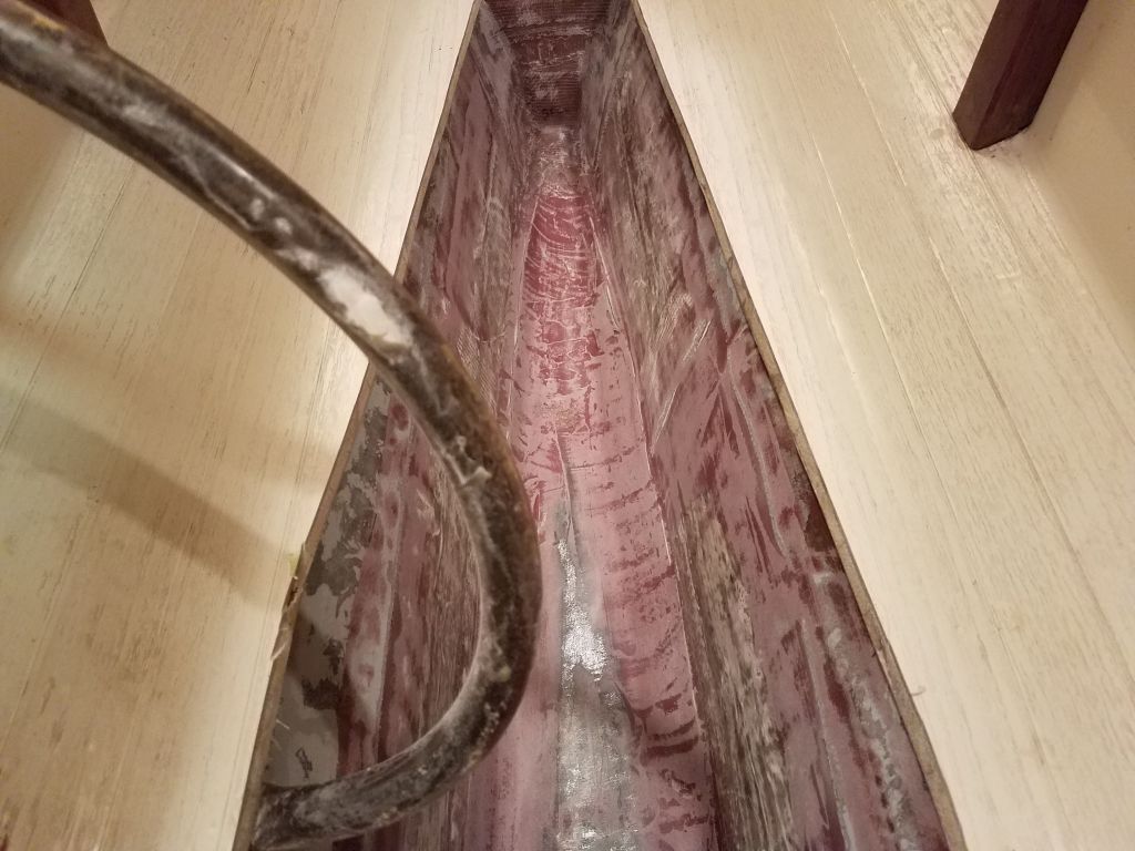
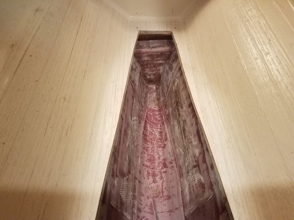
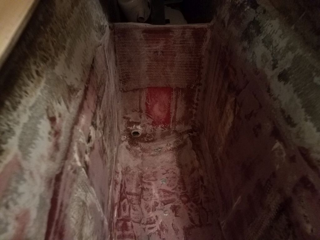
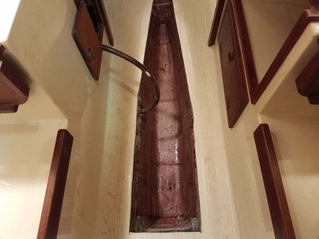
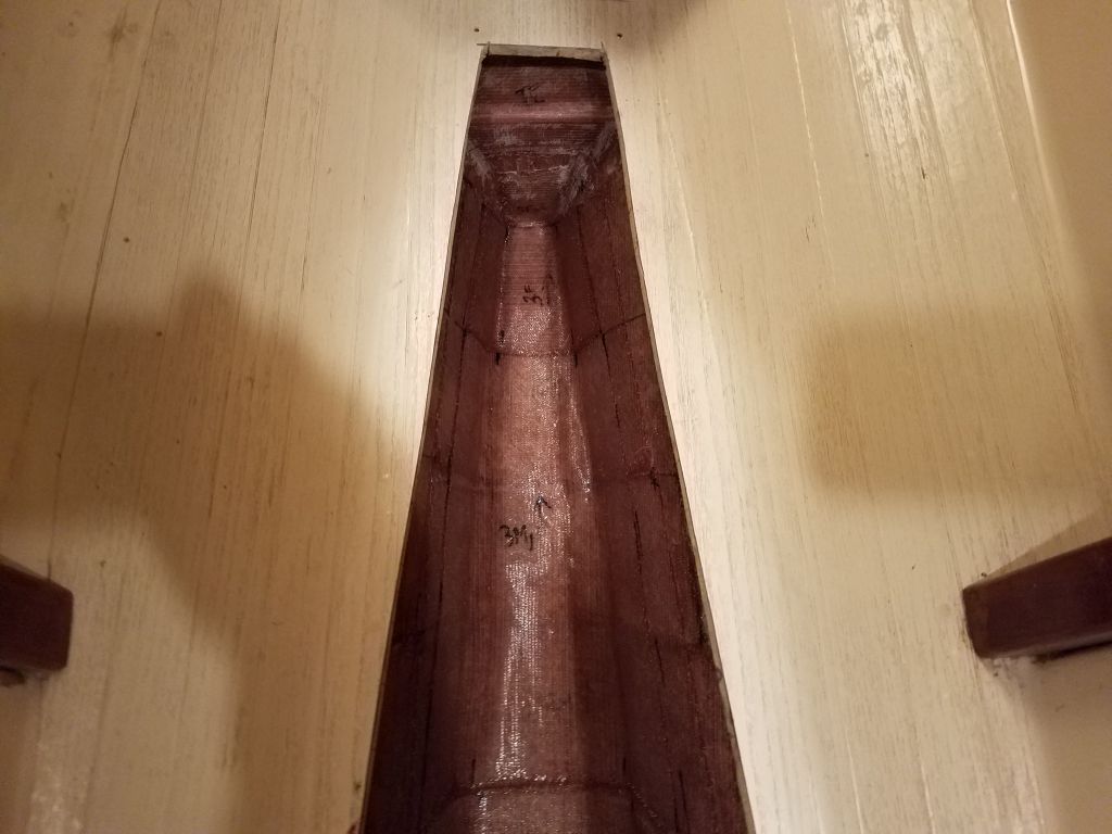
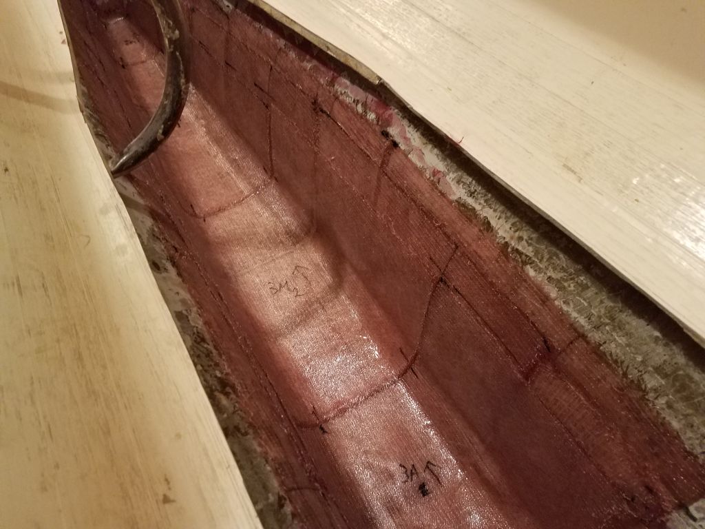
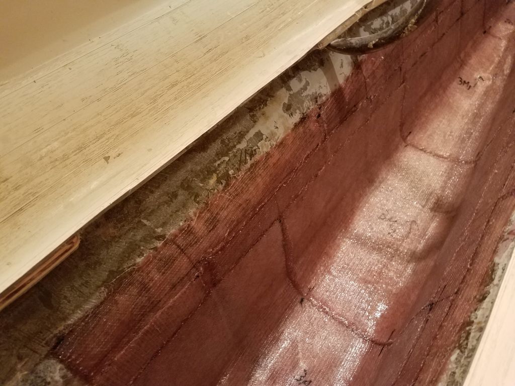
Over the weekend, I painted the new bilge area (formerly the waste tank) with gray bilge paint, completing the work within.
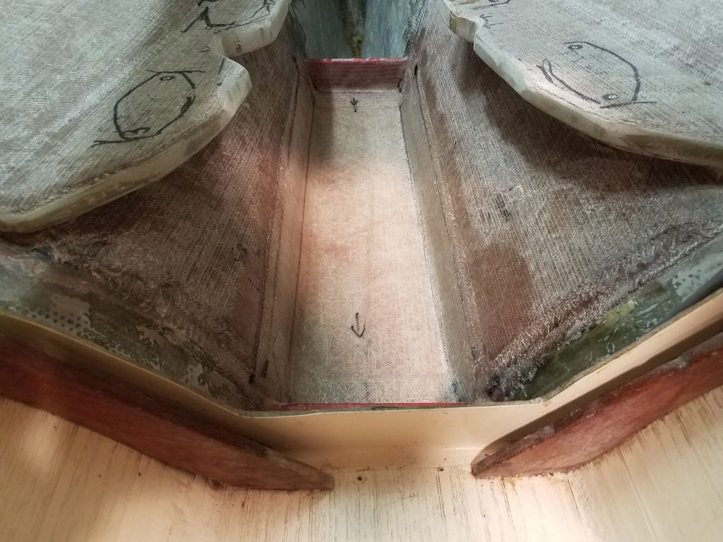
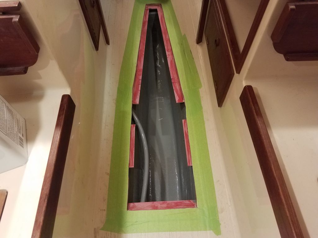
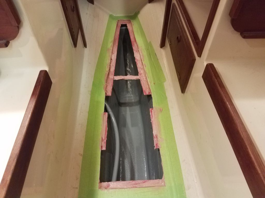
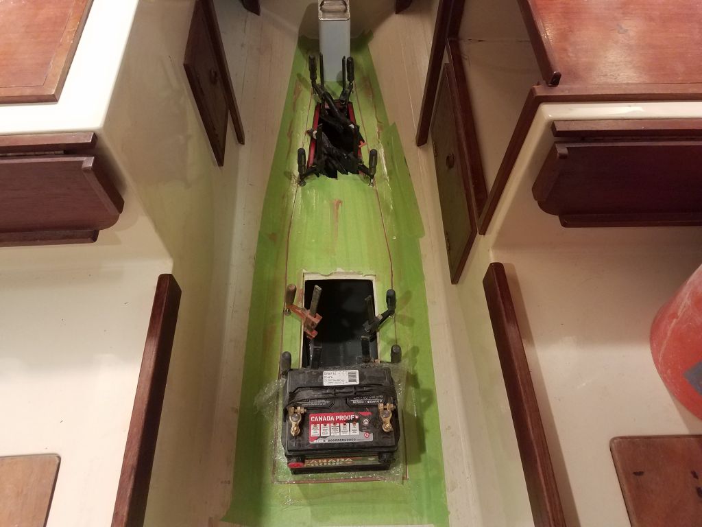
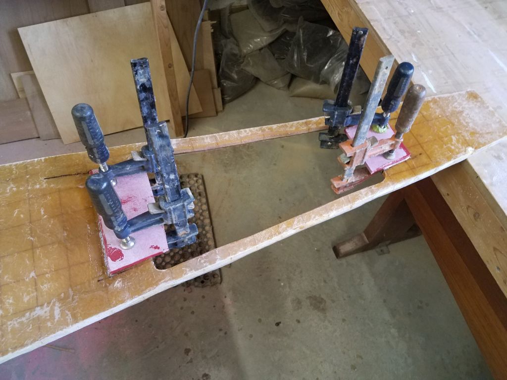
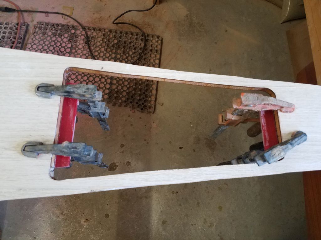
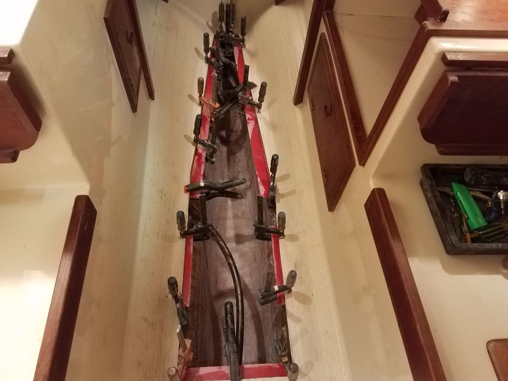
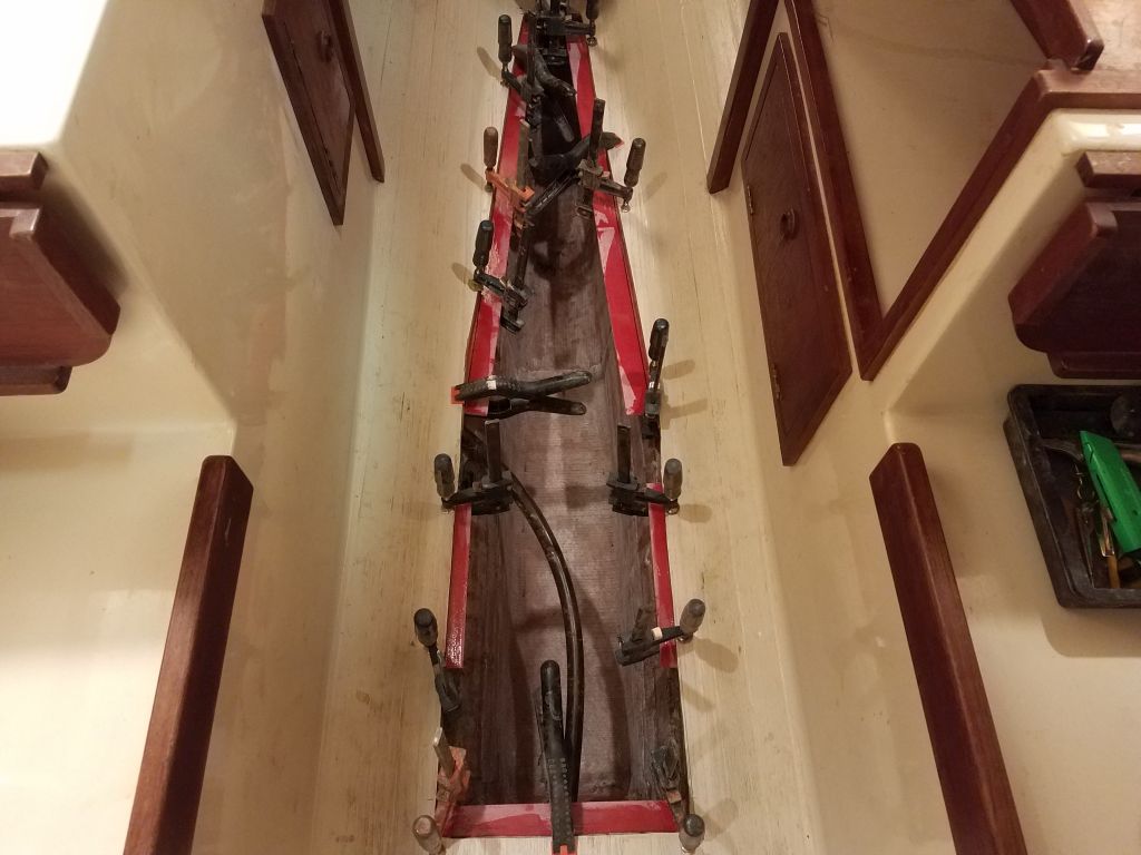
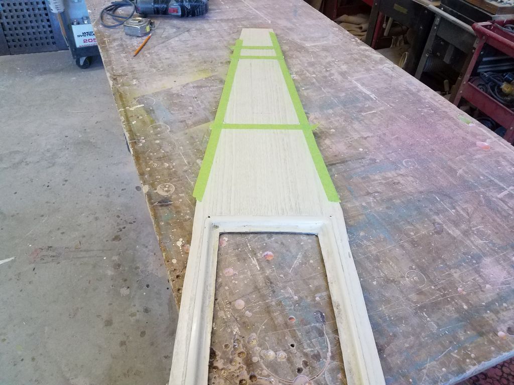
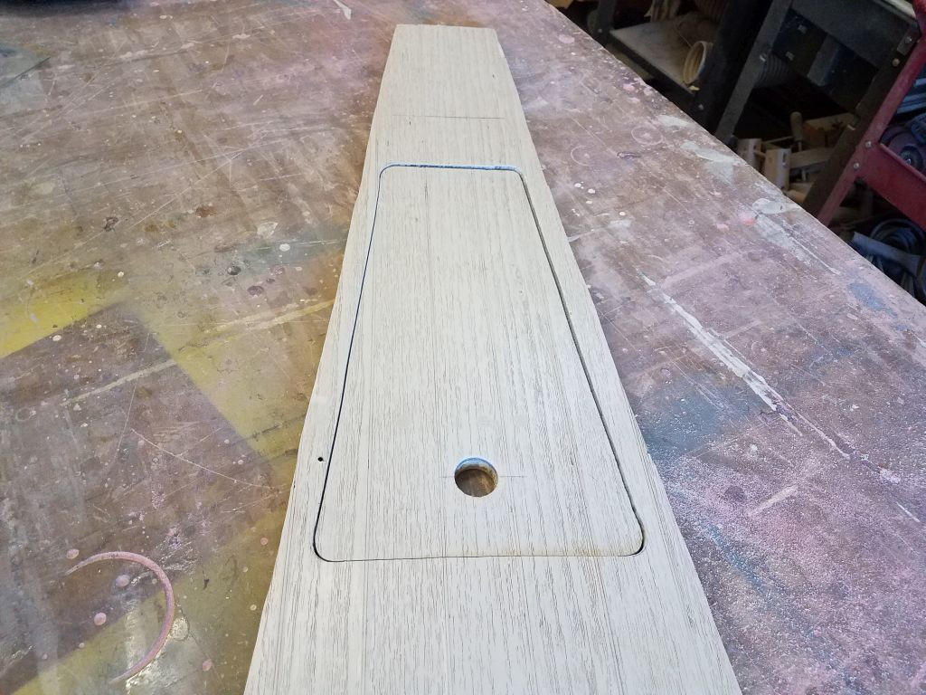
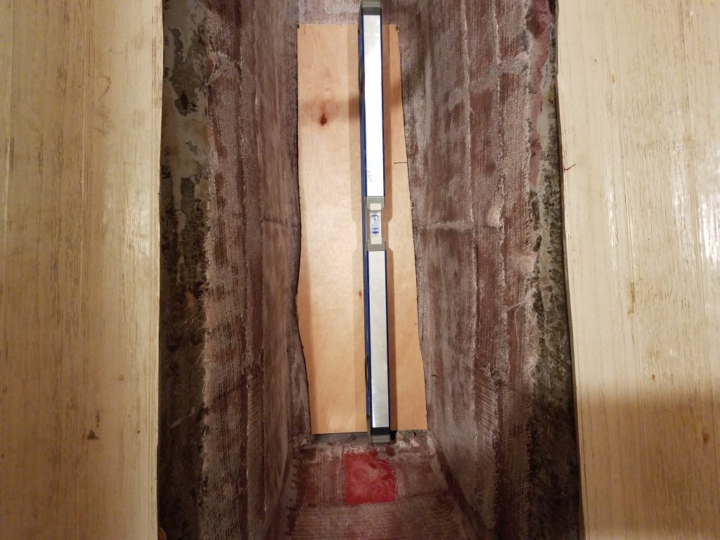
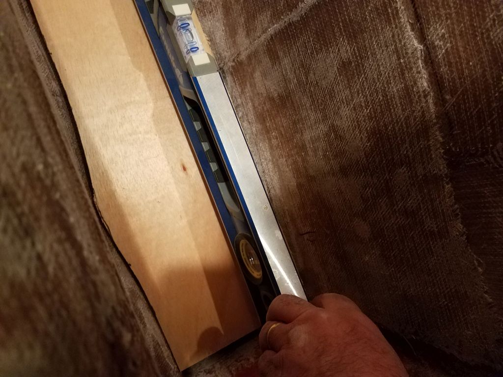
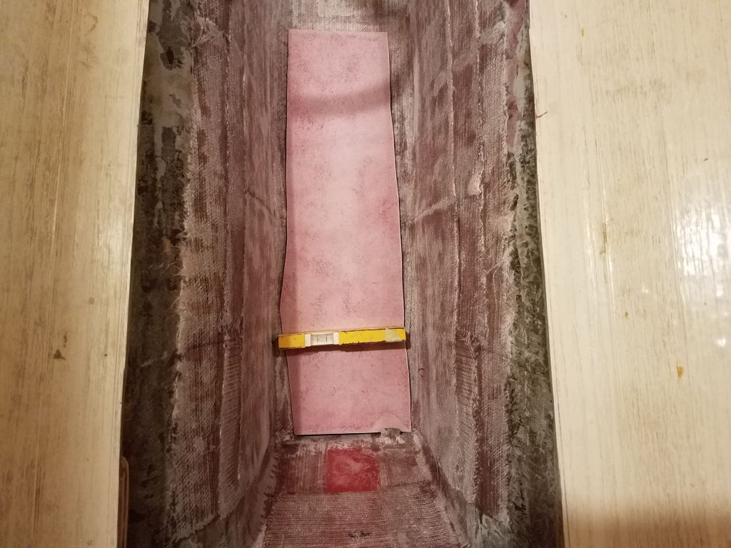
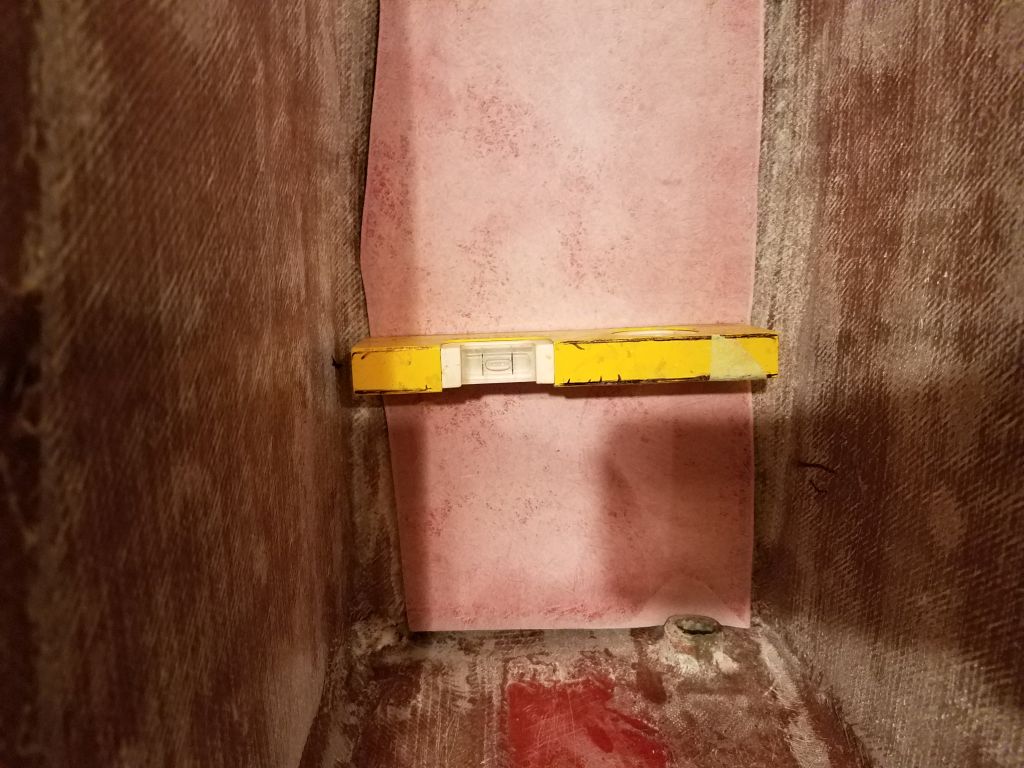
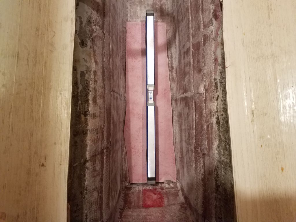
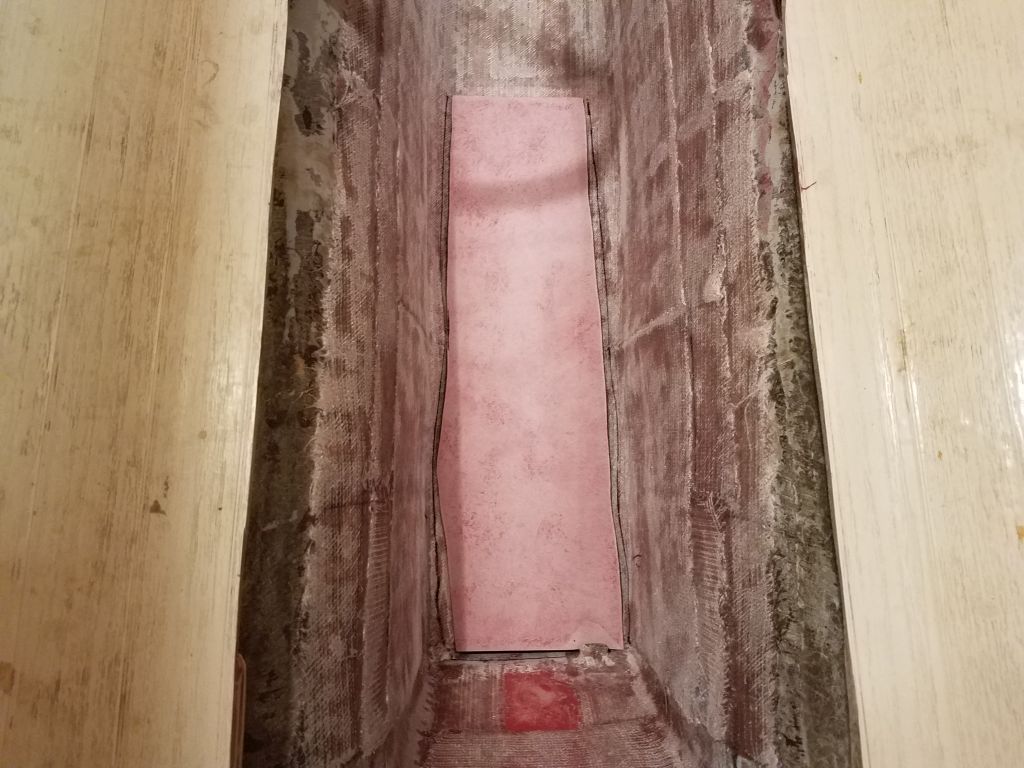
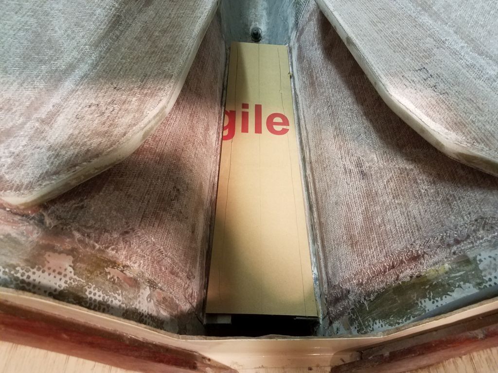
This meant that I could move forward to install the cabin sole, starting with a final test-fit. Then, I made final preparations, including cleaning the bonding surfaces and masking off the edges of the opening, as well as the center section of the sole, to protect these from epoxy. Finally, I installed the sole in a bed of thickened epoxy adhesive, clamping it well wherever possible and adding weights at the ends to help secure those areas I couldn’t directly clamp. I filled the gap at the cut line with additional thickened epoxy as well.
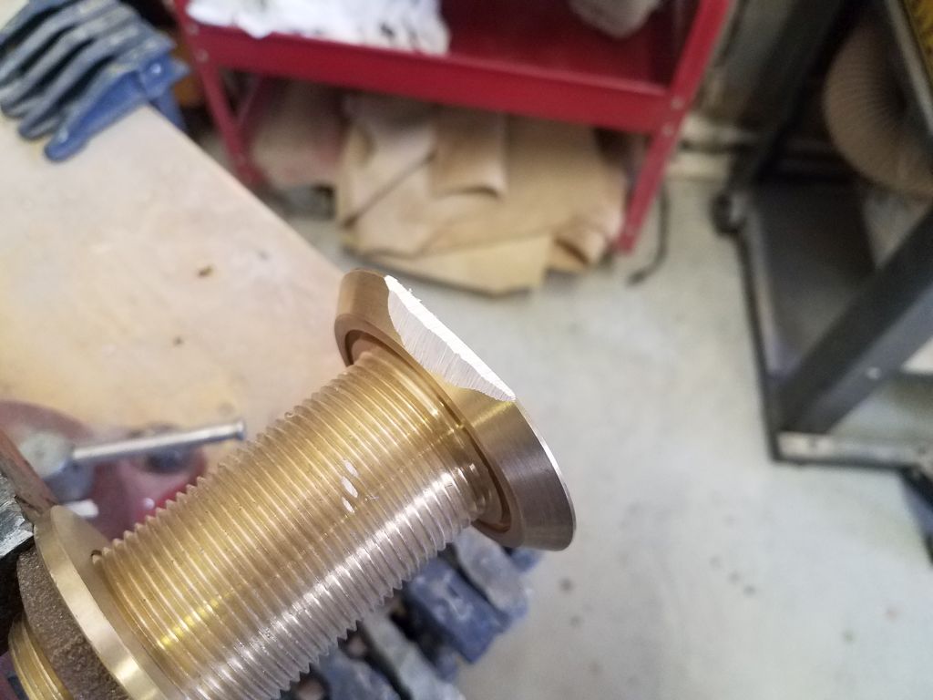
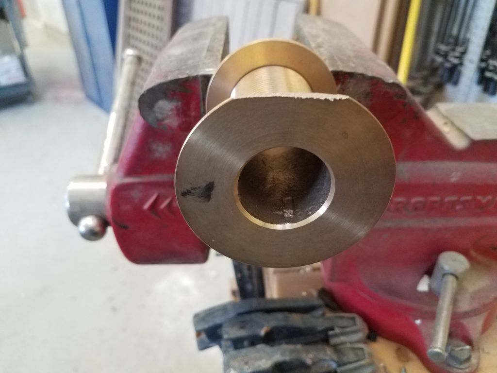
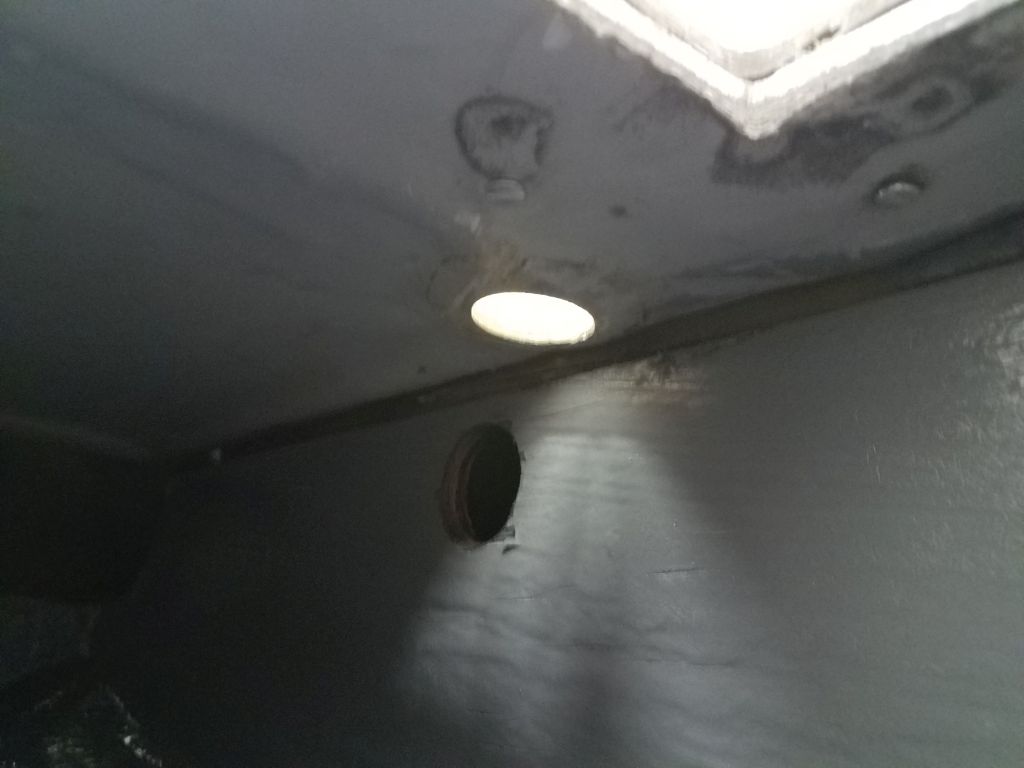
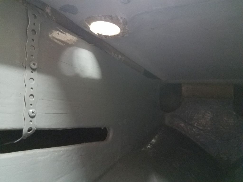
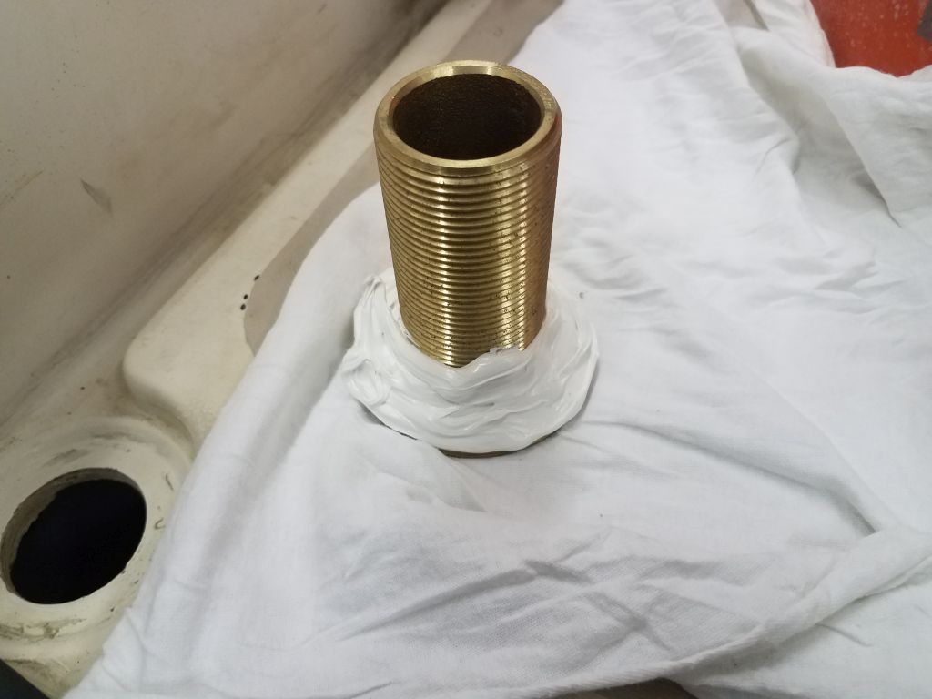
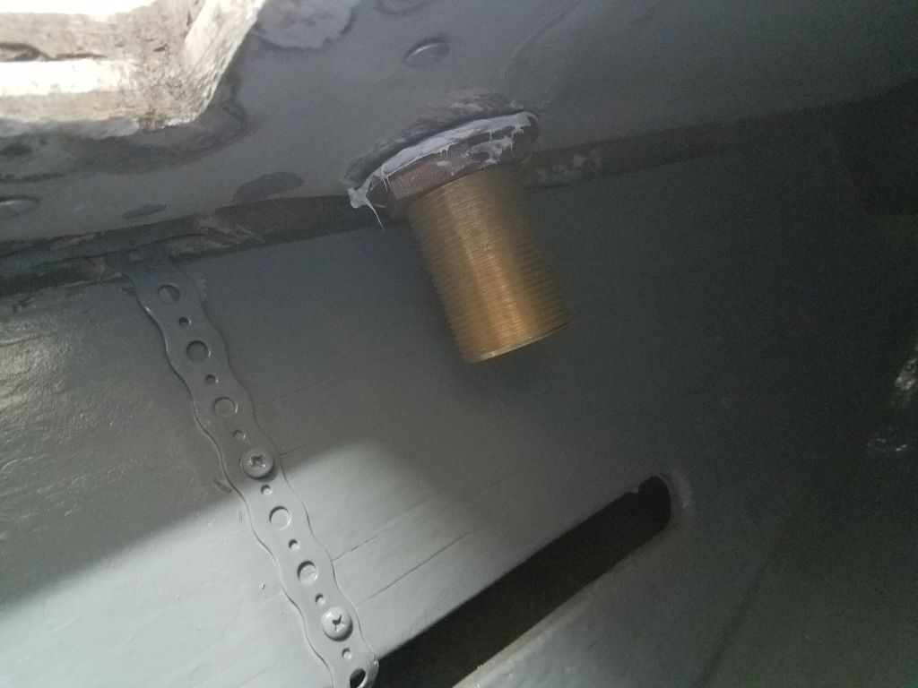
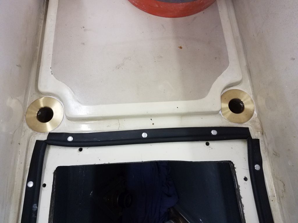
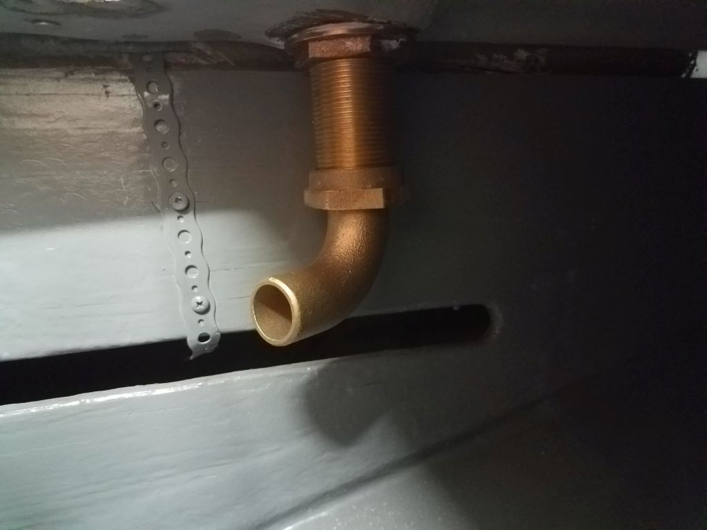
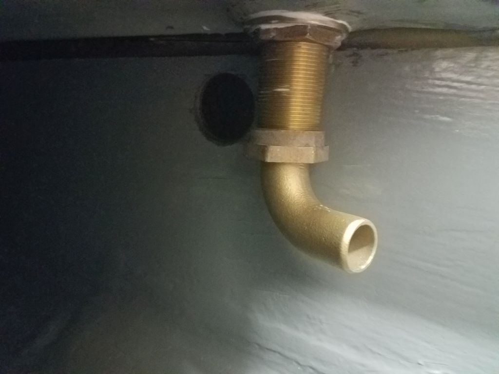
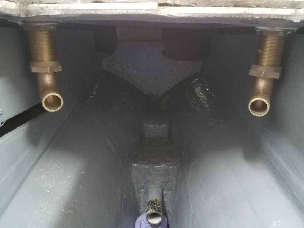
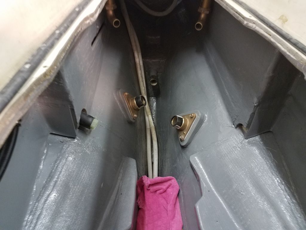
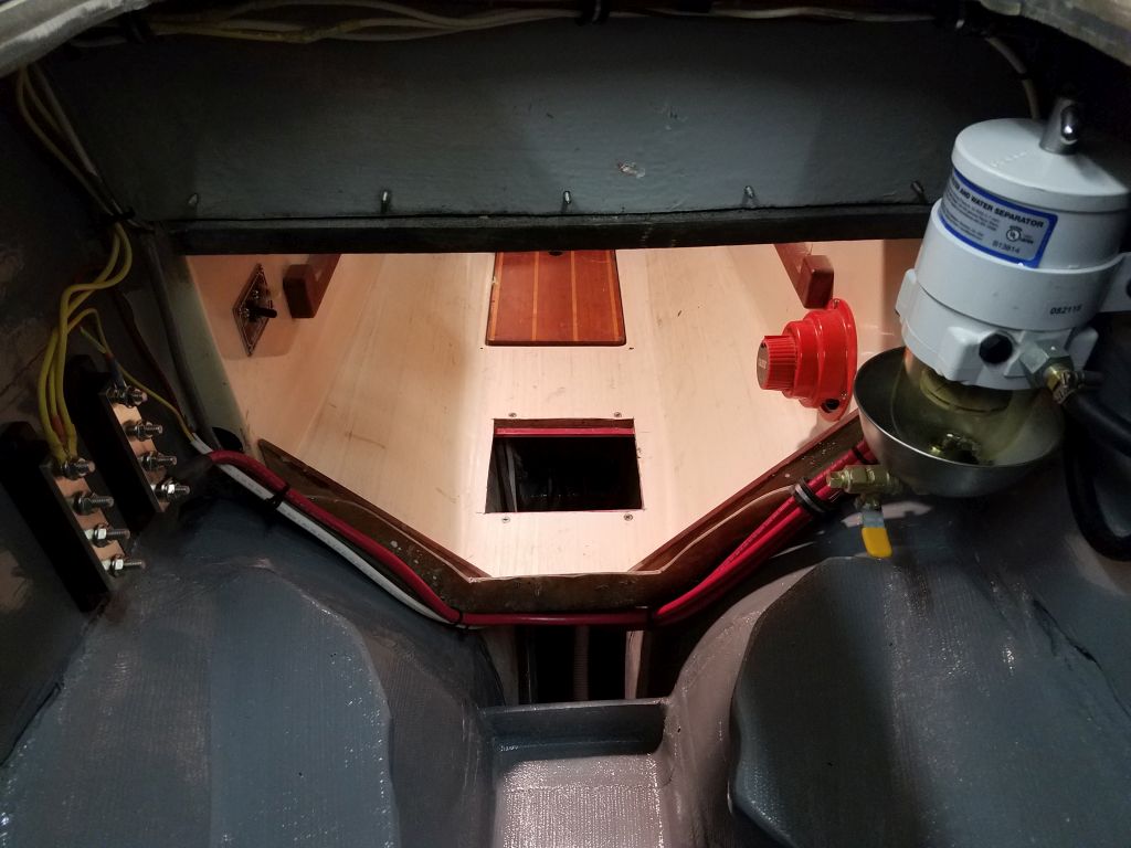
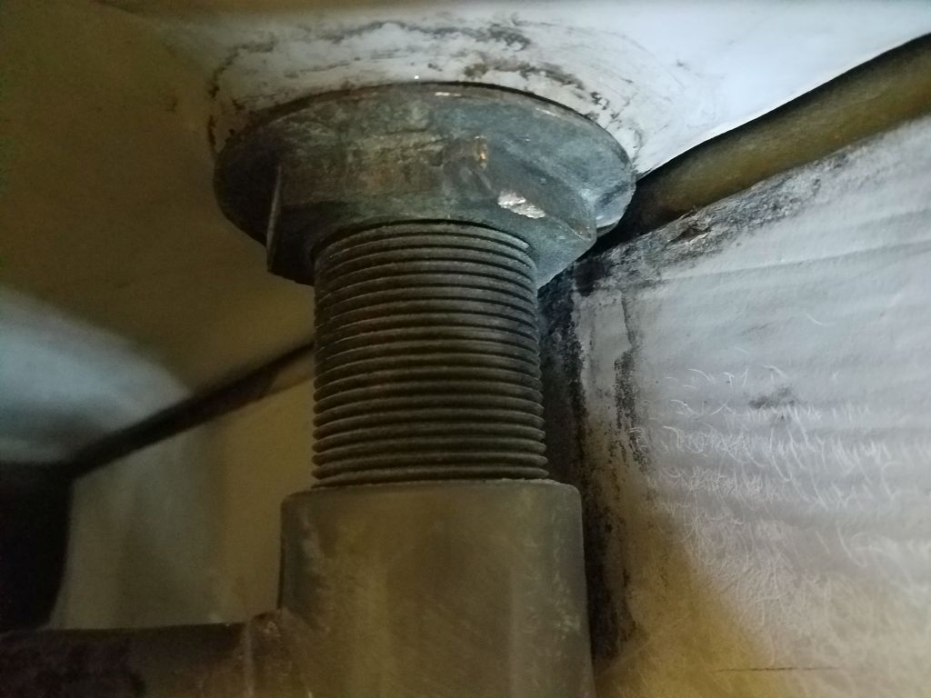
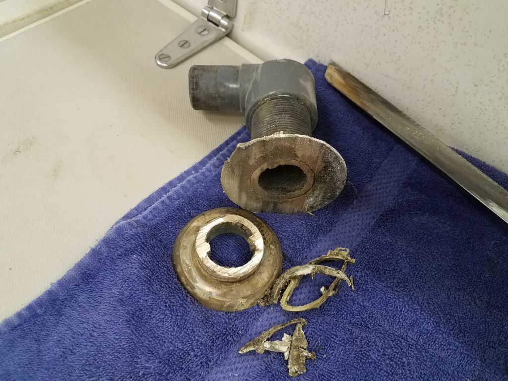
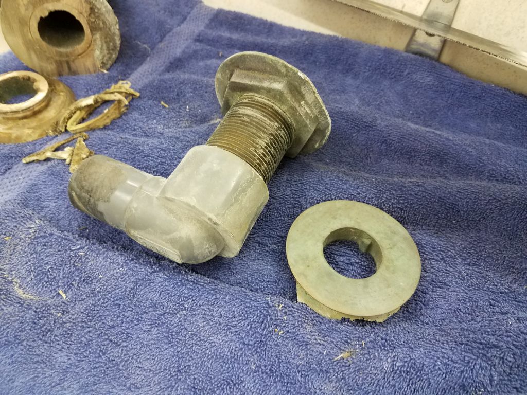
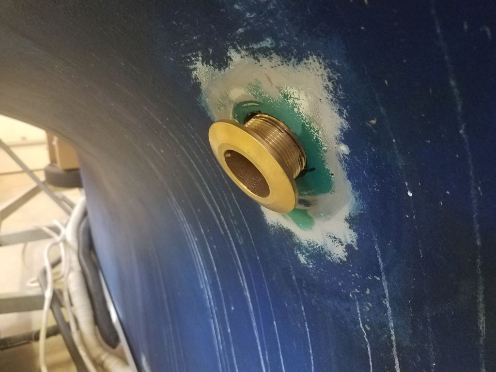
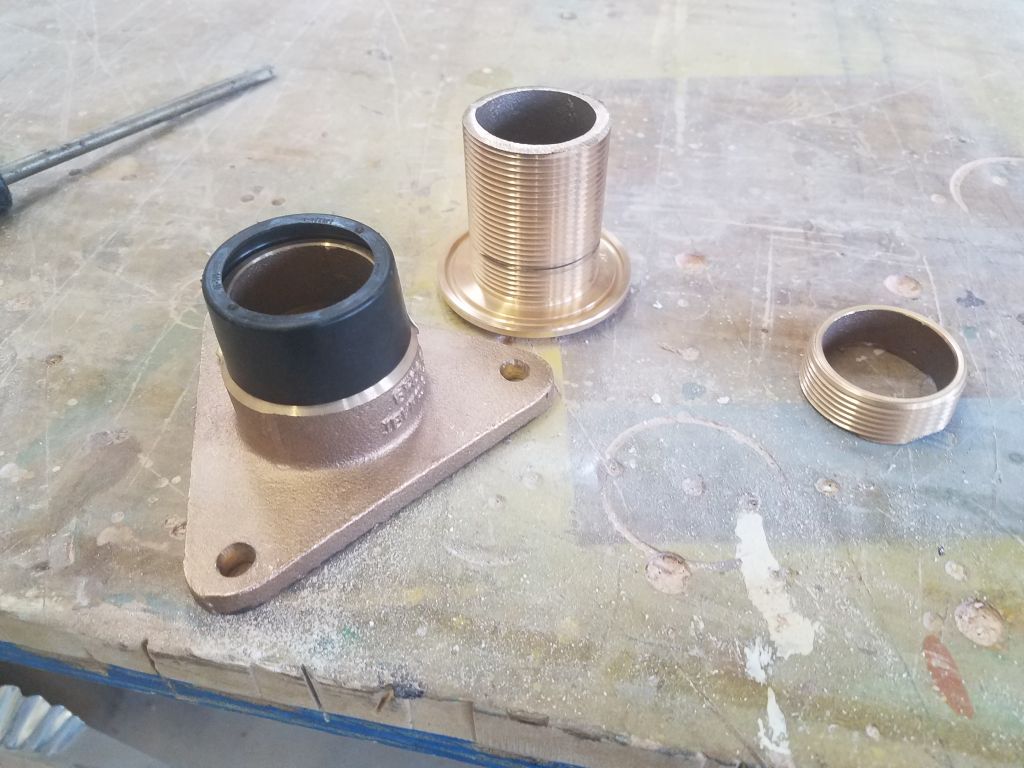
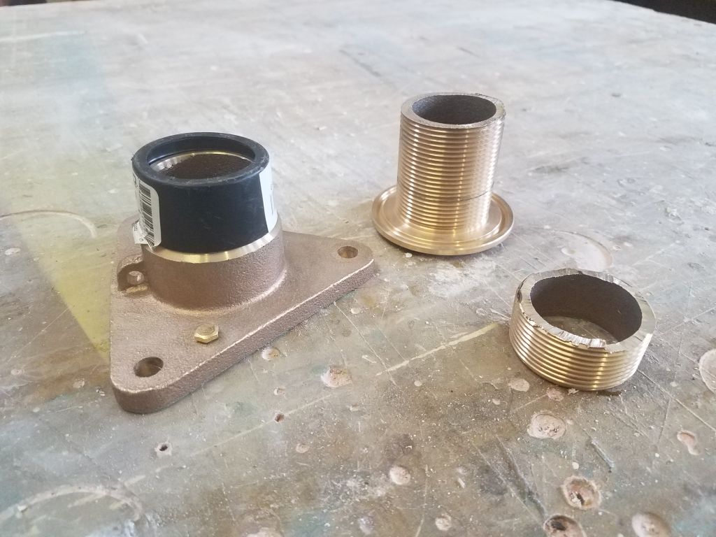
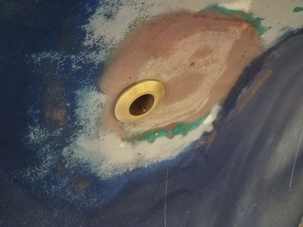
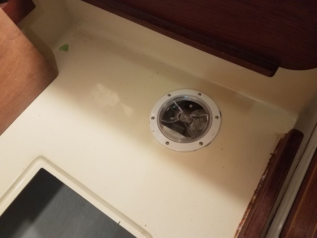
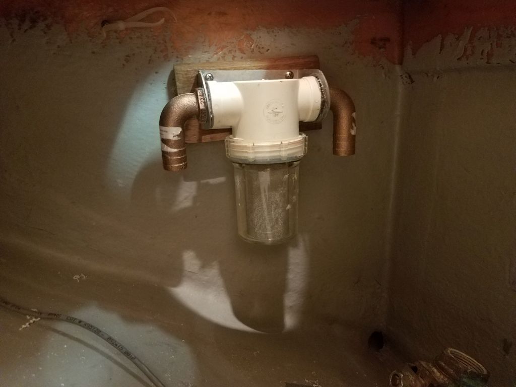
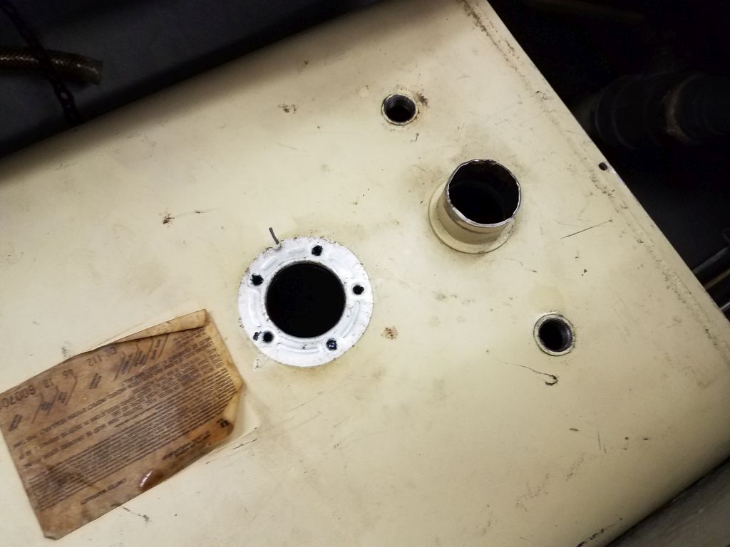
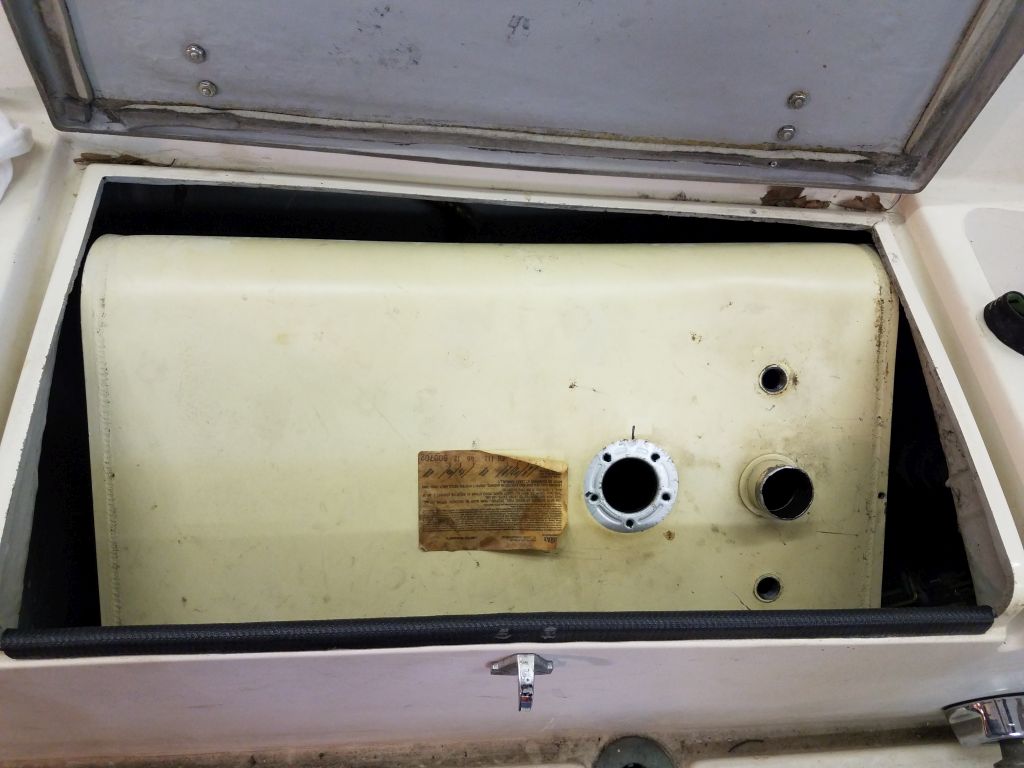
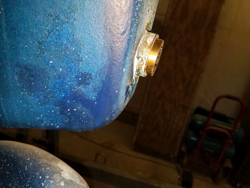
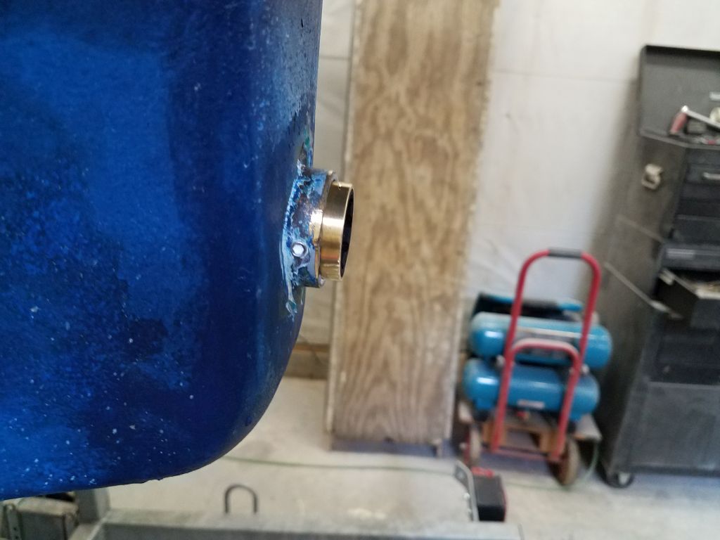
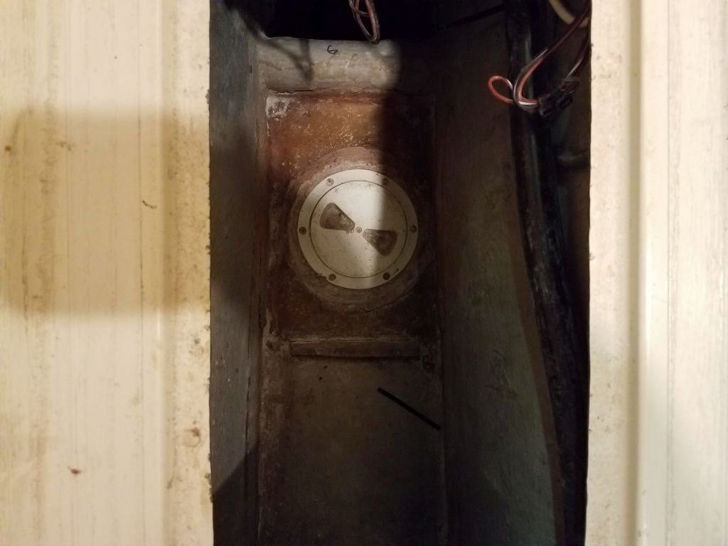
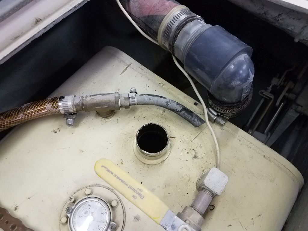
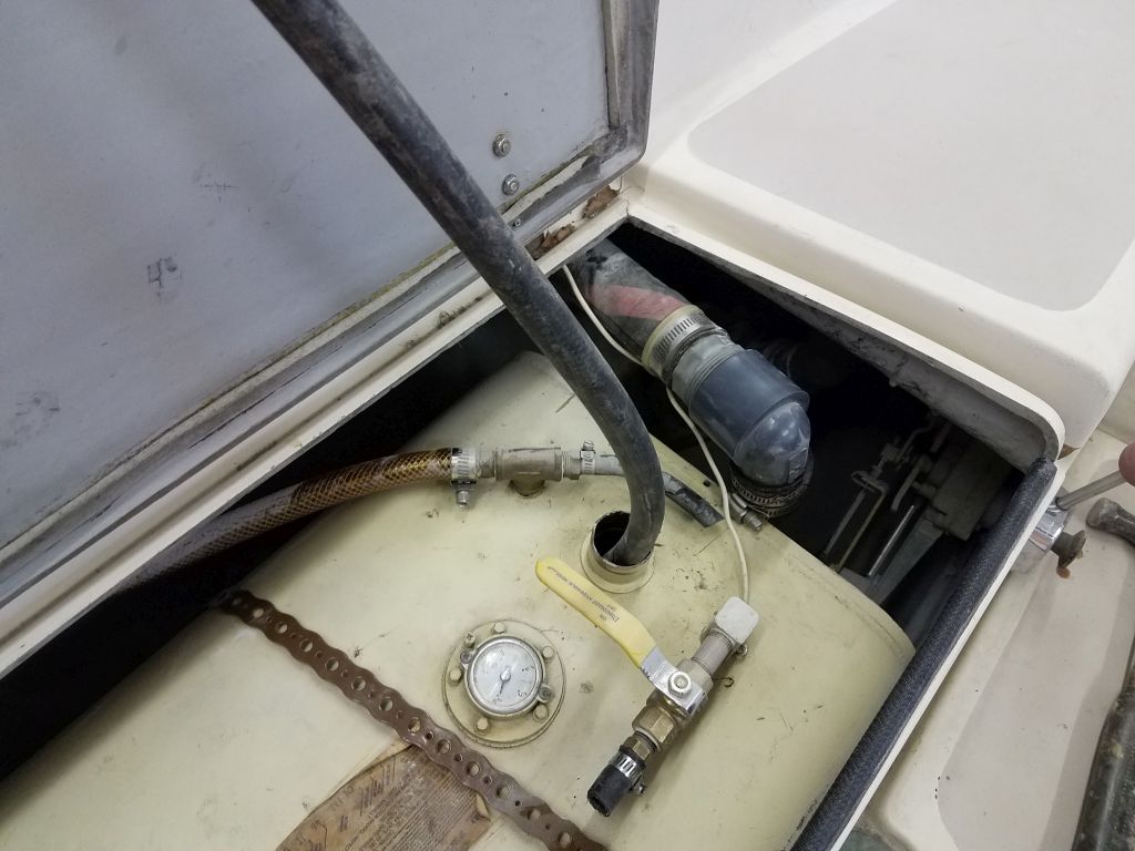
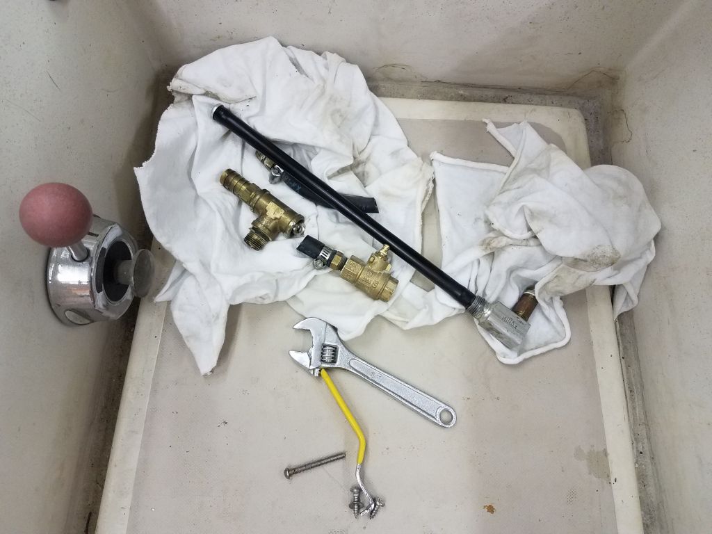
While the sole adhesive was curing, I planned to spend the day in the engine room, starting with the scupper through hulls, which I was ready to install as I began to close in on the final work leading up to the engine installation itself. I gathered the various pieces of each through hull assembly, and prepared to go through the normal motions of through hull installation.
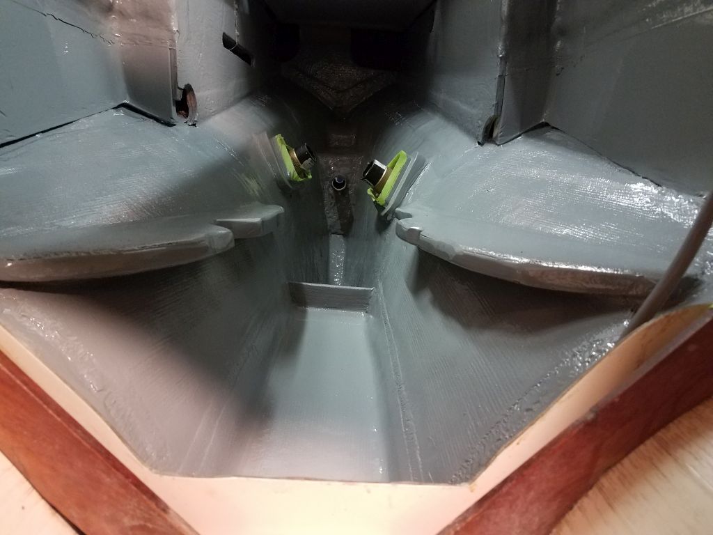
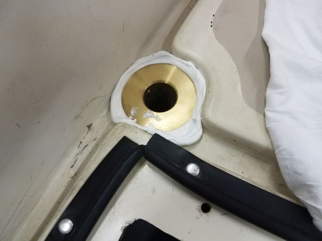
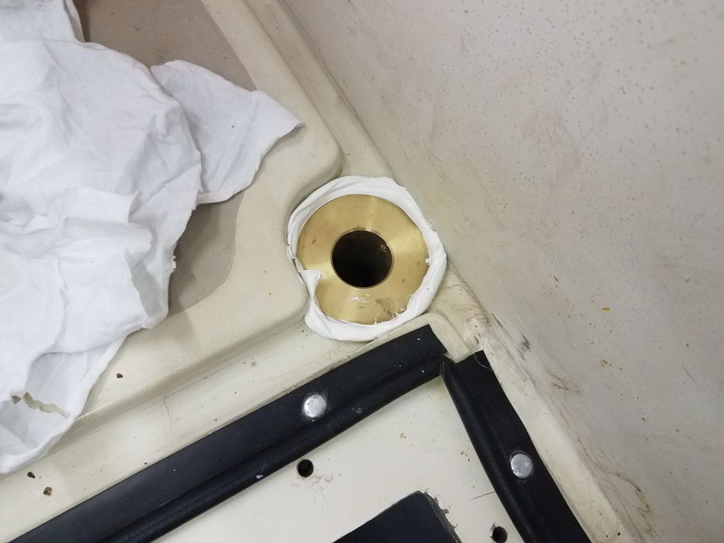
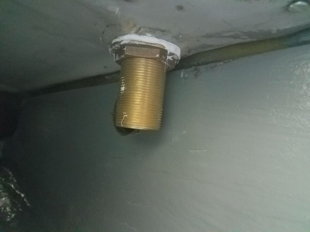
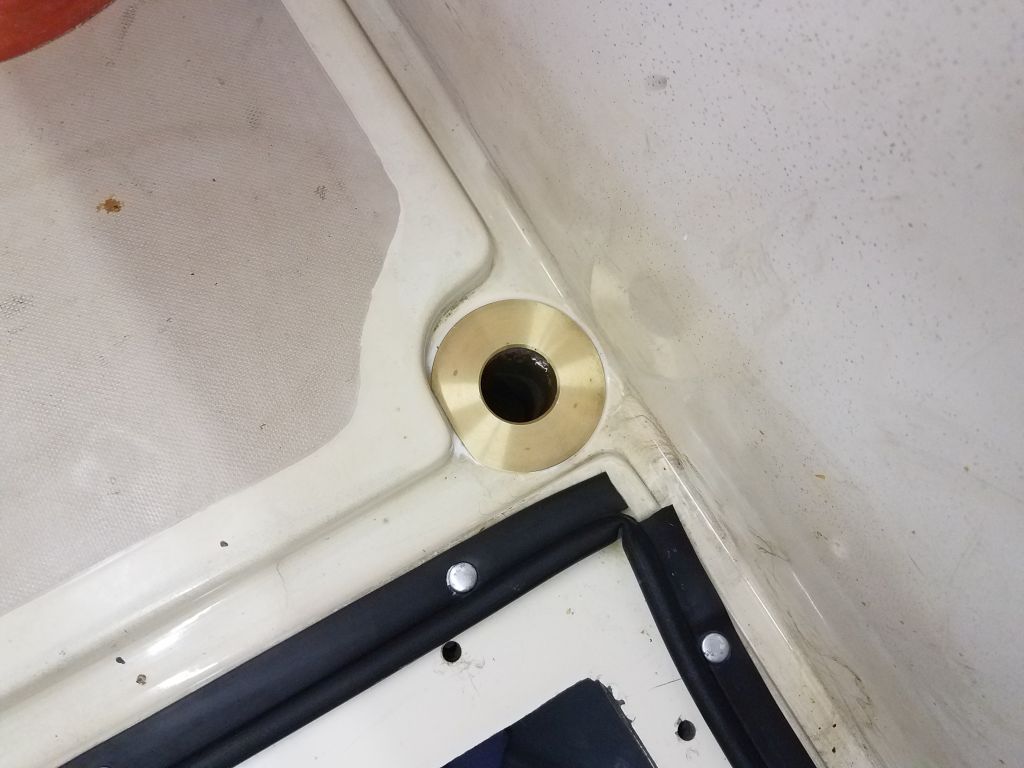
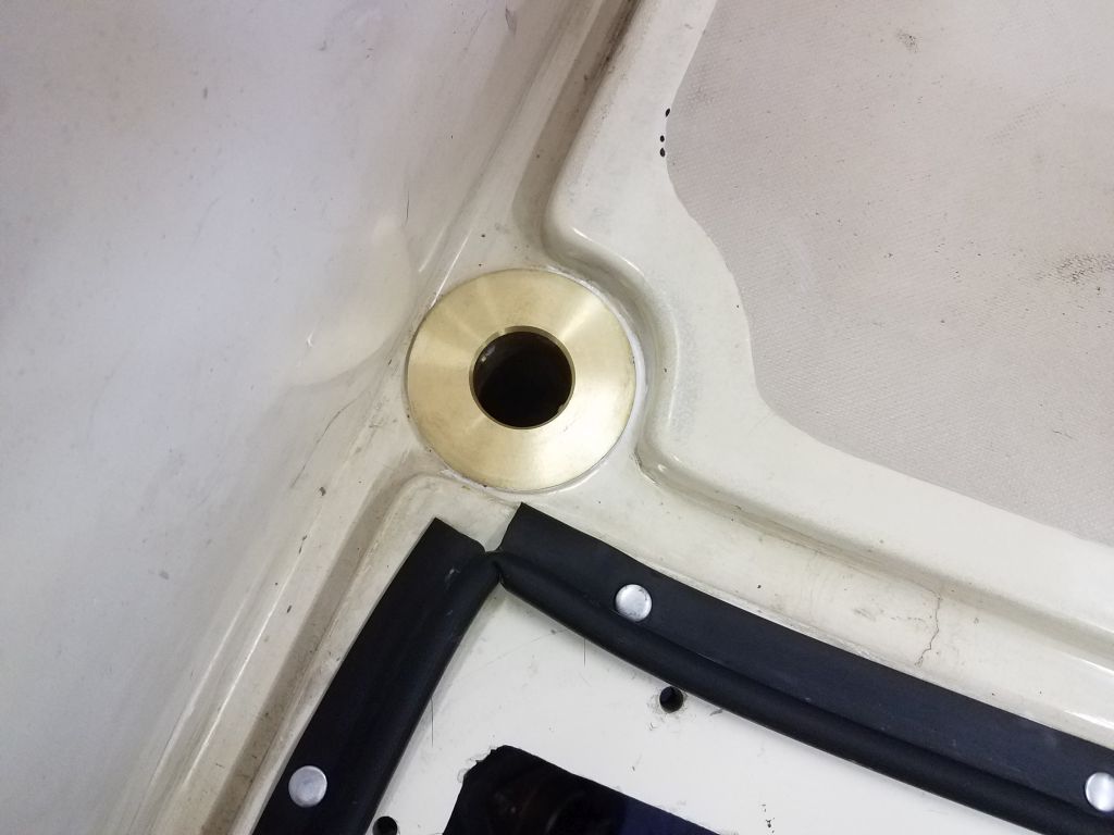
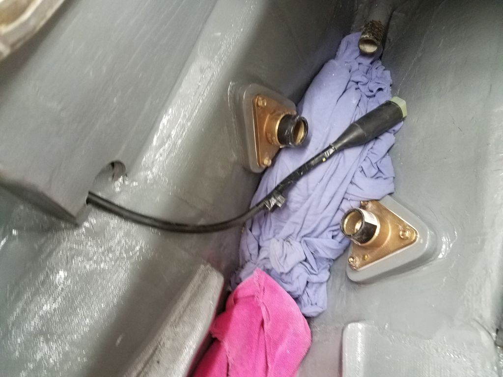
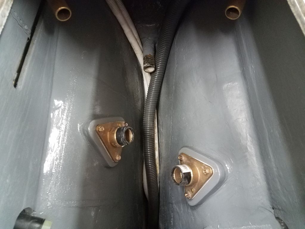
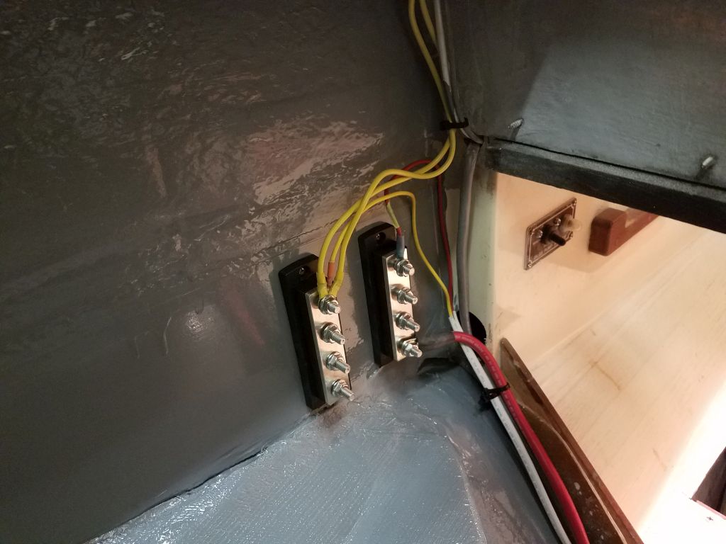
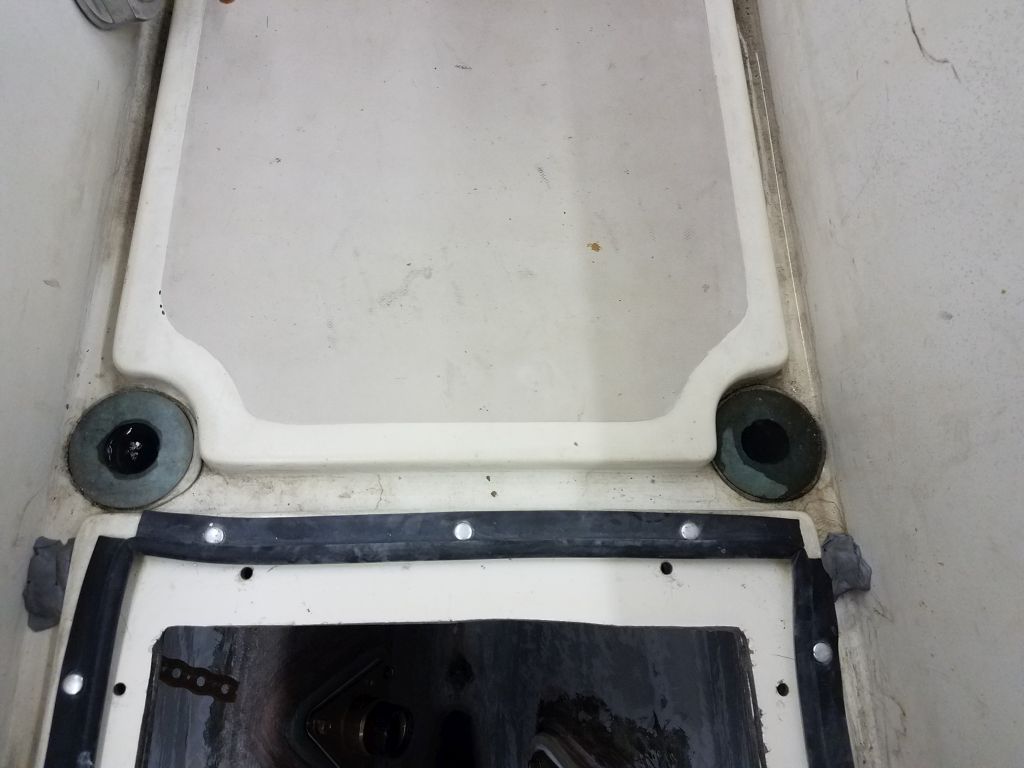
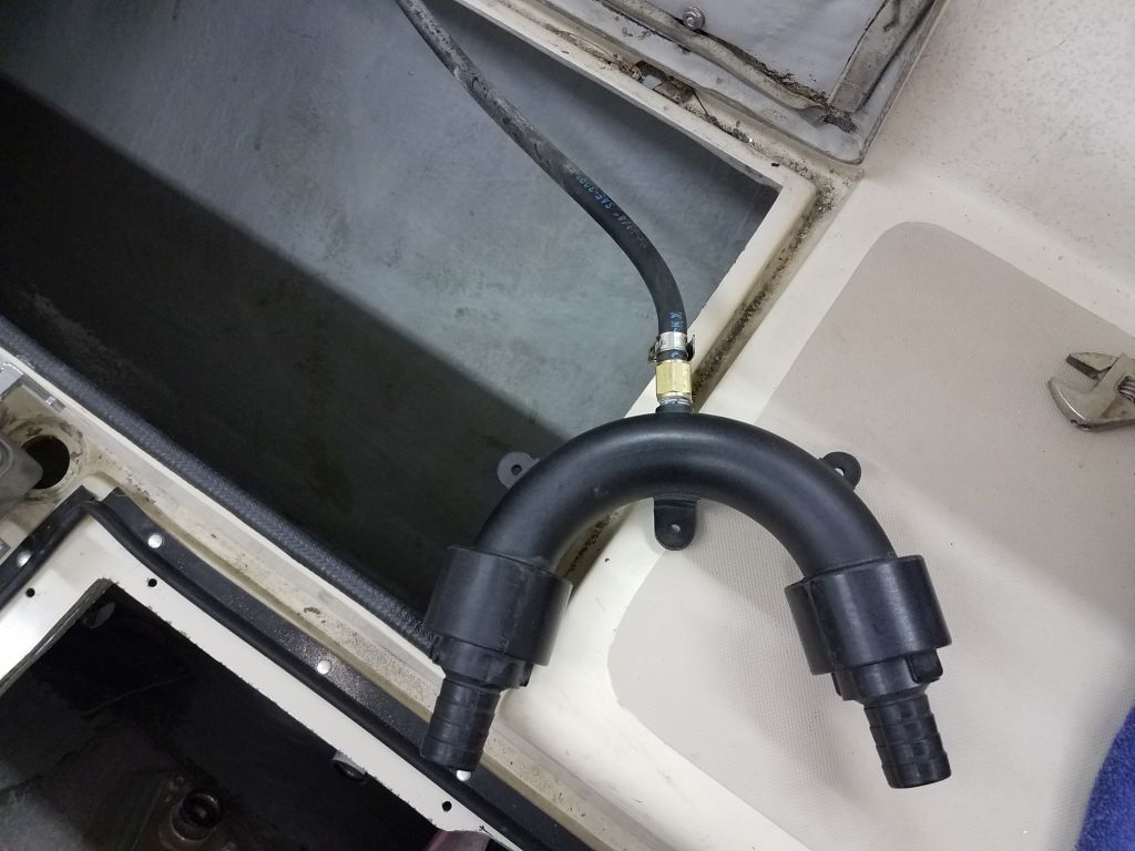
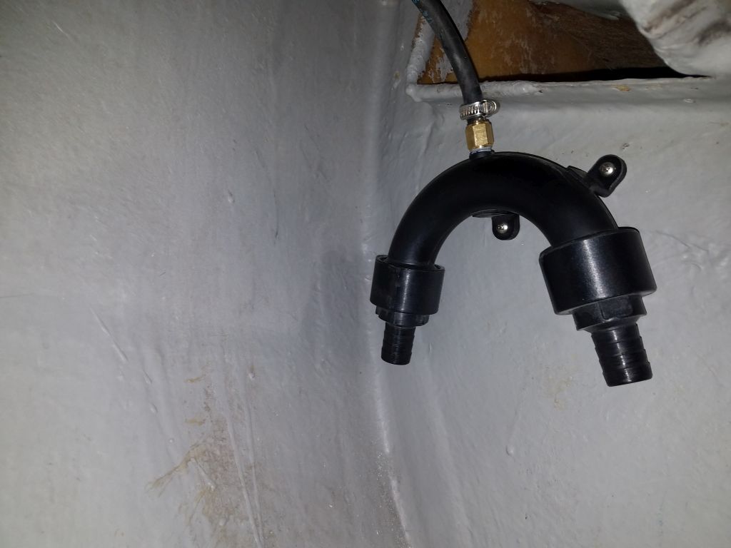
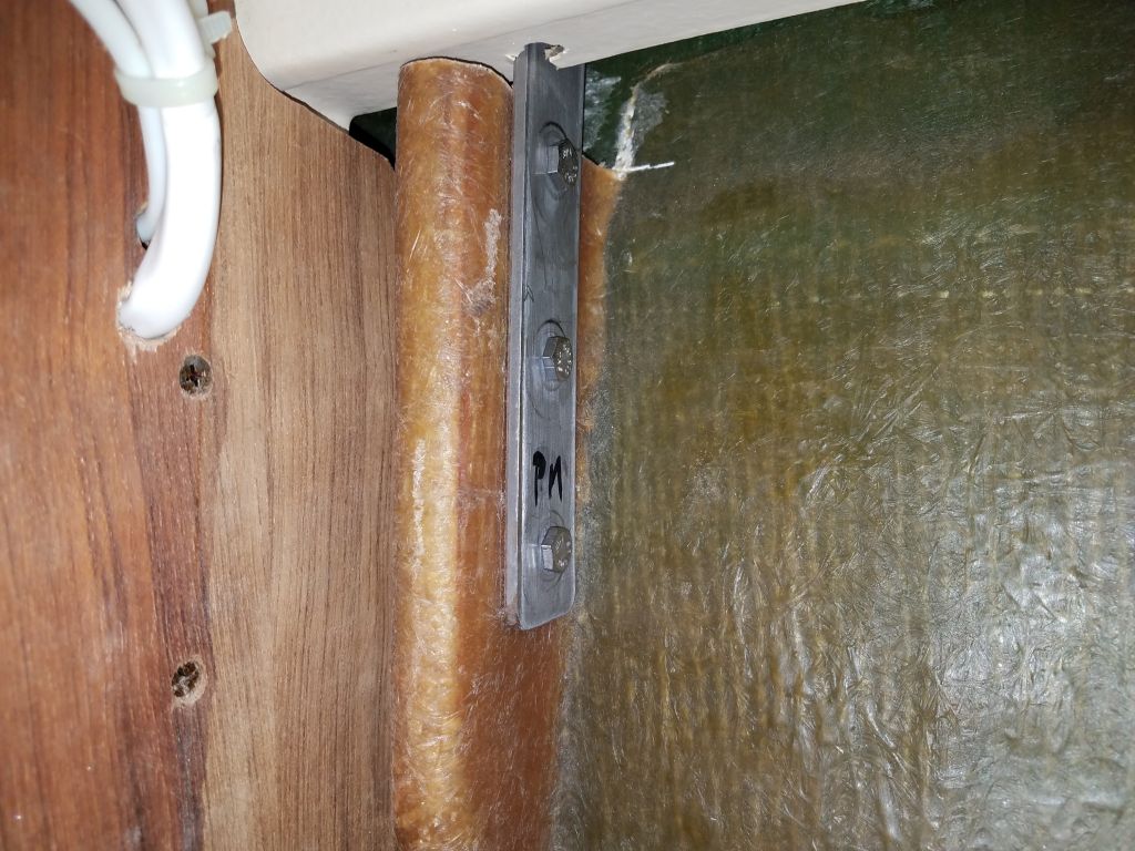
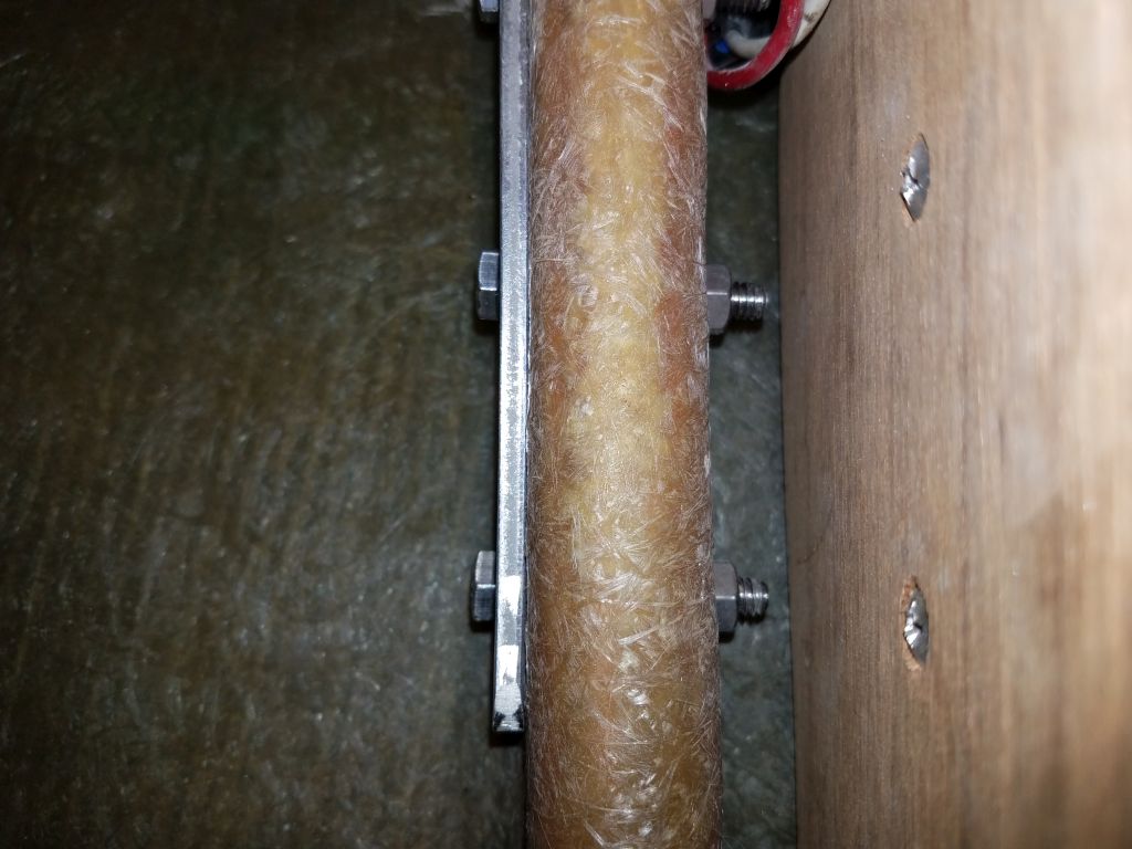
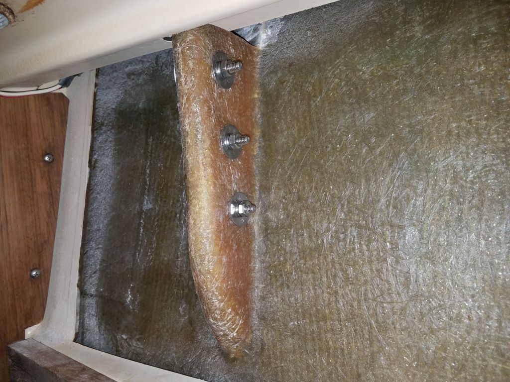
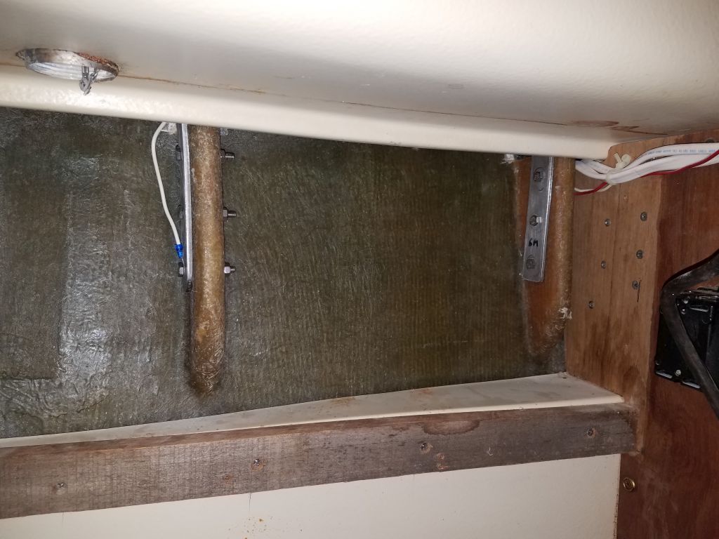
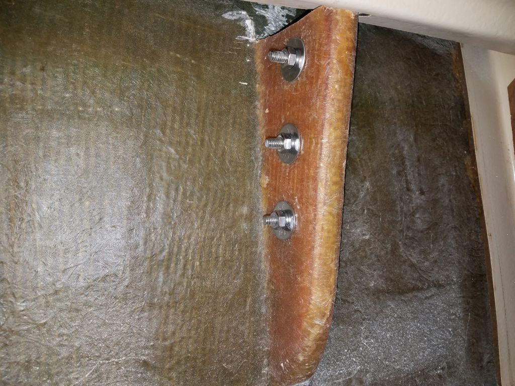
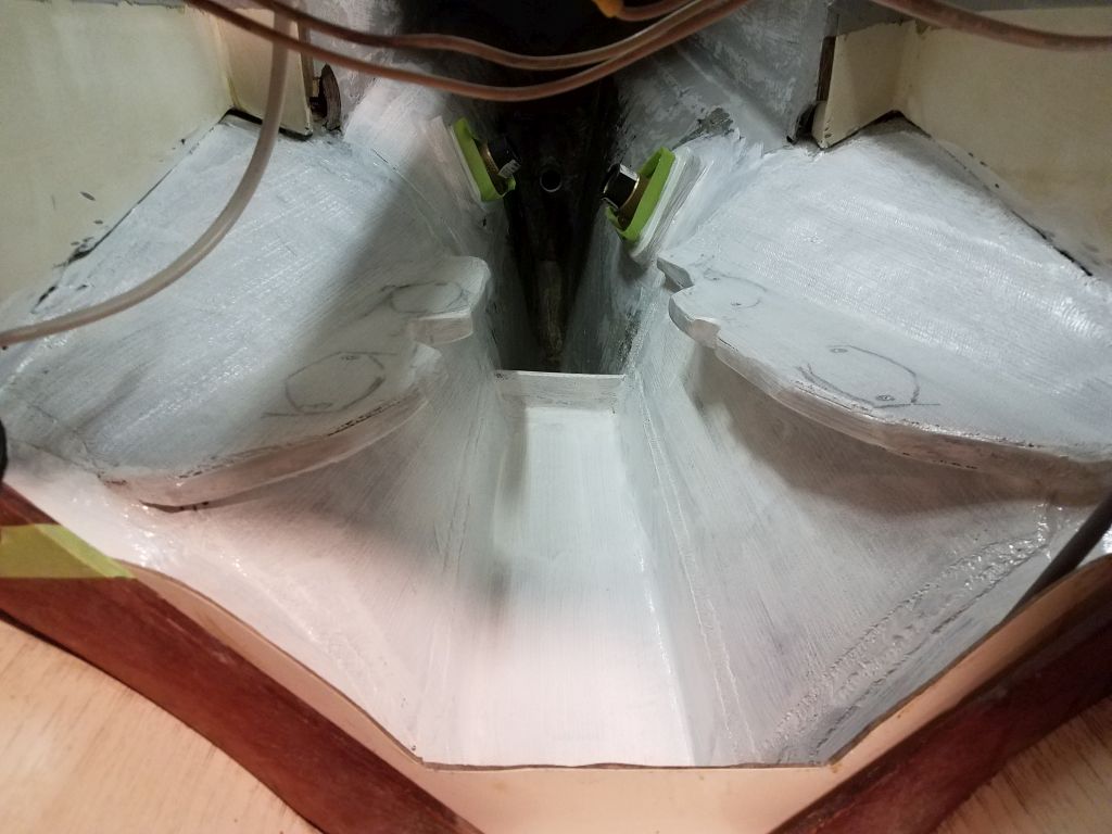
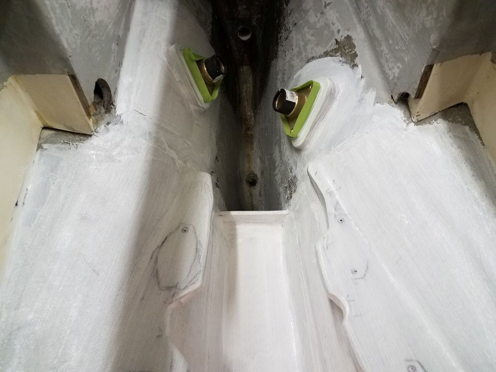
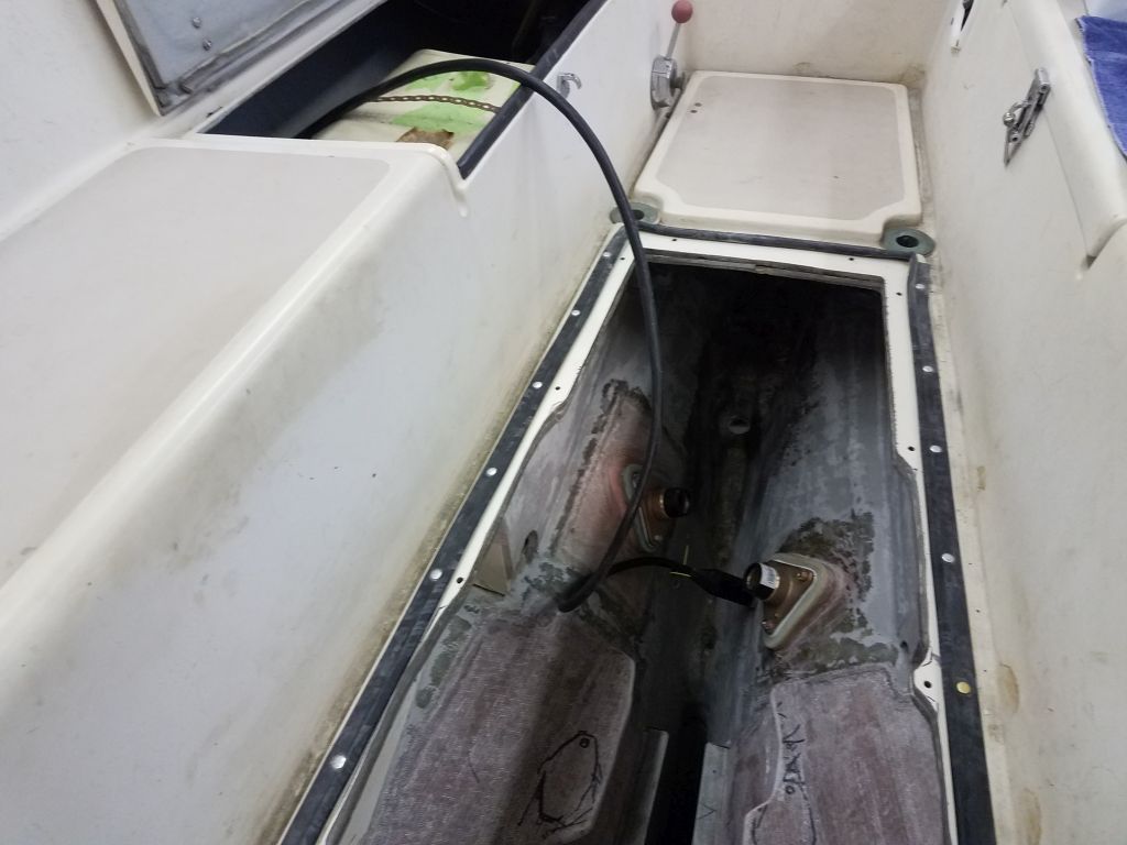
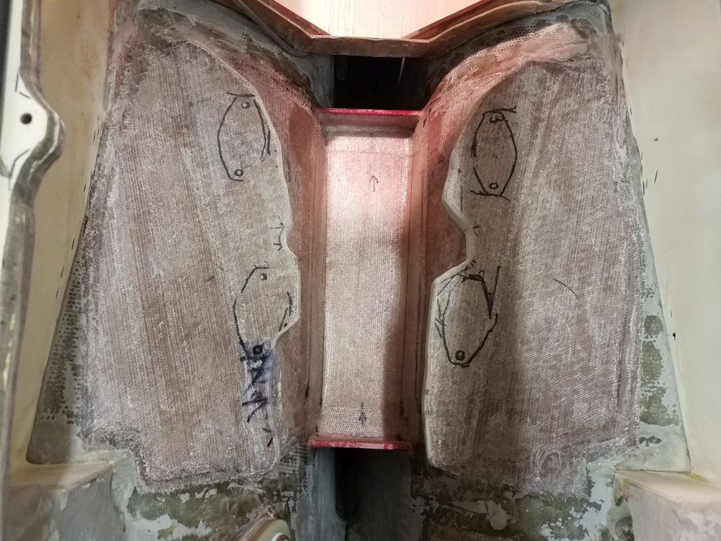
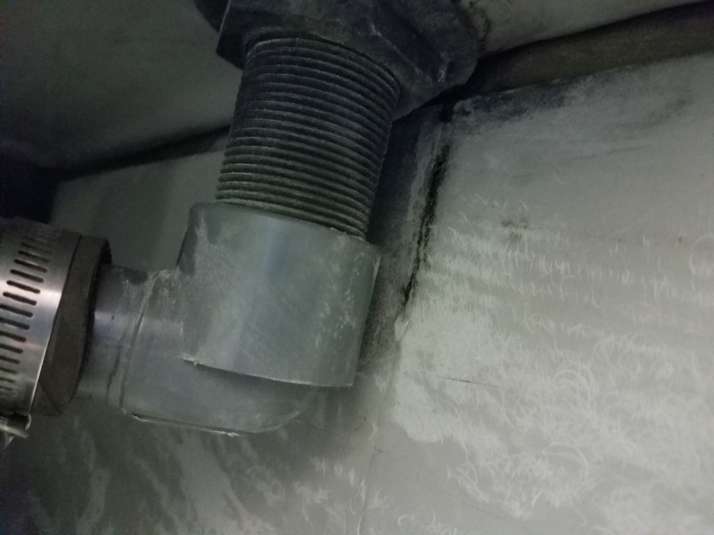
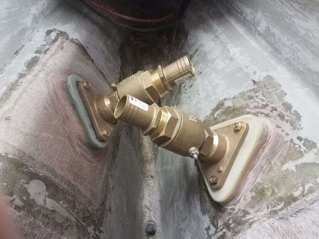
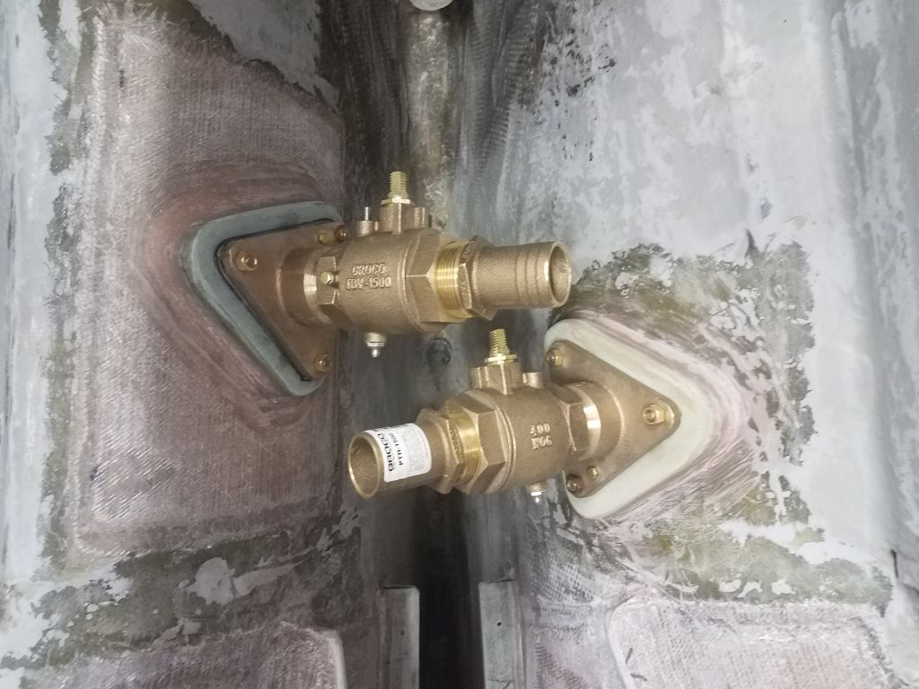
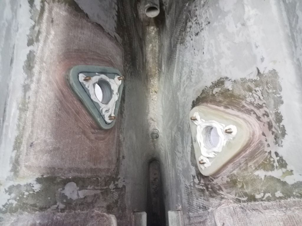
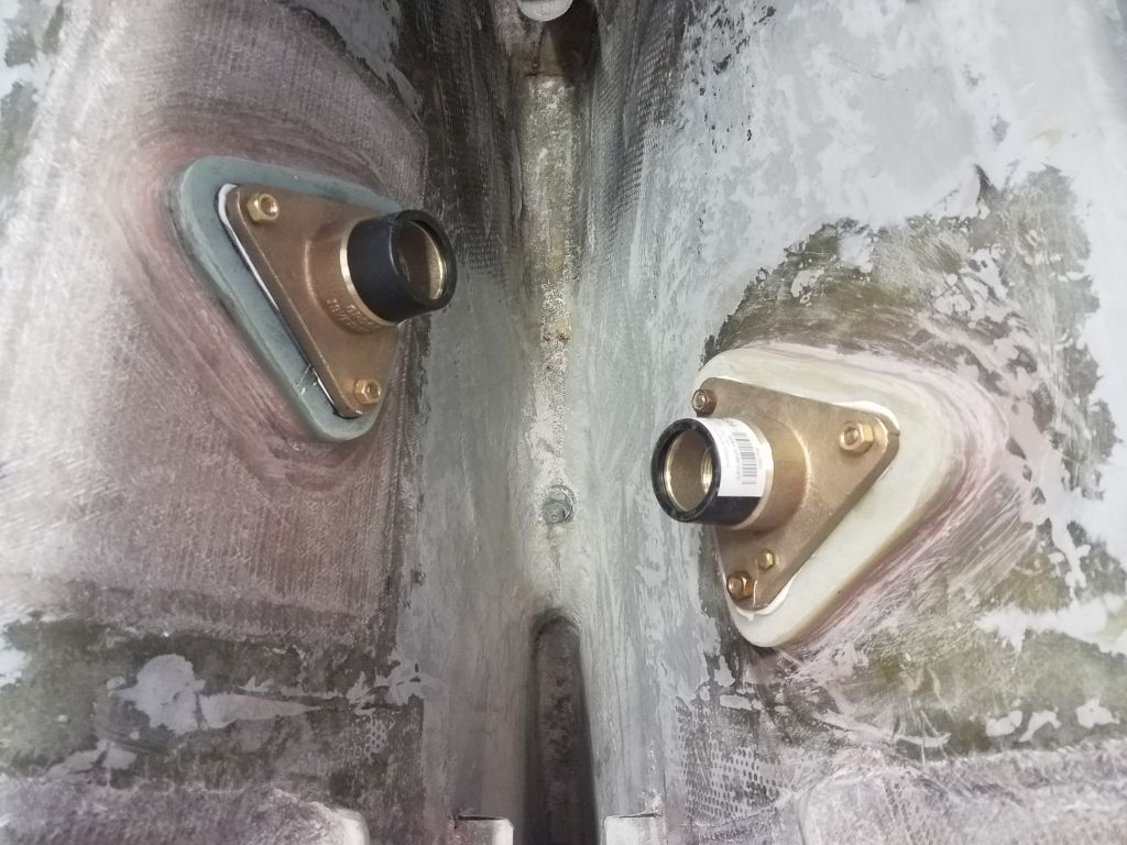
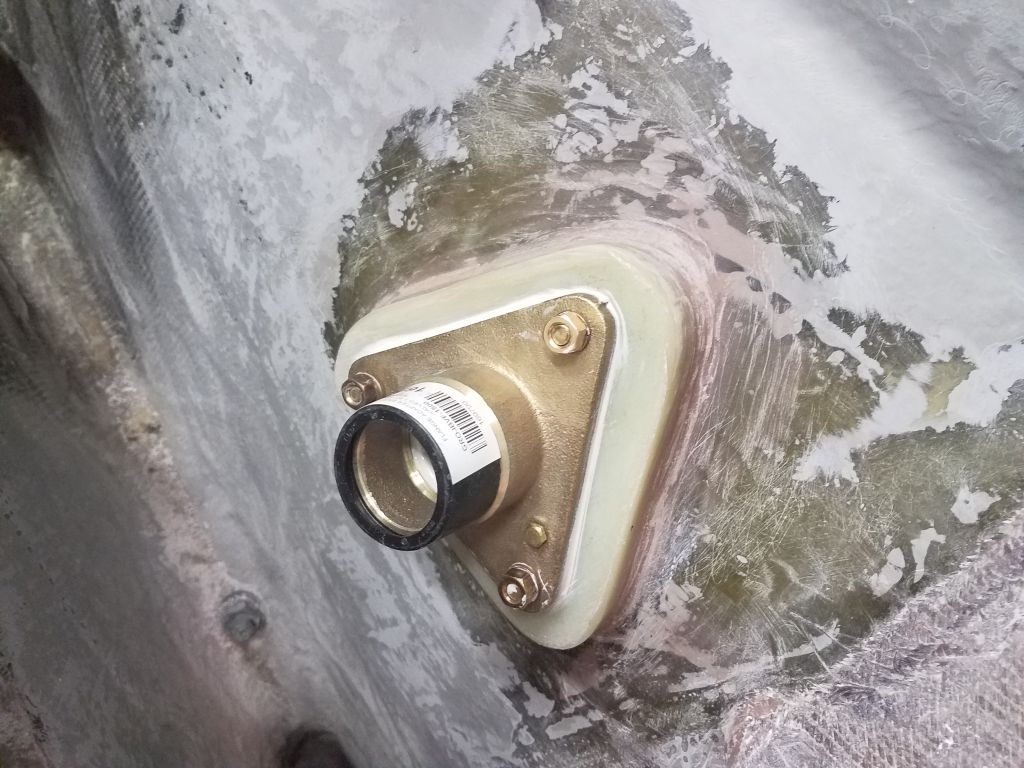
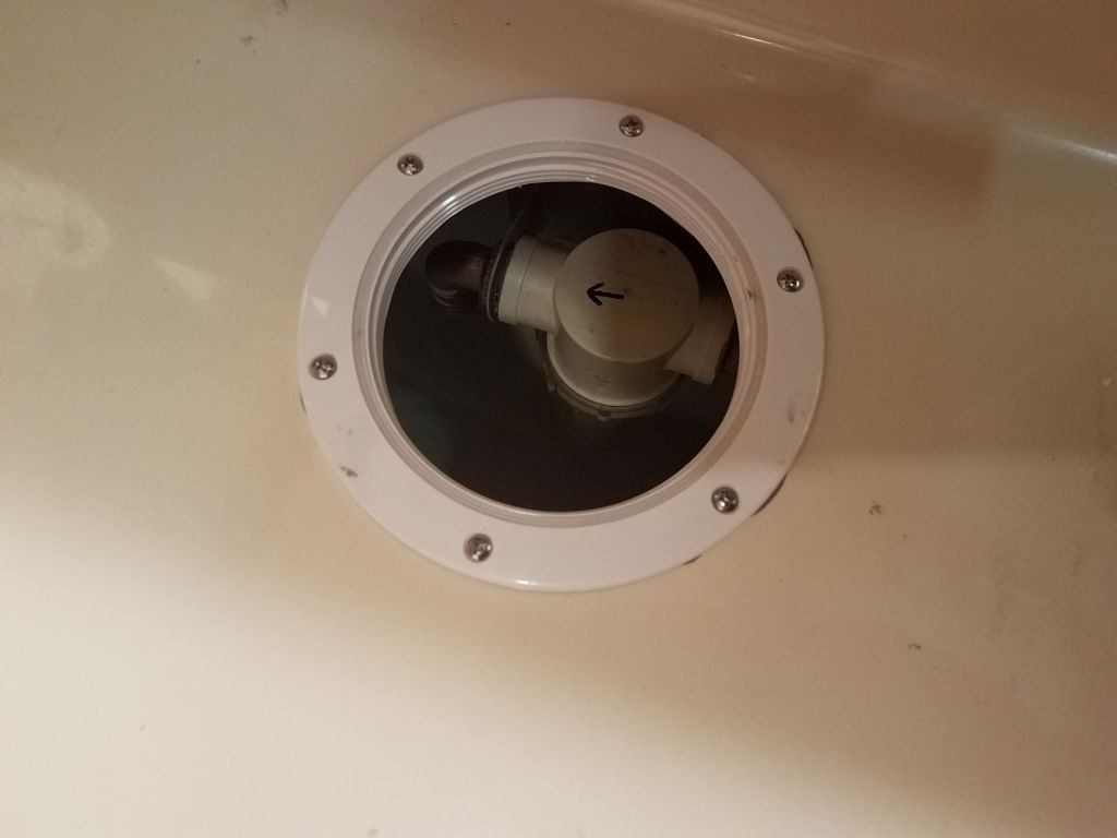
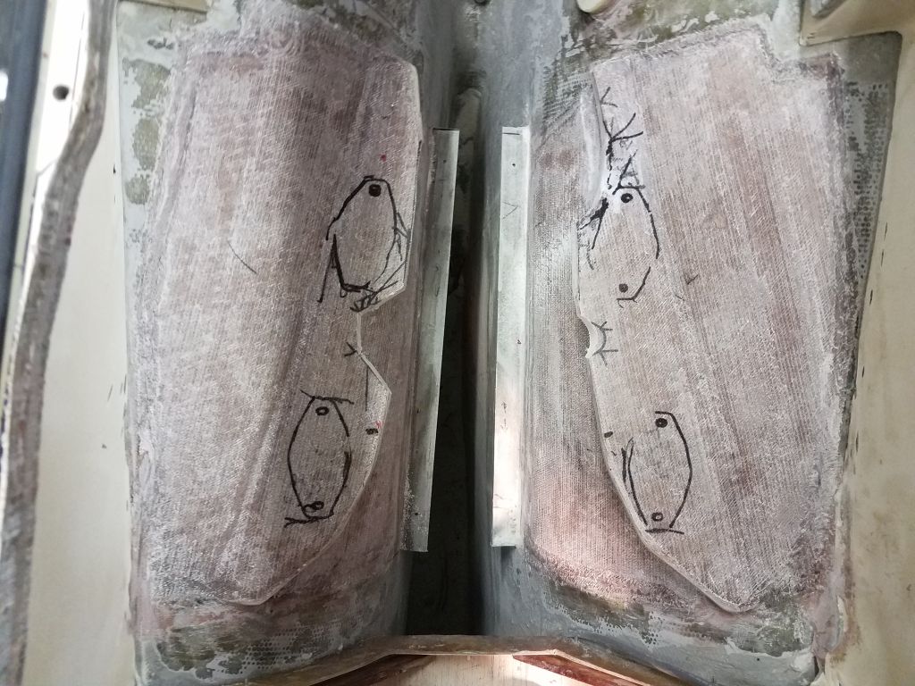
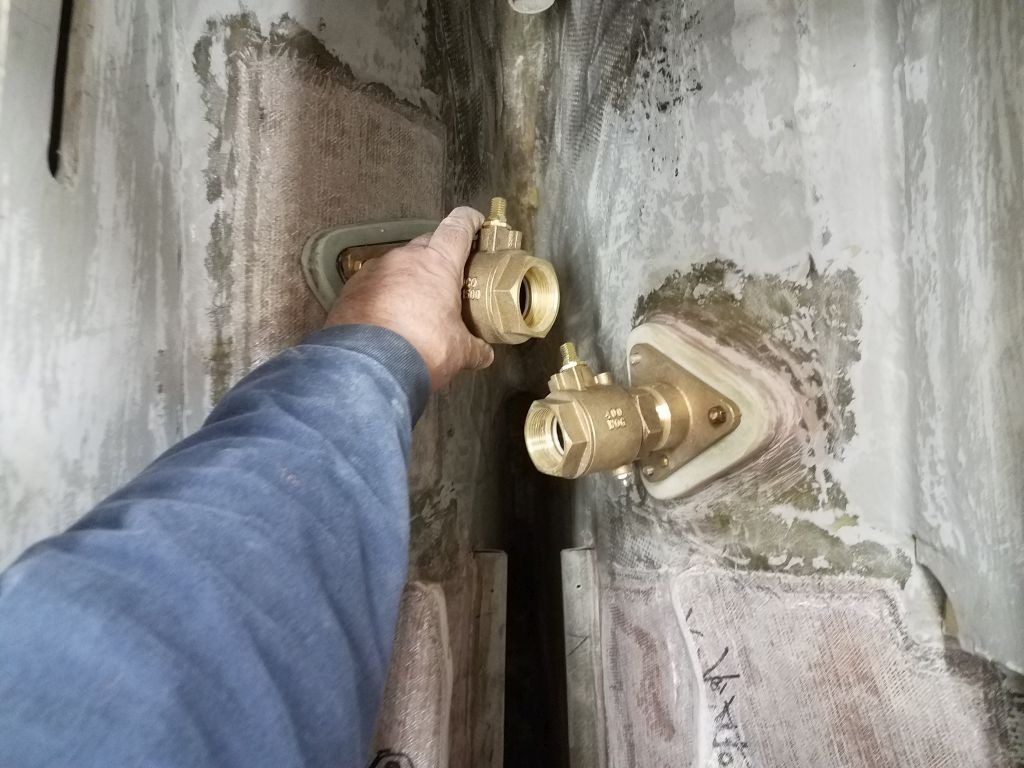
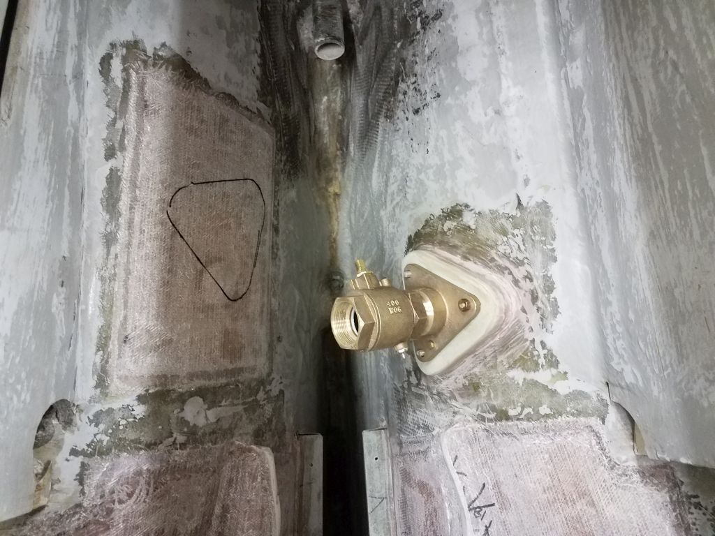
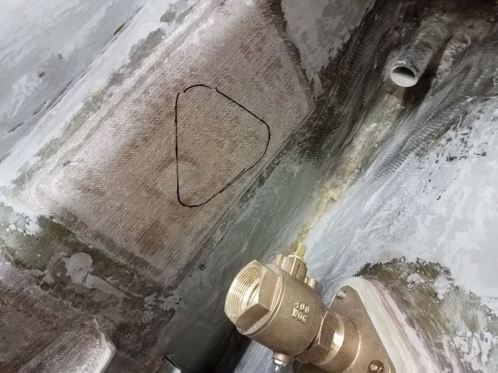
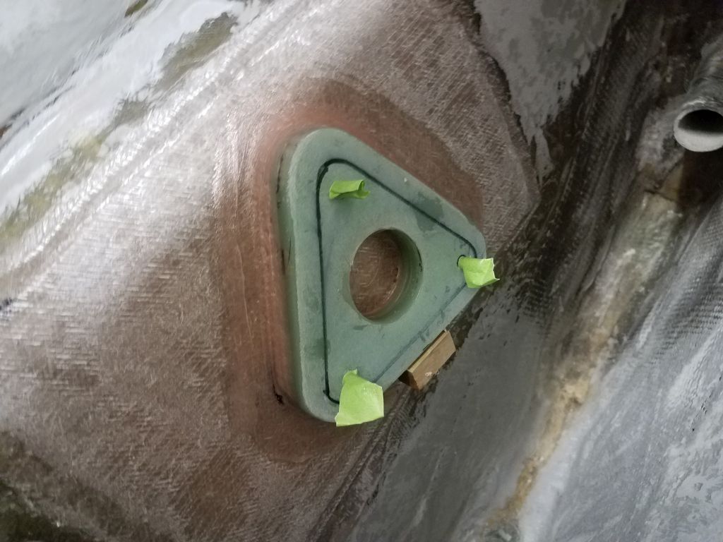
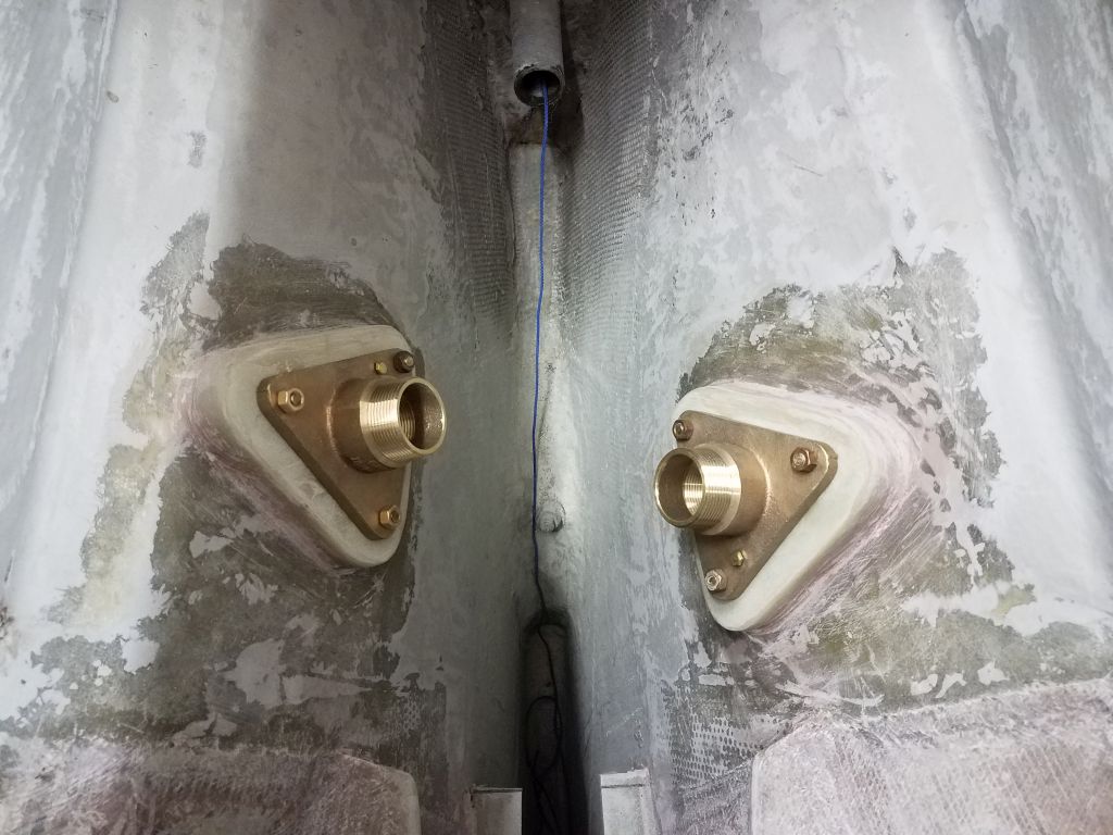
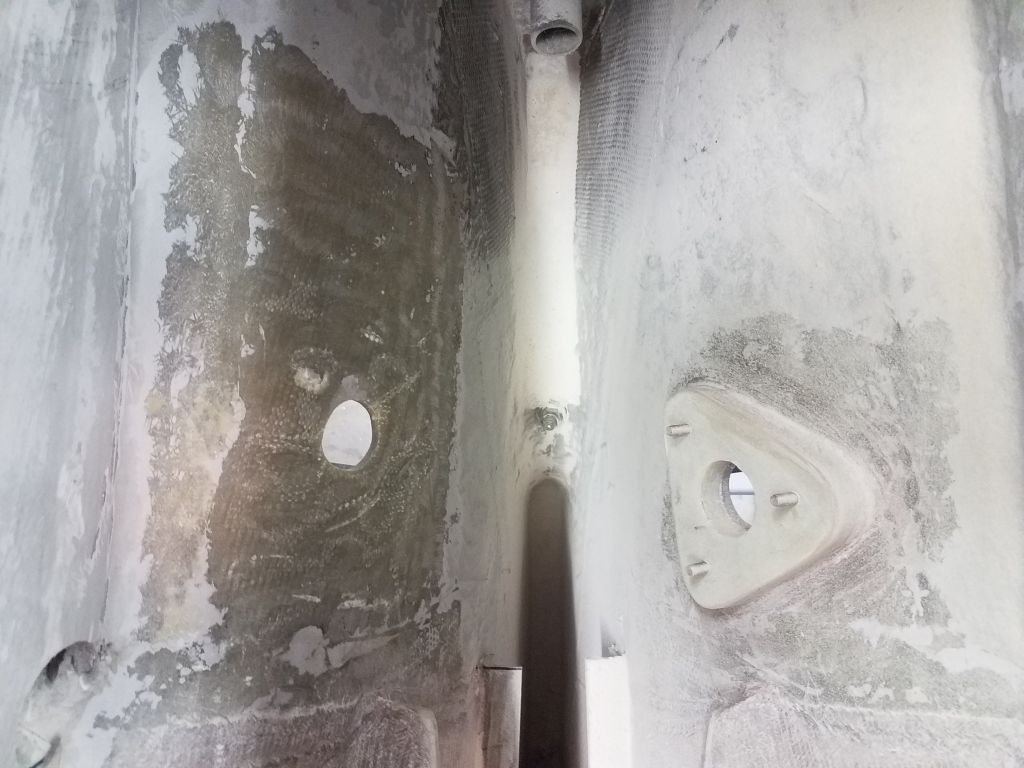
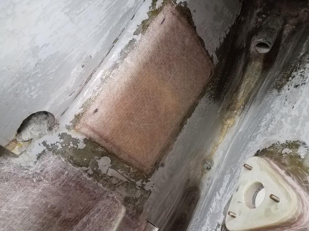
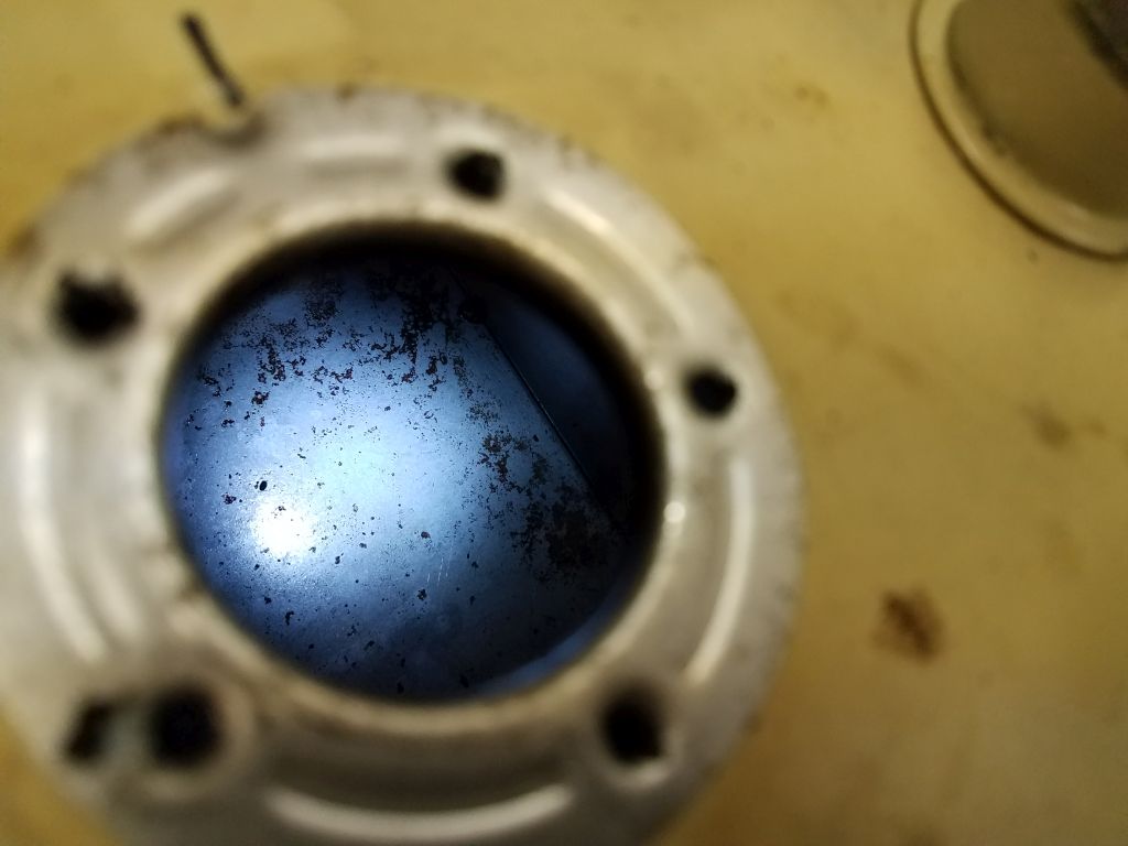
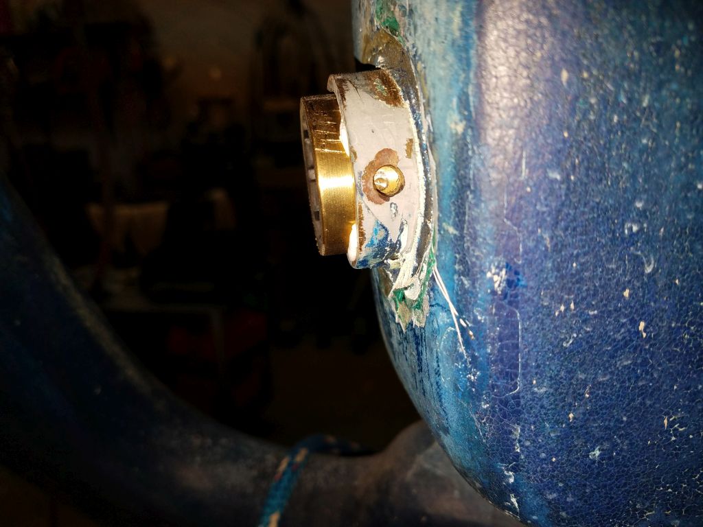
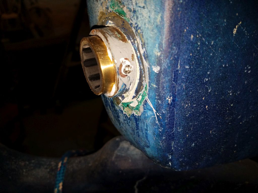
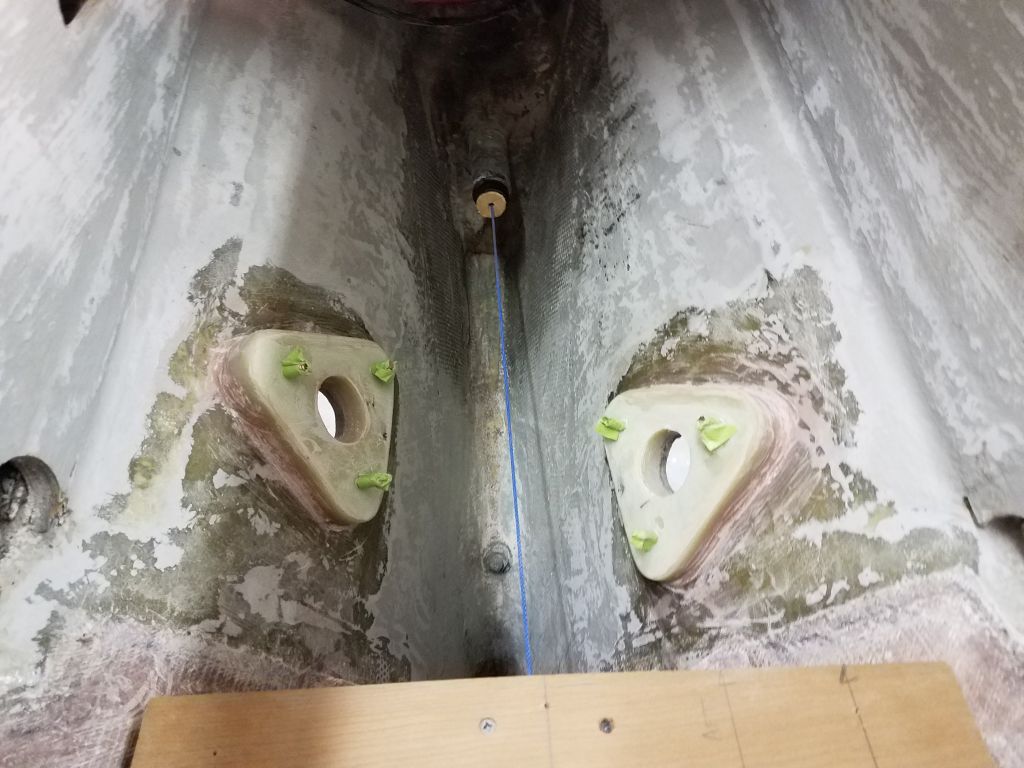
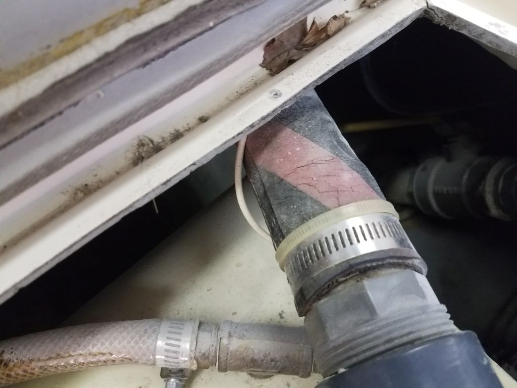
Inside the boat, I dry-fit the two flange bases on the pre-installed backing blocks and studs, intending to test-fit the threaded through hulls themselves and cut them to length. First, though, I wanted to see if I’d be able to spin on the through hull valves after installing the flange base and through hull, or if I needed to pre-install the valves first, given the tight confines of the space and proximity of the two fittings across from one another.
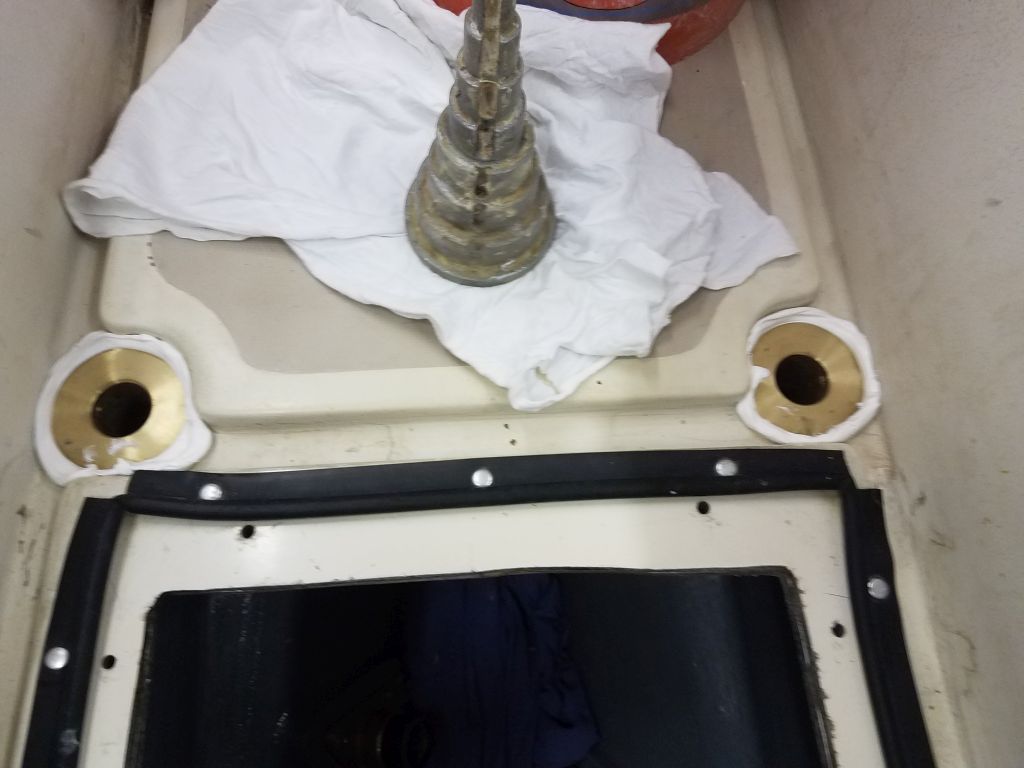
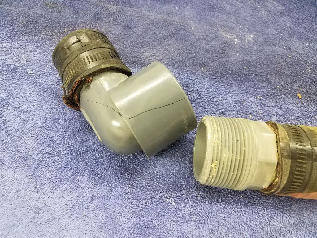
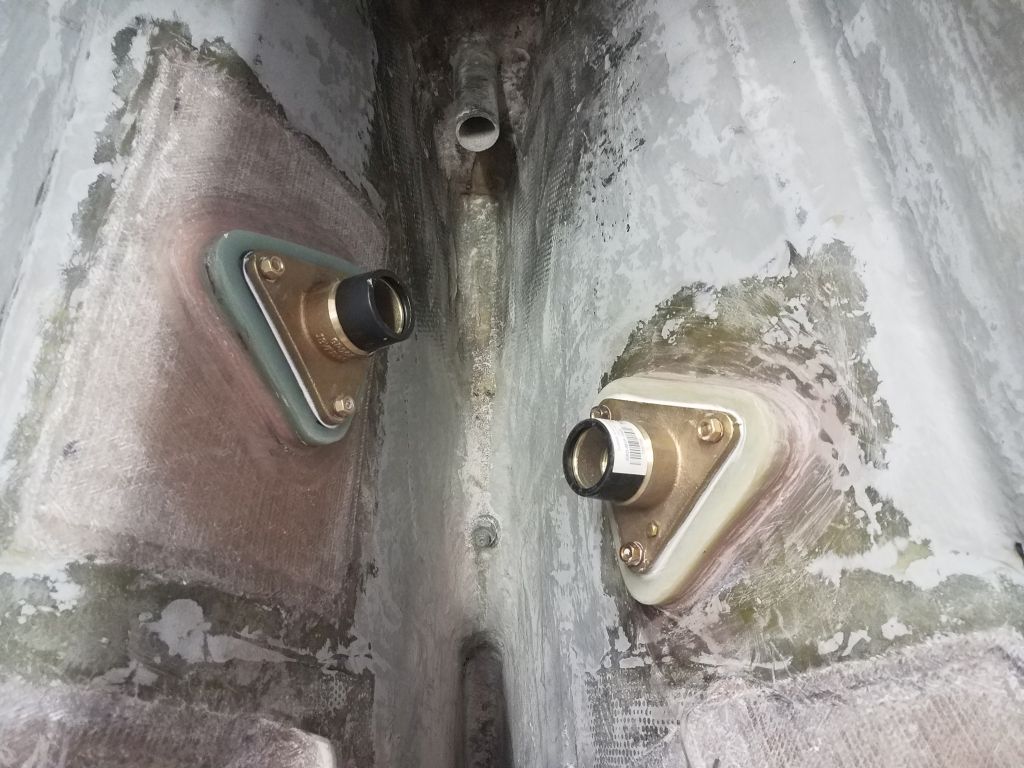
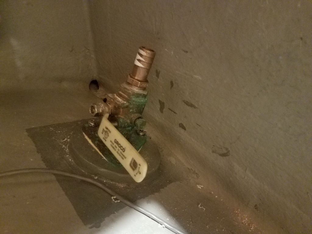
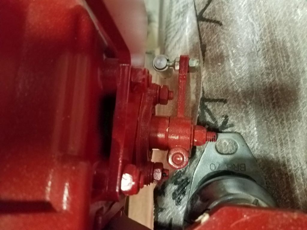
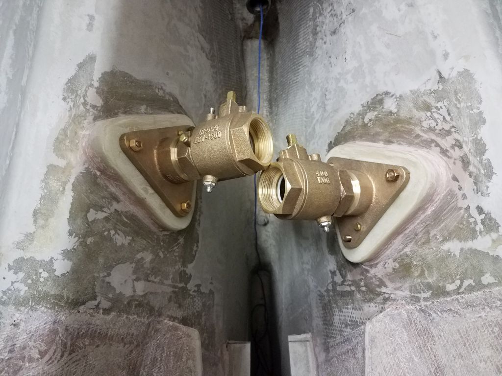
Immediately, this highlighted a major problem: The two valves didn’t clear one another sufficiently. Well, the valves sort of did, but there was no way that the pipe-hose nipples would clear enough to allow a workable result.
I felt like kicking myself off the boat. I knew the two locations were close, of course, but also knew they were slightly offset, intentionally, and that the old valves had fit. But none of that mattered here, since in this case the two fittings interfered with one another in an ultimately catastrophic way.
I should have checked before starting the install long ago whether the new fittings would clear one another, but I never had. I foolishly assumed, without confirmation, that the new fittings would fit in the same locations.
Contemplating this unwanted turn of events, I considered my options. First, of course, was to move one of the fittings. Over the years, as I’d installed things like this, I’d often wondered what someone, say, 30 years in the future might have to say about my installation, and how difficult these installations might be to remove. I never had any problem with the apparent permanence of what I considered a permanent installation, like a through hull, so had never worried about providing for its removal. Now it looked like I might get a chance to try.
I really, really did not want to have to do that, so I considered if there was an alternative. I thought of changing the hardware to 1-1/4″ valves, which would work with a full-flow tailpiece to accept 1-1/2″ hose and which I’d sometimes used in the past because the slightly reduced flow diameter of the 1-1/4″ valve meant the valve body itself was substantially smaller. I thought that this might improve the clearance here enough to work, and was all set to order the new parts, but then I realized that the bolt pattern of the smaller flange base would also be smaller, and since I’d pre-installed the bolts in this case, there was no way to change the hardware either.
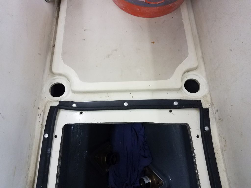
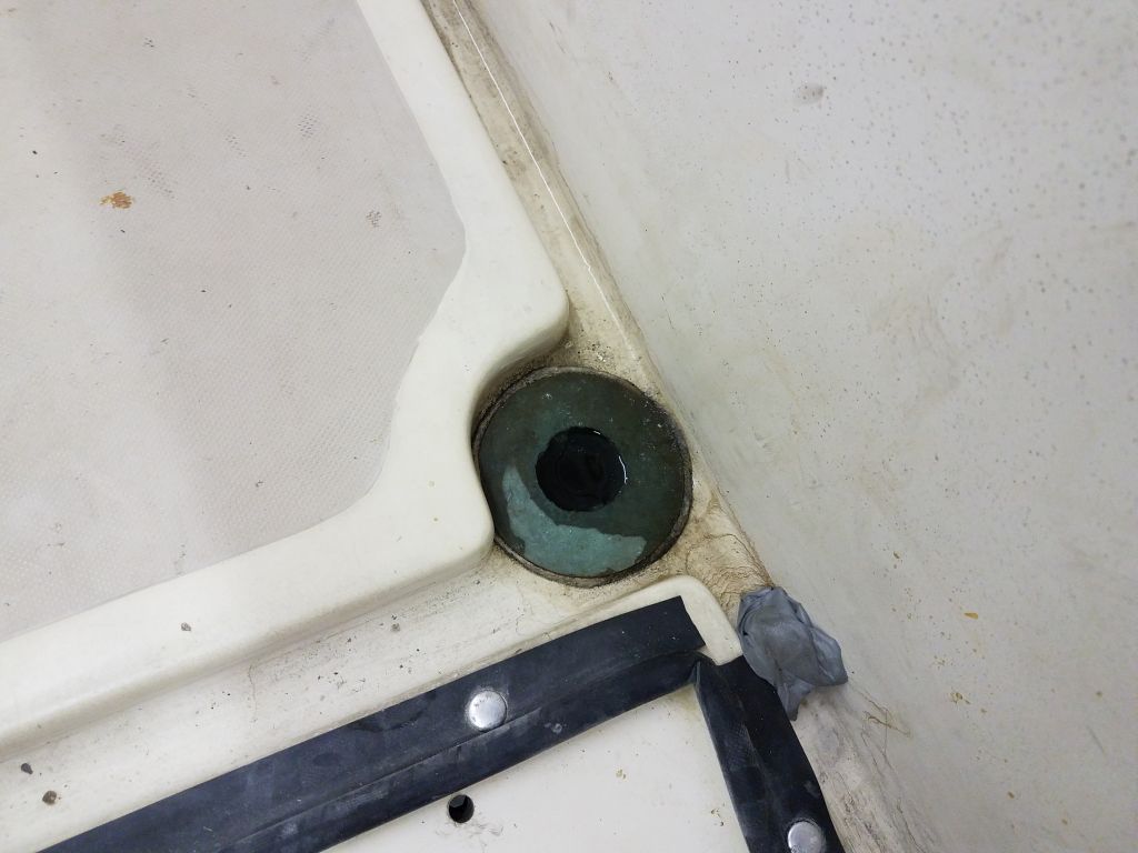
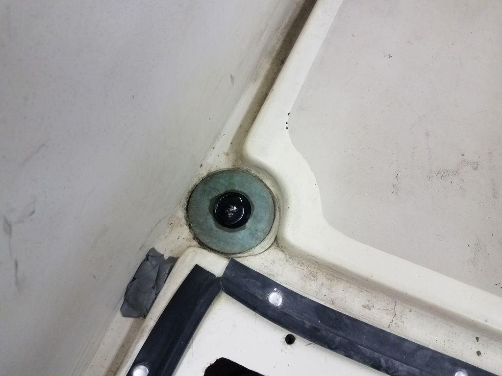
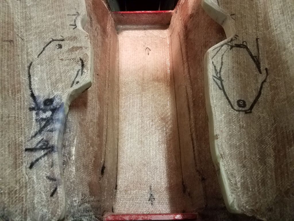
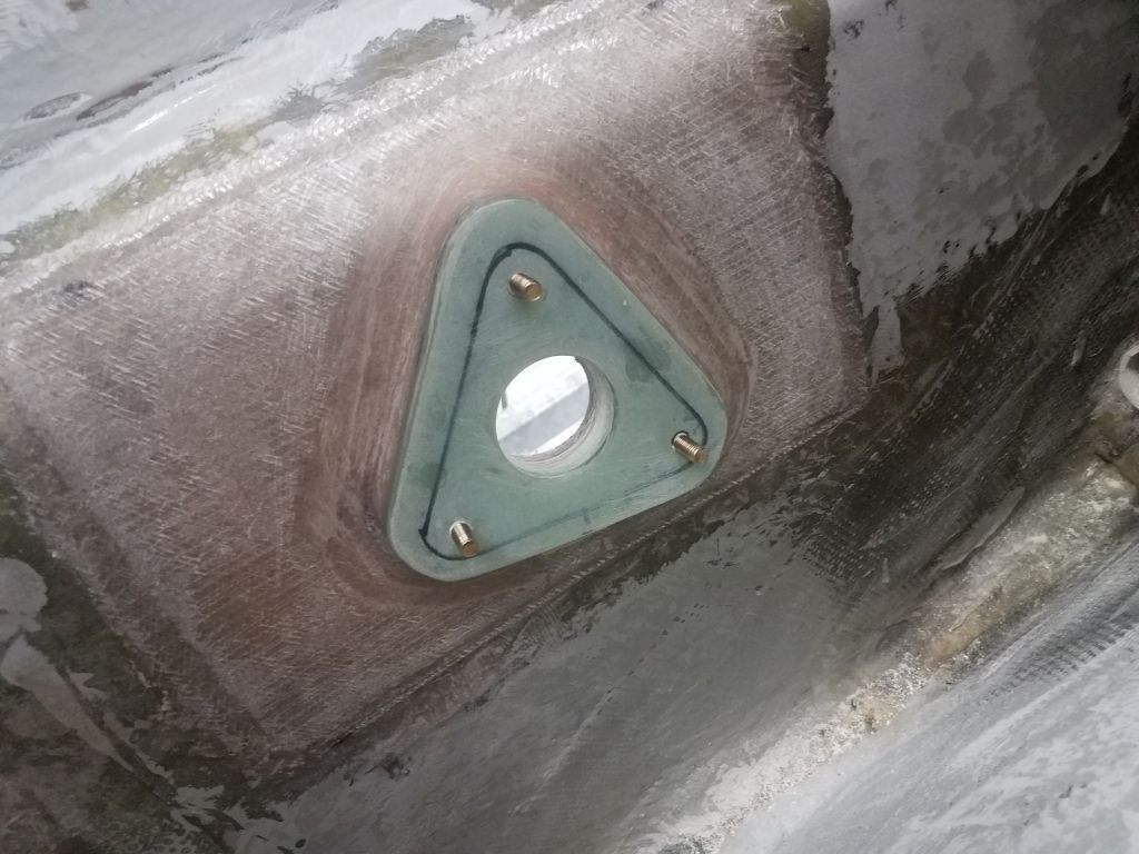
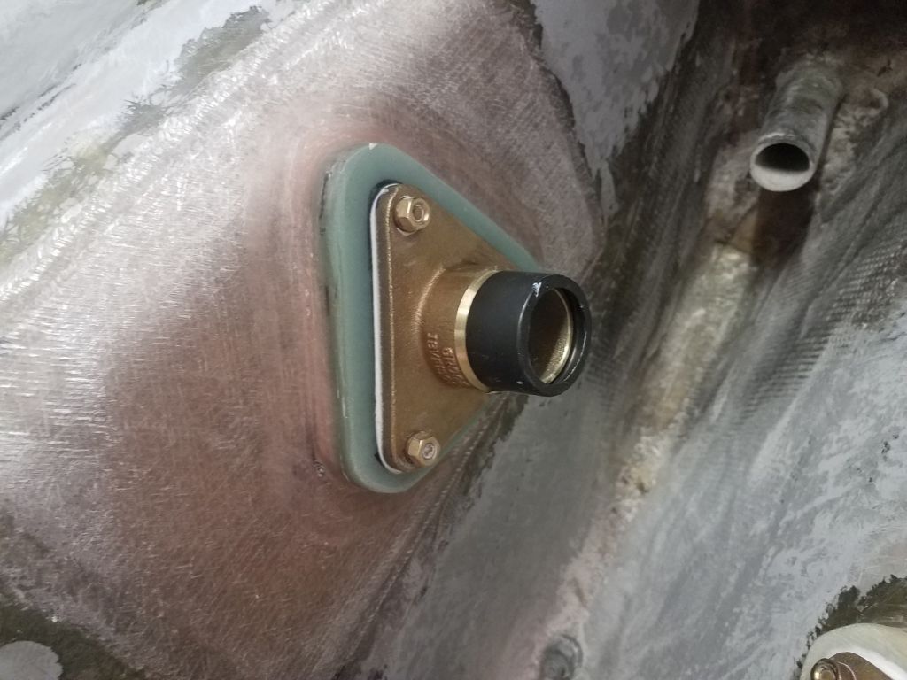
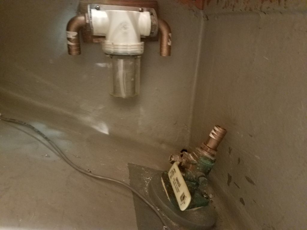
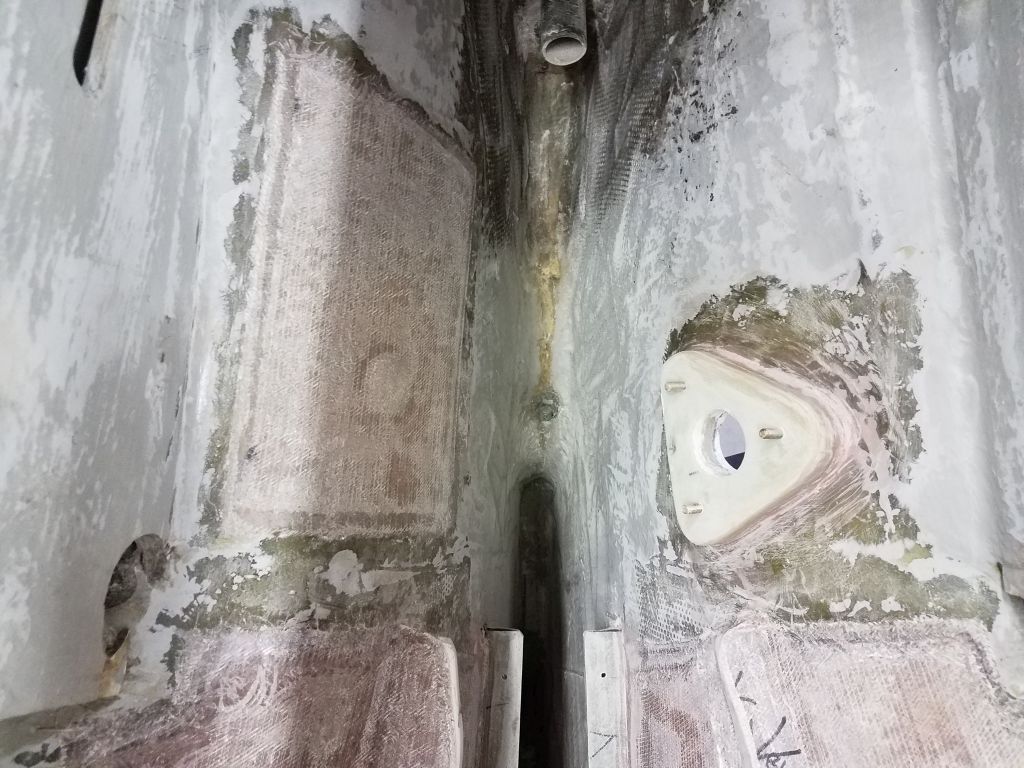
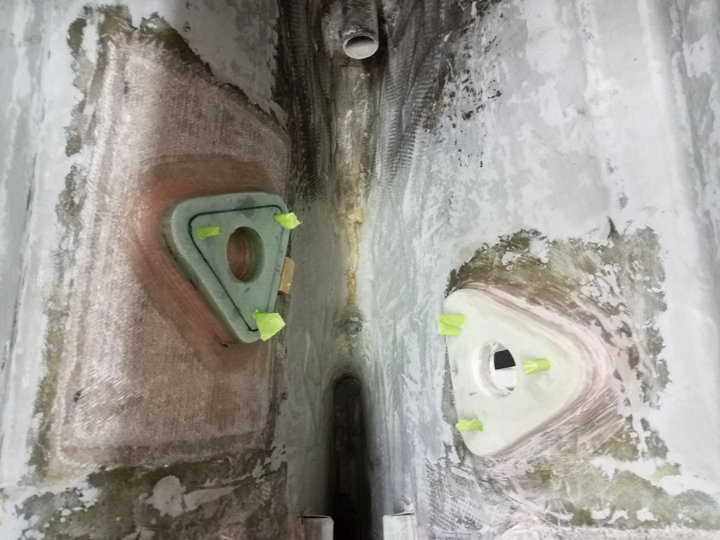
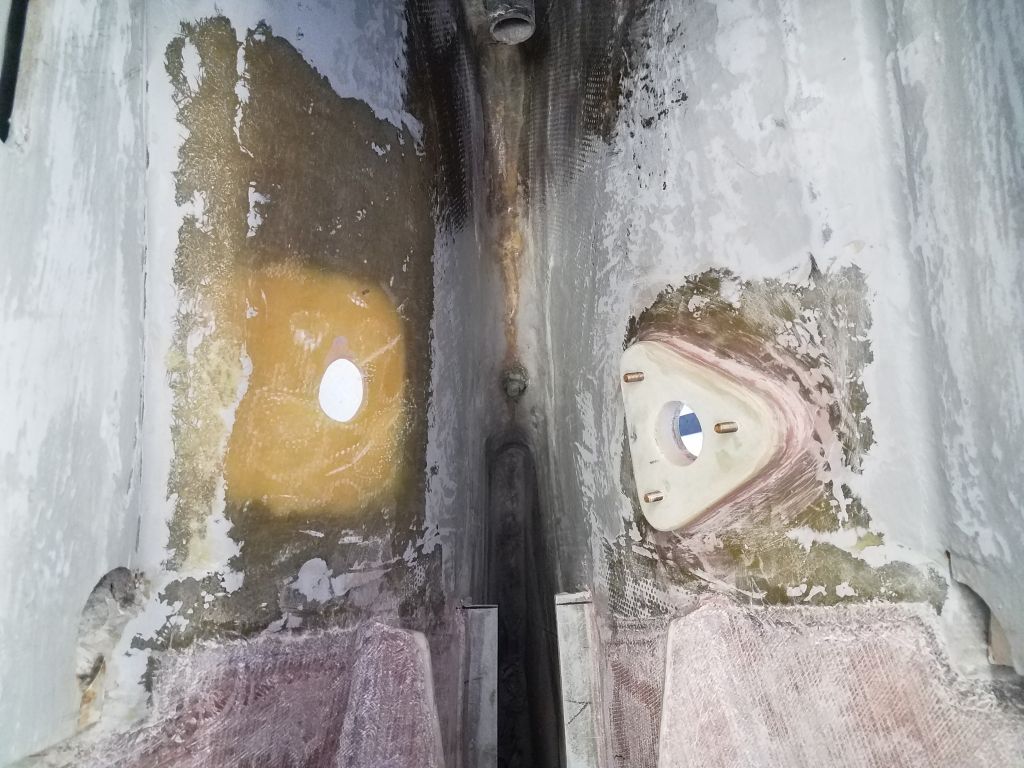
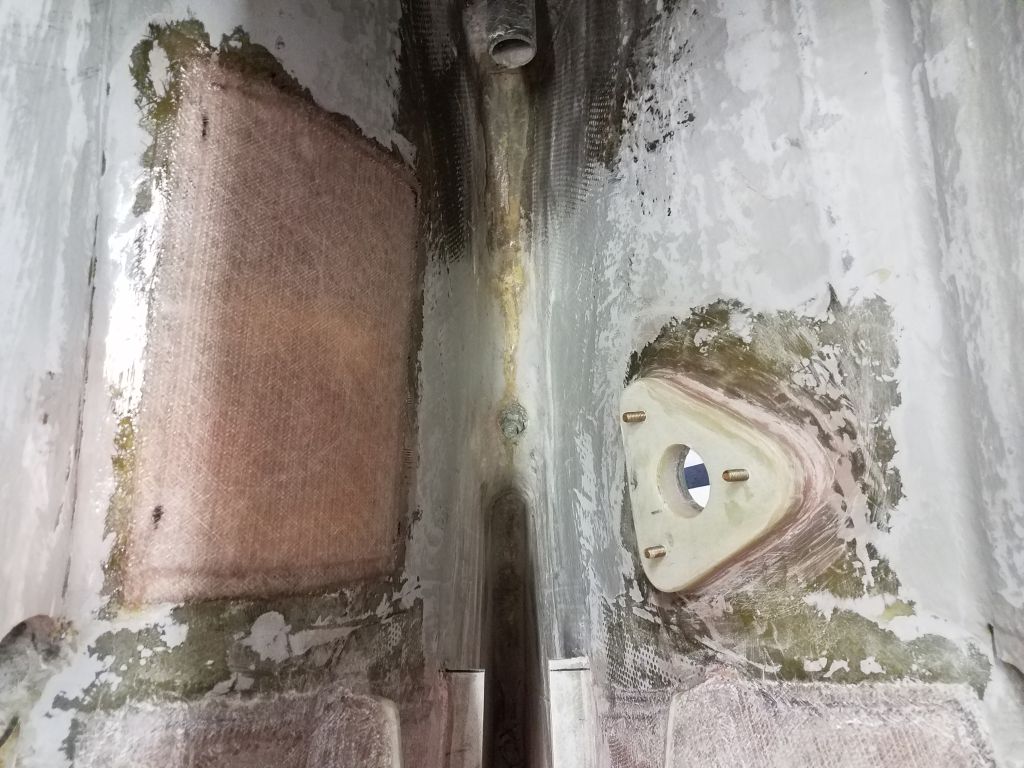
This left me no option but to get on with it and remove one of the new pads I’d installed, and reposition the through hull sufficiently to allow the required clearance with the other side.
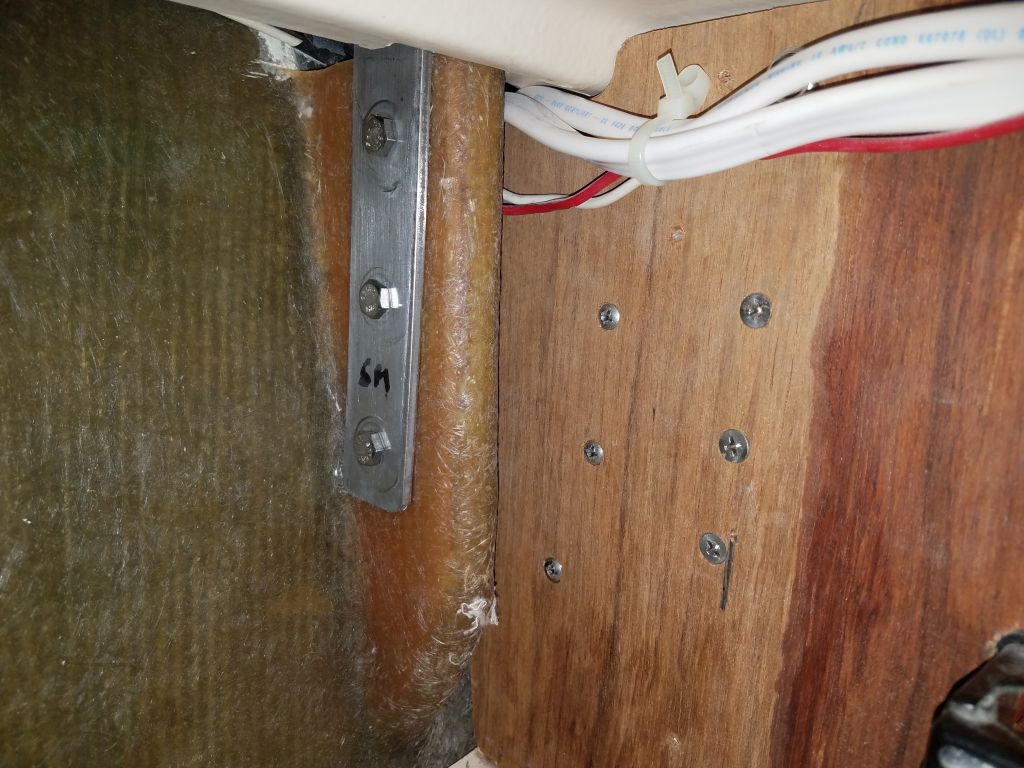
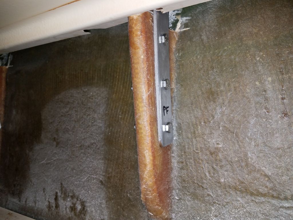
I chose the starboard side because it was positioned aft of the port fitting, and there was room to move it a bit aft; the port side would have had to move forward to increase clearance, and this would have brought it unnecessarily close to the engine foundations.
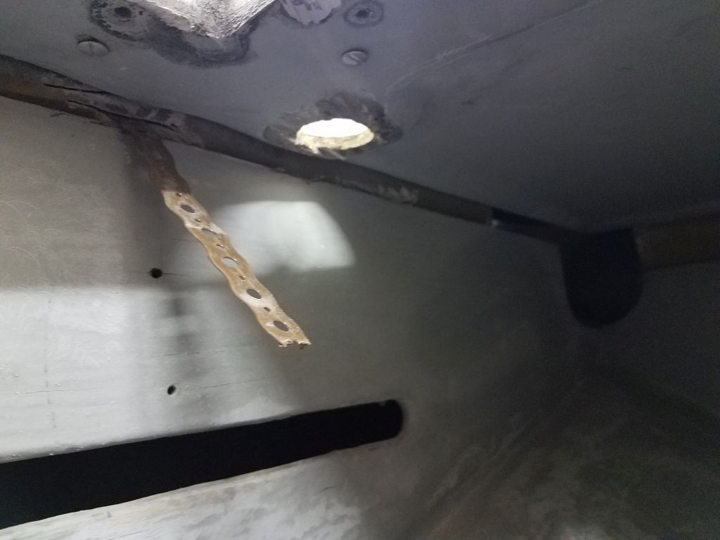
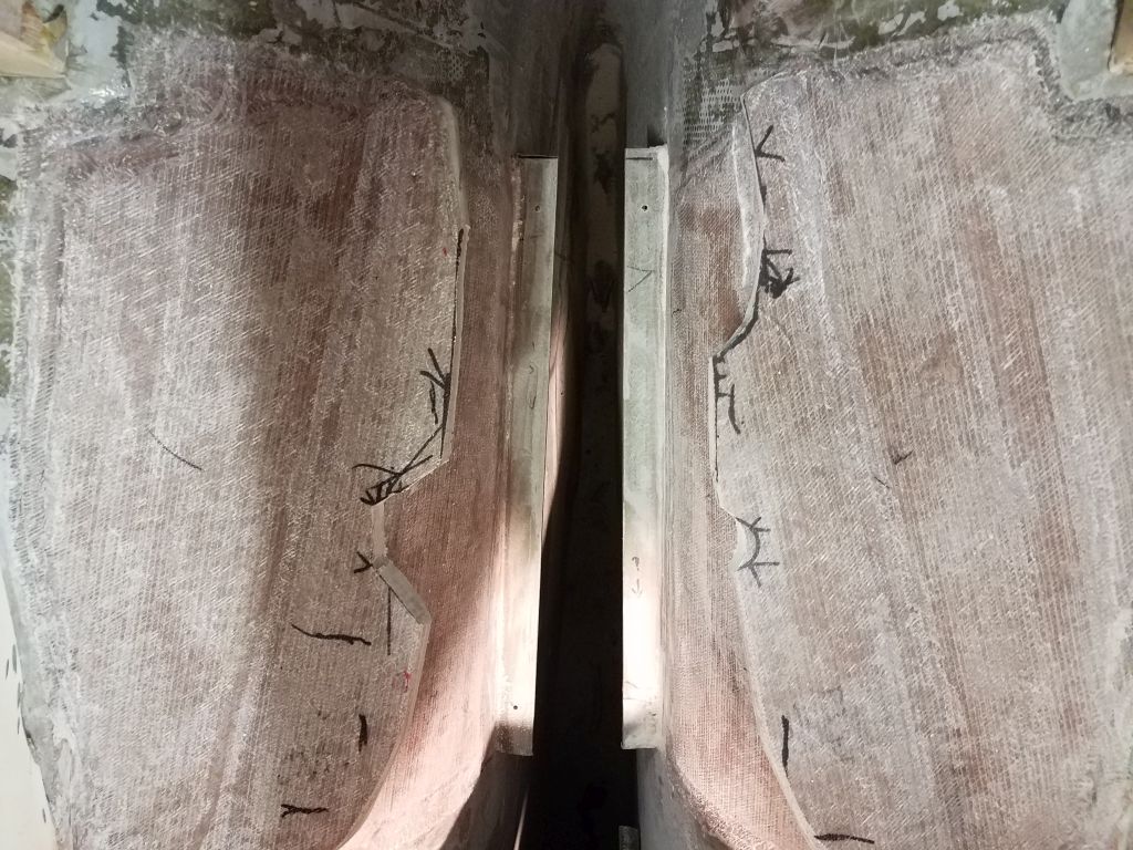
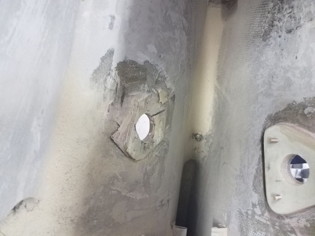
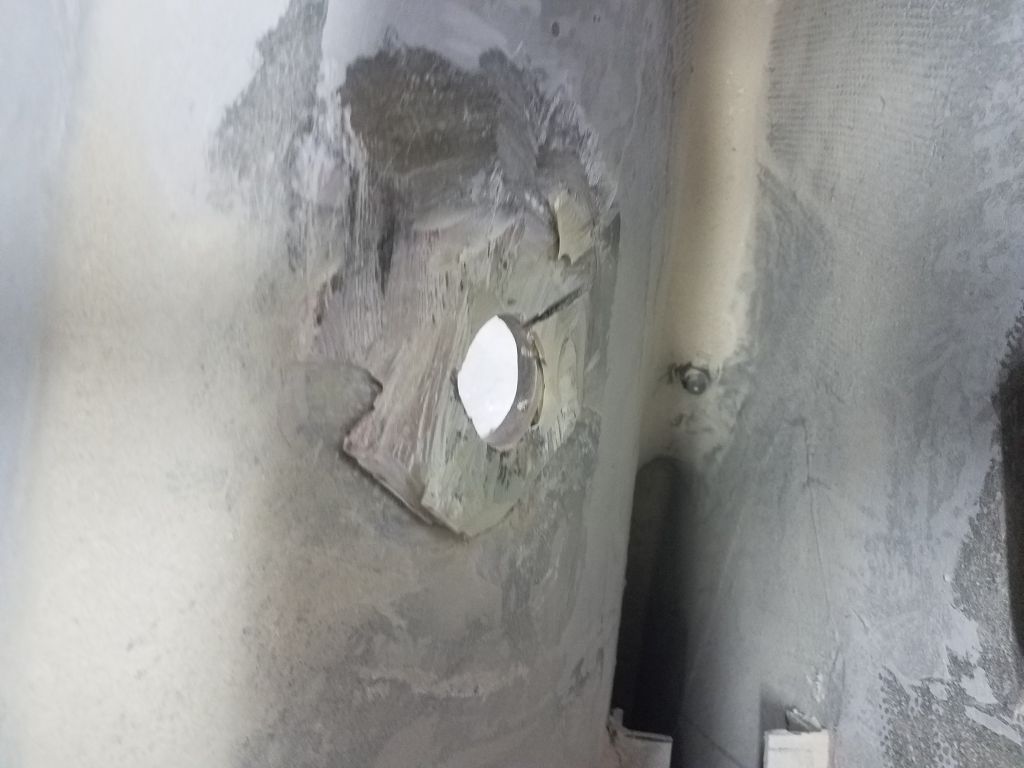
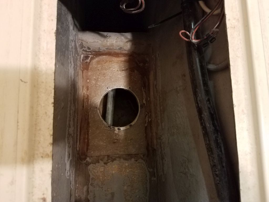
With grinder and cutoff wheel, and a reciprocating saw, I removed the “old” base as well as I could. Access was, of course, difficult, between the tightness of the space (shoulder room), the steep curvature of the hull, and the proximity of the nearby longitudinal bulkhead, but with significant effort I got through the G-10, leaving just remnants of the epoxy adhesive that I could grind smooth once more. I extended the ground area a bit aft to provide space for the necessary patch (to fill the old hole) and also for the new location.
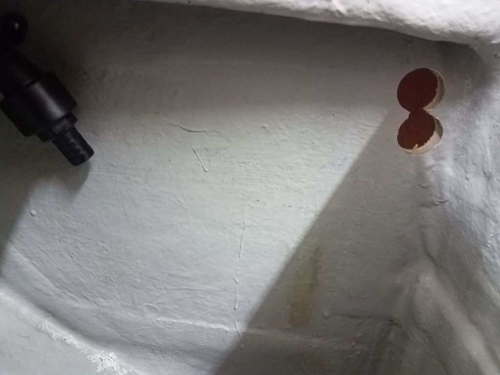
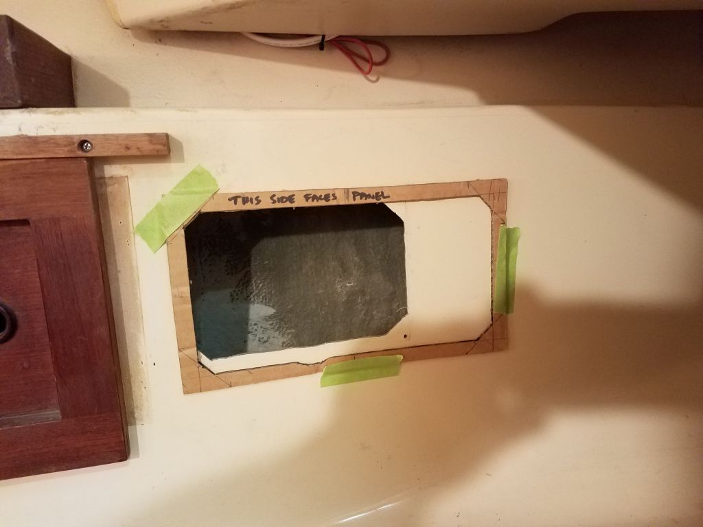
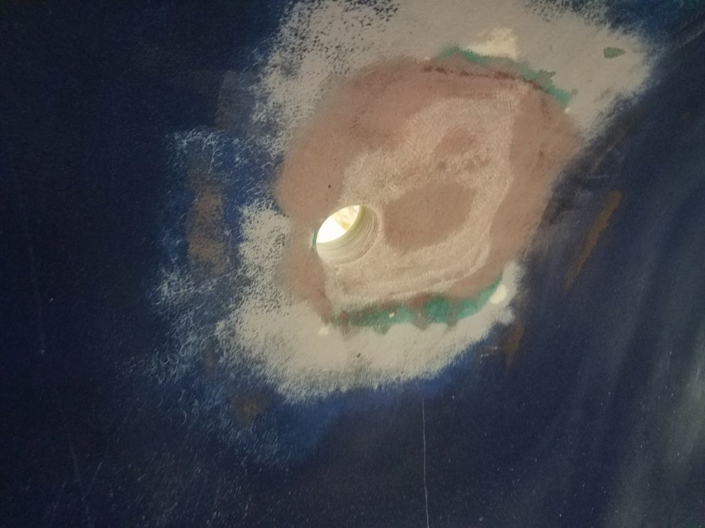
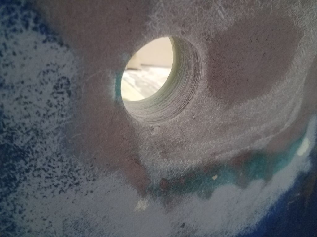
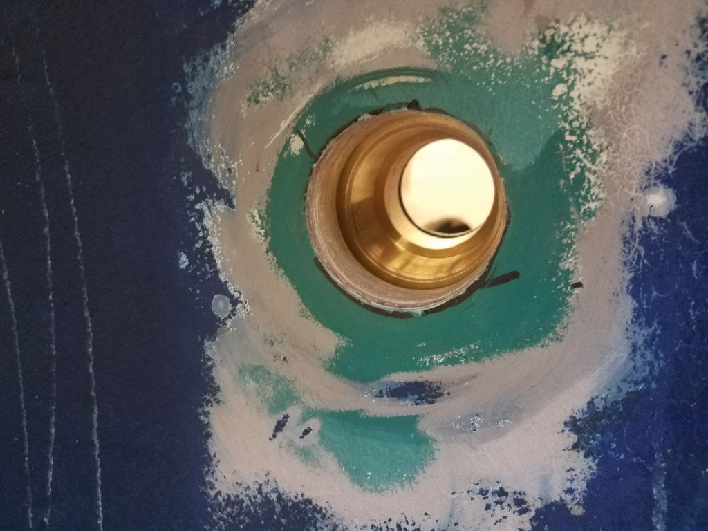
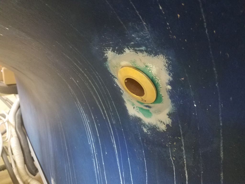
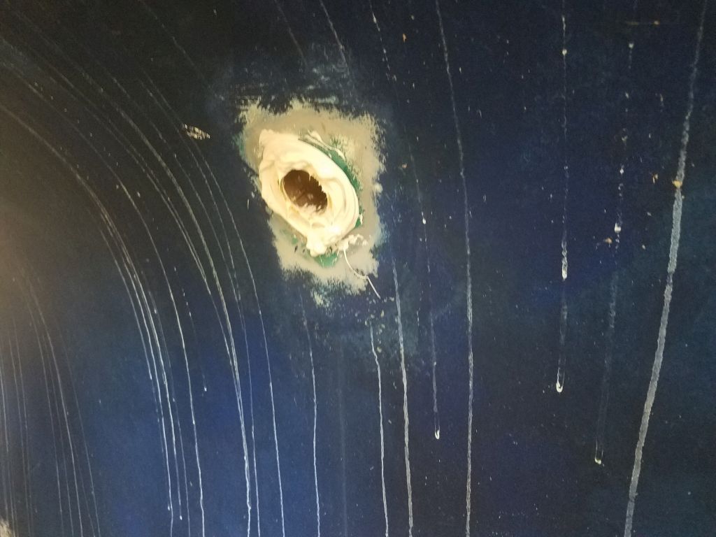
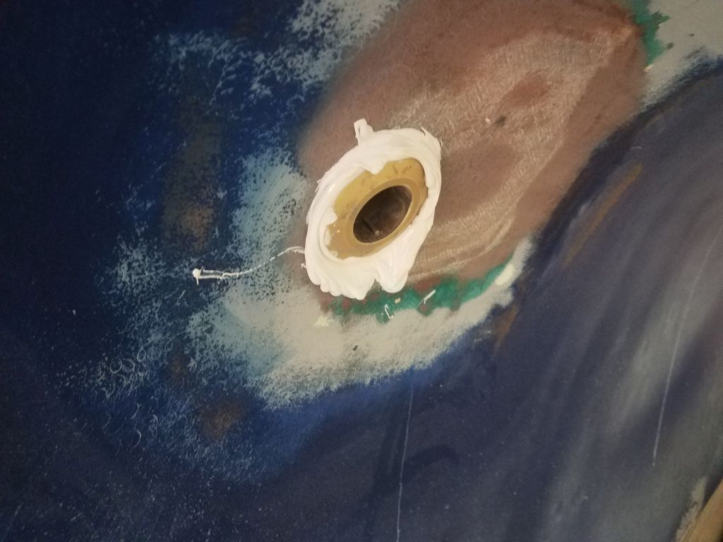
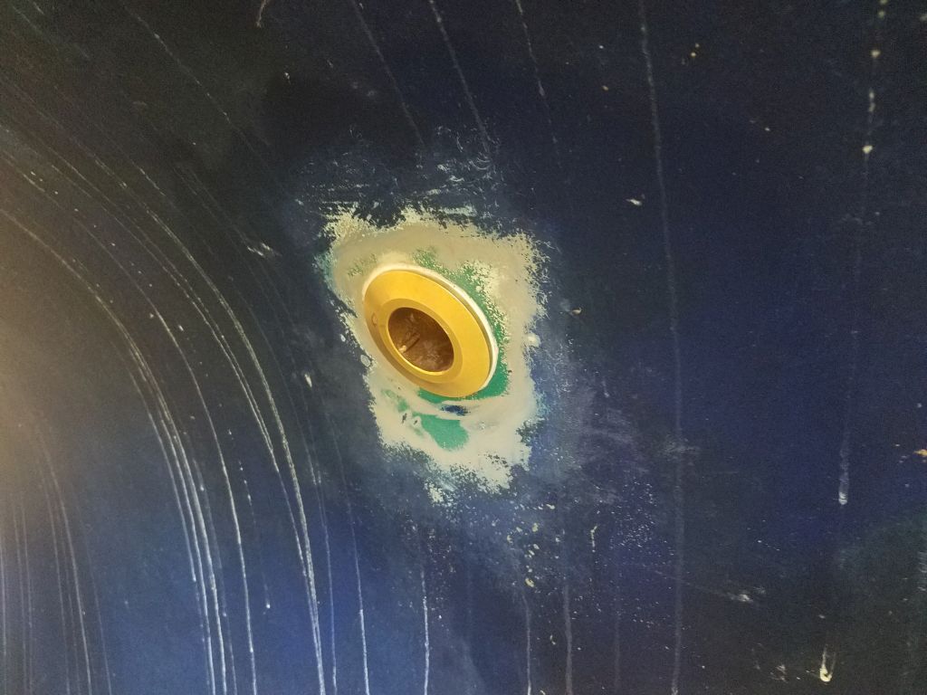
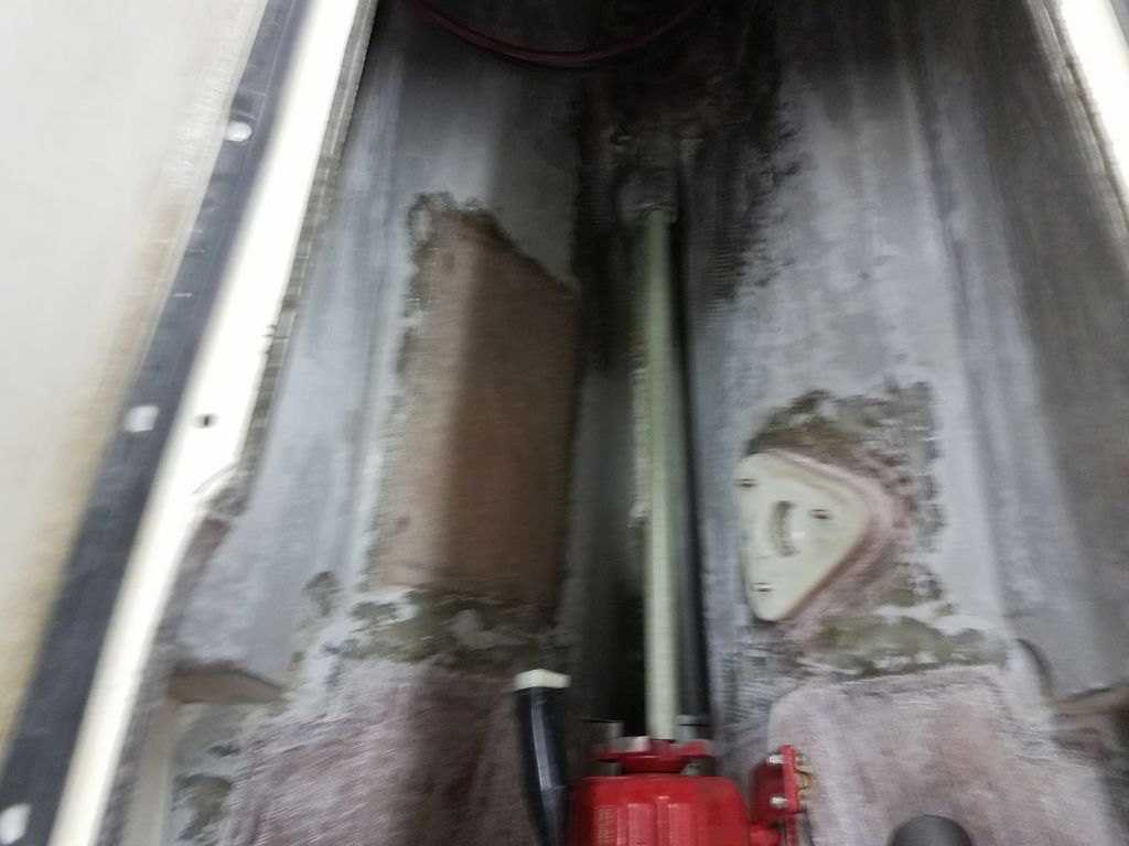
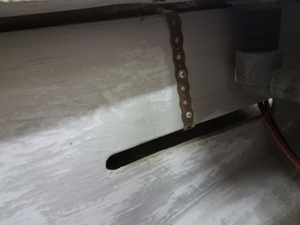
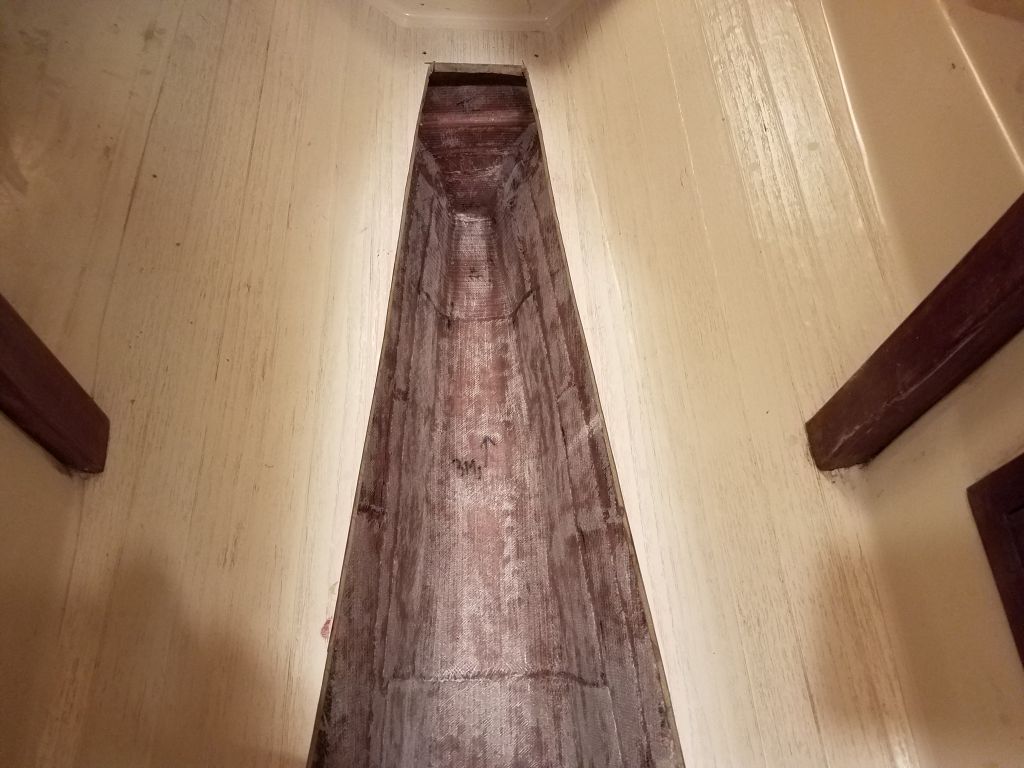
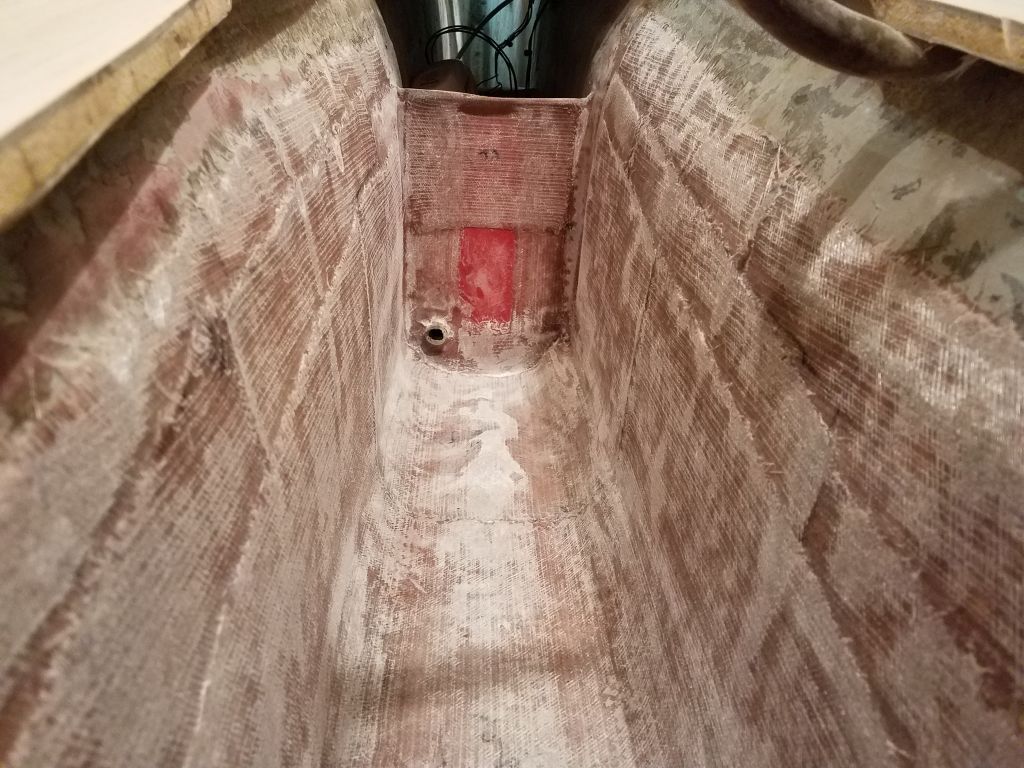
With the miserable work in the engine room completed, I moved outside to prepare the exterior of the hole for patching in the usual way.
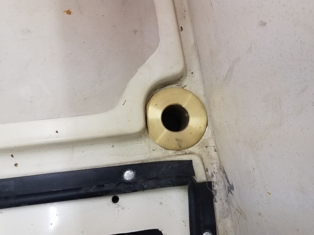
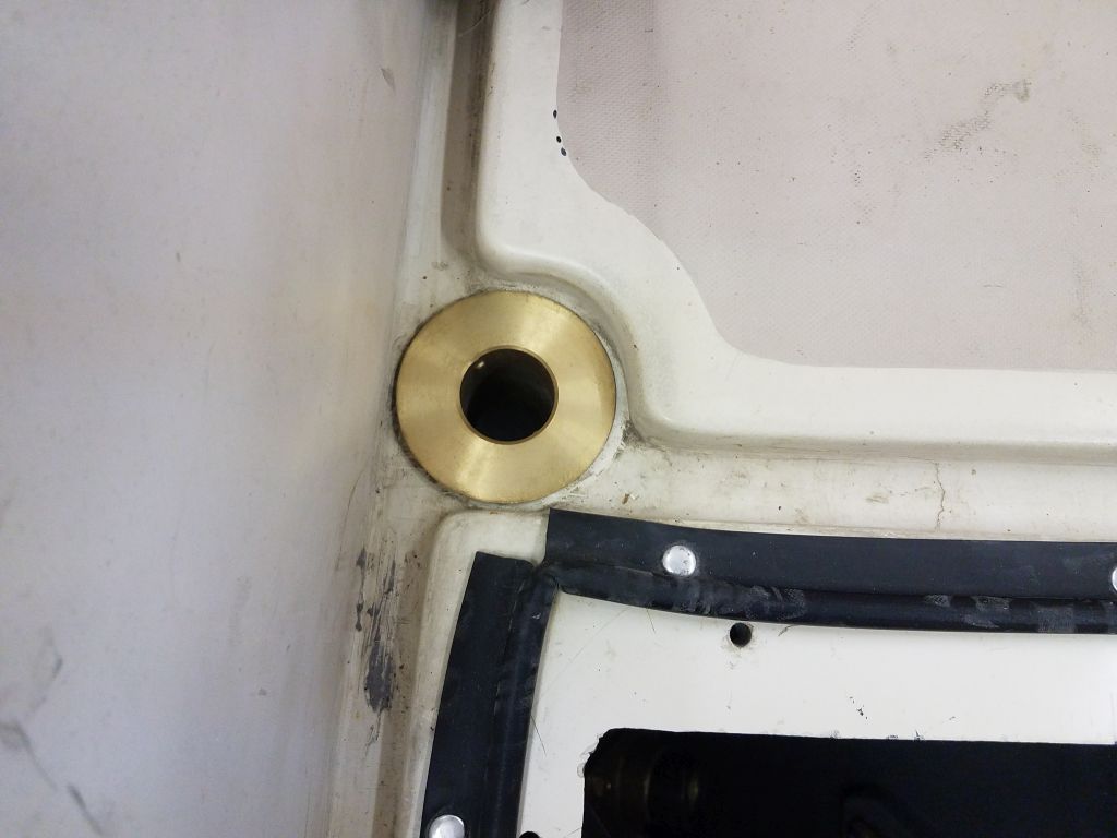
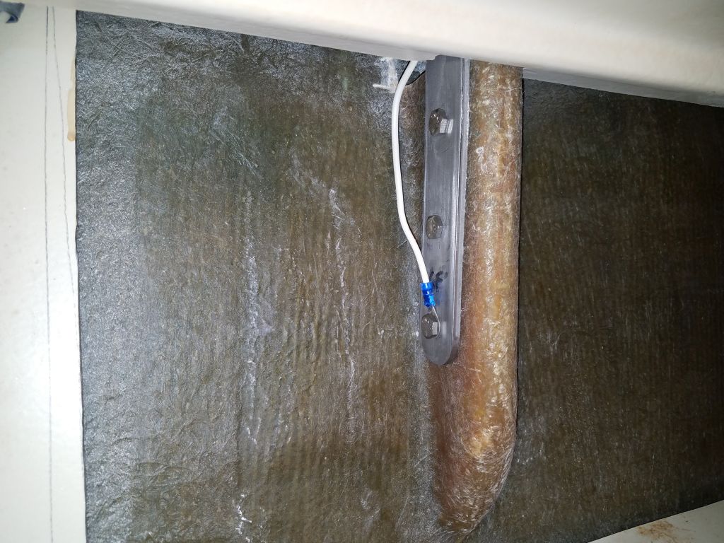
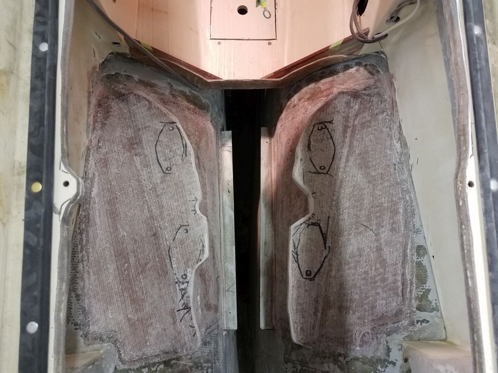
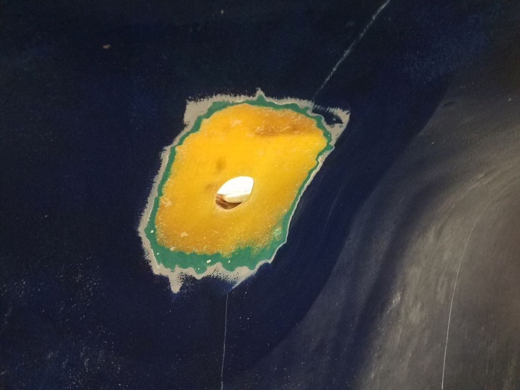
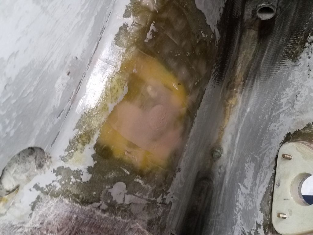
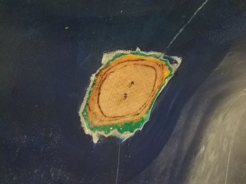
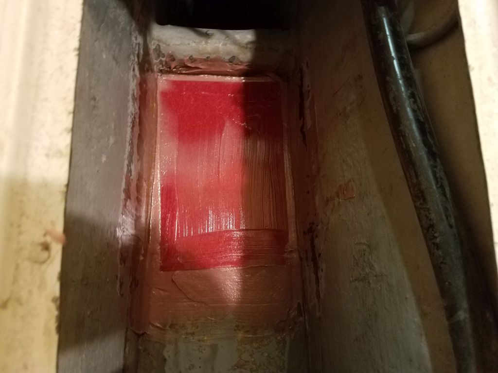
To patch the old hole, I masked over the opening from outside, then filled the hole with reinforced, thickened epoxy from inside, using some leftover epoxy to wet out the newly-ground area inside and make it ready for two layers of fiberglass over the whole area, including the after section where I planned to install the fitting when the repair was complete.
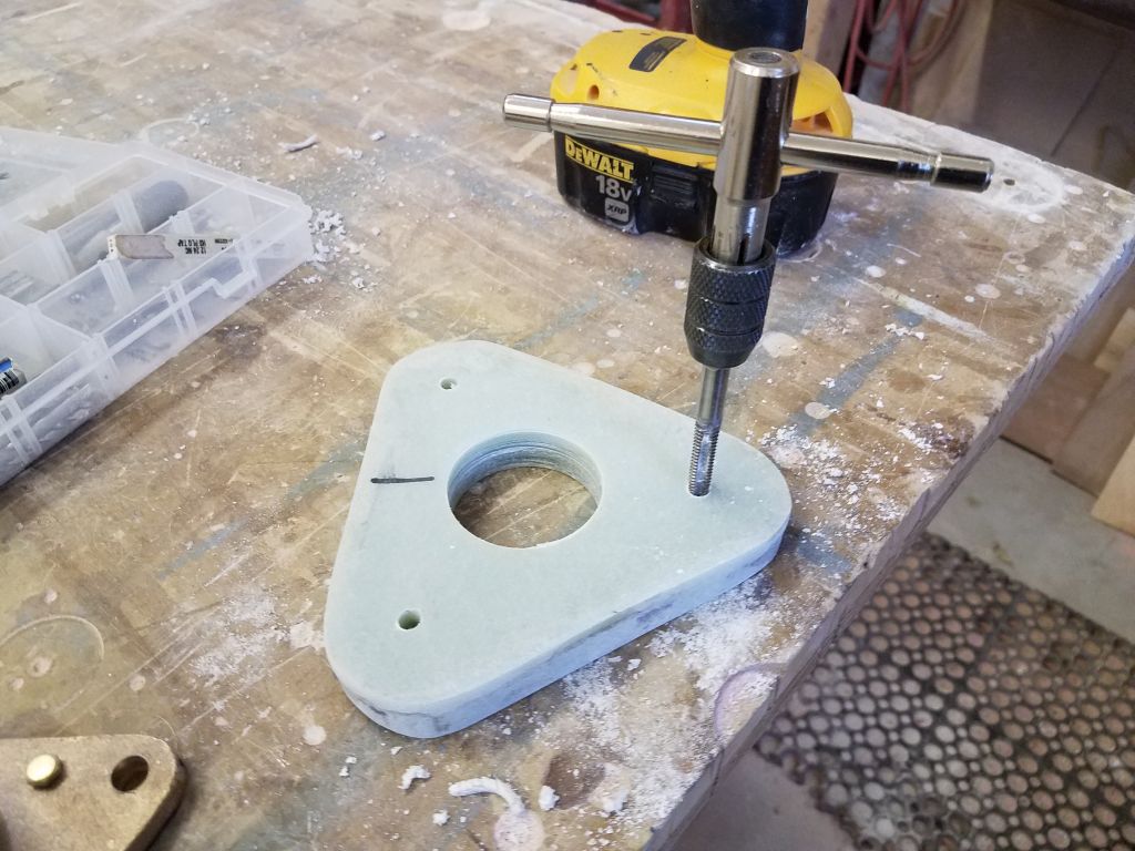
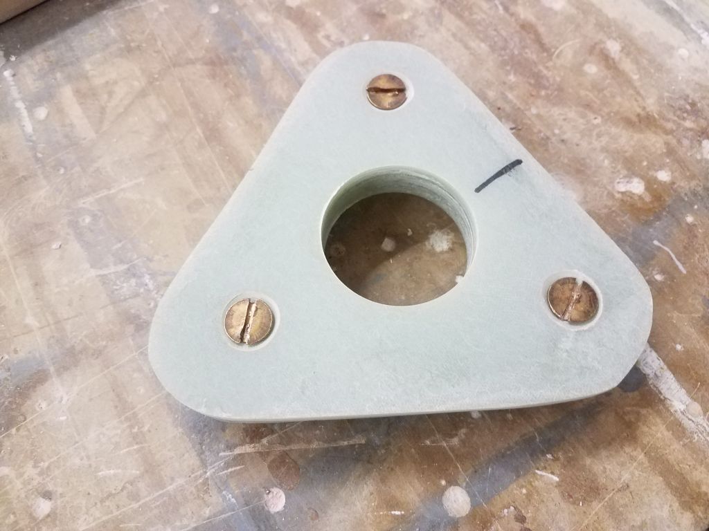
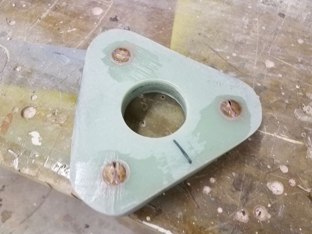
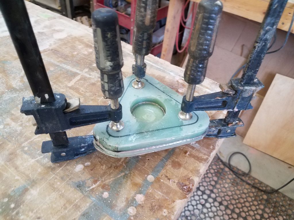
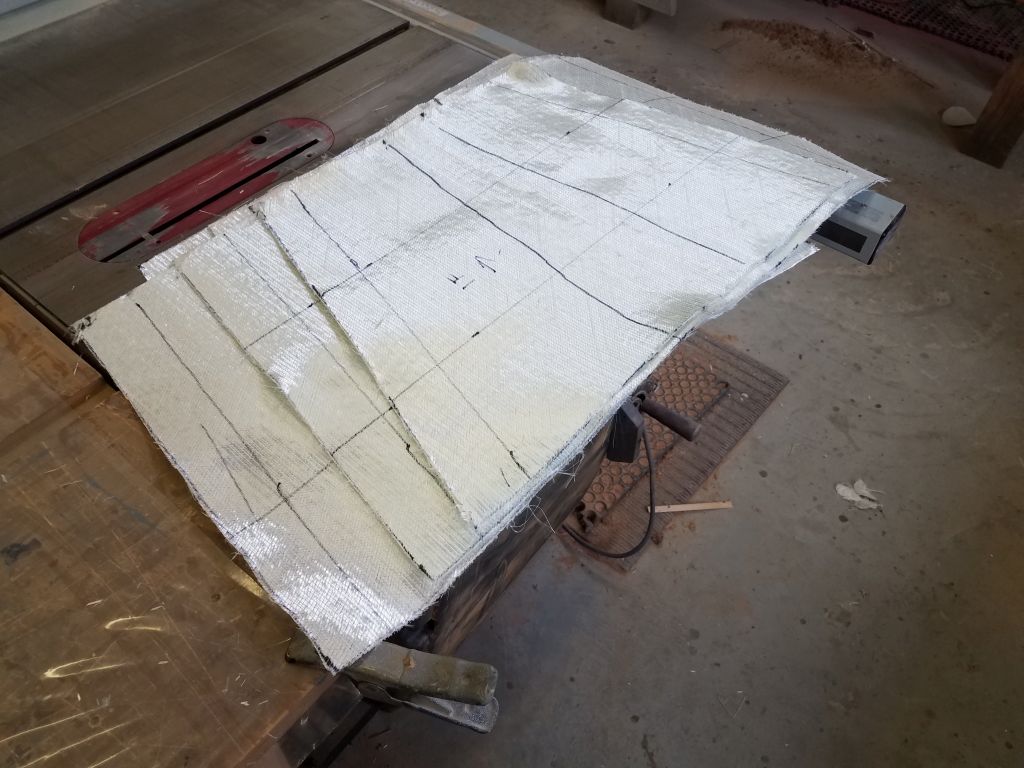
Meanwhile, I turned to building a replacement pad for the flange base. Of course I found that my remaining supply of 3/4″ G-10 wasn’t wide enough to accommodate the size of the flange properly, so I had to make up a lamination from a piece of 1/2″ and 1/4″ G-10 to provide the requisite thickness.
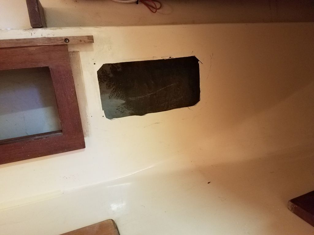
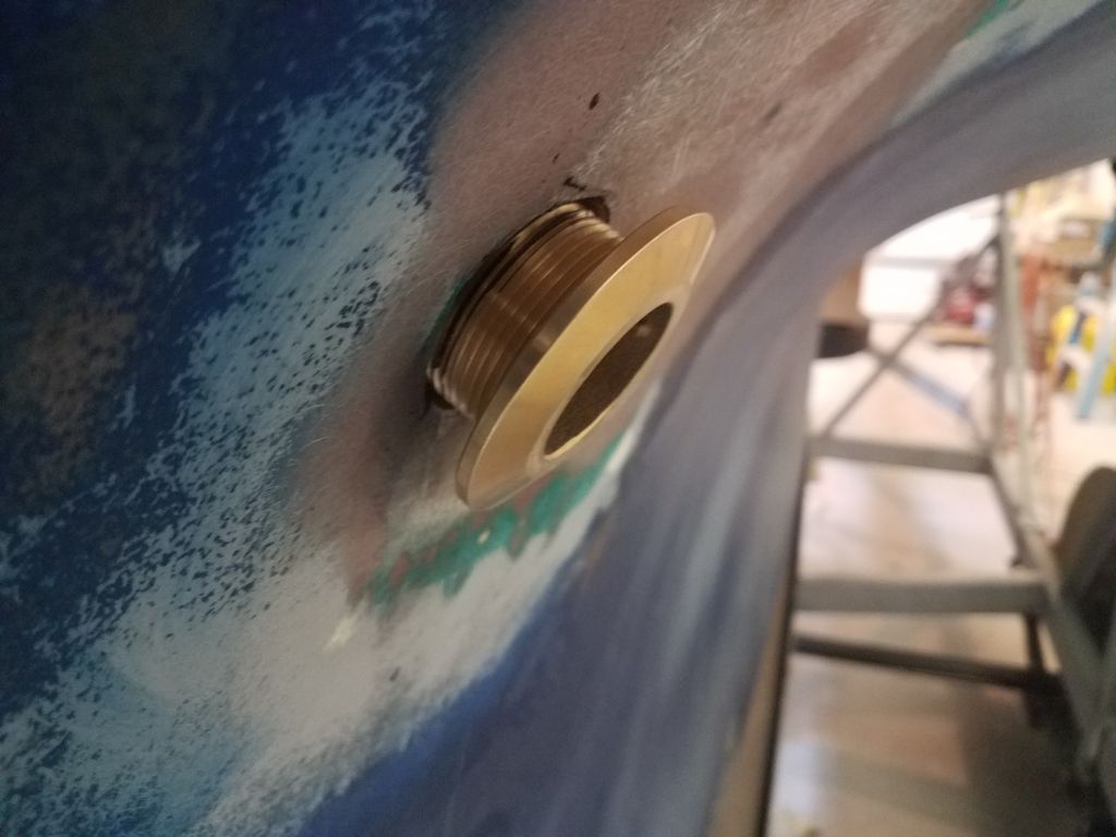
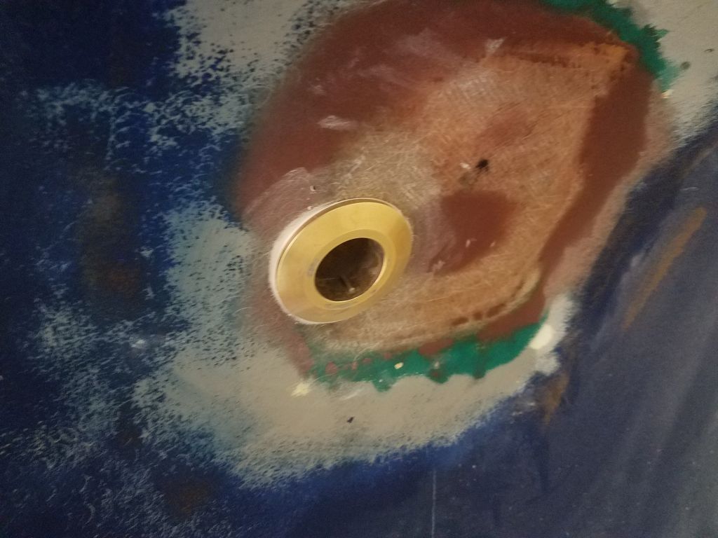
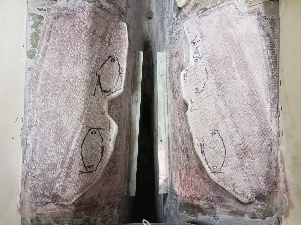
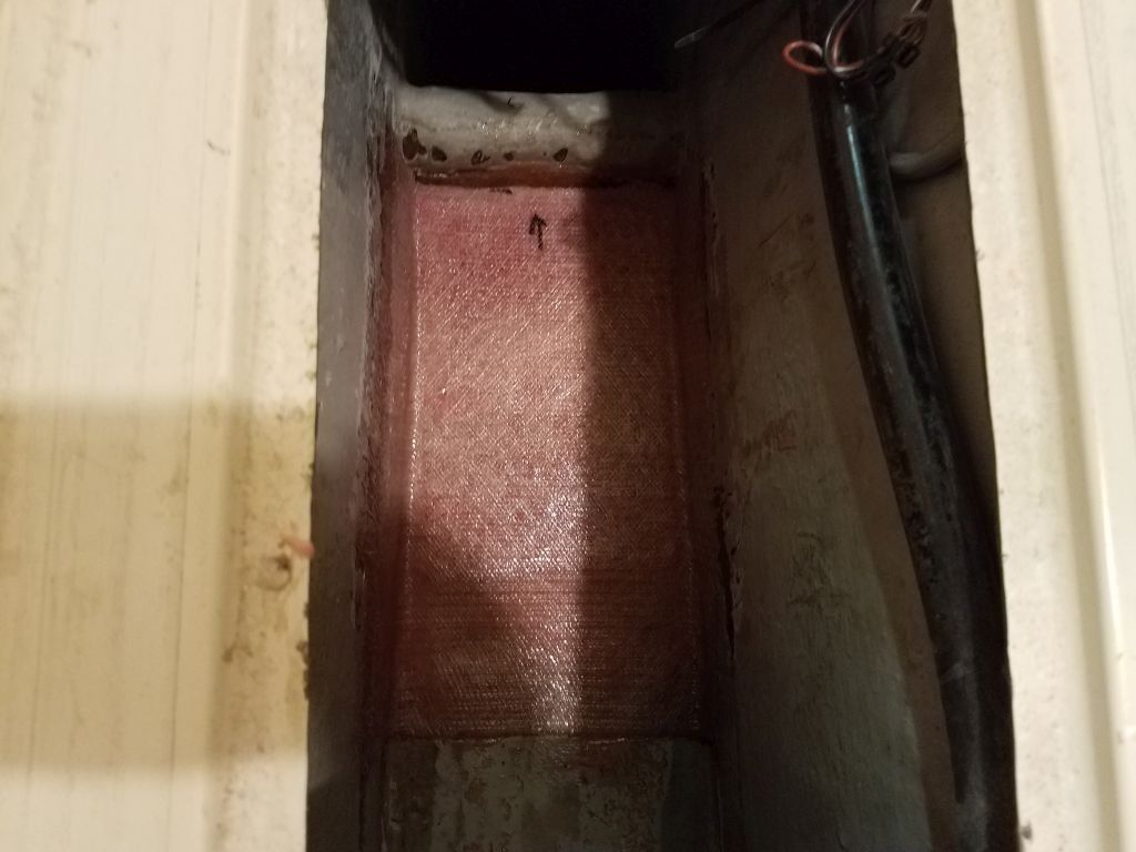
A bit later in the day, the epoxy had cured enough to allow me to remove the masking tape from the outside and install three layers of fiberglass over the exterior, completing the basics of the original hole repair and getting me closer to starting the new re-installation.
Removing the old pad, patching the hull, and the other work took two hours, which I expunged from the day’s totals, and I suppose it all could have been a lot worse, though it was an exercise I didn’t plan to do again anytime soon. Still ahead I’d need to reinstall the new G-10 base and relocate the through-hull hole, which would catch me up with where I’d started at the beginning of the day.
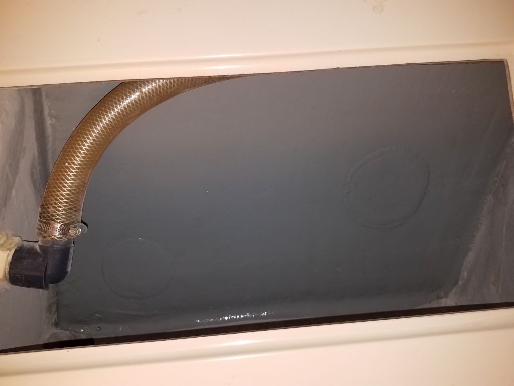
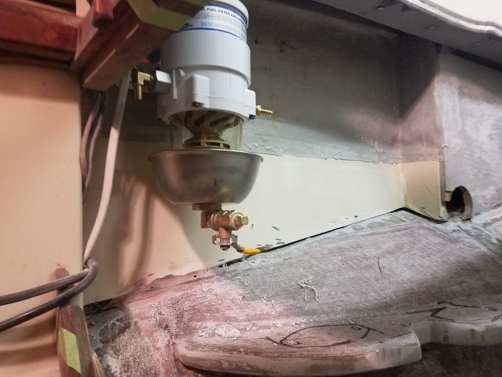
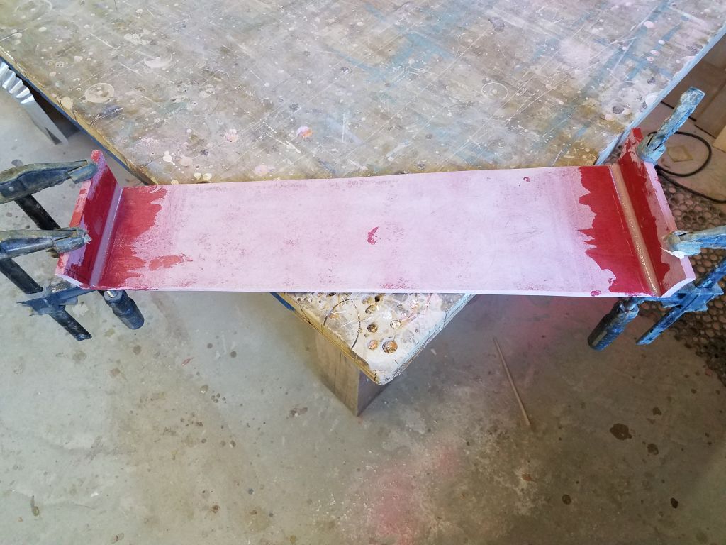
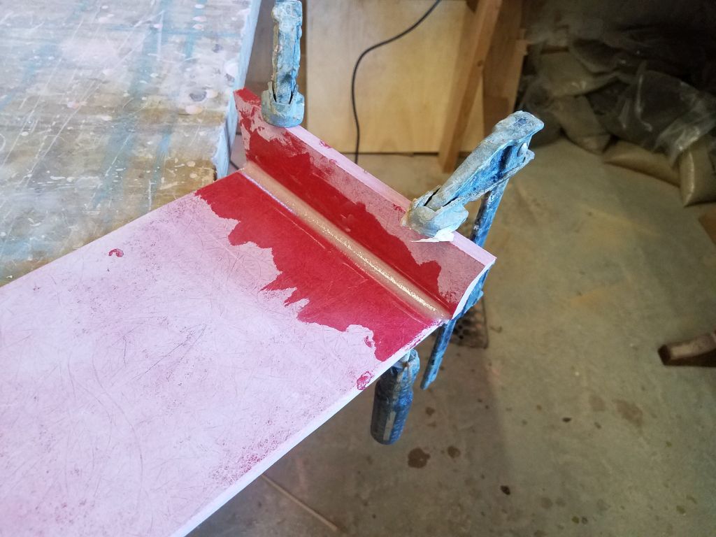
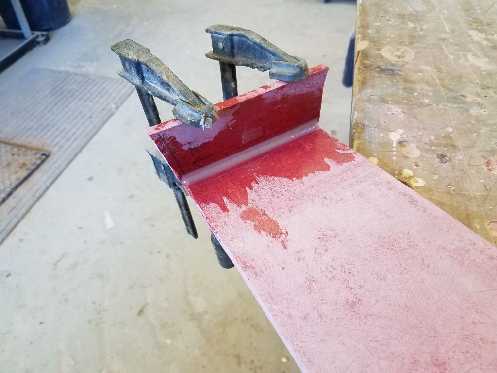
Moving on, I cleaned up the glue joints on the fiberglass drip pan assembly, and after a final test fit drilled and tapped for four screws that would eventually secure it to the cleats in the boat. I’d finish up all the painting in the space before I installed it permanently, however.
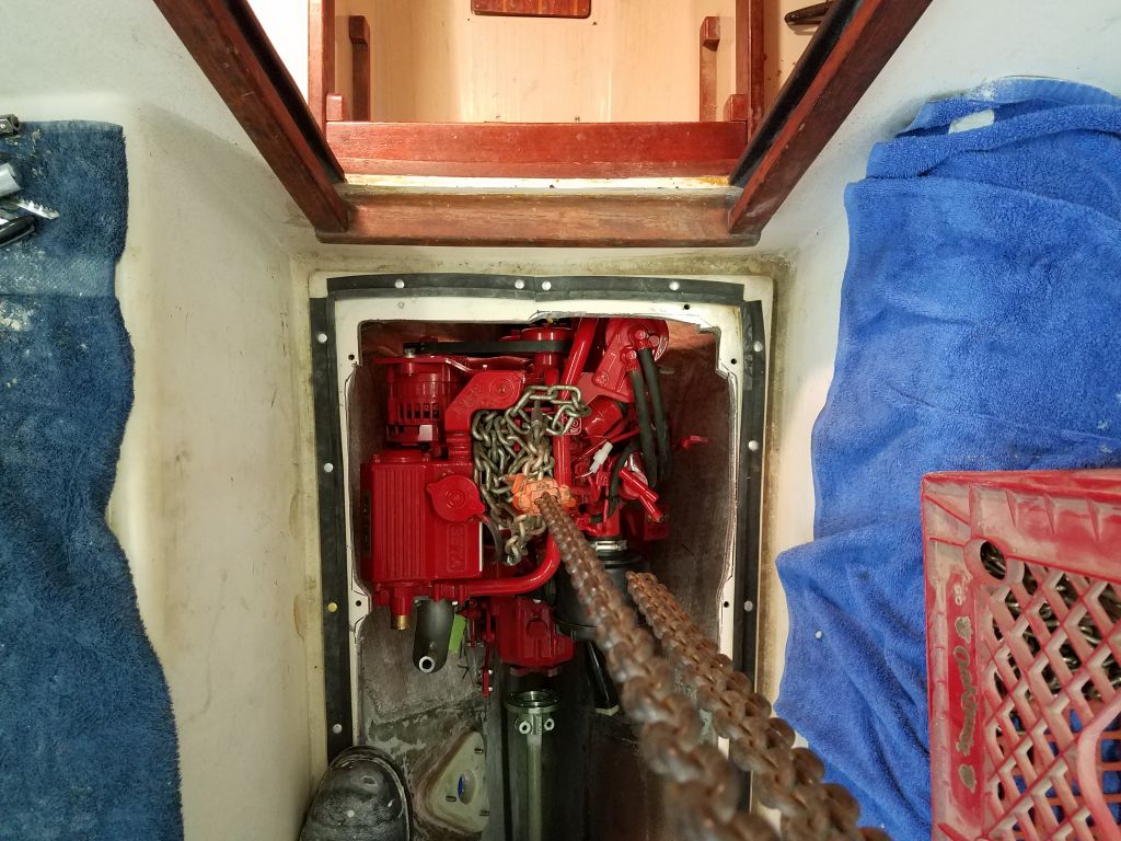
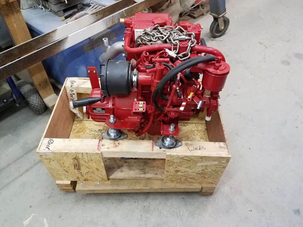
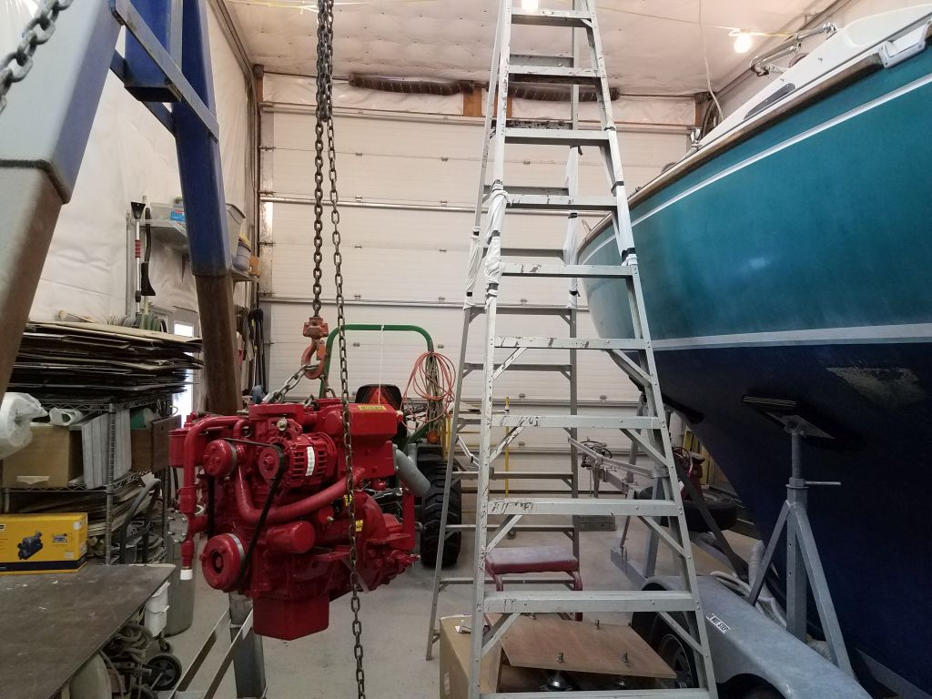
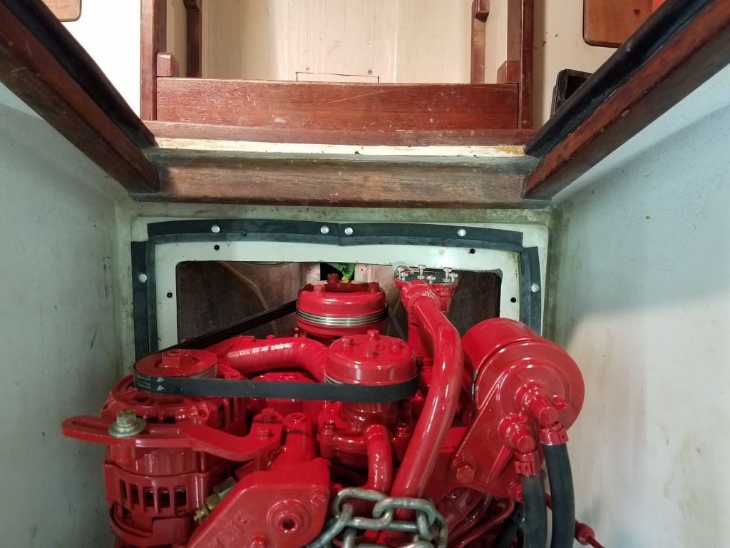
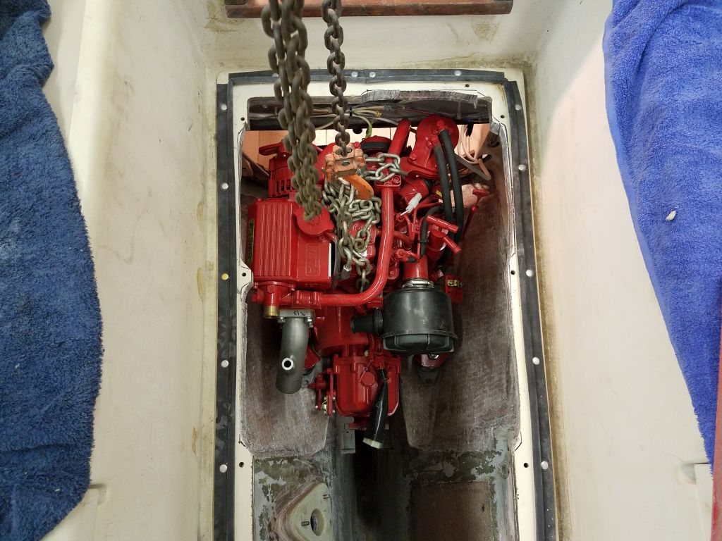
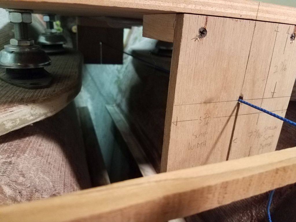
Next, I thought I’d test-fit the engine in the compartment. I anticipated a need to slightly modify the deck opening, as well as possibly some modification to the engine foundations to fit the engine, and in neither way was I disappointed.
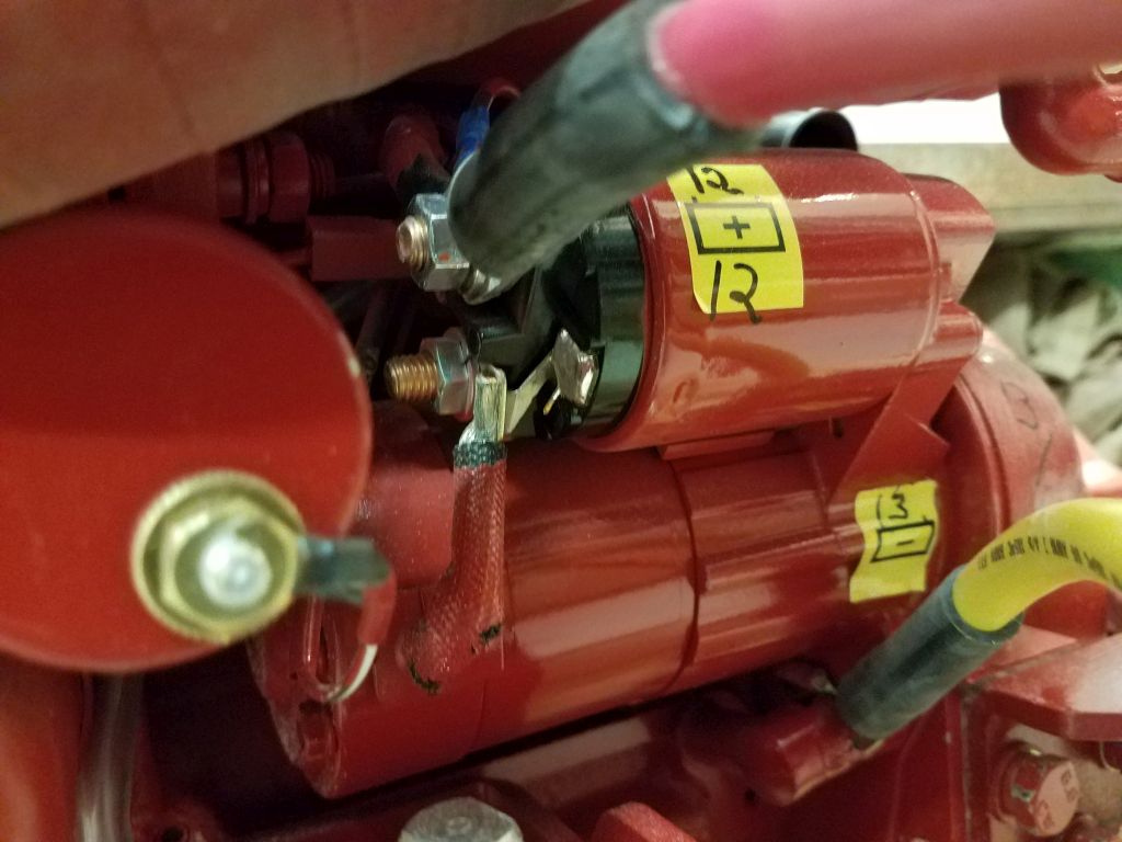
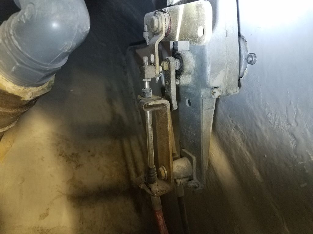
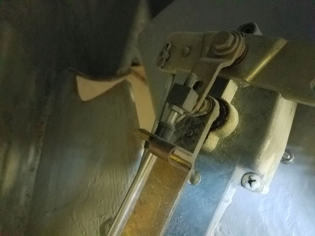
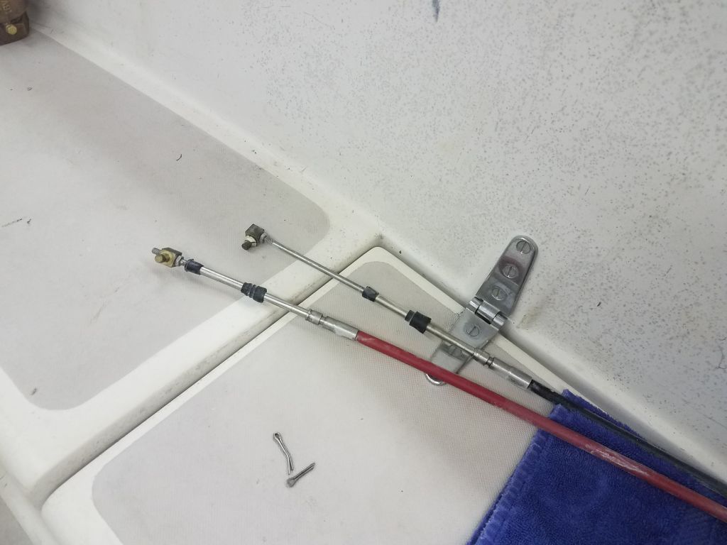
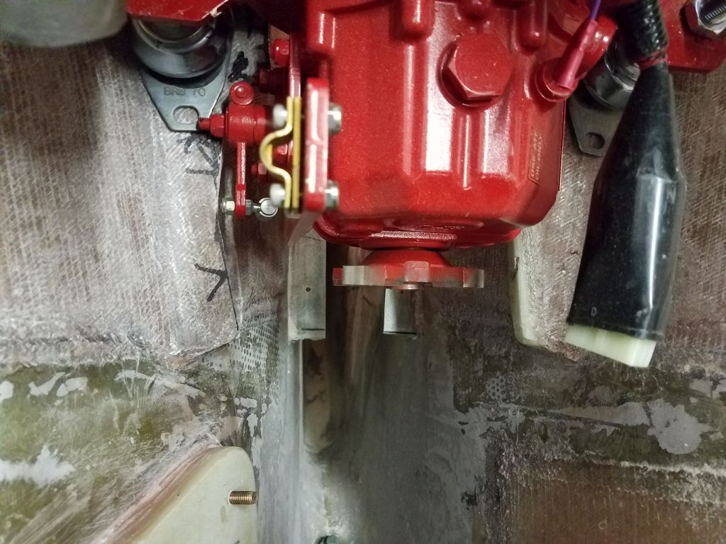
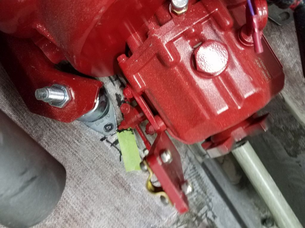
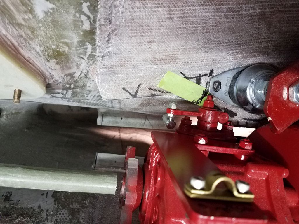
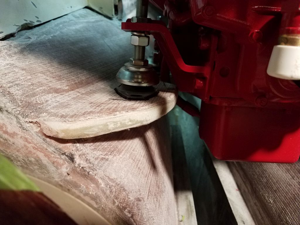
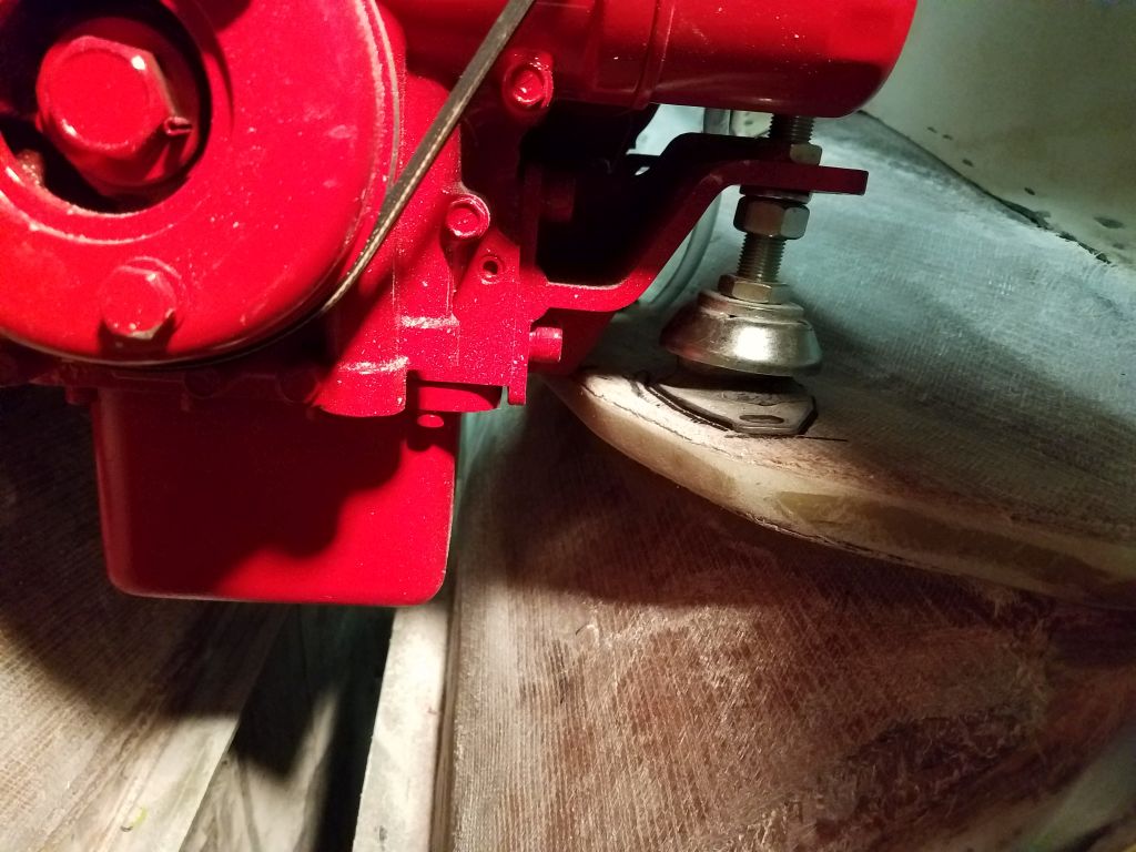
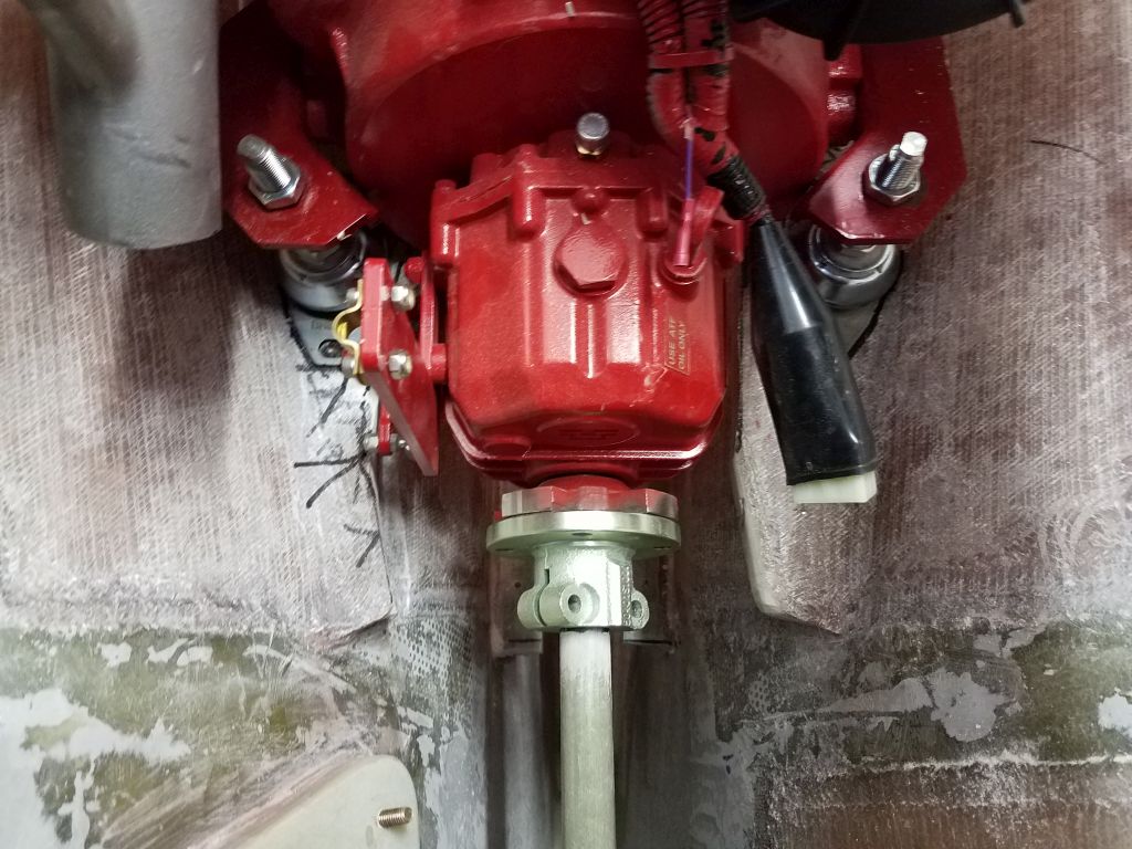
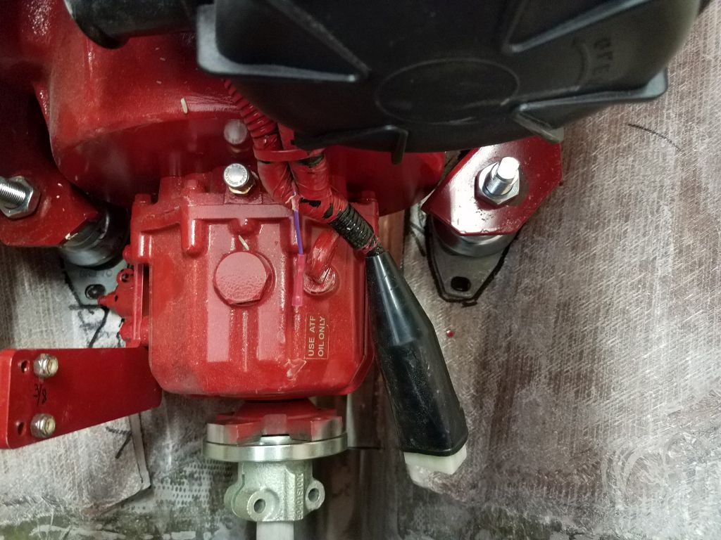
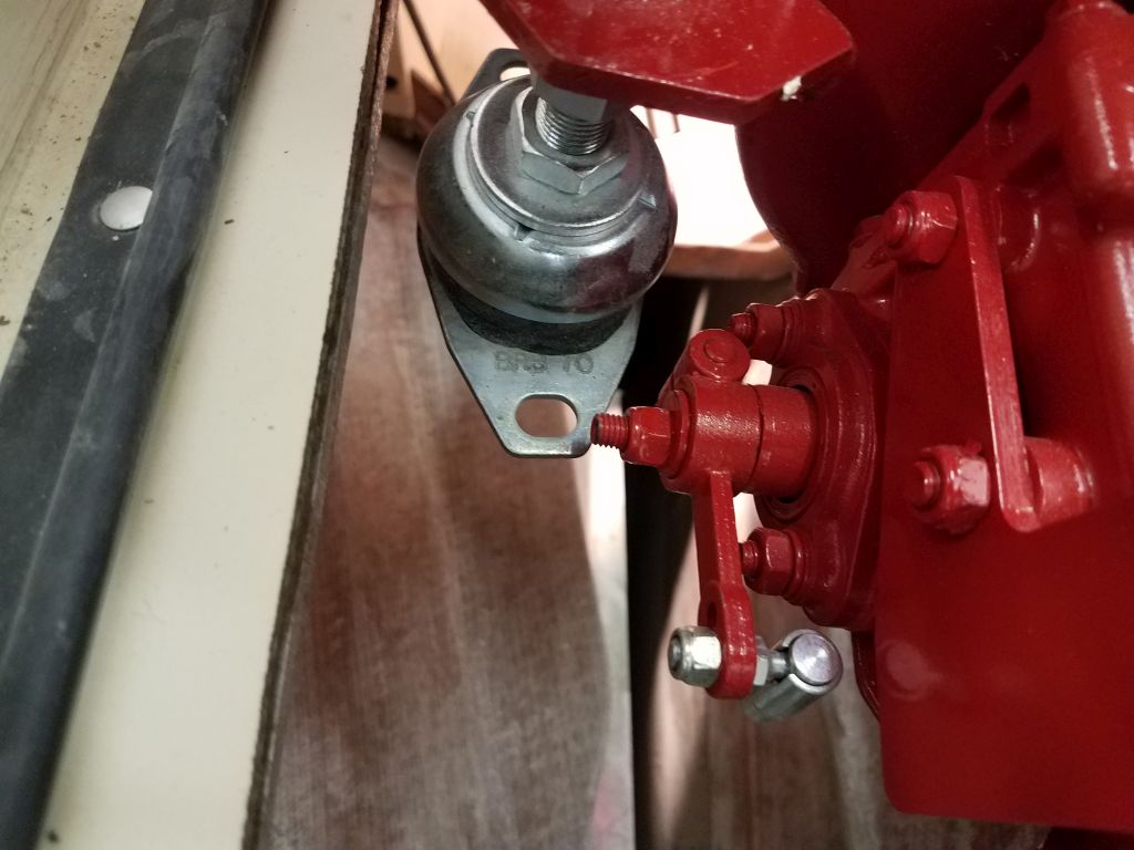
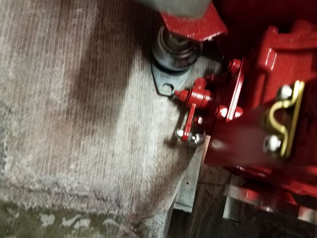
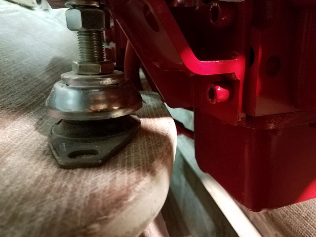
When I installed the flexible mounts on the engine after I had it up in the cockpit, I immediately noticed a potential clearance issue with the port after mount, which barely cleared the transmission lever at best, and not at all if the mounting base had to angle, which I thought it probably would in this installation. This issue came to light because of the narrow 11-1/2″ mounting centers, for which the engine wasn’t really designed. Whether this became a real issue or not would depend on the final height of the mount versus the protruding bolt on the transmission lever. Right now, they were nearly level with one another, and I expected this was something I’d have to deal with, but first things first.
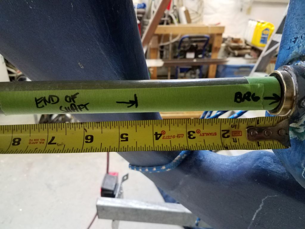
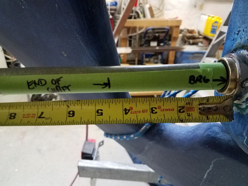
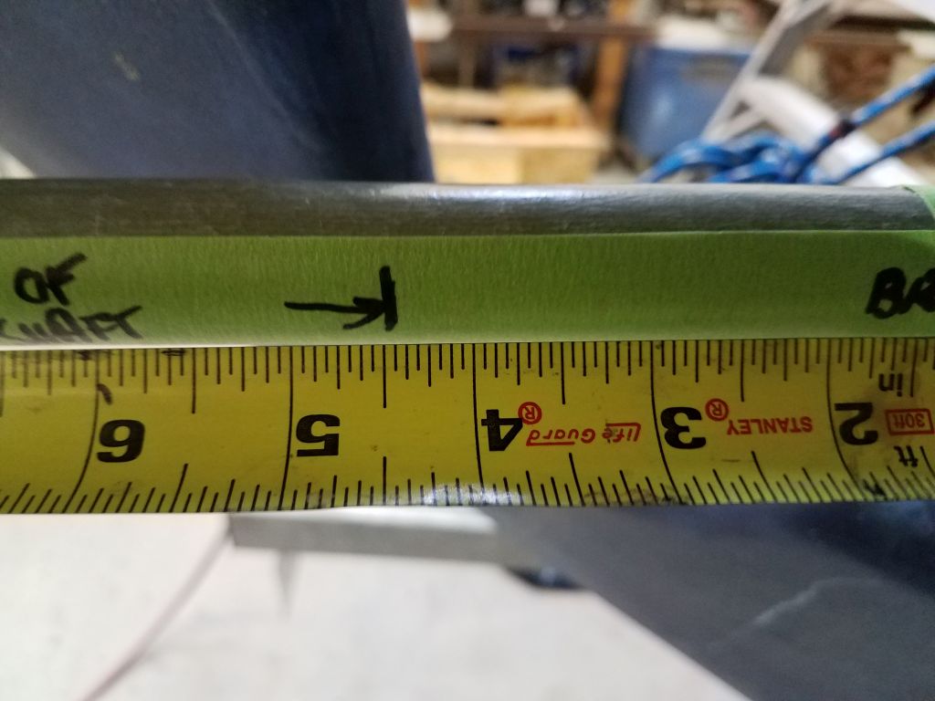
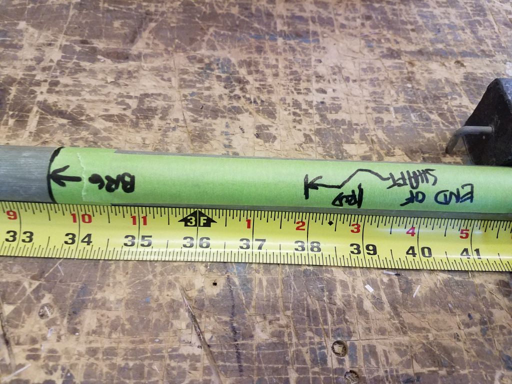
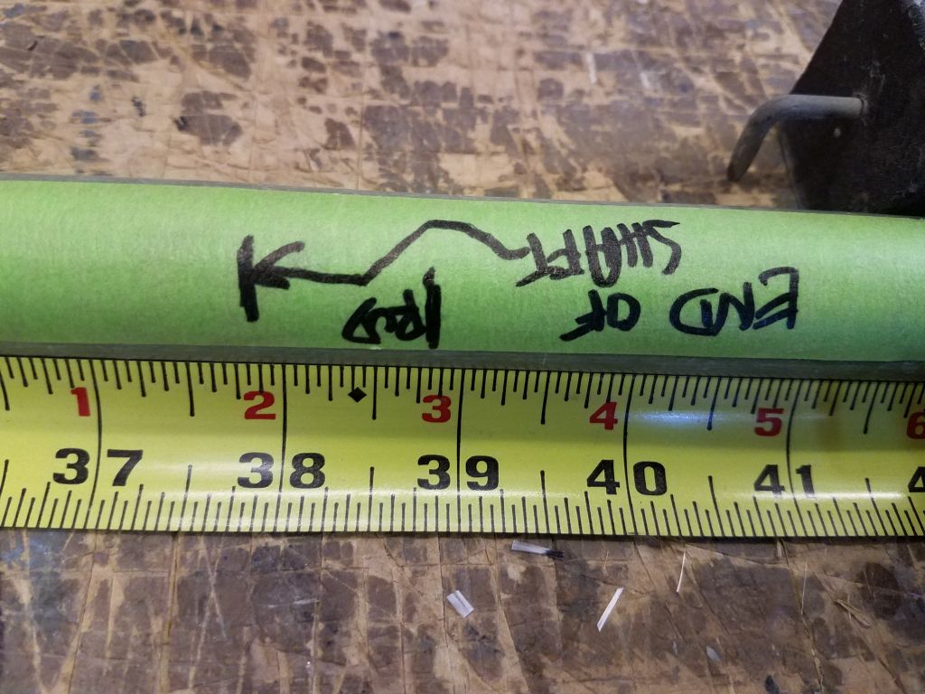
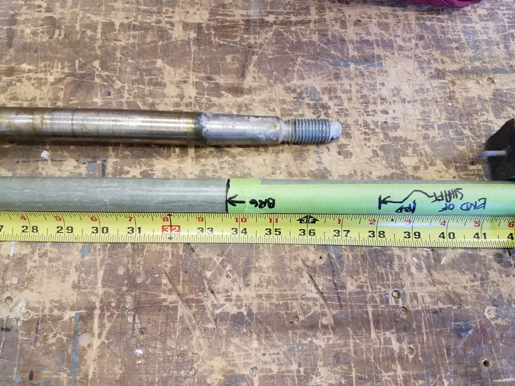
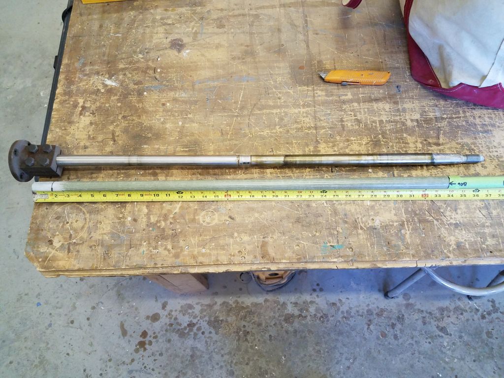
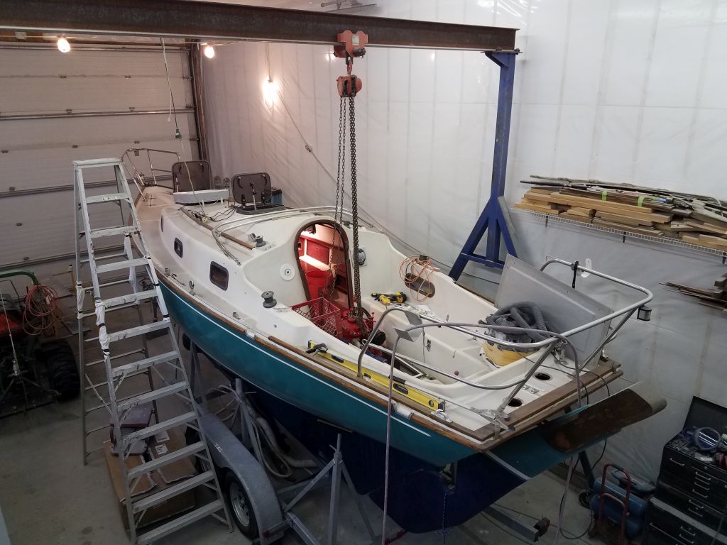
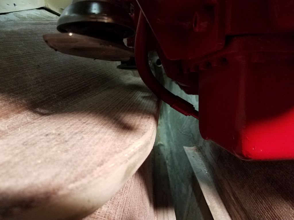
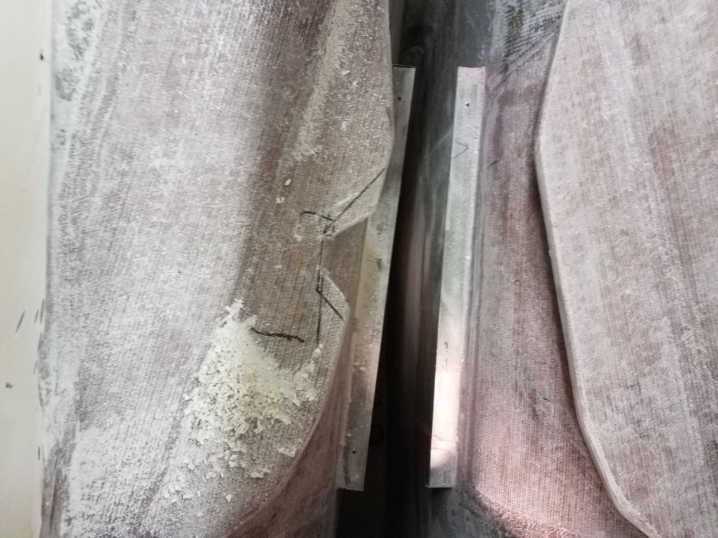
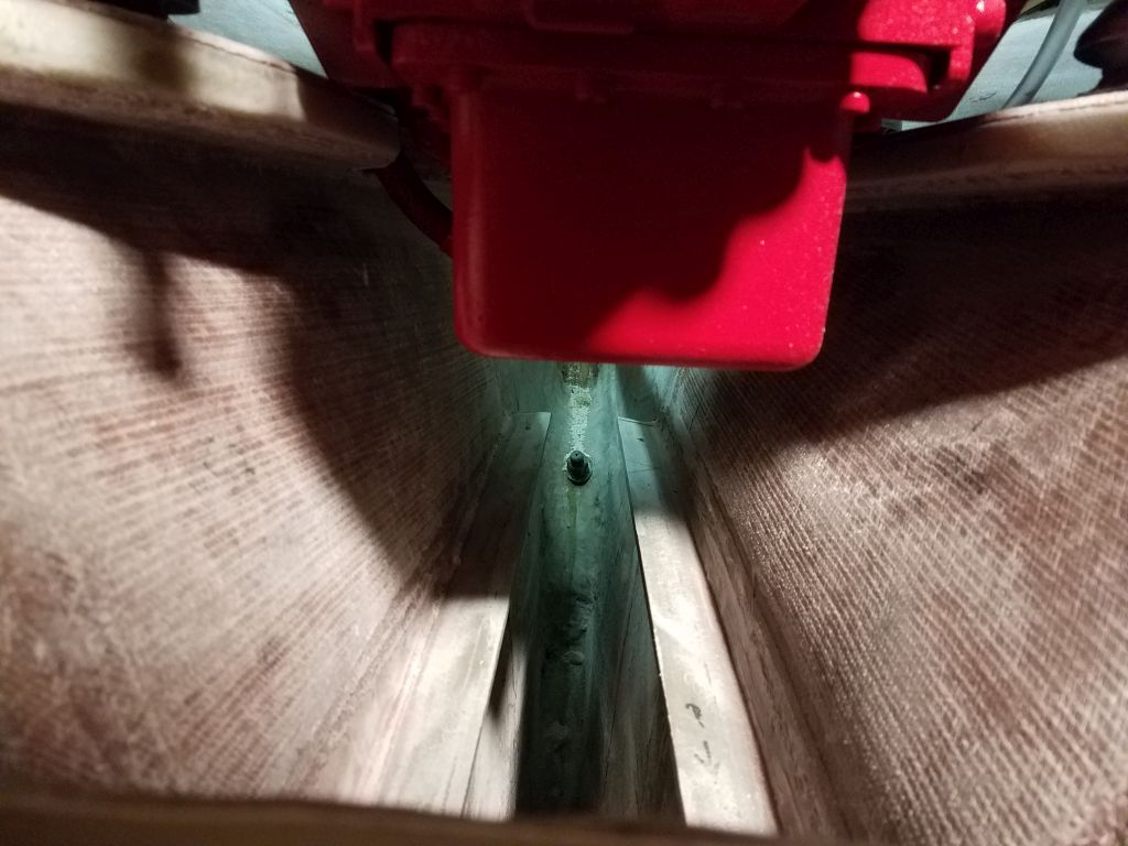
With the engine suspended over the opening, I noted where cuts were required to expand the opening for an easier fit for the engine, then made these cuts as required. I’d come back later and clean up the cuts with a sander, but for now my goal was (at first) to set the engine in the boat so I could measure for and order the new propeller shaft, so I left the fancier work for later.
Making the cuts was slow going, as there were heavy layers of fiberglass plus an aluminum plate in the engine compartment surround. I left all the existing bolt holes (which threaded into the aluminum plate) intact for reinstalling the cockpit sole/engine room cover later. Once I enlarged the opening, lowering the engine posed no problems.
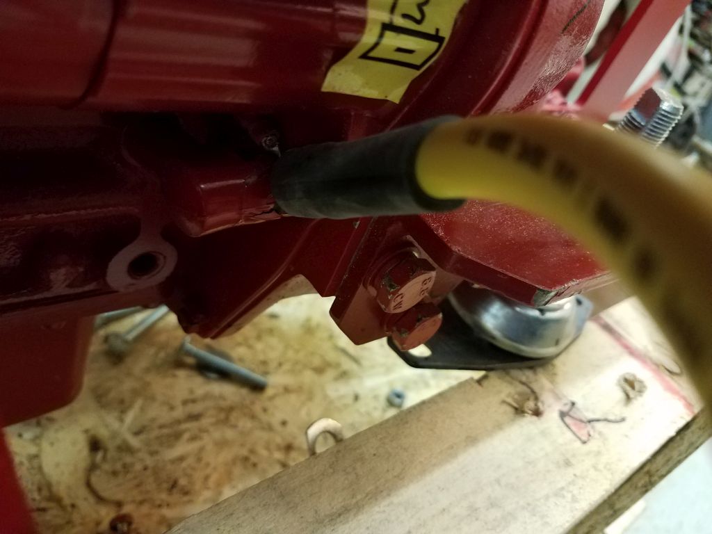
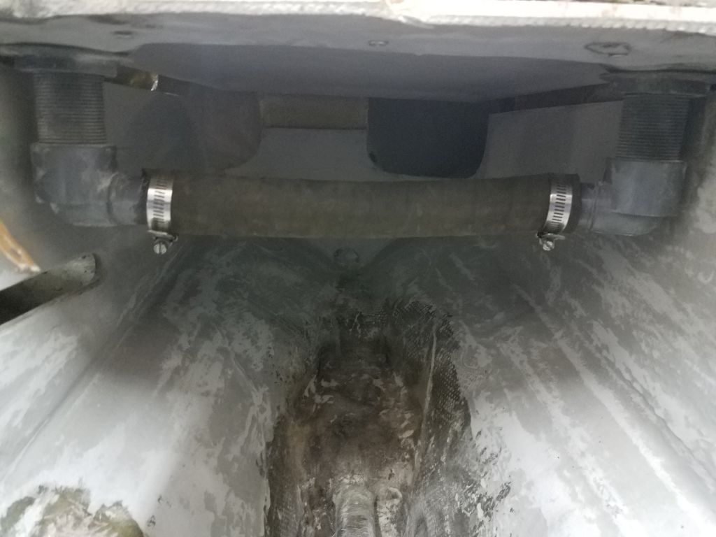
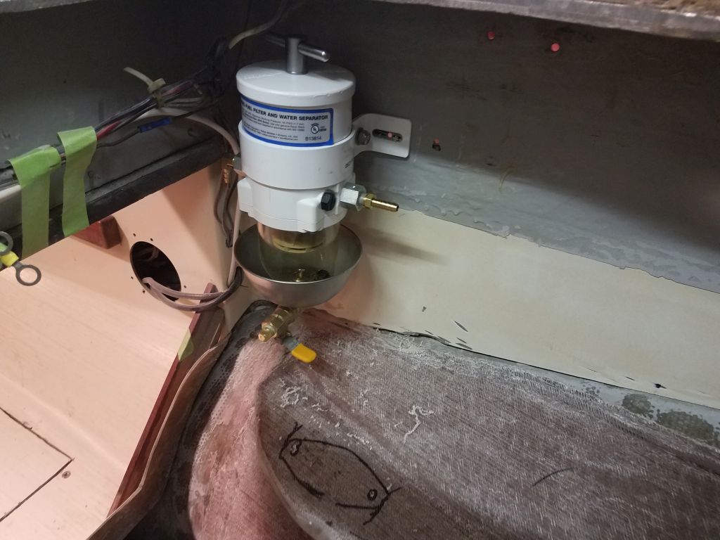
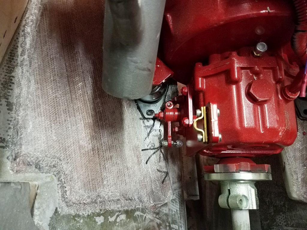
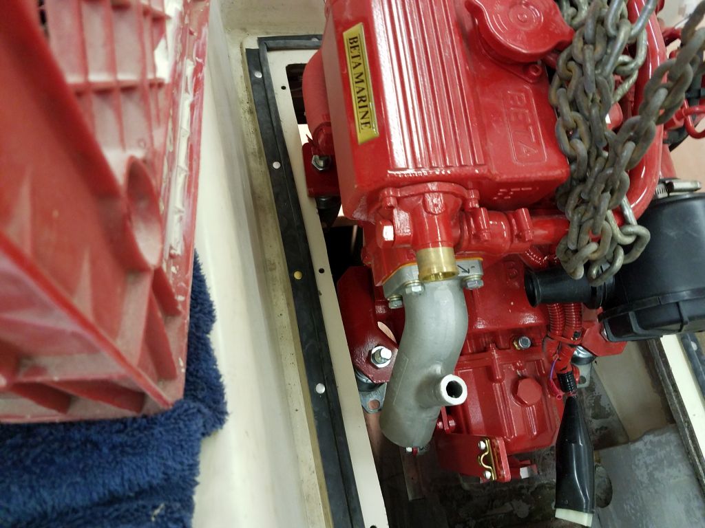
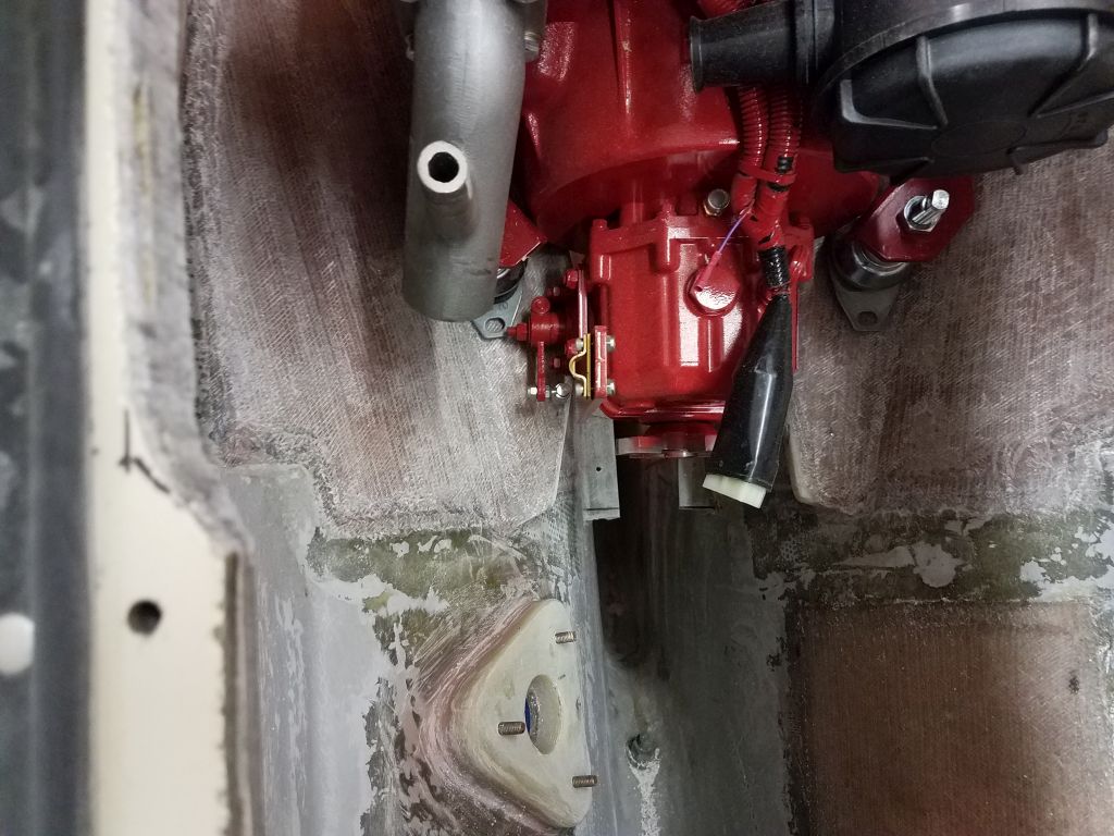
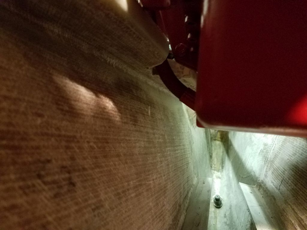
There were several clearance issues that immediately prevented the engine from lowering all the way to the foundations. First, the oil pump hose, which ran out the starboard side of the engine from the oil sump and which frequently causes minor issues in tight installations in my experience, hit hard against the foundation (which angled inwards as it ran aft thanks to the requirements of the hull), so I made some marks there to cut out a section of the foundation and allow clearance.
Raising the engine out again, I cut out a chunk of the foundation in way of the oil hose, and lowered in the engine again.
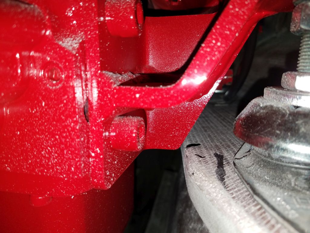
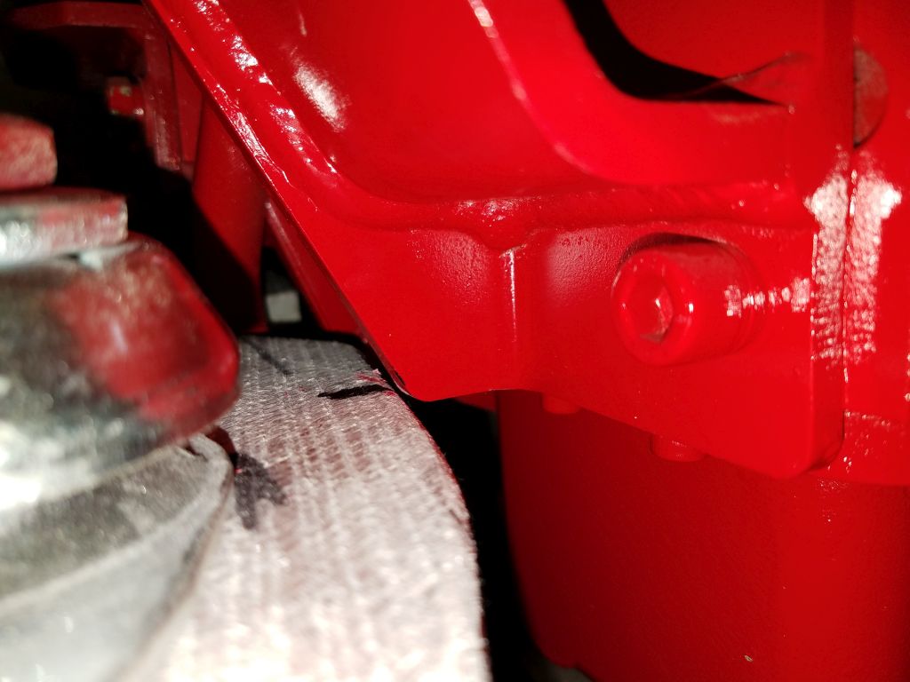
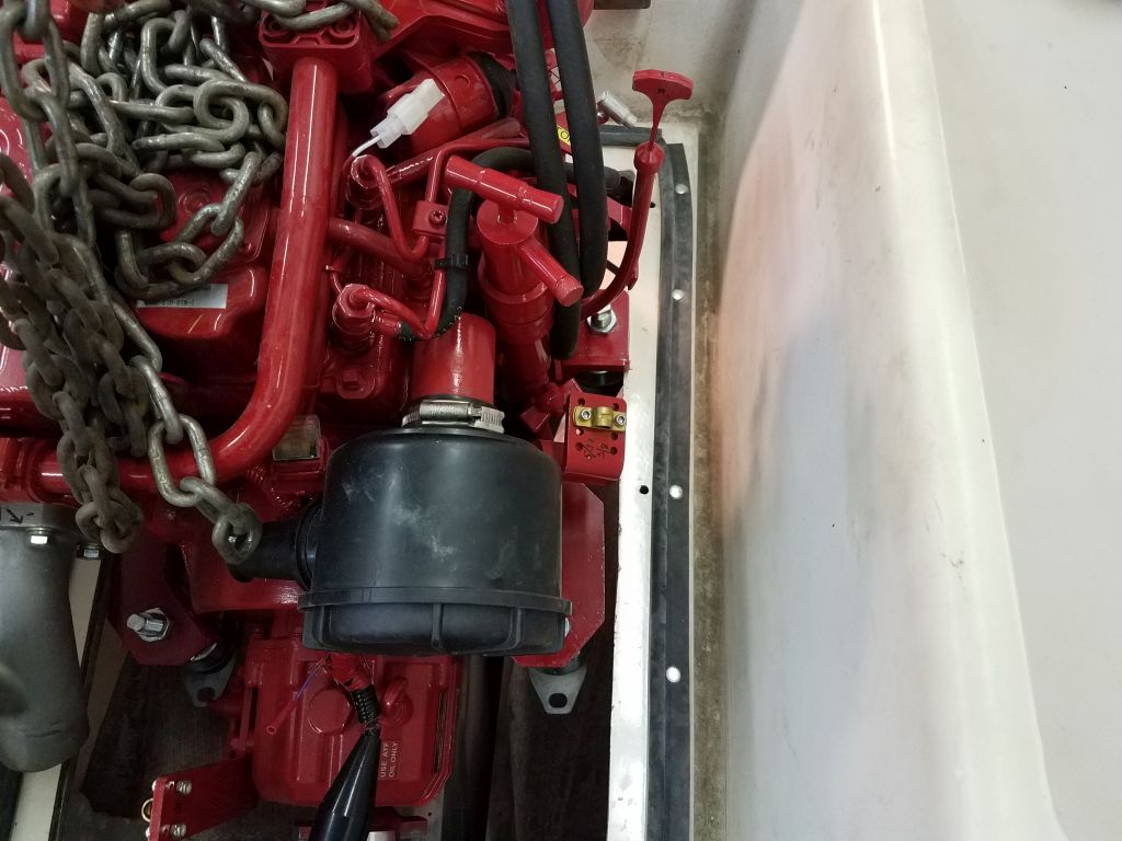
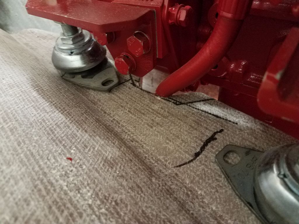
Now there were several other clearance issues, all of which caused by the tight shape of the hull and narrowness of the foundations at the aft end. There were places where the bell housing at the after end of the engine contacted the edge of the foundations, so I marked these as needed. Also, there would be a need to cut out a large section at the very aft side to port, to allow the transmission lever clearance to operate (i.e. to be pushed down). I made reference marks for that, but at least for now I could leave it be since it wasn’t preventing the engine from sitting where it needed to.
The oil hose now fit fairly well, but to avoid chafe I needed to open up the cutout just a bit more.
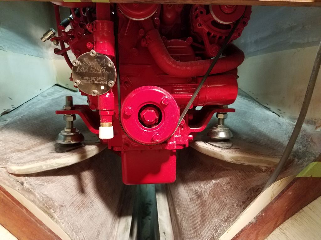
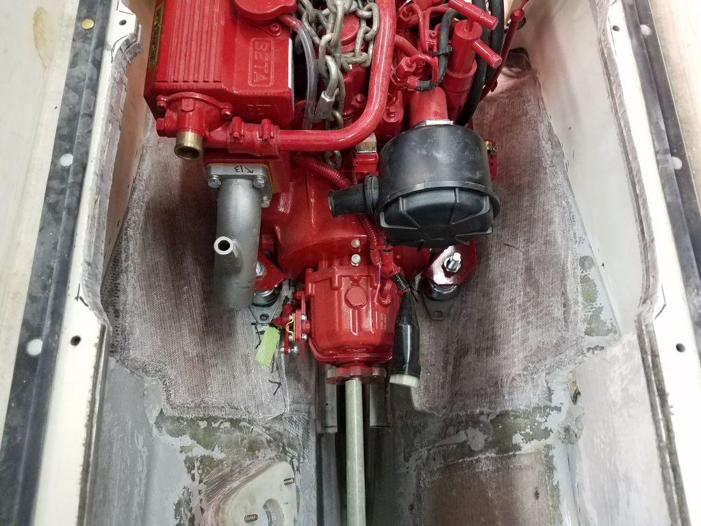
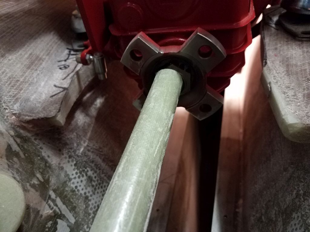
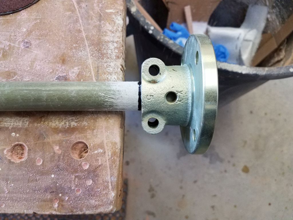
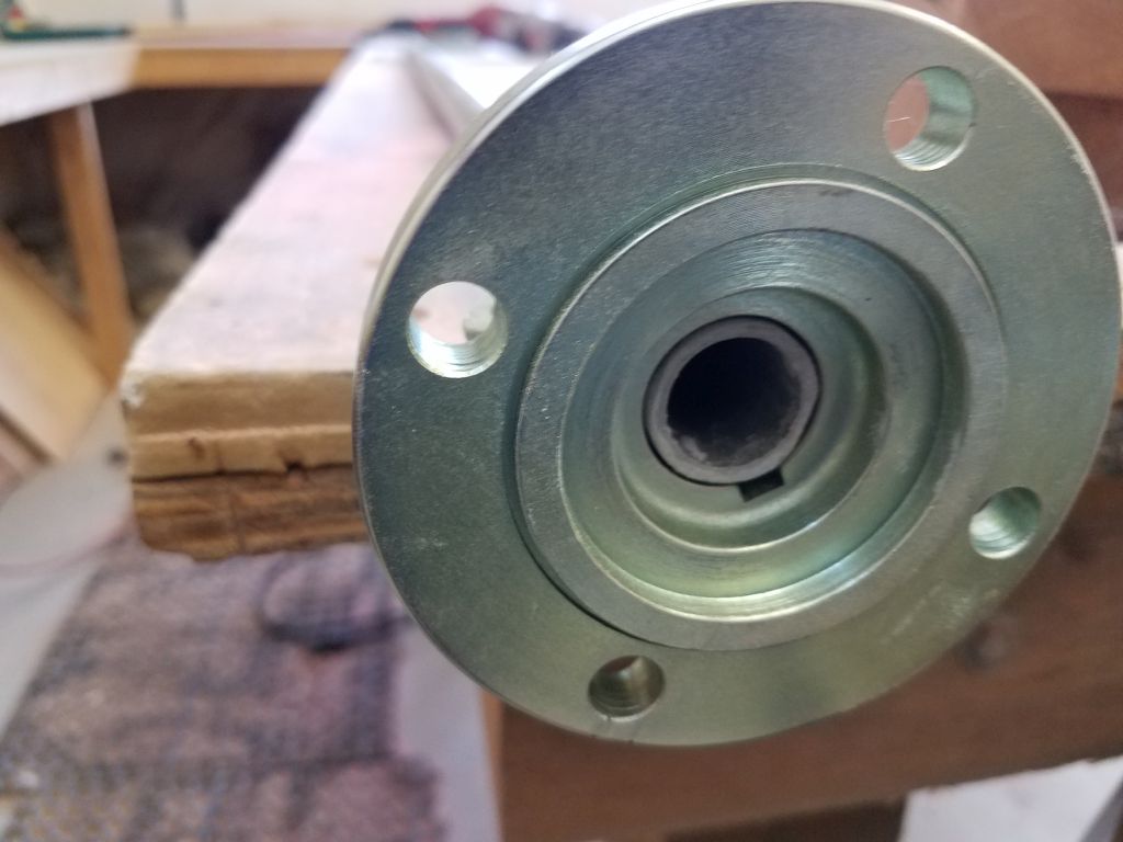
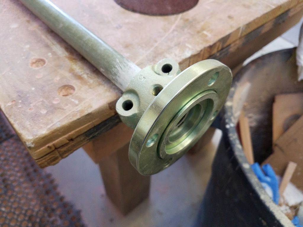
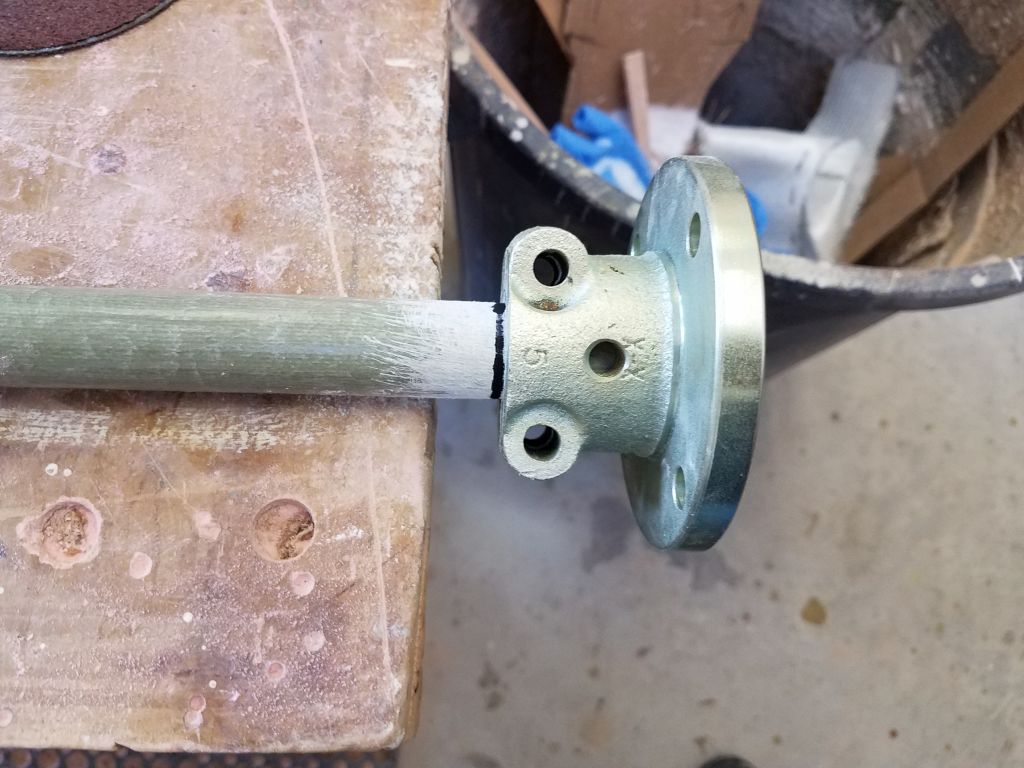
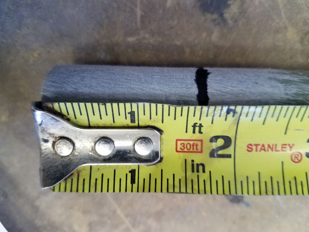
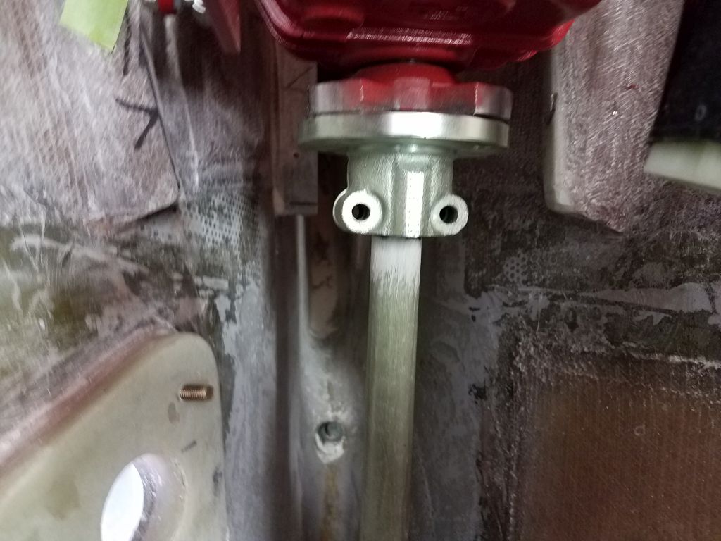
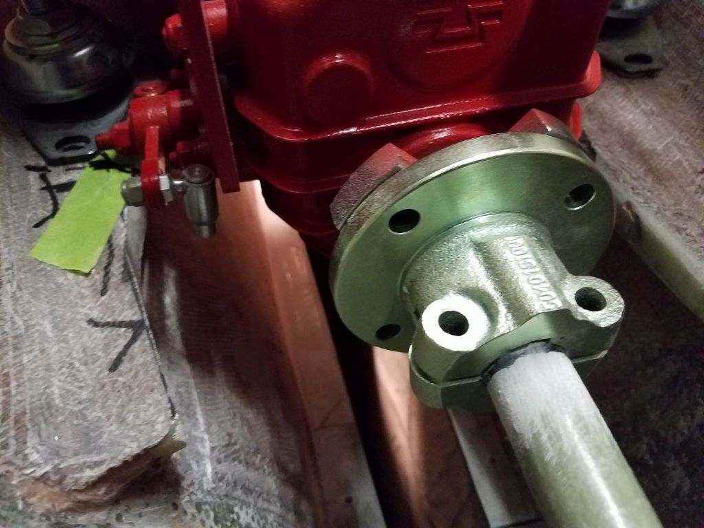
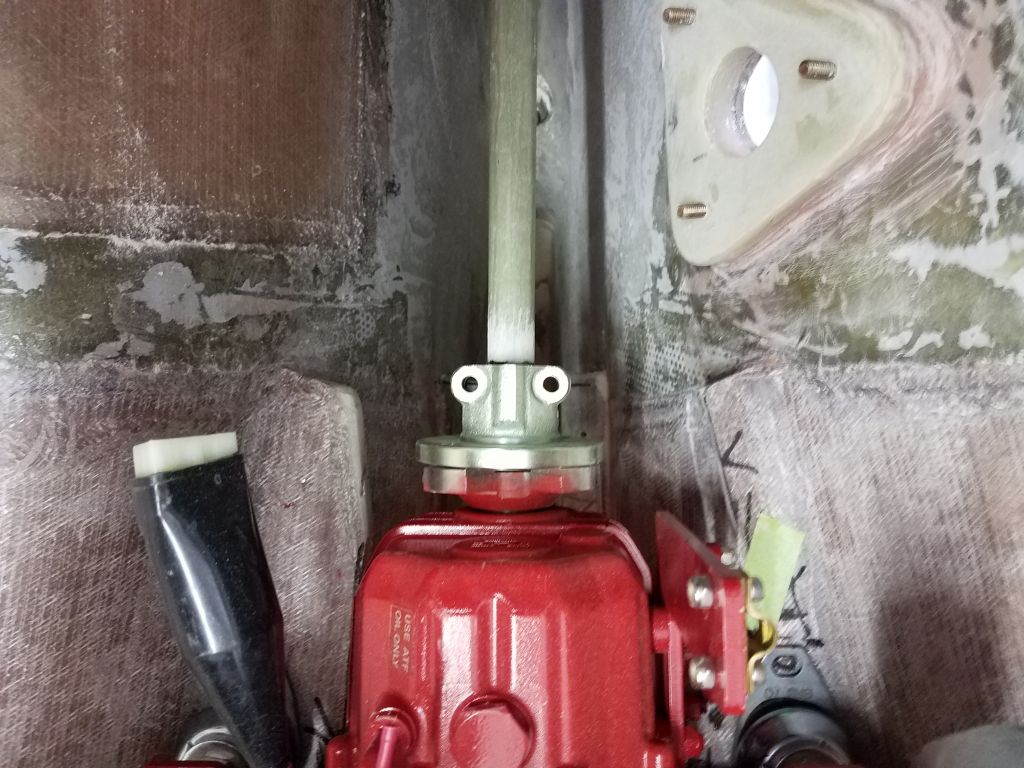
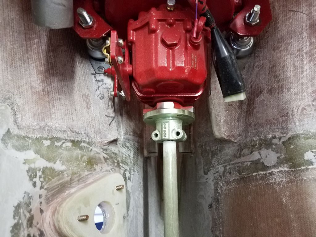
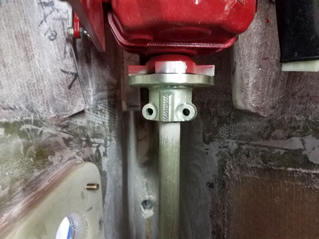
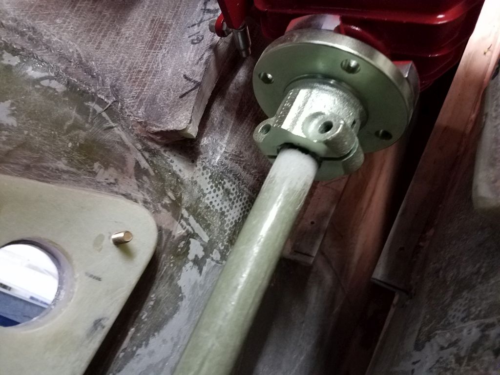
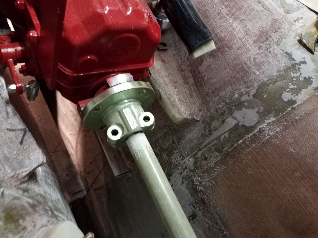
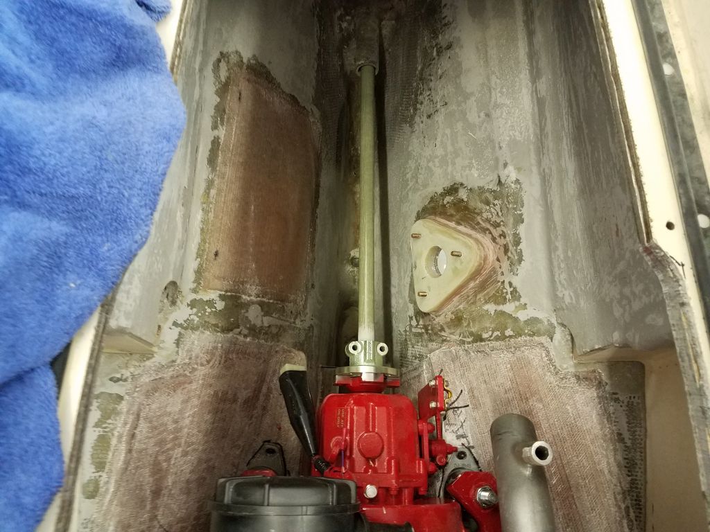
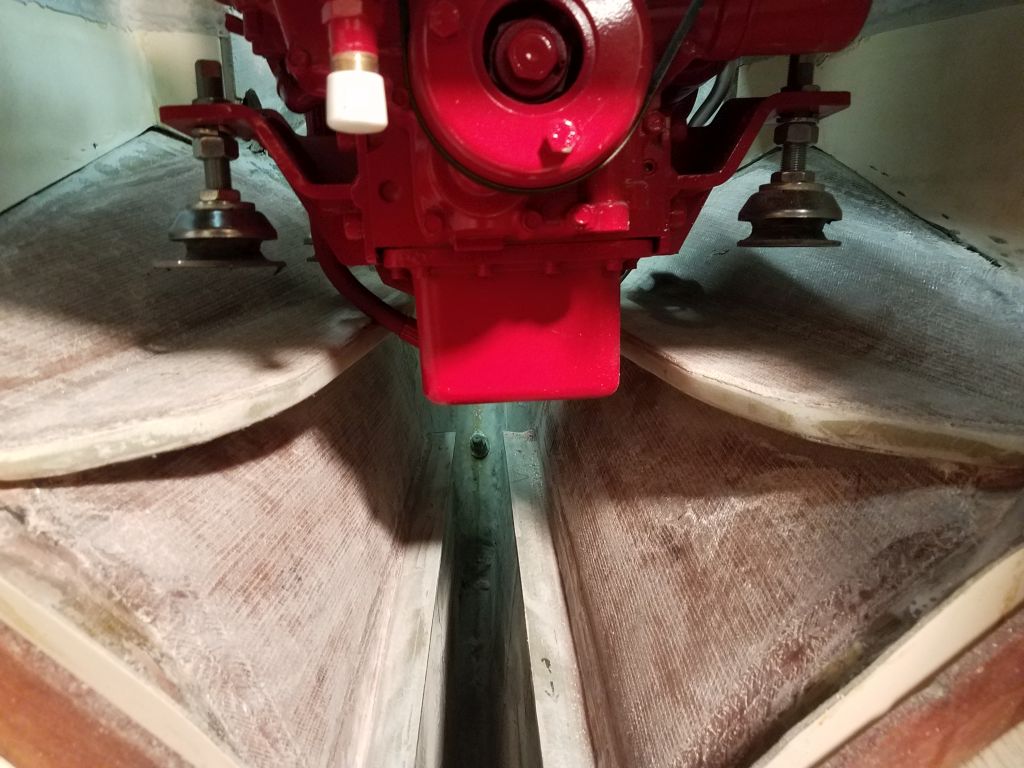
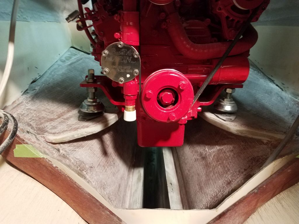
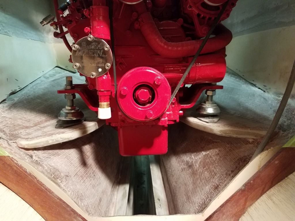
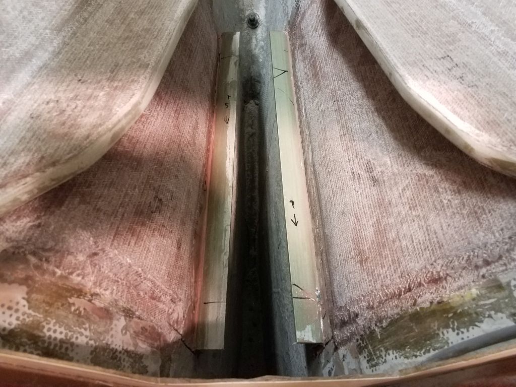
Meanwhile, I could check the basic engine alignment with a 1″ fiberglass tube that I used as a stand-in for the shaft. Some continuing adjustments would be required to shift the engine slightly to port, but otherwise things looked pretty good. Some of this adjustment would be possible once I’d made the newest clearance cuts in the foundation, so I lifted out the engine once more.
After finishing the new cuts, I lowered the engine in once more, and things were looking better and closer to where they needed to be. But the clearance issues on the port side continued, not only the transmission lever (which I’d yet to cut out), but with that after port mount, which was likely to be an issue with the transmission, as well as with the curvature of the hull, which right now was preventing the engine from moving in the correct and required direction.
I let things stand there for now. Though I had the engine nearly as far forward as it could go (the further forward, the better the clearances at the aft end), I thought I might be able to go just a bit further forward. In any event, the day was done, and it was time to go clean up from the day’s snowstorm.
Total time billed on this job today: 5.5 hours (plus 2 hours not billed for the through hull re-work)
0600 Weather Observation: 32°, light snow, about 2″ down. Forecast for the day: Snow, a couple more inches, 32°