Friday
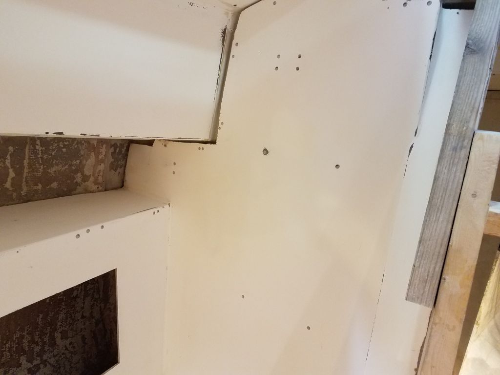
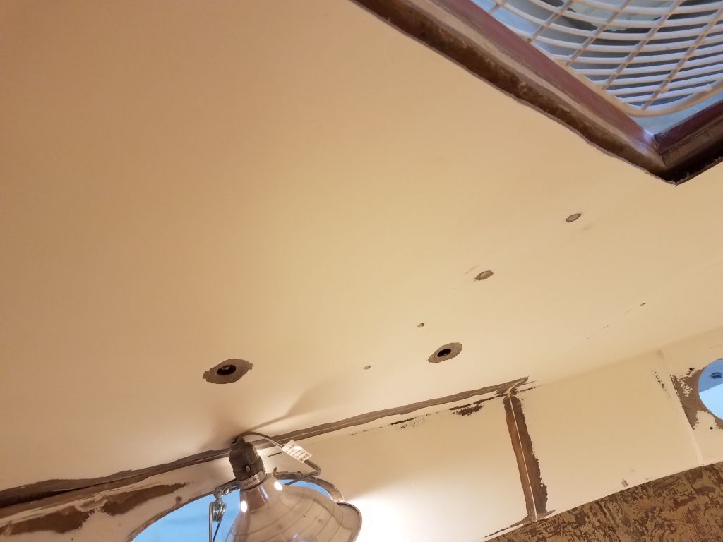
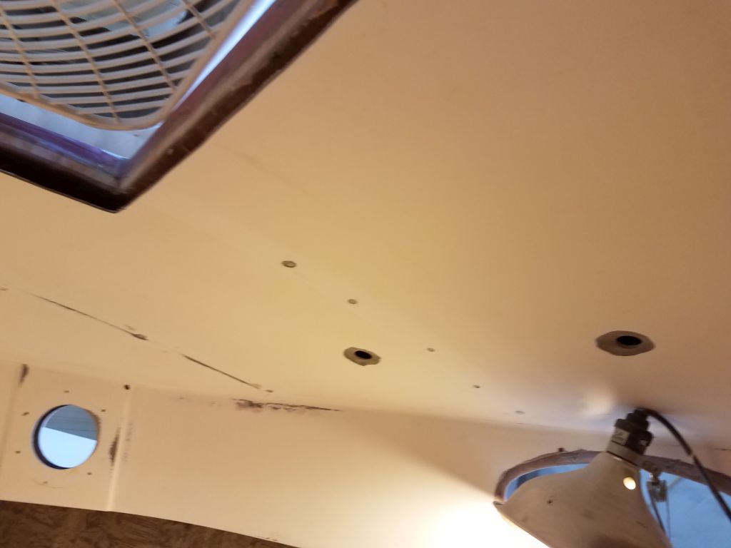
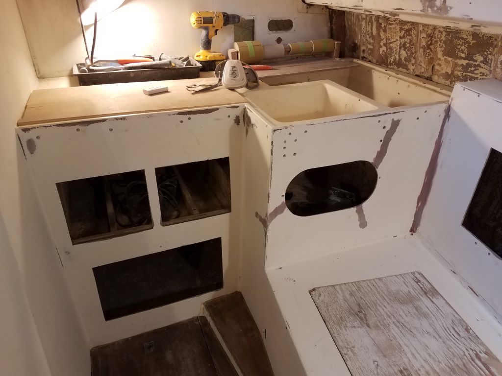
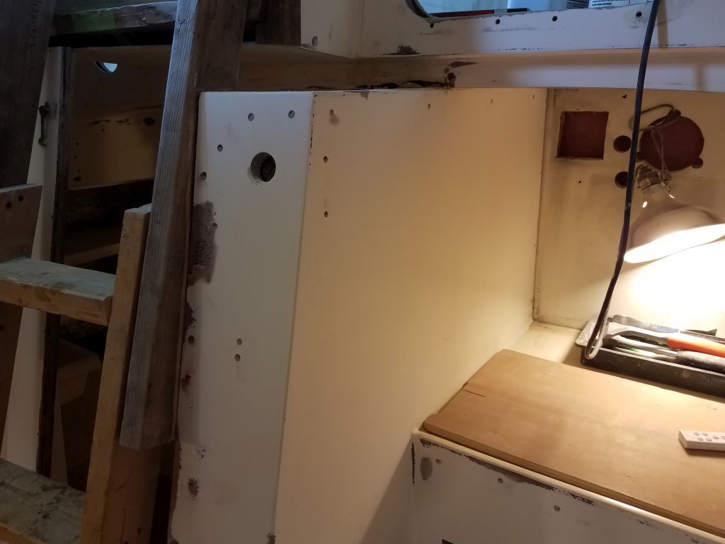
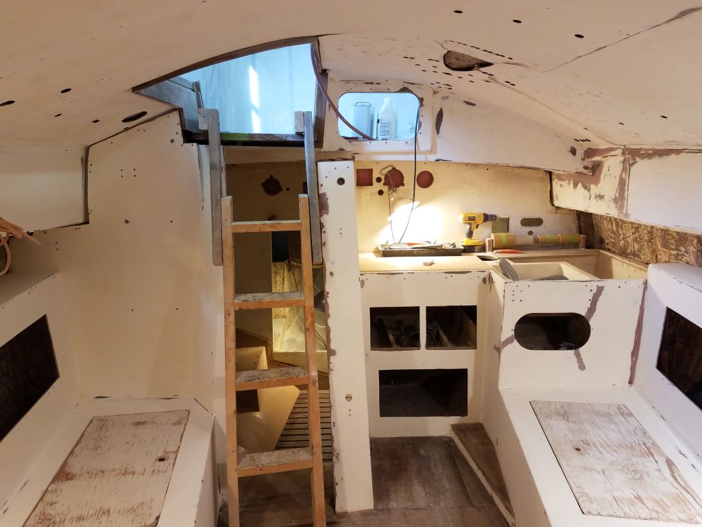
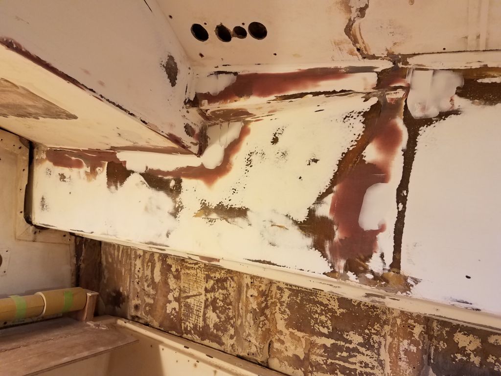
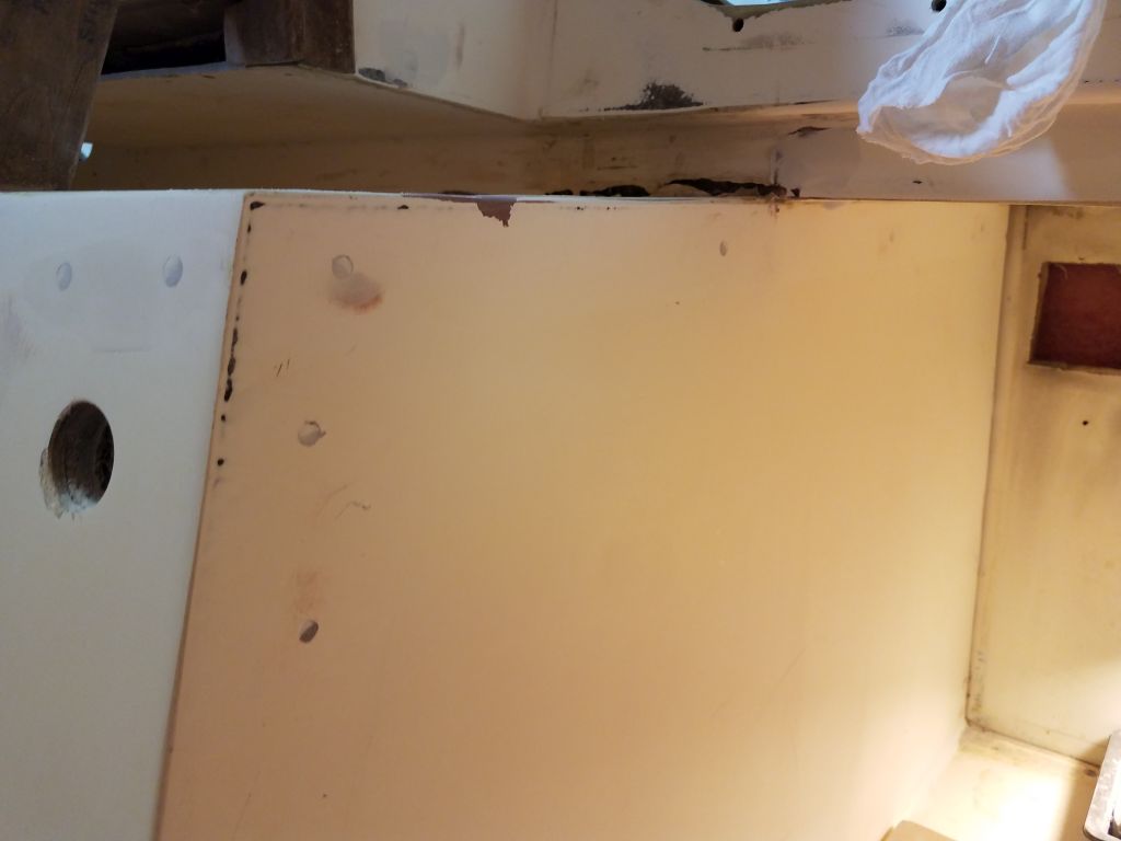
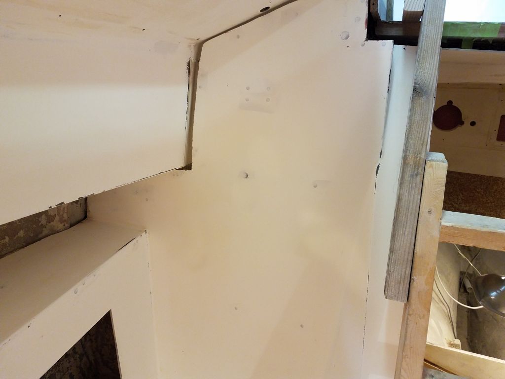
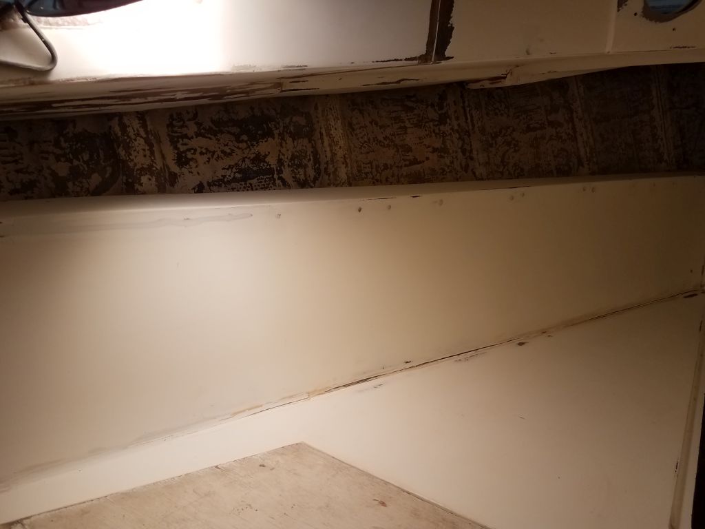
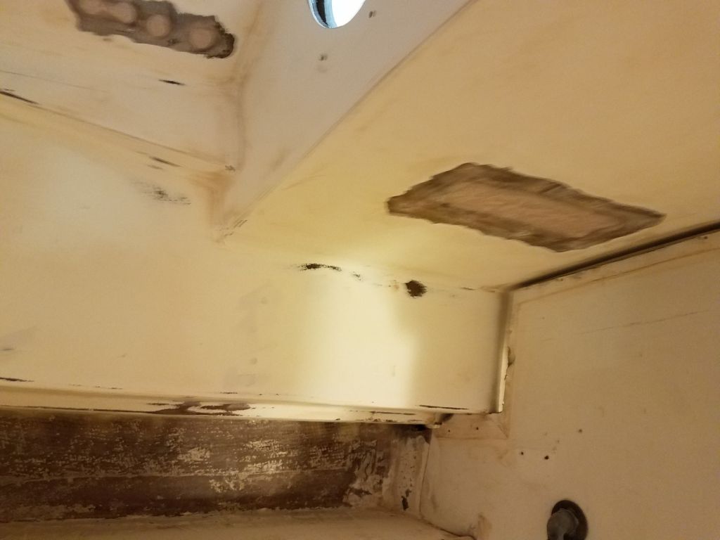
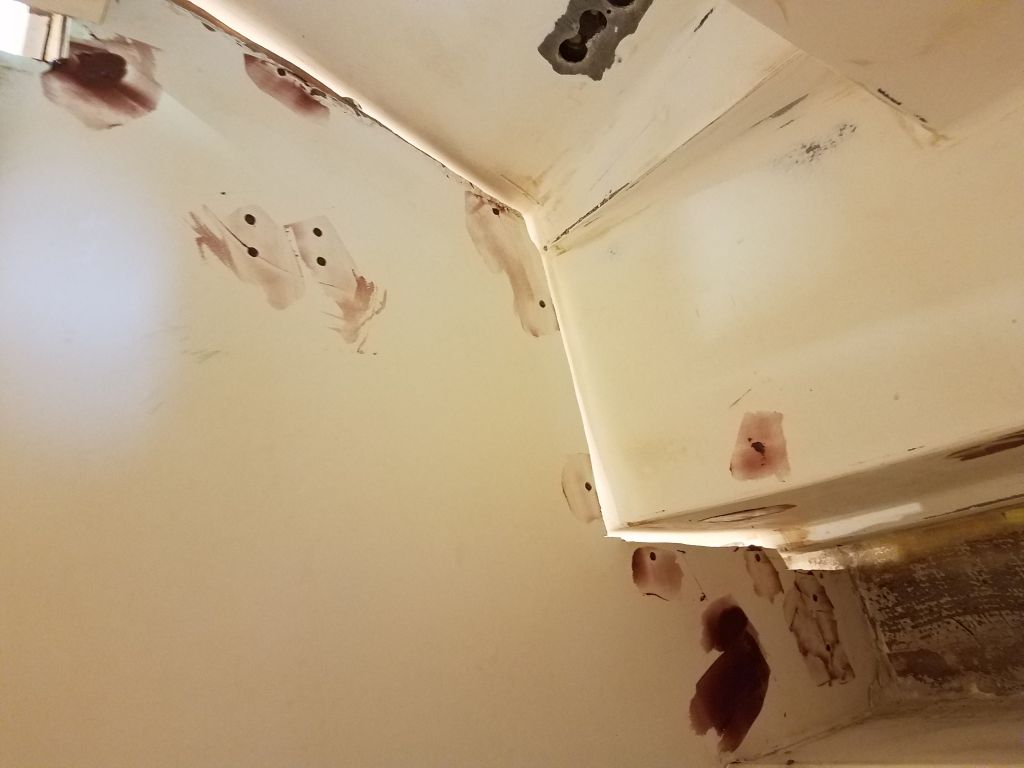
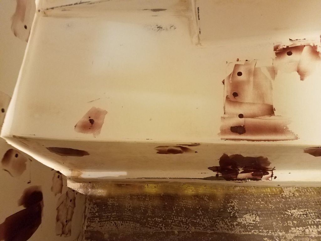
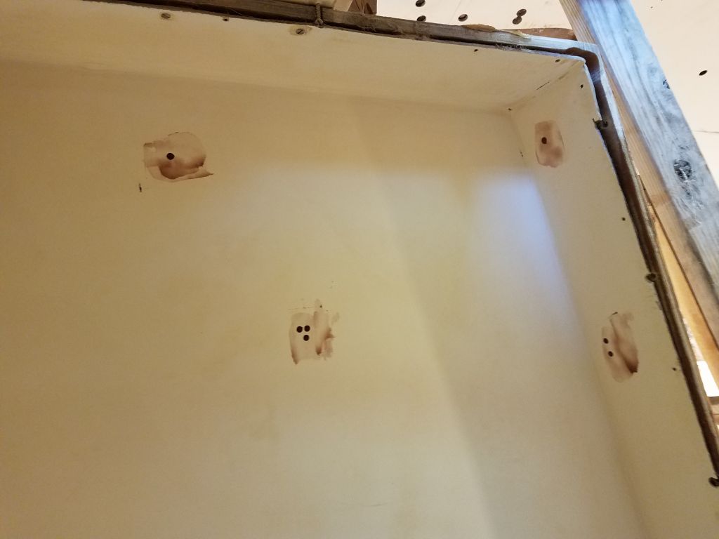
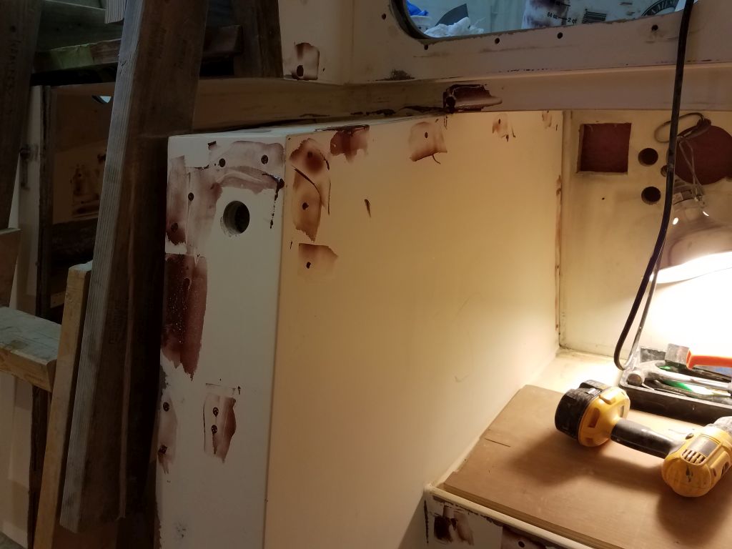
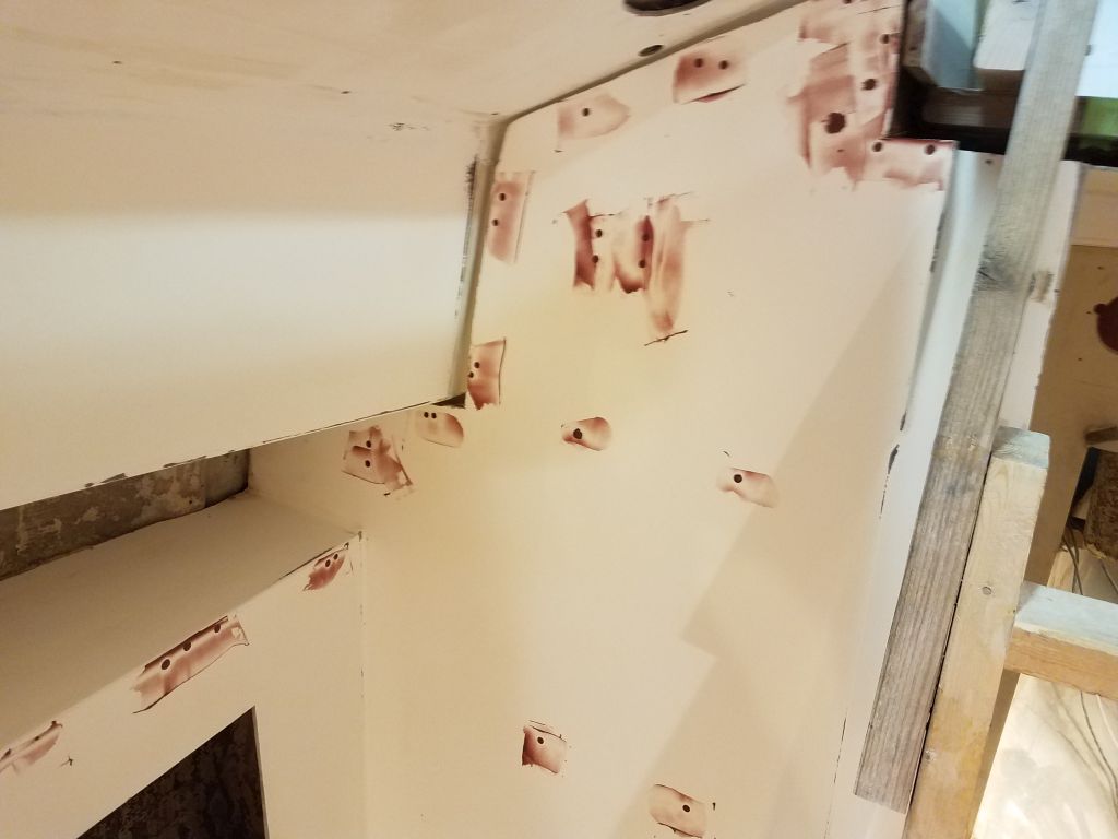
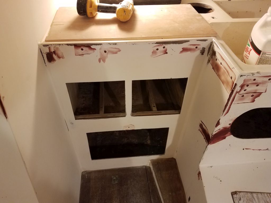
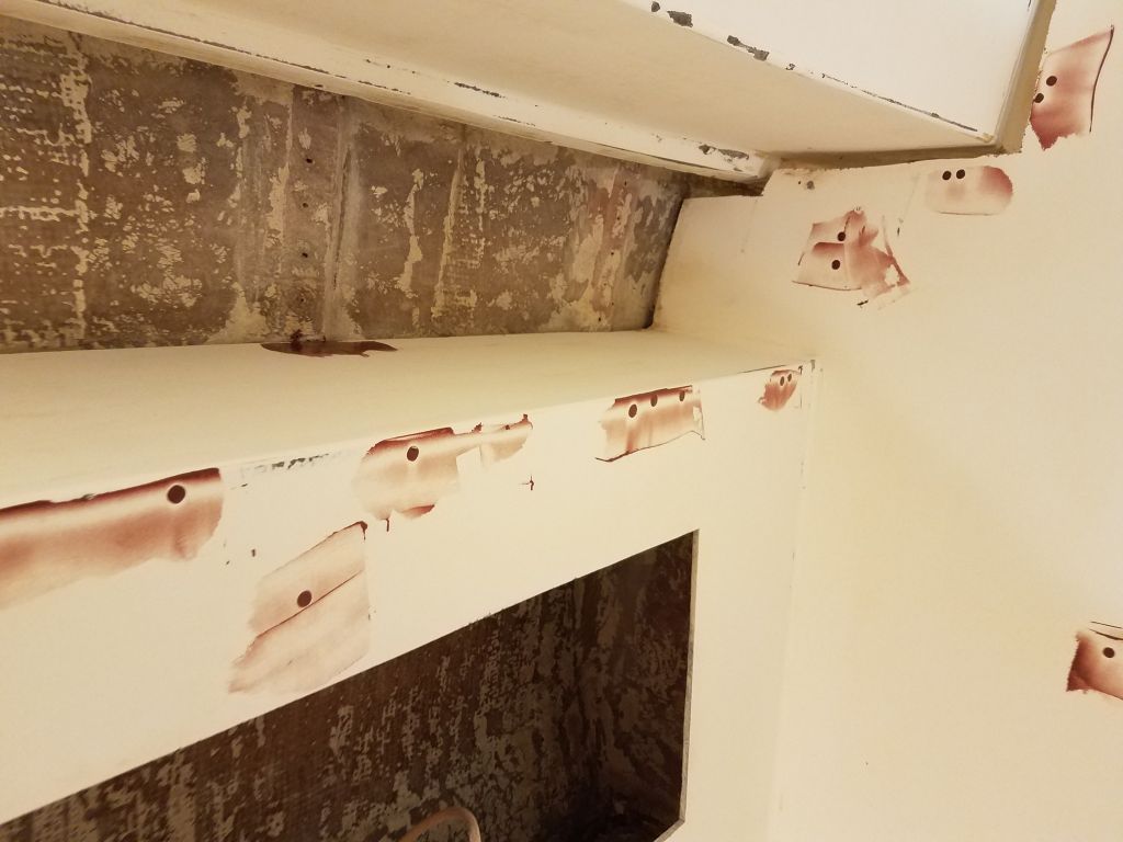
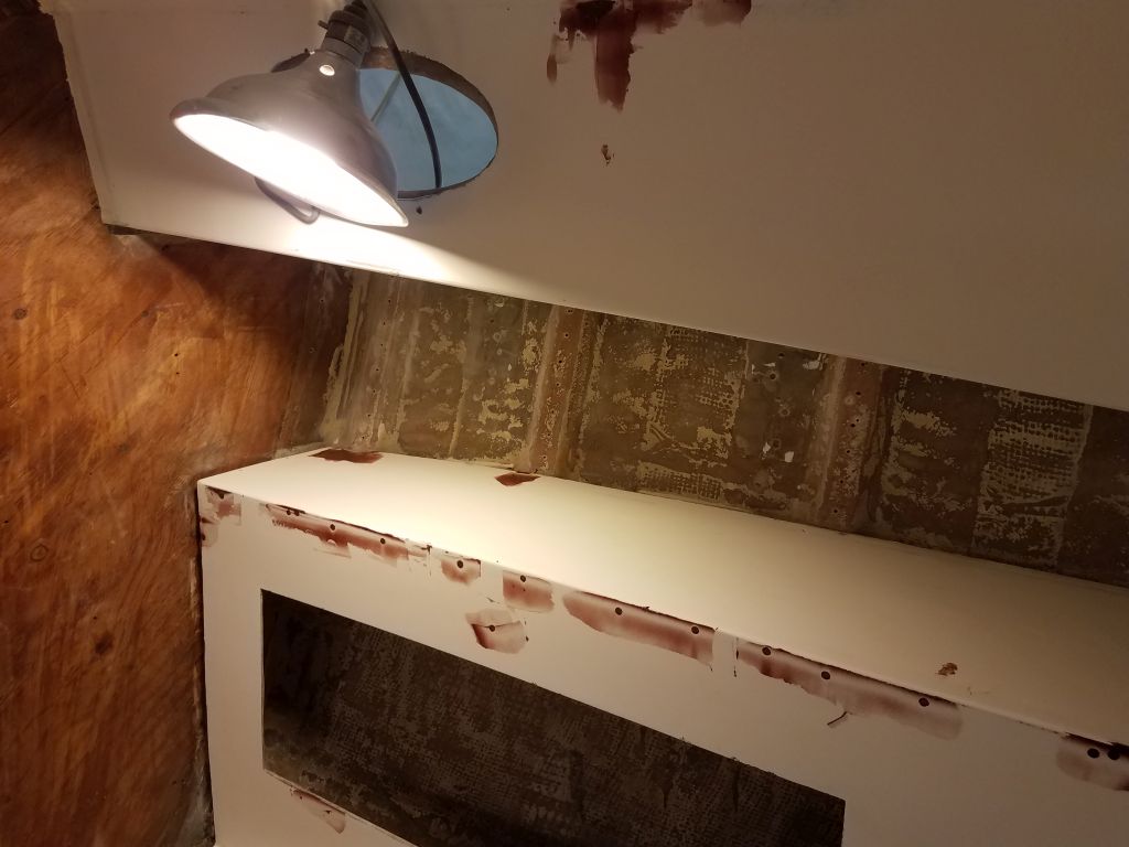
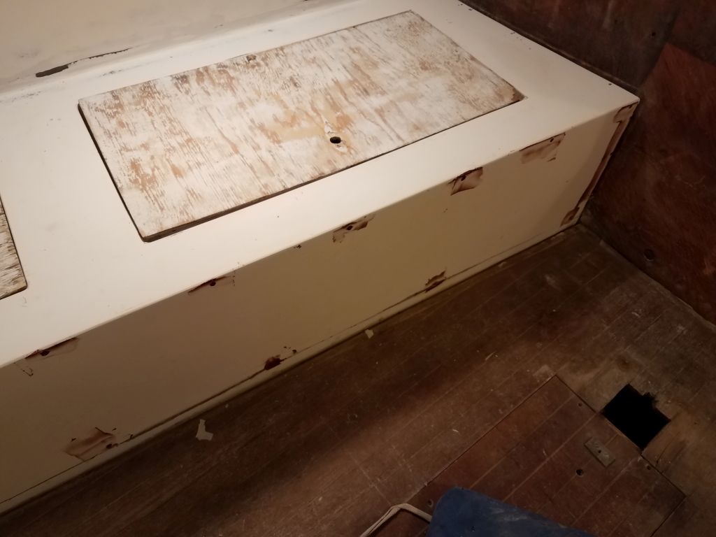
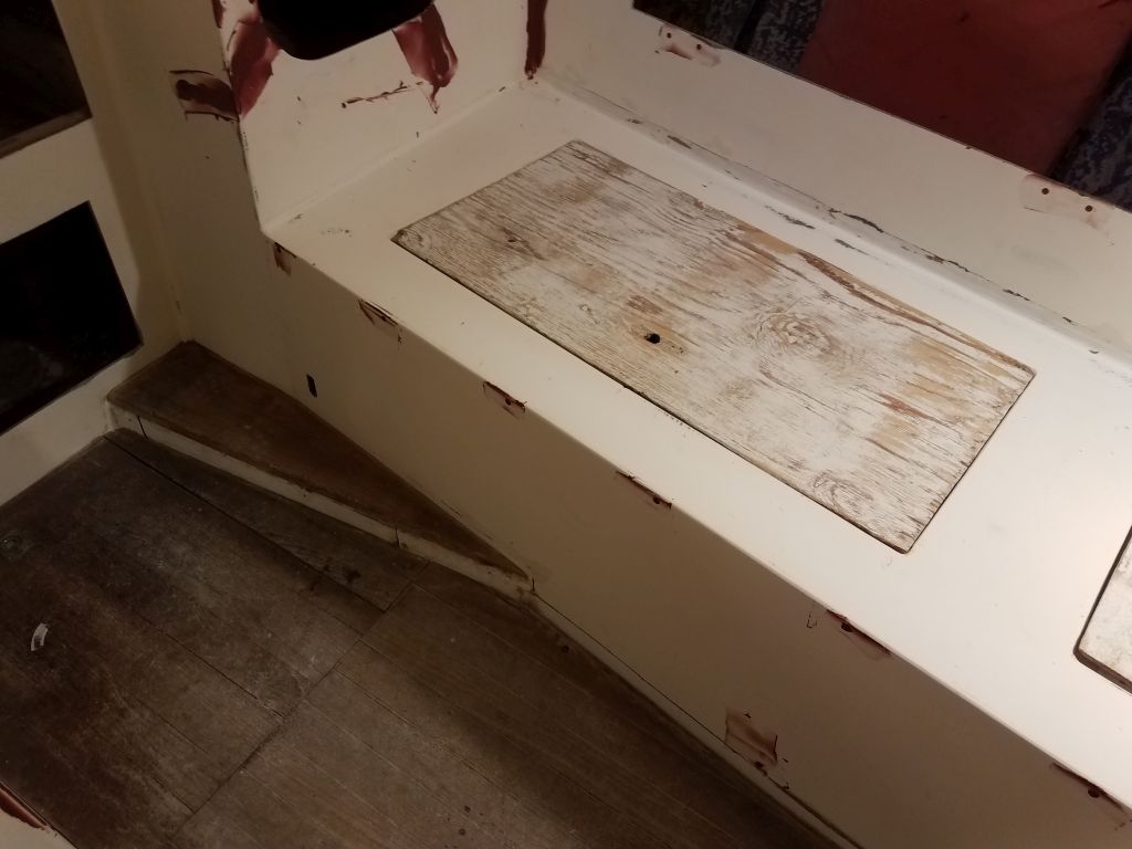
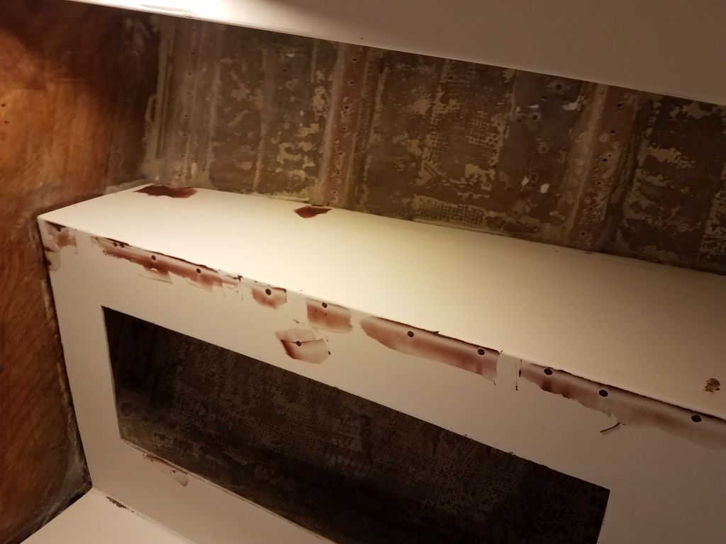
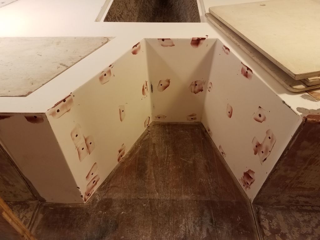
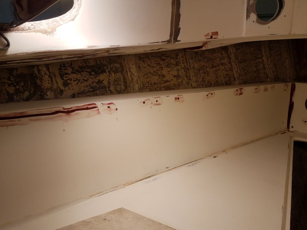
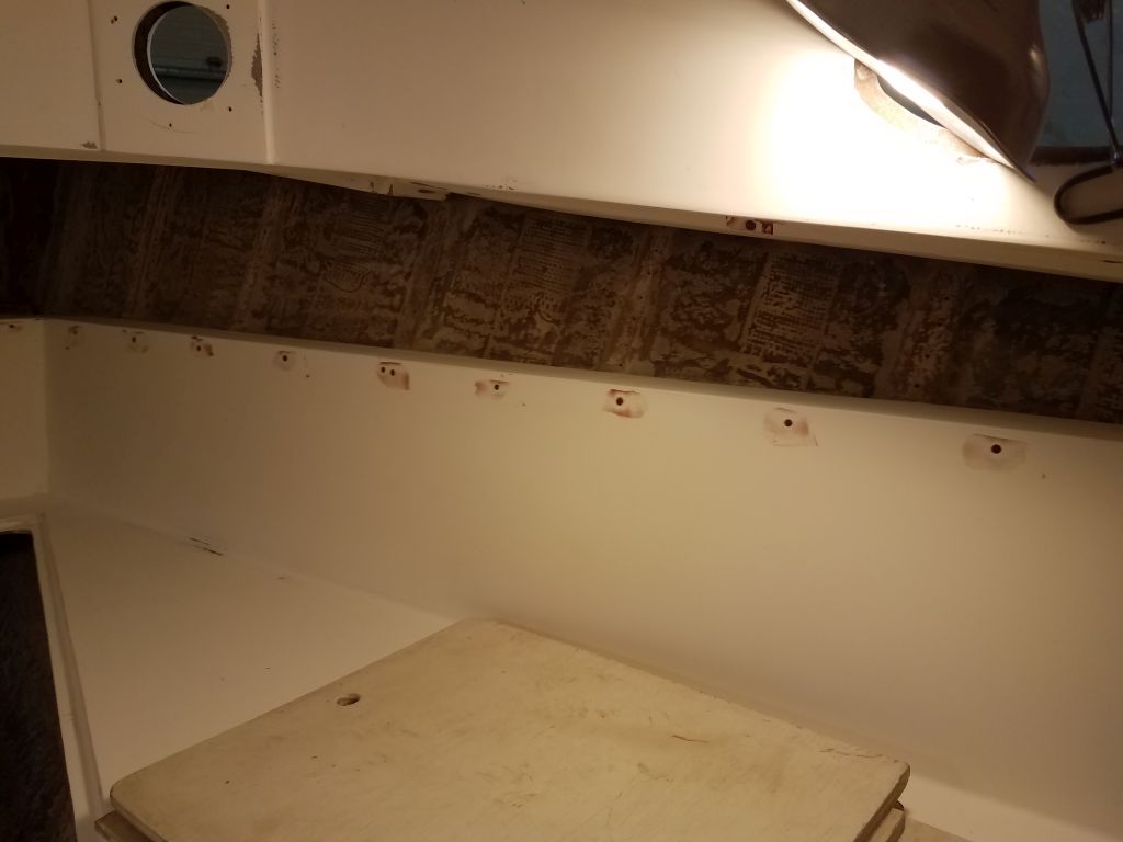
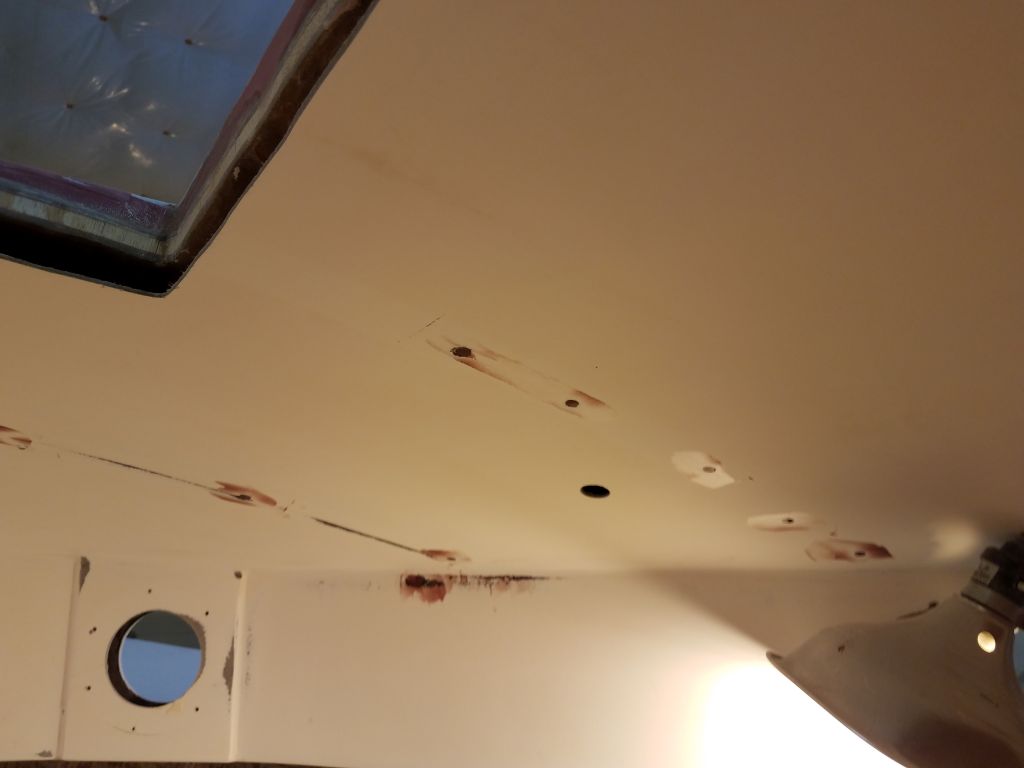
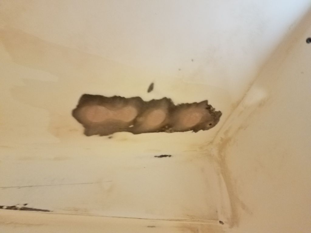
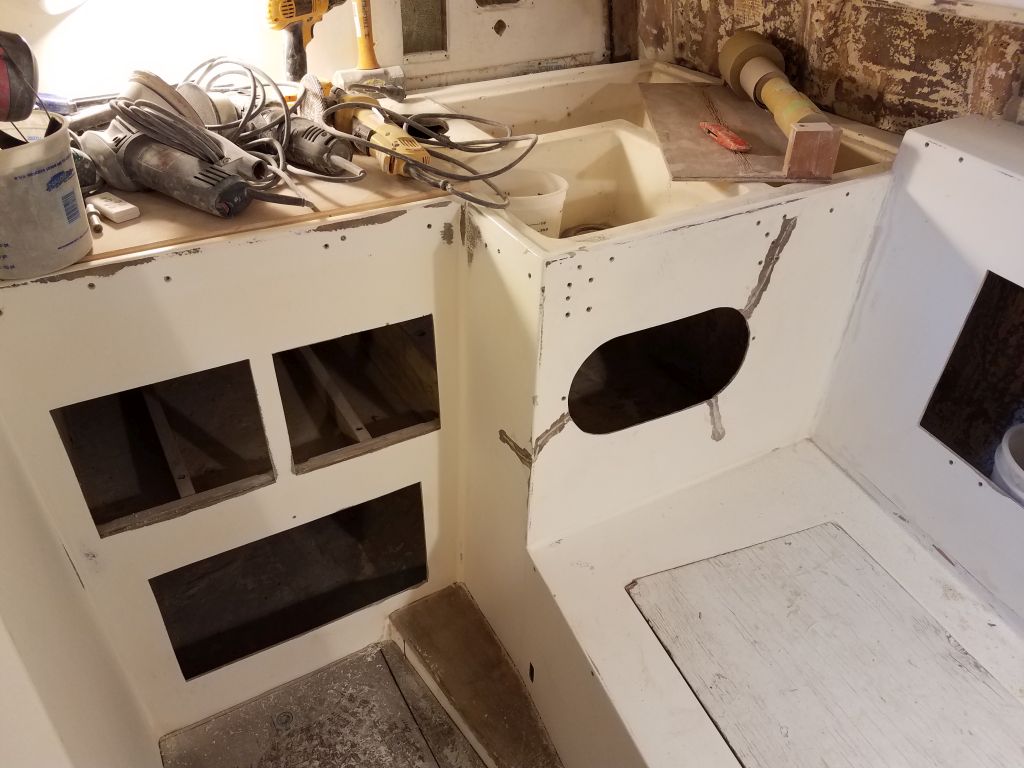
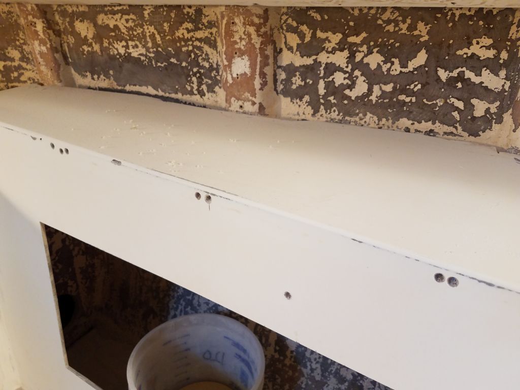
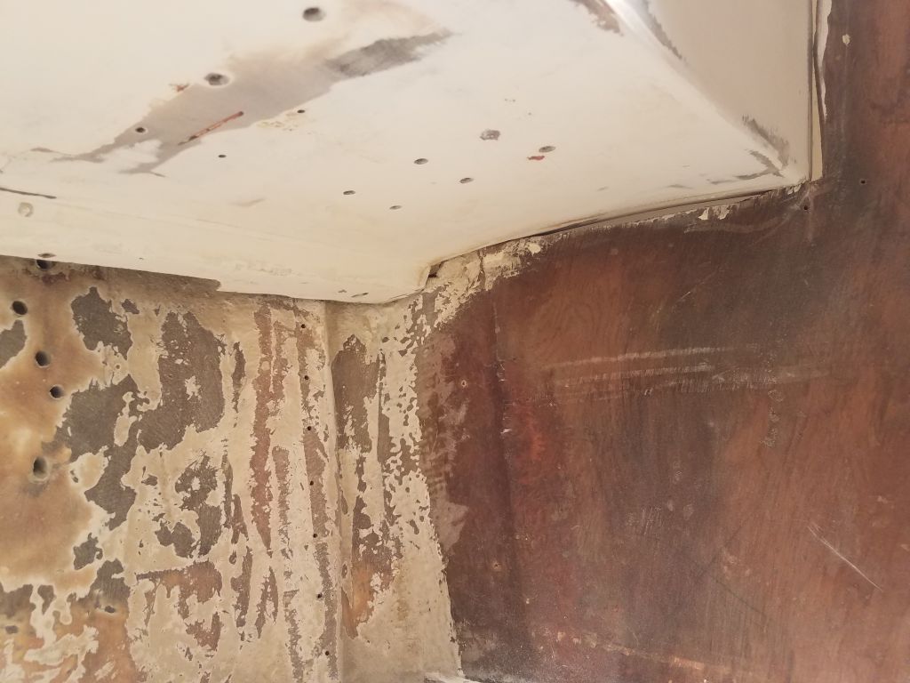
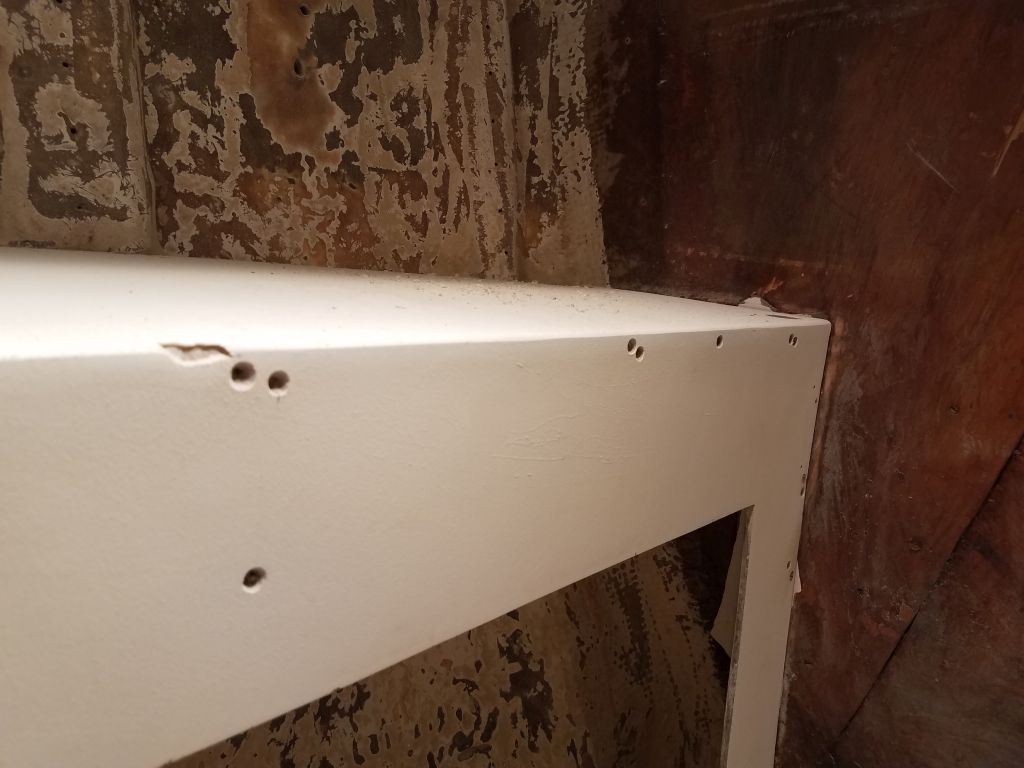
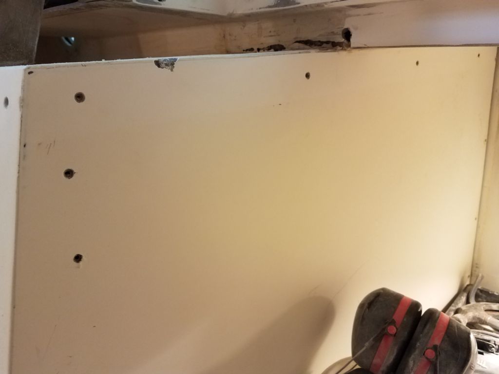
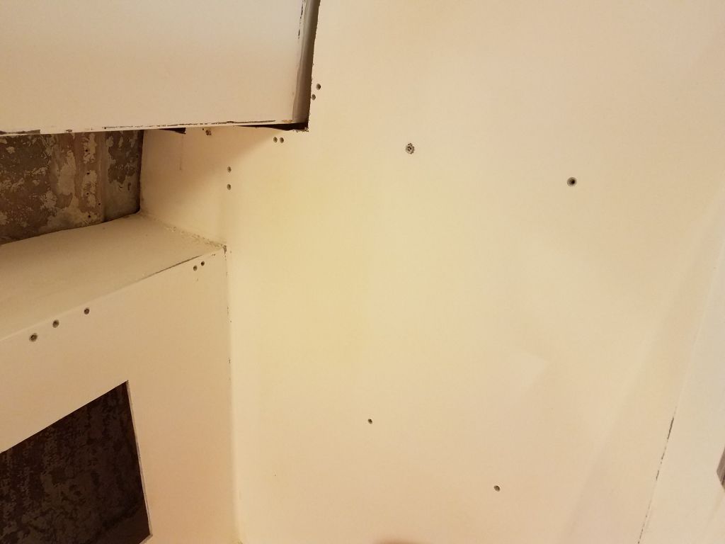
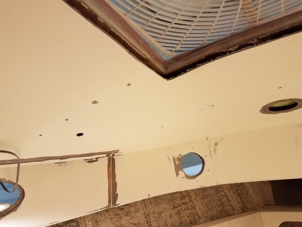
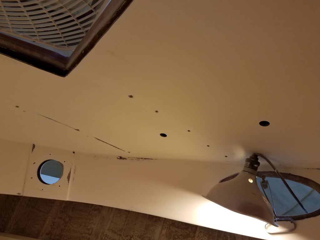
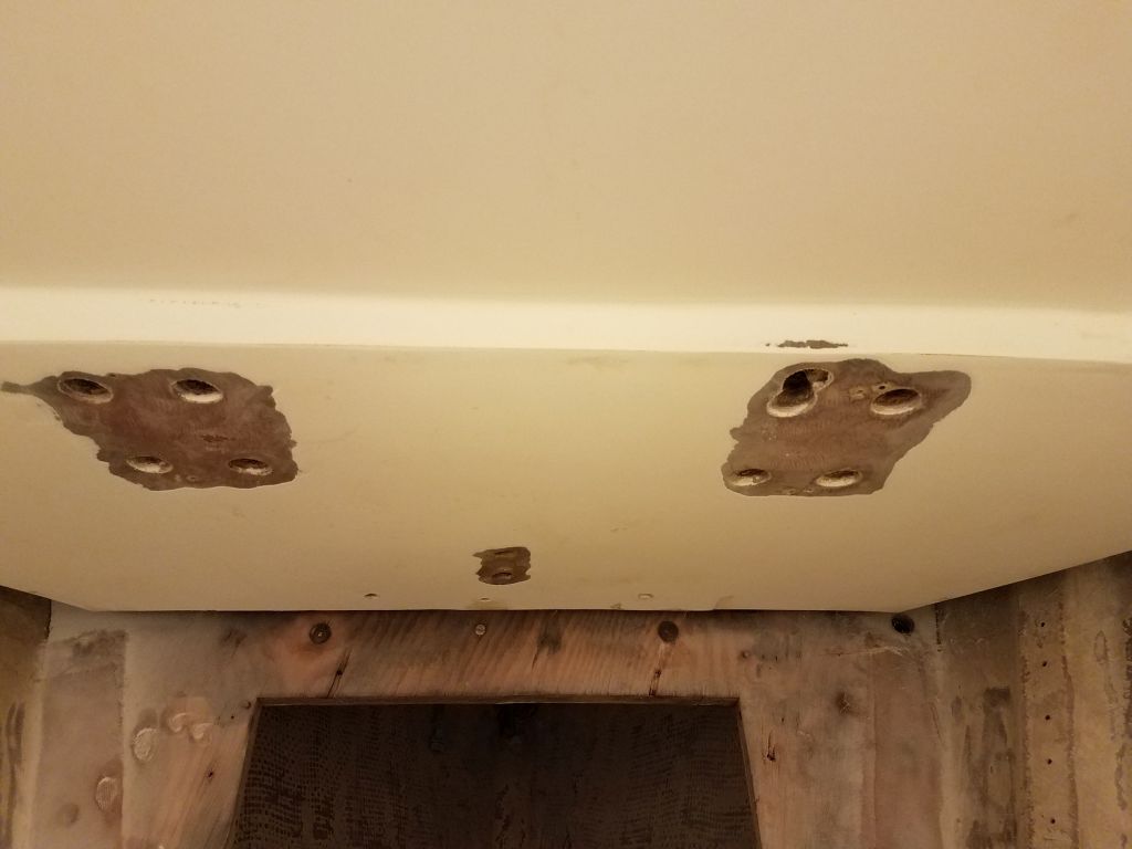
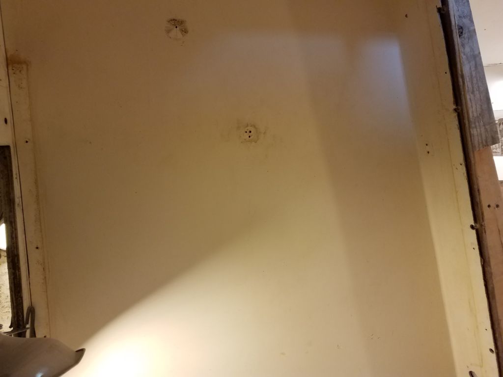
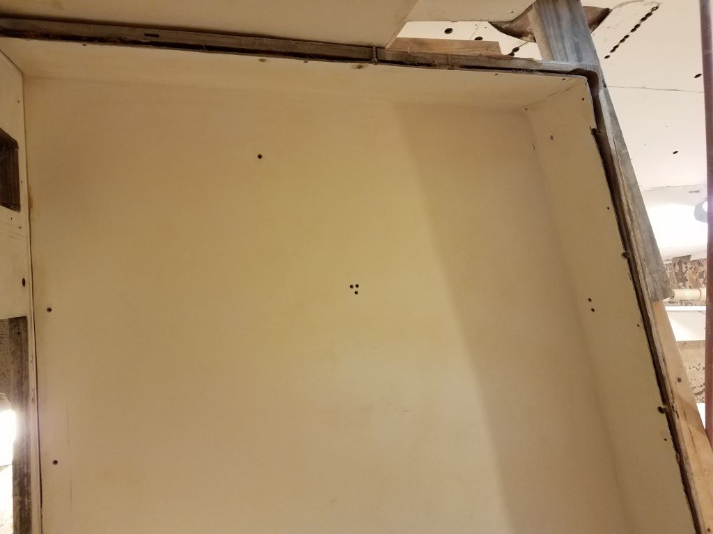
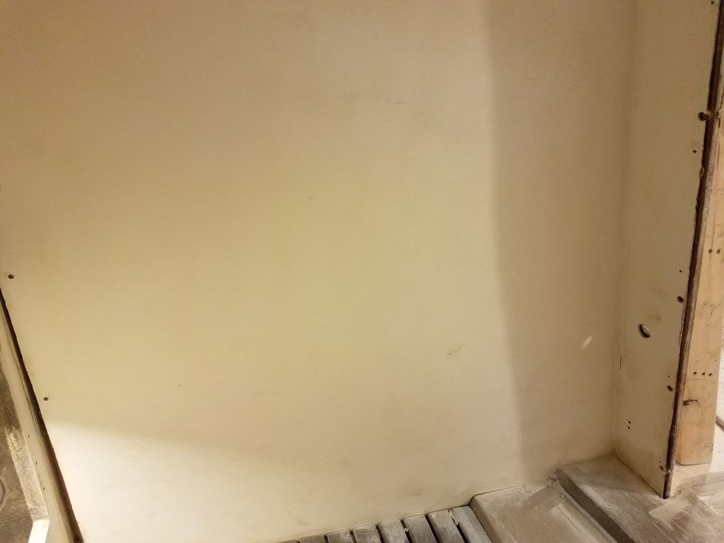
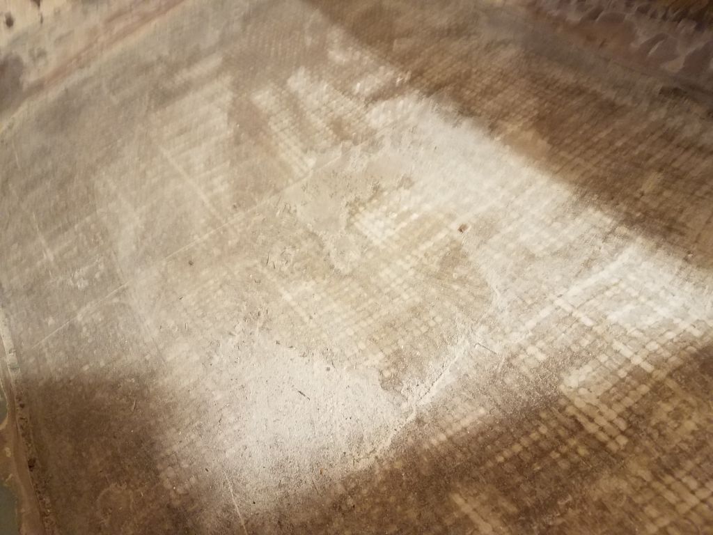
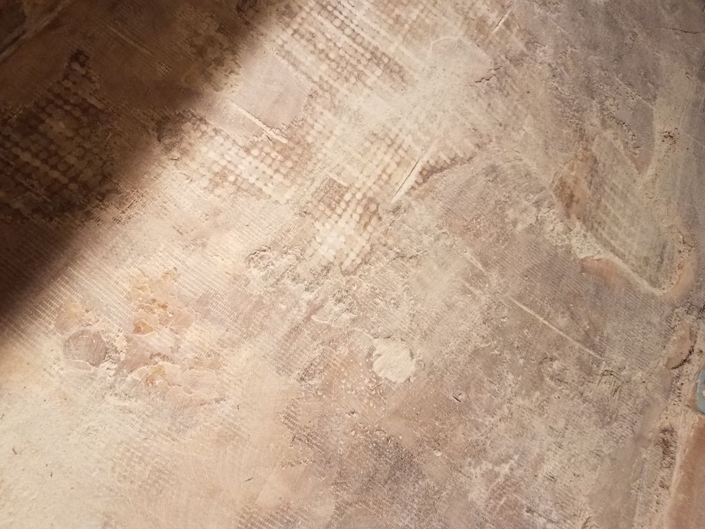
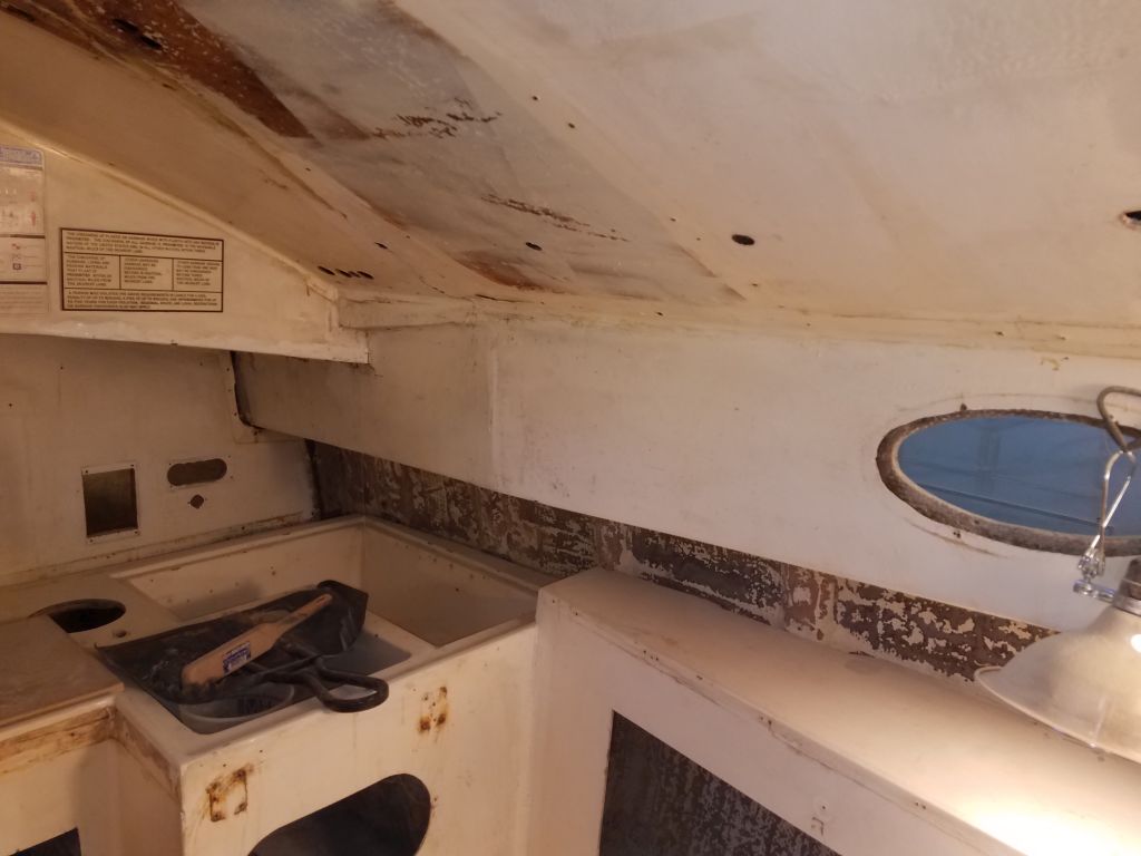
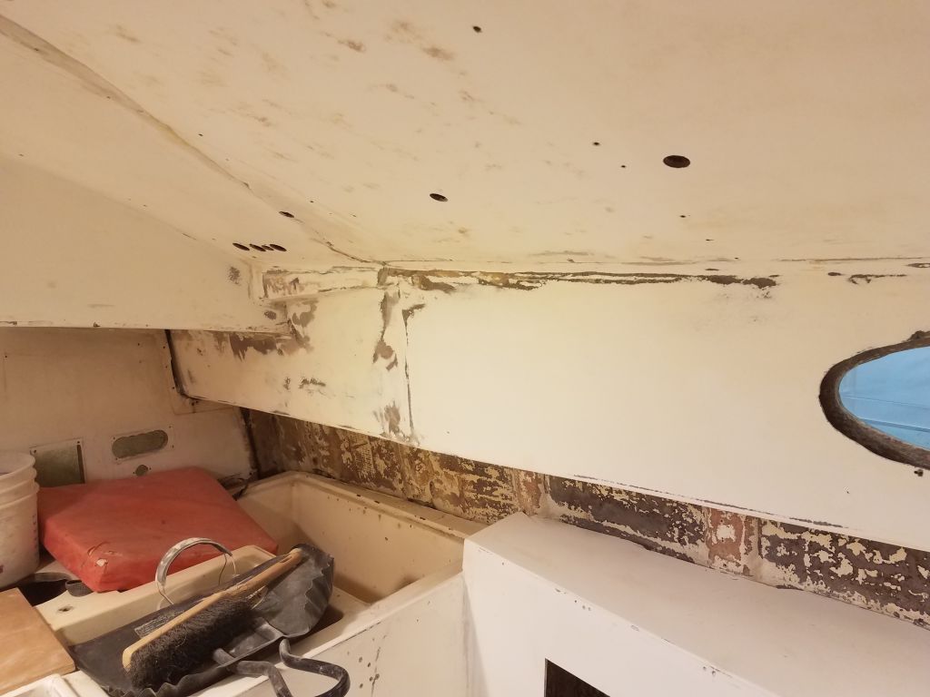
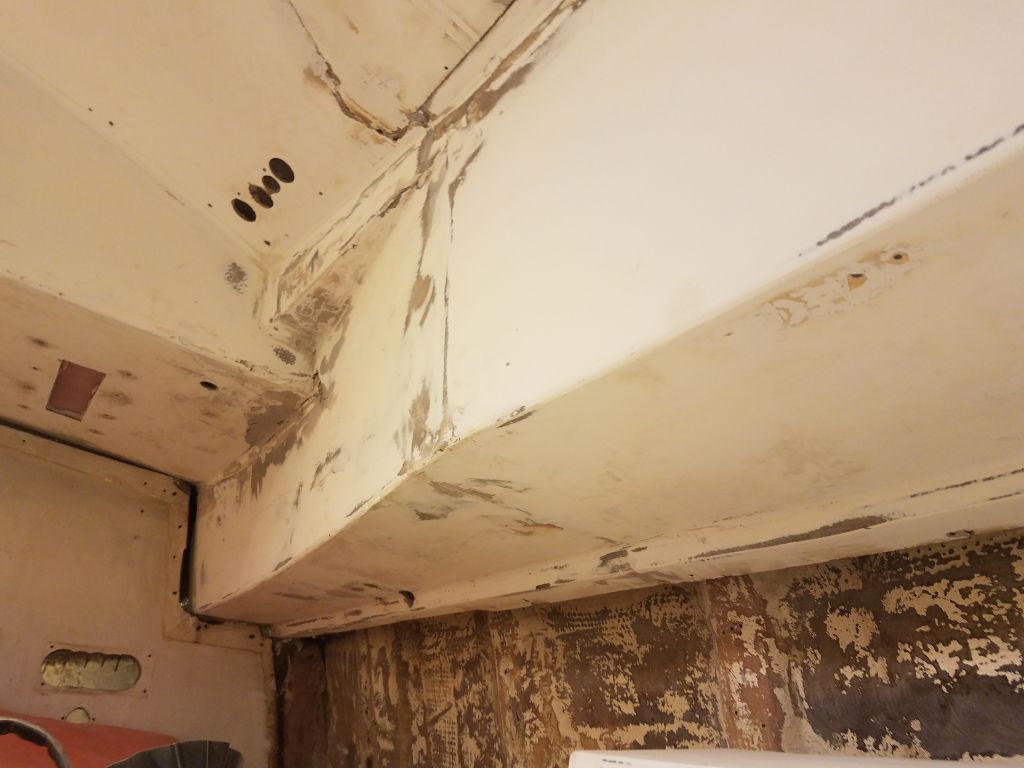
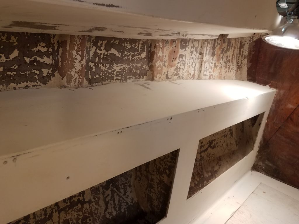
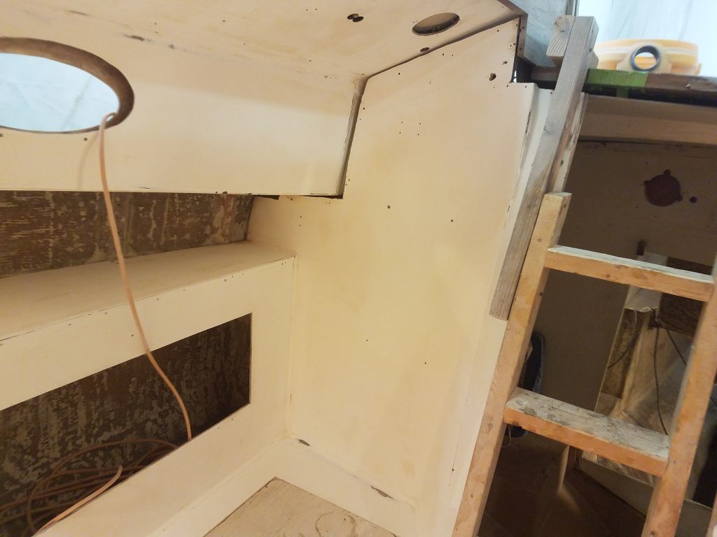
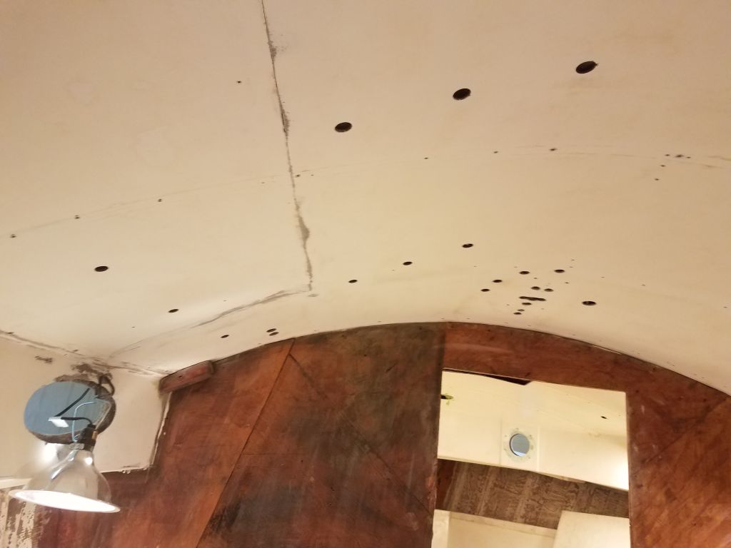
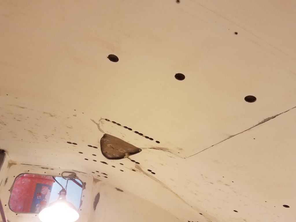
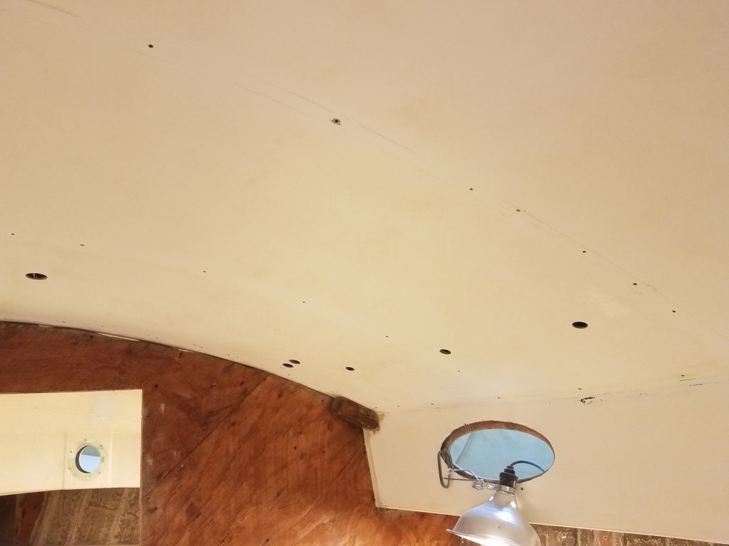
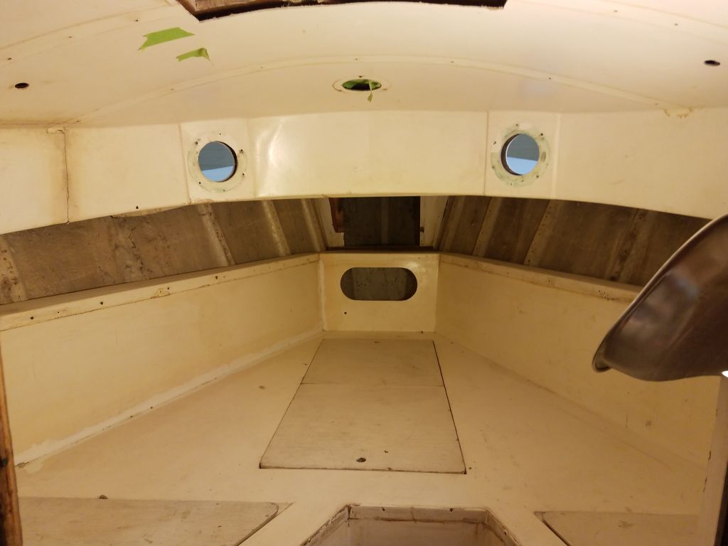
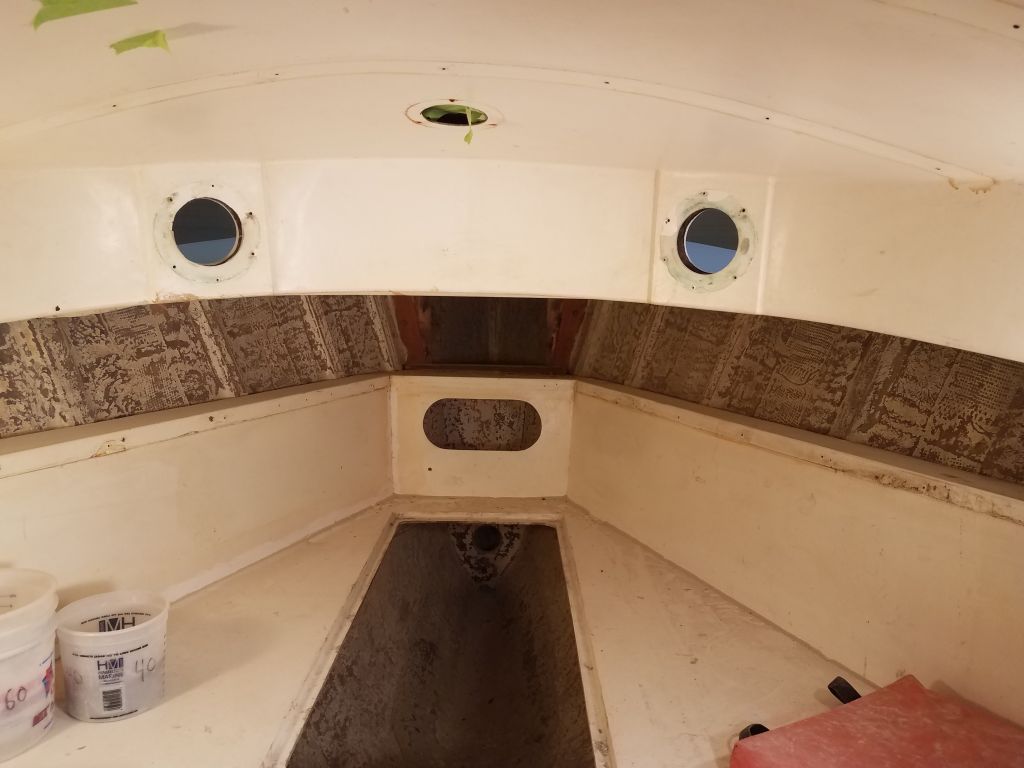
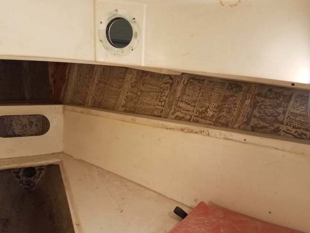
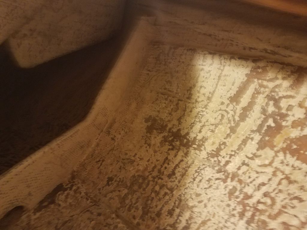
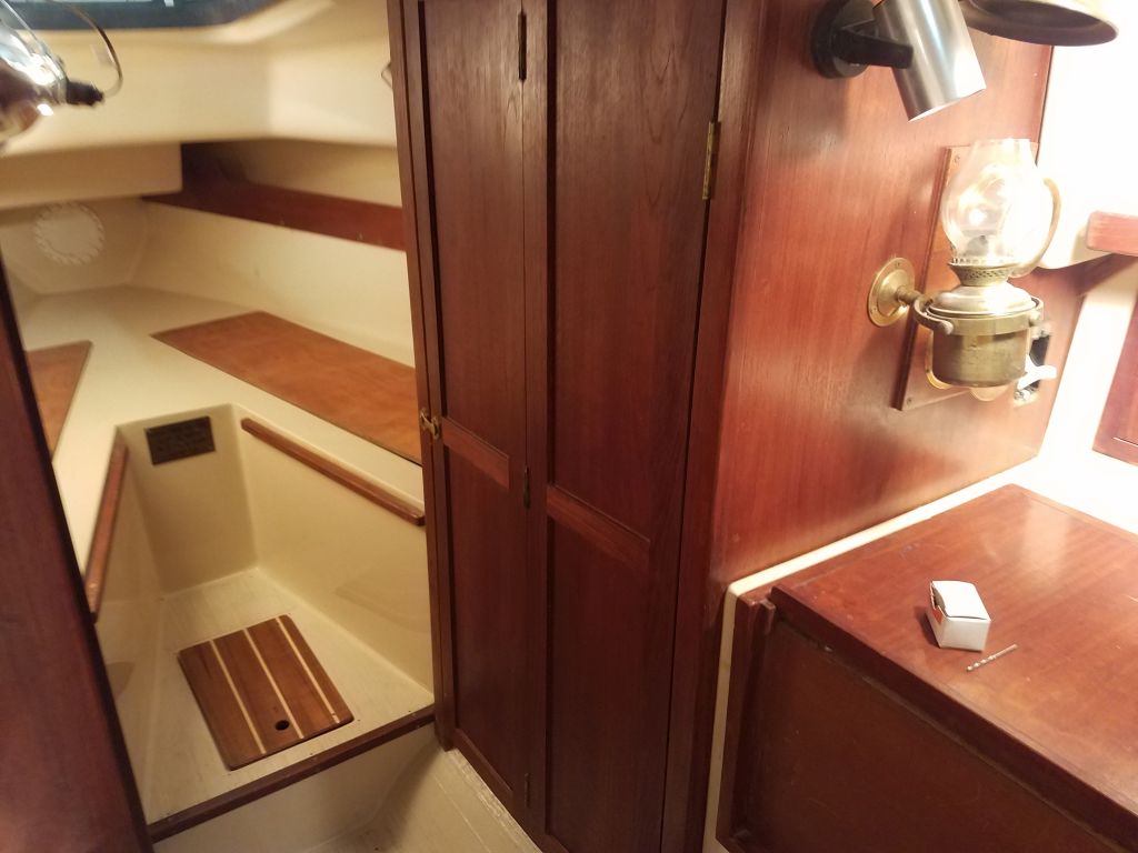
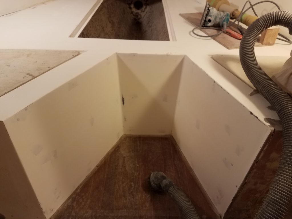
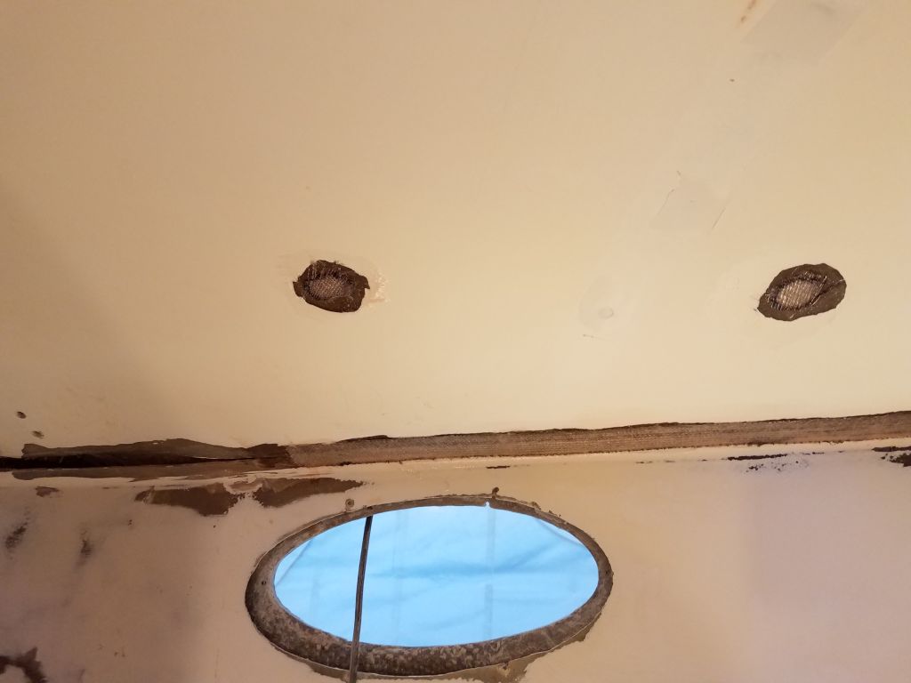
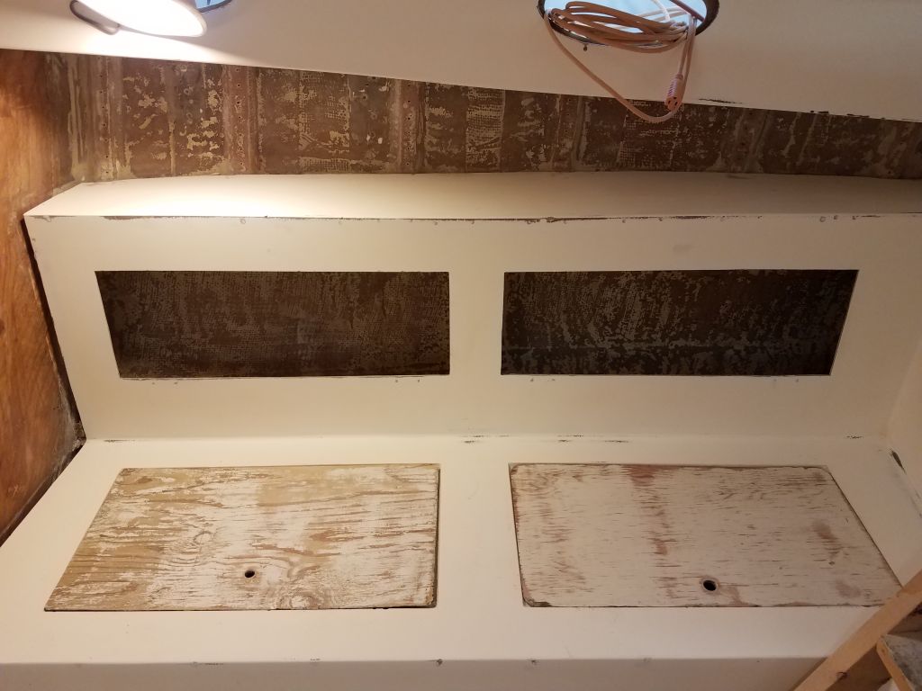
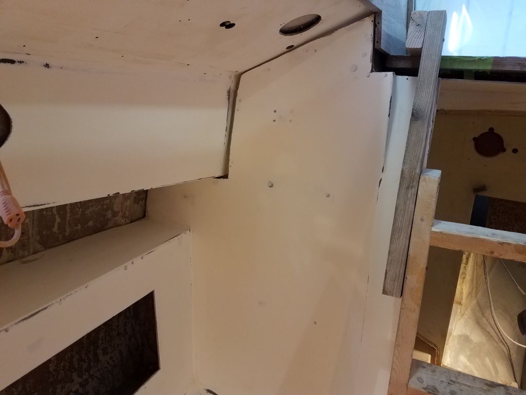
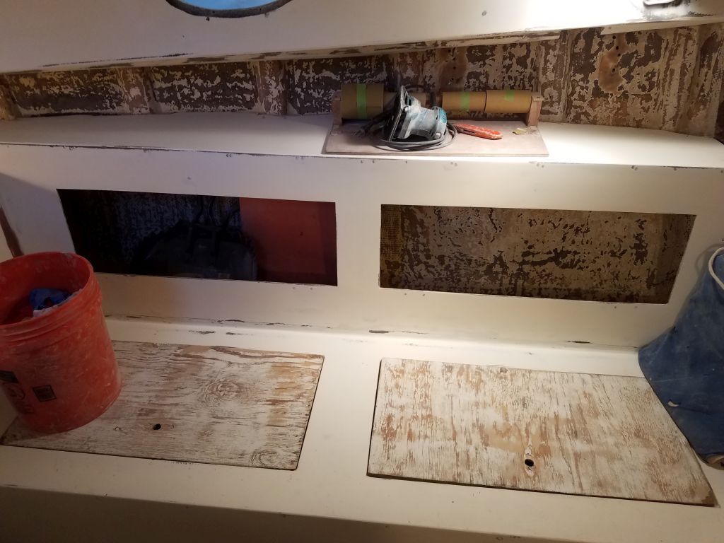
After sanding the second round of hole filler in the cabin, I found many of the spots weren’t yet smooth and flush, so I was required to apply an additional coat of the filler throughout the cabin. I had hoped to avoid this, but fortunately the white acrylic filler would cure quickly and I’d be able to get back to it later in the day.
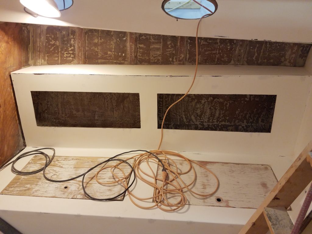
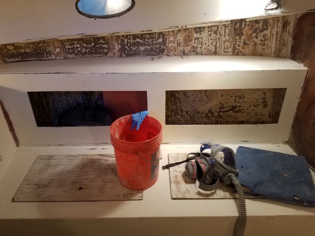
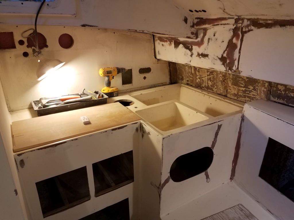
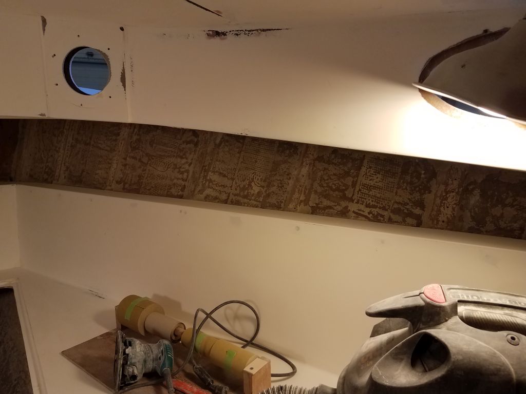
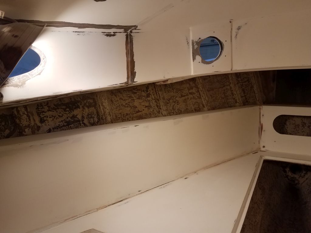
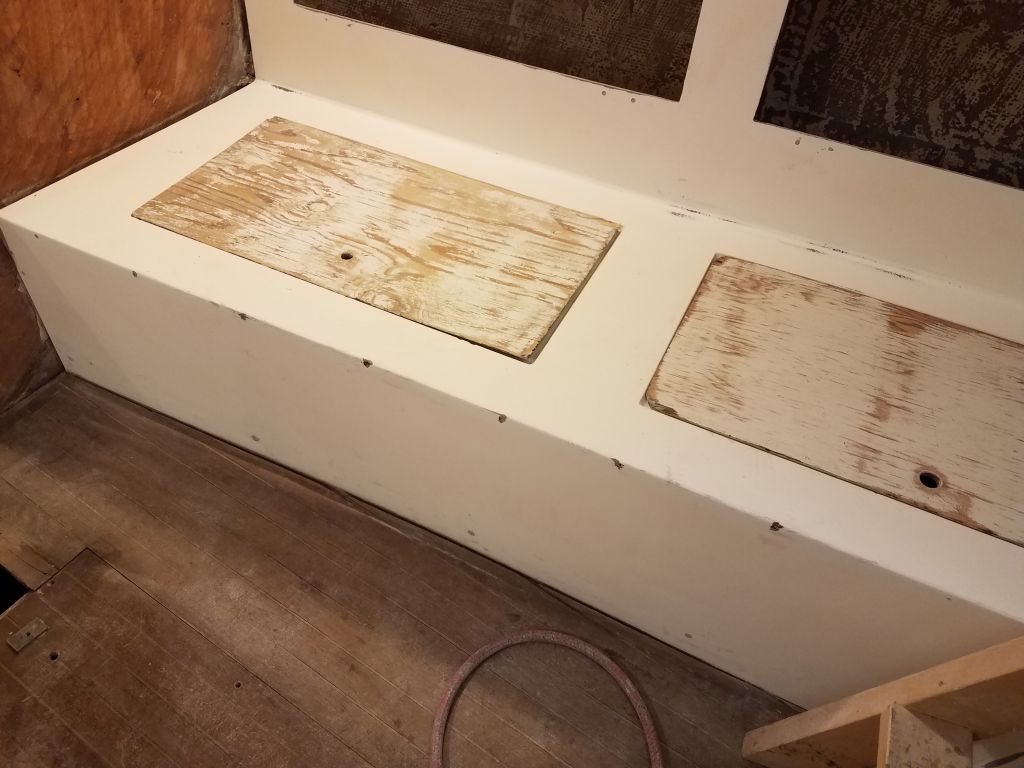
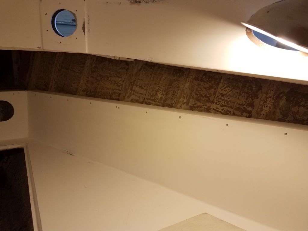
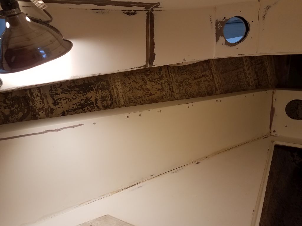
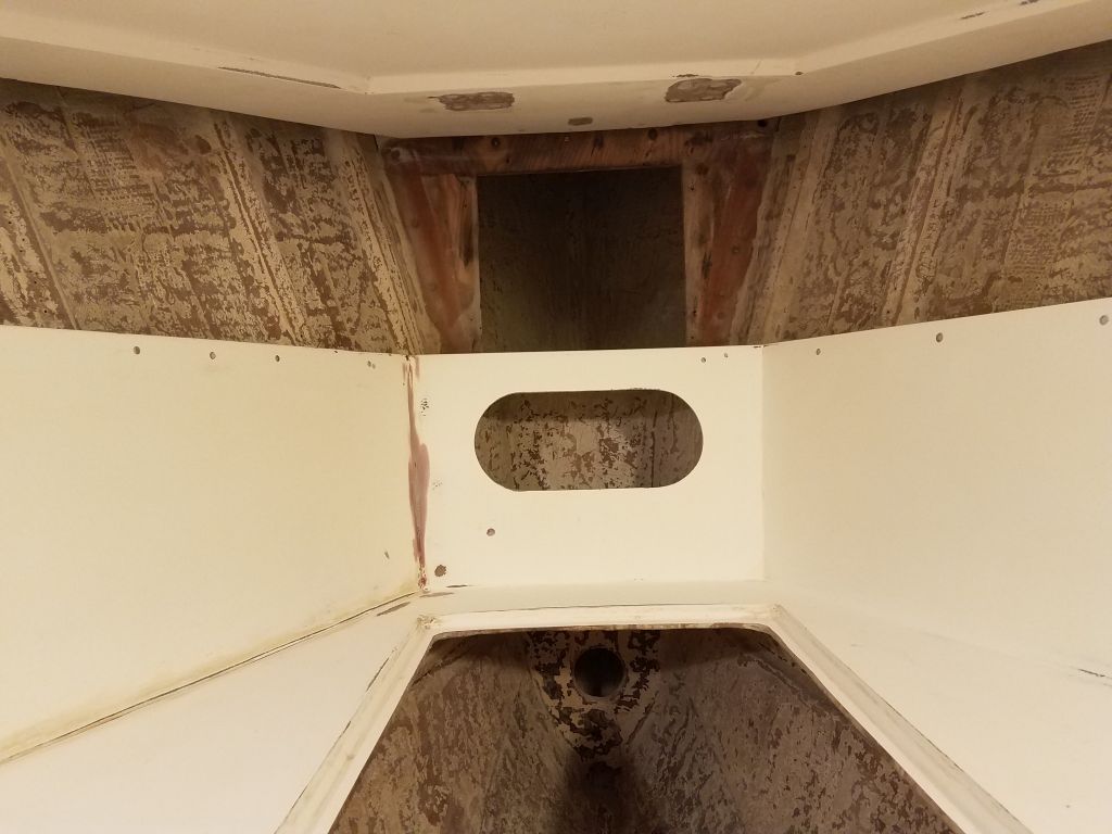
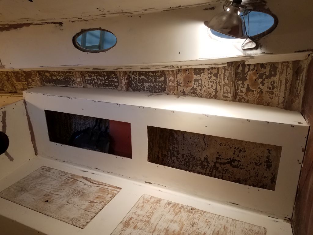
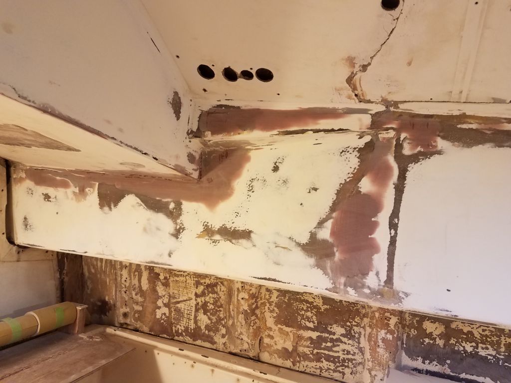
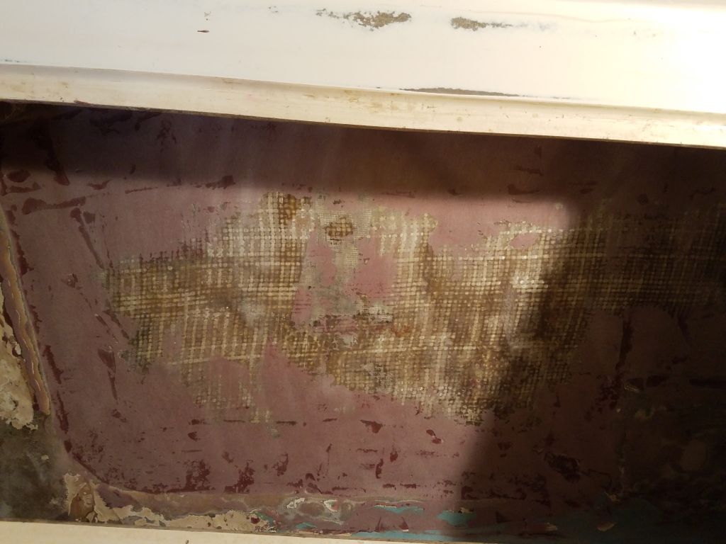
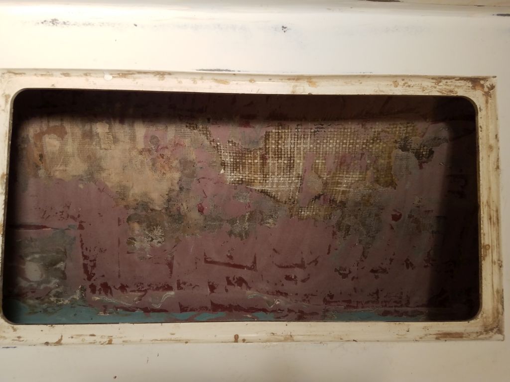
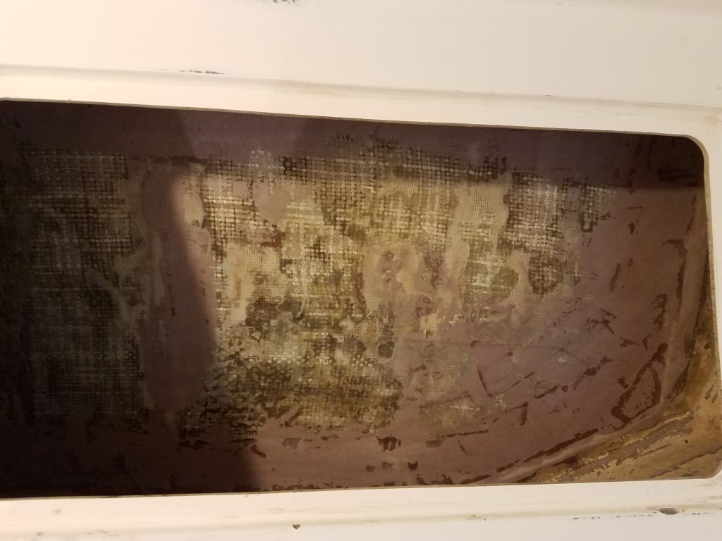
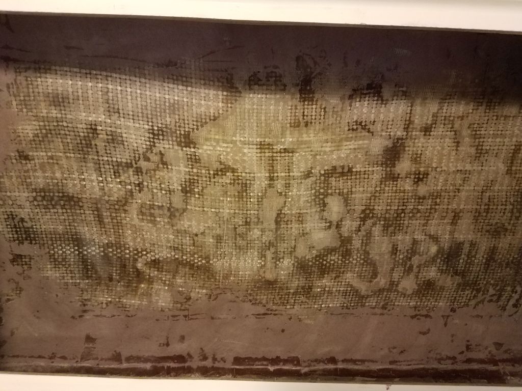
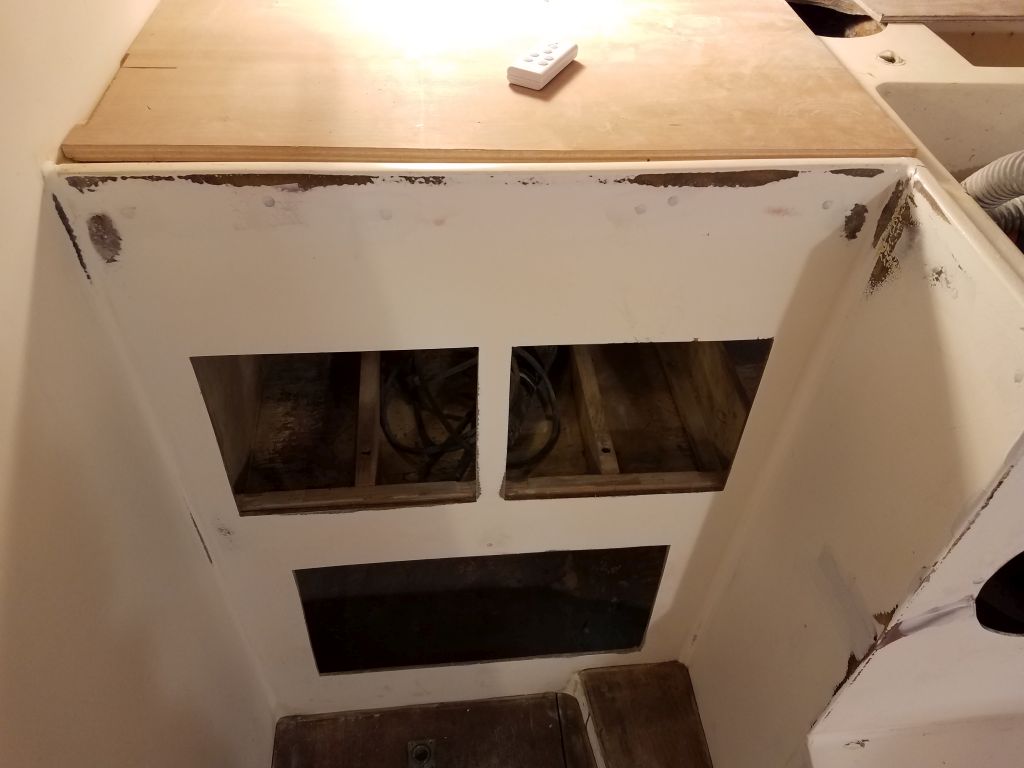
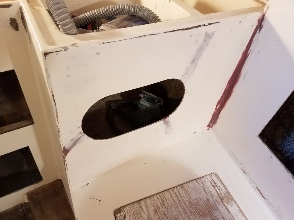
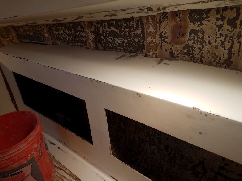
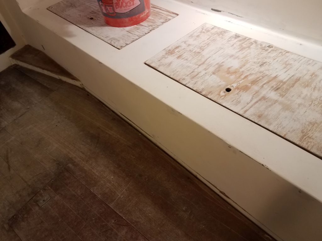
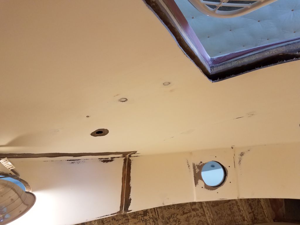
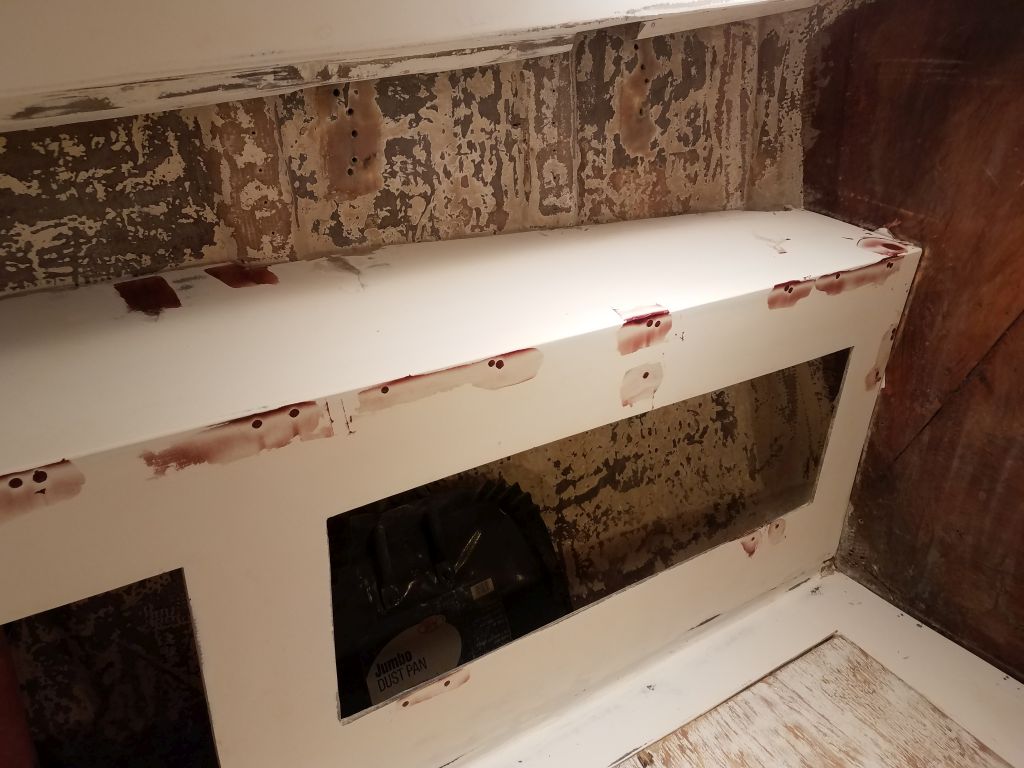
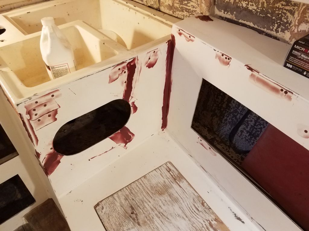
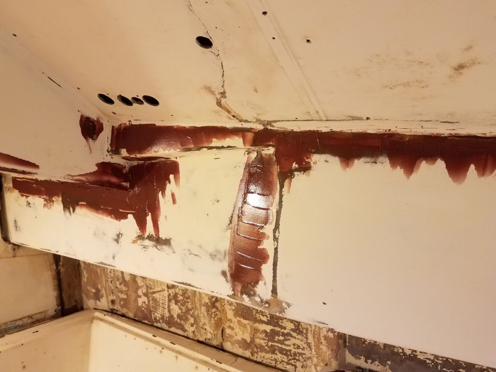
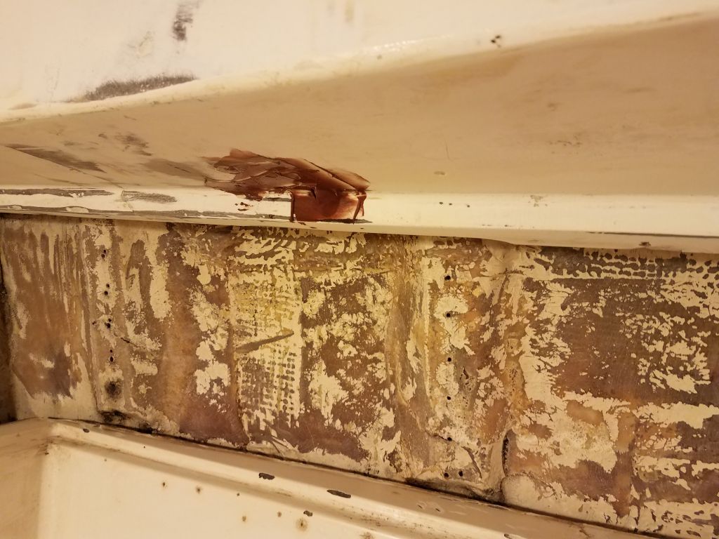
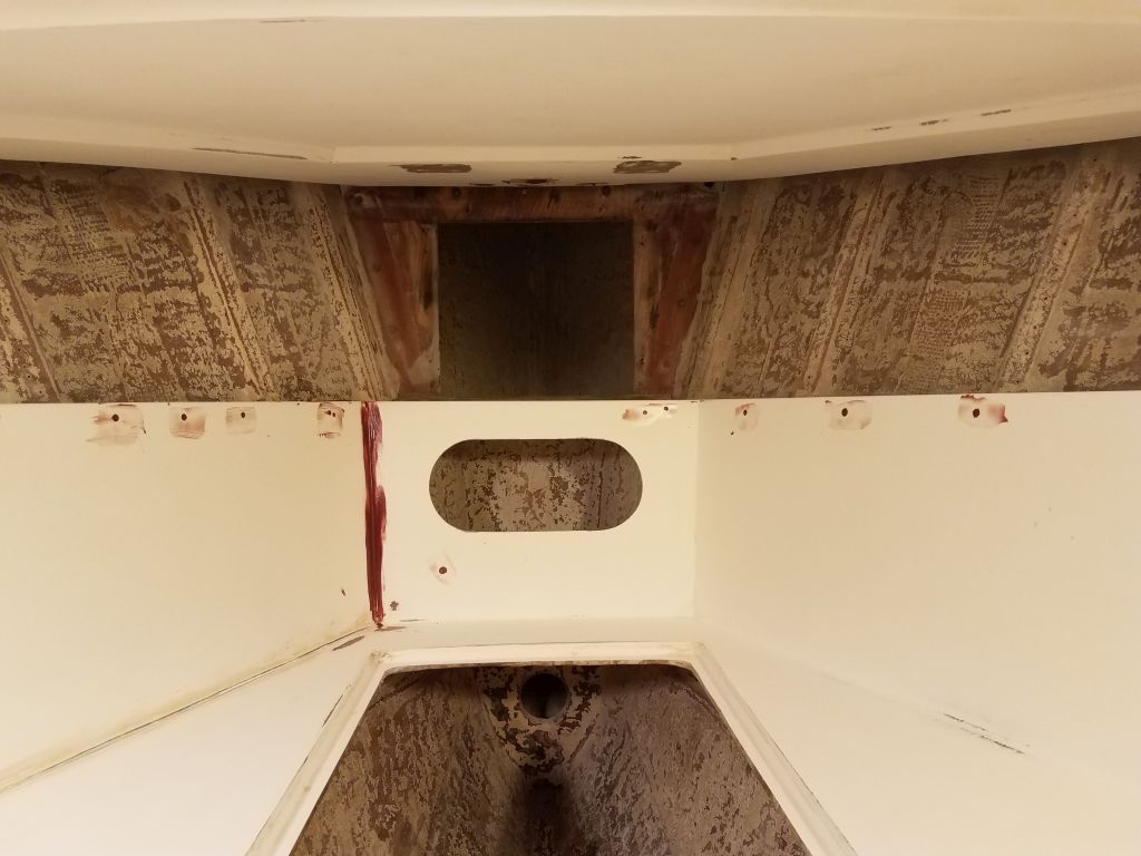
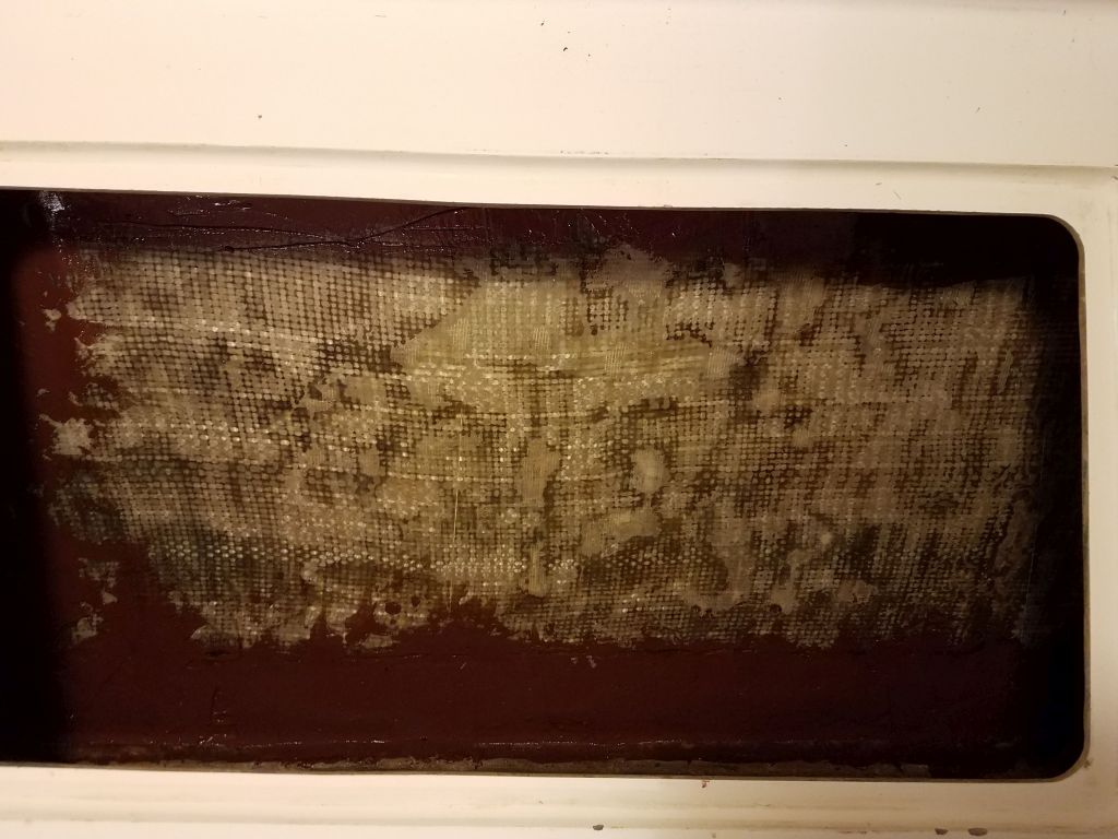
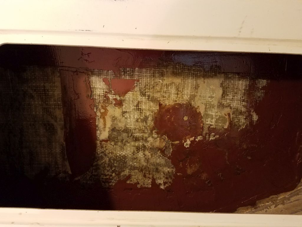
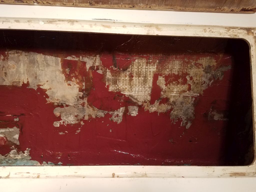
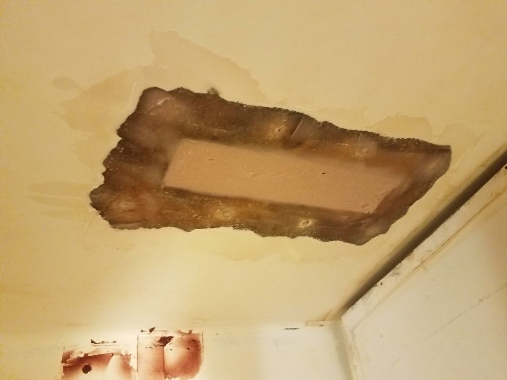
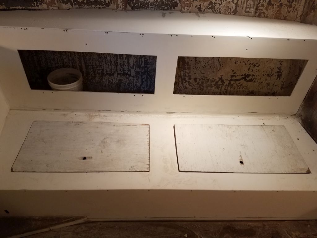
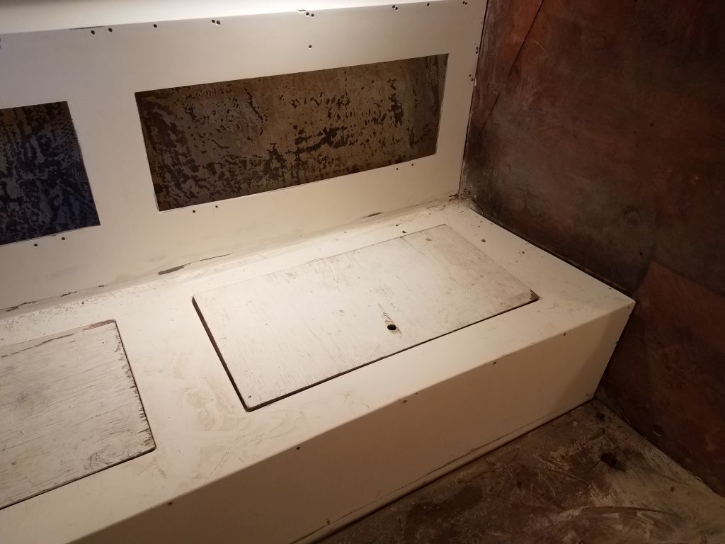
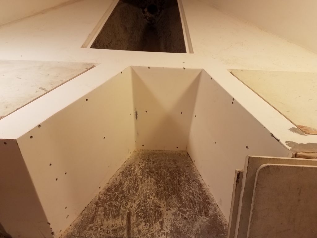
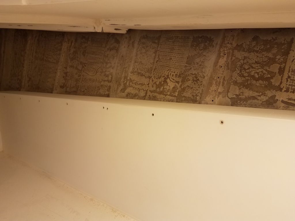
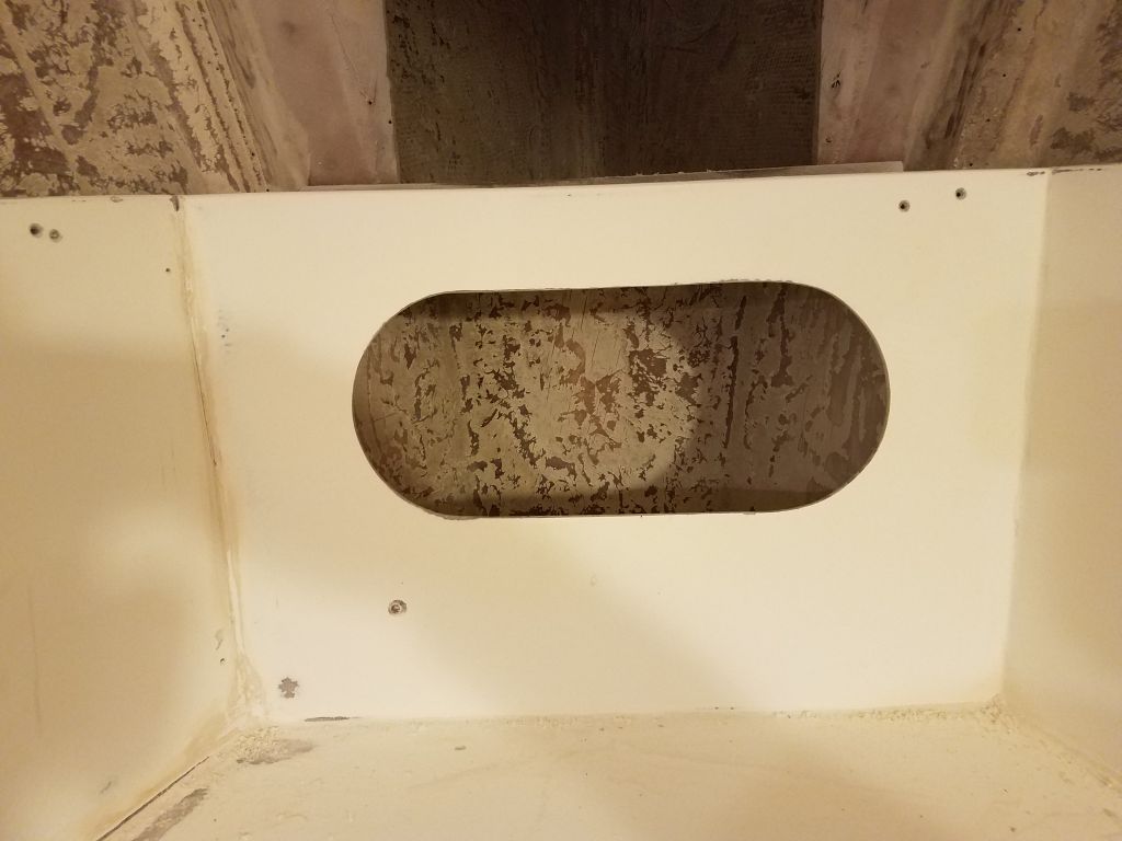
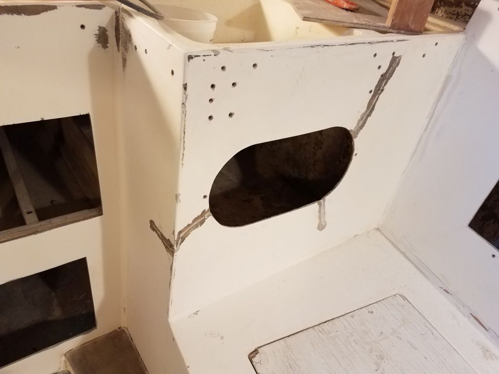
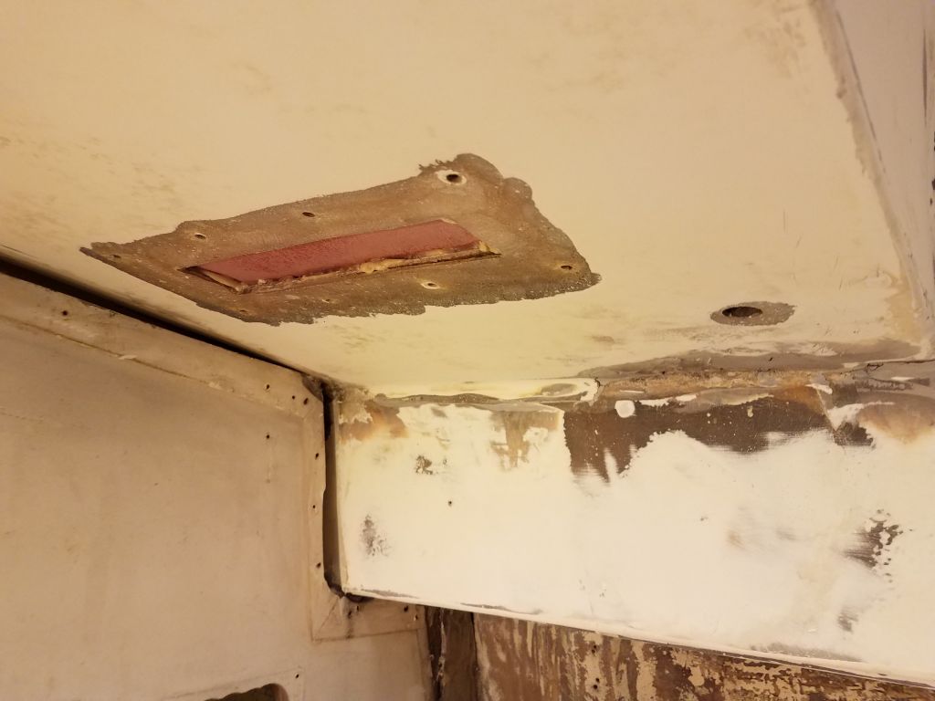
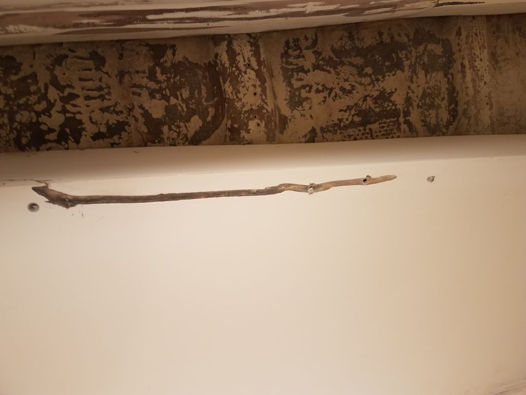
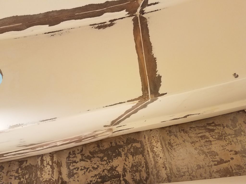
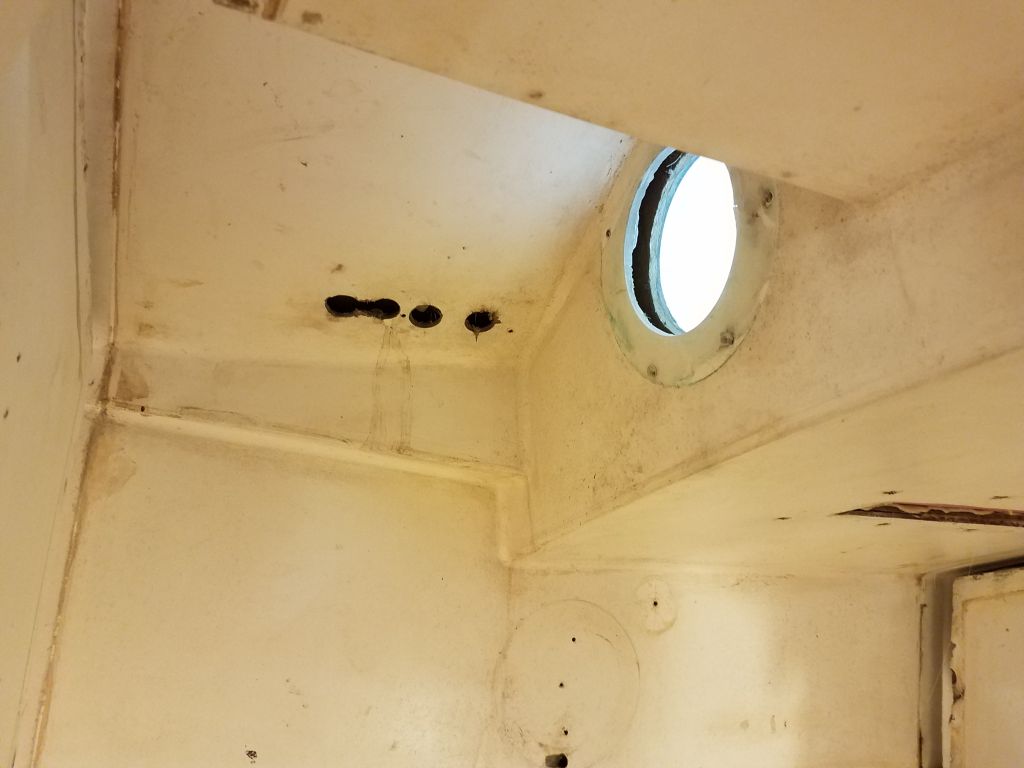
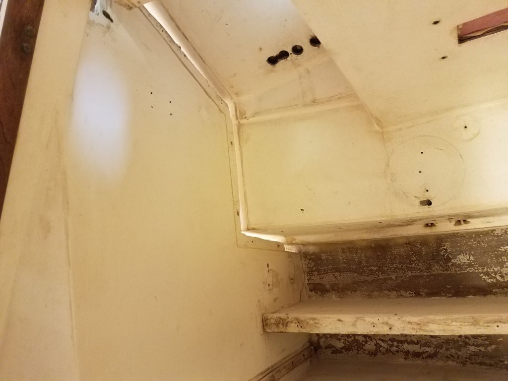
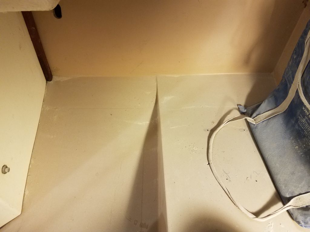
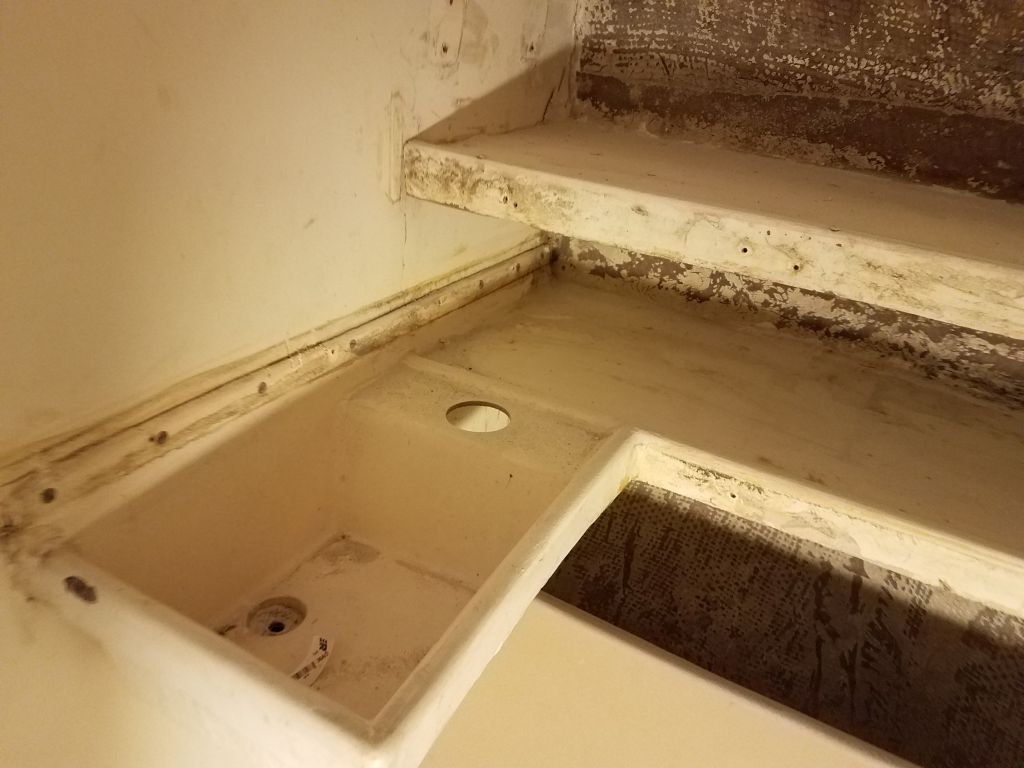
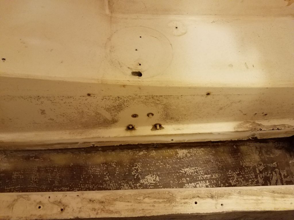
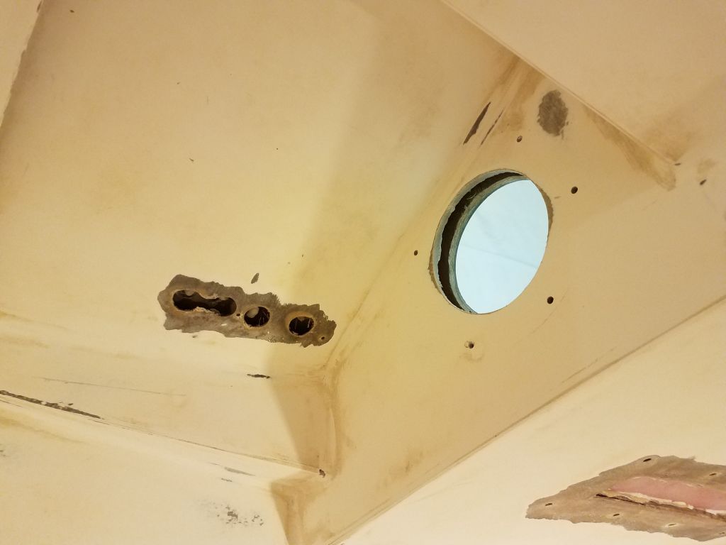
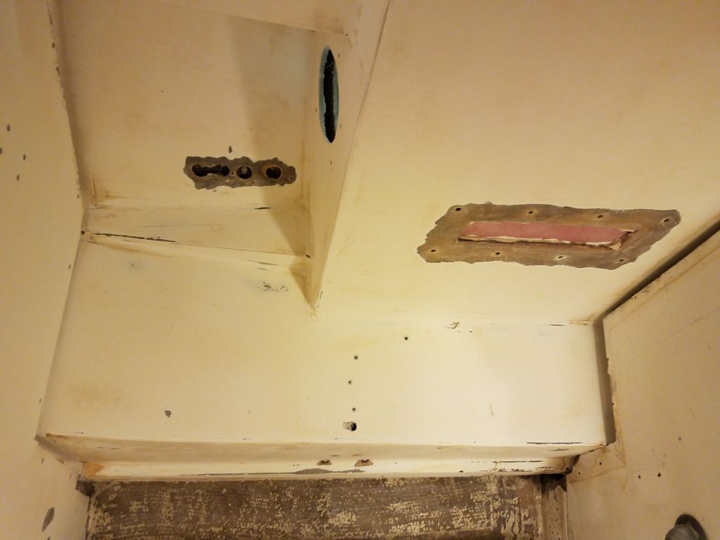
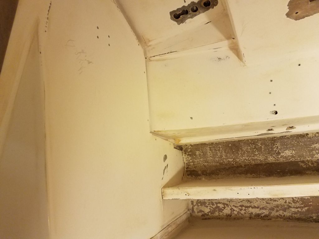
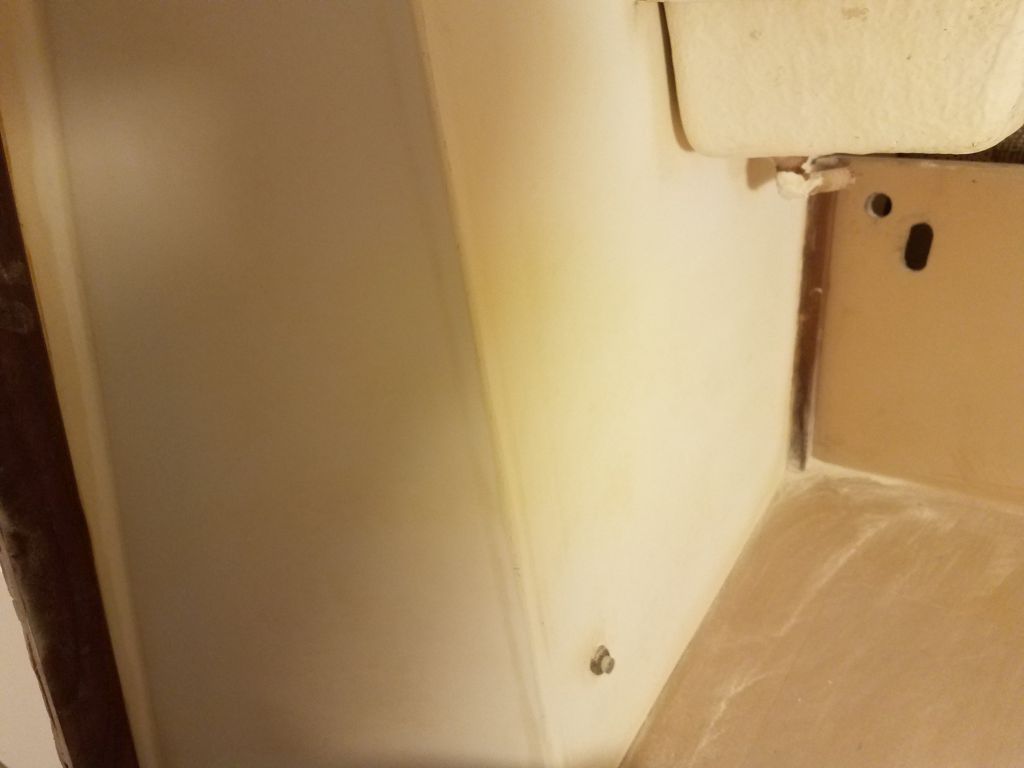
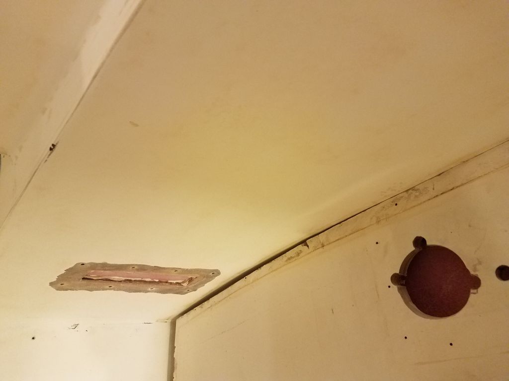
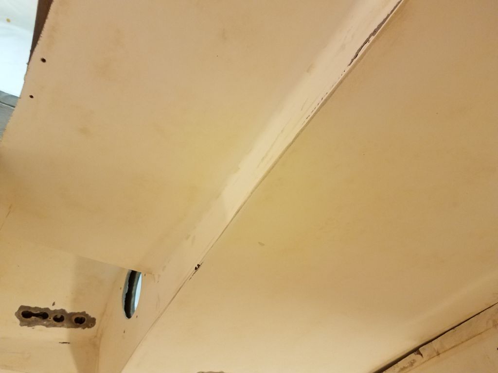
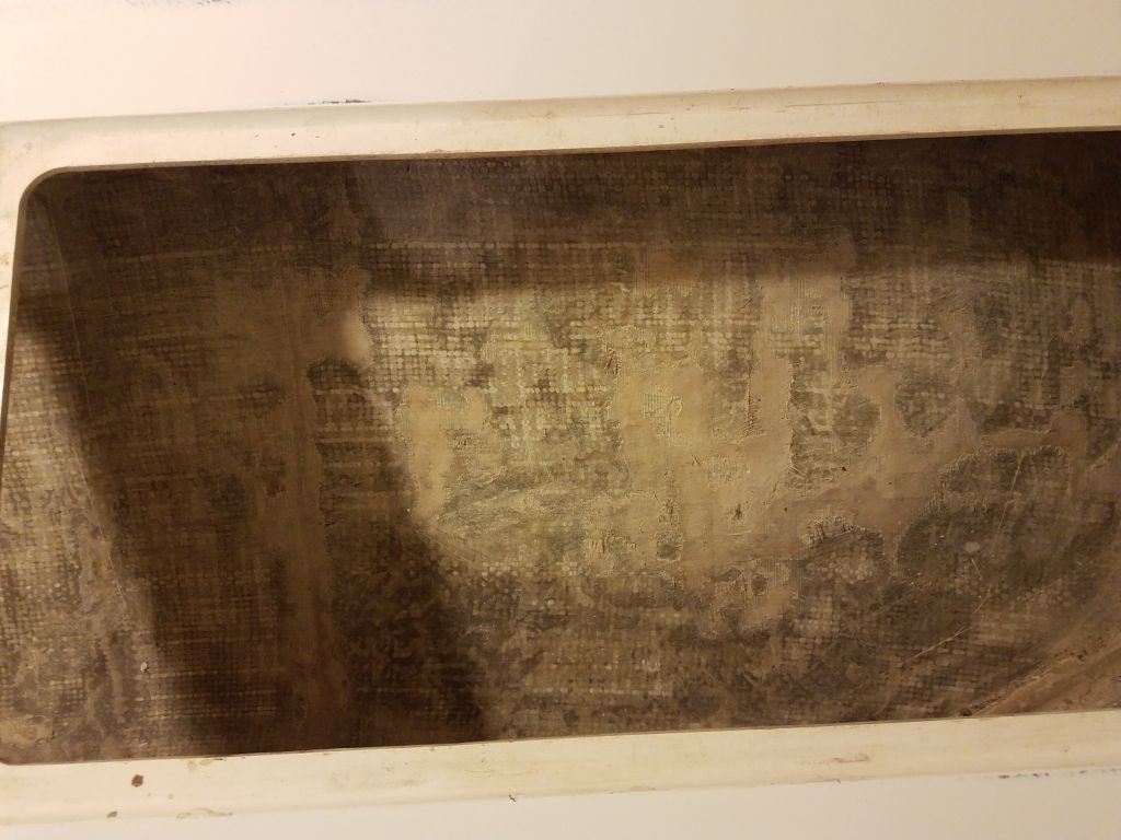
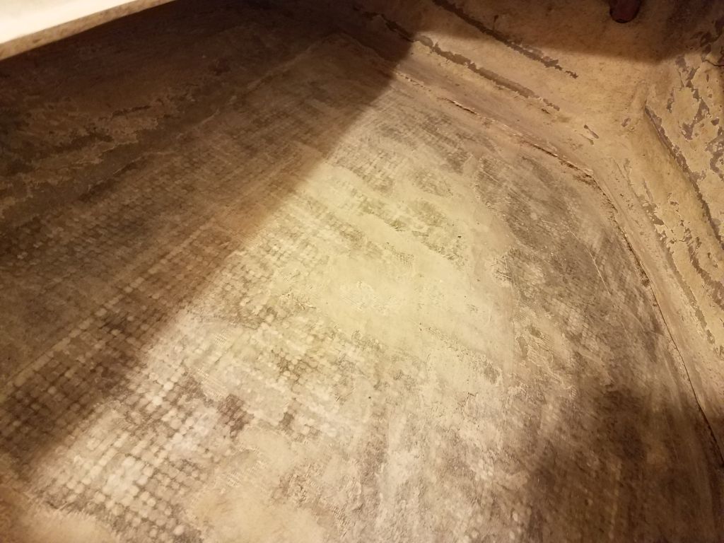
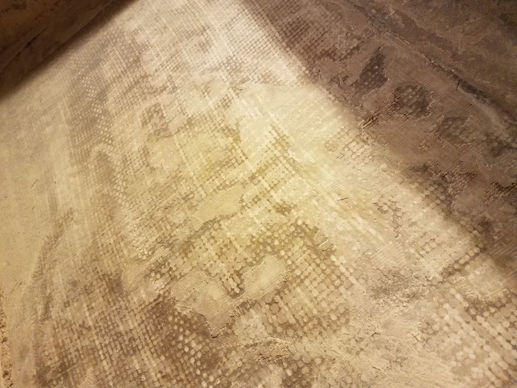
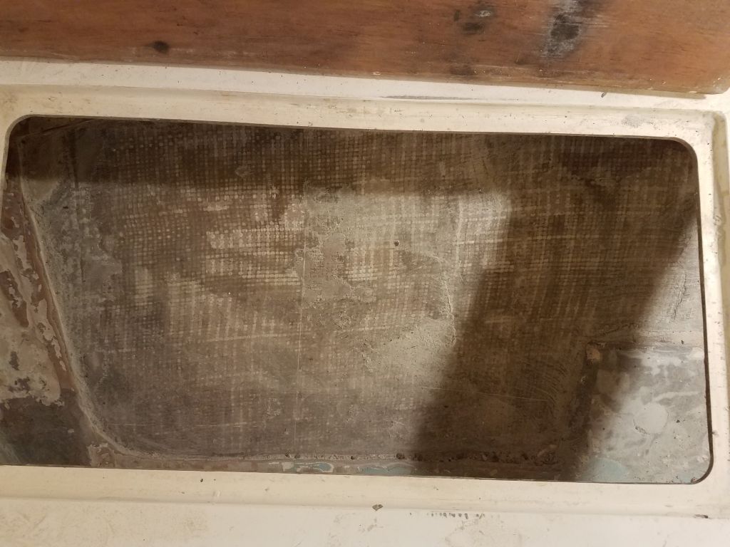
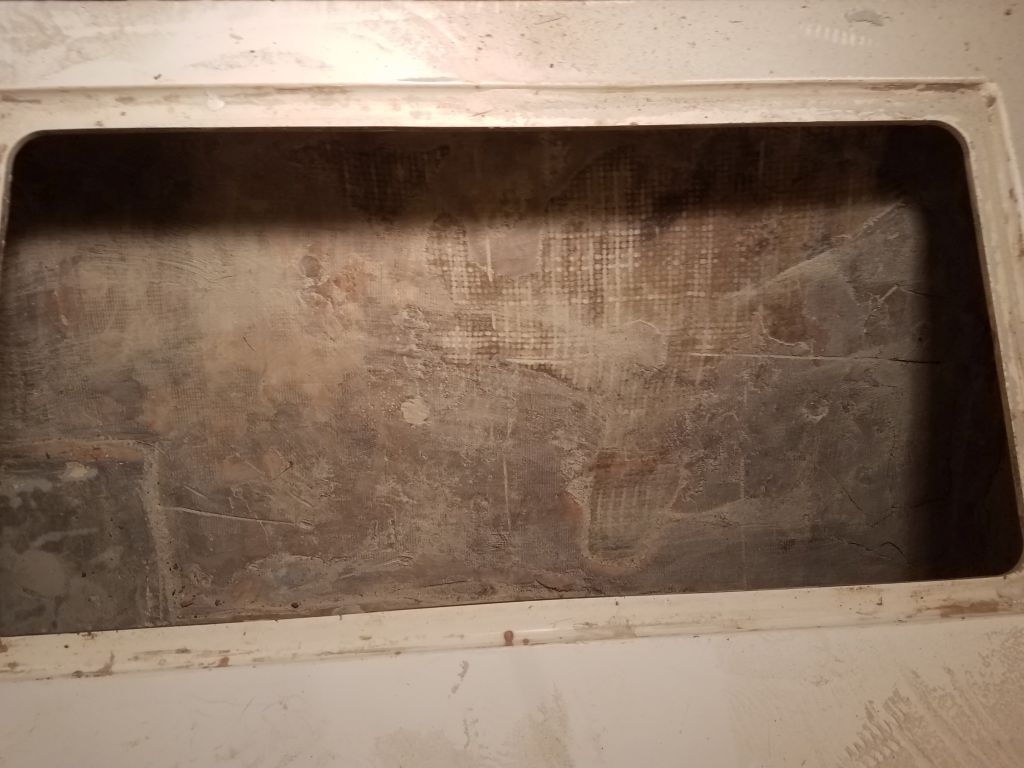
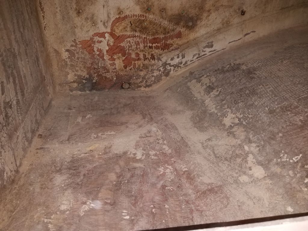
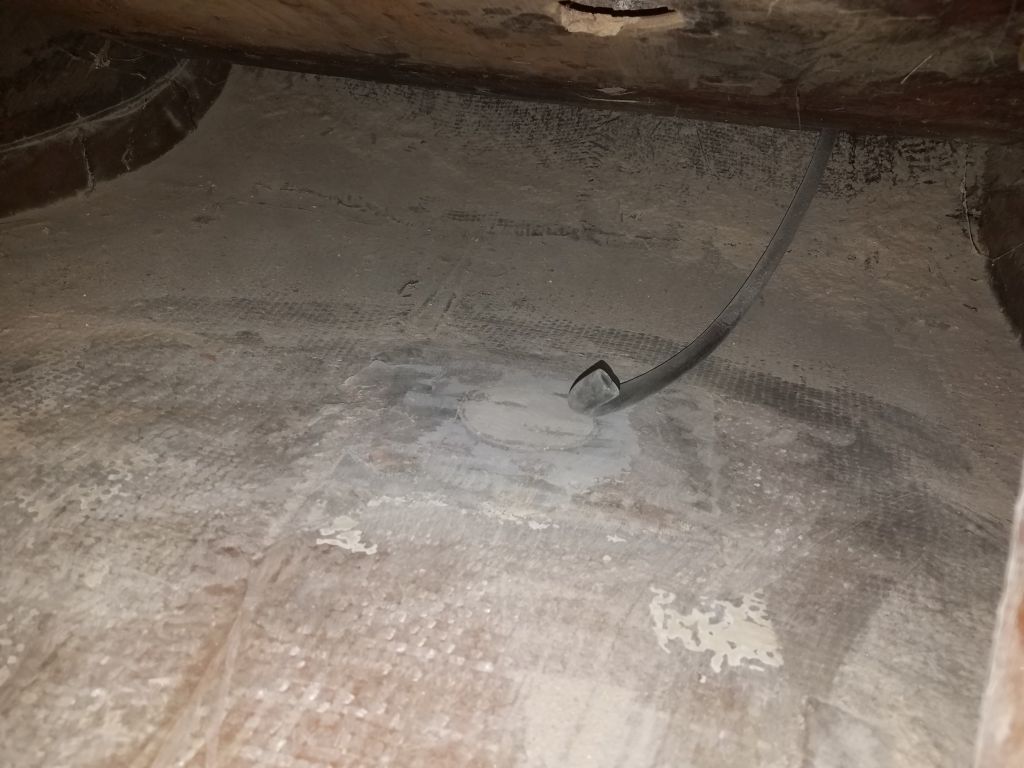
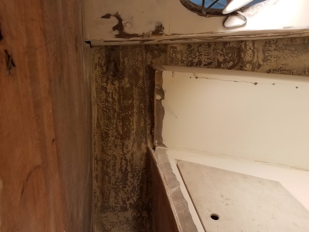
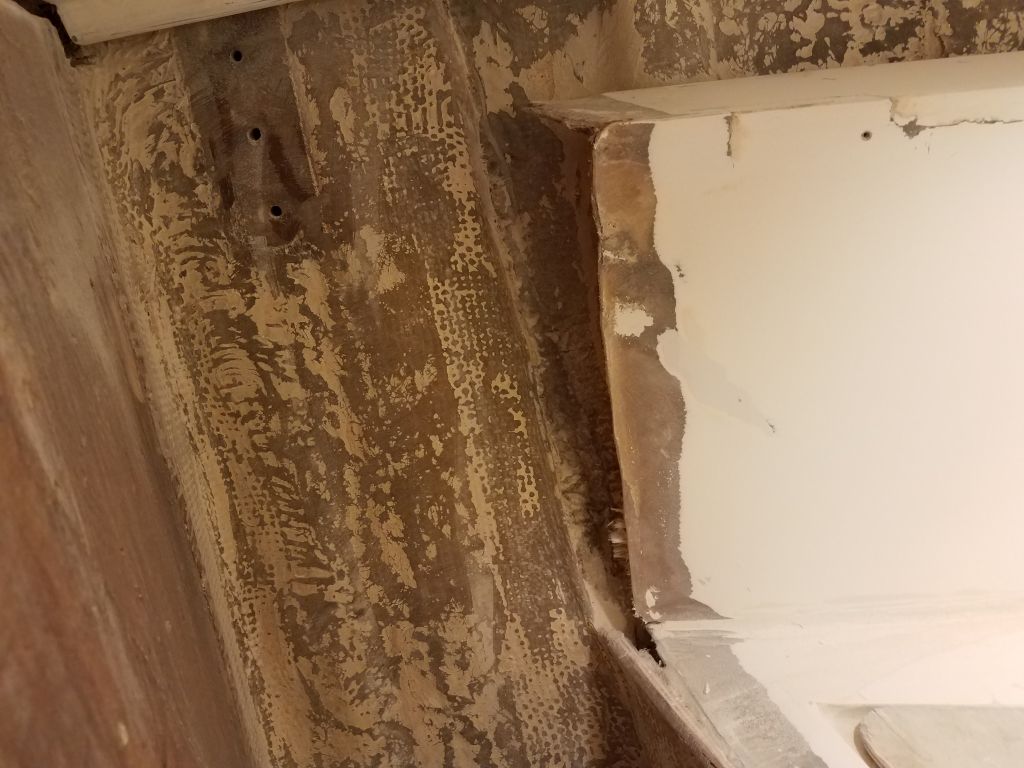
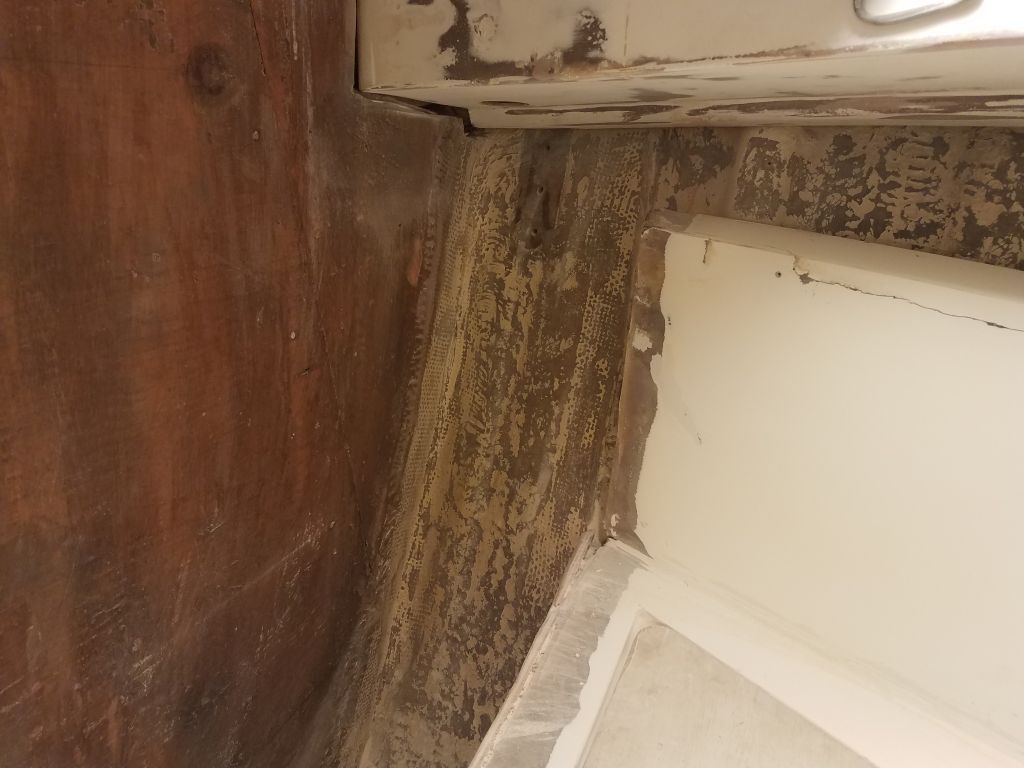
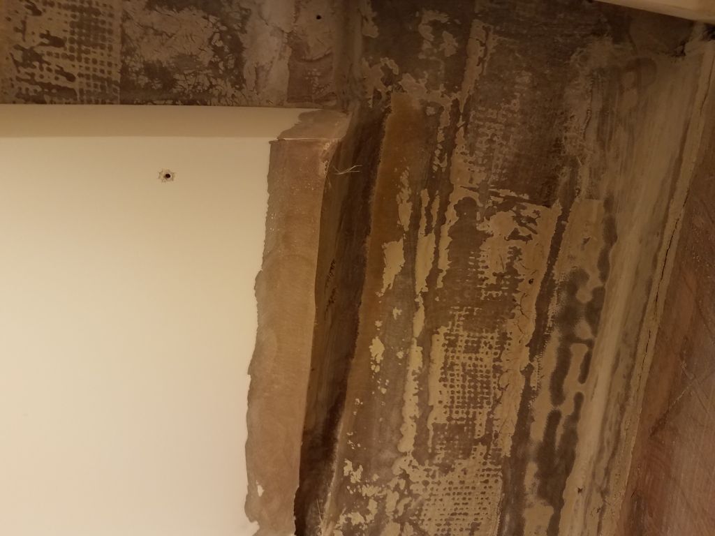
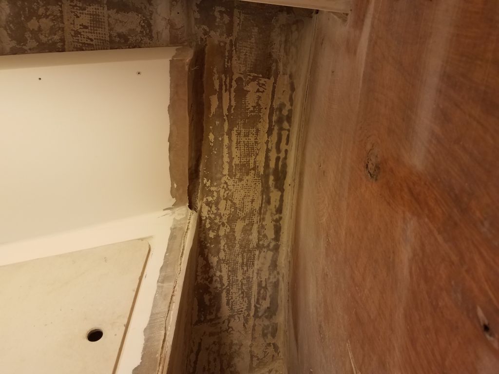
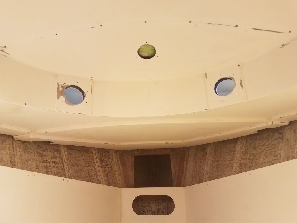
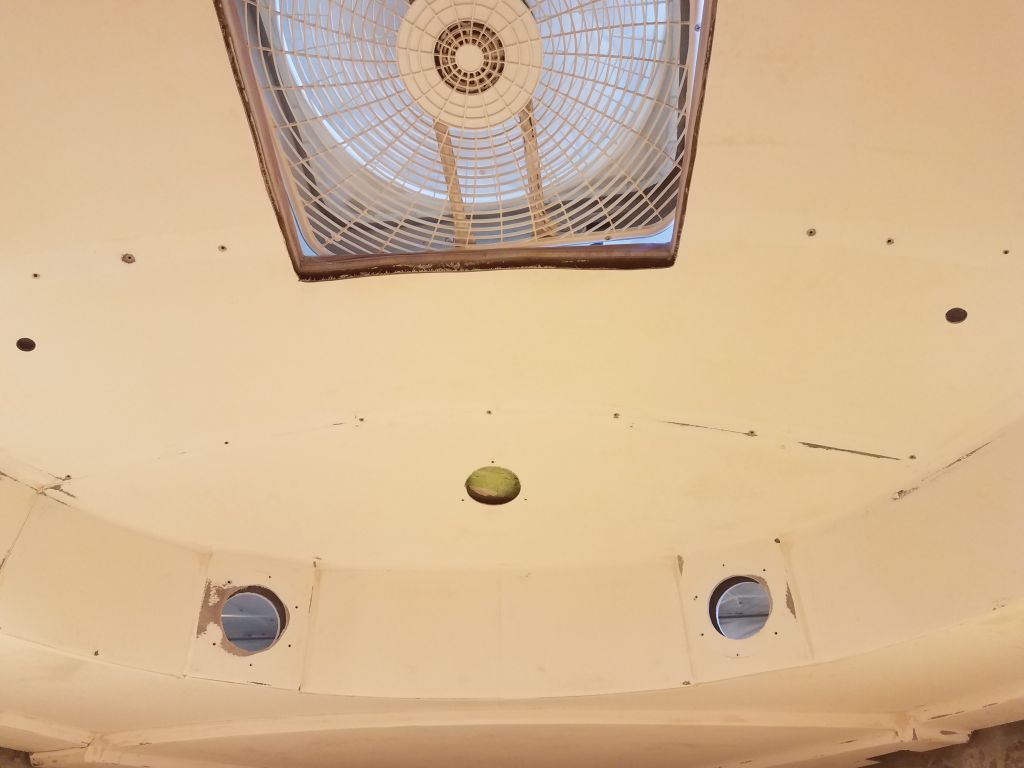
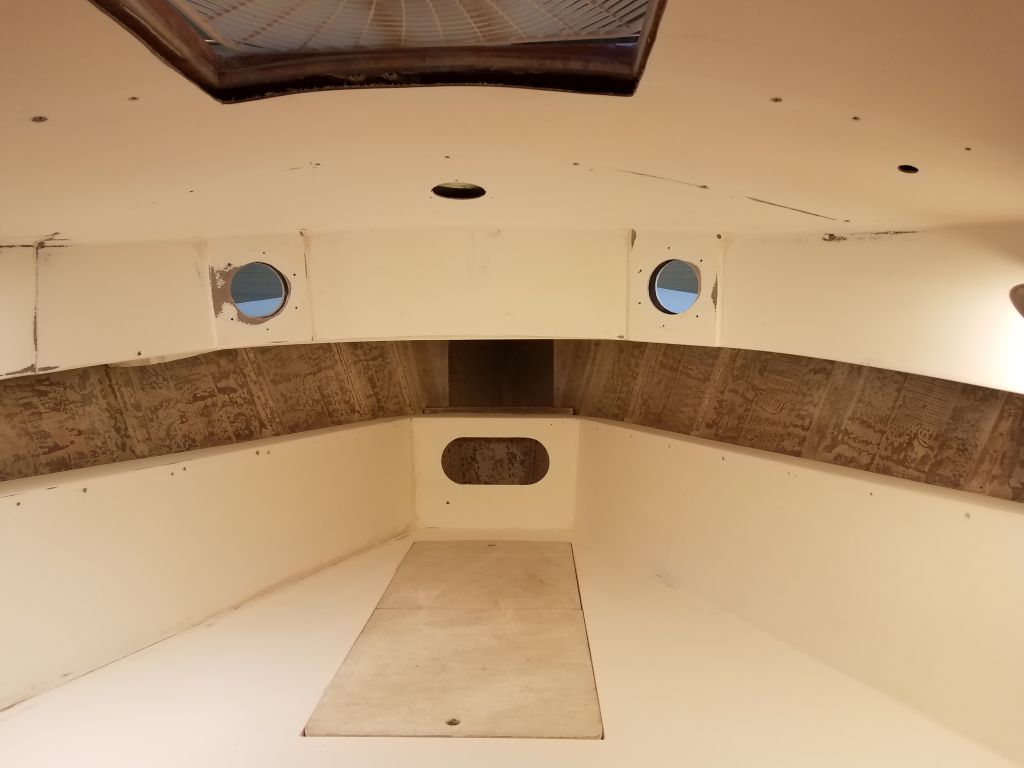
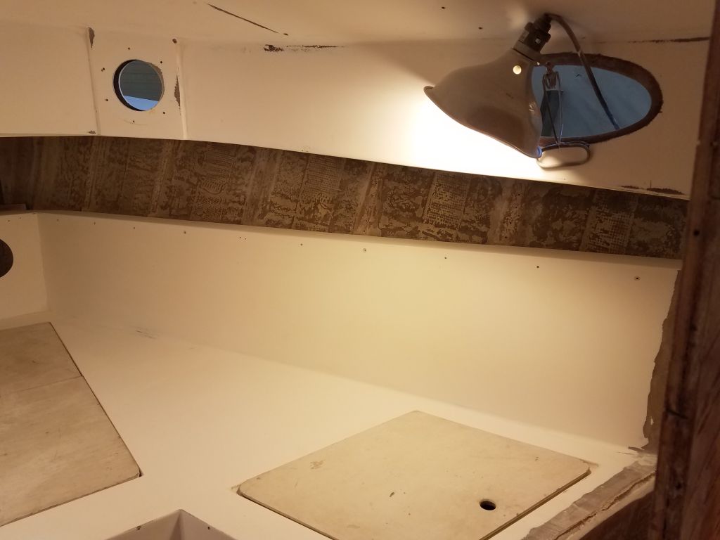
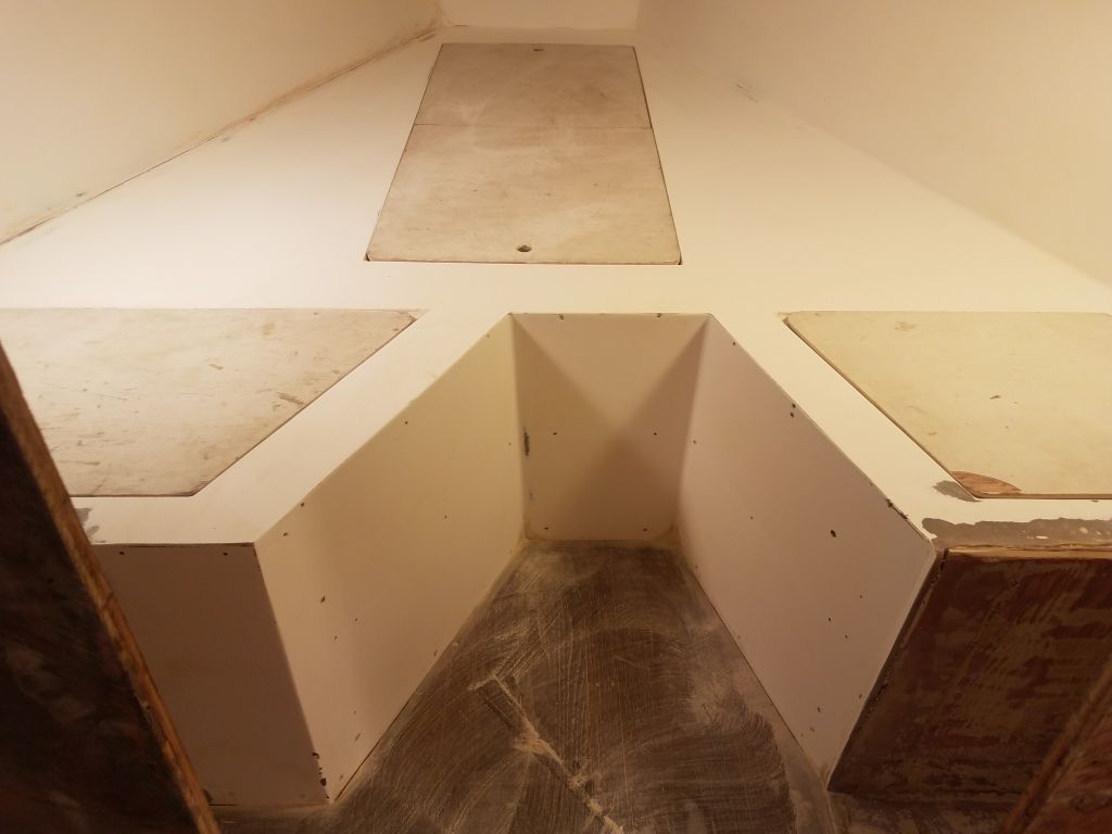
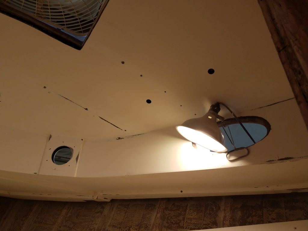
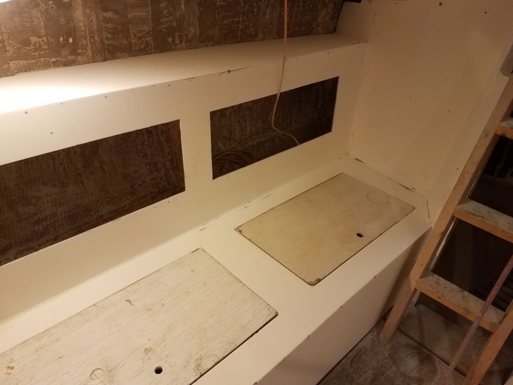
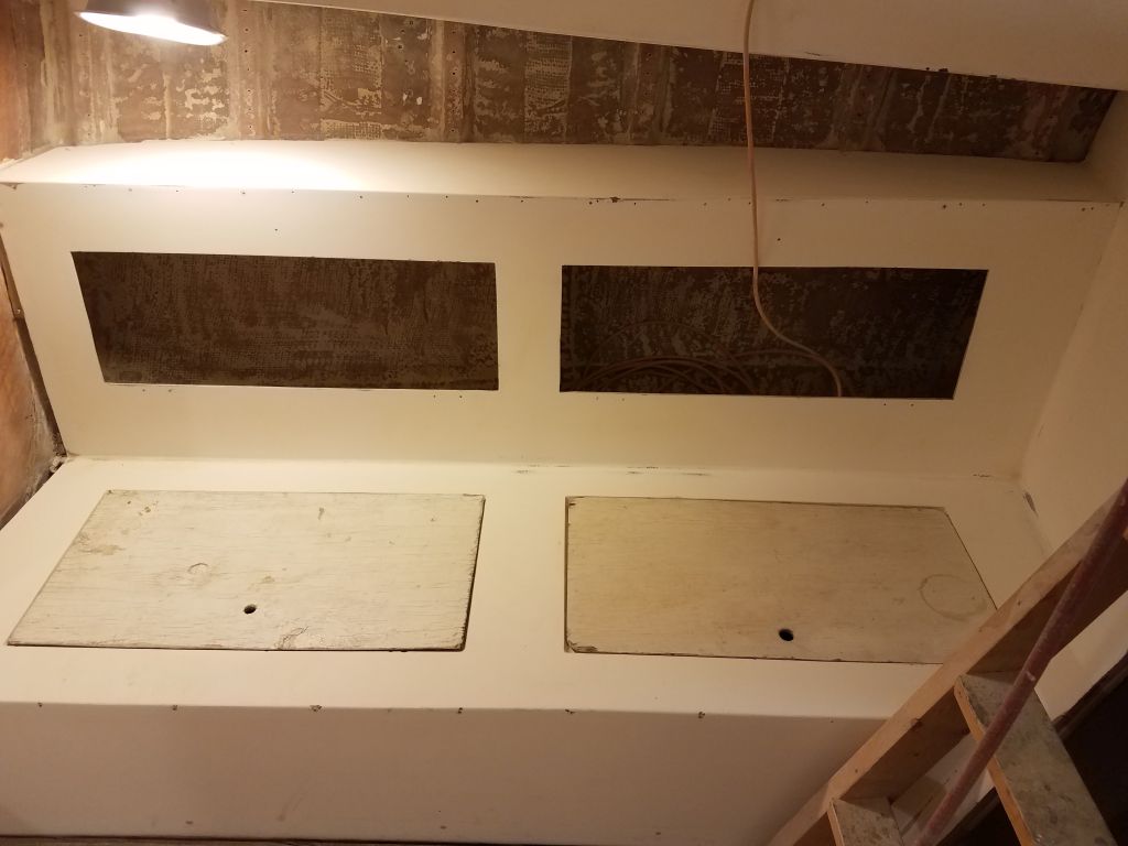
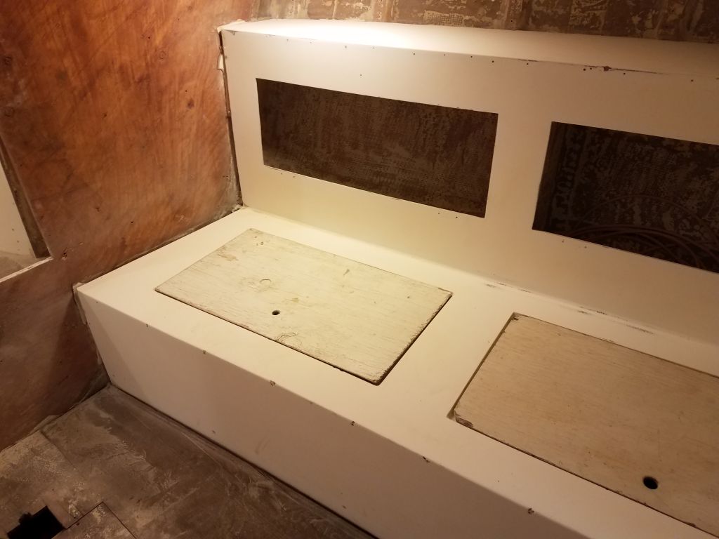
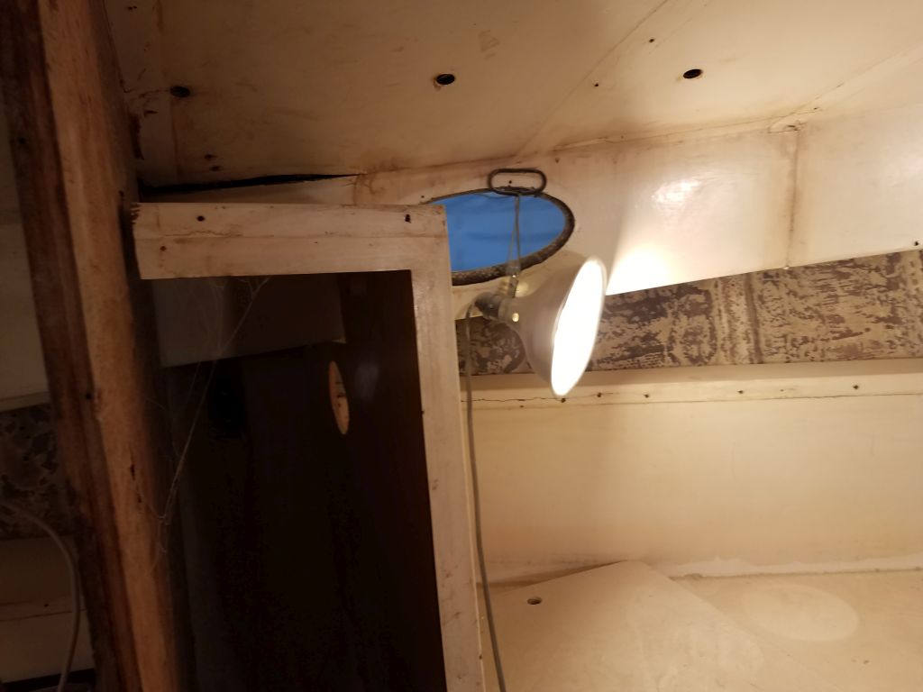
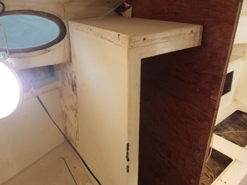
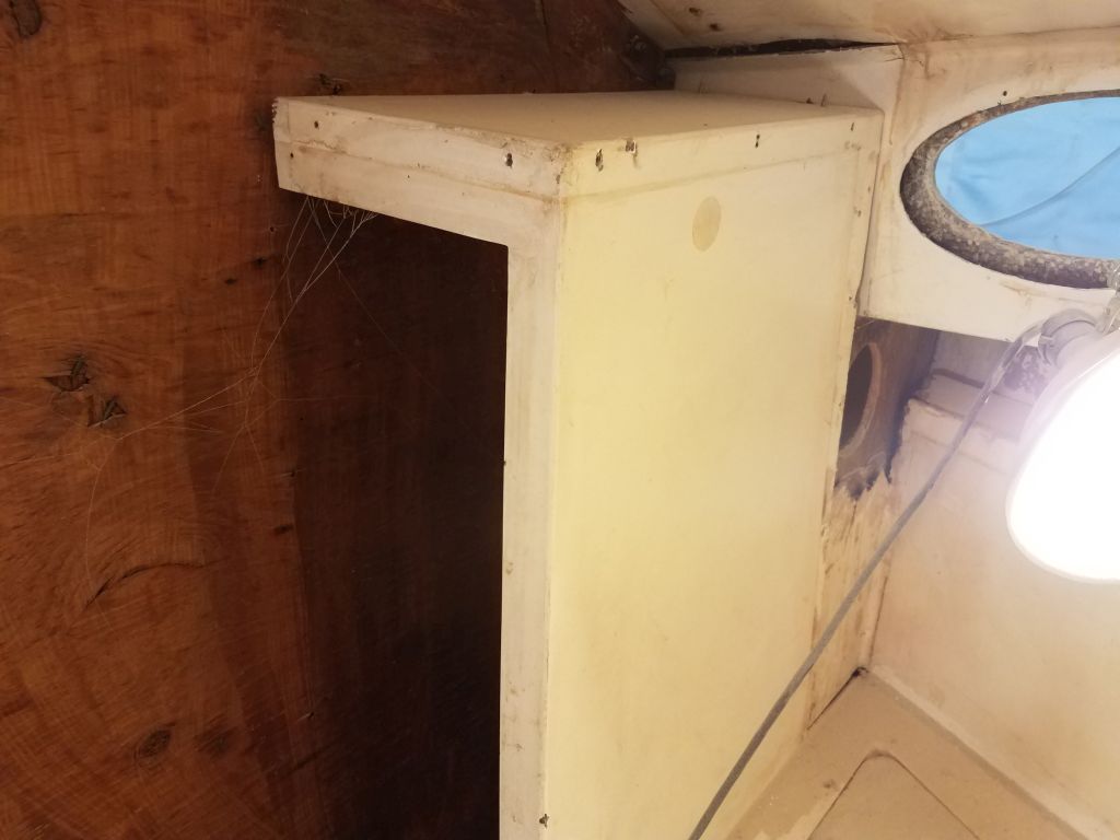
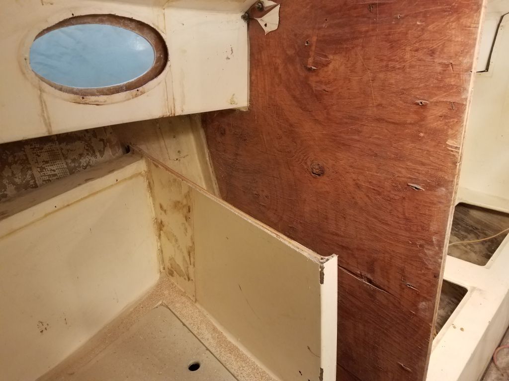
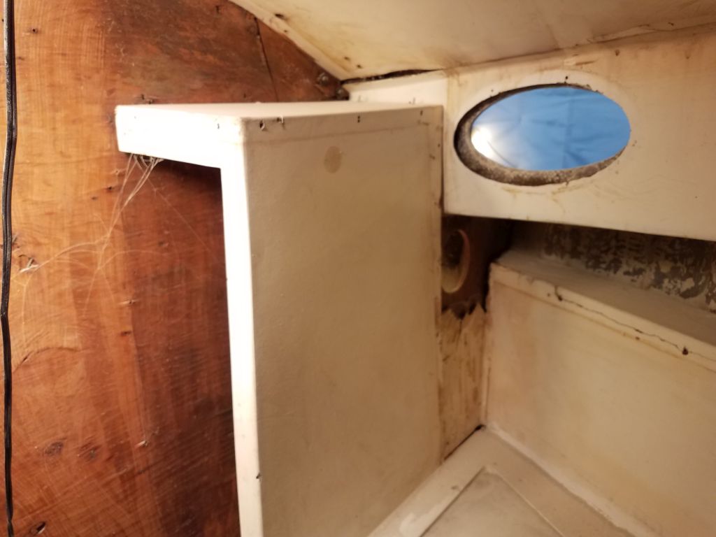
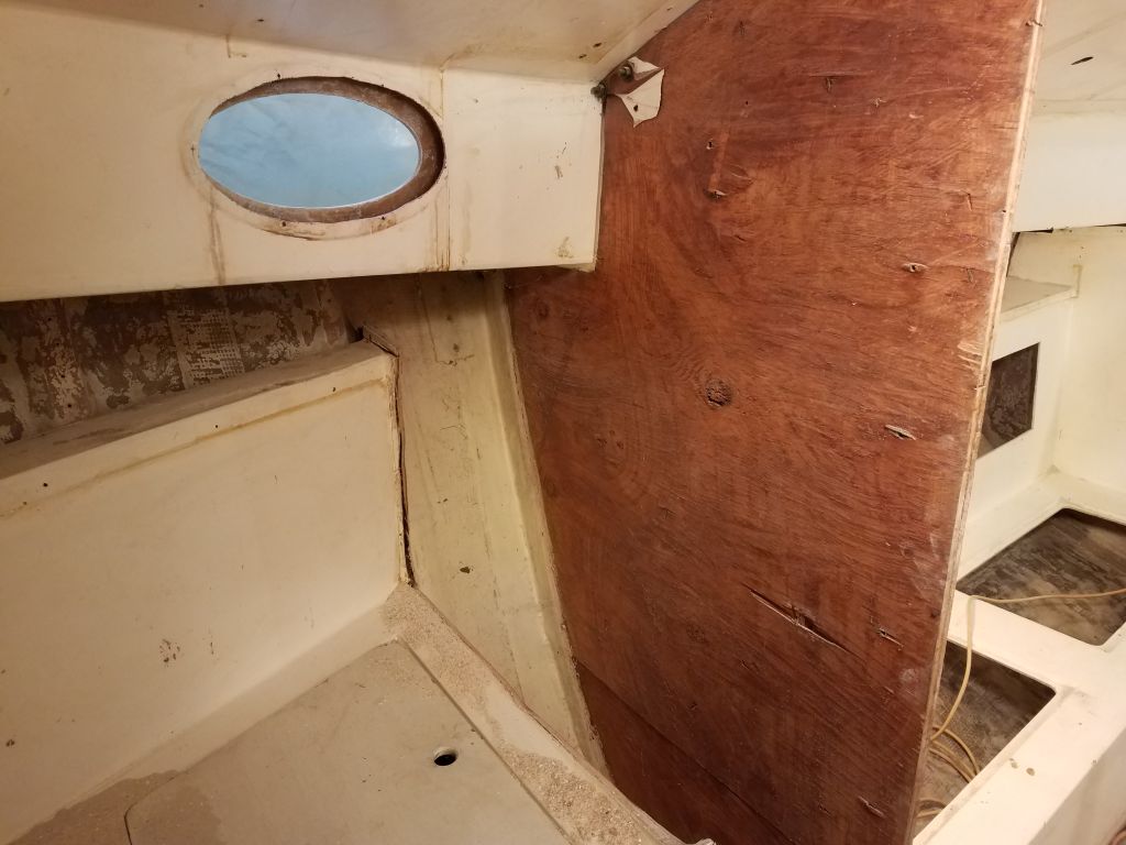
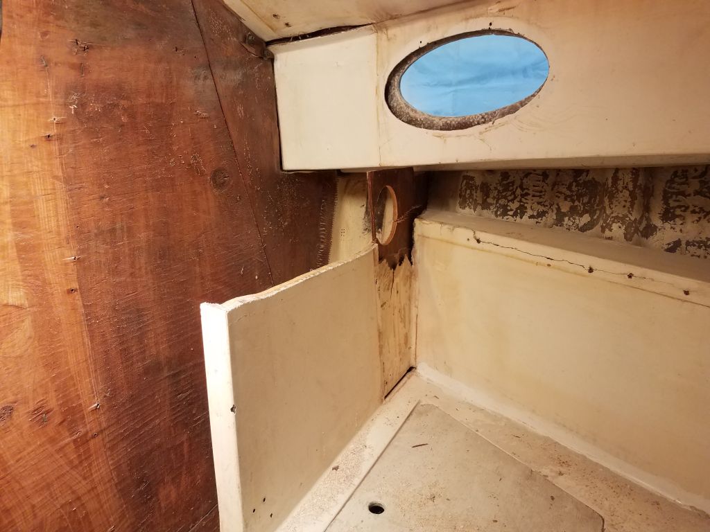
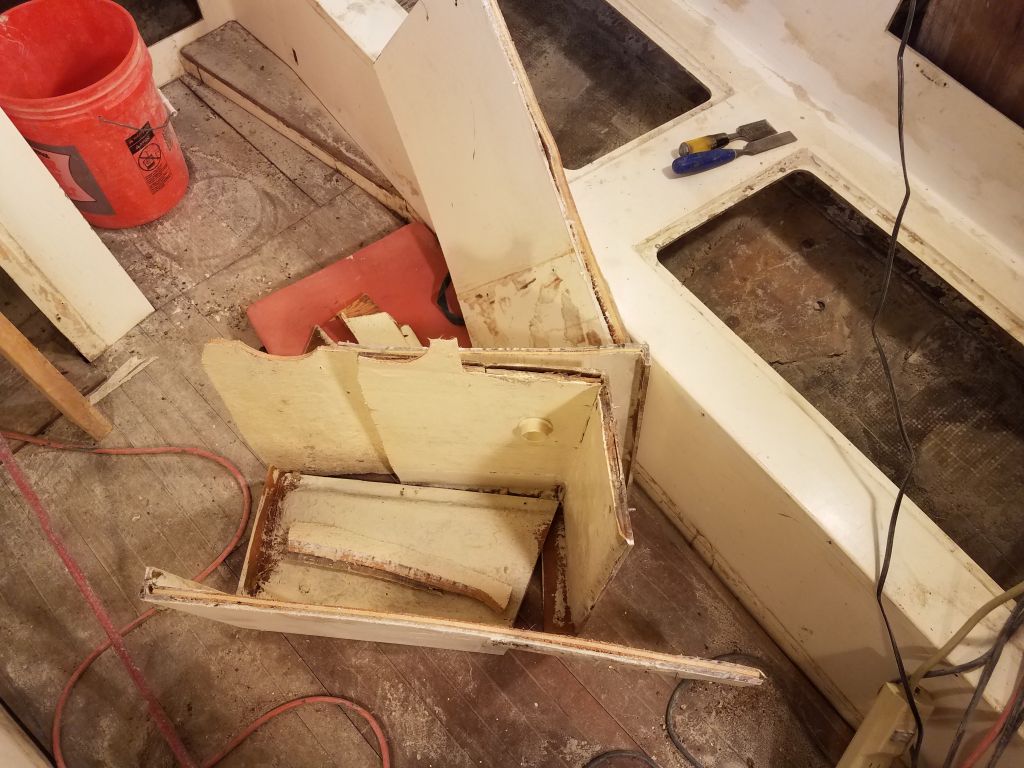
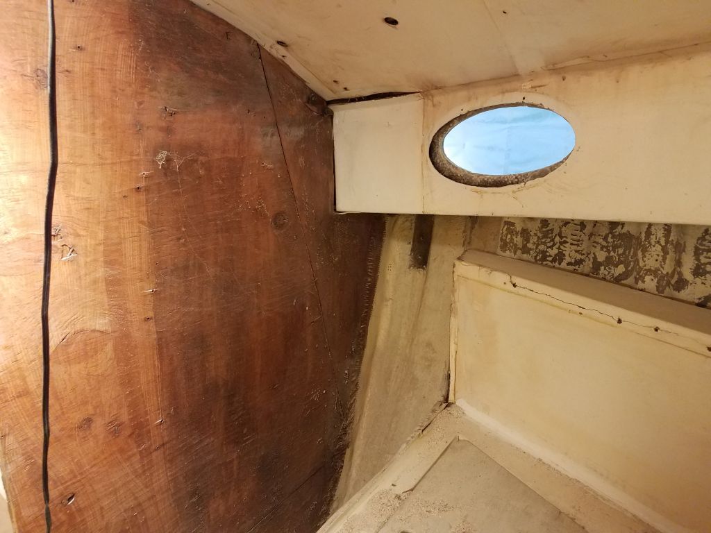
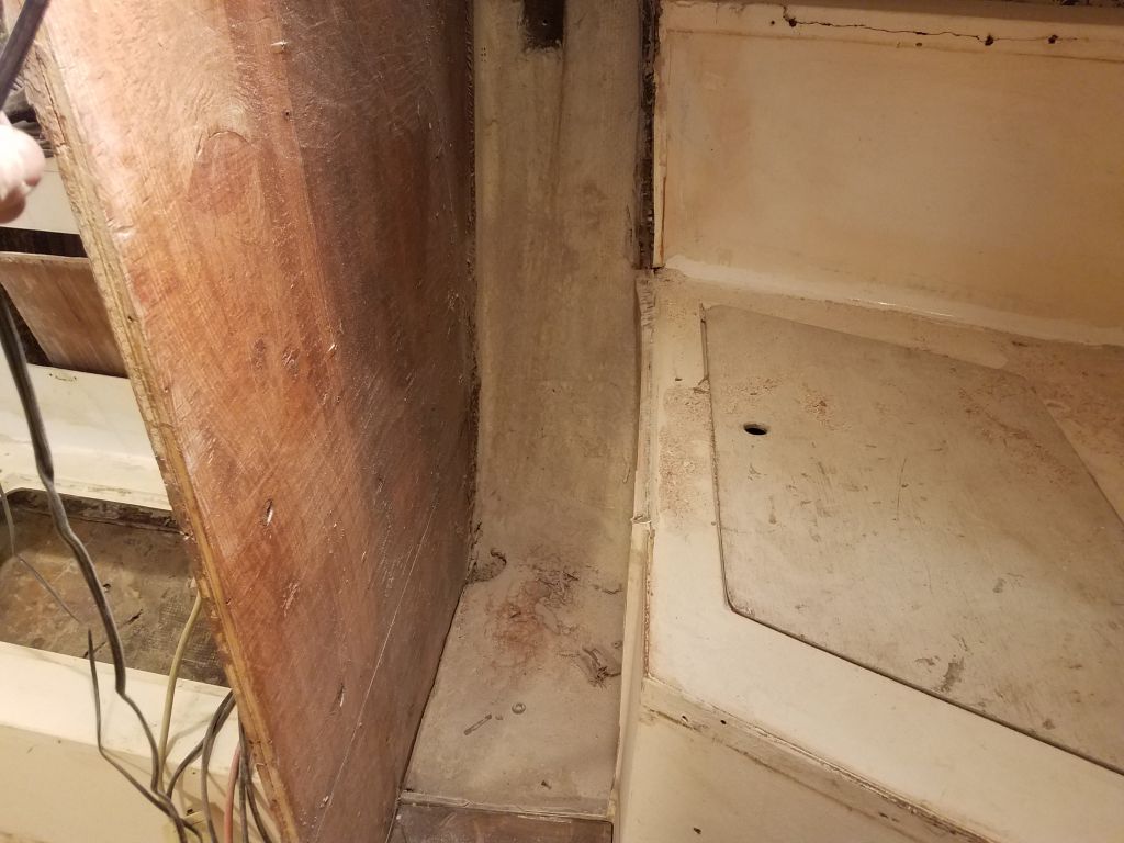
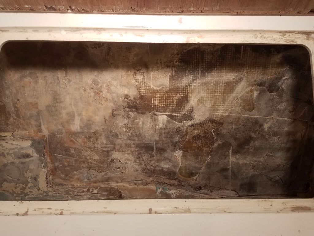
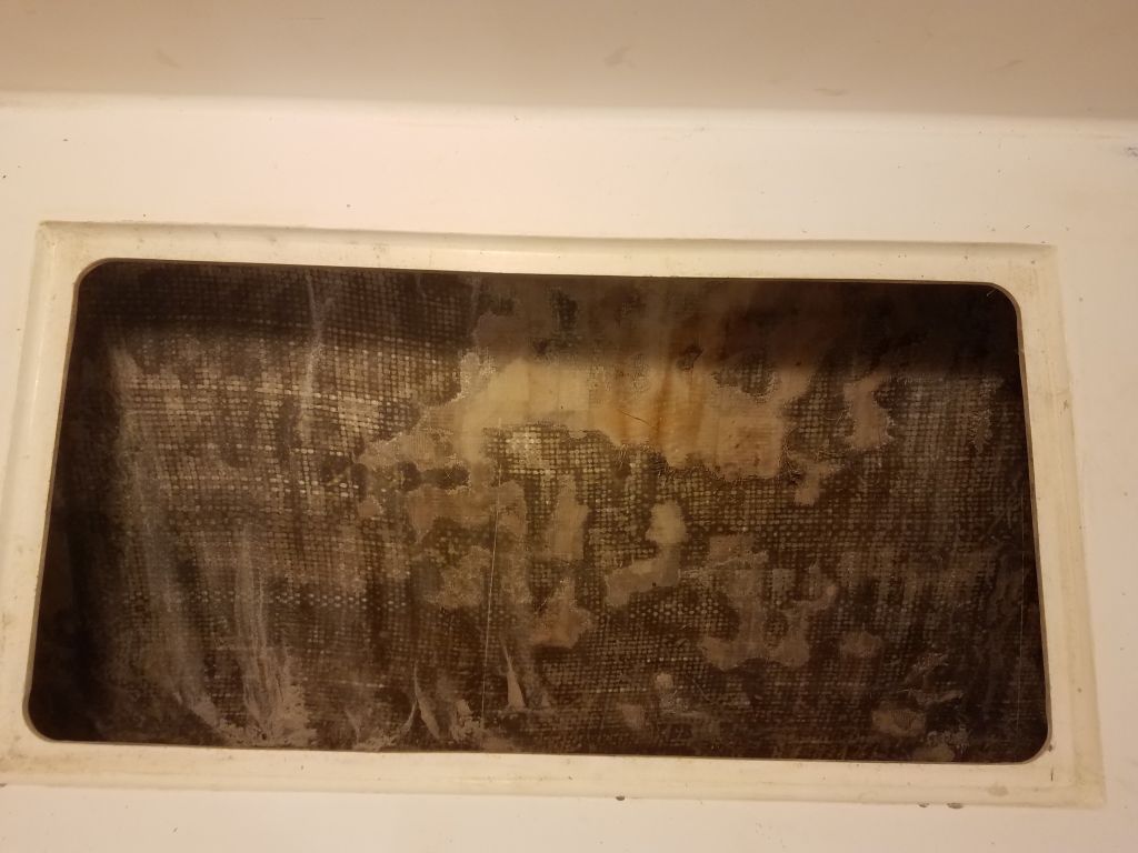
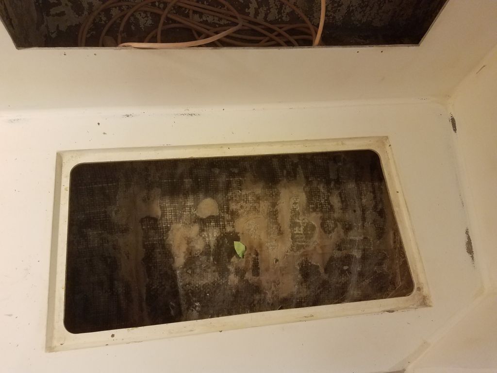
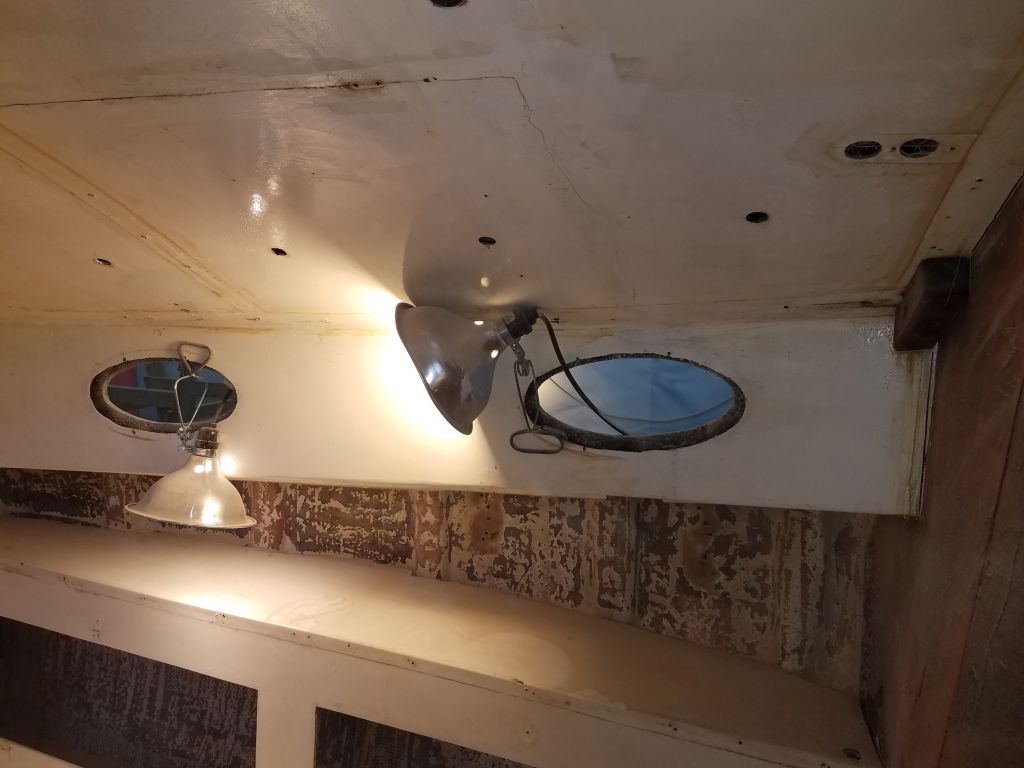
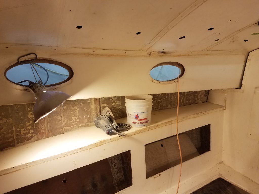
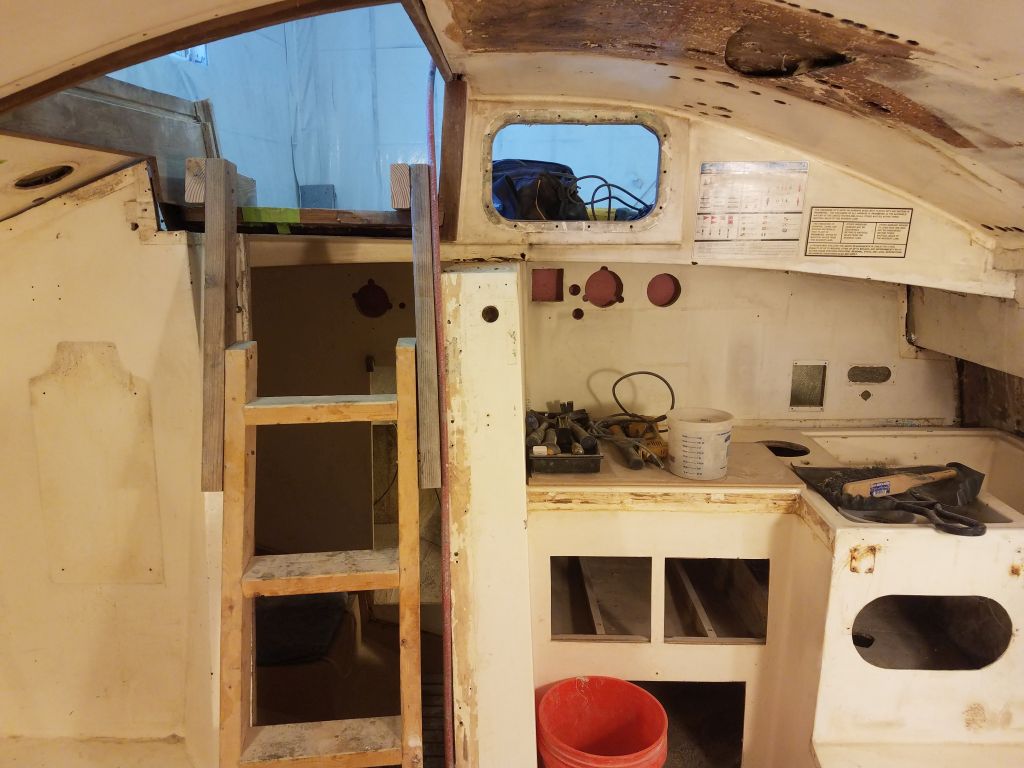
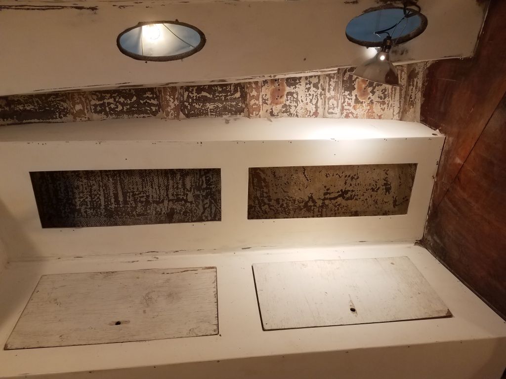
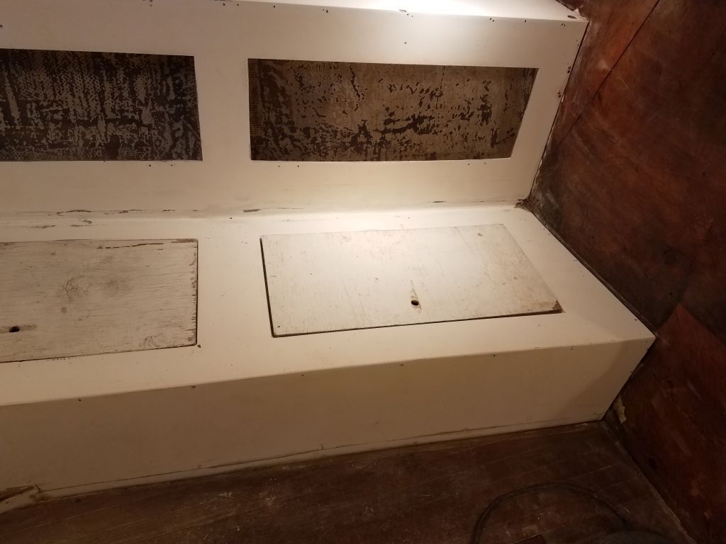
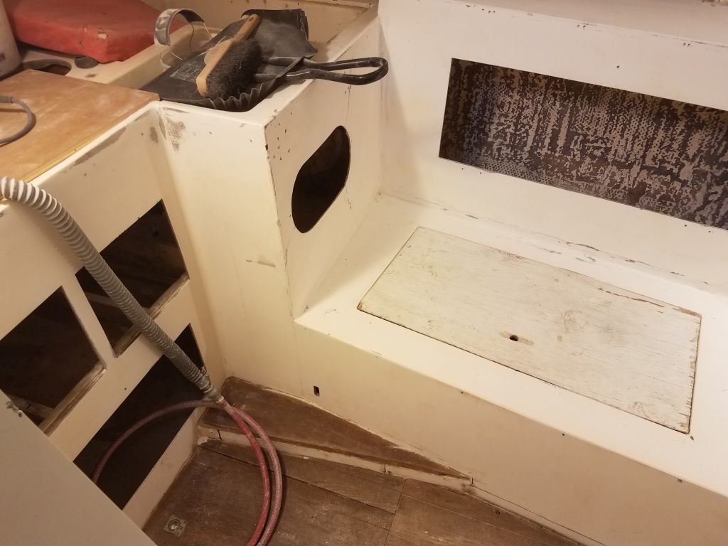
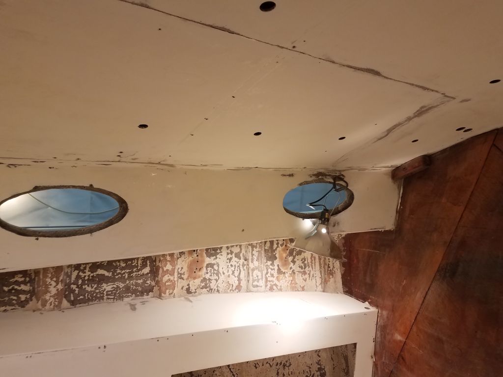
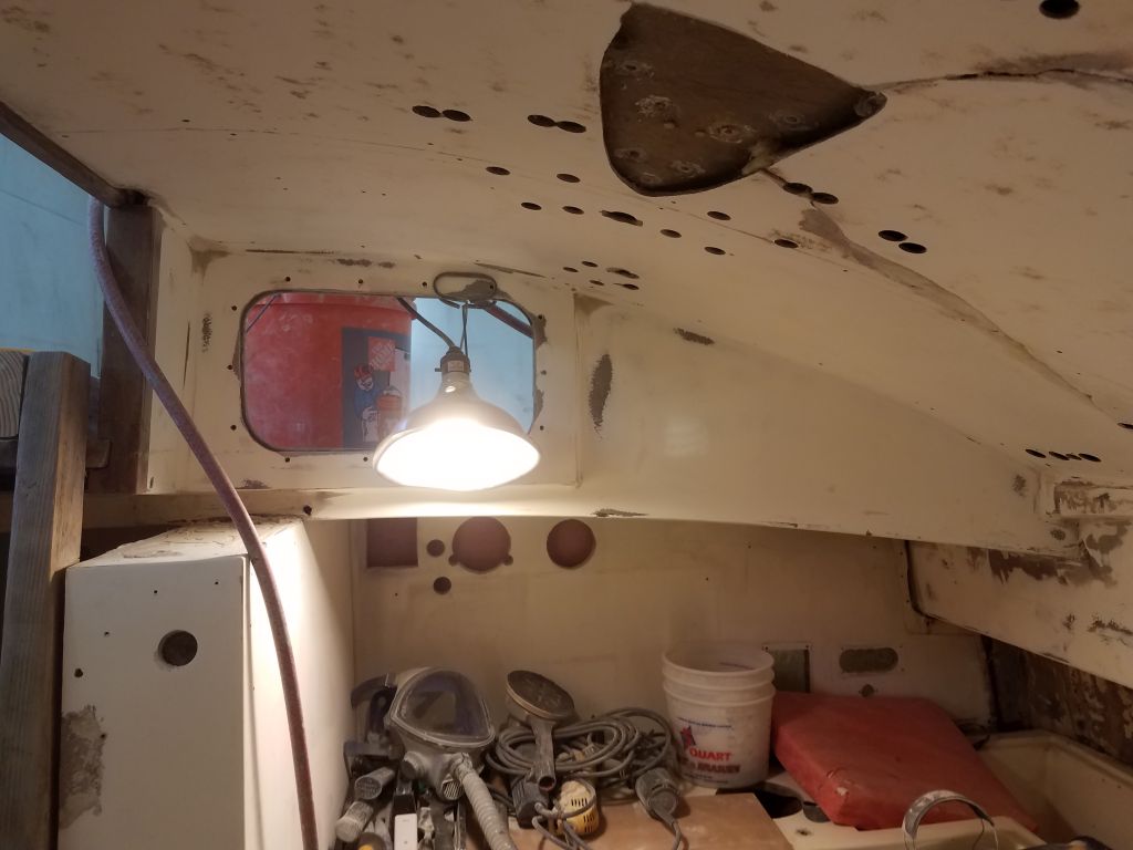
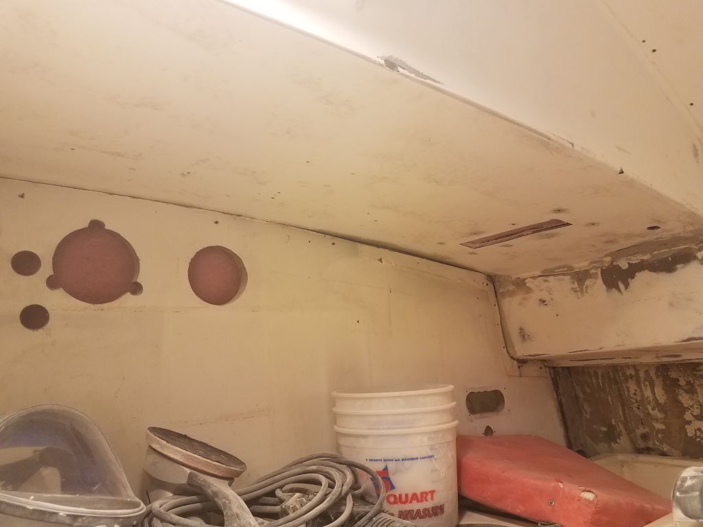
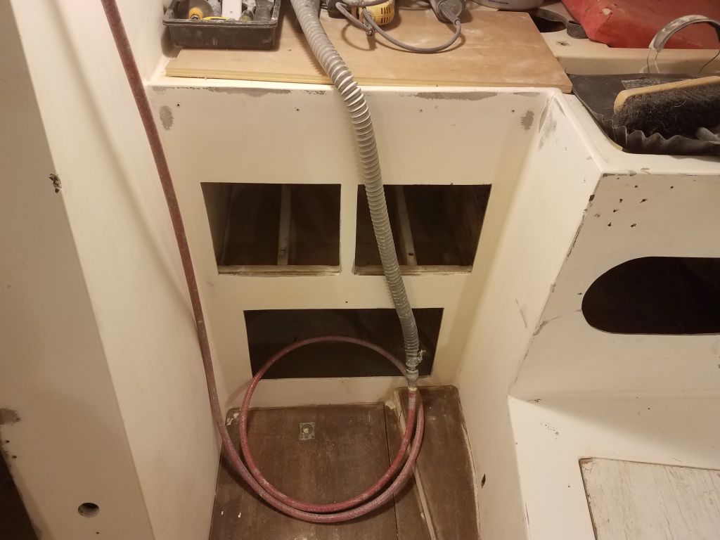
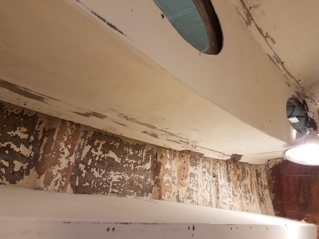
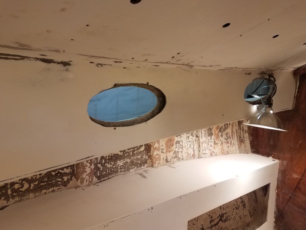
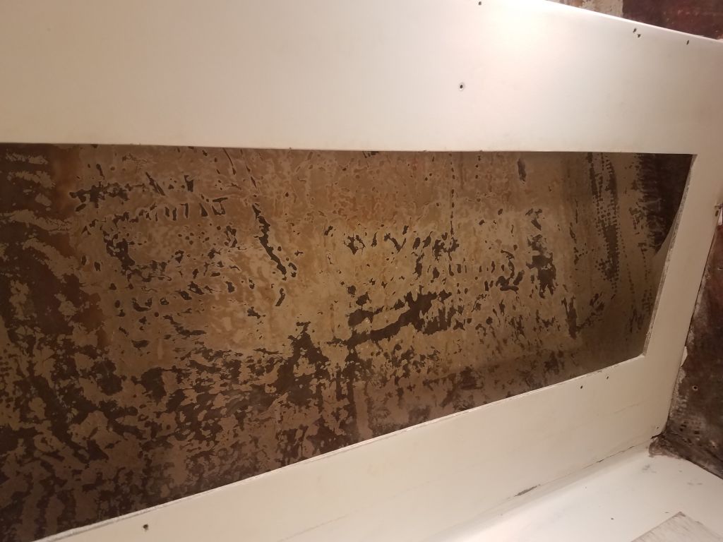
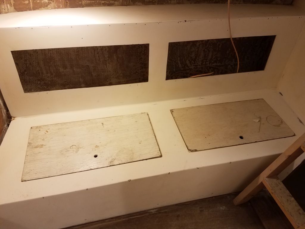
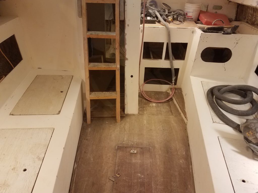
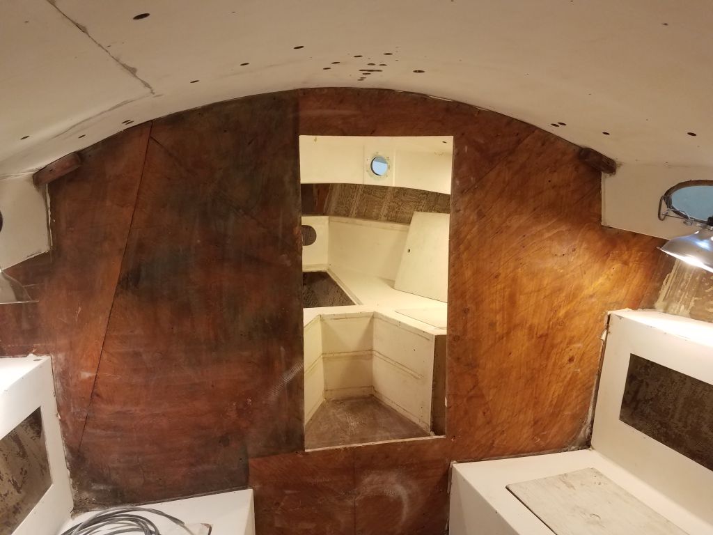
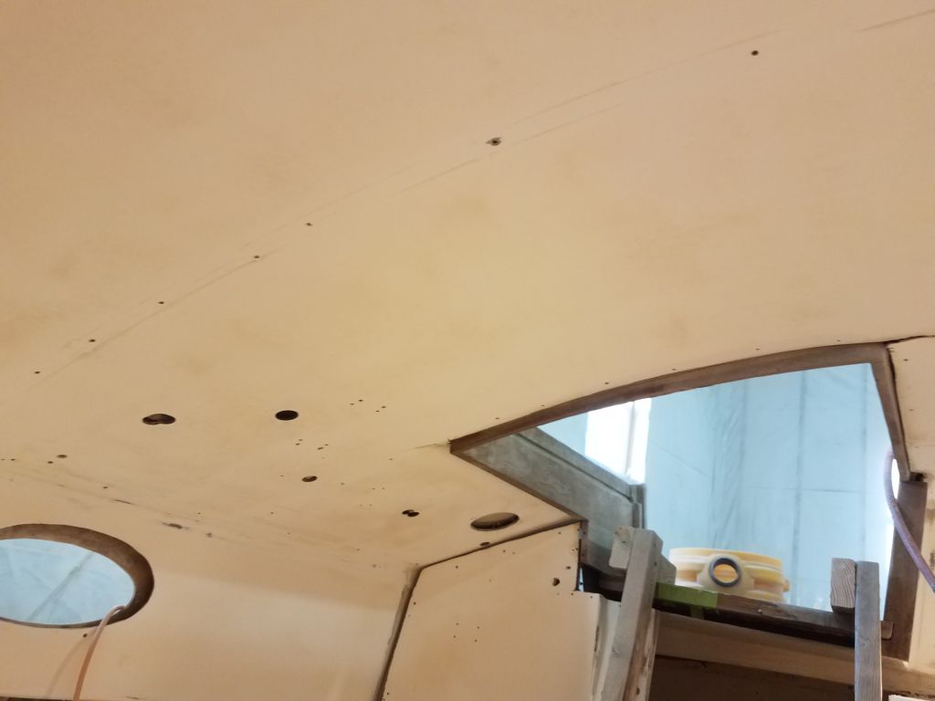
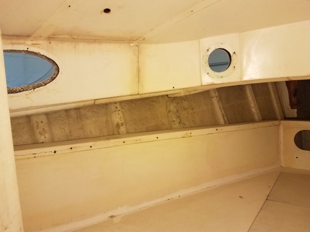
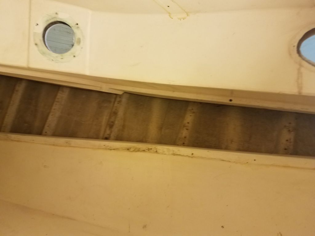
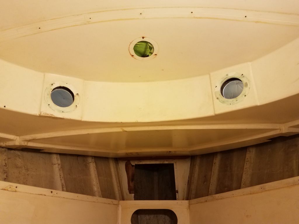
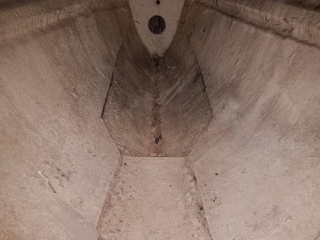
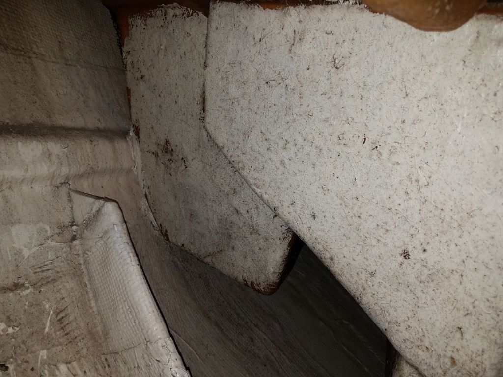
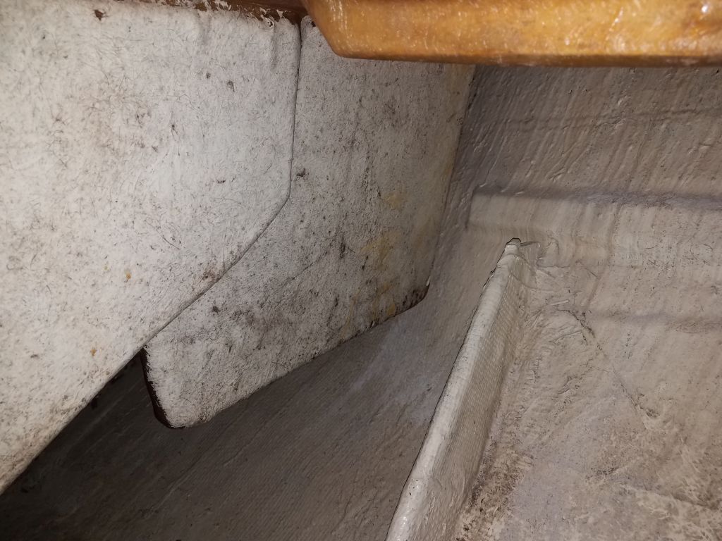
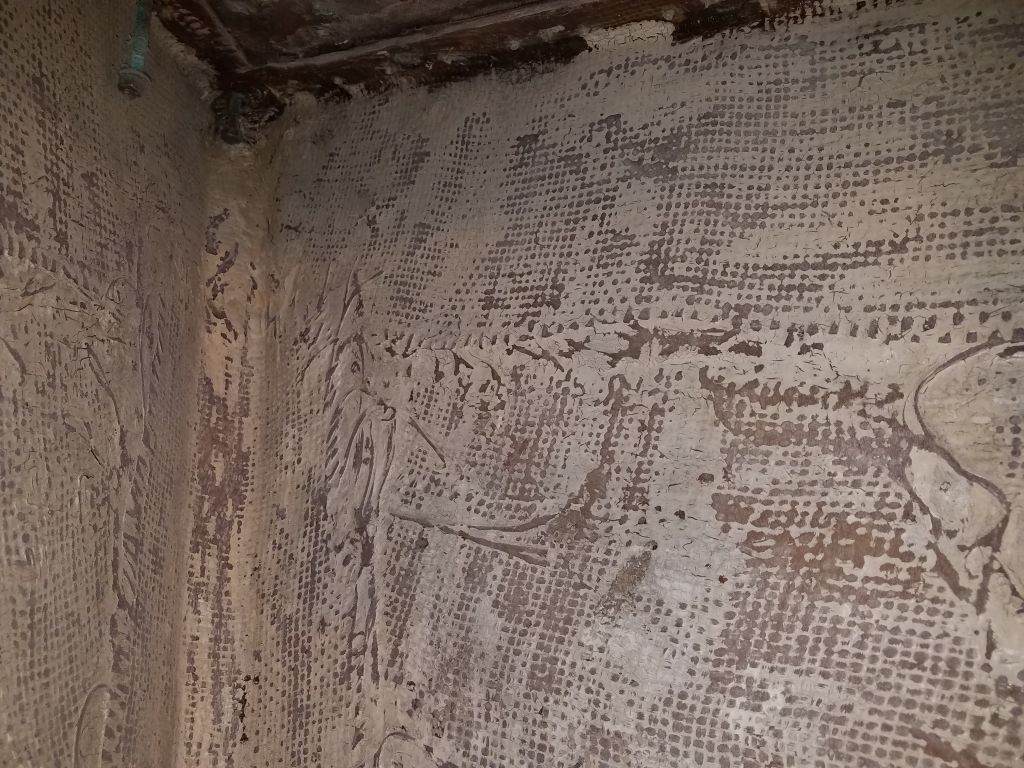
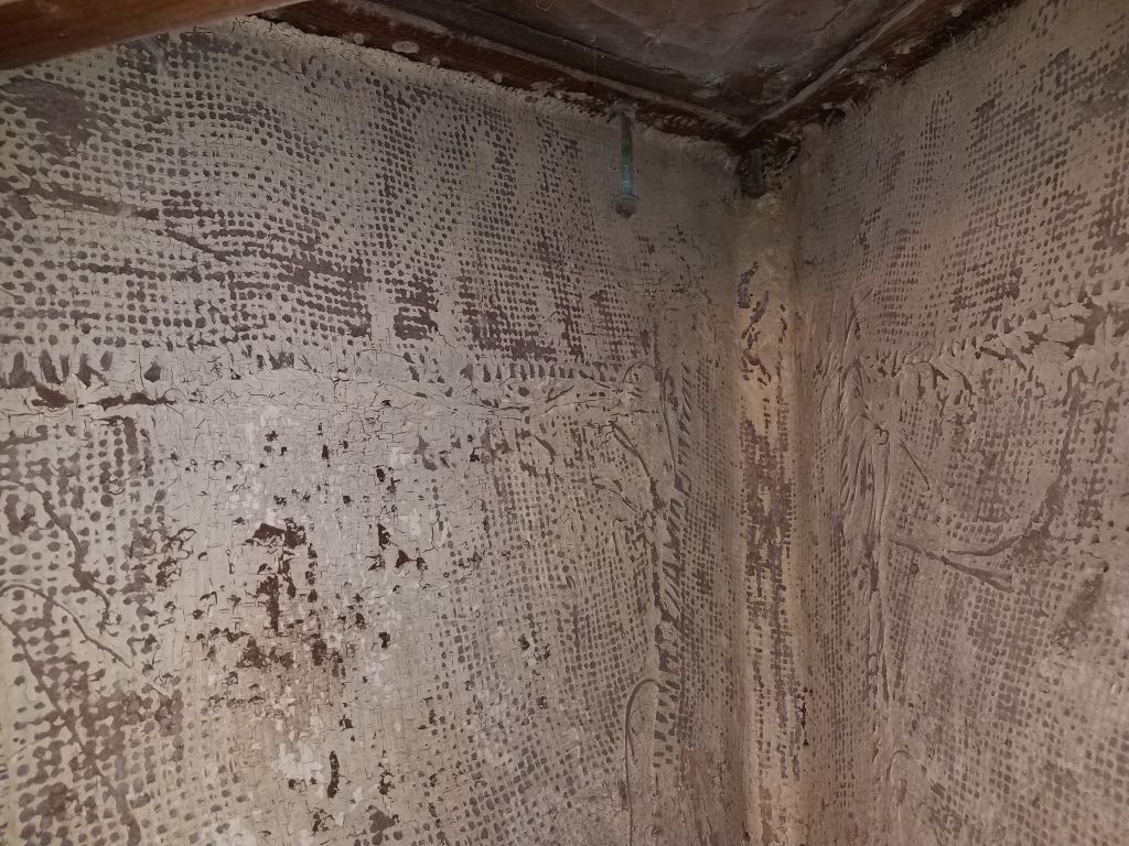
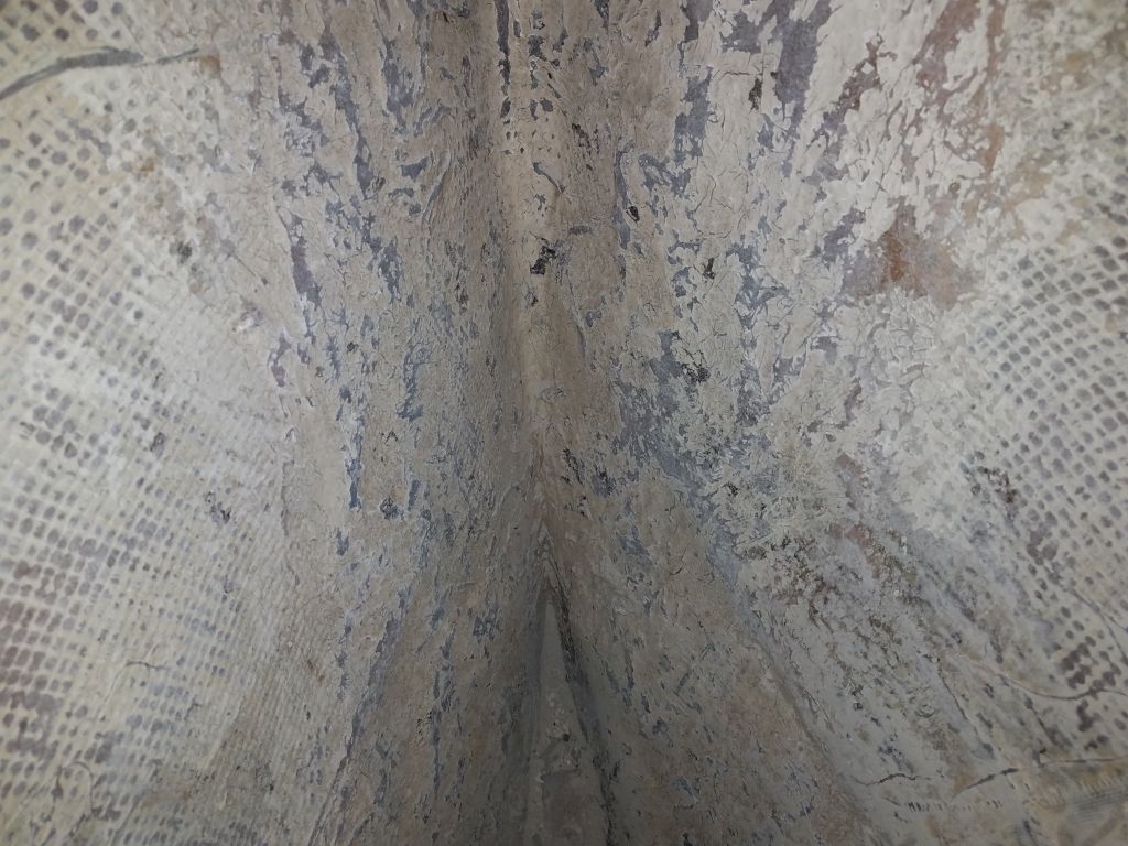
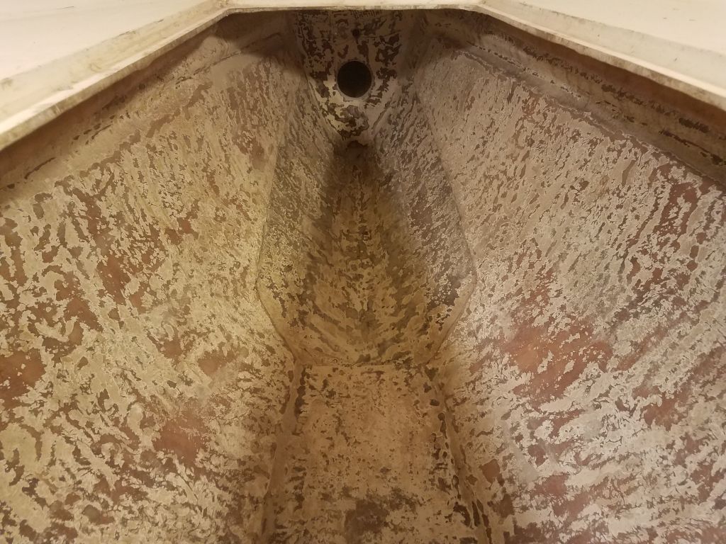
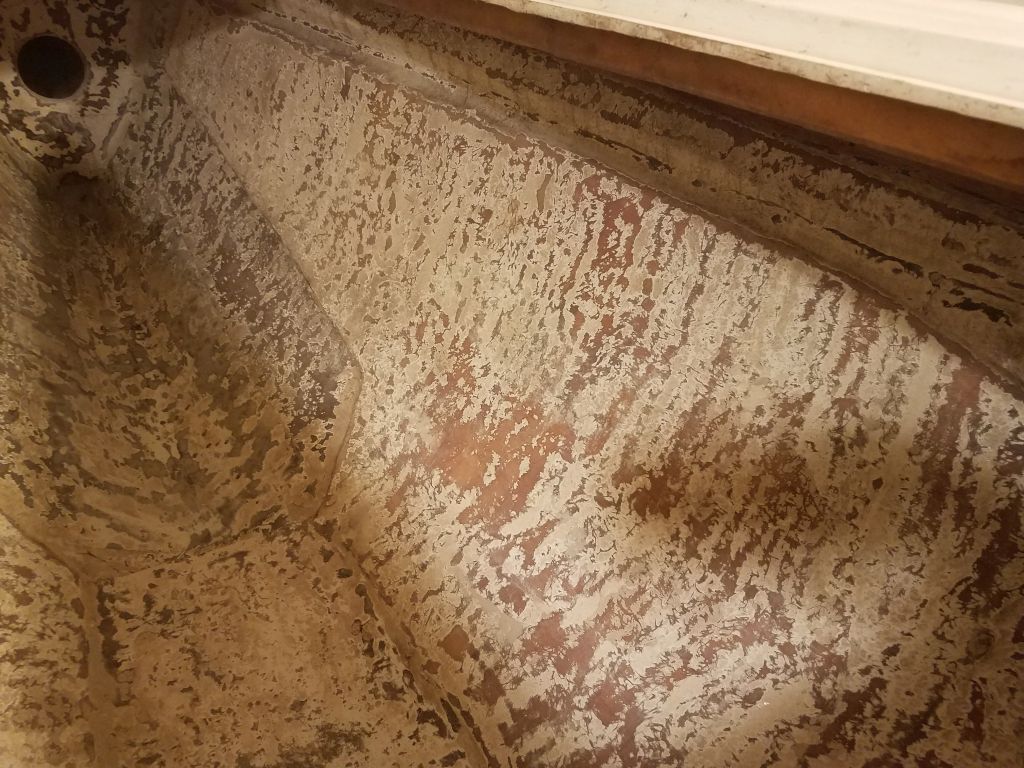
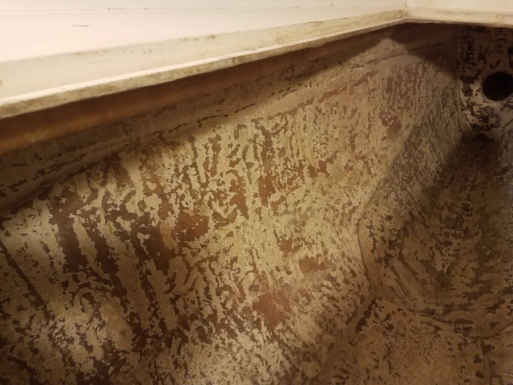
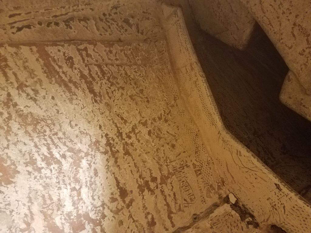
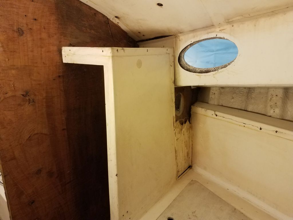
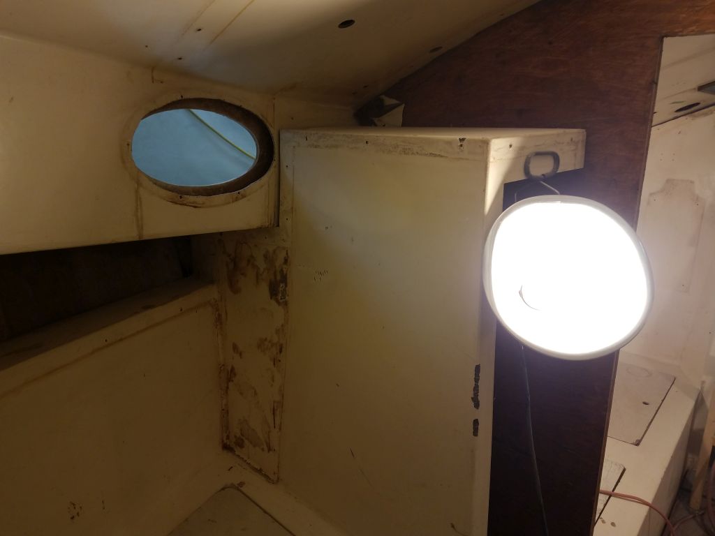
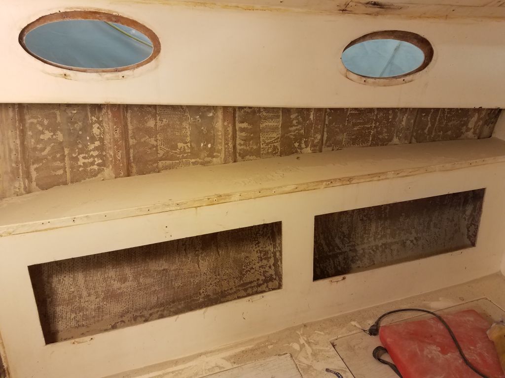
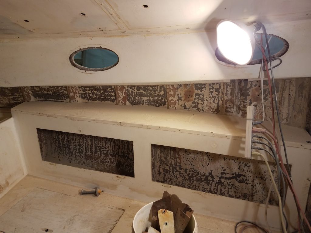
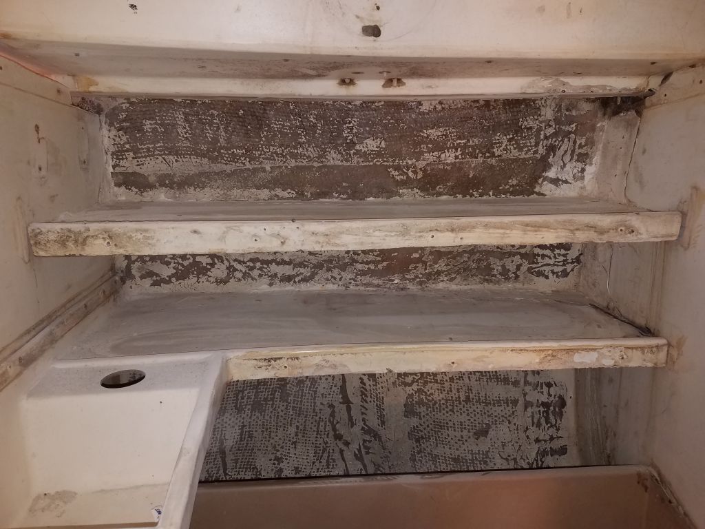
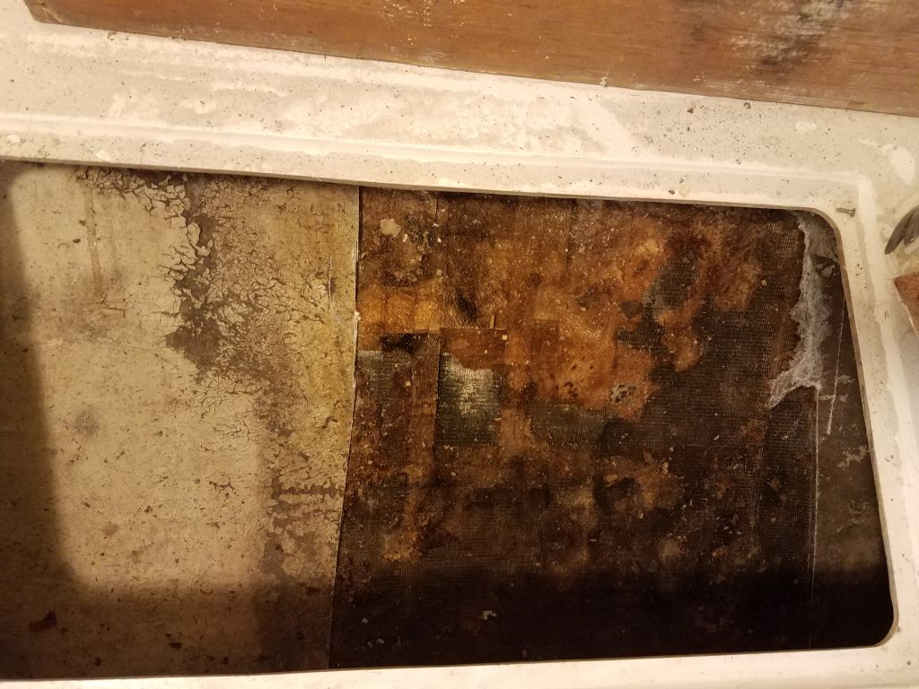
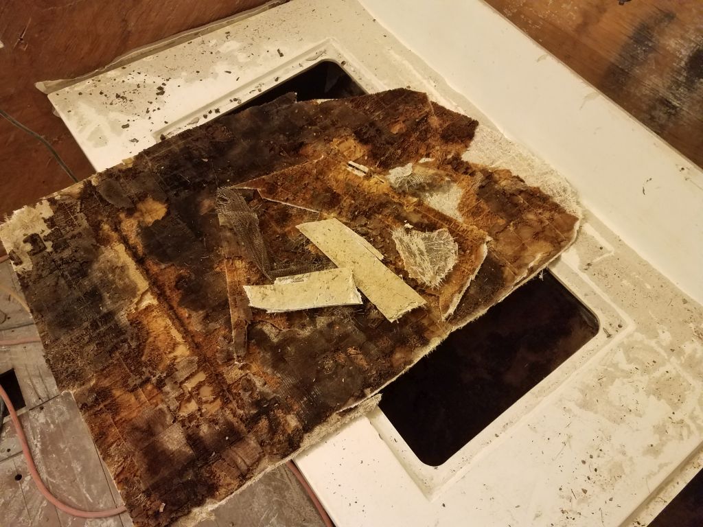
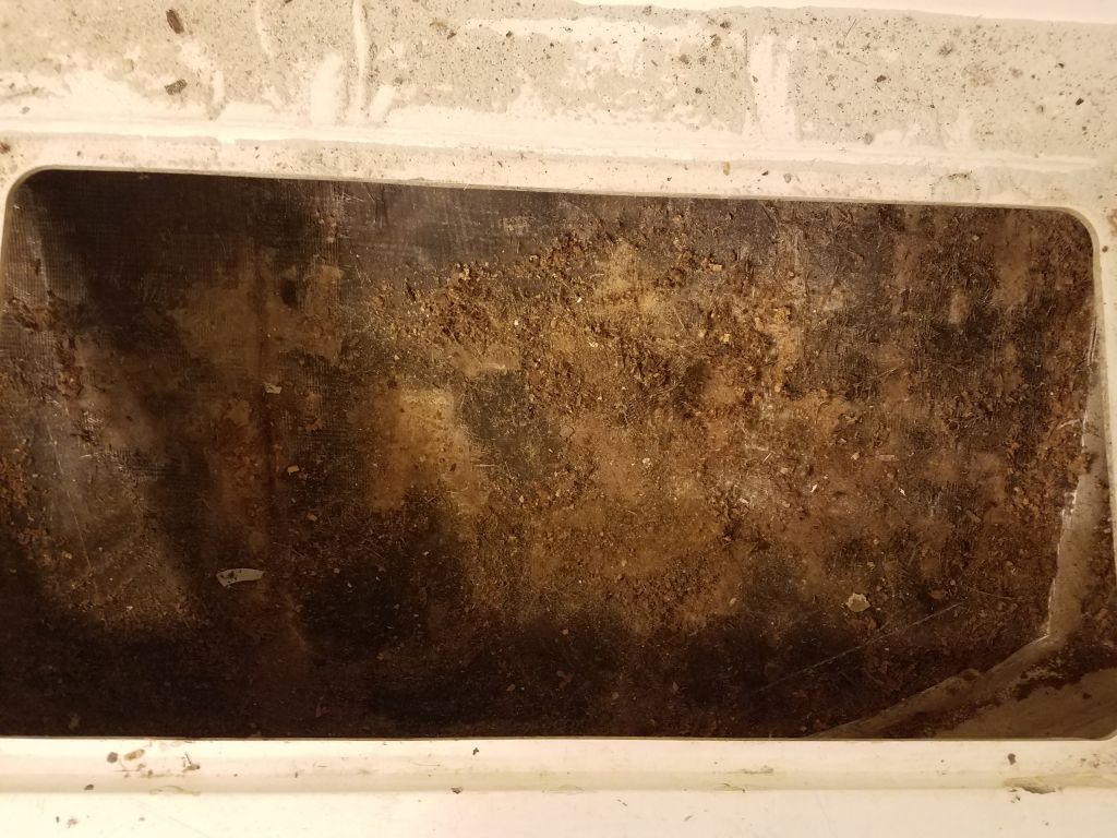
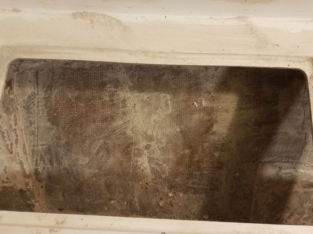
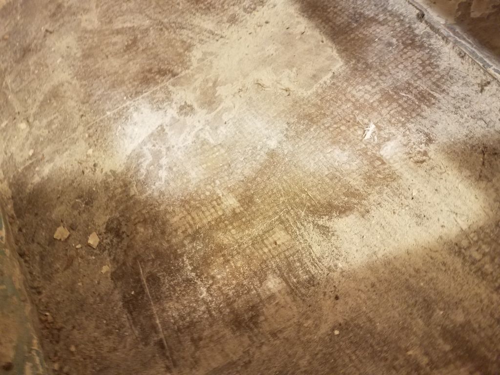
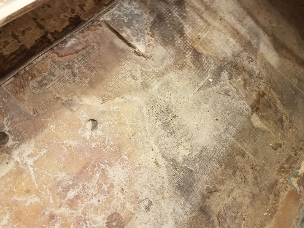
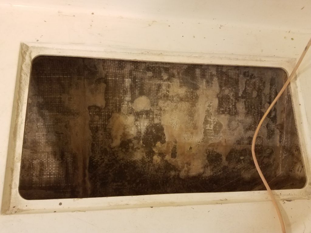
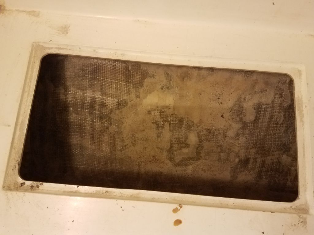
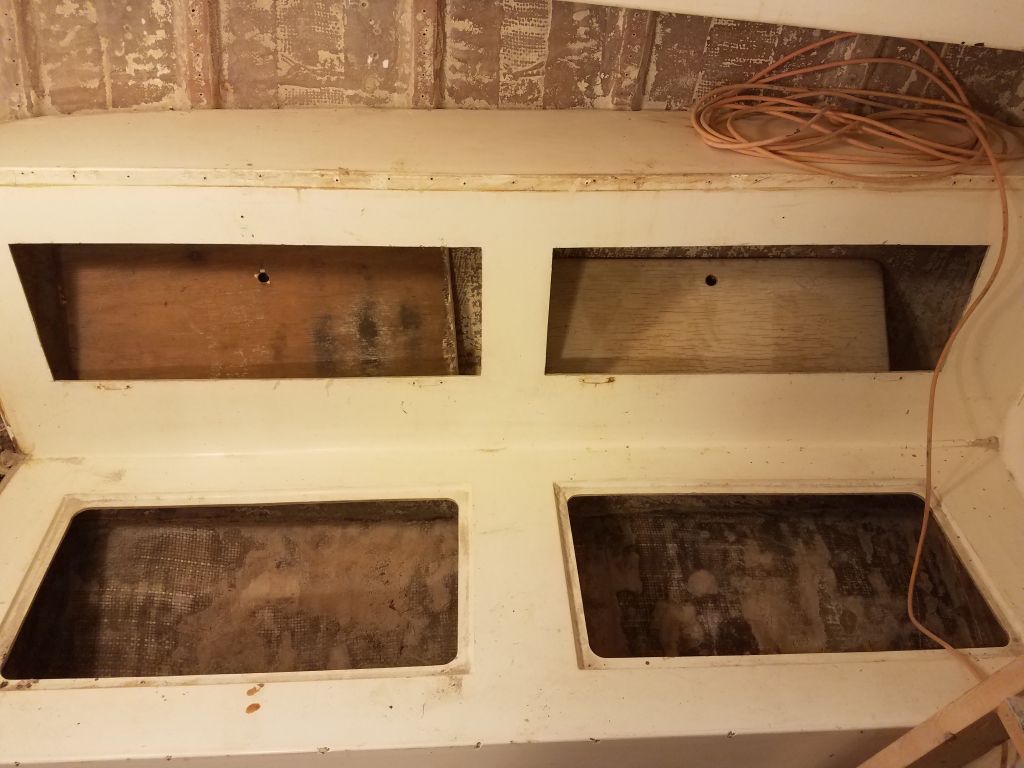
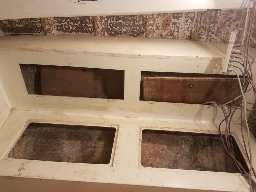
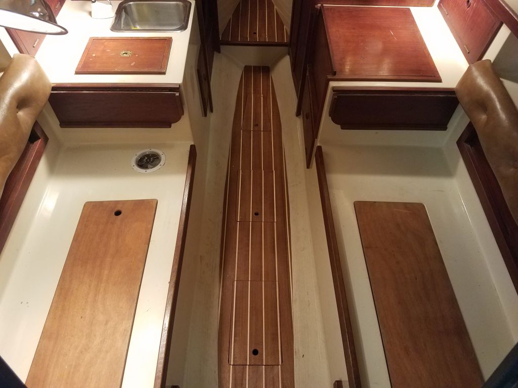
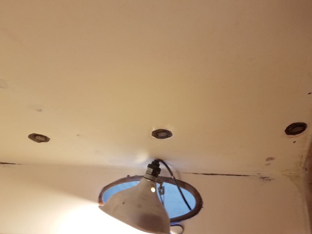
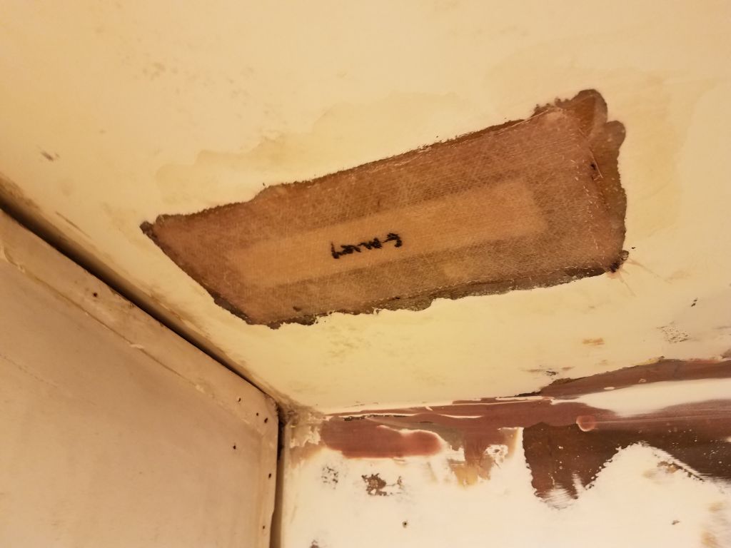
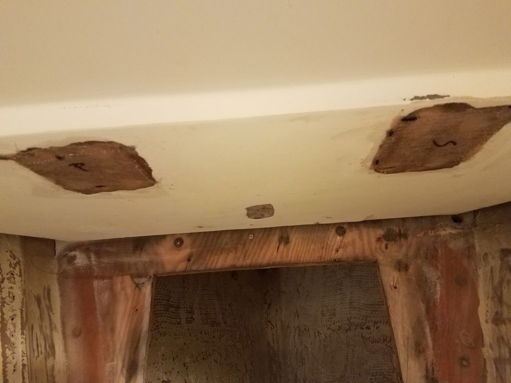
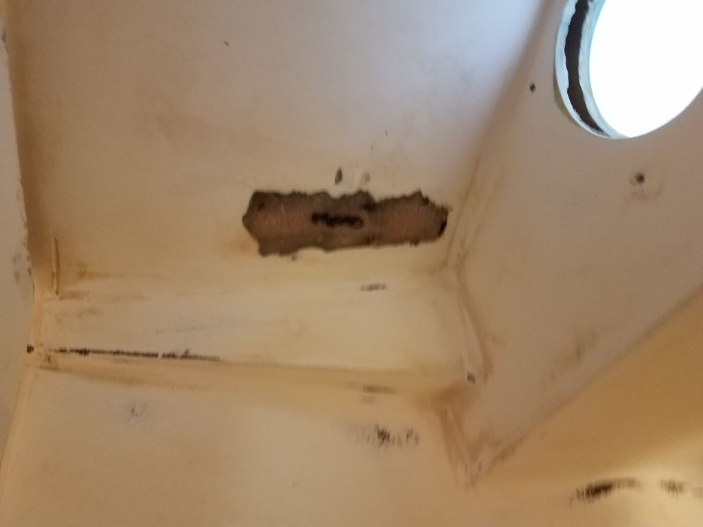
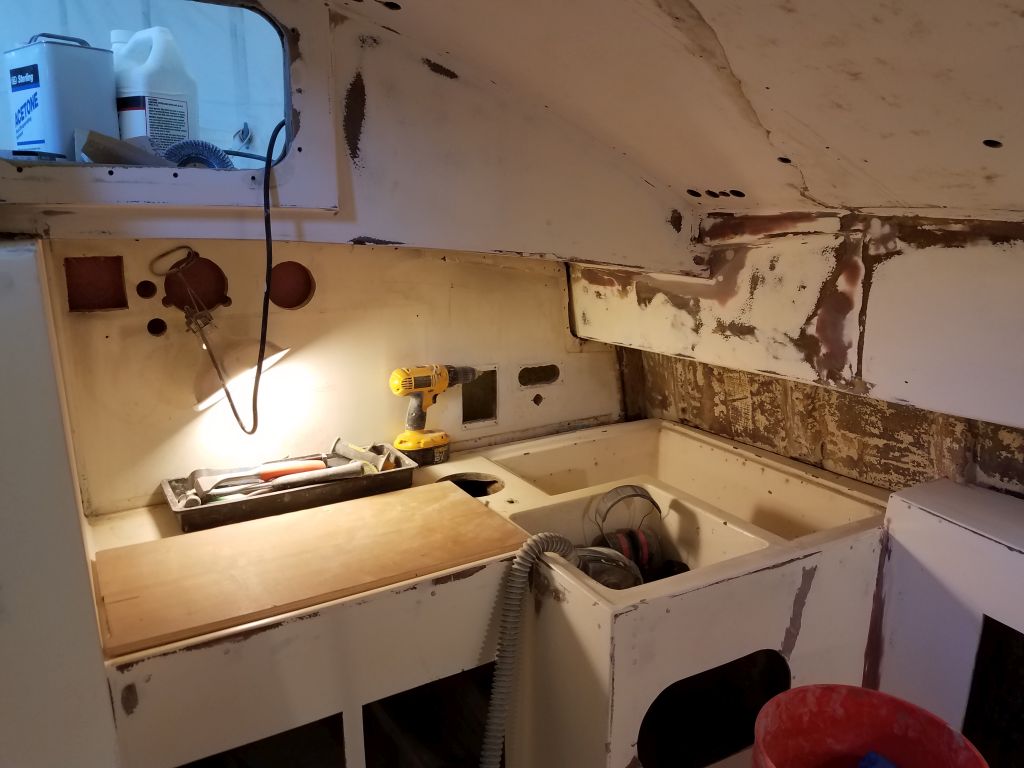
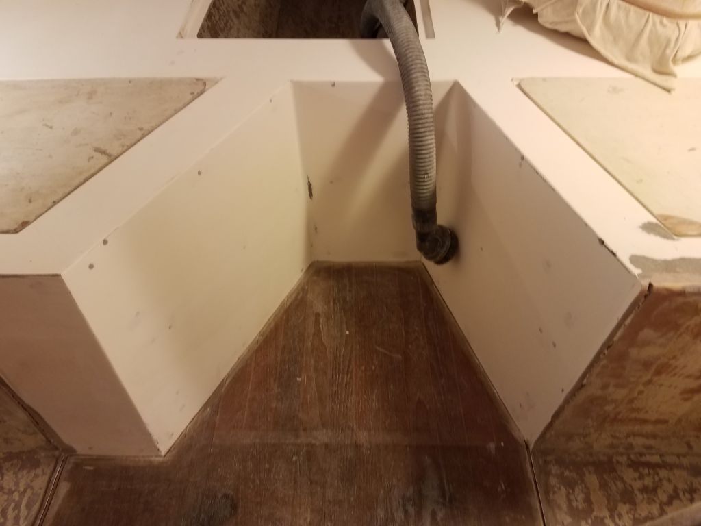
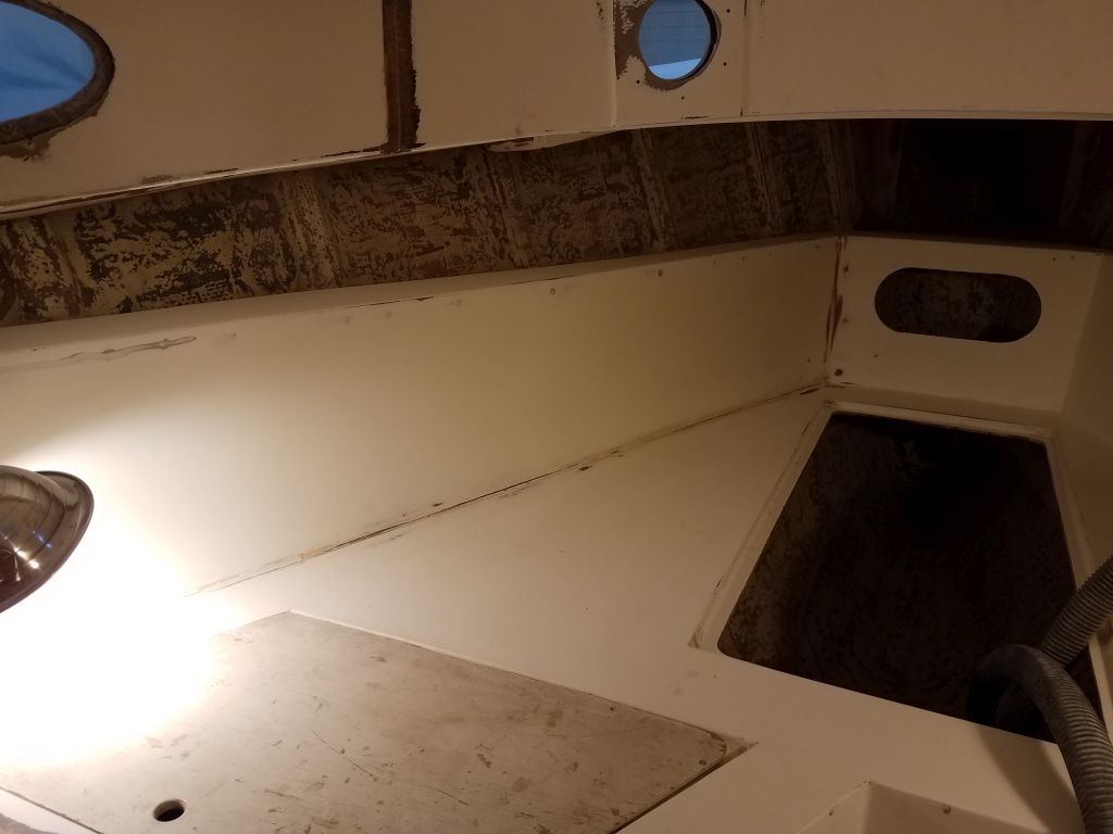
While I left those spots to cure, I prepared to install various fiberglass patches throughout the interior, including the old deck prism openings and some cracks in the forward part of the liner, as well as three remaining through hull locations–the galley sink, head sink, and an old depth transducer location in the port settee locker–that I’d previously filled and patched from outside, but hadn’t yet patched from within because when I did some of the other patches earlier in the project, I’d yet to sand and prepare the inside of the hull in these other areas.
After cutting the new fiberglass for all areas, and other final preparations, I wet out with epoxy and installed all the patches.


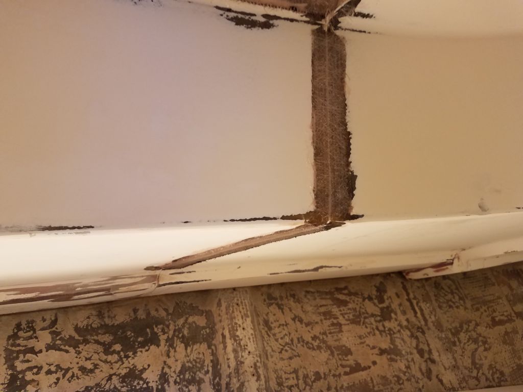
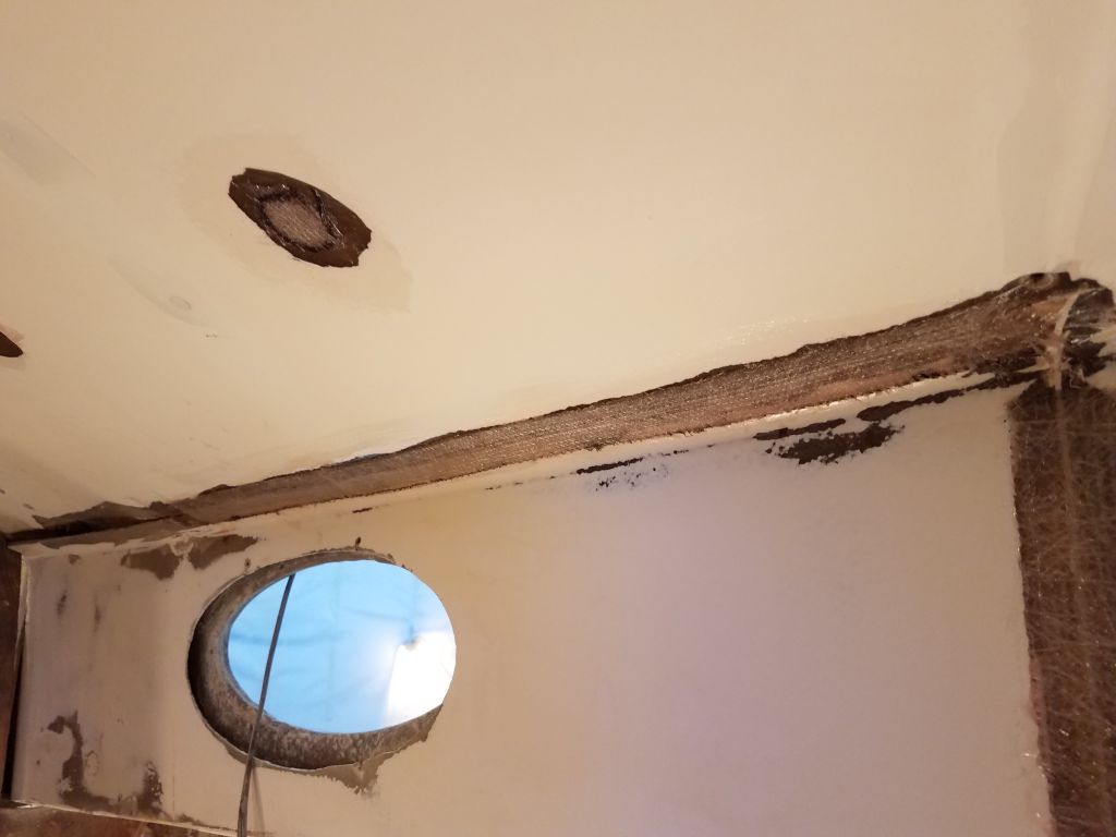


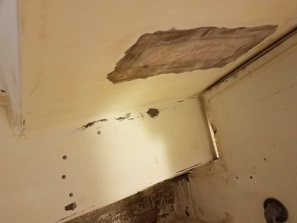
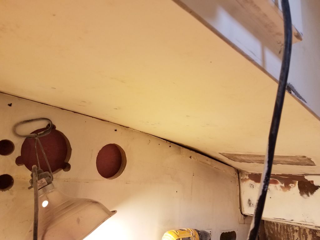
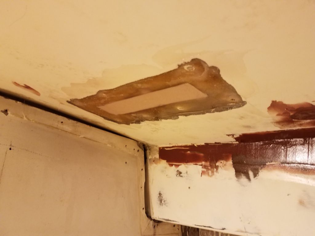
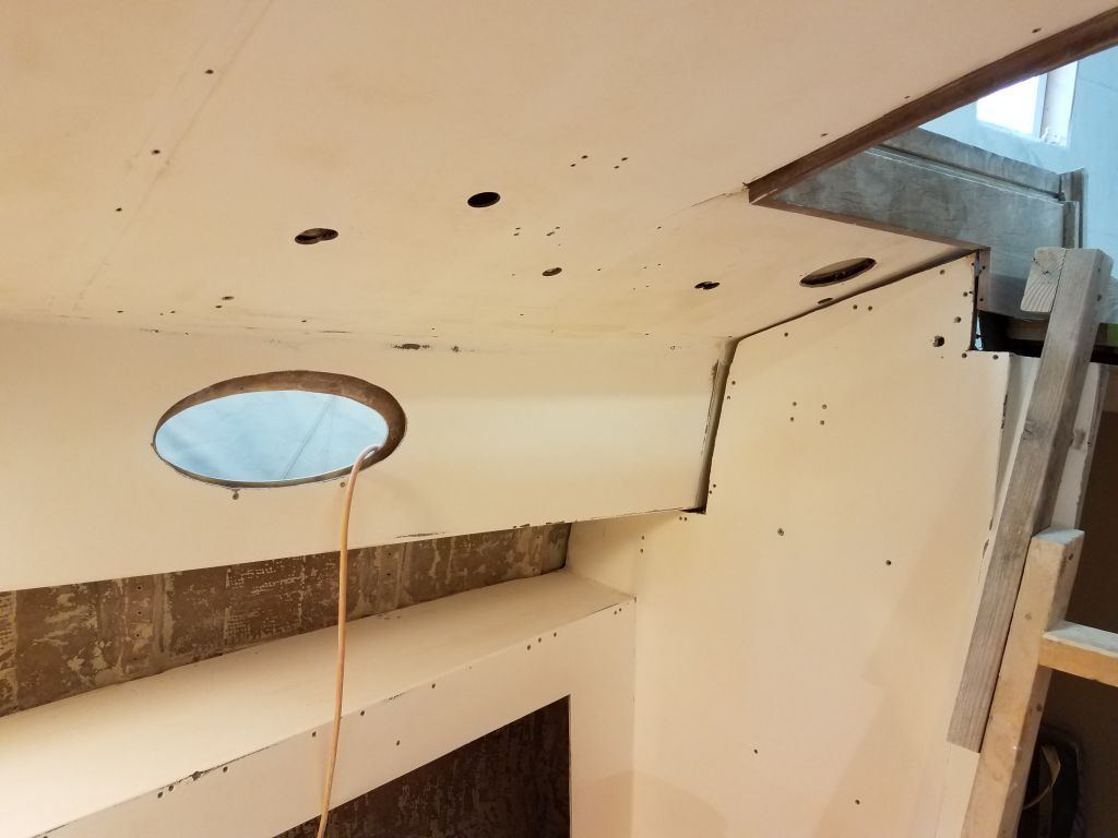
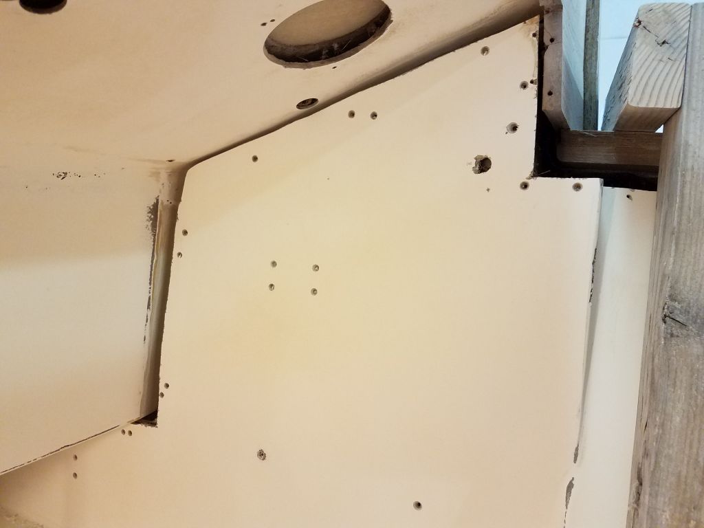
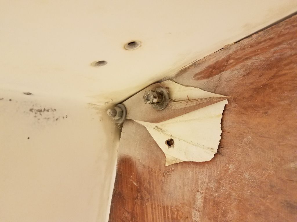
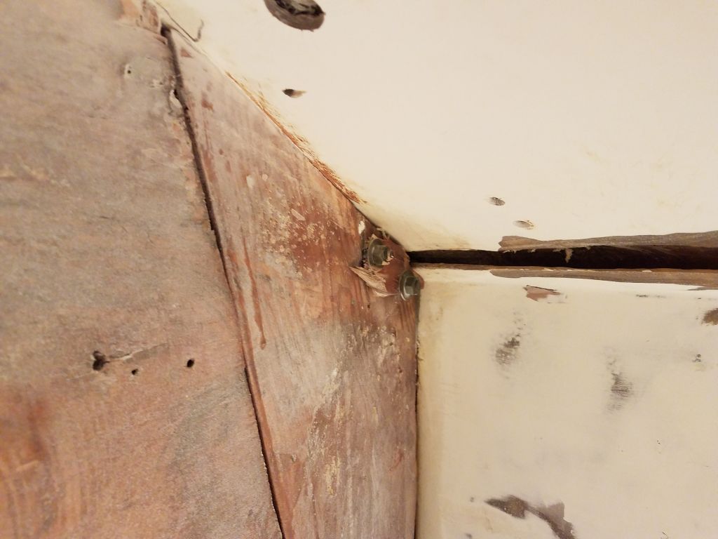
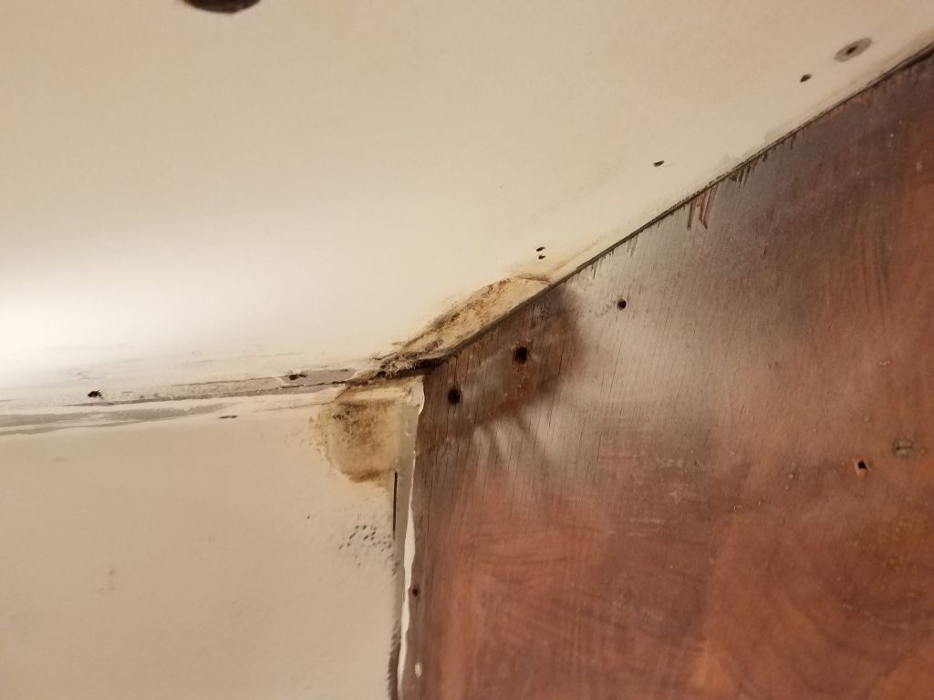
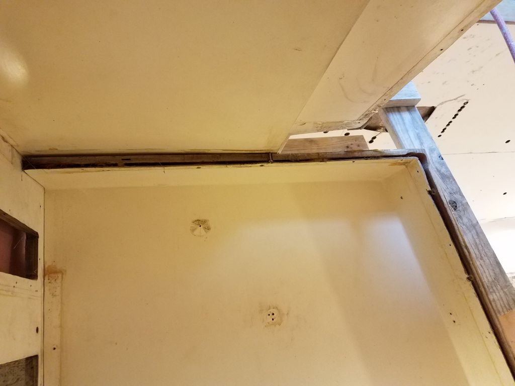
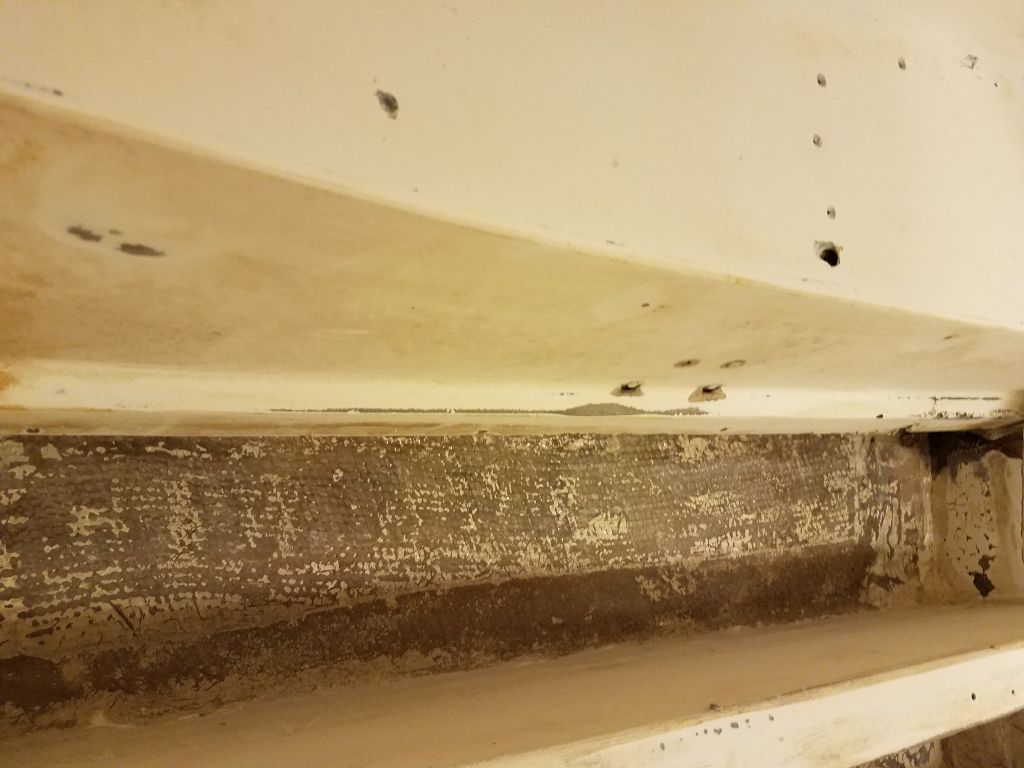
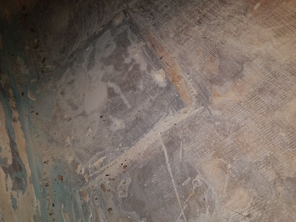
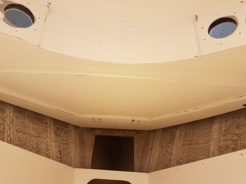
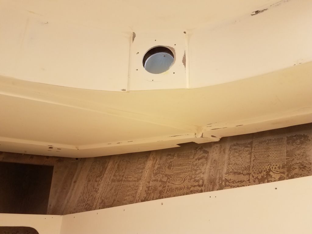
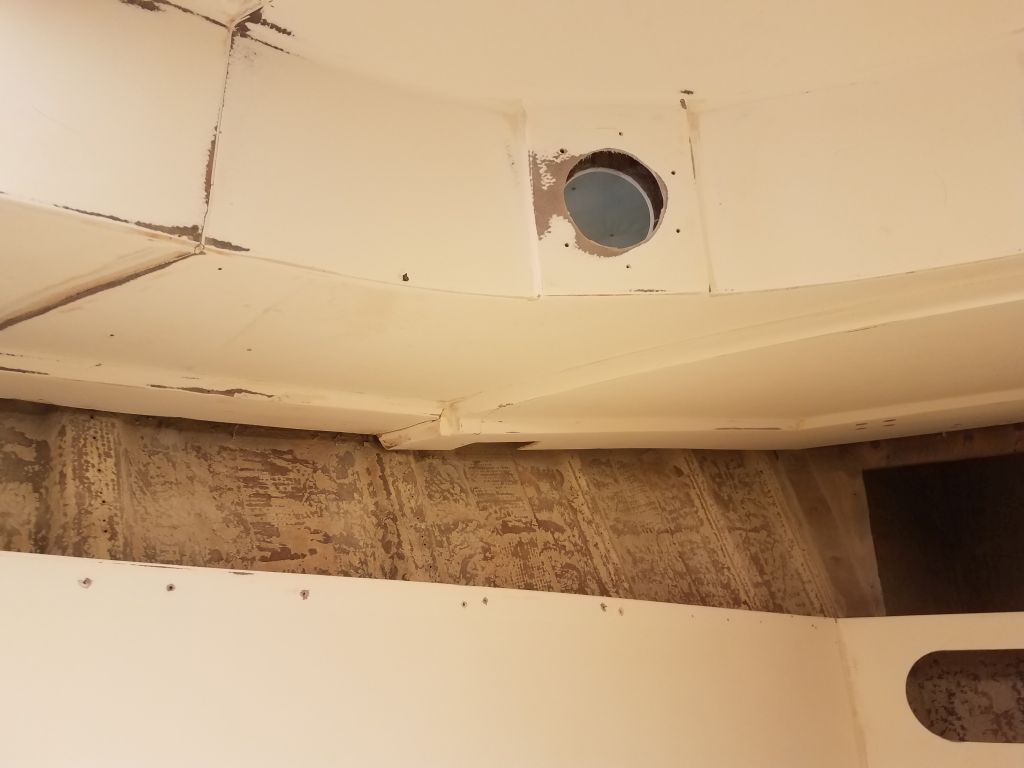
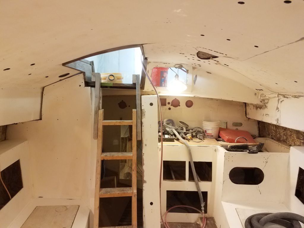
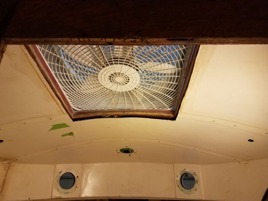
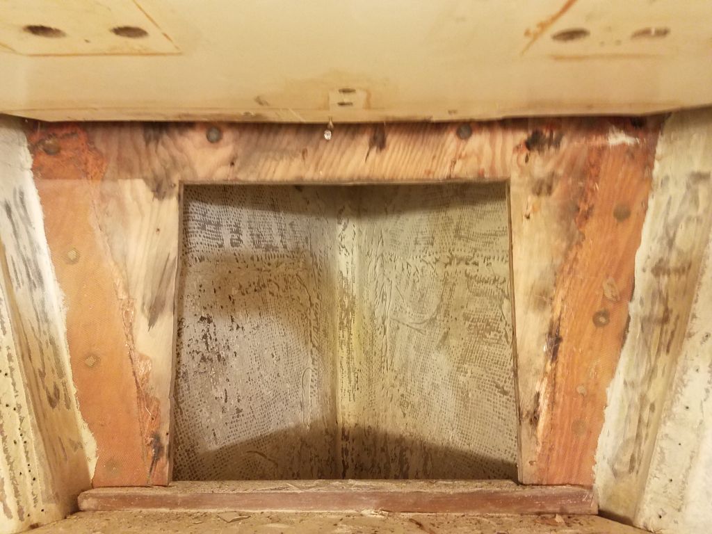
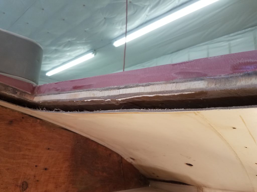
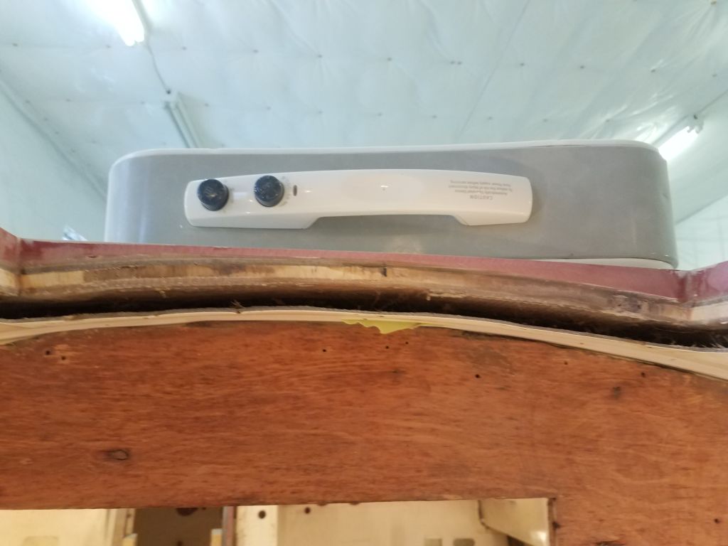
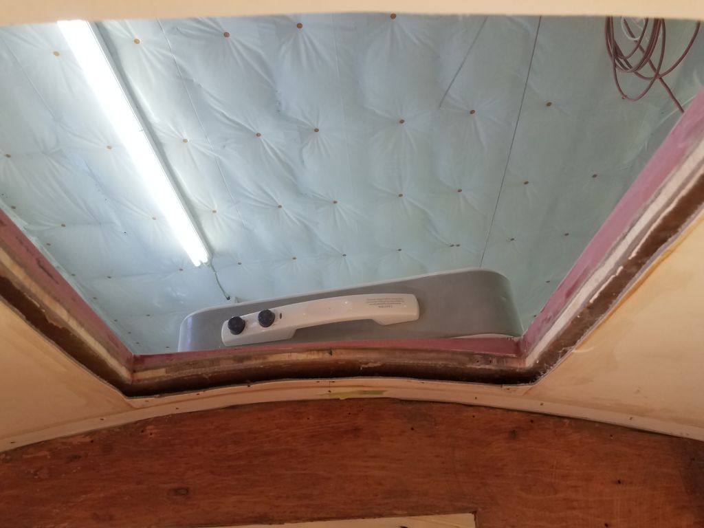
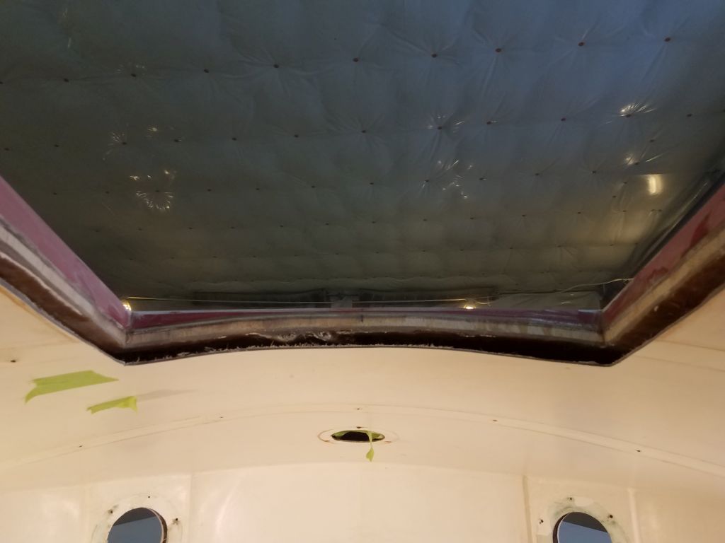
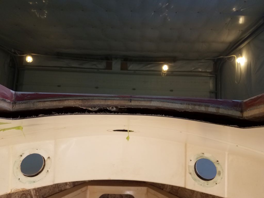
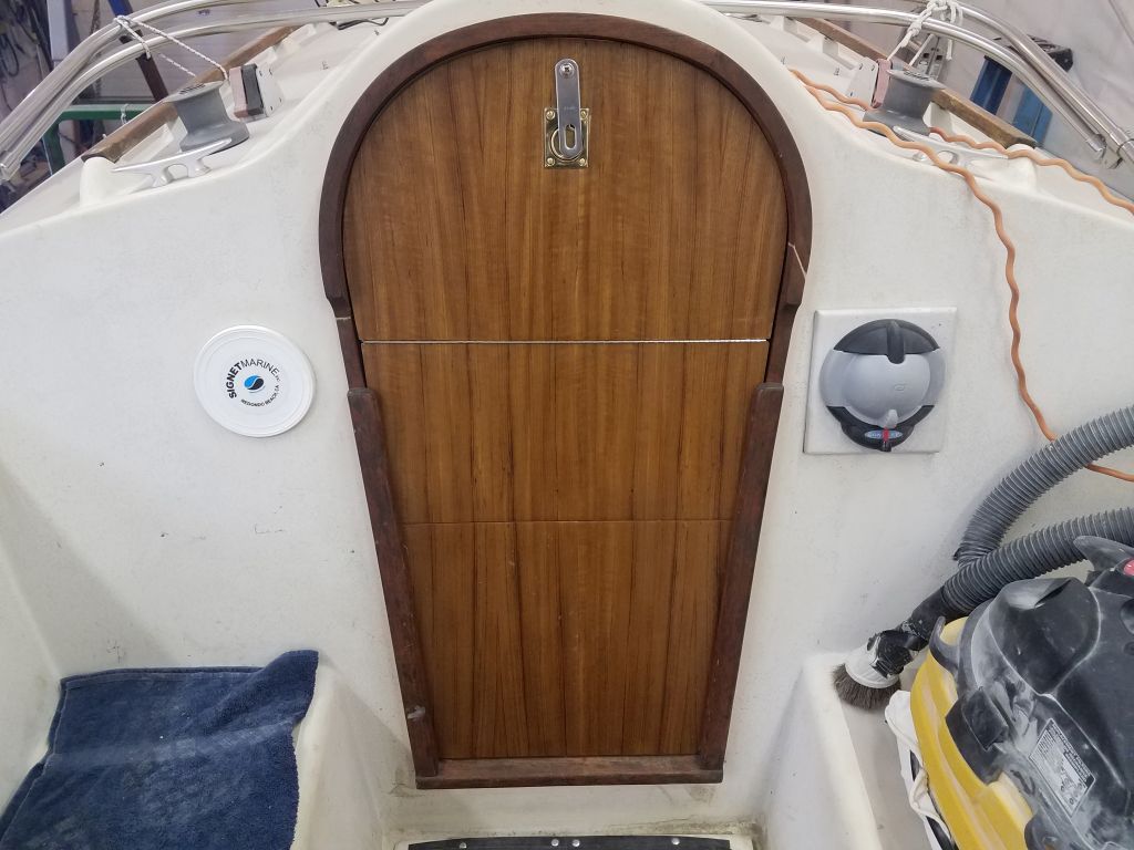
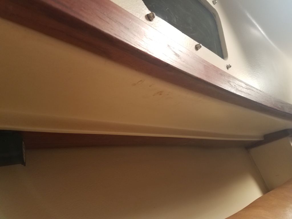
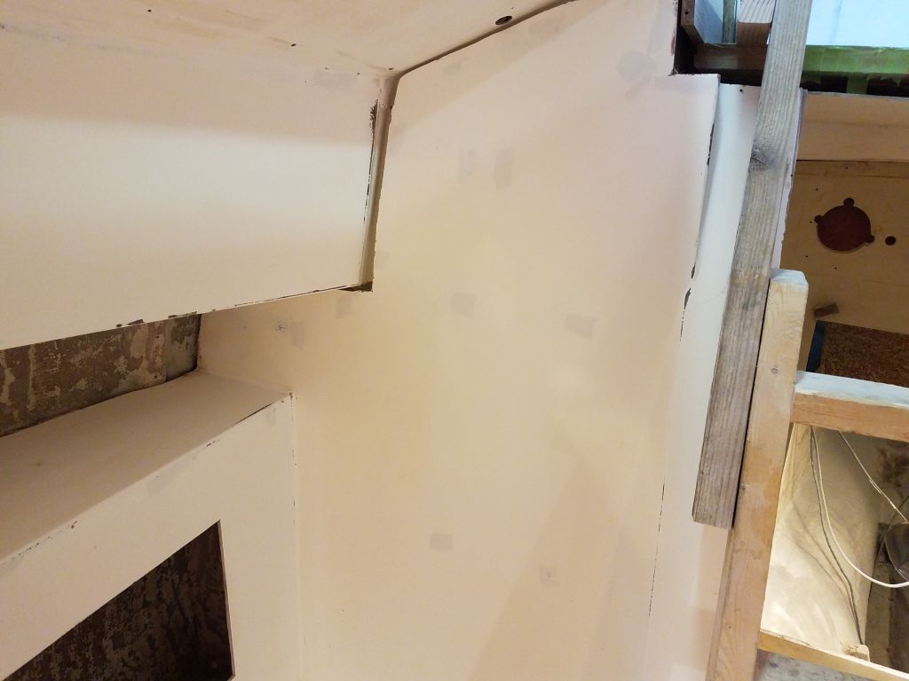
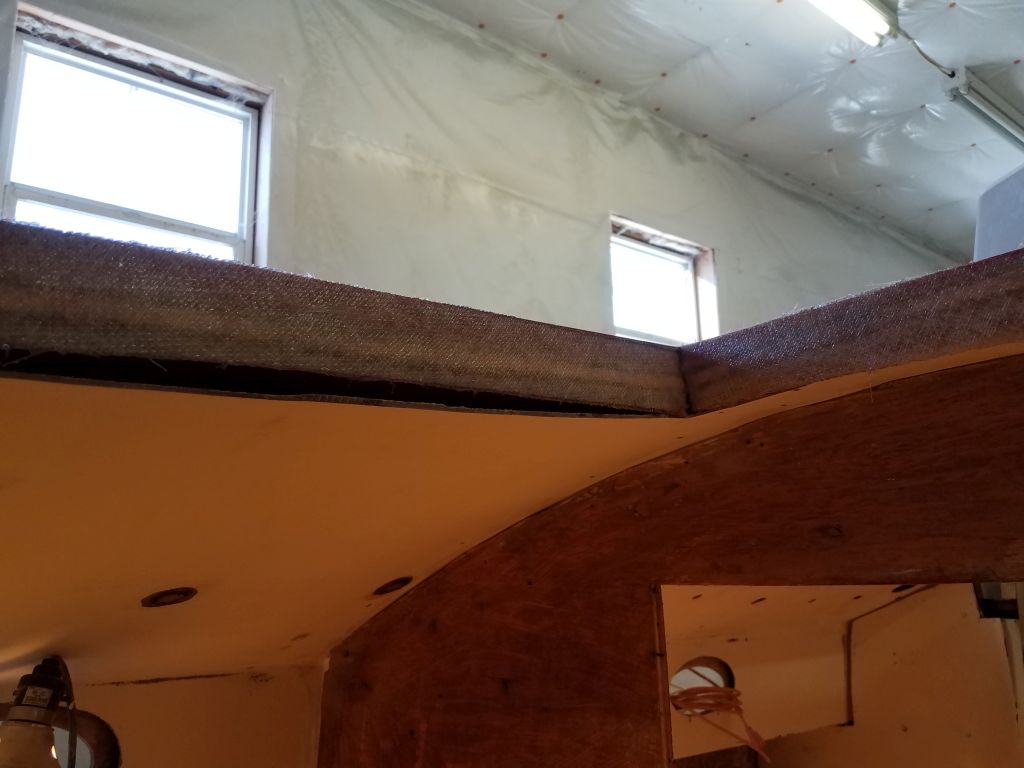
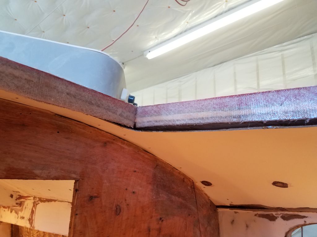
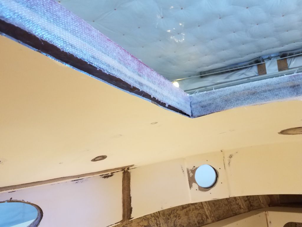
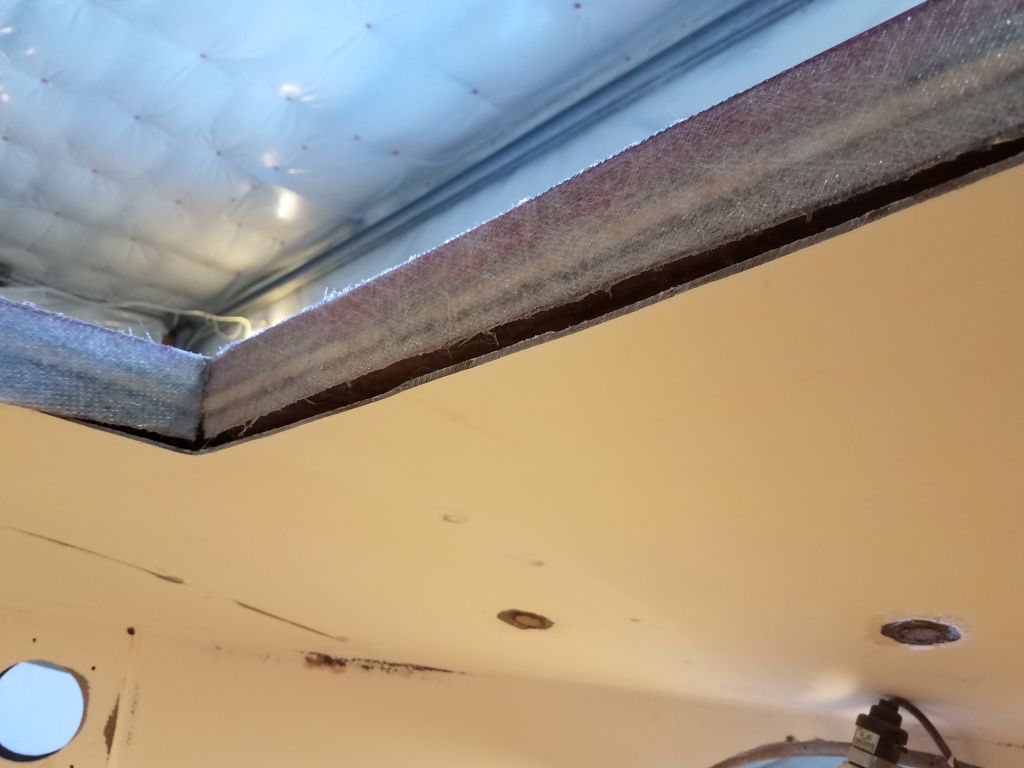
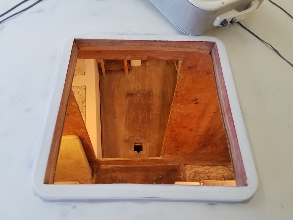
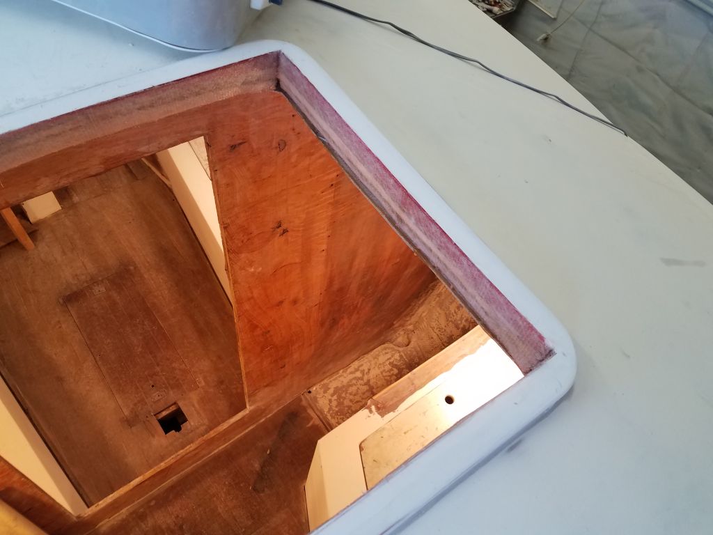
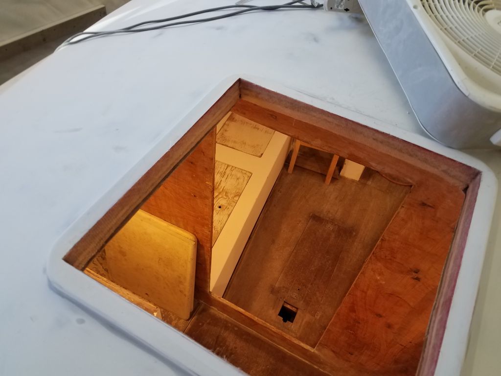
To finish off the forward hatch frame installation, I installed narrow strips of fiberglass over the inside of the opening, extending from the new fiberglass frame down over the exposed core and deck structure. I let the pieces hand down a bit over the gap between the deck and the interior liner, but did not attempt to incorporate the liner into the system. The fiberglass would add some strength and also sealed off the exposed core; all this would later be hidden with trim.

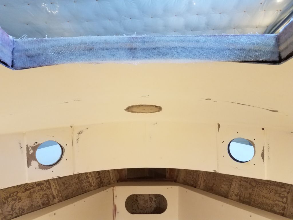
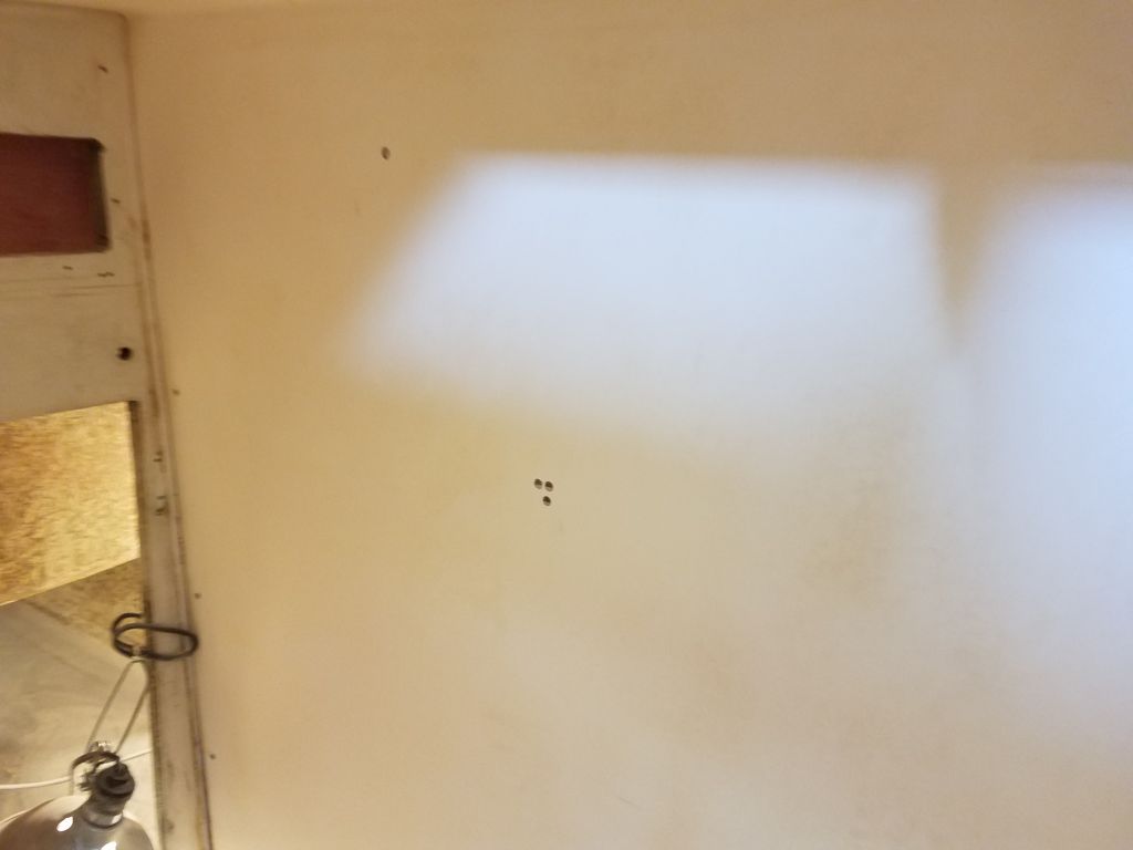
By now, the putty over the holes in the cabin liner had cured, and I performed what I hoped was the final sanding of all areas.

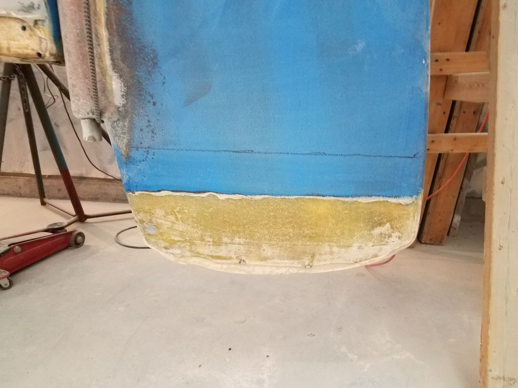
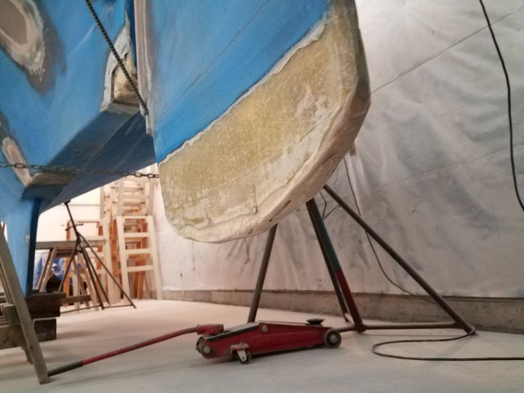
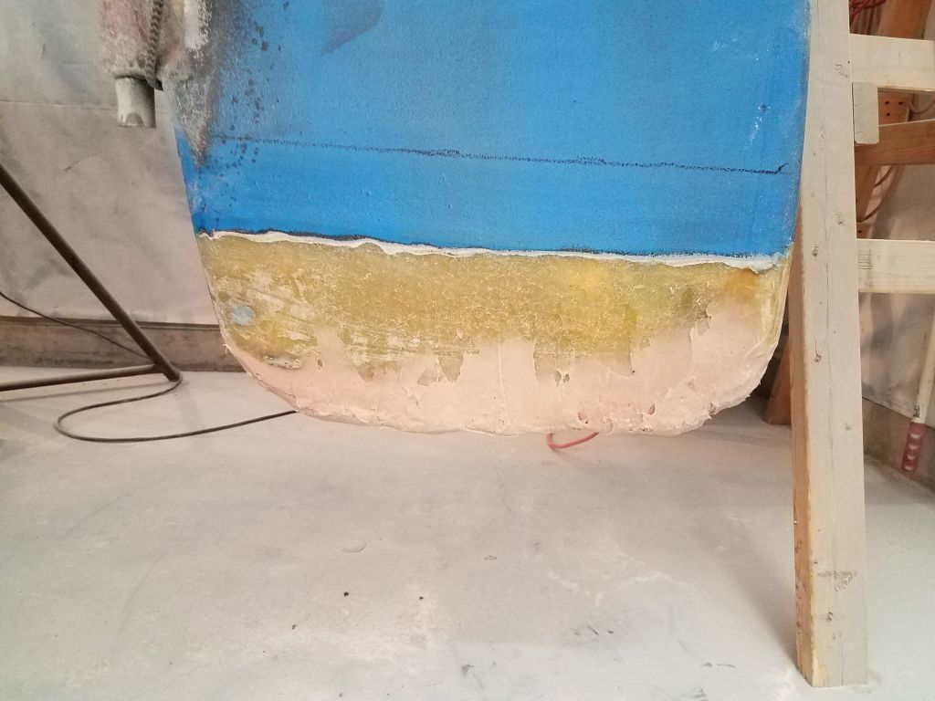
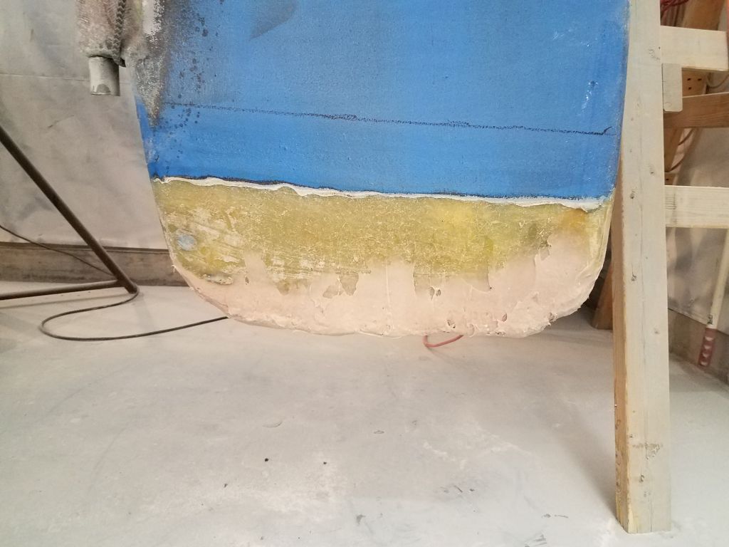
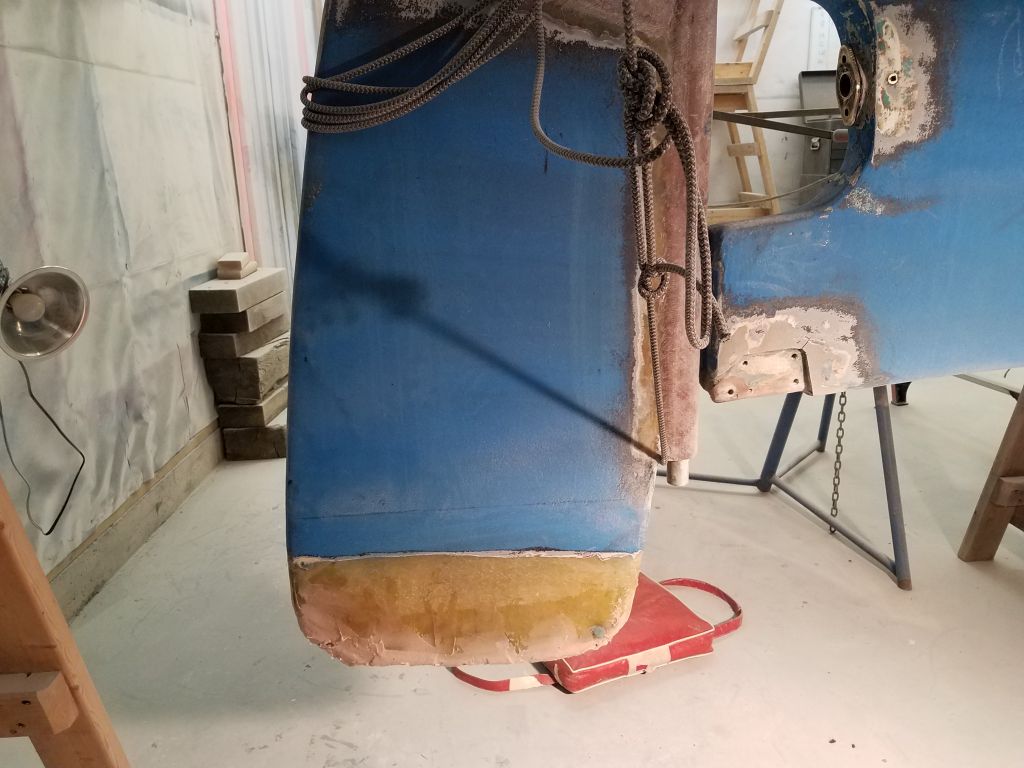
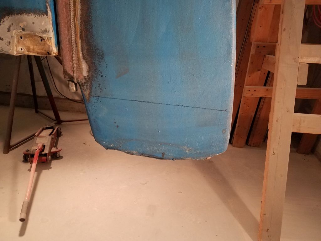
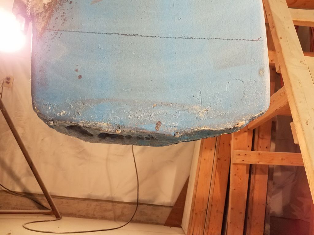
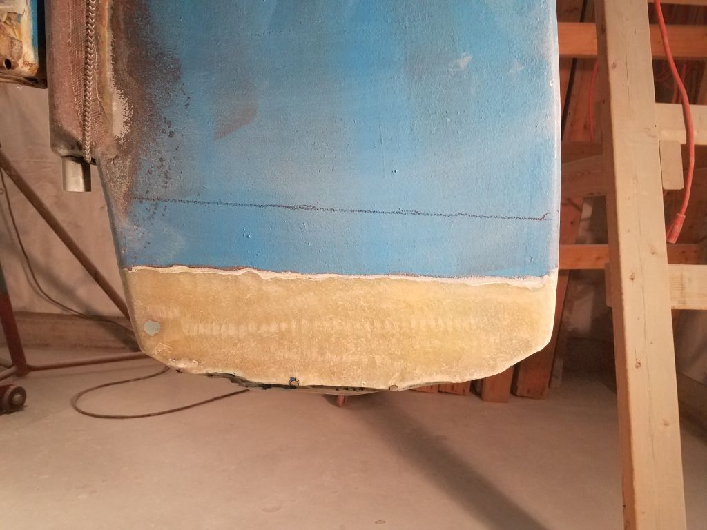
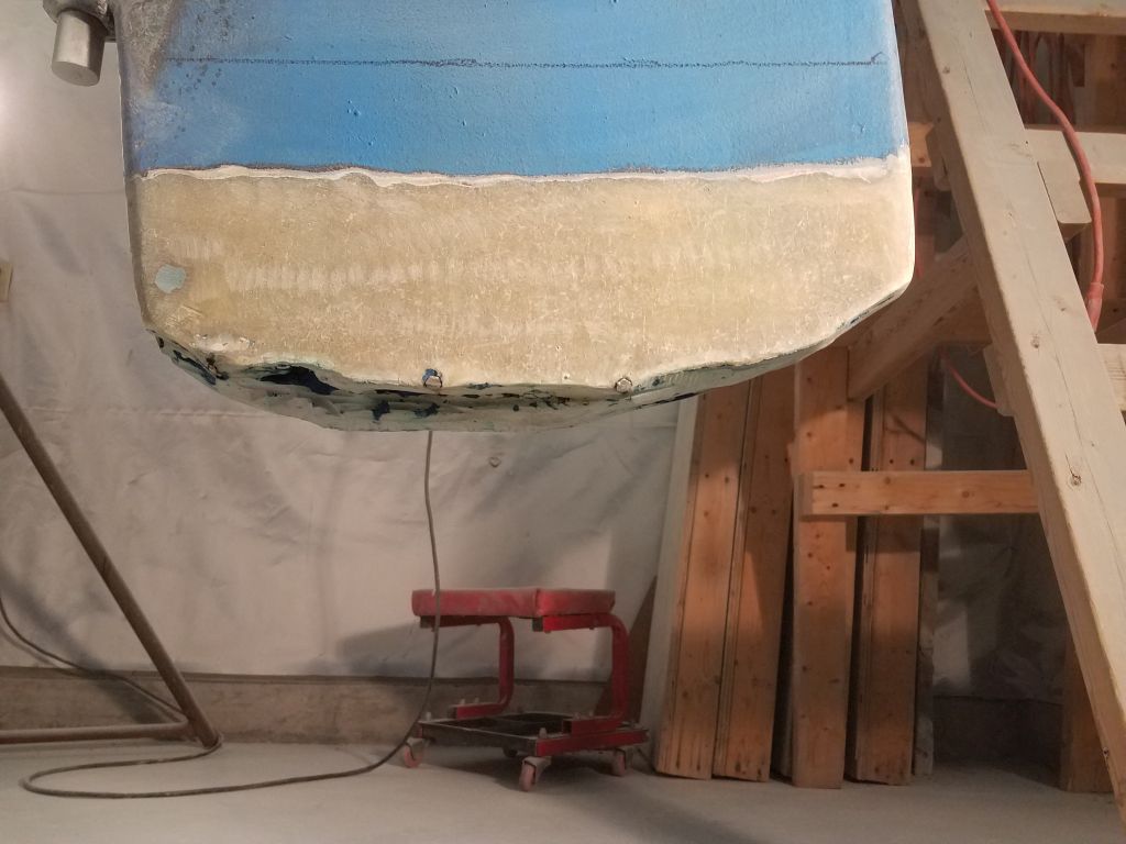
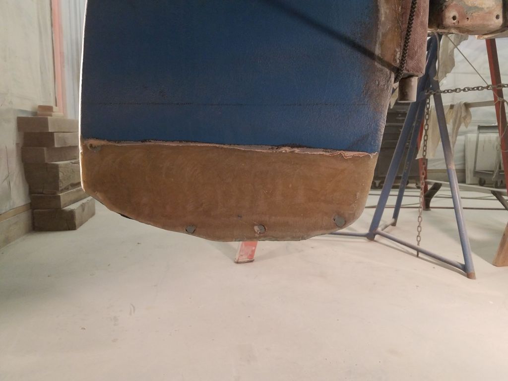
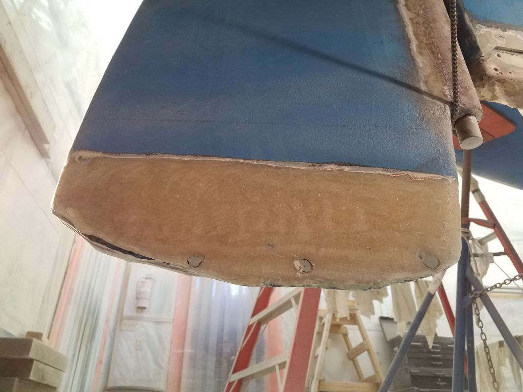
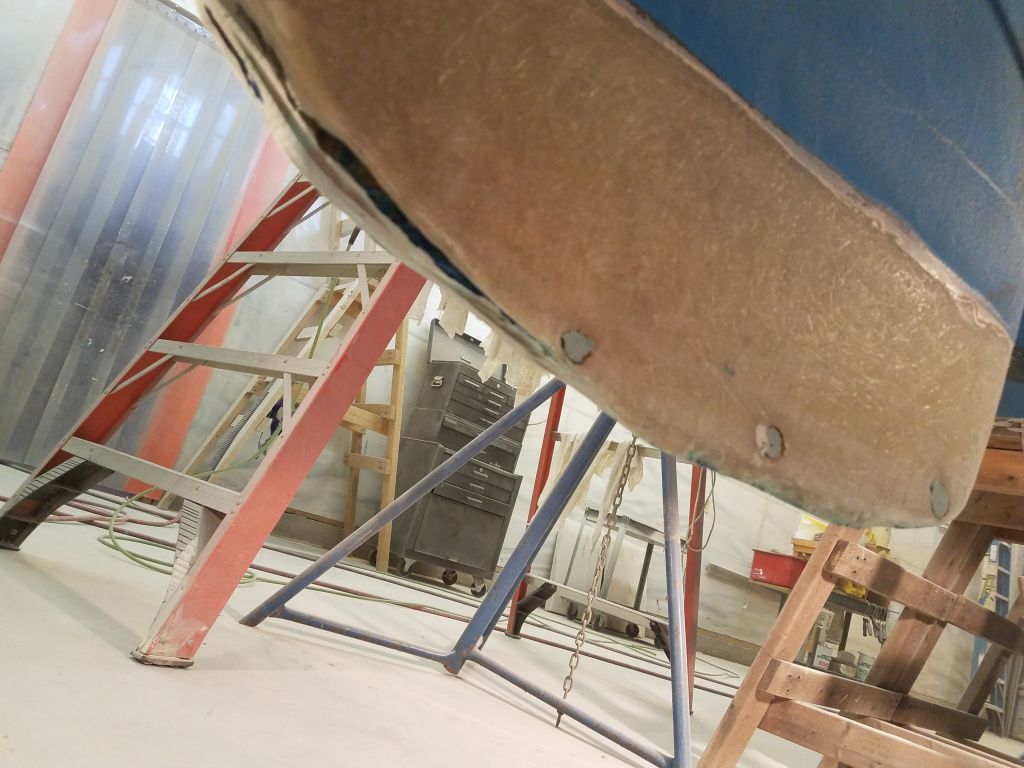
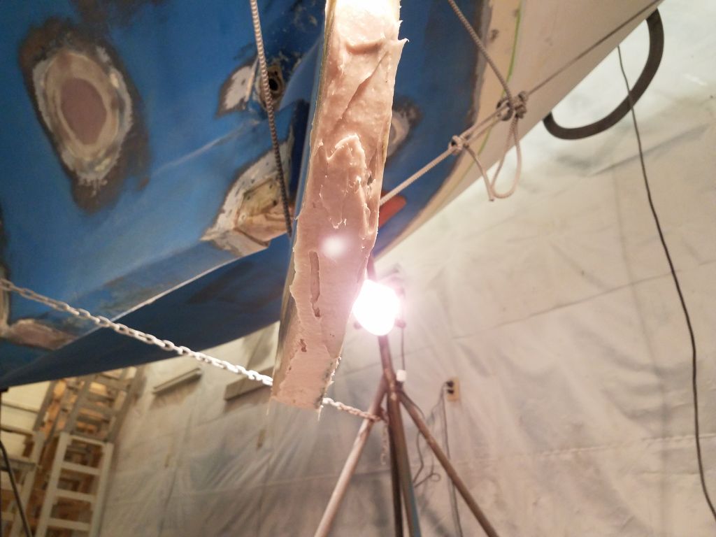
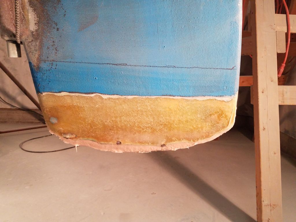
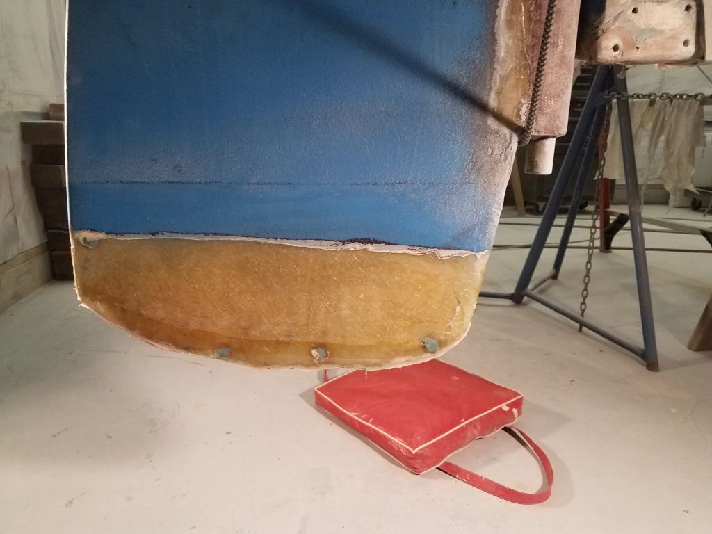
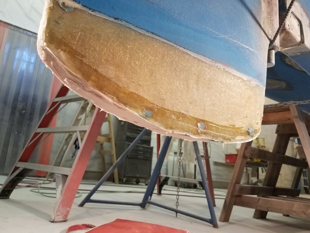
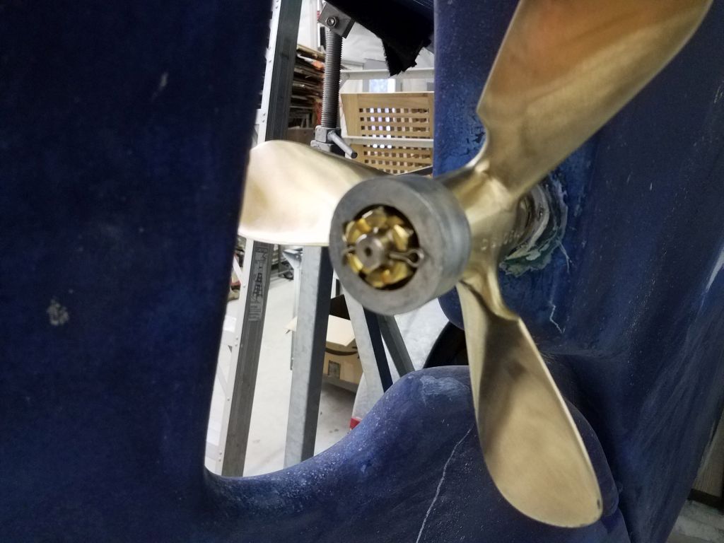
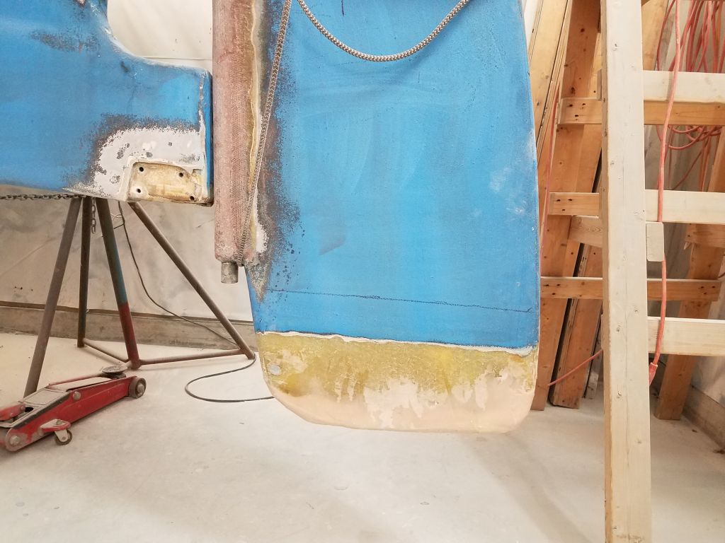
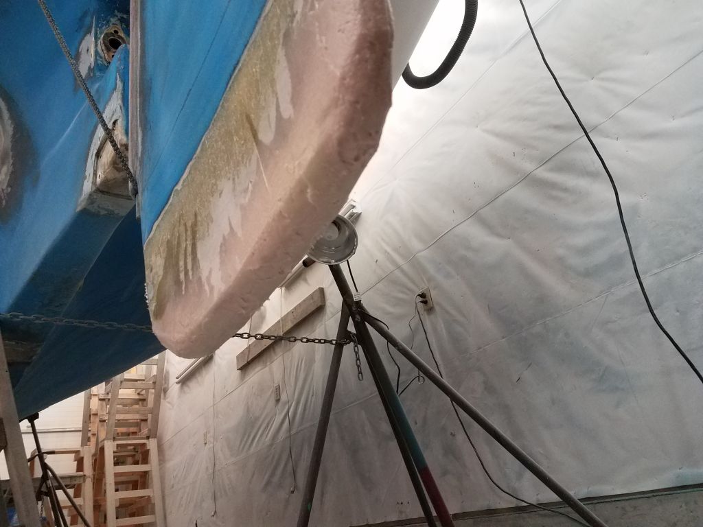
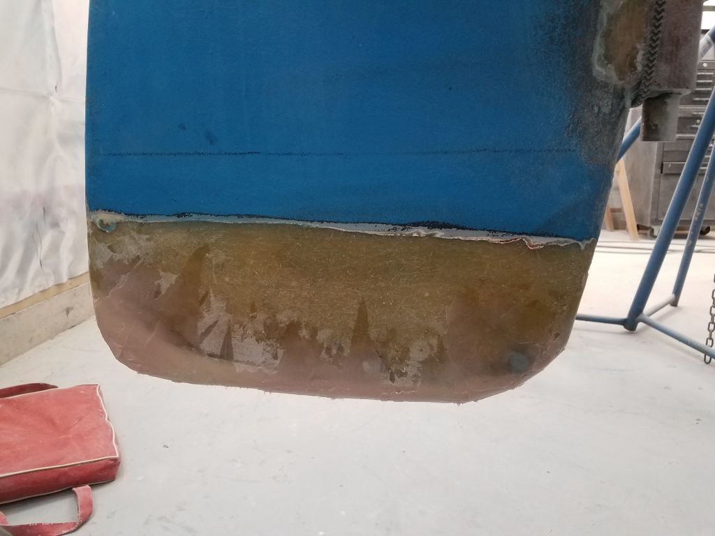
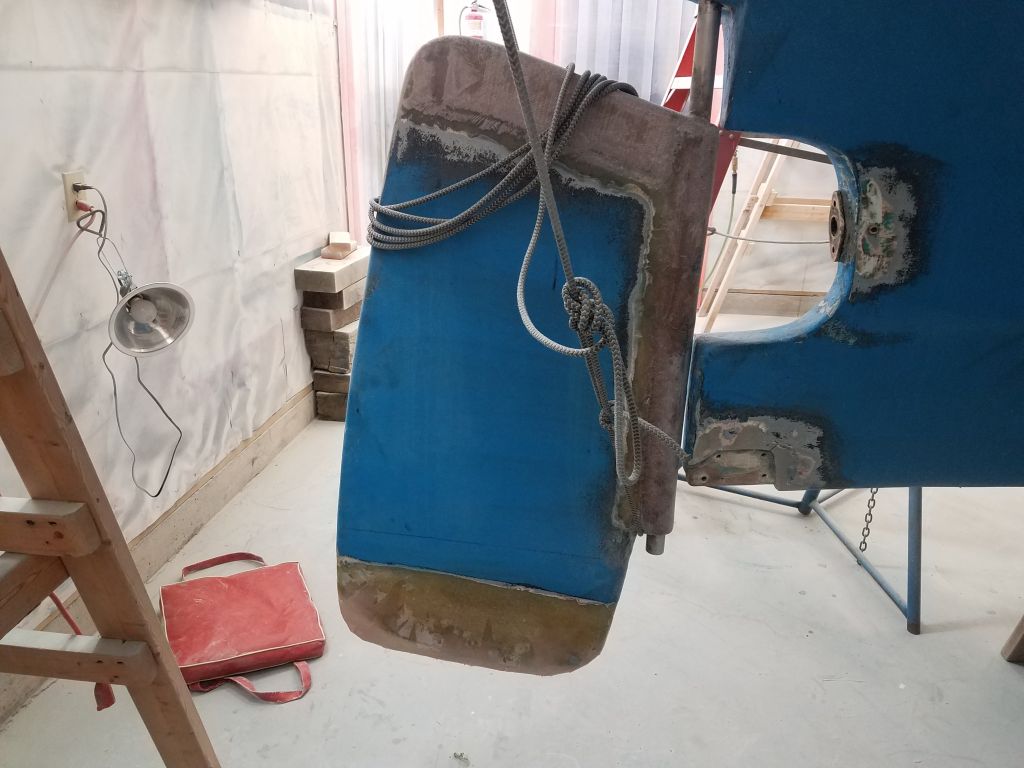
To finish up the day, I continued work on the rudder, beginning with sanding and cleaning up the second round of reconstructive structural epoxy.
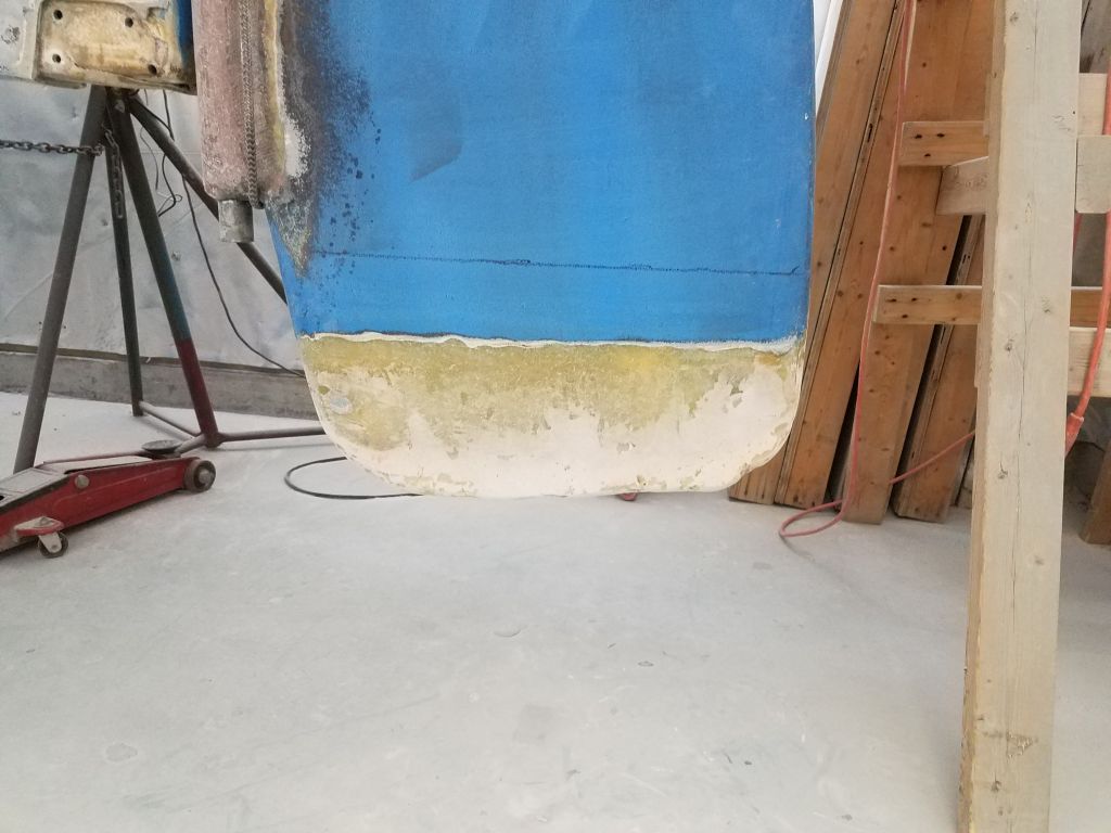
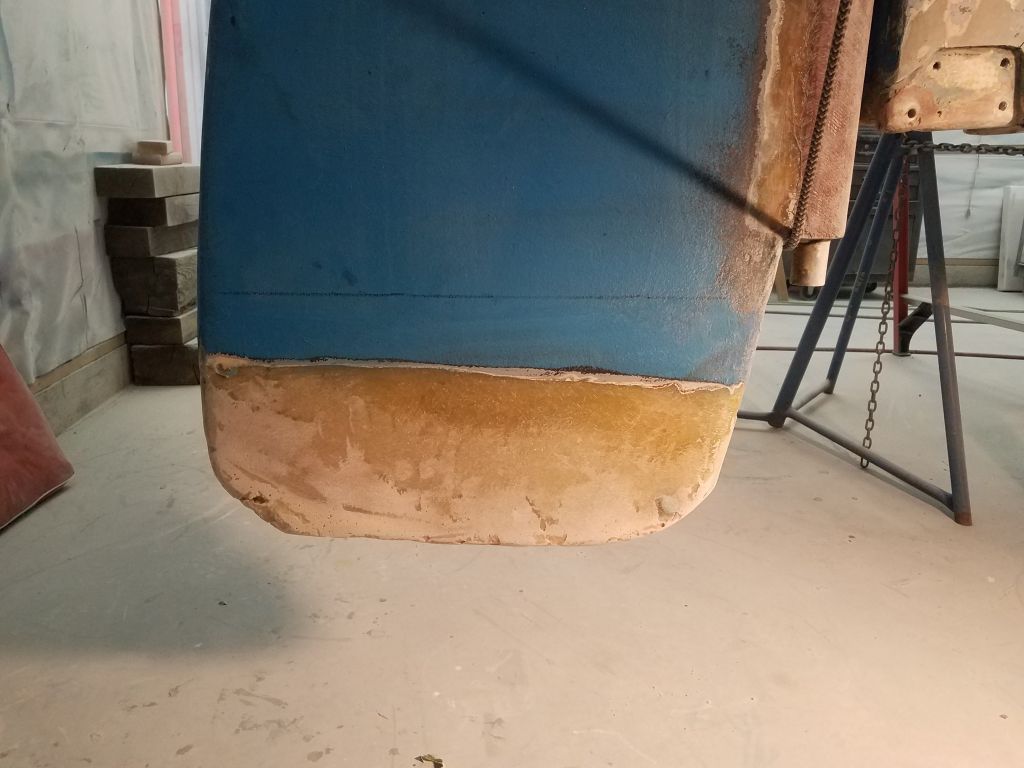
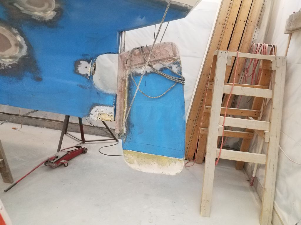
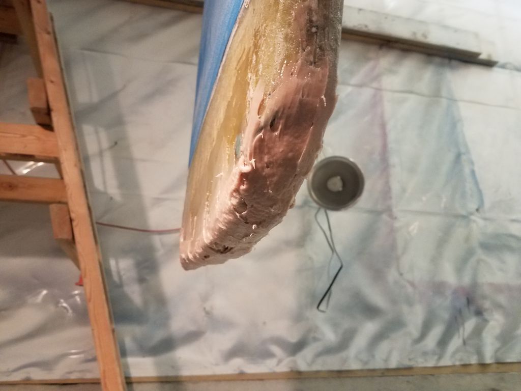
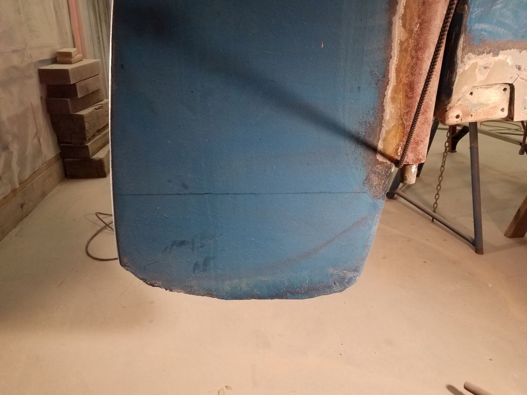
Afterwards, I built up the bottom edge just a bit more as needed, focusing mainly on the after corner where I wanted a “squarer” rounded shape. By now, the shape was looking pretty close to what I was going for, and I expected one final round of minor shaping and smoothing to fine-tune the rudder before I could finish up with new fiberglass.

Total time billed on this job today: 6.75 hours
0600 Weather Observation: -4°, clear. Forecast for the day: Sunny, 20°