|
|
~MENU~ |
| Home |
| The Concept |
| The Boat |
| Bringing Her Home |
|
Weekly Progress Log |
|
Daysailor Projects |
| The Boat Barn |
| Resources |
| Other Sites |
| Email Tim |
|
|
| From a Bare Hull: Bulkheads (Page 2) |
|
Hull Leveling | Basic Layout | Chainplate Bulkhead | Mid Bulkhead | After Bulkhead | Fillets & Tabbing | Limbers |
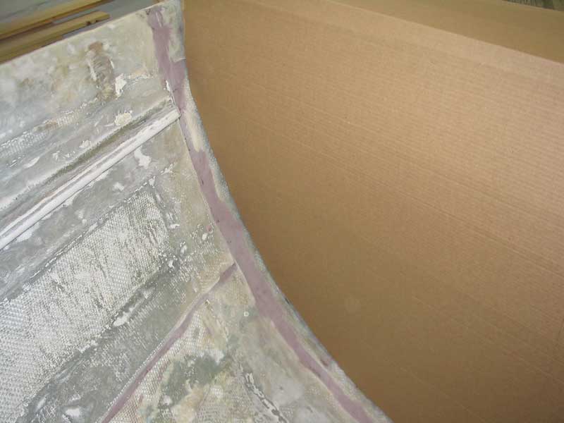
Layout and Issues With the basic positioning set, and the temporary cross beam in place, I used a plumb bob to drop a series of marks to the hull below the beam, so that I could locate the bottom edge of the bulkhead. Each mark was exactly plumb with the beam above, which meant that if I followed the marks the bulkhead would end up plumb, as desired. But with the completion of this task, I
began to comprehend the enormity of the job ahead. As I contemplated
the bulkhead shape, I realized how many factors would be directly affected
by its size and shape. First and foremost, I had to decide whether
to step the new mast on deck, as in the original, or to carry the new spar
to the keel. I quickly decided to go for a keel step, as the
engineering was substantially simpler. Since the spar will be new, I
can spec it as however much longer it needs to be to reach the keel,
without shortening its overall height. Also, the forward bulkhead needed to have a large opening for access to the forward part of the boat; what exactly will be built forward was, at that juncture, undetermined, but I figured some sort of V-berth unit. After some minutes of pondering, I decided to build a quick cardboard template to get a better idea into what form my ideas were coalescing. |
 Starting
with some scrap cardboard, I cut it down quickly to the rough shape, then
fine-tuned the shape with a scribe. With the basic shape taped and
stapled in place in the boat, I could more easily visualize what sort of
cutout I needed. After more thought, I created a plumb cut, with the
upper edge 21" from the hull; this corresponded to the width of the
planned deck, minus the carlin, in that area. Using the old V-berth
location as a rough guideline, and after determining where I though the
cabin sole should go (higher and wider than original), I made a level cut
across the template from the inside edge to the plumb cut I made
earlier. This level cut represented the eventual height of the
V-berth platform. Starting
with some scrap cardboard, I cut it down quickly to the rough shape, then
fine-tuned the shape with a scribe. With the basic shape taped and
stapled in place in the boat, I could more easily visualize what sort of
cutout I needed. After more thought, I created a plumb cut, with the
upper edge 21" from the hull; this corresponded to the width of the
planned deck, minus the carlin, in that area. Using the old V-berth
location as a rough guideline, and after determining where I though the
cabin sole should go (higher and wider than original), I made a level cut
across the template from the inside edge to the plumb cut I made
earlier. This level cut represented the eventual height of the
V-berth platform. |
 With
both sides cut and secured in place, I left it to rest overnight while I
slept on the ideas the templates represented. The next morning,
after looking it over some more, I decided I liked the general concept,
and began to make preparations for installing the actual bulkheads.
The design calls for three bulkheads: the forwardmost, or
chainplate, bulkhead; a full-width and full-height bulkhead at the aft end
of the cabin (or forward end of the cockpit); and a final bulkhead
somewhere further aft (location to be determined). With
both sides cut and secured in place, I left it to rest overnight while I
slept on the ideas the templates represented. The next morning,
after looking it over some more, I decided I liked the general concept,
and began to make preparations for installing the actual bulkheads.
The design calls for three bulkheads: the forwardmost, or
chainplate, bulkhead; a full-width and full-height bulkhead at the aft end
of the cabin (or forward end of the cockpit); and a final bulkhead
somewhere further aft (location to be determined). |
Chainplate Bulkhead Installation 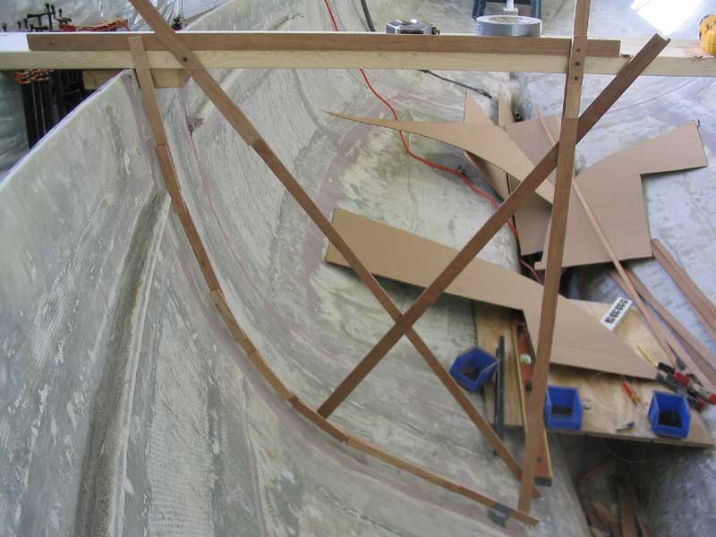 My
next step was to make an accurate template of the two chainplate bulkhead
pieces, essentially replicating the rough template seen above, but with
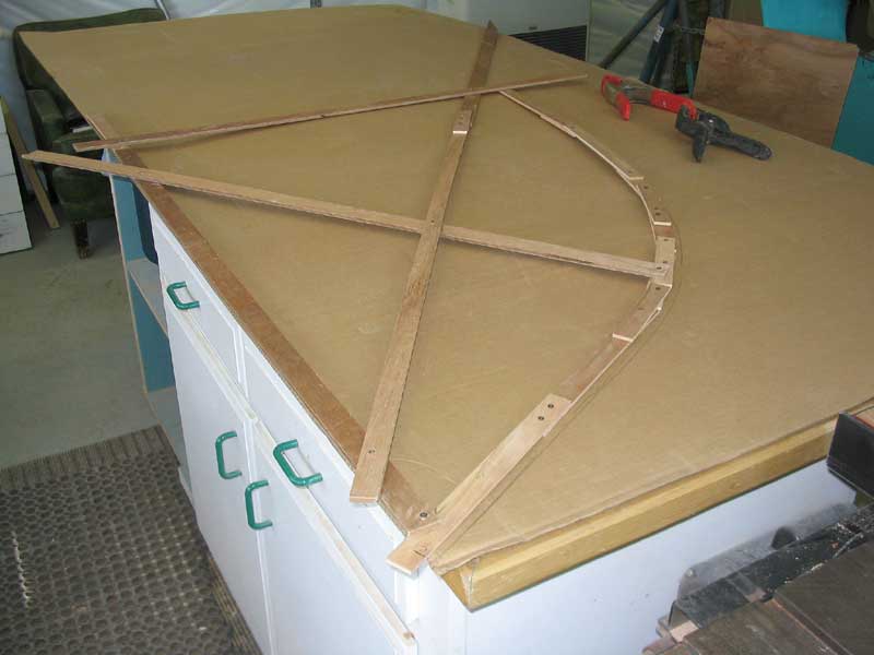
much greater accuracy. Initially, I thought it would be more
accurate to create a template made out of thin strips of wood, which I
laid along the hull and secured together with screws. Then, I
installed several braces to stiffen the template, and scribed a line on
the wood, which I hoped to then transfer to a piece of cardboard for a
test fit. Unfortunately, this produced relatively poor results,
since I had trouble transferring the scribe mark from the 1/4" thick
wooden template to the cardboard. My
next step was to make an accurate template of the two chainplate bulkhead
pieces, essentially replicating the rough template seen above, but with
much greater accuracy. Initially, I thought it would be more
accurate to create a template made out of thin strips of wood, which I
laid along the hull and secured together with screws. Then, I
installed several braces to stiffen the template, and scribed a line on
the wood, which I hoped to then transfer to a piece of cardboard for a
test fit. Unfortunately, this produced relatively poor results,
since I had trouble transferring the scribe mark from the 1/4" thick
wooden template to the cardboard. |
 The
problem was the scribe would end up at an unnatural angle, and the scribed
mark on the cardboard turned out to be rather different than the original
intention. Undaunted, I tried again, and made some other
adjustments. Somehow, I managed to spend far too long fiddling with
this idea, before I finally called it quits and decided to revert to the
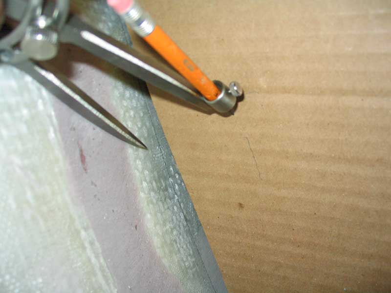
idea I should have used in the first place: the tick strip. I
had used this on another project with complete success, and don't quite
know why I chose to try something different here. I wasted several
templates and a couple of hours, all for nothing. The
problem was the scribe would end up at an unnatural angle, and the scribed
mark on the cardboard turned out to be rather different than the original
intention. Undaunted, I tried again, and made some other
adjustments. Somehow, I managed to spend far too long fiddling with
this idea, before I finally called it quits and decided to revert to the
idea I should have used in the first place: the tick strip. I
had used this on another project with complete success, and don't quite
know why I chose to try something different here. I wasted several
templates and a couple of hours, all for nothing. |
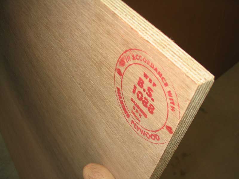
The tick strip worked extremely well. In only a short time, I had marked off both sides of the forward bulkhead, and was stymied only by my lack of plywood to actually make the bulkhead (wood was scheduled for delivery the next day).
|
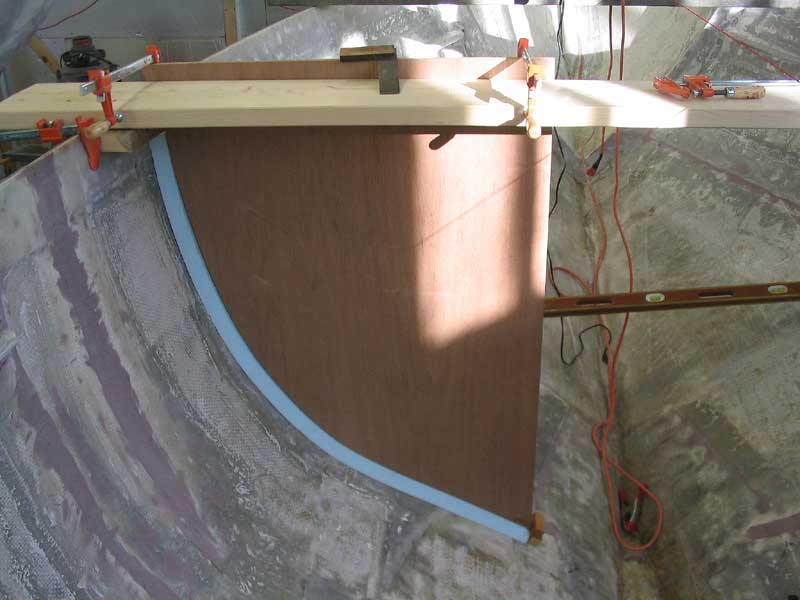
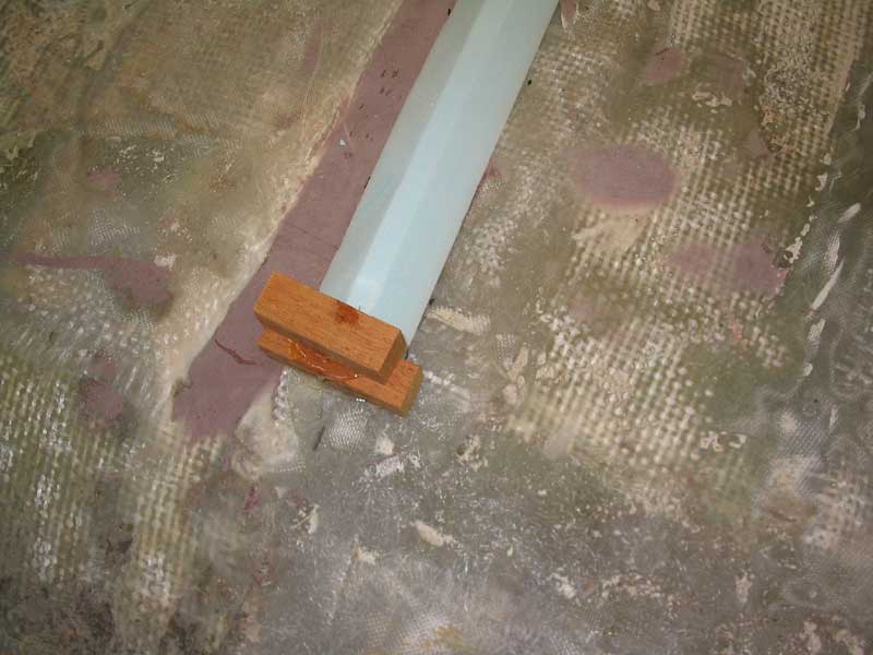 With
the bulkhead cut to shape using the tick strip pattern, I clamped it in
place in the boat to check its fit, and to make adjustments as
necessary. The fit was surprisingly good, and there was no need to
make any other adjustments since I planned on trimming an inch off the
plywood anyway to allow for a cushion of 1" foam against the
hull. To help hold the plywood from slipping down the hull, I
hot-glued a block of scrap wood in the proper location, which was helpful
in later alignment as well. With
the bulkhead cut to shape using the tick strip pattern, I clamped it in
place in the boat to check its fit, and to make adjustments as
necessary. The fit was surprisingly good, and there was no need to
make any other adjustments since I planned on trimming an inch off the
plywood anyway to allow for a cushion of 1" foam against the
hull. To help hold the plywood from slipping down the hull, I
hot-glued a block of scrap wood in the proper location, which was helpful
in later alignment as well. |
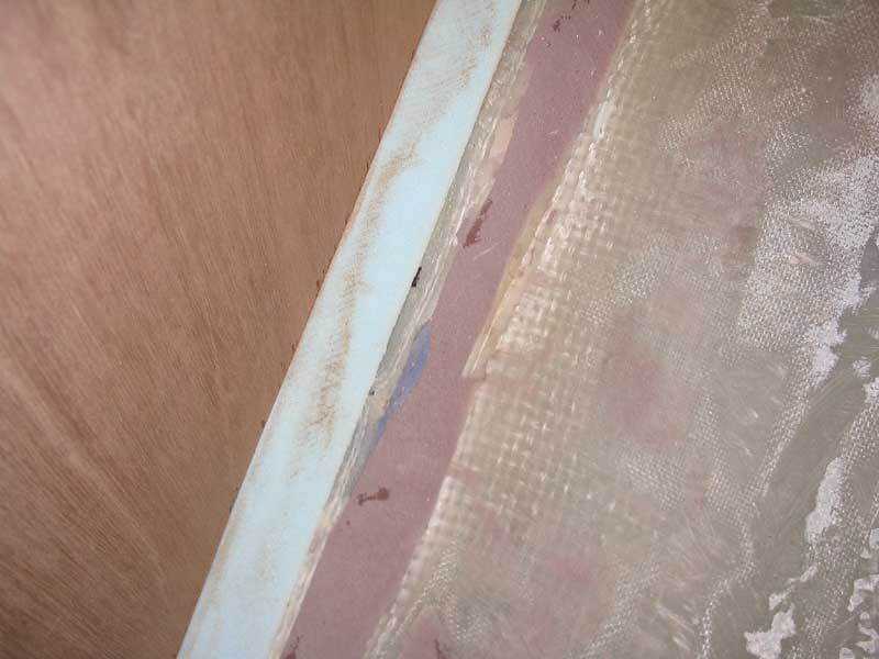
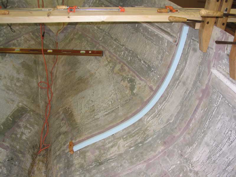 Using
a scrap of the 1" foam, I scribed a mark on the plywood and cut the
excess material away. The foam actually made for an excellent
scribe-marking tool, and the resulting cut was highly accurate.
Before continuing, I hot glued a strip of 1" foam to the hull where
the bulkhead edge was to go; earlier, I had cut several strips of foam
with a 3/4" flat on top and 45° bevels on each side. The foam
forms a cushion where the narrow edge of the bulkhead bears, helping to
prevent a hard spot on the hull, and also forms a good fillet to make
tabbing easier later on. Using
a scrap of the 1" foam, I scribed a mark on the plywood and cut the
excess material away. The foam actually made for an excellent
scribe-marking tool, and the resulting cut was highly accurate.
Before continuing, I hot glued a strip of 1" foam to the hull where
the bulkhead edge was to go; earlier, I had cut several strips of foam
with a 3/4" flat on top and 45° bevels on each side. The foam
forms a cushion where the narrow edge of the bulkhead bears, helping to
prevent a hard spot on the hull, and also forms a good fillet to make
tabbing easier later on. |
|
|
|
|
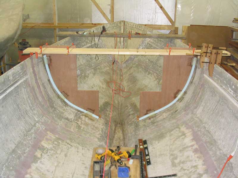 With
both bulkhead halves in place, I was ready to secure them more permanently.
Unfortunately, some wide fiberglass tape I needed was still on order, so I
lacked the proper materials to fully secure them at that time.
Instead, I cut several small pieces of 4" biaxial tape that I had on
hand (six per bulkhead) and tacked the bulkhead in place with those,
simply to hold it so that I could remove the cross beam and begin work on
the next bulkhead once the small tabbings had cured. With
both bulkhead halves in place, I was ready to secure them more permanently.
Unfortunately, some wide fiberglass tape I needed was still on order, so I
lacked the proper materials to fully secure them at that time.
Instead, I cut several small pieces of 4" biaxial tape that I had on
hand (six per bulkhead) and tacked the bulkhead in place with those,
simply to hold it so that I could remove the cross beam and begin work on
the next bulkhead once the small tabbings had cured. |