|
|
~MENU~ |
| Home |
| The Concept |
| The Boat |
| Bringing Her Home |
|
Weekly Progress Log |
|
Daysailor Projects |
| The Boat Barn |
| Resources |
| Other Sites |
| Email Tim |
|
|
| Sidebar: The Tick Strip |
Boats, by nature, are curvy, with no straight lines or parallel surfaces. Plywood, on the other hand, is straight and rectangular. This presents an obvious problem: how to make the plywood fit tightly into that curvaceous hull. Often complicating the matter is the fact that clearances around the area in question might be tight, so the problem of making an accurate template of the hull and/or deck curves becomes even more challenging. One excellent solution that works extraordinarily well, belying its apparent simplicity, is the tick strip. In essence, a tick strip involves a narrow strip of wood used as a pointer, and a second piece of wood (usually scrap) onto which measurements are noted, or, I suppose, "ticked" off. Through an improbably simple method of transferring lines and marks to the scrap wood, a highly accurate pattern of the surface in question can be made in only a few minutes. |
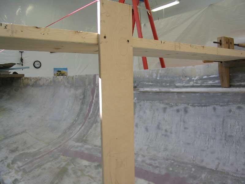
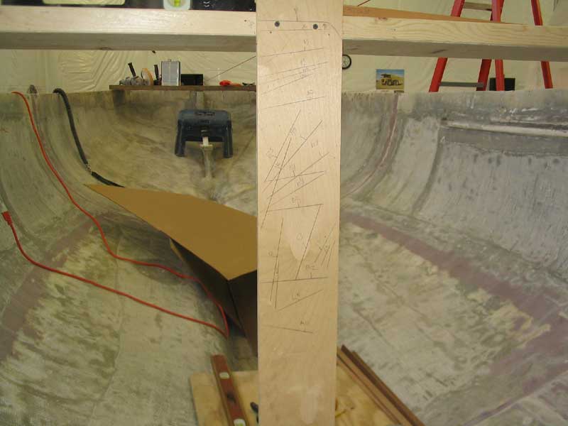
Depending on the situation at hand, perhaps the most complex (using the term loosely) part of the tick strip process is choosing the right position for, and then attaching, the scrap piece of lumber onto which measurements will be marked. In new construction, the hull is likely wide open, like in my case, which means that certain braces and supports for the wood might have to be temporarily installed in place. In a more finished boat, there are likely several handy attachment points already nearby, and it takes little of a boatbuilder's ingenuity to figure out how and where to attach the template board. The key, whatever the actual situation, is to locate the template board in such a way that it becomes a known reference off which all other measurements can be taken. Typically, this involves setting the template up plumb, level, and square, and in the same plane as the structural member for which the measurements are being taken. To illustrate better, I'll go through the process for one of the new bulkheads in the Daysailor. |
In my case, there were no known references; the hull was completely empty, and I was starting from scratch. Therefore, my first step was to establish some basic positioning and add temporary braces; this is explained in detail here. With the basic positioning and plane of the bulkhead established, I next chose reference points from which to attach my tick strip template board, for which I used a narrow strip of scrap plywood. Nearly any wood will do for this purpose, as long as the shape and size are such that it can be successfully secured in place for the measuring process. It doesn't really even matter if the edges of the strip are straight, curved, or wavy, though I think a straight board is easiest to work from.
I secured the template board in place both top and bottom to hold it securely in the proper, and chosen, orientation. The board could be clamped, screwed, or taped in place, depending on the situation. In my case, I drove drywall screws into the temporary cross brace across the hull to secure the top end of my template, and attached the bottom edge with a single screw driven into a piece of scrap that I hot-glued to the hull. Don't overlook the utility of a hot melt glue gun for working on boats, especially at the rough stages. Time and again, this silly craft tool proves its worth in the shop. Before continuing, I ensured that the template board was aligned as it should be--plumb and in line with the inner edge of the new bulkhead. |
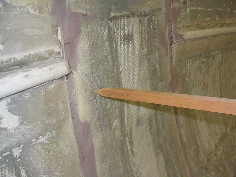
 Next,
I cut a scrap of wood to create a pointer, basically. The size and
length of this piece might vary, but mine in this case ended up being
about 3/4" square and approximately 3' long. I cut a rough
point on one end with a saw; having a sharp point isn't strictly necessary, but it helps to at least reduce the size of the stick at the
pointing end, so that an overly large flat end doesn't get hung up on
something and create a false measurement. The stick needs to be long
enough so that it can easily reach from the hull (or whatever surface)
back to and overlapping the template board at all points. Longer is
better, within the confines of the specific situation. To help with
future reference, I labeled the sides of the stick I planned to use--which
side faced towards me ("out"), and which side faced up, from
which the measurements would be transferred. Next,
I cut a scrap of wood to create a pointer, basically. The size and
length of this piece might vary, but mine in this case ended up being
about 3/4" square and approximately 3' long. I cut a rough
point on one end with a saw; having a sharp point isn't strictly necessary, but it helps to at least reduce the size of the stick at the
pointing end, so that an overly large flat end doesn't get hung up on
something and create a false measurement. The stick needs to be long
enough so that it can easily reach from the hull (or whatever surface)
back to and overlapping the template board at all points. Longer is
better, within the confines of the specific situation. To help with
future reference, I labeled the sides of the stick I planned to use--which
side faced towards me ("out"), and which side faced up, from
which the measurements would be transferred. |
|
|
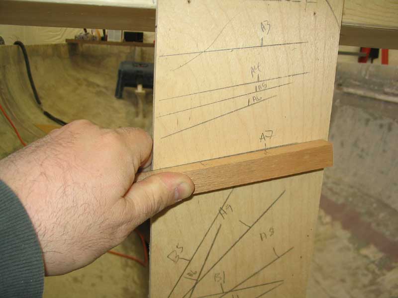
 In
this manner, I continued down the hull, creating mark after mark on my
template board. Eventually, the first mark on the stick (mark
"A") became unusable, so I simply made new reference marks as
necessary ("B", "C", and "D"). The
marks on the stick are completely random, and one can use as many as
desired and/or necessary. The key is to ensure that the template
board is properly labeled, so that any marks made using "A" are
labeled as "A1", "A2", etc. More reference marks
are better than fewer and help make a more accurate template. When
templating a large, complicated bulkhead, one can end up with 20 or 30
marks; the template board will look like a preschooler got ahold of
it. But this seemingly random collection or unkempt markings is soon
to become a highly accurate template. In
this manner, I continued down the hull, creating mark after mark on my
template board. Eventually, the first mark on the stick (mark
"A") became unusable, so I simply made new reference marks as
necessary ("B", "C", and "D"). The
marks on the stick are completely random, and one can use as many as
desired and/or necessary. The key is to ensure that the template
board is properly labeled, so that any marks made using "A" are
labeled as "A1", "A2", etc. More reference marks
are better than fewer and help make a more accurate template. When
templating a large, complicated bulkhead, one can end up with 20 or 30
marks; the template board will look like a preschooler got ahold of
it. But this seemingly random collection or unkempt markings is soon
to become a highly accurate template. |
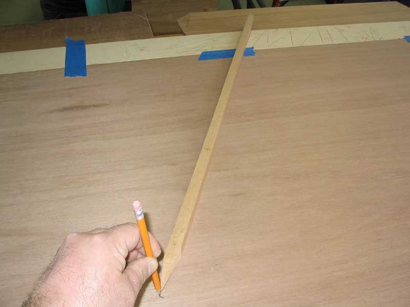
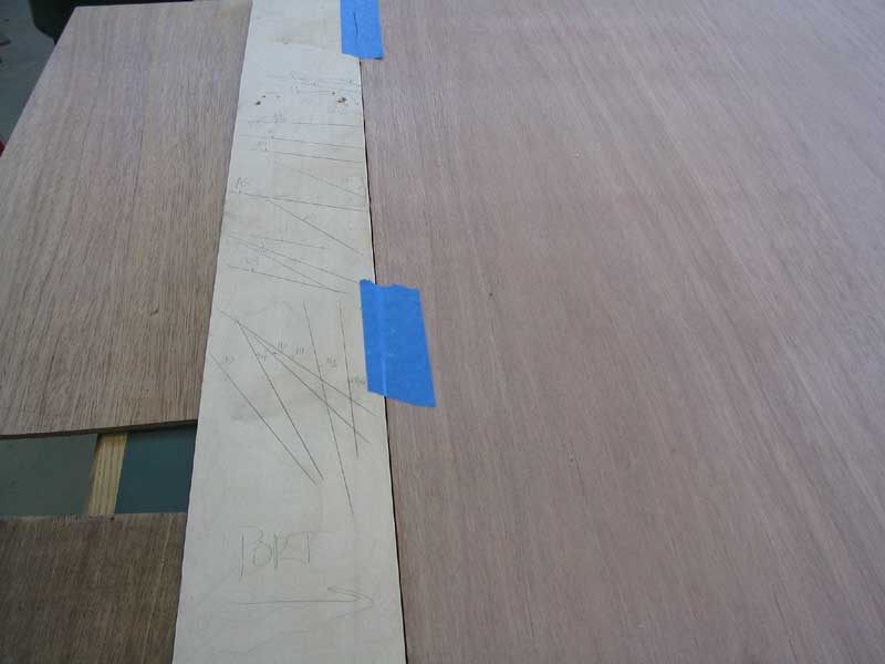 Once
all the marks were made, I removed the template board and prepared to
transfer the marks to the sheet of plywood intended for the
bulkhead. For this example, I laid the template board on the bench
next to and tightly against the plywood edge, since I had chosen to align
the template board thusly when inside the boat. To prevent it from
sliding, I secured it with some tape temporarily. Then, I laid the
marking stick against one of the marks on the template, properly aligned,
and lined up the proper tick mark to signal the length of the stick.
At the pointed end of the stick, I made a mark on the plywood
template. In this manner, I transferred the marks from the template
to the plywood sheet, one by one. Once
all the marks were made, I removed the template board and prepared to
transfer the marks to the sheet of plywood intended for the
bulkhead. For this example, I laid the template board on the bench
next to and tightly against the plywood edge, since I had chosen to align
the template board thusly when inside the boat. To prevent it from
sliding, I secured it with some tape temporarily. Then, I laid the
marking stick against one of the marks on the template, properly aligned,
and lined up the proper tick mark to signal the length of the stick.
At the pointed end of the stick, I made a mark on the plywood
template. In this manner, I transferred the marks from the template
to the plywood sheet, one by one. |
|
|
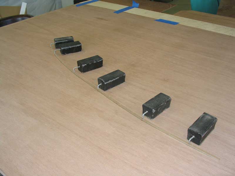 With
all the marks made, I continued by connecting the dots, so to speak, with
a flexible spline and spline weights. I traced the spline and made a
final cut line on the plywood, then cut the plywood out with a jigsaw. With
all the marks made, I continued by connecting the dots, so to speak, with
a flexible spline and spline weights. I traced the spline and made a
final cut line on the plywood, then cut the plywood out with a jigsaw. |
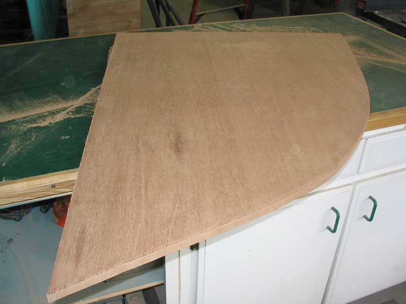 The
finished product...a near perfect fit! The tick strip is an
extremely simple, satisfying, and accurate method, and is difficult to
improve upon. If an absolutely perfect scribe were necessary (it's
truly not critical for a bulkhead), one way to handle it would be to use a
tick strip to get the shape very close to begin with, then to scribe the
resulting panel and recut for a precise fit. But for bulkheads,
particularly when they are installed against foam fillets, this is a
wasted effort. The
finished product...a near perfect fit! The tick strip is an
extremely simple, satisfying, and accurate method, and is difficult to
improve upon. If an absolutely perfect scribe were necessary (it's
truly not critical for a bulkhead), one way to handle it would be to use a
tick strip to get the shape very close to begin with, then to scribe the
resulting panel and recut for a precise fit. But for bulkheads,
particularly when they are installed against foam fillets, this is a
wasted effort. |