(page 8 of 13)

Calliope Girl 57

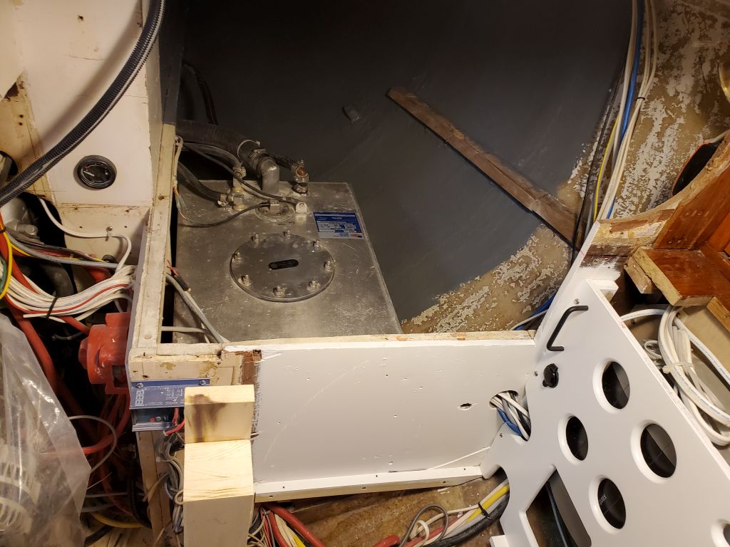
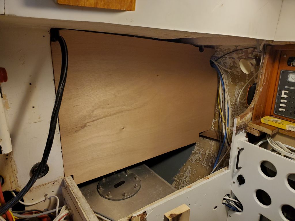
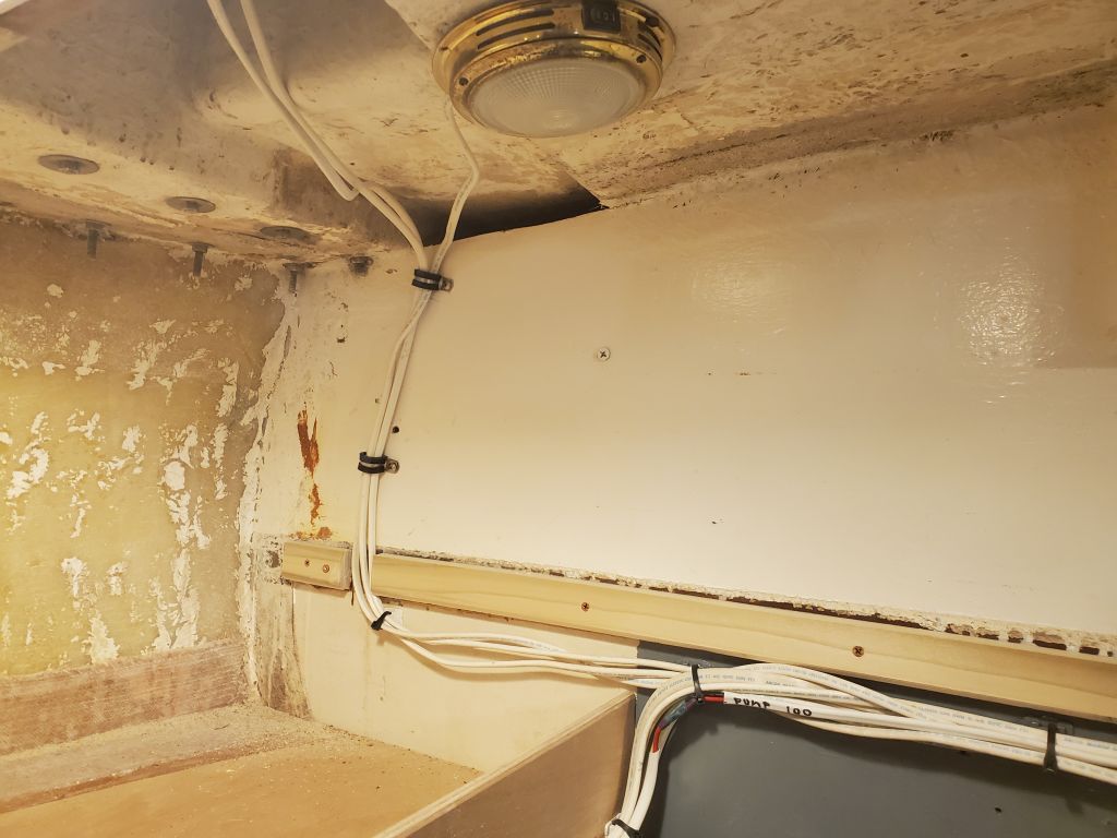
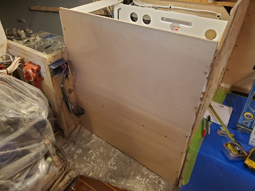
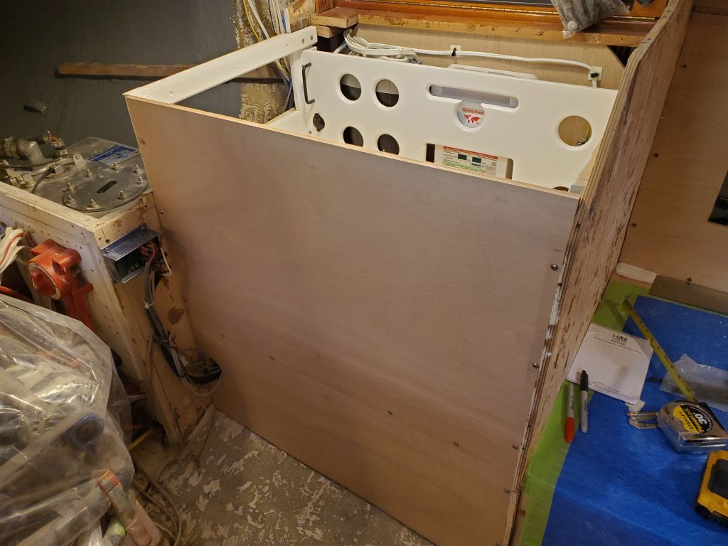
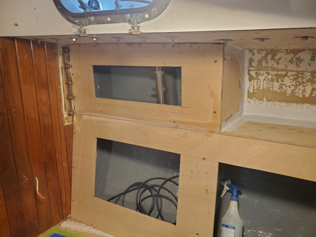
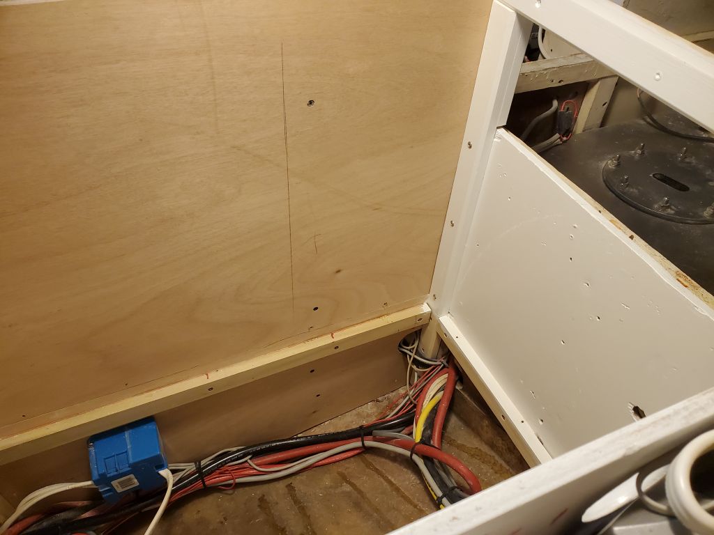
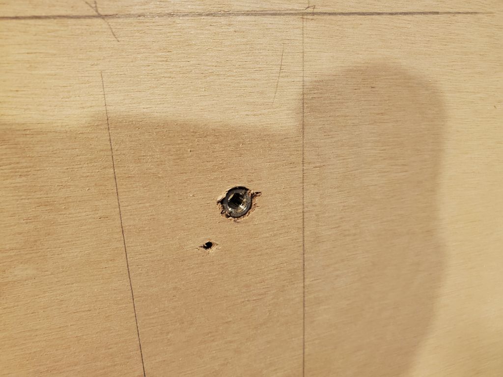
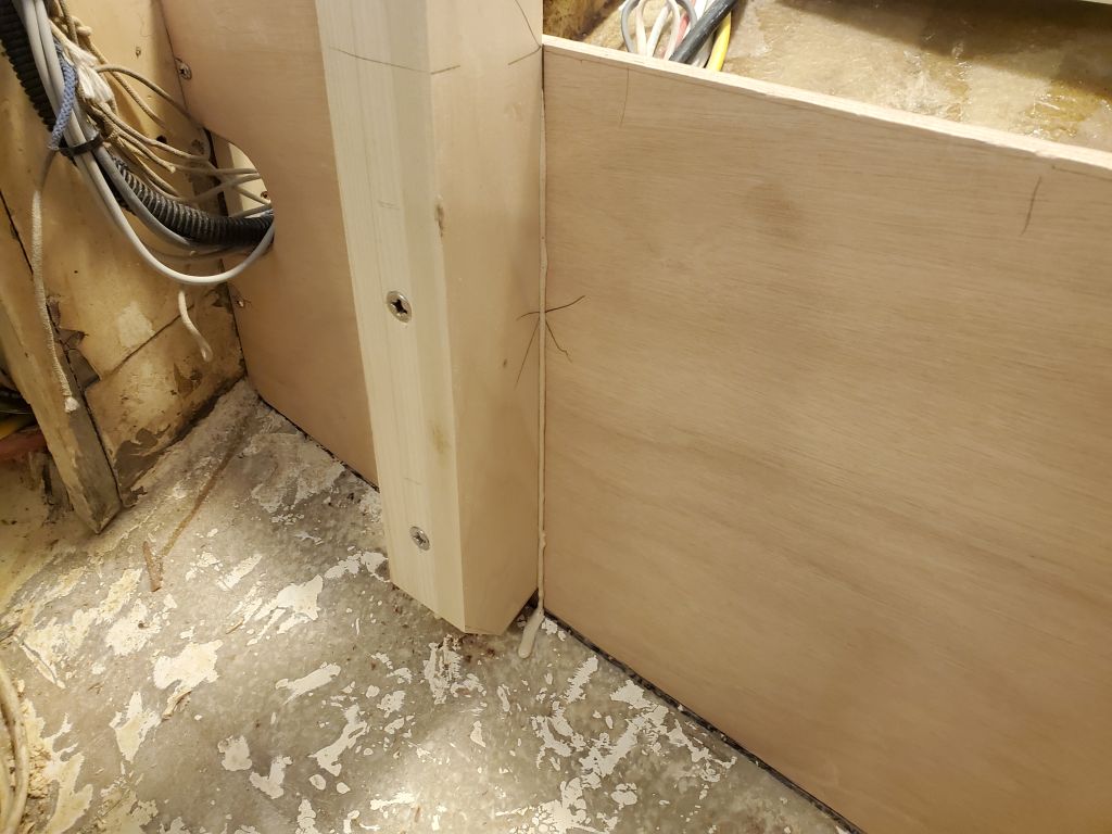
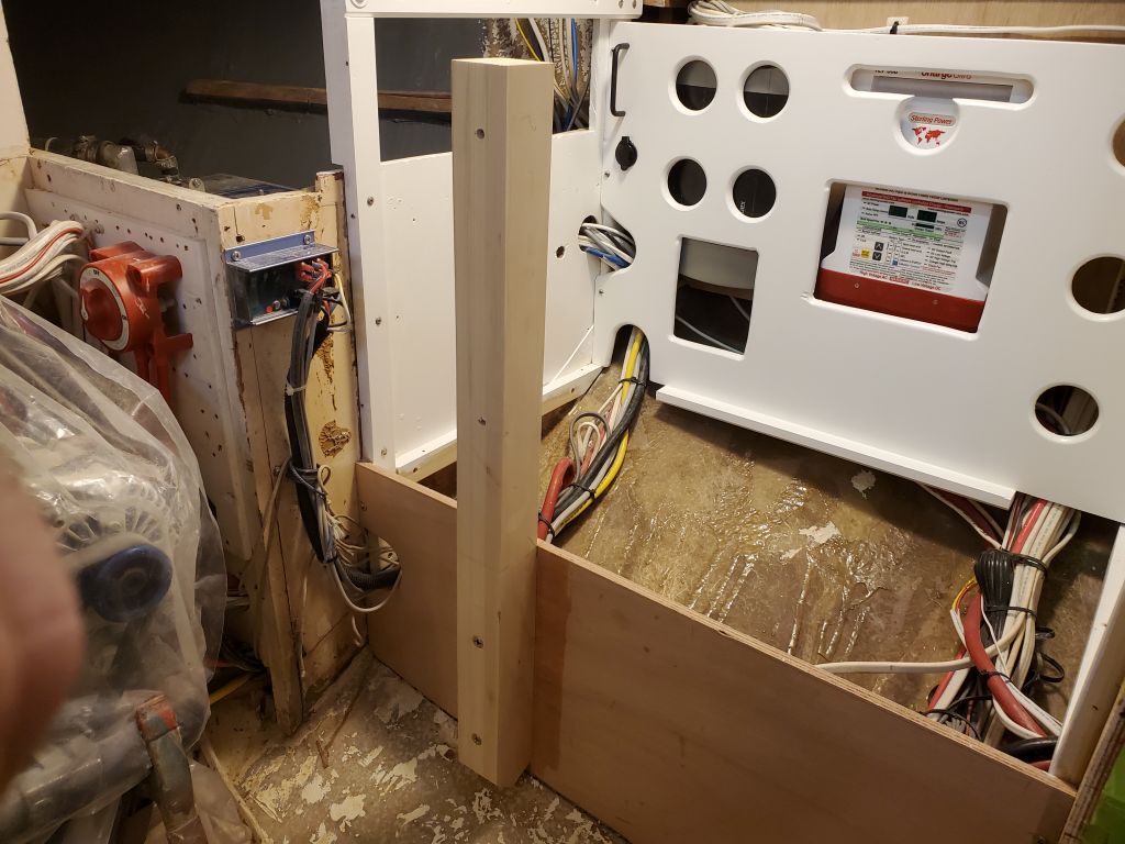
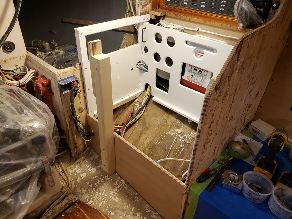
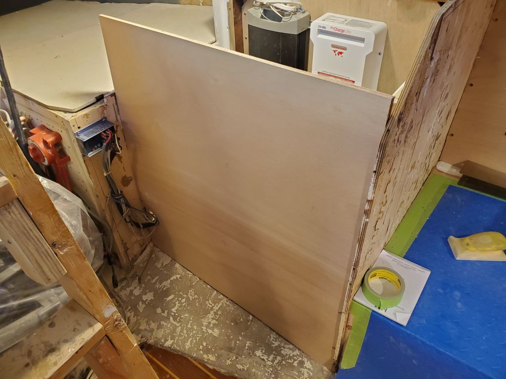
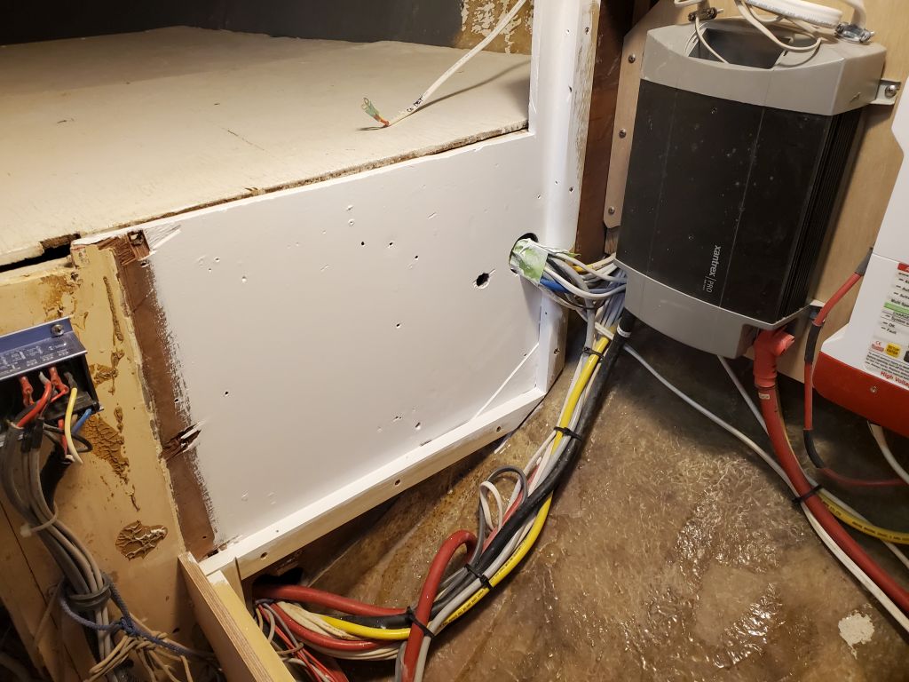
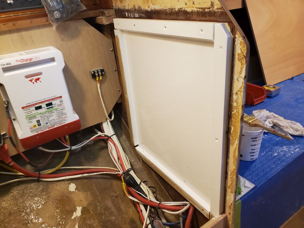
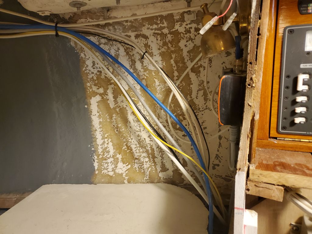
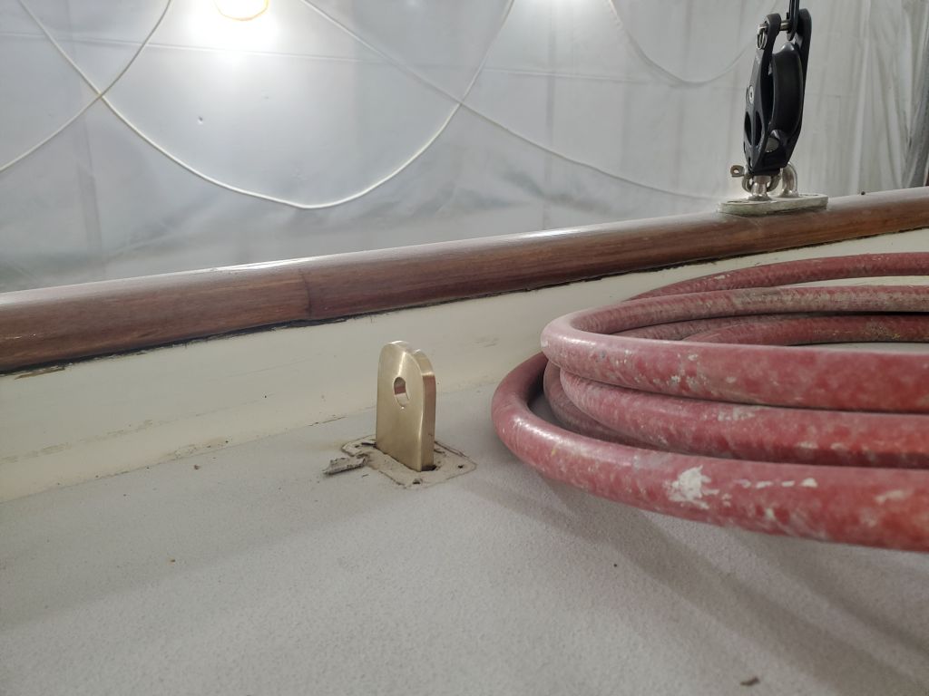
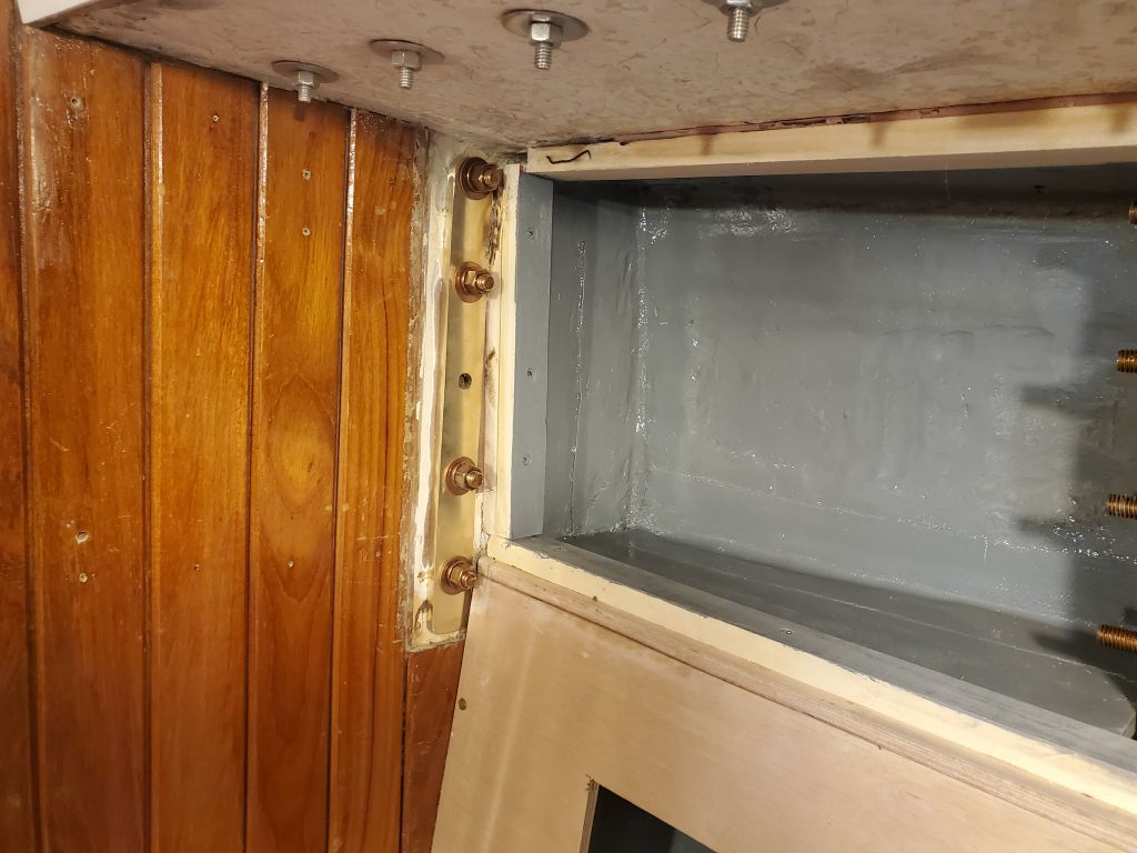
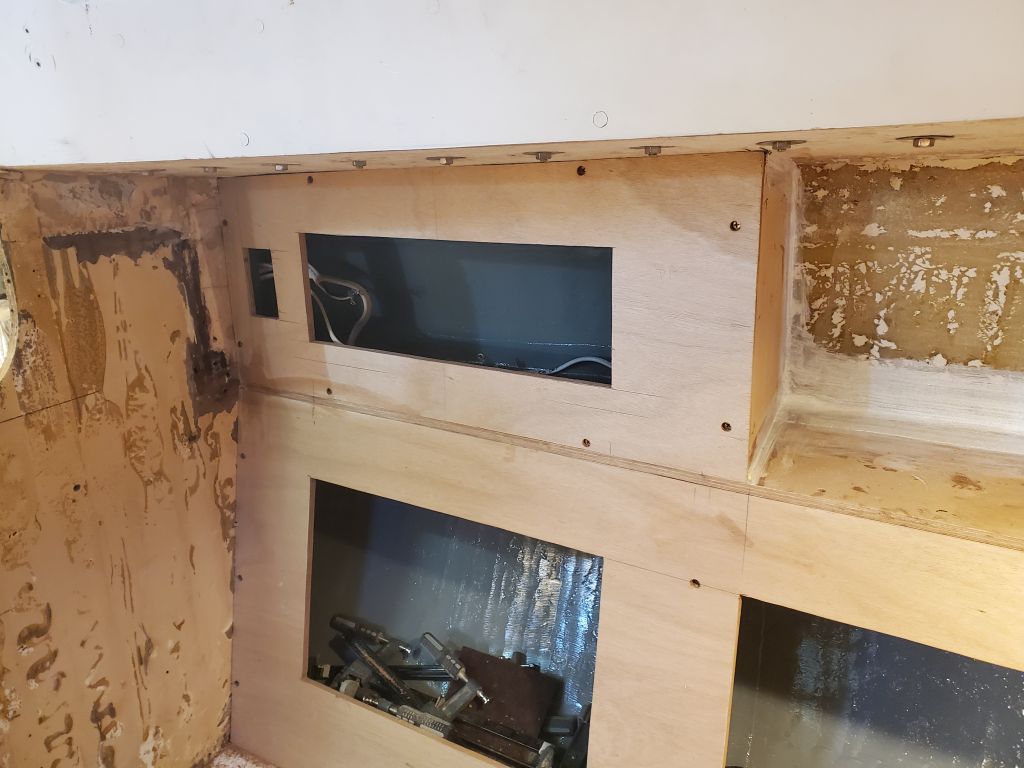
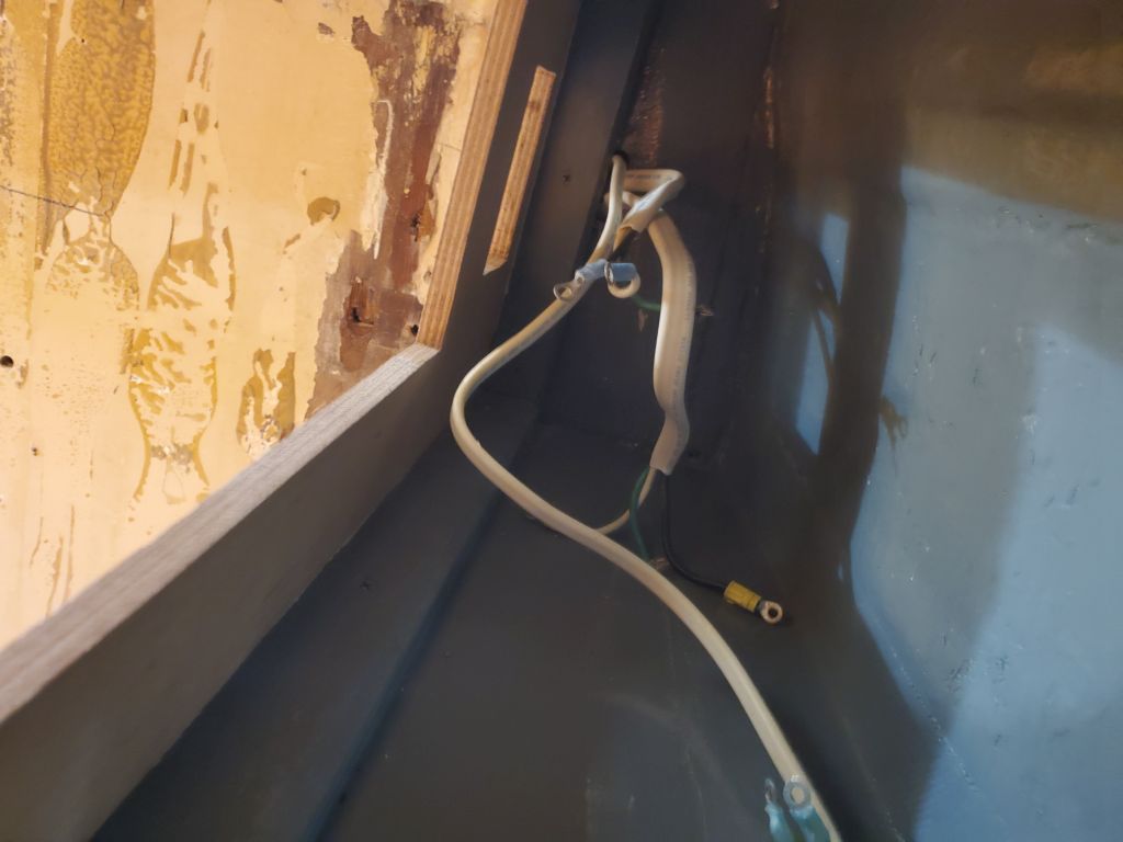
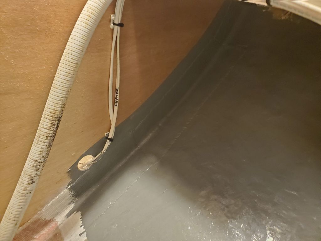
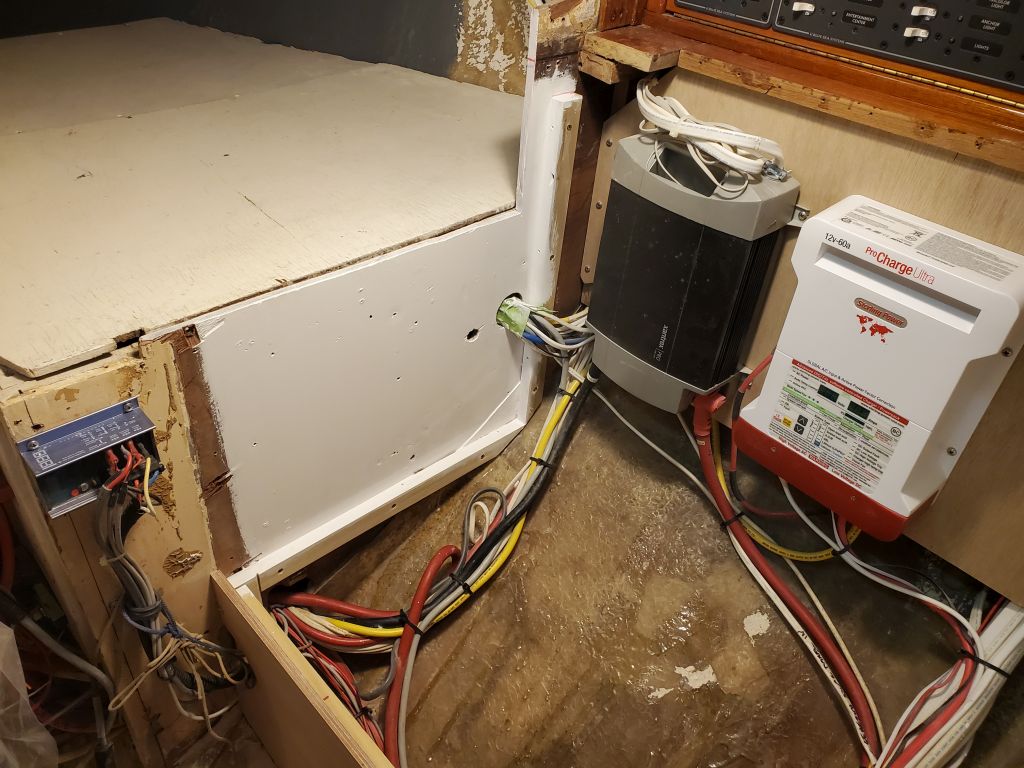
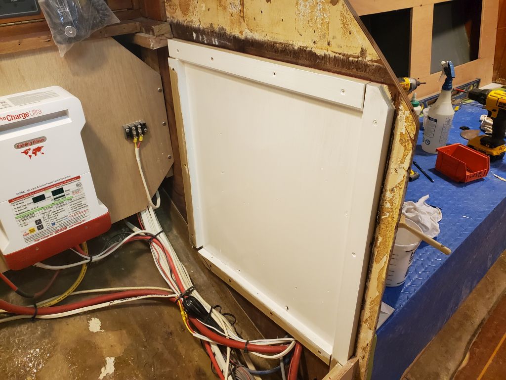
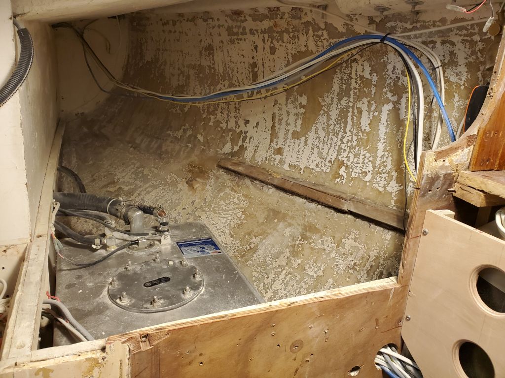
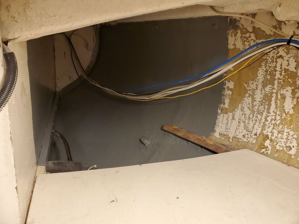
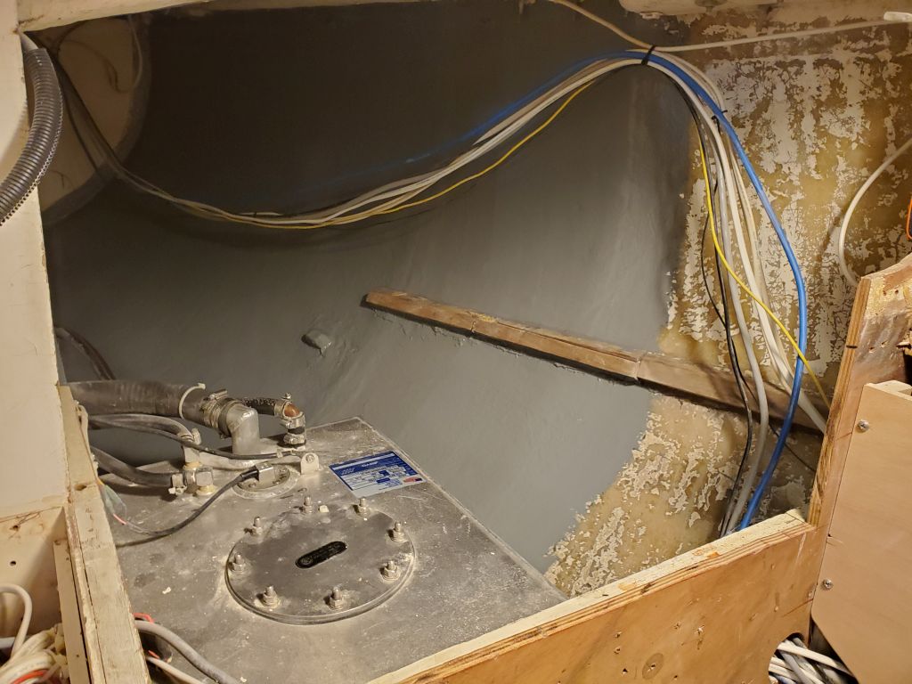
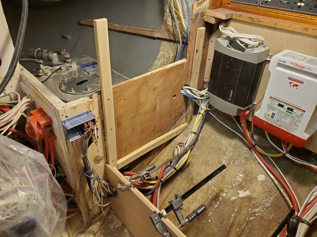
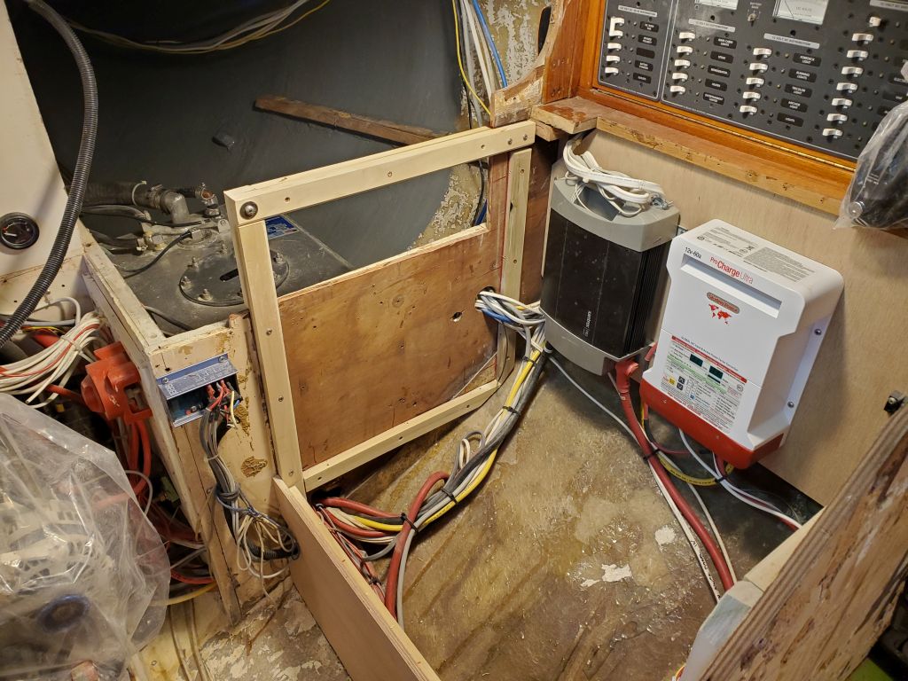
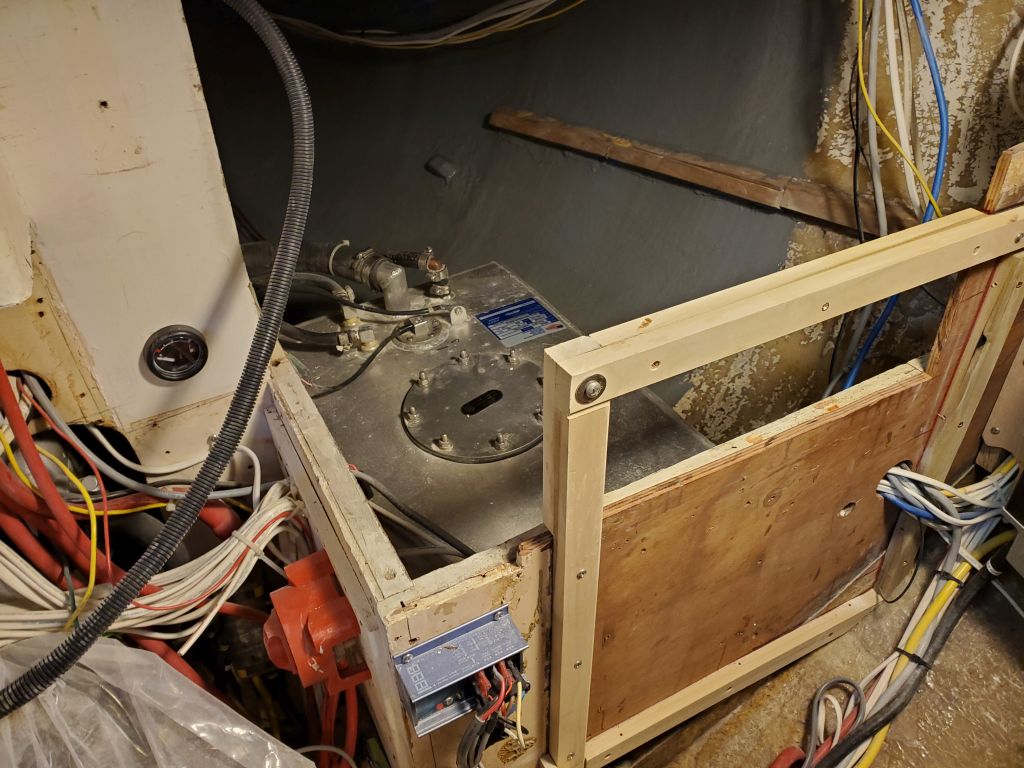
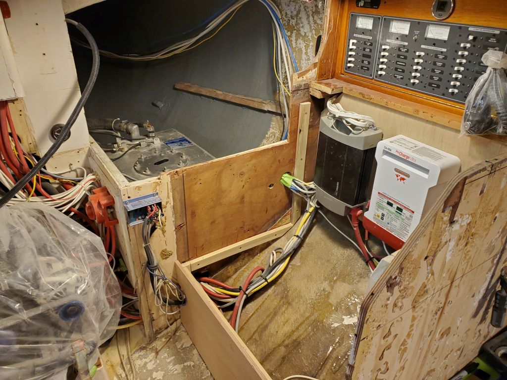
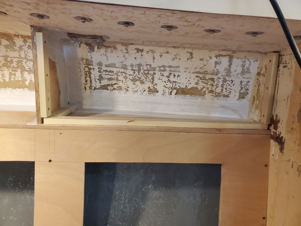
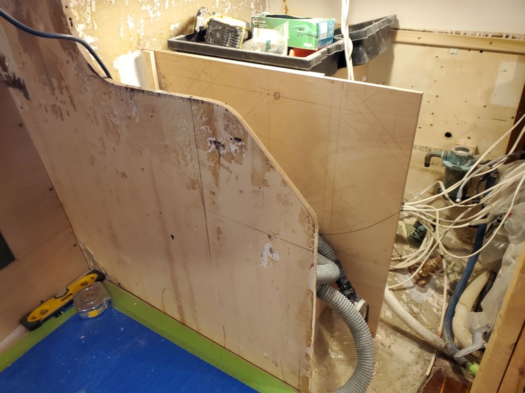
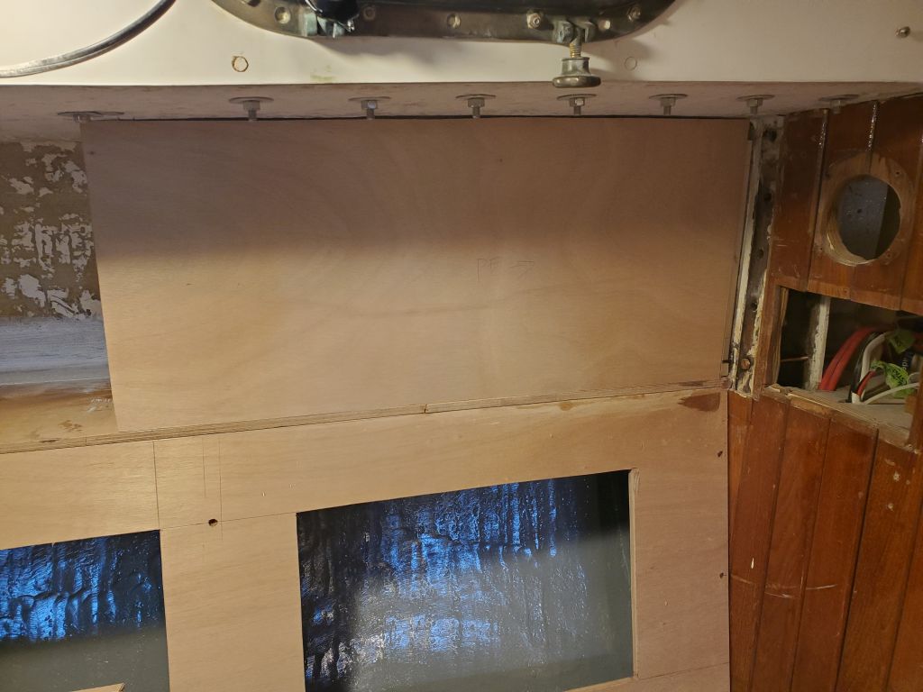
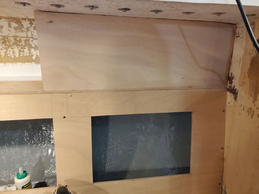
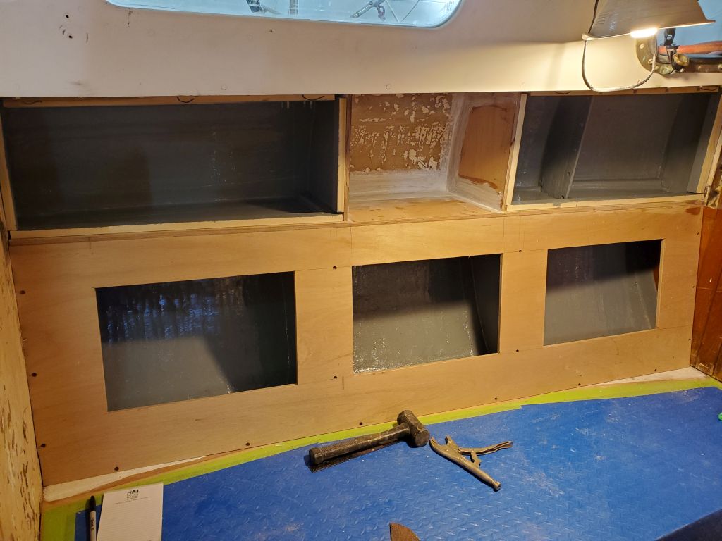
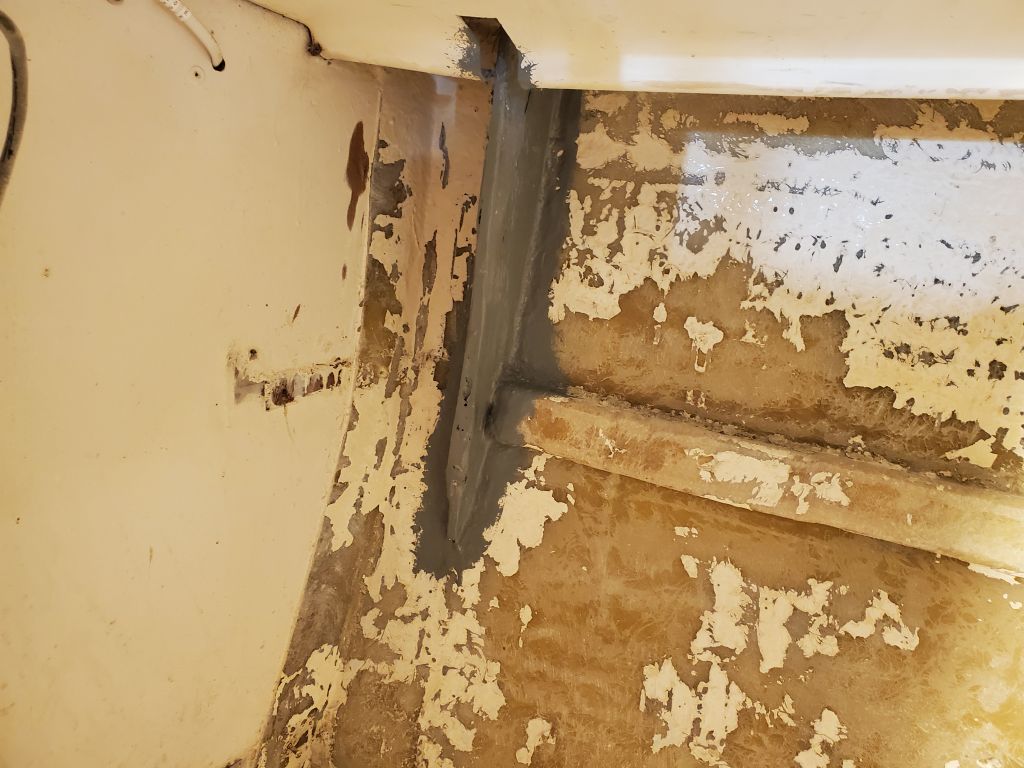
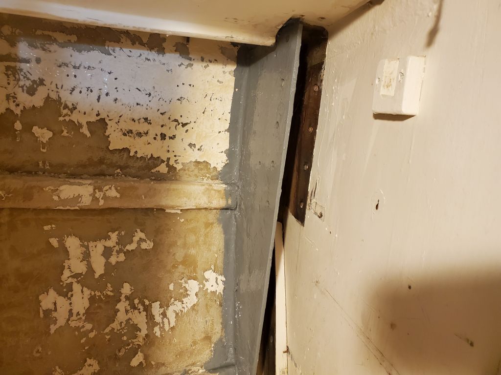
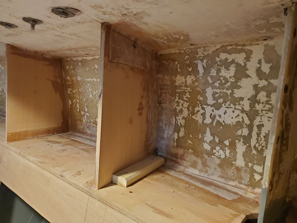
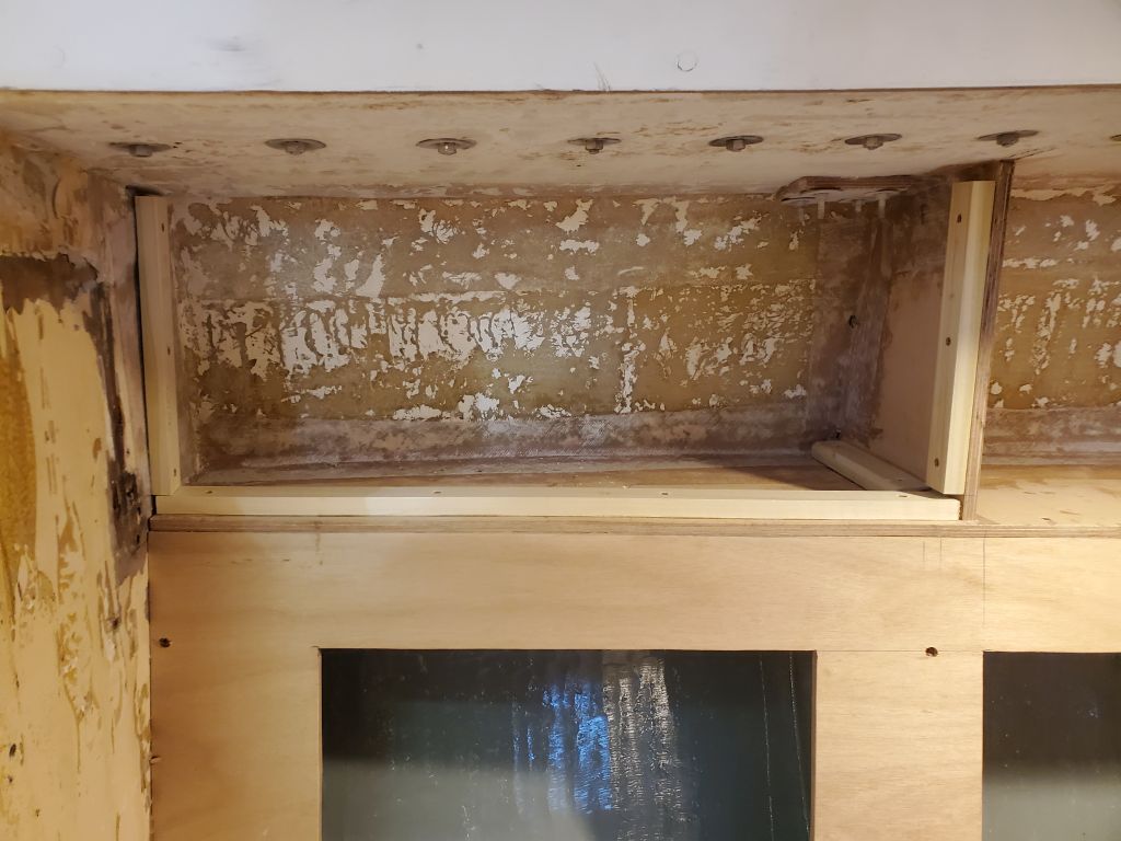
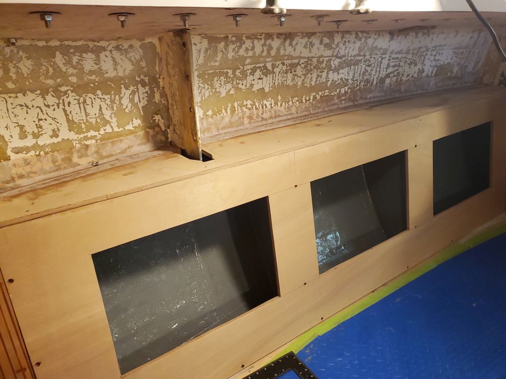
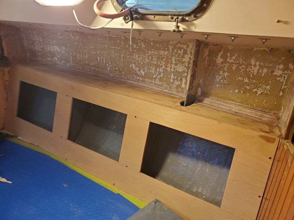
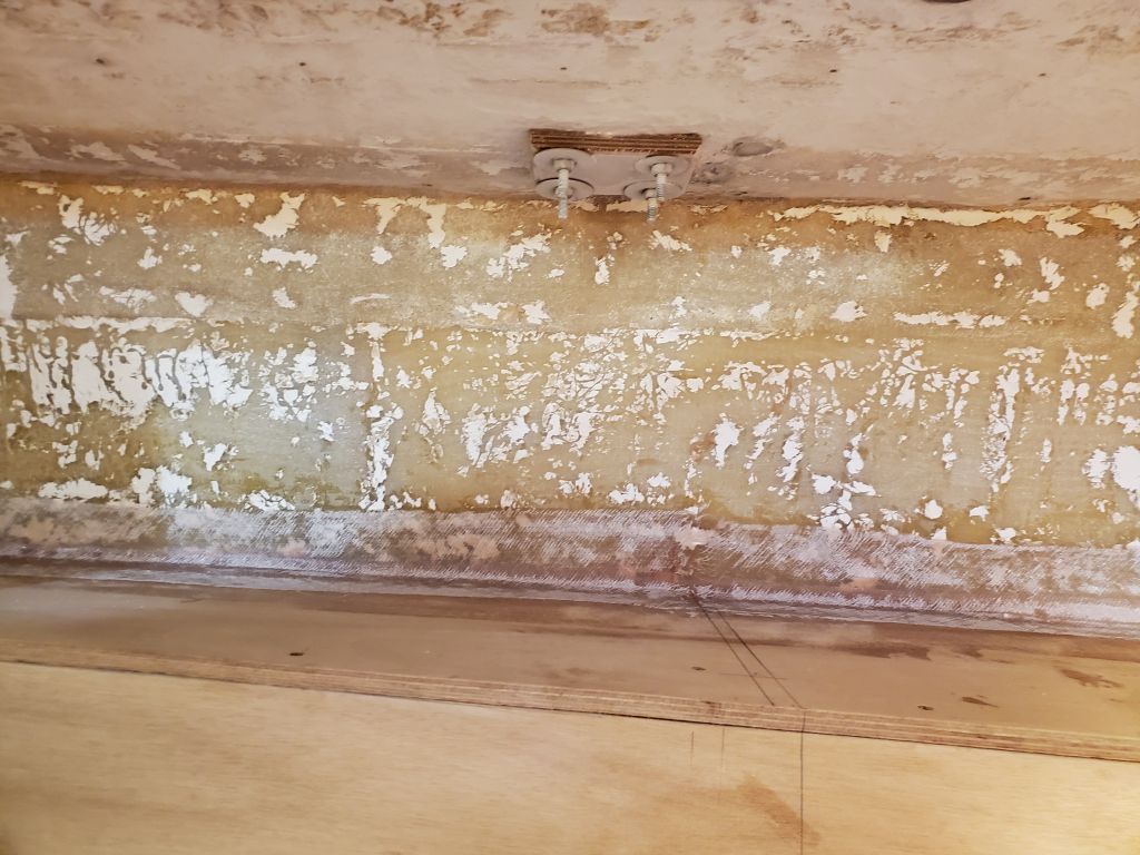
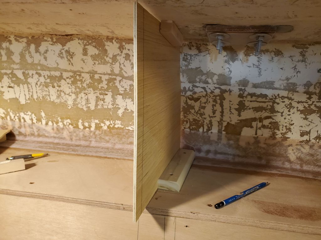
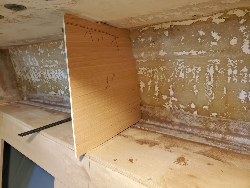
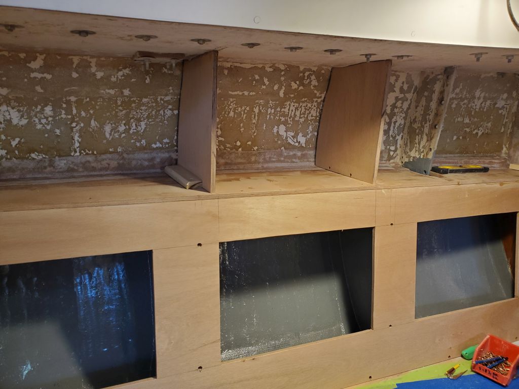
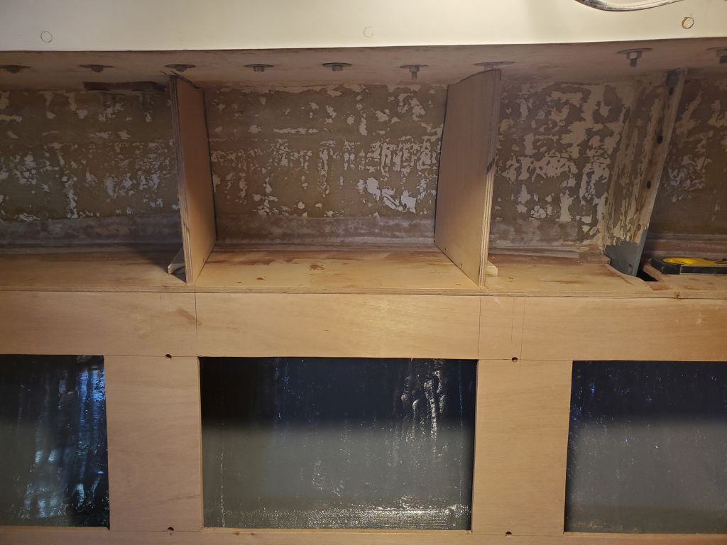
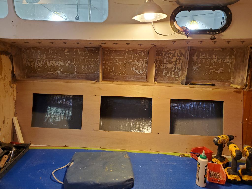
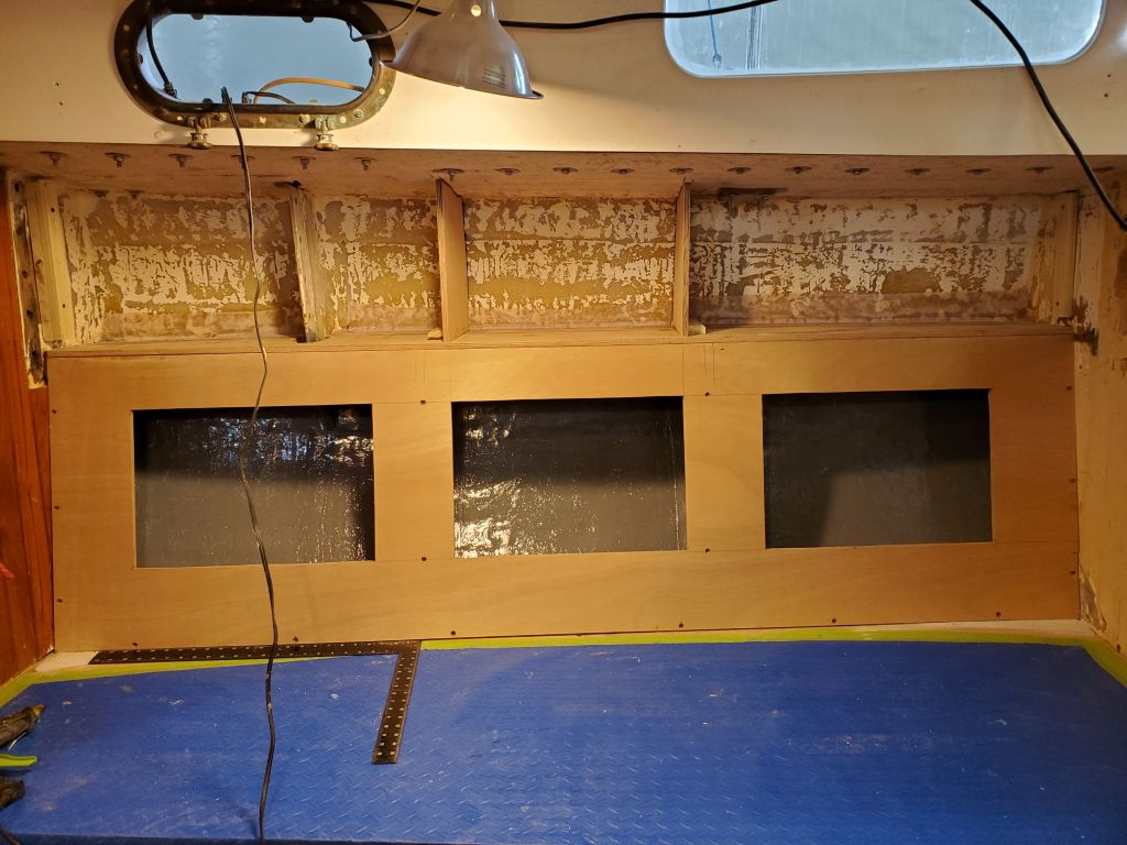
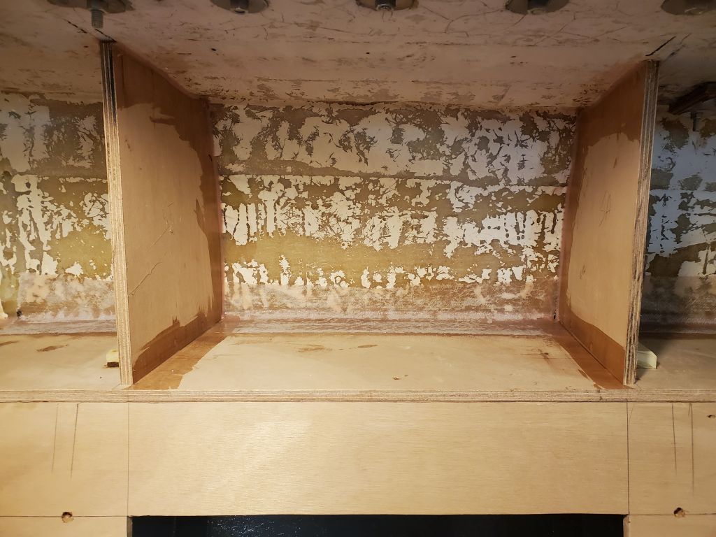
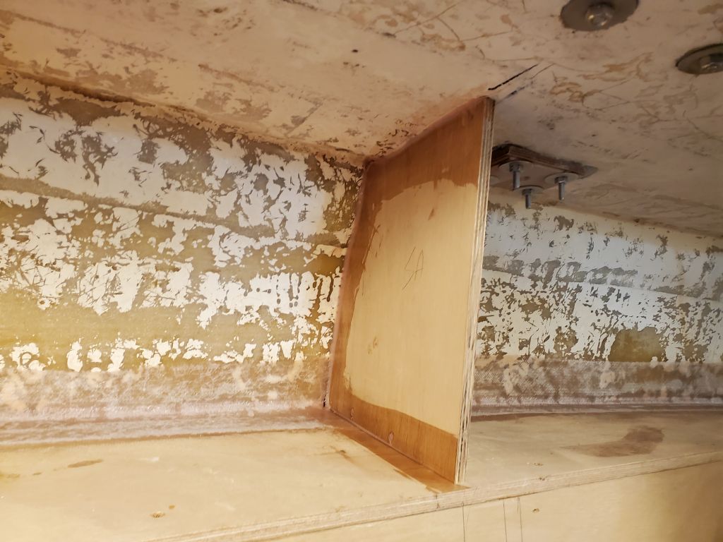
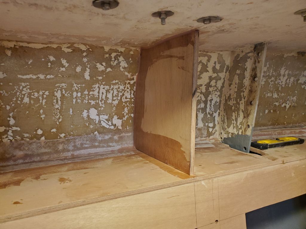
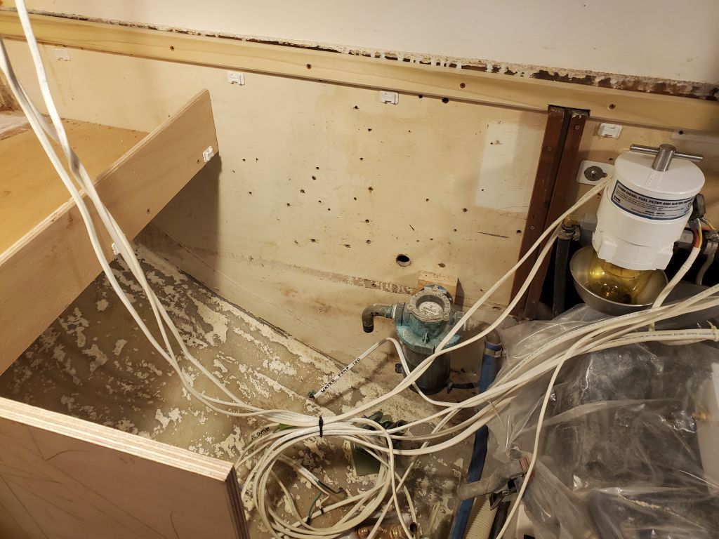
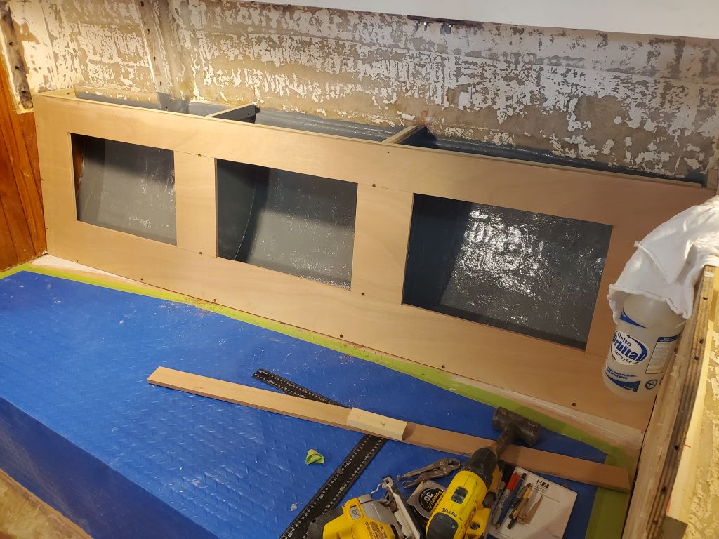
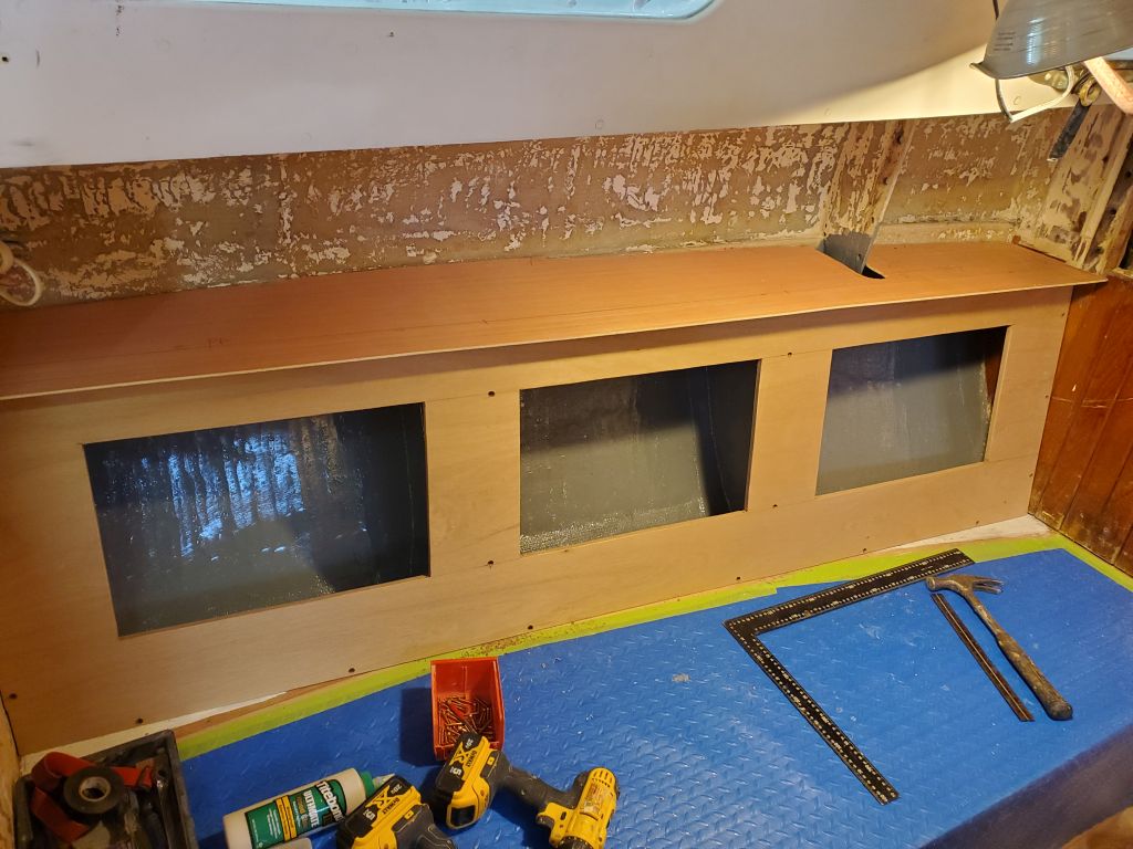
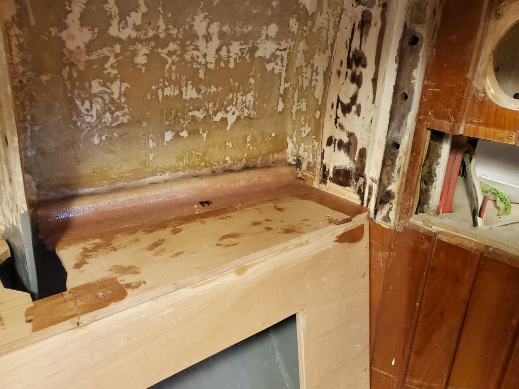
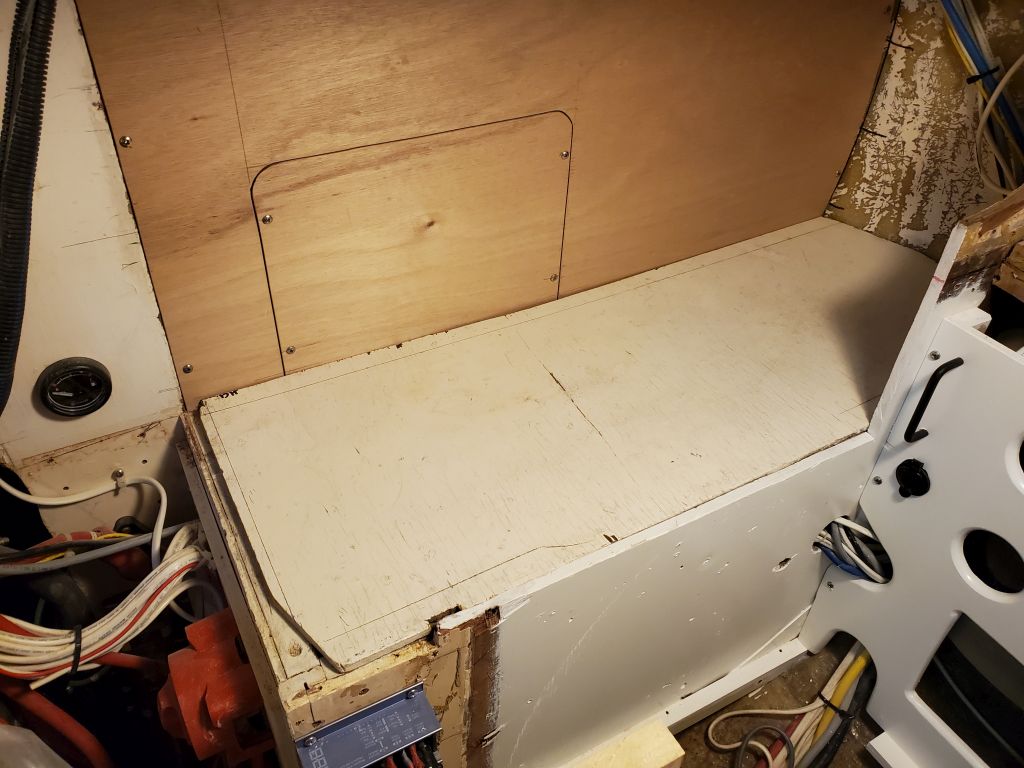
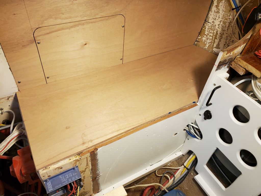
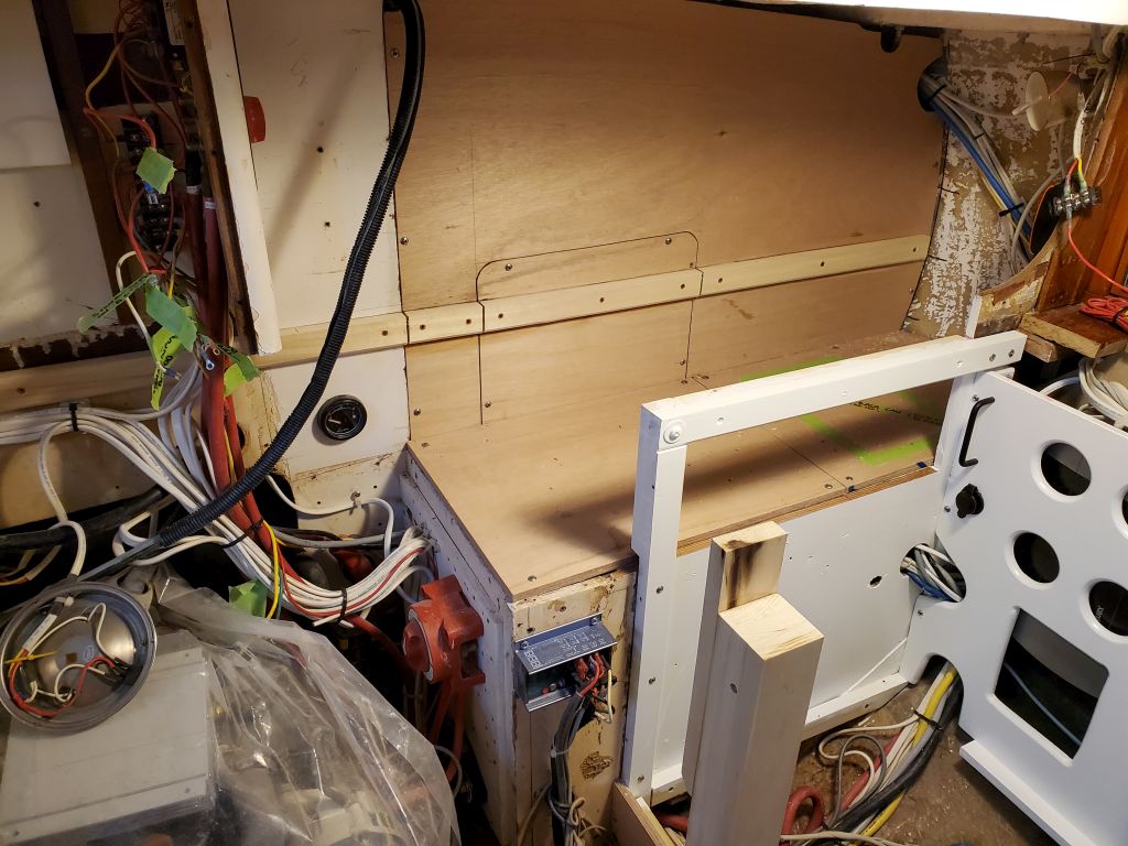
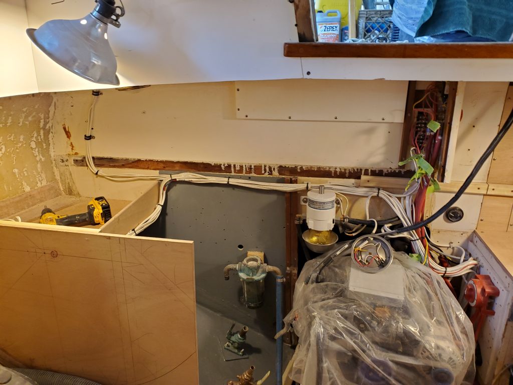
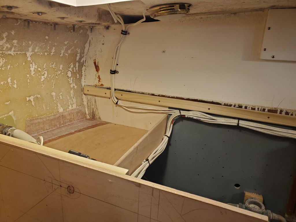
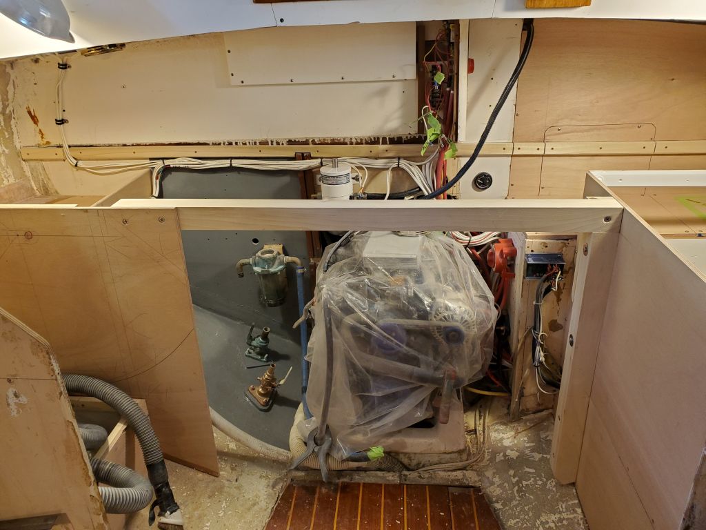
Now that the new cleats were secure to the hull, I could go ahead and install the new bulkhead across the old quarterberth, after first painting the small area just aft of the bulkhead location to fill in the section I’d previously left unpainted.  I secured the bulkhead to the cleats on both sides with pan head screws, as the entire bulkhead would remain removable should major access be required to this space.

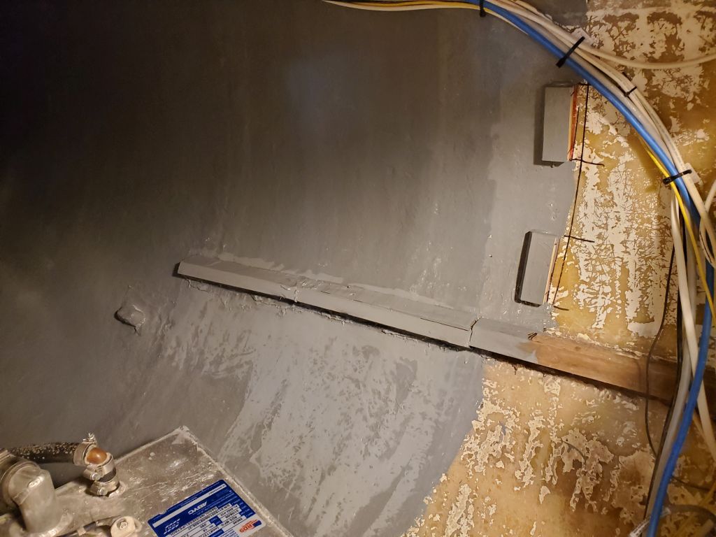
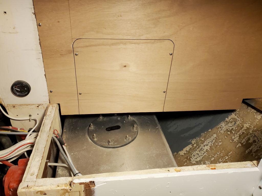
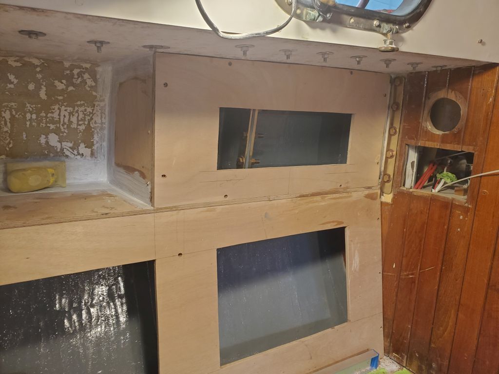
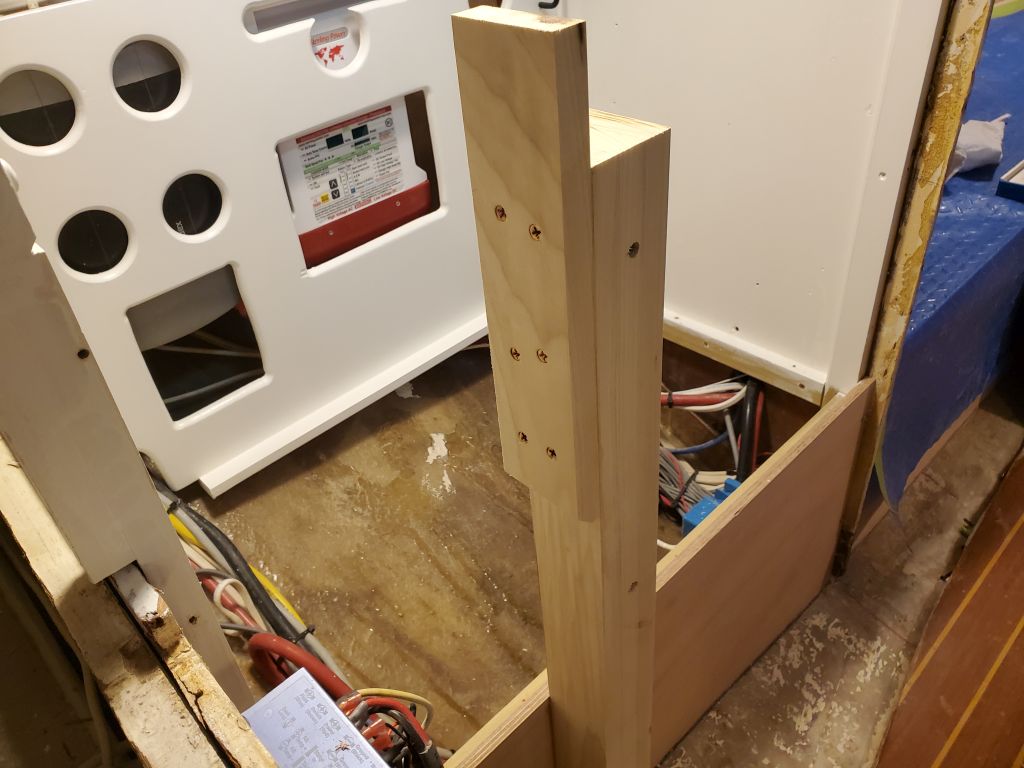
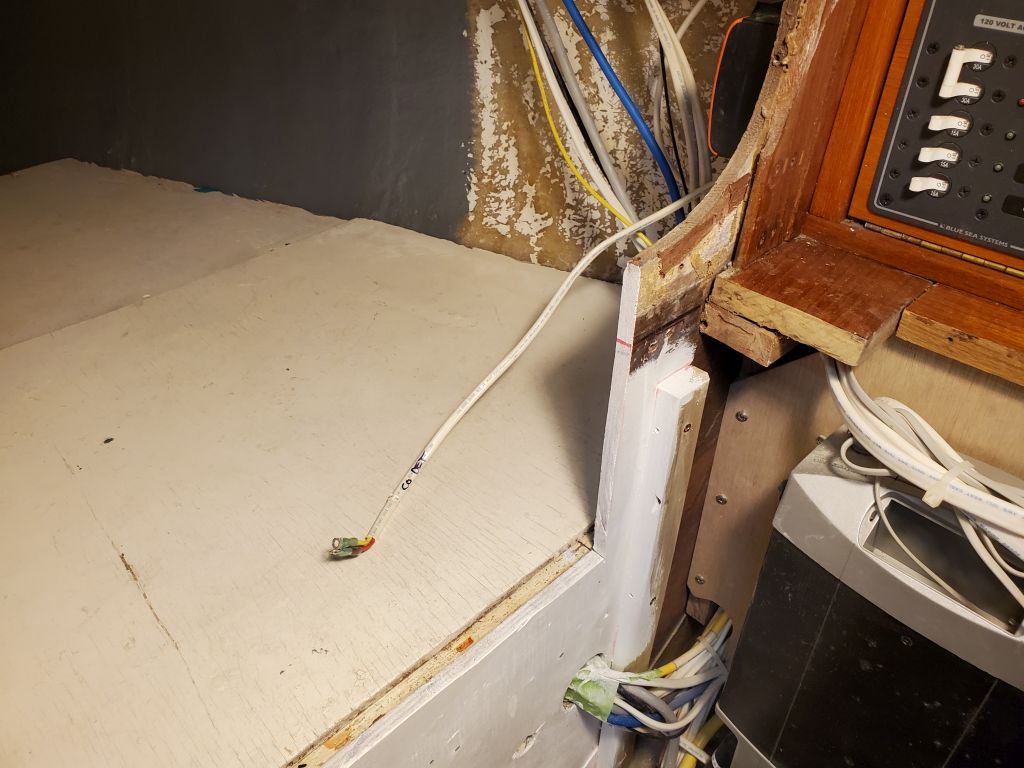
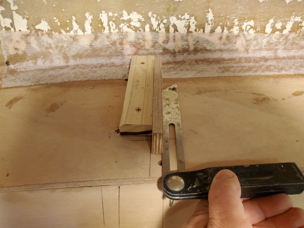
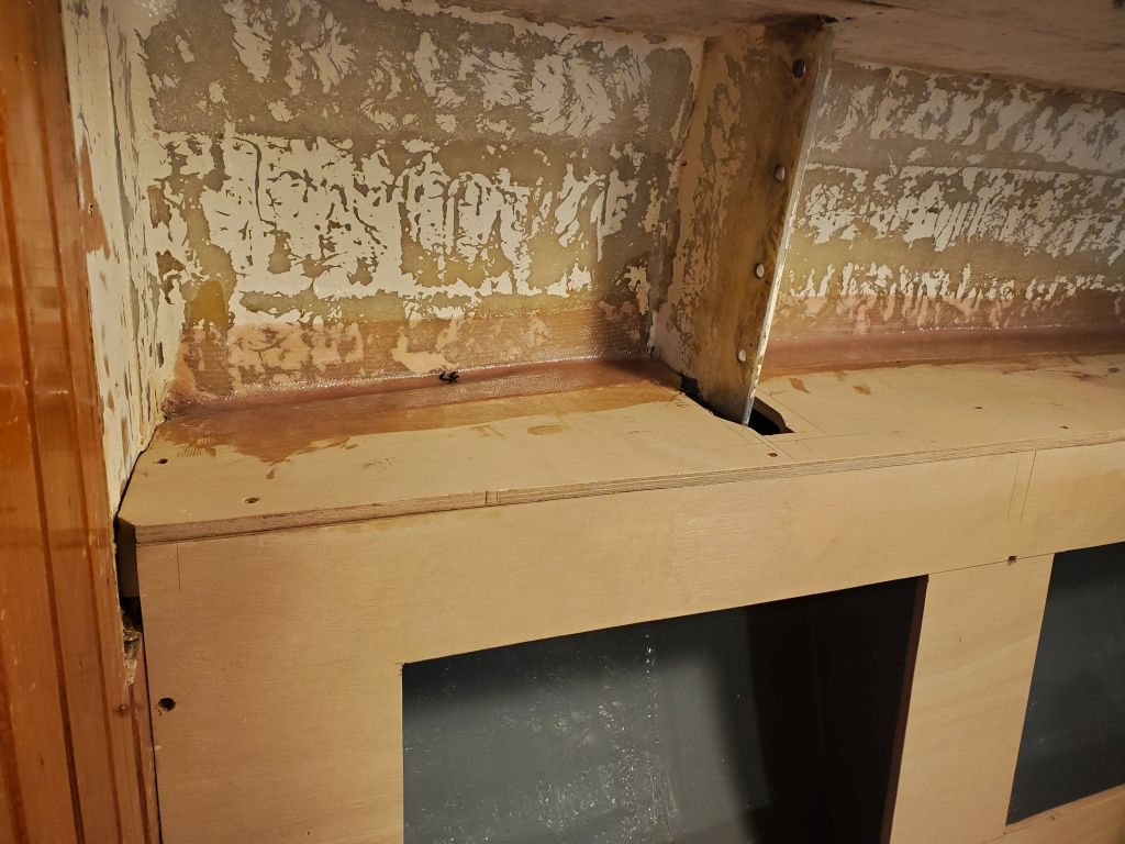
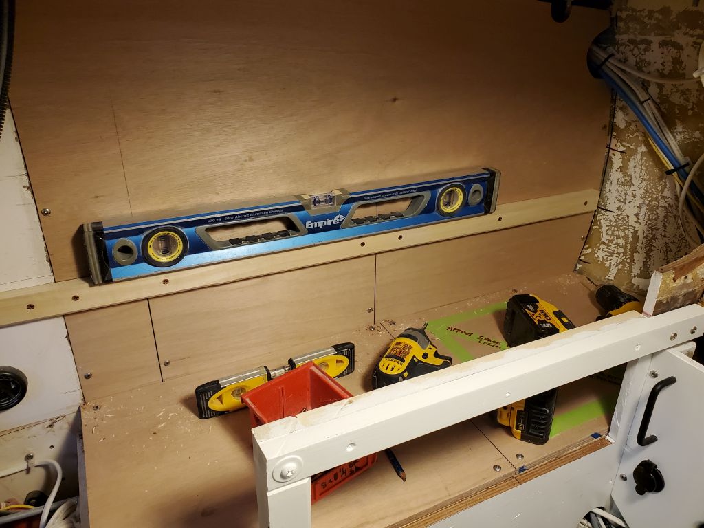
Next, I cut and installed a support cleat for the lower shelf, running across the bulkhead from the existing engine room cleat/bulkhead to the cleat located on the hull.  For now, I ran the cleat in a single piece across the space, but I marked it where it passed over the seam of the access panel in the bulkhead so I could cut it later and keep the panel removable.

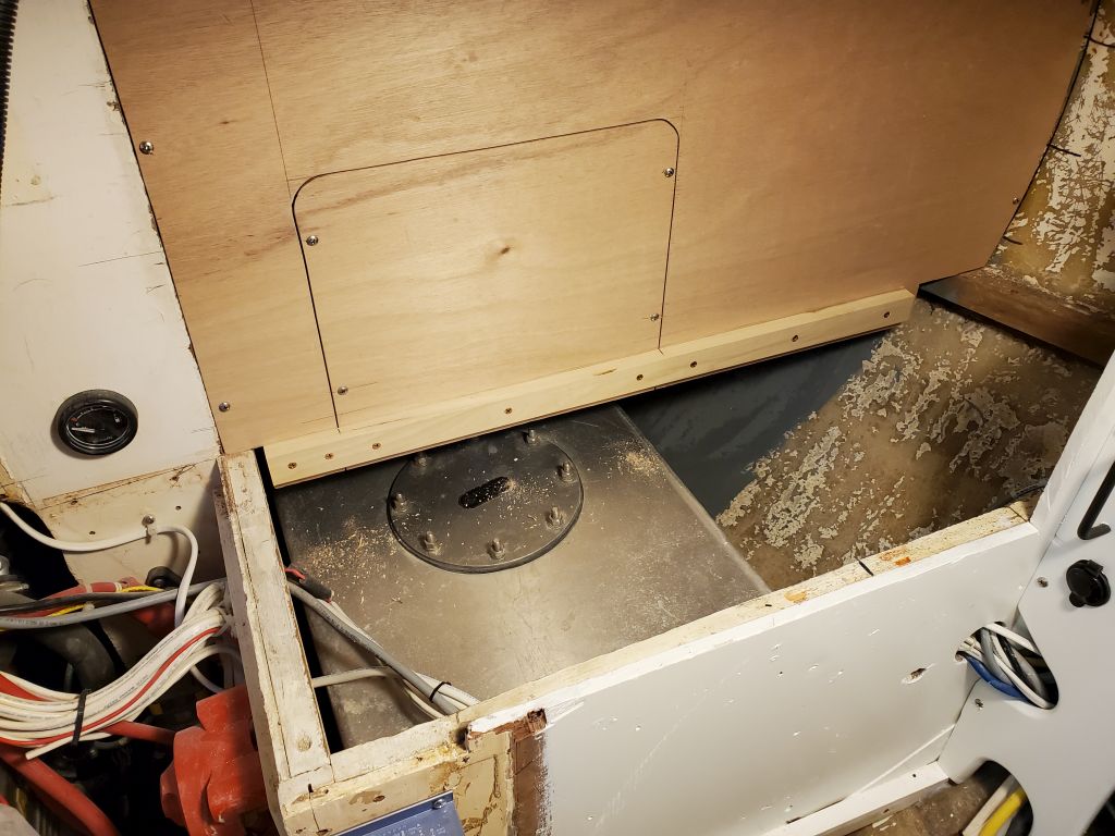
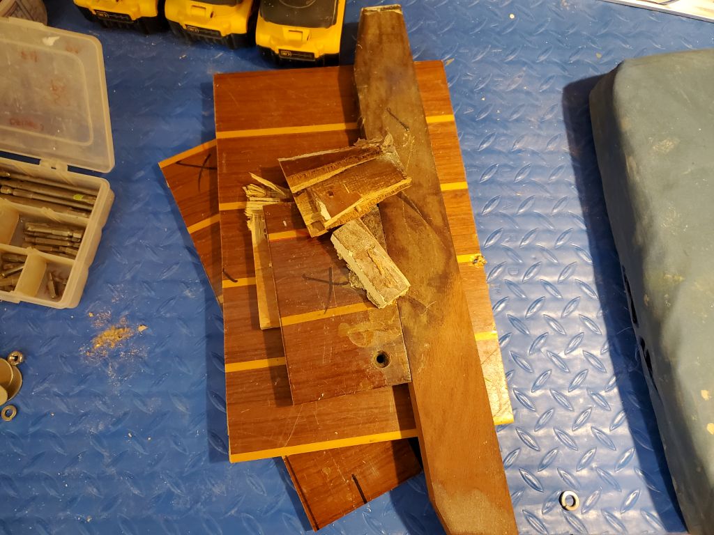
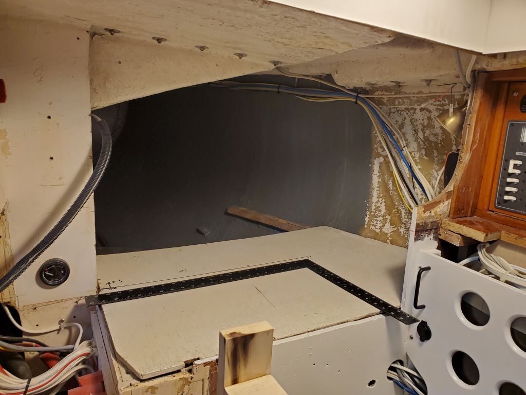
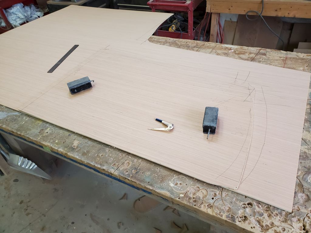
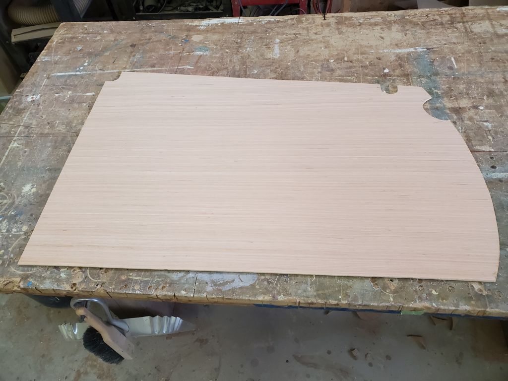
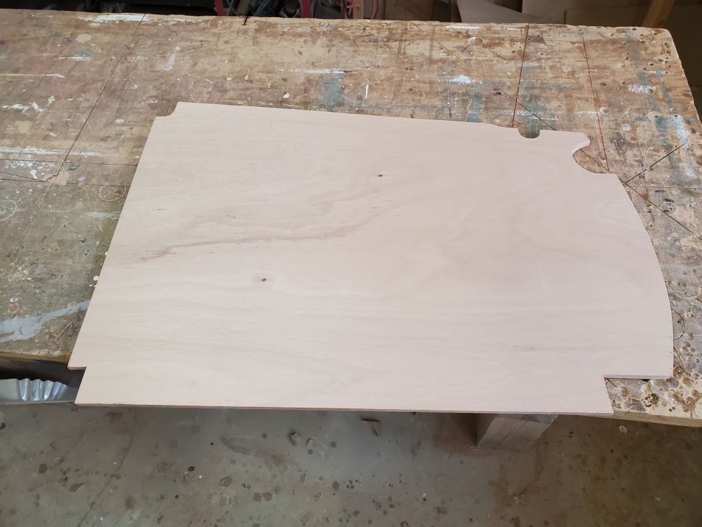
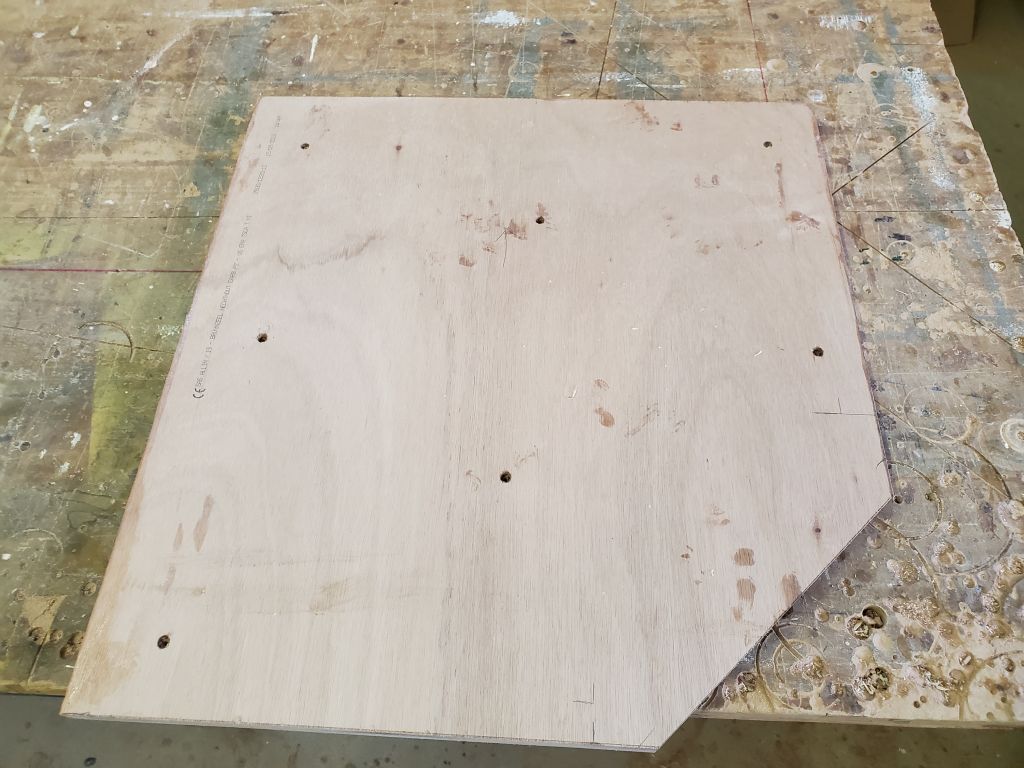
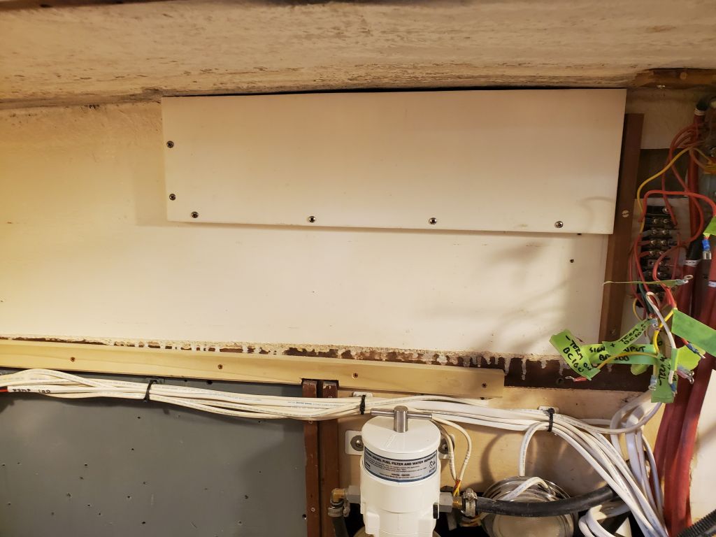
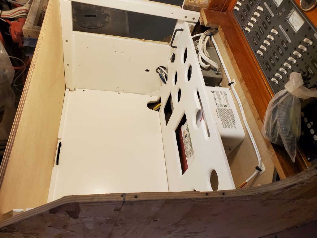
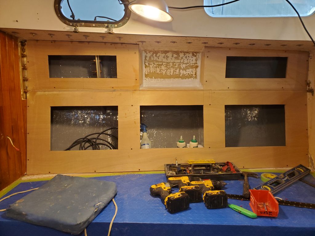
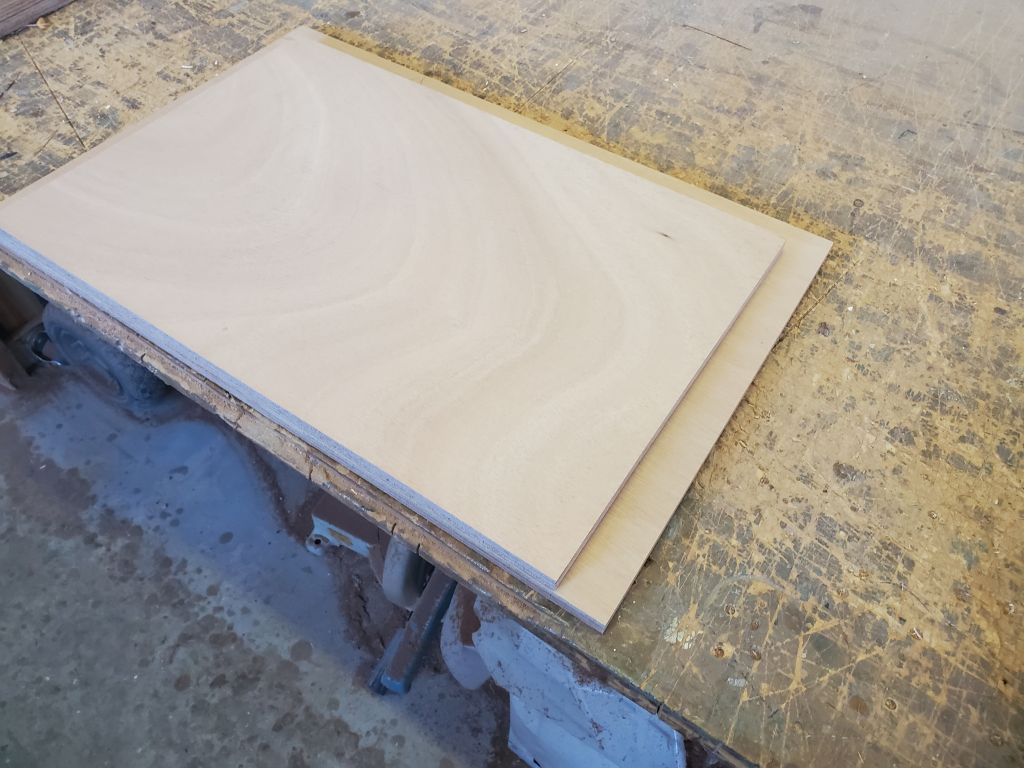
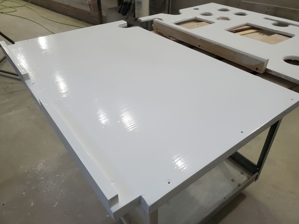
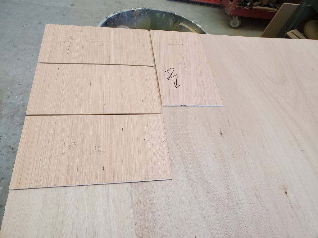
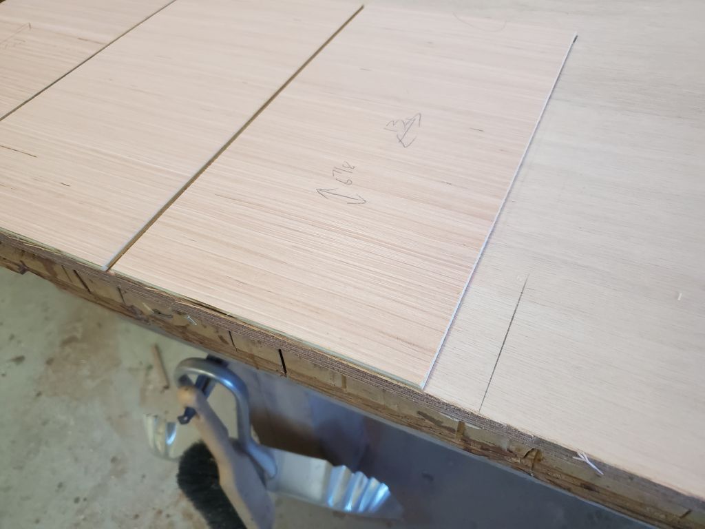
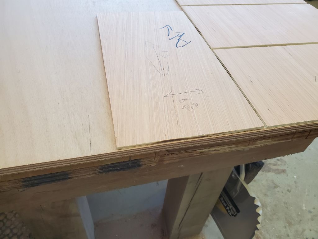
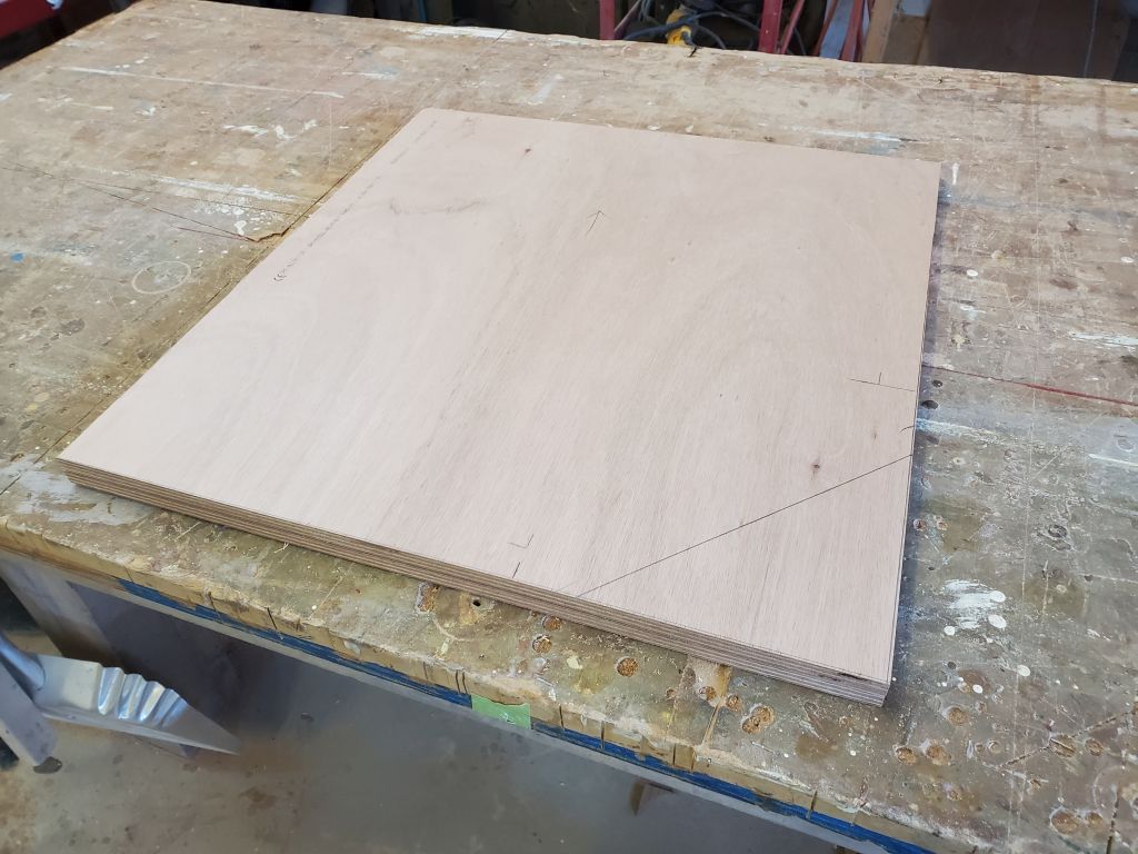
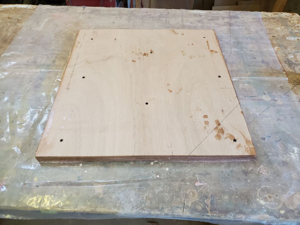
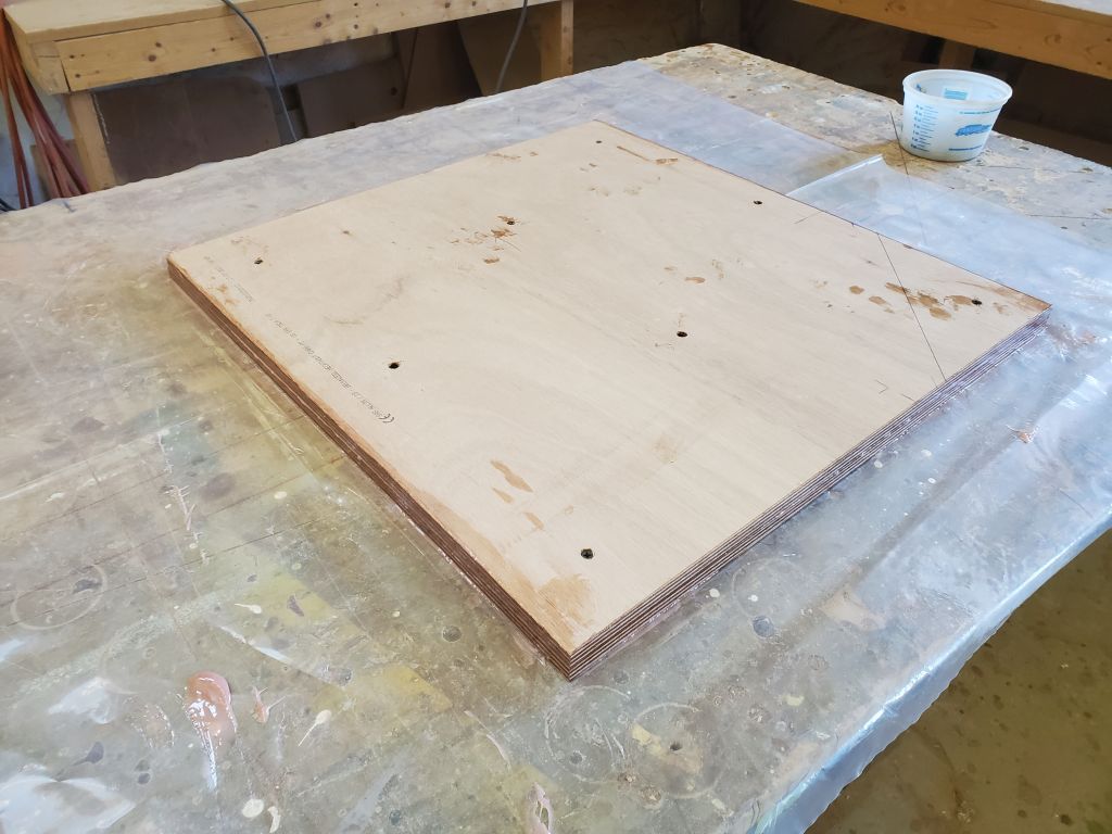
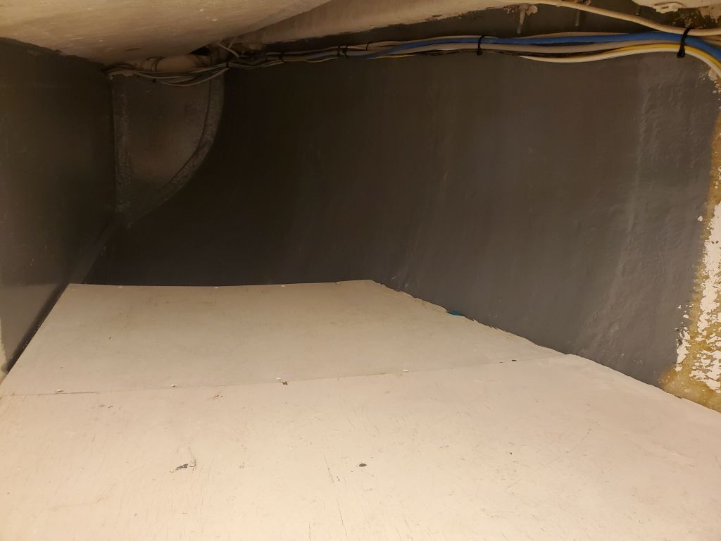
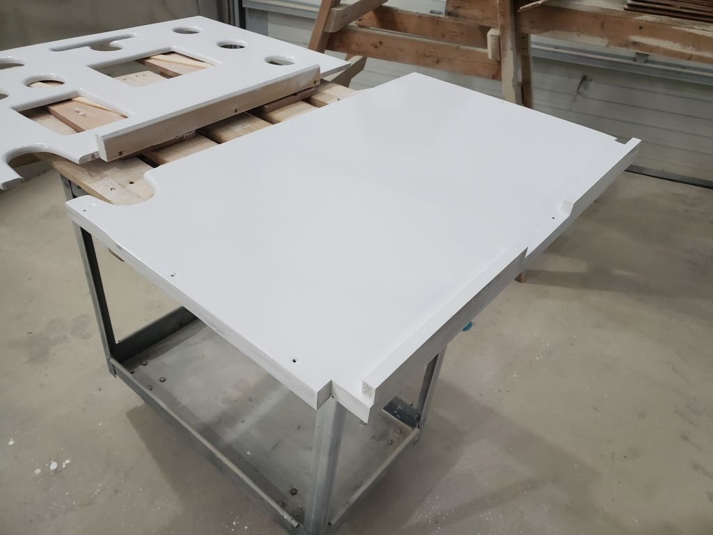
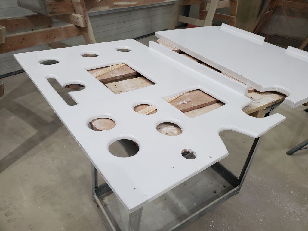
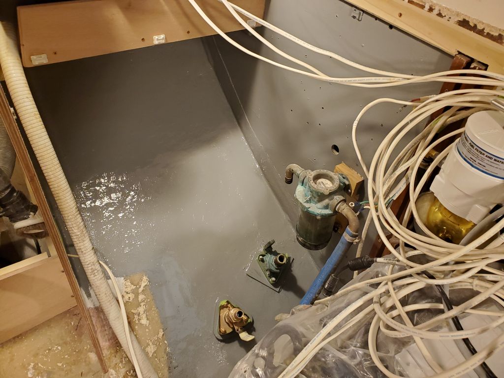
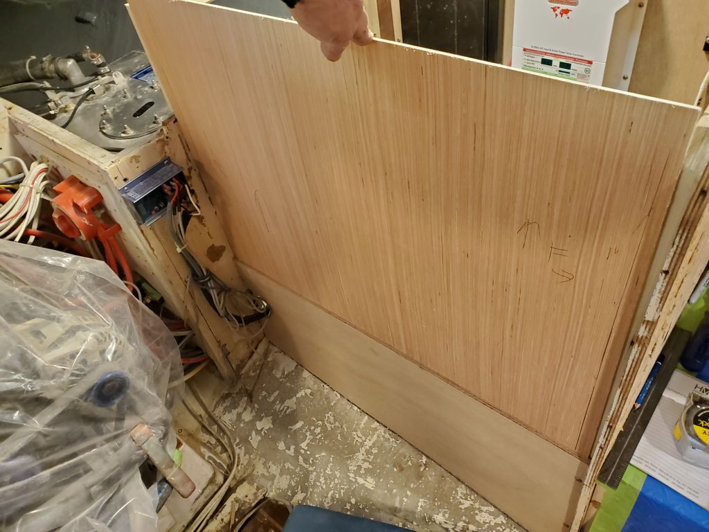
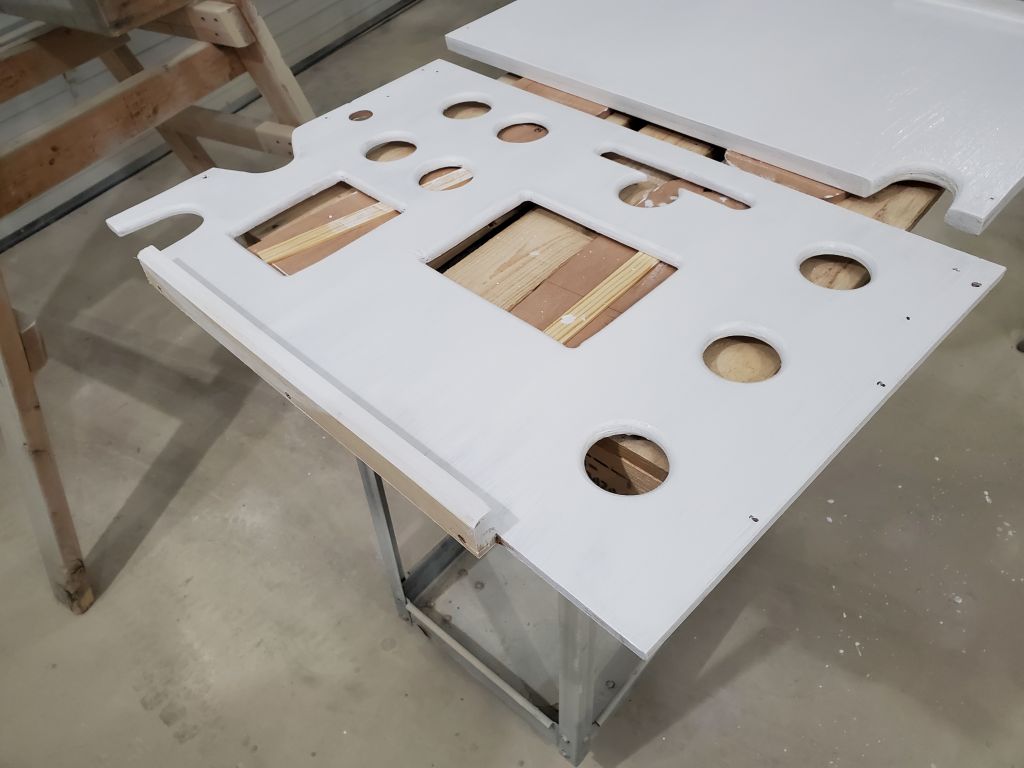
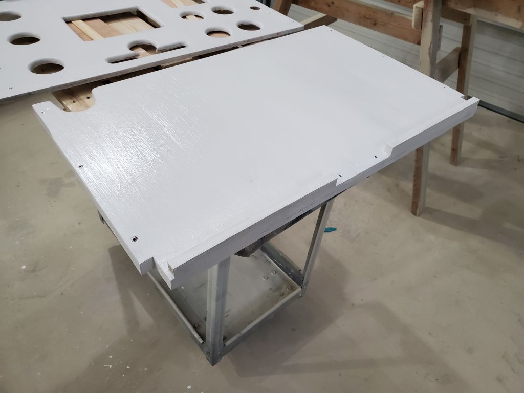
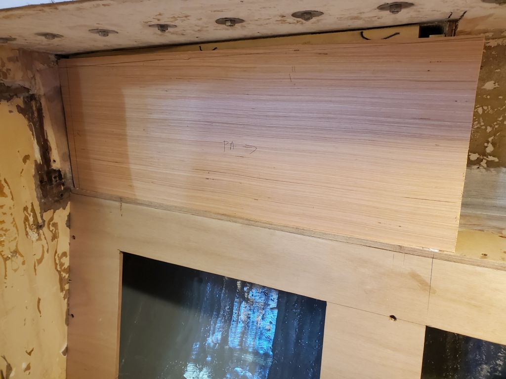
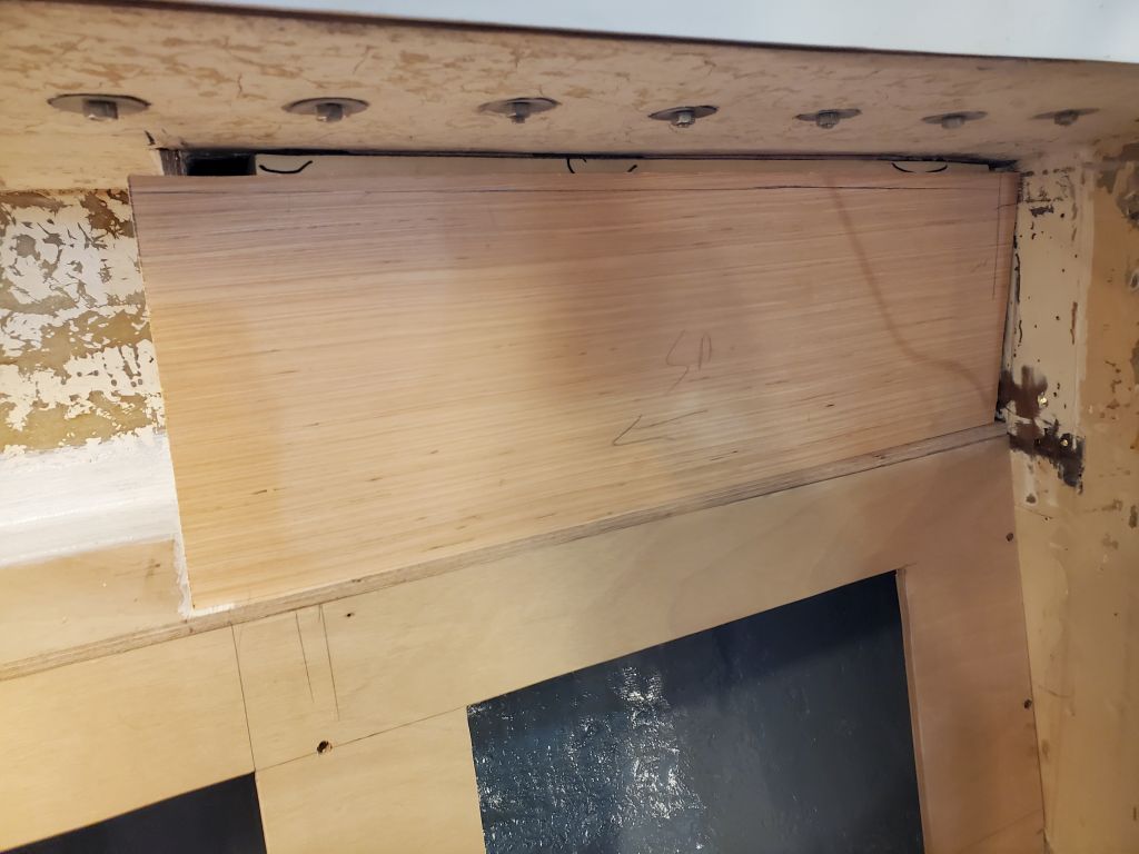
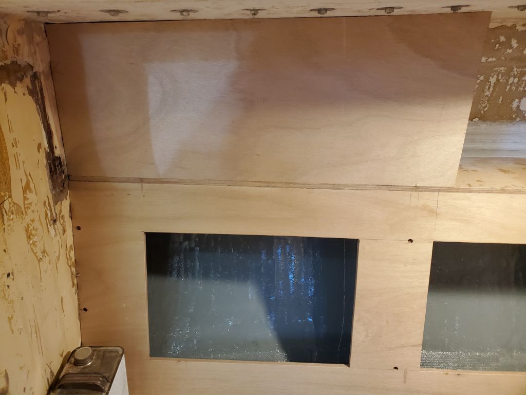
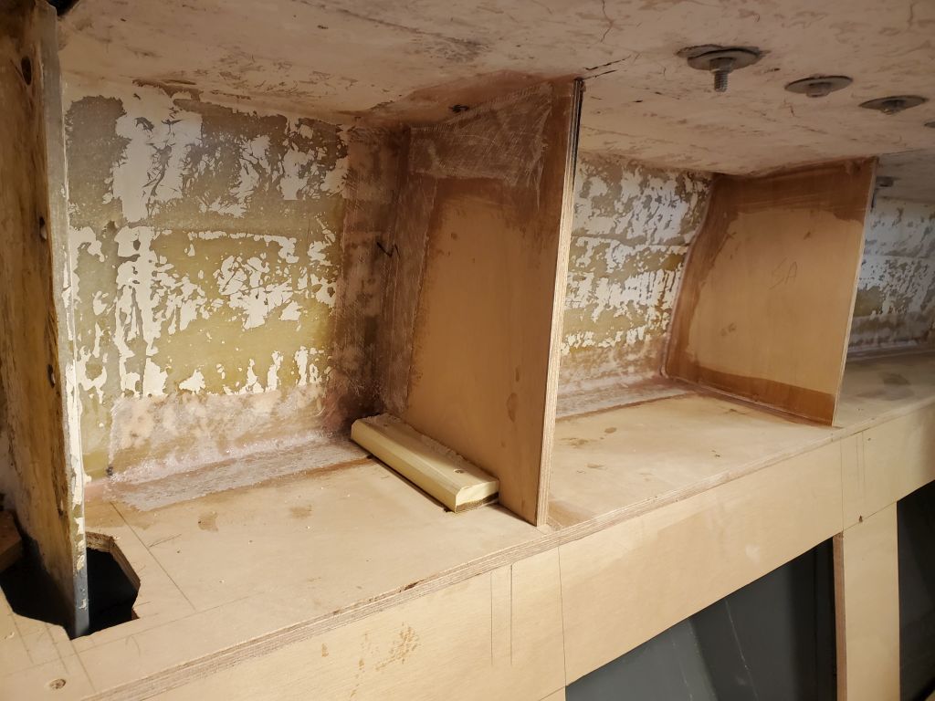
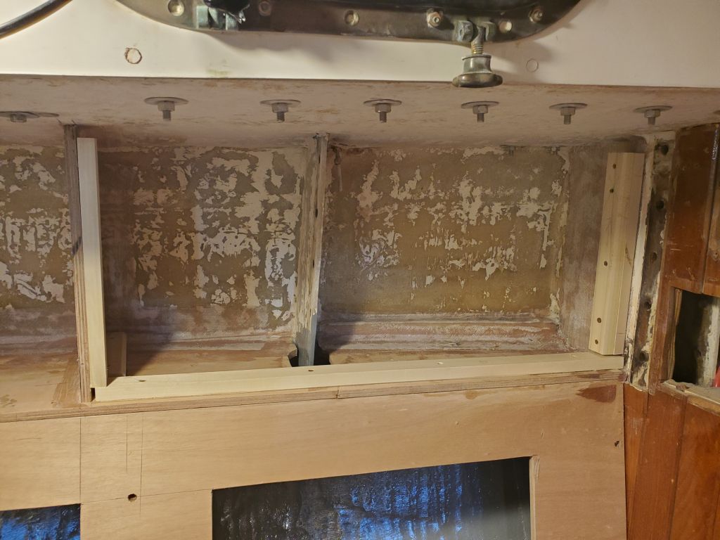
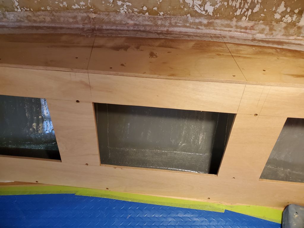
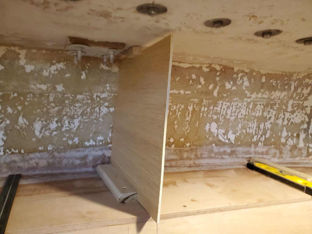
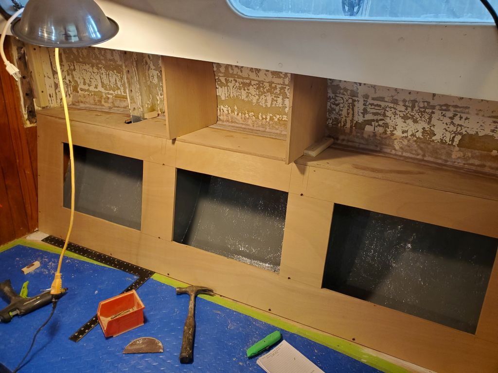
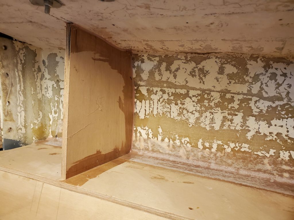
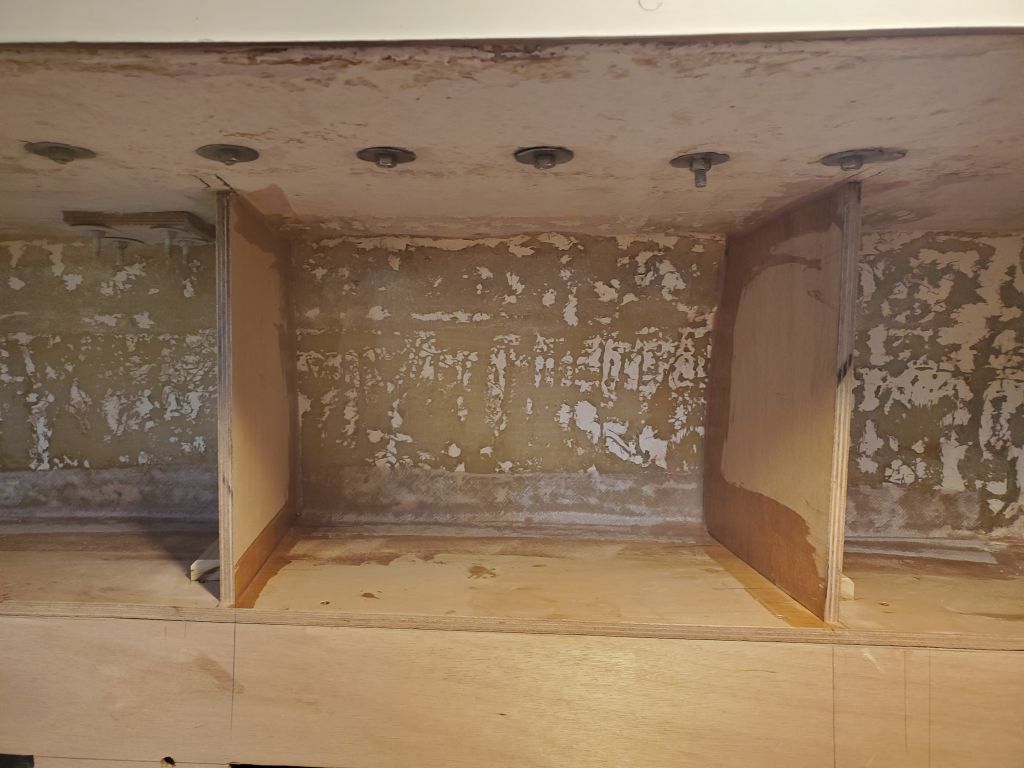
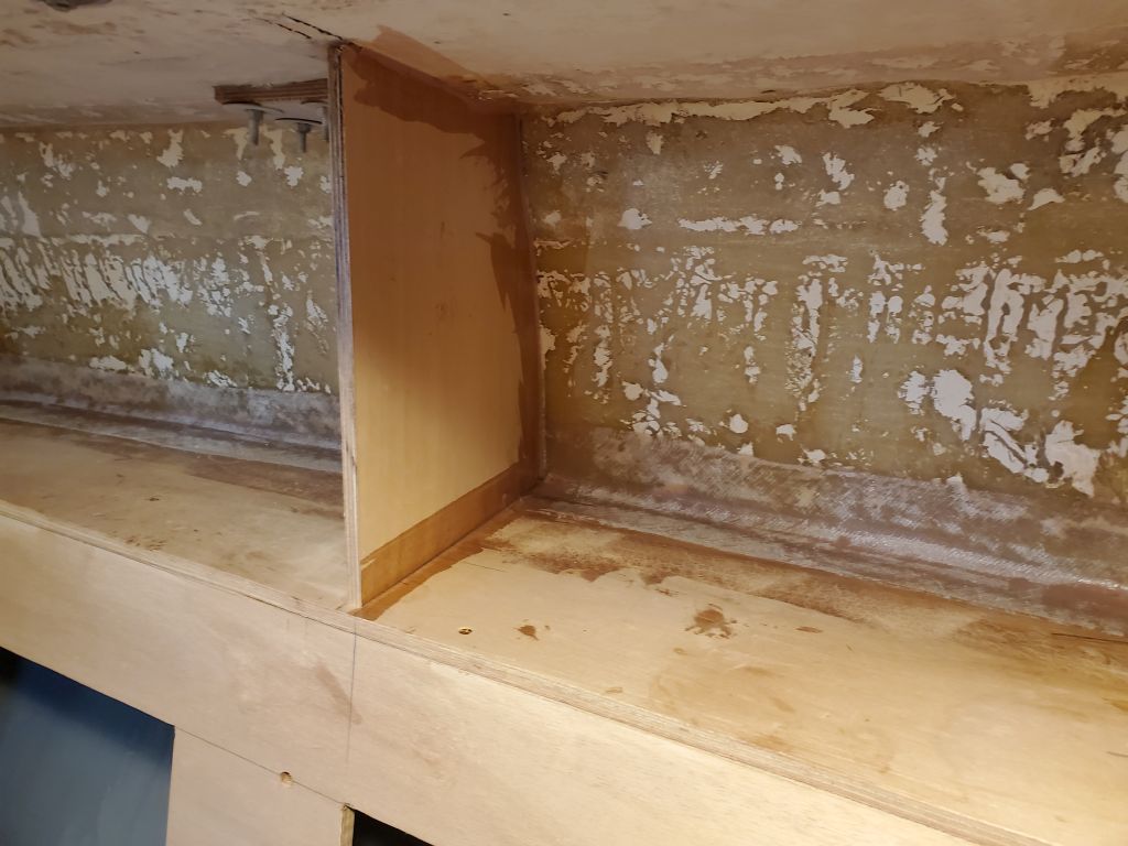
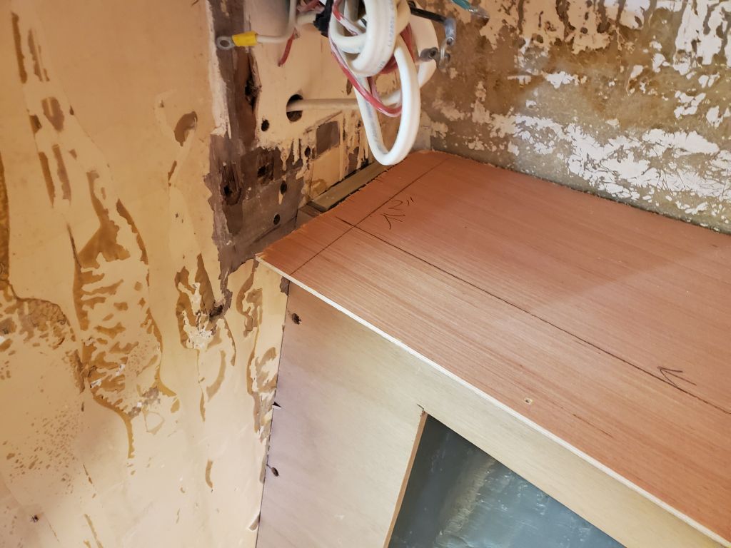
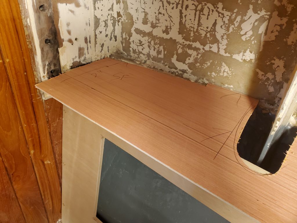
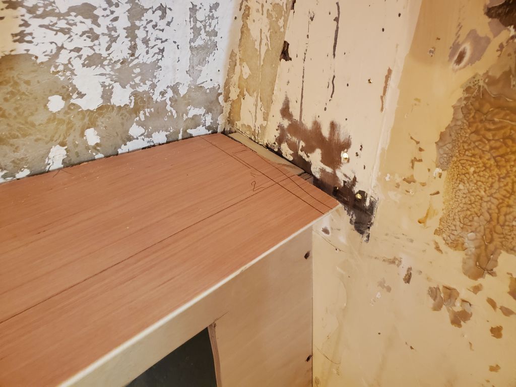
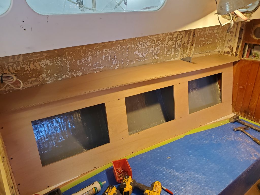
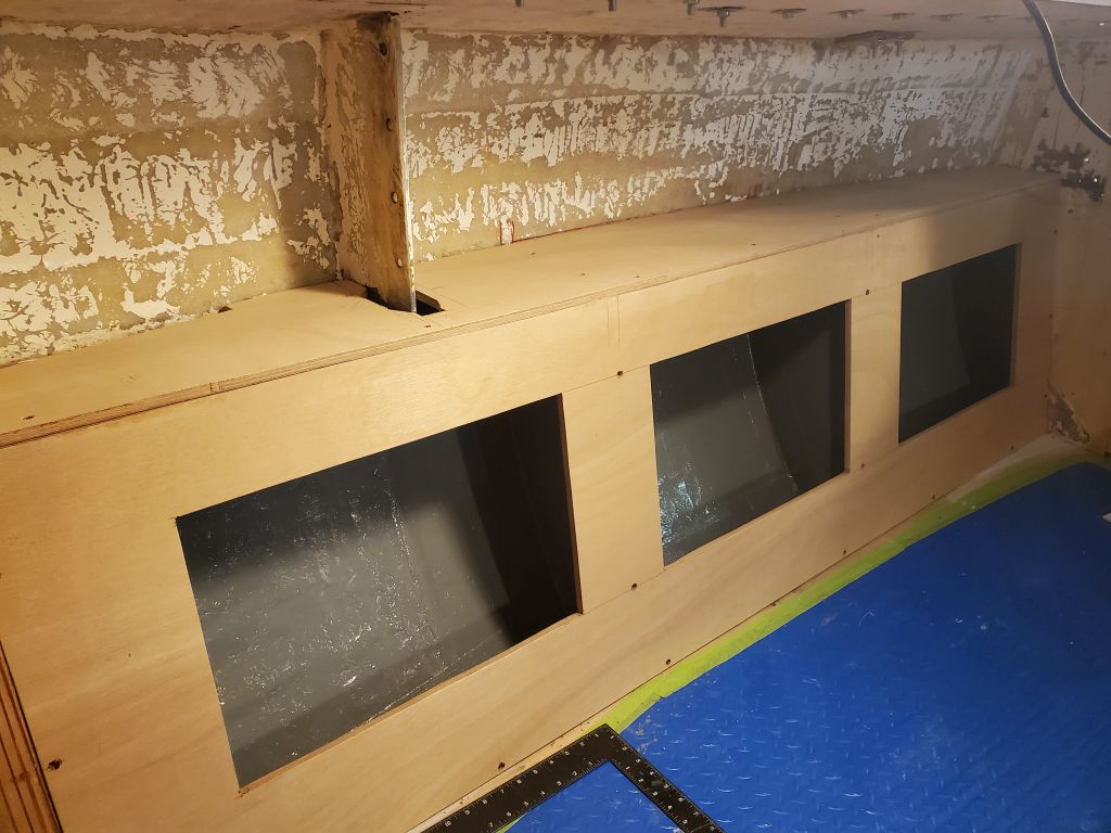
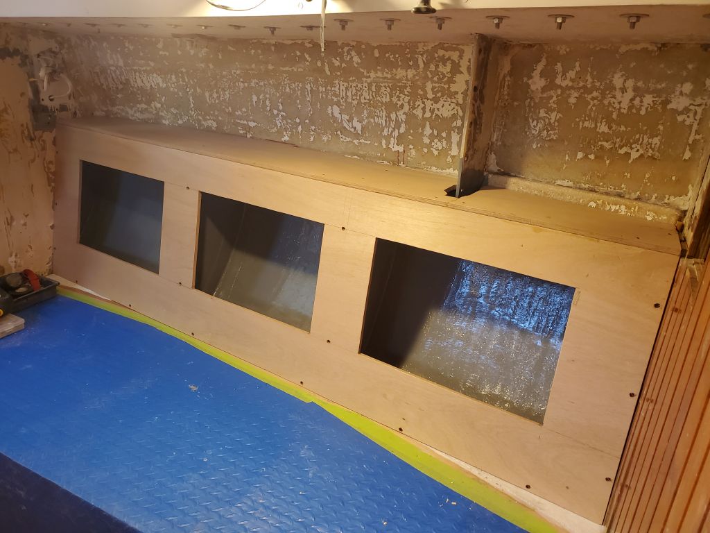
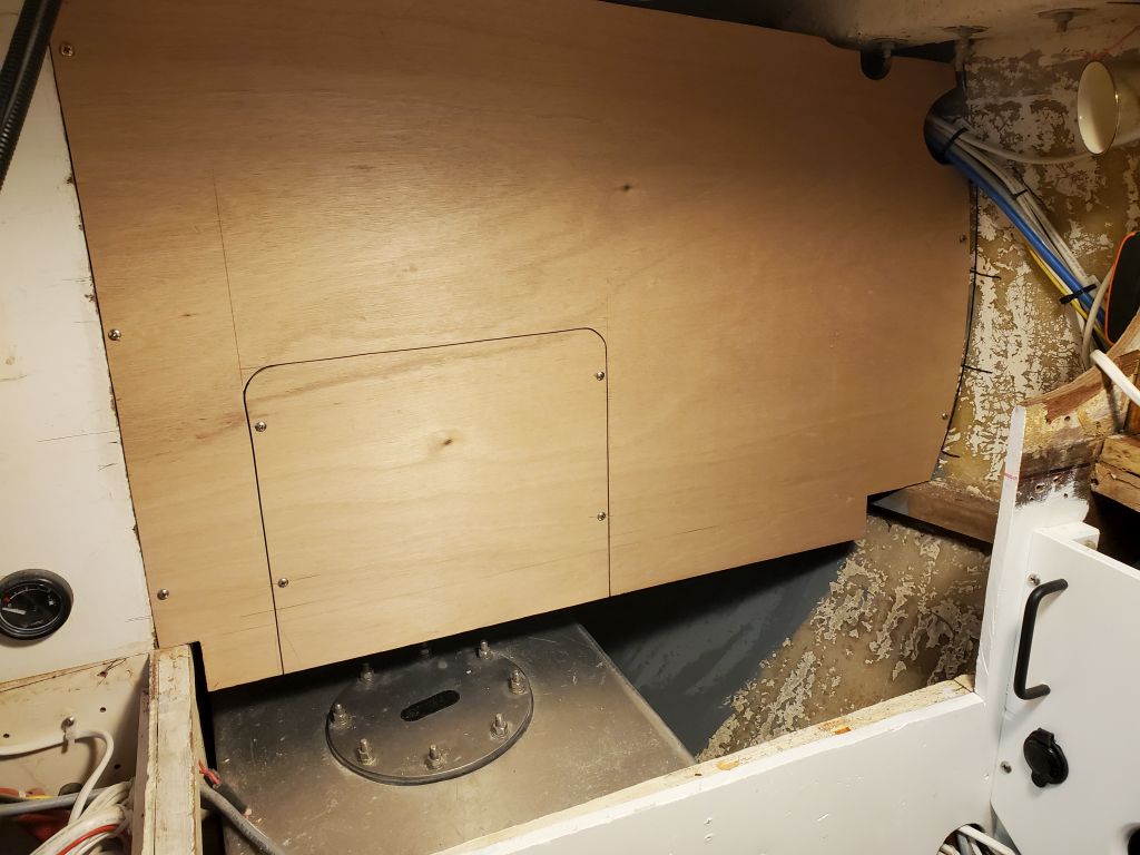
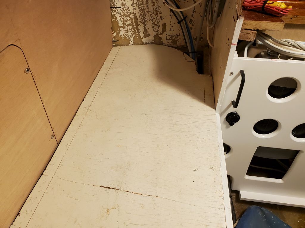
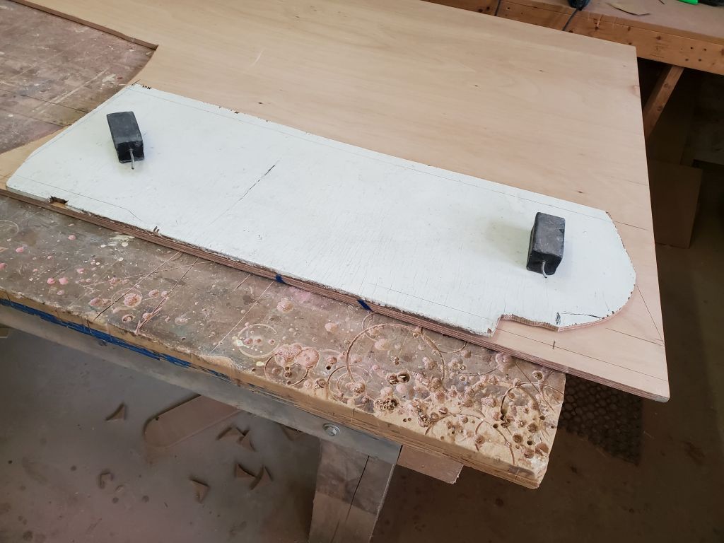
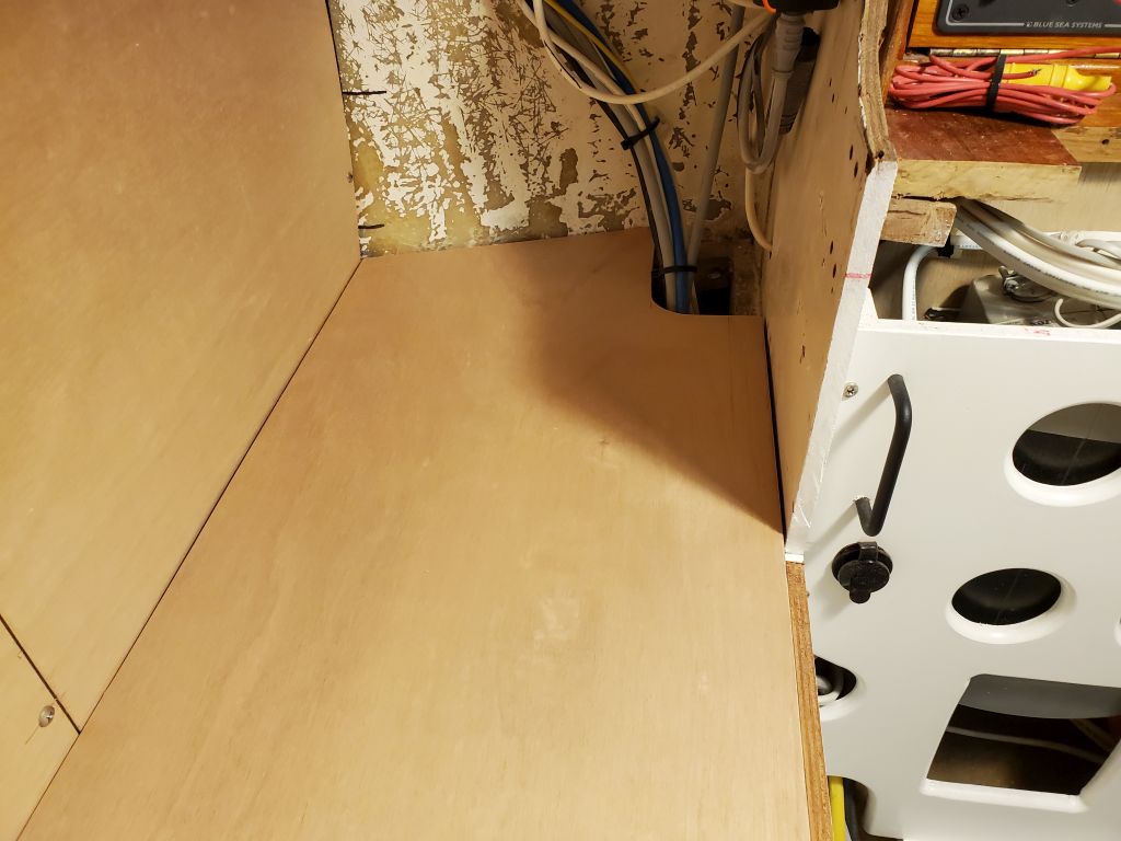
Using a cut-down section of the original platform as a template, I cut a new panel to fit the space.  The new panel required a bit of trimming on the inboard edge, and afterwards I marked it roughly at the edge of the fuel tank so I could cut the panel into two pieces to make removal easier for access to the fuel tank and other spaces in the future.  I installed a support cleat (not shown in the photos) on the underside of the inboard shelf panel to support the seam, and secured these panels with screws to hold them in place, while maintaining easy removability/  I also removed and cut the support cleat on the bulkhead, then reinstalled the three pieces permanently with glue and screws.

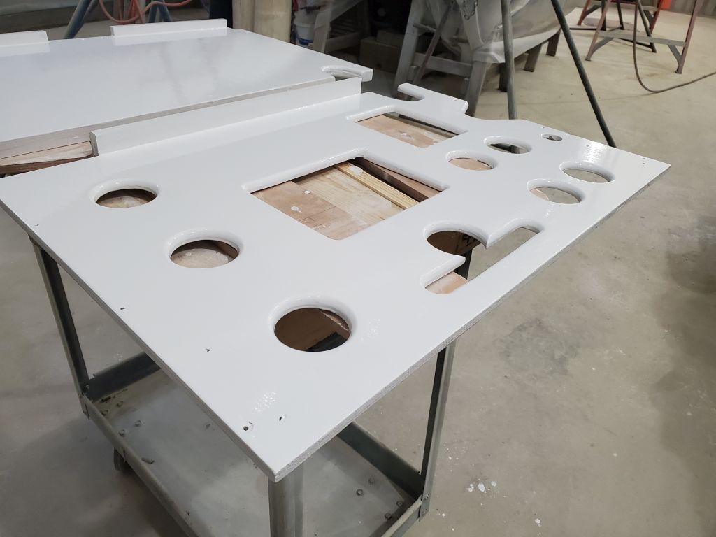
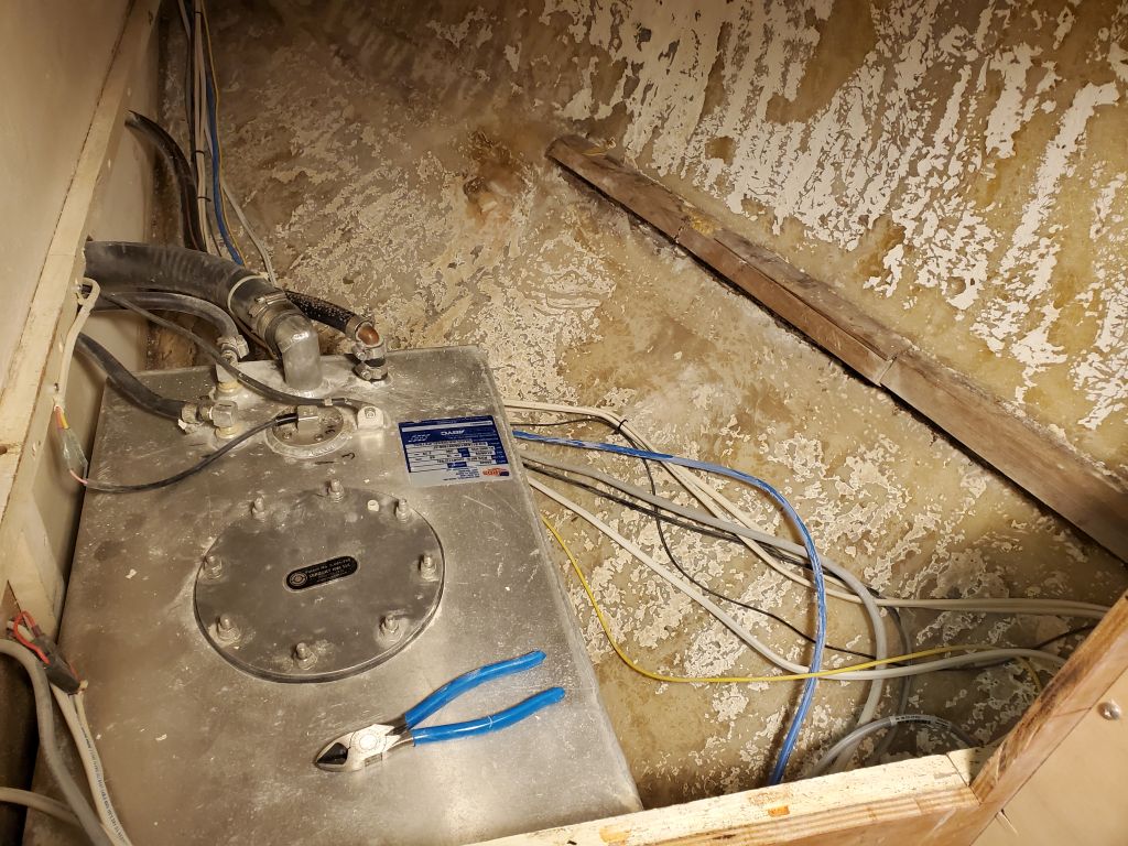
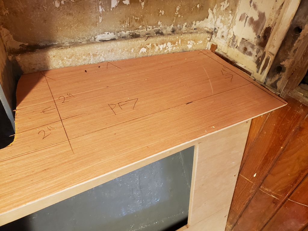
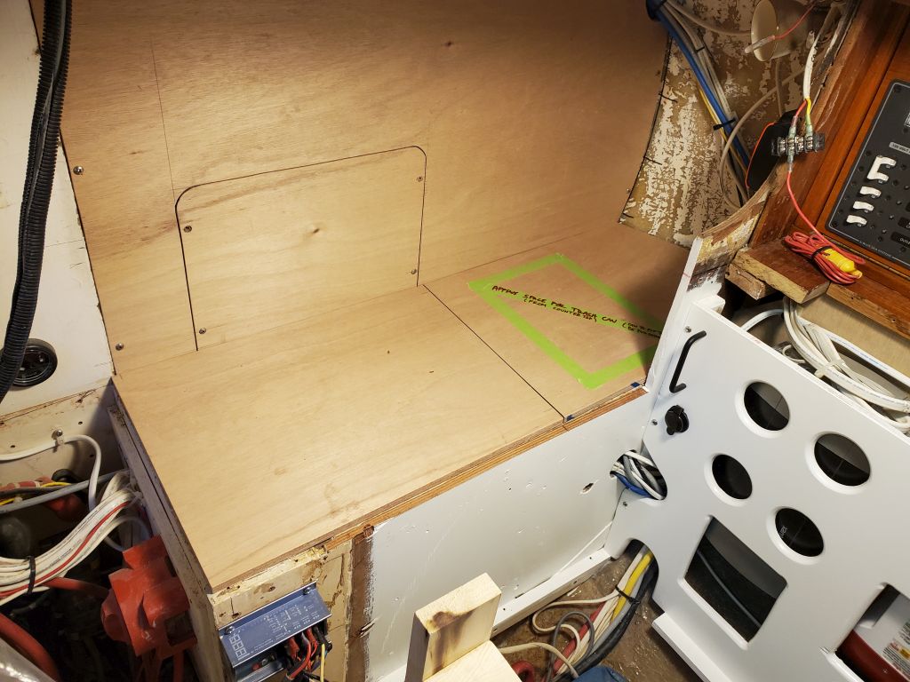
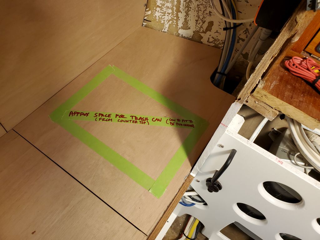
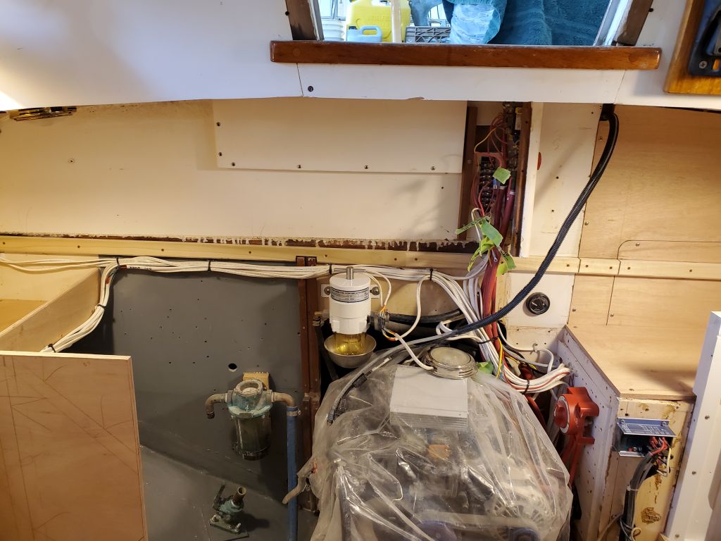
At the owner’s request, I planned for a garbage can beneath the countertop in the outboard section of this space, where the can could conceivably extend down into the open space adjacent to the fuel tank.  I’d find a can somewhere to fit, then make any cuts accordingly a little later.

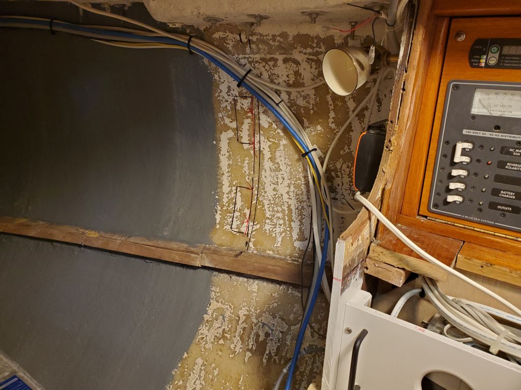
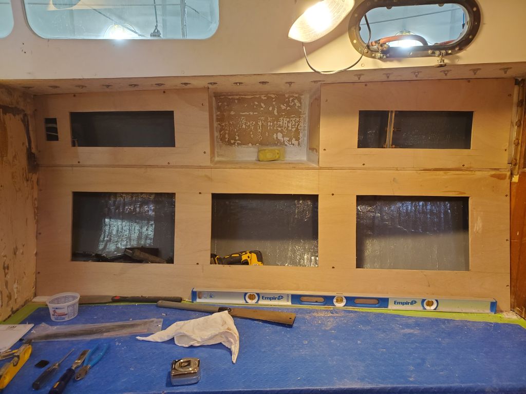
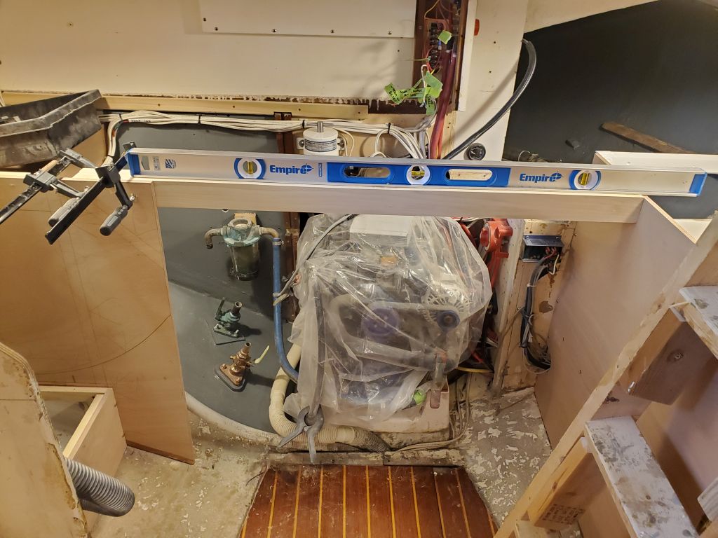
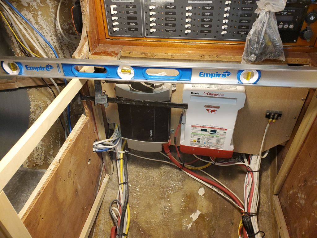
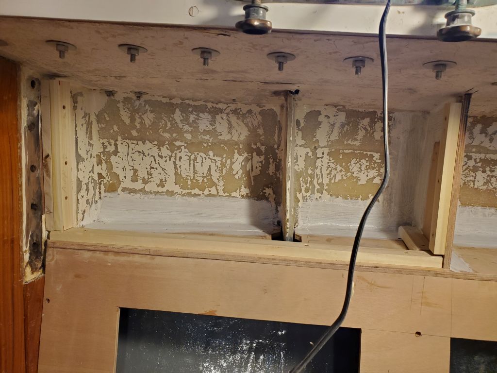
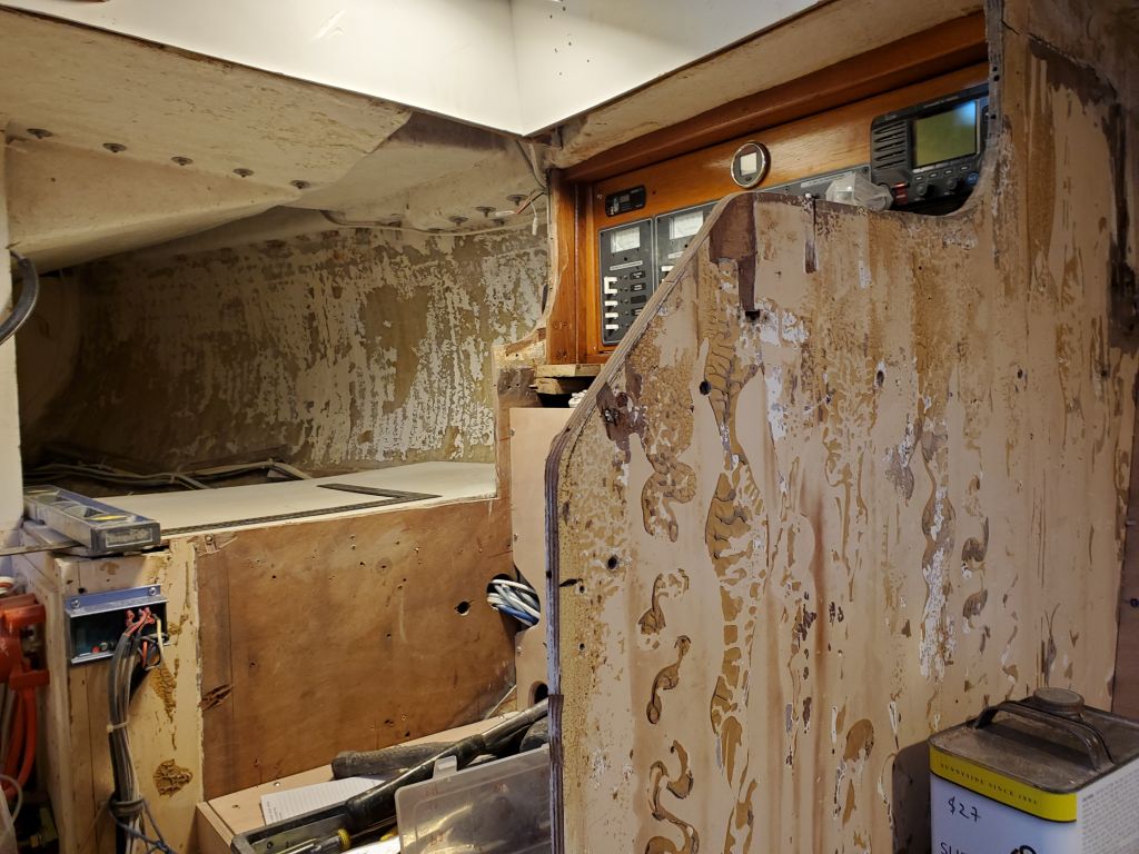
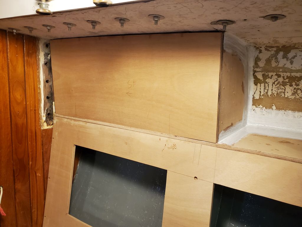
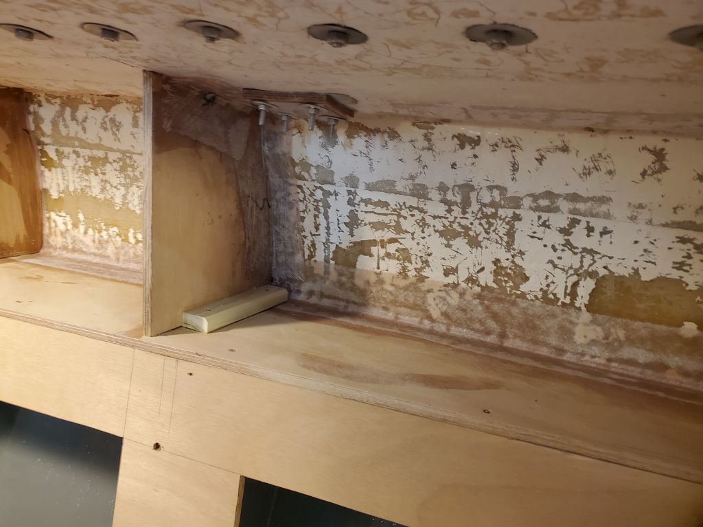
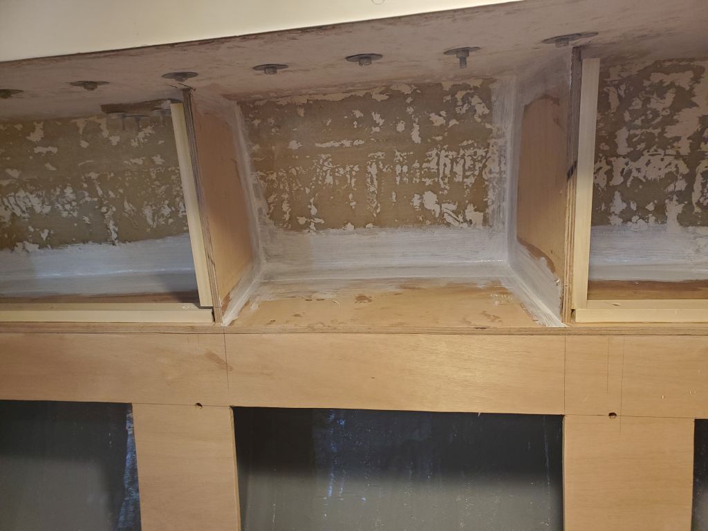
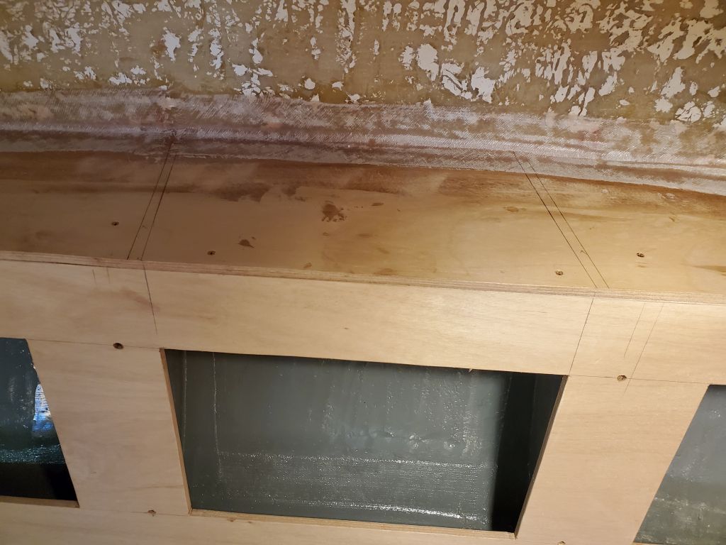
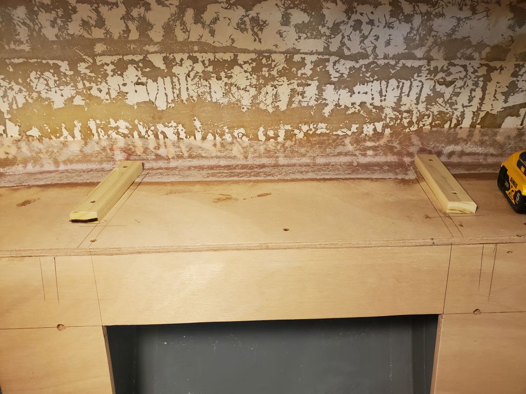
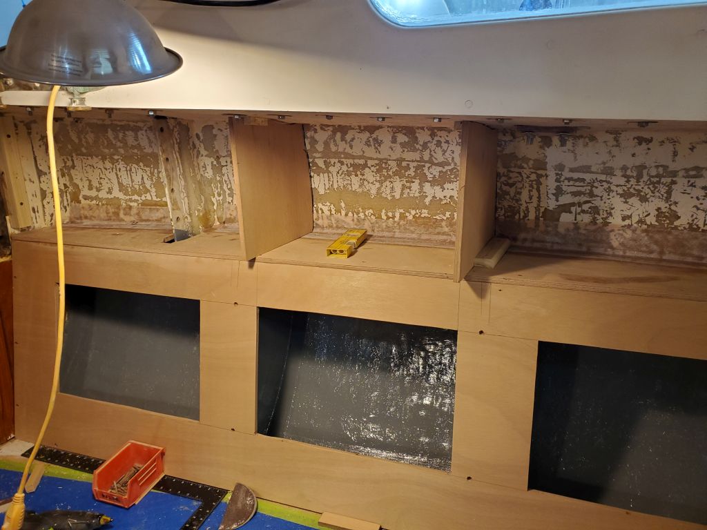
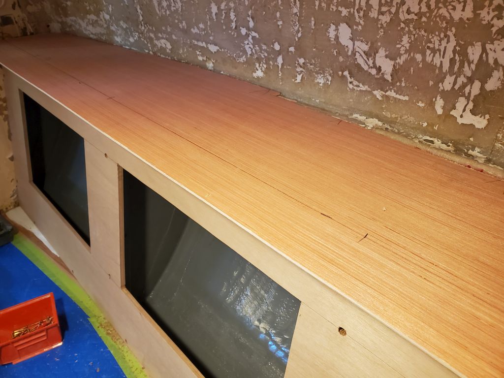
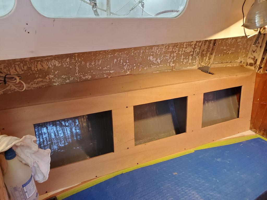
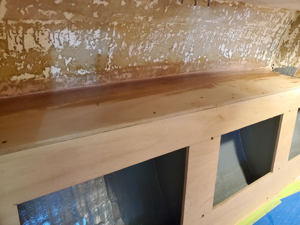
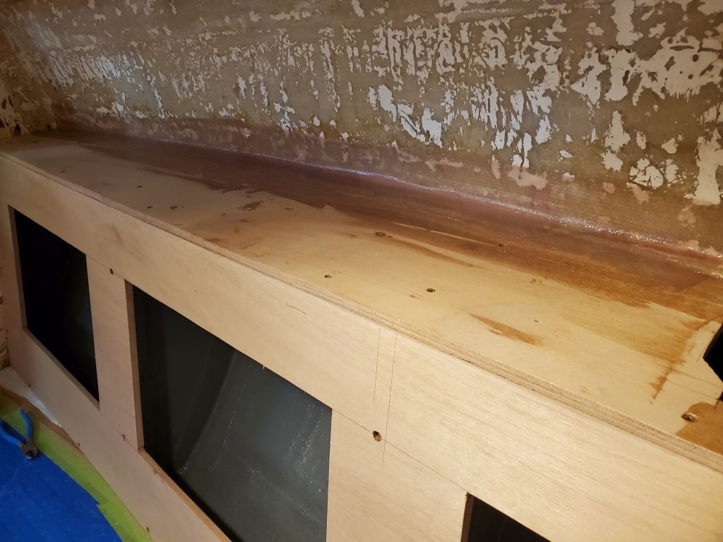
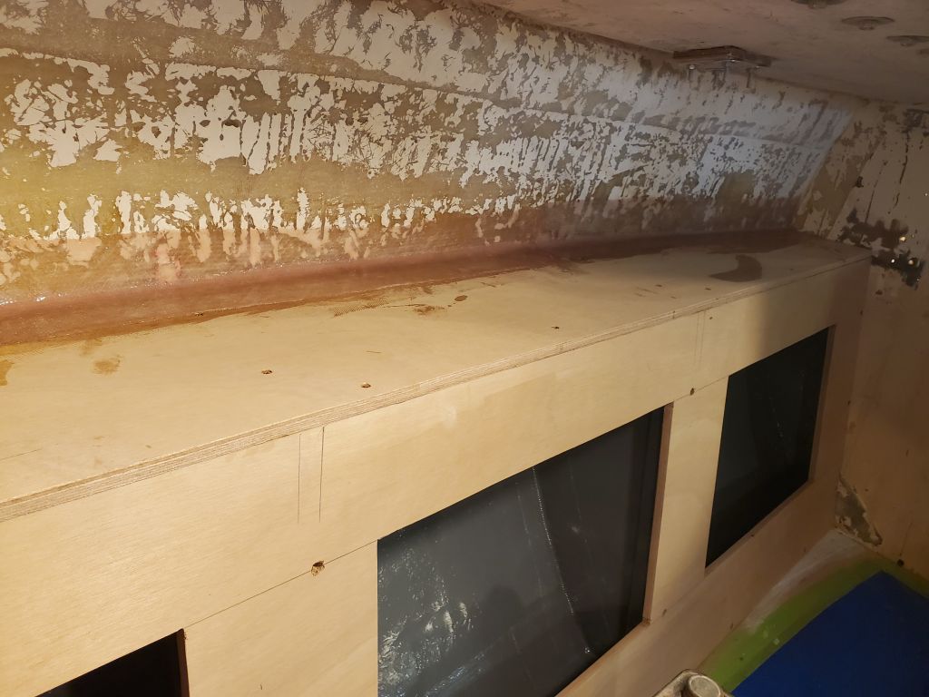
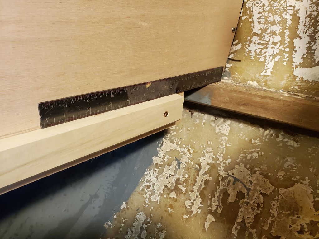
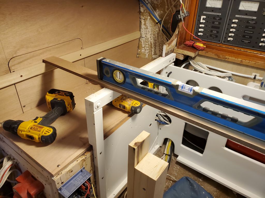
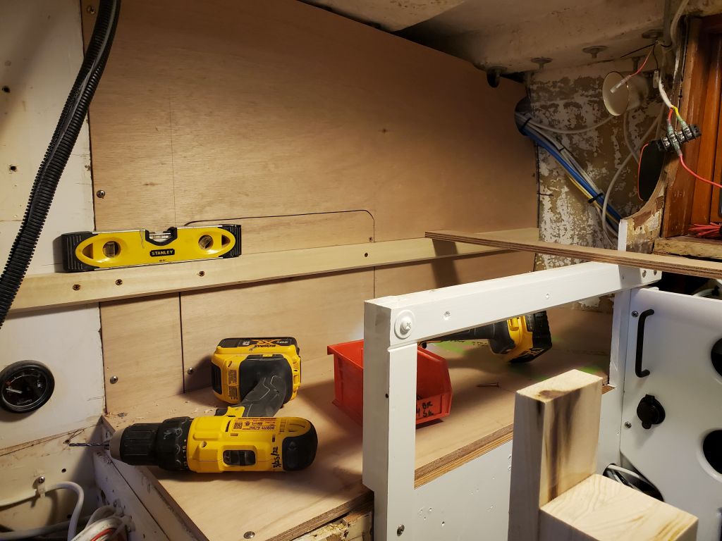
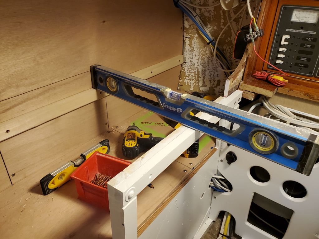
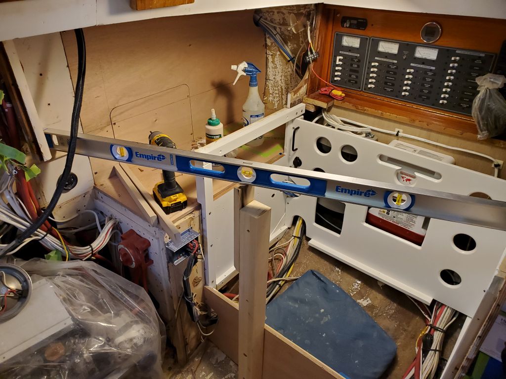
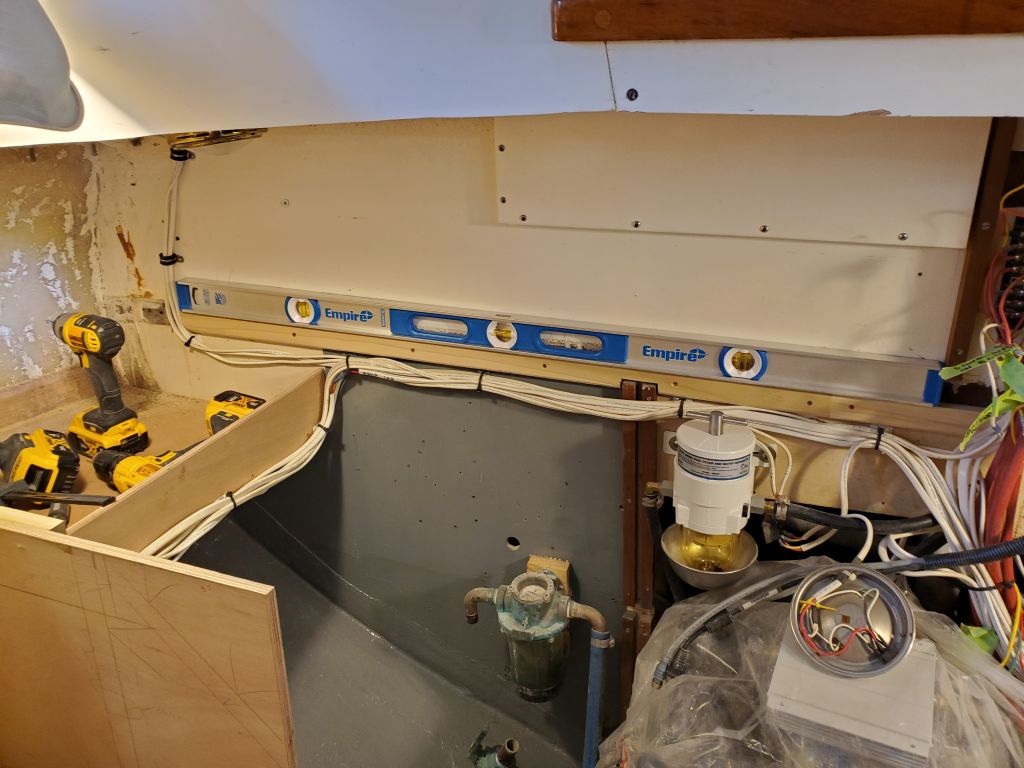
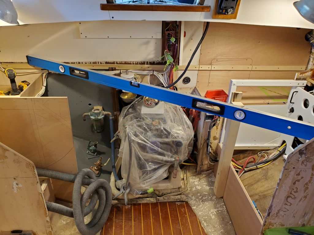
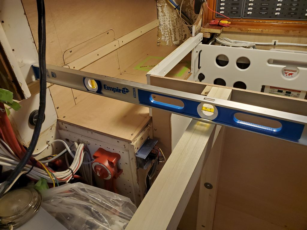
Now I reinstalled some of the support structure around the refer compartment so I could lay out and install support cleats for the countertop.  After making some initial layout marks, I dry-installed a full-length cleat across the space, and as far inboard as the edge of the similar cleat on the starboard side that I’d installed earlier.  I’d initially determined the countertop height starting with the port side, some weeks earlier, as I worked to enclose the refrigerator, and this height, which at the time I determined was roughly an inch lower than the original counter, drove the rest of the layout, including the stove enclosure and that aft cleat on the starboard side.  That cleat never looked quite right after the fact, but I’d checked its level across the boat a number of times, and from the supports on the port side, and it didn’t help that the ghost of the original cleat on the bulkhead was clearly out of whack, making the new cleat look odd, and also higher than expected, though I knew from the port side that I’d lowered the original height.  This bothered me, but it was level athwartships, and seemed to coordinate correctly with the other layout, so I figured it would work itself out.  And indeed, it did.

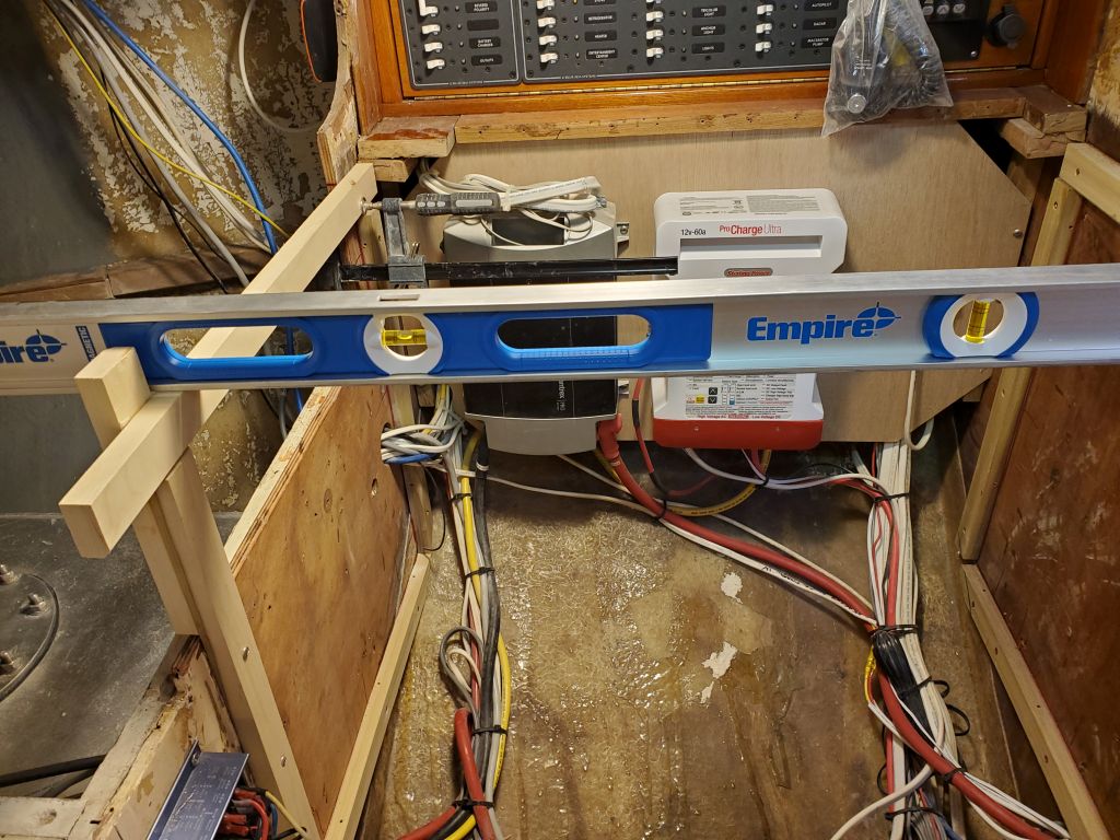
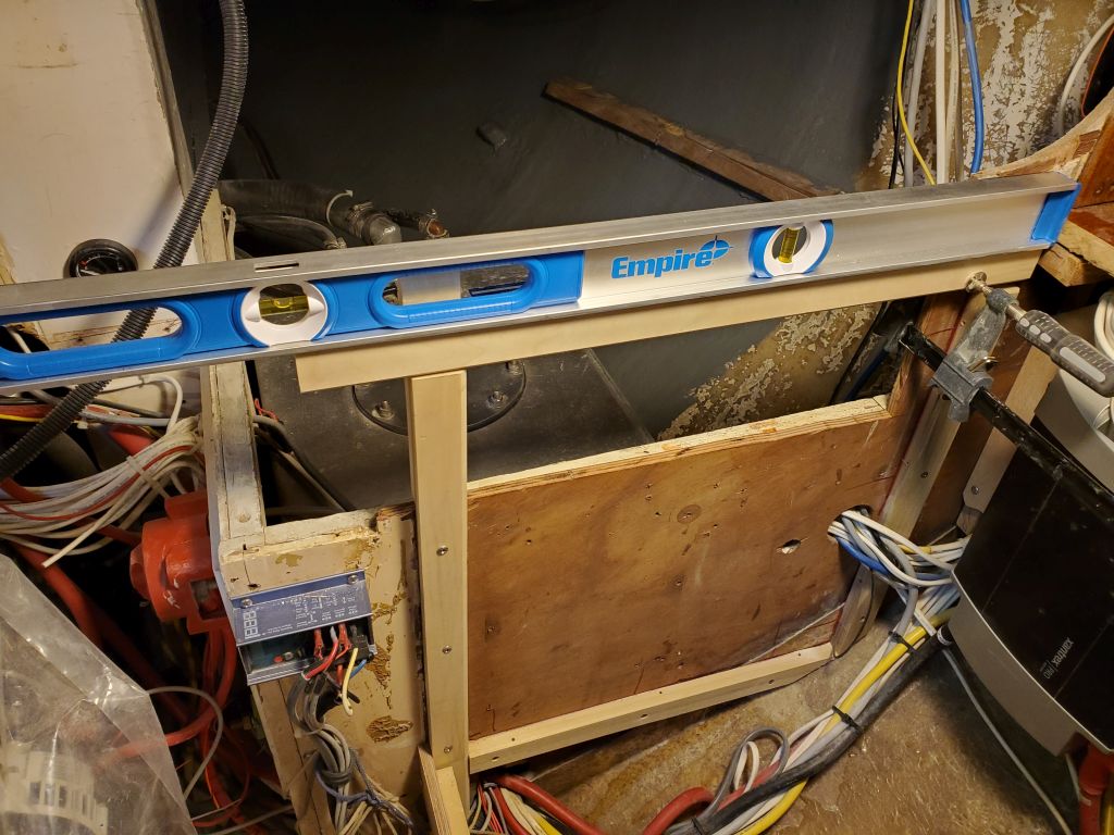
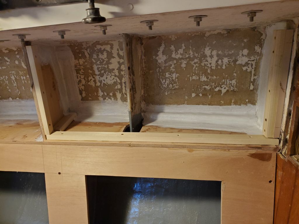
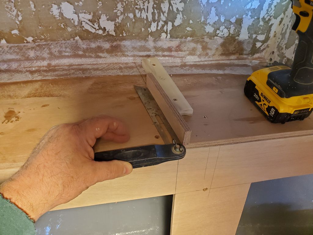
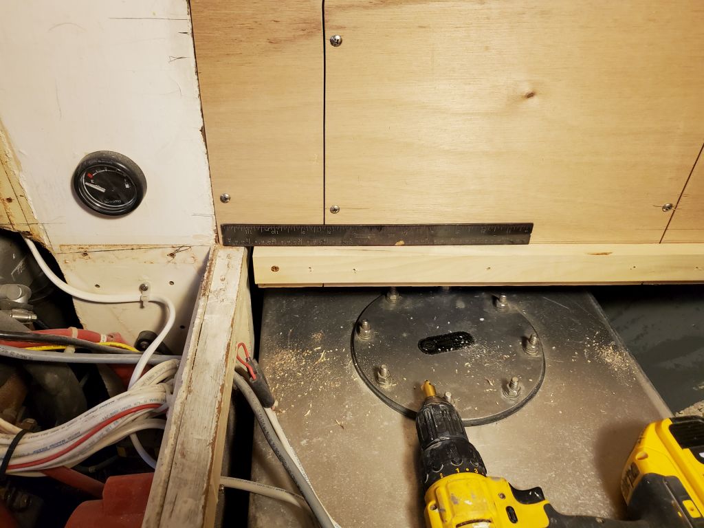
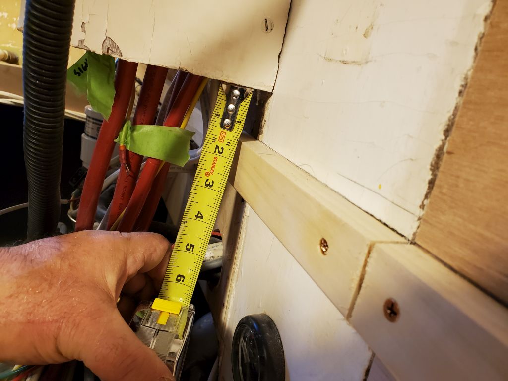
When I laid out and installed the new cleat across the port side, double- and triple-checking the level across in as many dimensions as possible, it turned out that the new cleat met the old one approximately 1/2″ lower.  This led to some additional detailed checking of the starboard cleat’s position, which I eventually determined was indeed level athwartships, but was mounted just that bit too high.  This explained everything–the impression that the countertop was higher than I thought it was, and the idea that the cleat had never been quite right in (till now) undefinable ways.

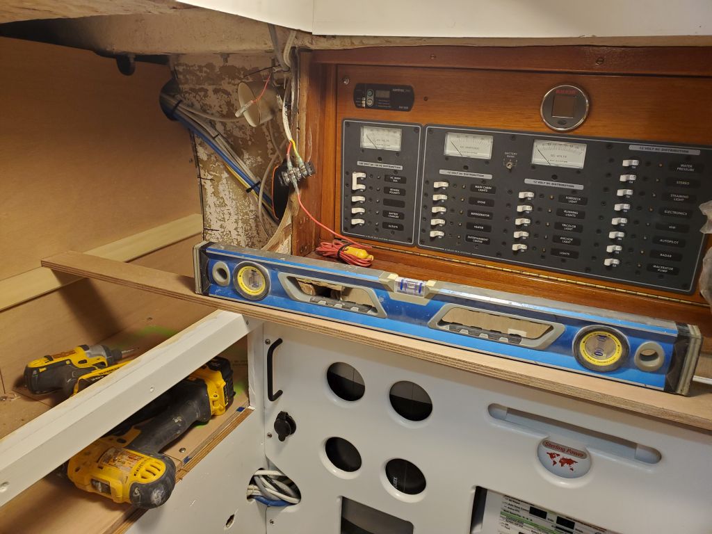
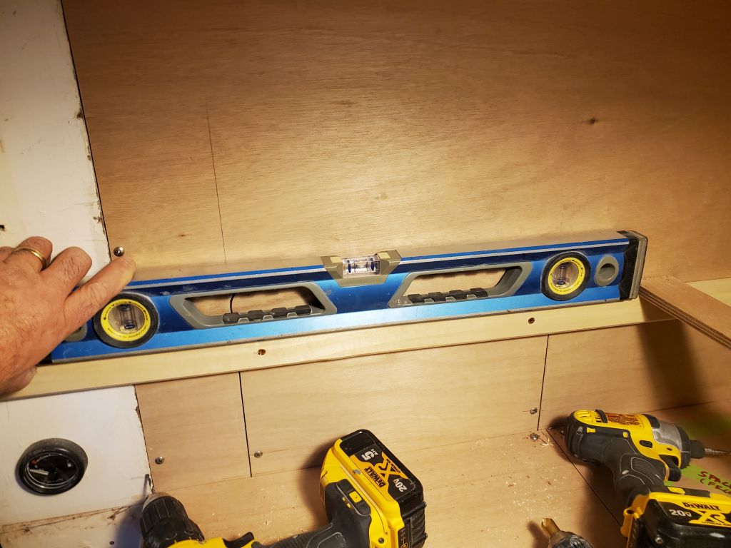
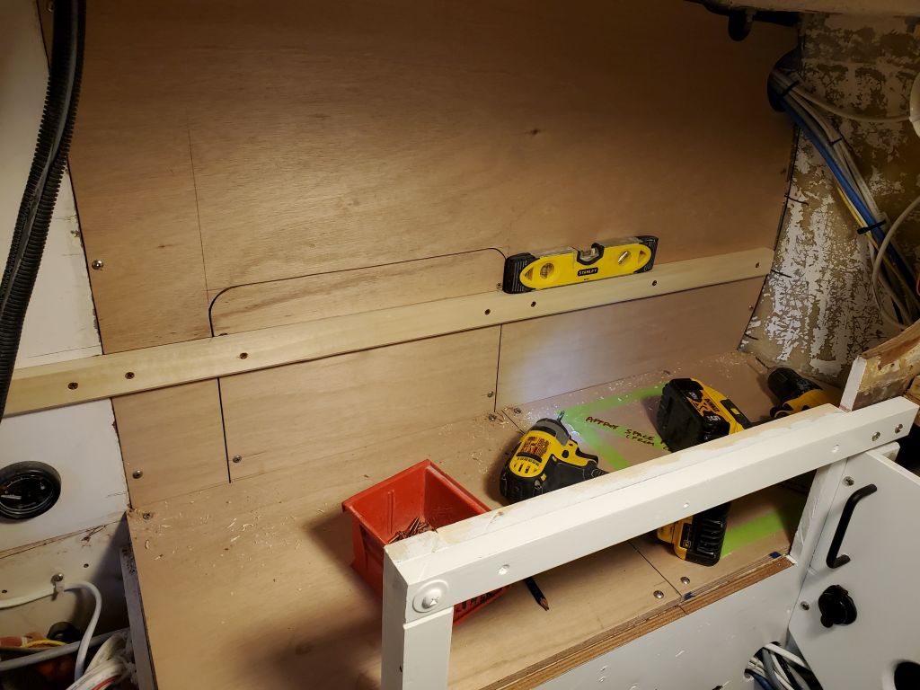
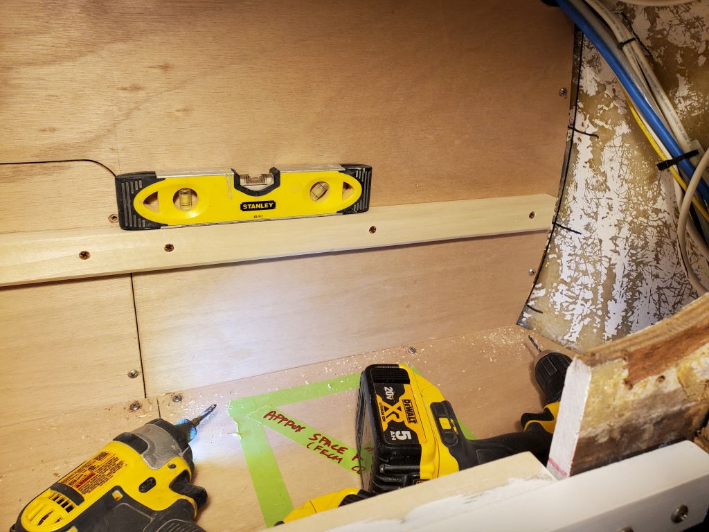
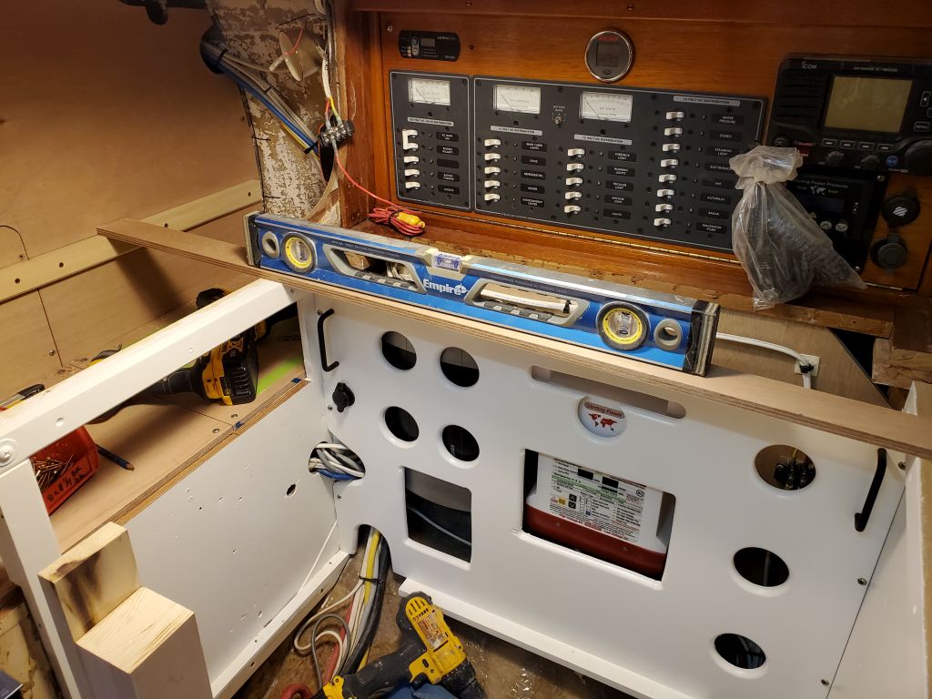
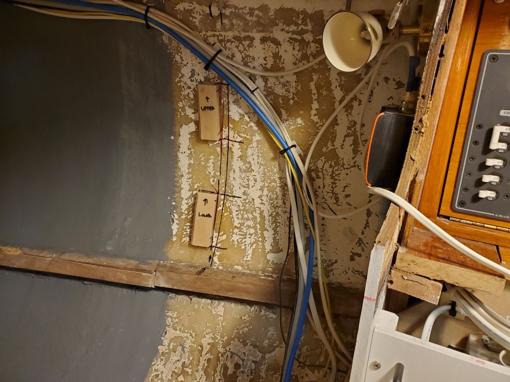
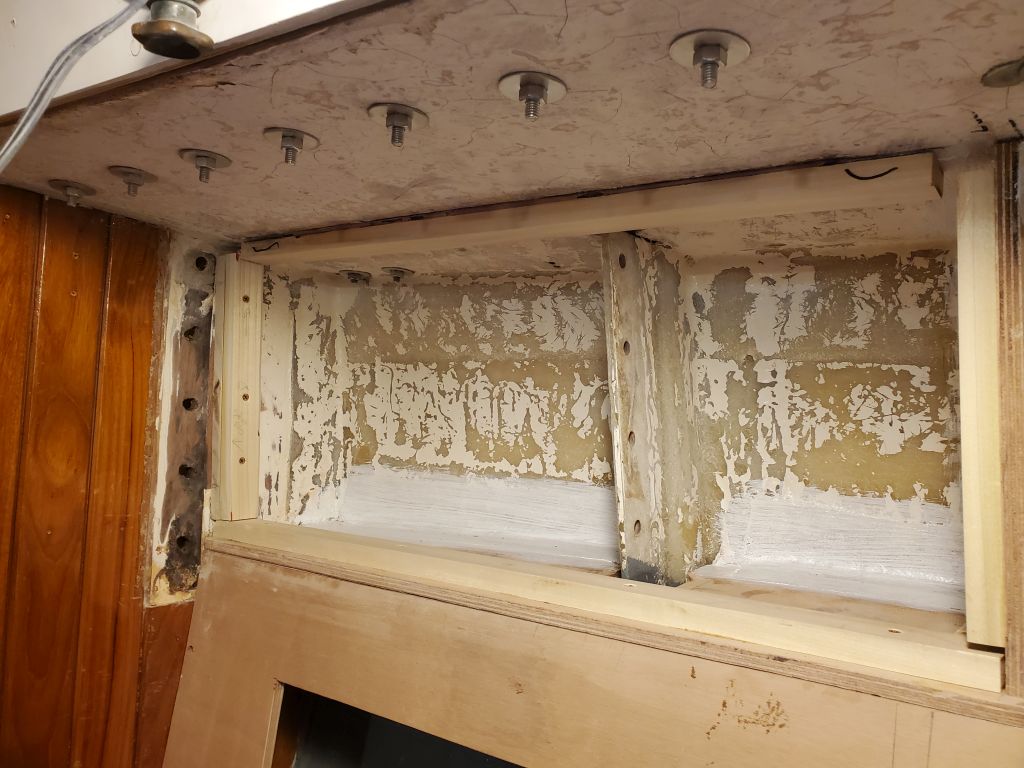
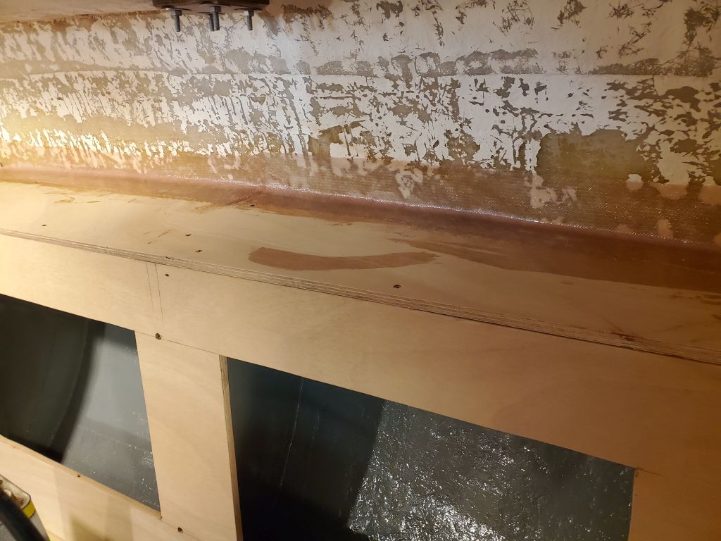
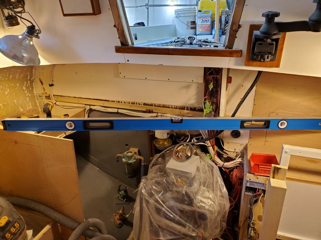
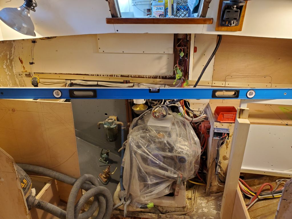
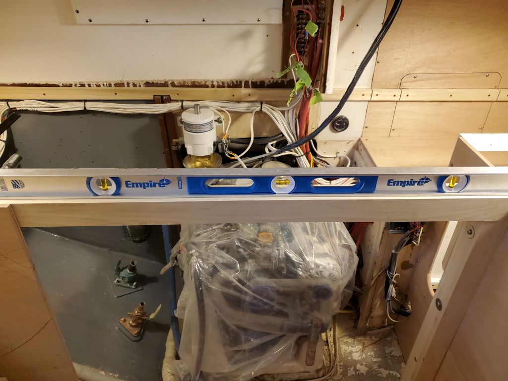
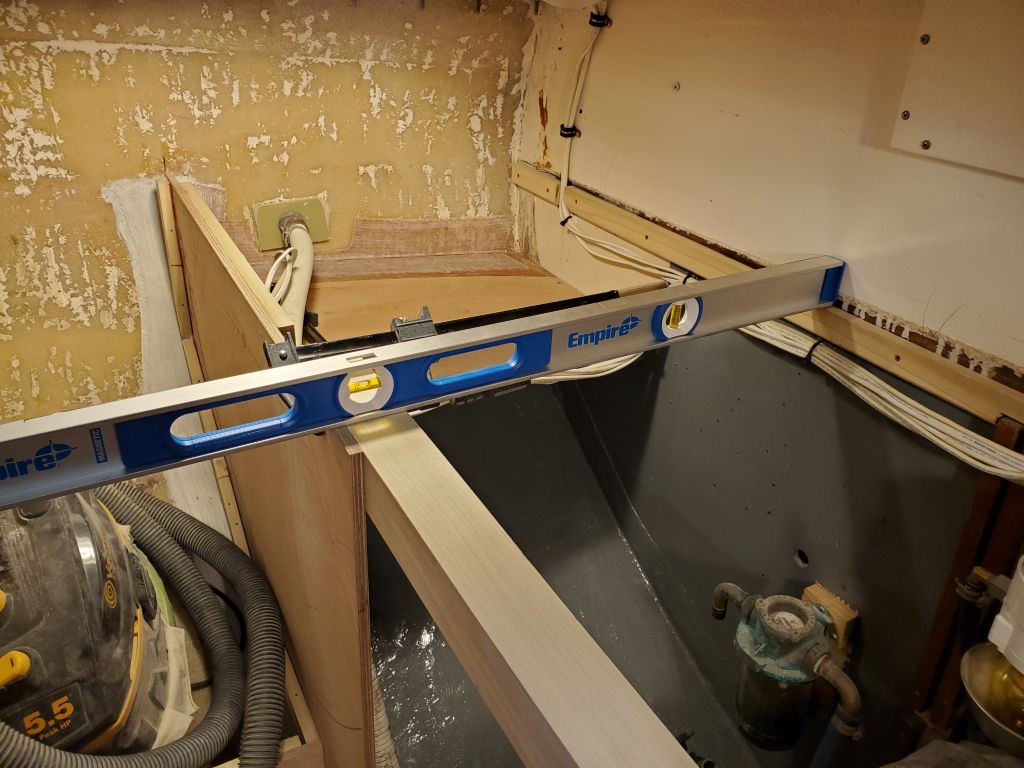
After confirming that everything else was still in proper agreement with the initial early height reference points and every which way, I determined that my layout was correct from the onset, but somehow I’d installed that cleat just too high.  All I could do now was blame the 4′ level that I had used this cleat’s installation, which level had started seeming wonky when I was laying out the settees around the same time too (that level had since been discarded and replaced with a new one).  In any event, fortunately the fix was an easy one to remove the cleat and reinstall it at the correct height, which happily was the same as the new cleat I’d just installed (as well as everything else).  Once I’d reinstalled the cleat correctly, everything tied in well, which I checked with every level I had and in as many directions as I could across the boat and fore and aft and athwartships.  Using the bottom edge of the vertical panel that once defined the edge of an upper galley locker, above the engine room, I determined the new cleat was just under 1-1/2″ lower than the original countertop, meaning the new countertop (at 1/2″) would end up 1″ lower than the original, which was what it should have been all along.

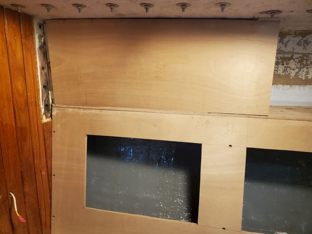
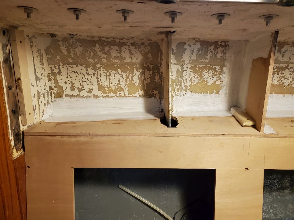
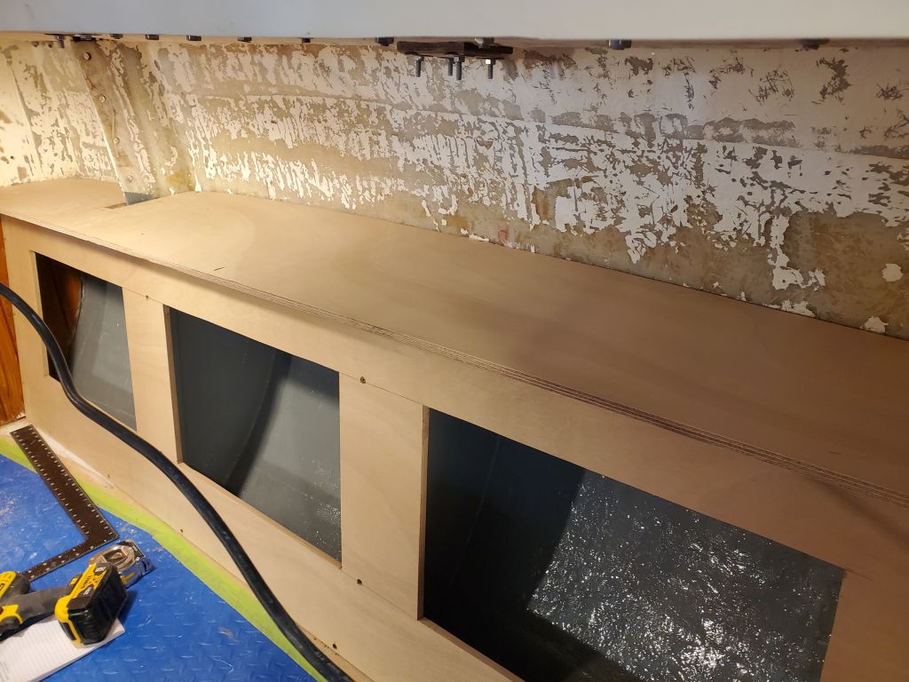
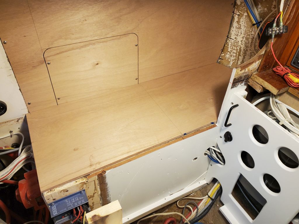
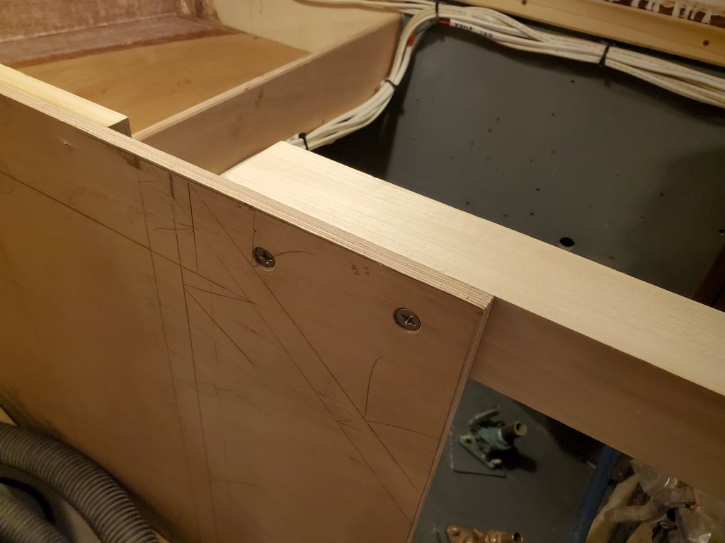
Once I’d determined that the new aft cleat was correct, and had puzzled through the other inconsistency, I removed the new cleat as well and cut it as needed at several places to allow removal of the entire quarterberth bulkhead (if needed) and the smaller access panel above the fuel tank, then reinstalled the now-four pieces with glue and screws.  This completed the basic layout and position of the countertop.

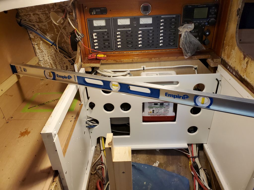
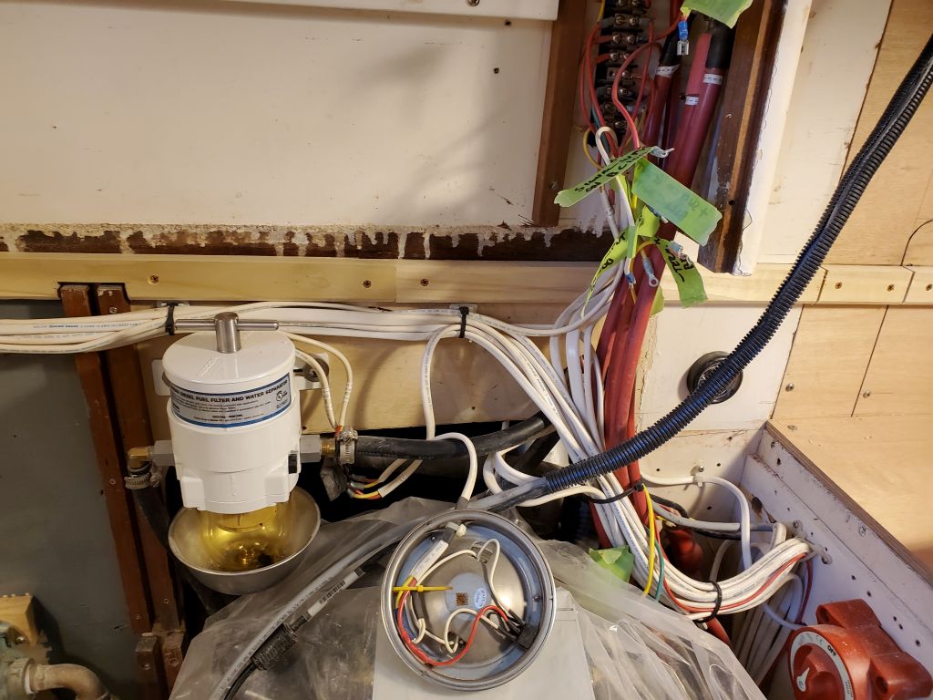
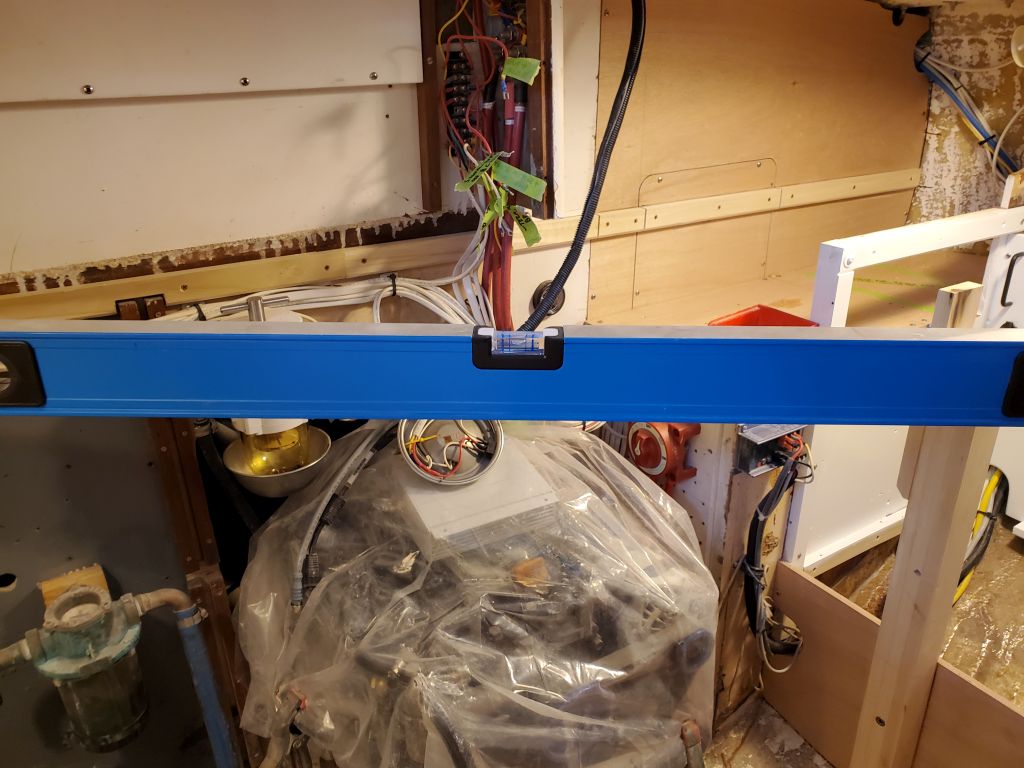
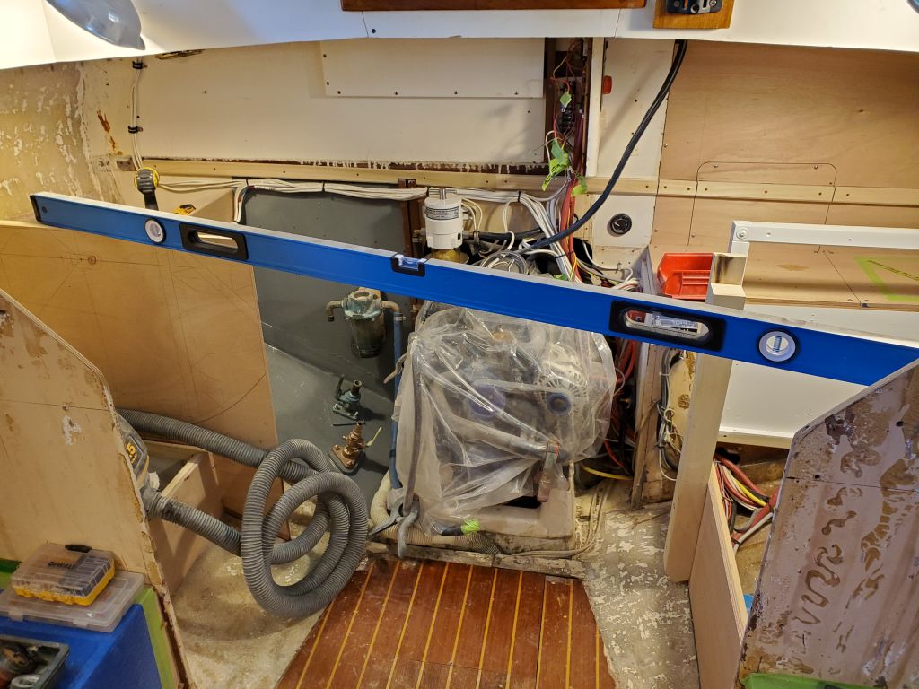
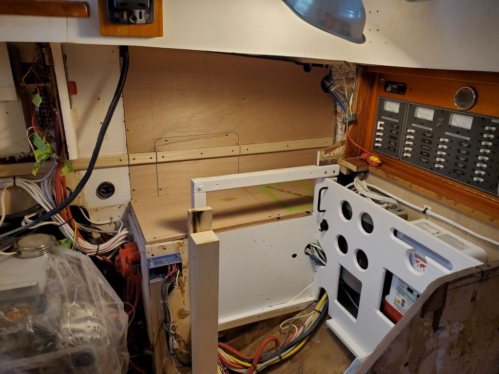
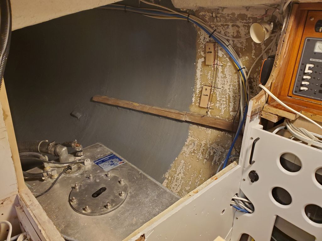
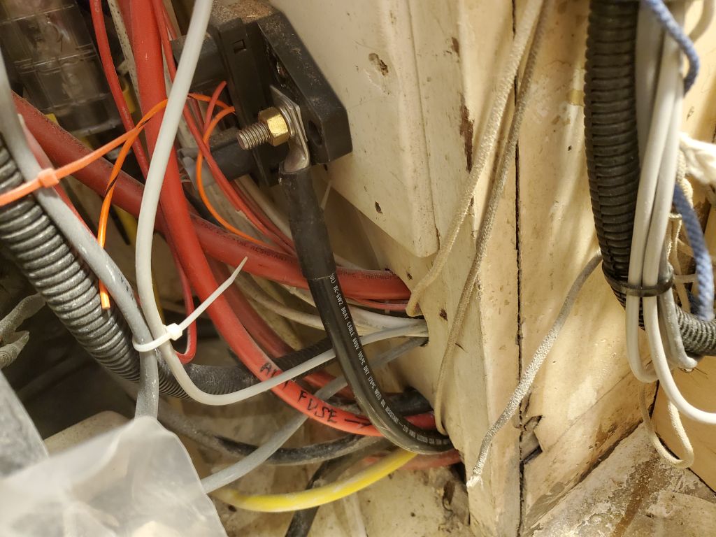
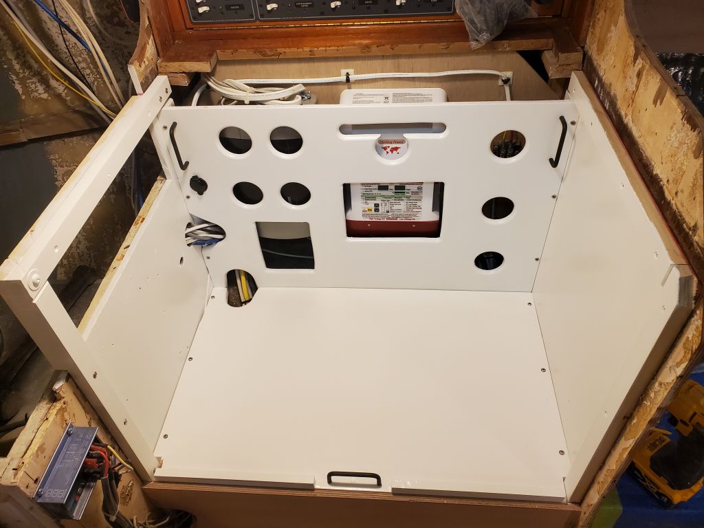
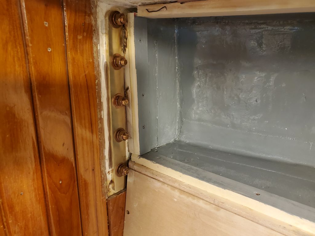
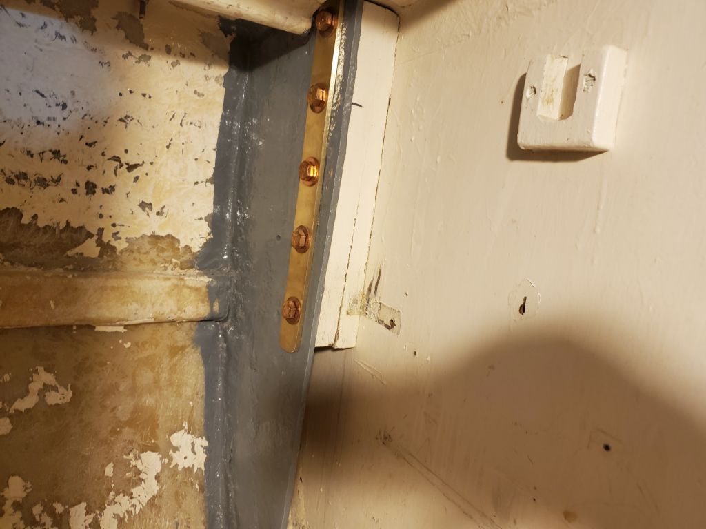
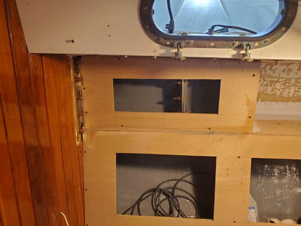
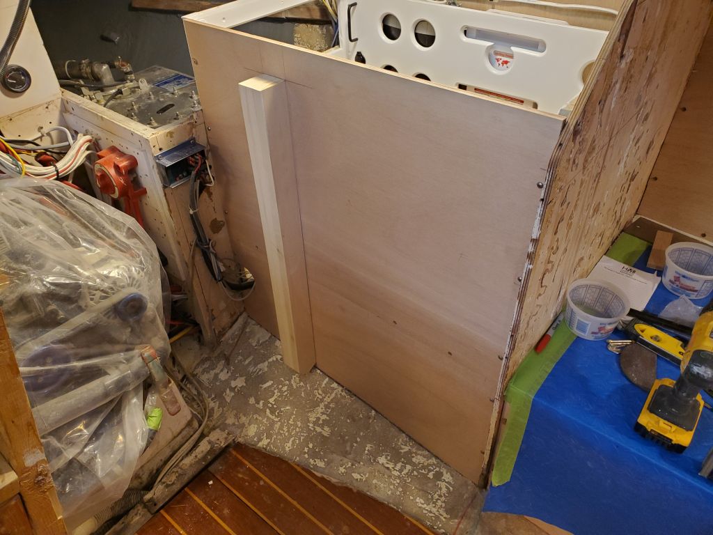
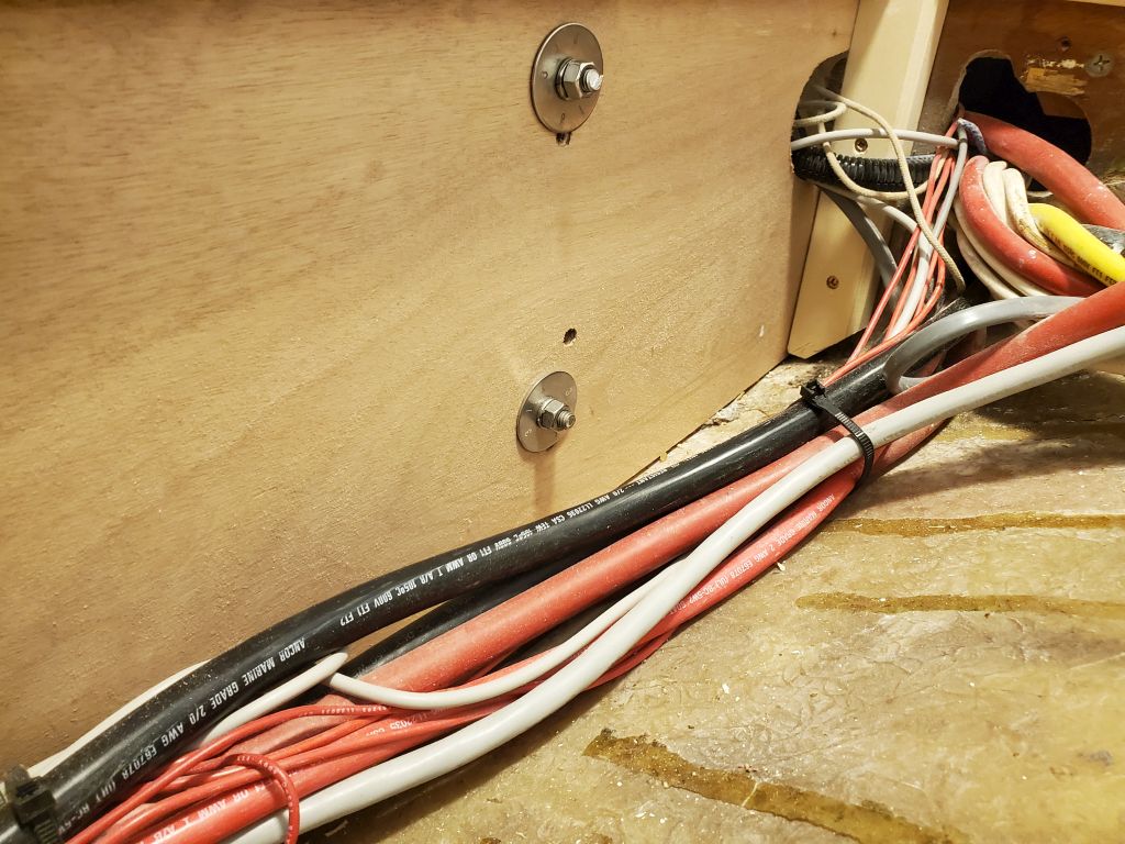
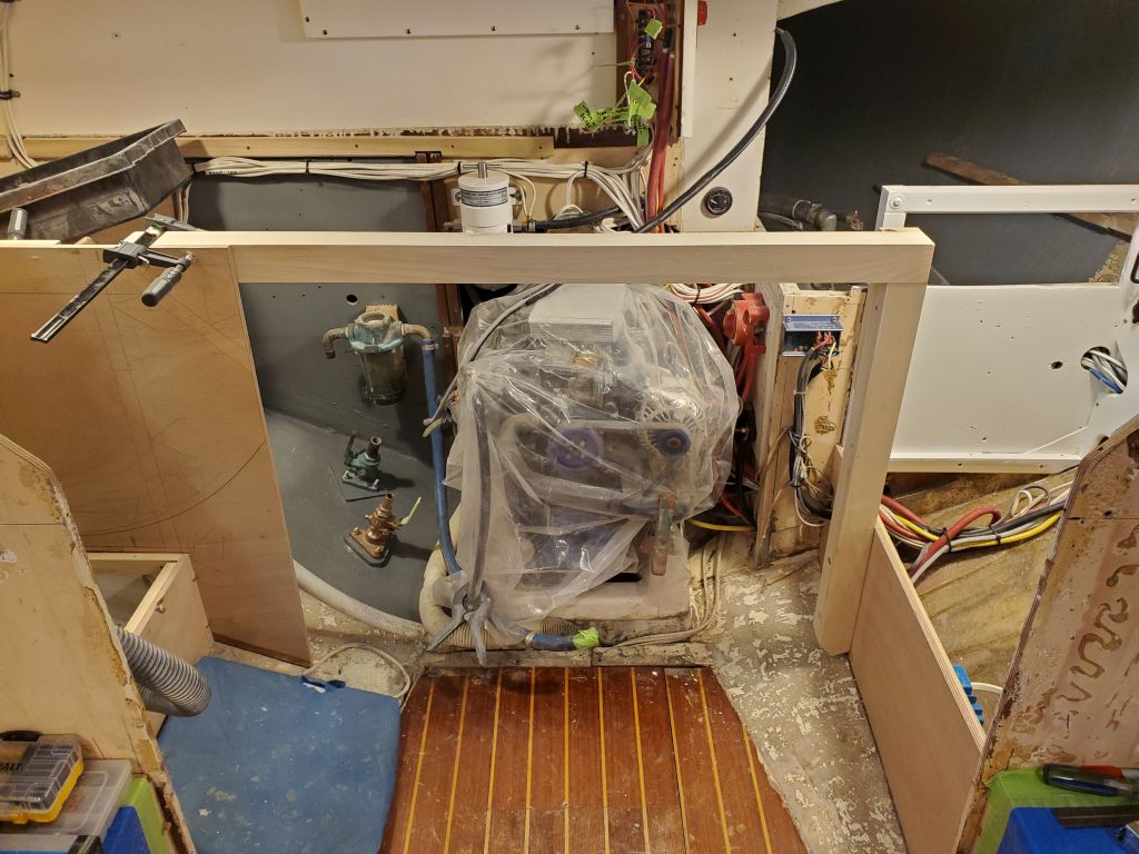
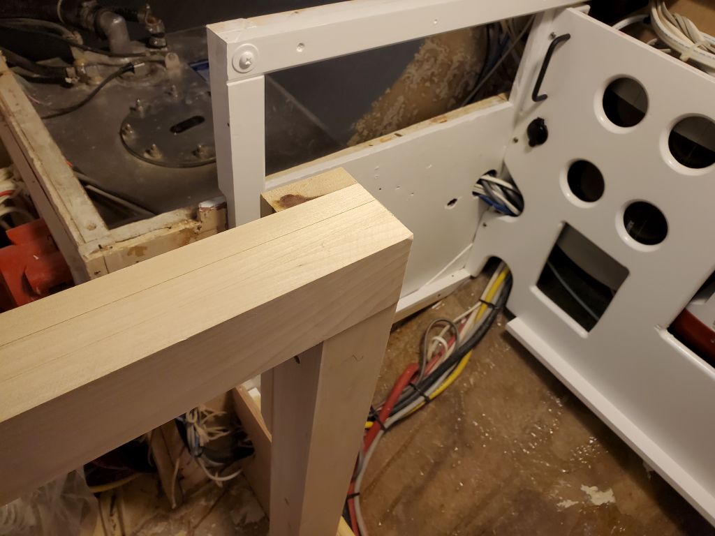
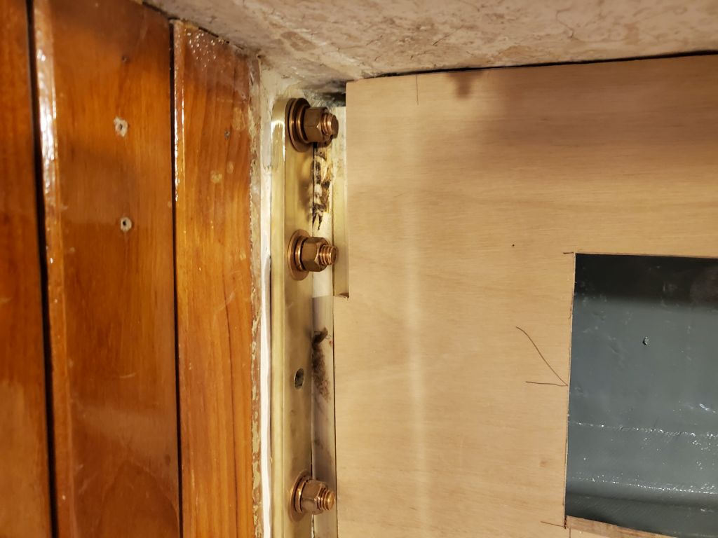
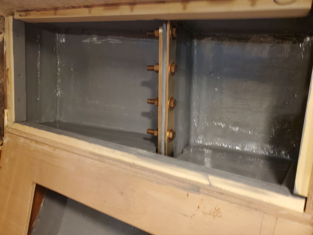
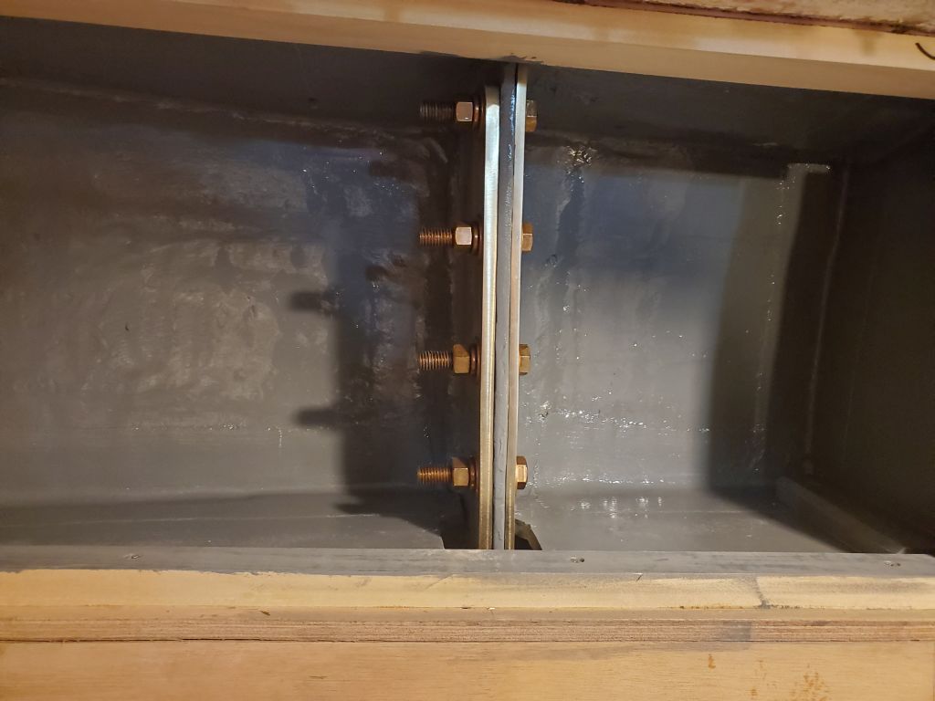
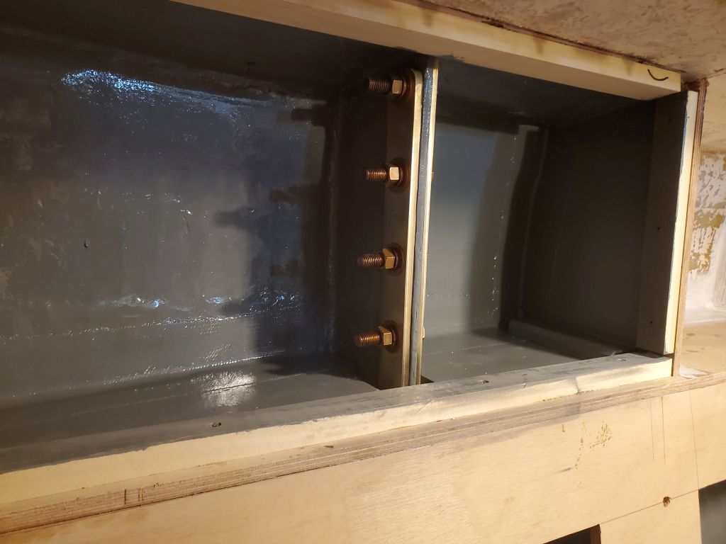
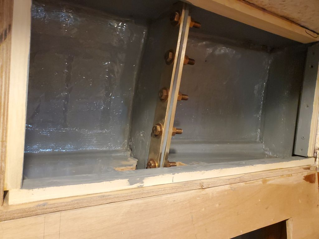
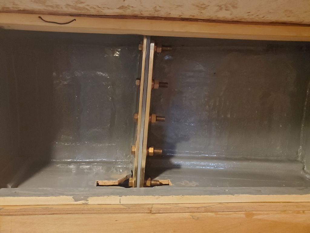
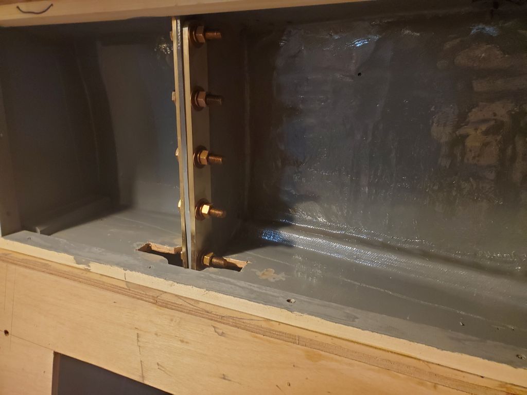
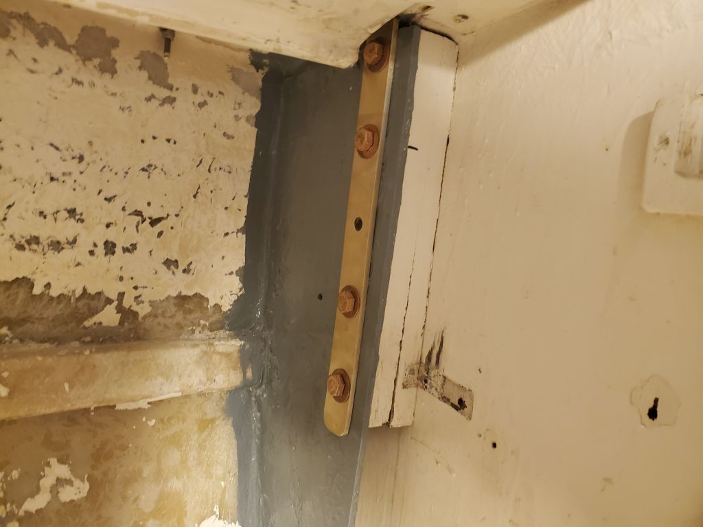
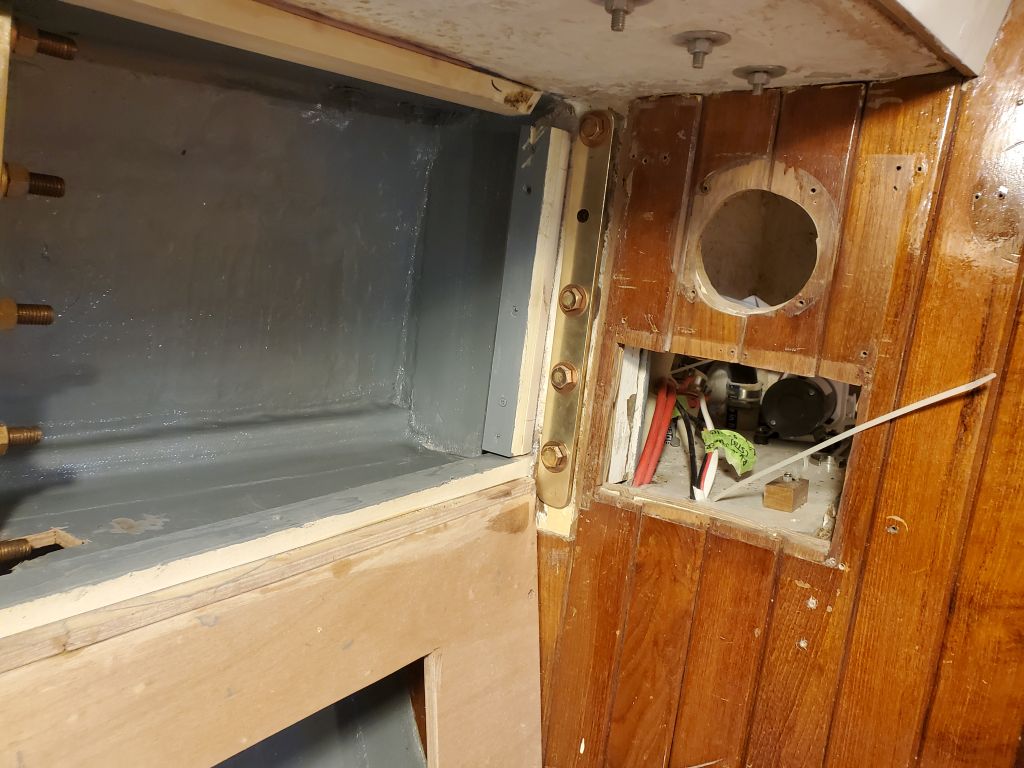
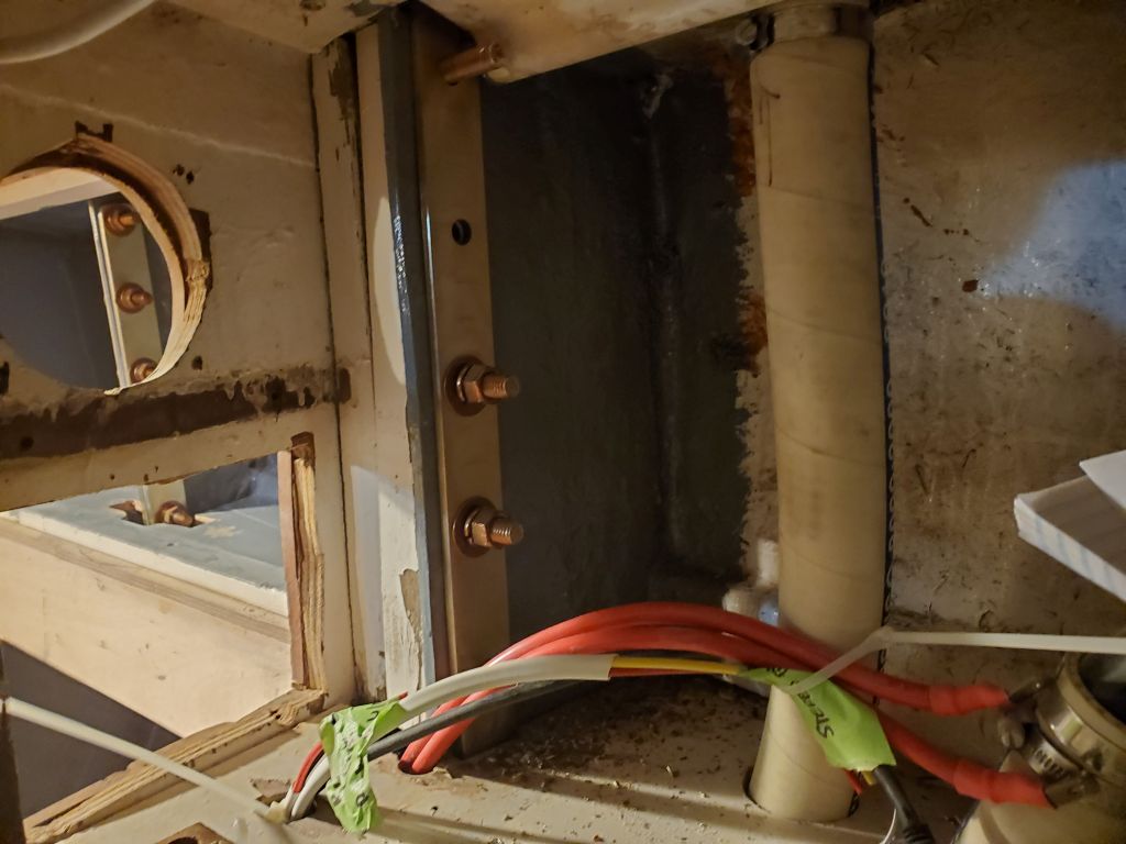
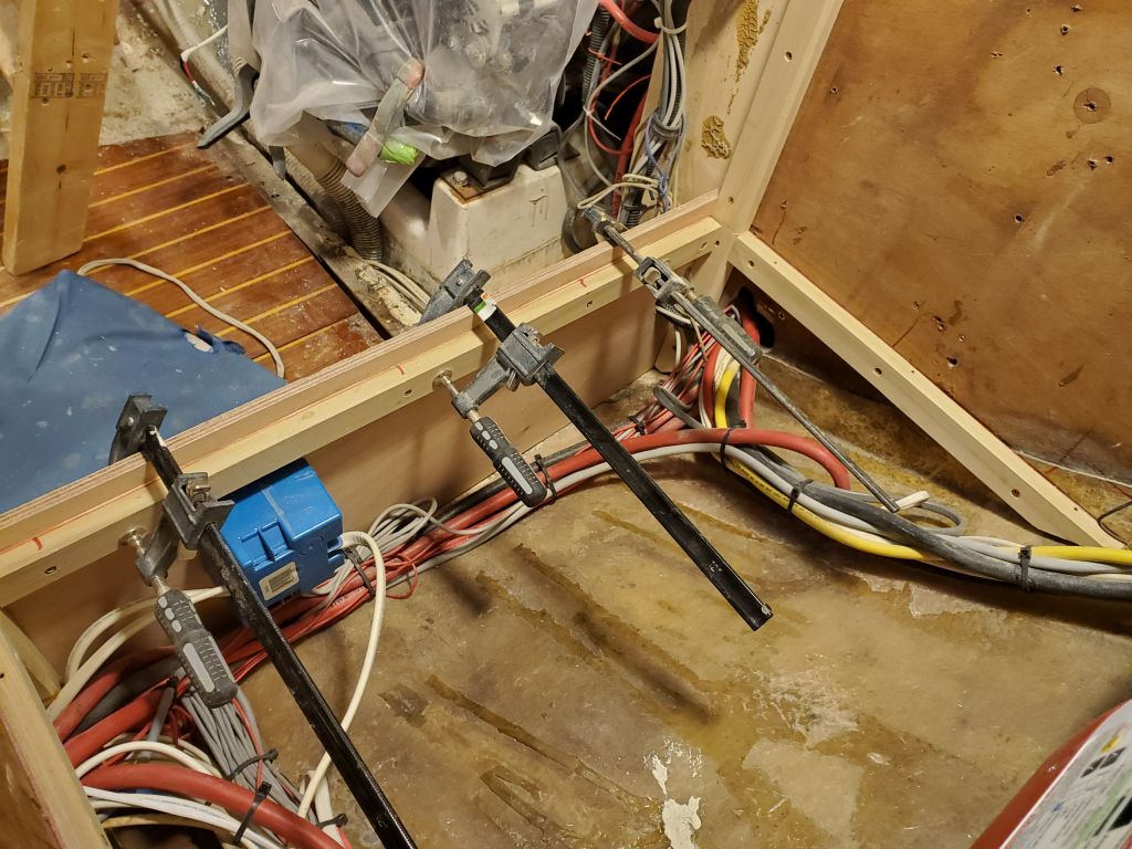
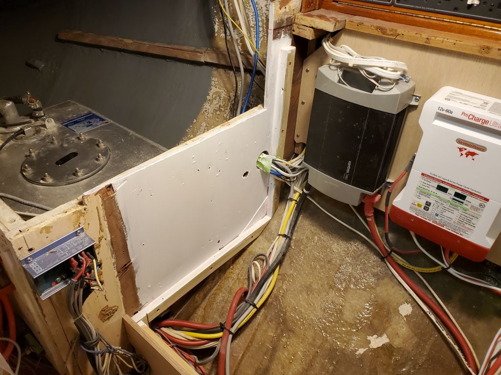
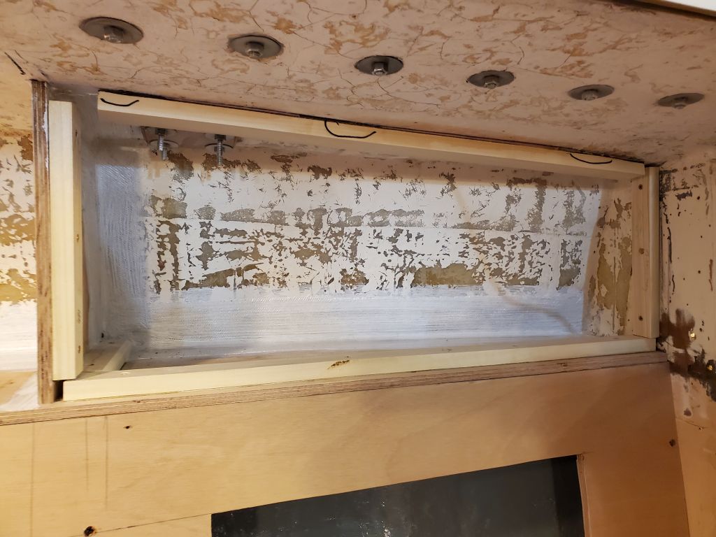
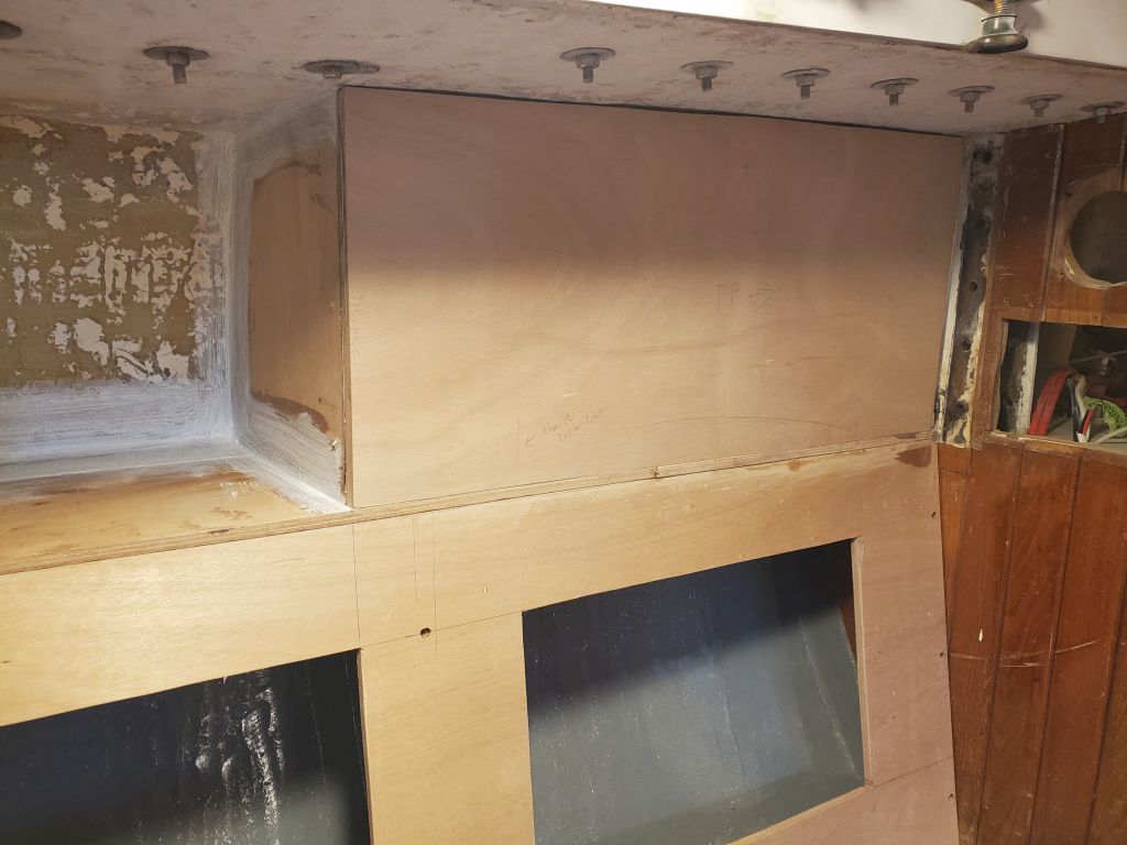
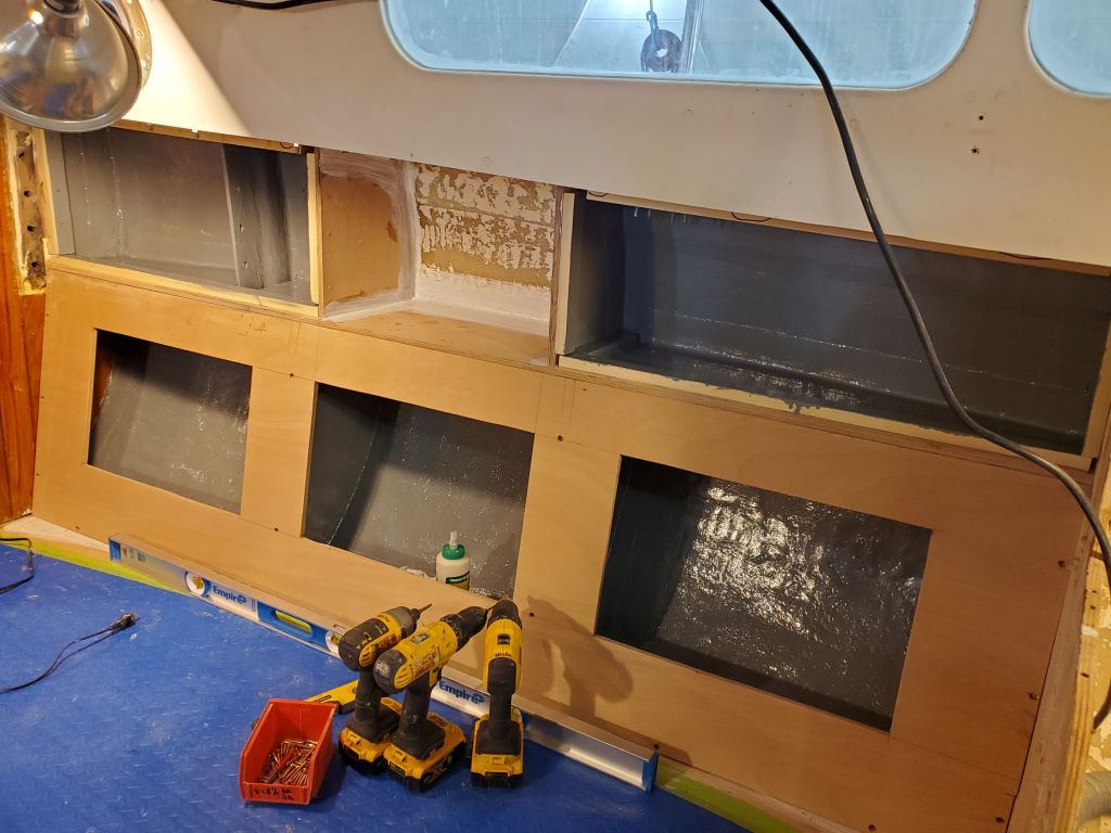
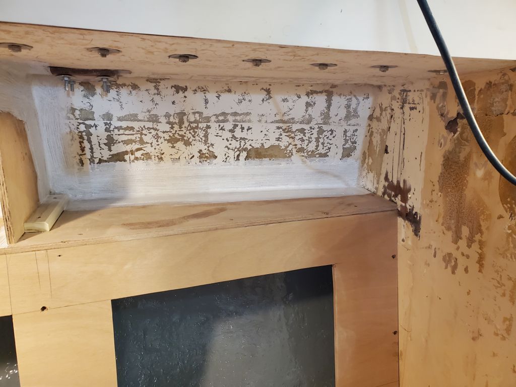
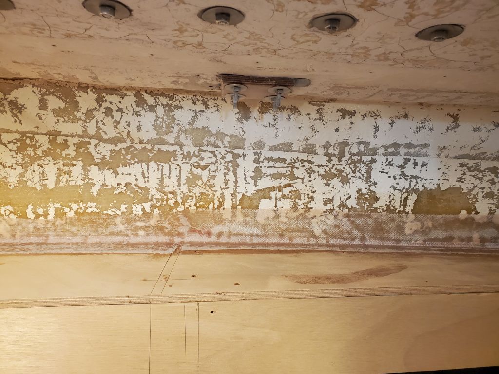
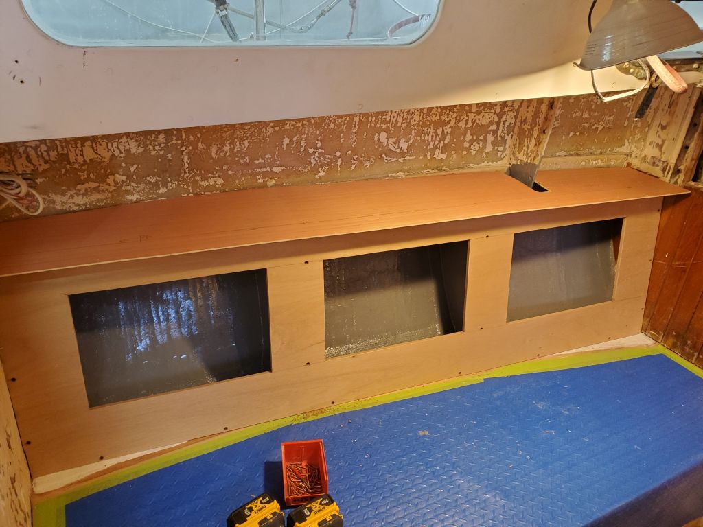
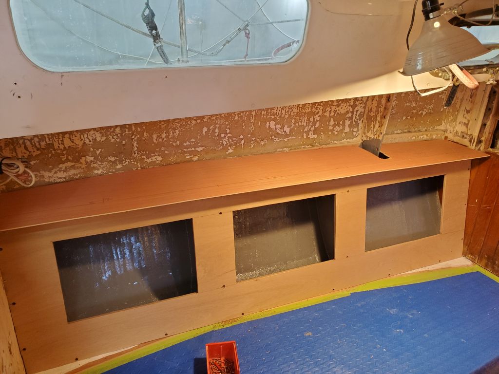
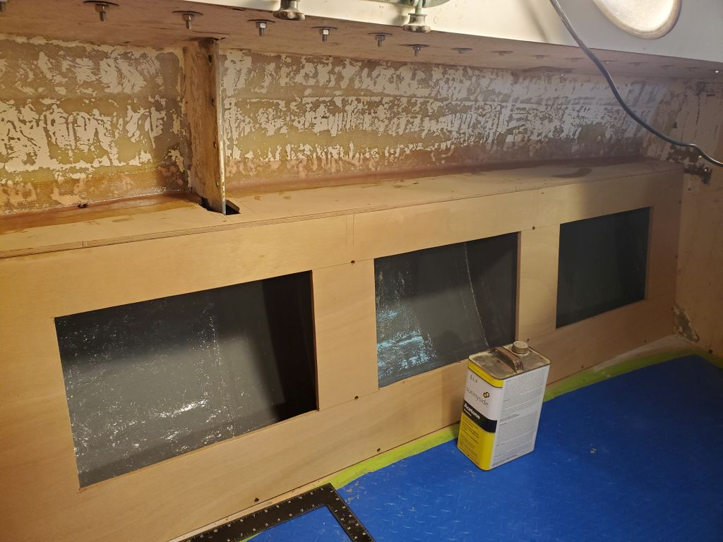
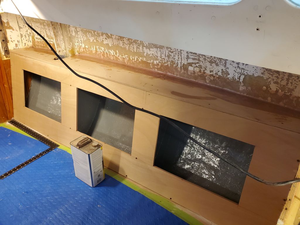
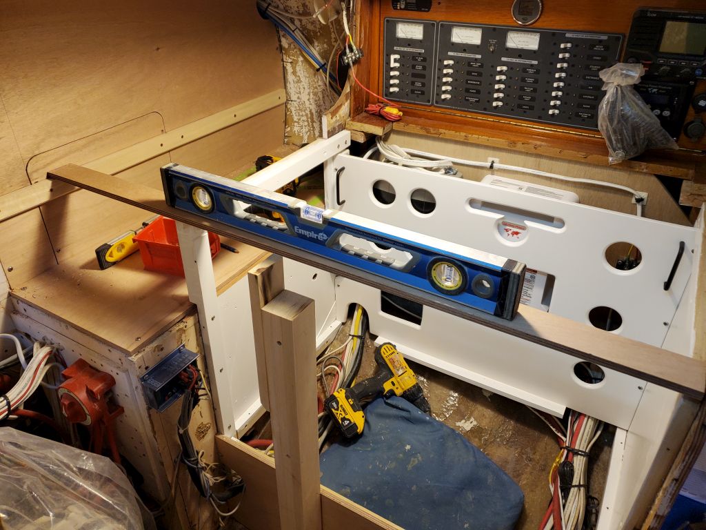
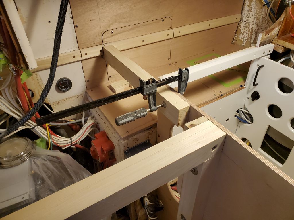
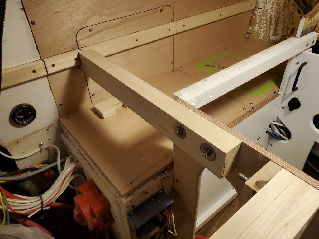
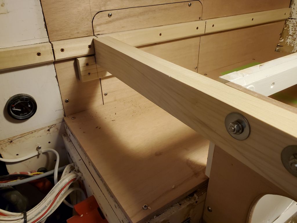
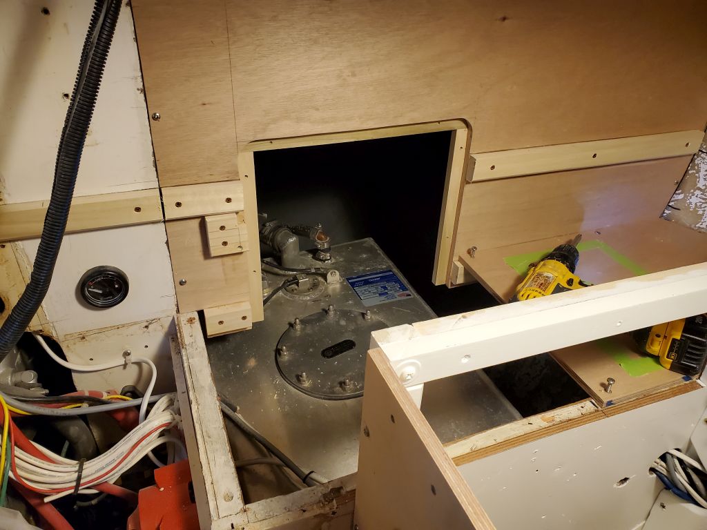
Next, I installed the refrigerator panel, then installed the support beam across the engine room opening, double-checking its position with all the other supports before bolting it in place at both ends.

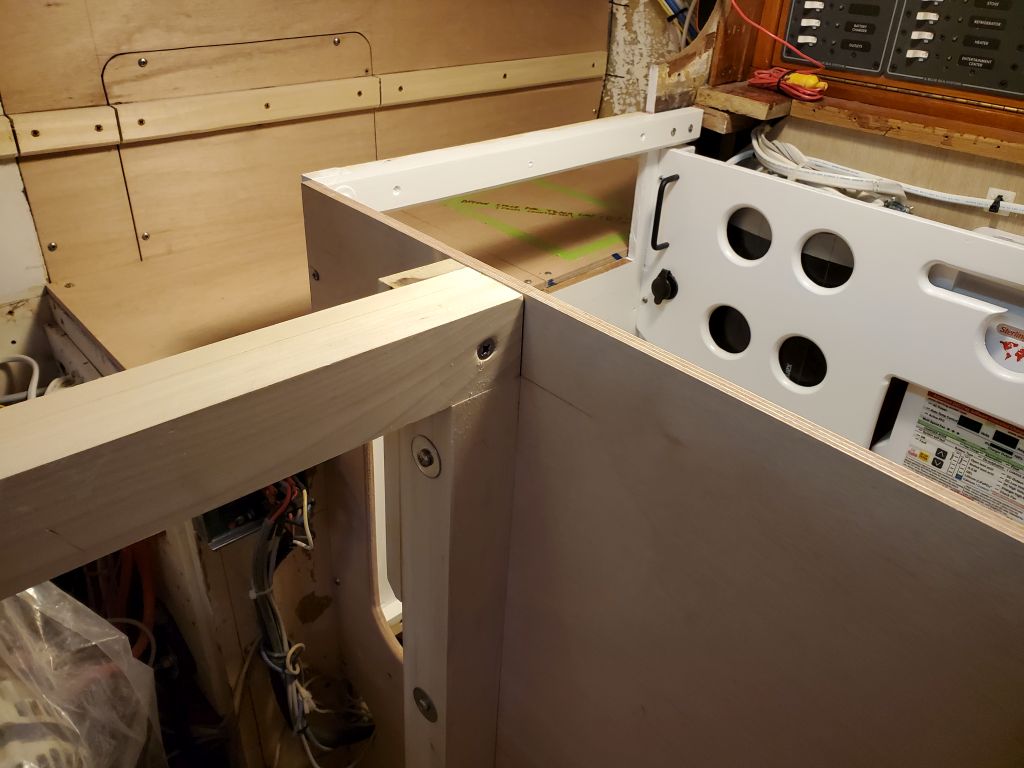
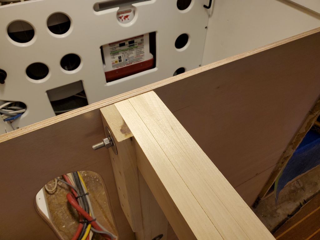
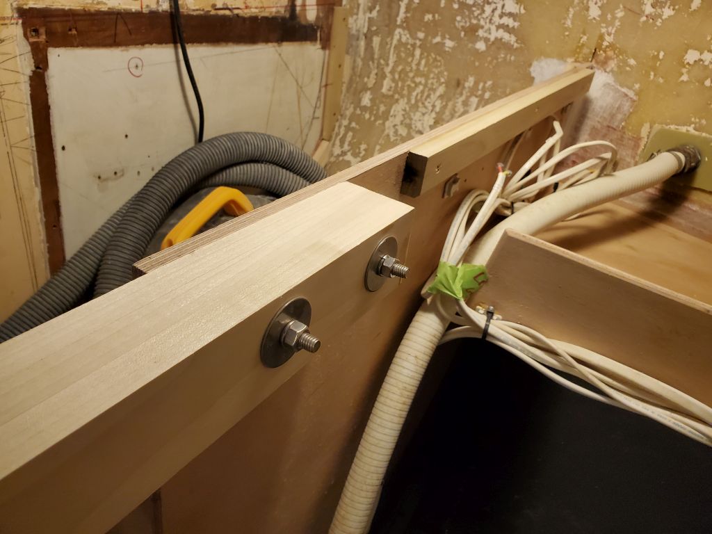
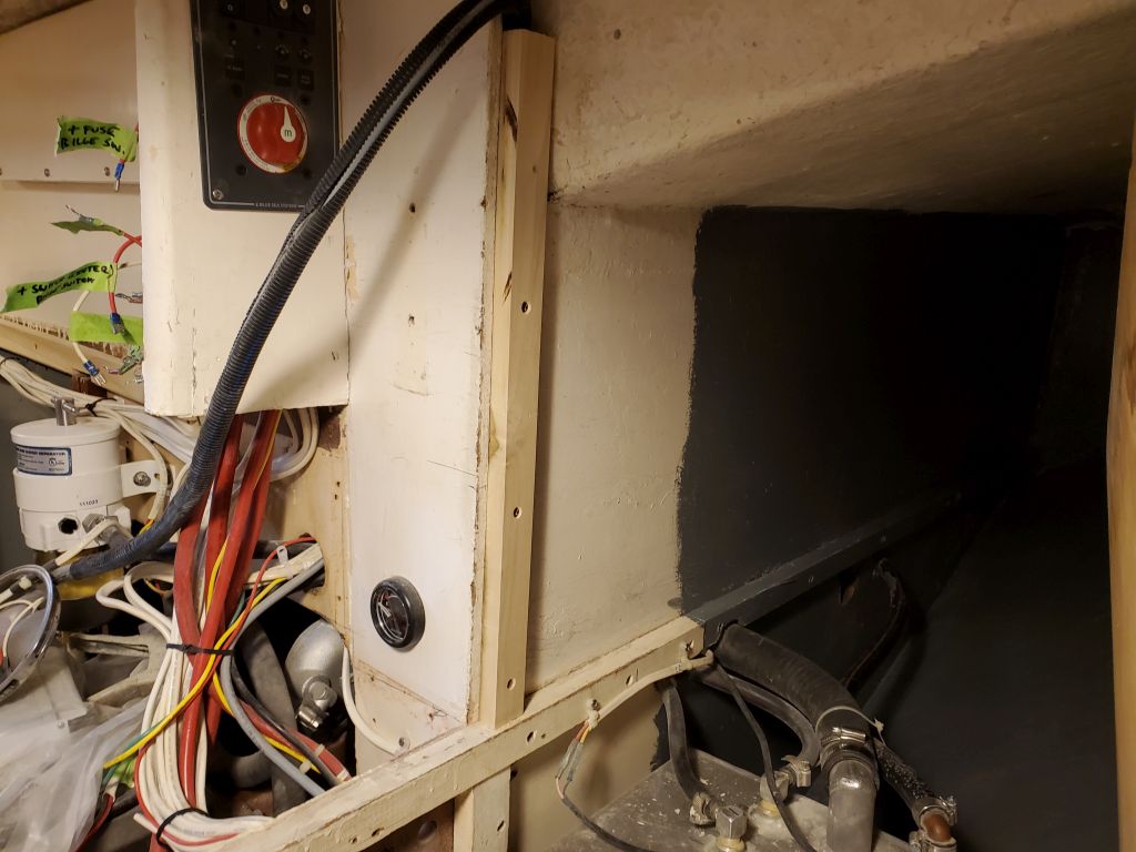
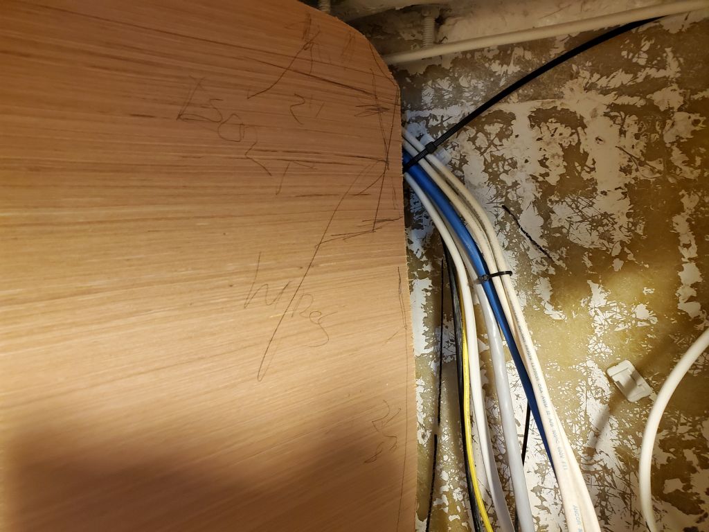
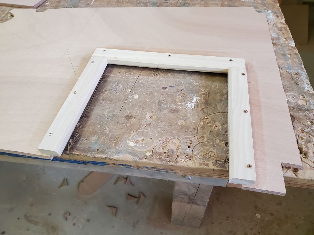
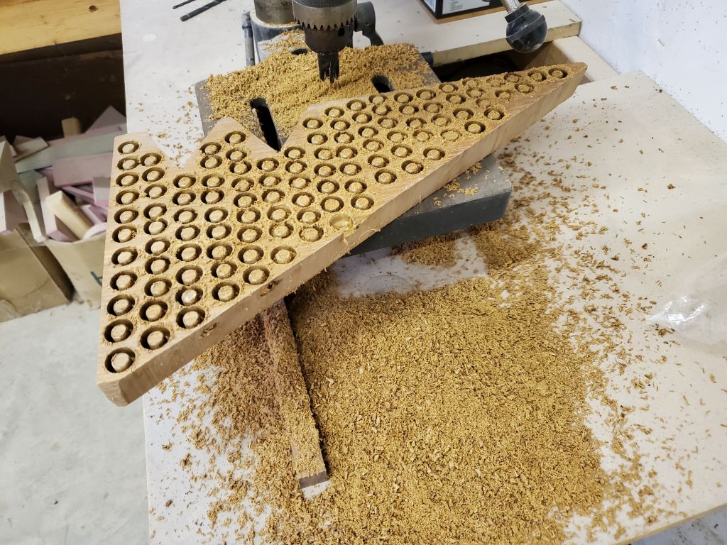
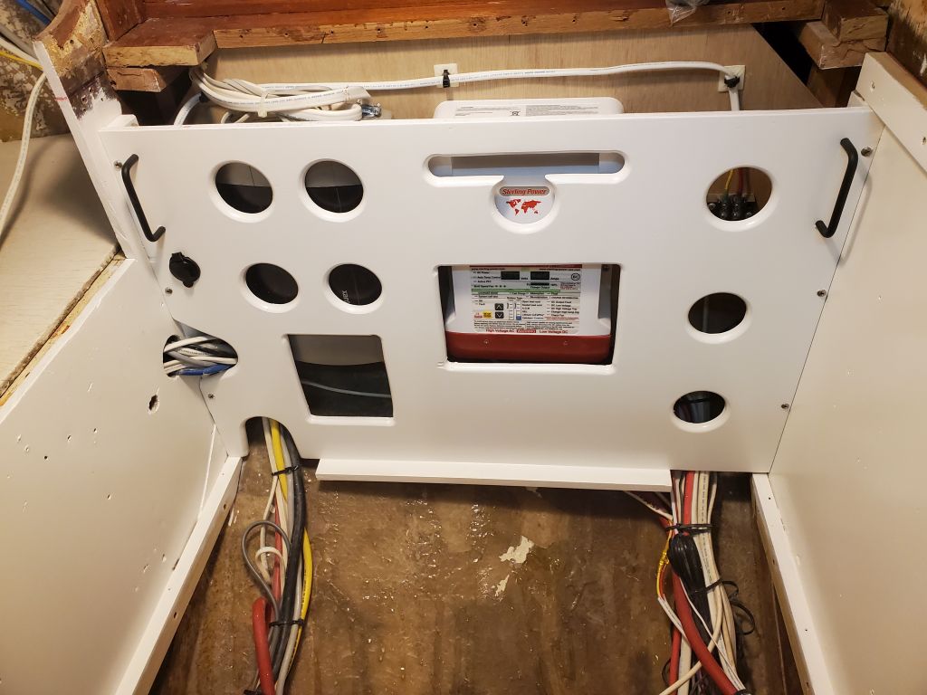
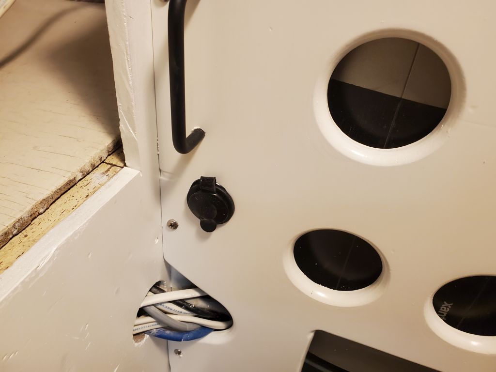
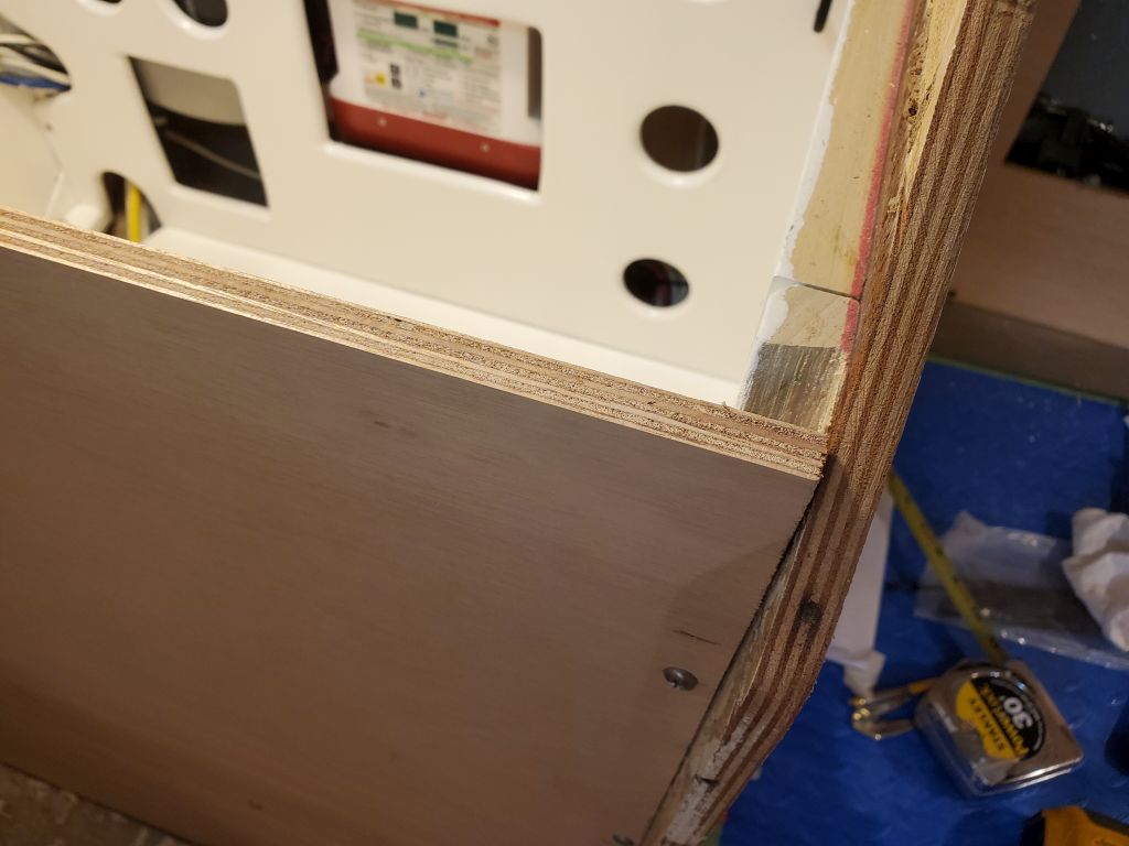
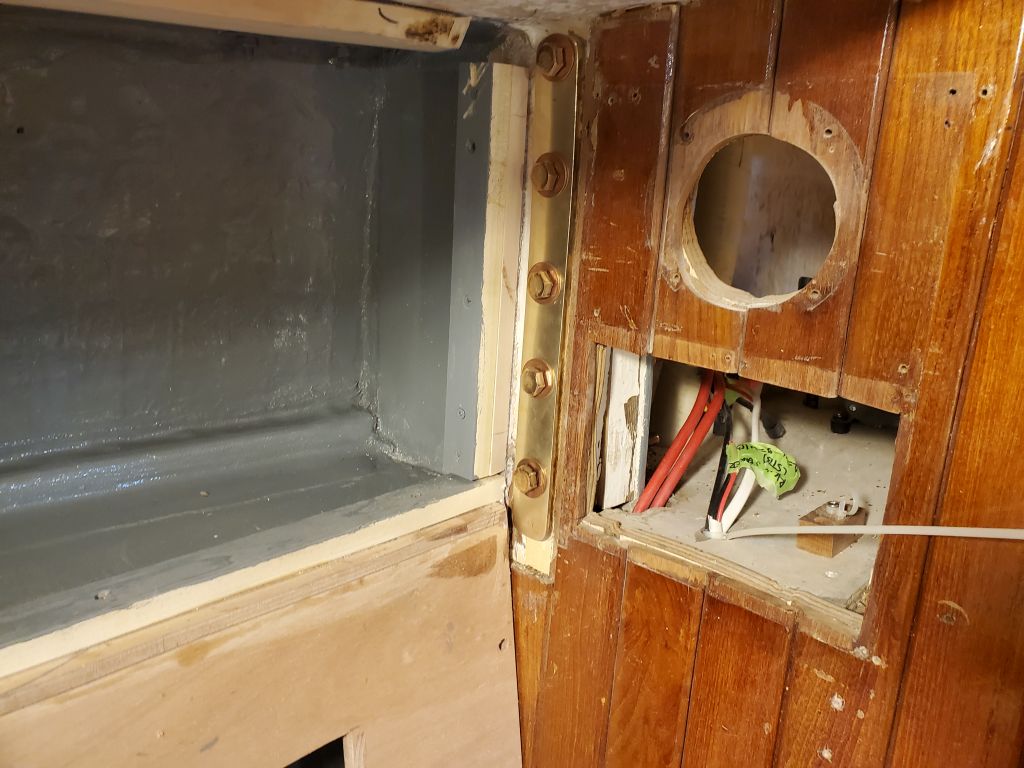
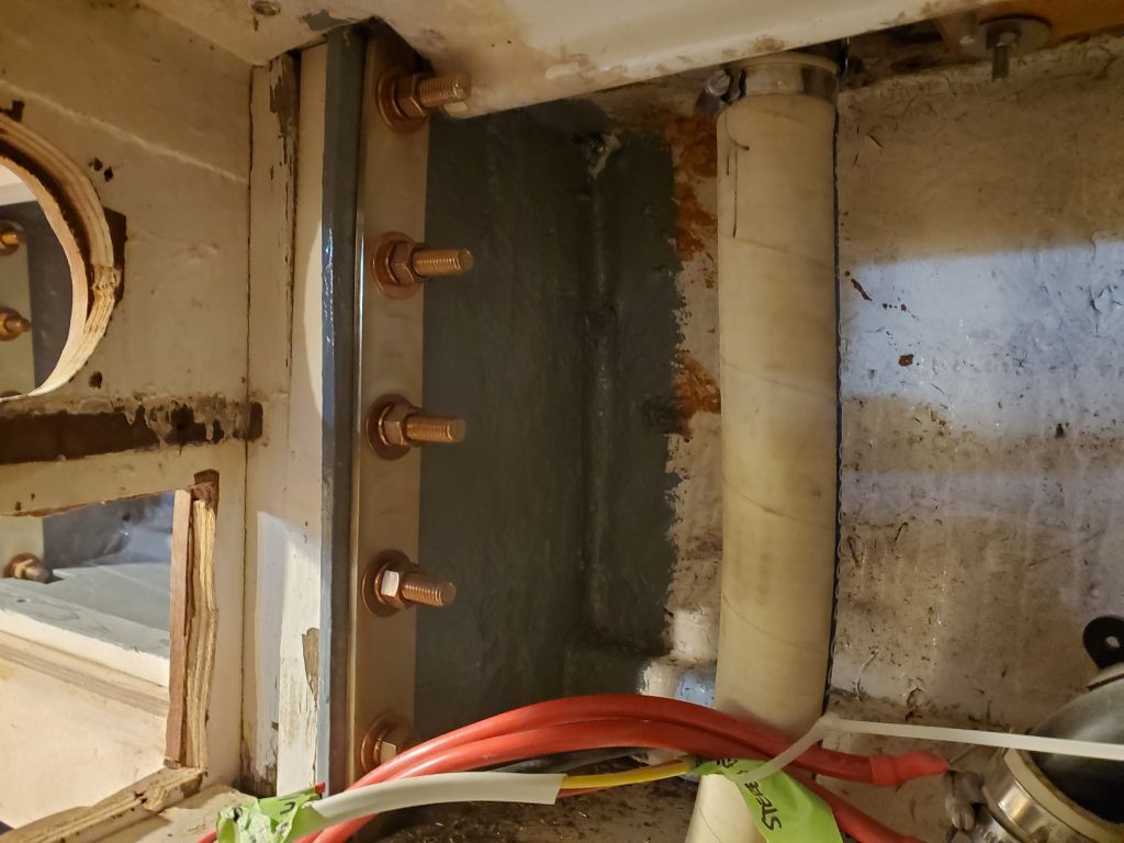
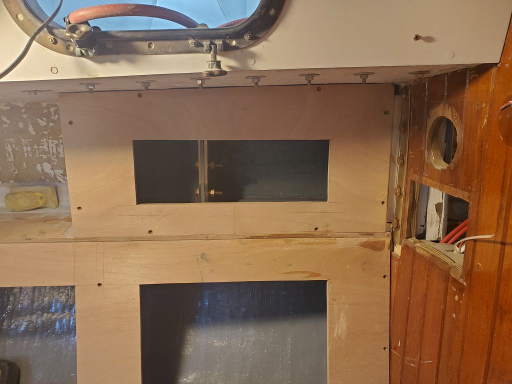
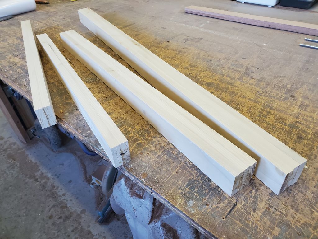
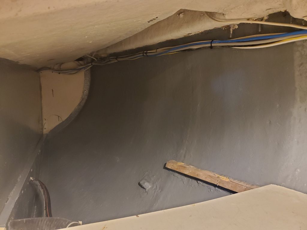
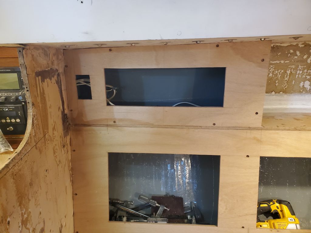
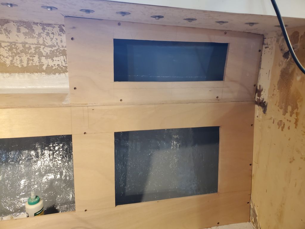
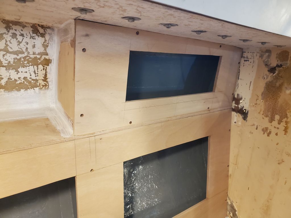
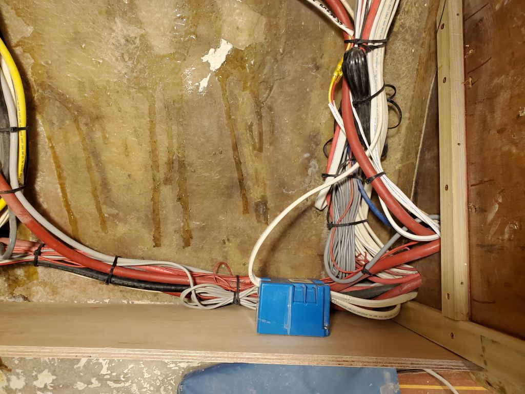
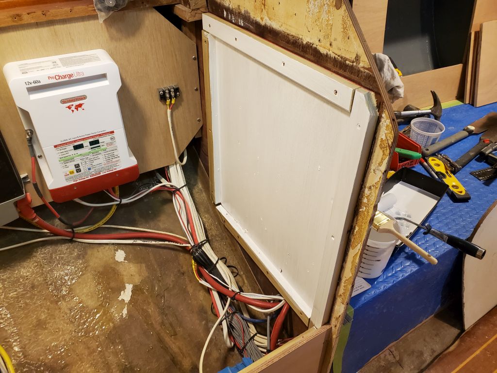
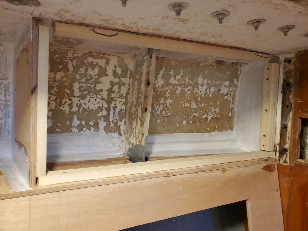
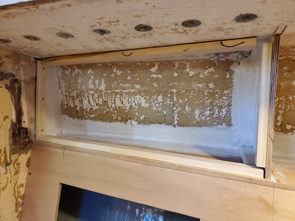
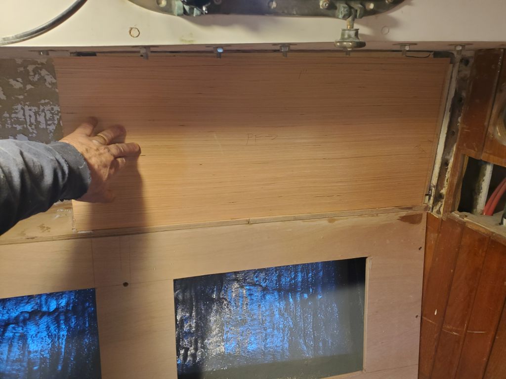
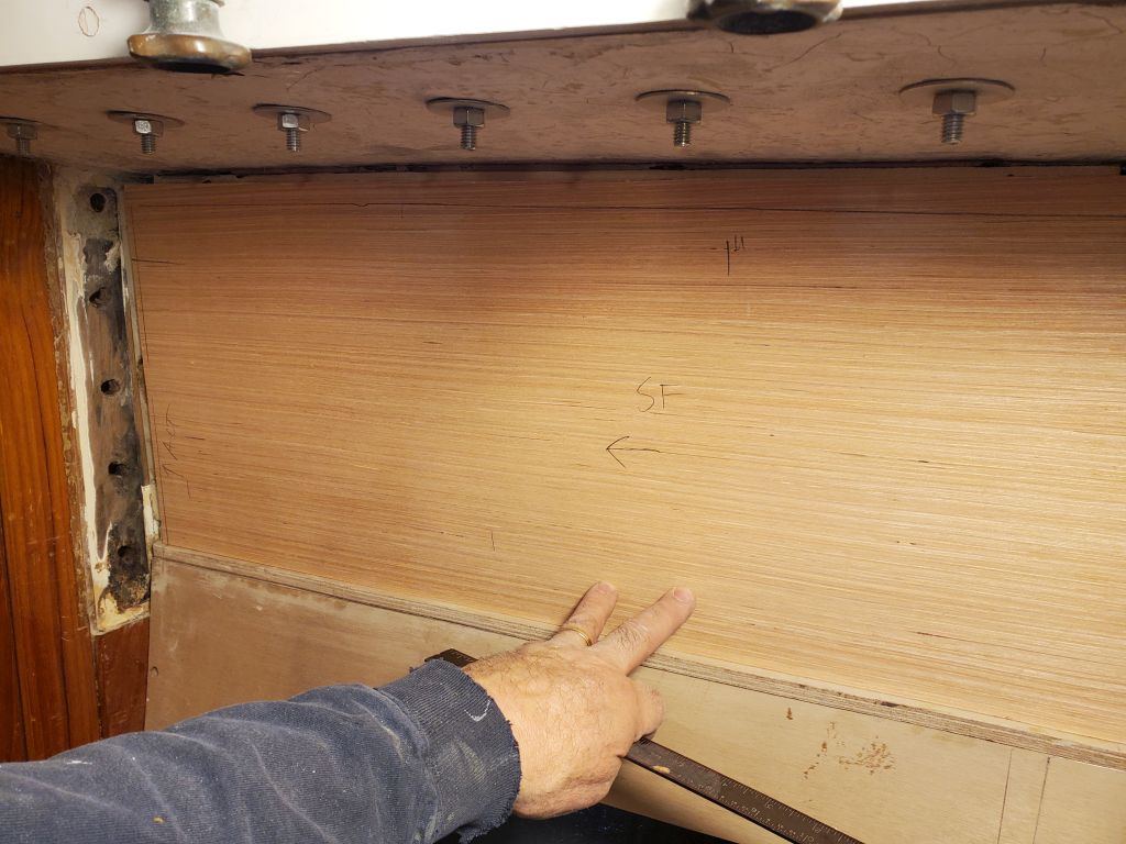
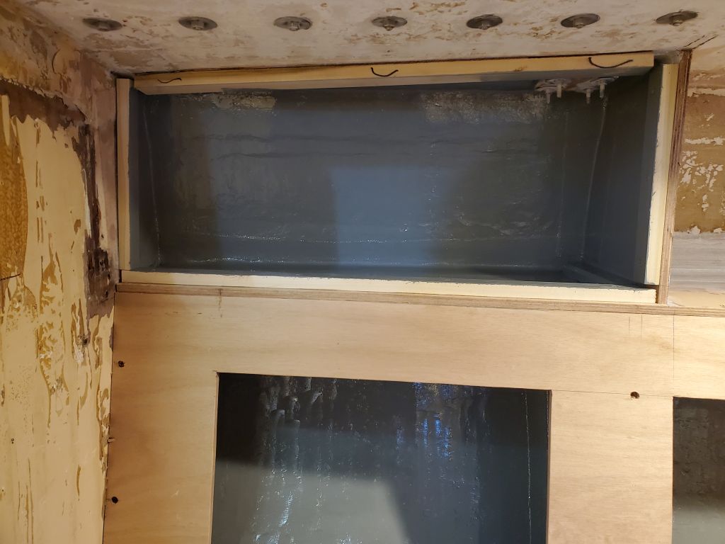
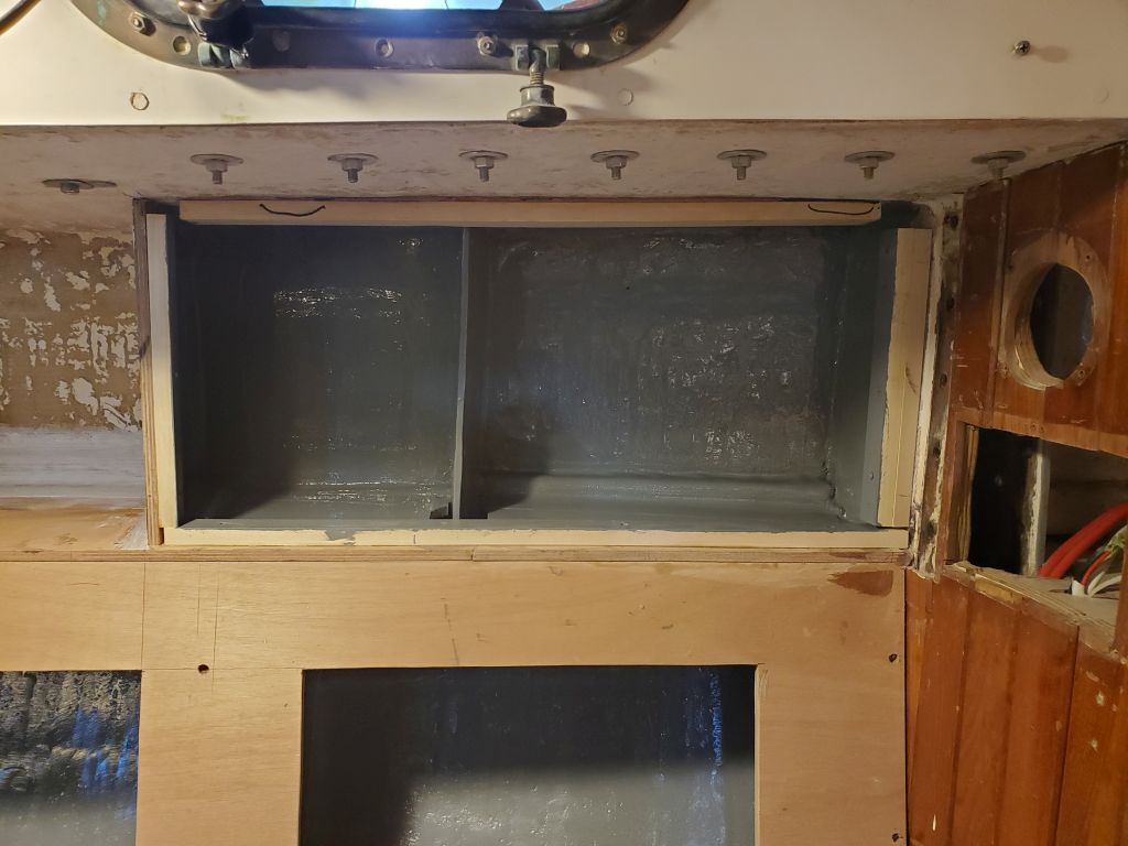
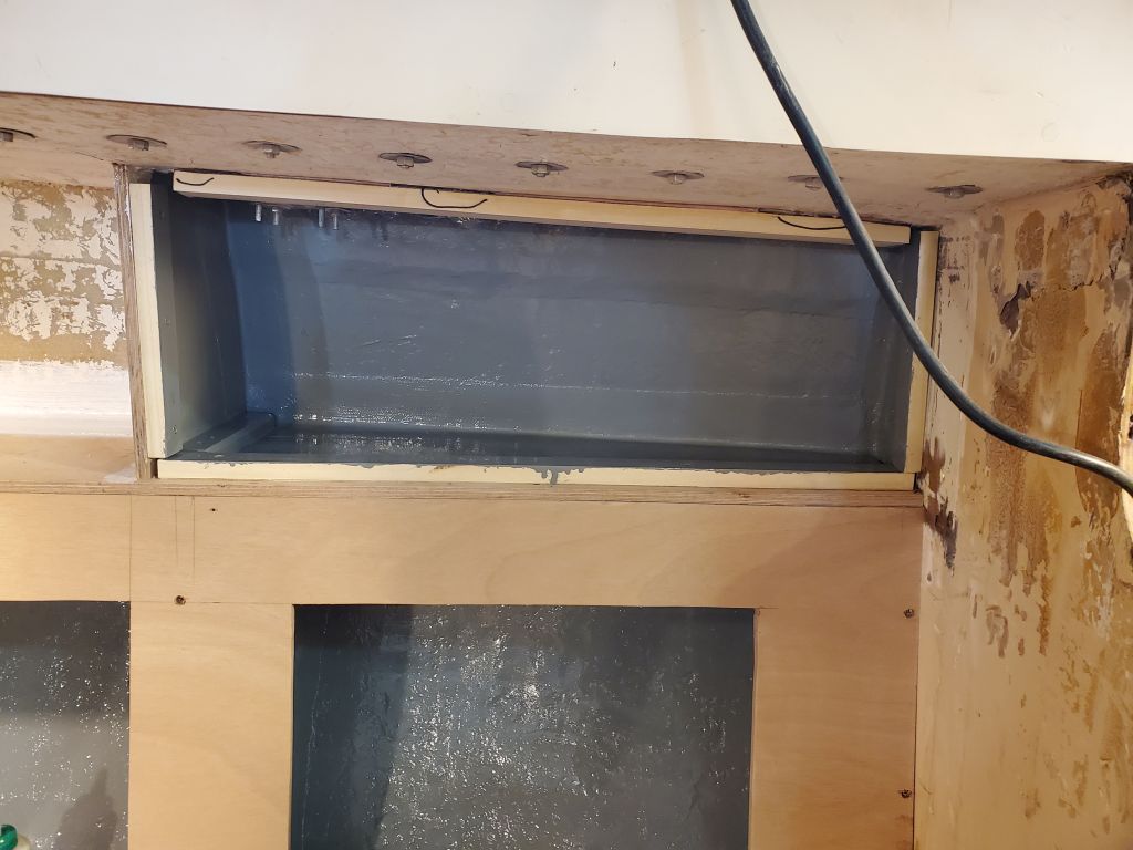
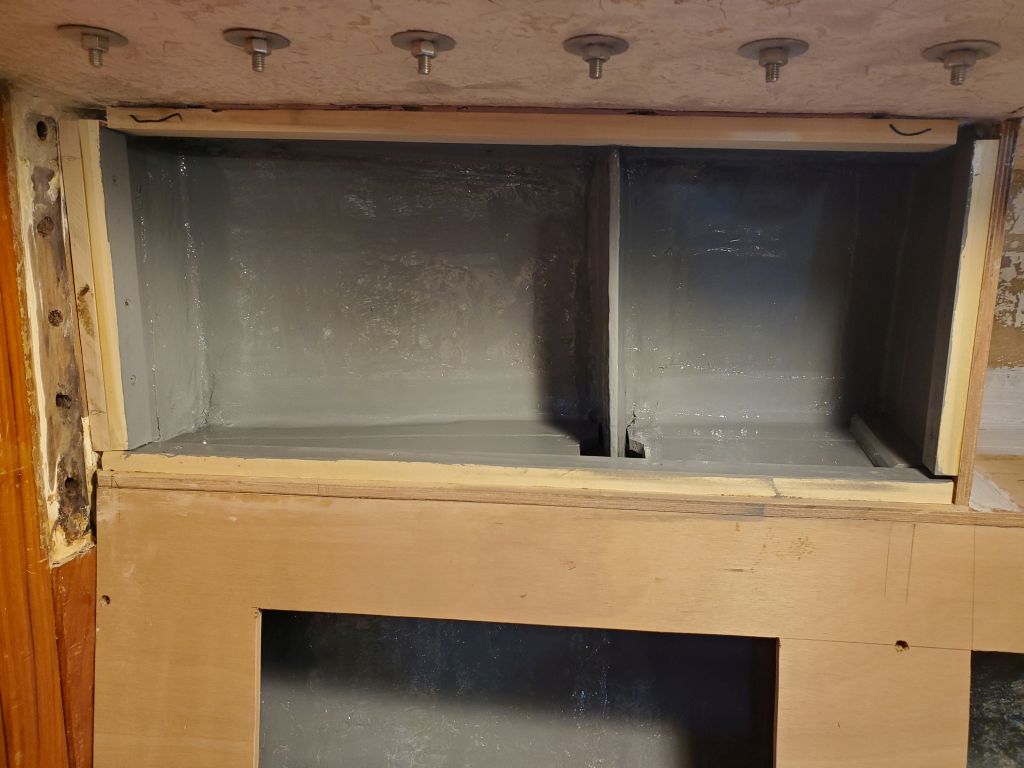
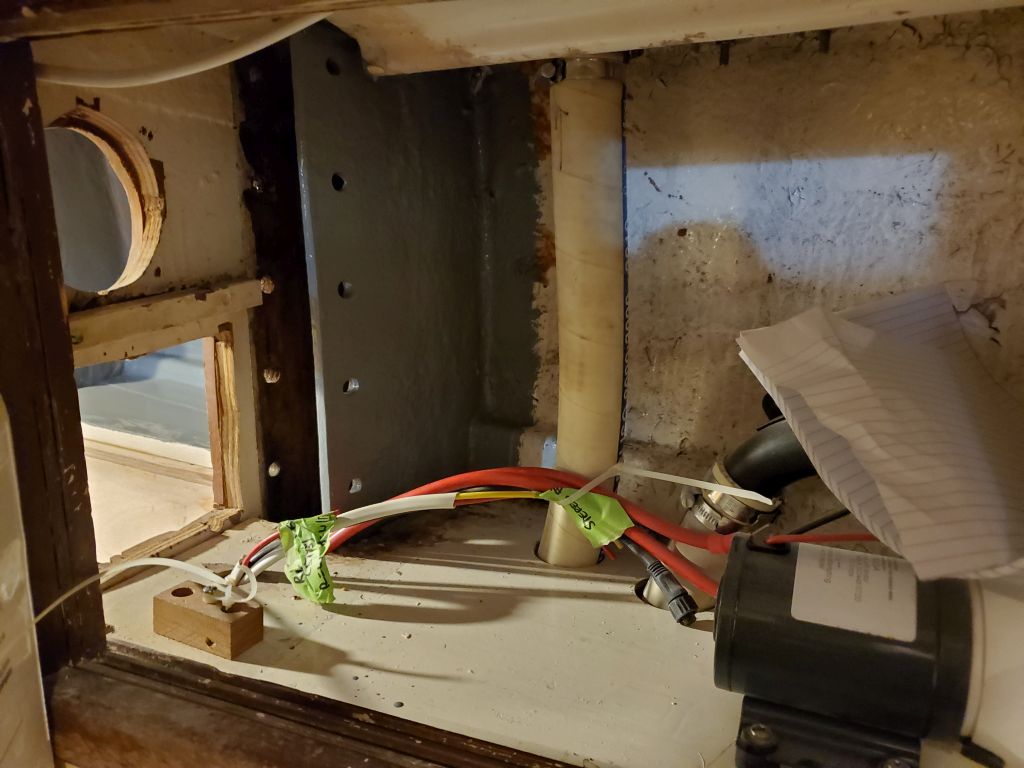
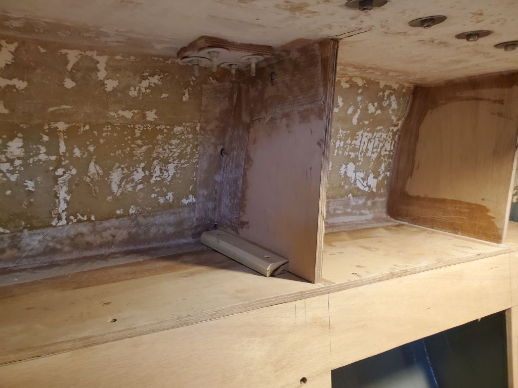
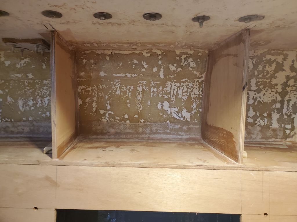
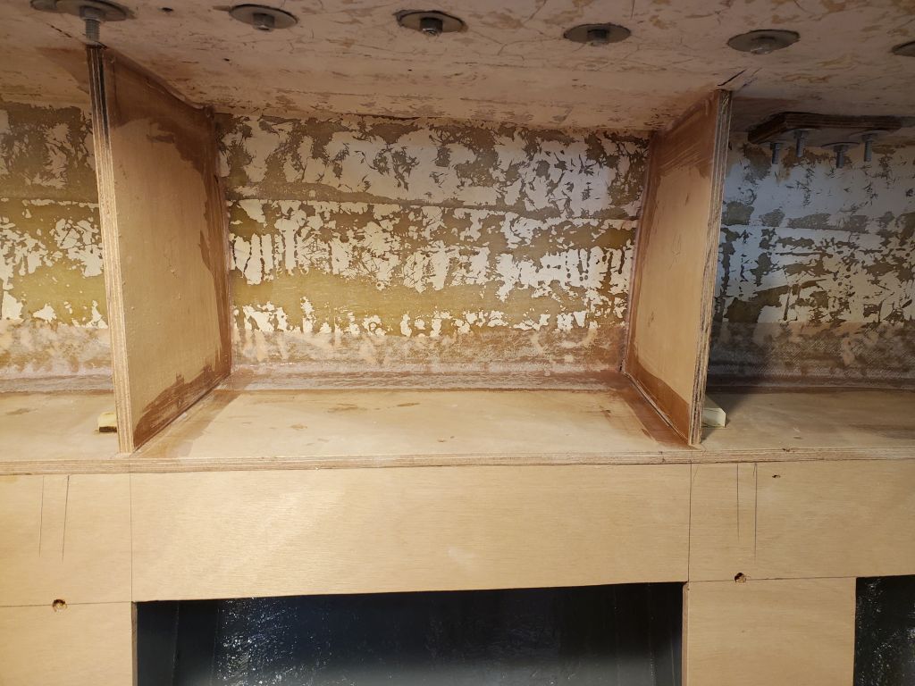
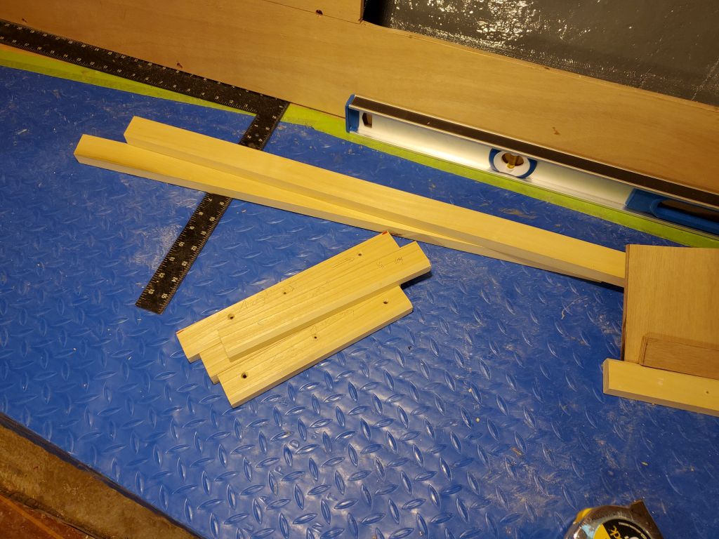
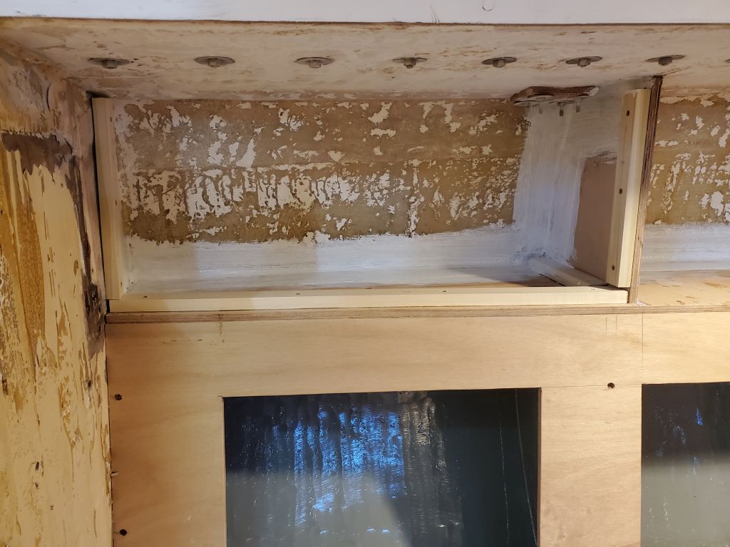
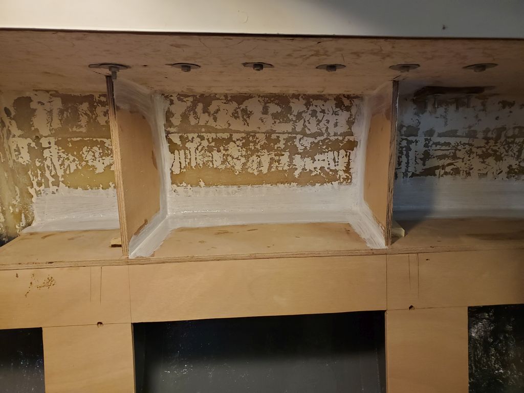
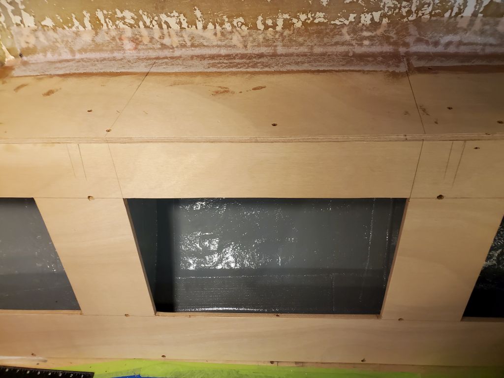
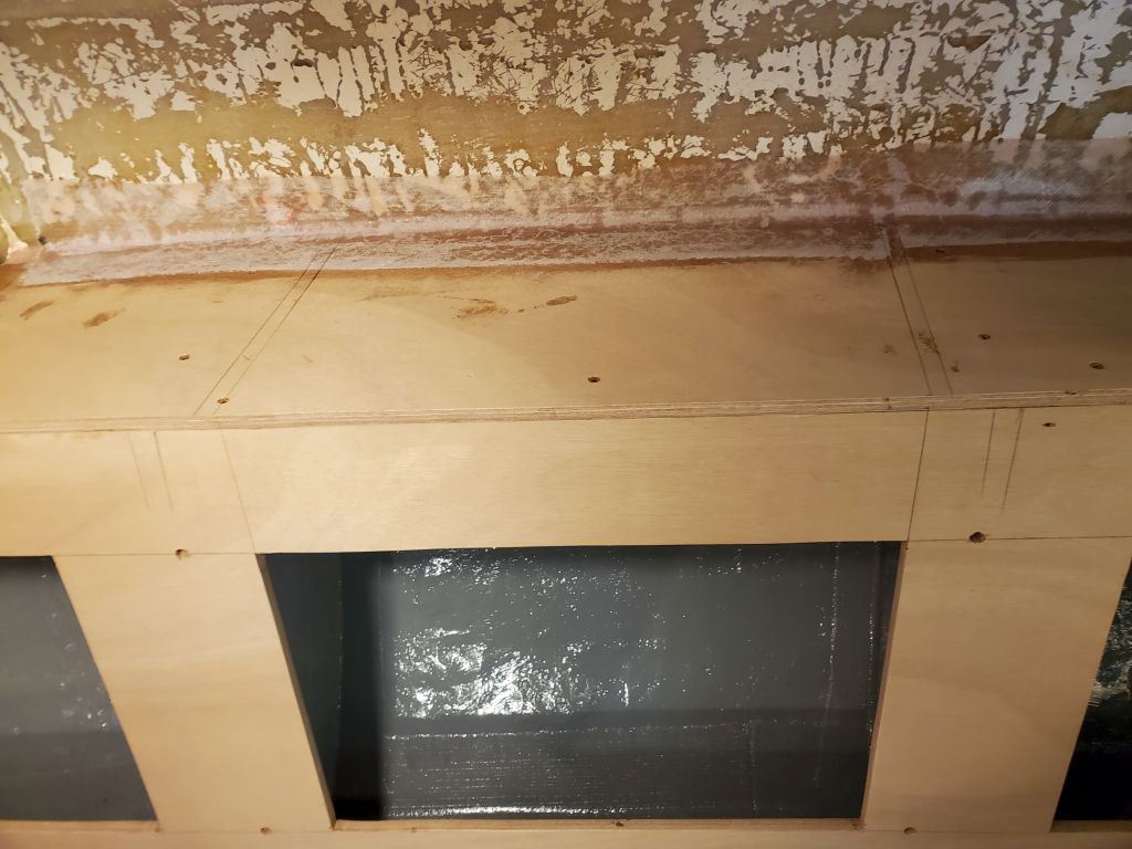
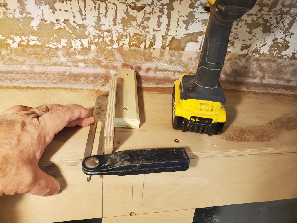
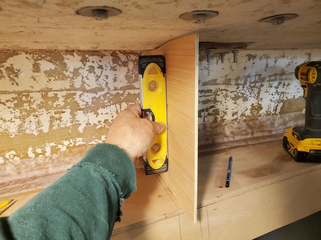
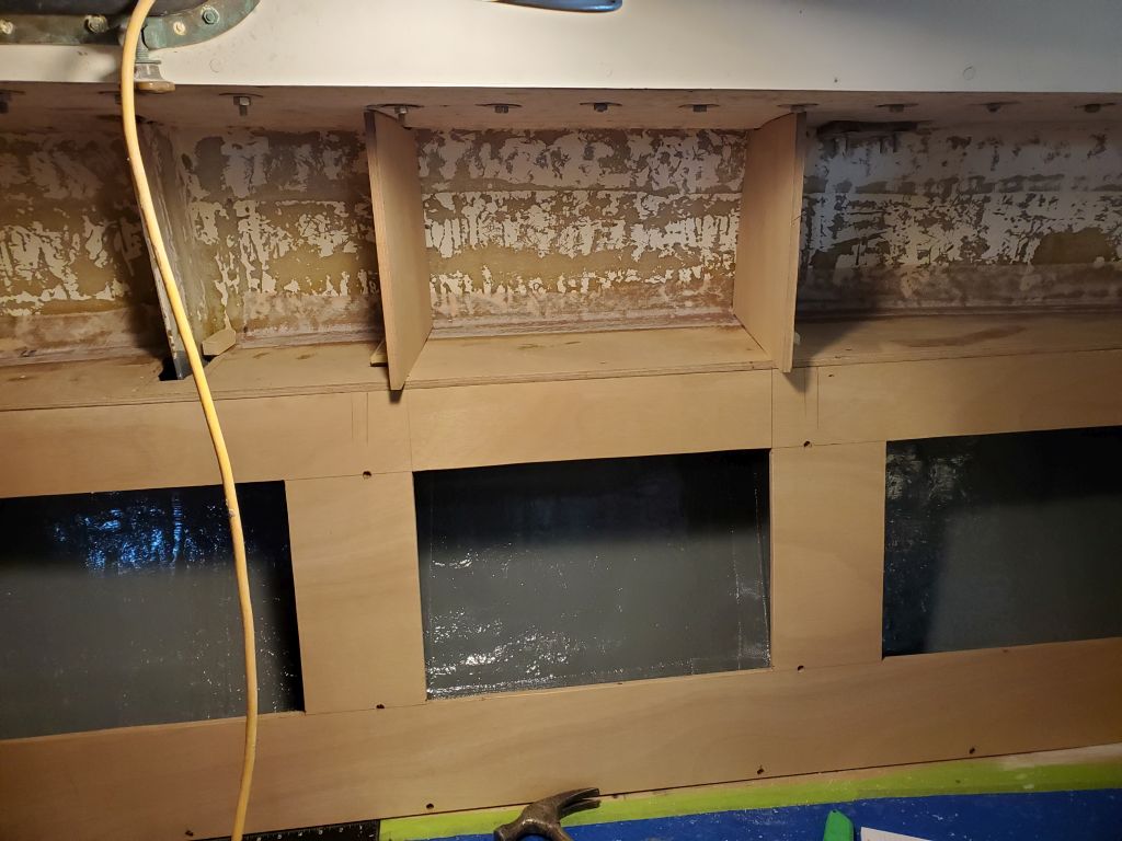
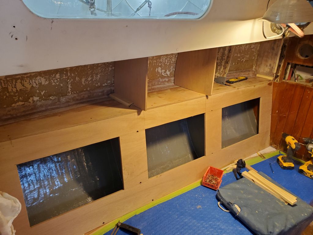
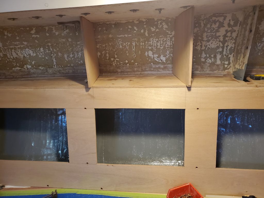
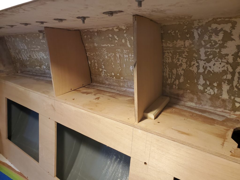
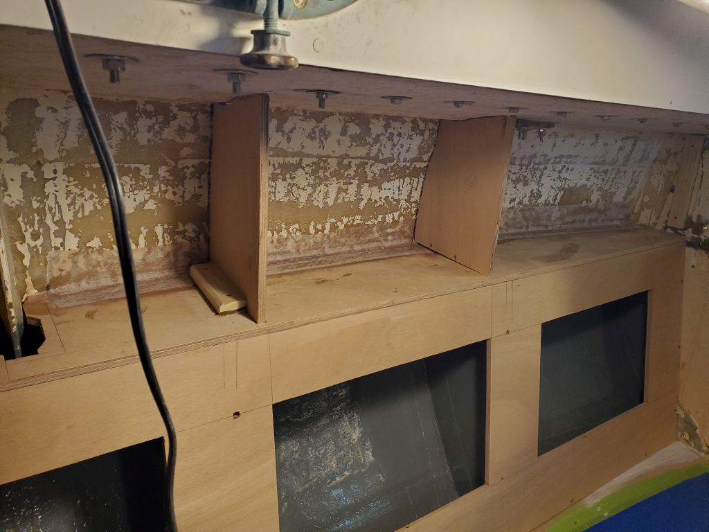
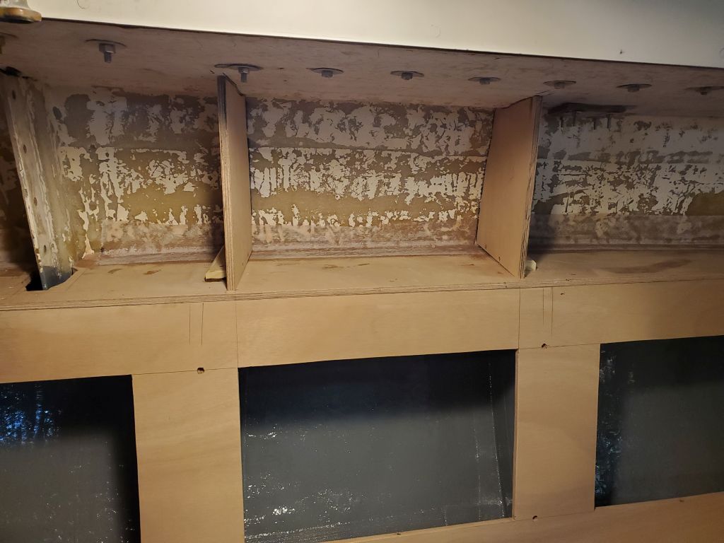
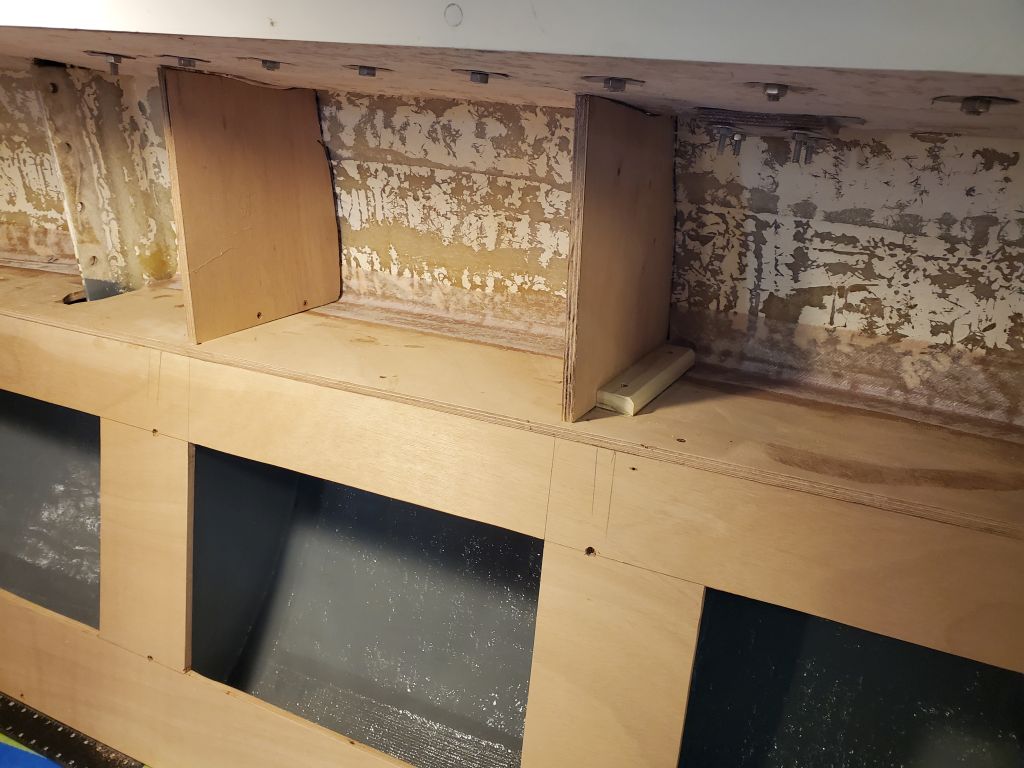
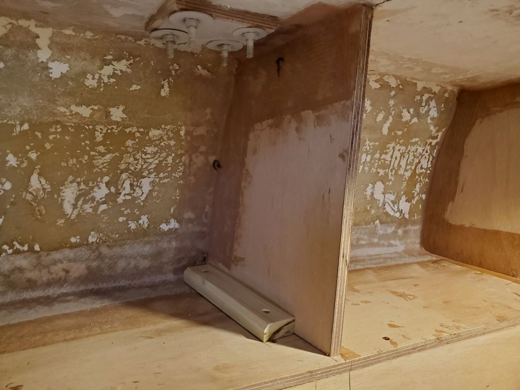
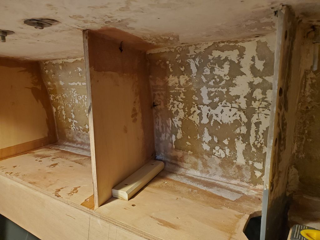
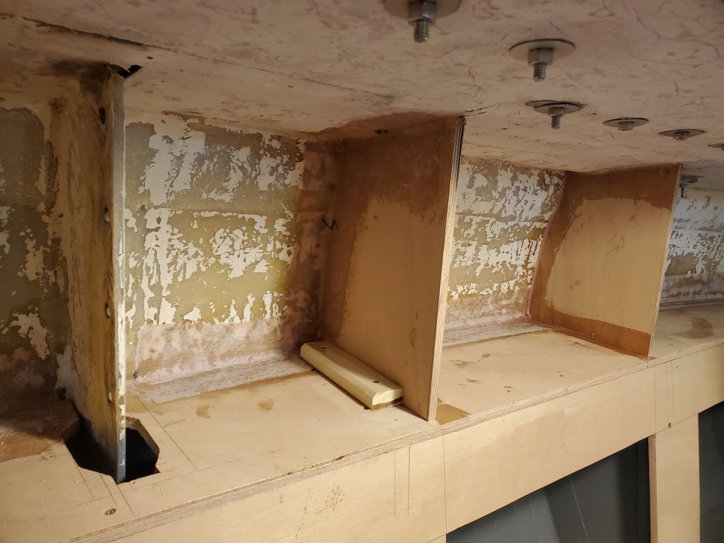
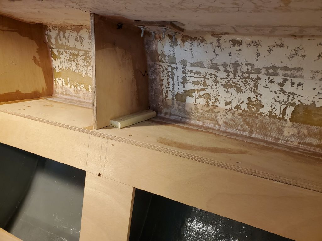
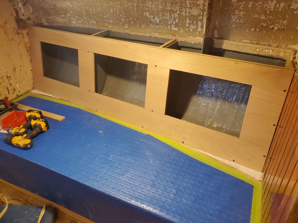
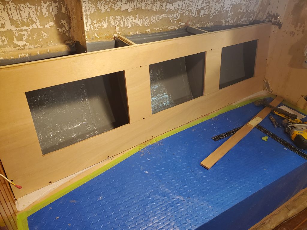
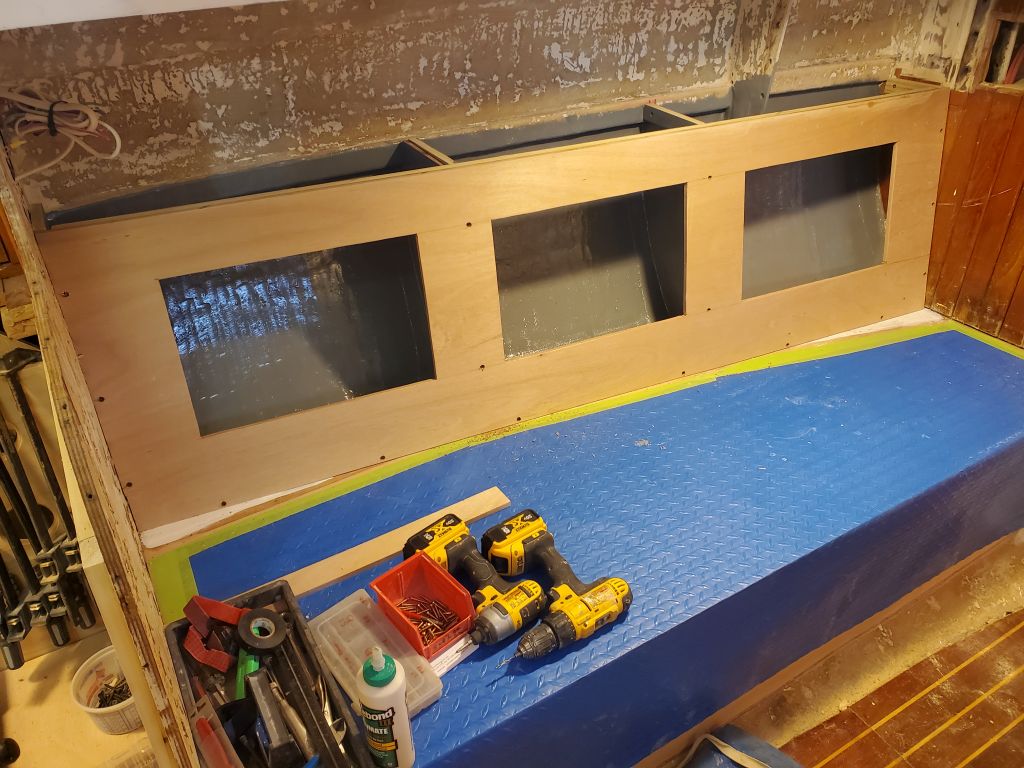
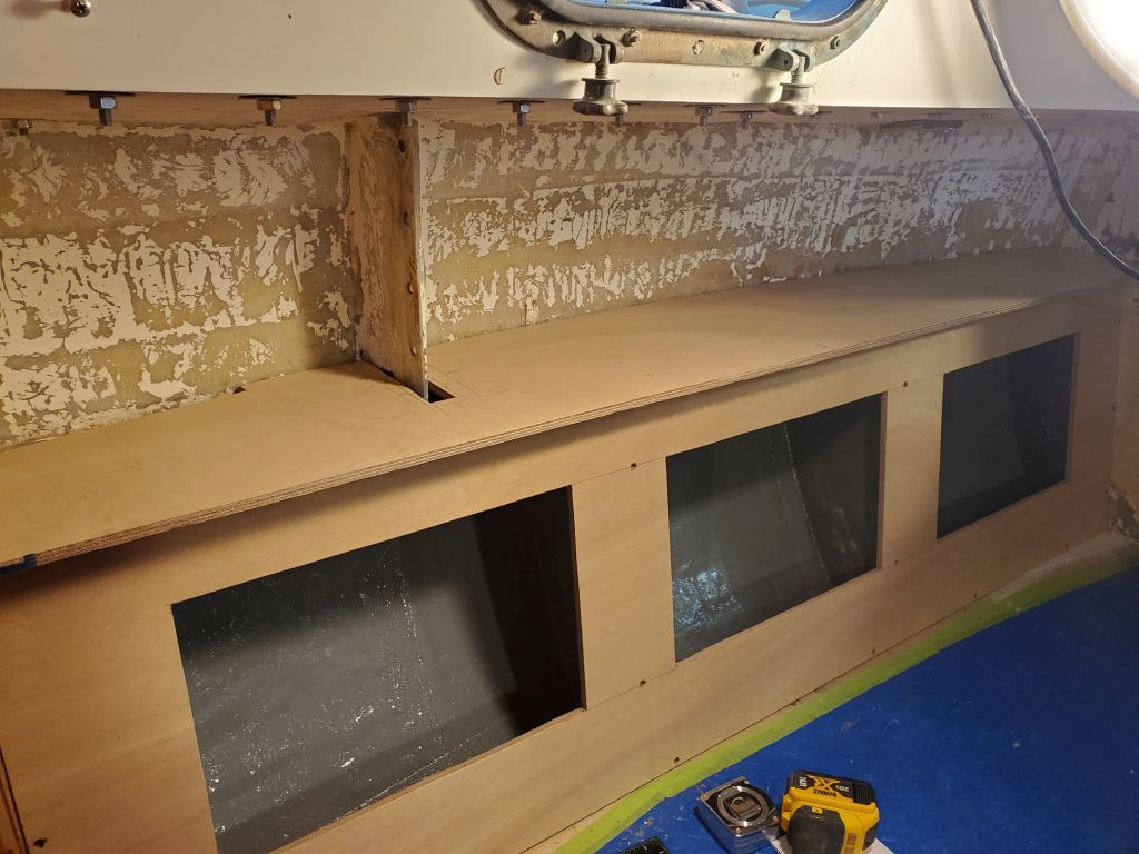
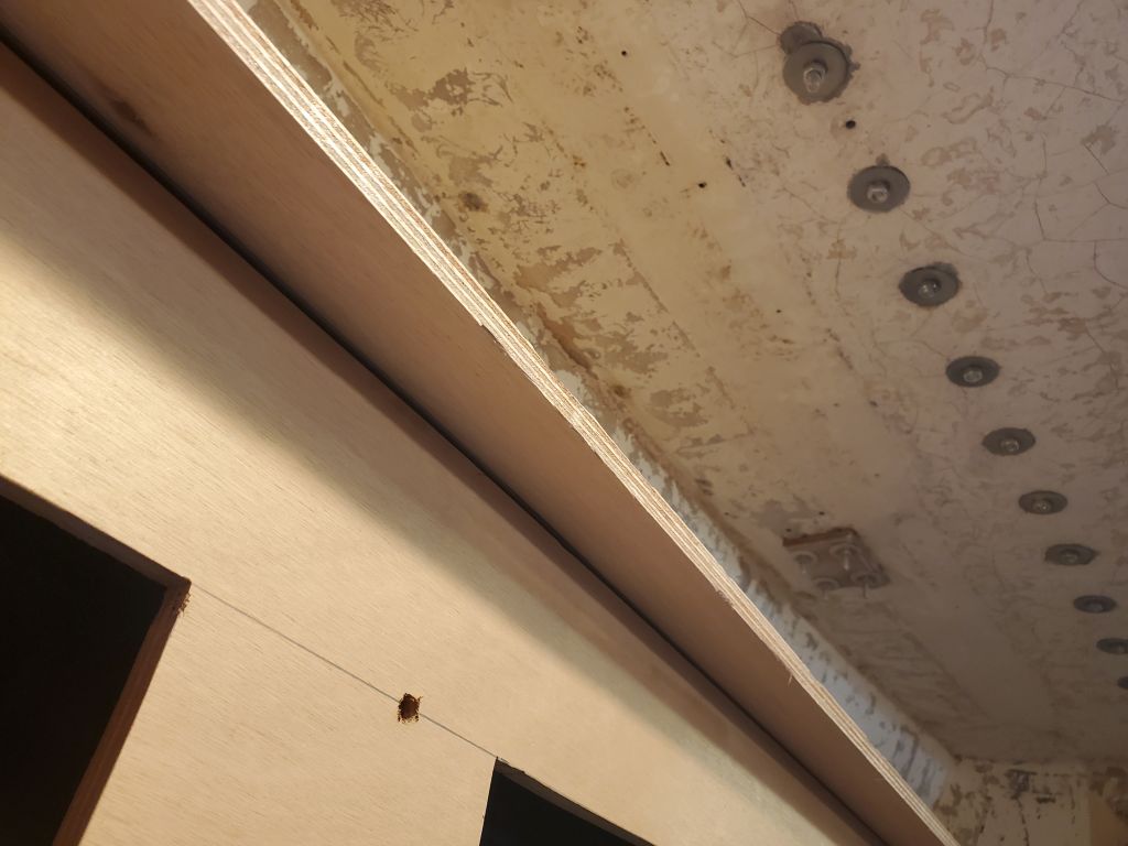
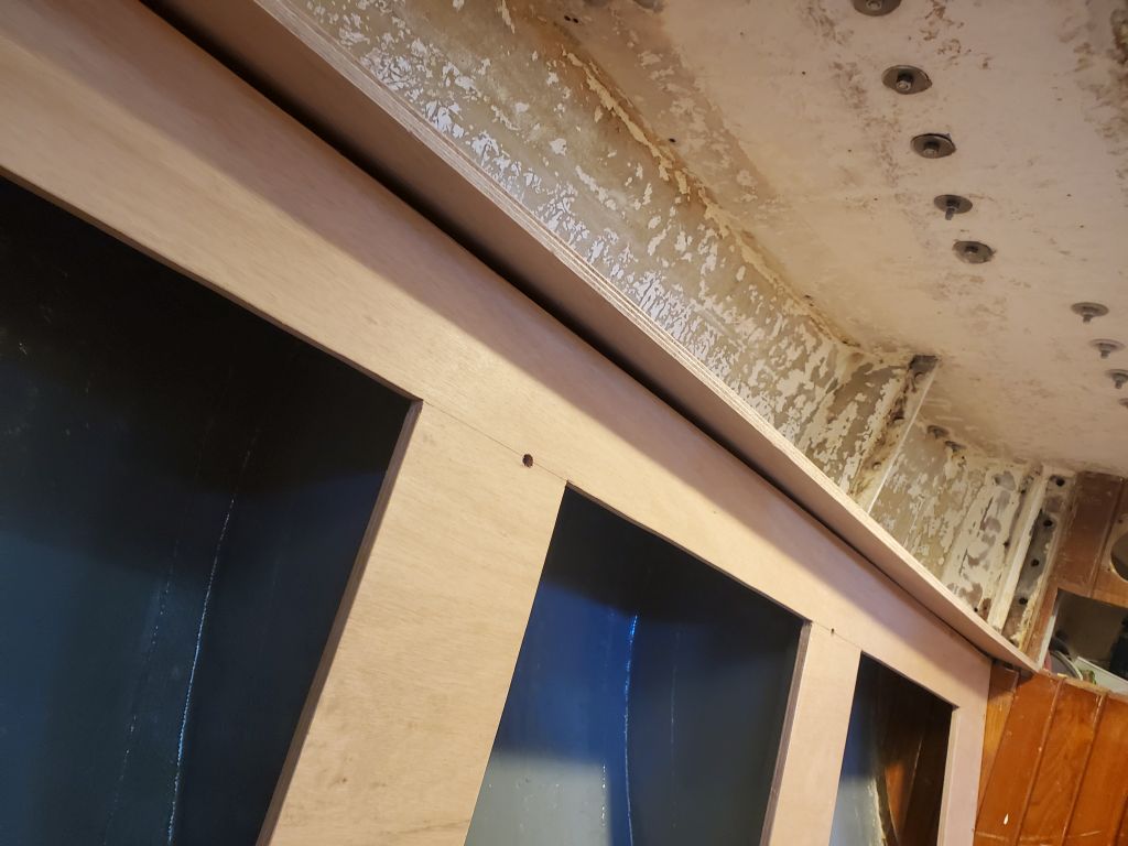
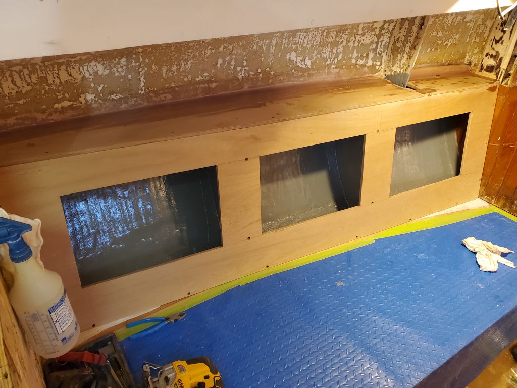
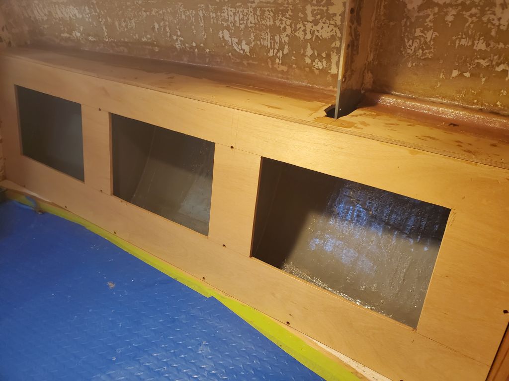
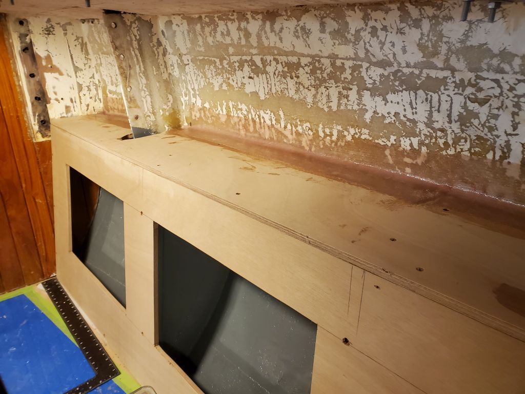
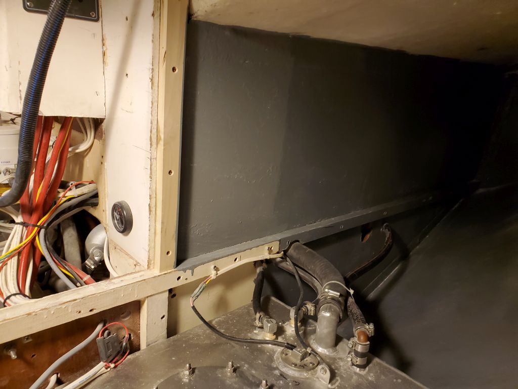
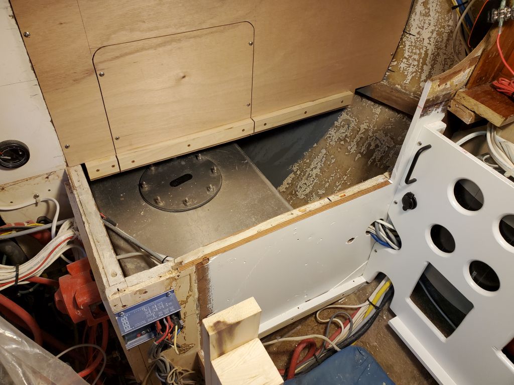
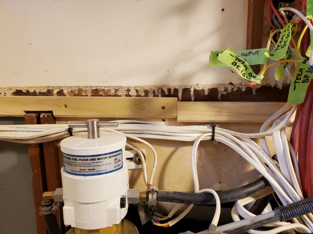
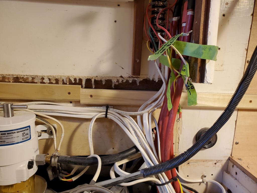
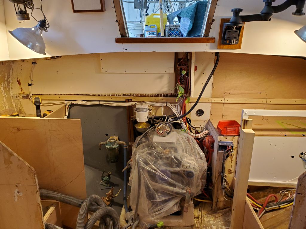
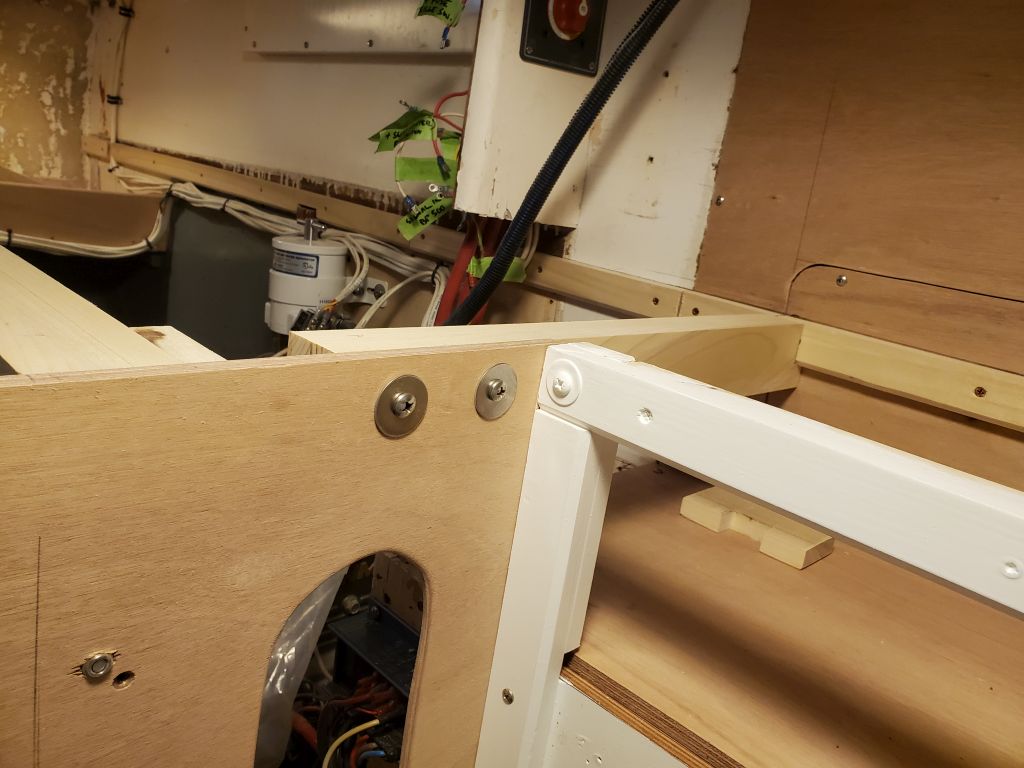
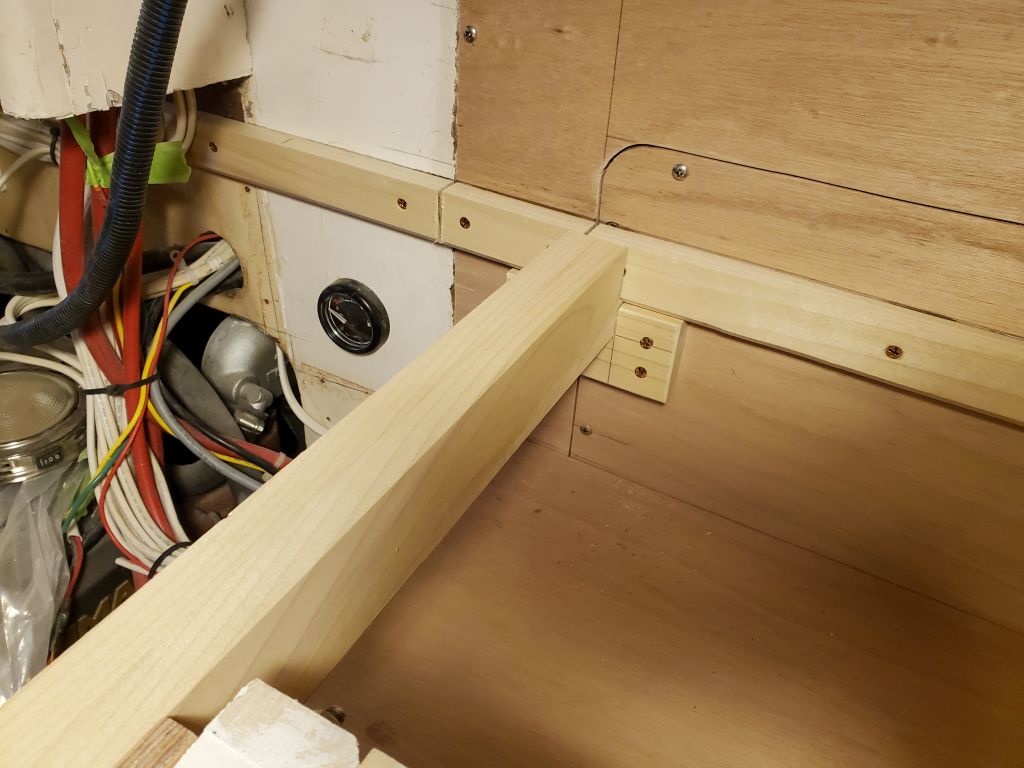
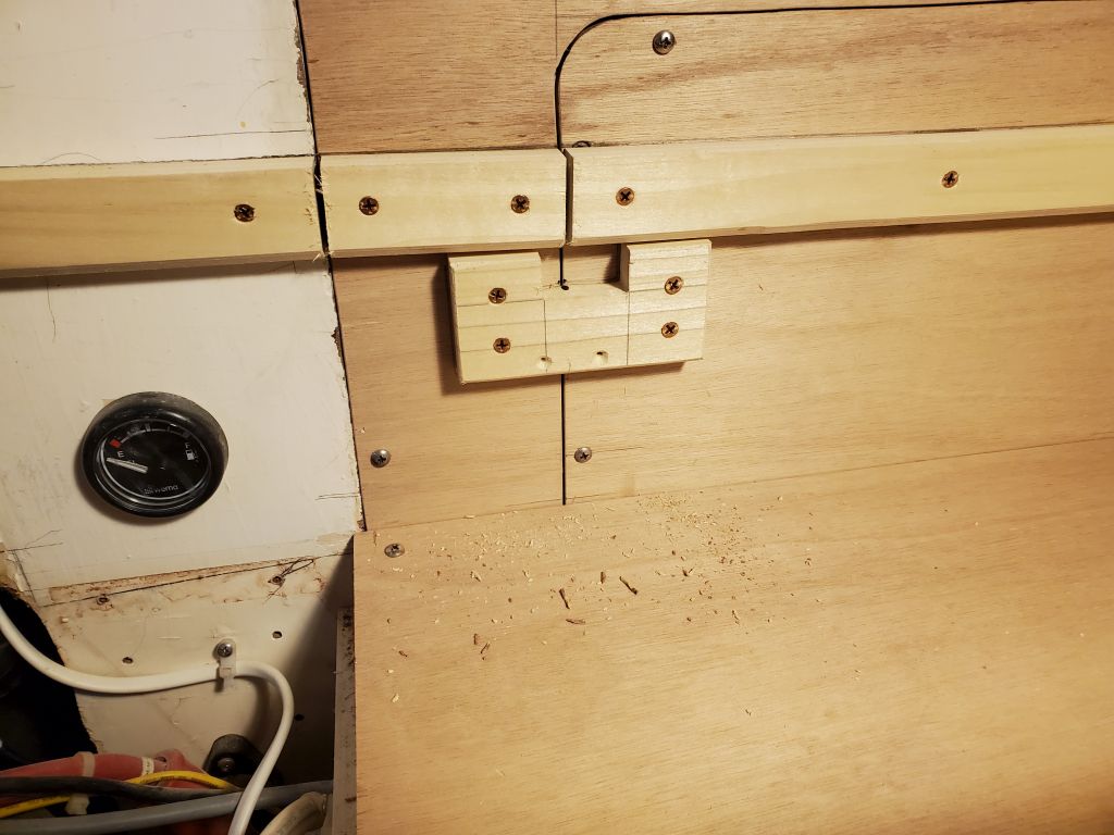
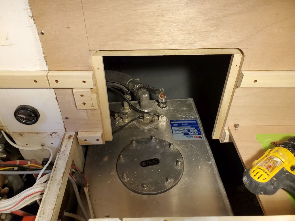
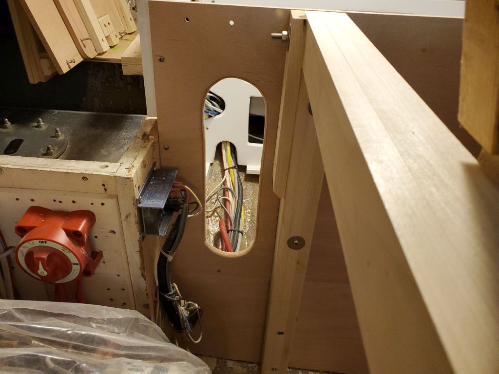
I’d prepared two smaller laminated beams to help support the countertop across its width in some way.  Since I wanted to make the countertop aft of the refer compartment (across the former quarterberth) removable individually, as part of the removable aspect of that section of the boat, I determined one of the beams needed to be located there, so I pressed on with the installation details.  I cut it to length (leaving space around the bolt securing the main transverse beam ahead of it), notched the aft end to fit around the after support cleat, then bolted the forward end to the refer panel (these would be easily accessible to maintain the removable qualities of this area).  To support the aft end, I fashioned a little cleat that fit beneath the beam; I had to split this across the seam of the access panel as well, because of where the beam had to end up, but this was of little matter.  In the end, the access panel remained removable with ease, as shown.  I also included a photo showing the large ventilation opening I’d previously cut in the section of the refer panel facing the engine room.

(Actually, reviewing this for publication I realized that maybe this beam wasn’t in a workable place after all, as the bulkhead wouldn’t be removable if the main countertop extended past the bulkhead seam.  I might have to change this–a problem for a new day.)

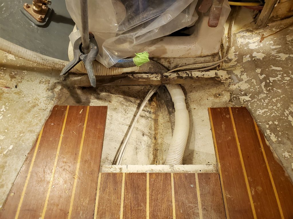
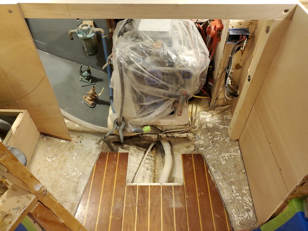
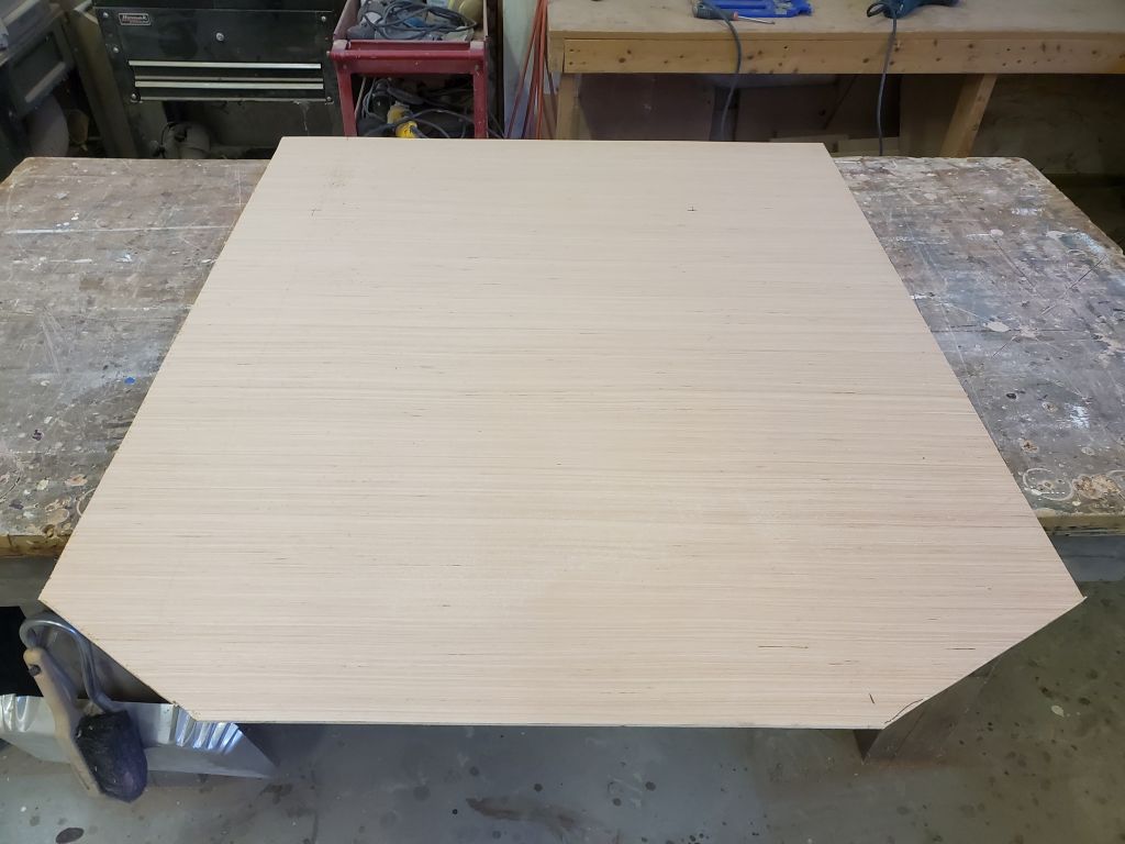
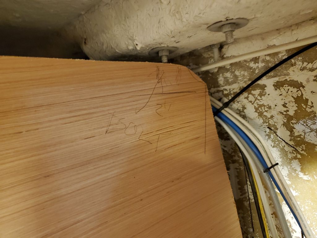
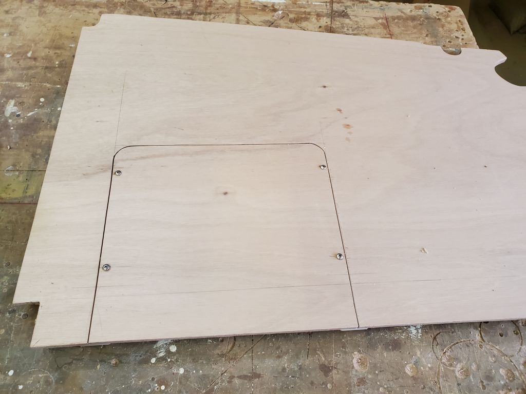
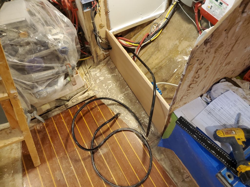
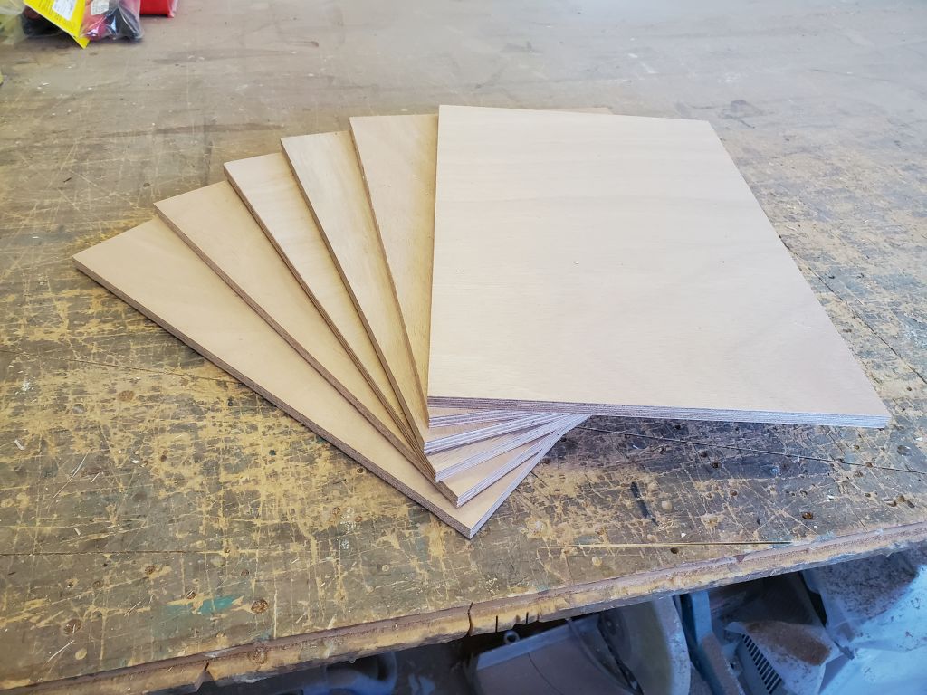
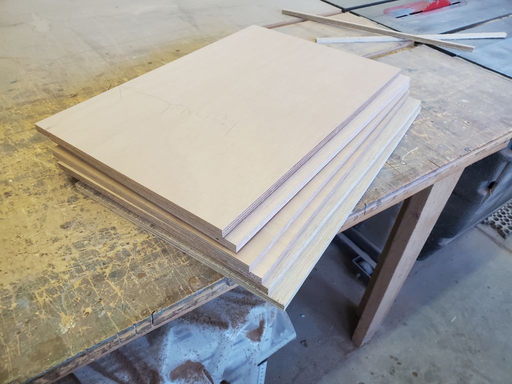
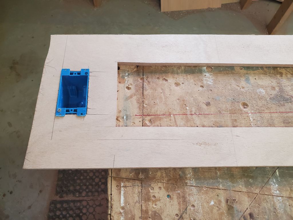
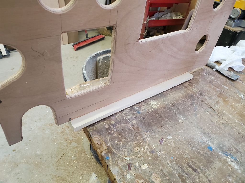
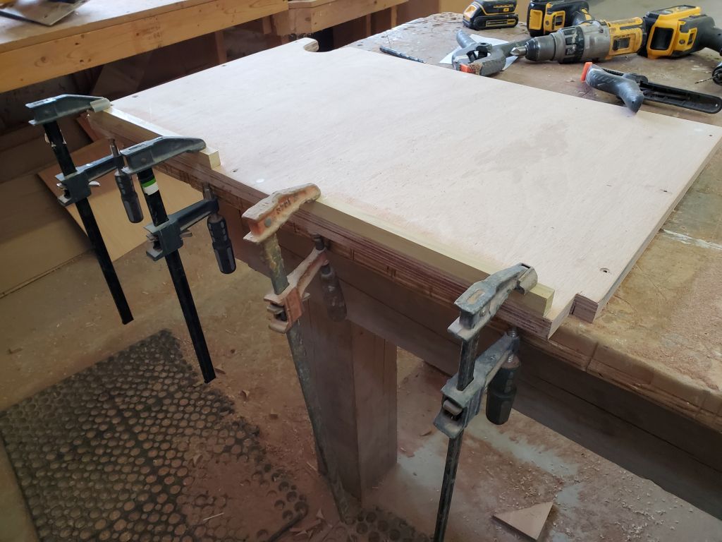
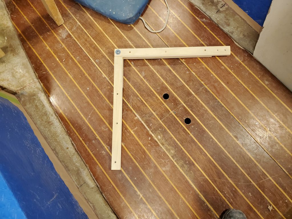
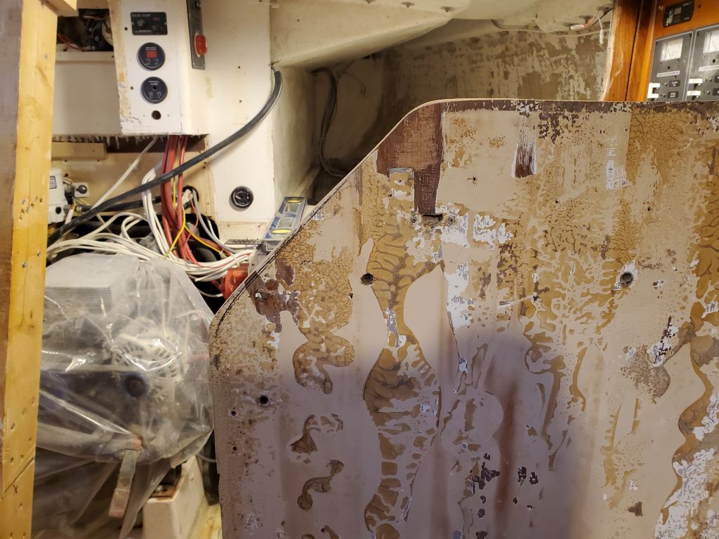
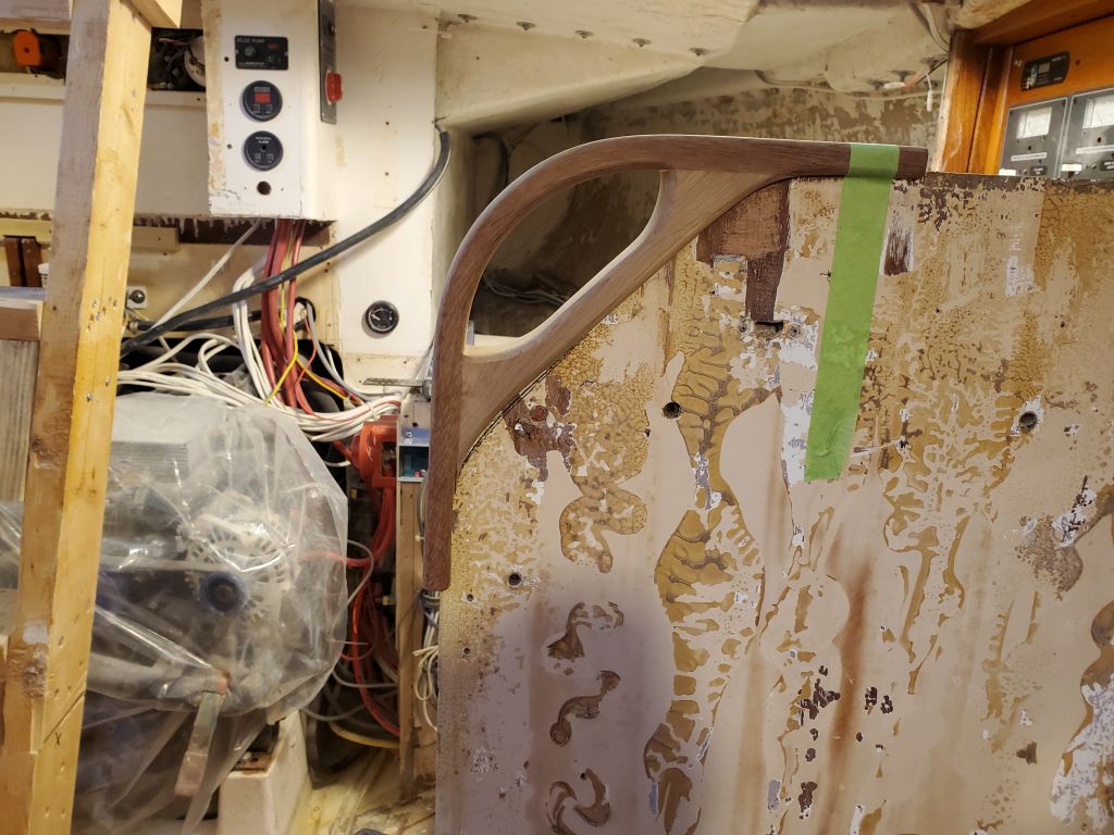
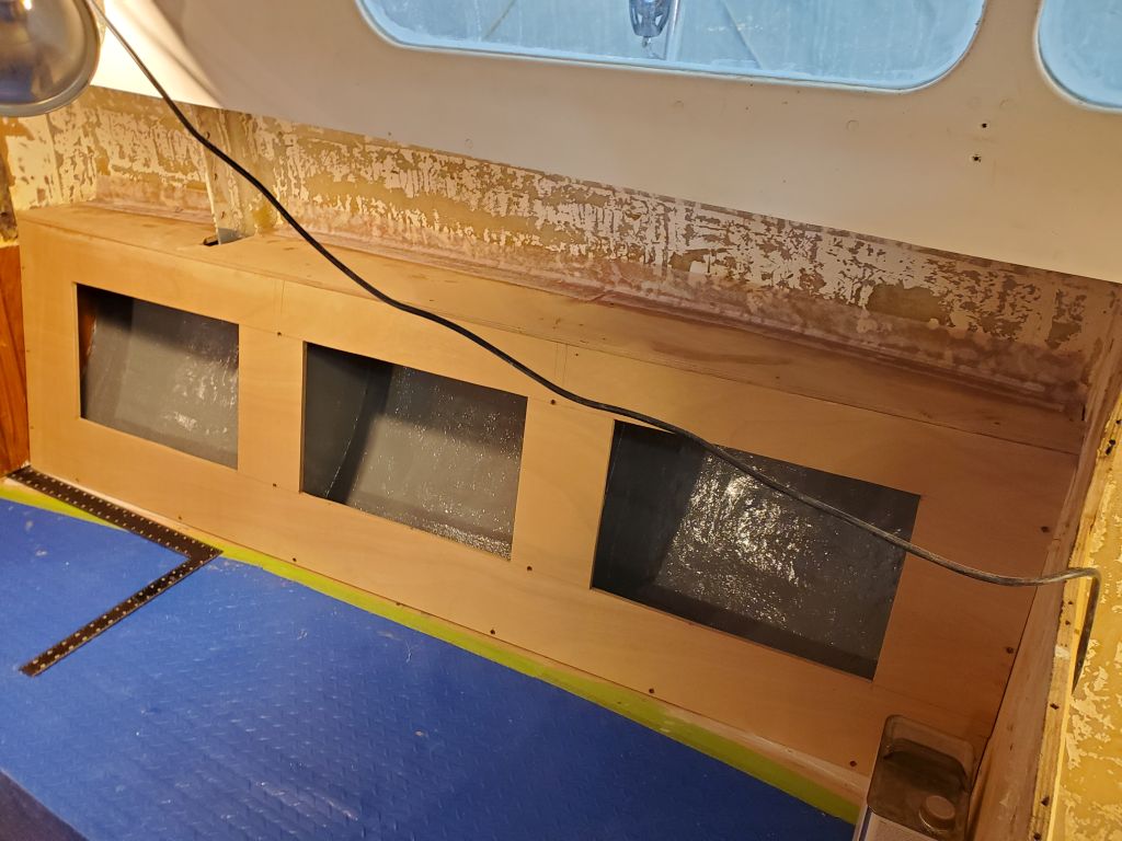
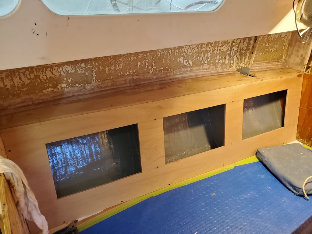
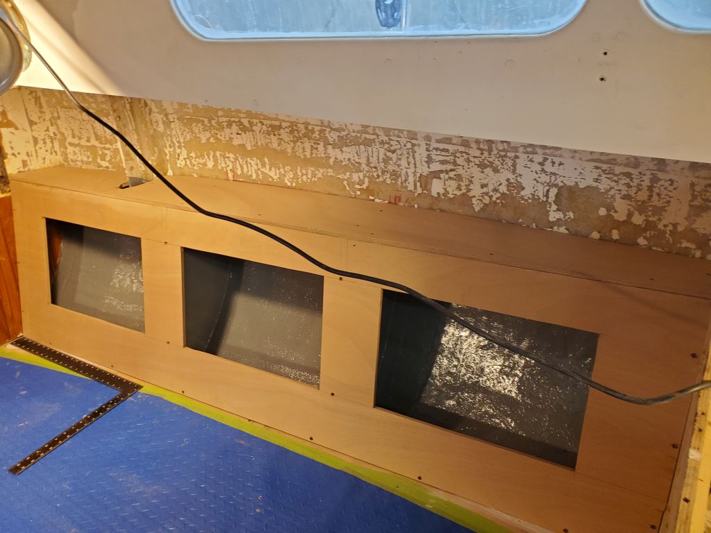
I expected to install a second longitudinal beam somewhere to starboard of the engine, but where and how, exactly, depended on a couple other things, such as sink placement and some existing removable panels defining the starboard edge of the engine room, so for the moment I waited on this.  Instead, I started work on the forward panel to enclose the space, which would be partially fixed and partially removable to access the engine.  To begin, I removed a section at the aft end of the cabin sole, so this wouldn’t be in the way of the new cabinet, then, with some basic measurements, began a simple plywood pattern to template the space.  This brought me to the end of the day.

Calliope Girl 56

Overnight, I got thinking of the propane lines and connection to the stove, and wanted to check the old lines I’d removed to see if they were of appropriate length and condition to be reused, since the new propane locker would be further away than the original.  This got me into briefly removing the regulator and valve assembly from the old plastic locker, as well as removing the two hoses, neither of which would be long enough in the new installation.

I also checked the connection on the back of the stove, and as I’d feared, it was something different than the normal US standard, which normally would have a male 3/8″ flare connection to mate with the female ends on all standard hoses.  The connection on this stove featured female 1/2-14 BSP threads, as indicated on the plastic shipping plug.  This led me down a rabbit hole of searching for an adapter fitting that would be appropriate, as most standard adapter fittings found at the usual sources were all intended only for the standard thread profile.  I eventually found and ordered one possible candidate (requiring a combination of two fittings) so I could check the threads on hand, and also contacted the stove company looking for their suggestions (as of this writing, I had not heard anything back yet).

With that situation at least moving towards resolution, I spent most of the rest of the day working on the port aft corner of the galley.  I needed to close off the old quarterberth, while striving to maintain reasonable future access to the fuel tank for service and even removal.  My first step–I thought–was to replace the existing warped plywood quarterberth platform with a new piece of plywood, and I started down this road, but soon realized that what I actually needed first was the vertical bulkhead/divider, onto which the platform would eventually rest.  This would give me several possible avenues to maintain the access as needed.

With the old platform in place just to help with layout, I extended the plane of the existing bulkhead across the space to the hull on the port side, and made some reference marks for use during templating.  Then, I cut and installed a support cleat on the edge of the inboard bulkhead.

In the usual way, and starting with basic measurements of the space, I created a rough plywood template, which I used to scribe the hull and overhead as needed, then transferred these to another piece of template material to better ensure the final fit before cutting the piece out of the 12mm plywood.  I left spaces for some of the existing wires to run, and, in the center portion of the fuel tank space, let the bulkhead hang down a bit to provide room for a support cleat for the new platform/shelf to be installed.  With the bulkhead in the proper position, I marked the edge where it met the hull so I could install some support cleats there, which I did next, securing them with thickened epoxy adhesive and a dab or two of hot glue as insurance while the epoxy cured overnight.

Though I planned to keep this new bulkhead (and things being built using it as a basis) completely removable if needed, to provide more route access I built in an access hatch over the fuel tank, which, when removed, would allow access to the cleanout and fittings at the aft end.  I cut out an appropriate section of the plywood, then installed hardwood support cleats on the aft side.

With a bit of time left in the day, but no immediate way to progress the galley construction while awaiting the epoxy cure time, I prepared several prefabricated fiberglass panels that I planned to use to build the new propane tank locker, so they’d be ready whenever I was ready to start building the locker, perhaps during future slack moments like this.  The first step with this material is always to sand the factory finish to prepare the fiberglass for additional bonding and paint work, which sanding I completed now and set the pieces aside.

I cleaned up the edges of the new battery compartment base, removing any epoxy squeezeout left from lamination, then trimmed the aft corner at 45° along the line I’d drawn during the initial layout.

Finally, using a scrap of teak I cut a large number of bungs to use in the settee construction, and eventually for trim work going forward.

Calliope Girl 55

To prepare for “final” installation of the newly-painted panels for the refrigerator enclosure (these panels were built to be removable for service later), I had a couple tasks to complete first, starting with leading a 2/0 negative battery cable for the house bank, running from an engine room shunt forward towards the eventual battery compartment.  I recycled one of the cables that had once led to the starboard battery bank, and snaked and secured it through the wire runs as needed, leaving the end in the forward port settee locker for now, along with other wires awaiting final and additional attention once the batteries were in place.

The electrical connection for the refrigerator was located on its aft side in this installation, and to prepare for this I installed a 12-volt receptacle in the vertical panel (I’d cut the hole earlier, before painting), and led a new wire from the existing terminal block, which was mounted on the forward end of the backing panel, around to the aft side, leaving enough wire there to allow the panel to be removed and the wires disconnected if needed.  Then, I installed the vertical panel, as well as the floor of the space.

While I was doing electrical-y things, I cut an opening through the galley countertop support cleat and led three existing wires through, and secured them to the aftermost bulkhead out of the way; cutting through the cleat meant the wires would be tight to the bulkhead and taking up less space when the countertop was installed. These would eventually be hidden inside an upper galley locker.  I also reinstalled a wooden cover panel for the engine panel and shore power outlet in the forward end of the cockpit; I’d removed this earlier in the project, thinking I might need access, but there was nothing in there that was related to anything I was working on in this project.

I test-fit the new inboard panel for the refer/engine room, and marked and cut the top to the correct (countertop) height.  Sometime later, I’d figure out how the forward end would interact with the bulkhead trim and corner handles and finish it off appropriately.

The additional bronze bolt and washers I needed for the chainplates had arrived, so I finished up the installation of the main chainplates on both sides.

This meant that I could also do the final installation of the forward upper settee locker panels with glue and screws.

I spent the afternoon in the galley, working on the main support beam and post to define the remainder of the galley and engine room lockers.  I clamped the 4′ laminated beam I’d built across the space so its end was tight and square to the new panel on the refer compartment (all level as it should be), and made a reference mark so I could strike a plumb line down to locate the support post, for which I measured, then cut the blank to the appropriate length so the horizontal beam could rest atop.  I temporarily secured the post to both the upper and lower sections of the refer compartment with some screws from the back side (having first removed the refer floor), ensuring it was properly aligned and plumb.

To secure the post to the top (removable) section of the port galley, I planned to use machine screws and threaded inserts.  Through the top section of the post, I drilled two 5/16″ holes, just far enough to dimple the plywood beneath for reference, then removed the panel so I could drill for and install the stainless steel inserts to accept 1/4-20 machine screws.  While the top panel was out of the way, I completed the final installation of the post to the lower panel (which was still intended to be removable, though would likely rarely or even never need to be) with glue and two 5/16″ bolts.

While I had the panel out, I laid out and cut a large ventilation opening in the section aft of the support post, which would communicate with the business end of the refrigerator compartment.  I forgot to take a picture of this, but it will show up the next time this panel makes it into the description.

Meanwhile,  to capture and eventually secure the horizontal beam, I installed a board on the aft side of the post, flush with the countertop height, with glue and screws, bringing me to the end of the day.

Calliope Girl 54

I had several jobs underway that couldn’t be “finished” just yet, whether because I was awaiting parts (additional fasteners for the chainplates), or inability to complete one thing was holding up completion of the next thing (i.e. the forward upper settee locker panels awaiting the chainplates’ completion, and the pending galley construction awaiting the paint completion in the refer compartment), but that hardly meant there was nothing to do.

I started with a couple small items, first lightly sanding the last coat of white paint on the galley parts to prepare for another coat later in the day, always my first task when in a finishing mode.  Then,  I re-routed a wire (for the CO detector) I’d recently led into the port upper compartment, where it had been led in the original interior, to the aft end above the galley, as the owner told me he didn’t think it needed to be where it had originally.  No time like the present.

I also used my plywood template to cut the actual upper panel for the refer compartment in the galley, and test-fit it (it fit well, though the after vertical cleat was out of the boat for painting, and the top edge would later be trimmed to the correct height in situ).  I set the panel aside for now to await its next step.

The clearance between the starboard mid chainplate and the new locker panel was a bit tight at the top, so I trimmed back the panel a bit as needed; this area, including the chainplate, would later be covered with trim work.

Down at the table saw, I trimmed the laminated posts and beams I’d glued up earlier to square and clean up the edges and prepare the pieces for use in the project.

Continuing at the table saw for a while, I prepared six plywood blanks, all from plywood offcuts, to fit the locker openings in the settee backrests.  I sized these so they’d fit inside the openings; these were the bases of the locker doors, which would also be cushioned backrests, and would eventually be hinged at the bottom.  Next, I cut six additional panels 1″ larger than the opening on three sides (the bottom side remained flush), which panels would later be cushioned and upholstered and  attached to the hinged base panels.  This project did a good job using up most of the leftover plywood pieces left from cutting some of the larger interior components.

To complete the upholstery panels, I cut a 2-1/2″ radius into the four corners, then rounded both sides of the panel and sanded smooth.  I ordered hardware to secure the two pieces together and set things aside for now. Note that the small exposed corner of the inset (hinged) panels, where the upholstered panel curves into the base, would be hidden in the final analysis by the bulk of the cushioning and upholstery wrapping the corner.

That all took quite a bit of time, so once complete, and since I had to leave the shop early for an appointment, it was time to apply the next (final) coat of semi-gloss white paint on the galley parts.

I used the time left in the day to start work on the battery locker, which would be built inboard of the forward end of the port settee.  I’d done some preparatory and layout work earlier, and now, with that basis in mind, I laid out the four battery mockups on a new sheet of plywood and, leaving a bit of additional room around them (using some thin plywood as a spacer between each “battery: and along the edges), as well as enough room around the inboard/aft edges for some support cleats for the sides, I cut two identical rectangles from the plywood, which I laminated together with epoxy to form a strong 1” thick base to support the batteries’ weight.  I planned to cut the inboard/aft corner at an angle, as I’d done in the mockup earlier, but would cut that only once the laminated panel was cured.

Calliope Girl 53

My first task was the contorting one of getting the wire bundle in the quarterberth secured to the new wire mounts beneath the gunwale, now that the paint was finished.  I also painted the small bulkhead at the aft end of the space, which had been tough to get to with the wires in the way before.  At the forward end, I still had to see where the wires would end up leading themselves and how the galley work would tie in, so I left that part of the bundle unsecured for now.

With most of my new bronze hardware on hand for the chainplates, I decided to install the after four, leaving the two new forward lowers for another time (none had ever been installed before and I’d need to cut slots through the deck).  Installing the two aft lowers wasn’t too bad, though on the port side, where the alignment of things was a bit different, it turned out to be awkward getting the lowest bolt in, as it was more or less aligned with the settee shelf, so I had to open up a new slot in the shelf on the fly.  I’d come back some later time to install the deck plates and bedding.

The main chainplates, or uppers, were a bit more difficult to install.  Though there was a substantial set of fiberglass knees for the chainplate forward of the main bulkhead, the original installation had bolted the chainplates through both, with wooden spacers to fill the 2-1/2″ gap between the bulkhead and knees.    I had no desire to change the original, so I installed the replacements the same way.  This ended up taking some time because the tiniest misalignment on one end, with spacers, backing plates, and five, 5″ bolts, turned into something more difficult at the other end, and it simply took much longer to get the bolts in place (particularly on the starboard side, which was the first one I tried) than one would think.  Otherwise, the process went smoothly enough, though I did end up ruining the threads on the end of one of the bolts, so I had to order a replacement since I’d ordered only enough for the job, as these bolts were expensive and otherwise unneeded stock around the shop.

I had to order 6″ bolts for the port side because of latent differences between the two sides, and these came from a different supplier, but later in the day they arrived and I had better (and faster) luck with this side–though I’d miscalculated the number of washers needed, perhaps because I didn’t account for using flat washers on both sides of each bolt, so I couldn’t finish the installation with what I had on hand. But all the holes were aligned, and I hoped to be able to finish the installation quickly with additional washers.

I’d hold off installing the forward set of upper cabinets till the chainplates were done, but now I could install the after set, after first taking a moment to cut an opening for an outlet box on the port side, to replicate what was in the original interior.  I also re-led the wiring for this box through a new hole into the electrical locker, as the originals were outside of the new locker.

In the galley, I decided to temporarily remove the bilge pump switch and two related gauges below from a small, original panel so that I could eventually reinstall these in the new galley cabinet.  I removed the wiring from each, labeling as needed, and removed these installations so I could remove the face panel as well; I planned to leave the adjacent battery switch panel in place, where it could be easily accessed through the new lockers once built, and since relocating it at all would involve more re-wiring work than it was worth.

Meanwhile, I started to clean up and secure some of the wiring run through the galley, which wiring had originally been secured beneath the old countertop.  Now, I resecured it to the new wire mounts along the aft bulkhead and elsewhere to direct various portions where they needed to go.  I spliced a new length of wire to the original fresh water pump wiring so I could extend it forward to the new location.  All this work was leading up to the continuation of the galley construction presently.  Additional work remained as the process progressed.

To wrap up the day, I prepped and painted, this time with white semi-gloss finish paint, the bulkheads and panels from the refrigerator locker.

Calliope Girl 52

The upper panels for the settee lockers were ready to go, but for now I held off installation to allow the paint a bit more time to cure (it was still a bit tacky), and I also planned to install the aft lower chainplates (at least) before the lockers were complete; although access would be possible and even easy afterwards, it was still easier now.  But I’d ordered the wrong size bolts for the chainplates, delaying their installation a bit till the proper size arrived.  In any event, not installing the settee panels wasn’t holding anything else up at the moment, so there was no harm in waiting.

Back at the quarterberth, I cleaned the surfaces and installed a series of wire mount bases along the gunwale, eventually to hold the wire bundle leading aft that had been beneath the old platform.  I cleaned up this bundle and removed the old wooden supports from the aft end, which had fallen off the hull earlier, then temporarily secured it near the forward end to hold it as much out of the way as possible while I painted the locker, from the aft end to the fuel tank.  I left the forward end as is for now pending some decisions and installations in the galley.  Once the paint was dry, and the adhesive securing the wire mounts had had adequate cure time, I could secure the wiring up along the gunwale out of the way, leaving the locker clear for the new propane locker and cockpit access, and for finishing off the galley at the forward end.

Speaking of the galley, it made sense now to paint most of the locker on the starboard side, aft of the stove and beneath the sink area, leaving a bit of it unpainted near the forward edge and in way of the new stove bulkhead where I would soon be installing the remaining bulkhead across to the port side.

On the port side, I removed the two panels forming the refer compartment so I could attend to some small details and prime and paint these panels.  This gave me a chance to re-secure an AC terminal block and junction box cover to the inside vertical panel of the space; this box had originally been installed on the forward bulkhead, and had been loose and awaiting a final home since.  I added a support cleat to the lower edge of the back (vertical) panel to help support the floor panel, and another cleat on the inside edge of the inboard panel for the same purpose.  All these panels would remain removable if needed, but worked together for mutual support.  At the inboard edge of the floor panel, I installed some small cleats that would provide support for a to-be-built front panel that would enclose the space.

Next, I added a vertical cleat to the aft end of the space, this cleat needed to capture the eventual front panel, and also to help support the countertop and lid for the space.  Eventually, through several steps that made themselves clear as each additional piece came into being, this cleat assembly grew to include a horizontal support for the aft end of the lid to the refer compartment, with an additional cleat behind for the fixed portion of the countertop, and all designed to be removable in a single piece for access to the fuel tank should it be needed.   I also wanted to leave the aft bulkhead at least partially open to promote additional ventilation for the refrigerator.

I glued what I could, including the 90° joint at the inboard corner, which I also secured with a through bolt for strength.  Once I’d built this support, I removed it again for the moment, to allow for some painting and to keep it out of the way till I was done in the quarterberth, but before I did I made a quick plywood template for the enclosure panel along the inboard edge, to be built soon and which would eventually incorporate additional open ventilation, plus a support system for the remainder of the galley/engine room construction.

This would be an at least partially visible, “finished” space (though the refrigerator would take up most of the space), and as such I planned to paint everything with the white paint intended for other parts of the cabin.  To begin, I applied white primer to the bulkheads as needed, then to the floor and back panels as well as the aft support cleat  I’d continue with a couple coats of semi-gloss white to finish these up before reinstallation.  This process would also give me time to finish up a couple wiring reinstallations through the space before I buttoned it up (though again, these components were designed to be removable for access with as minimal effort as possible).

Calliope Girl 51

I began by installing the cleats I’d cut for the starboard upper compartments–3 per compartment.

To support the upper edge of these cabinets, I cut and installed four additional cleats with epoxy (with dabs of hot glue to secure the pieces while the epoxy cured).

Giving the epoxy a bit of time to cure gave me a window of time to check out some teak bulkhead corner handles the owner had hoped to use on the two galley bulkheads.  I’d ordered the pieces to have on hand and check if they could work, which I suspected they would.  Working on the port side, I checked the concept, then, having confirmed the function, snuck up on the final 45° cut required on the bulkhead to allow the handle to fit as intended.  I’d have to figure out how these would interact with the bulkhead staving on one side, but all in the fullness of time.  I repeated the process on the starboard bulkhead, which went more quickly as I could transfer some basic positioning and measurements from the opposite side.  For now, I set the teak handles aside for installation later in the project.

With some rough measurements, I prepared four cheap plywood template blanks for the upper settee cabinets, then held them in place for marking and scribing as necessary against the underside of the deck, and at the bulkhead ends.

I transferred the patterns to the final plywood and cut out the blanks, leaving them to run wild past the upper dividers so I could mark them in place for trimming.  For some reason, I don’t have photos of the two after panels after final trimming.

I made some reference marks to indicate the position of the locker openings in the backrests below, which, down on the bench, I used to to lay out and eventually cut the locker openings for the uppers.  I chose to make these openings the same width as their lower counterparts, and positioned the lower edge of the cutouts 3″ above the base of the panel to provide plenty of support for whatever cabinet contents there might be.  This allowed for a 6″ x 18″ opening.

Finally, I performed ritual final cleaning and preparation and painted the insides of these four lockers, as well as the chainplate knees forward of the main bulkhead.  The open center portions of the settees would later be painted white to match the remaining cabinetry.

Calliope Girl 50

When I’d demo’d most of the rest of the interior of the boat and done my bulk surface prep and sanding early in the project, the narrow quarterberth had been inaccessible to me, behind a tall bulkhead at the aft end of the then-nav station.  So I’d left that area for some other time, and in the meantime, it’d been mocking me in its undone-ness, fairly defying me to put it off any longer.   Despite this, I managed to pretend it wasn’t there for quite some time.  But with new construction progressing, it was getting harder and harder to ignore the last vestige of peeling paint and despair, and now, with a short day on tap thanks to an afternoon commitment, I decided the time was nigh to get the job done.

I’d not been looking forward to getting in there, and I came close to putting it off for another time, but eventually I buckled down and got it done as I’d planned all week.  As it happened, it turned out to go more quickly and less messily than I’d feared (it’d been making a humongous mess that had been the most dreadful part as I imagined the job), as most of the residual dust ended up staying pretty trapped in the small compartment thanks to my own effectiveness as a dust-blocker by virtue of simply being in the space and bodily taking up most of the opening.  This space was to be utility only going forward–with a to-be-built propane locker located in the after portion, and storage (hopefully accessed from the cockpit) in the forward section–so the surface prep needed only to remove loose and flaking paint and generally clean up the space to be ready for bilge and locker paint, at best.  So as with many things in life, the anticipation ended up being worse than the work itself, and once I’d cleaned up I was happy to have the job behind me.  Sometime later (soon), I’d get in there and install some new wire mounts and relocate the wire bundle up along the gunwale somewhere out of the way.

For the remainder of the morning, I focused back on the settee upper lockers, starting with a light (hand) sanding of the new tabbing securing the dividers.

Next, I measured, cut, and began to install the support cleats required for the upper cabinets on each end.  Cleats can be time-consuming, especially when most of them, as in this case, required a 10° angle on their edges to match the angle formed between the main bulkheads and shelf, and these angles required notations first so I’d remember which orientation the cleat for each place had to be, since they were different on each side of the boat and often depending on which side of the dividers they were placed on–impossible to reconcile on the fly when making the cuts down in the woodshop.  The forwardmost vertical cleat, located on the main bulkhead just outboard of the chainplates, required an additional cleat thickness since I planned to hold the forward panel just aft of the bulkhead to allow chainplate clearance (which gap would later be covered by teak trim).

In the event, it took the remainder of the morning to install most of the cleats on the port side (excepting the two overhead cleats), and while I had the cleats cut for the starboard side, their installation would have to wait till next time.

To finish up my brief day, I mixed and applied 2-part epoxy primer to the shelf and upper bulkhead tabbing to prepare the areas for locker paint soon.  I only apply this primer as the final thing in any day, or at least if I plan not to be back in the cabin, as the fumes would otherwise drive me out anyway.

Calliope Girl 49

After a quick and light sanding of the newest tabbing securing the settee shelf, I was ready to begin layout and construction for the upper cabinets.

With the basic idea of two enclosed cabinets on each side, bookending an open shelf in the center, I studied the specifics of the spaces and ultimately decided that the center, open section should align with the edges of the center lower locker opening, which would make the two enclosed lockers a bit longer (but essentially symmetrical with each other).  The reasons this worked and ruled the day were several.  If I’d divided the space equally into thirds, the upper locker openings on the ends would he hard-pressed to align in a pleasing way with the openings below.  But by keeping the open section (which probably  didn’t need to be as large anyway) just over the center lower opening, this meant the end lockers’ doors could be centered directly over their lower counterparts, which would look the best, and frankly anything else would have seemed odd.

This placement also worked well to avoid–and ultimately hide/enclose–the backing plate and hardware securing one of the stanchions above, with the divider ending up clear of these by an inch or so.  I struck layout lines based off the vertical edges of the locker opening below, and, with a bevel gauge set to the angle between the fore and aft bulkheads and the settee backrest, drew marks on the shelf to indicate the position of the small dividers and supporting cleats.

Next, I cut and dry-installed cleats at each of the four layout locations, offsetting the cleats by the thickness of the plywood (so the edge of the divider would be in line with the locker opening below) and ensuring each was aligned at the correct angle, i.e. ultimately square to the boat’s centerline.  Then, with cheap plywood templates cut roughly to size, I went through the usual process of scribing/marking and cutting the templates to fit, aligning them plumb and installing hot glue blocks as needed to hold them so.

Next, I transferred the shapes to 12mm plywood and checked the fit, leaving the inboard edges wild for marking.  I planned to run the faces of the end cabinets past the edge grain of the dividers at each end, so I marked a 12mm offset from the edge of the shelf, then a plumb line up from there.

I cut the dividers to their finished lengths, each end angled to match the settee, and, satisfied with everything, permanently installed the cleats with glue and screws, and marked the hull and deck on each edge of the plywood for alignment during installation.

I secured the dividers in place with glue and screws against the cleats, and epoxy along the edges where they met the hull and deck, with just a dab of hot glue on the inboard upper corner against the deck to hold the panels in proper vertical alignment.  I formed small cosmetic fillets on the inside edges, which would be exposed in the open portions of the cabinets, and additional fillets on the outer sides, which I then covered with strips of 4″ tabbing to secure these bulkheads in place.

Calliope Girl 48

To start the day, I made an early trip to the machine shop to pick up the new chainplates and backing plates.

Over the weekend, the owner and I discussed relocating the fresh water pump from its existing location in the galley, which he said was hard to access, to the forward cabin, where the new water tank would be.  This would also simplify the plumbing, and extending the wiring would be straightforward.  In my mind I remembered enough room for the pump there, so I decided to go ahead first thing and move the pump to its new location.

First, I used a long level to mark the aft bulkhead in the v-berth with the proper level height, as the original had been several inches too low at the aft end.  I transferred the new mark across the bulkhead on each side to give me a reference point for how much room there was available.  There was enough room outboard of the existing washdown pump already located there to mount the fresh water pump, while still staying clear of the eventual berth structure and the other pump and maintaining access for hoses, filter changes, etc.  For now, I mounted the pump and its associated wiring terminal; I’d extend the existing wires forward another time.

Now I turned to the final installation of the settee backrests with glue and screws.

With those permanently in place, I made some basic measurements and cut rough patterns for the top shelves from 3/16″ plywood, then scribed and adjusted these as needed till I was satisfied with the templates.

I transferred the shapes to the 12mm plywood and cut out the shelves, leaving them a bit wide to overhang the backrests for now and making minor adjustments as needed till the shelves fit properly.  I marked the overhangs  for trimming.

Down on the bench, I trimmed the overhangs and enlarged somewhat the openings around the chainplate knees to allow room for the chainplates and bolting access, then installed the shelves permanently with glue and screws on all the support cleats I’d previously installed, and epoxy along the hull edge.  Then, I installed a strip of 4″ tabbing to help secure the shelf all along the hull.

This brought things to the end of the day; I’d continue next time with the upper cabinets.

Older posts Newer posts