Friday
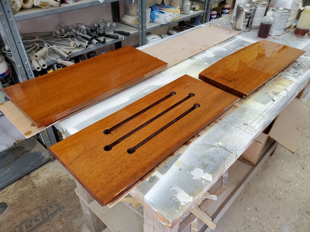
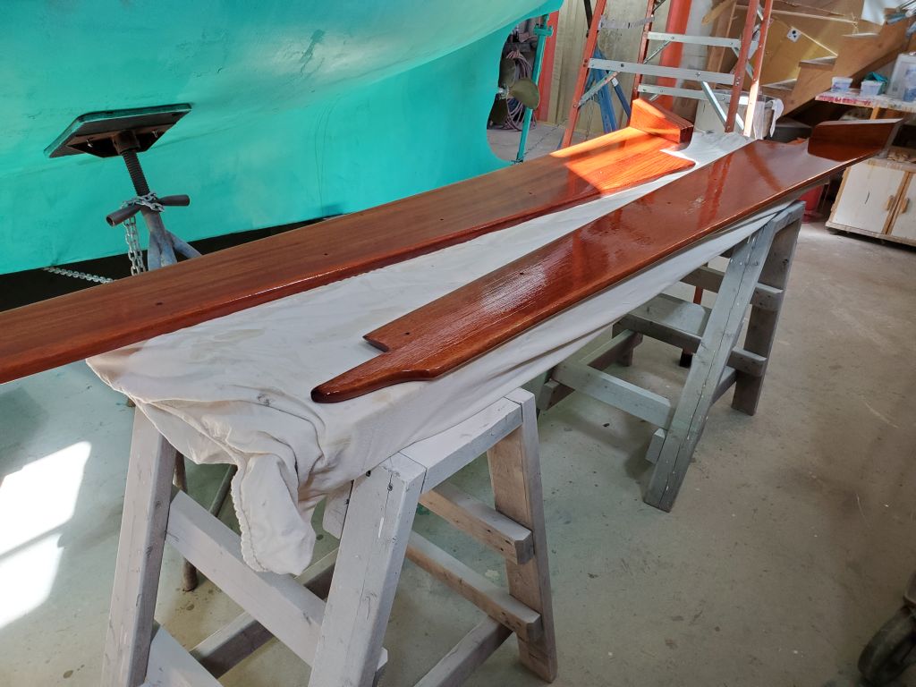
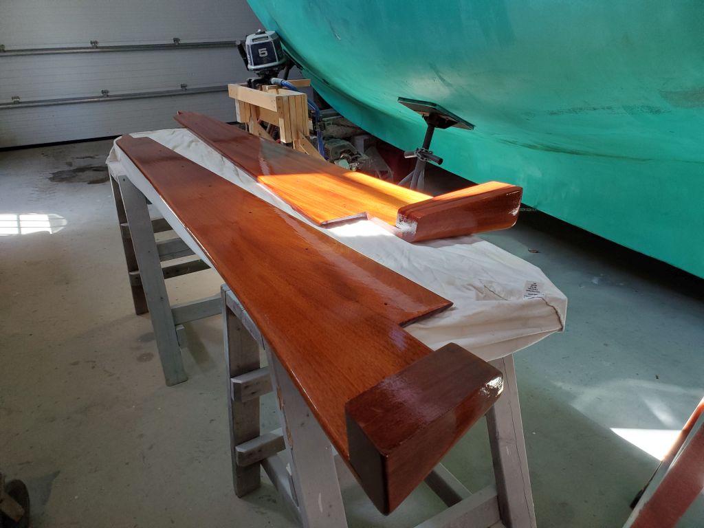
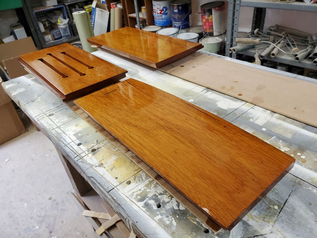
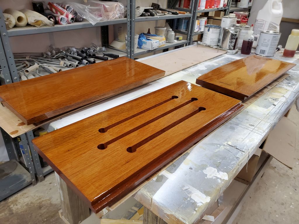
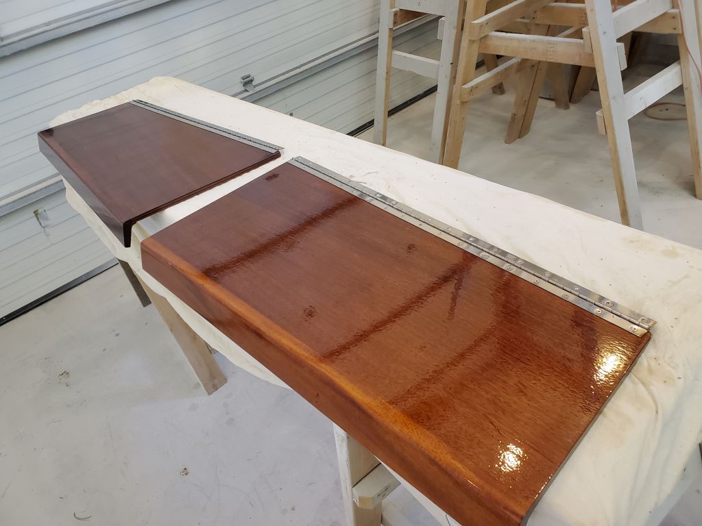
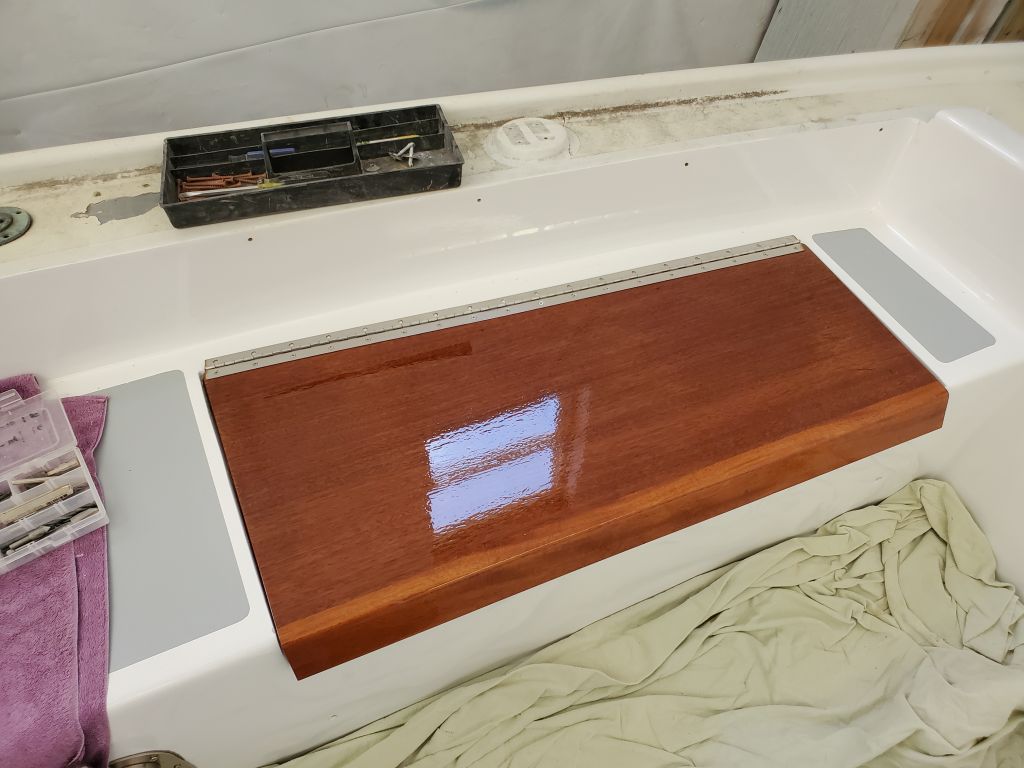
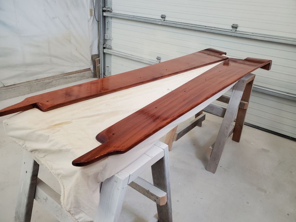
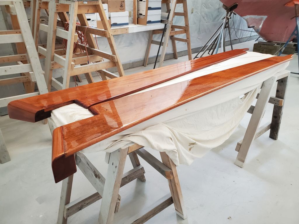
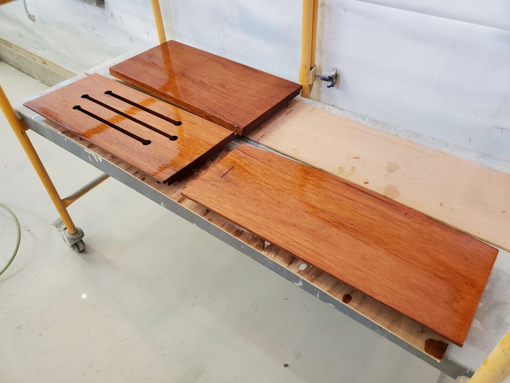
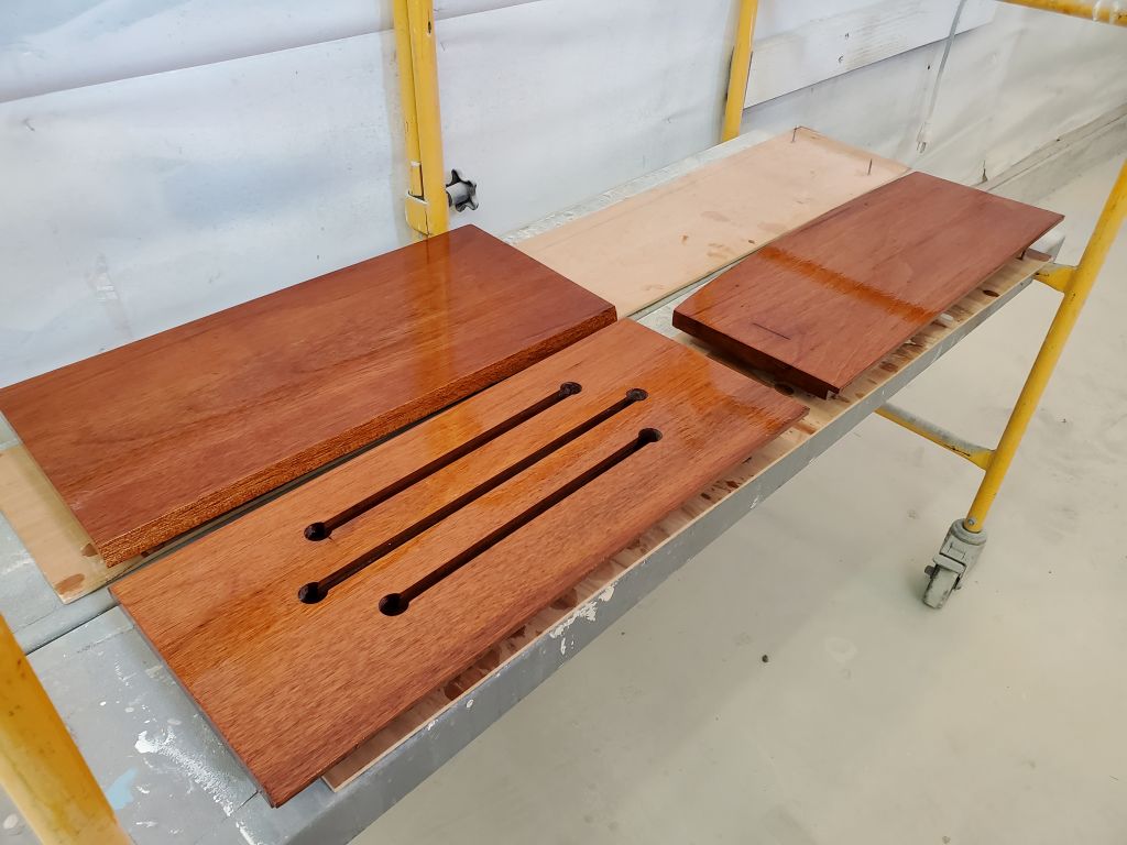
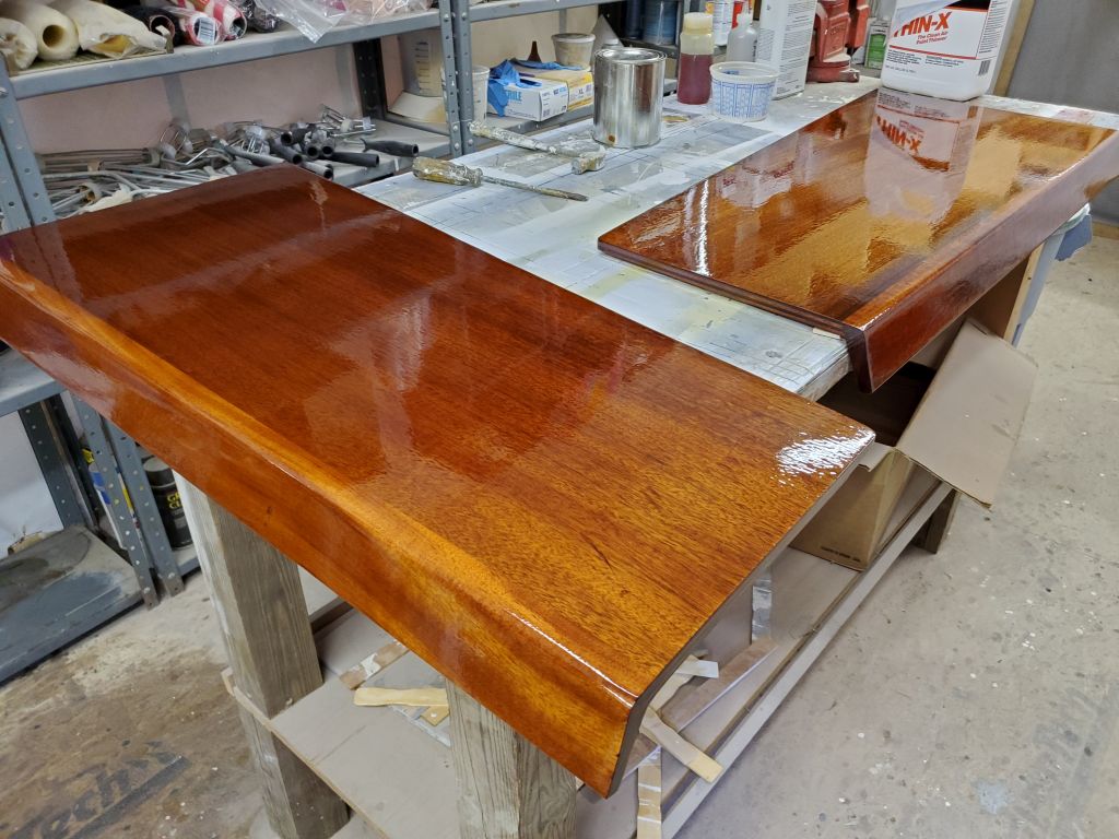
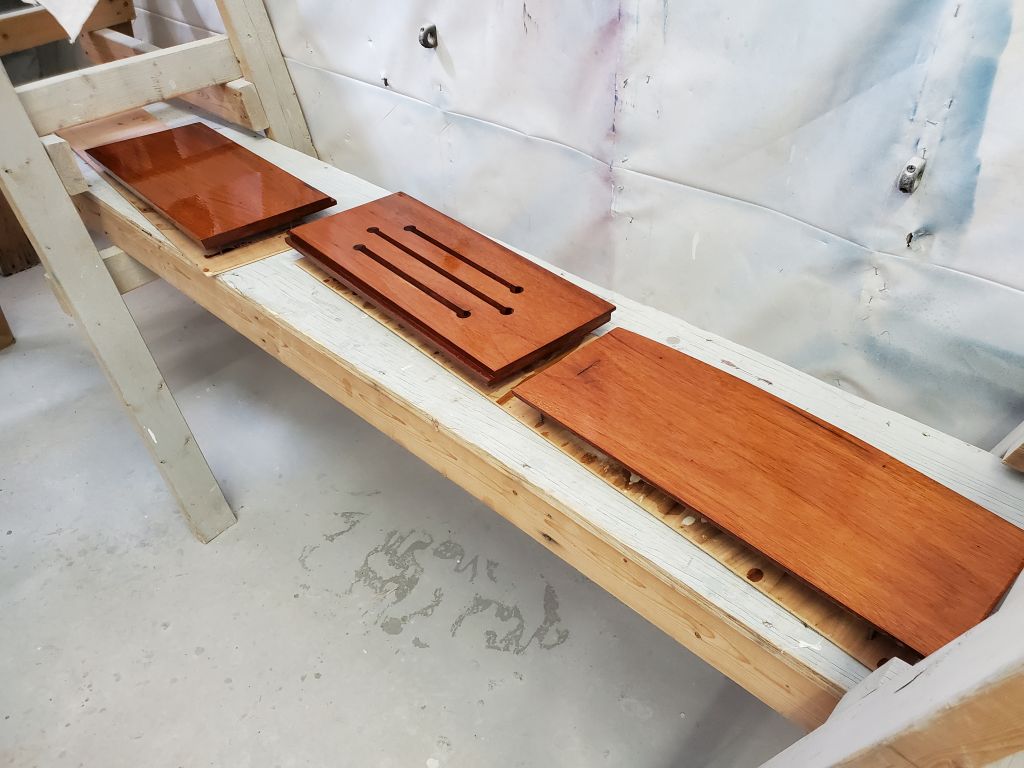
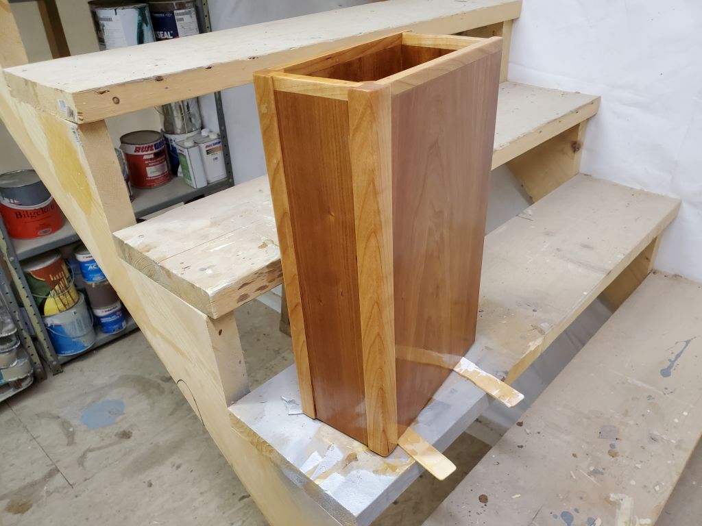
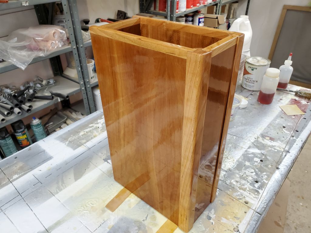
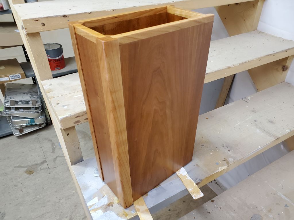
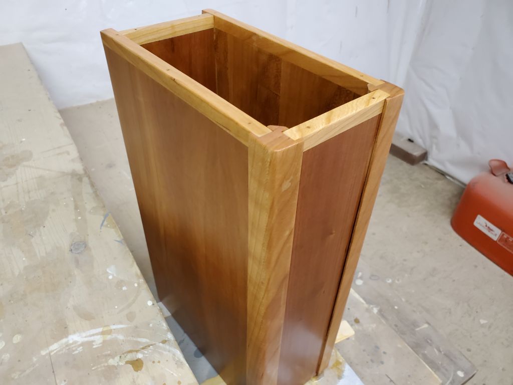
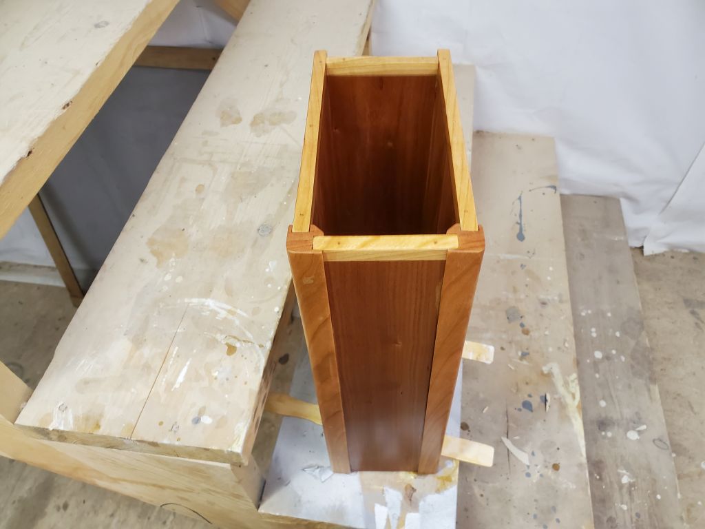
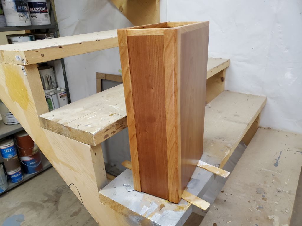
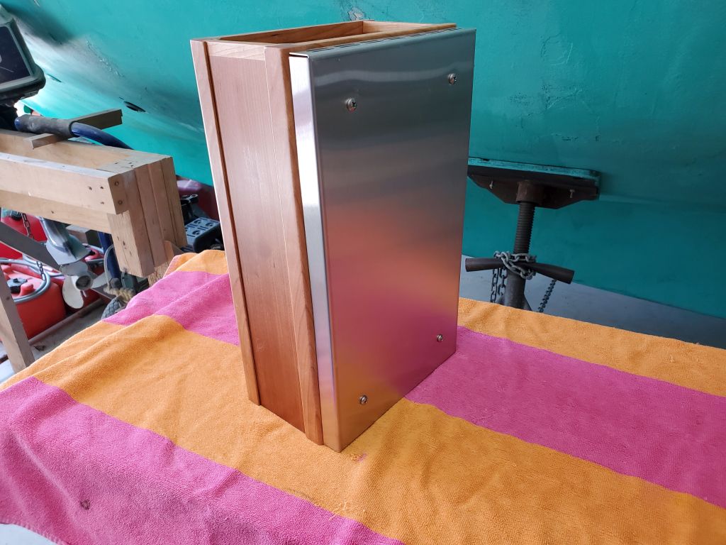
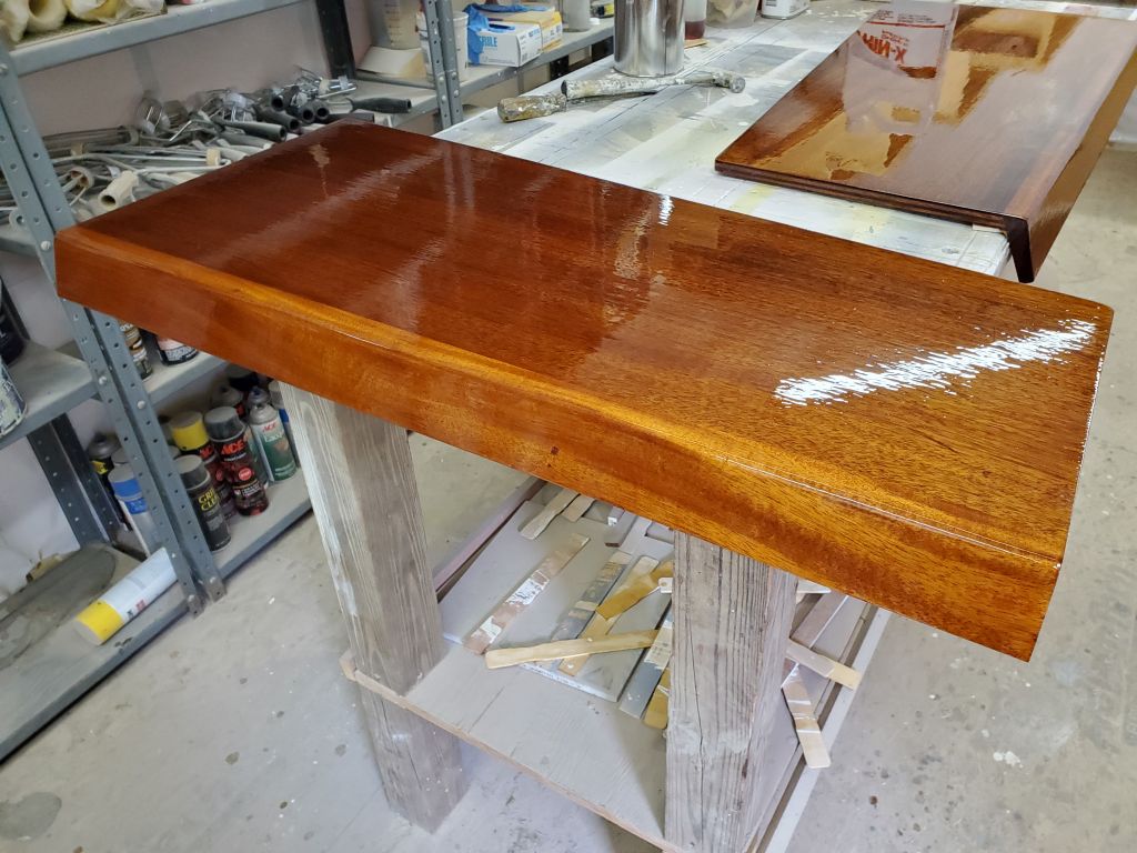
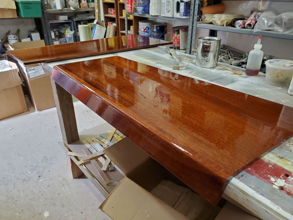
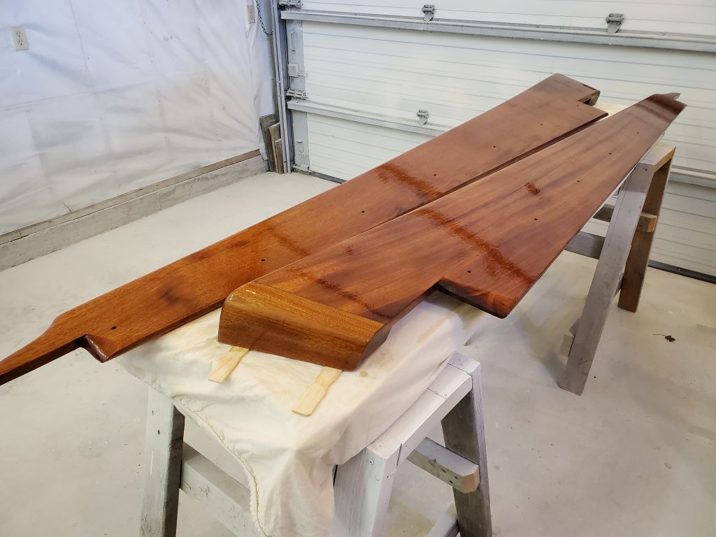
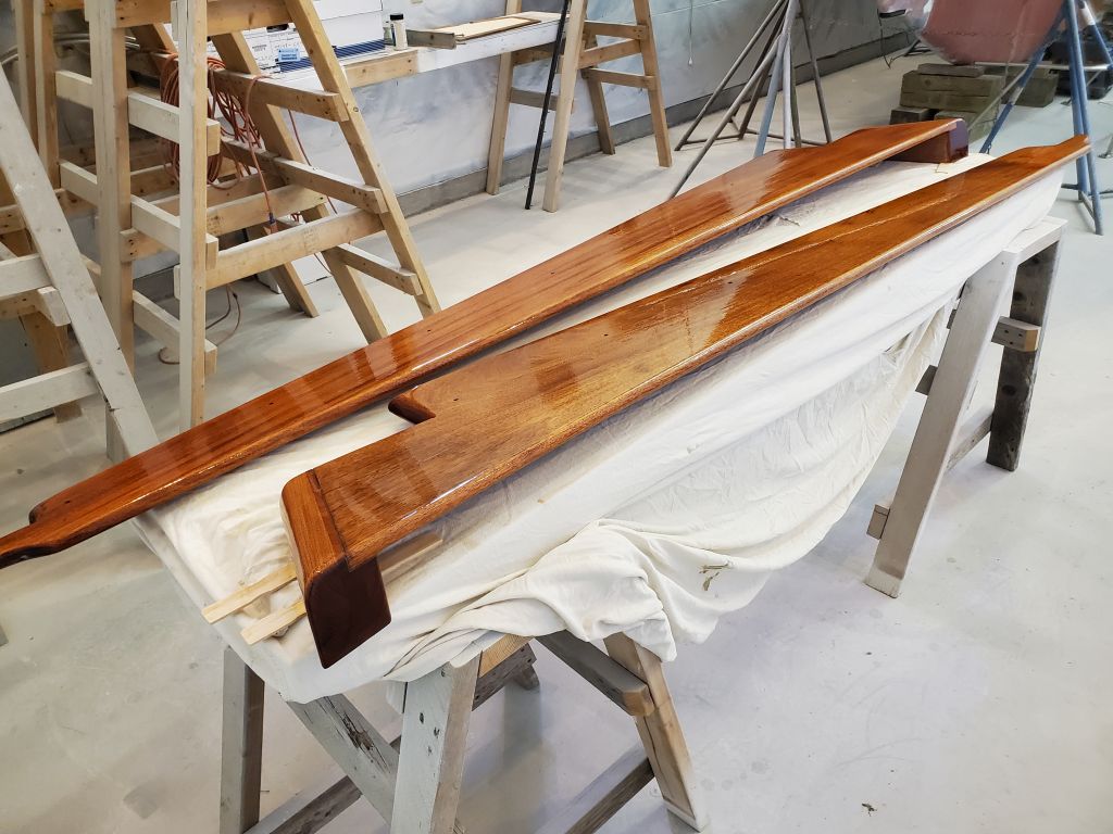
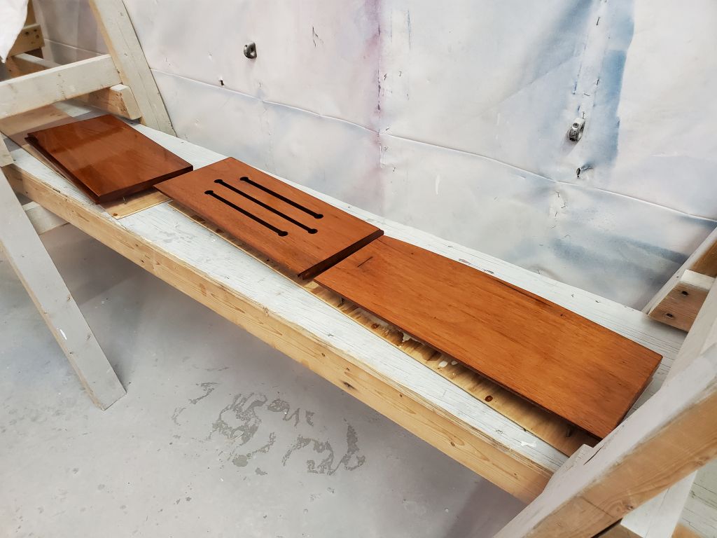
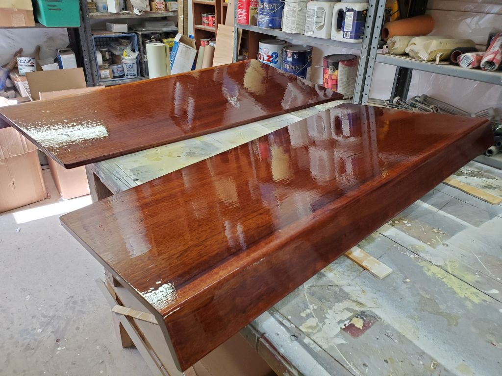
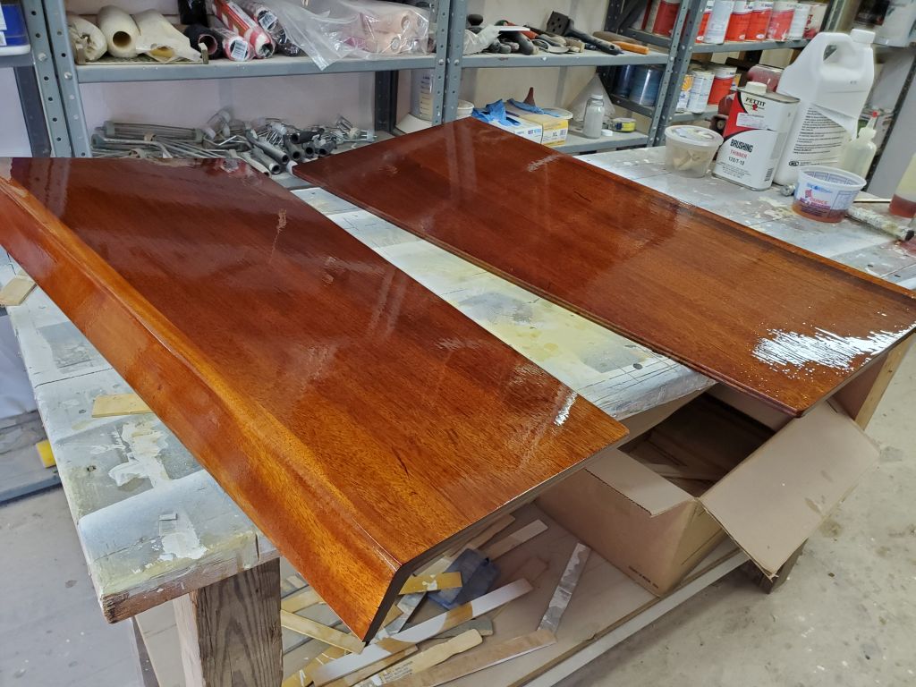
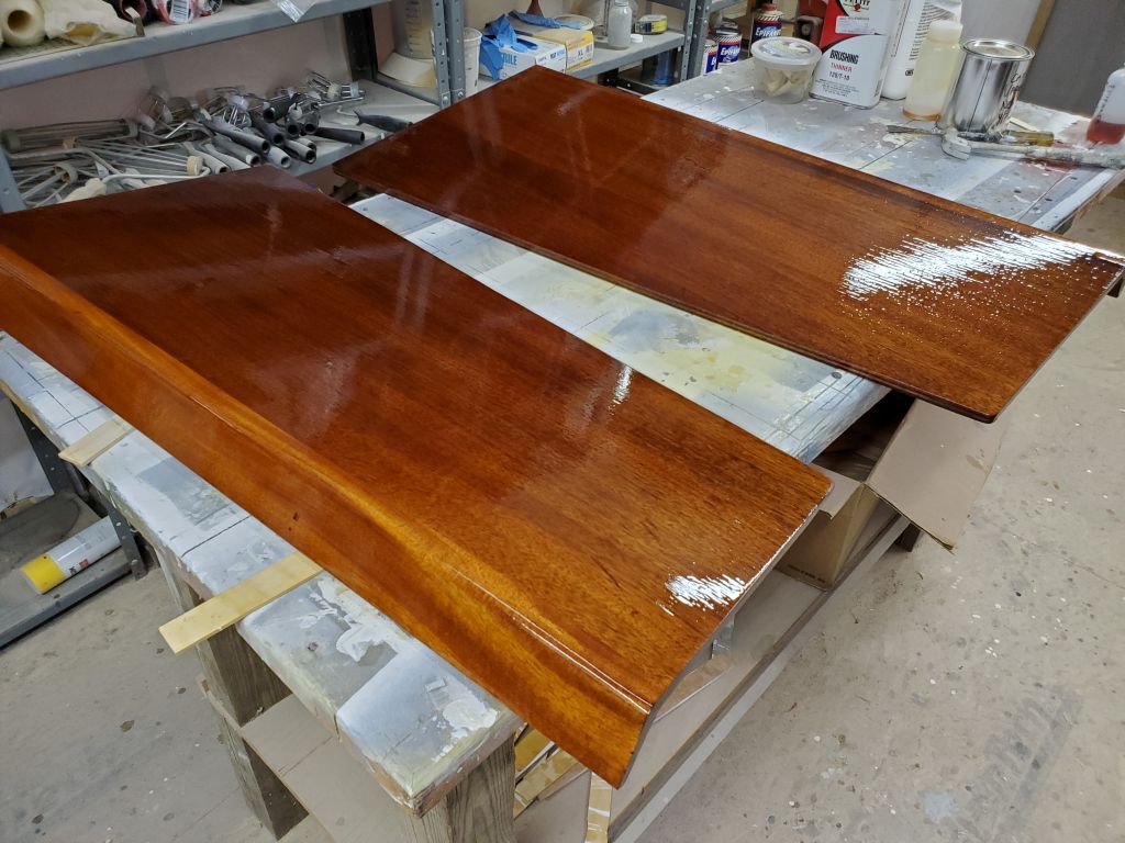
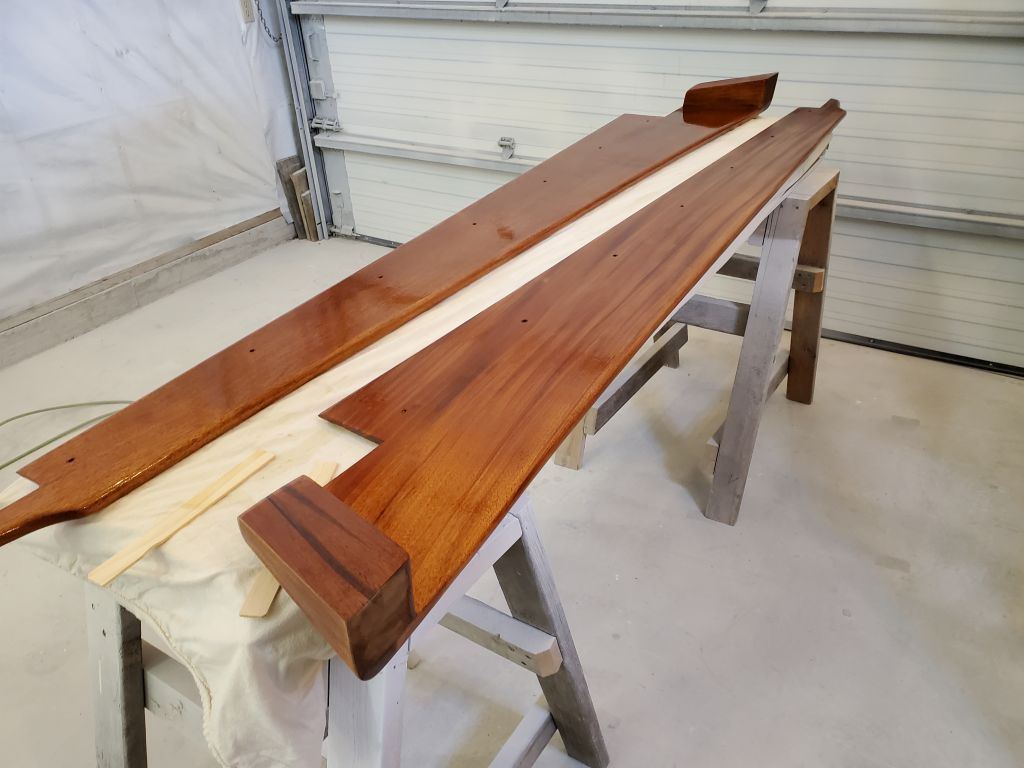
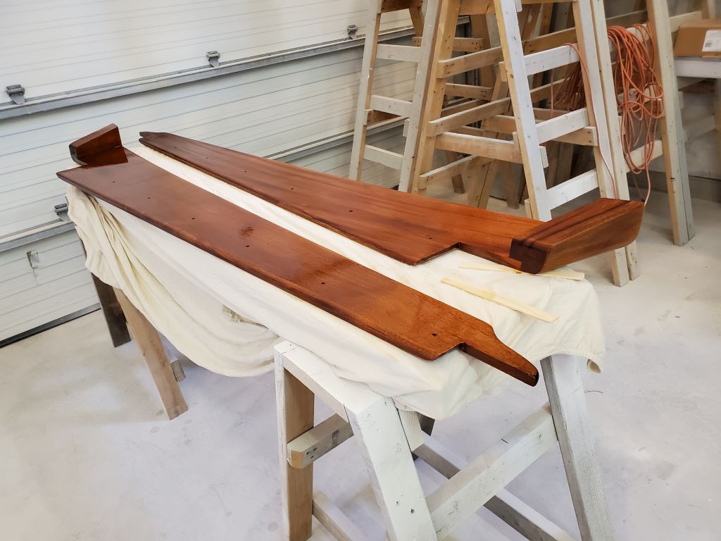
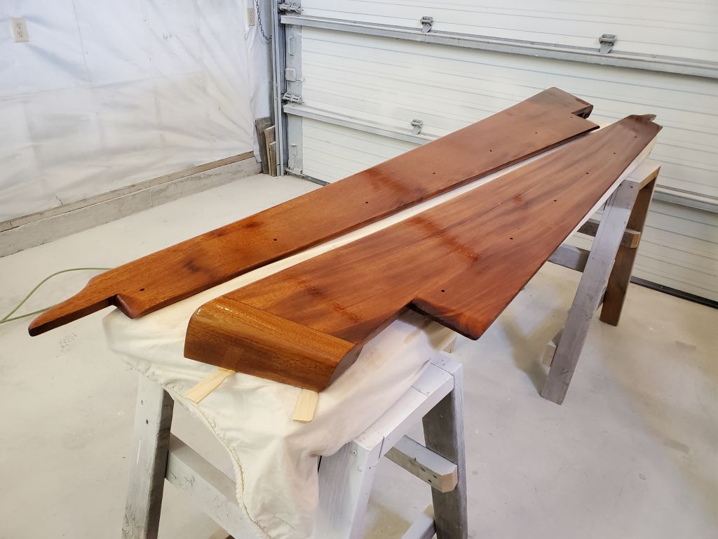
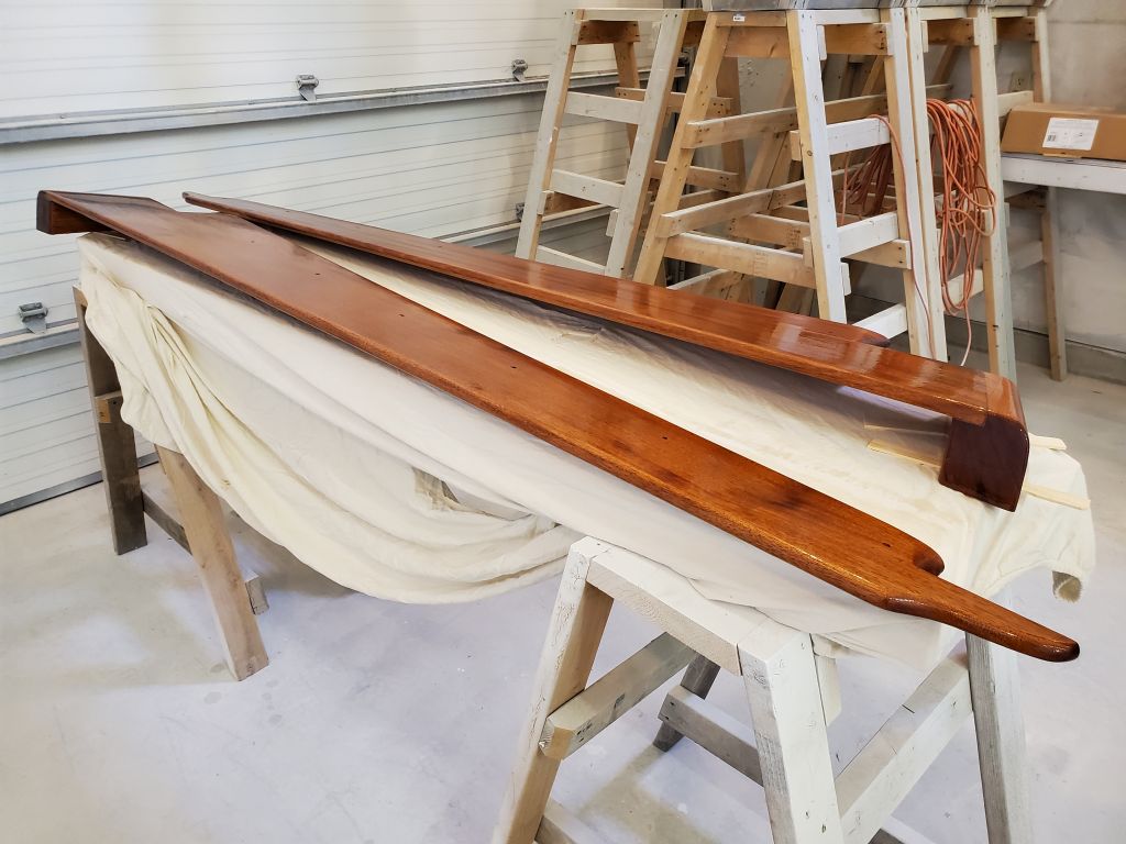
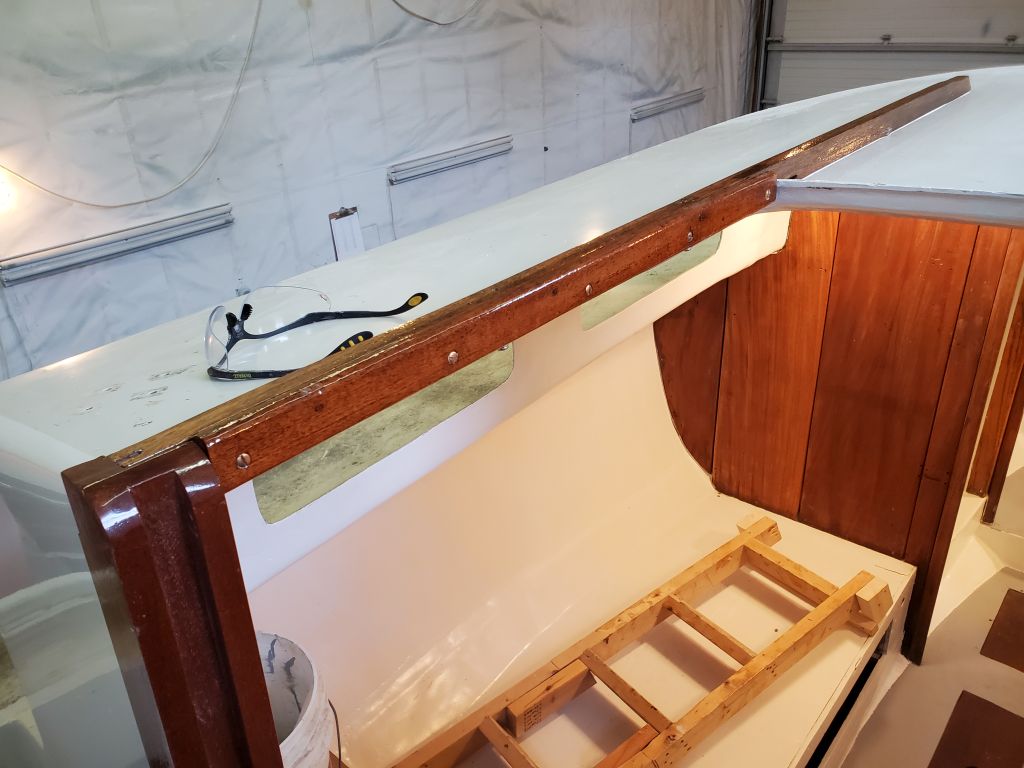
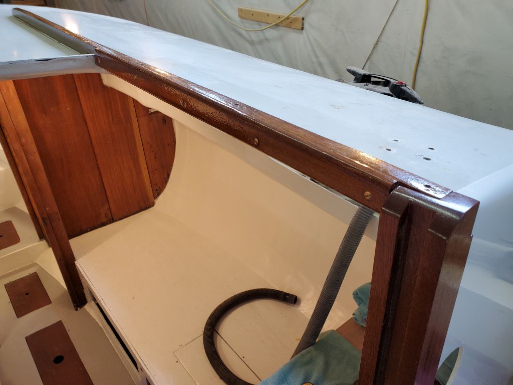
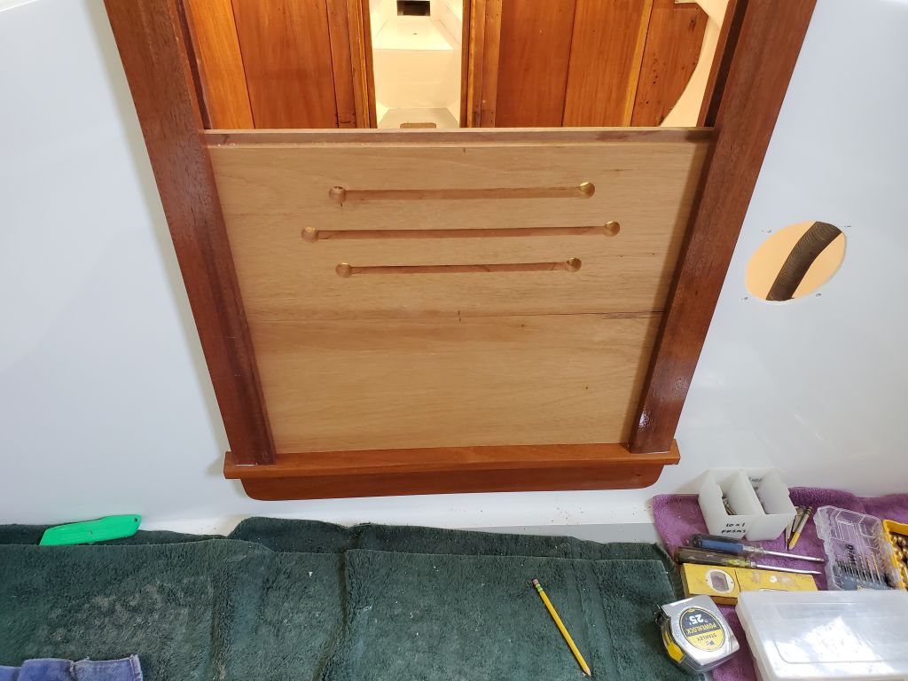
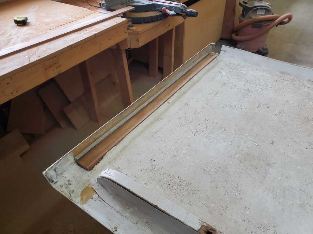
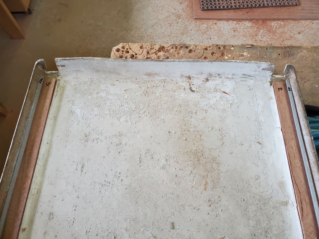
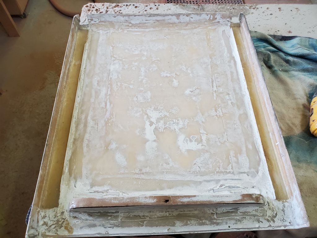
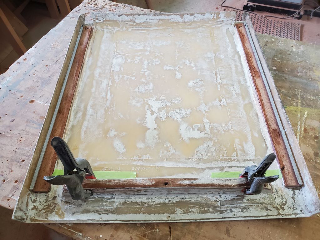
Over the past several days, I’d worked to build up base coats, then the final satin coat, of varnish on the new wood box, finishing up in time to allow the box to fully cure for a few days.
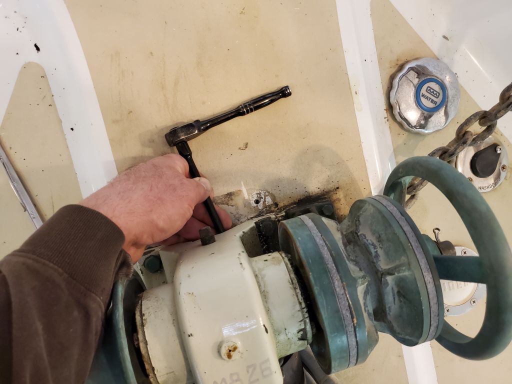
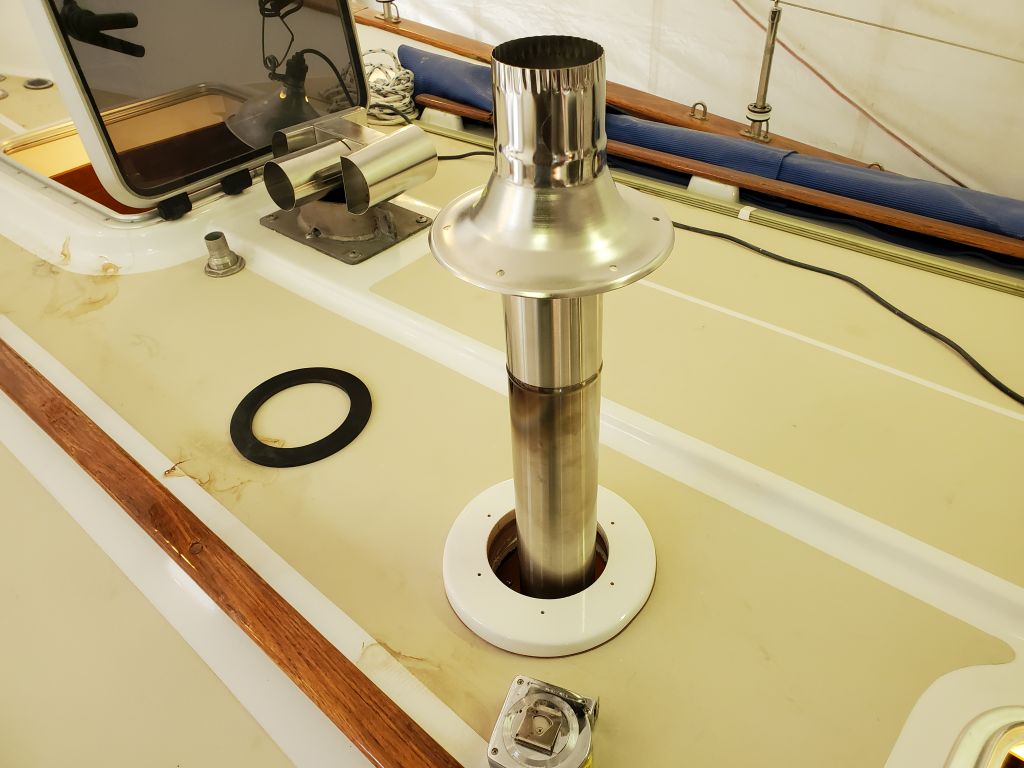
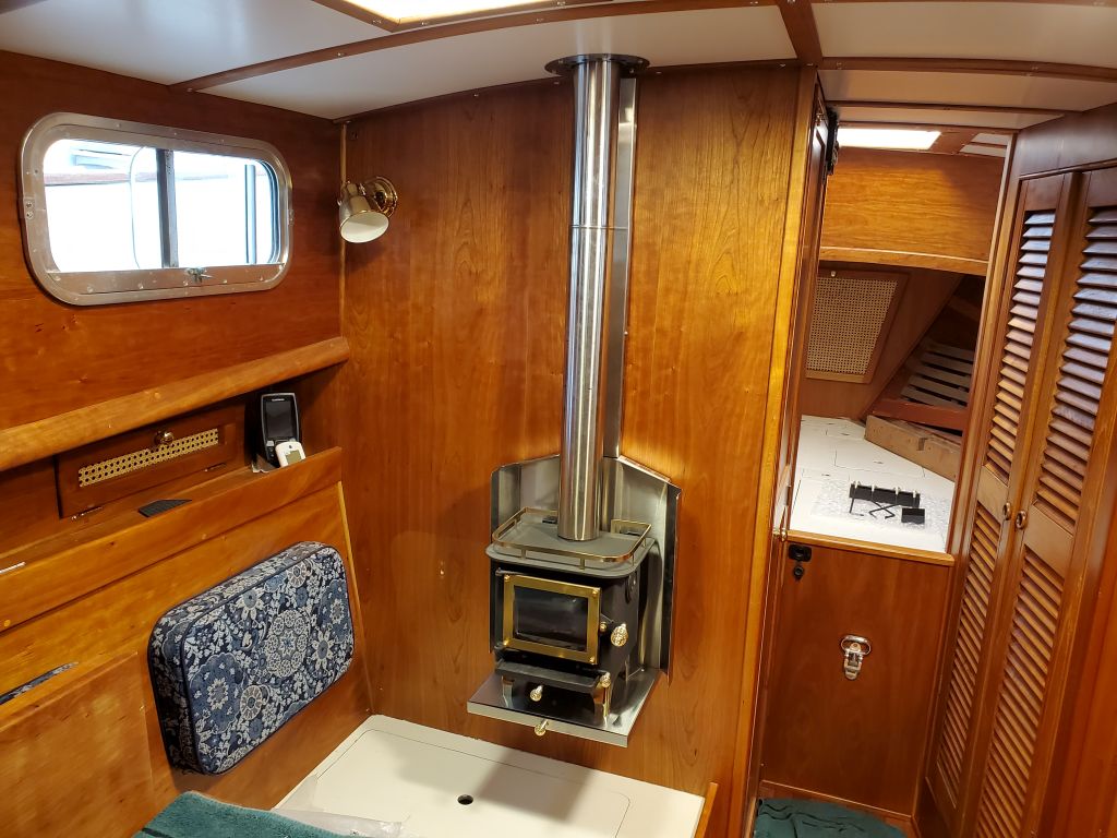
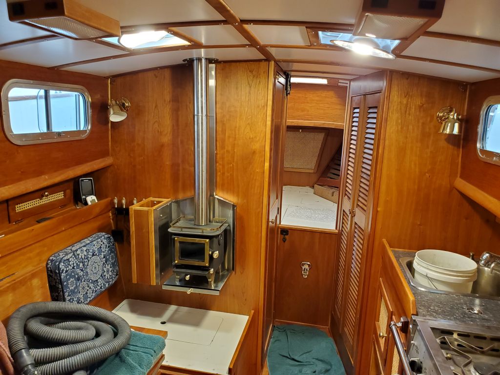
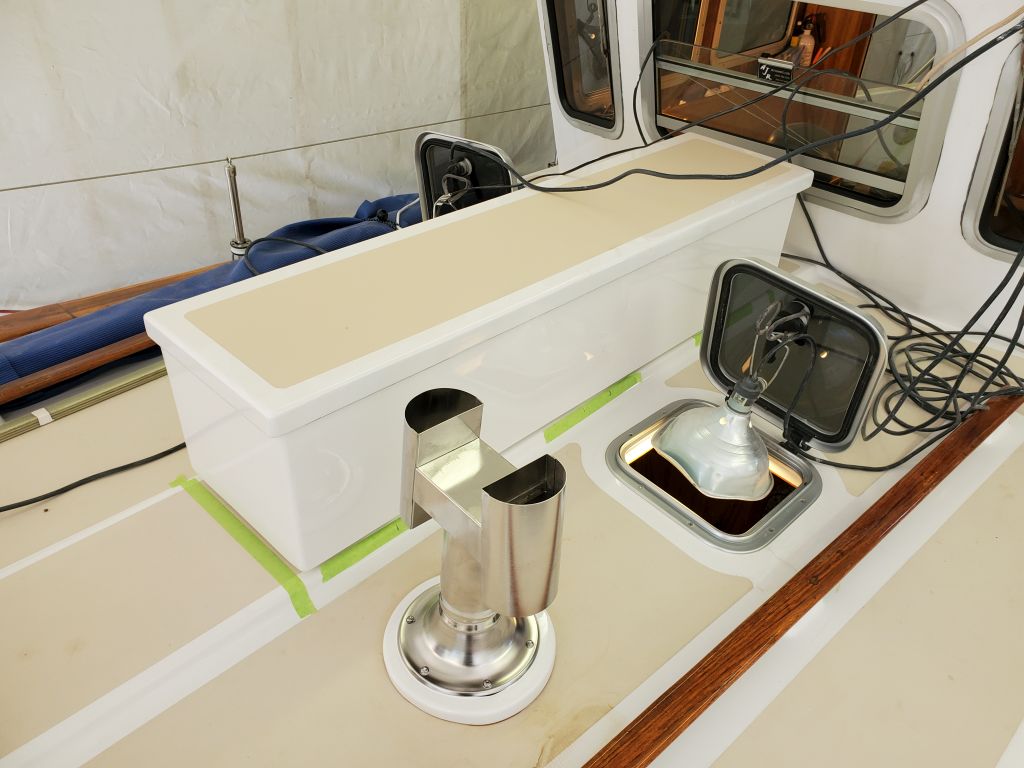
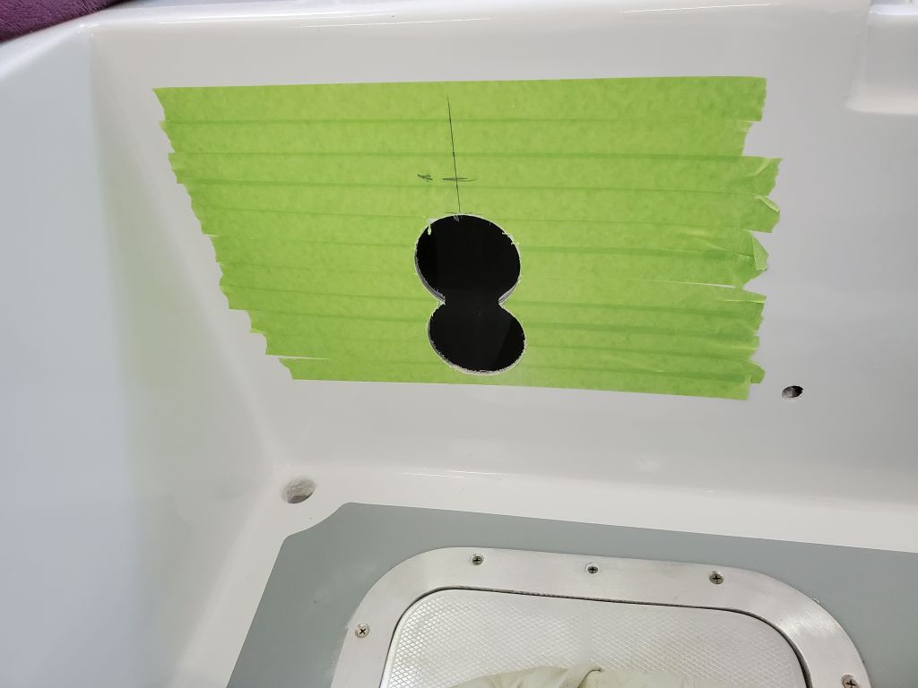
My main focus for the day was to wrap up the woodstove installation. With the stove in place, and the deck trim ring installed, it was a theoretically simple matter to cut the stove pipe to length and install it along with the deck fitting. Because of how the sections needed to fit together, it wasn’t just a matter of marking the pipe at deck level and cutting it off; for the parts on hand to work together as needed, I had to remove excess length from the bottom of one of the pipe sections.
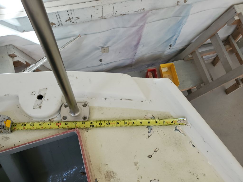
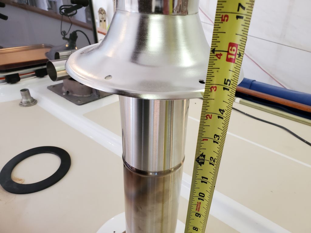
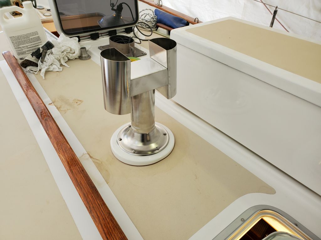
To begin, I set up the two 24″ lengths of pipe together with the deck fitting, allowing the assembly to protrude above the deck. I measured the distance from the underside of the deck fitting flange to the trim ring below (14.5″) which, with all the pieces in this configuration, was how much I needed to cut off.
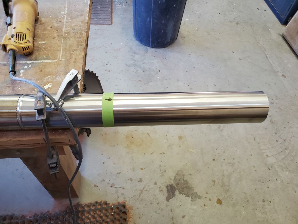
With a grinder and cutoff wheel, I cut the pipe at the mark: All was fine, though this wasn’t fun stuff to cut. Because even before cutting I’d had a vexing difficulty getting the two pieces of pipe to fit together during my dry fits in the boat (though I’d managed), I’d left the two sections fitted together while I cut them, specifically to avoid the difficulties in getting them to fit back together later. For reasons that are now lost in a miasma of events and apparent suppressed memories born of severe trauma and blinding anger, at some point after cutting the pipe and while cleaning up the cuts, the two sections came apart, or I took them apart for some reason; whatever the case, what was once a connected length of pipe was now two again. It really shouldn’t have mattered.
And for some reason I found it absolutely impossible to reassemble them.
It made no sense then, and it made no sense later, but I spent far too much time fighting the pipe sections and trying to reassemble them in a usable length once more. I couldn’t reassemble them in their original configuration, and I couldn’t reassemble them with the cut section atop the full section. I tried everything. One issue was that the double-walled pipe was spot-welded together at one end, to hold the inner and outer sections together. Assembled correctly, this didn’t matter because of how the joints interacted–but now it mattered, though I still didn’t understand why since these sections had been connected before. Where the inner and outer sections were connected in this way, obviously the pipes couldn’t slide together.
In the event, in fighting the sections I’m sure that I made whatever problem existed worse by further distorting the pipes in the effort to connect them (the inner and outer sections had minimal clearance between). I didn’t want to, or intend to (at least at first haha)–but it happened. Eventually, it was clear that the cut section–the piece I needed to use–was a lost cause. I didn’t have extra sections–they don’t give this stuff away at Cubic Mini–so what made me the angriest wasn’t needing another section, but that I couldn’t finish up the installation as intended. I may have sealed my fate when somehow the section of pipe I’d been fighting with ended up beneath the head of my hammer several times. Weird.
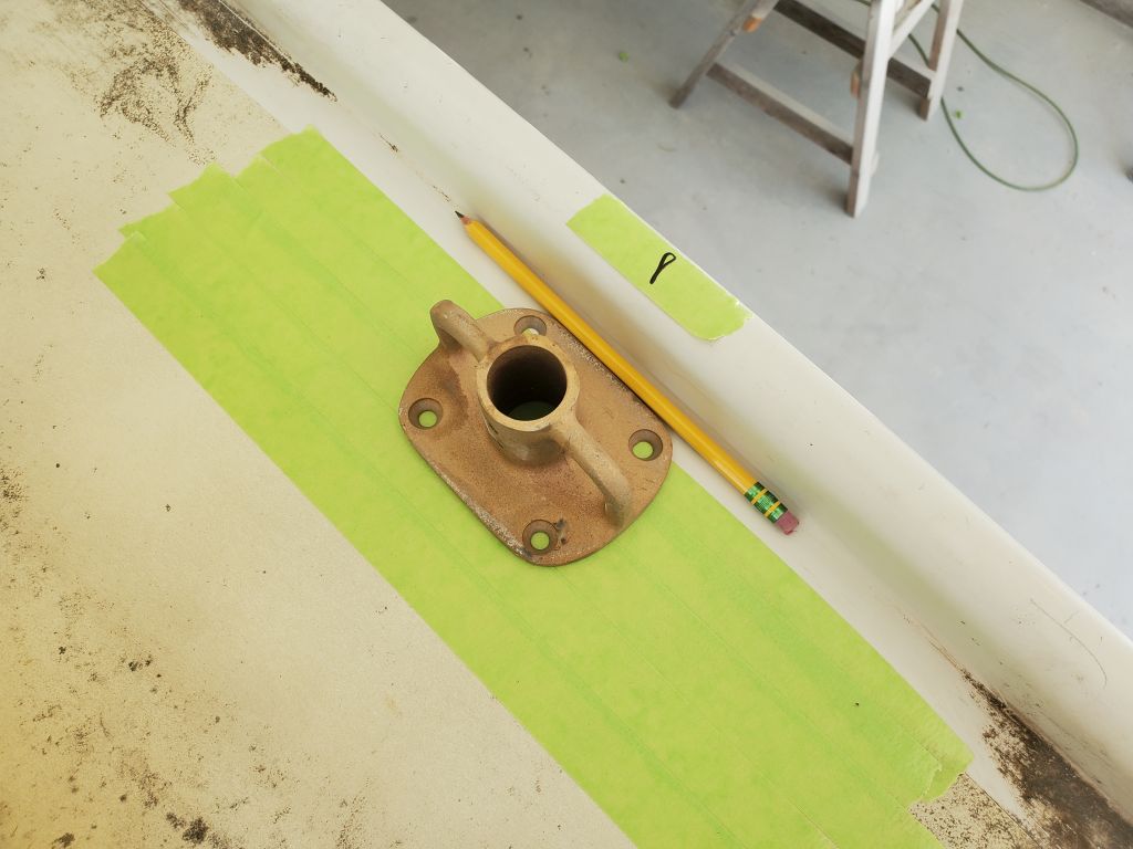
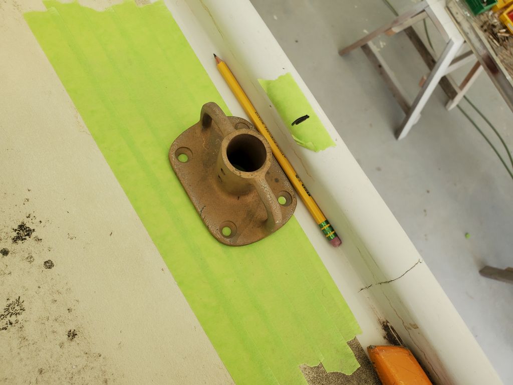
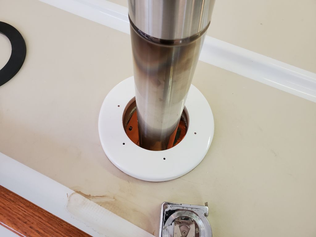
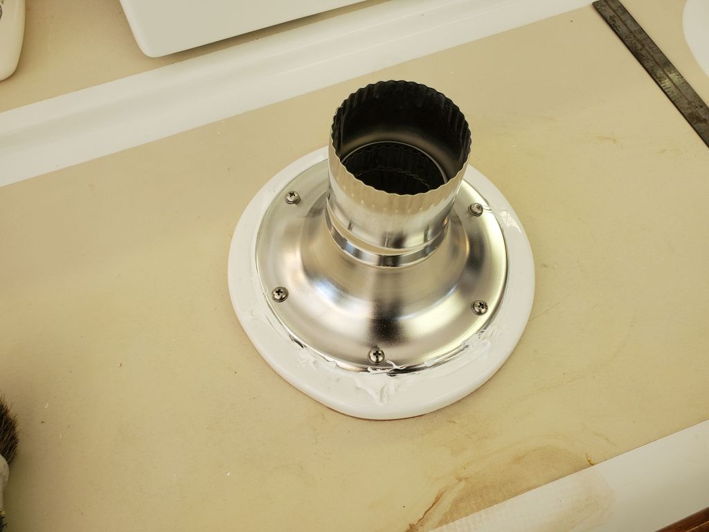
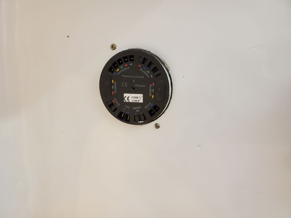
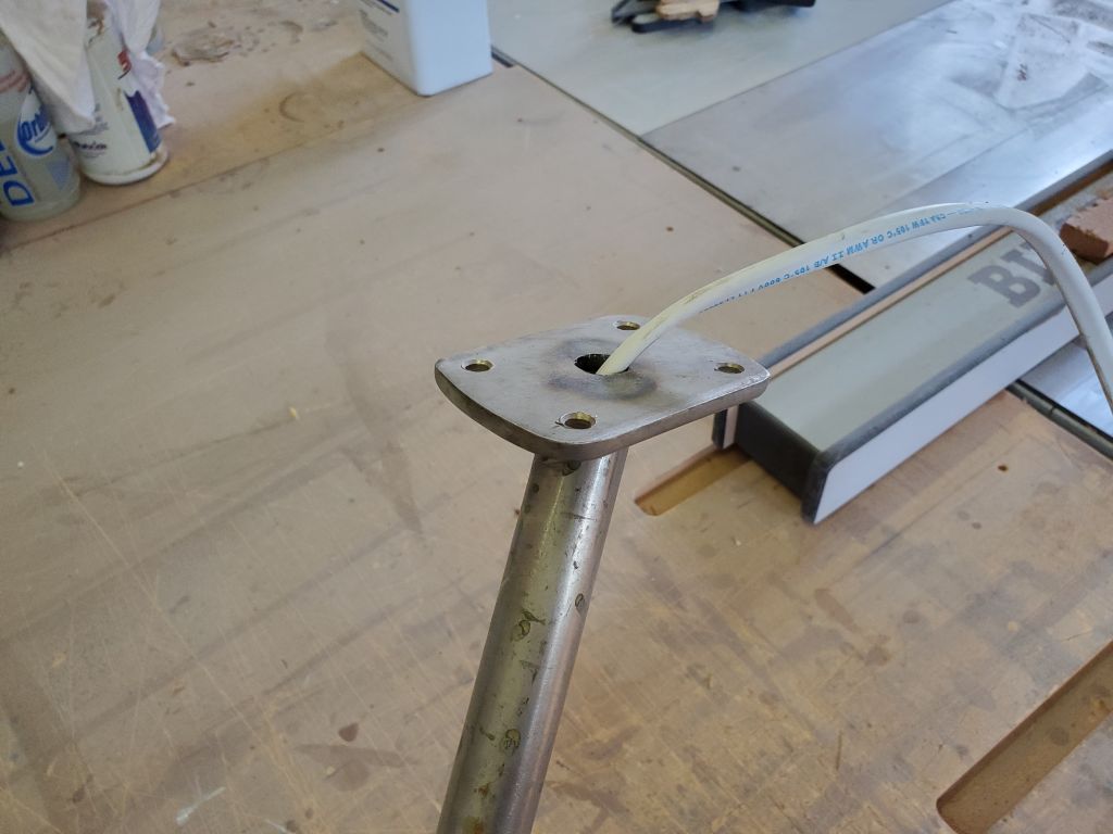
After a break to emergency-order replacement pipes, which felt like something positive even though it threw my schedule awry, I returned to assess what I had left and see if there was any other way to use the longer length of the original pipe–but supposedly the wrong end–to make this work. And to my amazement I found a way forward. It turned out that the deck fitting, which I’d originally planned to connect using a special adapter (seen in the photos above), which allowed the deck fitting to work with the upper, crimped end of a stovepipe section, actually fit well in the cut end of the pipe, slipping between the inner and outer walls of the stovepipe like it was its job. (I seem to be a little short on photos during this miserable hour or so of the day, so I don’t have a photo showing that.)
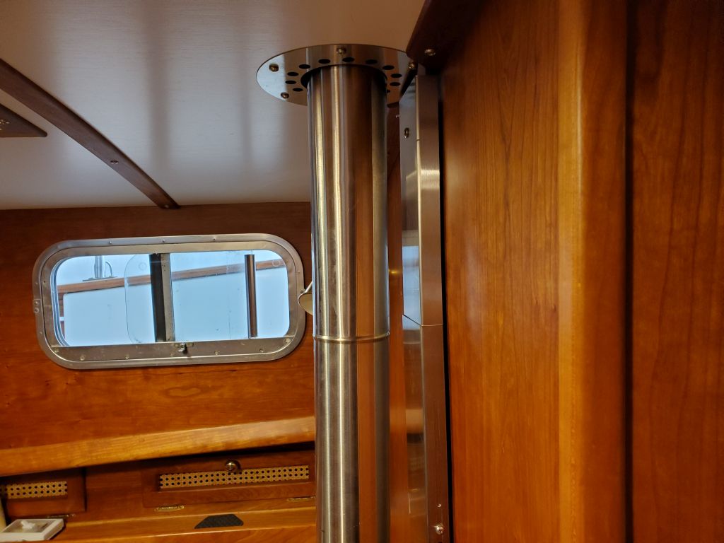
Thinking back, now I remembered from some of the info online that I’d looked at a few months before had mentioned this too, so I felt good proceeding in this way–and it meant that I could finish up the installation too, and avoid the wait and expense of the replacement pipes. So with the sections installed together in their new way, and after determining how far into the pipe the deck fitting would slip, I eventually determined the final length and cut the pipe a bit shorter as needed now–being sure to tape the pipe sections securely together, just in case. (In the new configuration I had no problem connecting the pipes as it happened.)
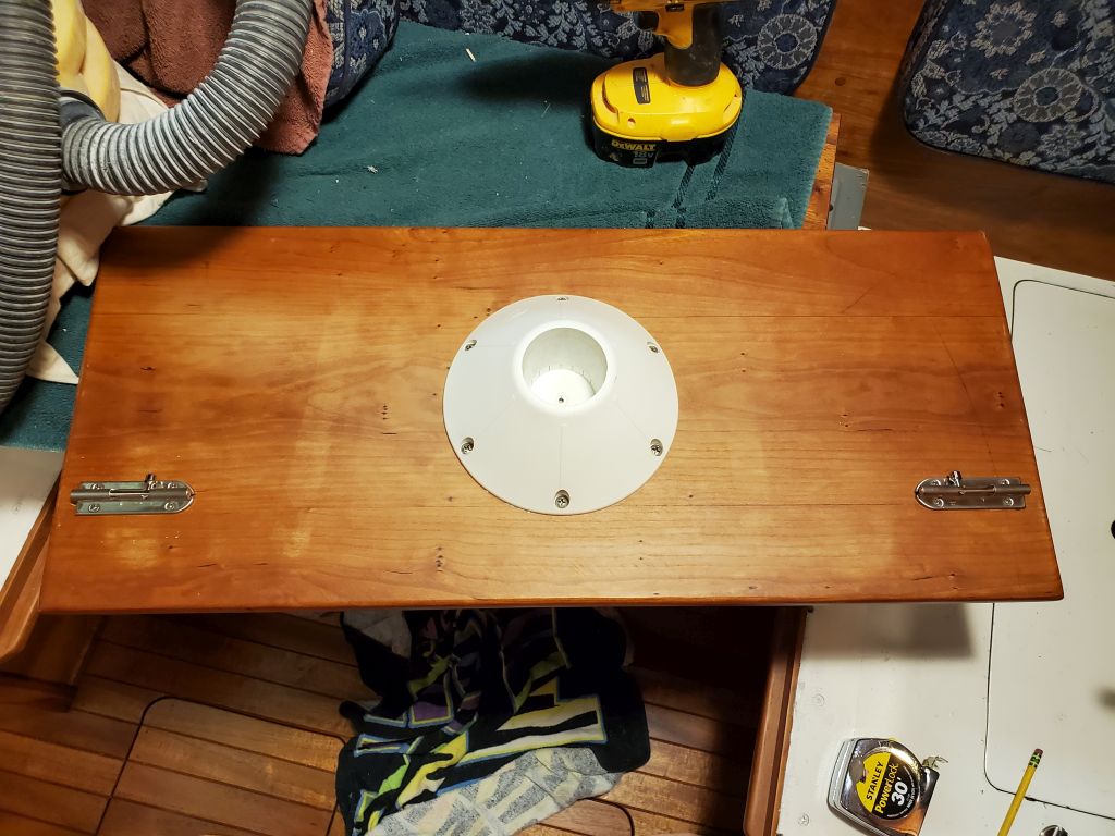
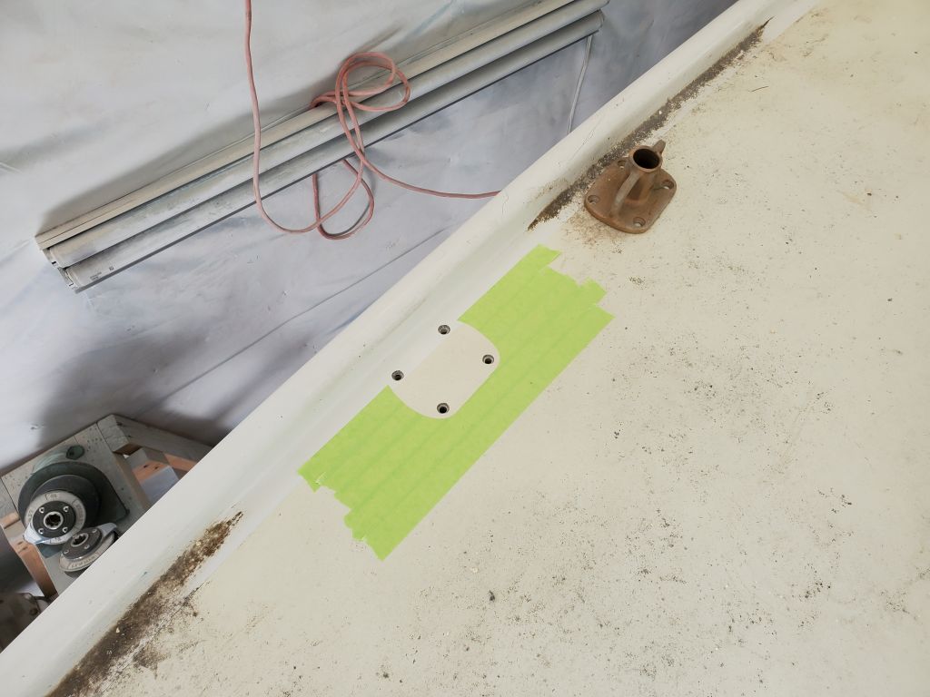
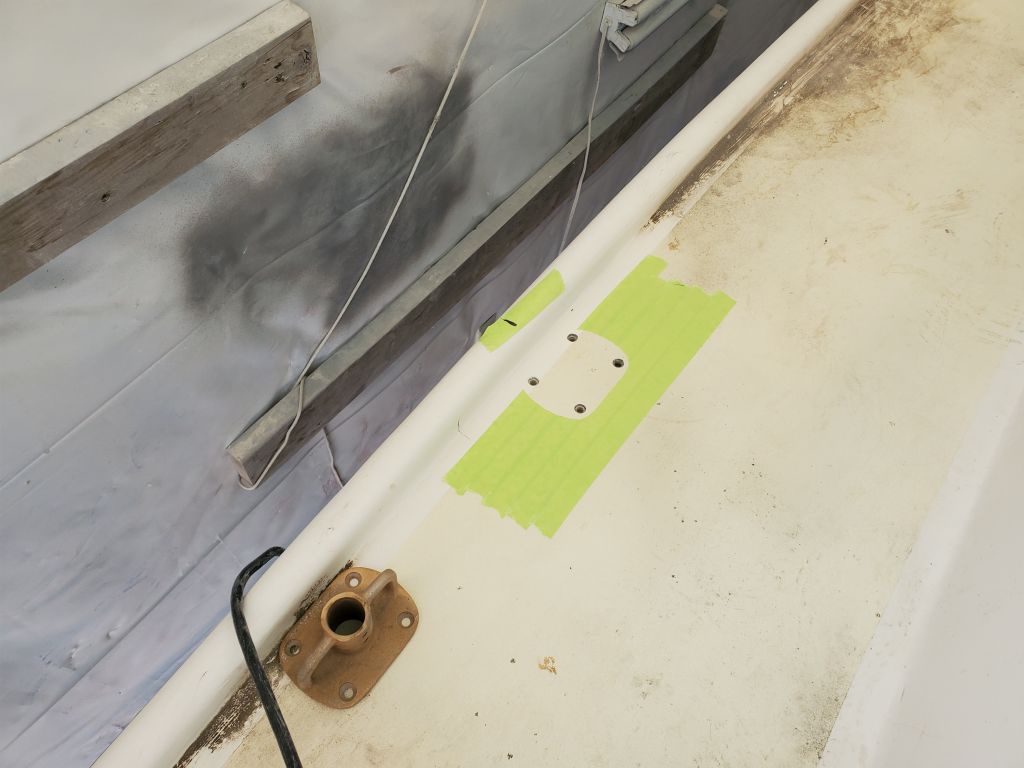
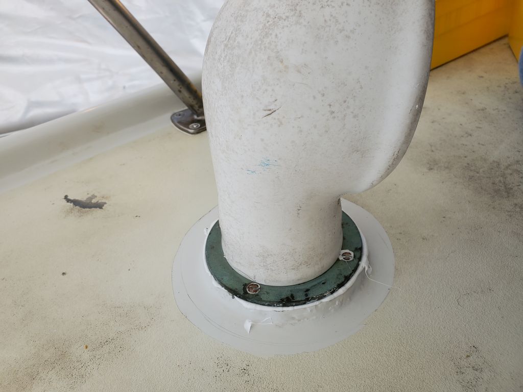
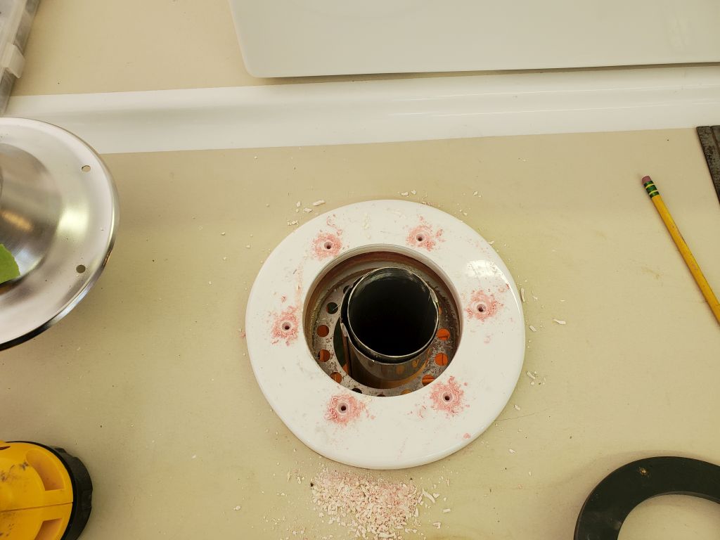
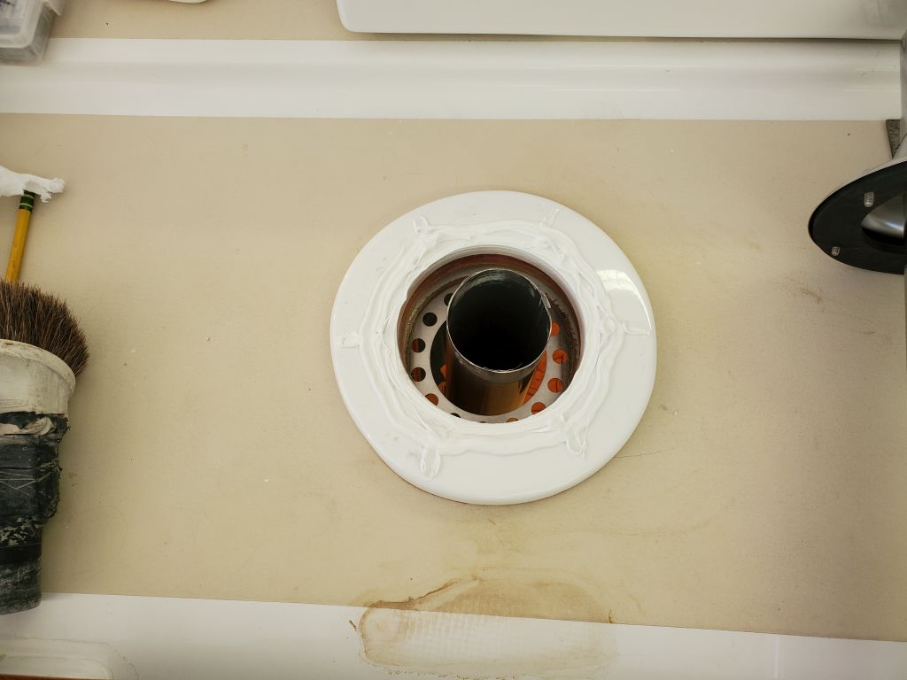
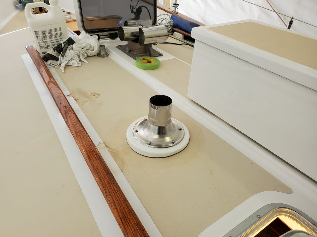
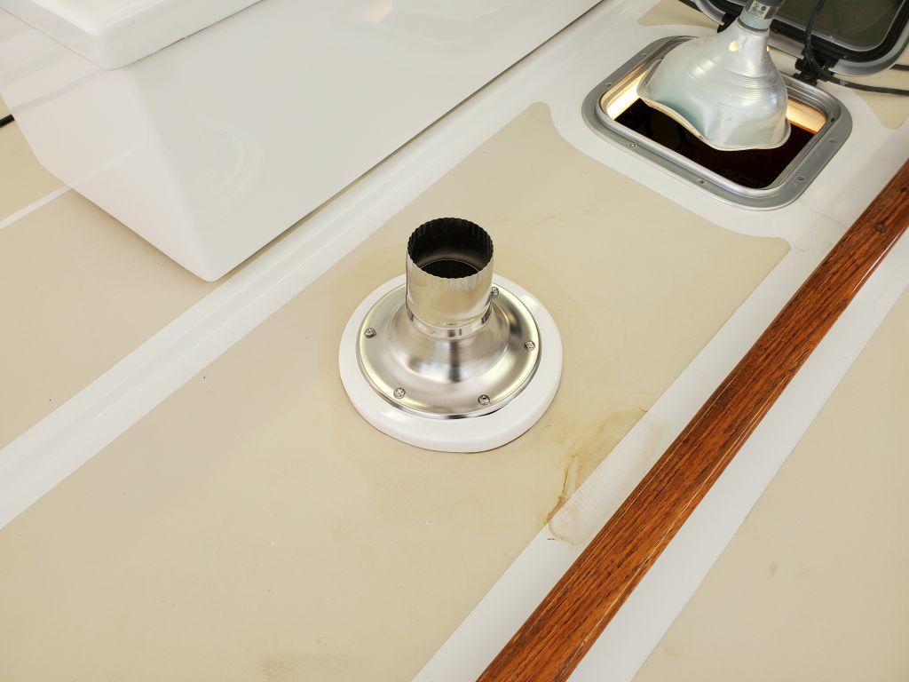
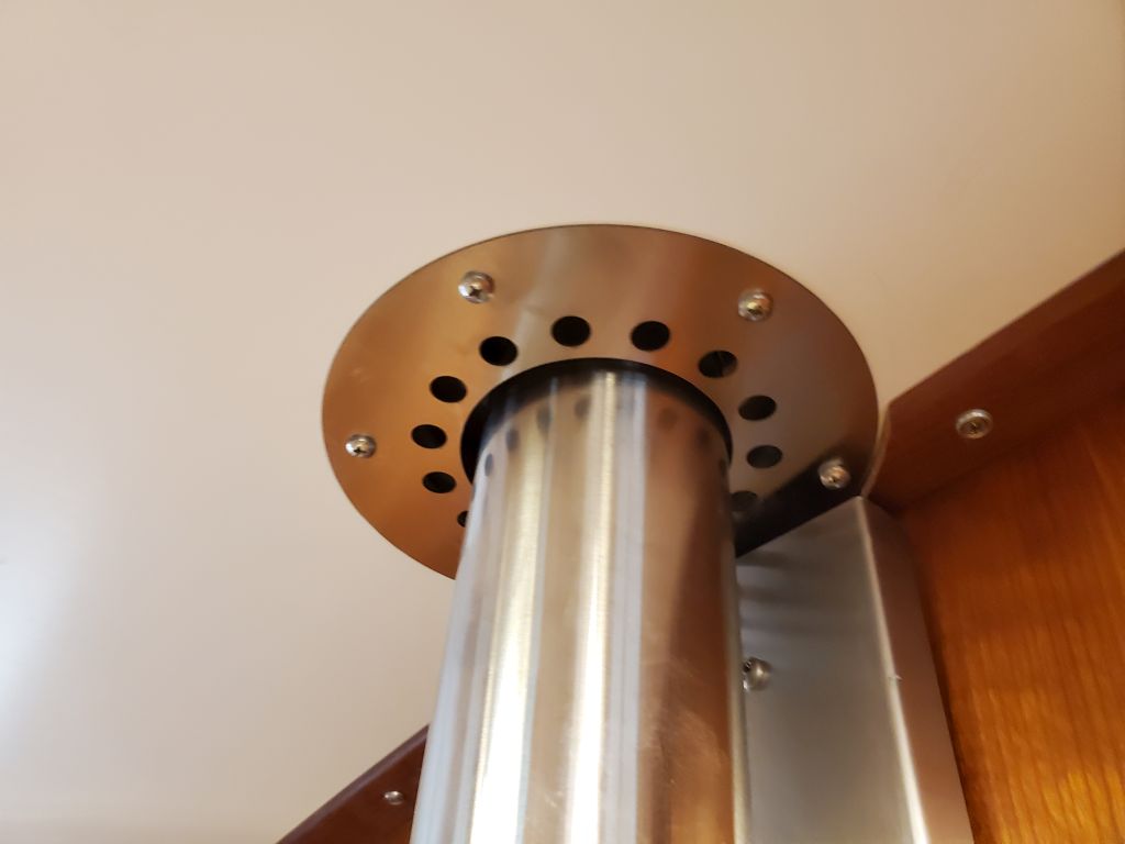
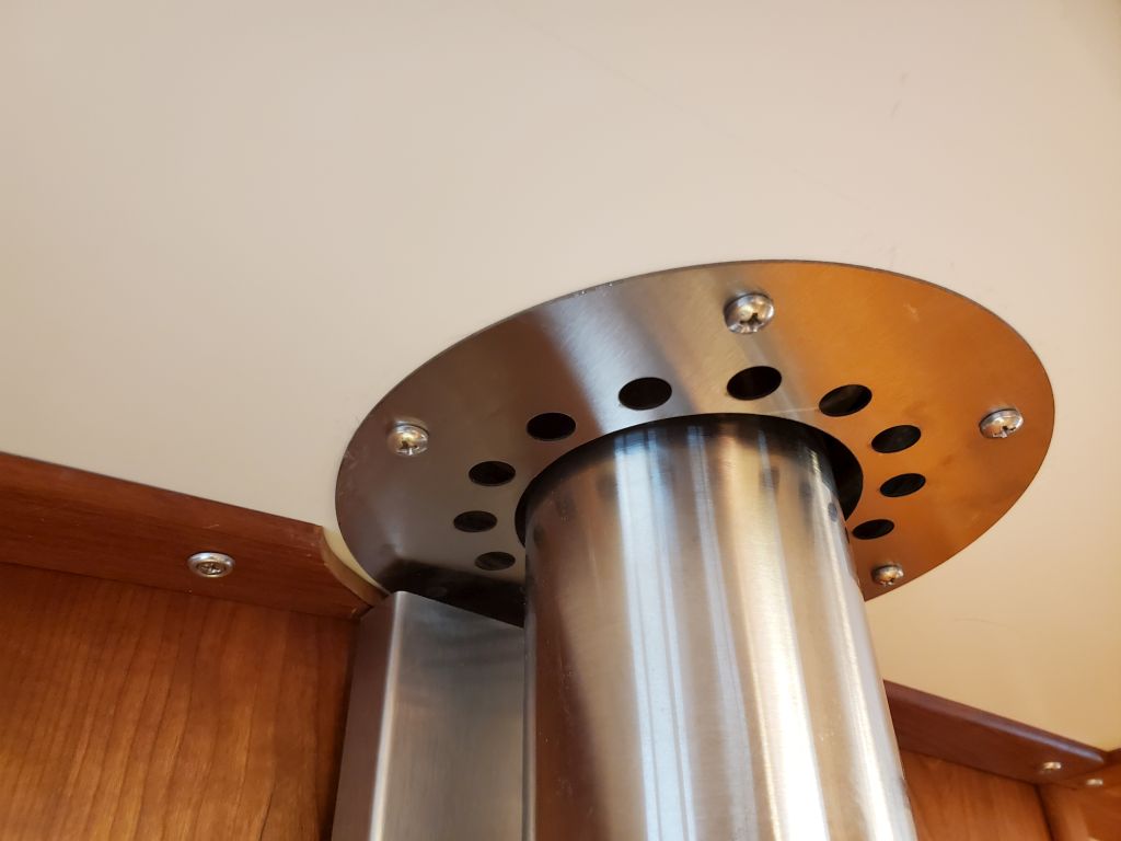
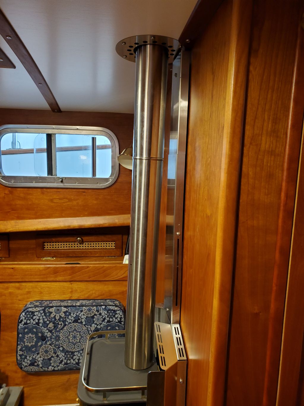
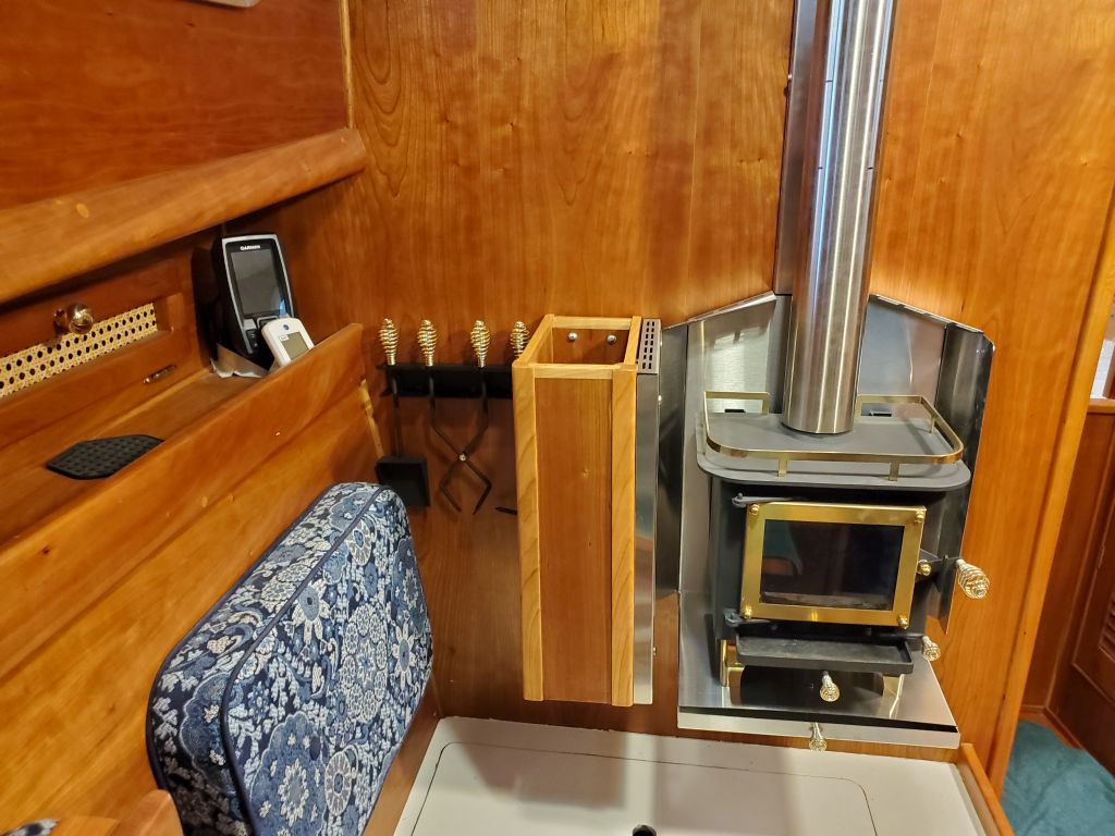
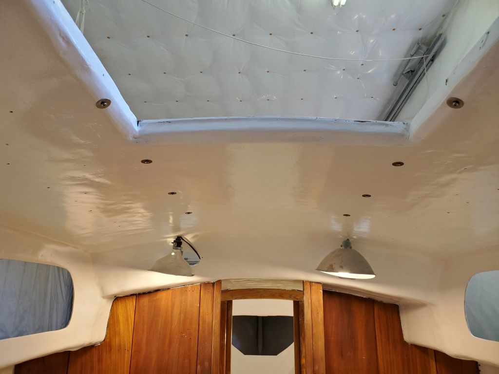
Now I could drill and tap the deck for the machine screws that would secure the deck fitting, and after final preparations I installed the deck fitting with its supplied heavy rubber gasket and sealant as well. In the cabin, I secured the inside trim ring (which by design also allows air to flow into the gap between the stovepipe and the deck cutout) to the overhead with screws. I’d made sure from the beginning, even before things went wrong, that I pre-secured this trim ring to the overhead with some tape so I wouldn’t forget it–there was no way to put it on once the stove pipe was in place.
It’s the way of the world with this stuff: It’s the simplest-seeming tasks that can send everything into turmoil, doubling the time required to do a simple job.
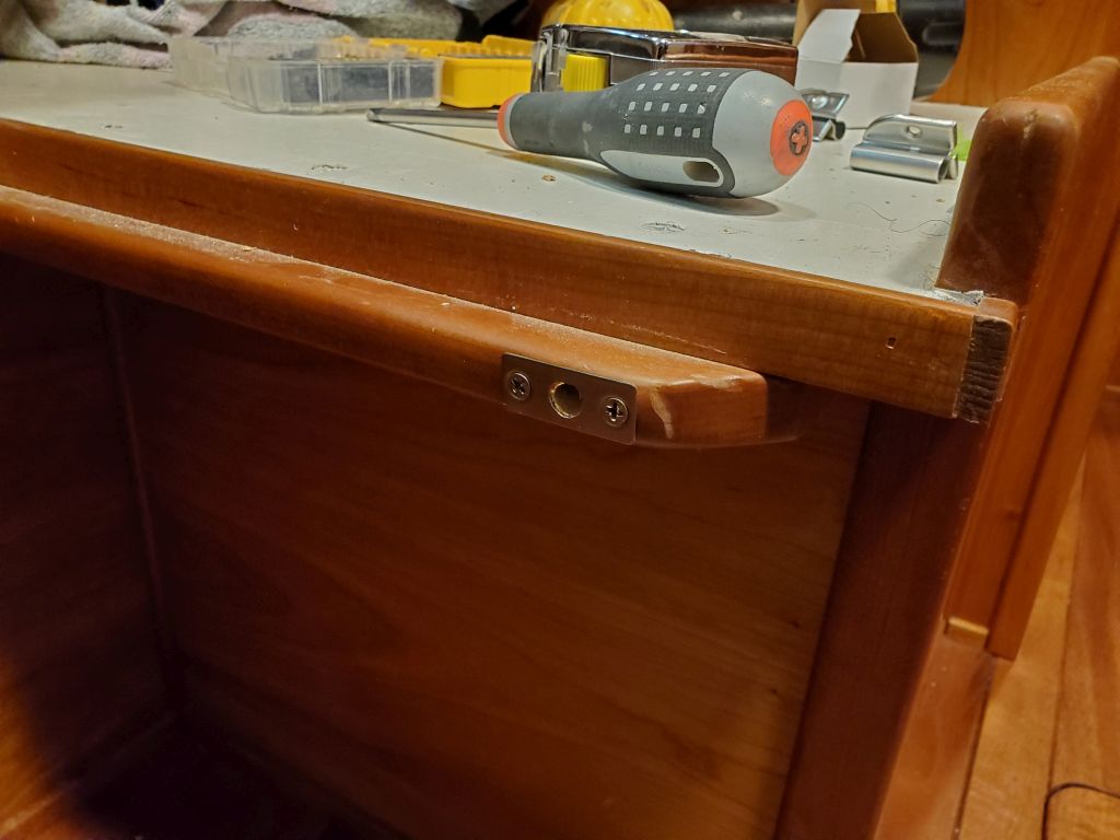
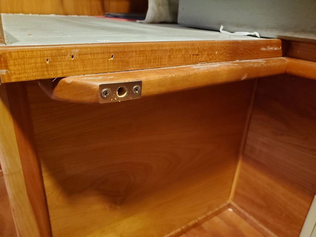
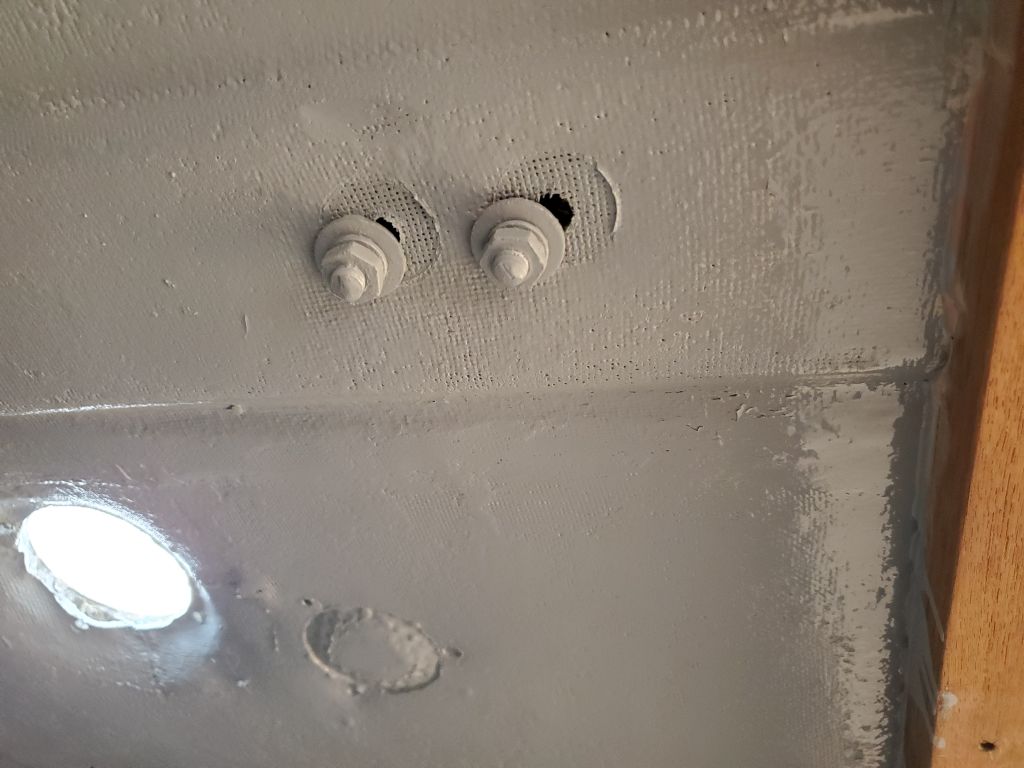
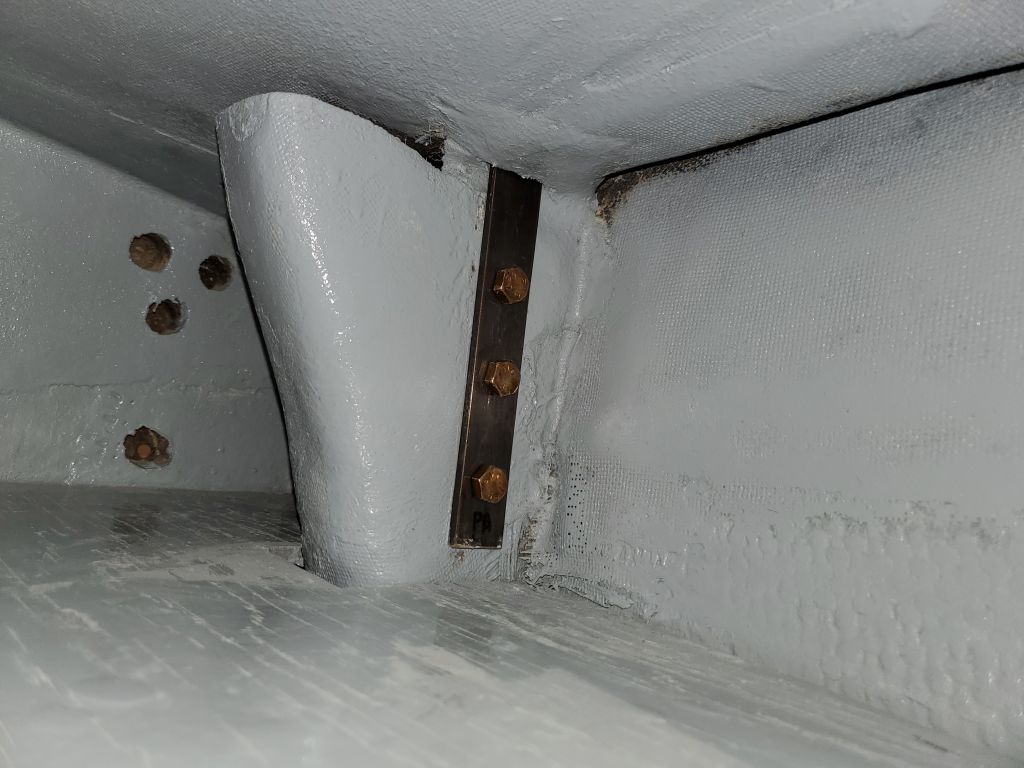
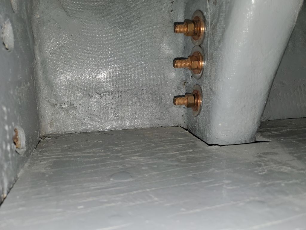
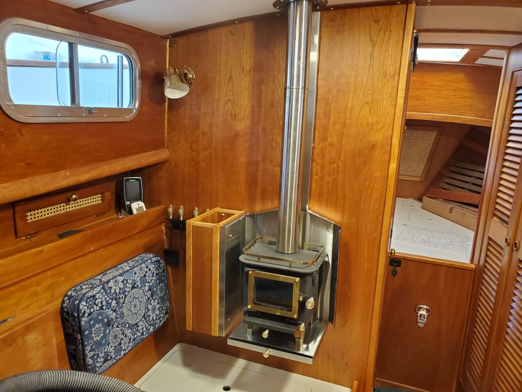
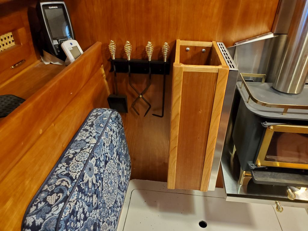
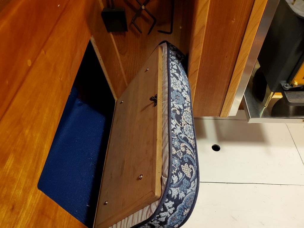
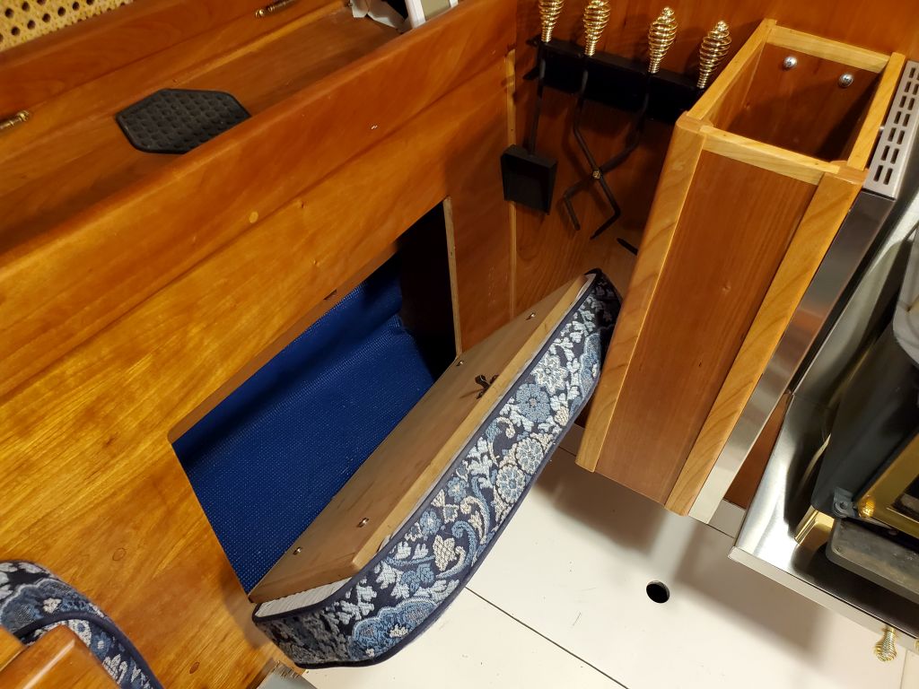
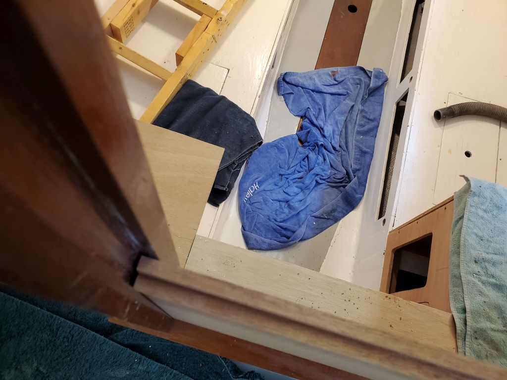
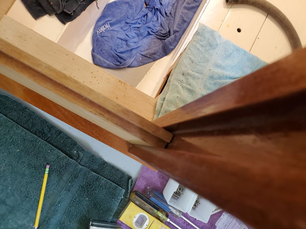
Now I could finish up the installation for real with the wood box and side heat shield. To begin, down on the bench I installed the heat shield on the side of the box with stainless screws and the supplied standoffs. To install the box, I predrilled holes for three screws (two through the top of the back panel, one through the bottom, accessible in the recess I’d built beneath the floor of the box for this purpose), then hung it on the bulkhead next to the woodstove. This gave the required minimum distance of 3″ between the stove and the combustible material.
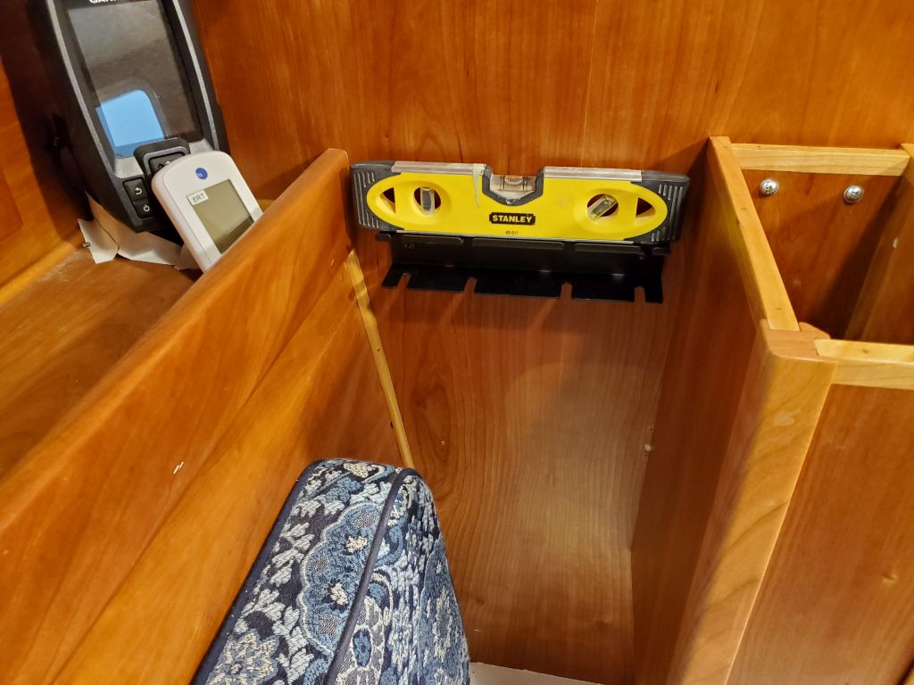
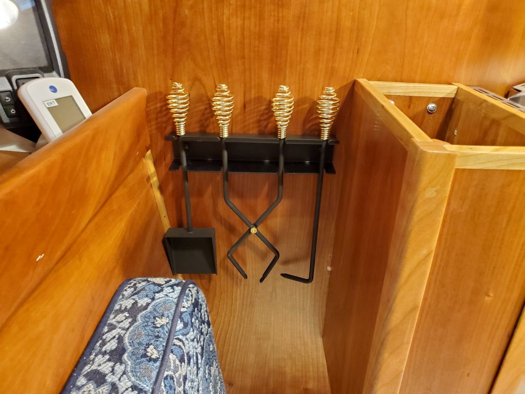
To finish things off, I hung the rack for the cutest little dollhouse stove tools in the space between the box and the settee back, which the owner and I had previously determined and which fortunately worked basically perfectly. This left enough space for the locker to open more than enough for good access, and frankly the whole stove/woodbox juxtaposition and installation turned out even better than I’d hoped it would, looking quite at home there and as if it had always been there.
And I was able to cancel my emergency pipe order before it was processed, all the better to save $150.
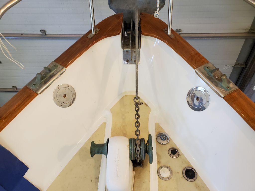
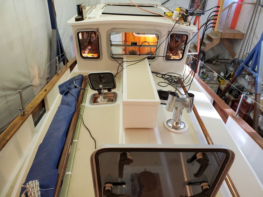
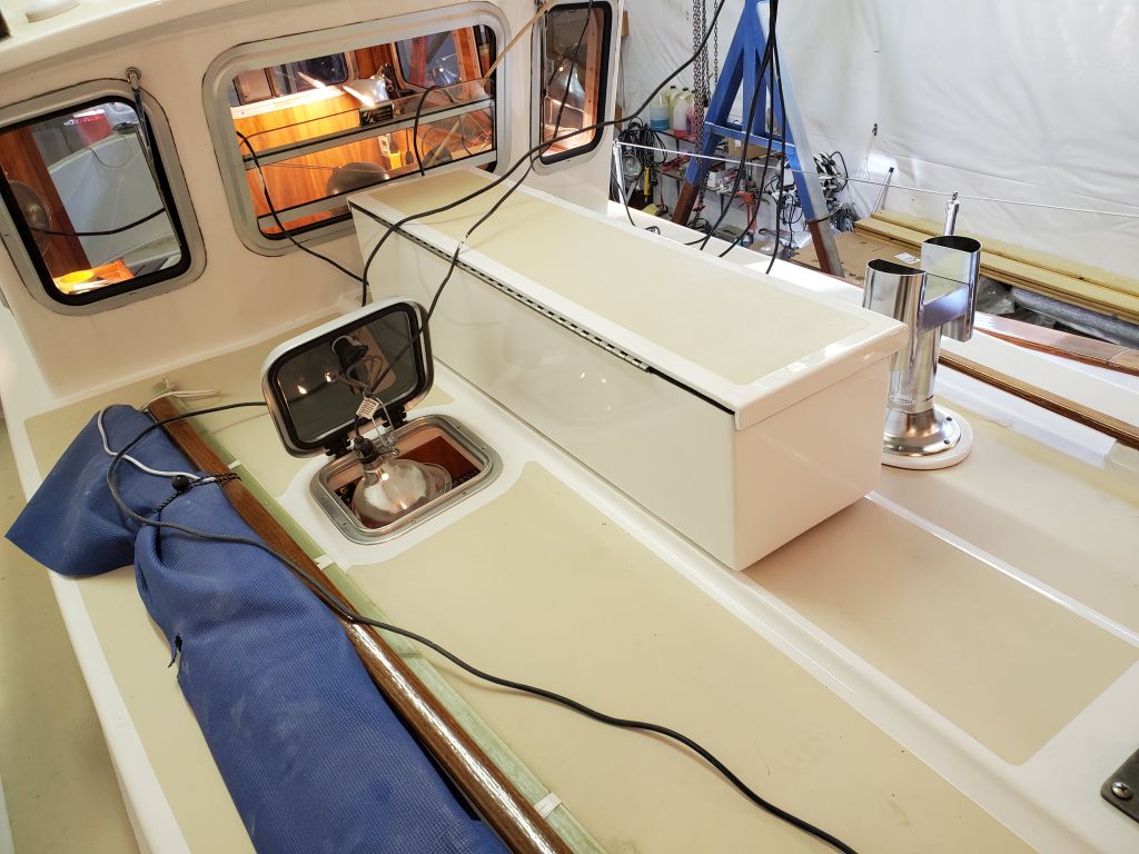
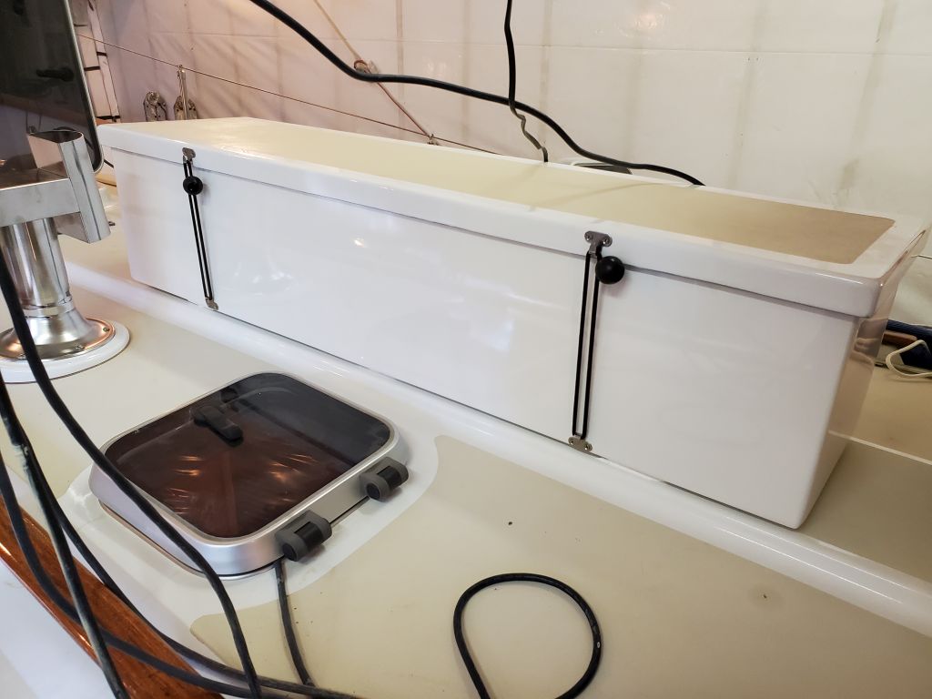
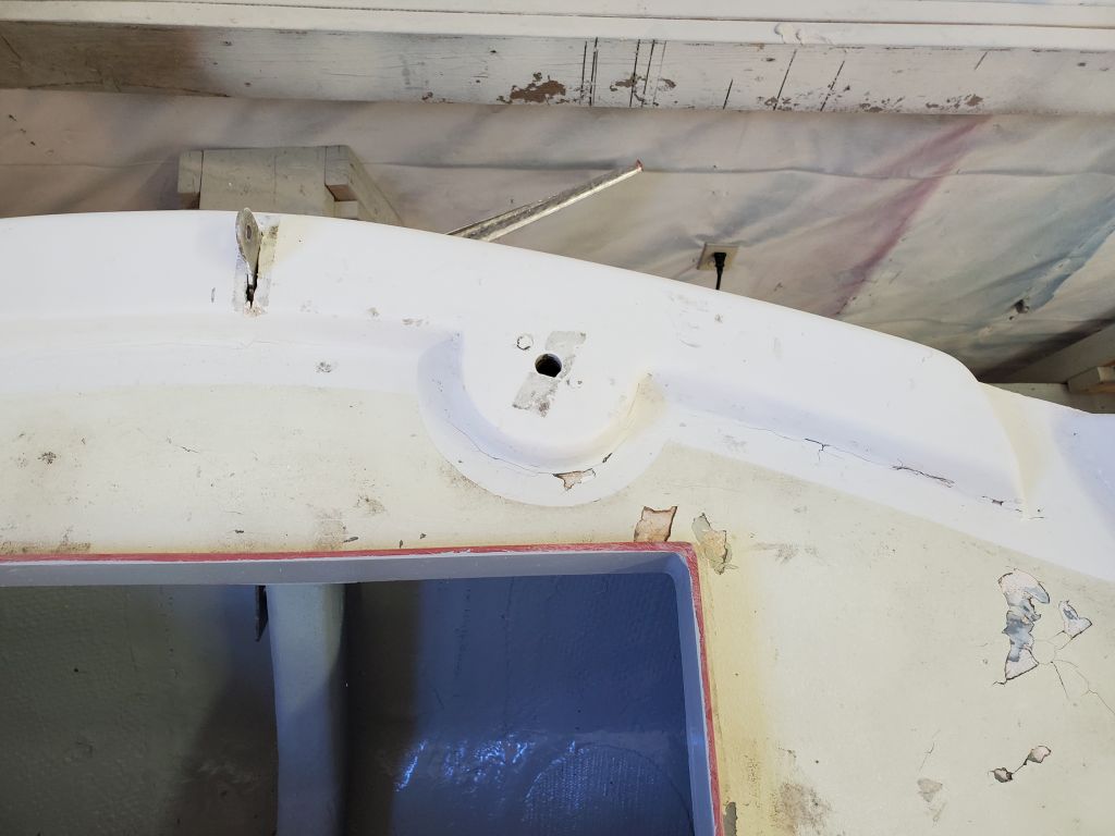
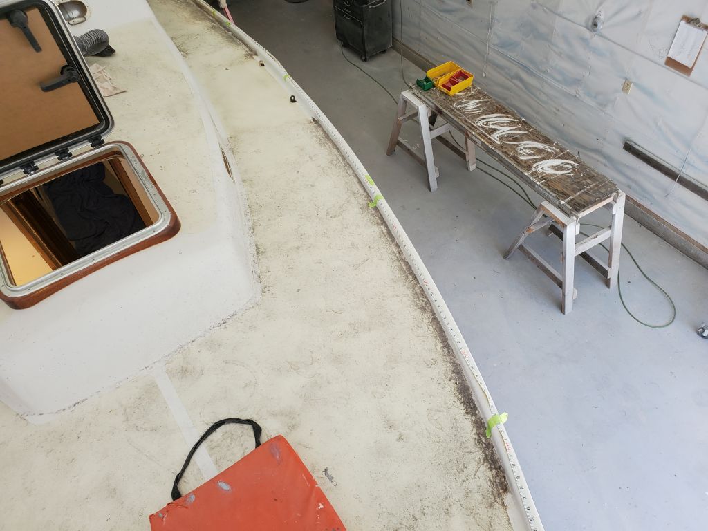
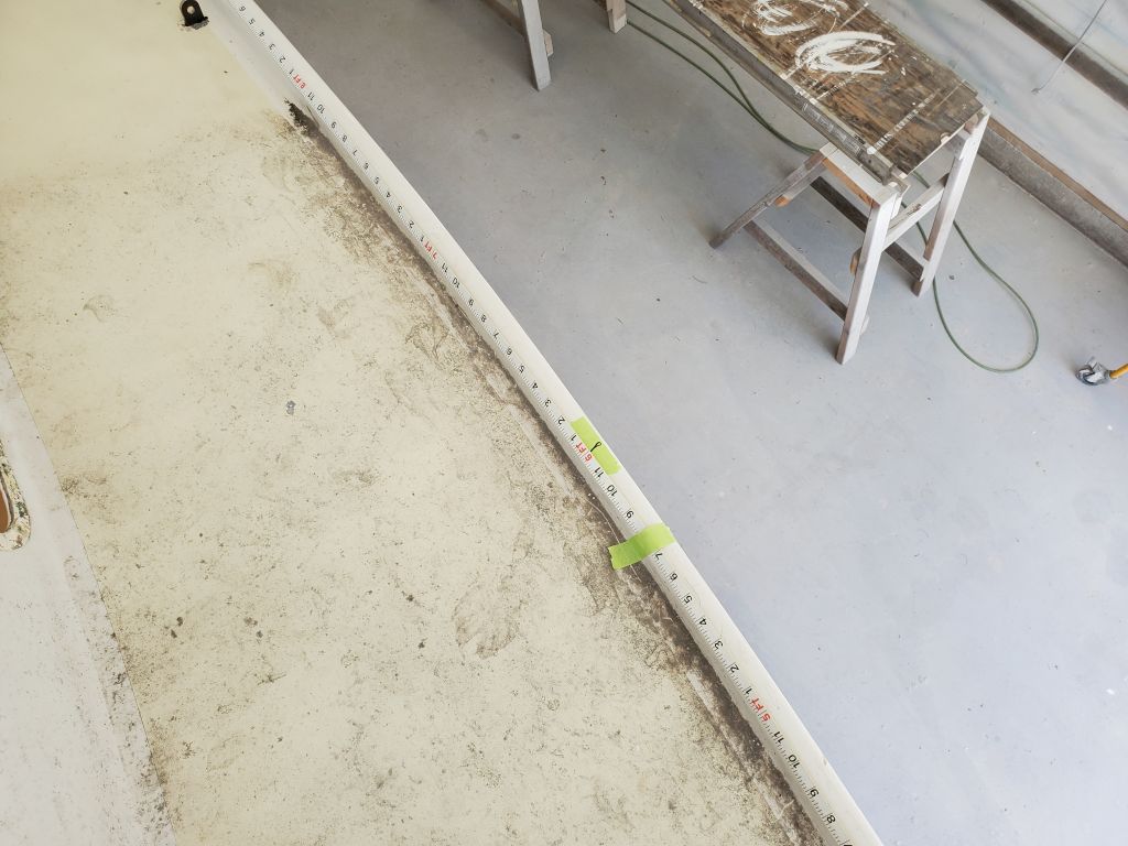
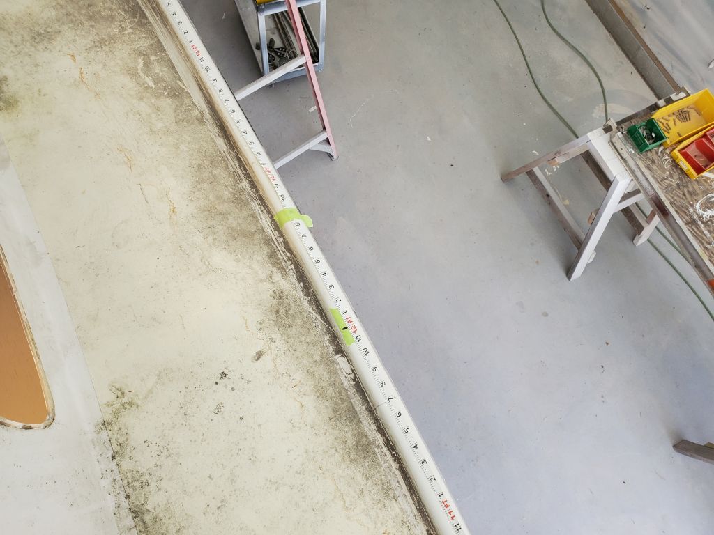
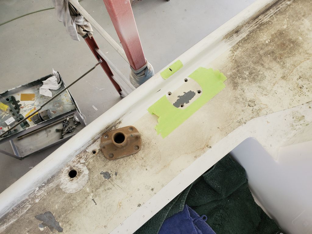
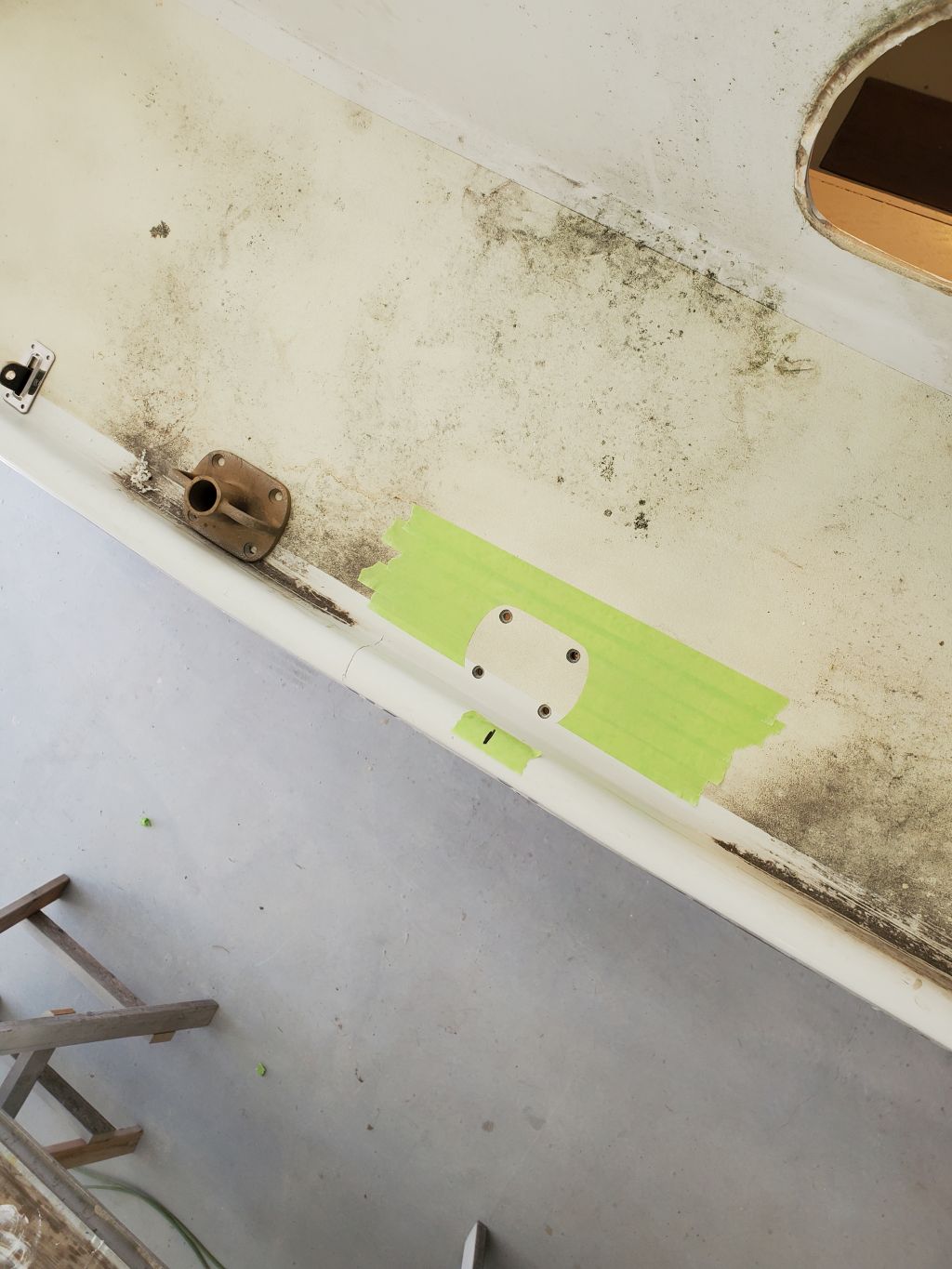
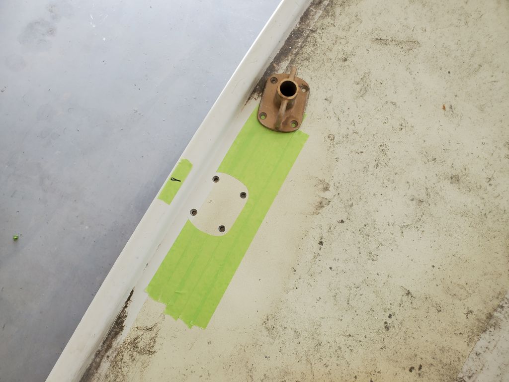
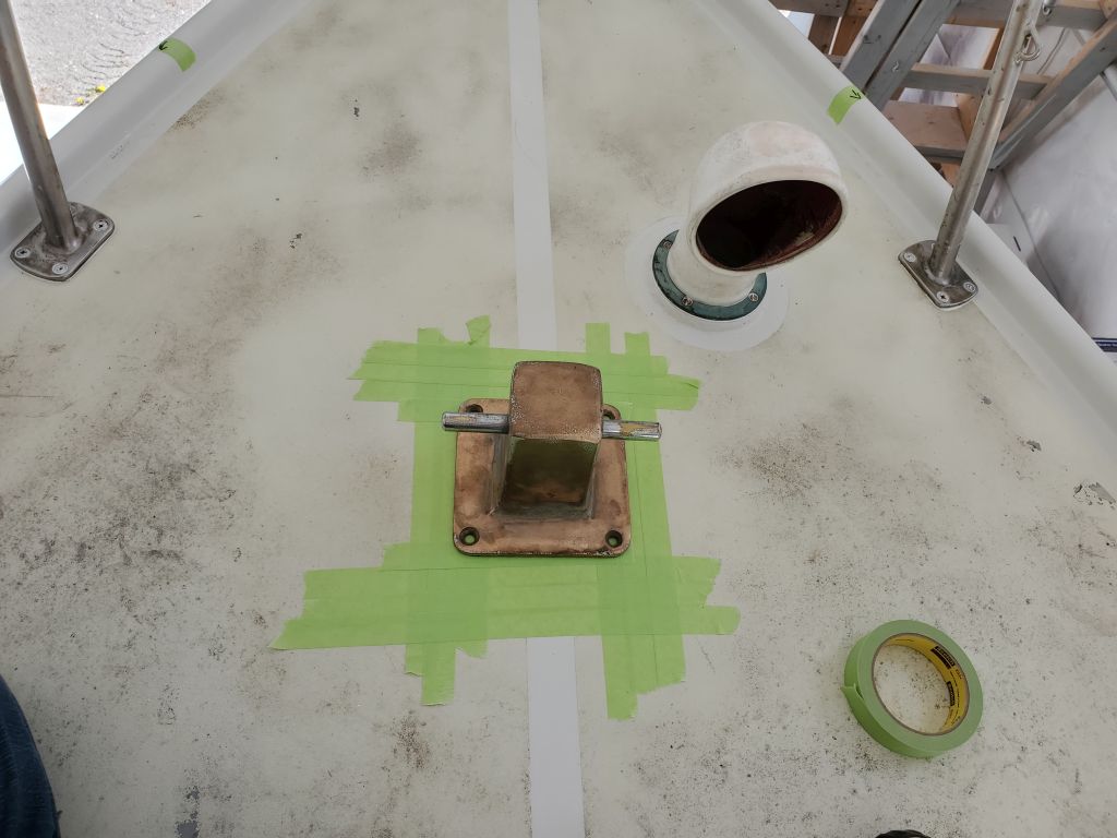
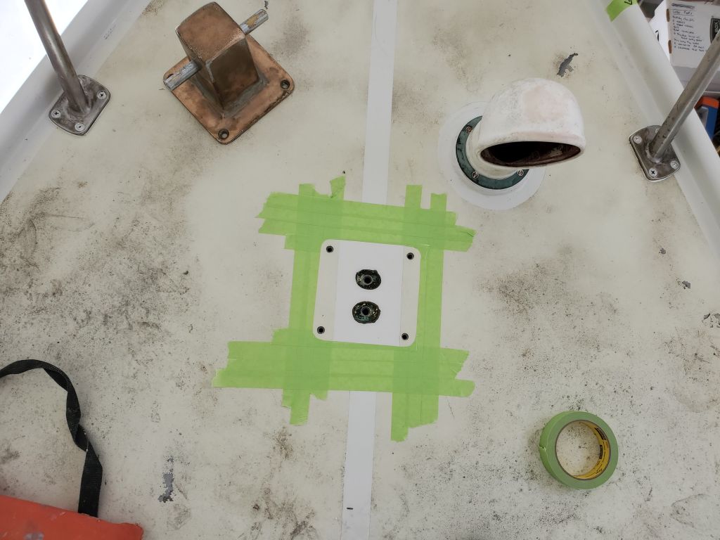
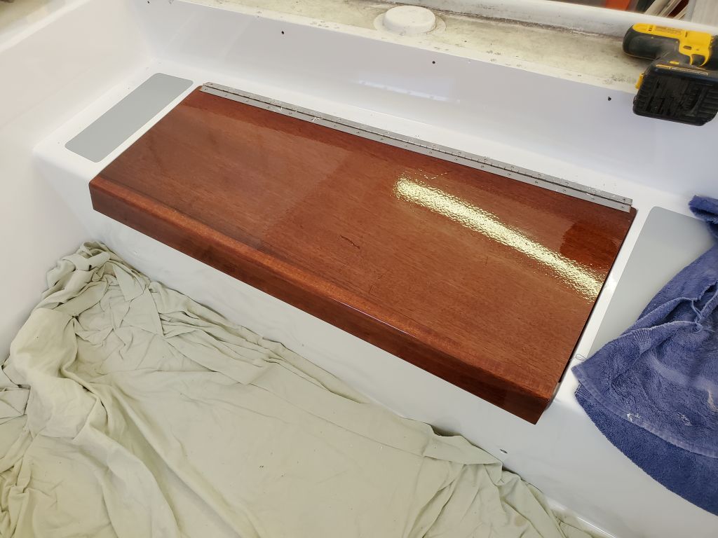
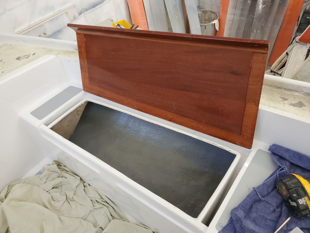
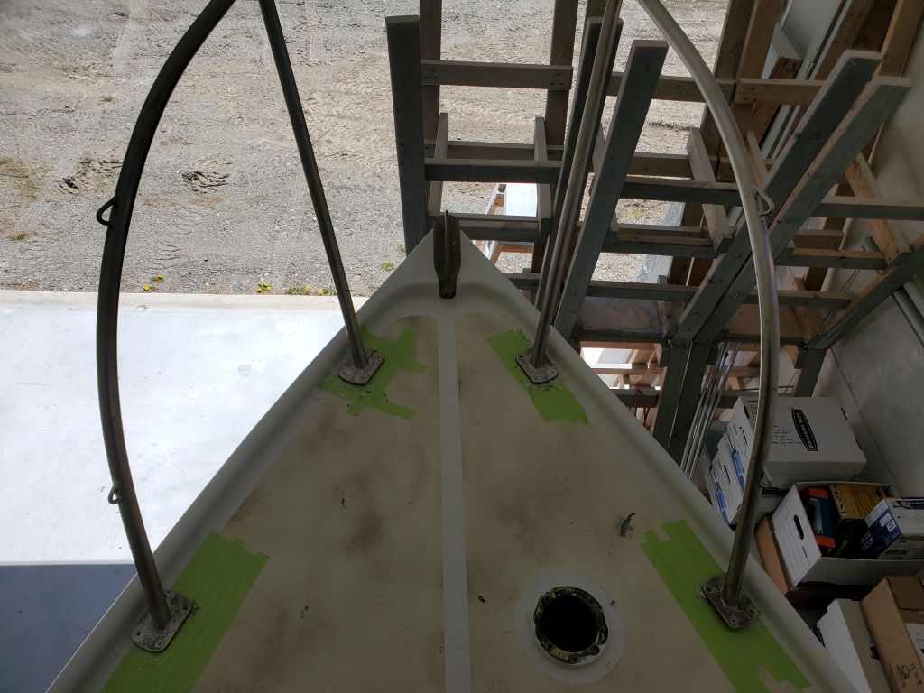
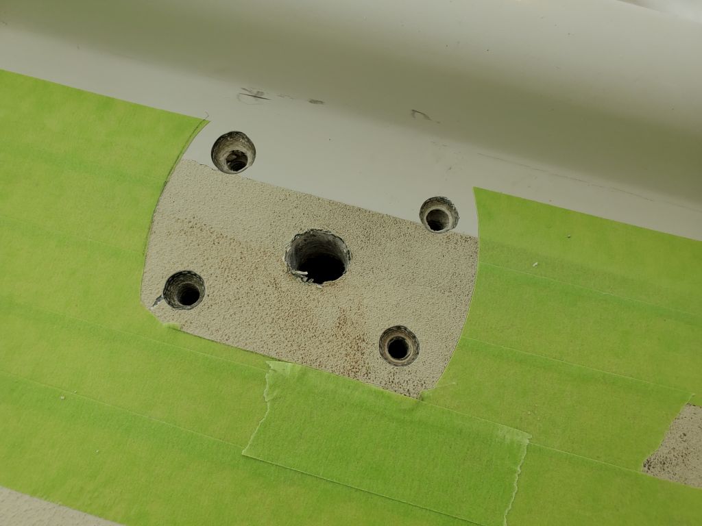
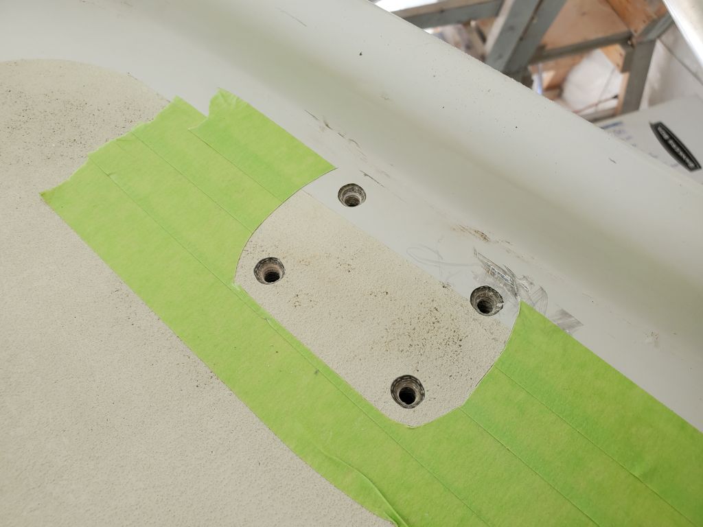
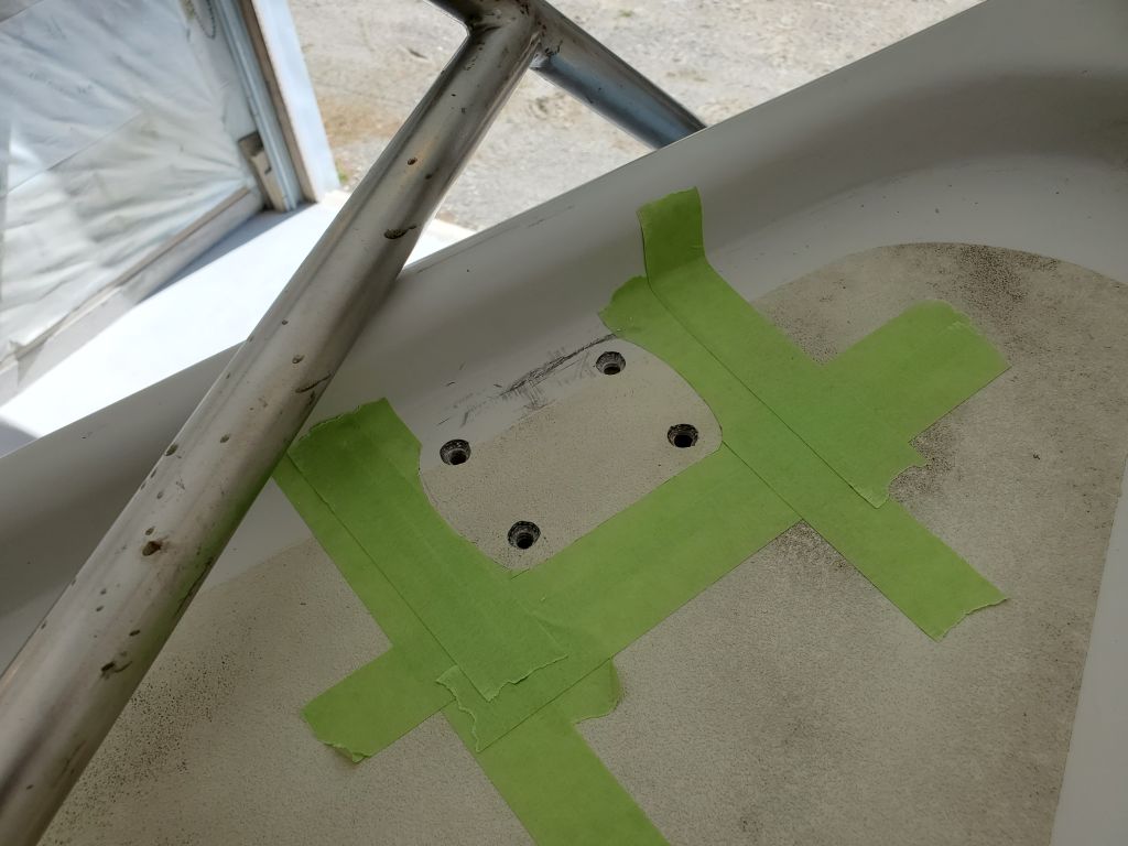
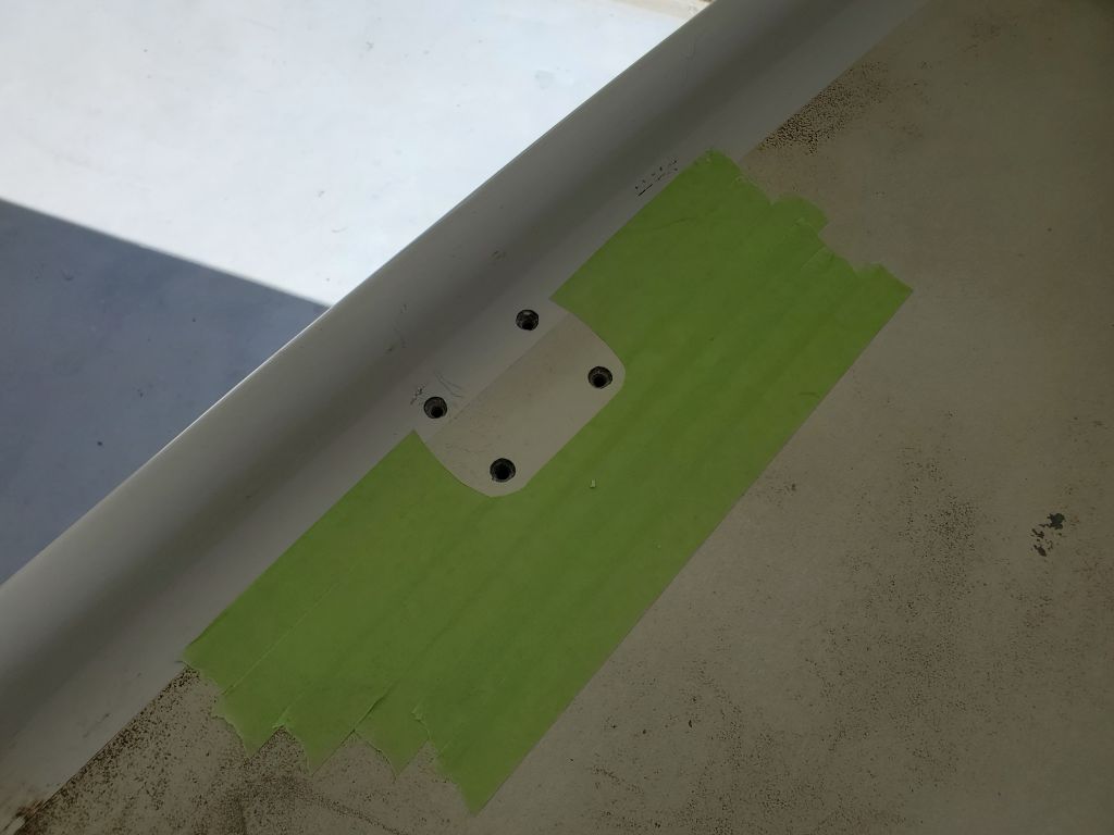
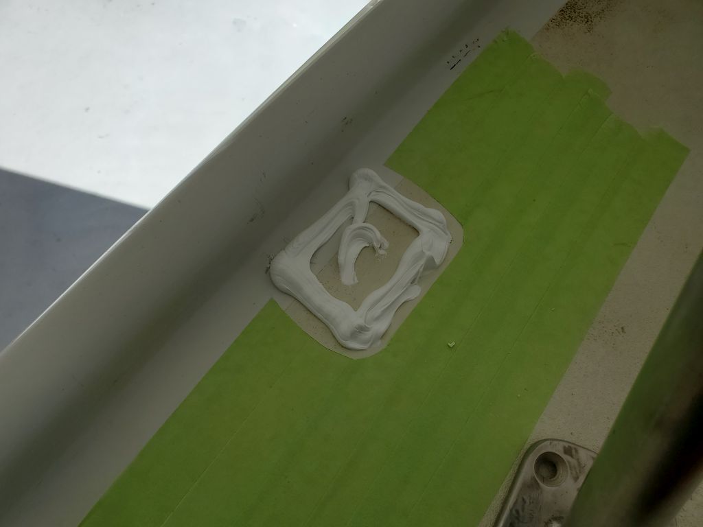
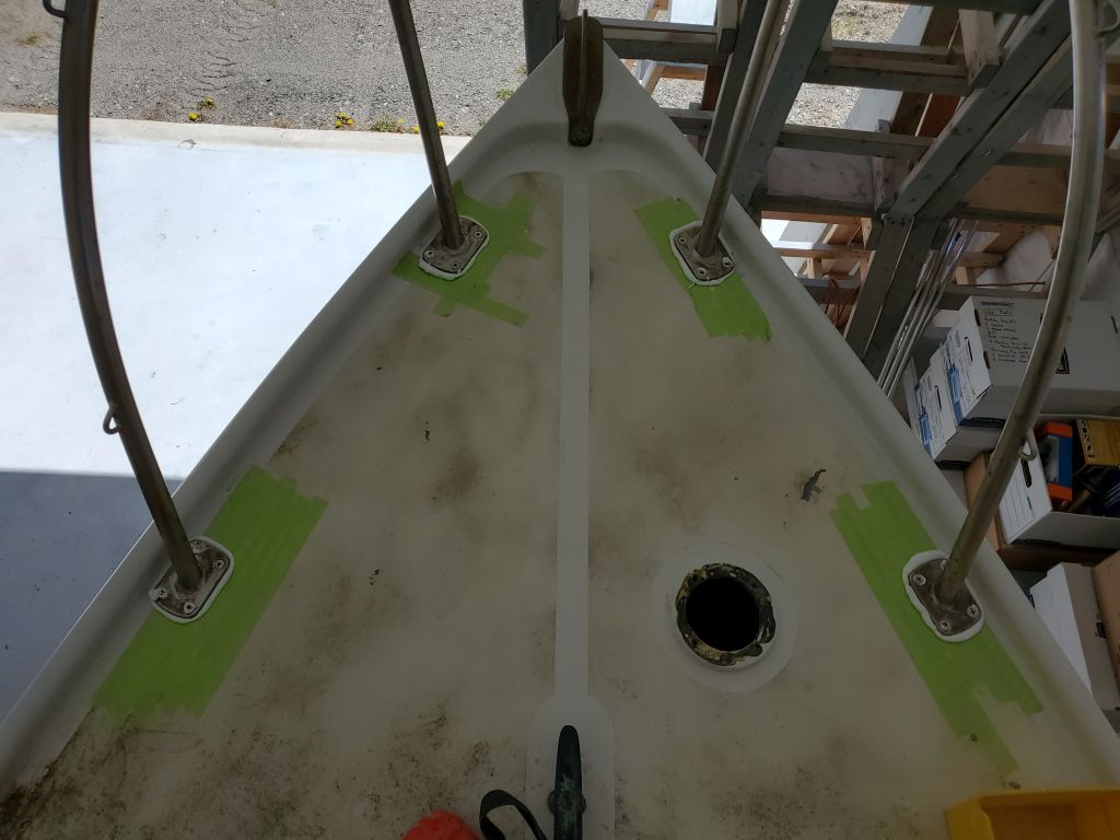
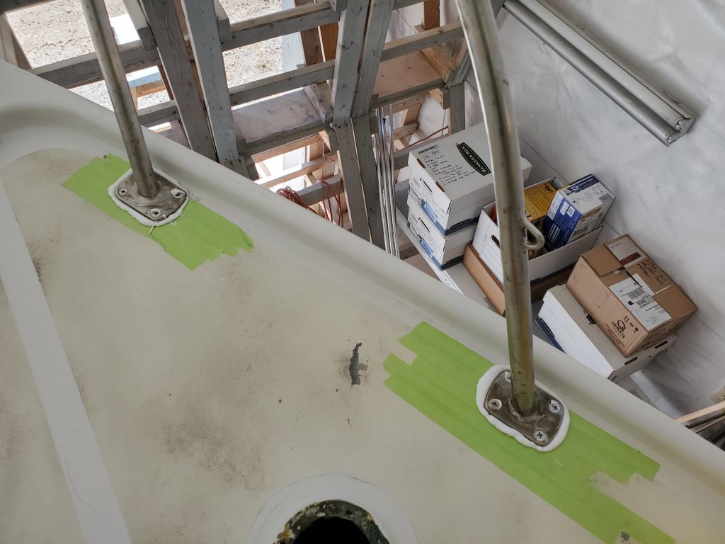
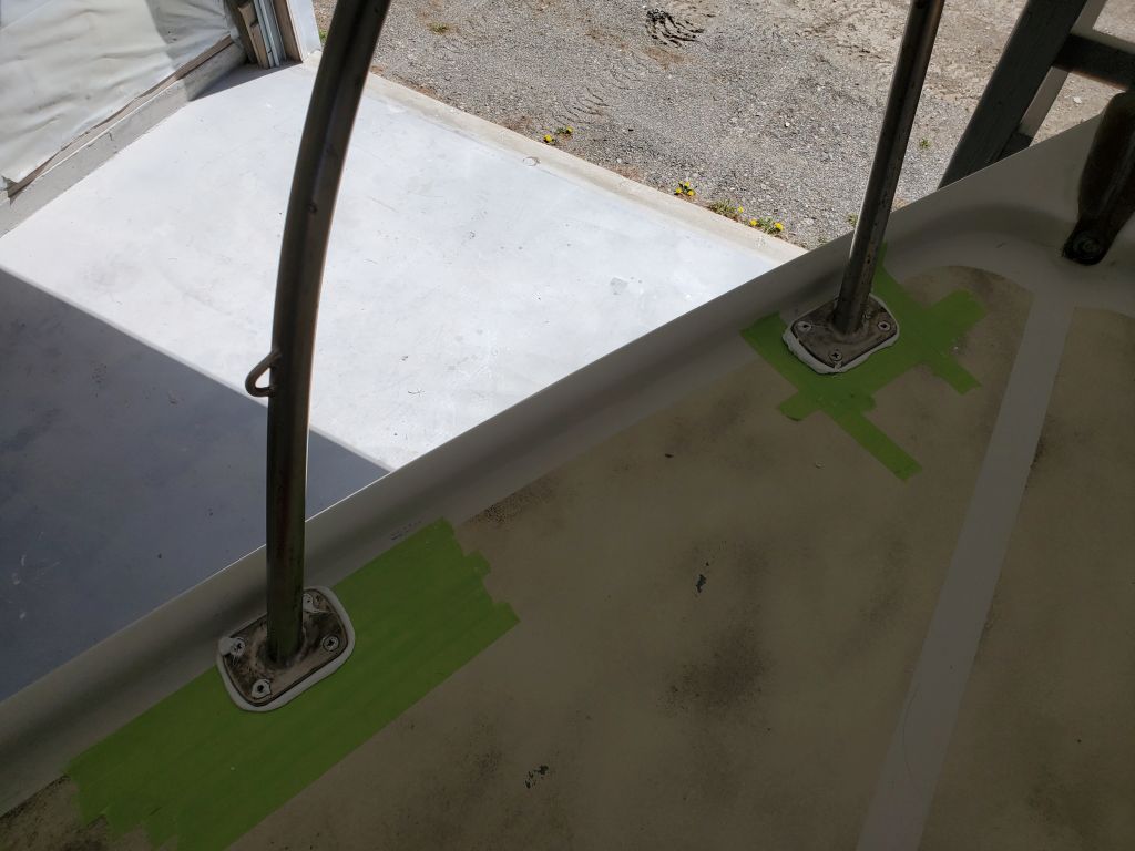
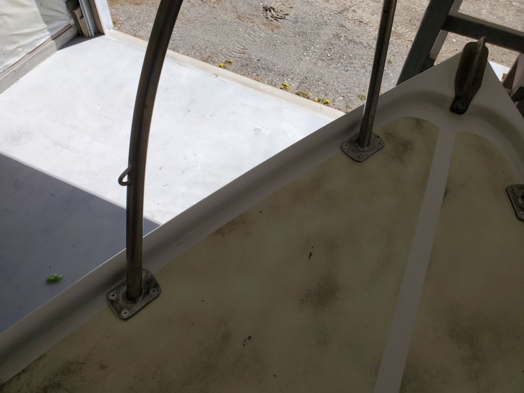
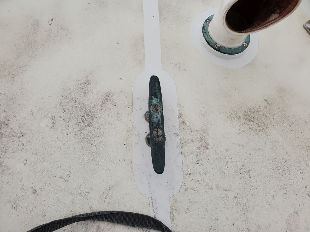
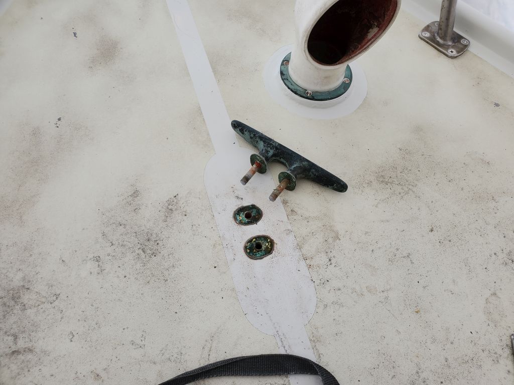
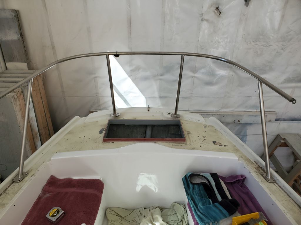
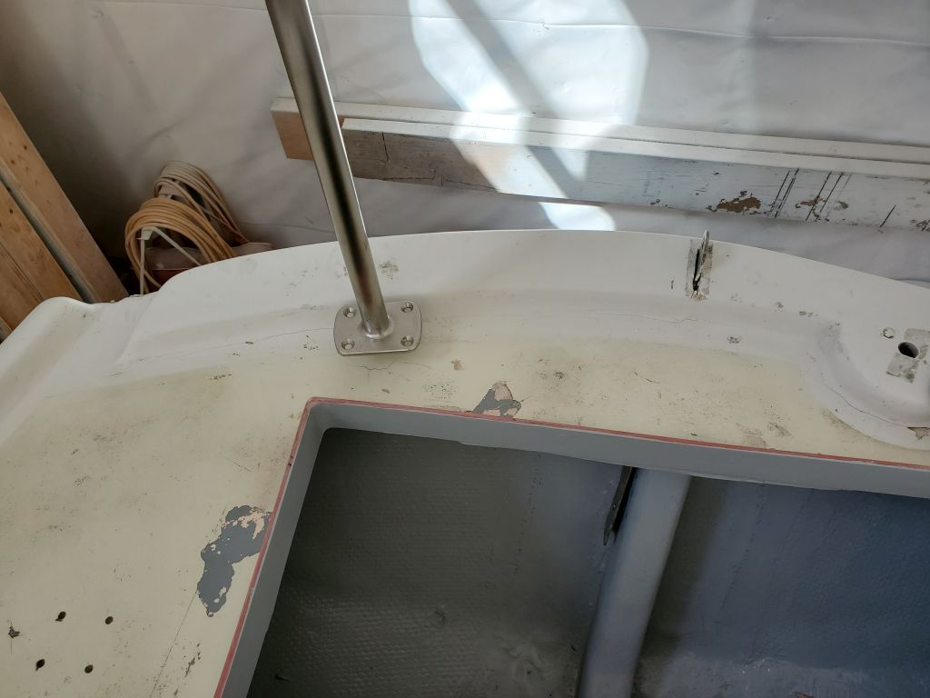
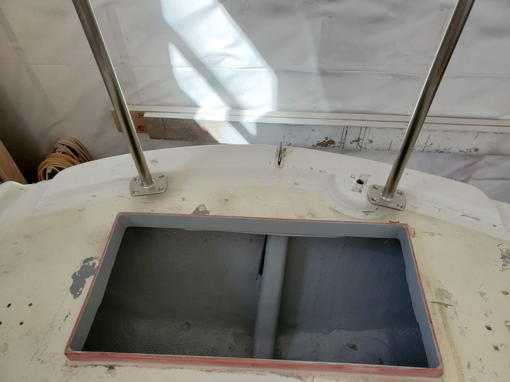
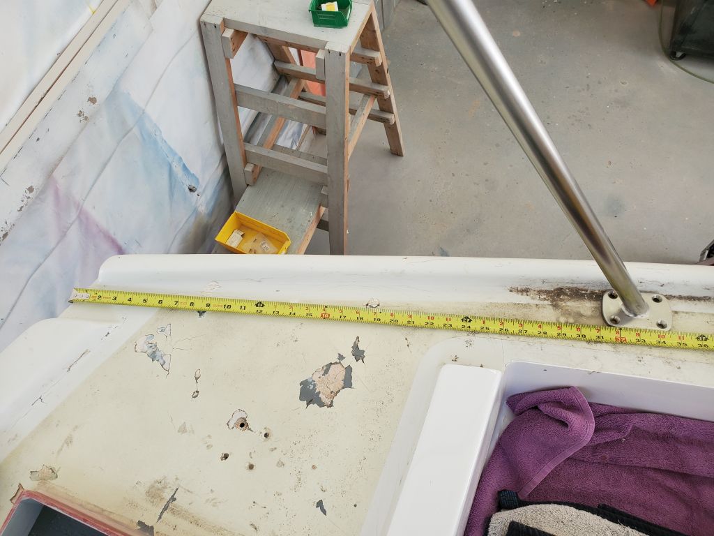
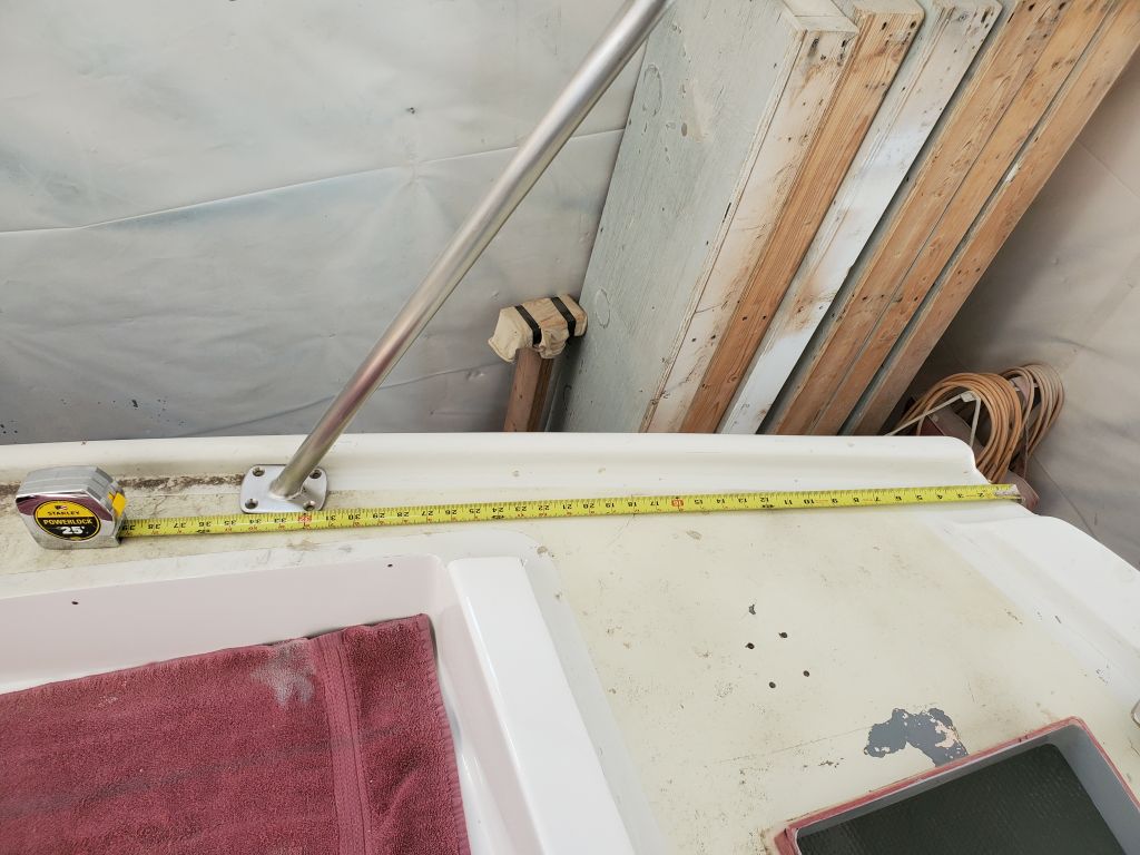
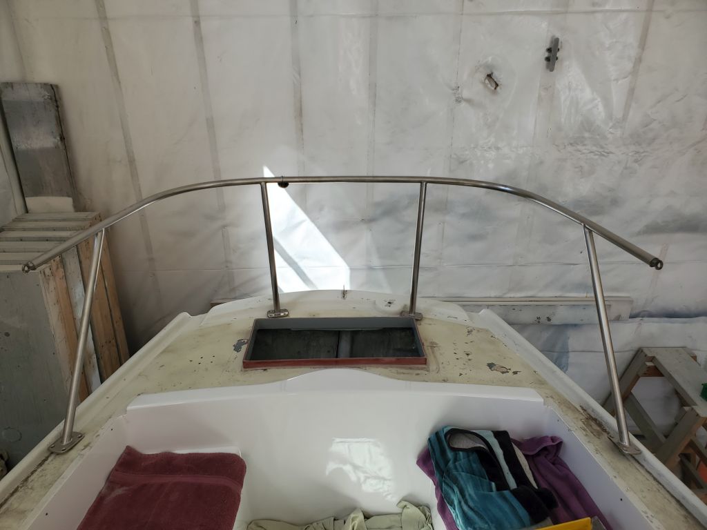
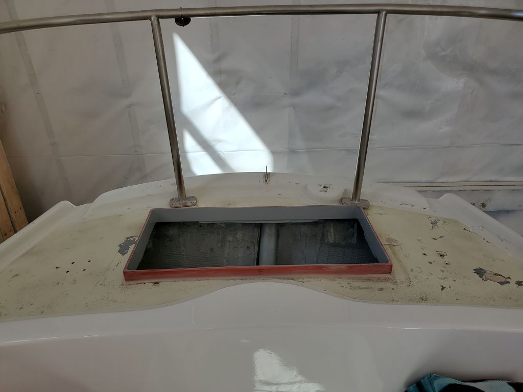
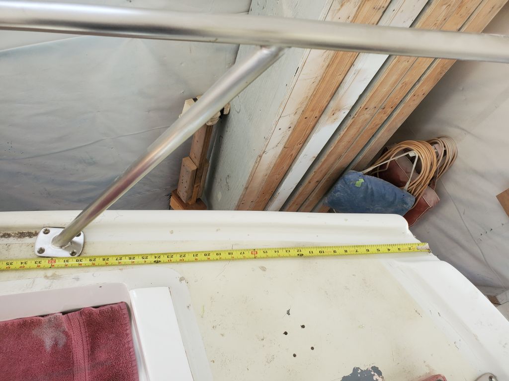
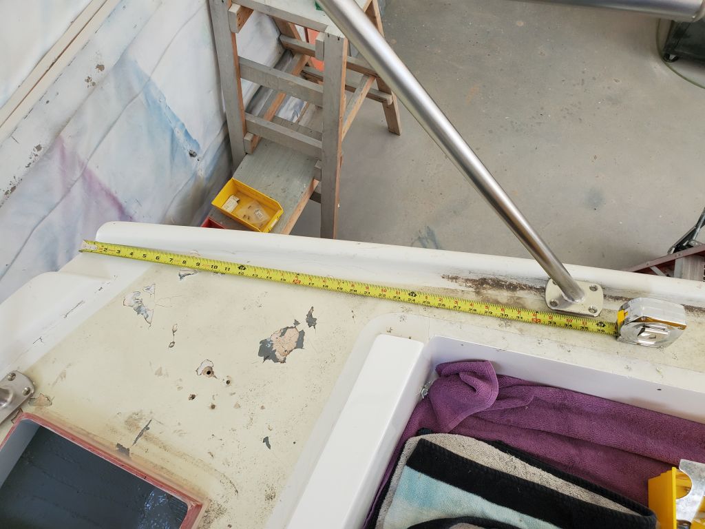
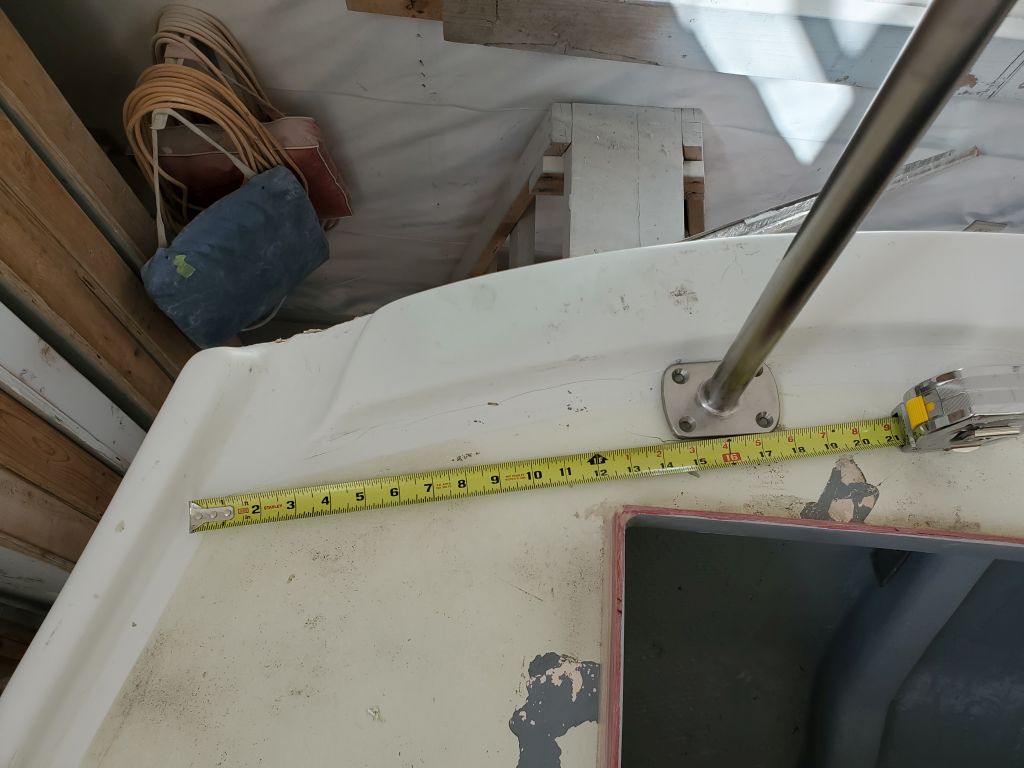
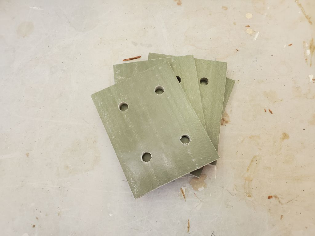
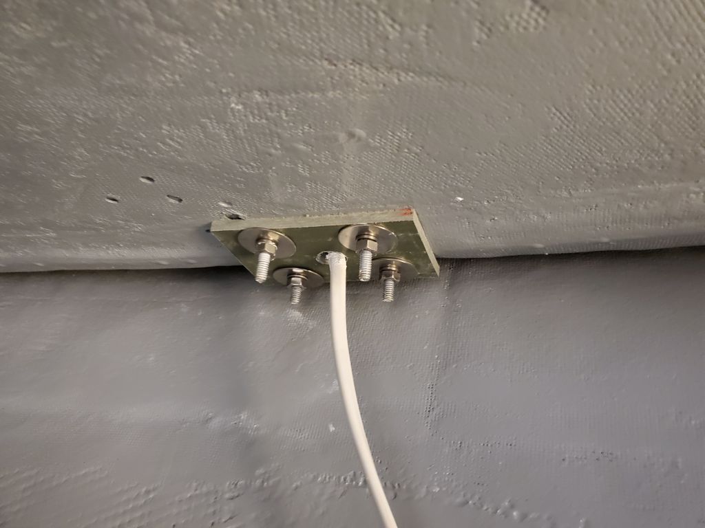
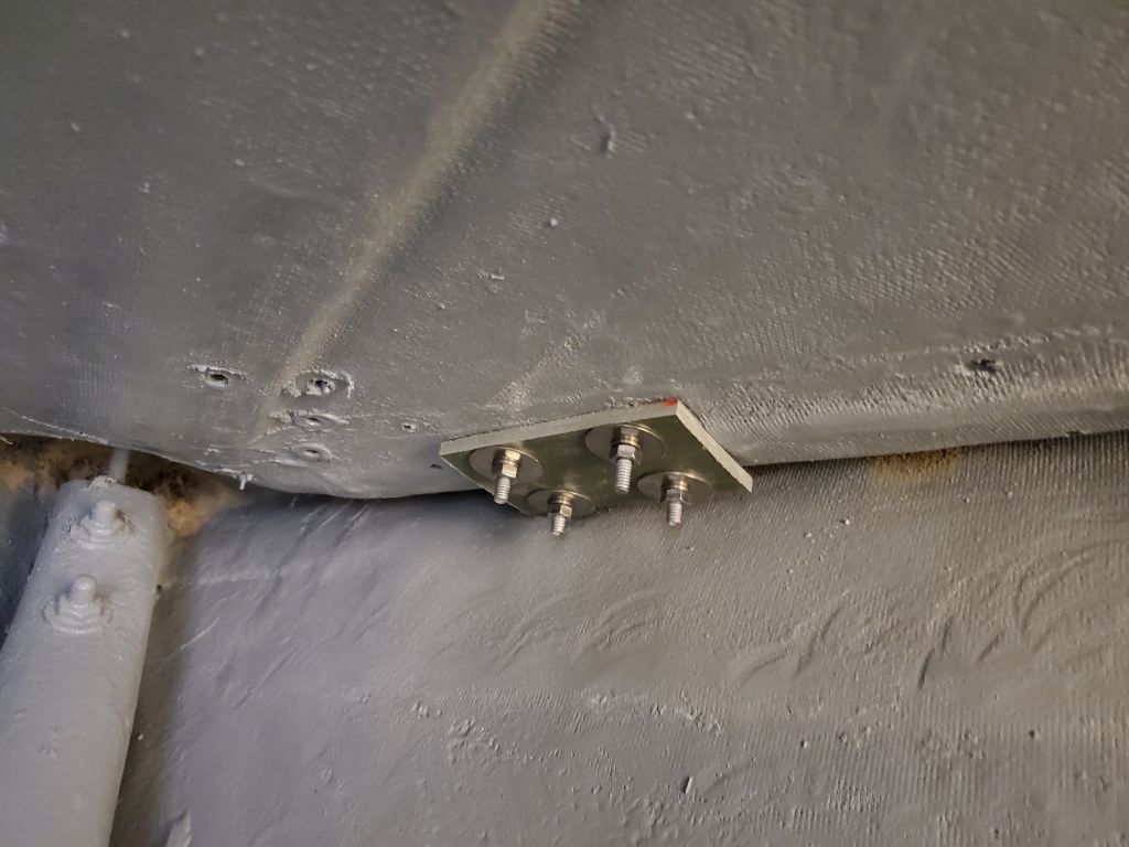
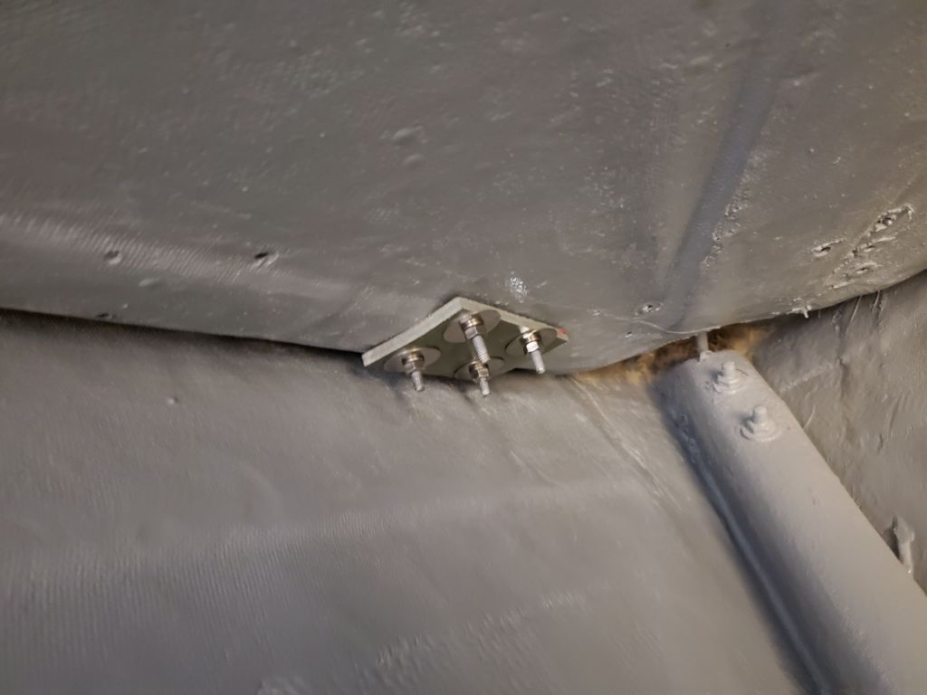
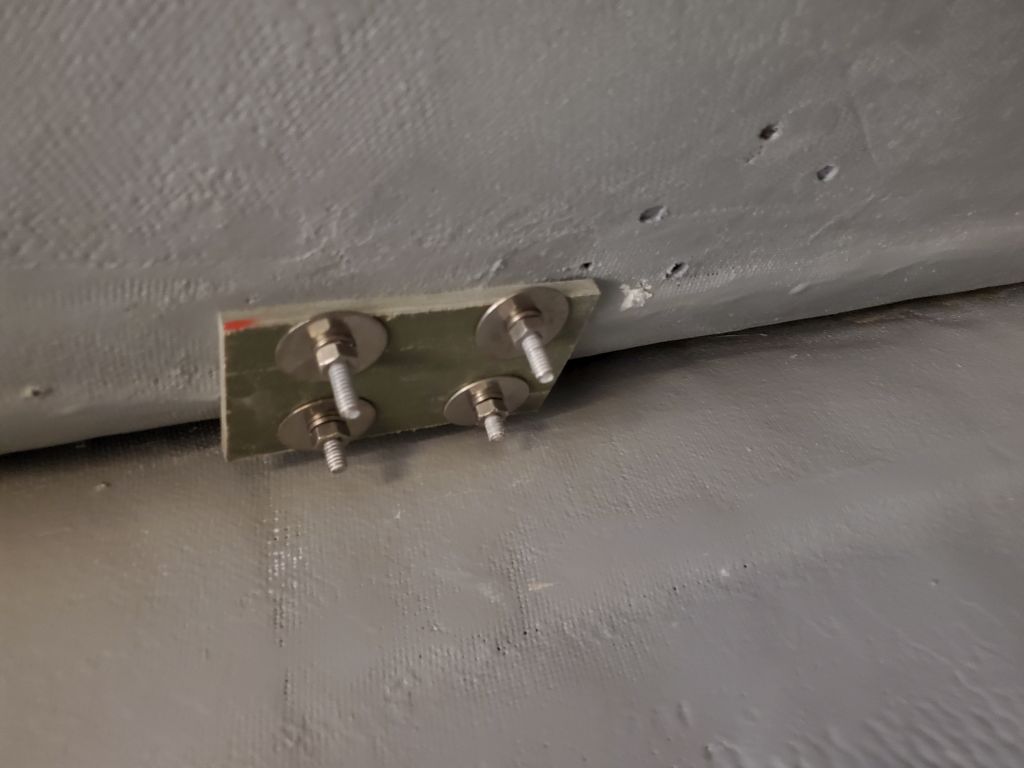
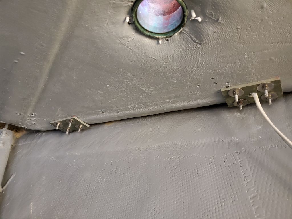
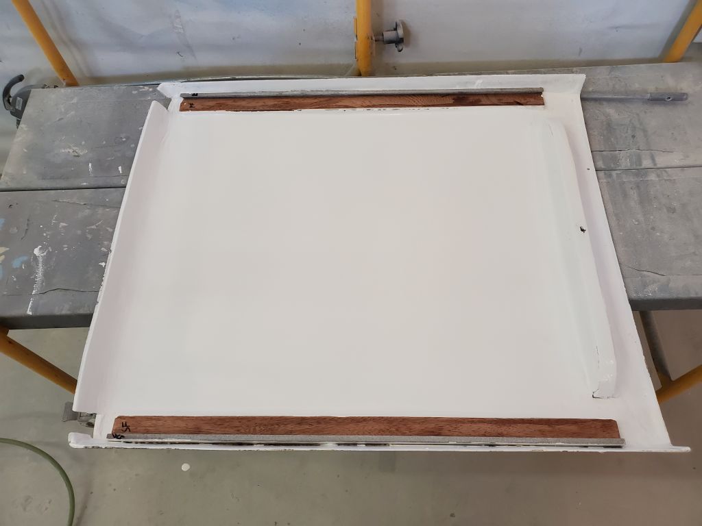
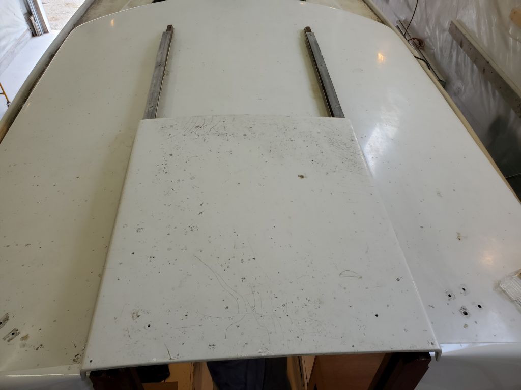
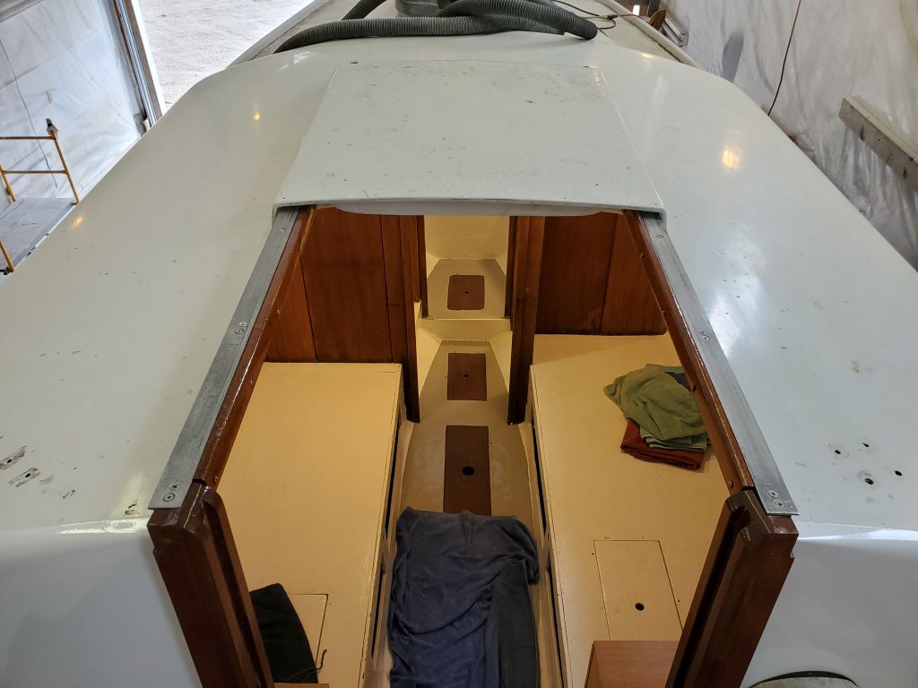
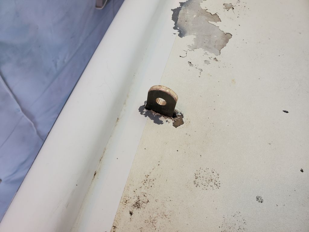
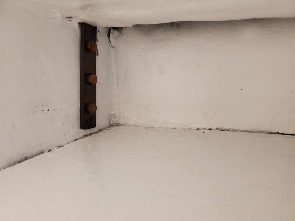
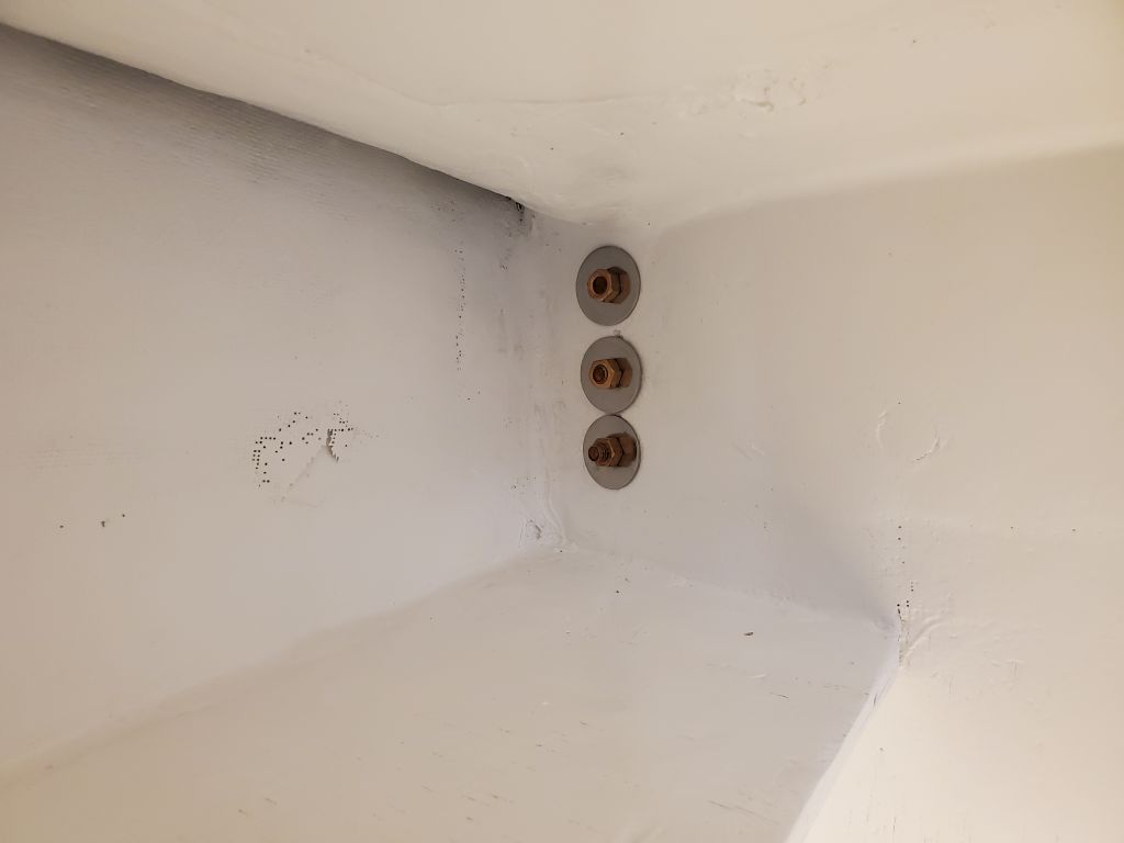
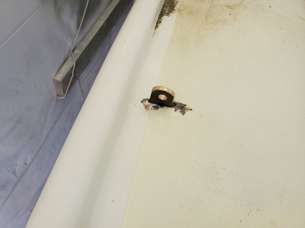
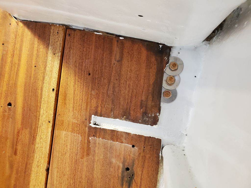
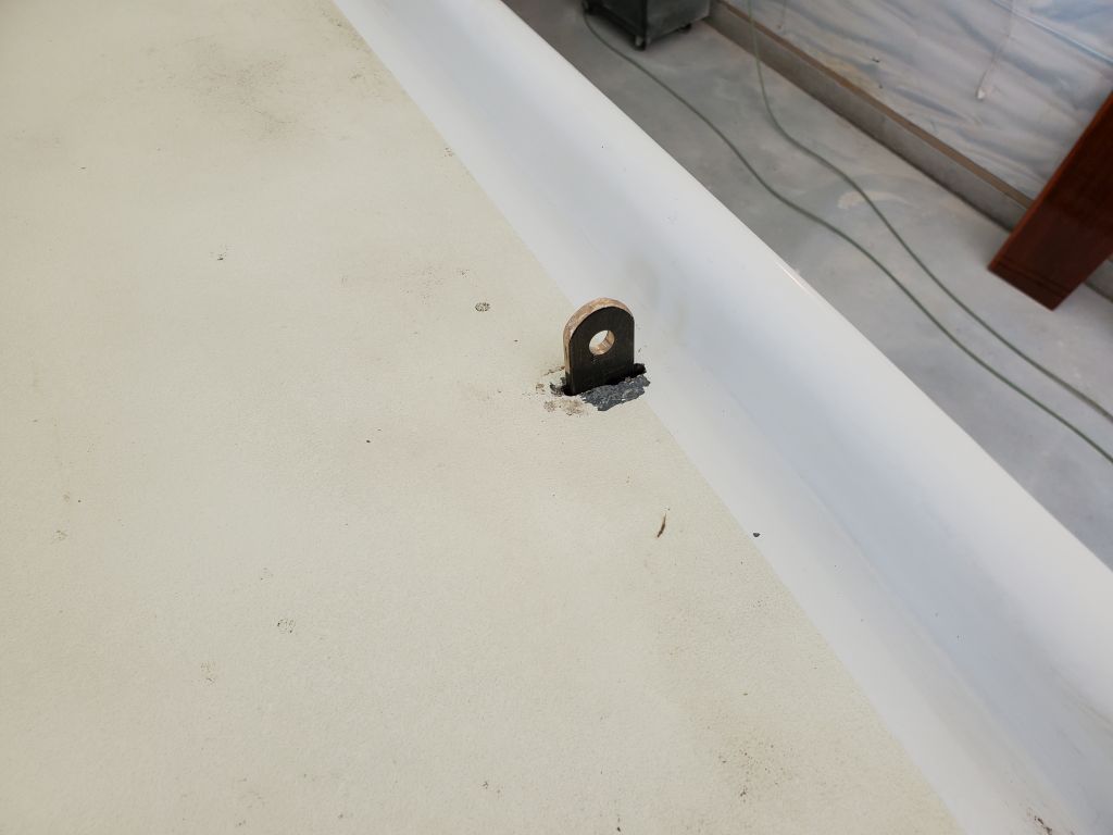
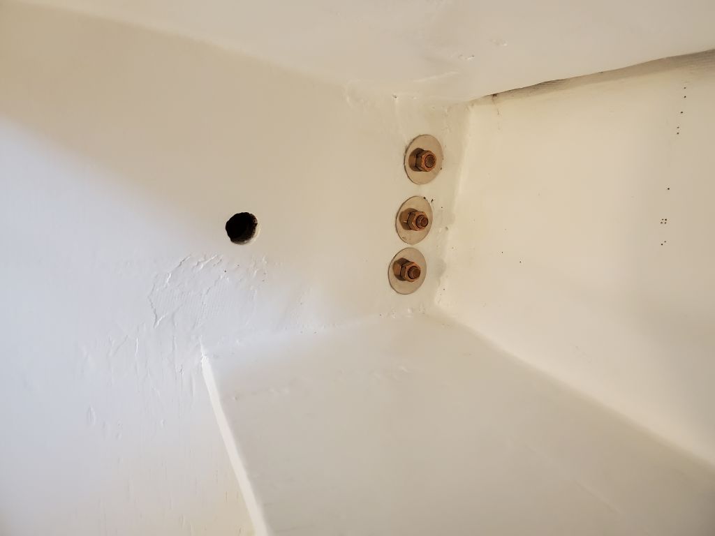
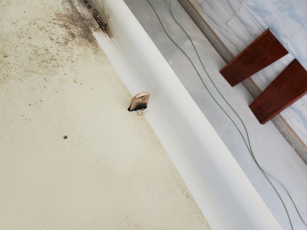
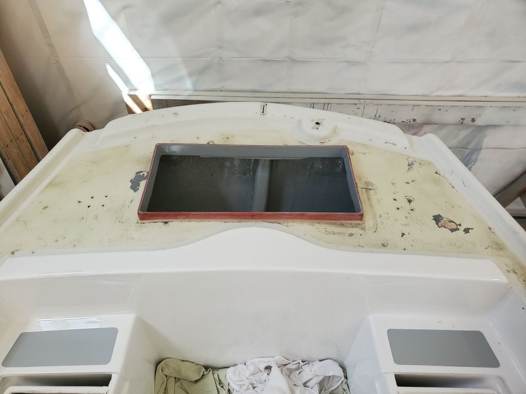
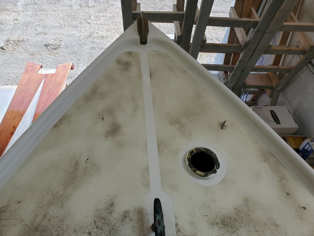
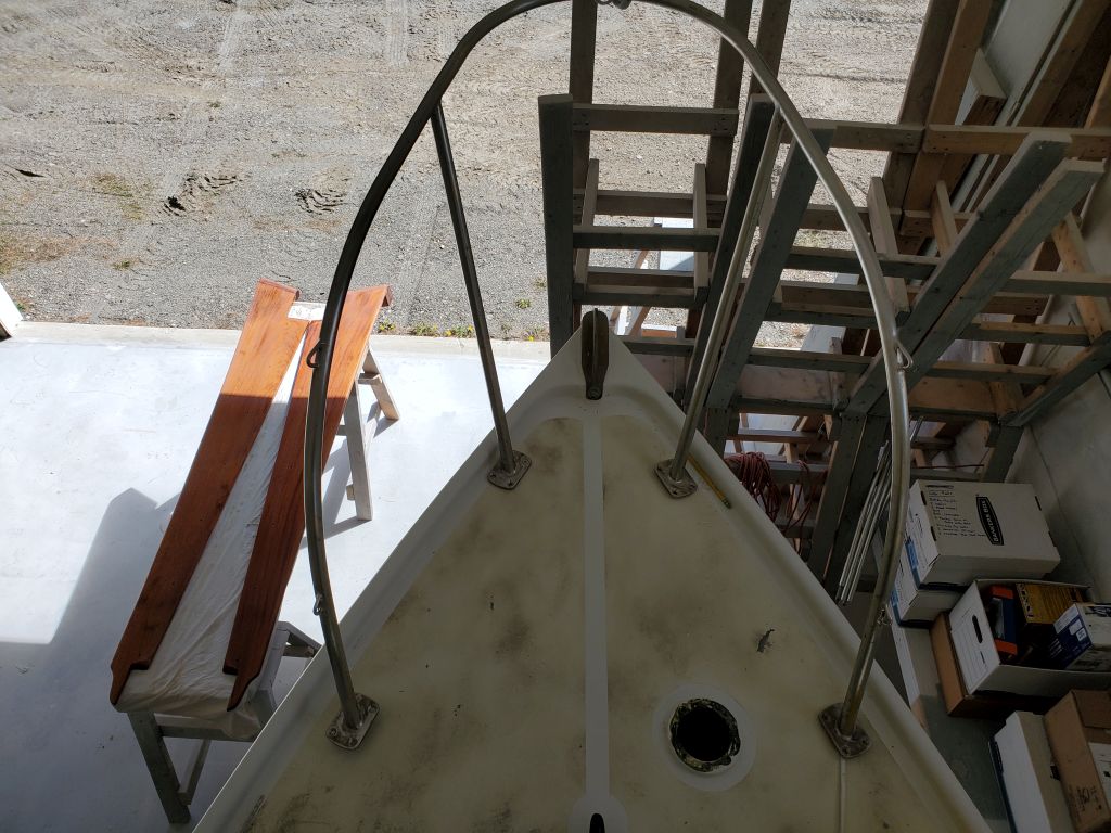
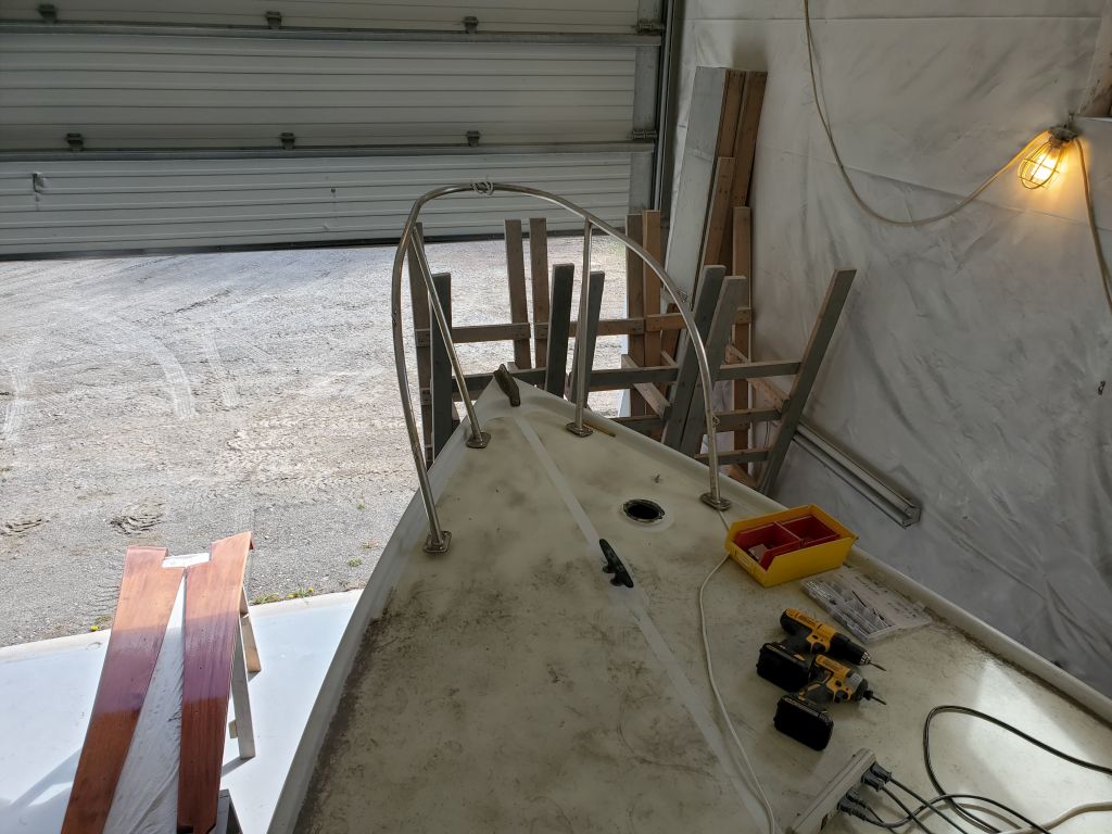
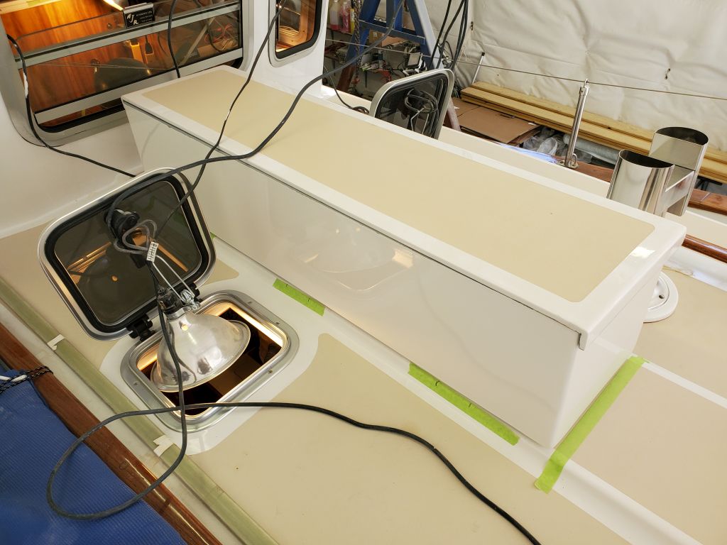
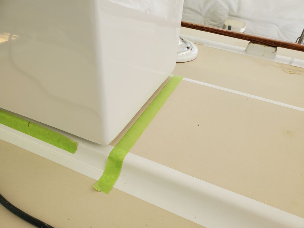
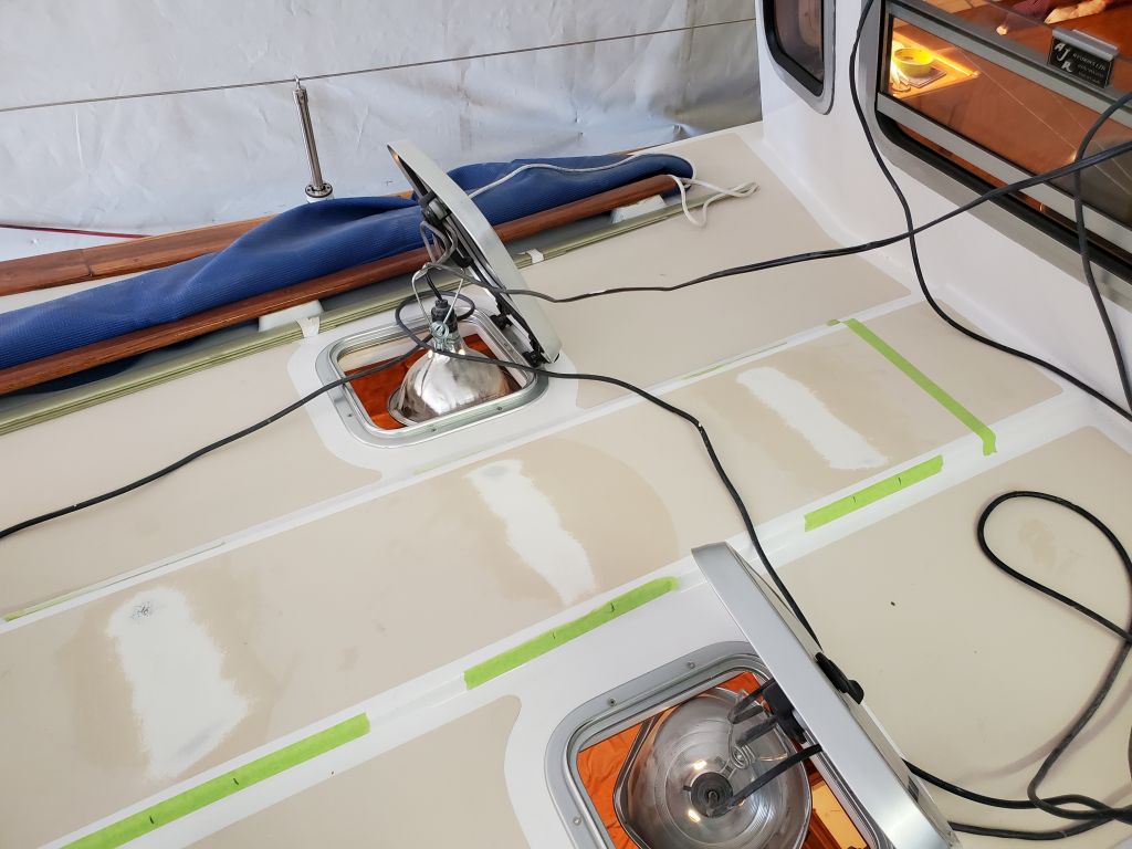
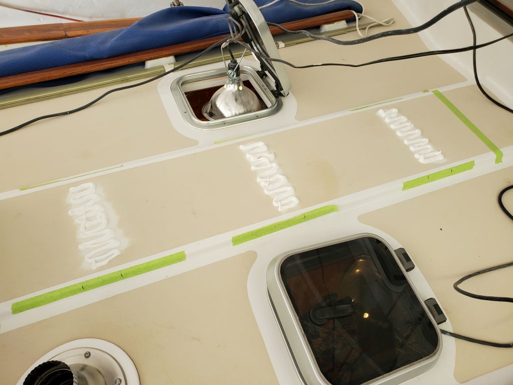
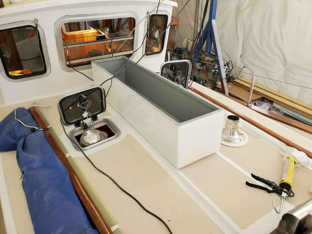
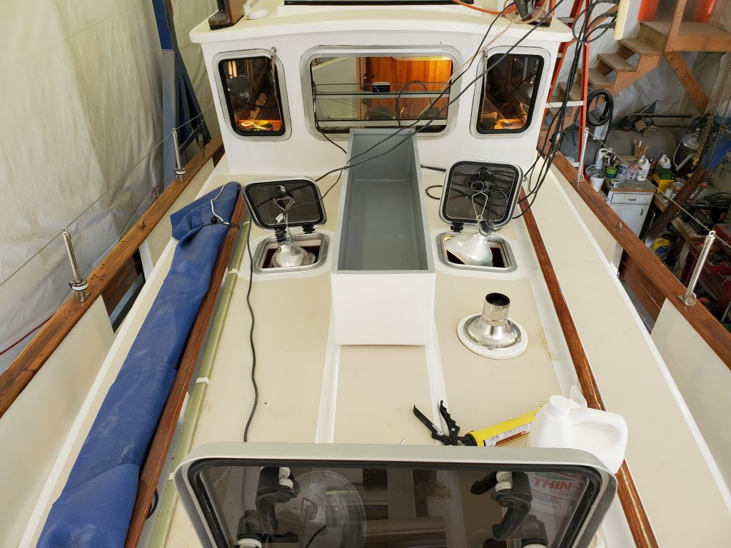
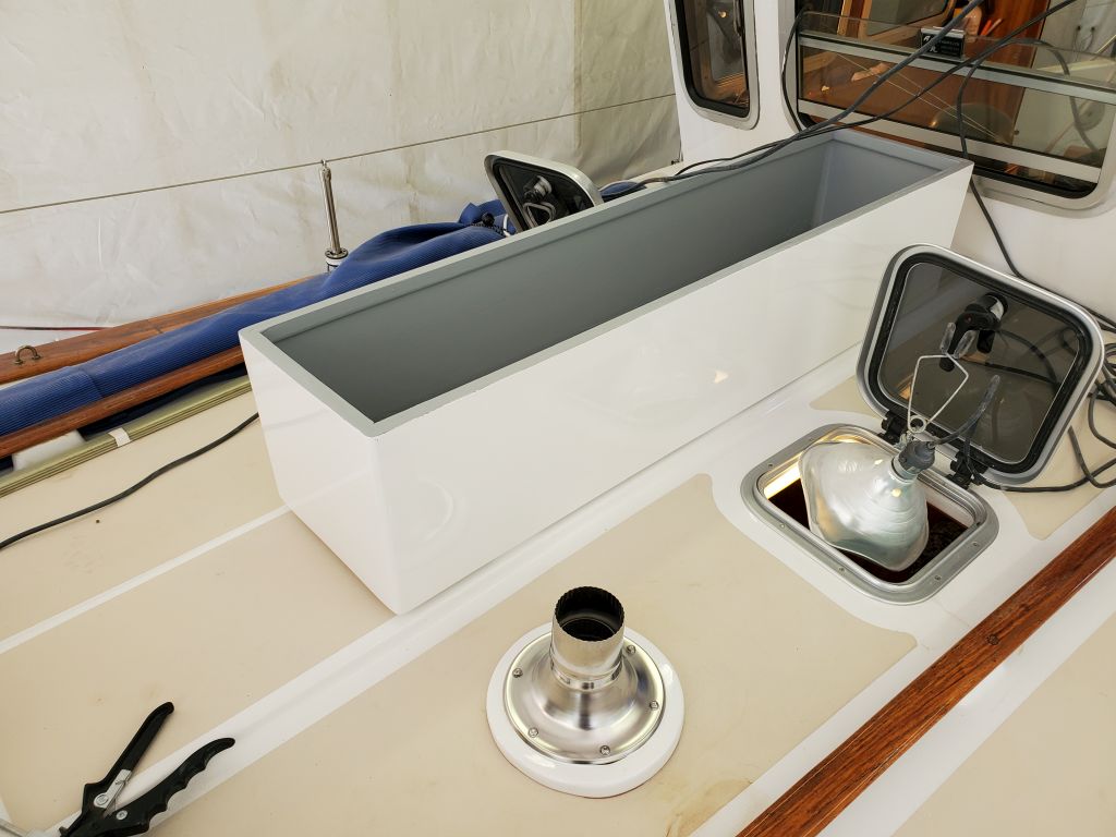
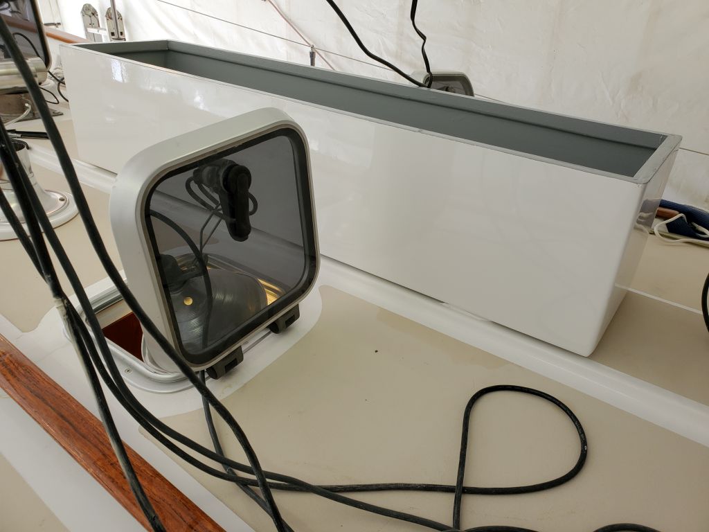
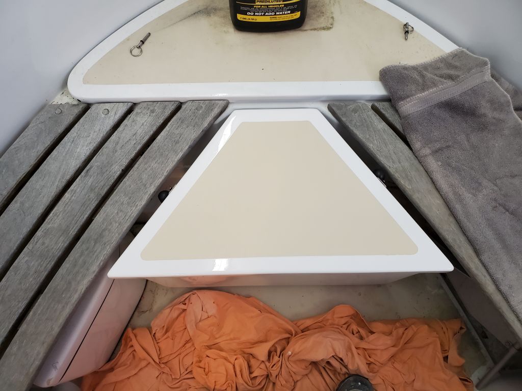
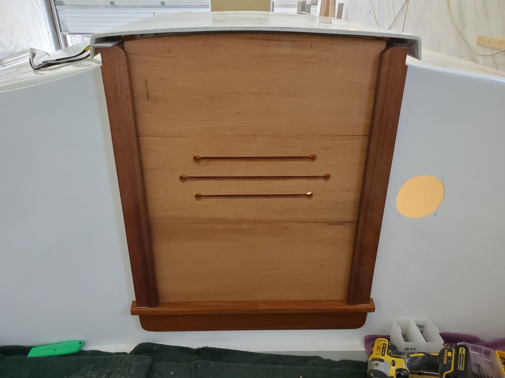
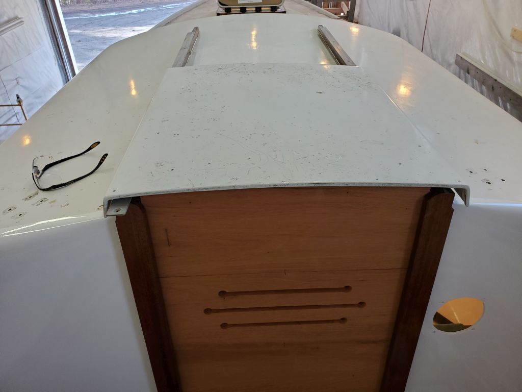
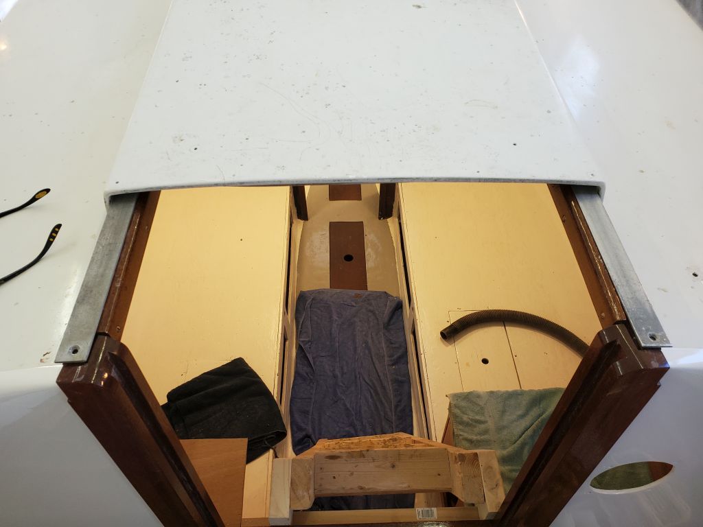
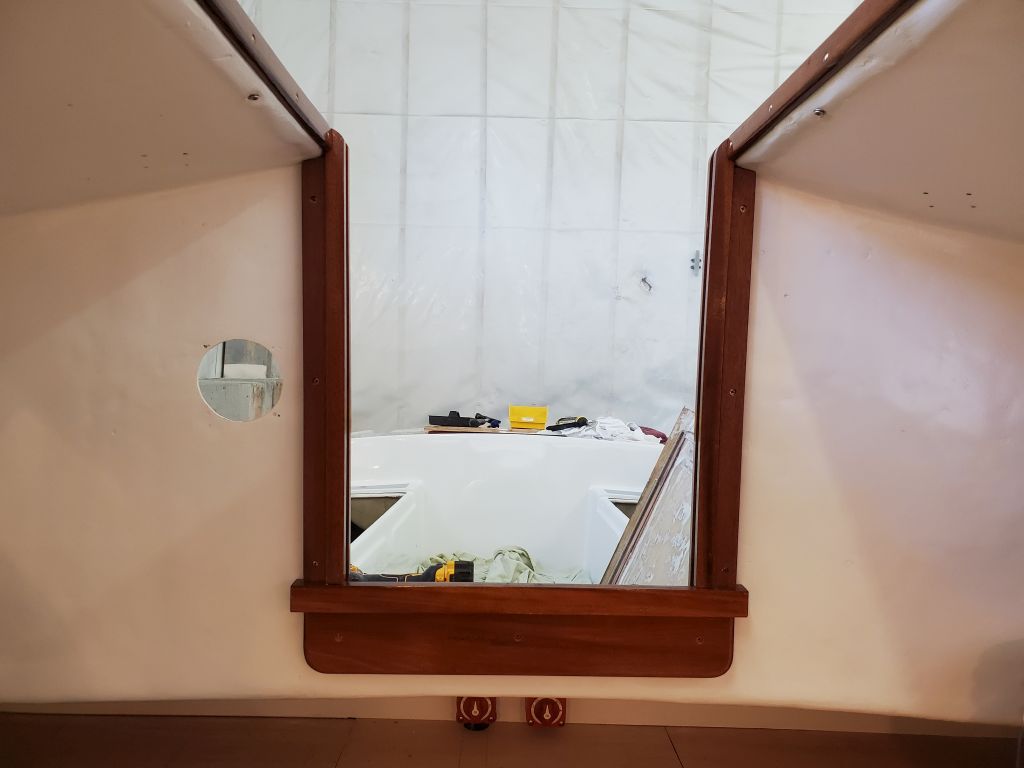
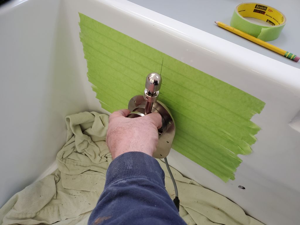
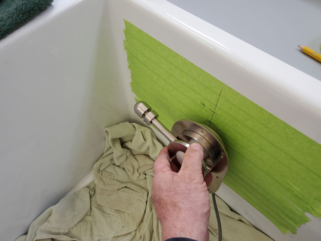
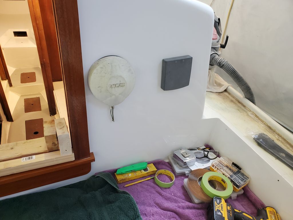
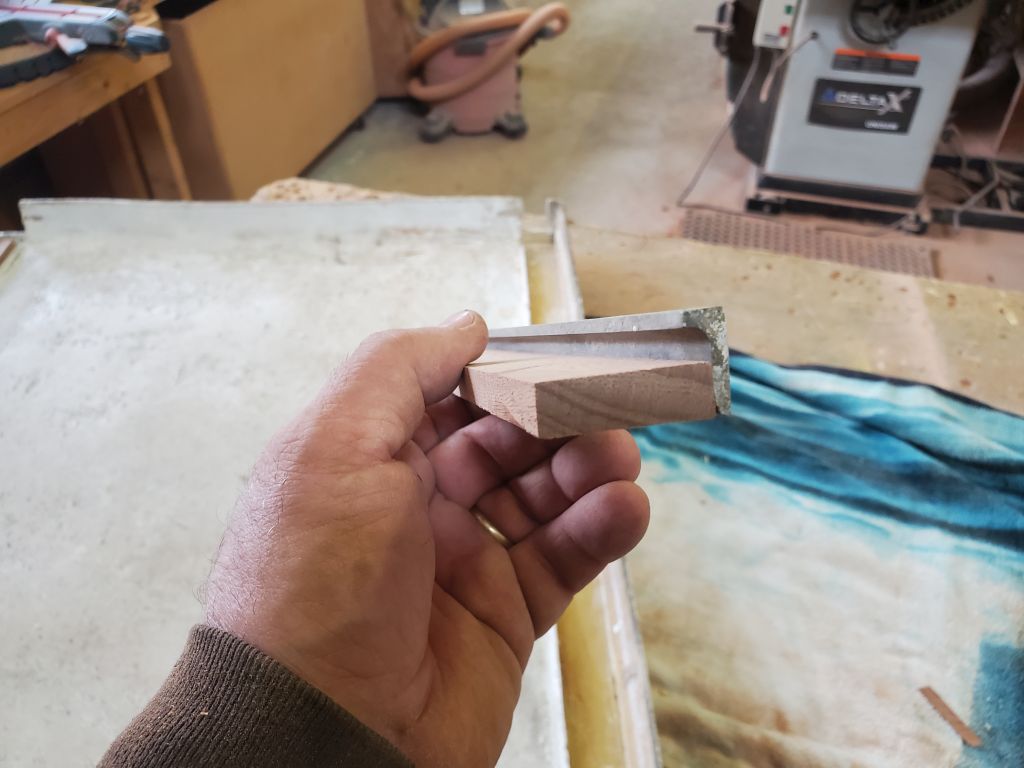
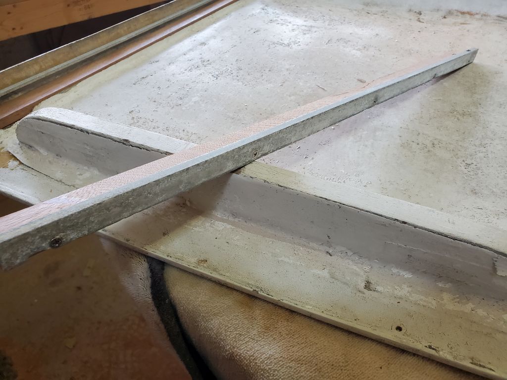
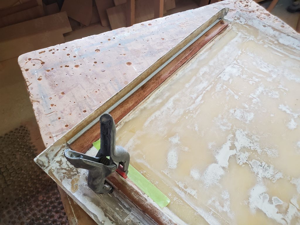
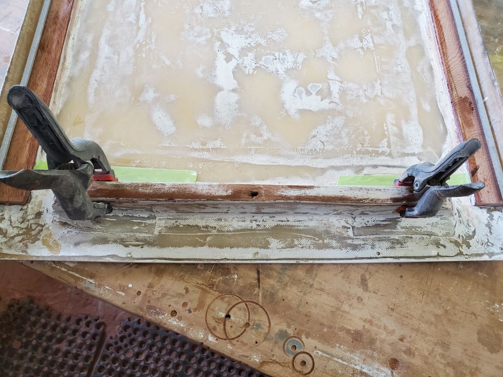
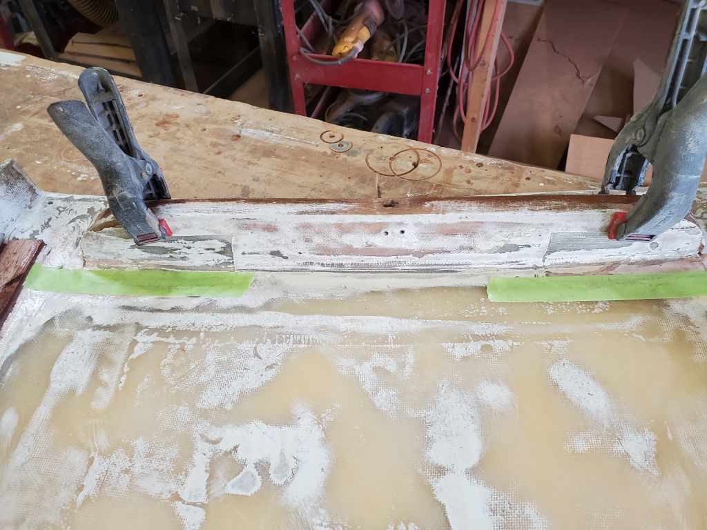
Next on my agenda: The deck boxes, starting with the large forward box. I planned to install this to the deck with marine adhesive (5200), saving the deck penetrations and time consumption of removing the overhead in the cabin. To prepare, I aligned the box where I wanted it, and marked the ends with tape, and also marked with tape the positions of the three mounting “feet” from the side. Removing the box, and using my marks as a guide, I removed the paint from the deck in way of the three mounting surfaces and, after final preparations and cleanup, applied heavy beads of adhesive to each location and pressed the box into position, aligning it carefully with my end marks and by eye to ensure a symmetrical mounting on the deck. I left this to cure.
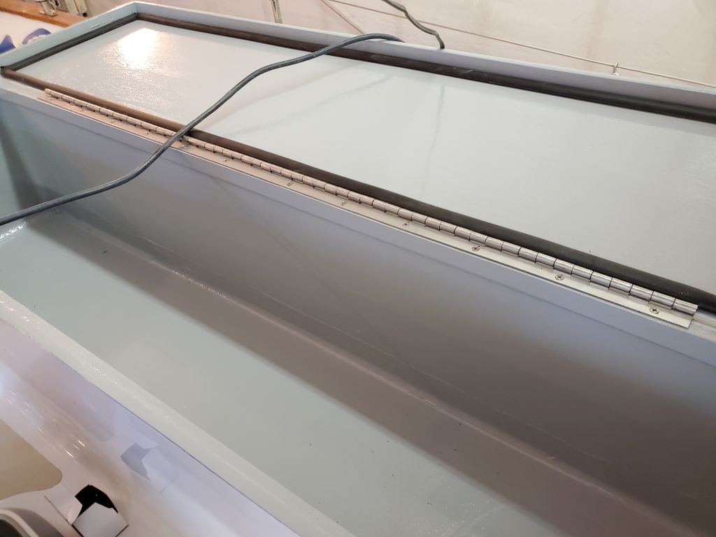
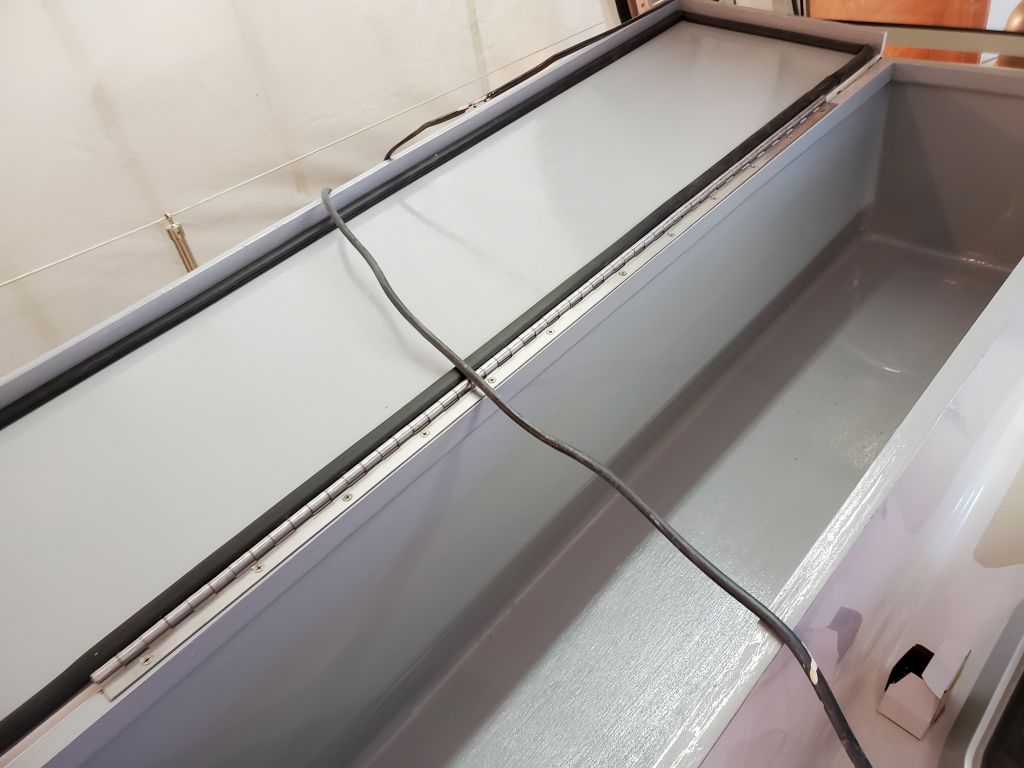
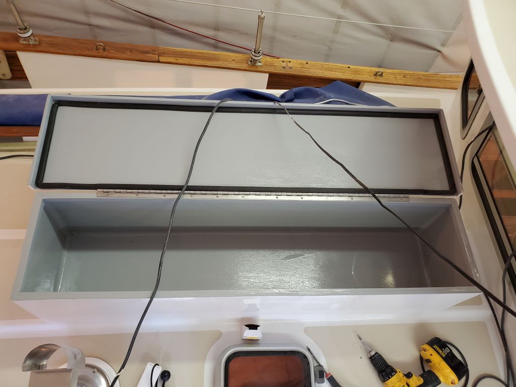
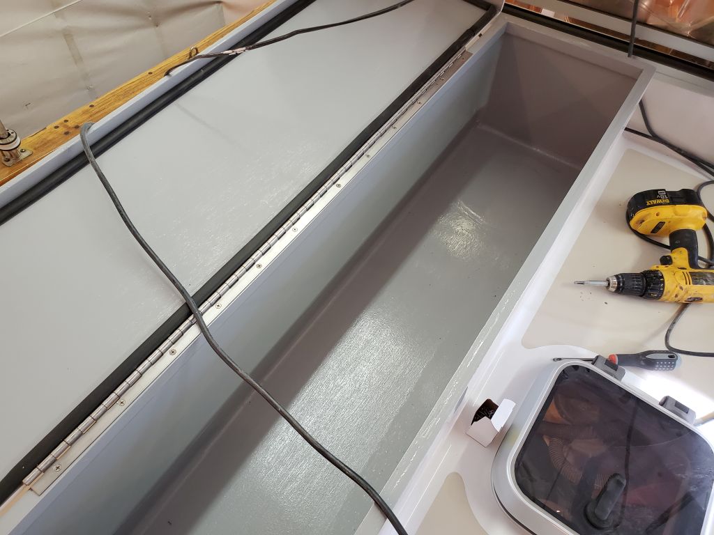
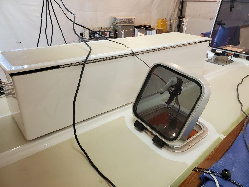
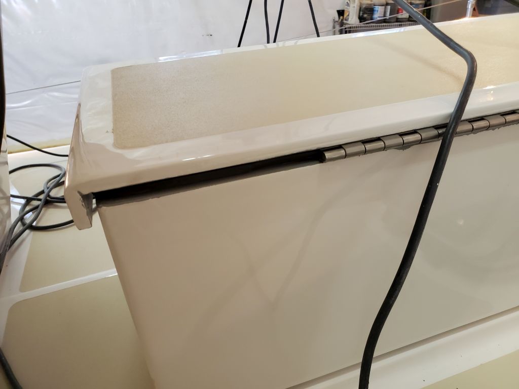
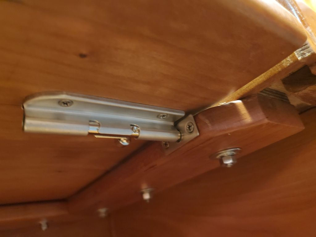
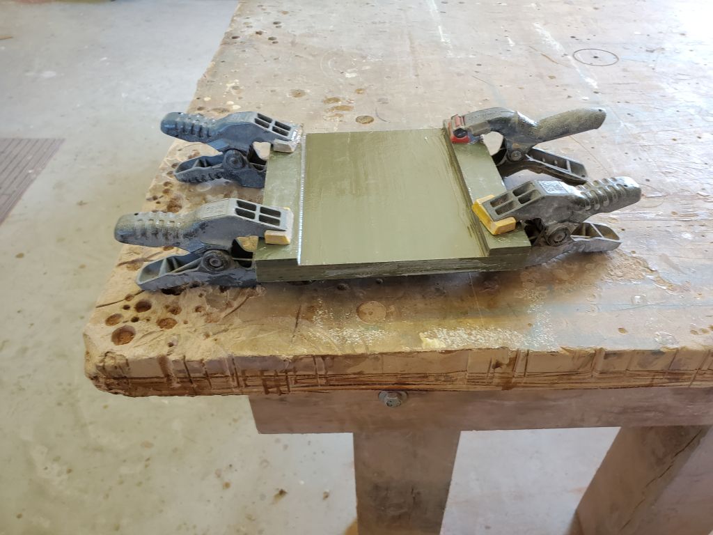
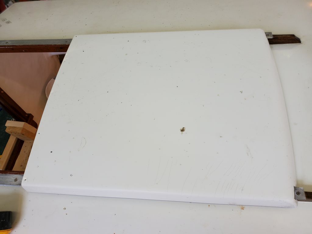
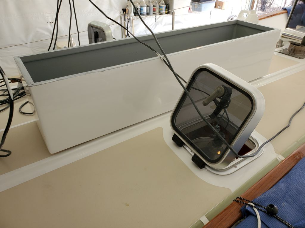
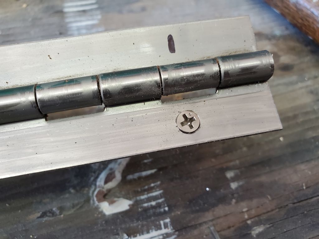
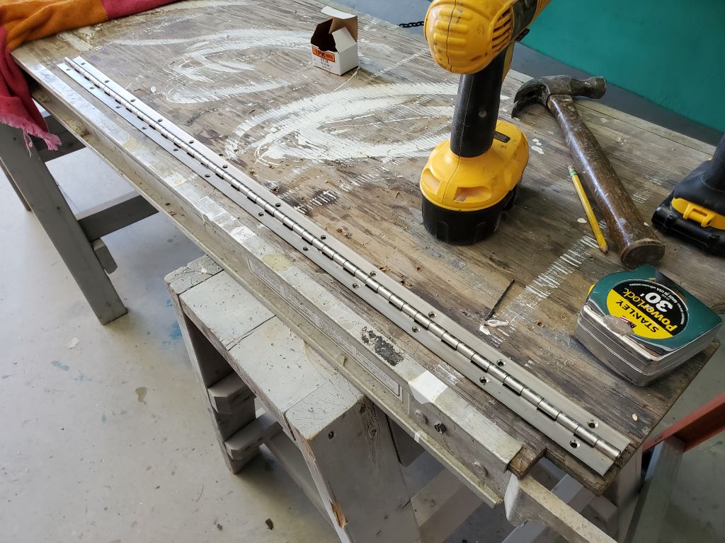
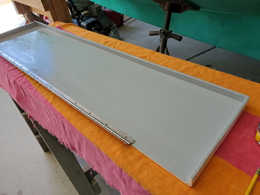
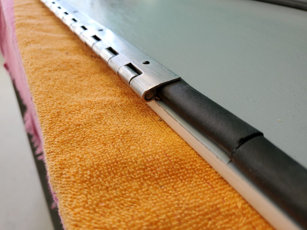
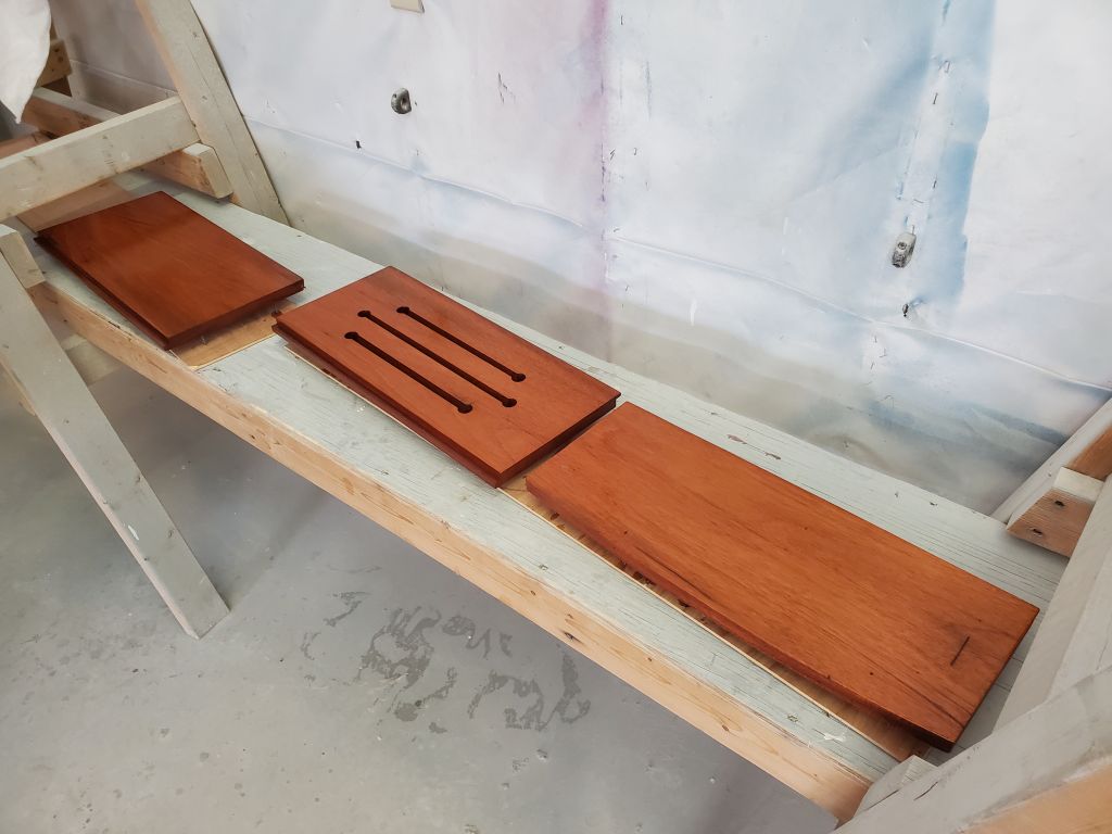
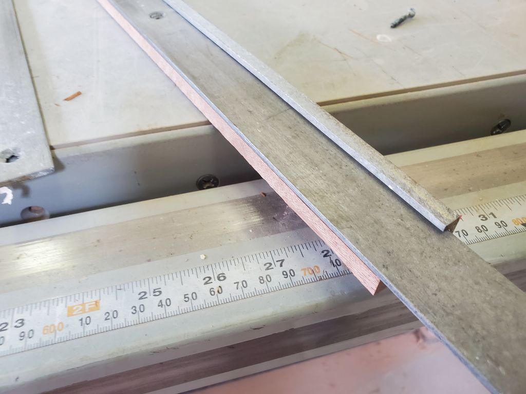
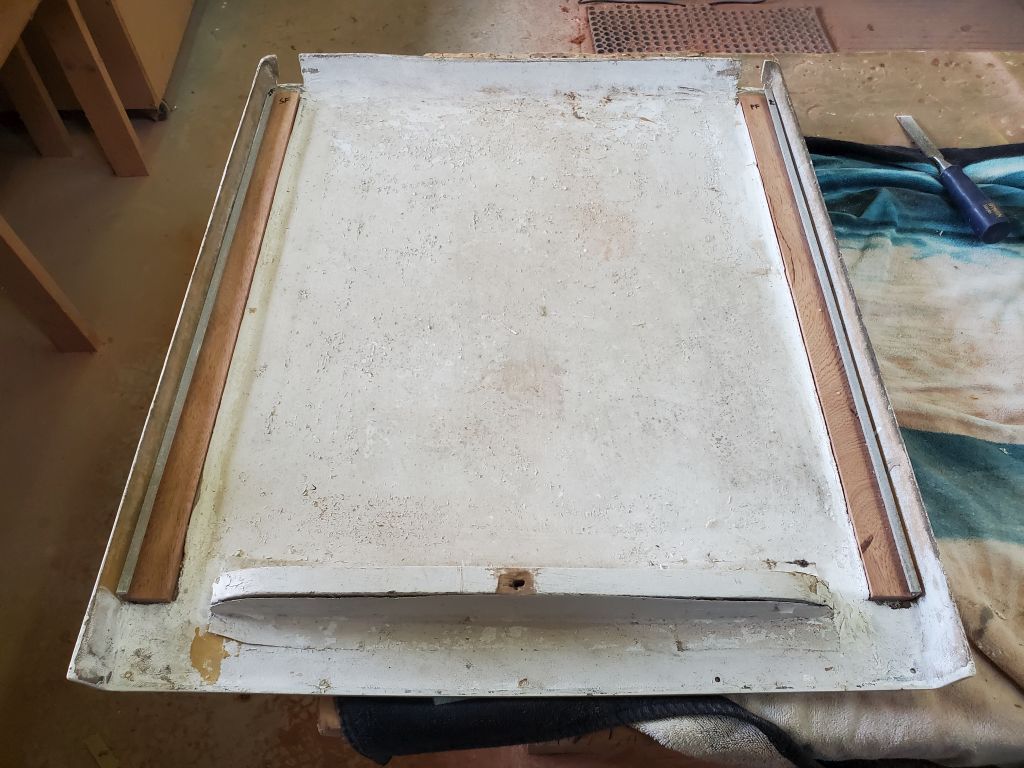
I chose to leave the lid off till after installation to make the box easier to handle. Towards that end, I got ready to install the hinge on the hatch itself. The piano hinge I’d sourced, which had extra space between the leaves when closed to allow room for a gasket, came without screw holes, so my first task was to lay out, drill, and counterbore the hinge for mounting screws. In drilling stainless, I’ve found that the key is to buy the appropriate drill bits in bulk first, to ensure ample sharp, new bits for the job. Every time I have amply prepared myself like this, a single bit easily makes all the cuts required, but if I try to use bits on hand, or if I have a single new one, the bit will break or they’ll be so dull that I spend 4 hours on a hole. I’m now flush with 11/64″ bits–a small price to pay for having a task I hate go so swimmingly.
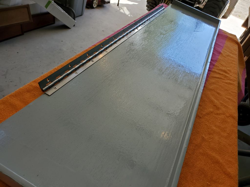
With the hinge prepared, I installed it on the underside of the hatch, then installed the gasket around the perimeter of the lid. Once the box was secure on deck I’d install the lid and some hold-downs.
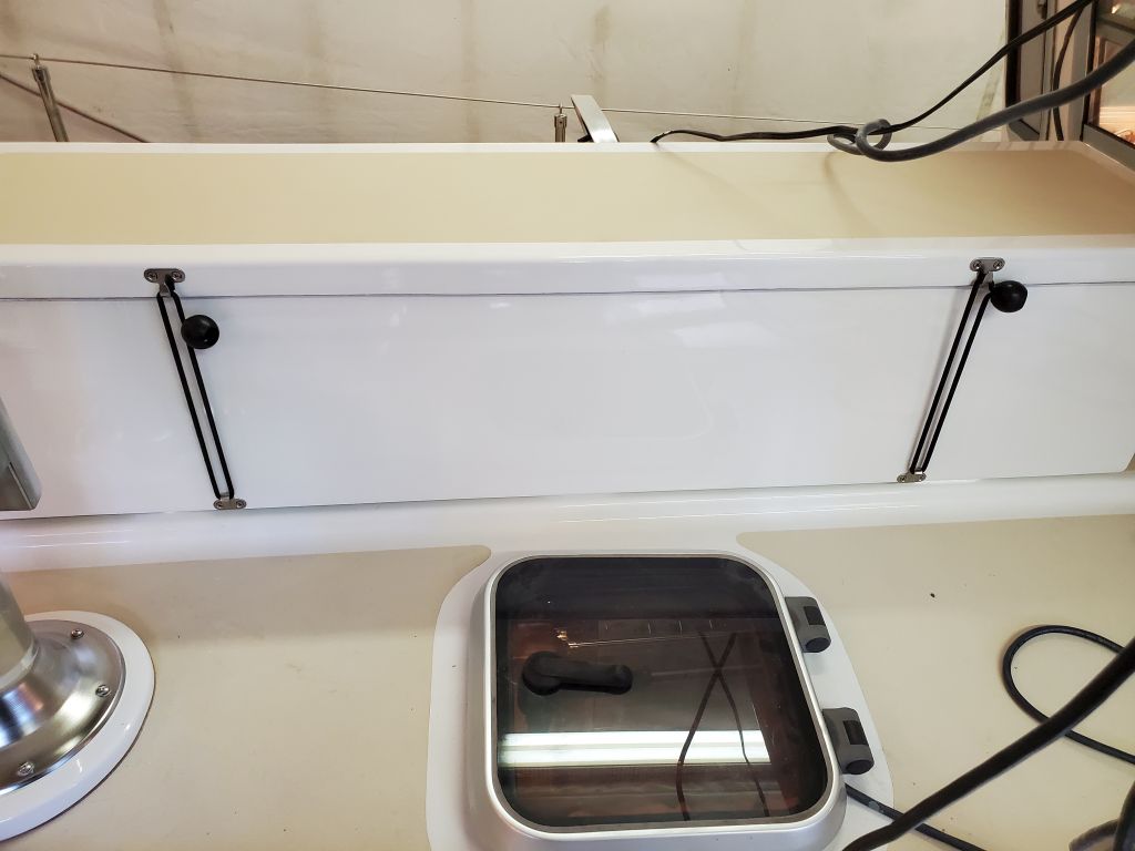
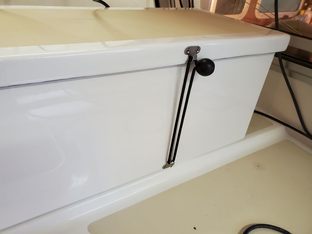
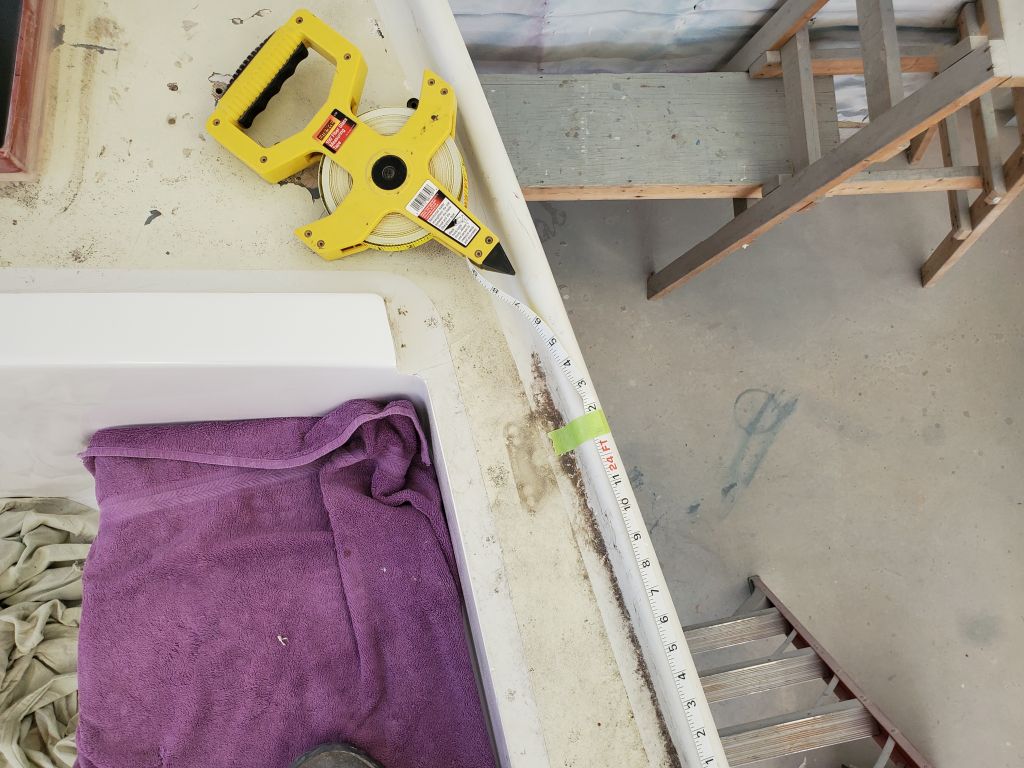
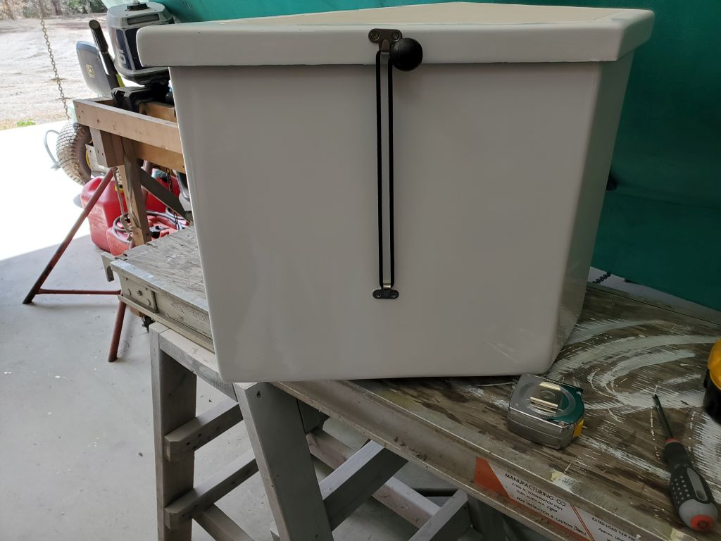
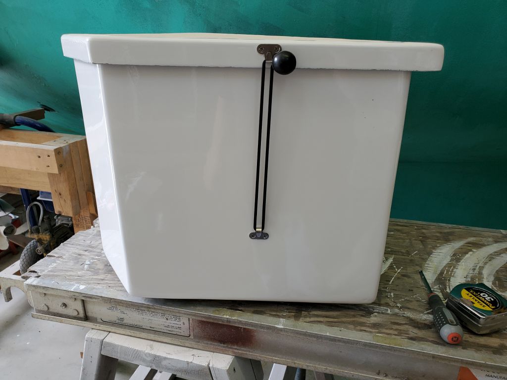
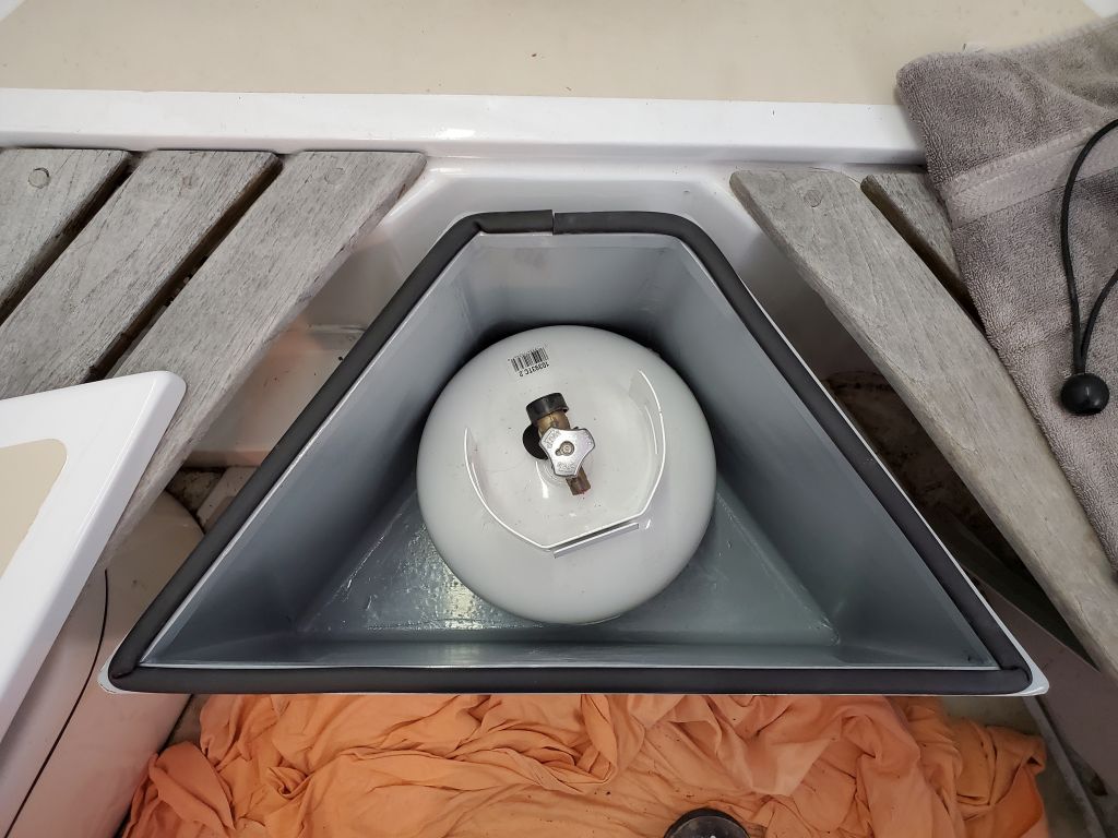
For the cockpit deck box, I installed gasket around the top of the box (I actually did this before the other deck box, and before it occurred to me that perhaps the gasket was better suited on the hatch than the rim of the box), then installed some little brackets to secure bungee cords, which were the owner’s suggestion of a simple, effective means of securing the lids on these boxes. I like dead-simple things that work too.
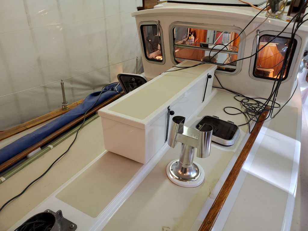
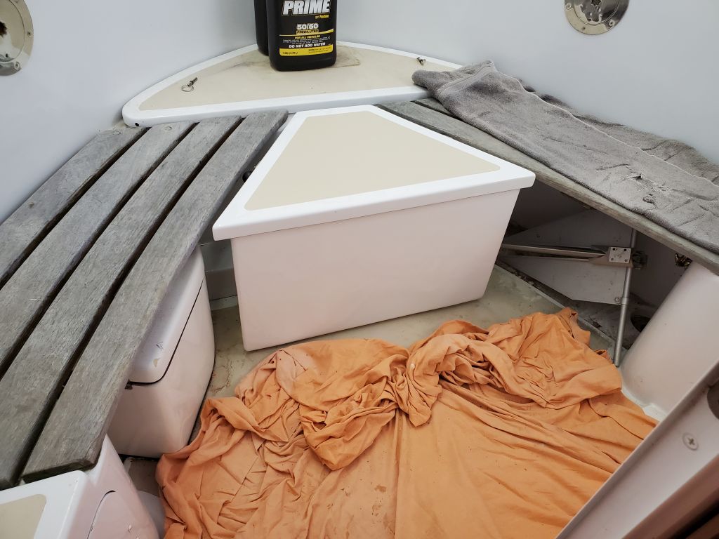
This done, I “installed” the box in the cockpit: This was just to sit of its own accord, assisted by the rubber pads I’d installed on the feet. This would work here because the cockpit was so small, and so protected, that under the known circumstances of how the boat was used there was really no scenario where the box wouldn’t stay in place like this.
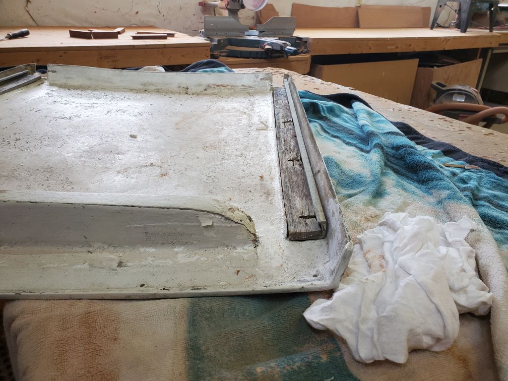
To finish off the day, I removed the door to the head, which the owner said swelled up and stuck badly at the bottom during the summer and when the boat was in the water (it worked fine now), and cut more than 1/4″ off the bottom before reinstalling it (no pictures).
Total time billed on this job today: 6.5 hours
0600 Weather Observation: Clear, 35°. Forecast for the day: Sunny, 65°