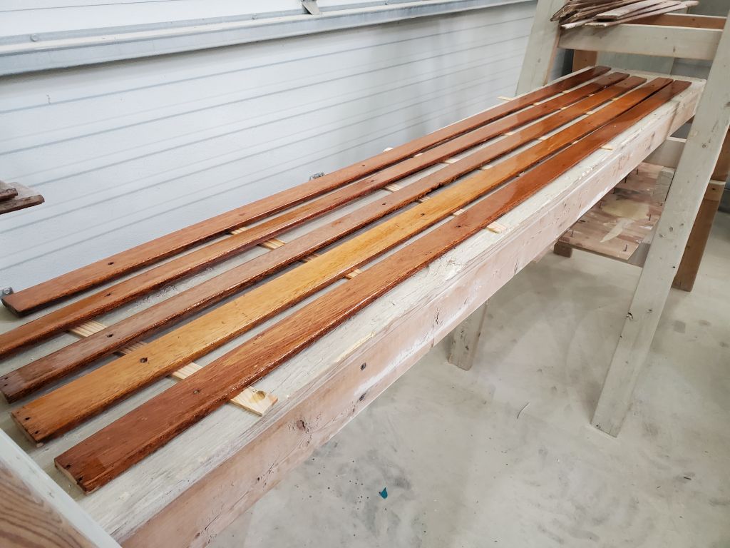
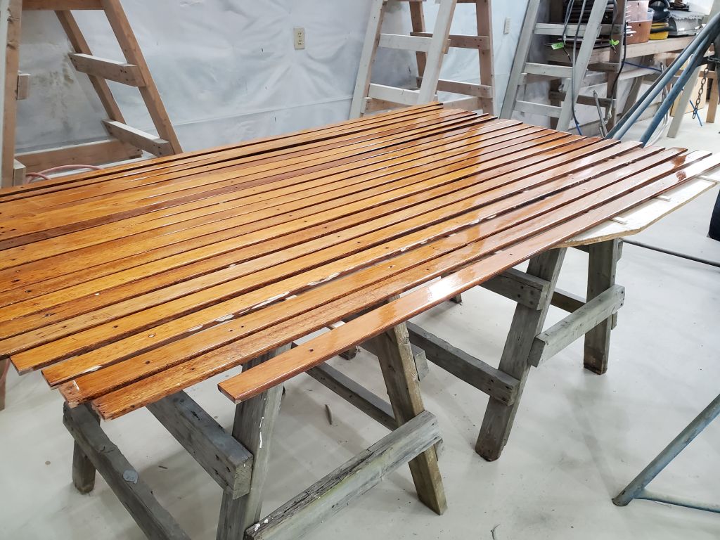
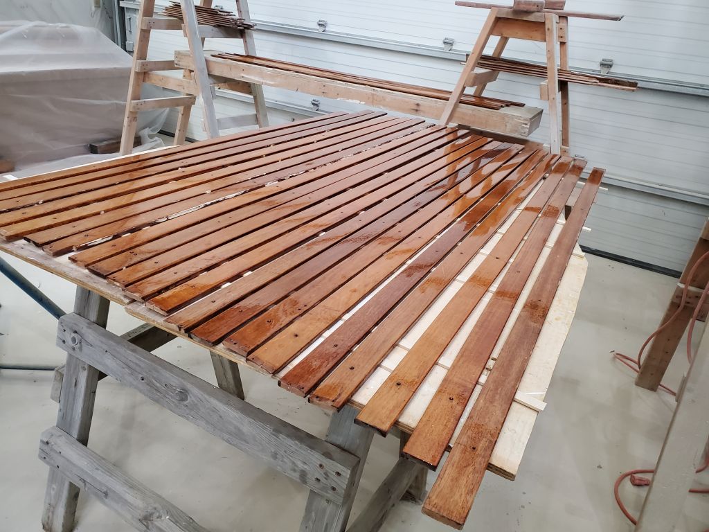
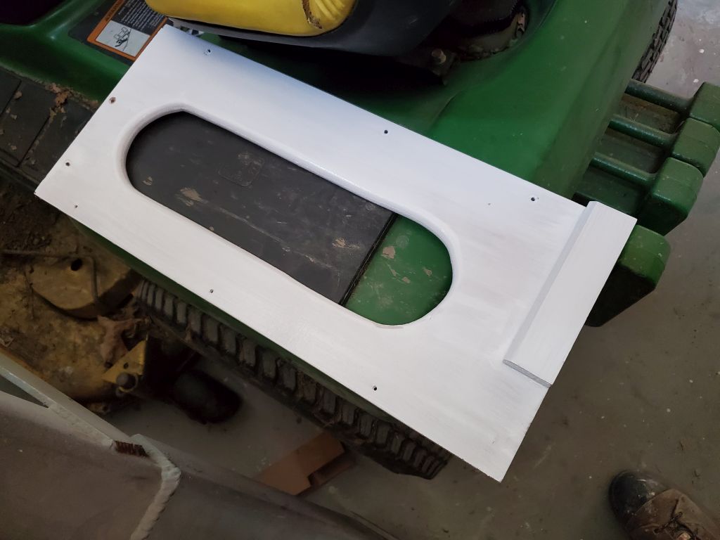
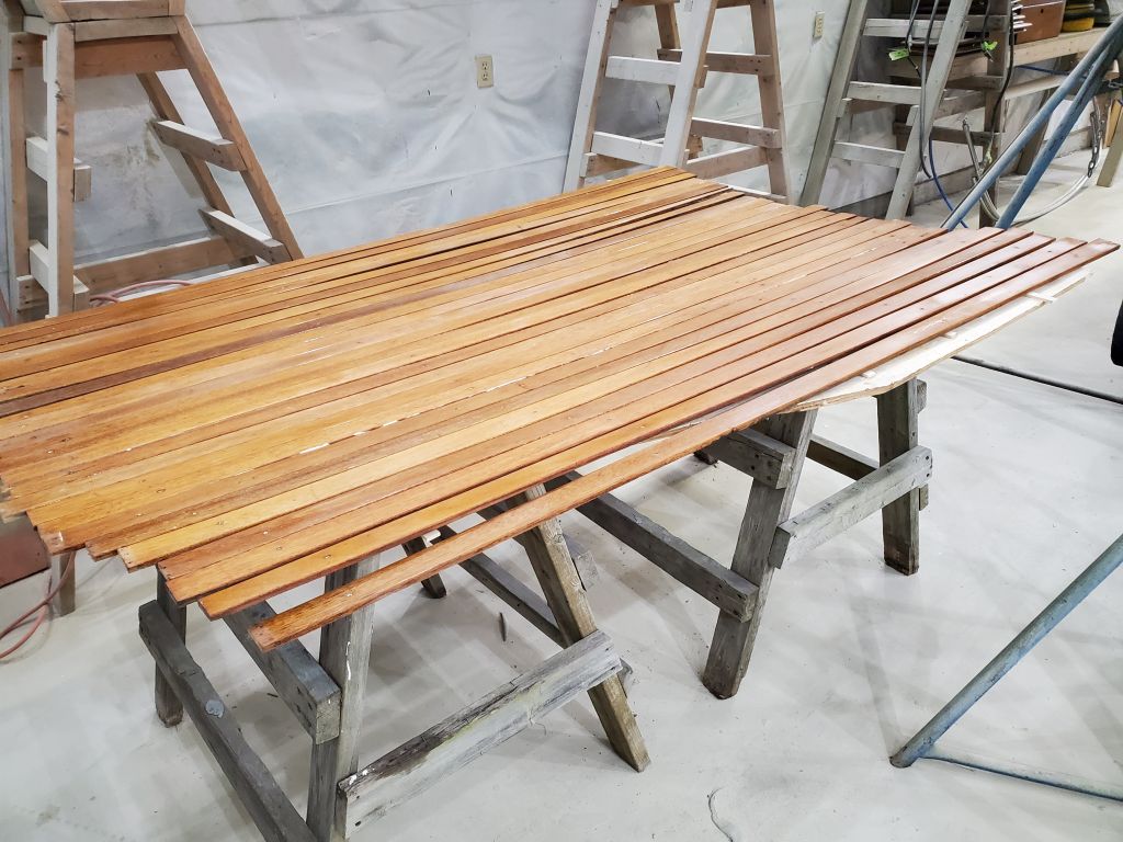
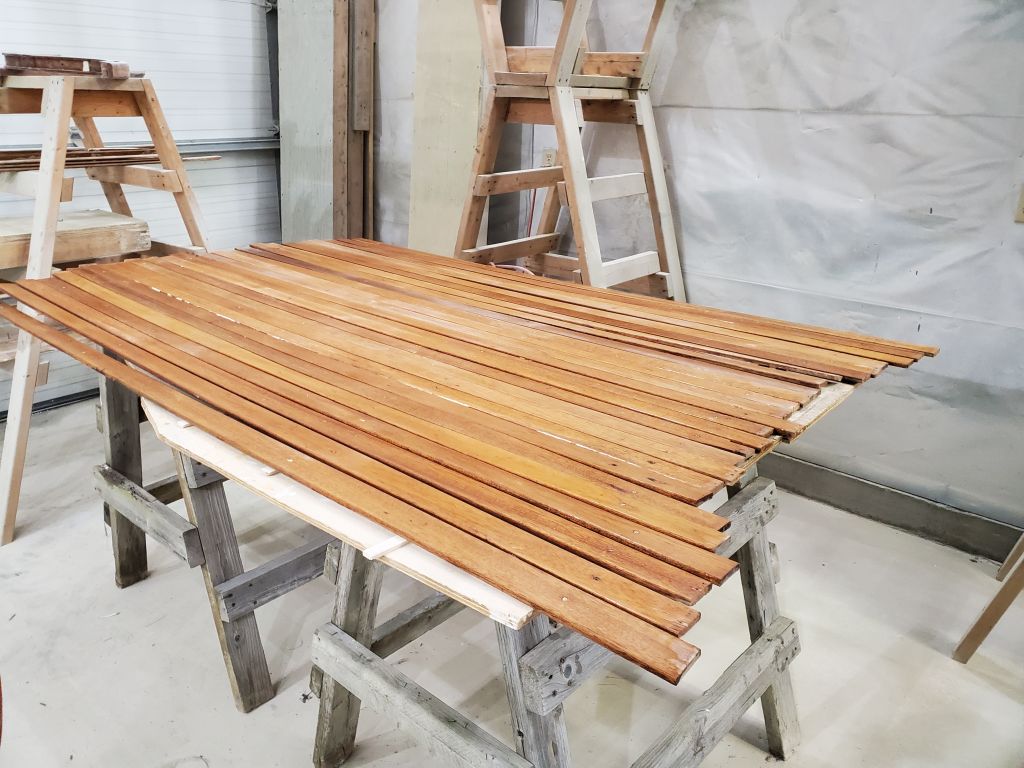
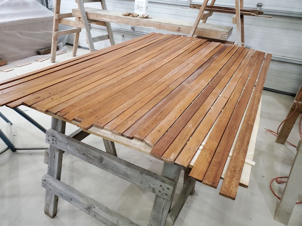
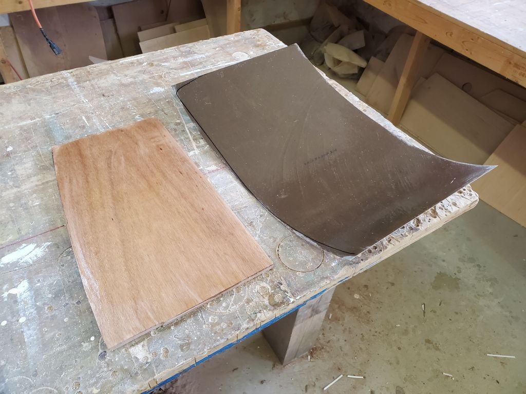
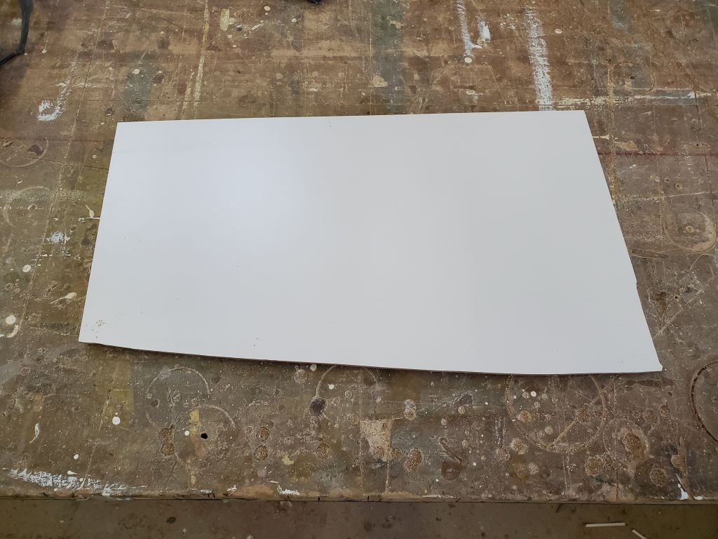
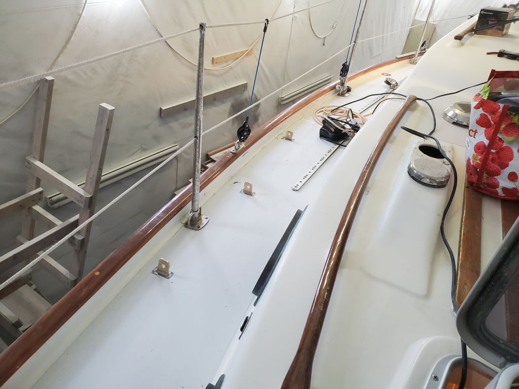
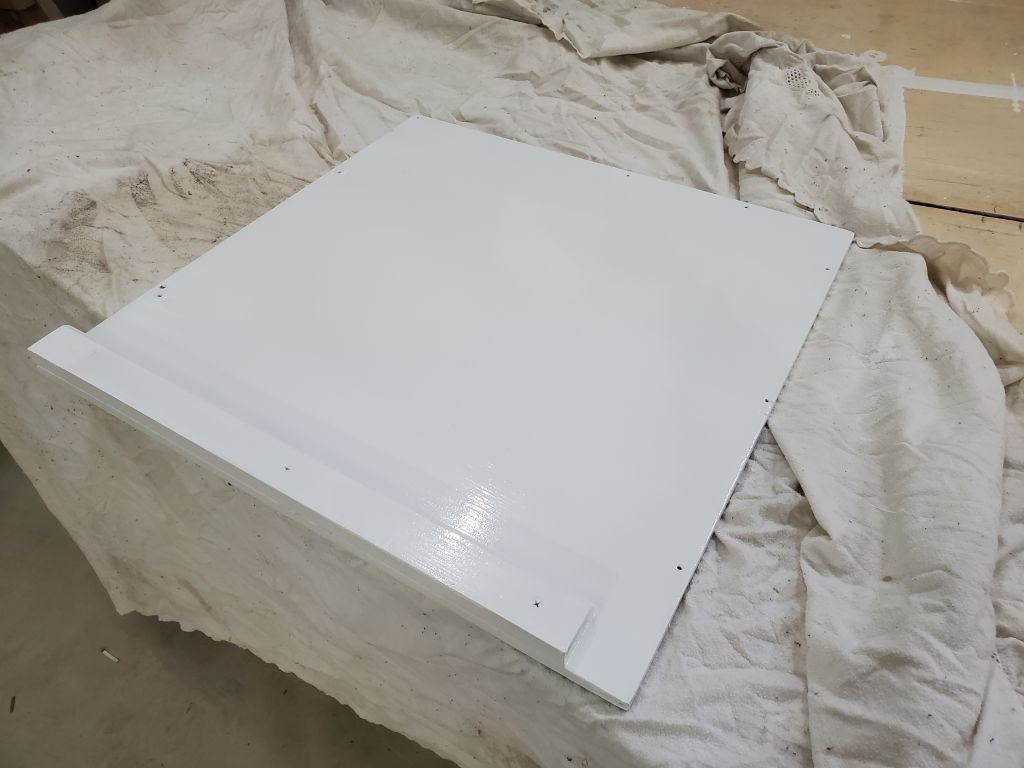
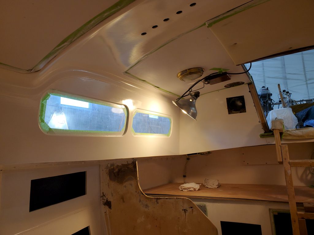
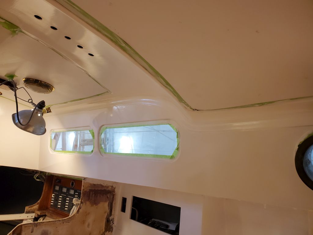
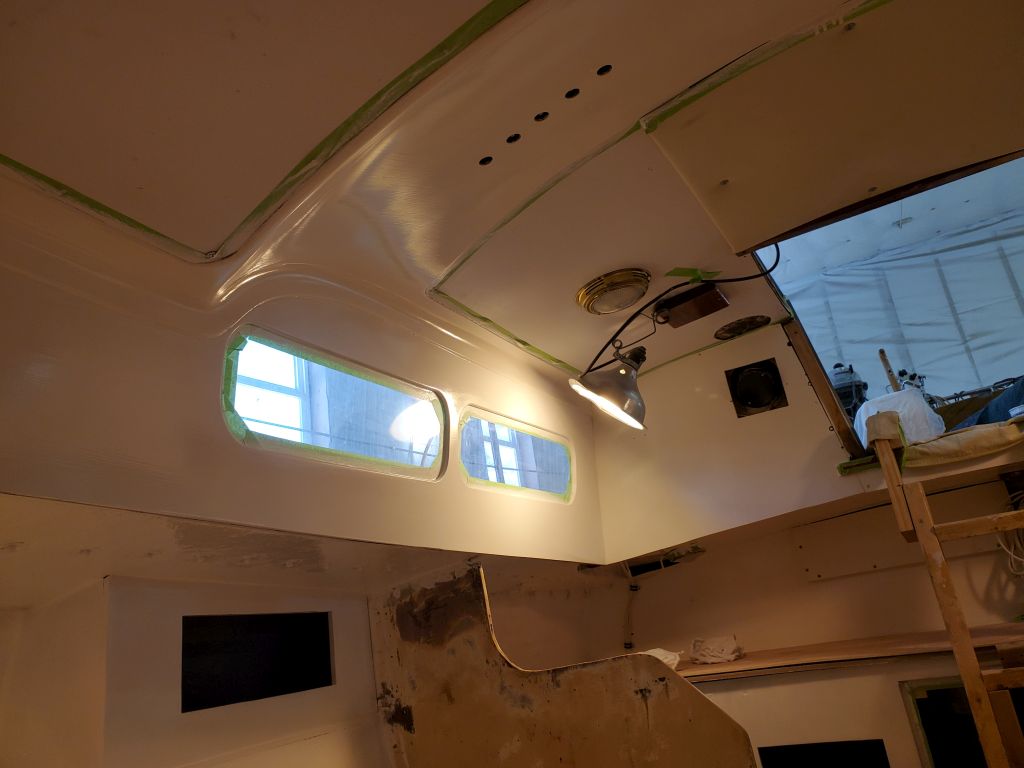
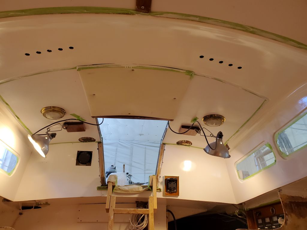
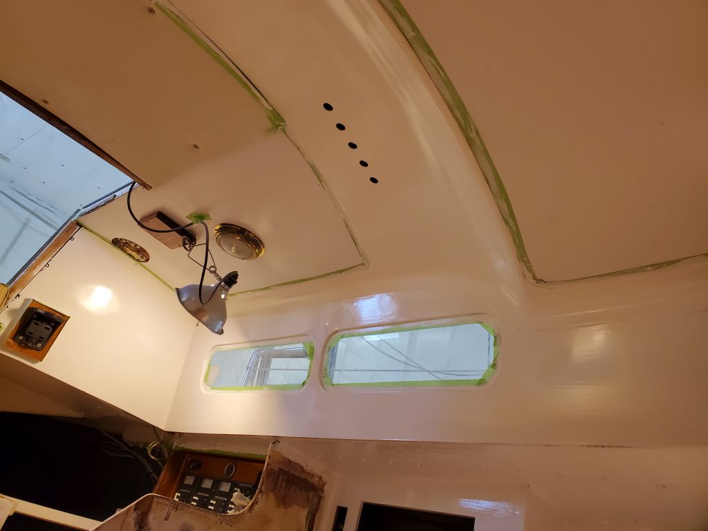
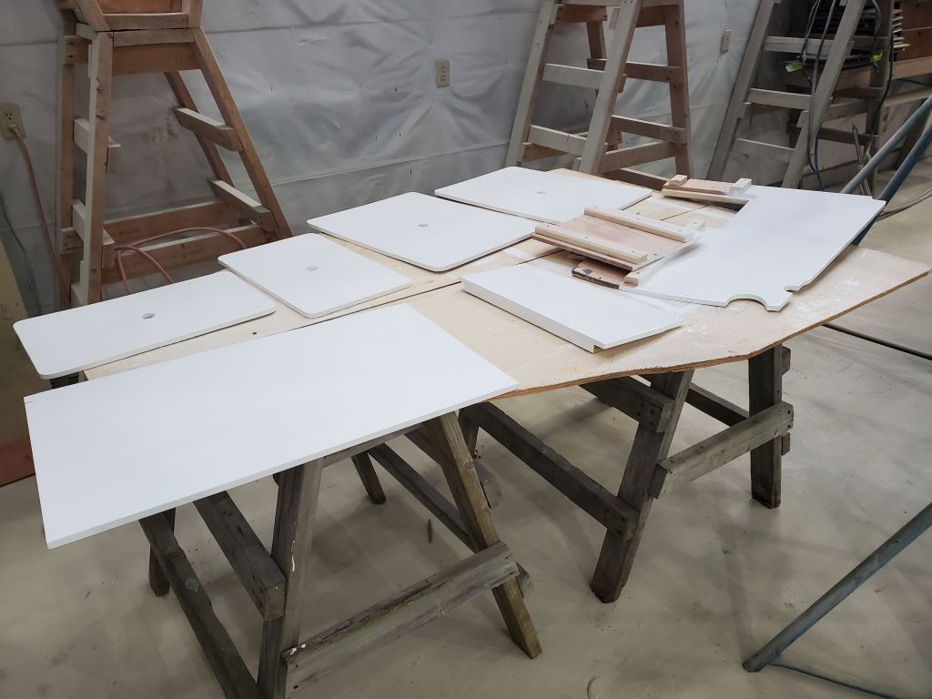
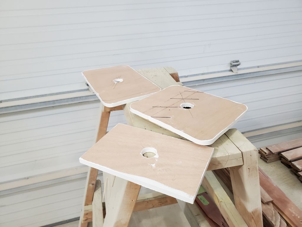
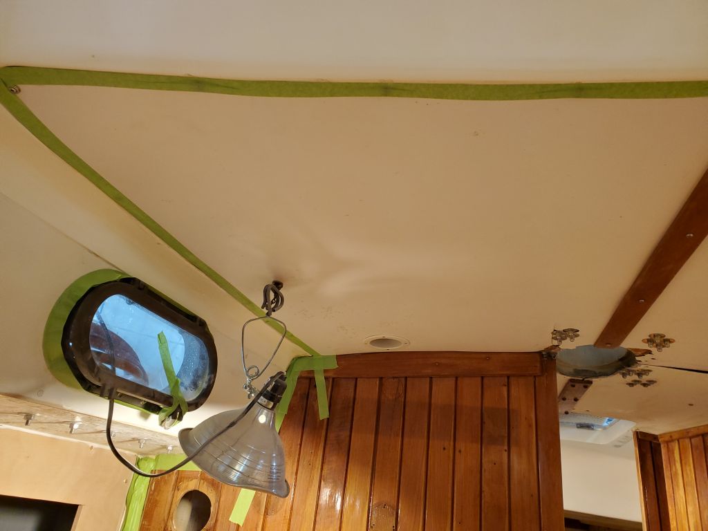
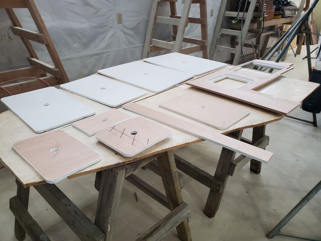
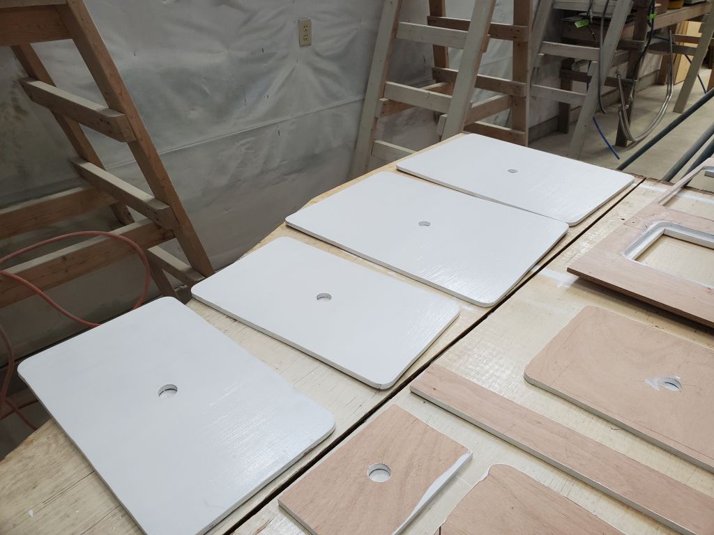
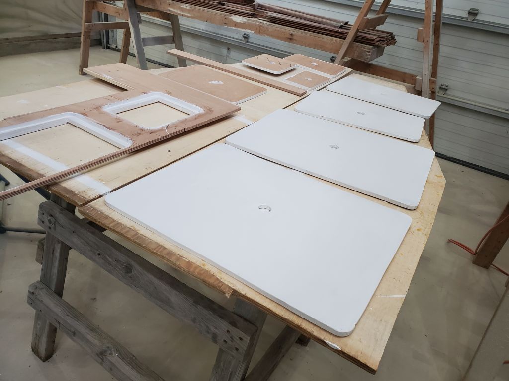
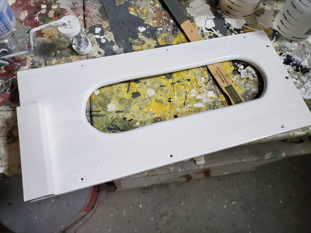
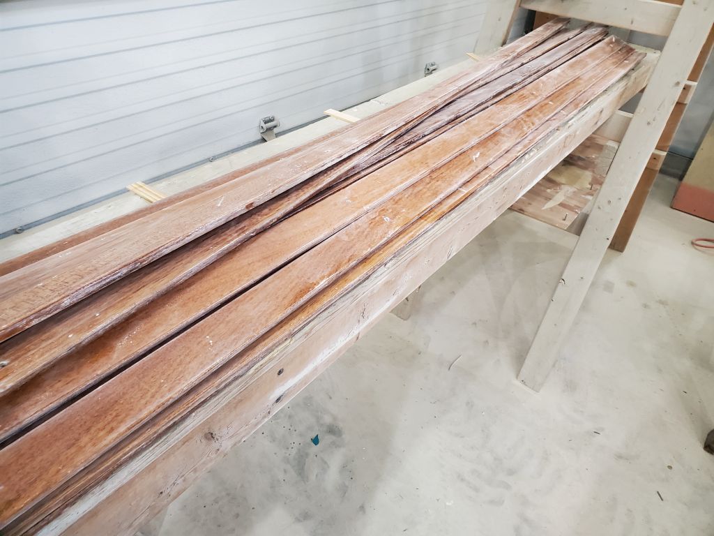
I started with some quick rounds of light sanding: the head and forward cabin areas I’d primed several days before, and the mahogany ceiling strips from the forward cabin. Getting this sanding out of the way would ensure it’d be straightforward for the next coats whenever time made itself available. For now, I didn’t bother cleaning or re-laying out the ceiling strips as I knew I’d be making some dust in the boat later. I also gave a quick sand and first coat of finish paint to the lonely refrigerator panel I’d been working on.
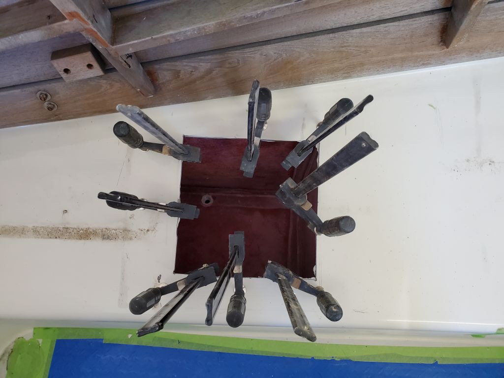
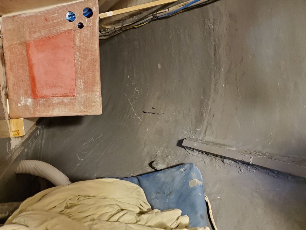
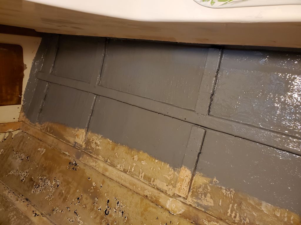
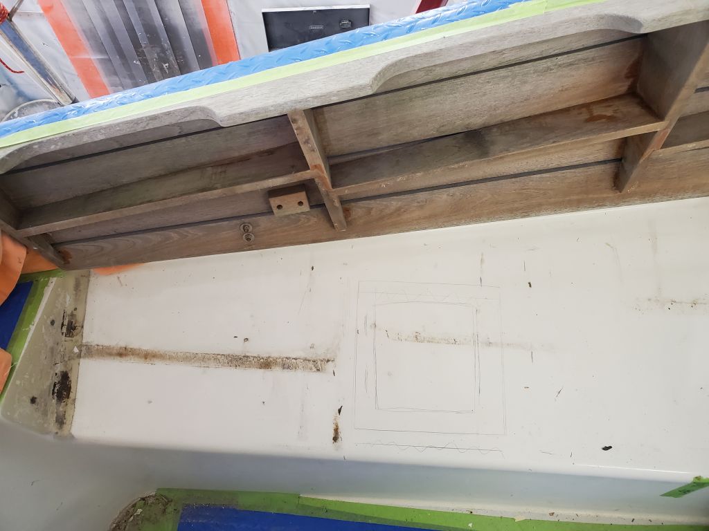
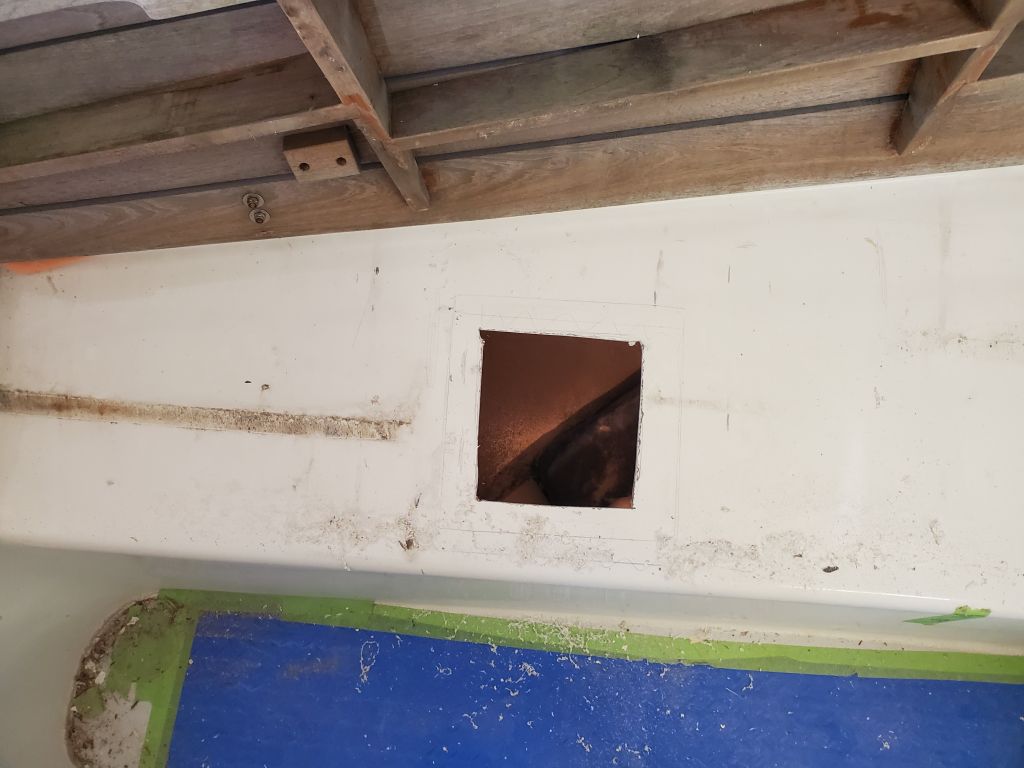
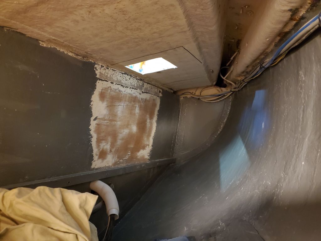
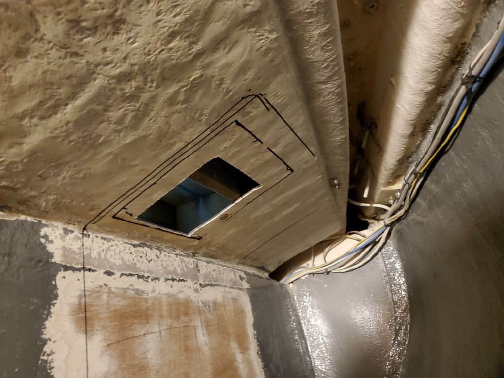
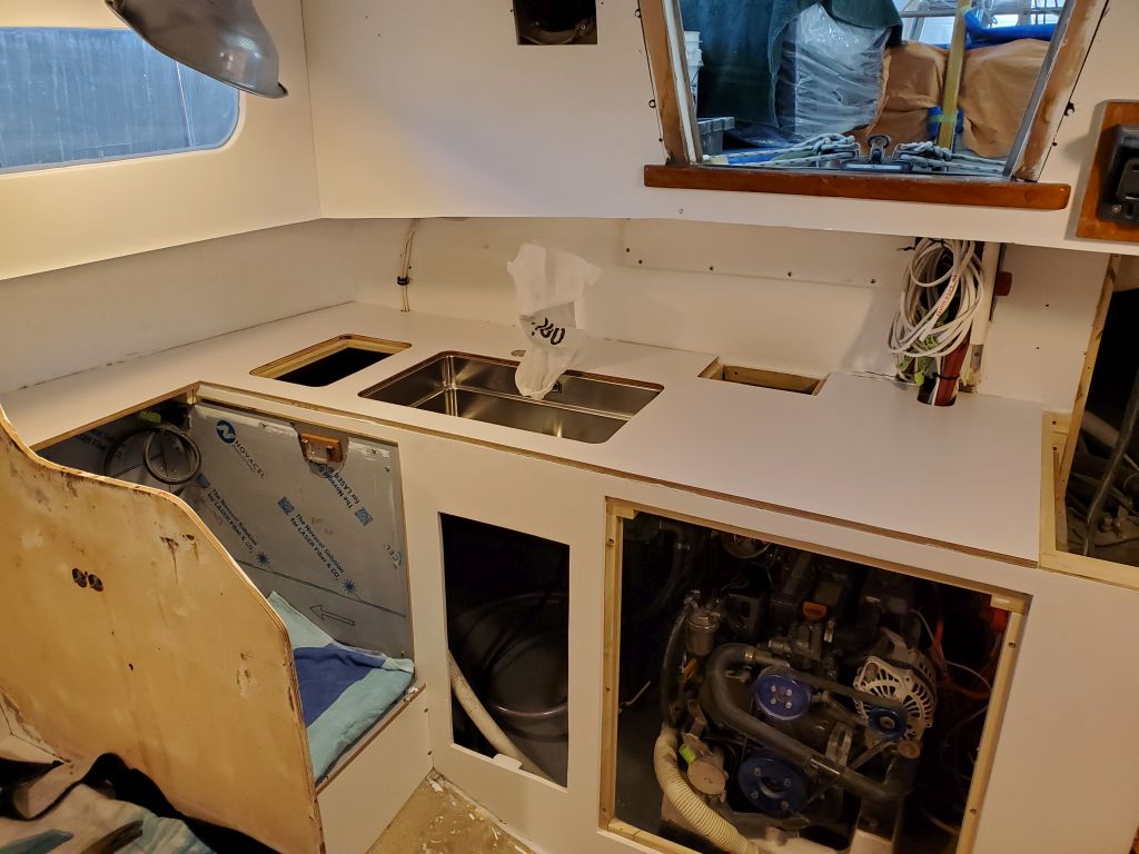
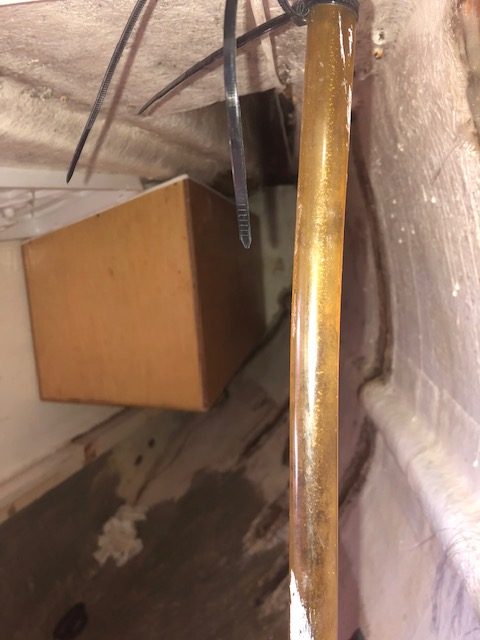
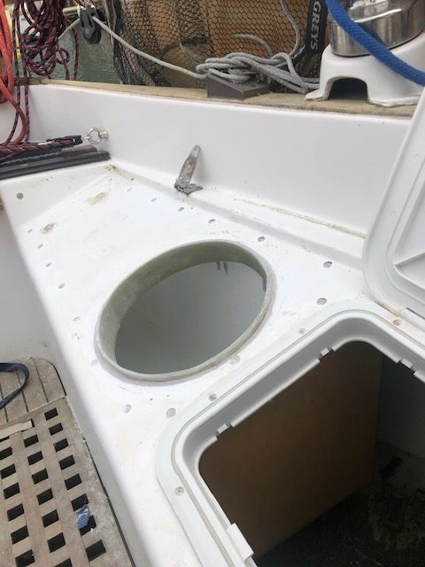
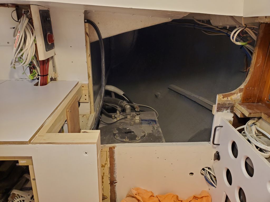
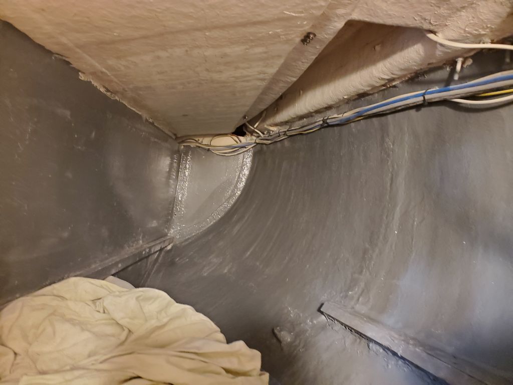
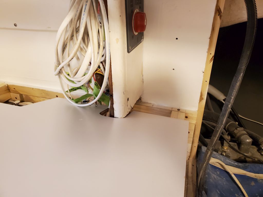
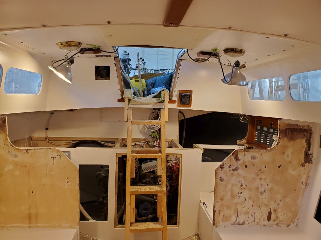
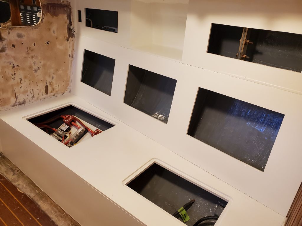
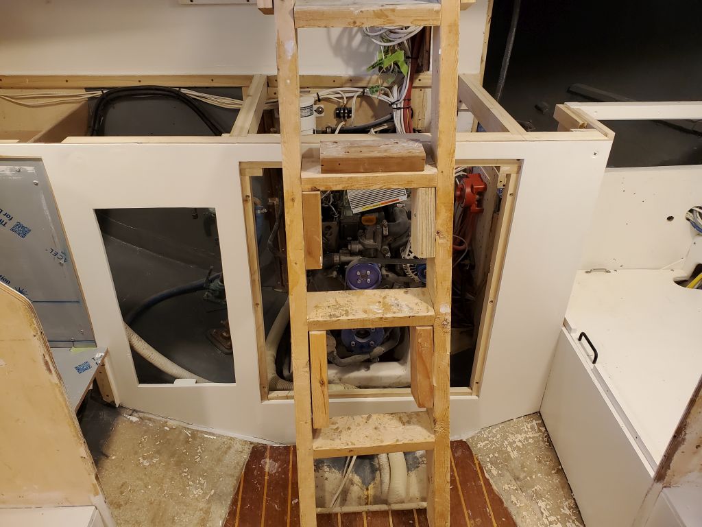
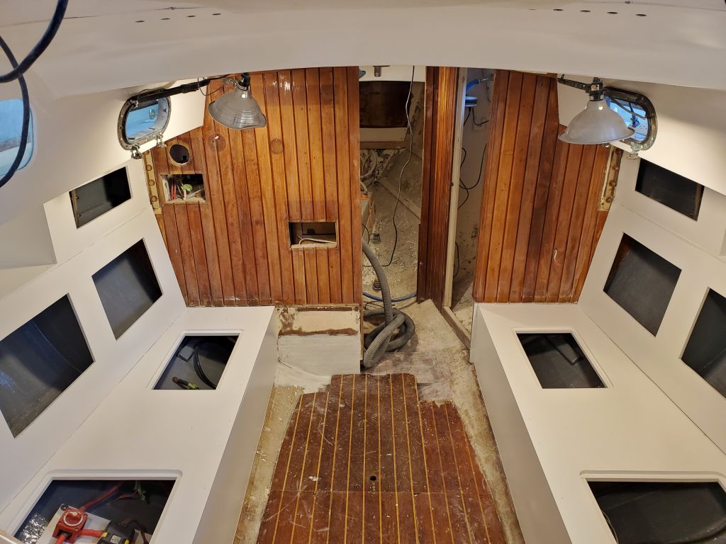
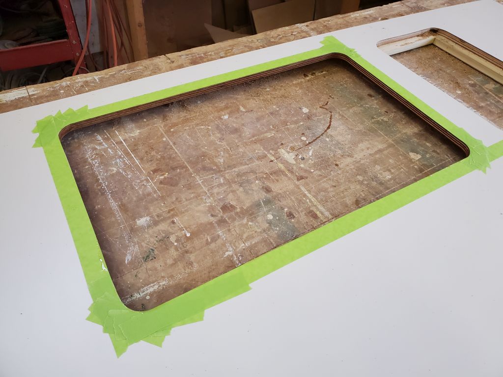
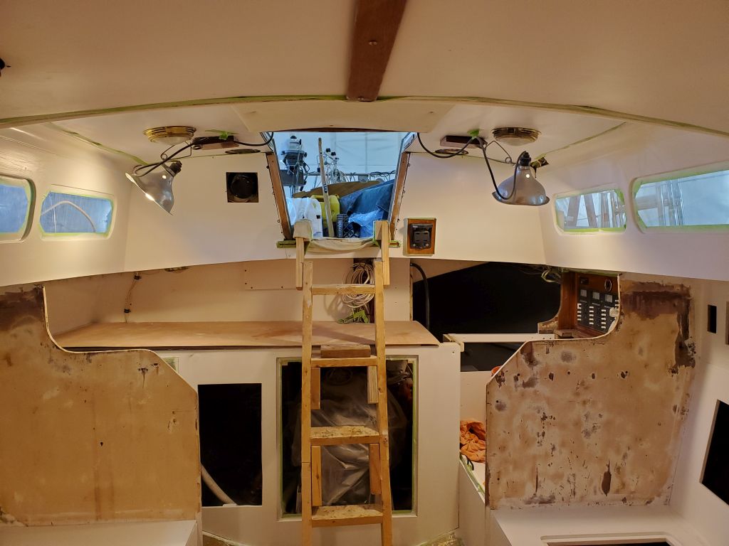
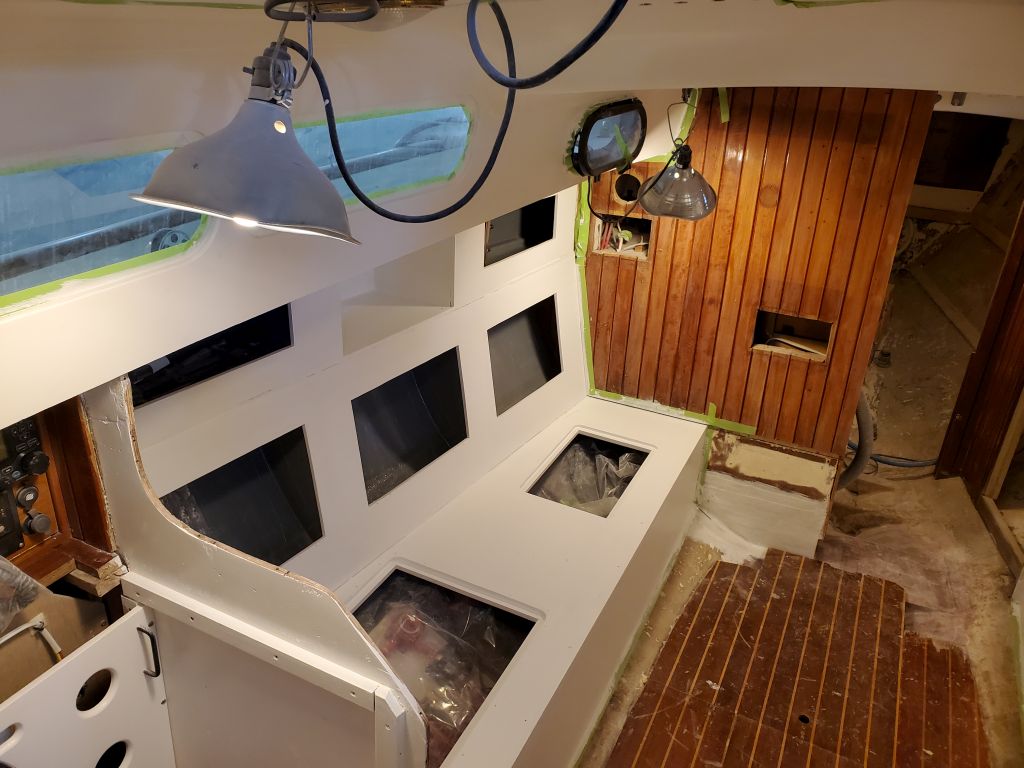
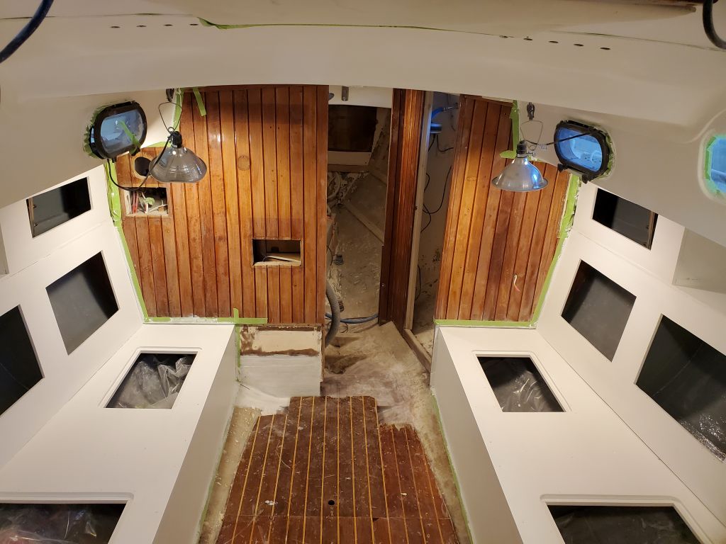
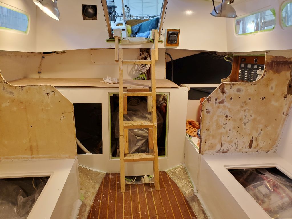
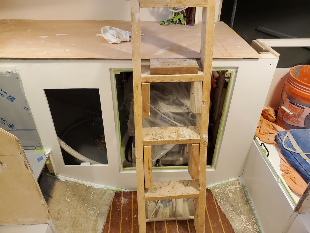
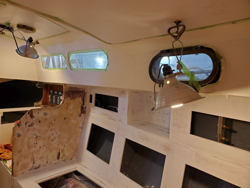
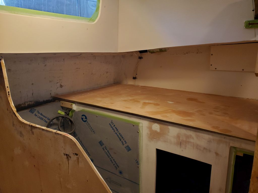
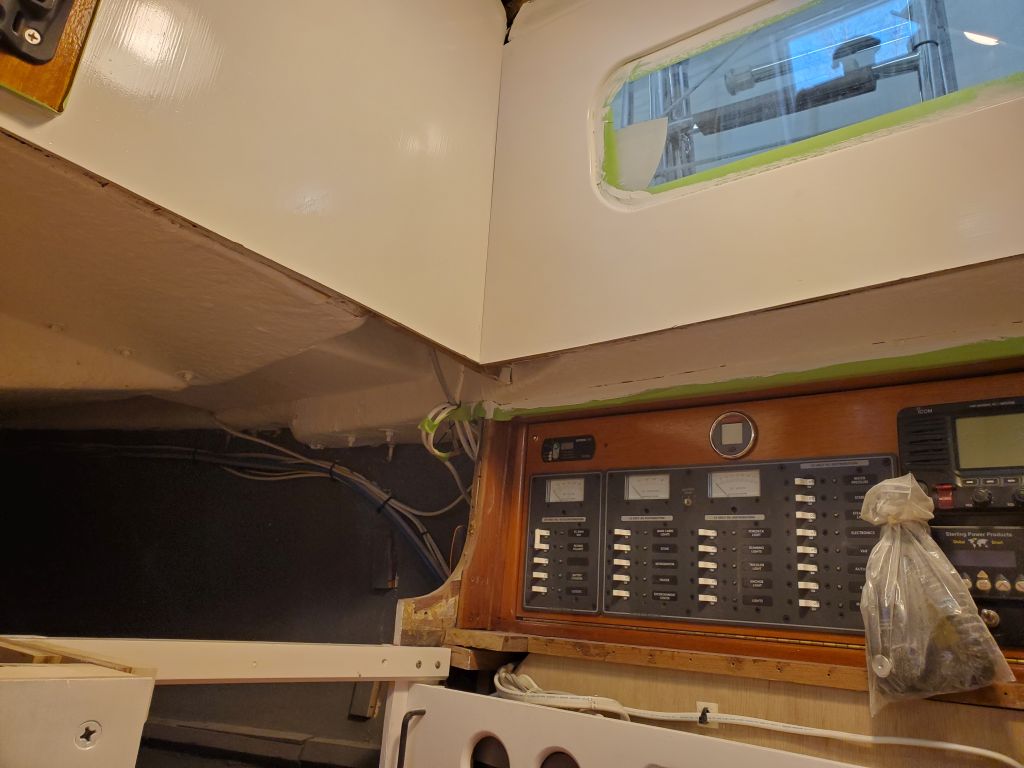
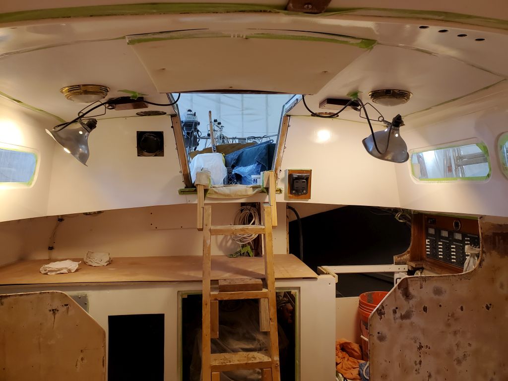
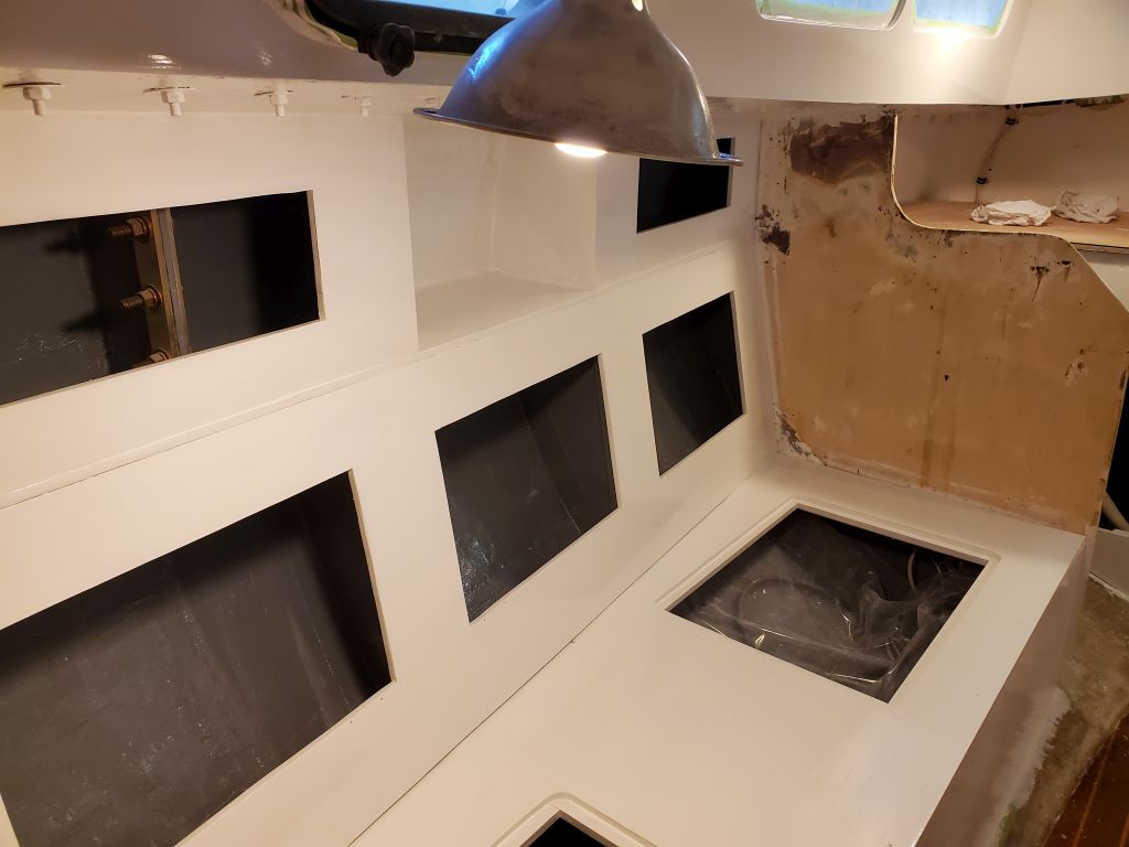
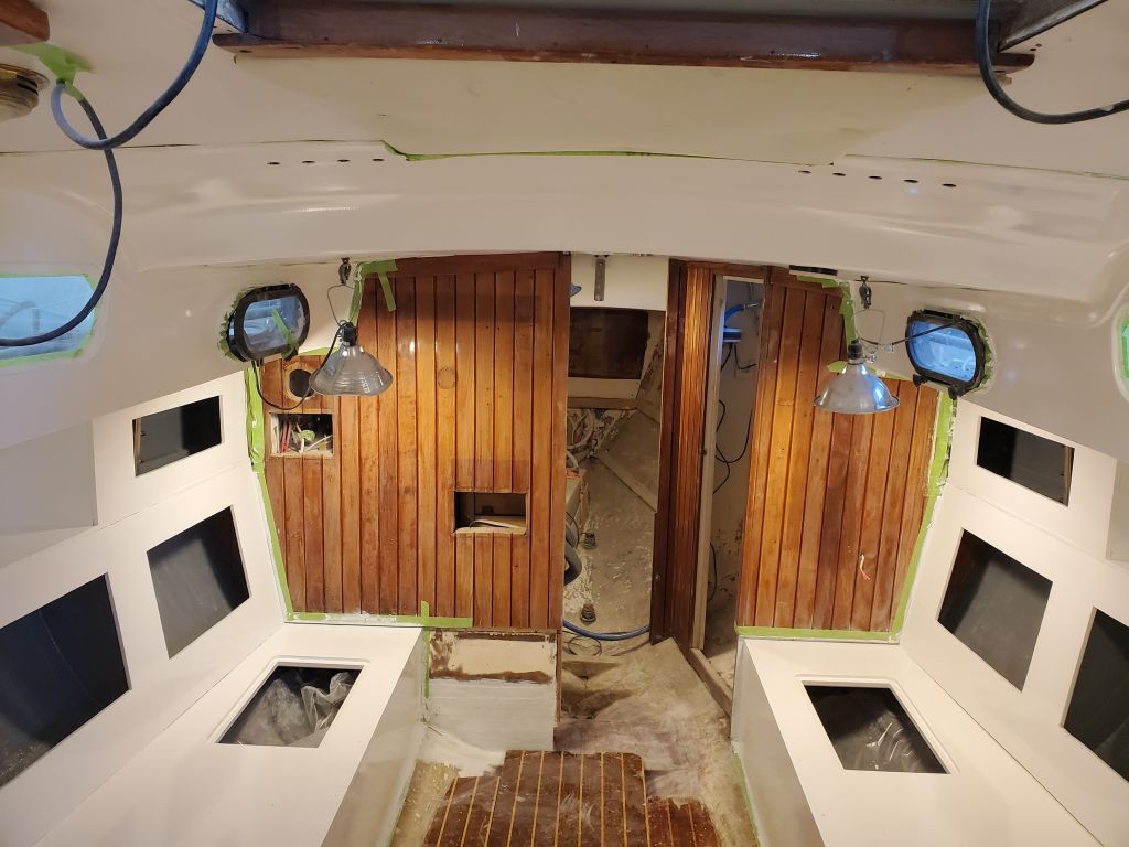
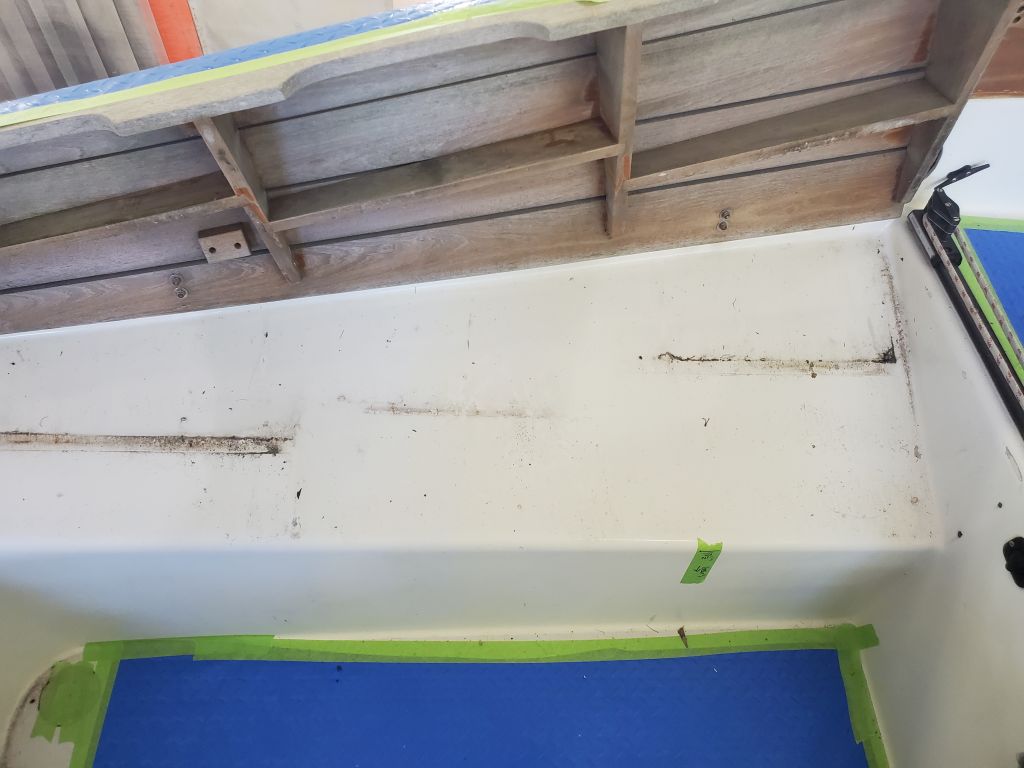
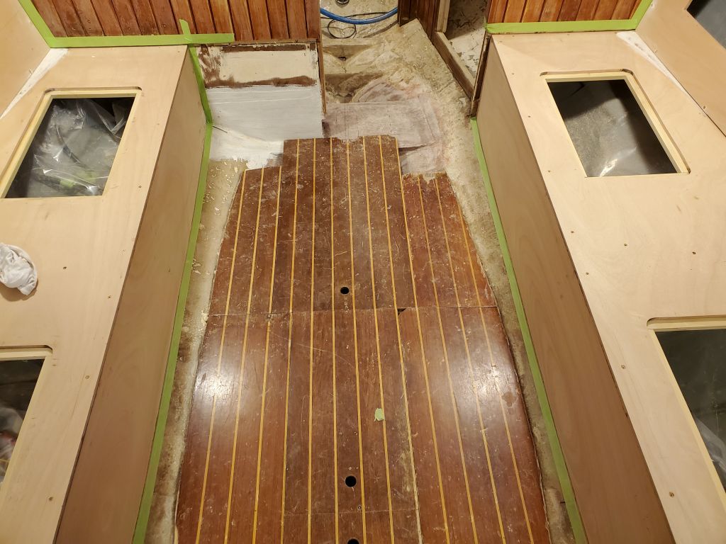
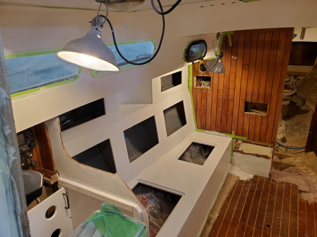
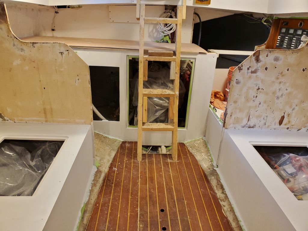
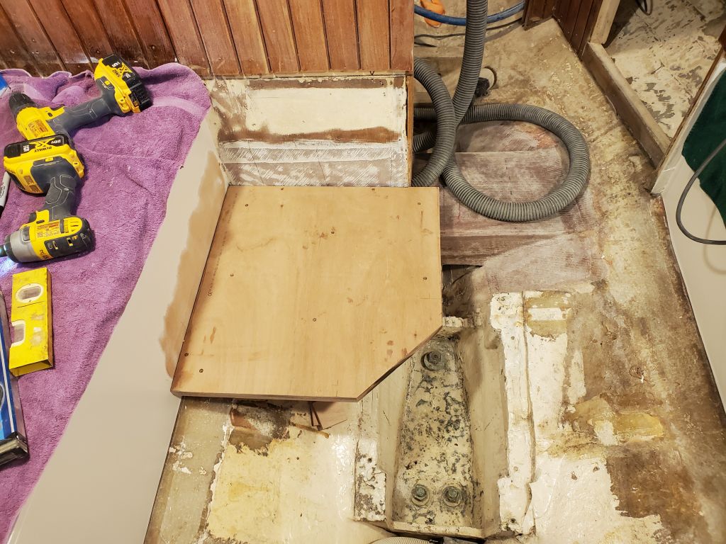
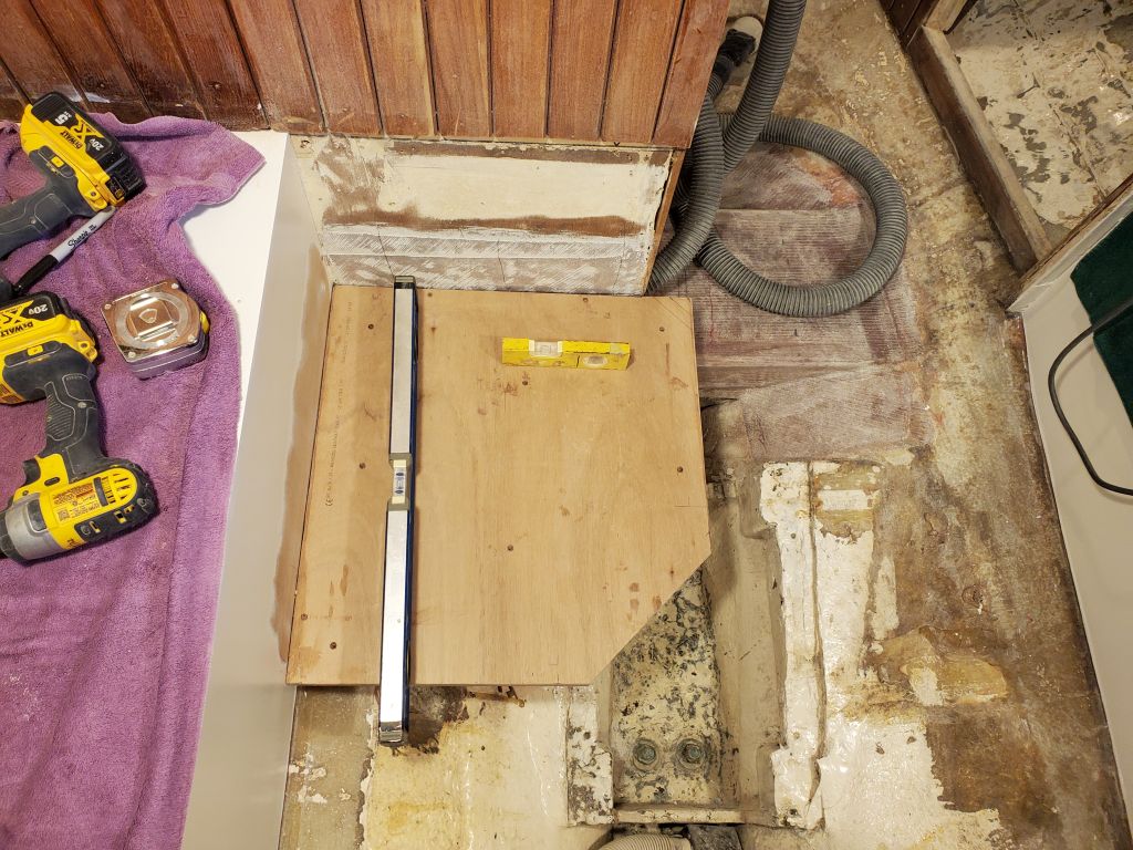
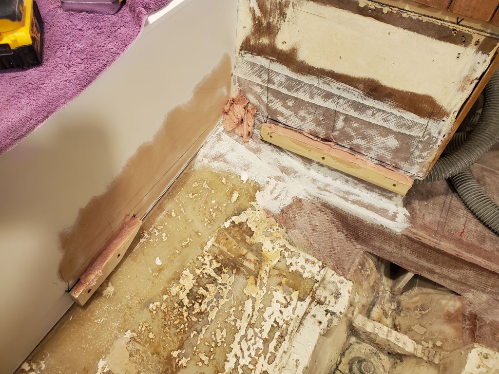
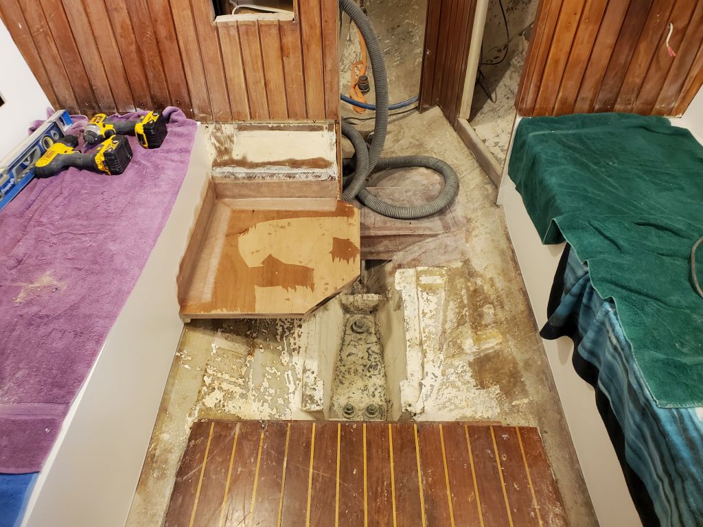
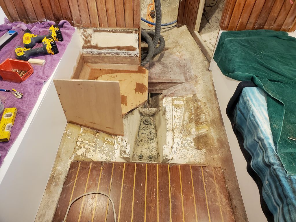
I spent most of the day working on the battery box, which would become part of the port settee in the main cabin. I’d previously built the 1″ thick laminated platform to hold the batteries. Now, I prepared the main cabin by removing the cabin sole in way of the battery location. This happened to be a separate section of sole and came out by hand without any effort, including the cross beams. I cleaned up the dust and detritus that had made its way beneath the sole during other parts of the project so far.
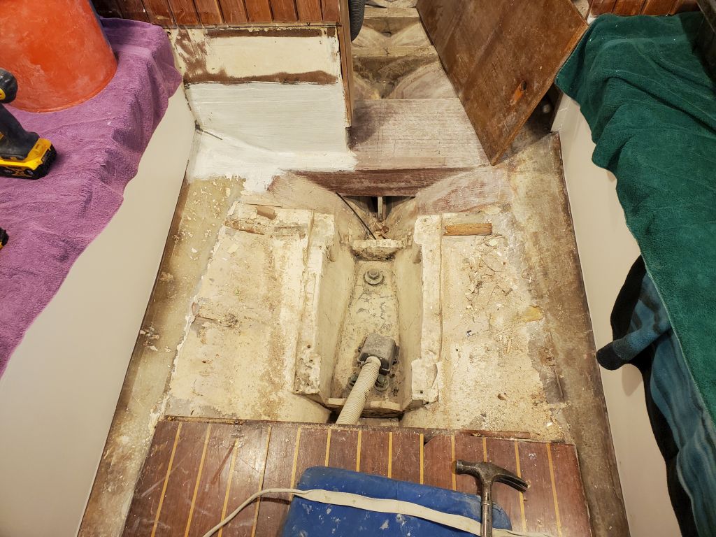
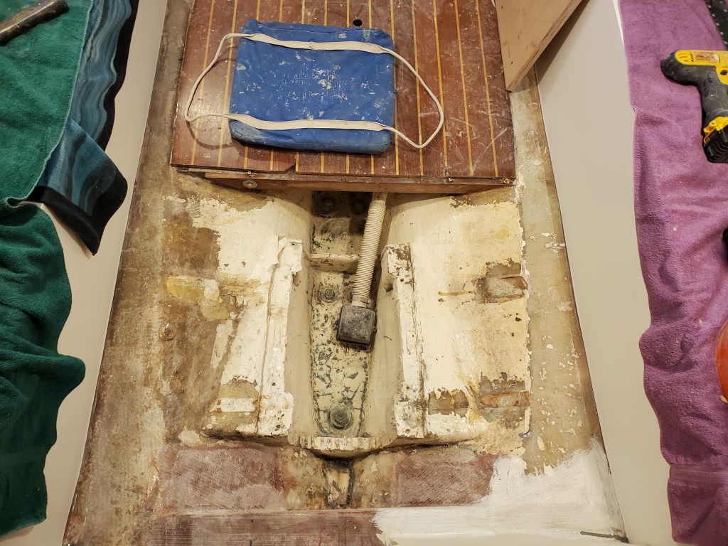
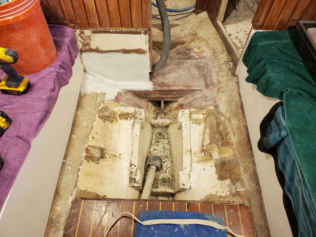
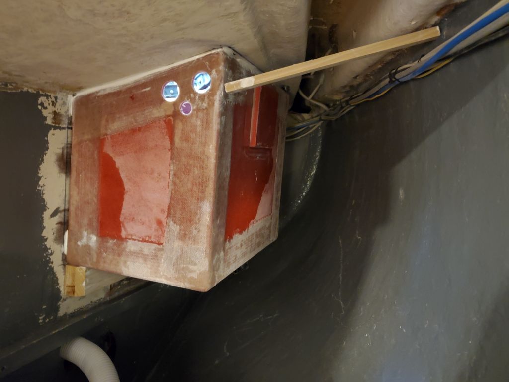
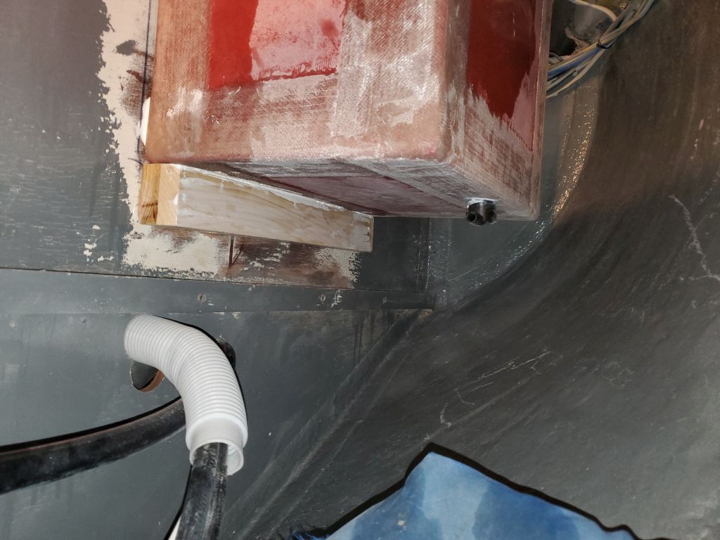
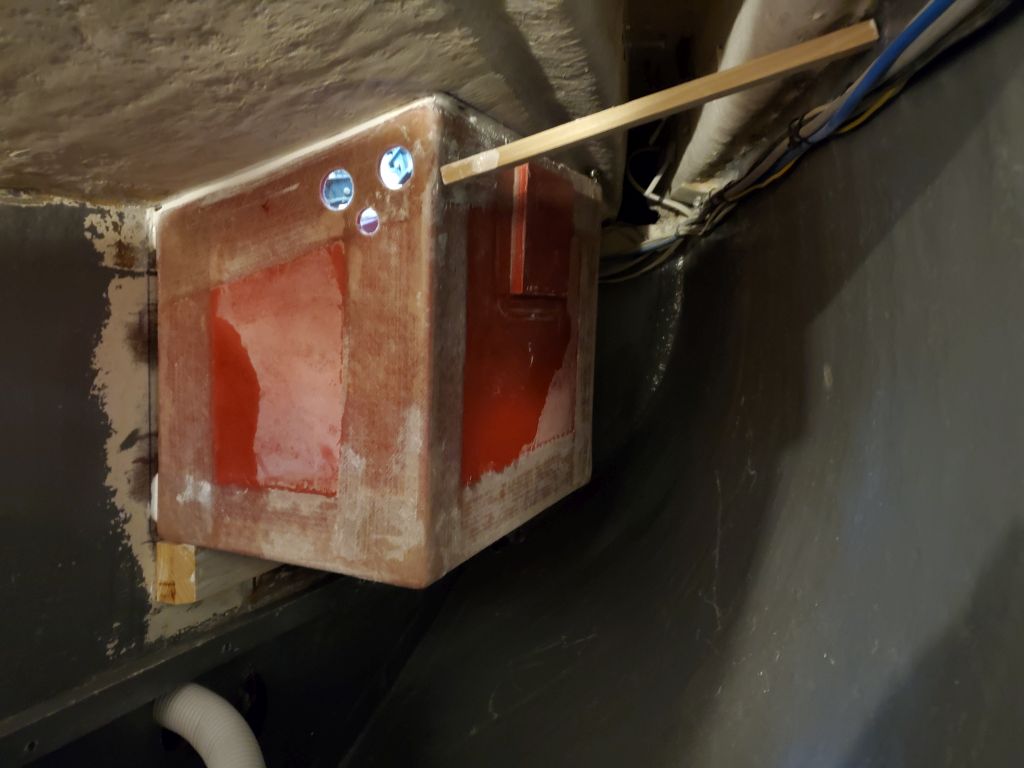
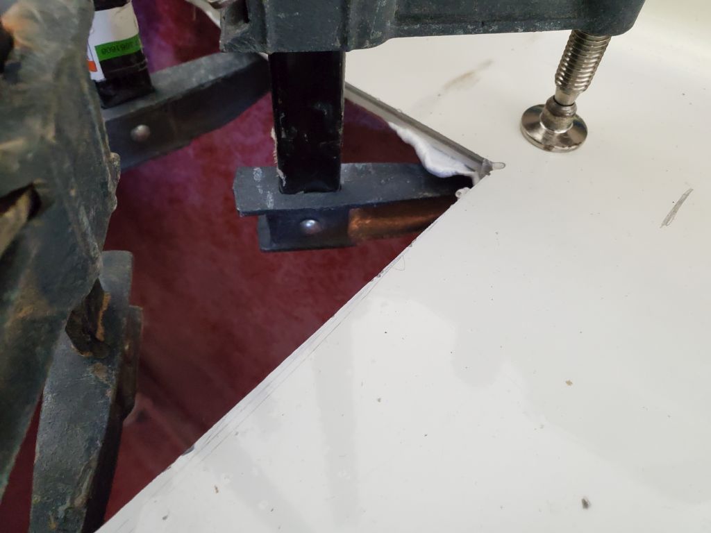
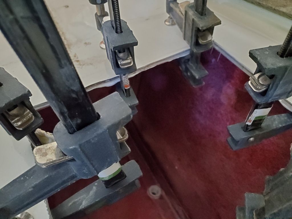
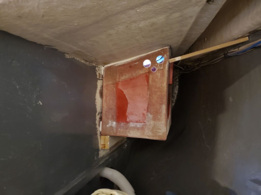
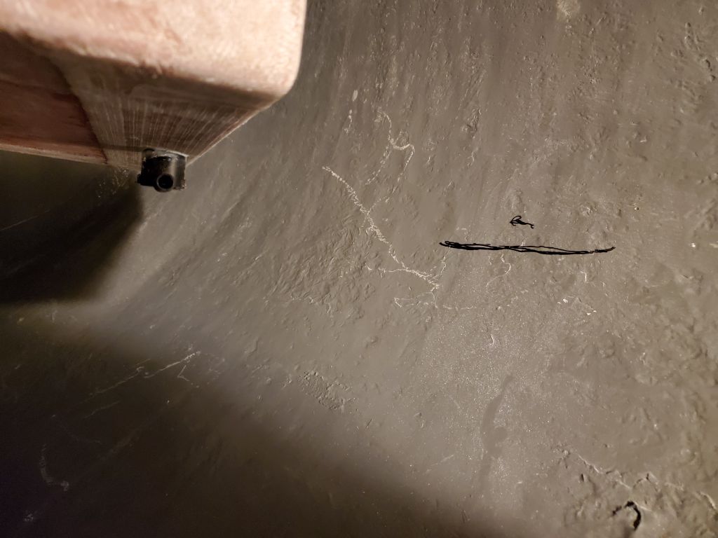
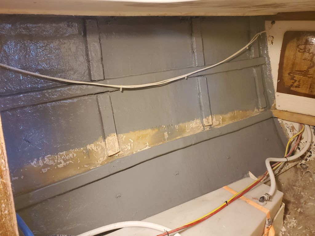
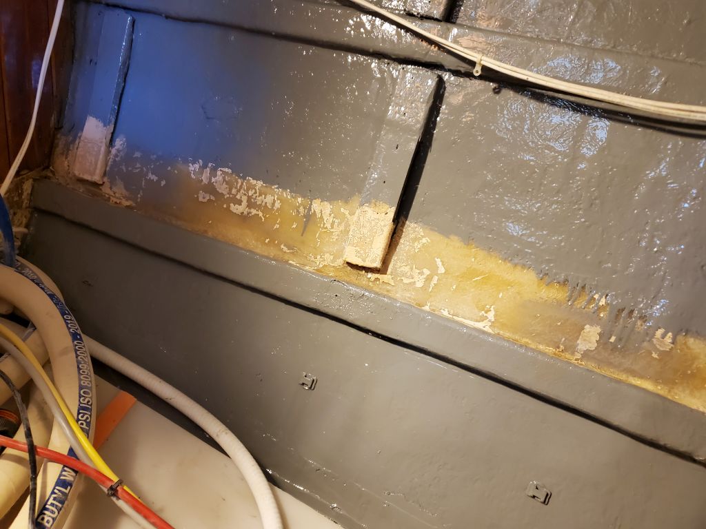
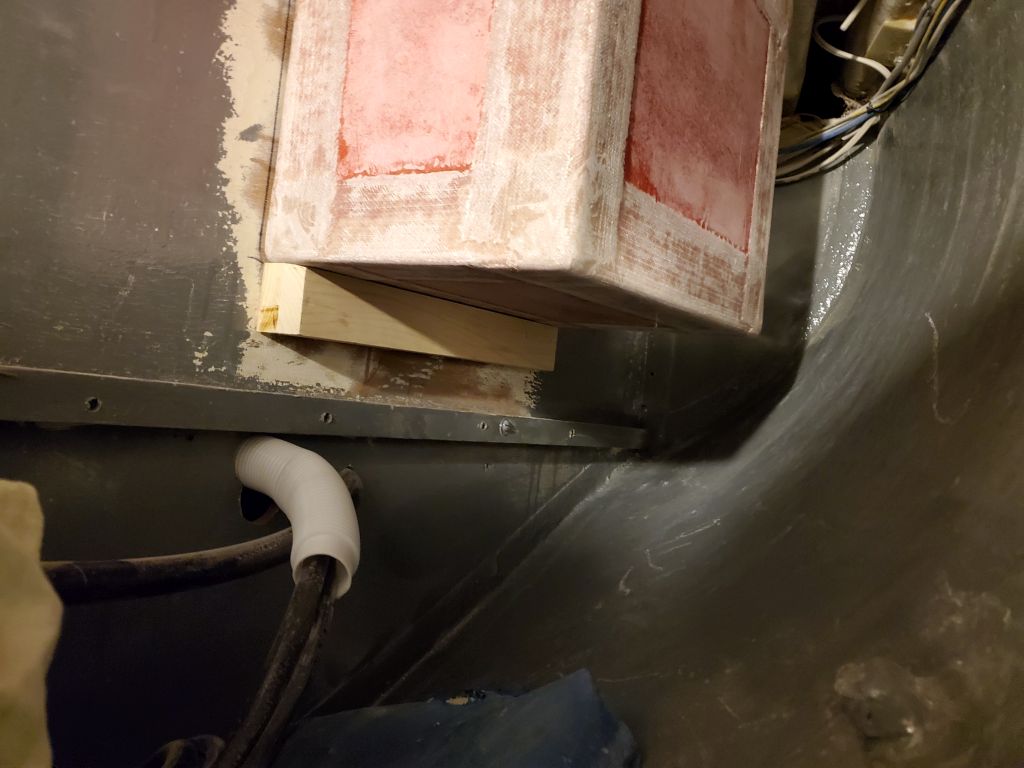
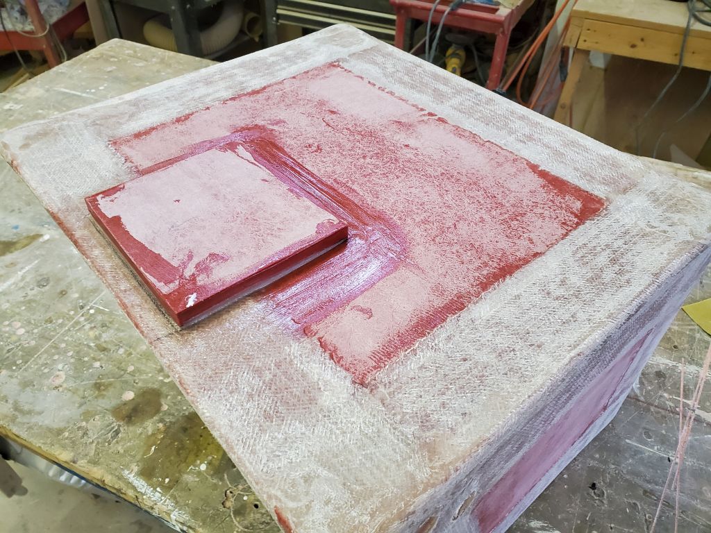
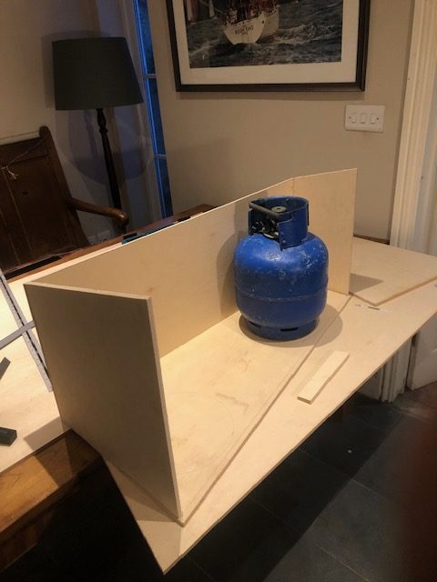
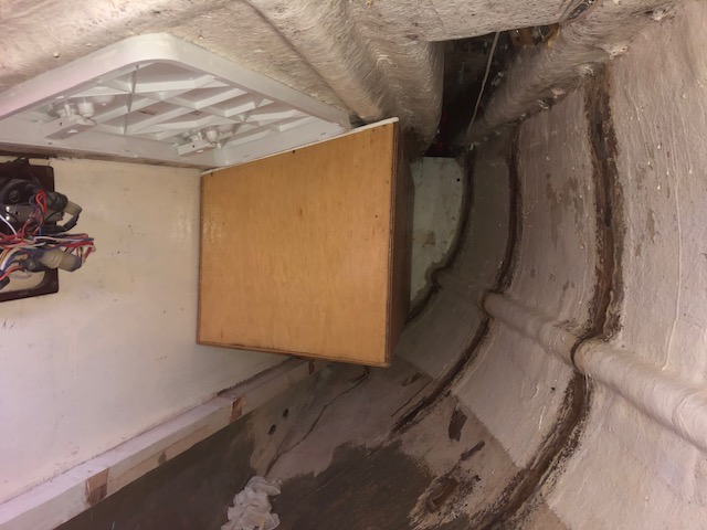
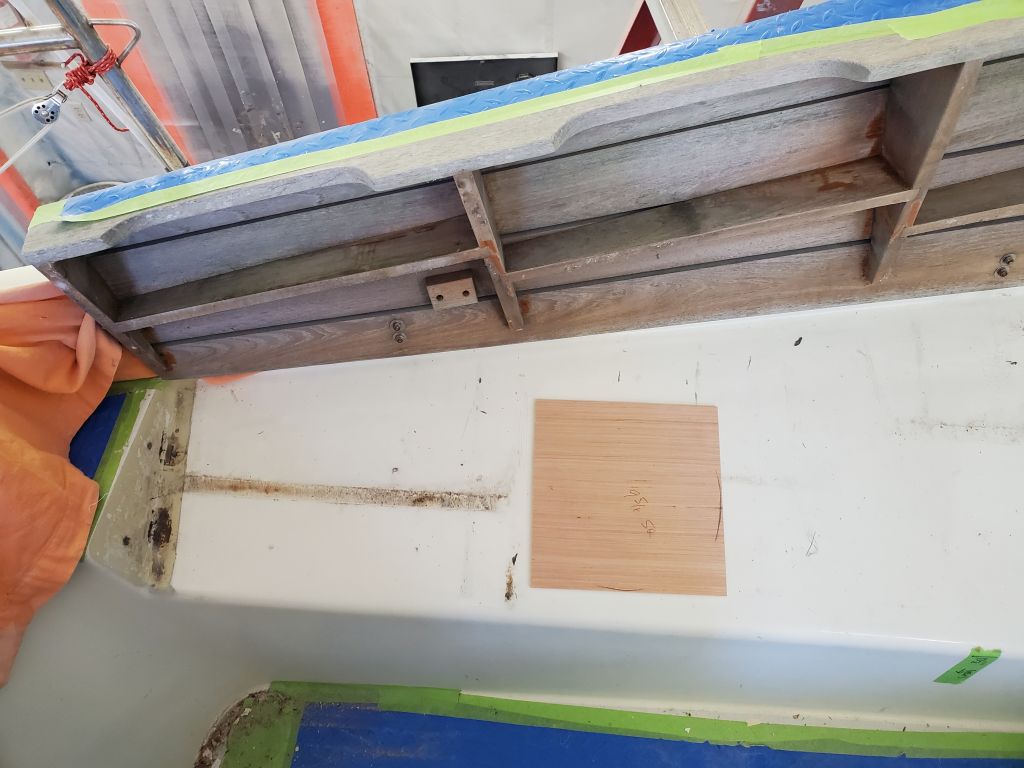
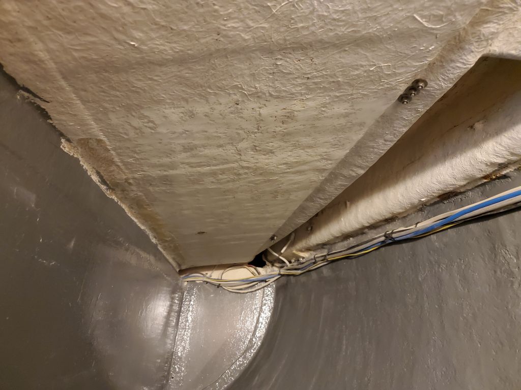
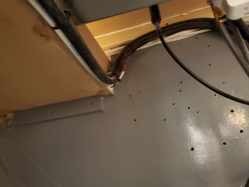
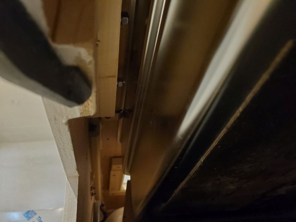
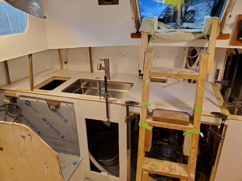
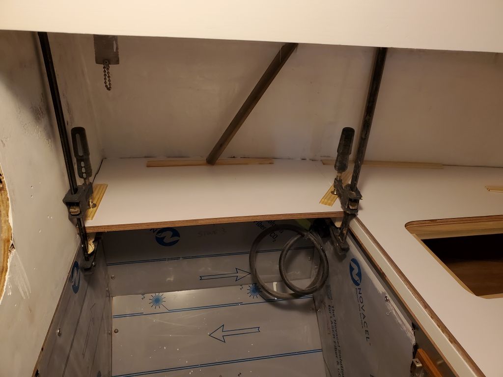
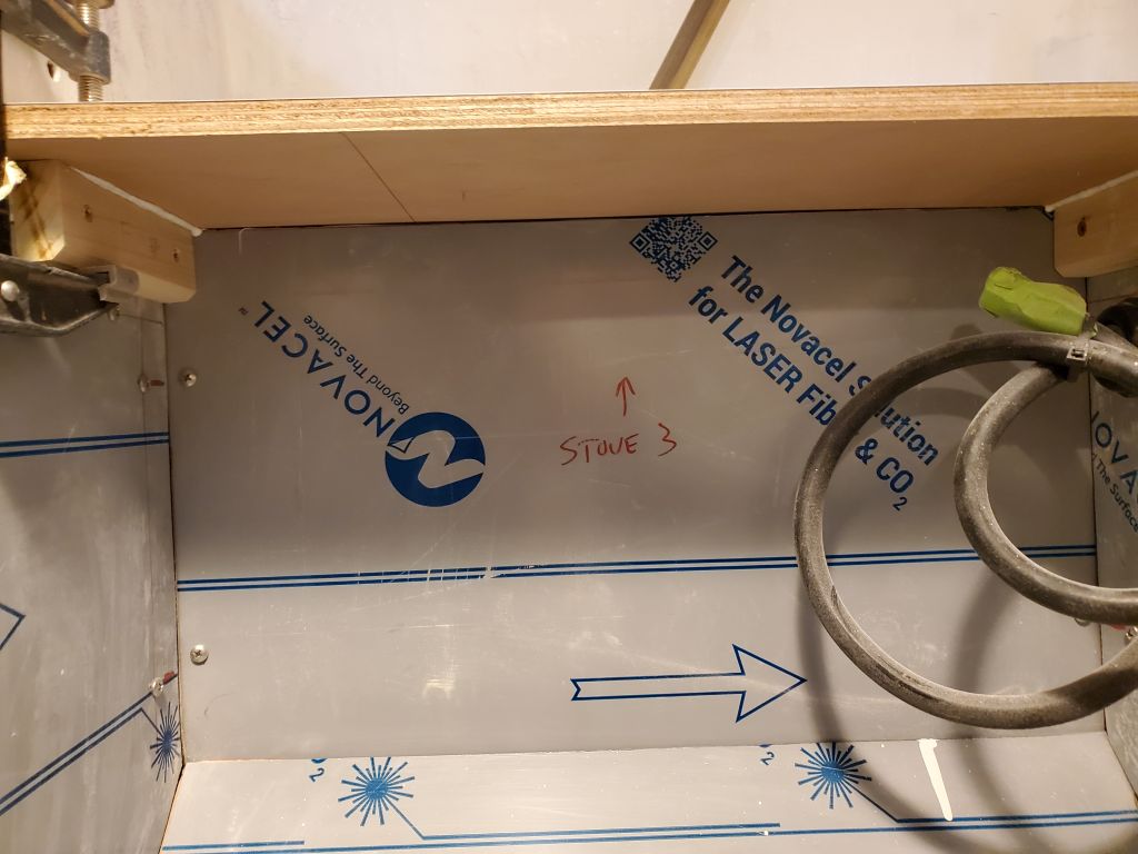
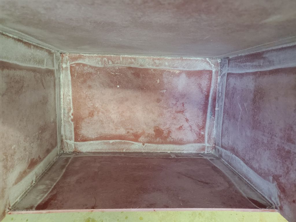
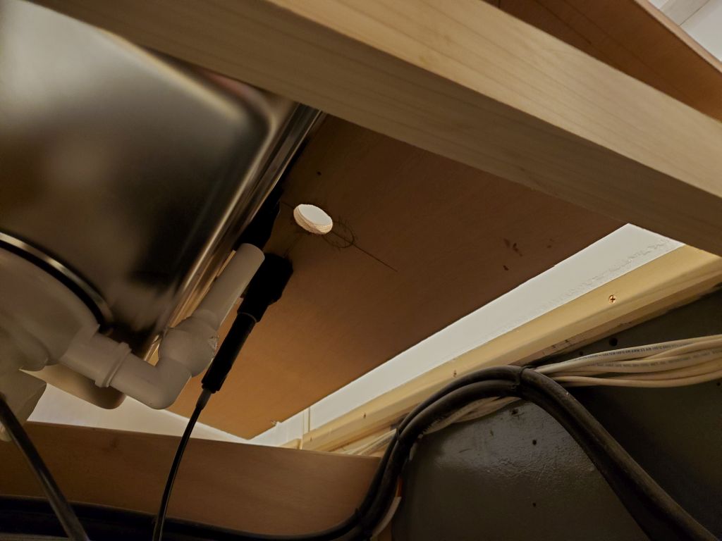
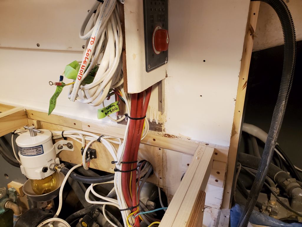
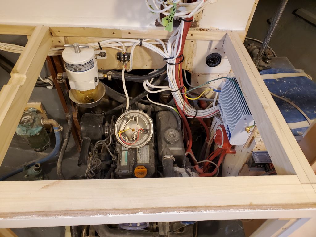
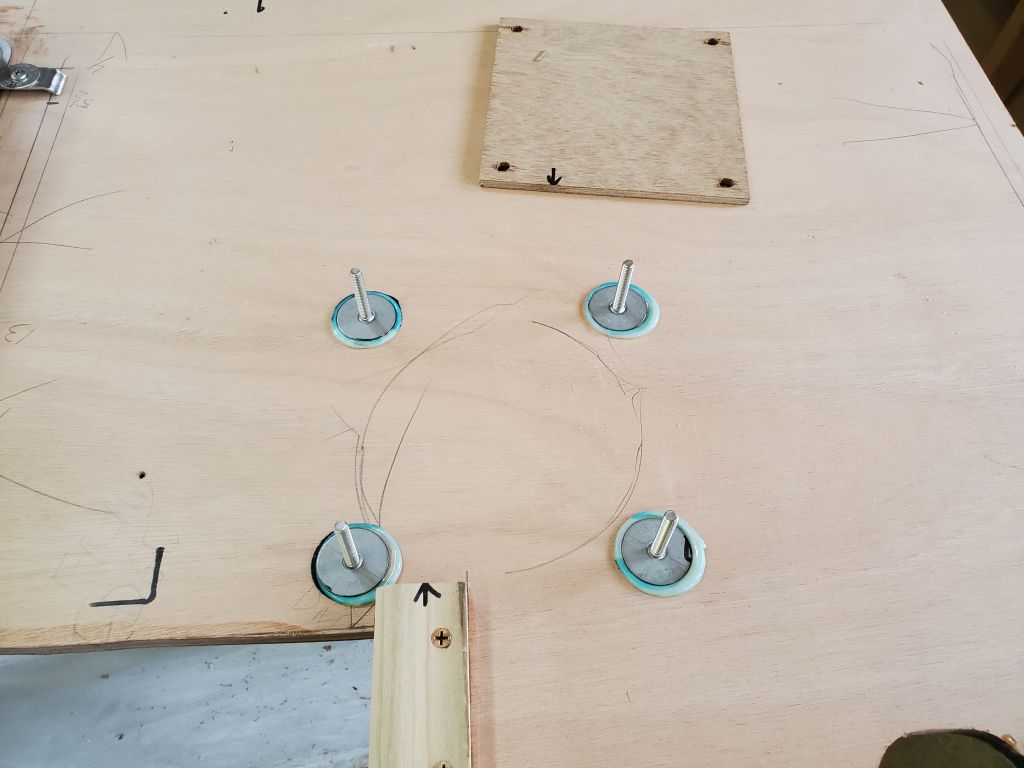
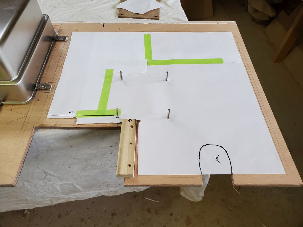
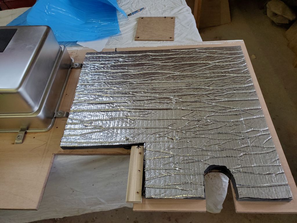
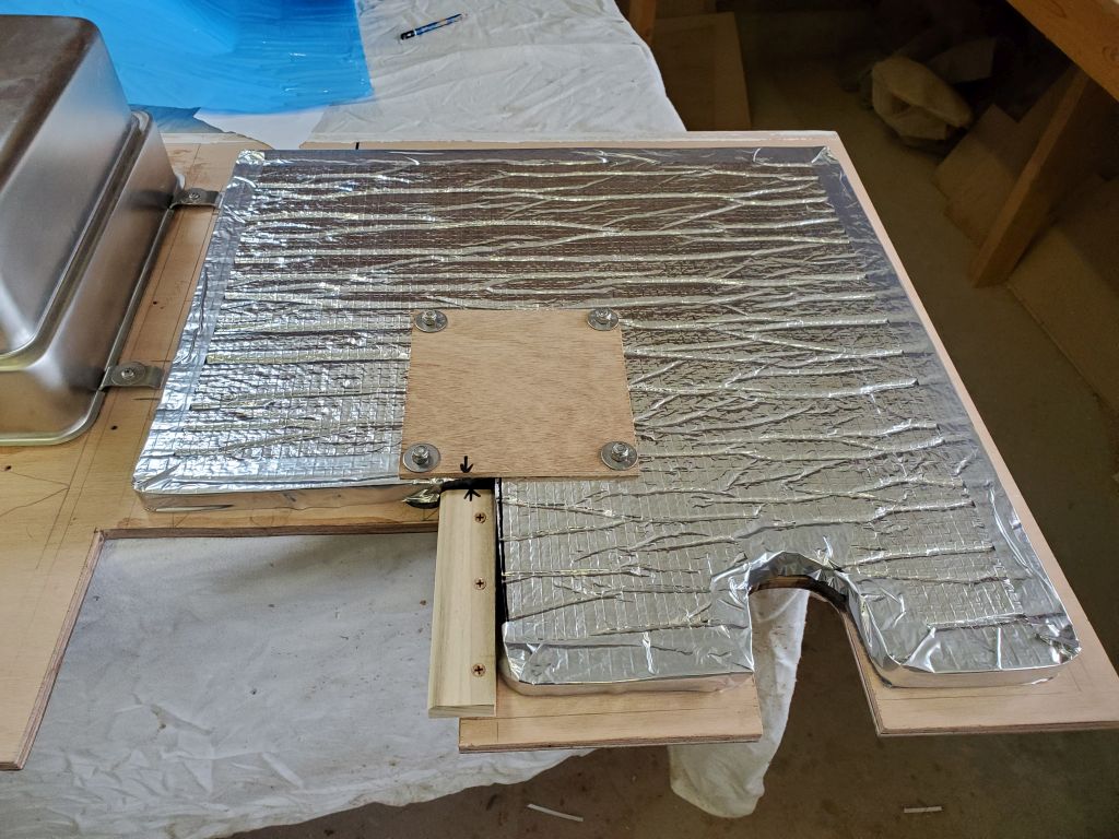
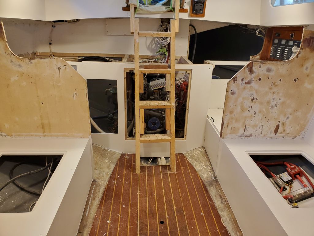
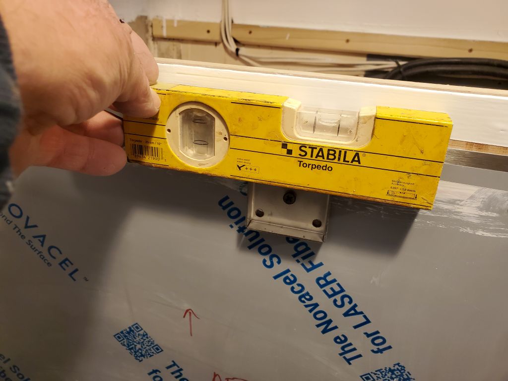
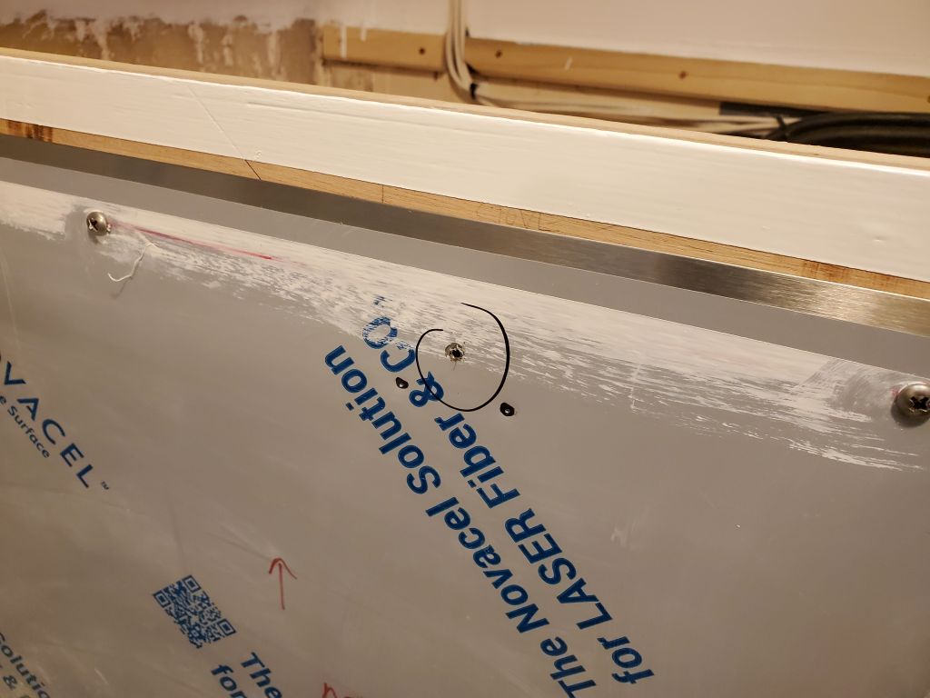
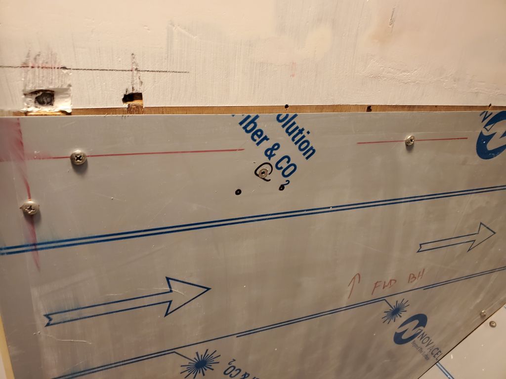
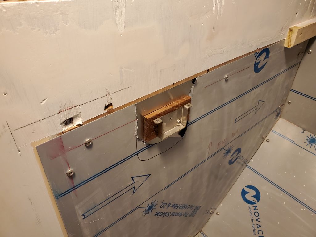
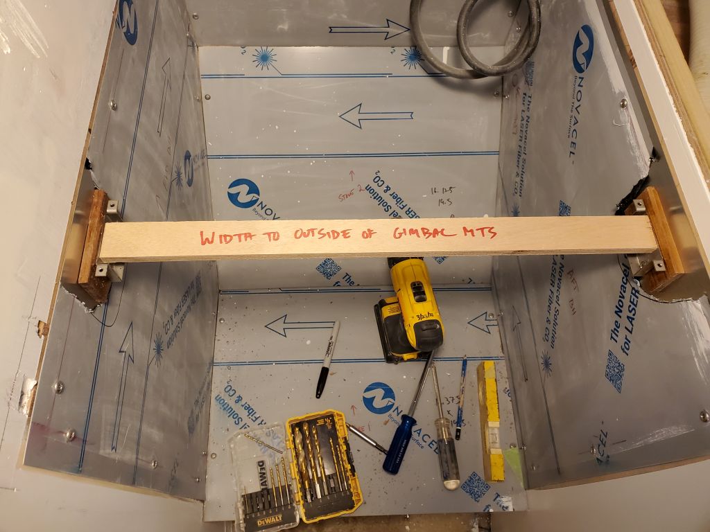
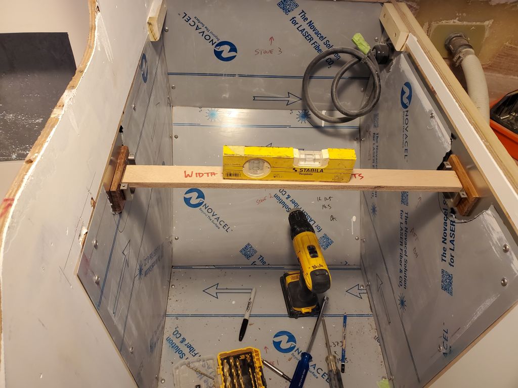
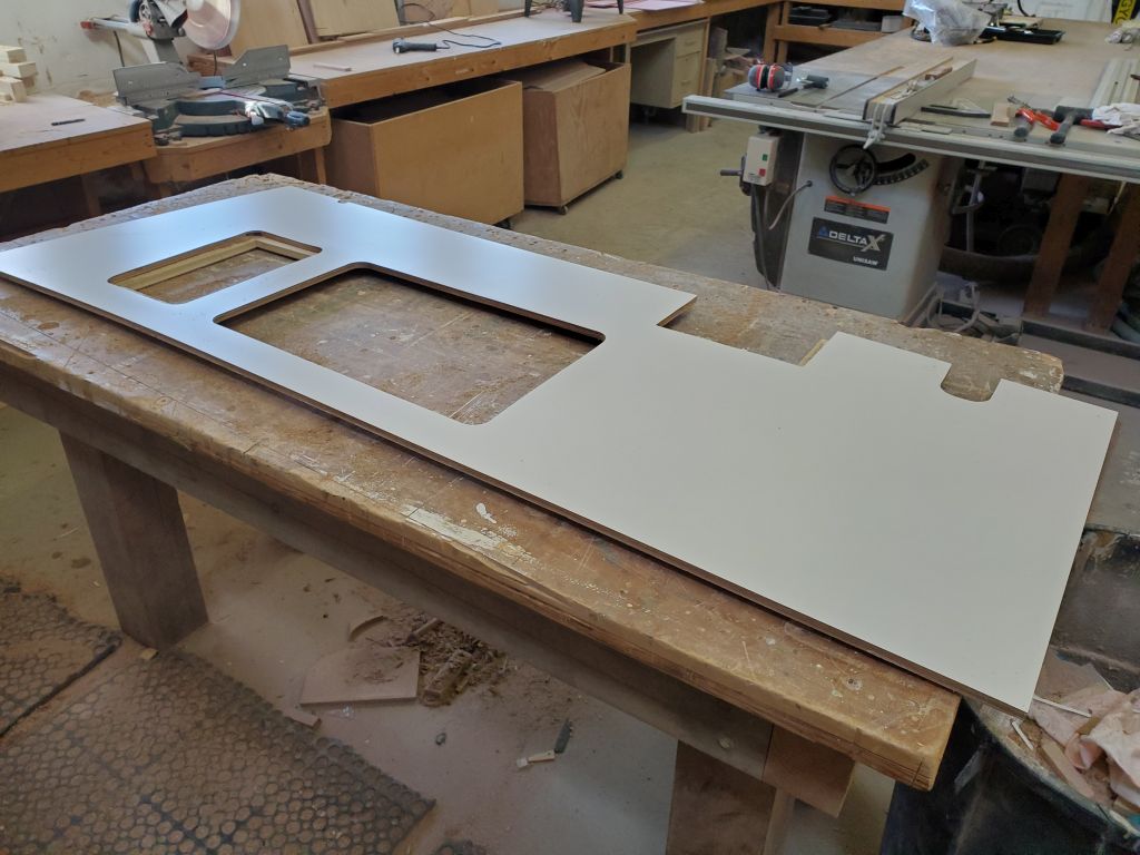
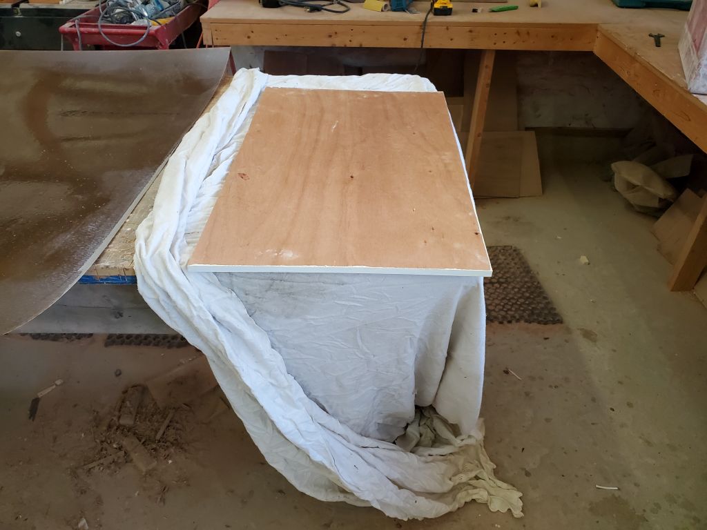
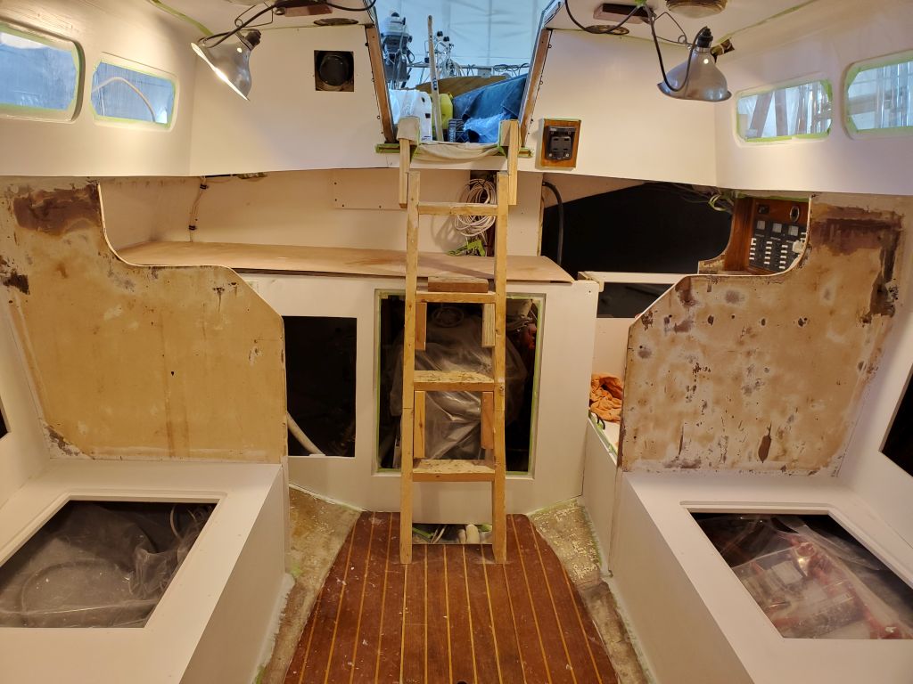
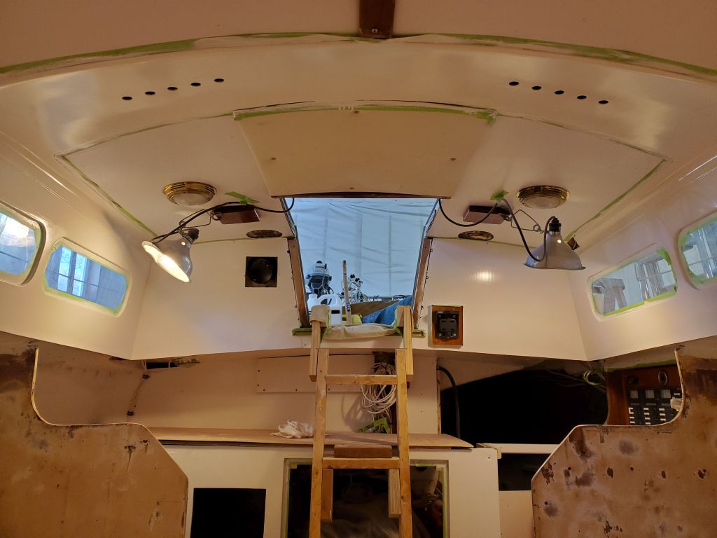
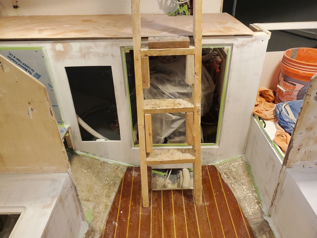
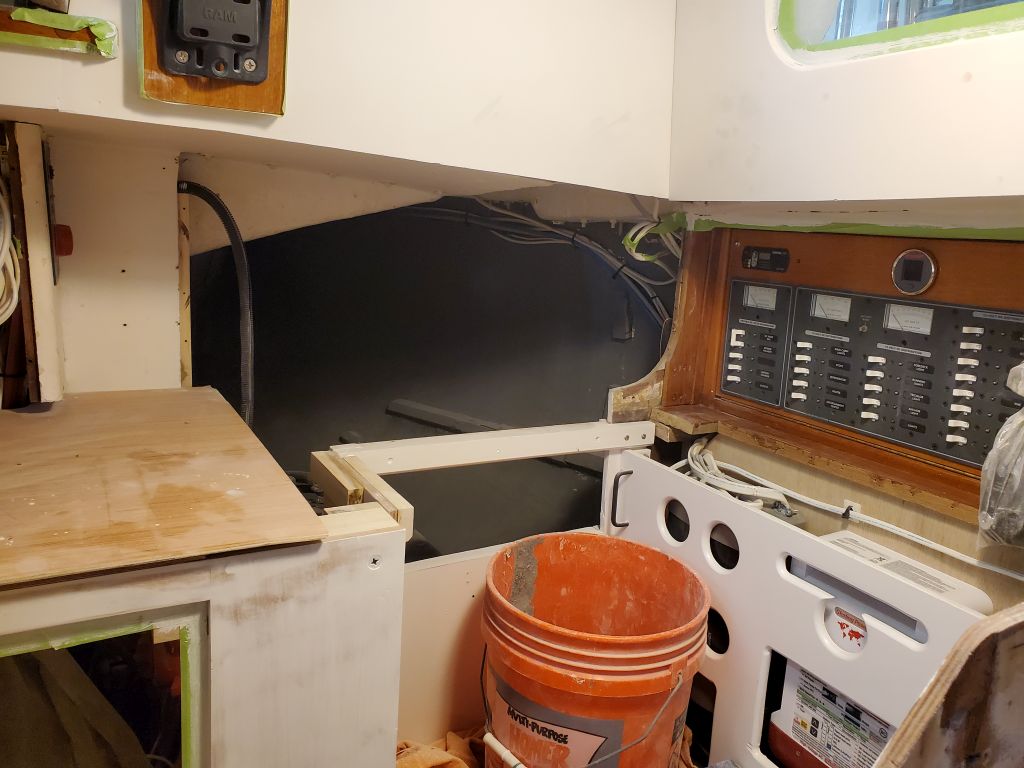
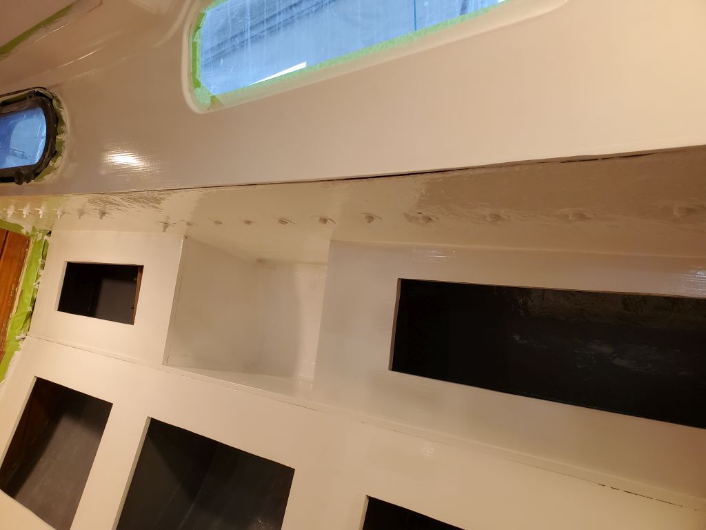
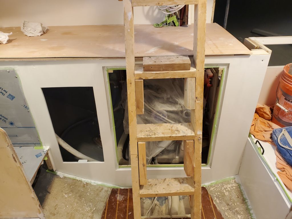
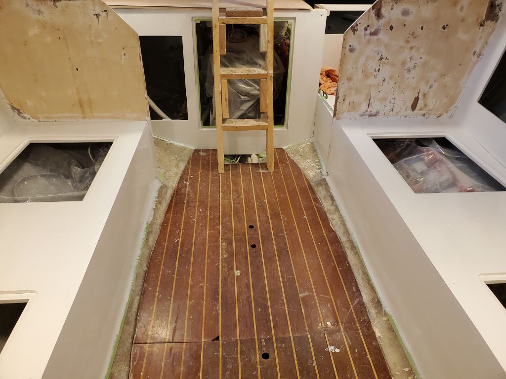
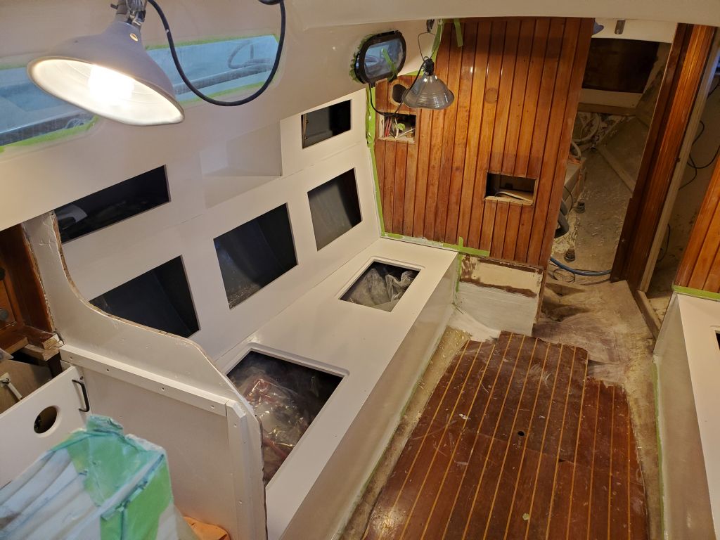
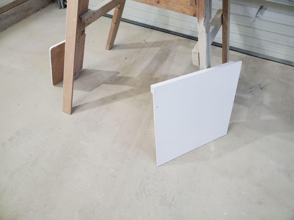
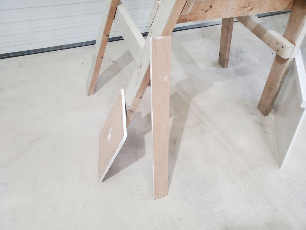
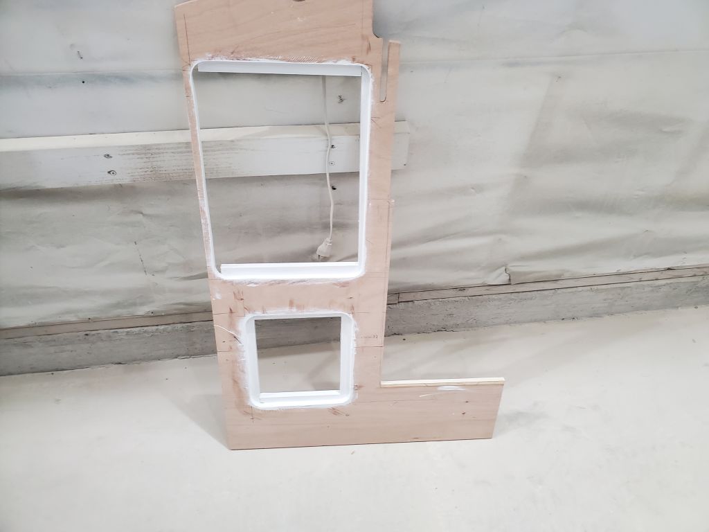
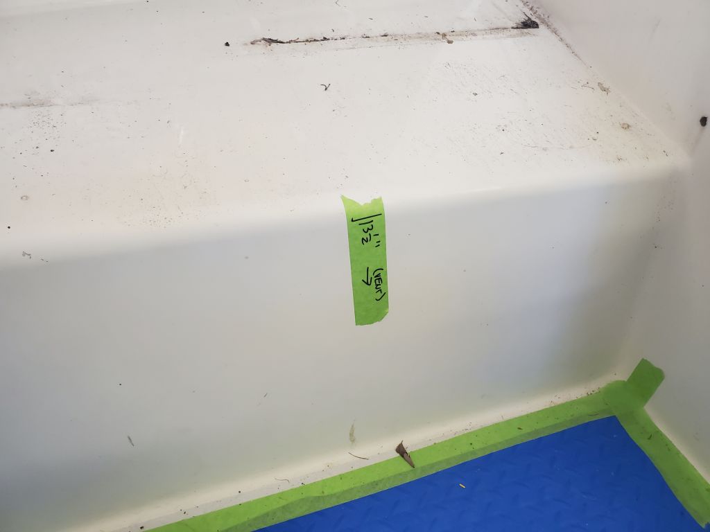
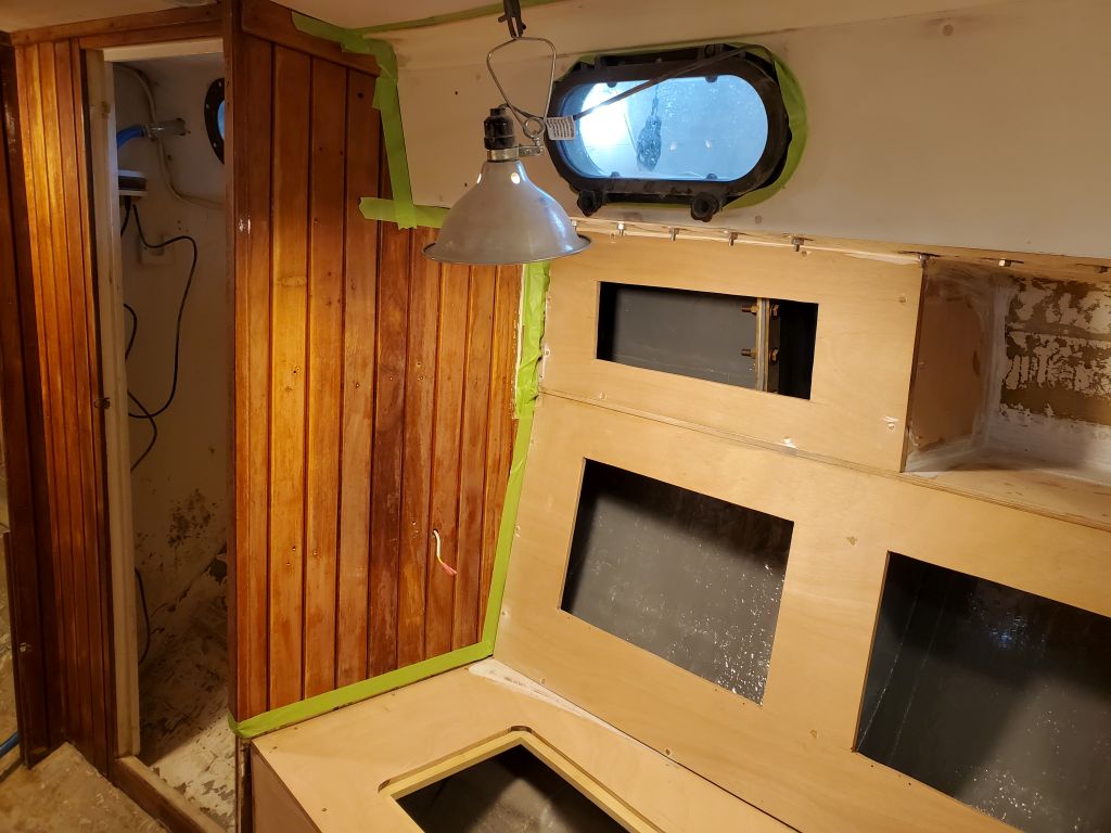
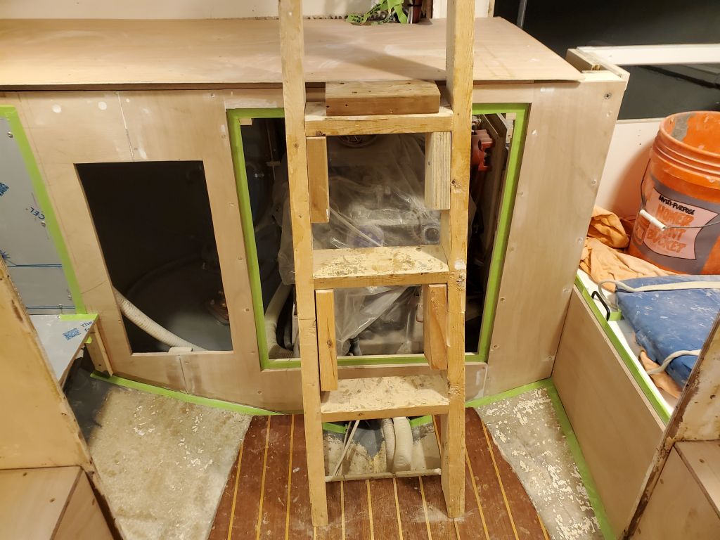
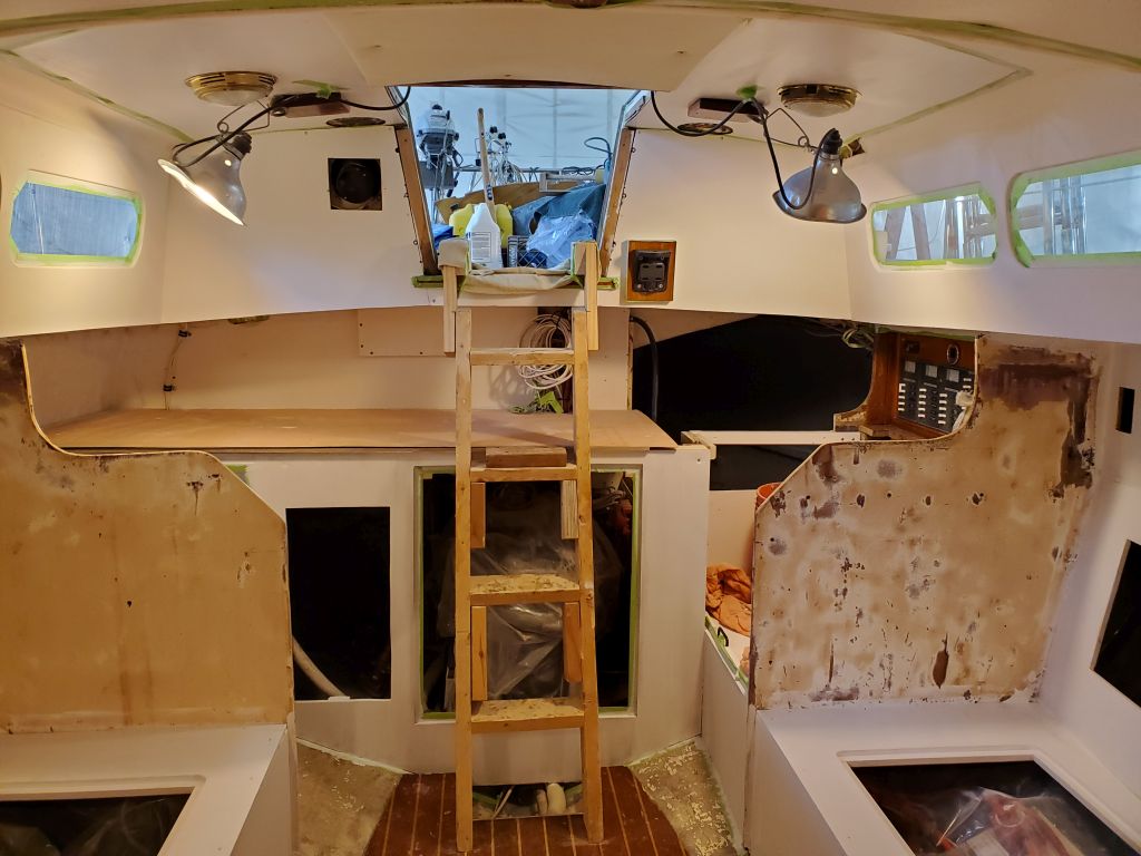
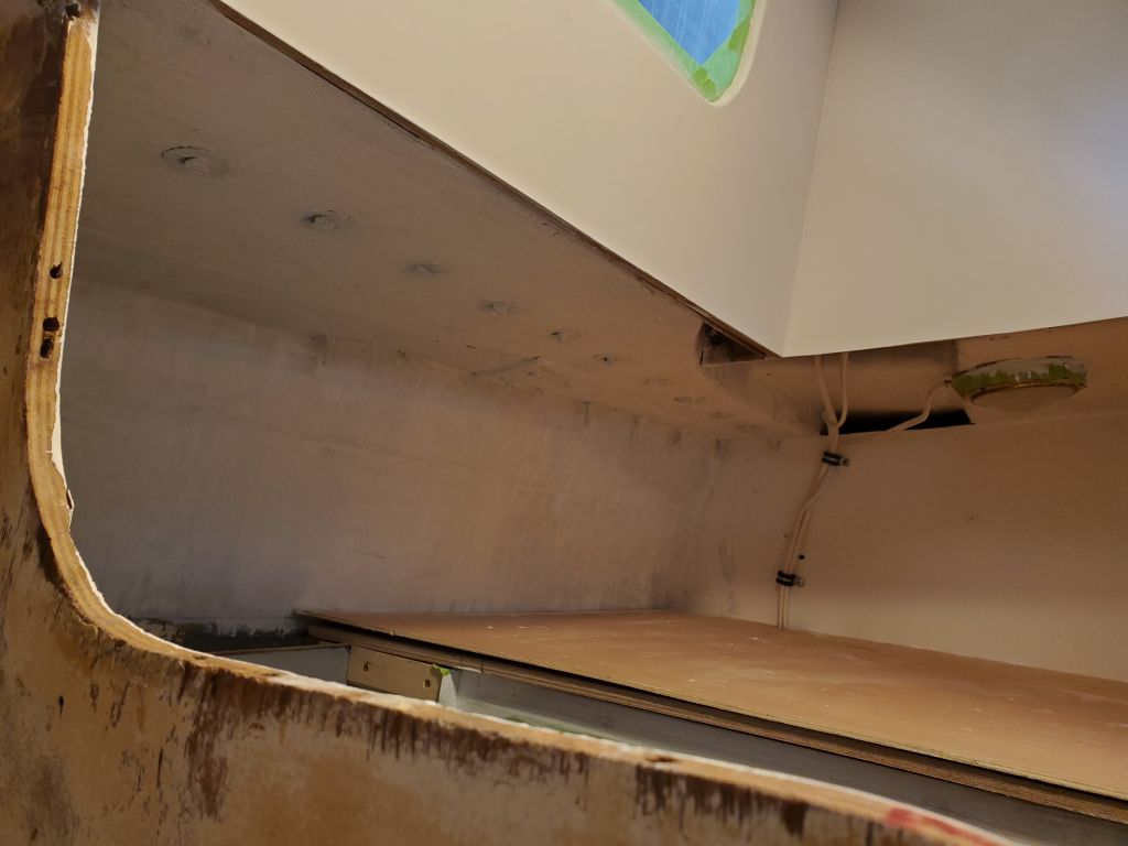
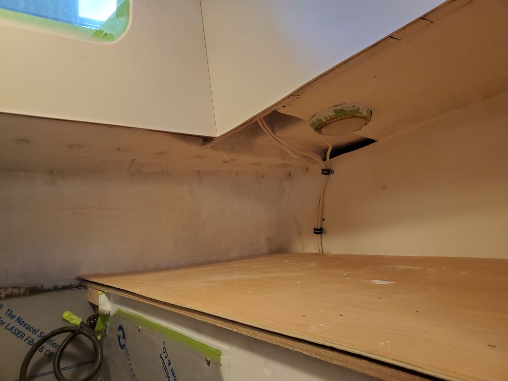
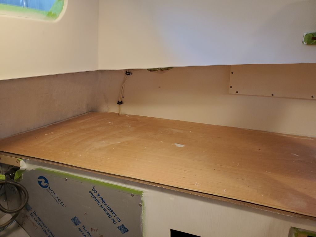
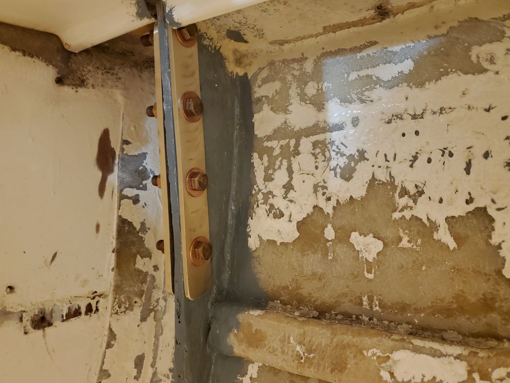
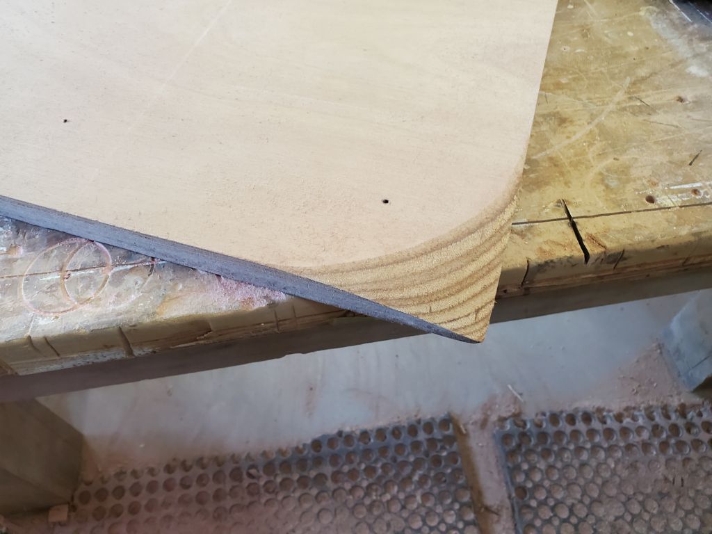
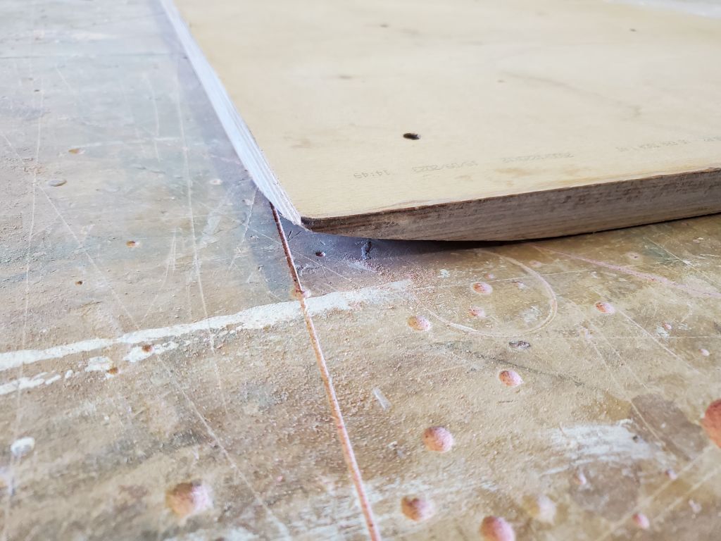
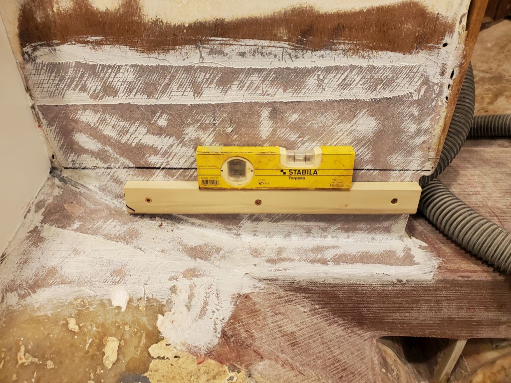
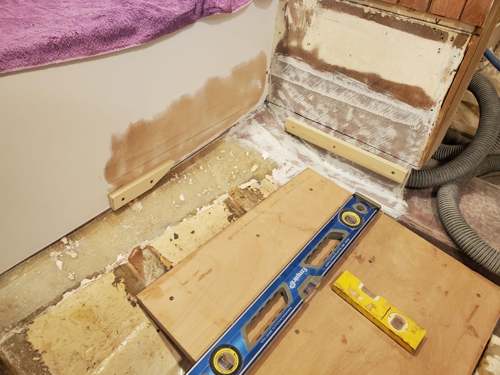
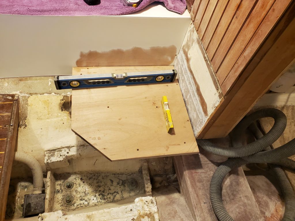
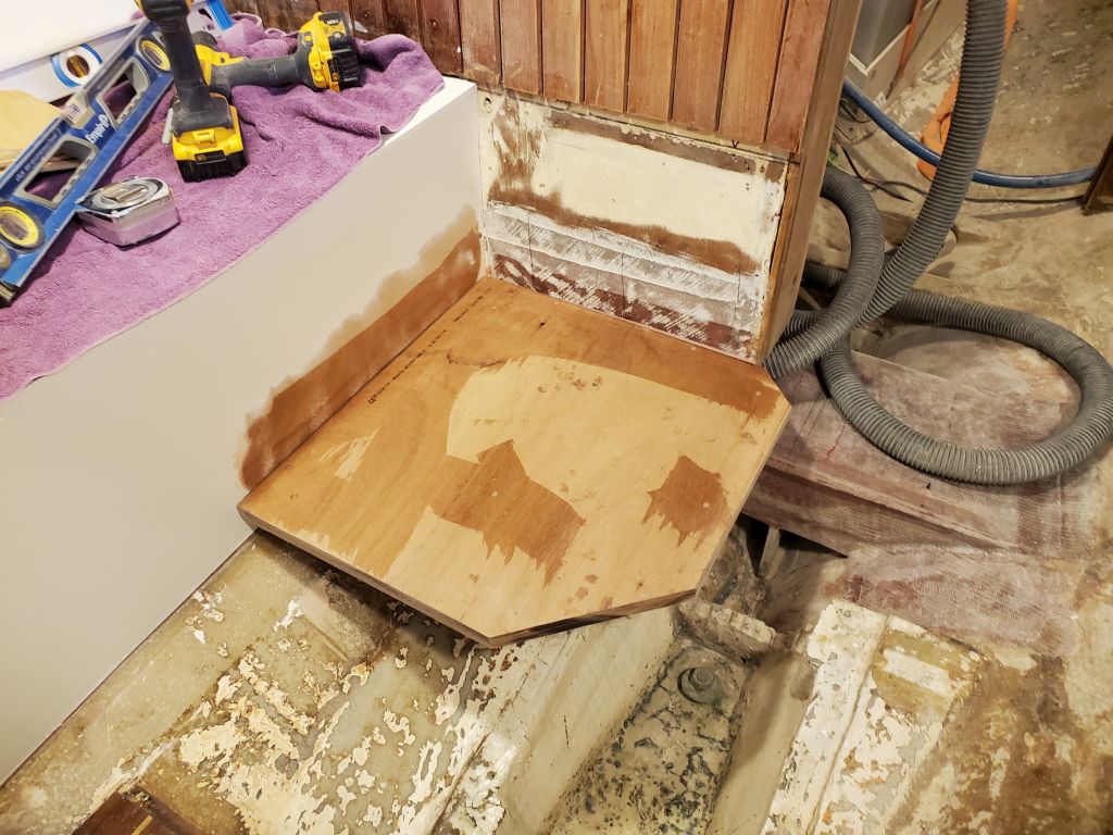
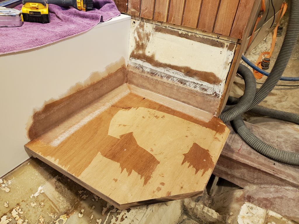
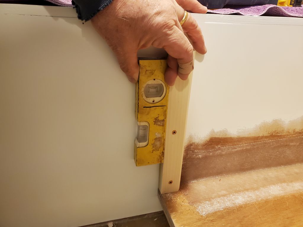
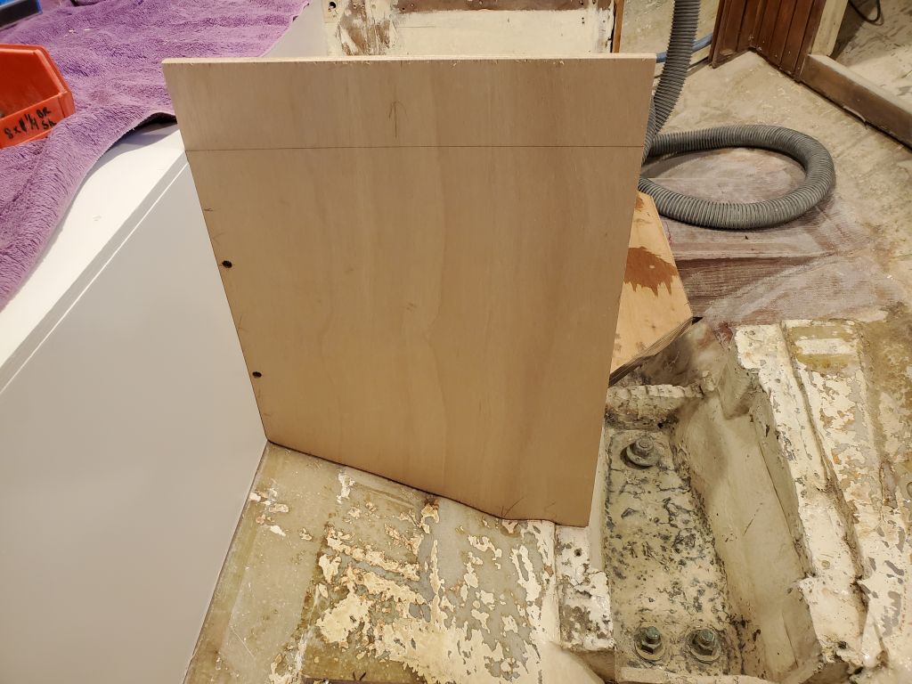
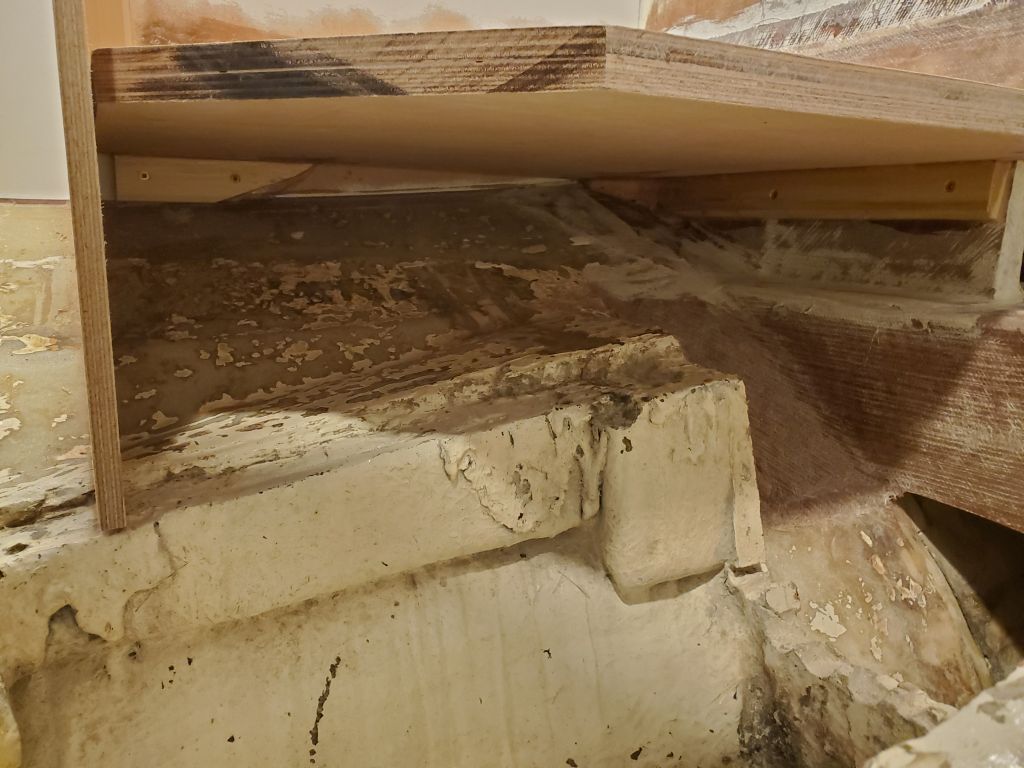
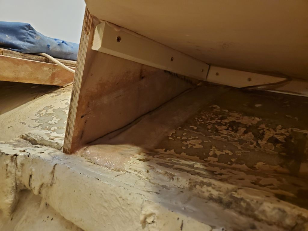
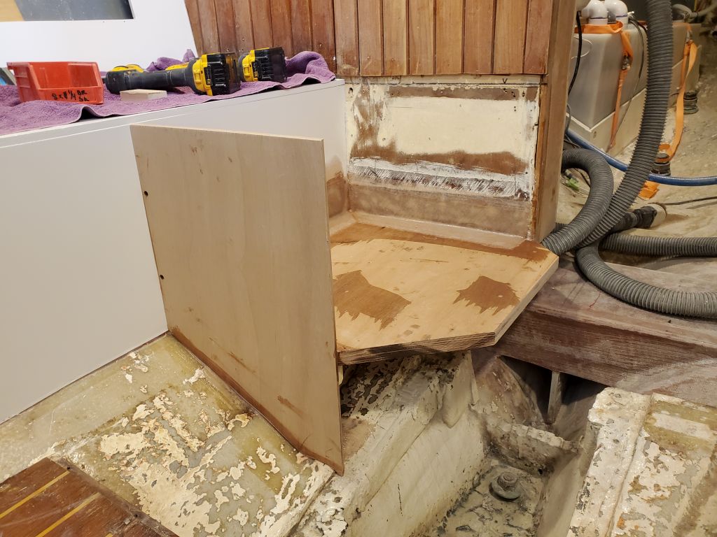
At the forward corner, the hull took a sharp upward turn, and this point dictated the level of the entire battery box. To help lower the platform as much as possible, I eased the underside of the forward corner, allowing the base panel to fit into the space nearly an inch lower. I did some preparatory sanding to remove paint from places I planned to use epoxy or other adhesive and then, after some basic layout to level the platform in both directions, secured support cleats on the two sides where possible. I temporarily secured the platform to the cleats with screws to check its fit and level in both directions. At the forward inboard edge, I made a mark to pare off that corner as well, lest it interfere with the mast step. With the platform in its final position, there was ample height for the batteries and all appurtenances, as shown with the plywood template leaning against the forward bulkhead; the template, as shown, included the height of the terminal fuse blocks as well as the batteries themselves.
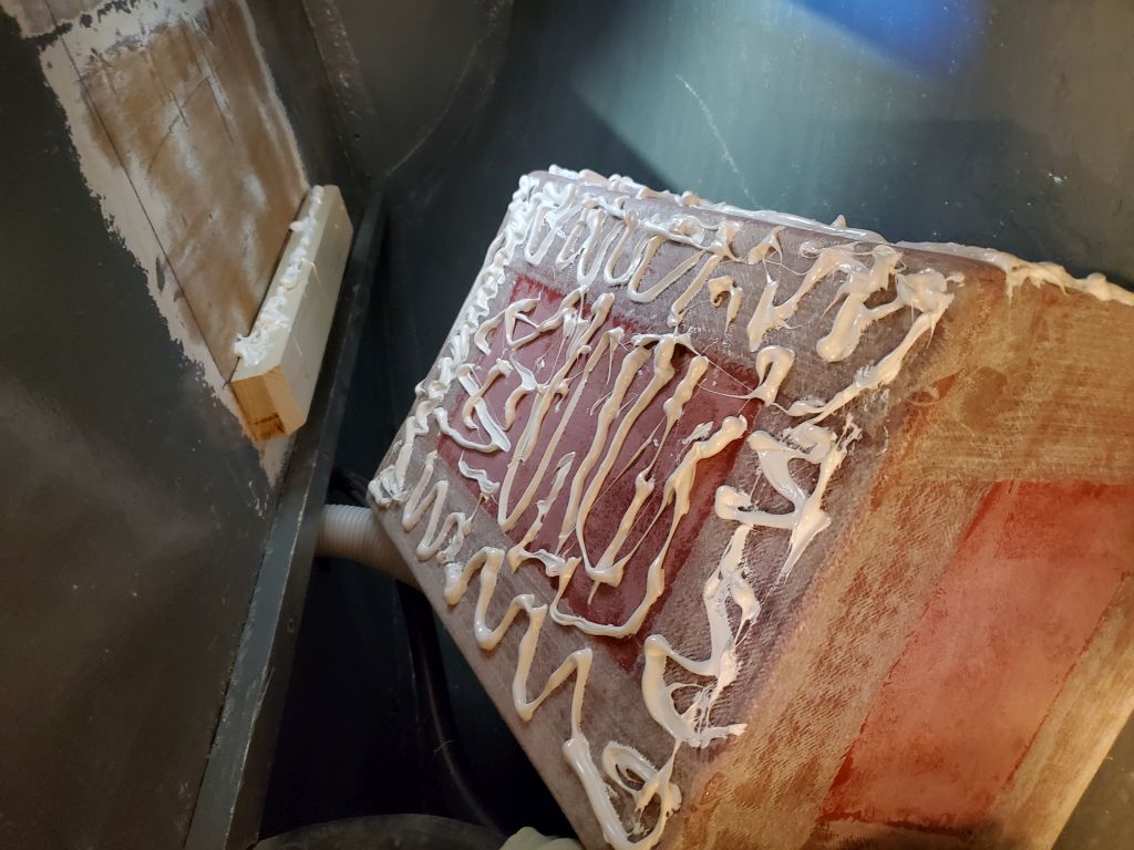
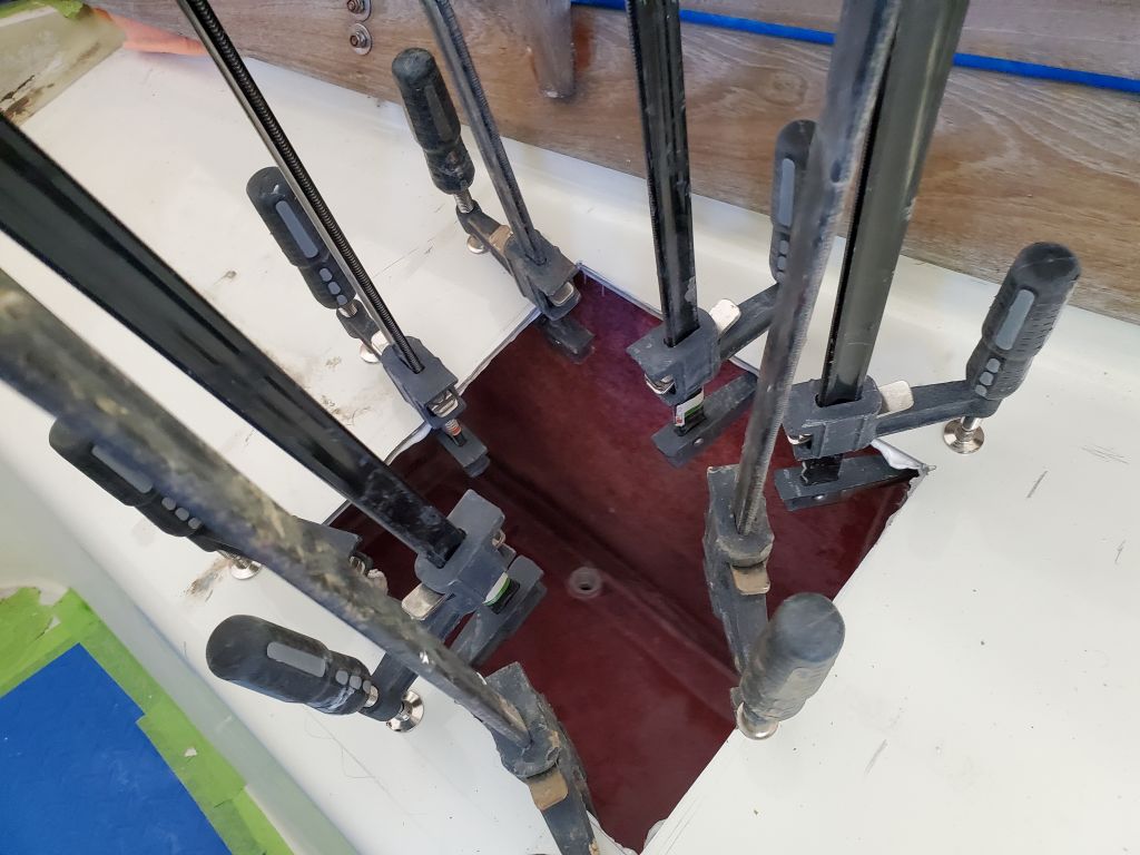
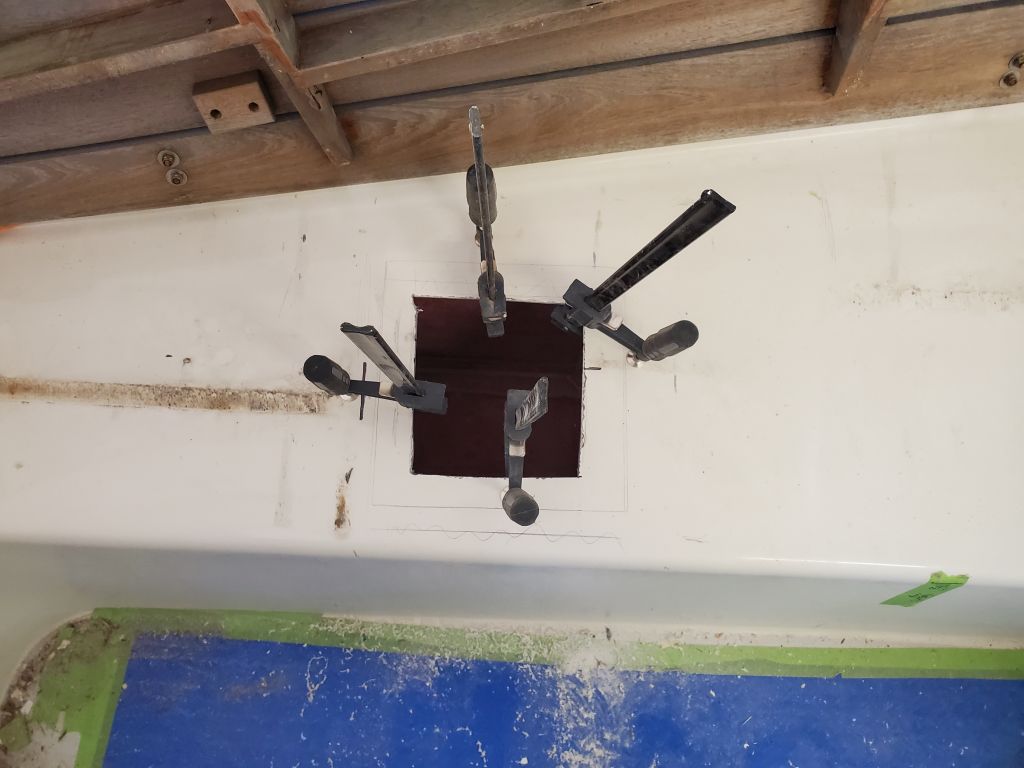
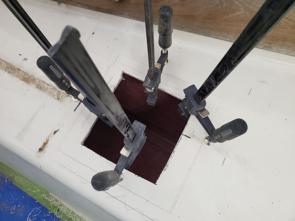
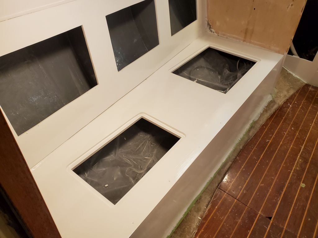
With the dry fit and support in place, I removed everything and, after final preparations, resecured the two cleats with screws and epoxy adhesive, then installed the platform with more epoxy adhesive in the forward outboard corner and on all the faying surfaces and screws into the cleats to secure it. Then, I installed two layers of heavy tabbing to secure the platform to the nearby bulkheads. This coincided with lunch, so it was a good time to let the epoxy tack up briefly before continuing.
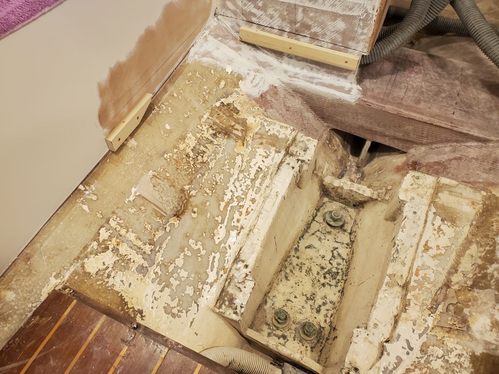
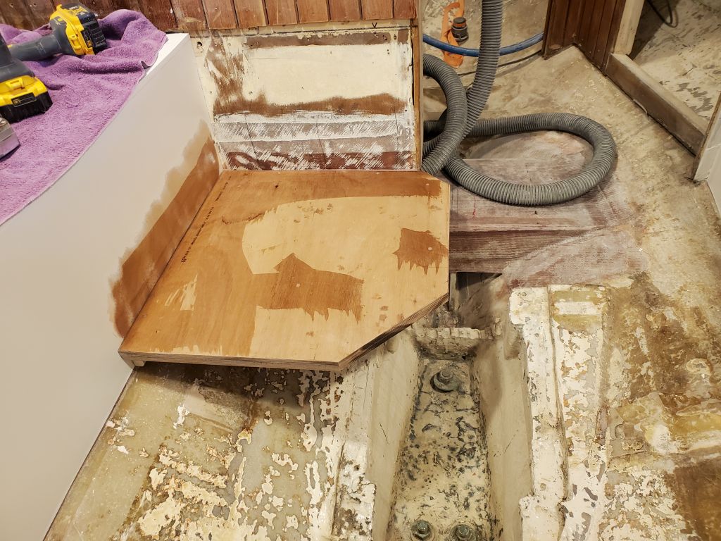
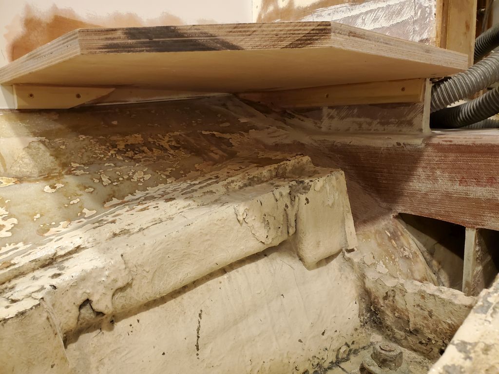
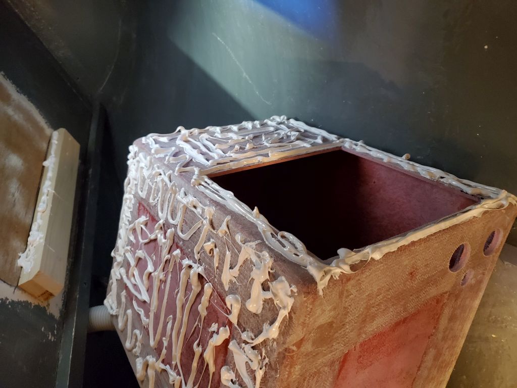
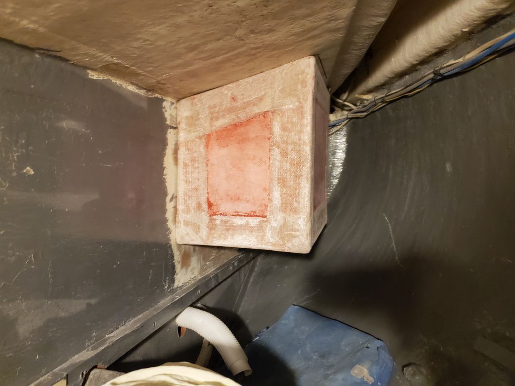
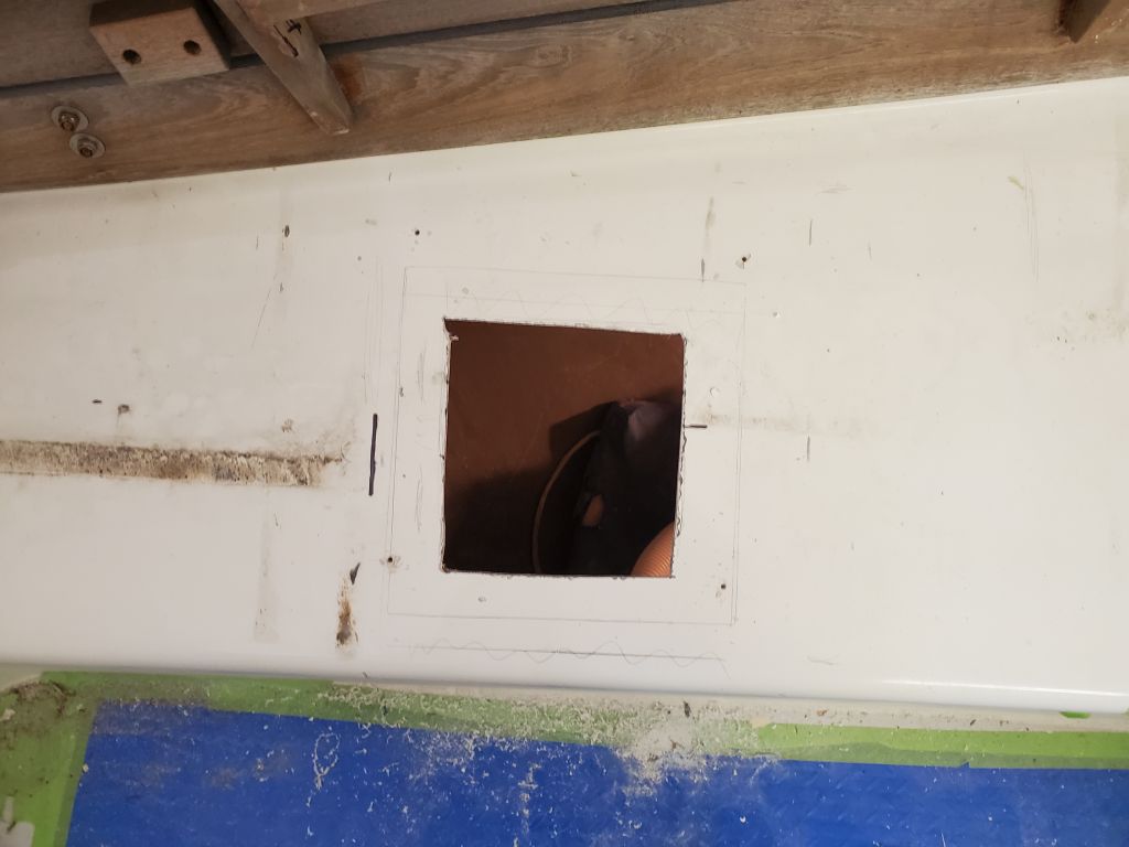
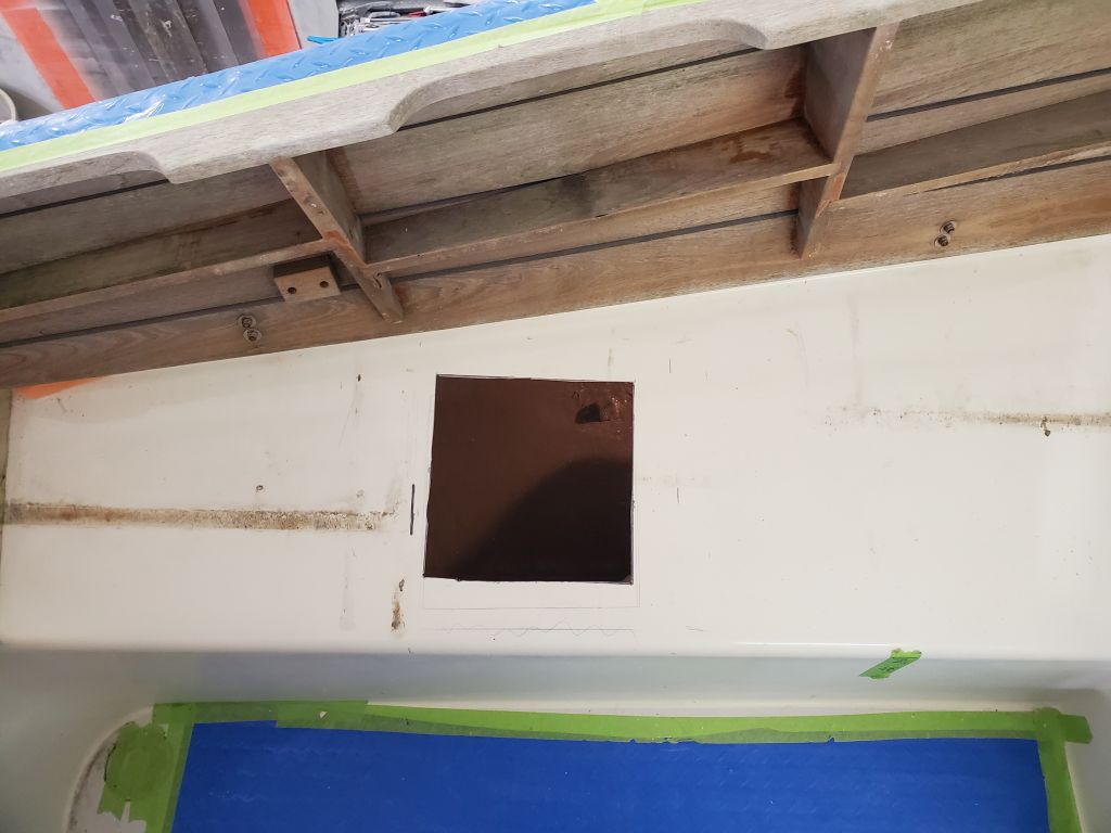
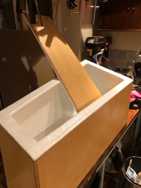
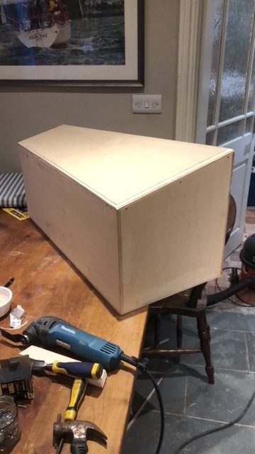
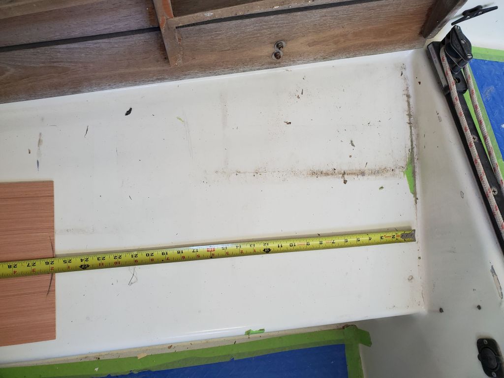
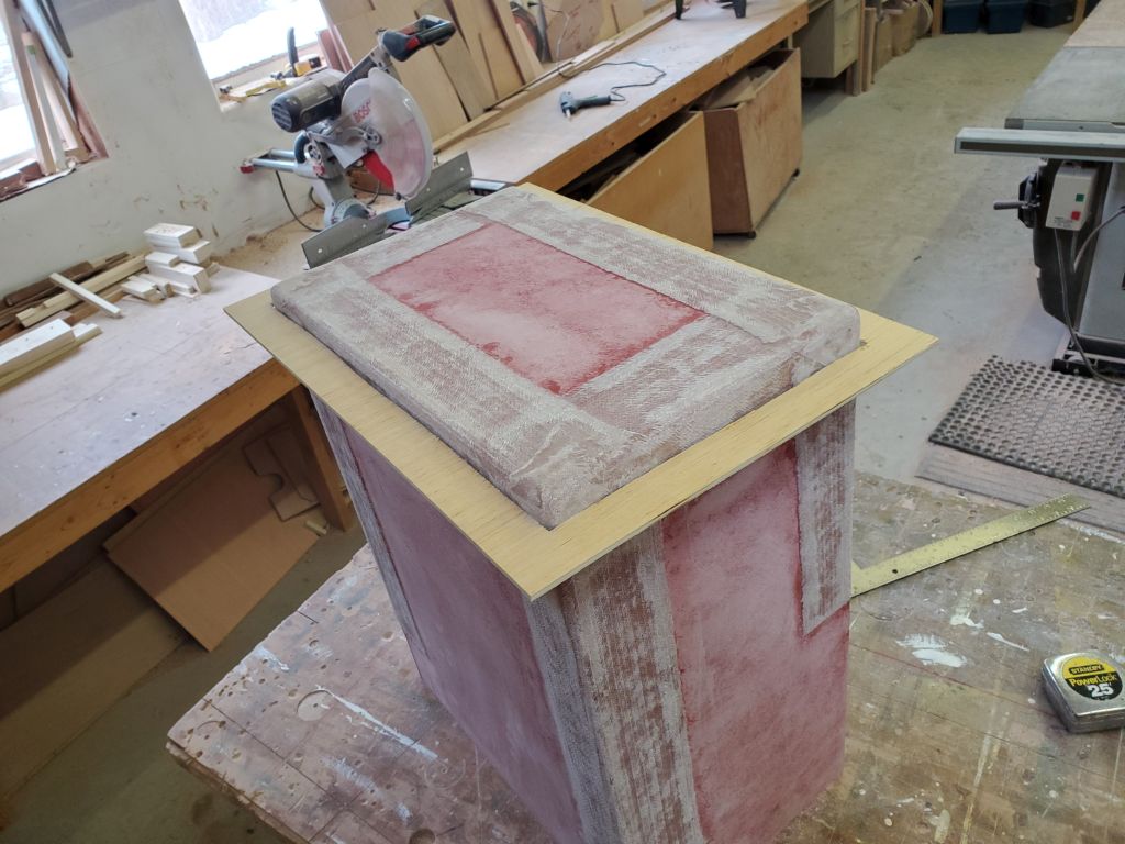
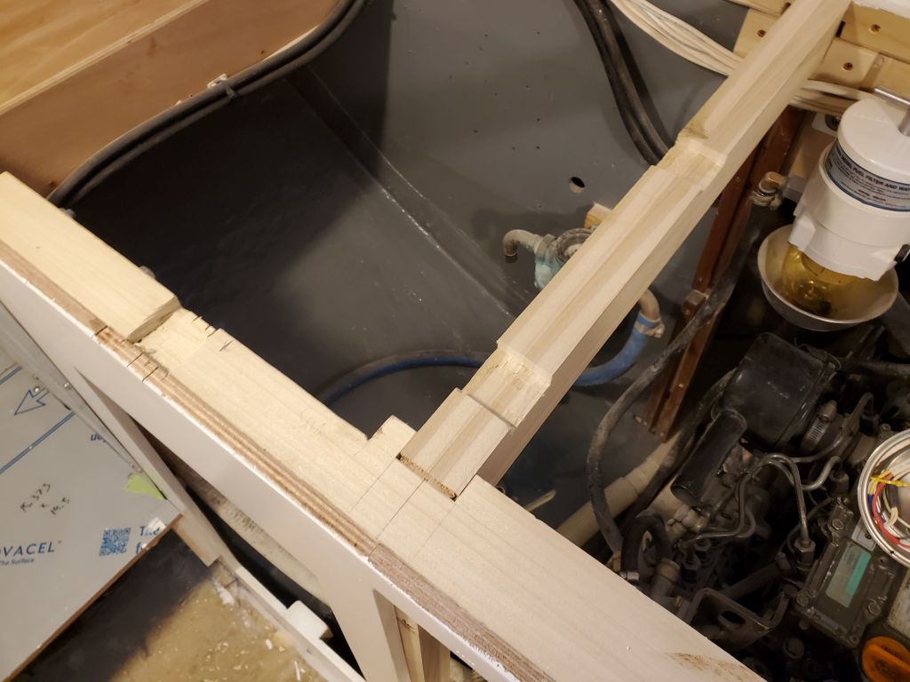
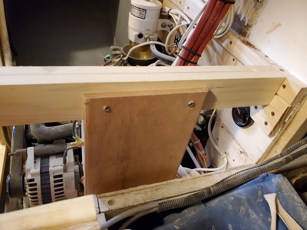
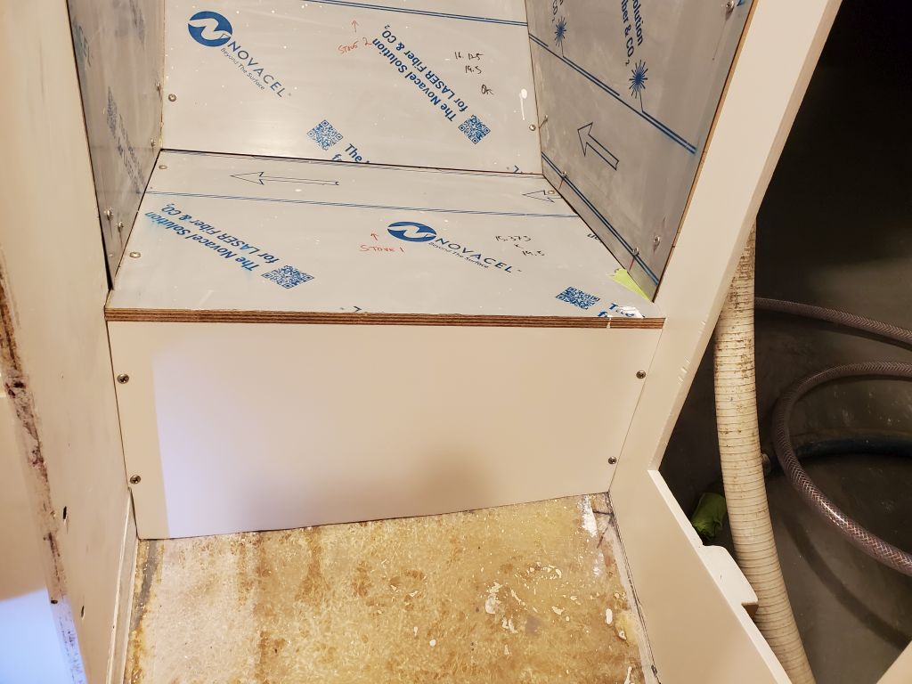
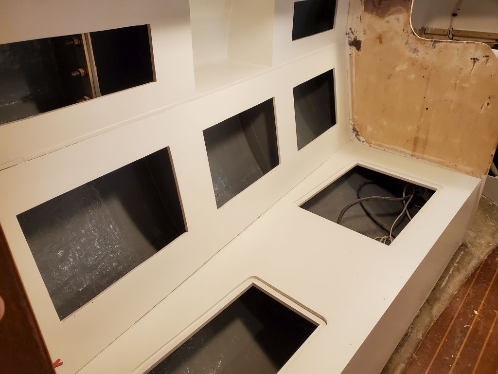
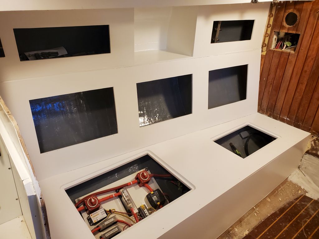
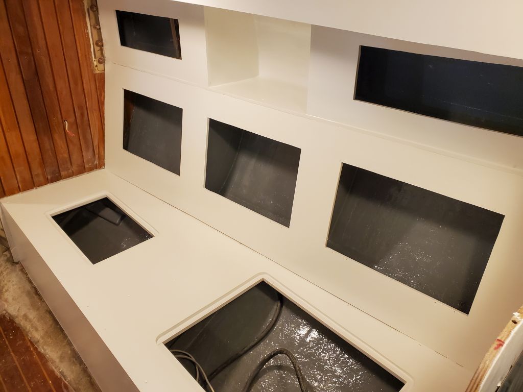
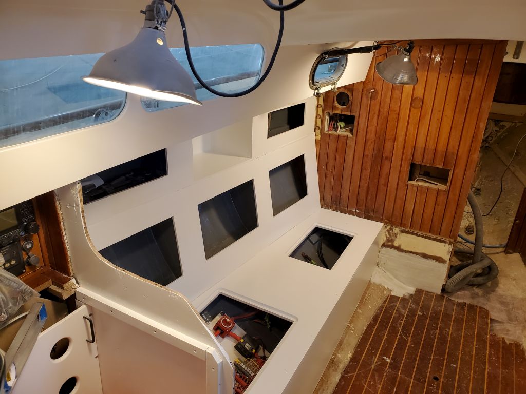
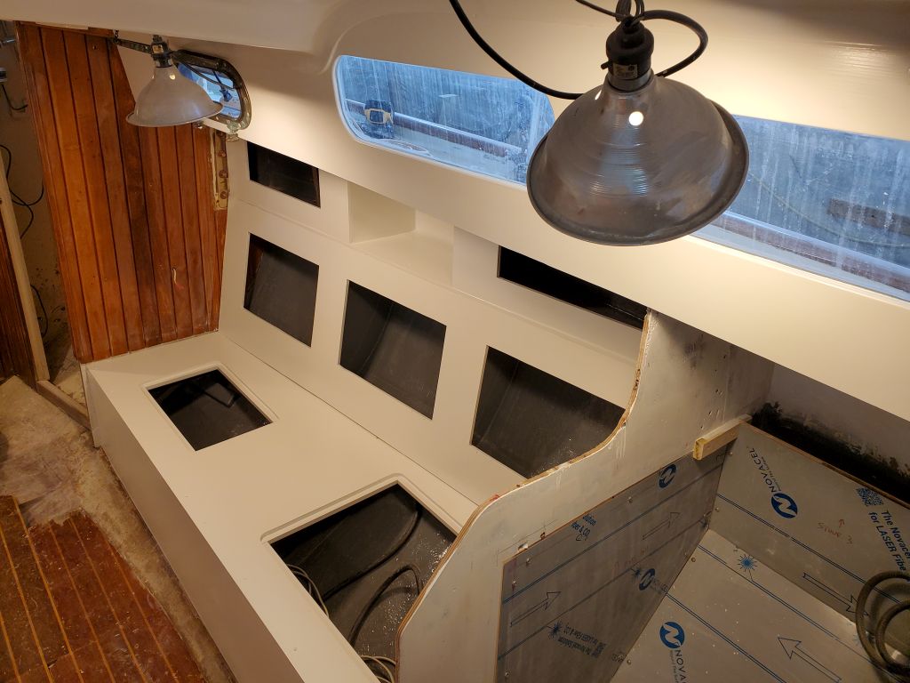
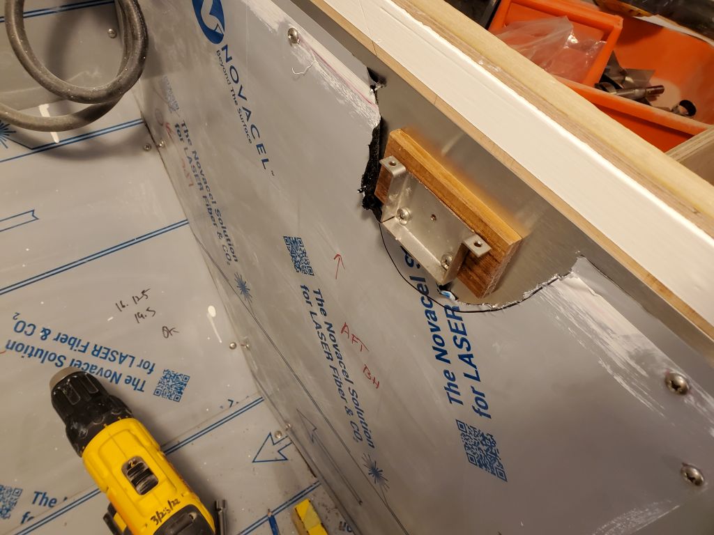
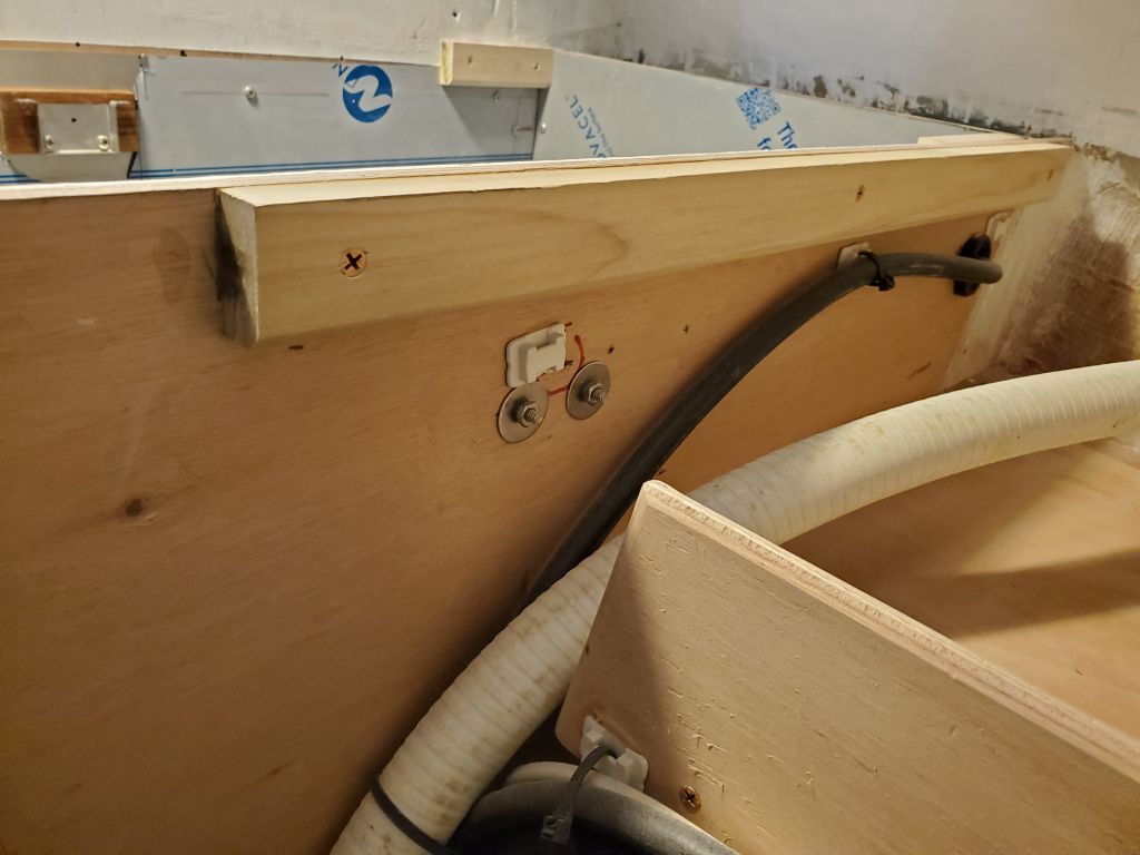
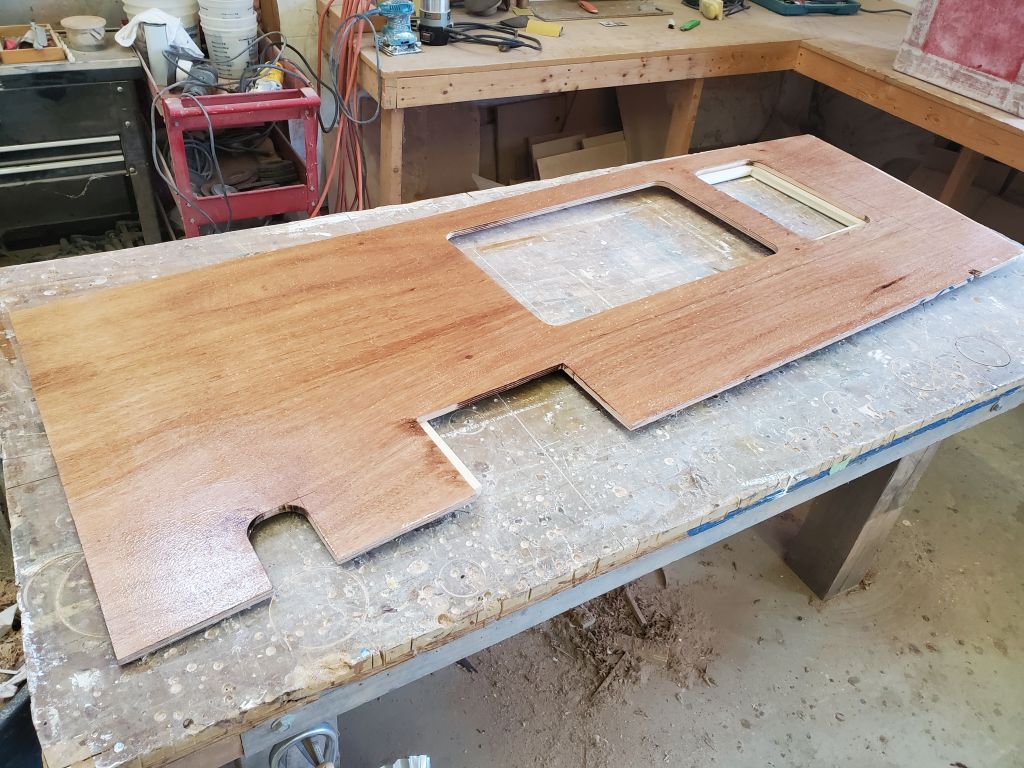
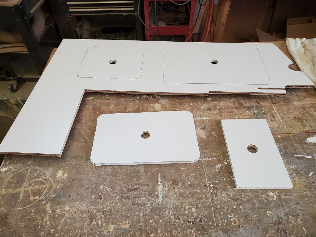
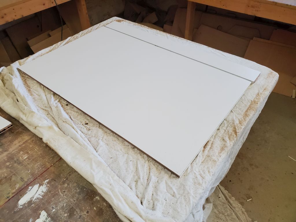
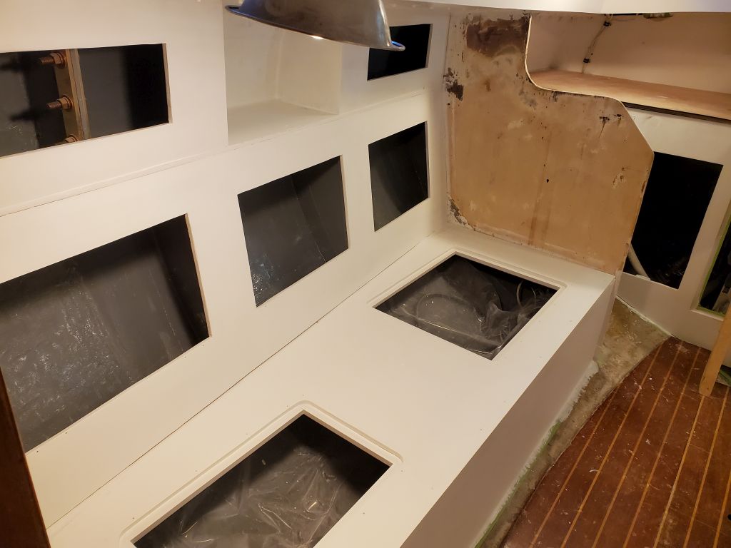
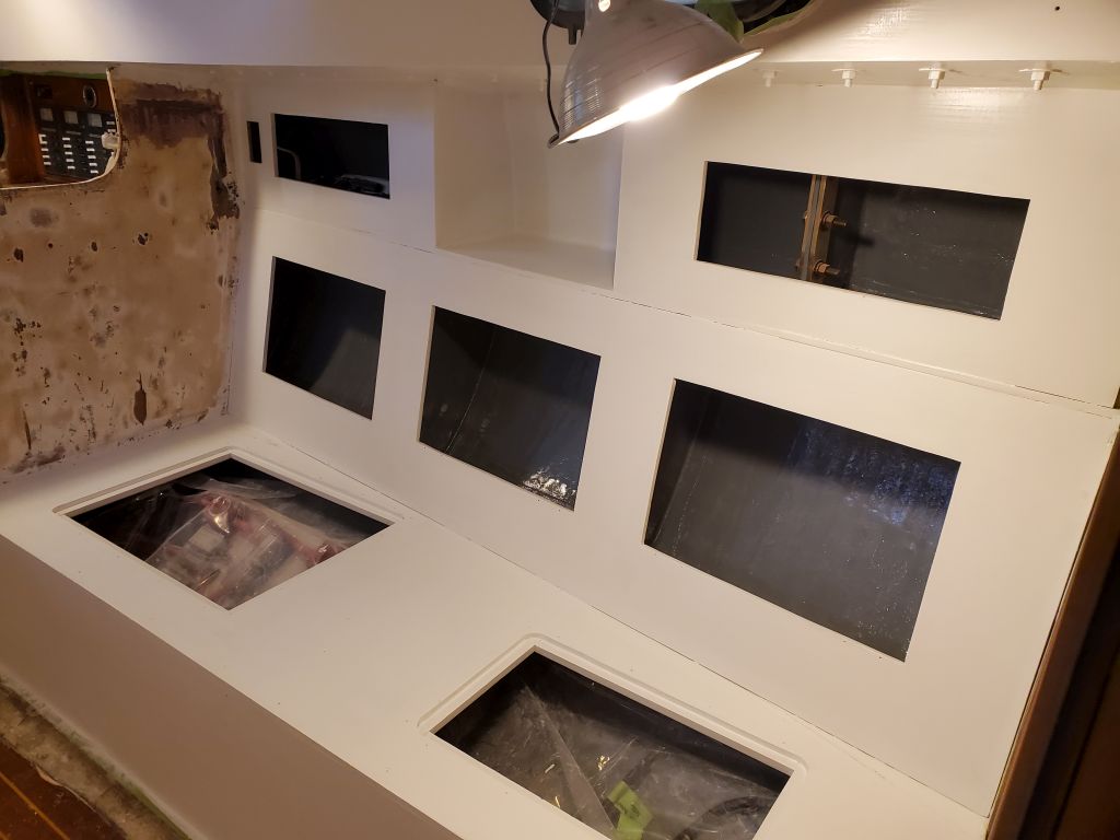
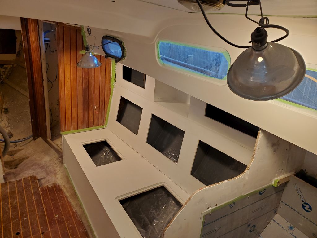
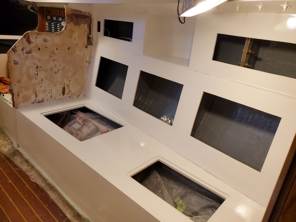
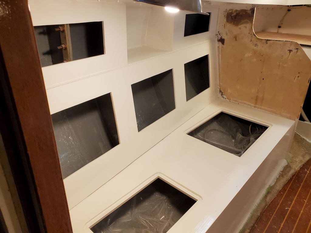
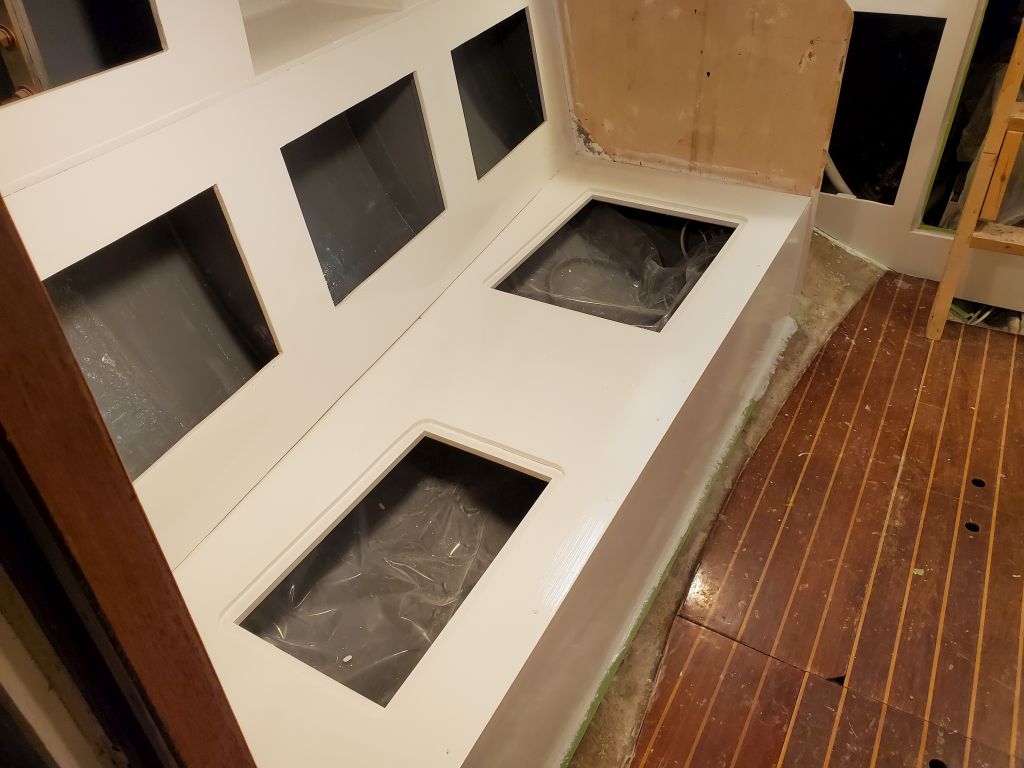
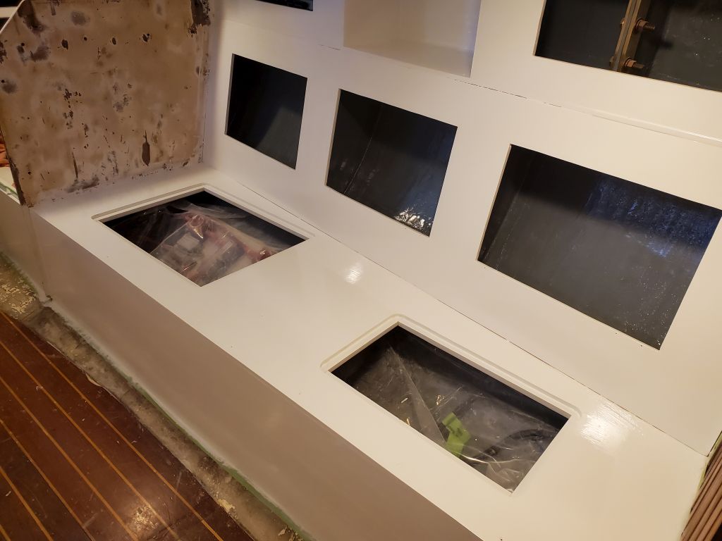
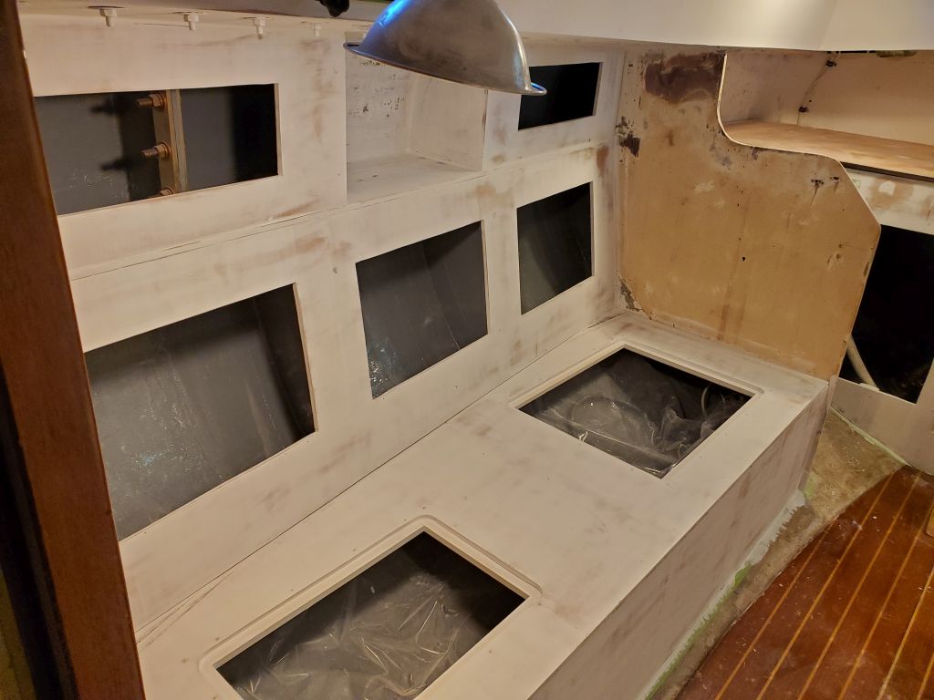
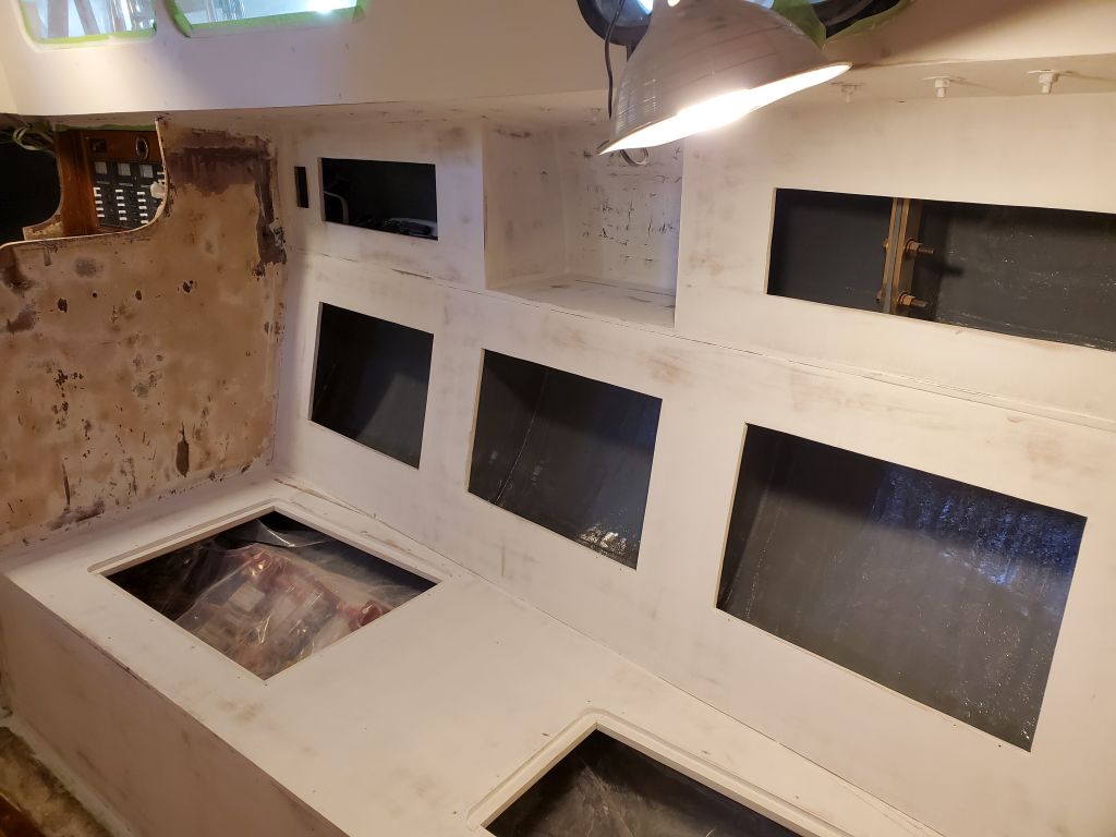
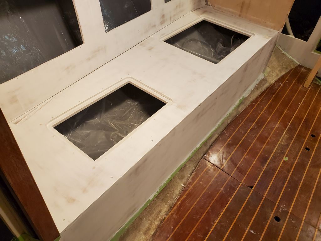
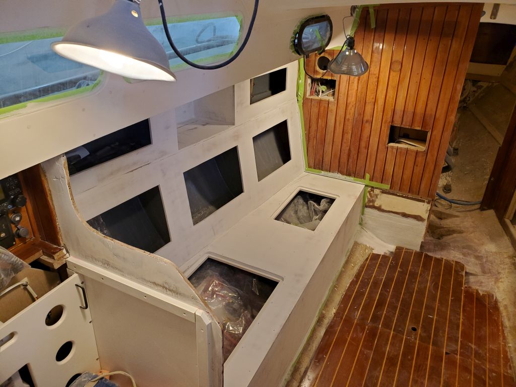
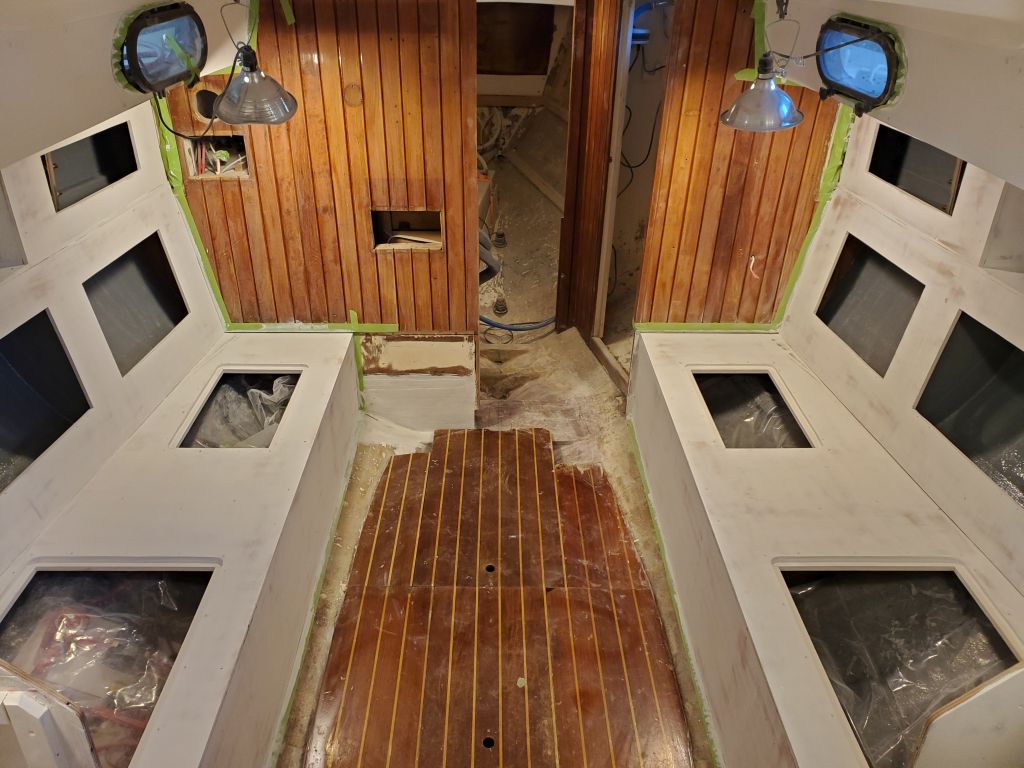
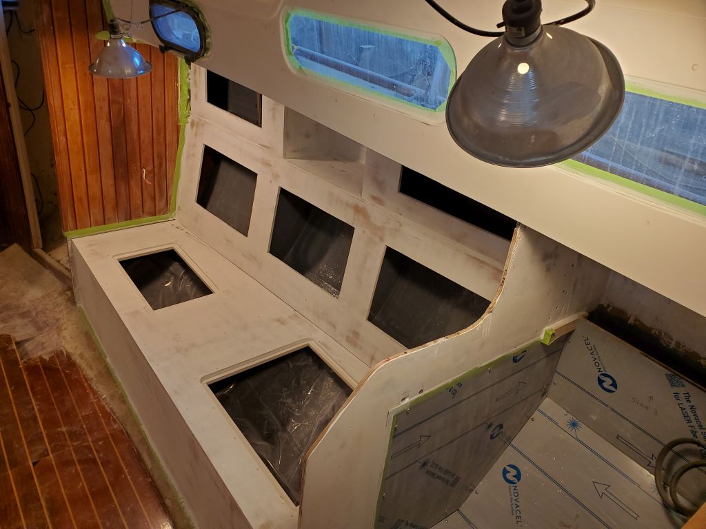
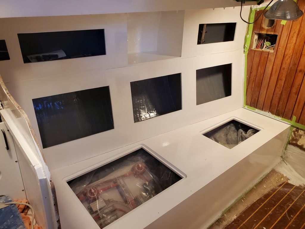
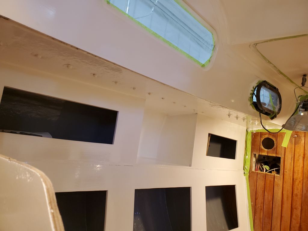
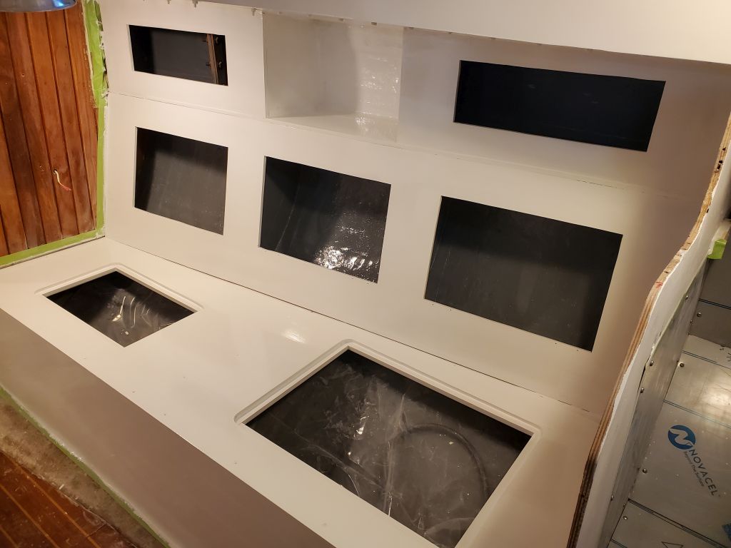
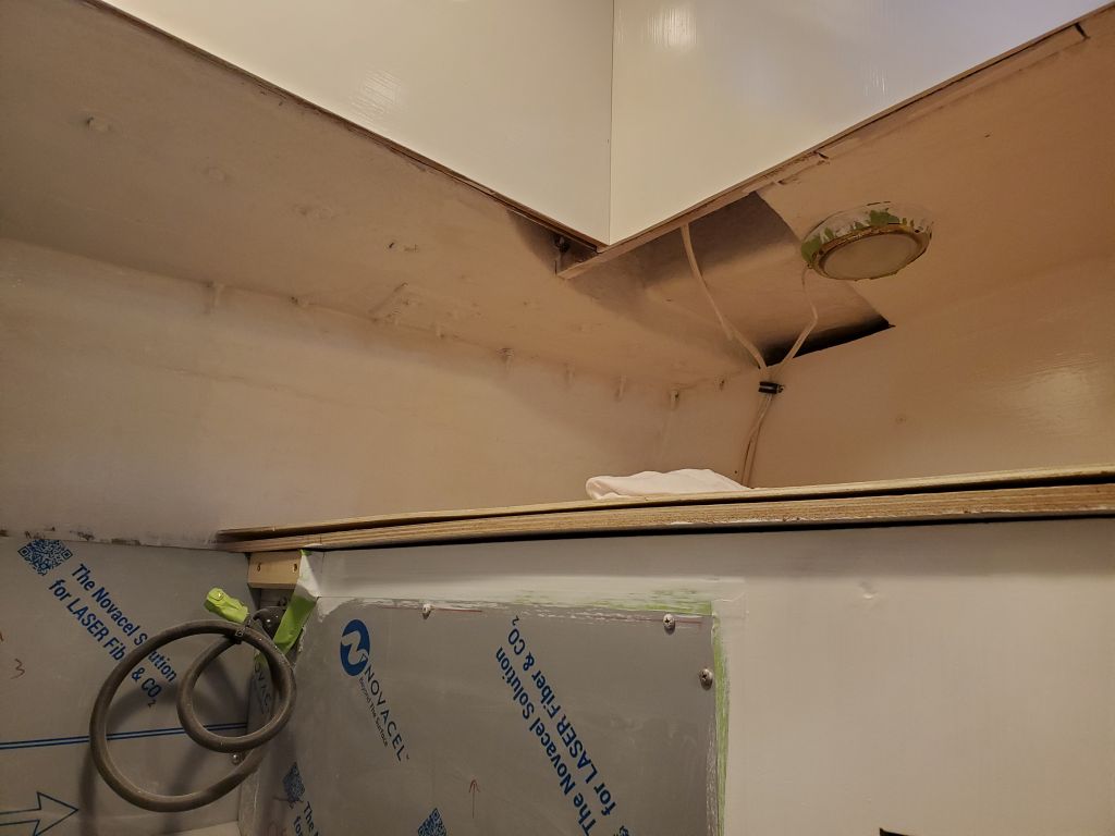
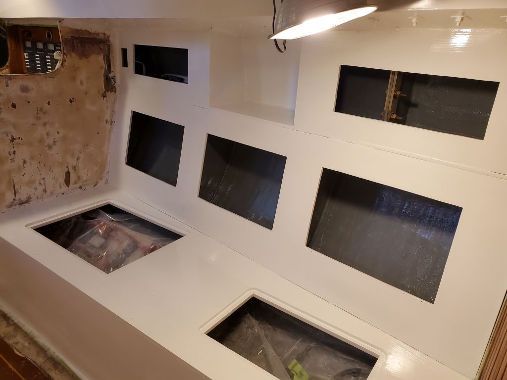
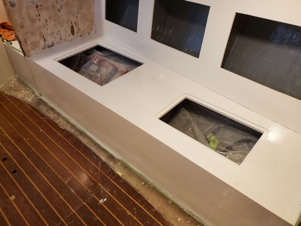
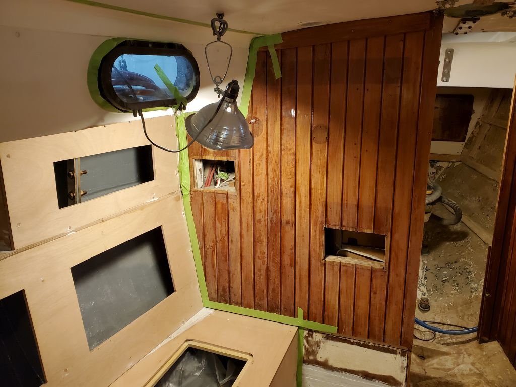
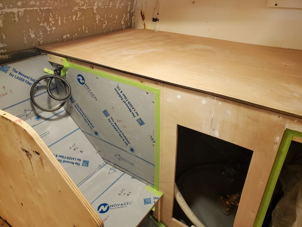
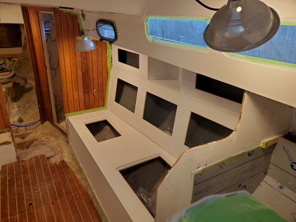
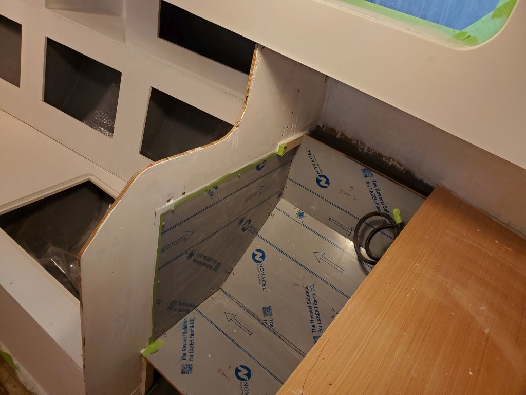
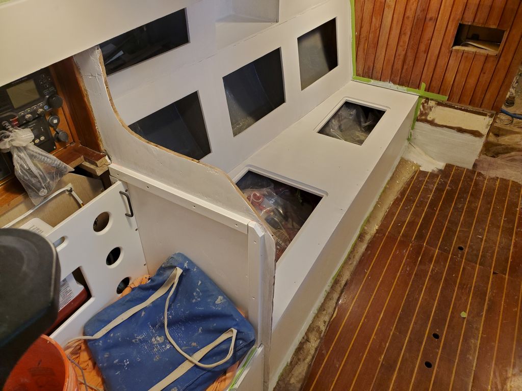
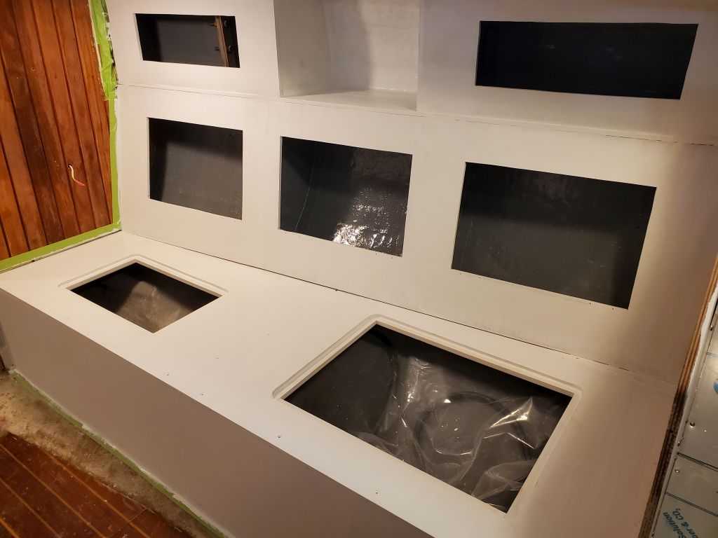
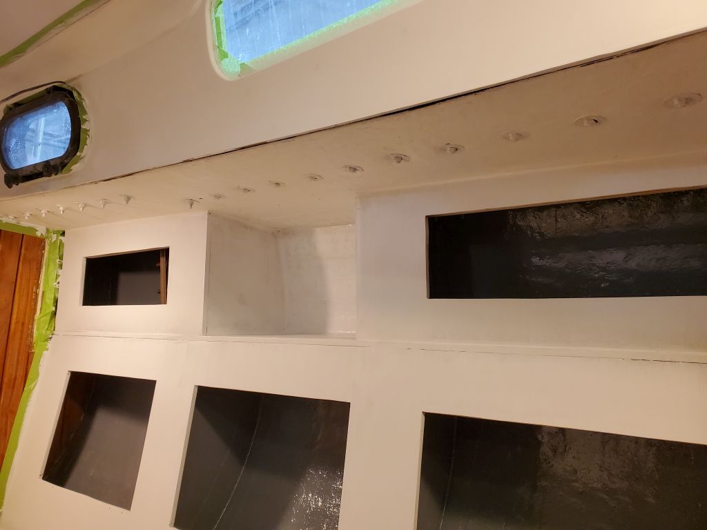
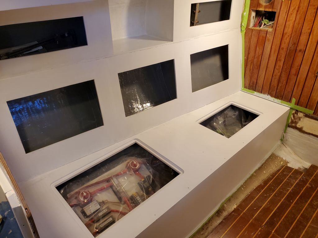
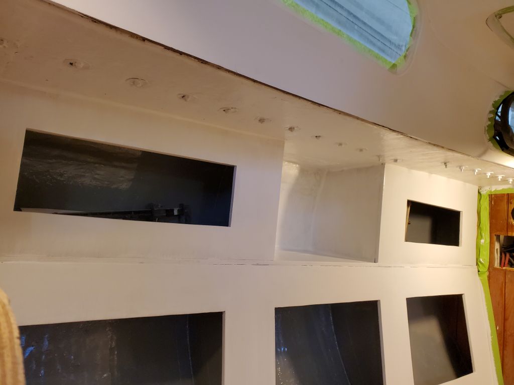
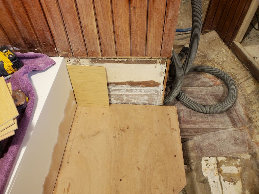
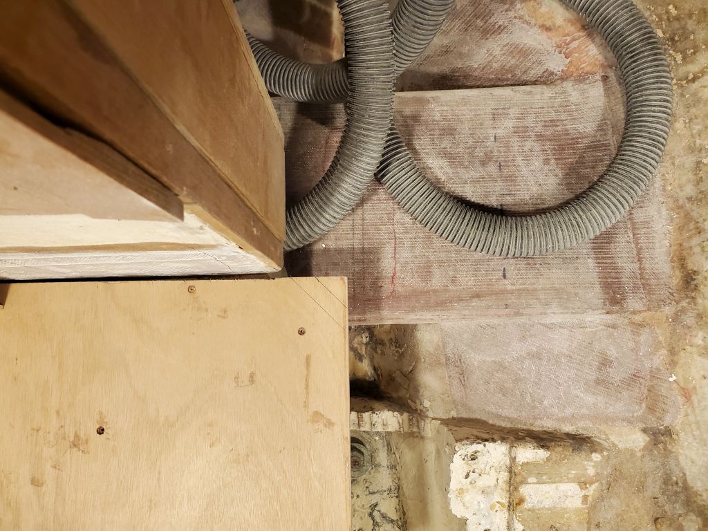
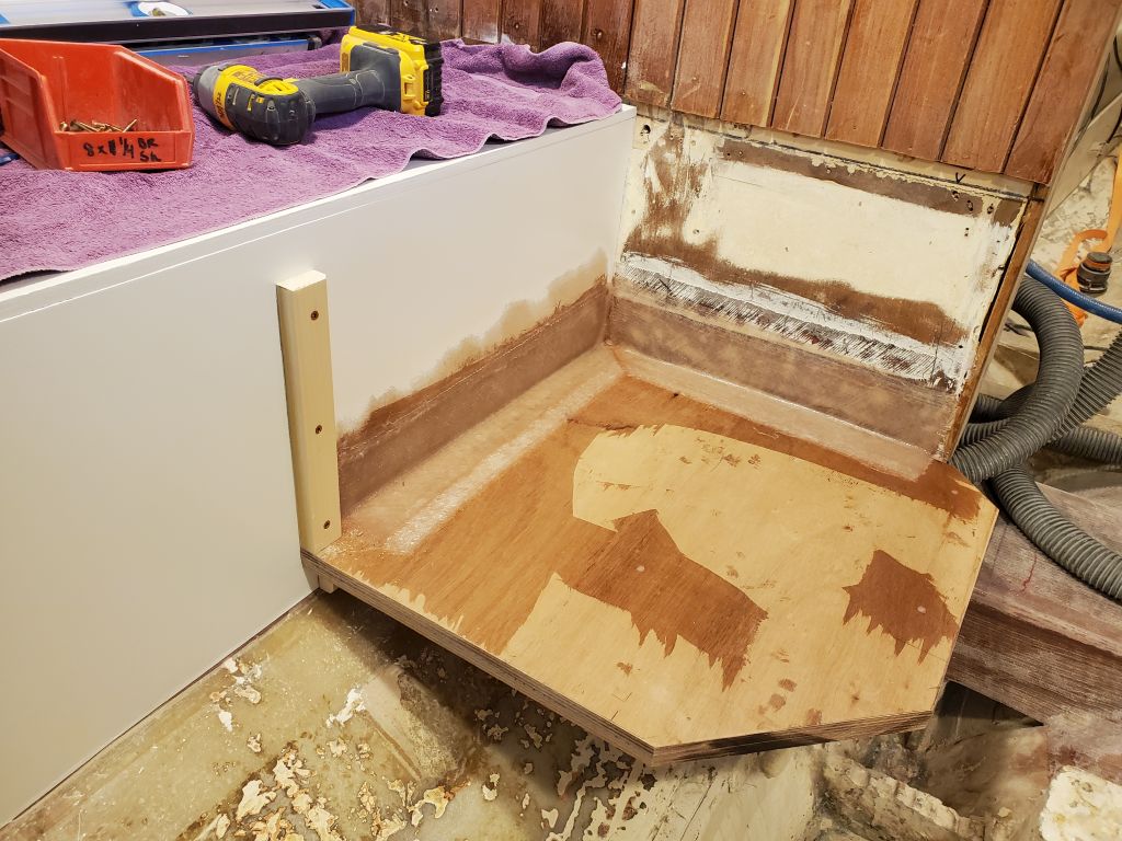
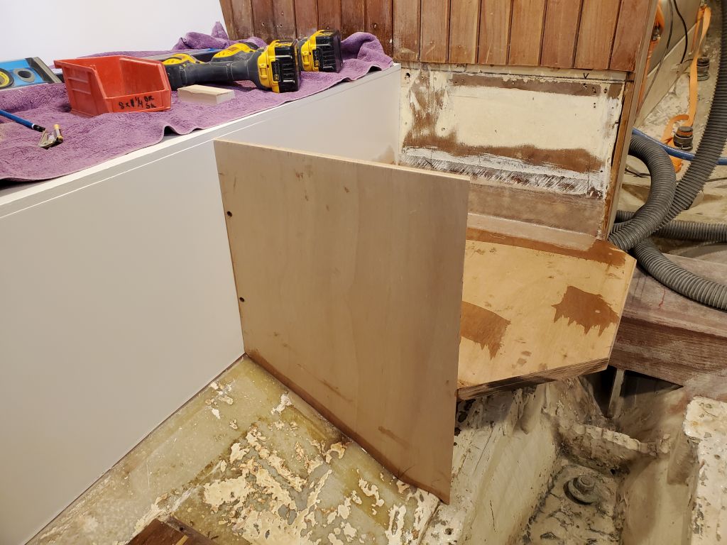
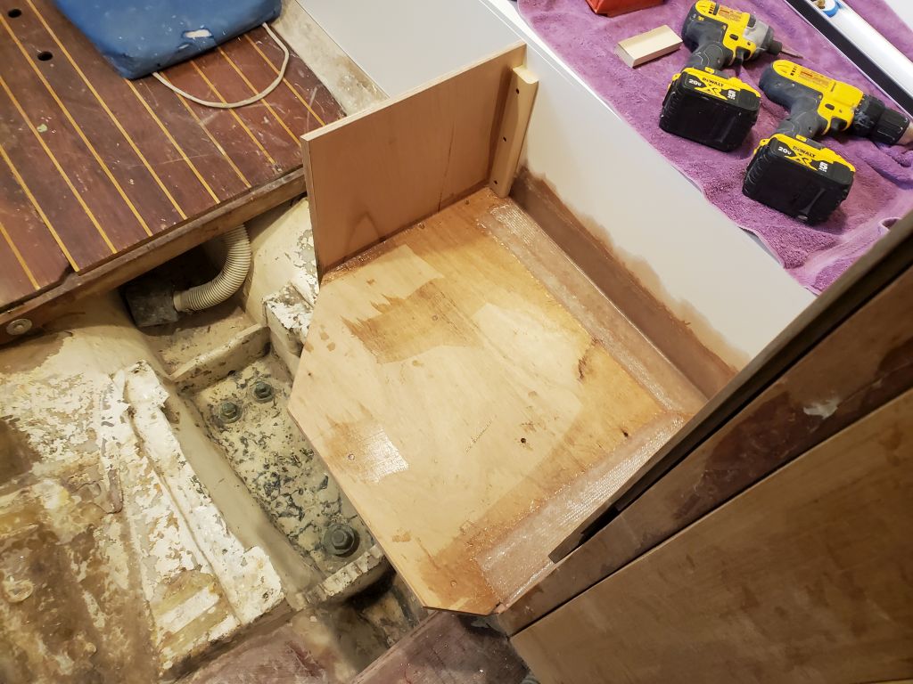
In the afternoon, I worked on the after bulkhead to define and support the platform and storage box further. I’d left space for, and now installed, a vertical support cleat at the aft end of the platform, then cut and scribed a slightly-oversized piece of plywood to fit, eventually trimming it to the correct height and width, with a 22.5° angle at the inboard corner where the box would continue to wrap around the platform. Eventually, with the fit complete, I made the installation permanent with a support cleat beneath the platform (marked in place and installed down in the woodshop), and installed the new aft panel with epoxy adhesive on all possible faying surfaces, finishing up with two layers of tabbing where the bulkhead met the hull (beneath the platform). This part of the platform formed the main basis of support for its entire eventual weight; I’d not yet determined whether the remaining sides would sit atop the new cabin sole or form the support for the sole itself, but in either event I wasn’t counting on these sides being critical structural support for the weight of the batteries. Ultimately, I also planned to fiberglass all the inside seams of the box, once complete, so the entire structure would work together for increased strength.
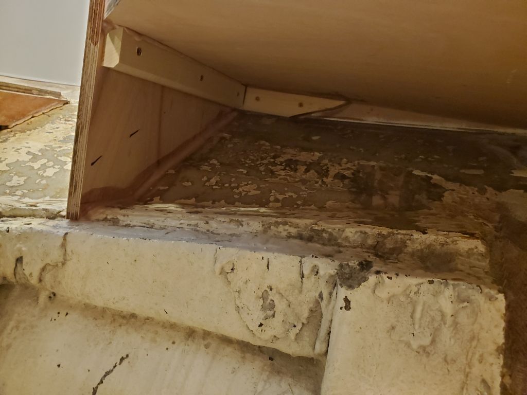
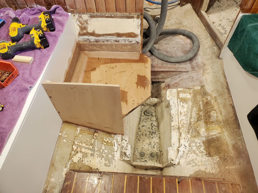
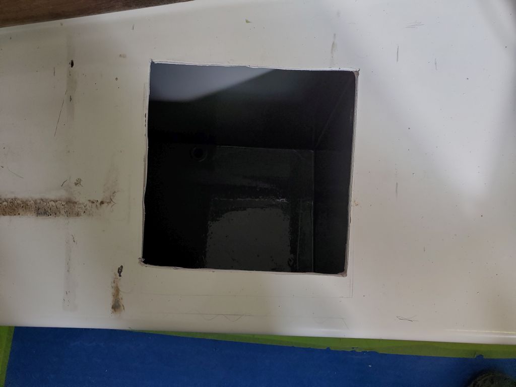
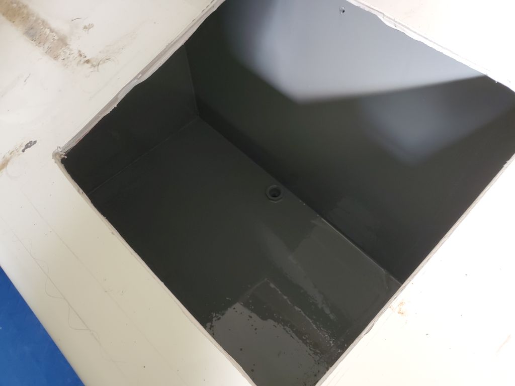
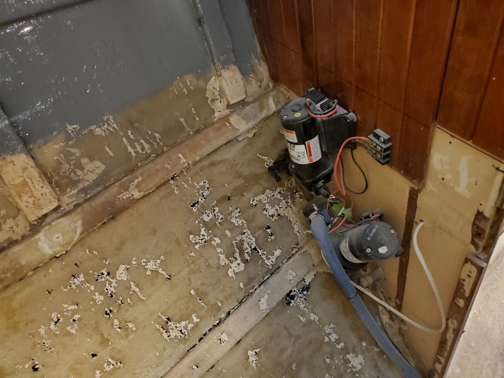
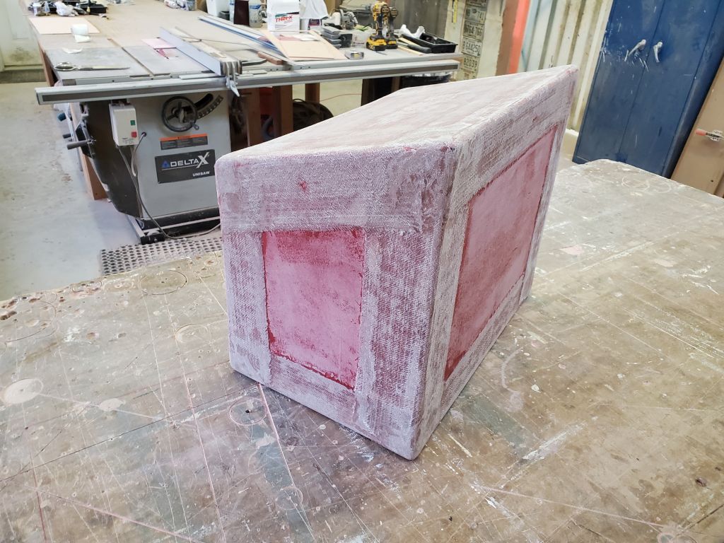
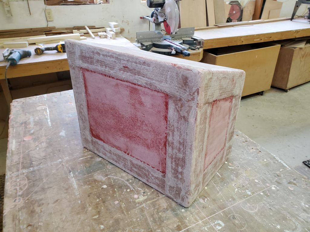
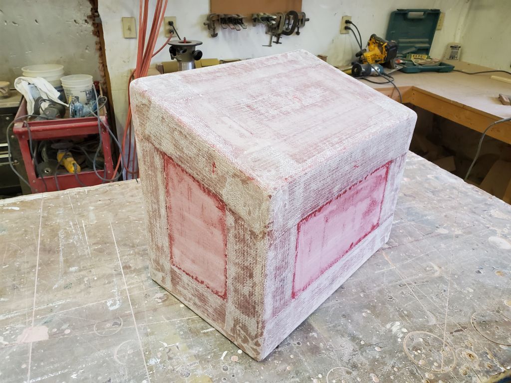
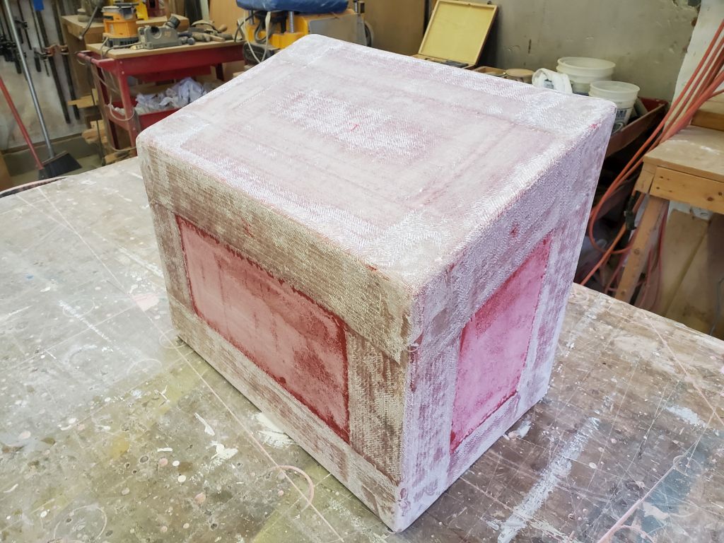
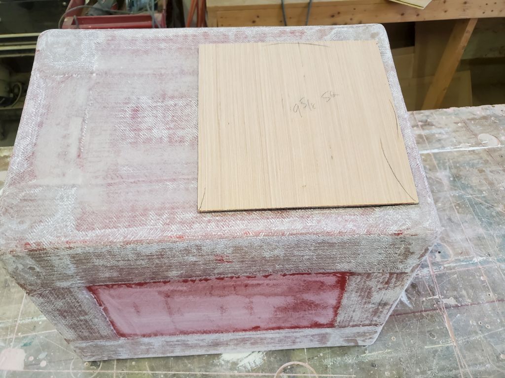
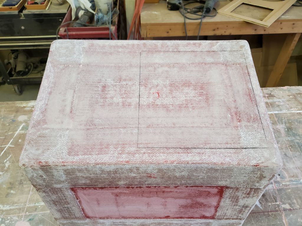
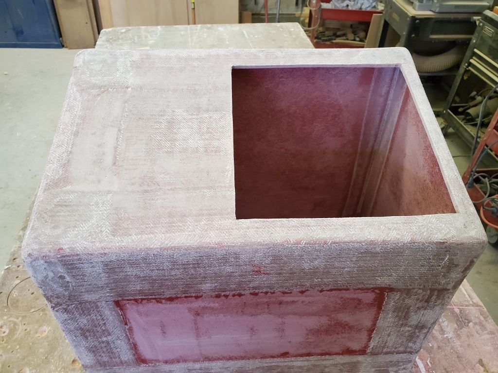
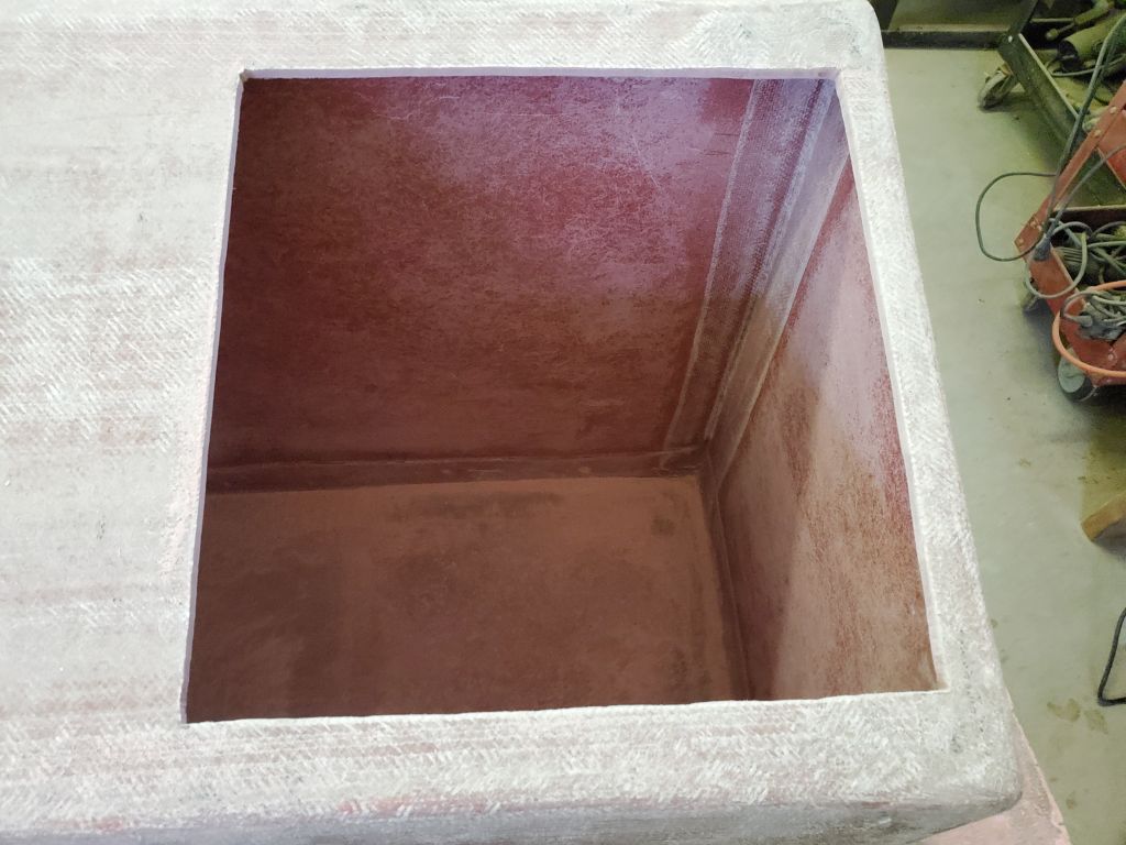
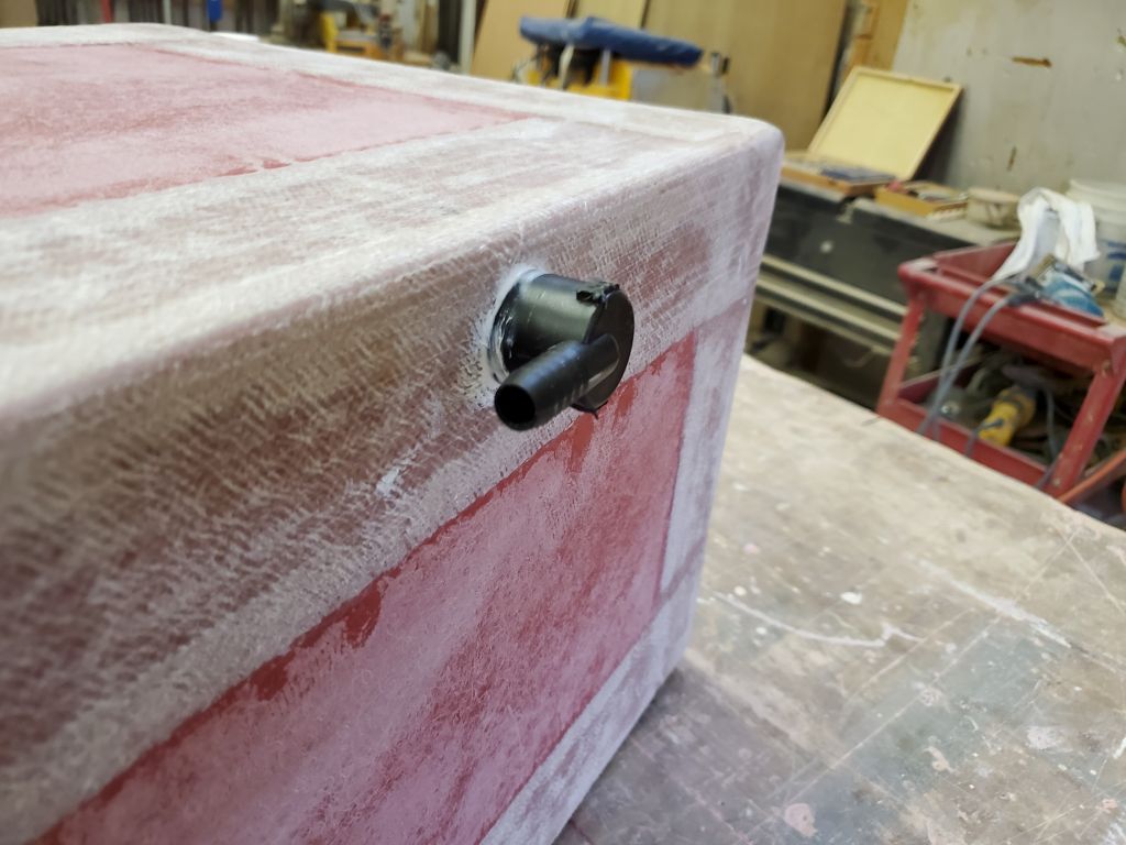
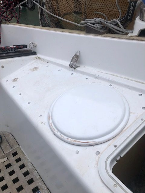
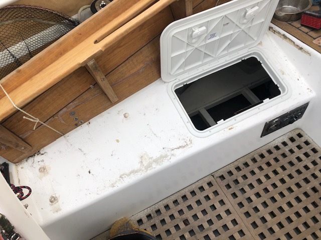
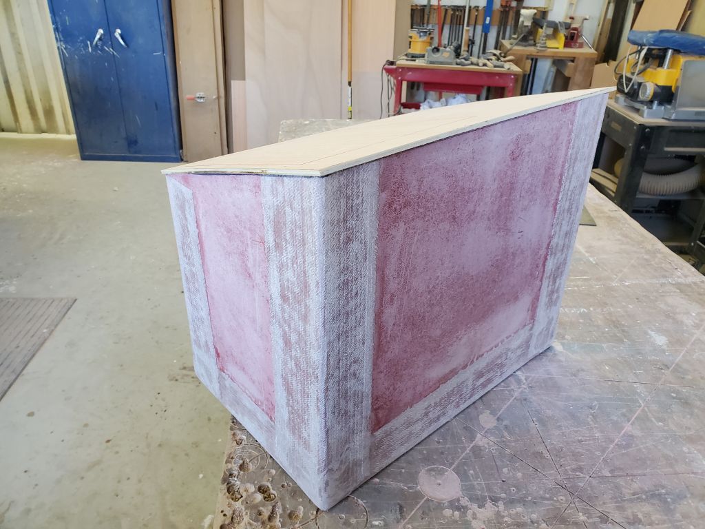
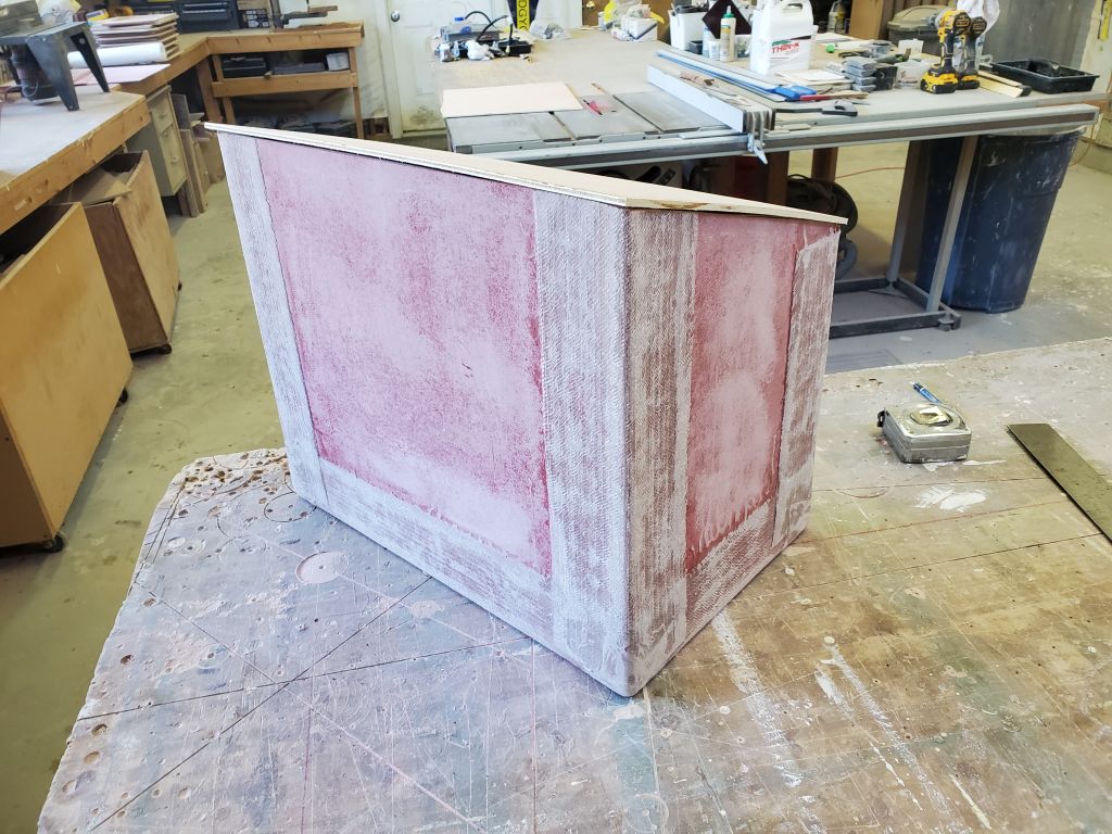
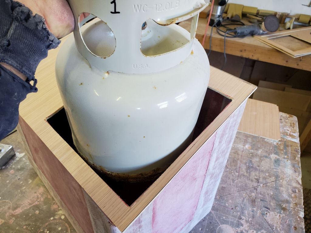
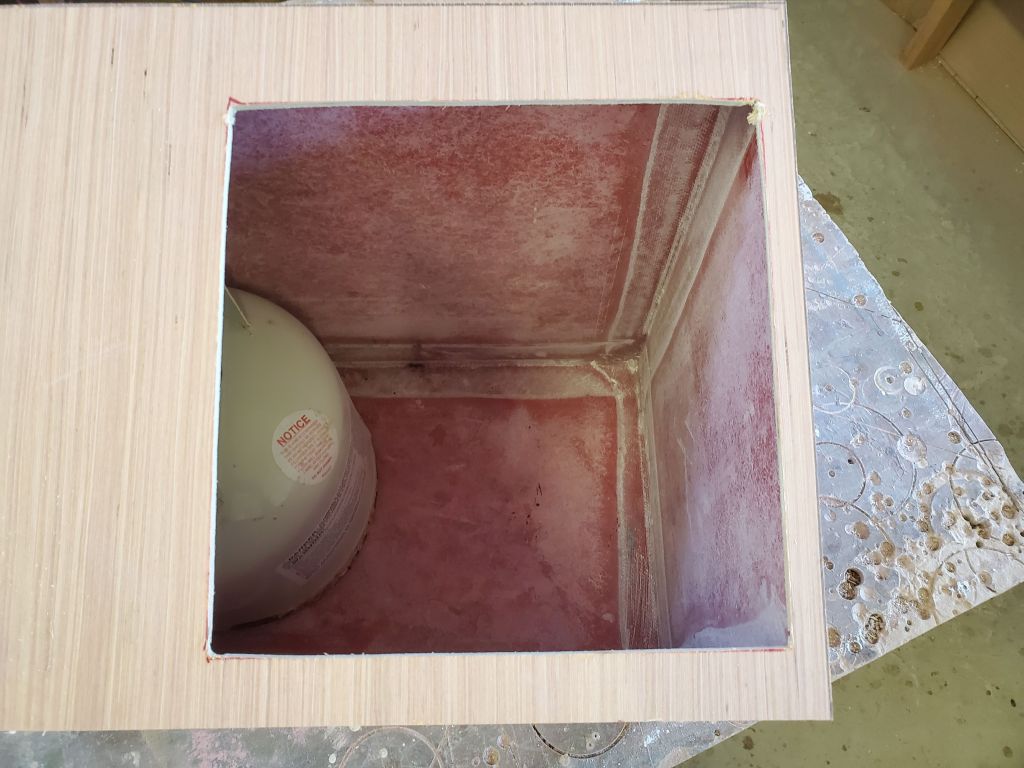
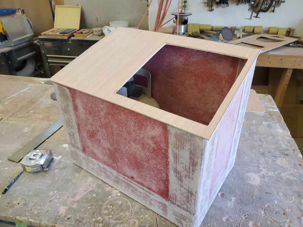
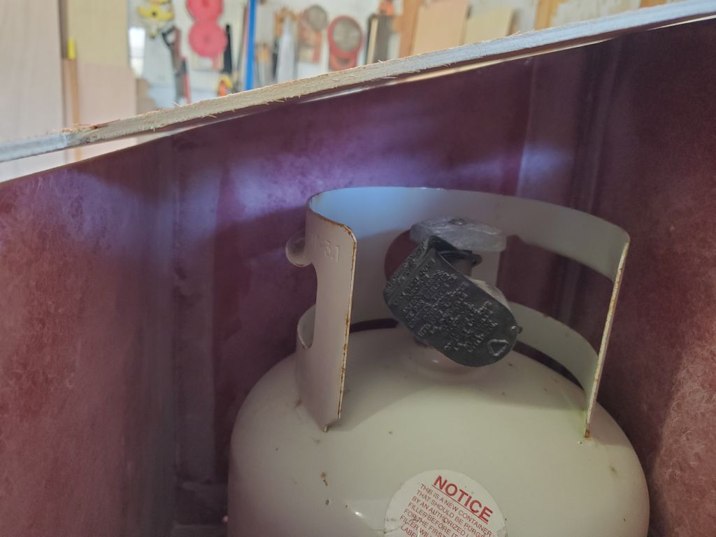
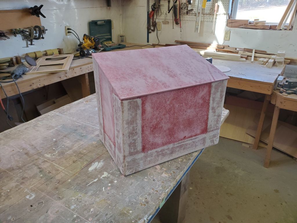
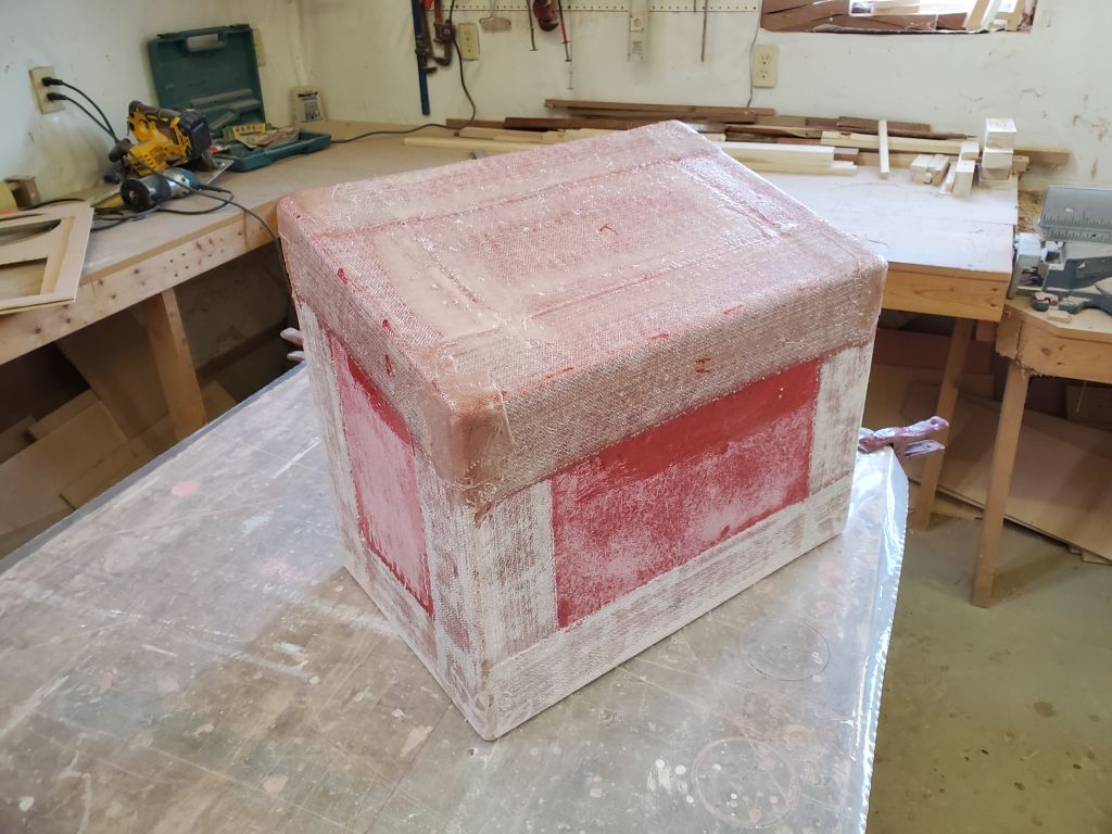
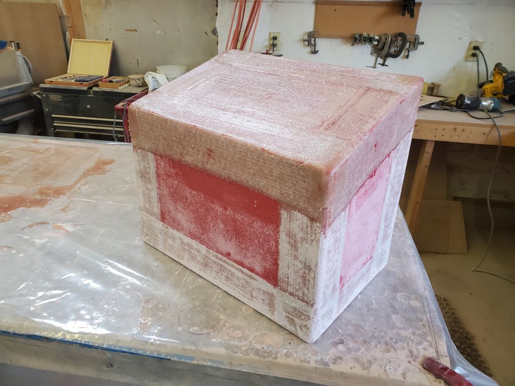
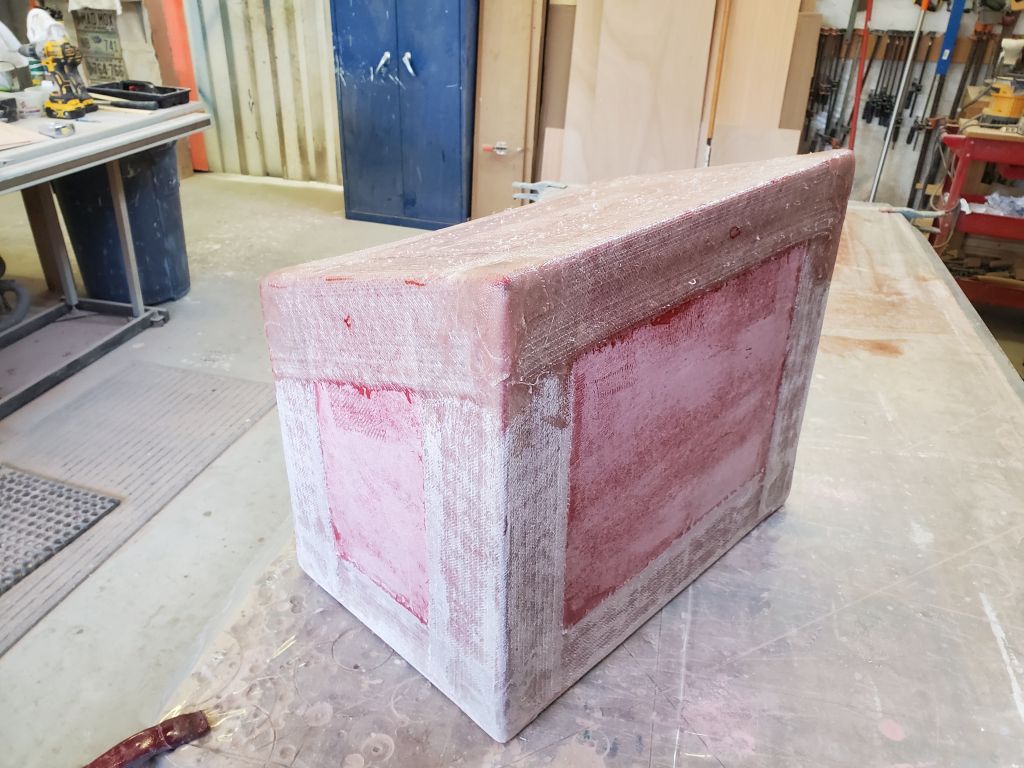
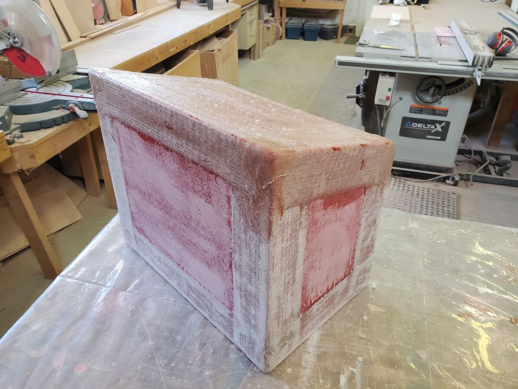
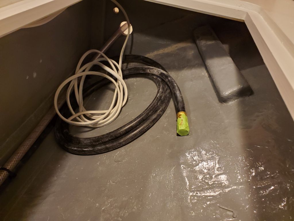
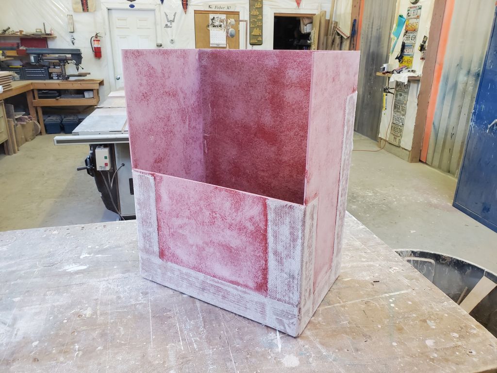
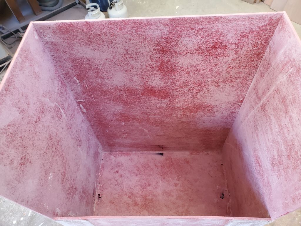
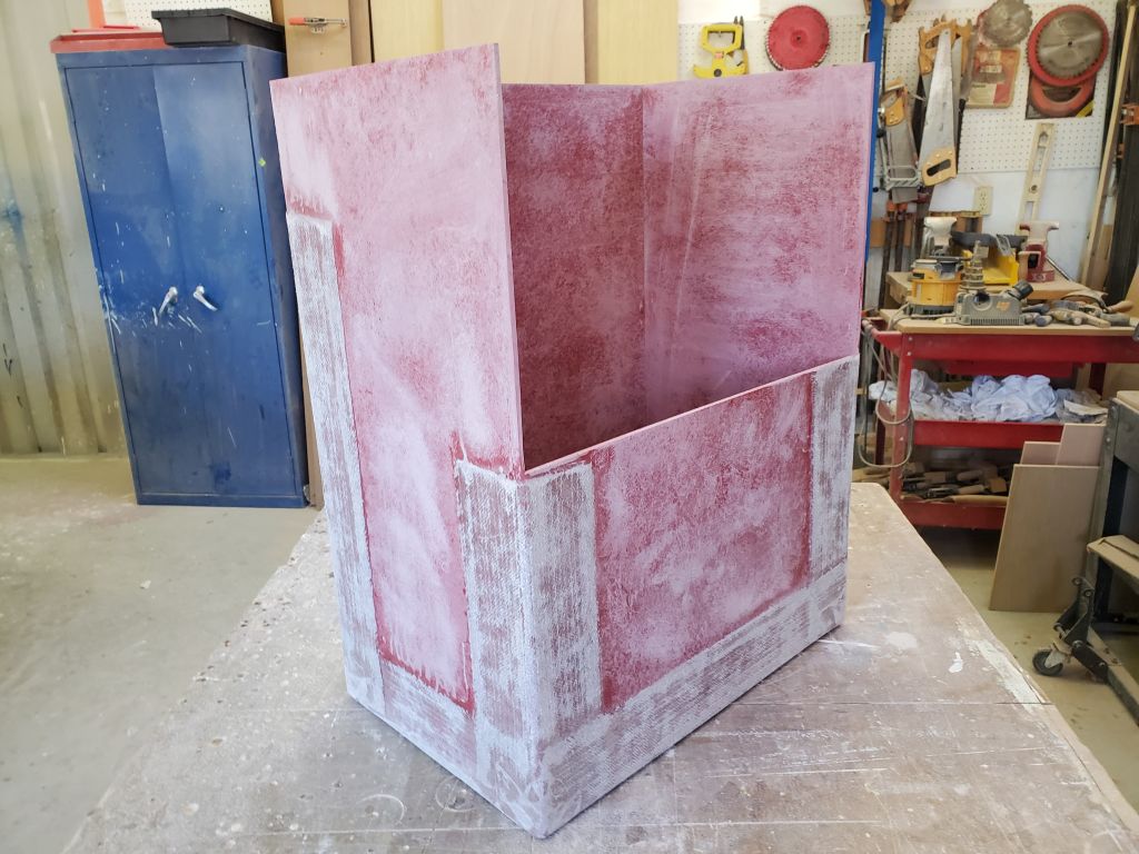
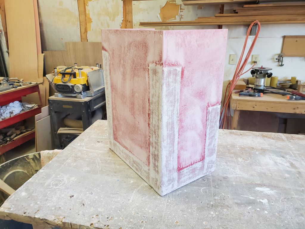
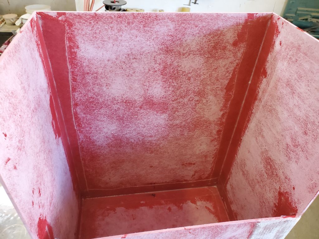
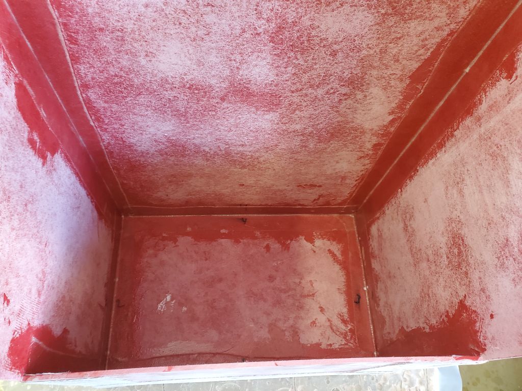
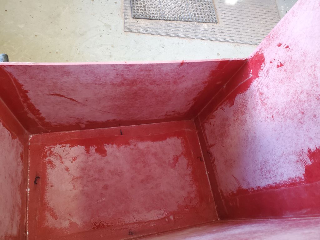
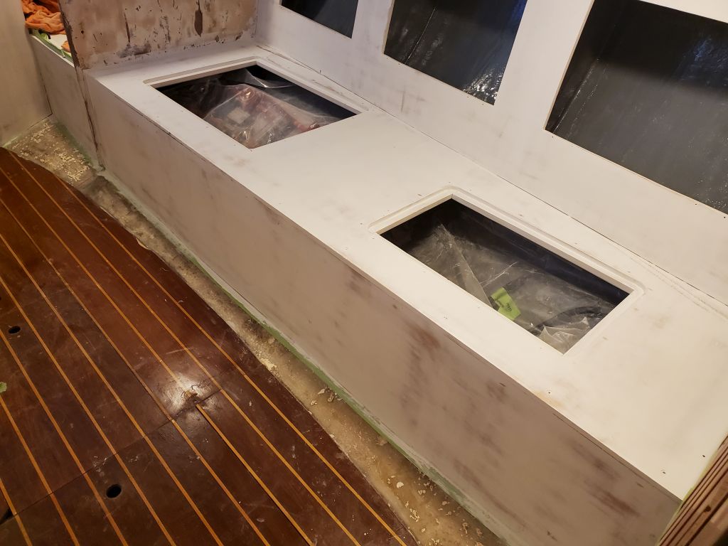
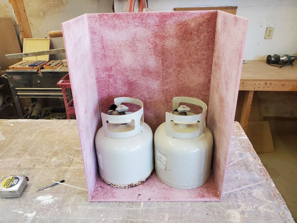
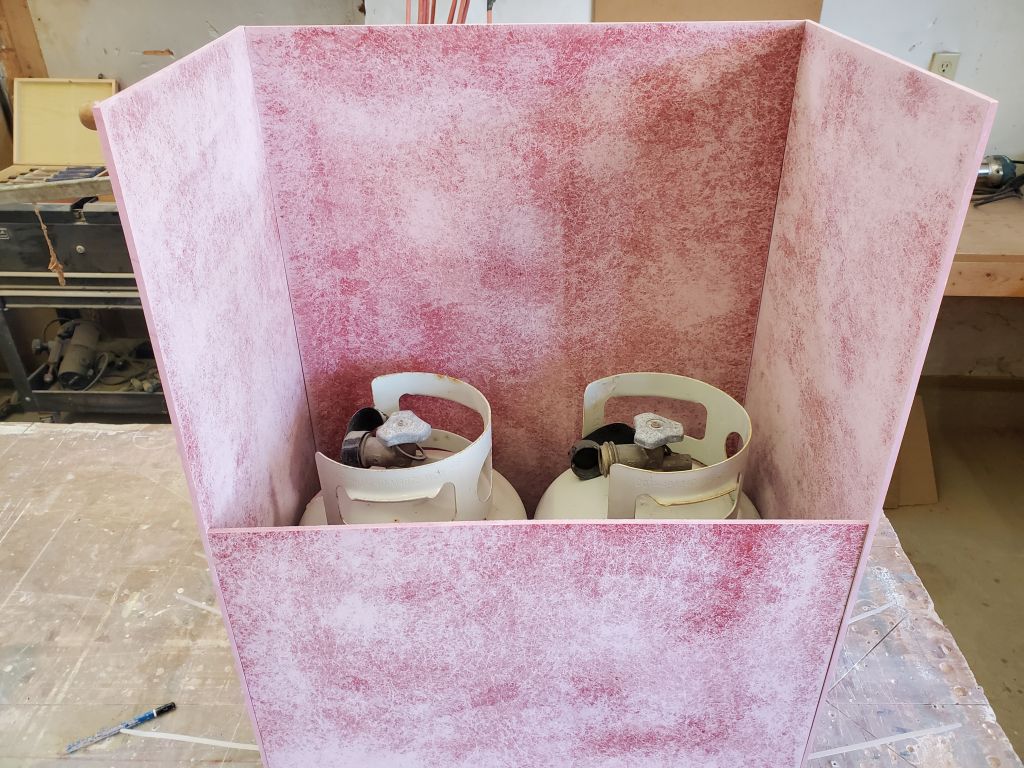
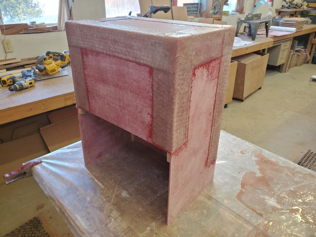
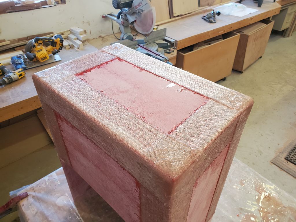
I thought I’d probably install a longitudinal support beneath the platform, generally on top of the old engine foundation that ran beneath, but that would be a job for next time as the day was running short, and before I left I wanted to get the propane box painted inside and out.