Next on the agenda was the cabin sole replacement. For various reasons, I’d somehow put this off throughout the project, though in many ways it would have been better to do it early on. In any event, the time was nigh, and I was ready to focus on the cabin sole. The owner had asked me to try and lower the sole by an inch or so, which would require some reconfiguration of the structural supports (floors), which brought with it various complications.
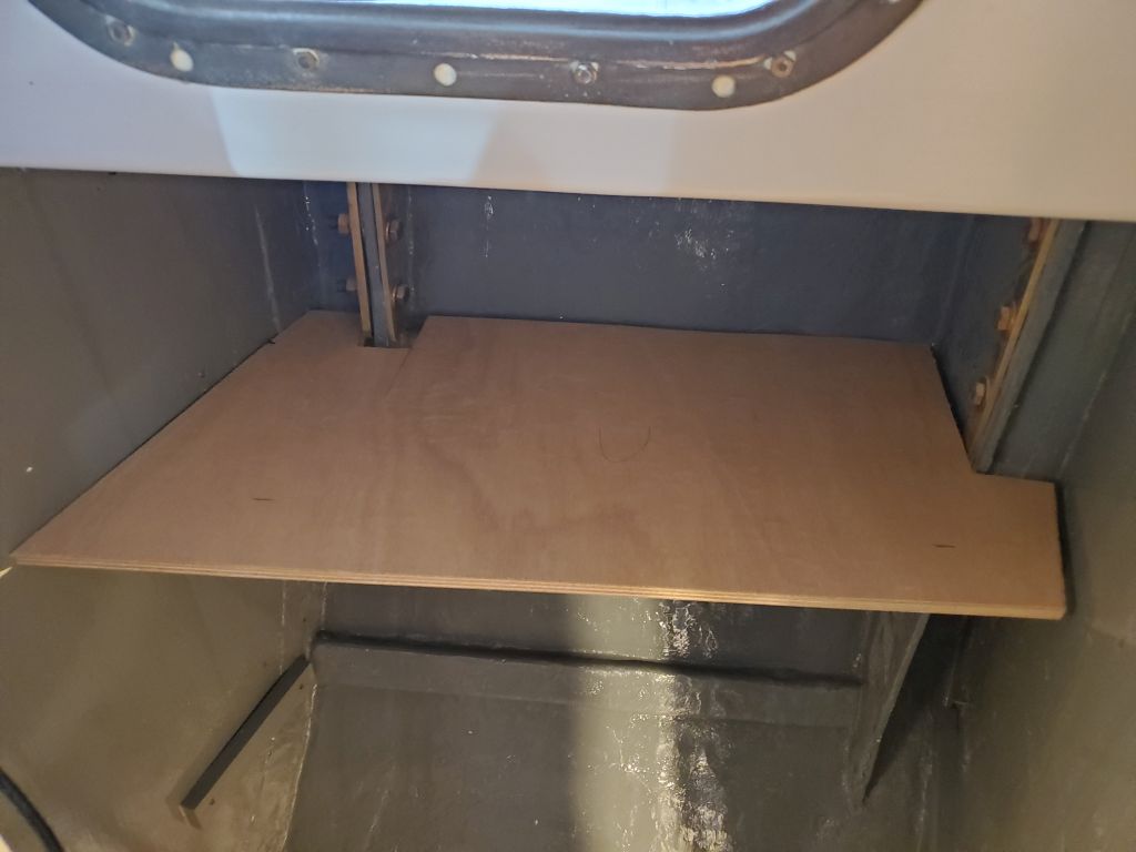
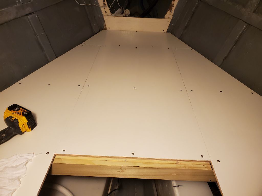
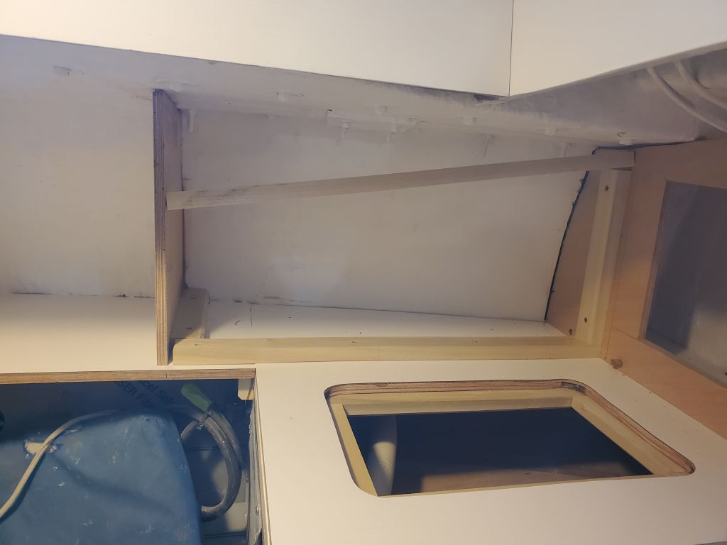
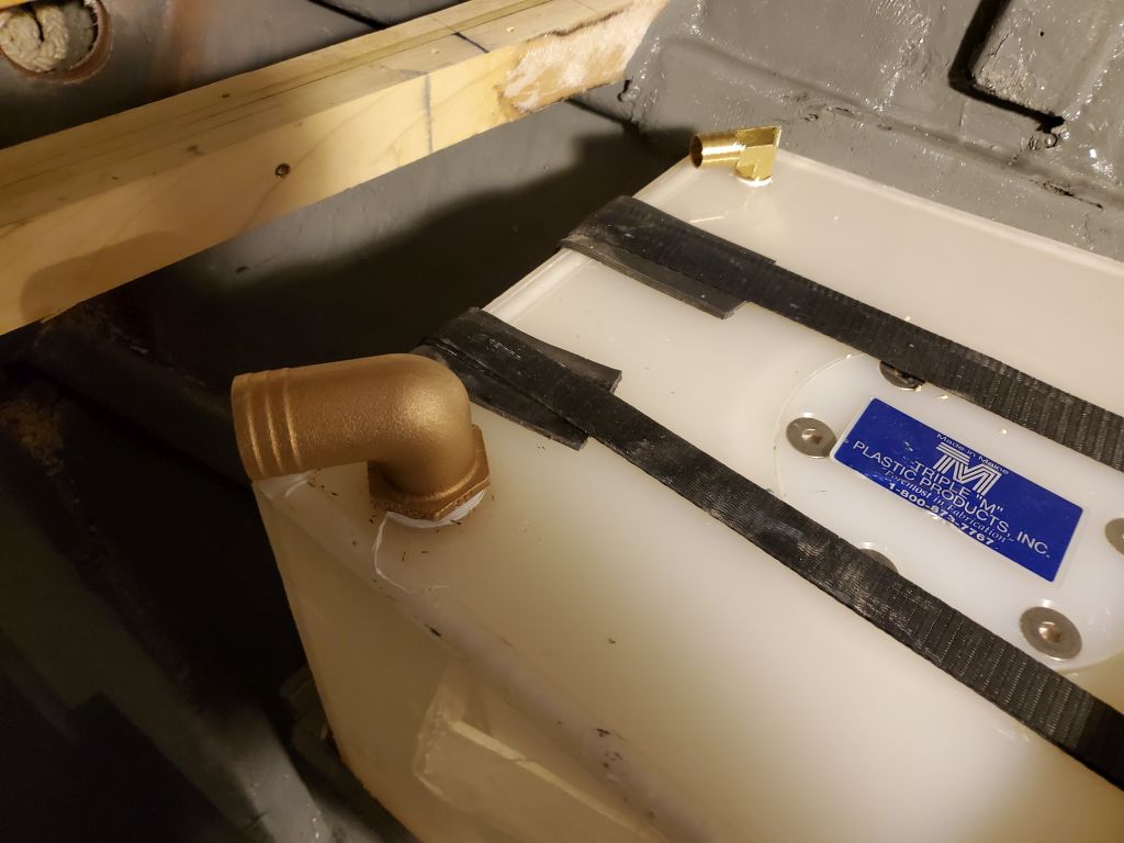
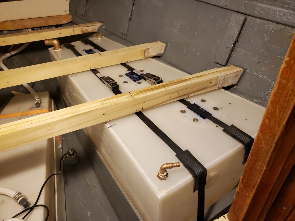
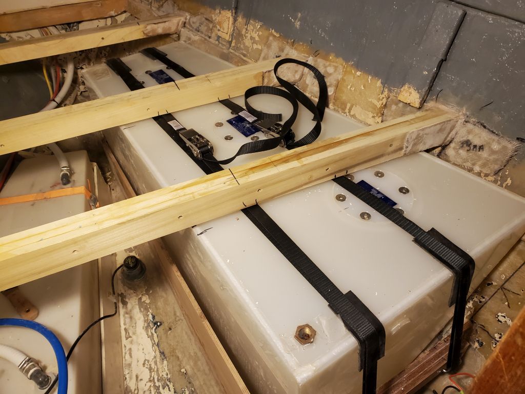
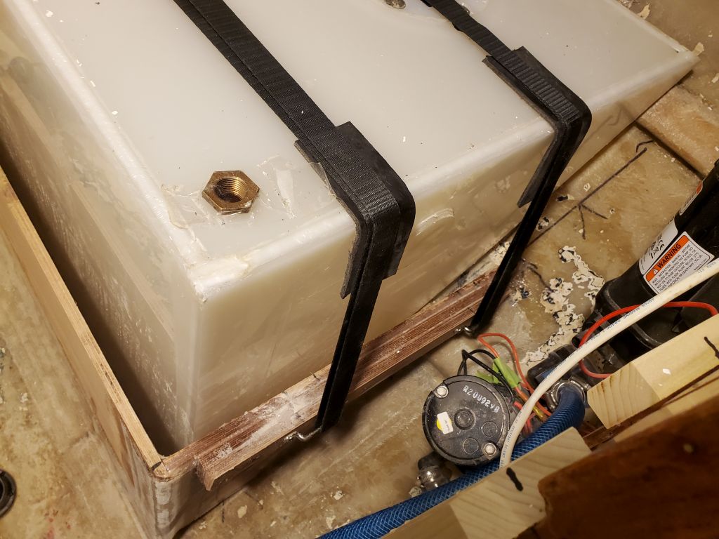
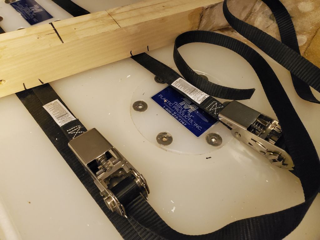
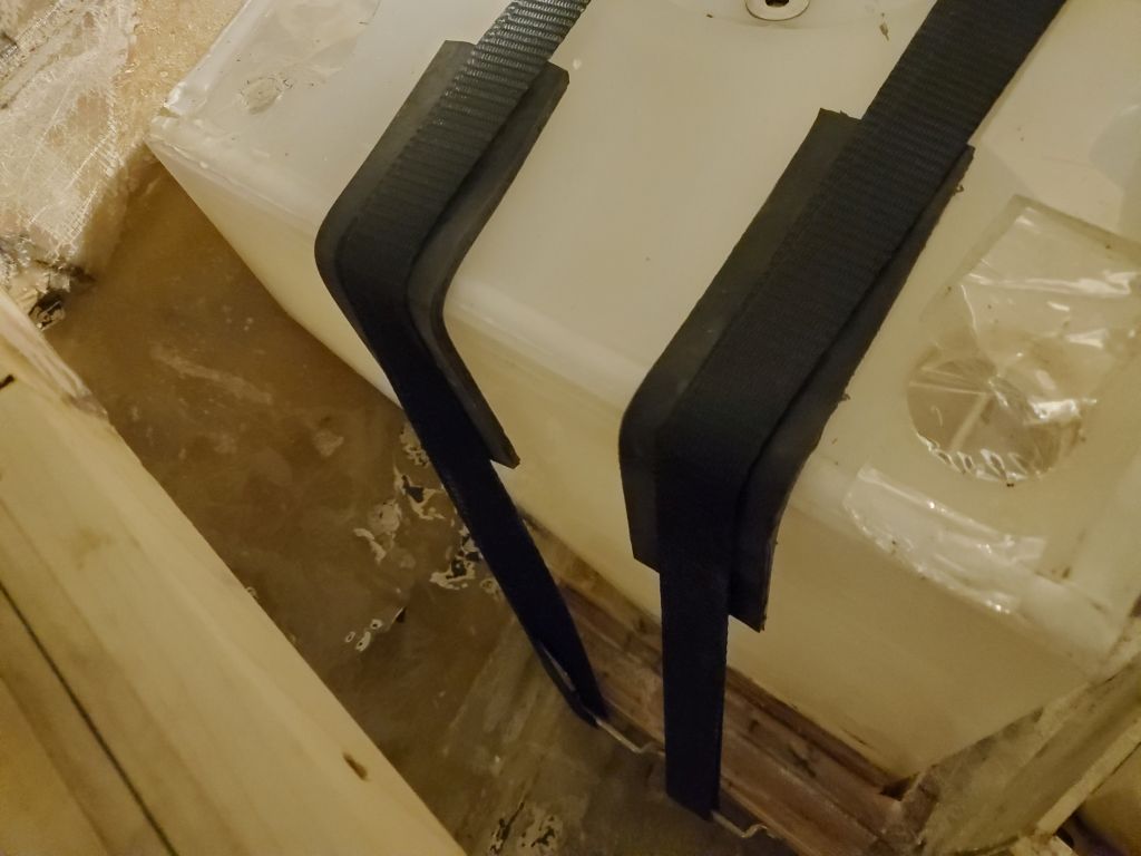
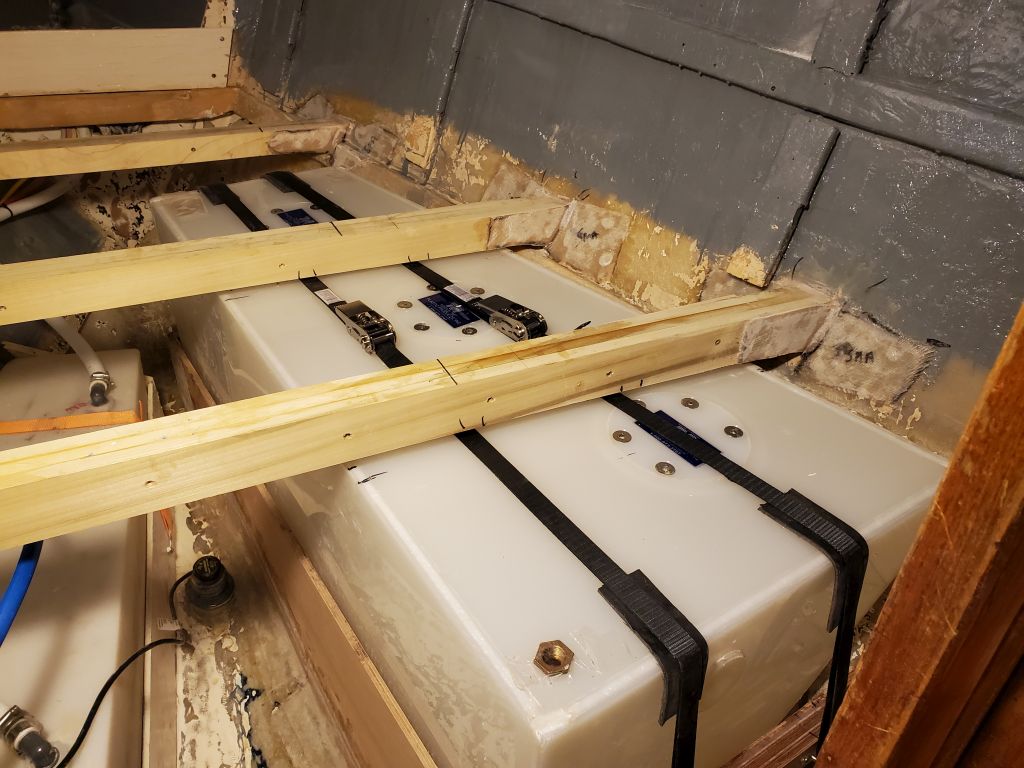
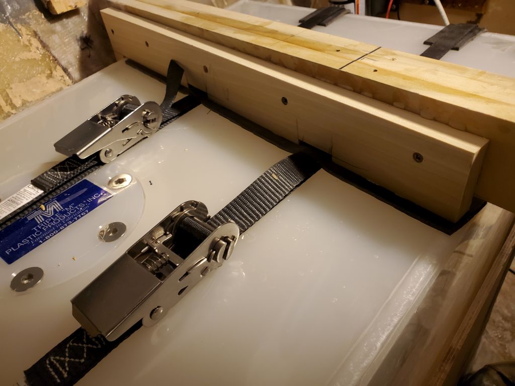
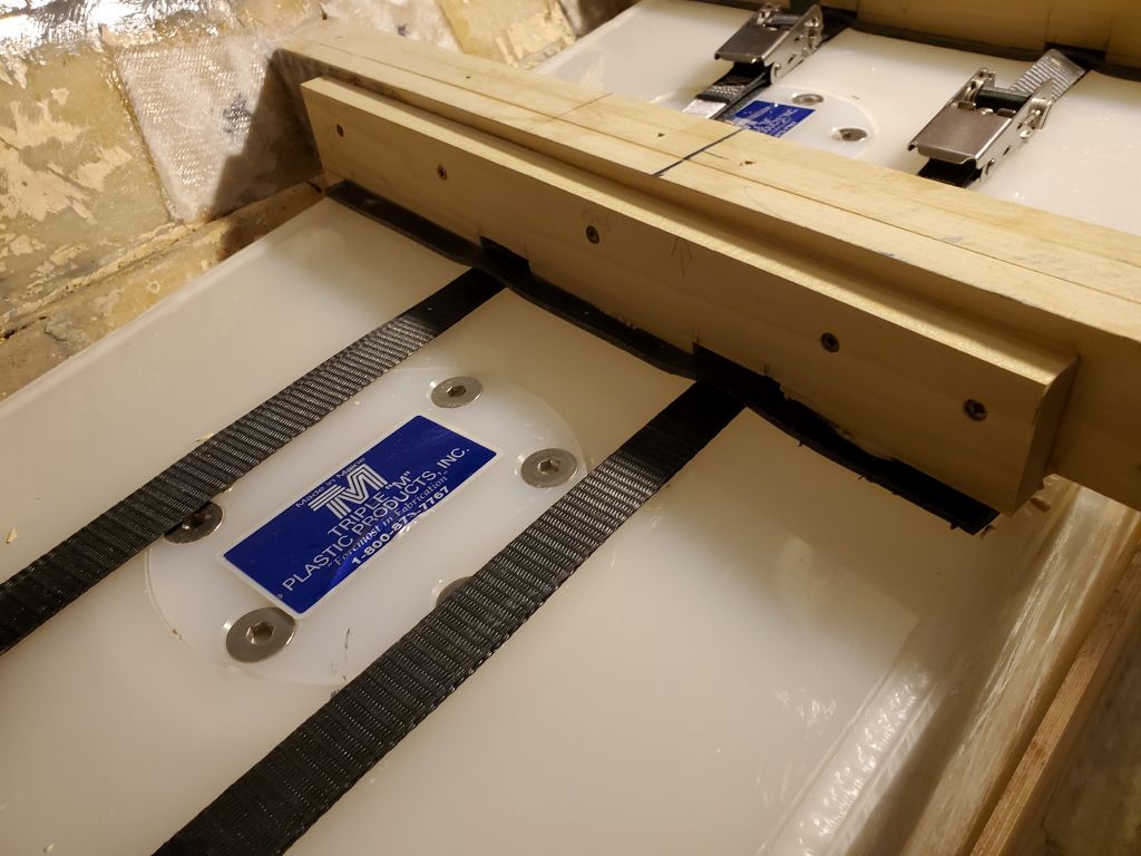
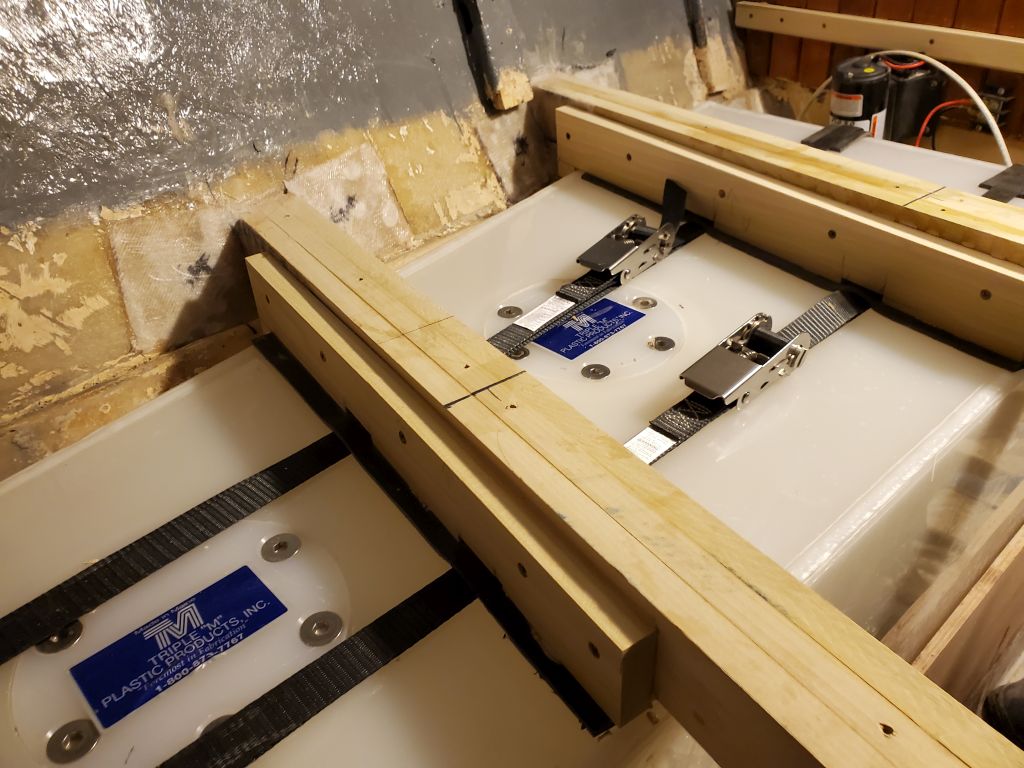
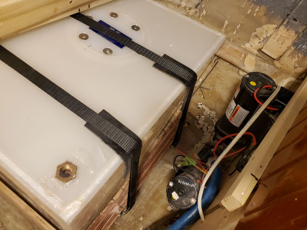
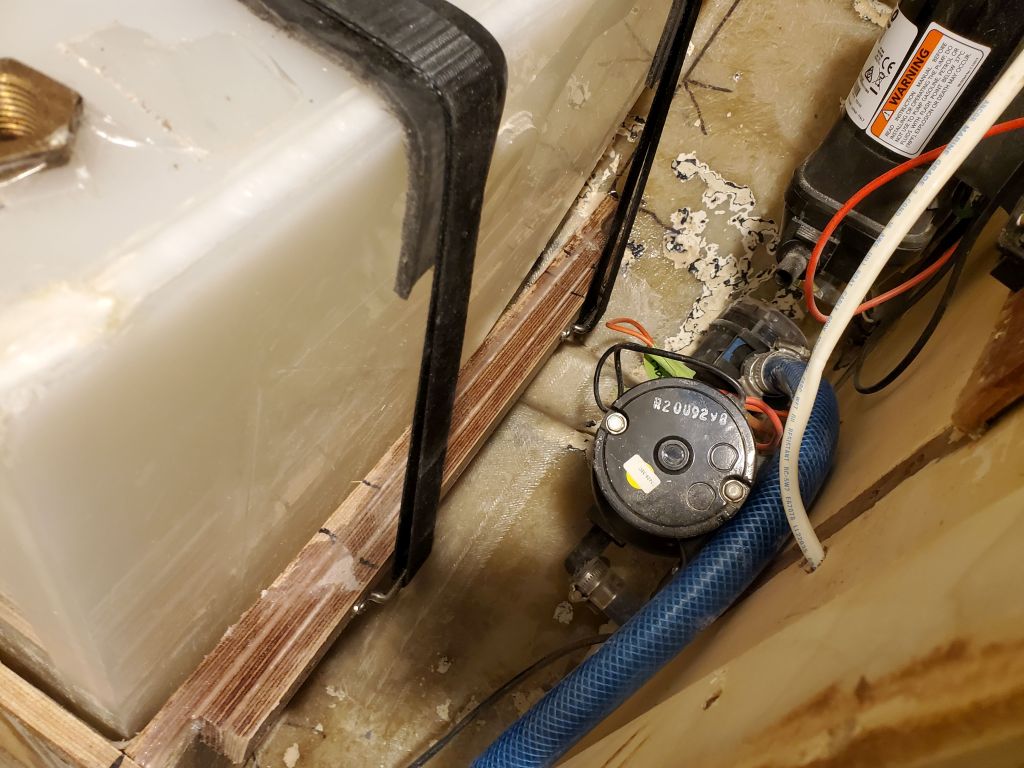
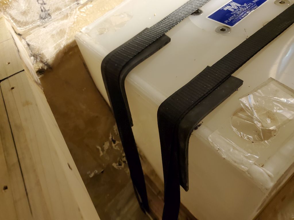
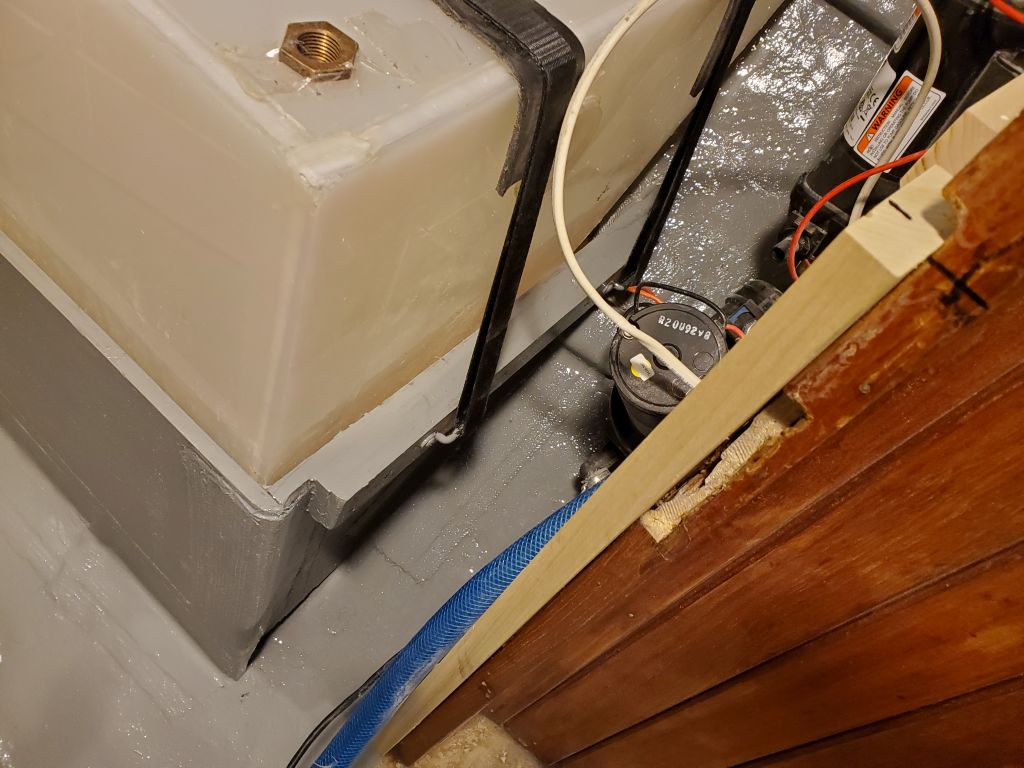
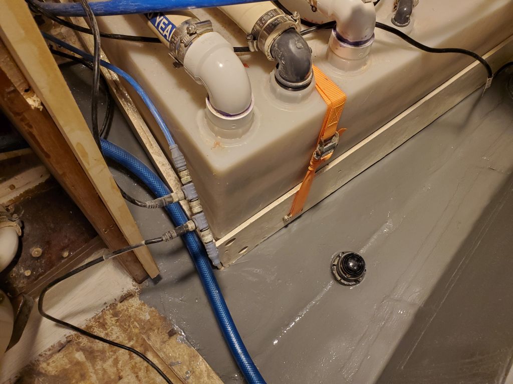
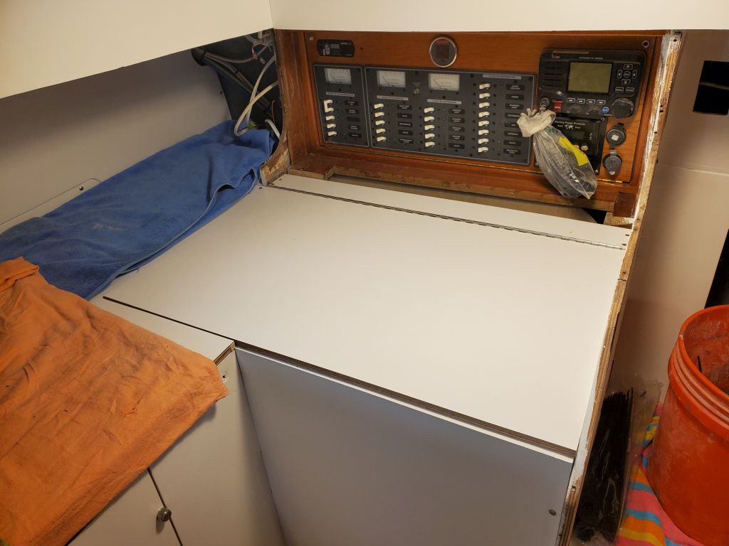
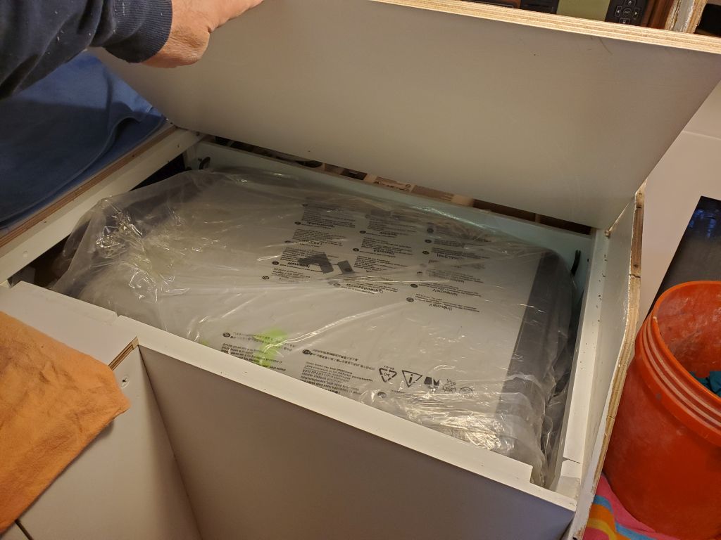
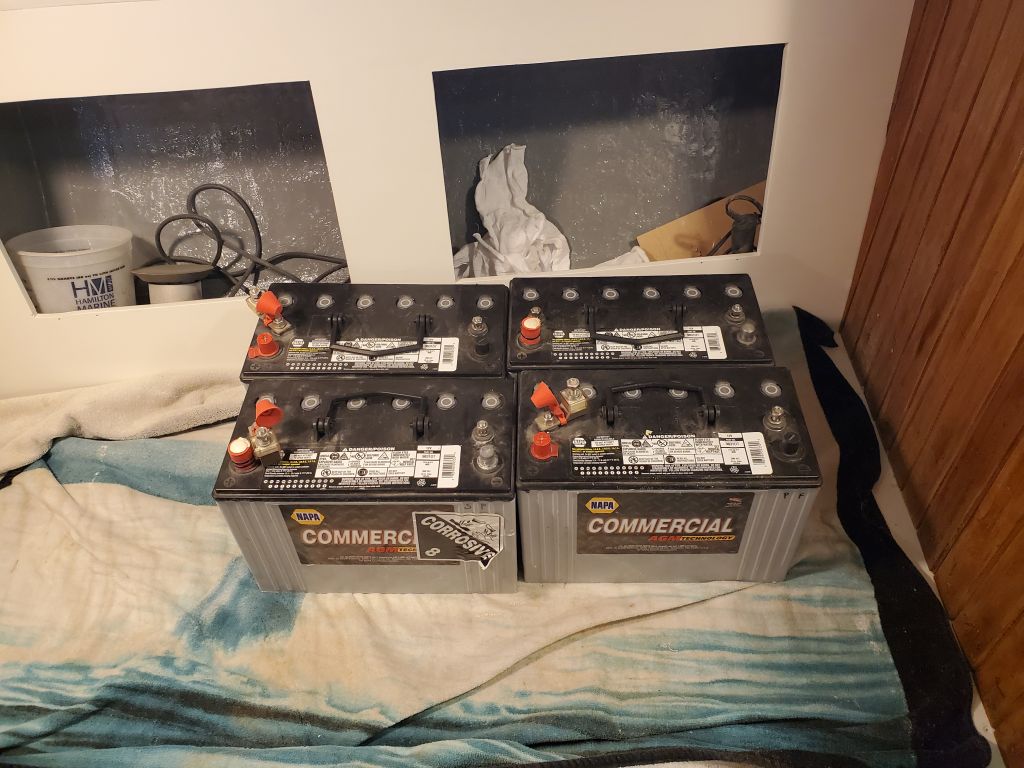
Before removing the sole, I took a moment to get the four batteries back into the boat while I had a platform. I’d stored these in the cockpit throughout the project, and would soon be reinstalling them in the new locker, so I wanted them ready to go.
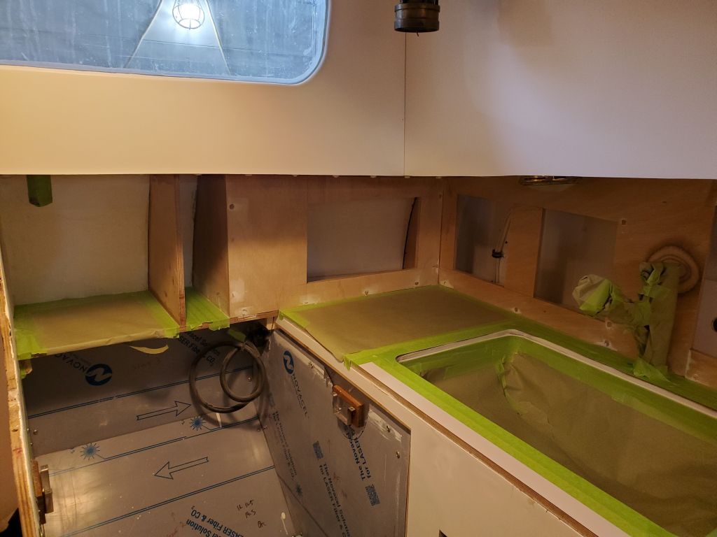
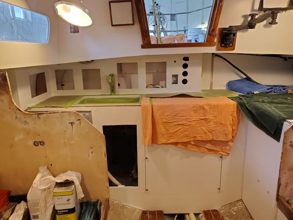
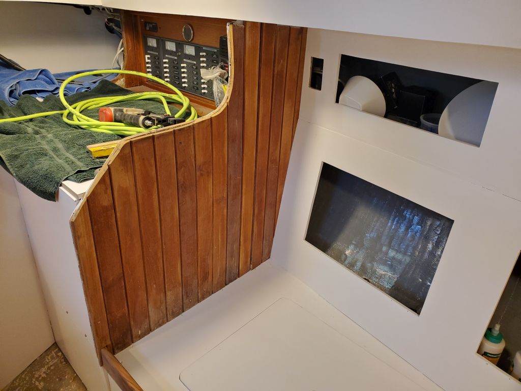
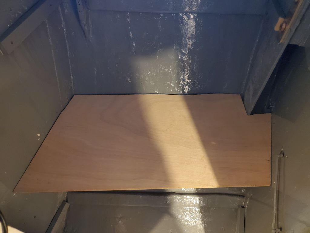
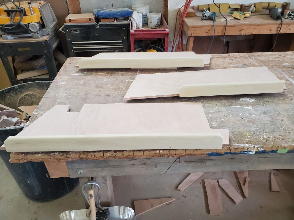
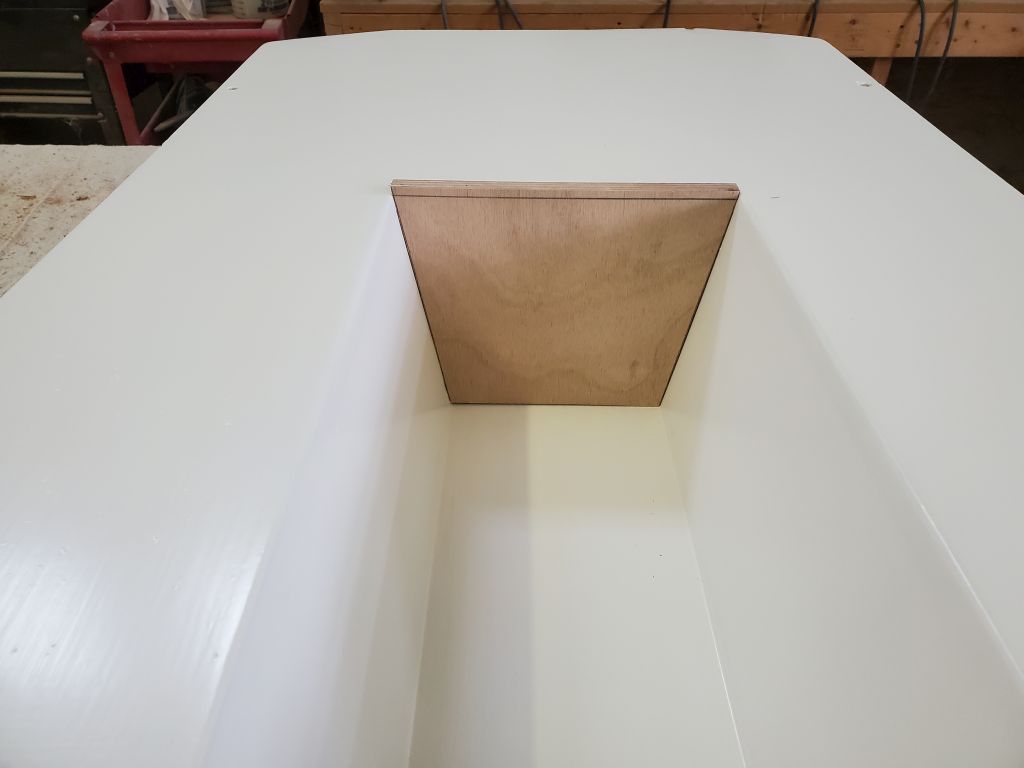
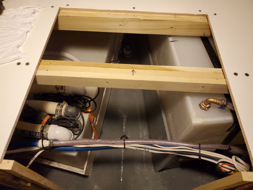
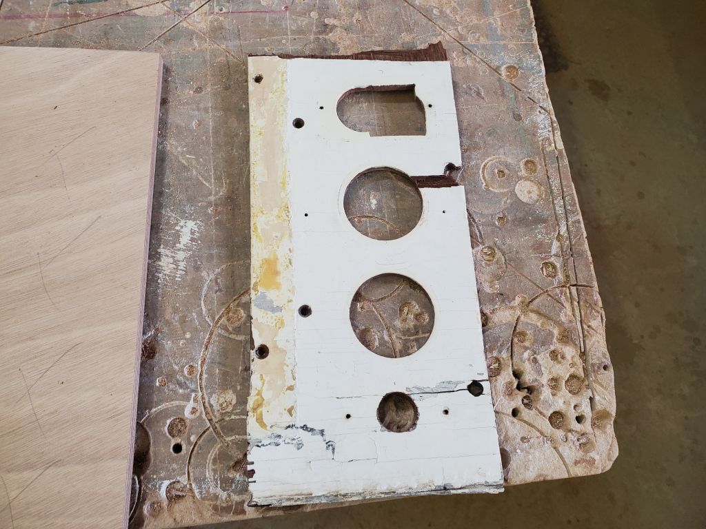
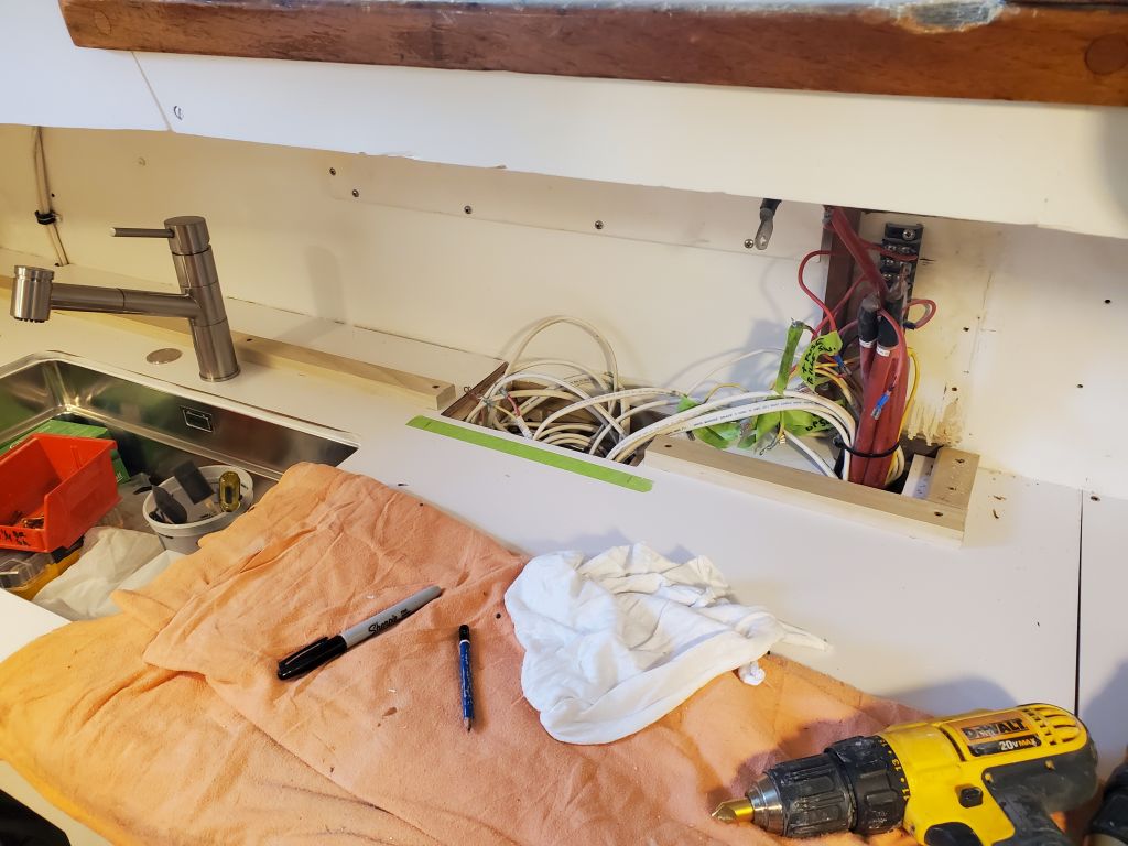
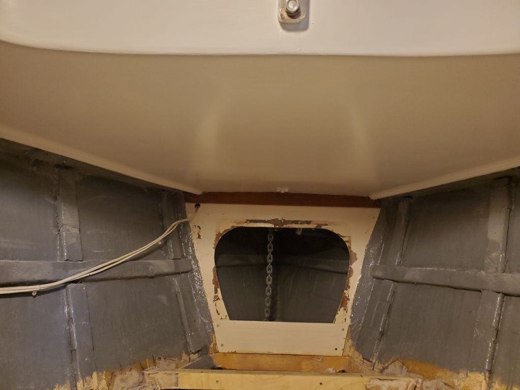
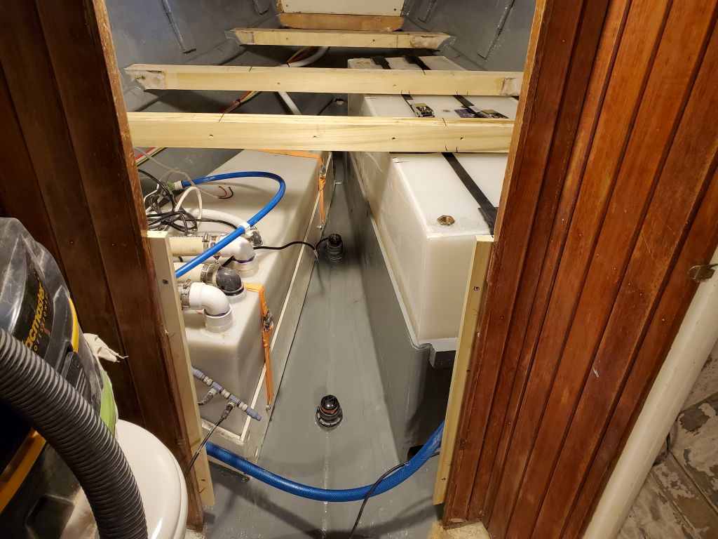
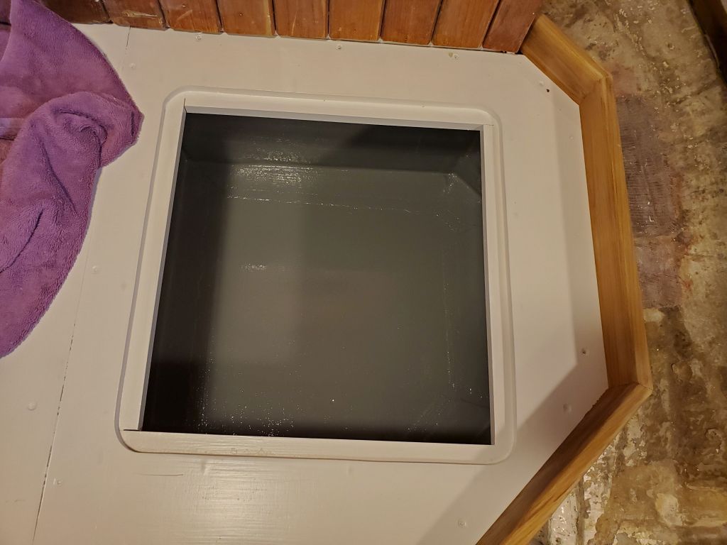
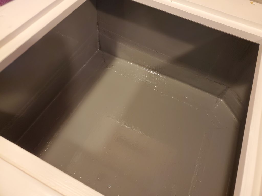
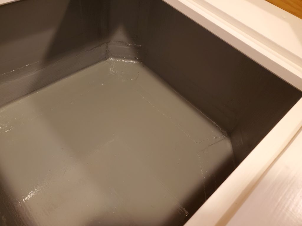
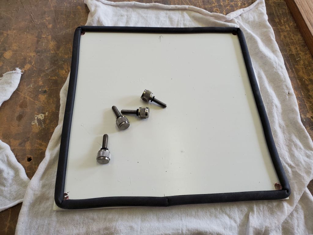
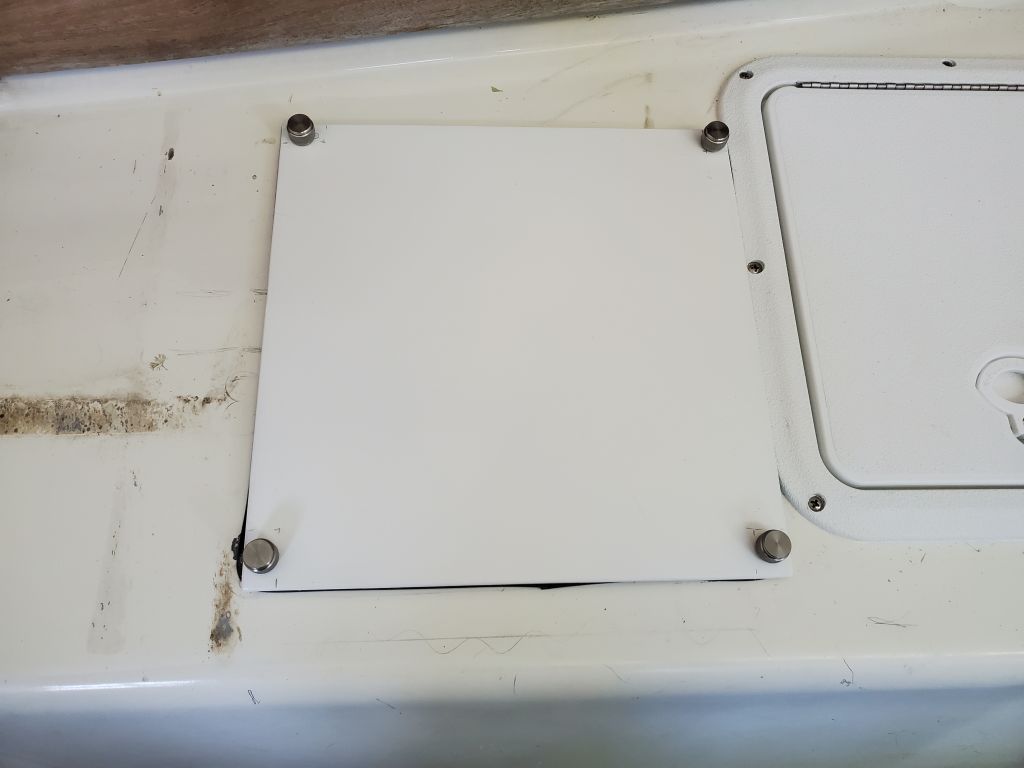
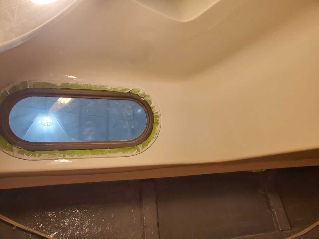
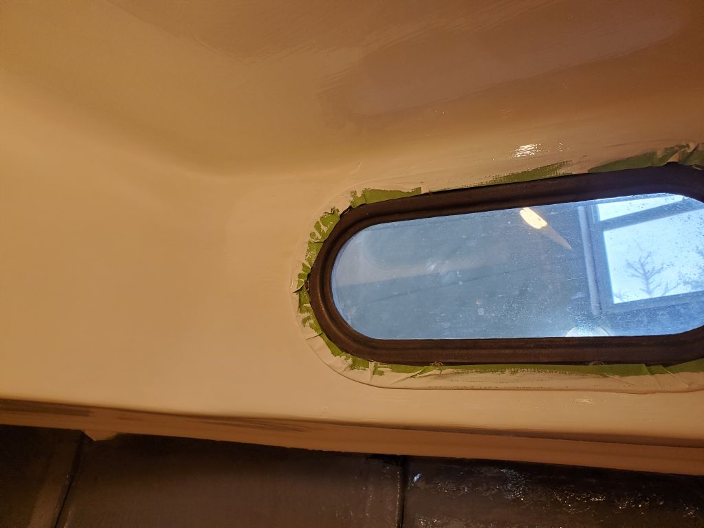
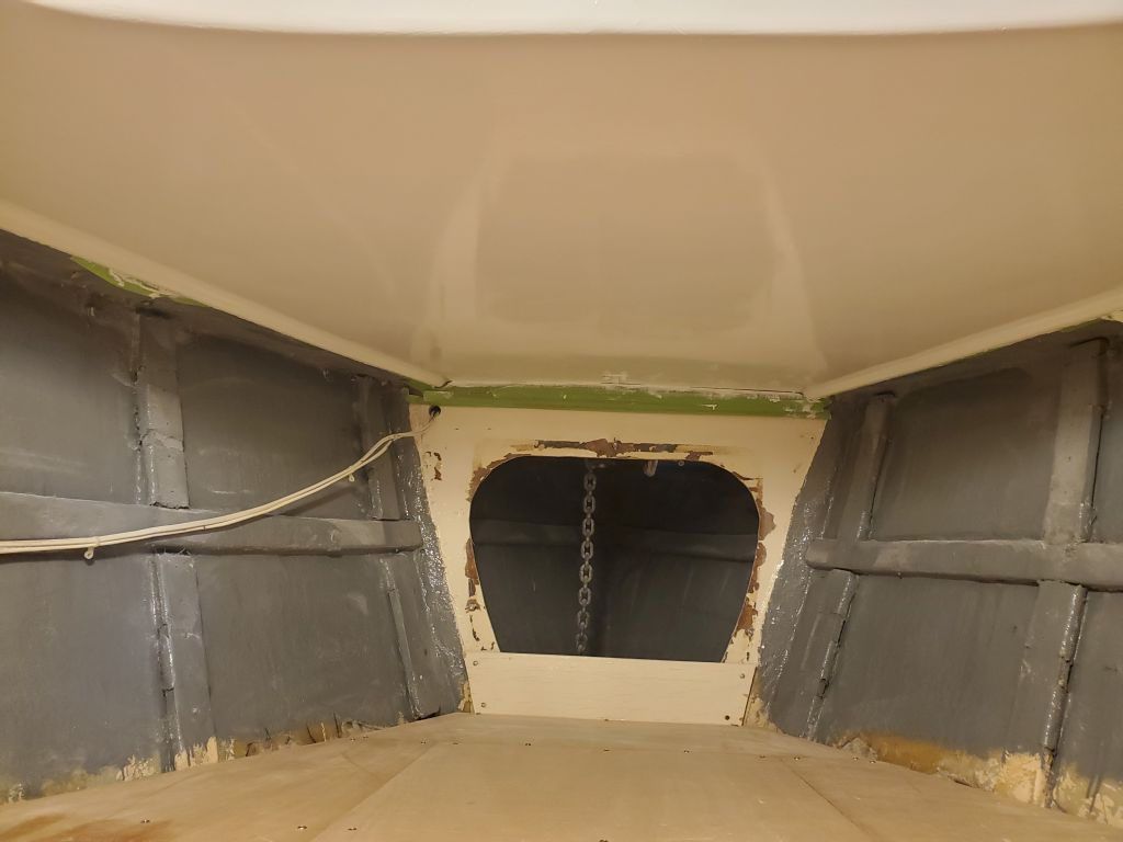
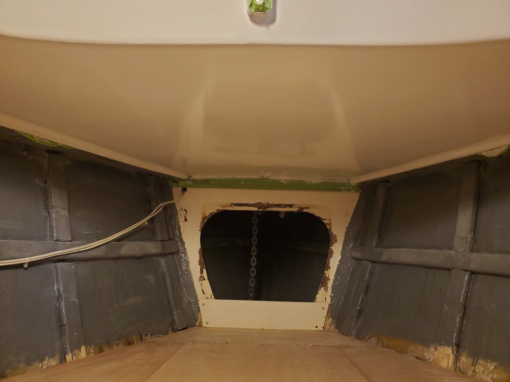
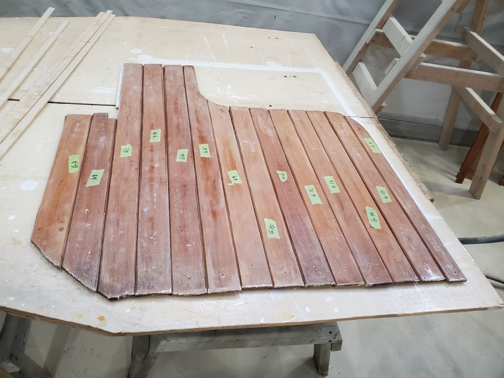
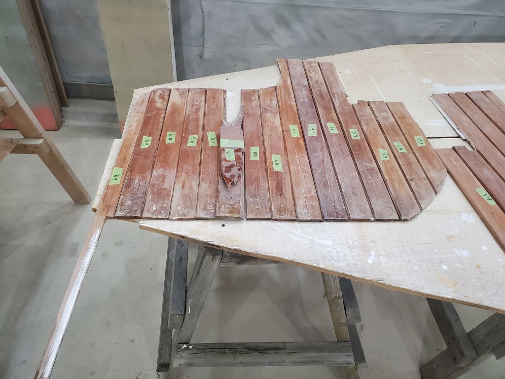
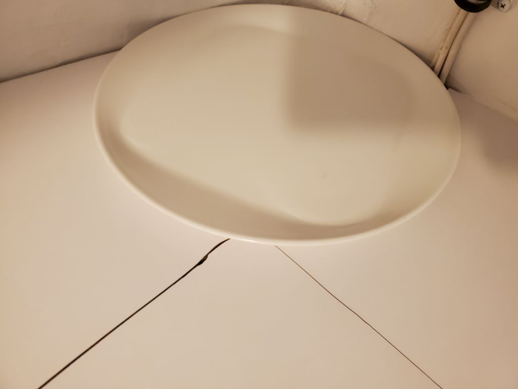
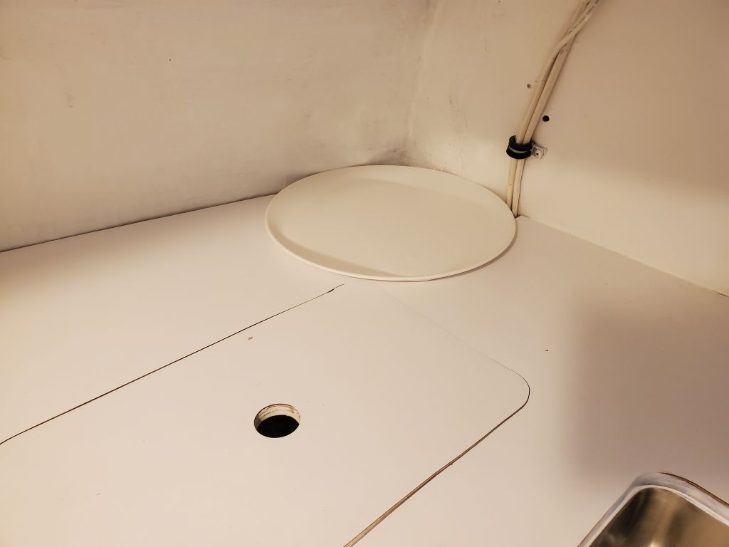
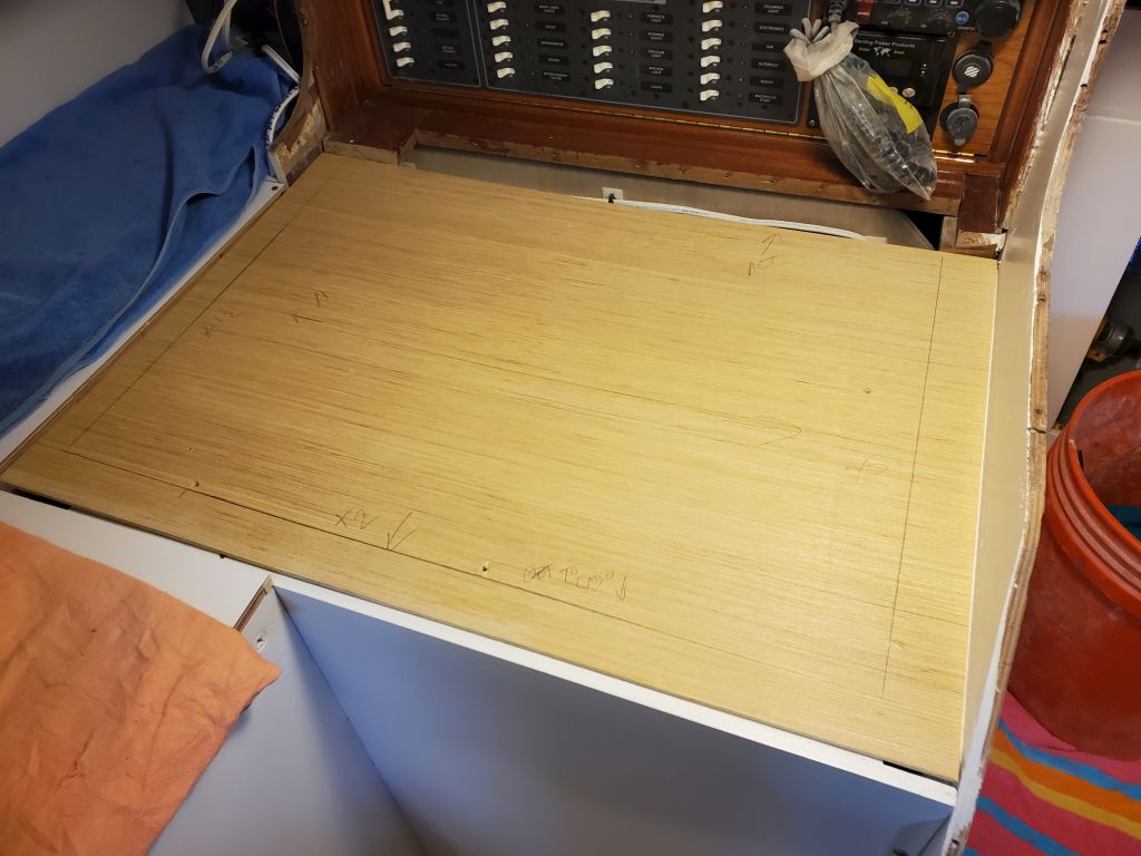
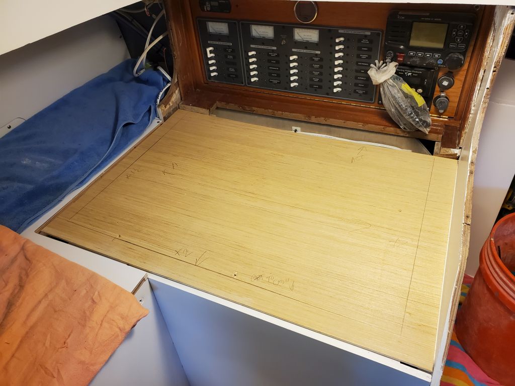
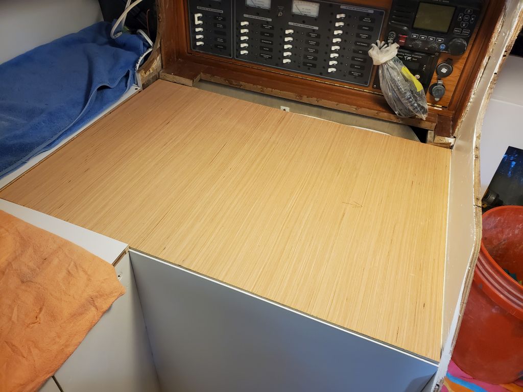
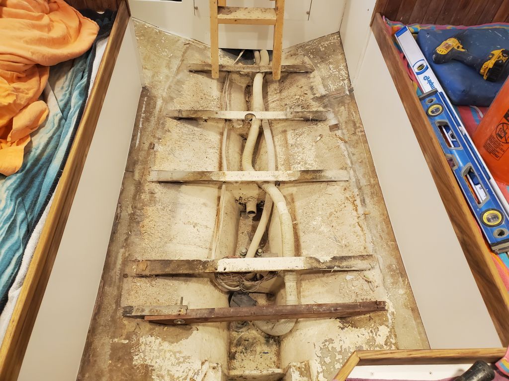
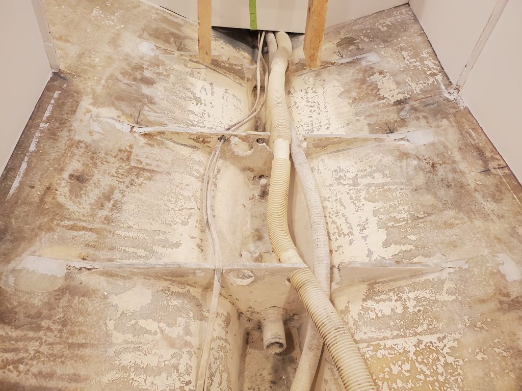
During the project and as needed, I’d pared away portions of the old sole to give me access as needed for some of the other interior work, like the new mast step and the battery compartment, so there wasn’t much left. The entire center portion was removable in two panels.
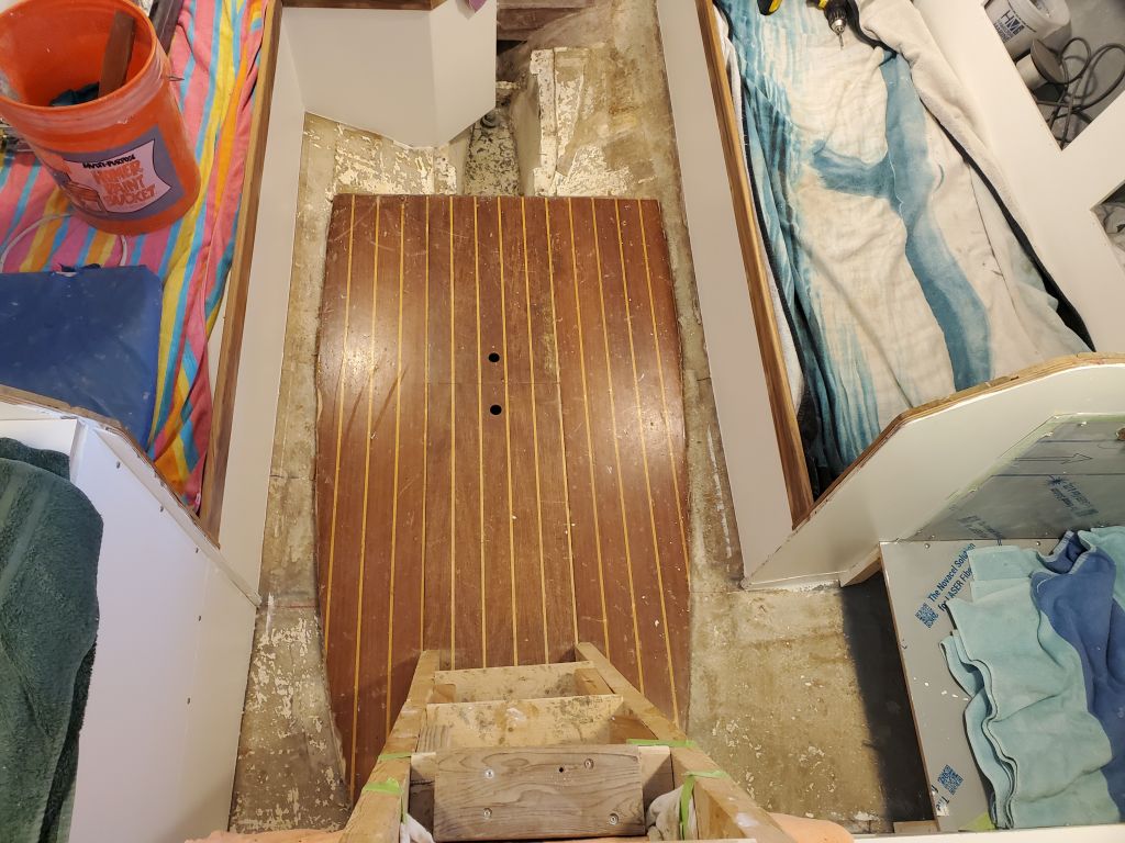
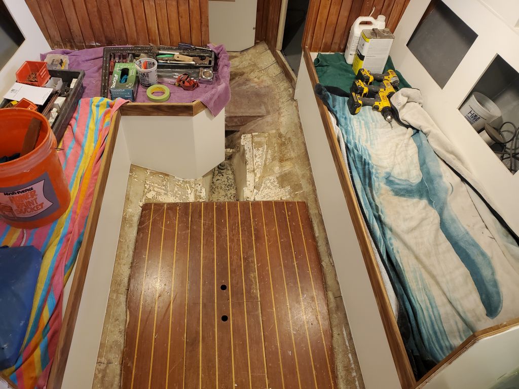
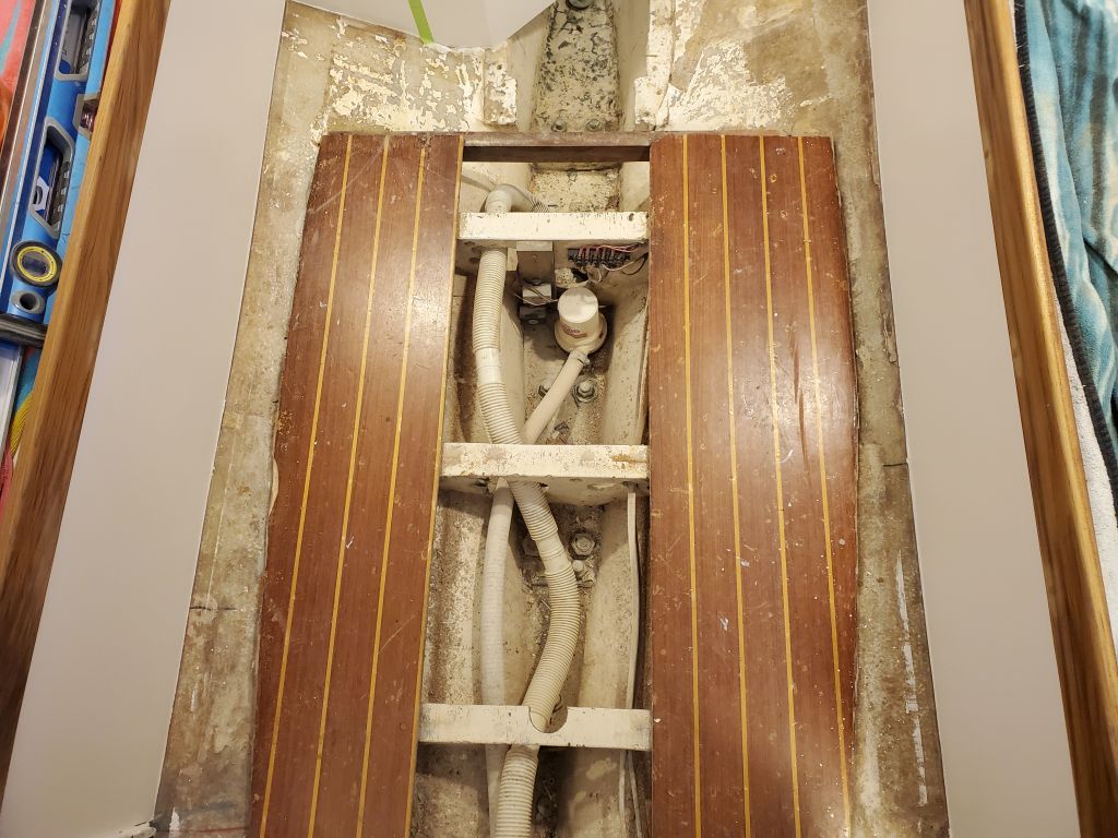
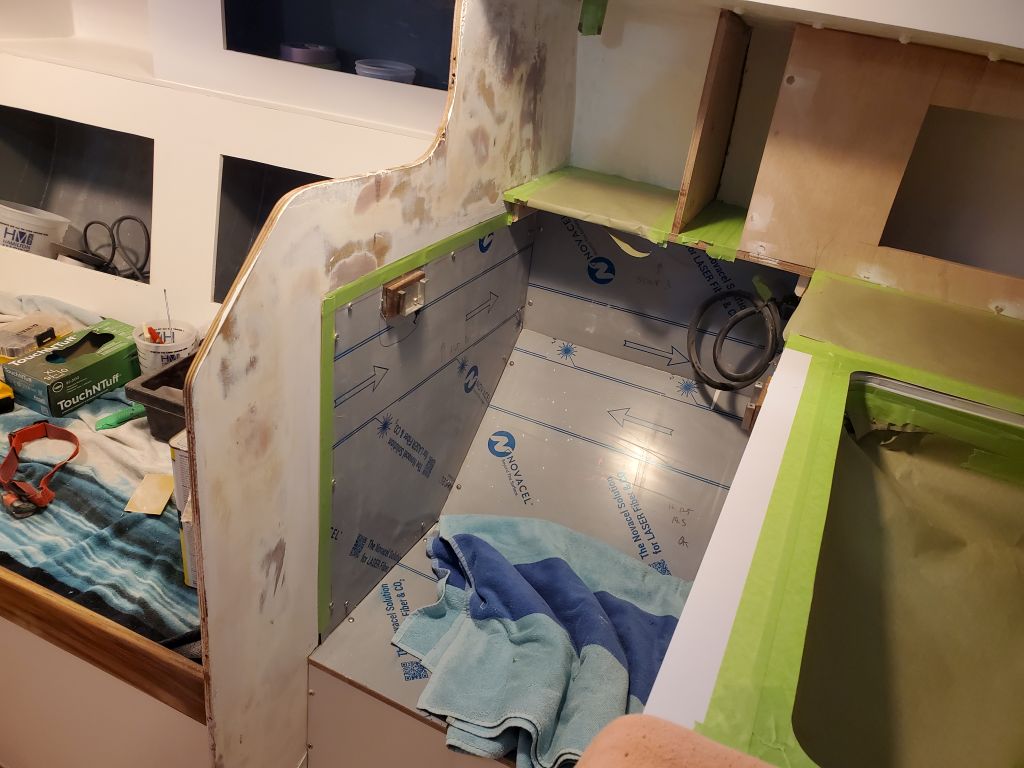
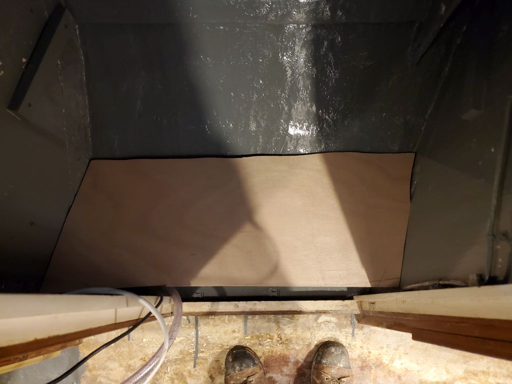
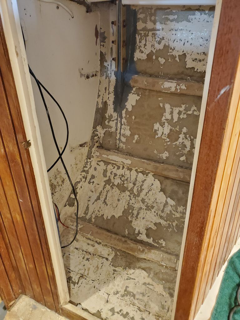
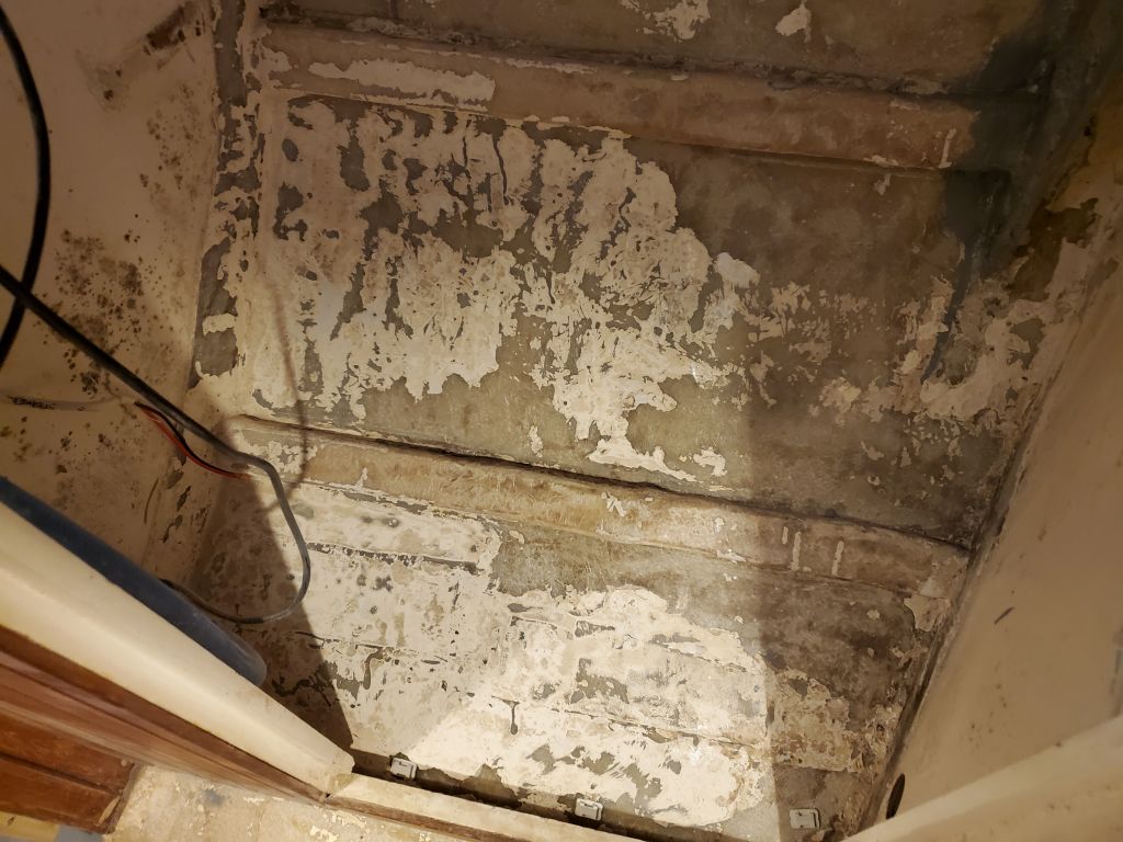
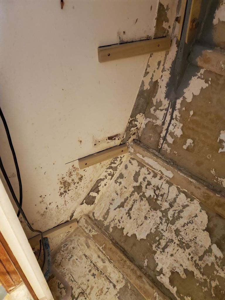
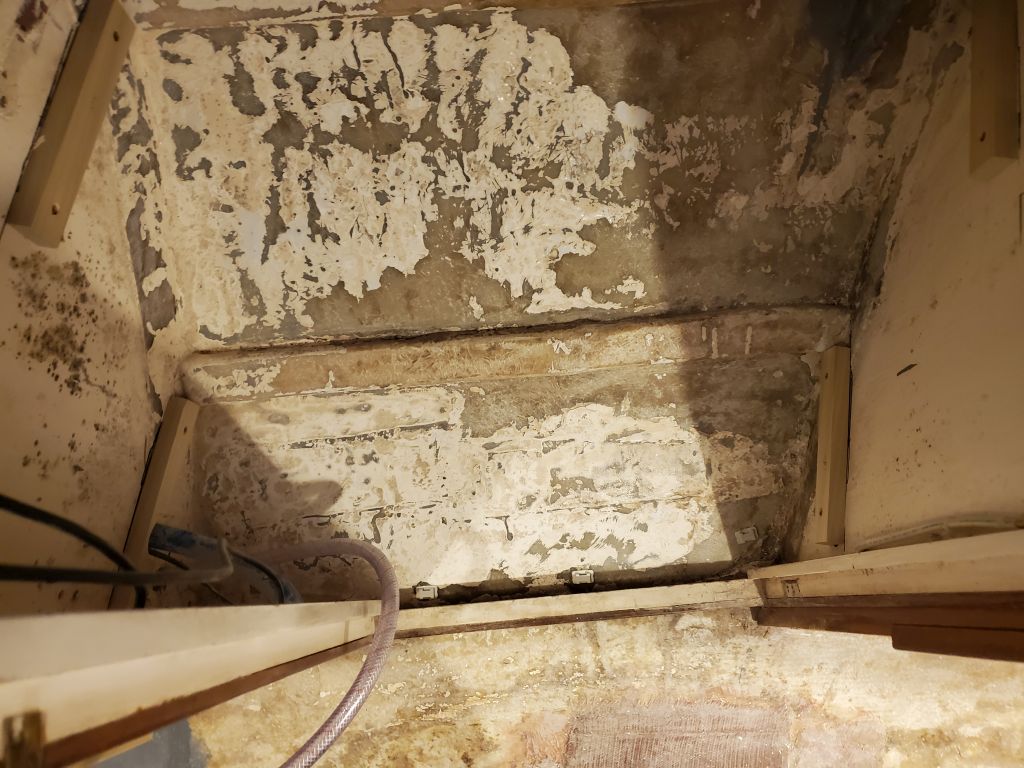
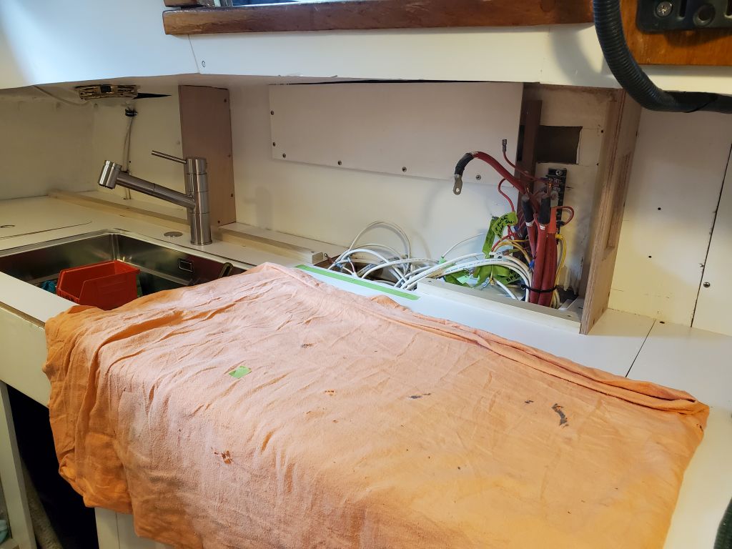
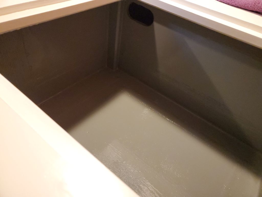
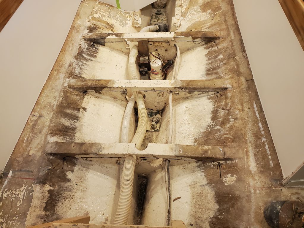
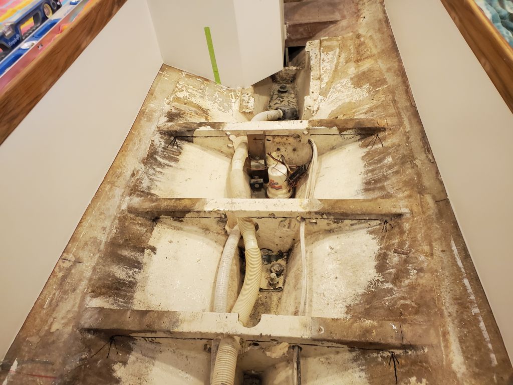
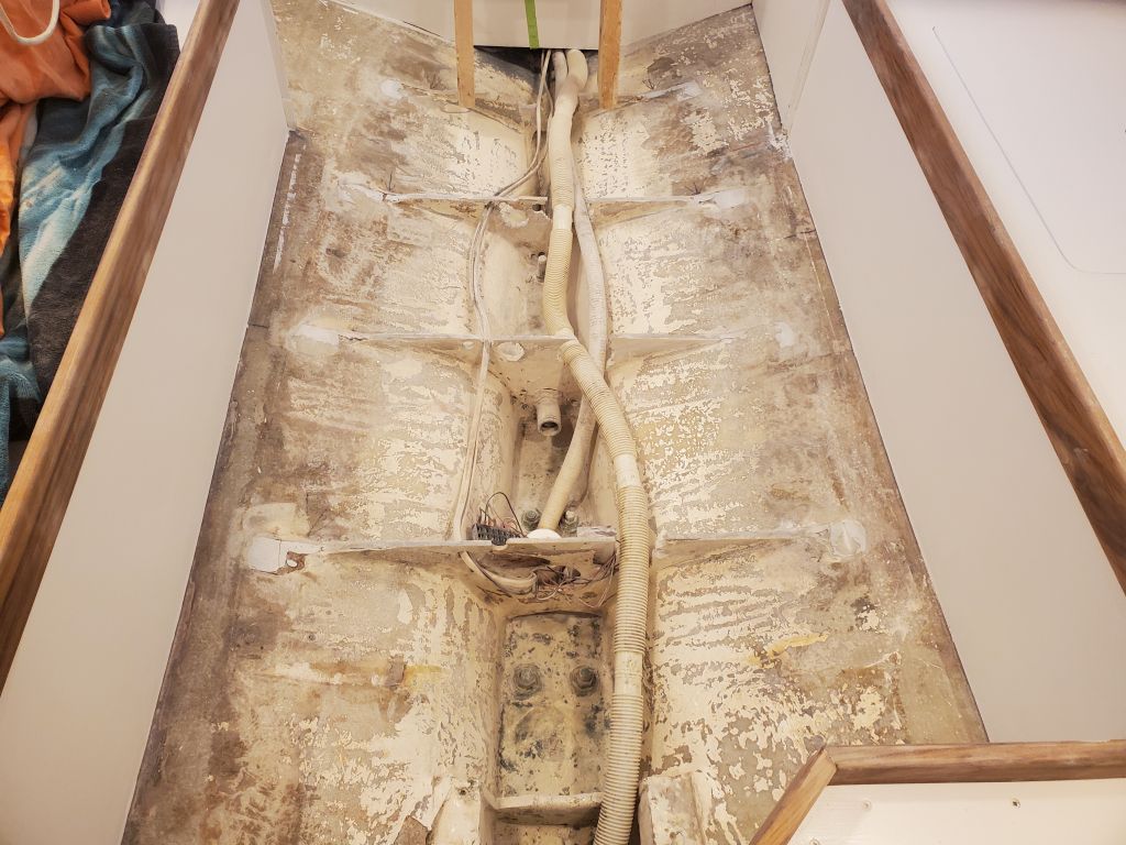
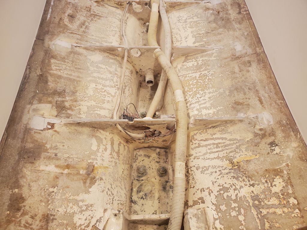
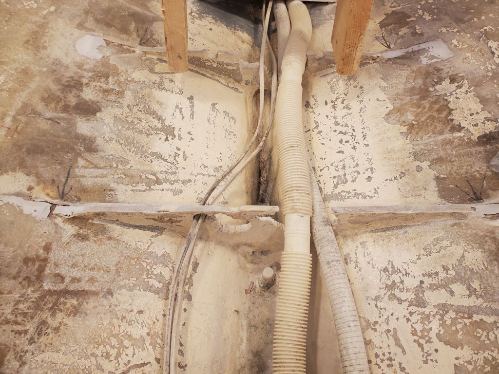
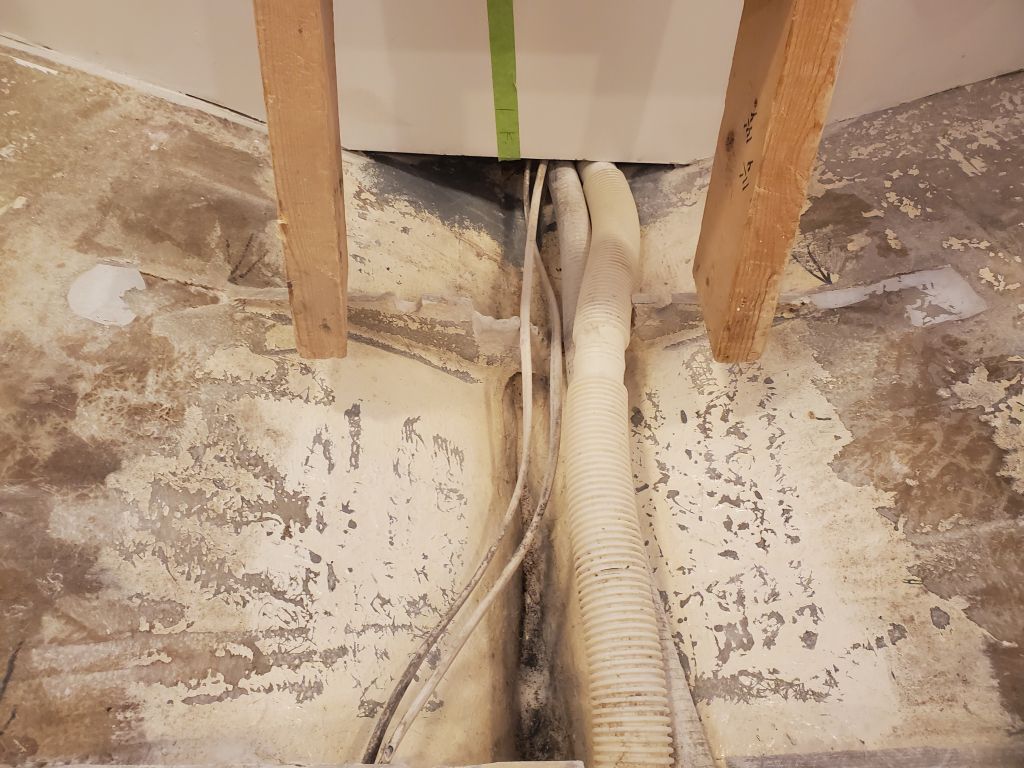
I pulled up the remaining sections with minimal help from a prybar, exposing the entire area for the first time. There was a lot of dust and debris from the other construction, so the first thing I did was clean all this up.
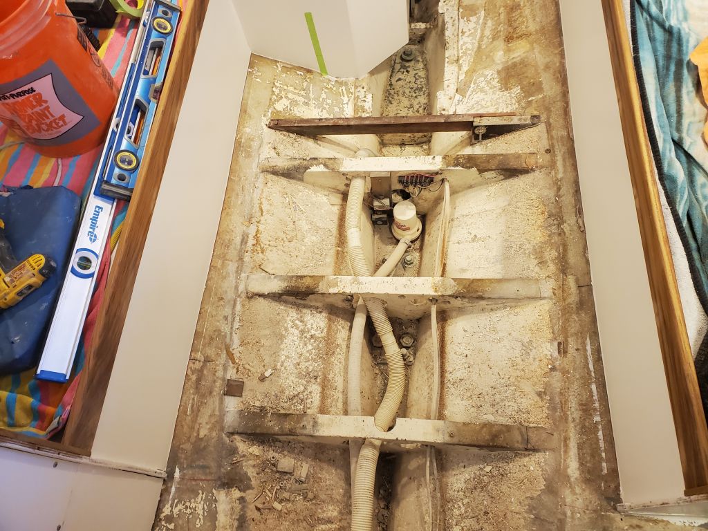
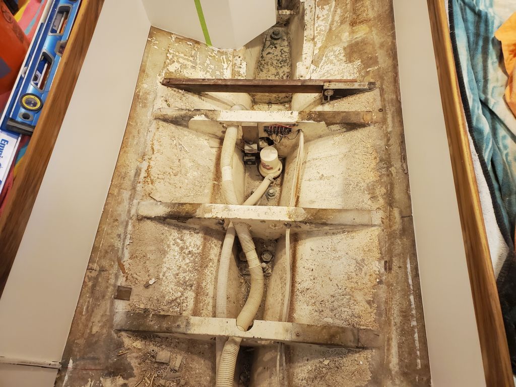
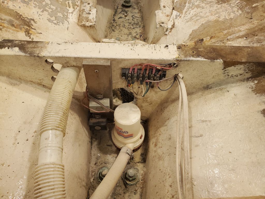
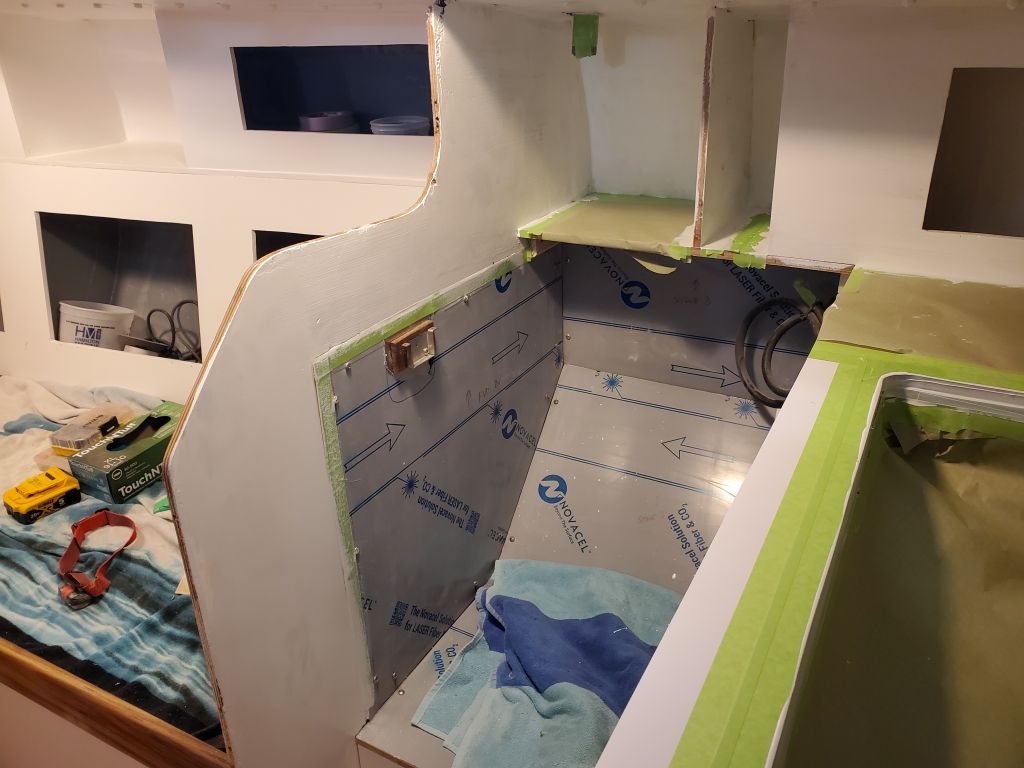
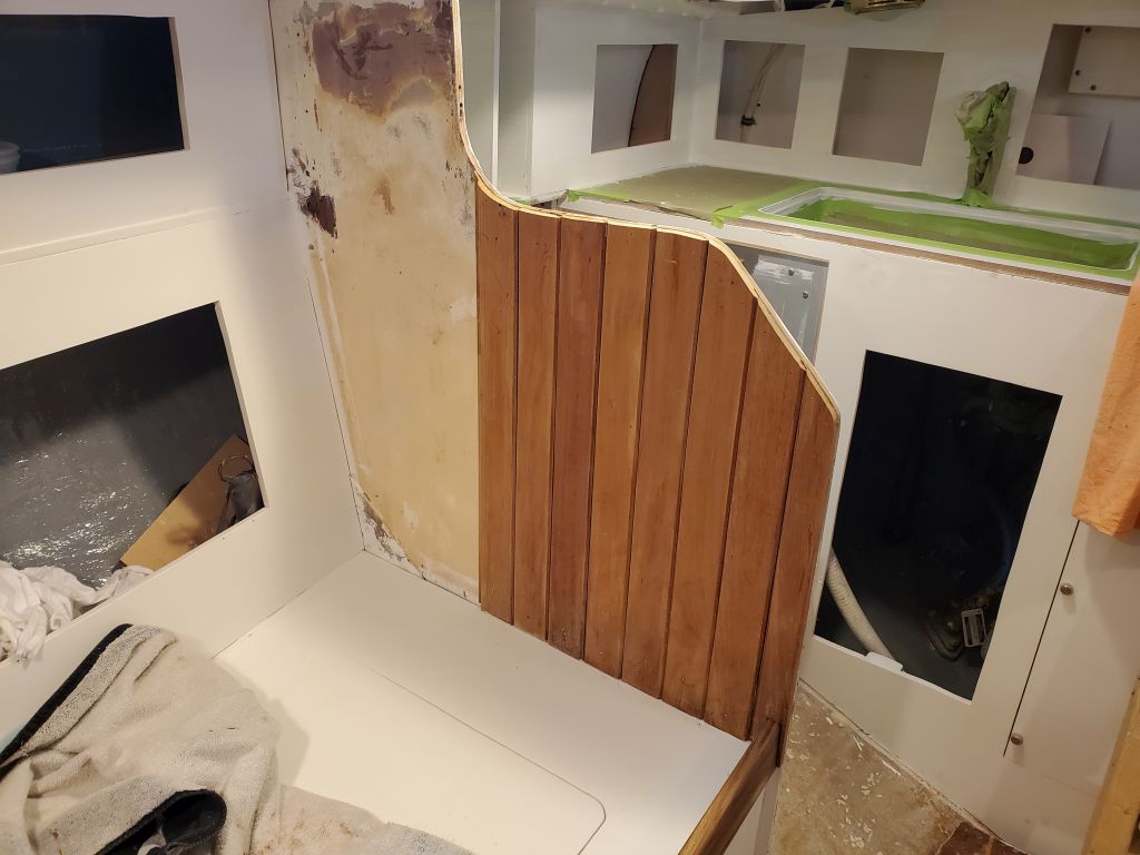
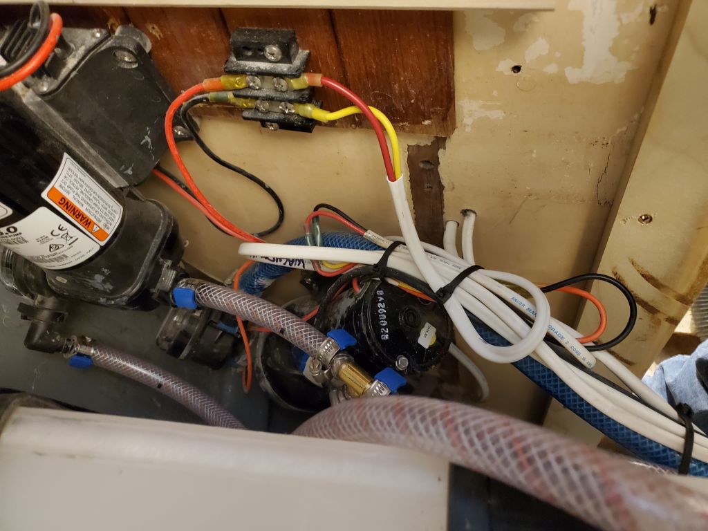
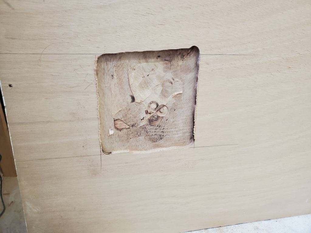
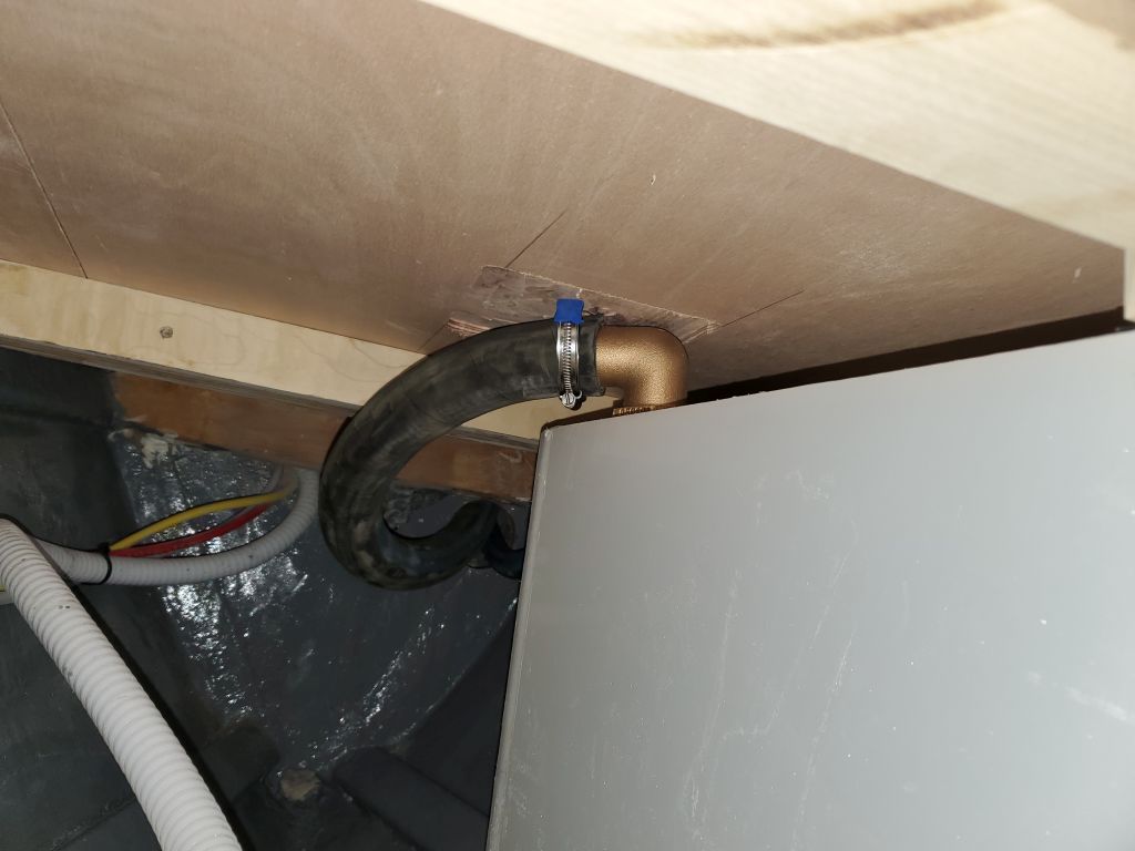
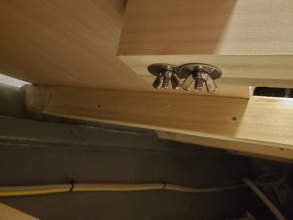
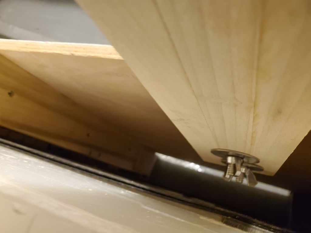
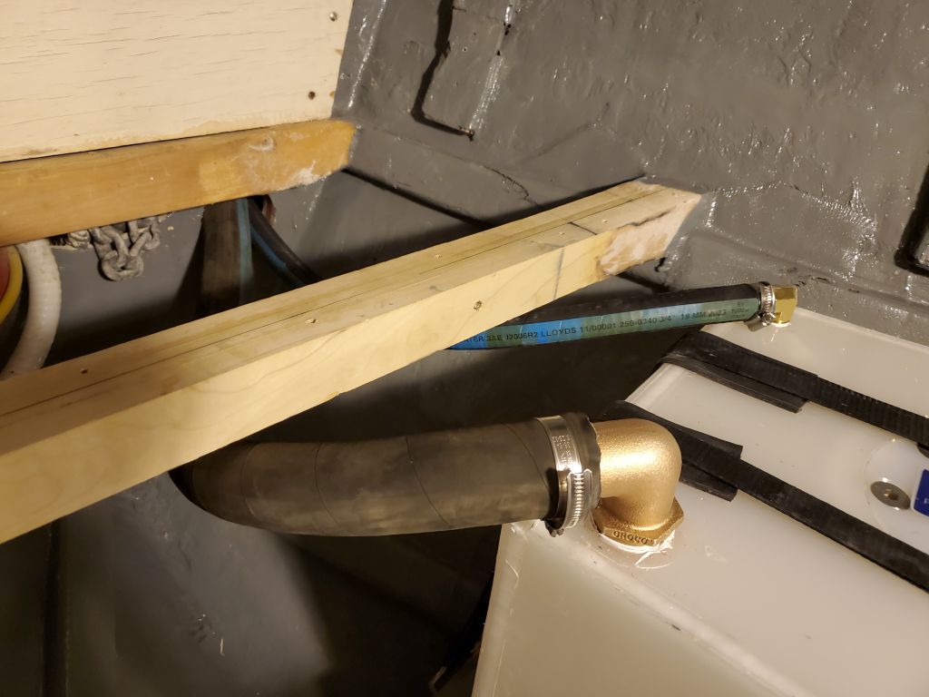
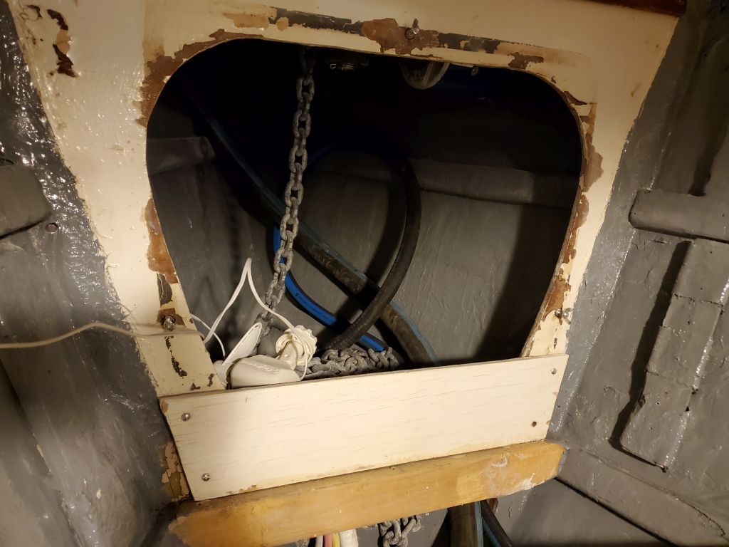
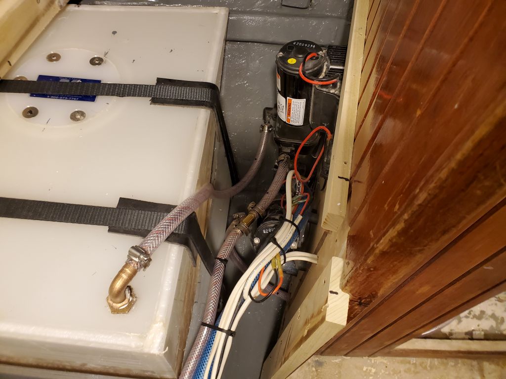
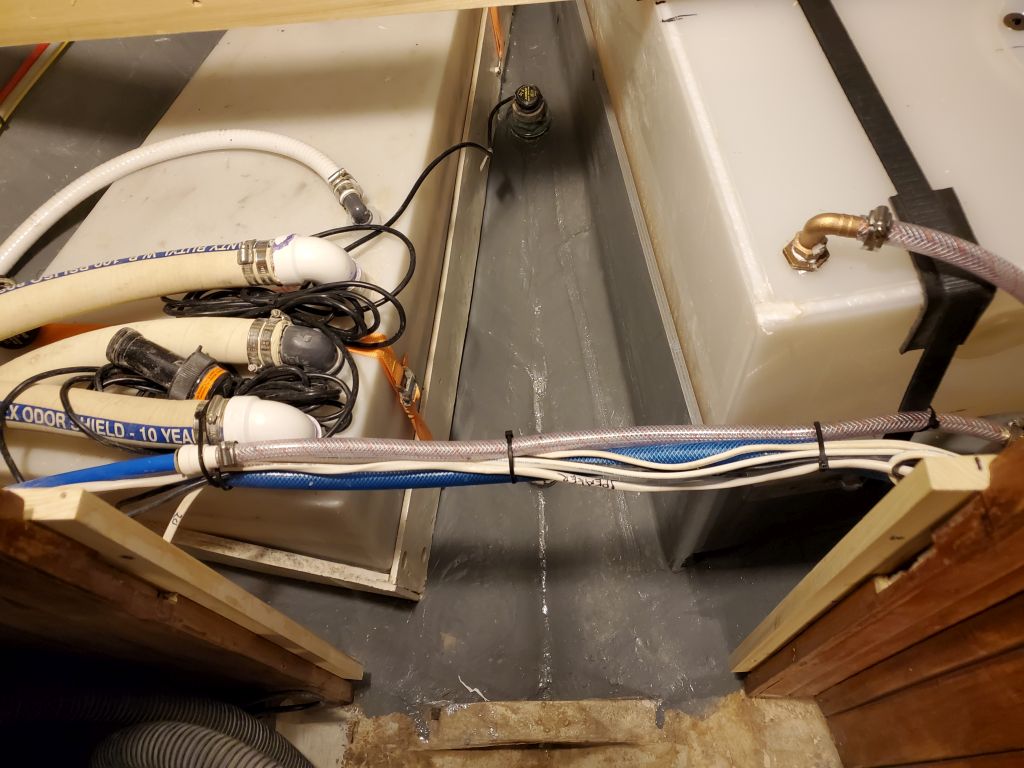
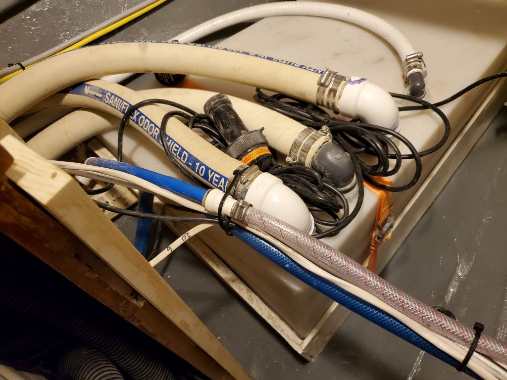
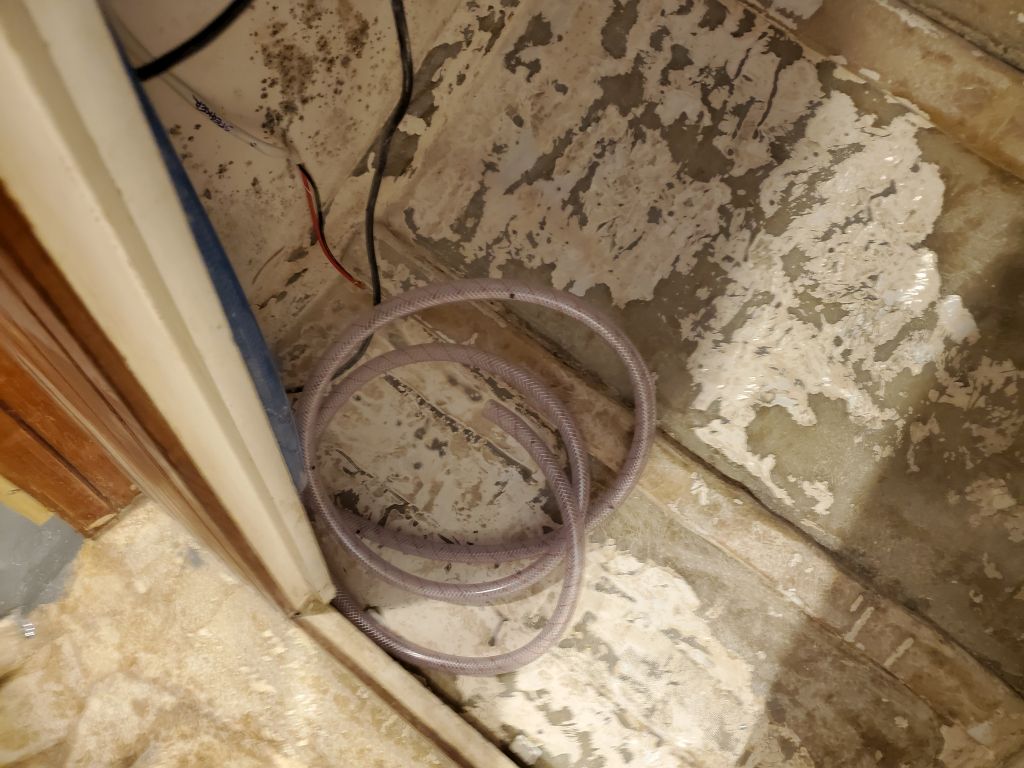
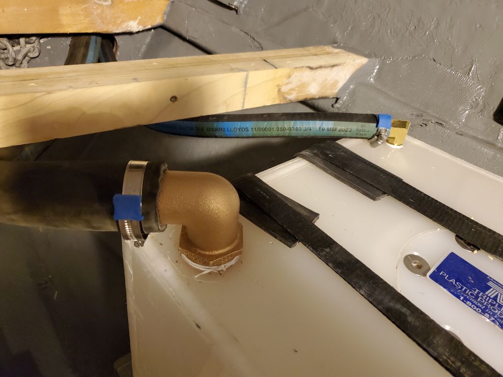
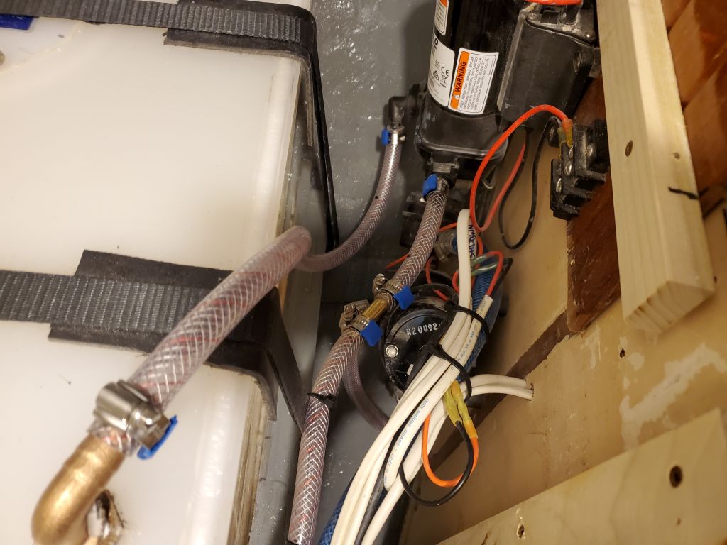
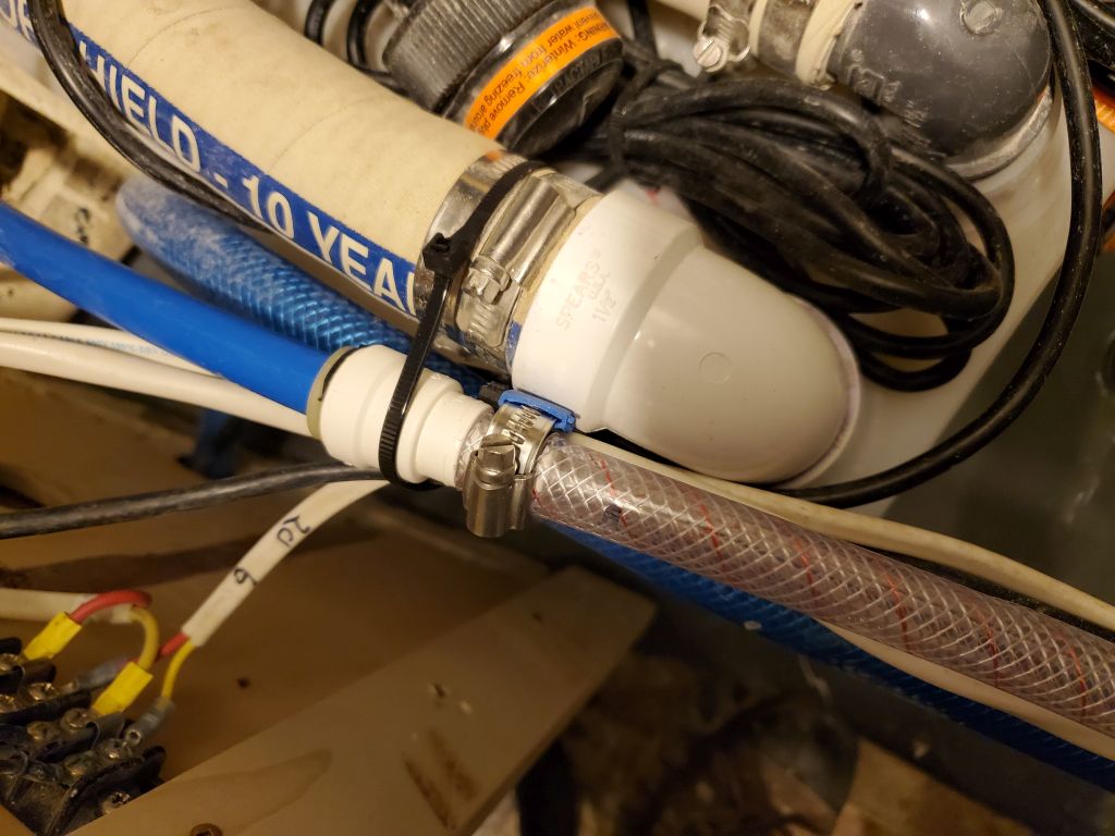
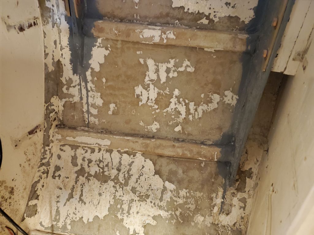
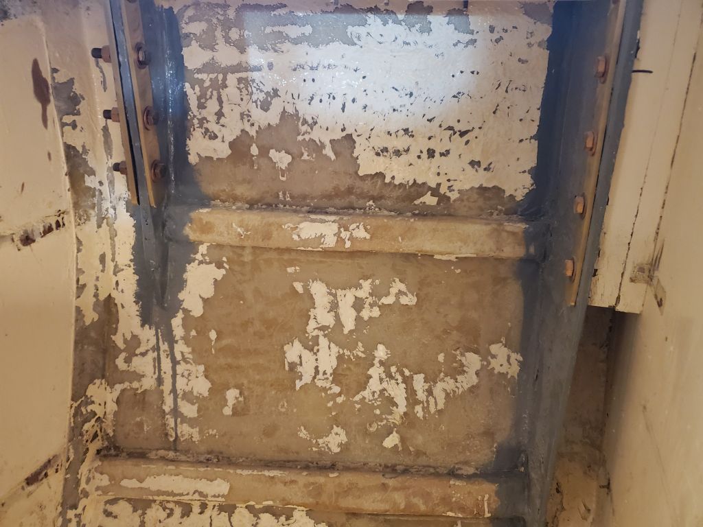
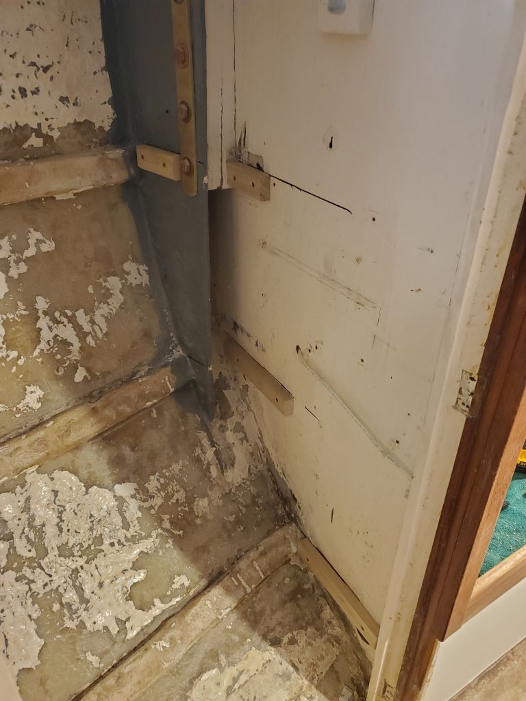
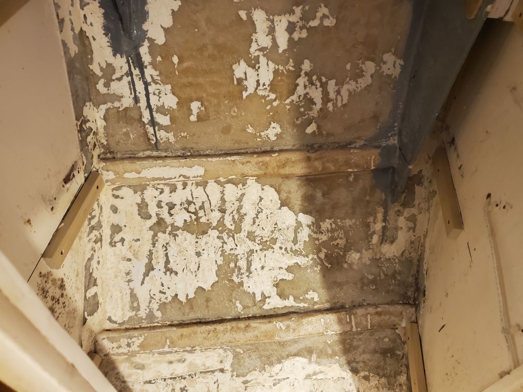
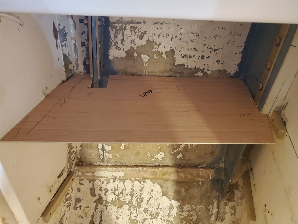
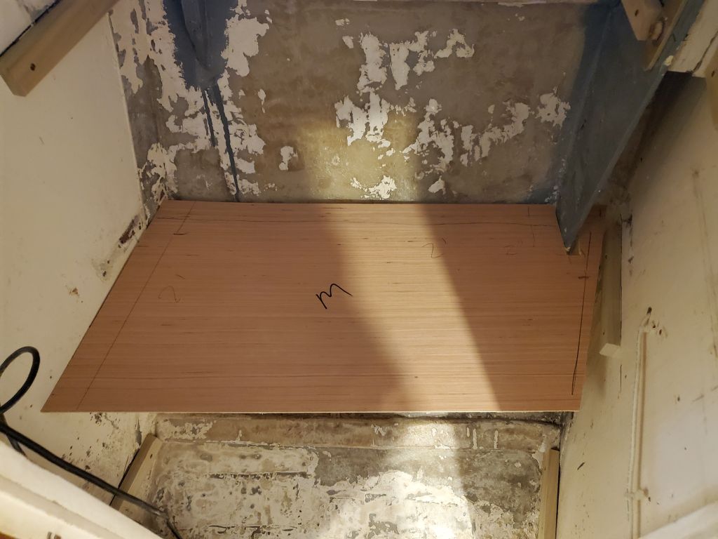
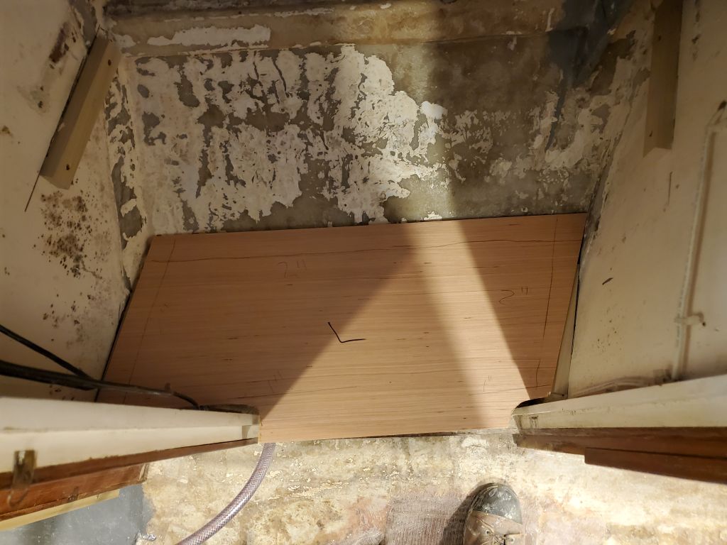
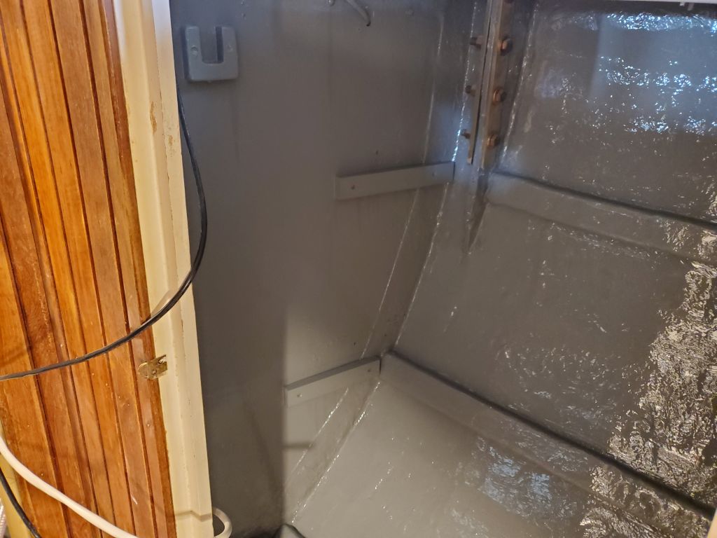
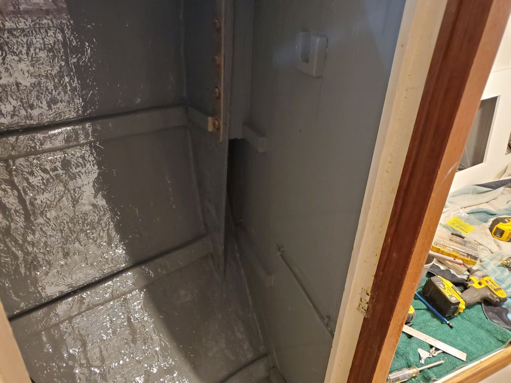
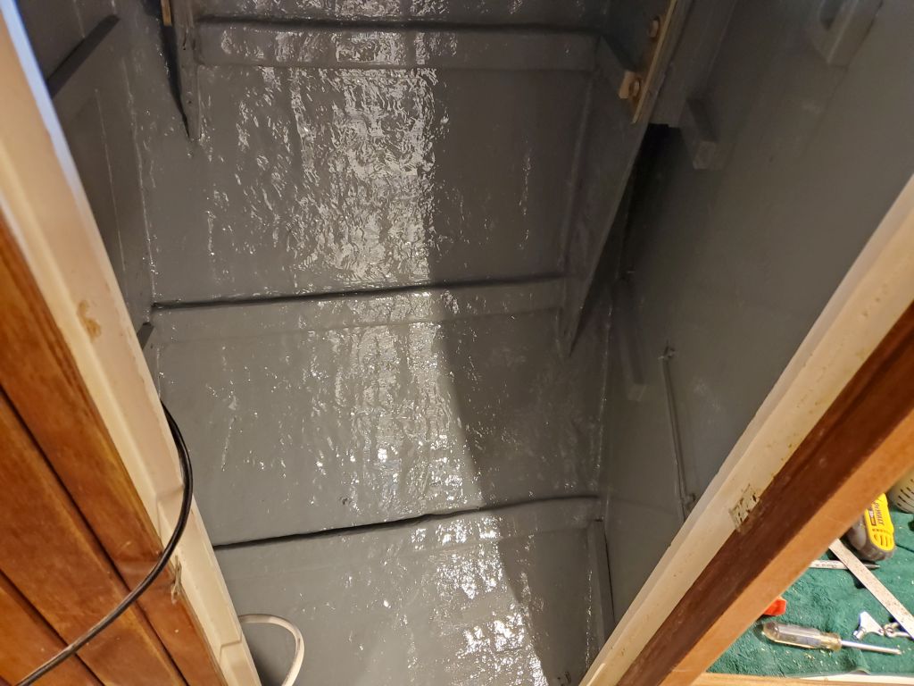
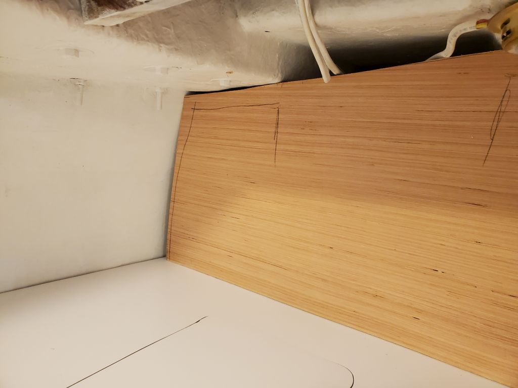
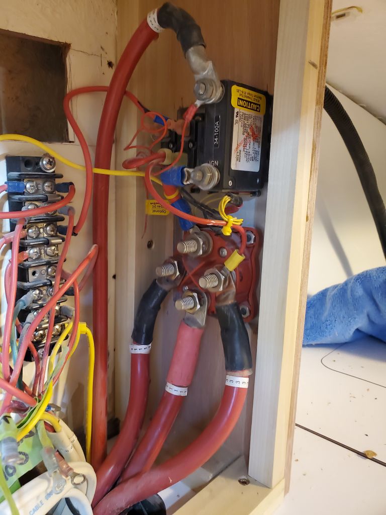
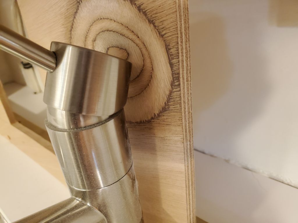
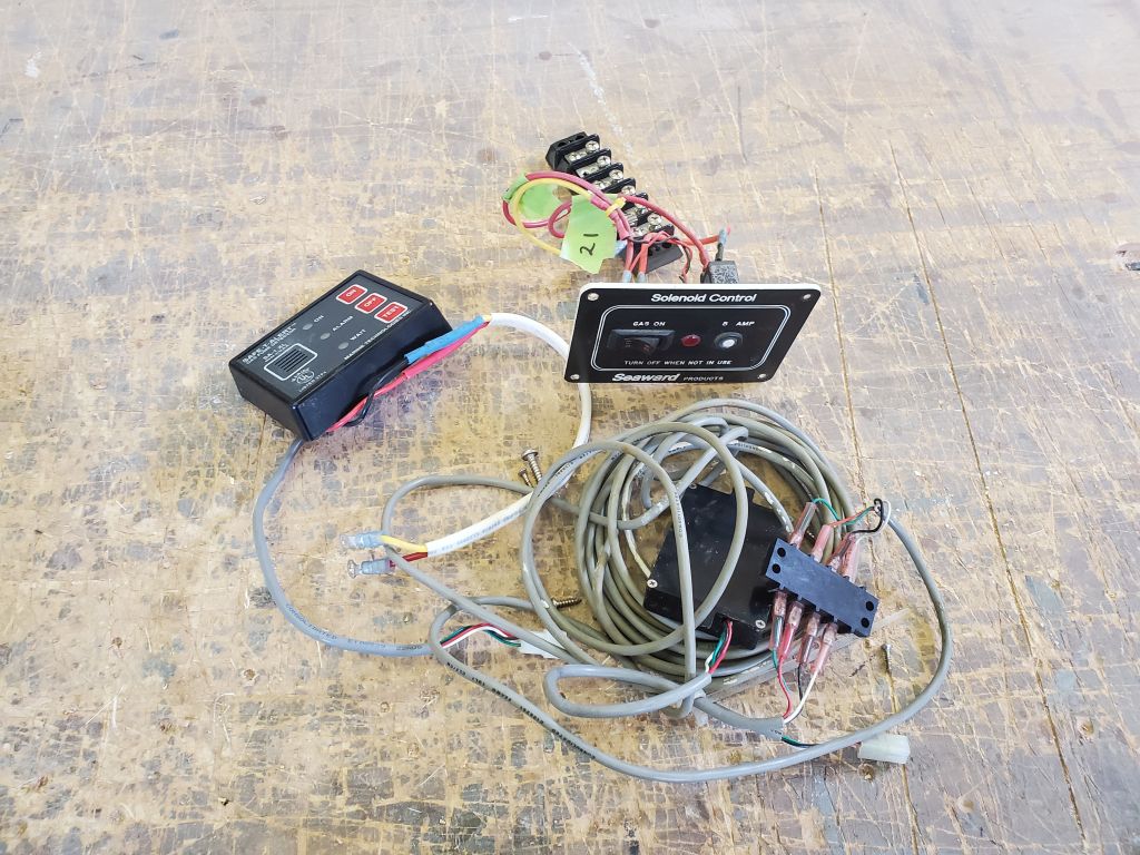
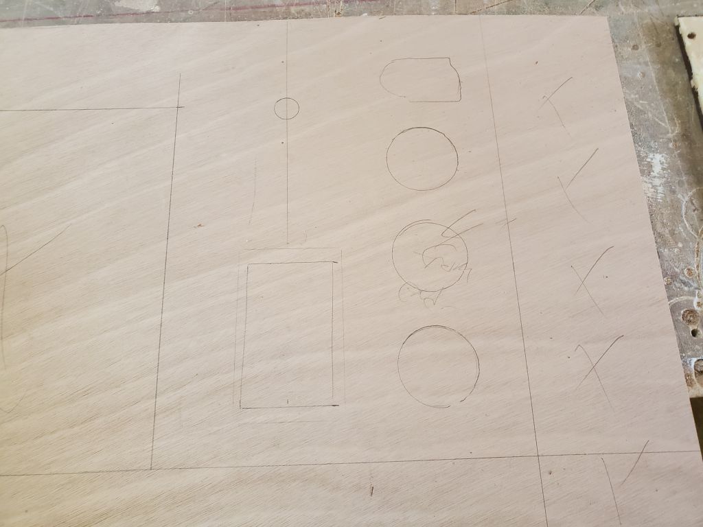
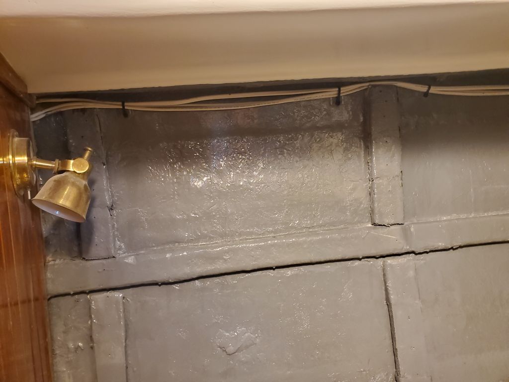
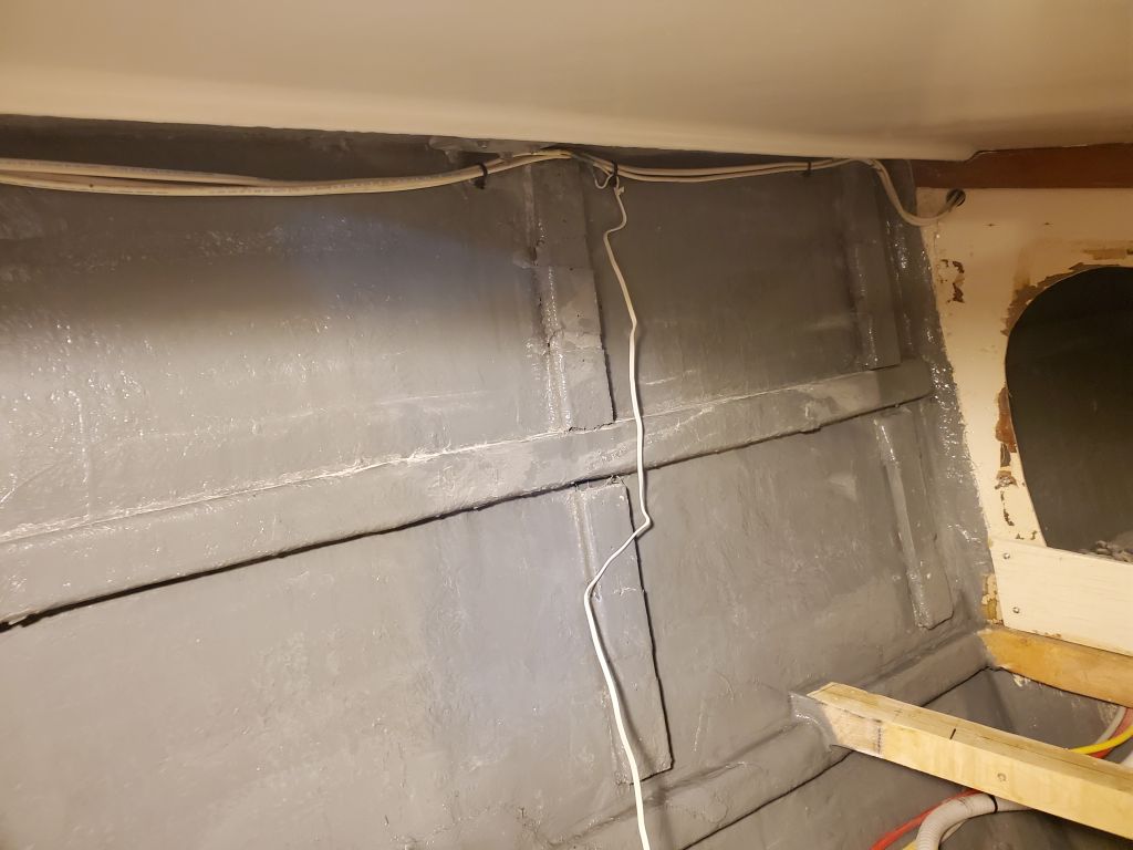
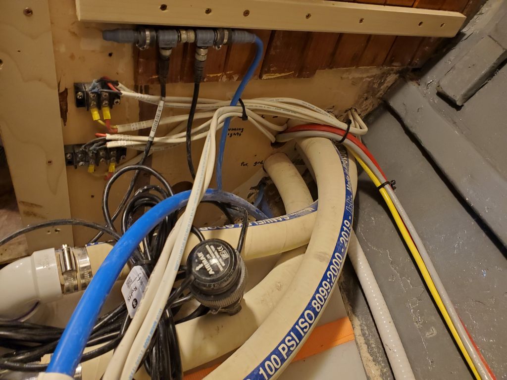
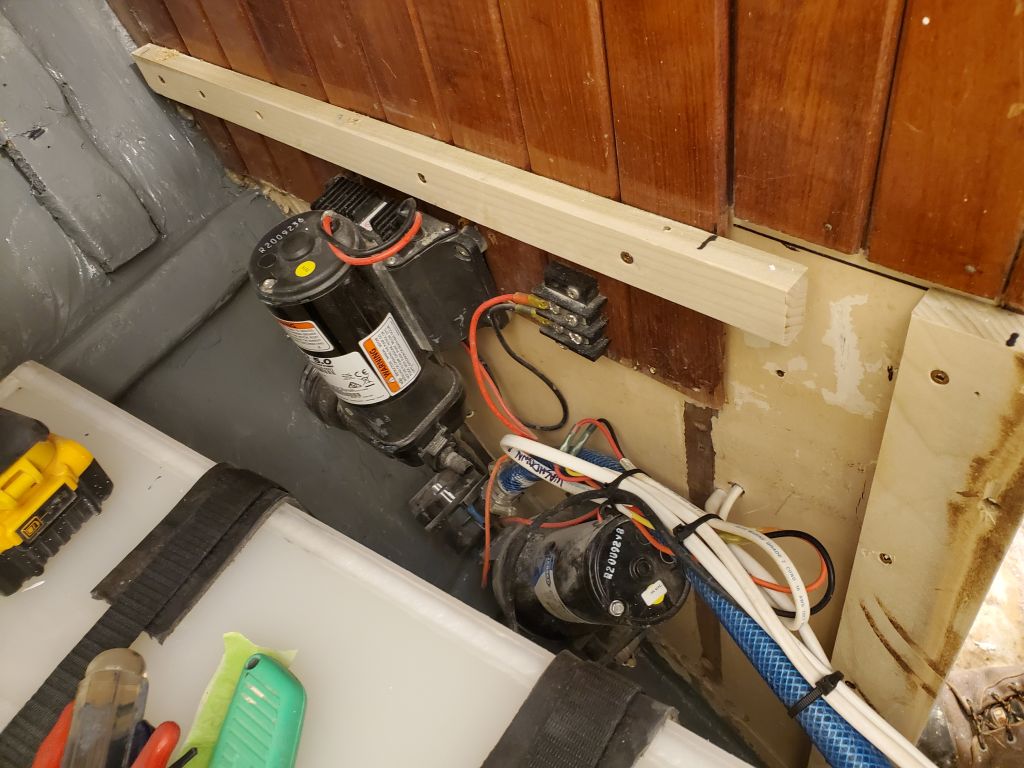
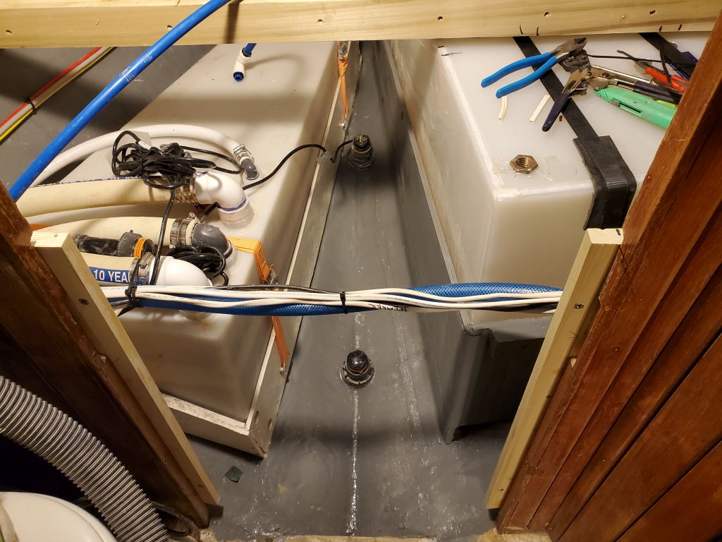
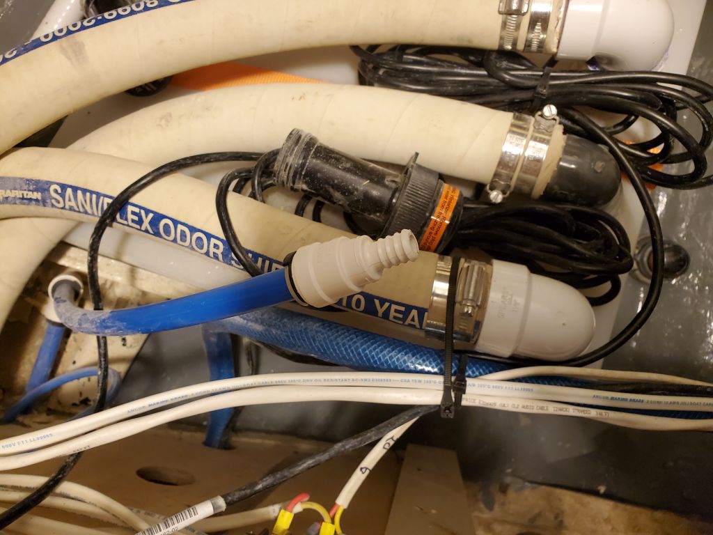
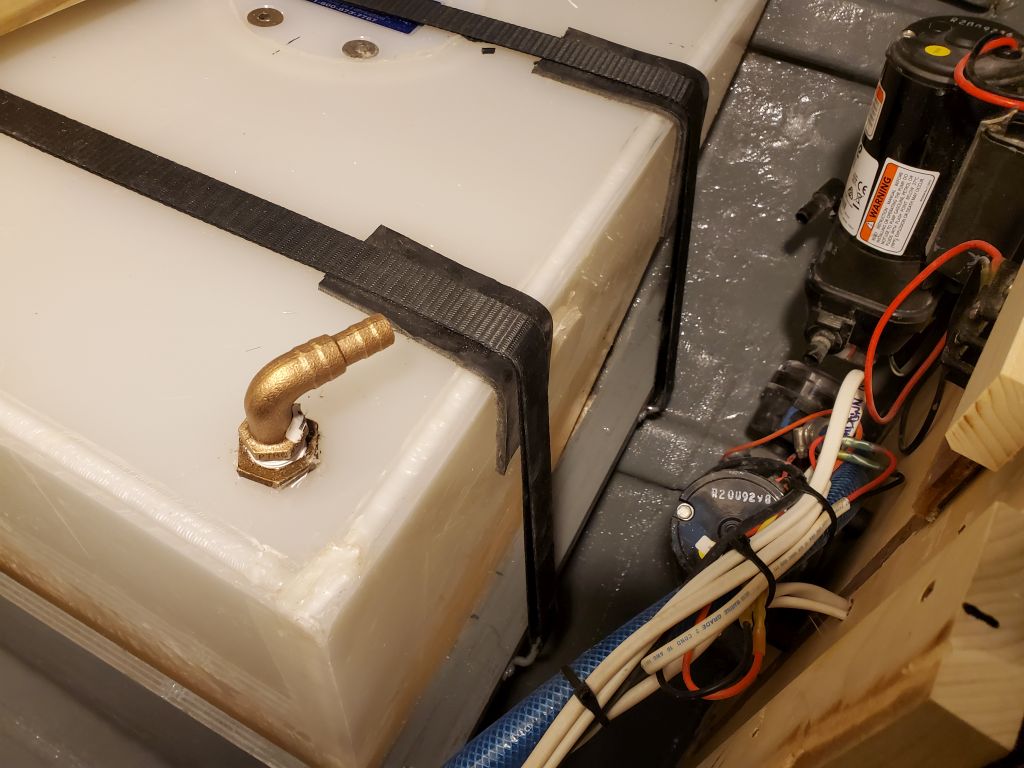
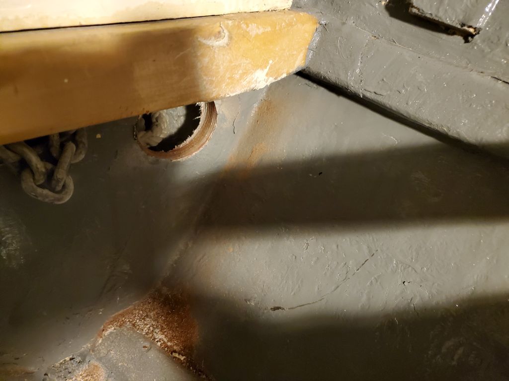
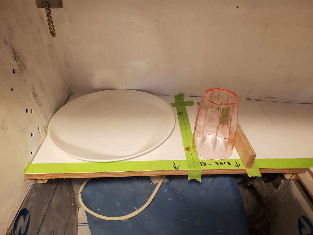
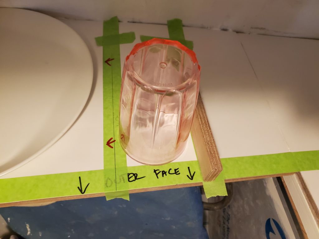
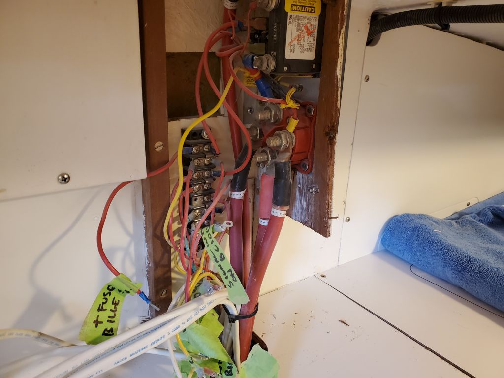
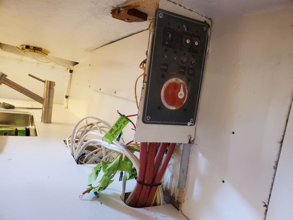
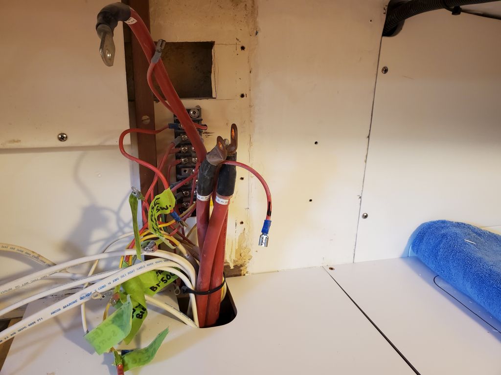
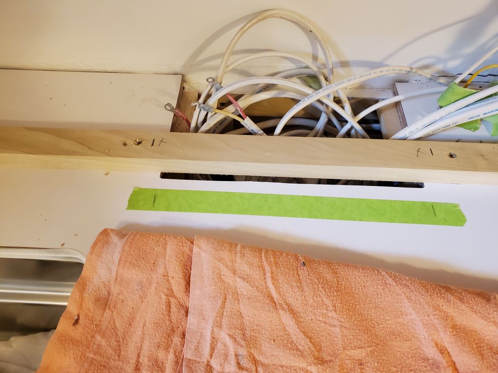
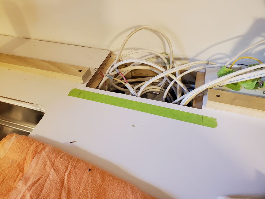
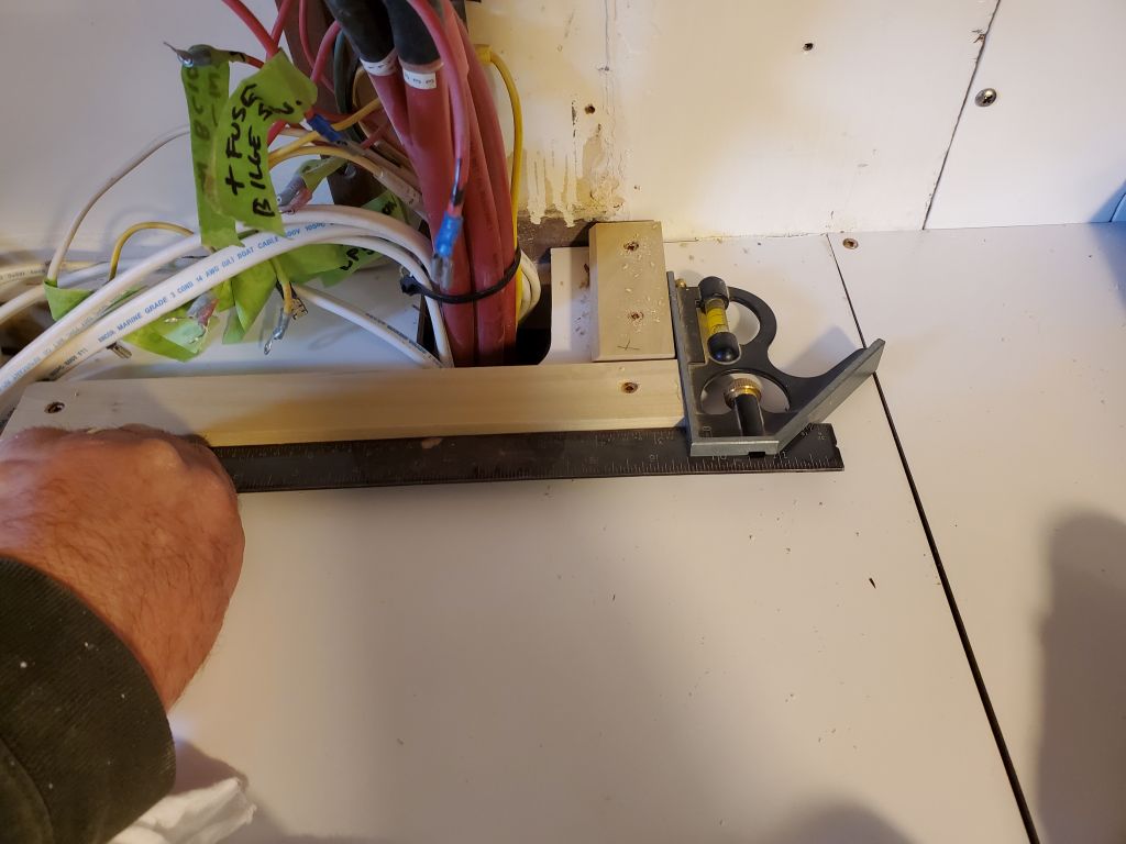
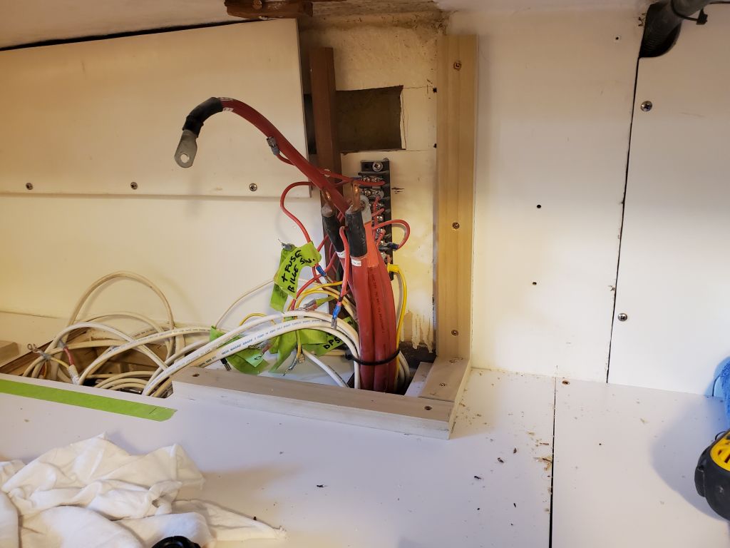
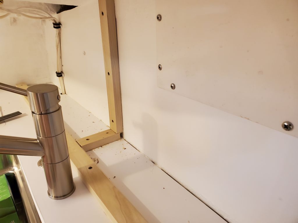
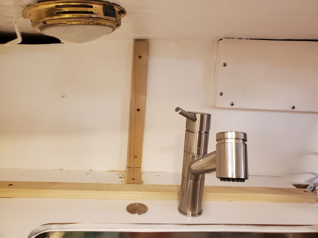
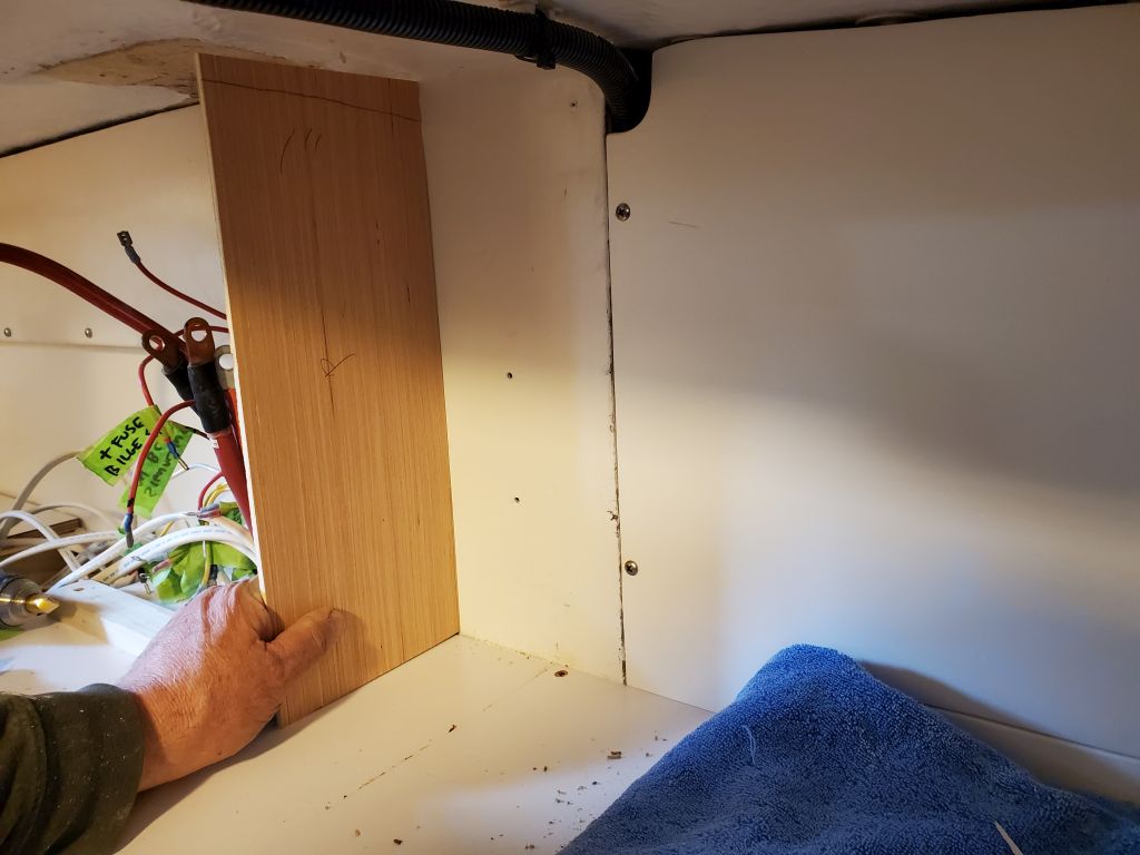
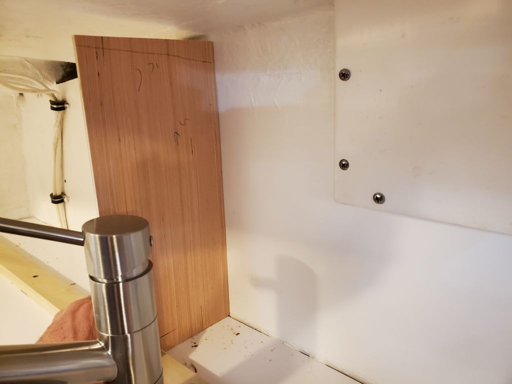
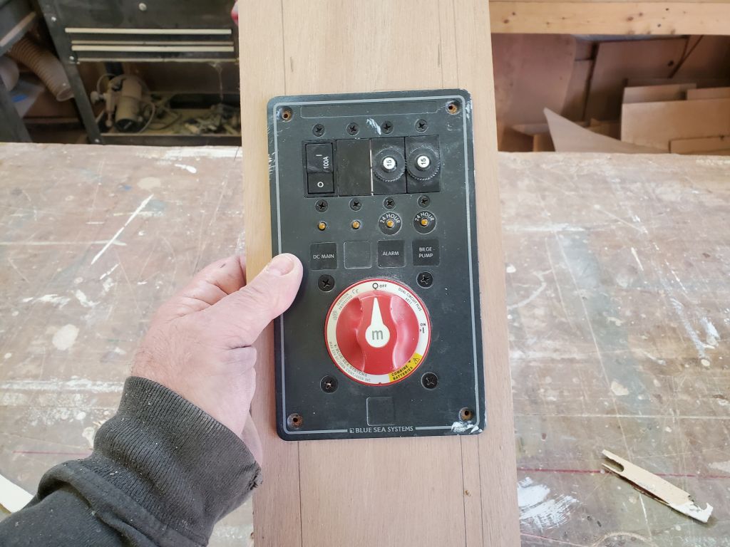
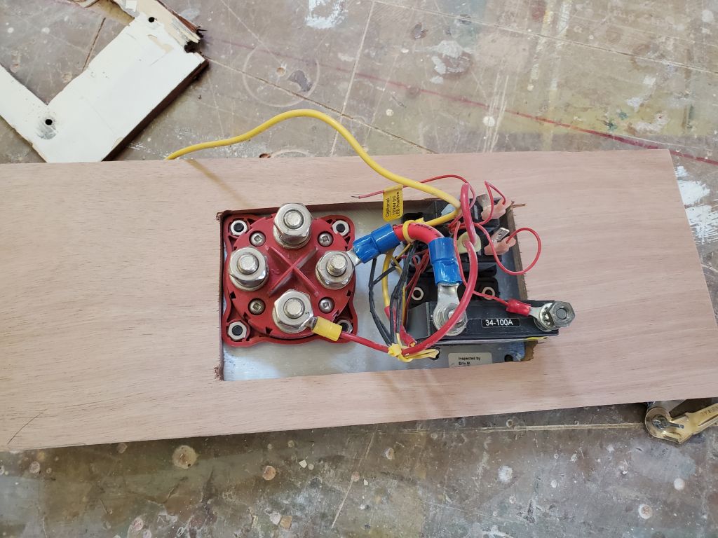
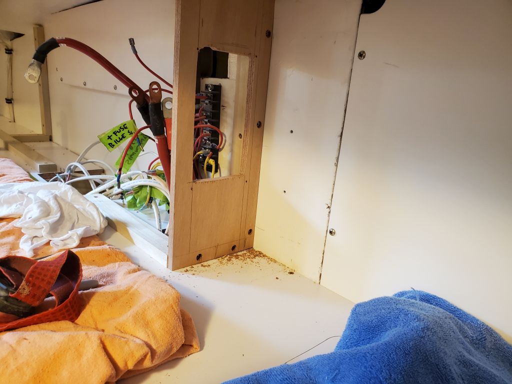
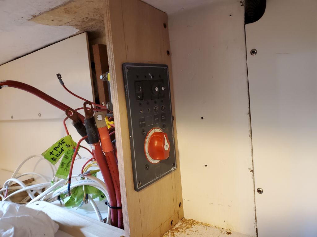
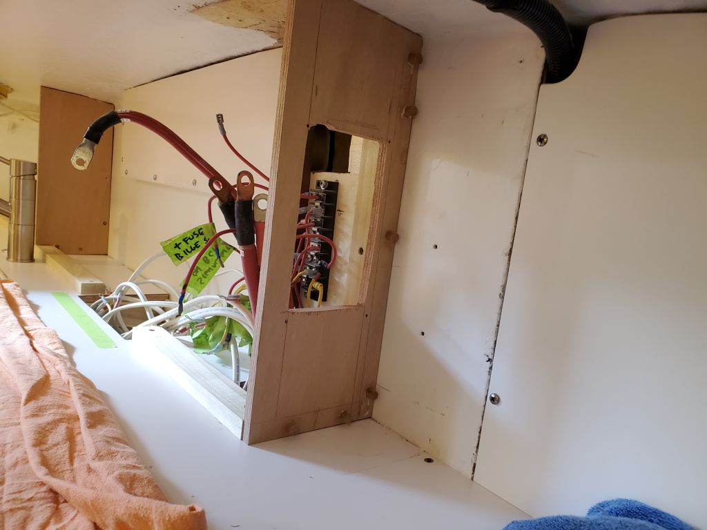
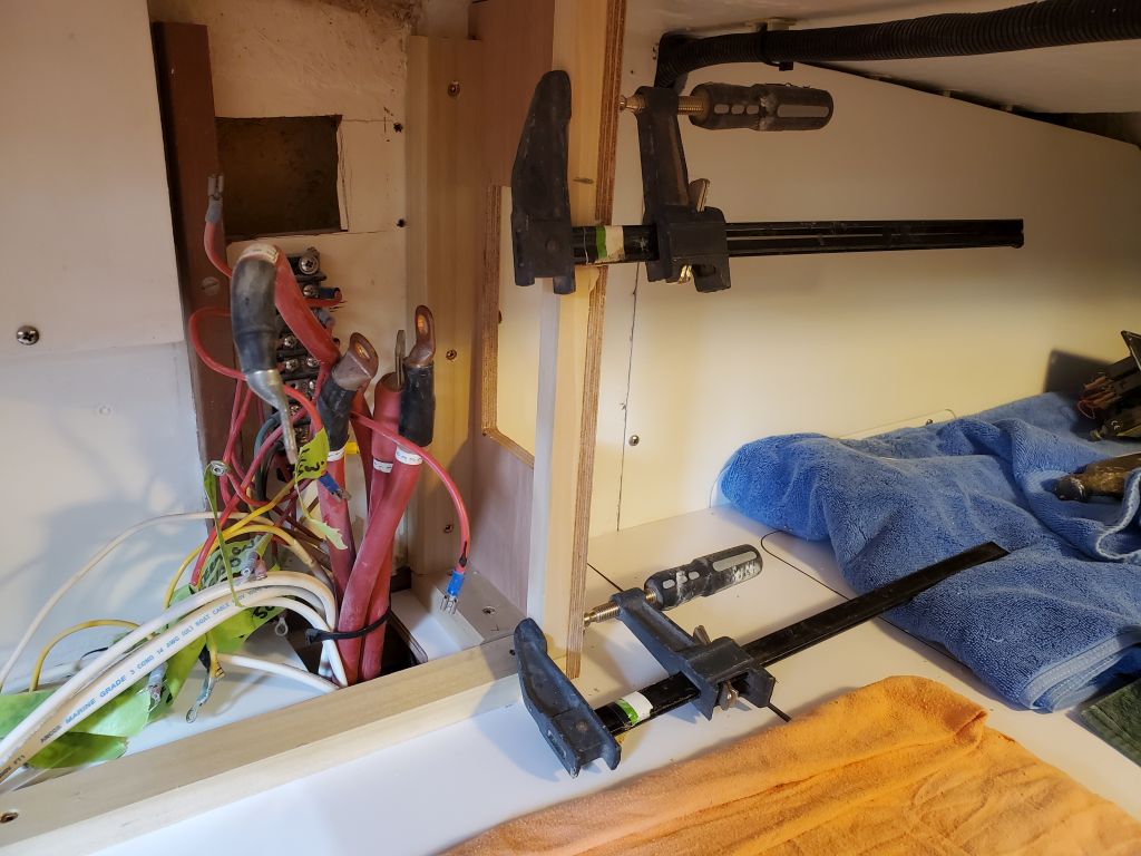
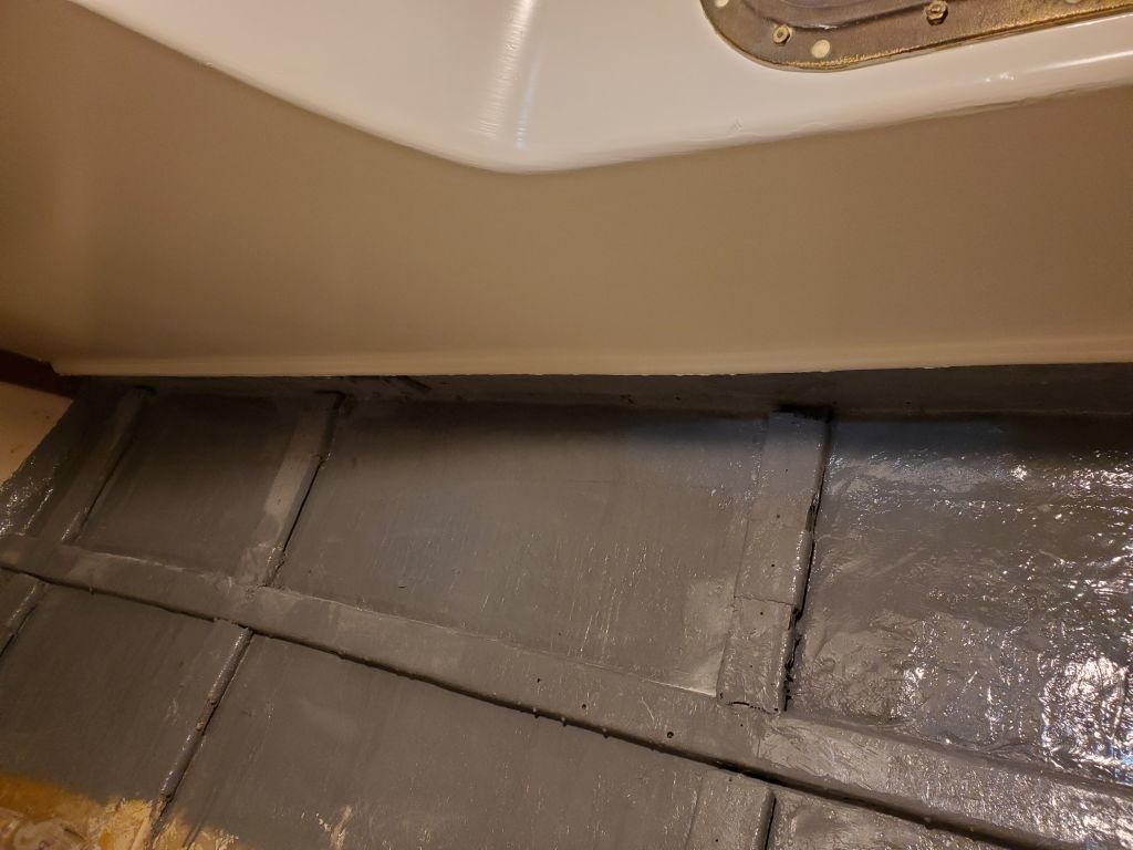
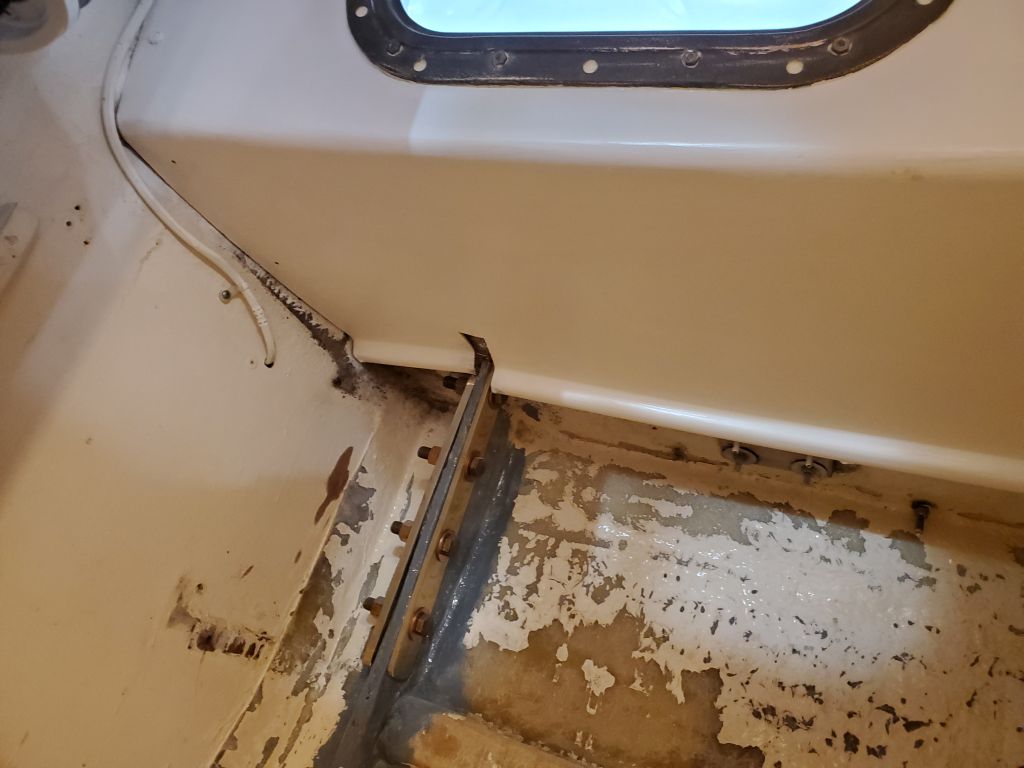
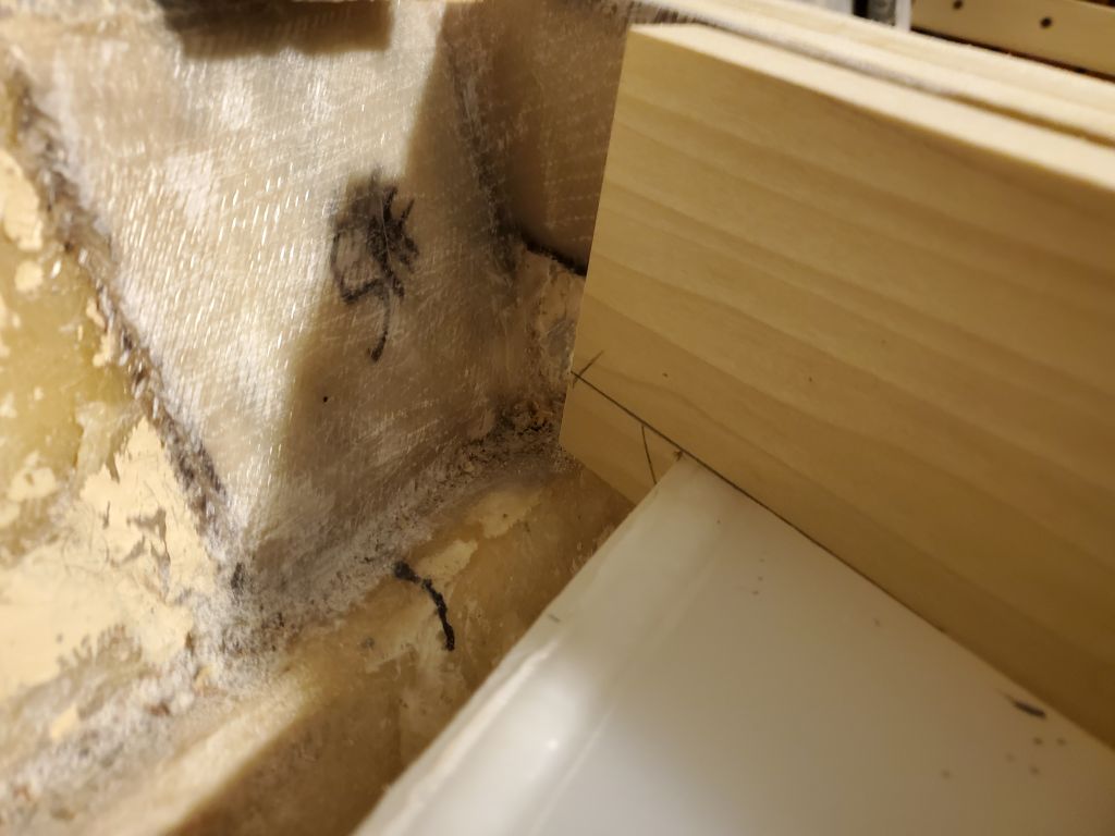
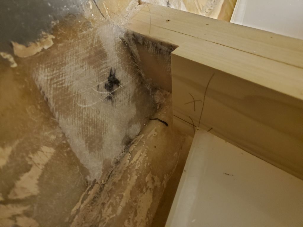
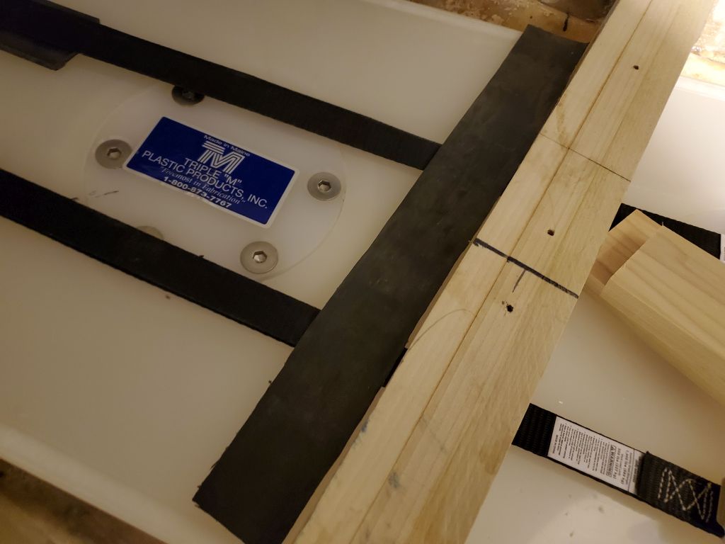
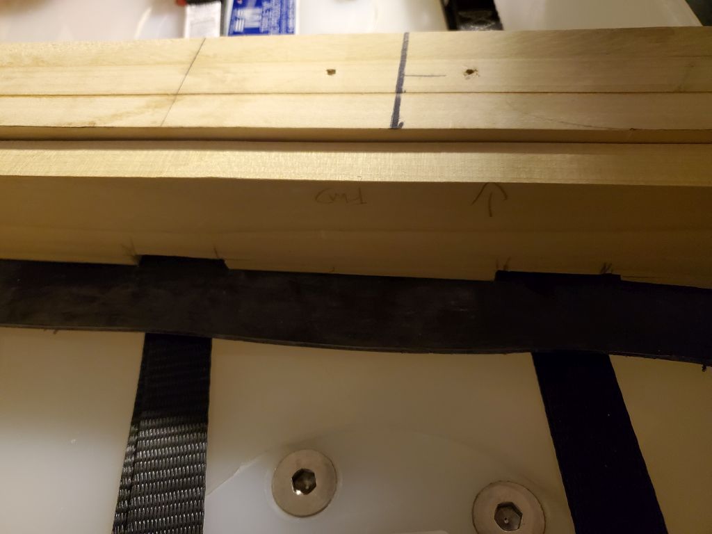
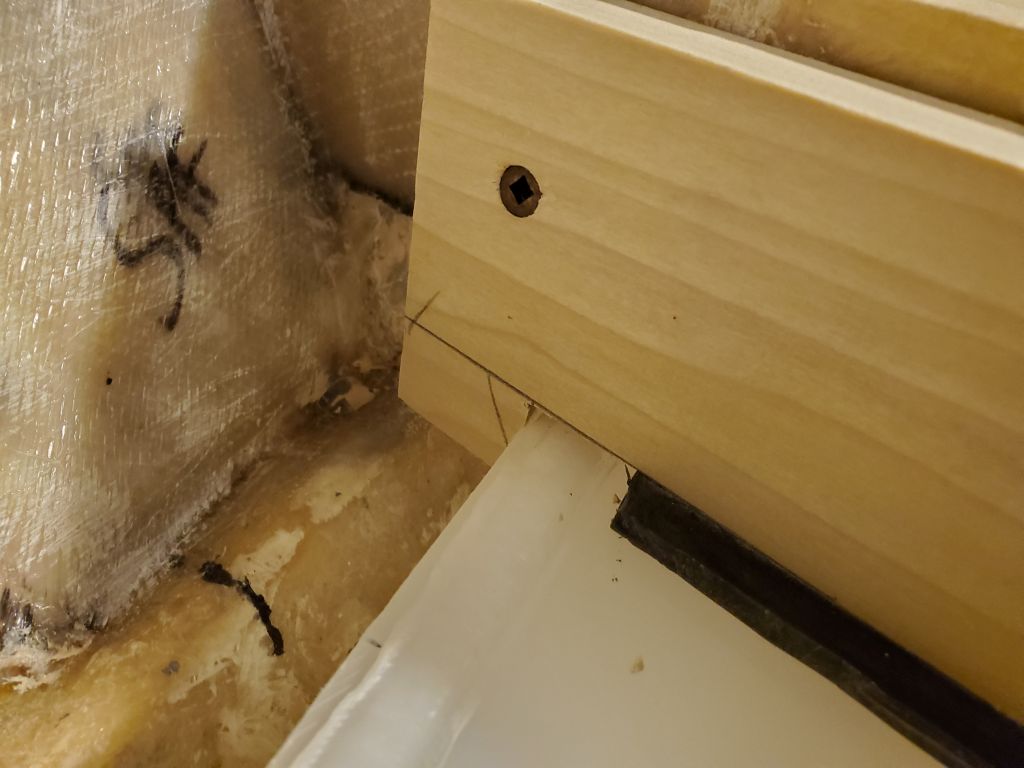
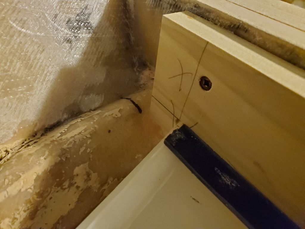
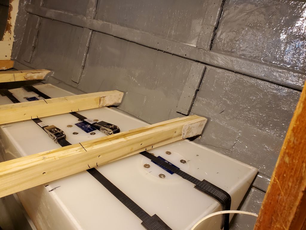
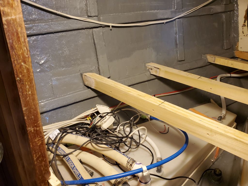
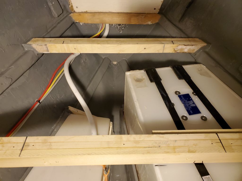
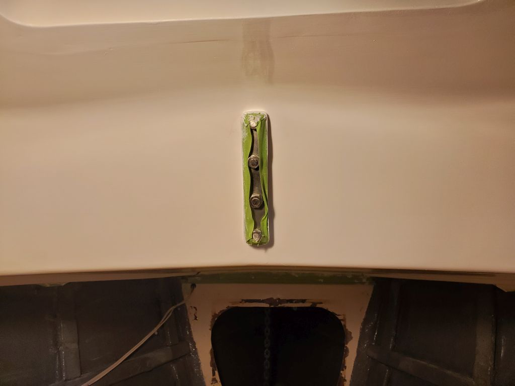
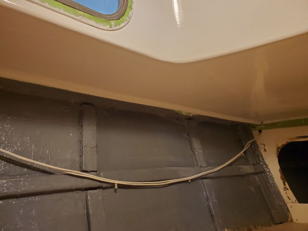
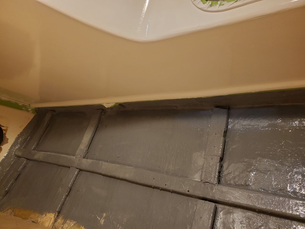
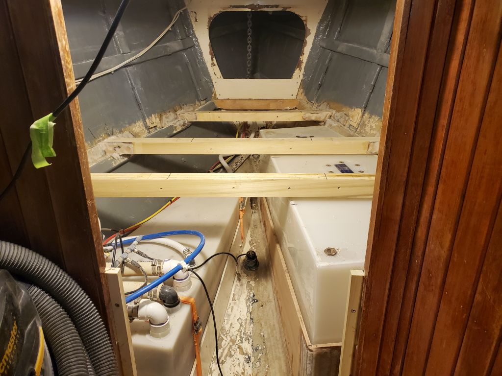
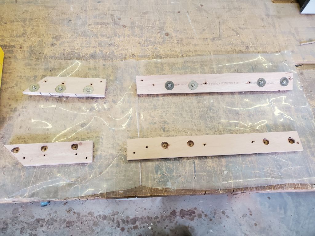
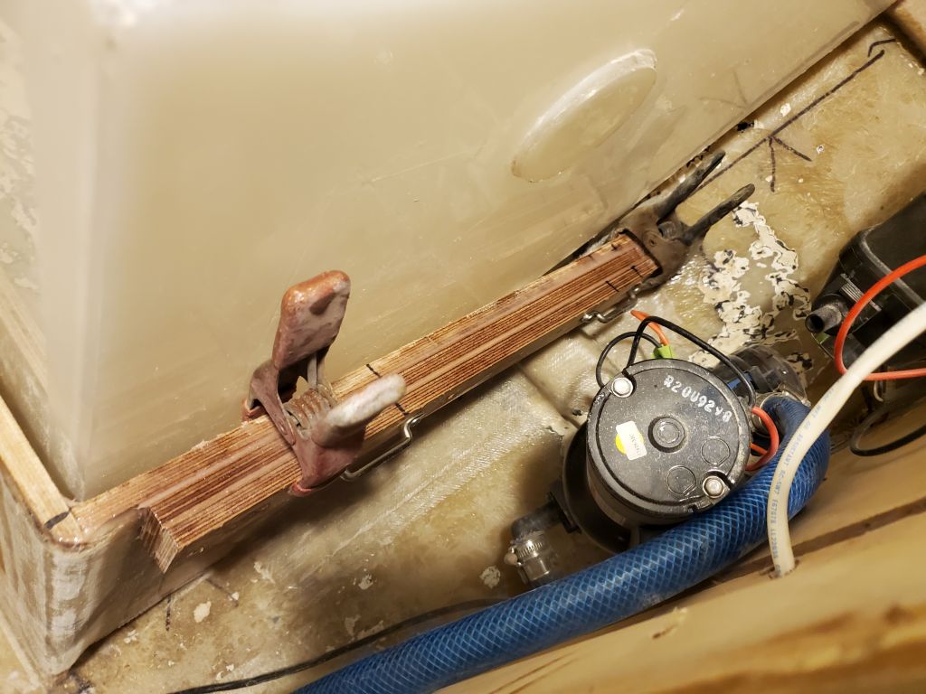
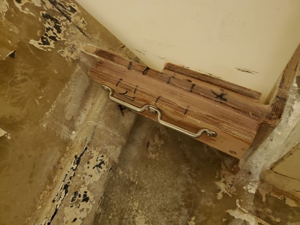
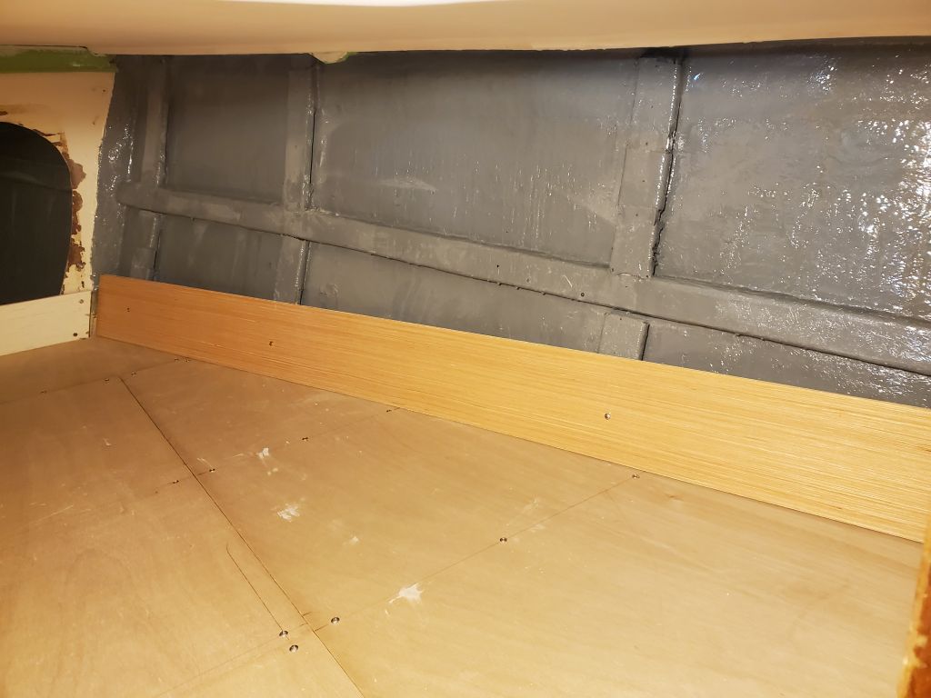
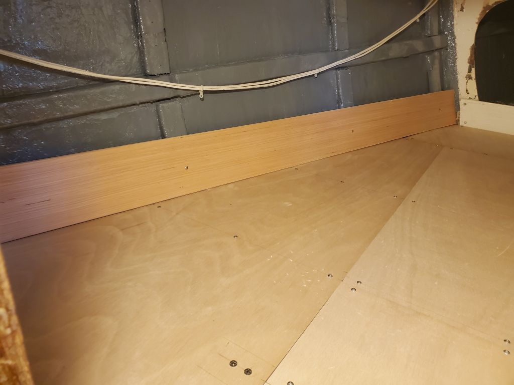
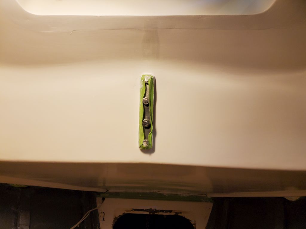
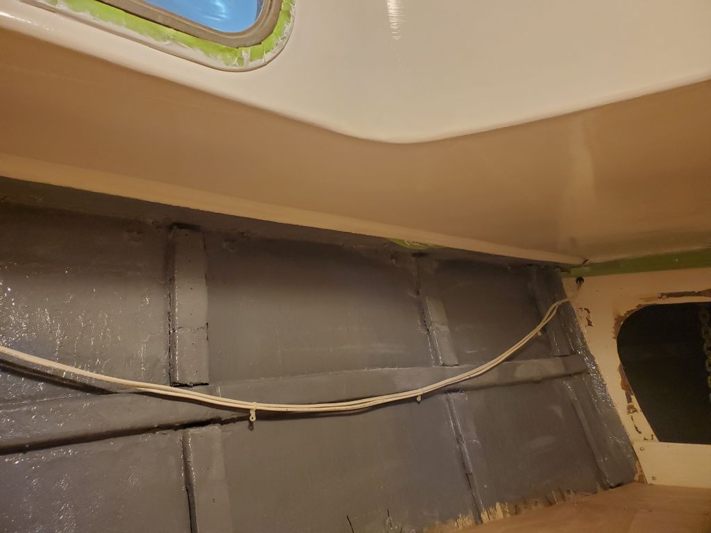
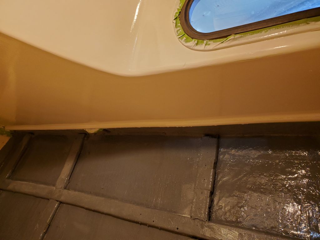
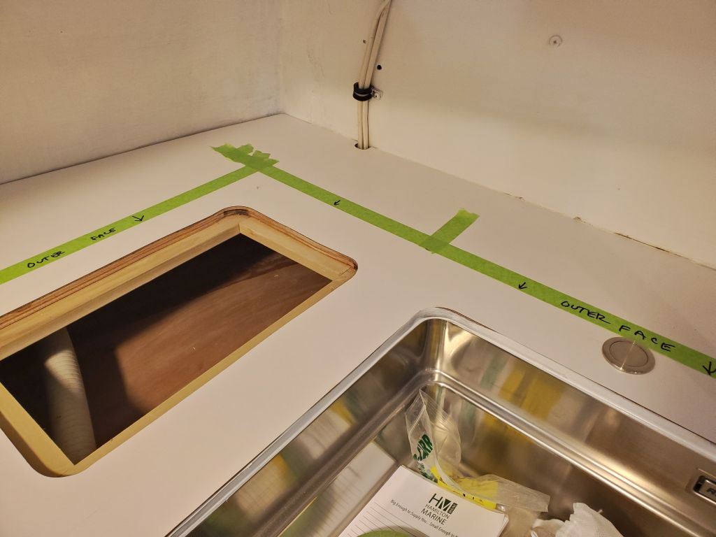
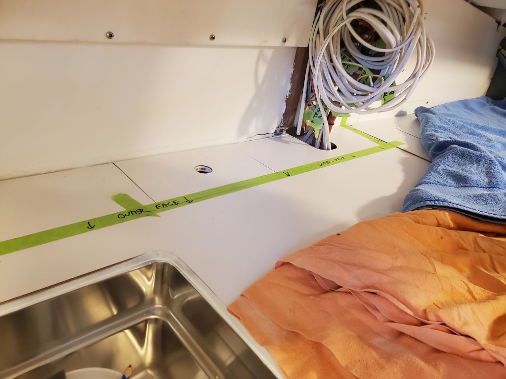
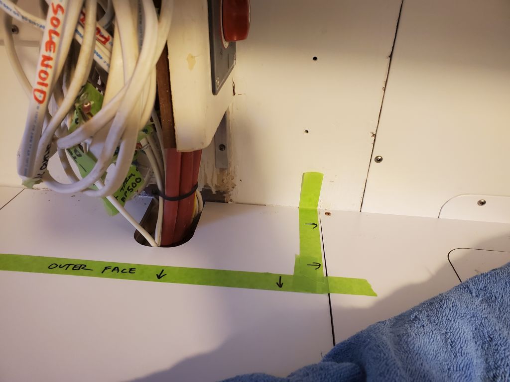
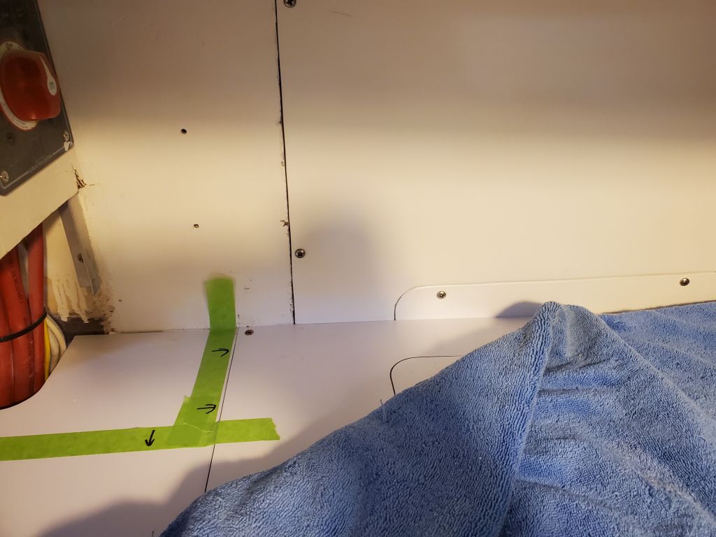
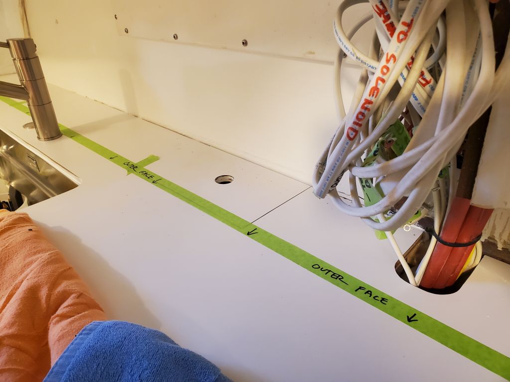
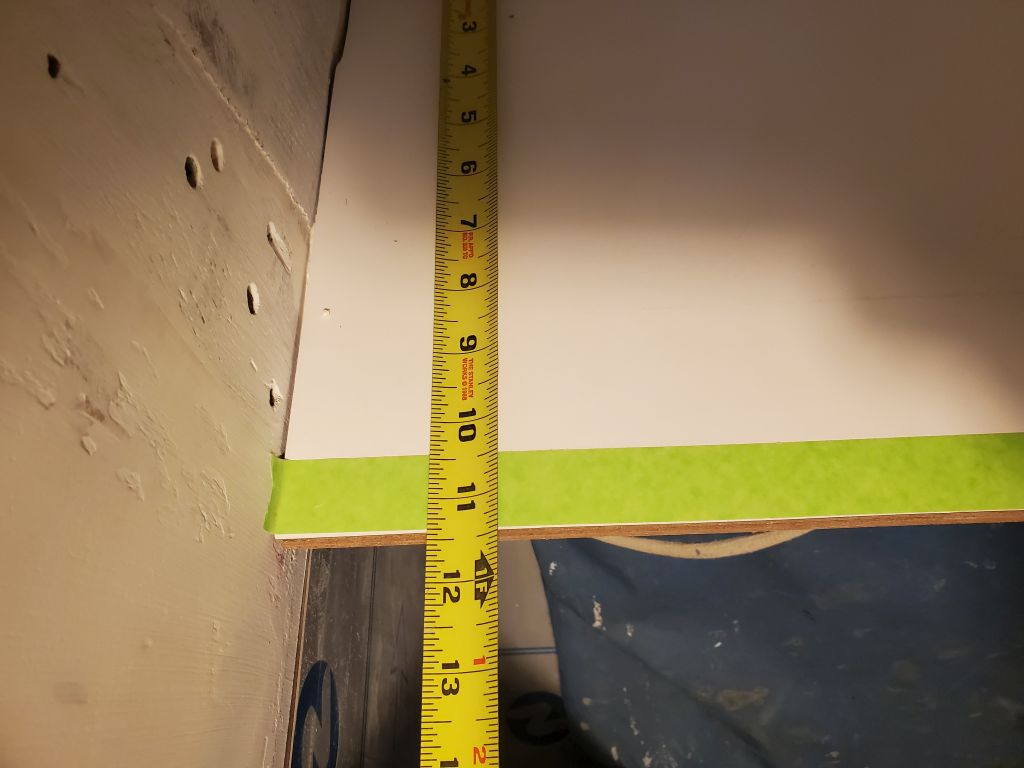
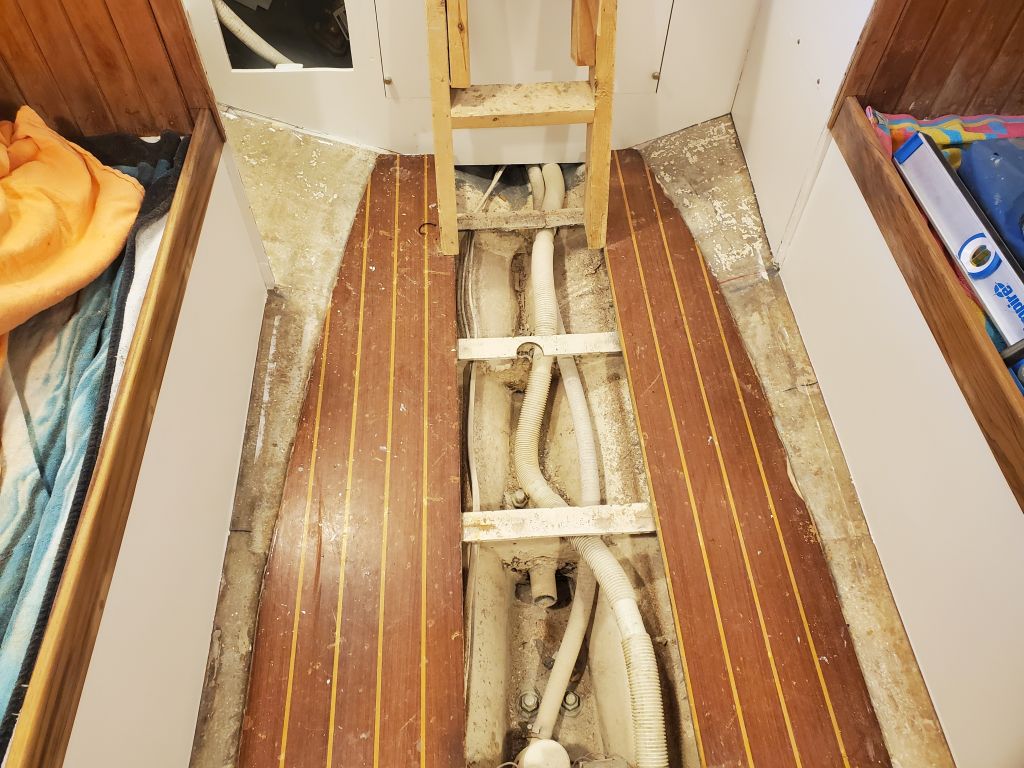
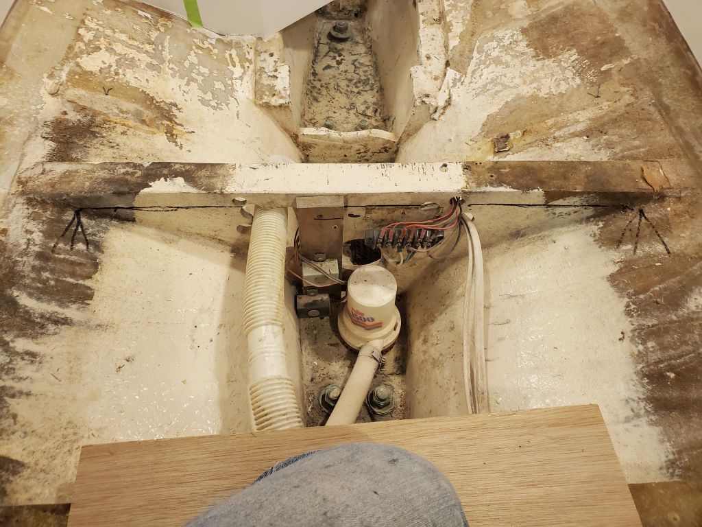
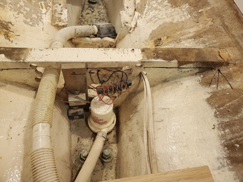
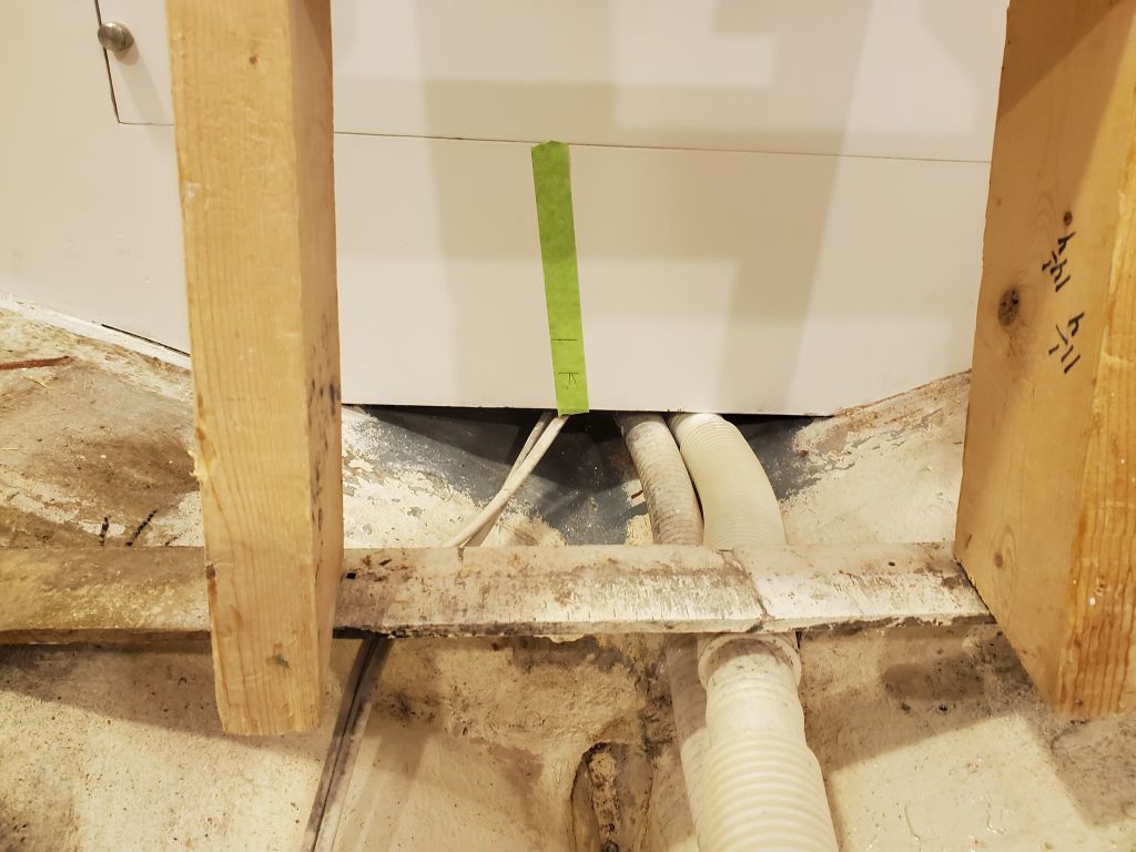
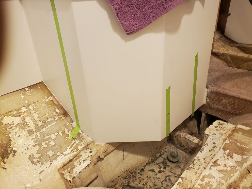
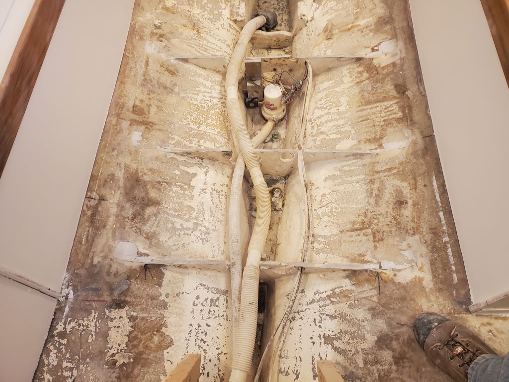
To gain the extra headroom, I had to cut back the existing floors. I’d been thinking this process through for months, and had come up with a plan of attack to strongly and efficiently achieve the requirements. To start, I marked a line 1″ down from the top edge of each floor, and also used a level to make some reference marks on the battery compartment and engine room bulkhead for future use, both at the existing height and then 1″ down. I had to reroute some wiring leading to the bilge terminal block, and temporarily unfastened the block to keep it clear of the work to come.
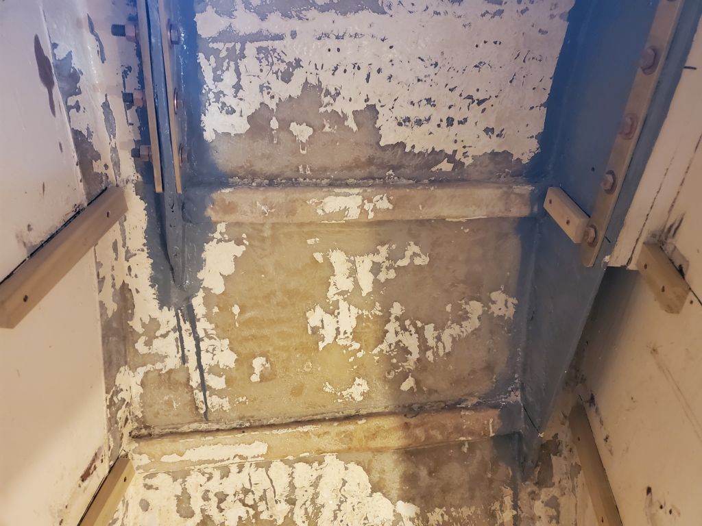
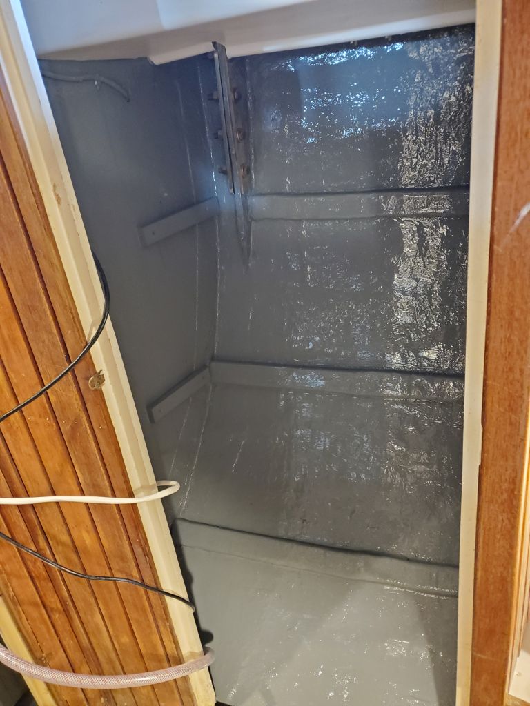
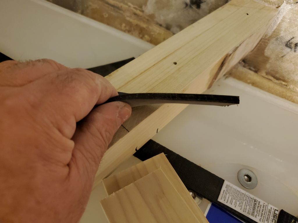
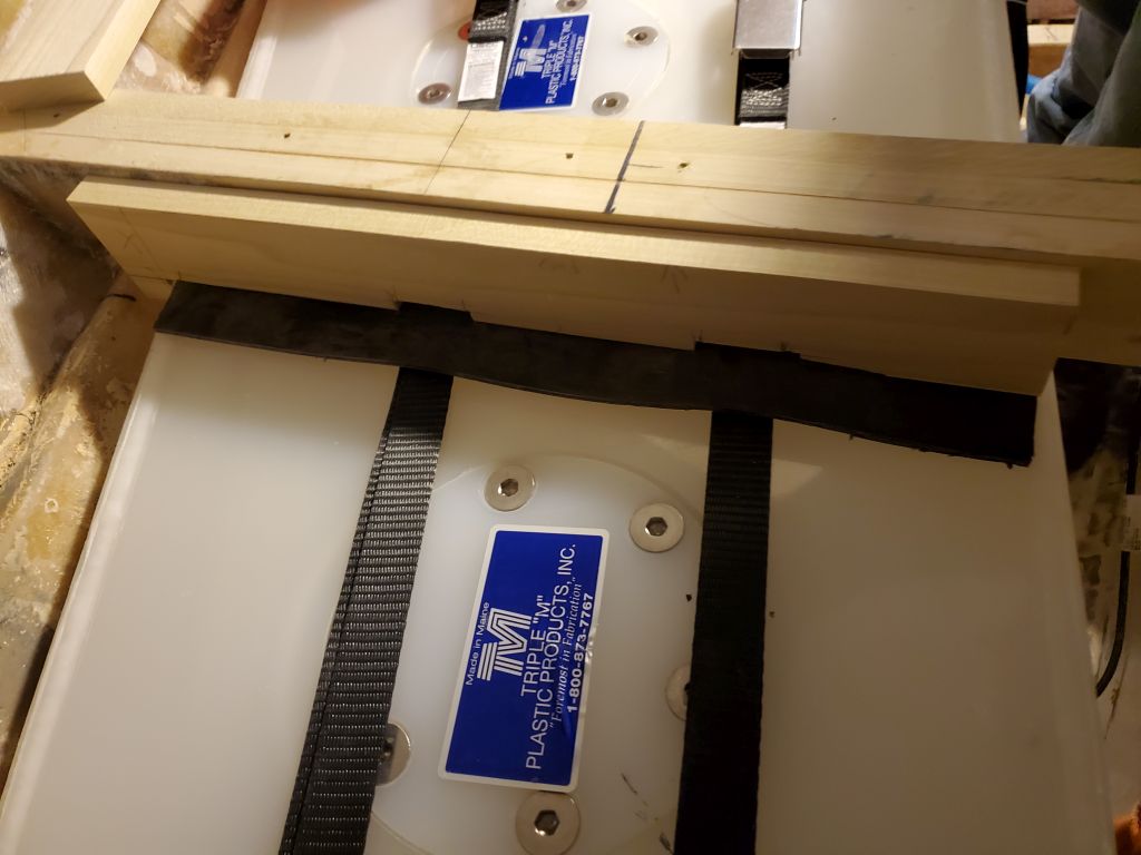
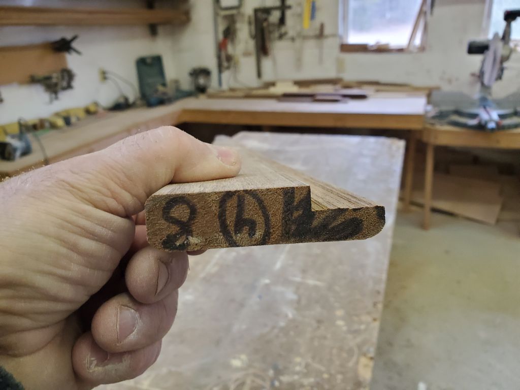
Now I used an angle grinder and cutoff wheel to cut to these lines, removing the top sections of all four floor installations and grinding off the tabbing and adhesive filler at the ends as needed. This was as fun as it sounds and made quite a mess, but it was the worst part of the job and was now over.
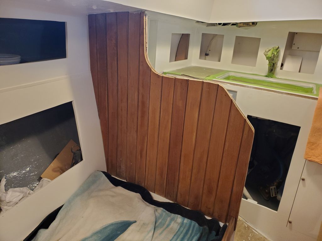
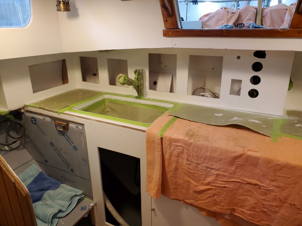
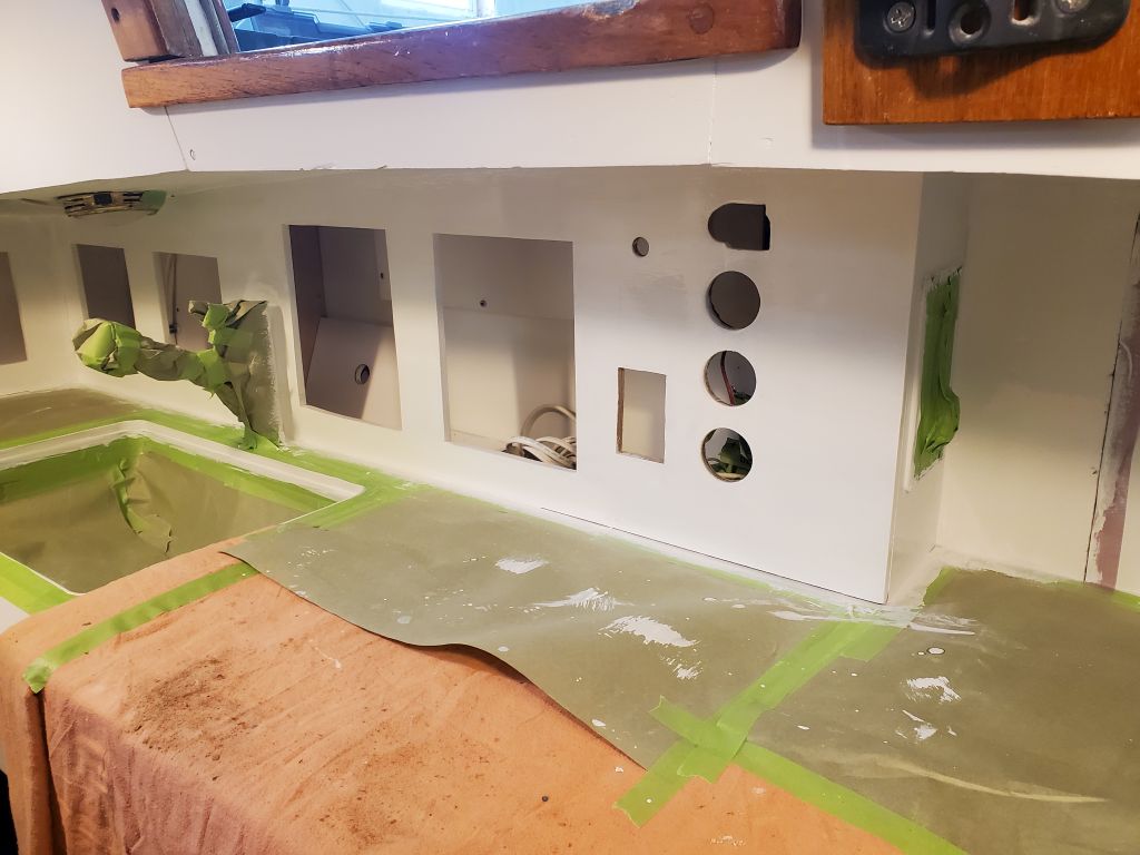
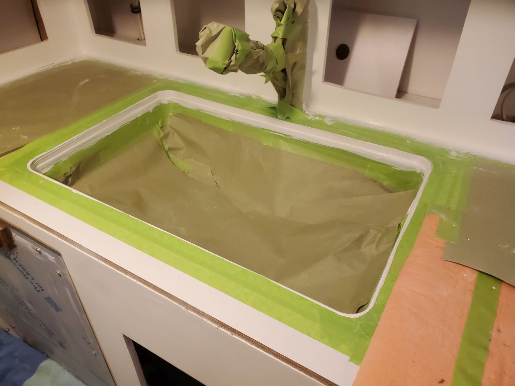
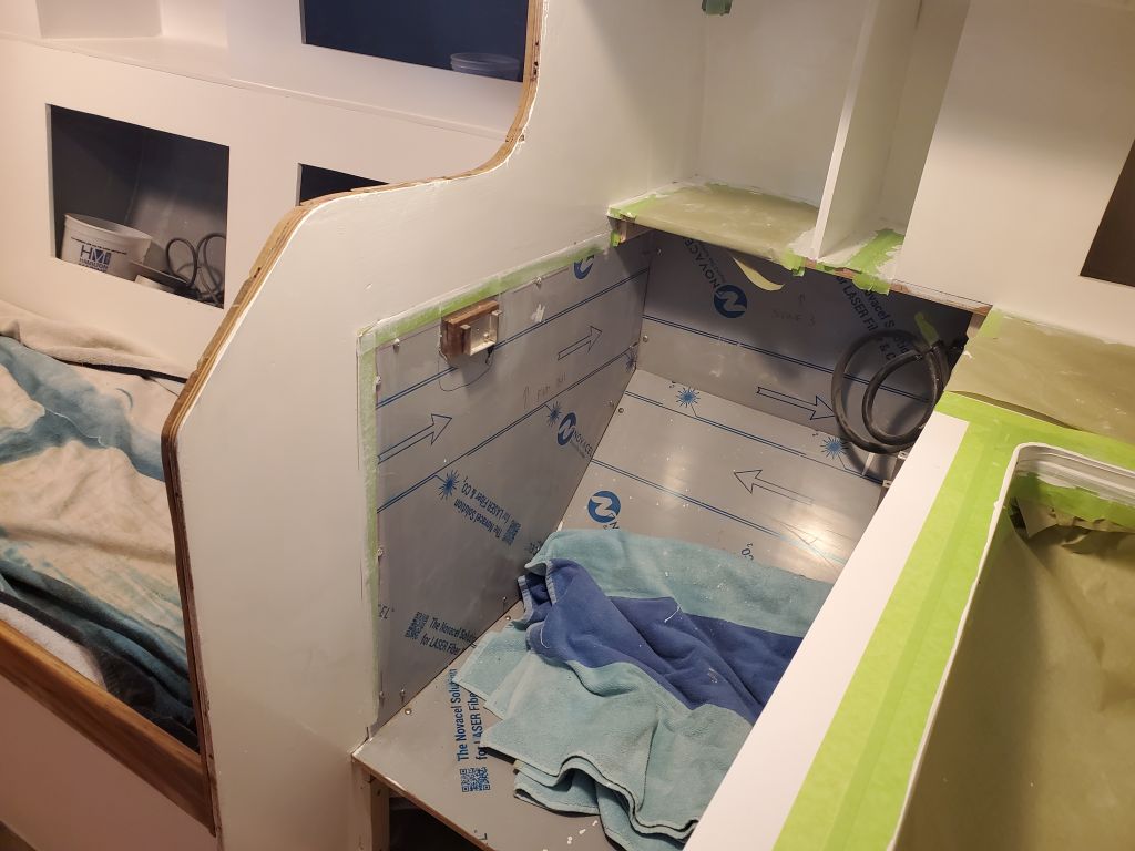
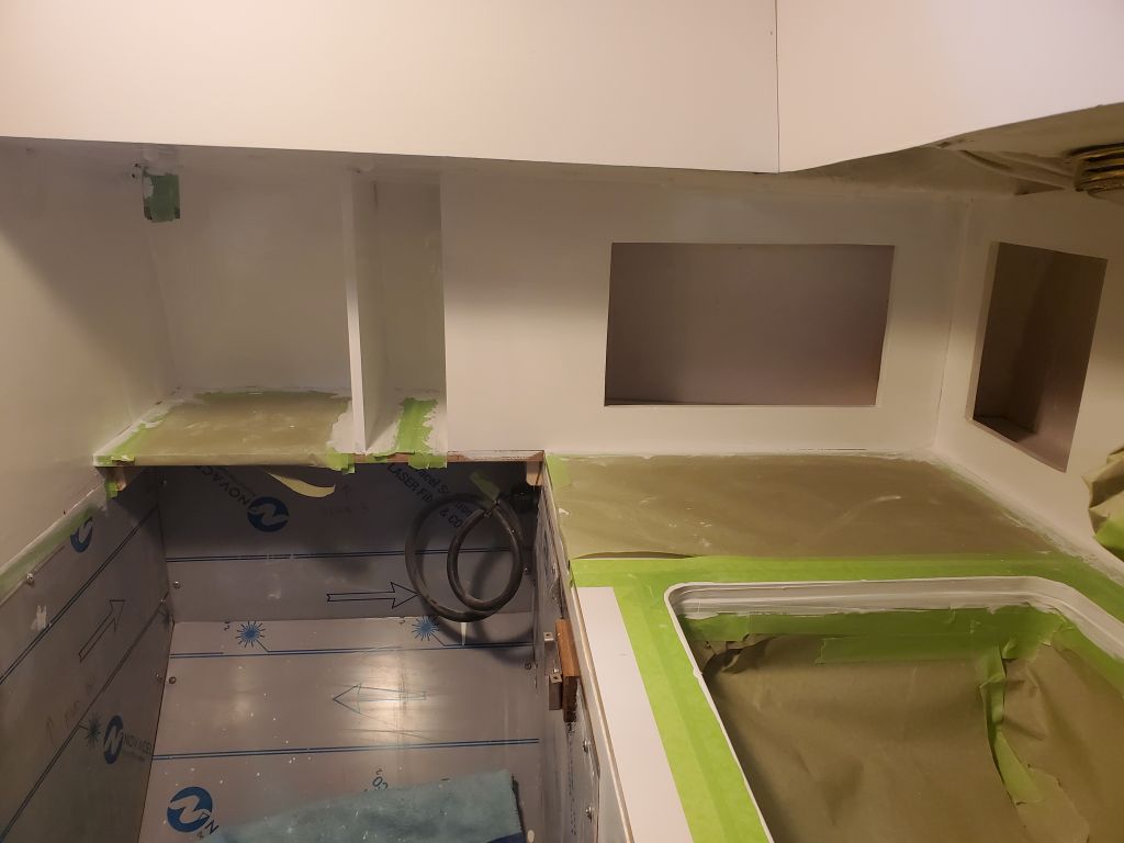
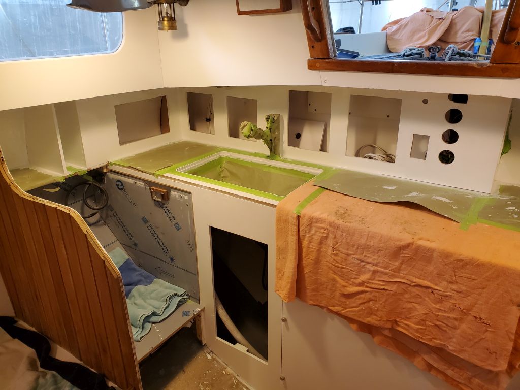
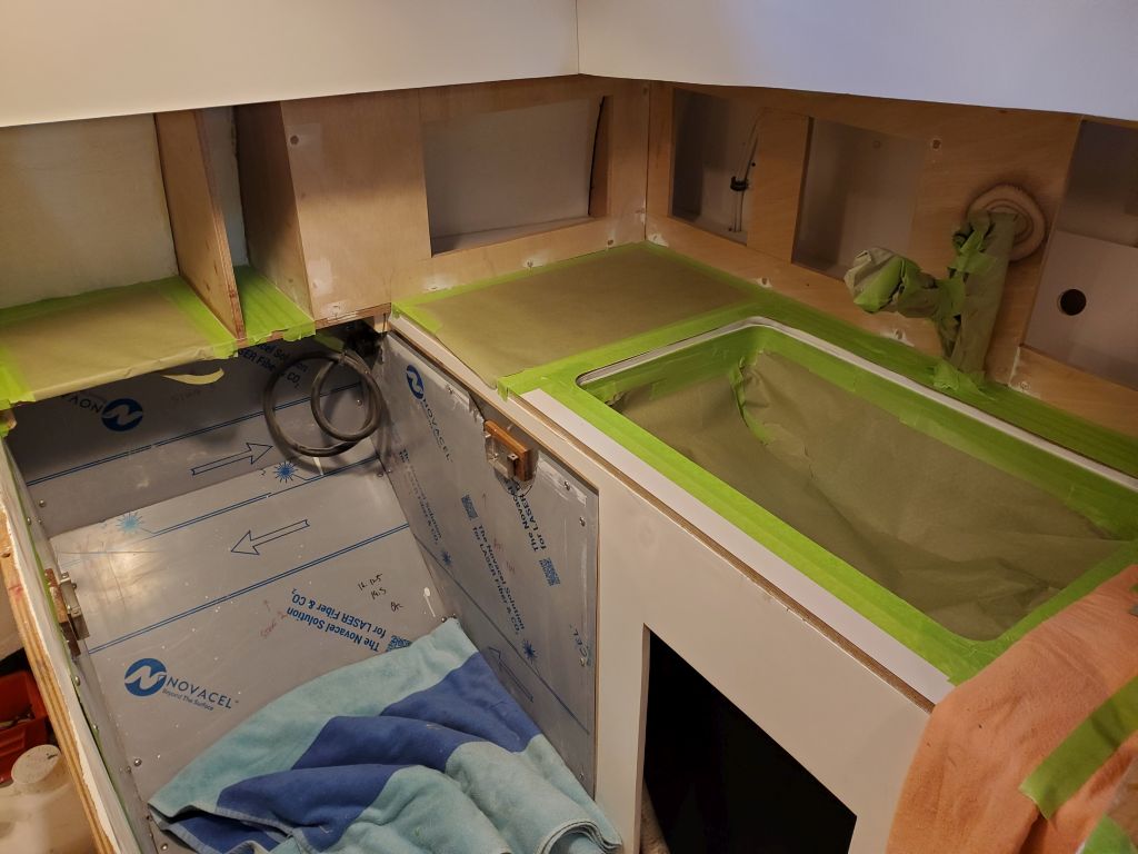
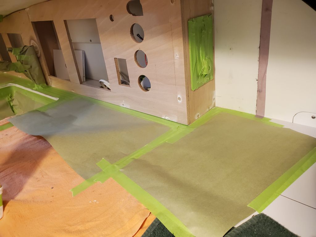
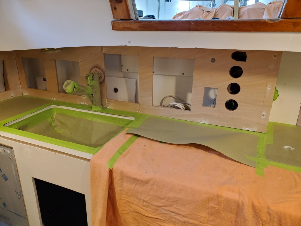
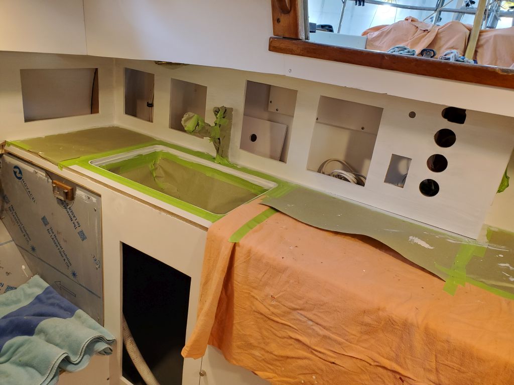
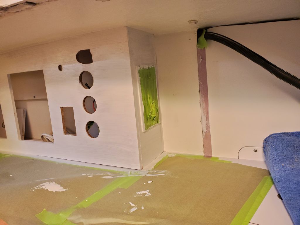
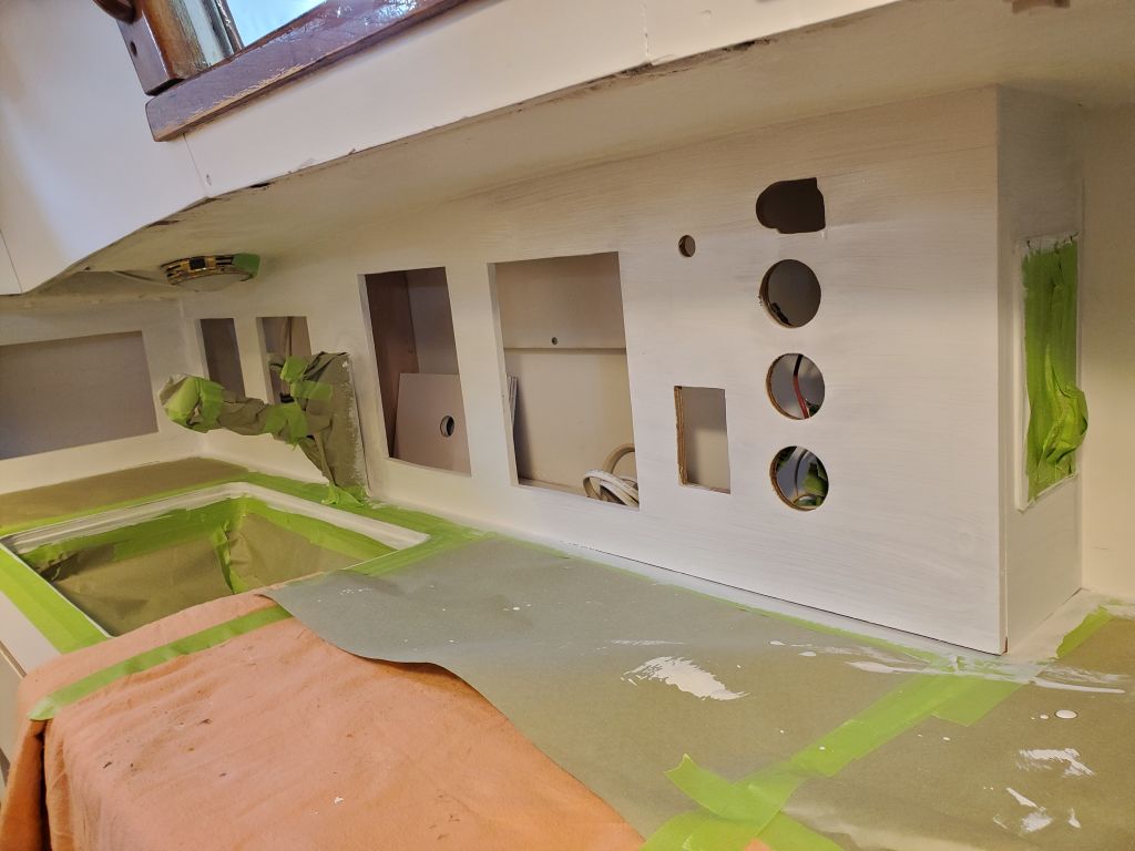
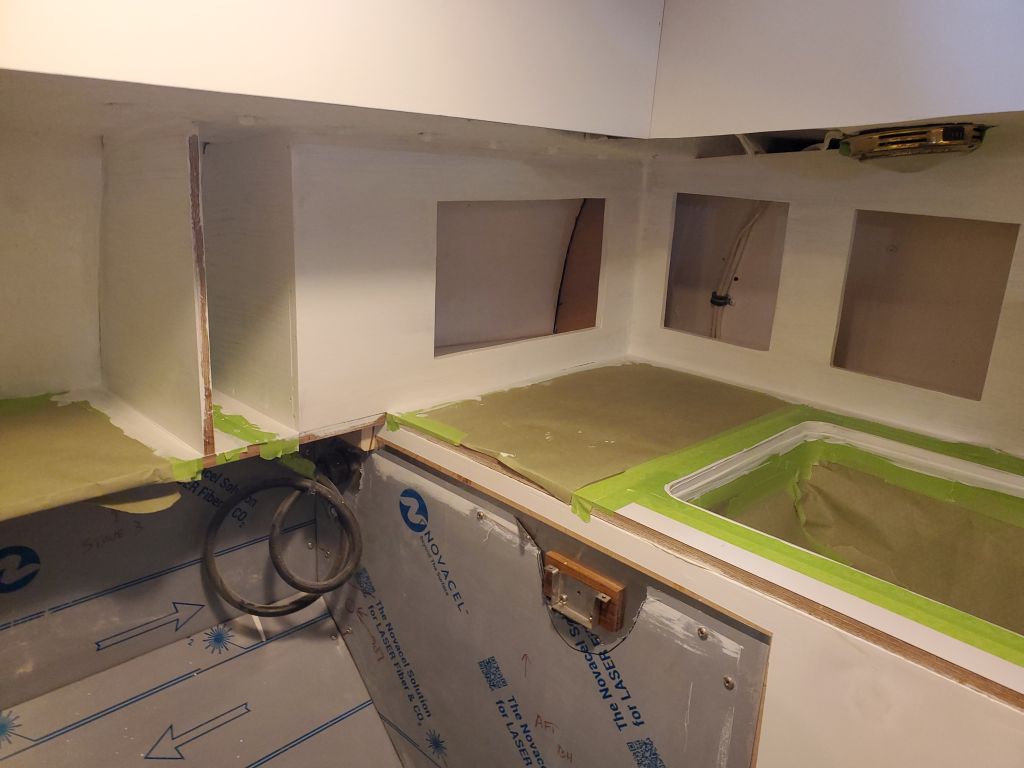
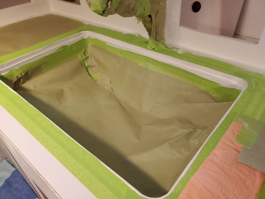
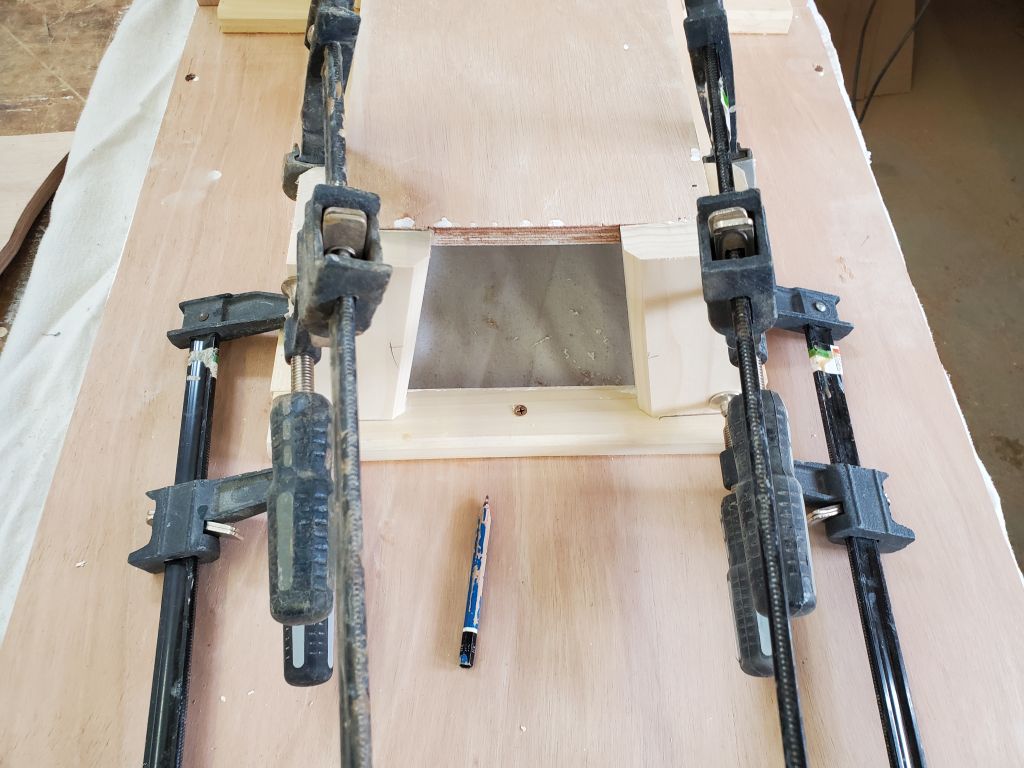
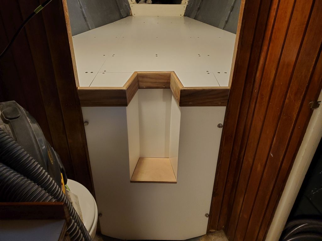
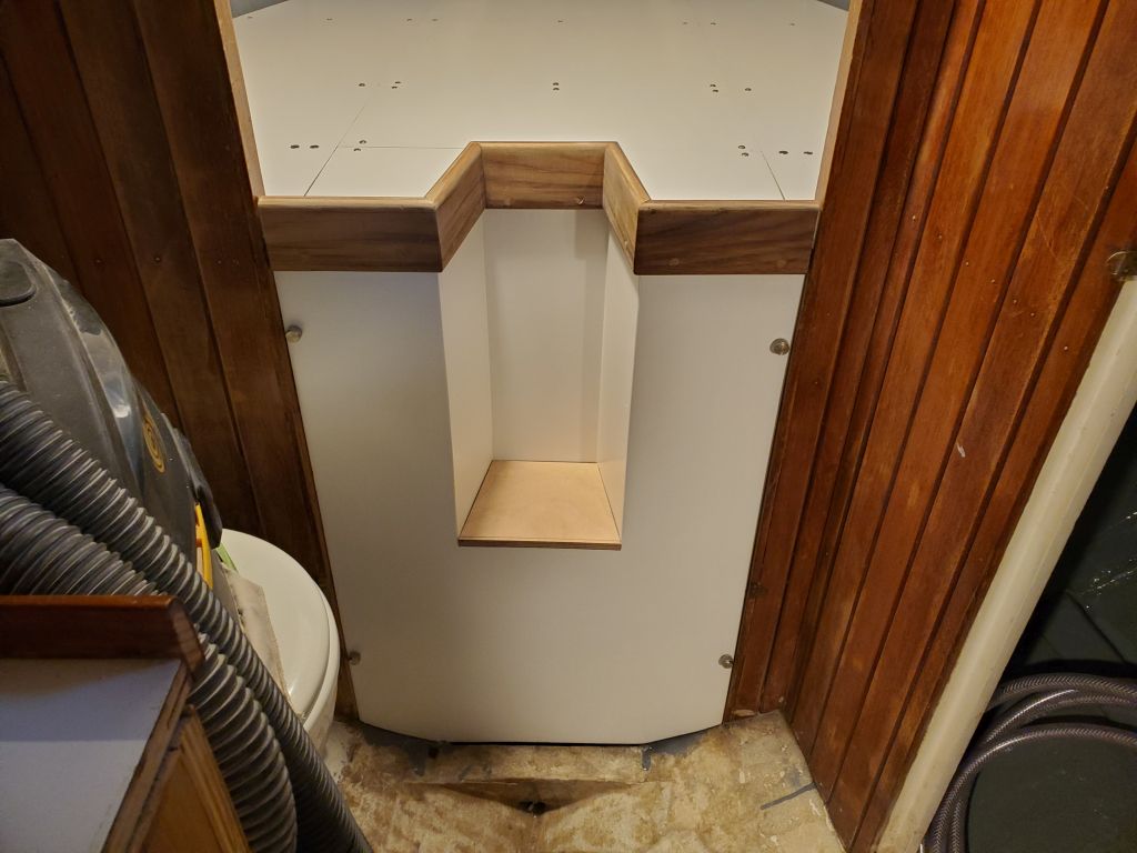
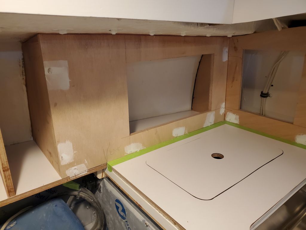
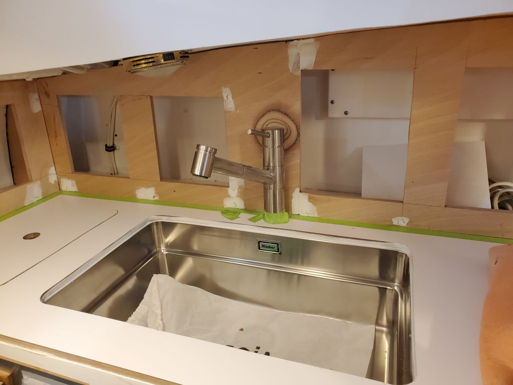
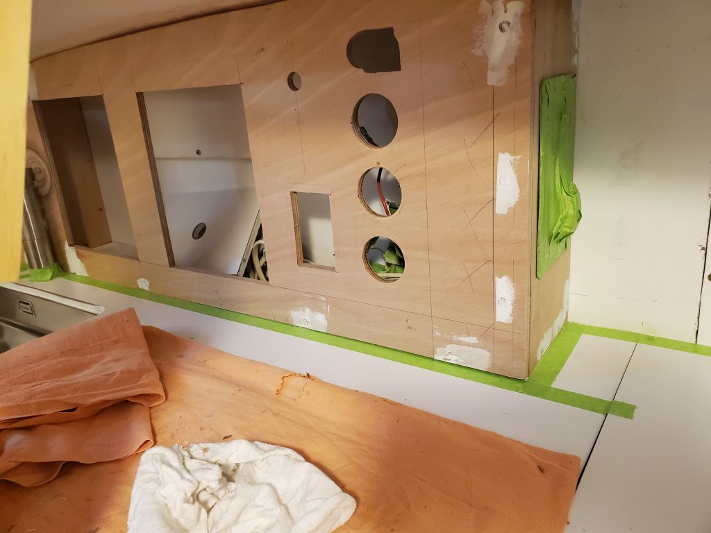
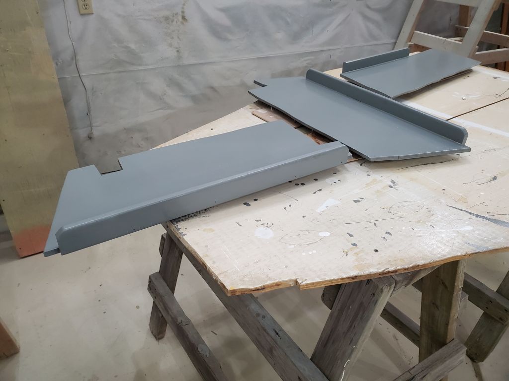
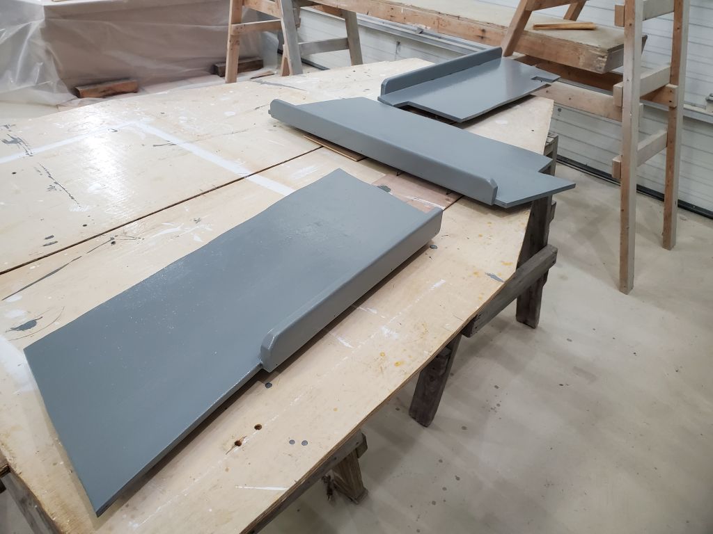
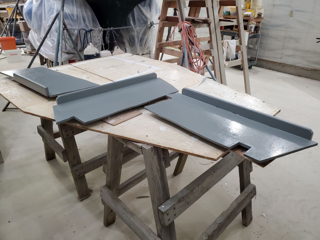
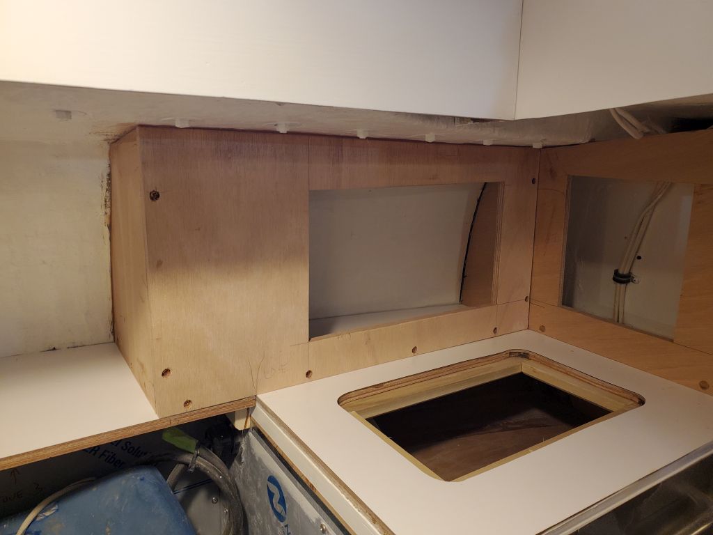
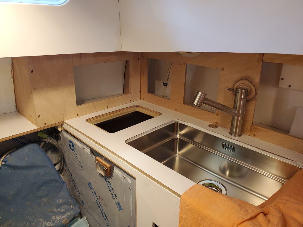
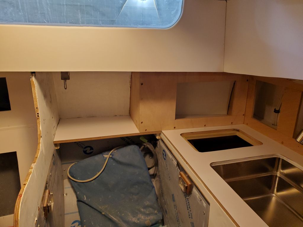
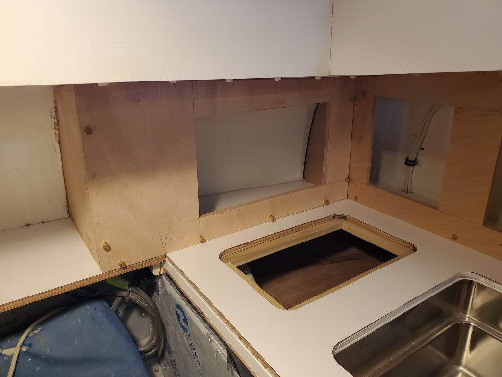
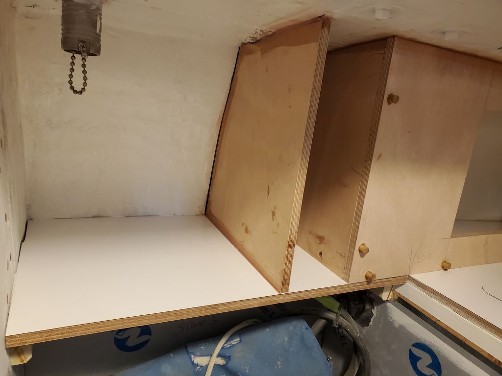
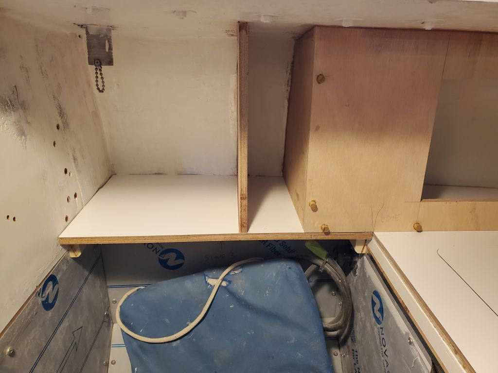
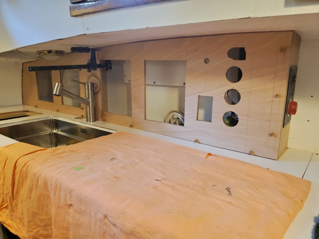
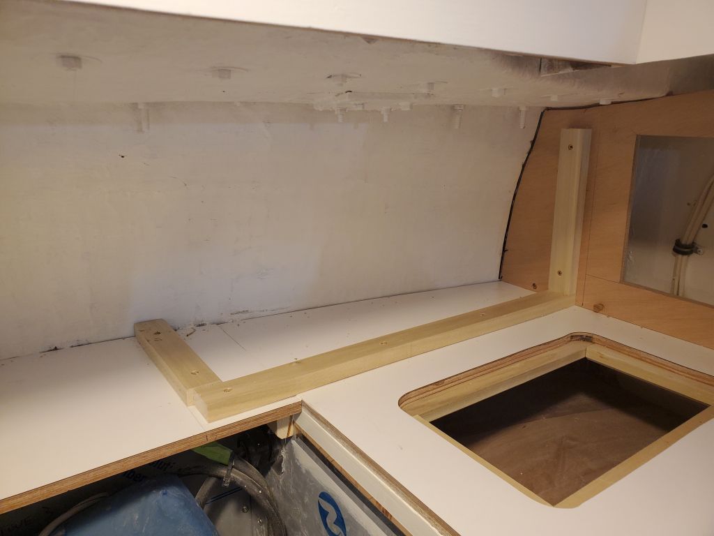
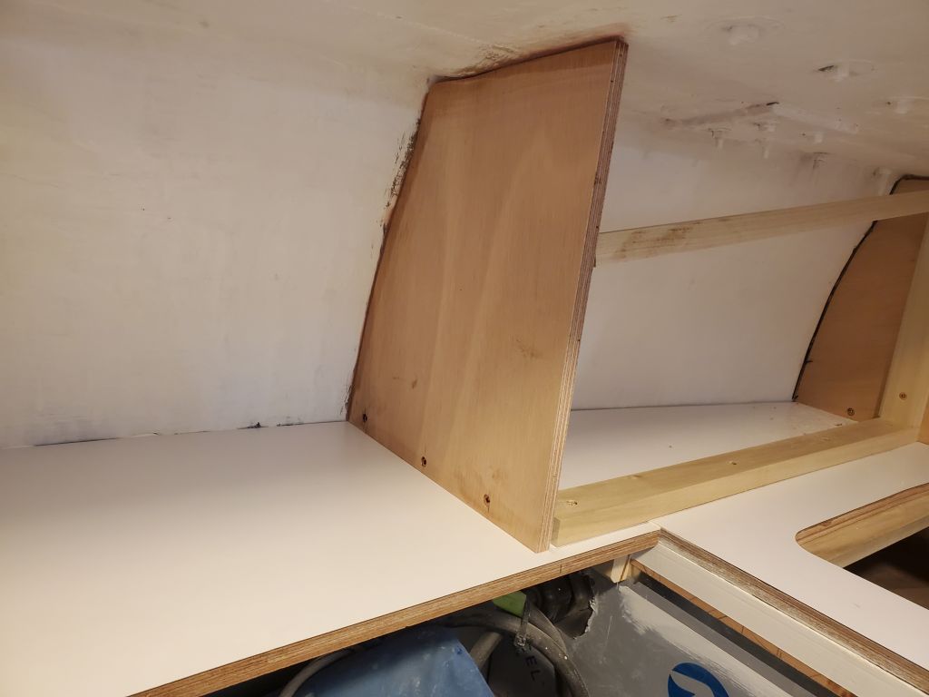
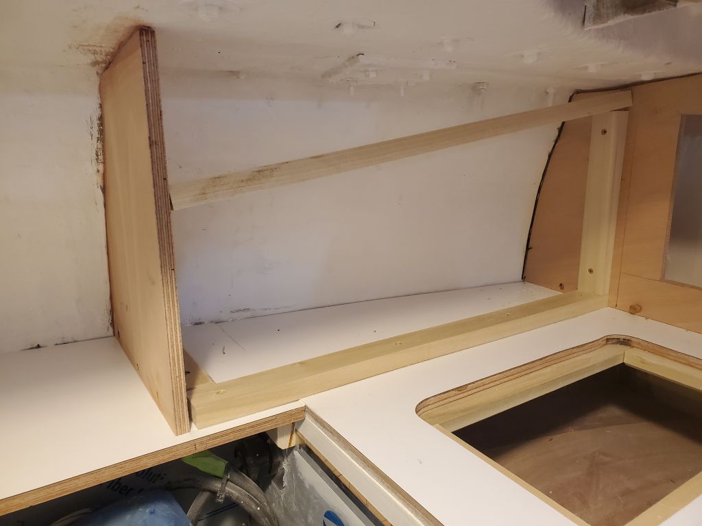
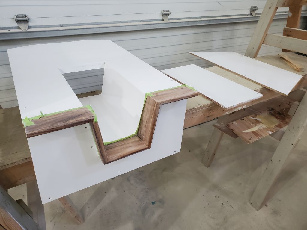
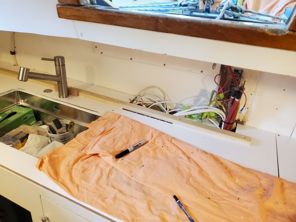
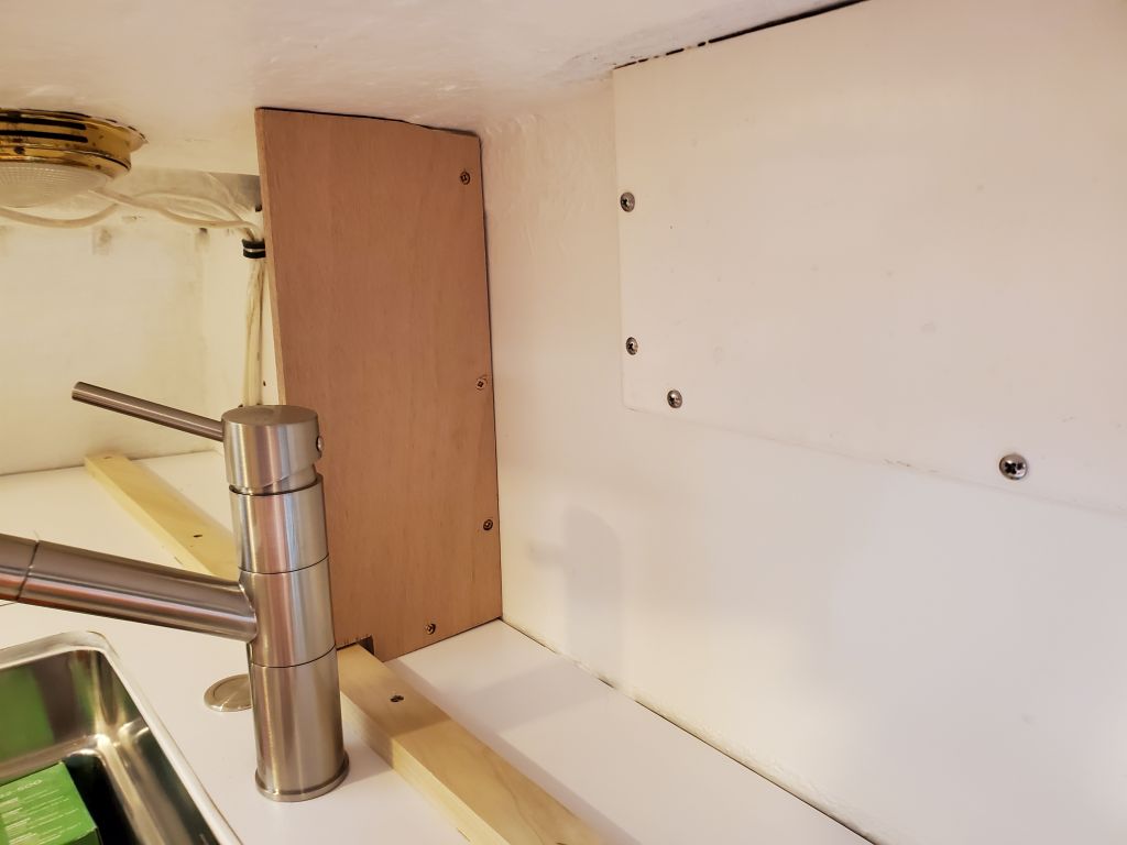
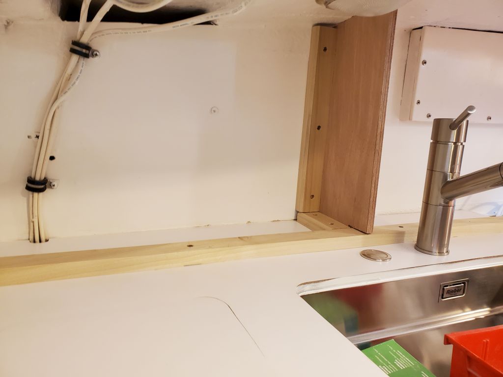
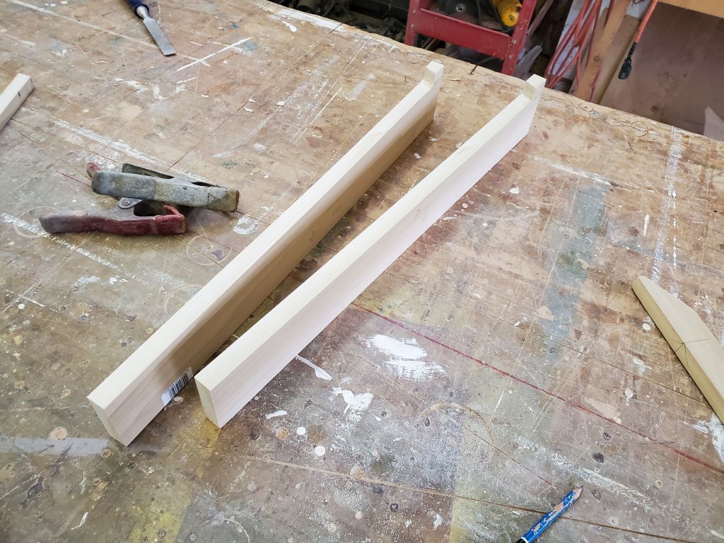
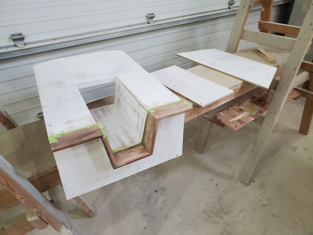
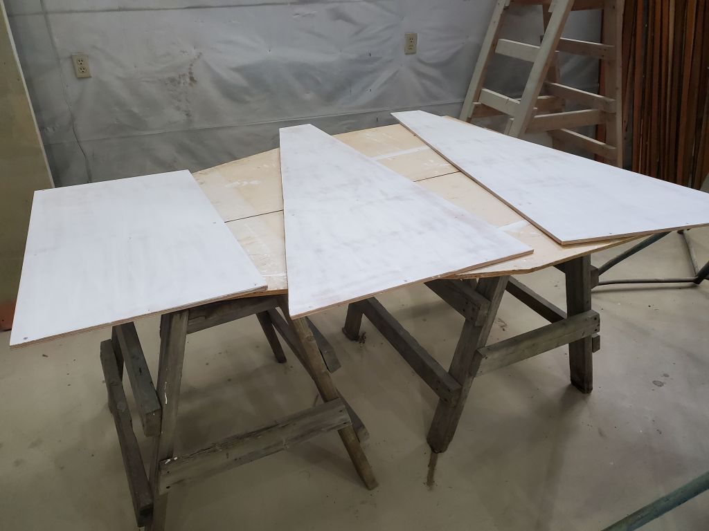
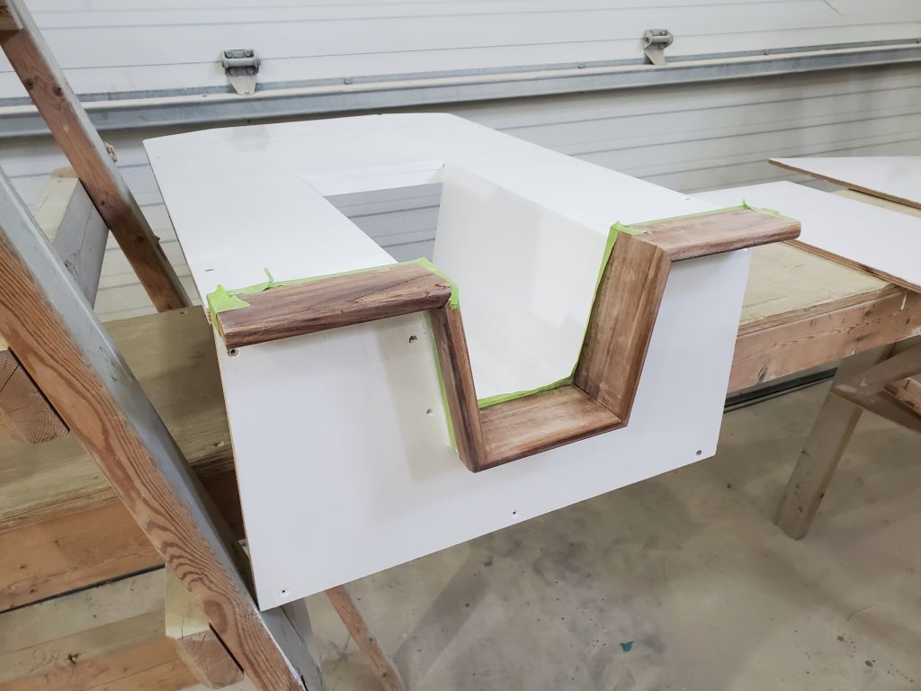
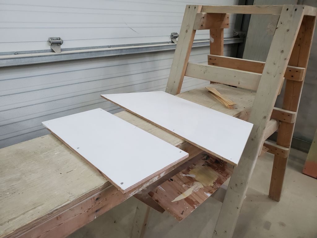
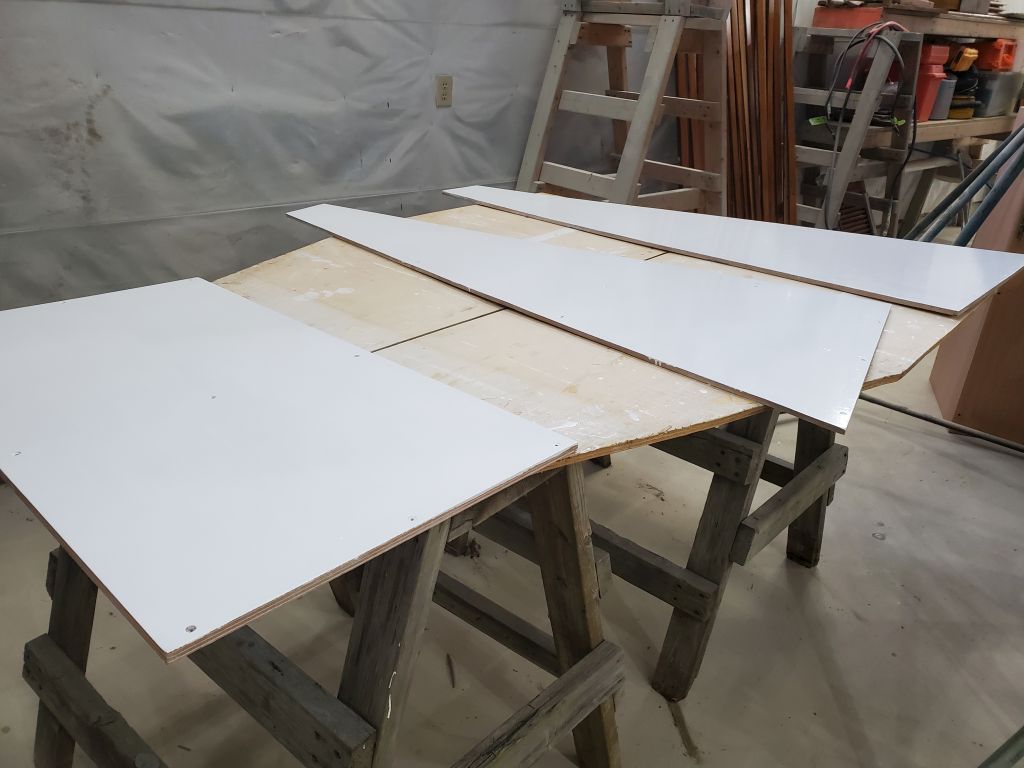
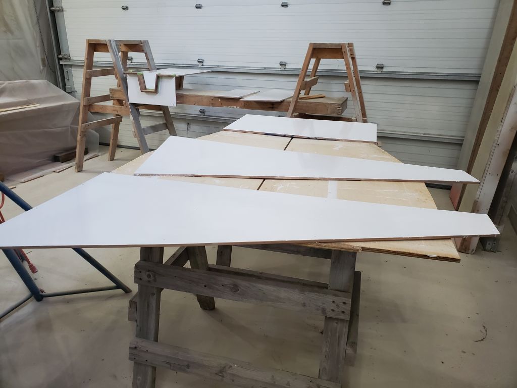
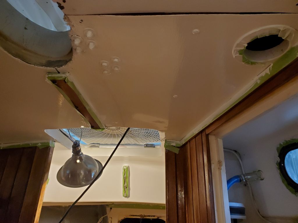
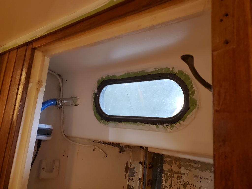
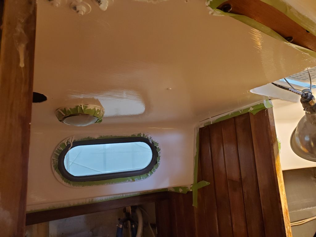
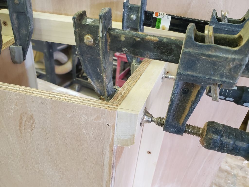
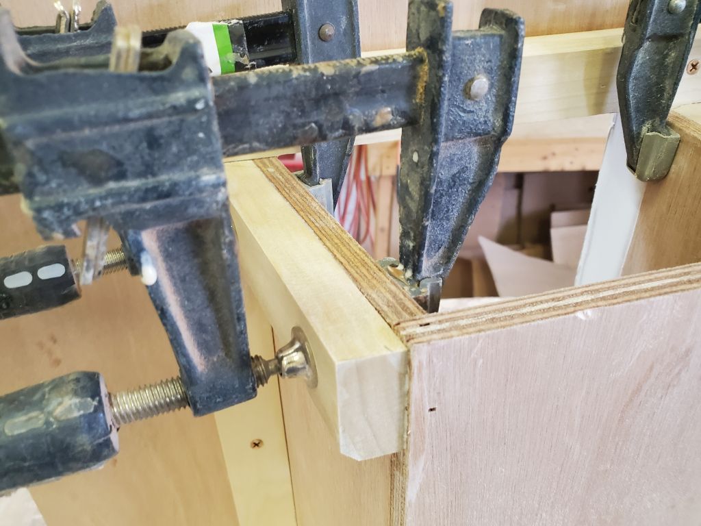
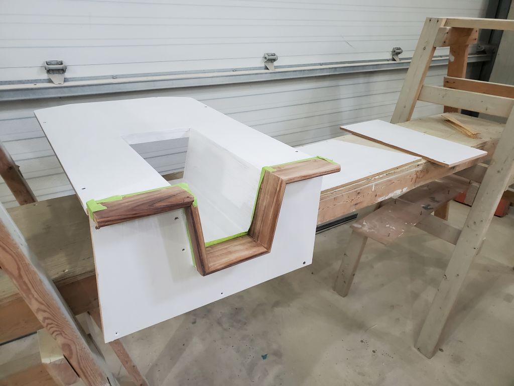
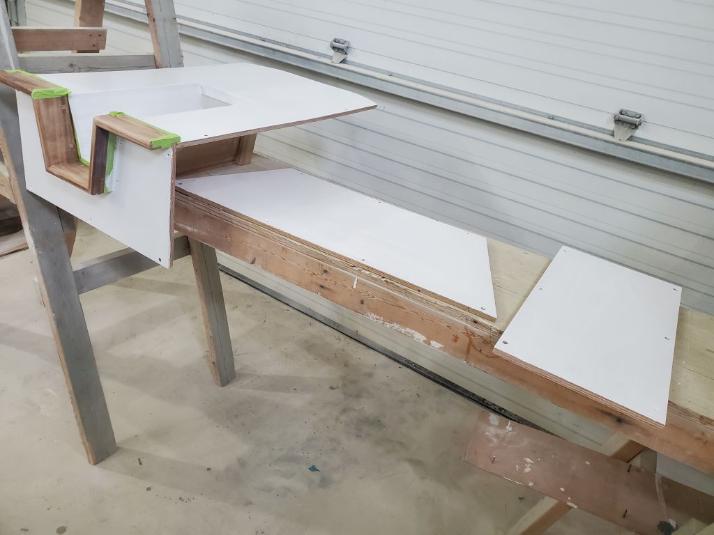
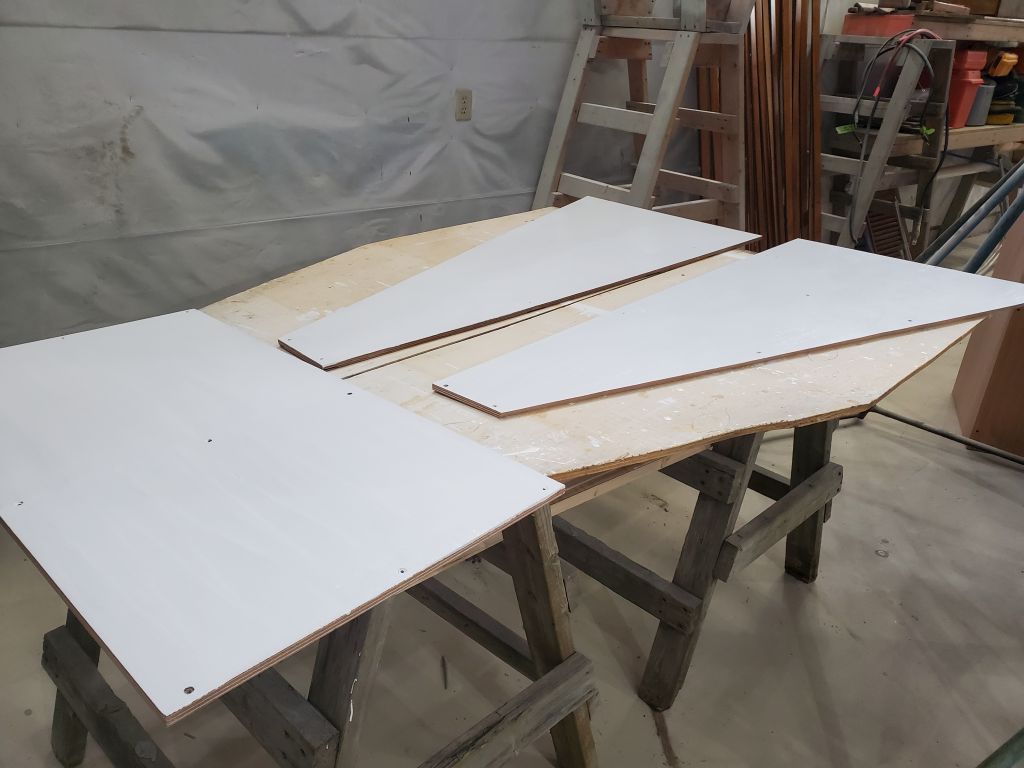
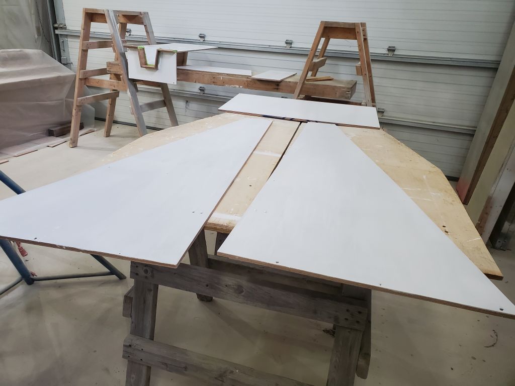
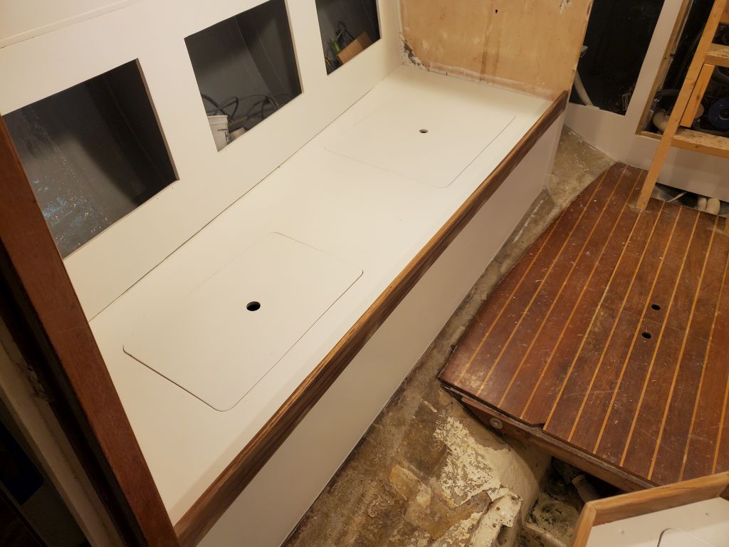
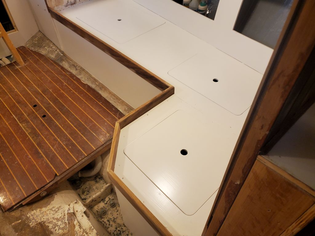
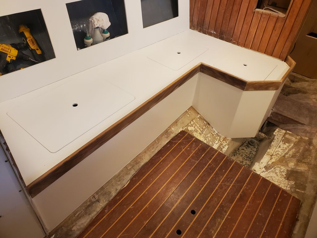
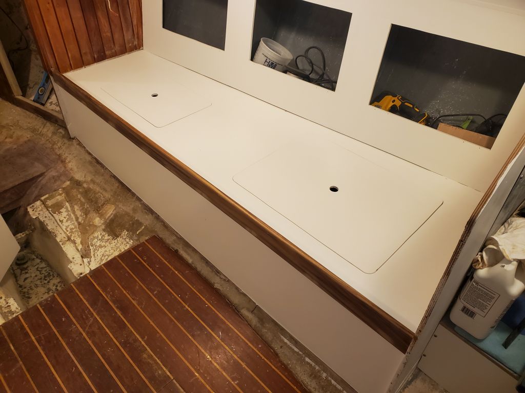
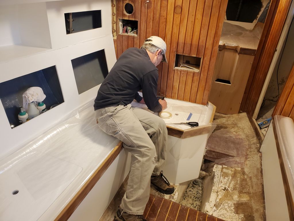
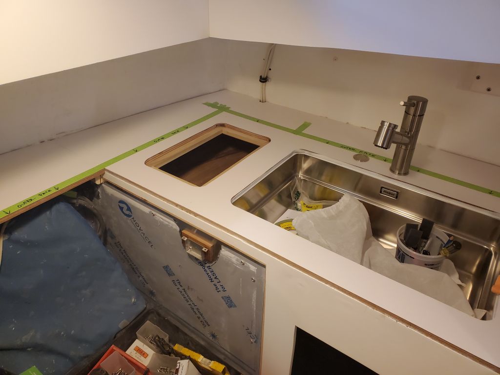
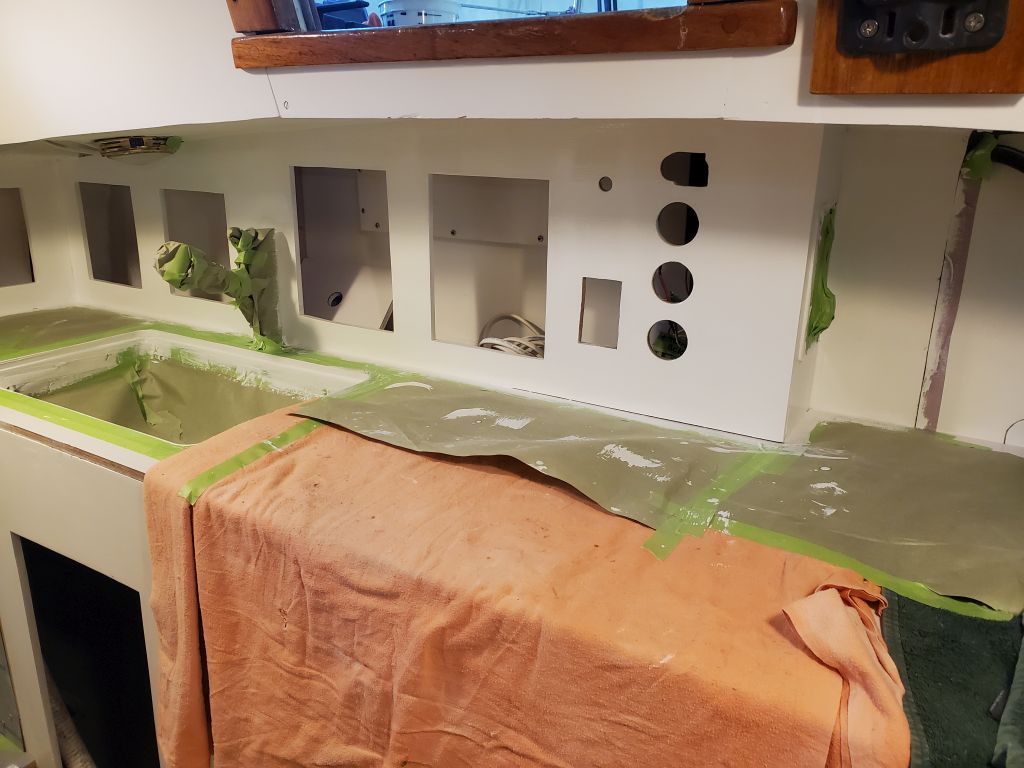
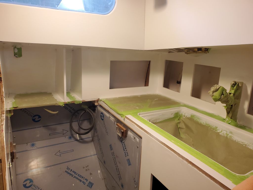
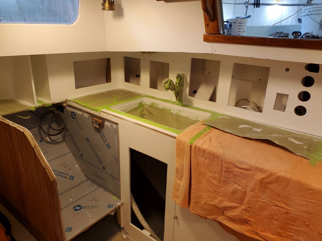
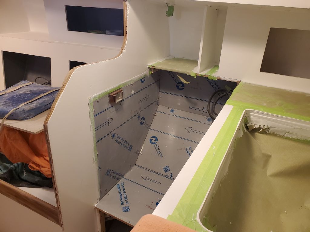
My rebuild plan was to install new fiberglass angle to be bolted and epoxied to the forward face of each floor, and glassed to the hull on each side, all level in both directions. But this work would come next time, as I wanted to spend what was left of my available time this day (as I was leaving early so I could watch the total eclipse) preparing the galley cabinets for their final coat of white paint, which I did once I’d cleaned up thoroughly from the cabin sole removal.
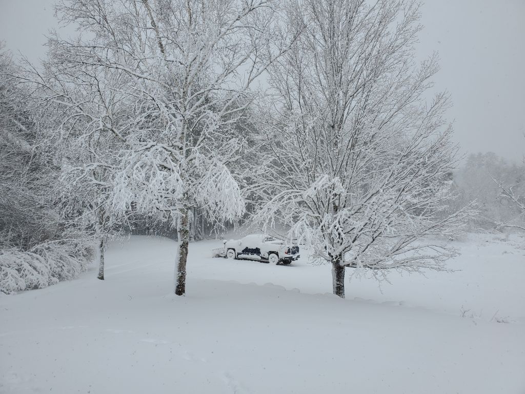
We had perfect weather for the eclipse, with 60-degree temperatures and completely clear skies. Where we are, we had 98% totality (according to some tool I found online), which was close enough for us. I tried taking pictures through my dark glasses, but only this one at about halfway to totality came out well enough to use. At maximum coverage, the outside temperature dropped at least 10 degrees, and the light was very dim and with a harsh, white quality to it, much like the unfiltered sunlight one sees in the pictures of people on the moon. We were lucky to have a great view and near totality right from home.