Monday
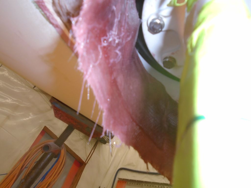
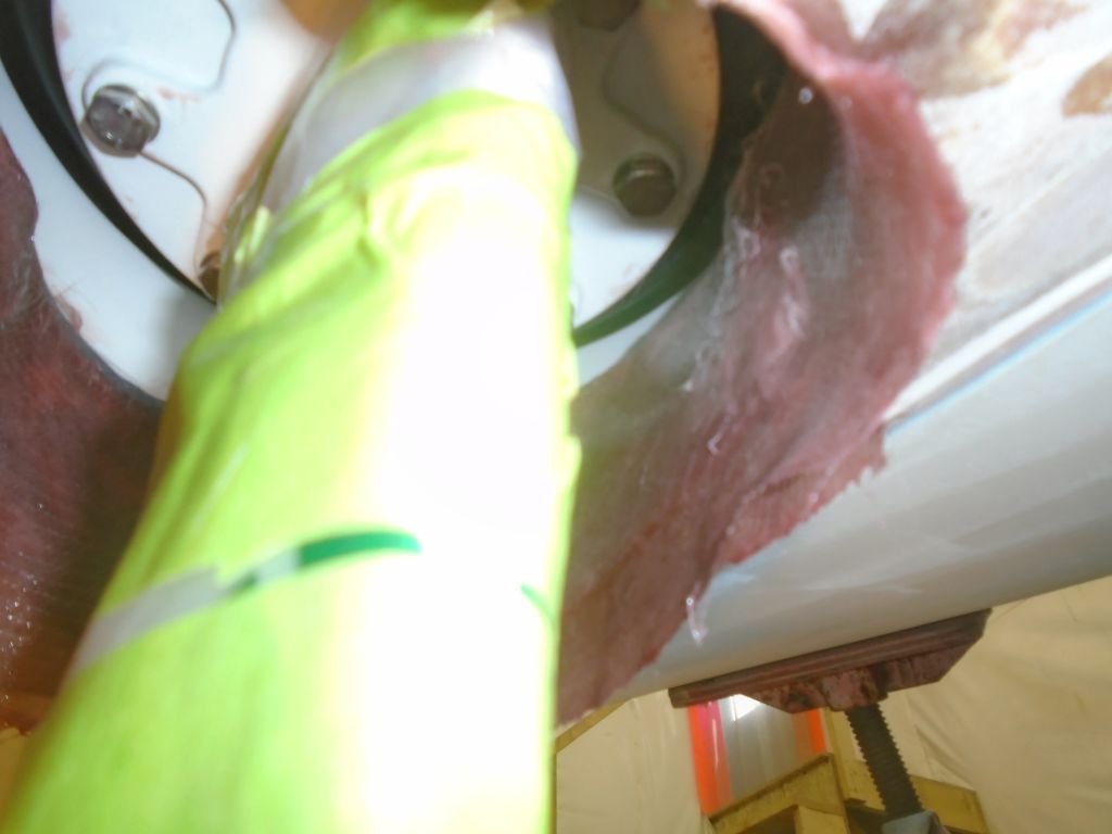
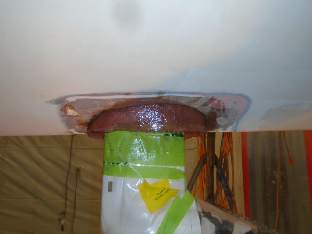
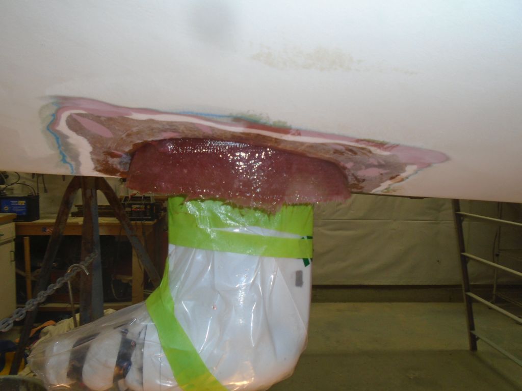
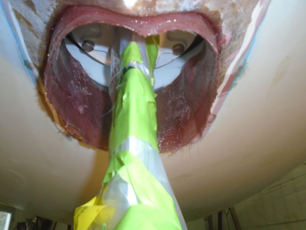
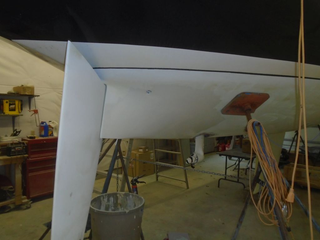
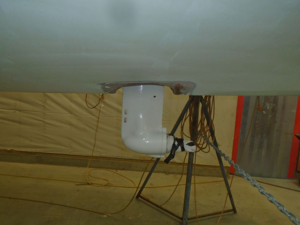
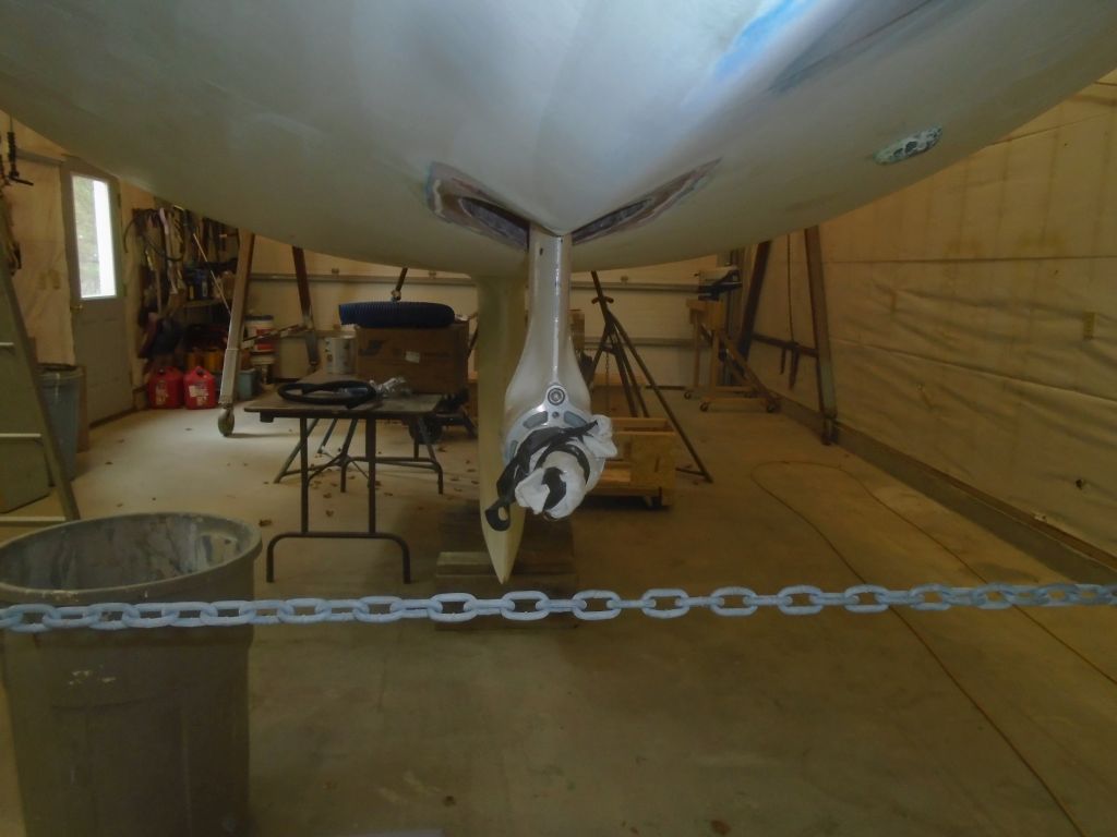
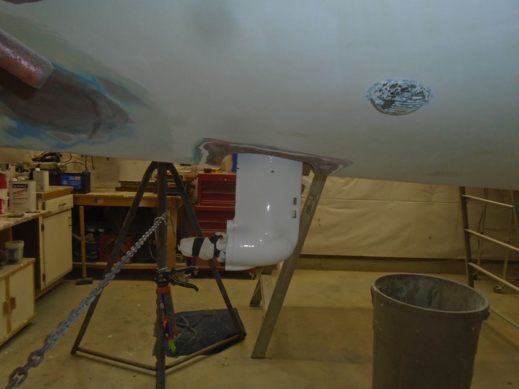
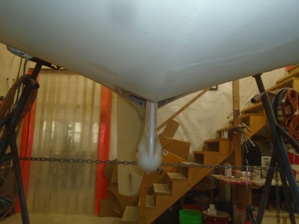
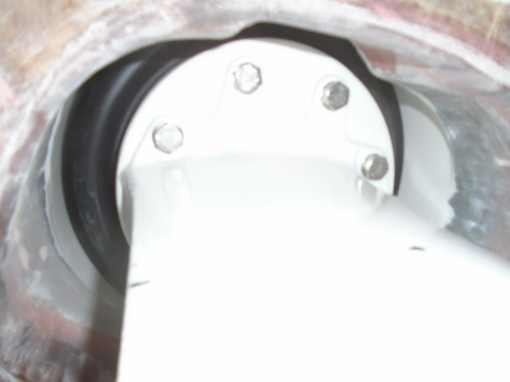
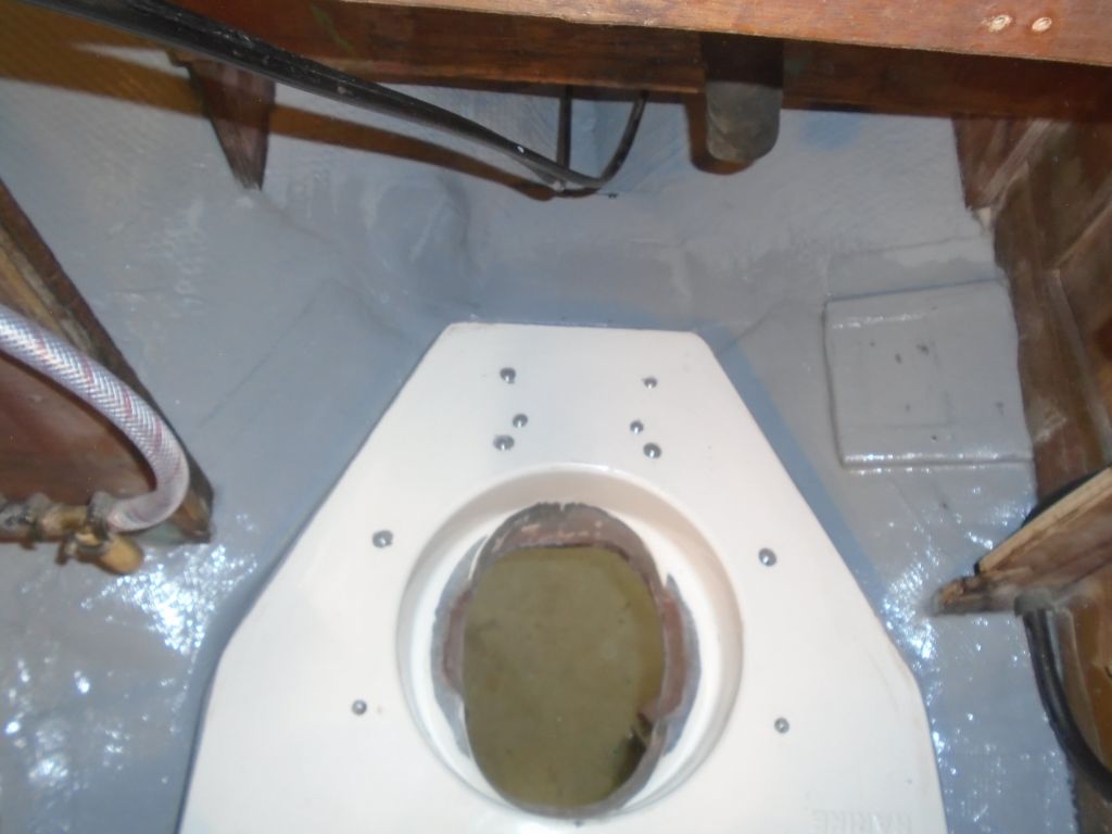
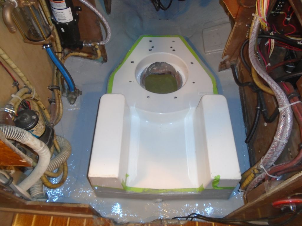
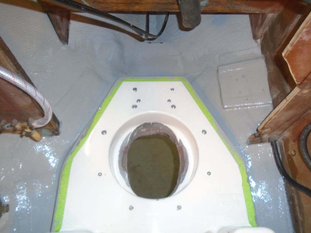
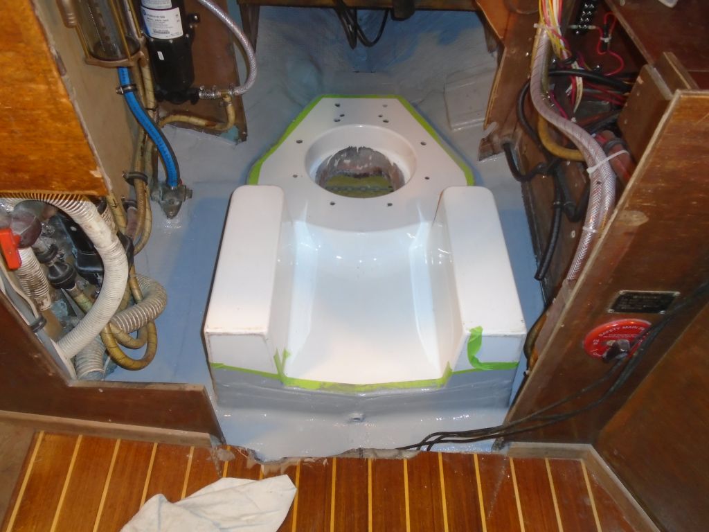
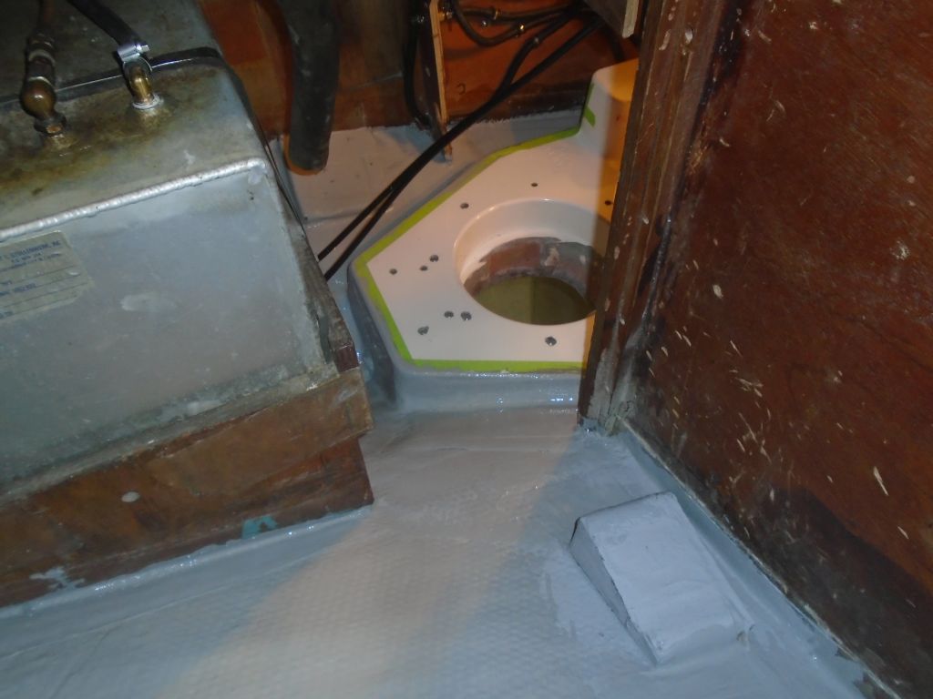
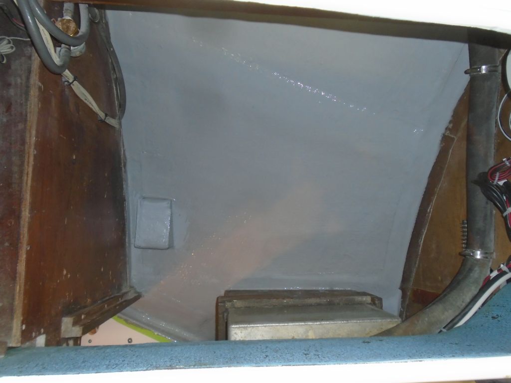
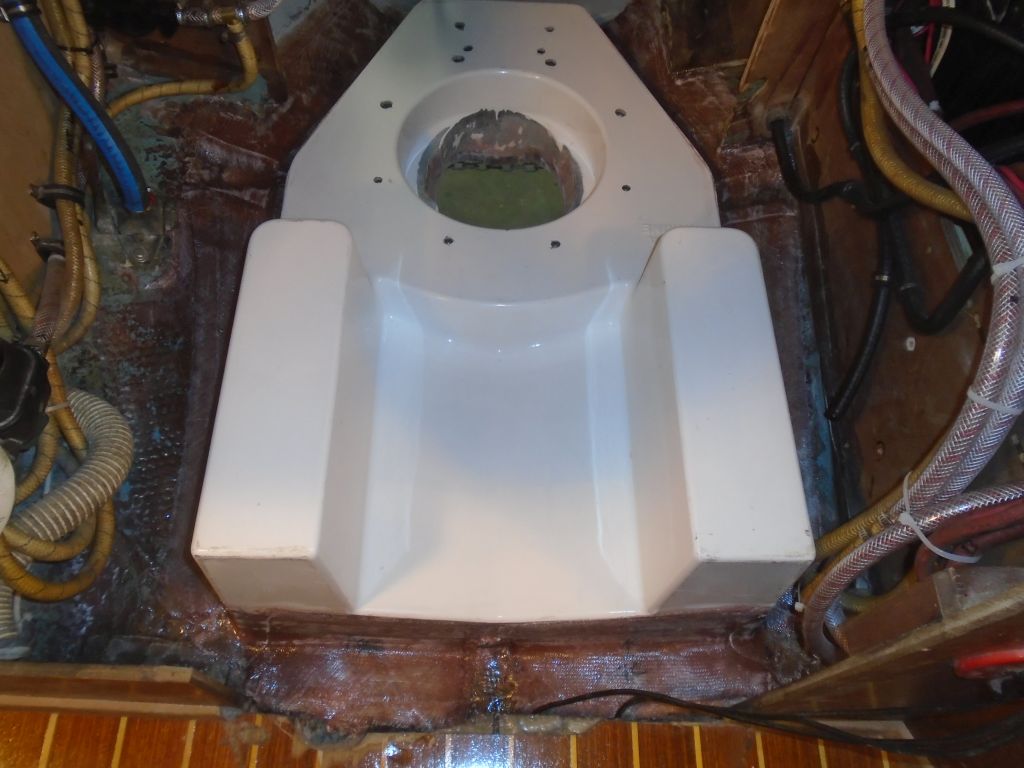
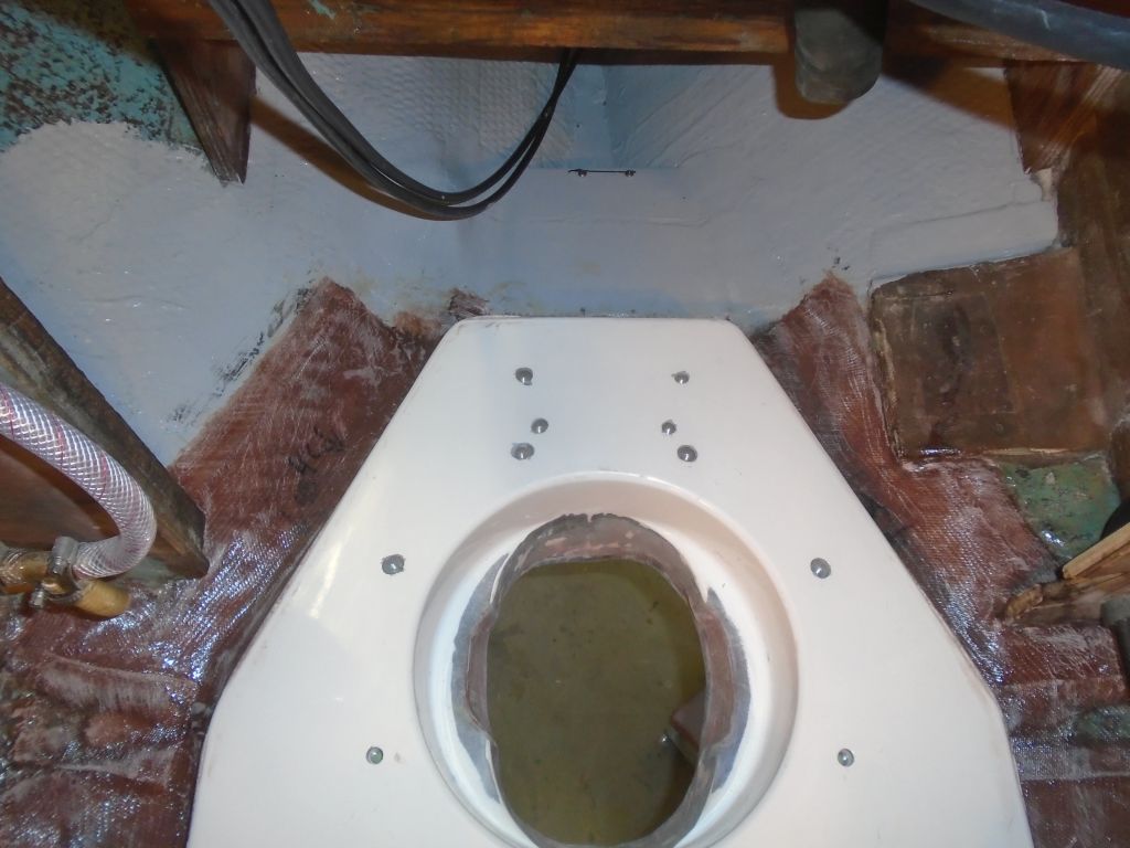
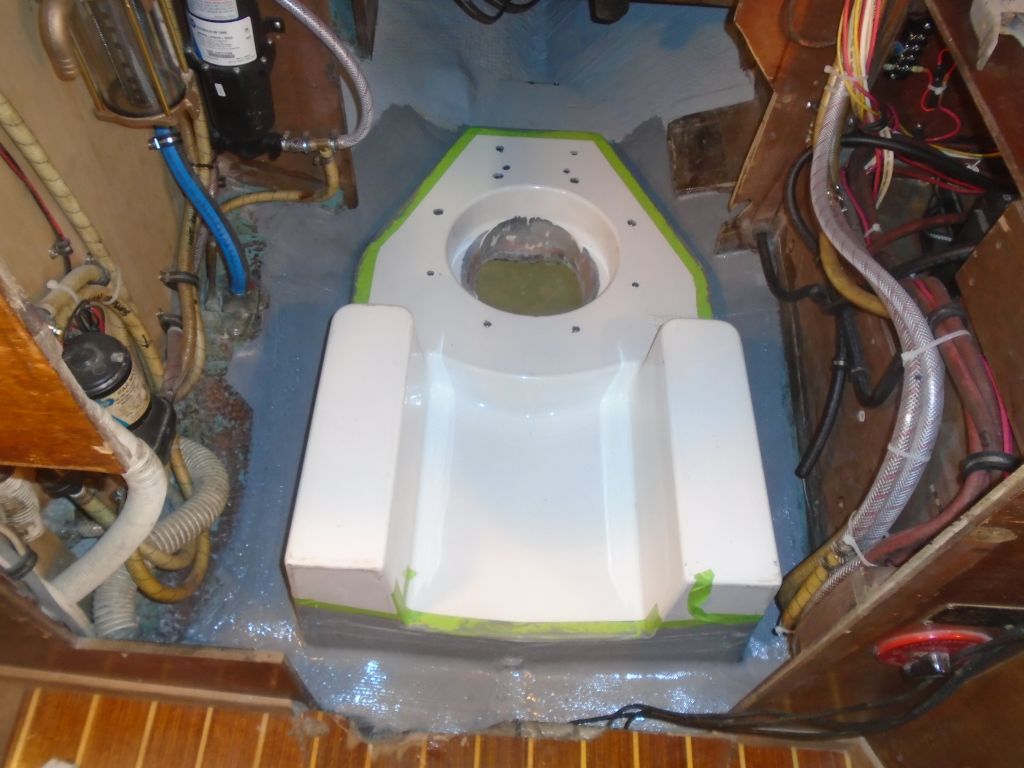
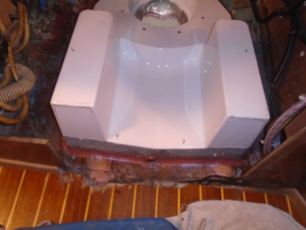
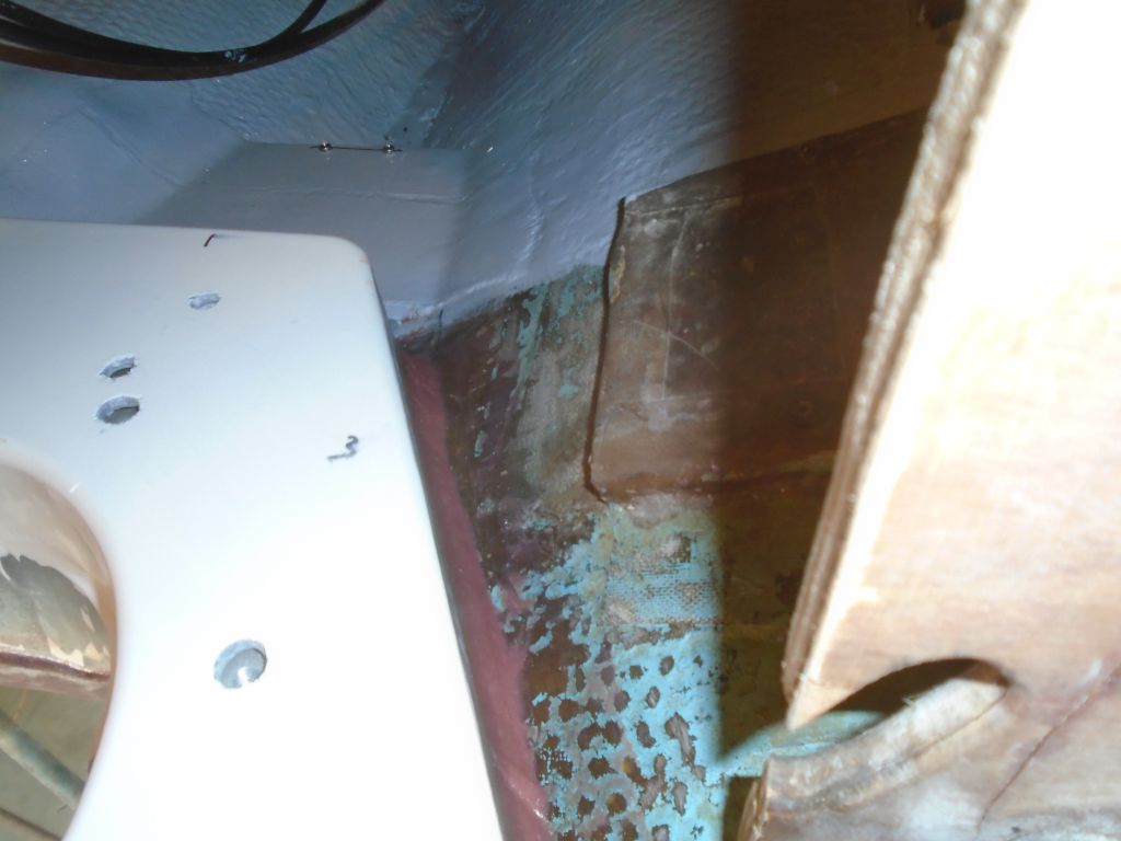
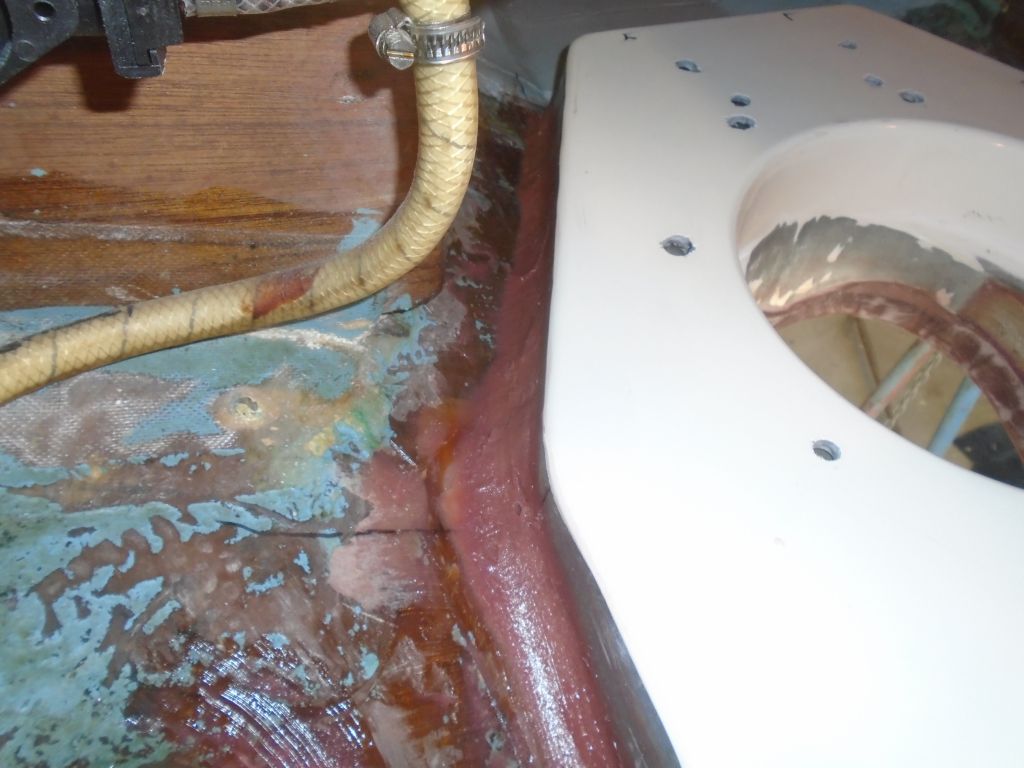
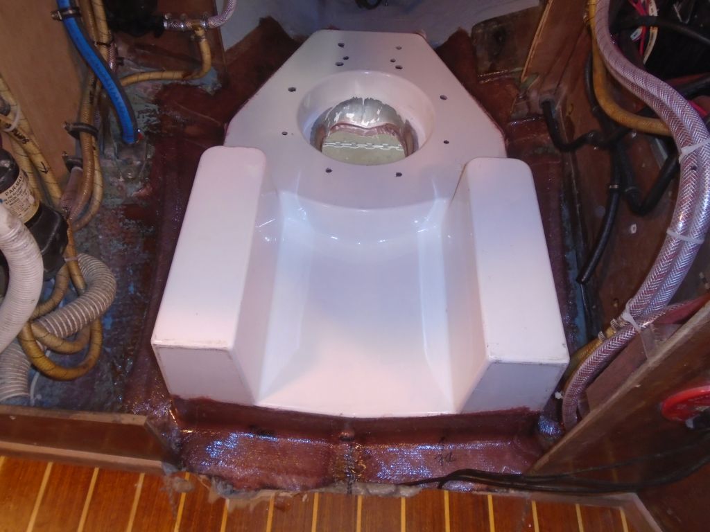
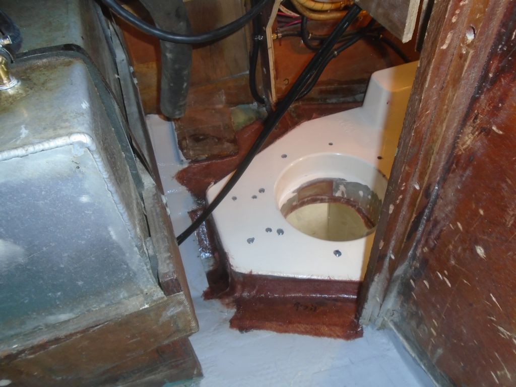
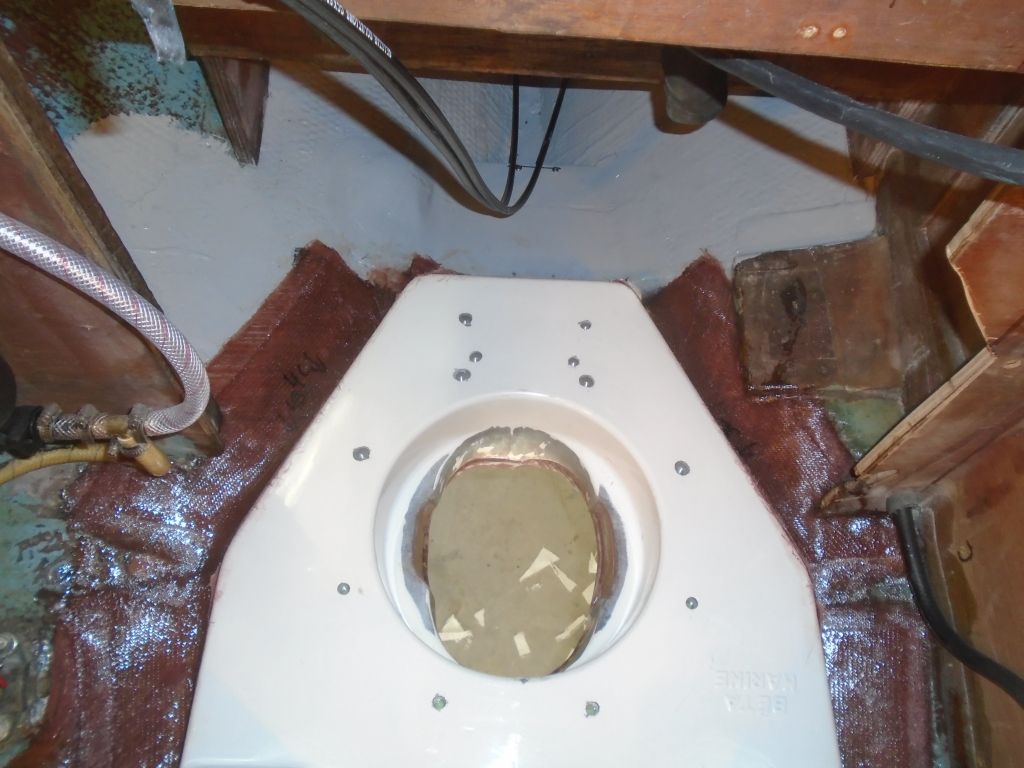
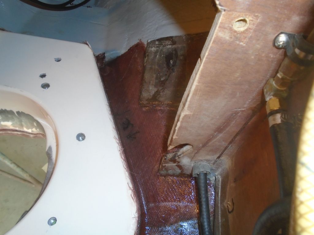
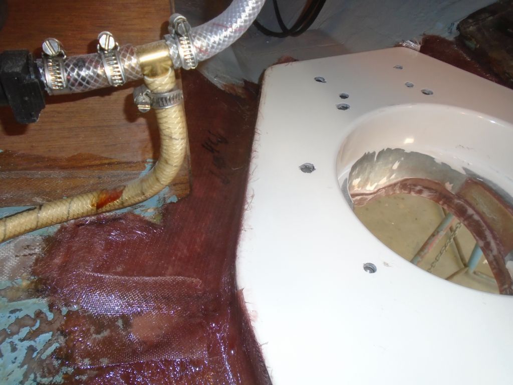
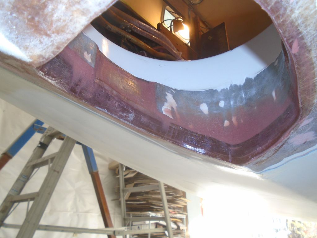
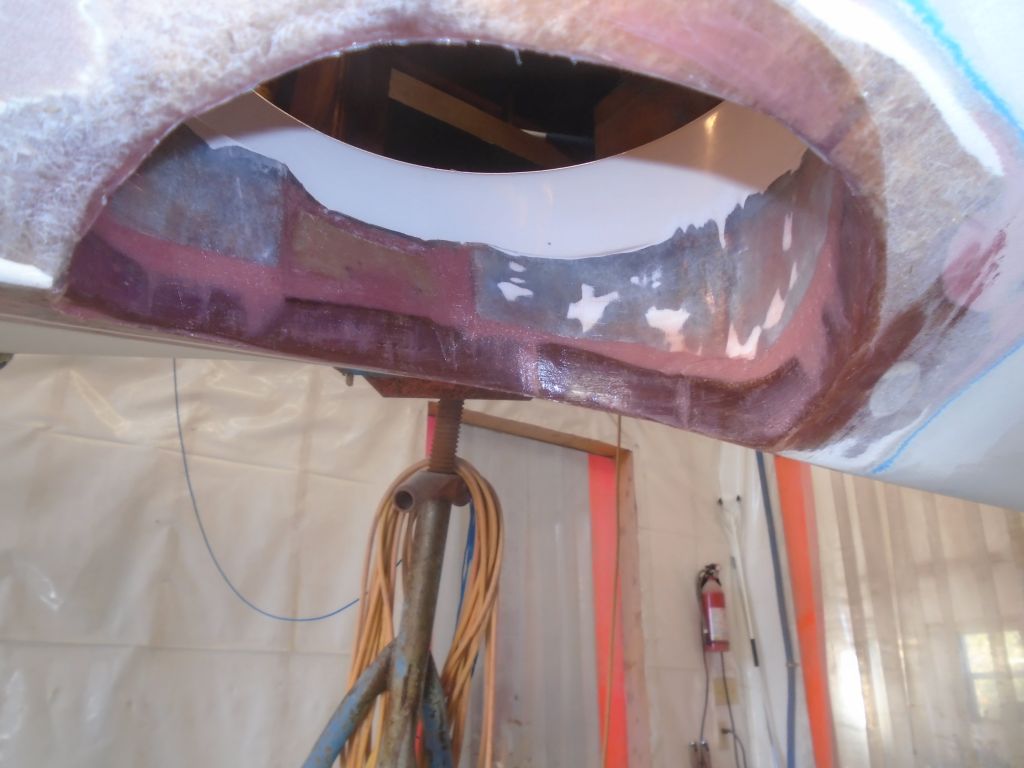
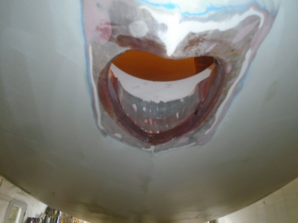
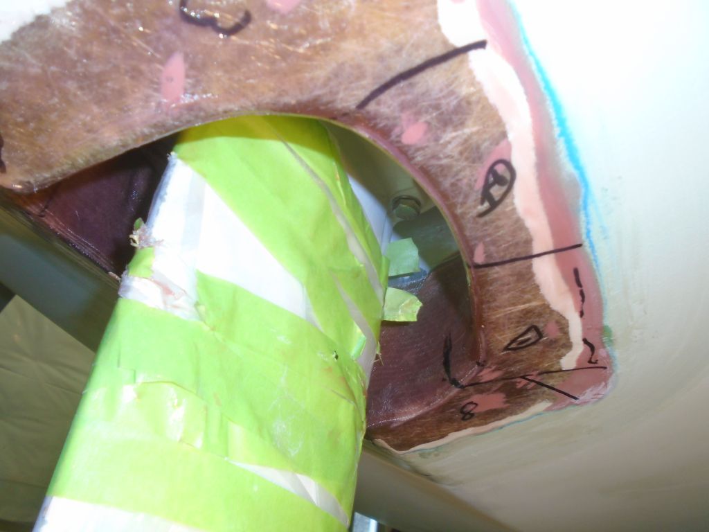
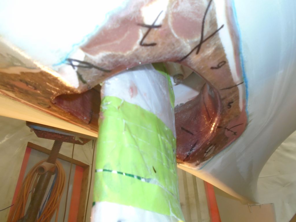
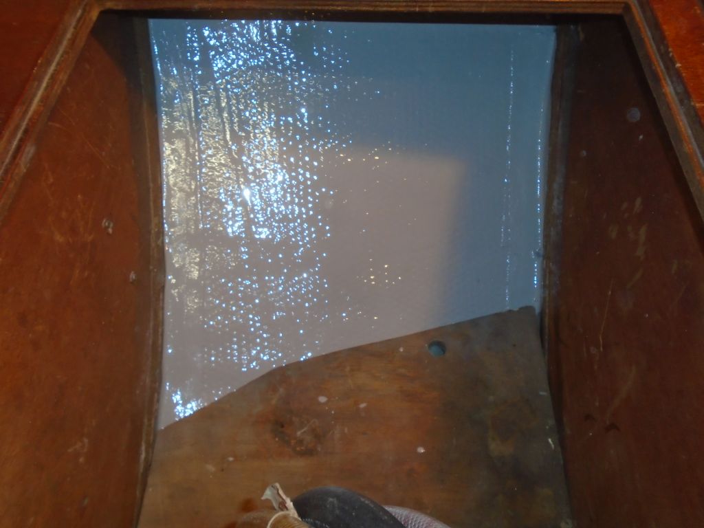
With a grinder and cutting wheel, I removed the excess cured fiberglass draping beneath the saildrive leg opening, then sanded the remnants flush with the hull and cleaned up the inside of the opening as needed. I sanded a radius on the opening’s edge to help fiberglass lay over this area later.

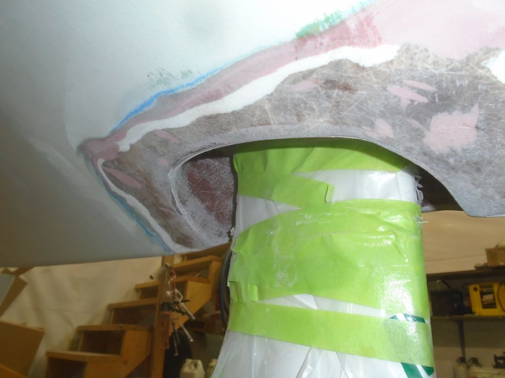
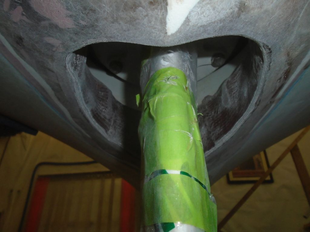
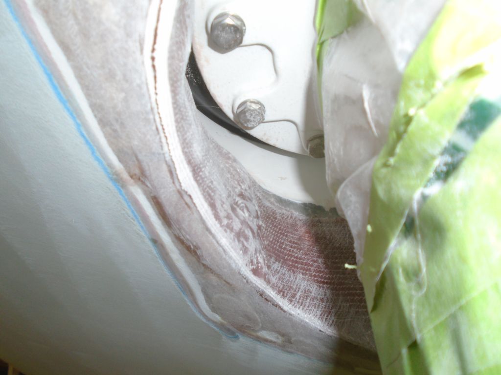
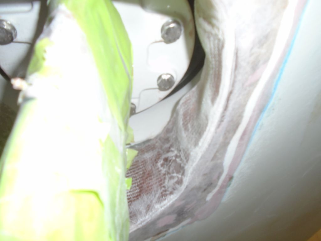
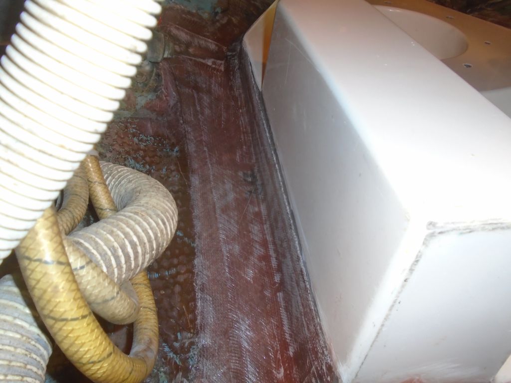
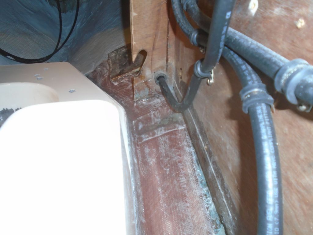
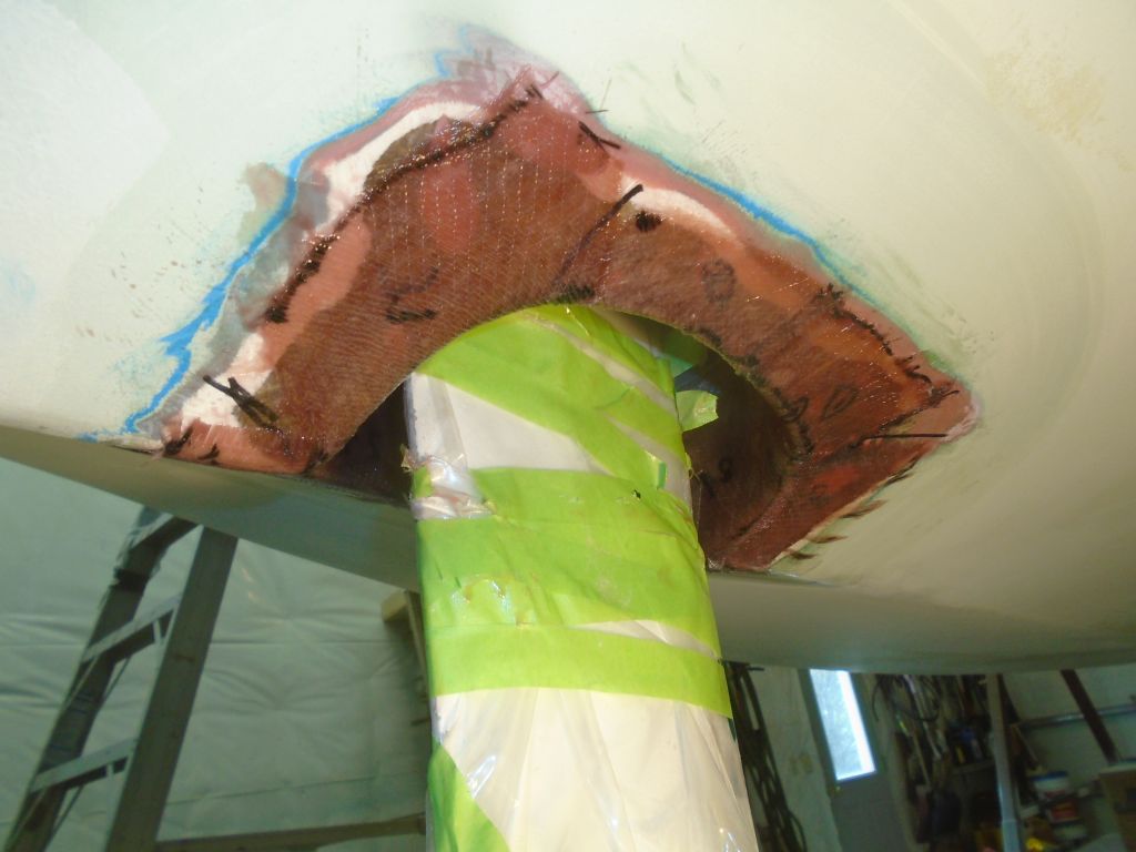
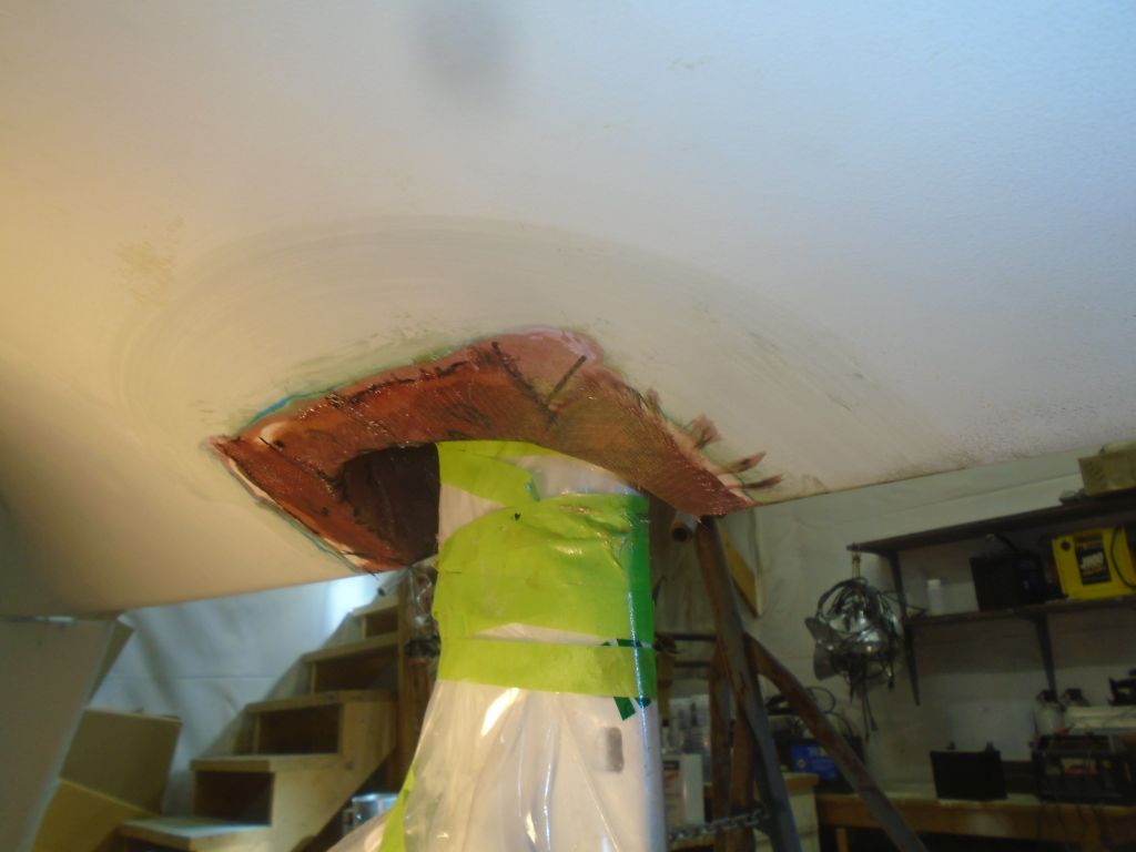
After cutting fiberglass tabbing for the next step, I prepared the surfaces with an epoxy coating, which I spread over the inside of the opening, the edge, and the hull. I allowed this to slightly tack before wetting out and installing tabbing spanning from the inside of the opening to the adjacent hull on all sides.

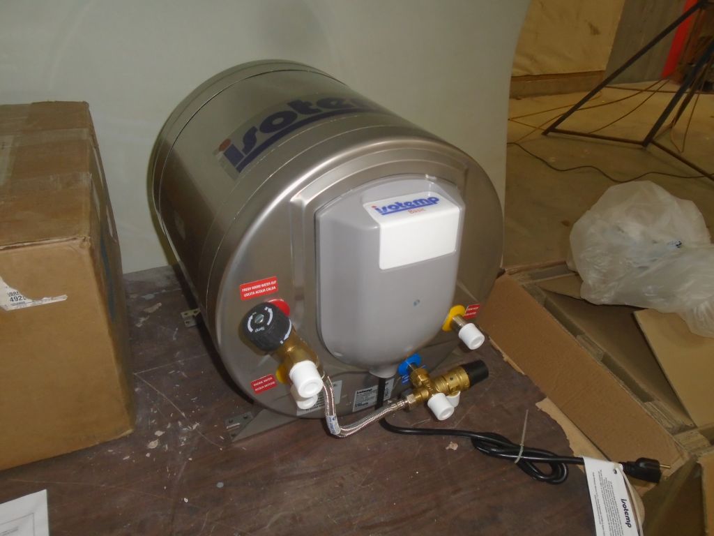
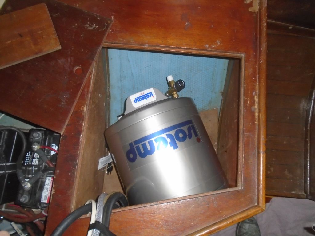
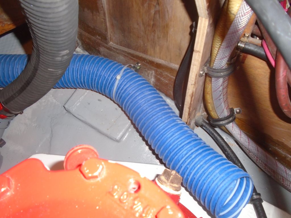
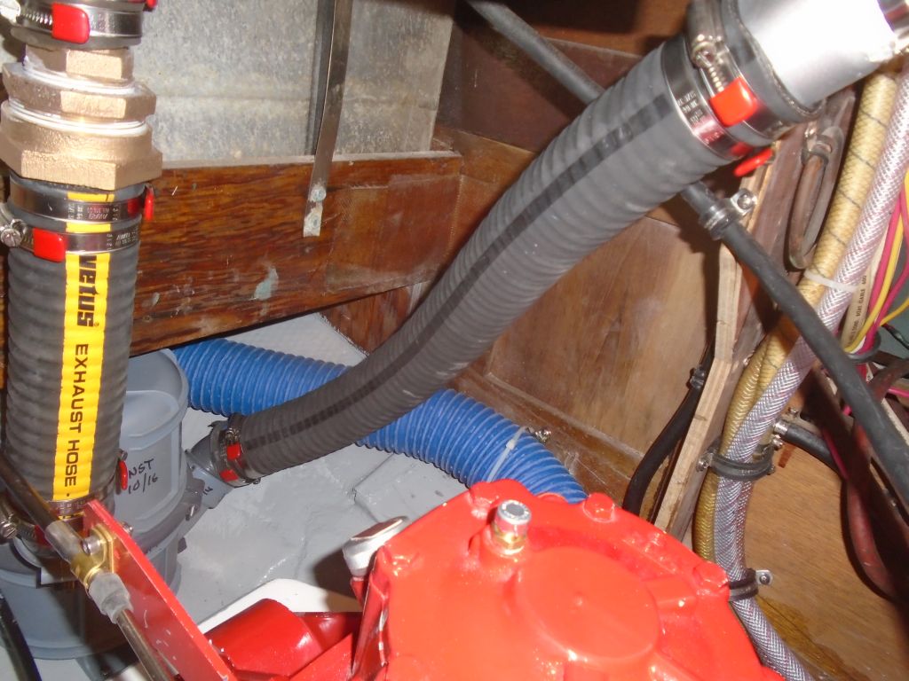
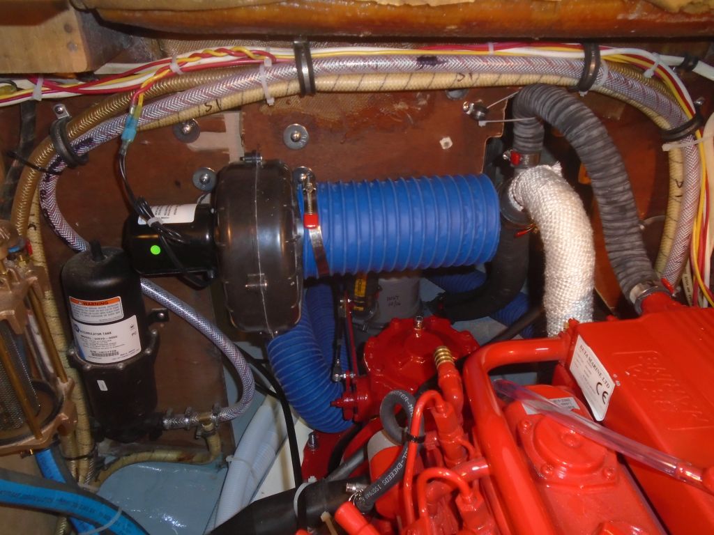
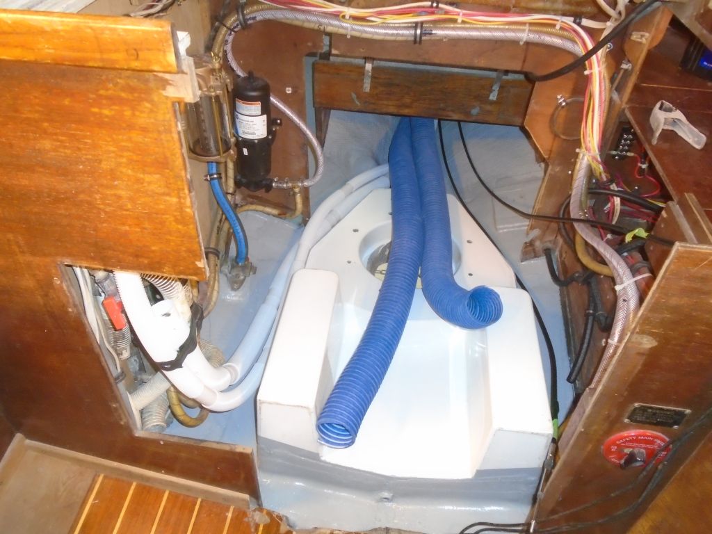
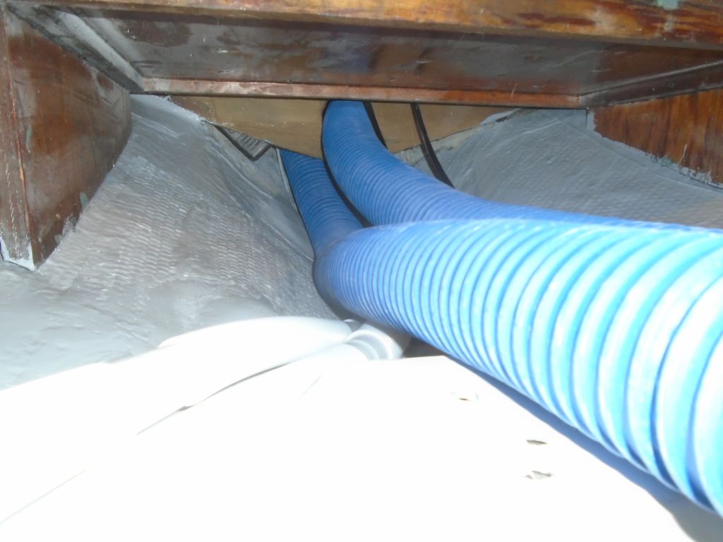
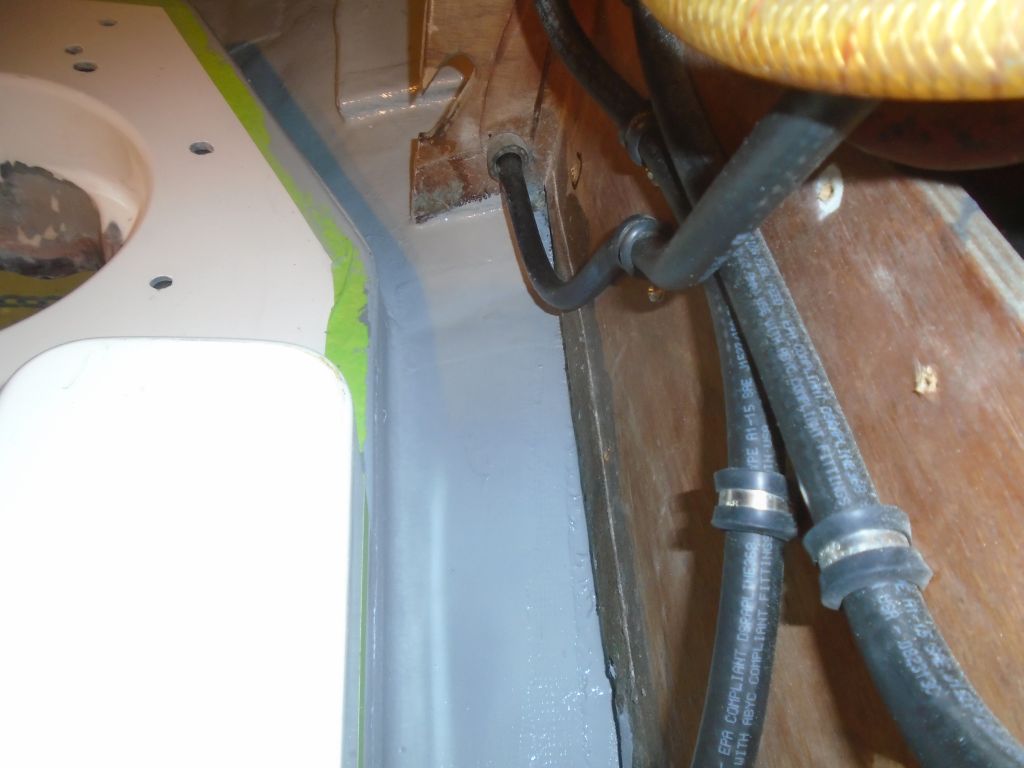
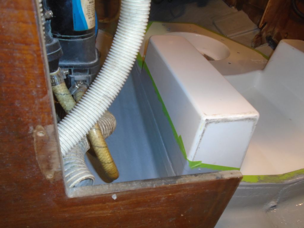
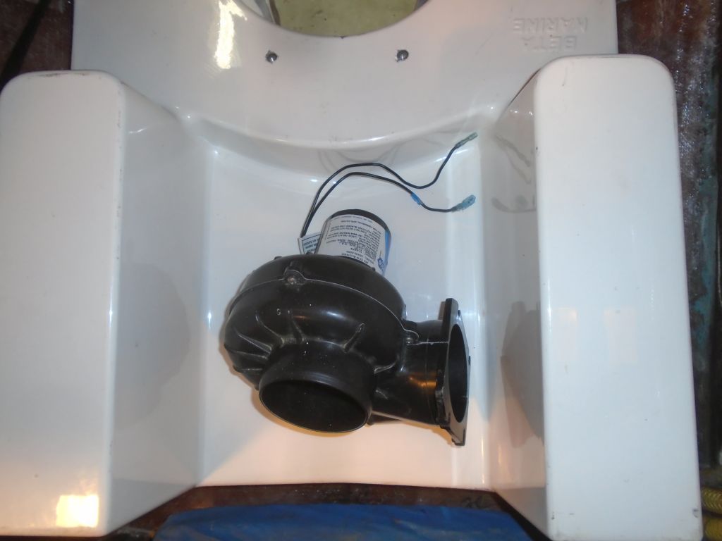
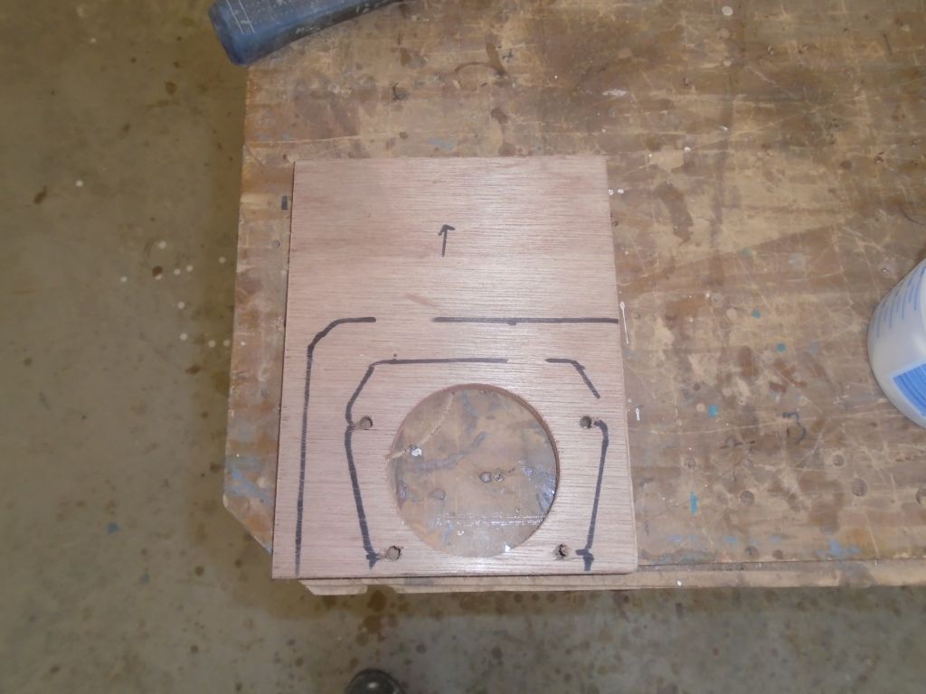
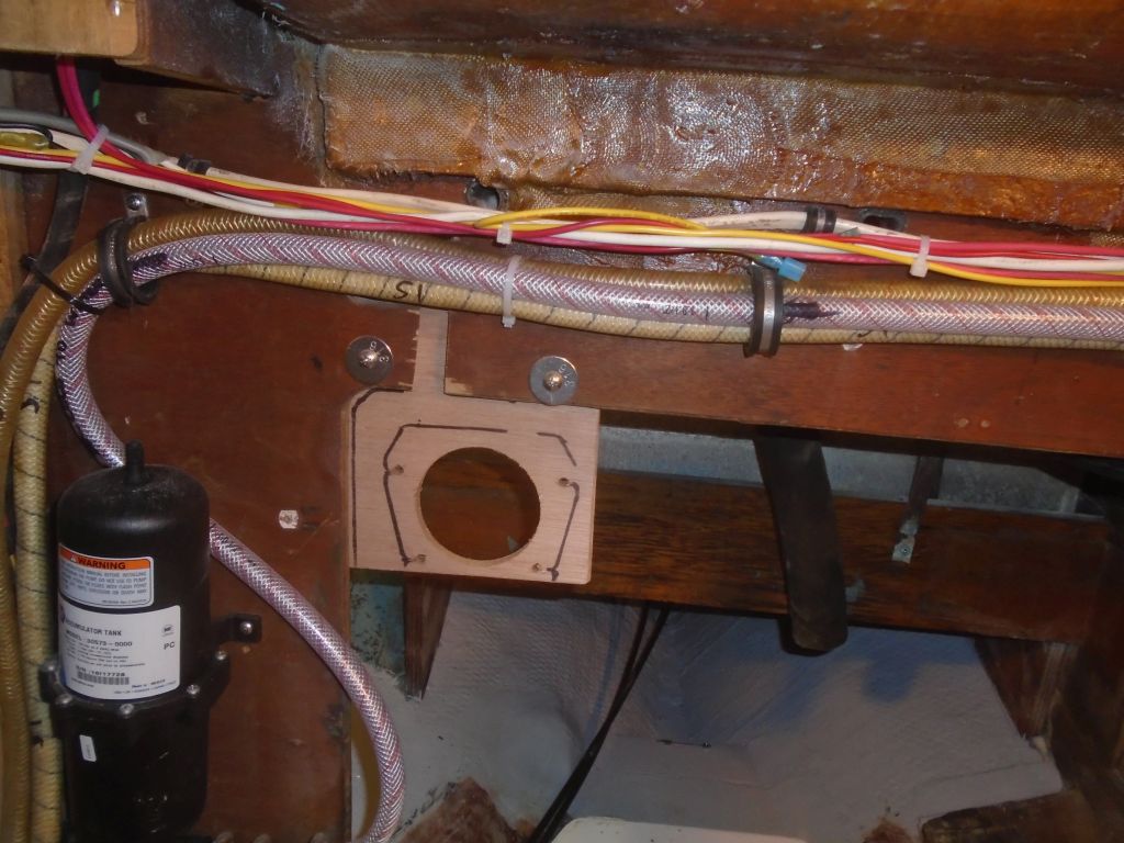
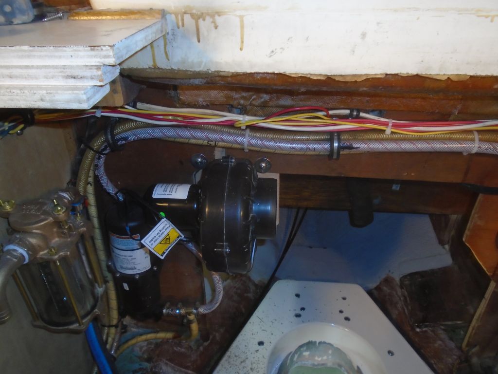
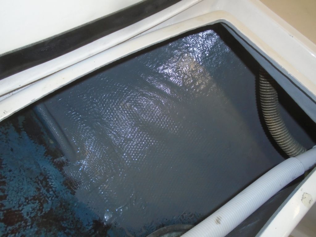
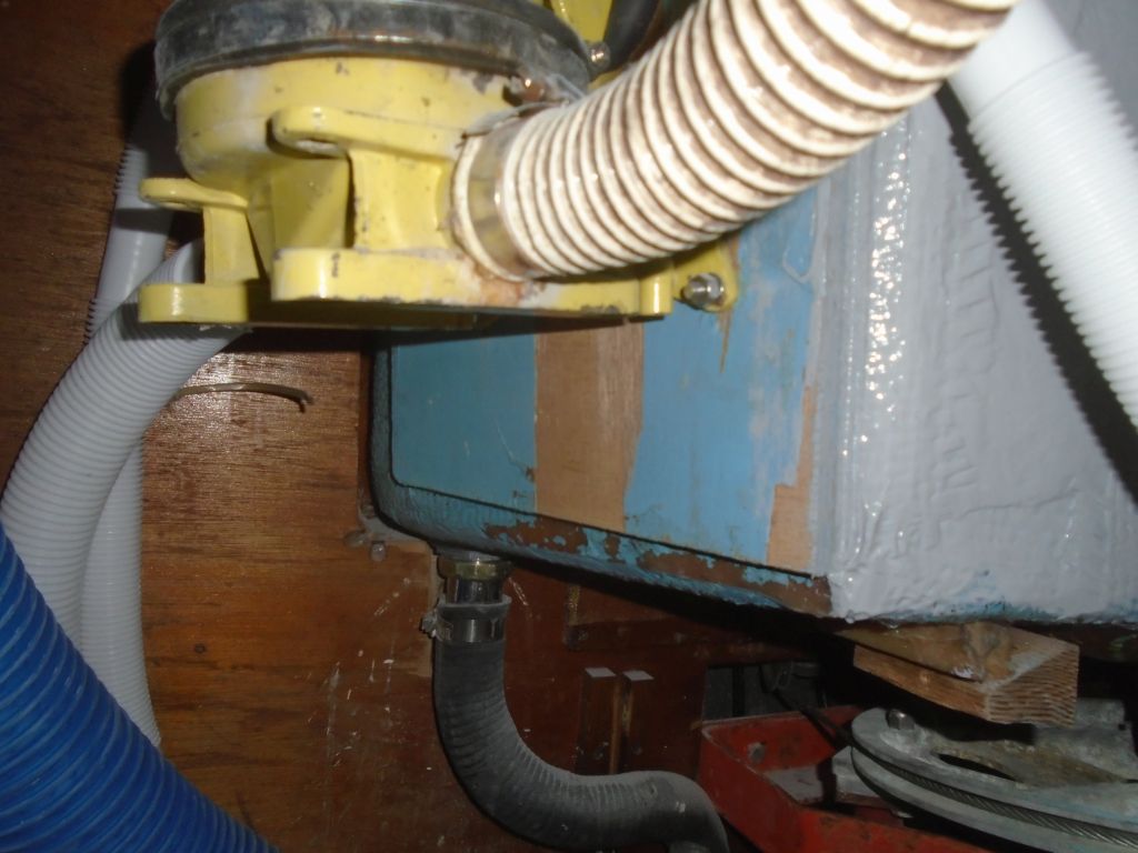
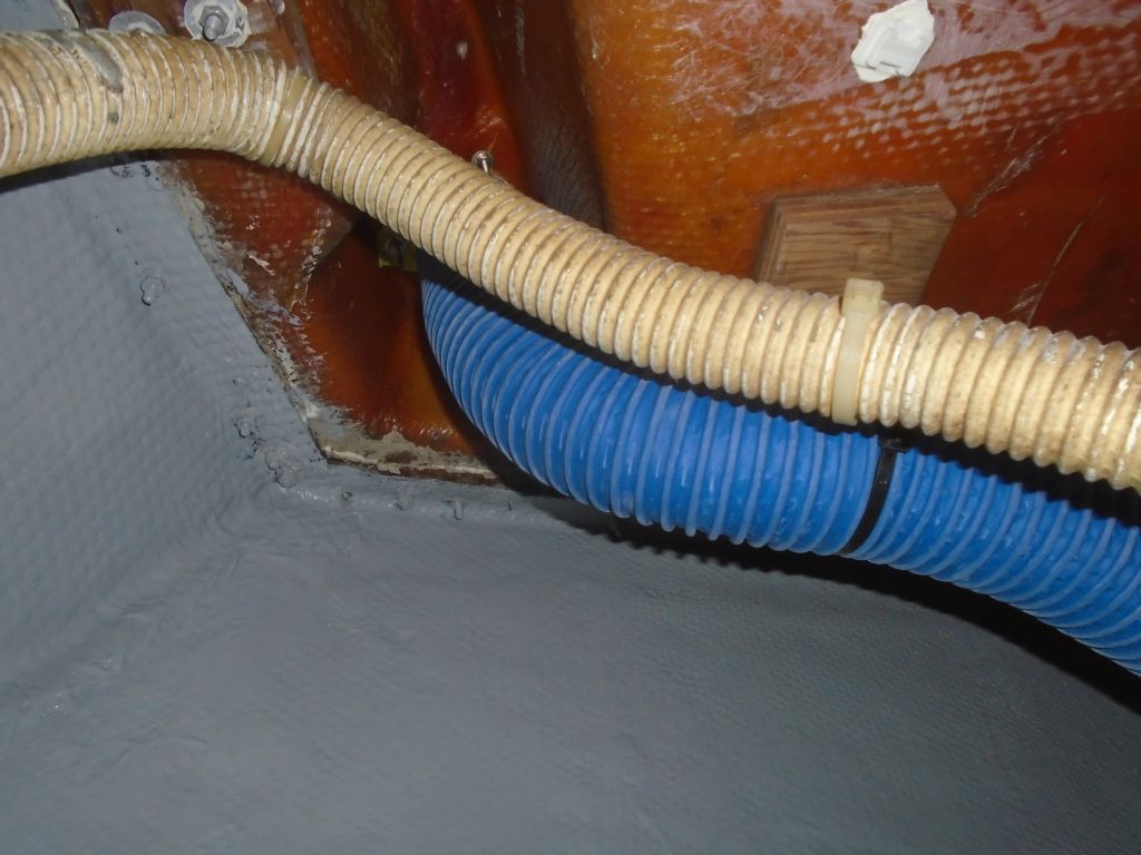
The owner arrived for a meeting about some additional work he wanted to do on the boat, and afterwards we worked on resecuring the bilge pump and ventilation hoses in the lazarette (the blower hose required an adapter flange to secure it to the bottom of the clamshell vent, which I ordered later), then he cleaned up and began painting the lazarette, completing half of it now; the other half could be done later, once the first side was dry. He also painted the hull inside the locker where I eventually planned to install the water heater.
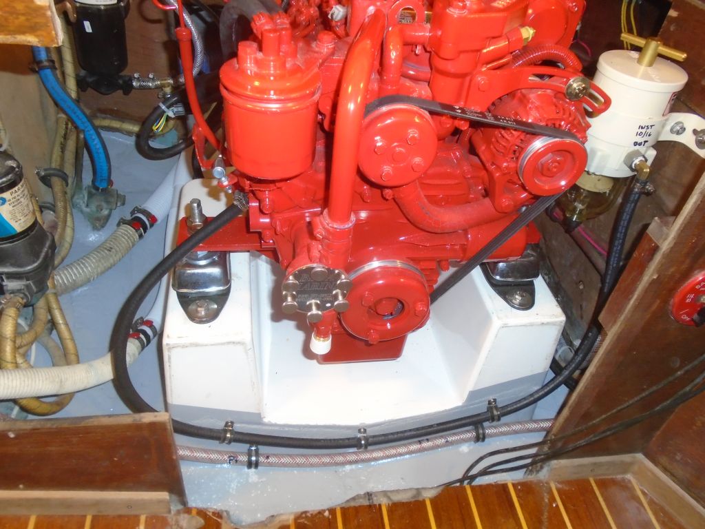
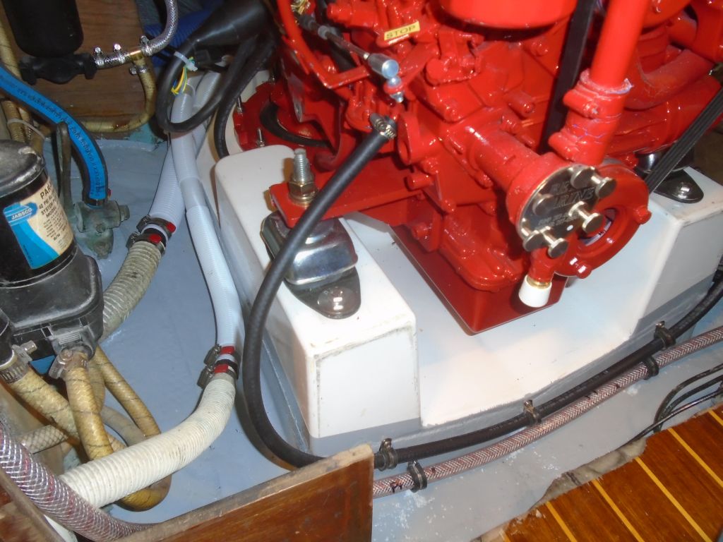
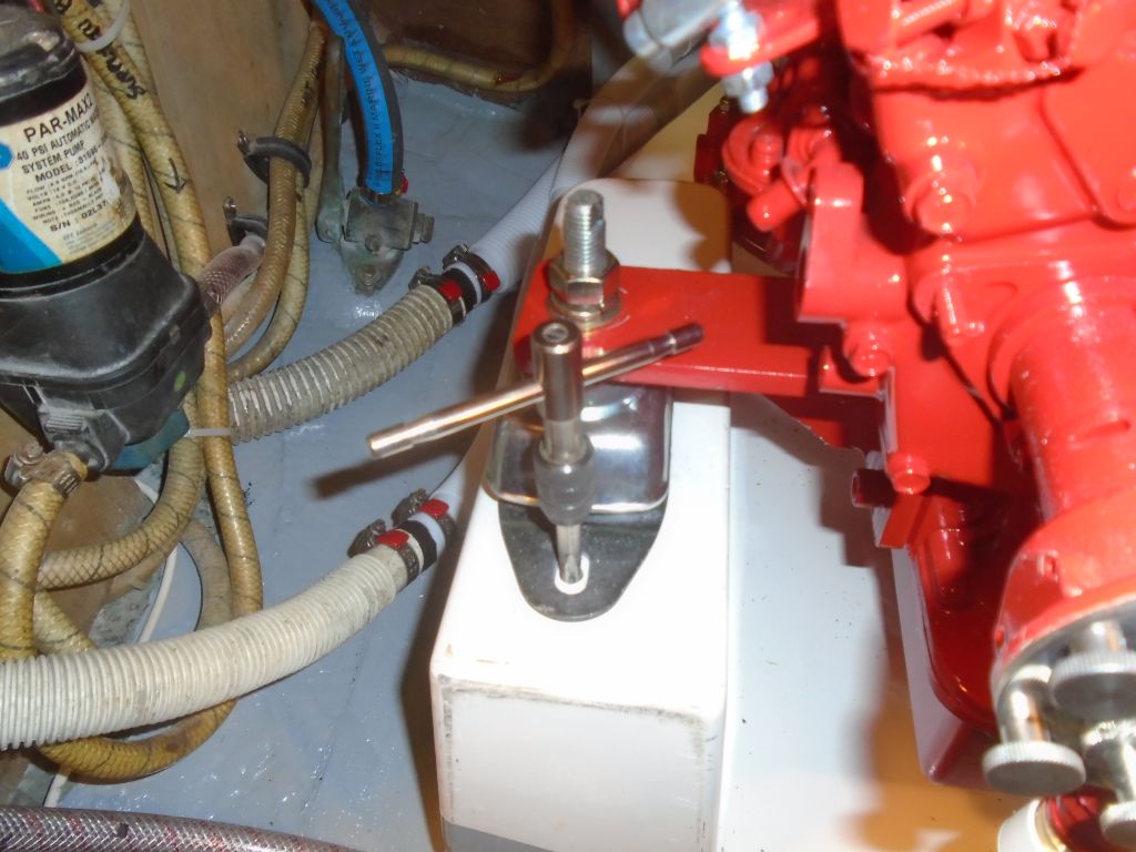
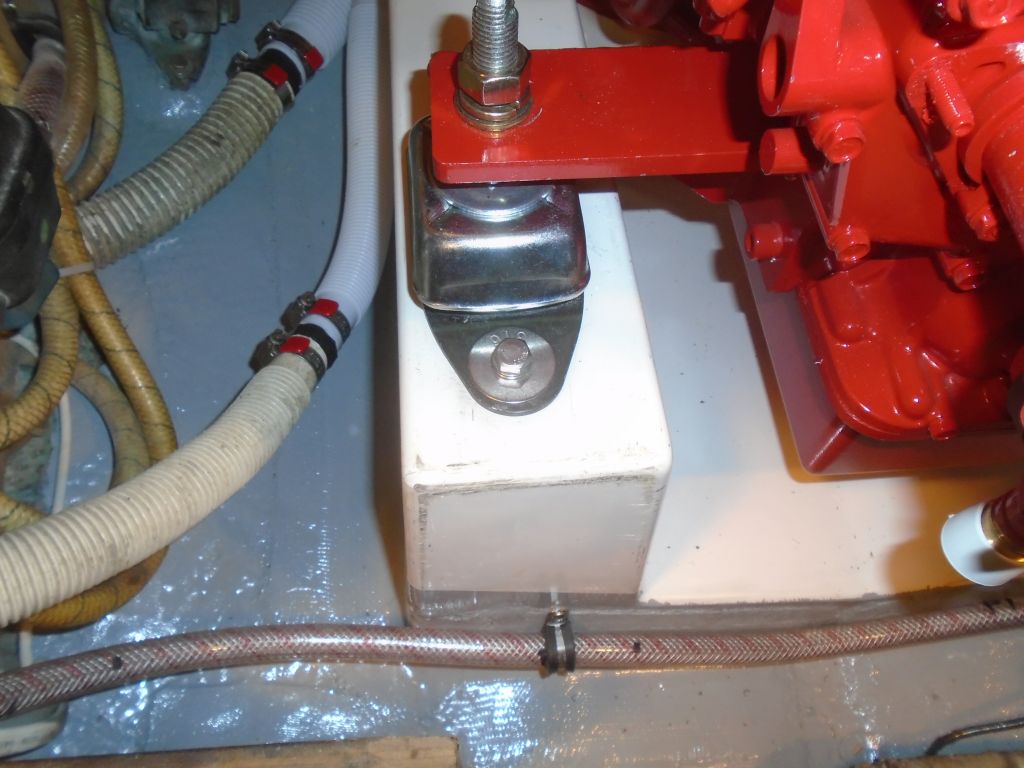
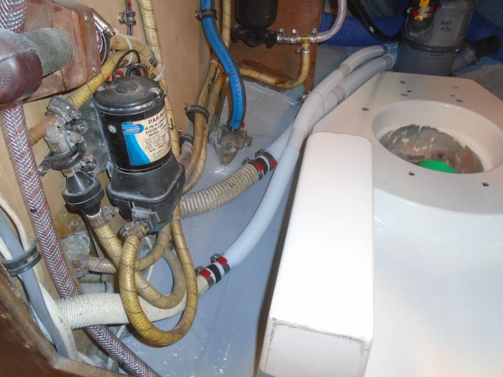
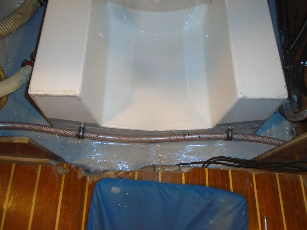
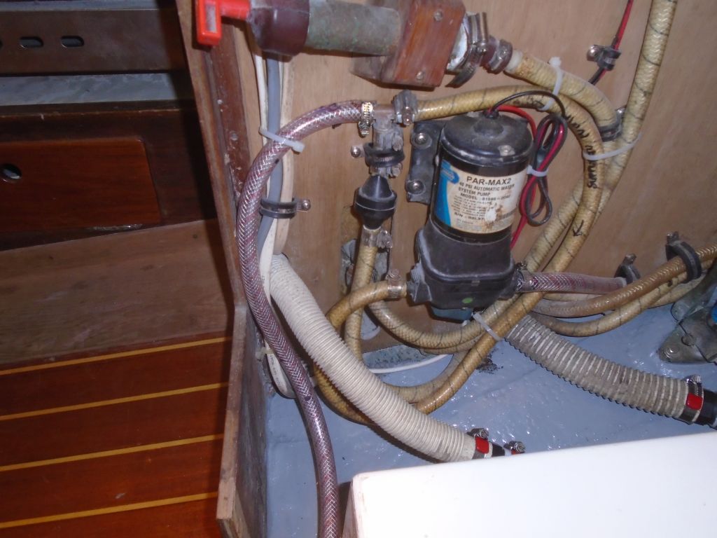
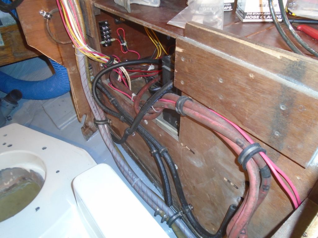
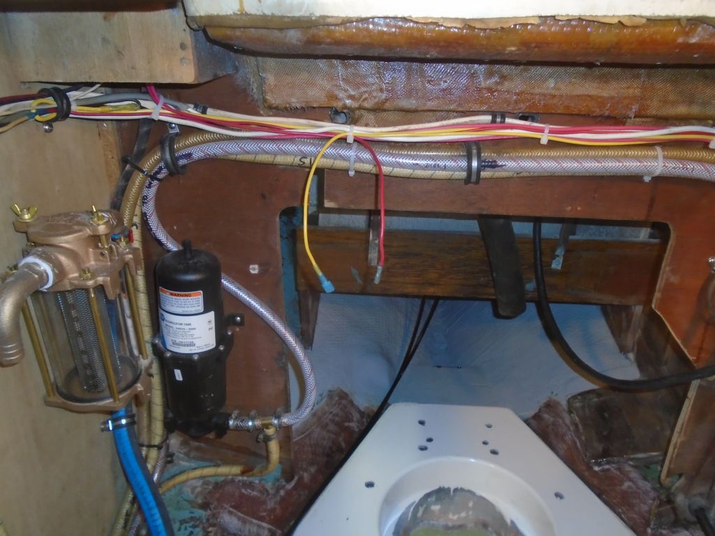
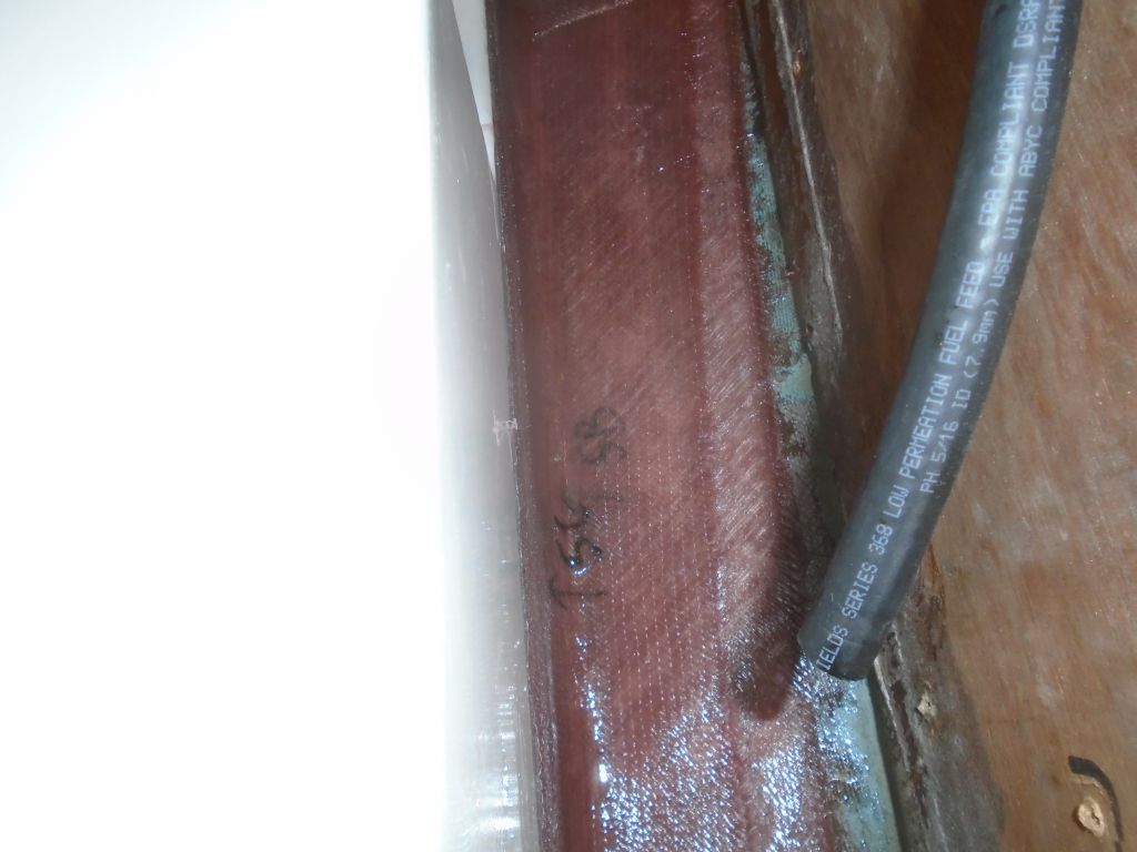
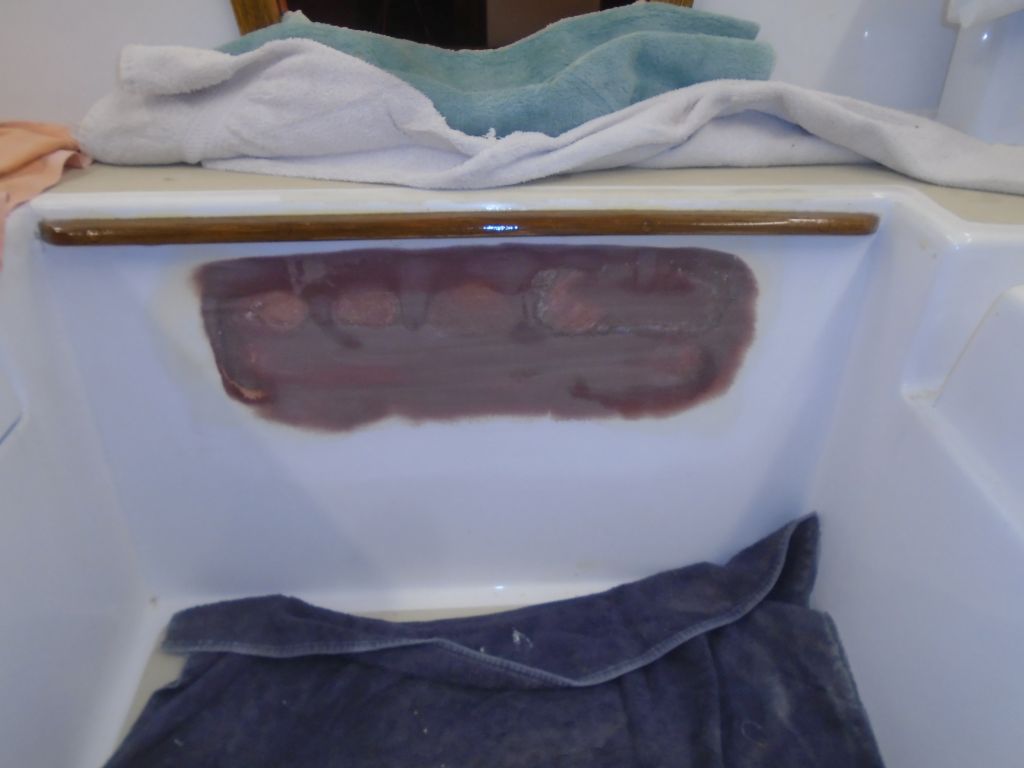
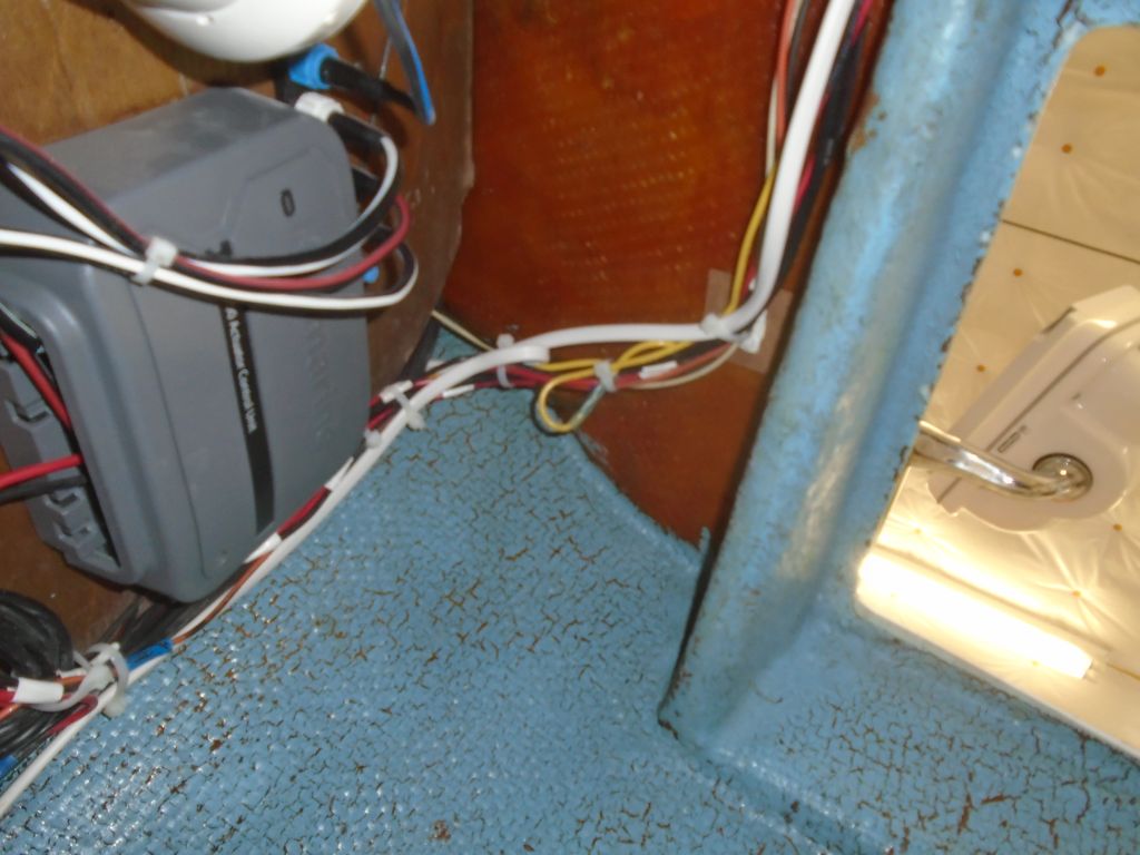
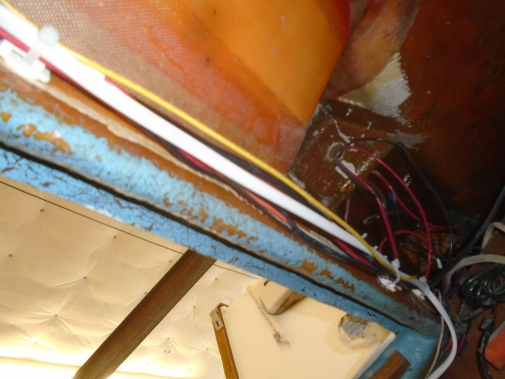
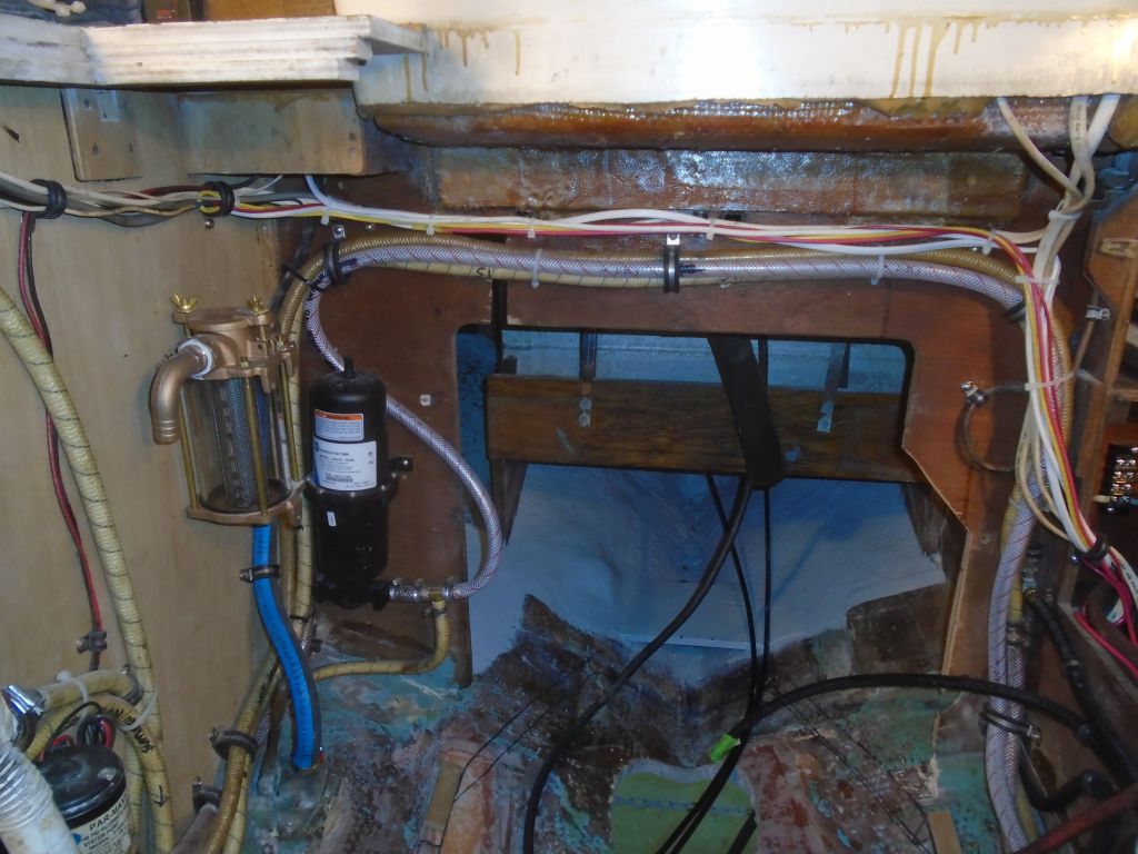
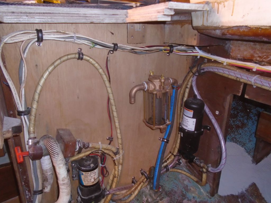
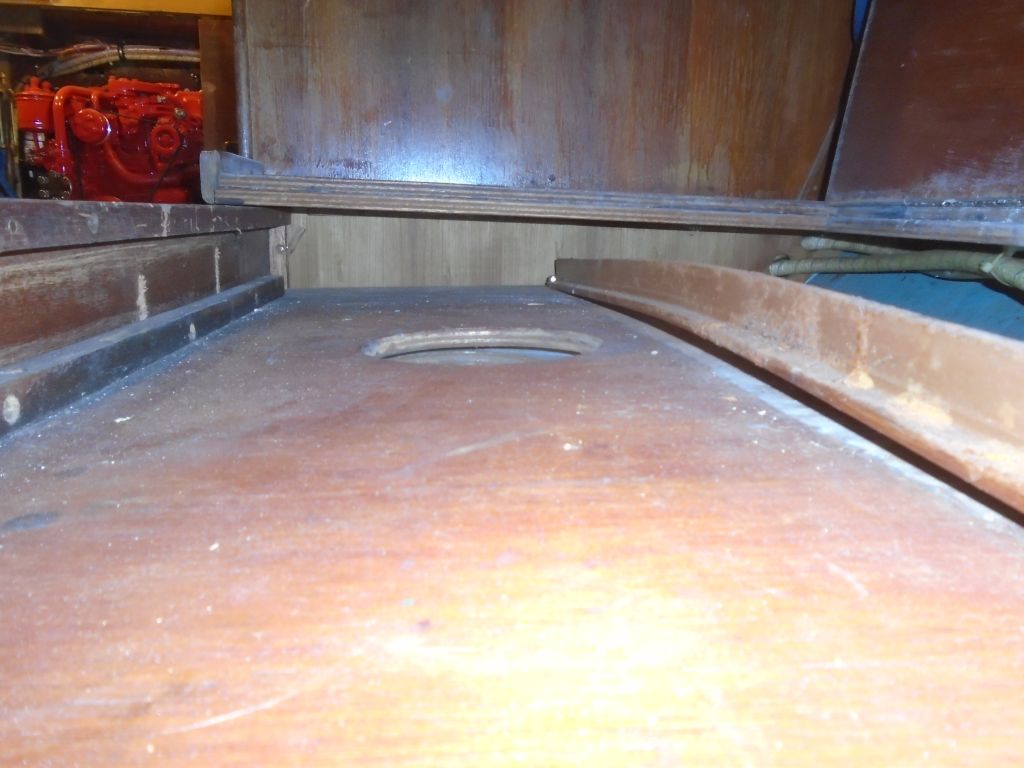
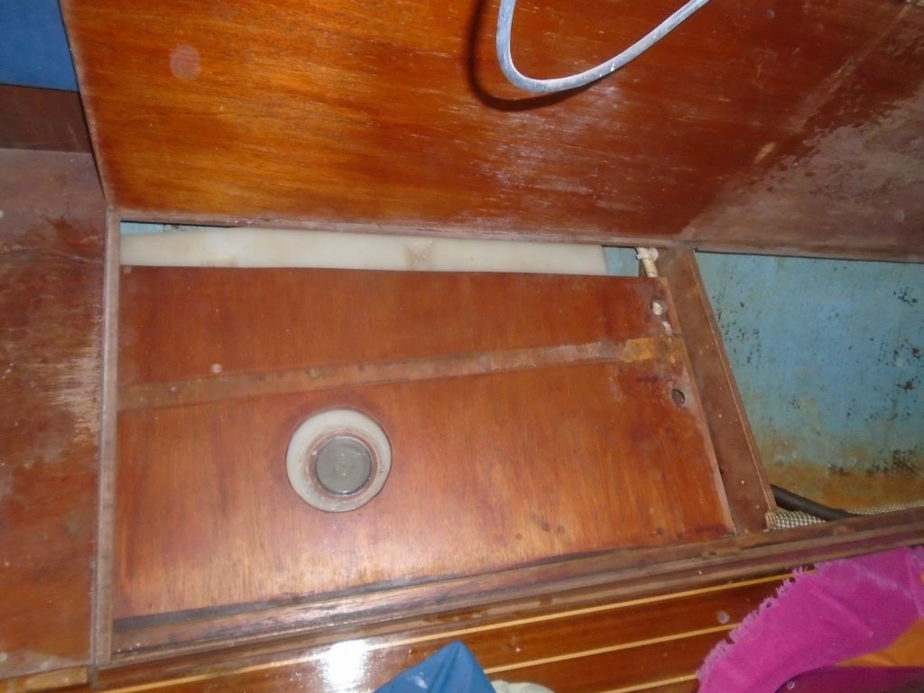
Meanwhile, I got started on one of the newer tasks on the list: a reconfiguration of portions of the fresh water system. The way it was originally (and now) set up, the supply from the starboard tank, located beneath the settee, ran all the way around to the port tank location on the opposite side, where there was a valve to select between one tank or the other. The owner requested that this valve be relocated to the engine room for easier selection of the tank supply. Also, he reported that the original system for securing the tanks in place–a plywood top with a metal brace secured to it as a stiffener–had failed, and the tank was free to expand when being filled, forcing this plywood top up. Over time, this expansion had bent the T-shaped metal stiffener. I planned to reconfigure the system to better hold the tanks in place.
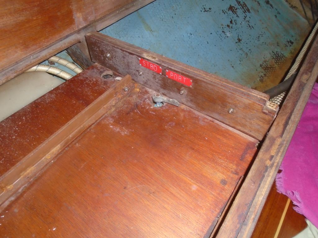

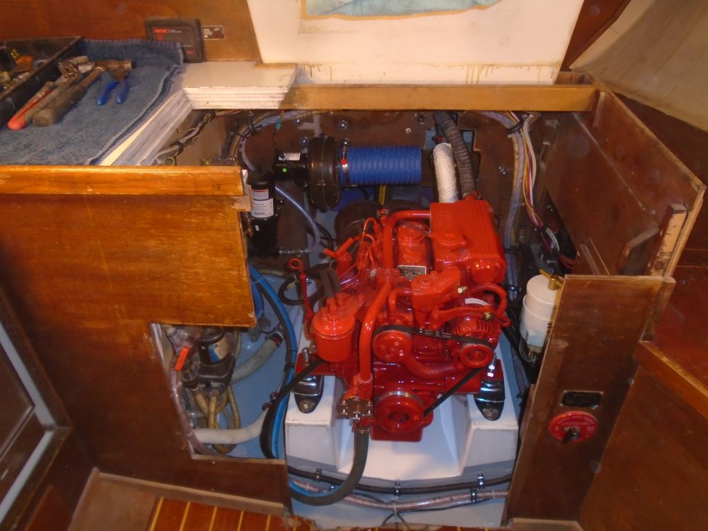
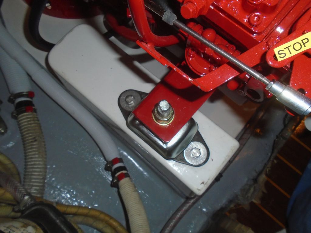
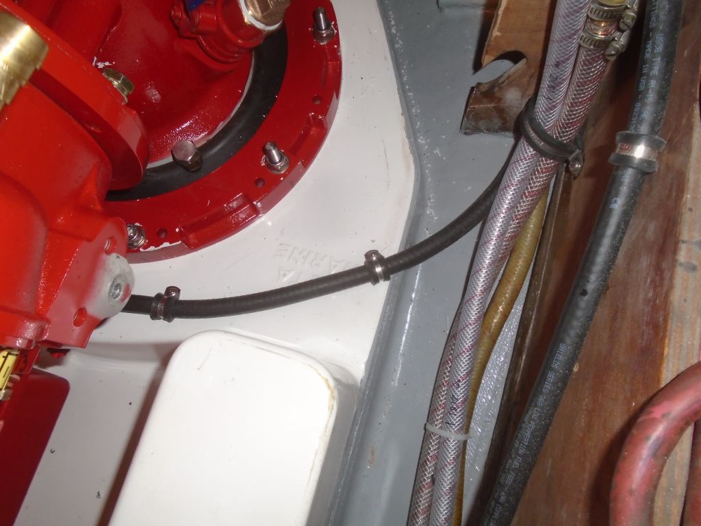
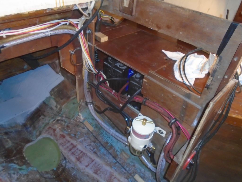
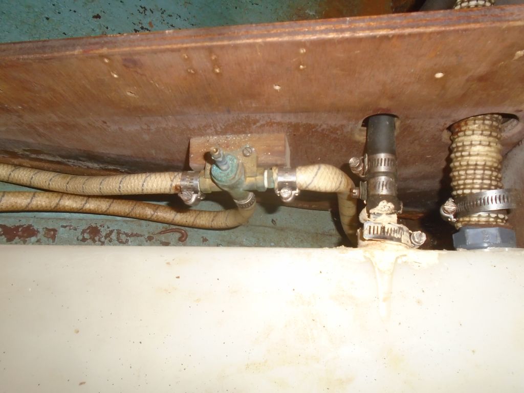
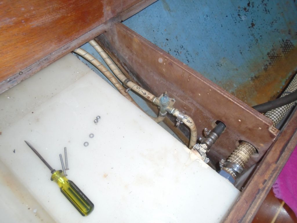
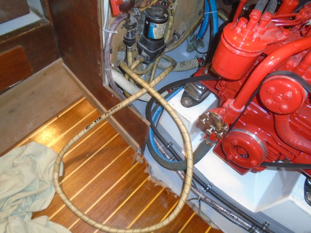
Removing the top, I removed the metal stiffener, and left the plywood aside for the moment. I removed the selector valve from the interim bulkhead and, after tracing the hoses as needed, I removed back to the engine room the line leading around to the starboard tank, and reconnected the main supply line to the port tank supply. At the engine room, I pulled free the starboard supply hose from its circuitous route around the aft end of the engine room, leaving the excess free on the starboard side near the water pump, where I’d soon reconnect it to a selector valve along with the port supply hose. I’d take care of that, and some other related water system tasks, next time.

Total time billed on this job today: 7 hours
0600 Weather Observation:
40°, clouds and a shower. Forecast for the day: Becoming sunny, near 50°