Wednesday
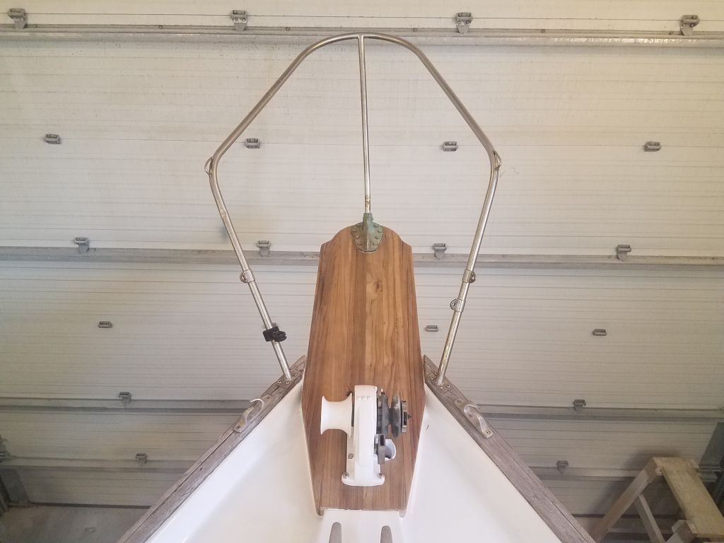
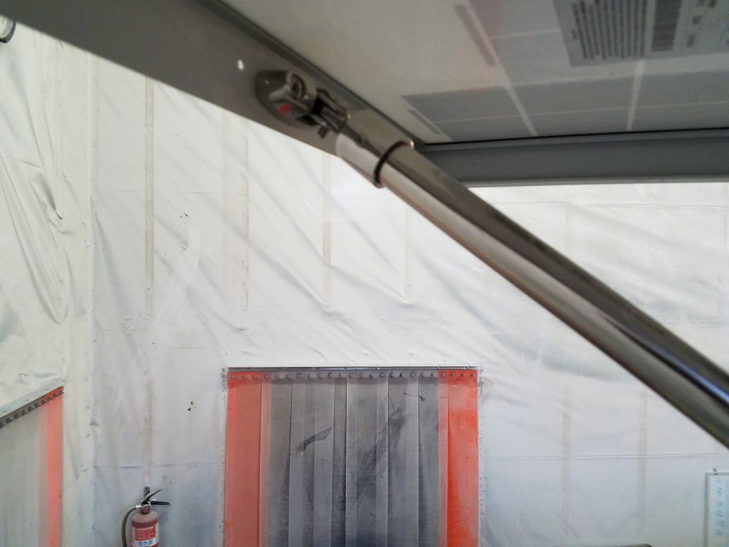
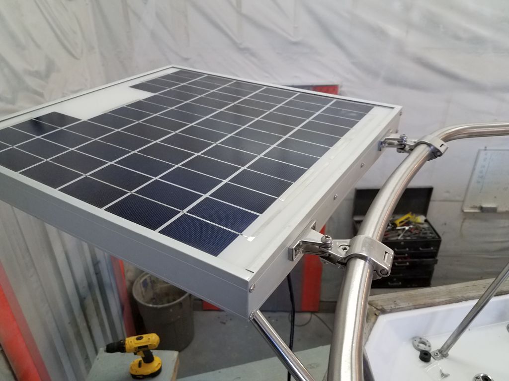
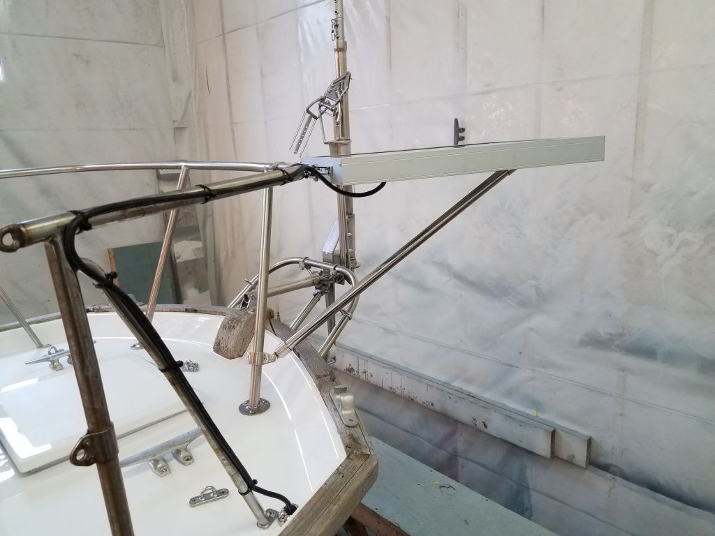
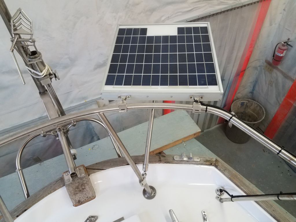
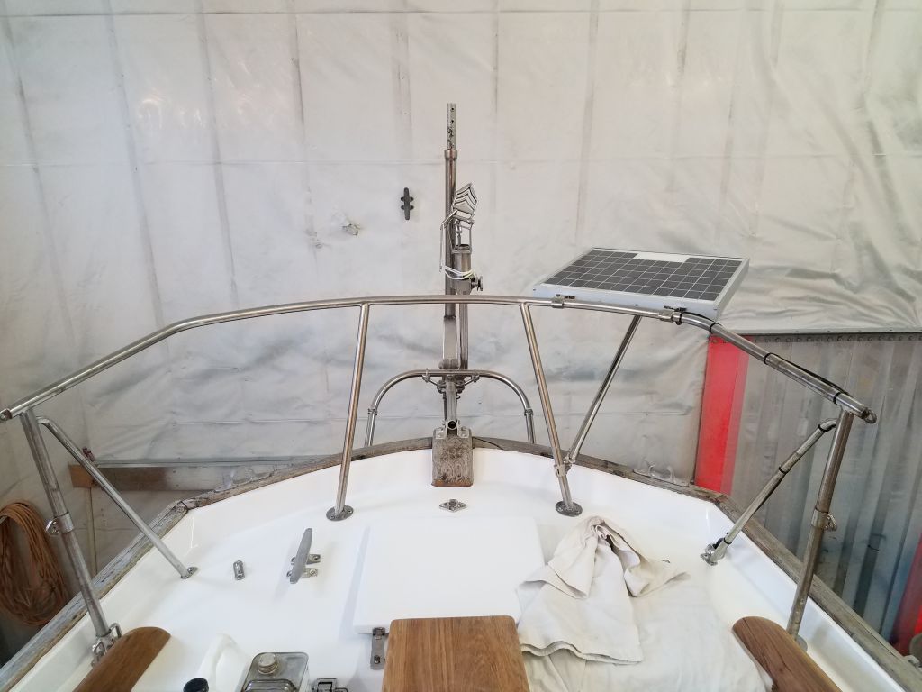
The owner had a small solar panel already on board, though when the boat arrived here the panel had just been temporarily wired and had no mounting system. Now, he requested that I install the panel on the stern pulpit using some hardware that he provided. Holding the panel against the port side of the rail, I ensured that it wouldn’t affect the windvane operation or otherwise be in the way, and I made some marks to show roughly where I needed to install brackets on the panel frame.
Down on the bench, I installed the two brackets on the panel frame itself, bolting through the aluminum frame. These brackets would accept the business end of a pair of clamp-on rail mounts and would form the basis for the support of the panel. Because of the way the two hardware parts interfaced, the machine screws supplied with the rail mounts were a bit short, but for now the threads just engaged so I could use these screws in the immediate term for fitting the panel.


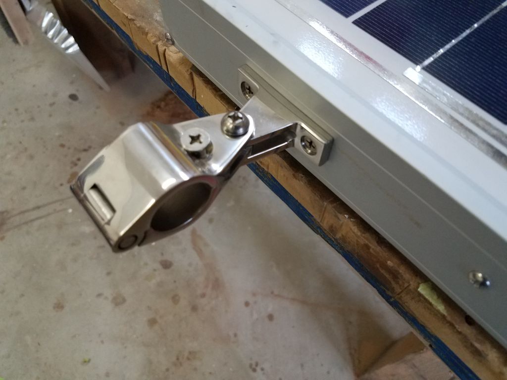
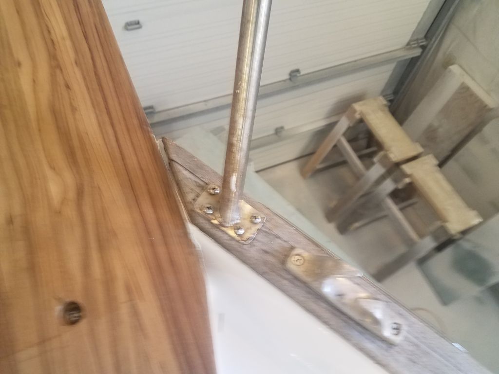
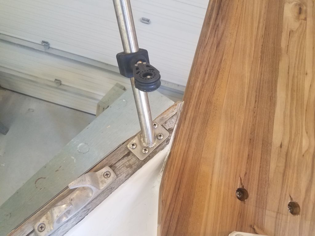
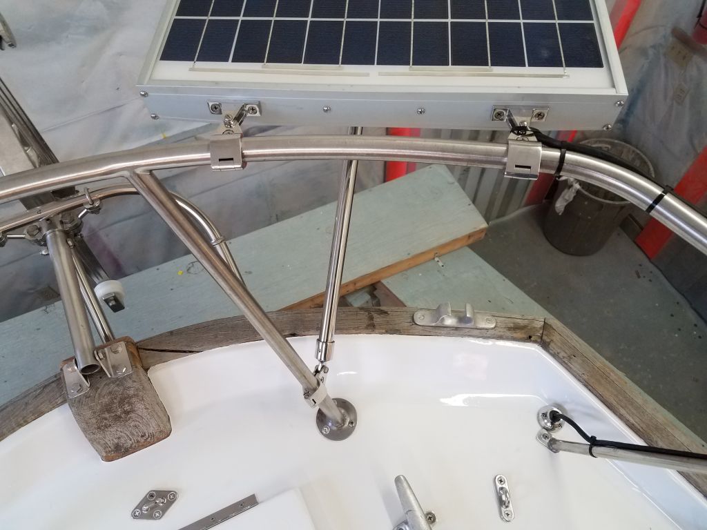
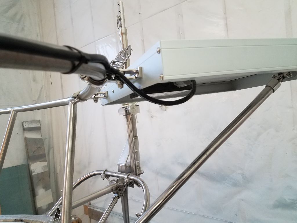
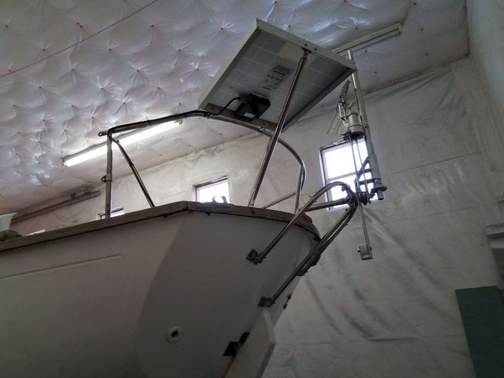
I clamped the fittings to the rail and installed the panel, which held it securely enough so that I could prepare an angled support from beneath, which I’d make from 1″ stainless tubing. Using the hardware on hand, I installed a swivel mount for one end to the center of the panel on the aft side, then cut a piece of tubing to run down to a third clamp-on rail mount, which I installed on the nearest vertical stanchion. I cut the tubing so that the panel ended up horizontal; there was some adjustment possible by sliding the lower rail mount one way or the other as needed.
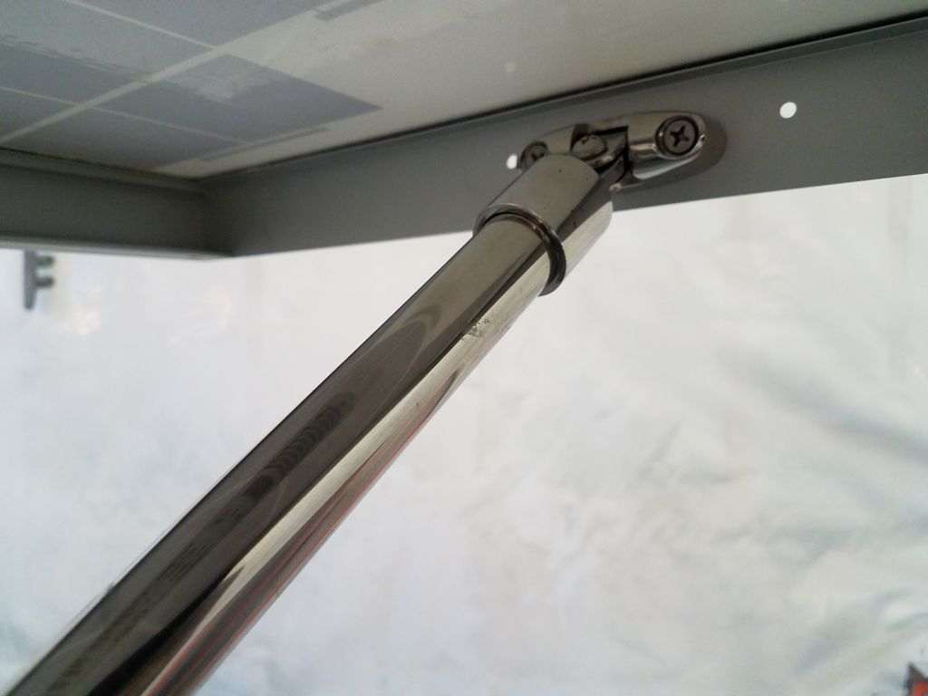
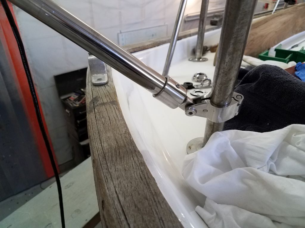
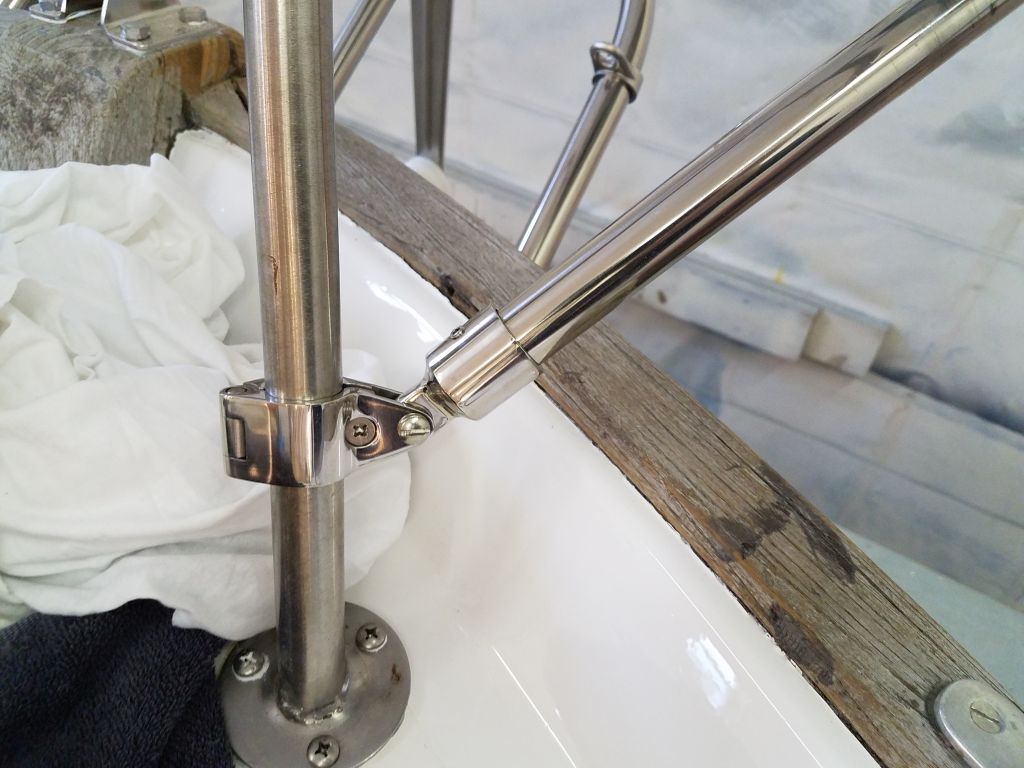
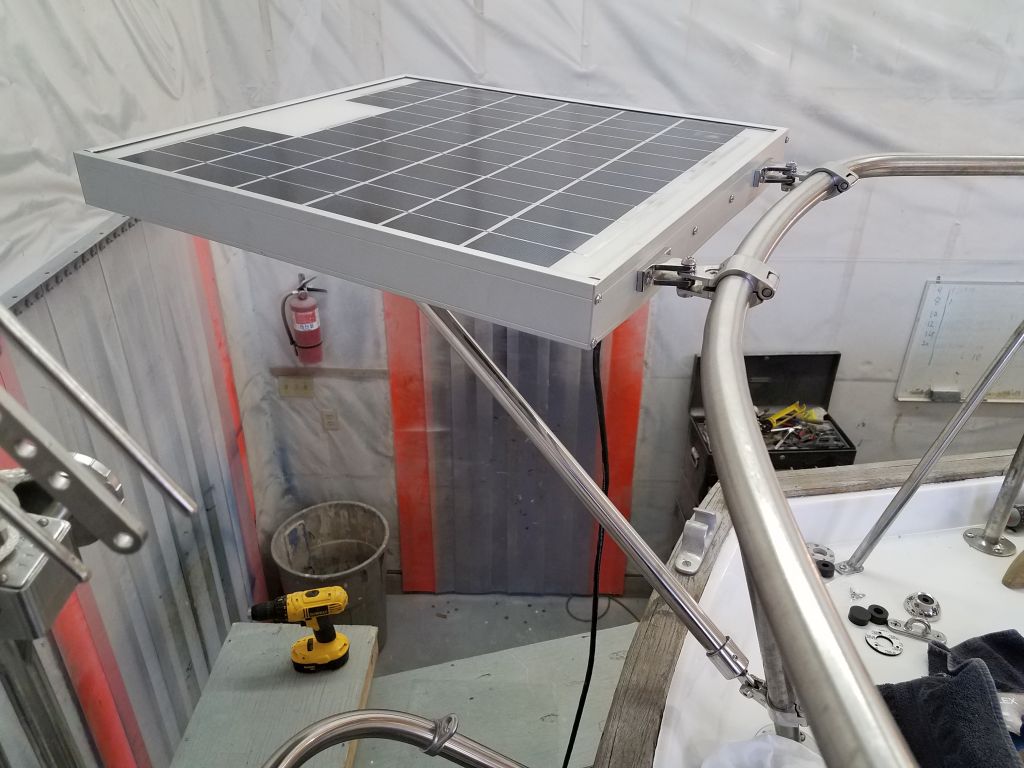
This completed the main panel support, and the panel seemed sturdy and solid, with only a hint of movement between the tubing end fittings on the lower angle support–a function of the hardware itself. To better secure together the panel mounts and upper rail fittings, I replaced the short machine screws with through bolts and secured them tightly.
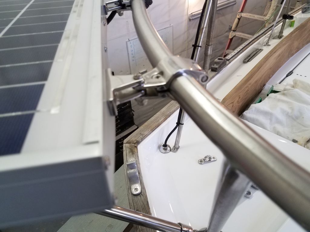

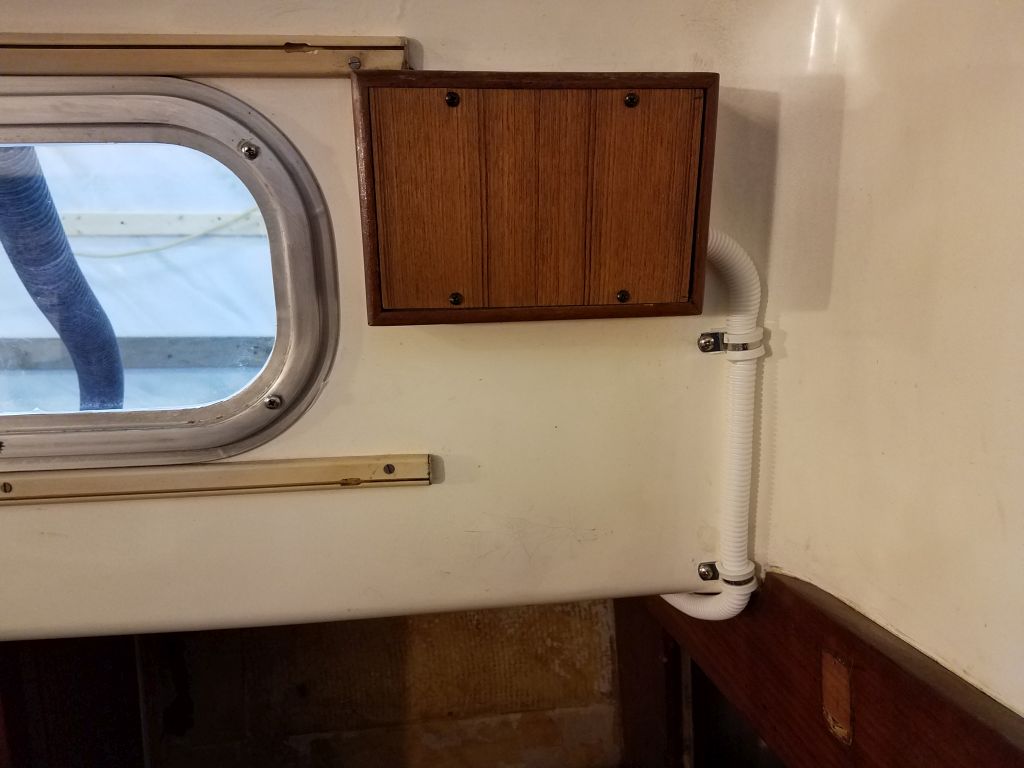
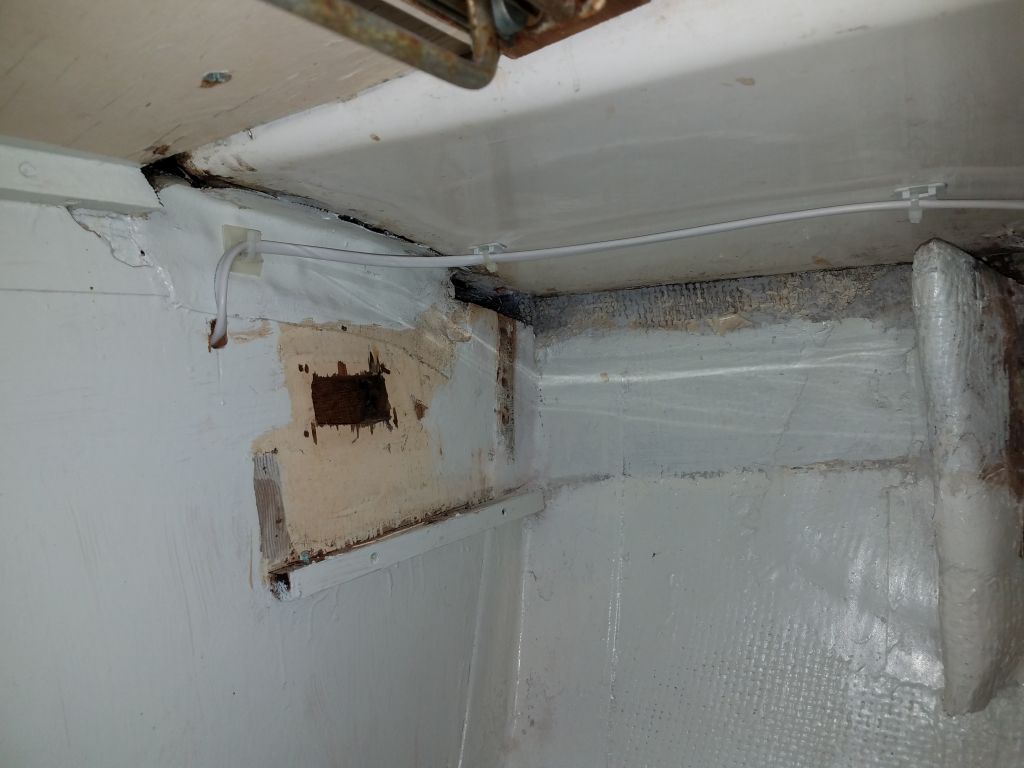
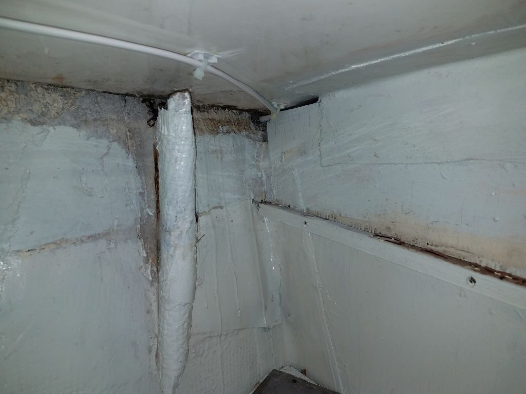
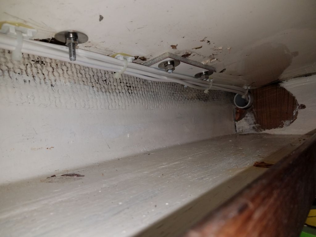
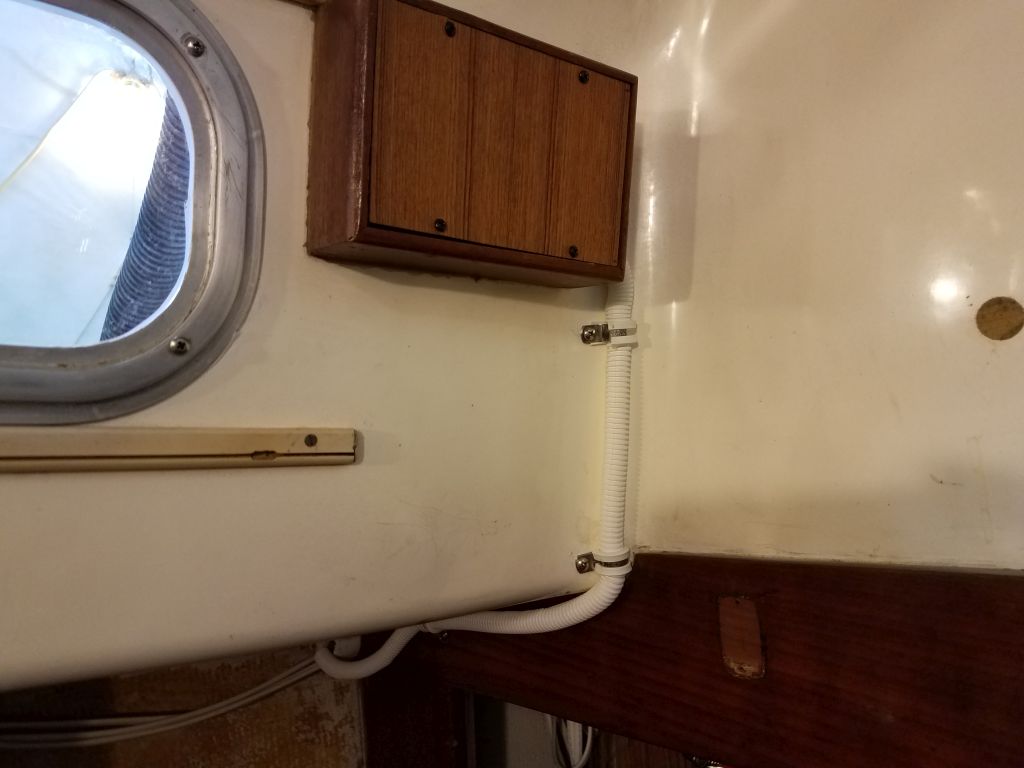
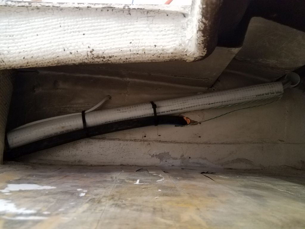
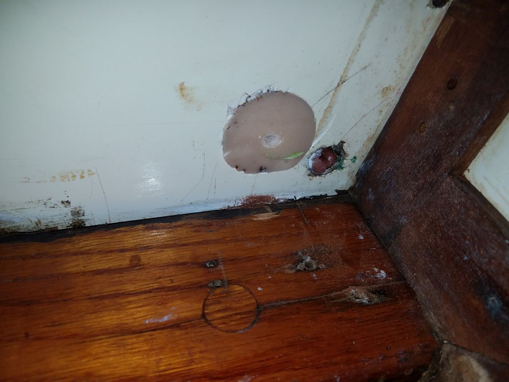
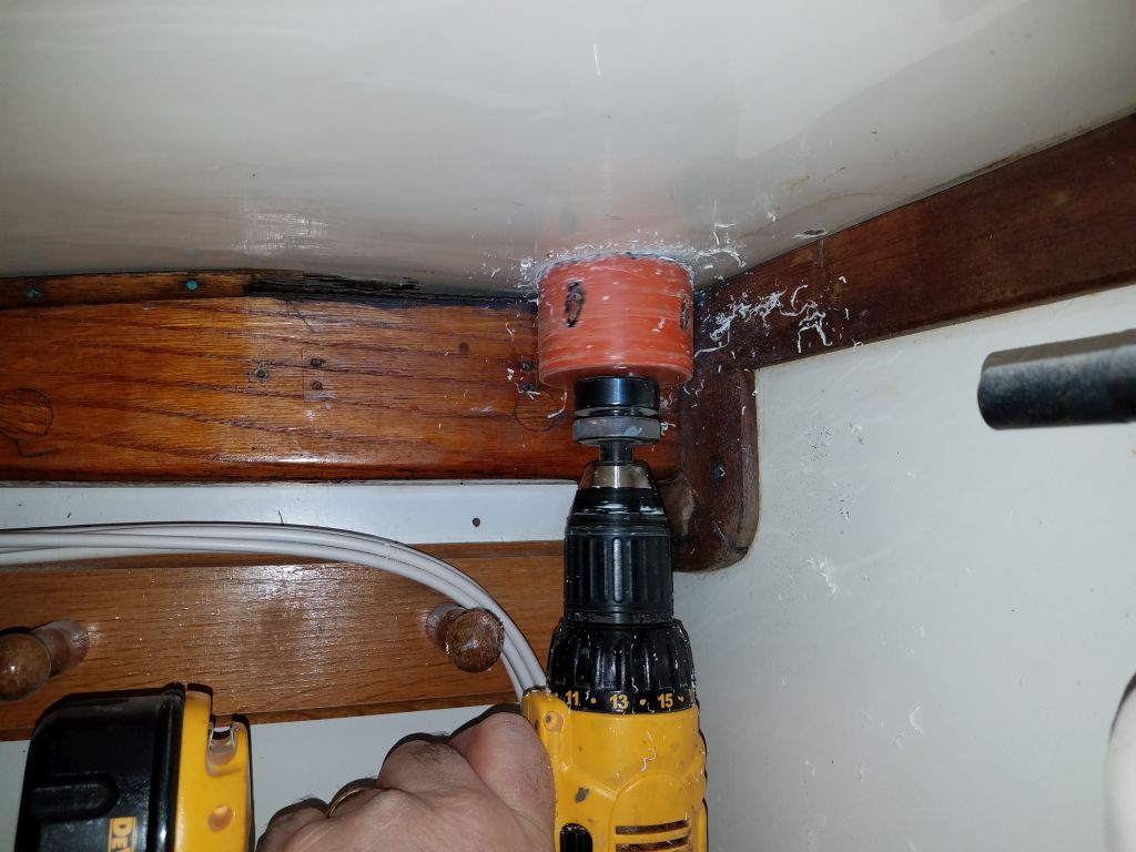
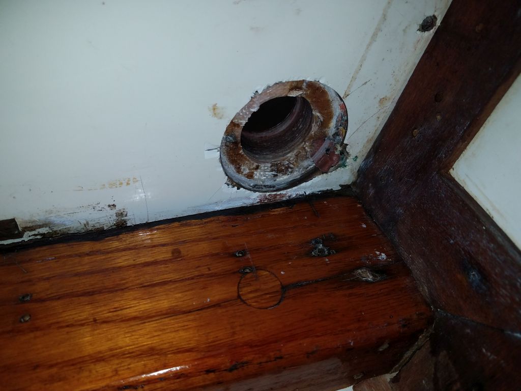
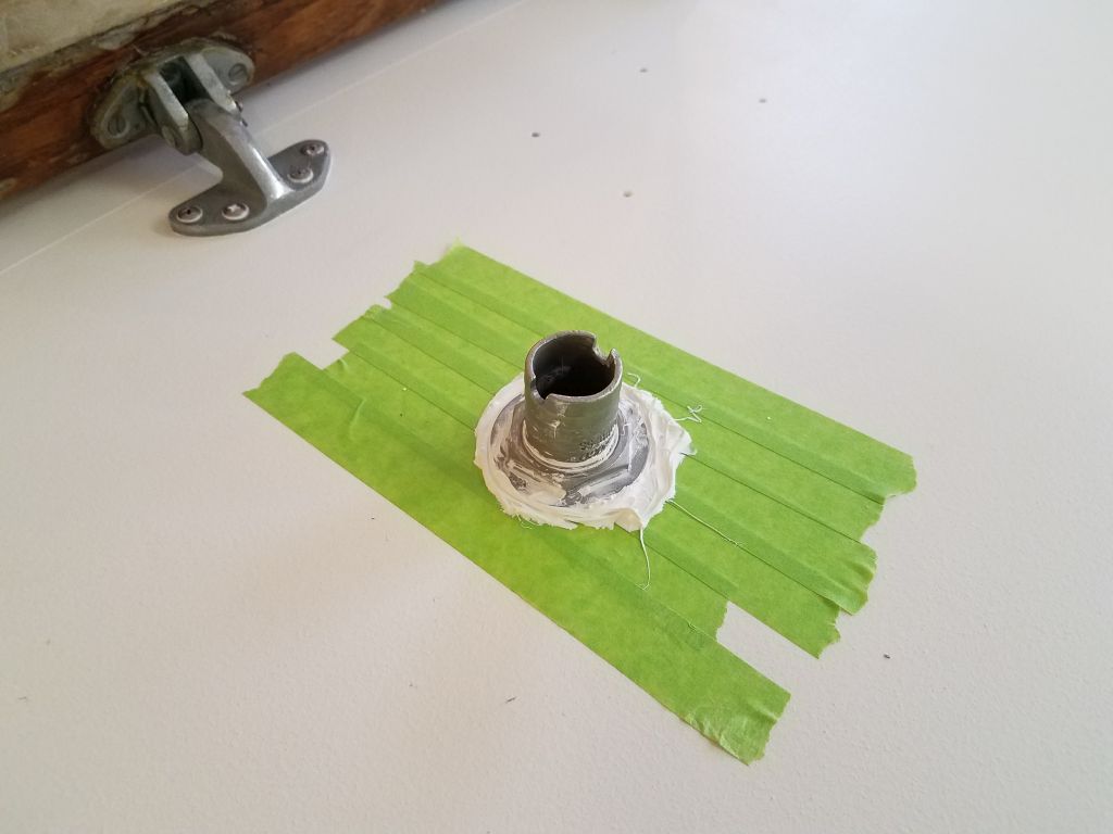
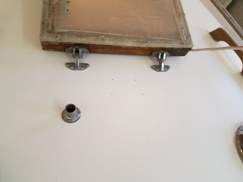
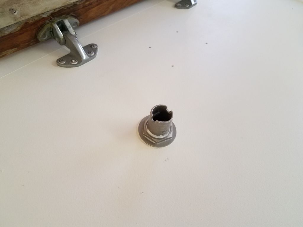
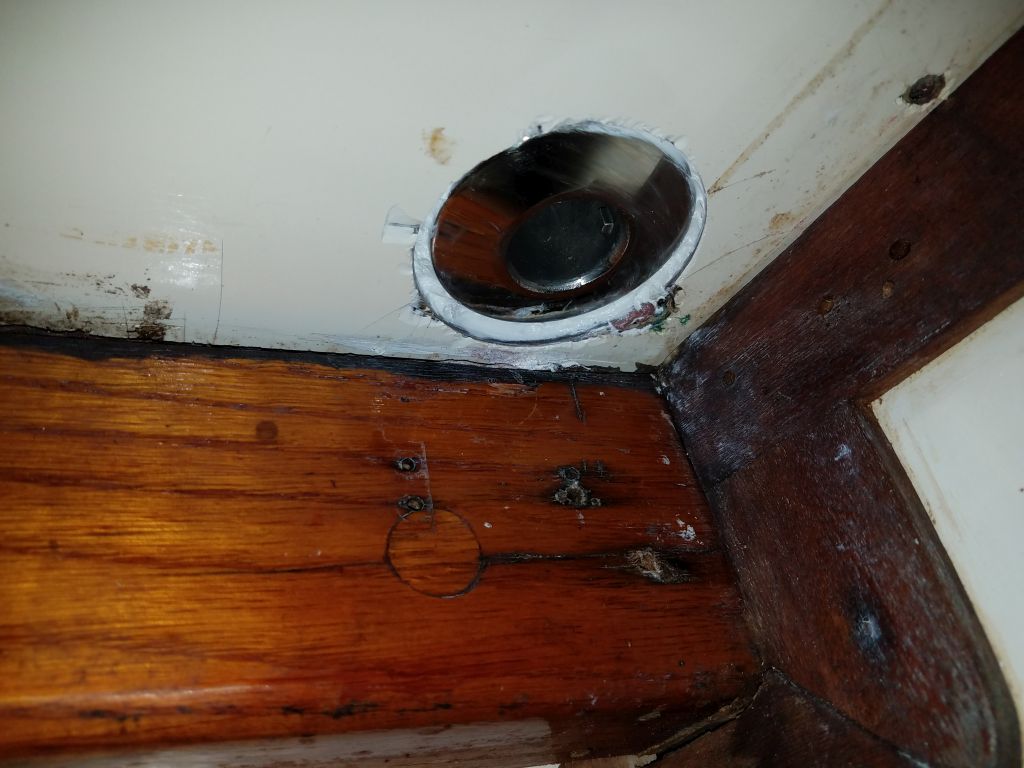
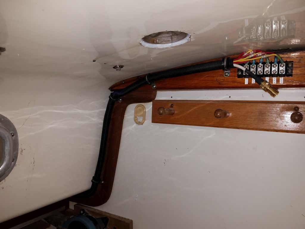
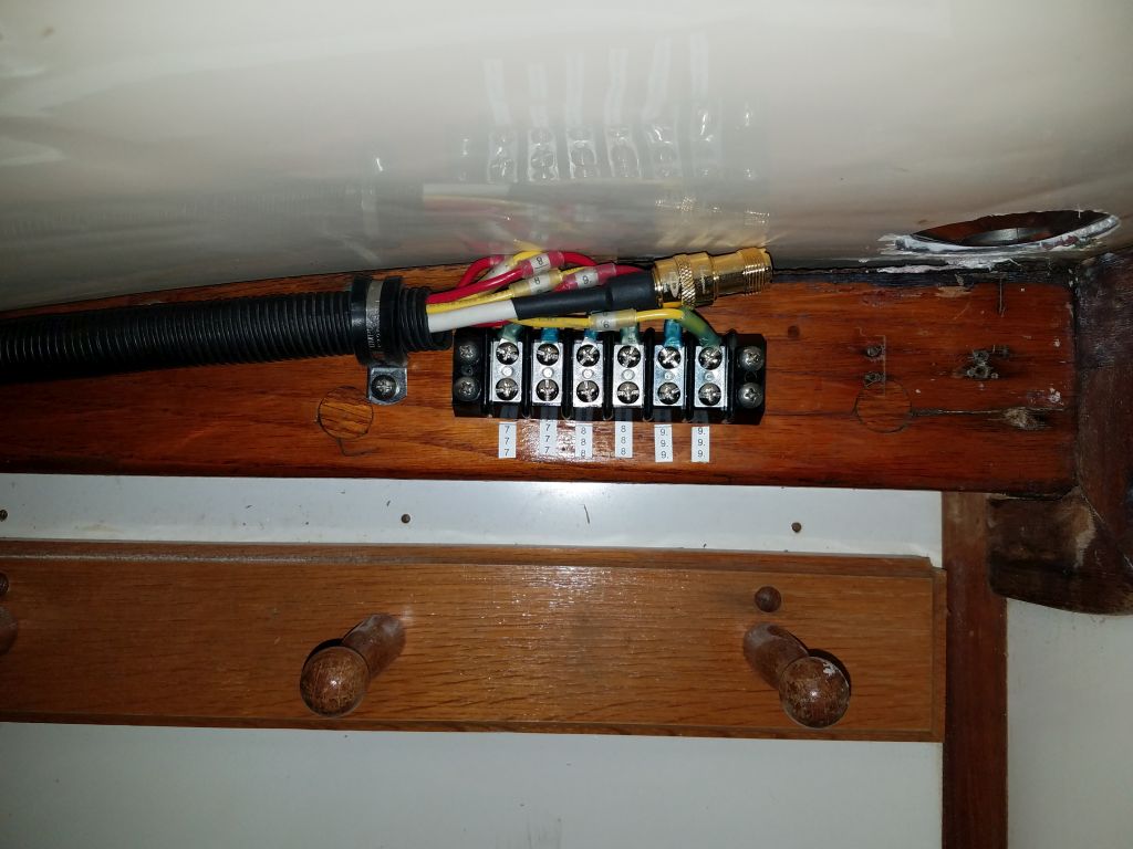
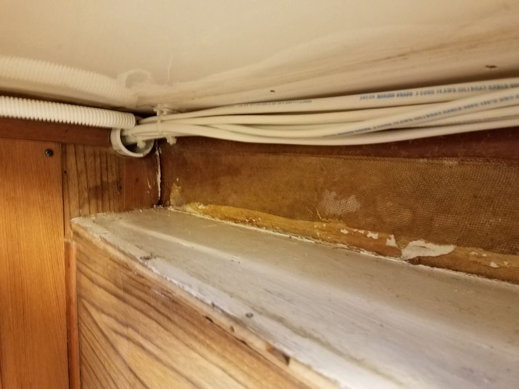
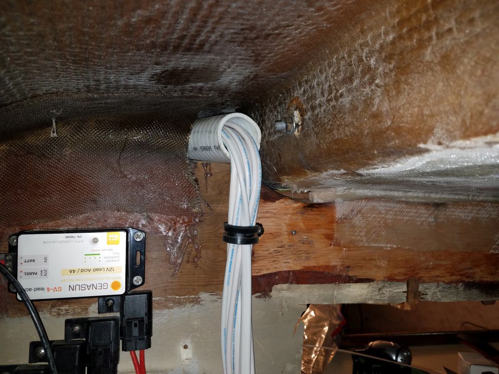
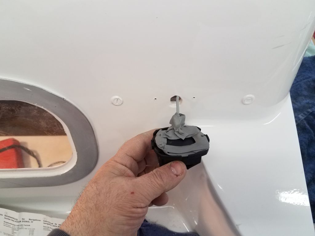
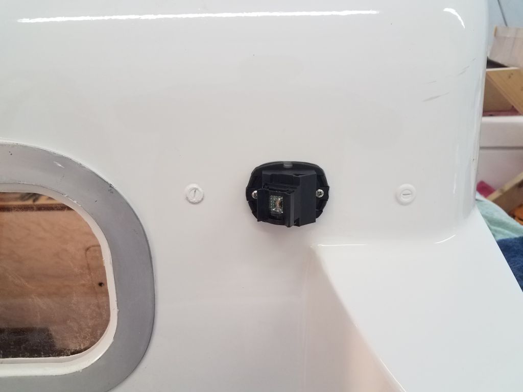
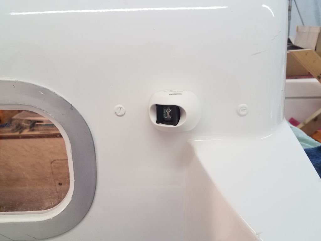
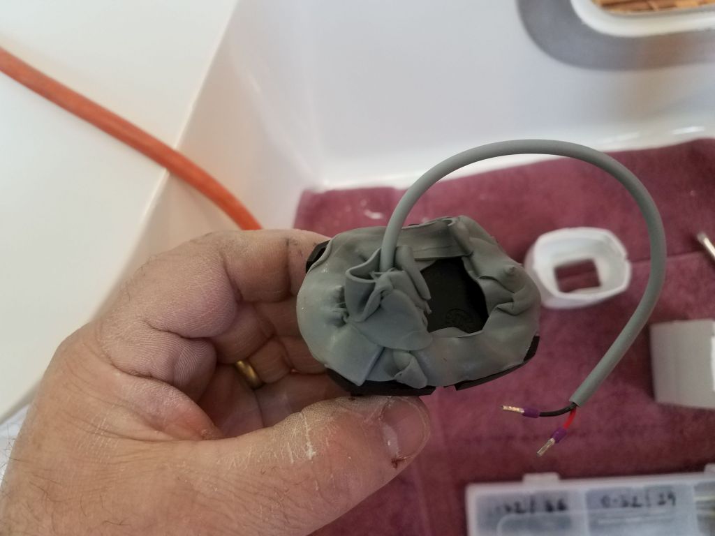
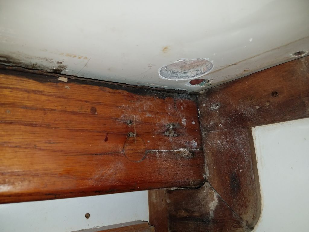
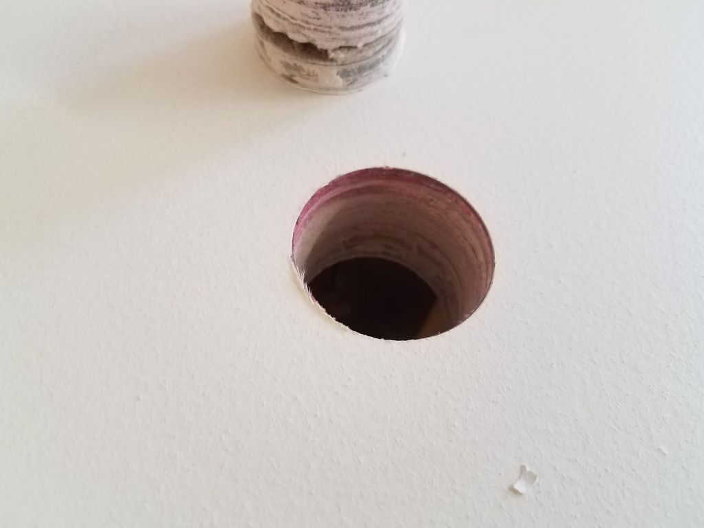
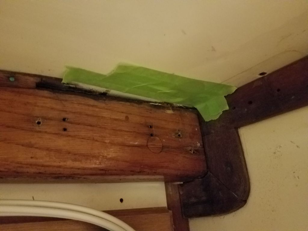
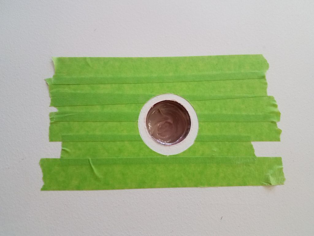
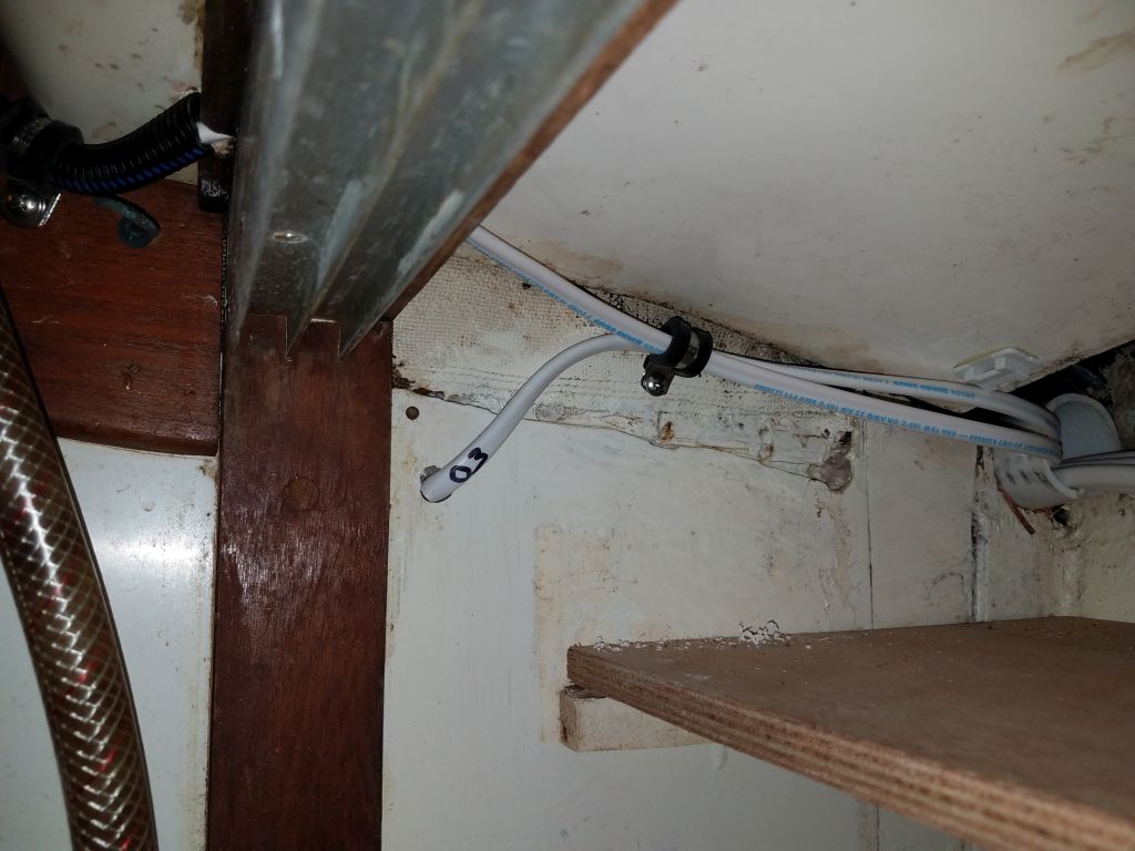
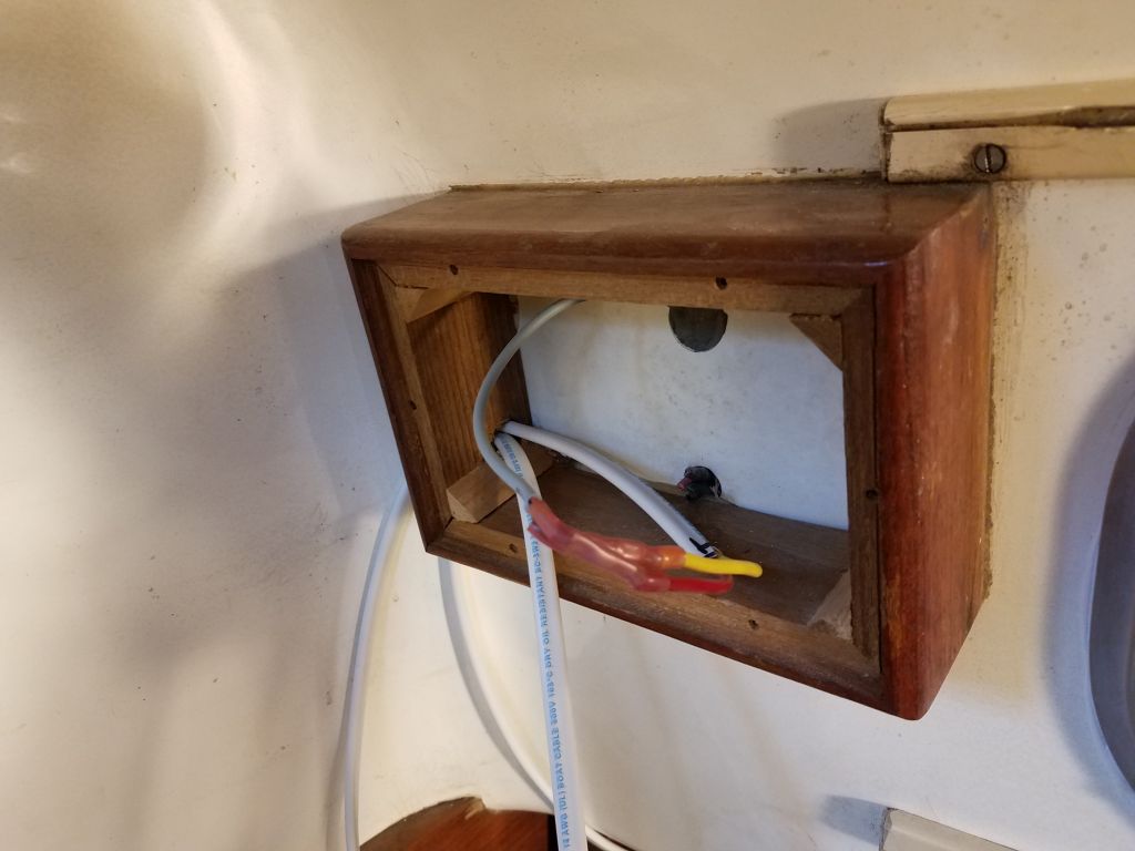
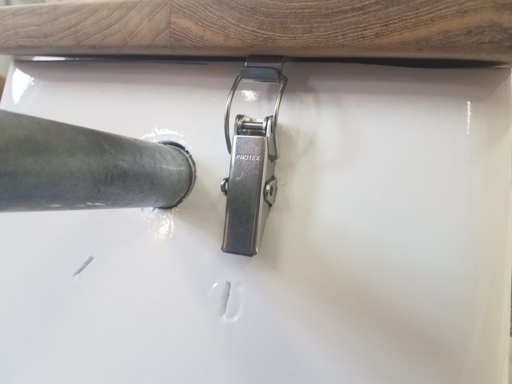
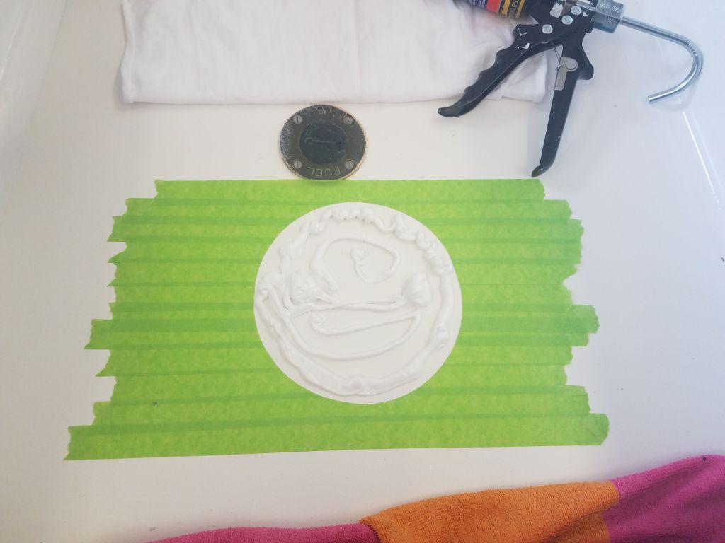
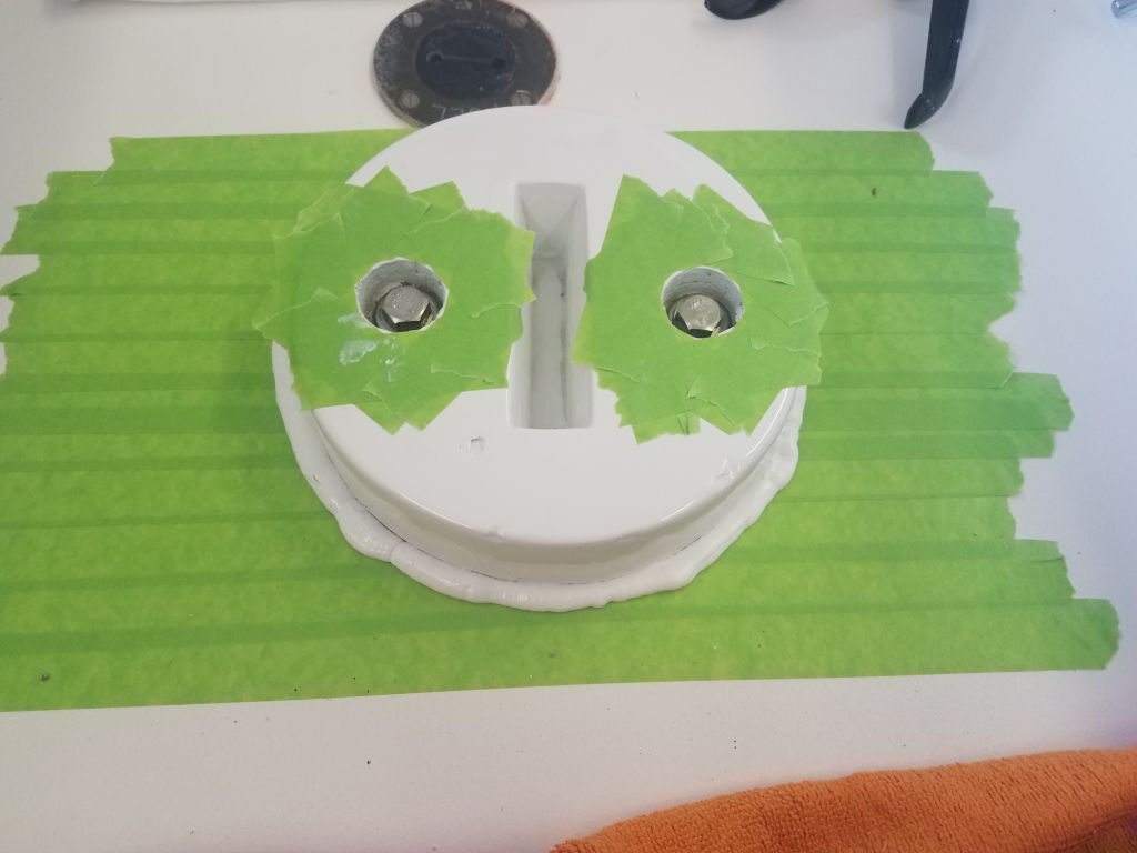
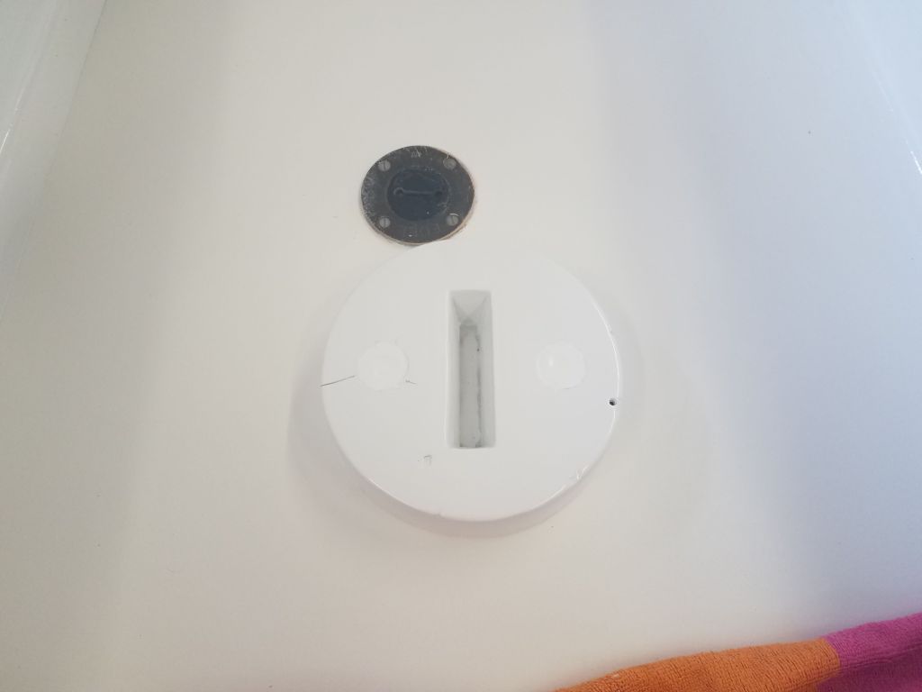
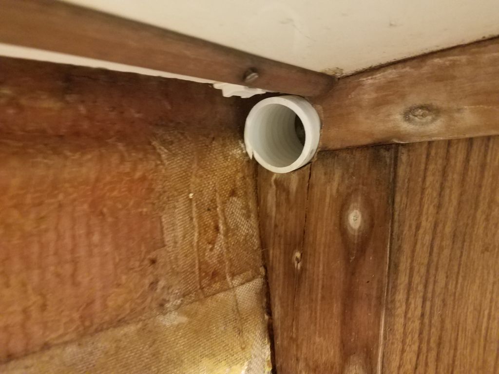
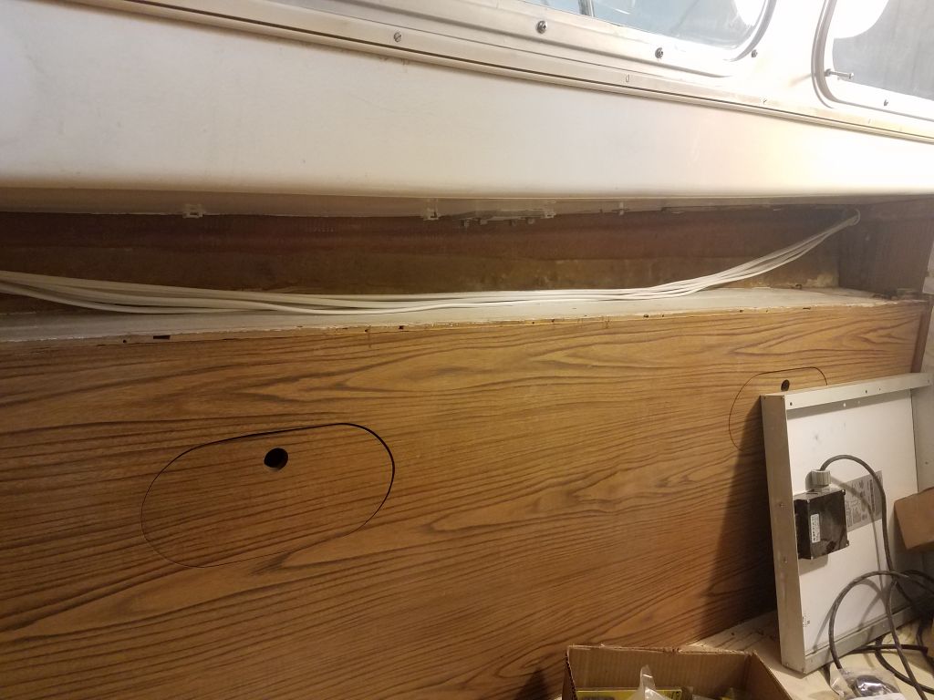
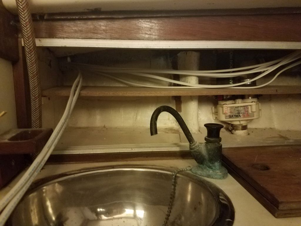
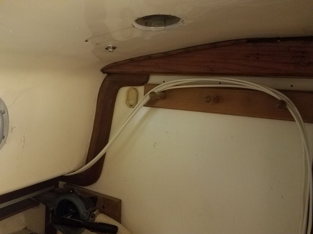
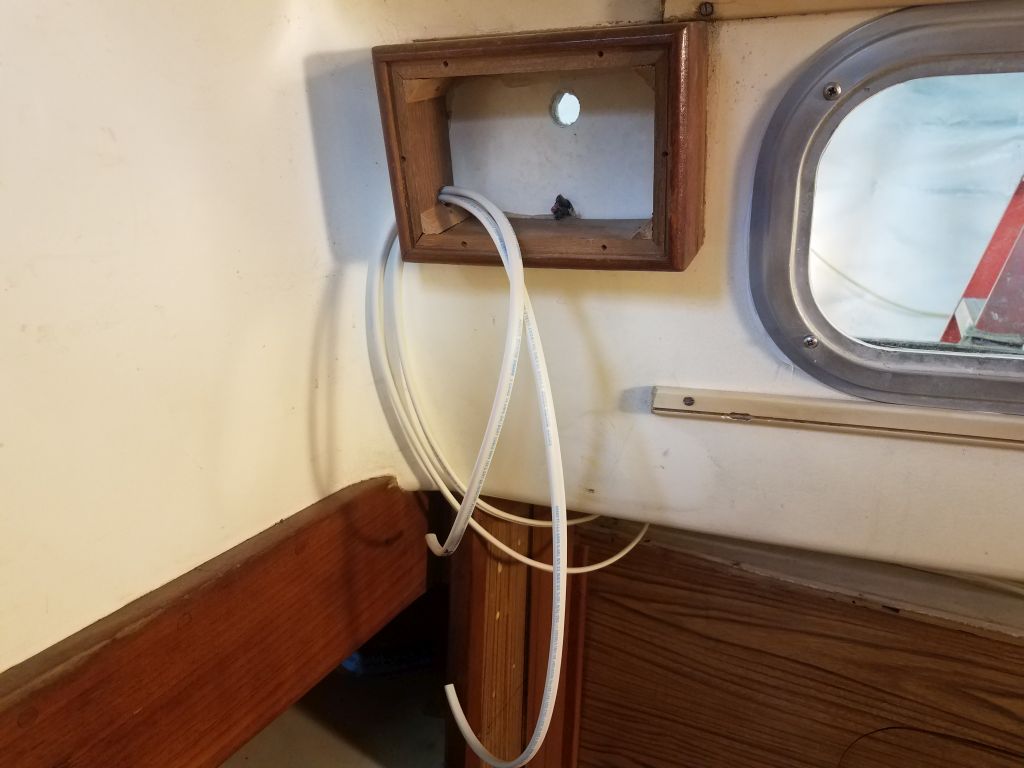
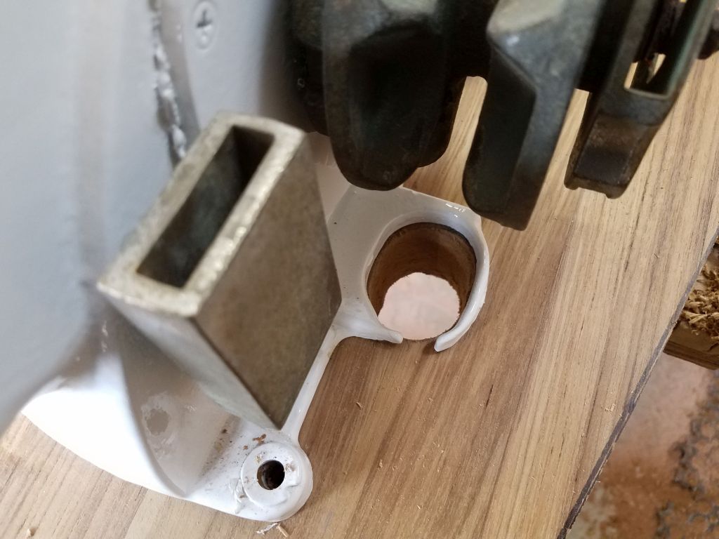
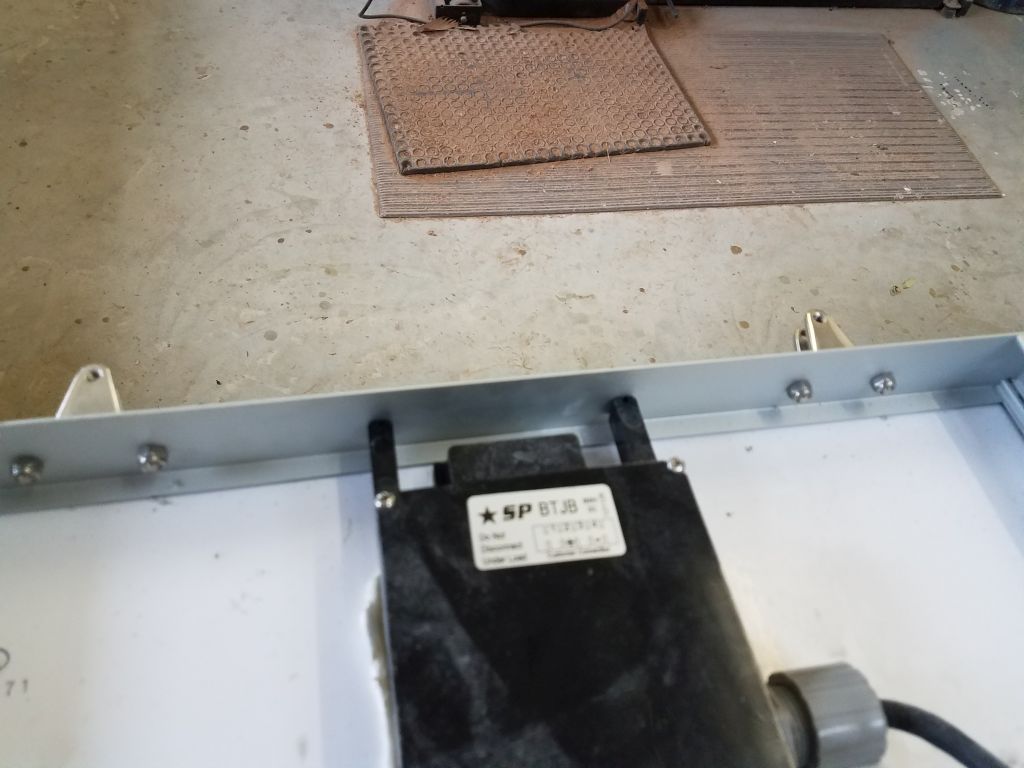
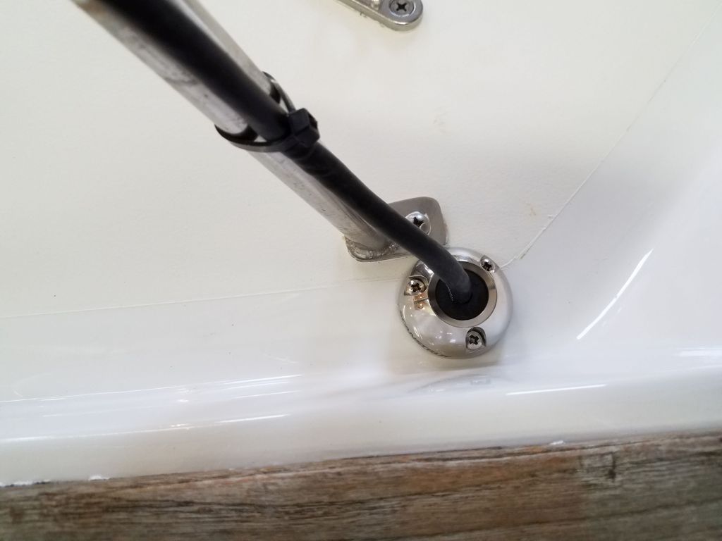
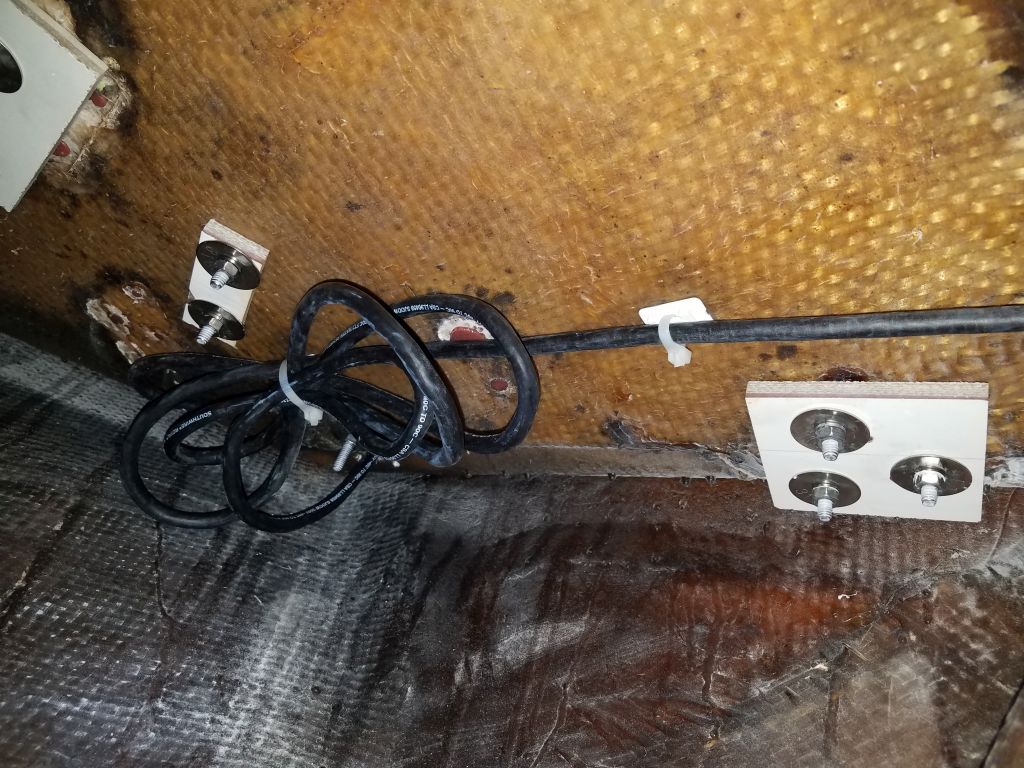
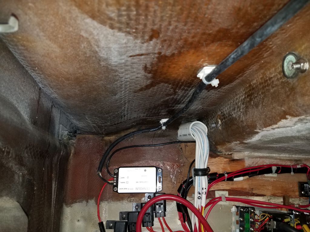
To run the wire belowdecks and to the panel controller (already installed by the owner the previous year), I installed a through-deck cable fitting, choosing a location near a stanchion and far enough outboard to pass through the solid area of the deck. I secured the wire along the pulpit and stanchions, then through the fitting and forward to the controller, securing it along the way to the wire mounts I’d installed before. I left the excess wire bundled beneath the deck near the deck fitting, so the panel could be dismounted and moved as needed and within the limits of the excess cable available.
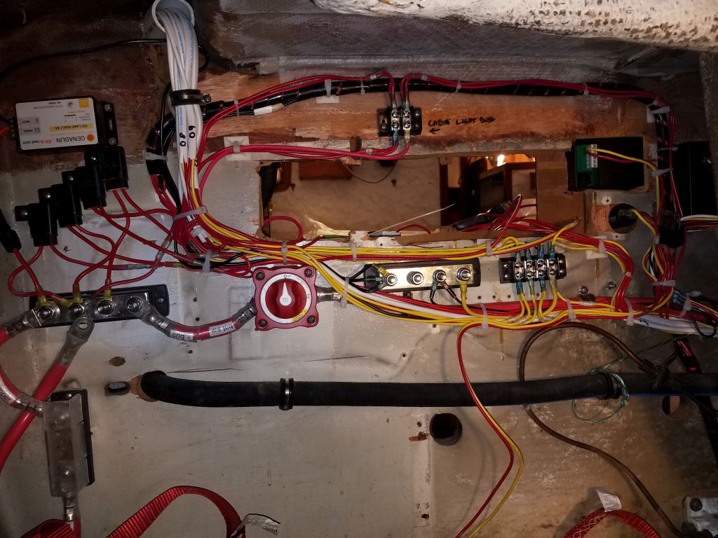
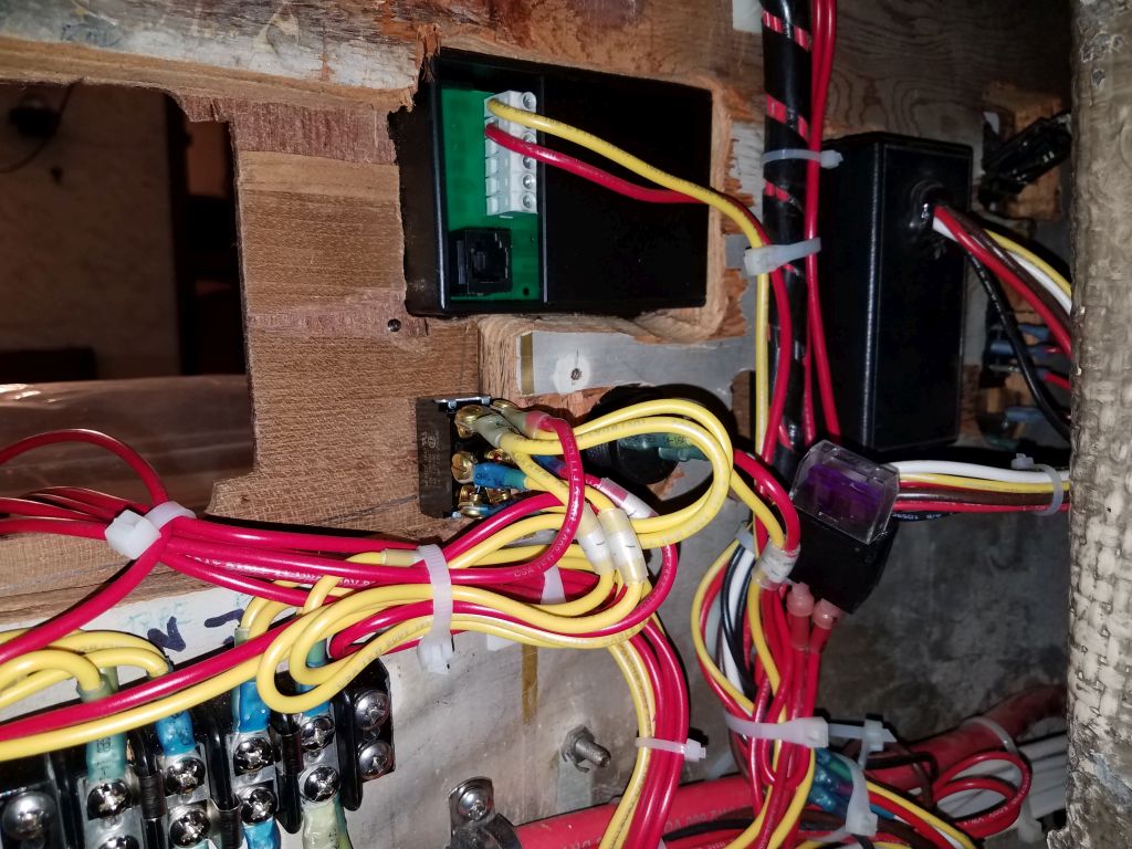
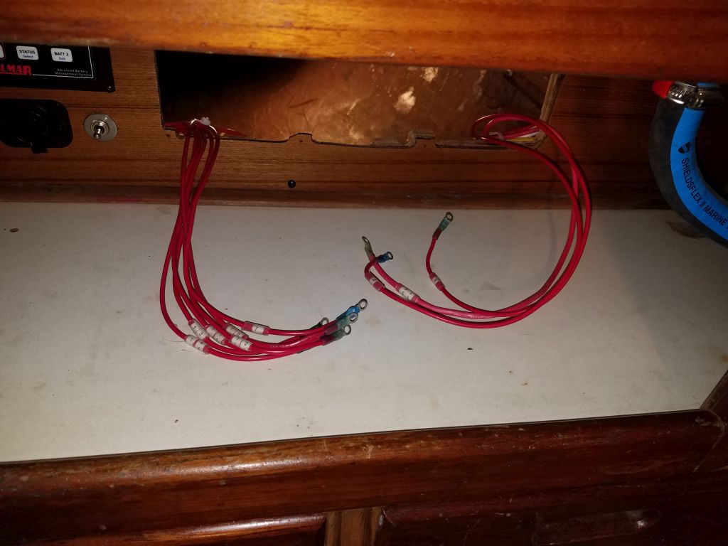
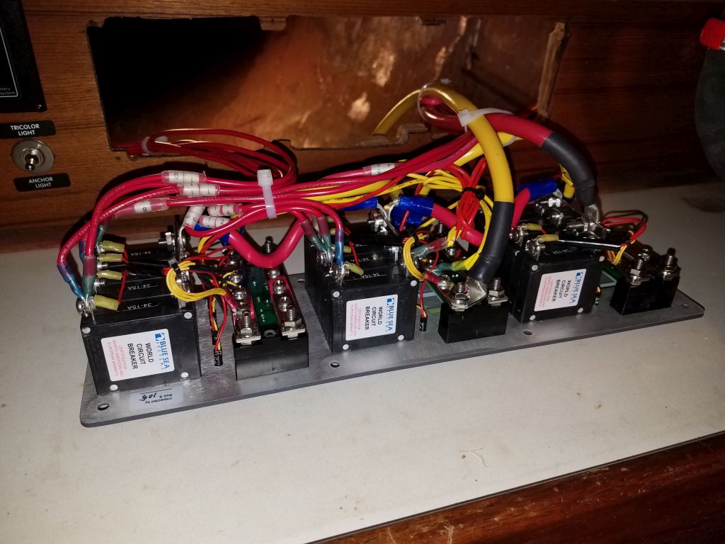
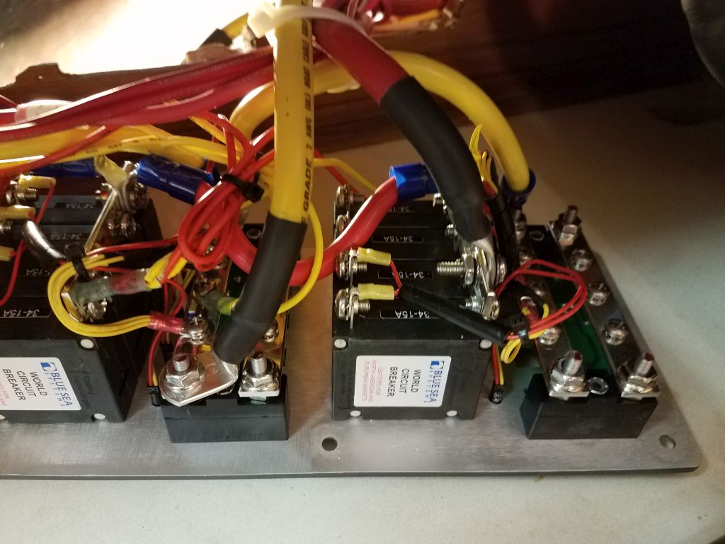
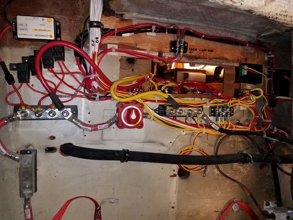
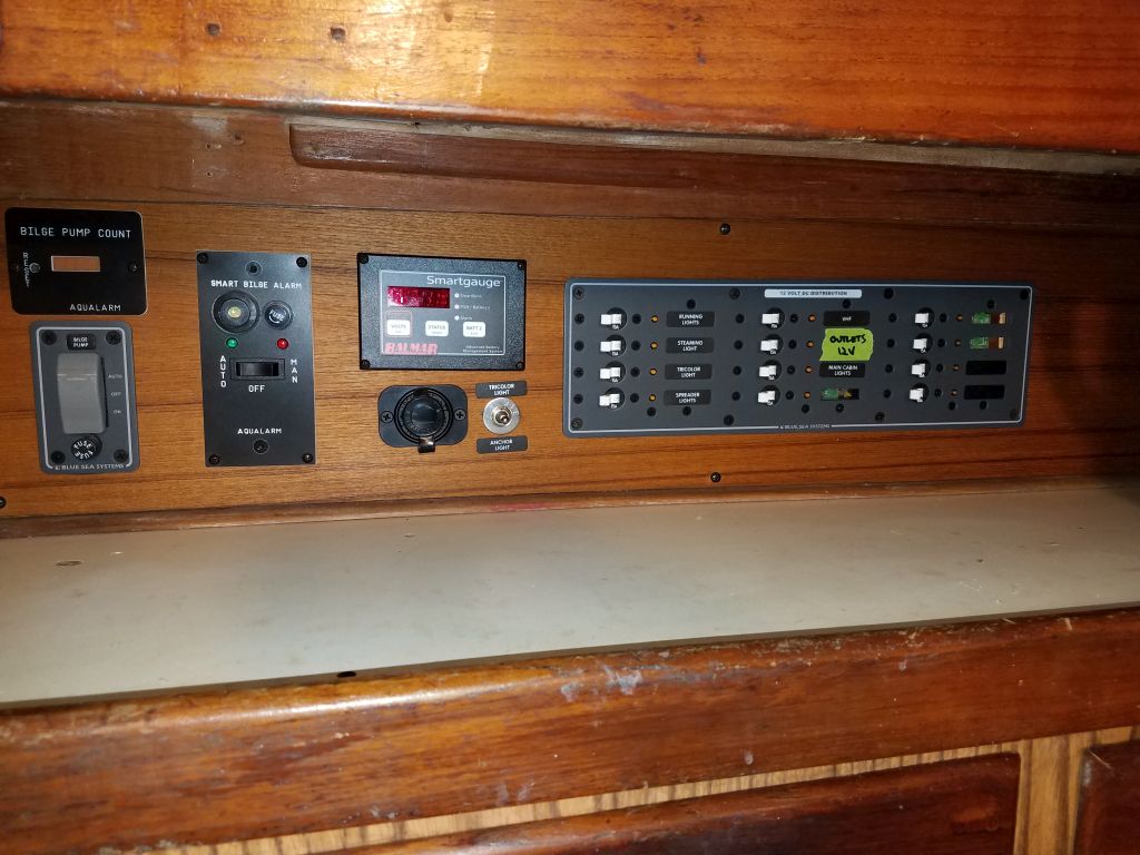
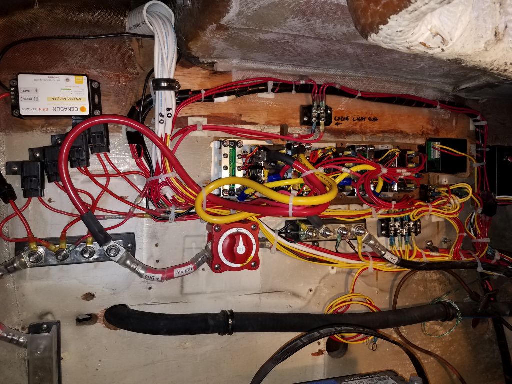
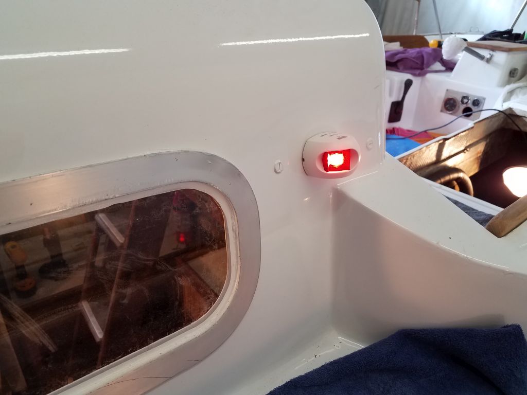
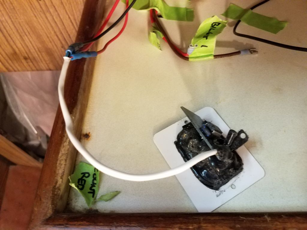
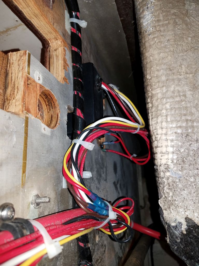
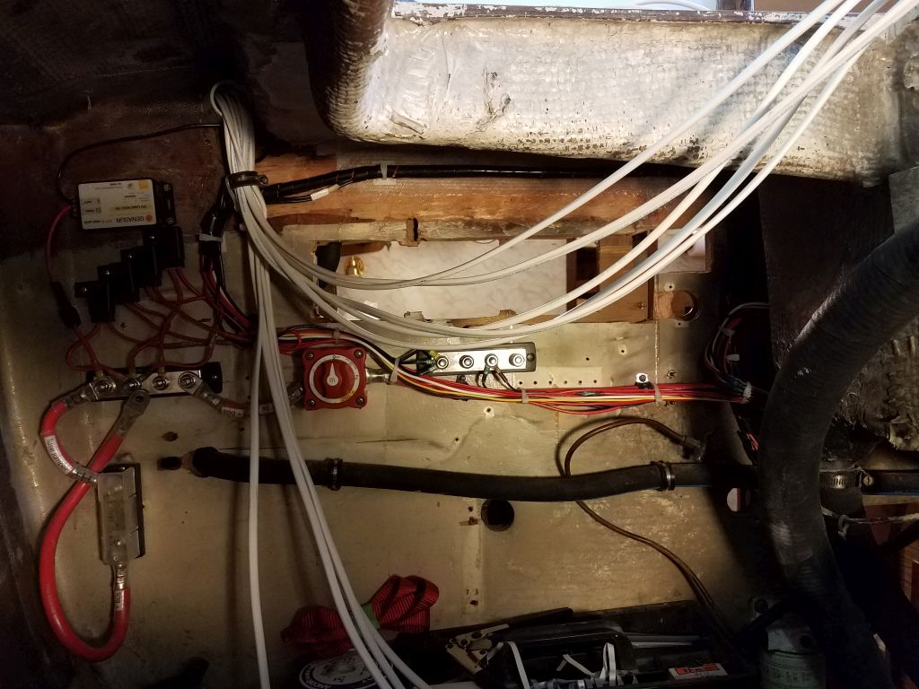
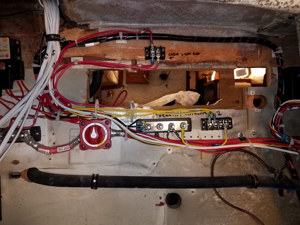
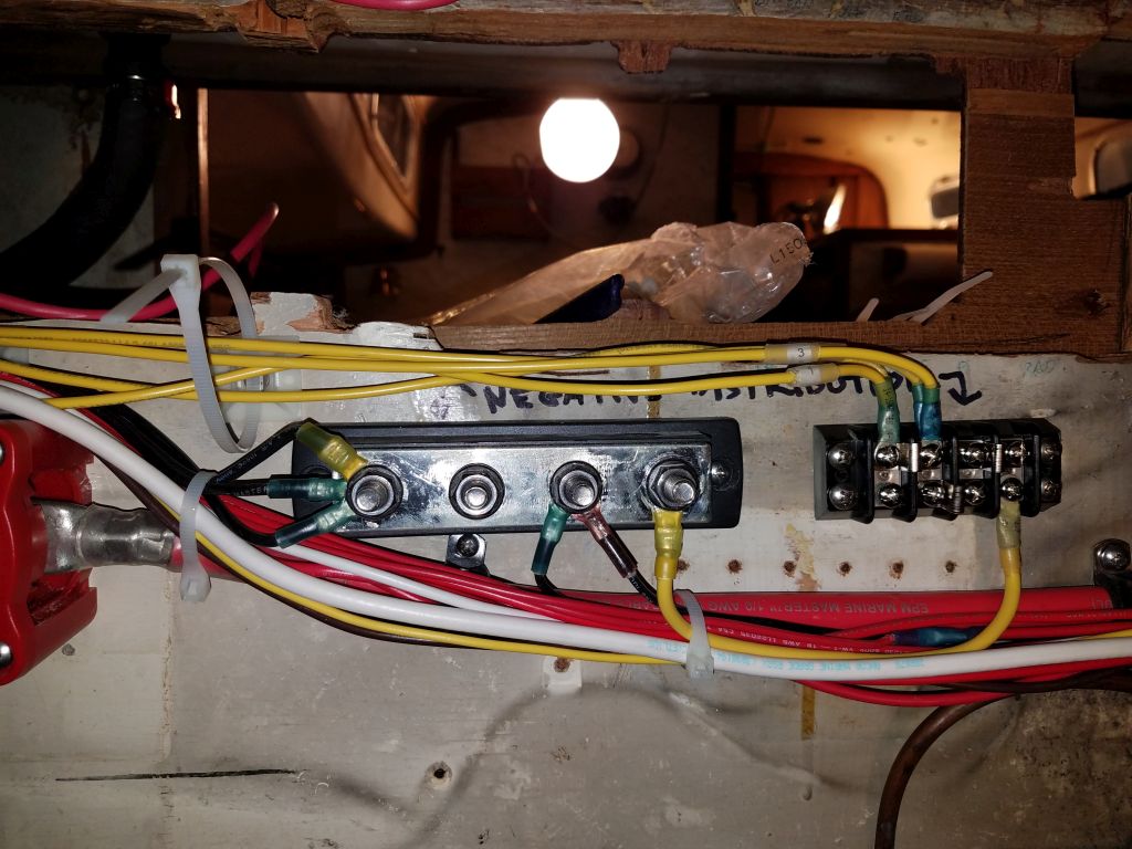
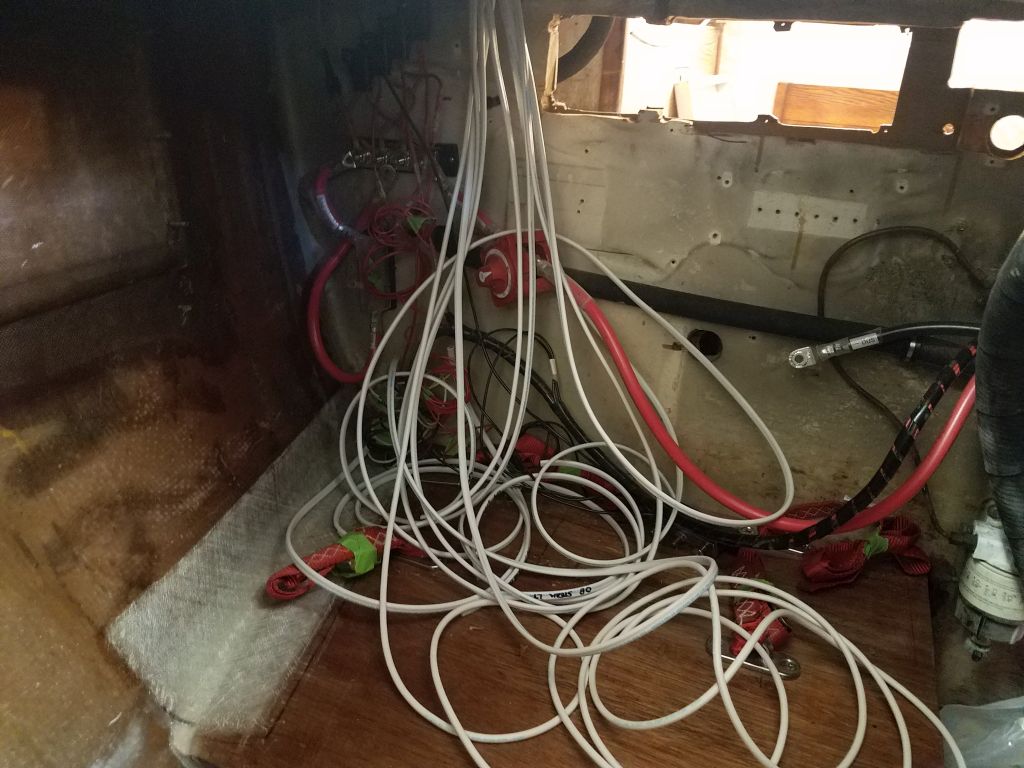
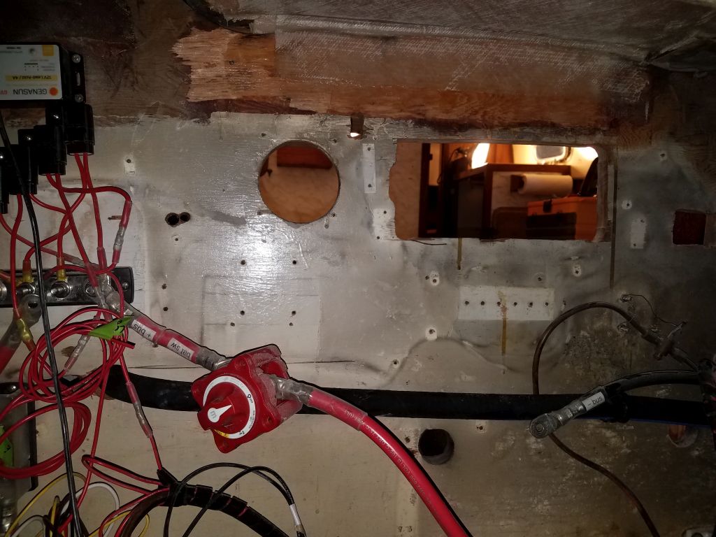
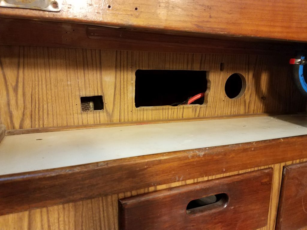
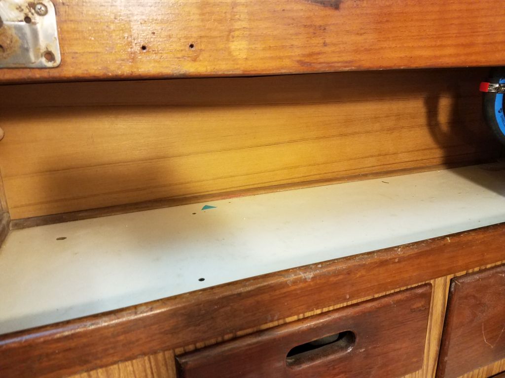
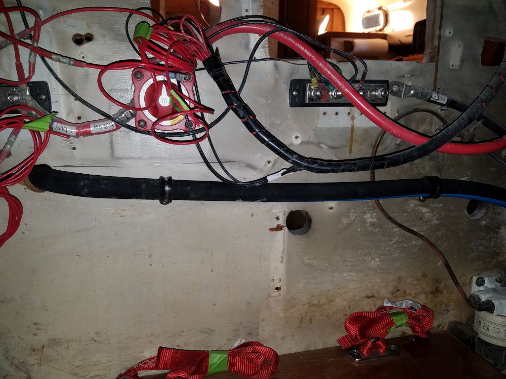
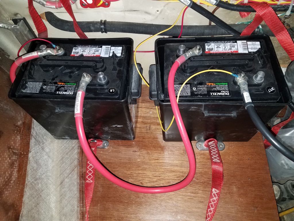
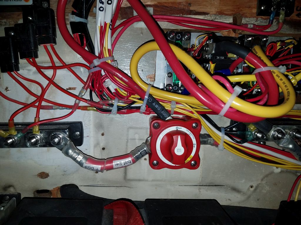
The boat’s pair of 6-volt deep cycle batteries was charged and ready, and with the panel in place I decided to reinstall the batteries so they could benefit from the trickle charge from the panel, both while inside the shop and, later, outdoors again. As I installed the batteries, I realized that I should have run the power feed from the service panel through the existing battery switch, not from the positive buss, since the buss was on the battery/always hot side of the switch. Since I didn’t install or change any of the basic battery and engine-side wiring, which the owner had installed the previous season, it hadn’t immediately occurred to me. So I re-led the supply cable to the proper terminal on the battery switch, and finished up the other battery connections. I led a pair of wires from the new battery gauge to the battery terminals as required, a simple installation that didn’t require a shunt like most battery monitors. The battery boxes fit securely in the space I’d built for them on the new platform, and I strapped them down with the nylon straps.


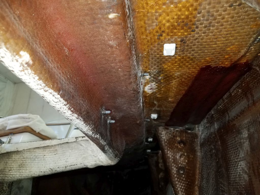
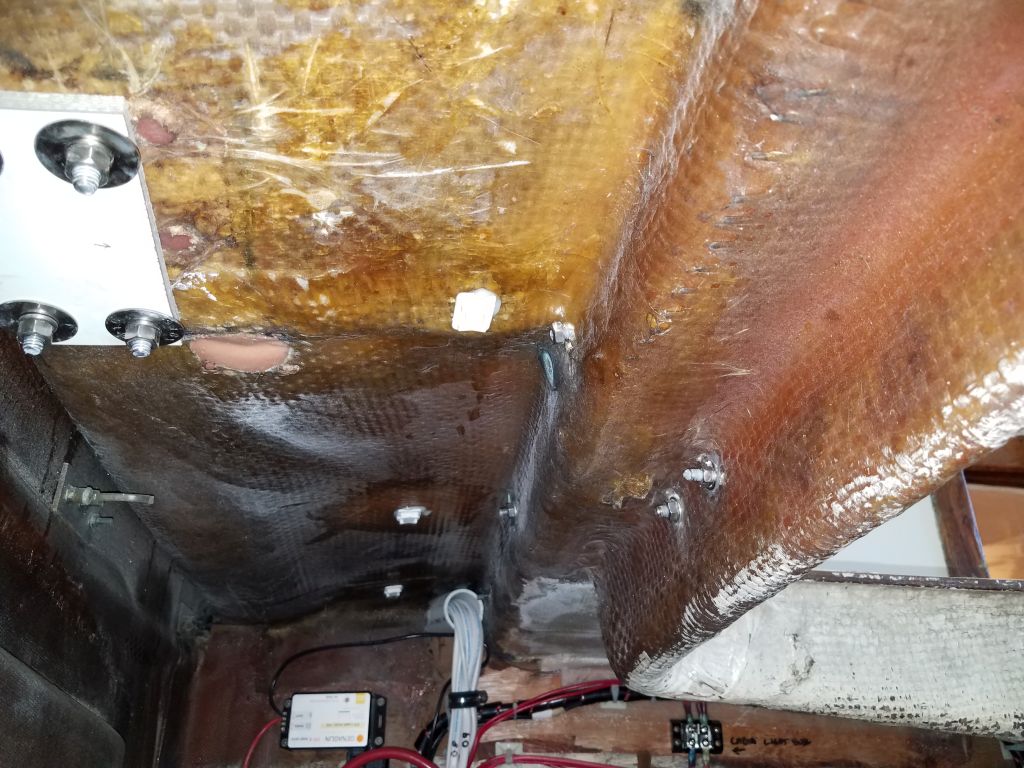
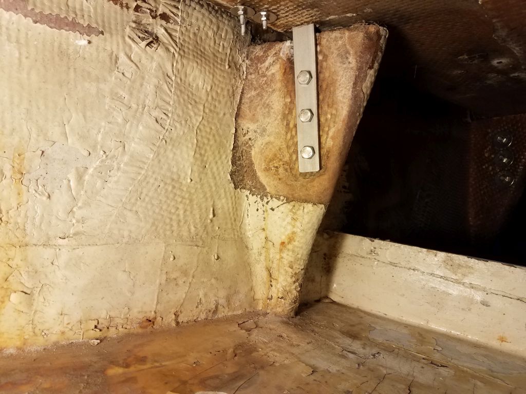
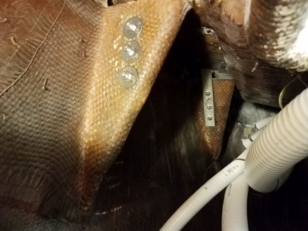
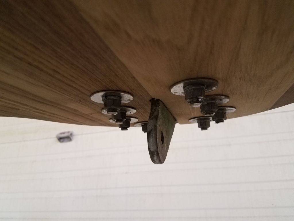
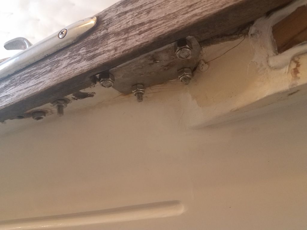
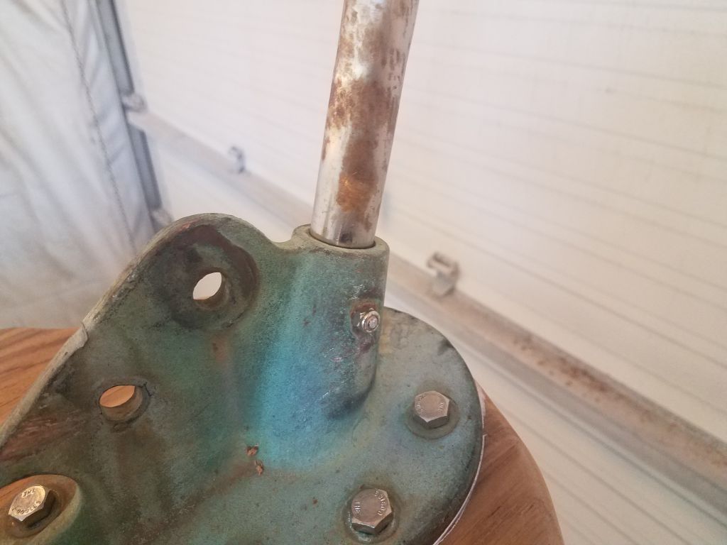
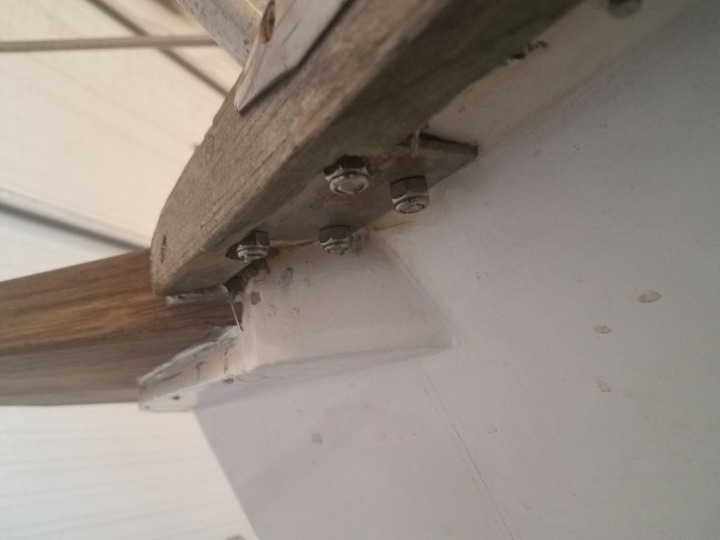
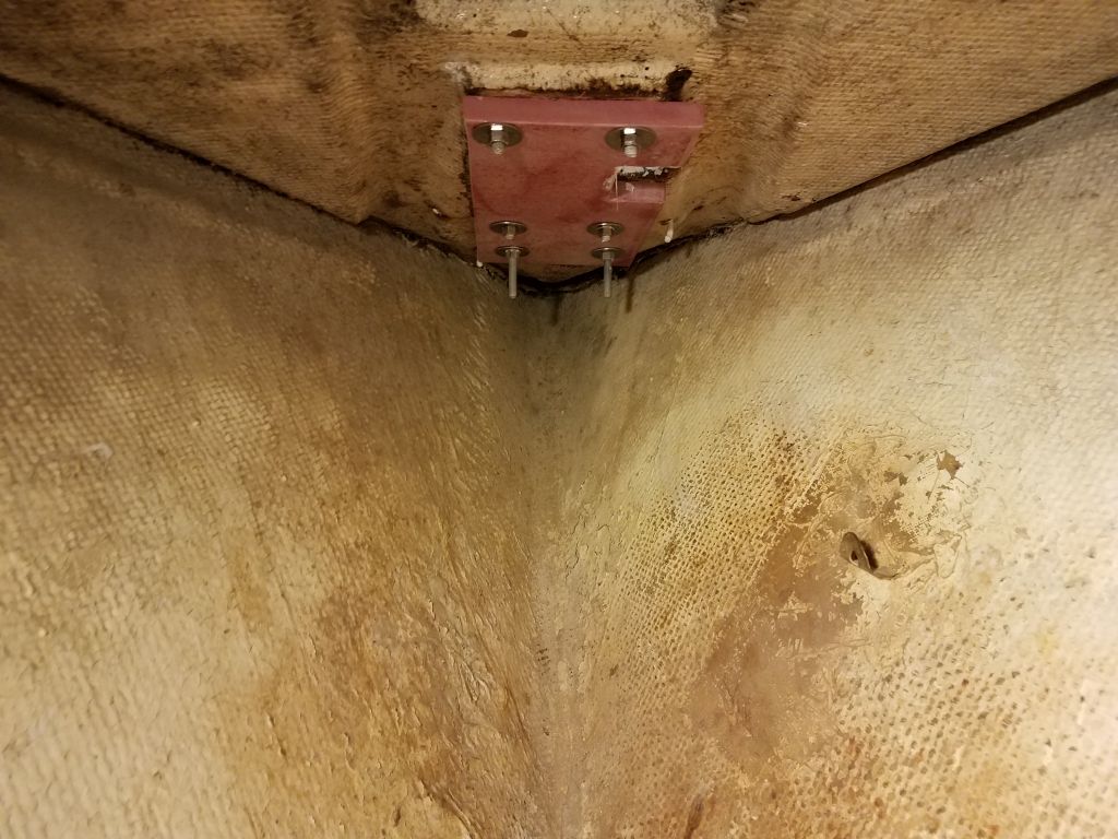
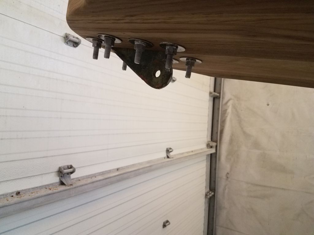
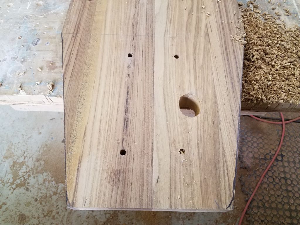
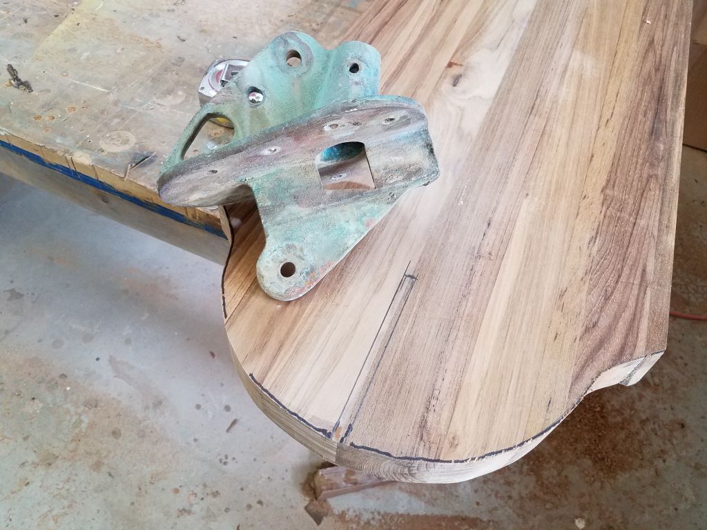
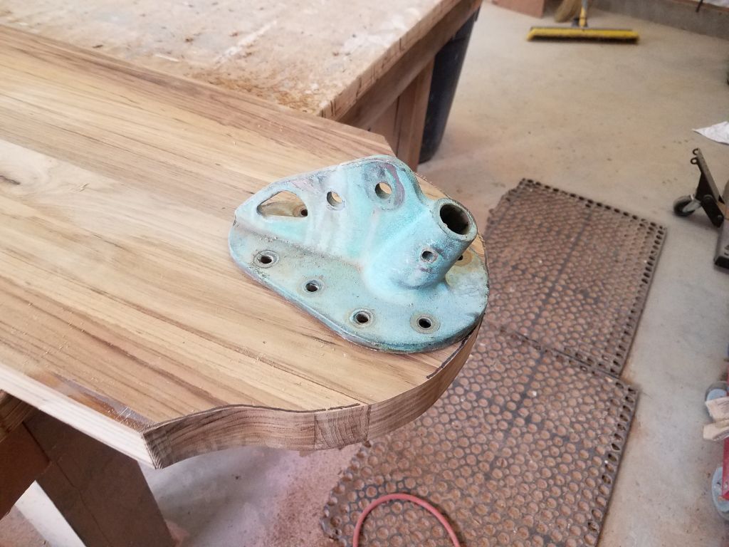
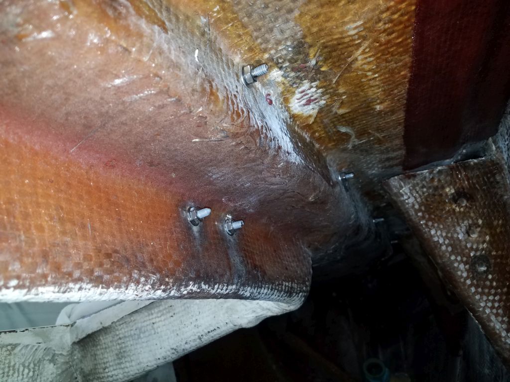
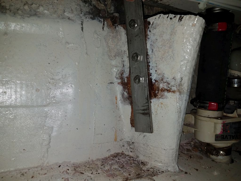
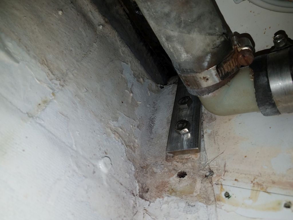
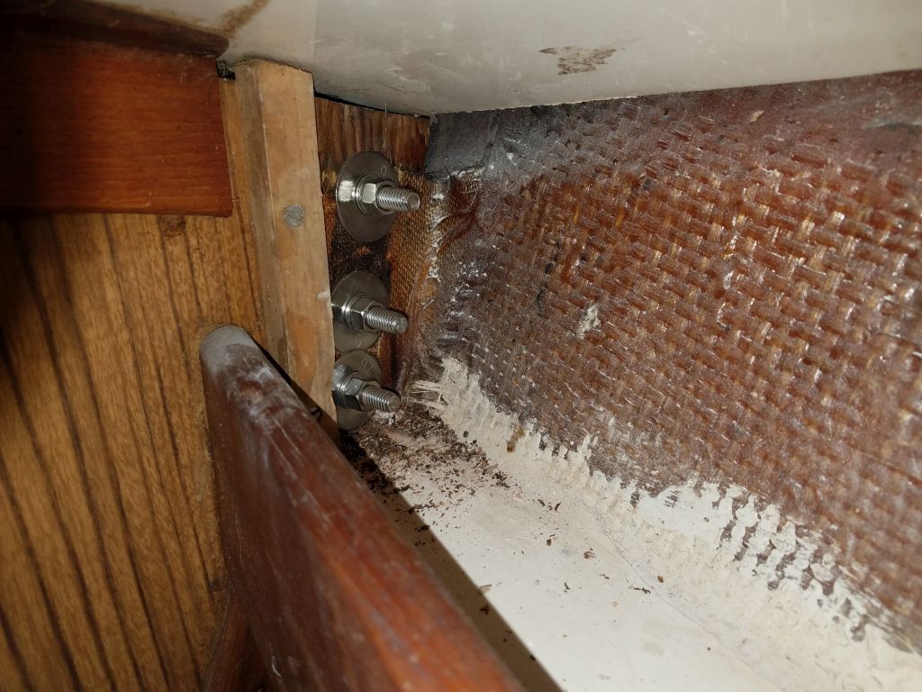
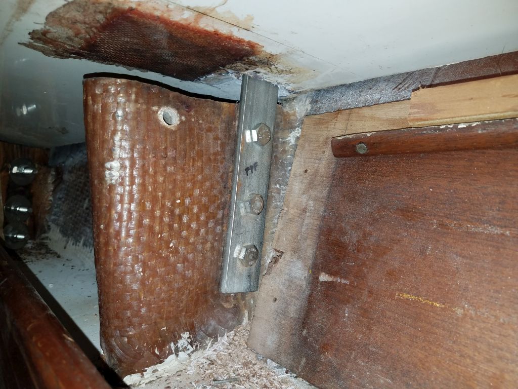
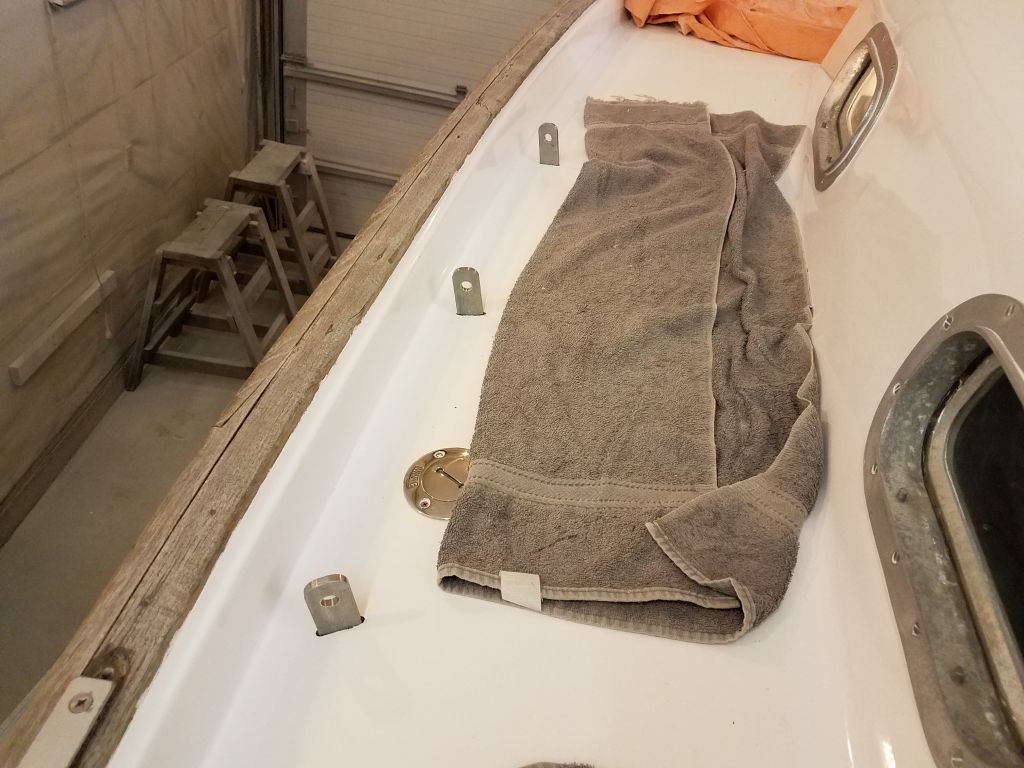
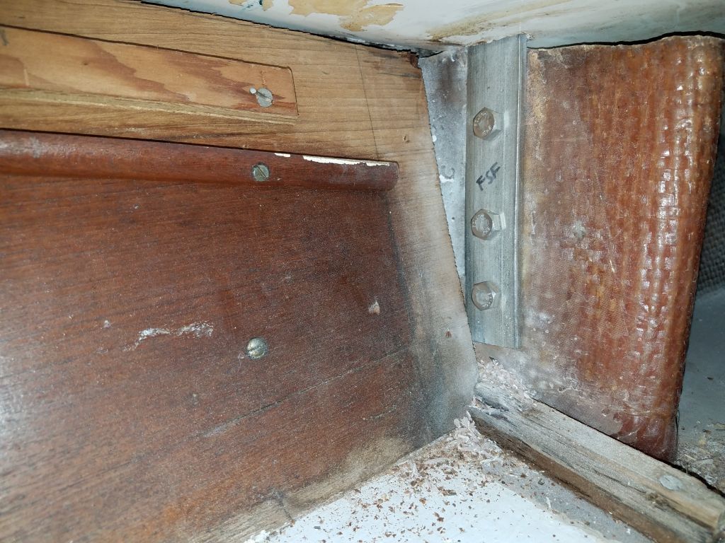
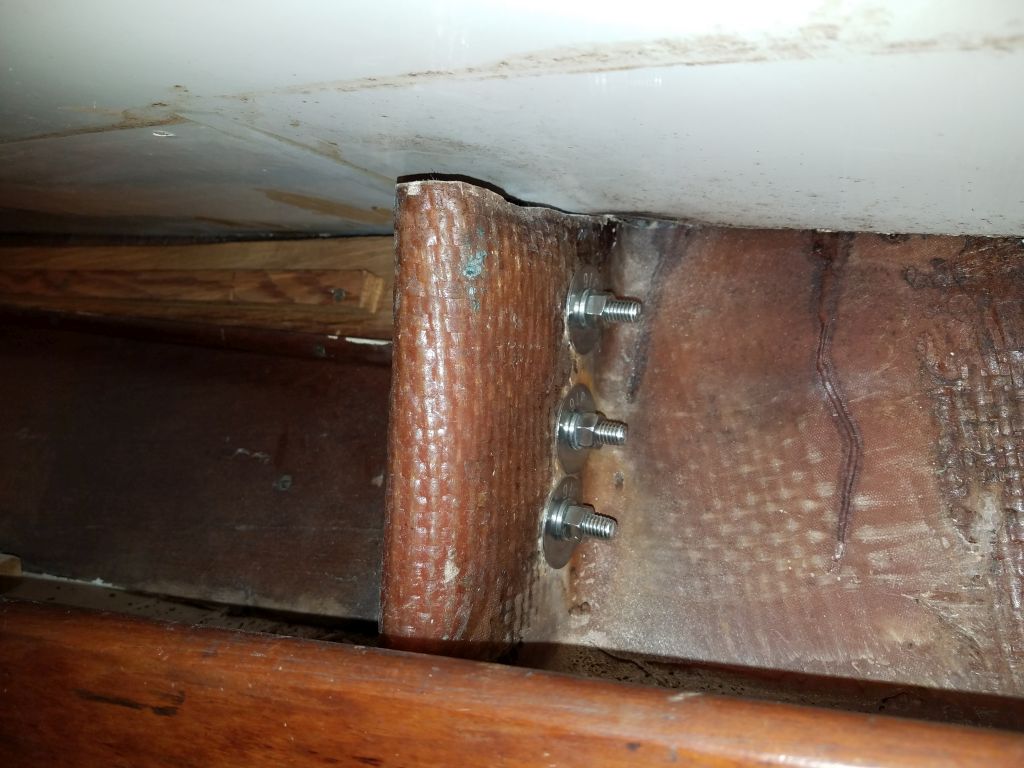
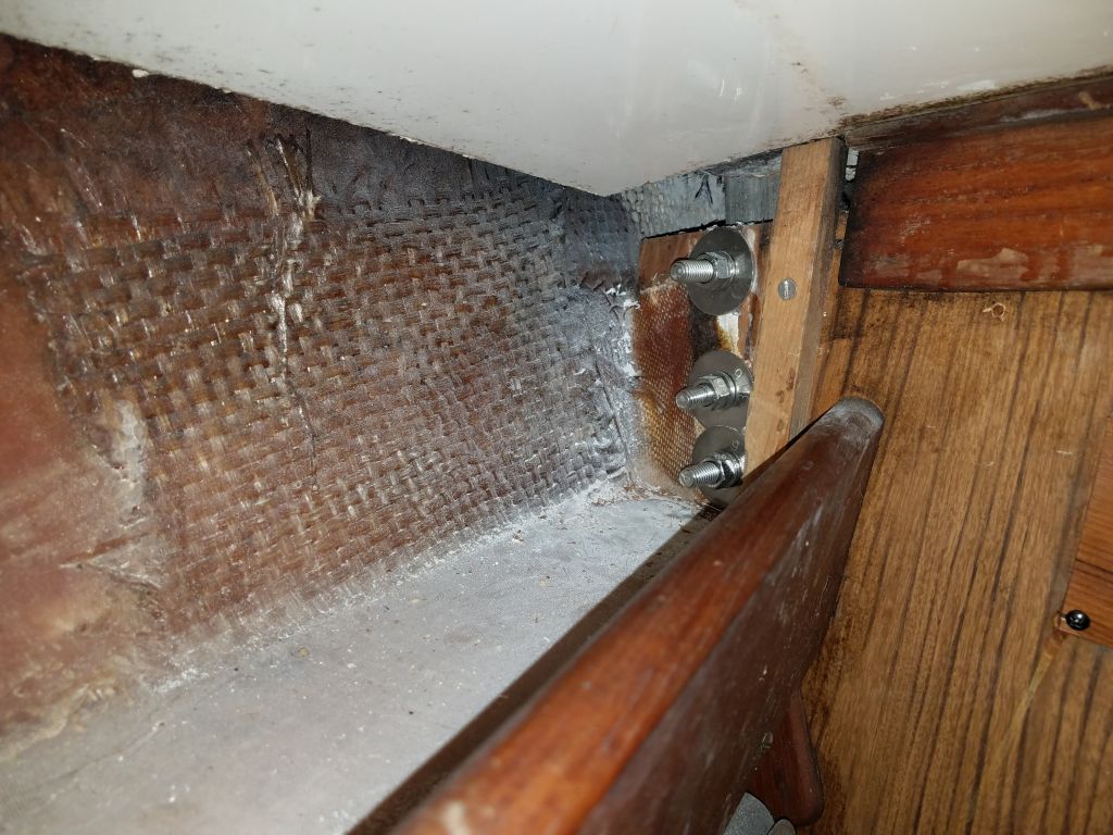
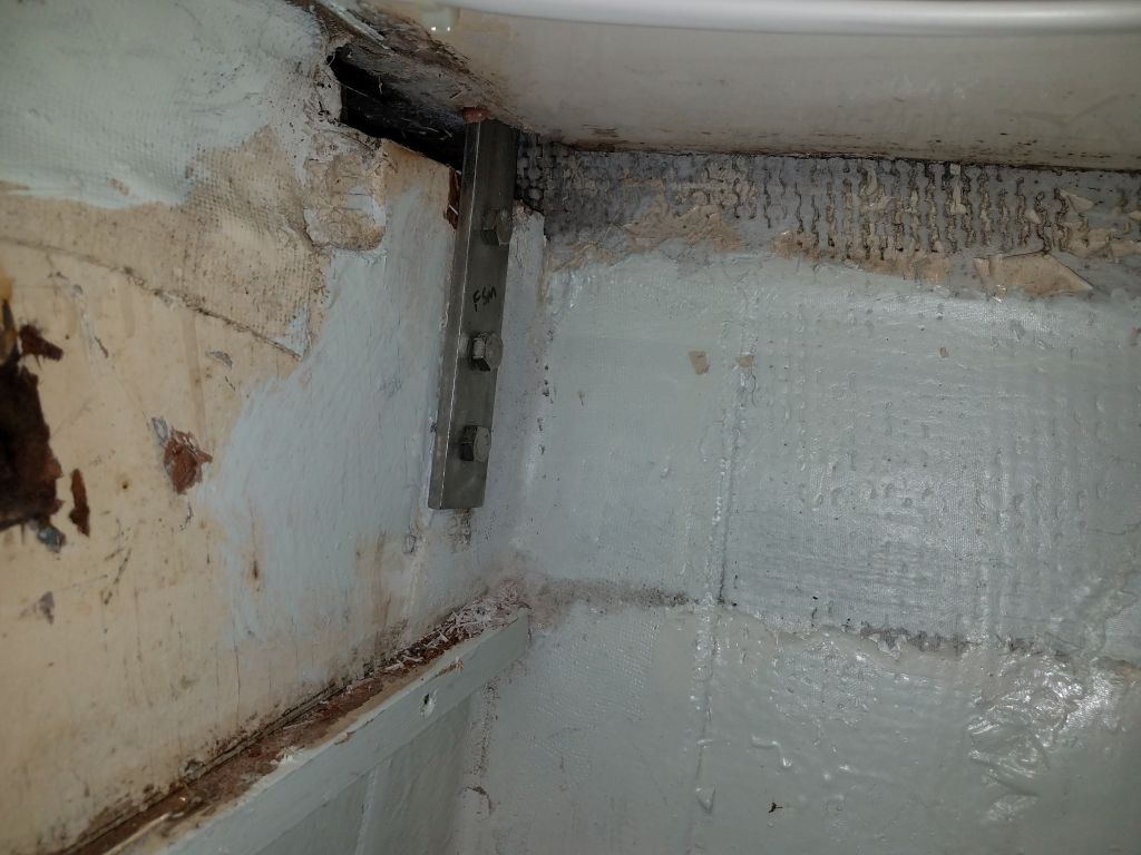
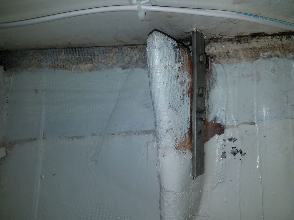
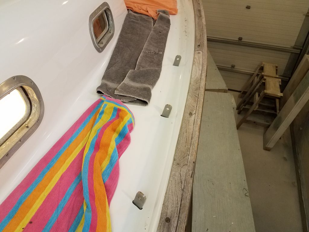
Once my new, longer bolts arrived for the chainplates, I got to work on the final installation of the remaining nine chainplates, beginning with the port after three, which serviced the mizzen stays and mainmast backstay. I’d install deck cover plates and sealant for all the new chainplates later.
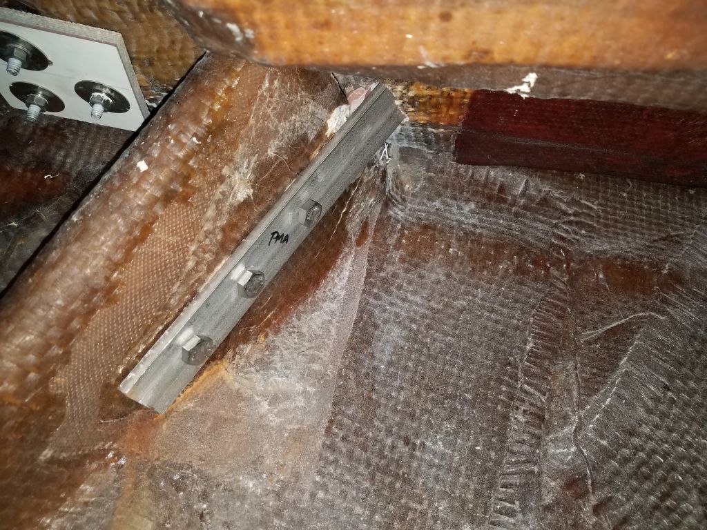
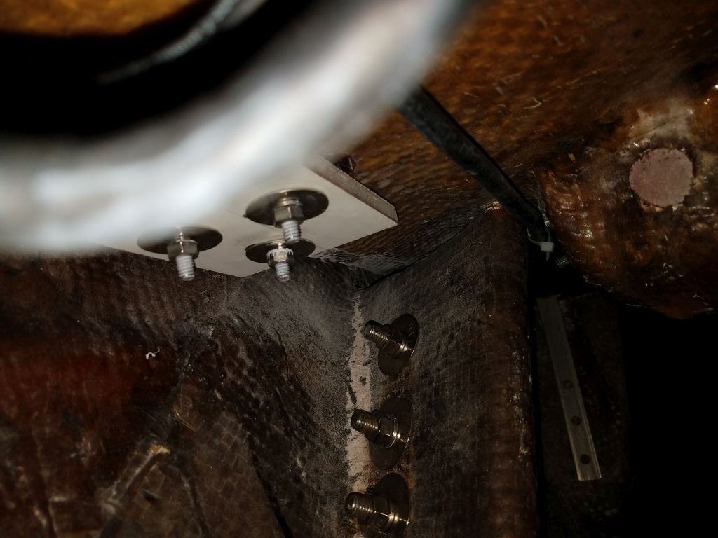
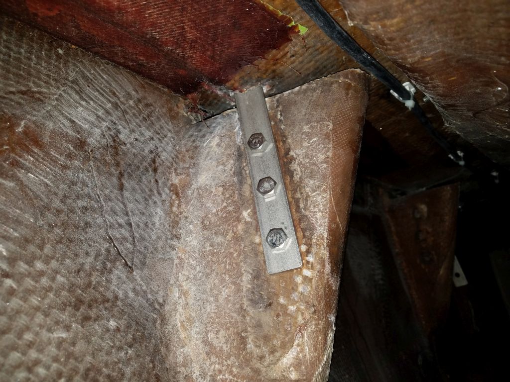

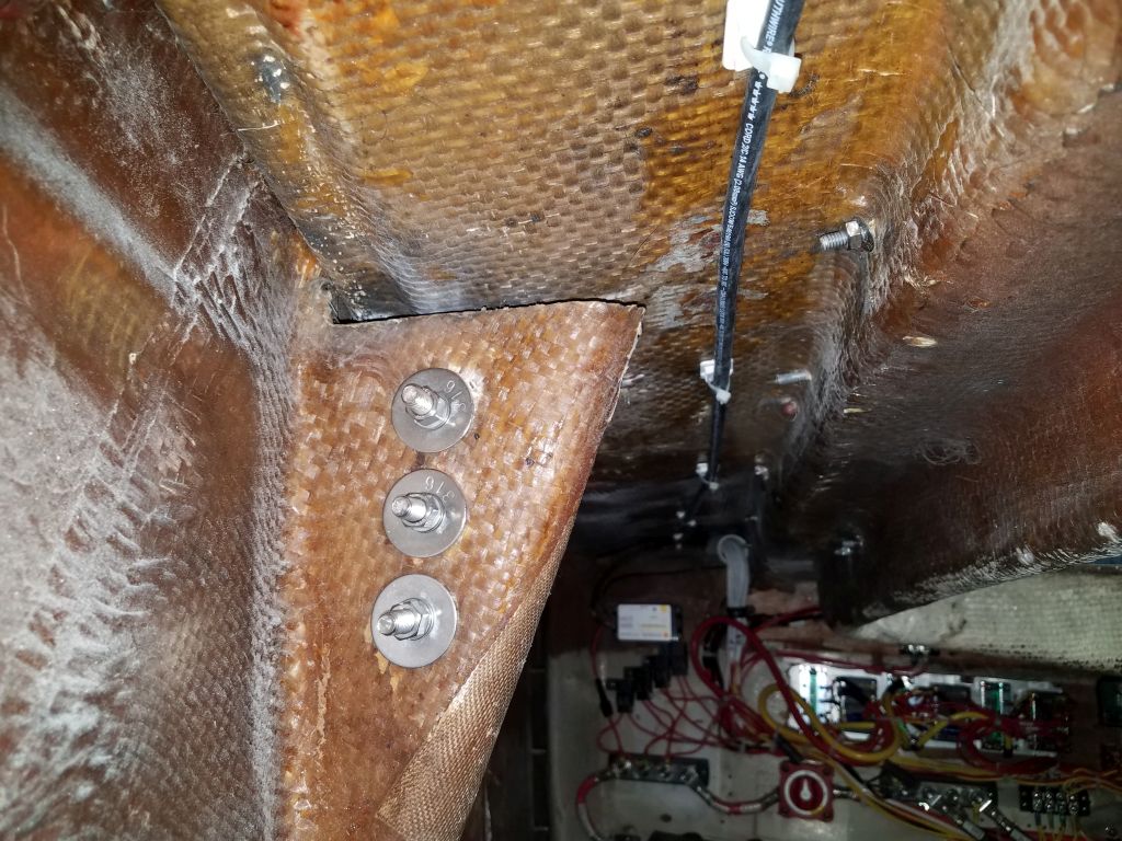
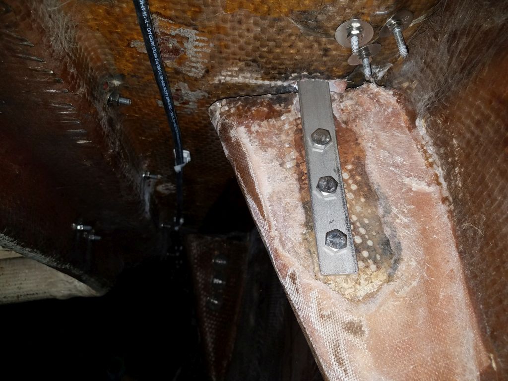
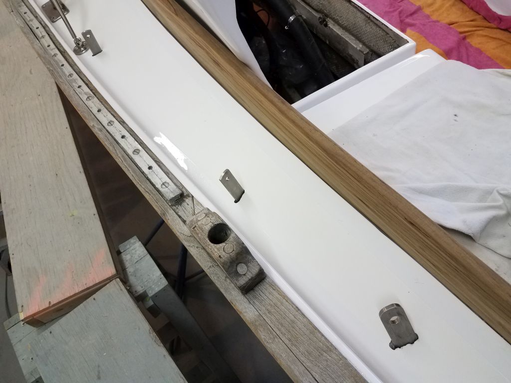
I finished up the day with the six chainplates for the mainmast. Access to the knees for securing many of these chainplates, particularly on the port side, was tight and at the limits of practical workability, so this chore took time, but by quitting time all the new chainplates were in place and bolted securely with the new bolts and large washers.


Total time billed on this job today: 7.5 hours
0600 Weather Observation: 30°, cloudy. Forecast for the day: Clouds, snow showers, then steadier and heavier snow overnight.