(page 108 of 168)

Dharma Rose 4

Wednesday

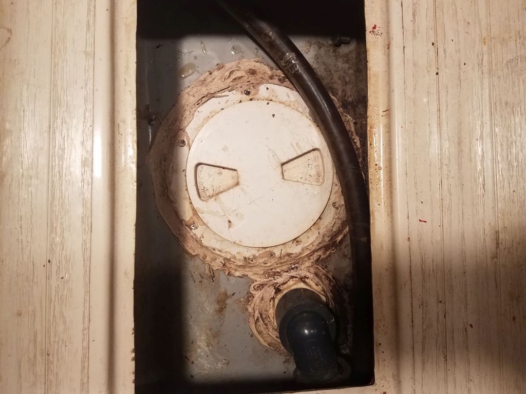
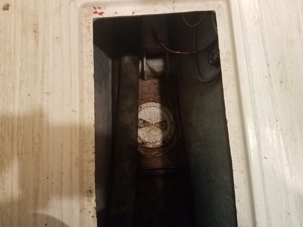
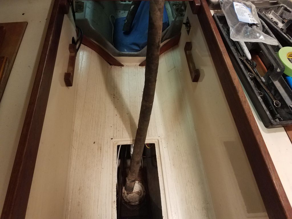
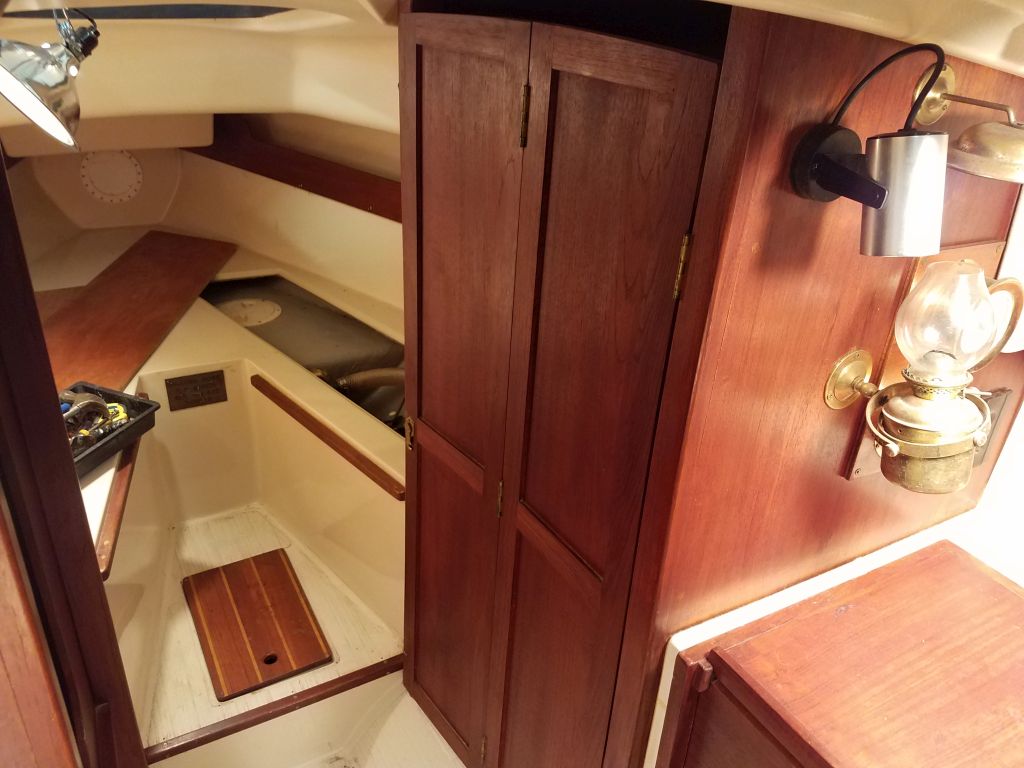
Still in removal mode, I turned to the head system.  In addition to the soon-to-come job of opening up the old waste tank in the bilge area, the owner also planned to remove all the existing hoses and equipment related to the system, with simpler waste management plans for the future.  We had a brief discussion mid-morning to consider last-minute alternatives for the system, but ultimately stayed true to the original plan.

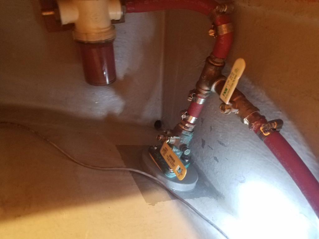
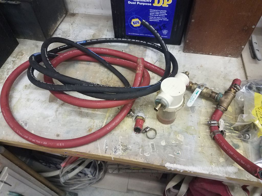
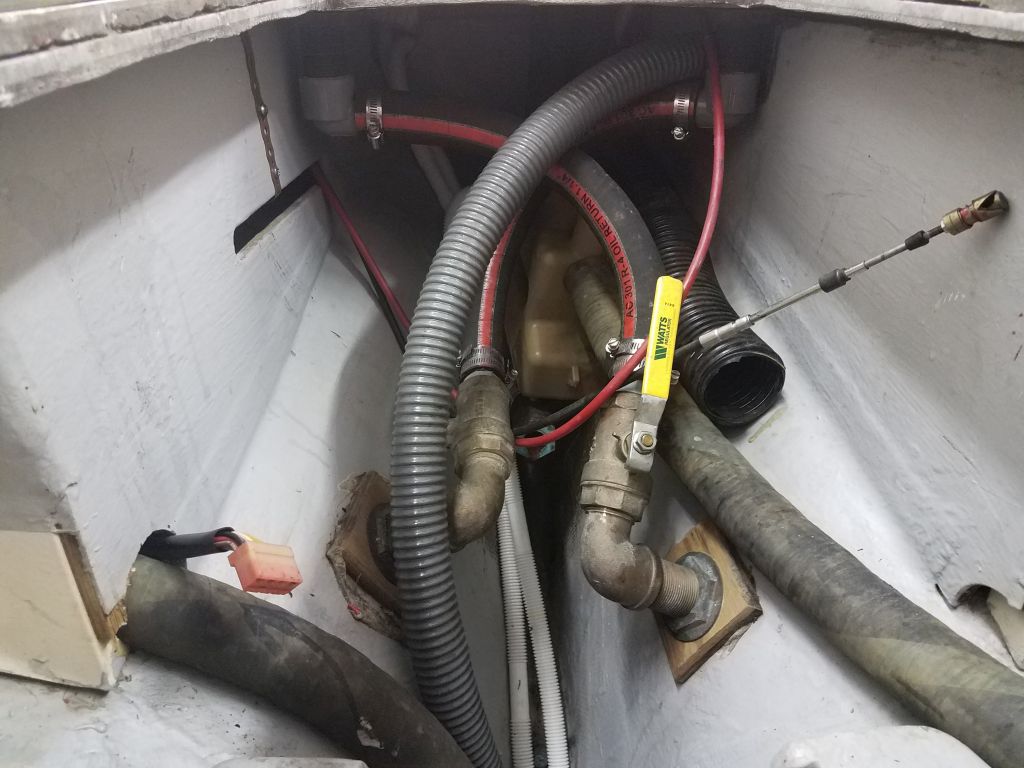
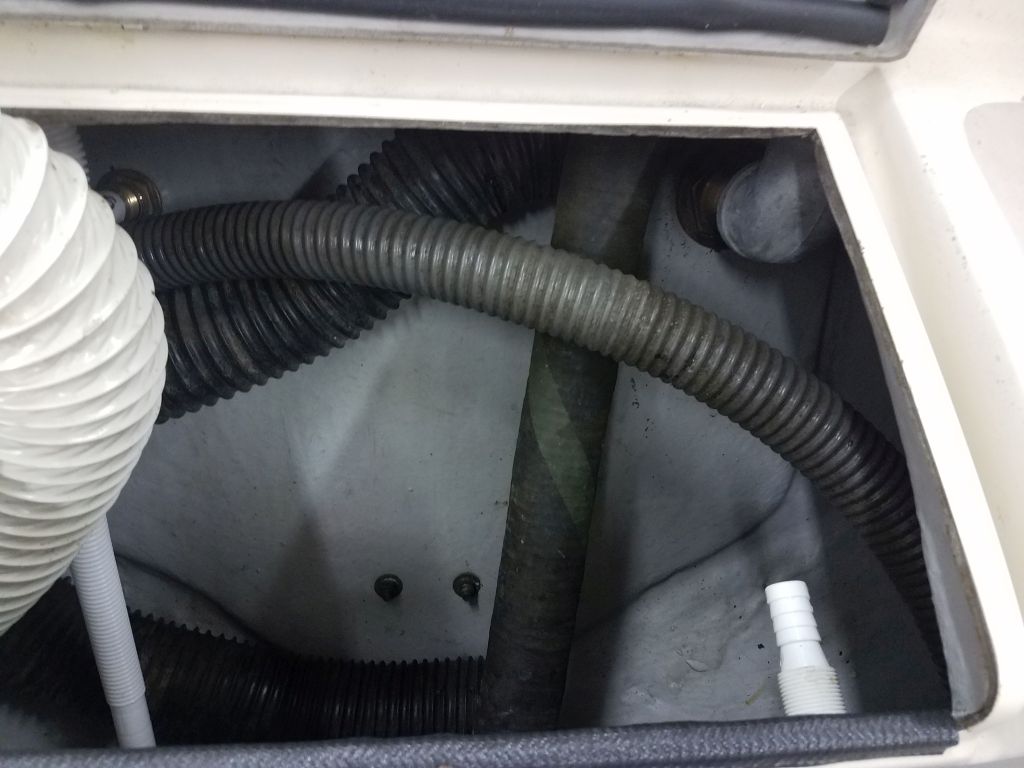
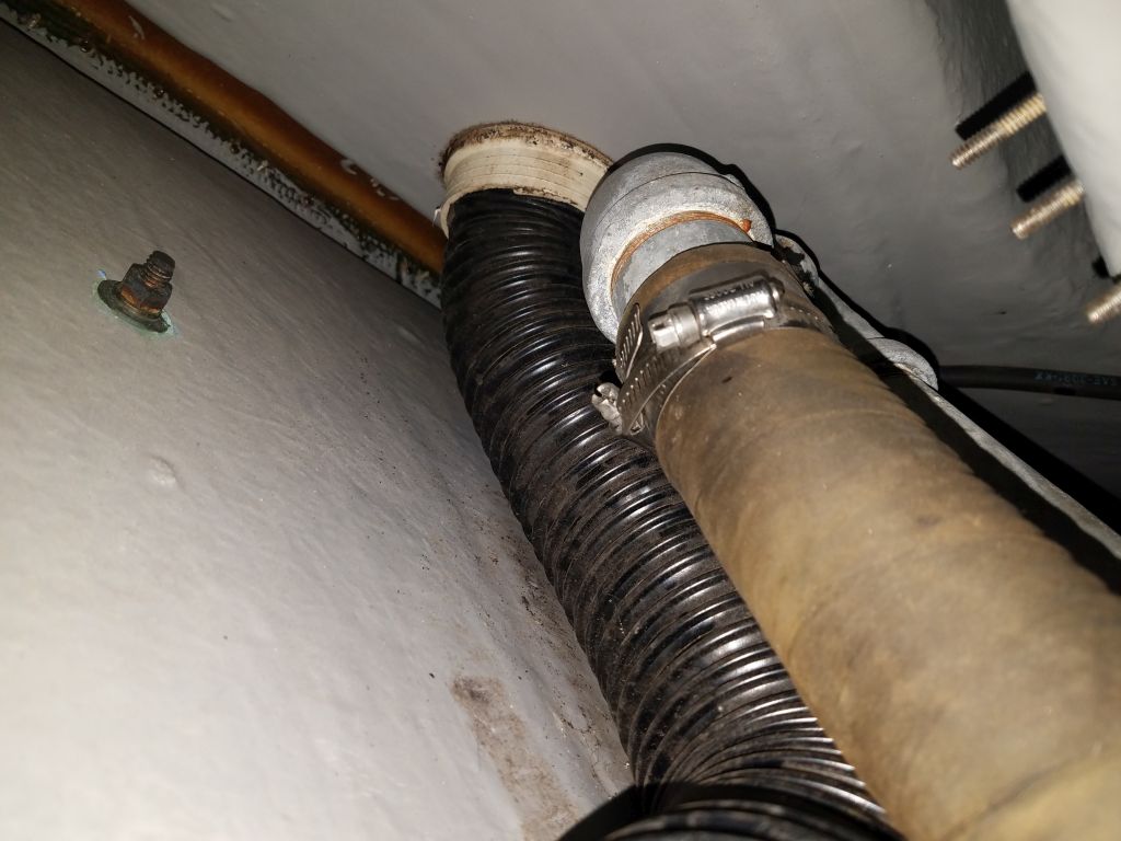
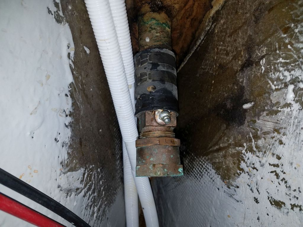
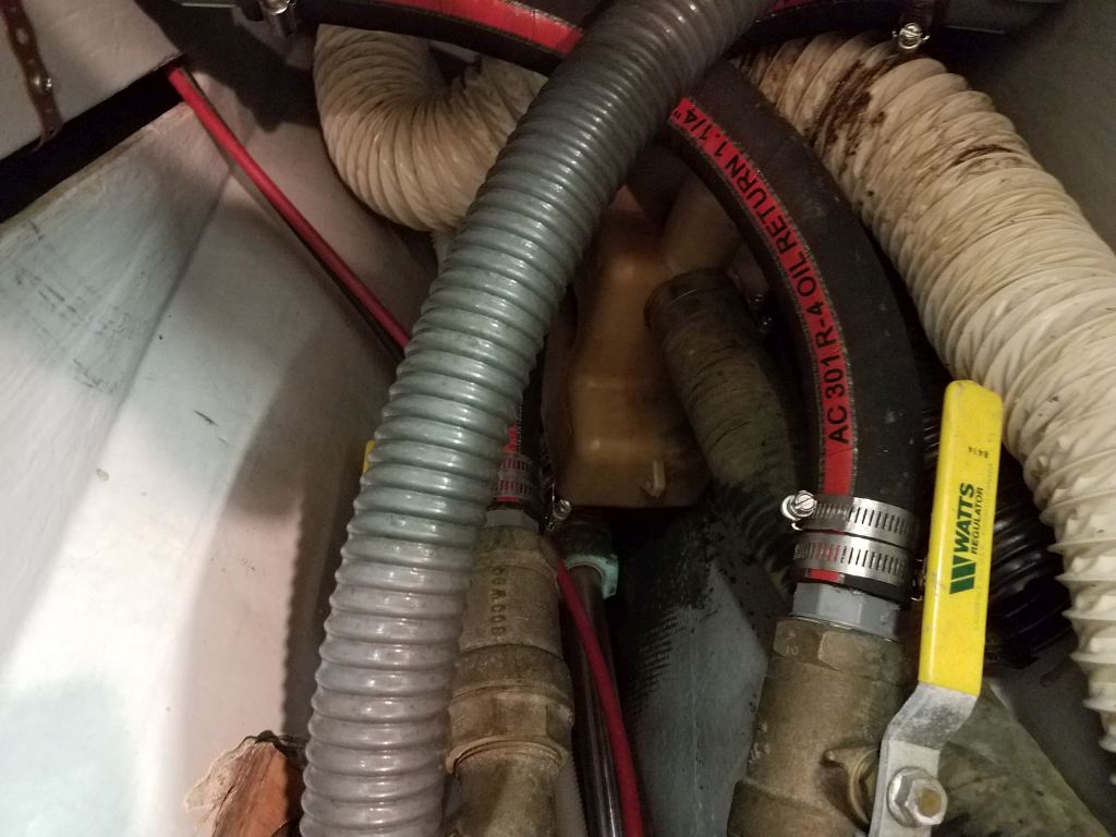
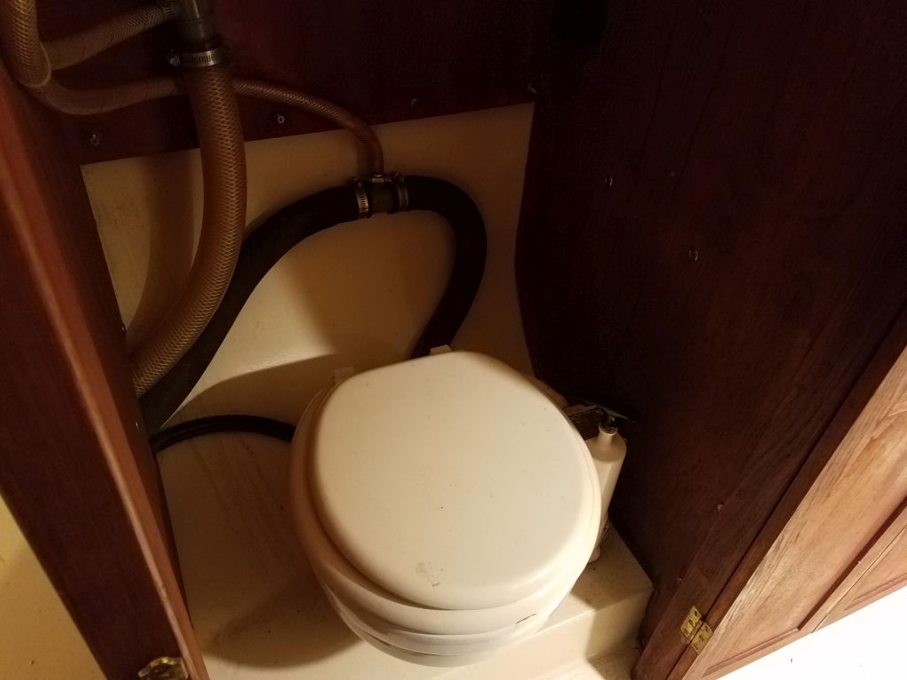
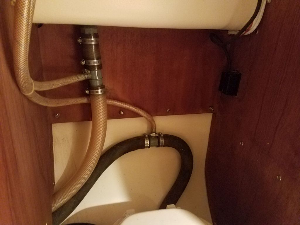
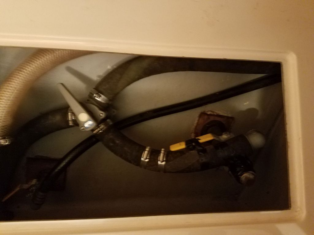
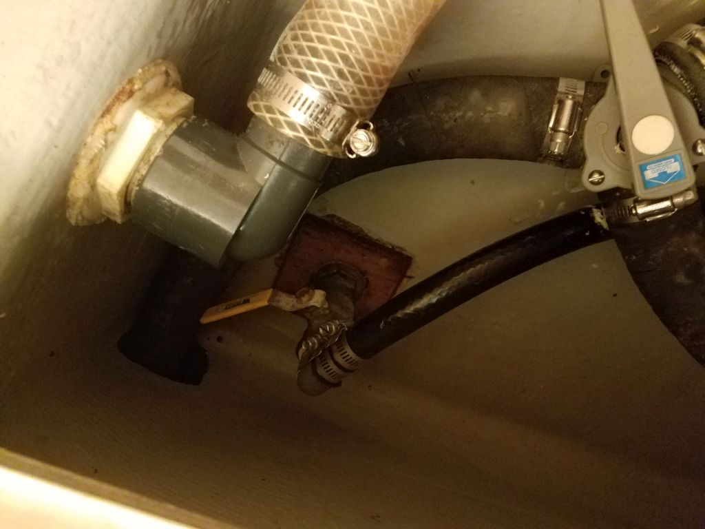
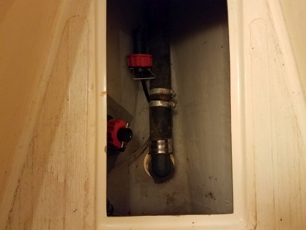
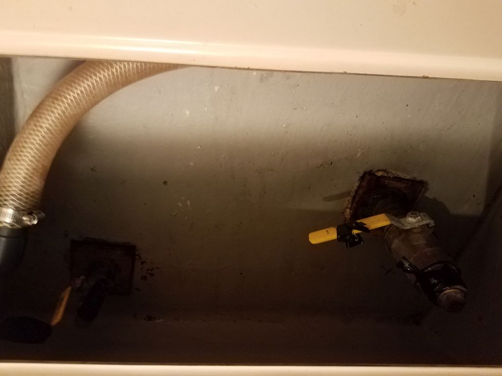
As in most older boats, the head system was pretzeled with multiple hoses, vents, a Y-valve, and just a complexity of old, cracked hoses.  The hose to the direct overboard discharge through hull had been removed and that fitting plugged at some point in the past.

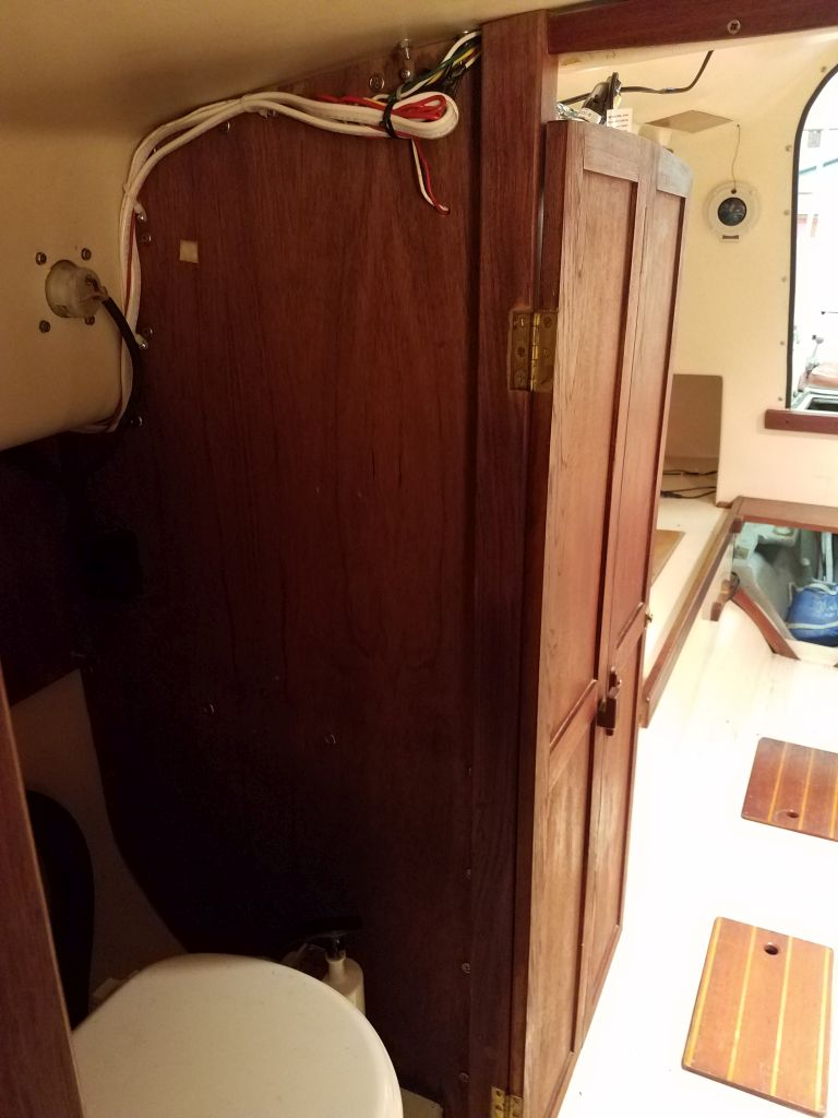
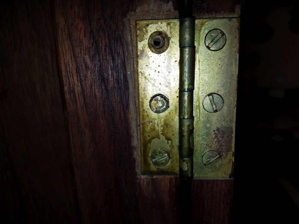
First, I removed a bifold door that closed off the head compartment, which would help open up the space for the various work ahead throughout the project.  This was straightforward except that one of the brass screws (the last one…always the last one) sheared half its head off at the slot on the first turn of the screwdriver, but once I reinstalled another screw to to the work of holding the hinge in place, I found there was enough of the head left to allow me to carefully remove the screw.

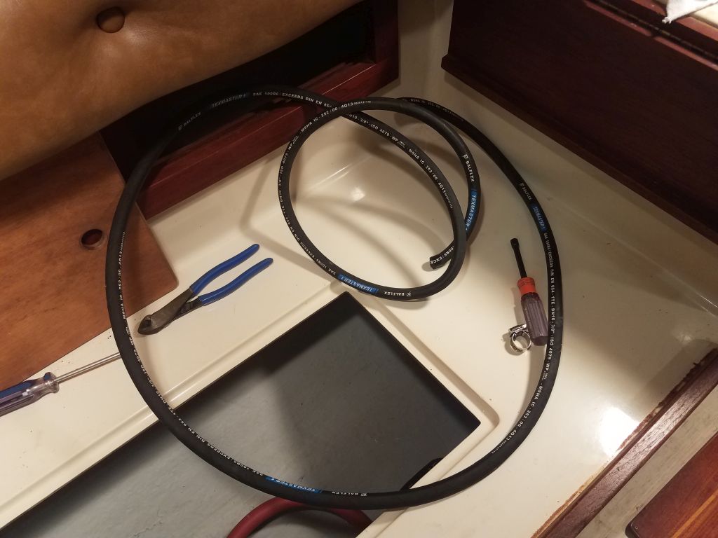
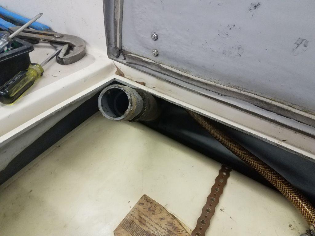
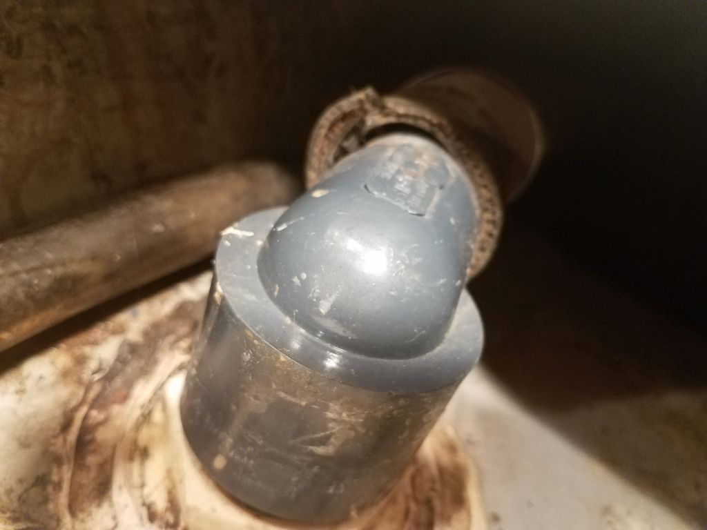
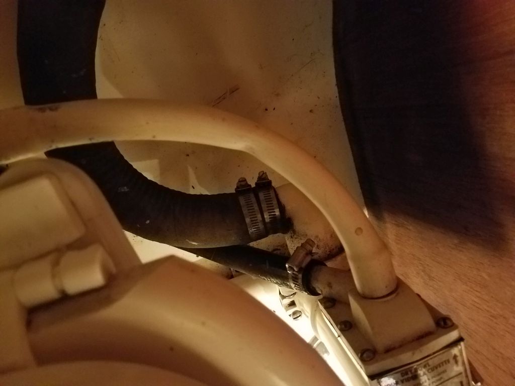
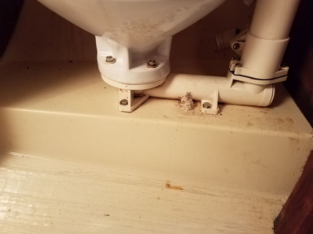
With the space opened up as much as possible, I started removing the old hoses.  Not unexpectedly, but still to my dismay, I got one gush of (ahem) water out of the hose when I removed it from the fitting at the base of the marine toilet, but fortunately this was just a leftover in one of the low points of the hose and therefore a containable amount.  The rest of the hoses, once this initial gush spewed forth, proved to be acceptably dry, and I had no issues removing the remaining hoses.

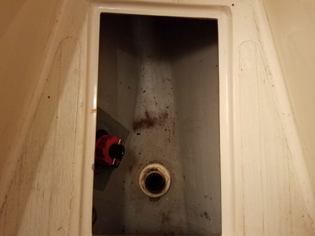
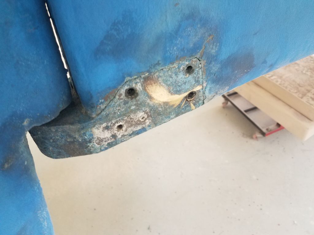
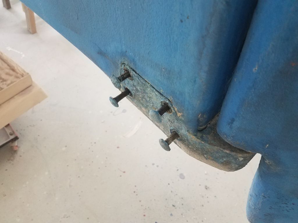
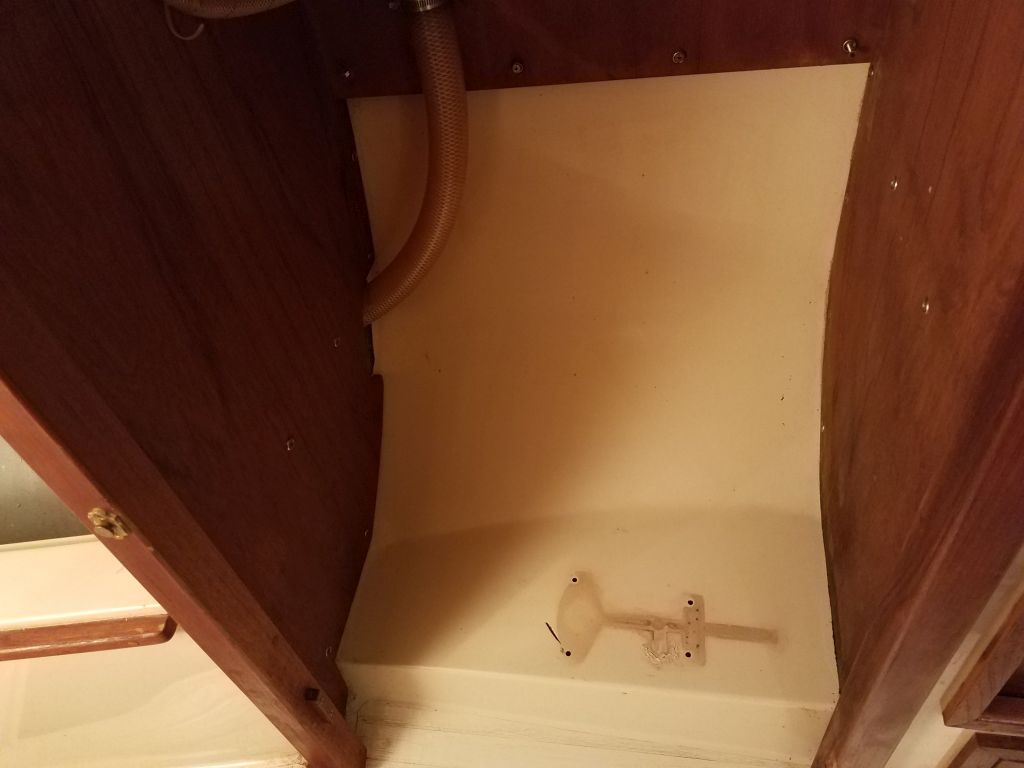
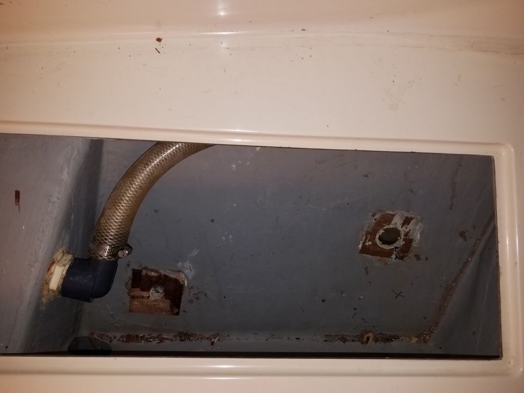
The toilet was secured to the molded fiberglass interior liner with four (please?) lag screws  stainless steel bolts installed through the molded fiberglass interior liner conveniently at some comfy work station at the factory in 1984 before the boat was assembled, but the builders thoughtlessly provided no access to the nuts for the (surely) unthinkable possibility that the head might someday require removal.  Fortunately for me, the base of the toilet was plastic, so it was an easy task to cut through the plastic just beneath the bolt heads, and then sever the bolt heads with the saw while remaining clear of the fiberglass platform itself.  I actually only needed to cut through the most accessible two, after which I manhandled the toilet away from the remaining two bolts, tearing through the plastic like so much toilet tissue.  (Later I cut off the remaining bolt heads easily).

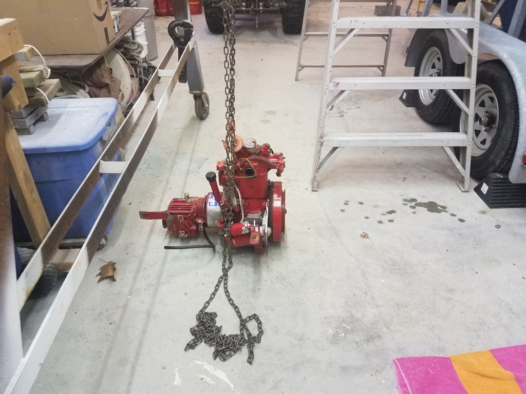
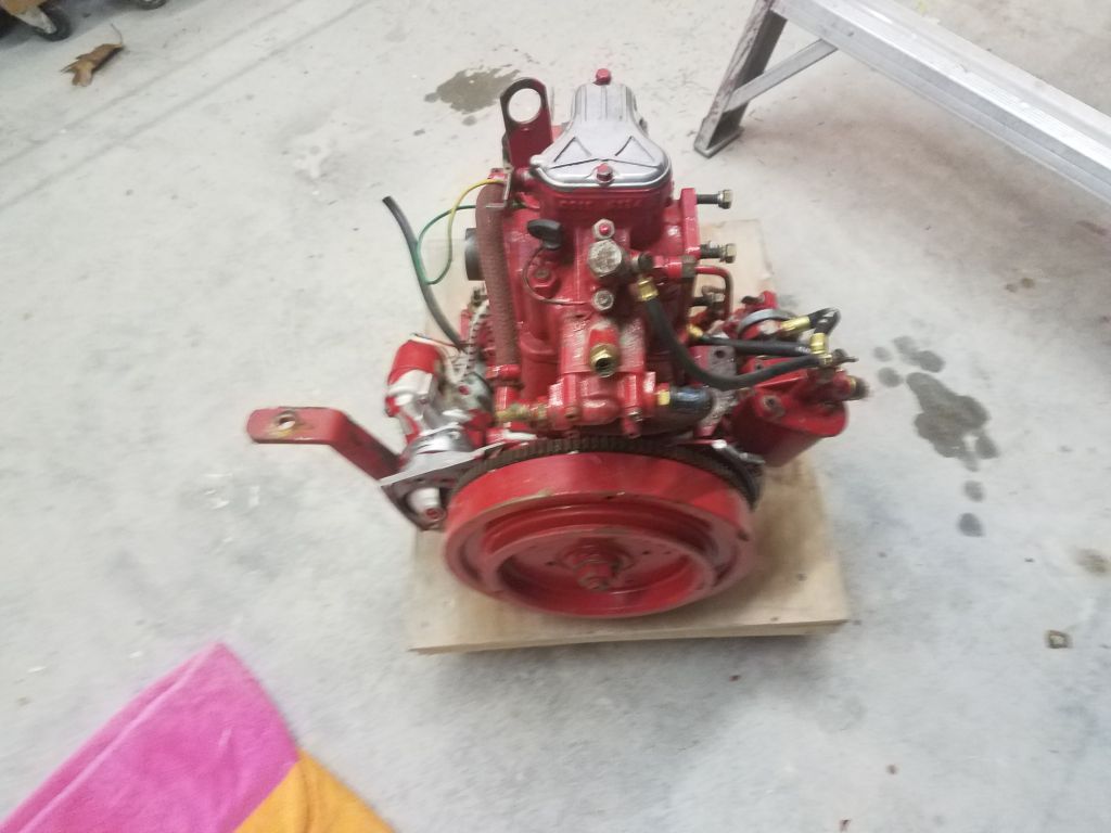
Gurgling forth a ghastly final gush, (which photo I’ll spare you, dear reader), the toilet surrendered with a whimper and I happily deposited the old toilet down on the shop floor, reunited with its long-suffering hoses.

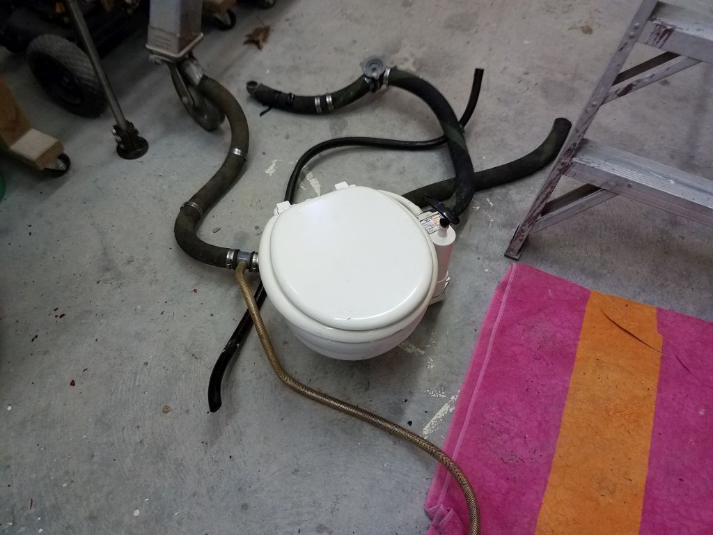
If one can’t keep a sense of humor while working with old toilet systems, all hope is lost.

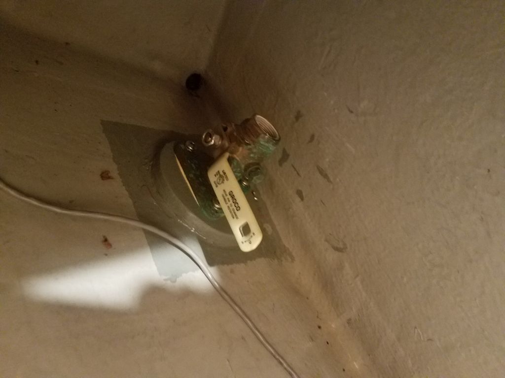
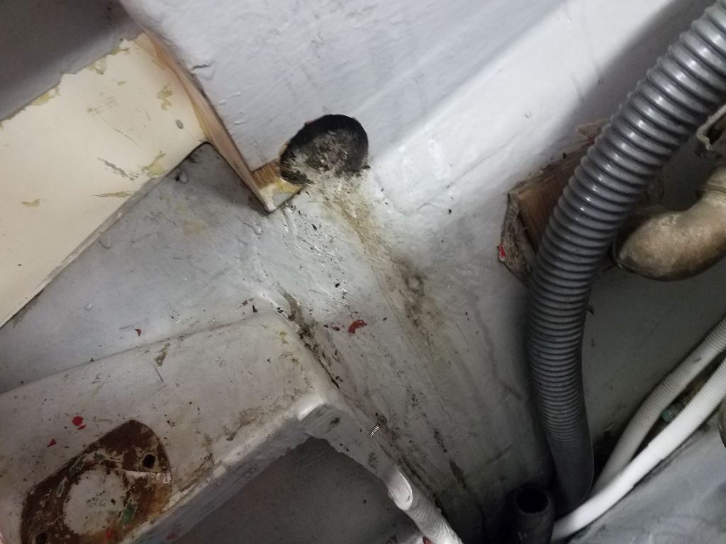
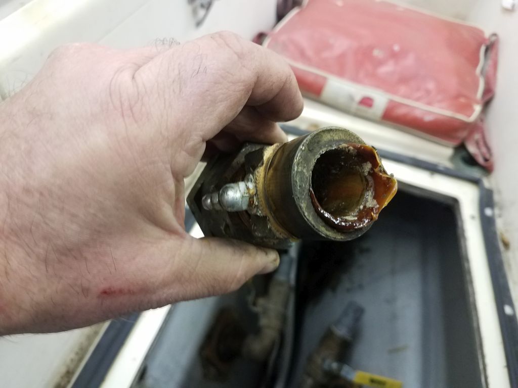
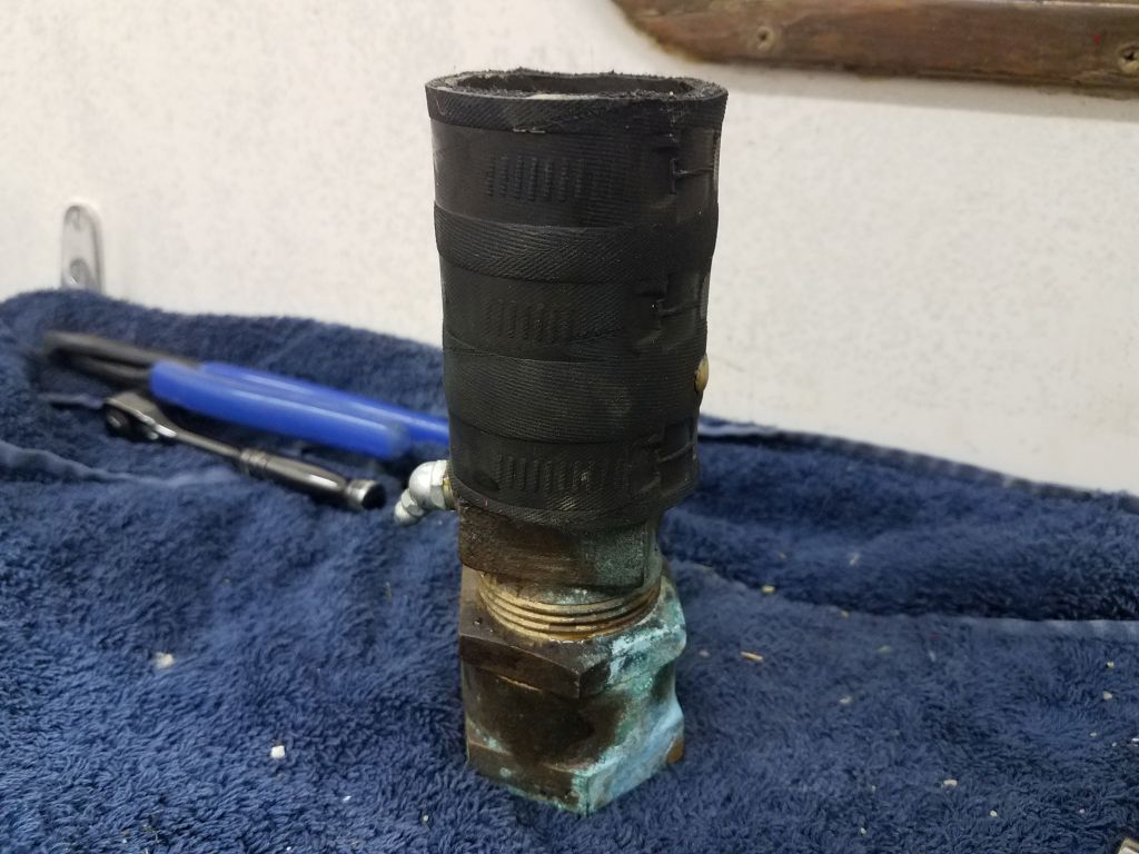
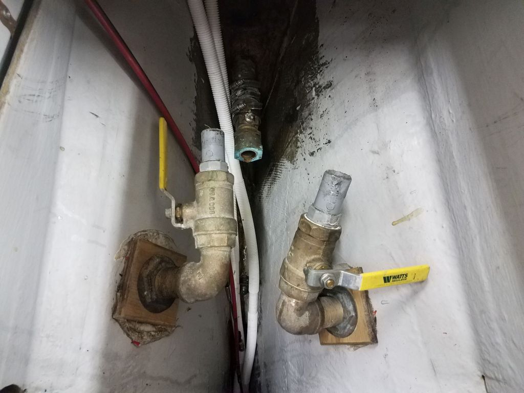
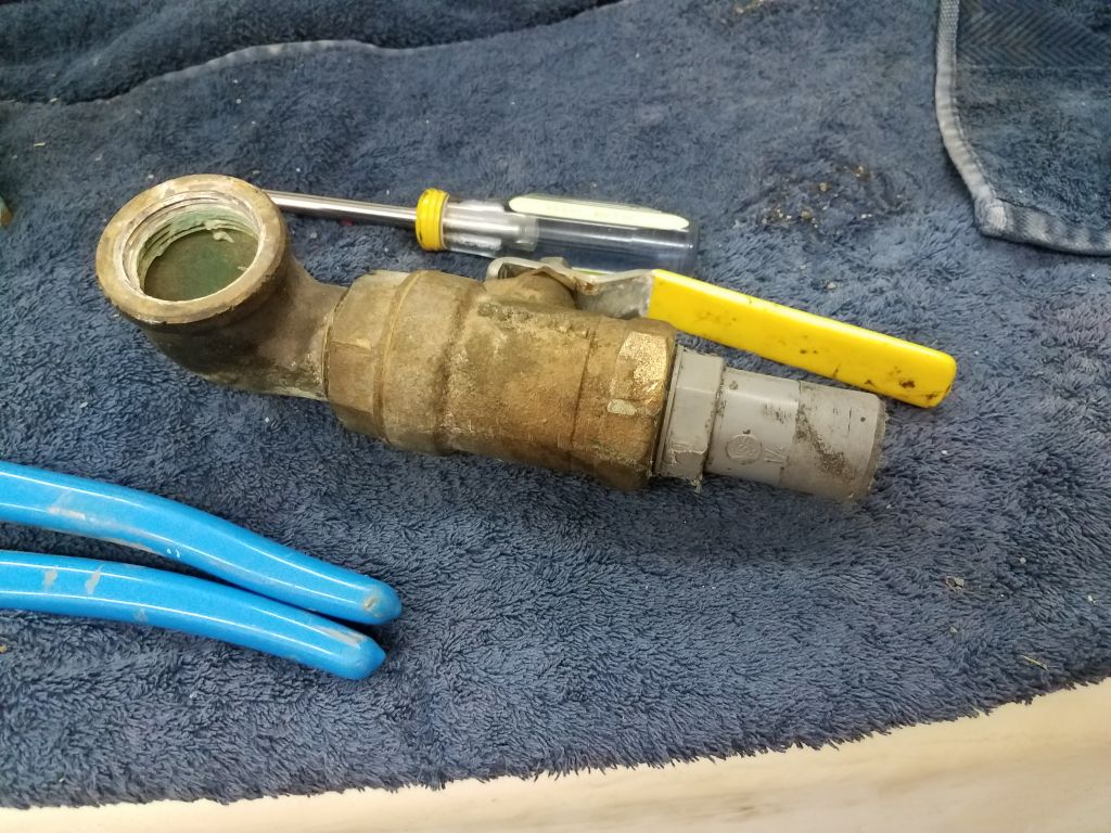
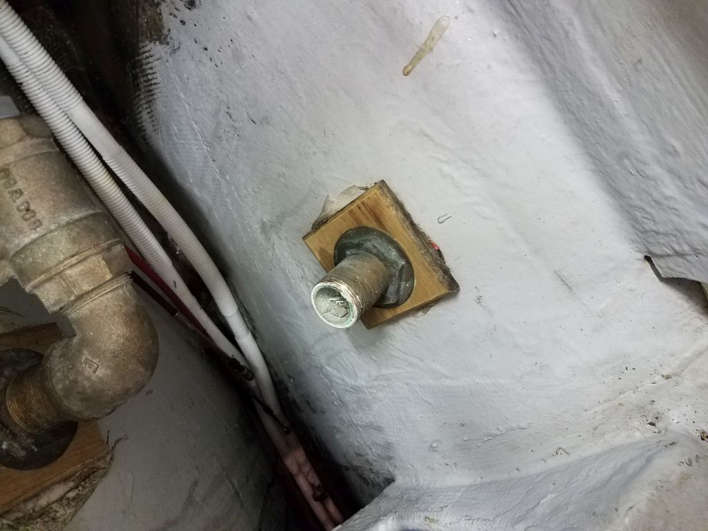
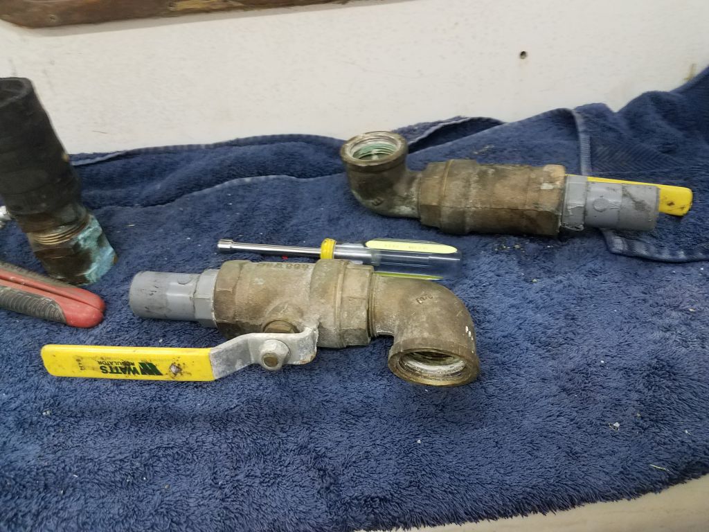
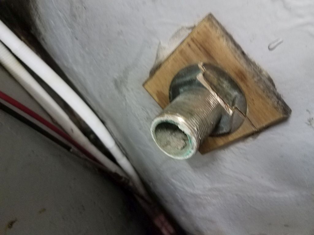
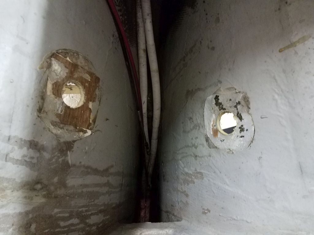
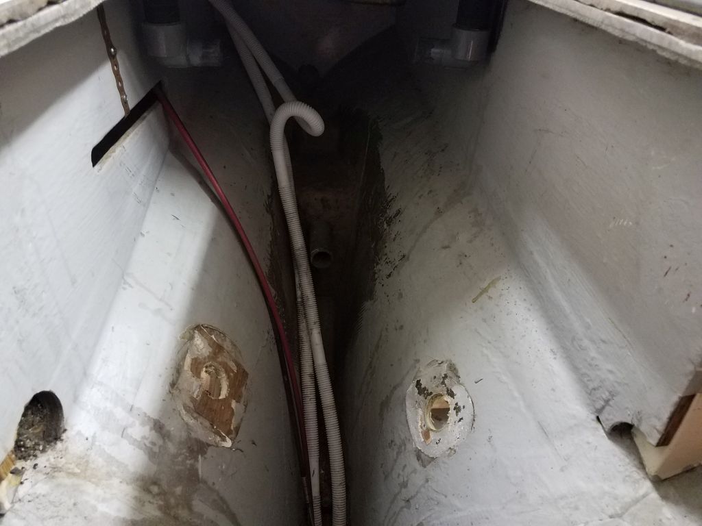
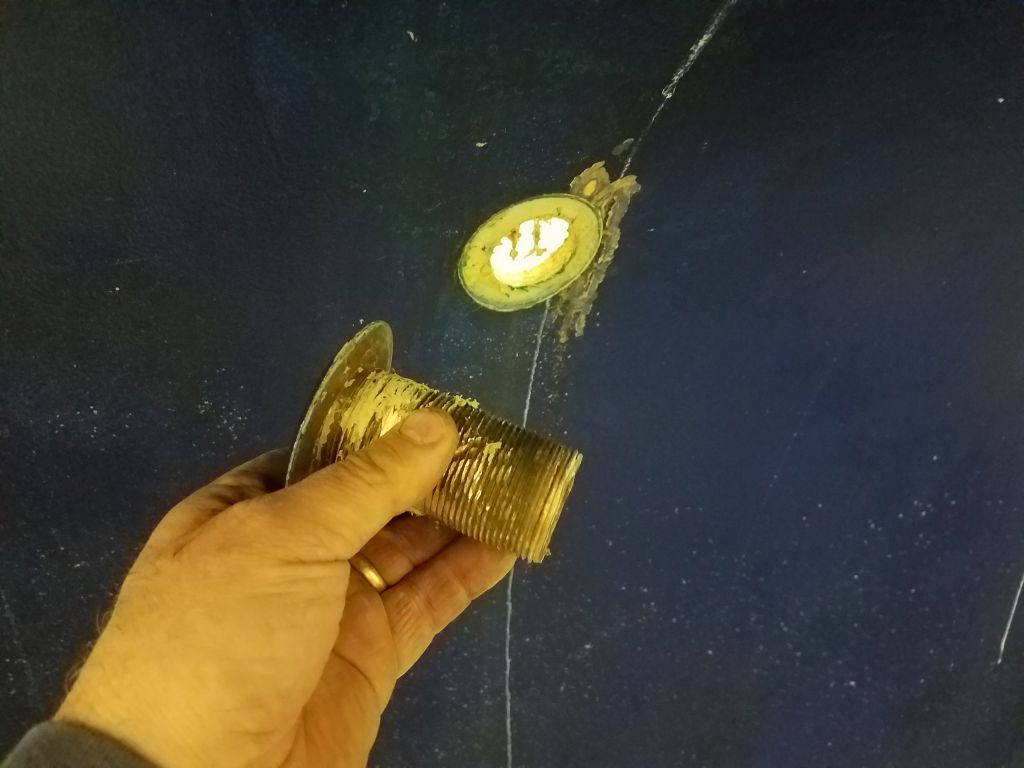
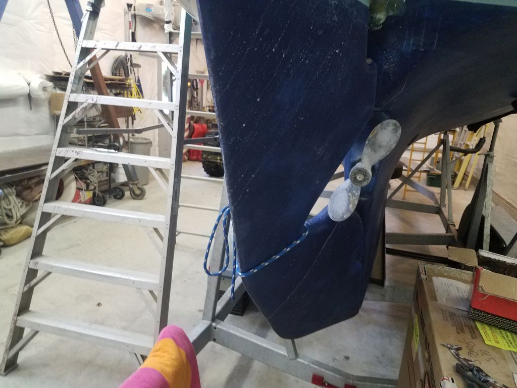
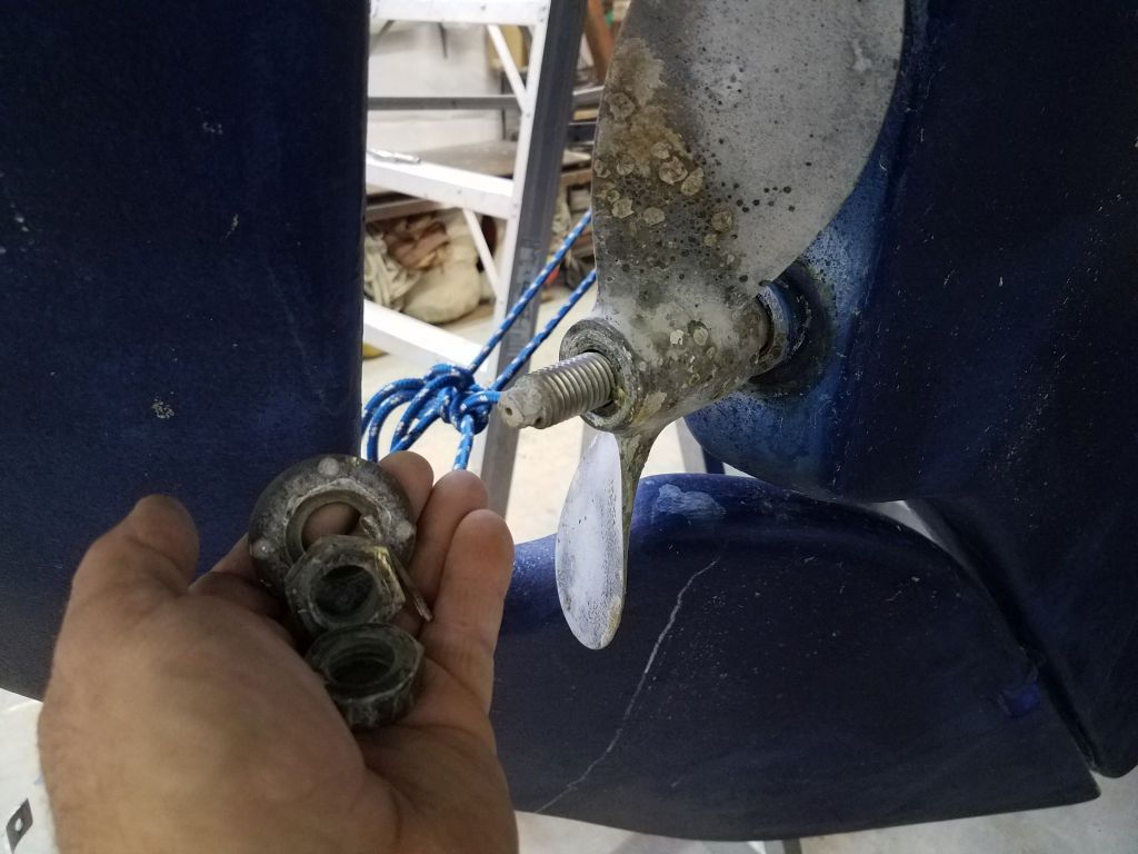
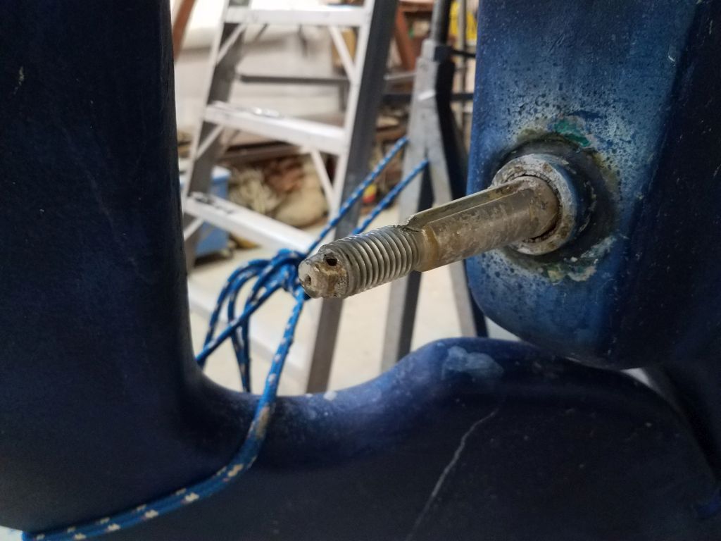
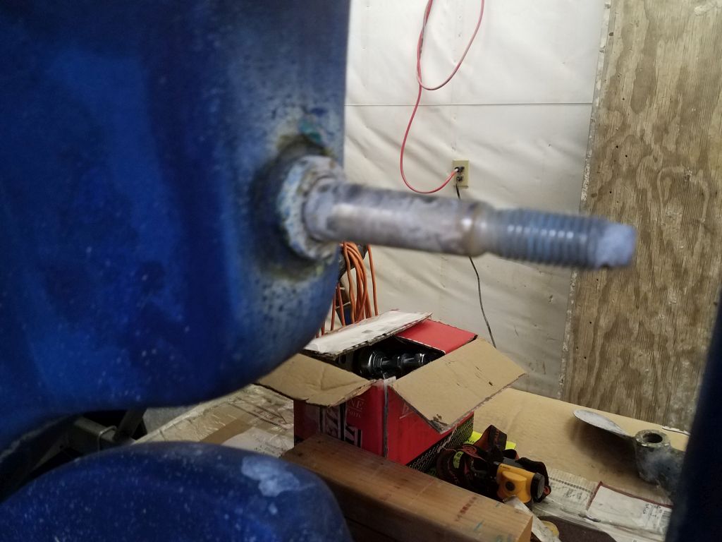
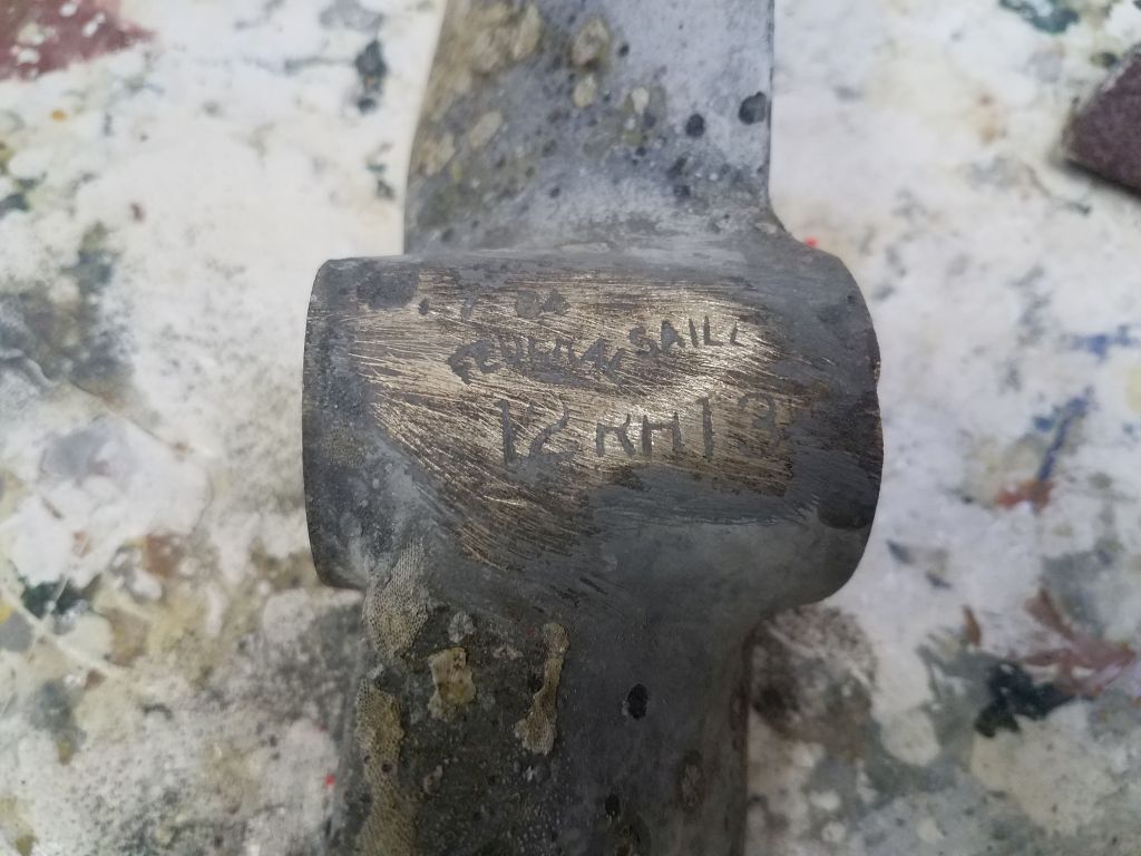
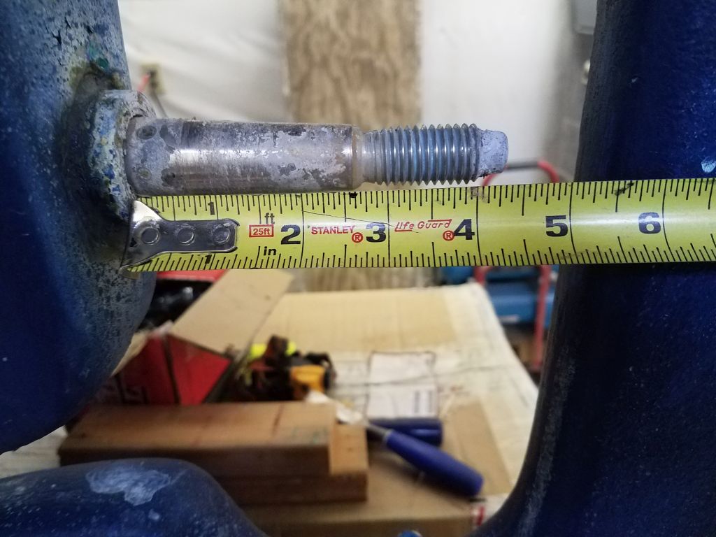
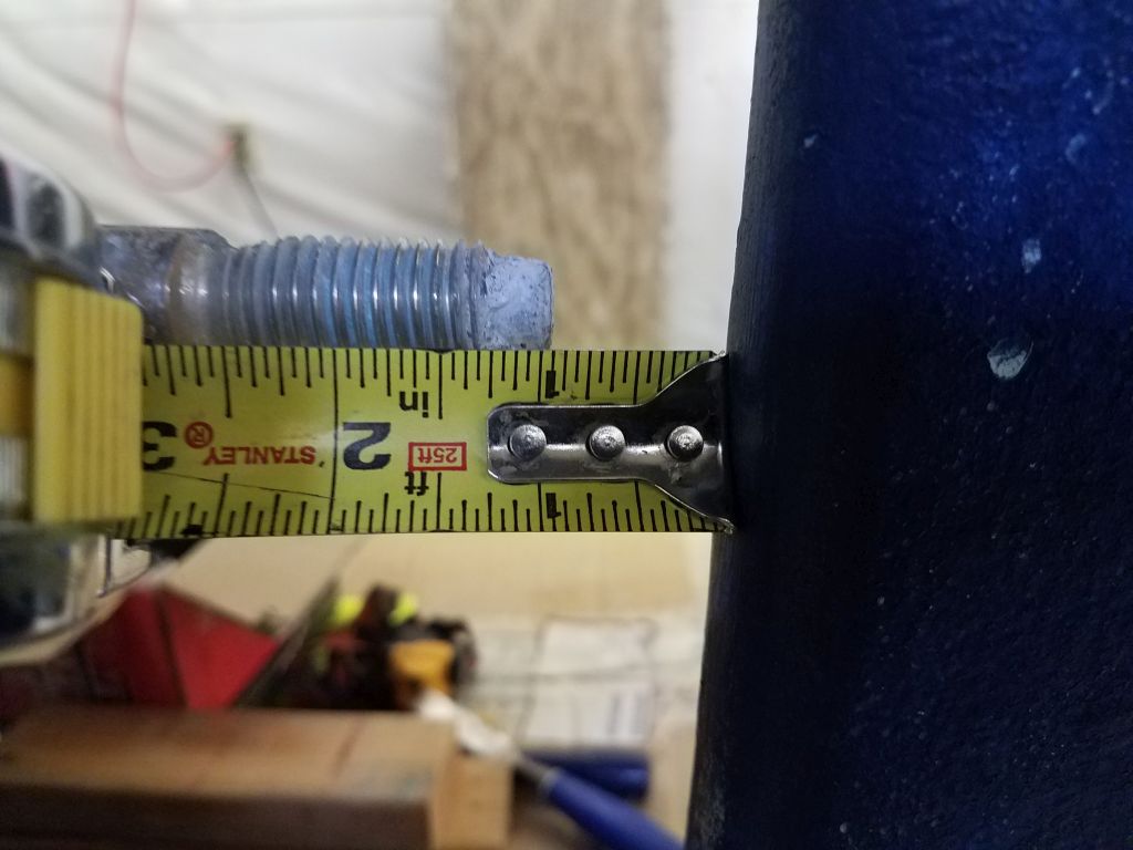
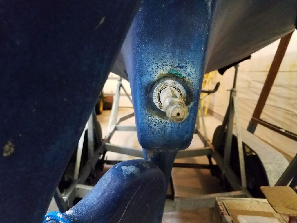
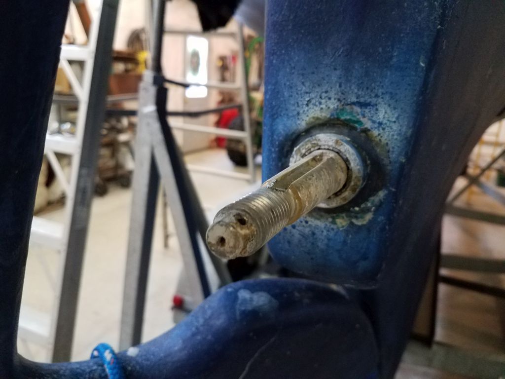
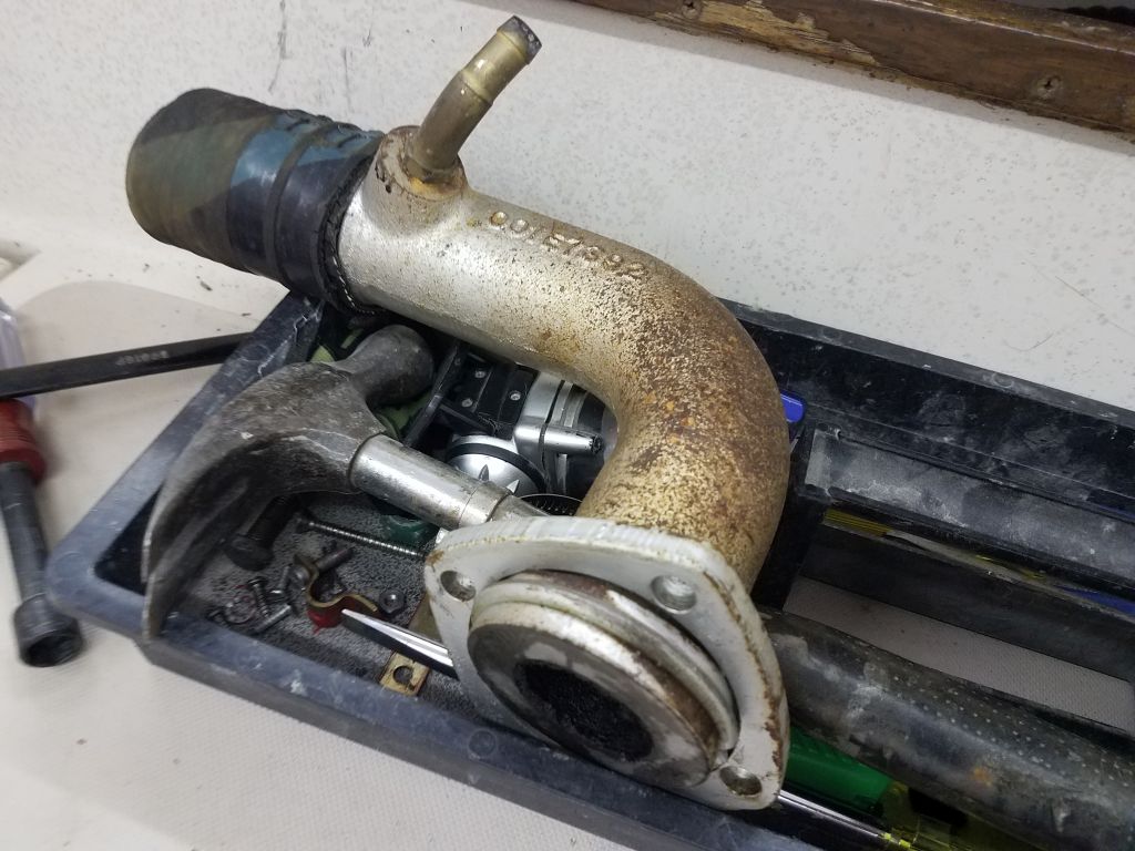
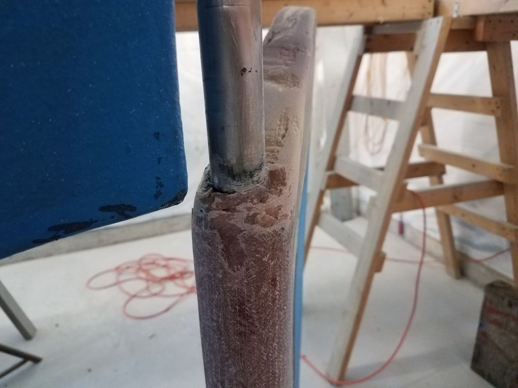
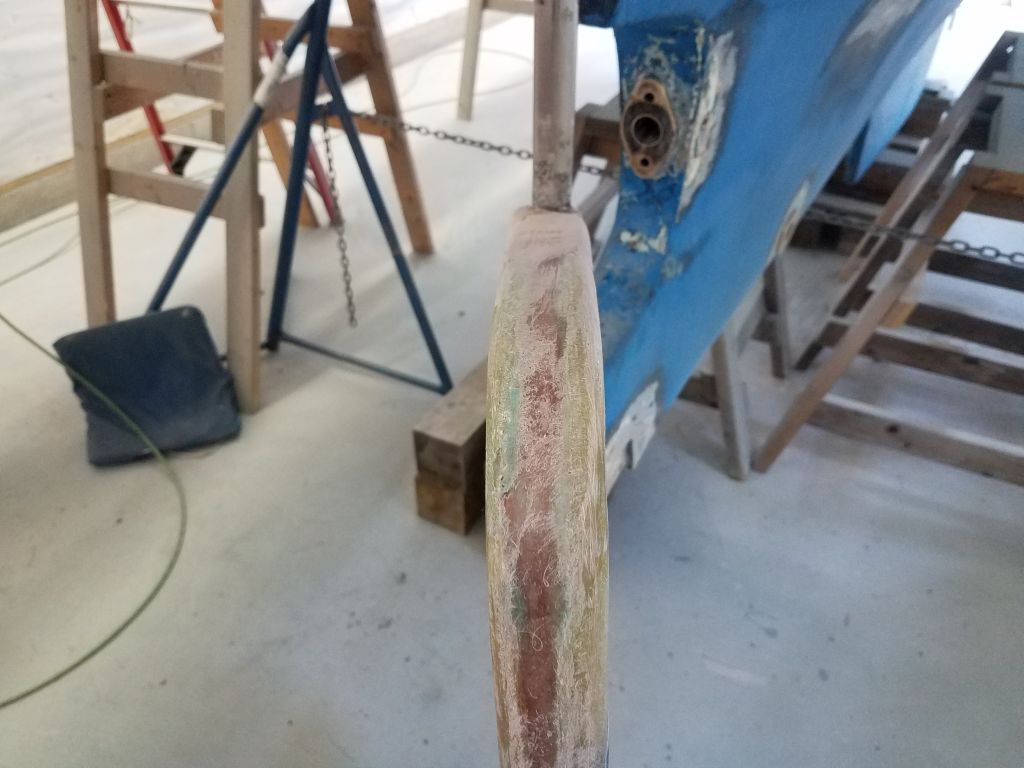
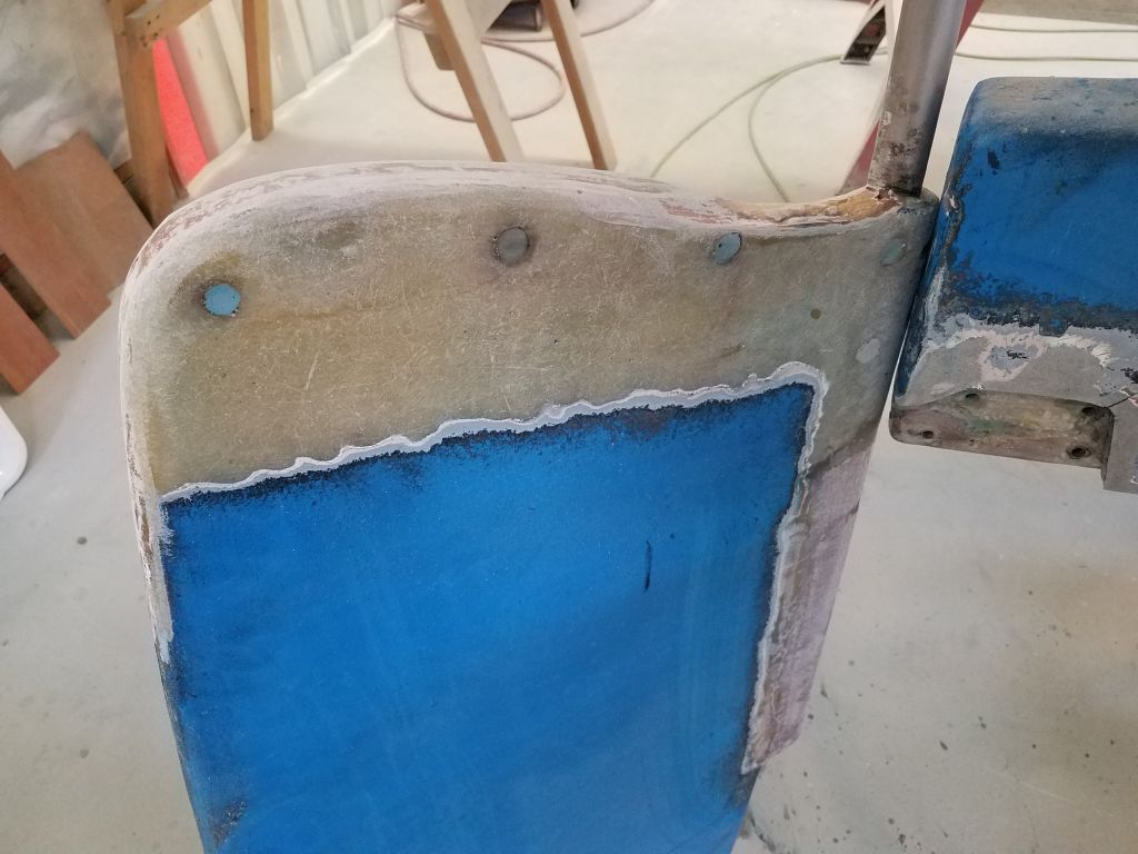
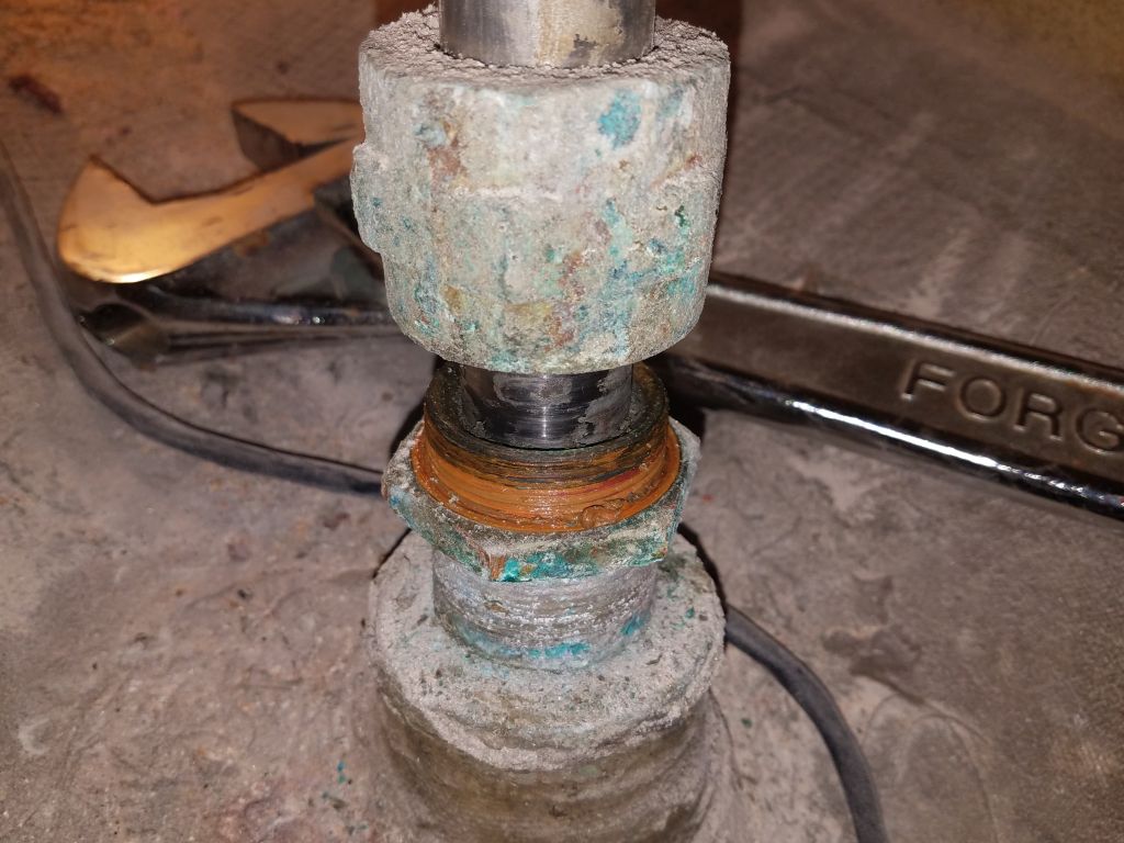
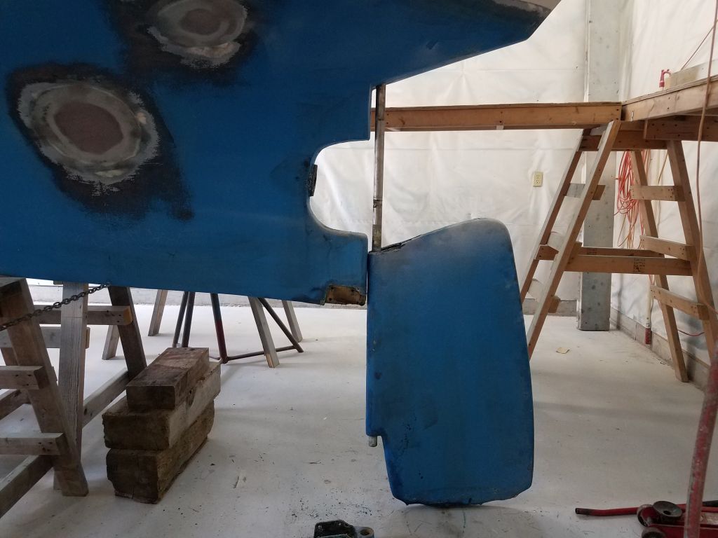
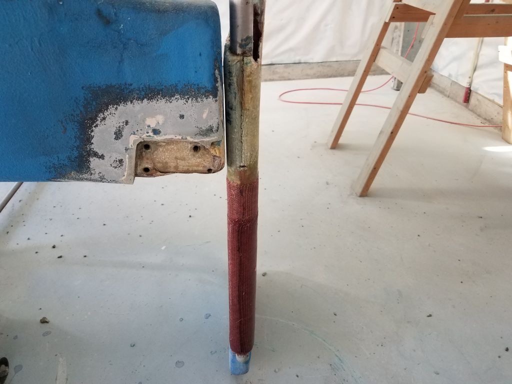
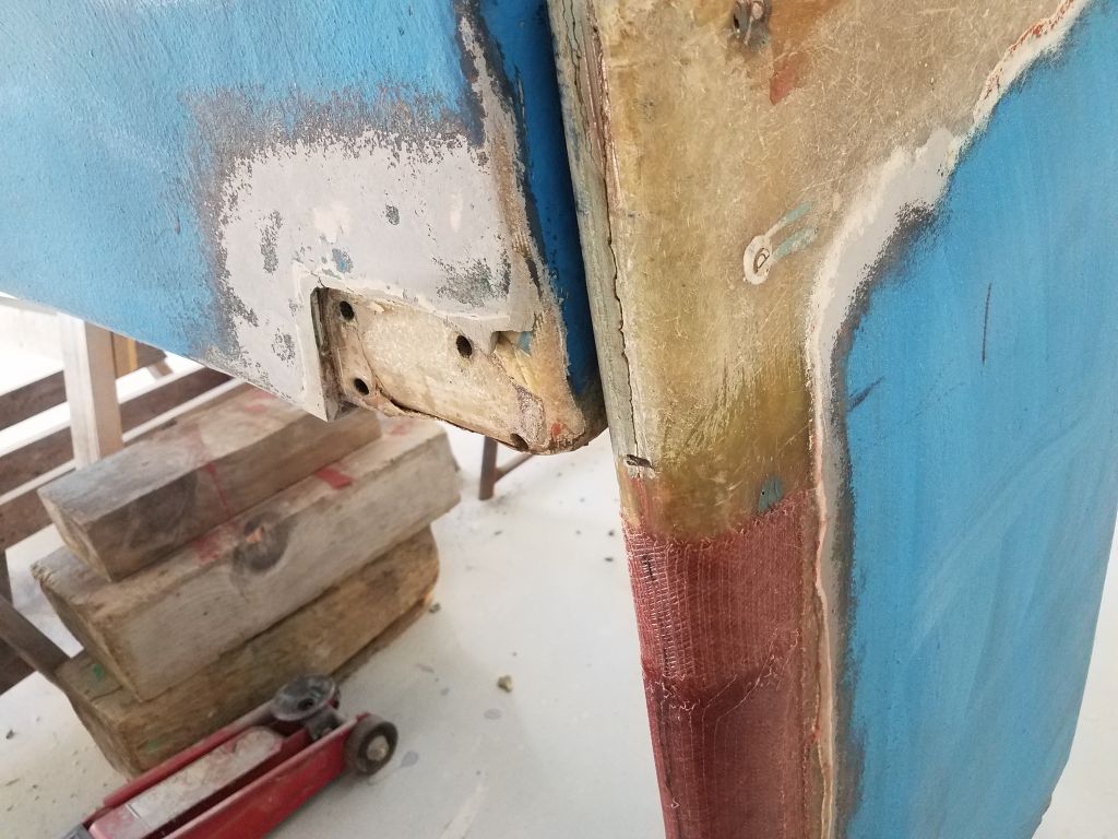
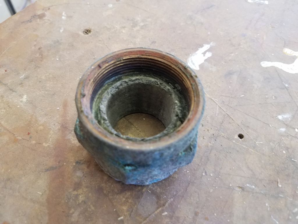
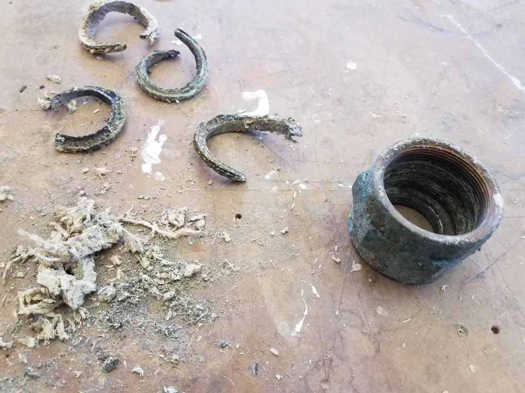
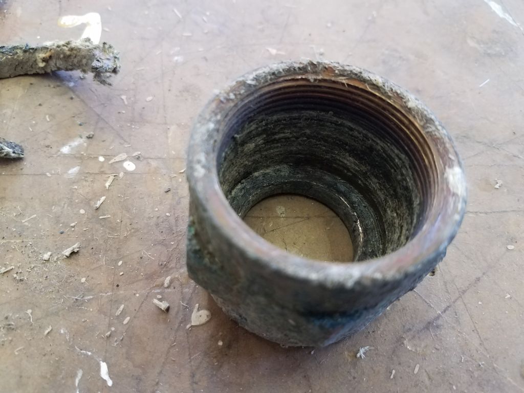
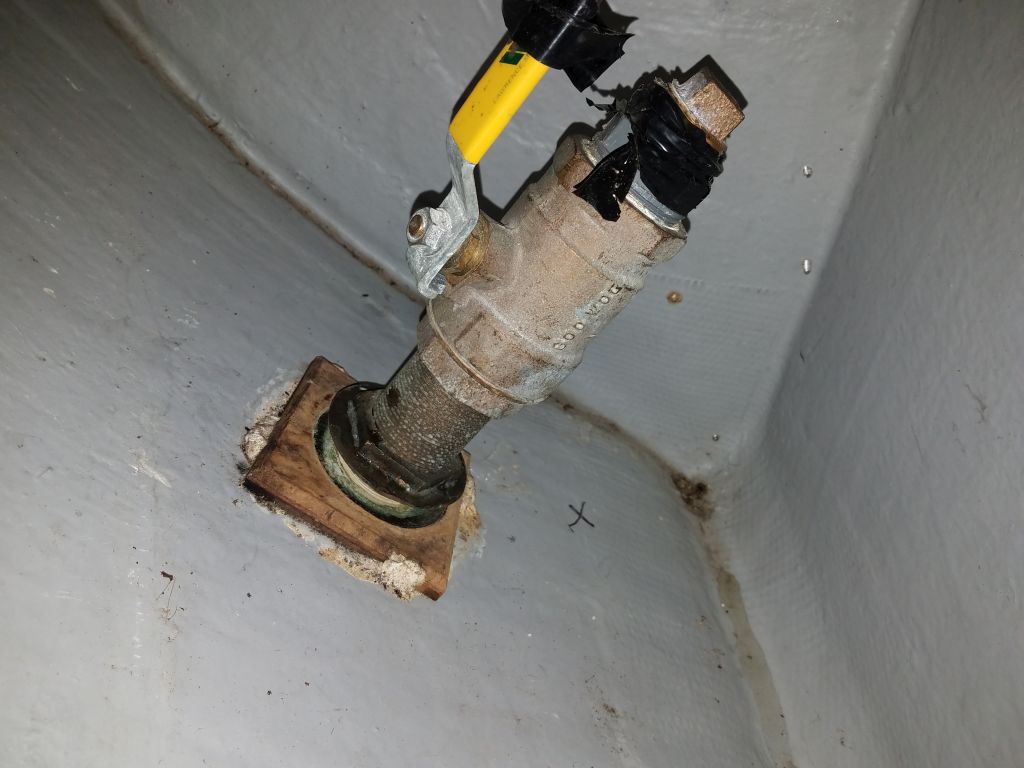
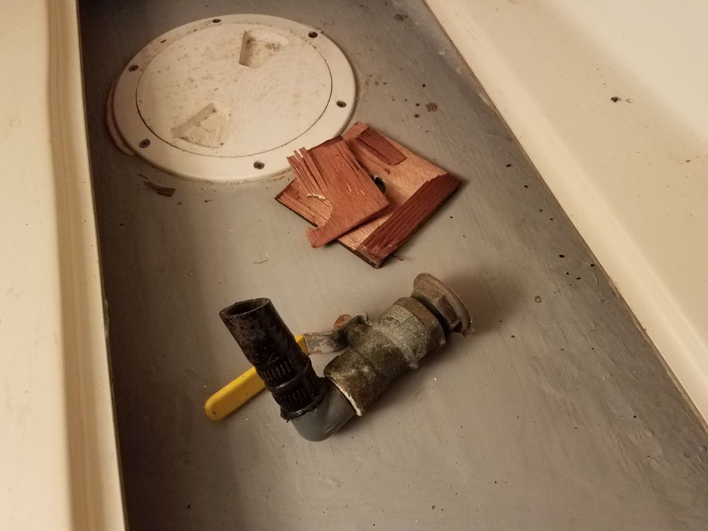
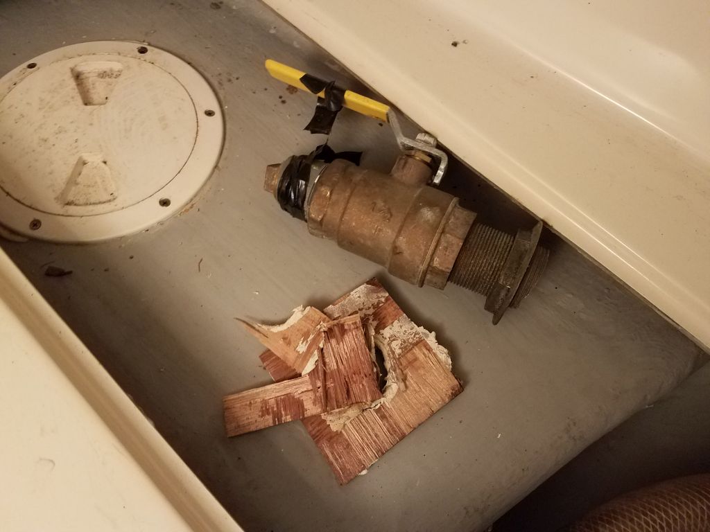
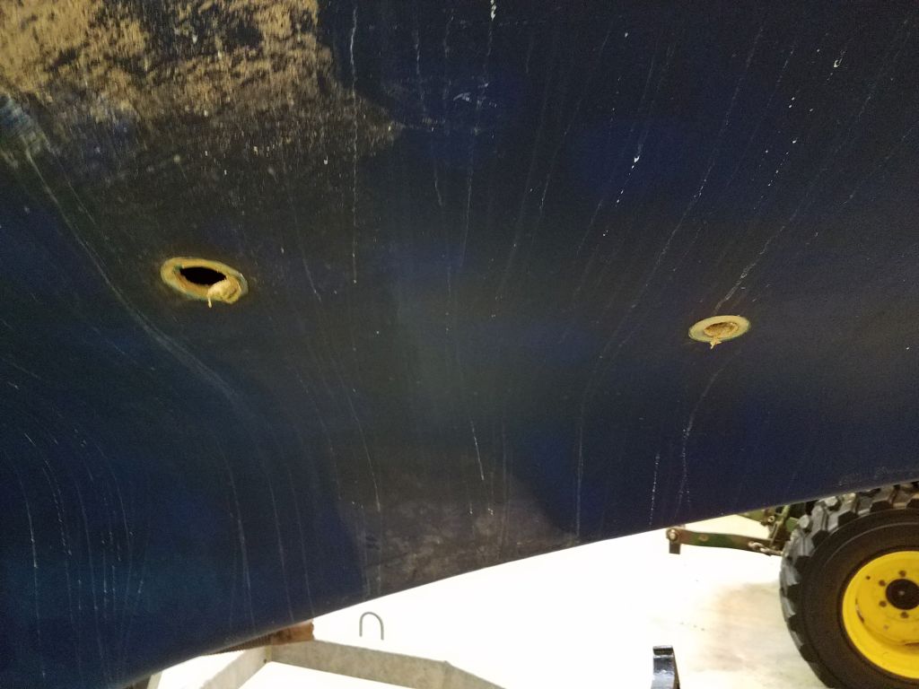
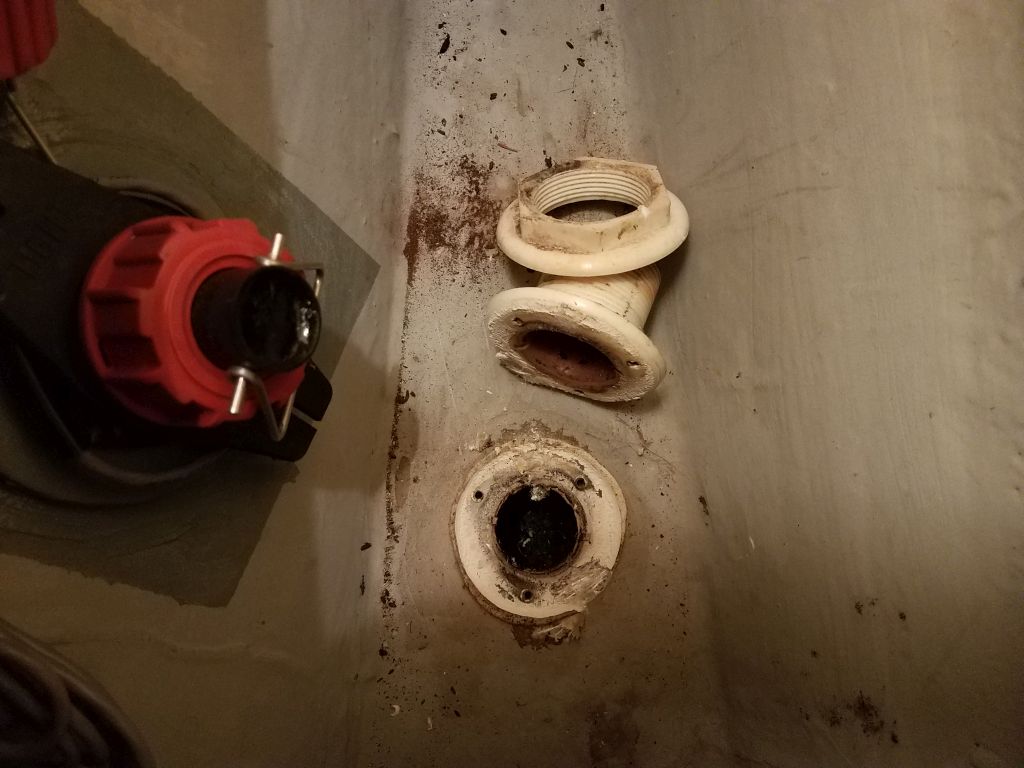
Moving on, I removed the two through hulls associated with the toilet–intake and discharge–so I could patch their now-unneeded holes.  Here, I found that I could partially unwind the through hull nuts beneath the threaded-on ball valves, which exposed enough of the through hull shanks so I could easily cut through with a saw to remove the fittings.

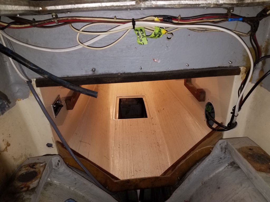
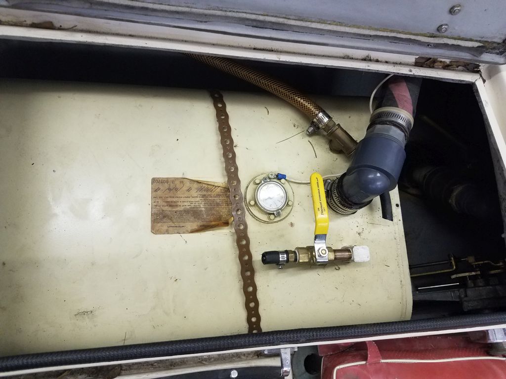
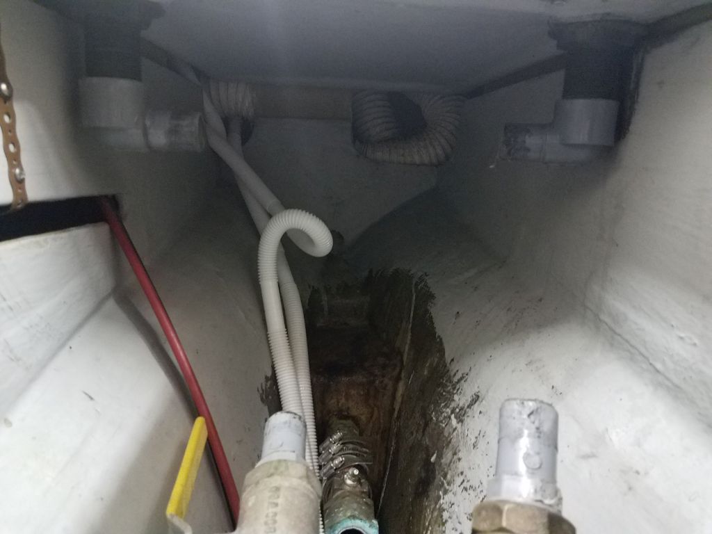
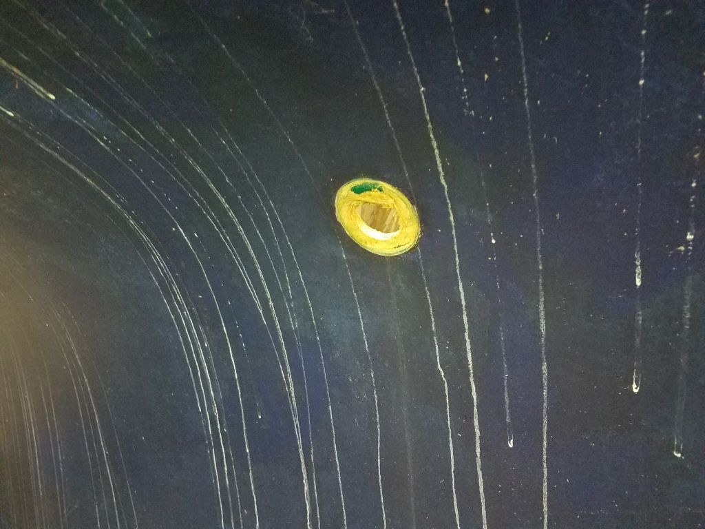
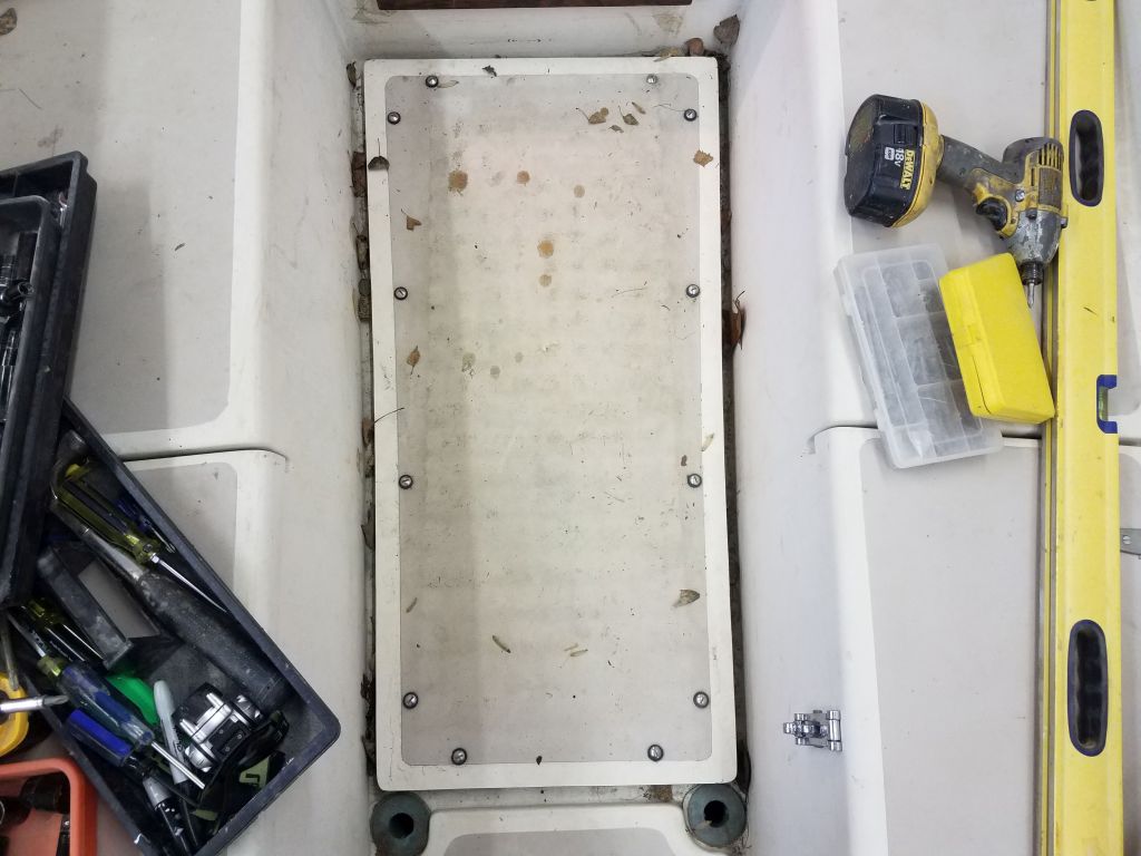
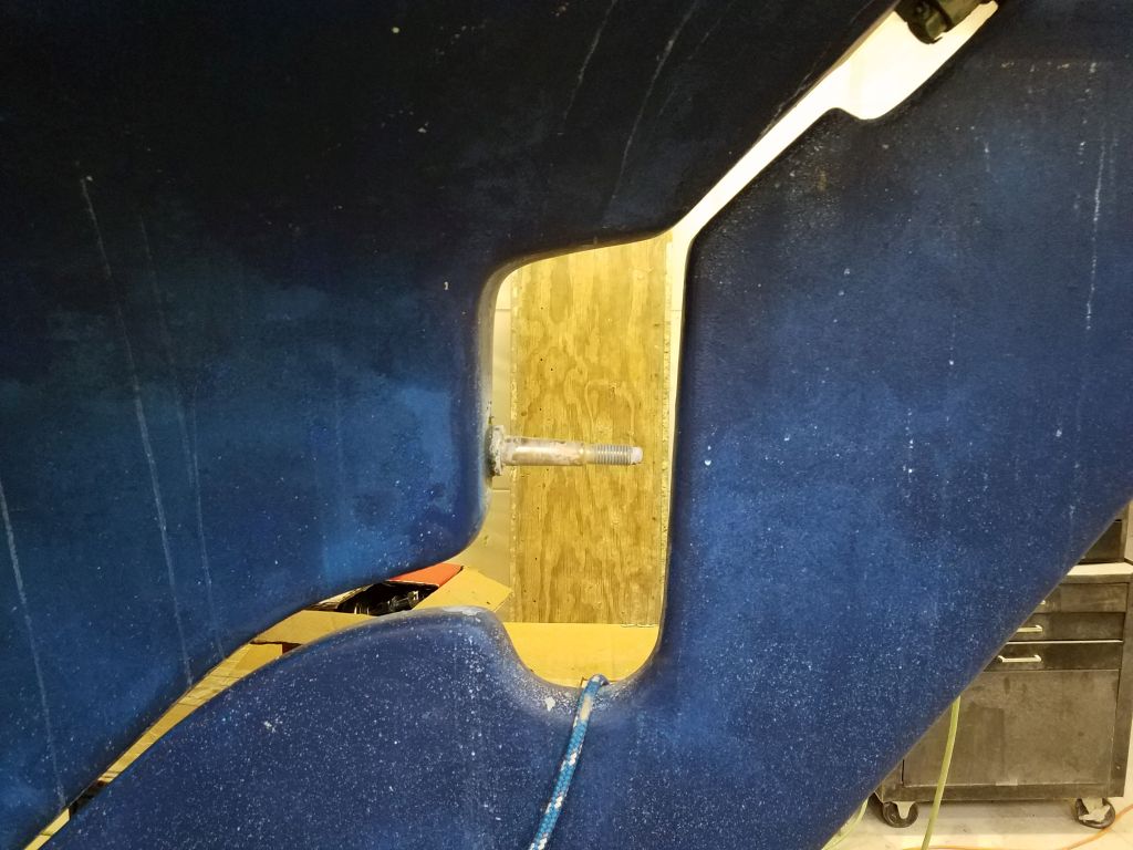
Where one of the hoses had entered the waste tank, centerline beneath the v-berth sole, I removed an interestingly-installed fitting there, the exact likes of which I’d not seen previously.  Here, a normal plastic/Marelon-type mushroom through hull fitting had been installed upside down on top of the tank, splooshed into a pile of sealant and screwed to the tank through the mushroom head, then covered with the through hull’s normal nut.  The removal was otherwise unremarkable.

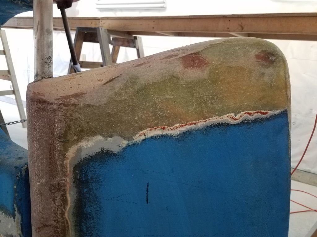
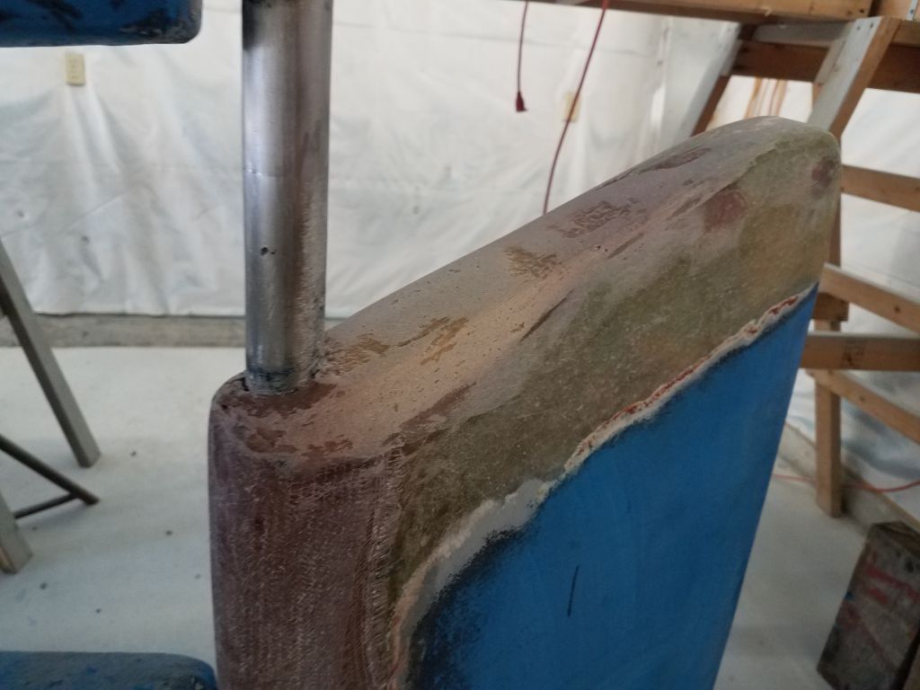
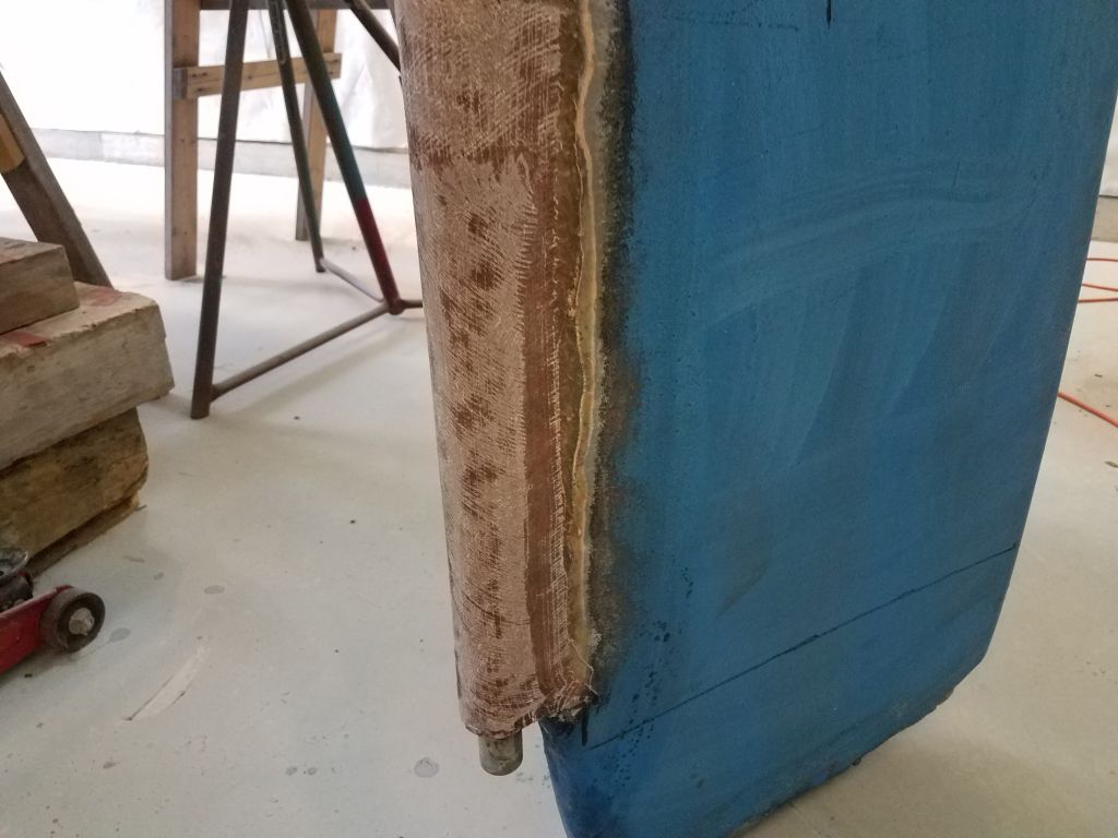
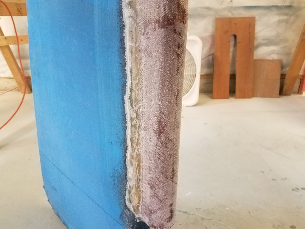
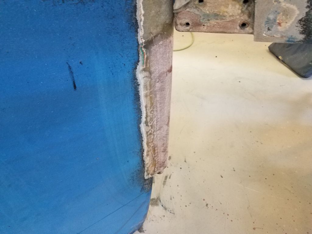
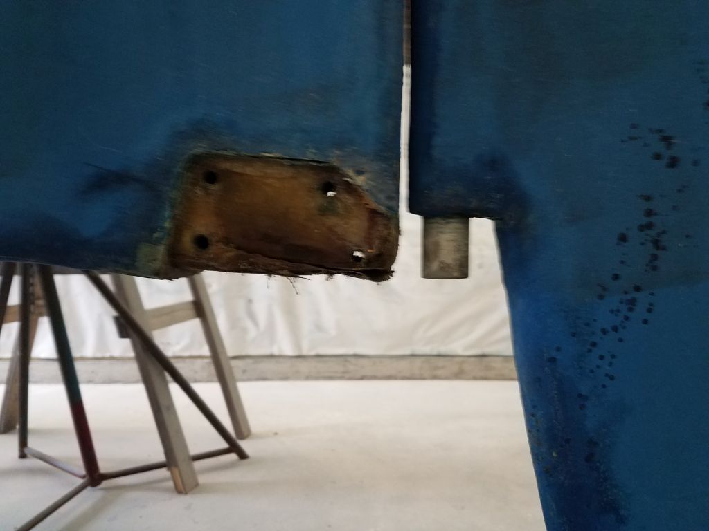
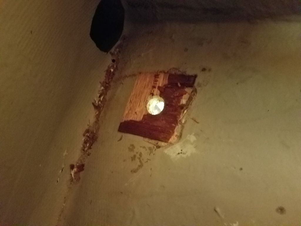
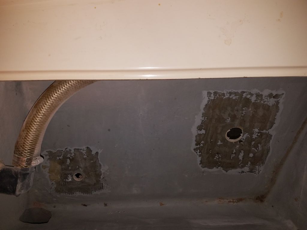
Later in the day, I ground clean the inside of the hull in way of the two through hulls, removing remnants of sealant, gelcoat, and wooden backing block to prepare these areas for patching.

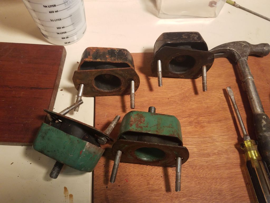
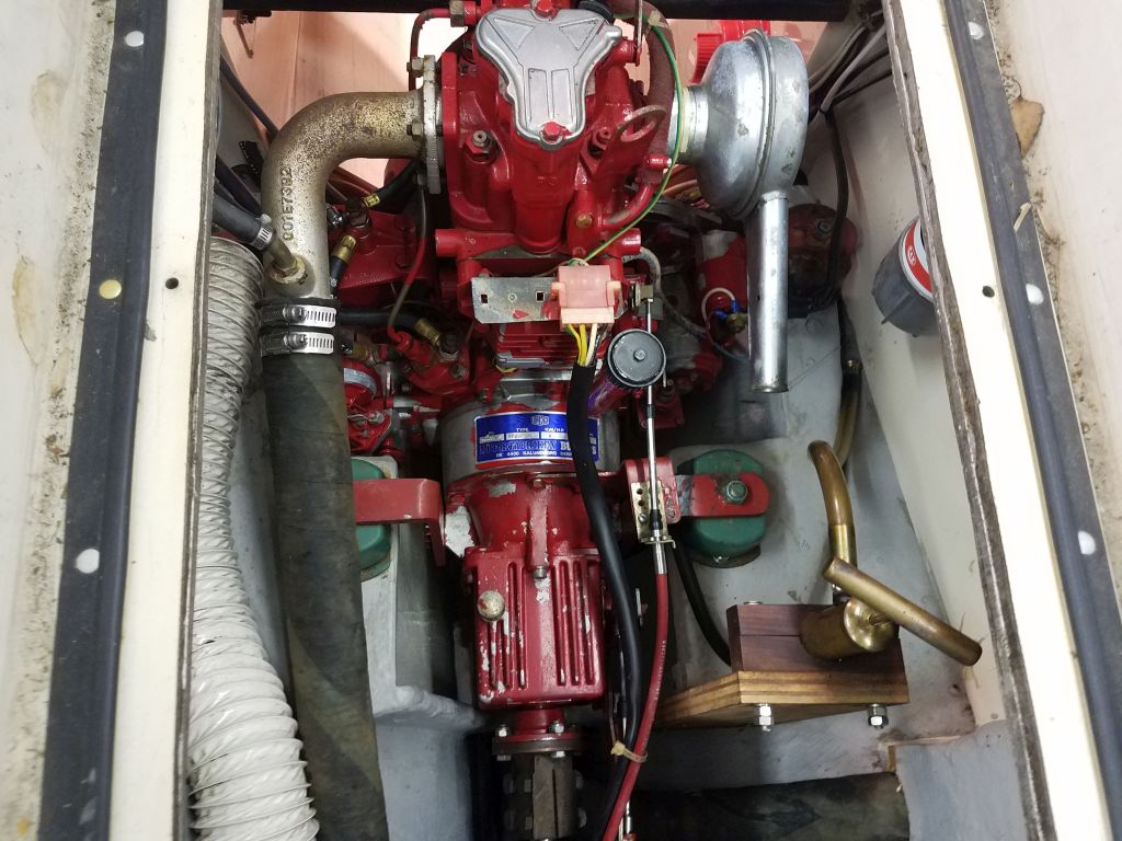
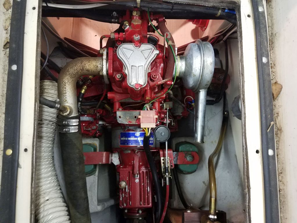
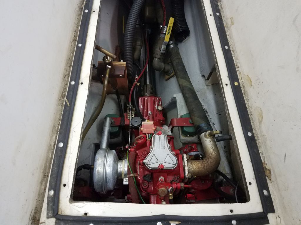
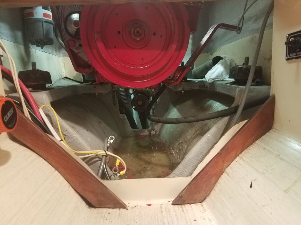
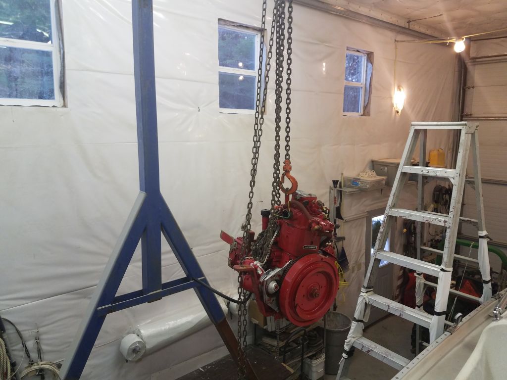
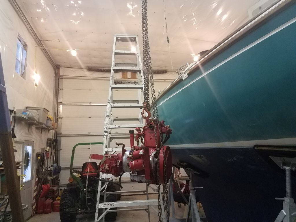
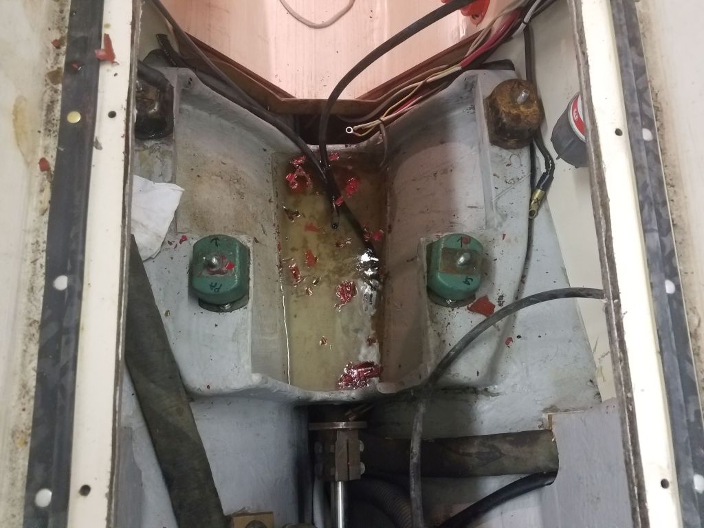
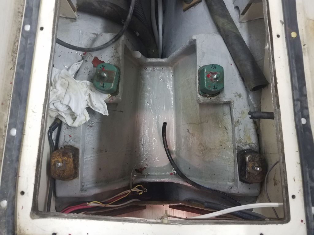
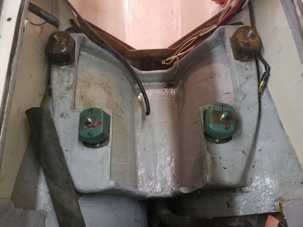
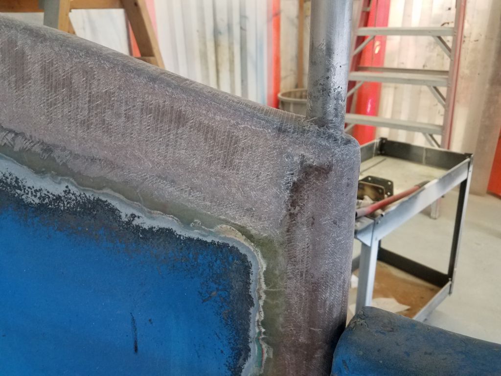
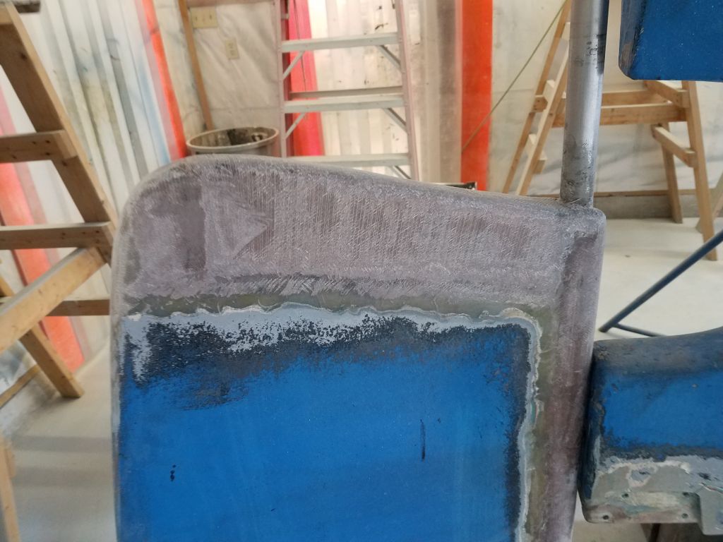
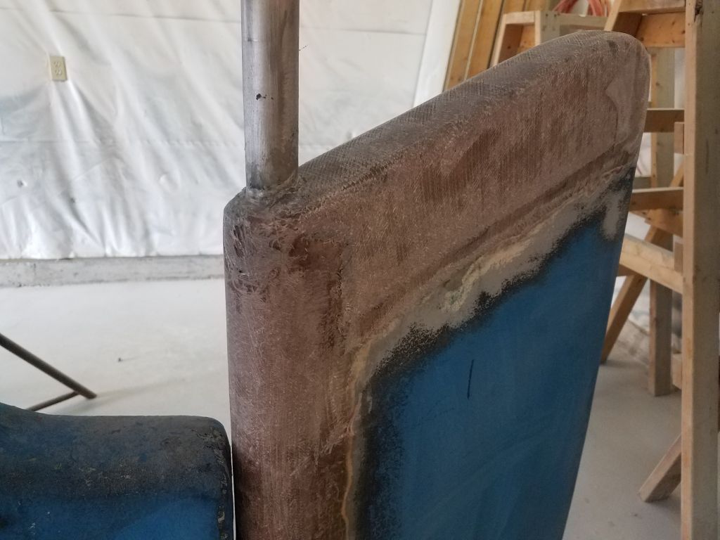
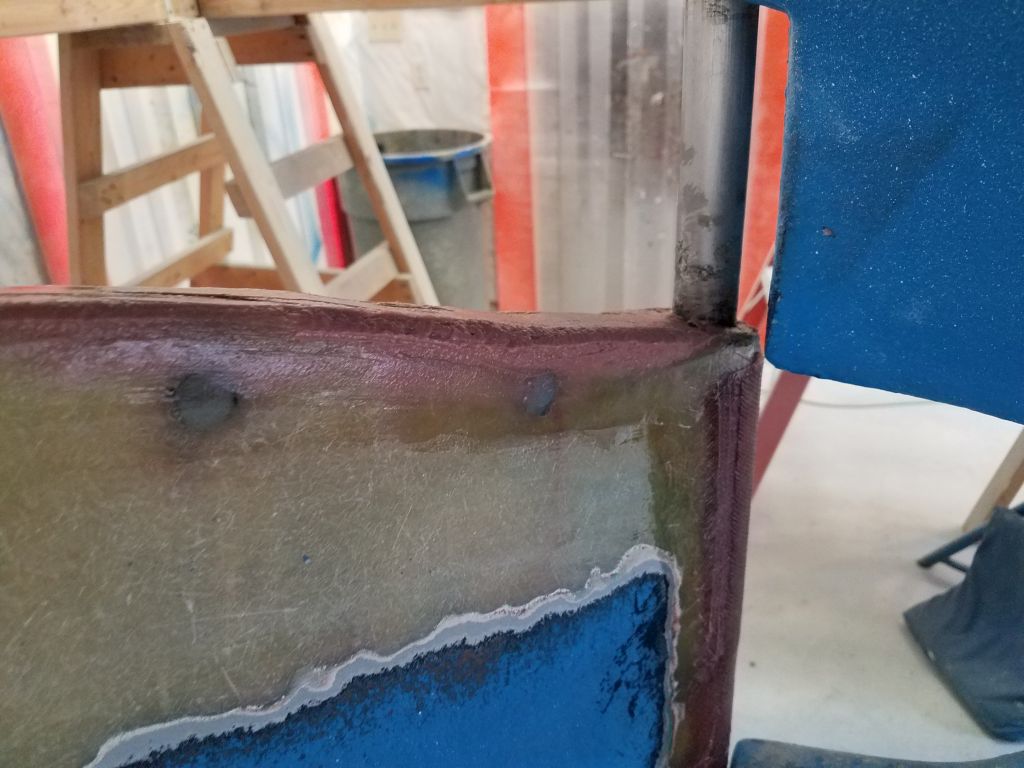
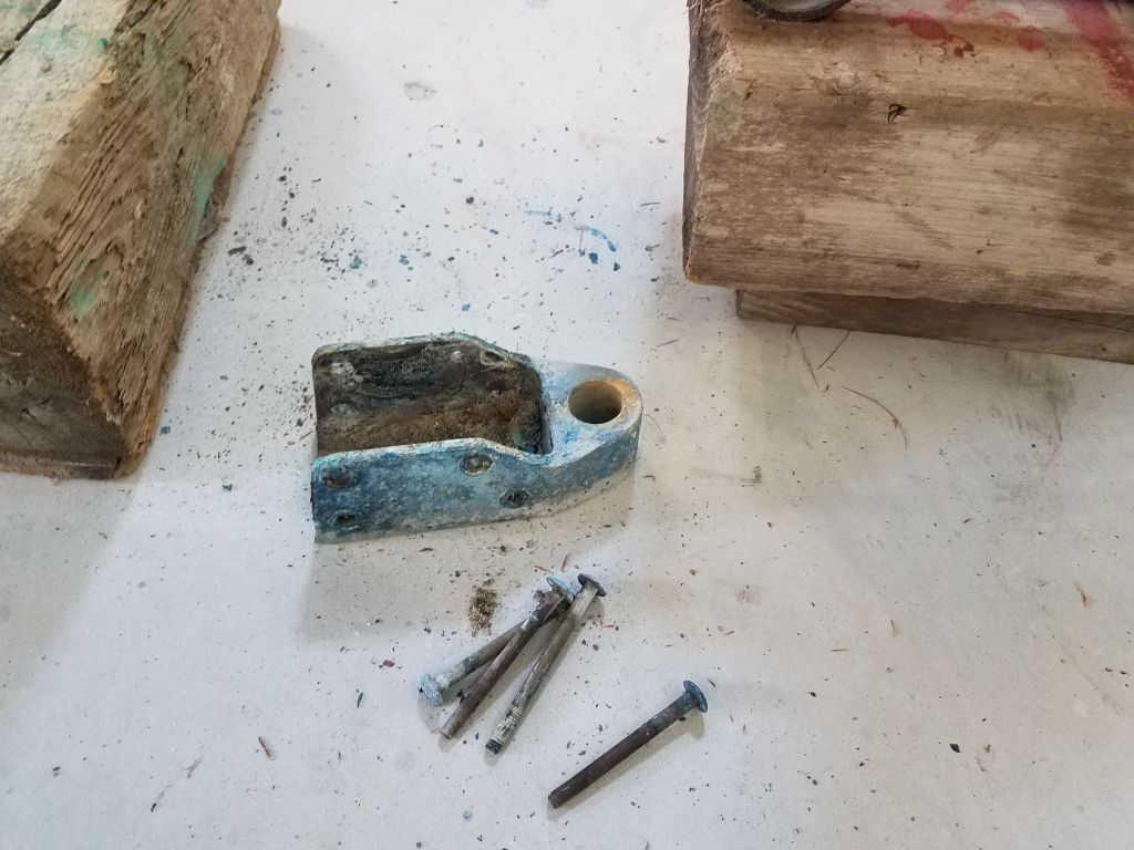
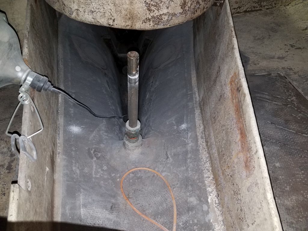
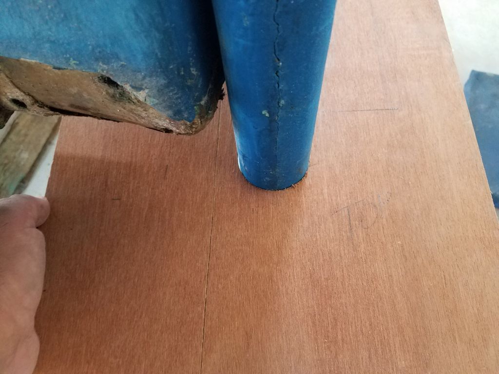
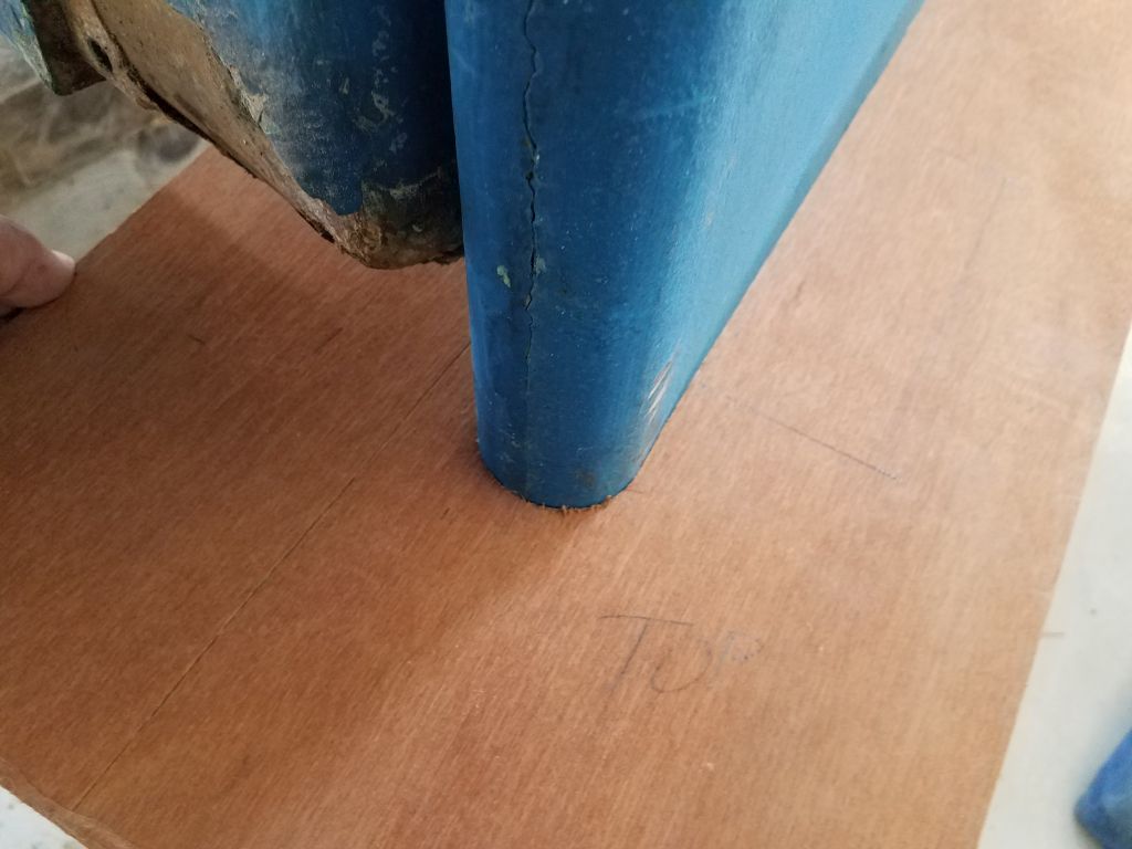
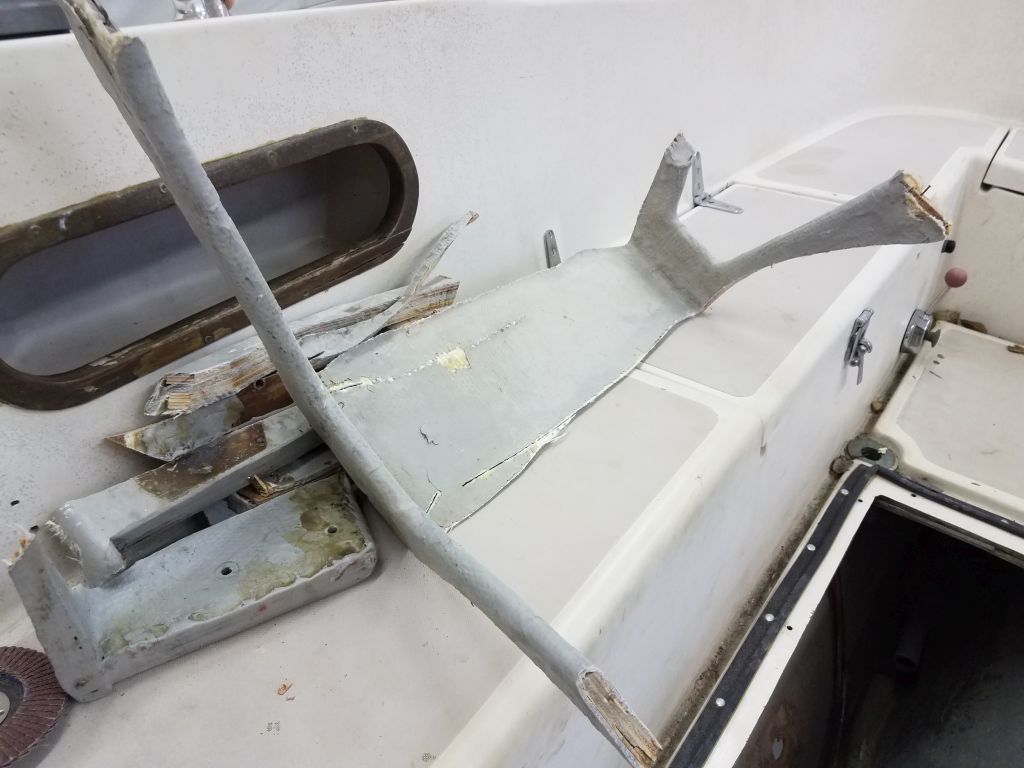
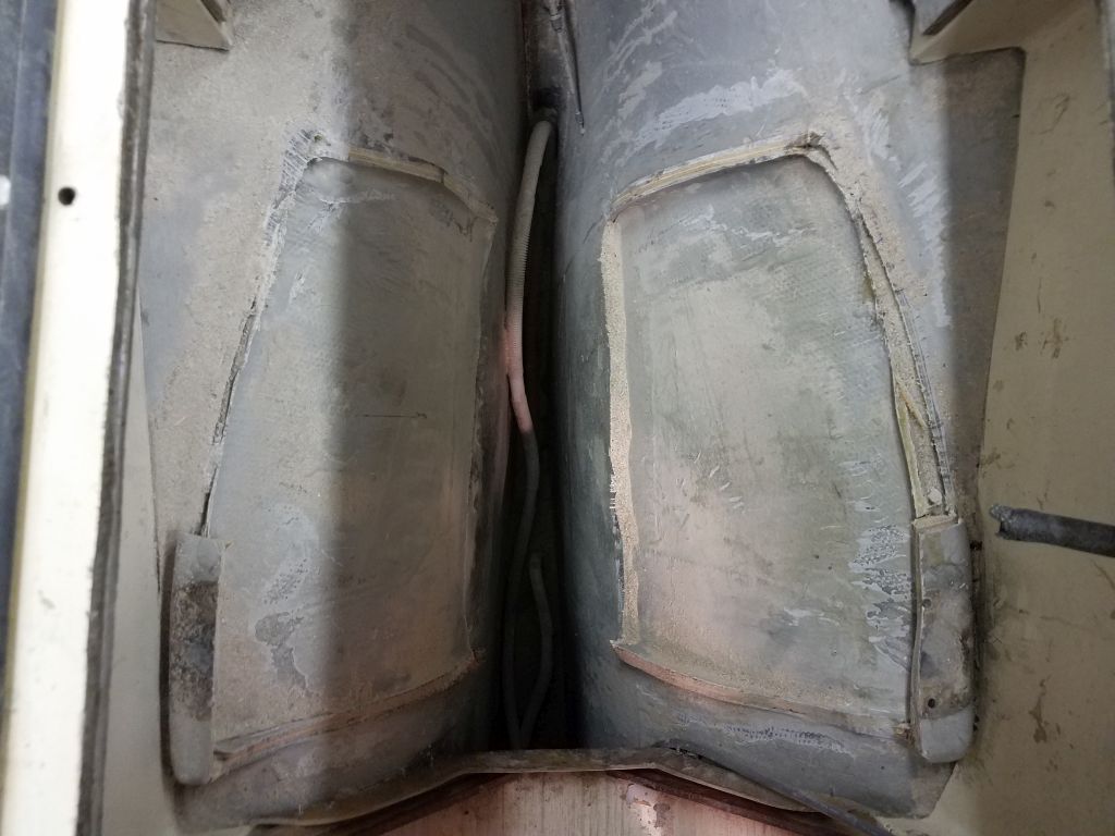
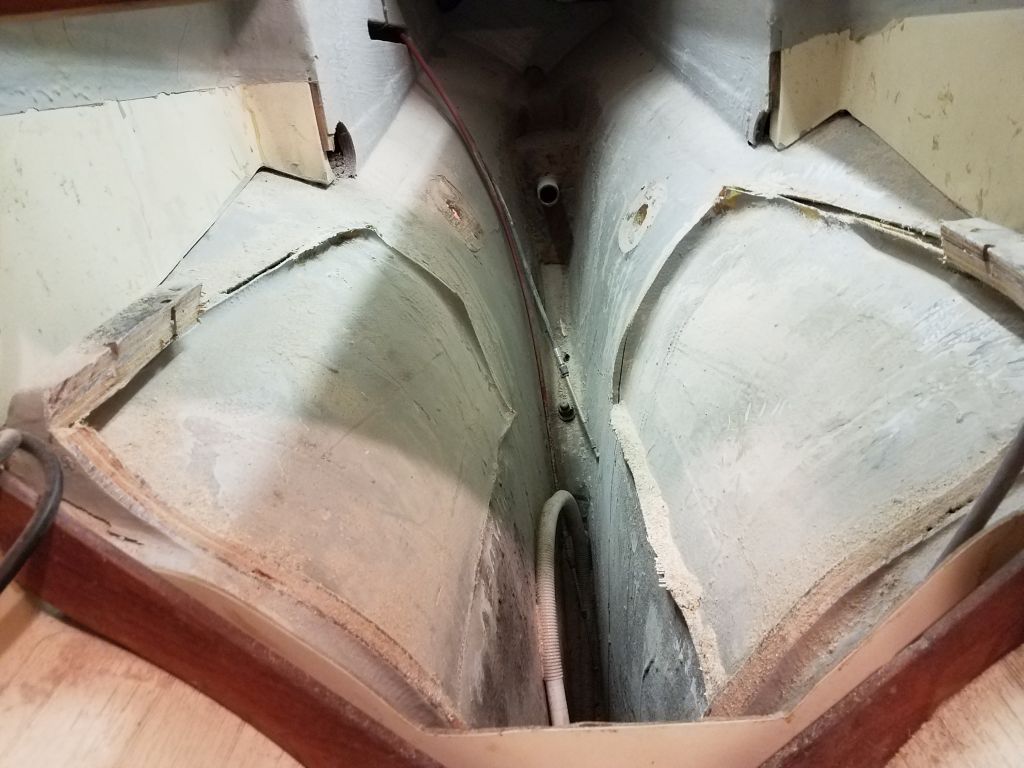
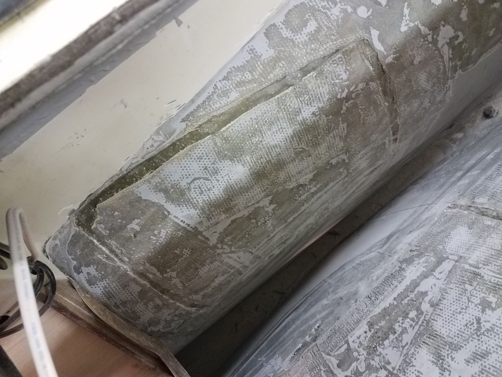
With a basic incompatibility born from a differently-shaped new engine and vastly different engine mounts, the existing engine foundations required removal, a job best gotten over with.  I studied the existing foundations for a time, trying to figure out cutting angles, which tools I needed, and how, indeed, best to approach the removal, since the process would remove the very means I might have otherwise used to support myself in the space for the task.

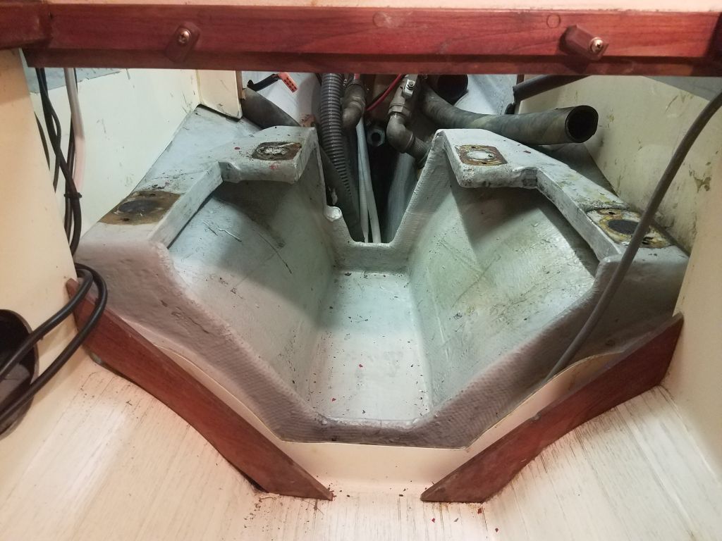
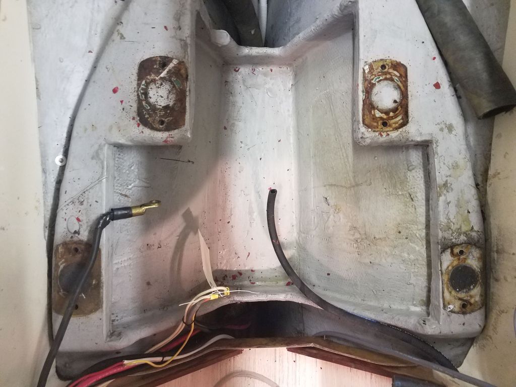
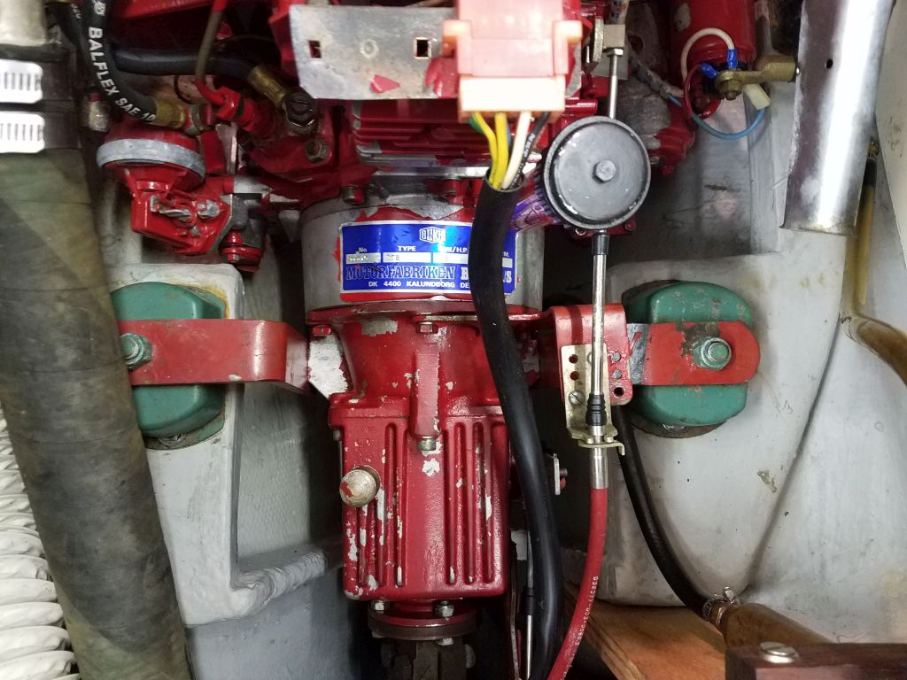
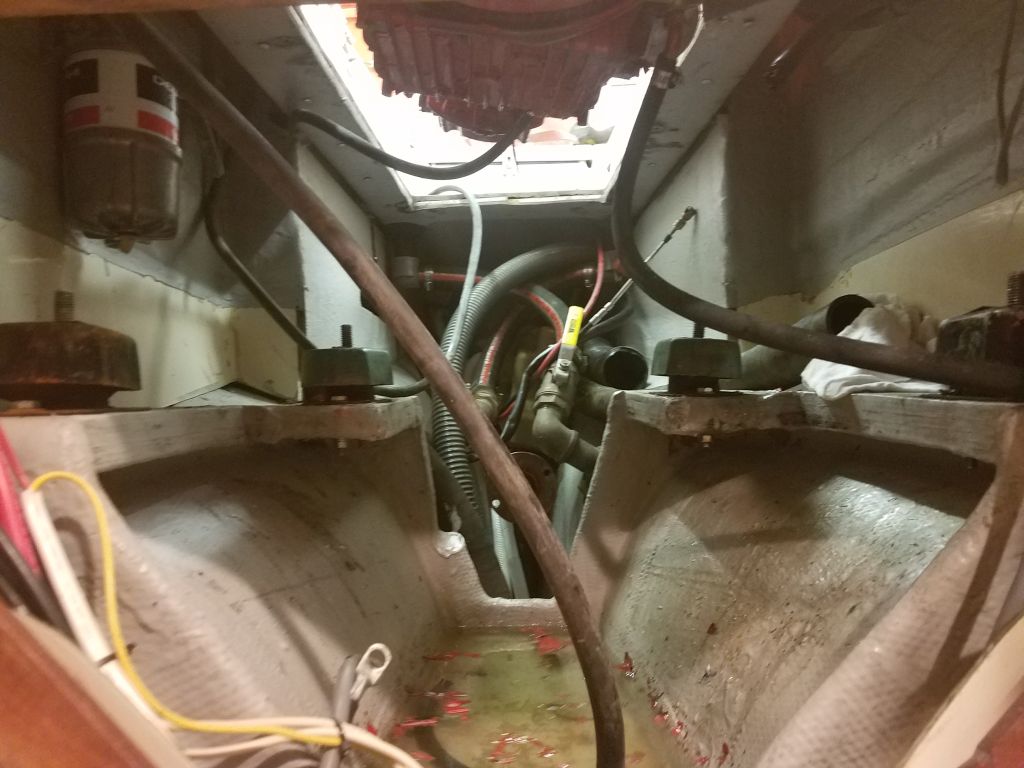
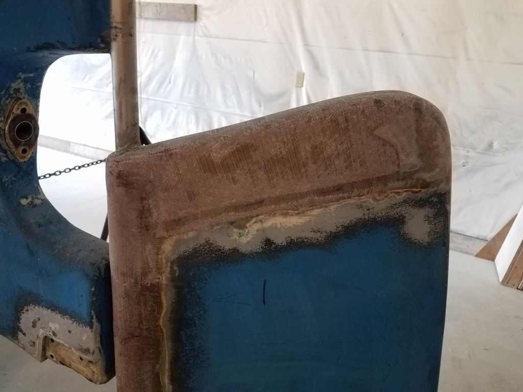
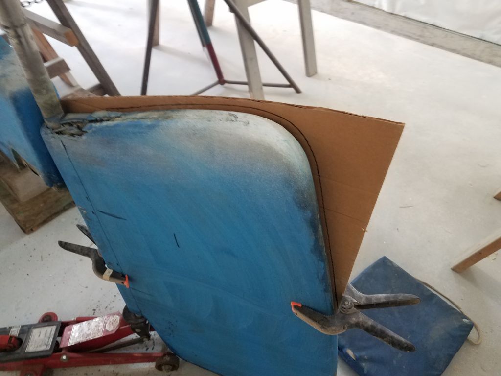
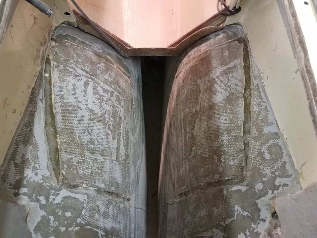
The basic problem, other than access itself, was that the very wide foundations spread so far up the curvature of the hull, and against the nearby longitudinal bulkheads, as to make cutting access to the tabbing challenging.  So I essentially started by cutting what I could, and what was generally easy–the forward and after portions that curved down towards the drip pan–and also removed some of the inner width of the flat top surface to allow better (or any) access to the tabbing within the tight curvature beneath.  I left the drip pan intact at first since it provided at least a semi-foothold for access.  I used a reciprocating saw with a carbide blade for much of the initial demolition.

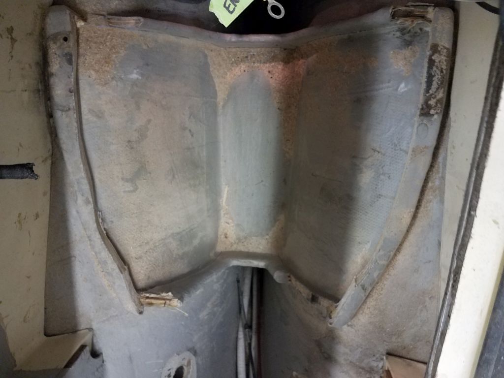
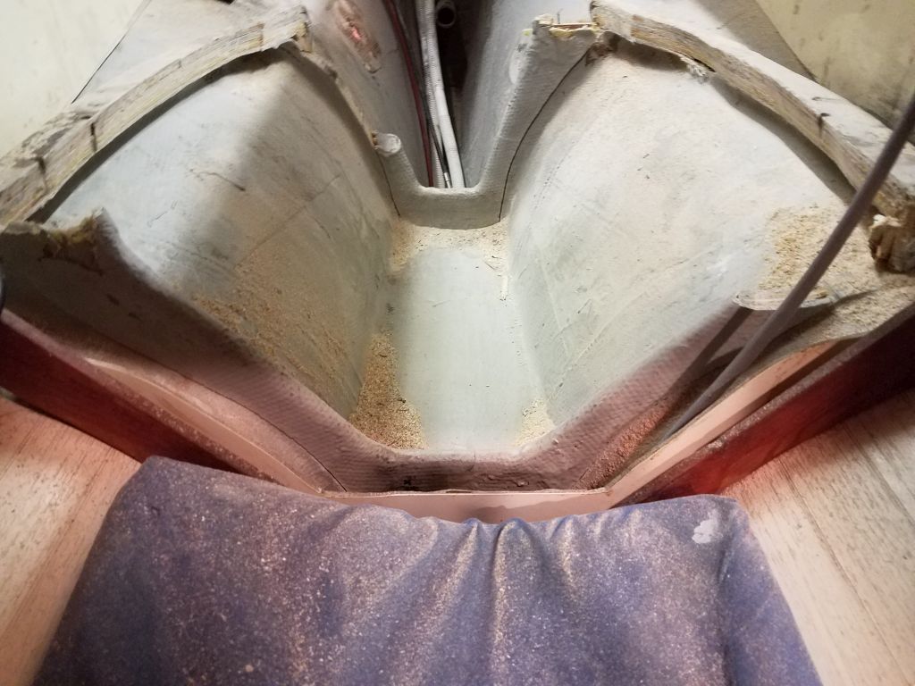
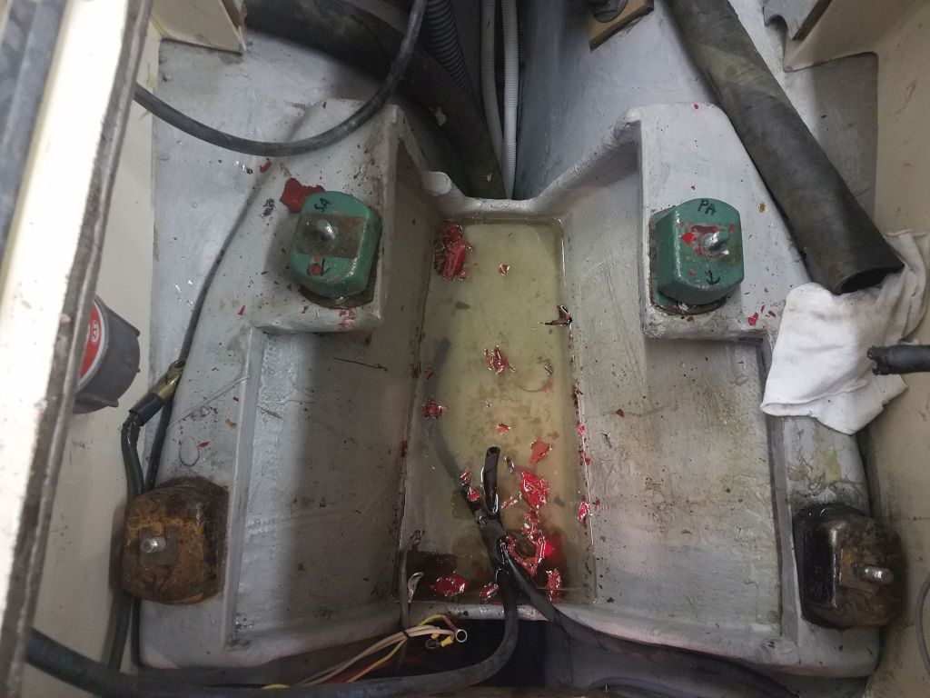
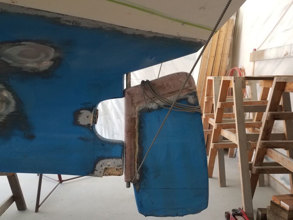
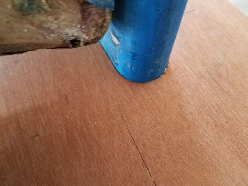
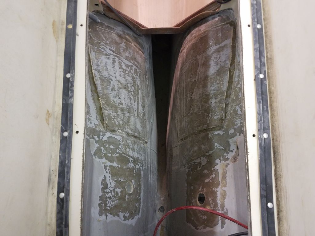
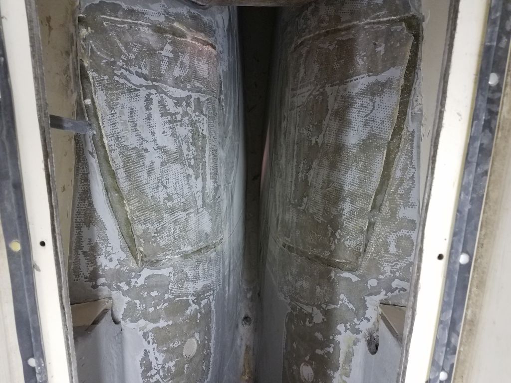
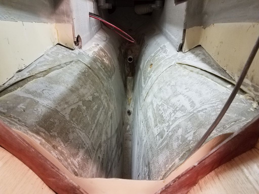
Continuing, I cut what I could with the saw, stopping as the blade got too close to the bulkheads and their respective tabbing, and cleaning up some of the earlier cuts, but then I had to switch to a small grinder equipped with a cutting wheel, which worked fine but was tough to control since the access was not ideal no matter where I tried to set myself up.  And even still, the forwardmost corners of the old foundations were so tight against the bulkheads that I just couldn’t really get in there from any angle to cut the old tabbing.  Still, through these various means I managed to remove the bulk of the existing foundations, which, it must be said, were quite durable.  This process left little narrow pieces of plywood still stuck between the remnants of tabbing, but later I pried out the wood since it made further cutting and grinding next to impossible.

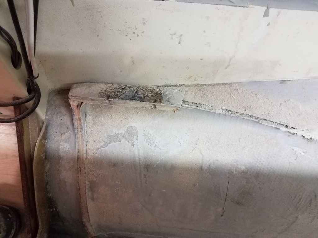
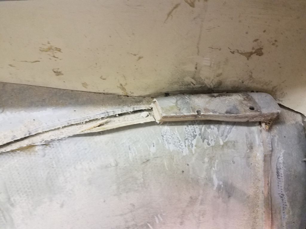
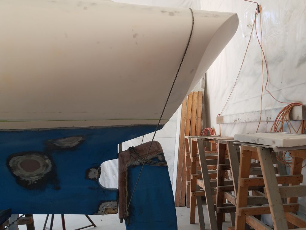
With some effort, mainly with hammer and chisel, I finally freed the last little corners of the old foundations at the forward end enough that I could turn to the grinder with an angle flap disc to remove the remains of all the tabbing, as well as to remove most of the gelcoat from the engine room (and scupper through hull locations).  I might sand some more once I determined where the new engine foundations would lie (the owner had purchased and provided a prefab engine foundation from the Contessa builder in England), but for now the bulk of the prepwork in the engine room was done, other than a continuing cleanup of the deep, deep (and still directly inaccessible) bilge beneath, which contained some water and various debris from now and in the past.

Total time billed on this job today:  5.5 hours

0600 Weather Observation:   32°, cloudy, drizzle and show showers.  Forecast for the day:  Mainly cloudy, high 30s

Dharma Rose 3

Tuesday

With the engine out, my next goal was to clean out the rest of the engine room, inasmuch as required for the scope of work.  In this case, since I’d be replacing all engine-related components (exhaust, battery wiring, raw water, and so forth), basically everything in the compartment could go, along with the scupper hoses and through hulls, as these were also on the list to replace with new.

To begin, I removed the four flexible engine mounts, which were secured with bolts through the fiberglass engine foundation.  Fortunately, these were stainless steel bolts in good condition, and other than the usual access issues the bolts came out with ease thanks to the clean, well-maintained, freshwater engine room.

The existing raw water hoses and related components, at 1/2″ and 3/8″ hoses and pipe fittings, were sized too small for the new engine, which would require a 3/4″ water intake, so I removed all the old materials for now, reserving them for some later use if possible.  The existing through hull would accept the proper pipe nipple at the top, so I removed the existing one so I could adapt the system to the 3/4″ hose required.

Next, I removed extraneous wiring from the engine room, where it ran through the forward portions above and below the little opening from the cabin.  In order to clear the way for new wiring, as well as for the new work in the engine room, which would involve removing the old engine foundations and installing new ones, I removed all the old batter cables, setting them aside for later assessment, as well as the cabin-mounted battery switch, from which I removed the other ends of the various cables. As needed, I labeled existing wiring for ease of re-connection, since most of the boat’s wiring was outside the scope of my work now.

In the way that so many things are connected in any boat project, now I turned to the old waste system, since  I wanted to get rid of the old pumpout hose, which ran beneath the engine pan, through the battery compartment under the cabin sole, and to the keel-mounted, built-in waste tank.  Removing this tank, repurposing the space, and removing all the related waste lines and components was part of my job scope.

The waste pumpout hose ran from a deck fitting outboard of the cockpit on the starboard side, through the fuel tank locker, into the engine room, and then beneath the engine and cabin sole to the tank.  The hose was supported at the forward end of the engine foundation with a metal strap, which was bolted to the foundation.  Of course the access to the screw slot on the forward site was so tight as to nearly prohibit all possible access, so unscrewing one tiny bolt required multiple trips up and down to the toolbox for various tight-access screwdrivers and the like, and then a frustrating many minutes manipulating in the tight space before I finally released the bolt and the strap, freeing the hose.

Access to the hose connection beneath the deck fitting was tight and non-visual, outboard and above the fuel tank, but after releasing the hose clamp (blindly with a small socket and ratchet), I found to my immense pleasure that the hose was secured to a plastic threaded fitting, and the threaded fitting was actually loose so I could easily unthread it, making removal of the hose in that tight space far easier than anticipated.  I just had to cut the hose a bit out from where it exited into the engine room, which freed the hose for rotation, and then I pulled that 3′ length out of the opening in the bulkhead.

While I was in there, I cut off the excess lengths of fuel supply and return hose, which I planned to replace (and possibly the tank, though we’ll see).  Access to the clamps was fussy and I didn’t want to waste the time right now, but I’d return later to remove the cut ends and prepare for the new installation.

Now, with the remaining length of hose for leverage, I could twist the hose free from the plastic fitting located at the tank itself, and then remove the hose and throw it away.

Removing the waste hose from the fuel tank area opened up enough access beyond so that I could see how and where the wiring harness for the engine panel was pinched, and thus I was able to remove that as well.

The aft end of the engine room was a tangle of scupper hoses and valves, exhaust hose and muffler, and ventilation hoses.  I made some space by pulling out a second length of ventilation hose into the lazarette, and then while I was in there decided to remove the exhaust hose from the metal gooseneck fitting secured to the transom outlet.  Again, this connection was located in a blind area, visible only by camera, and with tight access (and previous experiences) I feared the worst.  Fortunately, I released the hose clamps without issue, and then managed to pull free the exhaust hose with nary a whimper, perhaps the only time in my experience where the hose wasn’t completely stuck to the nipple.  This freed the whole length of hose and the plastic muffler assembly, and I could remove the whole assembly at once.

With the muffler and hoses out of the way in the engine room, I could access and remove the old stuffing box and hose.  This was an unusual greased packing gland, which type I knew of but hadn’t seen in practice for many, many years.

The scupper hoses didn’t put up too much of a fight when I removed them, and afterwards with a bit of elbow grease I removed the threaded elbows and old valves from the through hulls.  I didn’t have such easy luck with the through hull nuts themselves, which proved too tight for me to easily remove given the weird angles and, in the main, the tight access that simply didn’t allow the shoulder room for me to get in there properly.  The large cockpit hatch might look in the pictures to make for a convenient and roomy access to the space, but in reality it’s too tight to allow easy access for head and shoulders for tasks like unwrenching large nuts.  In the end, I simply cut through the nuts on one side with a metal cutting wheel on my grinder, and removed the old fittings easily from there.  After a long only semi-productive day with myriad unrelated distractions, from snow outside to deal with to some inner workings of this website, and other things that need no mention here, this seemed a good time to call it a day, so I did.

Total time billed on this job today:  5.5 hours

0600 Weather Observation:   32°, snow, an inch or two down so far.  Forecast for the day:  Snow, maybe changing to or mixing with rain (we’ll see).


Dharma Rose 2

Monday

Dharma Rose’s owner brought her to me to accomplish several larger jobs that he deemed crucial to his future sailing plans, including replacing the original engine with a new Beta 14, installing a new Monitor self-steering windvane, and some semi-structural work in the cabin to repurpose a built-in keel-mounted waste tank, along with sundry maintenance and upgrade items along the way.  The boat was in good original condition that generally belied her age.

The engine replacement was the #1 job on the list, so after removing a small amount of gear from the boat to clean out the cabin and storage areas, I removed the cockpit sole to gain access to the original Bukh 8HP diesel beneath.  I was impressed by the appearance of the engine and engine room, both of which were cleaner than usual, and the engine itself (and related components) were so free from corrosion that I guessed the boat must have had the luxury of a mainly fresh-water life.  Clearing the way for the work ahead, I immediately pulled out of the way a length of ventilation hose that ran through the space, pulling it aft into the lazarette for now.

I began outside to remove the propeller, which I like to do immediately since using a prop puller requires that the shaft be secured and there’s no better time to do it than at the onset of the engine removal.  There was a prop zinc secured over the prop nuts, a two-piece design that clamped together between the two nuts, and while I suspected there were little screws holding it together, their heads were filled with corrosion or debris, so I simply knocked off the zinc after chiseling a groove through it, exposing the nuts for removal.  I tied the rudder to one site to improve access, Neither nut was particularly tight, so they came off easily once the zinc was out of the way.

I used a small two-blade prop puller to remove the propeller next, which also went more easily than I’d anticipated:  just setting the body of the puller behind (forward of) the prop hub was enough to loosen its grip on the shaft, and I pulled it off easily.  The original propeller was two-bladed, size 12RH13. Afterwards, I made some measurements of the shaft clearance and aperture size for future reference in spec’ing new equipment later.

Now up in the boat, I began to disconnect the engine for removal.  I tried to work systematically from aft to forward and top to bottom, removing anything that connected the engine to the boat.  I started with the shaft coupling, which once more was pleasingly free from corrosion, and the four bolts released without a fight.

Next, I removed the exhaust hose from the elbow; since I planned to replace the hose, I cut it just below the nipple.  I also removed the small vent line, which ran up into the port cockpit locker where there was a vented loop (I hoped to reuse these components).  Meanwhile, still near the aft end of the engine, I removed the throttle and gear control cables and moved them out of the way. I disconnected the wiring harness leading to the engine panel down in the cabin, but found that the wires were pinched somewhere along their run, somewhere out of my immediate reach, so for now I left the panel and its wiring for later.

In this way, I moved my way along the engine, removing the four nuts securing the engine to the flexible engine mounts, fuel lines, electrical connections, and raw water hoses as needed till the engine was free all around.  Knowing I needed to reduce the width of the engine in order to fit it through the opening directly above, I removed the air filter and exhaust elbow, and while I knew I’d probably have to take something else off later, I held off more disassembly for now since I wanted to minimize how much I did before knowing it was necessary.

With the engine free, I hooked up my hoist and prepared to lift it out.  I soon found that anything that could get caught somewhere and hang up the engine definitely would get caught somewhere and hang up the engine, so it was with significant continued effort and various additional parts removals (including three of the four wide engine mounting flanges, the secondary fuel filter assembly, and more) that I finally somehow wedged the engine up through the tight opening and into clear air.  It was obvious that this engine had been installed in the hull before the deck was installed above since the physical dimensions simply didn’t work any other way.

I lowered the engine to the shop floor and a little rolling dolly so I could move it around easily.  Since the owner already had someone interested in buying the engine, I’d tried to be careful during its removal, and now I reassembled the various parts I’d removed in order to make it whole again.

Meanwhile, back in the engine room I bailed out the engine drip pan, which was full of water, and cleaned up the space a bit further, removing the fuel filter and pulling the fuel lines back into the fuel tank locker for the moment before calling it a day.  I’d continue work in the space next time.

Total time billed on this job today:  8 hours

0600 Weather Observation:  34°, cloudy. Forecast for the day:  Cloudy, showers to rain/snow/mix overnight


Scupper 64

< Back to Scupper

Friday

With 220 grit and a palm sander, I sanded the spots on the hull where I’d applied fine filler earlier, removing the excess material and smoothing the hull.

Next, I lightly sanded the new fiberglass on the top of the rudder, just removing rough edges and lightly fairing with the surrounding areas.

There’d be more work on the rudder ahead, but for the moment I wanted to partially raise it back up into the boat and remove the temporary blocking, as I needed to move the boat over closer to the wall in the shop to make room for other projects for the next couple months till I got back to work on Scupper in earnest  with Phase 2  later in the winter.  With my jack, I lifted the rudder back up, then used a line wrapped over the poop deck to hold the rudder in place for now, just so I could reposition the boat.

Afterwards, I moved her over closer to the wall, opening some space to one side of the shop and near the door that I could use for some other projects on the docket.  It wasn’t a big move, but enough for what I needed, and I wouldn’t need full access to Scupper’s hull for the next round of work in any event.

Total time billed on this job today:  1.75 hours

0600 Weather Observation:  25°, clear.  Forecast for the day:  Increasing clouds in the afternoon, rain overnight, 45°

Scupper 63

< Back to Scupper

Thursday

I began with a light sanding of the most recent round of fiberglass work on the rudder, including the upper portion of the leading edge and the top edge of the blade, bringing the fill work down to the final contours at the top.

Some slight depressions remained on top, and around the rudder post, so I installed some thickened epoxy over these areas to do the final smoothing.

Afterwards, and while the new epoxy was still uncured, I wet out and installed two layers of 1708 fiberglass over the top of the rudder, wrapping around the rudder post and overlapping slightly the new glass on the leading edge.

Total time billed on this job today:  2.25 hours

0600 Weather Observation:  55°, cloudy.  Forecast for the day:  Mainly cloudy, increasing sun, low 60s

Scupper 62

< Back to Scupper

Tuesday

I continued work on the first stage of the rudder repair, starting with a light sanding of the new fiberglass and related work that had cured overnight.

I used my plywood template to check the contours of the leading edge of the rudder over the new repair.  As I’d hoped, the two new layers of fiberglass brought things back to where they needed to be, without making the shape too large.

With the lower section glassed, I used my jack and blocking to raise and support the rudder at a greater height so I could access the top portion of the leading edge.

After final preparations, I installed the corresponding two layers of fiberglass over the top, with the top layer overlapping the bottom section by three inches as planned.

At the top of the rudder, I used a thick mixture of strengthened epoxy to build up the forward section near the rudderpost, bringing it back close to the original shape,. working only by eye at this stage.   This application would later serve as the basis for the final shaping once cured.

Moving on, I turned to the topsides, beginning with vacuuming and a solvent wash to remove residual dust from an earlier round of sanding following the high-build primer.  Afterwards, I went closely over the hull with a strong light, looking for small flaws and pinholes that required filling, just as I’d done on deck before.  I marked these with simple pencil marks as I found them, since it was very hard to see them otherwise.  This would make filler application easier.

Mixing up a batch of epoxy fine filler compound, I troweled it into the various spots as needed, including filling the remnants of the recessed scribe line from the top of the original boottop.

Total time billed on this job today:  4 hours

0600 Weather Observation:  64°, mostly cloudy.  Forecast for the day:  Cloudy, maybe a stray shower as what’s left of Florence passes to the south, 77°

Scupper 61

< Back to Scupper

Monday

I’d originally planned on removing the rudder at some point when I lifted and moved the boat, since there was not enough clearance to the shop floor with the boat in the shop to allow a complete removal of the shaft.  However, for the moment I planned to keep the boat where she was, and after some consideration I decided I could attack the rudder repair now without completely removing it–barring unforeseen circumstances, of course.

The main problem with the rudder was at the top edge, where the blade had hit the hull over the years since there had been no rudder stops installed in the steering system to prevent such an occurrence.  This had crushed the fiberglass and crumbled the interior structure of the rudder (basically a mix of solid putty).

(Photos from earlier in the project)

There was also a crack along the seam at the centerline on the leading edge of the blade–a common issue with rudders on many boats–plus additional damage to the bottom edge of the blade, which would also require some rebuilding work. (Photos from earlier in the project)

A bit earlier in the project, I’d prepared for the rudder’s removal by releasing the interior stuffing box nut and partially removing the bolts securing the bronze shoe on which the rudder shaft rested.

I set up a jack beneath the rudder to help me lift it off the pintle on the bronze shoe, and also to help me control the rudder’s descent.  There was little clearance to lift the rudder given its relatively tight fit against the shape of the hull, but it was enough to ease the pressure on the shoe and allow me to remove the bolts, after which the shoe dropped to the ground of its own accord; there was only a little bit of silicone sealant behind it.  Then, with relative ease, I could lower the rudder the rest of the way to the floor (after dropping it partially and removing the jack and blocking).

With the rudder down, I could access the top part of the blade–the most-damaged area–and also the leading edge, at least roughly half at a time.  I hoped the scope of repair would fit within the limitations of the access, which indeed it appeared it would.  The bottom of the blade I could deal with later, once I’d dealt with the top and leading edge.

Clearance between the rudder and the skeg and hull was tight, and there was no room to add extra material to the rudder in the course of repair, particularly at the leading edge, which had virtually no clearance between it and the skeg.  So to reinforce the cracked, curved edge, I’d need first to remove sufficient material to accommodate the thickness of new reinforcement.  To ensure that I maintained the existing shape and contours, I began by making a simple template–first from cardboard, then eventually from 1/4″ plywood–of the leading edge.  This would guide me as I ground off material and built up the new.

I also made a quick cardboard template of the shape of the top of the rudder, using the relatively-intact starboard side as my guide.  The template would help me keep the rebuilt top in the correct shape, though this wouldn’t be much of a challenge since the top of the blade was basically a straight line from the rudder shaft aft to where it curved down to meet the trailing edge.

Templates complete, I ground the leading edge of the rudder as needed to remove paint and gelcoat, and also deep enough to accommodate several layers of fiberglass that I planned in order to better reinforce the cracked edge.  I ground a bit into the crack running along the edge (the crack was simply where the two halves of the rudder came together but had been inadequately reinforced).  At the top of the rudder, I ground into the damaged areas enough to remove all loose fiberglass and the damaged filler in between, and also sufficiently down onto the blade to allow room for new fiberglass that I’d wrap over the top during the rebuilding process.  The round areas lining the edges of the rudder are filled areas covering the heads and bases of bolts that someone had installed long before in an attempt to reinforce the rudder.  I saw no reason to remove them, as they’d end up fully encapsulated within the rebuilt blade.

Holding my leading edge template against the rudder according to some reference marks I’d made before grinding, I could see that I’d removed enough material to allow for the rebuilding.

I also sanded the skeg around the edges of the rudder shoe recess, to clean and prepare this area for eventual reinstallation.

Despite these shortfalls, the blade itself, over most of its area, seemed sound enough, and short of starting from scratch I felt that the repair scope was such that I could–and would–proceed with the repair in place, despite the fact that ideally it would have been nice to fully remove the rudder.  But I didn’t see the need to spend the time and effort to lift and move the boat in order to drop—and then later reinstall–the rudder given what I’d found so far.  I had full access to the top and (later) bottom of the blade, and I could address the leading edge reinforcement in two overlapping sections, since the skeg interfered with part of the rudder even with it dropped as far as possible.  But raising the rudder part way after fiberglassing the lower part would allow me the access to the upper section as needed.

Now that I’d cleaned out loose and broken material within the top of the rudder and exposed solid material all around, it was time to build up–in several separate applications to avoid undue heat during curing–the interior of the rudder, now with a solid epoxy mixture of structural components like chopped strand and high-density filler.  After two applications during the afternoon, I reached the top of the existing sides of the blade.  Additional material to bring the rudder back to its final shape would have to wait till these first stages cured overnight.

Meanwhile, I got to work on the lower section of the leading edge, beginning with some strengthened epoxy filler in the groove I’d ground out over the crack, then following with two layers of biaxial tabbing set in epoxy.  I left room on the second layer so that the second layer from the top section could later overlap and conjoin the two sections accordingly.

While I had the rudder dropped, I removed the packing nut from inside so I could replace the packing before reinstallation.    The old packing (5 rings, though the fifth disintegrated to dust upon removal) was well-worn and overdue for replacement.  I’d cleanup the bronze nut and corresponding threads on the rudder tube before installing new packing and reinstalling it once the rudder was done.

Total time billed on this job today:  5.75 hours

0600 Weather Observation:  64°, foggy.  Forecast for the day:  Fog, then eventual clearing, around 80°

Dory 16

< Back to Oyster Dory

Thursday

To complete the refinishing part of the project, after the hull paint had cured a couple days I continued with some green bottom paint–chosen  because I had it on hand, not necessarily because it matched the color of the interior trim (though it did closely match, as it happened).

To round out the interior, I painted the flat surfaces of the deck with a cream-colored nonskid paint.  Originally I’d planned to cut this in closely to the sides and other framing members, but in practice I quickly discovered that the thick brush I had was not adaptable to this sort of detail, nor was the roughness of the bottom planking and other surfaces.  Instead, I ultimately chose to paint up to about 1/2″ of the structure all around, leaving a band of the overlapping green paint in all areas.  There was no way I was going to mask around all the members for this project; frankly, it wasn’t worth the time.  While my freehand lines were imperfect, so too was the whole boat, and the net effect was what I wanted.

Overall, I thought the boat looked good, and a whole lot nicer than the original boat.  I was pleased with the transformation, and thought it represented a reasonable blend of practicality and good looks.

Total time on this job today:  1.5 hours

Dory 15

< Back to Oyster Dory

Tuesday

Second coat, same as the first.

Total time on this job today:  .5 hours

Dory 14

< Back to Oyster Dory

Sunday

Now that the two coats of green paint for the interior and trim were dry, I could continue with the hull paint.  There was no need to mask, since the overhanging gunwale gave me a good place to cut in by hand, and the waterline was already ready.  For the hull, I chose a paint called Shaw’s Yellow, and in little time applied the first coat with roller and brush.

Total time on this job today:  .75 hours

Older posts Newer posts