
110 Cookson Lane | Whitefield, ME 04353 | 207-232-7600 | tim@lackeysailing.com
Summer Song | Monday, January 27, 2014
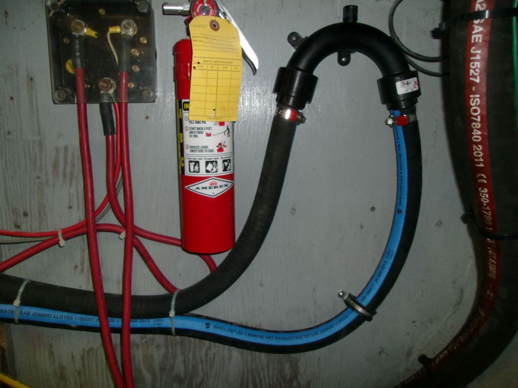
With new materials on hand, I finished up the engine exhaust siphon break plumbing by installing the "return" length of hose from the siphon break to the exhaust riser. I precut a length of 2" exhaust hose for the final connection between engine and muffler, but left it off for now to provide better access when I installed the shaft, which I'd ordered and would hopefully be on hand soon.
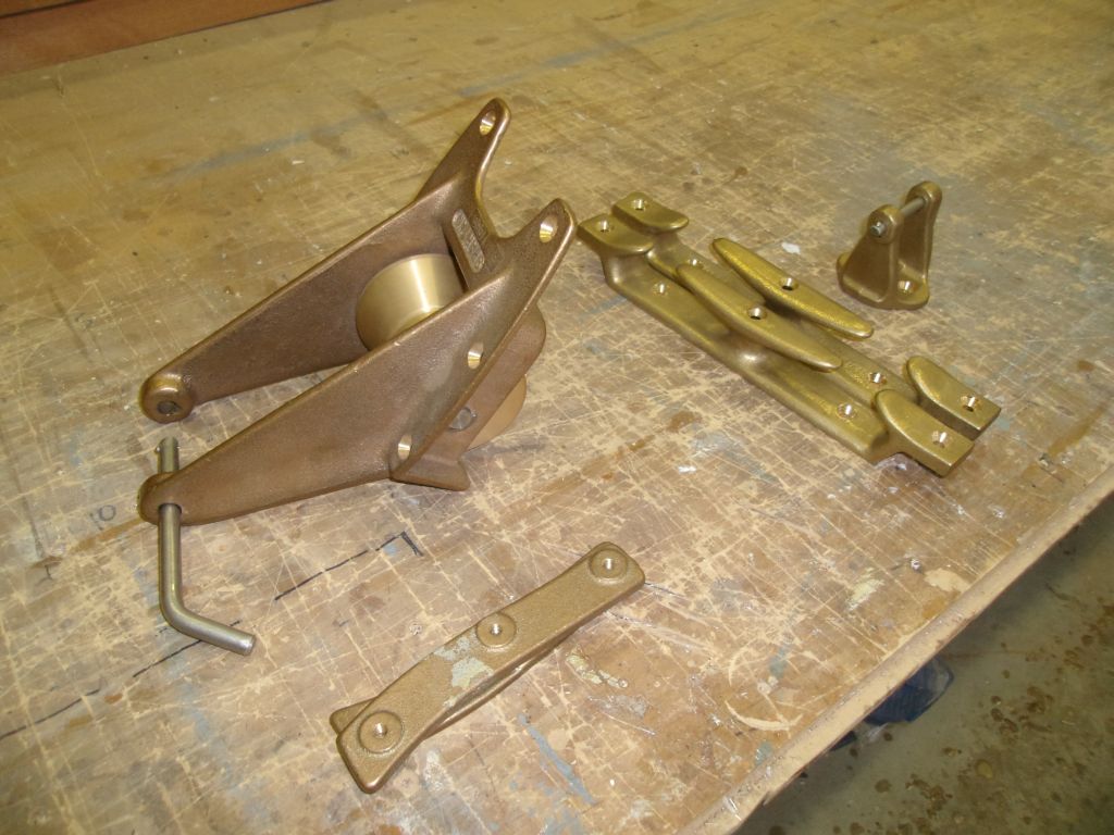
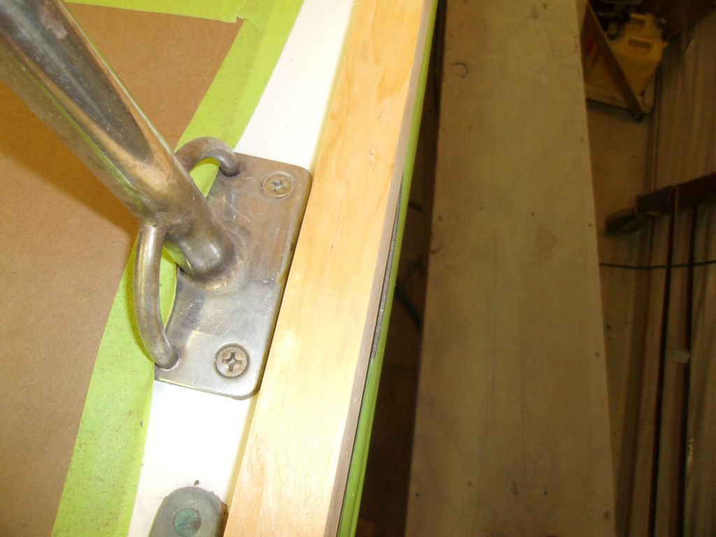
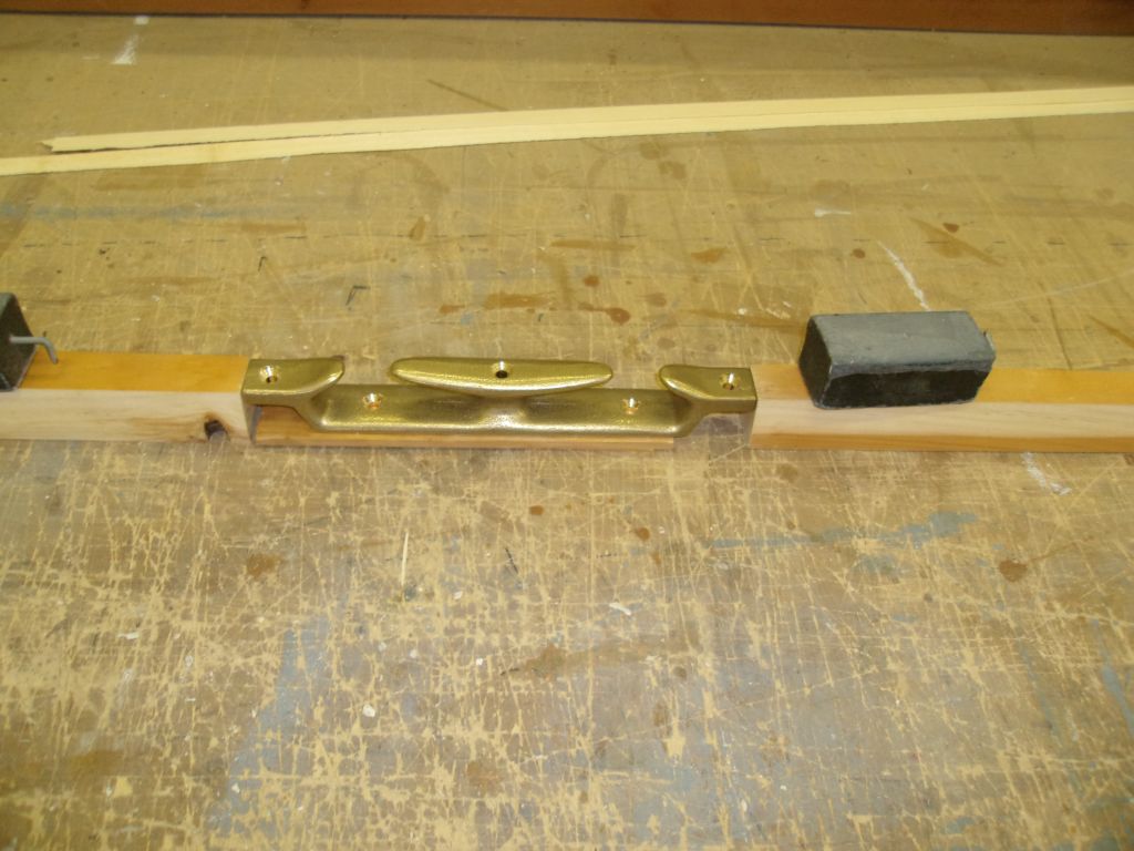
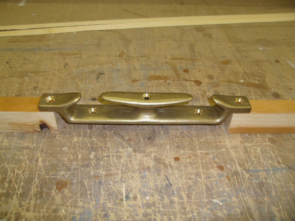
After various delays, the bronze hardware related to the toerail finally had arrived--worth the wait, as it was very nice hardware. Along with a bronze anchor roller and anchor shank pin, in particular, I'd been awaiting a pair of bronze mid-rail chocks with integral cleat, the shape of which was going to dictate the final profile of the toerail. I didn't want to work just off the measurements available for the hardware.
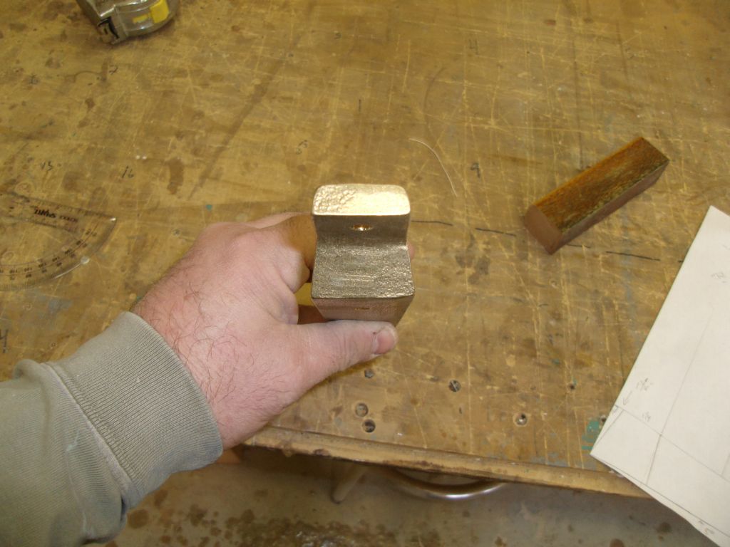
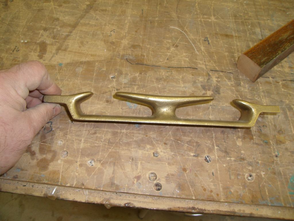
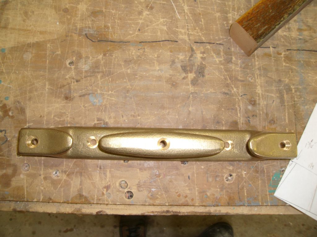
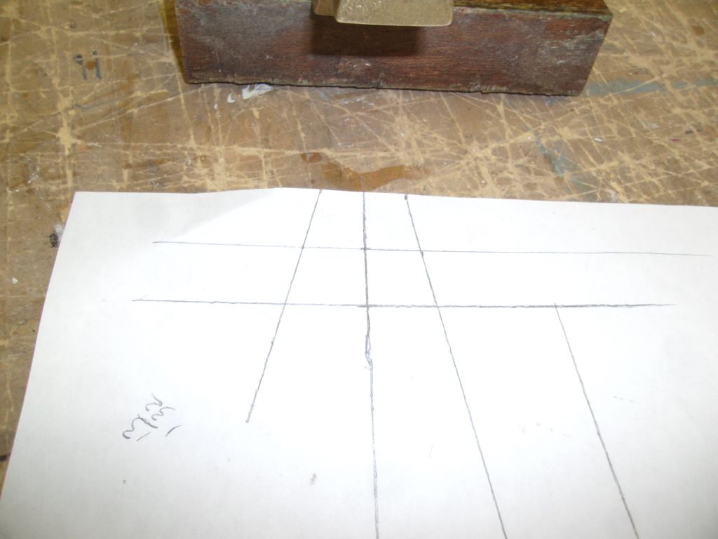
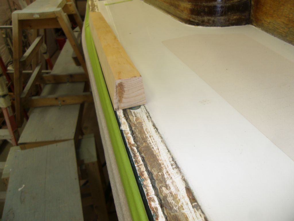
Beginning with these measurements, along with measurements taken off the hardware itself, I prepared a rough drawing of the potential profile to get the angles and shape clear in my head before beginning. Then, from scrap lumber I cut a short blank to the dictated dimensions.


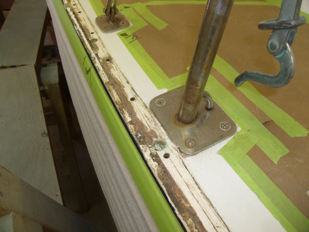
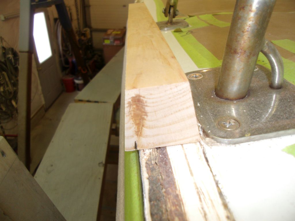
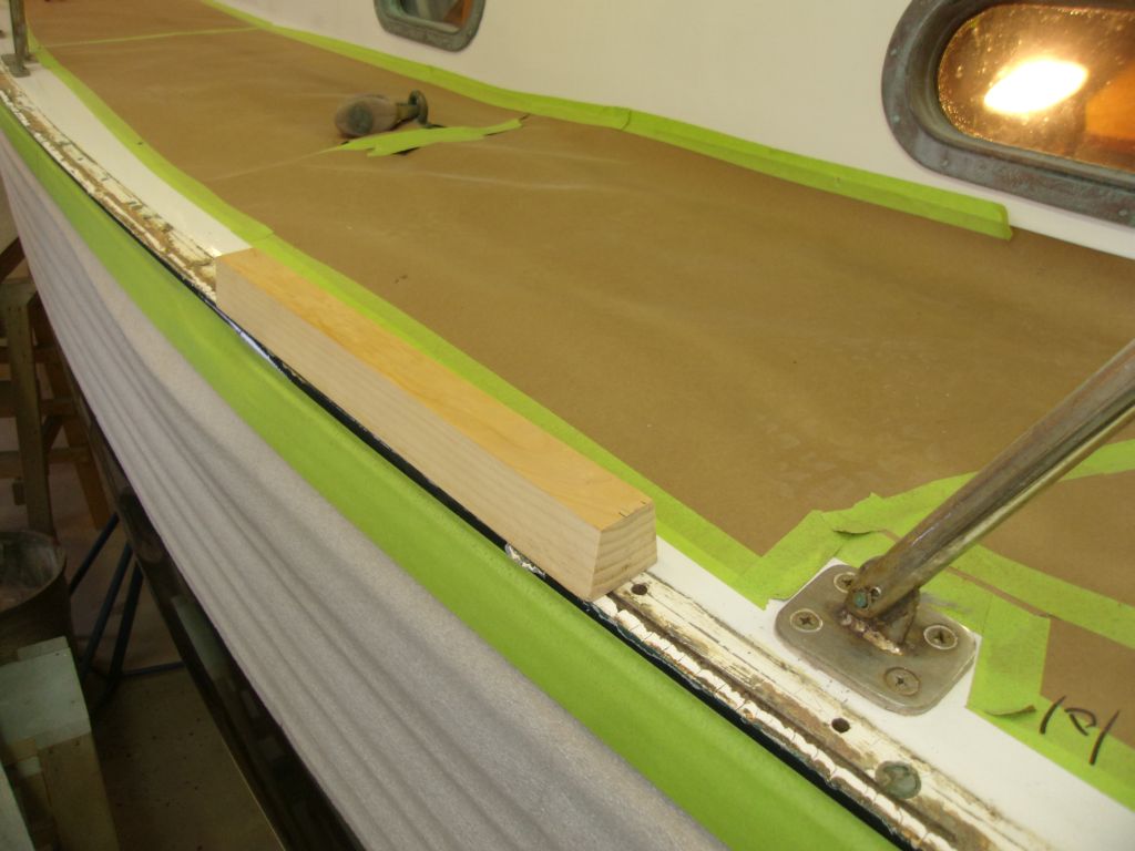
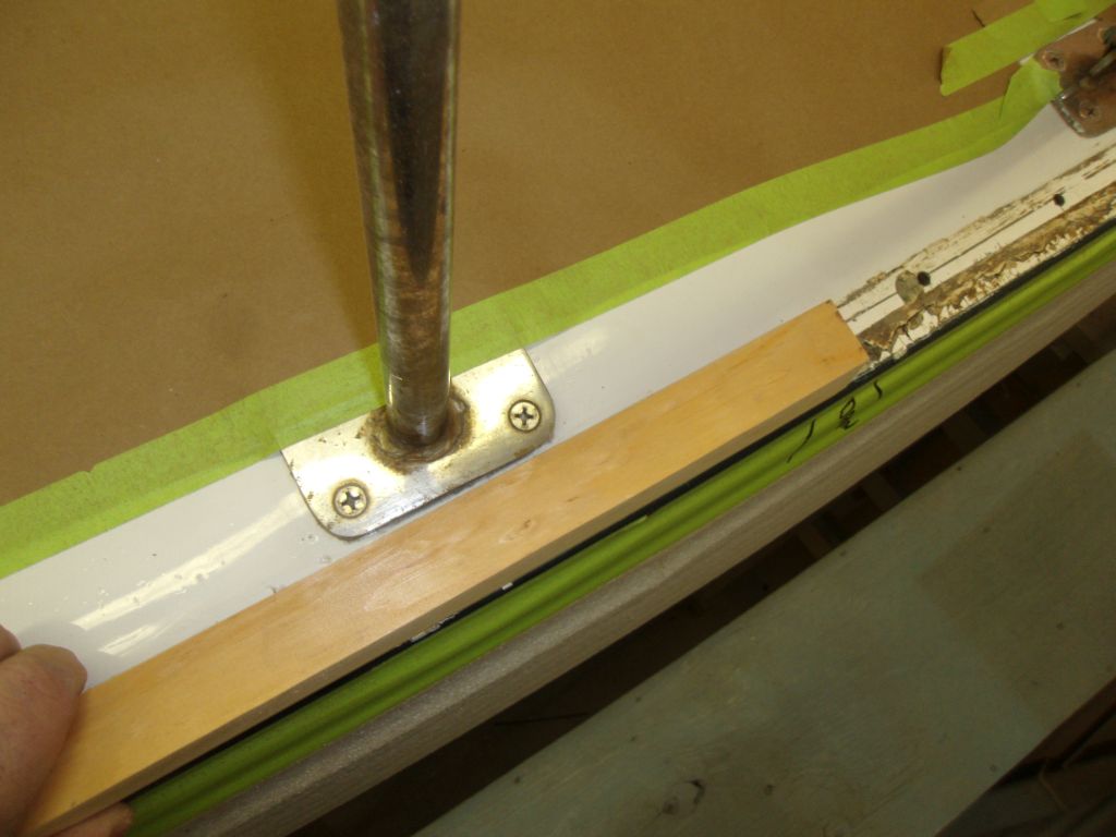
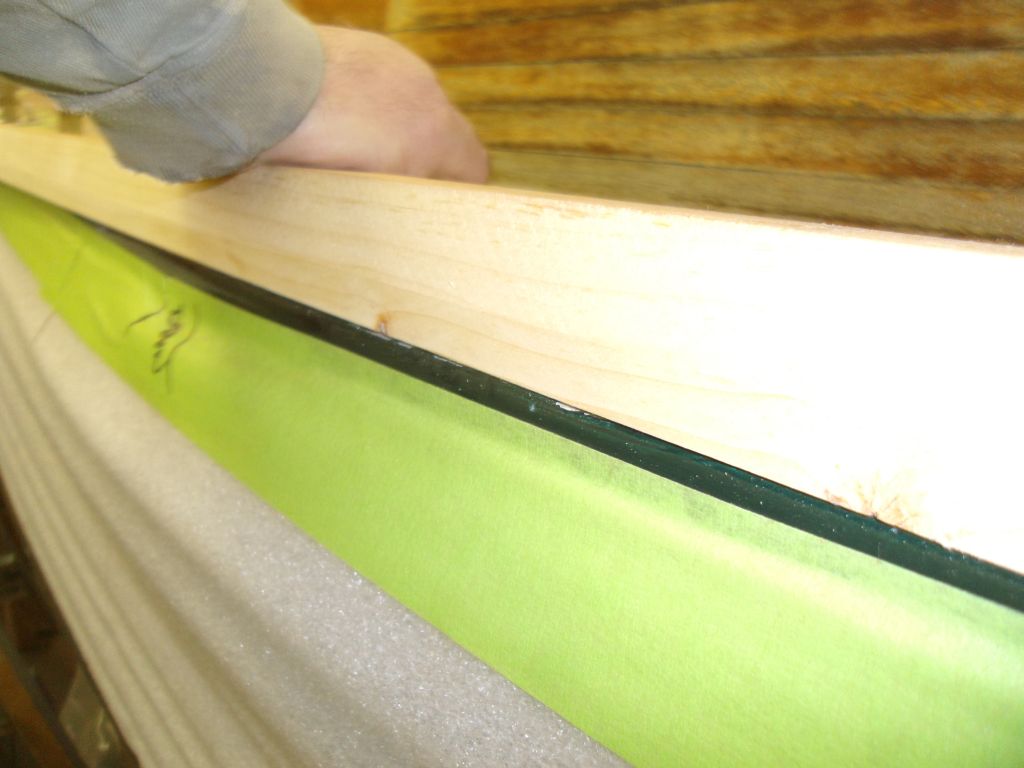
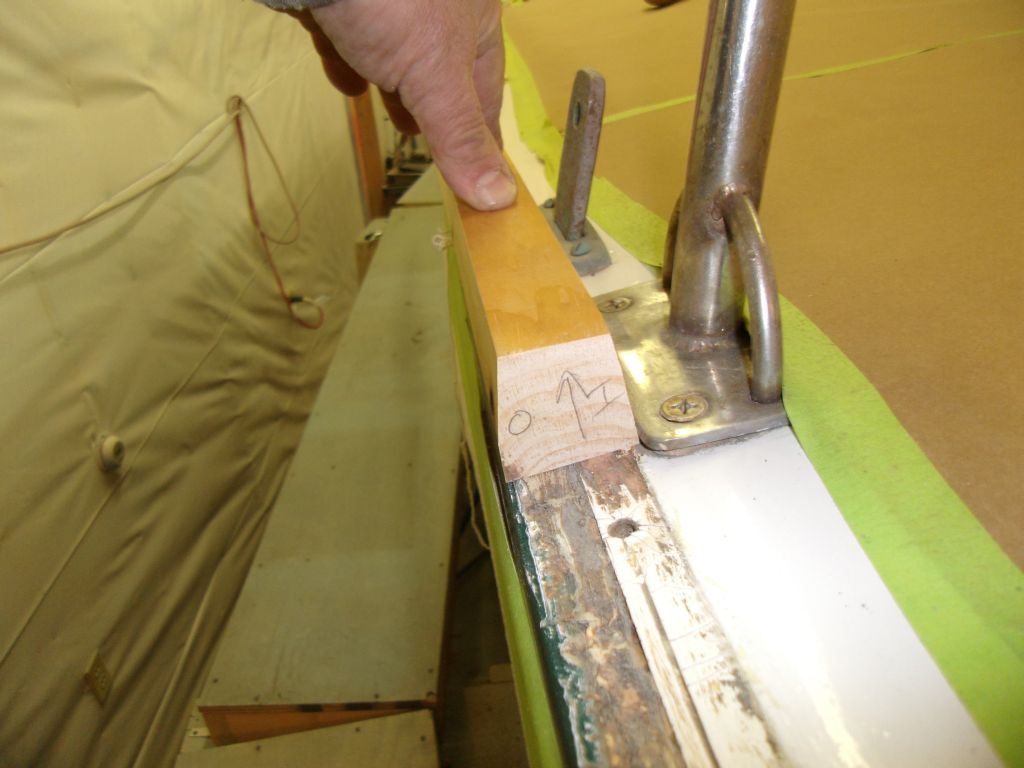
There were some constraints on the boat that I had to work around, in addition to the profile required for the mid-chocks to incorporate smoothly and the desire to keep the rail essentially similar in dimension and shape to the old rail that I removed. The width of the bottom of the toerail was limited by the nearby installation of stanchion bases and chainplate deck covers. Though these installations varied somewhat in their proximity to the rail base, the two closest bases--one on each side--dictated the maximum width the toerail could have. At the start, my initial rough profile was wider than this maximum.

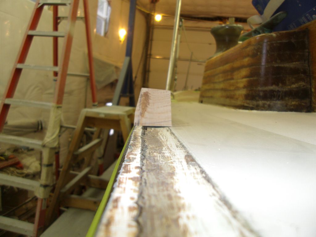
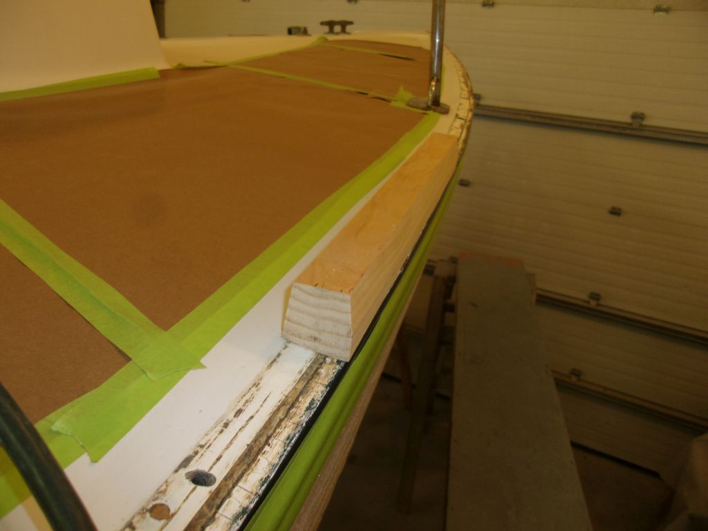
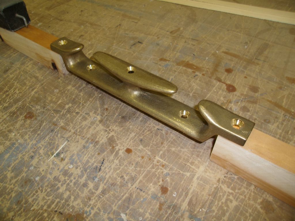
This didn't pose a problem since I felt the mockup was still a bit chunky and was slightly larger than it had to be to inorporate the chocks anyway. I made a reference mark at the toerail edge, and tested the mockup elsewhere to get a sense of its appearance.
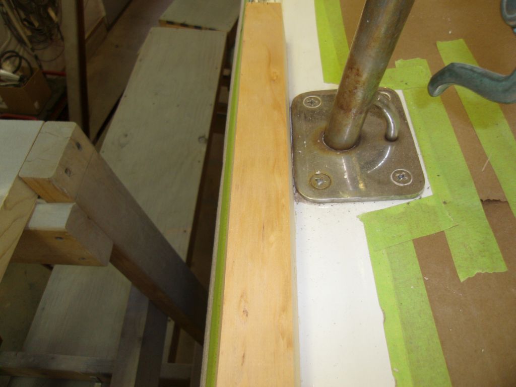
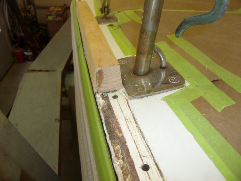
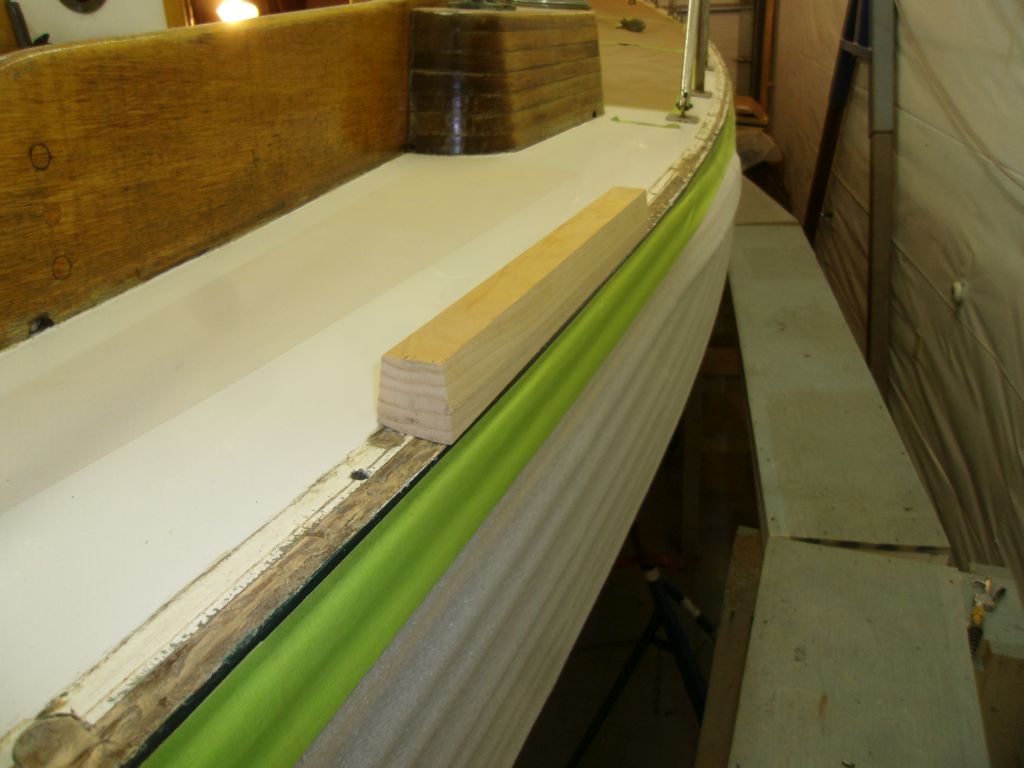
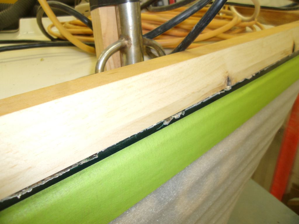
Back down at the bench I made various adjustments. I slimmed down the entire rail profile, as I had room to spare at the top surface width, and, to make up the rest of the width decrease required I milled a flat (vertical) profile at the outboard lower edge where it met the hull; this flat could serve as a landing area for a rubstrip to hide the seam between the hull and rail, something the original toerail had not had but which might be a nice addition. Finally, I milled a 5° angle on the bottom to match the deck camber.
The new rail profile fit cleanly by the two closest stanchion bases, and looked much better overall; the profile still fit the mid-rail chocks well, and the overall height matched that of the existing taffrail.
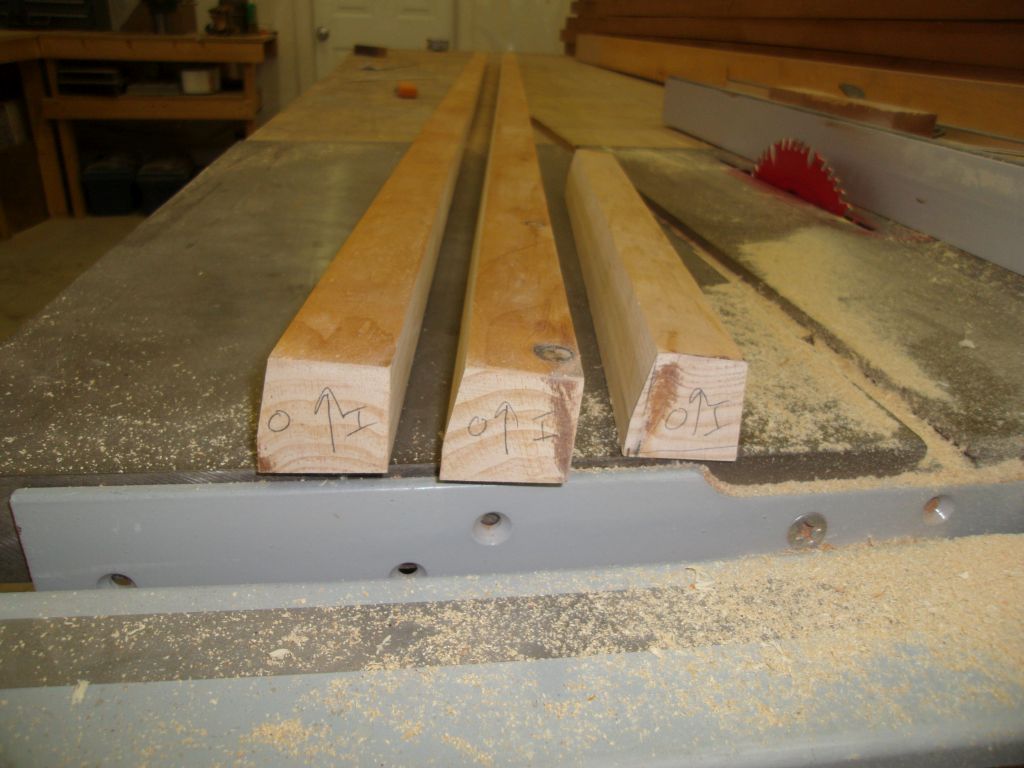
Satisfied with the profile, I prepared two longer test blanks to try out the milling process and to provide me with blanks to use for testing scarf profiles and cutting procedures, among other things.
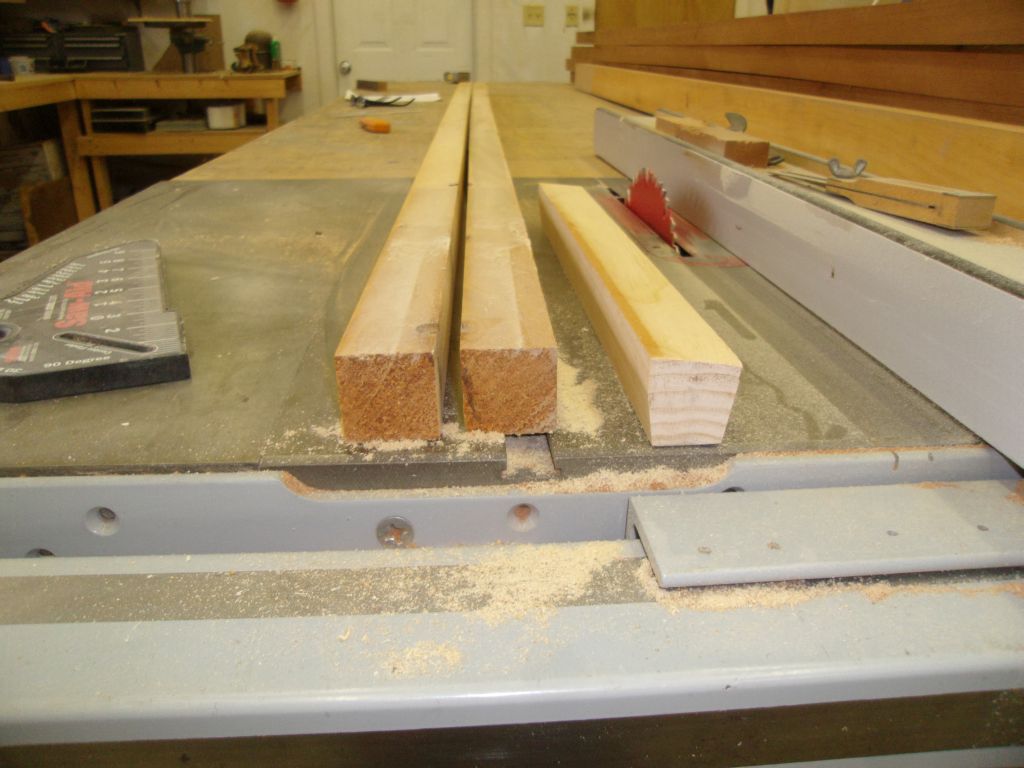
First I cut the 5° angle on the bottom side of the blanks.
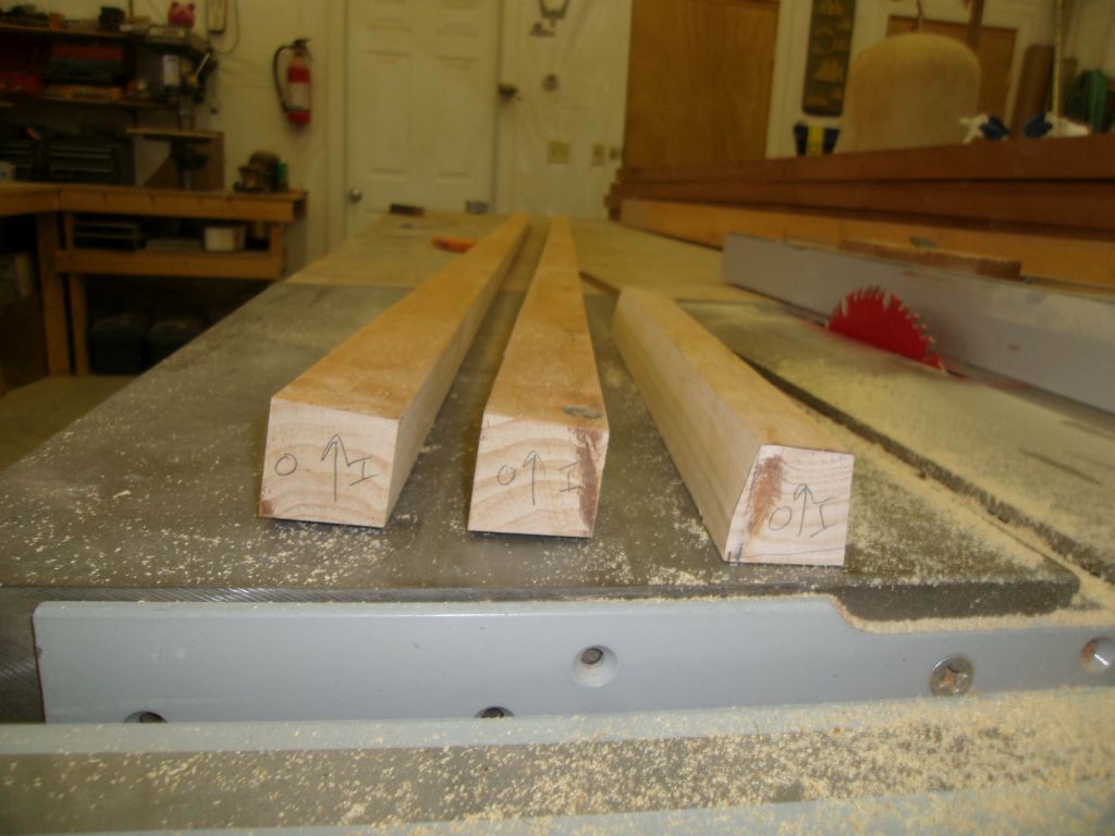
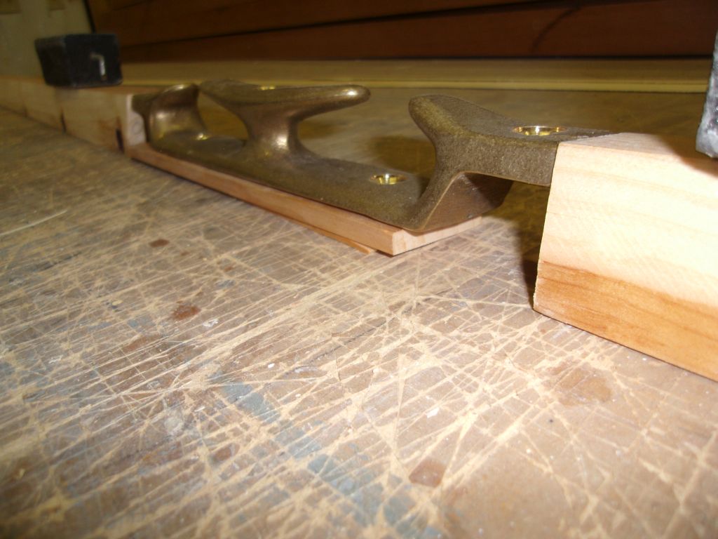
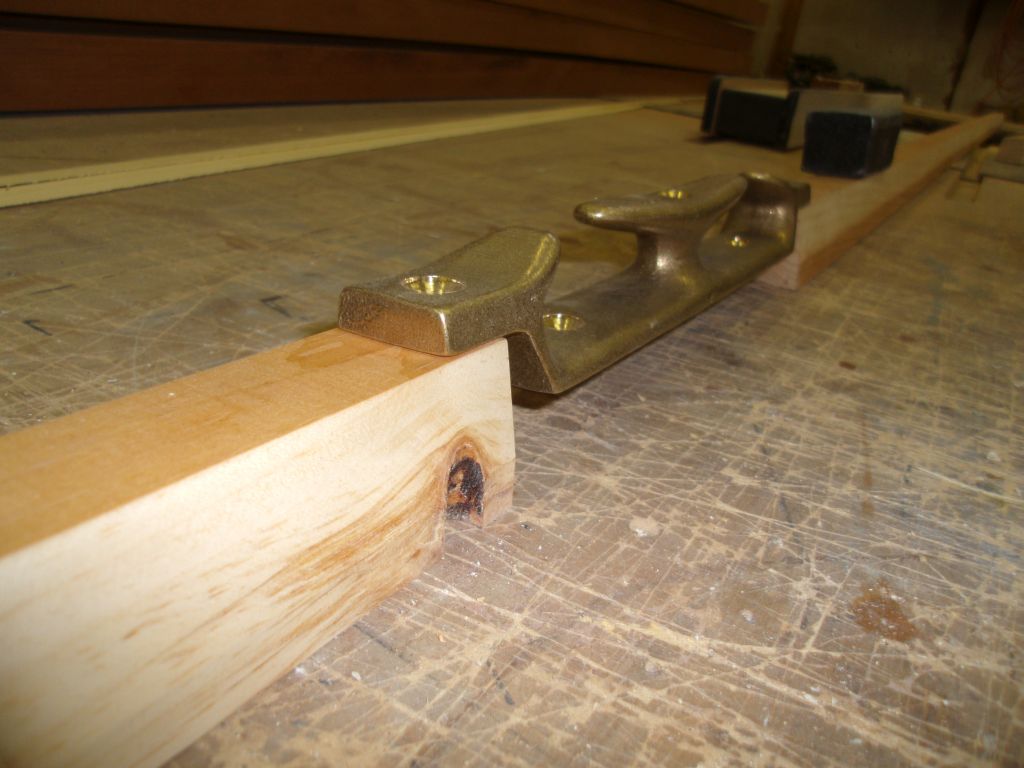
Then I cut 8-1/2° angles on the two sides, adjusting the fence for the second cut to leave the flat area and end up with the desired final profile after three cuts. Then I trial-fitted my "final" blanks in various places around the boat to ensure the profile was what I wanted and fit properly.
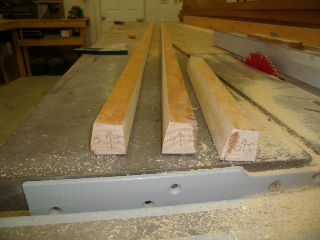


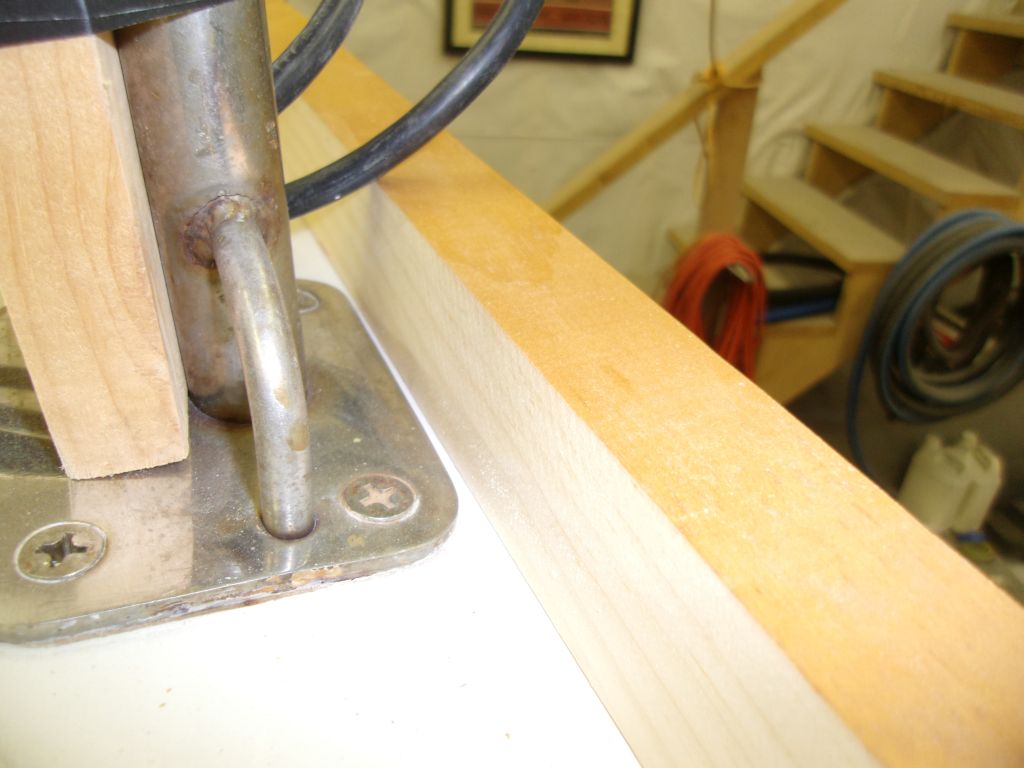
I tested the mid-chocks in two configurations--flush at the top, and with the top ears overlapping the rail. With an appointment planned for later in the day, I left milling the actual mahogany into the toerail profile for another day, nbow that I had the mockup complete.

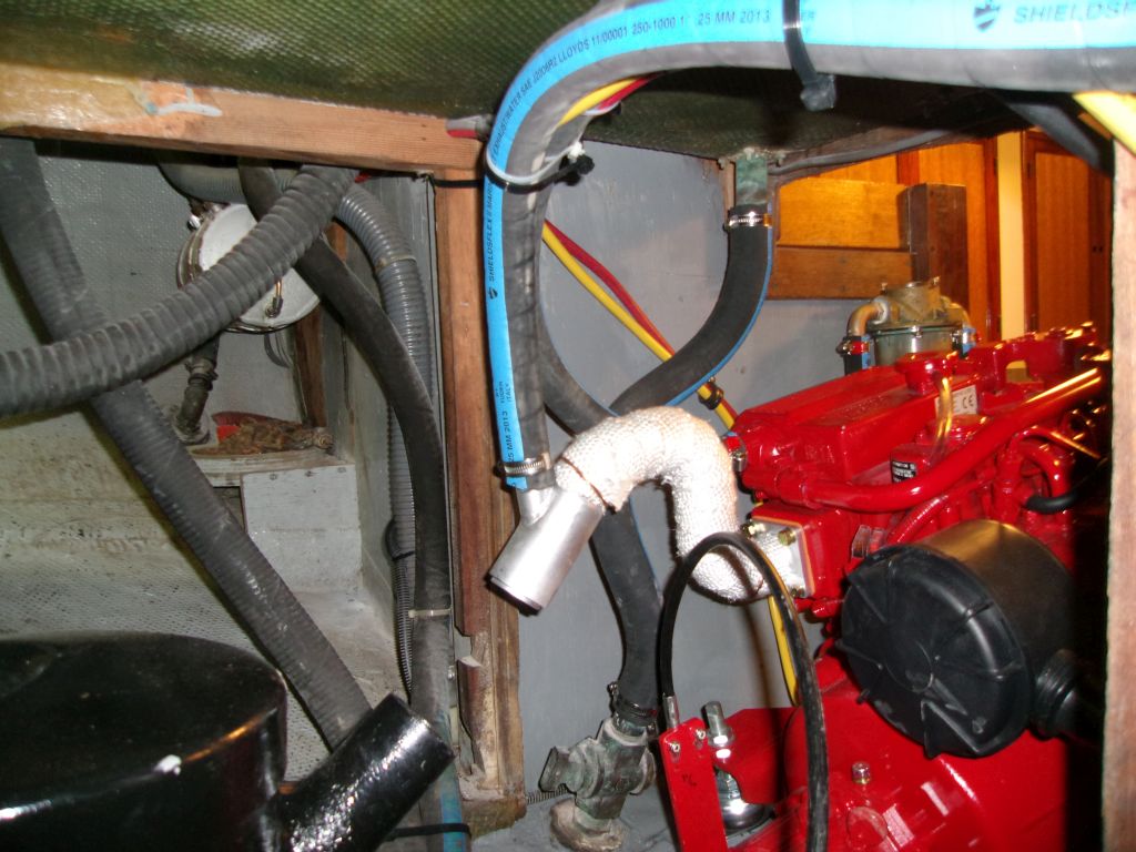
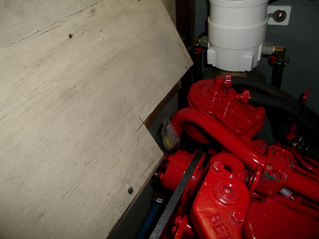
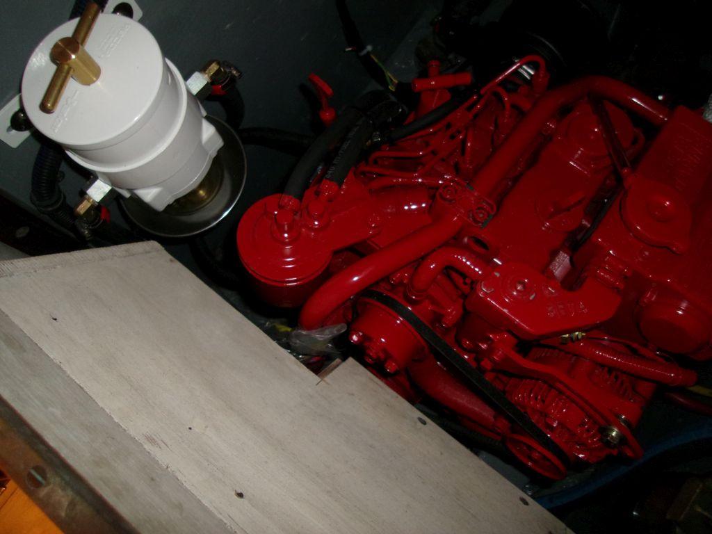
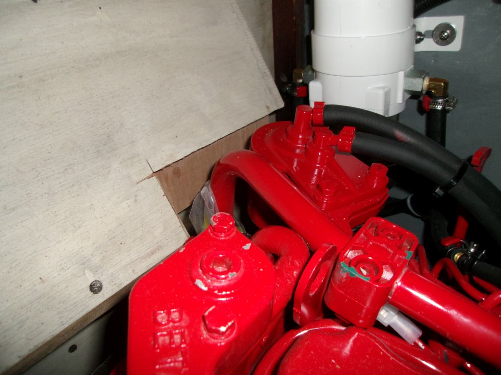
The existing engine box cover (or front, as it were) featured a built-in recessed step that naturally protruded into the engine space. I'd not let this dictate the desired position of the new engine, but the step conflicted slightly with the engine-mounted fuel filter and part of the raw water system's piping. Essentially, I'd need to clip this little corner of the step in order to allow it to clear the engine.
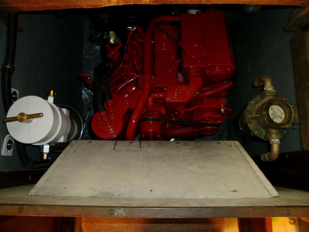


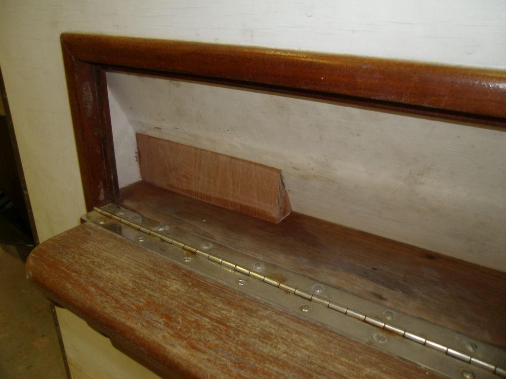
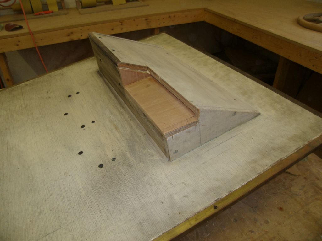
After making some reference marks, I cut out the offending corner and, after making sure the fit was correct, I patched the area with additional plywood, which I'd paint to match once the glue dried.


Total Time Billed on This Job Today: 4.75
Hours
