

December 30, 2024
PT11-44
Monday
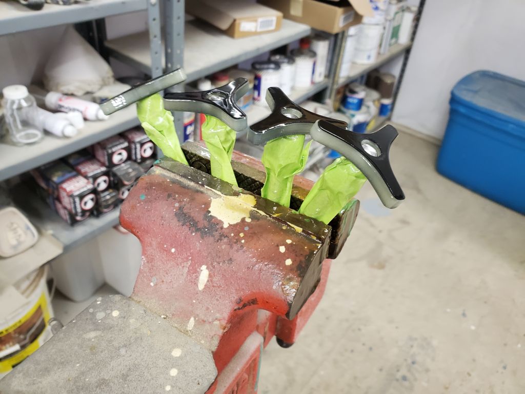
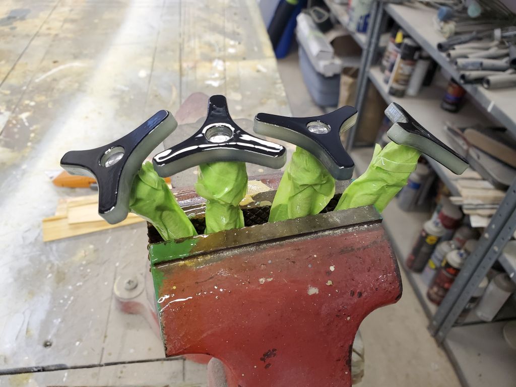
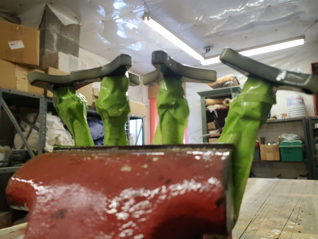
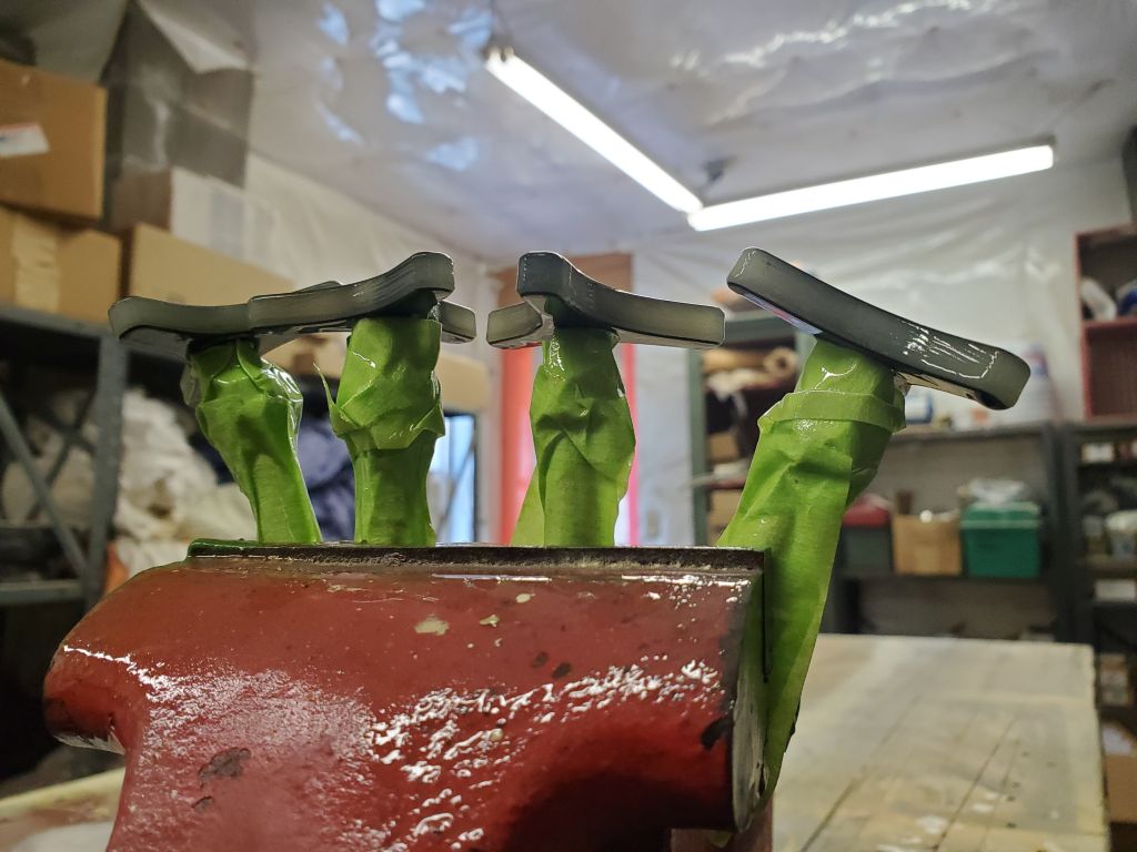
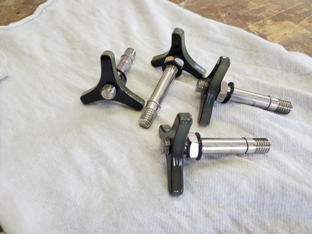
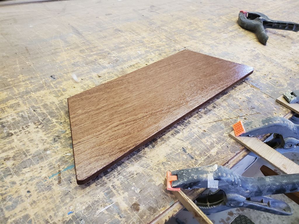
Earlier, thinking I was done with assembling the boat halves for a while, I’d removed the knobs and pins from the connecting hardware, anticipating interior finish work and masking. But I realized while glancing ahead in the book that I’d have to assemble the hull to do the initial layout for the alignment clips. So, over the holiday break and taking advantage of the fact that the knobs were already off, I went ahead and applied finish to the knobs, which would save having to do it later. I thought the knobs as machined looked pretty cool, so I chose to finish them with spar varnish, which I happened to have in a handy spray can. I masked off the pins and held the knobs in a vise so I could apply several coats of varnish over a day or two.

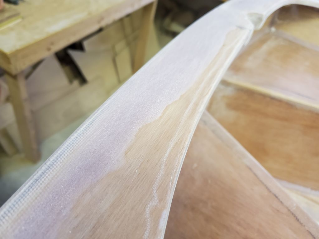
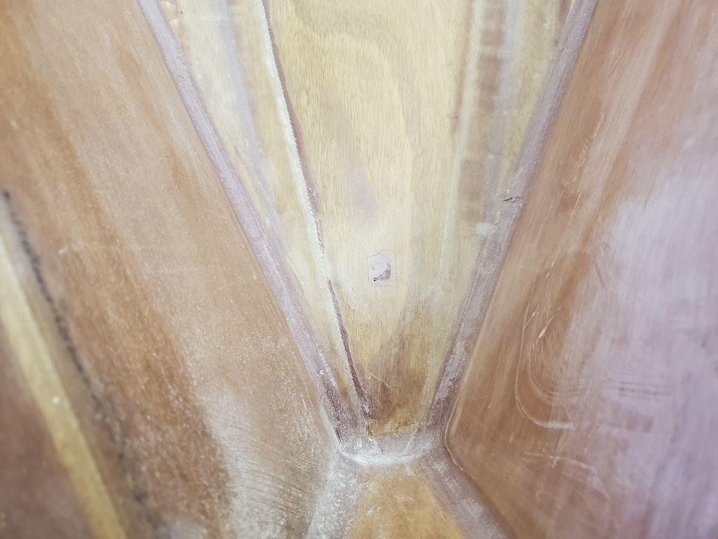
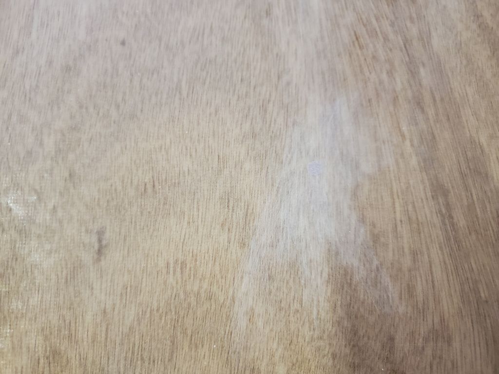
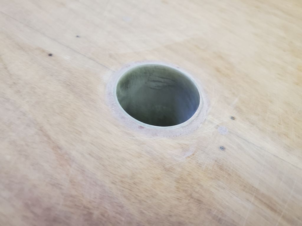
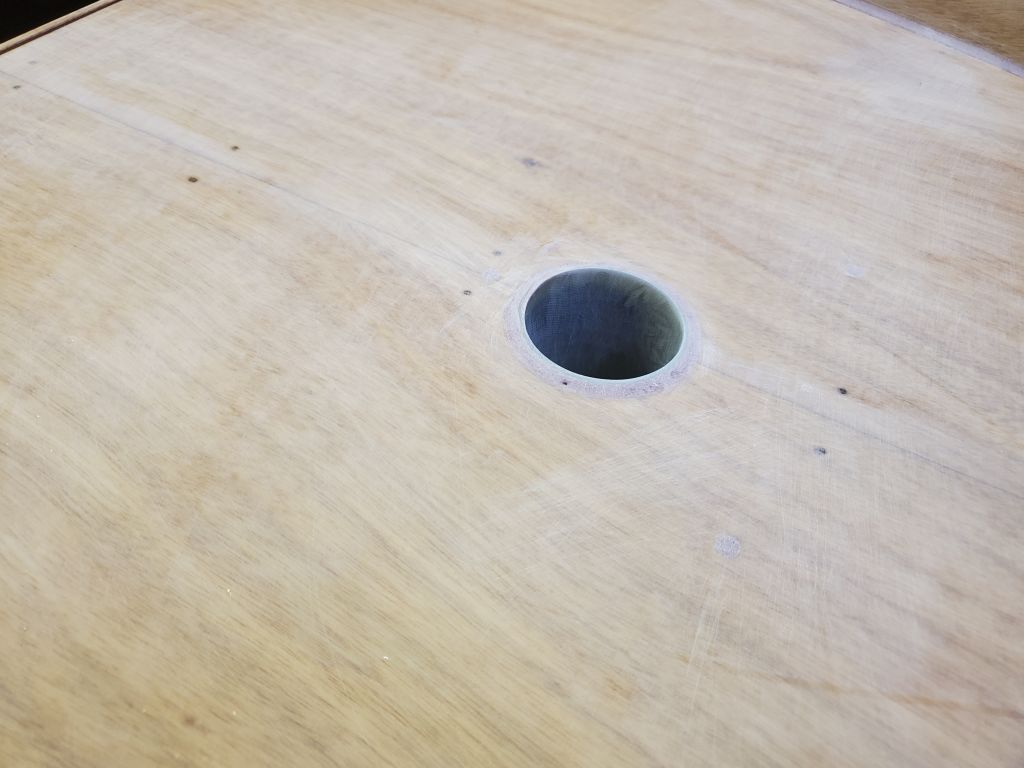
Moving on with real work, I started out by sanding all the filled screw holes and other areas from last time, working only by hand and with a small sanding block with 12o grit. This included the fairing on the inwale, and the filled screw hole on the forward bottom edge of the skeg, along with the small fillet surrounding the mast tube. A few areas still had some low spots that would require some spot filling later.
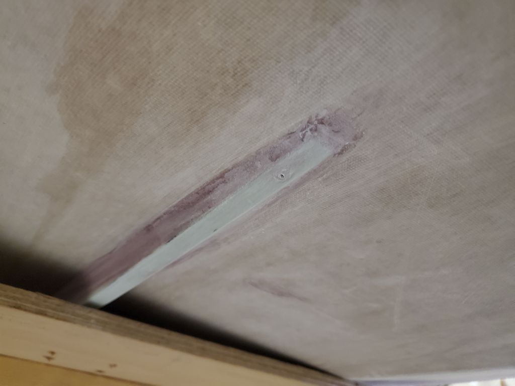
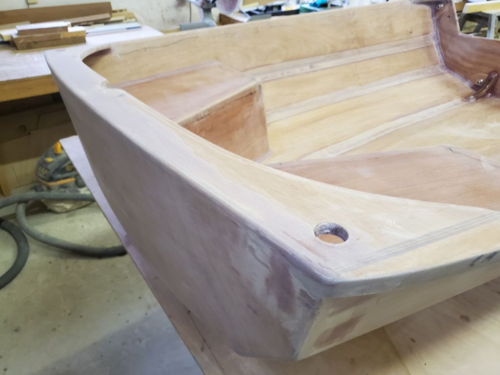
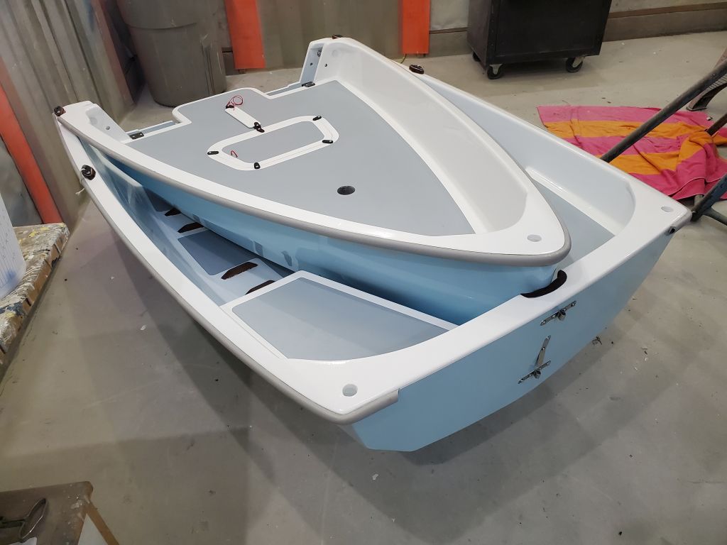
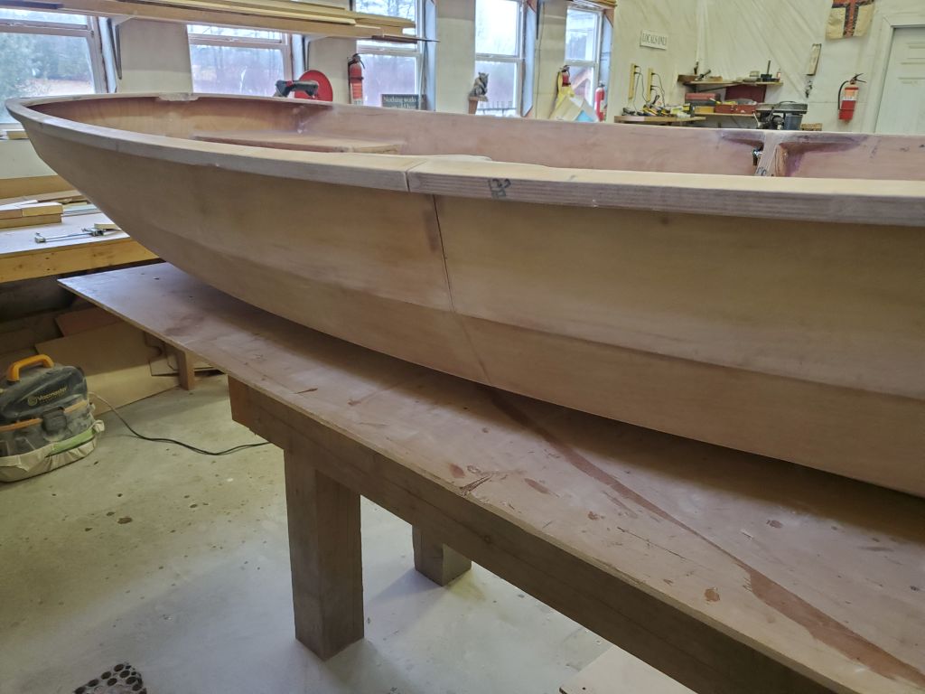
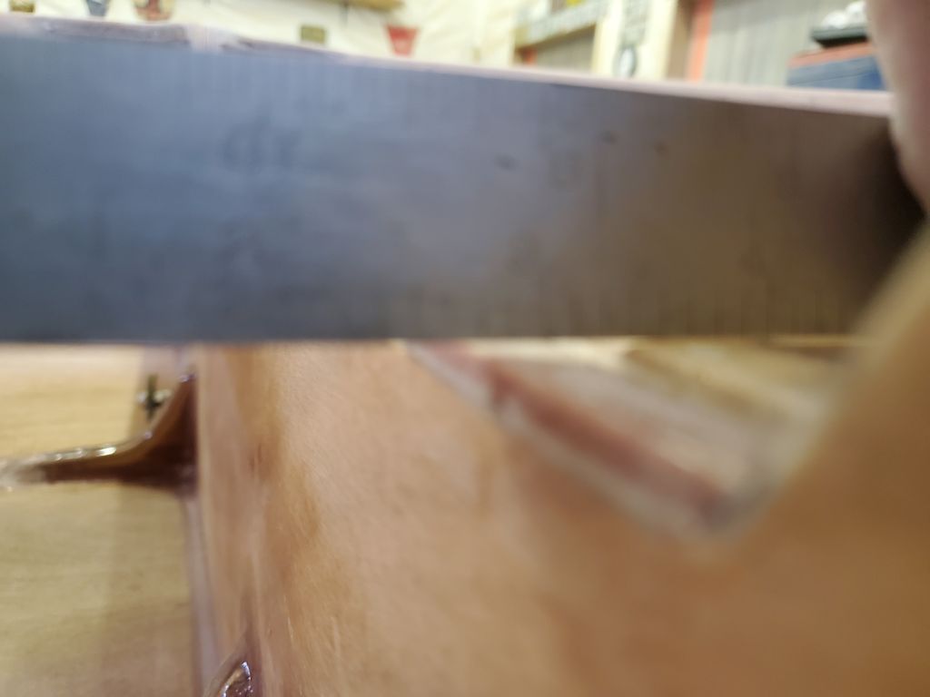
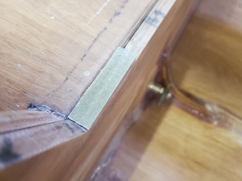
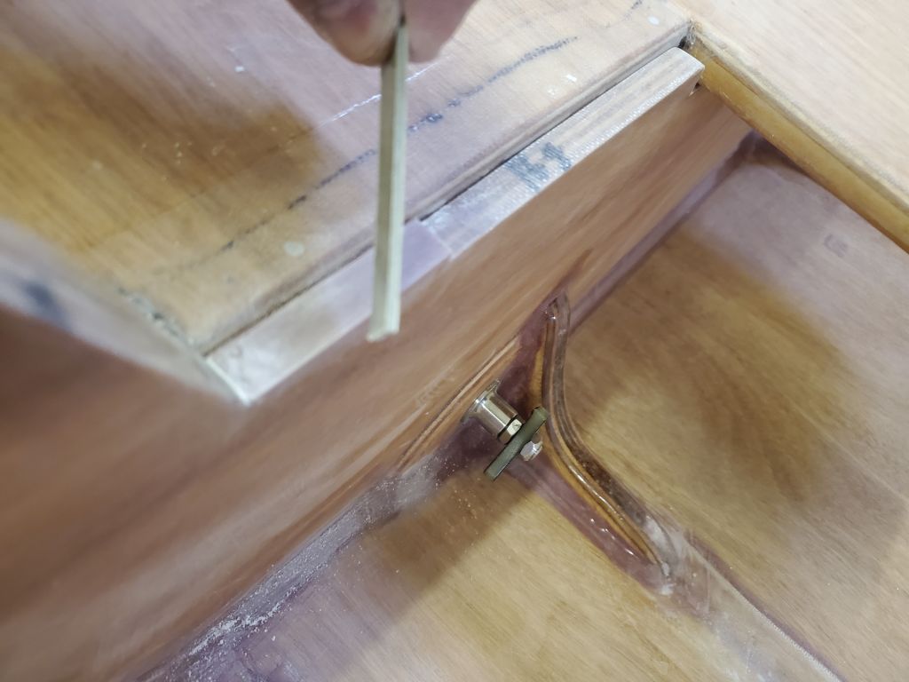
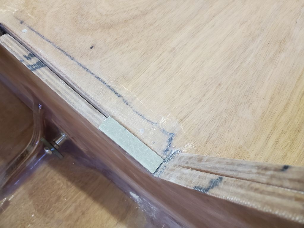
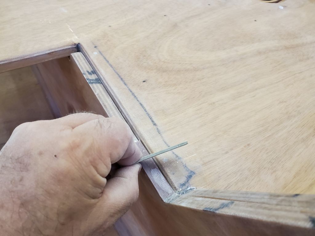
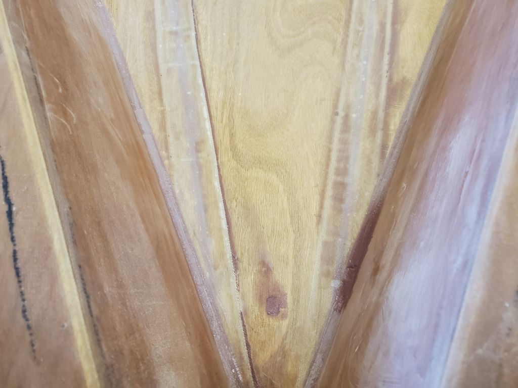
I block-sanded flush the edges of the small fiberglass shims I’d epoxied at the aft bulkhead corners for the alignment clips, then reassembled the connecting pin hardware so I could conjoin the boat halves again to continue the initial layout of the alignment clips. The shims were intended to bring the aft bulkhead up to or just higher than the level of the foredeck, so I was unprepared to find that in fact the shims were still below foredeck level once the boat was assembled, as determined by holding a straightedge tight to the foredeck and observing how it passed over the shims on both sides. This was mildly frustrating and wholly unexpected.
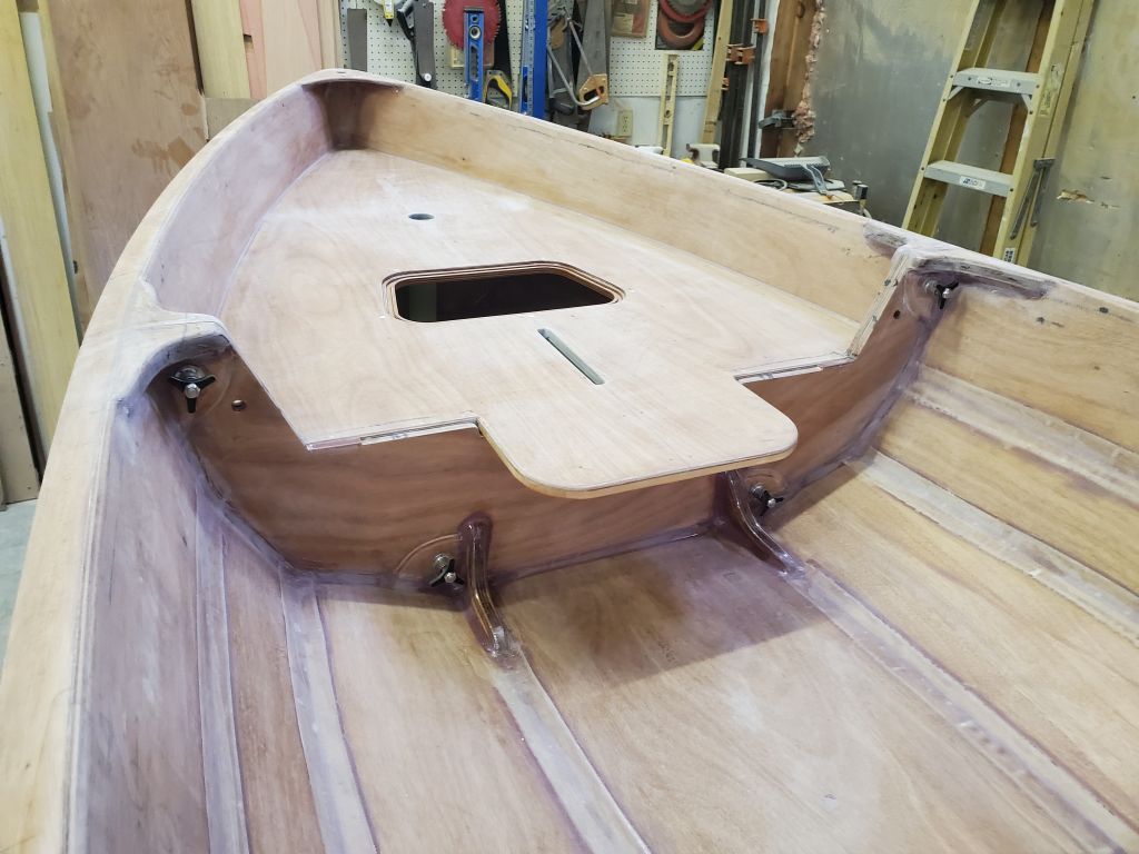
I cut some additional shims from prefab fiberglass stock on hand, and ensured that they’d be thick enough to stand proud of the foredeck once installed.

I disassembled the boat once more and, after final preparations, glued in the extra shims with thickened epoxy.
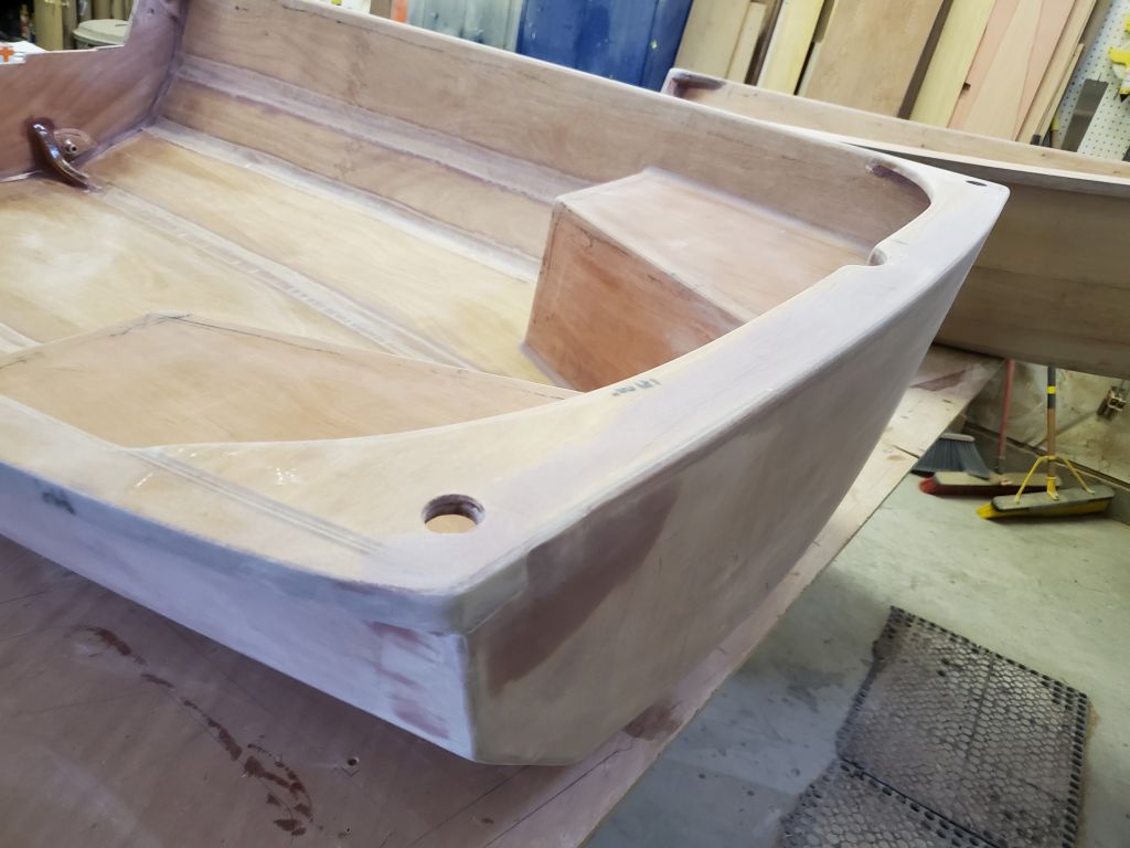
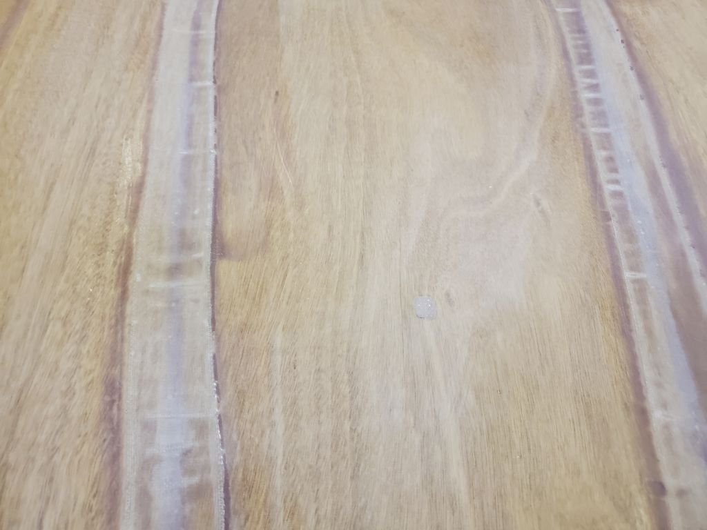
Without any additional work required for now on the hulls, I applied some fairing epoxy over some of the screw holes, the inwale, and previously-filled nail holes in the foredeck to bring everything up flush as needed.

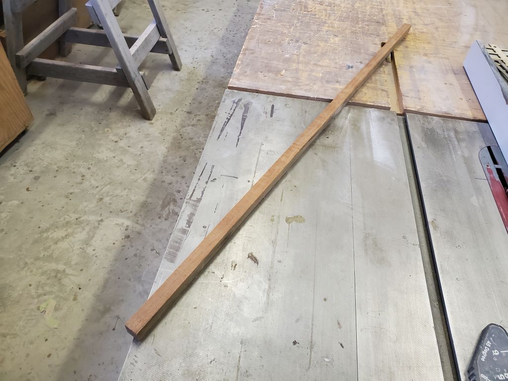
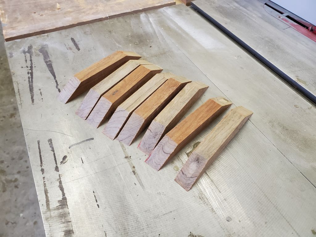
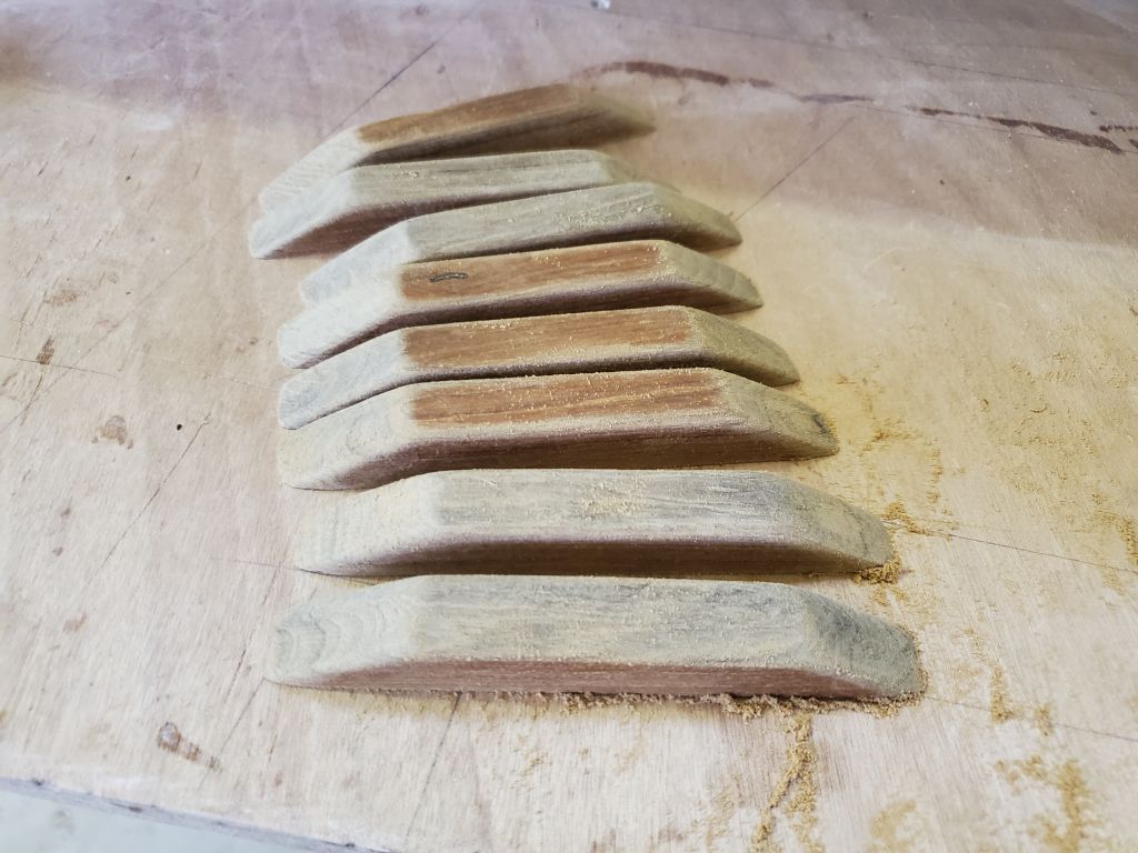
A few days earlier, while pulling out various small parts left in the inventory and which would require some epoxy steps before final installation, I discovered that there were no rowing foot support cleats amongst them. I found this odd since an installation template was included, and the book covered in some detail their installation, but it turned out that for reasons beyond comprehension these cleats were an optional add-on and not part of the stock kit. Given the otherwise completeness of the kit, and the necessity of these foot supports for efficient rowing, this was surprising. Fortunately, I had teak stock on hand from which I could easily (if unnecessarily) make up the cleats in the shop. From a teak leftover, I milled a 3/4″ square piece that was long enough to build the eight 5-1/2″ long cleats the manual suggested were necessary, and I shaped them according to photos in the book, with angled ends and rounded corners.
(Note: It took 30 minutes to mill and sand the cleats, and $8.37 worth of teak, so the total cost of the shop made cleats was about $45, versus $55 for the add-on kit.)
Now with all the required small parts at hand, I turned to some epoxy pre-finishing as detailed in the book. Along with the foot cleats, I had to address four rowlock risers, two aft seat support cleats, a daggerboard filler piece cleat, and the two carbon fiber alignment clips, plus the aft seat itself.

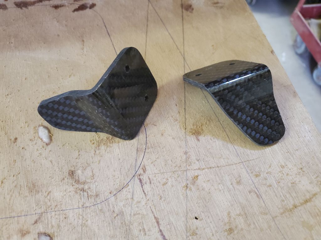
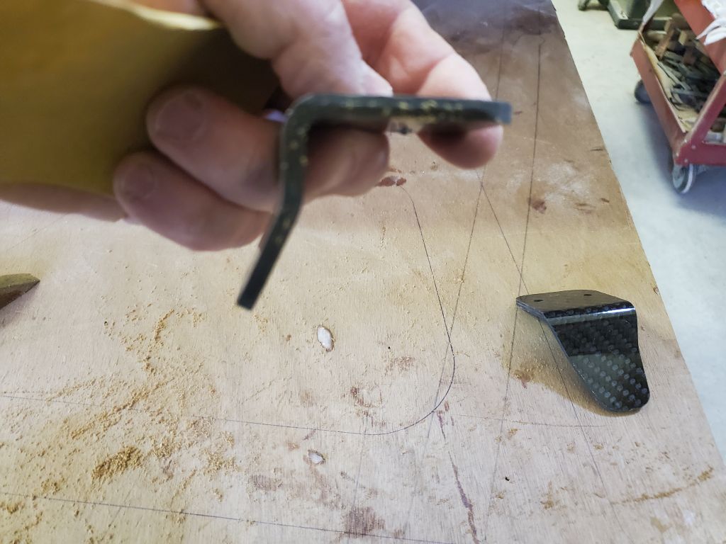
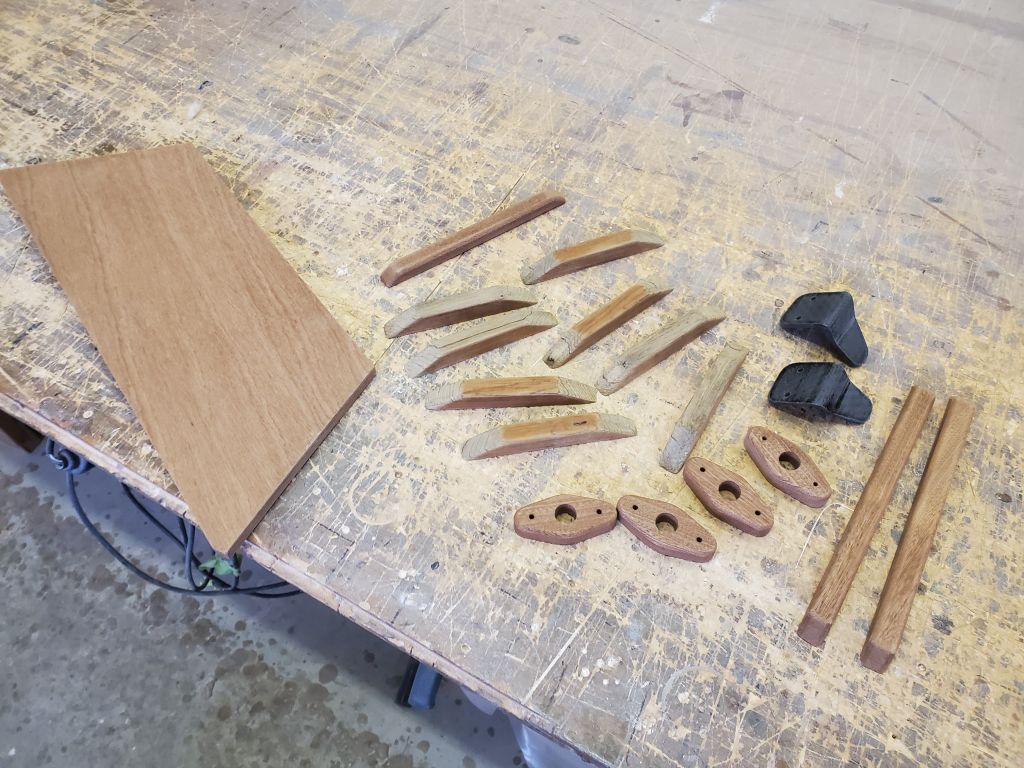
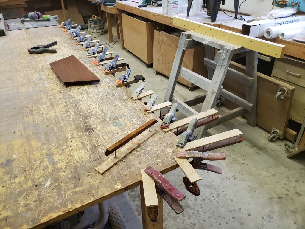
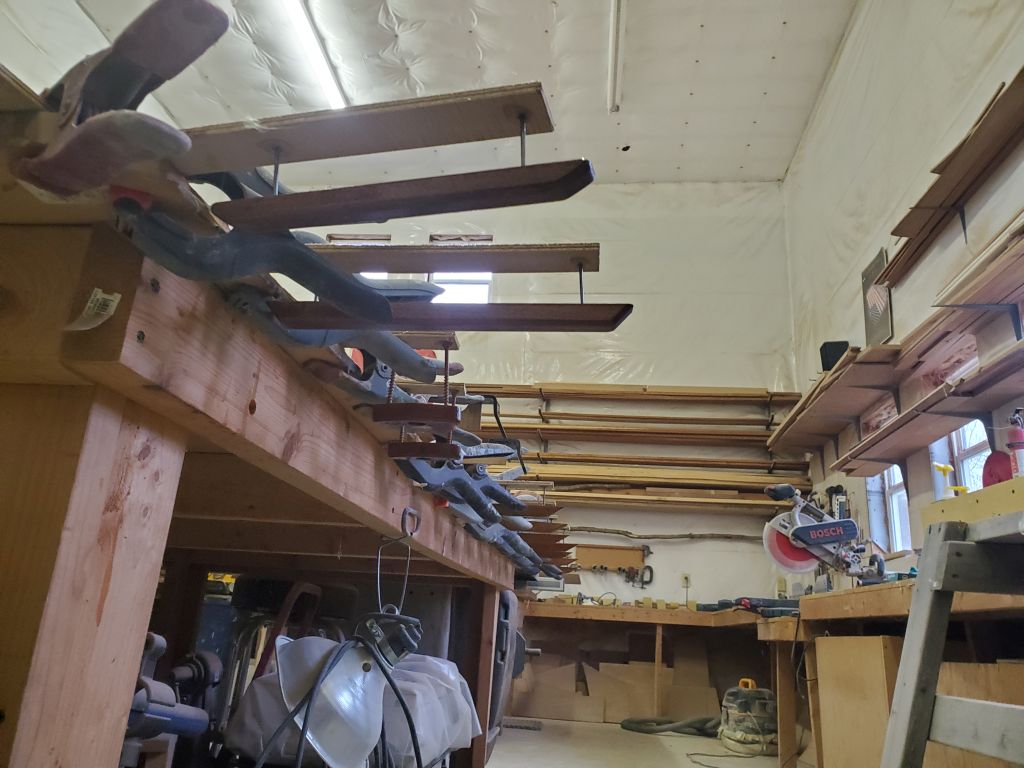
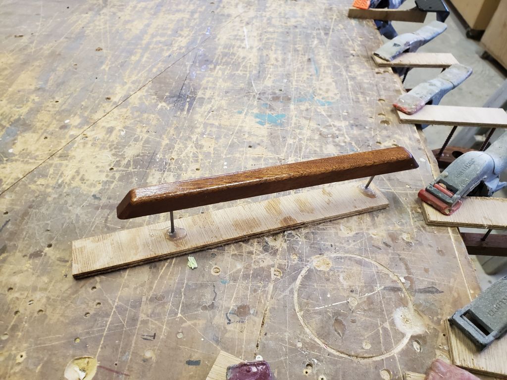
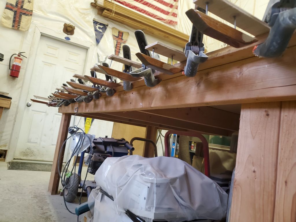
To thoroughly epoxy-coat all these tiny parts, I followed the teachings of the manual, and attached all the parts to small plywood bits with nails and hot glue. The oversized plywood strips–quickly milled from scraps–provided a way to easily secure the parts with standoffs, in this case either nails or screws glued to the plywood, and this arrangement allowed for easy coating and handling of the 18 parts, including–at the book’s suggestion–clamping the parts upside down off the bench while the epoxy cured. I coated all sides of the aft seat by holding it off the table with nails driven into the table surface, and their heads cut off (as I’d done throughout the project for various parts). These parts would receive two more coats in the coming days.

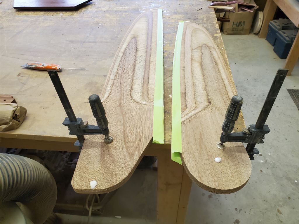
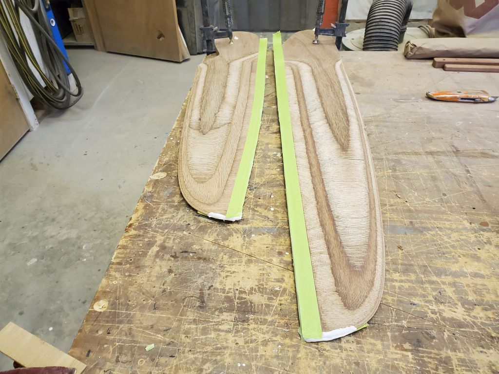
These small parts were the last components of the boat itself requiring work for now, so I turned to the sailing foils kit–rudder and daggerboard–that this owner also chose to purchase, and which came with its own separate manual and collection of parts. The foils as delivered were pre-milled to shape from 3/4″ plywood.
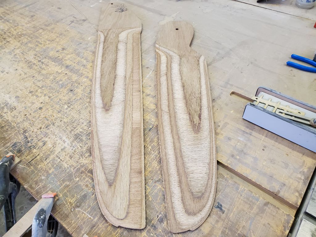
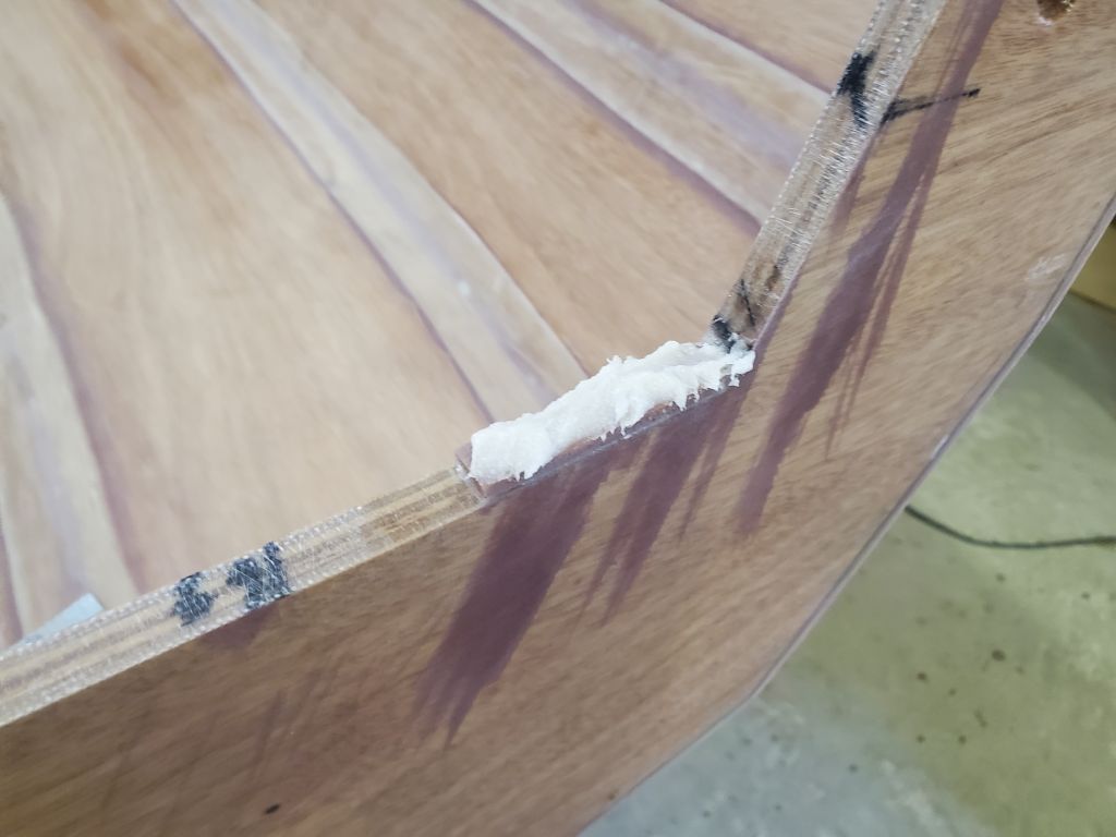
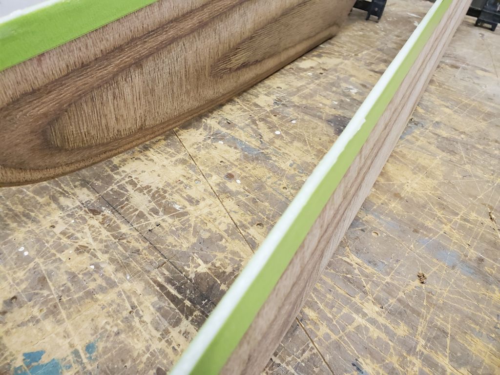
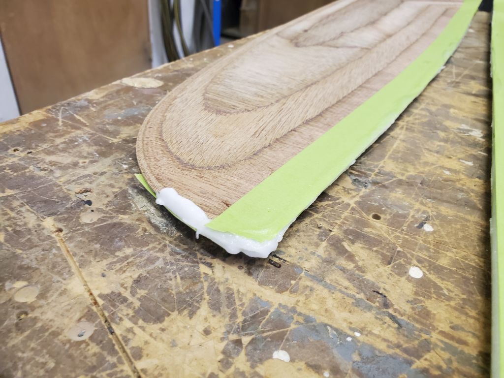
The first task required with the foils was to build up trailing edges of solid epoxy, much as I’d done with the skeg a few days earlier. The milled parts included a built-in space for this extension on their trailing edges and tips.
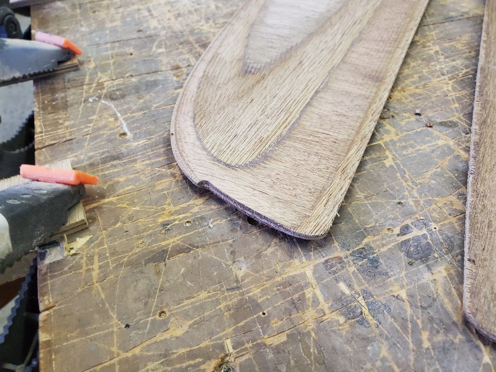

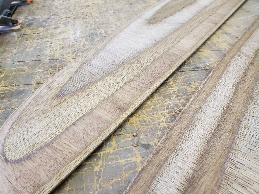
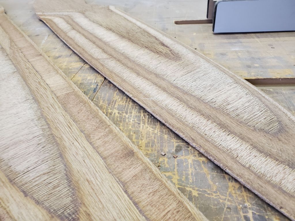
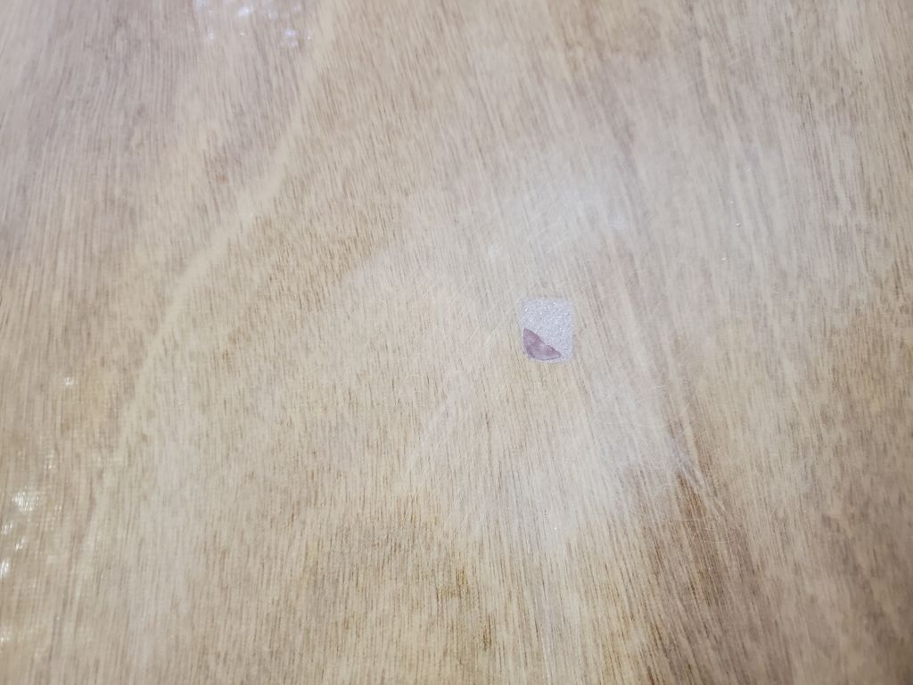
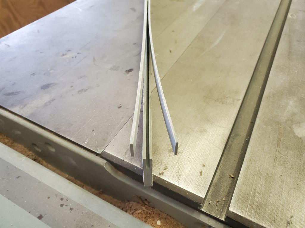
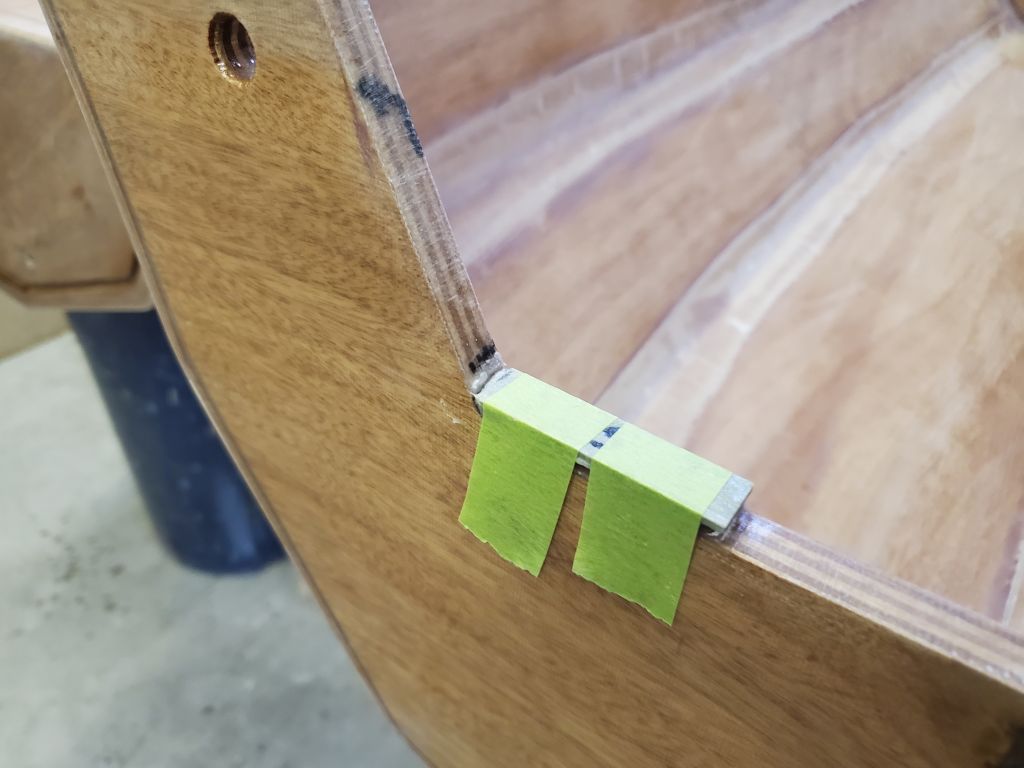
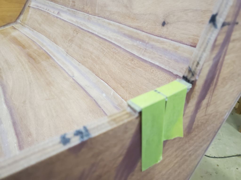
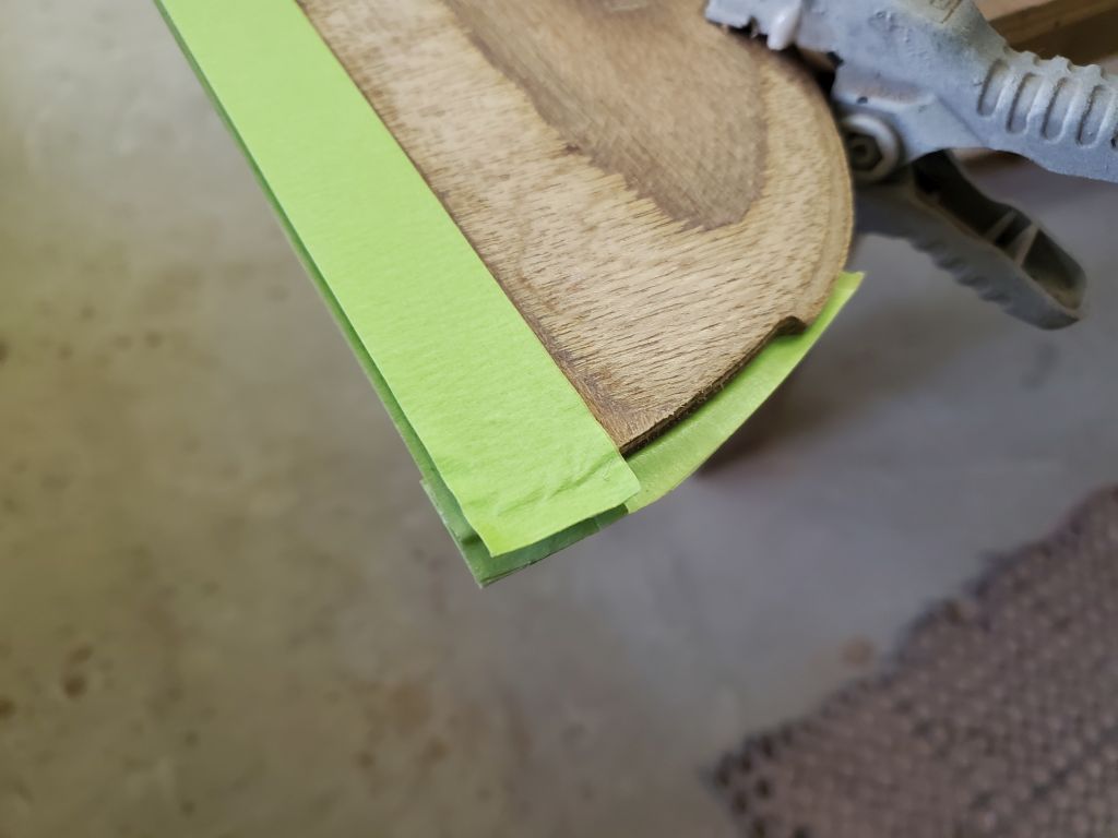
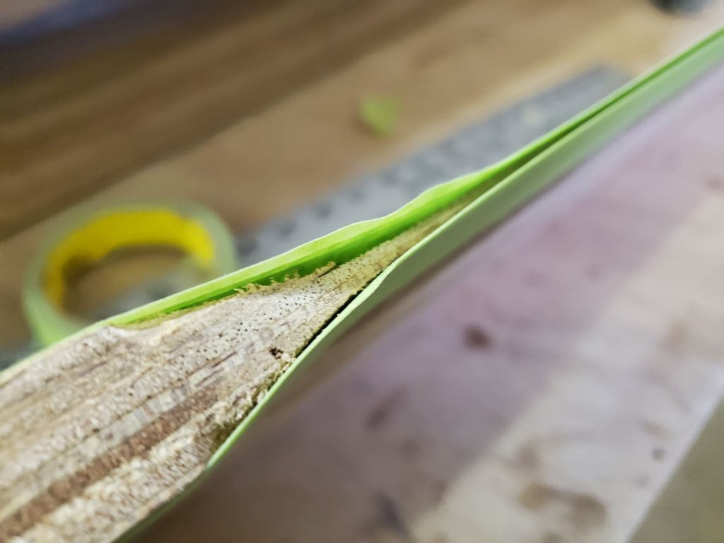
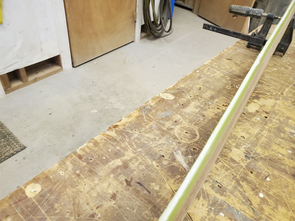
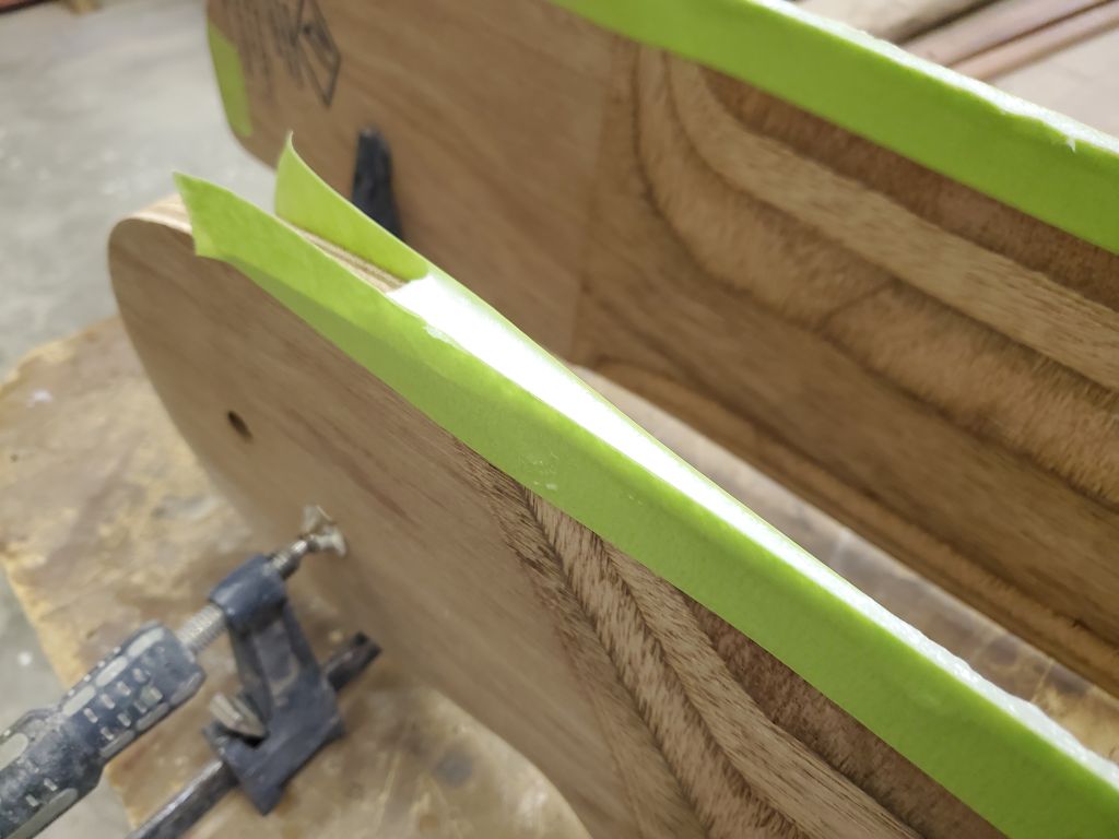
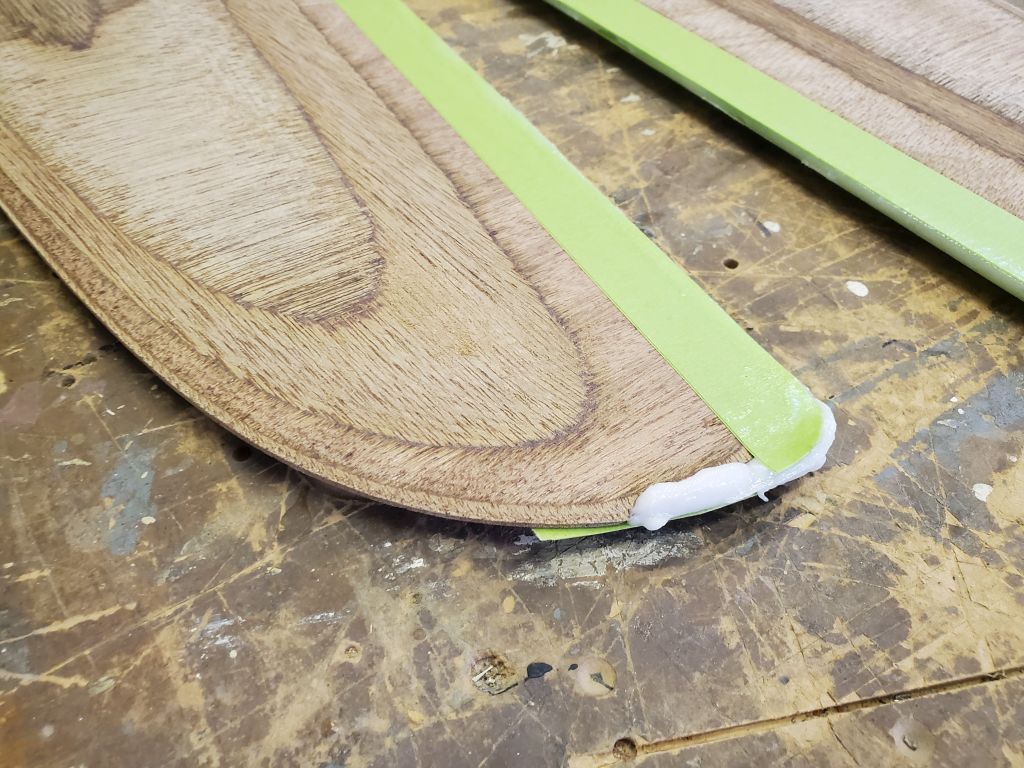
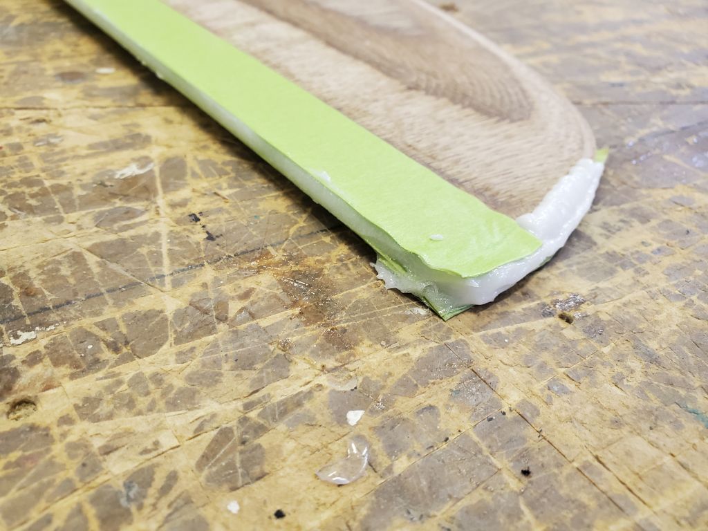
To form these new trailing edges, I proceeded in accordance with the manual, and applied three layers of masking tape (pre-laminated on a long metal ruler) to the trailing edges on both sides of each part, pressing the tape tightly against the plywood edges and leaving a small gap, or quasi-mold, formed by the tape.
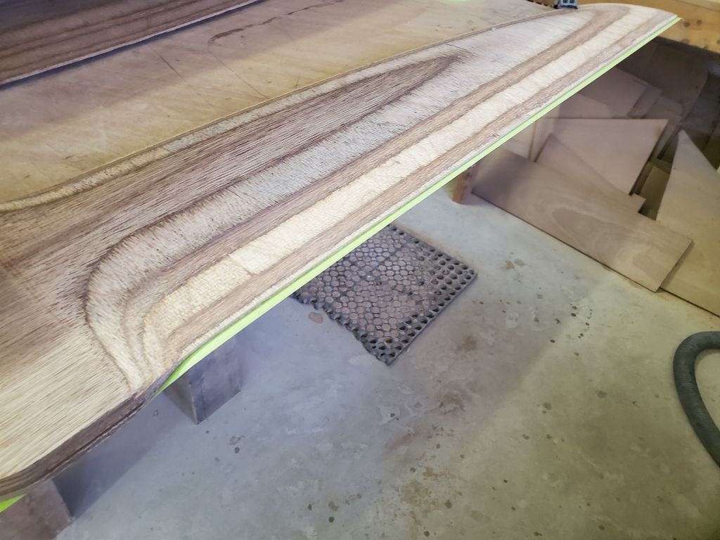
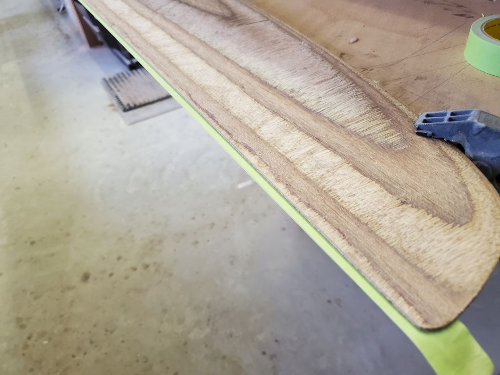
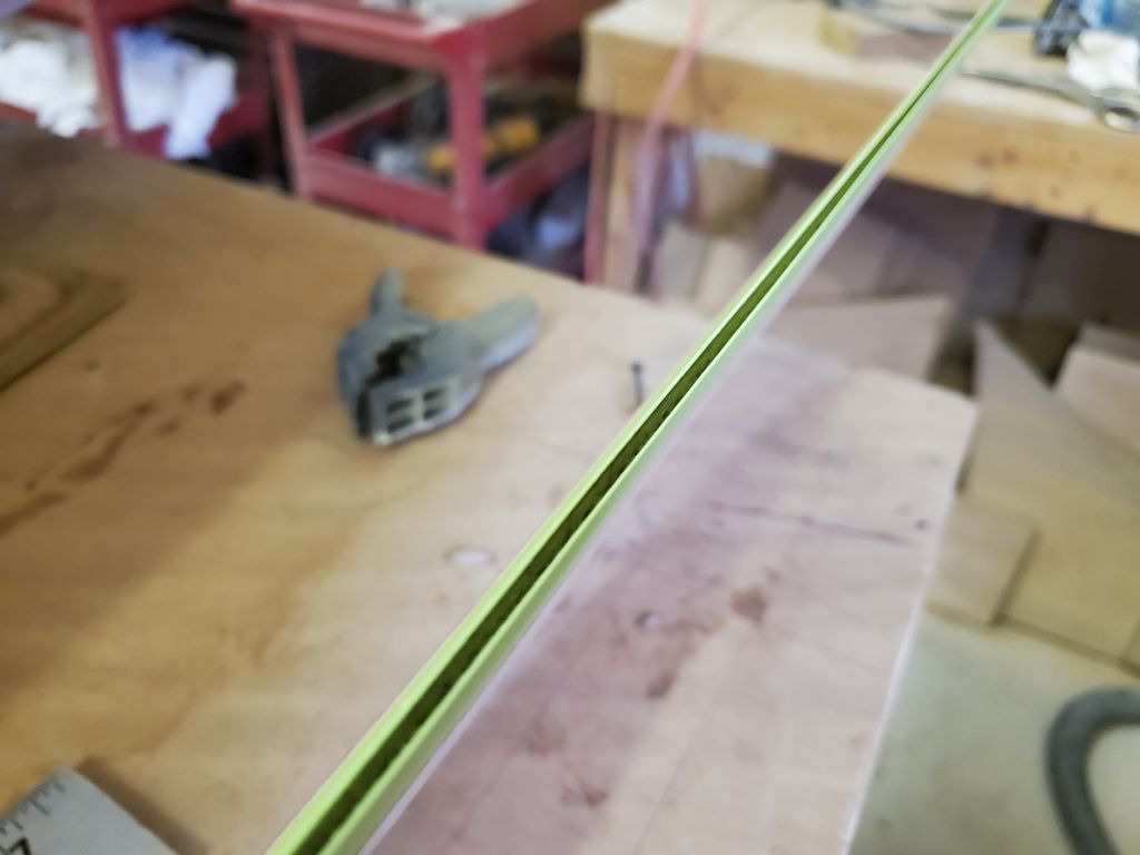
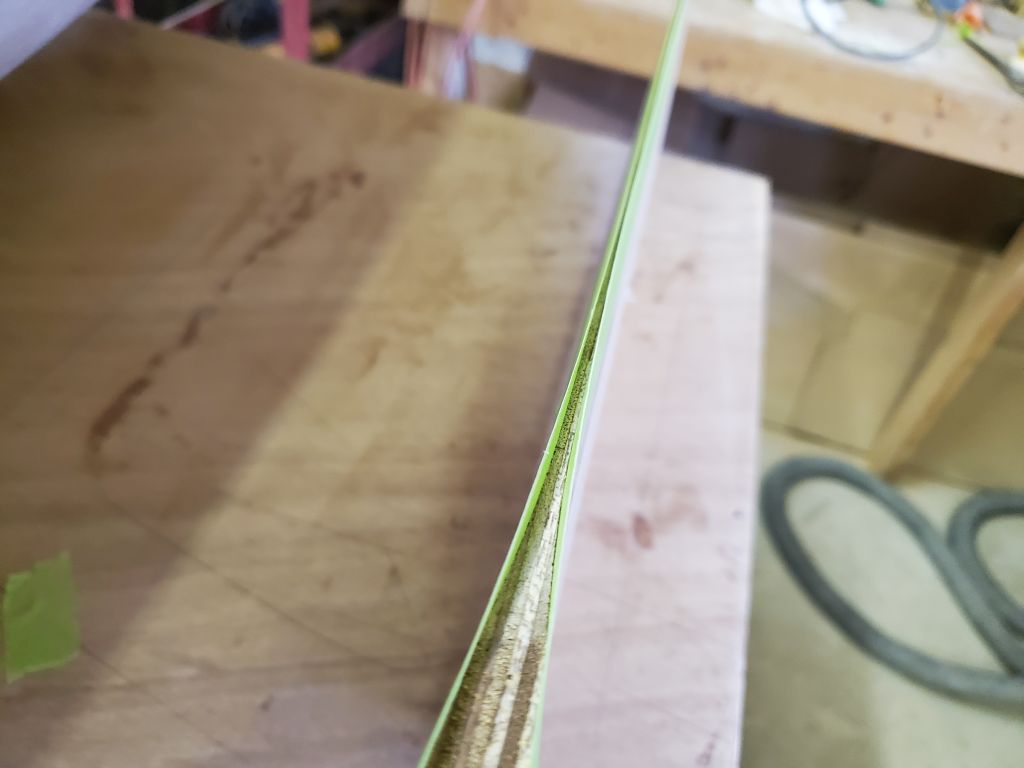
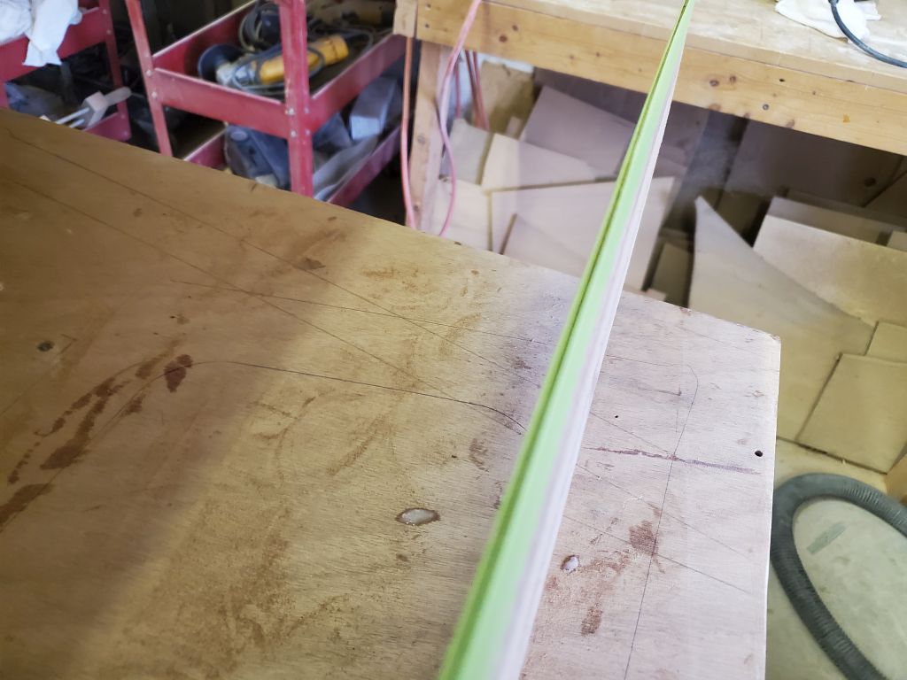
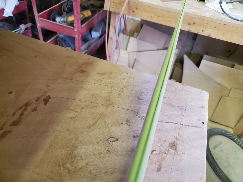
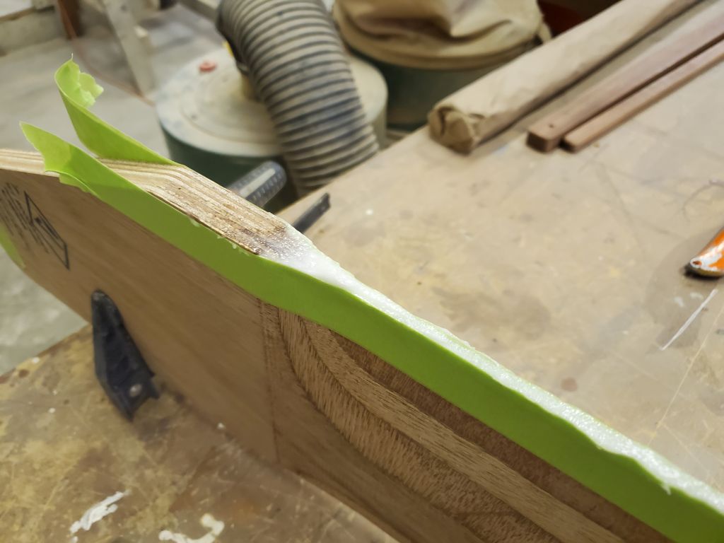
I propped the parts up so the trailing edges faced upwards, and filled the “molds” with a thickened epoxy mixture, piped in by syringe.

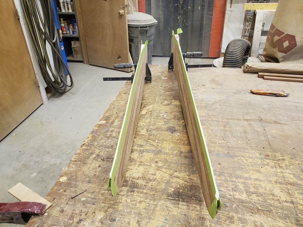
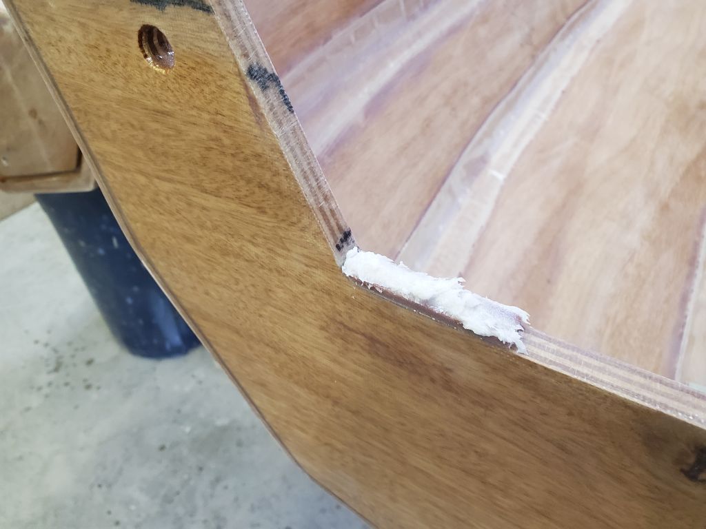
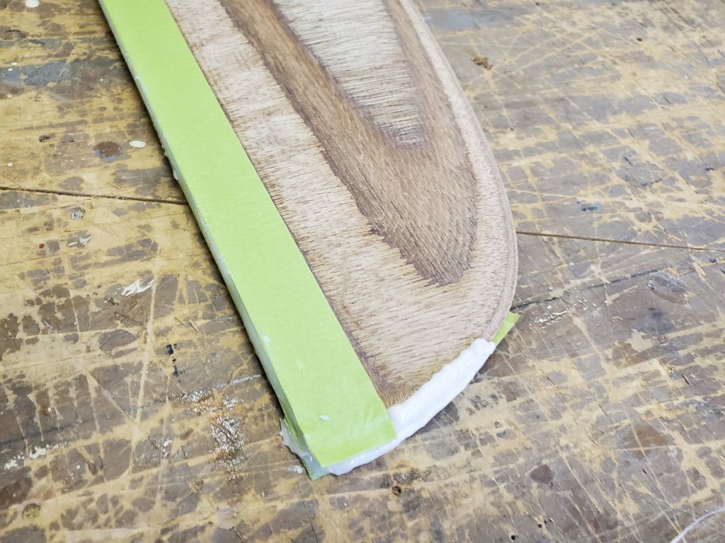
Then, I laid the parts on their sides and applied more thickened epoxy to the tips, which were only masked on one side, meaning the epoxy had to be abundant so I could shape it down to the required profile later. I also filled the holes at the top of each part with the thickened epoxy; I’d masked over these from the underside previously.
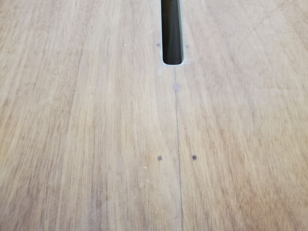
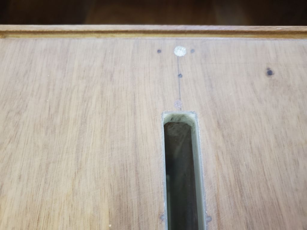
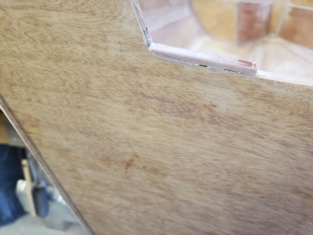
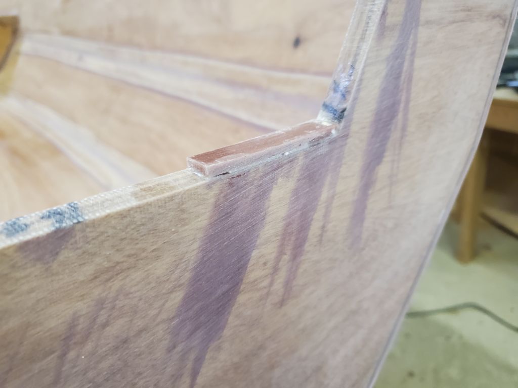
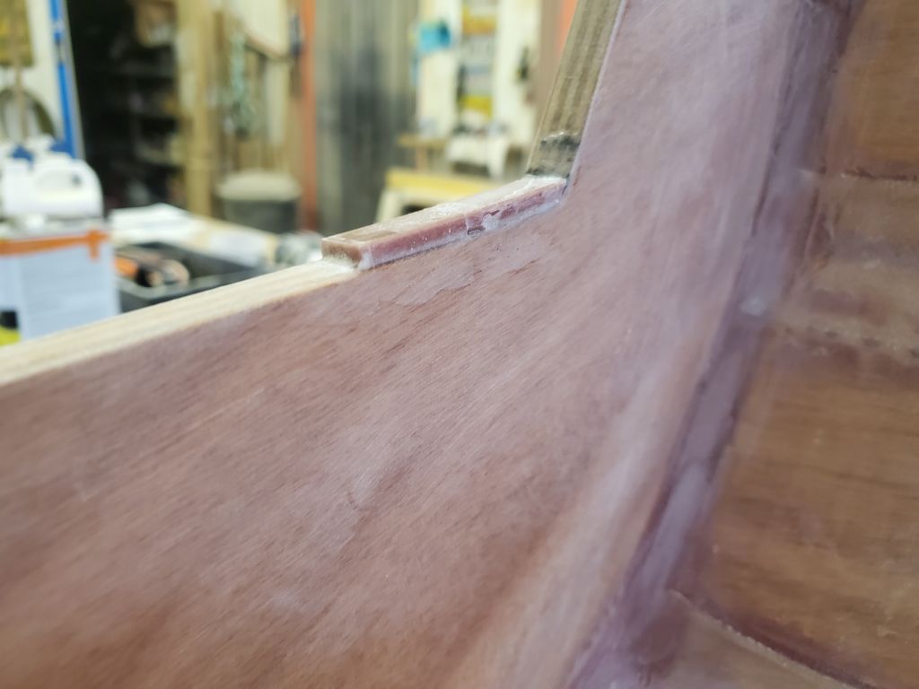
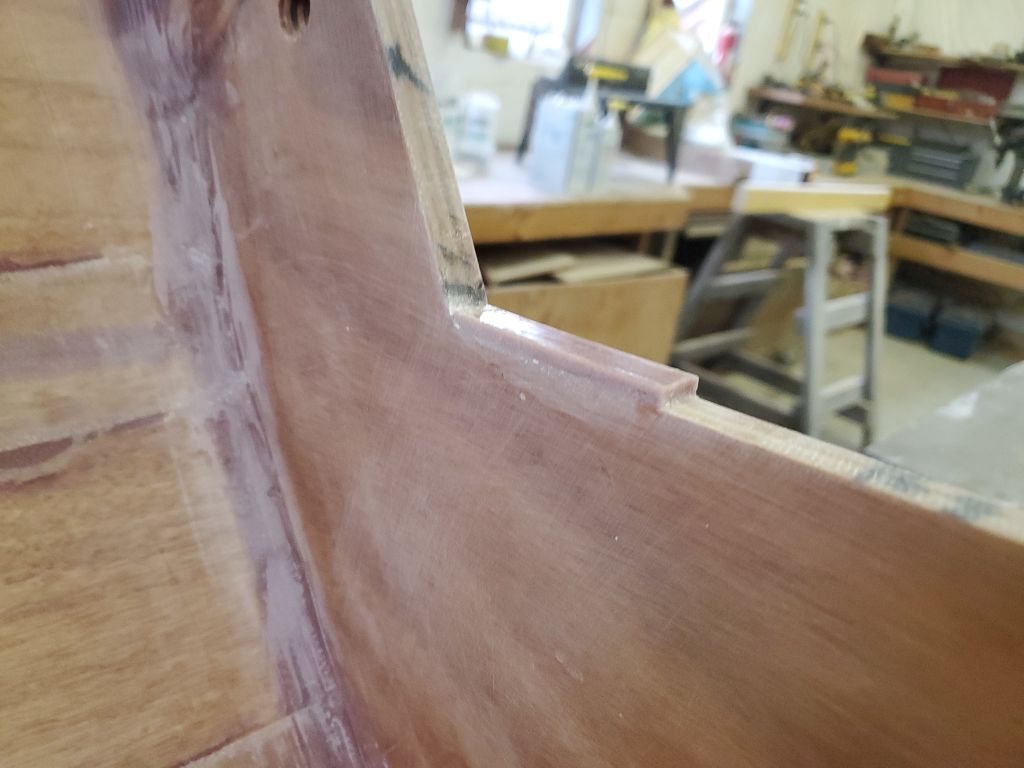
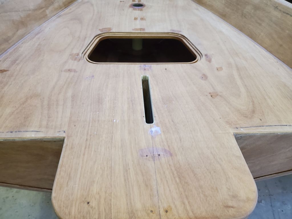
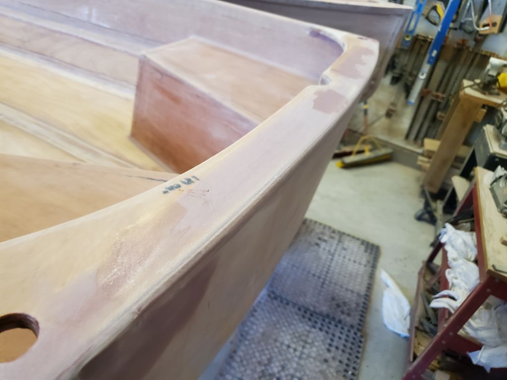
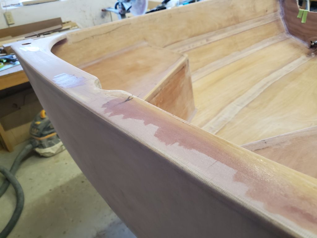
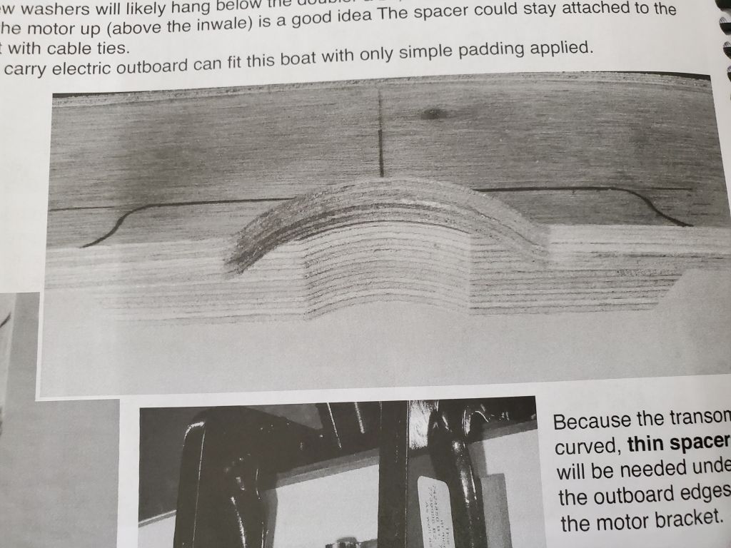
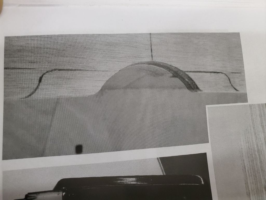
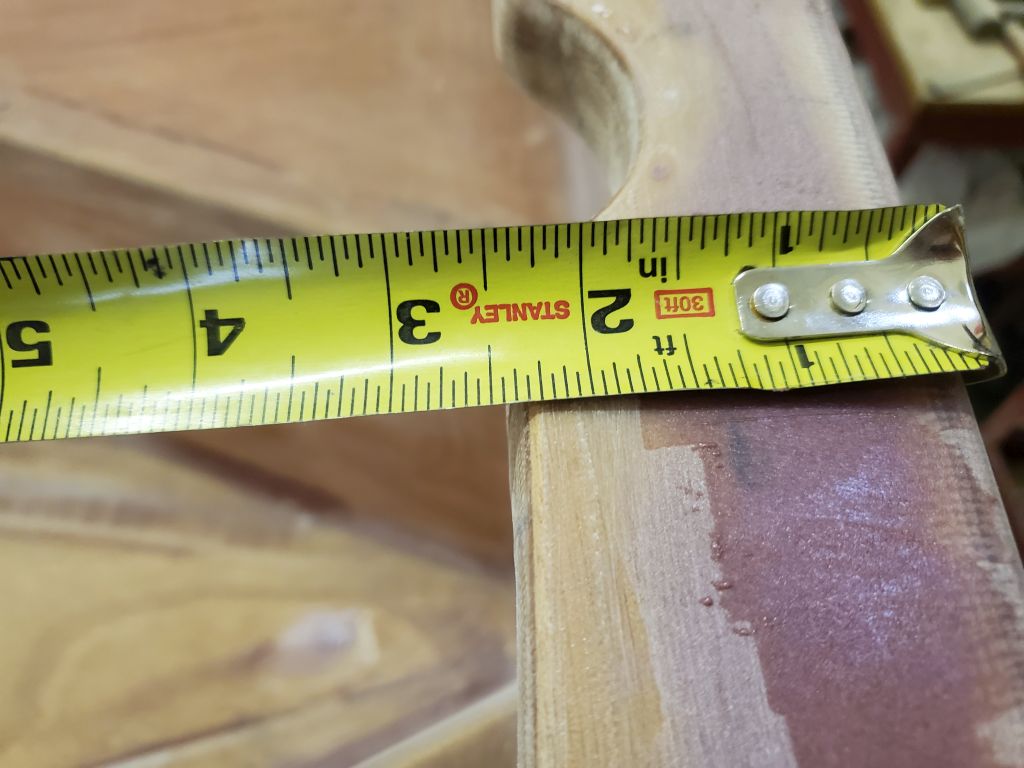
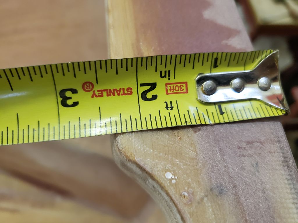
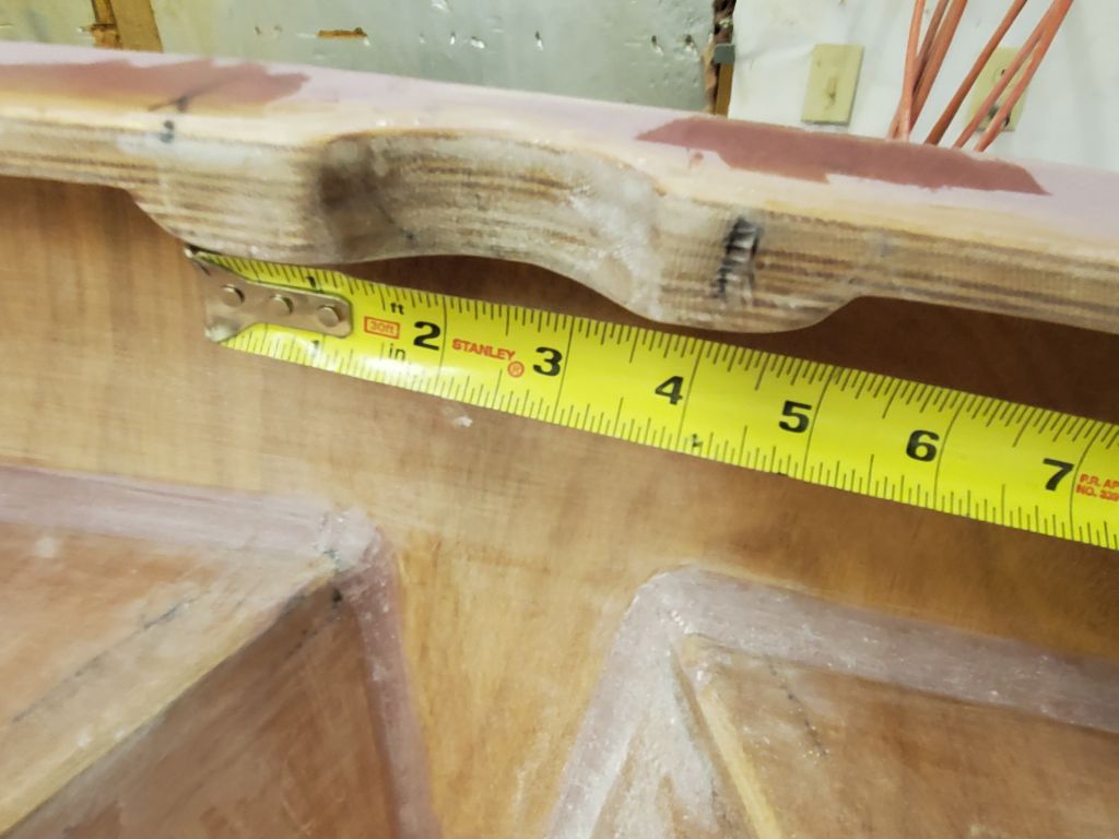
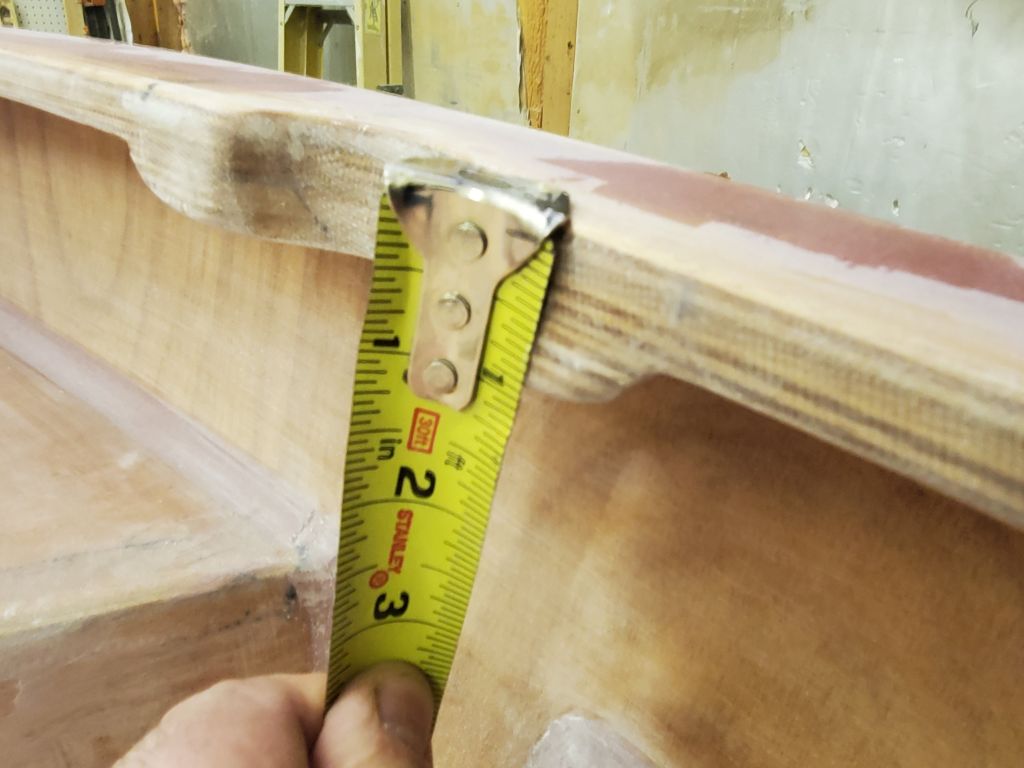
Finally, the owner requested that I make provisions for the possible (and hopefully minimal) use of a small electric outboard on the dinghy. The manual didn’t hold back much on the designers’ opinions vis a vis the use of an outboard, but nonetheless did offer some basic guidance. I started by locating a measured drawing of the owner’s outboard online, so I could determine whether or what modifications I might need to do at the transom. The second two photos here are pirated from the manual to show what they suggest to accommodate various small outboards: A small relief cut to narrow the inwale in the center of the boat, reinforced with an additional plywood block beneath the inwale.
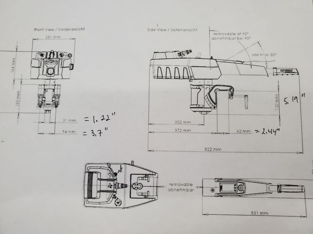
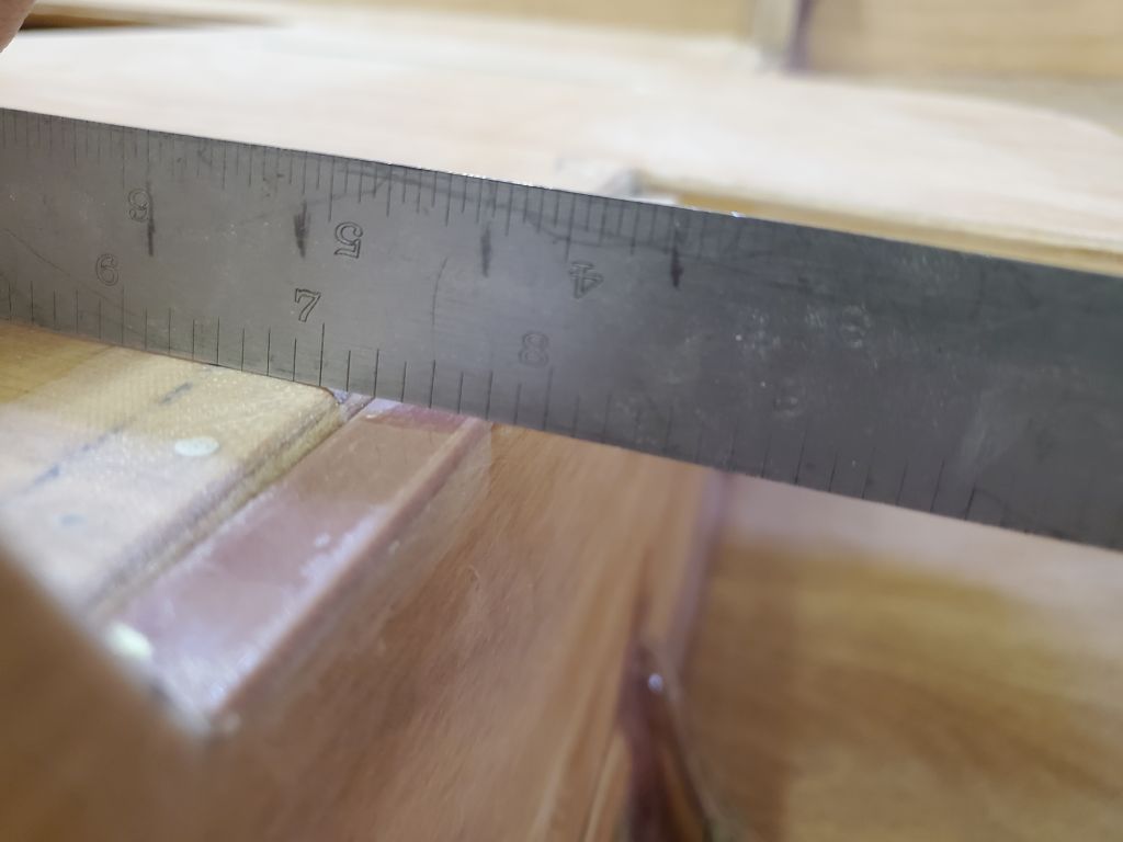
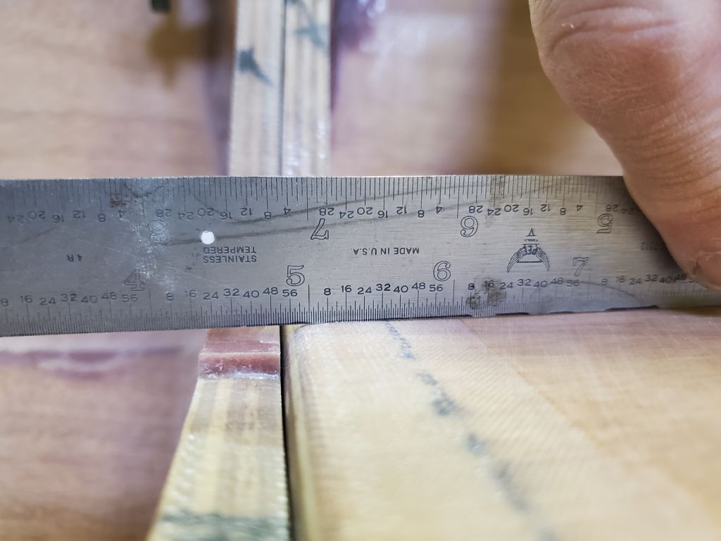
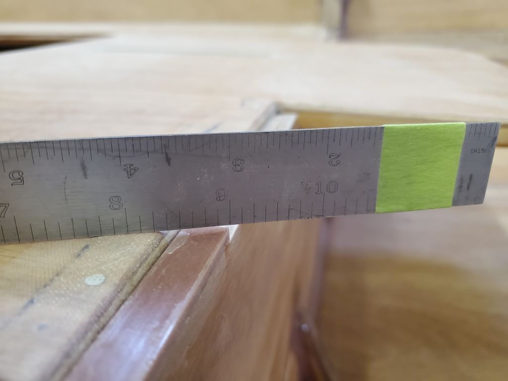
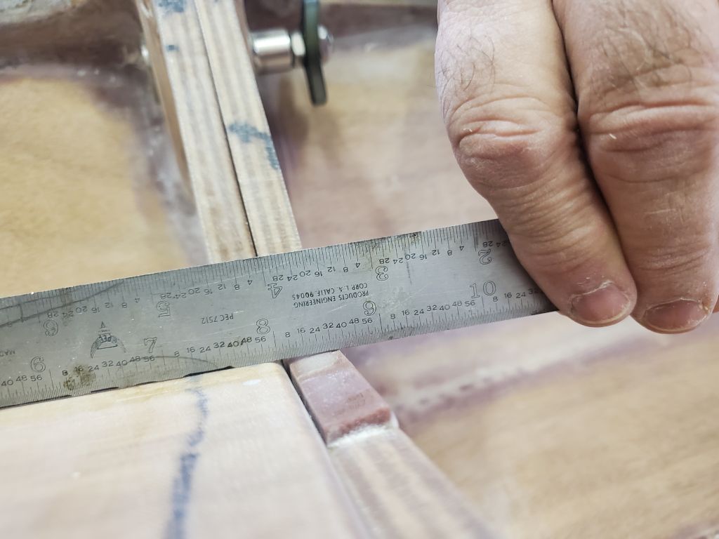
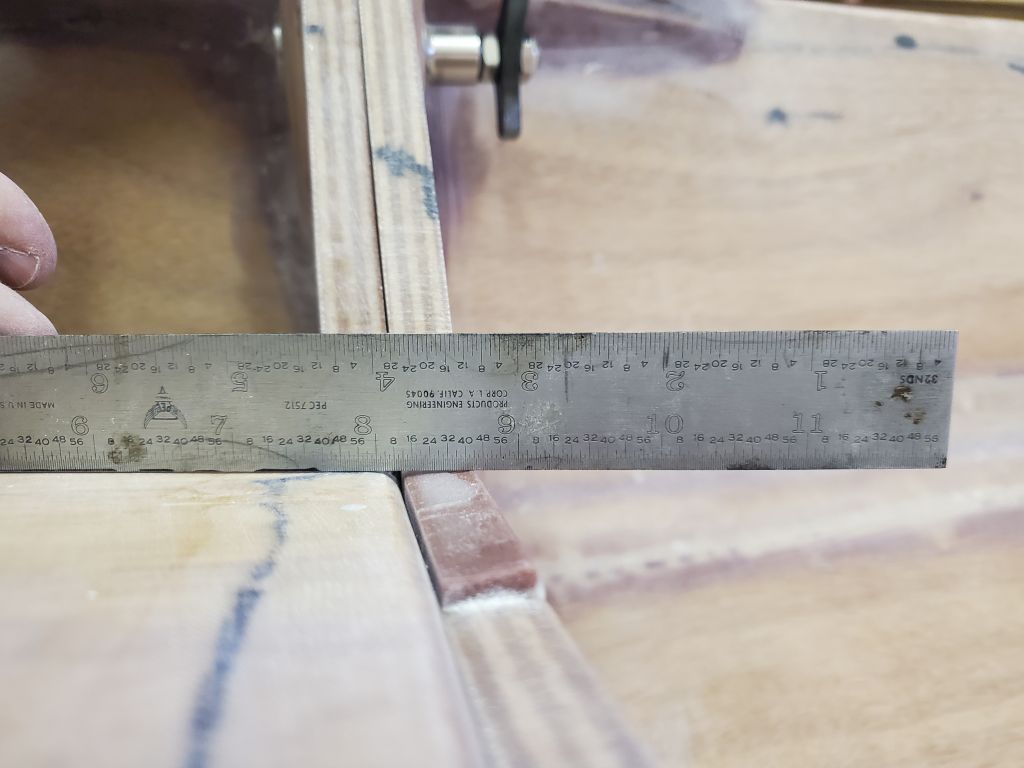
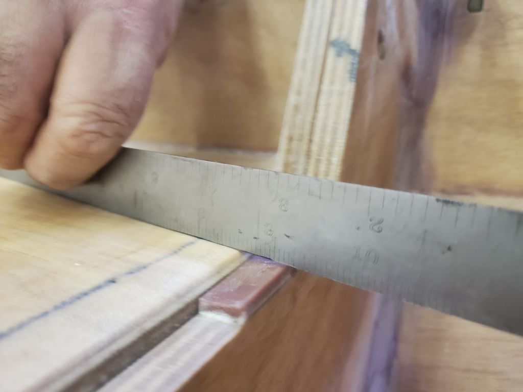
I measured the inwale width, which at between 2-1/4″ and 2-3/8″ was almost or exactly at the maximum opening of the outboard mounting clamps, so it looked like it’d be a good idea to make the relief cut and install the extra thickness beneath the inwale. This would be a project for another day.
Total time billed on this job today: 7 hours