

January 20, 2018
Handy Cat 1
Saturday
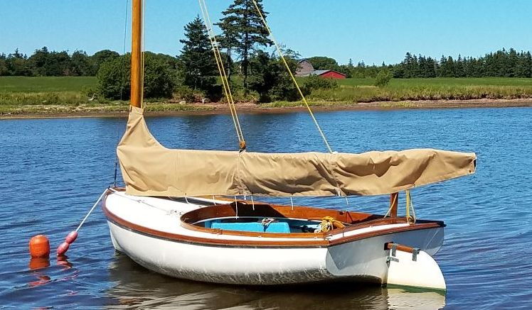
A while back, I purchased a 14′ Handy Cat, built in 1973 by Cape Dory (this design, like many small boats, was licensed to a number of different builders over the years). The boat was in great shape from the onset, though the previous owner had had the poor judgement to install a horrendous outboard bracket on the delicate transom. The first thing I did once I bought the boat was remove this abomination, not only because I hated the looks, but also because I had no intention of using an outboard on this boat.

Where I sail (or attempt to sail) the boat is a shallow creek with a narrow entrance leading to an expansive (but still shallow) bay. What I quickly learned in practice was that it simply wasn’t realistic (or even possible) to sail out the entrance channel, which had a navigable channel only perhaps 10 or 12 feet wide, other than at the occasional (and always very early morning) extra high tide that filled the adjacent sand/mudbanks satisfactorily. This never occurred at any time when I actually felt like sailing: for whatever reason, the tide cycle here never seemed to allow these full tides during the middle part of the day or evening. That’s a whole discussion in and of itself; suffice it to say that the tides never acted favorably to provide more room in the channel.
The direction of the channel–which also curved significantly over its considerable length–rarely caused the winds to align in such a way as to make the entrance passable without a need to tack–which was, frankly, quite impossible given the narrowness. And when the wind direction seemed right, it was too snotty. A complicated situation to be sure, but for this seemingly whiny combination of reasons it never worked out well for me to get this little boat out into the real waters.
The long and the short of all this is that I found the channel to be an impenetrable barrier to fun and useful sailing, which not only limited my use of the boat, but even my interest in trying. I’d initially thought I might use oars to row the boat out the channel as needed: it came with oarlocks. But this turned out to be a non-starter, as the low boom and centerboard trunk prevented any sort of realistic rowing position, and any oars long enough to actually reach the water without an absurd angle would be impractical on board. So this turned out to be a failed idea as well.
After a full season filled with disappointment and guilt over the situation, I determined that to have a chance at sailing this boat in a satisfying way, I’d have no choice but to provide some sort of auxiliary propulsion for the channel. There was a more traditional outboard bracket available that wouldn’t look so terrible, but I still hated to go that route for various reasons: the weight and appearance of the outboard; the need to buy a new outboard; my general dislike and dissatisfaction with small outboards to begin with.
Then, a friend told me about an interesting installation he’d seen on a newly-built Eric Dow Boatshop Herreshoff 12-1/2, where they’d built a custom rudder that incorporated an electric-powered propeller and shaft within. While the 12-1/2 is a very different boat, I thought the idea was terrific and might solve my problem.
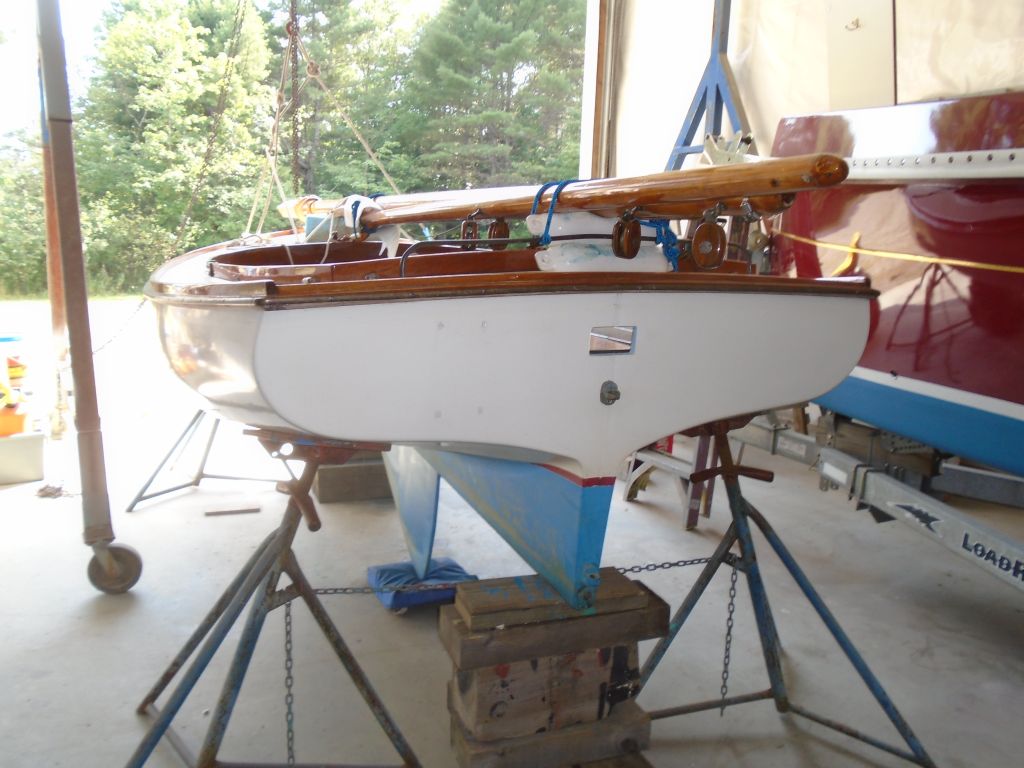
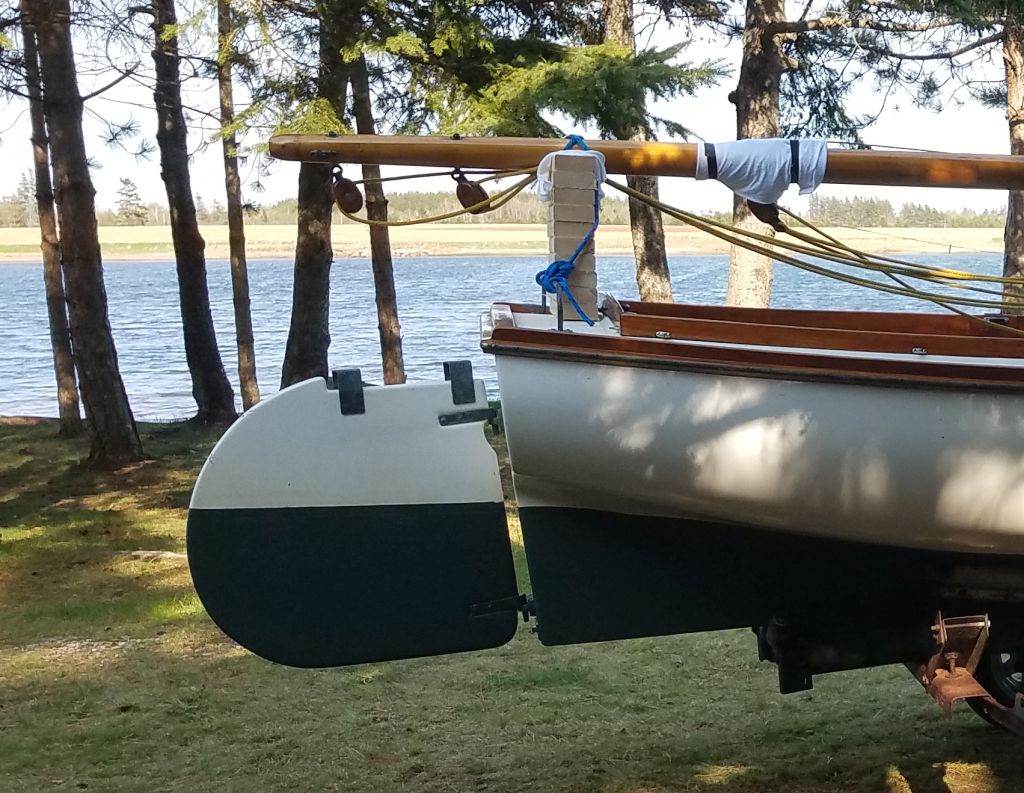
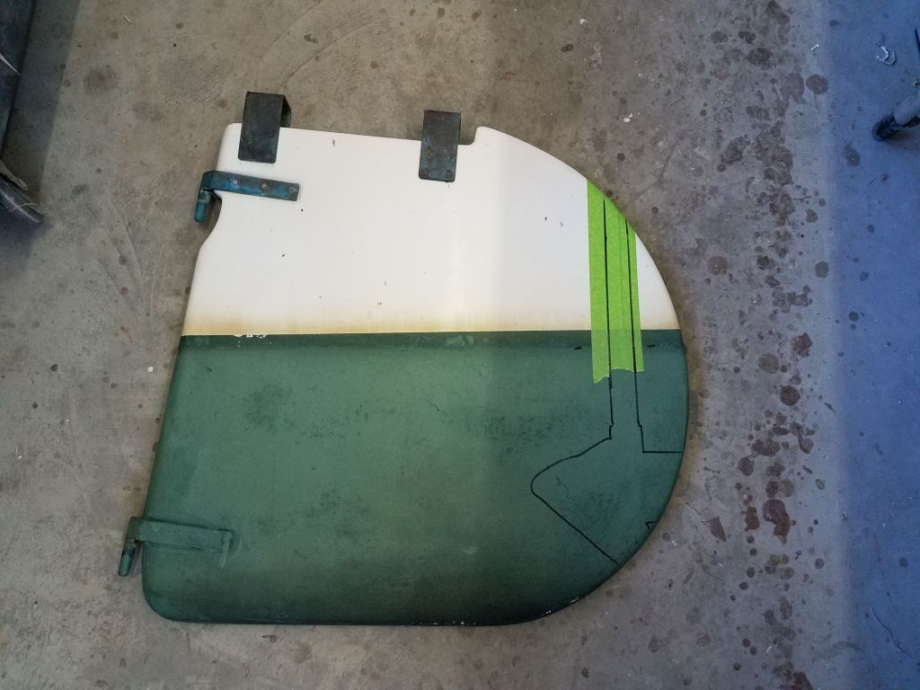
The Handy Cat, like most or all traditional Cape Cod catboats, features a large, shallow barn-door rudder hung from the transom. The rudder seemed to offer plenty of space to incorporate a small propeller and housing. For my specific needs and location, I didn’t think I required much in the way of power, and therefore the propeller size–and size and shape of the housing–wouldn’t overwhelm the shallow rudder.
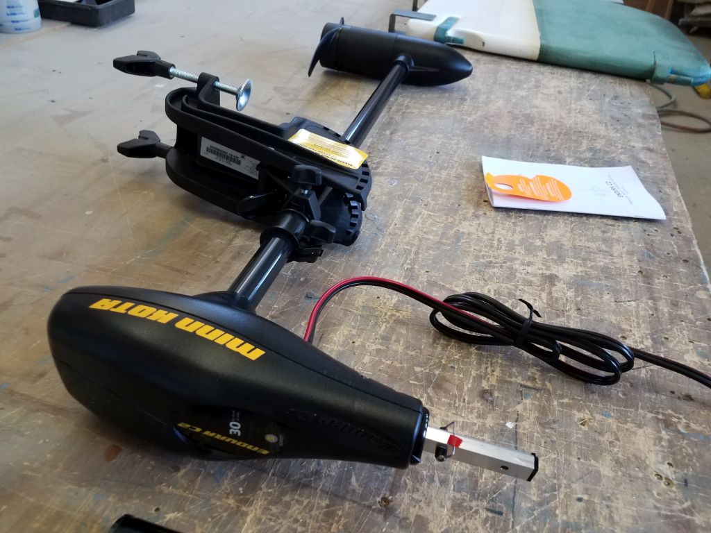
I spent some time researching trolling motors, about which I really knew nothing and with which I had no experience. (My only foray into fishing was many years ago, all saltwater and on larger boats, and at which I was an utter failure.) Soon, the project began to come together in my mind, and I settled on a small, inexpensive Minn Kota Endura C2 30 transom-mount trolling motor with 30 pounds of thrust. The motor had 5 forward speeds and three reverse. The usual Internet scuttlebutt suggested this was a competent motor, well-rated and well-liked by its users, and with ample power for what I needed, which frankly was 5 minutes’ use per time to proceed through protected waters in a small, easily-driven boat. The low entry price really gave me nothing to lose, which was good since I’d need to dismantle the motor for my installation. The fact that the engine was built for freshwater was of little matter to me, as I felt it would hold up in my limited season, and anecdotal reports online suggested similarly. My final installation of the electrical side would actually end up more durable than the original, so that didn’t concern me either.
I found some useful videos online detailing some of the basics of disassembly, and it looked much simpler than I’d even imagined (again, I’d no experience at all with these little trolling motors and didn’t even know how they were put together). To that end, I’ve chosen below to detail thoroughly my own disassembly for the edification of anyone else looking to do something similar.
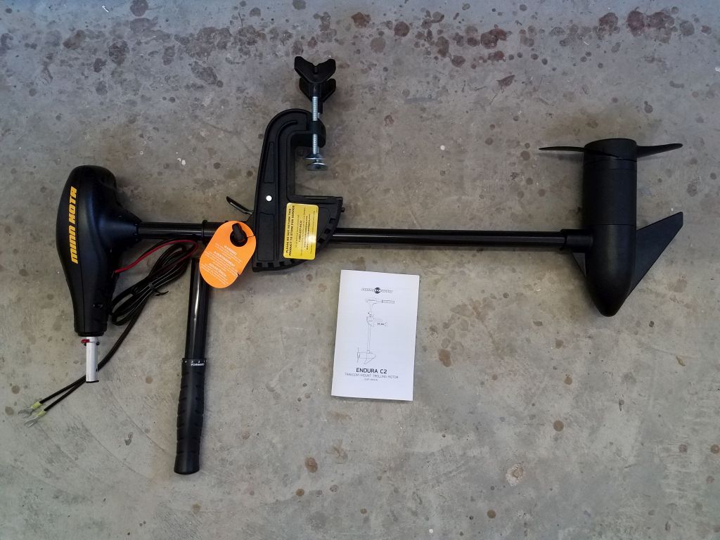
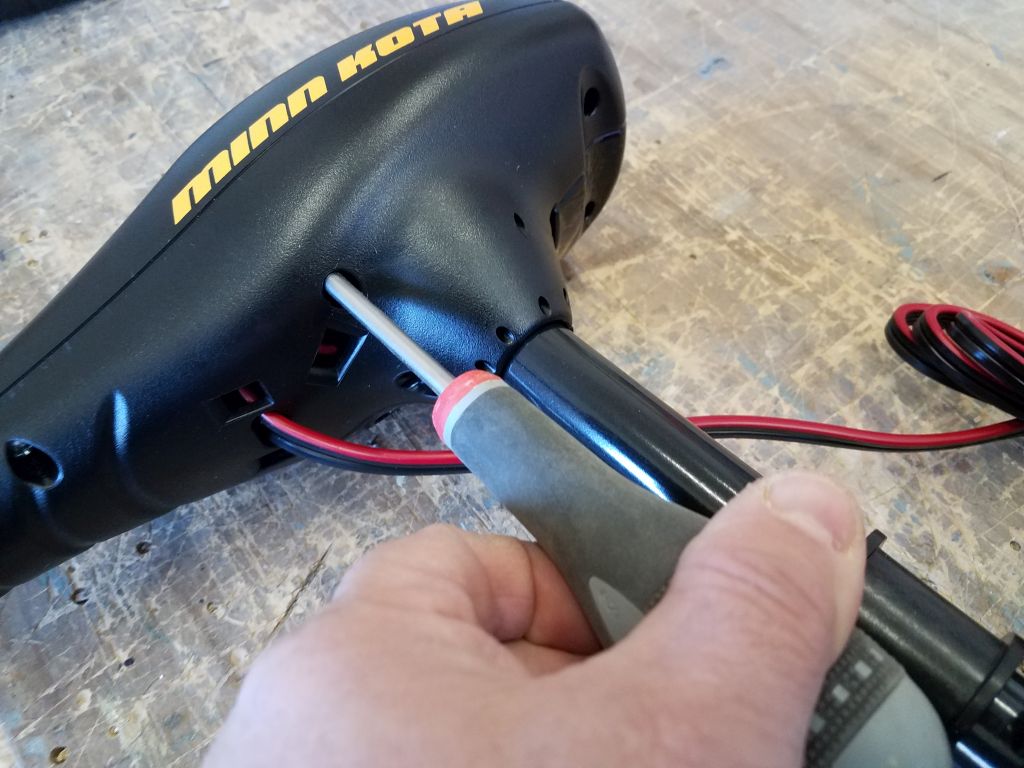
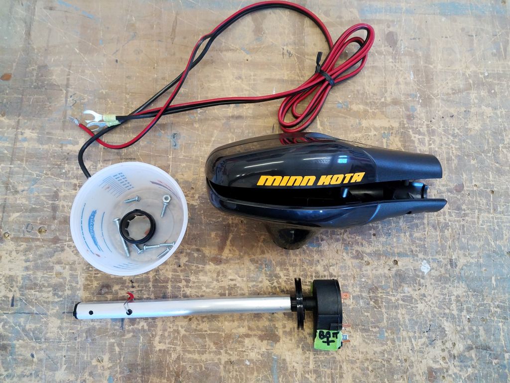
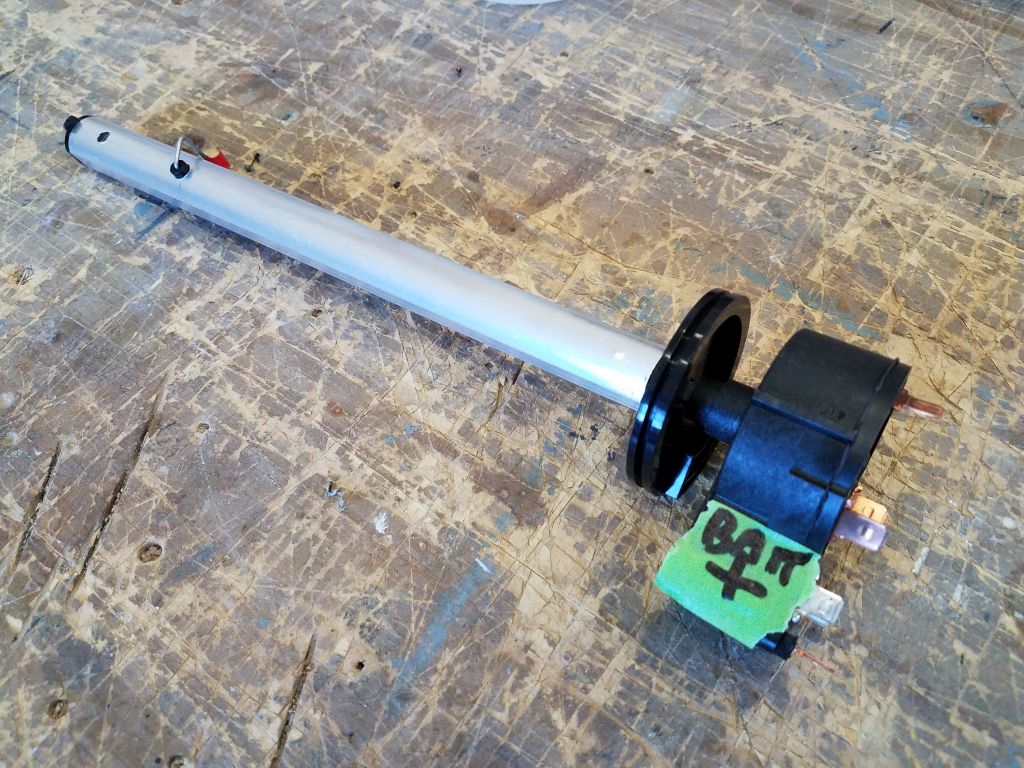
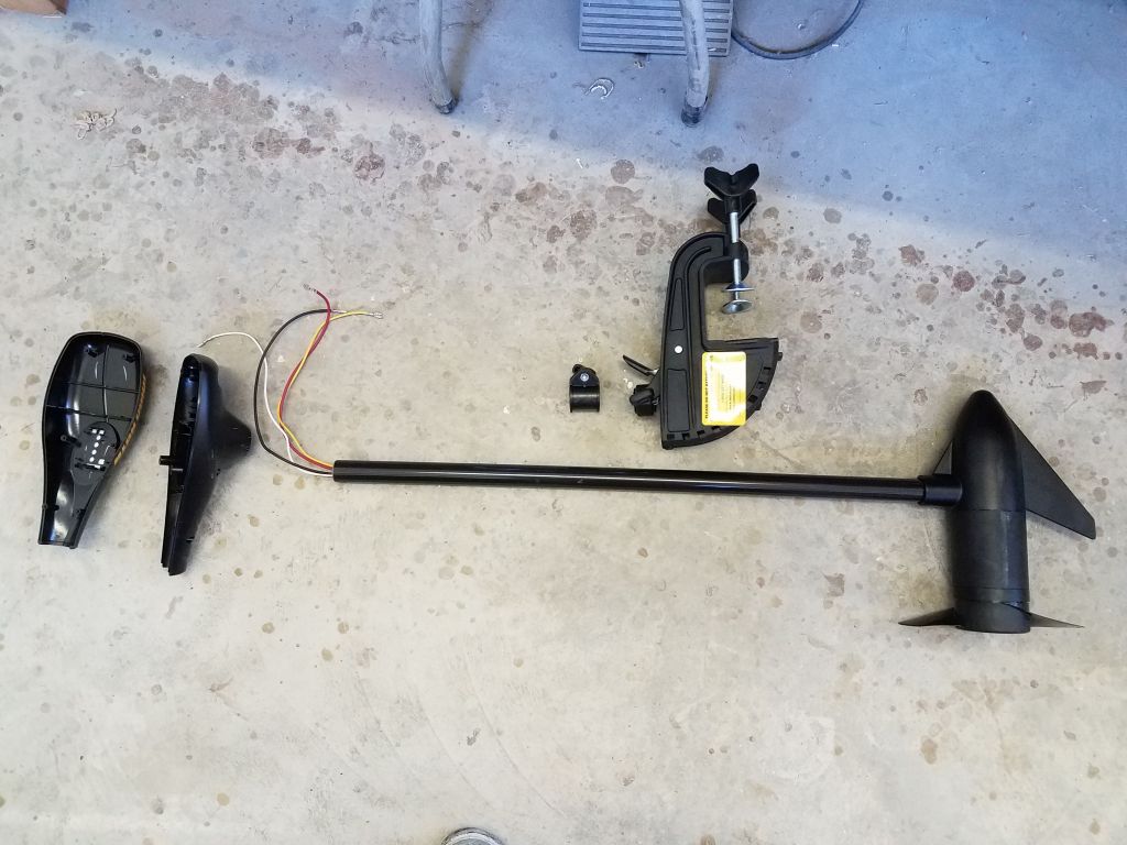
When my new trolling motor arrived, I wasted no time disassembling it, though I began with thorough documentation of the motor in its original form. The electric motor itself is housed within the propeller pod, with only wiring and the controller switch in the housing above. The adjustable transom mount would slide right off the shaft once I took apart the top housing.
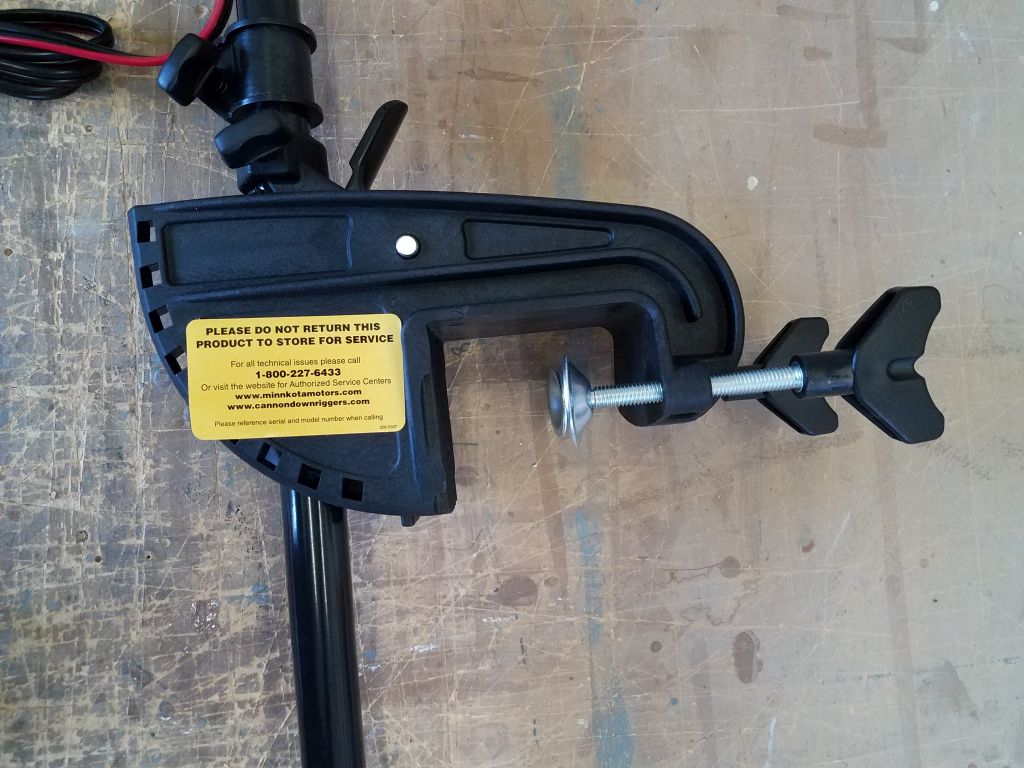

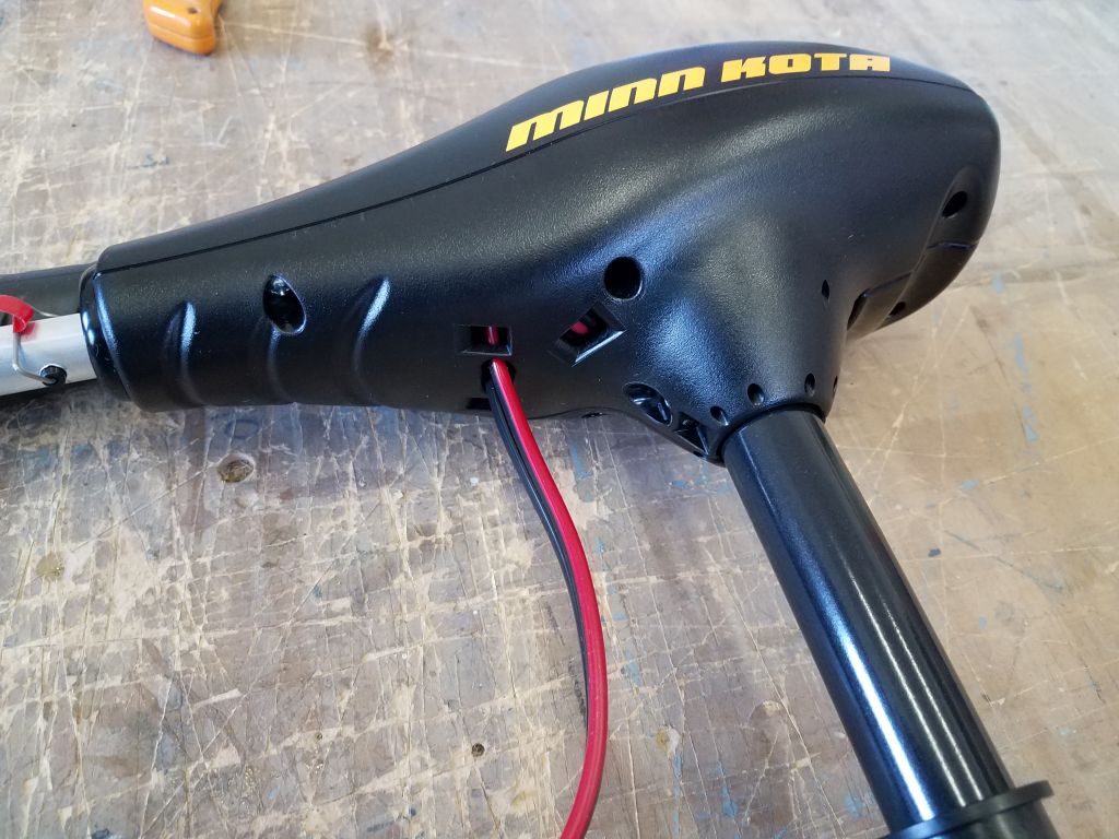

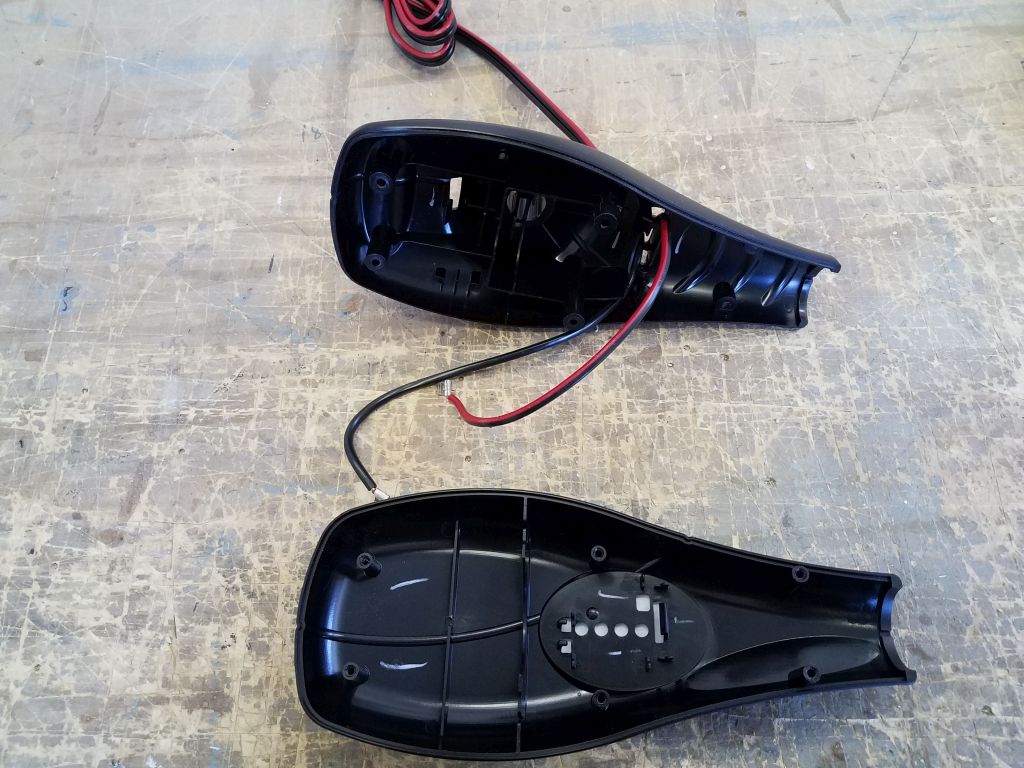
The housing featured a clamping screw to hold it to the top of the vertical shaft (which was a composite, not metal, construction on this motor), and six screws beneath that held the two plastic parts of the housing together, and this took little time to take apart.
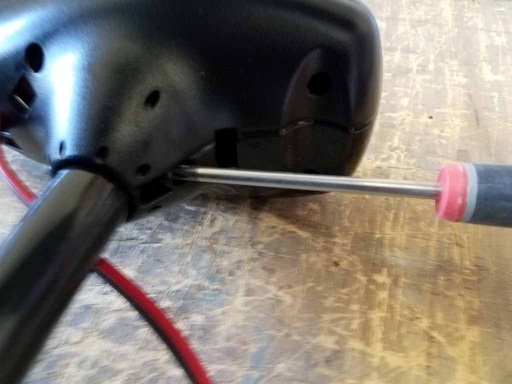
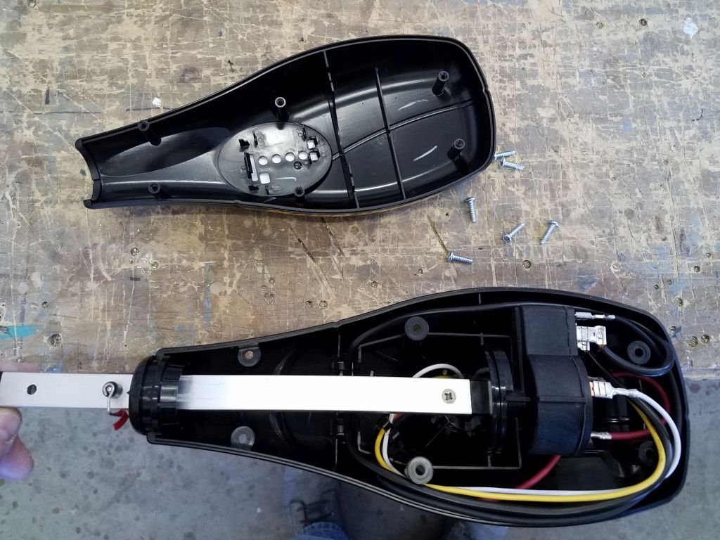
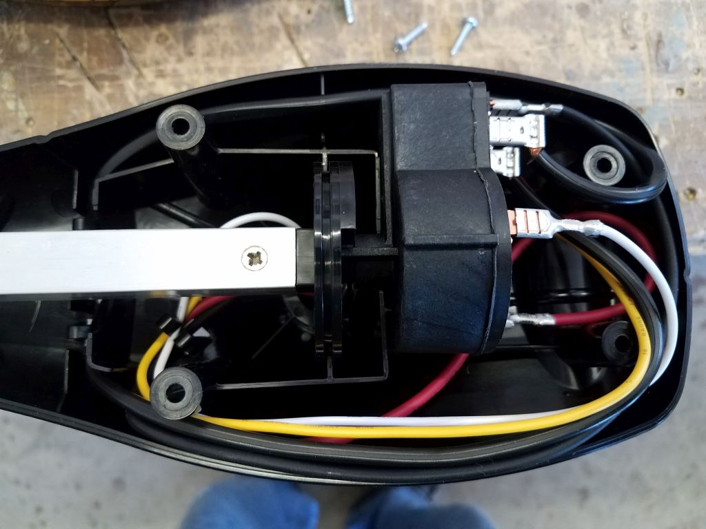
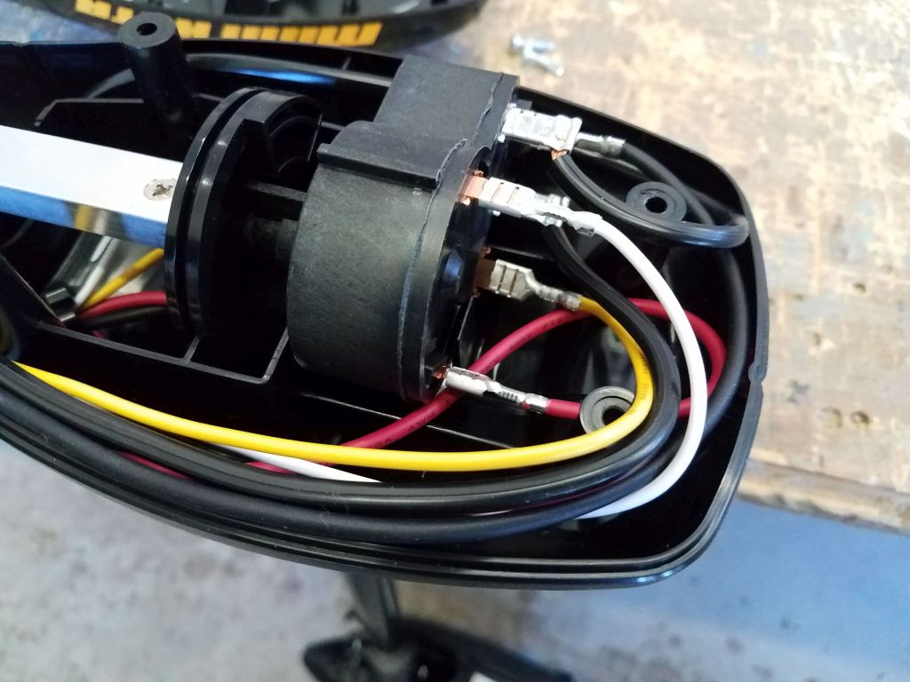
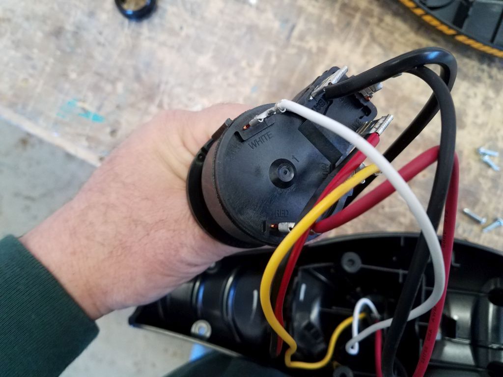
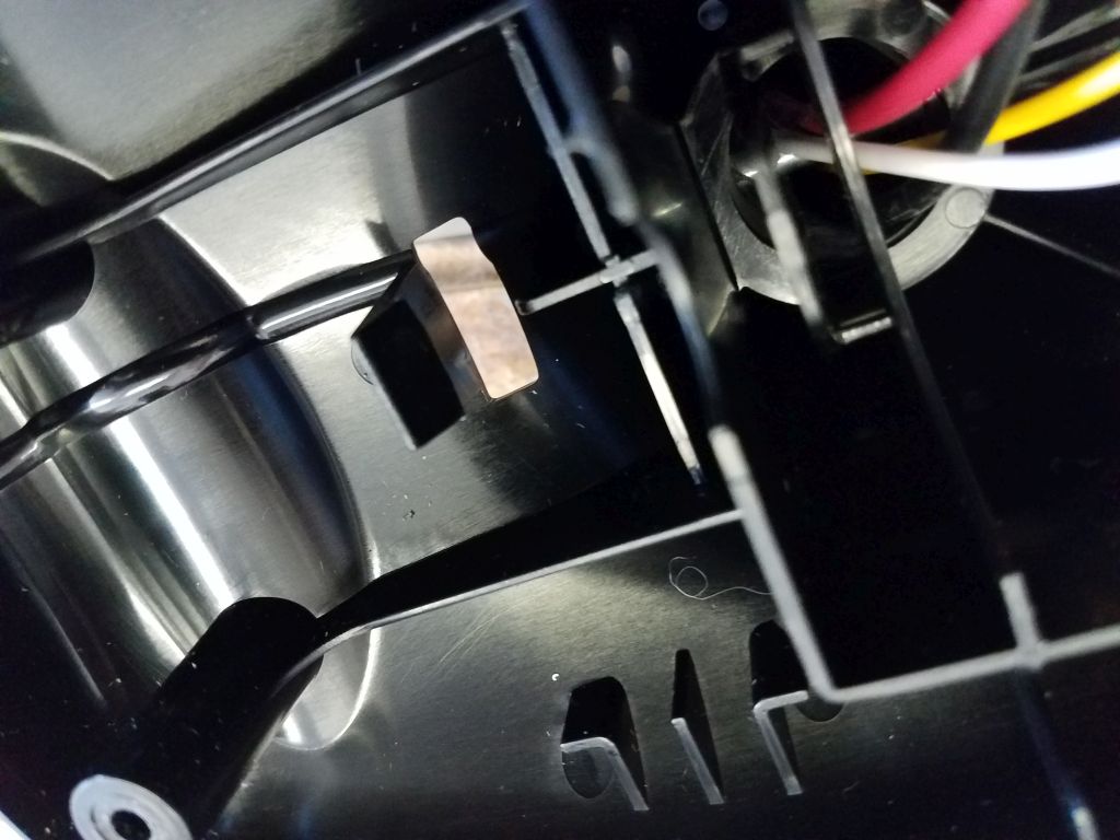
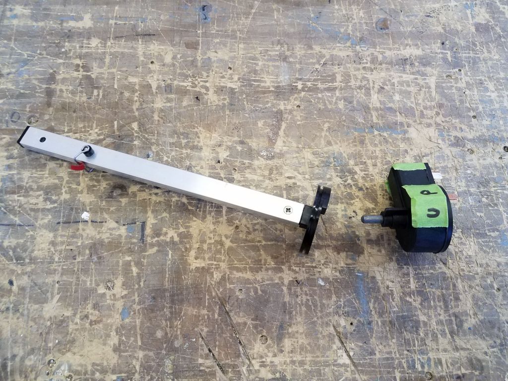
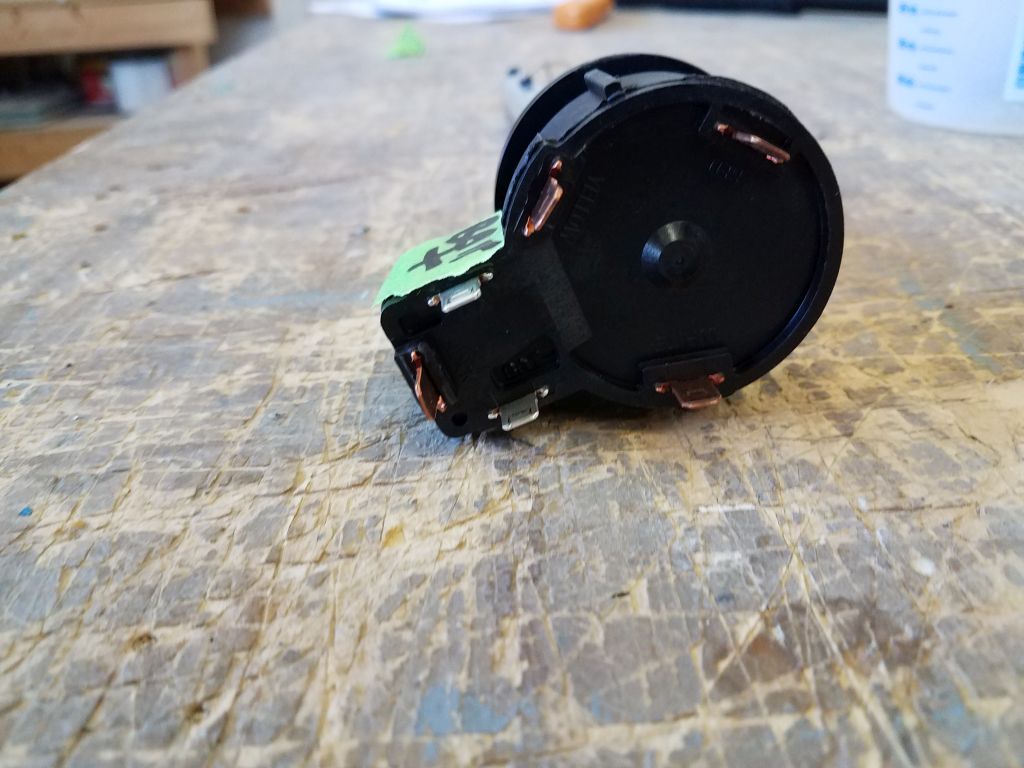
The wiring from the propulsion pod led up through the vertical shaft and connected to the internal control switch (all the terminals were labeled with wire colors for future reference), and the battery wires led out through the bottom of the cowling. The various wires were secured with built-in plastic clips within the compartment as needed, and the control switch itself was held in place with a little plastic spring clip, and was easy to remove. Once I had the switch out, I removed all the wires, which freed the switch from the housing. I’d need this switch for controlling the motor later. The tiller/twist control handle slipped right on and off the shaft of the rotary switch. What this all left me with was the bare propeller housing and vertical shaft, with its internal wires running out the top, plus the switch and battery cables that I’d need later. For my installation, I had no need for the transom bracket.


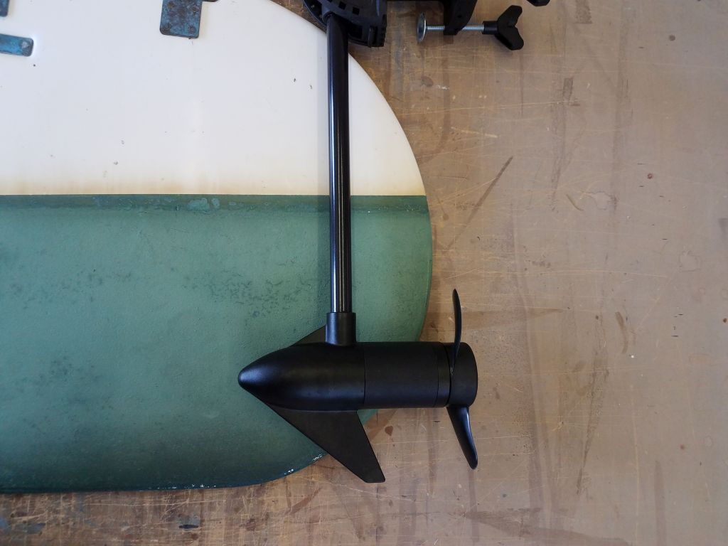
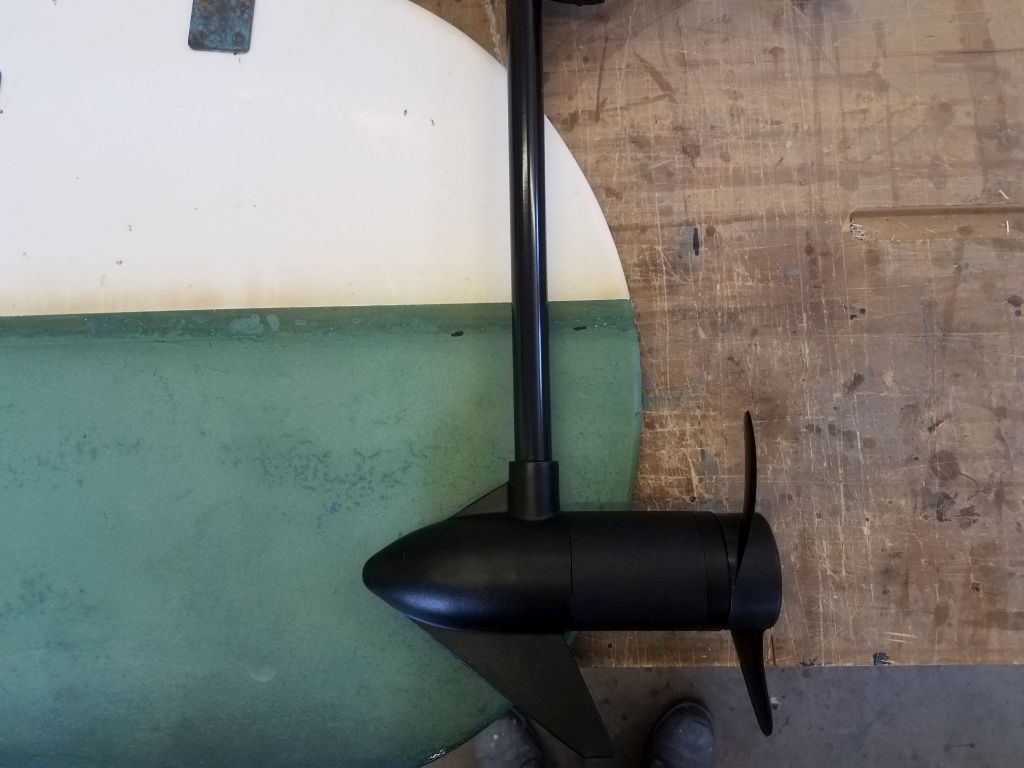
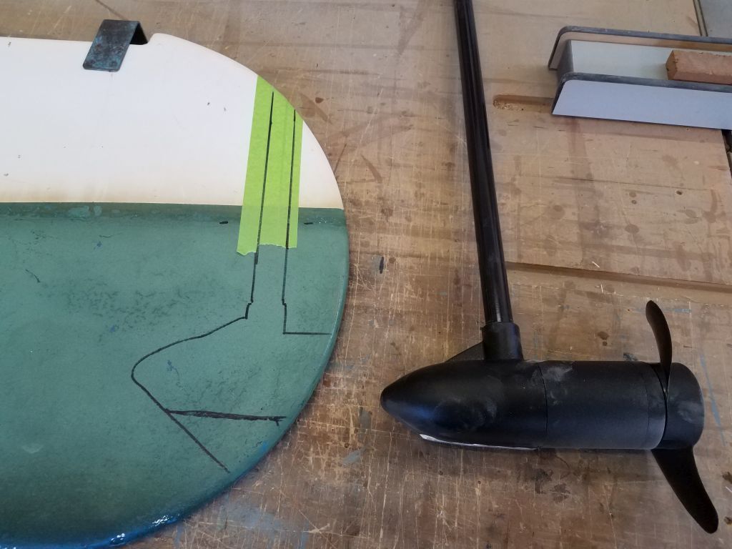
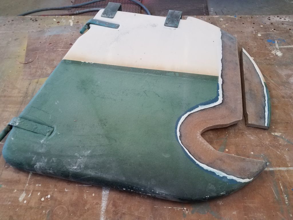
With the rudder on my bench, and the now-bare propeller hub, I tried out some layout. The instructions recommended minimum 12″ depth from the waterline to the top of the propeller pod, but I didn’t have that much space here, so I compromised with the pod at what looked like a reasonable depth, taking into account the shape of the rudder and how best to incorporate the pod within. I wanted to minimally impact the function of the rudder while keeping the installation as sleek and unnoticeable as possible. Once I was satisfied, I traced the outline of the pod and the shaft.

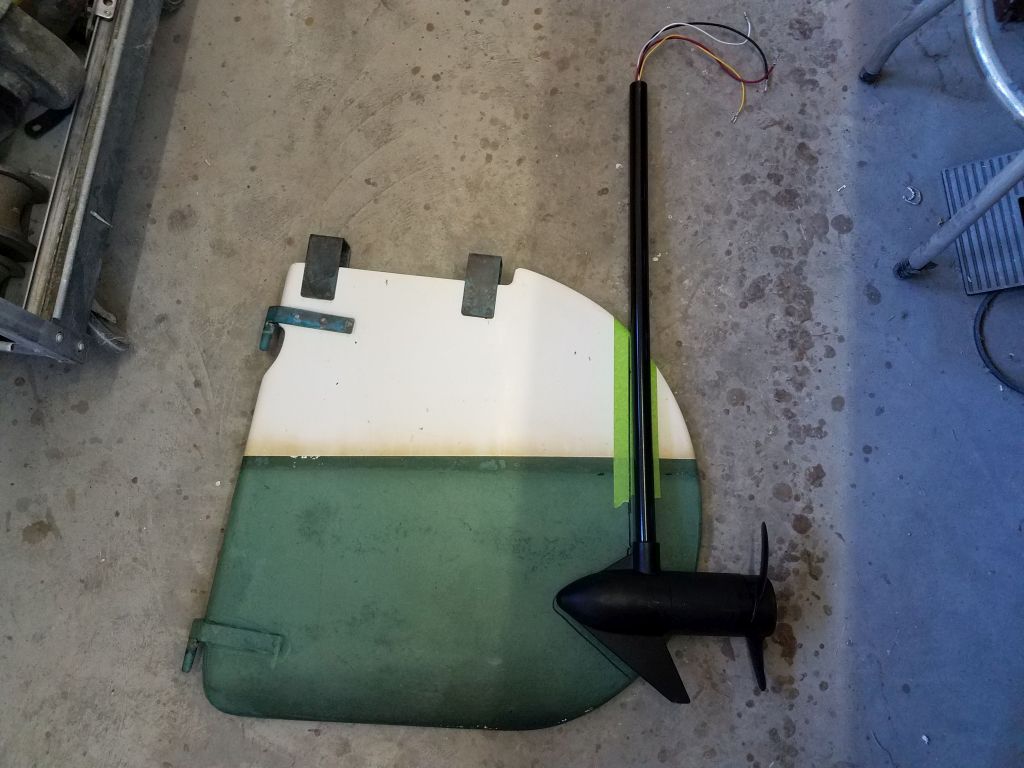
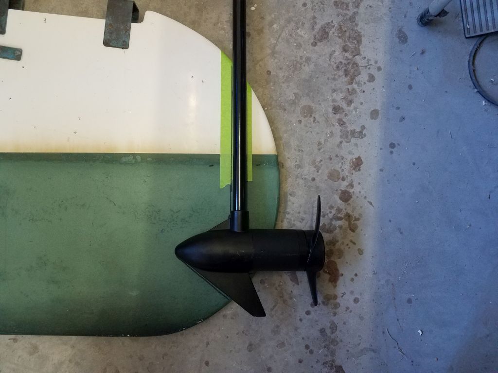
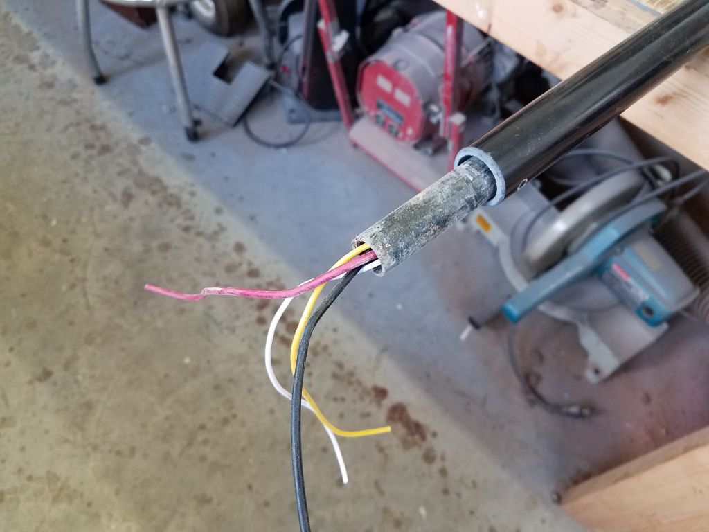
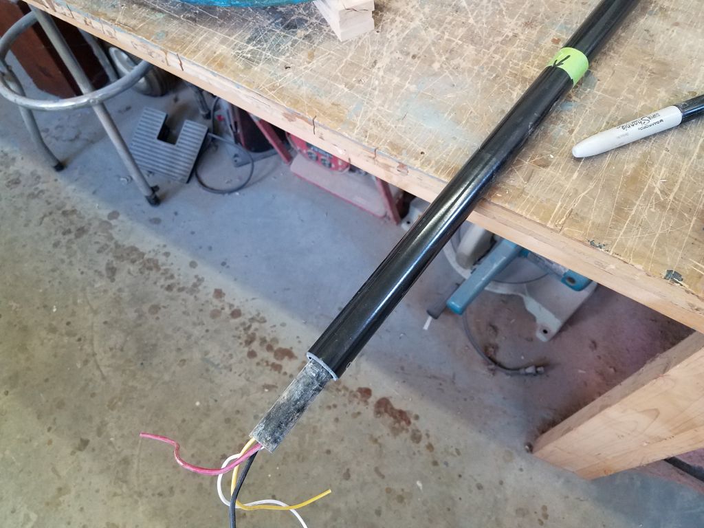
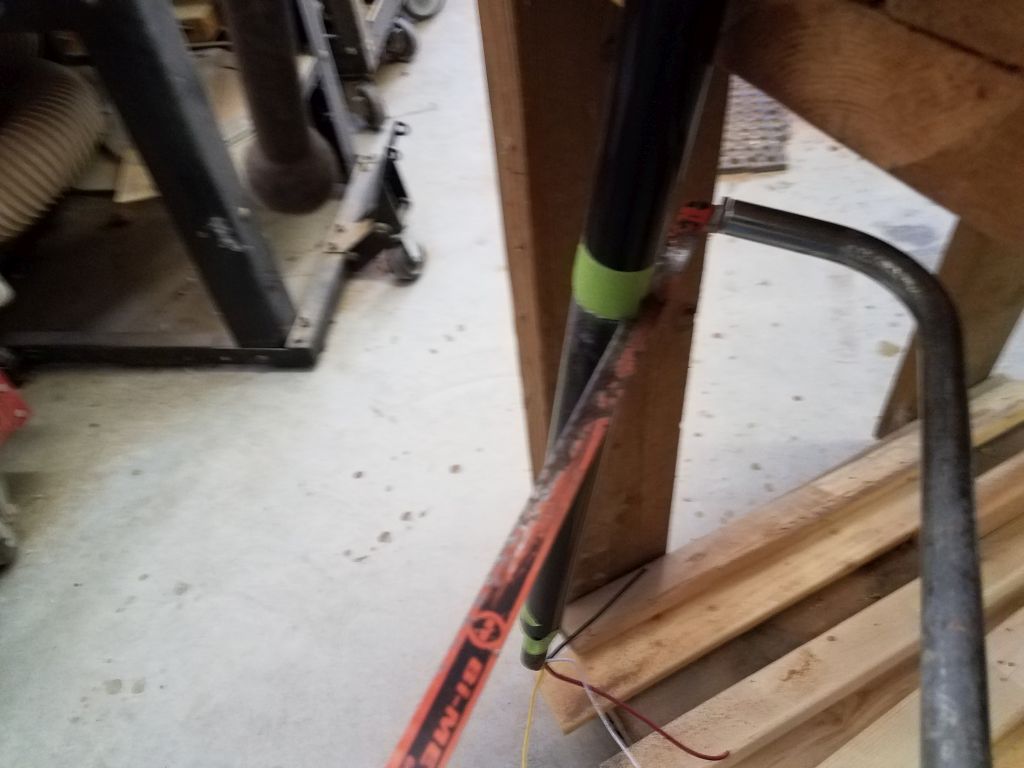
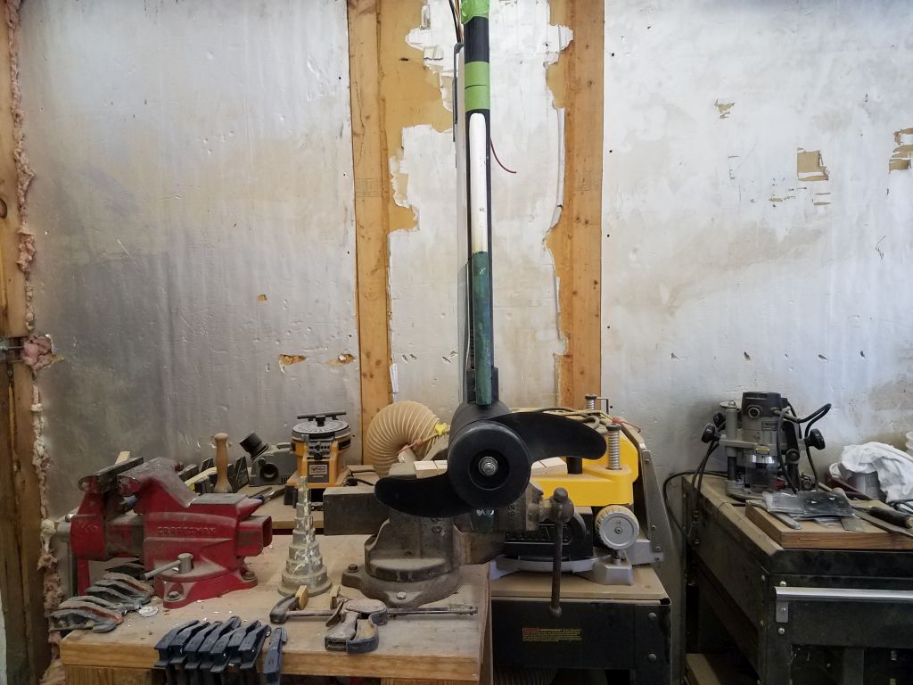
The composite shaft was longer than it needed to be for my installation, so I marked it at the appropriate height (about even with the straight top of the rudder) and cut off the excess tubing, using a smaller tube inserted within to protect the wires during the cut. I hung the shaft upside down from a vice so that any cutting spoils would drop out the tube rather than fall possibly into the propulsion pod. The tube was easy, if awkward, to cut in this position and given how my vice happened to be set up.

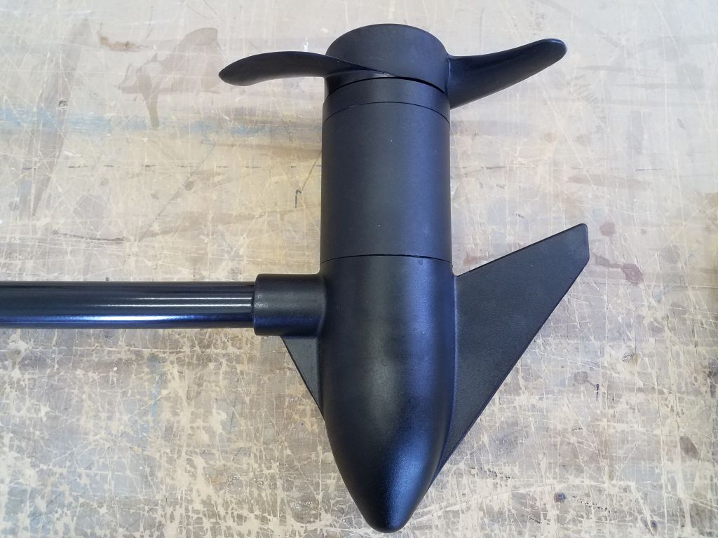
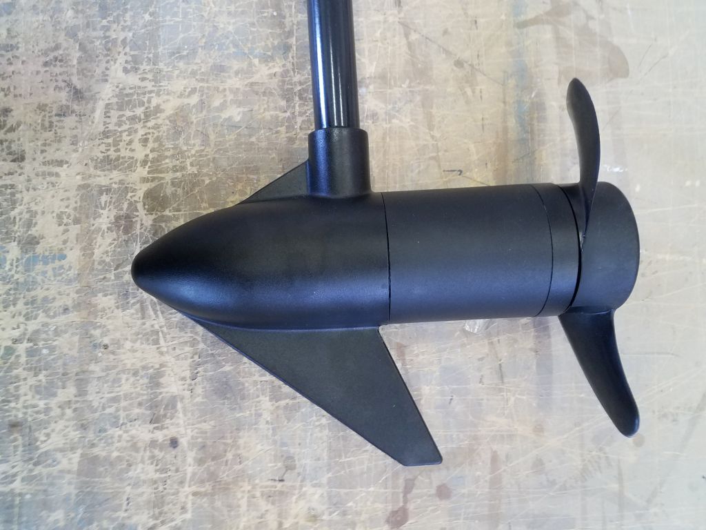
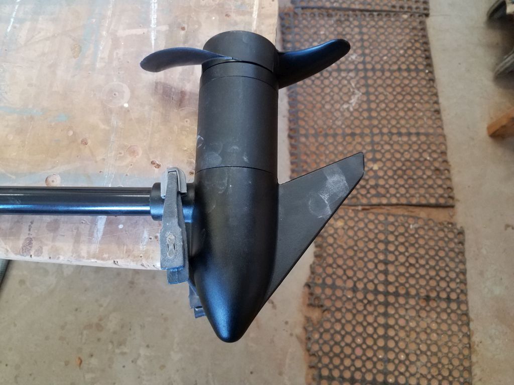
For the moment, my focus was on the rudder modifications, so additional steps to deal with the wiring and controls will come later. Now, with the wiring tube cut to length, I turned to the pod itself, which was constructed from aluminum (with a plastic propeller) and featured the usual trim tab/skeglet beneath the pod. I didn’t need nor want this for my built-in installation, so I cut off the skeg with a grinder and cutoff wheel. This skeg was surprisingly robust and took a minute or two to carefully cut away.

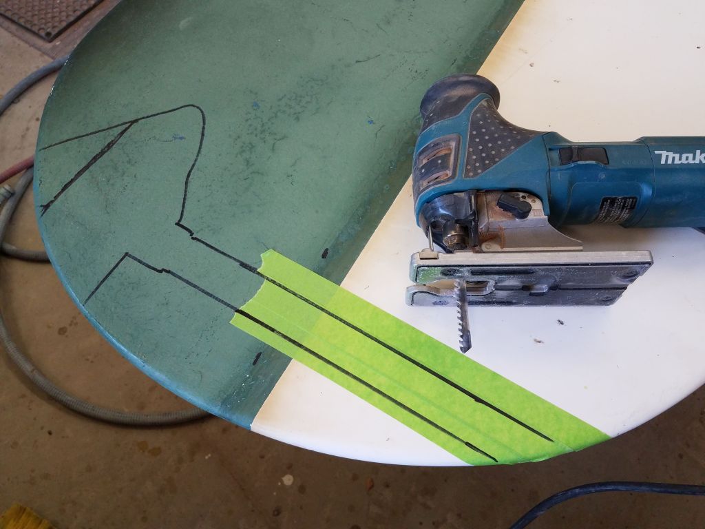
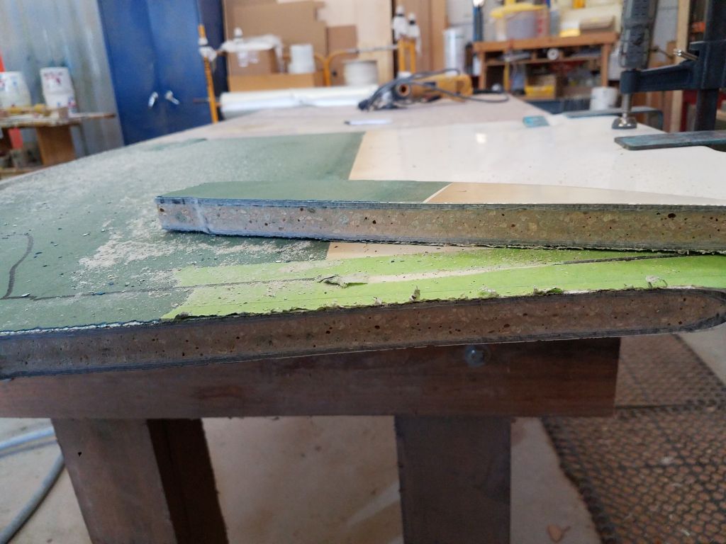
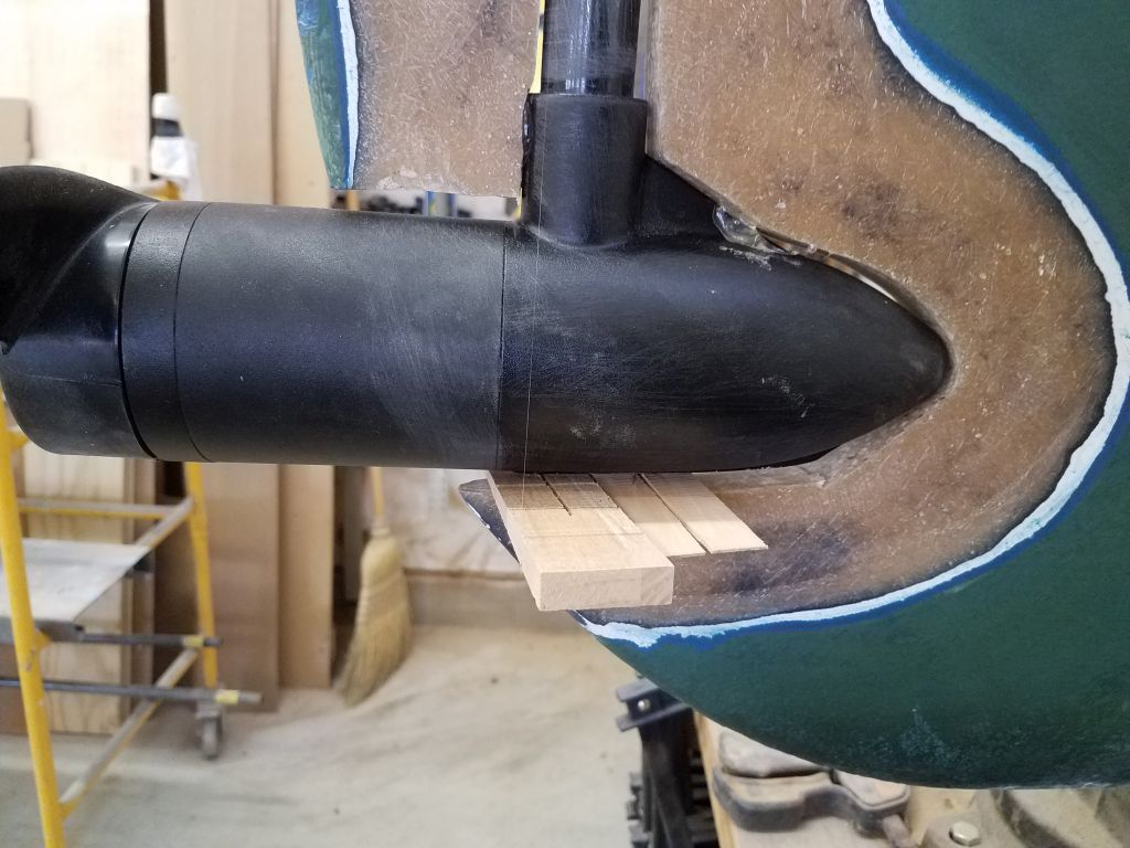
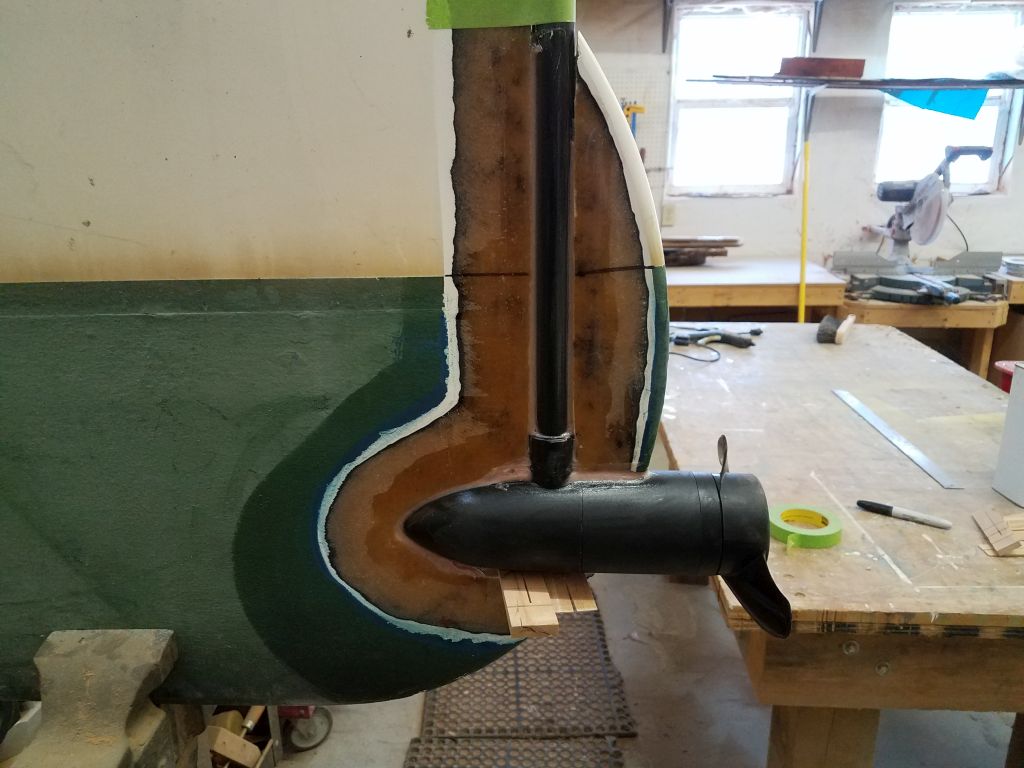
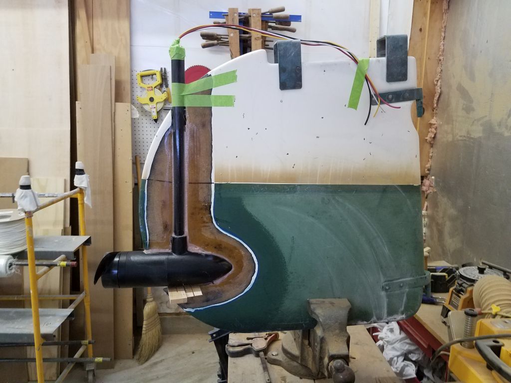
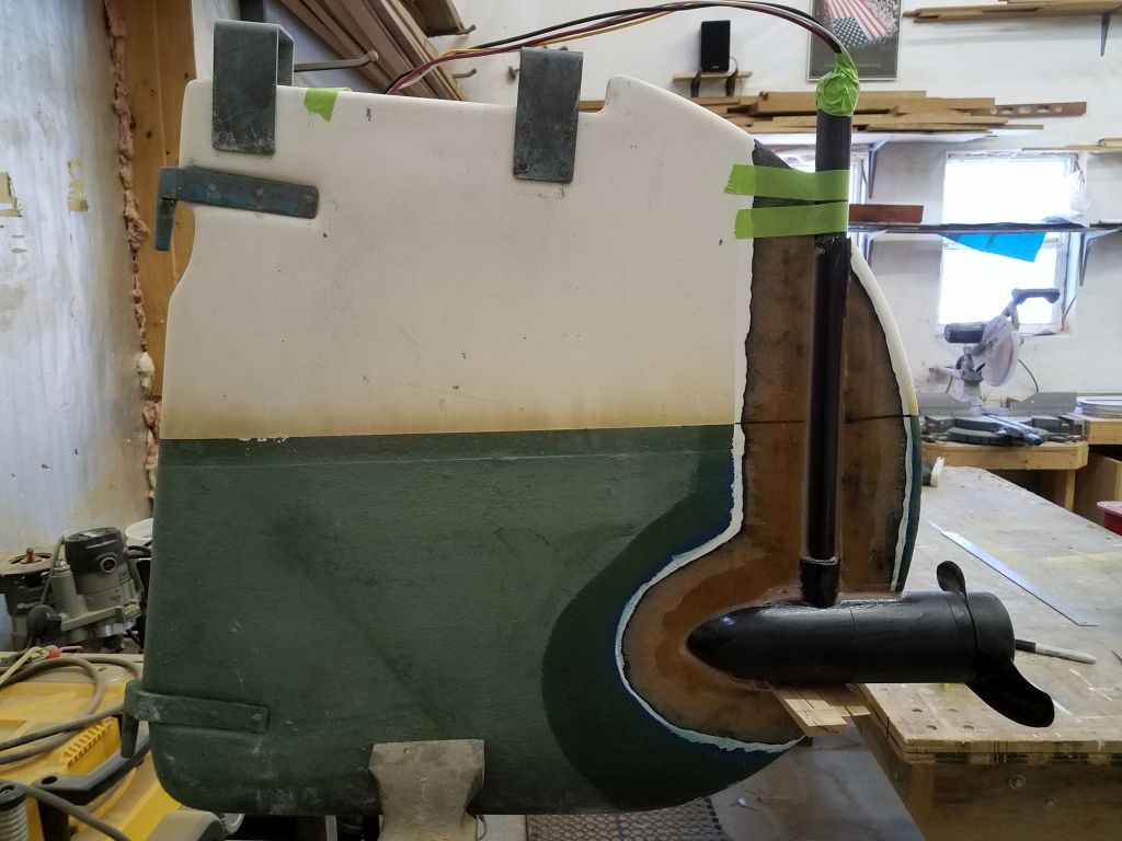
With layout finalized, I made two cuts in the rudder: first to remove the small piece outboard of the vertical shaft (I’d reuse this piece to reconstruct the rudder); then the other line I’d traced, removing the material in way of the new motor unit and shaft. The rudder on this boat was constructed with a solid mish-mash material between the two skins, so cutting with a carbide blade was not difficult and the rudder itself required no extra work to prepare the cutout area afterwards.
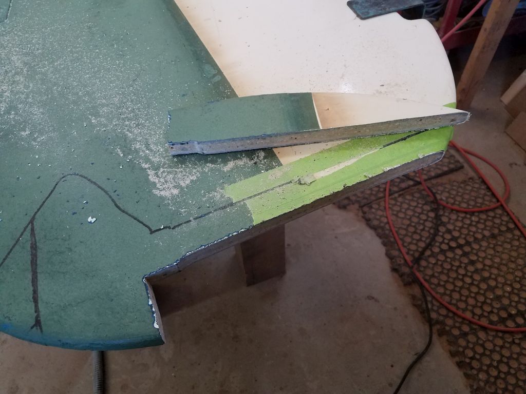

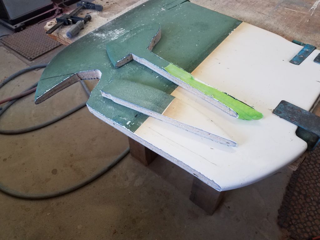
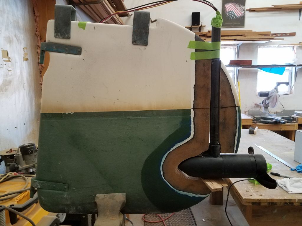
I dry fit the components now that the cut was complete.
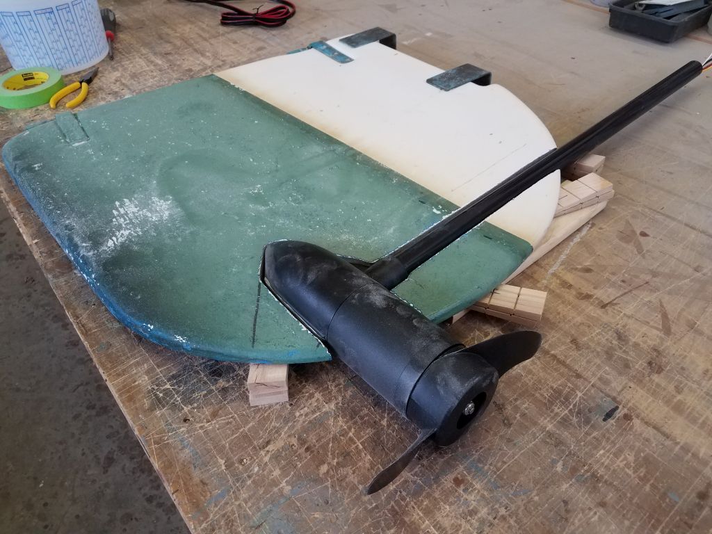

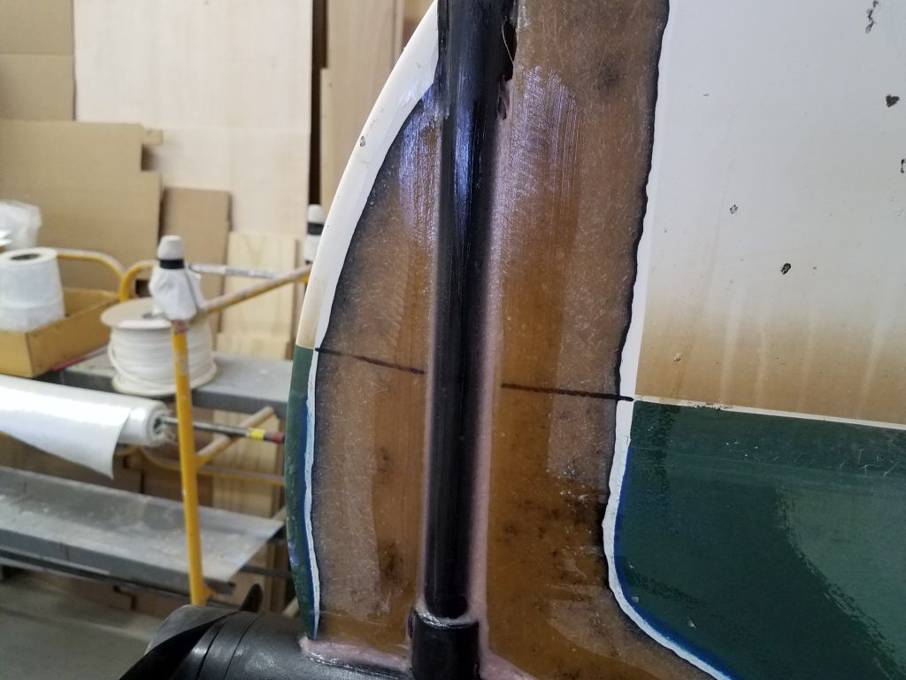
To prepare the rudder for reassembly, I ground off the paint and gelcoat on both sides of the cut, tapering back the original laminate about 2″ all around. I prepared the pod and shaft by scuffing up the bonding surfaces with sandpaper as well.


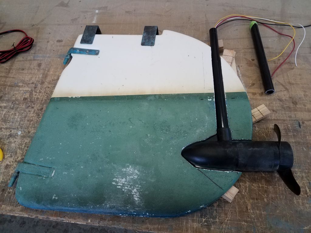
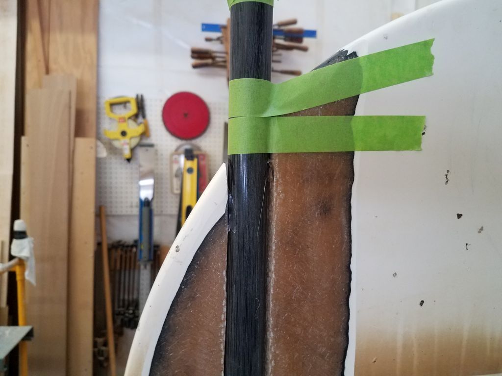
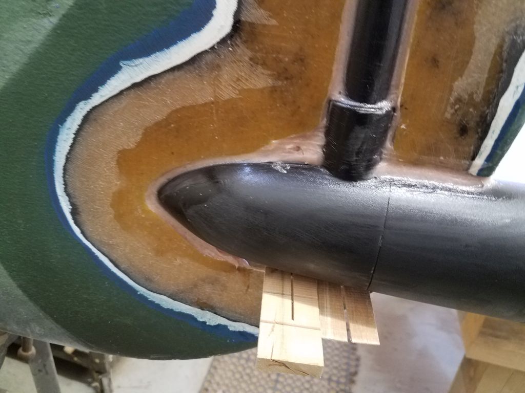
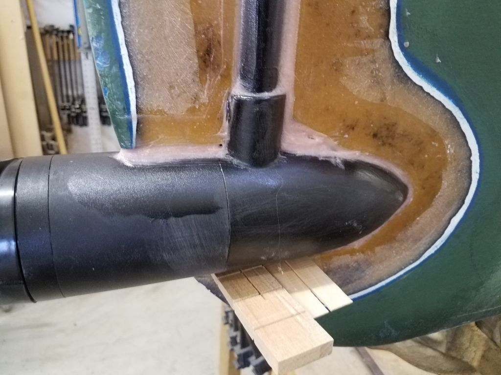
Clamping the rudder vertically in a vice, I temporarily secured the pod with some wedges beneath and some tape above, centering it carefully on the rudder. Happy with the position, I dabbed in some hot glue top and bottom to hold it securely enough, and used some additional glue to tack on the small aft piece of the rudder in its proper position.
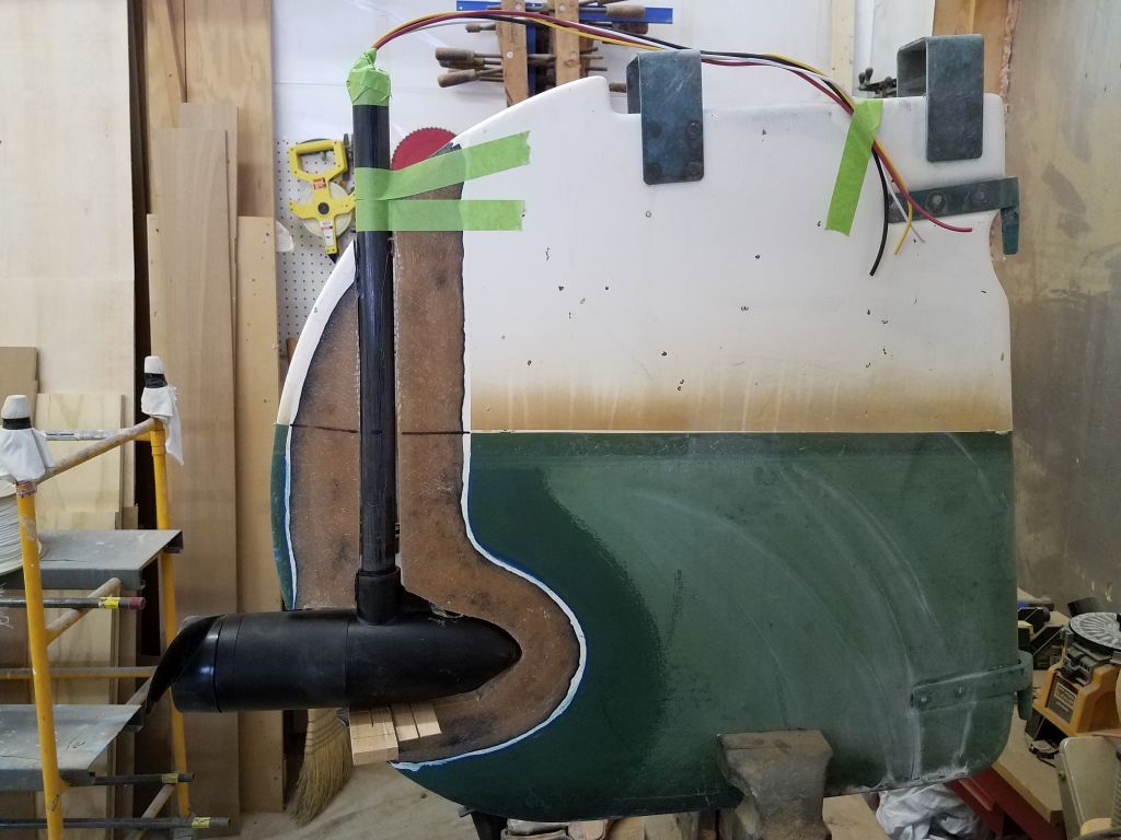
Meanwhile, I prepared some thickened epoxy to tack the assembly in place, enough to hold it securely once cured, but with some obstructions in place for now I left some areas unfilled; I’d take care of those later. I left the glueup to cure overnight.

Total time on this job today: 2.5 hours