lh7

< Back to Lively Heels

Wednesday

With the season around the corner, and the owner’s launch date a week or so hence, we made arrangements to get together and install the new sail track systems on both masts.  Earlier, we’d done all the required measuring, obtaining the internal track size specifications and overall lengths for the two tracks, and the owner had subsequently ordered them.  With the masts removed from their indoor storage shed by the boatyard, we could wrap up the installation.  I took few pictures, unfortunately, remembering only at the end when the tracks were complete.

Along with the new track on the mizzen mast, the owner wanted to lower the gooseneck (and therefore the boom) for easier access from the cockpit.  The boom height had been surprisingly (and, frankly, inconveniently/dangerously) high from a practical standpoint, making furling and covering the sail a real hassle, and with ample headroom beneath, there was no reason other than aesthetics (the mizzen boom height, as original, was sort of tied in with the main boom height so they looked visually level) not to lower the boom.  Since the old mizzen sail was a rag in poor condition, and lacking battens, the owner wanted a new sail made anyway, so it was the perfect opportunity to move the boom height.

I started by removing the mizzen gooseneck, as its existing position was in the way of the track.  Then, I had to use a Dremel tool to open up the mast slot a couple feet above the gooseneck, where the track would actually be installed; the existing slot was too short by half, and was open only on one side of the slot.  I’d opened up part of a slot on the mainmast much earlier, in order to fit one of the old sail slides at the time, so I was already familiar with the process.  Fortunately, the cutting went well and quickly, and we were soon able to install the track in accordance with the instructions.  The installation went swimmingly, and afterwards, I reinstalled the gooseneck a foot or so lower, at a location we’d determined previously.  We’d carefully measured the track so the track as provided was the exactly correct length.

Moving on to the mainmast, I also had to open up the second side of the existing track slot, as this one was open only on one side as well.  With that complete, we installed the track, which went just as well as the smaller one on the mizzen mast.  I didn’t have to remove the gooseneck in this case.  Overall, the installation on both masts, including setup and opening the mast slots as needed, went much more quickly than I’d ever hoped, taking only about two hours.

I wrapped up my end of this project with a couple odds and ends, including restringing the top line of the main’s lazy jack system, which I’d rigged incorrectly the year before, and installing some new registration numbers on the bow for the owner.

Total time billed on this job today:  2.5 hours

< Back to Lively Heels

0600 Weather Observation:
45°, cloudy.  Forecast for  the days:  clouds, maybe a shower, high in the low 50s or upper 40s

lh6

< Back to Lively Heels

Thursday

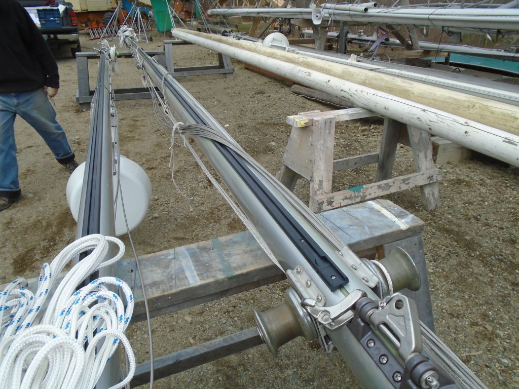
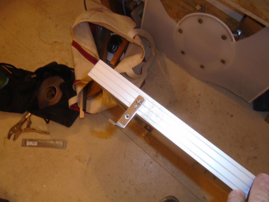
The last task remaining on my work list for this off-season was to help the owner install new aftermarket sail  tracks on both masts.  These tracks, by Tides Marine, make sail dousing a cinch thanks to their slippery no-friction construction, which essentially allows sails to simply fall without effort.

The first step before ordering the final product was to perform various measurements of the mast and existing sail tracks.  We’d planned to do this the last time I was working on the boat, but the required measuring tools from the manufacturer hadn’t yet arrived, so we postponed the measuring.  With the little plastic measuring tools now on hand to determine the actual track size, we headed to the yard where the masts were in indoor–but unheated–storage.  Despite one of the warmest winters on record, this day happened to be about one of the coldest of the entire season even with the late calendar date, but so it goes.

We repeated all the steps detailed below for both masts, and I’ve included specific details for each spar that might be useful for posterity.

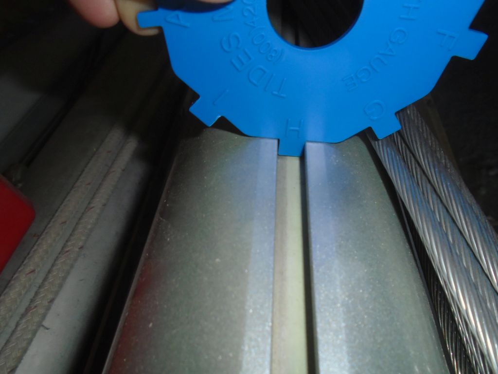
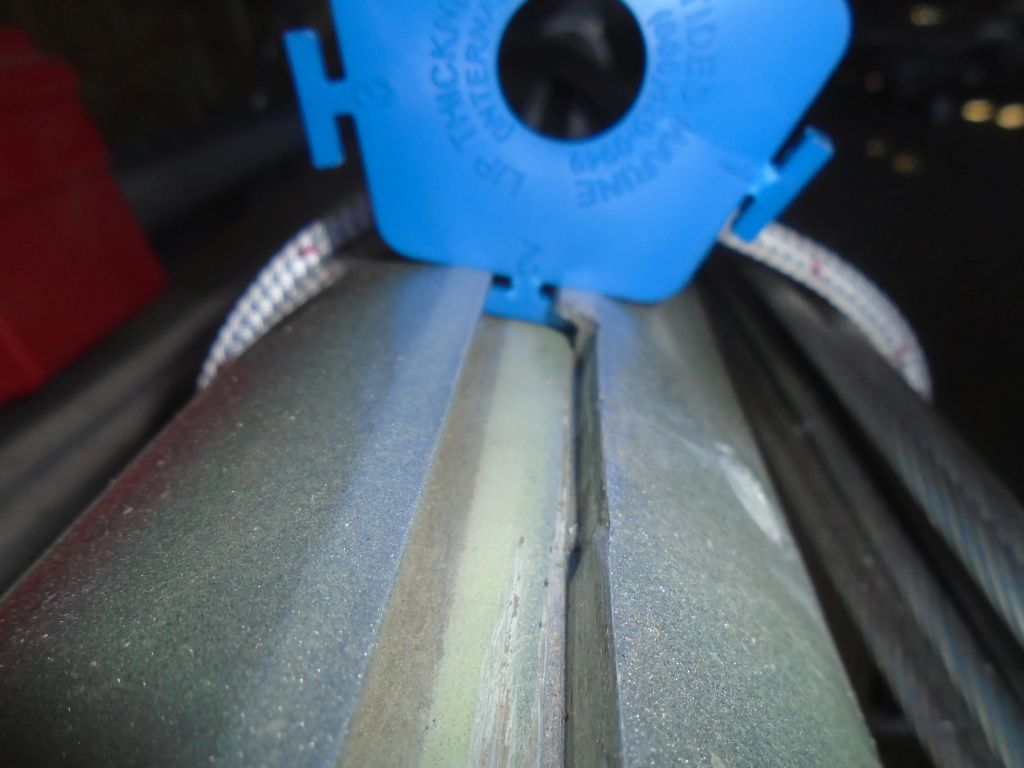
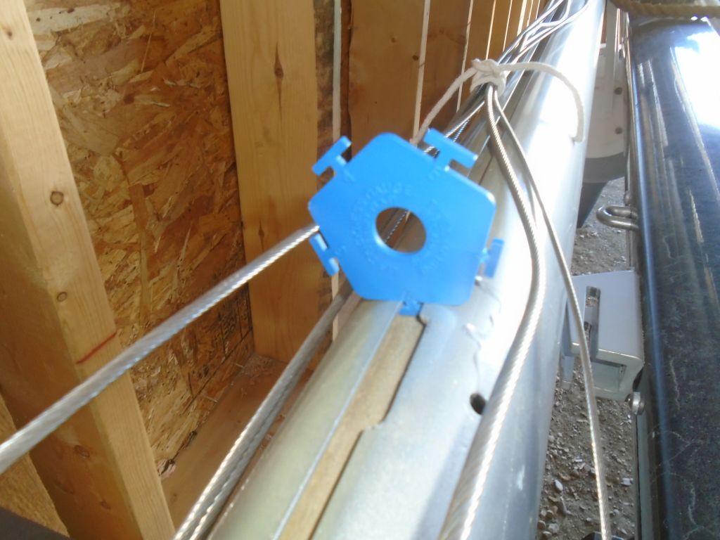
Starting with the mainmast,  the first step was to use the provided measuring tools to measure two aspects of the size and shape of the internal mast groove.   In this case, we had a flat internal luff groove built into the mast, so we proceeded with the appropriate tools and directions for that type of track.   According to the directions, the idea was to find the side of the measuring tool that fit the internal groove in a specific and well-defined manner, which two measurements would then indicate the size of the new track extrusion.  It was a simple trial and error process till we found the right slot width (size H as shown) and slot lip thickness (size 2 as shown).

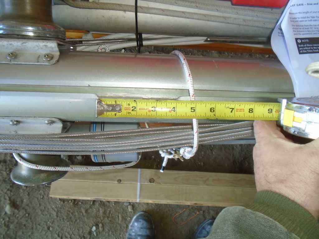
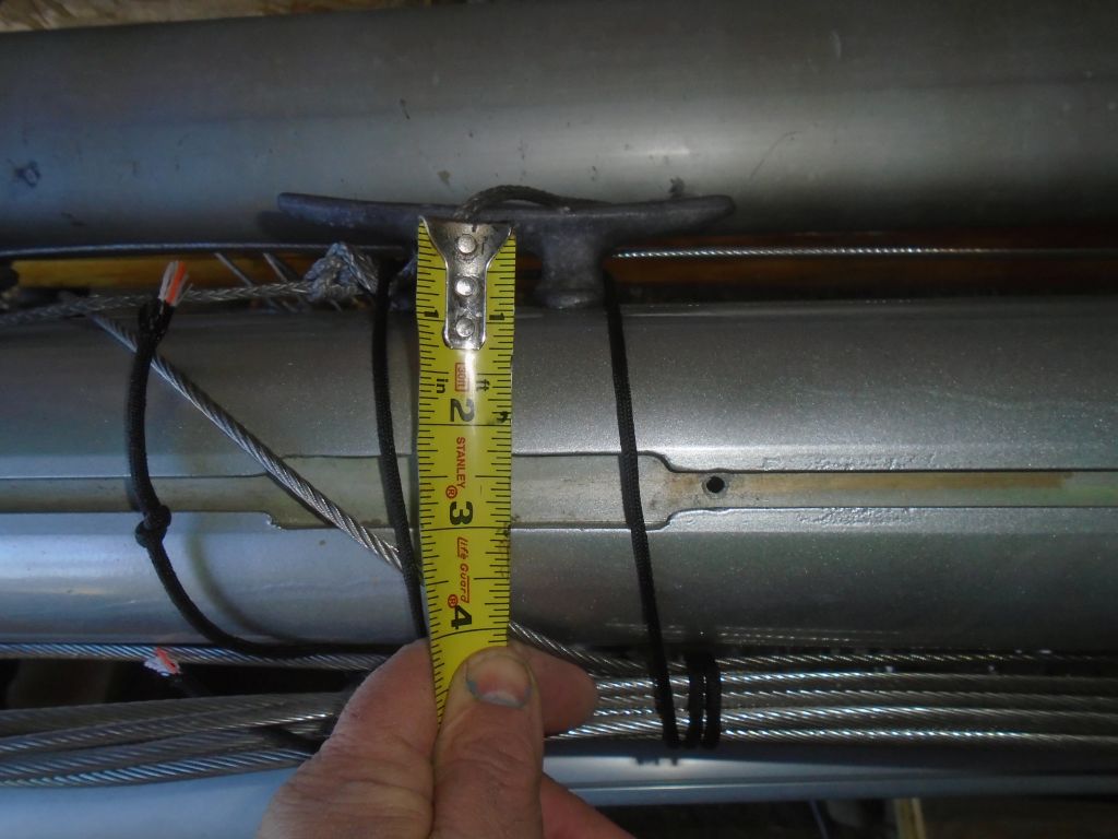
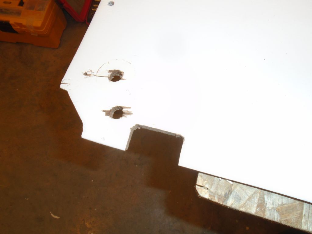
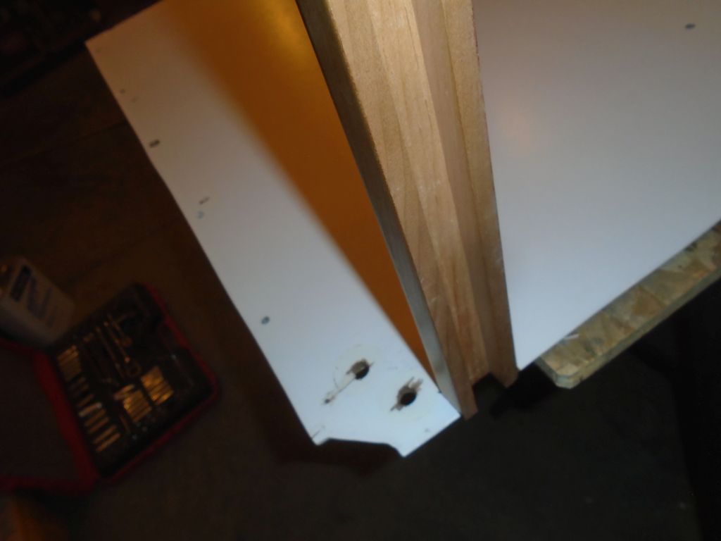
Many of the written directions were predicated on the idea that the track would be being measured and installed with the mast standing, which didn’t apply here and frankly made things much simpler from a measurement and installation standpoint, but nonetheless we went through all the motions and noted the measurements required as a matter of course.  These tracks come in a large reel, and get slid up the mast track right off the reel, in theory.  So to accommodate this, the instructions called for a certain minimum length to the mast gate, where sail cars (and in this case the new track) would be installed.  On the mainmast, the existing mast gate was 4″ in length, which was the recommended minimum, but later we’d have to modify the gate since it was open on only one side of the sail slot, and both sides needed to be open to accommodate the new track.  I’d already extended this gate once, on one side, and opening the other side would require careful cutting with a small grinder.  I’d do that later, when installation time came around.

The instructions also suggested that the top of the mast gate be at least 10″ above the gooseneck, and here we had plenty of leeway.

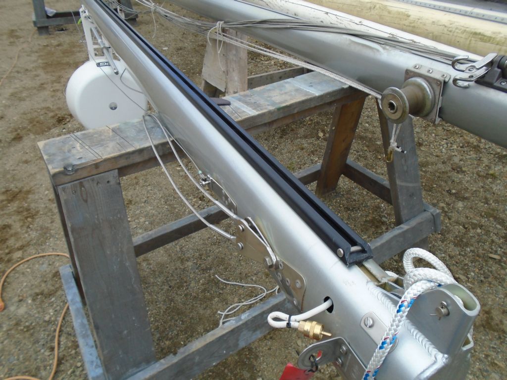
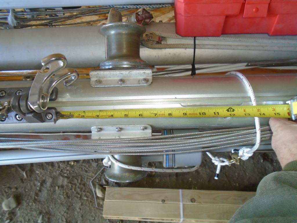
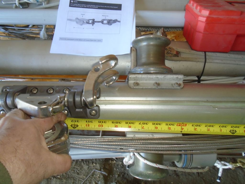
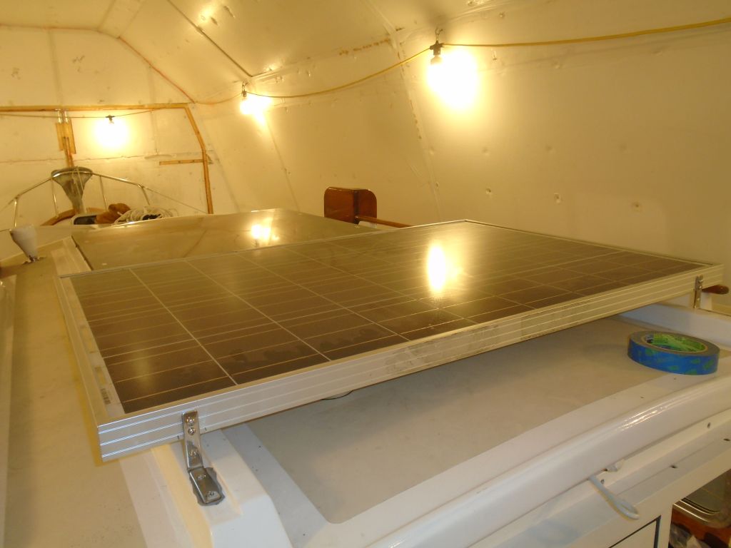
Next, we measured for the exact length of the new track.  With the instructions as a guide, we measured from a point about 1-1/2″ below the masthead sheave (which was high enough to allow the headboard cars to be raised all the way, but not so high where the track might interfere with the shackle or sheave at the top), and down to a point about 1-1/2″ above the gooseneck.  The overall measurement to the gooseneck fitting itself was 310-1/4″, and subtracting an appropriate clearance at the lower end brought us to a final track measurement of 308-1/2″.  One wants the bottom of the track to be as close to the gooseneck as possible, since the lower the track the lower the stack height (which is substantial with the cars used in this system) of the sail, but also high enough to allow insertion of the cars, including the 4″ long batten cars included with the system.

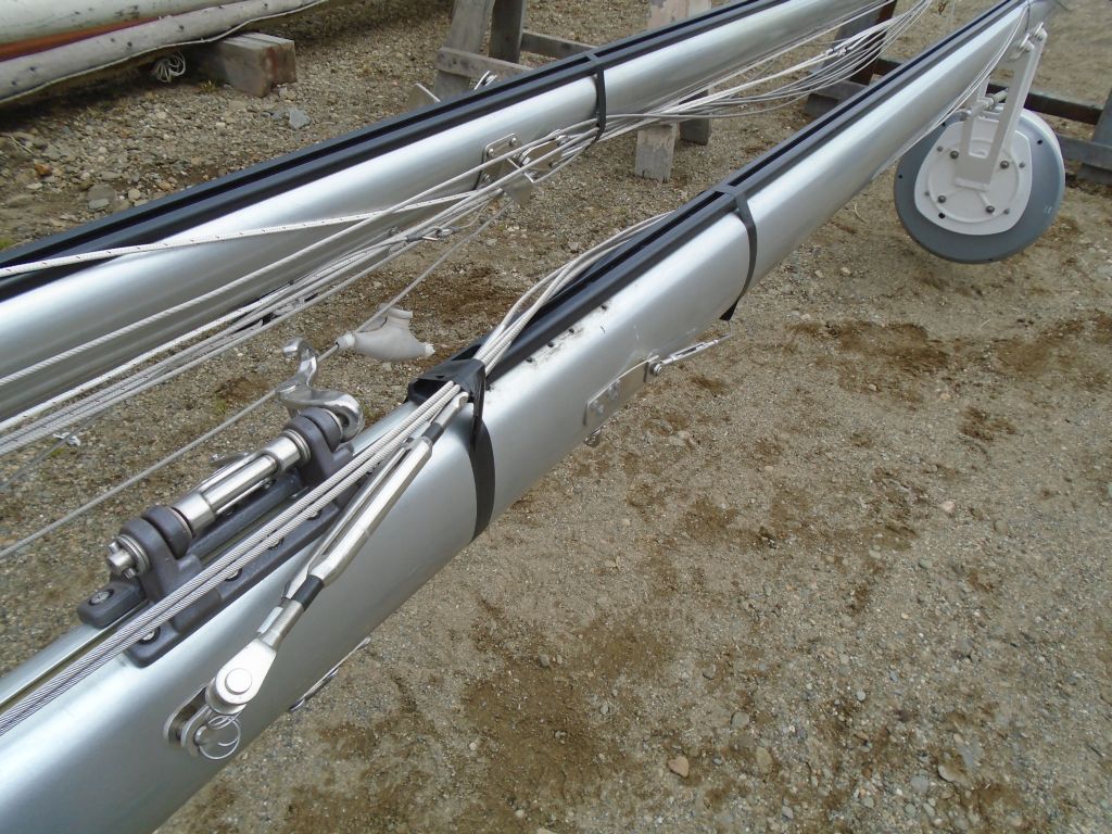
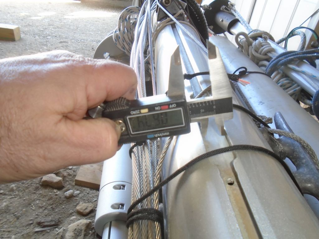
The final measurement requested in the ordering instructions was the internal width of the existing luff groove, a measurement that was easiest to get from a full-width slot further down the mast, which had once been used as the insertion point for the sliding gooseneck on the original boom.  I used calipers and a tape to measure this at between 5/8″ and 11/16″.   To allow enough space for the track to be installed, our thought was that erring towards the lower rather than higher side of this measurement would be prudent, depending on the manufacturer’s own recommendations or requirements.

Moving on to the mizzen mast, we repeated the same processes.  Most elements of the mizzen extrusion were the same as the mainmast, so it was more a matter of confirming this than starting from scratch.

Mizzen mast groove measurements were, as expected, H and 2 respectively.  Similarly, the overall luff groove width was the same at 5/8″ – 11/16″.

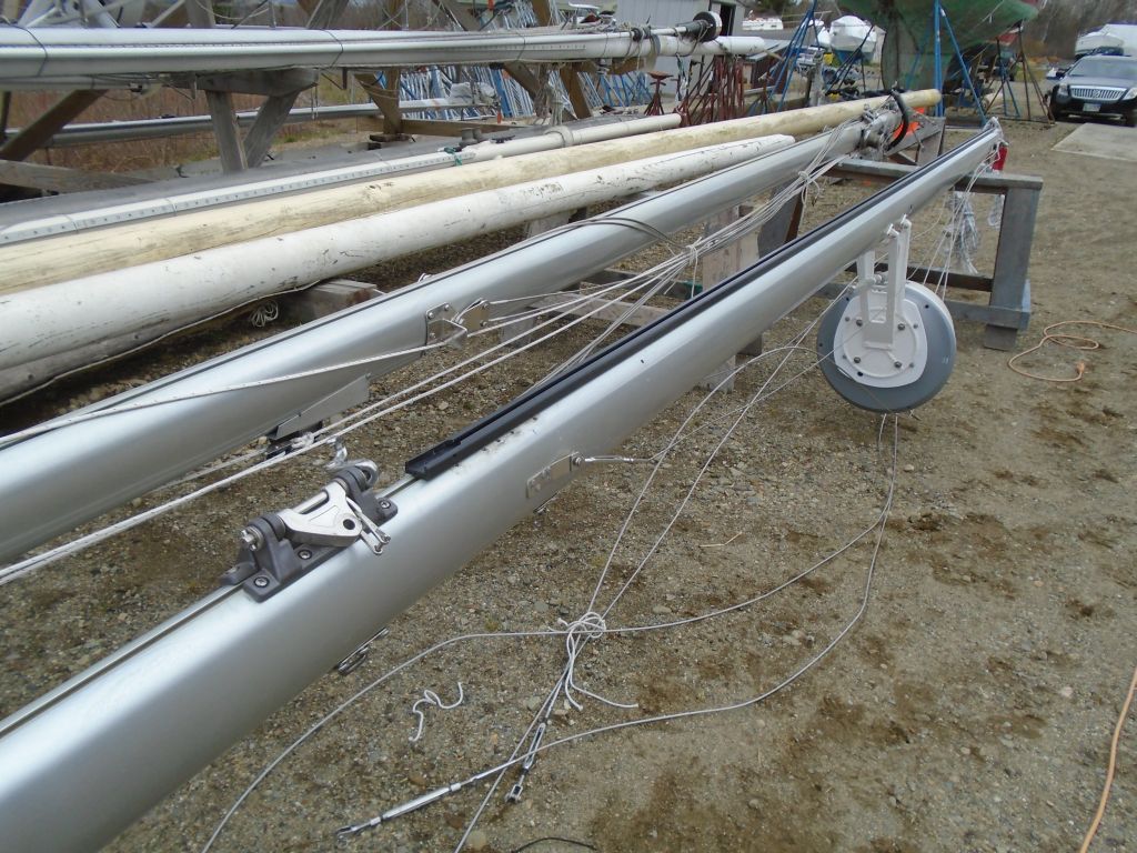
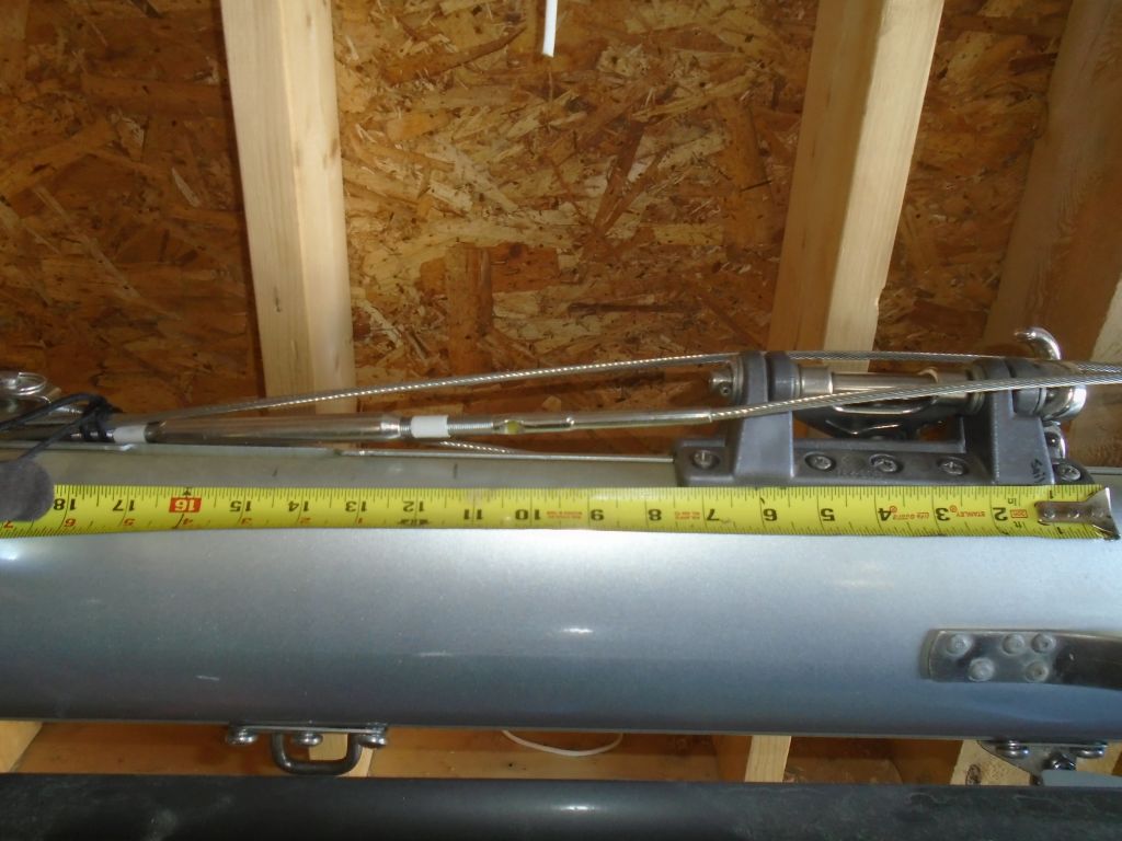
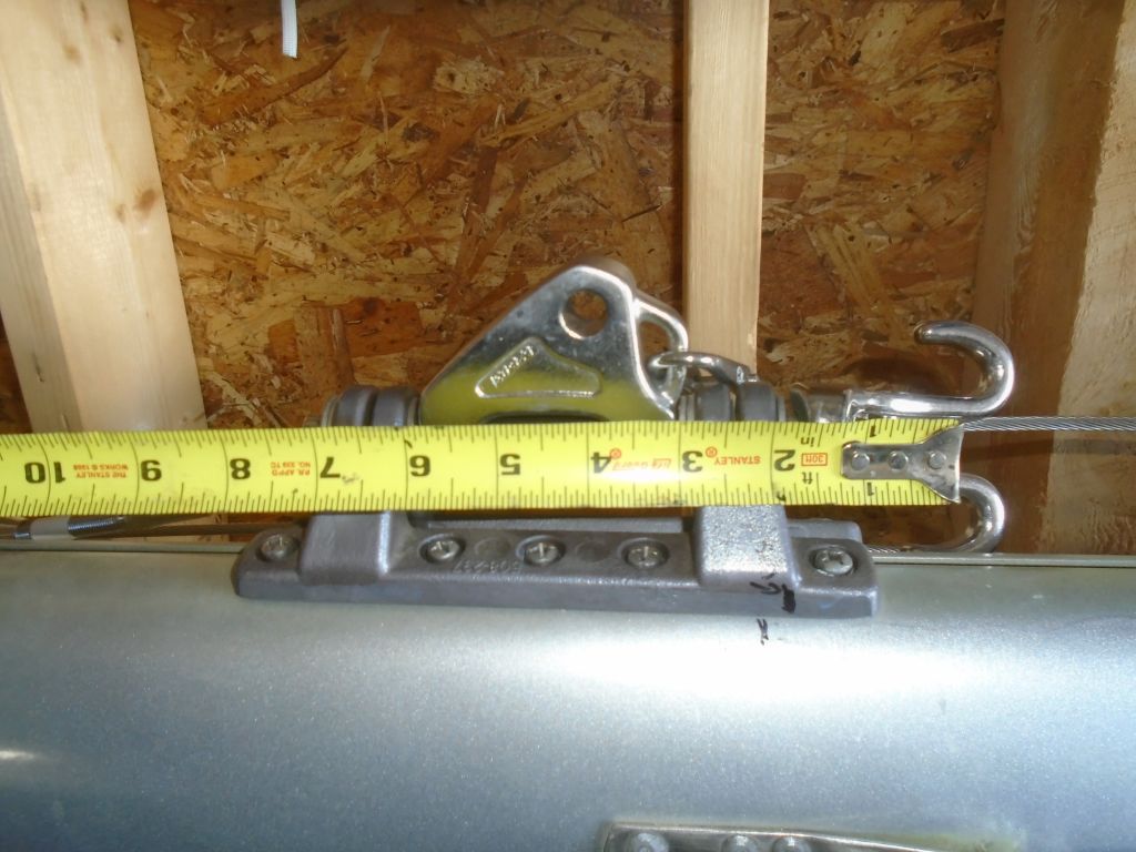
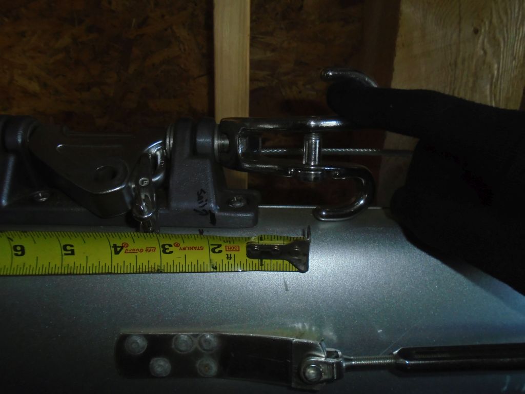
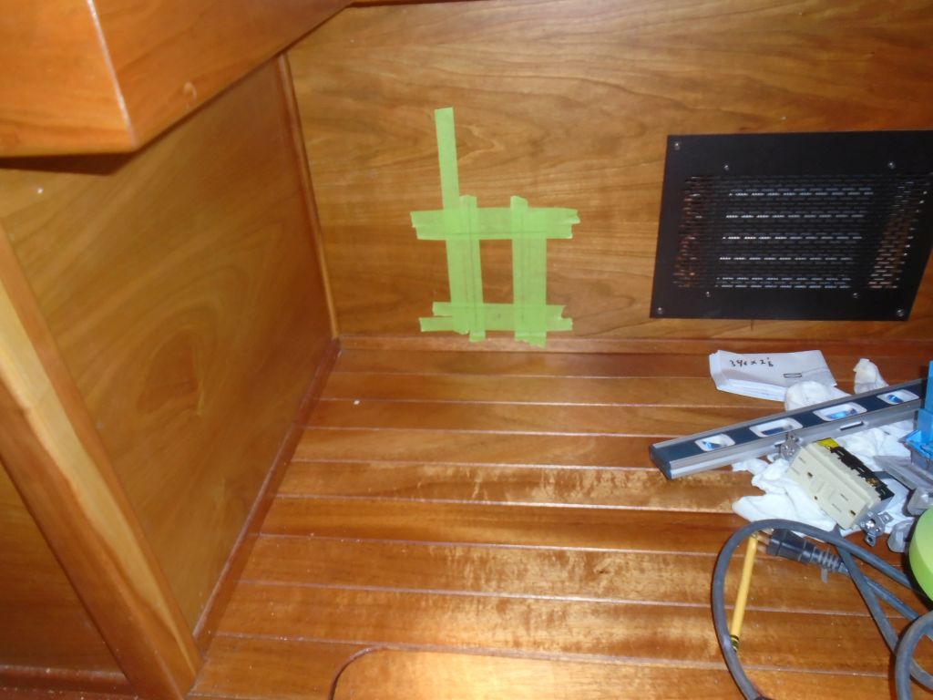
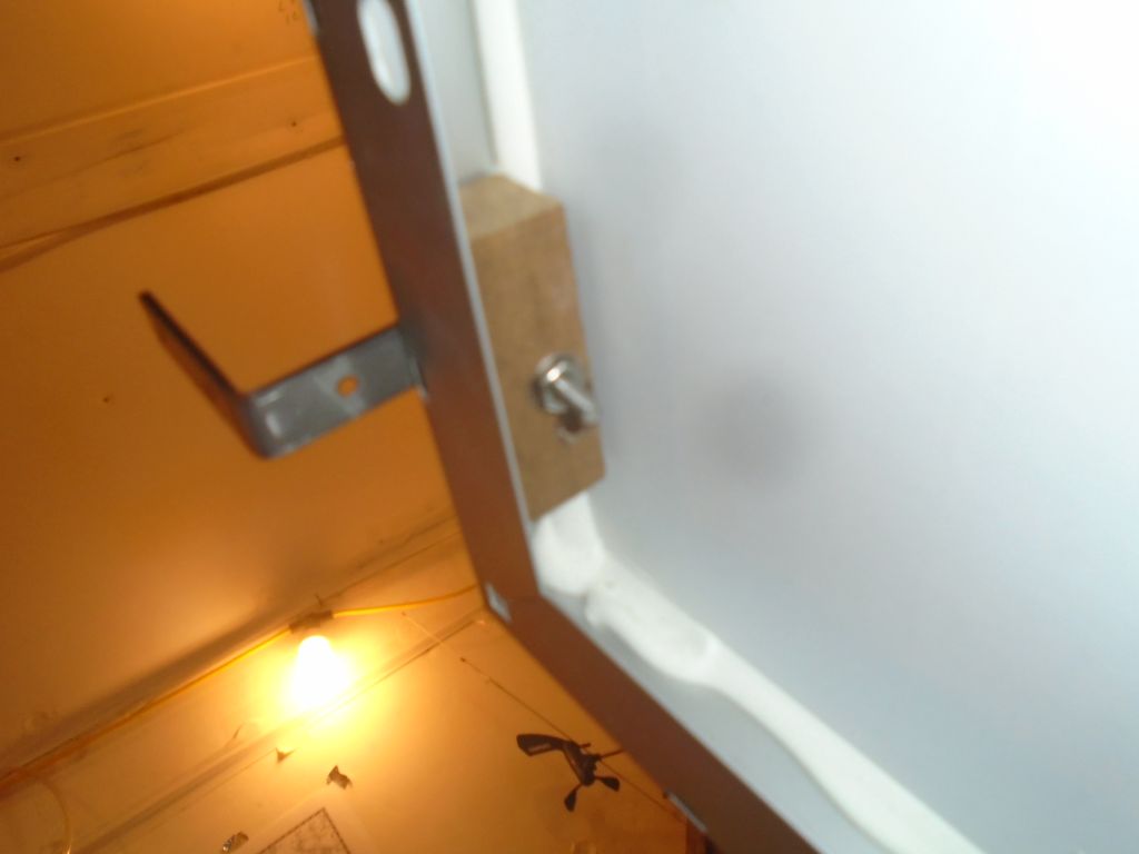
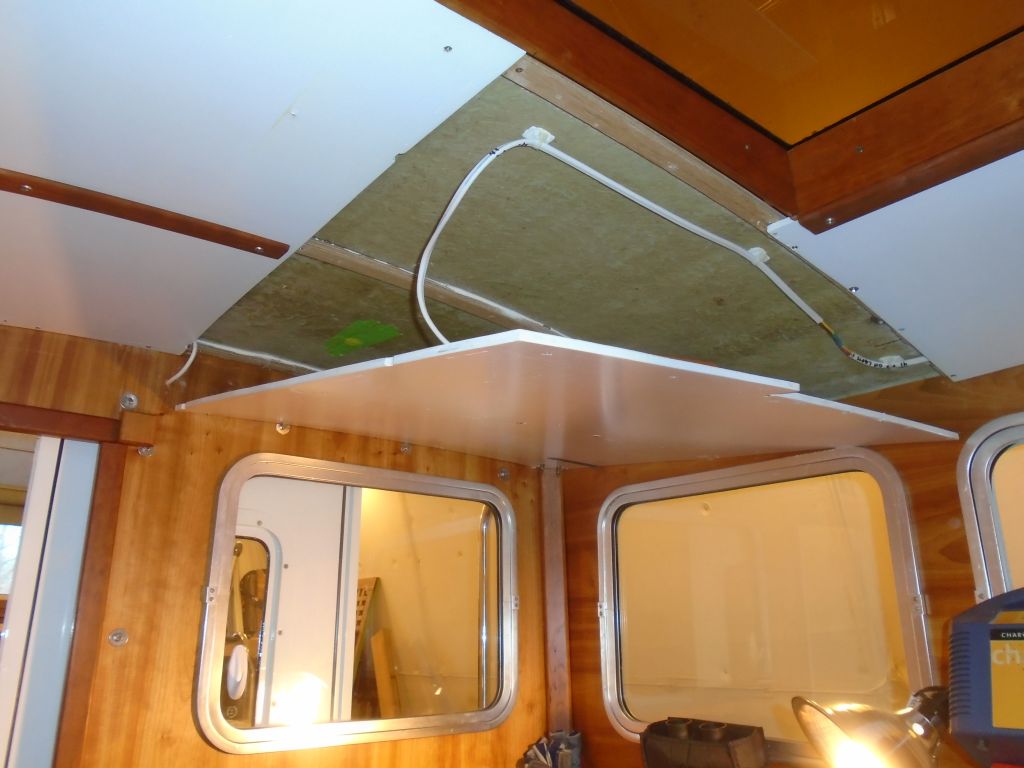
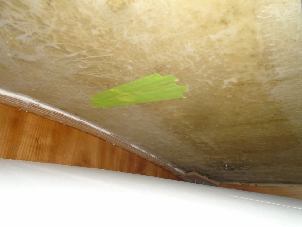
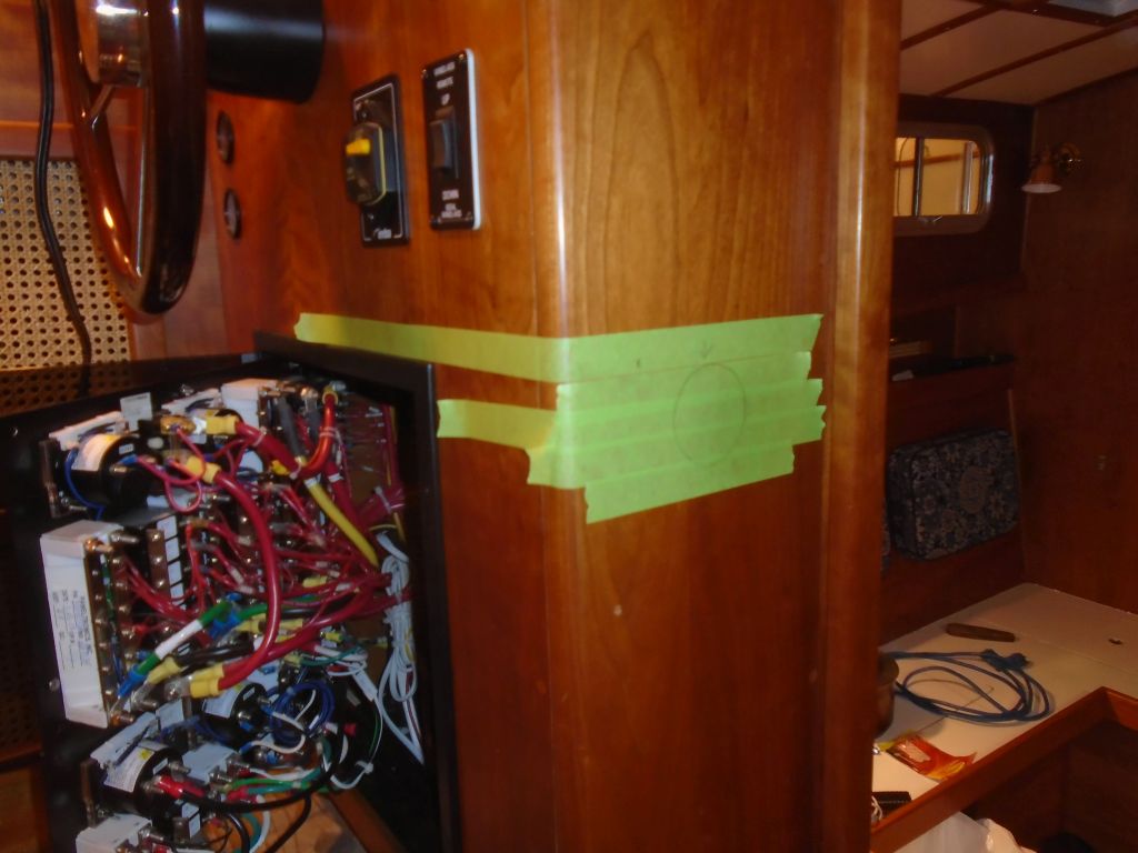
The mast gate above the new mizzen gooseneck was shorter than the required 4″ measurement, so modification would be required for that (as well as to open the other side as with the mainmast).  On the mizzen, the owner wanted to lower the boom position and gooseneck from its current location, as this had turned out to be inconveniently high for sail stowage and sailcovering.  In addition, he planned a new mizzen sail to replace the ratty old one, and to accommodate the new boom position, so several of our additional measurements had to account for this repositioning.  We’d deterimed some  months before that the new position of the gooseneck would be nearly 11-1/2″ lower than its existing position, as shown with these pencil marks.


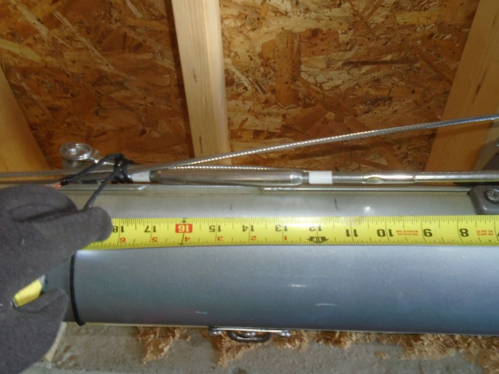
What all this meant at the immediate moment was that the measurement to the position of the mast gate was much larger than it appeared from the existing gooseneck position.  In fact, the top of the existing mast gate was 23-1/2″ above the new top of the gooseneck fitting (once it was moved).

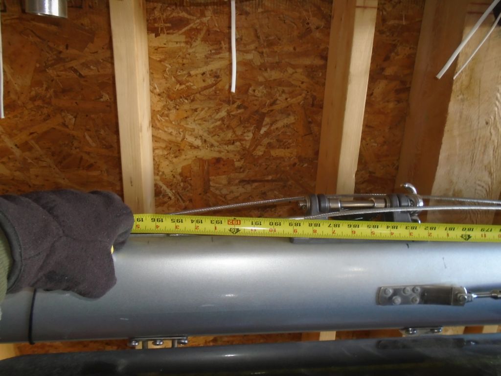
Taking all this into account for the final track measurement, and starting with the tape about 1-1/2″ below the sheave at the masthead, we determined the overall length to to the top of the gooseneck fitting (once repositioned) to be 193″, so the track length would be slightly shorter, or 191-1/2″, ending about 1-1/2″ above the gooseneck.

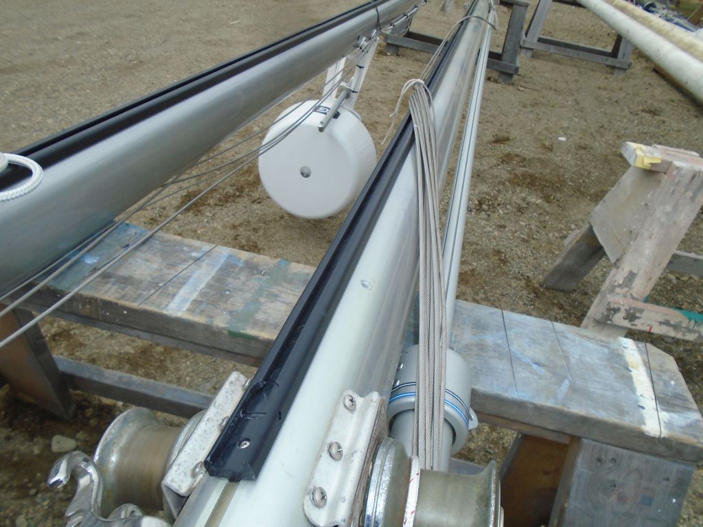
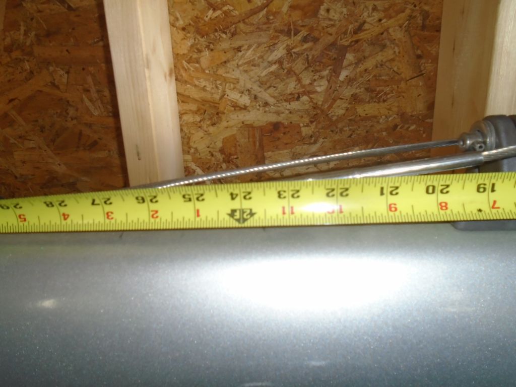
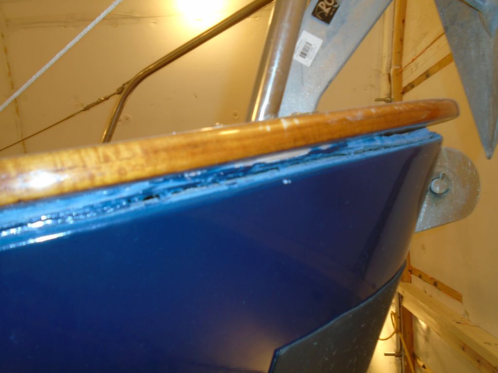
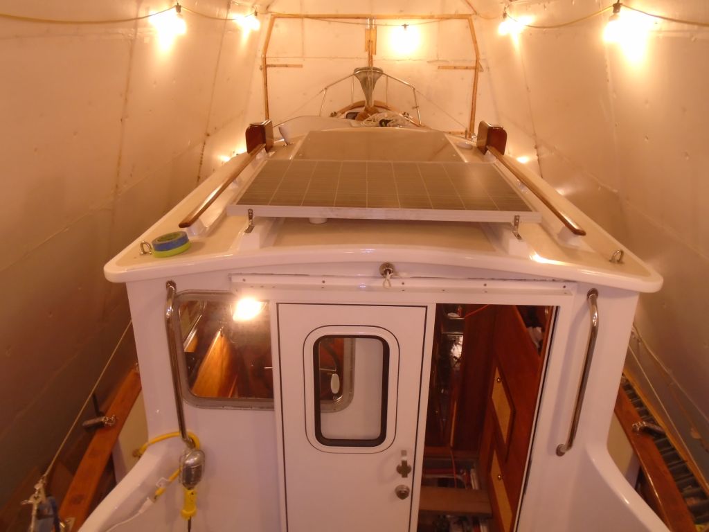
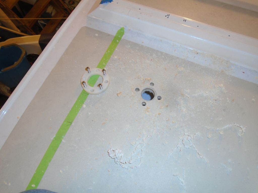
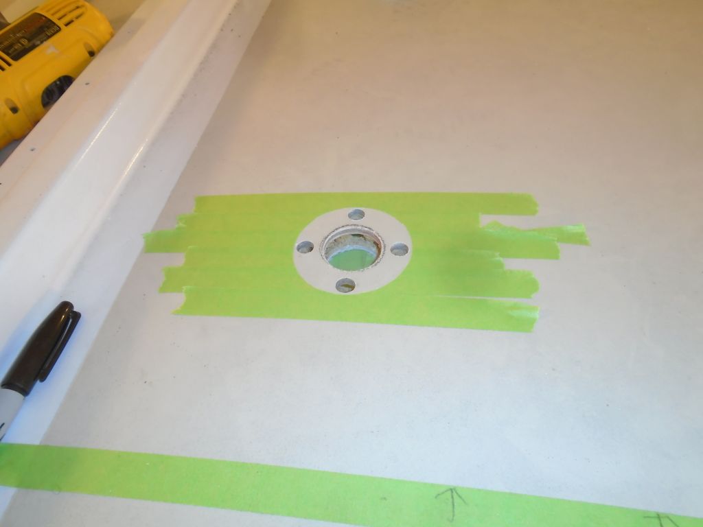
Allowing for the position of the actual tack connection point on the gooseneck, and leaving room for sail stretch and to ensure that the sail could always be fully raised (i.e. not too long), the dimension for the luff length of the new mizzen would be 190″.  These photos simply show the relationship and measurements of the gooseneck fitting, tack position, and boom position for reference purposes.

Total time billed on this job today:  2 hours

0600 Weather Report:
8°, clear.  Forecast for the day:  sunny, high around 23°

lh5

< Back to Lively Heels

Friday

During his first season with the boat, the owner had found that in certain sea conditions, water found its way into the forward cabin.  Investigation at the time suggested that the source of the leakage was the hull/deck seam at the bow, beneath the caprails, and indeed these areas did appear to have issues with old and failing sealant readily visible from the outside.  The space between the hull and the bottom of the caprail was large, and in places I could see gaps both above and below the otherwise-hidden deck molding beneath the caprails.    During my initial construction project on this boat, I’d rebedded the caprails, and also repaired and rebedded the hull/deck seams at all the freeing ports and other areas beneath the wooden bulwark planks, but these bow seams had not received the treatment.  The seams in question ran from the forward edge of the varnished bulwarks to the stem on each side, a distance of perhaps six or eight feet.

Starboard side:

Port side:

Starting with the starboard side, I used various tools to clean out and ream out the seam, removing old and failed material as required and generally cleaning up the area to prepare for new adhesive sealant.  Once I’d cleaned out everything I could and down to sound material, I solvent-washed the seam and masked both above and below it to prepare for new sealant.

I chose 4200 polyurethane adhesive sealant for this job since it possessed all the properties desired in this case:  proper texture (i.e. stiff enough to remain in the seam); adhesive quality; flexibility; durability.  I’d used the same product on all the other visible seams during an earlier part of the project, before paint work.  With a caulking gun, I forced the sealant deep into the seam and into the gaps where the deck joined the hull, and filled the seam flush and completely between the bottom of the caprail and the edge of the topsides, using a plastic squeegee to form the final shape.

At the stem, I used masking tape to form a wall or dam at the edge of the seam, as this area was wide open, and while I removed all the tape from the other areas of the repair as soon as I was done, I left the stem masked off for now, till the sealant cured completely, to hold the end in place.  The stark white sealant could be painted, and we planned to do so later, after it cured, as the seam was quite wide and now starkly visible.

I repeated the process with the port seam, first cleaning out the old sealant and masking off, then filling the open seam with more of the 4200 before removing the tape (except, again, at the very stem).  The job required one full tube of sealant on each side.

The last item on my list for the boat herself was to install a pair of manual wipers on the two small forward pilothouse windows.  We’d discussed electric versions, but there was limited space for wiper motors, and wiring would pose complications and challenges, and given the generally minimal need for wipers thanks to the forward-raked windows, the simple manual versions seemed like they’d be adequate.  Installation was straightforward:  a single 7/16″ hole in the proper position, through which the wiper assembly threaded.

The owner and I had planned to do some preliminary mast work–before launching we’d be installing new mainsail and mizzen tracks for the sail slides–but a measuring tool required before placing the order hadn’t yet arrived despite more than a week’s lead time, so we’d continue that project another time.

Total time billed on this job today:  3 hours

0600 Weather Report:
30°, snow shower.  Forecast for the day:  sunny, high around 32°

lh4

< Back to Lively Heels

Thursday

Returning for a day with hopes (and expectations) of finishing up the list of wiring chores, I got started with installing four new 6-volt batteries for the house bank.  The original 6-volt batteries that I installed in early 2014 when I still was working on the boat myself had been damaged by sitting in a discharged state for a year, an embarrassing mistake that I’d discovered when selling the boat to this owner.  The original set had performed badly during the boat’s first season,  and in addition to replacing the non-functional batteries, the owner elected at this time to add the second set that had been part of the electrical plan from the beginning, doubling the capacity of the house bank to over 400 Ah.

During an earlier work day, I’d prepared the new wiring for the second set of batteries, so installation now was straightforward in the starboard battery box, with the other set back in the port box, along with the starting battery, where the bulk of the wiring was.

Another small job pending from my earlier work session was  to adapt the 3/4″ discharge from the new bilge pump to the existing 1-1/8″ hose already in place.  This required a simple adapter fitting, which I’d purchased earlier and now installed.

bilgepump1-21116

With the solar panel and its basic wiring in place from before, I worked now to complete the installation of the solar controller, wiring, and a remote readout panel.  In my absence, the owner had attached a wooden block in a locker outboard of the engine room where I was to install the controller–convenient to the panel wiring and engine room, but out of the way and out of sight.  I attached the controller and remote readout in the owner’s selected position, then led in two pairs of 10AWG cable for the runs from the controller to the battery banks–one pair each for house and start banks, along with a smaller wire for a temperature sensor required for the controller.  The task was straightforward in concept, but with largely full existing wiring conduits and convoluted route between this location and the engine room, the physical chore took a bit of time, though it all went well and according to plan.

Next, I turned to the final wiring task on my list, which was to install a 300W inverter in the cabin to service a single AC outlet in the dinette area.  The owner had supplied the inverter, and earlier we’d discussed the location and wiring plan, so now it was a matter of getting down to business.

Between then and now, I’d made a couple preparations back at the shop, setting up a plastic outlet box with a glued-on fiberglass flange to allow me to secure it in the cabinet properly, and preparing a short length of 12/3 cable with a standard 3-prong plug on one end to connect the outlet on the inverter itself (which would be inside a cabinet and out of convenient reach) to a remote outlet located in the cabinet front.    Now, I began by running an 8/2 sheathed conductor from the locker beneath the dinette and into the engine room and electrical panel.  Fortunately, I found that an existing wire conduit was in place that I could actually get to and use, because despite the short distance the numerous other installations within and without the engine room made access quite complicated.  As it was, the chore was pleasingly straightforward, and I connected the cable ends to a circuit breaker in the panel that was already set up for this addition (second down in the middle row), then connected the other end of the conduit (after leading it alongside an existing wire run through the adjacent cabinet) to the supplied wire ends that plugged into the inverter itself.   I secured the inverter to the aft bulkhead in the center locker beneath the dinette, which already contained one of the heating fans for the heating system and which the owner pledged to keep free from detritus to allow the inverter the cooling space required.

I laid out for the receptacle in the front bulkhead of the locker, keeping the cover plate even with the bottom of the adjacent heating grille, and choosing this location both for its proximity to the inverter behind, clearance space behind the bulkhead, and because I needed a certain amount of access space for my saw in order to cut the opening.  I secured my plastic outlet box to the back side of the bulkhead with screws through the FRP flange that I’d attached, then ran my pre-made cable from the inverter plug into the box, where I wired it to a typical GFCI outlet.  The system tested operational.

Total time billed on this job today:  6.5 hours

0600 Weather report:
18°, partly clear.  Forecast for the day:  sun, clouds, show shower in the afternoon, high near 30 but dropping in the afternoon

lh3

< Back to Lively Heels

Friday

The tabbing securing the new blower vent pipe had cured in my absence, so with that complete I spent a few minutes touching up the new fiberglass with some sandpaper to remove sharp edges.  Then, I cut the flexible hose to length and connected it to the nearby vent through the aft end of the locker, completing the job.   This installation left a surprisingly usable amount of space in the tiny locker, which had been the goal of using the rigid pipe instead of simply running flexible hose only.

The owner would finish up the actual blower installation in the engine room, now that the wiring and vent components were in place.  All he’d have to do was install the blower on its platform–it was all ready to go–and then secure the platform as he’d designed.

After cleaning up the rough edges of the epoxy filling the through-hole in the pilothouse overhead, I continued work on the wiring for the solar panel.  I installed some wire tie mounts on the overhead, and ran through the extension cables–with standard MC-4 plugs at the ends to connect with the panel itself, using a cable clam to seal the wire penetration.

The wires needed to lead down into the utility space on the port side of the pilothouse, where eventually they could connect to the solar panel controller (and readout panel), which I’d later install in a blank space on the bulkhead there.  Because there was no way to run the wiring completely hidden, back at the shop while preparing for the project I’d made a cherry wire conduit for the job, to span the pilothouse wall between the overhead and the space below.  So now I ran the wiring along my new wire mounts on the raw overhead, and down the side of the pilothouse and through two holes in the little shelf, which allowed the remaining cable to enter the utility space beneath.  This was as far as I’d take the wiring for the moment, as I first wanted to focus on mounting the solar panel itself.

With the wire now secured, I could reinstall the overhead, but first I marked and cut out a notch to accept the top end of the wire  conduit.  Then I reinstalled the overhead panel and its trim pieces, and secured the wooden wire conduit over the exposed wires with a few screws.

The owner wanted the panel removable without heroic efforts, so to mount it I chose some simple stainless steel angle brackets, which I secured to the panel frame with a bolt and wooden backing block to take up some of the space within.  There wasn’t room for a second bolt, but to prevent any possibility of the bracket moving I installed a small sheet metal screw beneath the bolt location, just into the frame itself.  Earlier, I’d marked where these brackets needed to be while the panel was mocked up on the boat, so the brackets would align with the molded rails that used to accommodate the sliding pilothouse overhead hatch.

With the brackets secured to the panel, I mounted them to the pilothouse, drilling and tapping the molded rails for machine screws before securing the brackets with some butyl tape for ease of removal, if desired.  The wiring entry point was hidden beneath the panel, but the wires were still accessible for disconnection as needed.  To complete the installation, I’d need to install and wire in the solar controller in the pilothouse, but that would be a job for another day once I’d collected some materials required for the job.

In an embarrassing flub that the owner and I had discovered back when we launched the boat for him the first time, in June 2015, I’d found that somehow–and despite what I recall as great care on my part to avoid the very issue–I’d installed the mounts and blocks for a spreader flag halyard on the wrong side of the spreader–the top side, rather than the bottom.  This was humbling, but ultimately minor for the moment, and the immediate fix at the time had been to simply remove the hardware and press on.  Now, however, it was time to correct the issue.  I used small screws set in Tef-Gel to fill the erroneous holes in the spreader top, and reinstalled the inchworms and blocks on the correct side of the spreader this time.

halyard1-12916

In the past few days I’d made solid inroads to the original project list, and felt good about the early jump-start.  But for the moment, I’d reached the end of what I’d hoped to accomplish during these few days, and it was time to regroup and focus on the remaining elements of the project ahead, which I’d take care of over a few days as needed in the near future.  So I cleaned up and packed away my tools and equipment, and would return soon to continue a few things and keep the job moving.  For the meantime, though, it was back to the shop and relative normalcy.

Total time billed on this job today:  4.25 hours

0600 Weather  Report:
25°, cloudy.  Forecast for the day:  Clouds, scattered snow and rain showers.

lh2

< Back to Lively Heels

Wednesday

I got started with the new bilge pump automatic switch, a high-end float switch in a sealed containment.  Given the space availabilty and access to the bilge, and the way the switch could be mounted with its supplied mounting hardware, I chose to install the switch on a piece of narrow fiberglass flat stock to make mounting straightforward and retrieval of the switch easy.  I clamped the cylindrical switch to the stock after first cutting the fiberglass to length after a test-fit in the engine room, and led its wiring up the stick, securing it as necessary.  At the lower end, I added some chafing bear since the whole arrangement would be very near the stuffing box once installed.

With the switch mounted and wires in place, I installed the stick and switch in the bilge, at the aft end next to the shaft, and secured the mounting stick with two screws into a convenient plywood support member above.  Then, I made up the various wires–five in all–to interconnect the bilge pump and switch with the wiring to the boat’s bilge pump switch at the helm.

With the wiring complete, I tested the pump.  The auto switch could be tested by inverting it, but it also  came with a little green indicator light on the top of the switch to show that it was properly wired in the automatic position.  When switched to manual, the pump operated well.

light#-12716

One thing about these pumps is they don’t differentiate the wiring (two black wires) or inlet/outlet, since wiring one way versus the other would change the inlet/outlet position as it changed the direction of the pump motor.   I determined the flow direction of the pump–as wired–during the pump test, and marked the inlet and outlet myself for future reference.  Then, I attached a length of 3/4″ hose, along with the supplied strainer, to the inlet, running the suction end well aft into shaft alley.  The outlet end required an adapter to fit the 1-1/8″ hose that was already in place to the transom through hull, so I didn’t make this connection at the moment as I didn’t have the fitting on hand.

With the bilge pump complete for all intents and purposes, I turned again to the new engine room blower.  The plan for the outlet for the blower was to lead it through the defunct built-in propane locker and out a vent from there into the cockpit.  To maintain use of this locker as much as possible, we decided to use a length of rigid pipe installed through the locker floor, which would minimize fragile hose runs.  To this end, I drilled a large hole in the bottom of the locker (after ensuring the way was clear beneath) to accommodate the 4″fiberglass tubing.

At the aft side of the locker, I drilled another large hole in which I mounted a louvered vent fitting to extend the discharge out into the cockpit.  I installed the louvers with sealant and bolts, only using the bolts because it made it easier to install in this location since access was tight with the new propane locker just behind.

After cutting a 12″ piece of the fiberglass tubing, I tacked it in place inside the new hole in the locker with hot glue.  Because the blue vent hose I chose was a tight fit on this tubing, I pre-installed two lengths of the hose before I installed the pipe, as it was easier to do on the bench than in this tight locker.  Once the hot glue had dried and was holding the pipe securely enough, I mixed some thickened epoxy for fillet material, and, later, installed fiberglass tabbing all the way around the pipe to secure it to the boat.  Before these steps I’d sanded clean the bonding surfaces in the locker.  I left the fiberglass to cure.

The owner had a solar panel that he elected to mount on the pilothouse roof, and its installation details were next on my list.  It was late in the day, so to begin, I prepared to install a through-deck wiring lead for the panel wires, and after making some reference marks and removing a section of the cosmetic overhead in the cabin, I drilled a large-ish hole through the overhead, then reamed out the core from within its opening and around the fastener locations, and filled these voids with thickened epoxy to isolate the core through these penetrations.  I left this to cure before continuing the process.

Total time billed on this job today:  6.75 hours

0600 Weather Report:
32°, cloudy.  Forecast for the day:  Mainly cloudy, highs in the 40s but dropping during the afternoon

lh1

< Back to Lively Heels

Tuesday

The owner of Lively Heels had a list of upgrades and additions to the boat that he requested help with, including several electrical jobs and other sundry items.  With the boat in a heated building, and not wanting any of the work to affect his planned early spring launch date, I planned several days of work at the boat during the winter to get ahead of the project list.

After getting my tools and related supplies unloaded and at least semi-organized, I started the first project on my list:  installing a battery monitor for the owner to better manage his electrical usage.  We chose the Victron 702 model that would monitor both house and starting banks.  One advantage of this particular monitor was its simplicity in wiring to the monitor itself, which required only a single Ethernet-type cable supplied with the unit.

We chose the side of the helm/electrical console for the monitor, where the owner could easily see it from the cabin and where installation would be straightforward.  I elected to install it even with the top of the adjacent electrical panel housing, so I extended a line at that height to position the required hole, then masked off the varnished wood to protect it while drilling the 2-1/16″ hole required for the monitor itself.  This location was also free from obstructions on the inside, which had been a key factor in its selection.

With the mounting hole in place, I led in the Ethernet cable, which connected the monitor to the shunt that I’d soon install in the battery wiring, and connected it to the monitor before installing the monitor with the supplied external bezel, which I had to use since the console material was too thick to allow use of the threaded backing ring.  I secured the wire inside the console, leaving a bit of excess cable at the top near the monitor.

I chose to install the supplied shunt at the aft end of the port battery box since there was room there, it was convenient to the batteries, it was well-protected (when the box was covered), and, frankly, there were few other choices in the crowded space.  I wired the shunt into the battery negative circuits as directed, and connected the monitor’s Ethernet cable, as well as two small wires–one to each battery bank–for temperature monitoring.

While I was working with battery cables, I decided to build the cables to lead over to the starboard battery box, where I’d soon be installing another pair of 6V batteries to double the capacity of the house bank.  We’d also be replacing the original house battery bank, as the batteries I’d installed in 2014 had been damaged by sitting in an undercharged state for too long (by me, the boat’s refitter at the time), and had never held a proper charge during the new owner’s first season with the boat in 2015.  I led these cables across the front of the engine room and into the battery box to await the new batteries later.

To assist ventilation of the engine room, which lacked any immediate external vents, the owner requested a heavy-duty, continuous-rated blower fan to help exhaust heat from the space, and selected a 4″ blower with the appropriate specifications.  Leading up to the project, the owner constructed a removable platform in the engine room on which to mount the blower, and my job would be to wire it and install the venting into the cockpit.

Wiring was straightforward.  I led a wire pair through the engine room along existing wire routes, and into the console, where I connected it to the terminal block (it’s #5) that ultimately connected it to an unused switch in the upper accessory switch panel at the helm.  At the blower end, I terminated the wires at a small terminal block, which would allow the blower and its shelf to be easily removed during the off-season or when access to the spaces behind was required.  The venting side of the project would be a bit more complicated, and I’d get to that in due course.

Lil_Champ_4_inch_DC_Blower

Similarly, on the opposite side of the engine room the owner prepared a platform for a new, remotely-located diaphragm bilge pump, an upgrade over the centrifugal pump that was previously installed.    I removed the old pump, reserving its wiring to the console and its discharge line for reuse, and mounted the new pump to the removable platform (removal would be handy anytime access to the spaces beyond was needed).  I connected the original wires from the console to a new terminal block, and wired the pump to the other side of the terminals accordingly.  Still to come in this installation was the bilge auto switch, which I’d be installing presently.

Total time billed on this job today:  5.75 hours

0600 Weather Report:
22°, mostly cloudy.  Forecast for the day:  clouds and sun, highs in the 40s