(page 7 of 7)

Holby 8

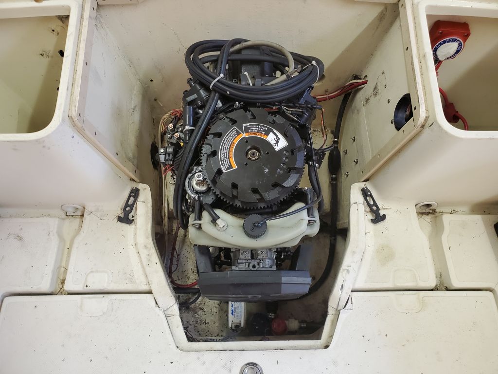
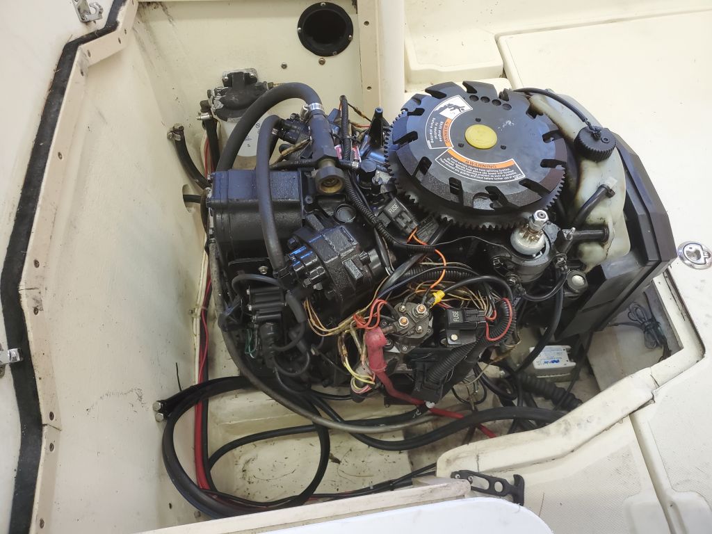
The owner and I discussed the problem of the engine and decided that the main thing for the moment was that the engine had to come out of the boat and wasn’t worth endless hours of so-far futile attempts at separating the engine from the jet drive.  The backup option I’d been holding close was the idea of cutting the fiberglass drive housing to free the engine and drive in one piece, for whatever disposition the combined units might have; they’d be intact, at least, and out of the boat.

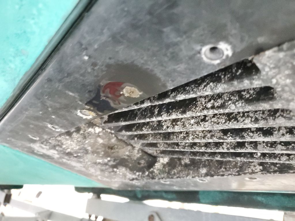
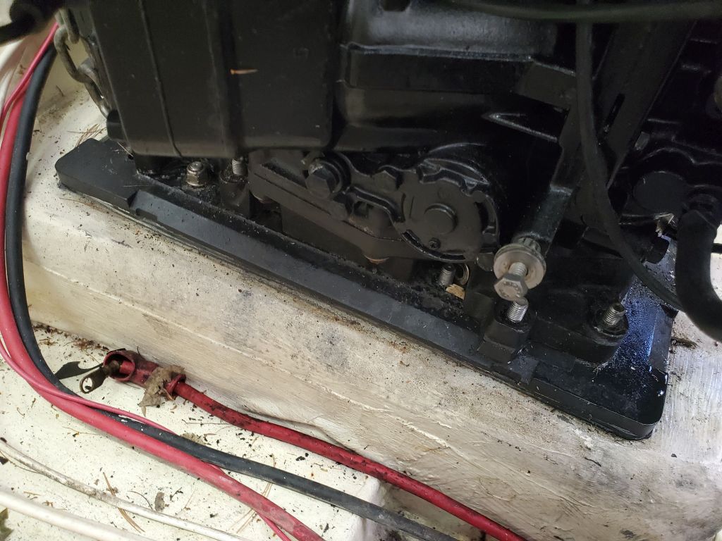
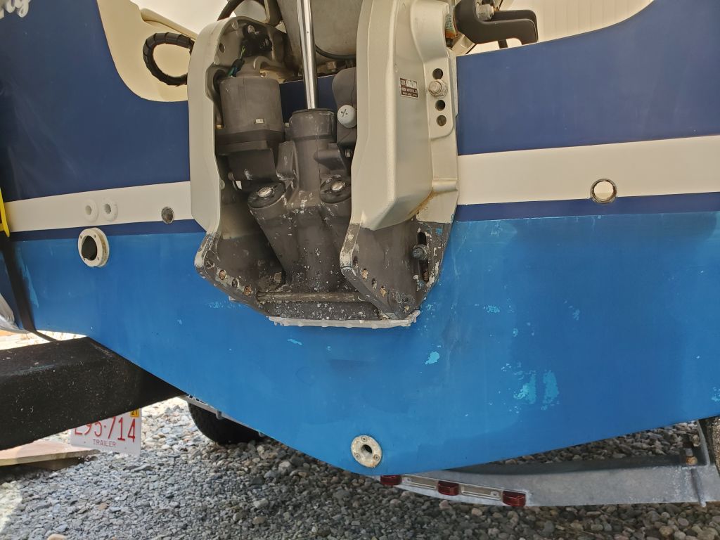
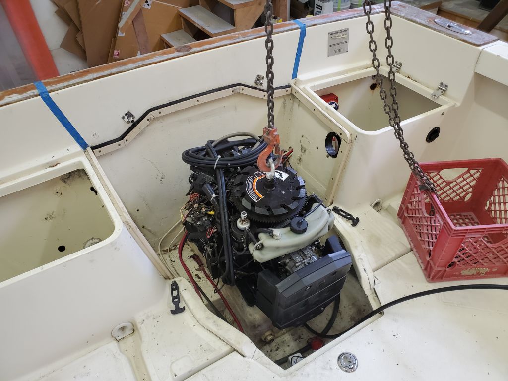
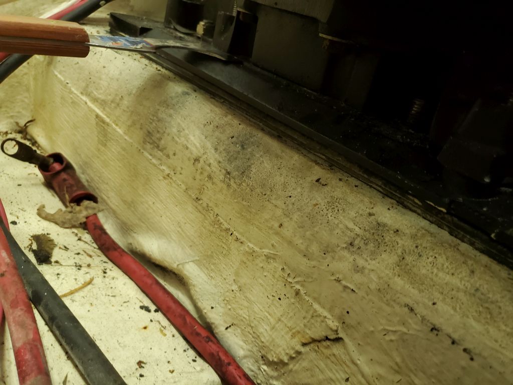
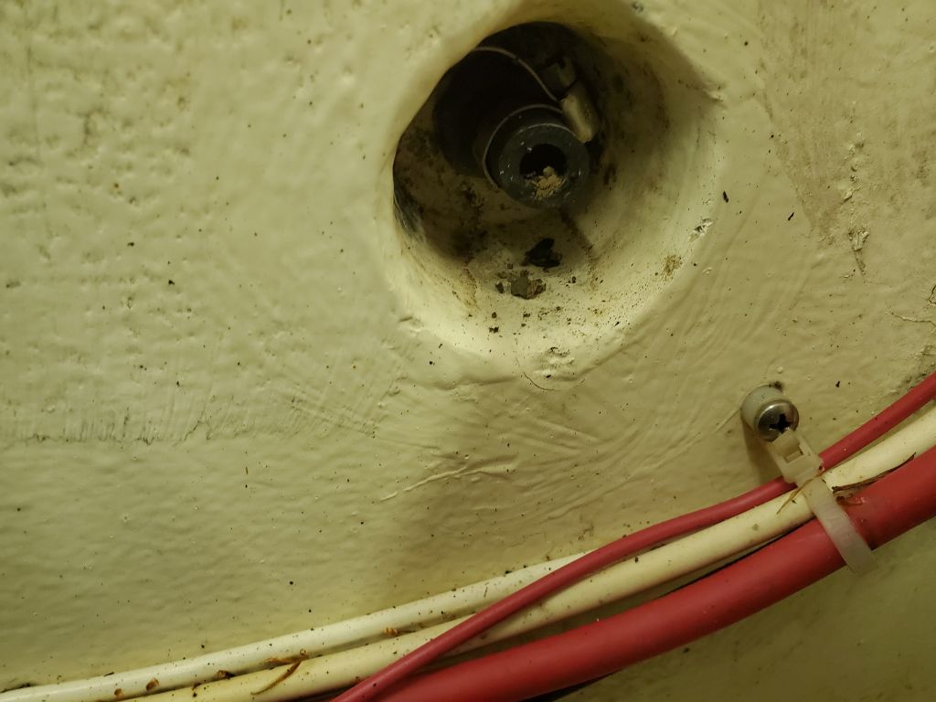
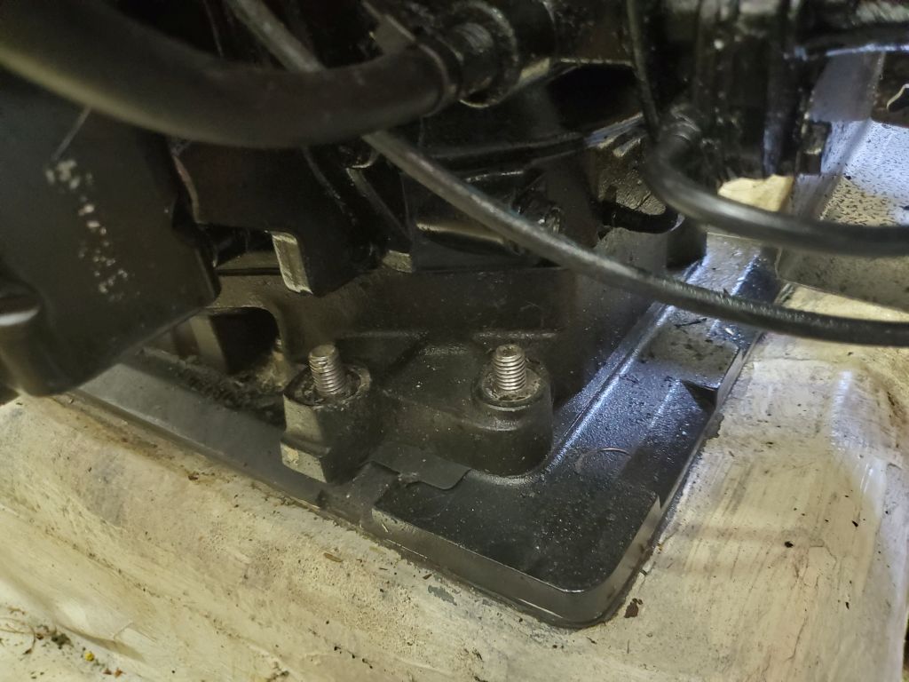
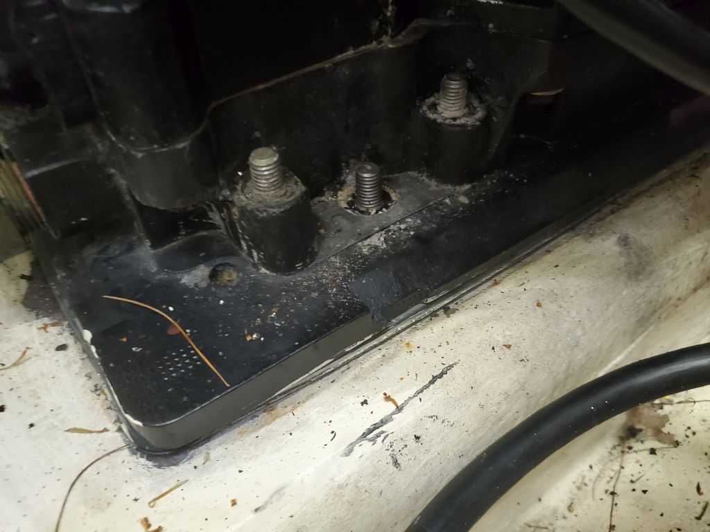
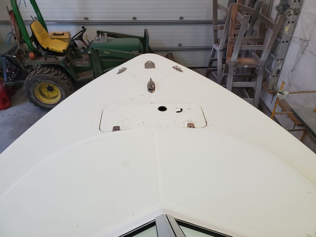
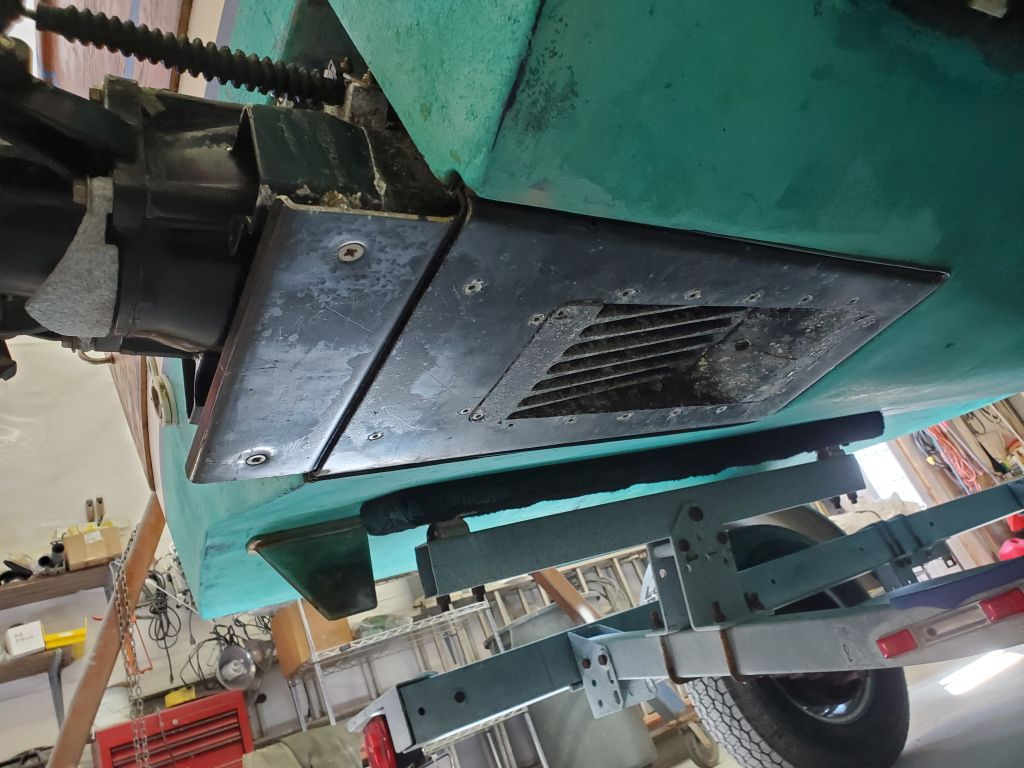
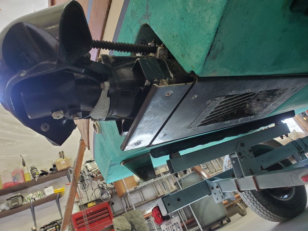
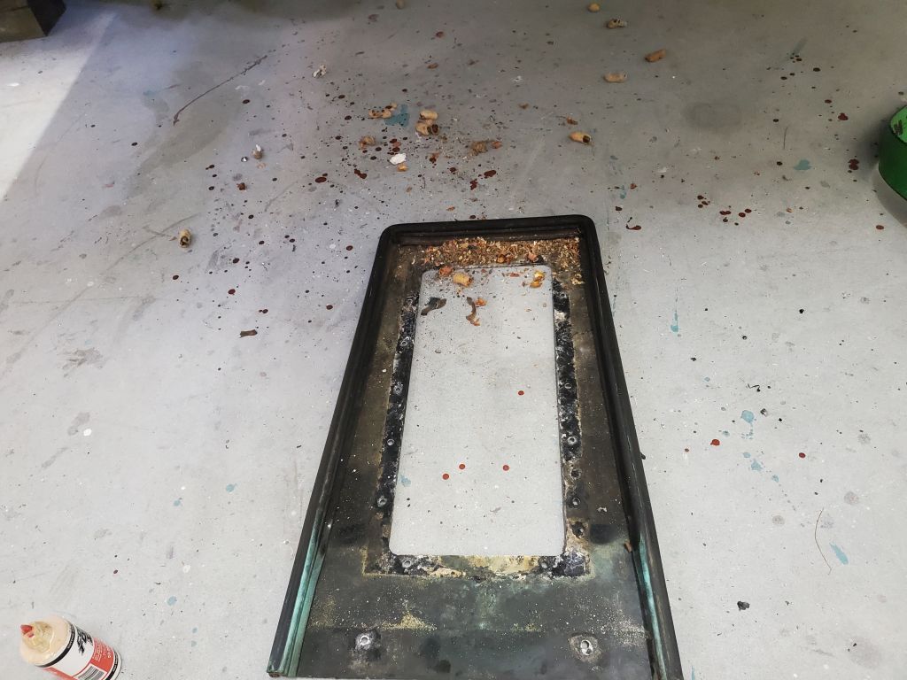
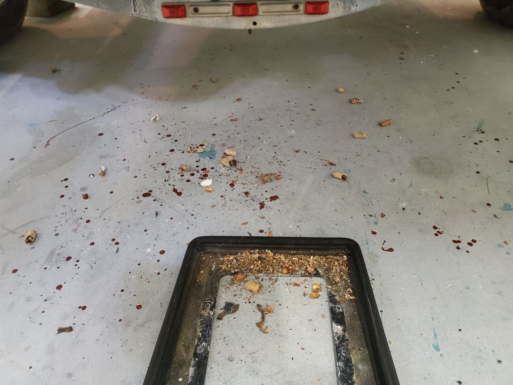
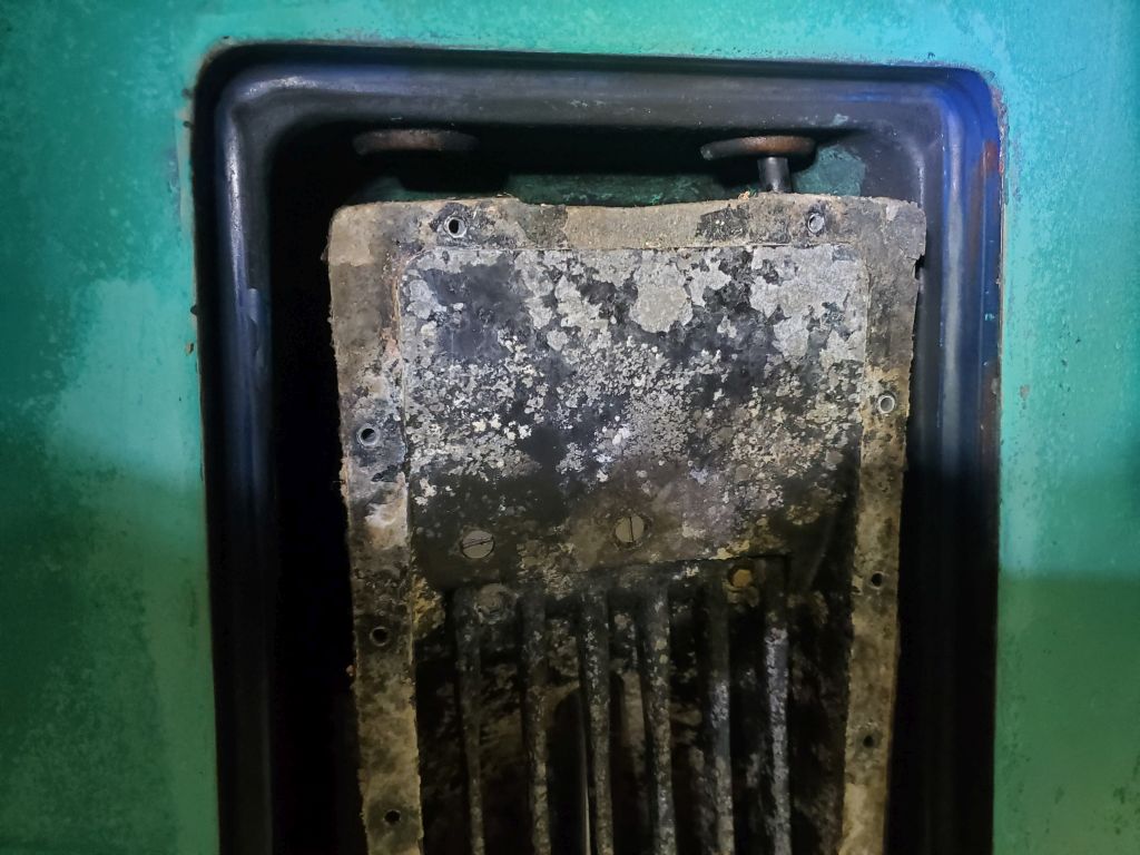
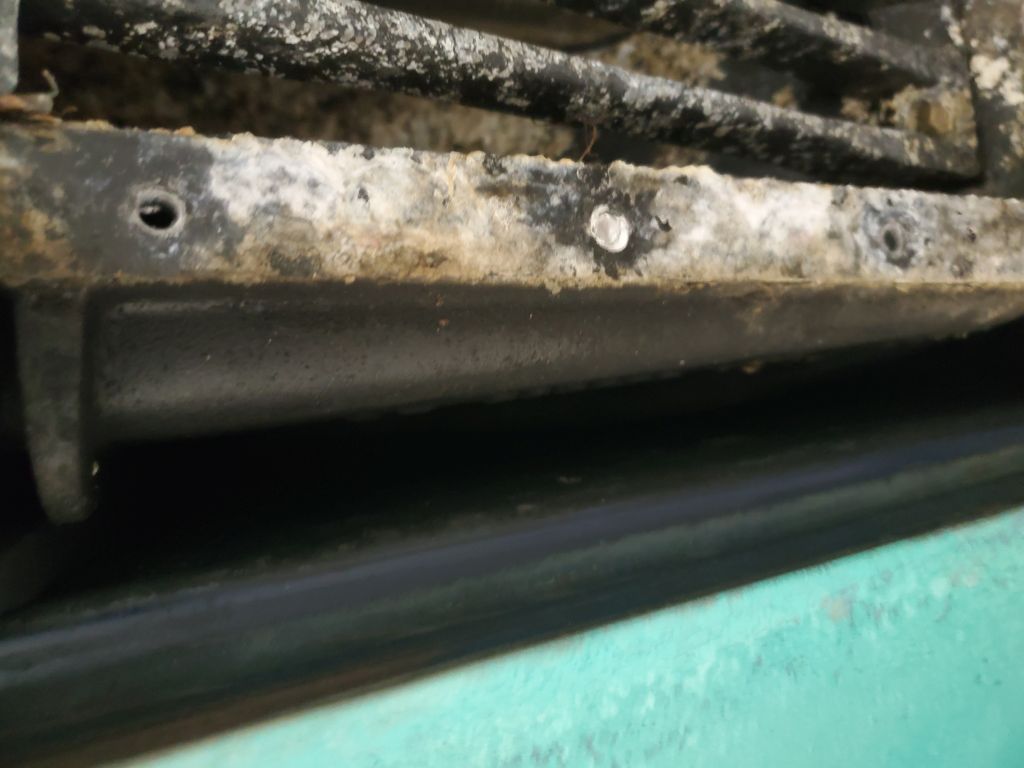
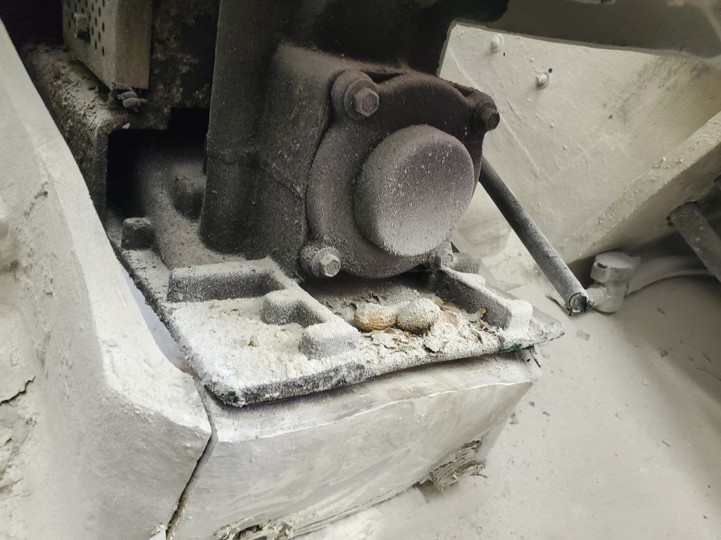
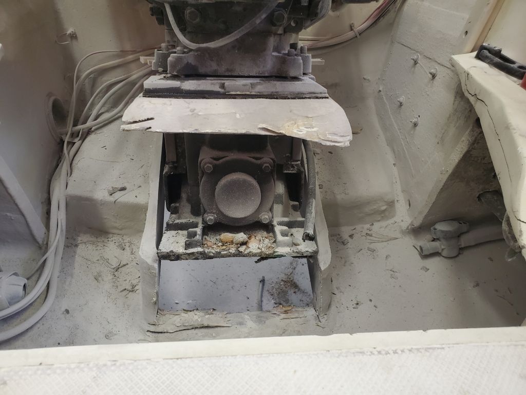
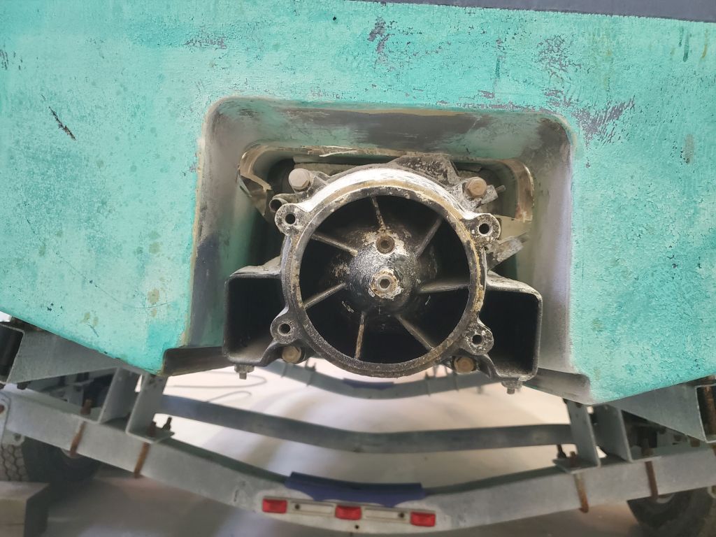
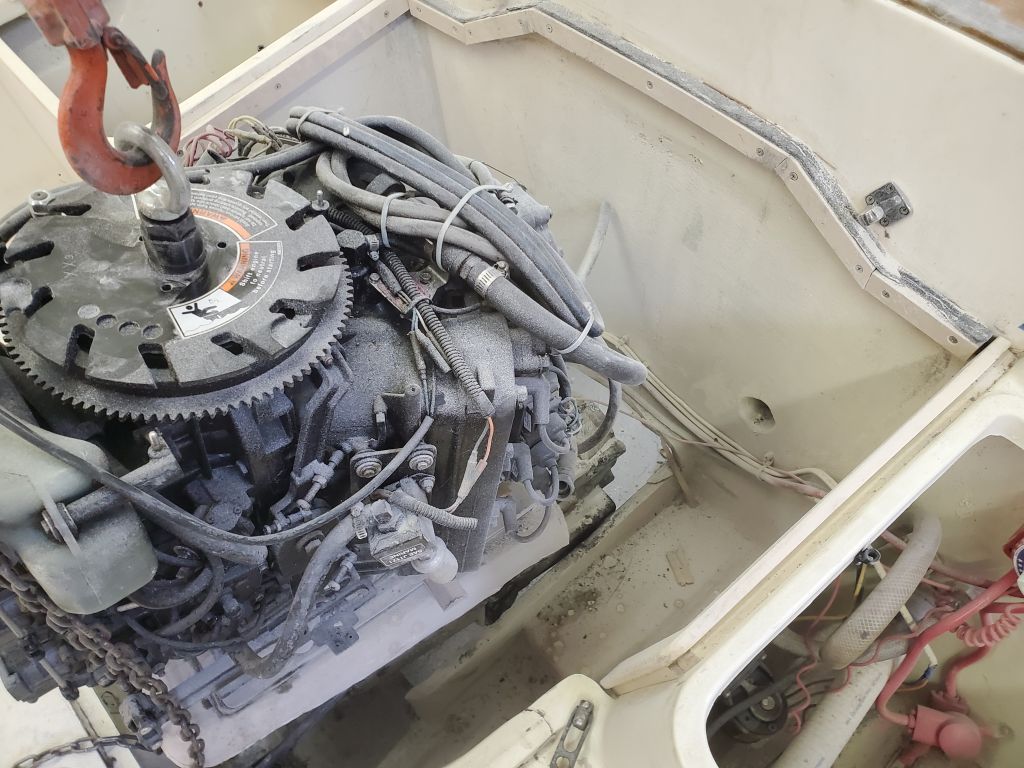
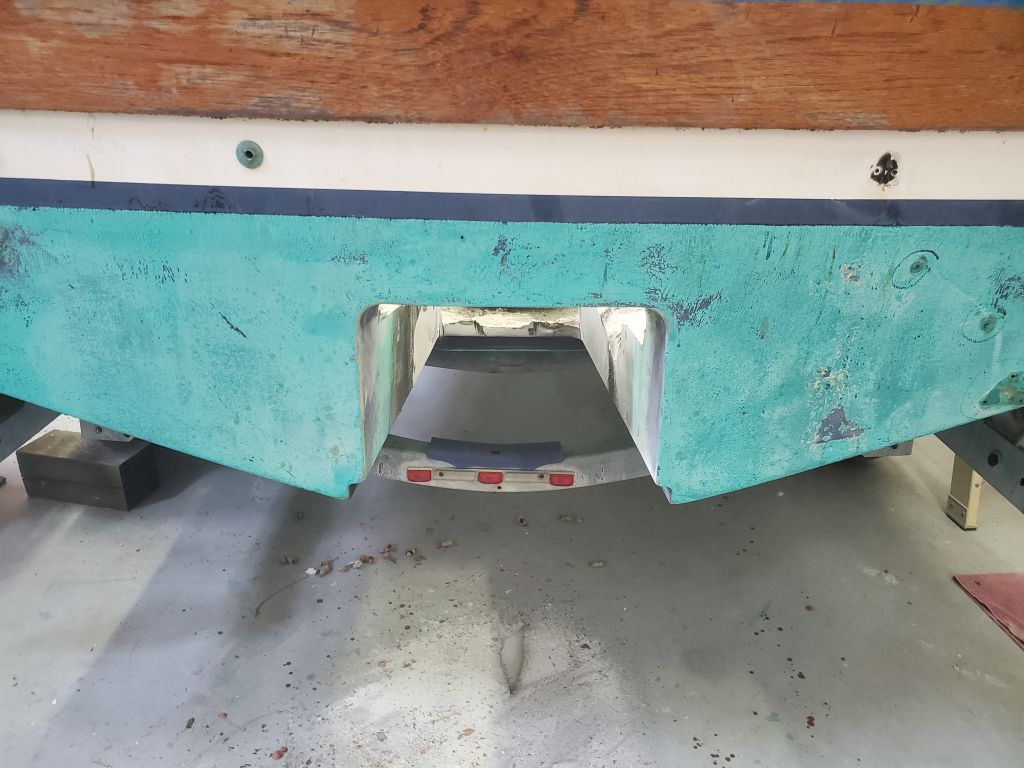
So with this in mind after a day away from the project, I got to work to remove the entire assembly.  To begin, I removed the final screw holding the ride plate to the bottom:  I had to drill out the head since I couldn’t get the screw to back out normally, and the jet drive wouldn’t come out of the boat from the top without removing the plate.  I found all kinds of peanut shells and other rodent-related detritus hiding beneath the plate when I pulled it out.

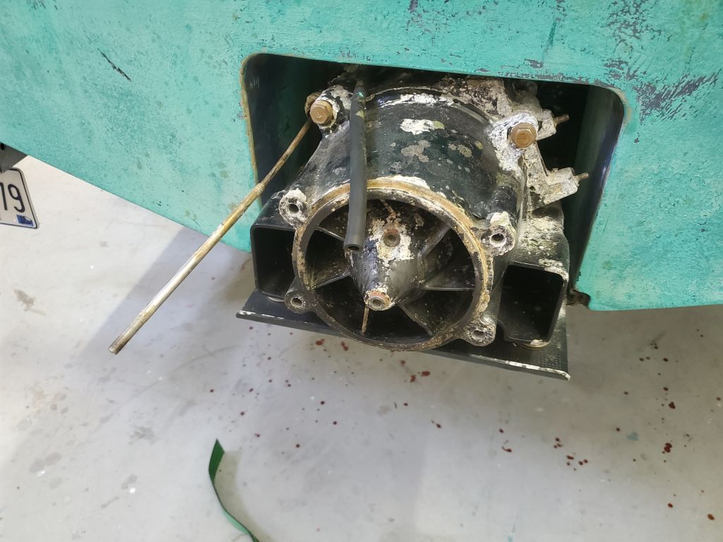
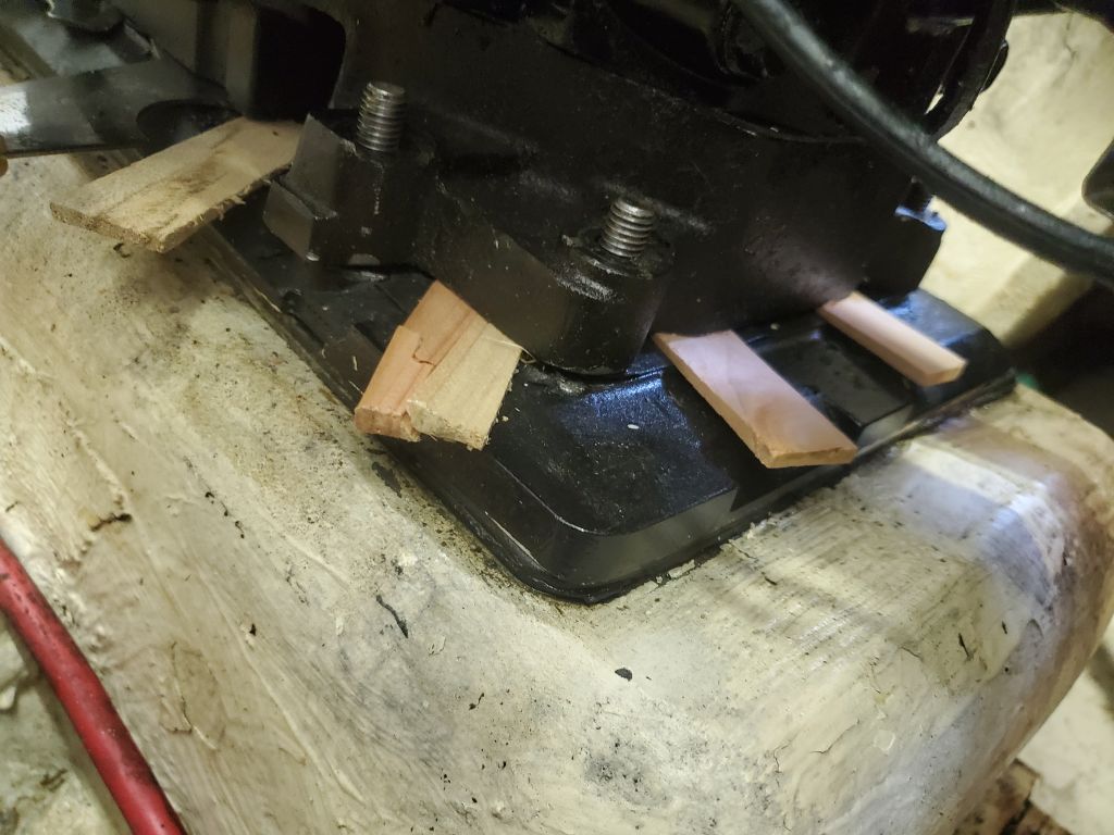
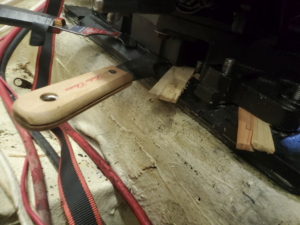
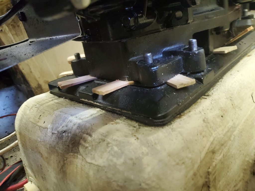
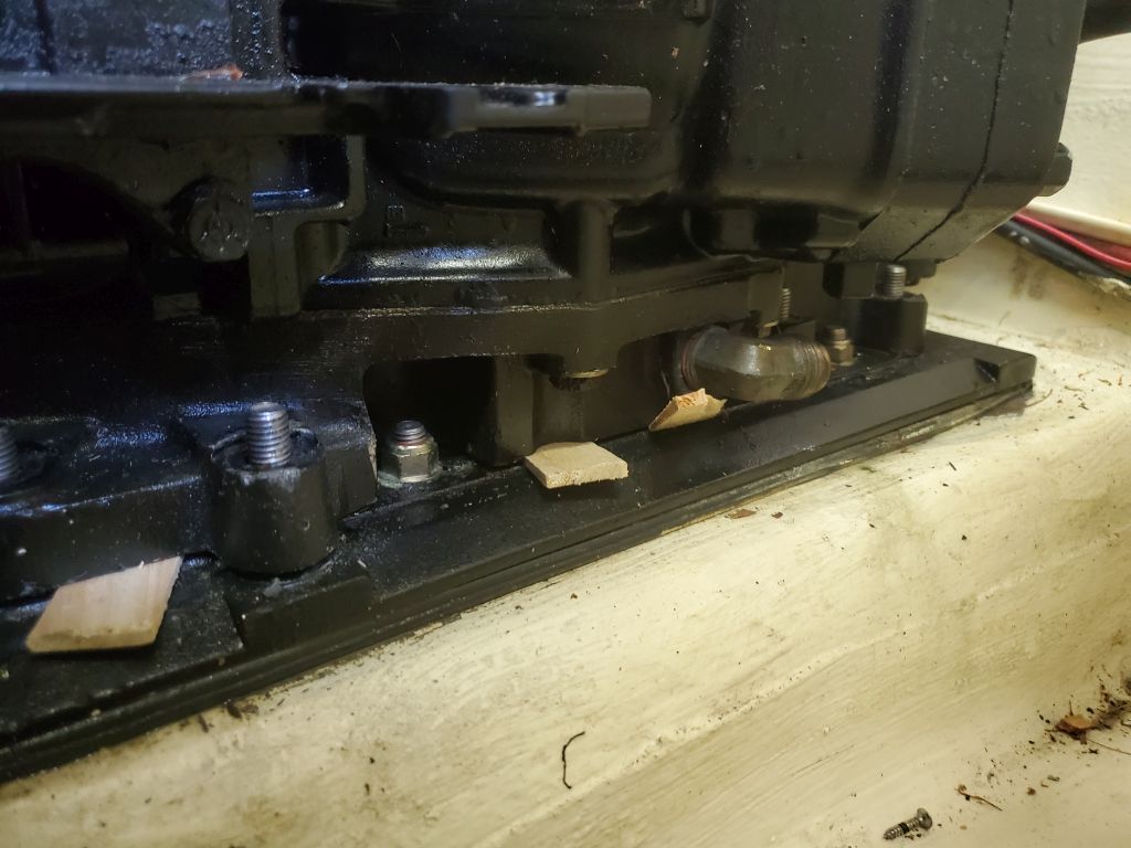
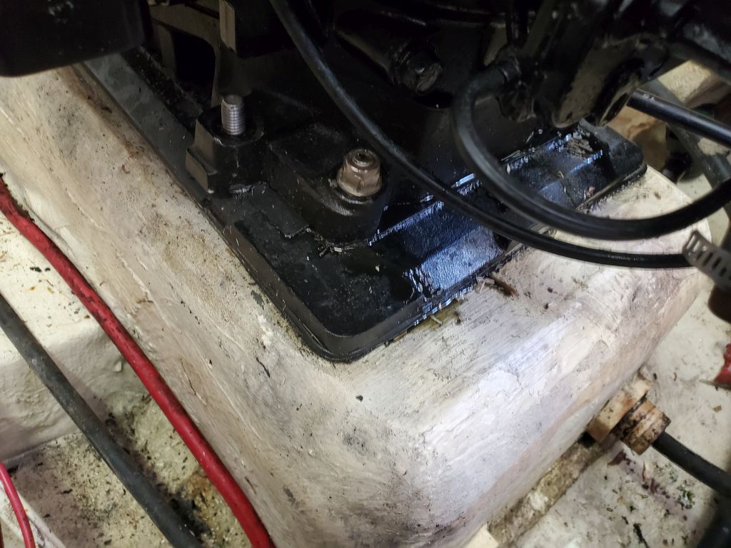
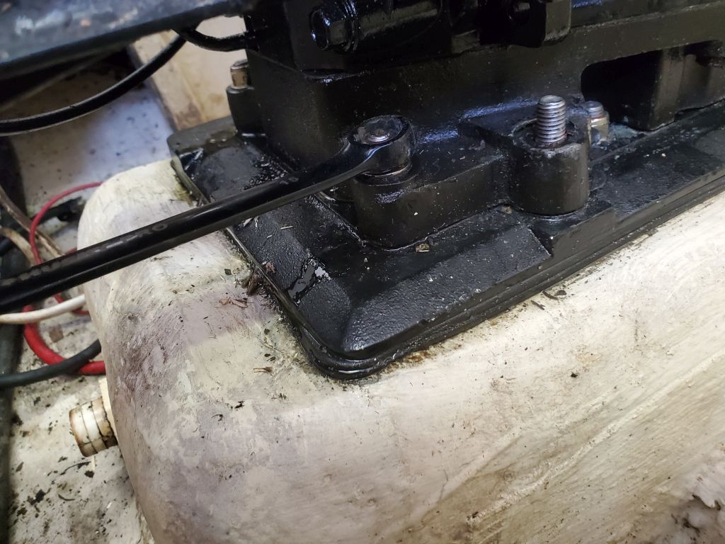
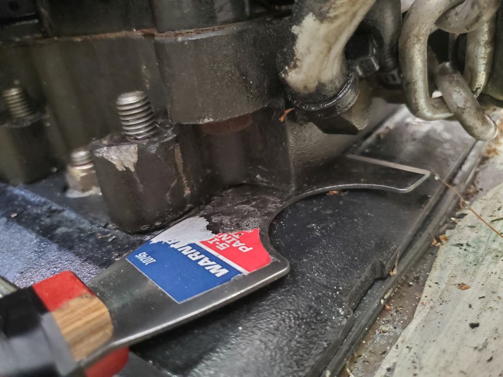
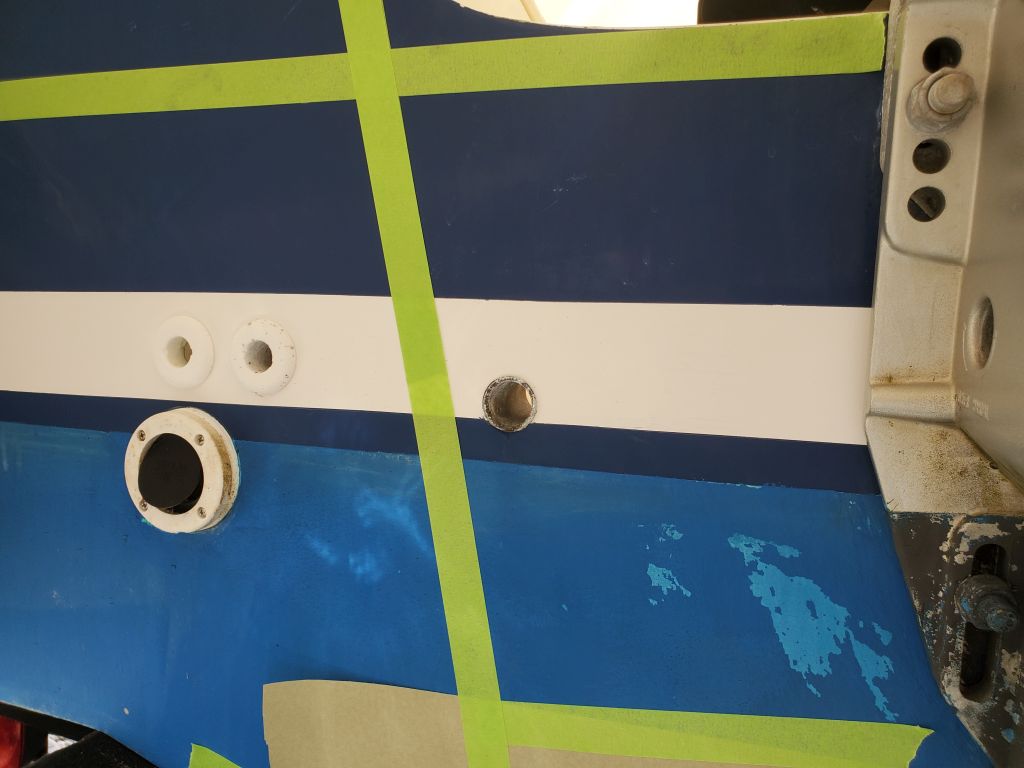
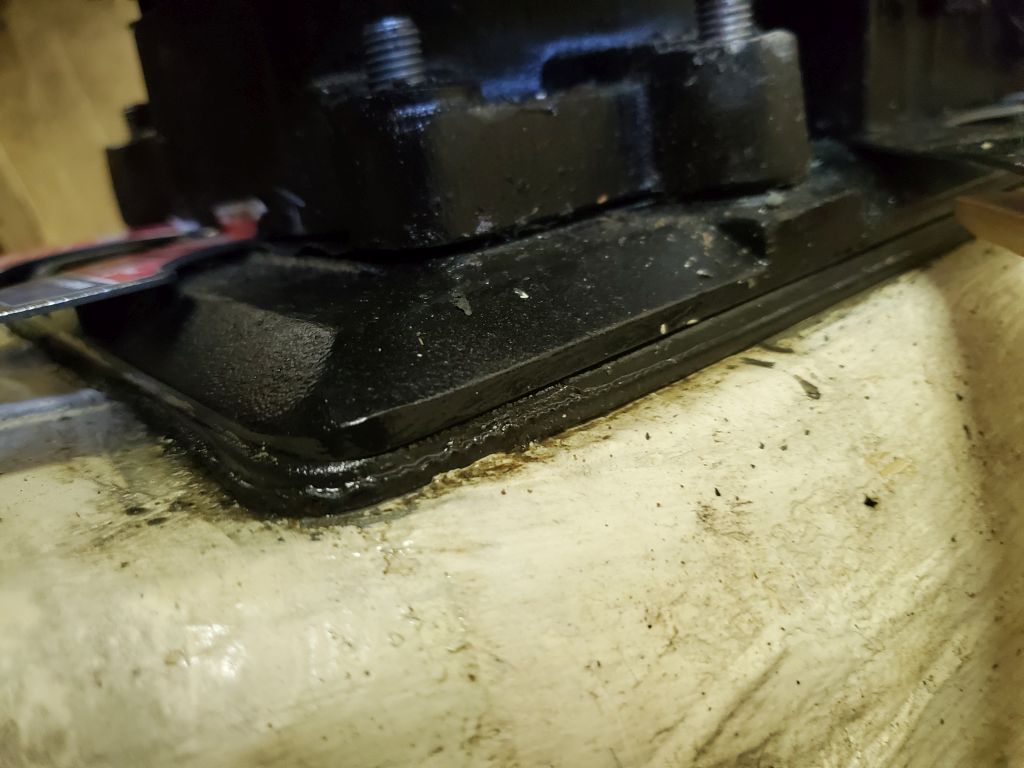
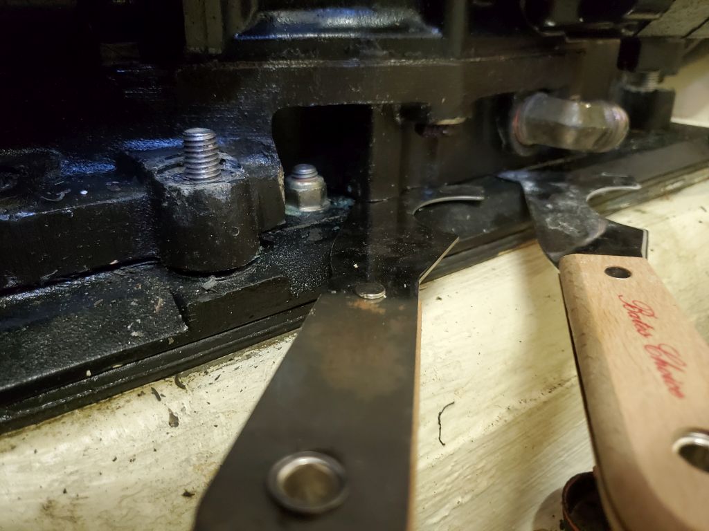
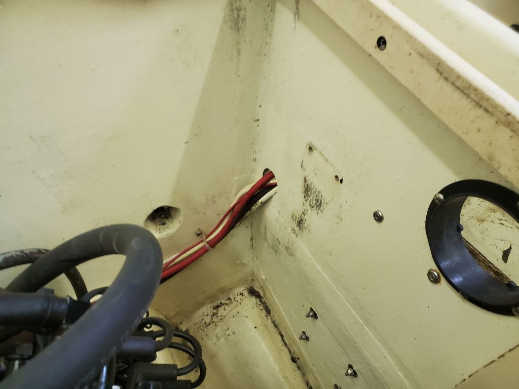
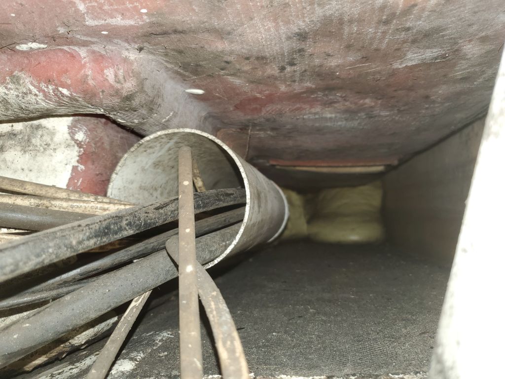
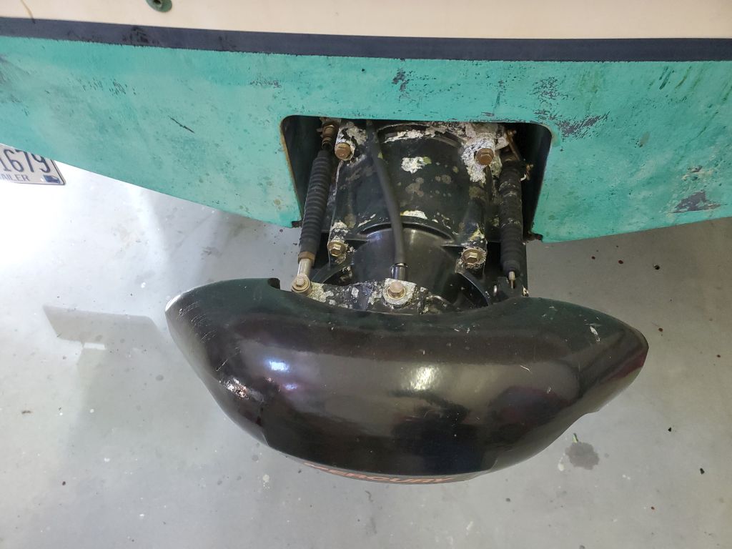
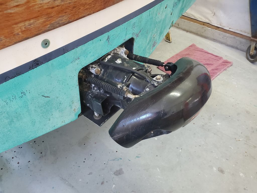
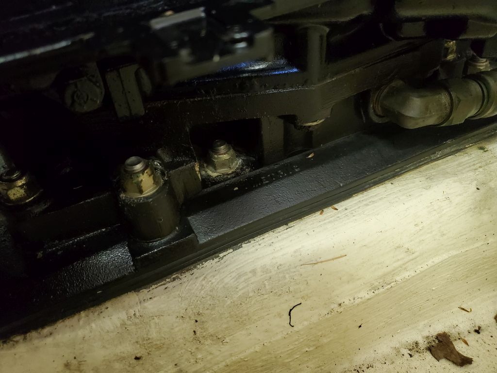
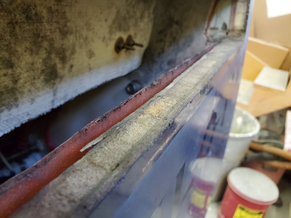
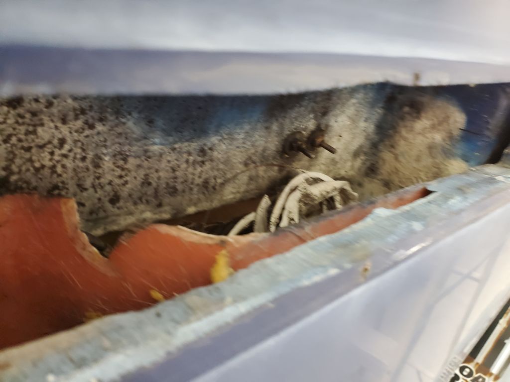
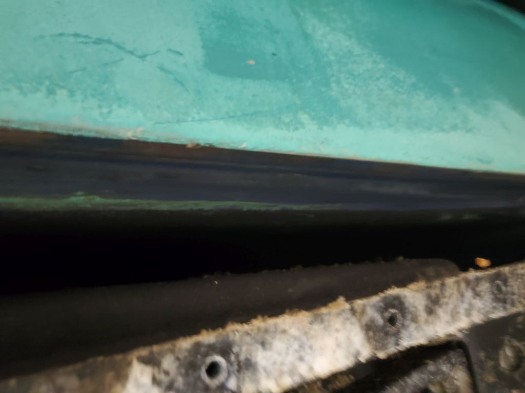
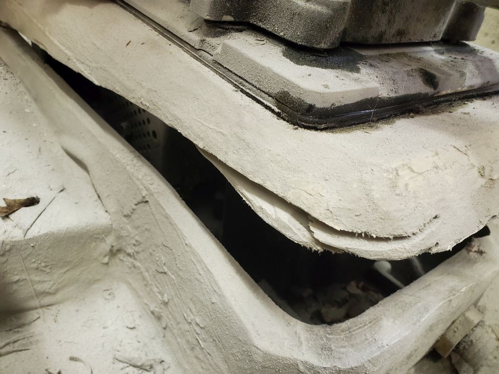
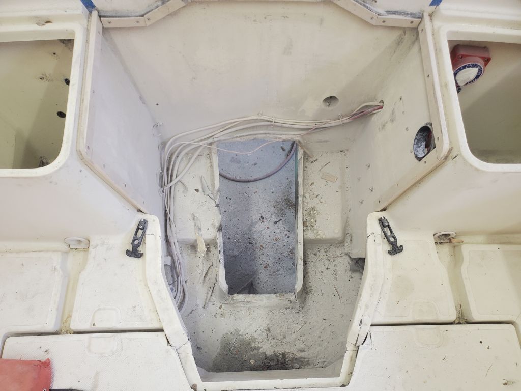
Removing the plate gave me good insight around the edges of the drive, confirming what I had hoped:  That there was air space around it, and that cutting the fiberglass housing above was possible without also damaging the drive.

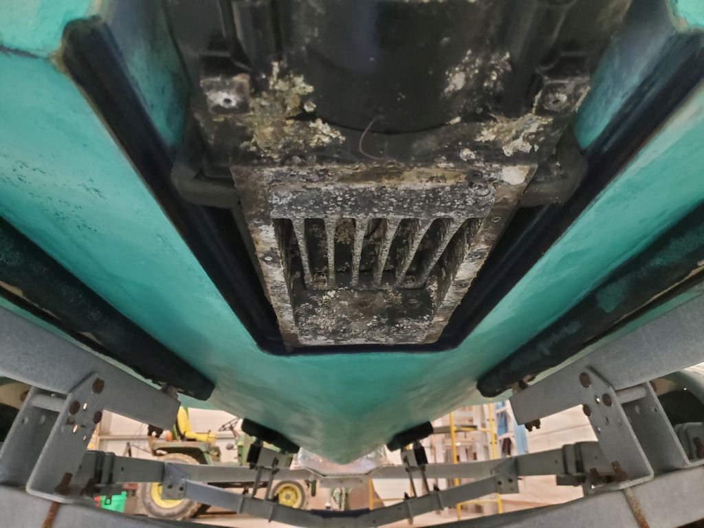
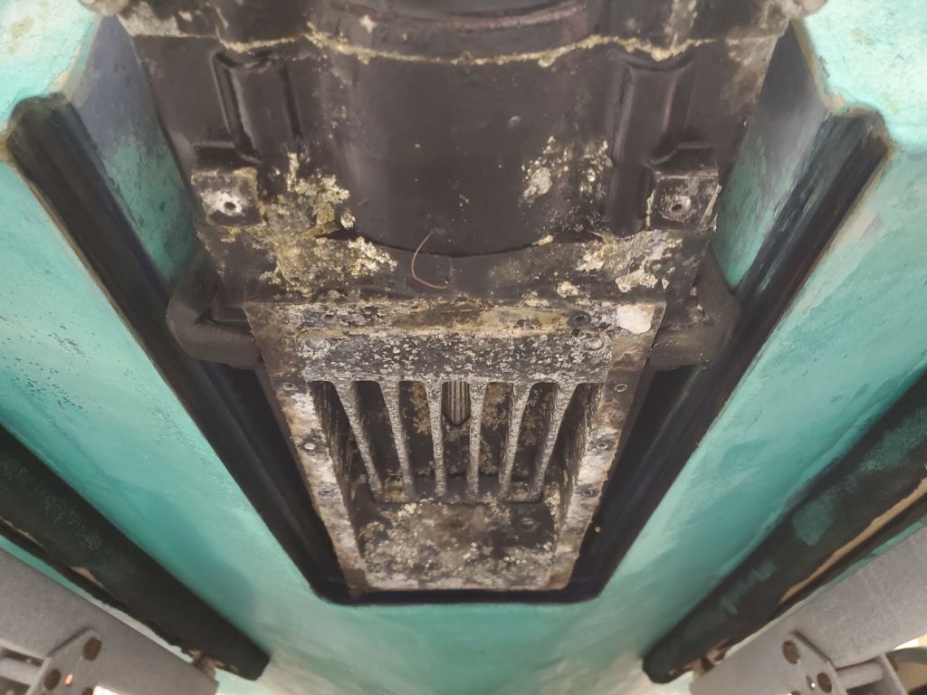
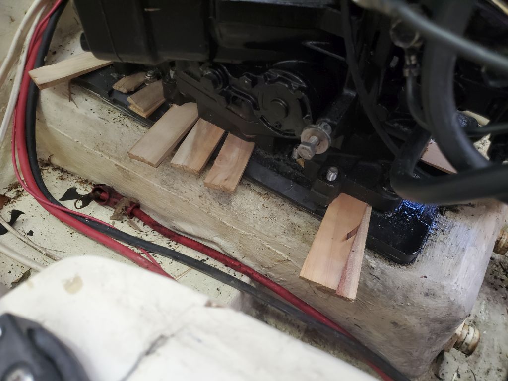
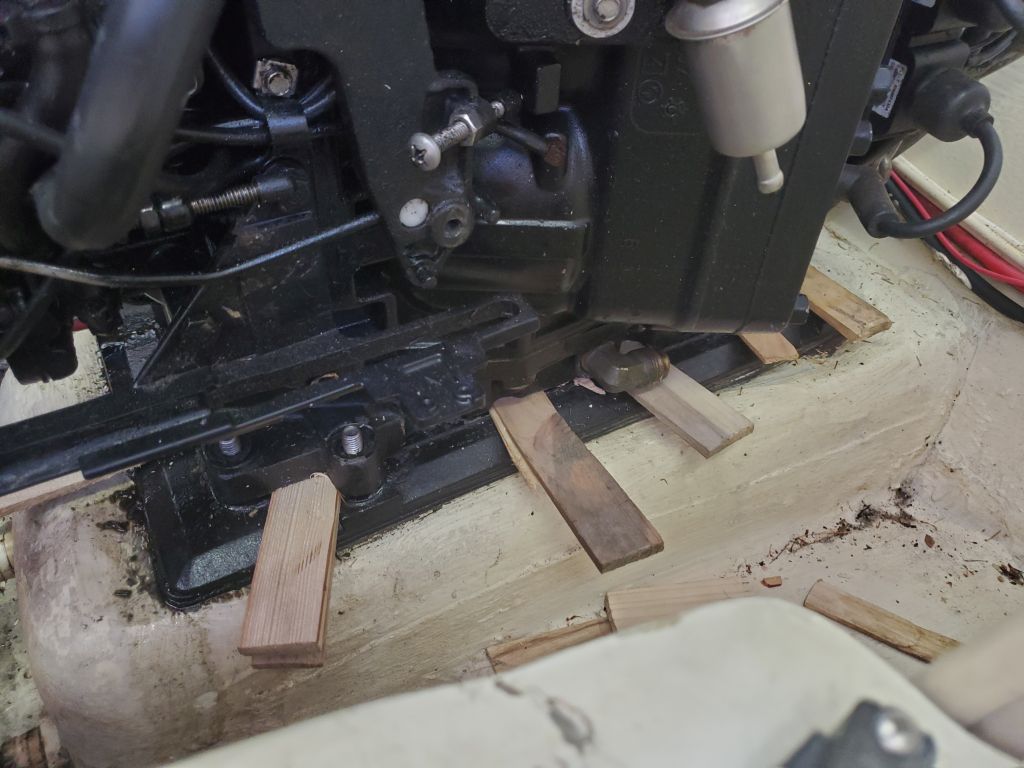
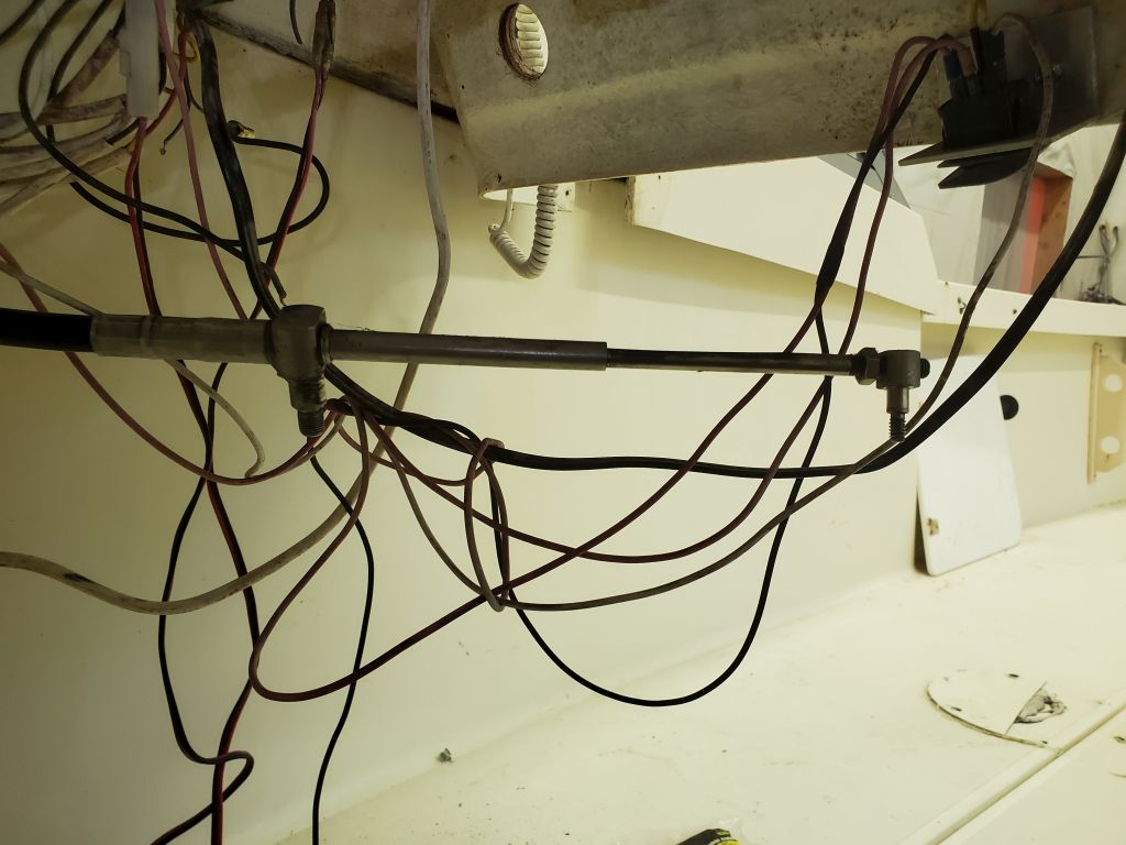
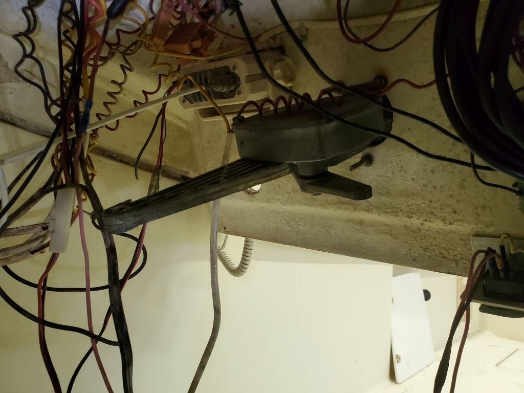
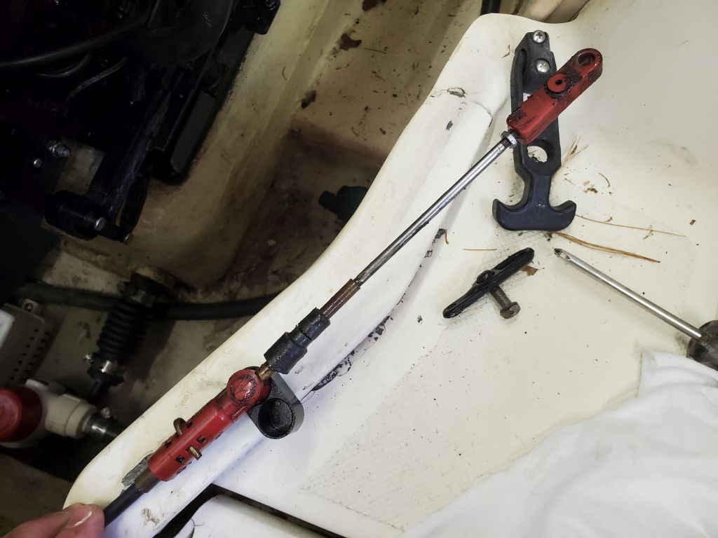
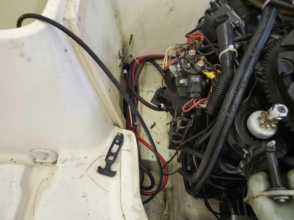
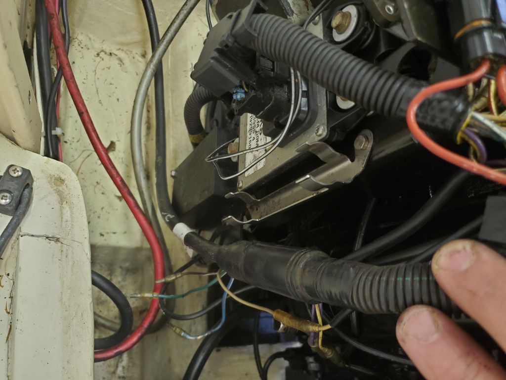
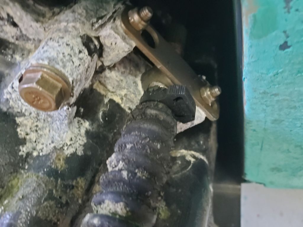
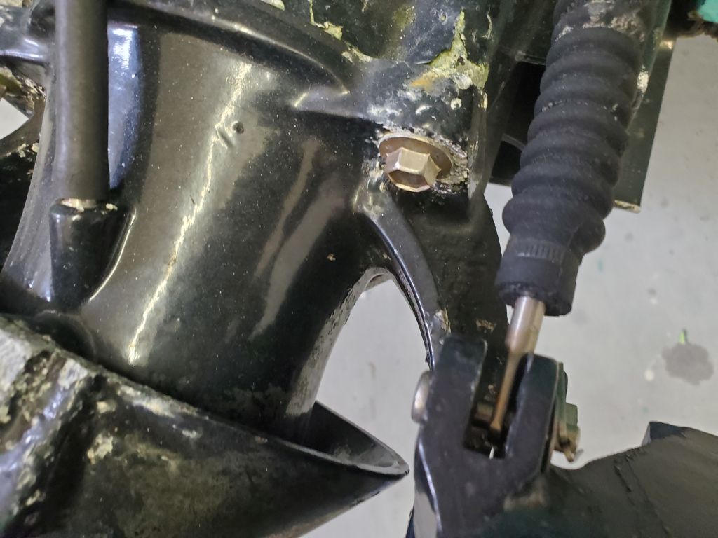
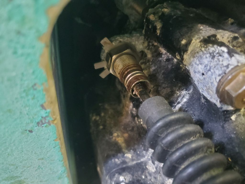
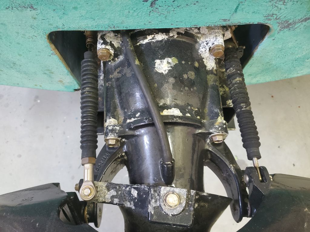
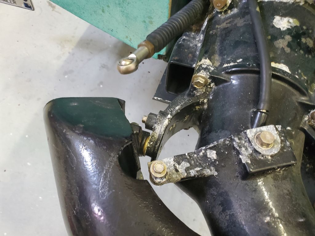
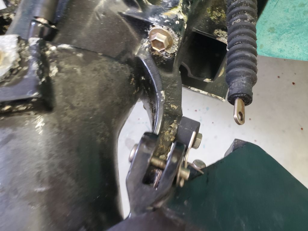
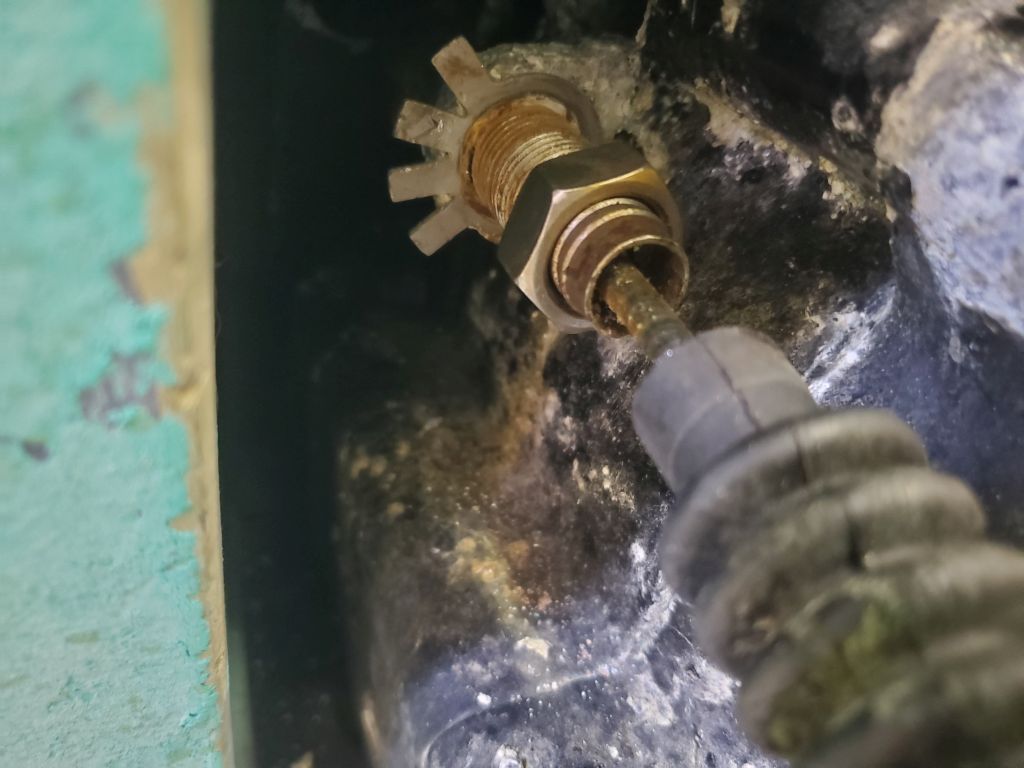
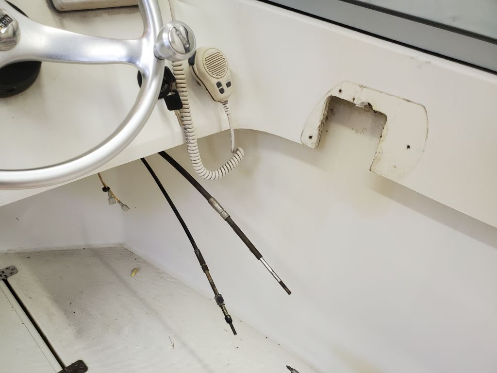
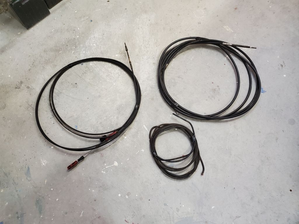
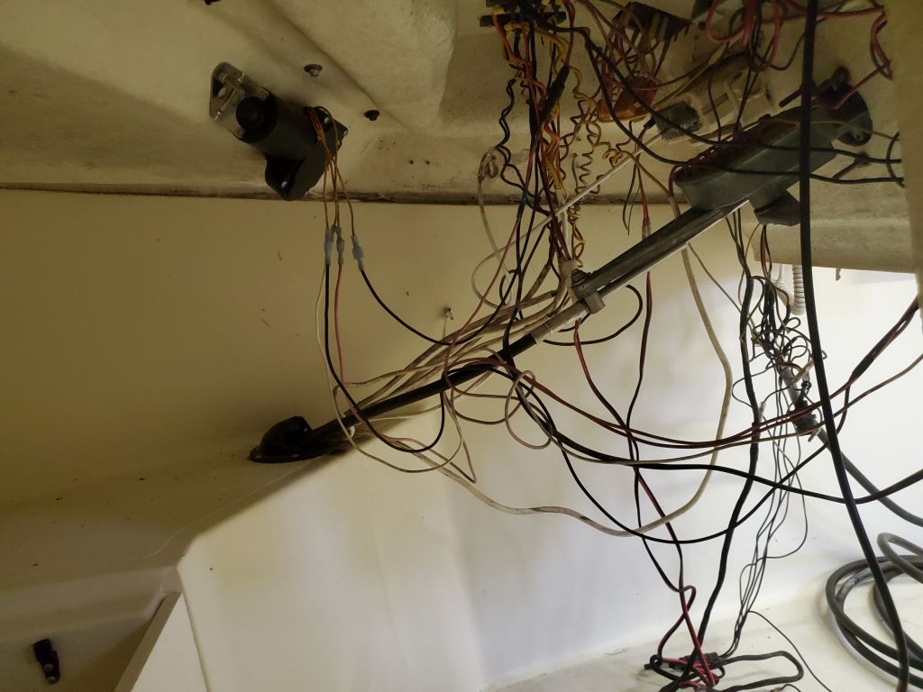
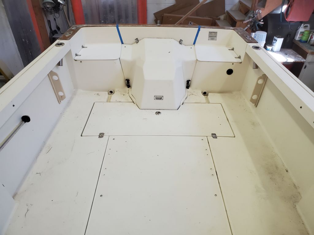
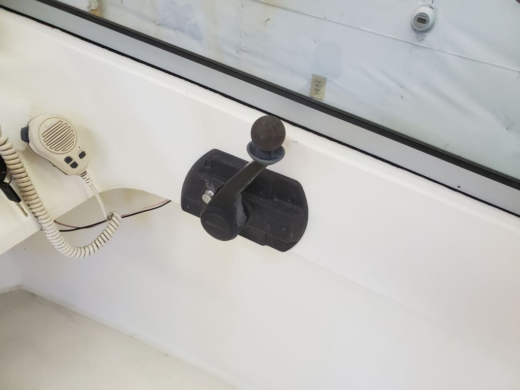
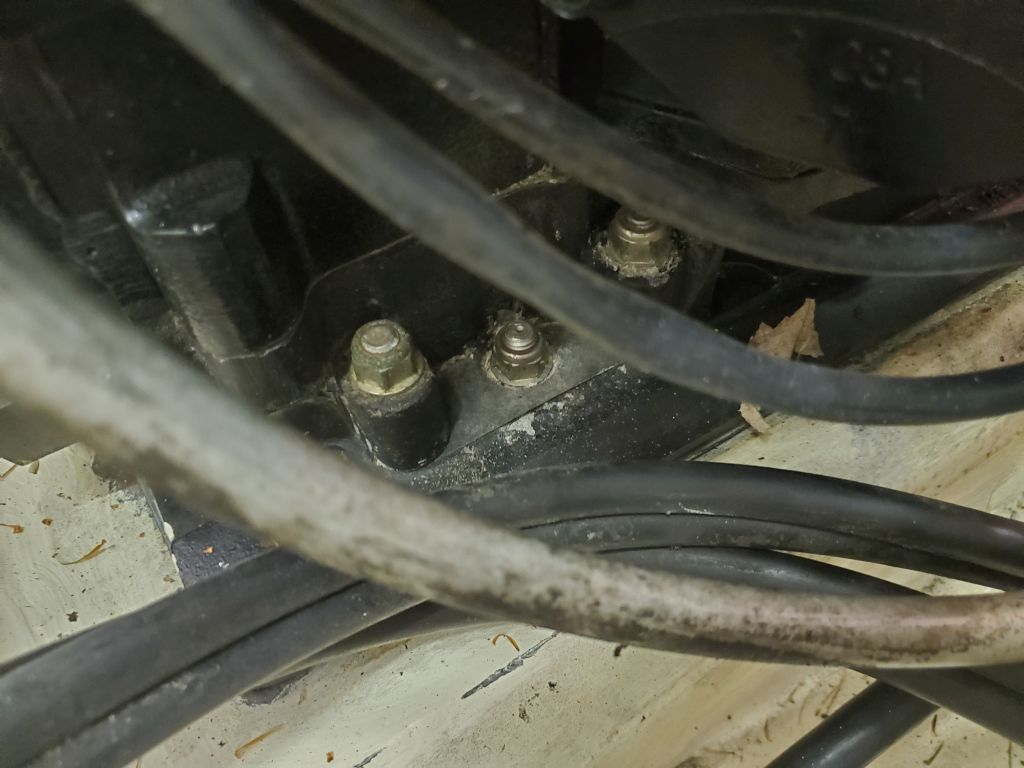
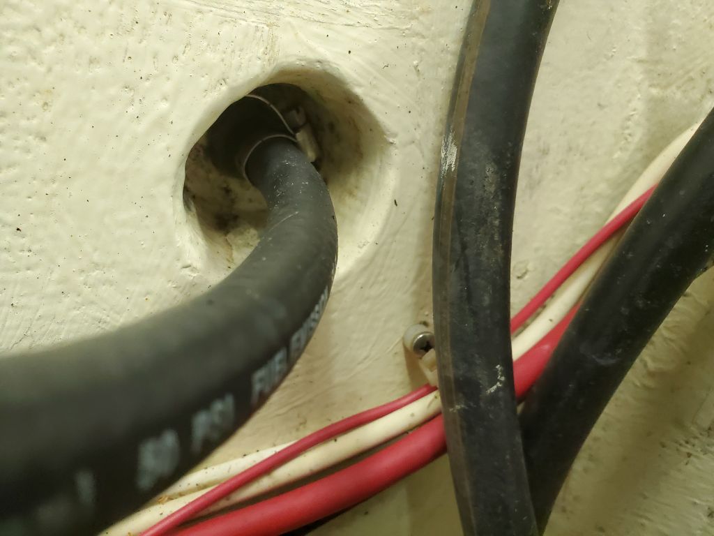
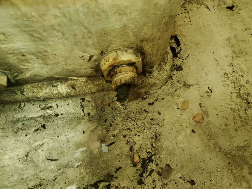
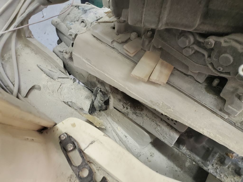
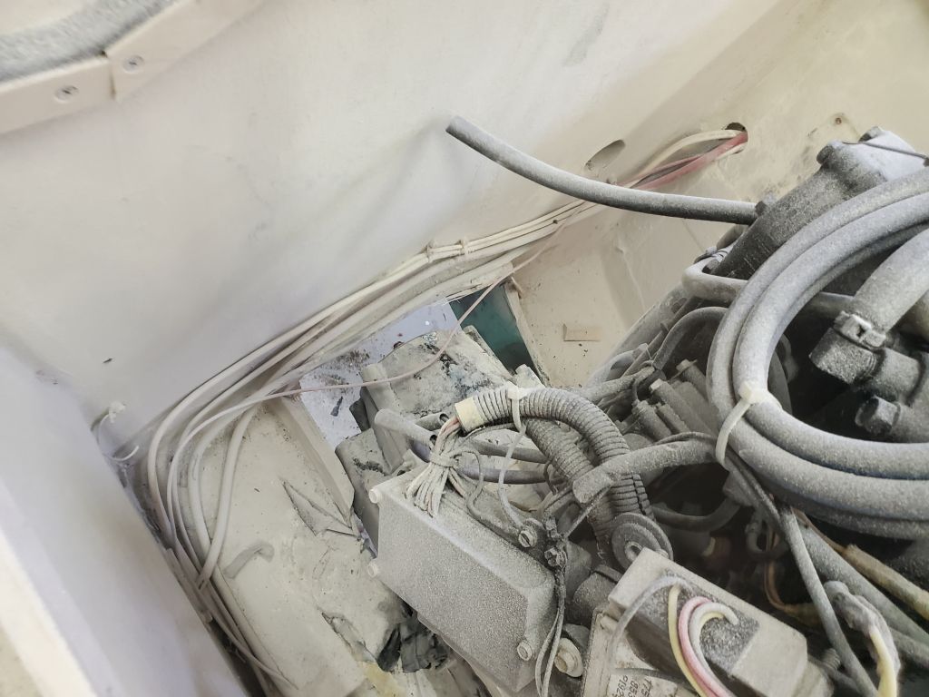
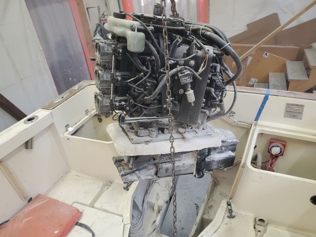
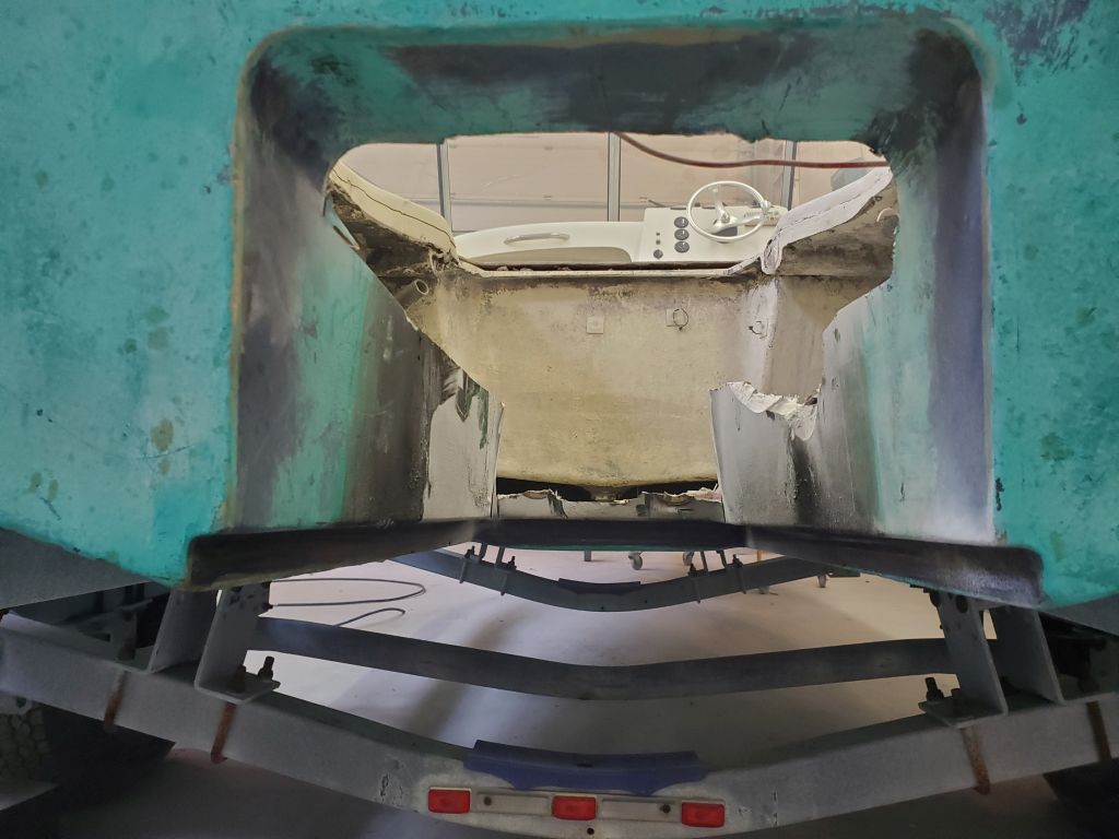
Next, from inside the boat I started by cutting off the remaining heavy control cable that ran through the fitting at the front of the housing, as the excess cable would just be in the way and would make removal of the engine and drive assembly unnecessarily difficult (since it’d been so simple so far…).  Then, I cut the fiberglass housing a couple inches below the engine and adapter plate.  The fiberglass tunnel laminate was extremely thick, about 1″ on the sides and thicker at the forward corners.  I mostly used an angle grinder with a cutoff wheel installed.  I confirmed that I’d cut all the way through the three main sides (other than the tight spot behind the engine) by lifting slightly on the hoist.

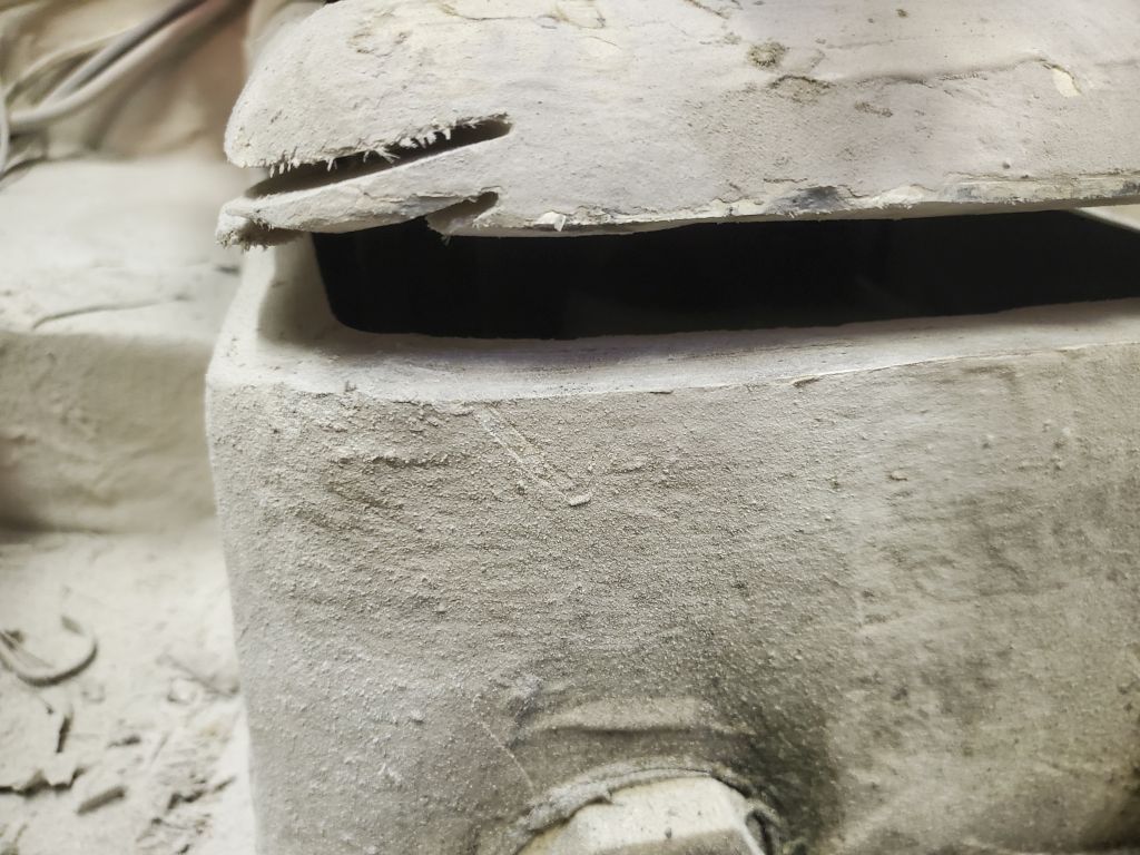
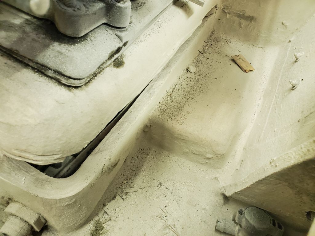
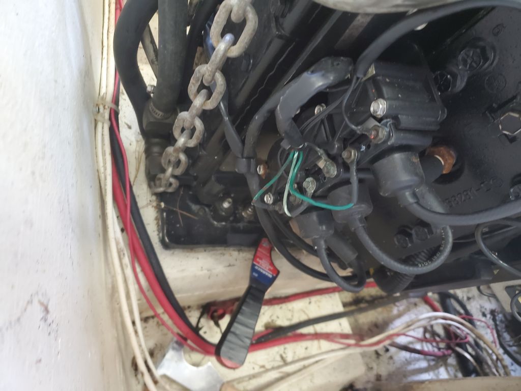
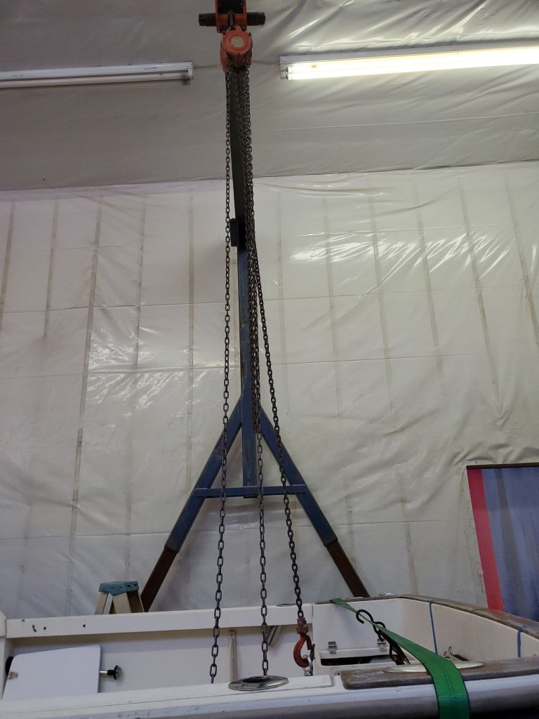
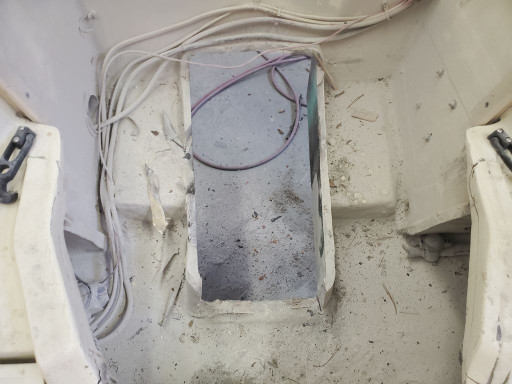
There was little room behind the engine, where it faced the solid transom, but I was able to start the cuts from each side with the angle grinder, which then gave me a slot into which to fit a reciprocating saw with a long blade, and then, finally, to finish up the cut in the tightest midships portion with an oscillating multitool.  Now I could begin to lift the engine and hopefully slide it forward to free the drive and then pull the whole thing out.  But it quickly became clear that the front side of the drive housing was in the way–I couldn’t pull the assembly far enough forward and up to clear it without binding the after part of the drive housing on the transom.  So, working carefully with my nearly-exhausted supply of blades and my precious last semi-usable remnants of a grinder cutoff wheel, I cut the front of the housing out with a saw cut on each side (vertically) and then along the bottom edge.  This opened up the front section to allow the drive assembly to move forward without lifting so much.

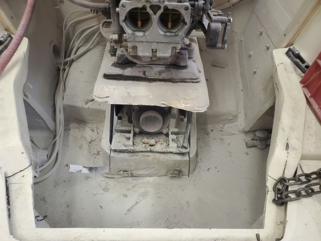
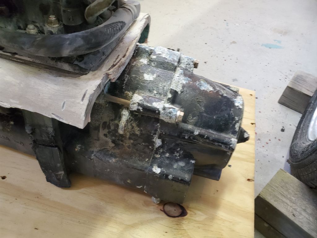
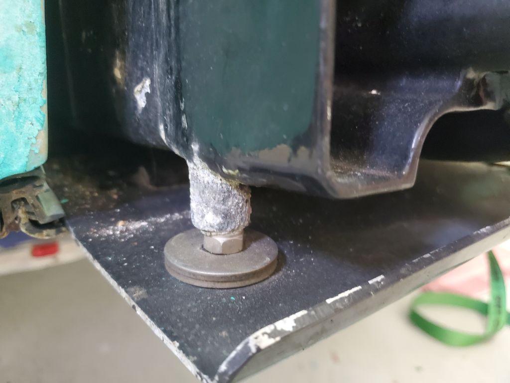
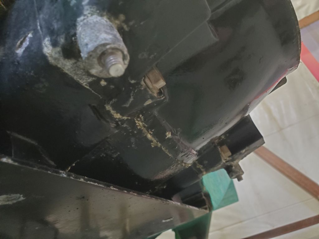
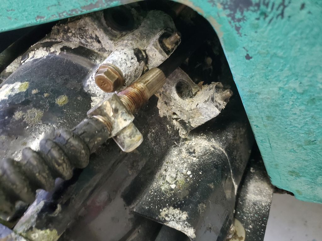
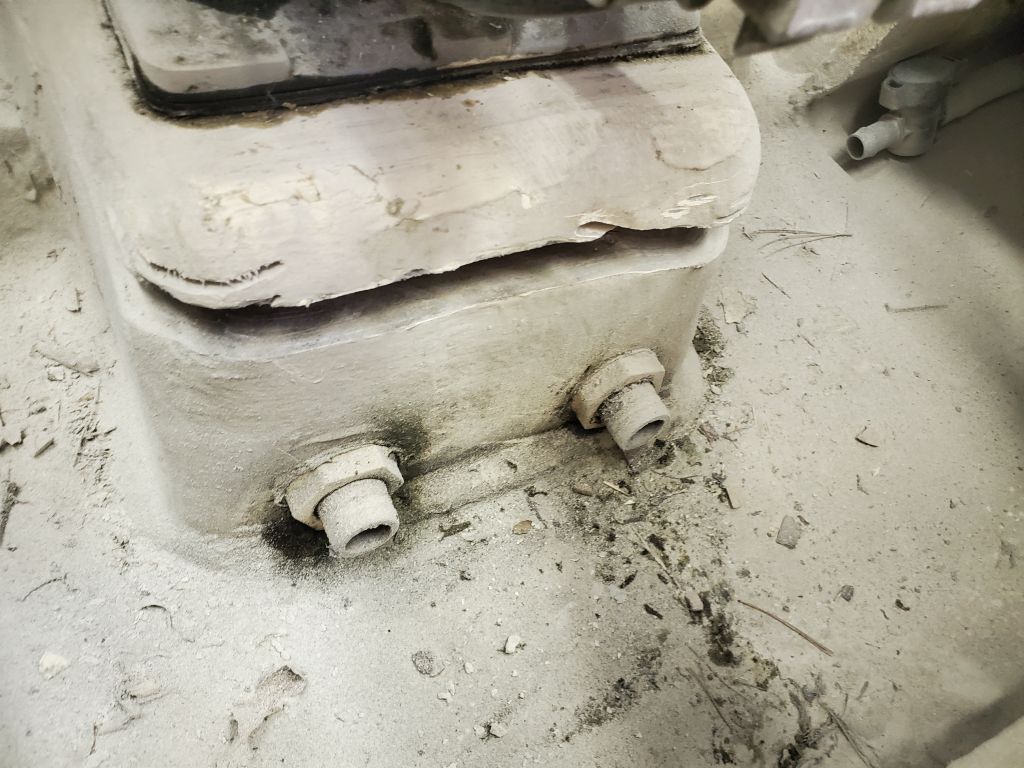
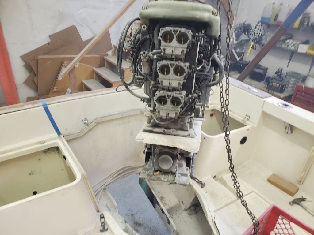
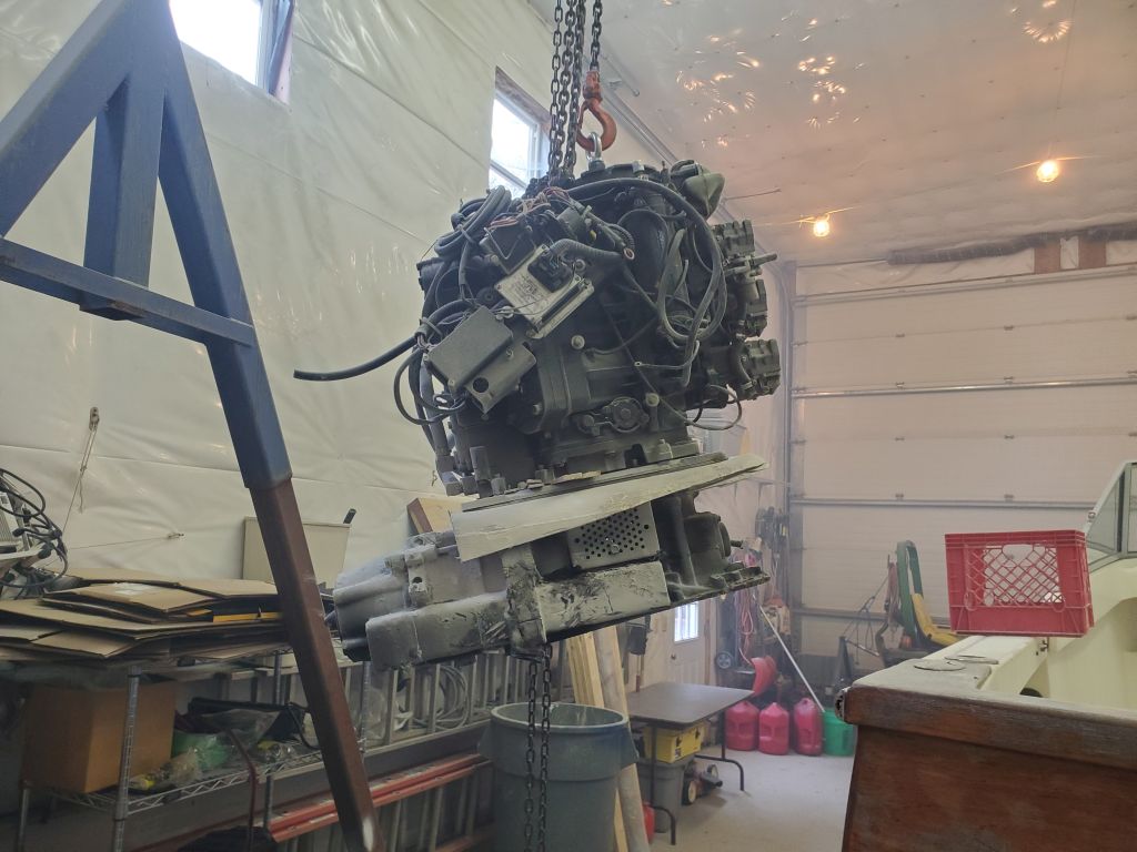
It should have been pretty easy from there, but the thing fought me every step of the way.  It took a little while and a bit of frustration and effort before I finally figured out why the assembly refused to move forward enough to clear the drive forward of the transom:  A combination of factors, including the fact that tunnel narrowed towards the forward end, and the drive had a tight-tolerance flange with gasket near the aft end that was binding hard on the narrowing tunnel.  I’d seen the gasket, but thought it was just that:  A gasket.  But there were cast flanges on each side to secure it, and these were tight on the fiberglass and couldn’t move forward any further.  With some difficulty, I eventually cut more of the fiberglass on one side, in way of the gasketed flange, to provide enough extra clearance to finally rid the boat of the unwanted resident.

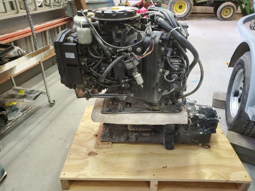
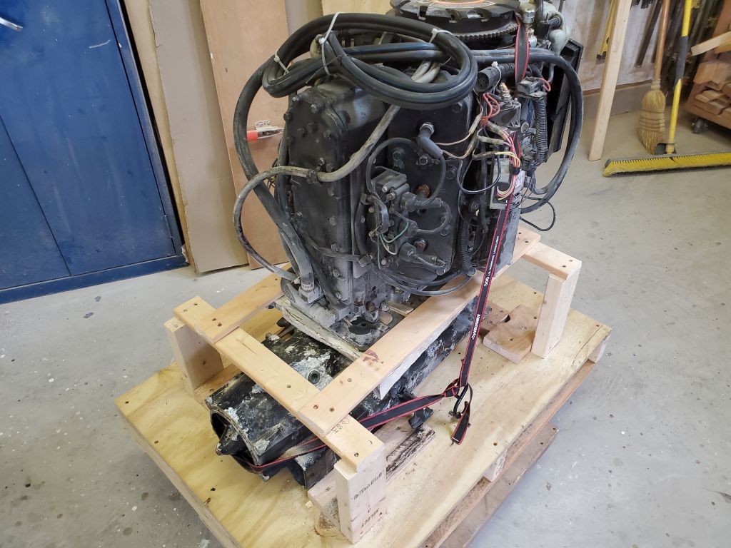
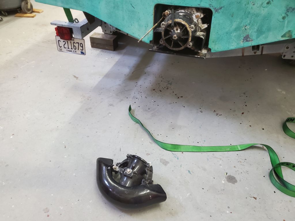
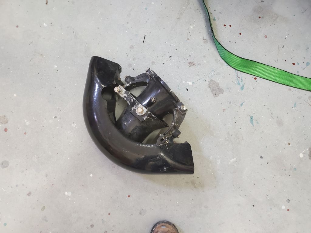
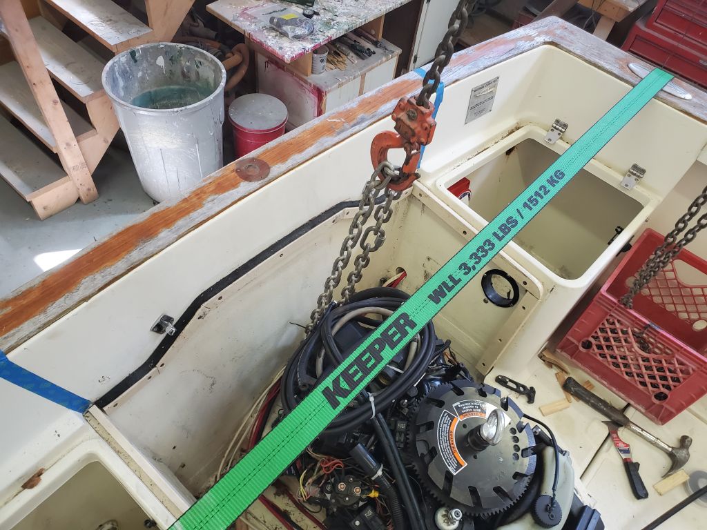
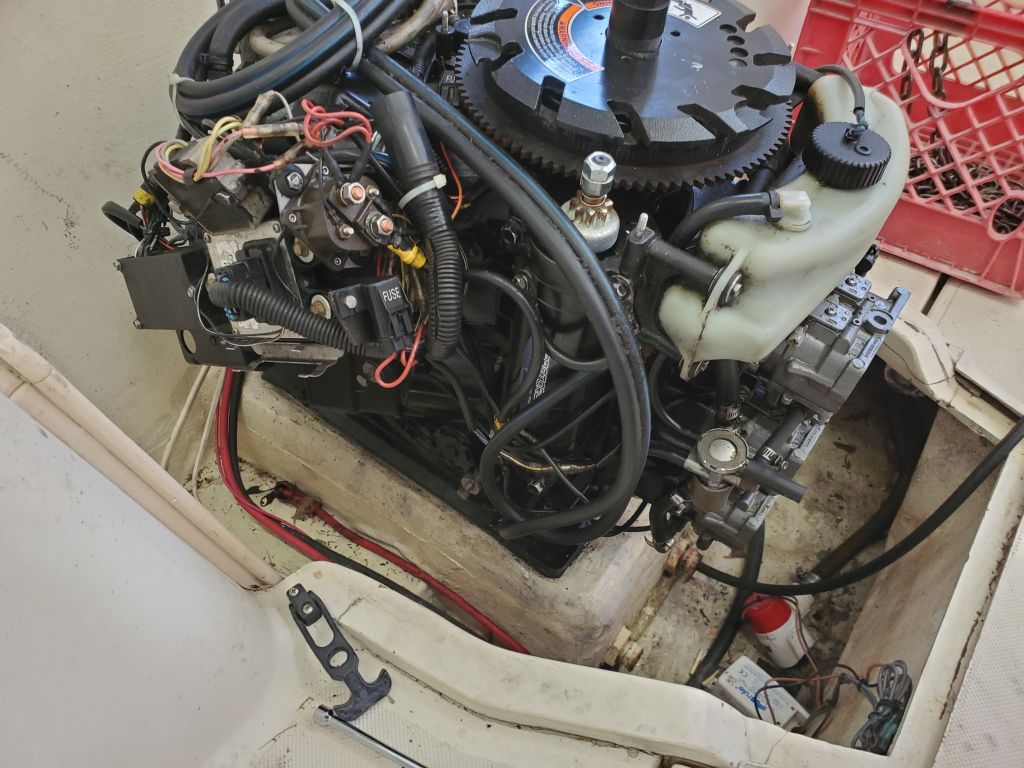
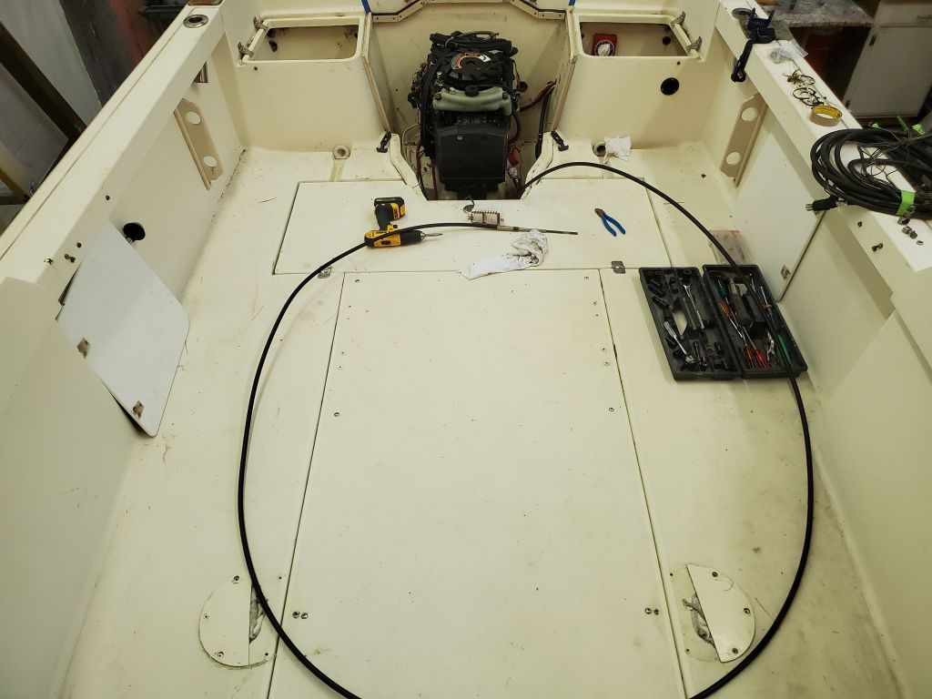
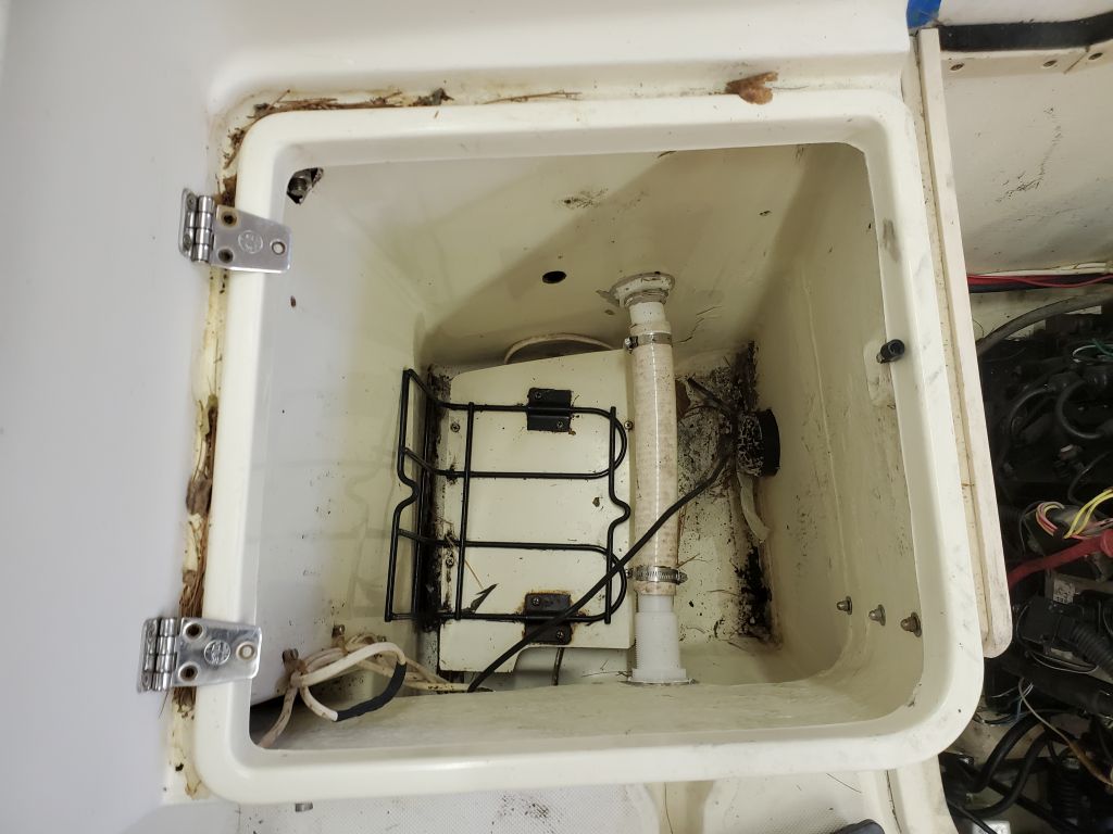
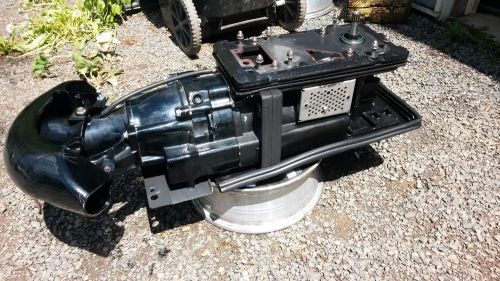
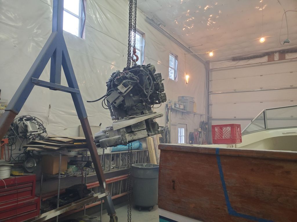
I wasted no time, after a quick pause for victory photos, in getting the thing over the side and down to the floor.  Perhaps this was once a nifty setup, but I never wanted to see its kind again.  I’d soon address the remnants of the tunnel and related structures in the boat, once I resupplied myself with the necessary cutting tools that I’d exhausted during the removal; all of this was always going to be cut out, and the resulting hole reshaped and patched, as part of this project.

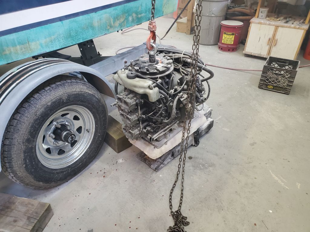
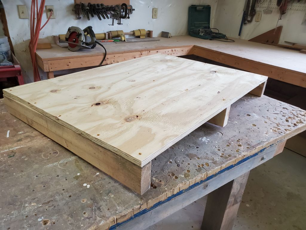
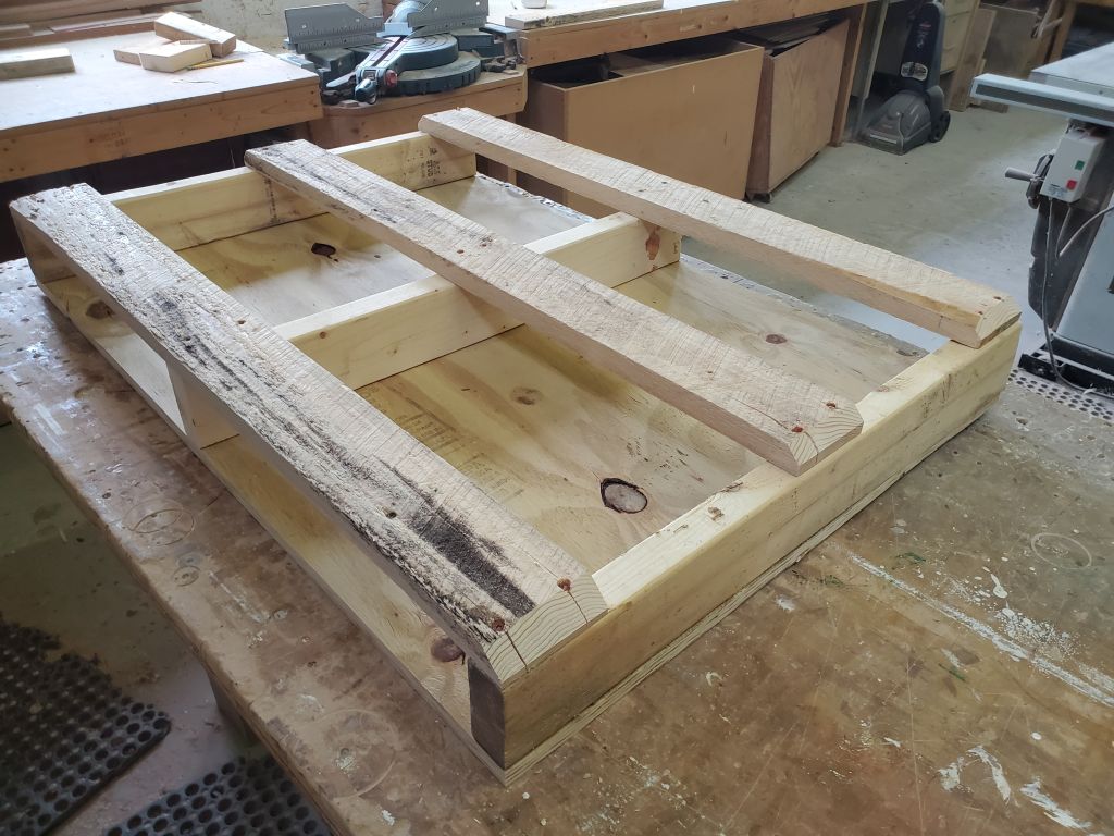
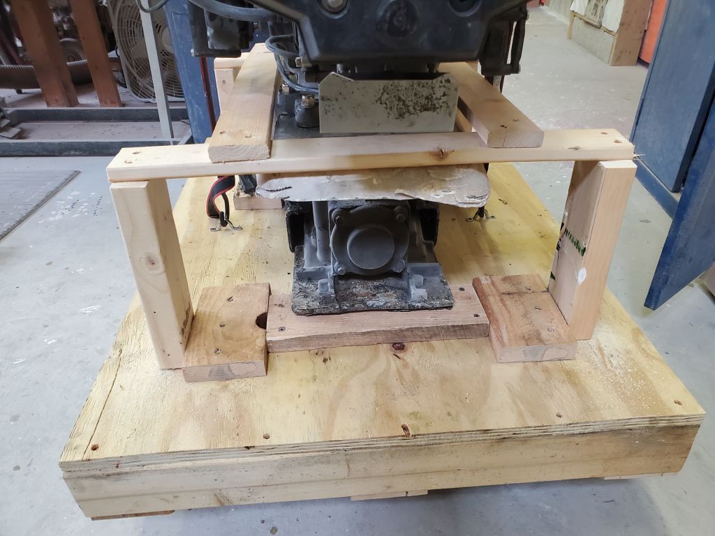
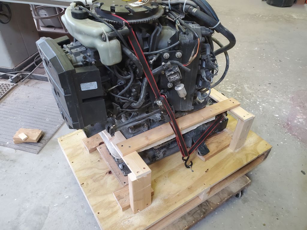
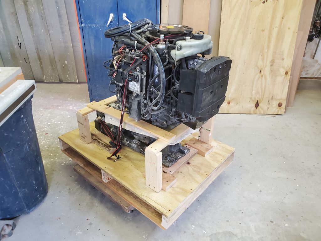
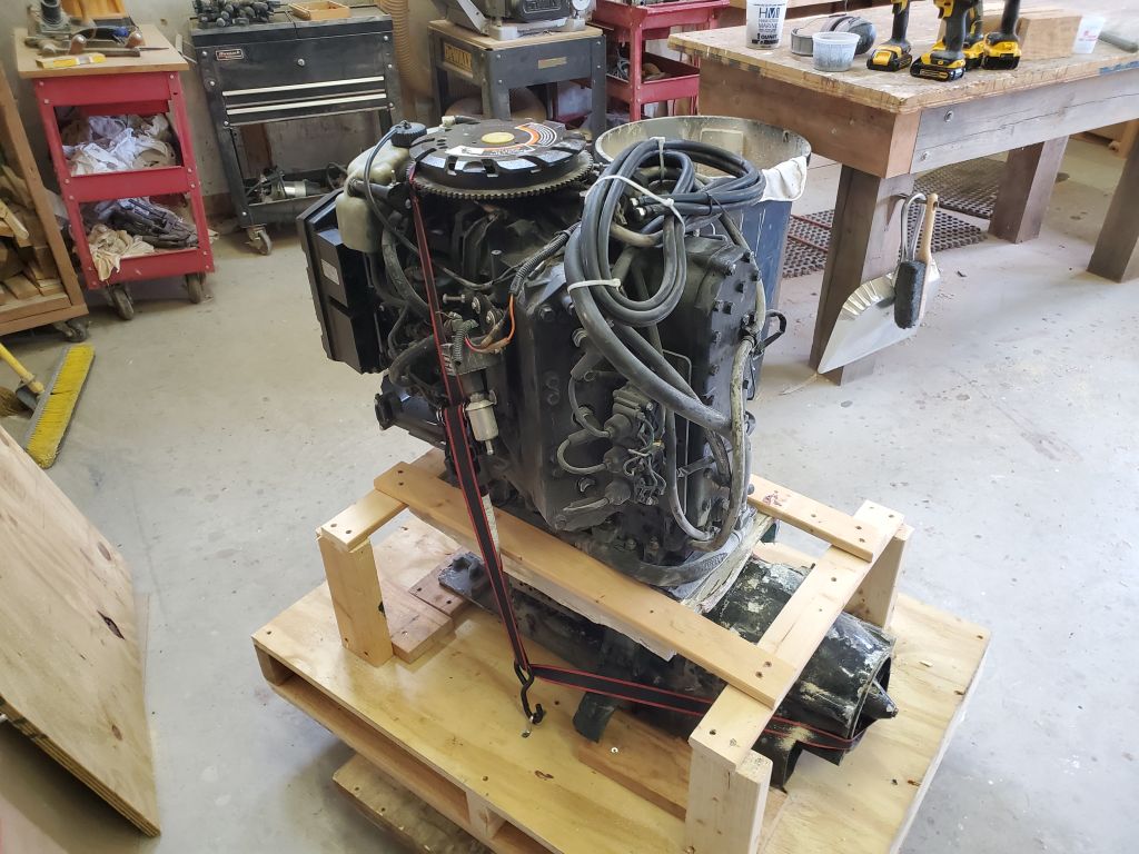
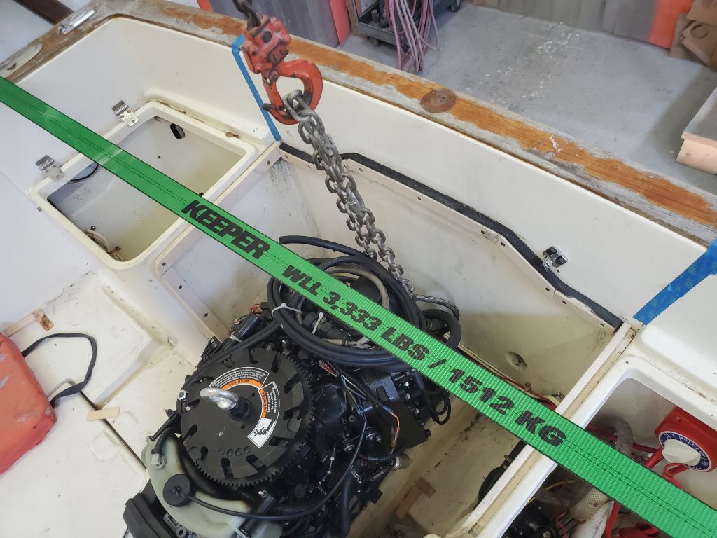
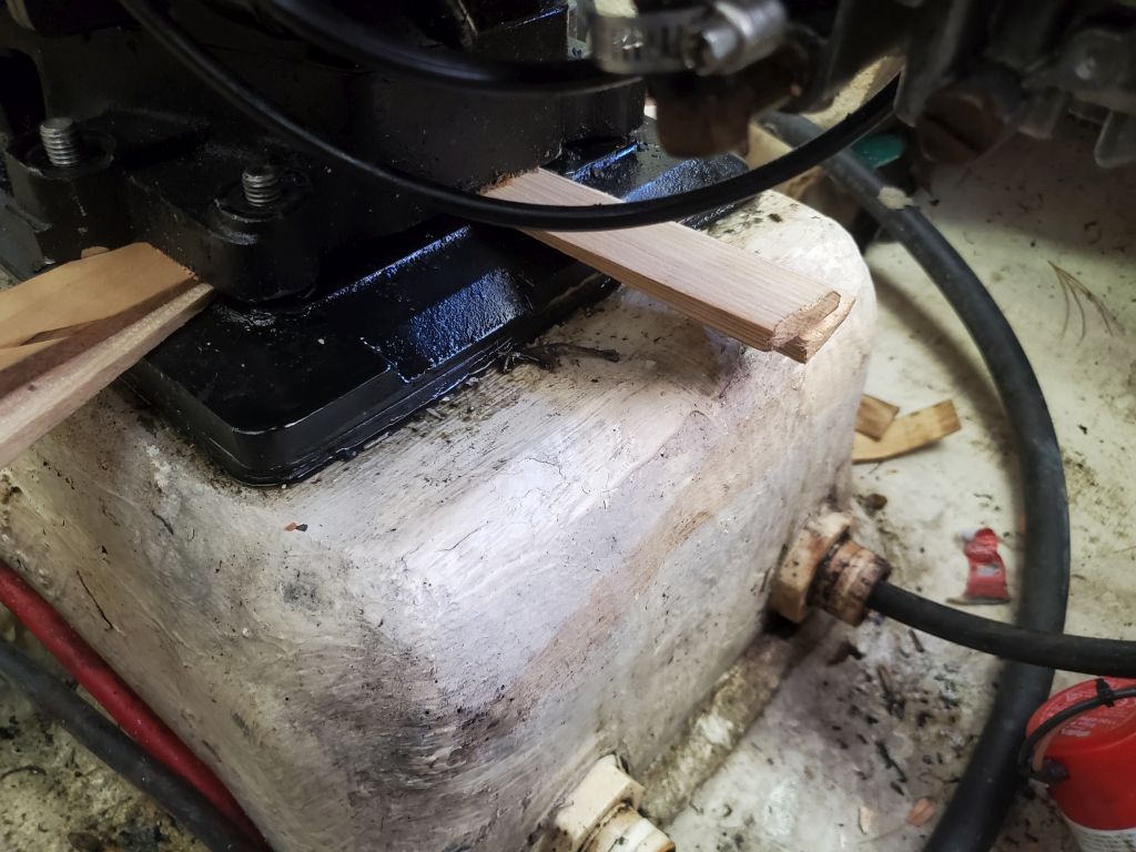
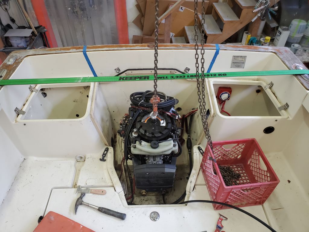
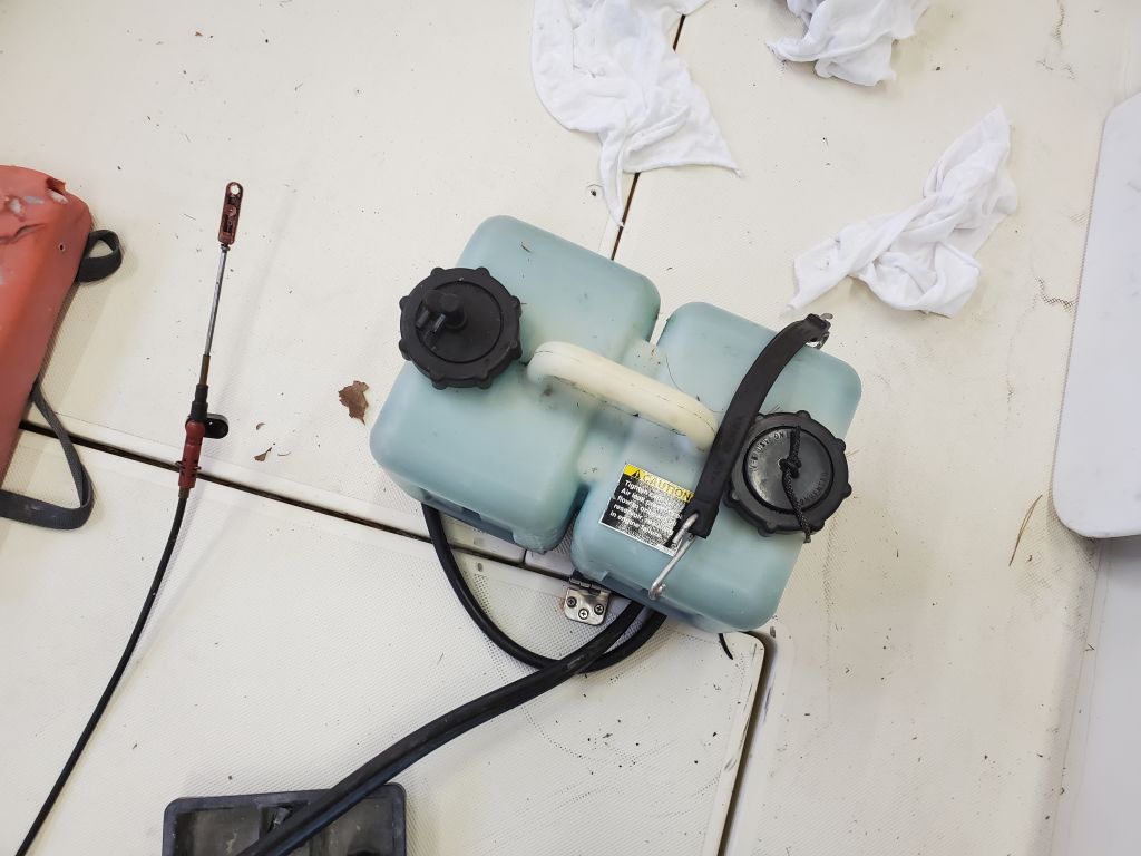
I spent the remainder of the day building a storage/shipping crate for the assembly, after quickly reattaching a couple of the accessory pieces I’d removed from the engine during the dismounting.  There was no way to bolt the assembly directly to whatever structure, so instead I devised a system to secure it tightly using a strap over the top and some wooden framework around and over portions of the assembly to prevent movement or tipping.

From here, the next step would be to build a simple framework to enclose the engine and cover it with cardboard or  plastic or something.  The crate also left ample room for all the various pieces of the drive and related components I’d removed earlier, so that whatever future recipient should have everything required on hand.


Holby 7

With a few other small, just-added jobs to finish on another project, I stayed mostly away from the engine removal.  However, the owner was ready, should it be needed, to take more dramatic action on the engine removal, and we’d discussed the possibility (likelihood) of simply cutting out the fiberglass box into which the jet drive, and onto which the engine, was installed.  This box had to be removed anyway given the transom changes to come, and as the silliness of the engine removal dragged on, it seemed more and more practical to take this route.

With this in mind, I spent a little time removing some excess components from the jet drive unit to make removal through the hole in the boat easier, starting with removing the reverse baffle and nozzle, a matter of four bolts.

Next, I removed the trim plate from the aft end–four more screws:  Two machine screws at the forward end, and two bolts at the after end.  The after bolts supposedly were not threaded into the aluminum drive housing (secured with nuts and the two washers seen), but regardless they did penetrate into the housing, and these penetrations (whether threaded or not) were completely seized and the heads of the bolts spun off during removal, leaving short studs for someone else to deal with eventually.

Next I removed all but one of the screws securing the ride plate to the bottom–that’s the big plate covering the whole bottom of the opening over the bottom of the drive.  The final screw was seized in place (amazingly it was the only one), and I broke the only T25 torx bit I had on hand at the moment.  I treated the screw with penetrating oil and left it to soak.


Holby 6

I continued work on-and-off on the engine “removal”.  This was frankly getting silly.  After secretly hoping that during my day away from the shop the engine would have magically jumped off its mounts, the reality was unchanged since I left it.

Heeding some of the minimal advice I’d found in my research, I pulled out all the temporary shims I’d placed beneath the engine as I’d microscopically lifted it, and pulled the forward end back to square one by installing a pair of the fixing nuts.  Because the tolerances around the shaft (and even the mounting studs) were so tight, even small lifting angles could cause it to bind all the more tightly, so went the advice, so by re-lowering it I hoped to have a fresh (and successful) start.

I replaced the strap at the aft end with a chain to avoid stretch, and, with a new plan of lifting from the aft end, incrementally, then switching to the lifting ring on the flywheel, incrementally, and so forth, tried anew.  To improve my access to all parts of the engine base (which, judging from some of the few photos I’d seen of other installations, was downright luxurious to begin with), I removed the large, bulky plastic carburetor cowl, and unbolted and lifted out of the way the powerpack on the starboard side of the engine, which greatly improved sight lines and access to the area beneath.  For the first time since I started this progress, these changes allowed me to finally get a slim, stiff blade beneath the engine at the aftermost end, and I got a little excited.

But that was about it for the rest of the day.  Shifting the hoist back and forth between the two lifting points (but focusing on the main lifting point on the flywheel), I lifted whatever amount was possible and installed wooden shims to hold the position.  Back and forth, but really with essentially no progress–certainly no eureka moments.  After the initial minor progress at the aft end, and with perhaps 3/16″ gained on the forward end (if I’m being generous), still there seemed absolutely no signs of pending release and a normal, even if prolonged, chance of lifting the engine.

Thus endeth the day.

Holby 5

I traveled with the boatowner to visit a sistership equipped with a traditional transom-hung outboard.  Though the boat was covered in shrinkwrap, fortunately the outboard was tipped up, allowing plenty of room around the engine cutout and well to take various measurements and photos that would be helpful in planning and building the new transom configuration.

I made a rubbing of the hull shape, since on the project boat the center section was configured differently to accommodate the jet drive, and while there was no oddity in the “real” shape, having a template made sense.  Other crucial measurements I took included the engine shaft length, height of the cutout above the bottom of the hull, and the width of the cutout at the bottom and top.

Holby 4

Armed with the required threaded insert (I thought I had some pictures of this before installation, but…) and eye bolt to fit within the flywheel top, I set up the overhead crane and prepared to lift out the engine, which was otherwise entirely disconnected and unbolted.  It immediately became clear that this was not to be a simple removal; I was prepared for this as I’d come across several accounts online suggesting that pulling the engine off the jet drive top plate might be a challenge, because of tight clearances between the engine and the vertical pump shaft, and at the eight bolt locations around the engine base.

The engine wasn’t budging, and I proceeded slowly and with care.  The first thing I had to do was reinstall the strap over the boat to hold it on the trailer, as the lift was trying to pull up the entire boat along with the engine.  I tried a few other things, including leading a strap beneath the cast housing for part of the exhaust system at the aft end of the engine, and lightly pulling (with the crane) on this to attempt to break free the aft end of the engine, since all online reports (by all online reports I mean only a couple–there simply wasn’t a ton of useful information about this specific process out there) suggested that the engine was tail-heavy and that this was a common problem and one possible solution.  This didn’t really do much, but still might end up being part of the solution.

The engine orientation in the boat was angled slightly forward from vertical, and to help the hoist pull as close to exactly parallel with the shaft beneath the flywheel as possible, I moved the crane forward a bit, chocking its wheels and those of the boat trailer to keep the few degrees of angle on the hoist as I tightened it.

Following other suggestions from the limited information available, I cautiously used slim wedges (a variety of my favorite 5-in-1 tools that have stiff, slim blades) to help possibly break free the engine from the drive plate beneath.  This seemed to have some effect at the forward end, which was encouraging, but I didn’t have good access to the aft end and it was clearly “more stuck” there.  So after careful and only slight progress on and off throughout the day, leaving things as is for a while and returning for additional attempts, I left the engine with slight strain on the hoist, along with strain on the ratchet strap at the aft end of the engine, and would return to fight again another day.

Holby 3

Continuing, I removed the various wires from the engine wire harness from the gauges and so forth where they were connected, then pulled out the remainder of the harness and key switch.  Beneath the helm, I secured the long, small hose, which I’d pulled through the conduit, leftover from a venturi/pitot tube speed indicator (long removed), as I wasn’t sure if this would be needed again.

Next, I removed the bolts securing the steering cable to the back side of the helm, then pulled the cable out from the aft end of the conduit.

I removed the end fitting and bellows from the aft end of the steering cable, but then found I couldn’t pull the cable out from the aft end of the jet drive as I’d hoped (at least not yet), as there was another nut securing the cable from the forward (inaccessible) side of the clamping opening on the drive housing.  Though the cable was semi-frozen in the aluminum housing, I was able to free it with little difficulty, but the inside nut was too deep within for me to manipulate, and was frozen enough that turning by hand wasn’t possible.  This nut would have to come off before I could remove the cable in either direction.   Worst-case, the cable would come out at the same time I removed the jet drive once the engine was out, but, hope spring eternal, I doused it in penetrating solvent and left it to sit for the weekend.

That was all the time I had for the day, but I felt like I’d reached a better stopping point that at the EOB the day before.

Holby 2

I began the engine removal by disconnecting anything attached to it and removing any ancillary equipment in the engine compartment that I could.  I began with the fuel line and filter, which I disconnected and removed and drained into a container; the fuel from the filter was dirty.

I also removed the batteries from the port aft compartment, and the oil injection tank from the starboard compartment; the oil lines to the engine had already been disconnected from this tank, and I coiled them up on top of the engine, to which they were still connected.  I removed the throttle control cable from the engine and secured it out of the way for now, and cut off a water hose that led to the fitting through the transom (presumably a water pump visual indicator); I had no idea how anyone had ever secured that hose clamp deep within the recess in the transom, but for now at least the hose was out of the way and not connecting the engine to the boat.

Next, I disonnected the battery cables and engine wiring harness from the starboard side of the engine, pretty much the last things that I needed to remove before I could start unbolting the engine.

Now removed the eight nuts required to release the engine from the adapter plate above the jet drive.  I started removing some adjacent nuts that seemed to be required, but determined these were part of the drive and adapter plate and weren’t holding the engine in place, so I actually replaced one nut I’d removed to ensure the drive wouldn’t move when the engine was lifted off.

The engine was ready to be lifted, but before I could do so I had to await delivery of a special eye bolt that threaded into the top of the flywheel, designed for lifting in the right place, which the owner was shipping to me.

Since that was all I could do to remove the engine itself for now, I turned my attention to removing whatever else I could, such as disconnecting the steering cable and shift cable from the exterior of the jet drive.  I could reach the fixings of these cables from outside the boat and removed the pins and clamps as needed.  The shift cable clamp was semi-frozen into the aluminum casting of the drive, but gentle pressure with a small prybar released it without difficulty.

These cables passed into the boat through plastic fittings and bellows at the forward end of the fiberglass drive housing; I unclamped the bellows to release them pending final removal of the cables.

The wooden overlay on the transom was eventually to be removed as part of this project, and to prepare I removed the builder’s plate (attached only with screws) and the two D-rings from the transom corners.  I also removed any other bits of hardware from the transom, such as the scupper covers and some abandoned wiring clamps, along with several screws in the bottom that were inserted in old screw holes leftover from running transducer and speedo cables to their long-gone housings (these holes would have to be patched).  I removed the starboard end cap from the rubrail, which was ill-fitted and semi-in the way for future work in the area (there was no cap on the port corner).

At the helm, the existing wiring was a semi-rat’s nest, but much of it would be disappearing along with the engine wiring harness.

Without much difficulty, I was able to remove the side-mounted control lever, and disconnect the shift and throttle cables, which I then pulled back out through the wiring conduit beneath the deck without issue; I pulled the shift cable out through the jet drive housing at the transom.

Next I removed various line clamps and wire ties from the engine room to release the engine wiring harness, which I pulled through from the forward end since it was still connected to the helm console there, which wires needed individual disconnection.  This is where I left things at the end of the day, with the harness ready to be disconnected at the helm end, along with the ignition switch.  All that remained to remove from the helm was the steering cable, which would be for next time.


Holby 1

The owner of this boat purchased it knowing he wanted to reconfigure from the existing gasoline inboard/jet drive propulsion unit to a modern outboard, along with associated and general upgrades and cosmetic improvements.  This would be a longer-term project, with work beginning now (the owner had recently delivered the boat to the shop), but extending into the fall work season and beyond as needed given previously-scheduled projects.

With time on the schedule immediately, I started work by moving the boat into the shop and removing the shrinkwrap so I could get my first look at everything.

The existing engine and jet drive was a Mercury 175 Sportjet, a hybrid of a regular V6 outboard engine and vertically-driven jet pump in place of the leg and lower unit of the outboard.  This was the first of these I’d encountered, and my first steps included as much online research as possible to determine how the parts were connected and how to remove them properly.  I found a schematic or two, and various pictures of units for sale elsewhere that helped me understand how the parts fit together and how to remove them, at least to begin.  The engine was paired to a vertical shaft in the pump housing below and secured with 8 bolts to the adapter/mounting plate.  Removal would require first removing the engine, then the drive itself.

The photos below are images of a similar jet drive that I found on the internet, shown only for reference and educational purposes.

The blue tape on the transom represents the owner’s template, based on measurements he took from a sistership, of the approximate proposed outboard cutout, but we’d be taking additional steps to confirm the measurements before making any cuts.

Further inspection of the engine compartment and adjacent areas revealed the bolts to be removed, along with ancillary equipment I could remove to improve access (and which all had to be removed for the conversion anyway).

I spent a brief time looking over the entire boat in general.  Two engine room vents (which would no longer be needed after the conversion) on the stern quarters were just sitting in their openings with no fasteners, so were easy to remove for a look at the hull structure, which appeared to be an Airex-cored laminate.  I’d spend more time presently to inspect the entire hull in additional detail to look for any “deal-breaking” issues before proceeding with the real work.


Newer posts