(page 5 of 7)

Holby 28

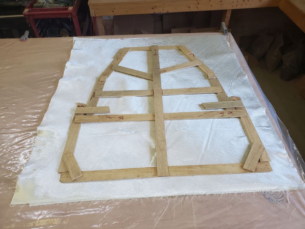
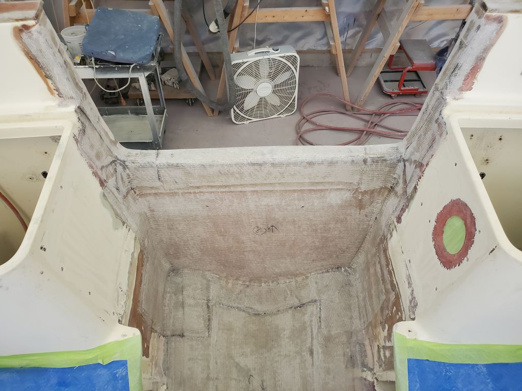
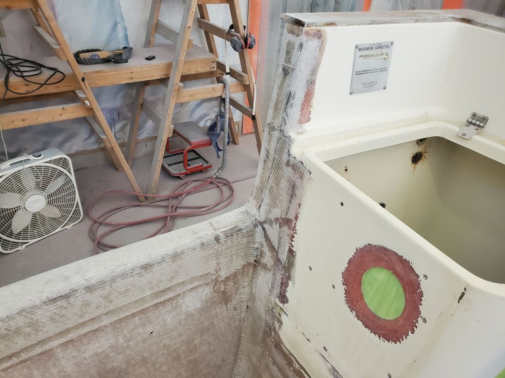
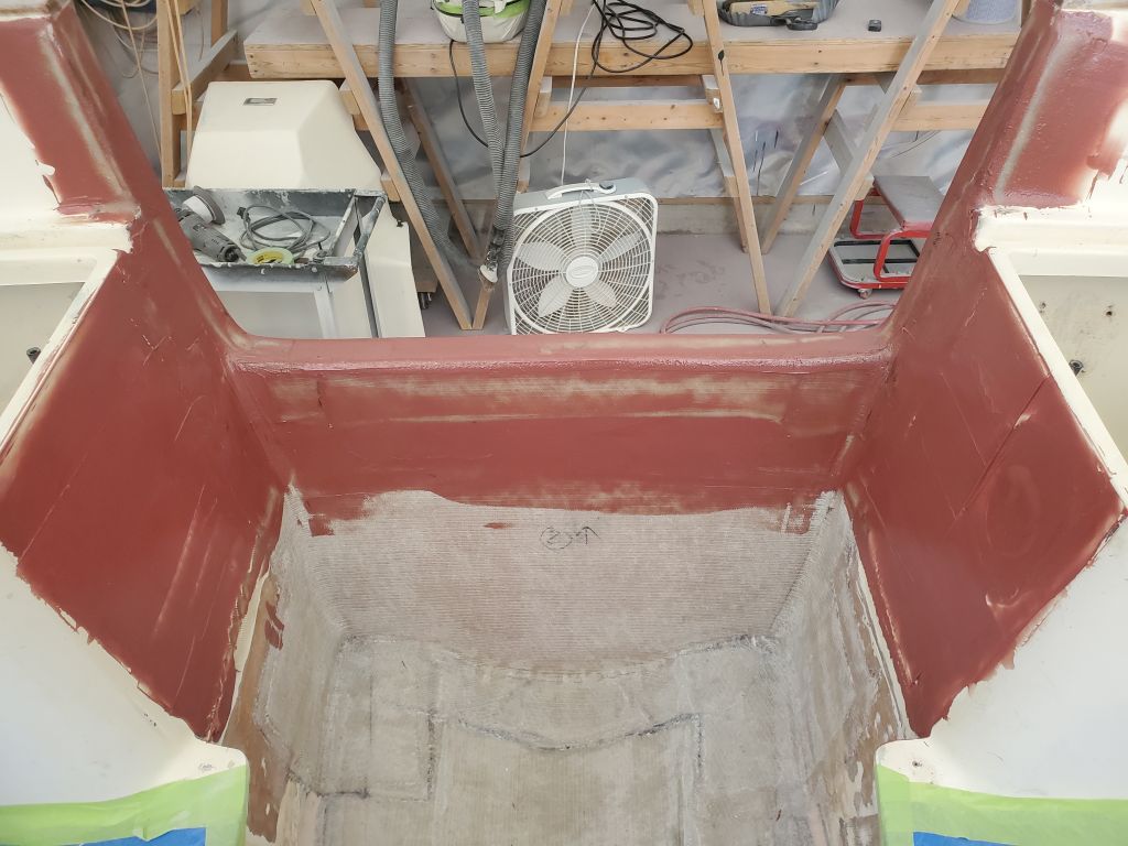
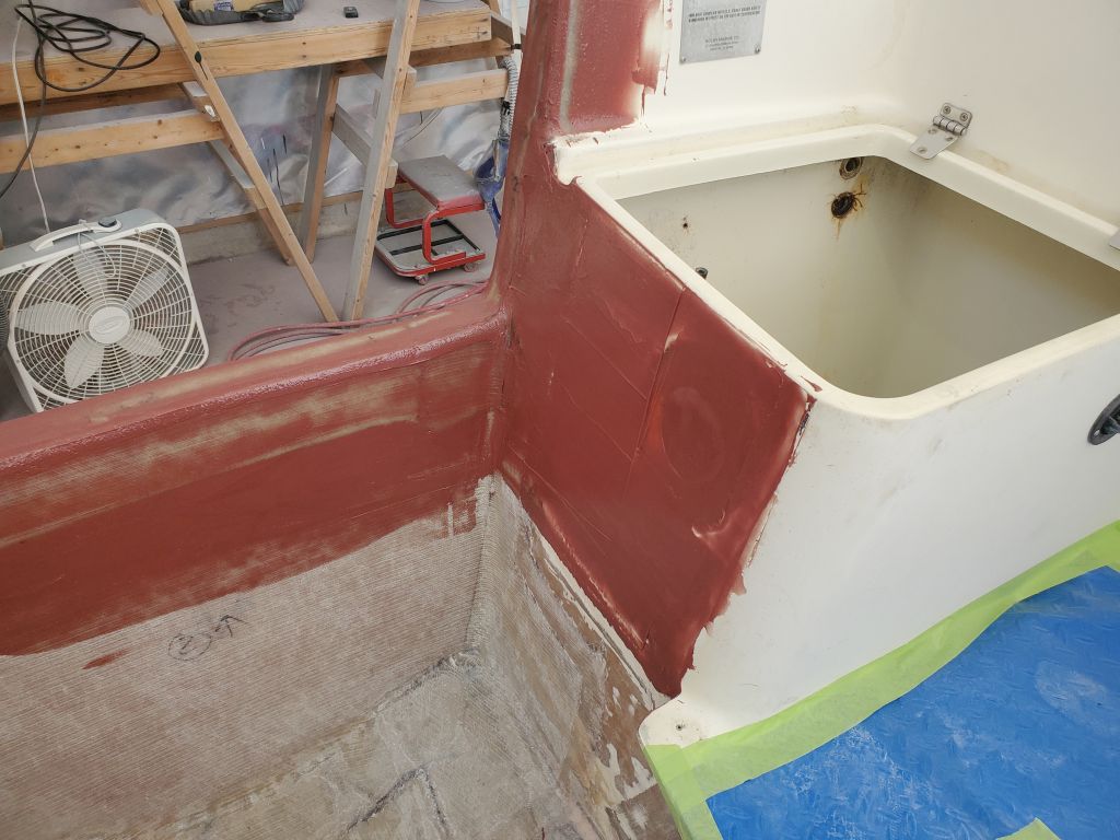
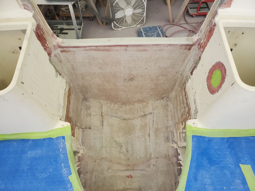
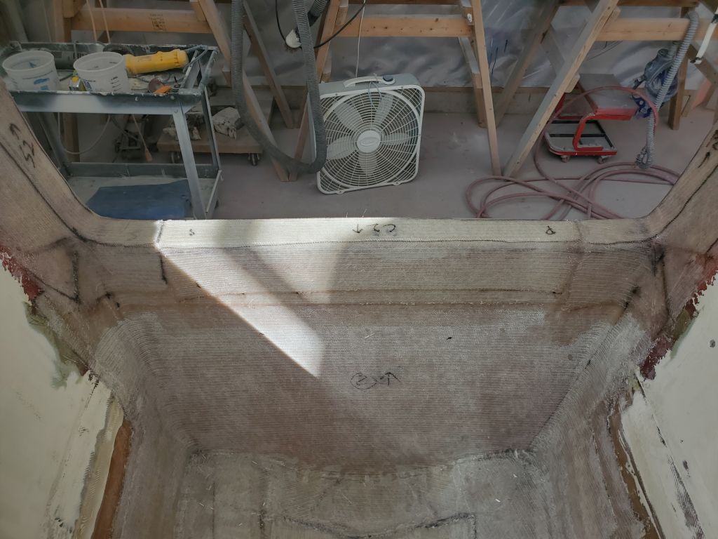
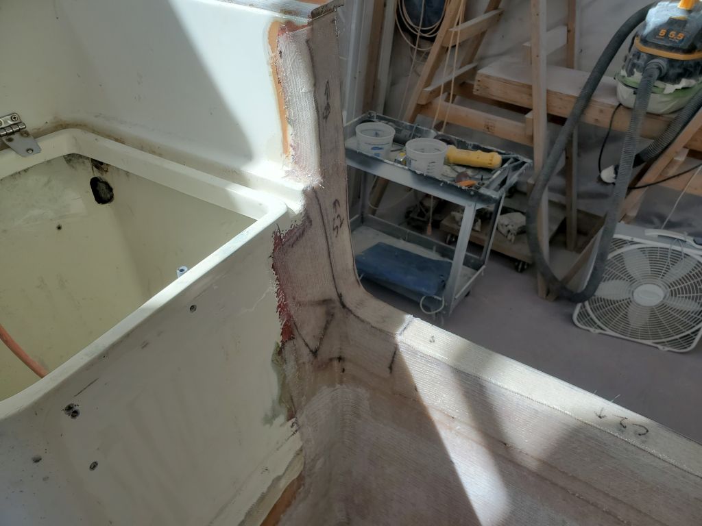
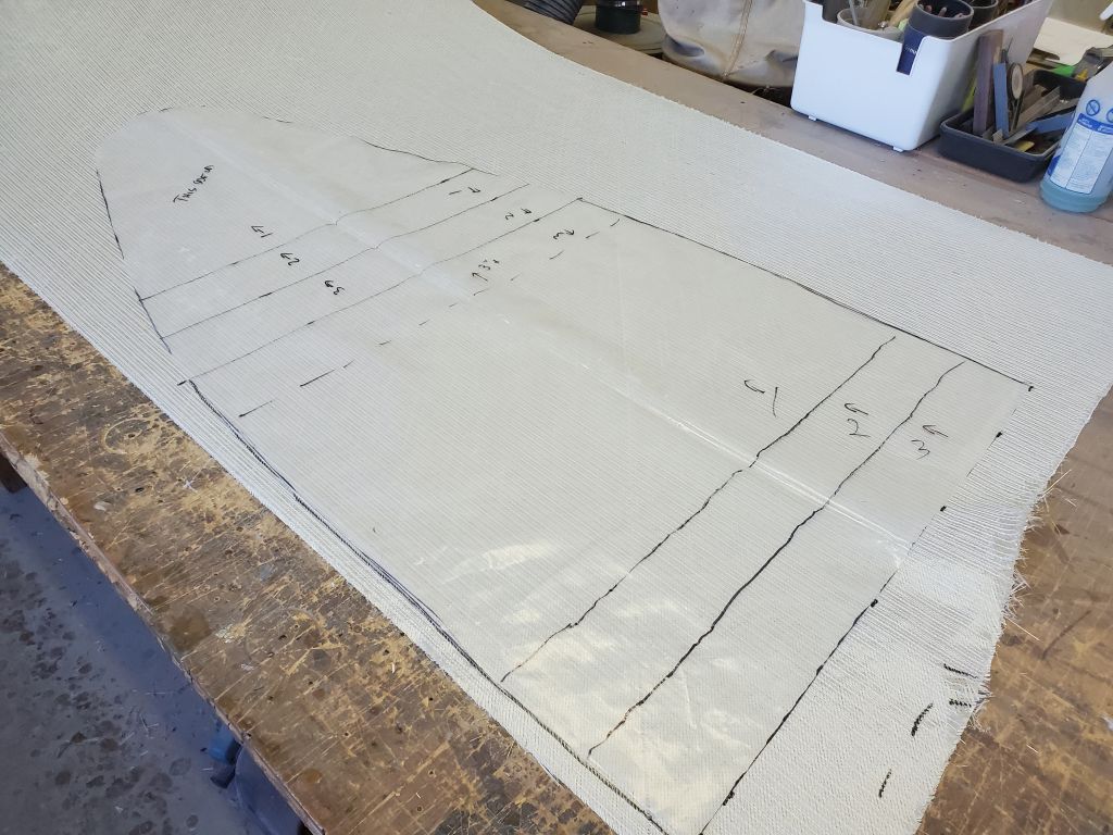
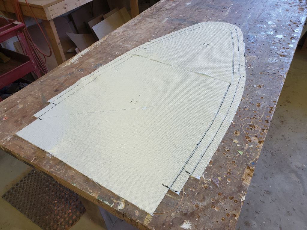
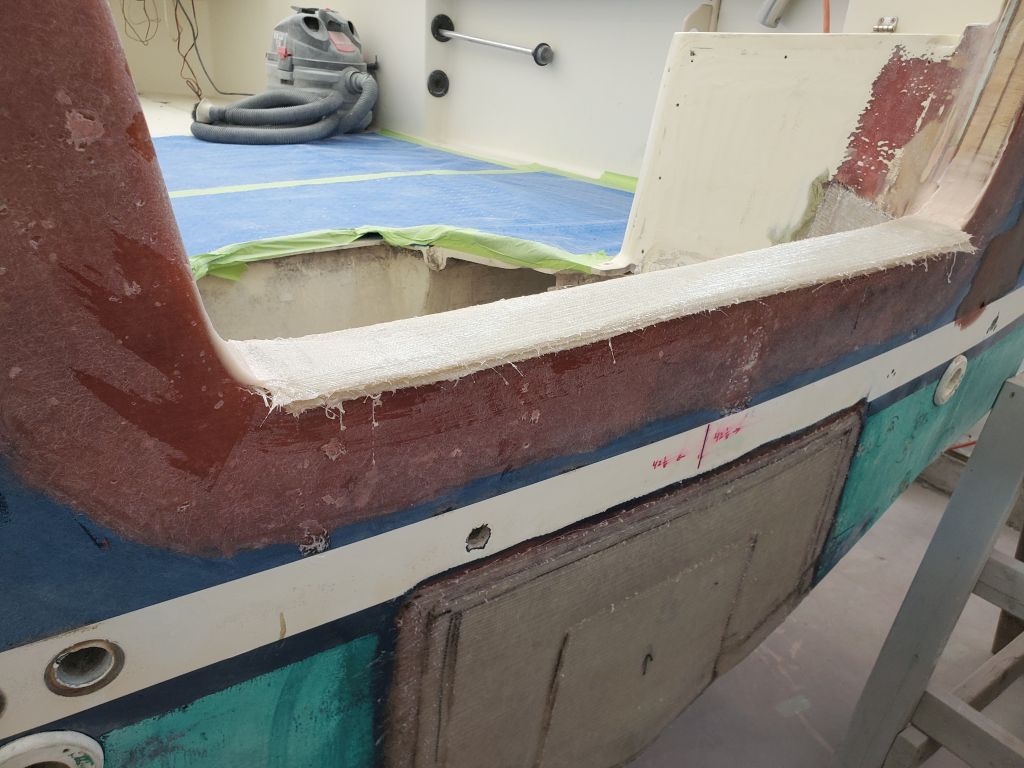
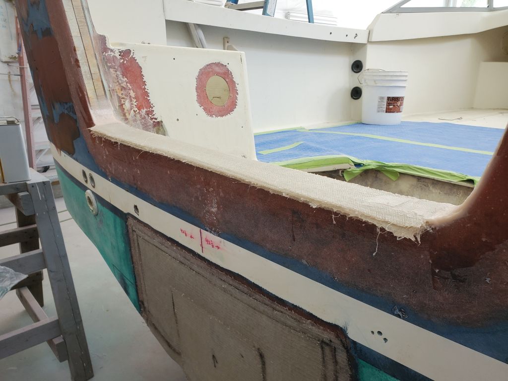
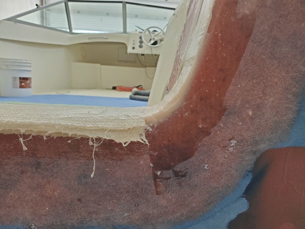
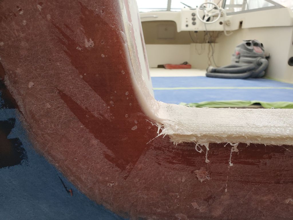
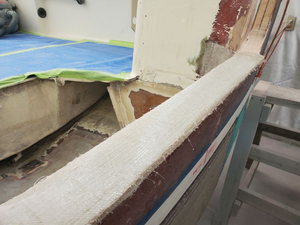
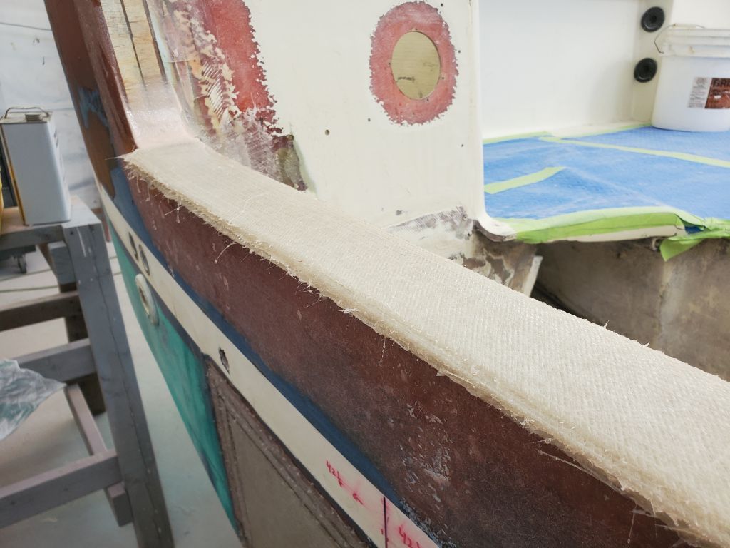
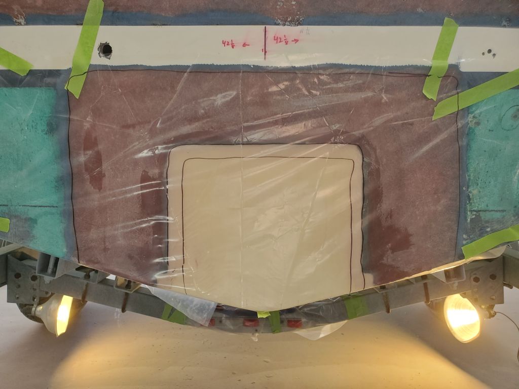
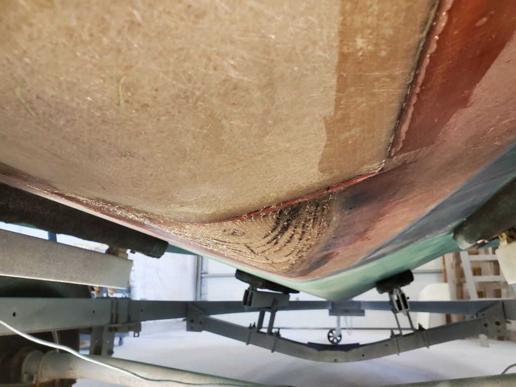
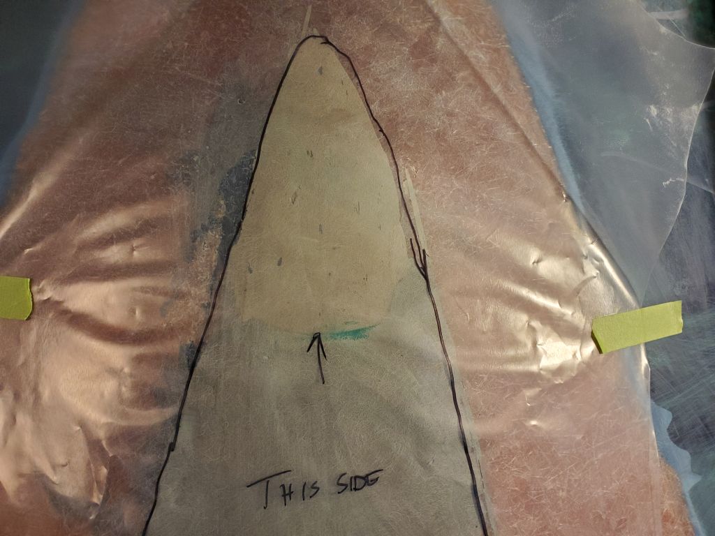
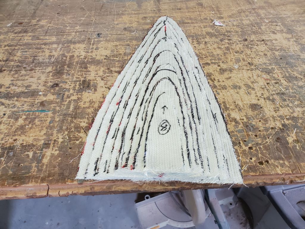
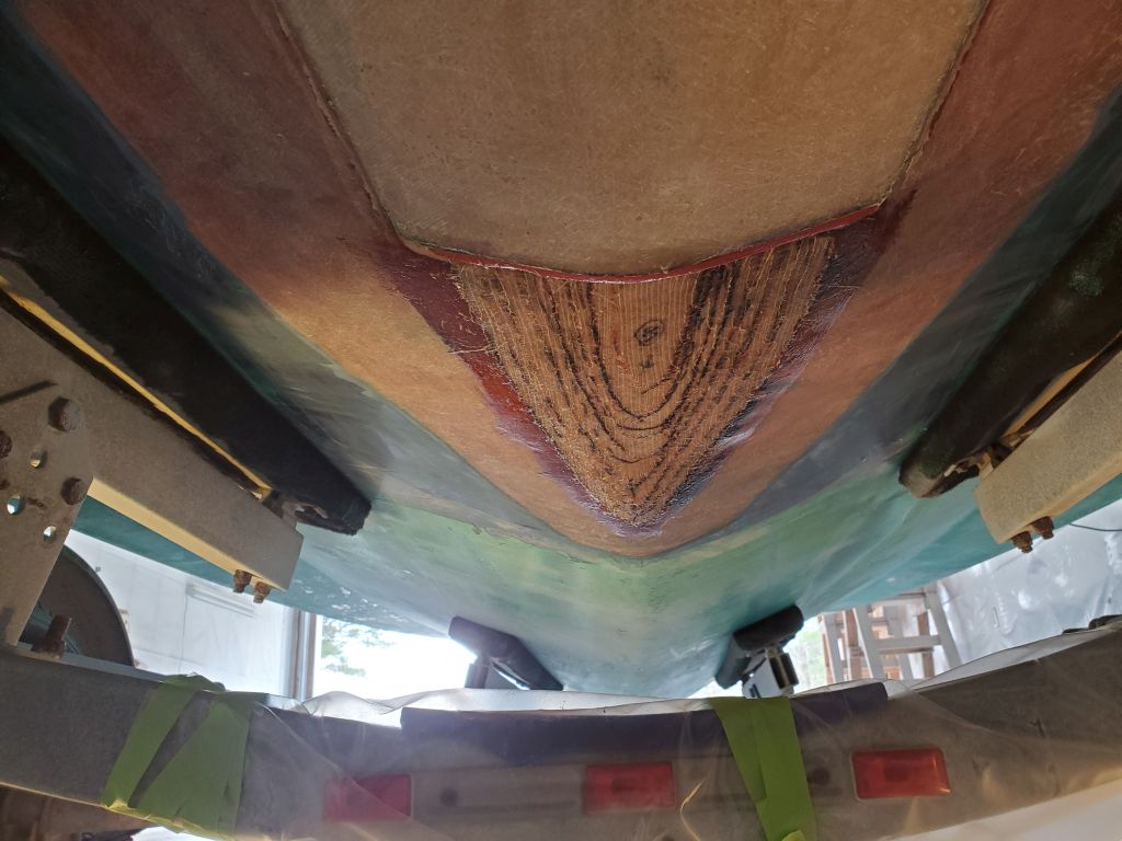
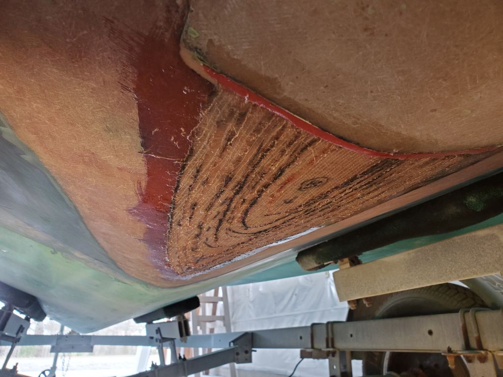
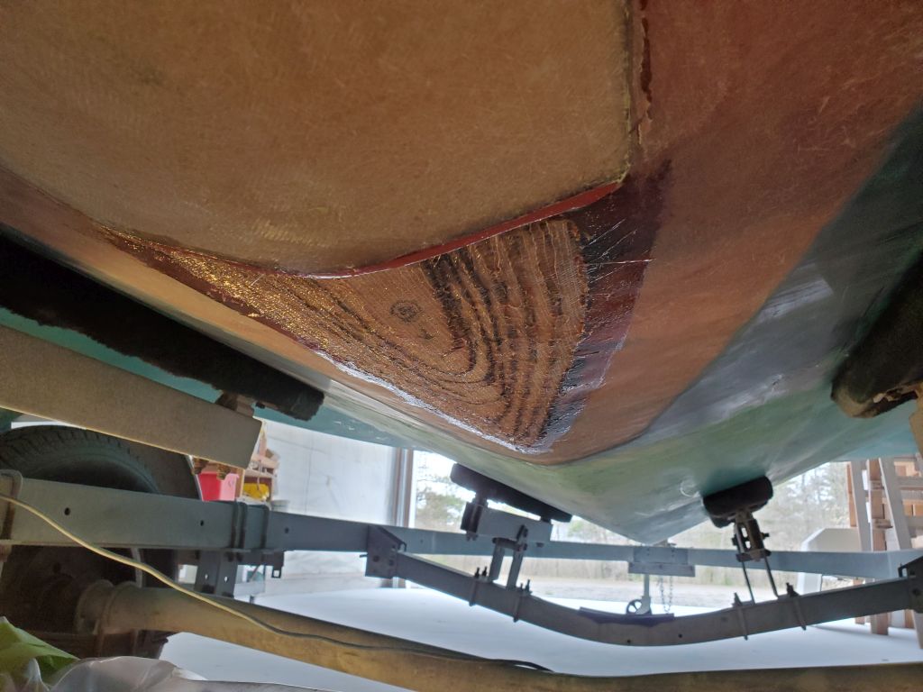
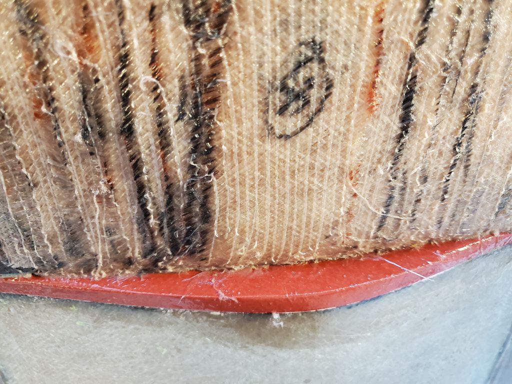
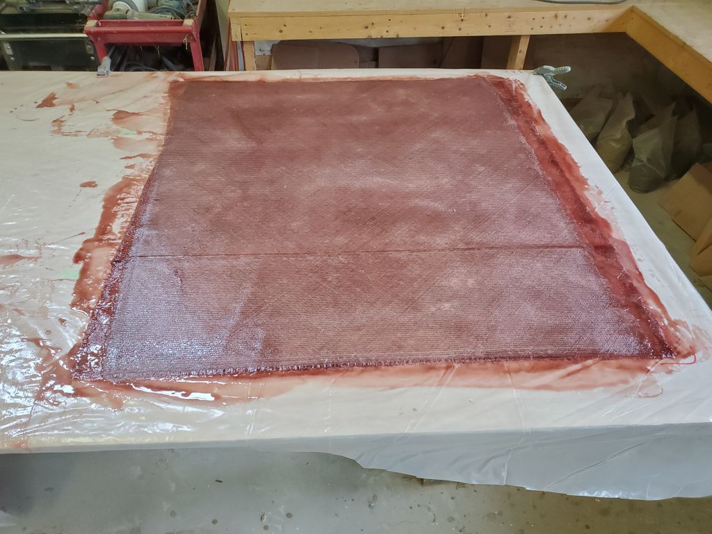
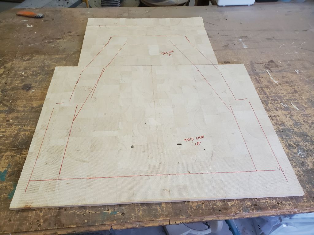
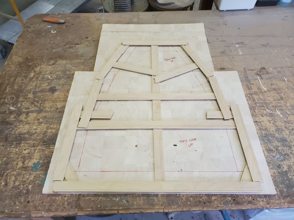
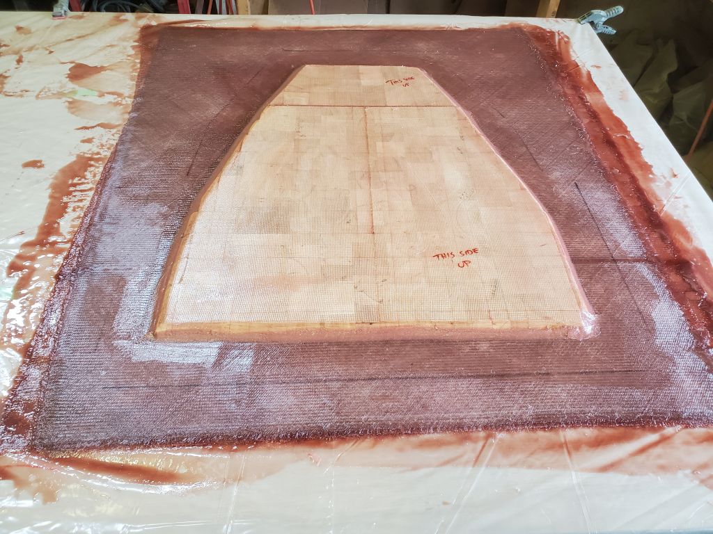
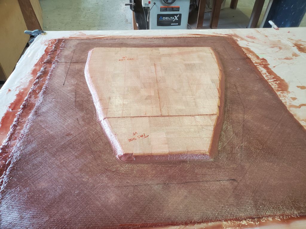
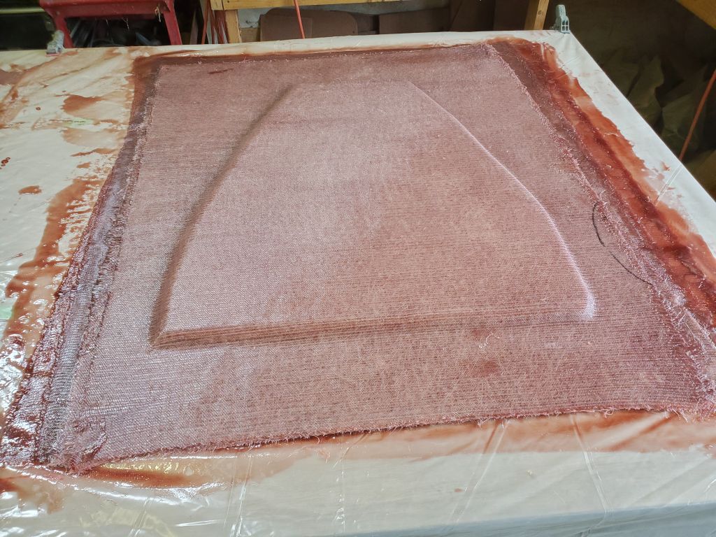
To begin, I laminated the three layers of fiberglass I’d previously cut with epoxy resin, creating a top-skin panel for the new outboard well deck.  While the initial layers were gelling, I prepared a section of 1/2″ balsa core to fit, using the overall template as a guide, then cutting the core 3″ short on all sides to leave room for a solid flange where the deck would rest on various cleats and supports along the edges during installation.  I cut a bevel on the outer sides of the core to allow fiberglass to lay over it during installation.

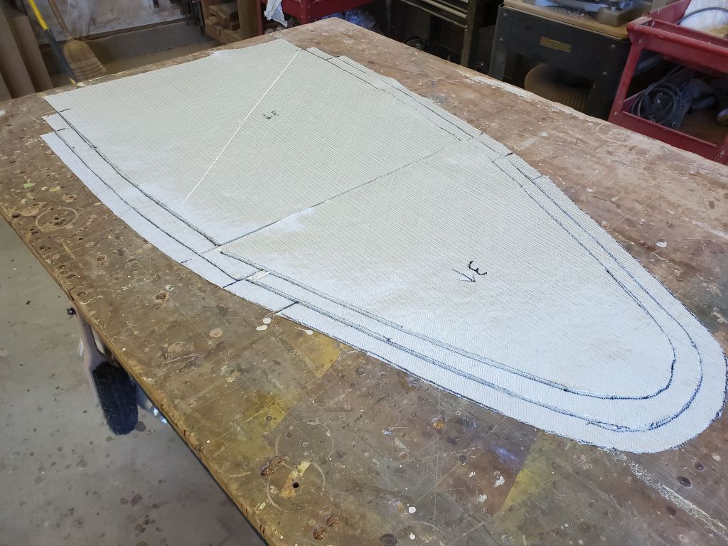
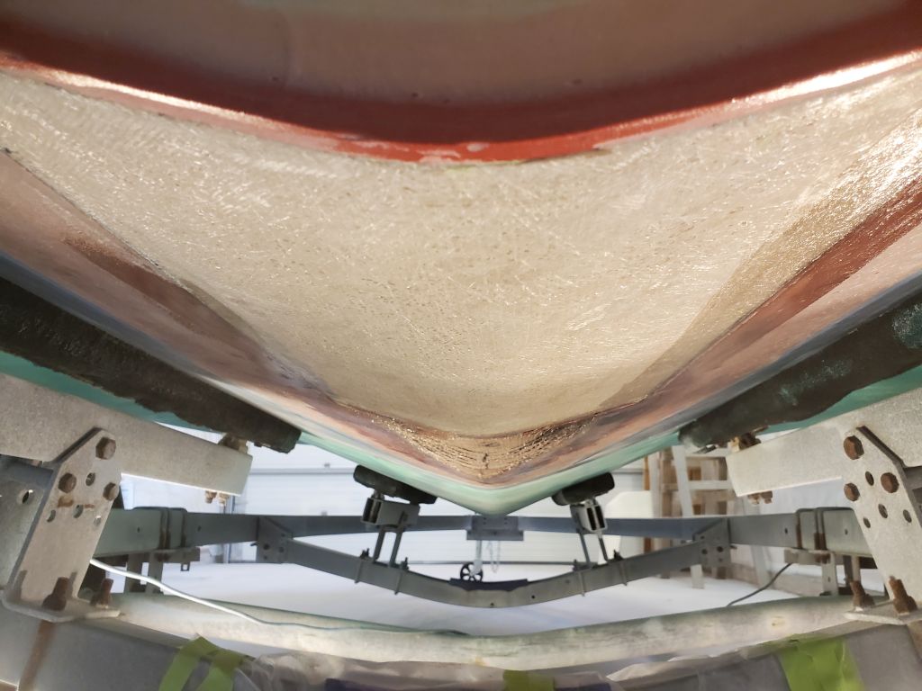
Once the three top layers had sufficiently cured, I made a light outline of the template on the surface and positioned the new core within; the rectangular base panel was sufficiently oversize that I had ample room on all edges for adjustment.  I pre-wet both sides of the core with resin, then installed it in a bed of epoxy adhesive before installing two additional layers of 1708 over the top of the core to complete the laminate structure for the sandwich.

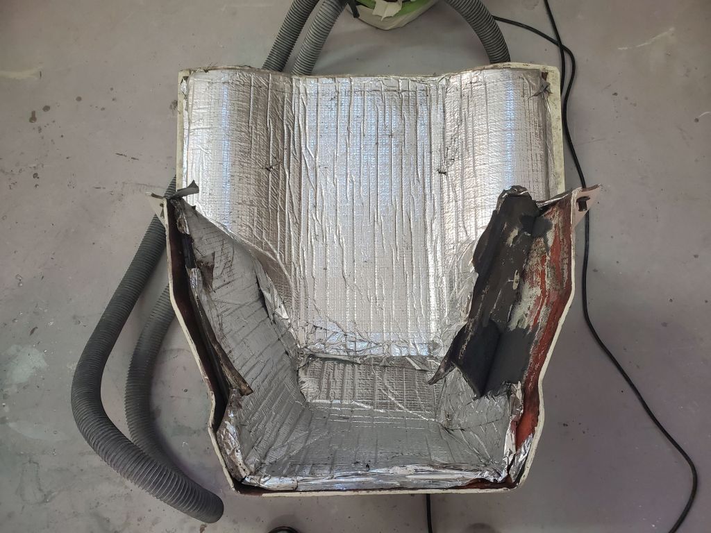
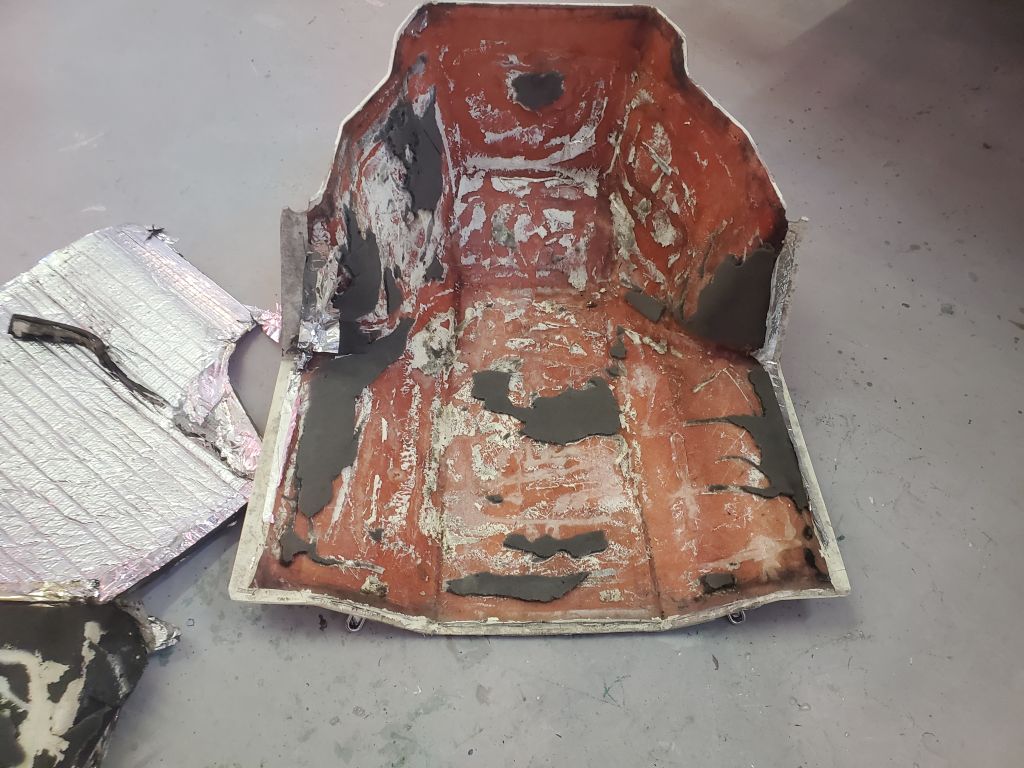
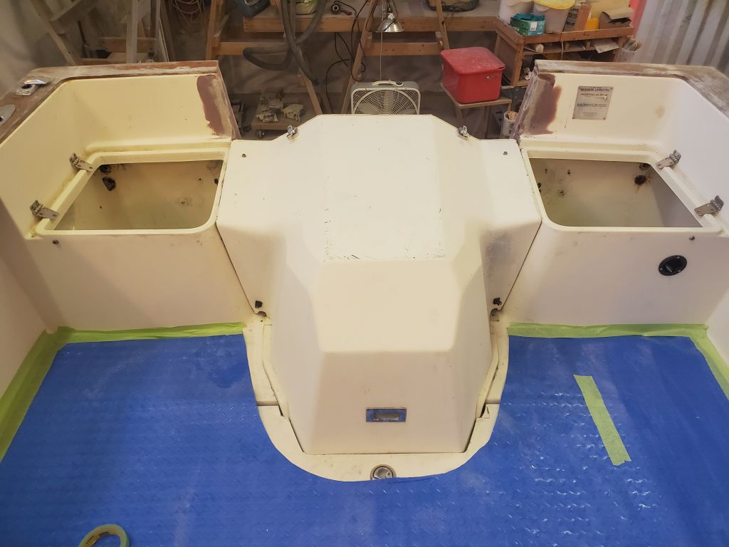
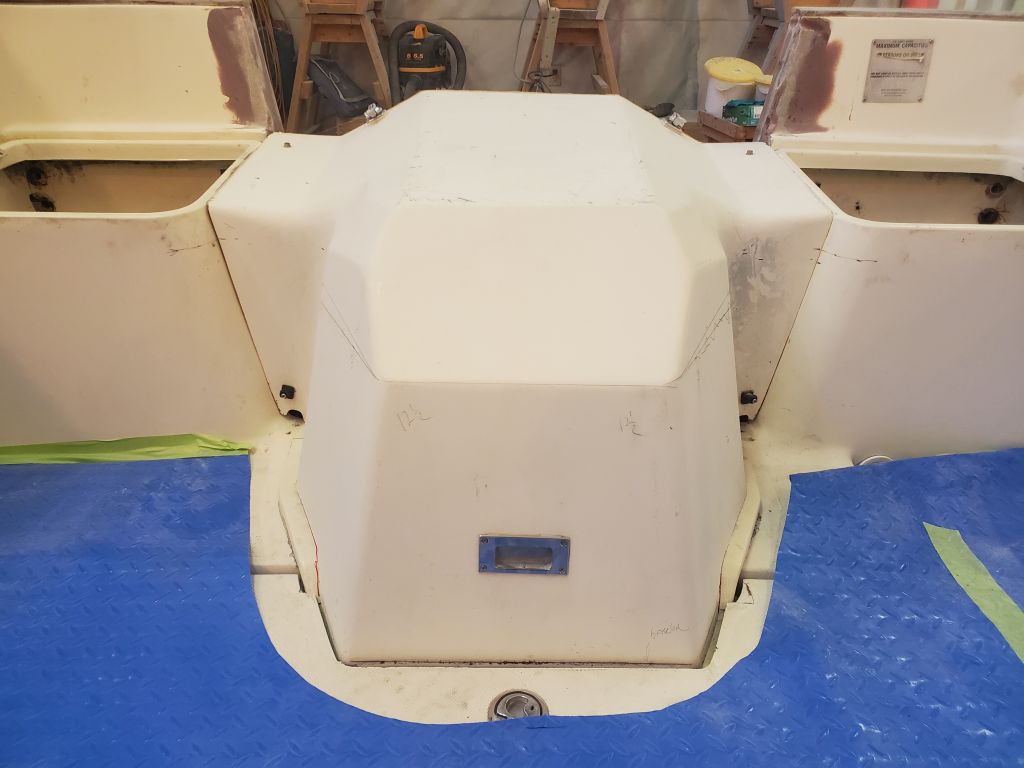
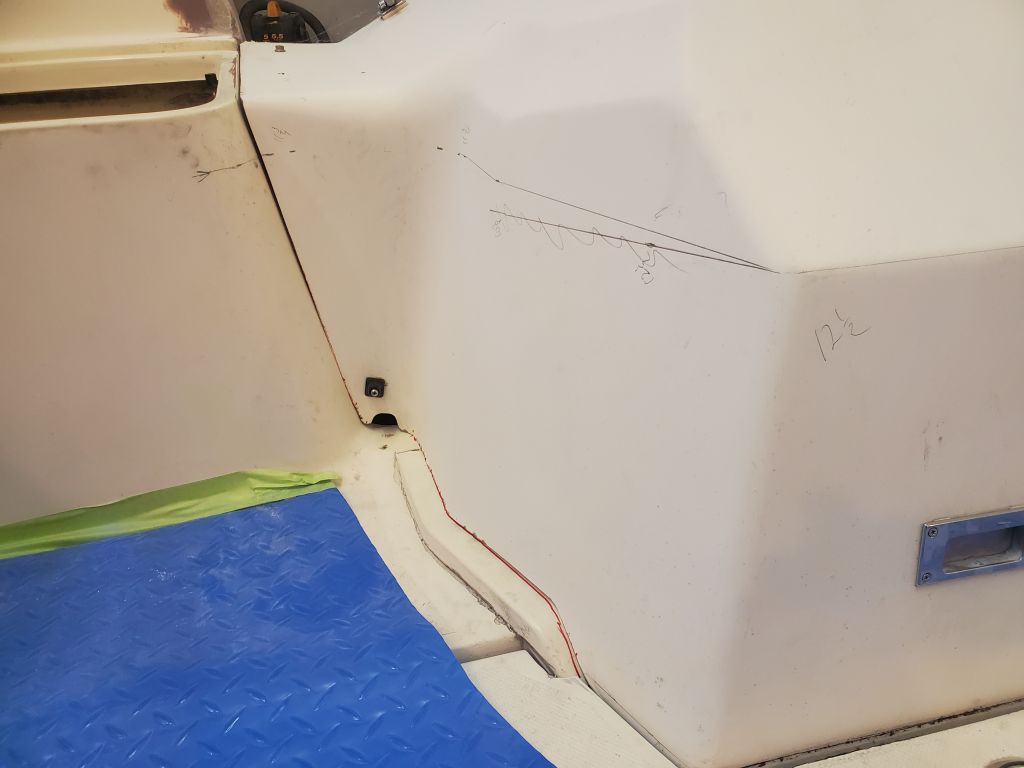
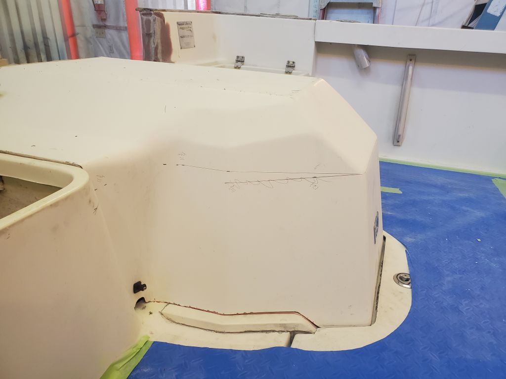
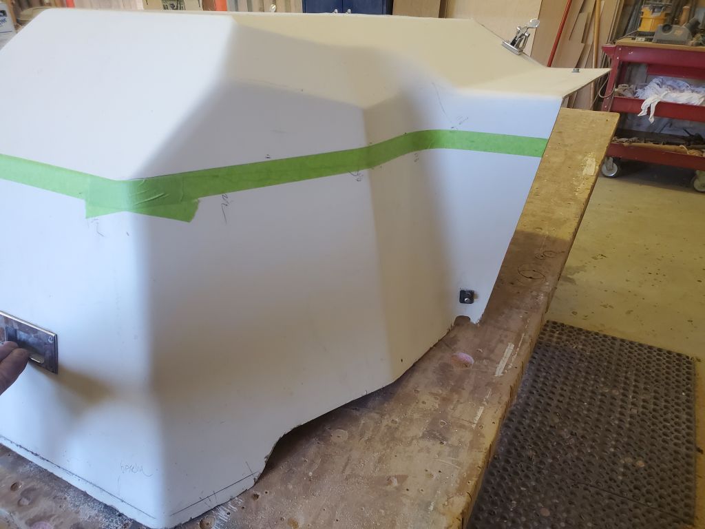
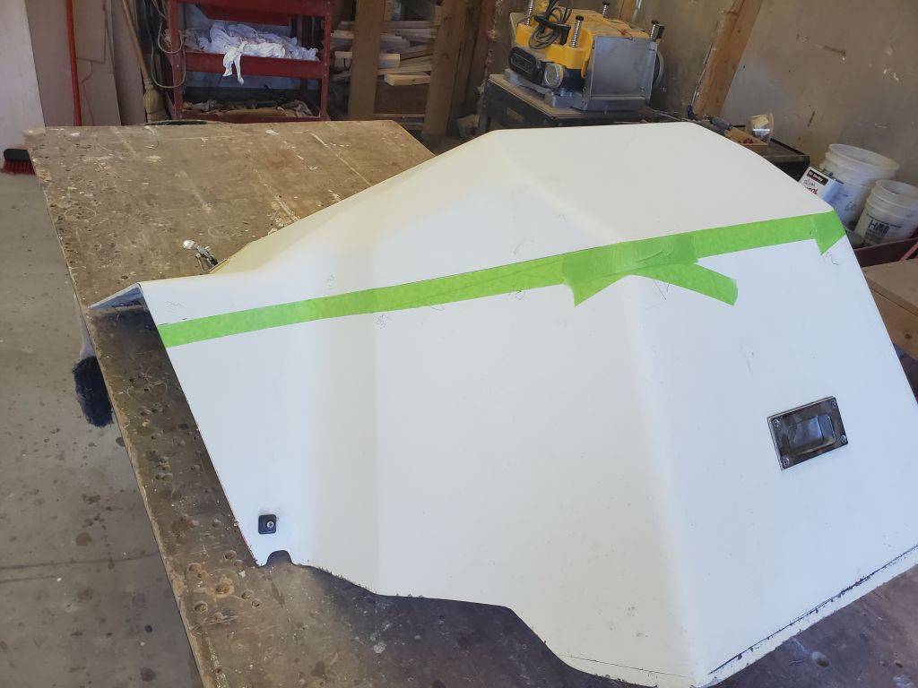
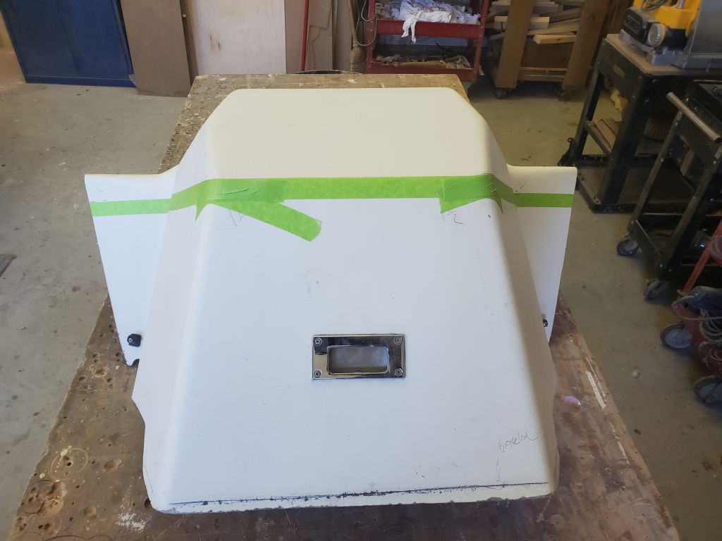
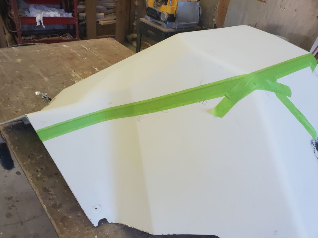
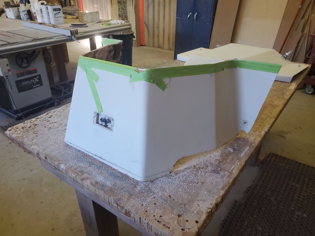
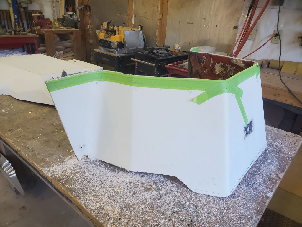
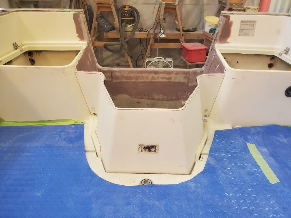
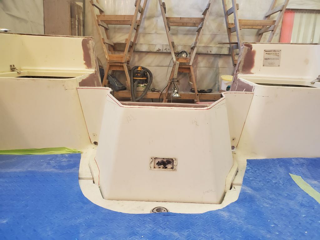
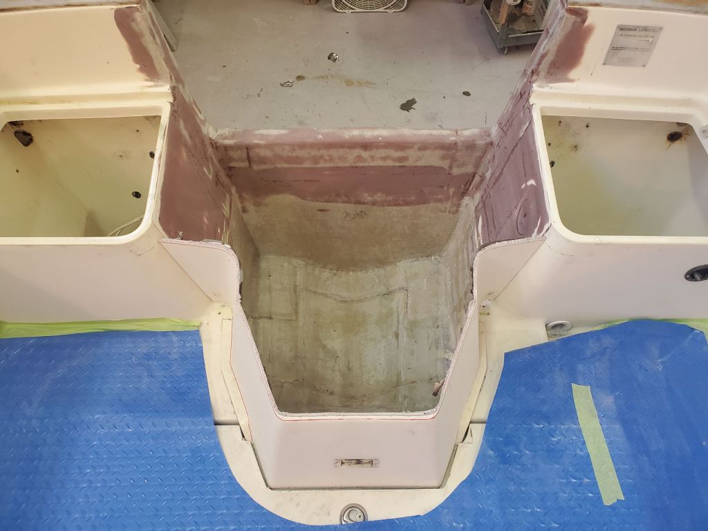
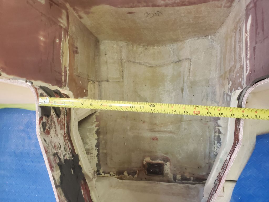
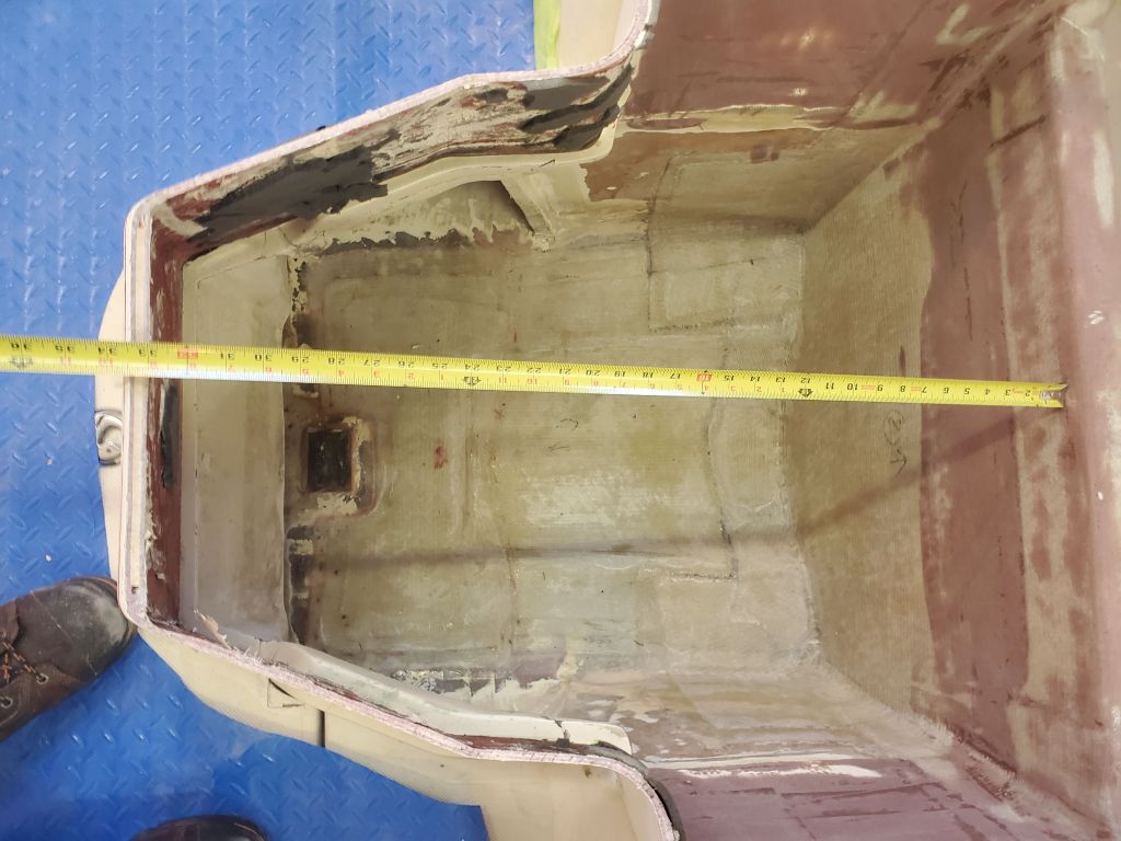
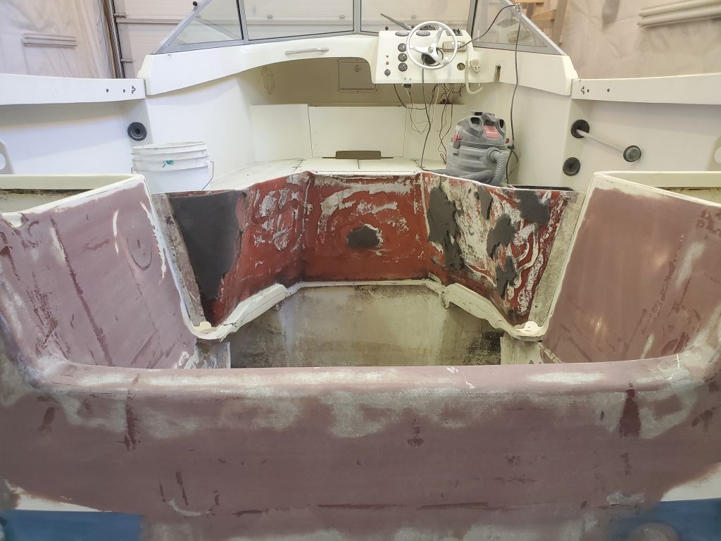
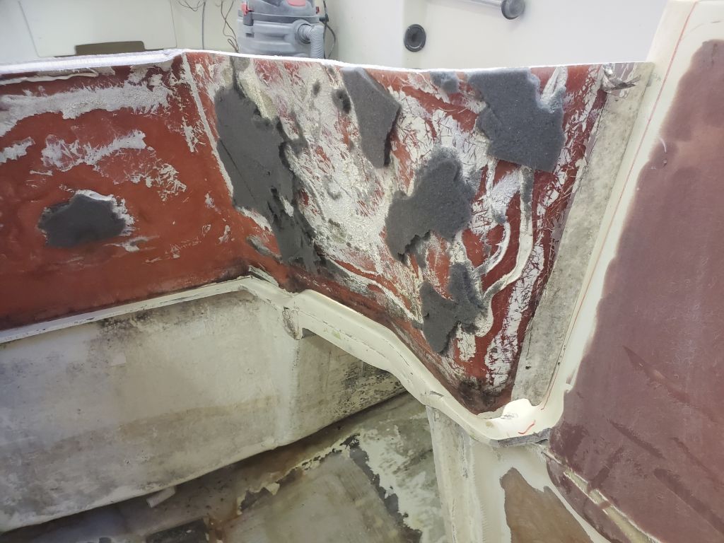
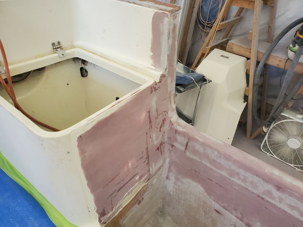
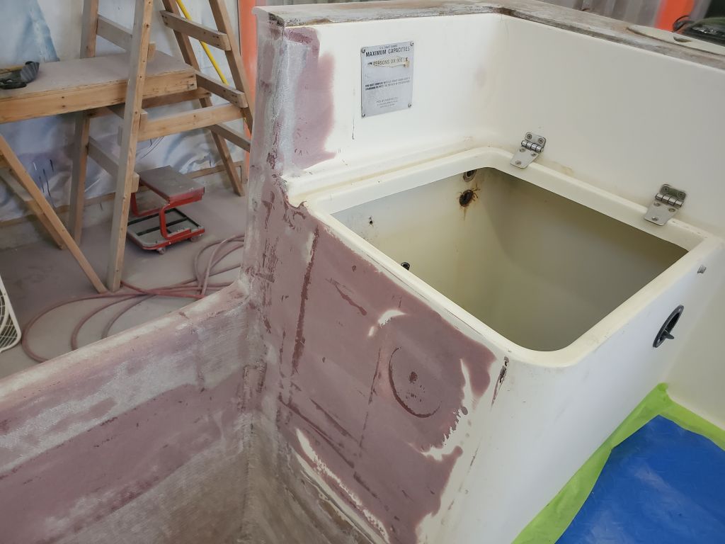
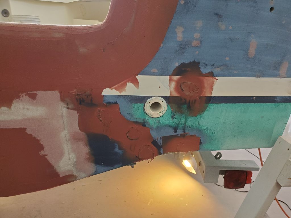
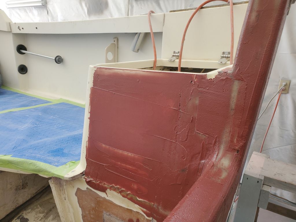
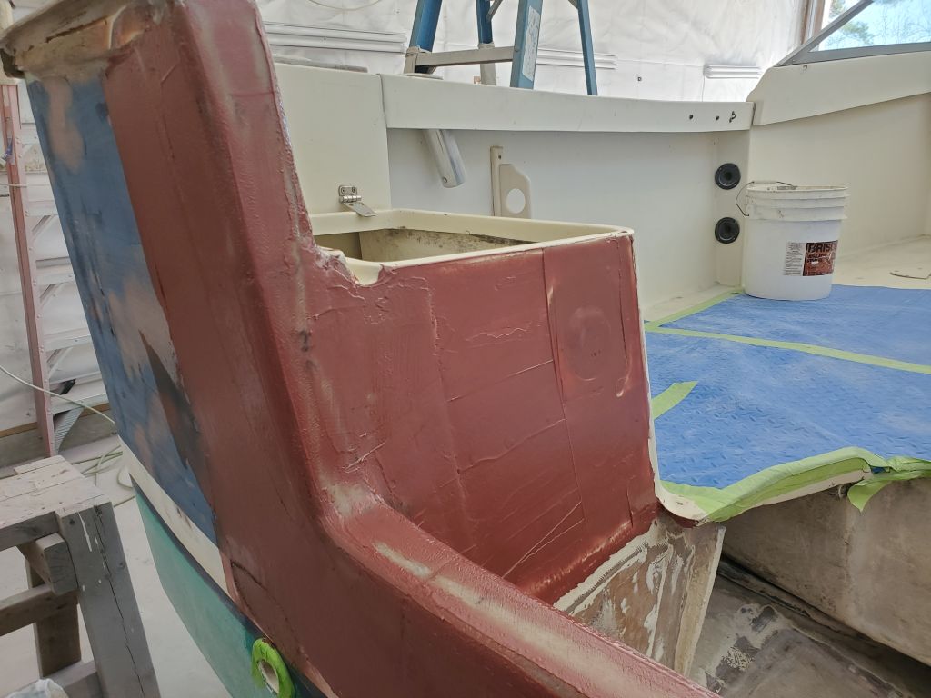
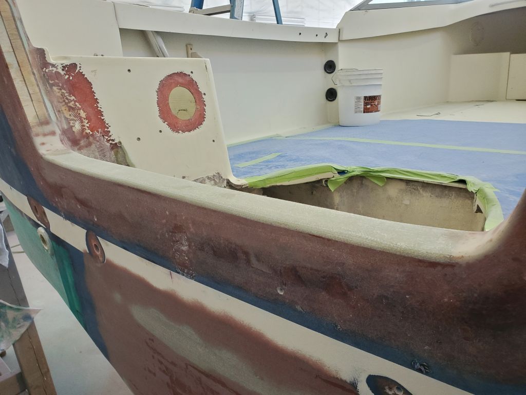
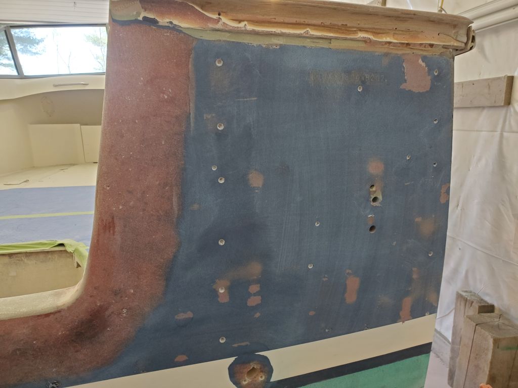
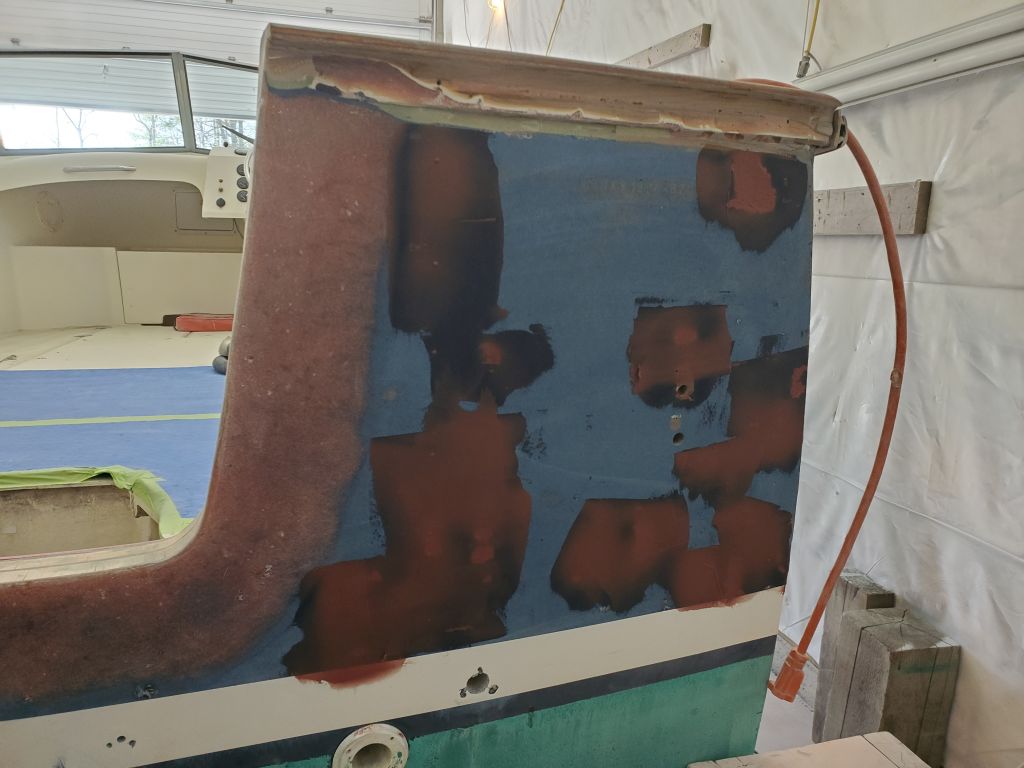
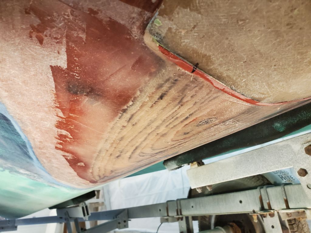
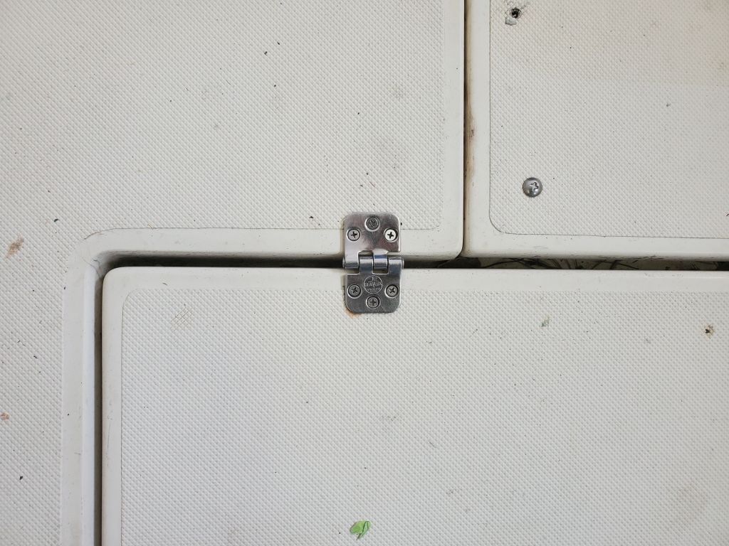
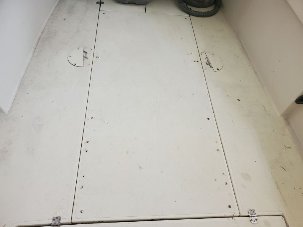
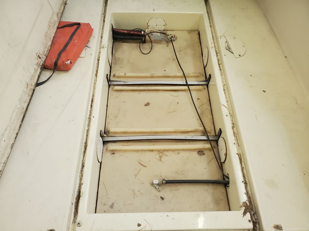
The owner reported that the hinged hatch for the livewell, and the semi-permanent hatch over the fuel tank, showed signs of core damage or water intrusion.  The livewell hatch was obvious at casual observation, as the aft edge, where it had been cut to accommodate the original jet drive installation, had obviously been poorly sealed–or perhaps not sealed at all–and the core there, such as remained, was exposed to the elements and in poor condition.  The condition of the larger hatch over the fuel tank was less obvious immediately, but now I removed both pieces so I could address the necessary repairs.  Removal was quick and straightforward.

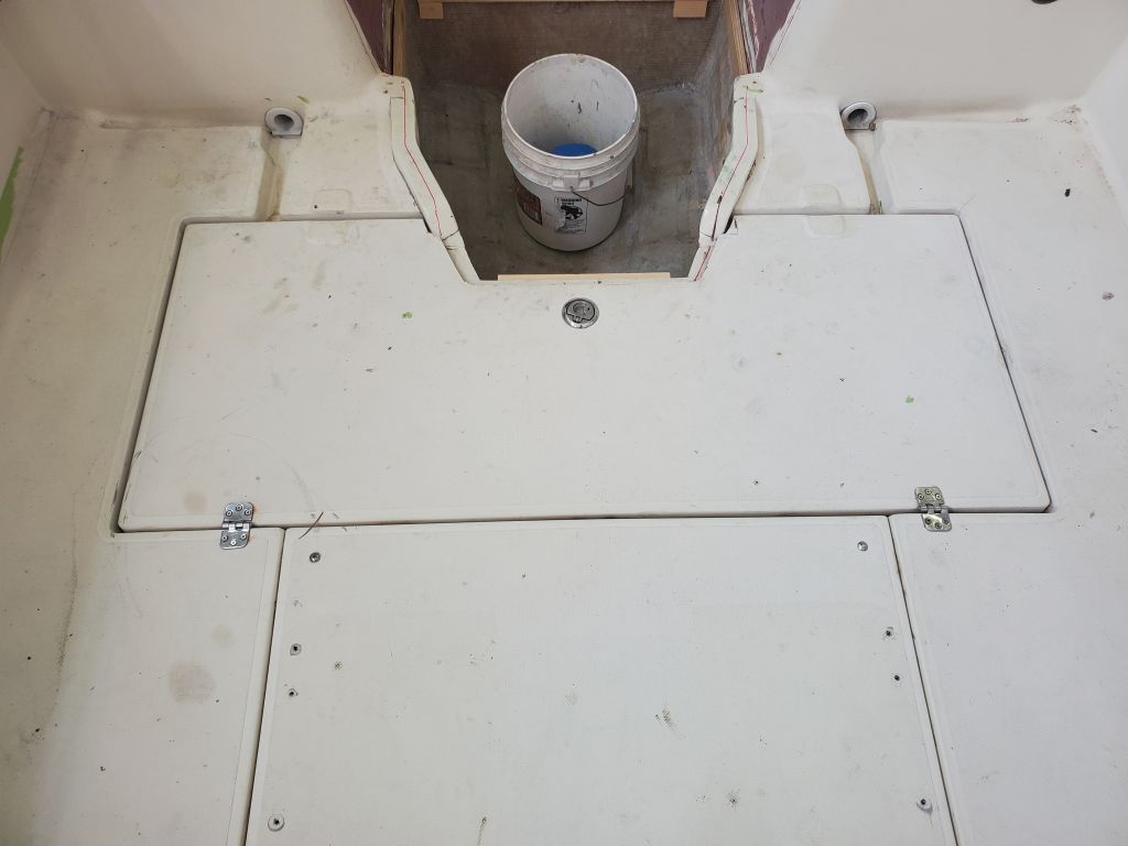
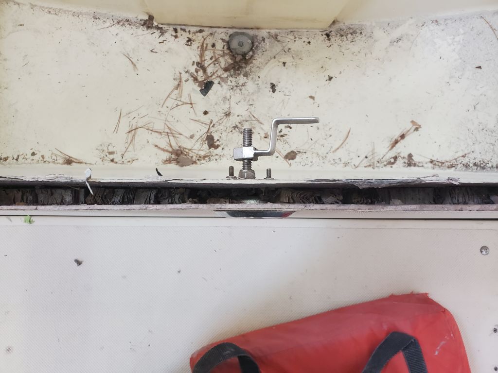
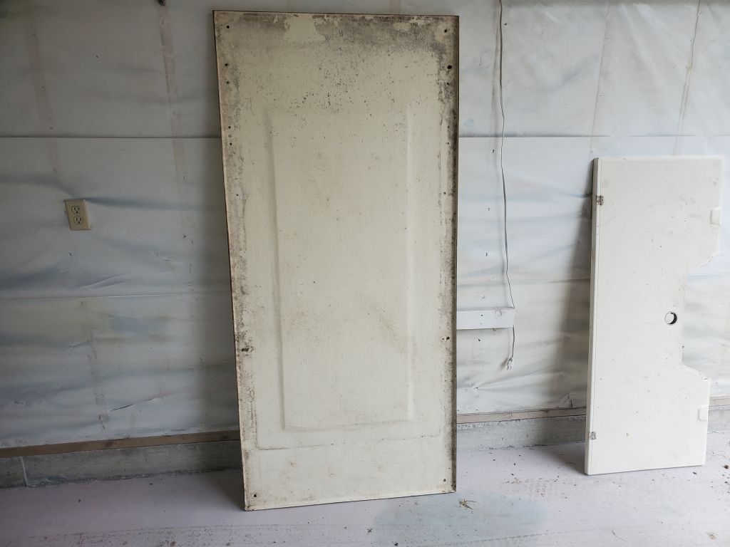
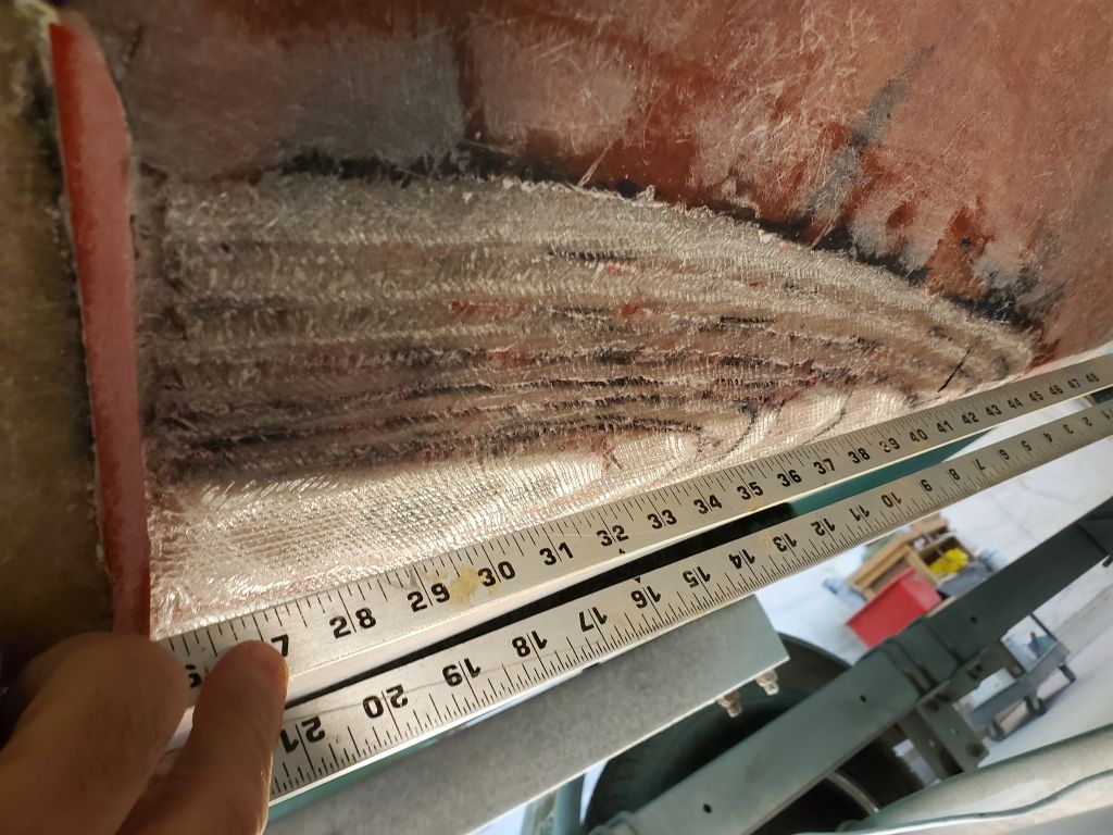
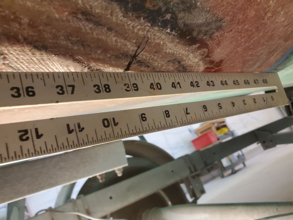
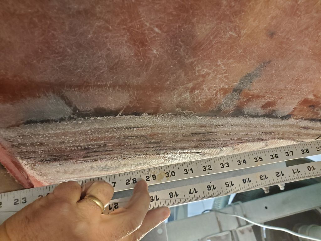
It was clear the livewell hatch would require new core and bottom skin, retaining the original top with its molded pattern for cosmetic reasons.  I removed the latching mechanism, devoid of sealant, to expose more of the core, and set this piece aside to deal with later.

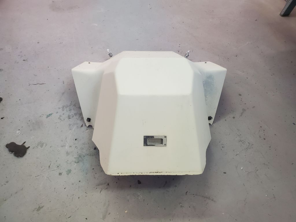
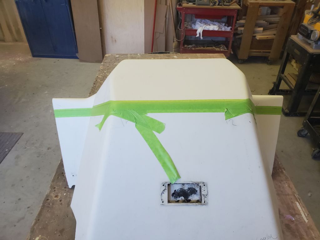
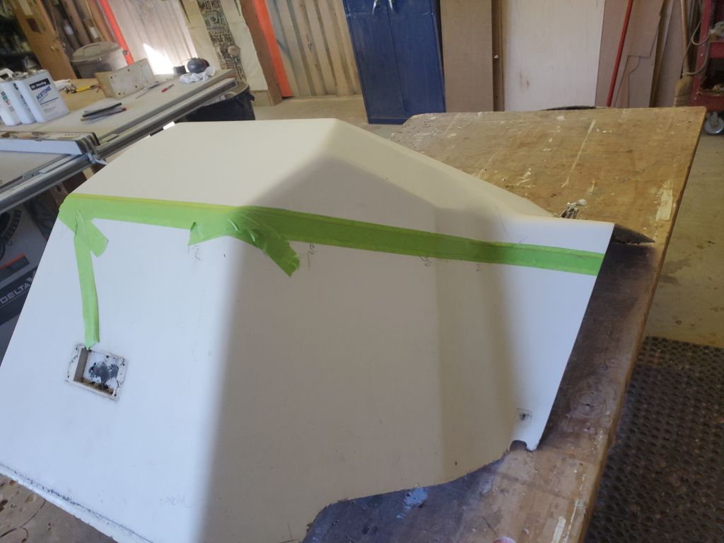
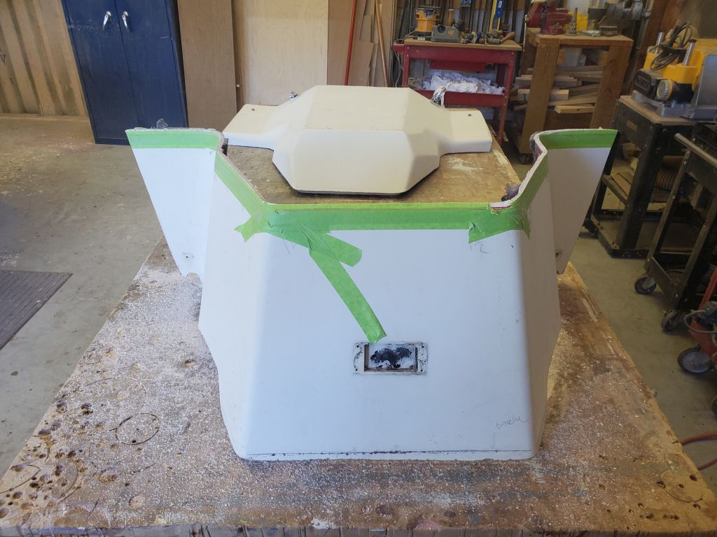
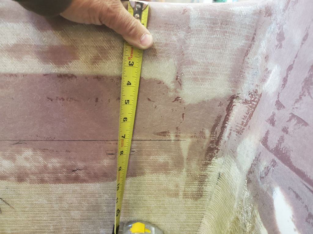
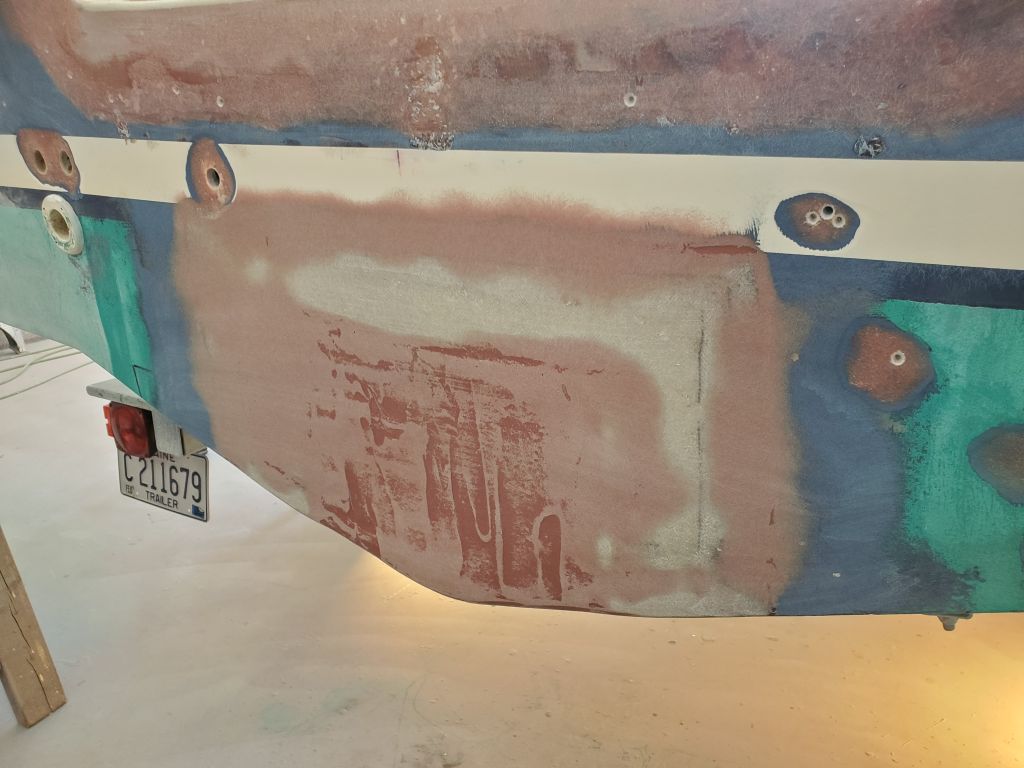
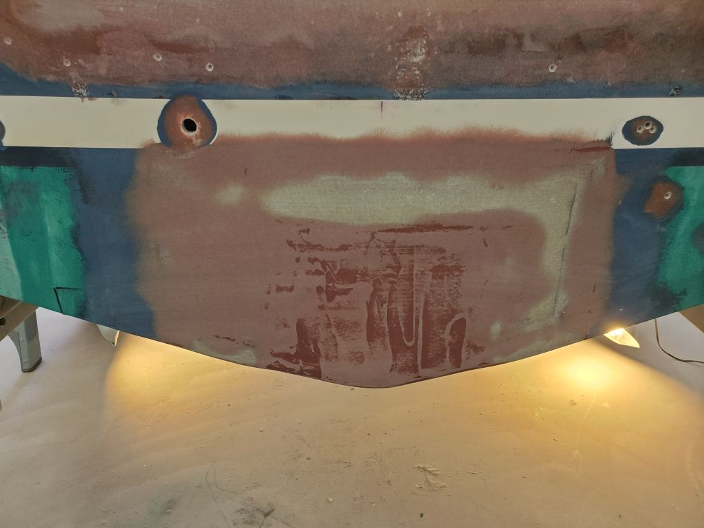
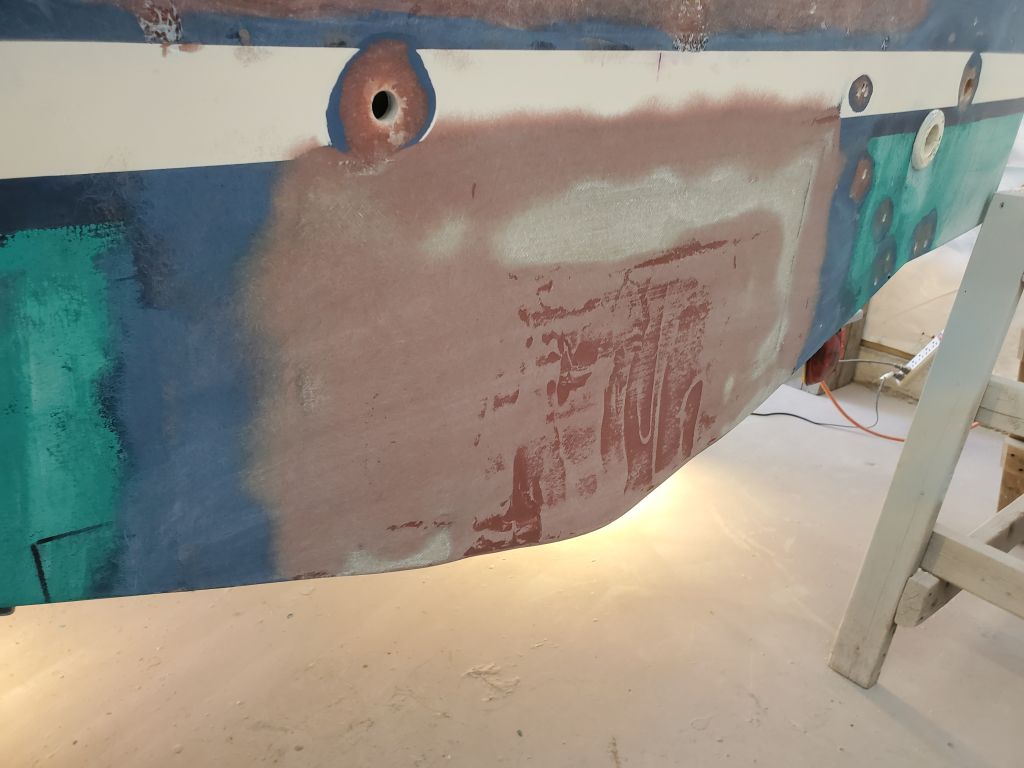
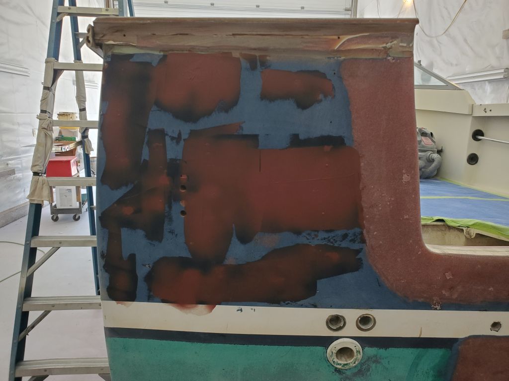
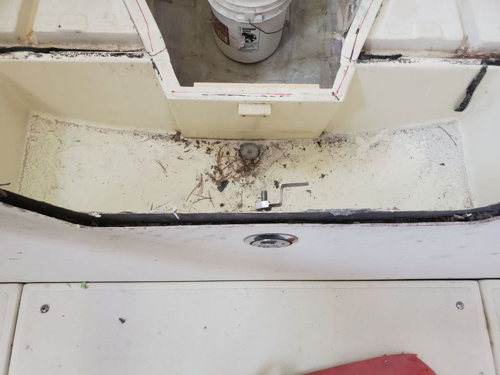
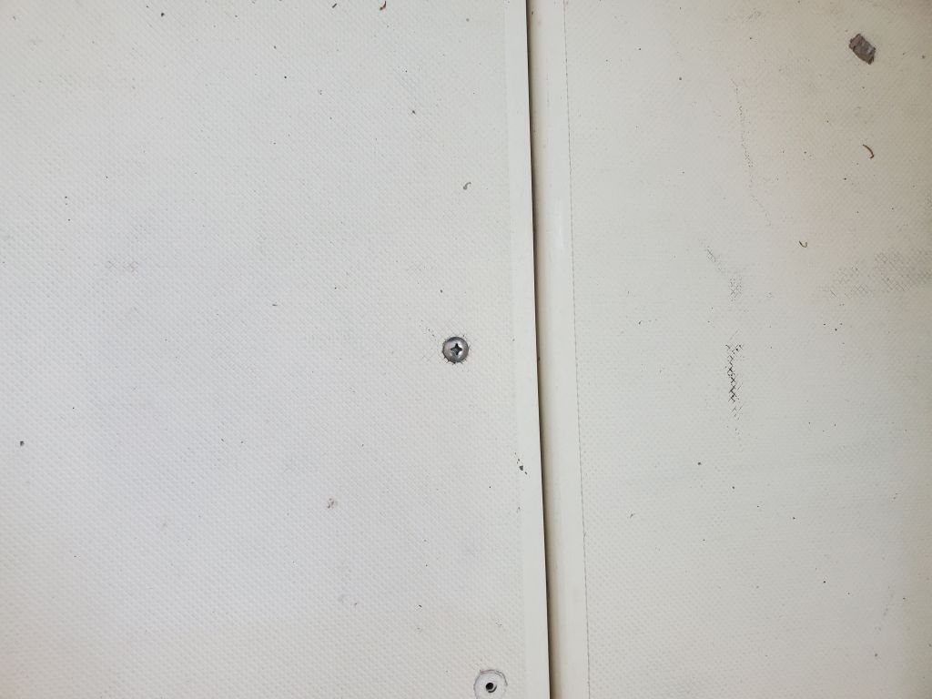
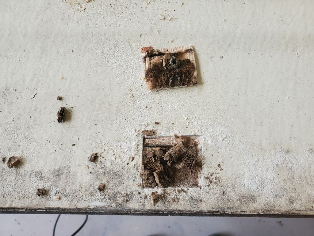
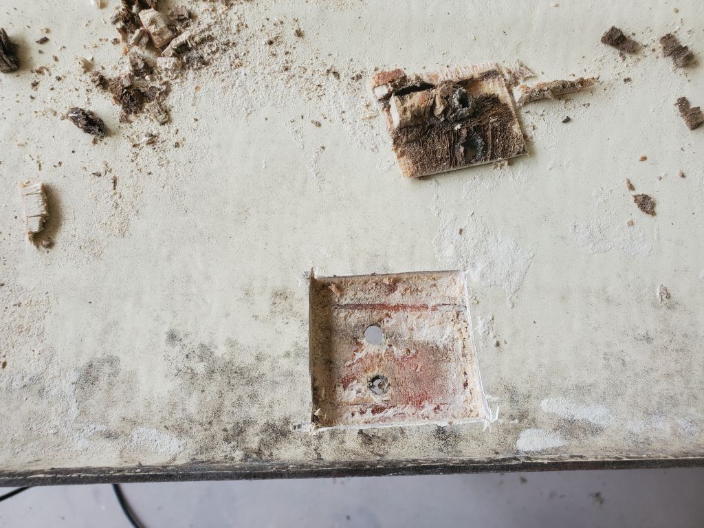
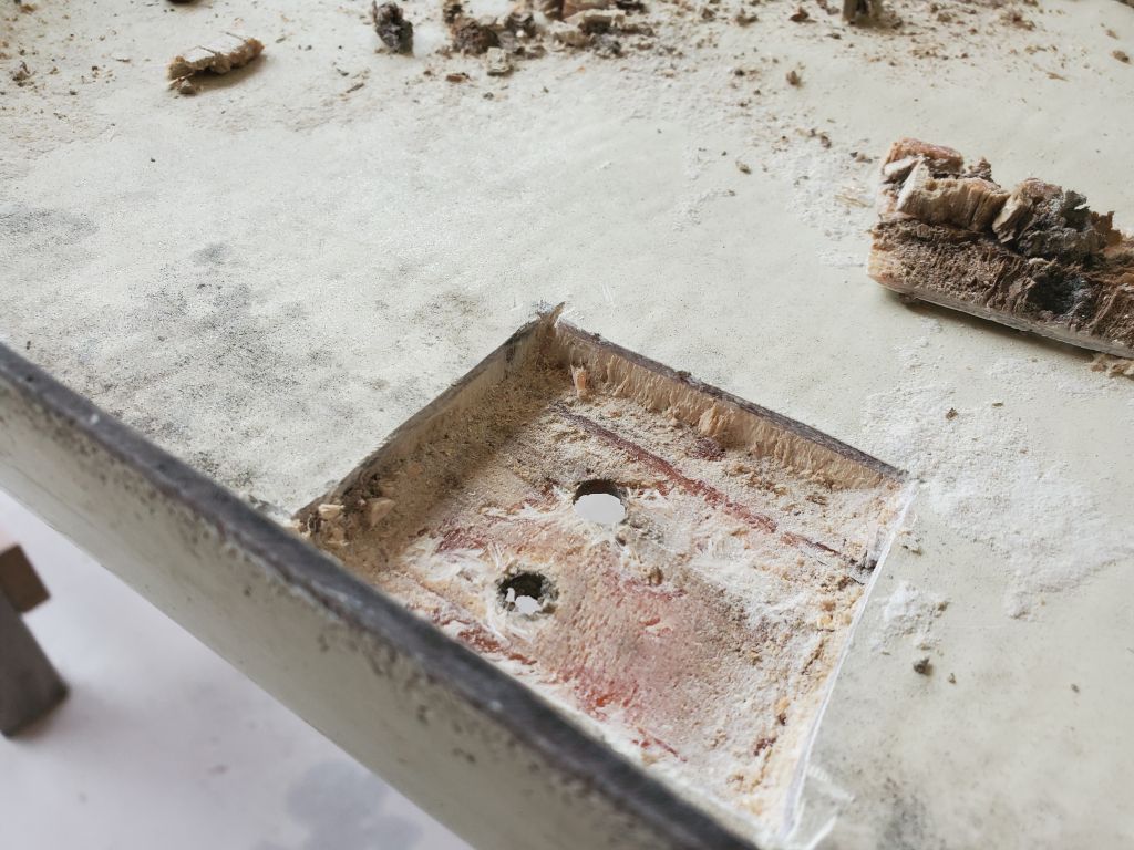
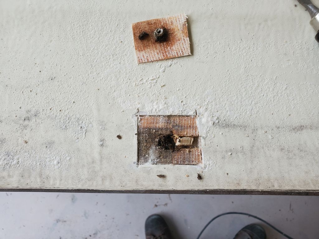
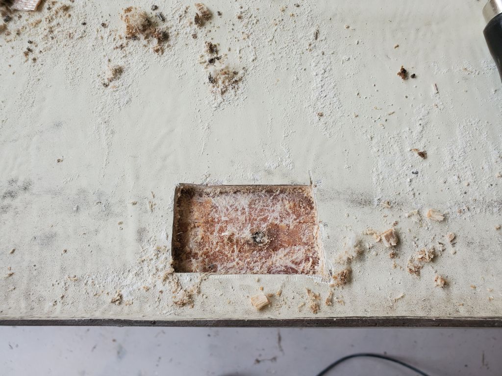
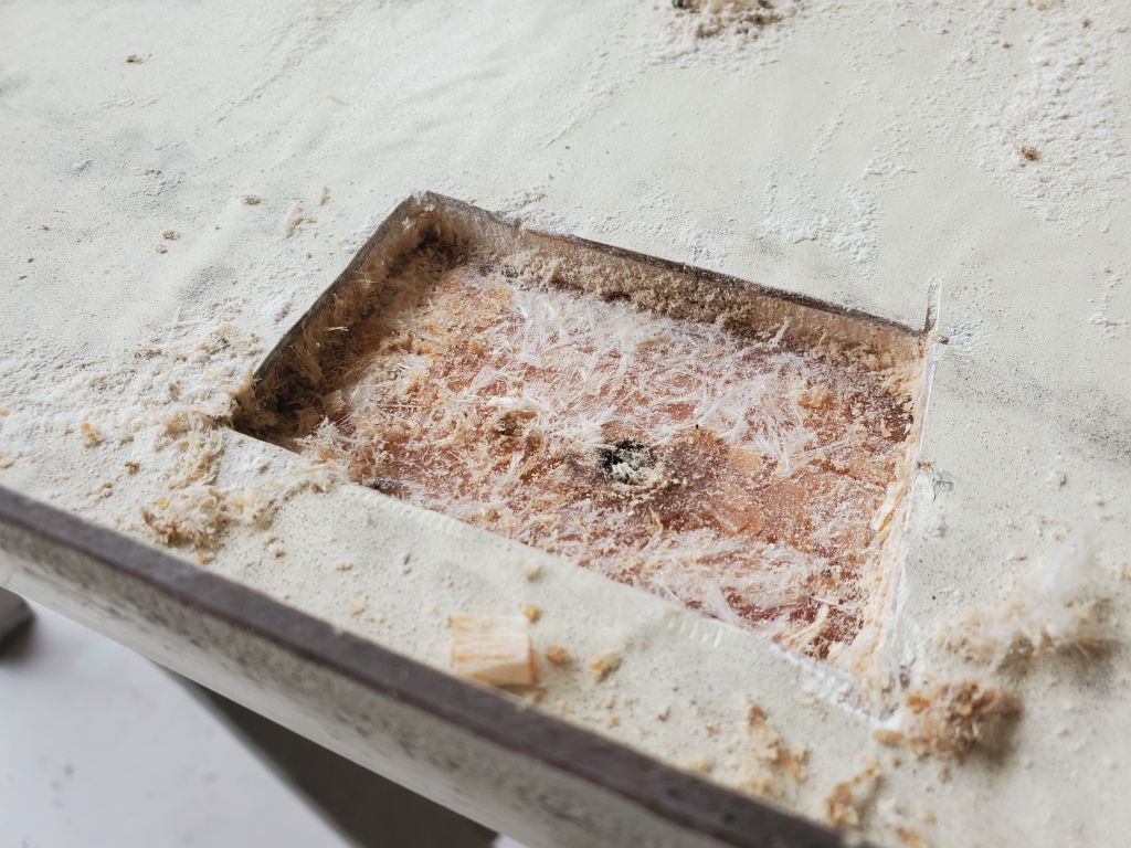
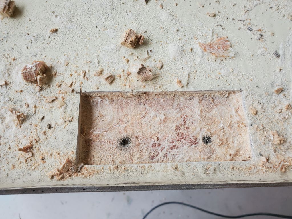
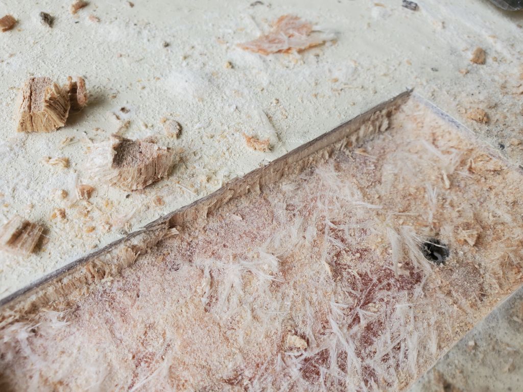
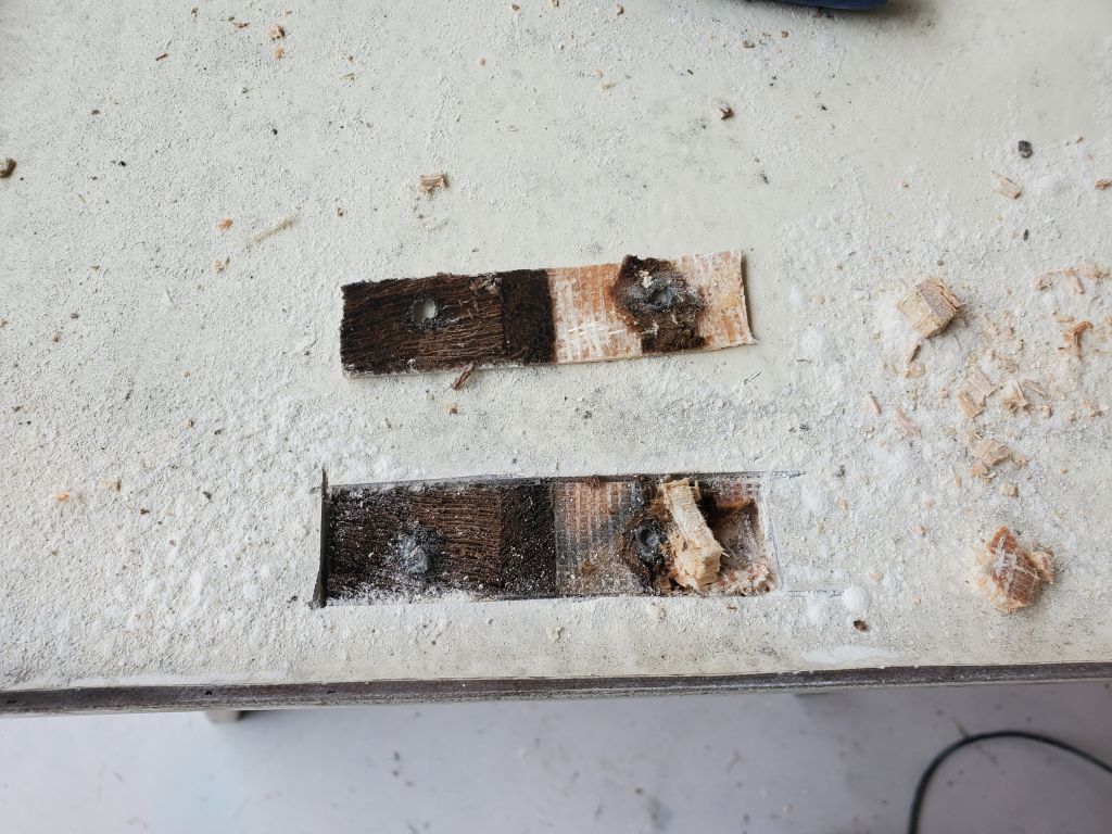
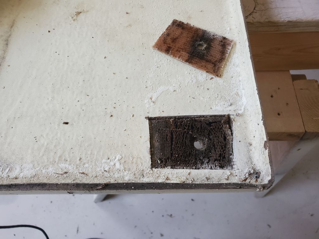
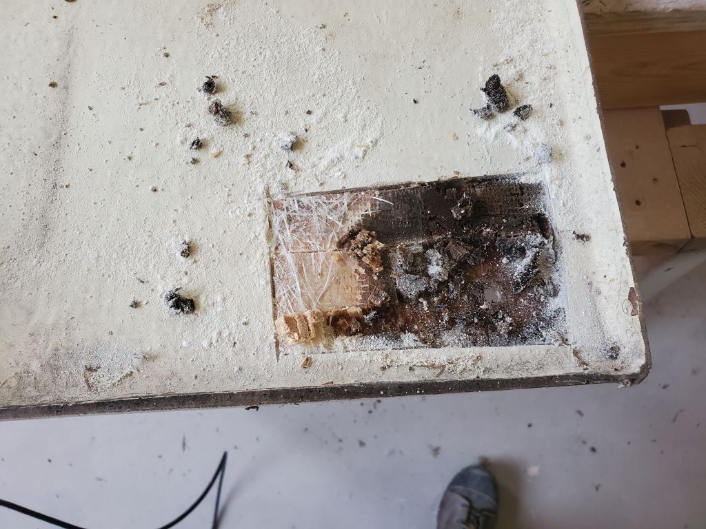
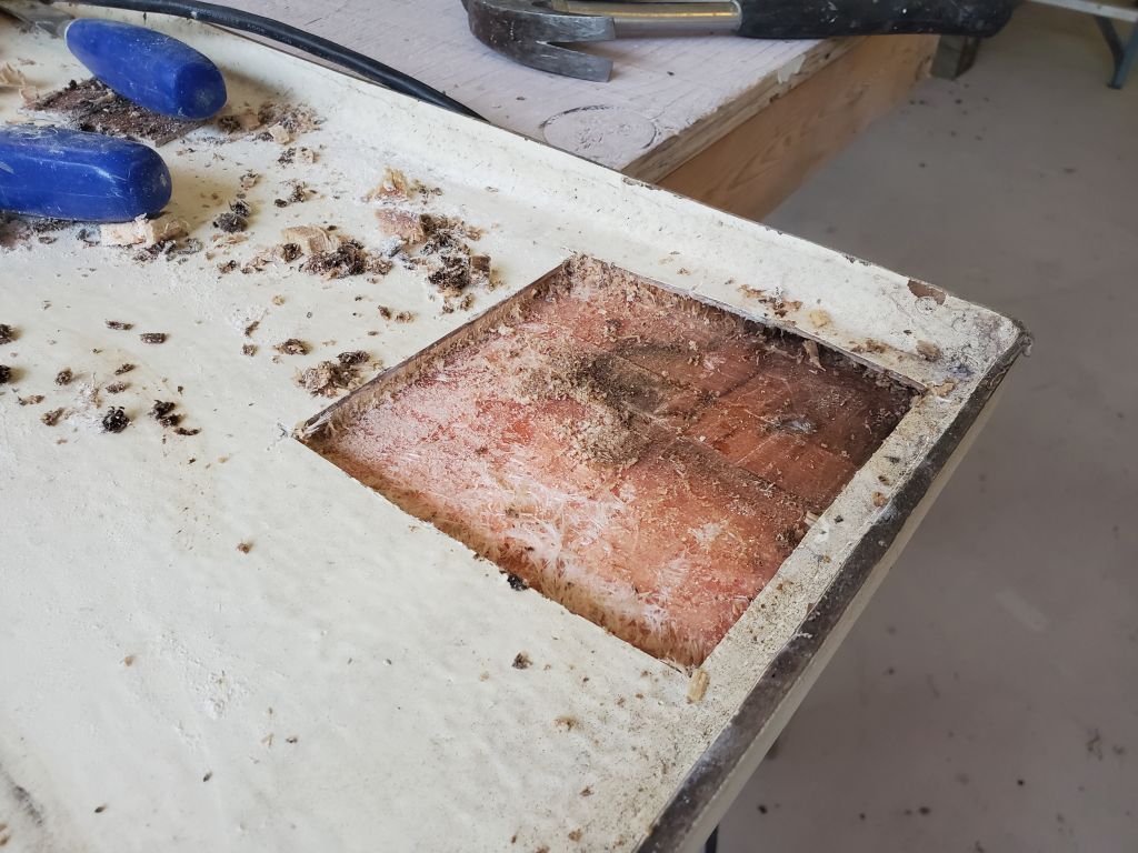
At initial inspection the fuel tank hatch seemed generally in good condition, but some careful exploratory inspection revealed evidence of water intrusion through the screw holes along the edges–both the fixing holes, as well as screw holes from the deck seating (previously removed).  But my sense was the overall structure was sound, so after setting up some benches I began by opening the bottom skin around a randomly-chosen screw hole, using an oscillating cutting tool.  I found an isolated pocket of damaged balsa core around the fastener hole, but it quickly became dry and sound, so it seemed wholesale core rebuilding would be unnecessary.  Continuing in this way, I opened all the screw locations on one side of the hatch, finding varying levels of core damage immediately at the holes and expanding the openings as needed in each case to expose only clean, dry, well-bonded core at the edges.

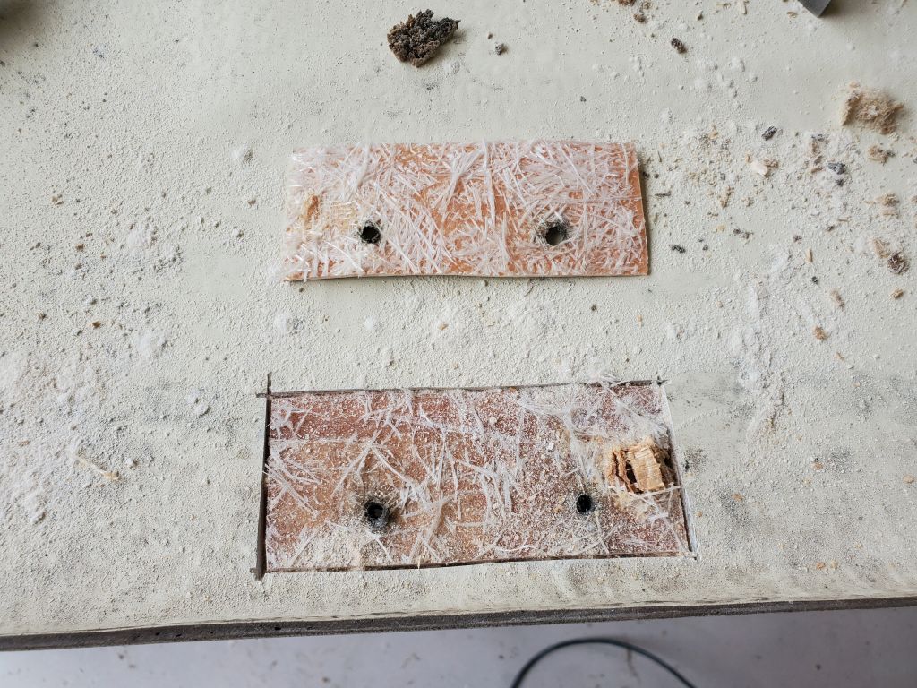
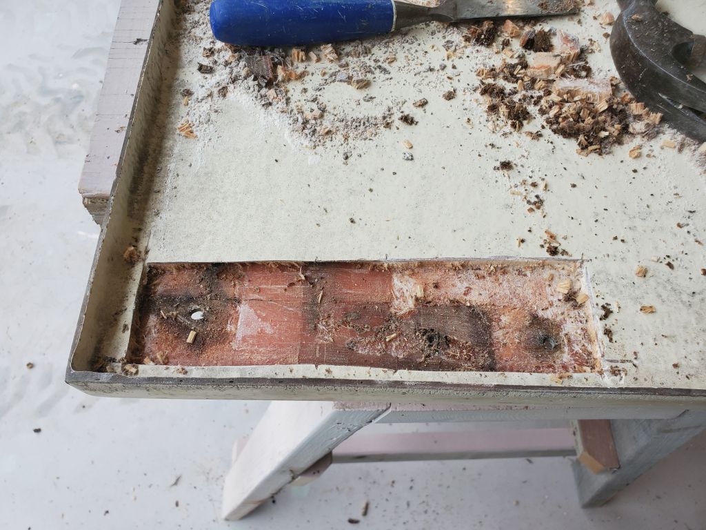
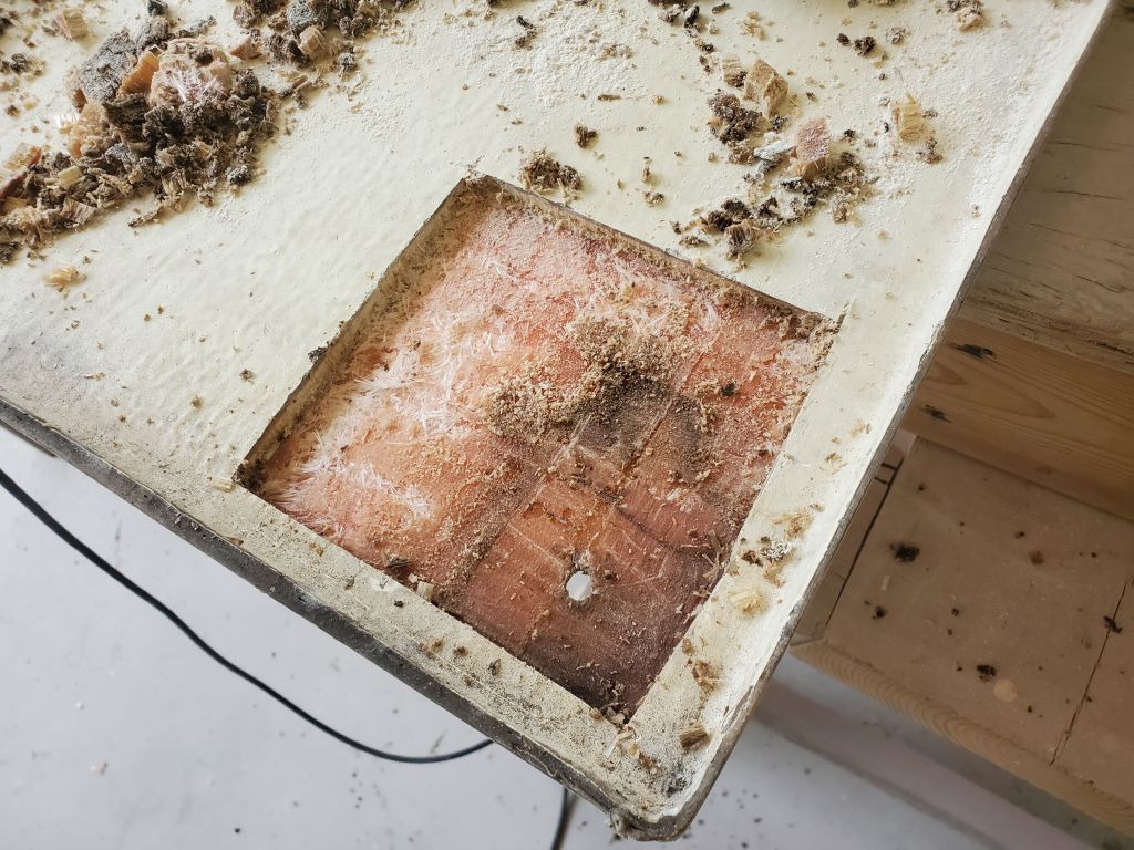
This brought me to the end of the day.  Next time, I’d continue on the other side of the hatch, then begin repairs, for which I planned to install solid fiberglass at each of the openings, filling them to the level of the existing skin.  This would not only replace the damaged core, but also prevent further water issues once the piece was reinstalled.

Holby 27

The next stage of the modifications to the transom involved the open deck area, leftover from the original jet drive engine installation.  To finish off the structural repairs, I needed to build a new deck to enclose the bilge, and create the usual splash well forward of the outboard cutout.

The owner and I previously discussed modifying the original engine box cover to work as the forward end of the splash well, mainly because it was already a reasonable fit, and handled the various different shapes of the cutout with minimal need for additional modification.  To begin, I removed the sound insulation from the inside of the cover, to lighten the piece and prepare it for cutting.  The insulation was glued in place with an adhesive flexible sealant and came off relatively easily, though there’d be substantial surface prep required on the inside surfaces later.

I set the hatch in its proper position in the boat.  The angled portion of the forward side seemed the appropriate place to use as a finished height for the modified piece for several reasons, from cosmetic to the fact that, at about 12-1/2″ up from the deck, it just happened to be a good height to begin with.  Using various tools I struck this line around the sides of the hatch , eventually intersecting with the molded seats/storage areas on either side.  My first line turned out to be in the wrong place, so I struck it out.

Happy with the initial line, I brought the cover to the bench and used tape to mask off the line for greater visibility.  Then, I struck a new line 1/4″ above, using a scrap of plywood as a guide, and masked to the new line; this would be the cut line, a bit above the hoped-for line, to allow me room for adjustments later after the test fit and proof of concept.  Happy with the line from a visual perspective, I made the initial cut with a jigsaw, removing the top of the old engine box.

I test-fit the modified bulkhead in the boat and made a couple measurements of the inside width and distance from the transom to confirm the owner’s choice of outboard would fit when tilted up.  My eventual plan was to secure this piece in place with epoxy and fiberglass from the inside, incorporating it with the new splashwell deck.  For now, the test-fit was complete and I set the assembly aside.

The splashwell deck had one known reference point along the forward edge of the engine room cutout, which was the aft edge of the main deck in way of the livewell locker opening.  From here, the deck should pitch aft to drain water naturally out the transom, where eventually I’d install a pair of small scuppers, one per side.    To determine the aft end position, I used a stiff straightedge held tightly against the plane of the main deck forward of the cutout, and extended it aft to the transom to make a couple reference marks.  From the initial marks, I adjusted them downwards to allow for the depth of the forward edge below the main deck, plus an additional distance for drainage, or roughly an inch total.

After I’d made these initial marks and begun some additional layout, I realized they weren’t correct, and made some new reference marks, beneath which I temporarily hot-glued a scrapwood cleat at the aft end.  At the forward end, I hot-glued another small cleat beneath the exposed deck edge.  These formed the two key points to determine the new deck’s plane fore and aft; it should be pitched roughly 3/4″ down towards the transom.

Now I needed to transfer that plane to the sides of the compartment so I could install additional temporary cleats.  I installed three longitudinal strips of plywood, on edge for stiffness, to span the space between the forward and after cleats, then used another piece of the plywood held tightly against the bottoms of those cleats to make several reference marks on each side of the compartment, to which I could hot glue additional cleats.

With the new deck plane defined on all four sides, I created a template of thin strips of plywood hot-glued together in the required shape of the perimeter.  I’d use this template to cut the custom fiberglass deck to shape once I built it.  With the template complete, I checked the position at the aft end with my straightedge once more, with the straightedge held tightly to the plane of the main deck.  The aft end was appropriately lower than the forward end when I measured both.

I struck a mark to show the waterline (or at least the top of the antifouling, good enough for this) on the exterior of the transom so I could check that the new deck inside would still be above the waterline for the small drains; they would be roughly 1″ above the waterline as defined by the top of the antifouling (itself a bit above the waterline).

To use up what remained of the day, I cut several pieces of 1708 biax somewhat larger than the template, and prepared a flat molding table to build the new deck.  I’d continue this process next time.

Holby 26

Another round of sanding brought the large bottom patch tantalizingly close to its final shape, with only a few small voids requiring more attention, as well as some additional work needed at the transition to the transom.

The transom portion of the patch grew closer as well, though some fine-tuning remained, particularly at the lower edge,  The adjacent work on the transom, including smaller patches and hole-filling, would continue to be refined as I moved ahead with additional rounds of fairing compound on the transom cutout and environs.

Holby 25

I spent the first part of the day sanding the fairing on the bottom and transom, and the new fiberglass on the transom cutout.

On the transom, once I’d sanded the various holes I’d epoxy-filled earlier, I prepared small fiberglass pieces to fit each spot and installed them in epoxy resin, leaving this to cure for a bit before proceeding with fairing compound over the various areas on the transom, including the patch over the jet tunnel and the beginnings of the fairing for the new tabbing all around the transom cutout and related areas inside the boat.

The work on the bottom was close to where it needed to be, but there were low spots running fore and aft on both sides, between the centerline and the outer edges of the repair, so when I applied the next round of fairing compound, I focused on these areas to bring them into spec.  The forward portion of the repair needed only minor touchups at this point.


Holby 24

Sticking with the usual cycle, I began the day with more sanding, focusing on the bottom to clean up the new fiberglass there, then continuing with the transom fairing as needed, and the outboard cutout where I’d slightly filled the edge of the new top laminate.  I also used a grinder to open up several larger, abandoned holes in the transom (leftover from various through hulls and wiring clamps), and reamed out the small screw holes leftover from the wooden transom veneer, all to make these ready for the first stages of repair and filling.

After cleanup, I applied a round of fairing filler to the bottom.  The basic profile and shape was close to final, so the fairing was mainly to fill the weave of the cloth and burnish the edges of the laminate.

Continuing on the transom, I applied a second round of filler on the vertical part of the jet tunnel, then into the various screw and fixture holes about the rest of the transom.

Later, I patterned and cut layers of fiberglass to fit over and around the transom cutout, then installed the cut pieces in epoxy resin.

Holby 23

Continuing the work on the combined transom and bottom repair, I started the day with a round of sanding to prepare the fresh fiberglass on the transom portion of the jet tunnel for the next stages of work, as well as to sand and lightly shape the forward part of the bottom vee, forward of the jet tunnel where the boat had originally had the flat area to transition to the tunnel.

I sanded smooth and flush the extra layers of fiberglass I’d added to the new transom cutout to raise its height a bit, bringing it now to about 23-3/4″ from the center of the bottom vee; the final height was to be 24″, and the extra 1/4″ would be made up by the final tabbing to wrap over the cutout and tie it in with the surrounding surfaces.  Meanwhile, I also sanded smooth the first round of fairing filler I’d applied to portions of the transom on each side; there’d be more to come.

After cleaning up, I prepared a pattern of the remaining fiberglass patch required on the bottom, which would extend from the transom (where I’d set up the fiberglass with a series of 3″ steps between layers to allow for overlap) forward to a point just ahead of the area formerly known as the flat, and which new layers would extend out onto the hull several inches on each side to complete the tying in of the repair work with the existing hull.

Because I’d never be able to handle such large pieces overhead, I divided the fiberglass into two manageable sections:  The first extended from the new transom glasswork to a point 9″ forward of the old tunnel location; the second section finished off the laminate from there.  In each case, subsequent layers were staggered and overlapped by 3″.

After final preparations, I installed the six new pieces on the bottom, completing the major fiberglass laminates of this repair.

To complete the day, I applied a first round of epoxy fairing filler over the vertical part of the transom repair, filling the cloth weave and low areas, and filled a small void beneath the new fiberglass on the transom cutout, bringing it flush since the cut had been rounded over before I applied the new layers.

Holby 22

After a light sanding and other preparation at  the forward vee portion of the repair, I applied a second round of fairing filler to take care of t he low spots left by the first-round troweling.  These efforts were designed to recreate the basic shape of the previously-flat spot on the hull, and with the second round it appeared close to the final shape needed before I could fiberglass over the whole area.

I had some fairing compound leftover, so I applied it to portions of the transom that were damaged during the wood veneer removal.

At the transom, I’d hoped to laminate three layers of cloth over the entire vertical transom repair, and overlapped 9″ onto the bottom, which would allow me to offset the three layers by 3″ each to provide overlapping room for the fiberglass to continue forward over the remainder of the bottom repair.  However, I simply couldn’t make the cloth take the required shape, what with the V-shape, not without huge and unwanted darts and cutouts in the cloth, so I changed my plan to one that would work.  I kept the 9″ overlap on the bottom (with the subsequent two layers spaced 3″ back in each case), but reduced how far up the vertical transom they came, with the largest layer extending 3″ up, and the remaining two staggered 1″ down.  I could make the cloth conform to this shape.

Above this, I installed three layers over the vertical part of the repair, butting the first layer against the upturned bottom layers, then overlapping the subsequent two layers appropriately over their staggered counterparts below.  I finished off the transom fiberglass for now with two smaller layers that filled the slight depression over the vertical part of the old jet tunnel, bringing this area nearly flush with the surrounds.  I let these layers hang just below the bottom for later trimming.

To round out work for the day, I installed six layers of 1708 over the top edge of the transom cutout, which would increase the height a bit to bring it closer to the required 24″ from the bottom of the vee when all was said and done.  Later I’d wrap more fiberglass over the entire cutout, which would bring the height up to the final dimension as well as tie it in the new cutout and complete the work there.  I let the strips of fiberglass overhang the opening a bit for later trimming, and used some thickened epoxy at the ends to reform the curved shape at each lower corner.


Holby 21

Before heading off to a morning appointment, I sanded all the new work from last time, starting with the forward vee.

At the transom, I sanded as needed to bring the new layers of overhanging fiberglass flush, and to prepare the new core and environs for future steps.

Inside the boat, I lightly sanded the new glasswork on the inside of the transom.

Later, upon my return, I applied a coat of fairing filler to the forward vee, using an improvised 24″ long batten to span between the ‘known” hull shape at the forward and after ends of the space previously known as the flat.  The many layers of fiberglass I’d applied had mostly filled the space, but now I could use fairing compound to finalize the shape before laminating over top.  This early round of filler was slightly rough because of the imperfect batten, but did its job of defining the shape well enough that the next round of filler would come close to establishing the shape required before fiberglassing.

Preparing for eventual fiberglassing at the transom and over the bottom of the tunnel patch, I started with a pattern of the vertical transom and onto the bottom going forward 9″.  I’d eventually stagger three layers of fiberglass over this area, conjoined with three adjoining and subsequently overlapping layers over the remaining part of the bottom patch.

Holby 20

I lightly sanded the new fiberglass on the forward vee part of the bottom, then, after cleaning, used a straightedge to check how I was doing, height-wise.  Obviously I knew it was low at the aft end, but this gave me an indication where the additional layers should stop at the forward end; I also used the straightedge to determine how wide the new layers should be at the aft end, i.e. where the existing fiberglass was already close to the proper geometry.

With this information, I made a new pattern and cut seven new layers, this time keeping the aft ends’ widths more constant while continuing to taper back the forward sides and end.  Because the new layers would overlap the stacked, tapered layers beneath, I skim-coated some thickened epoxy over the existing patch just to ease the transitions between the cured layers.

Afterwards I wet out and installed the seven new layers, which brought the finished rough shape close to what I needed, and just low enough that I could finalize the shape with fairing compound once cured and before fiberglassing over the whole area.

Meanwhile, I made a pattern of the inside of the transom for layers of fiberglass that would cover the entire transom and extend onto the bottom of the hull and along the sides to tie everything together.  Once I had the pattern made, I installed epoxy fillets as needed around some of the corners and wet out the whole area, leaving this to tack up while I cut two layers of fiberglass according to the pattern; then I wet out and installed them.

Continuing the work on the vertical part of the jet tunnel in the transom, I cut 10 layers of fiberglass to fit, as I still had an inch and a half or so of depth to fill.  I prepared epoxy fillets along the bottom corners to ease the transition beneath the core pieces I’d installed earlier, then, in stages, installed the 10 layers of fiberglass in the space.

Later in the day, this had cured enough that I could install another layer of 3/4″ Corecell over the fresh laminate, bringing the area out nearly flush with the surrounding fiberglass.  I installed a couple braces to hold the core tightly along the bottom, where it wanted to spring out slightly.   From here, once cured, I could start installing the fiberglass over the whole area that would finish off the repair and tie it in with adjacent structures.

Holby 19

Another (unintentionally) short day, as I got sidetracked with unrelated things.  But I started hopefully with the flat area forward of the old jet tunnel, creating a pattern of the area on some plastic, then cutting eight layers of fiberglass, tapered at the sides and forward end, to fit the space. Each subsequent layer was roughly 1/2″ smaller on each side, except the aft side.  The height required at the aft end was just about one inch, and eight layers would be roughly half that, so I thought I’d install these and see about adding more as needed.

Preparing the pieces for installation reminded me of a Coneheads reunion.  After wetting out the layers, I installed them, four at a time, in the space forward of the patch.  It turned out that I should have tapered the aft ends less than the forward end, as the layers got too narrow too quickly and the stack didn’t adequately fill the space from side to side as much as I’d hoped, so for the moment this stalled my plan to add more layers today; I decided it would be better to let this cure, lightly sand, then figure out the final stack of layers required to fill the space enough at the aft end, without adding too much at the forward end or elsewhere.

I’d planned to do more fiberglassing on other parts of the stern throughout the day, mainly the inside and outside of the transom, but somehow, and without intention, the day was lost from here on other, unrelated tasks.

Older posts Newer posts