(page 12 of 13)

Calliope Girl 17

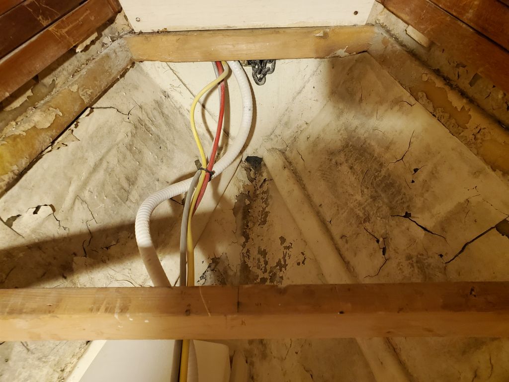
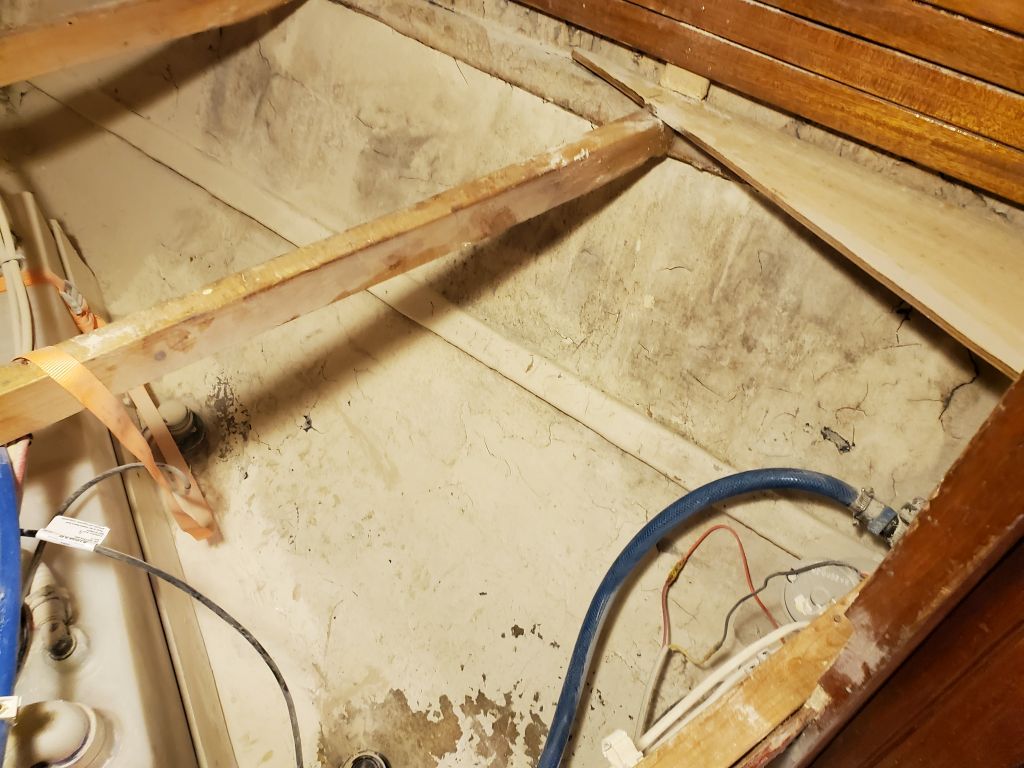
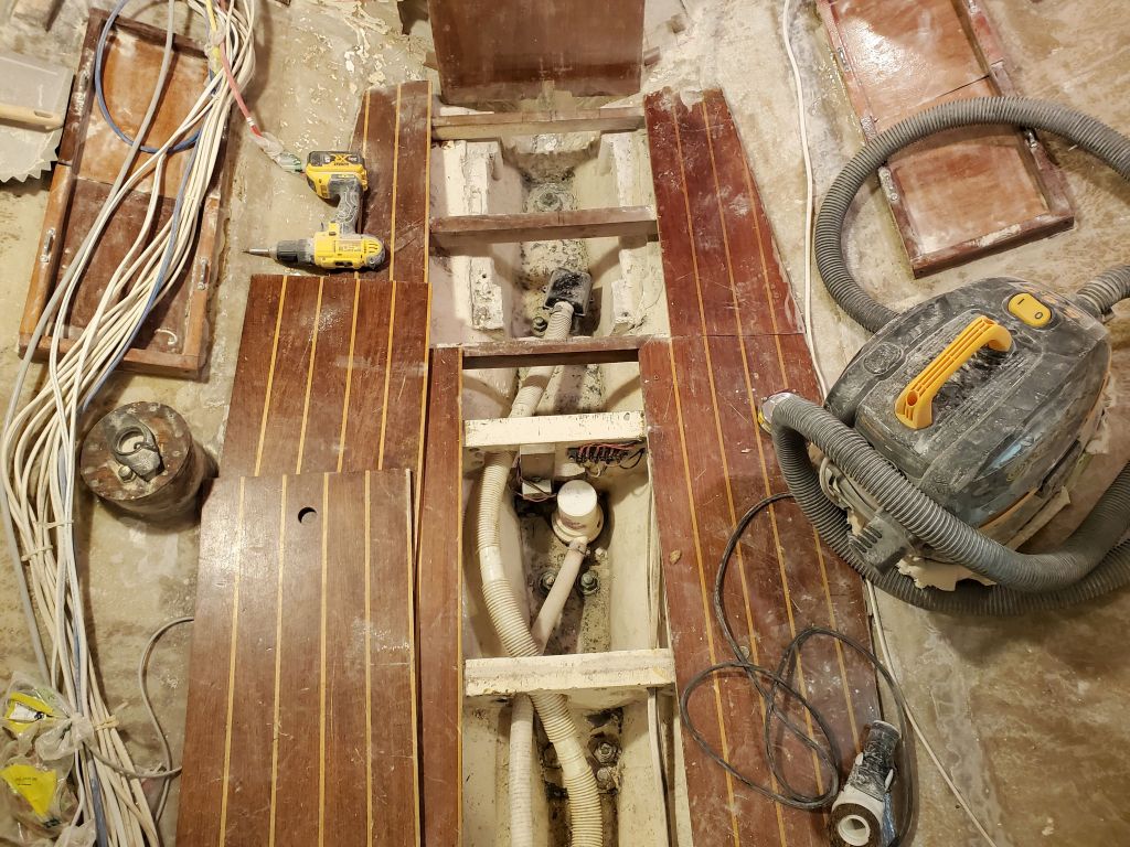
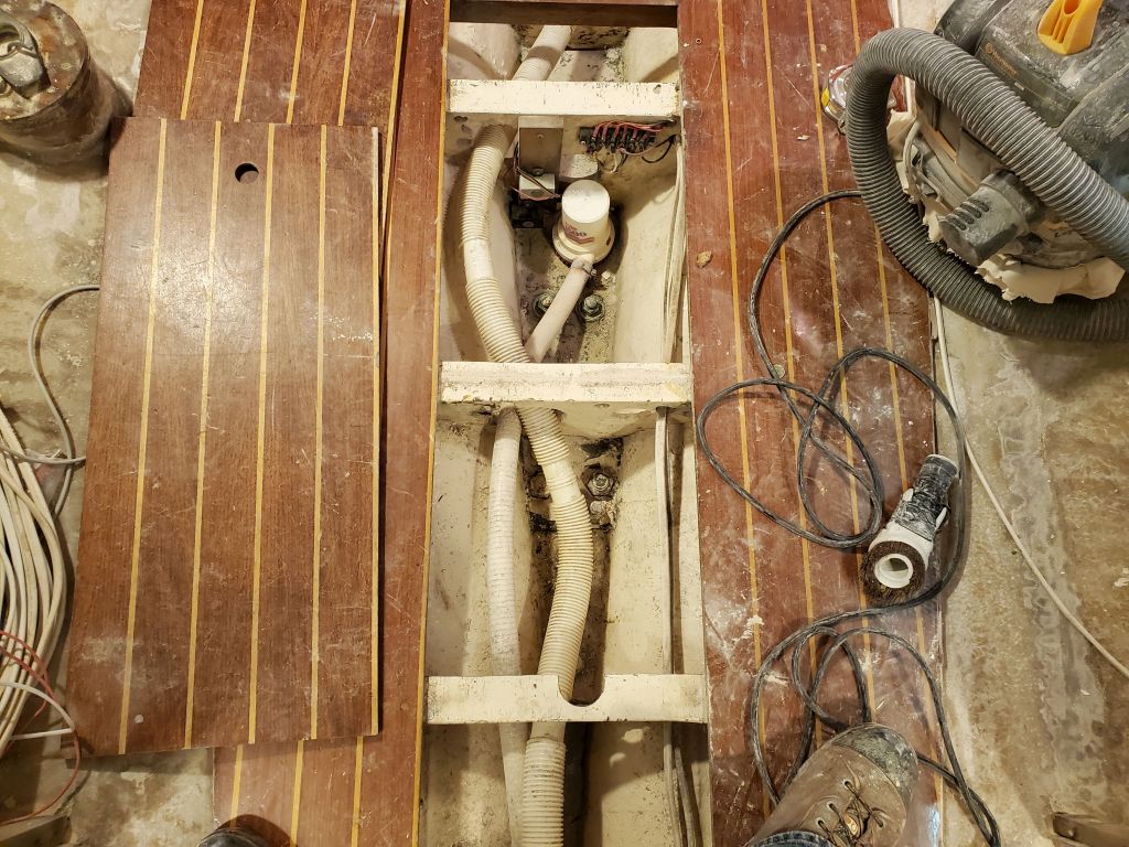
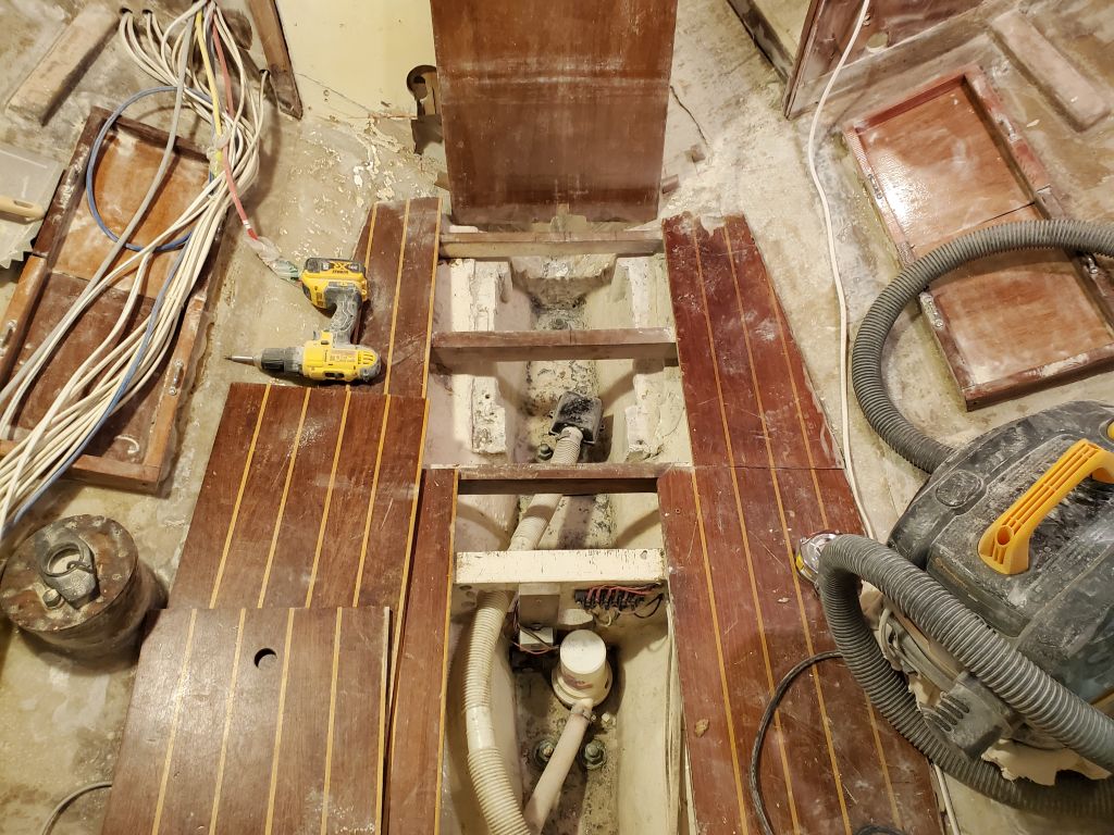
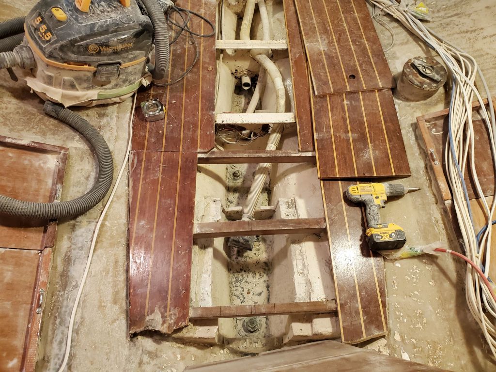
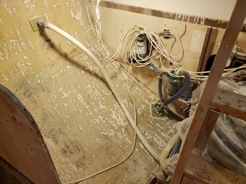
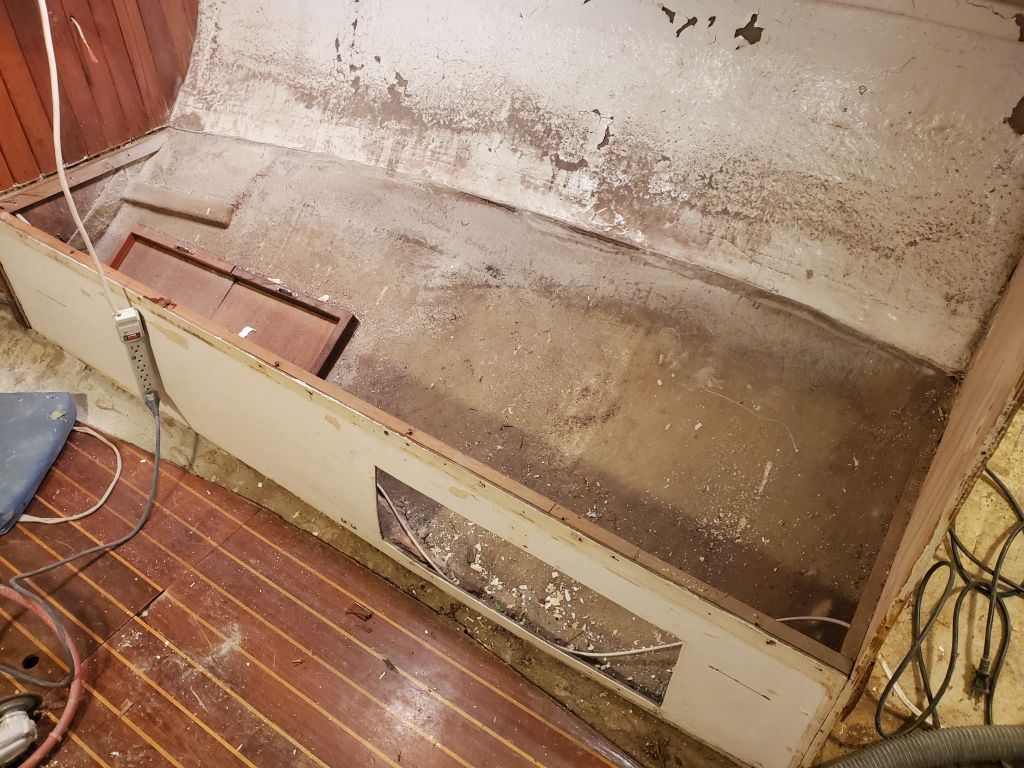
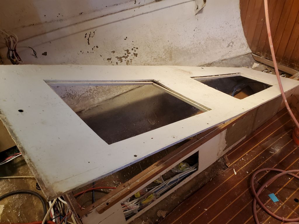
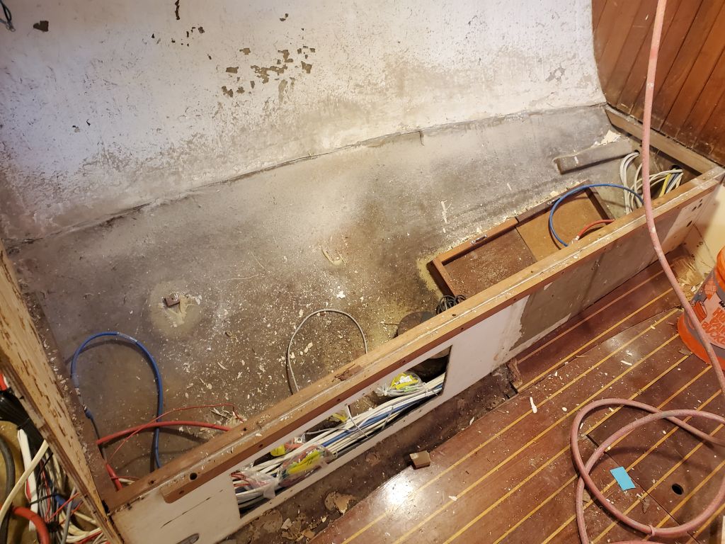
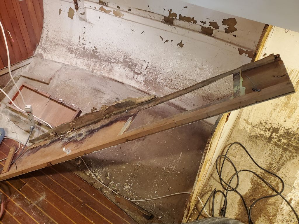
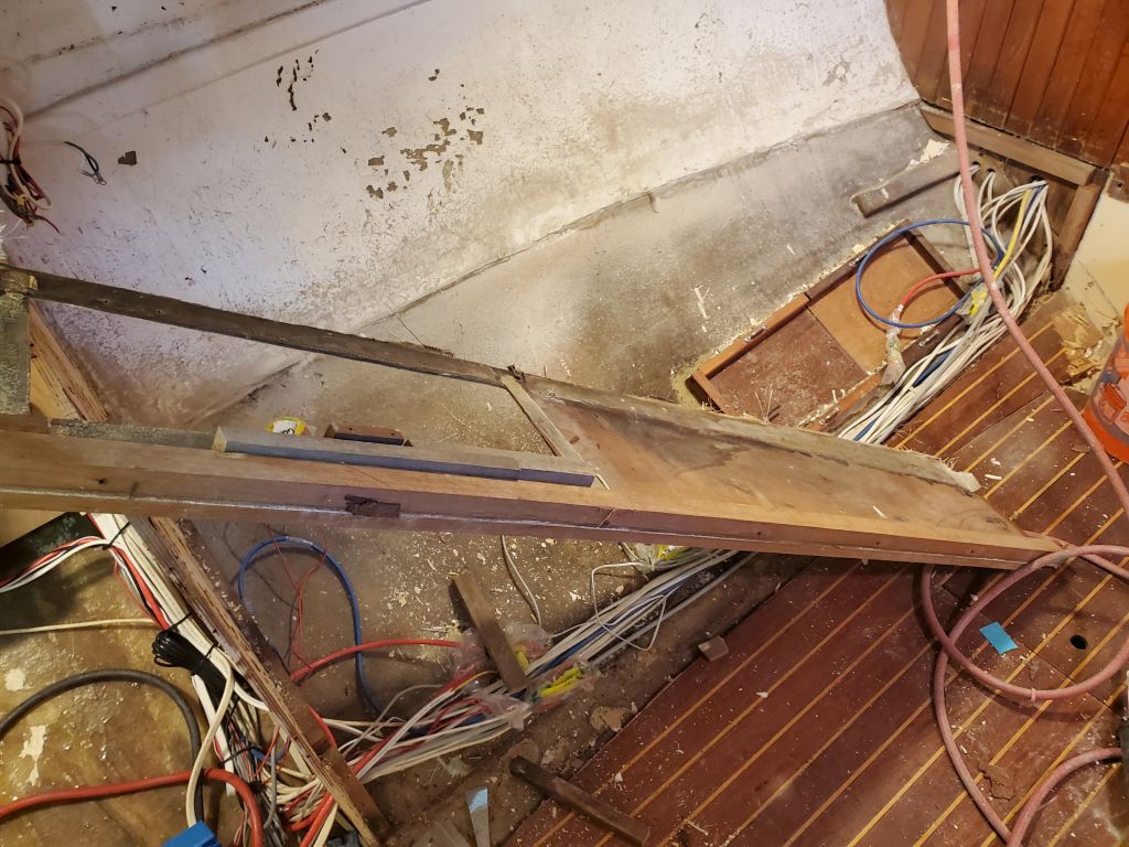
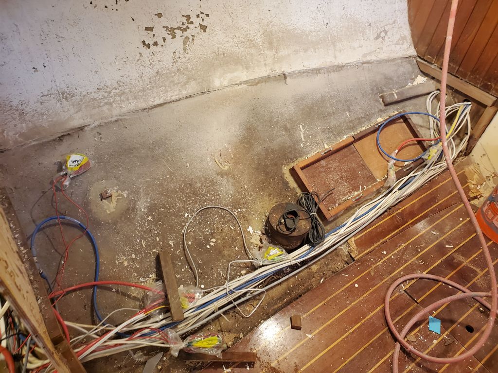
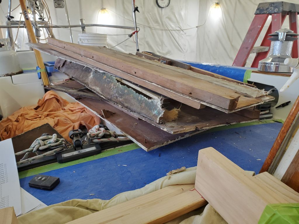
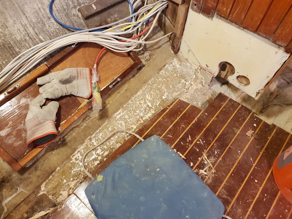
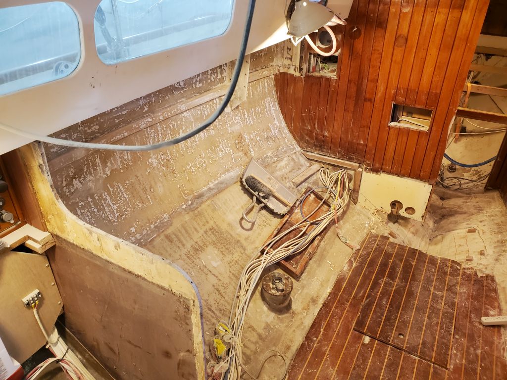
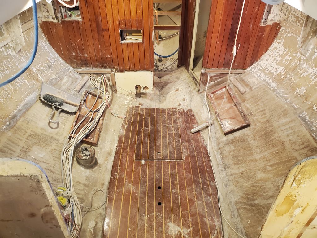
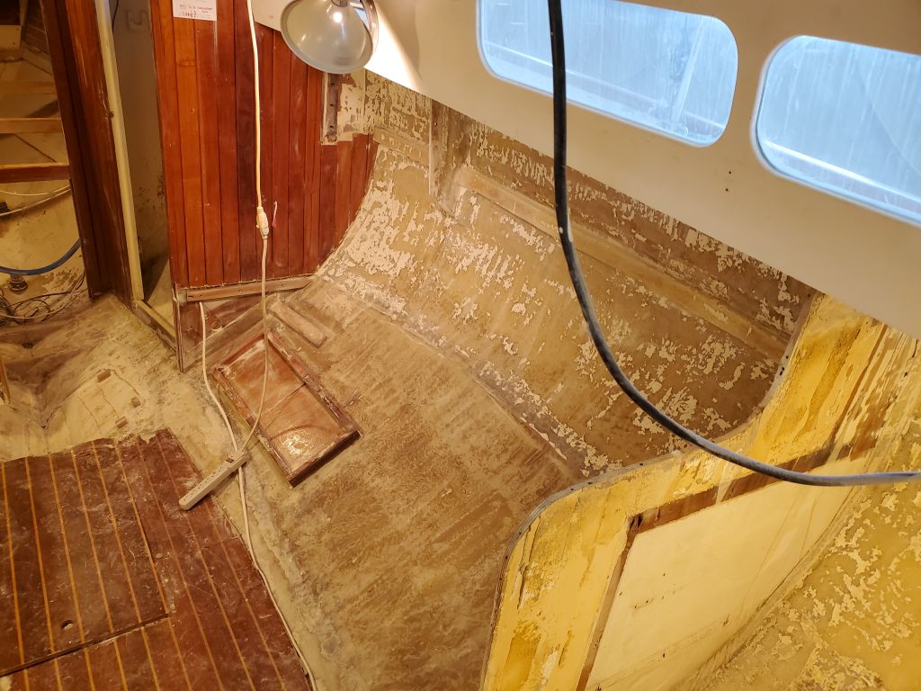
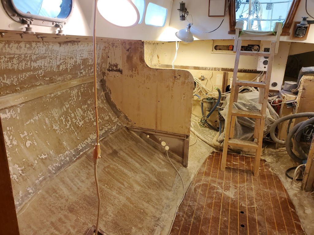
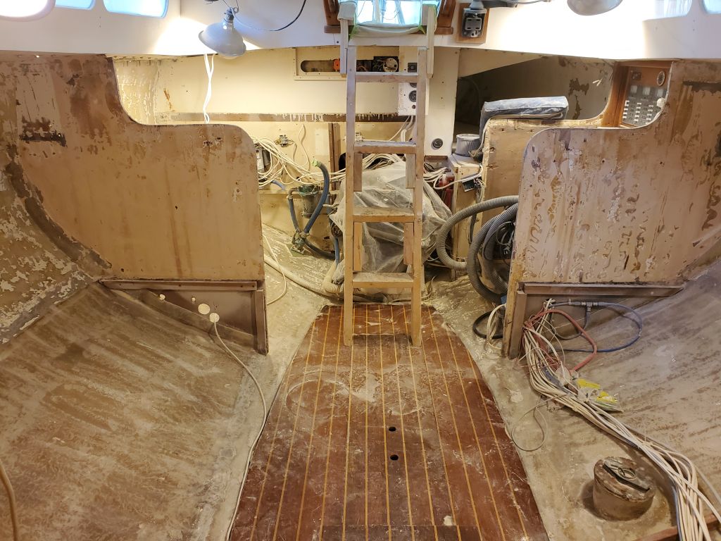
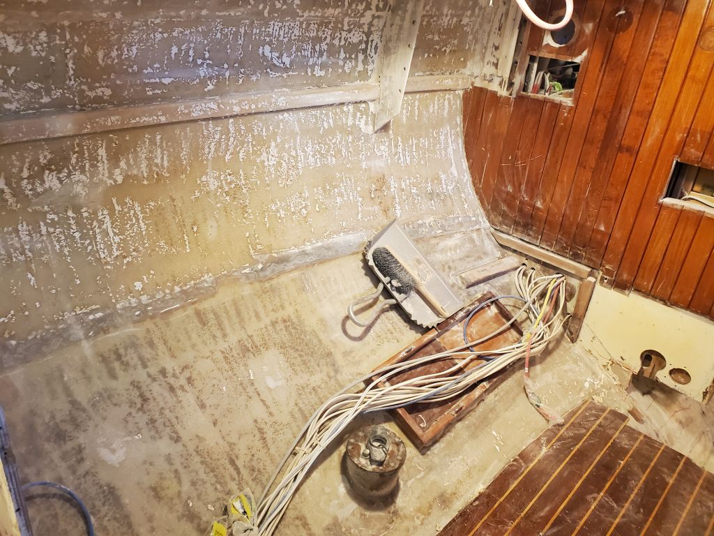
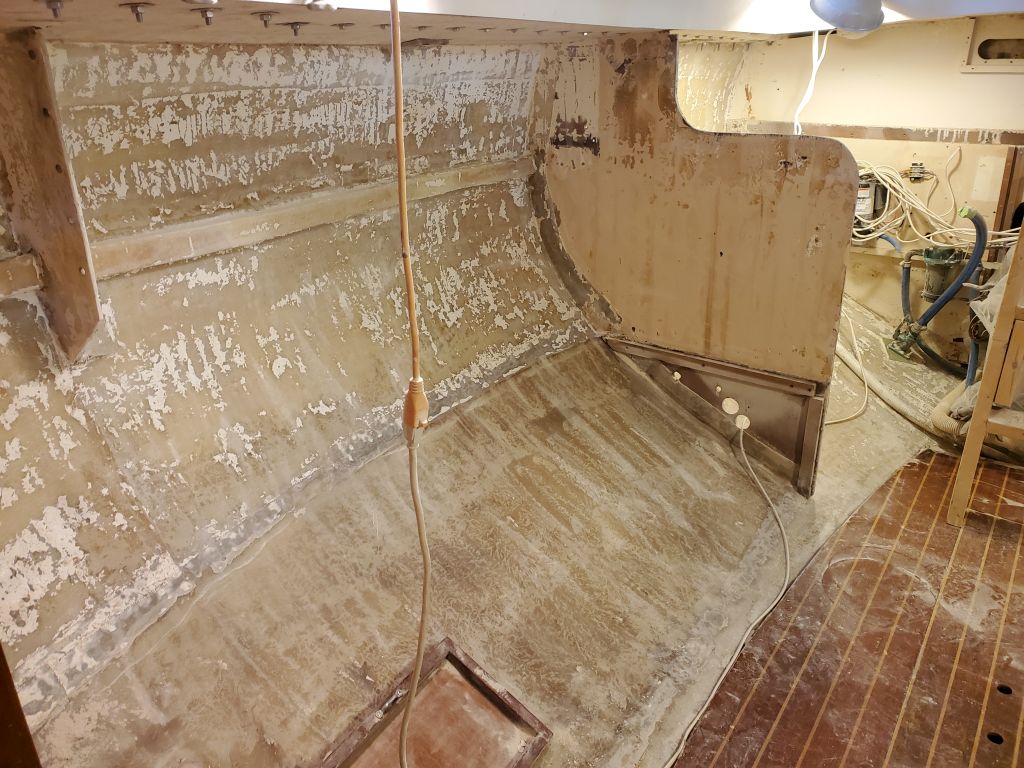
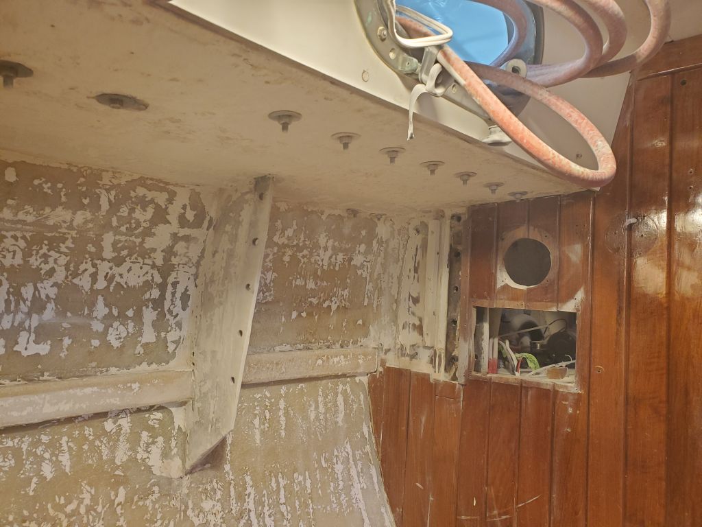
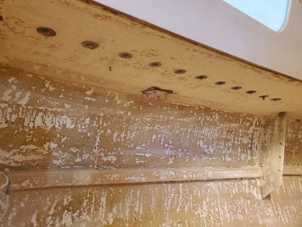
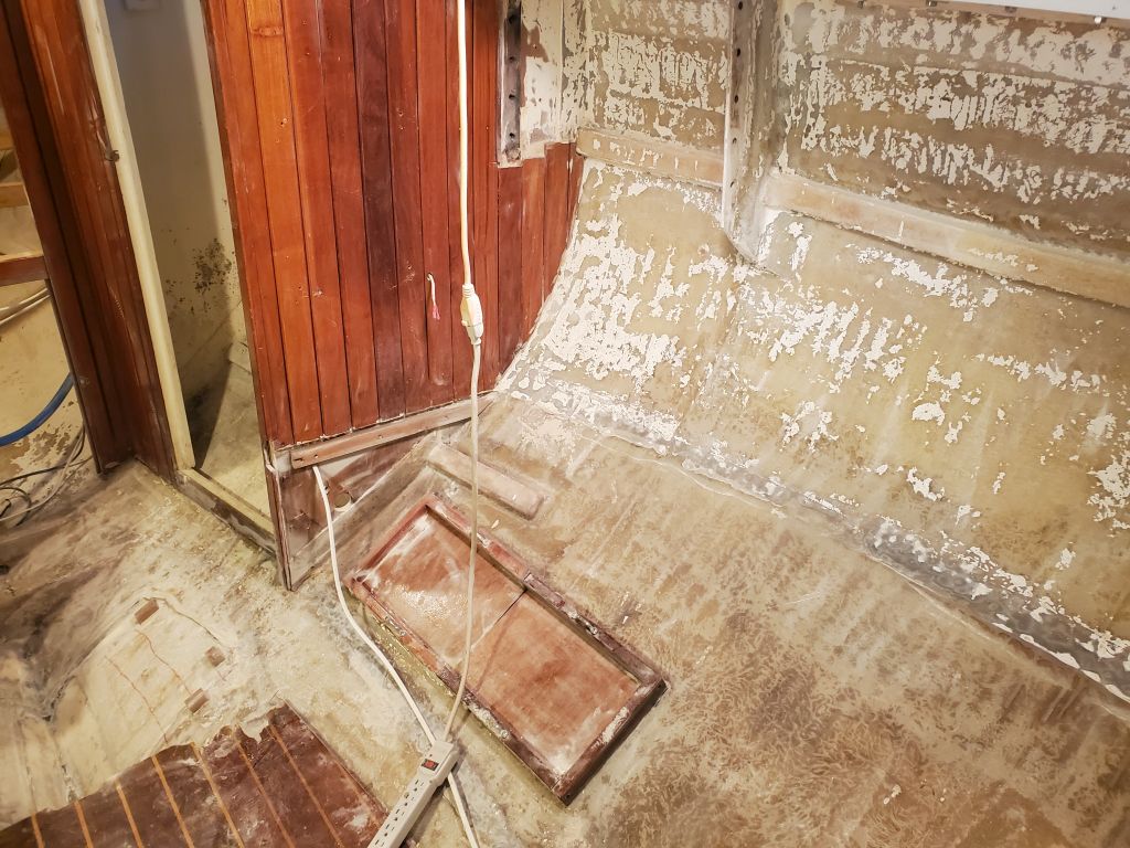
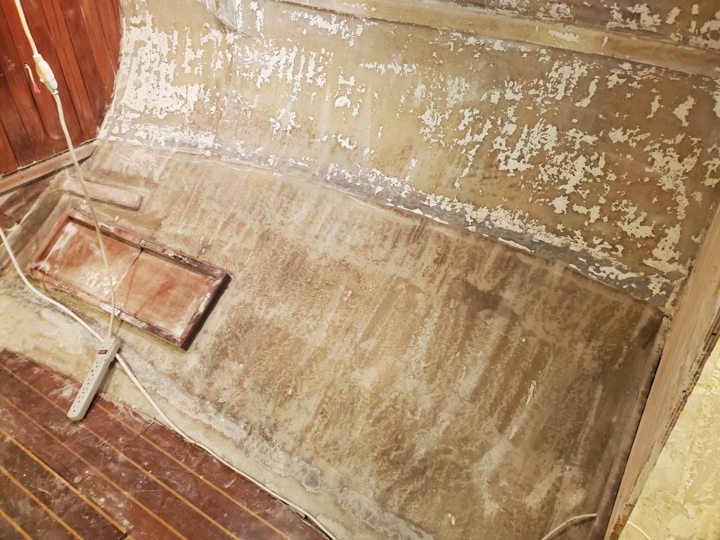
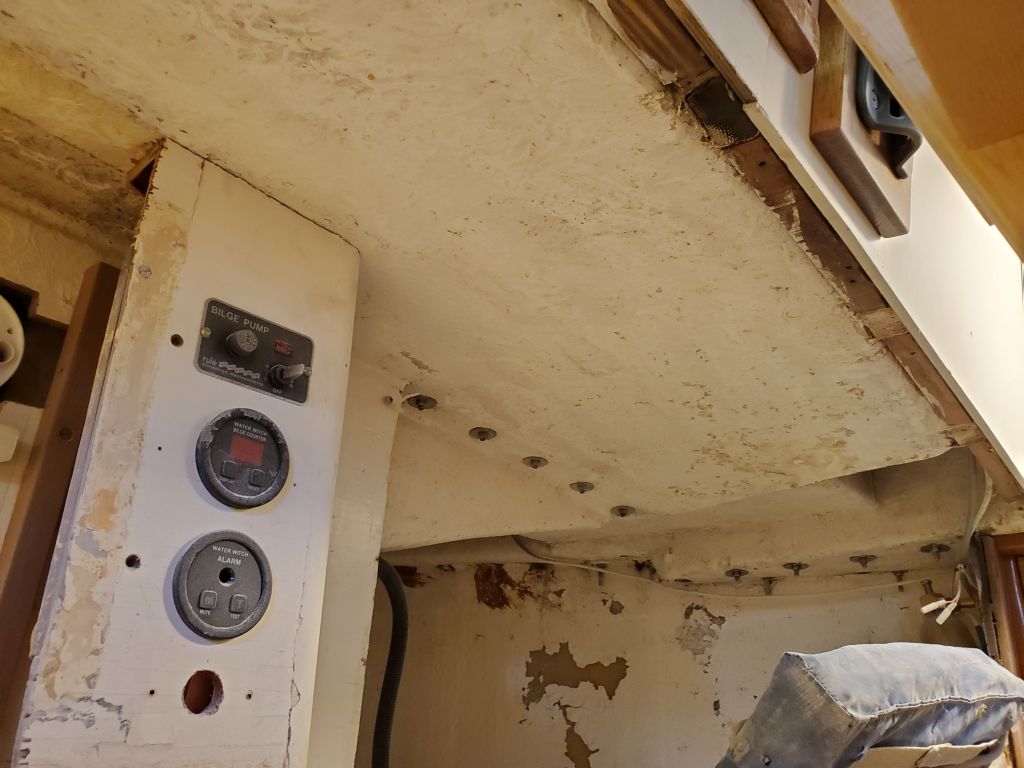
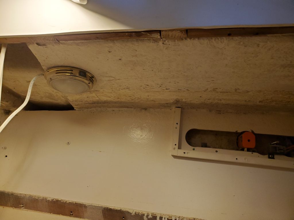
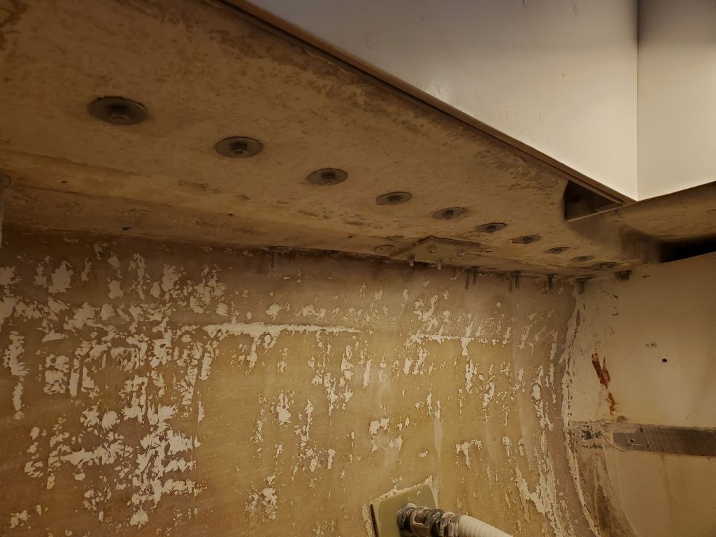
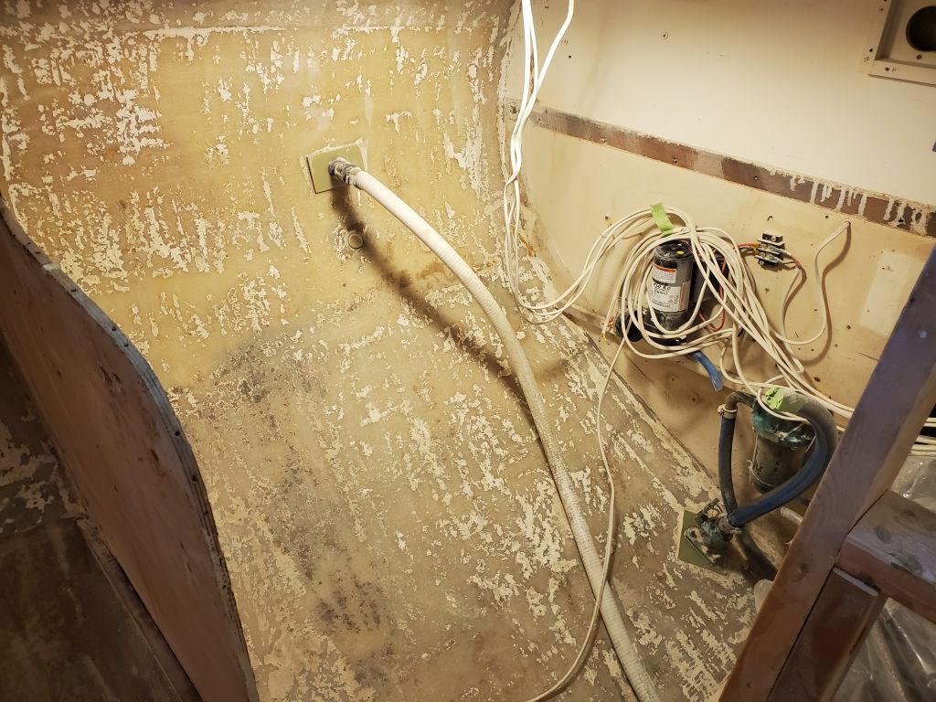
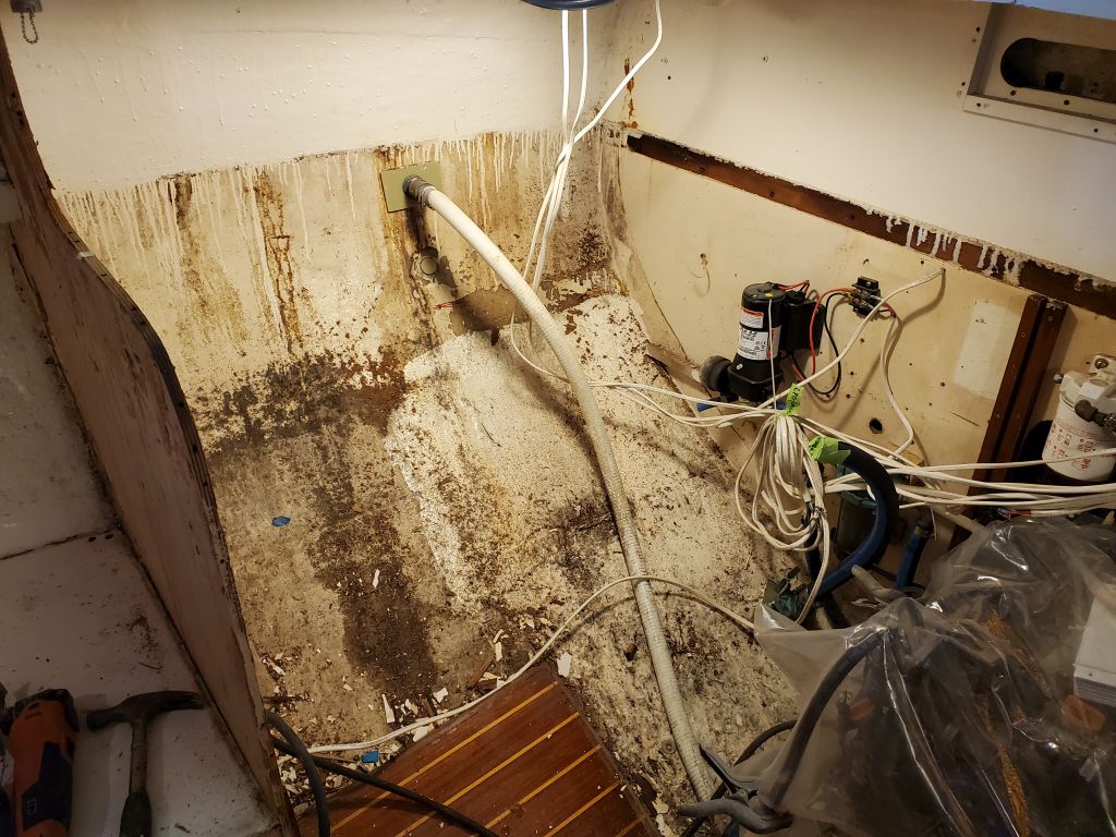
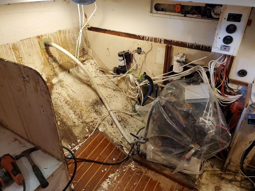
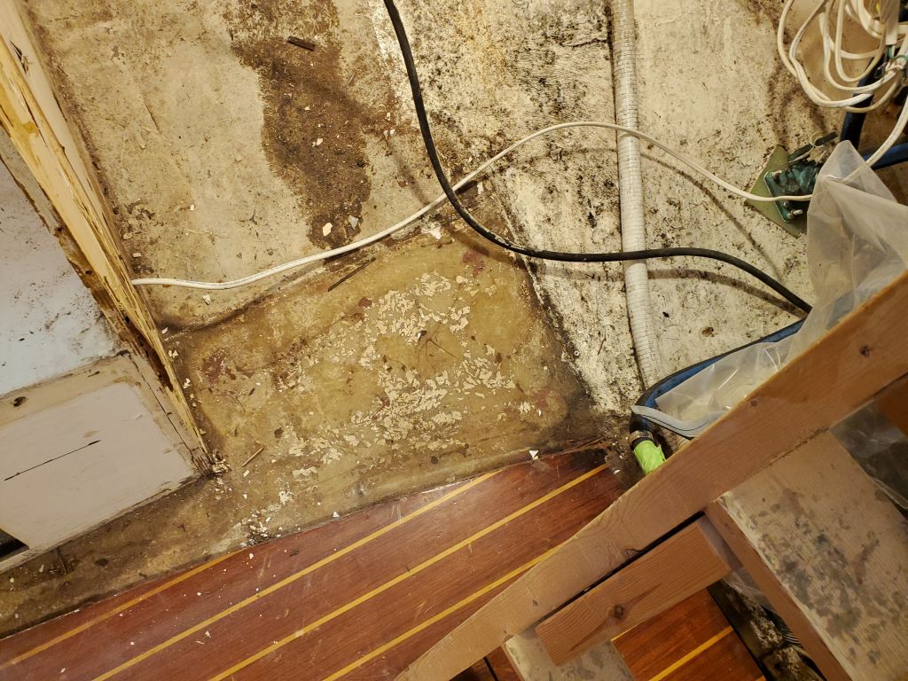
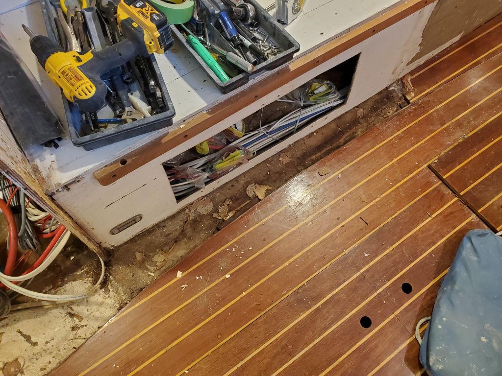
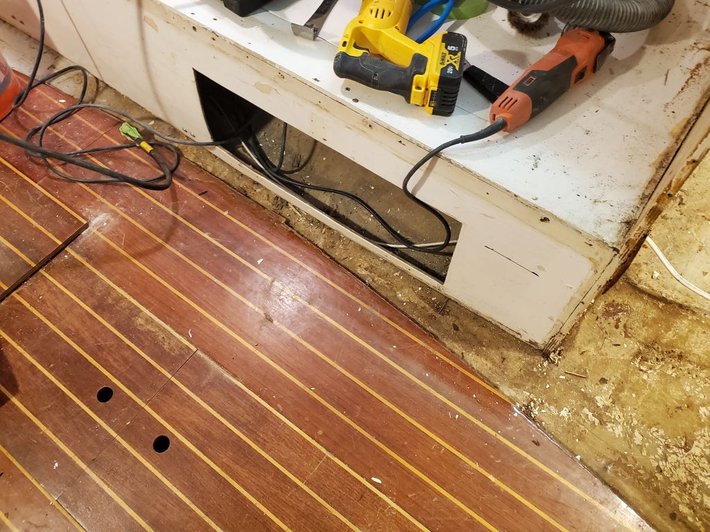
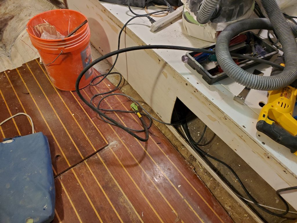
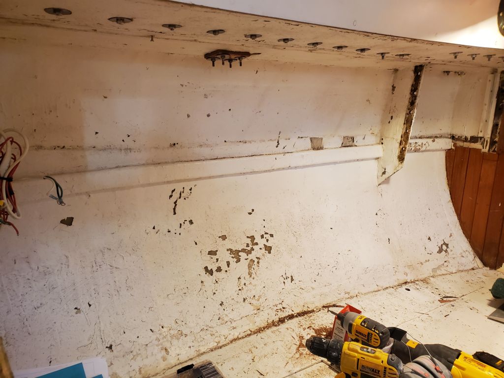
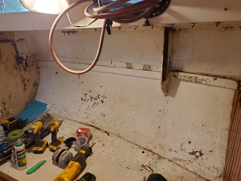
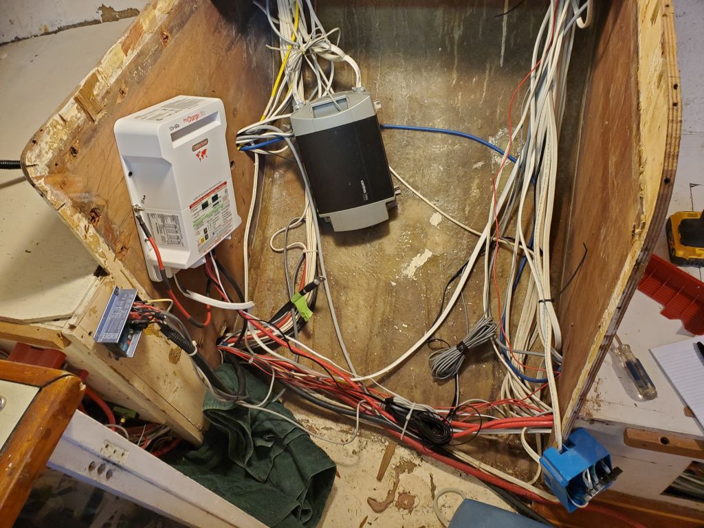
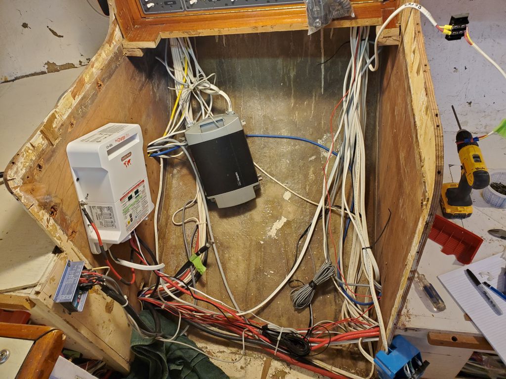
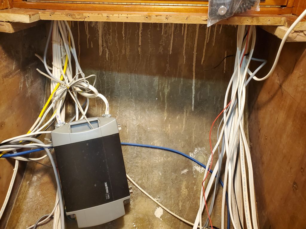
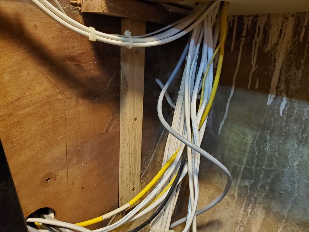
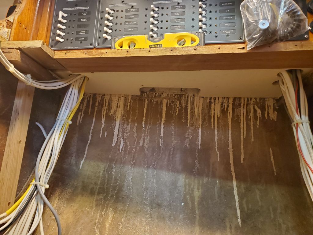
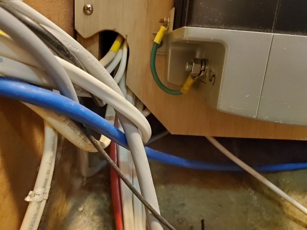
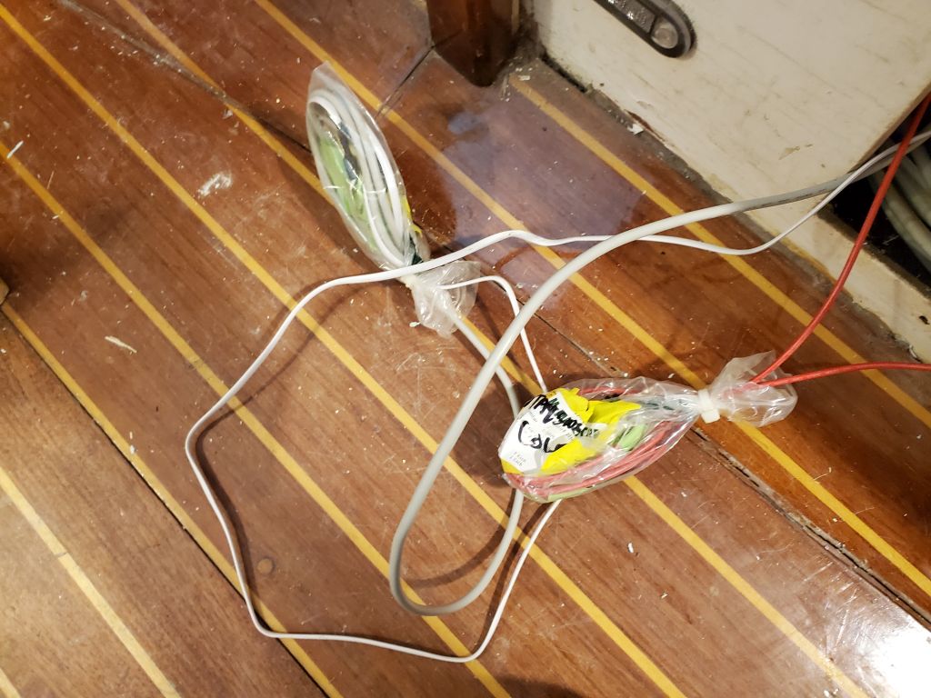
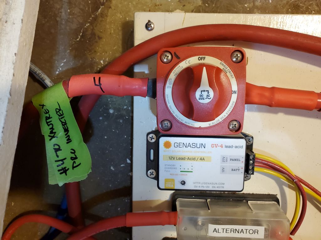
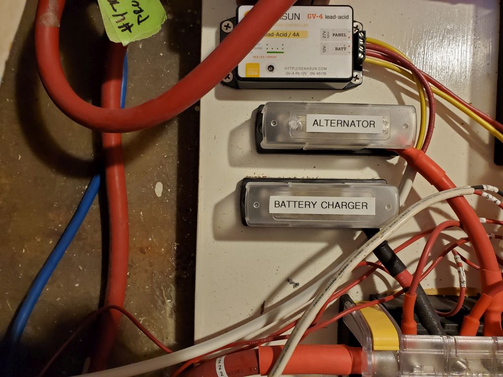
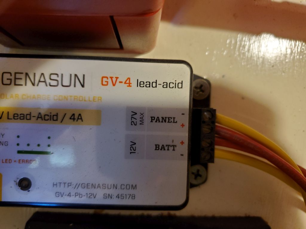
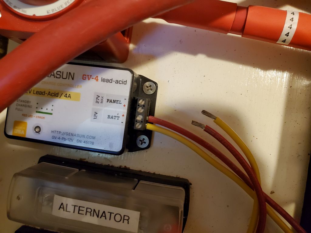
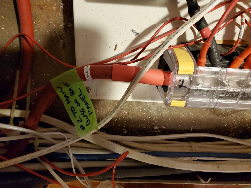
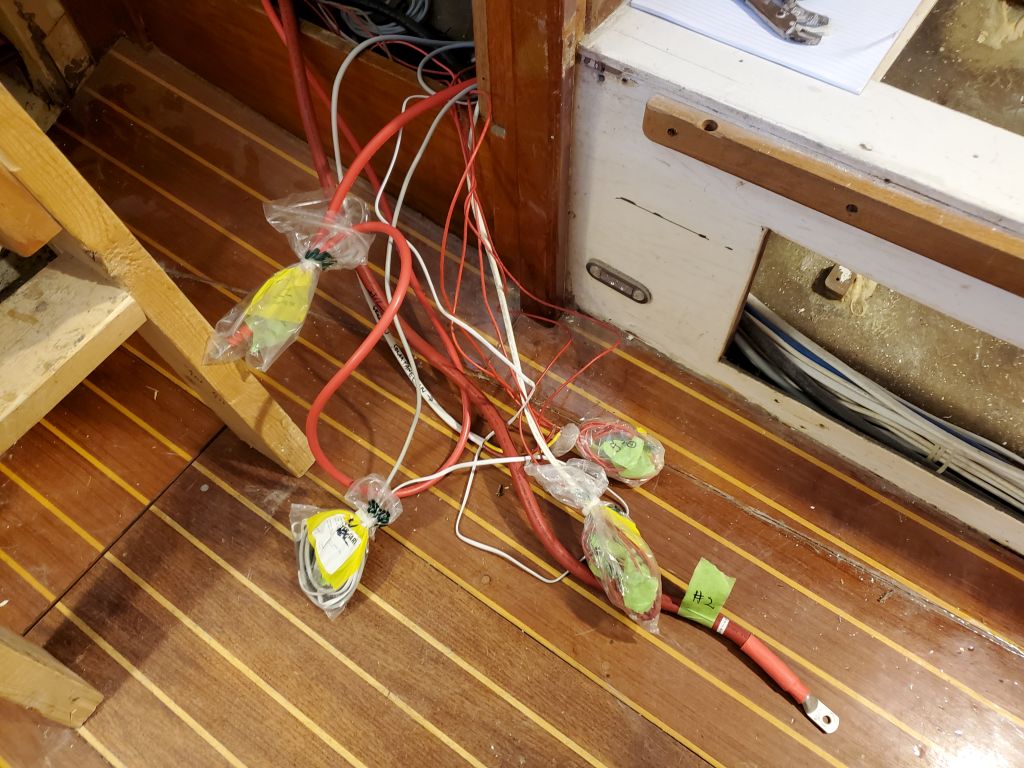
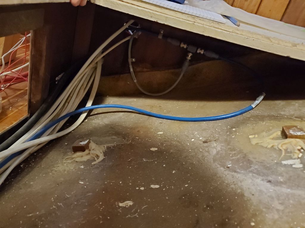
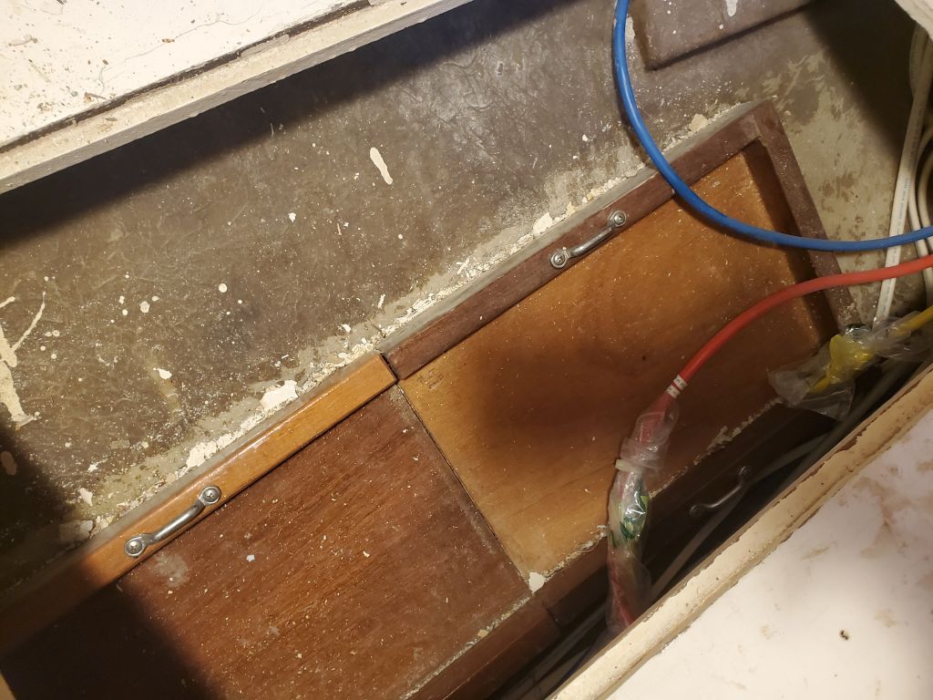
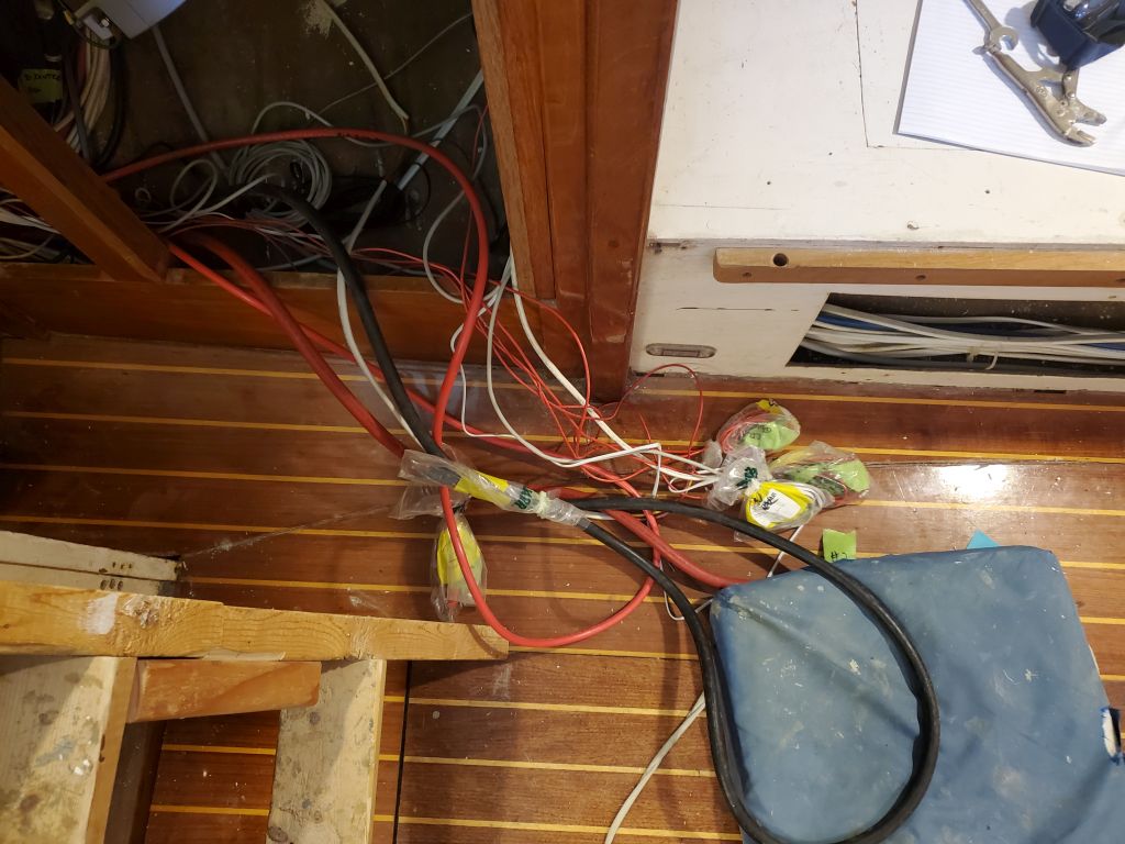
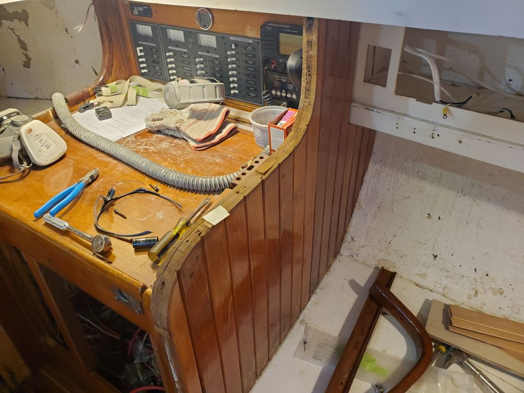
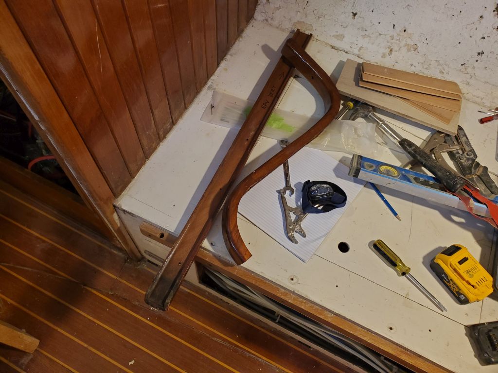
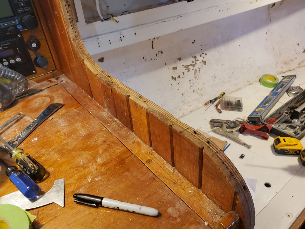
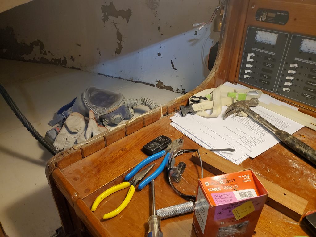
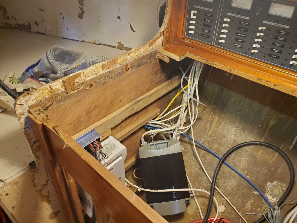
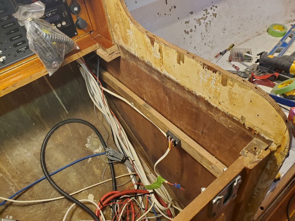
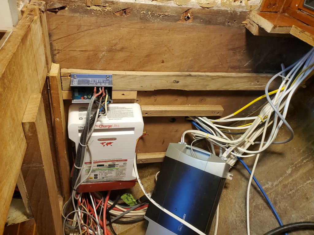
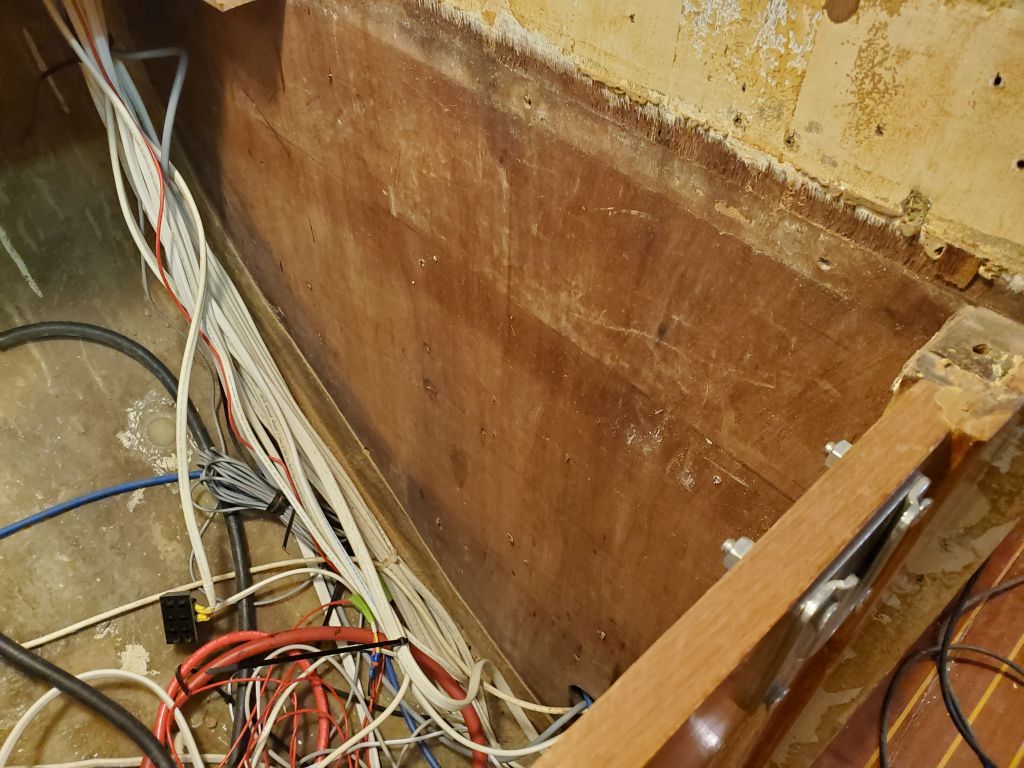
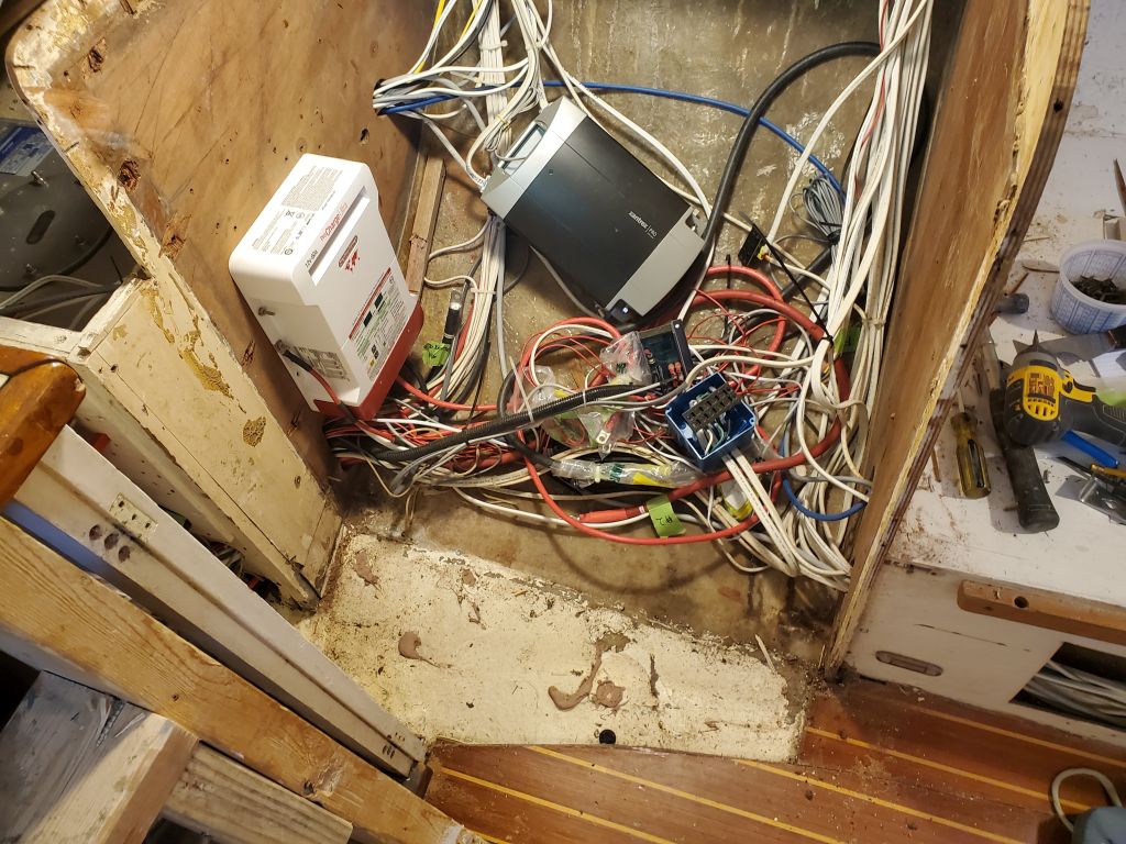
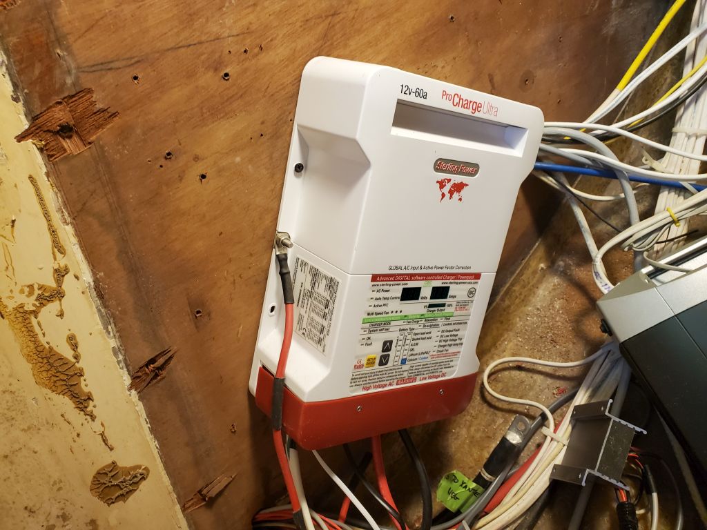
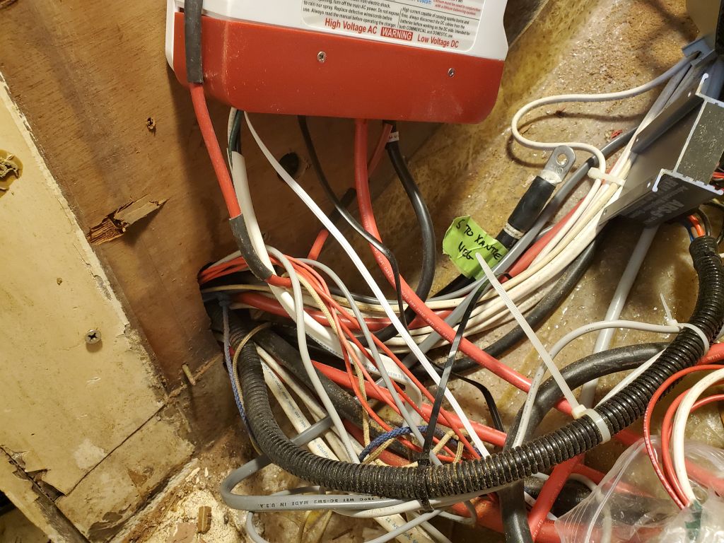
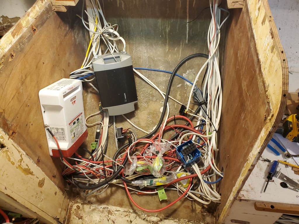
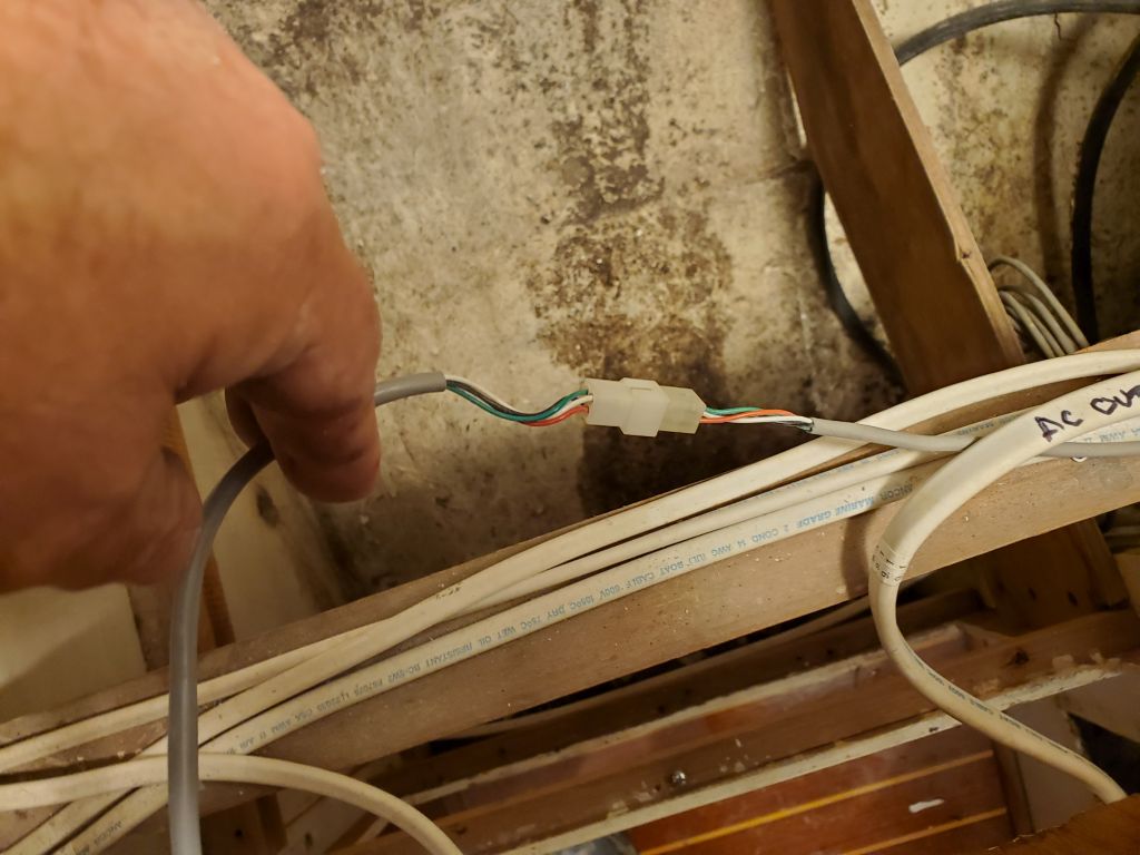
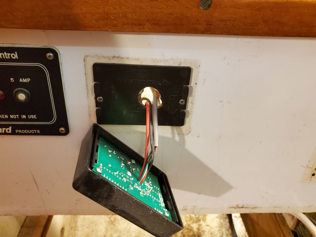
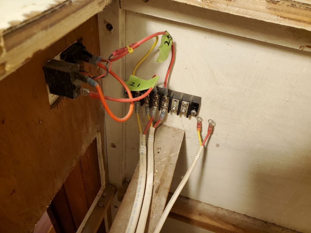
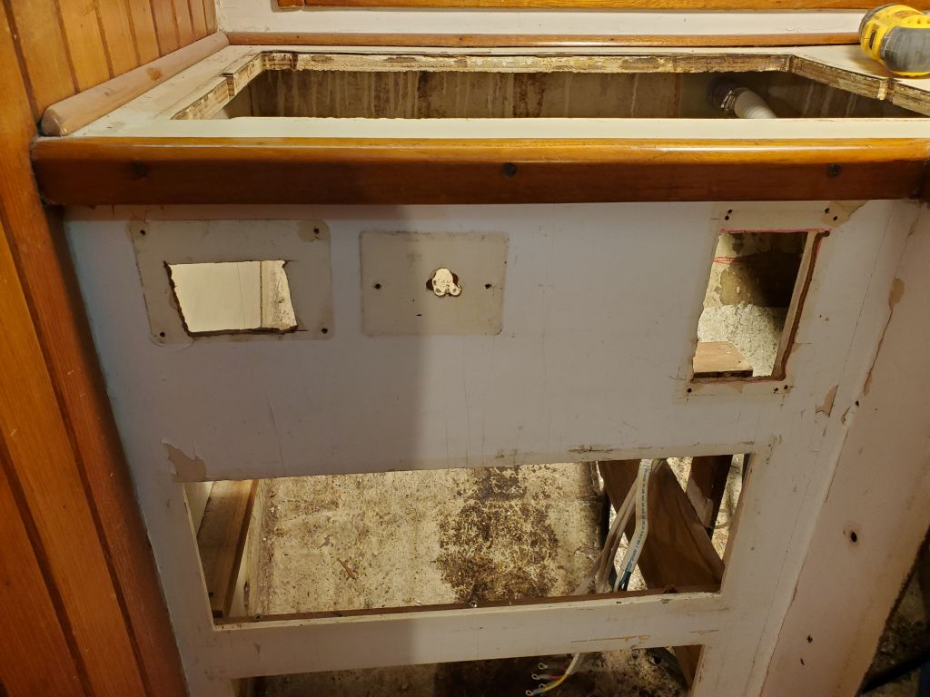
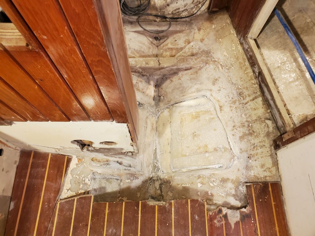
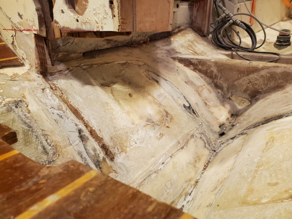
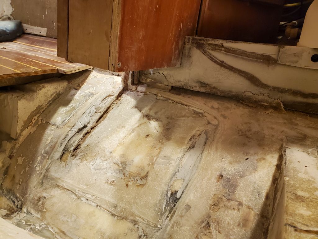
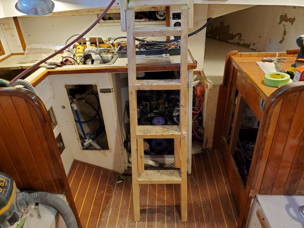
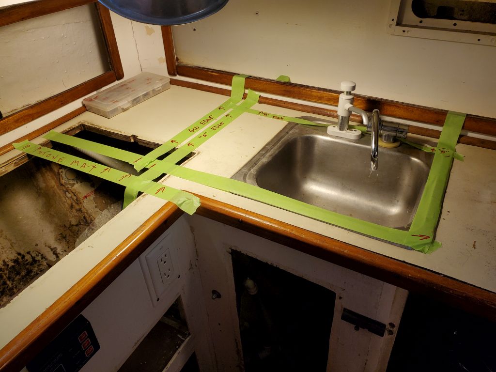
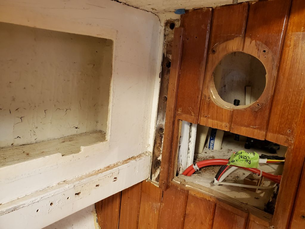
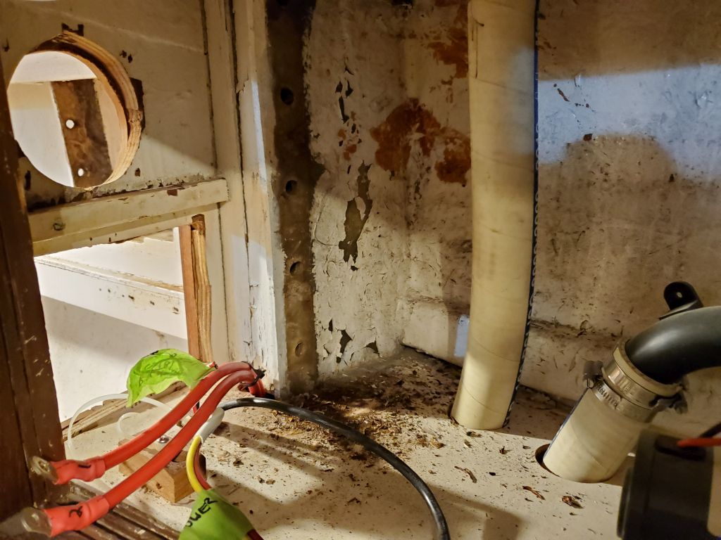
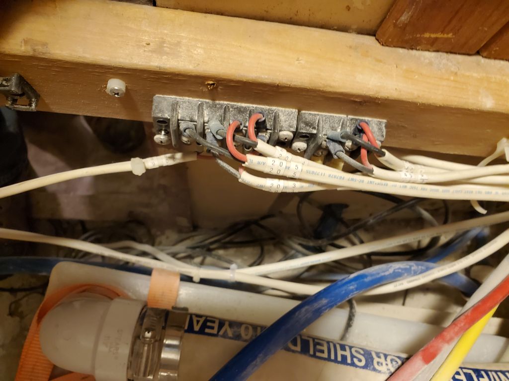
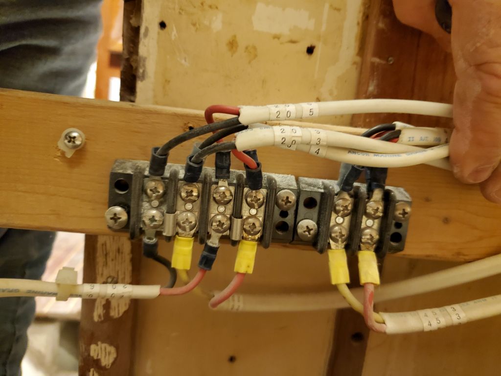
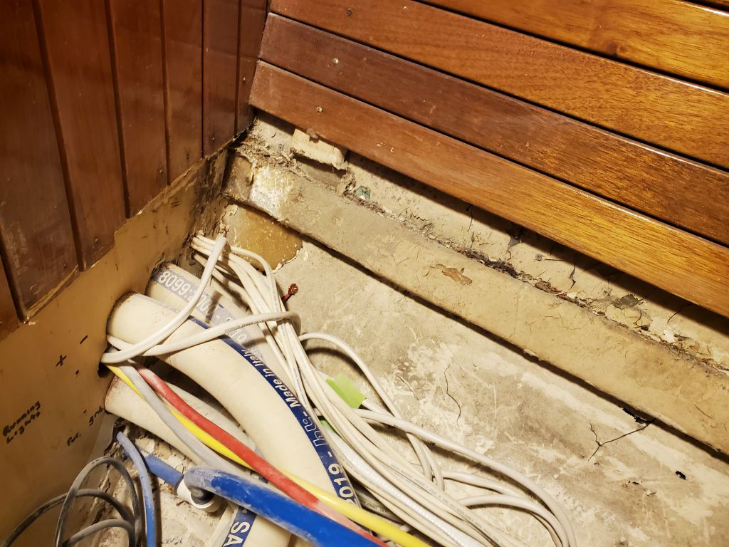
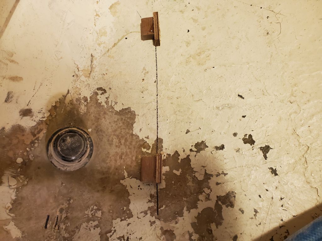
I picked up some cheap 3/16″ plywood to use for building tank mockups and for other portions of the interior rebuild to come.  With that on hand, I did some preparatory work in the forward cabin to clear the way for the new tank work, starting with disconnecting some wiring running across the aft end of the space, noting on each wire where it came from; I removed completely a wire running to the starboard stereo speaker, as this was straightforward and helped clear the passage into the forward space.  Then, I removed the after three of the original cross beams that had supported the berth platform; these came out easily, as I had hoped, by cutting in the center and then pulling away the light tabbing that had secured them to the stringers at the hull on each side.  These had to come out anyway, since the berth platform needed to be rebuilt and raised at the aft end to make it level.

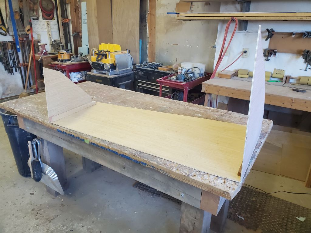
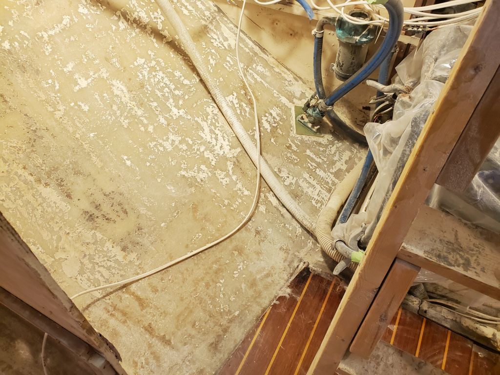
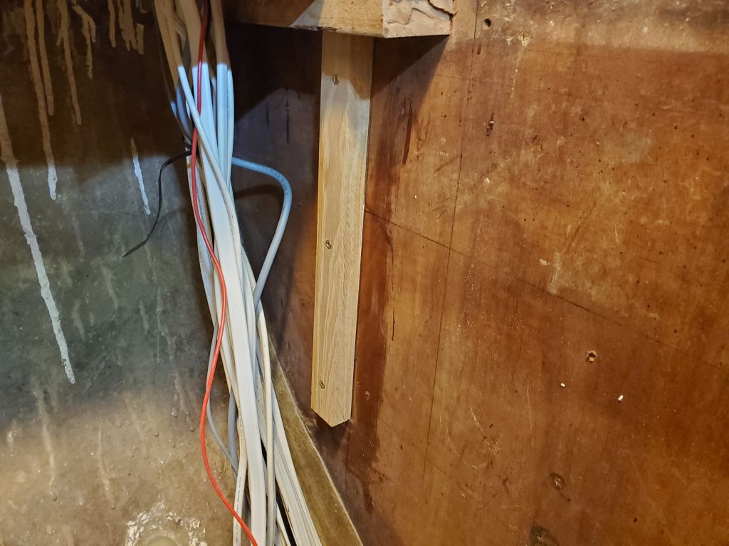
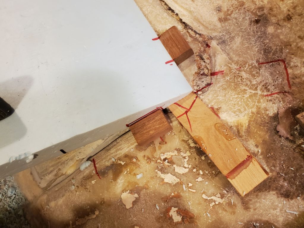
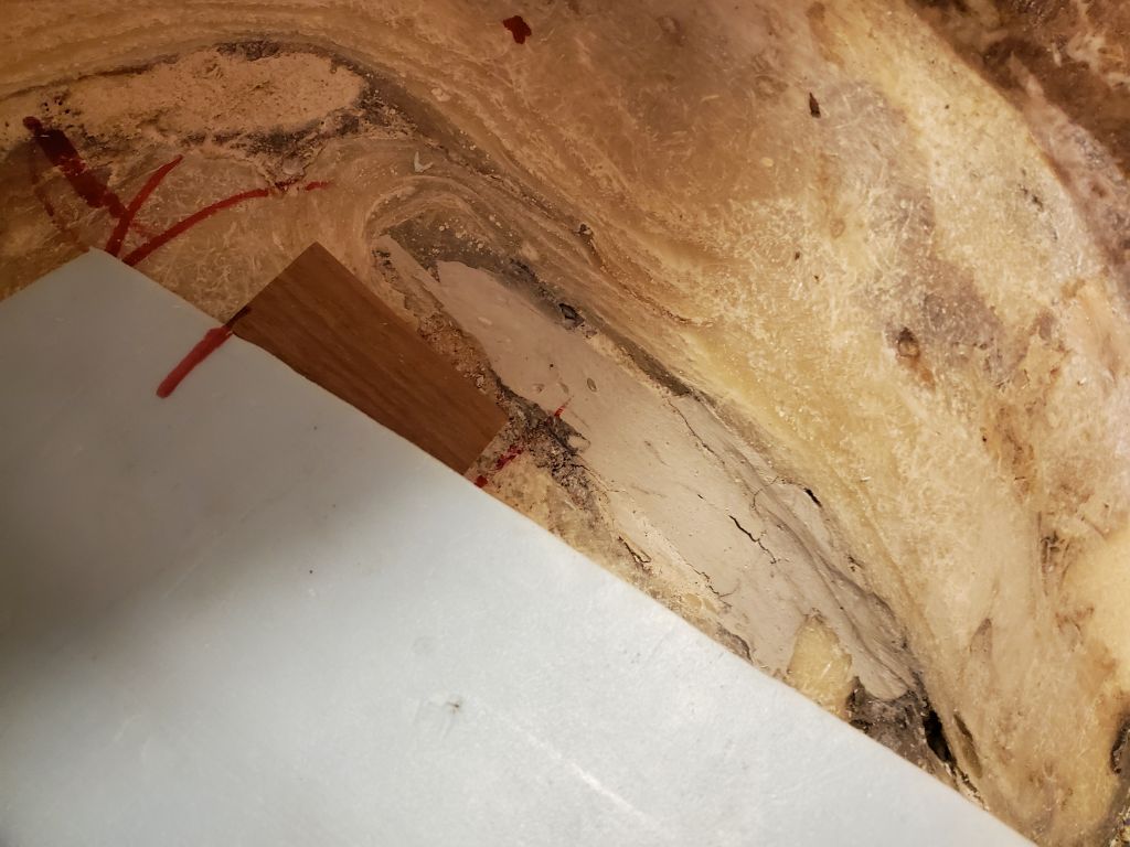
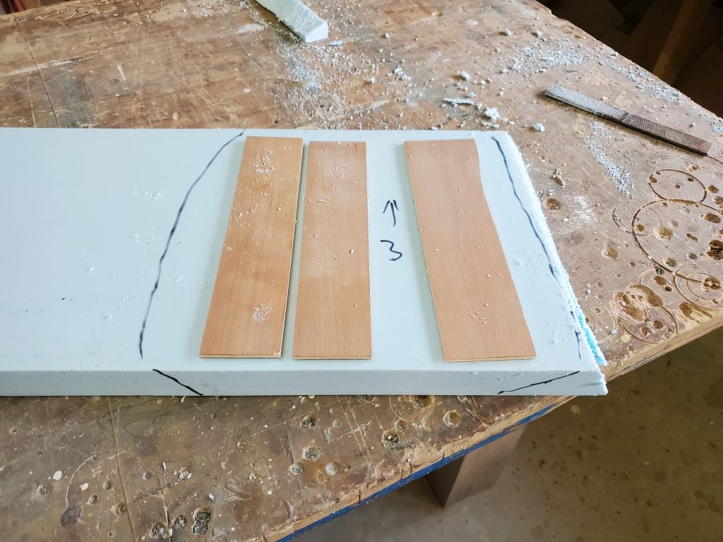
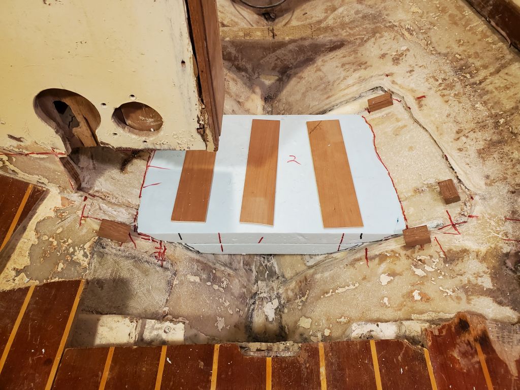
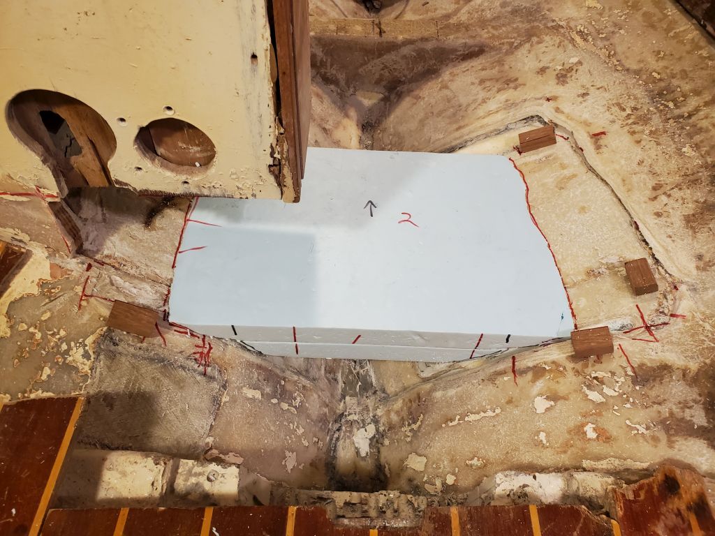
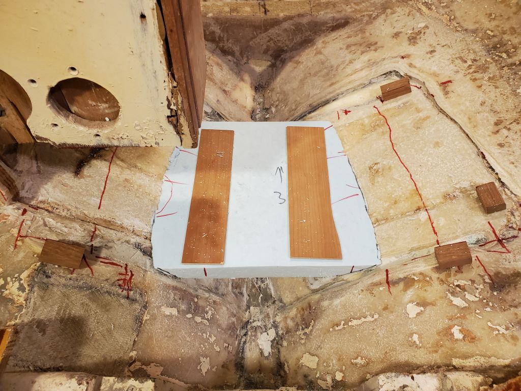
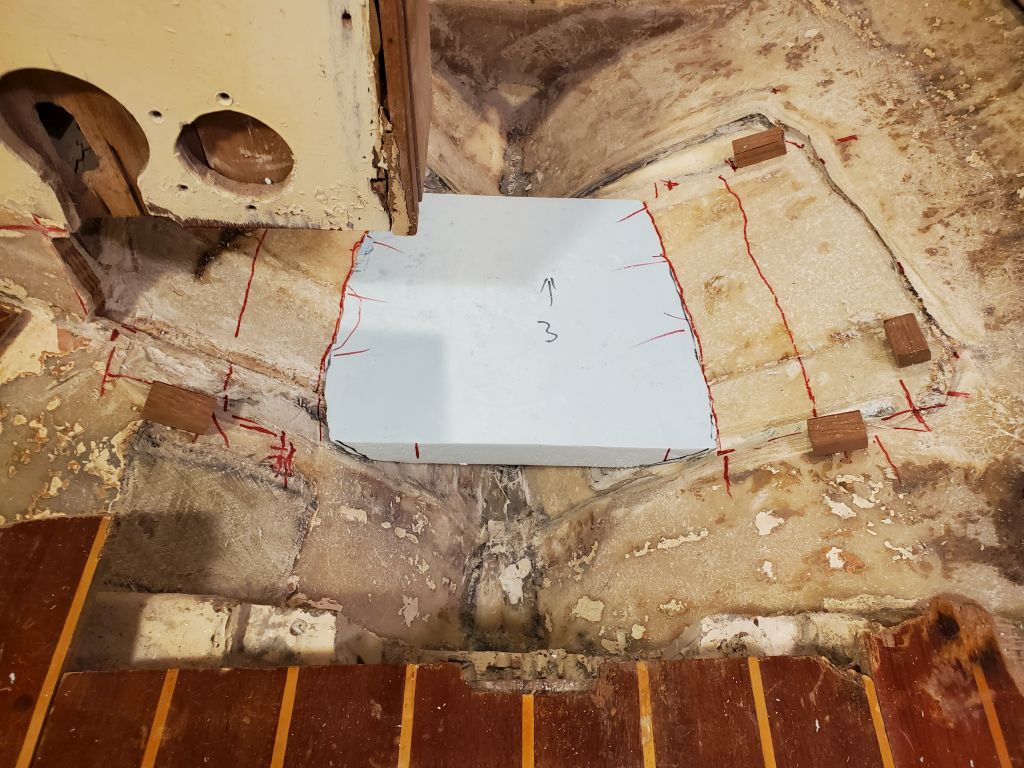
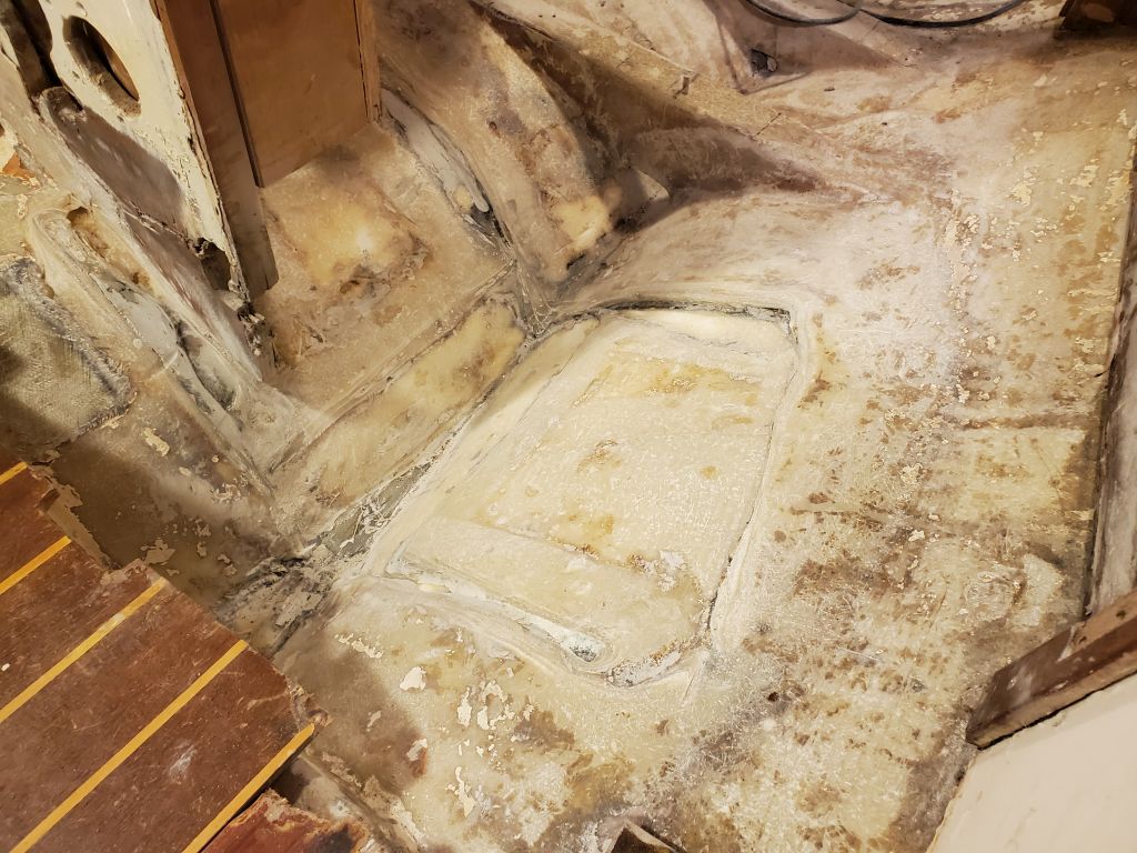
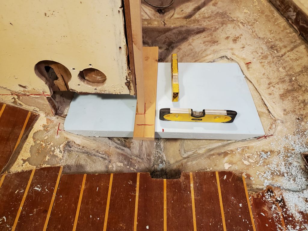
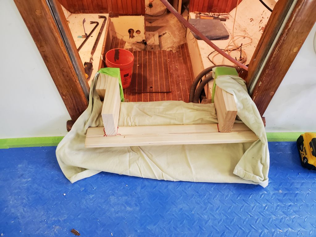
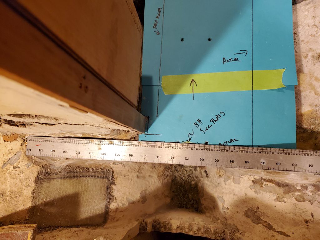
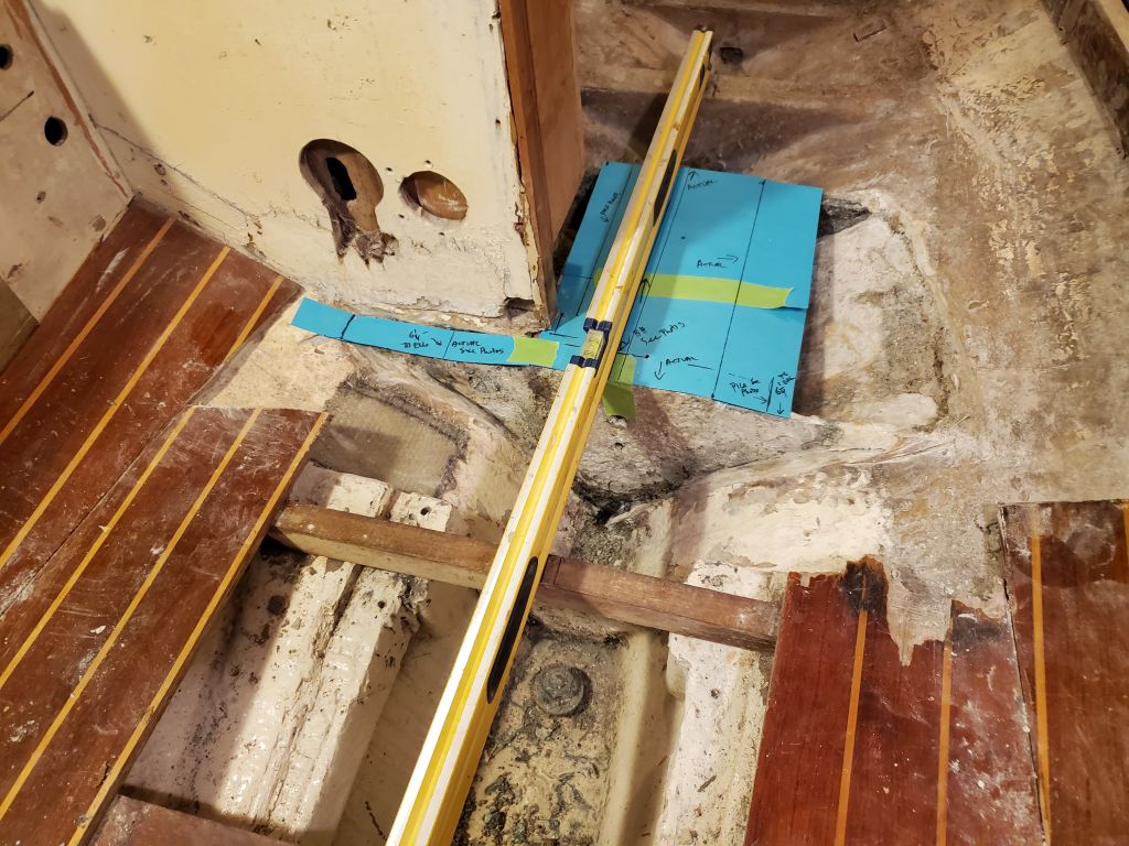
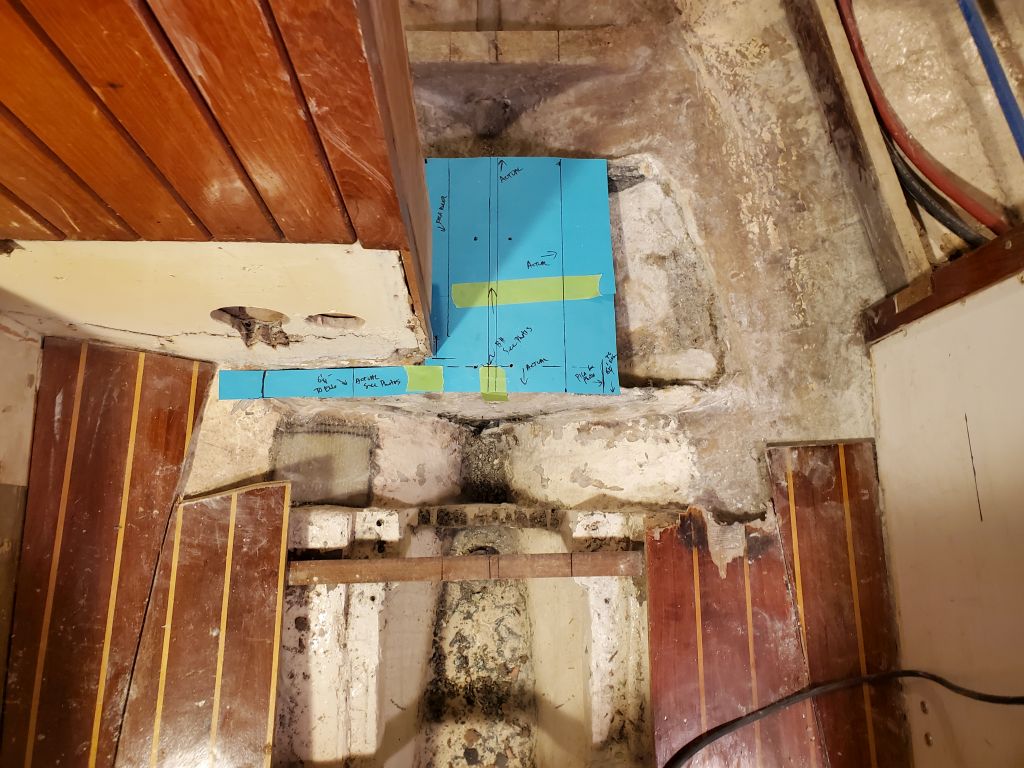
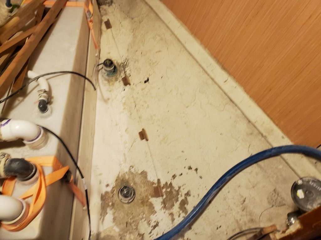
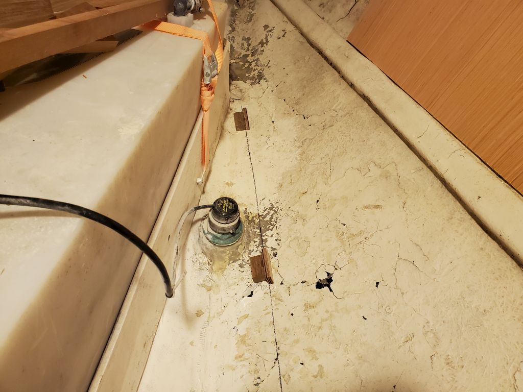
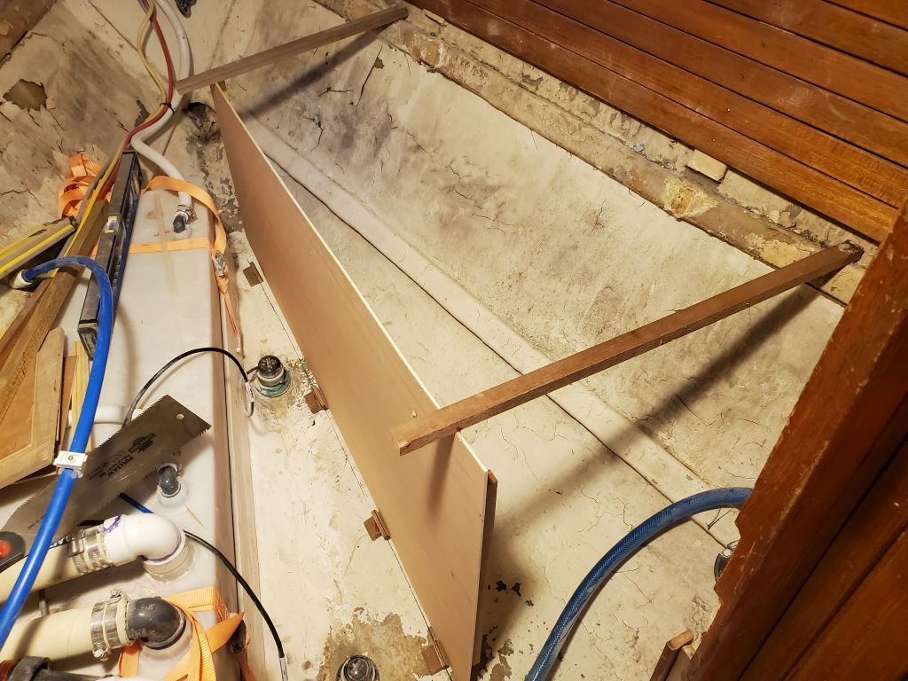
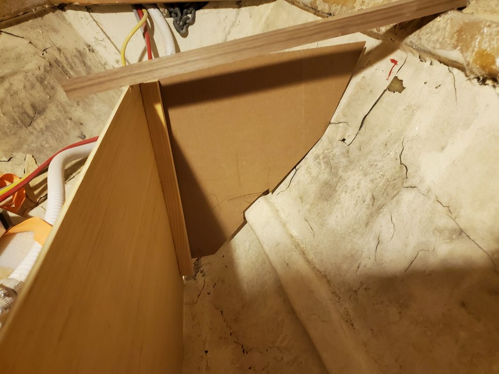
With the space as clear as possible for now, I began to work on the tank mockup.  I started with a piece of plywood cut somewhat oversized, and representing the inboard edge of the tank, and used it to strike a line near the centerline of the boat but leaving room for access to the transducers mounted  on the centerline.  I installed some temporary hot-glue blocks to help hold the template, and added 3/8″ (9mm) scraps of plywood to stand in for an eventual small structural bulkhead that would help support the actual water tank in the final analysis.

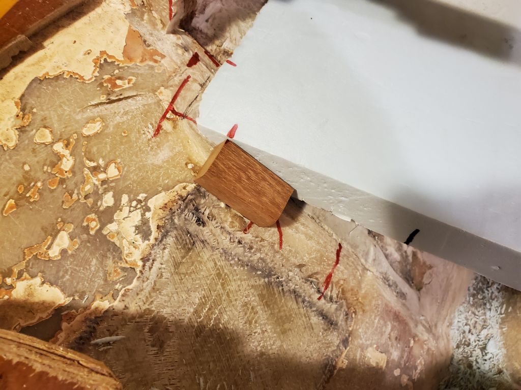
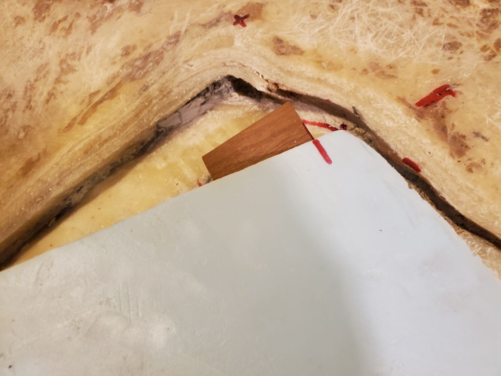
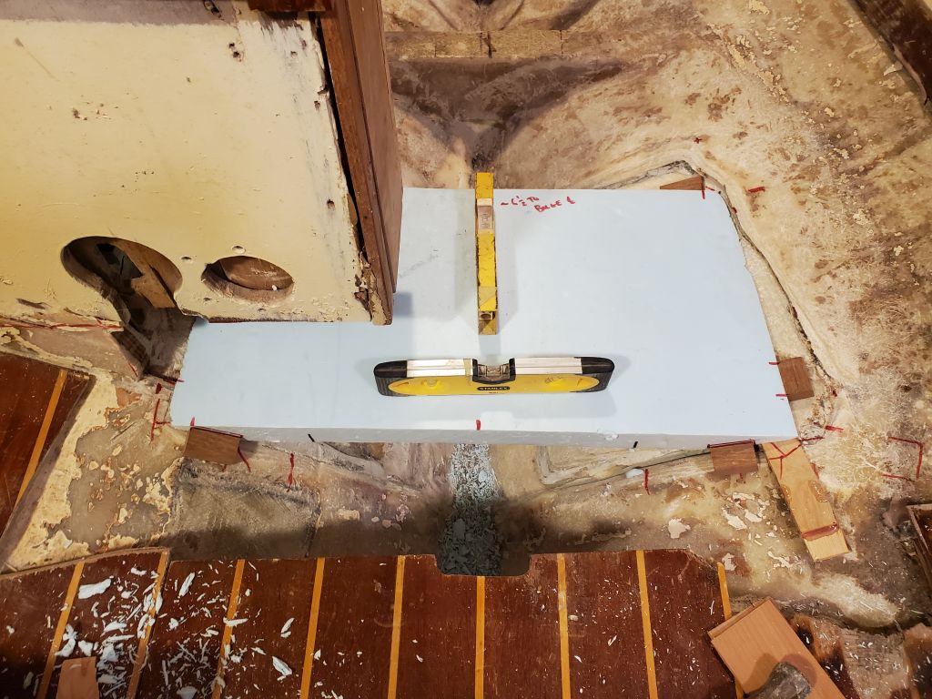
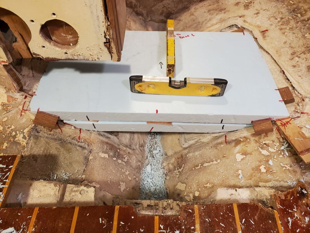
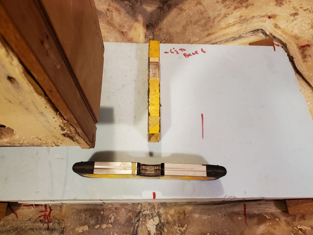
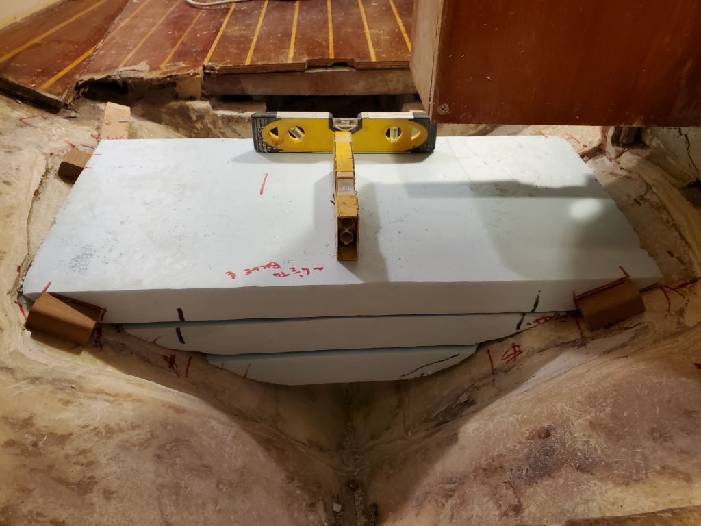
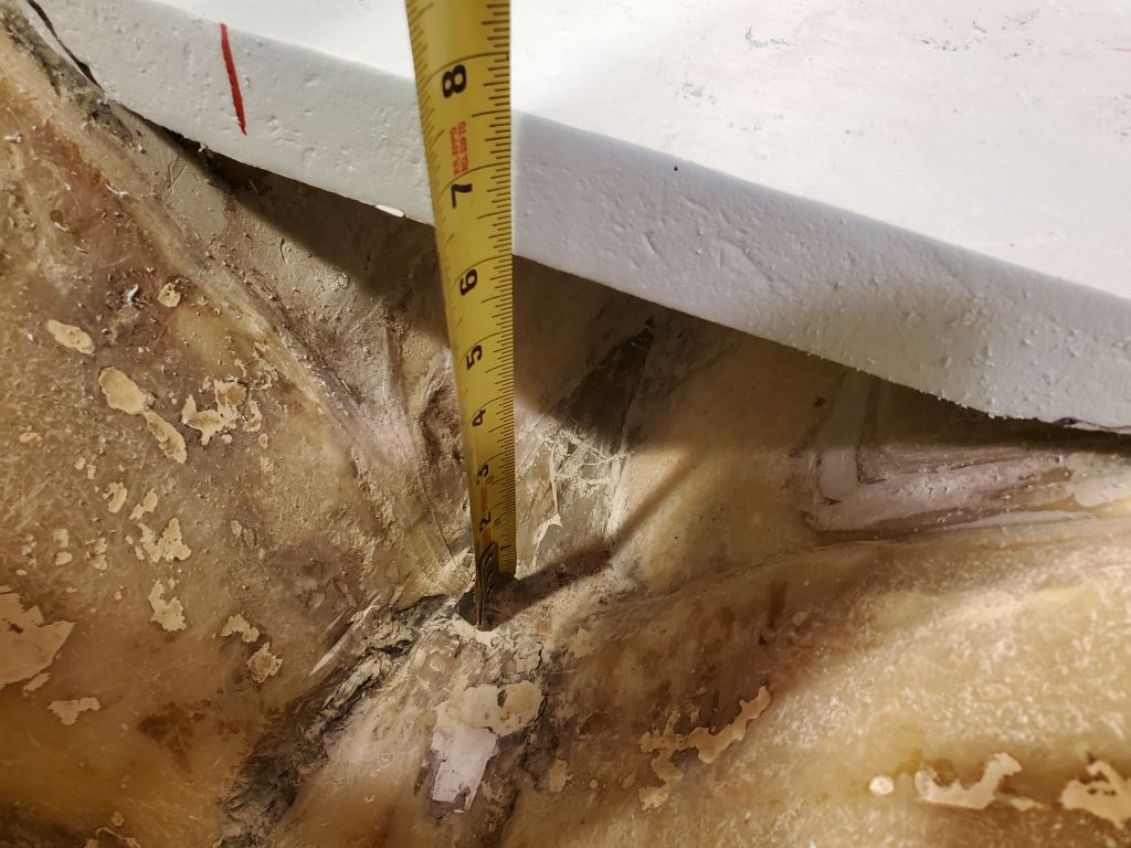
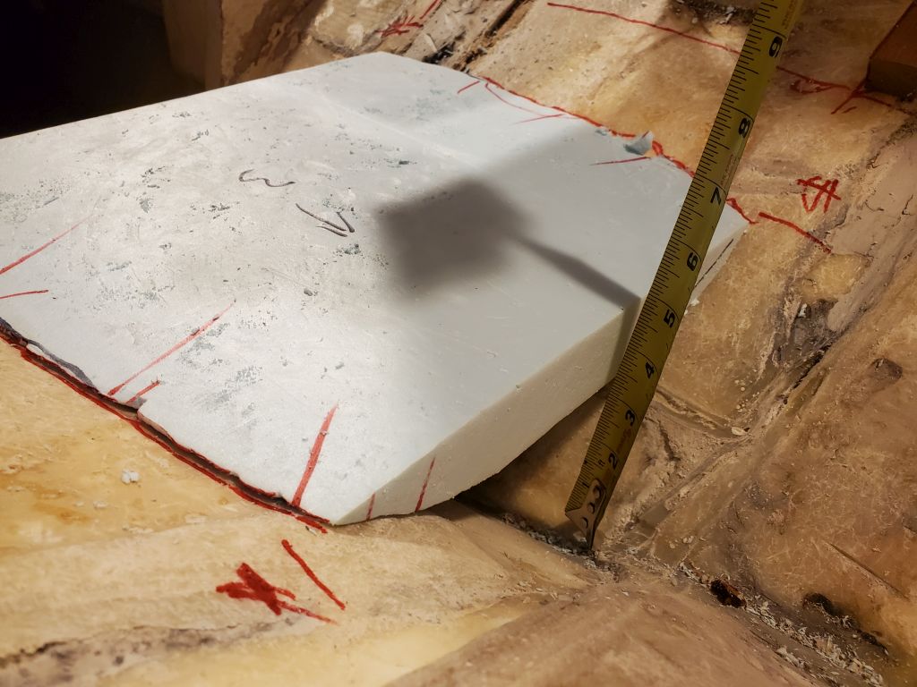
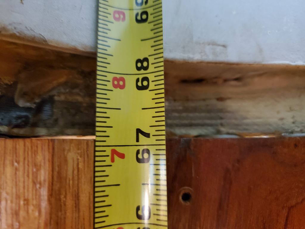
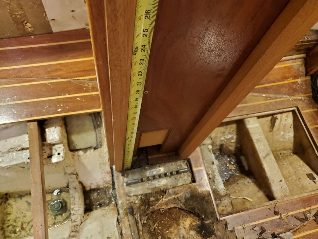
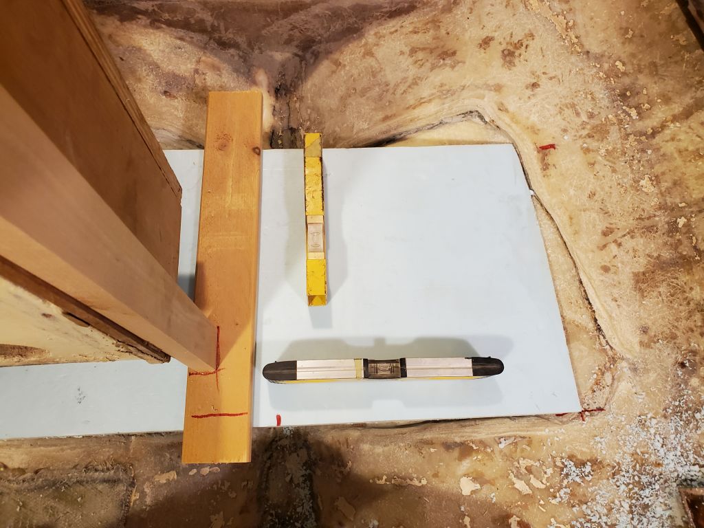
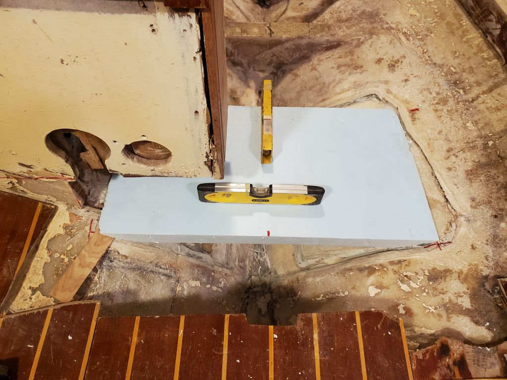
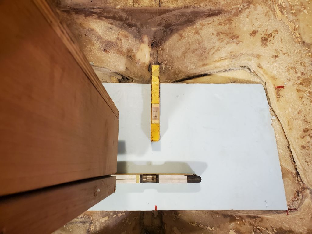
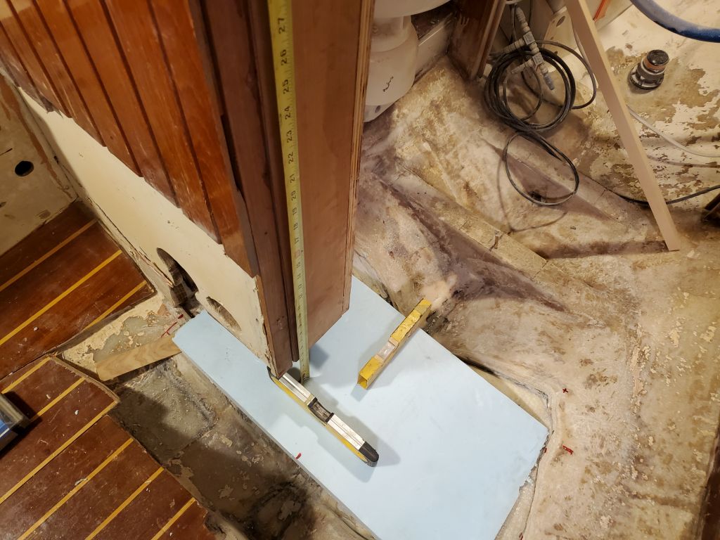
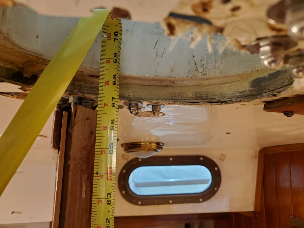
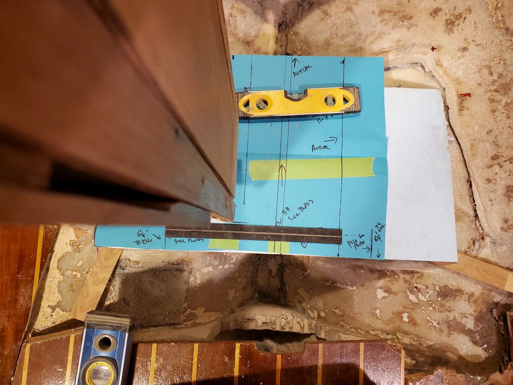
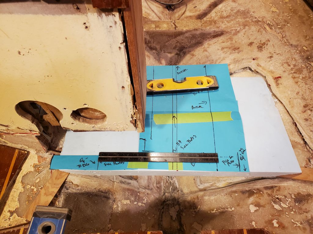
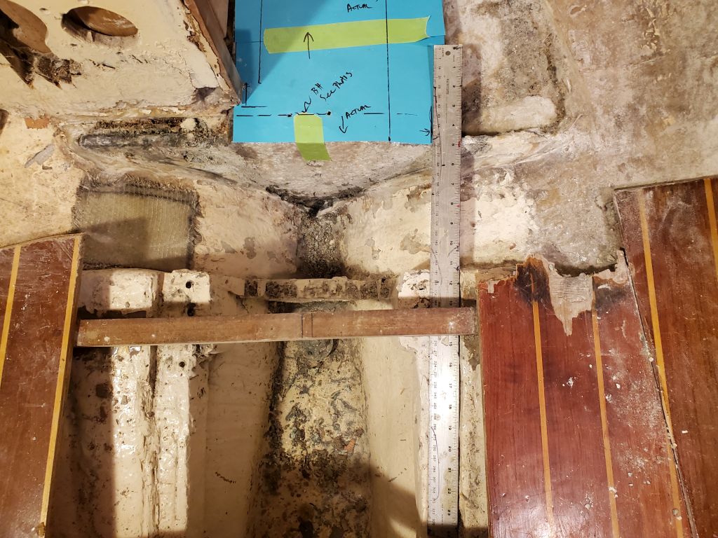
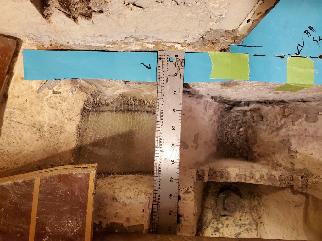
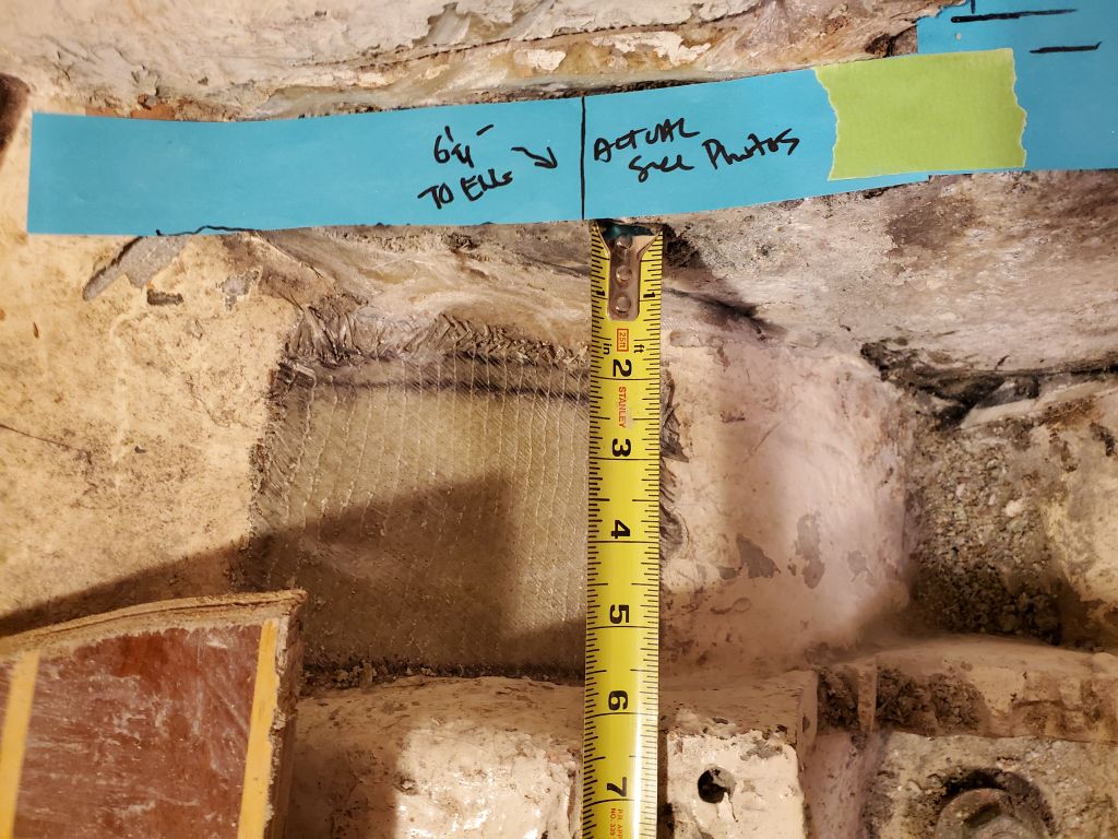
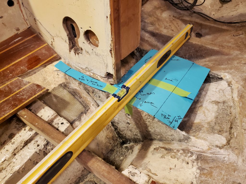
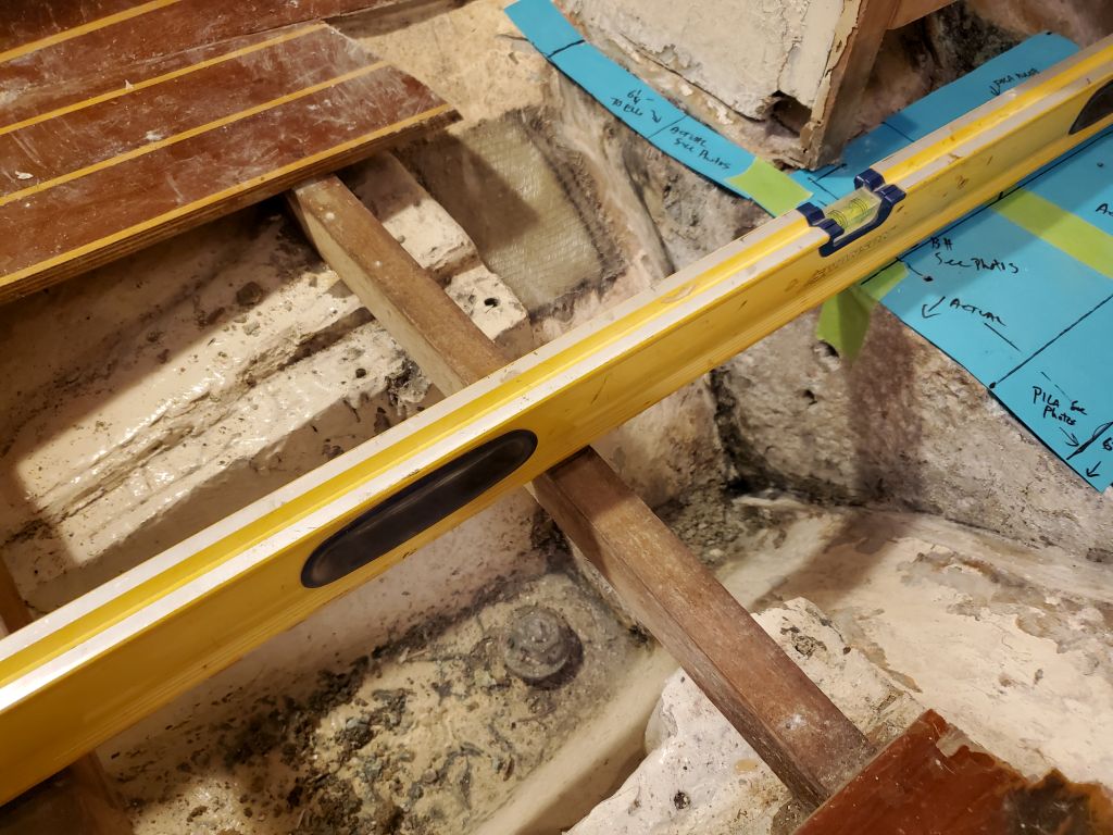
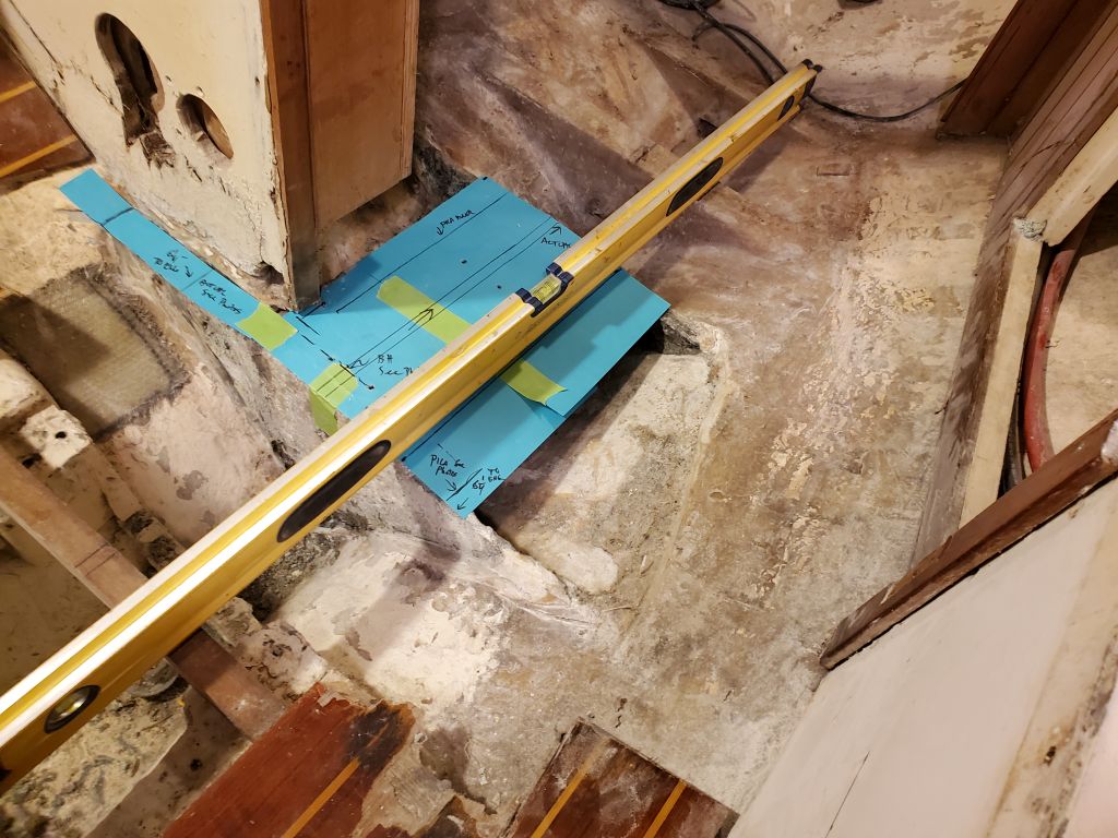
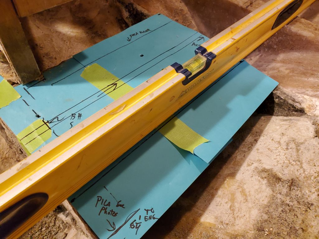
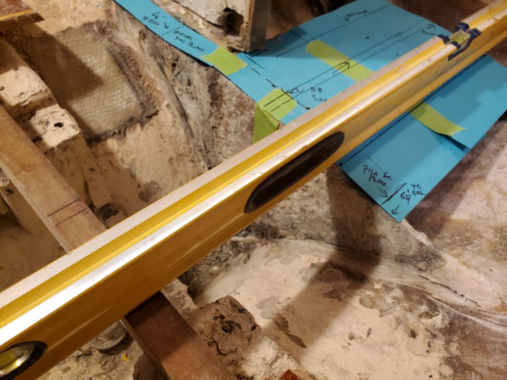
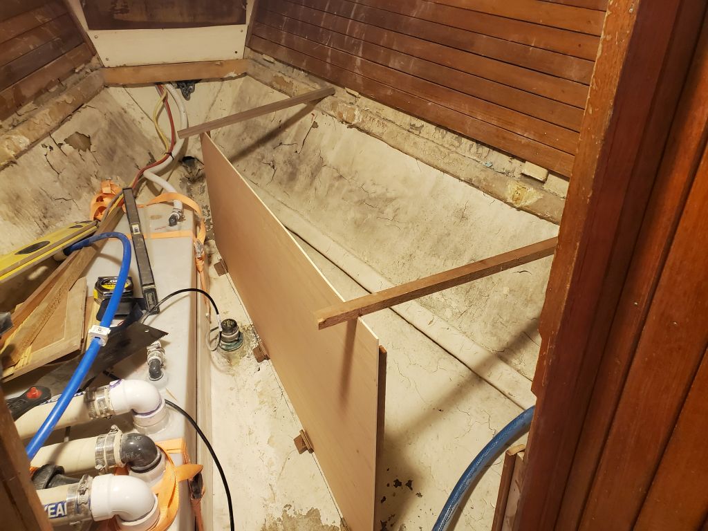
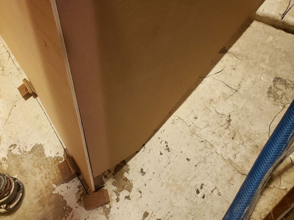
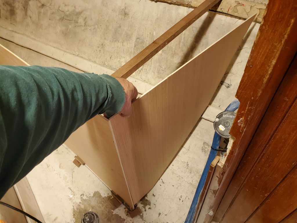
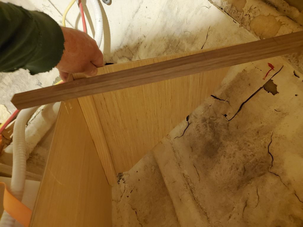
With a stick glued to the hull holding the panel plumb, I used a level to mark a vertical (plumb) line at the aft end, and also to mark a level line going forward at the correct height, keeping the top of the “tank” low enough to allow clearance beneath the eventual v-berth platform.

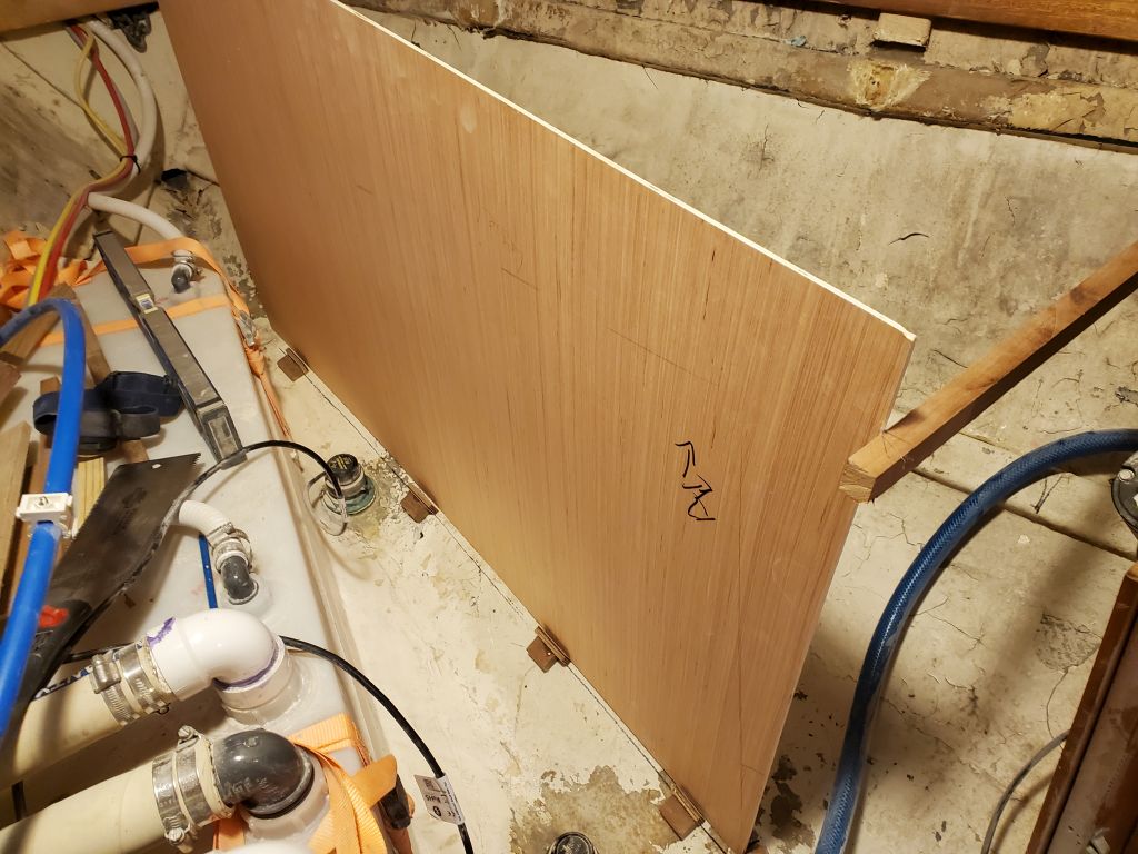
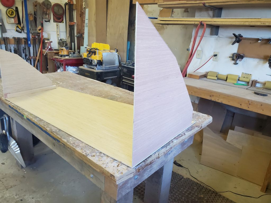
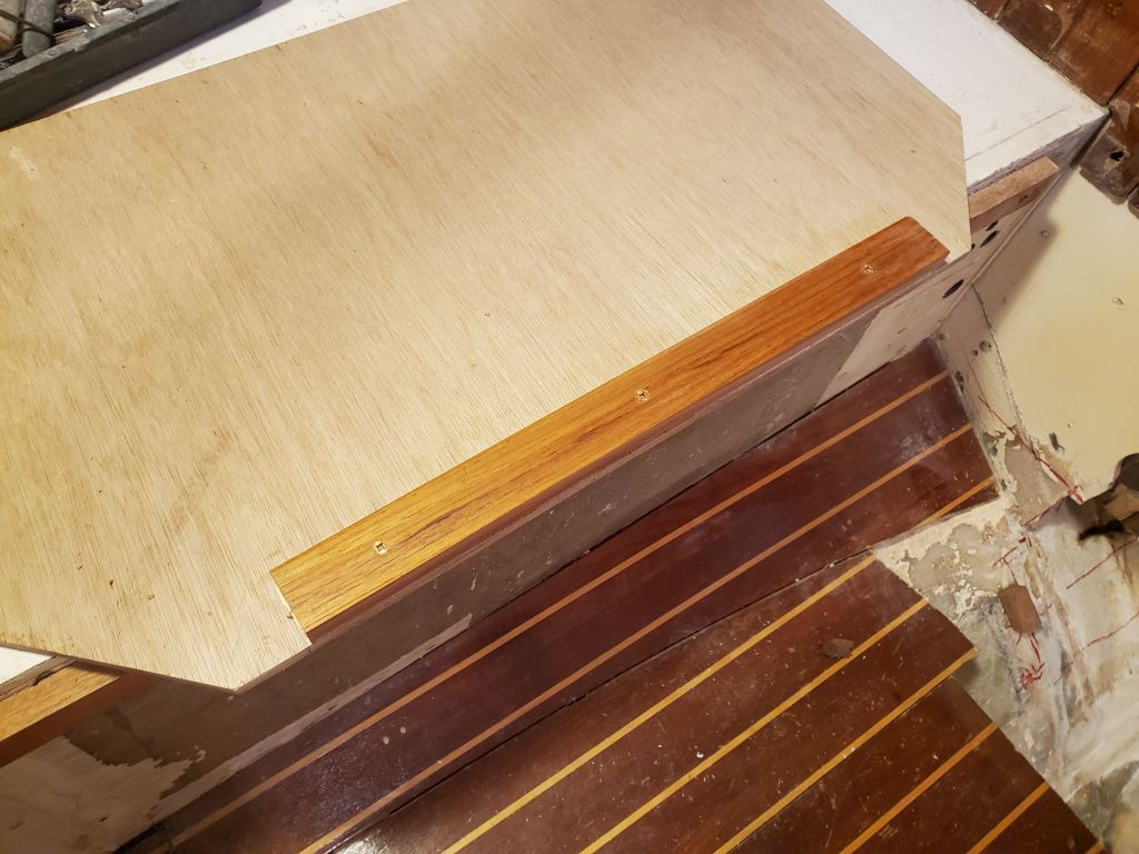
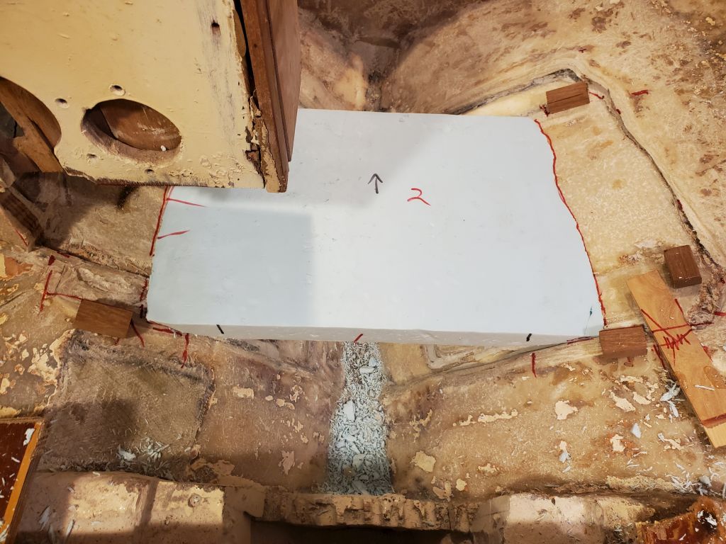
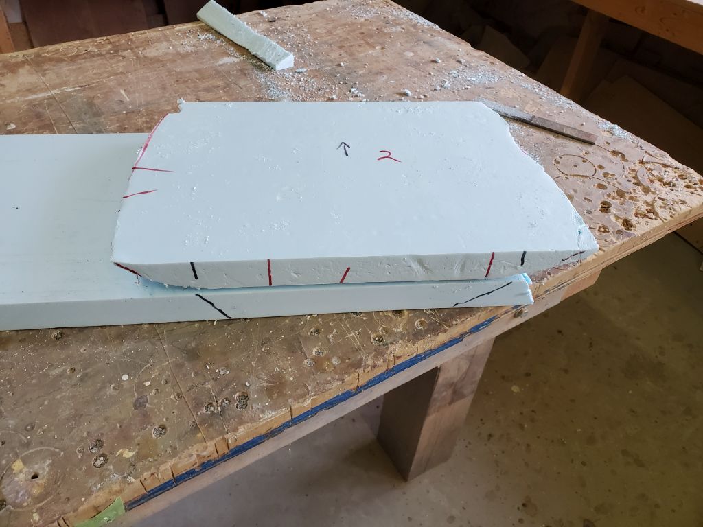
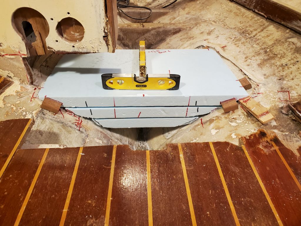
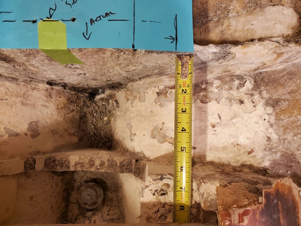
With the panel down on the bench, I cut along the marked lines, and transferred the plumb line forward to the forward end of the panel, creating a trapezoidal panel that fit along the hull and was plumb and level at the three remaining sides.  Back in the boat, I set up and used temporary supports to hold the panel in the proper position.

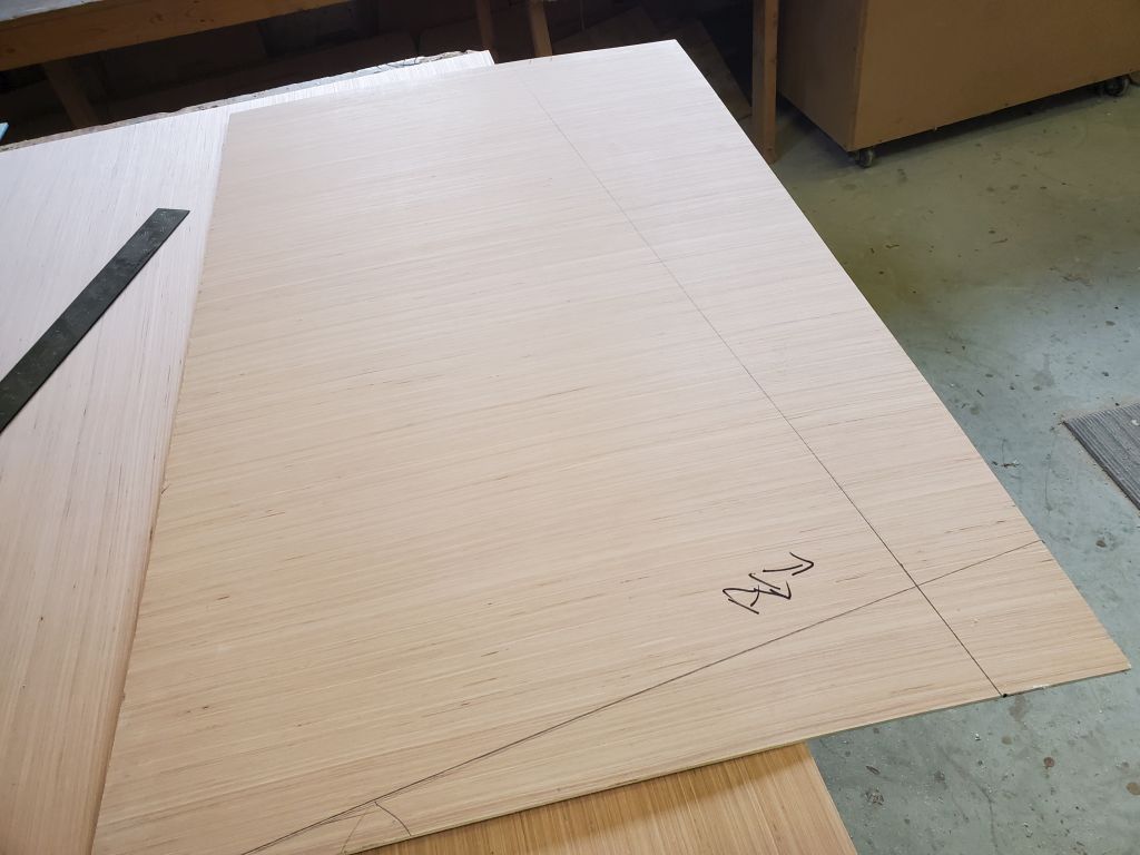
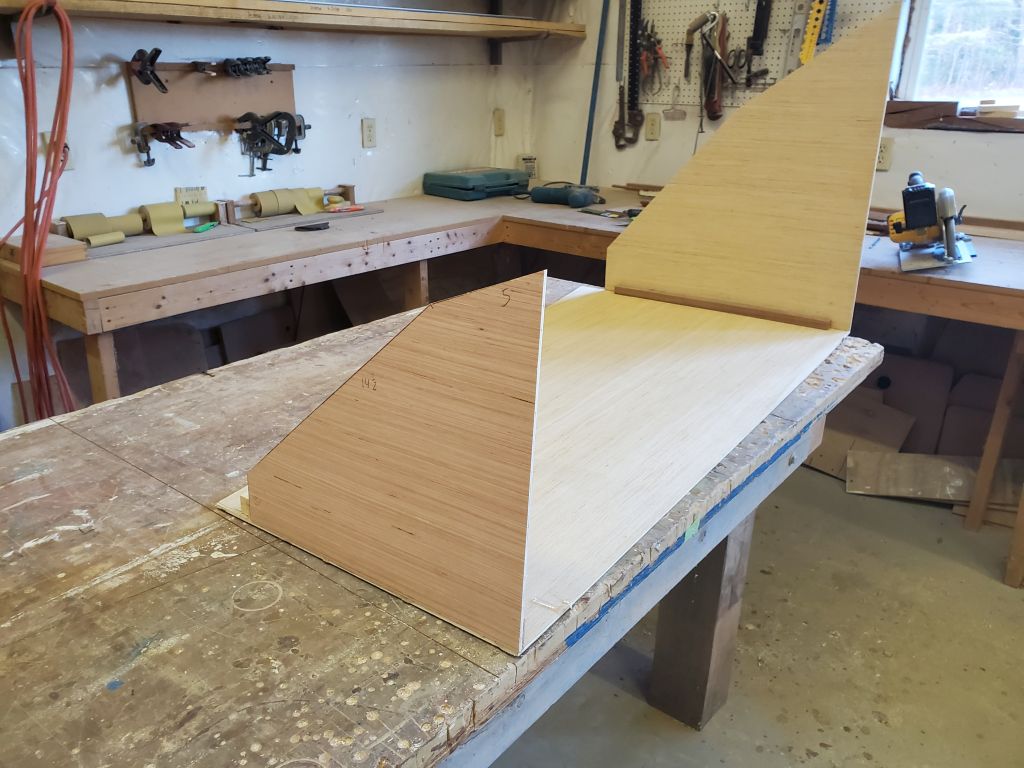
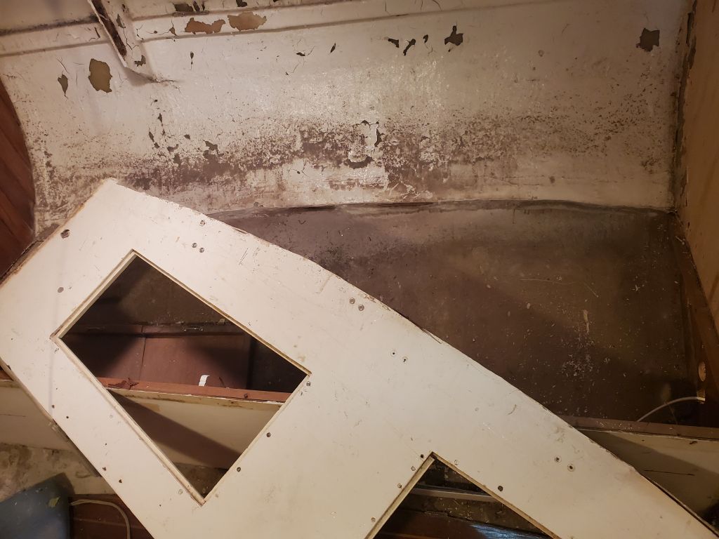
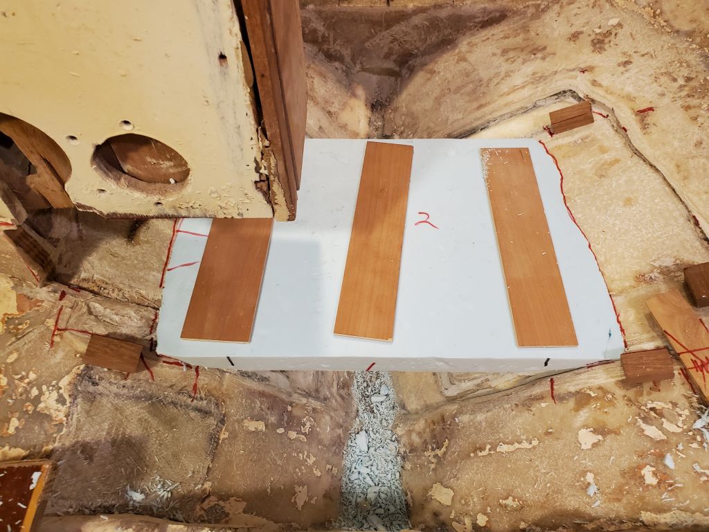
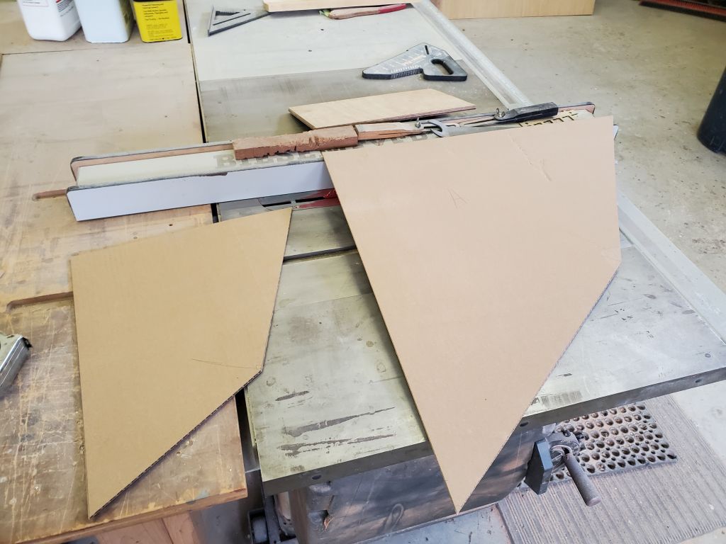
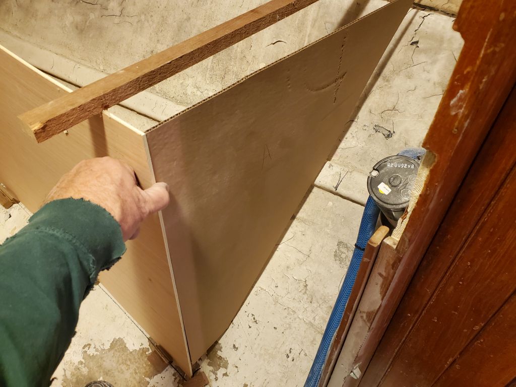
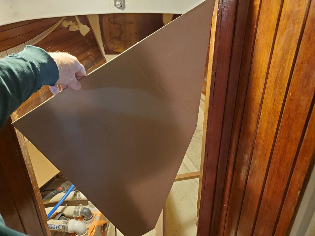
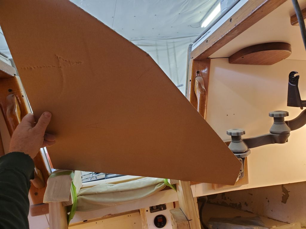
Now I used cardboard to make templates of the forward and after faces of the tank, making small modifications on the fly till I ended up with a 4-sided shape that maximized potential volume while staying away from the longitudinal stringers against the hull.  I tested the aft face–the piece that would determine the largest three-dimensional size of the tank–to ensure it fit through the passage into the berth, as well as the companionway (it may not look like it fits through the companionway from the poor photo, but it does).  Once I was satisfied with the cardboard templates, I transferred them to plywood and cut them out, with a final dry test-fit in the boat.

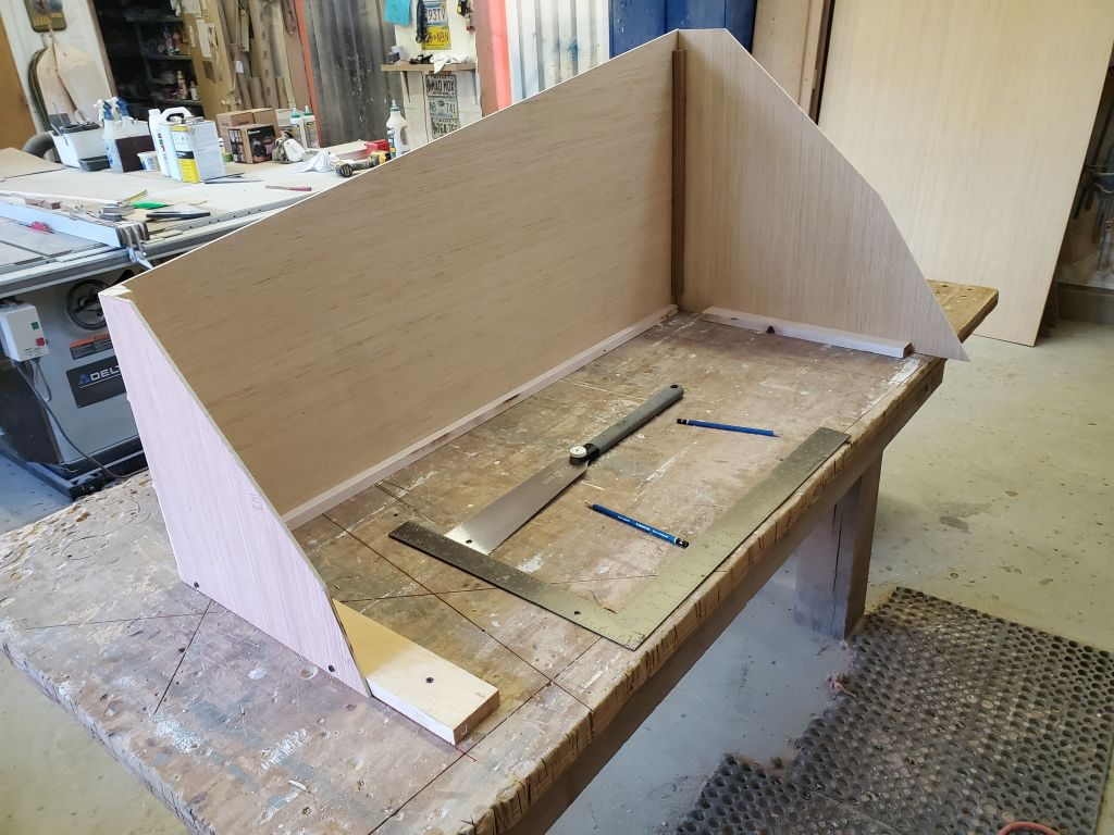
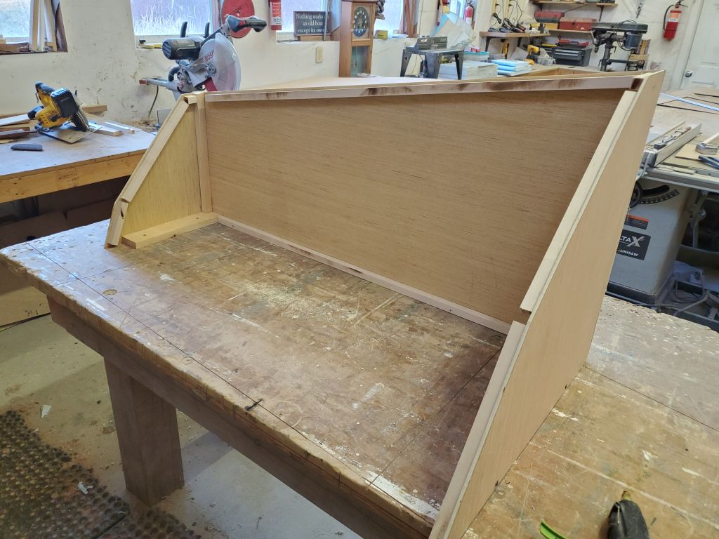
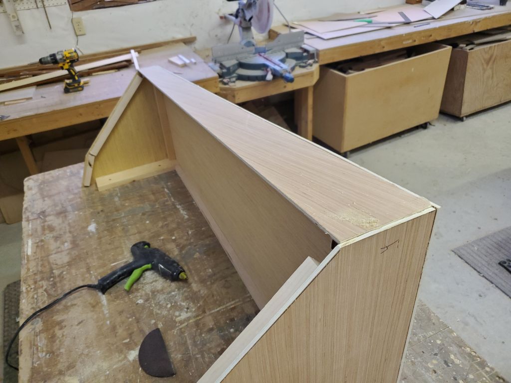
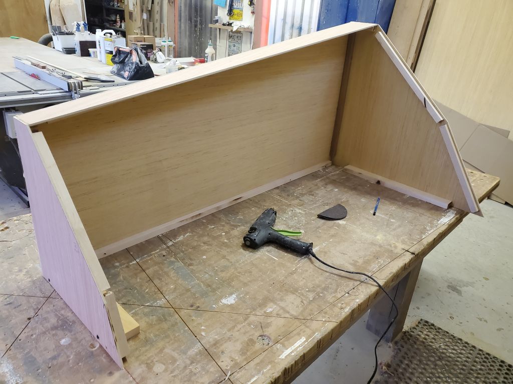
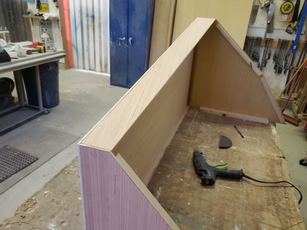
I removed the pieces down to the bench and assembled the ends and inboard panel with hot glue and cleats, then set the template upside down on the bench and secured it with cleats and screws so the three sides were square to one another and held firmly in place.  I cut and installed support cleats along the edges to hold the final sides of the template flush with the ends, and laid out and cut a flat on the bottom corner of each end (4″ wide at the aft end, 2.5″ wide at the forward end).   This flat not only gave the tank a bearing surface, but also helped with the layout of the angled outboard facets and maximizing volume along those edges.

This tank, as built, was somewhat larger than the original measurements I’d taken earlier, in part because the overall length is longer, the tank is a bit taller, and also because of the two-sided outboard edge.  As of this writing I’d not had a chance to calculate approximate volume but would do so once I could measure the final result.

Before the end of the day, I had time to lay out and cut the narrow flat bottom of the tank, which would ultimately rest on a small platform built into the boat for the purpose.  I’d finish up the mockup next time.

Calliope Girl 16

With a half day planned around an appointment in the afternoon, it was a good opportunity to start work on the final location and potential size of a new water tank to replace the bladder tank once held beneath the starboard berth.  The owner was interested in five different locations with potential for a new tank, depending on available space and other considerations, so over the course of the morning I measured each space and came up with a working drawing of the tank, along with approximate volume measurements.  For the purposes of the moment–which was mainly to determine which space or spaces to focus on, I didn’t bother trying to conceive ways to maximize the tank volume, such as through faceted angles or other adjustments, and stuck to the simplest possible geometric shapes, but once we finalized the location, I planned to build an accurate mockup so as to take advantage of the space as well as possible.

1.  The forward end of the space beneath the vee berth; this space ended up being quite small, under 10 gallons, and likely wasn’t worth the effort for a tank.

2.  The starboard side of the vee berth, opposite the existing waste tank.   This had always been a leading candidate, and at a calculated 34 gallons for the dimensions shown, continued to be.

3.  The bilge area above the keel, a good potential location in terms of weight distribution, but from a practical standpoint there simply wasn’t enough room there to make the effort, so I didn’t bother with any measurements.

4.  The space beneath the starboard settee (after removal of the old battery trays).  This space had potential as well, and a large tank fit to the space could hold up to 36 gallons as drawn.

5.  The difficult-to-access back corner beneath the galley.  This was a reasonable space, though installing a tank here could mean delays in the new galley construction while awaiting tank construction, the timeframe of which we didn’t yet know.  There were limits on the amount of the space available thanks to existing installations.

In the end, the two spaces with the most potential seemed to be the starboard vee berth, and the starboard settee.  The owner leaned towards the vee berth as long as the volume calculation was correct, as did I, so I’d press forward with a mockup to finalize the design and get more accurate measurements.

Calliope Girl 15

Next on the agenda was the settees.  The plywood tops were tabbed to the hull along their outer edges, so to begin I used a grinder and cutoff wheel to cut through this tabbing.  From there, it was a pretty simple matter to pull out the plywood, as there was little else holding it but some old screws and cleats that were already failing.  From there, I removed the vertical bases, which were also “tabbed” to the hull along their inside edges, but this tabbing had either already failed (starboard) or was so weak as to provide no resistance to hand removal.   I cut each of the plywood panels in half to make handling and disposal easier.

With the additional space afforded by the settees’ removal, I chipped away the small section of cabin sole on the port forward side, which took much longer than removing all the rest of the structure.  Removal was simply a matter of getting a tool between the adhesive (definitely either 4200 or 5200)  and the hull–fairly laborious, but fortunately the area was small.

With the debris cleared away, and all my tools and things stored elsewhere for now, there was no better time to get in and sand the hull where the settees and galley cabinetry had been, along with the underside of the deck.  This heavy bulk sanding removed the old and failed coatings, remnants of old tabbing, and cleaned up the areas to prepare for new work ahead.  The sanding and cleanup consumed the remainder of the day.  There’d be additional detail work ahead, as there were still old cleats in place that I needed to remove, along with the old battery trays, but the worst of the surface prep was in the books.


Calliope Girl 14

To begin, I quickly installed the battery charger on the new mounting panel, along with the terminal block for the existing refrigerator circuit, as this location would work for the new refrigerator wiring as well.  All the existing wiring to the charger worked in the new location, except the negative cable, which was now too short (along with the negative cable leading to the inverter.  (The inverter positive lead was still connected to the main battery switch panel I’d removed earlier.)

There seemed no time like the present to go ahead and make up new lengths of cable for these two positions, so I disconnected the old ones and prepared new ones of the lengths needed.  For the inverter, I could repurpose part of a long length of cable that I’d removed from the starboard battery bank, as that particular cable wouldn’t be re-used in its current format, and for the battery charger, I used new #2AWG yellow cable, which was slightly larger than the original #4, but was what I had on hand.

With that, I could straighten up the wire bundles in the space and move on to the galley.

In the galley, my immediate goal was to remove anything that was secured to the underside of the countertop and other structures.  I clipped wire ties and removed whatever fixtures necessary to accomplish this.

At least for now, I planned to leave a complicated little corner of the existing upper galley cabinets alone; this small locker included several gauges, terminal blocks and buss bars, and a battery switch panel with several heavy cables.  Relocating this would be time-consuming and difficult, so I planned to leave it be and figure out how to incorporate it into the new work as I went.  To release the nearby panels from the corner required a couple small cuts, in both the face panel and the countertop.  After that, I removed the upper cabinets in the galley with little effort.

I had to make a couple relief cuts in the countertop to free some wiring that ran through drilled holes, and afterwards I removed the countertop in several pieces to keep it easy to handle.  I removed the staving from both sides of the galley bulkhead, largely intact, and then I removed what remained of the cabinetry.

I removed the sections of cabin sole that ran up the curve of the hull on each side, which would improve access to the settees for their removal.  These sections mostly came out with ease, except for a short section on the forward port side, which was a later addition (presumably when the engine room was moved), and was very well adhered with what appeared to be 5200.  So for now I left this section alone; I’d remove it later, when I had better access to chip it out bit by bit.

I had enough time left in the day to remove the upper settee lockers.  These didn’t give up much of a fight and before long the space was clear.

Calliope Girl 13

My next step was to make some order out of the wiring runs beneath the former nav station, to clean up and untangle some of the wiring so it would make for cleaner runs later.  I also wanted to move and re-mount the inverter and battery charger on a new panel beneath the electrical panel, at the outboard side of the space.  I’d not initially planned to build the new panel, but once I started working on organizing these wires it only made sense to do so, given that the space was perfectly suited to re-mount these appliances.

Basically the cleanup work involved re-leading several wires so they were no longer trapped in some loop or another, which involved some temporary disconnection of various wires from the battery charger and inverter to allow these and other wires to be run more cleanly.  This all took time, but was not photogenic.  When all was said and done, however, I had three cleaner wiring bundles (two from the electrical panel, one across the bottom between the engine room and the port settee), and I temporarily hung the charger and inverter on the aft bulkhead to keep them out of the way while I constructed the new bulkhead on the outboard side.

For the bulkhead, first I determined where I could place it while retaining ample room inboard for the new refrigerator and other installations.  I also had to ensure that the new panel was large enough to support the two large boxes.  The right spot ended up being just inset beneath the last bit of nav station countertop trim I’d saved near the electrical panel, and once I had some plumb reference marks on each side, I cut and installed hardwood cleats with glue and screws; these cleats would support the panel across the space.  I prepared a 12mm marine plywood panel to fit, clipping the corners to allow clearance around the cleats supporting the electrical panel above, and to allow the existing wiring to run as needed.  There was only so much slack in these wiring runs, particularly the after one, so I had to make an additional cut in the bottom aft corner to ensure free passage.  By lunchtime, I had the panel mounted, and had mounted the inverter.  At the top edge of the new panel, I added a hardwood cleat to help provide additional support for the base of the electrical locker above.  I installed the new panel with screws to make it removable should access be required behind in the future.

I’d intended to install the battery charger forward of the inverter, and continue with the related work, during the afternoon, but I was called away unexpectedly for an emergency, so this ended up being where I left things for the day.

Calliope Girl 12

To move forward towards the goal of removing the settees to make way for new construction, the next step was to remove some of the electrical system beneath the port berth.  Here, the owner had located a large panel containing various battery switches, buss bars, and other components.  There were several wires connected here that I’d have to remove from one end or the other so I could remove the panel for safekeeping.

Over the course of the morning I labeled and removed all the wires required, being sure to carefully note each wire’s location with additional tags and lots of photo documentation along the way.  These photos are representative of the various steps leading to the ultimate removal of the panel itself.  I installed plastic bags over some of the disconnected wire ends to help protect the masking tape labels I’d installed.  This was a complex electrical system, quite newly installed, and my goal was to disturb it as little as possible while still allowing the new work to go on around the remains.

Next, I moved on to the nav station.  The staving on the bulkhead face pinned in the settee and would be in the way of removal and replacement, and this area was due for significant reconfiguration in any event, so to start I removed the bulkhead trim and then the staving.  I labeled the staving for possible re-use.  I found that the staving was installed with small nails and adhesive, making removal somewhat more difficult than expected, but it mostly came off without damage.  Then I removed the trim and short pieces of staving from the after bulkhead (not bothering to save these small bits), and along the inside edge of the forward bulkhead as well, though I left two panels of the staving near the electrical panel on both sides since this area was to remain undisturbed.

I continued disassembly of the nav station by removing the hinged top, then, eventually, the remainder of the top and front (inboard) framework.  At the outboard edges near the electrical panel, I measured out 4″ on each side and made a perpendicular cut, leaving the wood closest to the panel intact.  In the final analysis, all this would become incorporated with the new construction later.  I also removed various cleats from the interior, and unmounted the battery charger and inverter, both of which would have to be relocated to allow room for the new refrigerator.  Anticipating this, I’d previously removed the battery cables from the inverter, and in the near future I’d make adjustments to the other related wiring–and that of the nearby battery charger–to allow for their relocation.  My initial thought was to build a vertical panel outboard in the space, allowing room for the new refrigerator, and mounting these components on the new panel.  But that would all fall into place presently.

In the immediate term, there’d be a bit of housekeeping and wire-tidying in this space before I continued the preparatory work in the galley, after which I could start removing interior panels as needed.  That would be the focus next time.

Calliope Girl 11

I continued work on the mast step mockup and patterns.  With the top layer properly fitted, I installed some alignment blocks with hot glue, which helped pin the top piece in its correct position.  Each of the blocks had either a corner or a side that also registered the final height of the top platform for easy removal and replacement, which I’d have to do frequently as I patterned the two lower layers.

The surface of the top section was 1/4″ lower than the finished height required to allow room for several layers of fiberglass over the top, and to allow a bit of final adjustment room.  My plan for the construction of the overall structure was to tap each section individually from the bottom up during installation, which I thought would add substantial strength to the whole arrangement.  To allow room for the tabbing over each layer, I decided to use 3/16″ spacers cut from scrap plywood between the patterns as I shaped each lower section.   So I cut and shaped two additional layers in turn, each with the 3/16″ spacers between.  This was simply a trial and error process involving lots of rasp work to shape the foam, then checking frequently with the top section to get the right fit through all three layers.  At some length, I got all three pieces properly shaped with the space allowance between each, with the top layer ending up level in both directions and the proper 68-1/2″ distance from the mast collar datum point.  With three layers of fiberglass over the top when all was said and done, the top surface would end up the required 68-1/4″ down from the collar, matching the original.

These photos show the layers deconstructed one at a time just for interest, along with height of the lowest section above the bilge on the after and forward sides.  With these patterns made, now I could use them to shape the three sections of 1-1/2″ thick G-10 to fit, and then install.

With the worst part of the mast step replacement behind me now, I turned to some additional disassembly in the main cabin and galley to round out the day and the week.  I began by removing some potable water lines running down the starboard side between the galley and the forward cabin, to make room for the main cabin reconstruction, along with the remnants from the flexible tank installation, including the fill hose.  I set aside the various components for possible later use.  Next, I removed a length of battery cable that had run between the starboard battery bank and the negative distribution post in the engine room, and the various components of the propane system from the galley–solenoid and vapor alarm system and related wiring.  The goal with the electrical in this boat was to avoid disturbing anything unless absolutely necessary, as the electrical system was rather new and in good condition, so I’d be doing a lot of working around existing wire bundles and labeling carefully those wires and installations I did have to temporarily move, or remove.  There’d be more of this sort of work to come, particularly in the galley and on the port side, where the main battery switch panel was located beneath the settee.

Calliope Girl 10

With a new arsenal of cutting wheels and blades on hand, it was do or die time for the mast step.  I started with fresh cutoff wheels and cutting through the aluminum at the forward and after ends of the step, where it curved down into the bilge.  Cutting the old aluminum was much more difficult than one would expect (never mind the access), and ate through the discs quickly.

The longitudinal portion of the step that I could access from the relatively open starboard side was too deeply inset in the V between the top plate of the step and the hull for my grinder wheel to fit, so with a tough demolition blade in a reciprocating saw I made a cut here from forward to aft.  The step had seemed to well-adhered that there seemed no option but to do this cut at a minimum; on the port side, there wasn’t really any usable access for tools so after making the starboard cut I decided to see if I could get at least part of the assembly to move or break out before continuing.

I tried a big pry bar in the slotted cuts I’d made, first at the “easy” aft end, then at the forward end.  Of course there was no perfect angle or access available for the bar, but with some fiddling I got it to work.  At first, it seemed like I’d made no progress despite these fatal cuts.  This was discouraging.

But then, suddenly, the step was loose at the forward end, and after some minor jostling to clear the bulkhead and cabinetry partially overhanging it to port, it was out and clear.  Interestingly, despite the cuts I’d made in the aluminum, the entire remains of the step came out in one piece.  The only thing that had actually been holding it in place before I began the day’s efforts had been a mass of pour foam that filled the hollow center of the step and the entire area to the bilge; this foam came out in a more or less solid mass along with the step.

I didn’t care so much about the mechanics of it:  I was just happy to have it out, having far passed the point of no return with the structure and, given the challenges in removal, I’d been growing increasingly worried about what I’d have to actually do to get it out, as I was nearing the limits of what I could do with the tools and access available.

But the worry was moot now, and I cleaned up the worst of the debris from the boat and inspected the step assembly down on the bench just as a point of interest.  Of course the foam was saturated, but it appeared that my starboard saw cut had actually been the key to removal, as this fresh cut through the foam was clearly visible and must have released whatever adhesion the foam had with the hull just enough for me to start to pry the assembly out.  There seemed to be no other sort of adhesive involved in the initial installation of the step:  It appeared to have been plunked down into the mass of pour foam, then tabbed fore and aft and over the additional foam poured into the side cavities.

The aluminum was heavily corroded all over, but still quite substantial.    Without any intervention, this imperfect yet originally very strong structure probably would have continued its job for years to come, though clearly it was far from ideal.  It was out of the boat now and that was all that mattered, and now it was time to move forward.

There was no better time than present to get going with cleaning up the hull in way of the old step, so I cut tabbing remains and ground the area as clean and smooth as I could to allow for new work, then thoroughly cleaned up so I could work in safety and comfort.

The small section of the main bulkhead where the old step had been was in the way, had some damage at its lower corner, and already had some large holes left over from (presumably) the original engine installation, which had once been on centerline just aft of the bulkhead.  To provide better access for the new step construction, I decided to remove this small piece even with the lower edge of the head cabinetry on the forward side.  I made level and plumb cut lines as needed and cut out the section, then cleaned up the remnants of tabbing as needed.  Later, I’d patch this back in over the new step and retab the area as needed.

For the moment, I decided to continue on the mast step, which at least immediately would be easier while I still had nearby flat surfaces to store tools and equipment (soon the settees and other structures would be removed).  My idea for the new step was to create a massive block of G-10 fiberglass to span the area, well-tabbed in to all surrounding areas, and provide more than substantial support for the spar compressive forces, while leaving a sizeable limber beneath to allow free passage of bilge water, something that had been impossible with the old step, and which the owner had specifically complained of.  After various considerations and inquiries into the material available, I decided that a 4-1/2″ thick block, made from three laminated layers of 1-1/2″ G-10, would provide a good starting point.

The most critical datum for the new step was its final height when all was said and done.  The original step top plate (seen in the first two photos below) had been 68-1/4″ down from an easily-replicated reference point in the mast collar above, and that is where the final surface of the new step would also need to be.  To help me get set up at this crucial height for mockup purposes, I prepared a simple stick and bottom plate from scrap wood so there’d be an easy physical representation of the measurement to work from.  I allowed an extra 1/4″ of space because it would be easier to make up extra height than to end up too high, so I made my mockup stick 68-1/2″ to the bottom side of the bottom plate.  I tacked the stick in place with hot glue to give me a reference point in mid air.

To begin a mockup and also help with later shaping of the final product, I cut a piece of 1-1/2″ styrofoam to 12″ x 24″ to match the fiberglass sheet and fit the space at hand.   With some shaping, I fit the foam in place beneath the mockup stick and leveled it in both directions.  After various minor manipulations and adjustments, I had this where I wanted it.  I aligned the aft edge of the platform with where the original aft edge of the step had been, according to my pattern as shown in the final photos.  Of course this so far was only a rough beginning and simulation of the final product, but for the moment it confirmed the position and gave me additional information and insight I’d need to continue.  The top surface of my new platform was 68-1/2″ down from the mast collar, as desired.  (Upon reflection I thought might take this down just a bit more to allow for the construction I had in mind and to provide plenty of room for final fiberglass layers over the top.)

For now, the day was over, but I’d continue work on the mockup next time to give a sense of the final structure I had in mind.  Till then, bear with me.

Calliope Girl 9

With only a short morning available because of other commitments, and since I was waiting for my delivery of destructo-tools to help me finish off the mast step, I chose to focus on some basic housekeeping chores, for lack of a better term.

The existing companionway ladder, which was attached to the front panel of the engine room, was steep and uncomfortable to descend, and in any event the engine room and surrounding area would soon be removed to make way for new construction.  So now I removed the front panel and existing ladder, and replaced it with a repurposed construction ladder I’d used on many projects before.  I had to make a few modifications at the top end for the rough ladder to fit the space, so it would hang over and catch the companionway sill.   The new ladder showcased excellent joinery techniques and Chippendale-like cosmetic appeal, but would function for what it needed to do.  The whole thing could easily be lifted out of the way when access was needed behind.

To protect the engine against dust and debris during the cabin removal ahead, I covered it with plastic sheeting.

With demolition of the main cabin berths and other areas to happen sometime soon once I got the mast step burden out of the way, I began to remove some of the electrical and plumbing systems located within, starting with the starboard side, where without too much trouble I could pull out two long lengths of battery cable that had led between the port and starboard battery banks.    I’d intended to continue with the plumbing leftover from the bladder tank, but received an email from the owner requesting some information and input on the new galley setup, specifically some sink options under consideration, so I took what little remained in my day to make some measurements and rough mockups and send along the information.   The masking tape lines represent the overall sizes of the mounting flanges for two separate sinks.

Some quick background.  Because of the owner’s requirements for the interior, including maintaining two full-length sea berths in the main cabin, reconfiguring the galley to include a gimballed stove and oven requires maintaining the existing forward bulkhead; as a result, the space available for a stove is rather narrow, too narrow, in fact, for typical 22″ wide stoves.  The owner found a European stove that required only 19″, which width actually works in this setup, and a side benefit to this stove is that it (and the sinks under consideration) are designed around a variety of interchangeable stainless steel catering-type trays, which can transfer directly between stove and sink and so forth.  The PDF brochure reproduced here covers these features in greater detail.

I started by making a mark for the actual waterline inside the boat; to do this easily, I measured the height above waterline of a drain through hull from outside the boat, then transferred this measurement to the hull inside the boat (9″).  Then, I measured up to the underside of the existing countertop (12″ above).  This way, whatever sink ended up being chosen, we could know for sure whether its bowl would remain high and dry at rest, at least.  The existing bowl was about 7″ deep beneath the counter, as were the replacements, so this allowed a few inches of clearance and also for the possibility of lowering the countertop, which was under consideration to increase overhead clearance between it and the bridgedeck.

In any event, with measurements made and discussions under way, that brought to a close the work for the moment.


Calliope Girl 8

I continued work to remove the mast step structure, now on the port side.  I could pry up the fiberglass covering the foam-filled space between the webs, but it was still solid at the aft end, where access was poor.  I used a multi-tool to cut the tabbing back there, after which I could pull up the fiberglass to expose and remove the foam and such, which I cleaned out to the best of my ability given the awkward and backwards access.

Afterwards, I spent some time with cutoff wheel and multi tool to trim down the tabbing wherever I could to expose as much of the aluminum framework as possible, hopefully to allow for relatively easy removal.

I made a pattern to help me relocate the bolt holes for the mast step plate later, using some of the nearby structures as a guide and for measurements.  I made various marks on the pattern that, along with numerous photos I took for my records, would assist in recreating the position later.  These photos are just some of the ones I recorded.

I didn’t have enough cutoff discs or other demo tools on hand, necessarily, to allow for full removal of the structure (more on the way), but I thought I’d try and see if maybe I’d get lucky and the whole thing would pop out.  I managed to fairly easily break off the four transverse webs near the center mass, using a short mallet.  But alas, the center portion remained well adhered for now, and without fresh, new cutting wheels, I quickly found that attempting to cut the aluminum was a fool’s errand for now, as the two old ones I had (and had used for the fiberglass removal so far) were worn down enough as to be ineffective and wouldn’t cut deeply enough either.  Attempts to pry or otherwise persuade the structure out also failed for now.  So final removal would await another day soon.

Instead, I turned to the chainplates, which the owner wanted replaced with new.  There were four stainless steel chainplates installed, with generally good access.  To begin, I removed the deck plates covering the slots–a pair on each side.

Next, I unbolted the chainplates from below, which went fairly well though there was some corrosion on the threads and nuts.  I had one bolt on the final chainplate (port mid) that wouldn’t budge, so I used my electric impact gun to finally coax it free.  Each chainplate also had a thinner backing plate, and some wooden spacers of unknown and questionable value to the overall installation.   The chainplate knees were solid fiberglass, about 1/2″ thick and tabbed to the hull.  Later, when I got to the surface preparation in the cabin, I’d inspect these for condition, but there were no immediate issues to be found at first glance.

In order below:  starboard aft; port aft; starboard mid; port mid.


Older posts Newer posts