(page 10 of 13)

Calliope Girl 37

With a pile of rough teak in my way in the shop, I decided to get a head start on planing and dimensioning.  During the morning, I planed 11 boards (various widths and lengths) down to the finished 3/4″ thickness, and straightened one edge to prepare for final dimensioning into whatever trim parts I needed as the project continued.  I still had several boards to go, but but the planer blades needed to be changed out so I left that for next time, when I’d also finish up the last three boards.

Calliope Girl 36

To begin, I moved the wire bundle in the port settee so I could access and paint the remainder of the locker, mostly the inside face of the plywood front face.  I forgot to take pictures of this.

I spent most of the day continuing work on the refer compartment in the galley.  I started with determining the position of the forward cleat at the back (outboard) edge of the space, using a square to figure out where the plywood panel needed to pass before the battery charger and inverter, then marking and installing a hardwood cleat on this line.  Then, I installed the horizontal cleats to support the “floor” of the locker, starting with the aft end and placing this cleat as low as it could go on the bulkhead to give the required width (i.e the same as previously determined on the forward bulkhead between the two vertical support cleats) before running into the curvature of the hull.

I transferred this height to the forward bulkhead with a level and a flat board cut to just shy of the overall width of the space, then installed a horizontal cleat there.  I finished up with the vertical support cleat on the aft side, tucked beneath the wire bundles exiting the after bulkhead.  All these cleats were just dry-fit at this point, till I was satisfied with how the whole space turned out when all was said and done.

Now I measured for and cut out a 12mm plywood panel for the back side (outboard) of the space, allowing cutouts for the existing wire bundles at the aft end as needed.  The panel passed closely by the charger and inverter, but I planned to provide ventilation holes in the panel. I also left the top edge a inch or so lower than the eventual countertop height, also to help promote ventilation.  This panel would be removable for future access to these components when needed.

Next, I prepared a plywood panel for the floor, after which I could test-fit the actual refer in place to ensure it fit as intended.  The aft (business) end of the unit featured ventilation grilles for the compressor, and I planned to accommodate these as needed with ventilation into adjacent compartments, including through the back (outboard) panel of the locker itself.

The owner reminded me that the fuel tank was located beneath the quarterberth, in the space just aft of the galley, and that he wanted to maintain access for tank removal should it be necessary.  Though the details had yet to work themselves out, there’d be adequate space for the tank removal through this part of the galley, especially if I continued making these immediate components removable, which was my intent.  There also remained access to some screws though the bulkhead (beneath the aft platform cleat) that secured the forward end of the tank in place.    It would also behoove the refer (and the engine room) to perhaps leave the top part of the aft bulkhead at or near its current  lowered height for better ventilation and access.  Answers to these issues would work themselves out as the other parts of the galley and engine room came into being in the coming days and weeks.

I made some reference marks and notations on the vertical back panel of the refer locker, and cut various access and ventilation openings in the panel as needed to accommodate the refrigerator venting and the electrical components.  There’d also be ventilation possible over the top of the panel, as well as beneath through the wiring space located under the floor of the compartment.

For the floor of the compartment, for extra strength and stiffness to better support the refer unit, I chose to laminate with epoxy a second, identical, layer of 12mm plywood to the first.  I secured the two panels together with a few temporary screws and some weight atop while the epoxy cured.

Finally, I coated the undersides of the settee berth panels with epoxy to prepare them for installation and provide some moisture resistance once installed.

Calliope Girl 35

I picked up where I left off last time, continuing work on the engine intake replacement.  I’d ordered a plug to replace the old intake valve at the top of the drive unit–316SS, since I could find no source for a bronze plug in the correct thread type (1/2″ BSPT)–and now I removed the old valve (this came out easily) and replaced it with the plug, which I coated first in thread sealant in part to help act as a corrosion barrier between the plug and the housing.  I set the valve aside for the owner’s parts box as it still functioned correctly, at least in a visual sense that I could confirm the valve closed all the way.

Moving on to the other part of the conversion–the new through hull–I cleaned up the backing pad and mounting hole as needed, and removed the bottom paint in way of the new installation.  Then, I secured the through hull from beneath, and threaded on the flange base from above to find out how much (if at all) I had to trim the through hull neck to allow proper installation.  The base threaded nearly all the way down, but I’d need to remove 3/8″ or so of the through hull threads, which I did next with a cutoff wheel down on the bench.

With the through hull cut to length and the threads cleaned up as needed to ensure the pieces mated correctly, I reinstalled the mushroom fitting from below and threaded the flange base into its final position, then, from above, drilled the through-bolt holes.  Removing all the hardware, I finished up the new holes from below with a countersink to allow the bolt heads to mount flush or below the surface.  After final cleanup, I installed the through hull and base permanently using 4200 sealant on the fitting, mounting bolts, and beneath the flange inside the boat.  I started outside the boat with the through hull well-coated in sealant, pressing it into the hole and securing it with tape, then, from inside the boat, threaded on the base till I could install temporary place-holder bolts from above, after which I returned to the outside to install the final bolts (bronze flathead machine screws), well-gooped with sealant, and thread in the through hull the rest of the way with a special tool.  Then, back inside once more, I secured the bolts with nuts and washers before cleaning up all the excess sealant in all areas and, finally, threading on the shutoff valve and hose barb to complete the installation.  Sometime later, once the adhesive sealant was fully cured, I’d come back and flush-fill the bolt holes on the outside.

After receiving an order of rough teak stock to be used for interior trim later in the project, I turned to the settee lockers, ready now for their final coating and the final steps before I could install the berth tops and continue construction.  With just a single wire on the starboard side, I could paint all surfaces inside the locker, but on the port side, with its large wire bundle secured as much as possible up at the top of the settee front, I’d need to complete the painting over two days, starting now with the hull and as many other surfaces as I could do while the wires were out of the way.

With the settees slowly coming together, one of the next focuses in the interior was going to be the galley construction, and to that end I spent some time going over the installation details for the new propane stove/range, to be installed in gimbal mounts on the starboard side of the galley, and the “portable” refrigerator/freezer the owner purchased to go in the old nav station to port.  I’d get to the stove and its required construction soon enough, but for now decided to cogitate the enclosure required for the refer on the port side, in part because it was a more (relatively) straightforward conception and also because I wanted to confirm beyond all doubt that the unit would fit as planned.  I’d done the measurements earlier to approve the fit in concept, but with the unit on hand and unpacked, it was time to find out for real.  The measurements all fit, but there wasn’t a lot of extra room in any direction.  The refer also needed some space around it for ventilation, some of which could be enhanced by openings in the panels when possible.

I started with the proposed countertop height off the existing sole, 36″, and made a level mark on the forward bulkhead in the space.  From that reference, I could start to work out the size of the space actually available, between the curvature of the hull, the height required to fit the refer, and the existing wiring and other installations in the space, and from there determine the other fixed points from which to work.  Matching the settees, I dry-installed a vertical cleat 1″ in from the edge of the bulkhead (so the face of the new cabinet would end up roughly 1/2″ inset, like the settee), then dry-installed a cleat at the countertop height.  All this work brought me to the end of the day, but next time I’d continue with a full dry-fit of the cleats and panels in this space before committing to the final installation.

Calliope Girl 34

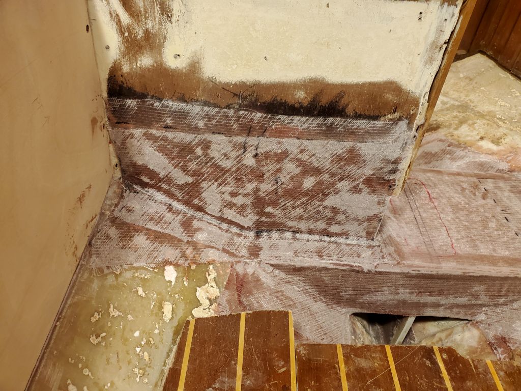
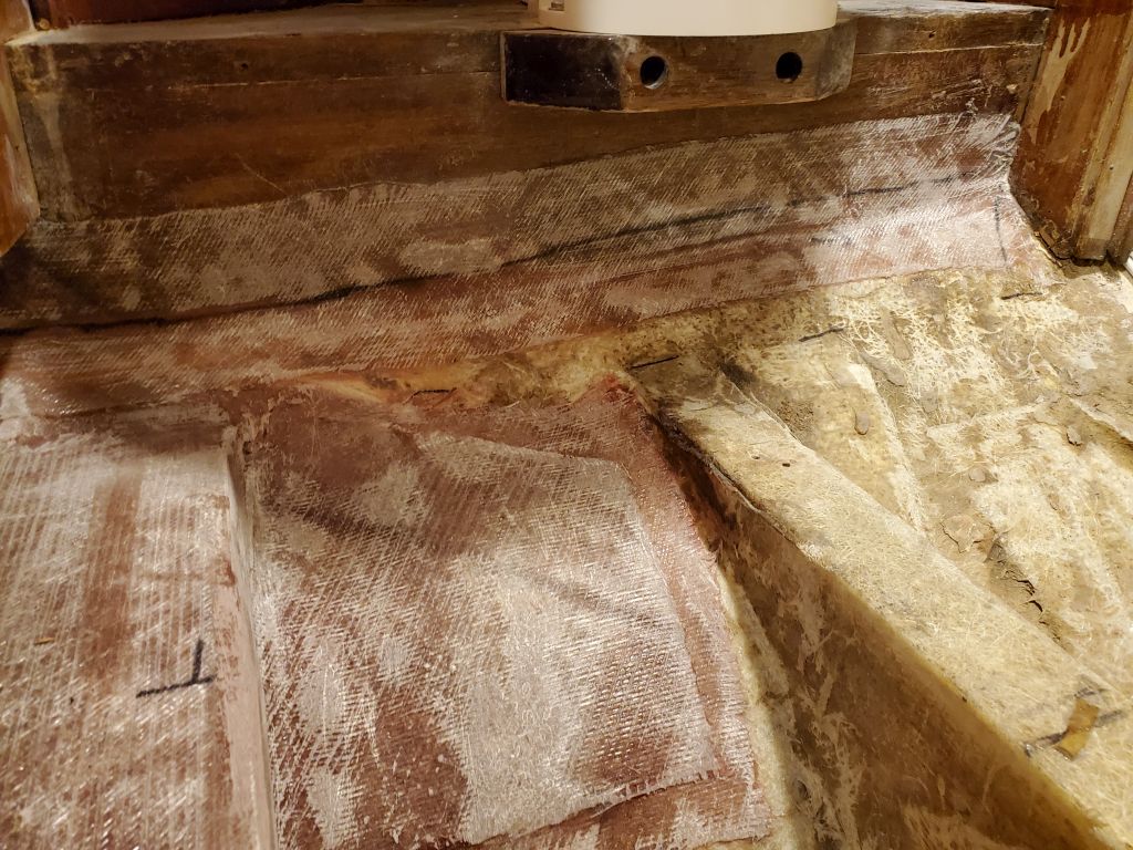
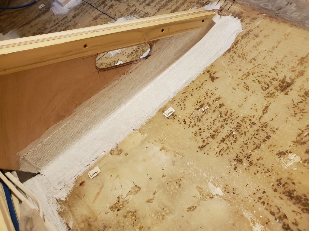
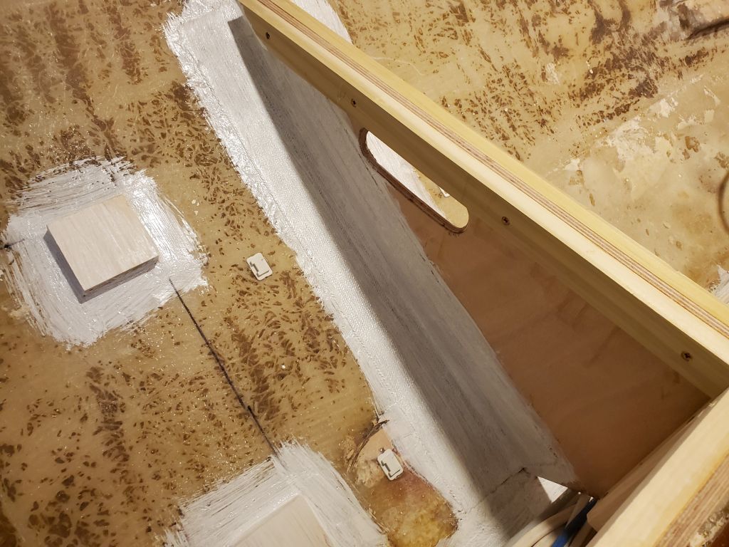
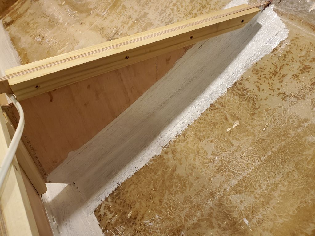
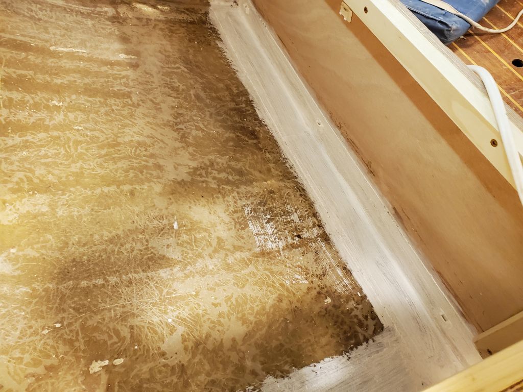
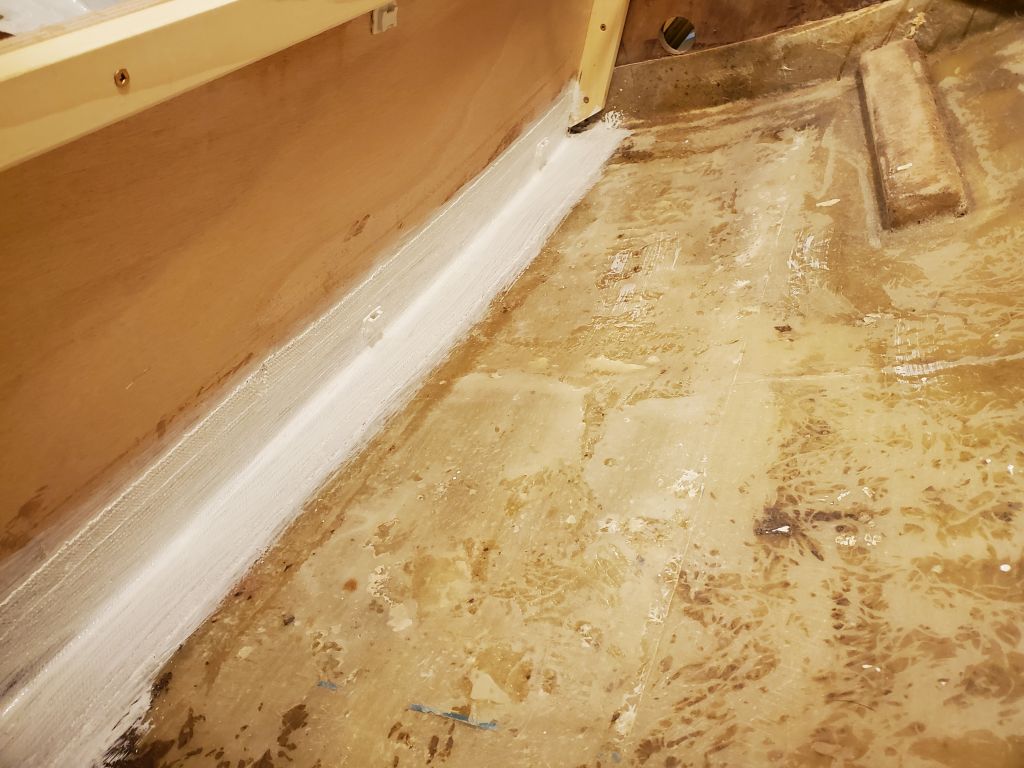
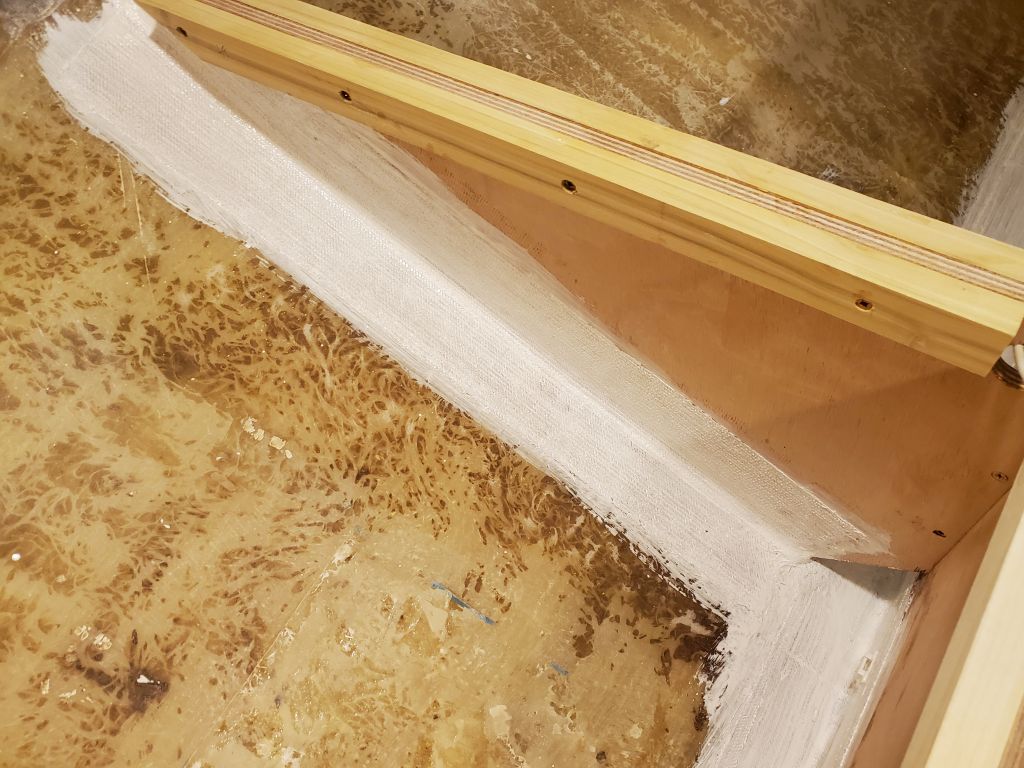
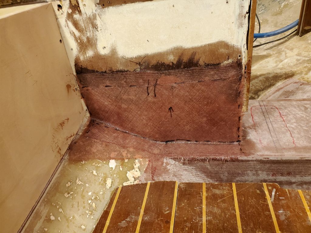
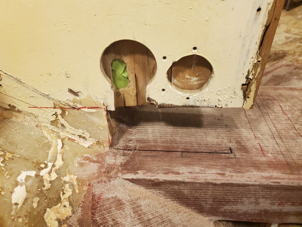
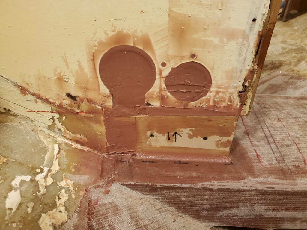
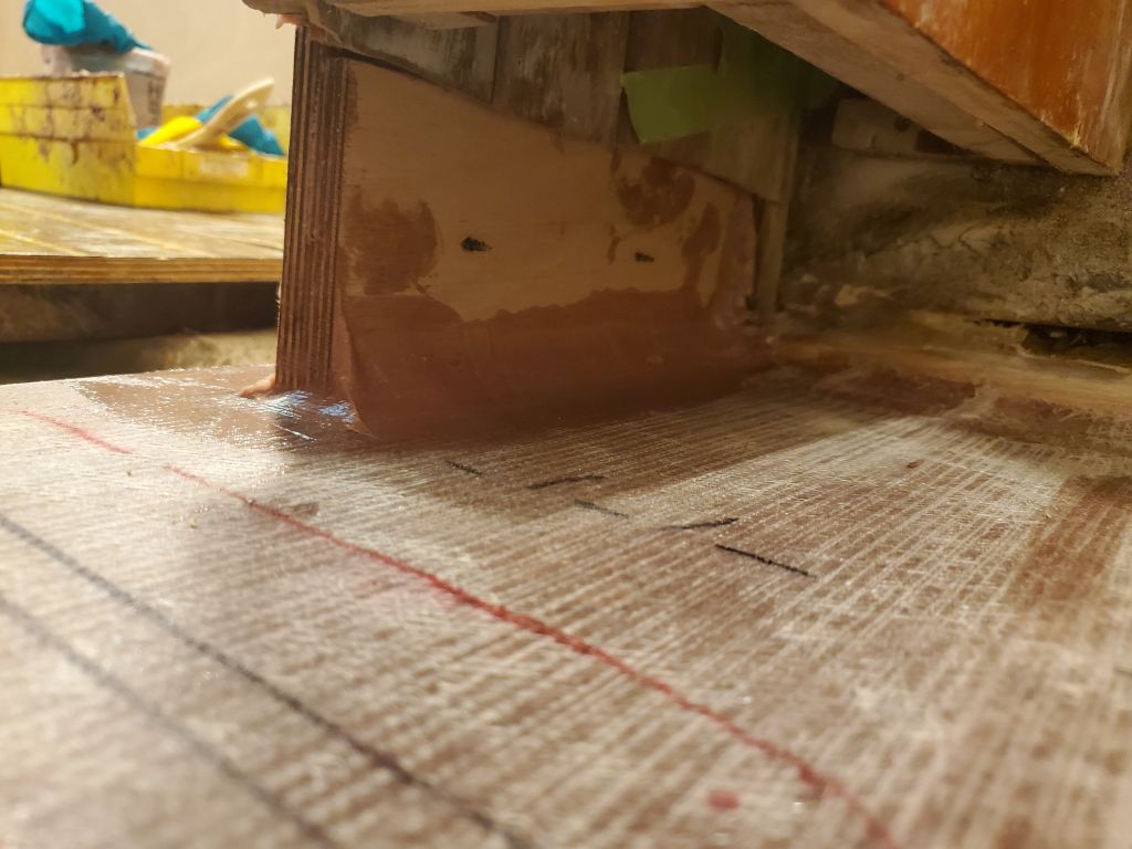
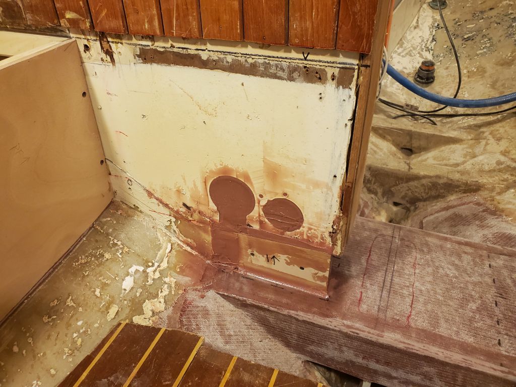
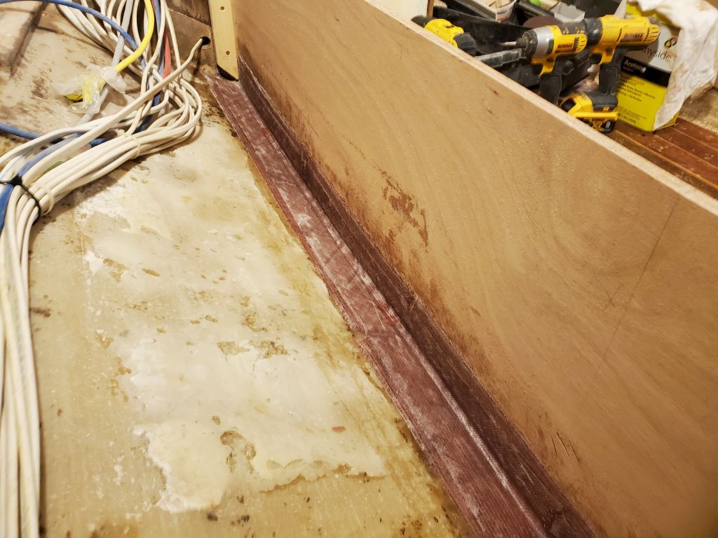
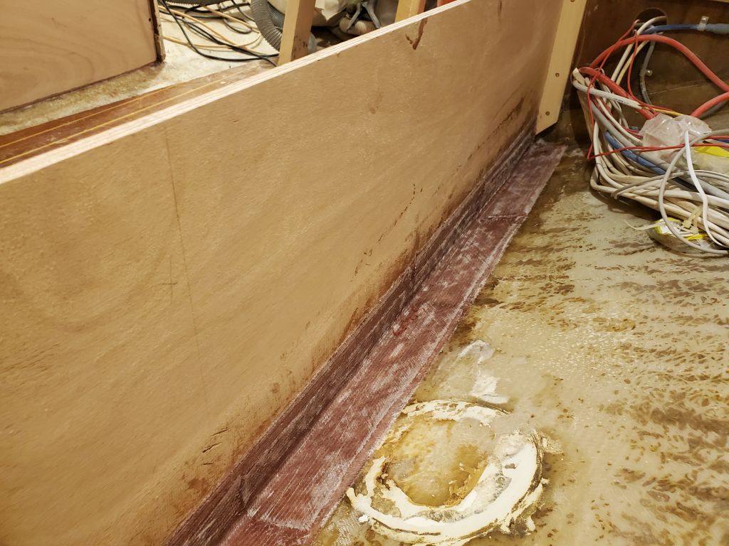
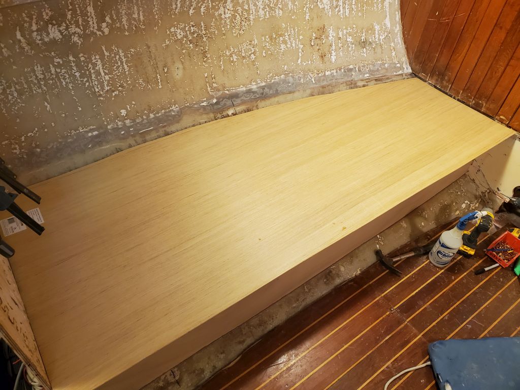
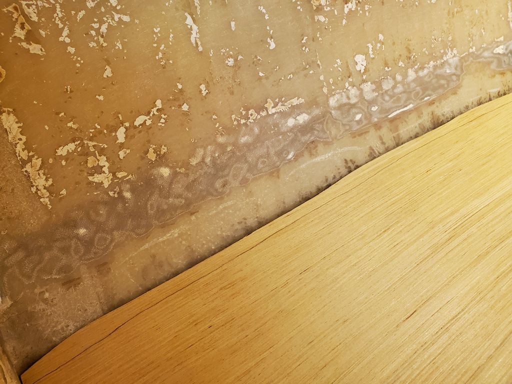
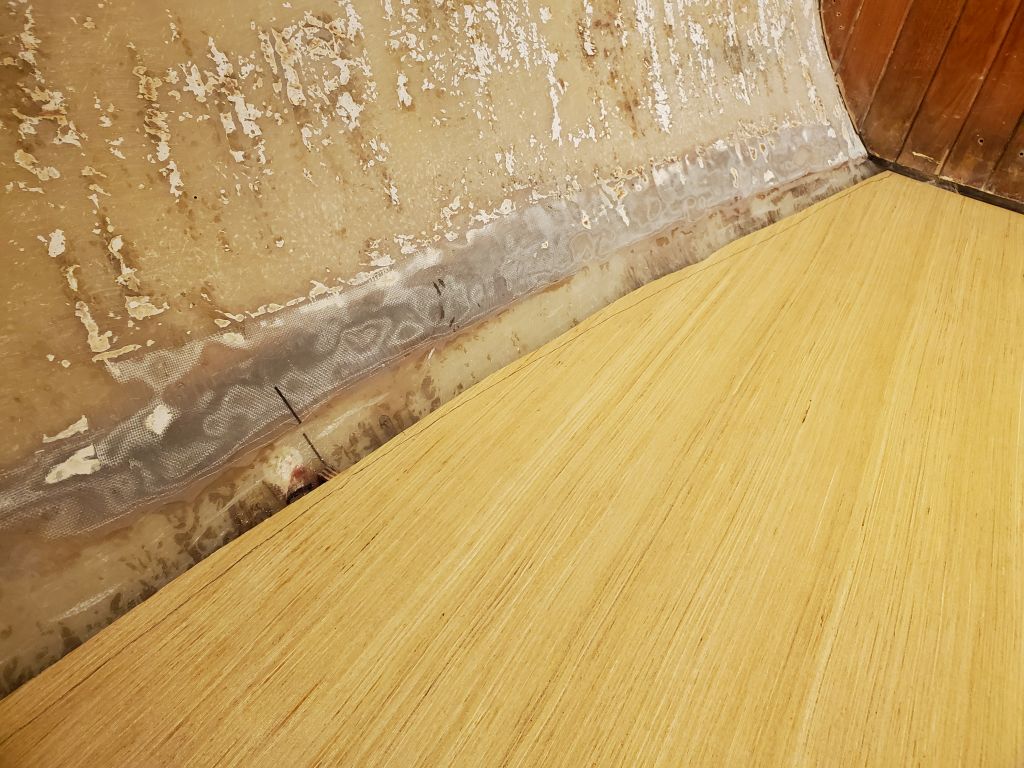
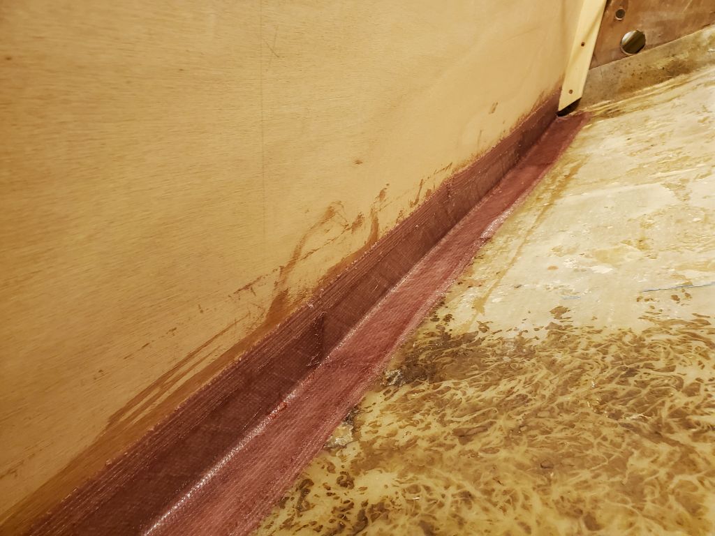
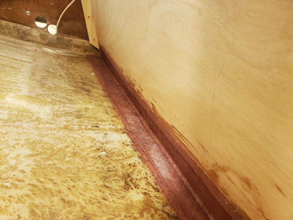
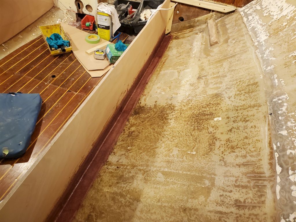
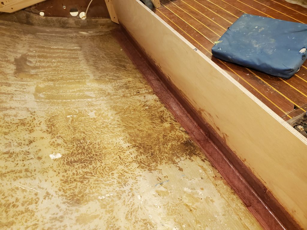
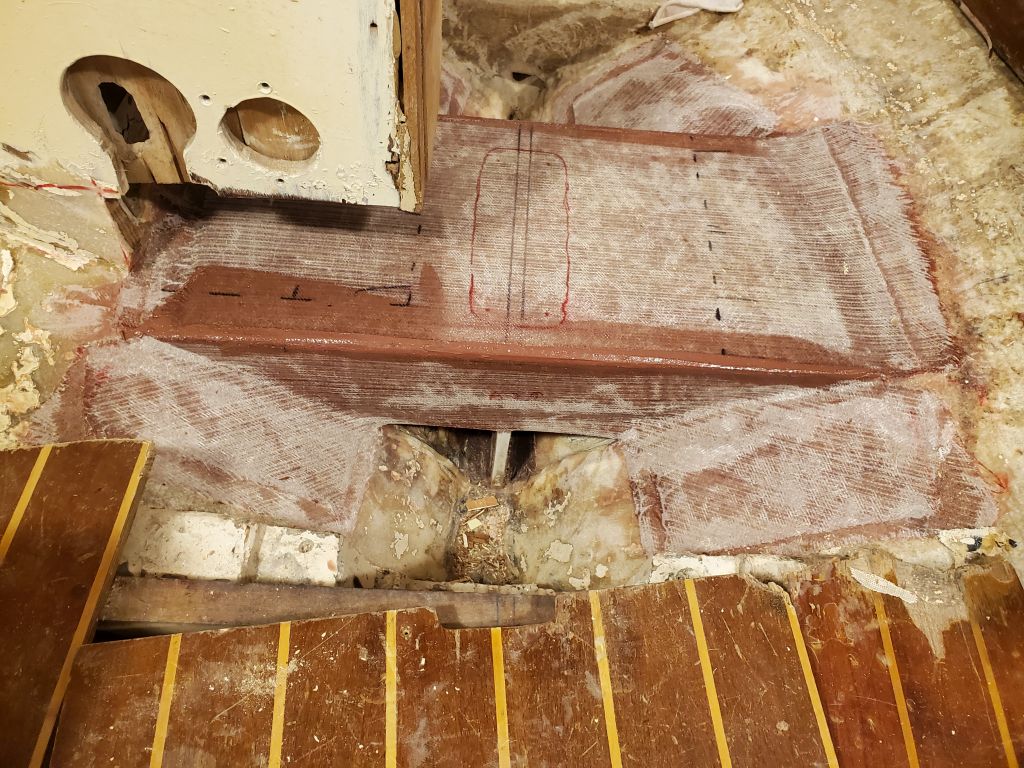
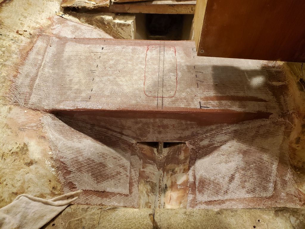
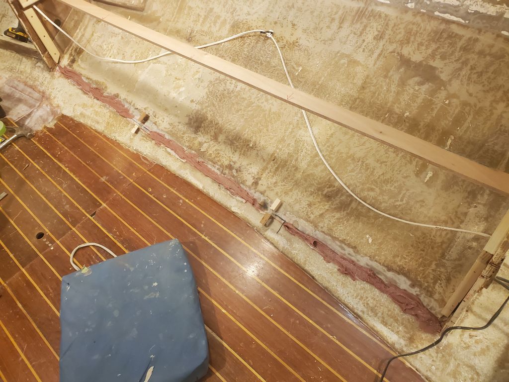
In my habitual way, I started the day with a water wash and light sanding of the new tabbing around the main bulkhead and head.

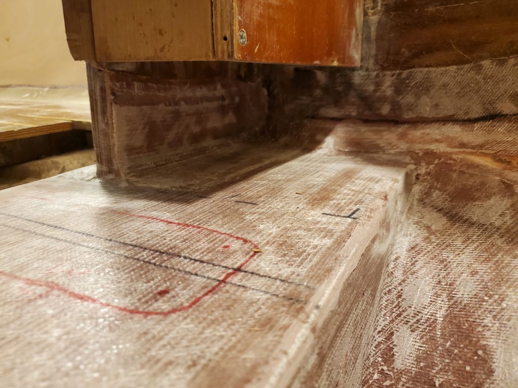
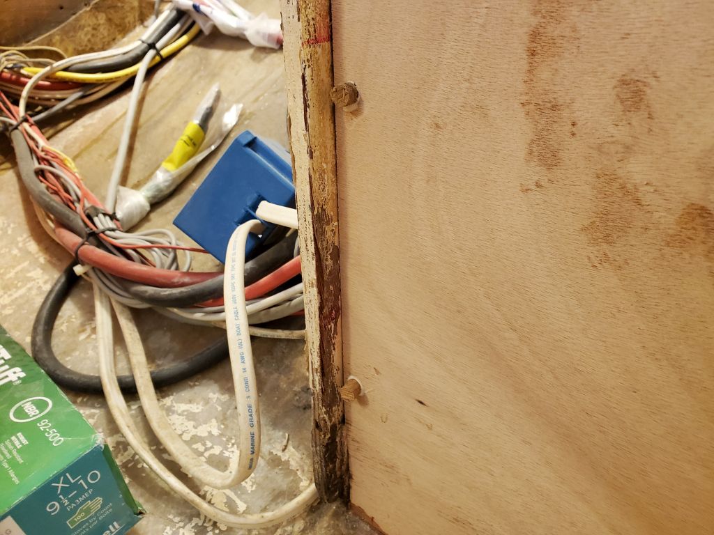
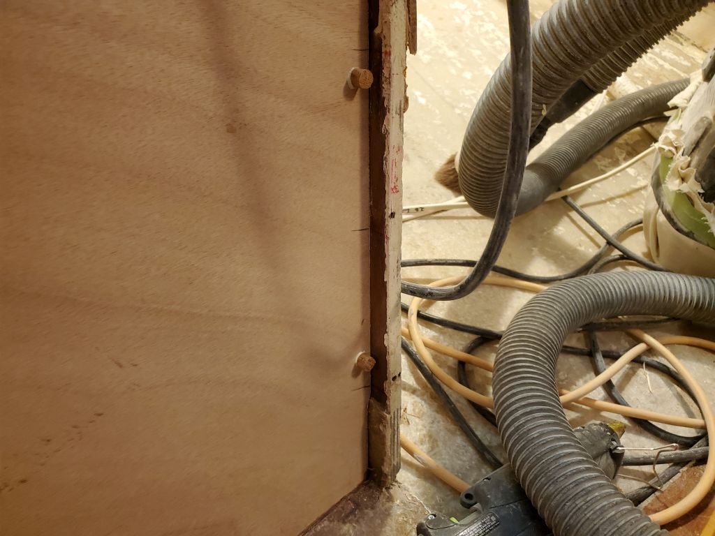
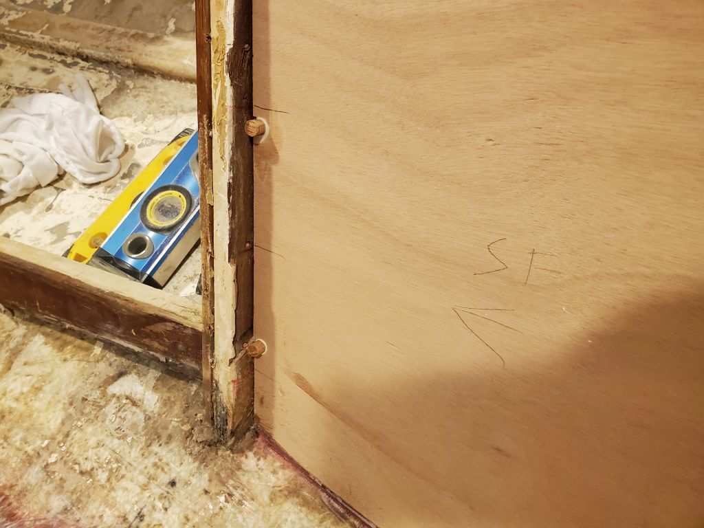
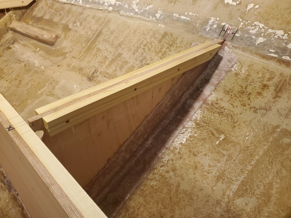
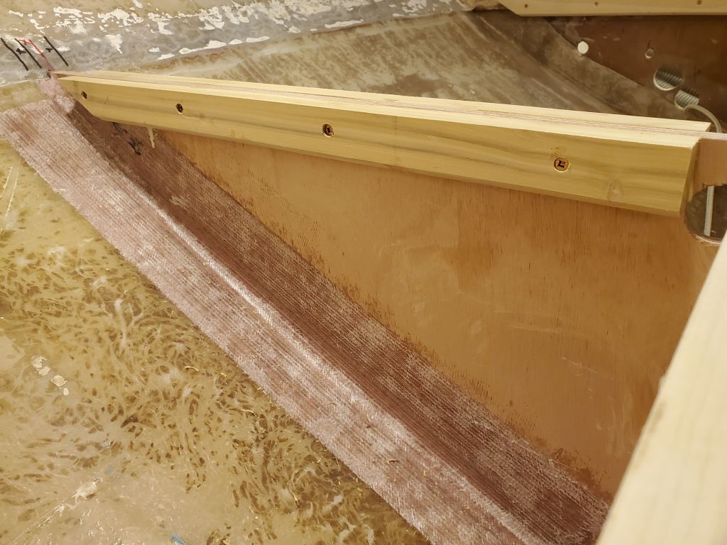
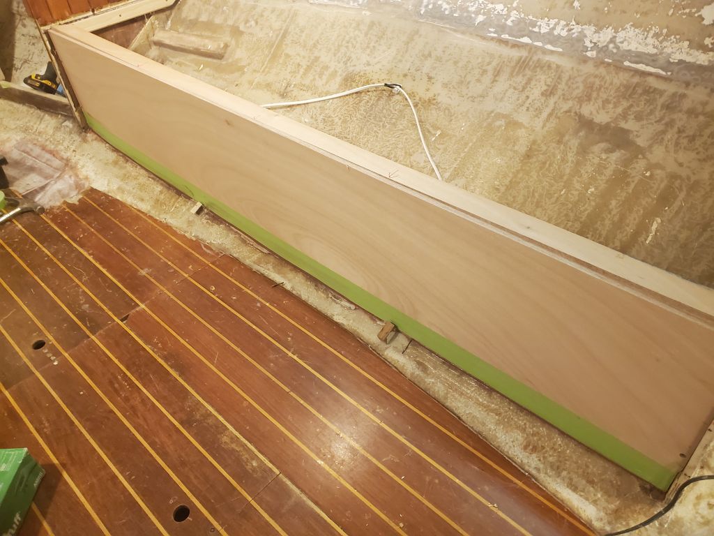
While I was thinking of it, I installed hardwood bungs in the screw holes securing the settee fronts to their cleats.

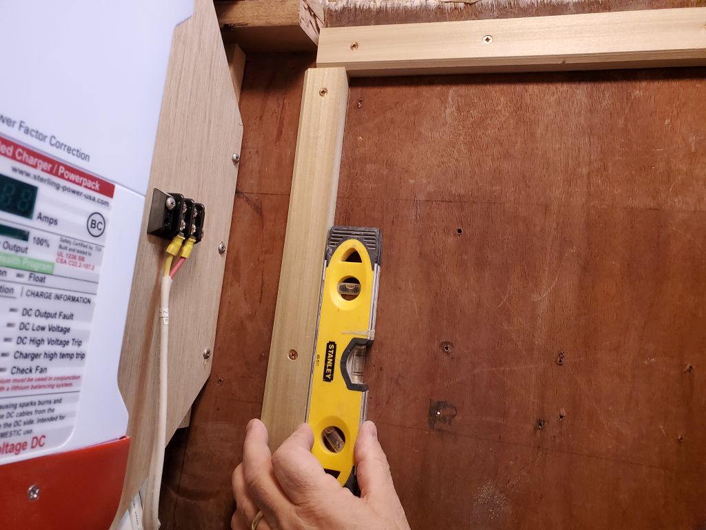
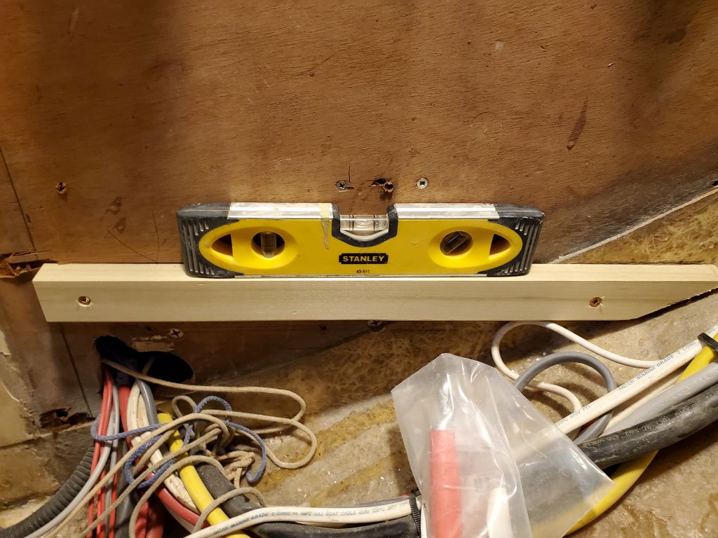
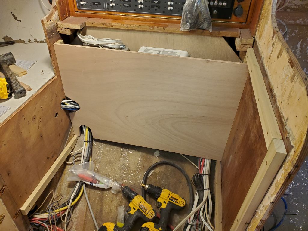
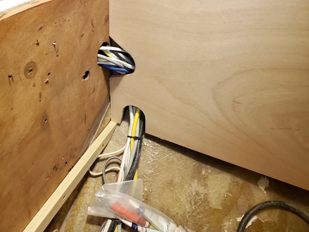
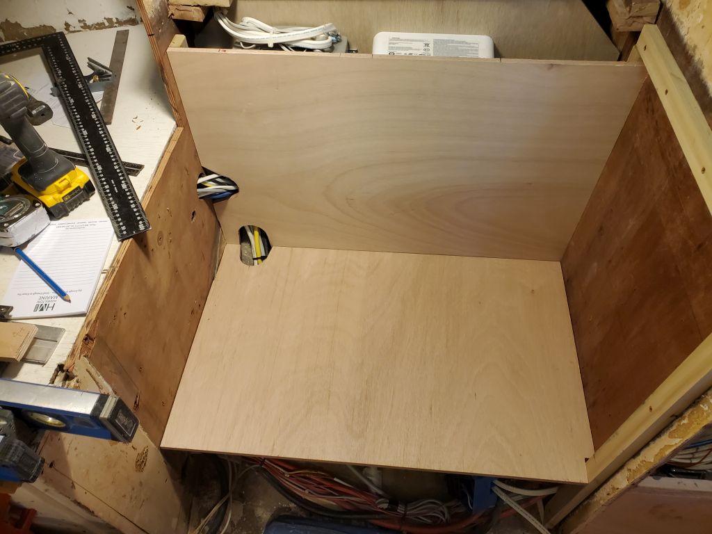
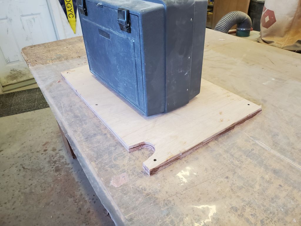
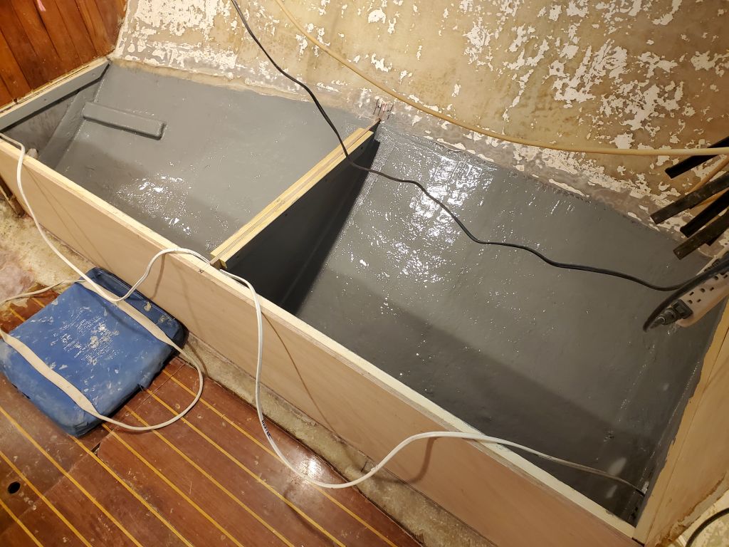
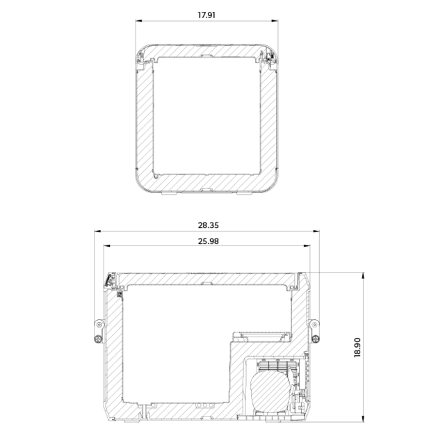
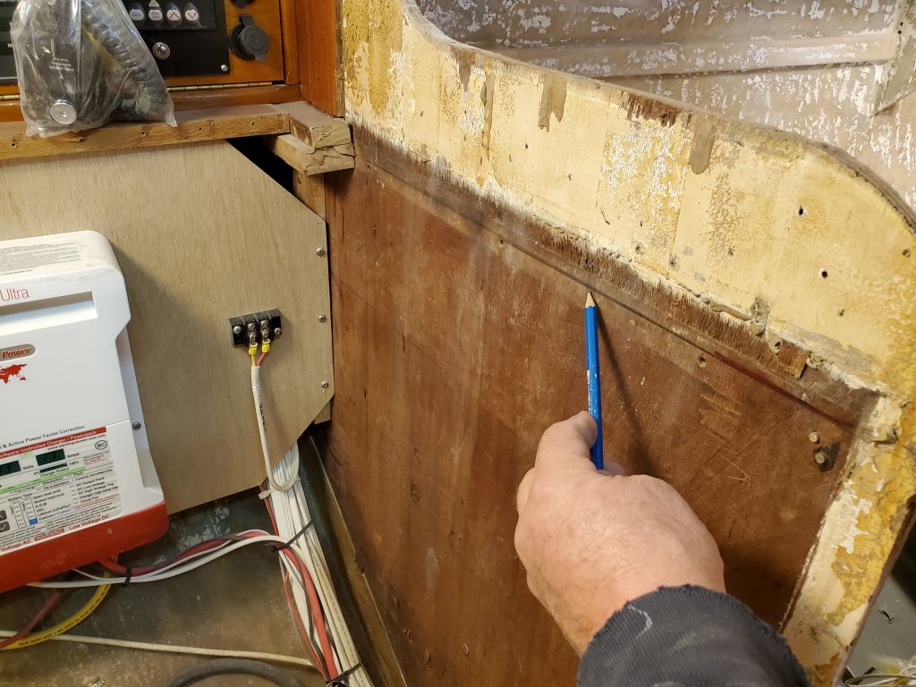
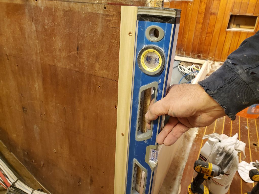
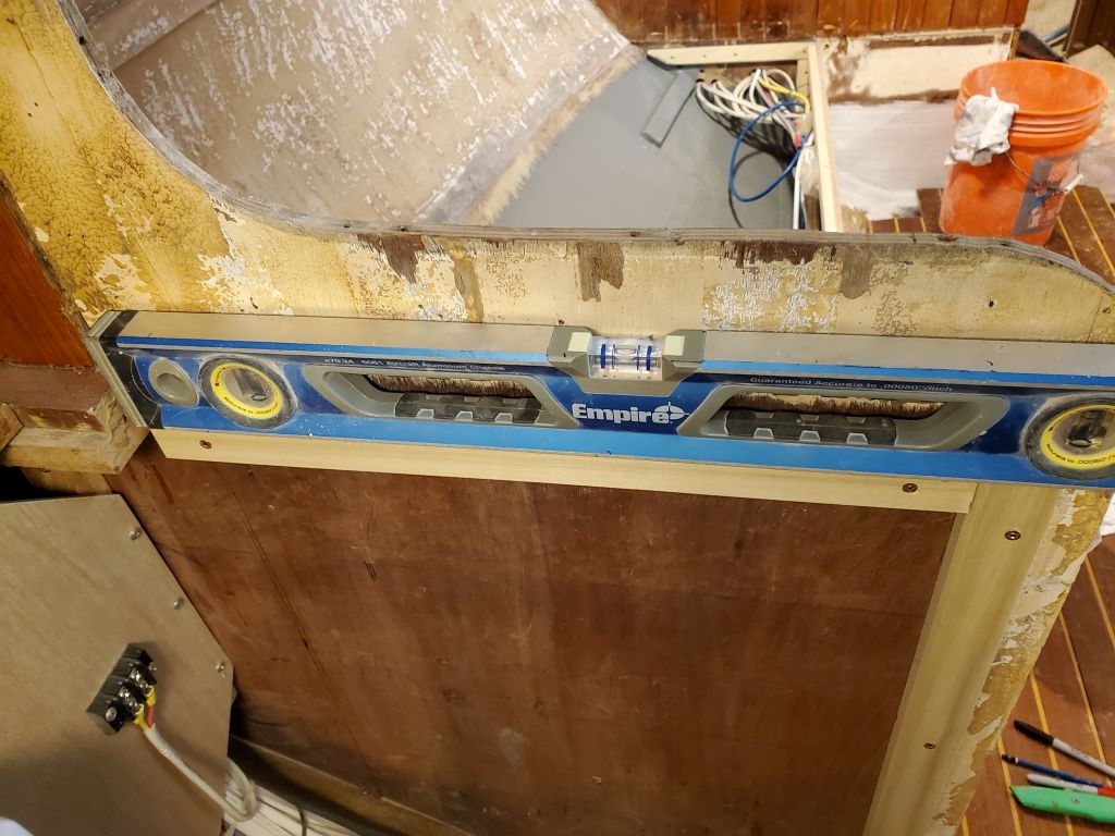
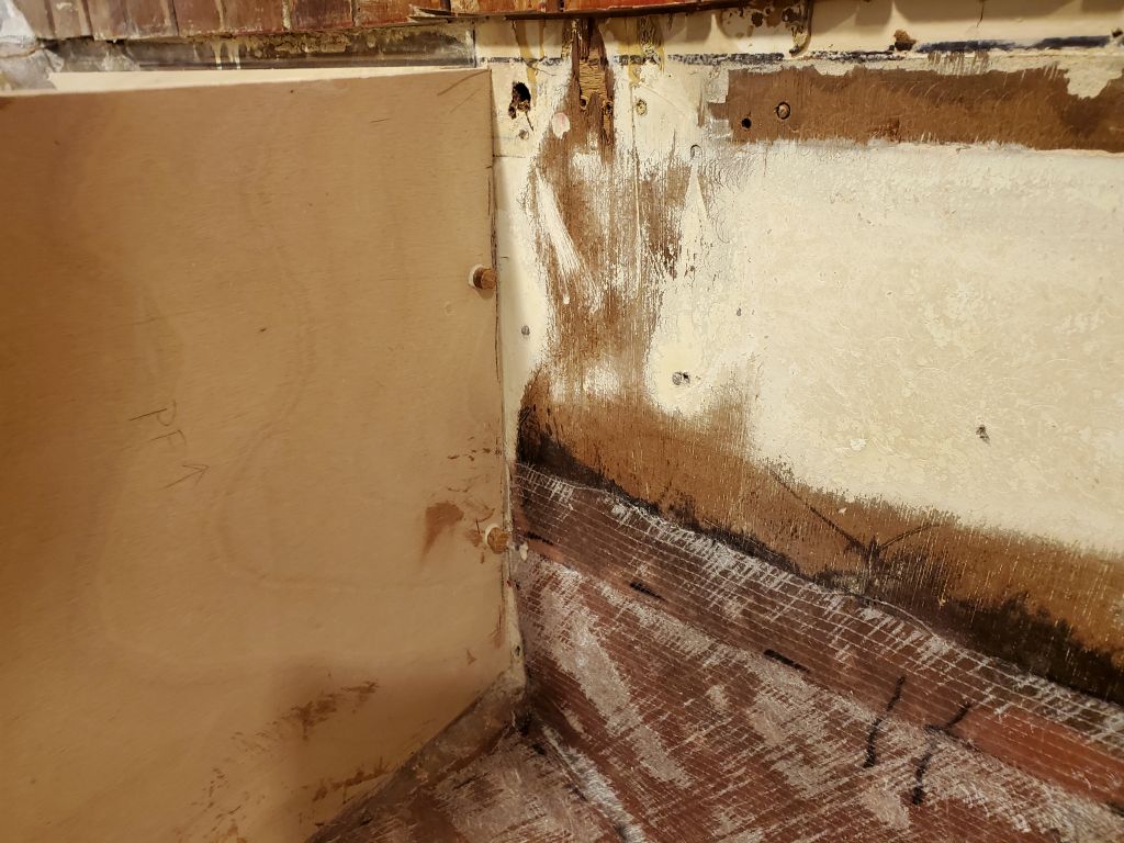
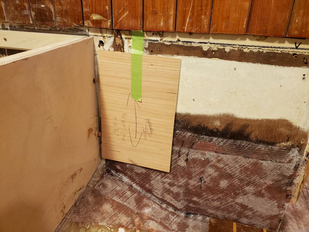
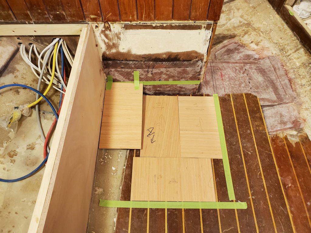
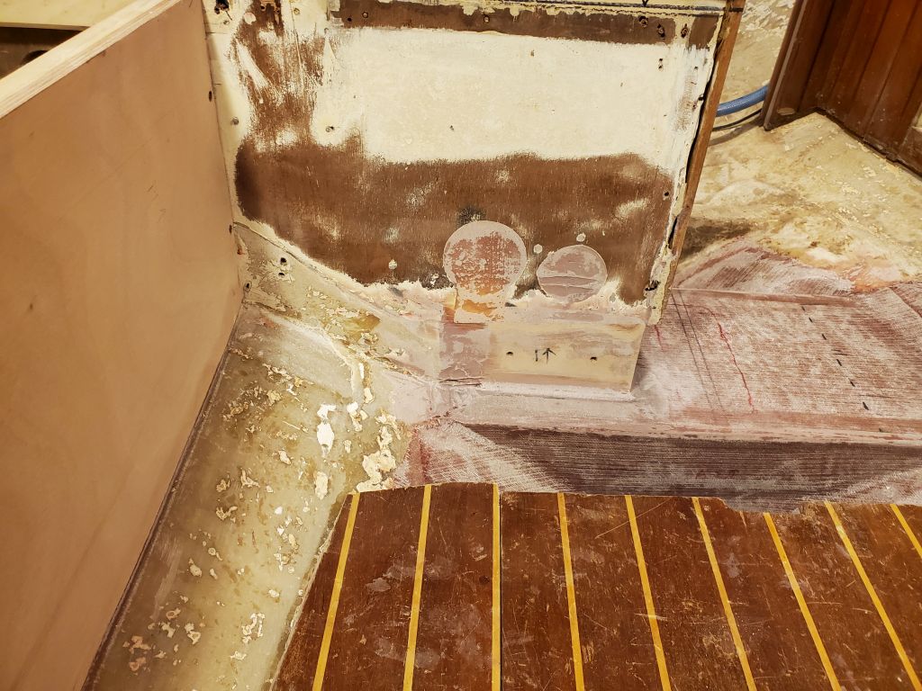
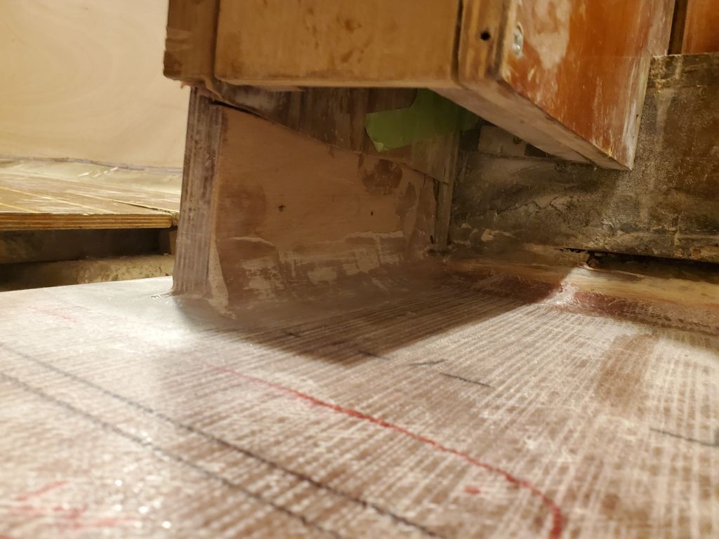
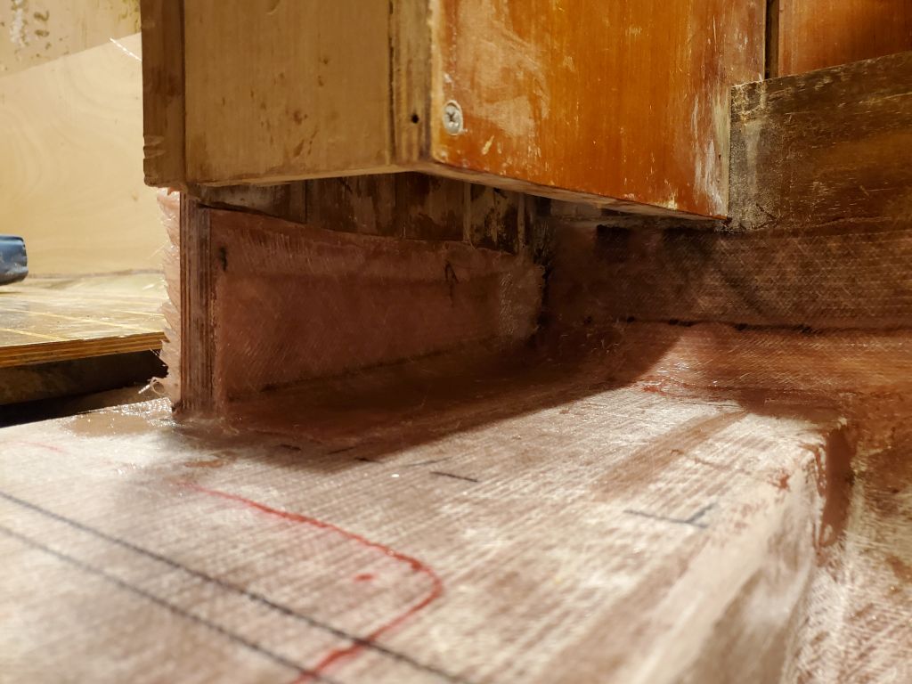
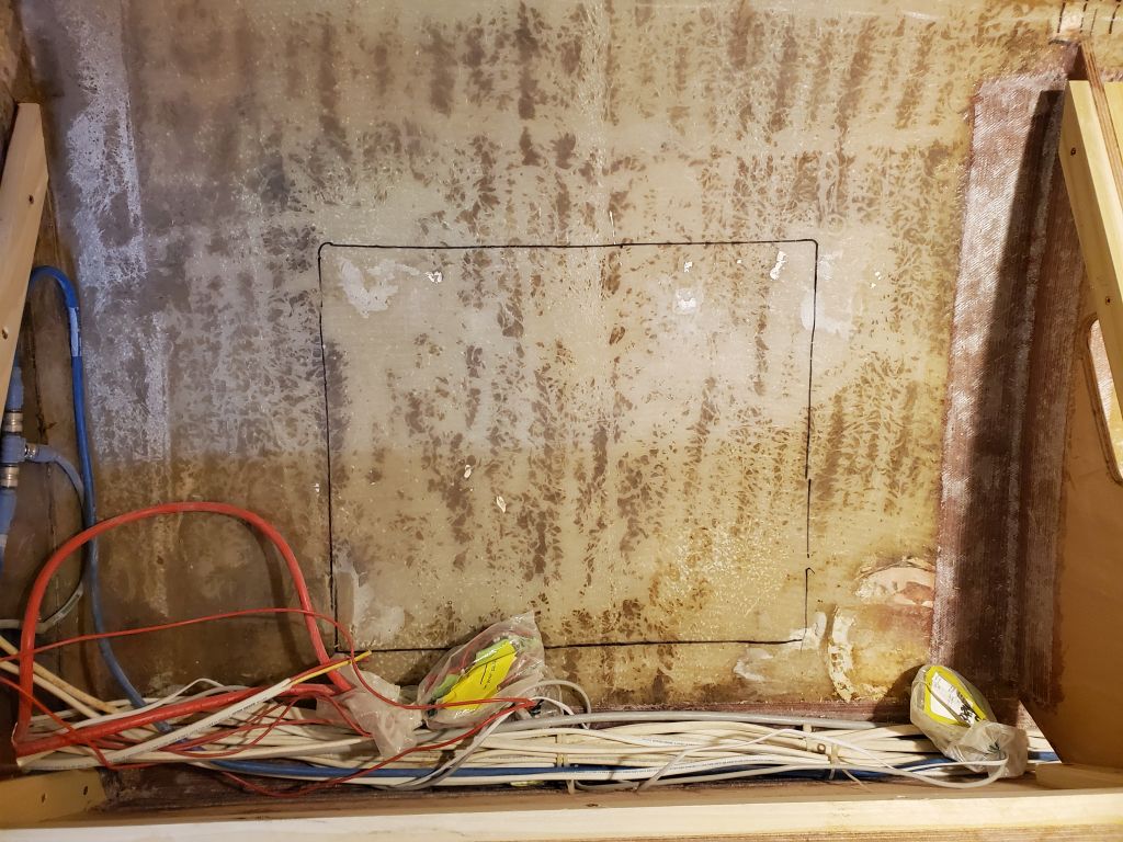
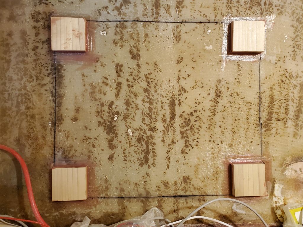
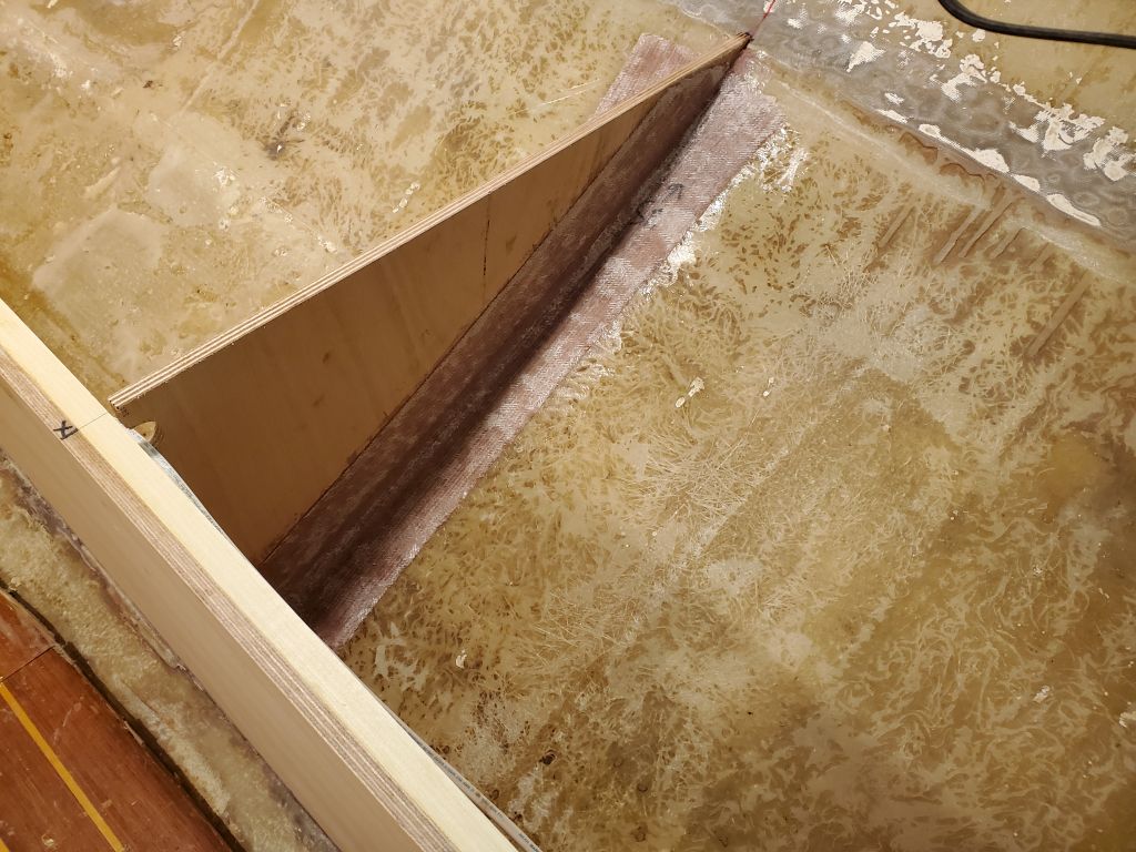
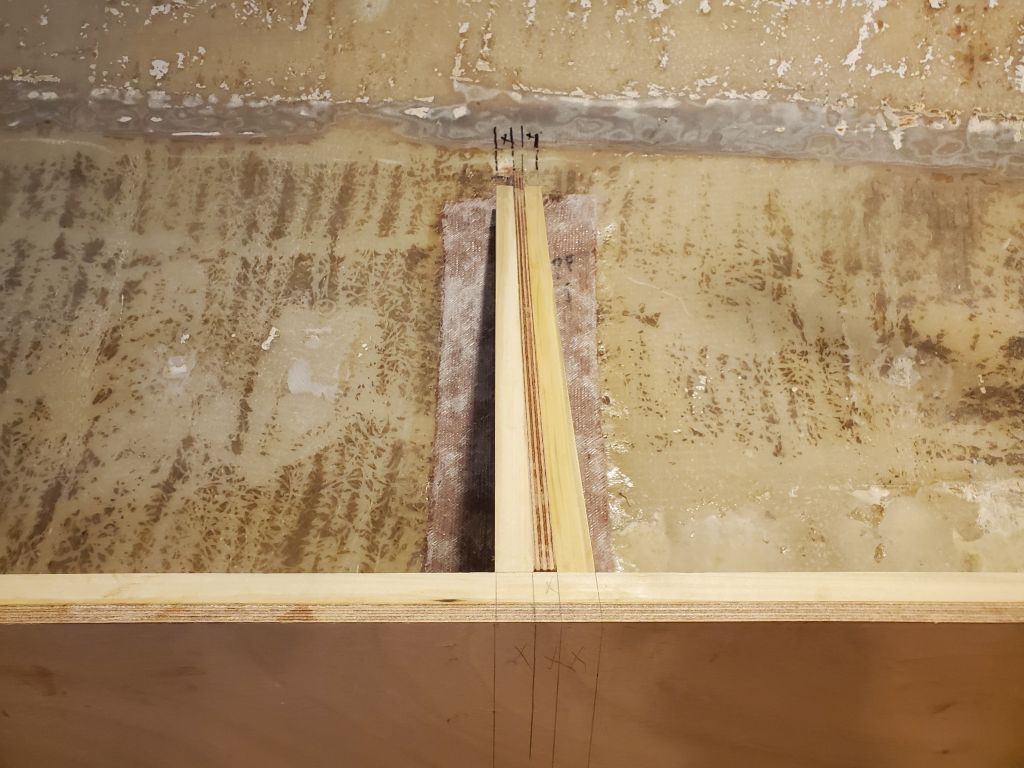
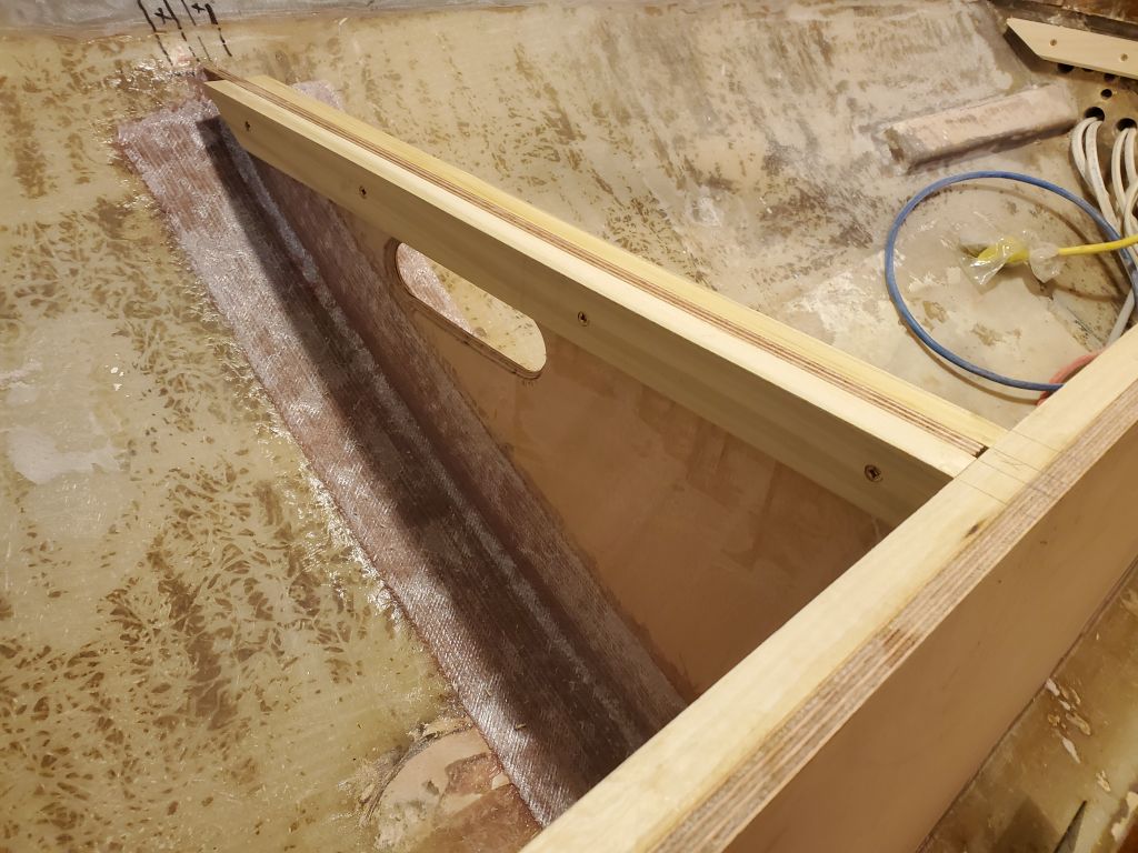
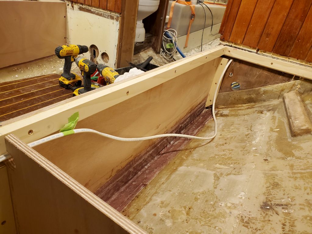
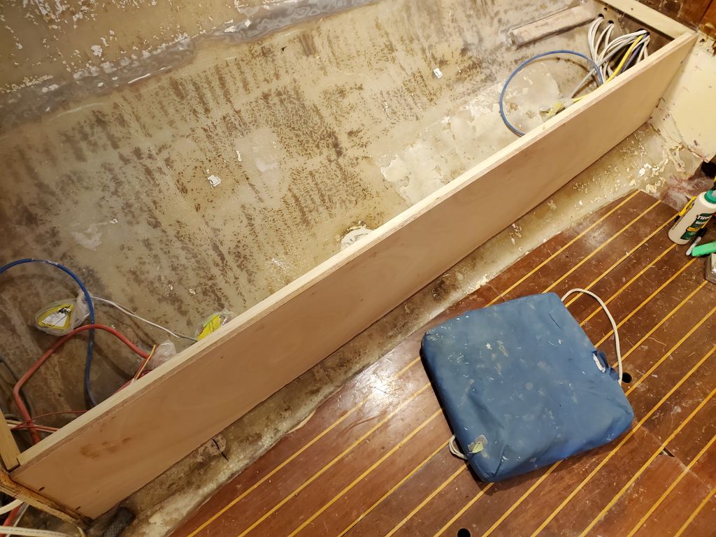
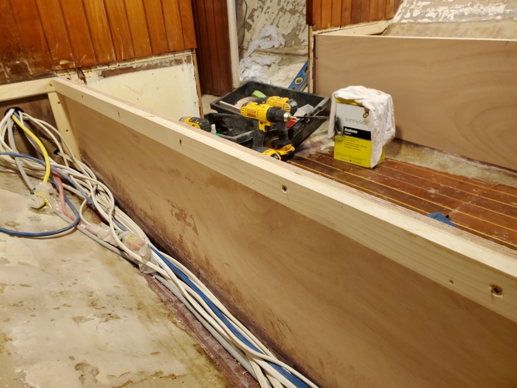
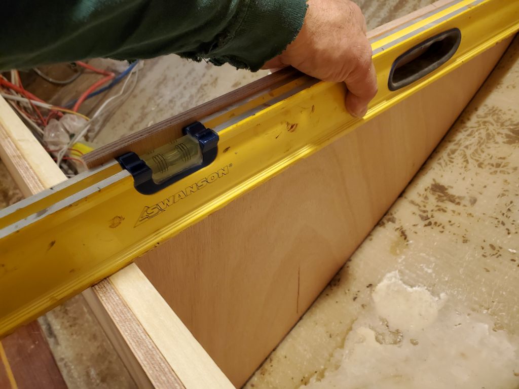
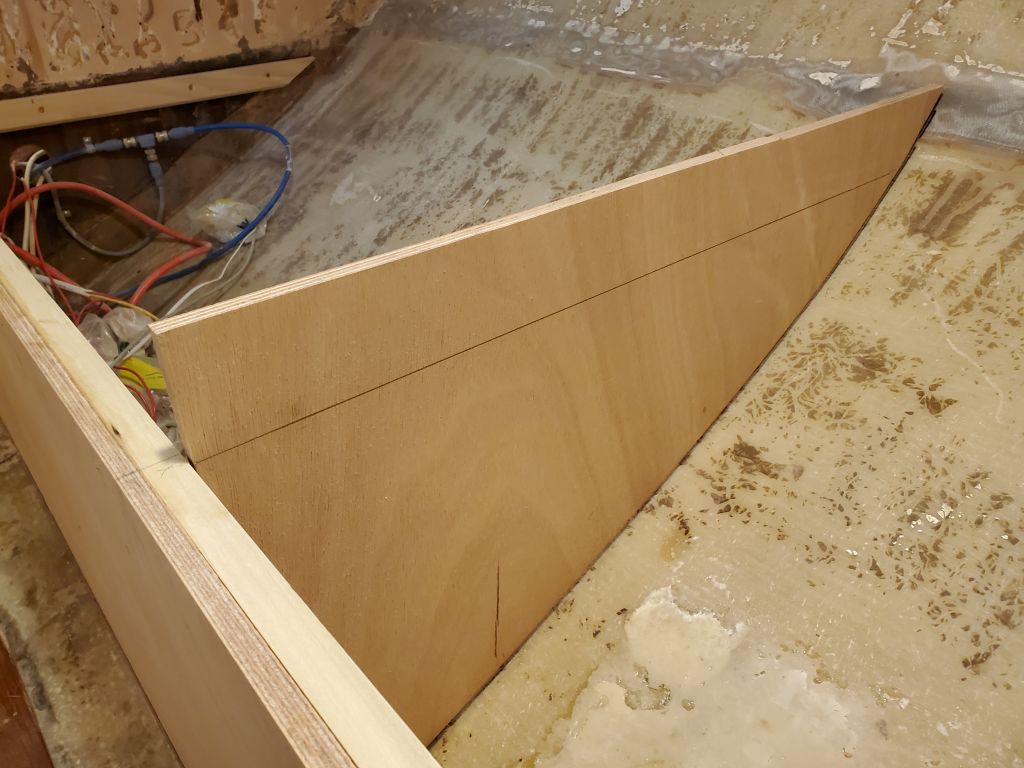
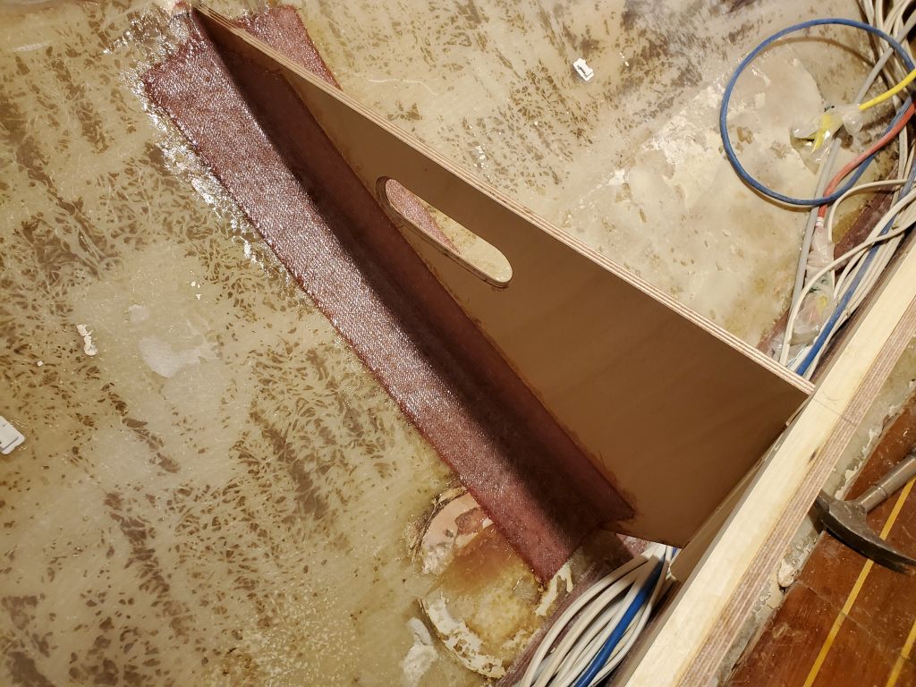
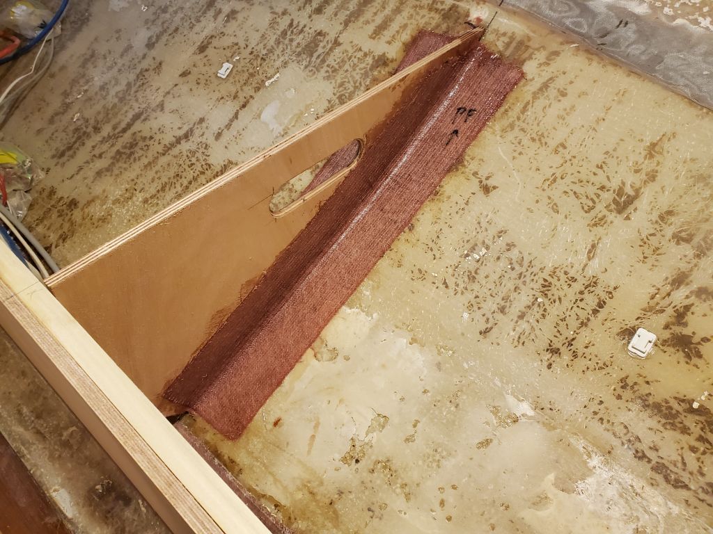
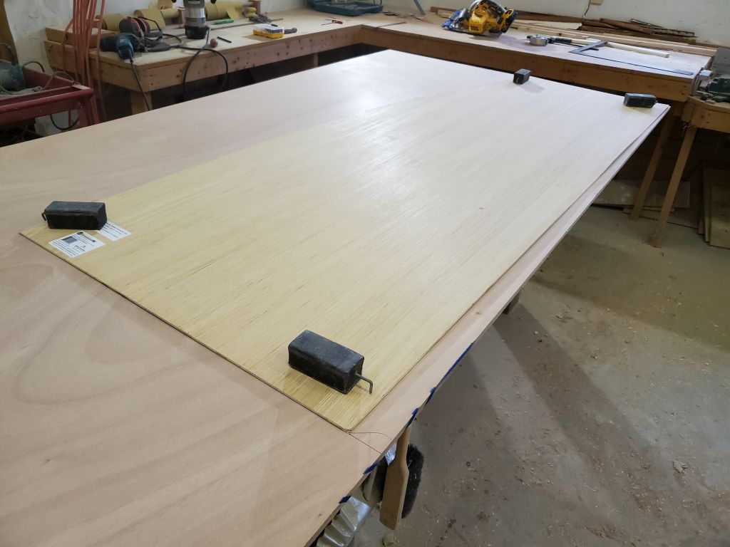
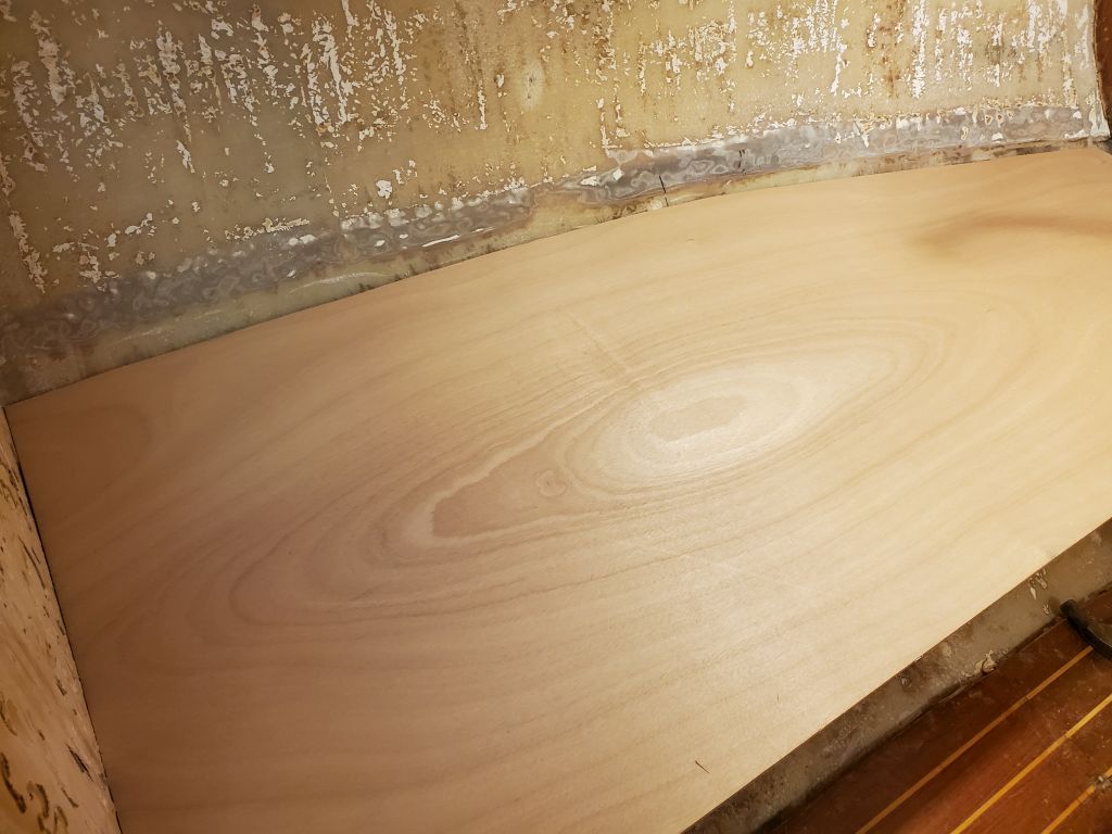
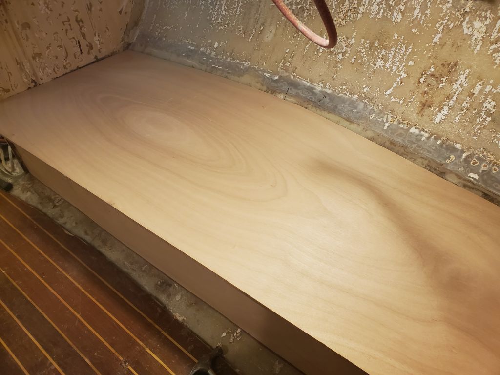
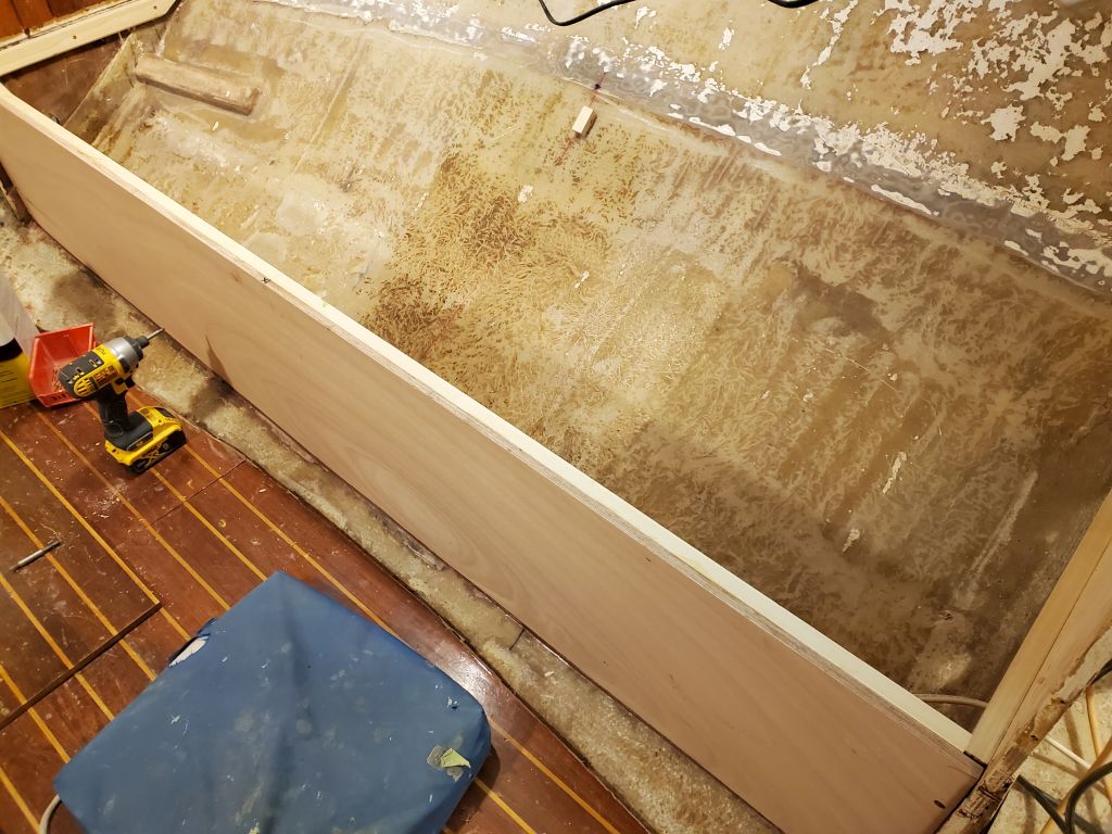
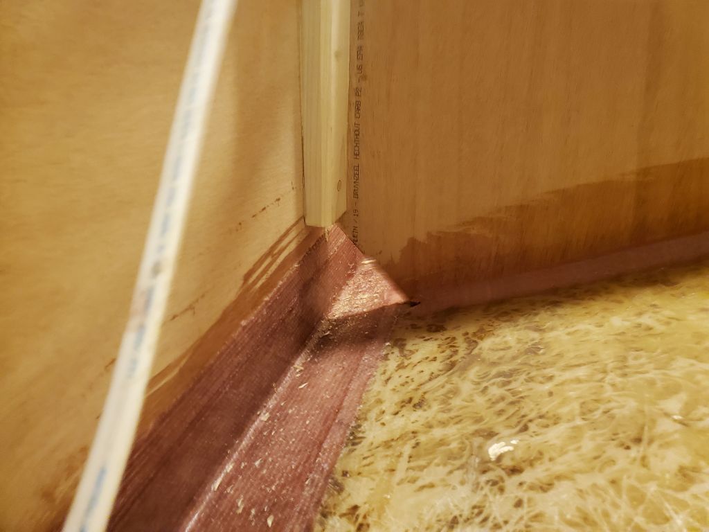
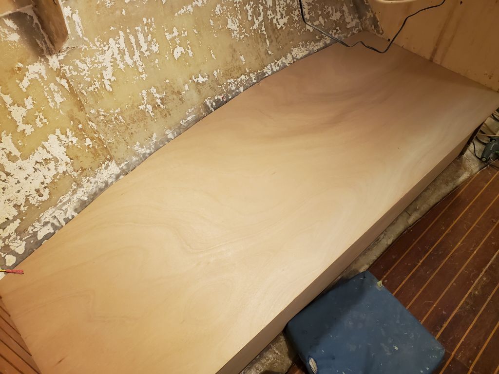
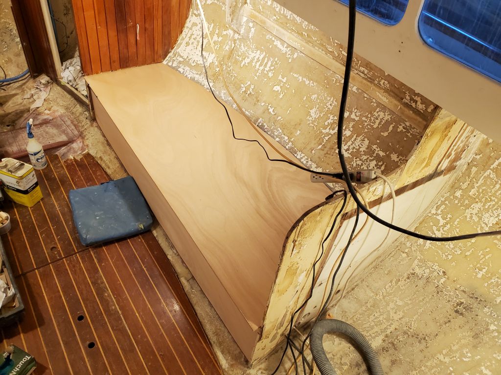
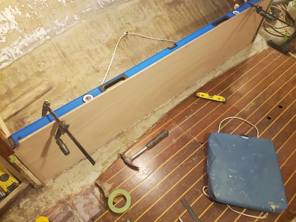
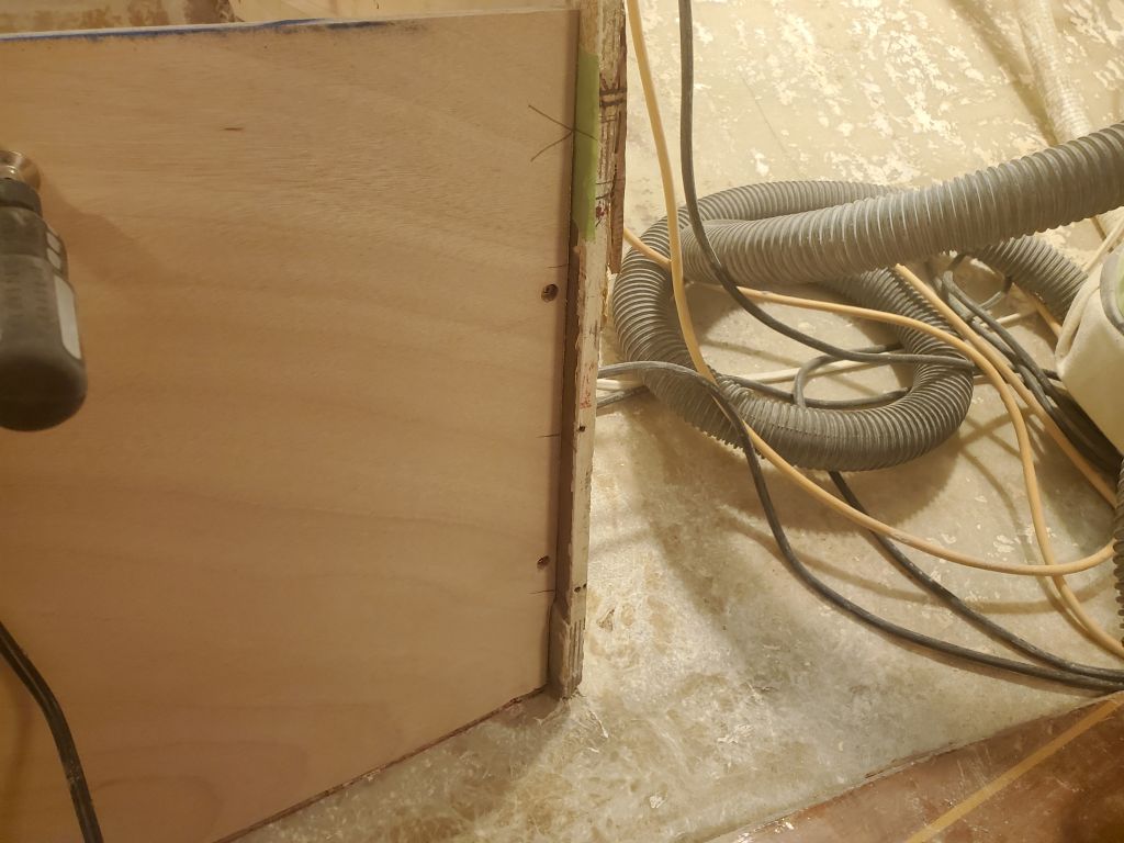
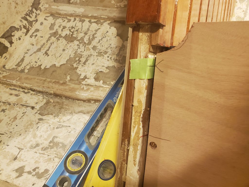
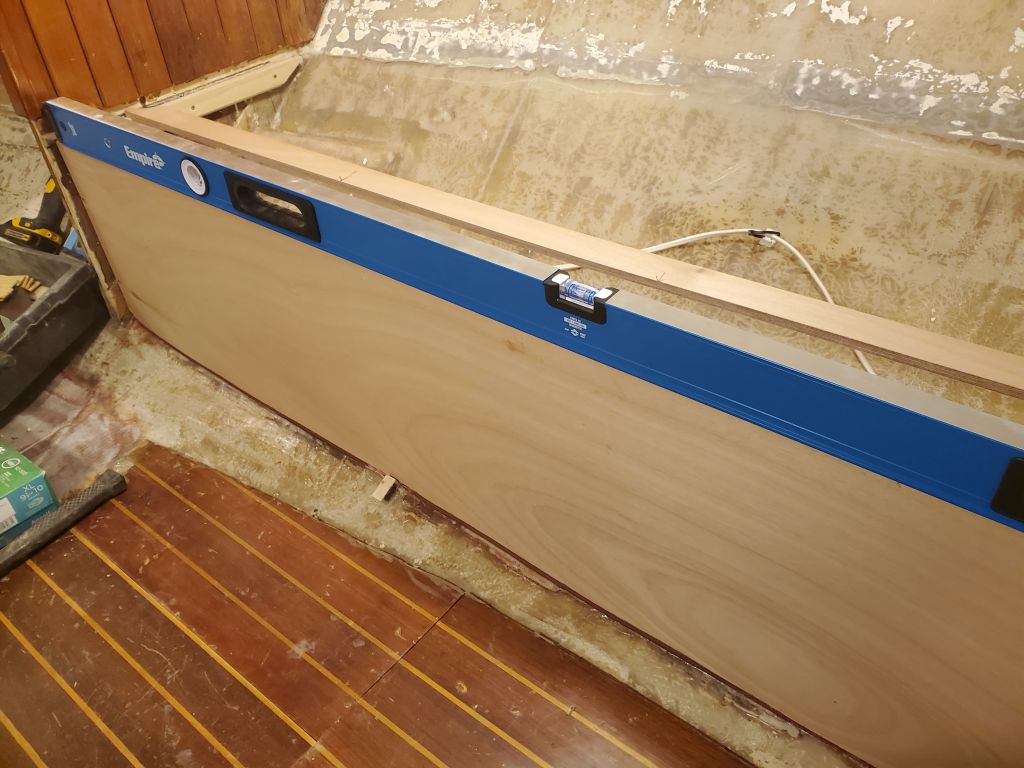
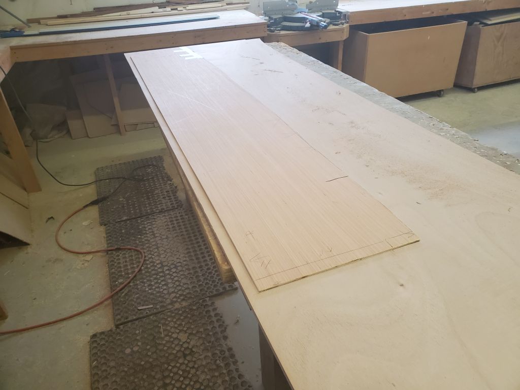
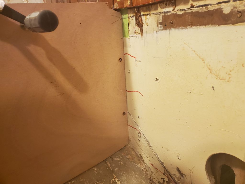
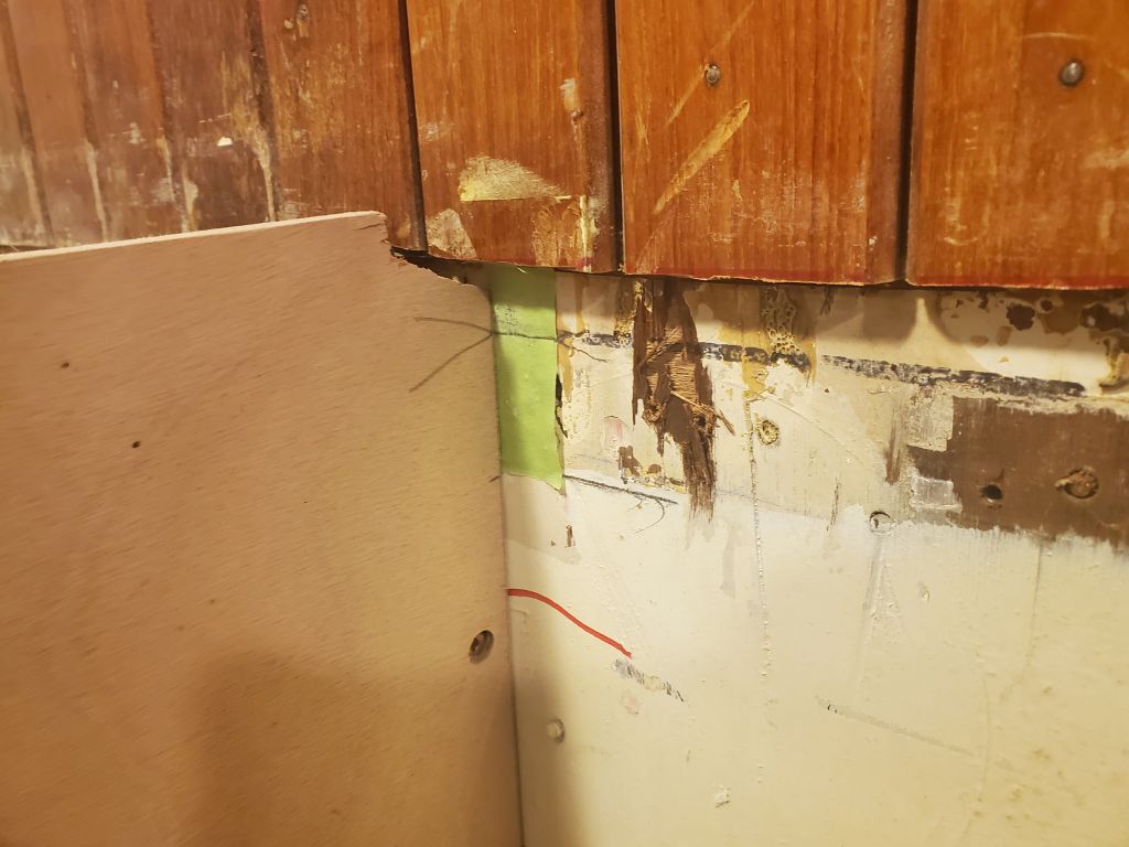
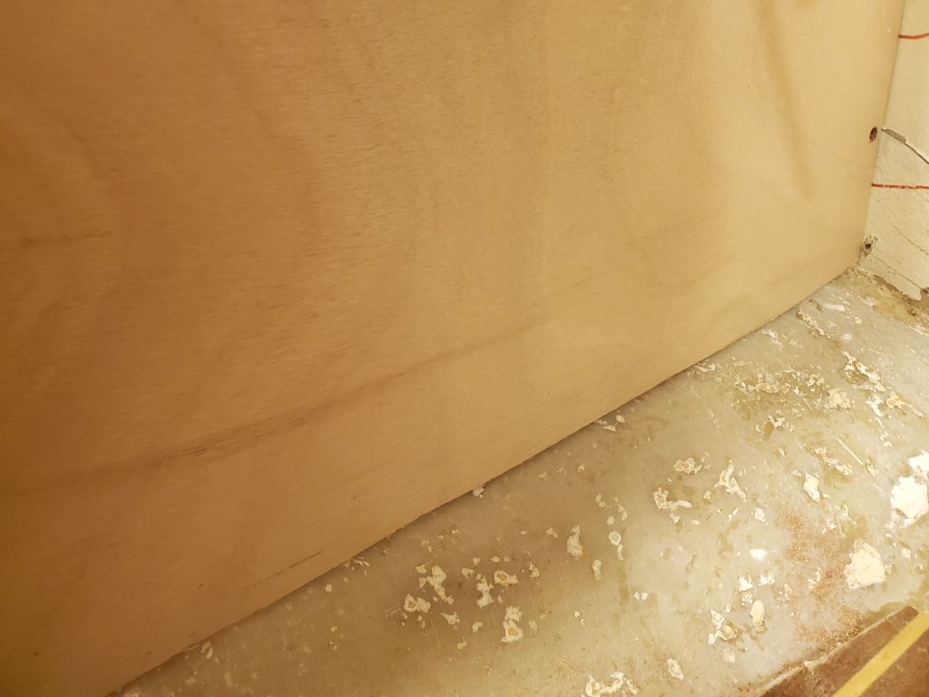
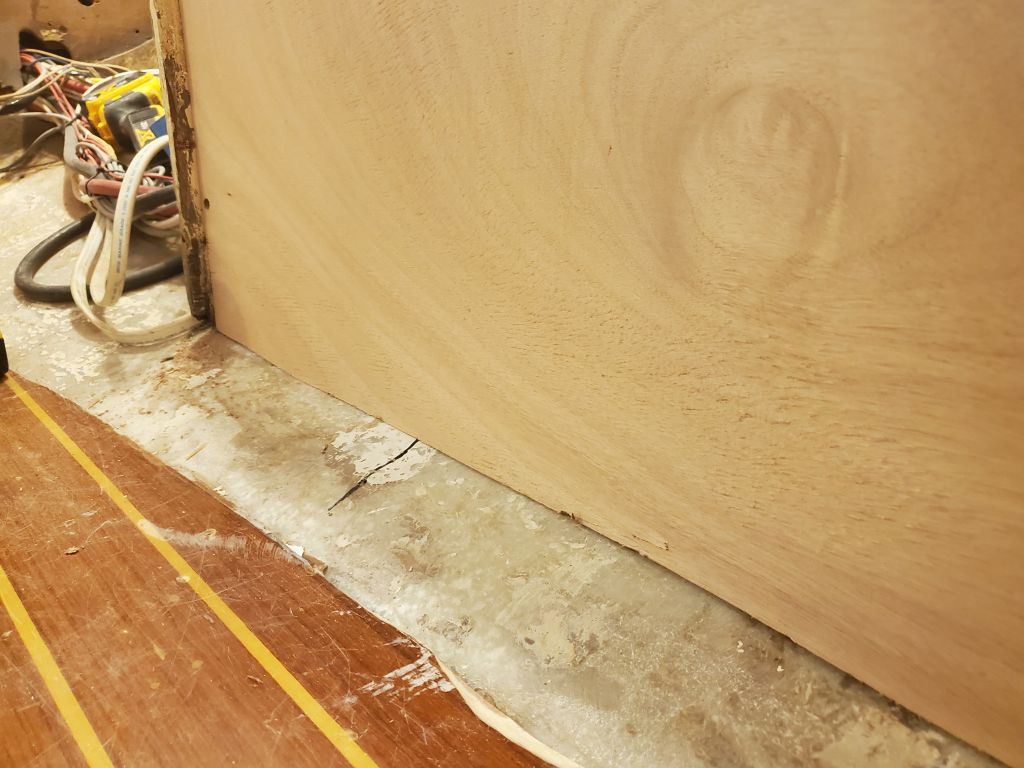
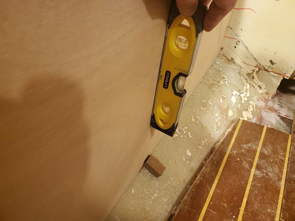
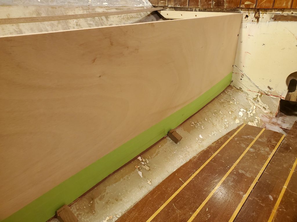
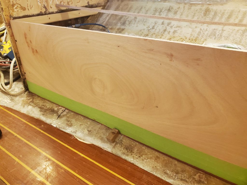
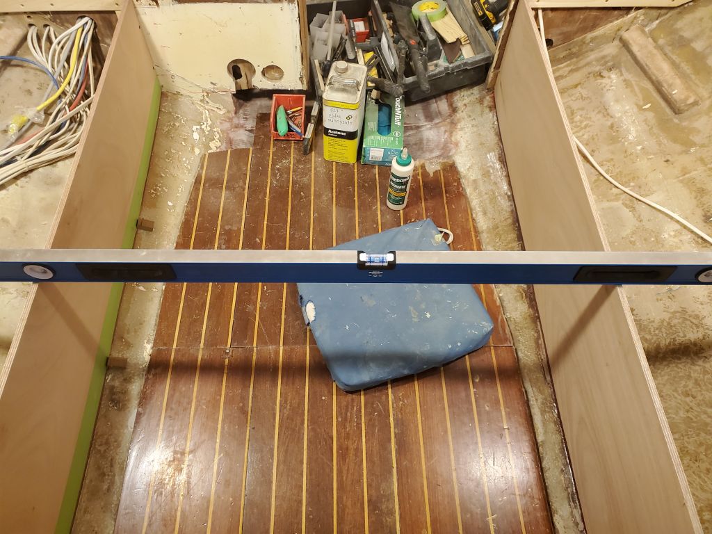
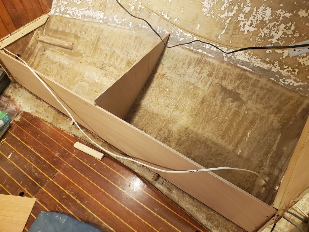
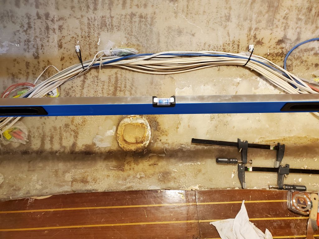
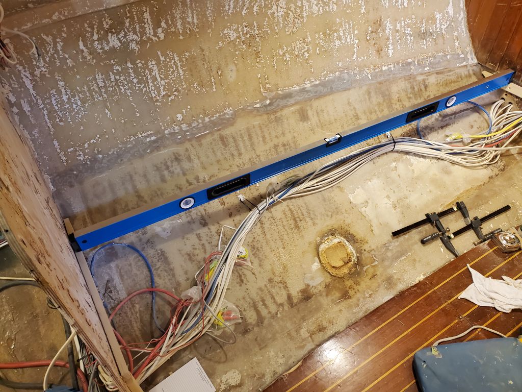
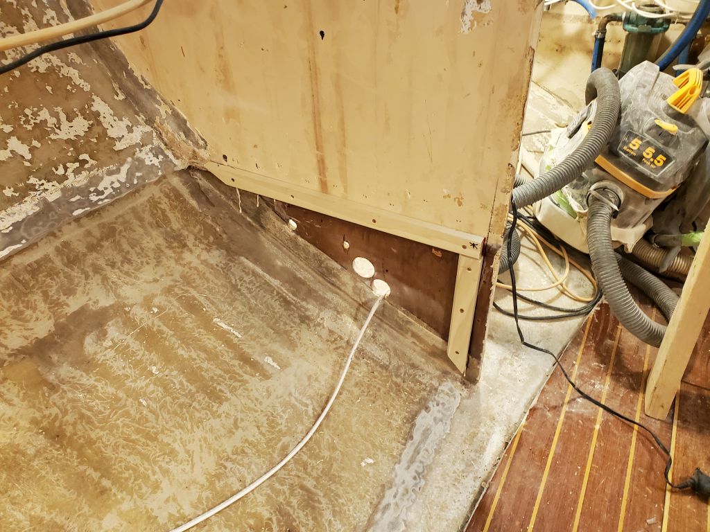
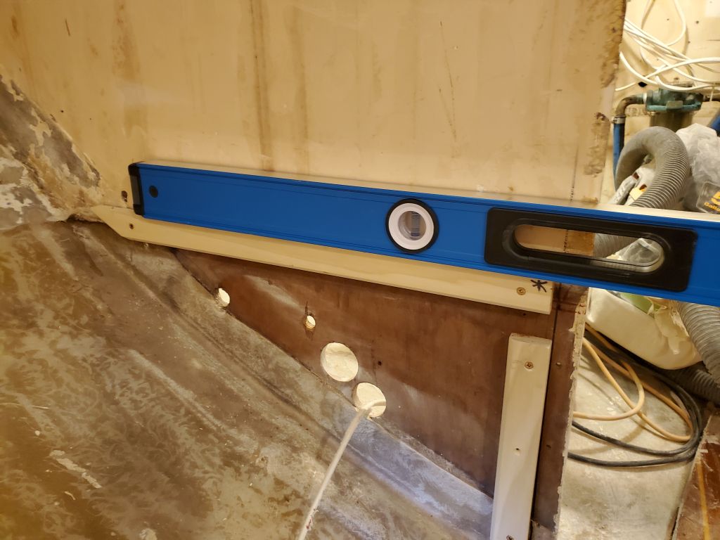
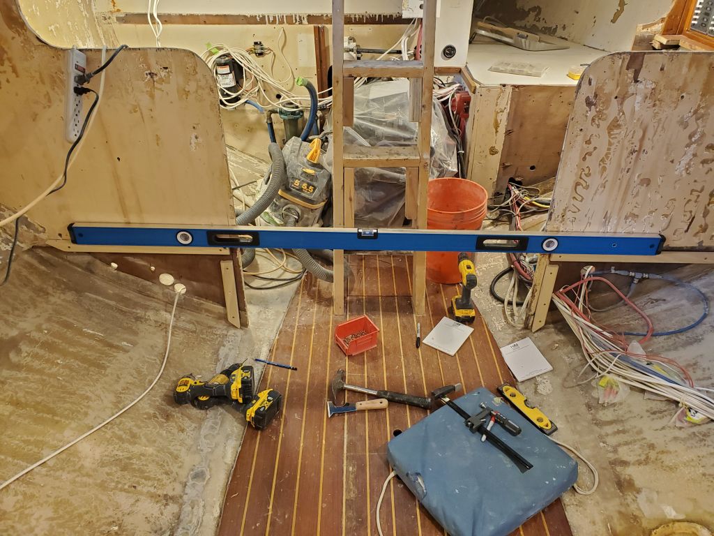
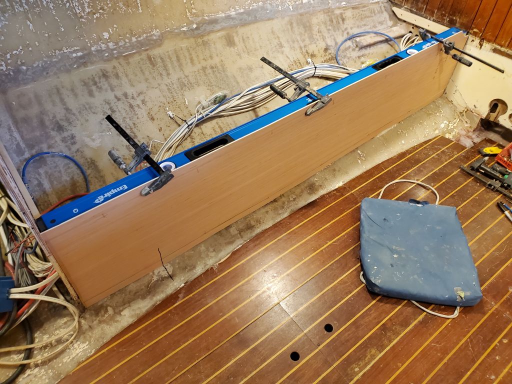
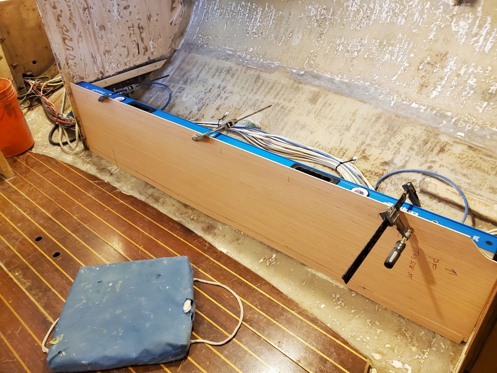
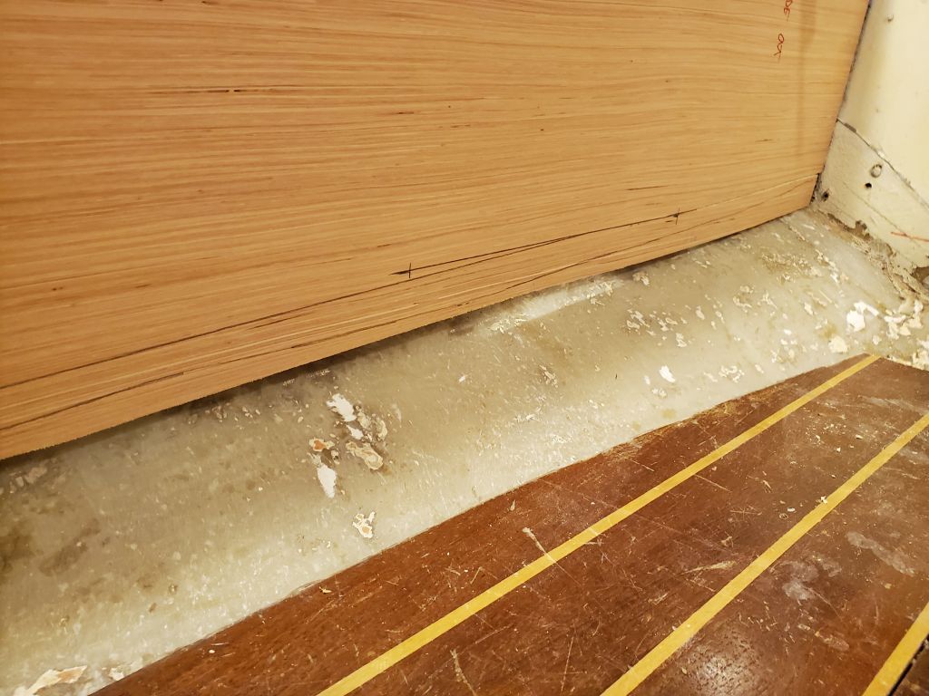
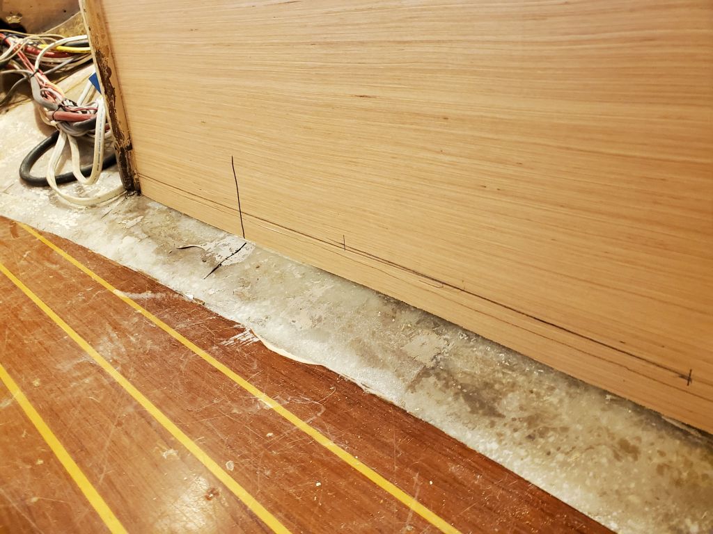
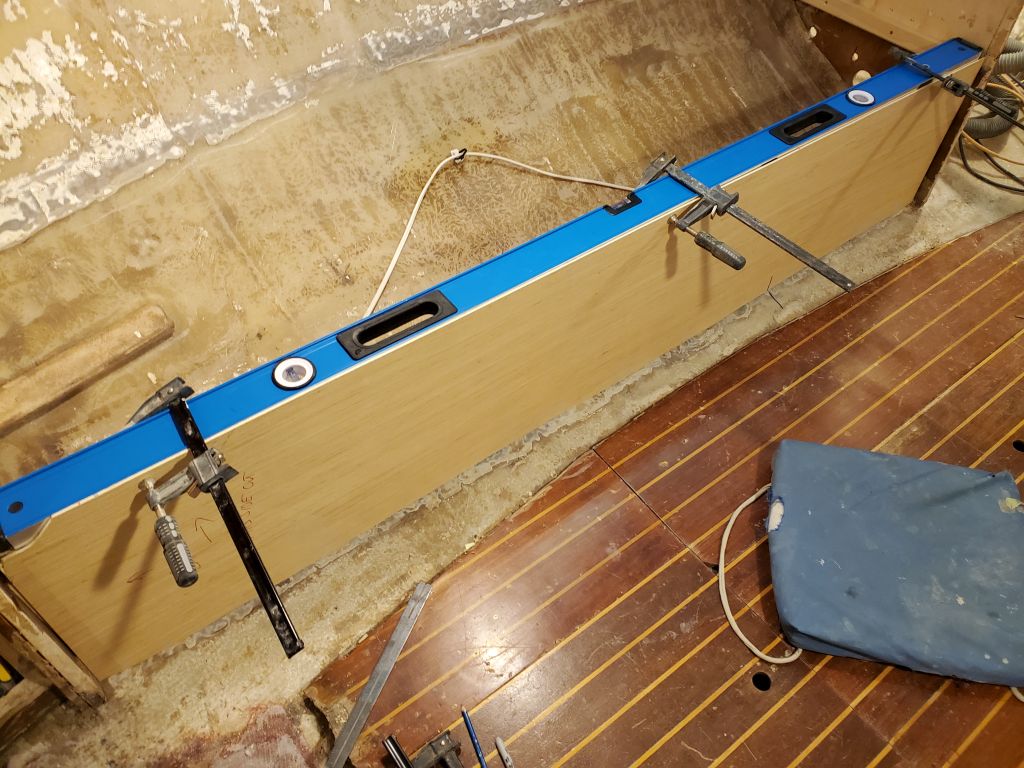
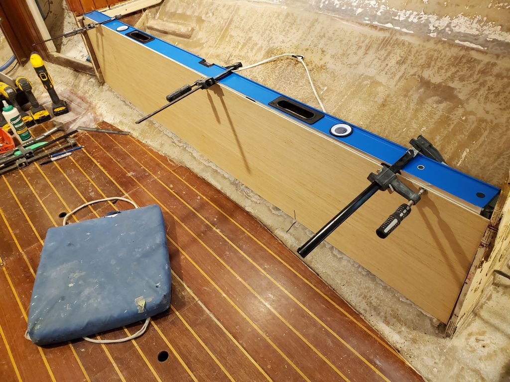
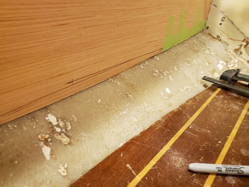
Before finalizing the settees, I wanted to mock up the battery location so we could decide how best to proceed with that.  The owner wanted the batteries moved to a new location just aft of the main bulkhead to improve weight distribution, so I’d build a new locker to accommodate.  With a plywood template representing the battery width and overall height (including terminals and attached fuses), I first checked the available space in the intended area, against the main bulkhead outboard of the settee.  There was ample height in this location even with the “battery” held up above where a finished floor would be, plus some extra room for wiring and adjustments.  I planned to keep the bottom of the locker as low as possible, which, because of the curvature of the hull, would start right where the settee front met the hull and the main bulkhead, just below the edge of the template.

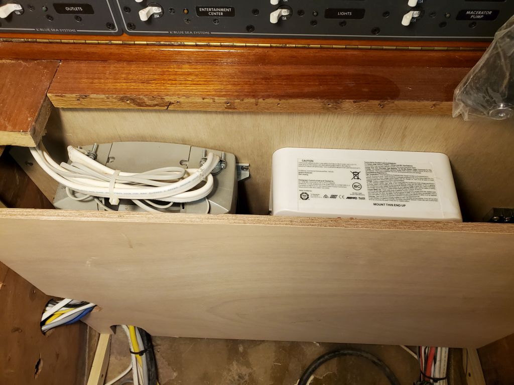
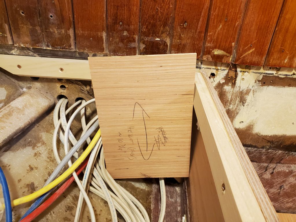
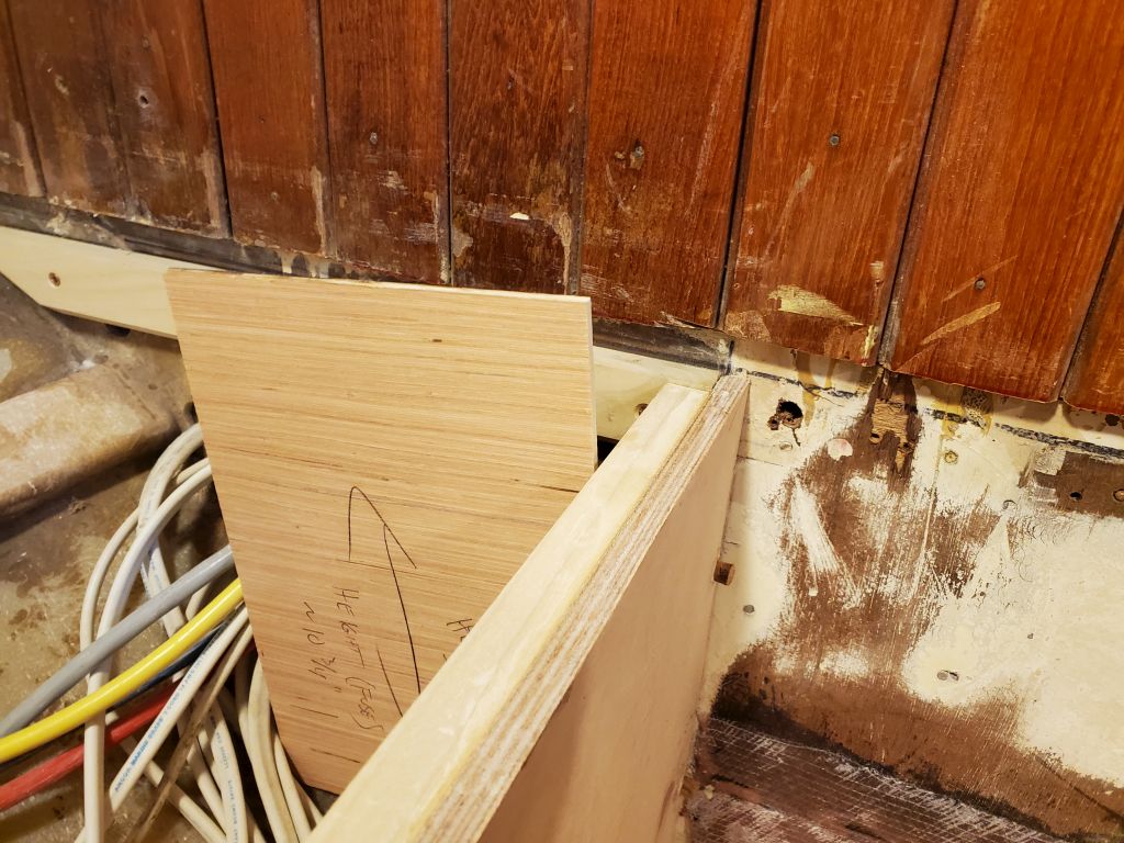
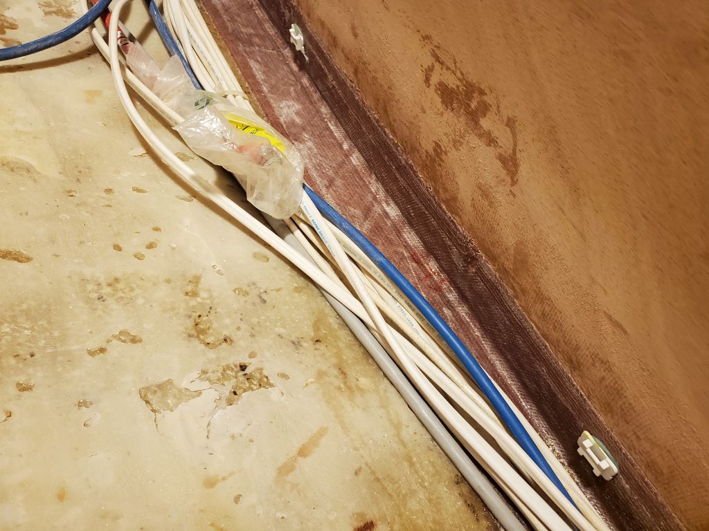
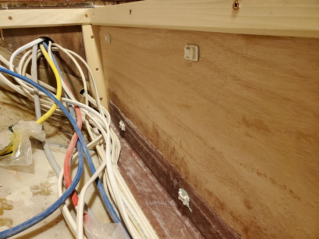
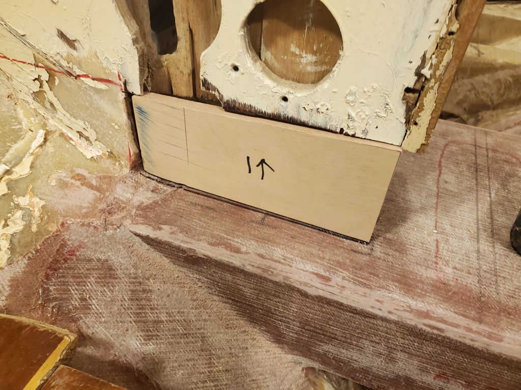
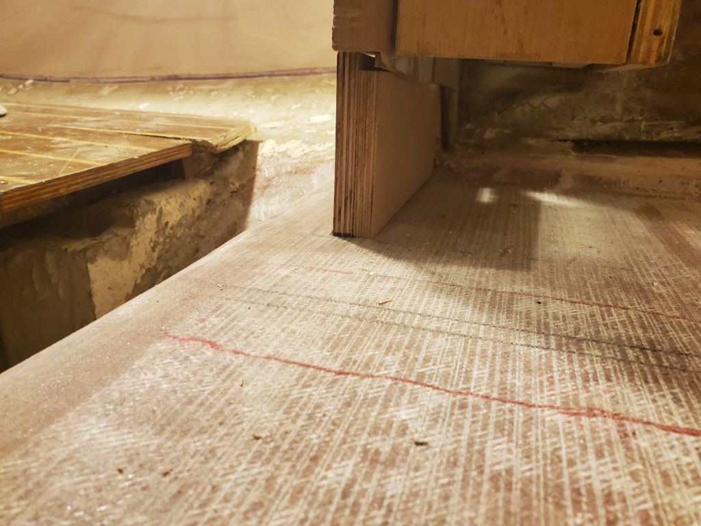
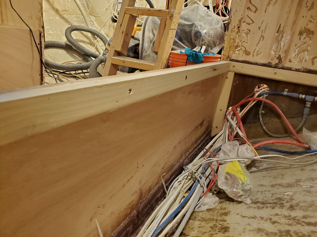
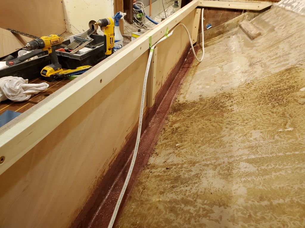
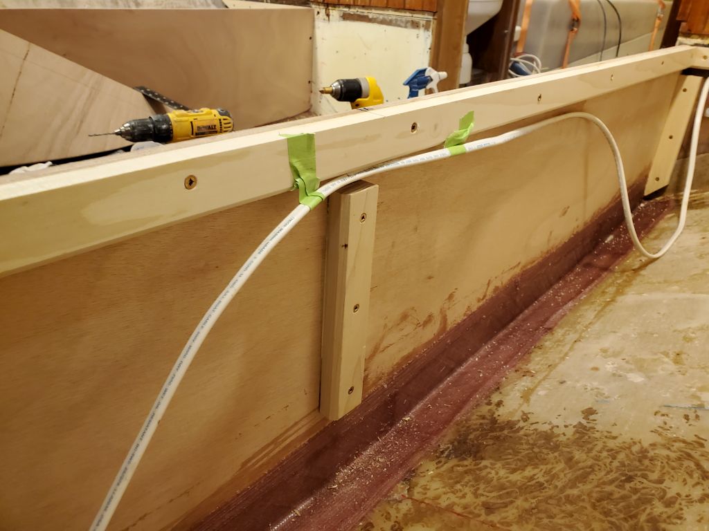
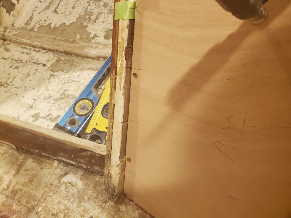
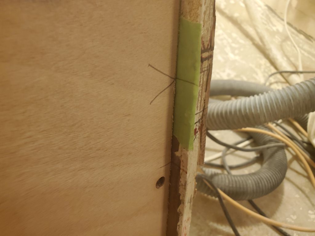
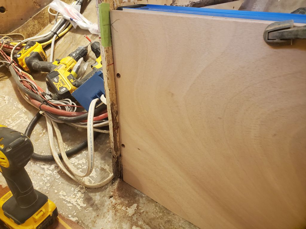
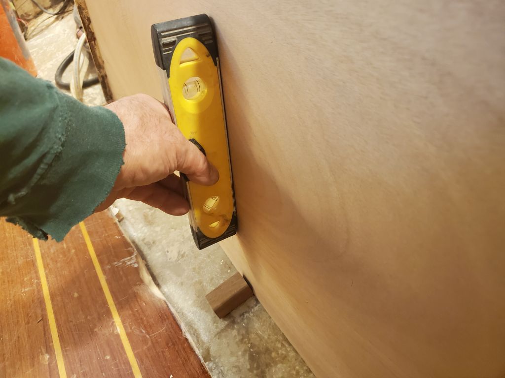
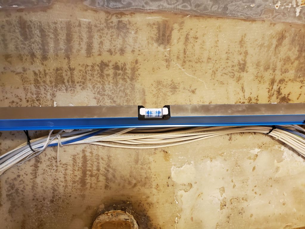
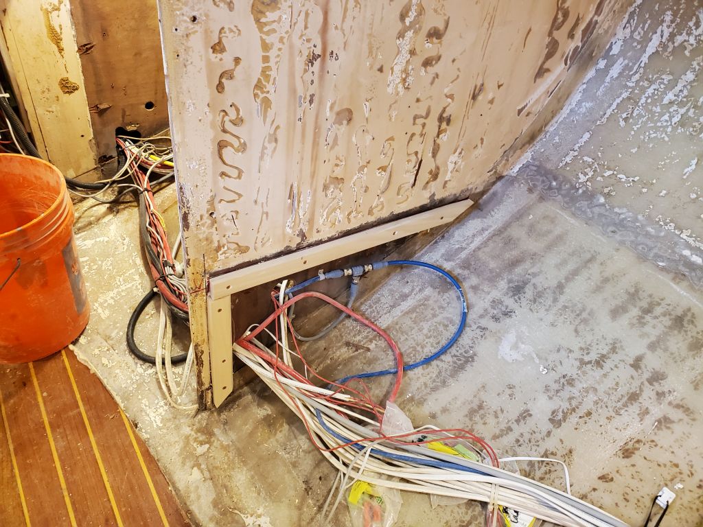
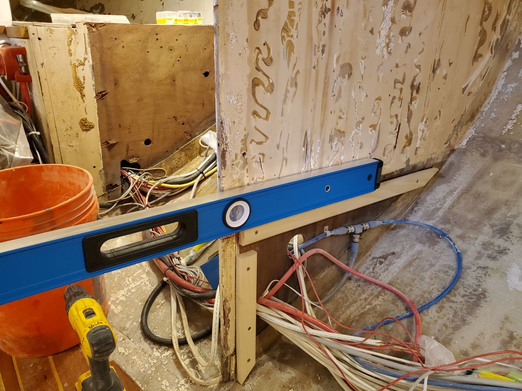
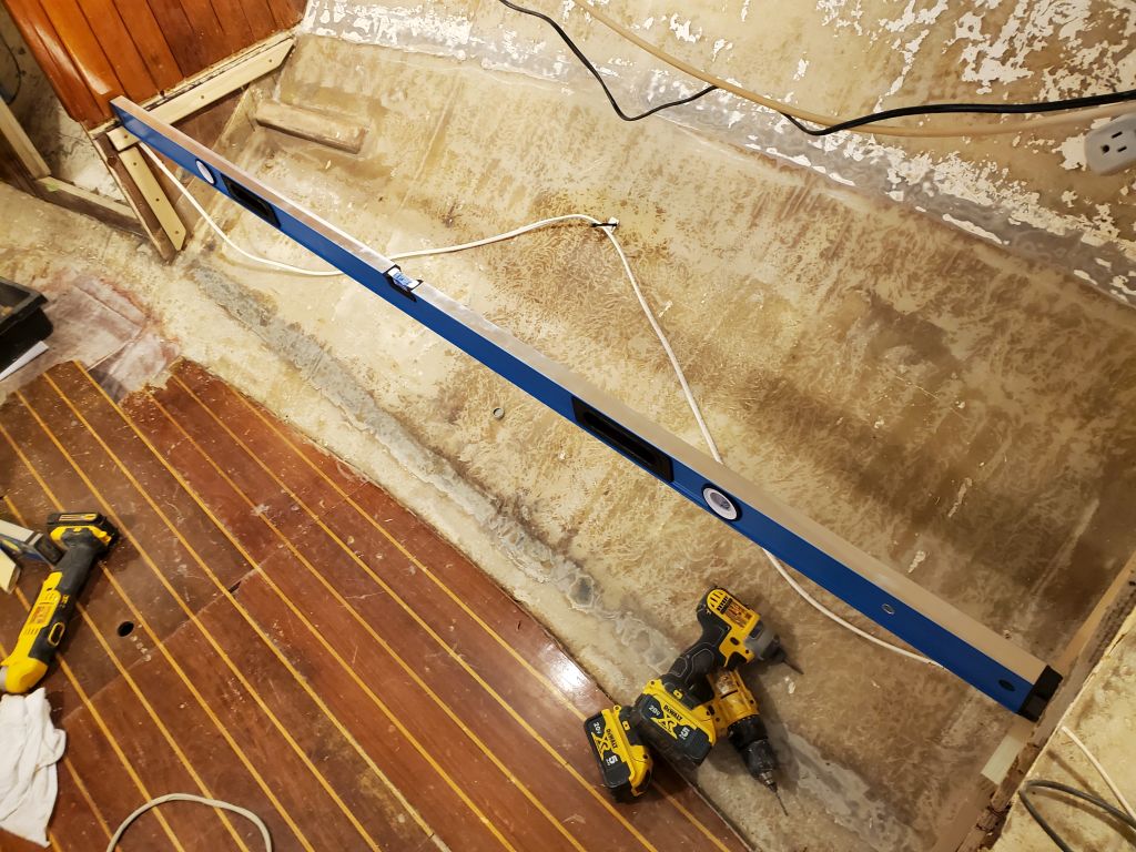
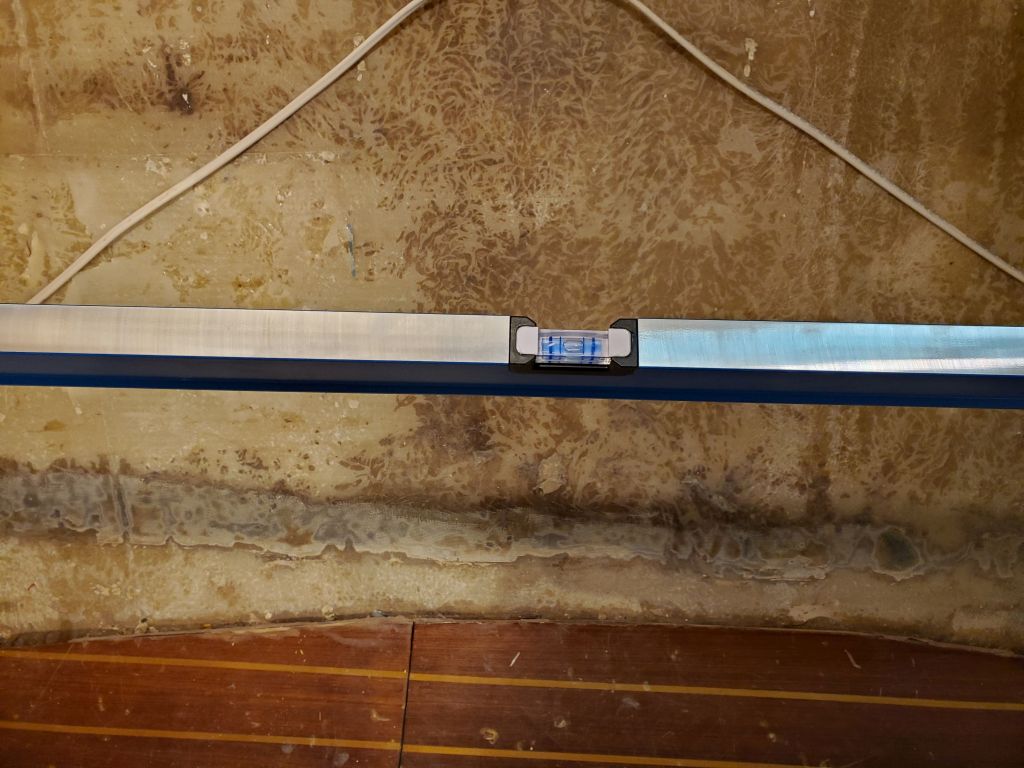
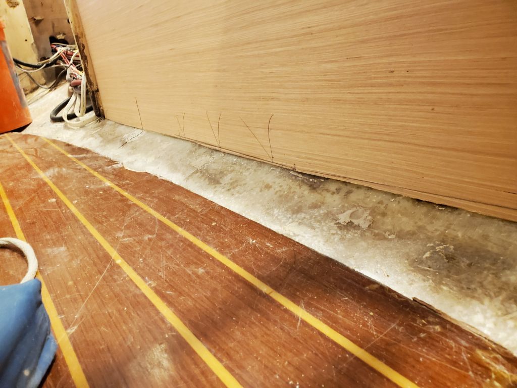
During construction to date, I’d held out a bit of hope that one battery might fit inside the settee, to save space in the main cabin.  To this end, I checked the battery height inside the port settee, just outboard of the location above.  With the curvature of the hull, however, there was nowhere near enough clearance for the battery and terminals in this location, unless the battery was tipped on its side (or somewhere off-vertical).  With all the existing wiring running through this space, this was not an ideal location unless the battery might fit easily.

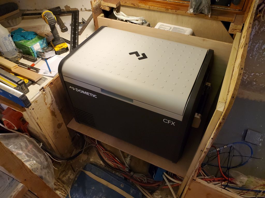
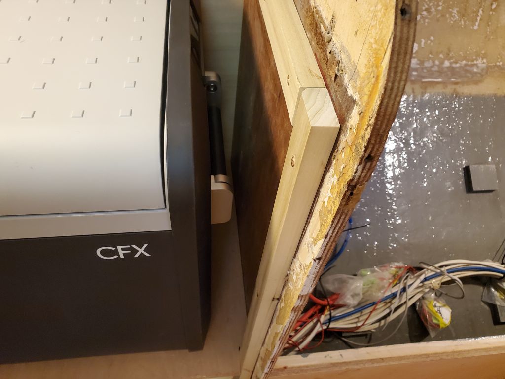
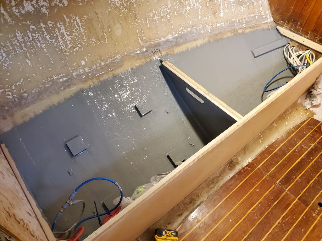
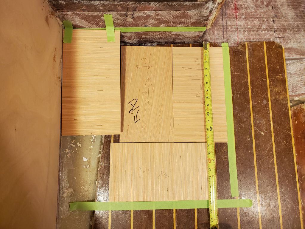
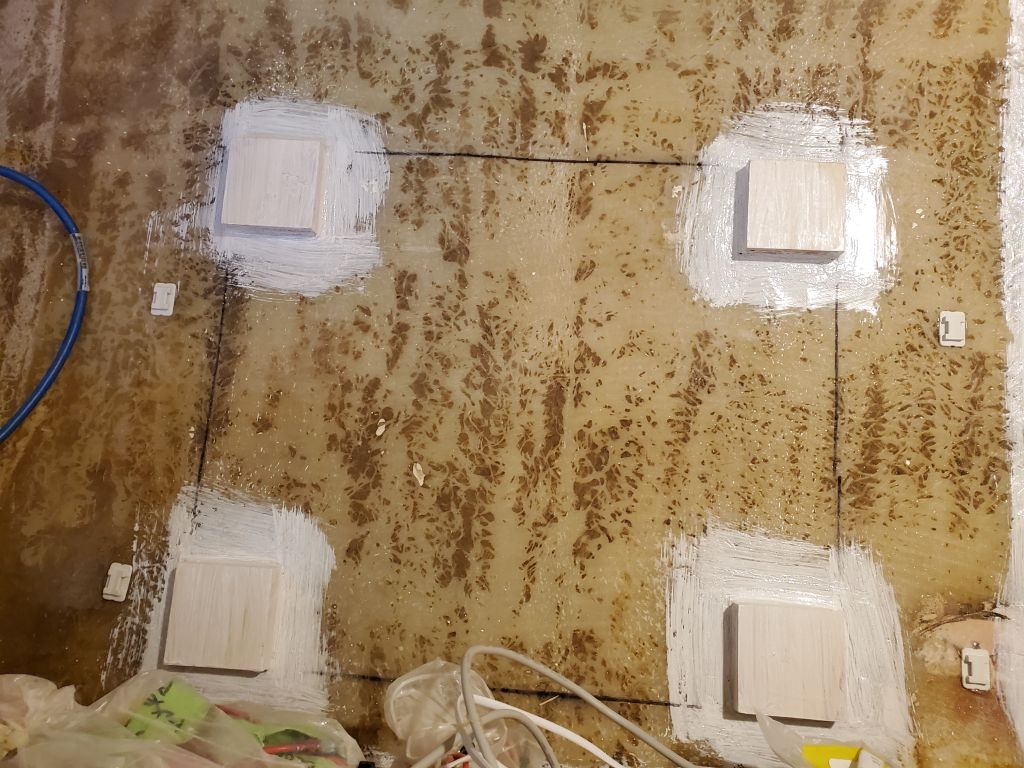
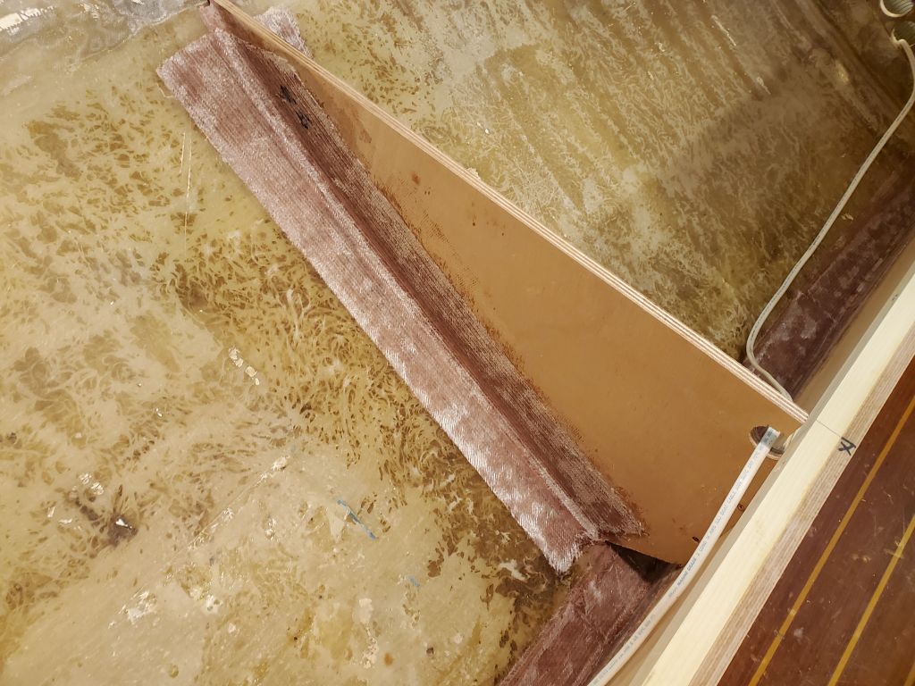
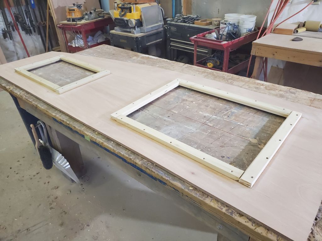
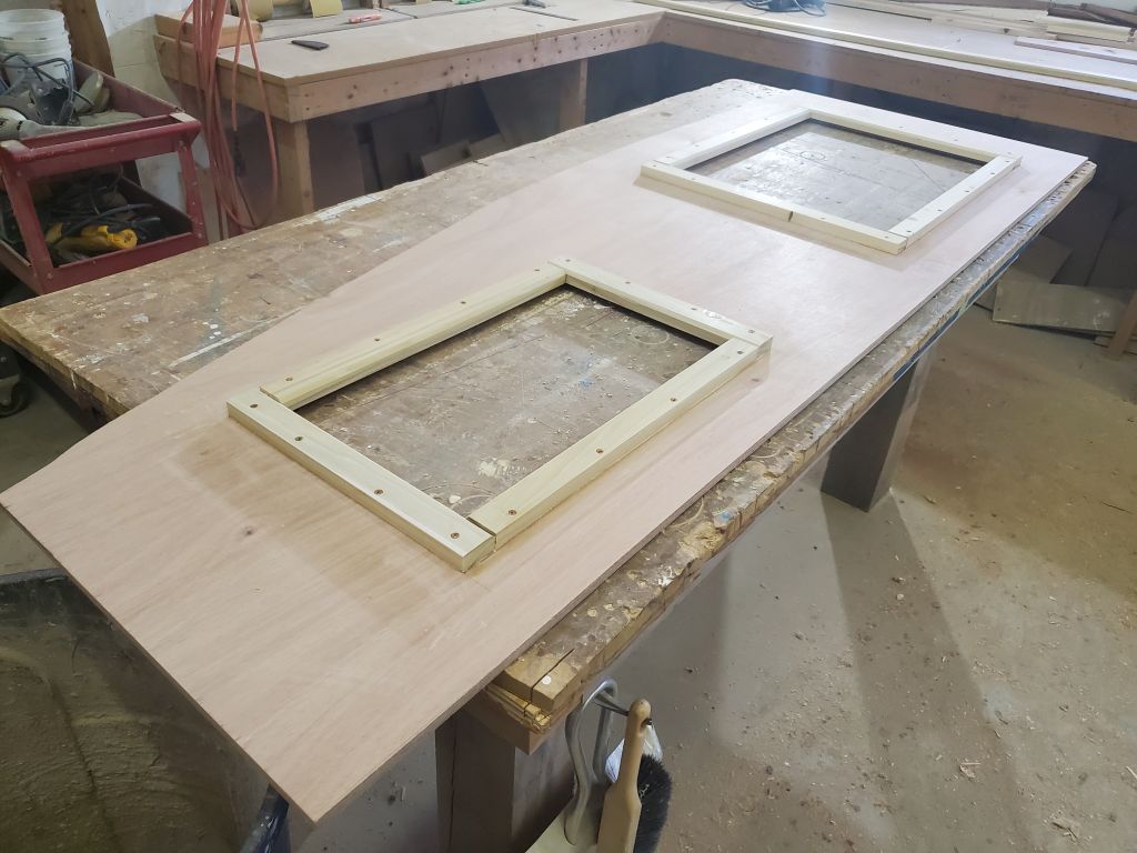
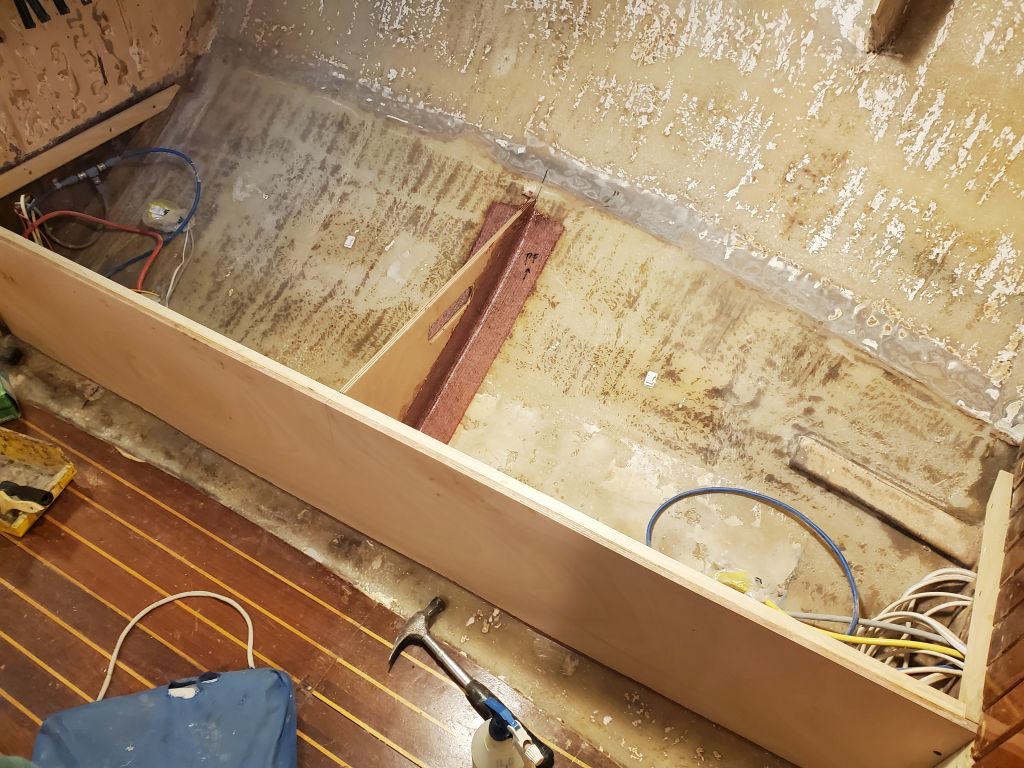
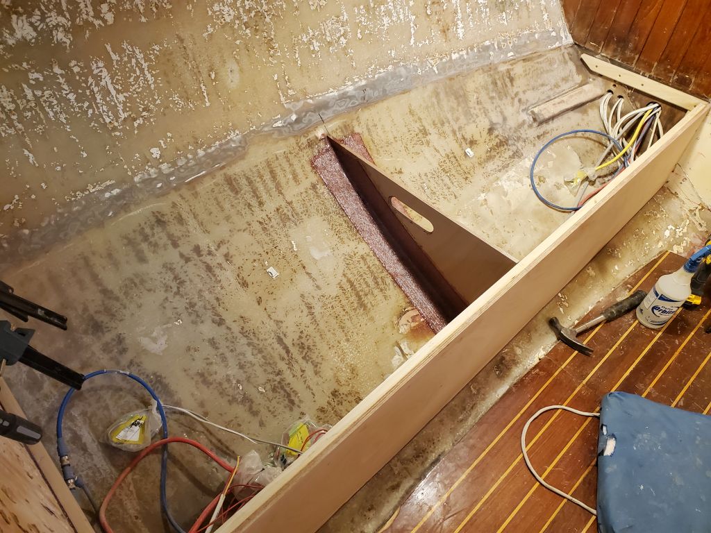
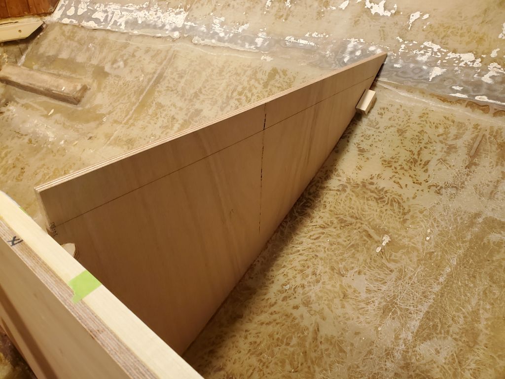
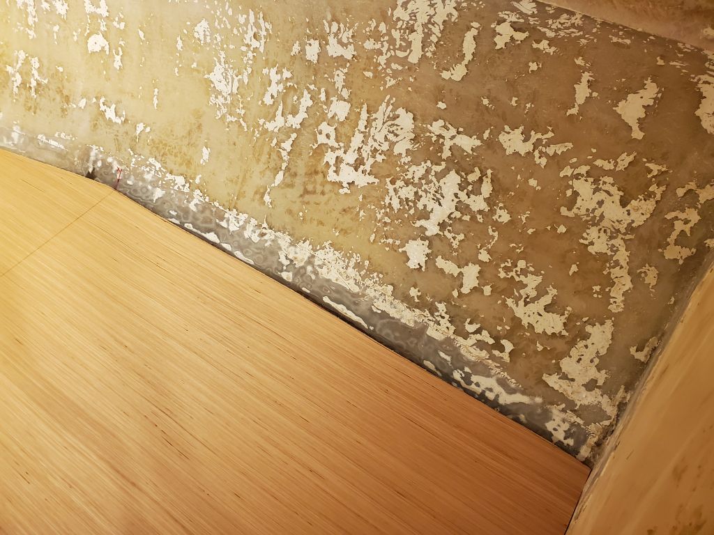
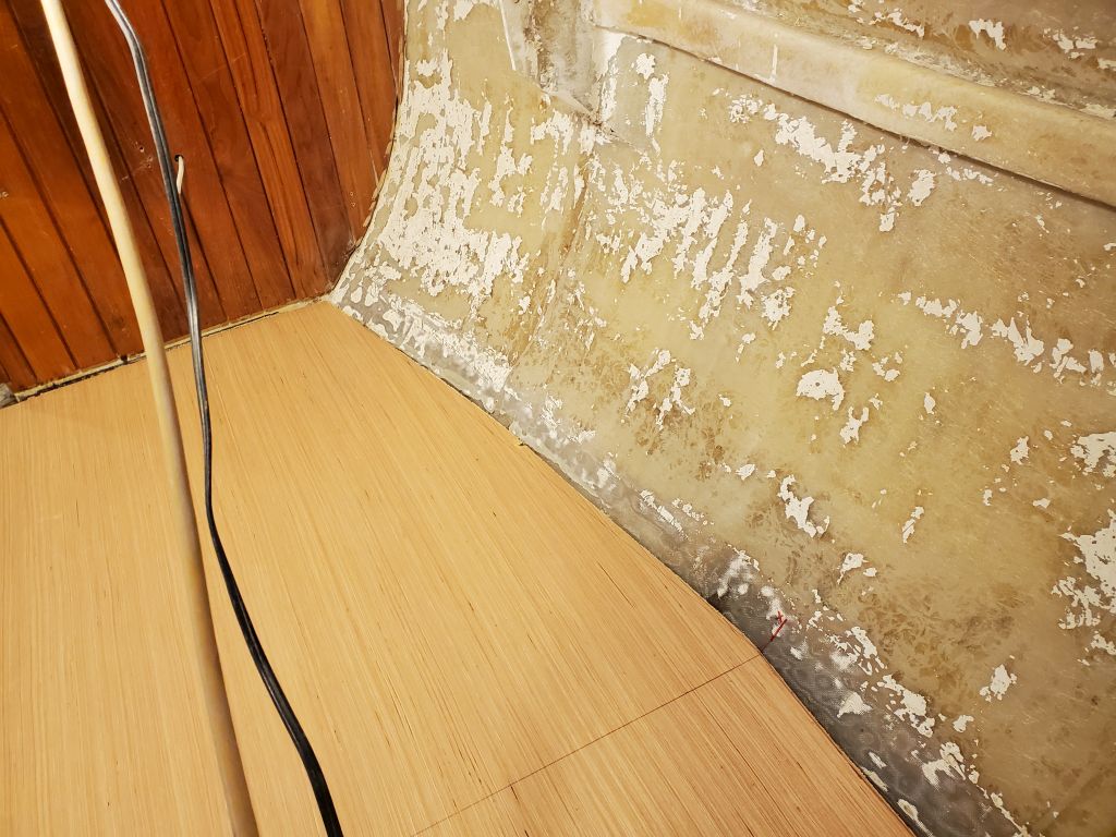
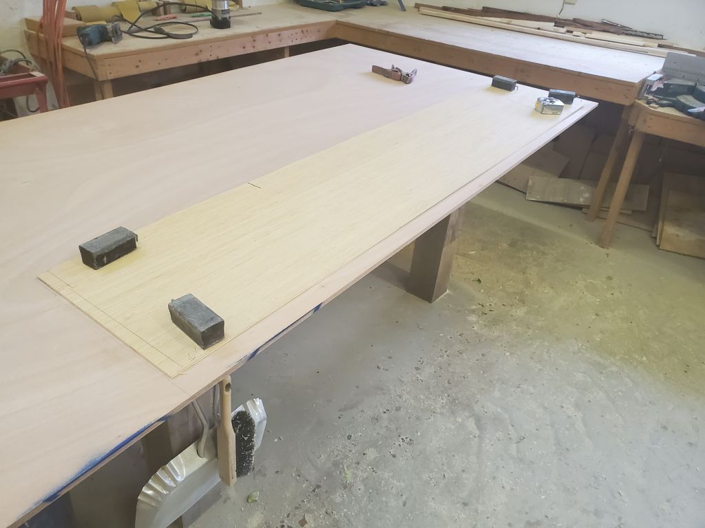
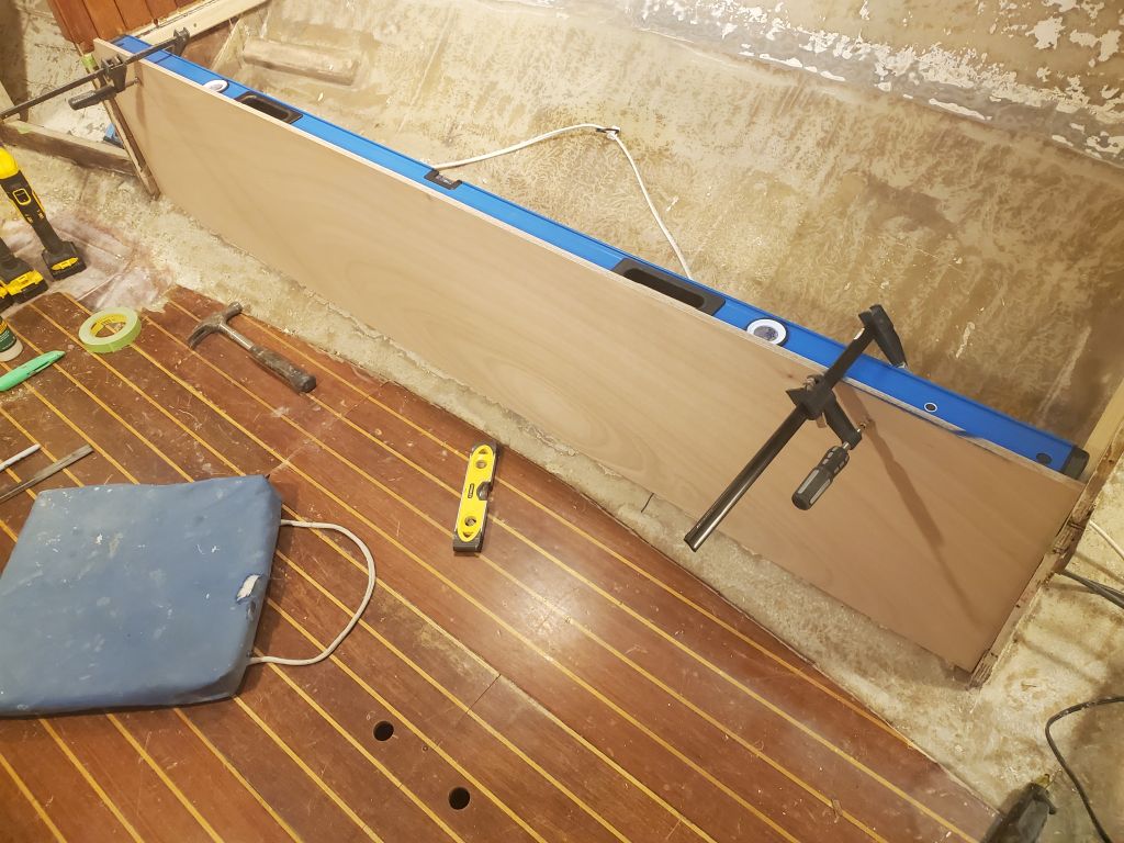
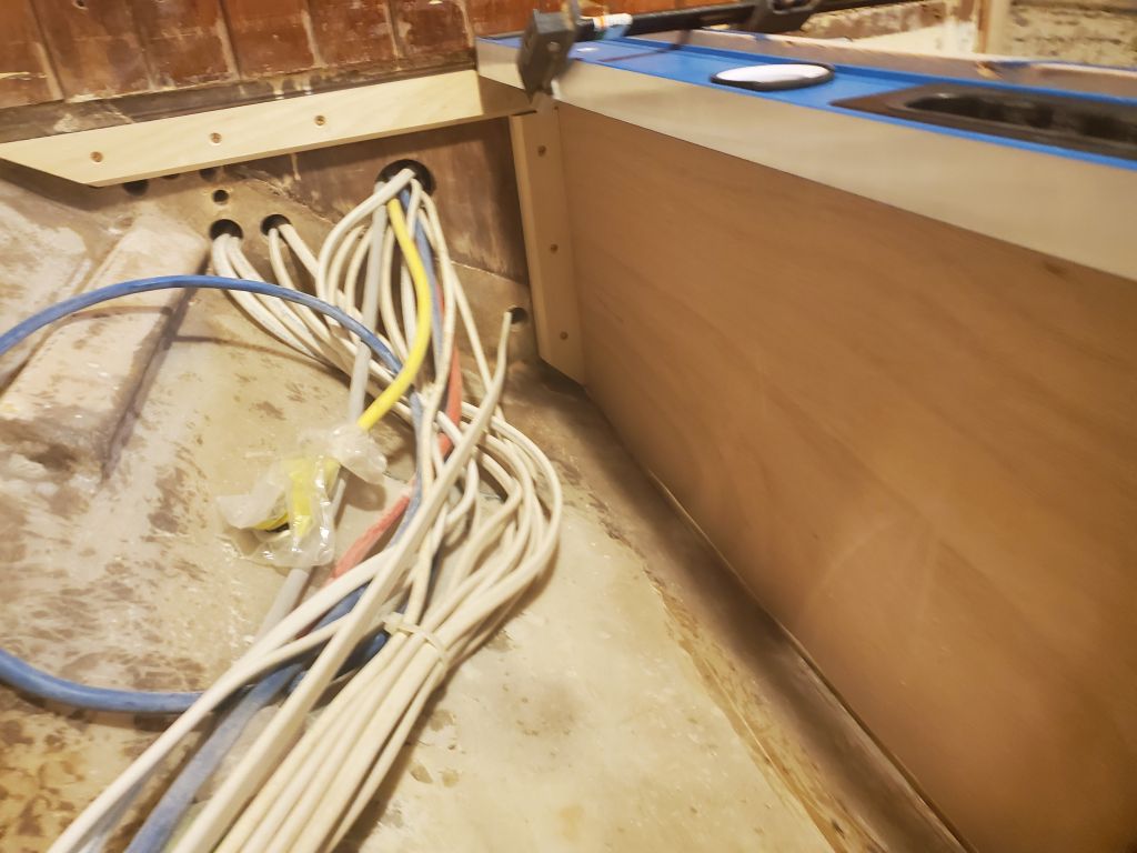
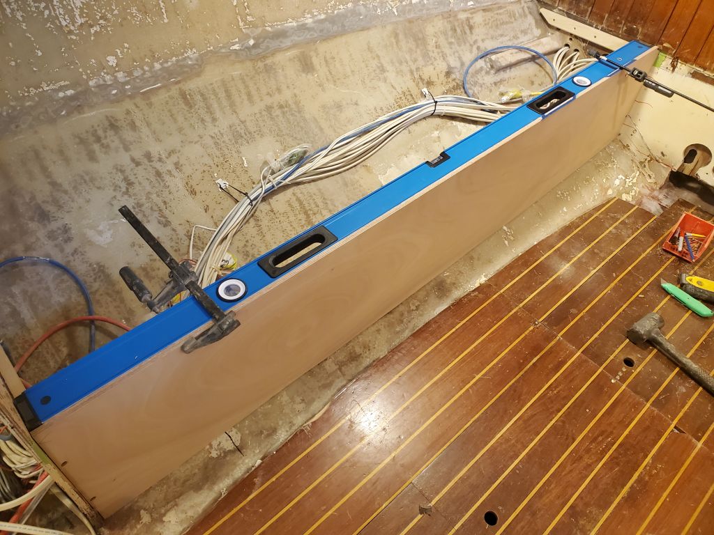
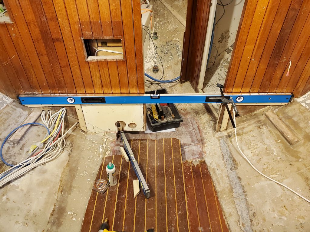
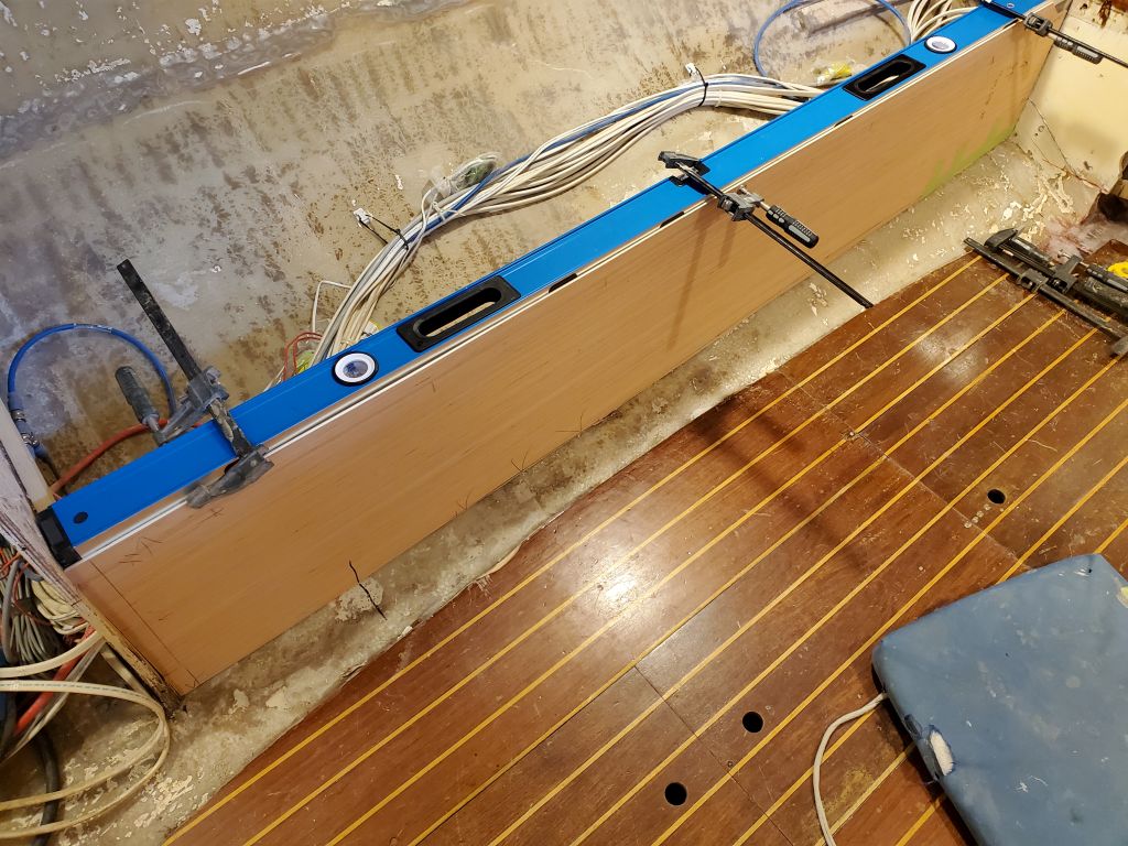
The four batteries could fit in two different orientations in the space in the main cabin.  In one option, I aligned the batteries  in a longitudinal orientation, side by side across the beam of the boat, with the fourth turned 90 degrees at the aft end.  This configuration pushed the potential battery box out to about centerline, and the eventual box around the mast would tie in fairly well with this when all was said and done.

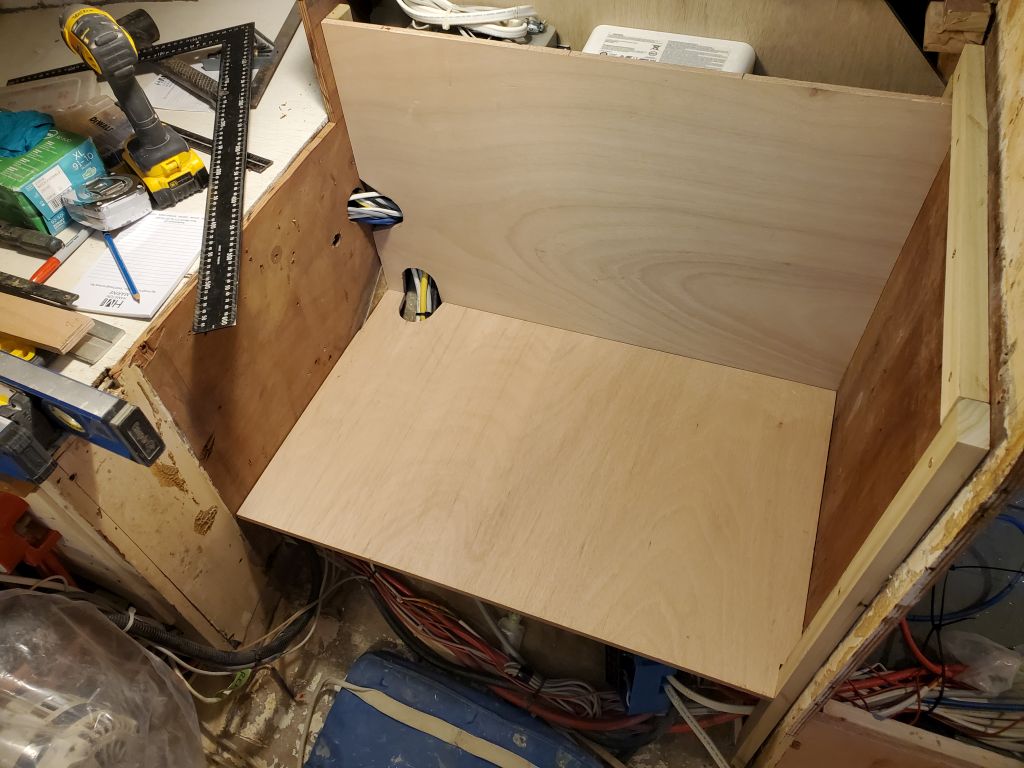
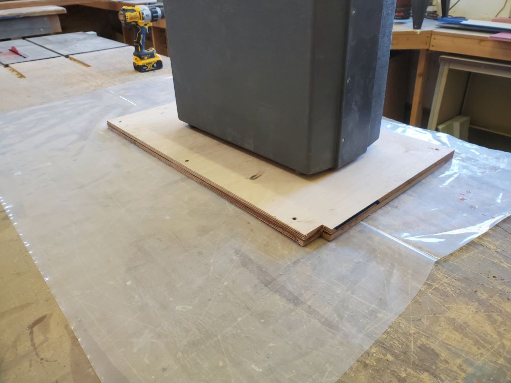
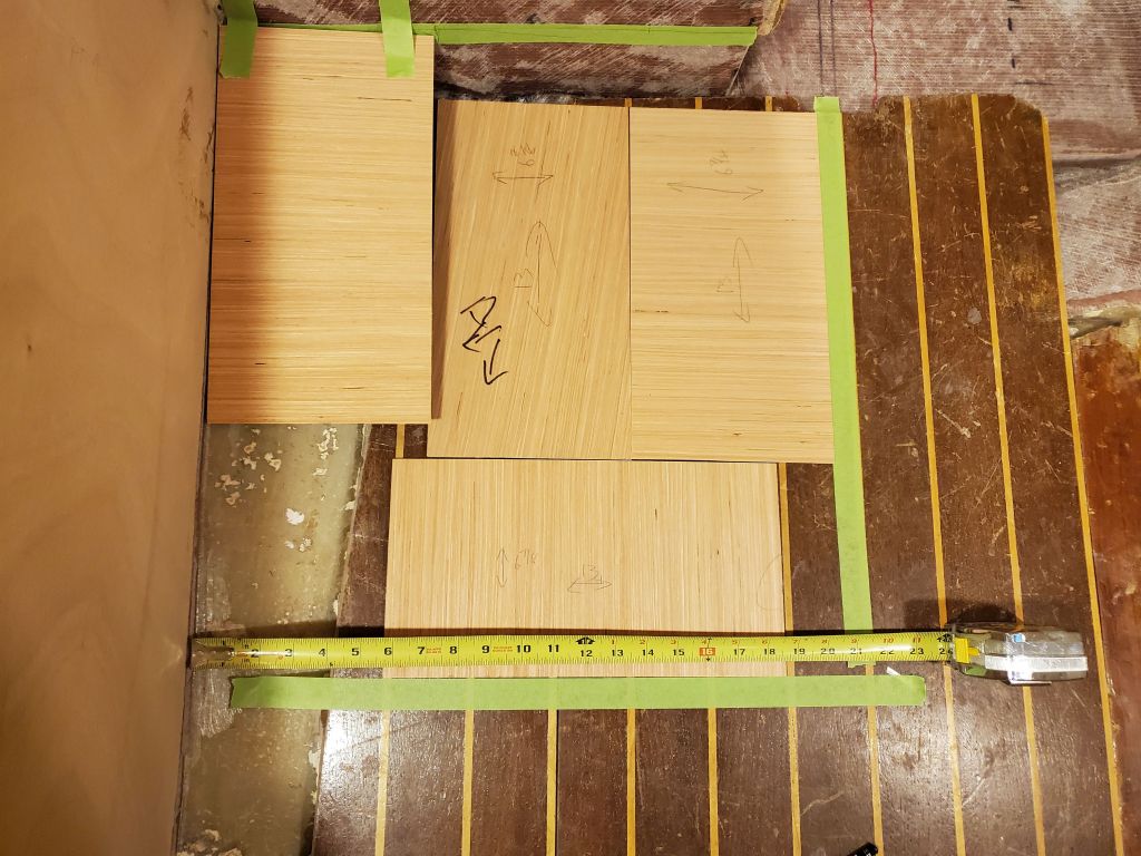
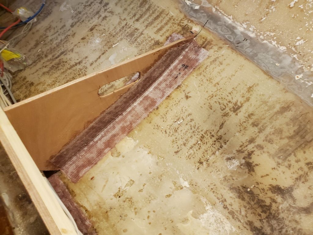
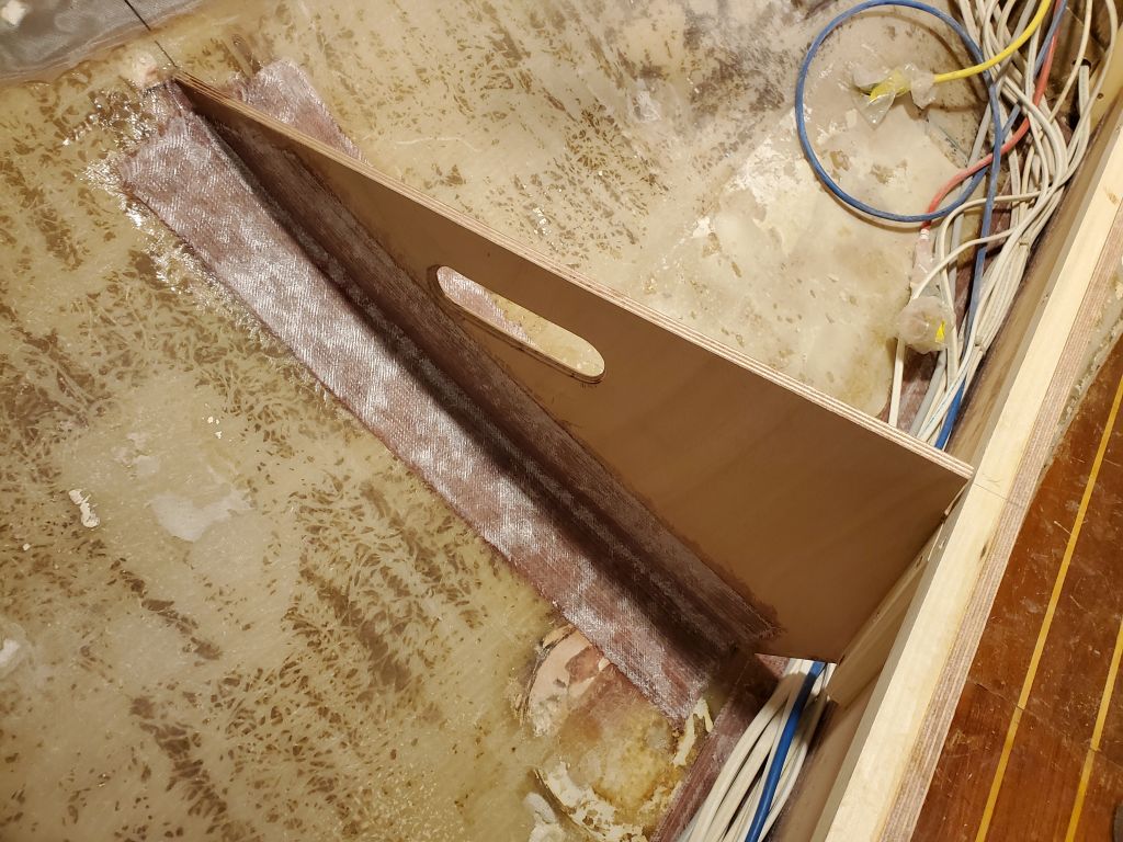
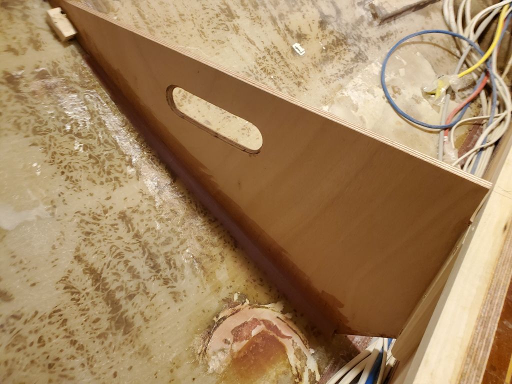
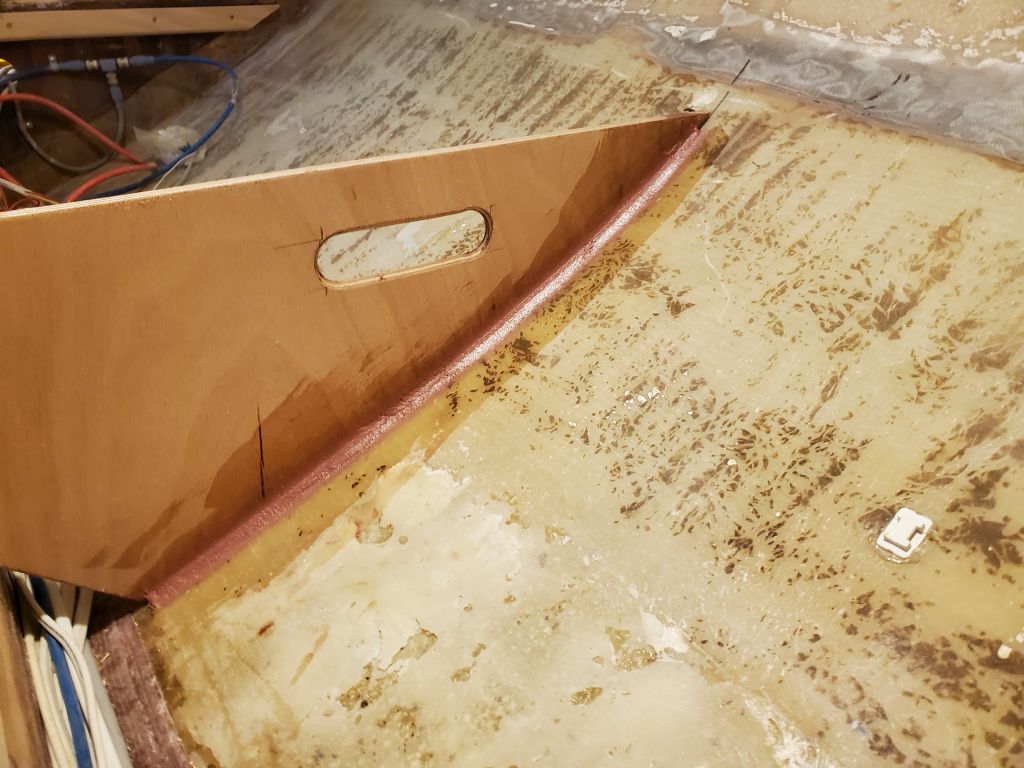
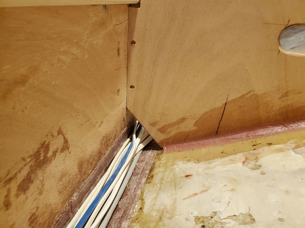
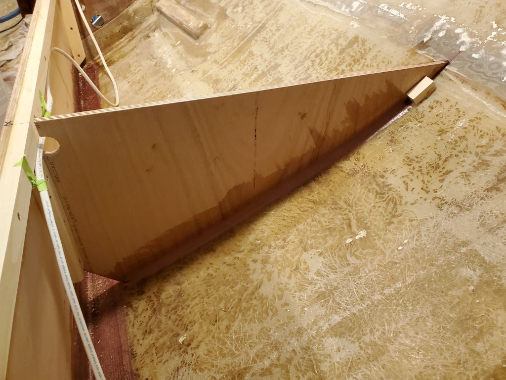
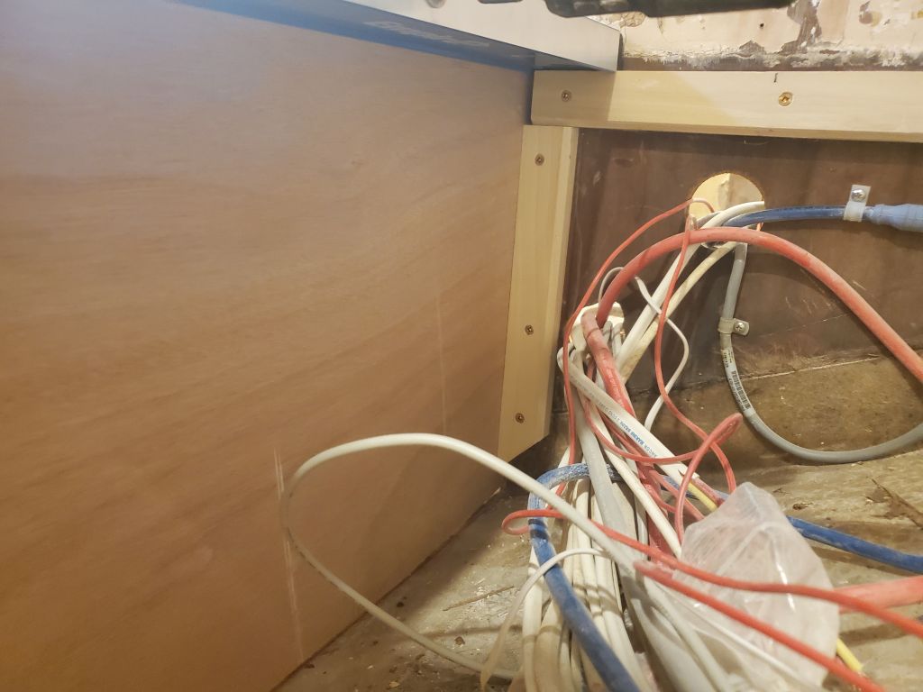
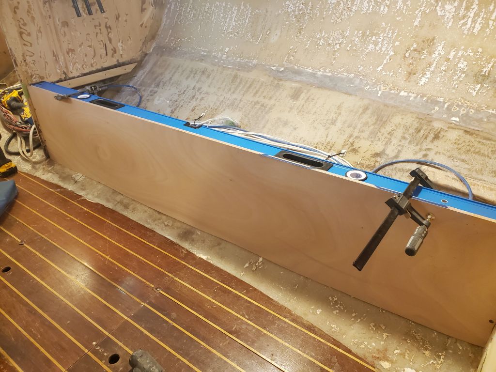
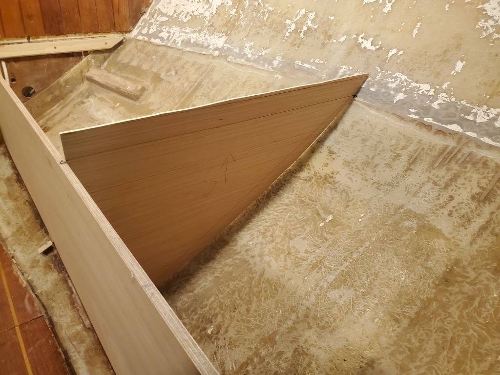
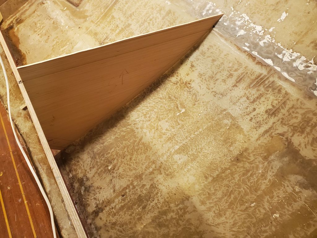
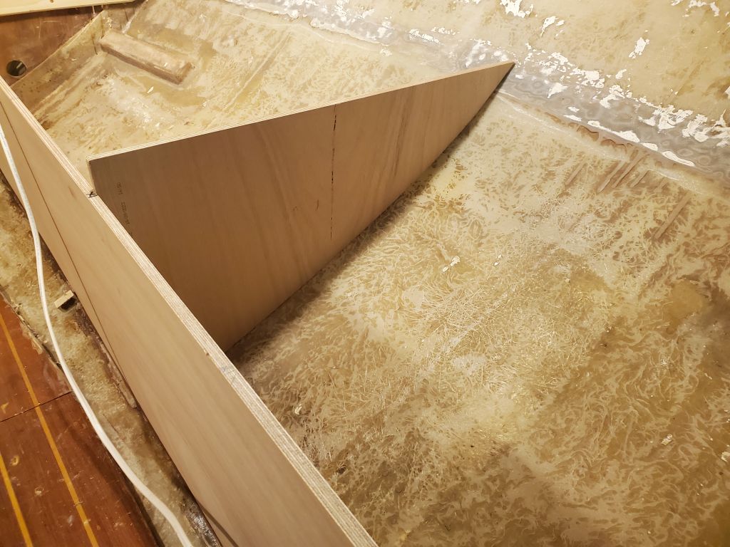
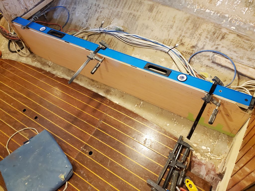
For the second possible orientation, I placed three batteries in a transverse direction, with their long sides parallel to the bulkhead, and the fourth battery closer to centerline along the short edges of the other three.  This used less space across the width of the cabin than the first option, and the batteries were less intrusive into the cabin.  In a last-minute eureka moment, I thought it might be nice to clip the aft corner at an angle, reducing the footprint, assisting in securing the batteries in the space, and making a cleaner overall look.

In either  option, the battery box would become an additional cushioned seat at the same height as the adjacent settee.  After discussions with the owner, he chose the second option, which I also thought was the far better alternative, with the angled corner as shown in a few of the photos just above.  I’d work on building this box in the near future.

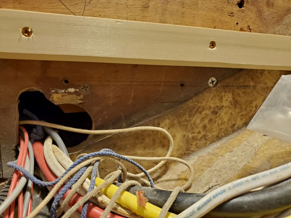
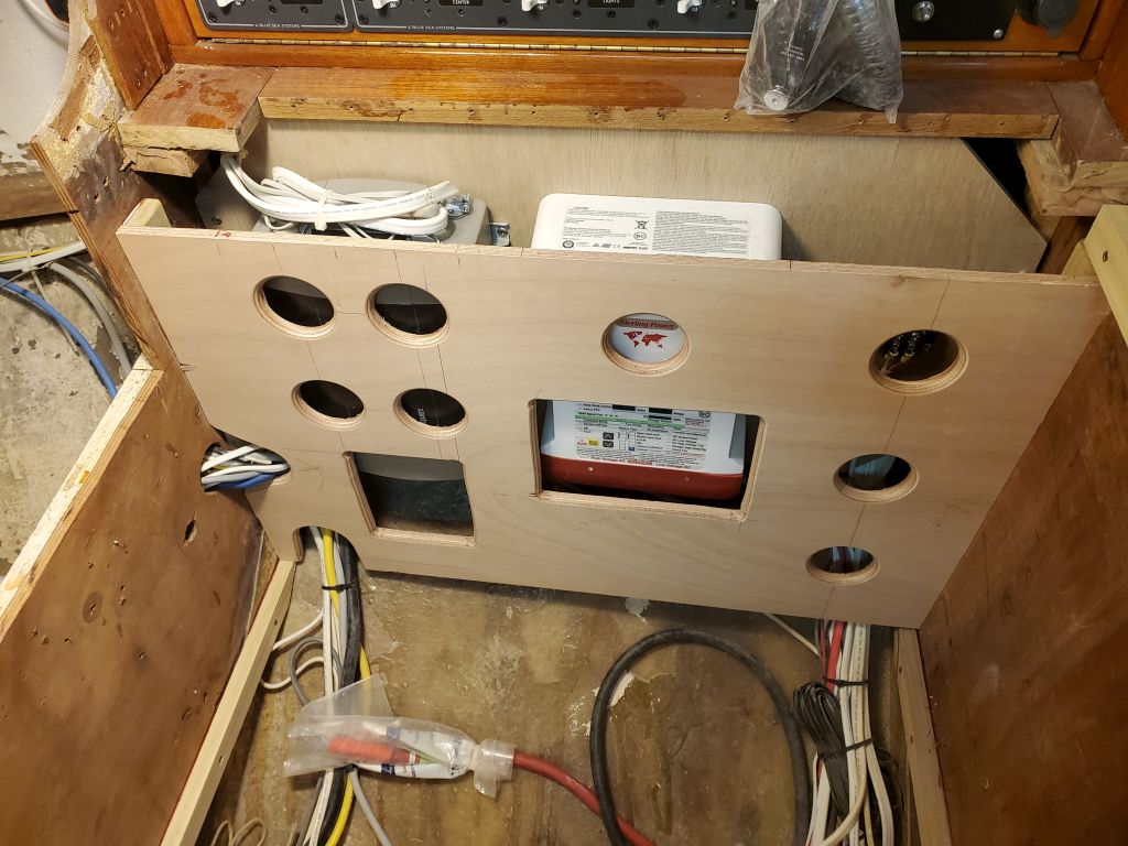
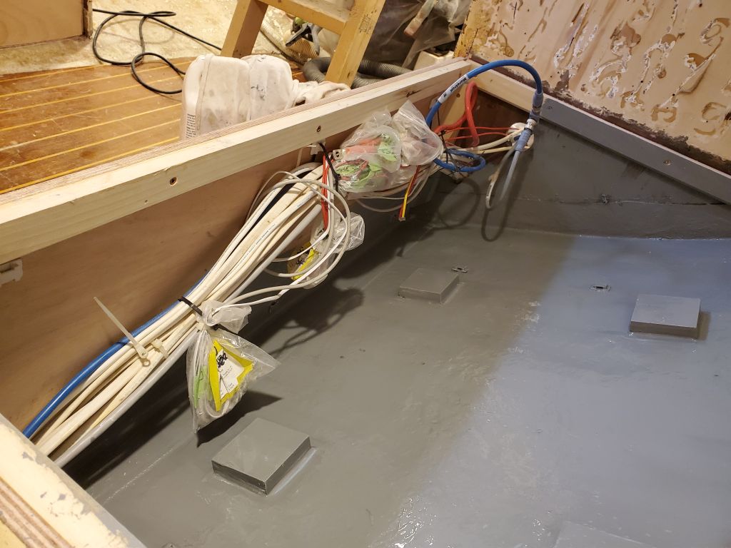
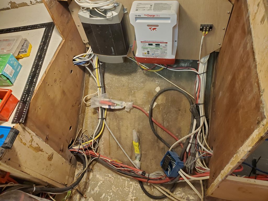
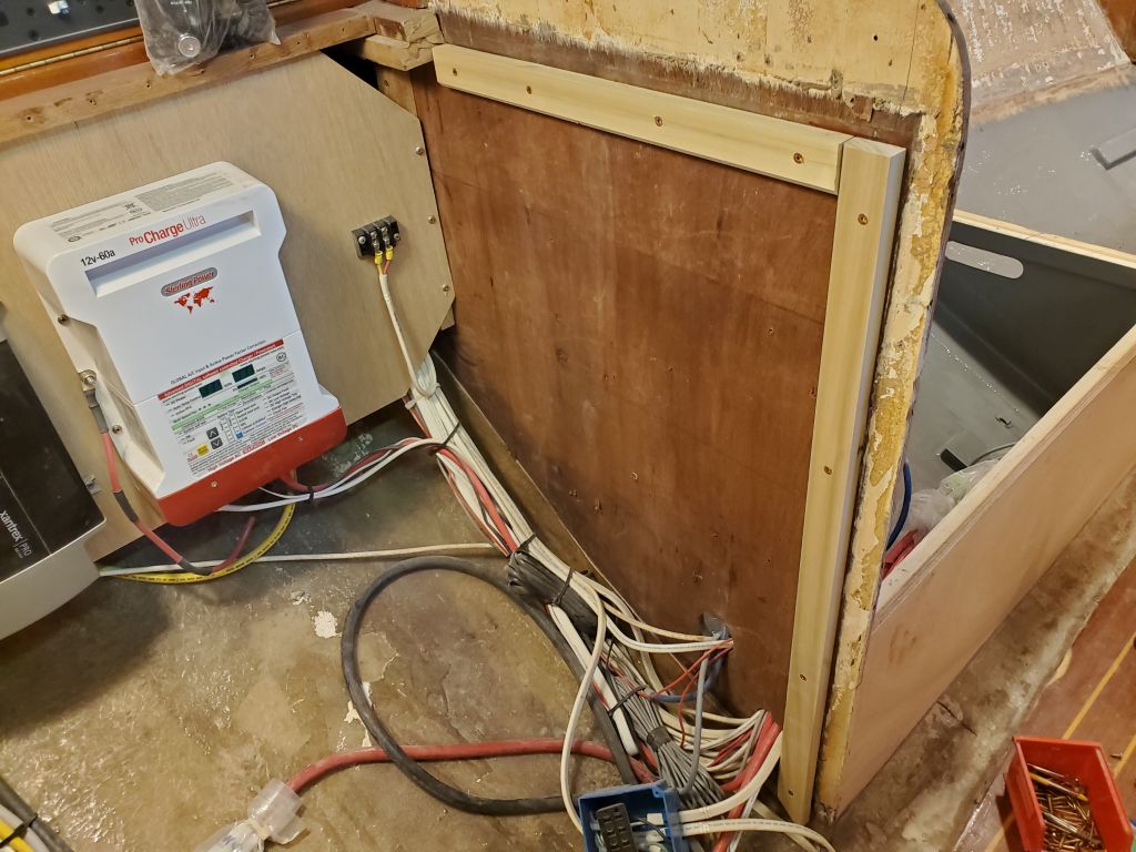
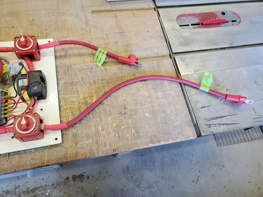
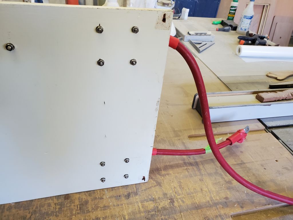
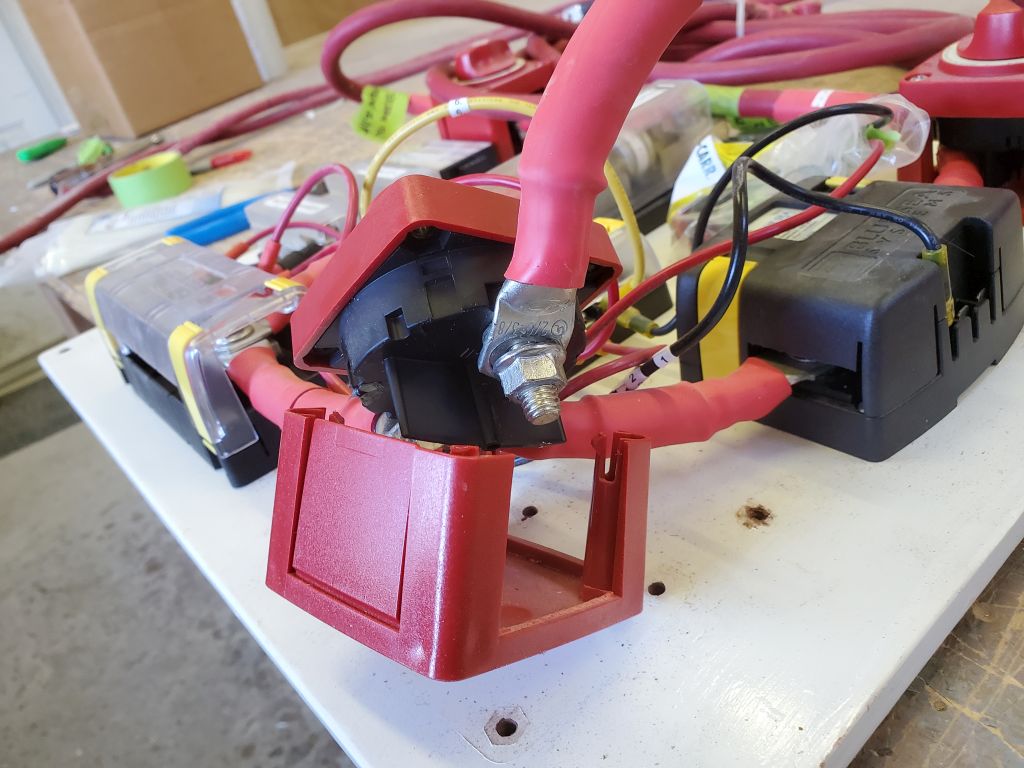
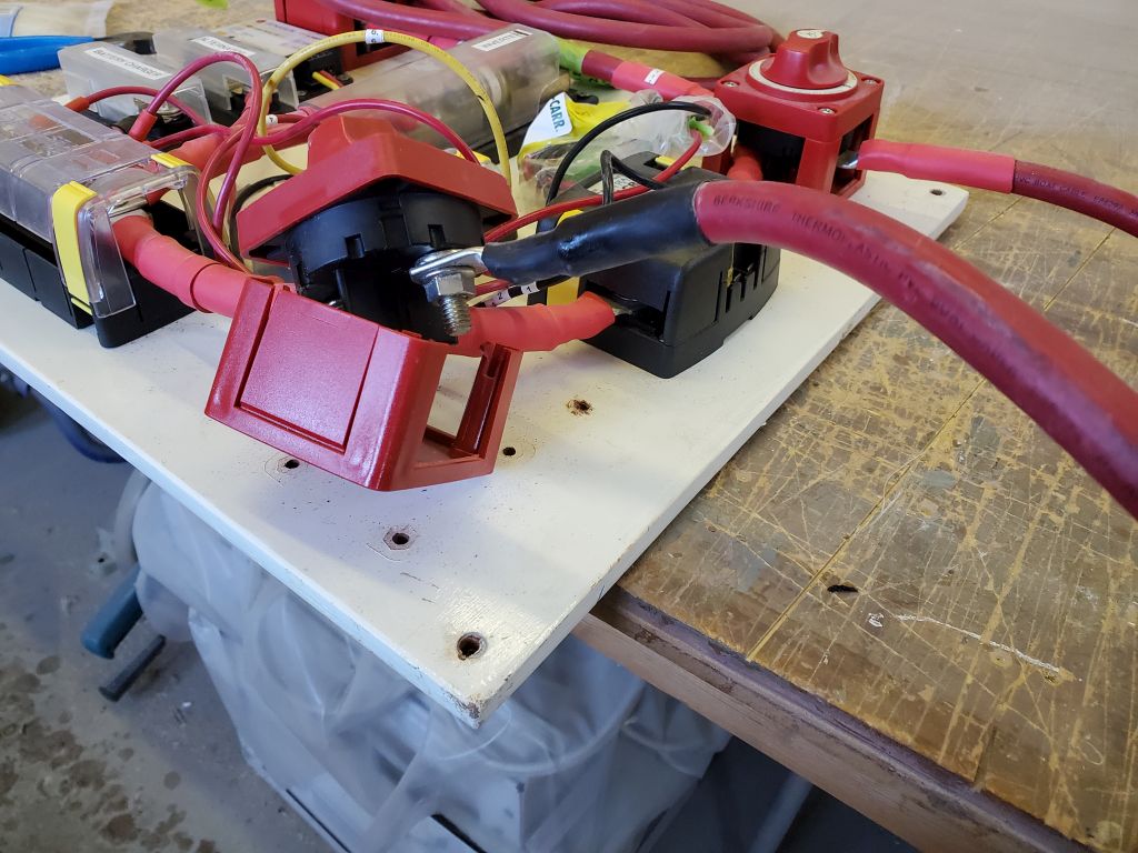
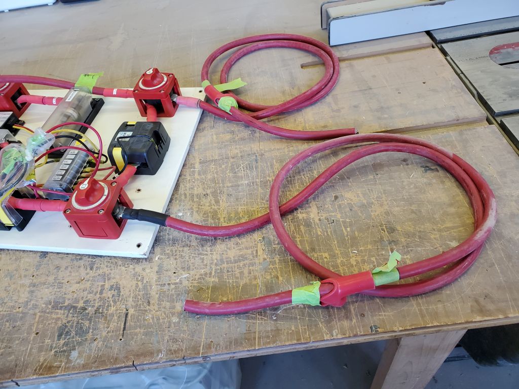
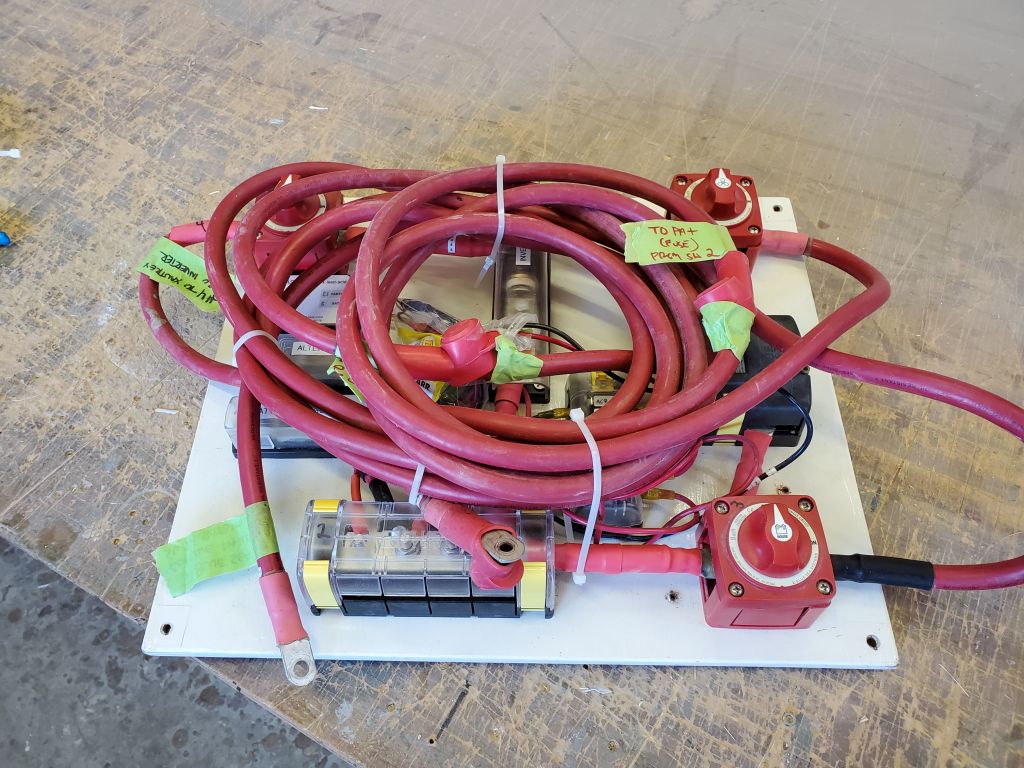
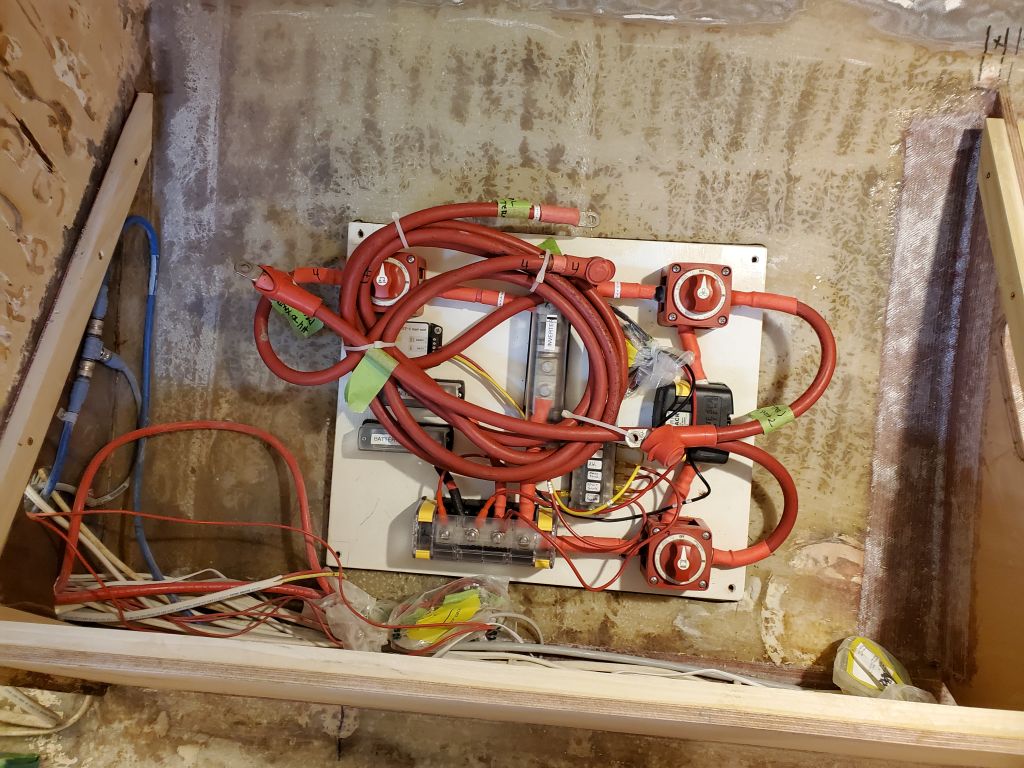
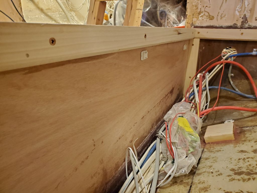
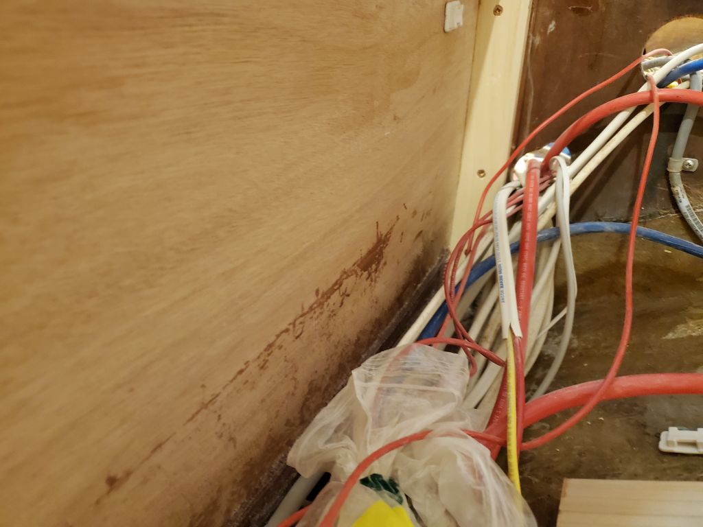
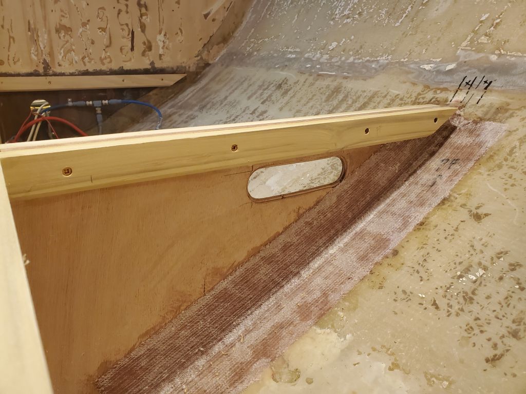
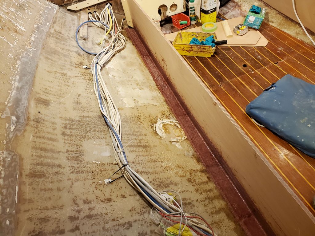
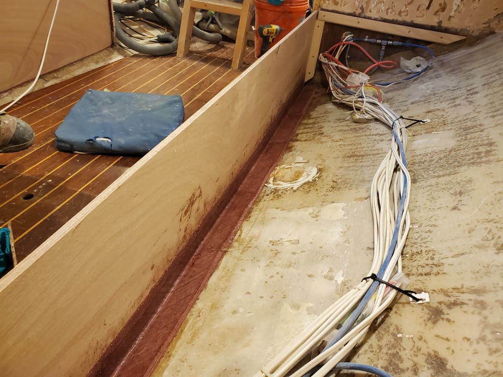
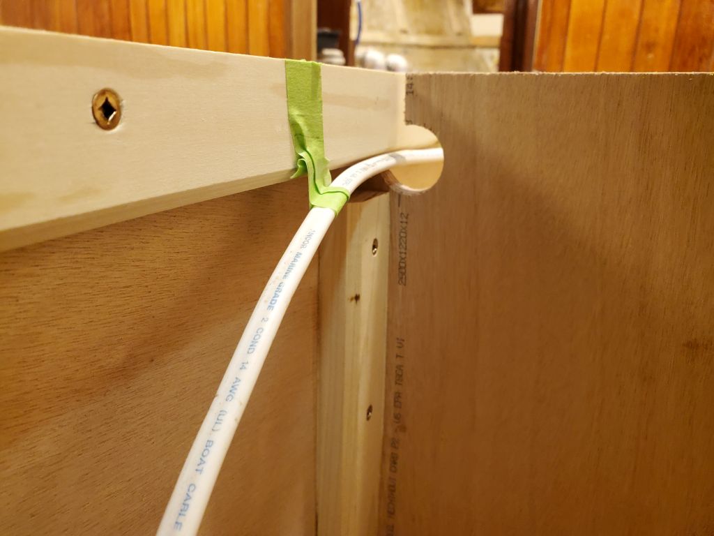
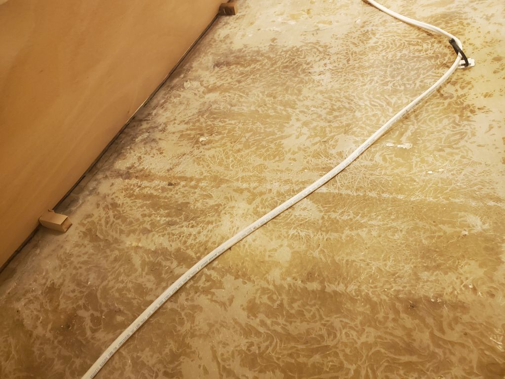
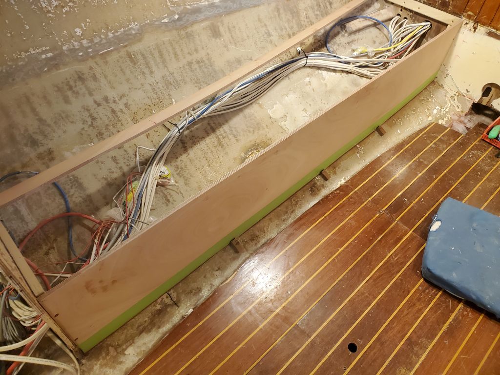
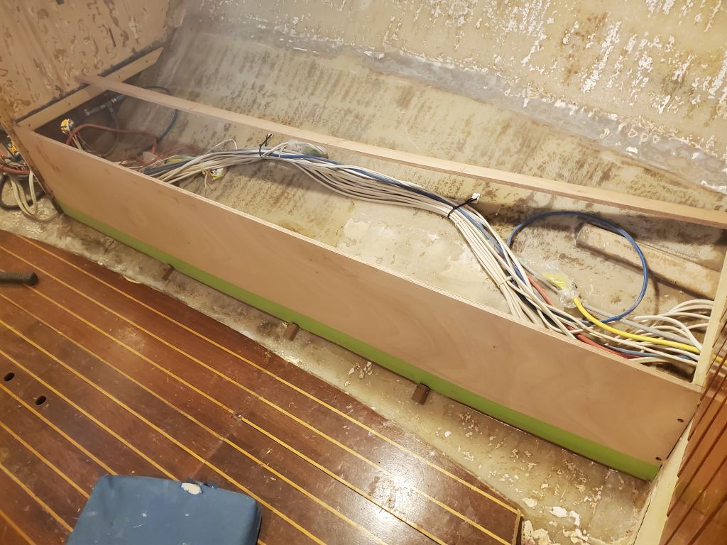
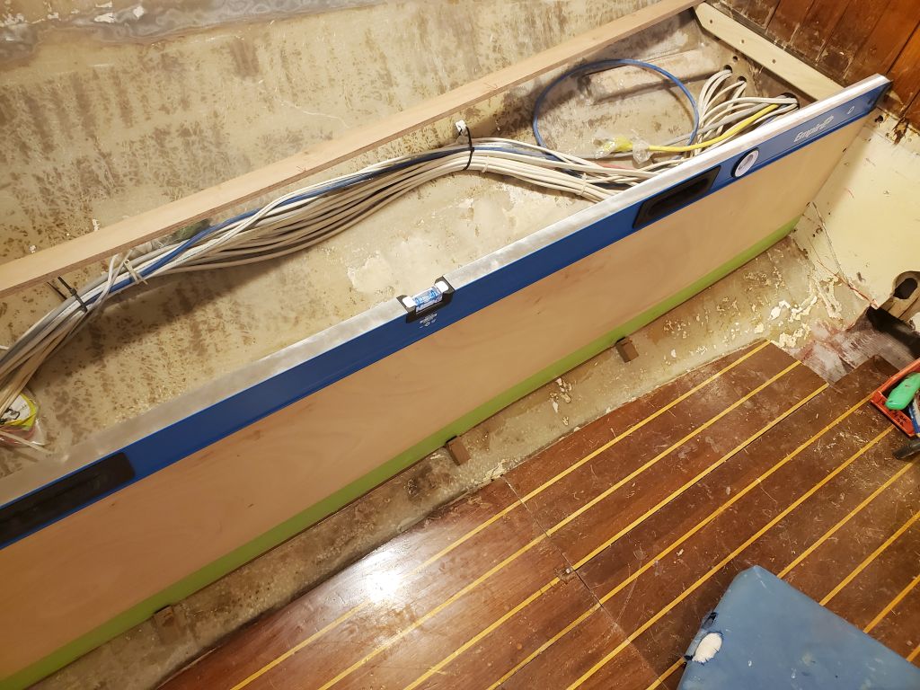
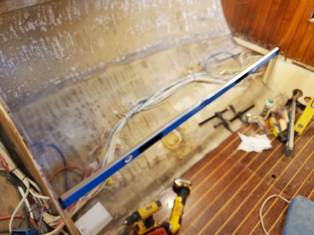
The new battery location meant that two of the existing cables connected to switches on the under-settee switch panel needed to be lengthened, as these cables had originally run just to the old battery bank located beneath the port settee.  Because the switches were bolted through the panel and needed to be removed to access the terminals, now was the time to make a change, while I could easily work with the panel out and on the bench.  Using a long length of battery cable recycled from the original installation (a jumper that had led from the port bank to the starboard bank by way of the forward cabin), I prepared two new sections, leaving one end raw for now but long enough to reach the new battery locker, and installed these in place of the two short originals.  Now this panel was ready to be reinstalled whenever the locker paint was completed, so I could reconnect all the wires while access was at its best.

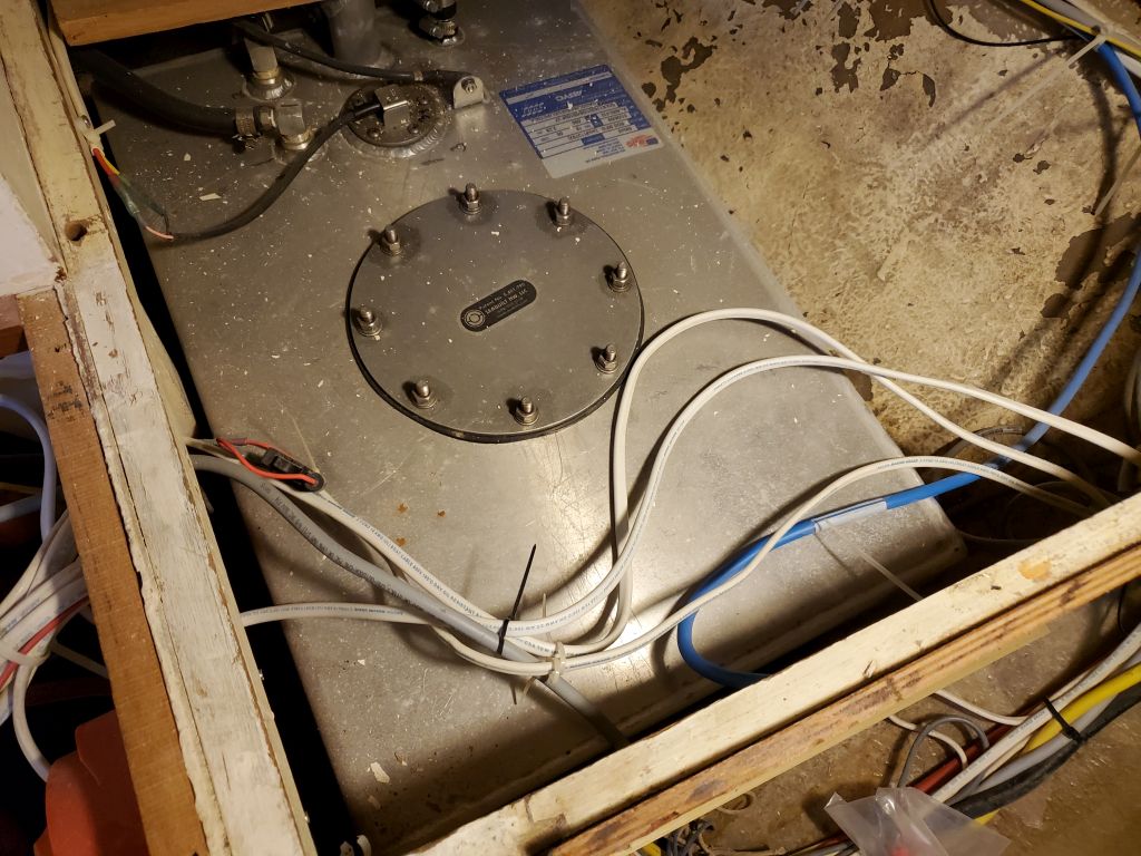
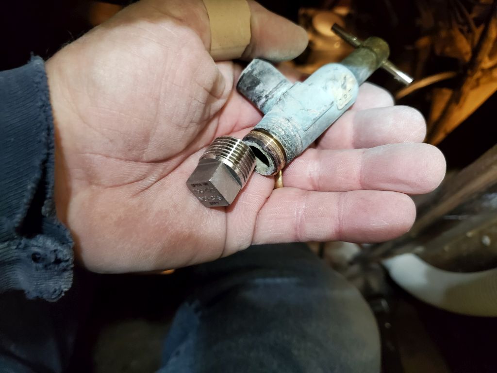
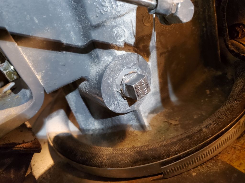
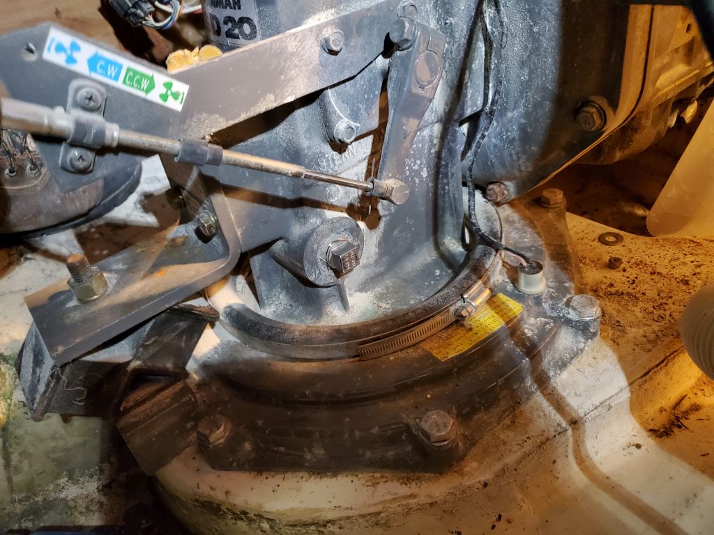
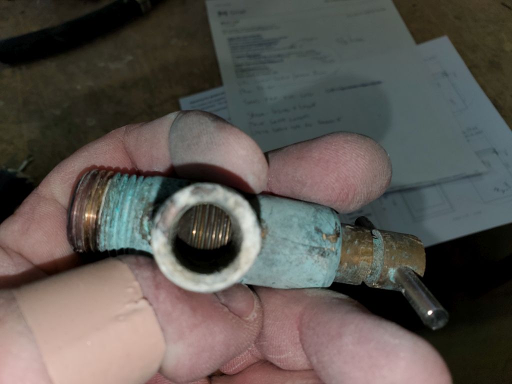
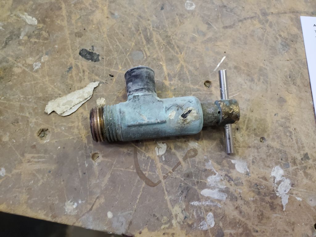
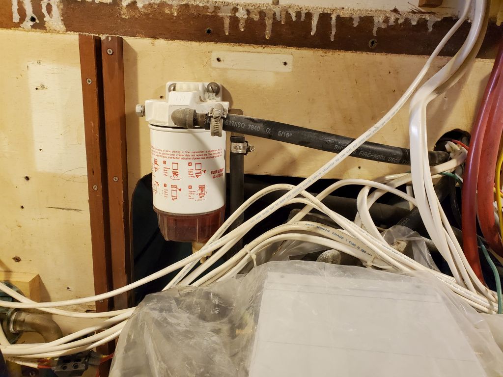
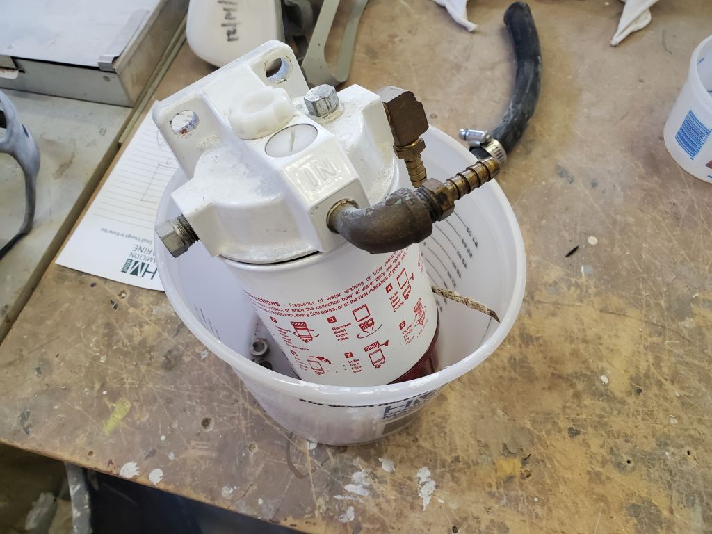
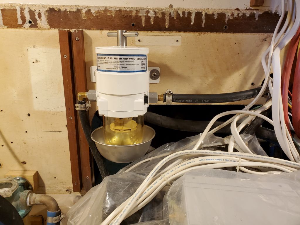
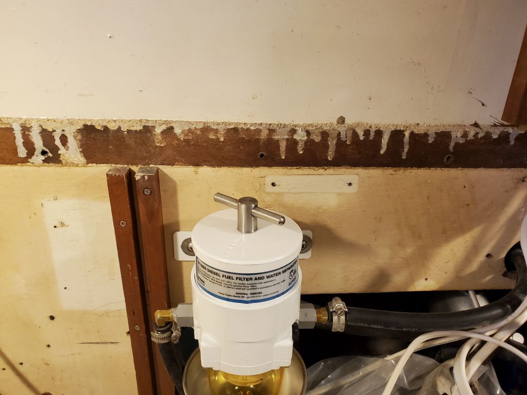
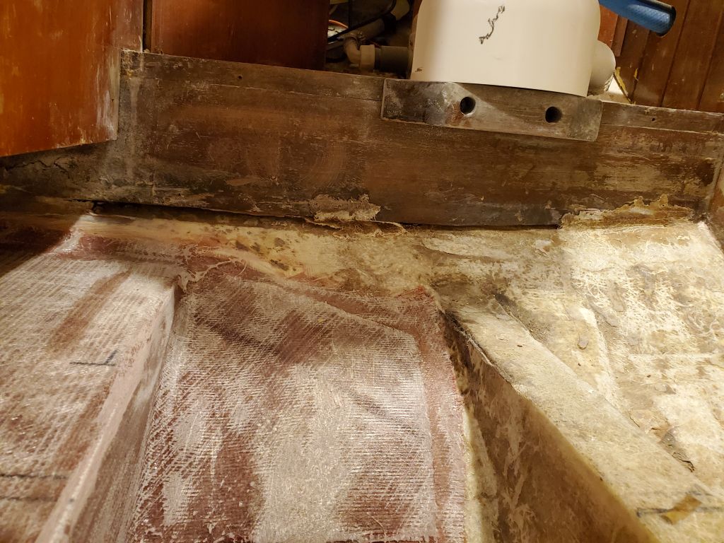
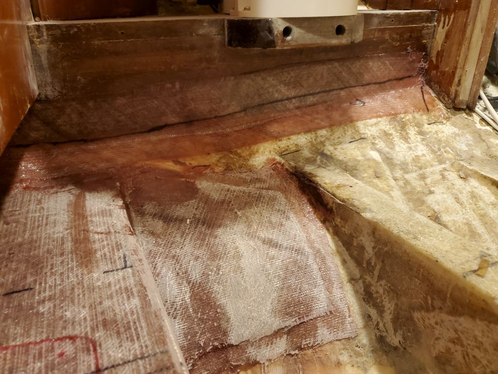
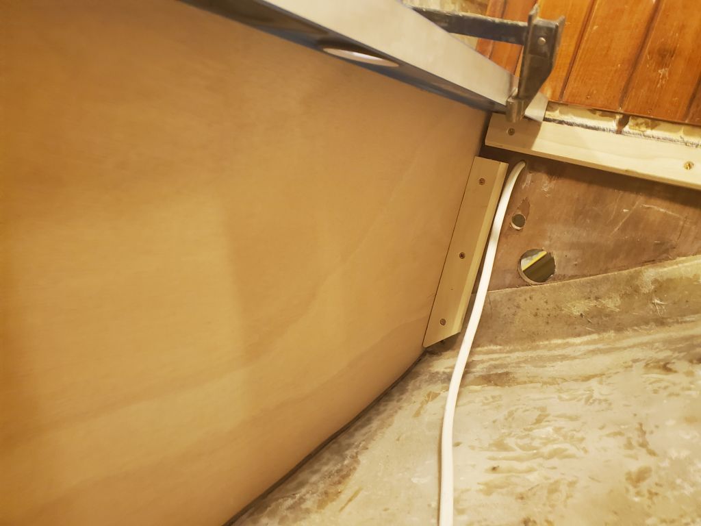
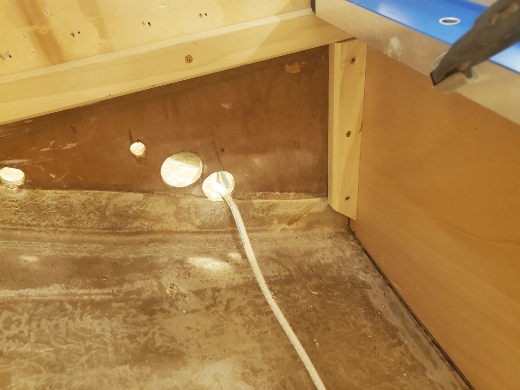
The owner asked me to replace the existing spin-on type fuel filter with a new turbine/cartridge filter.  With galley construction coming up soon on the list, there was no better time than now, with access as good as it would ever be, to make the switch.  The existing location seemed like it would work fine for the new filter as well, with ample room for the filter, bowl drainage, and no better nor more accessible location likely to make itself known with time.  The swap was straightforward, and the existing hoses reached the new filter nicely.  I secured the filter through the bulkhead with machine screws and nuts.  I planned to build an overhead access hatch in the galley counter/lockers when the time came to provide access for removing the filter element when needed, since overhead clearance was otherwise tight.

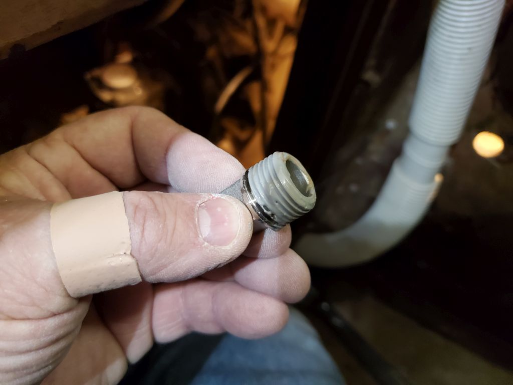
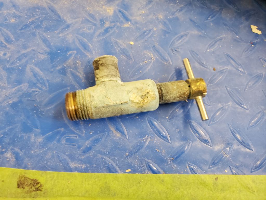
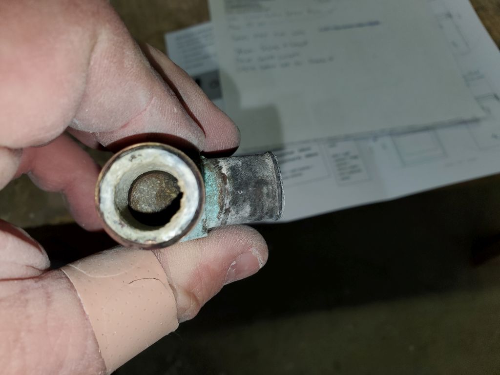
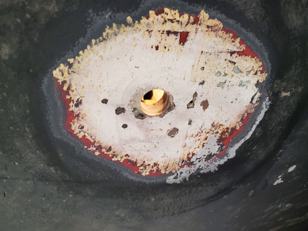
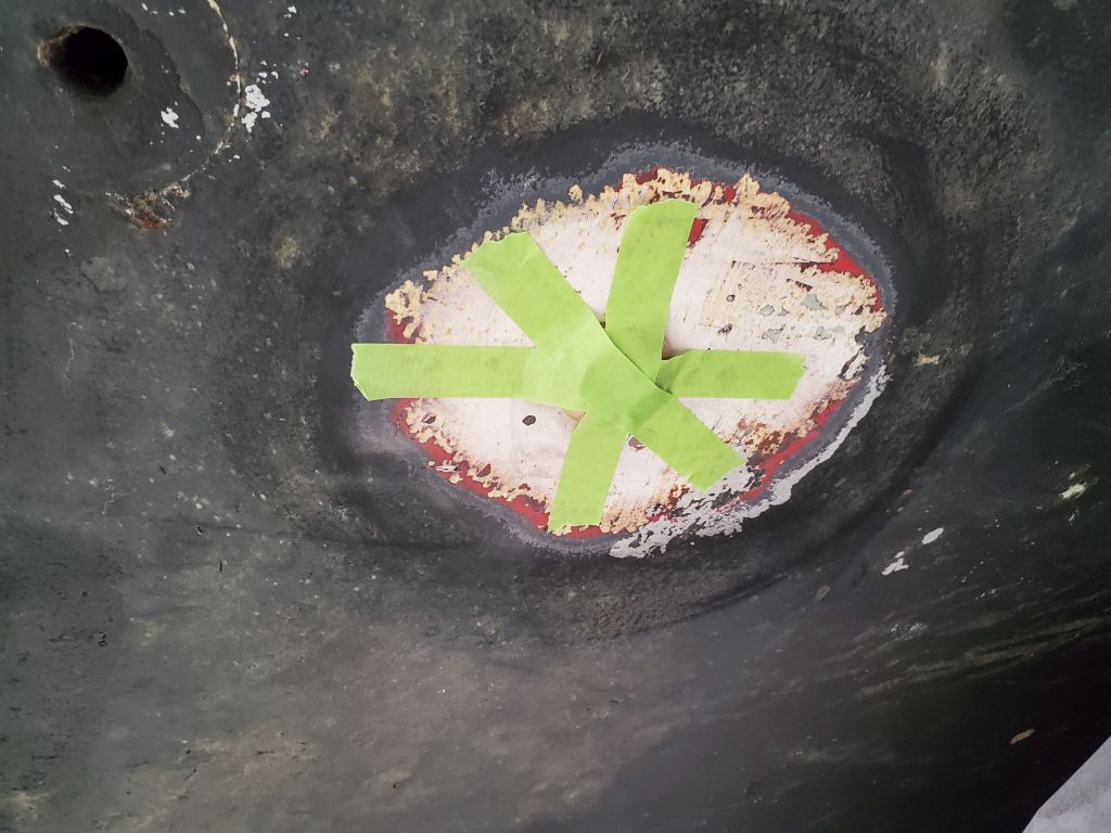
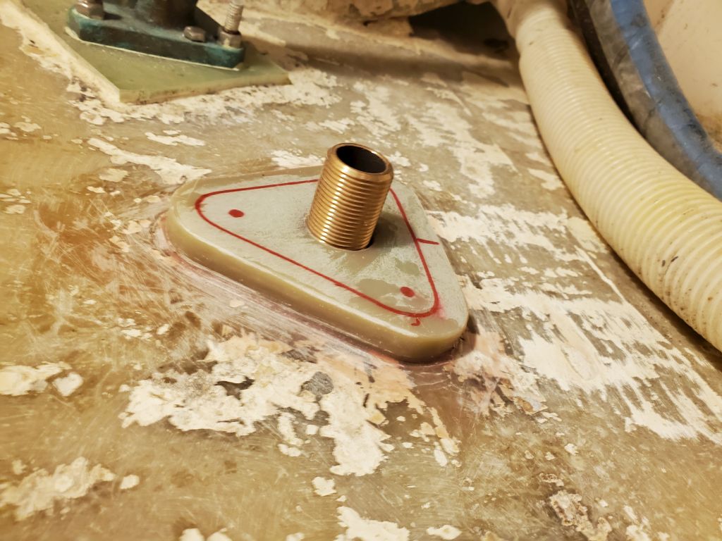
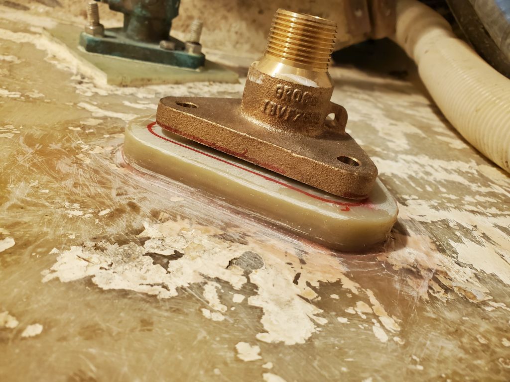
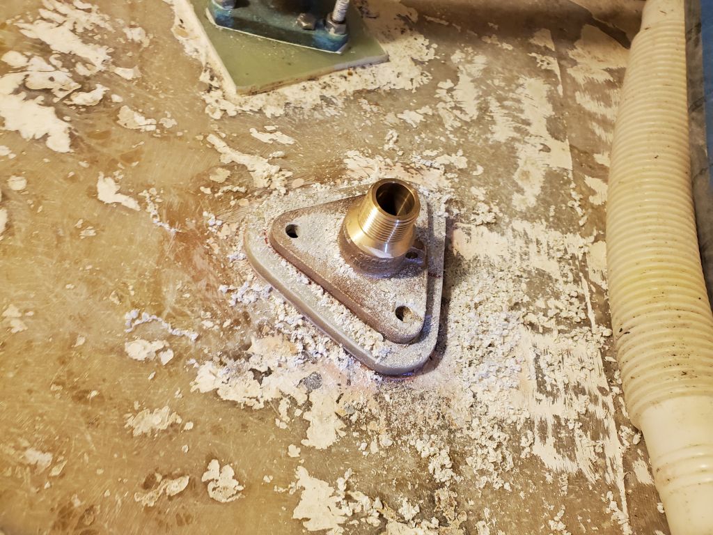
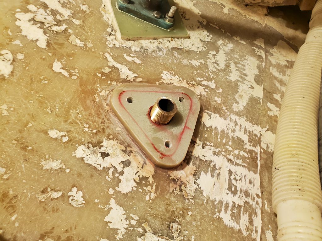
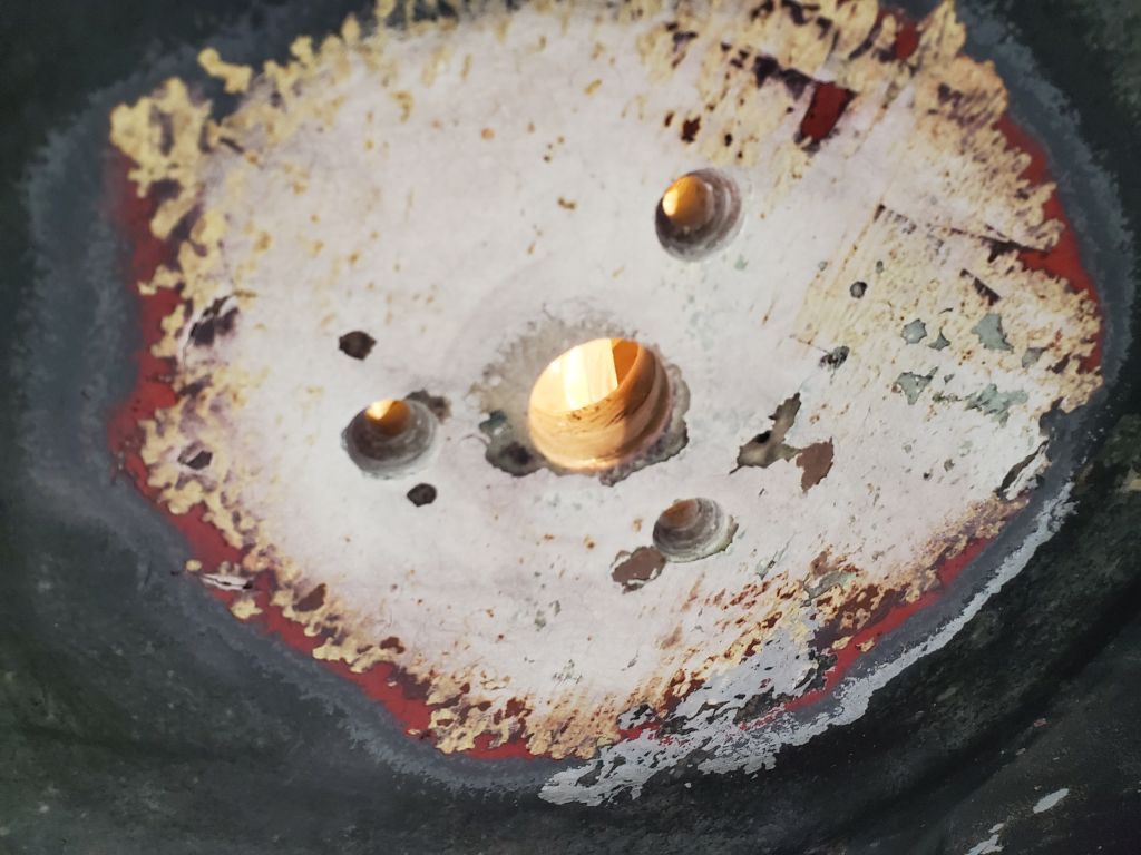
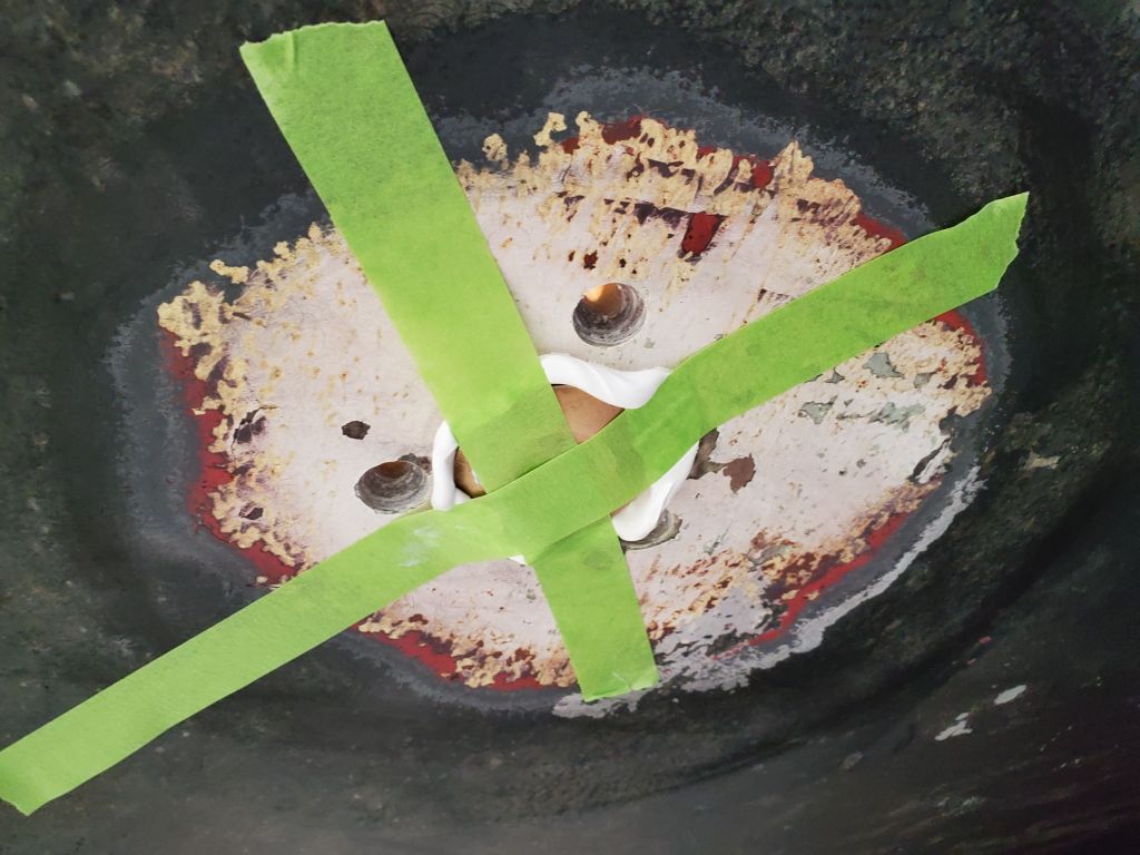
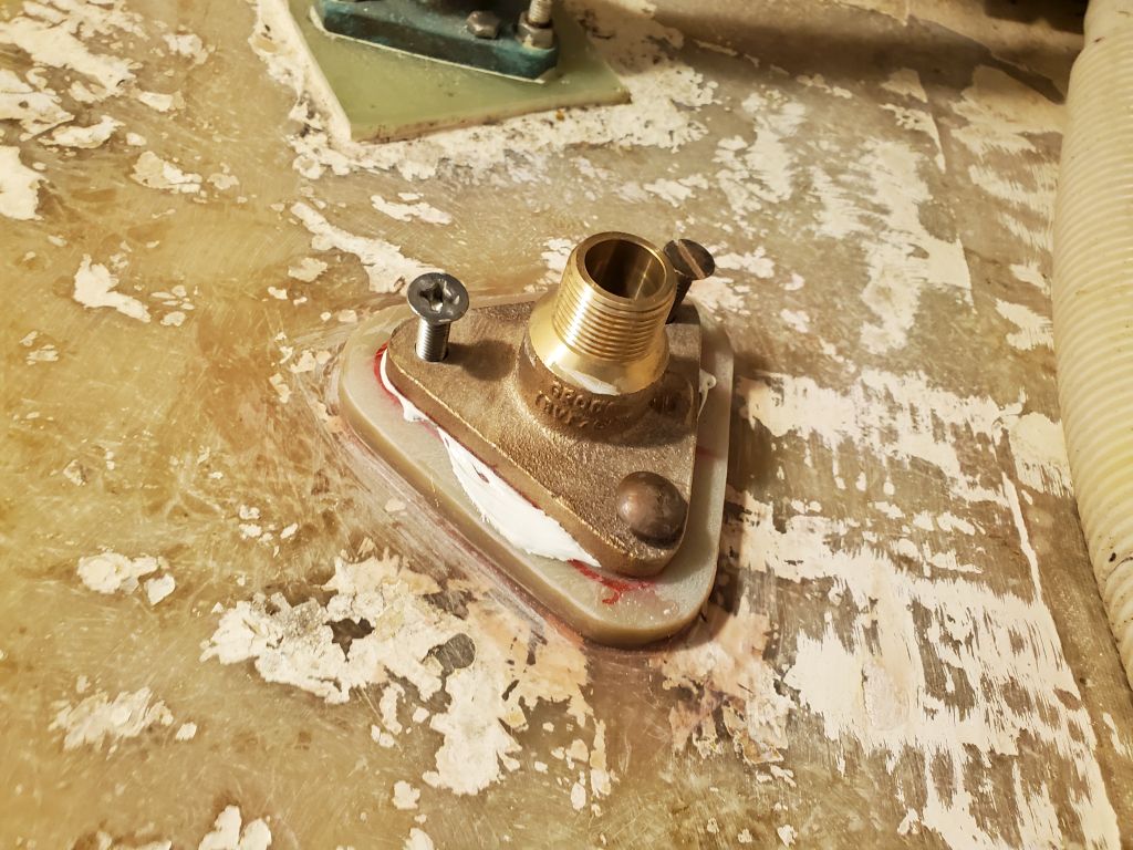
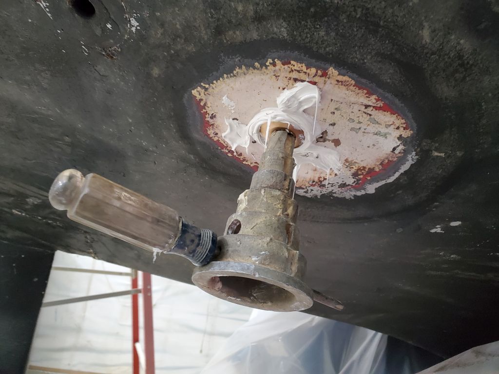
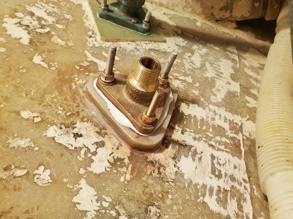
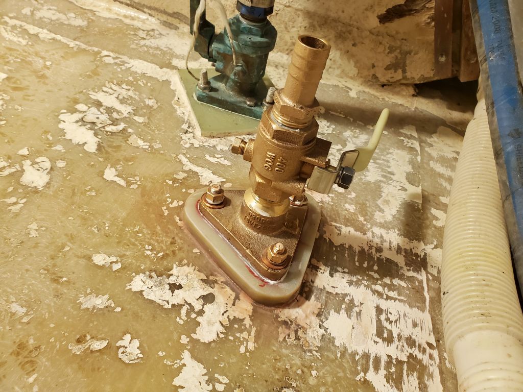
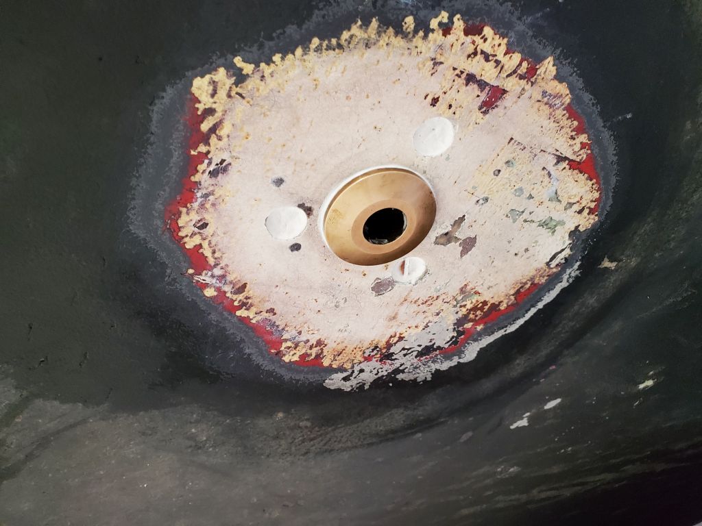
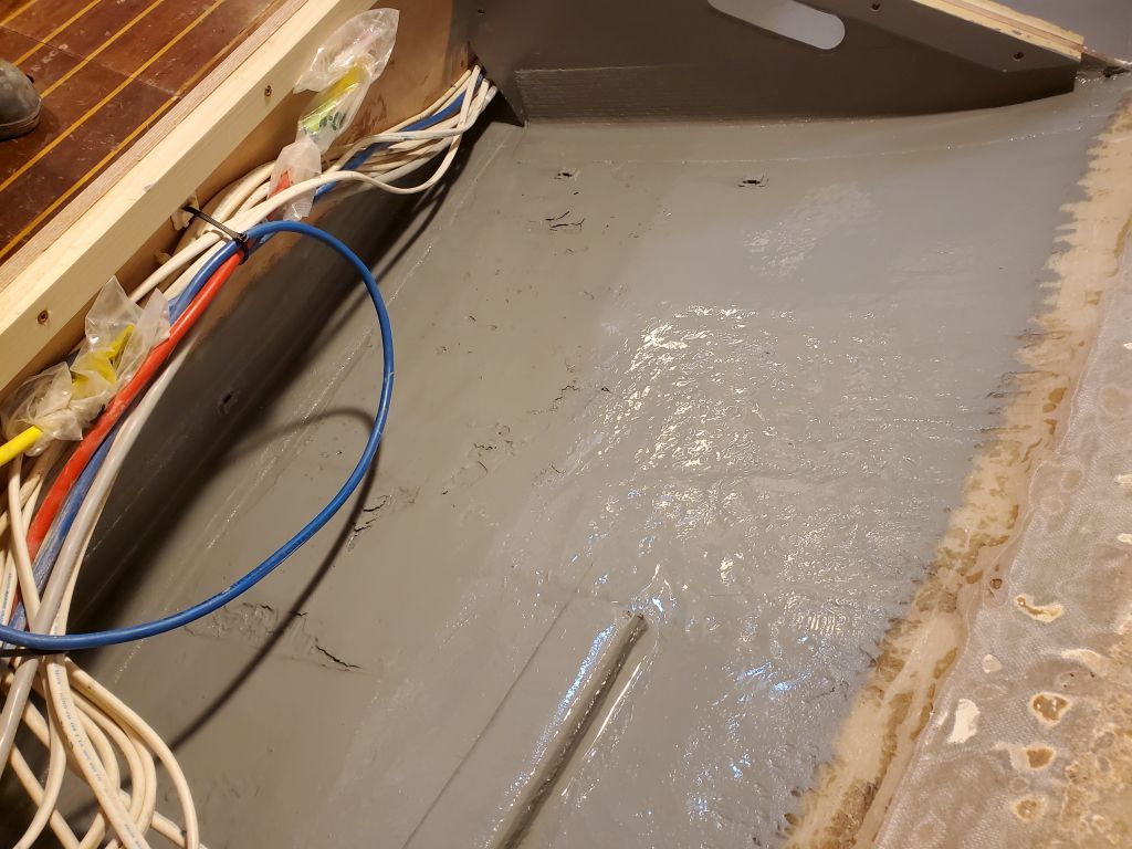
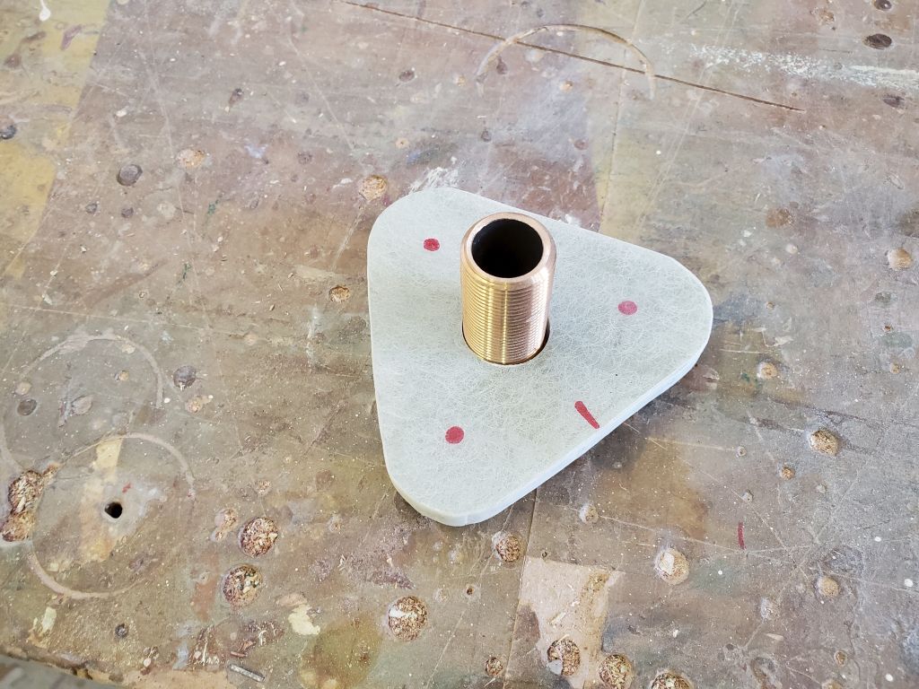
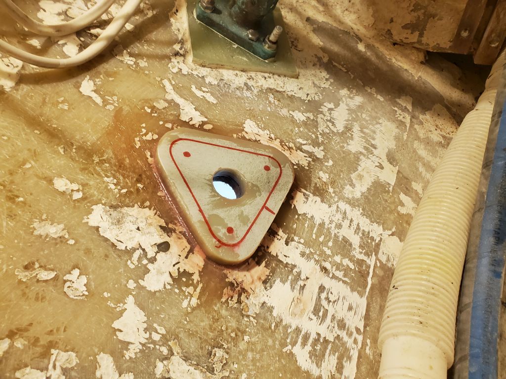
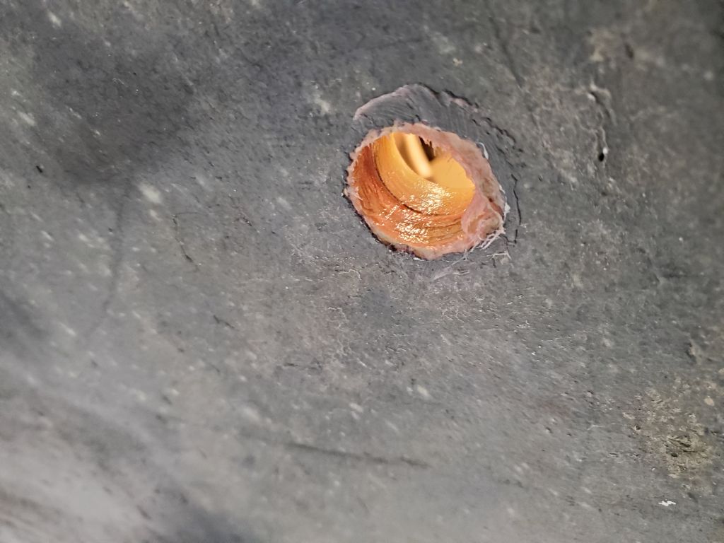
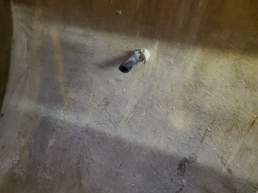
Continuing with the engine intake replumbing, now was also the time to install the new intake through hull.  I cut a backing plate to fit from 1/2″ G-10, then determined the mounting location in the engine room, a bit forward of the existing sink drain, and drilled through the hull.  Then, I installed the backing plate in epoxy adhesive, leaving it to cure overnight.

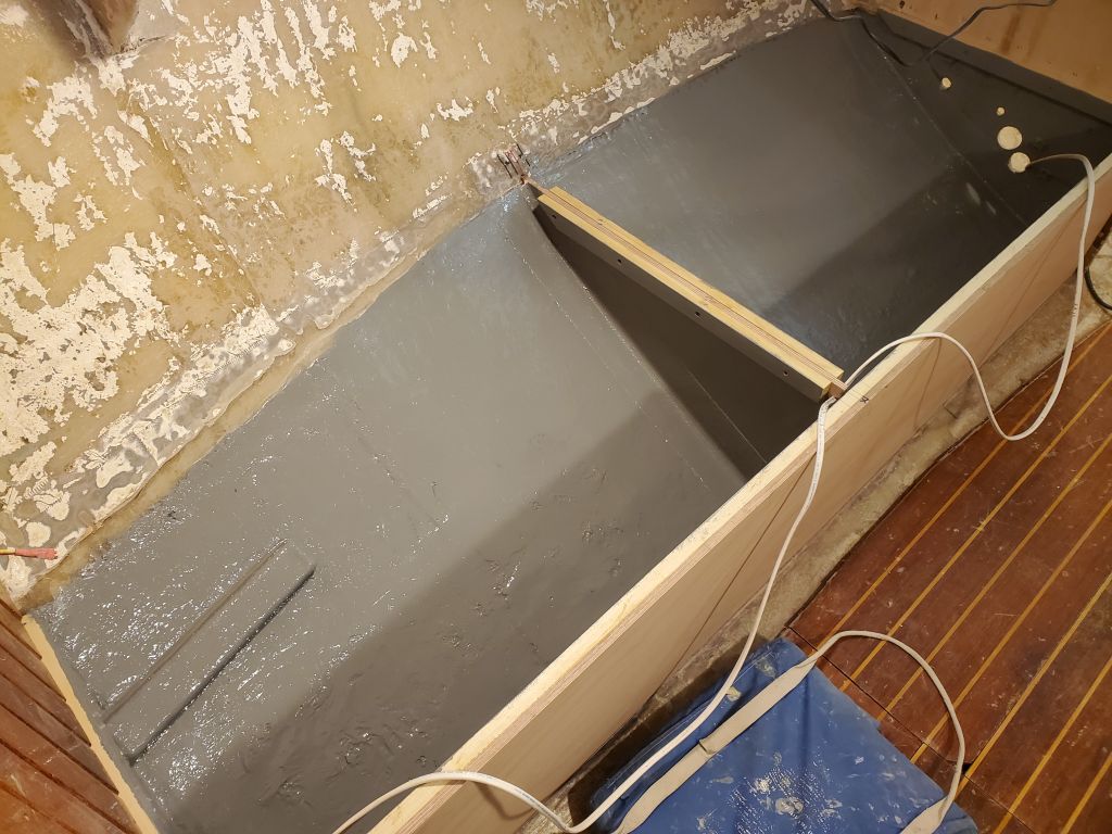
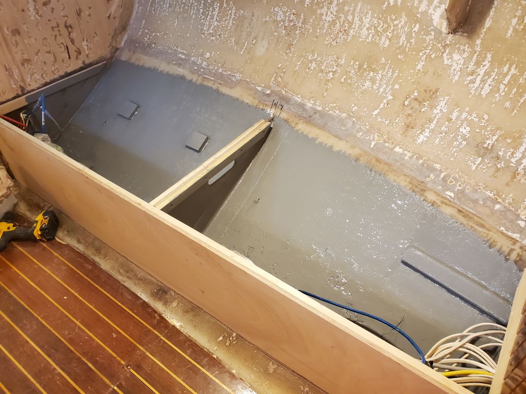
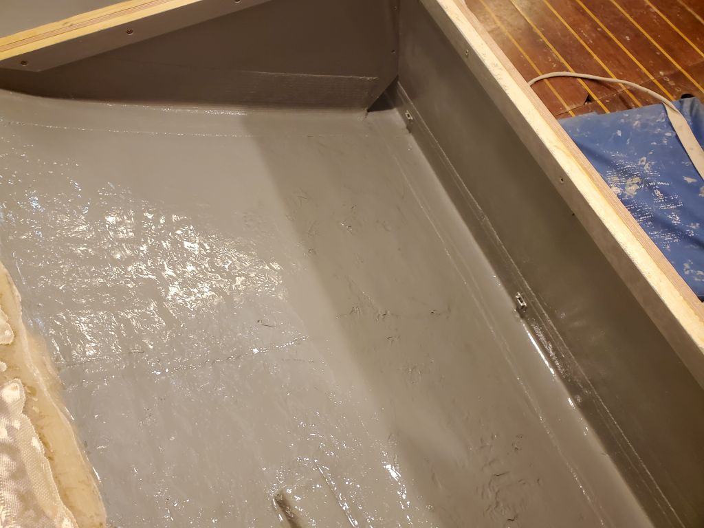
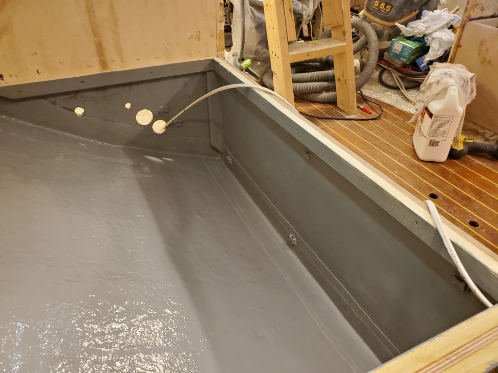
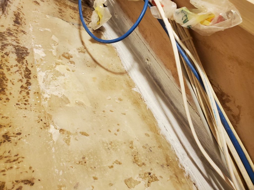
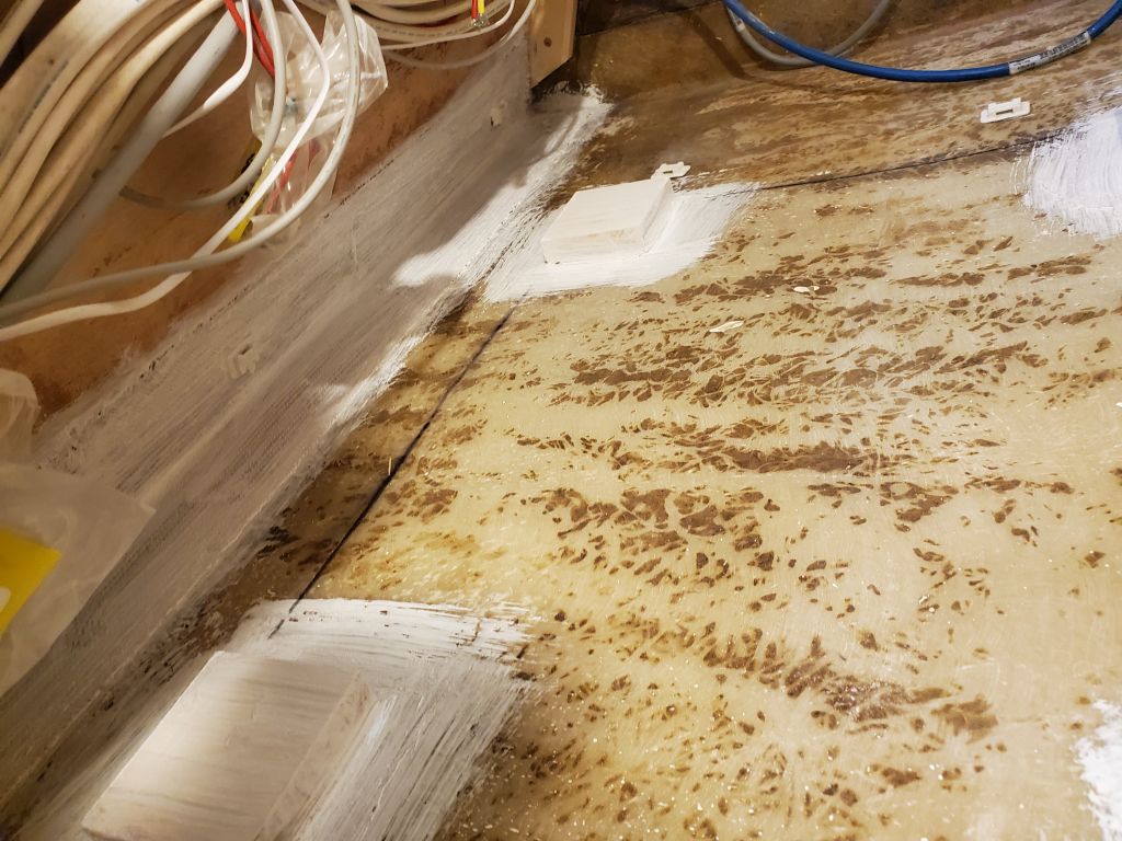
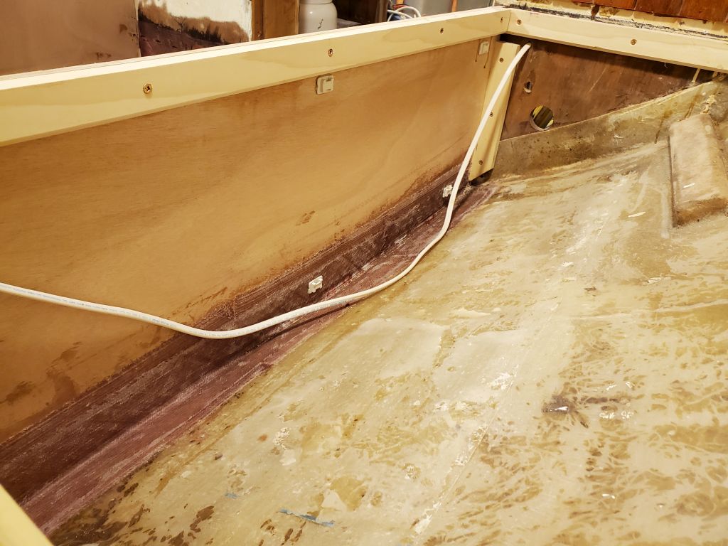
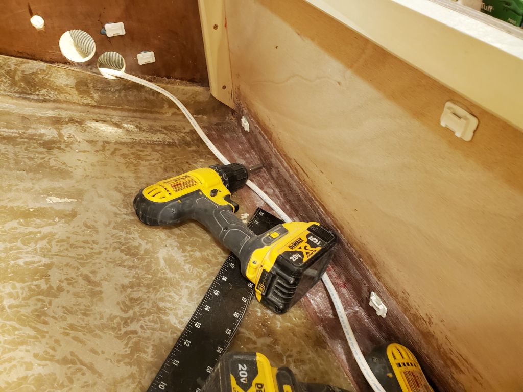
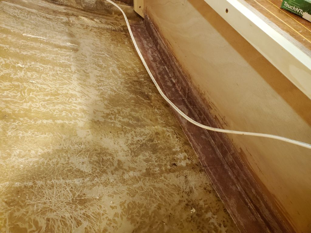
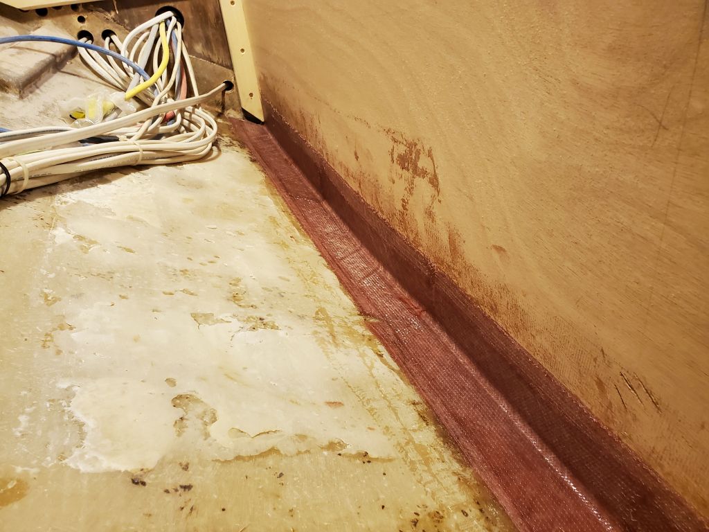
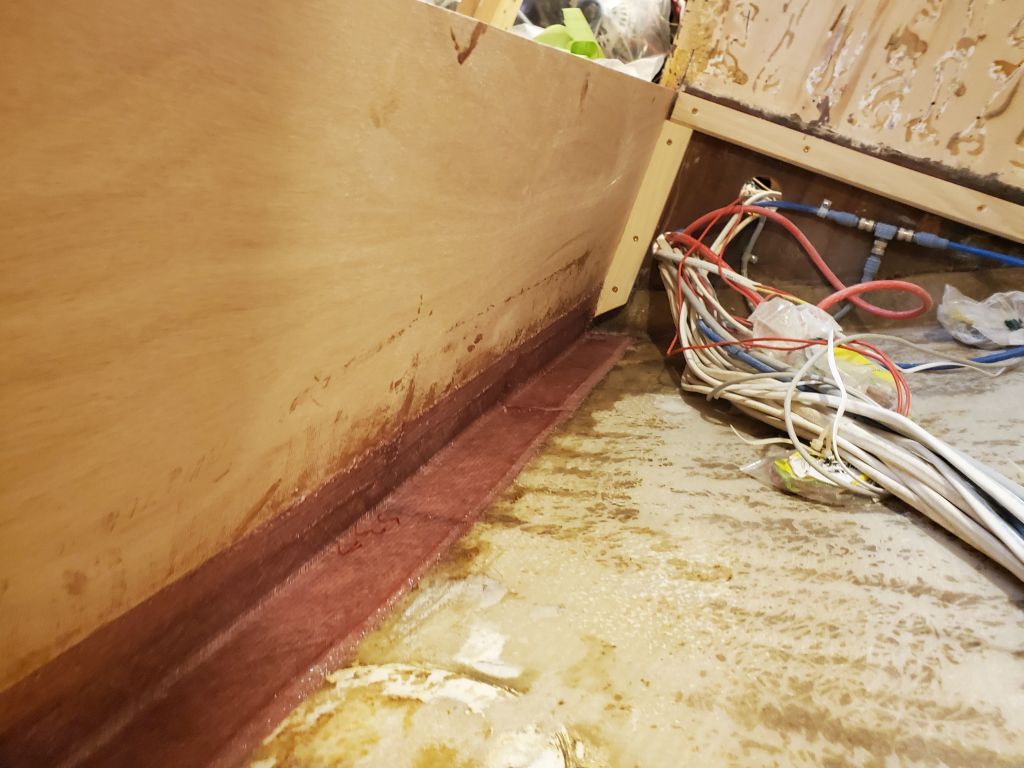
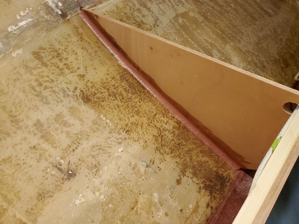
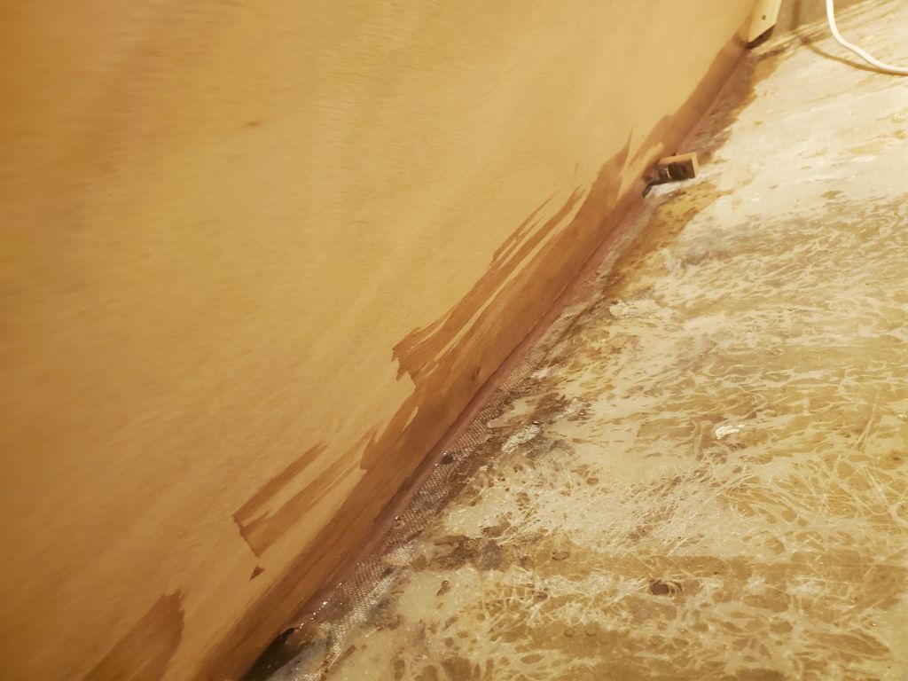
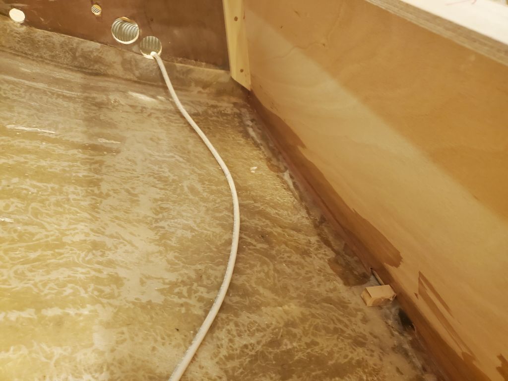
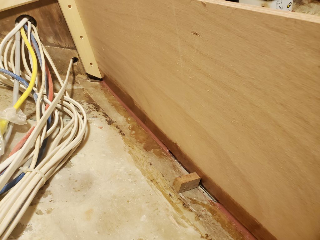
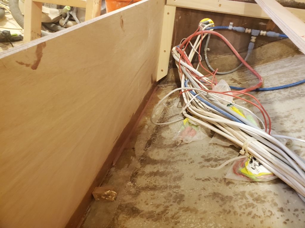
Finally, I made final preparations in the settee lockers, temporarily securing wire bundles out of the way and cleaning the surfaces as needed, then applied a coat of epoxy-based primer to all the fresh tabbing throughout both lockers, something I do as a matter of course to avoid curing problems with one-part paints over fresh epoxy and the final step before I could paint the lockers with their final coats.

Calliope Girl 33

With an unavoidable absence planned later in the week, I worked on New Year’s to make up the time and keep making progress.

To begin, I cleaned and sanded the recent work on the main bulkhead, removing paint from the aft side of the bulkhead to prepare for tabbing, and lightly sanding the epoxy fillets and filler left from when I installed the small plywood bulkhead patches.  The small bulkhead beneath the marine toilet needed some attention also to close a large gap and weak tabbing, so I prepared this area too.  Afterwards, I cut tabbing to fit as needed, applied some additional thickened epoxy to clean up the earlier filler and fillets, and to make a new fillet at the head platform, then wet out and installed two layers of tabbing (on each side of the main bulkhead) and a single layer on the head platform.

Next, I used the battery switch panel that I’d removed from the port after settee locker earlier to mark its own outline on the hull so I could install new hardwood blocks for securing the panel.  I secured the new blocks with epoxy adhesive.

Continuing with a punch list of work required before I could paint the settee lockers–itself a job I had to complete before I could install the berth tops–I installed a series of wire tie mounts throughout the spaces on both sides, both to eventually secure known wires, as well as for future possibilities.  These mounts are best installed before paint, as otherwise the paint has to be spot-removed at each location.

That was about all I could do with the settees for the moment, so, changing tacks, I turned to the engine intake.  The owner had requested that I install a new through hull fitting for the engine intake, as its current setup brought cooling water in through the Yanmar SD20 saildrive drive leg.  I planned to do the through hull work before I started building the new galley, and with that coming up soon, now was a good time to get into the cockpit locker and access the hose connection at the drive leg, and also see what exactly the situation was there so I could block off this intake as needed.  First, I had to remove some gear from the locker, along with the mostly-disconnected small LPG locker that would no longer be needed (and was also on my list to remove), leaving a stub of the LPG drain hose attached to its skin fitting for now (it would require a plug later).

The engine intake hose connected to a valve fitting on the top of the drive leg.  I removed the hose easily enough, and contemplated the fitting.  The T-shaped handle suggested a valve, but it was too tight to turn by hand.  Tentatively, with a wrench, I was able to turn the fitting, but, not versed on the specifics of this particular water cock, I wasn’t sure at first whether it was working correctly, so I did some research to satisfy myself.   Apparently the fitting is such that it requires a large number of turns to close (it’s a gate valve), so what I had experienced was normal, and the fitting could be closed completely.

In any event, I had a better idea what I was dealing with, and a start on how to secure it going forward.  I’d return to the locker soon to finish up this part of the job and also clean up the sanding dust from earlier parts of the project.

Calliope Girl 32

Getting started, I lightly sanded the tabbing on the settee divider bulkheads.  Then I marked and trimmed the port settee top to its final size.

With both settee tops cut and fitted, I laid out a pair of large access hatches on each side, then cut out the openings. (Top row:  port side; bottom row:  starboard side)

Next, I cut and installed, with glue and screws from beneath, hardwood cleats around each opening to support the hatches.

Back in the boat, I installed a pair of hardwood support cleats on the divider bulkheads–one cleat on each side of each bulkhead to provide a wide and secure bearing surface.

A few details remained to complete in the locker areas before I could think about installing the berth tops permanently.  I’d address the list in the coming days, but for now I turned to a small repair at the main bulkhead, where earlier I’d cut away the lower section for better access while working on the new mast step structure.  Now, I prepared a plywood patch (made from two laminated layers of 12mm plywood) to fill in the opening, and also cut circles of plywood to fill in a pair of old holes above leftover from (it looked like) an old foot pump for the head sink.  I installed these plywood patch pieces with a thickened epoxy adhesive–you can’t see the plywood in the circular holes, but it’s there, covered with a skim of the adhesive.  I filleted around the base of the bulkhead patch, but these areas would require a bit of dressing up before I could tab over the whole repair in the near future.

Calliope Girl 31

I started off by giving the new tabbing a quick wash and light scuff with sandpaper, which prepared the area for whatever was next.

I continued by gluing and screwing the top support cleat to the port side, along with the vertical cleat to support the port side divider bulkhead.  I’d already cut the basic template for this bulkhead, so now I scribed the base to fit the hull and, after a satisfactory test-fit with the template, transferred the shape to the final bulkhead, which I secured to the support cleat with screws so I could mark and trim the top edge level with the rest of the structure.

Once I’d trimmed the top edge, and cut a large opening in the panel to allow for wire runs from the battery selector panel that would be mounted aft of the bulkhead, I permanently secured the bulkhead with glue and screws to the support cleat, and epoxy fillets where the bulkhead met the hull.  I originally installed a hot glue block on one side of the bulkhead, to hold it in place, but determined I could remove the block and hold the bulkhead successfully with just a bit of glue at the very top corner where it met the hull, which meant I could finish off the fillets now.  On the starboard side, I used leftover epoxy to finish off the fillet where that bulkhead had been supported temporarily with a glue block.

I cut strips of 6″ tabbing to fit, then installed them on both divider bulkheads–one layer on each side of each bulkhead.

I recycled the template from the starboard berth top to use on the port side, flipped over as needed.  I scribed a line to match the hull and cut the pattern to fit.  Then, satisfied, I transferred the pattern to 12mm okoume and cut out the actual berth top (leaving a bit of extra to overhang for later trimming), catching the port side up with the progress to starboard.

Calliope Girl 30

After some minor surface prep to lightly scuff the fresh epoxy fillets securing the settee fronts, I prepared a small batch of the filleting material and filled in the several areas where the temporary glue blocks had been installed.  While that gelled, I cut, then wet out and installed, two layers of tabbing along the full lengths of both settees.

While it was on my mind, I took a moment to apply some fairing filler to the top corners of the new mast step structure, filling a small gap between the fiberglass on the top and the tabbing on the two vertical faces–this just as a cosmetic concern, to avoid a sharp edge or gap that would tend to attract debris.

Next, I installed a full-length cleat along the top edge of the starboard settee front to eventually support the berth top and provide additional stiffness to the structure.  I attached this with glue and screws from inside.  I had a twin piece cut for the port side, but for the moment decided to focus on the starboard side.  Afterwards, I installed a short vertical cleat to support the divider bulkhead, then finished the layout of this bulkhead by securing it to the cleat with two screws, squaring it to the settee front, and marking the hull accordingly.  To hold and align the divider during installation, I installed a temporary hot glue block near the outer edge.  Finally, I used a level to mark the top edge of the divider, after which I removed the panel for final trimming, epoxy coating of the edge grain, and then installation with glue and screws against the support cleat, and epoxy fillets along both sides where the bulkhead met the hull.  I left this to cure for now, and planned to install tabbing next time, once the epoxy cured.  I left a sizeable limber at the base of the divider (and also a space for hoses to run later), and provided a wiring chase at the top edge for the existing wire run through the space.

I continued work on the starboard side berth top, partly because I was anxious to have a flat work surface as soon as possible, and partly because the still-curing tabbing on the port side precluded work on the divider bulkhead there, as I’d need to release the large wire bundles in order to lay it out.   With some basic measurements of the space, I cut a template panel from junky plywood, which fit surprisingly well given its rough initial layout, but still required scribing and a second cut to match the curvature of the hull properly.

Once I was satisfied with the outboard edge of the template, I transferred the shape to a piece of the 12mm okoume and cut out the actual berth top, leaving it a bit wide so it hung over the vertical settee face for now.  I’d trim that to final size later, and there was still work to be done beneath, so it’d be a bit before I completed the final installation of the berth top, but at least now I’d have somewhere to put tools and such while I continued on the opposite side.

Calliope Girl 29

Laying the pattern for the starboard settee front on a piece of new 12mm okoume, I traced the pattern as needed, leaving an inch or so extra at the top edge for final trimming once I’d otherwise fitted the piece.  I cut out the panel and test-fit it in the boat, clamping the top edge to a straightedge to ensure it wasn’t bowed.

The fit was good and needed no changes other than to trim the top edge at the proper height, so I temporarily secured it at each end with two screws into the cleats behind.  I’d previously marked where the fasteners in the cleats were, and also marked the height of the horizontal cleat so I could easily transfer the final height to each end of the panel.

With the panel tightly secured at the ends, I ensured it was plumb in the middle (unsupported) sections and attached some small hot glue blocks inside and out to align and hold the panel properly (seen in the photos above).  Then, I removed the panel down to the bench so I could trim the top edge to the marks I’d made and prepare it for installation by epoxy-coating the end grain on the bottom edge.  To protect the front of the panel, I masked it off first.

After cleaning the faying surfaces in the boat, I applied some thickened epoxy adhesive to the hull, keeping it clear of the temporary glue blocks, and installed the panel into the adhesive and with some wood glue on the support cleats to help secure it along with the screws at each end.  I formed the epoxy into a small fillet on the inside edge of the panel and troweled any squeezeout flush on the outboard side.  I double-checked that the panel was level across the top, and later removed the masking tape from the exposed edge.

I repeated the process for the port side, first  test-fitting the 12mm panel and temporarily securing and aligning it as needed.  At the forward end, against the bulkhead, I planned eventually to incorporate a battery locker inboard towards the centerline, but for the moment I ran the panel straight across and would figure out the details of the additional storage area when the time came.

Happy with the fit, and with the panel aligned for reinstallation, I removed it to trim the top edge and epoxy-coat the faying surfaces before completing the installation as before.

By now, the epoxy on the first side had set up to the point where I could continue working without fear of upsetting anything.  From cheap pattern plywood, I made up a pattern for the center divider, a roughly triangular piece that would divide the settee locker into two sections and provide important support to the top and front panels in the process.  I roughed out the shape with some basic measurements, then test-fit the panel and scribed the lower (hull) edge to fit before transferring the pattern to a piece of the 12mm okoume for the final cut.  I left the top edge high for later marking and trimming.  This was as far as I could take this at the moment, since I needed to install tabbing on the inside of the settee front before I could install the divider panel; similarly, on the port side, though I cut out a rough pattern, I determined I couldn’t continue the layout since I’d have to first let all the wire bundles back down to the corner of the settee front, and the epoxy adhesive there was still too fresh for that.  In any event, the next steps were set up for next time.

Calliope Girl 28

On special request, Santa made an early stop at the shop after swinging by the hardware store and–surprise, surprise–brought me the new level I obviously sorely needed.  As it happened, this 72″ level was the perfect length for the settee berths.  I should have had this long before, but never had the need been so obvious previously.

With the new level, I quickly determined that indeed something was off–why this had been such an issue (when it didn’t seem like it should have been) remained unknown, but I found that the two horizontal cleats at the aft end were a bit low.

It was easy enough to raise up and reposition the after horizontal cleats to properly position them level with the forward set of cleats (which I also septuple-checked to ensure they were properly positioned too).  I checked the newly-positioned cleats in several places across their span on each side, and also across the boat from side to side.  This time, everything checked out the way physics and other aspects of reality required it to.

Finally satisfied with the cleats, I permanently installed them with glue and screws.

Using the long straightedge as a guide and measuring from the top of the settee down to the hull every foot or so, I made some basic measurements of the settee front to help me create a rough plywood pattern for each side.  This gave me the approximation of the curve required to match the shape of the hull.  After cutting out the rough shape from some cheap plywood, I fit each side and clamped it at the top edge to the straightedge to hold the floppy plywood securely and straight.  Then I scribed the lower edges to more exactly fit the various undulations of the hull beneath.

It took two rounds of fitting and scribing to get the patterns where they needed to be.  I made some reference marks at the vertical ends to help me cut the correct shapes there to match the bulkheads on each end (and around the tabbing at the lower ends), and some other notes to help when I transferred these patterns to the real plywood next time.


Older posts Newer posts