Tuesday
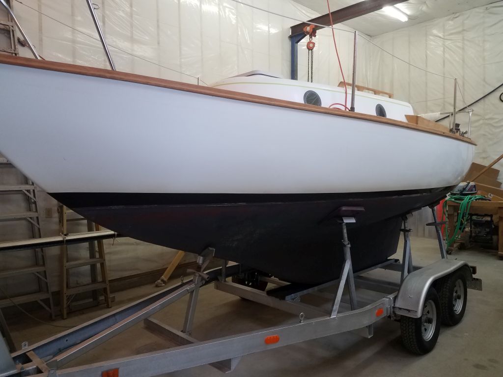
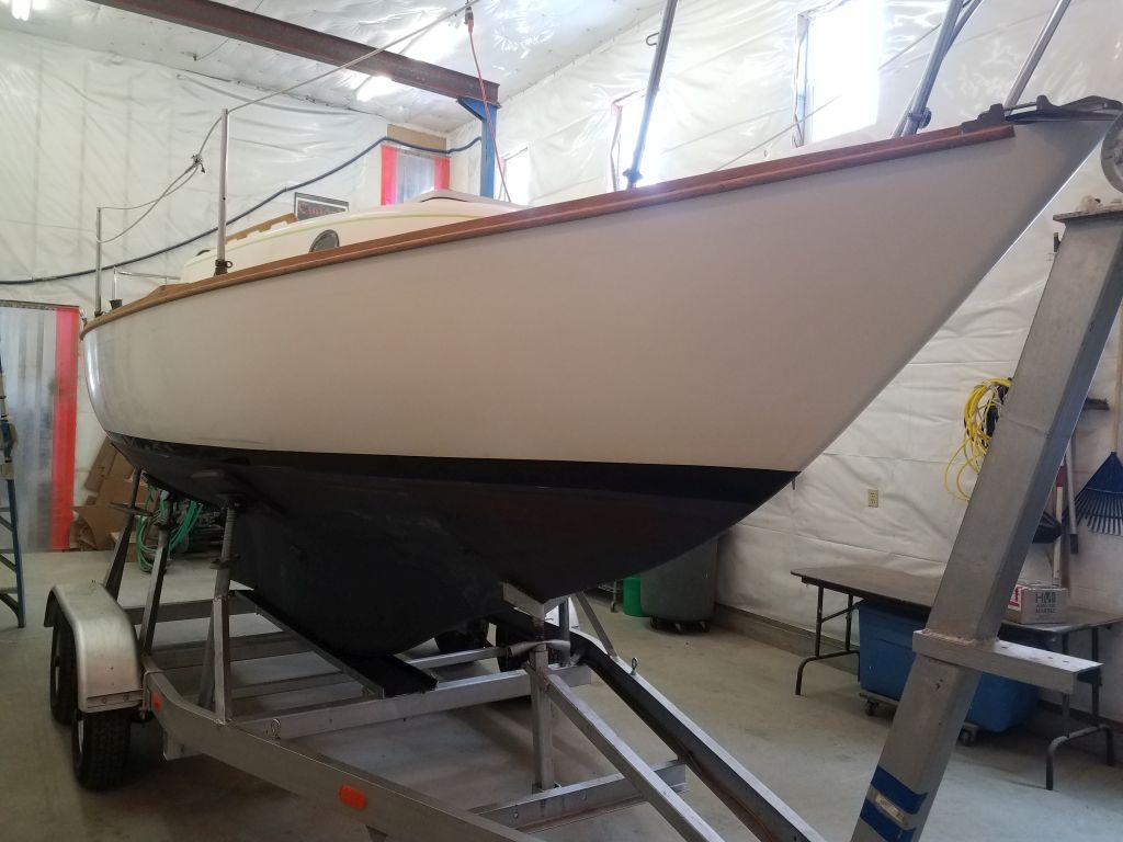
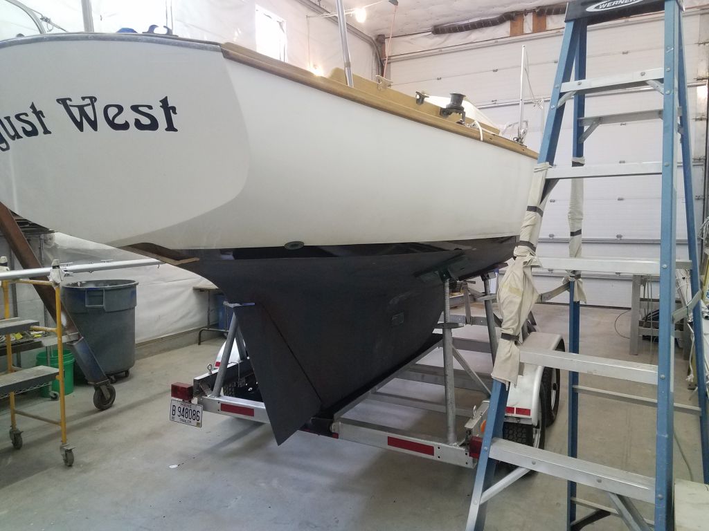
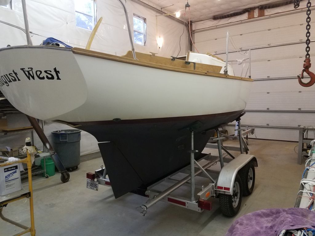
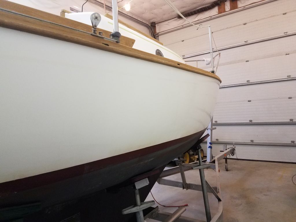
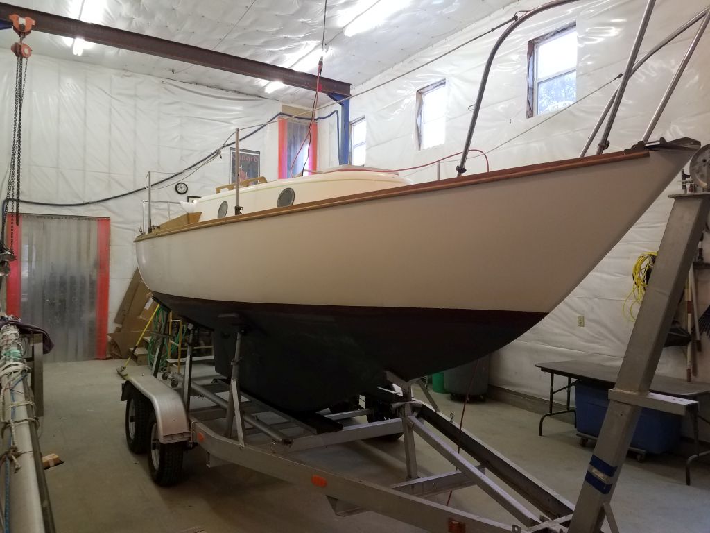
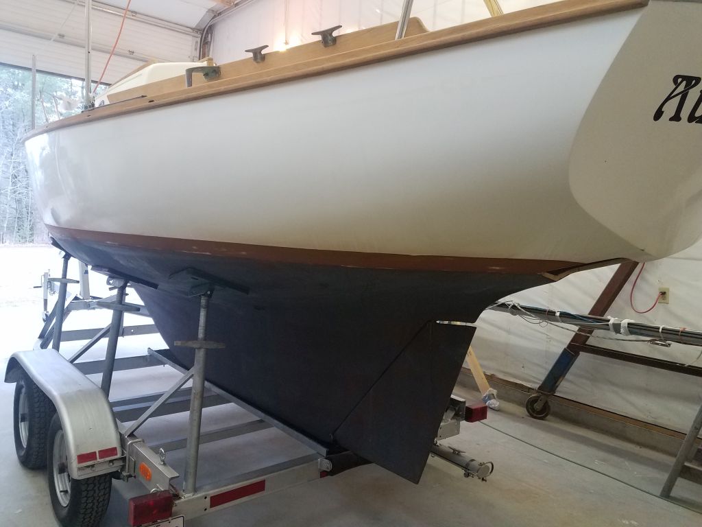
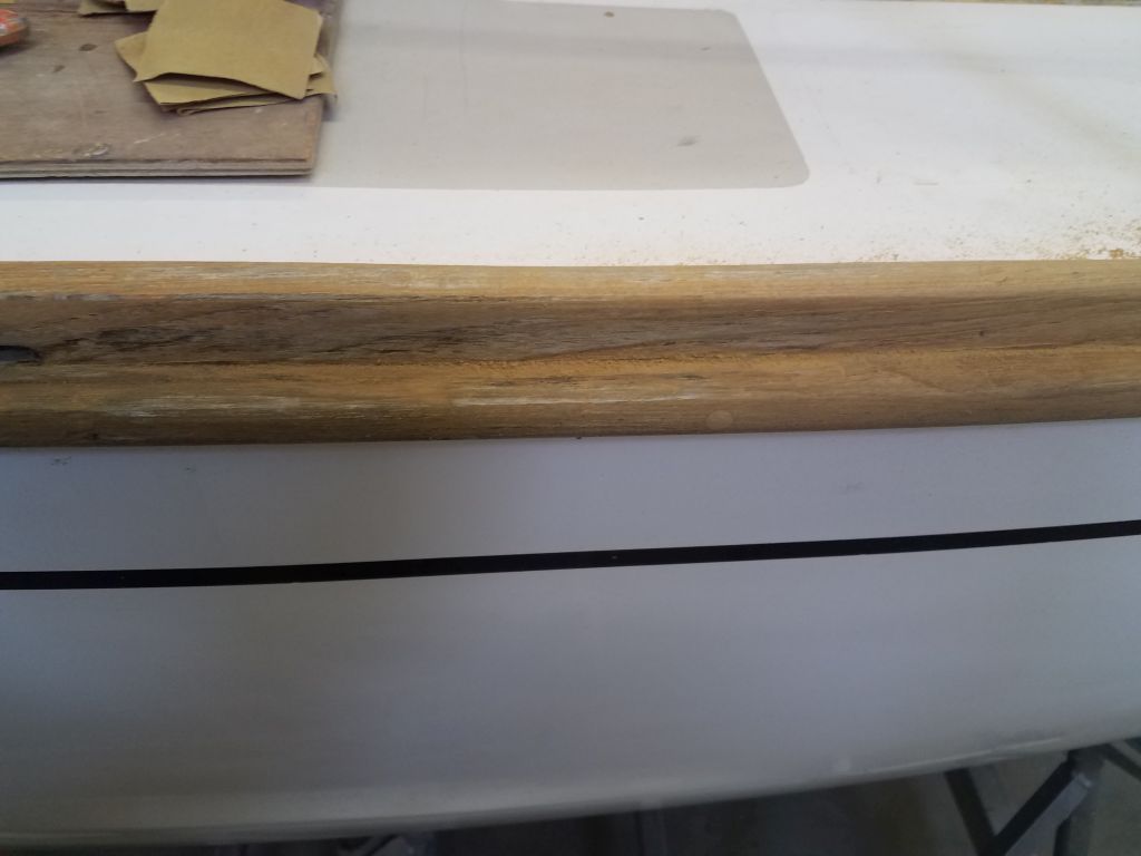
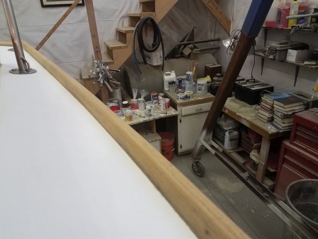
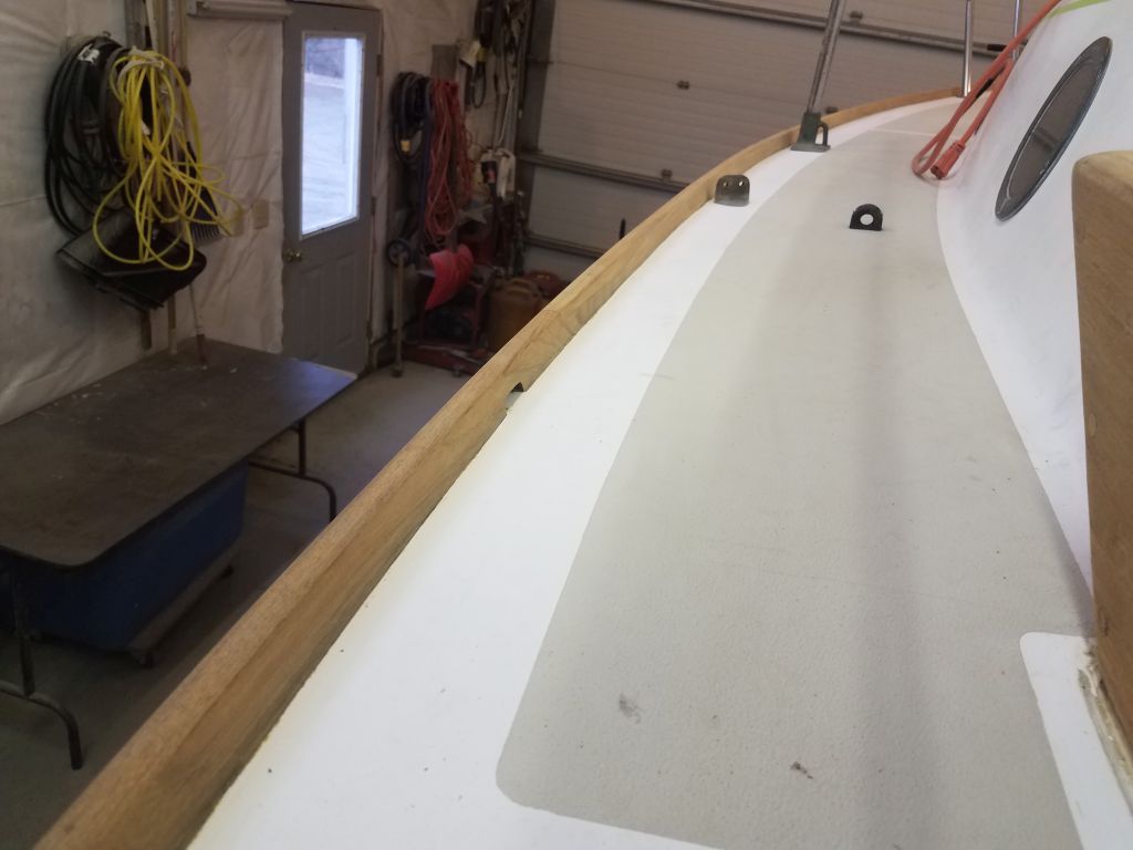
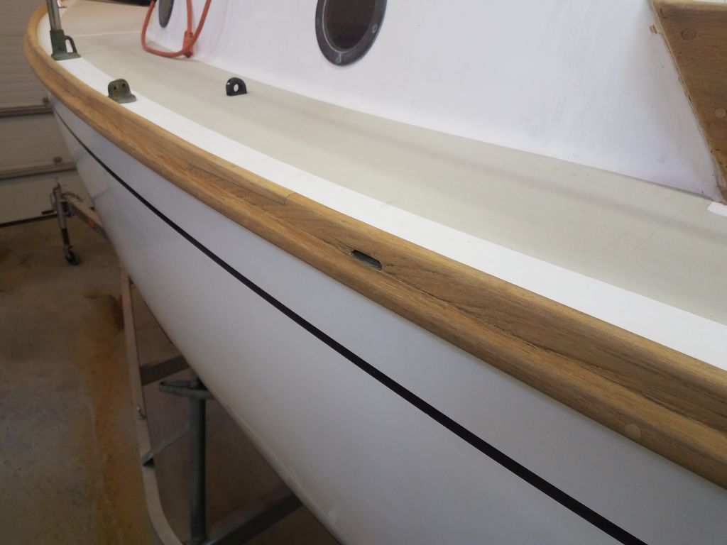
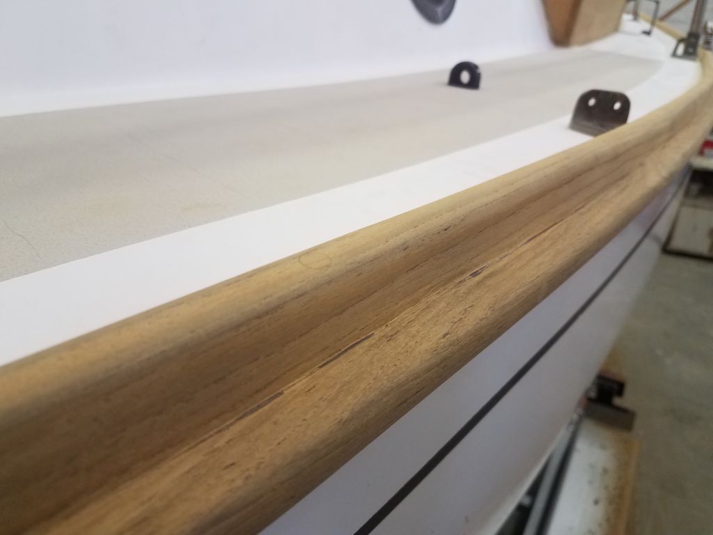
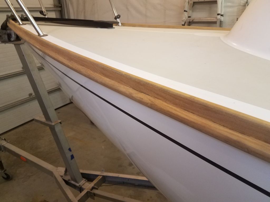
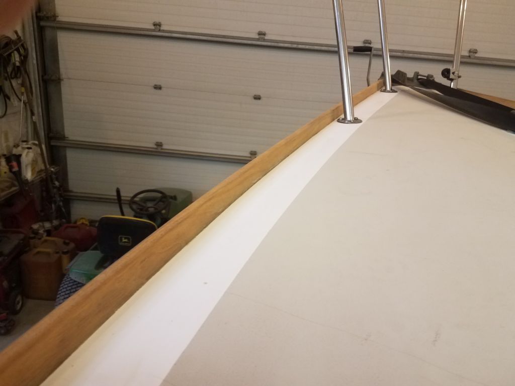
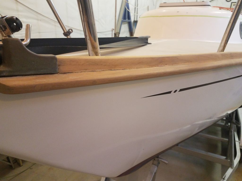
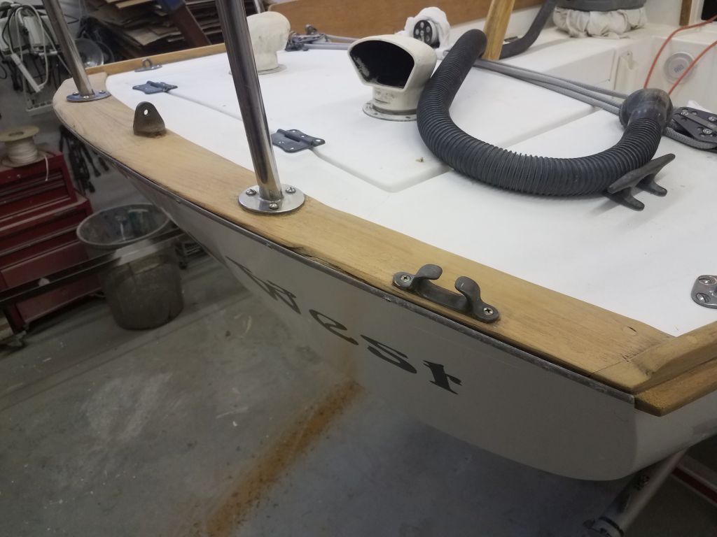
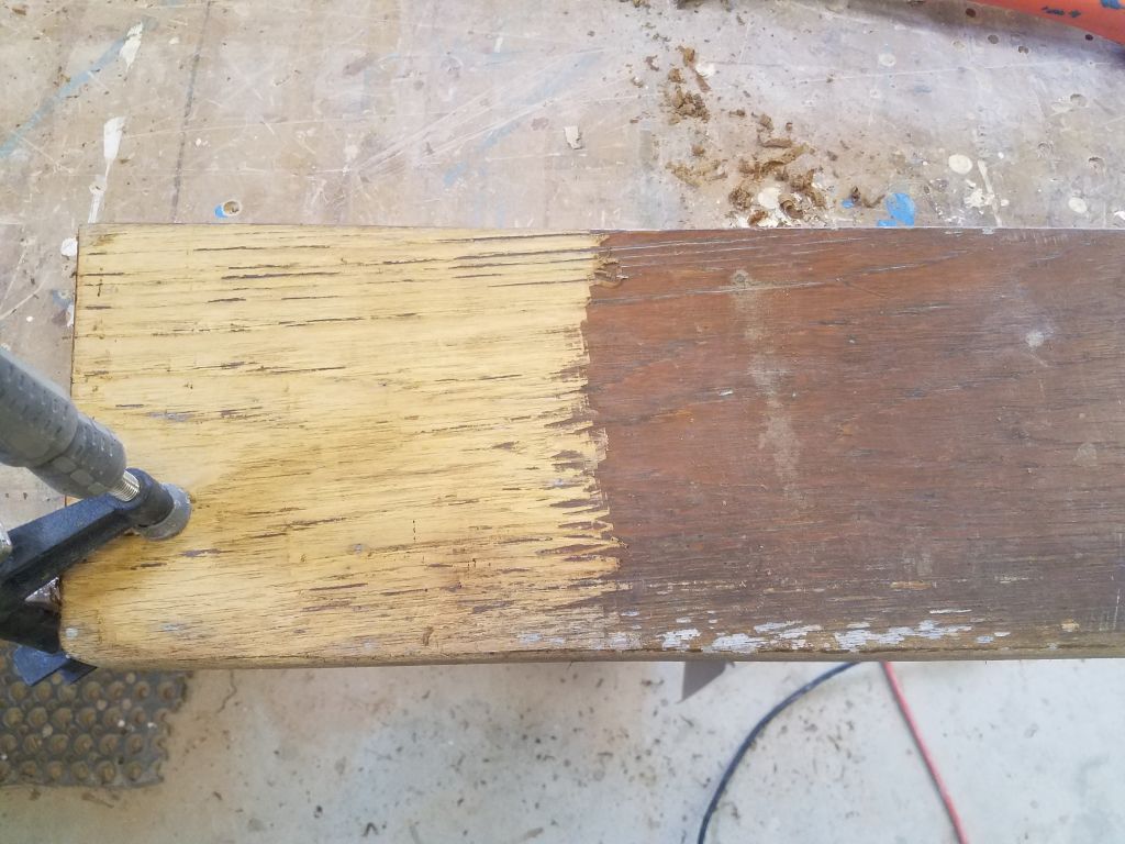
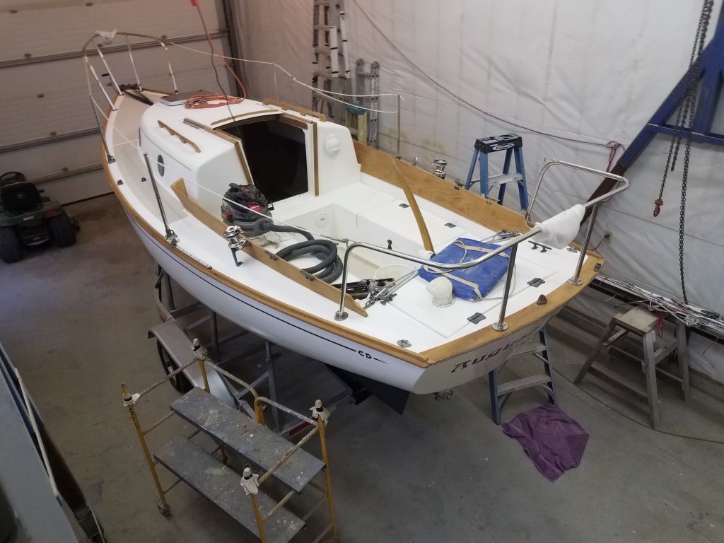
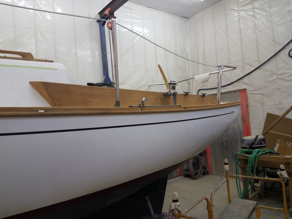
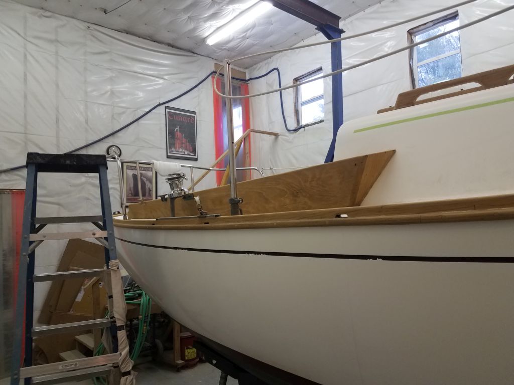
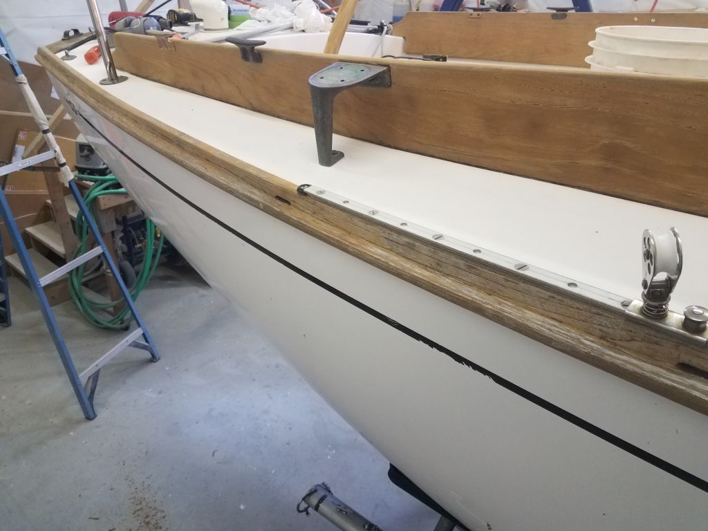
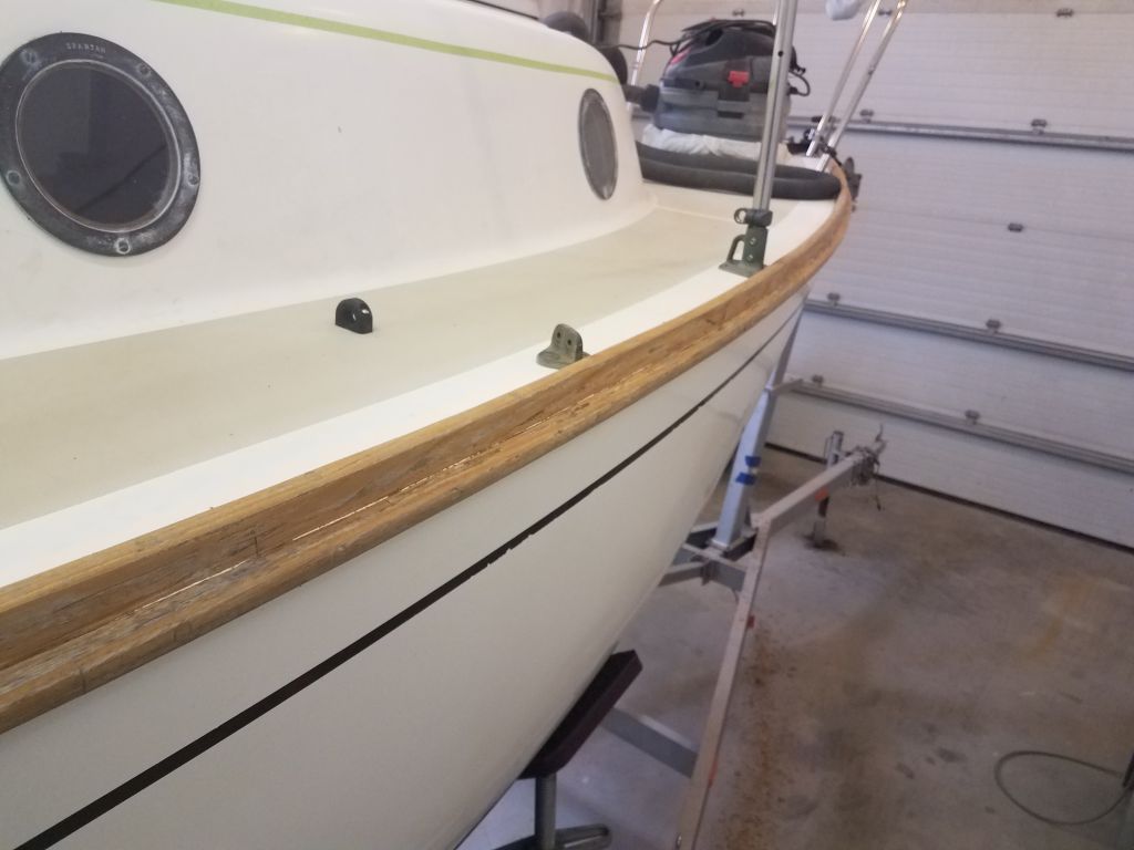
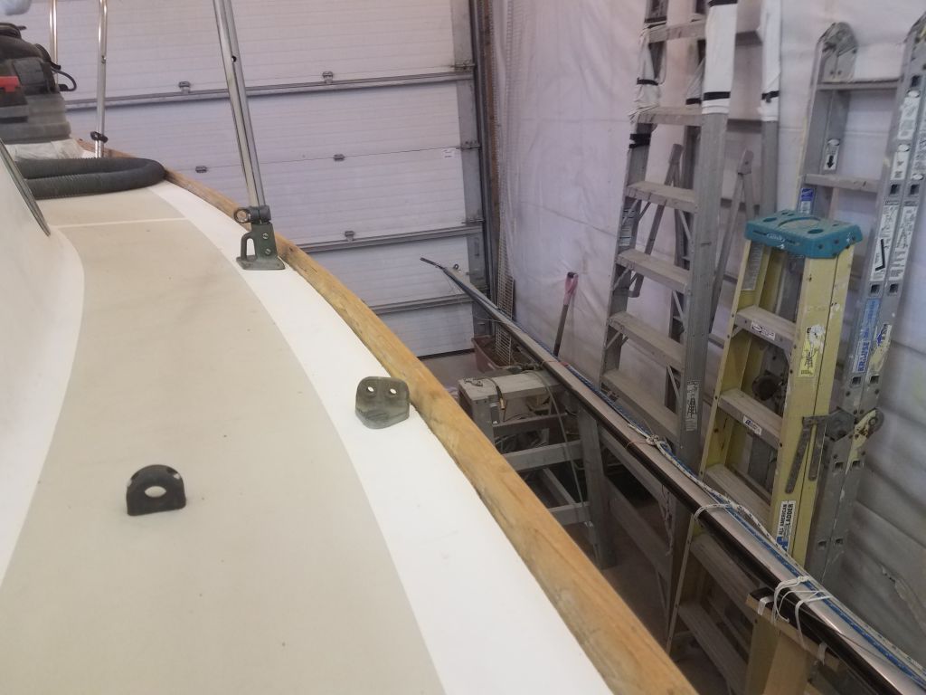
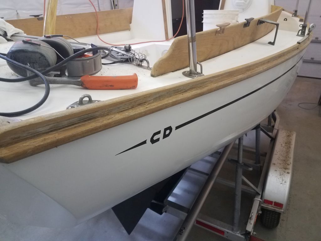
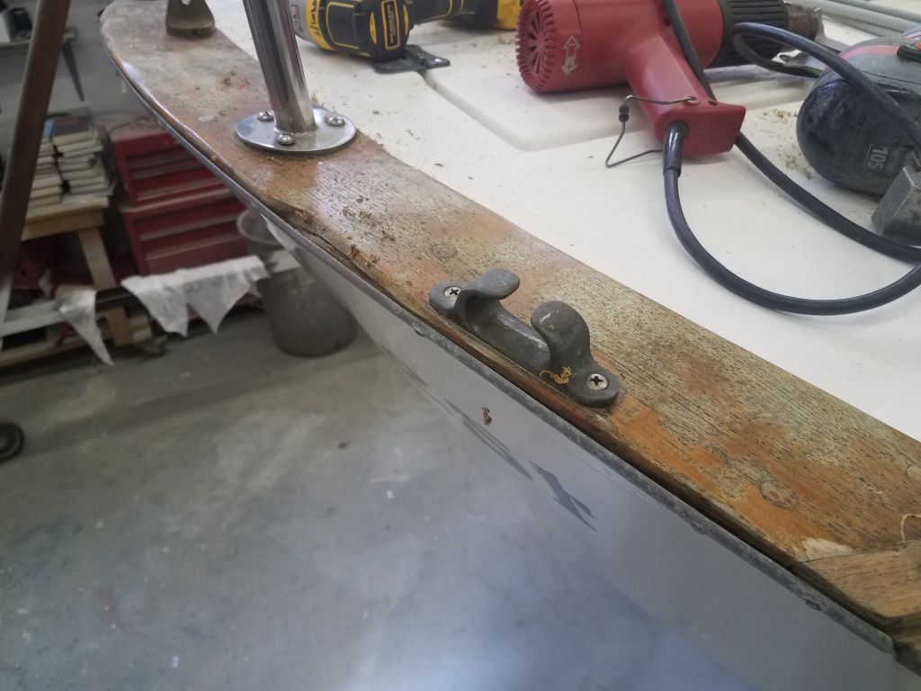
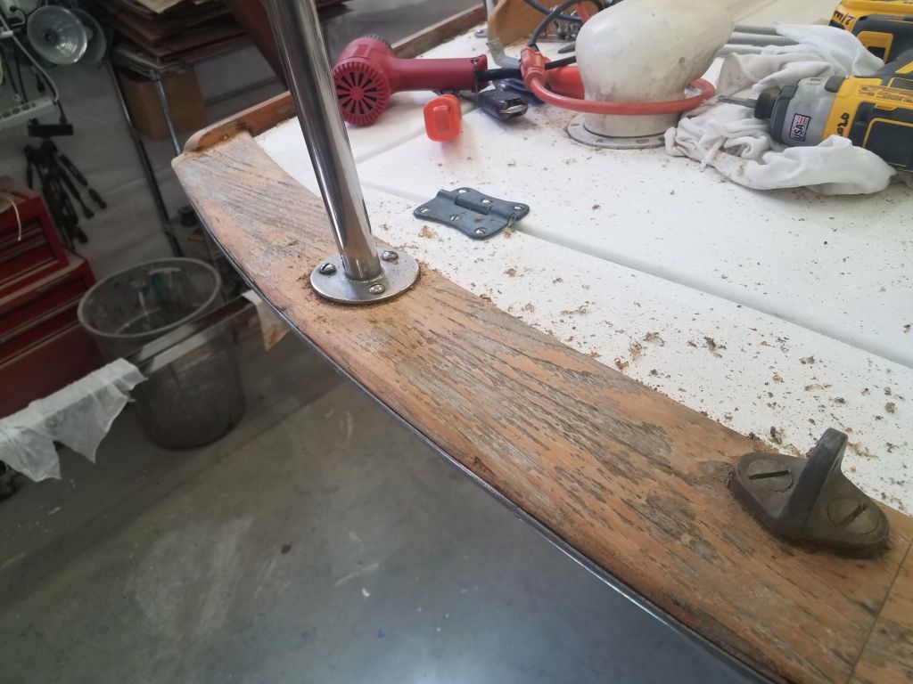
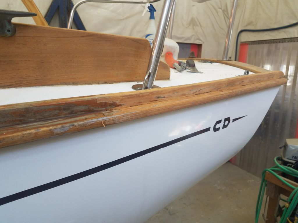
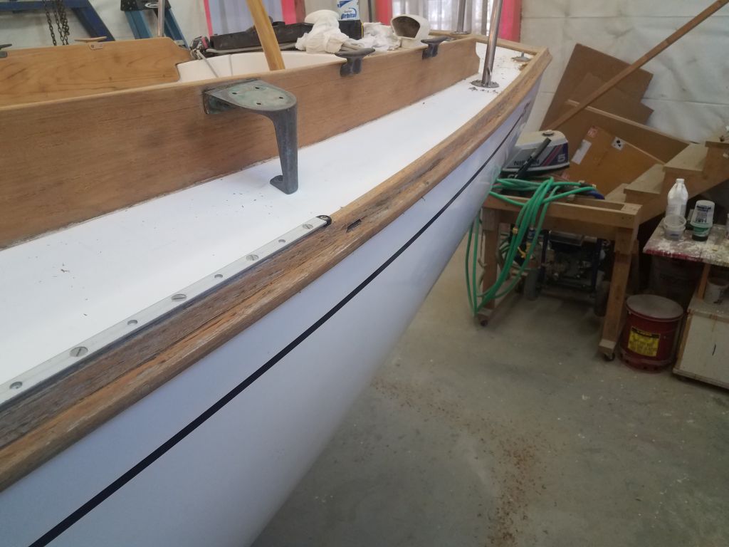
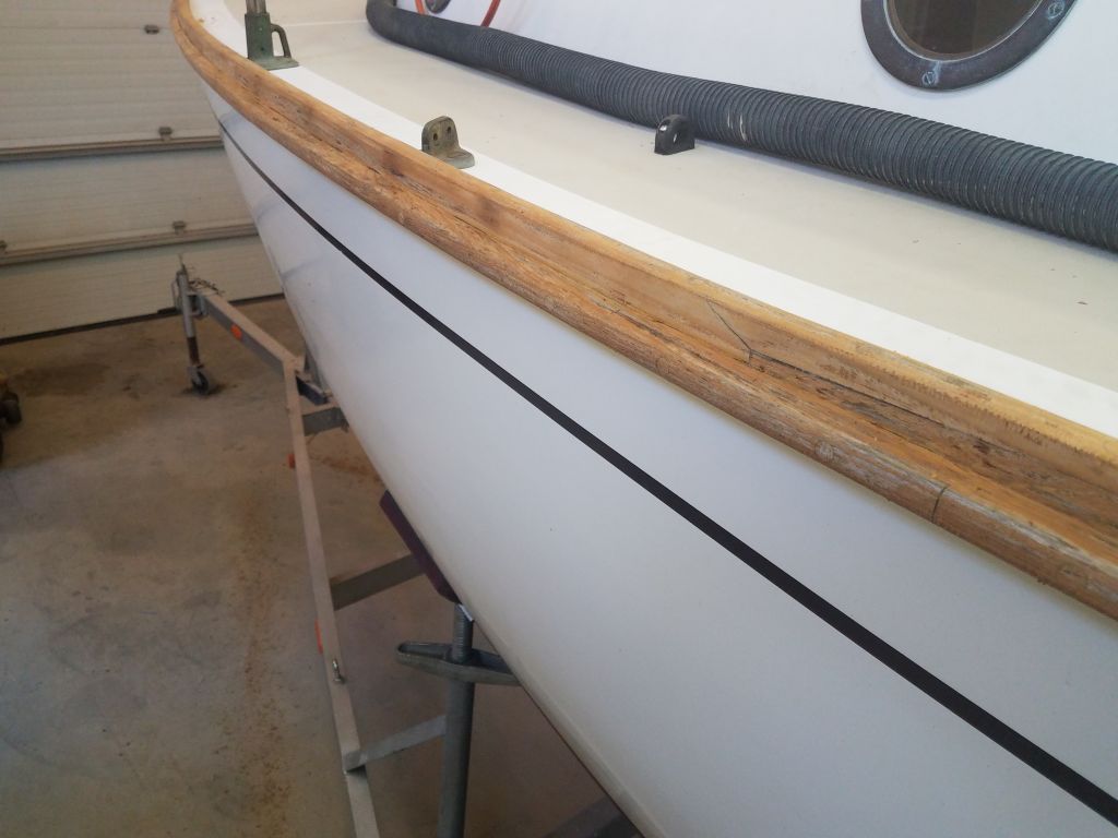
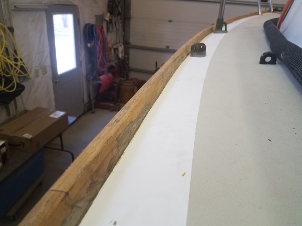
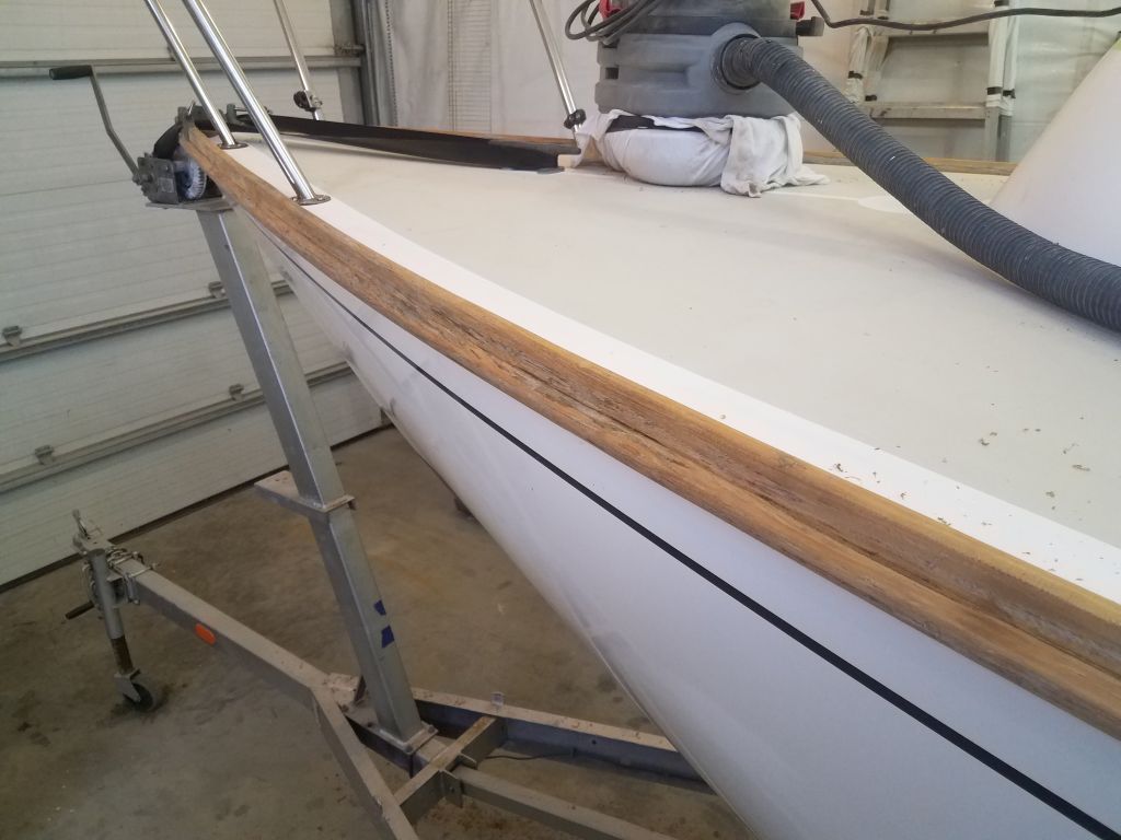
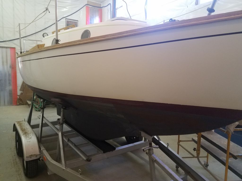
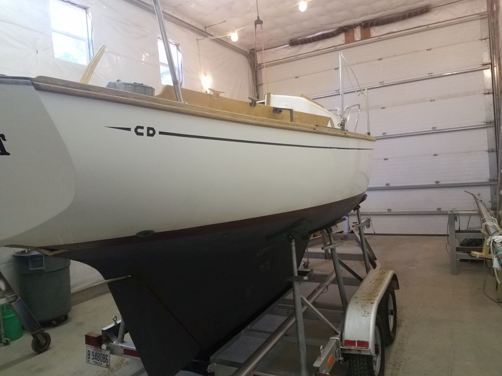
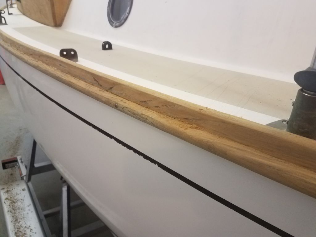
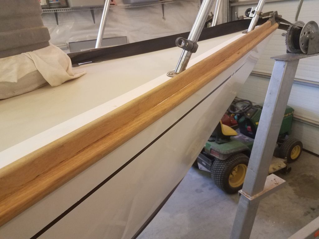
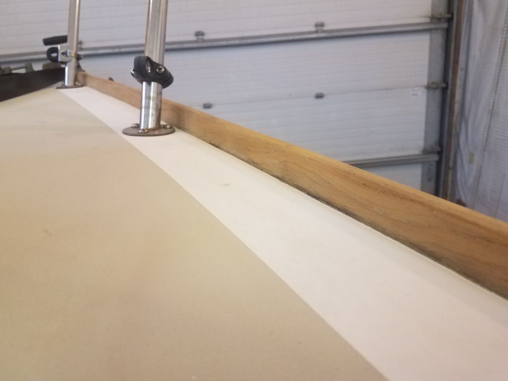
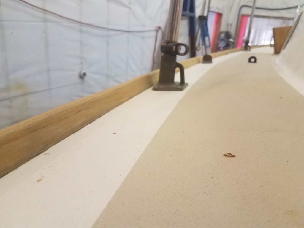
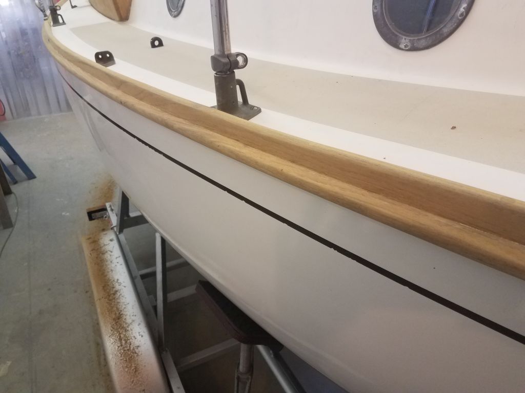
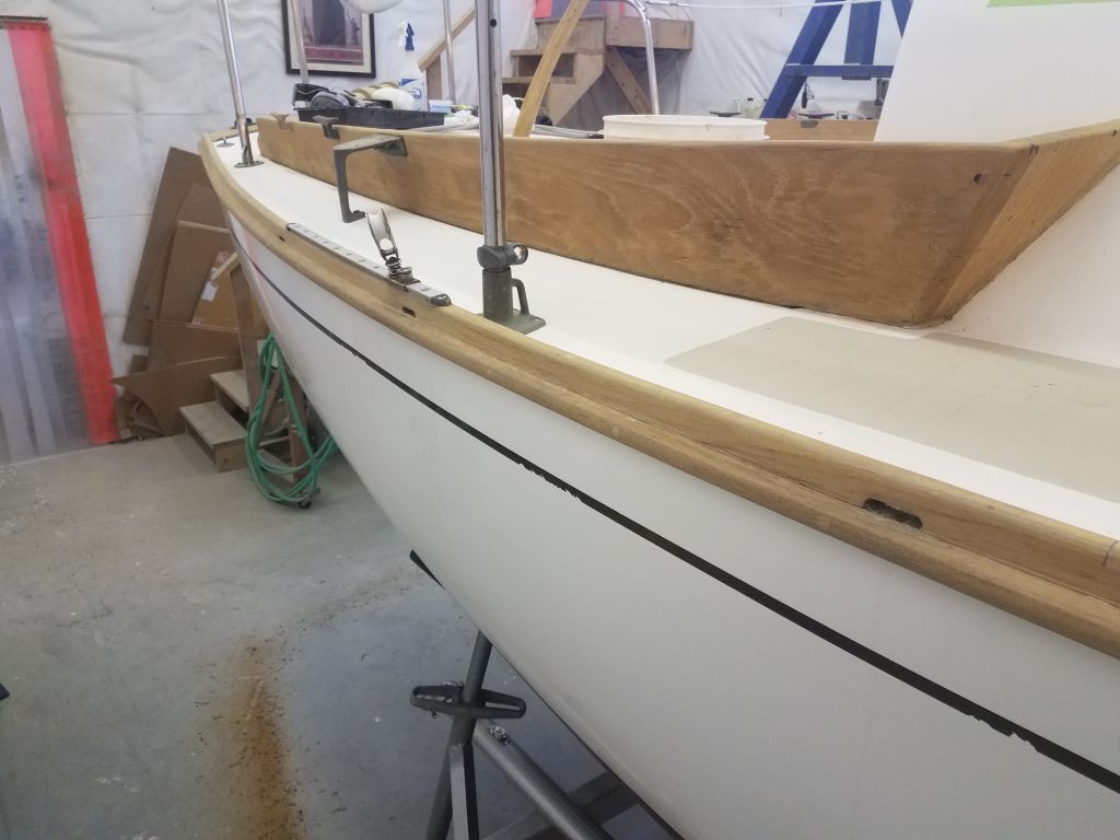
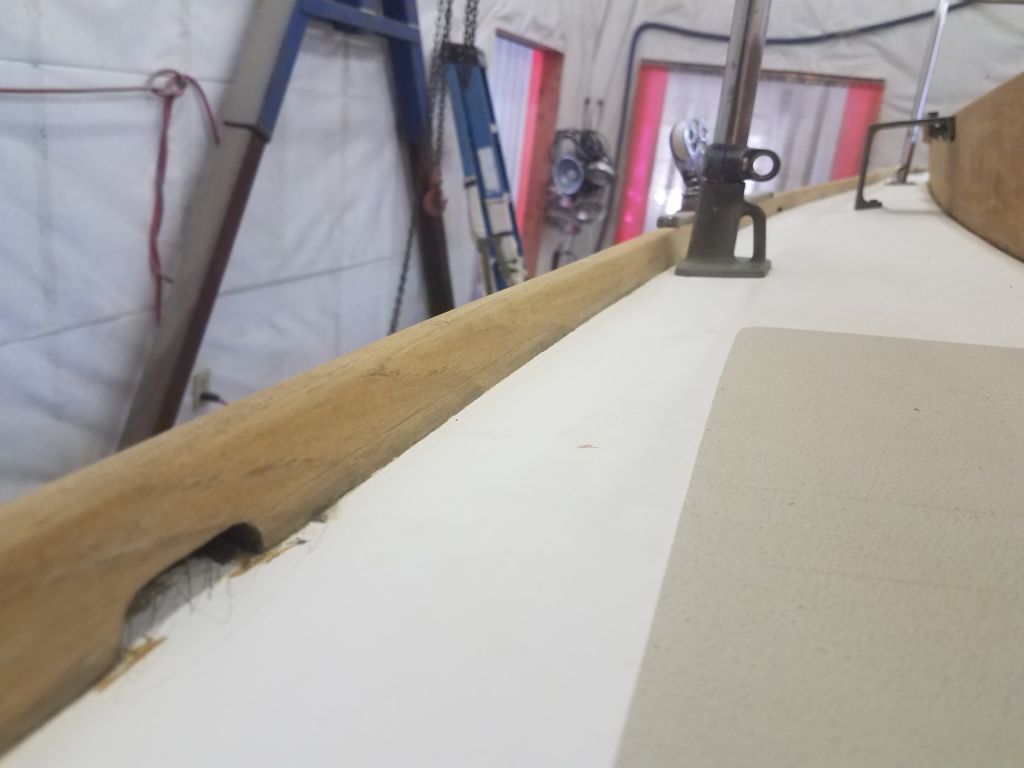
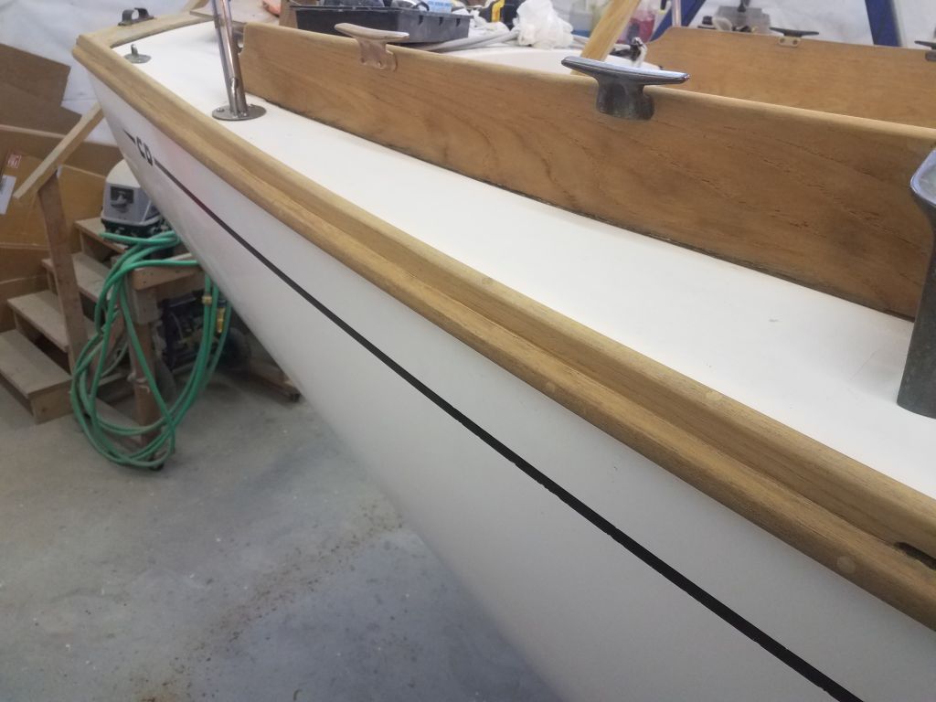
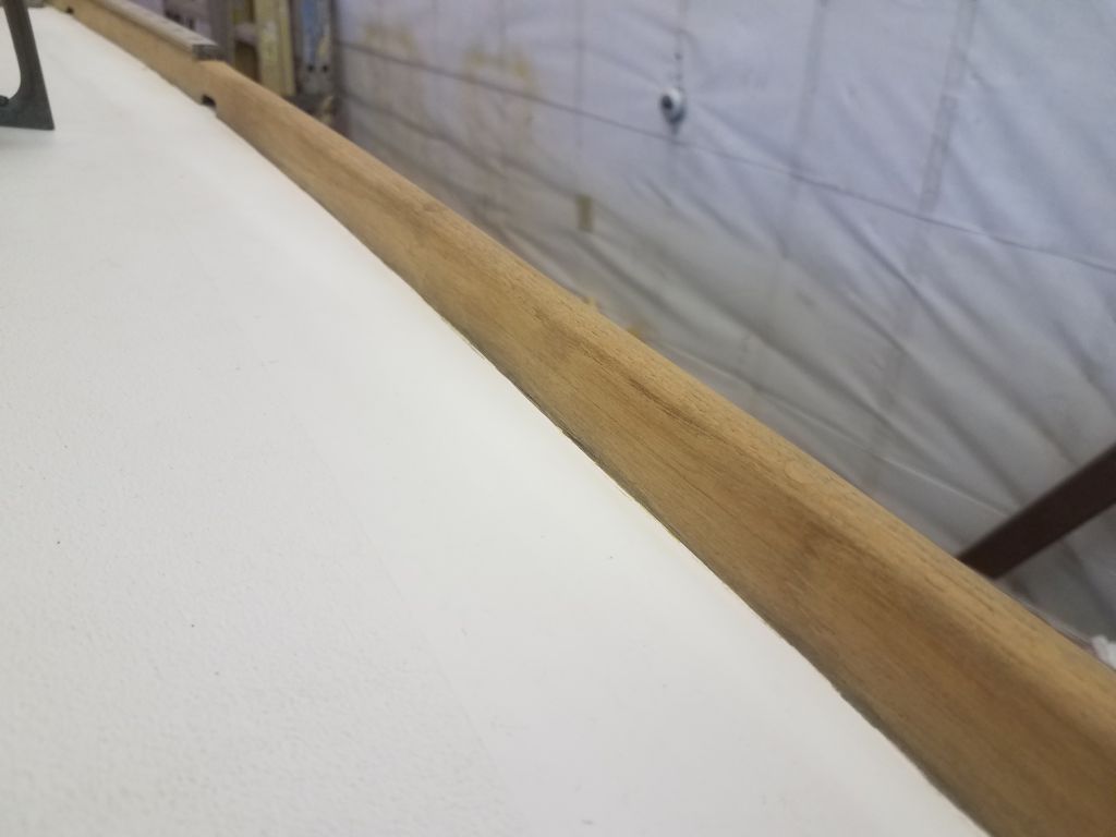
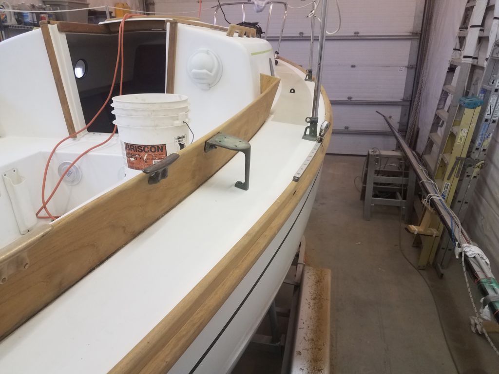
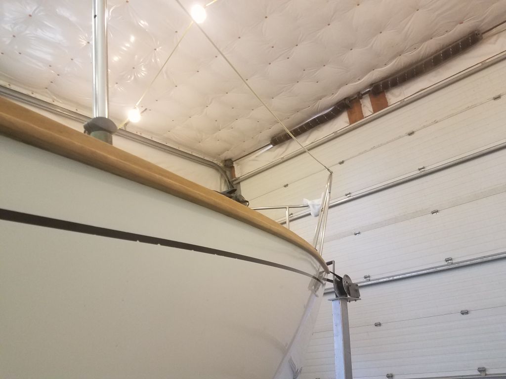
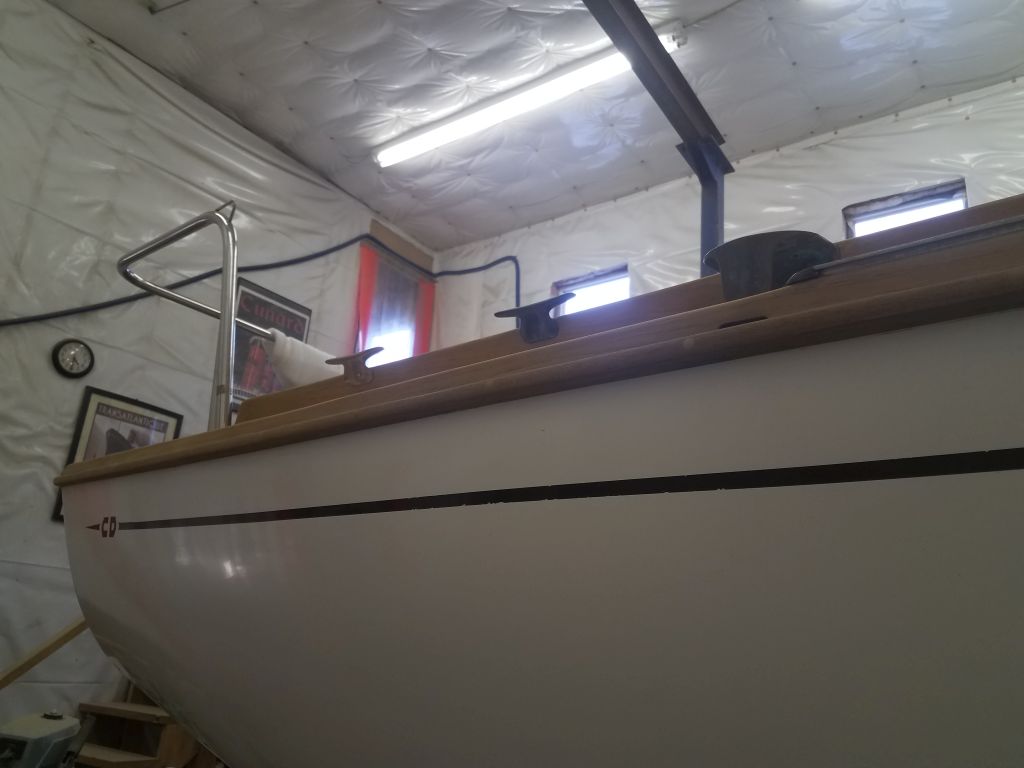
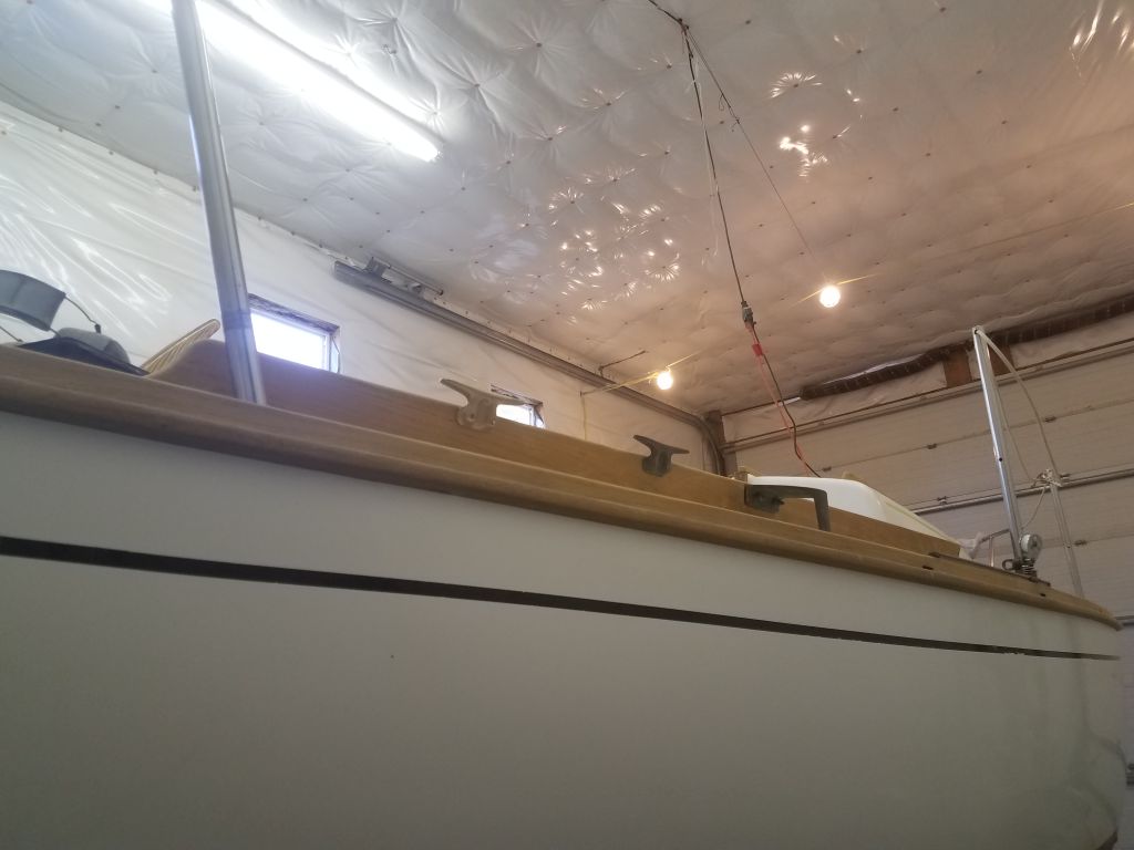
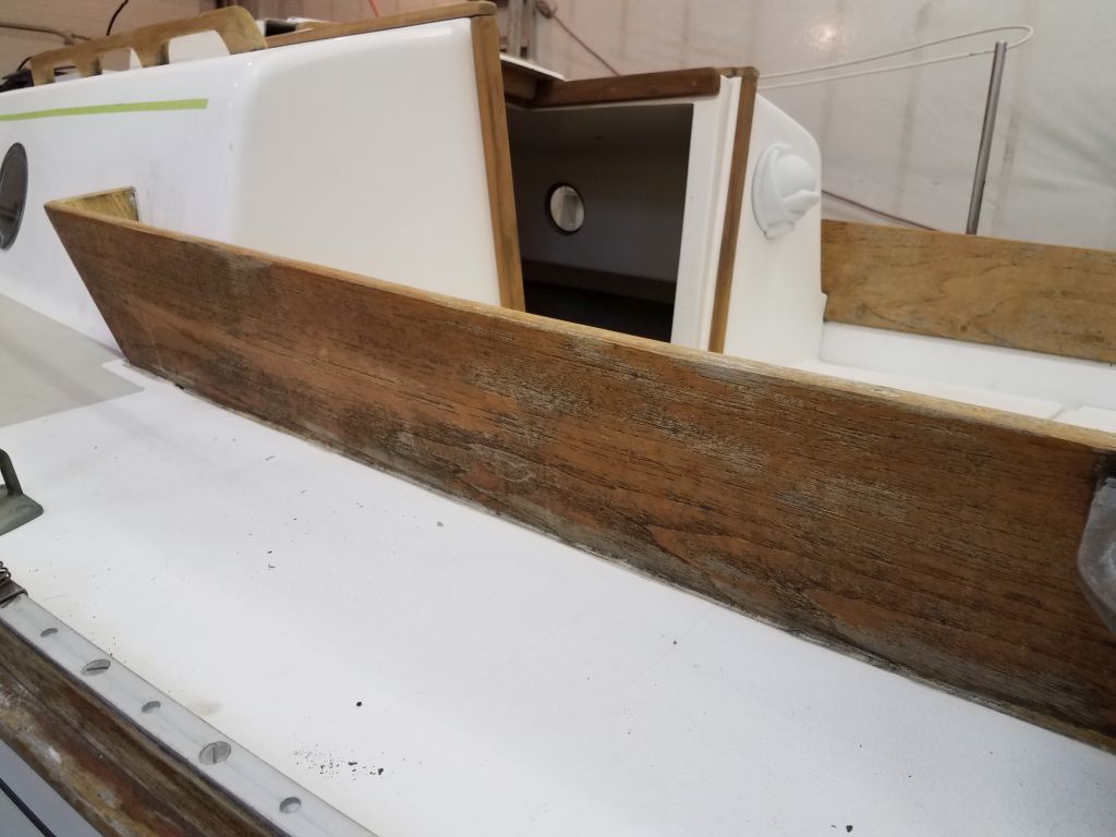
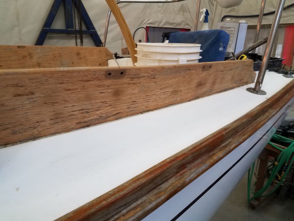
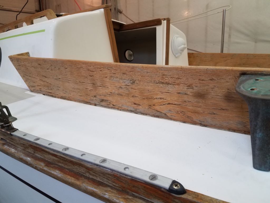
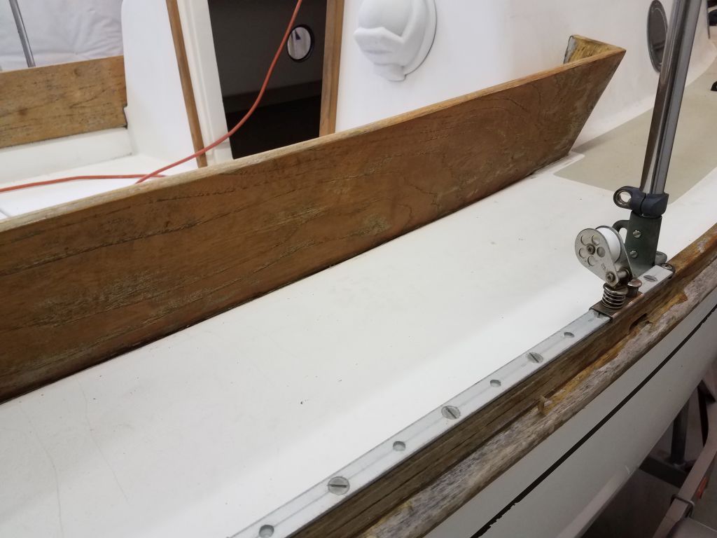
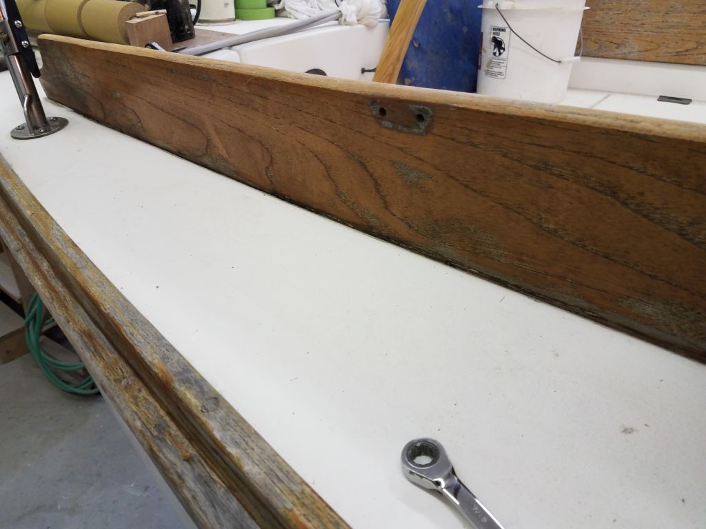
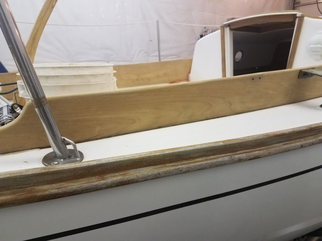
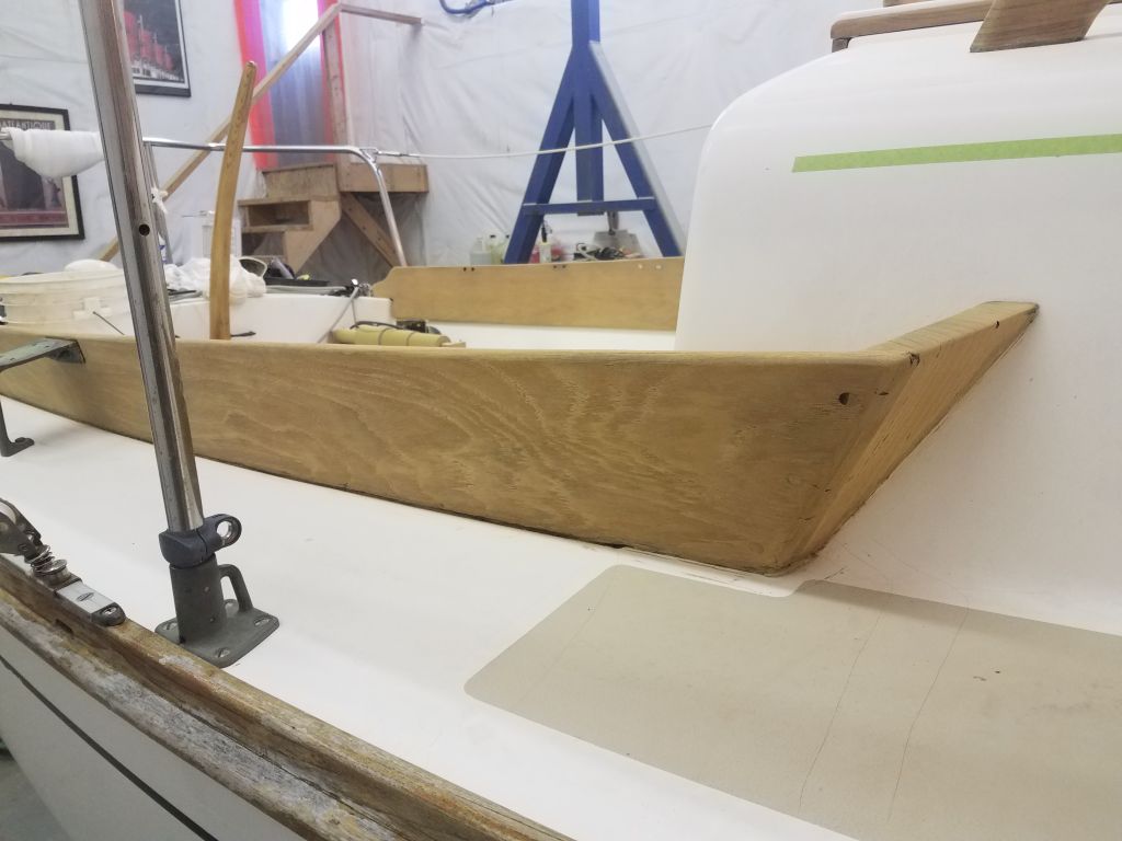
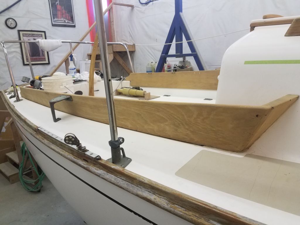
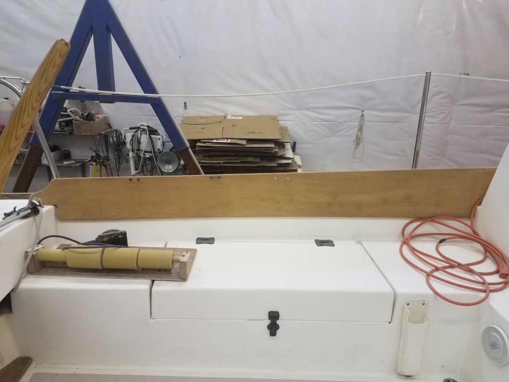
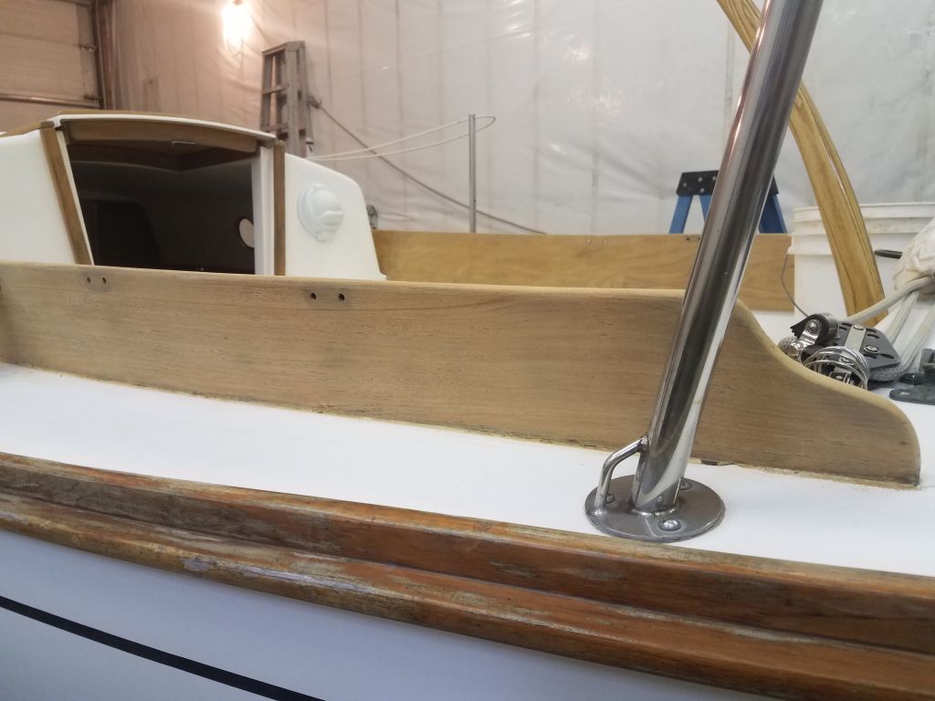
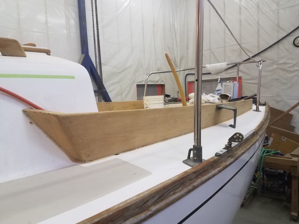
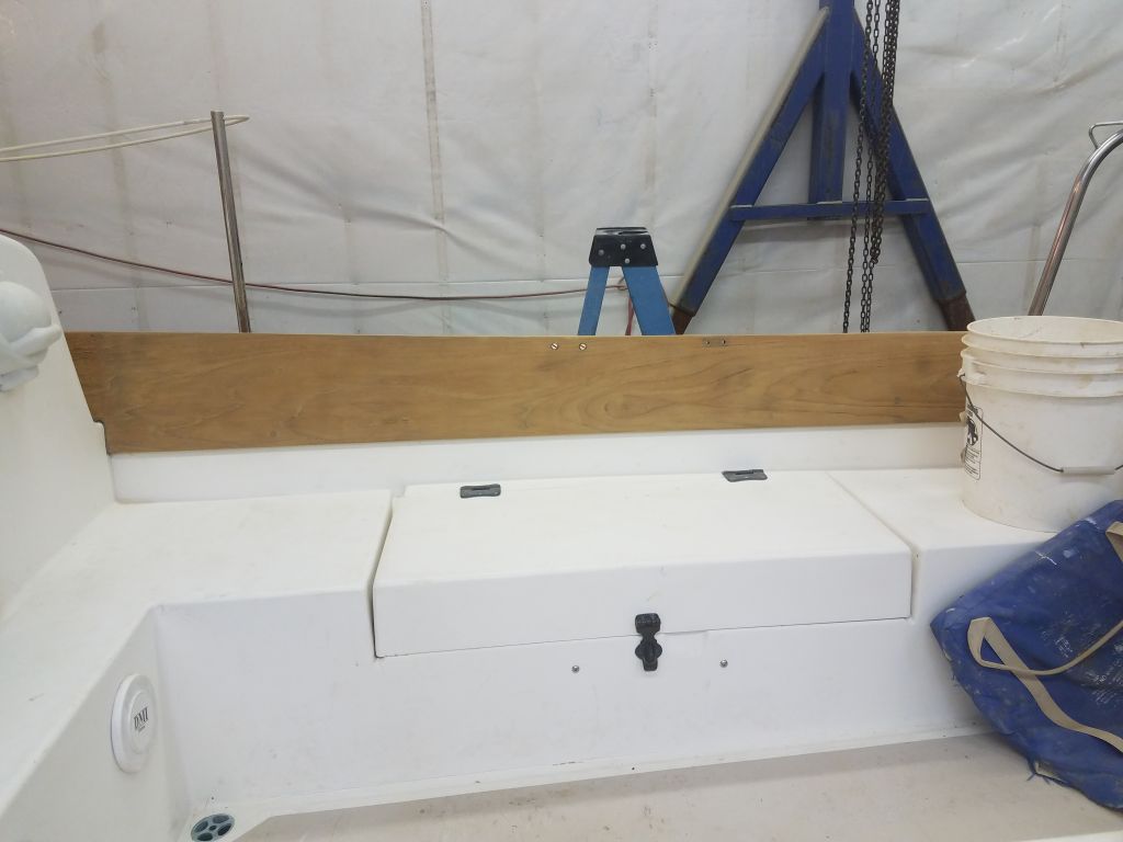
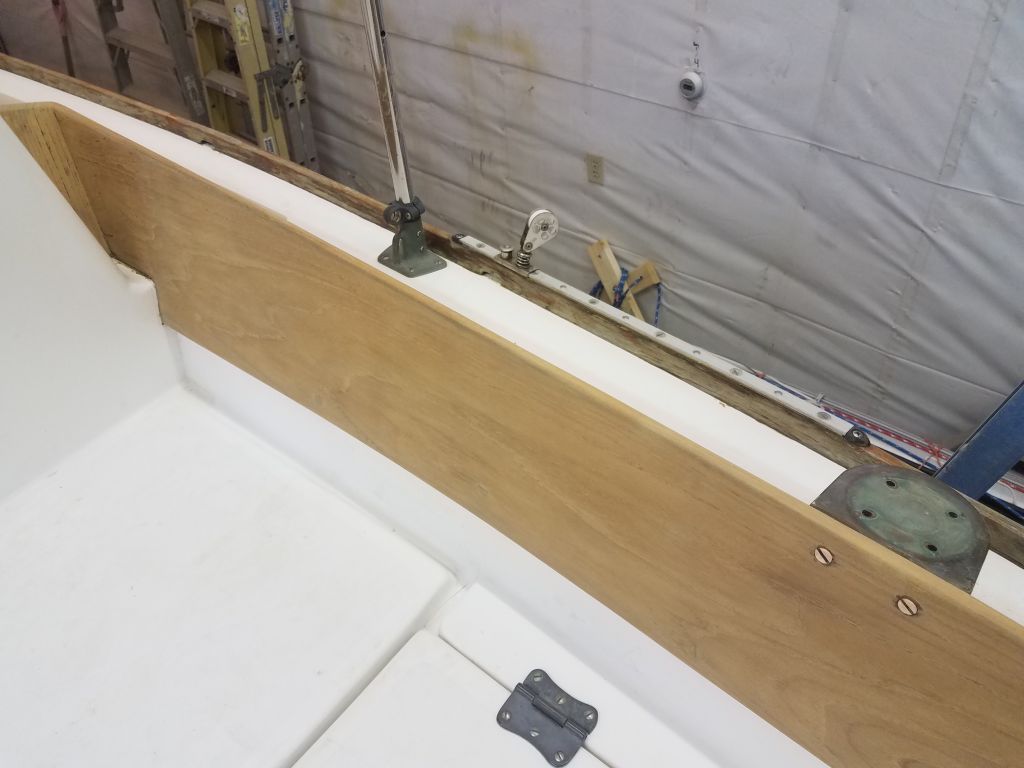
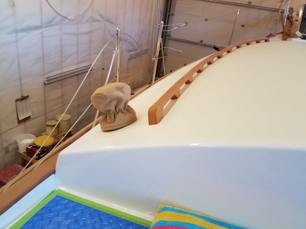
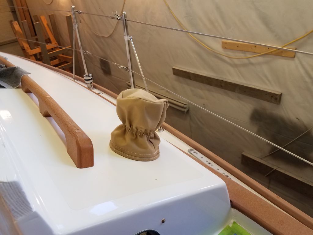
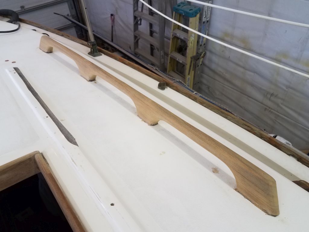
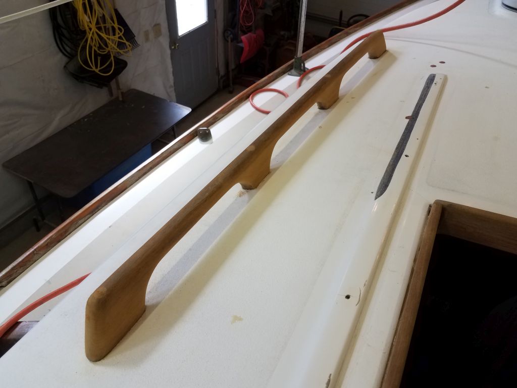
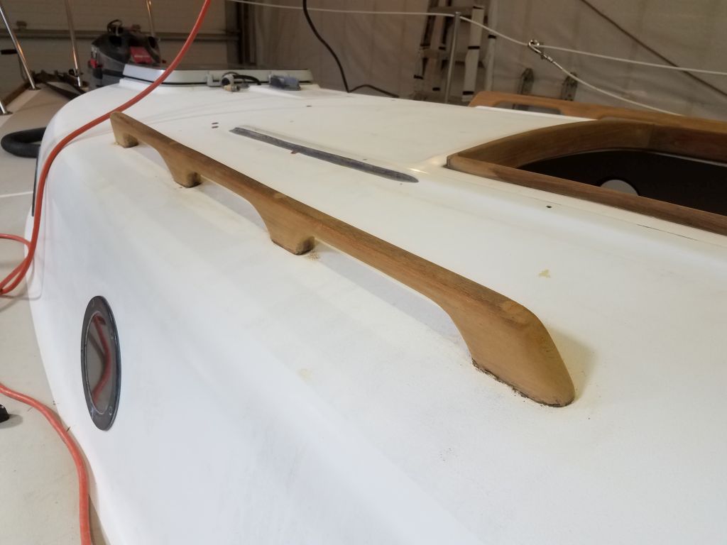
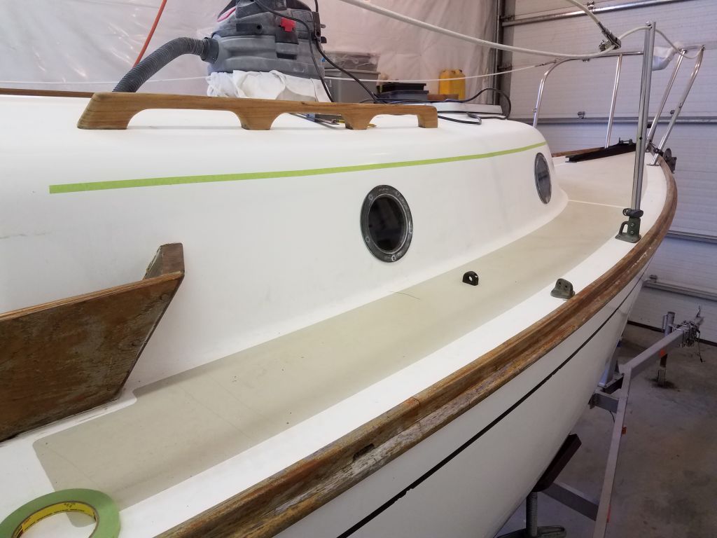
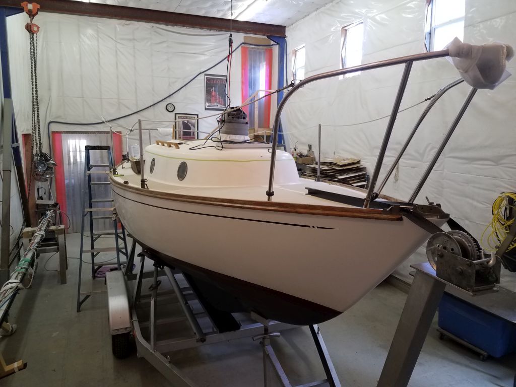
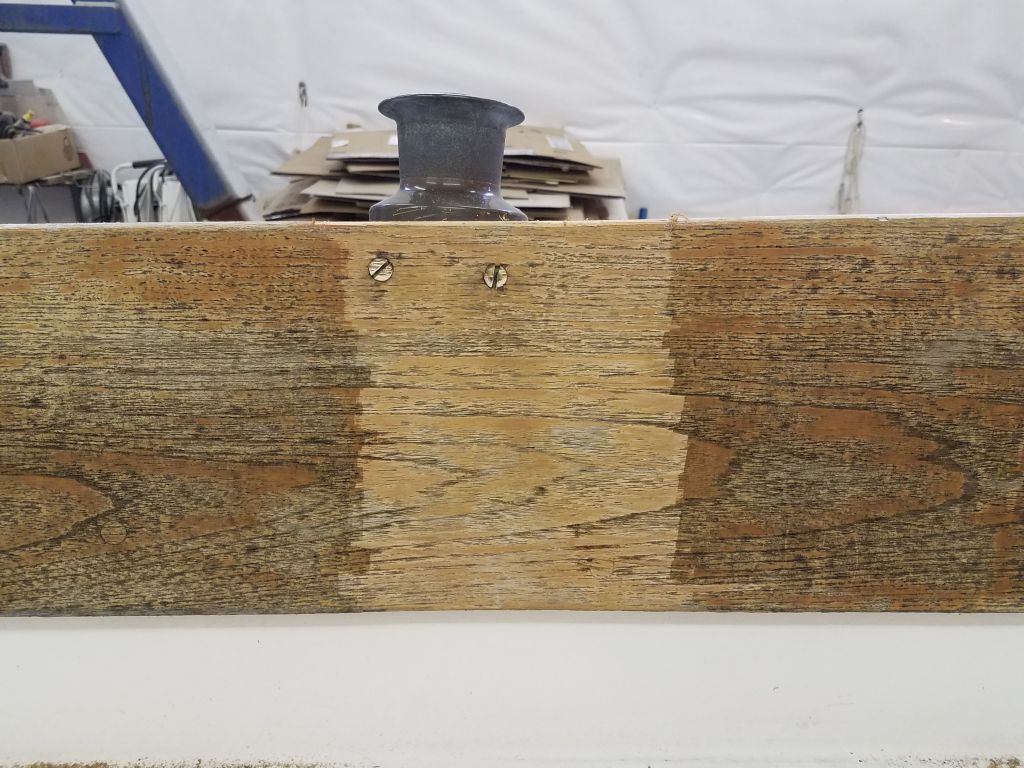
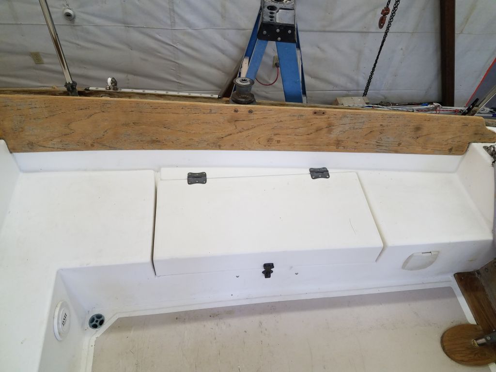
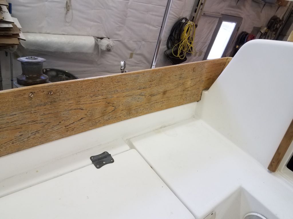
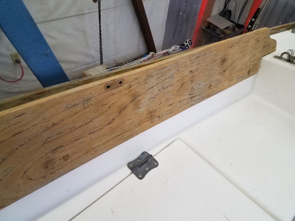
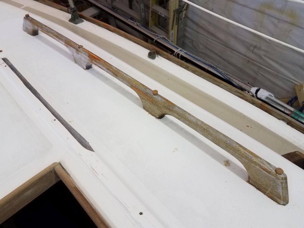
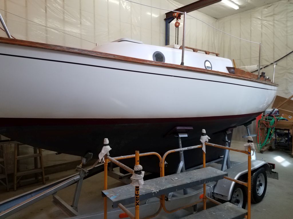
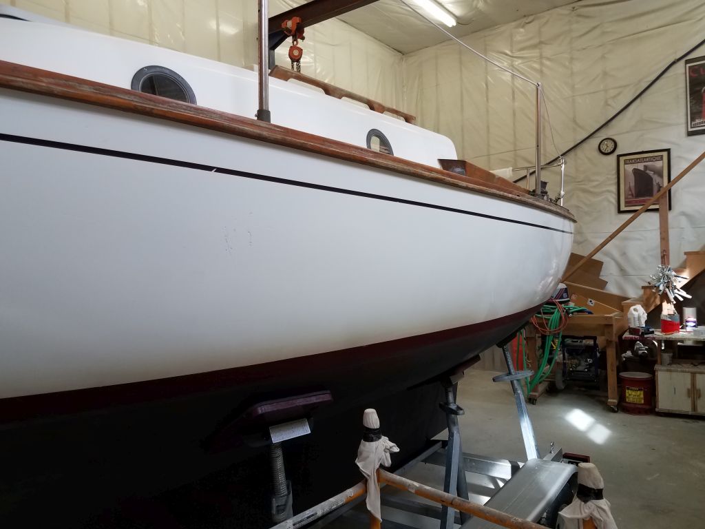
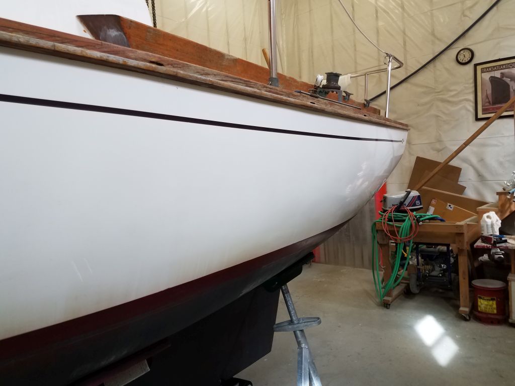
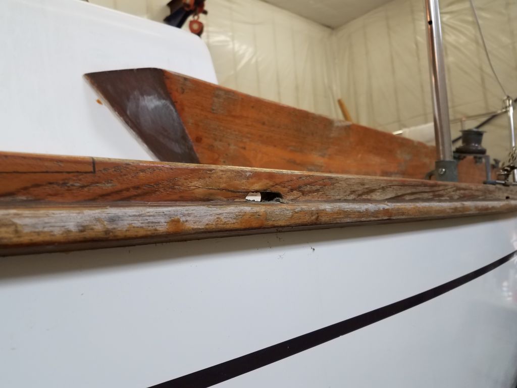
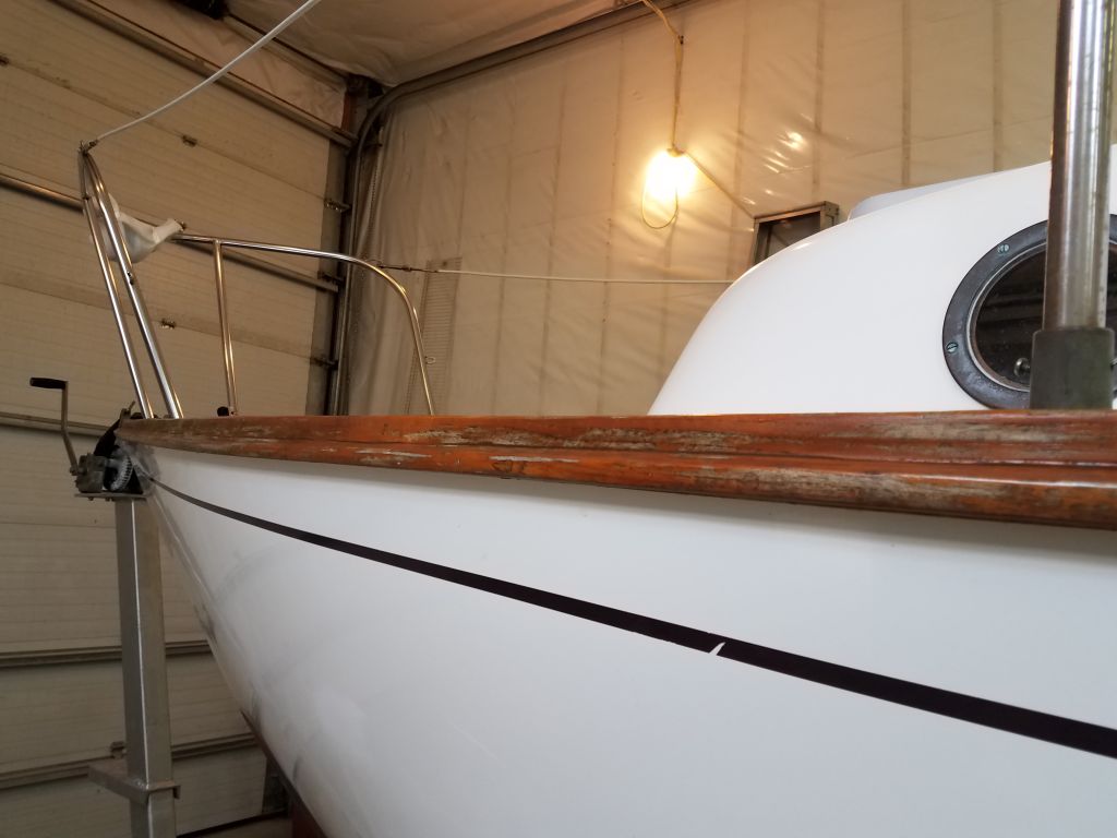
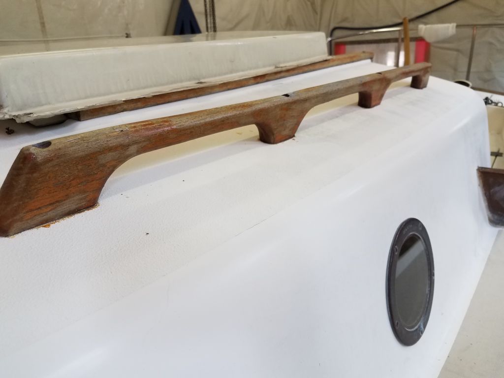
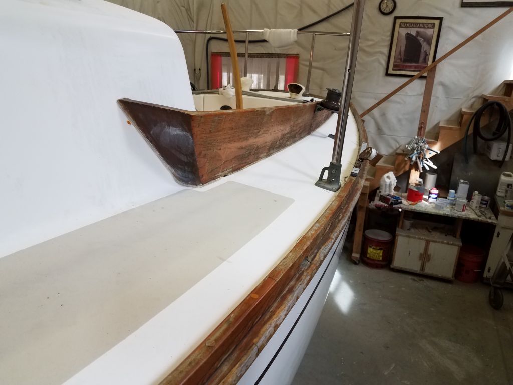
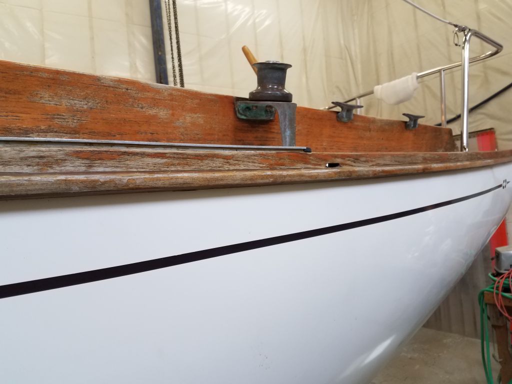
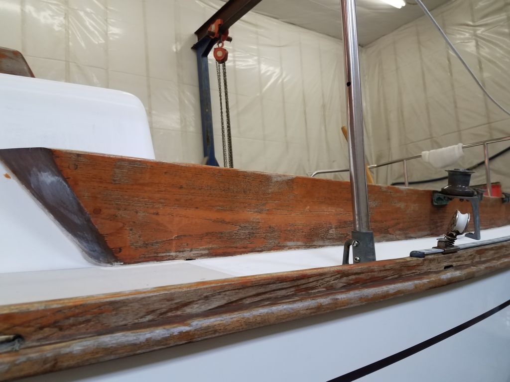
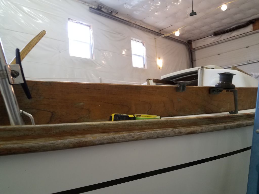
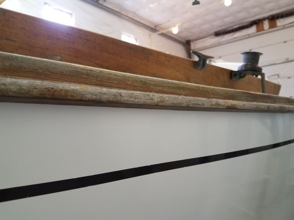
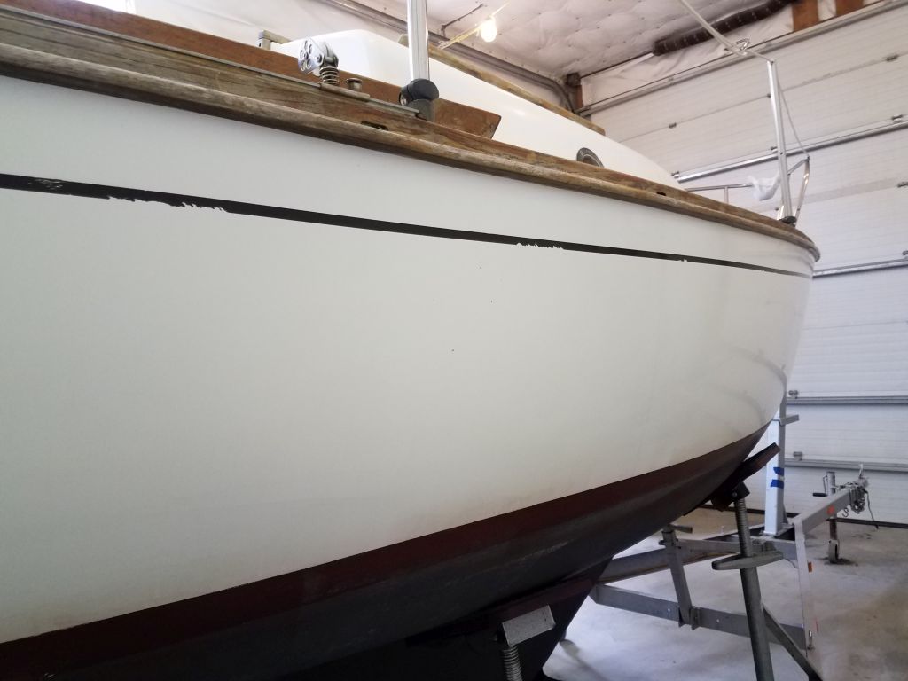
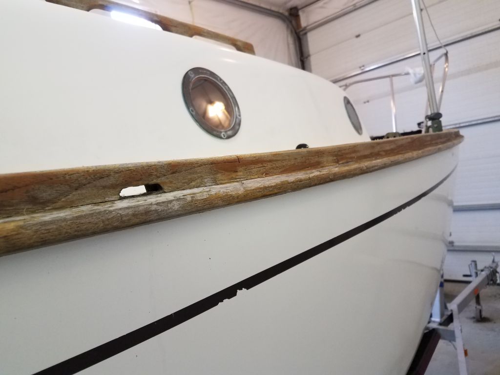
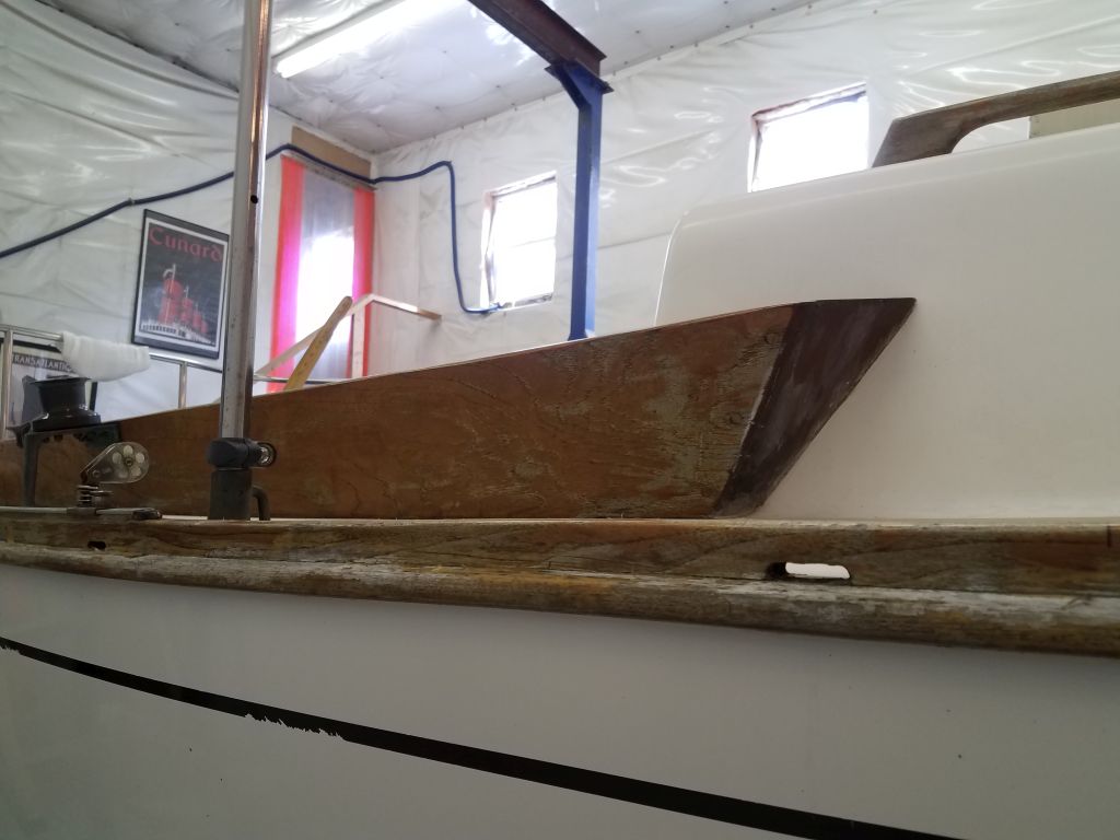
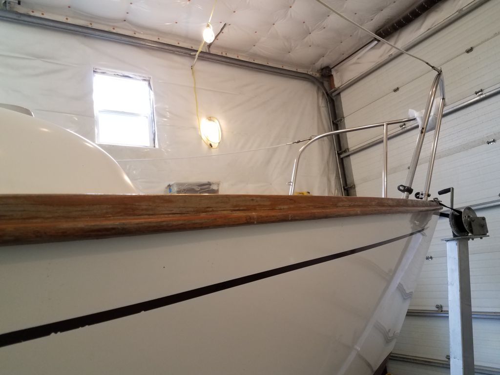
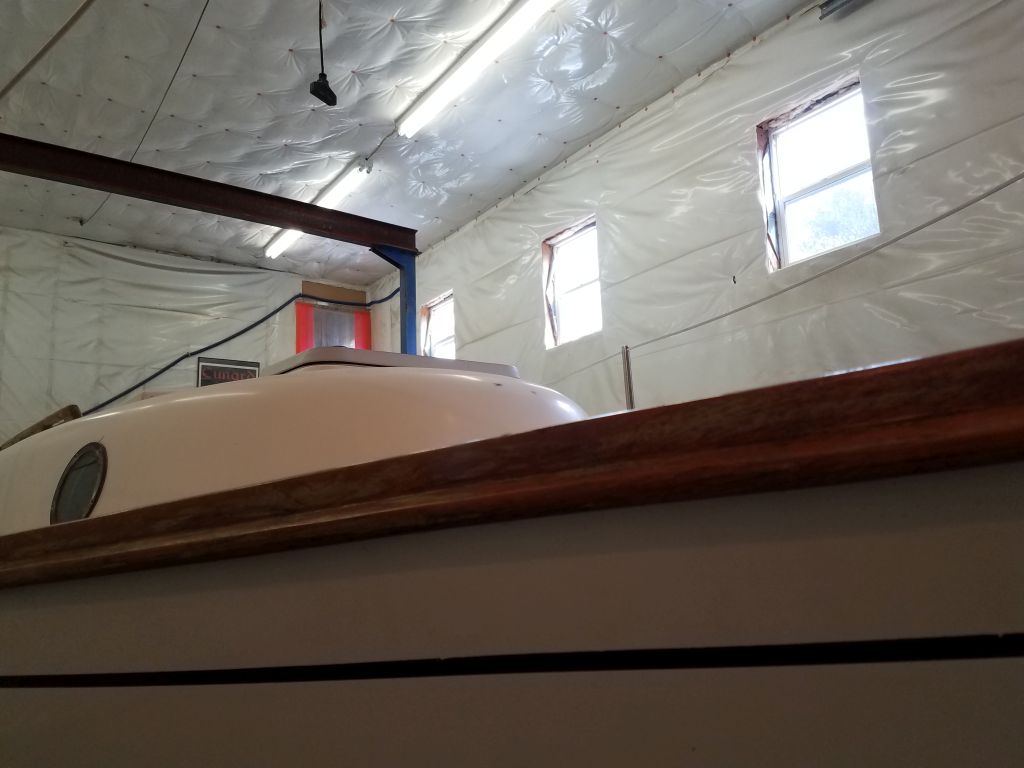
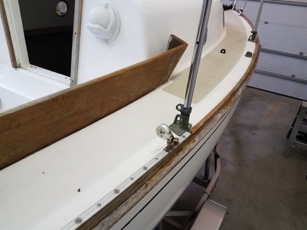
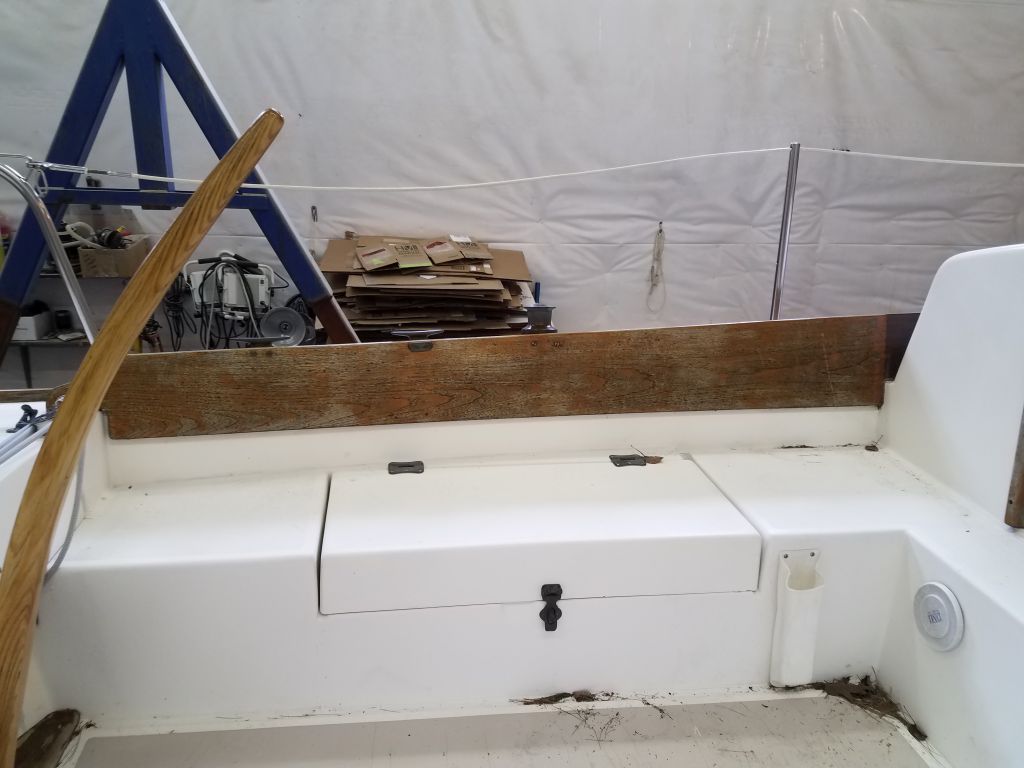
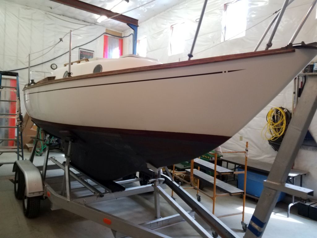
The work list for August West was eclectic and generally of the minor maintenance category, beginning with the exterior brightwork, including toerails, handrails, cockpit coamings, and various other trim bits. The existing finish was old varnish and/or Cetol in poor condition, and the owner wanted to strip it all back to bare teak and then let the wood weather naturally from there, which look and lack of maintenance was in keeping with his vision and use of the boat.
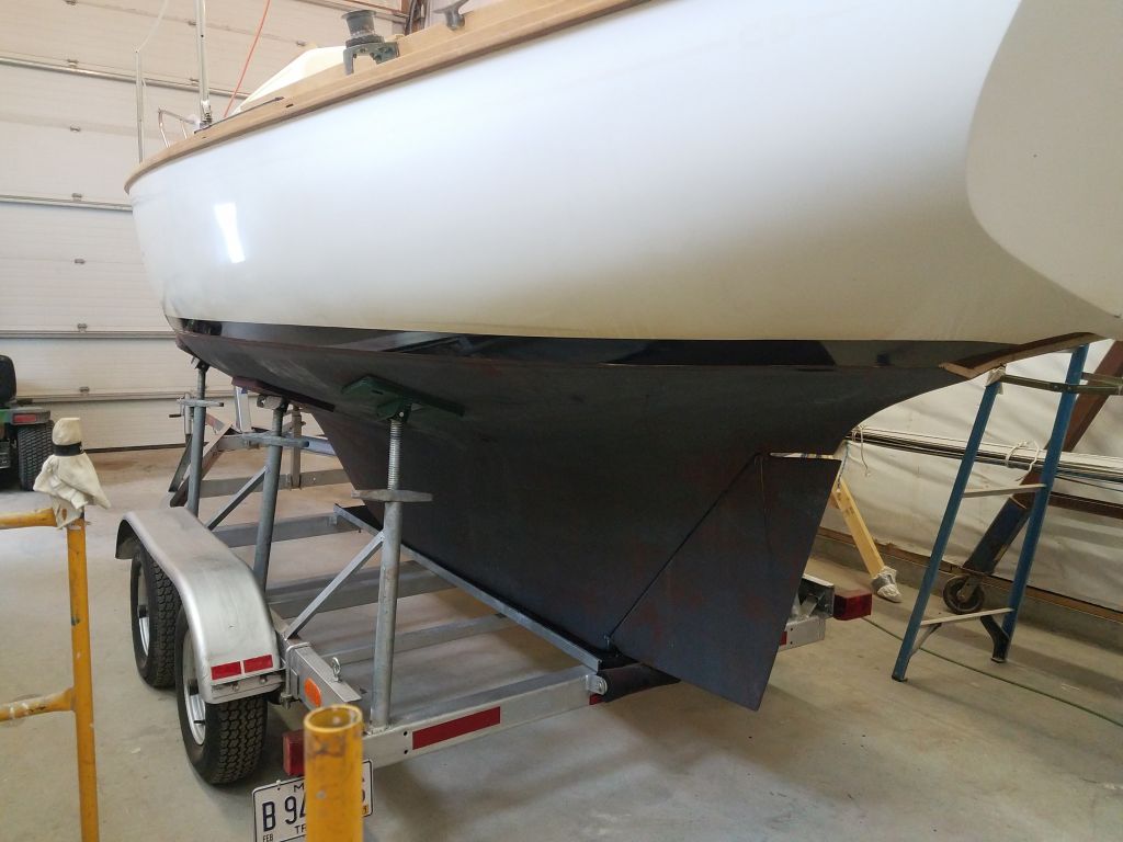
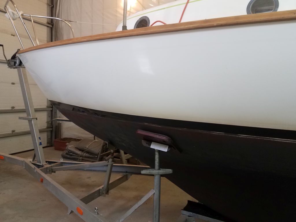
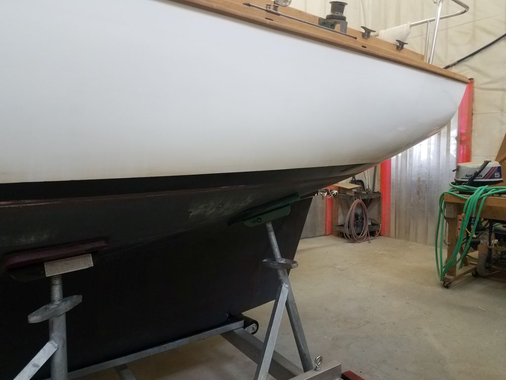
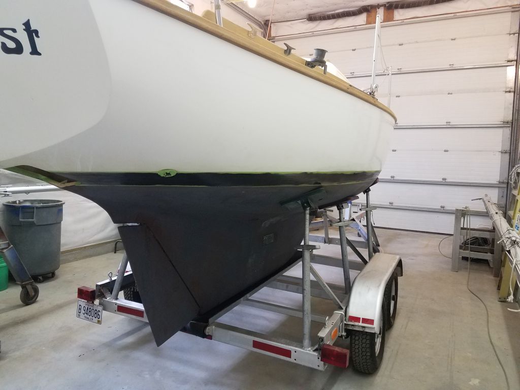
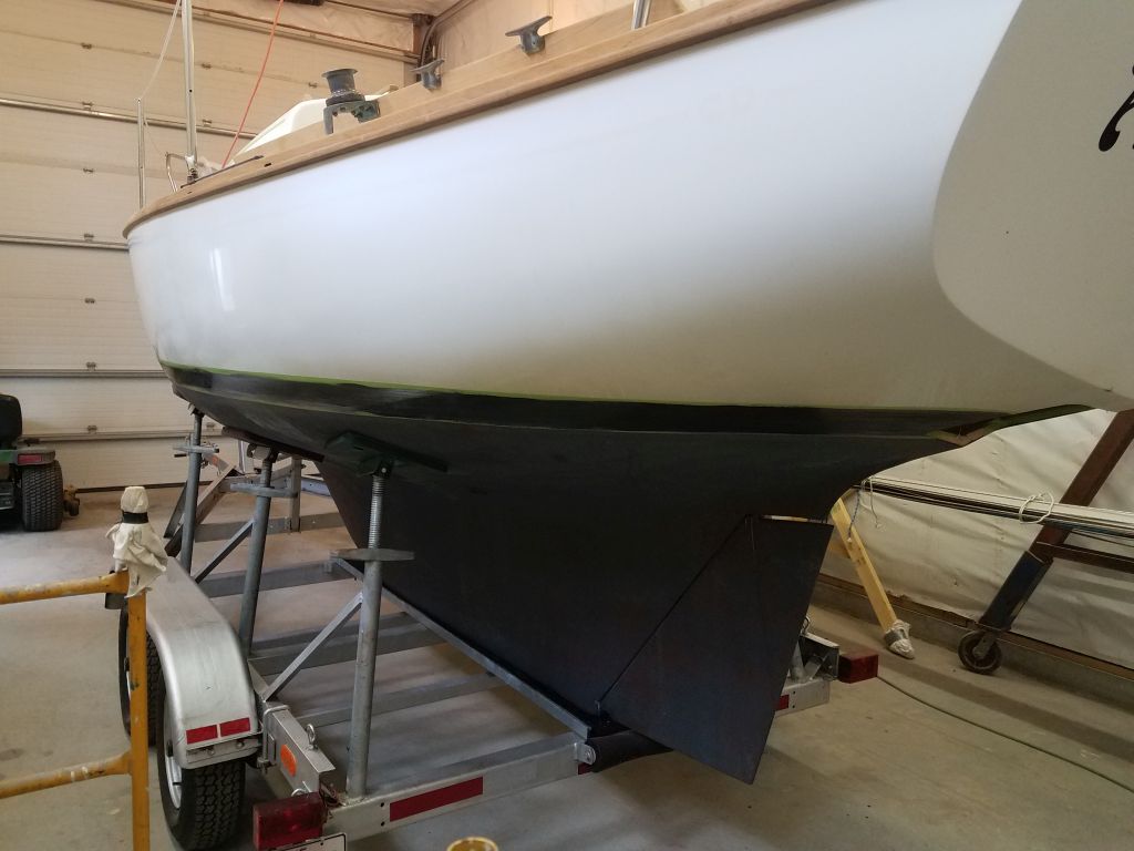
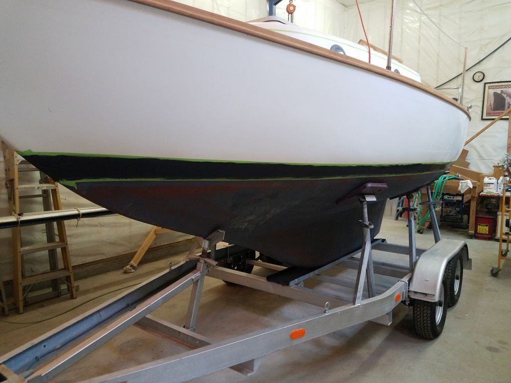
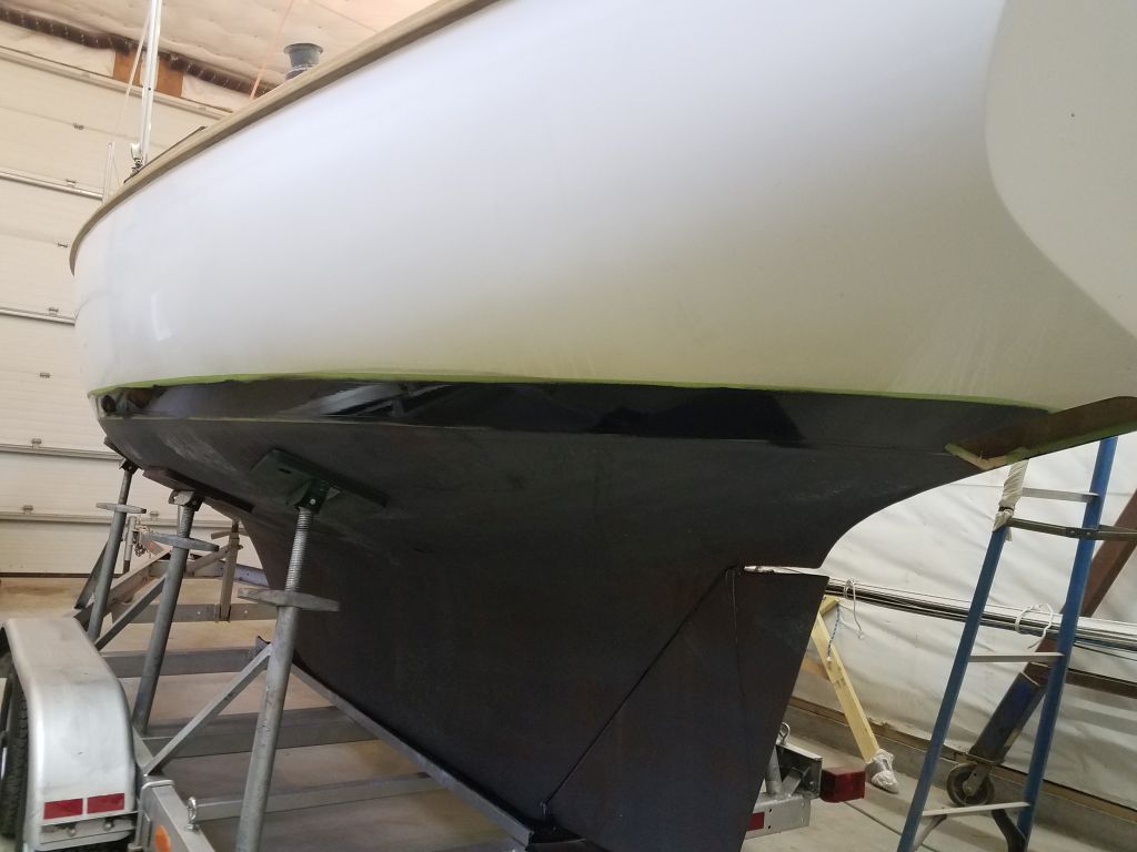
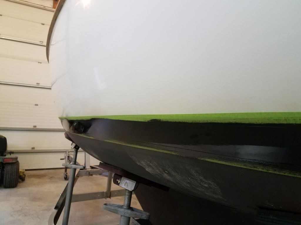
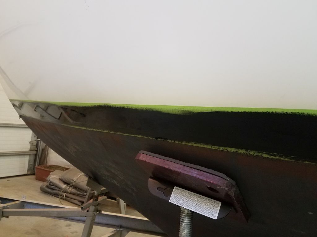
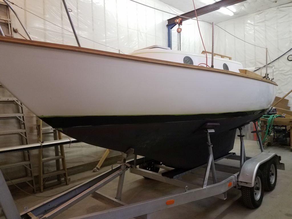
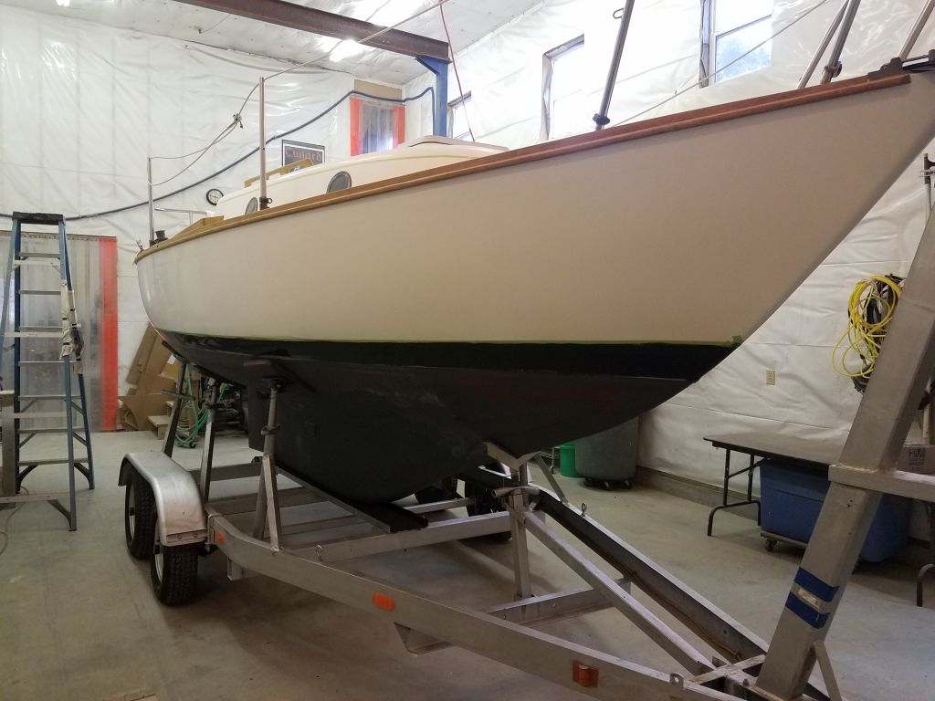
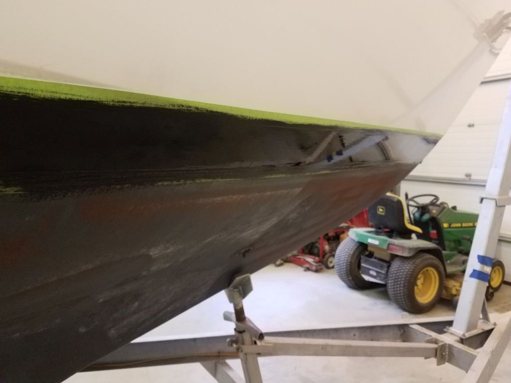
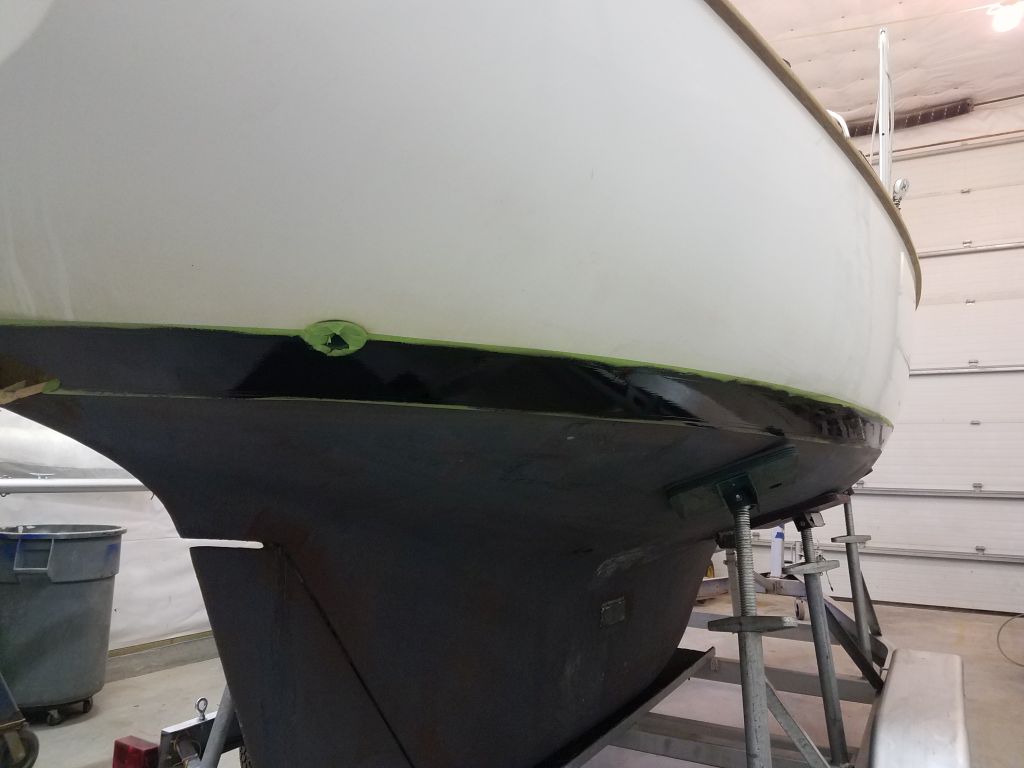
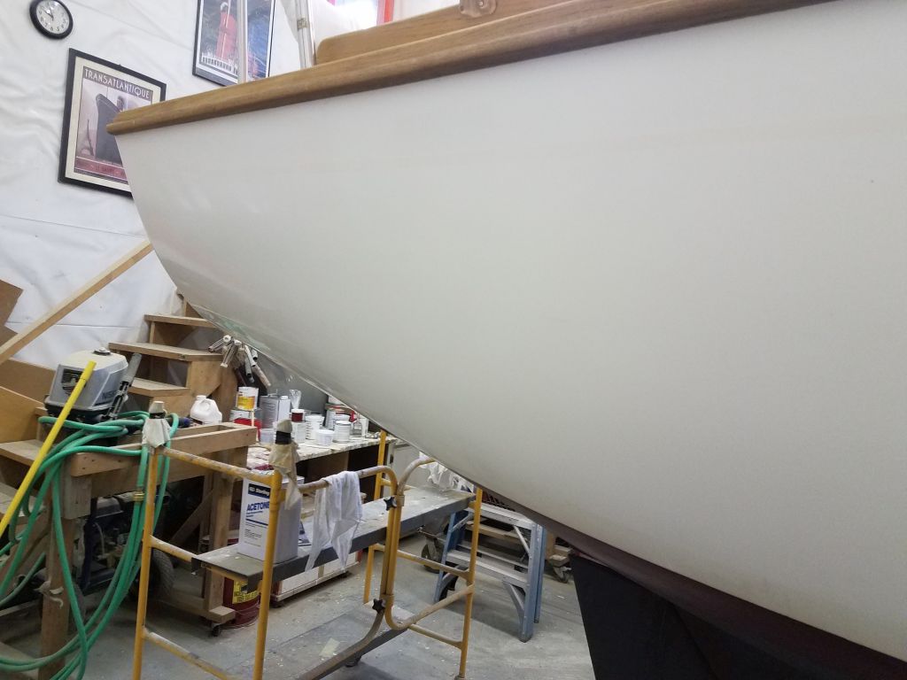
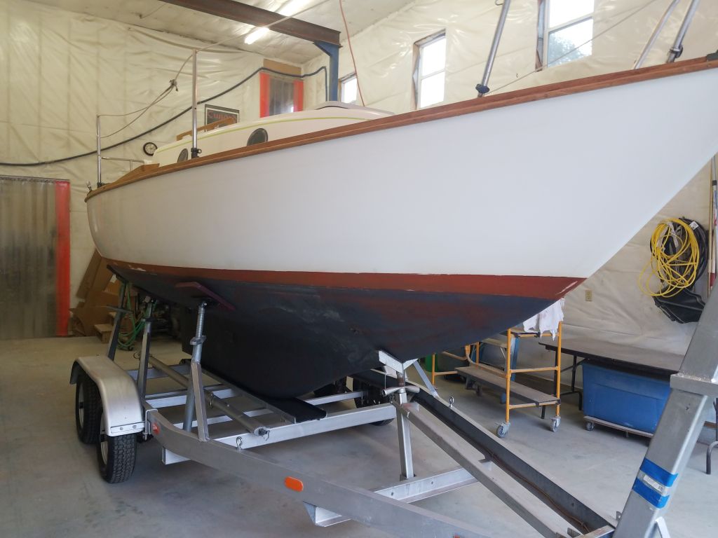
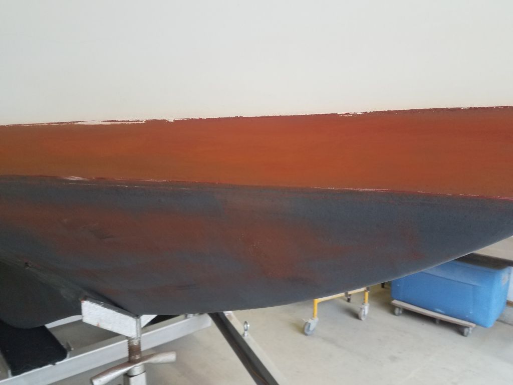
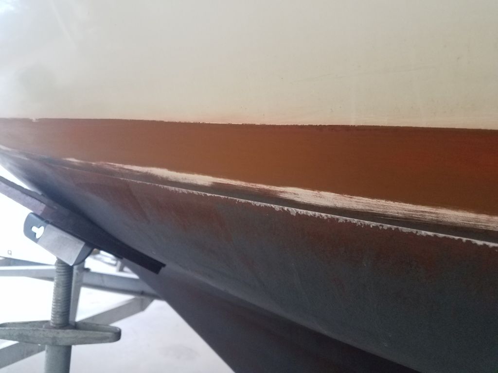
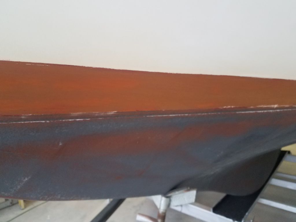
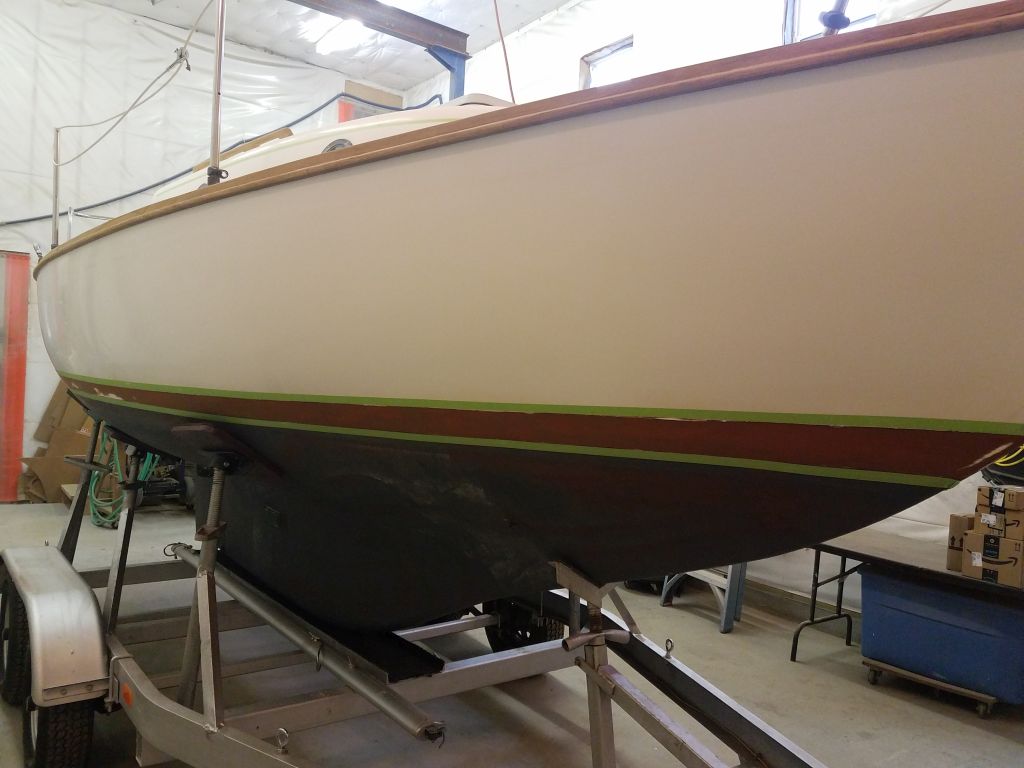
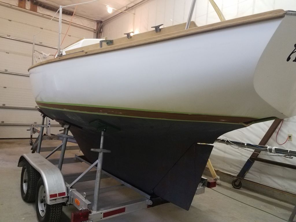
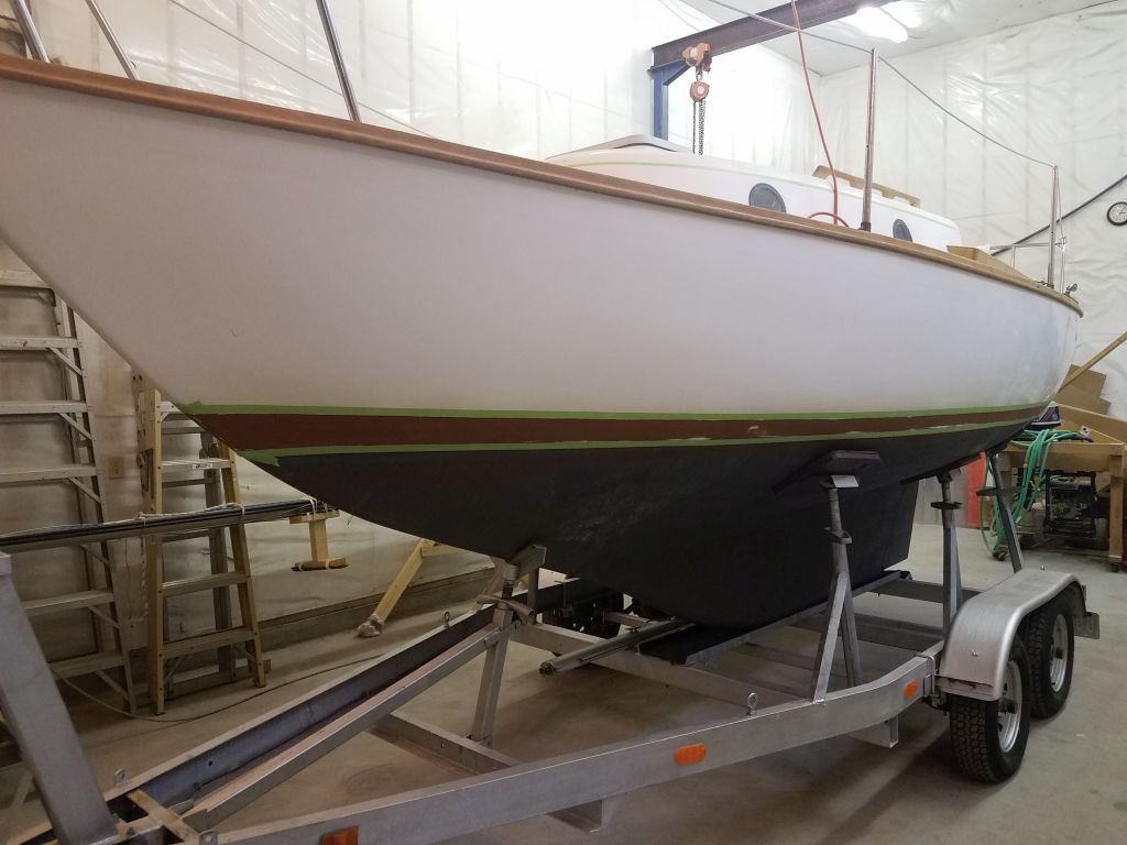
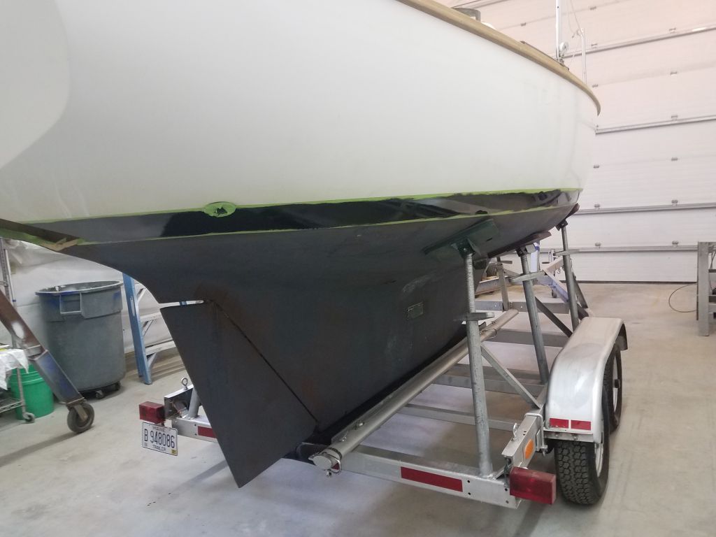
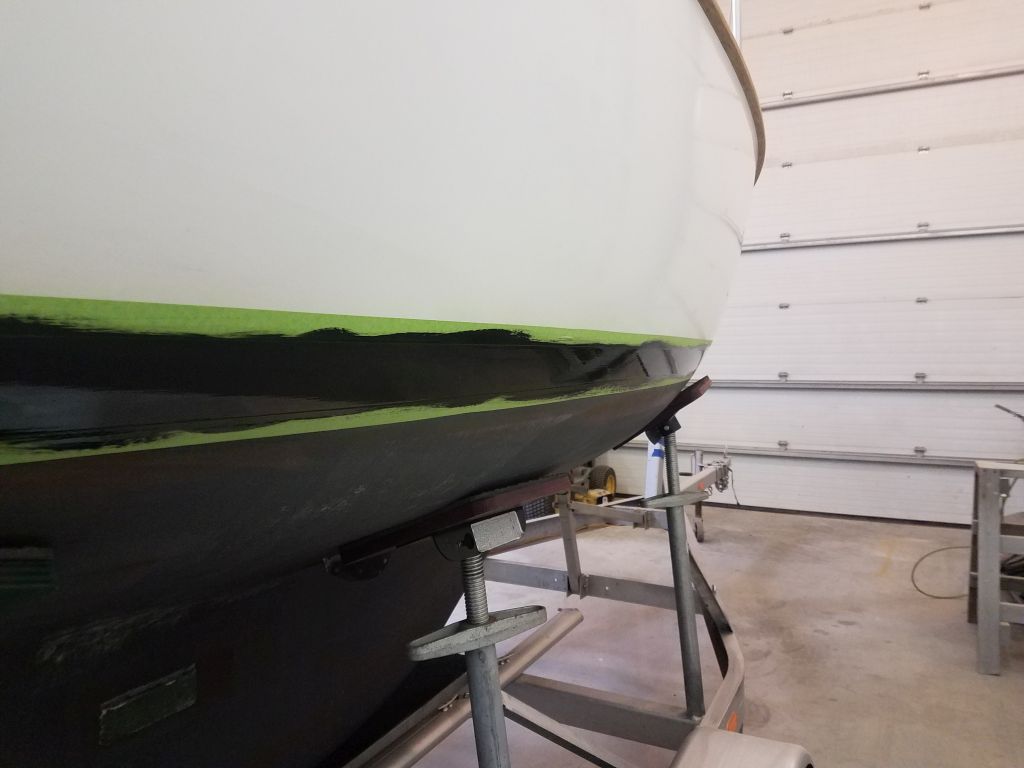
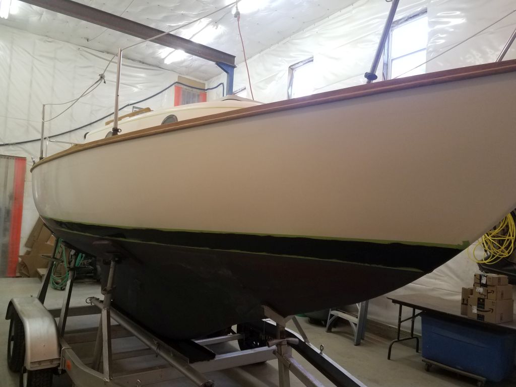
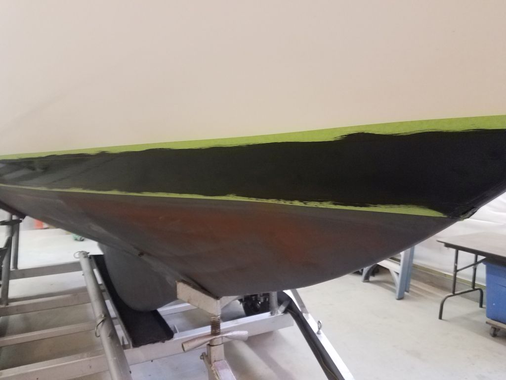
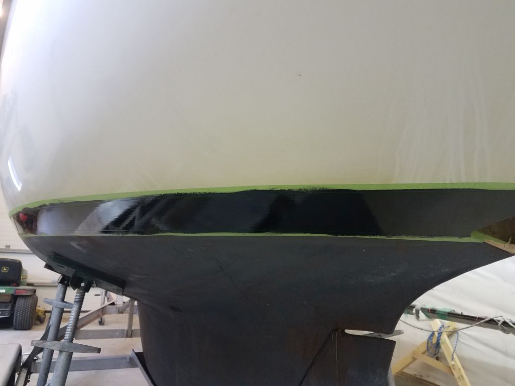
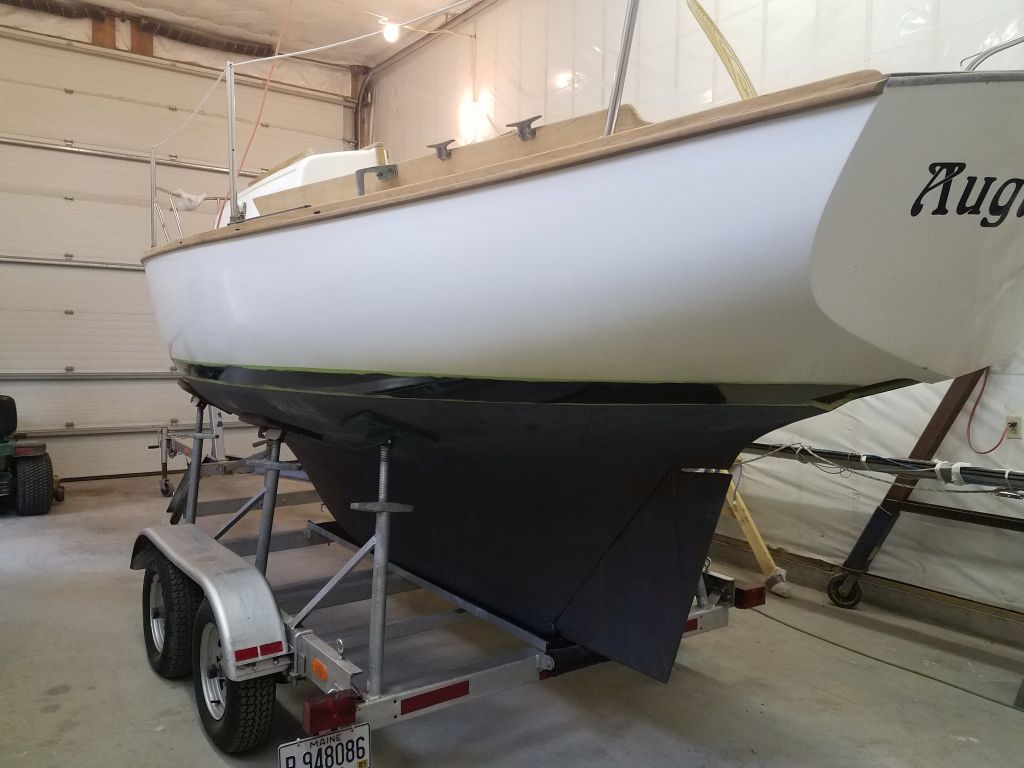
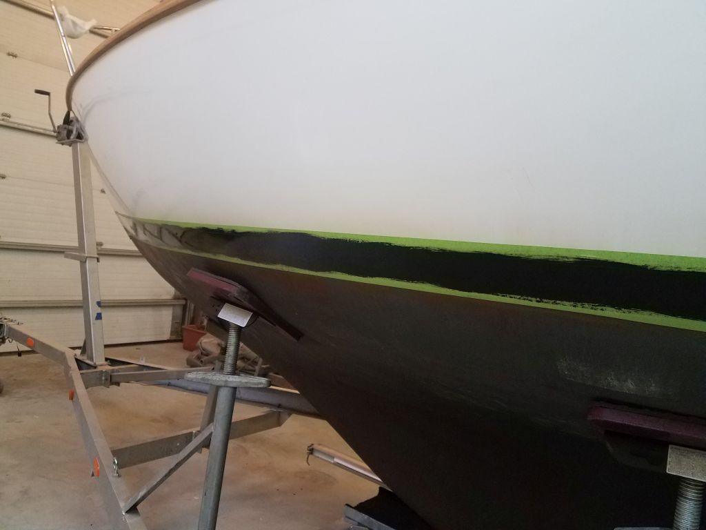
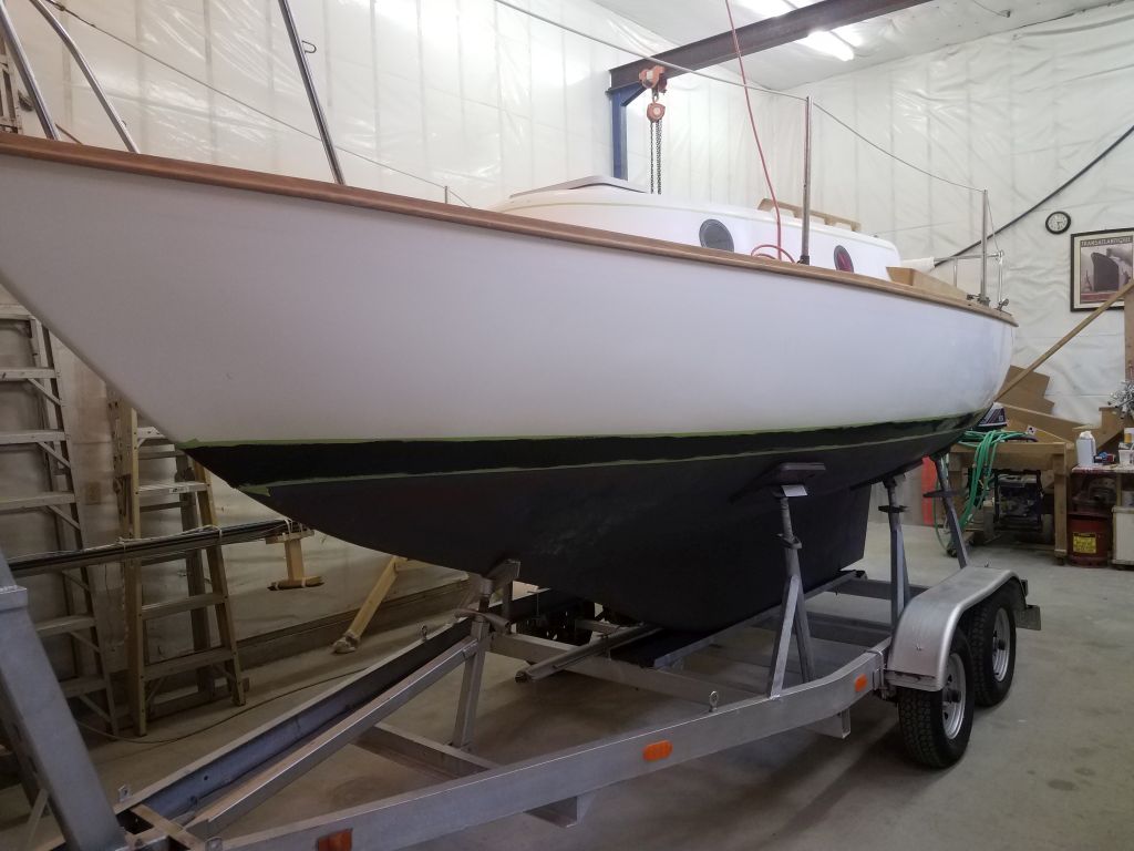
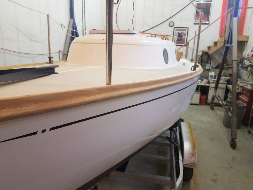
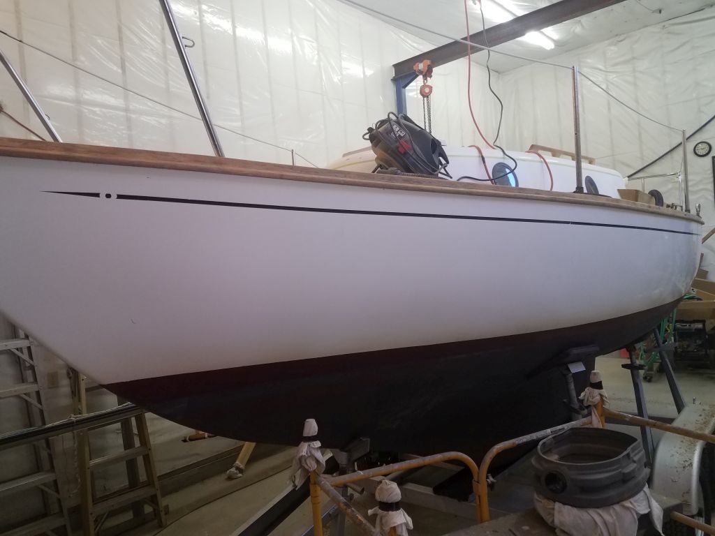
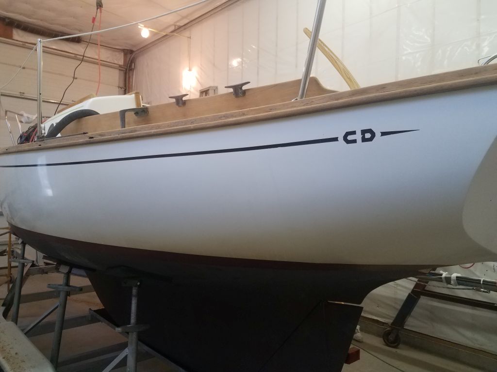
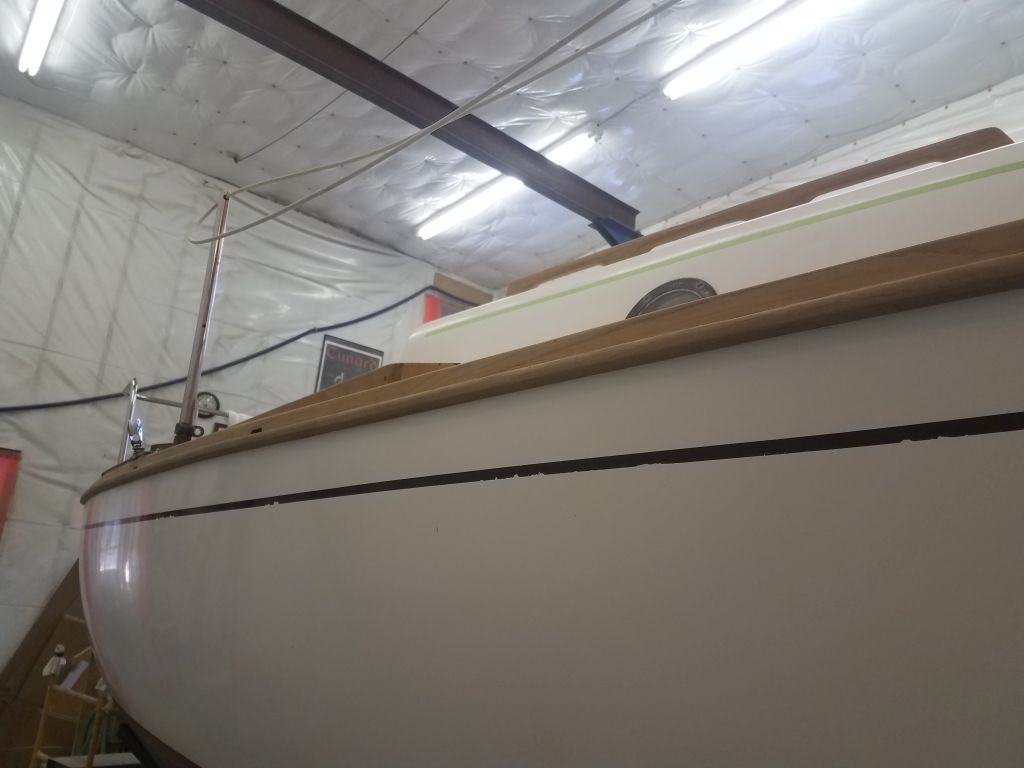
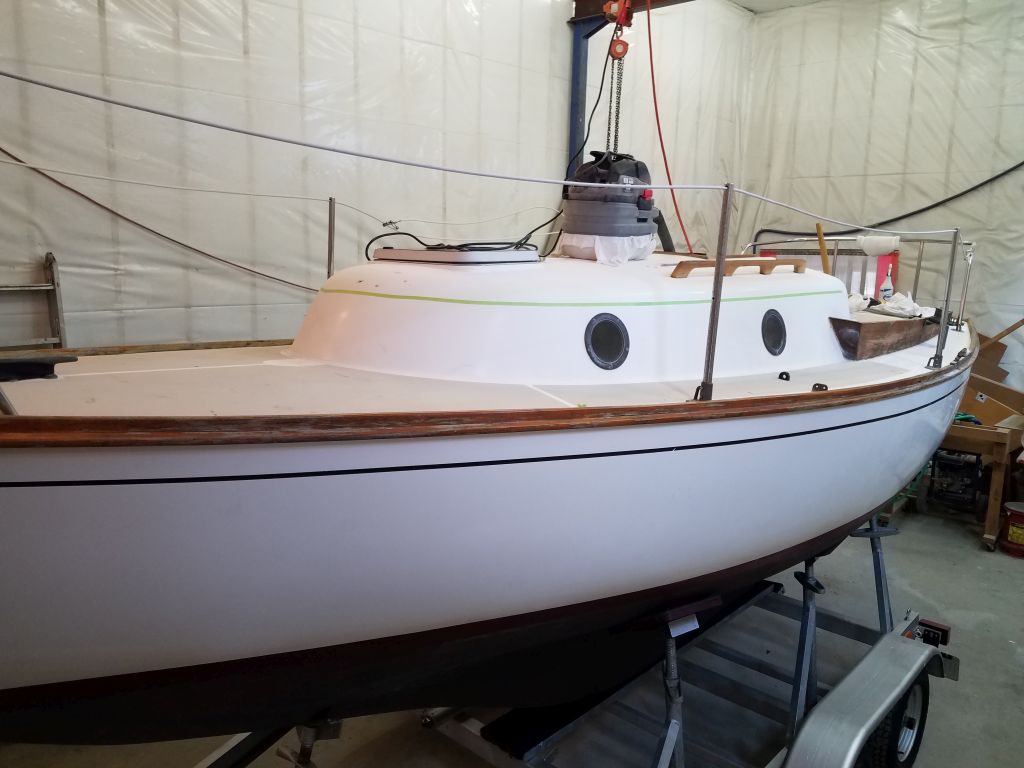
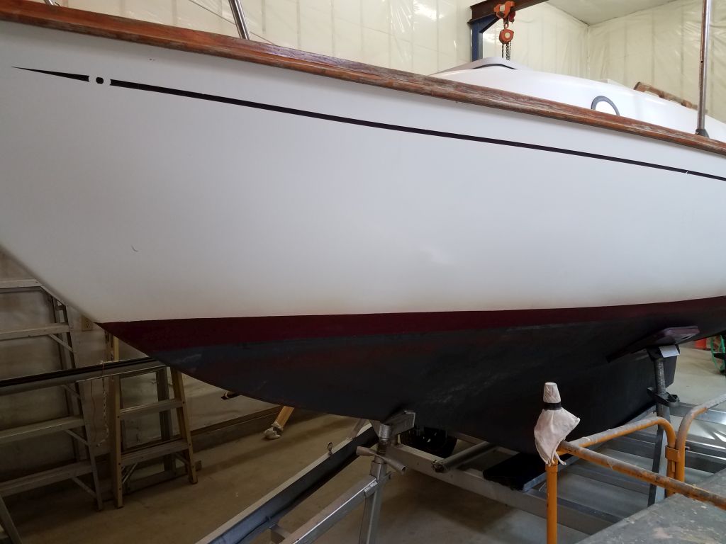
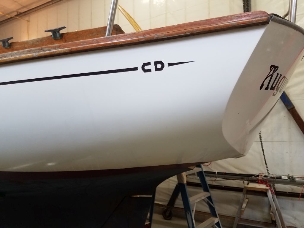
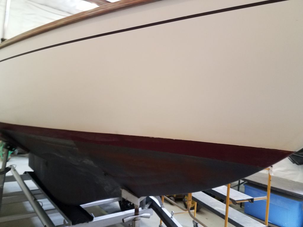
In the same general exterior appearance category, the owner requested that I repaint and change the color of the boottop and bottom, and also replace the cove stripe to match.
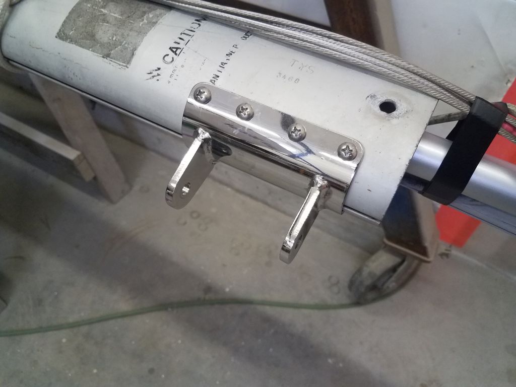
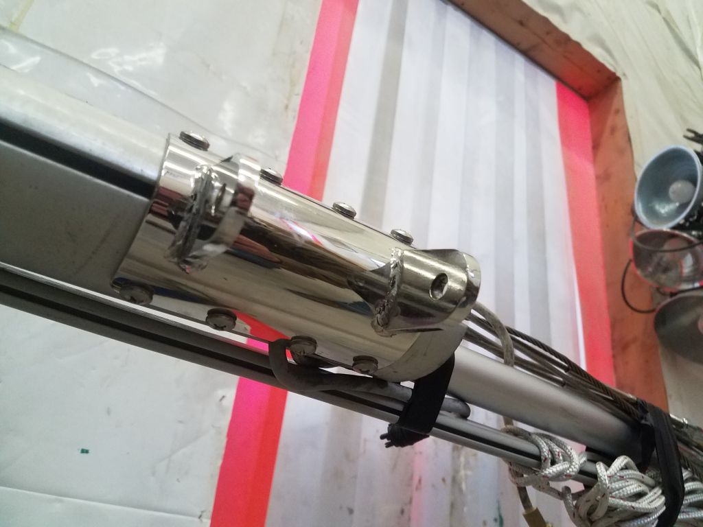
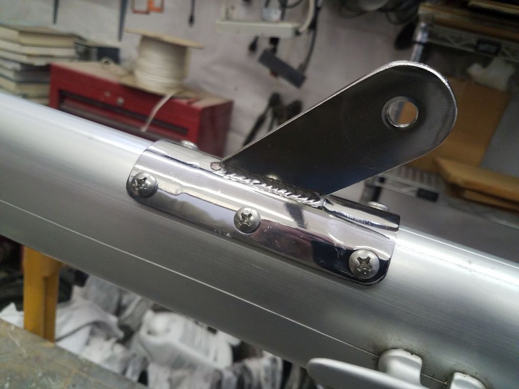
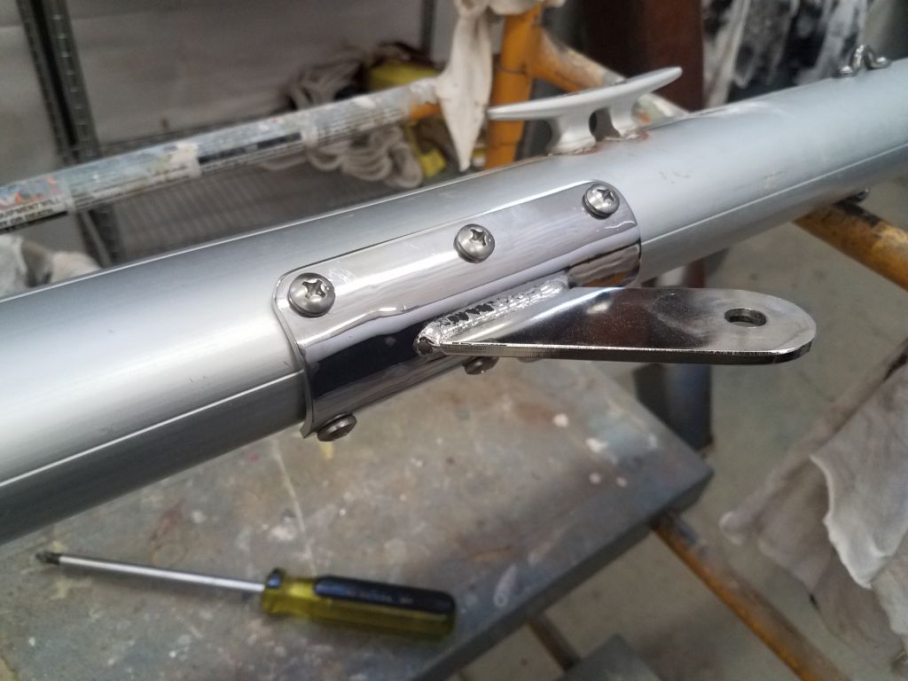
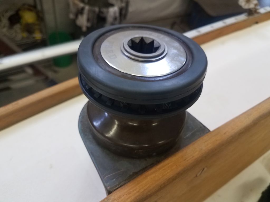
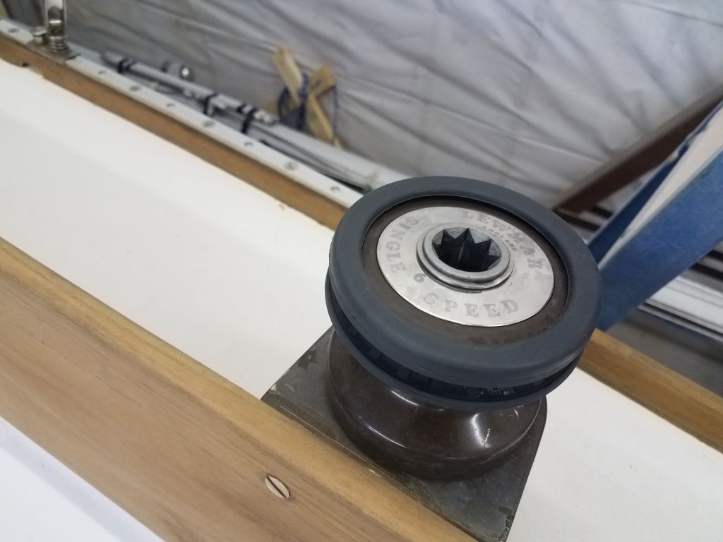
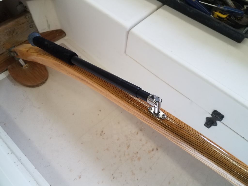
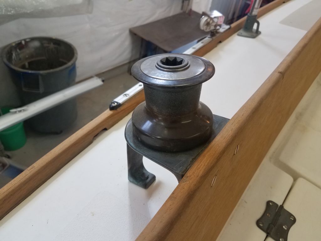
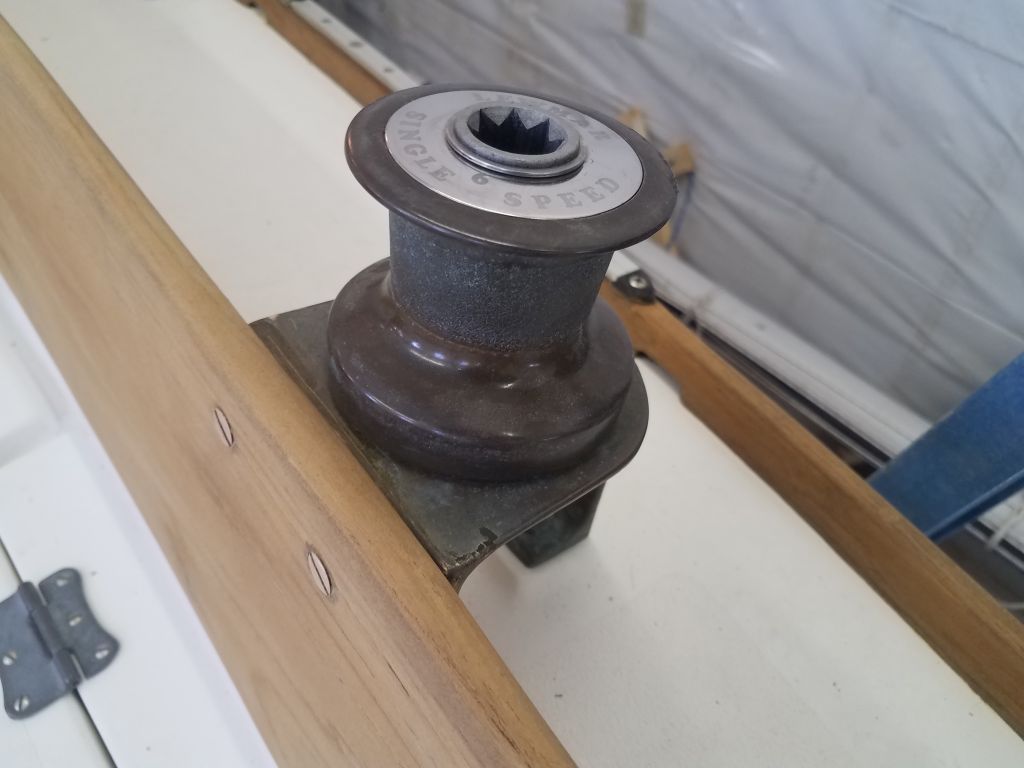
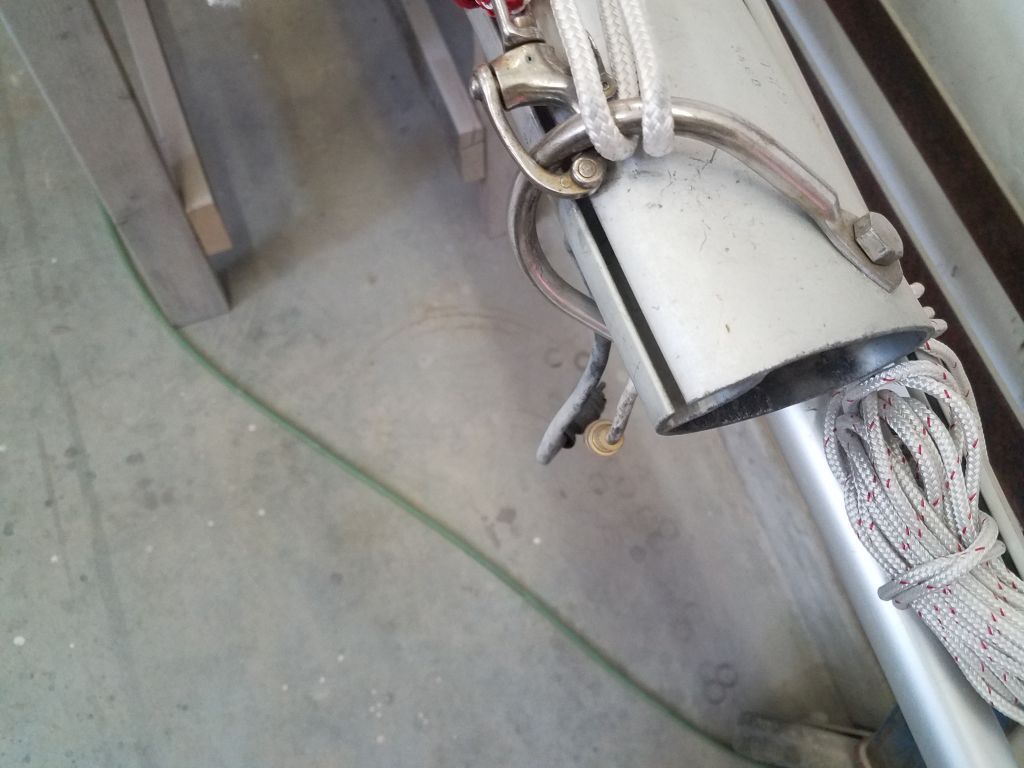
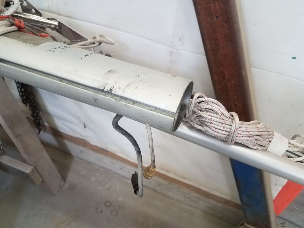
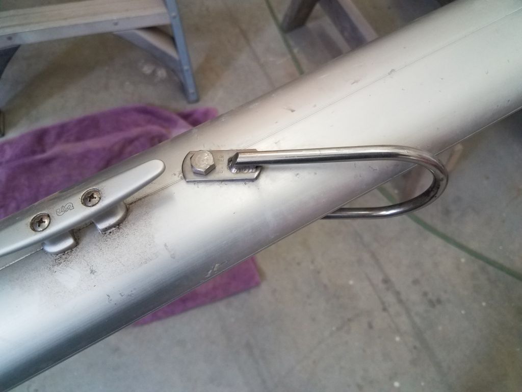
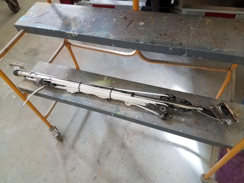
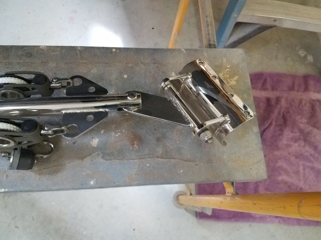
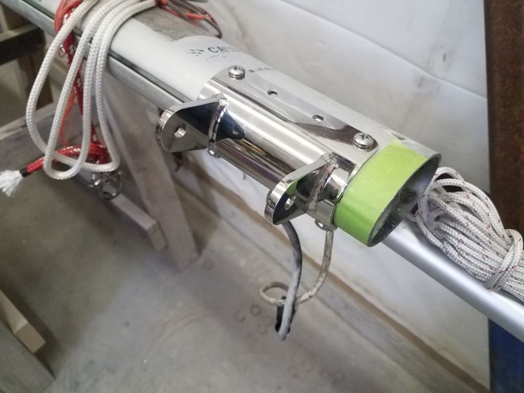
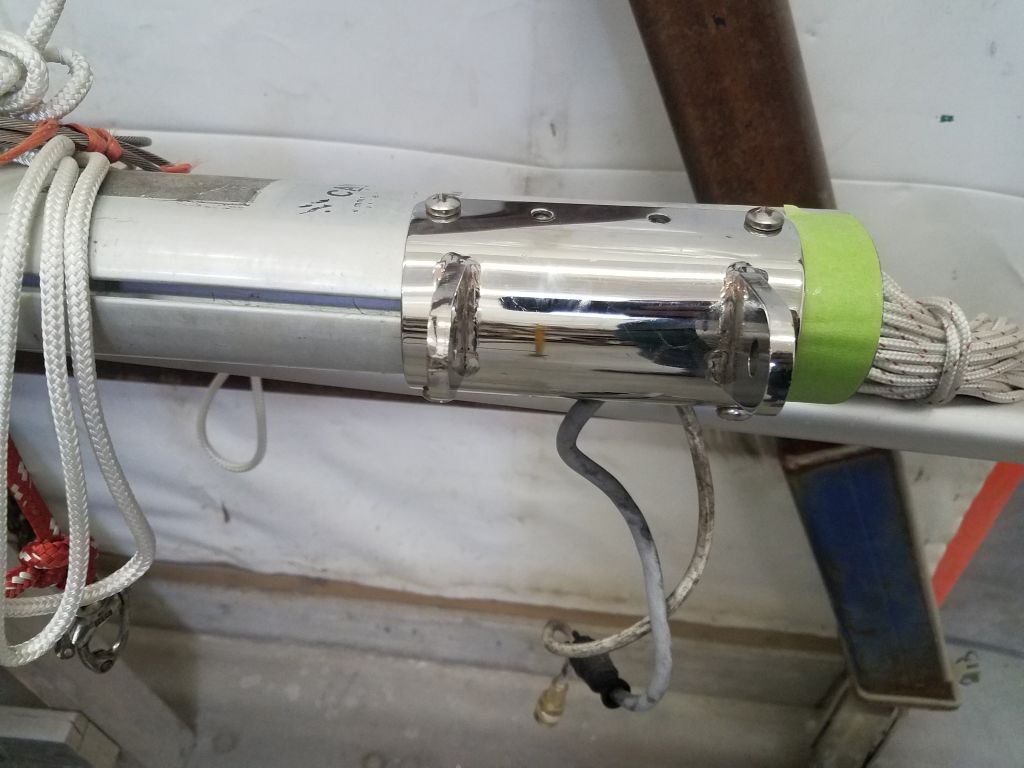
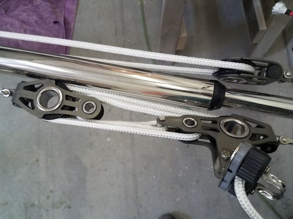
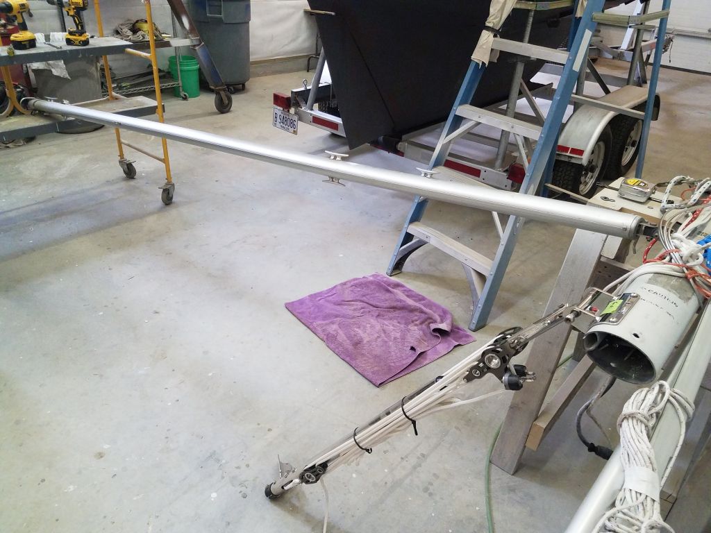
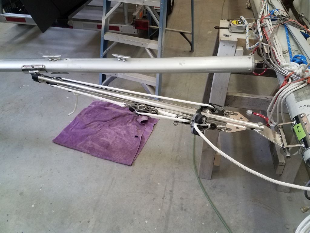
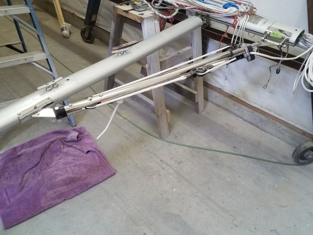
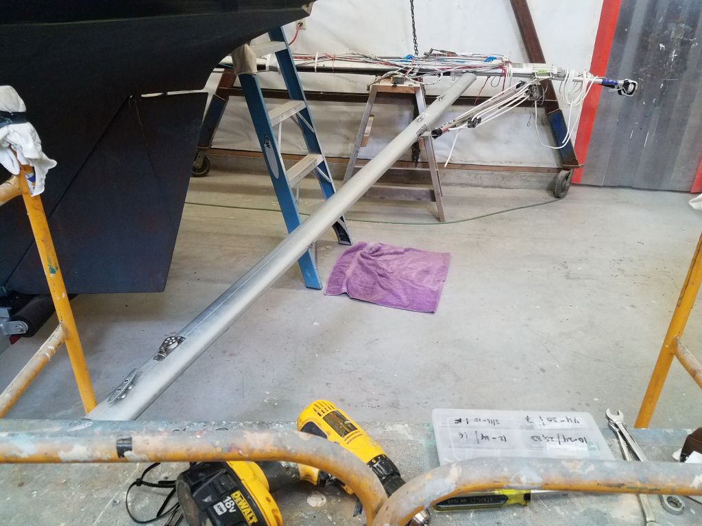
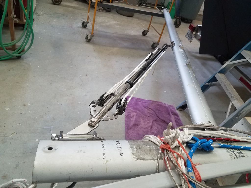
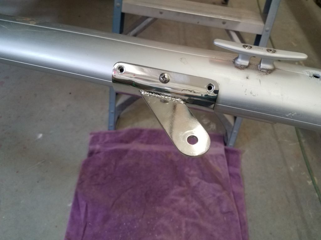
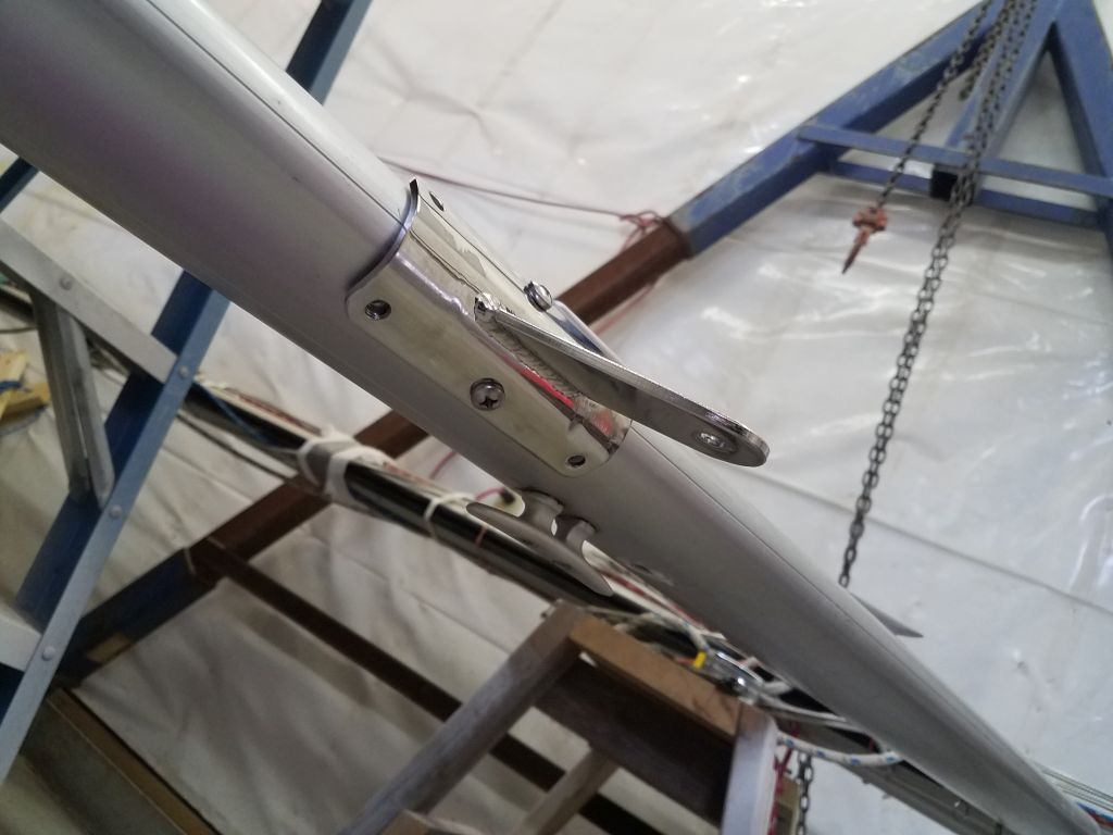
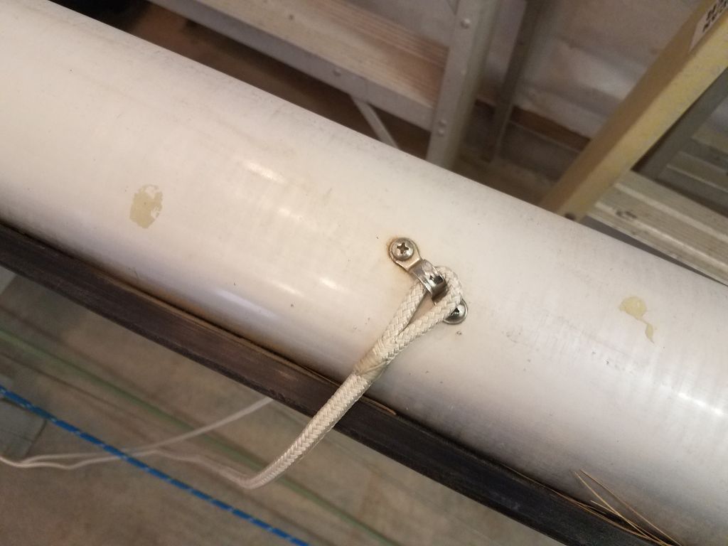
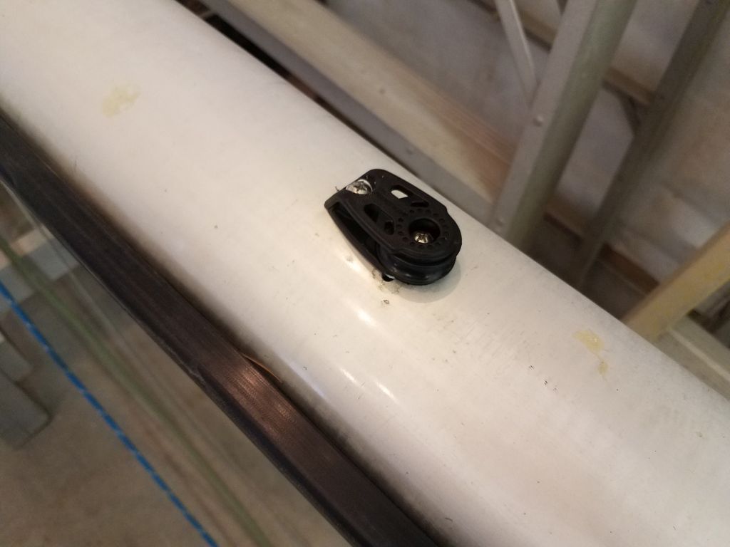
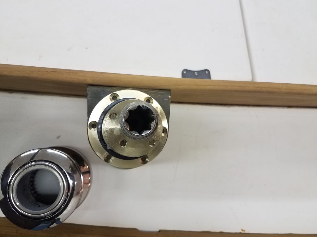
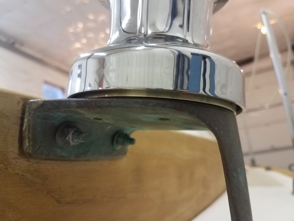
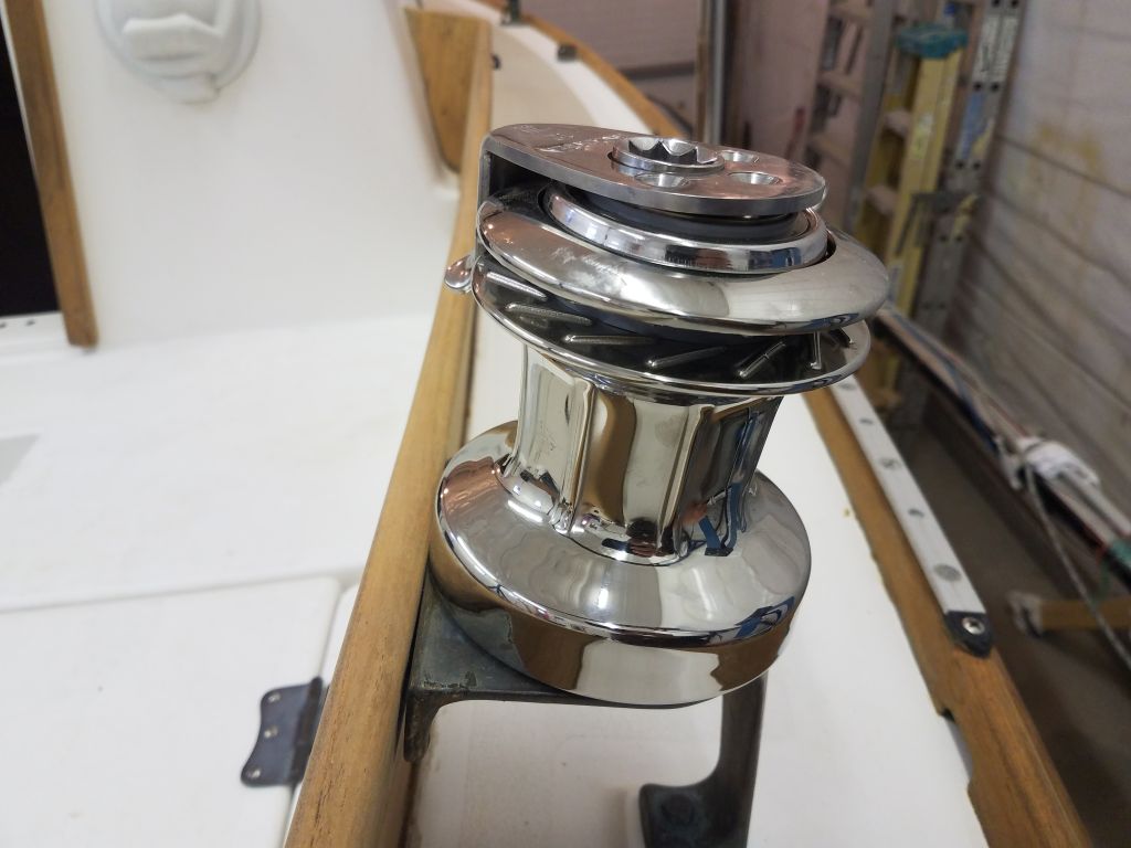
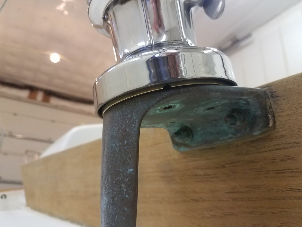
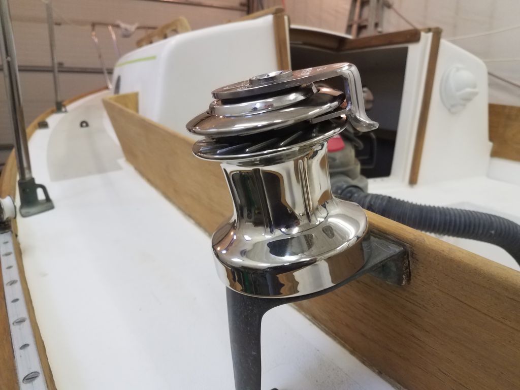
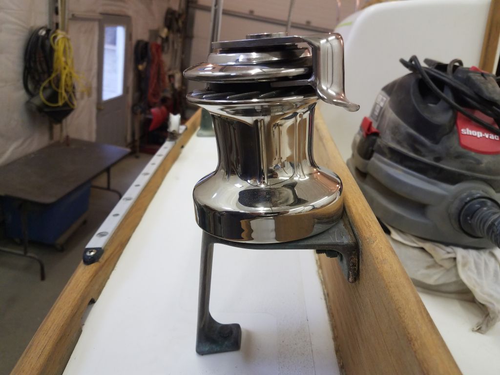
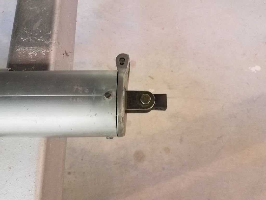
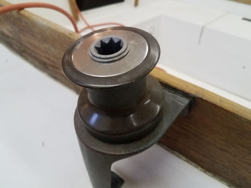
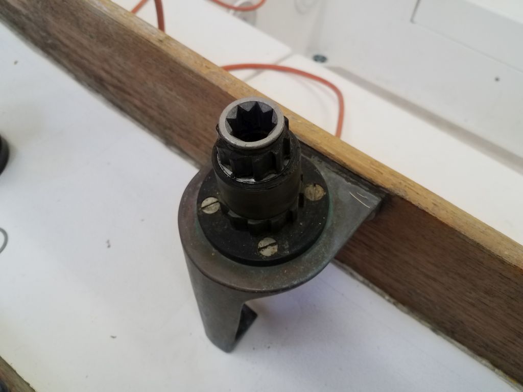
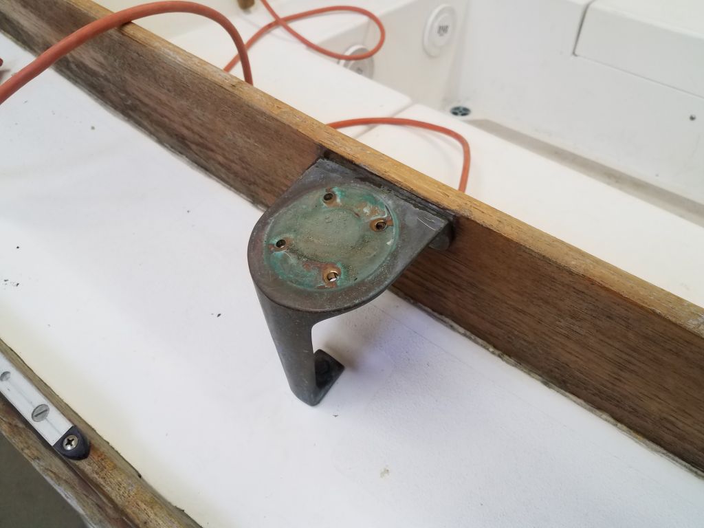
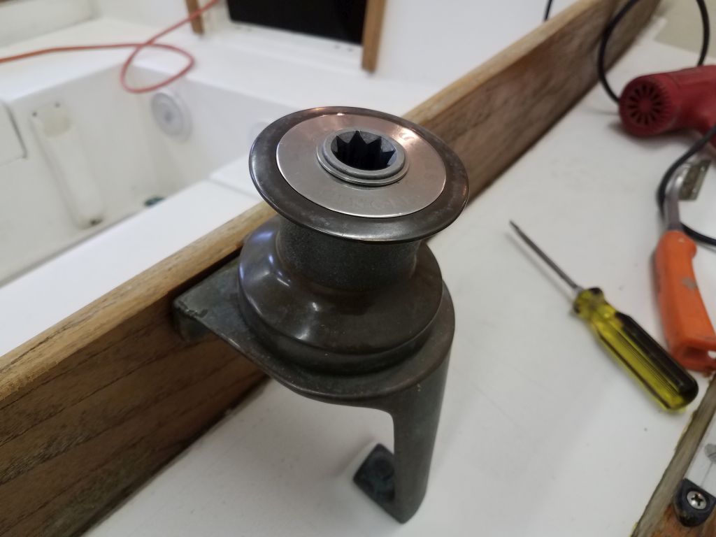
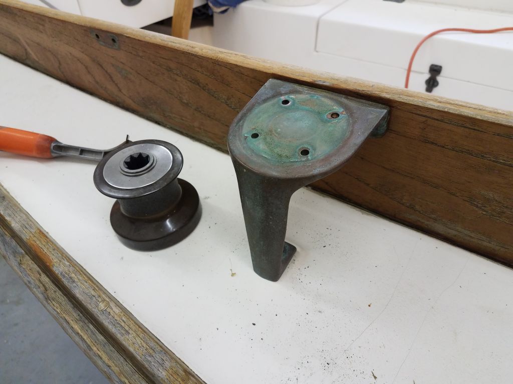
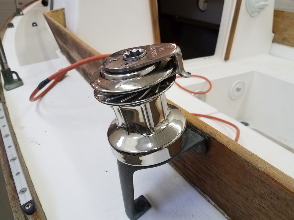
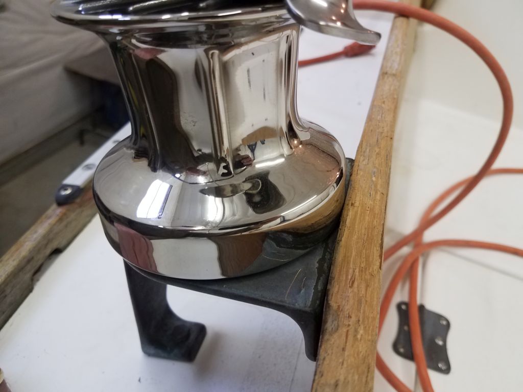
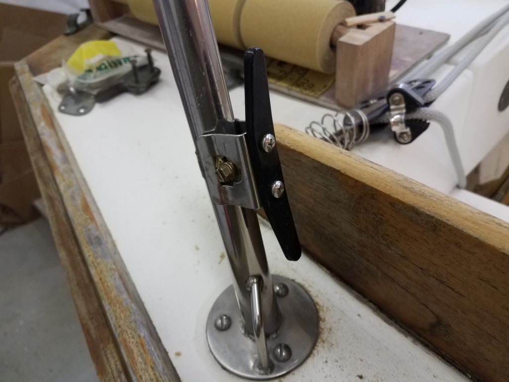
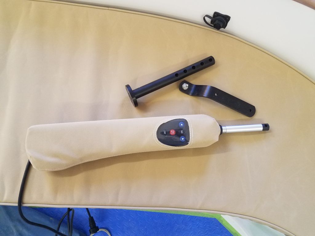
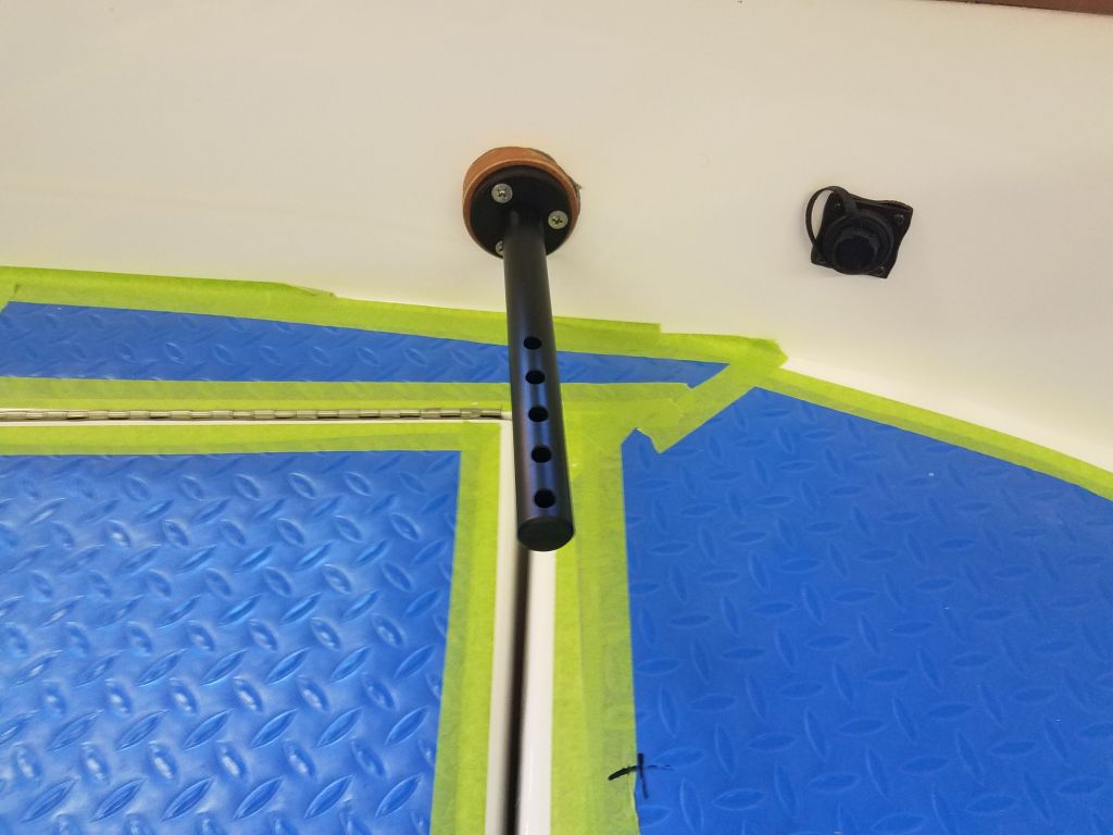
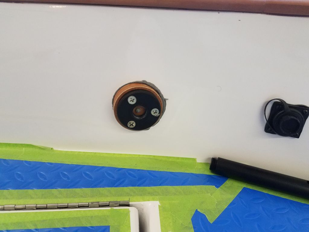
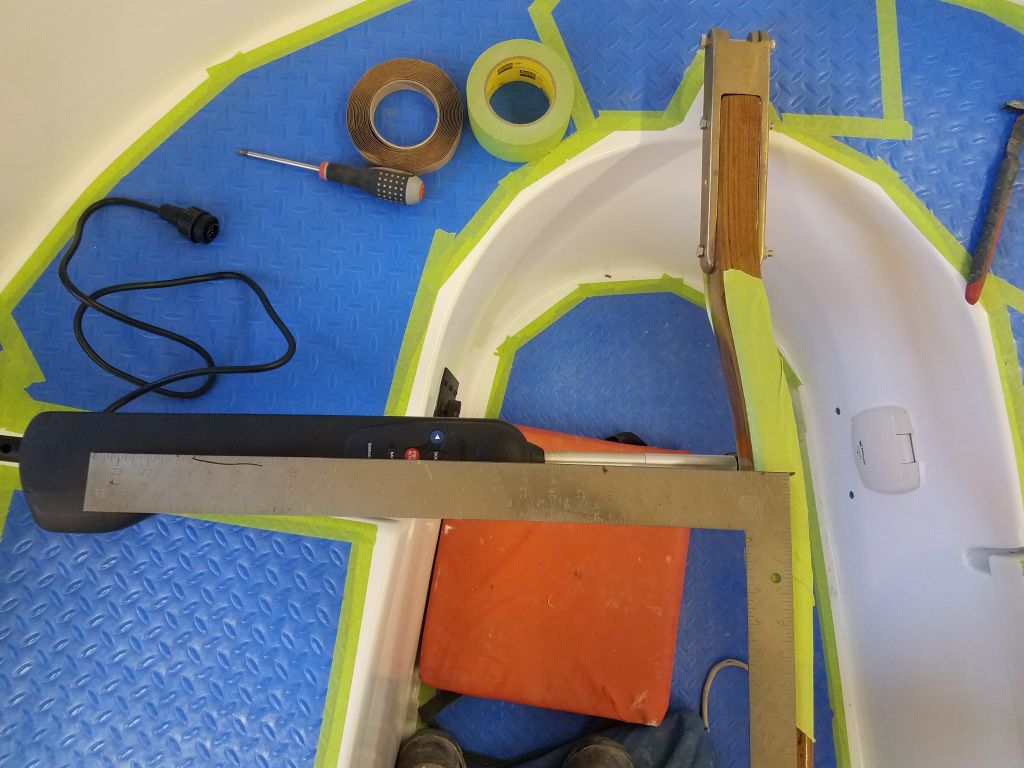
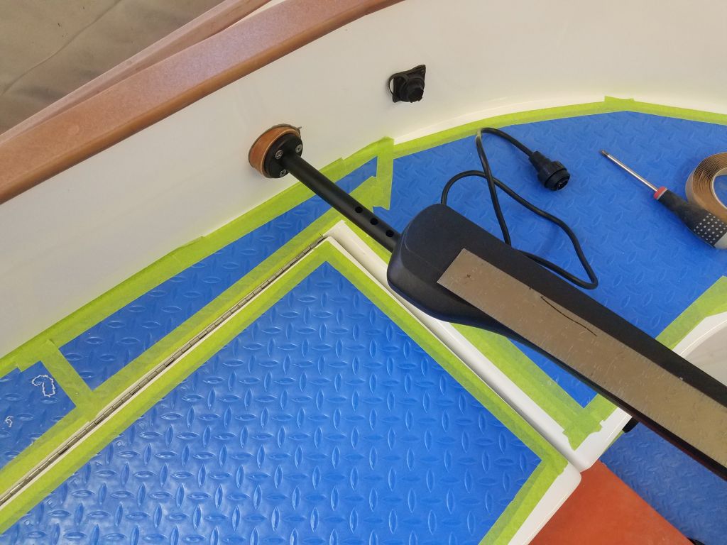
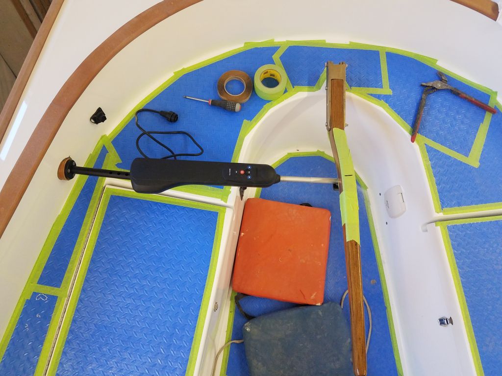
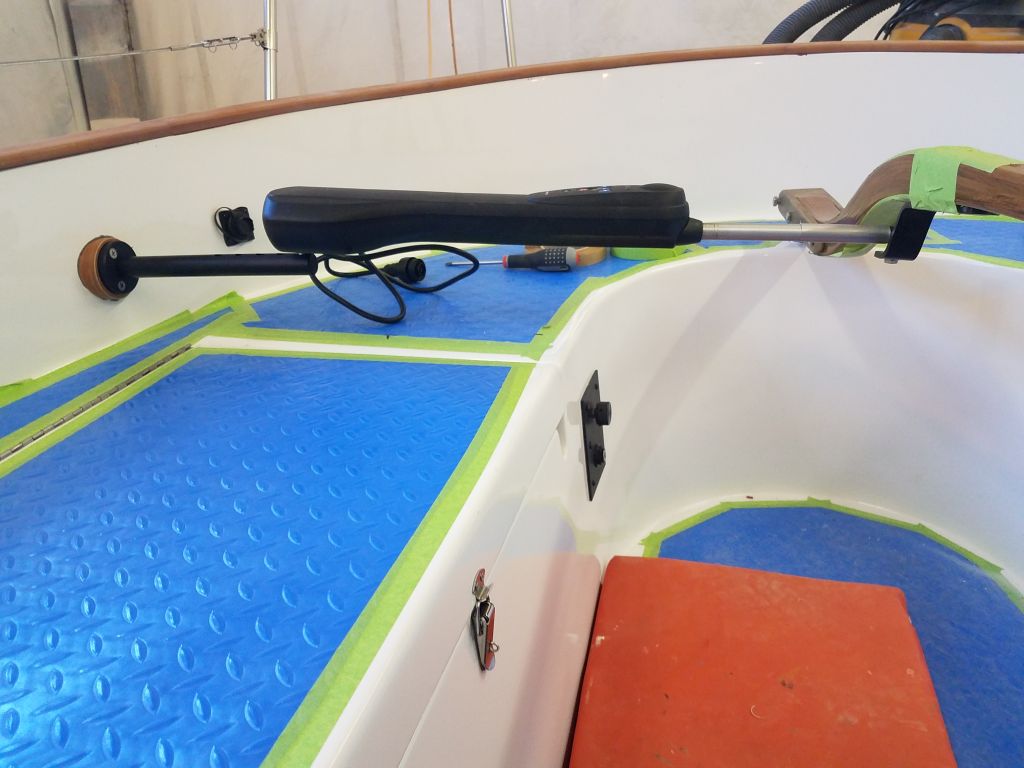
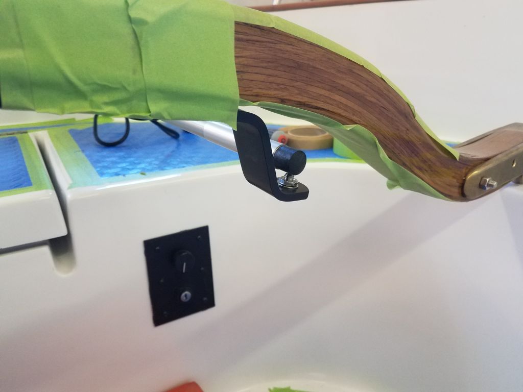
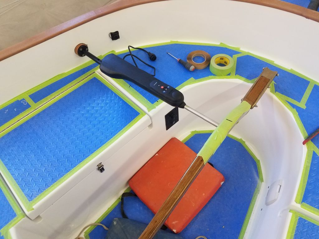
We also planned to enhance the sailing experience with new self-tailing winches for the genoa, a tiller extension, and a rigid boom vang, all of which I’d be installing soon.
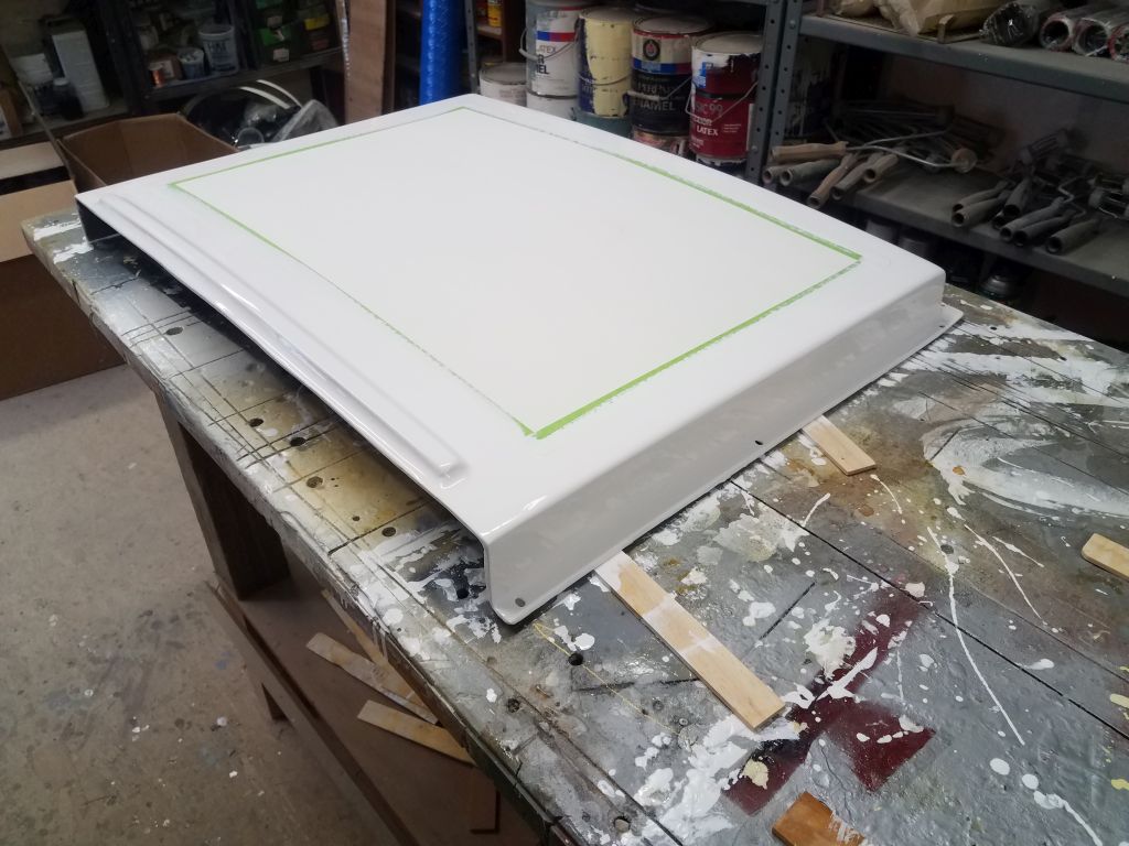
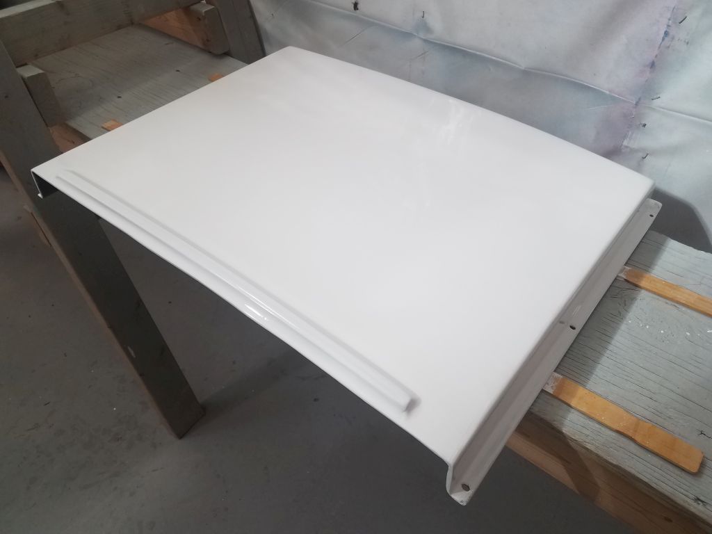
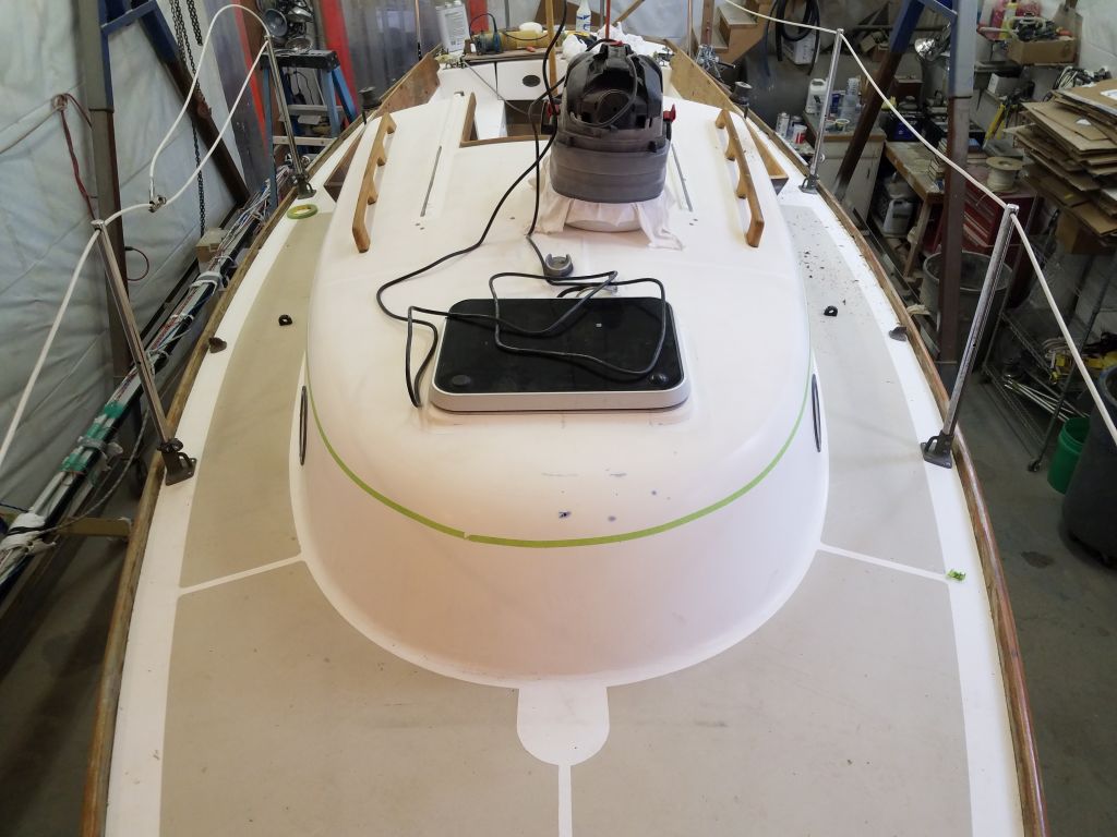
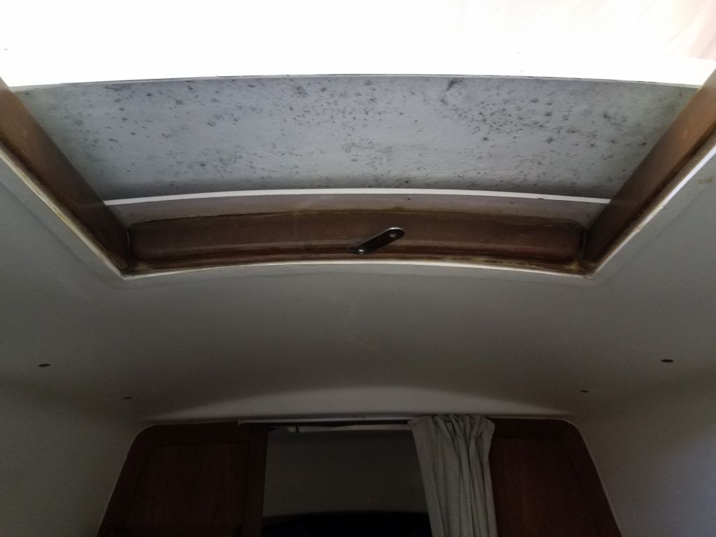
The owner also wanted to install a new dodger, and to that end he had purchased an old fiberglass sea hood that came from a Cape Dory 25; the existing companionway had no sea hood, and while one wasn’t required, it did make sense to install one and provide a better landing point for the dodger. We didn’t know if the old sea hood would be adaptable to this boat, but it seemed a worthy (small) investment to give it a try versus building something from scratch.
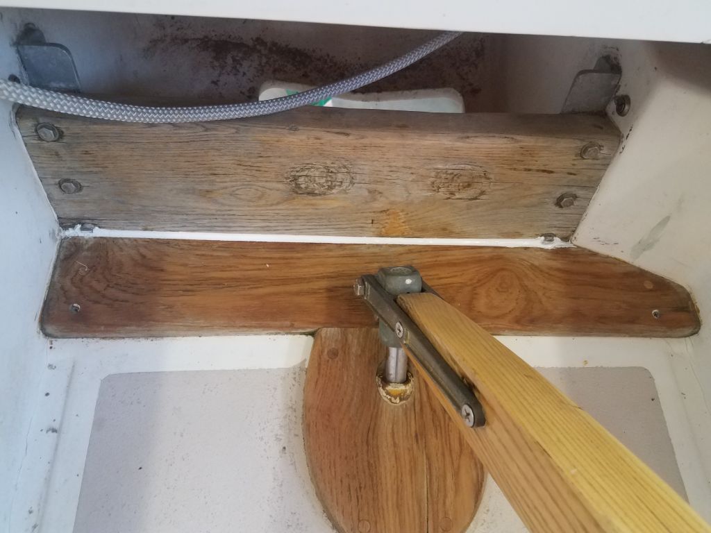
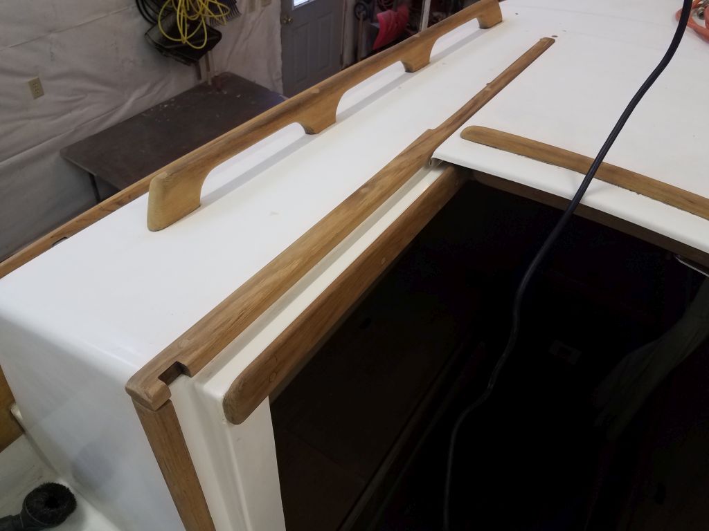
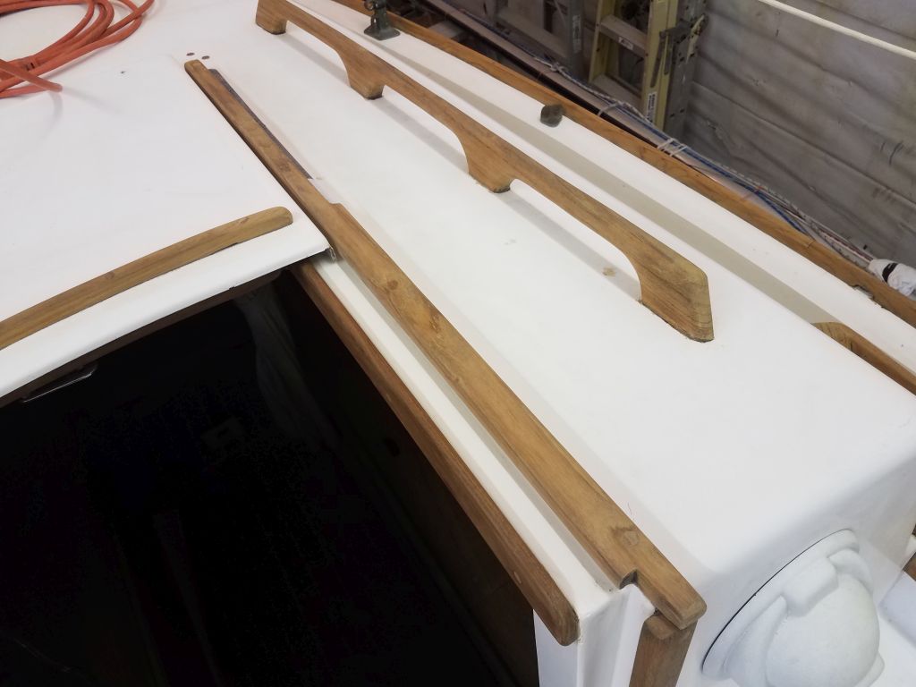
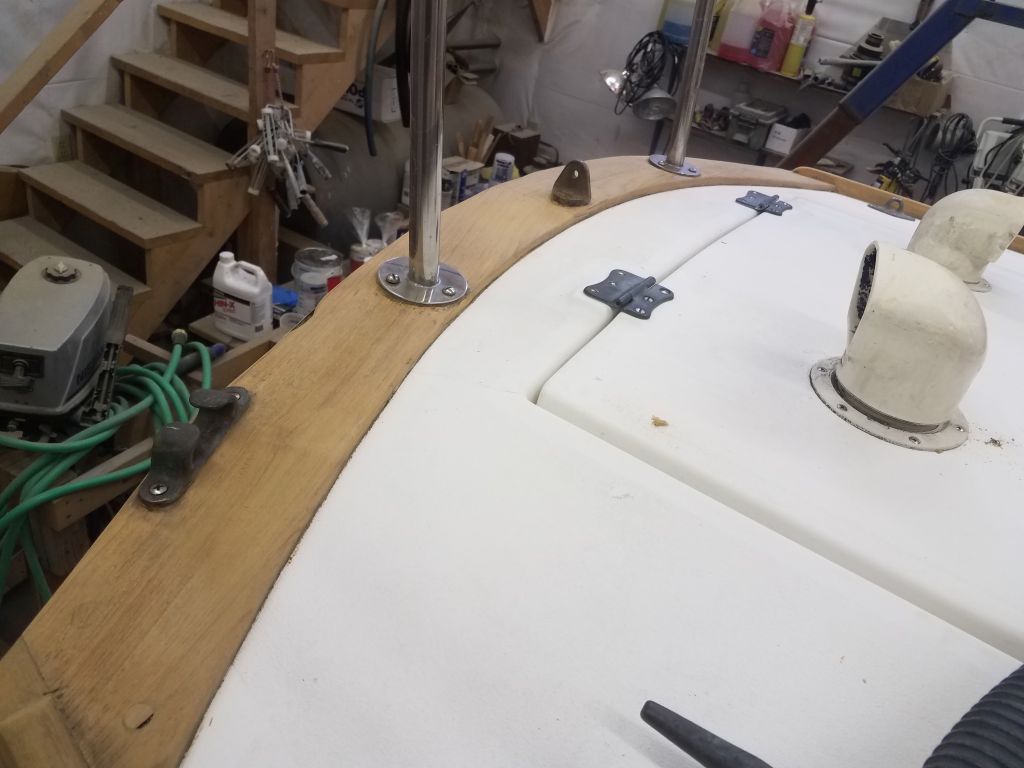
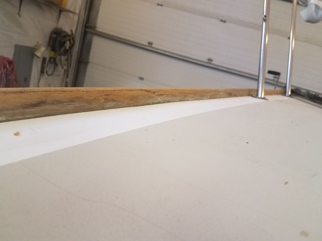
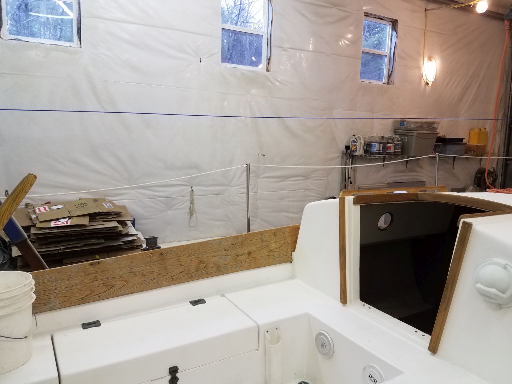
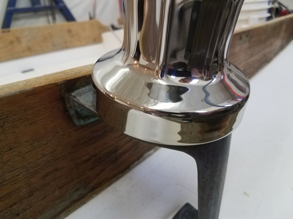
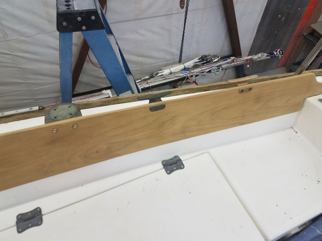
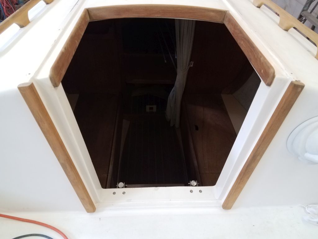
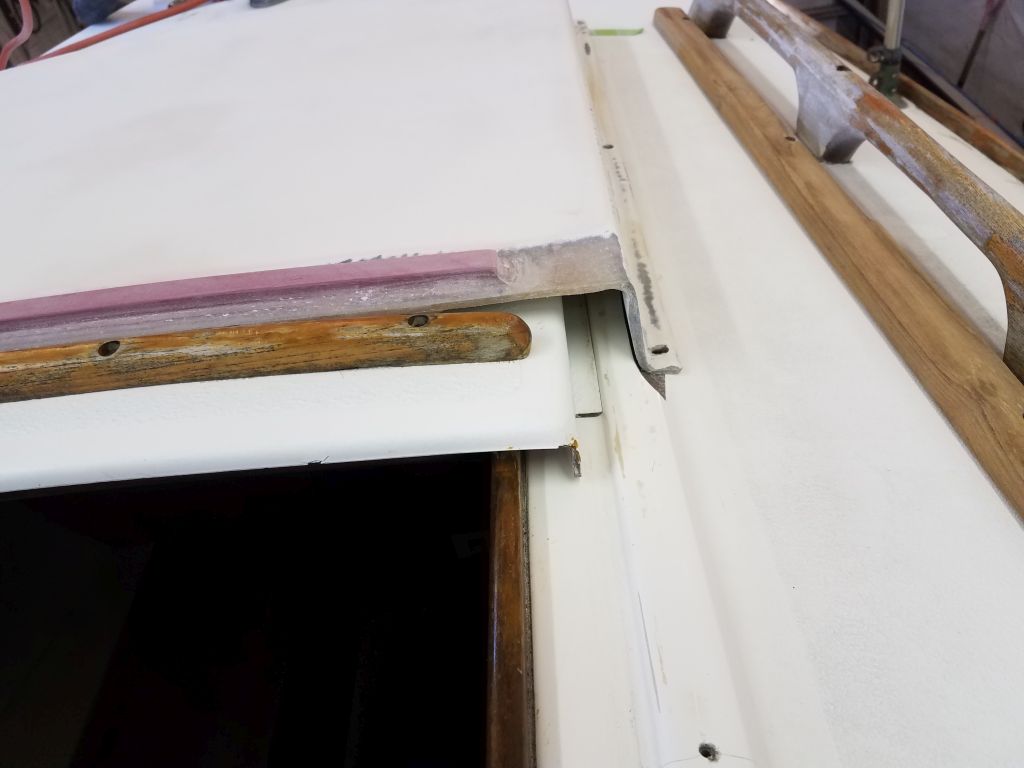
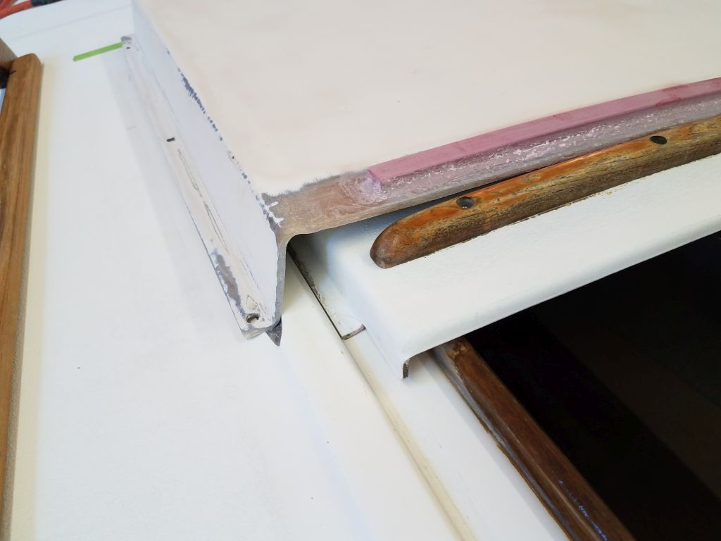
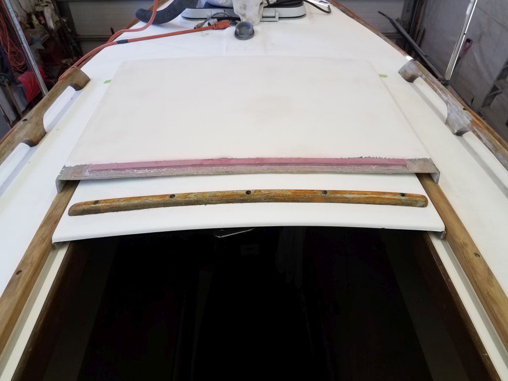
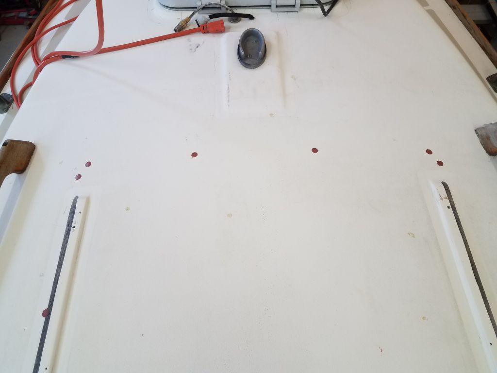
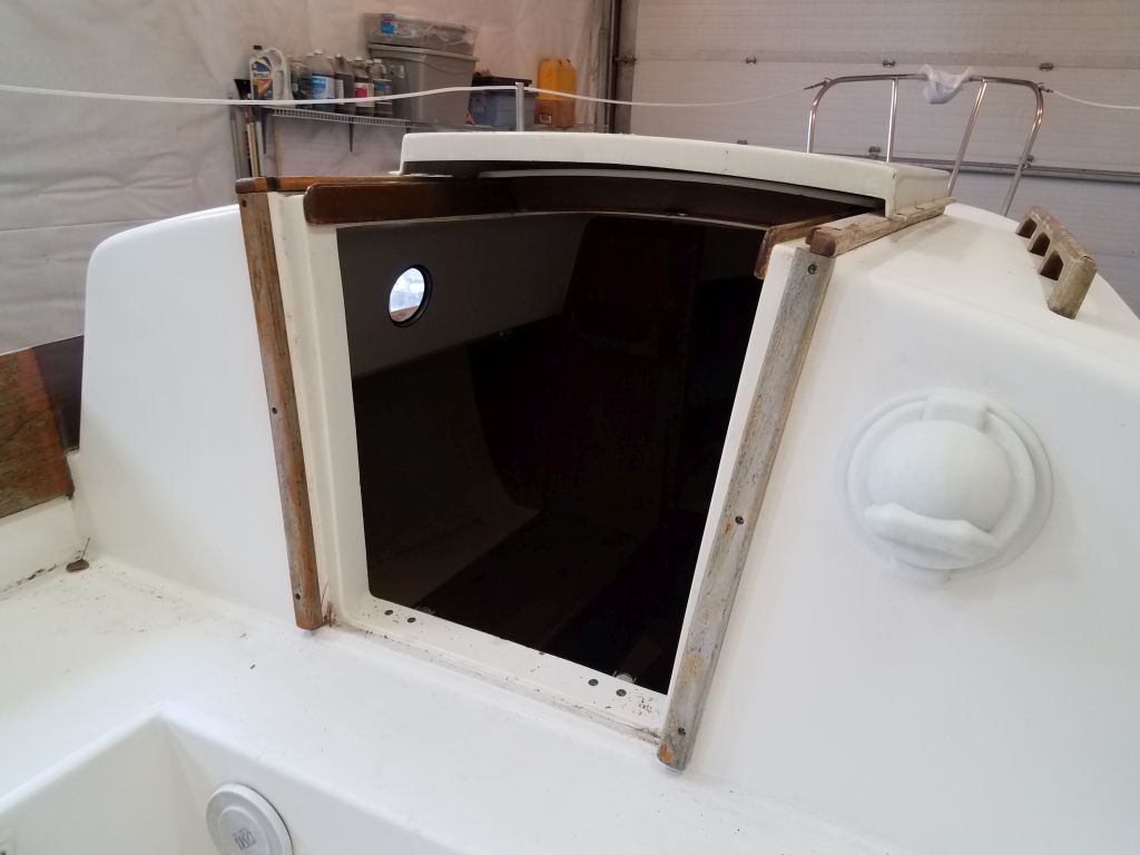
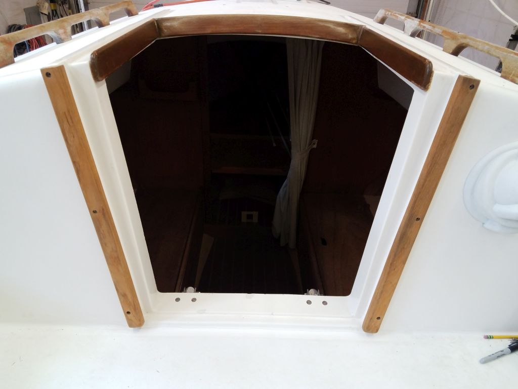
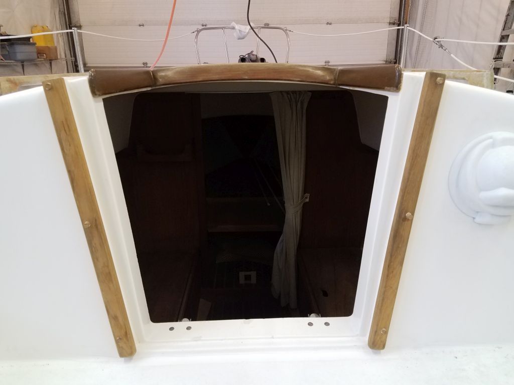
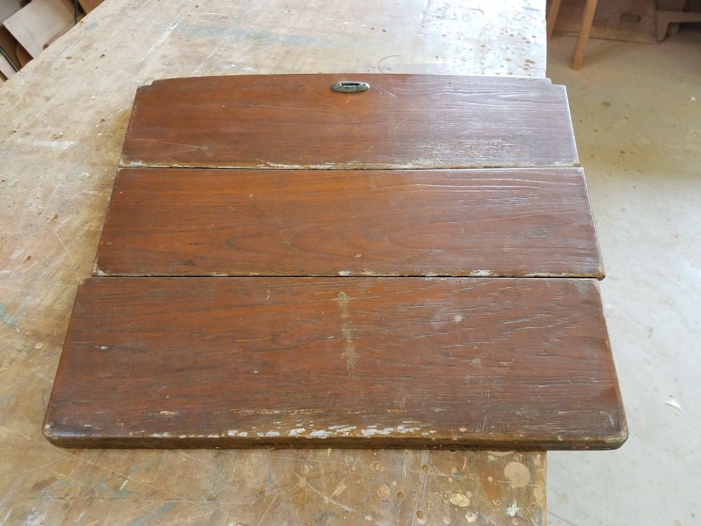
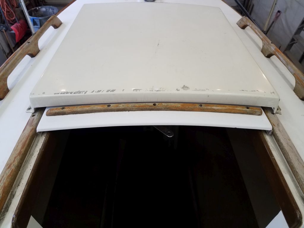
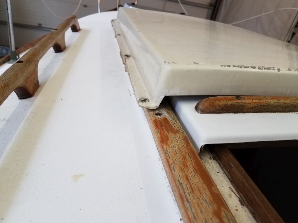
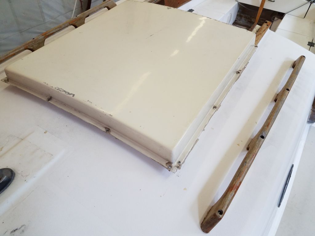
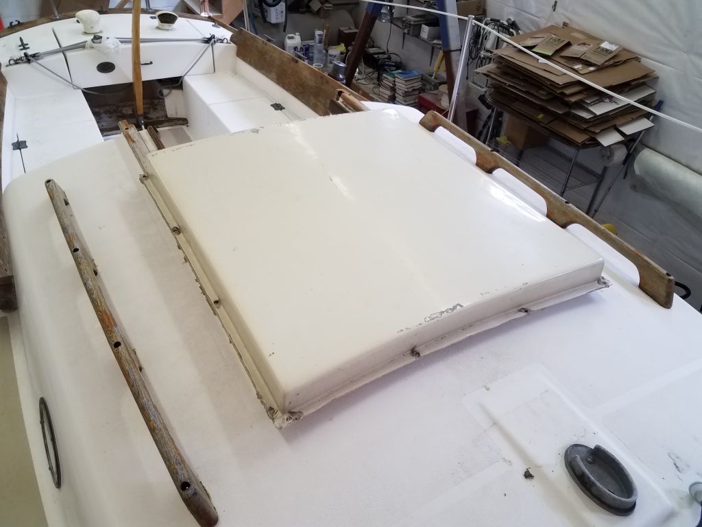
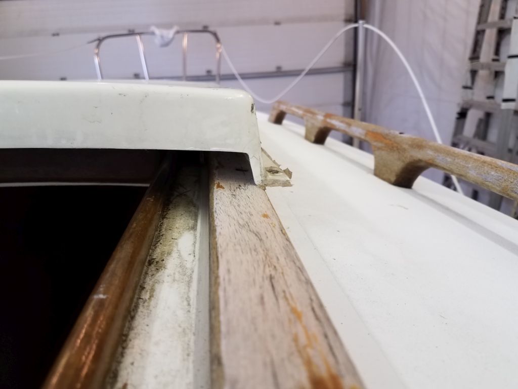
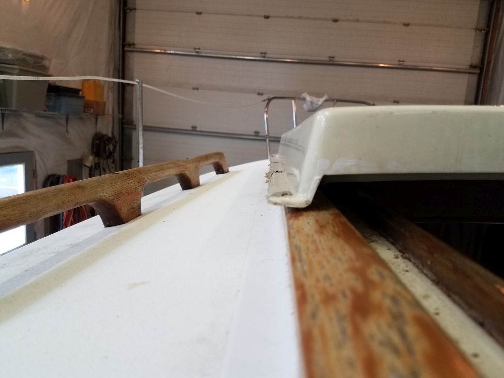
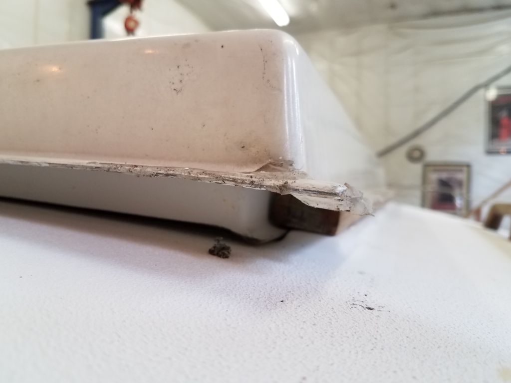
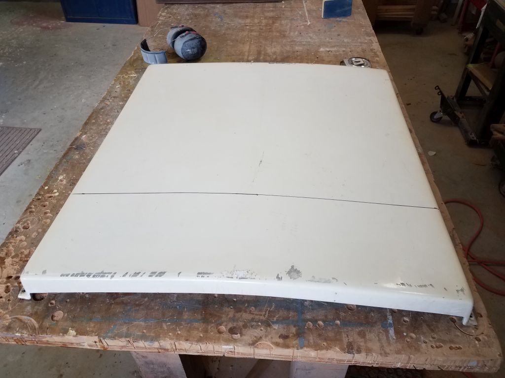
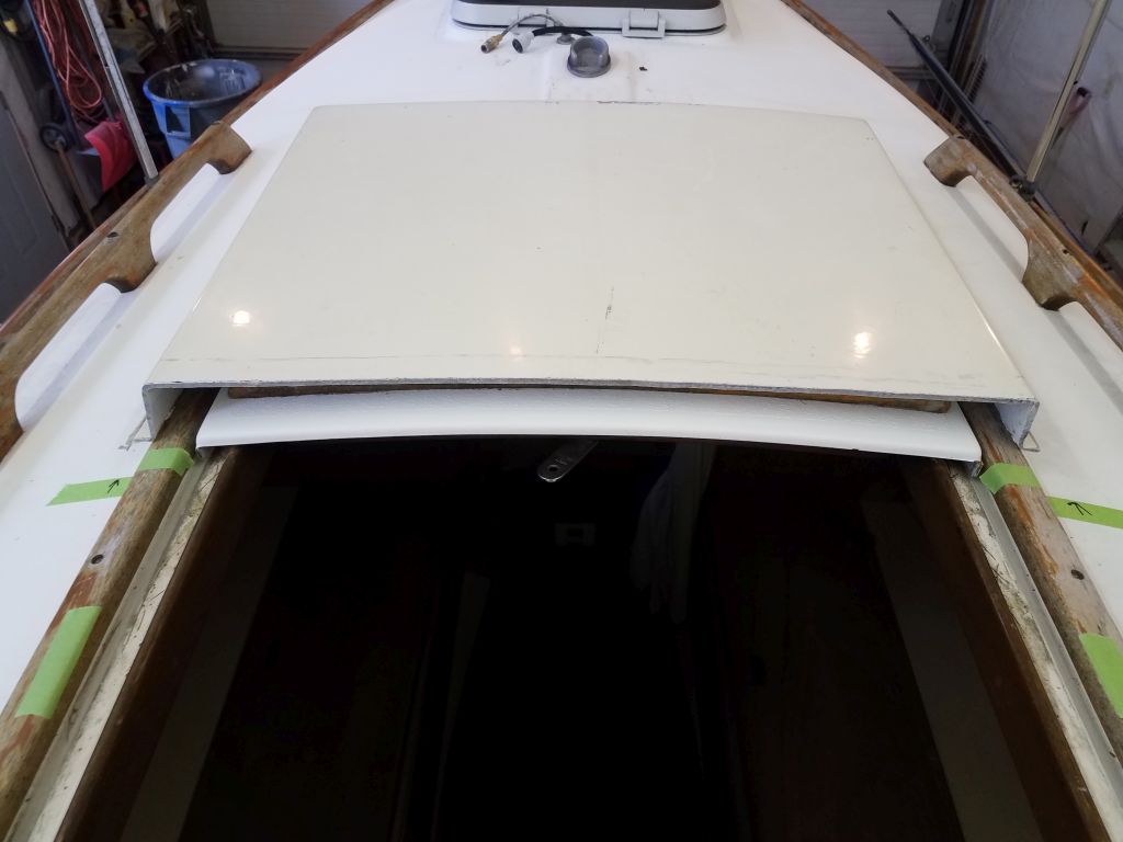
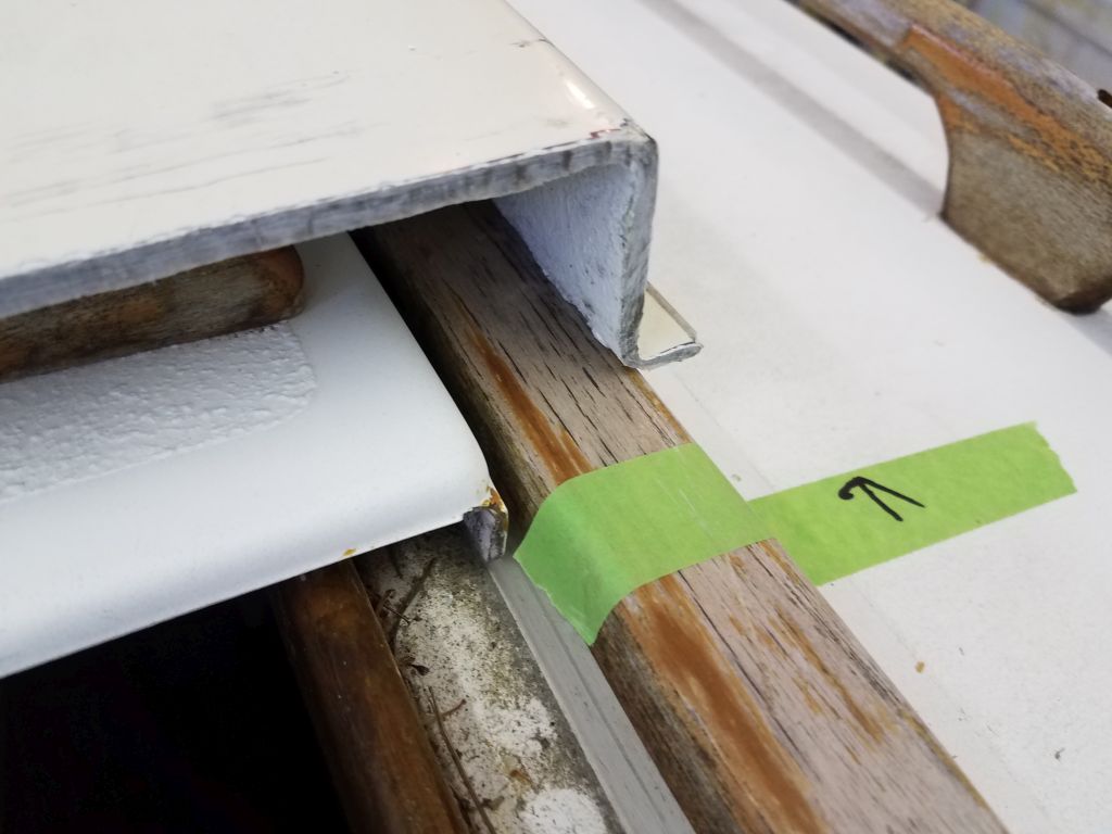
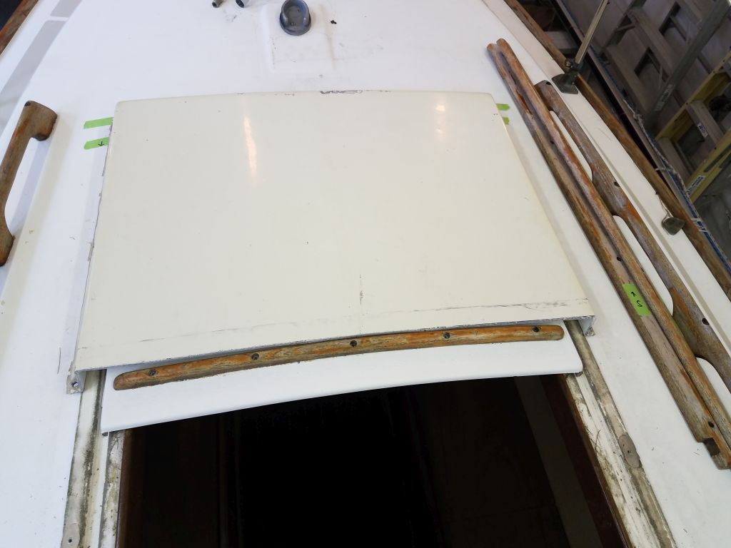
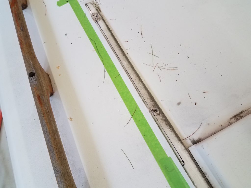
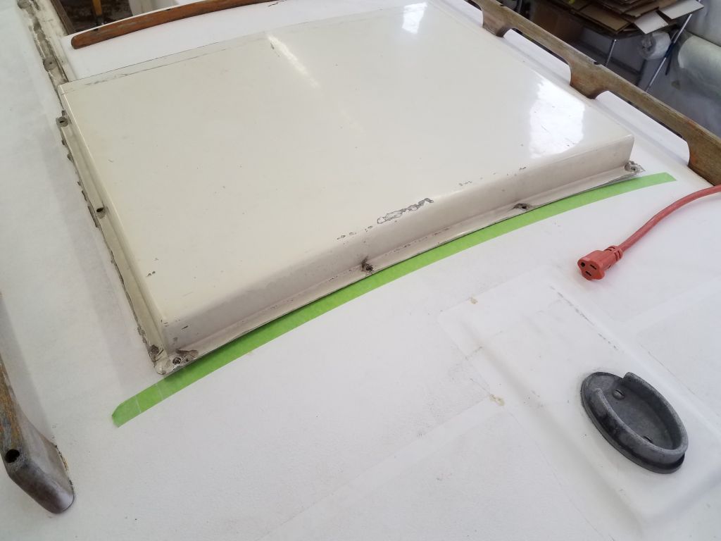
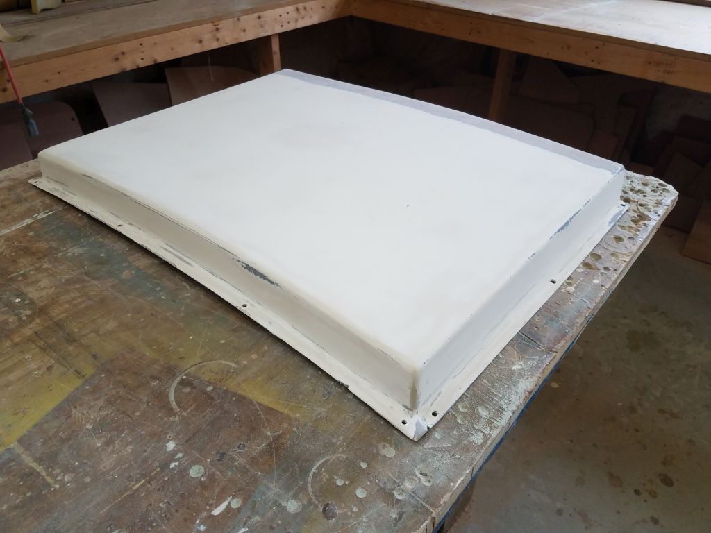
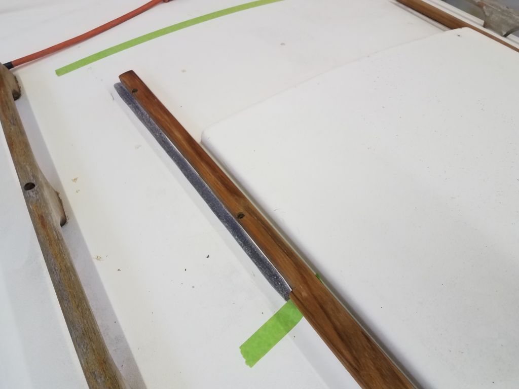
The old sea hood was structurally sound and in generally good condition, and I set it in place over the existing hatch to get a sense of its fit. I knew it would be too long, since the CD Typhoon Sr. features a rather short companionway hatch, but shortening the hood would be straightforward. In a perfect world, it would have fit cleanly and without need for other modification, but in reality, while the hood fit over the companionway well enough, it interfered with the wooden trim that acted as guides and hold-downs for the existing sliding hatch, as it wasn’t quite wide enough to clear the existing trims.
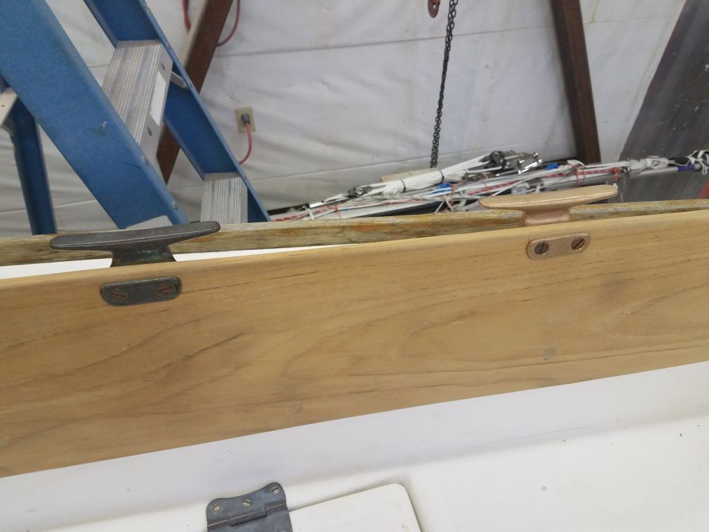
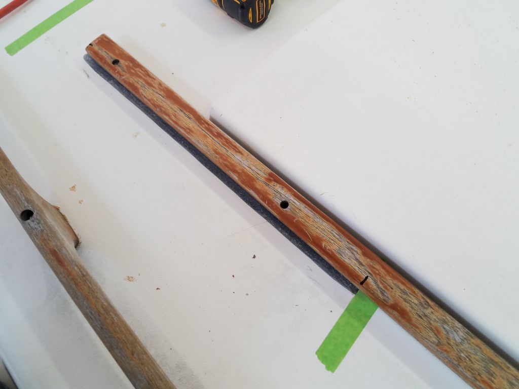
I considered and rejected various options for dealing with the fit, from doing nothing and giving up on the sea hood (not really a desirable option), to extending the wood trim (maybe), to making the sea hood taller on the sides (fussy and not really practicable nor attractive nor desirable), but in the end I decided it made sense to see about modifying (i.e. cutting narrower) the existing wood trim to accept the sea hood, which was a simple option since the sea hood almost fit as it was, and there was no need for the trim to be as wide as it was other than consistent appearance–and that wouldn’t be an issue since the modified trim would be inside the sea hood and not visible. Plus, conveniently, all the bungs were missing from the wood trim (and the handrails and the companionway trim and the coamings), so removal of the trim ought to be a snap.
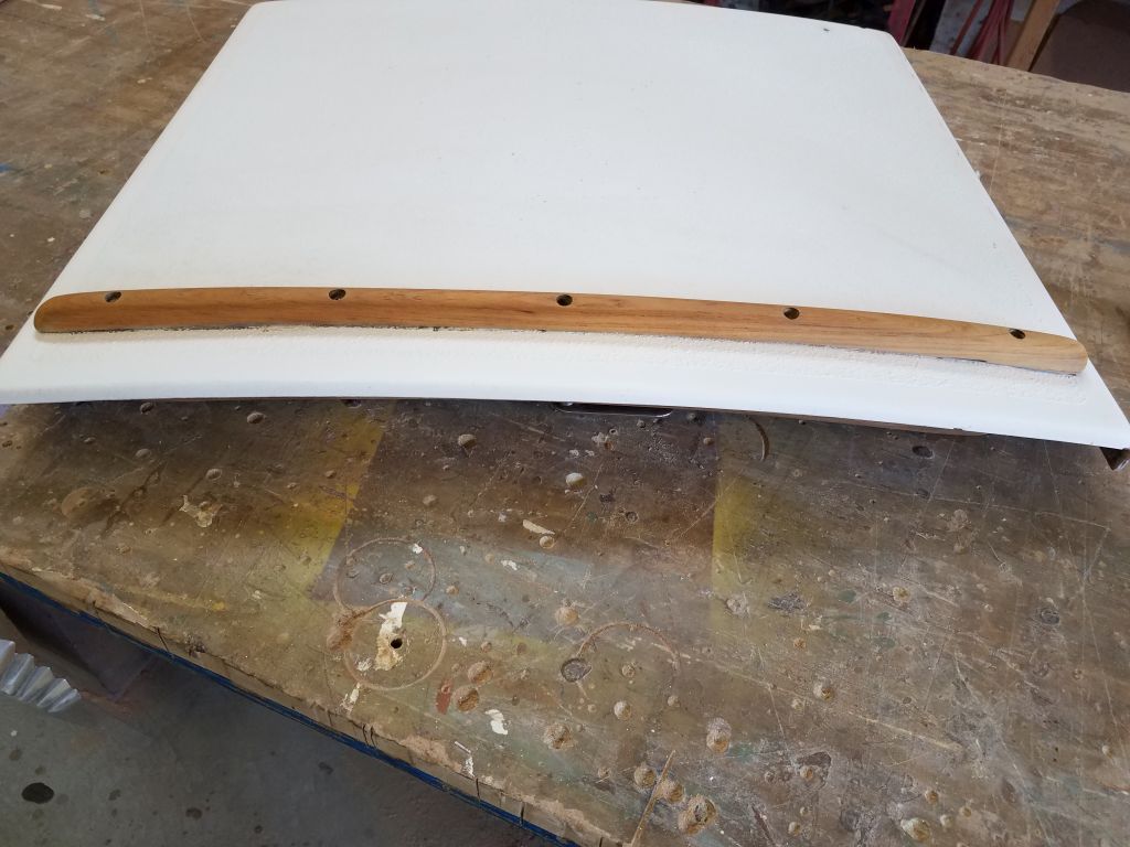
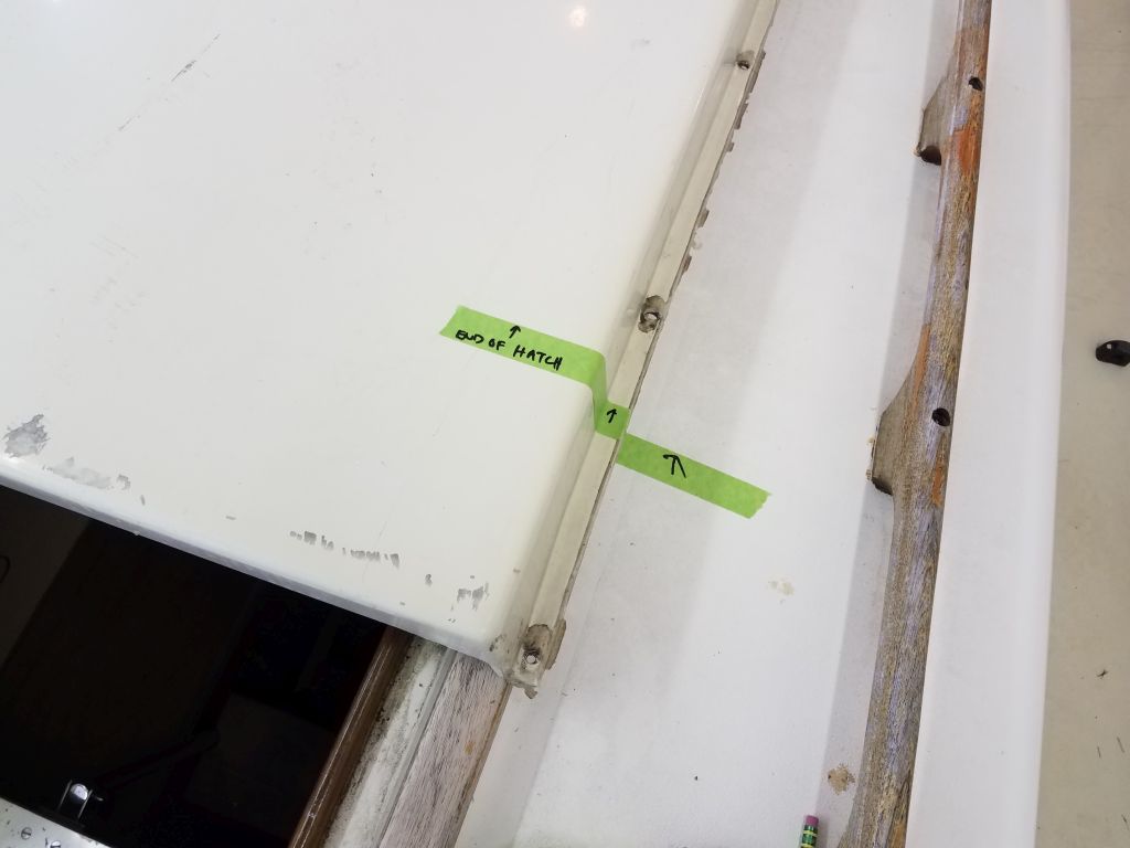
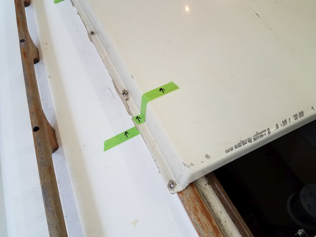
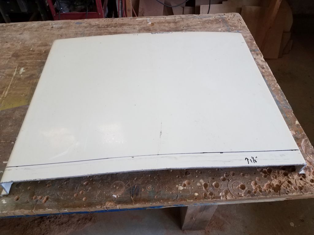
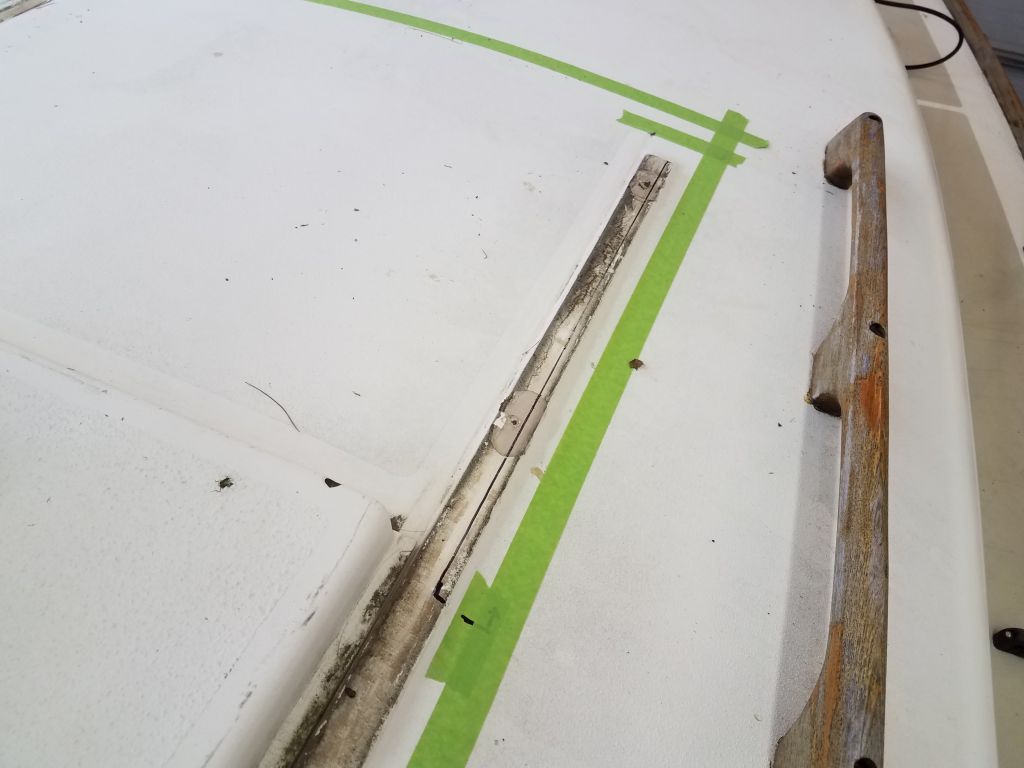
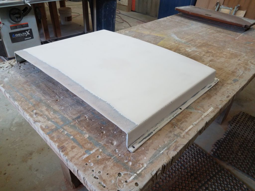
Happy with that idea, I made a few measurements and marks to denote the new length of the sea hood, since now it extended well past the companionway opening. Down on the bench, I fine-tuned the cut line and made the cut with a jigsaw.
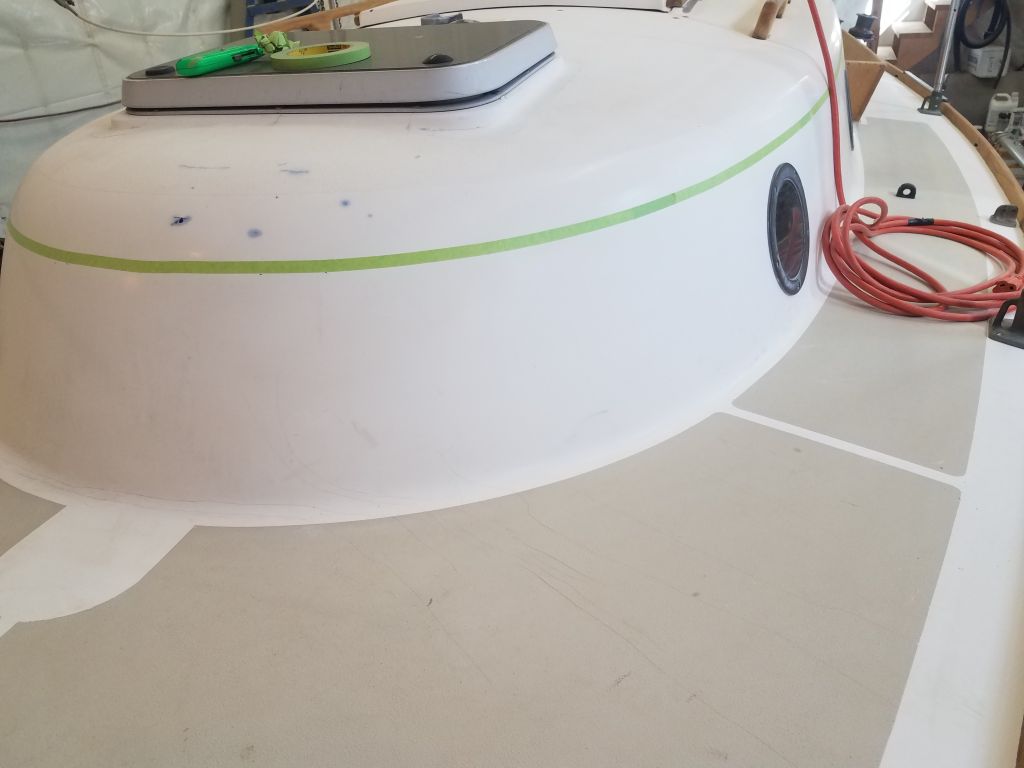
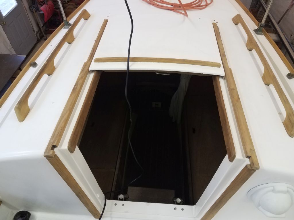
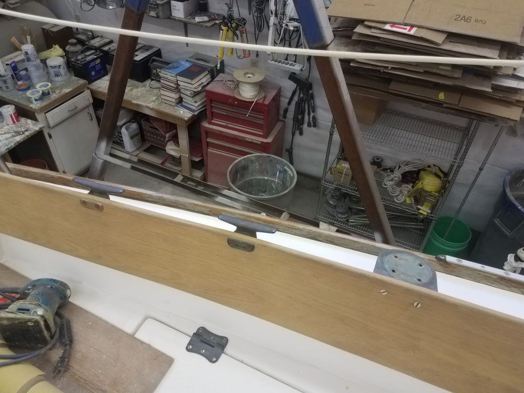
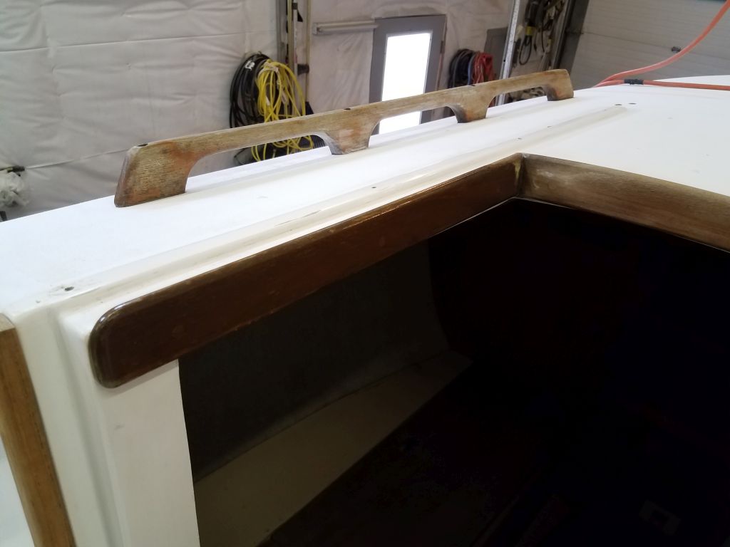
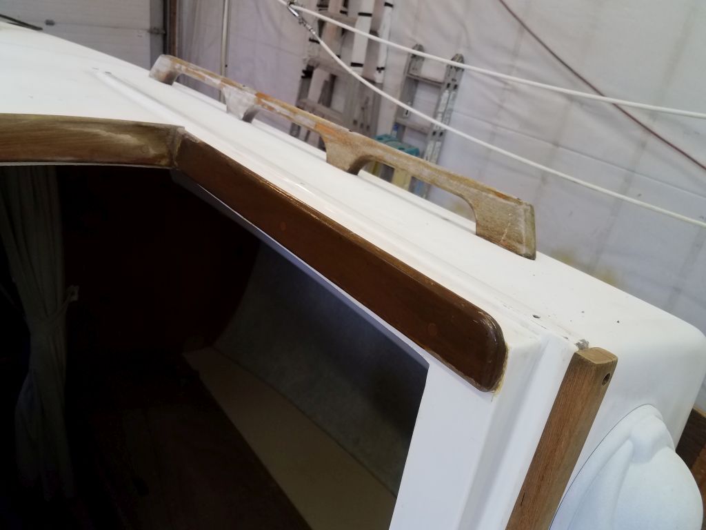
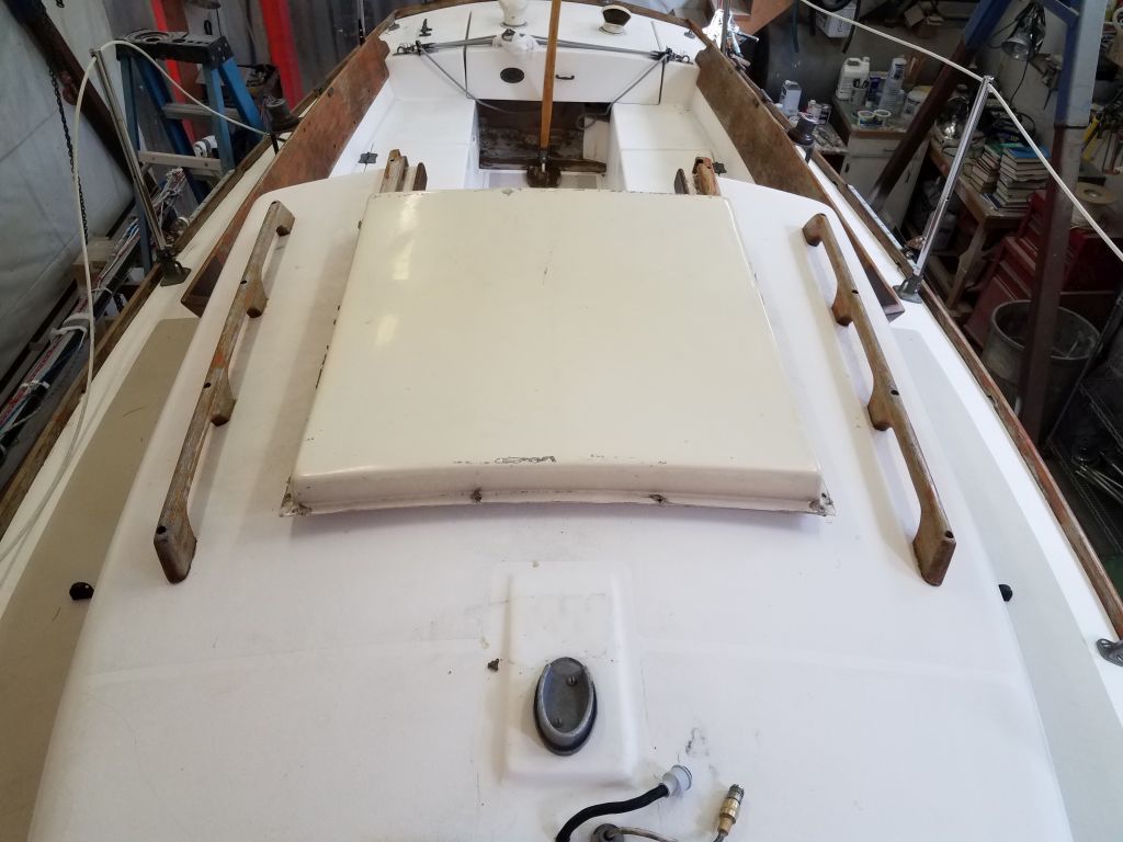
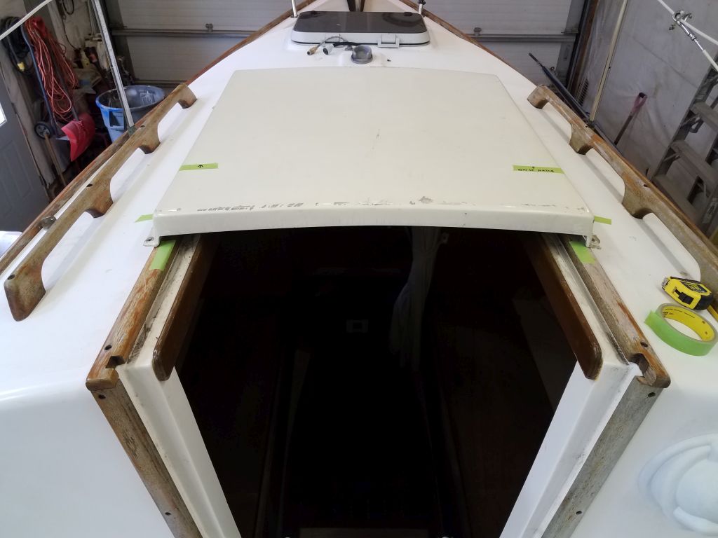
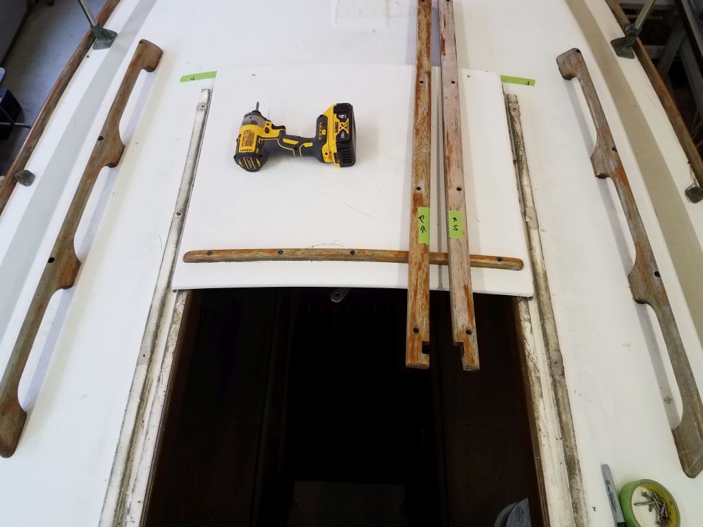
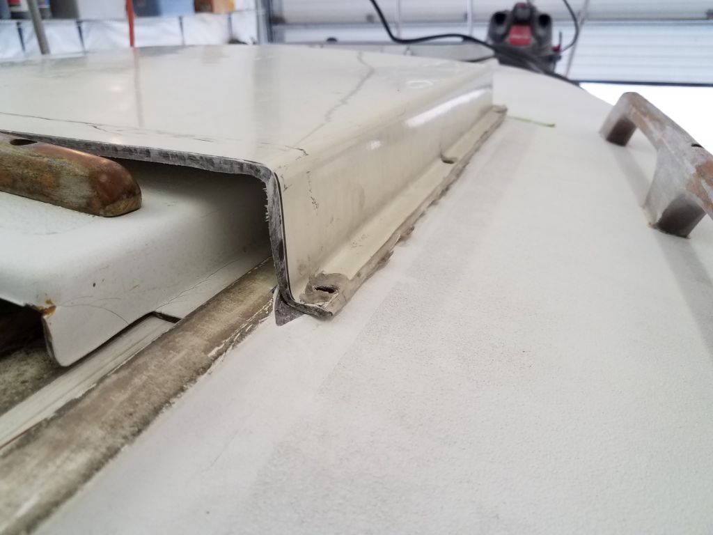
Back on deck, I test-fit the shortened hood. I’d been conservative in my initial cut, and while with the hood propped up on the wooden trims it sat nice and high and allowed the companionway hatch and trim to slide beneath, I could see that once I lowered the hood to deck height (by removing/modifying the wooden trims), the companionway hatch trim would no longer clear the hood, so I decided to cut off another 1-1/2″ to better allow for that.
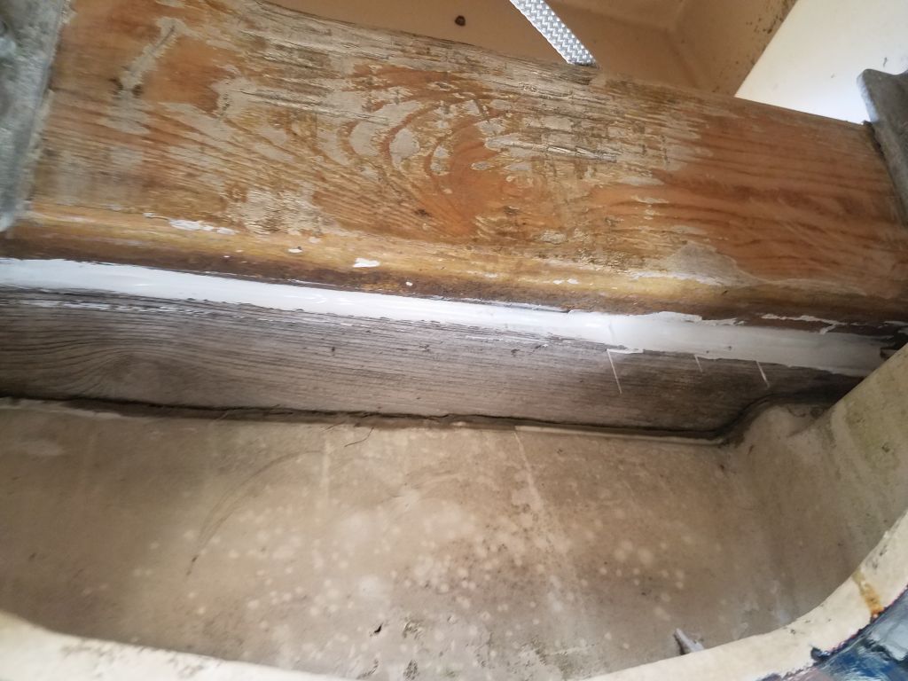
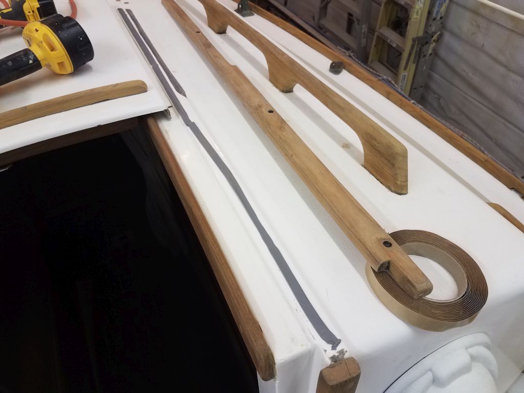
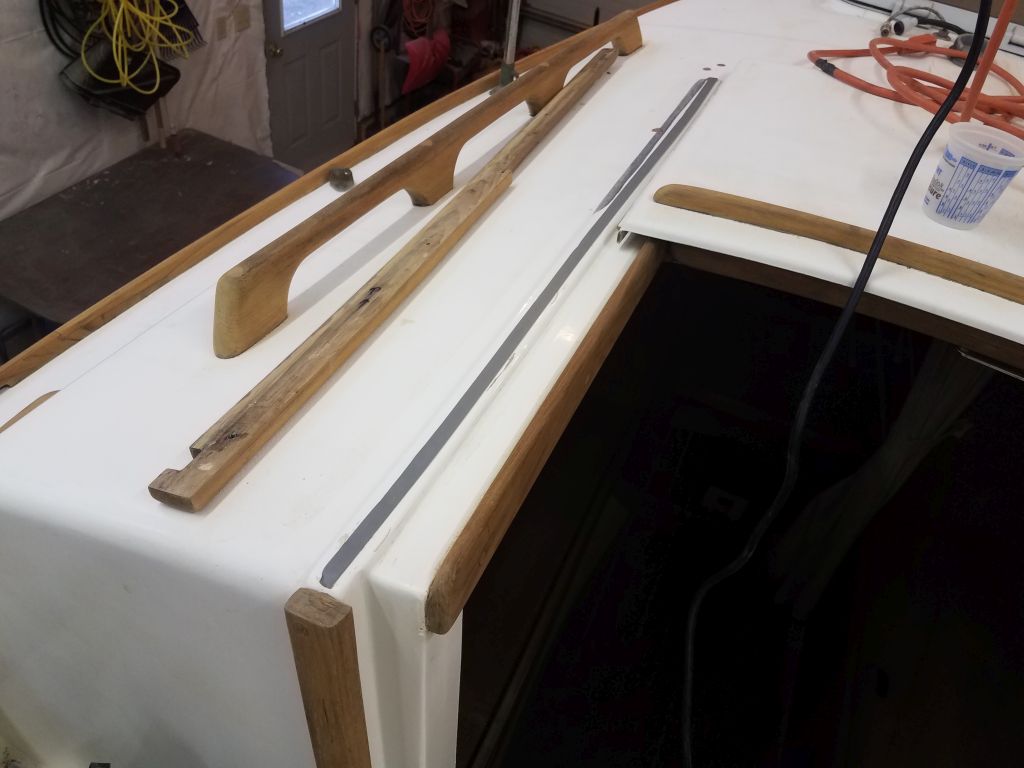
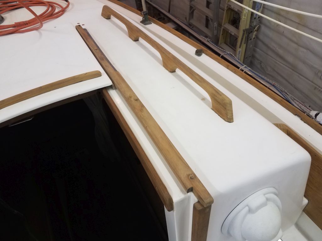
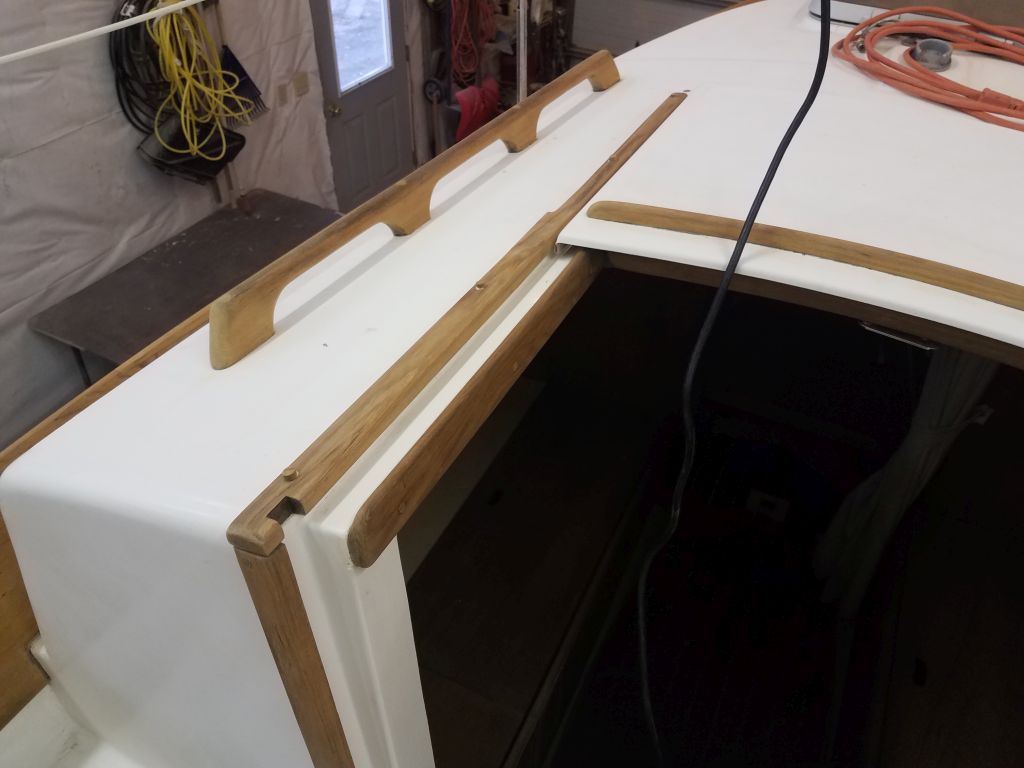
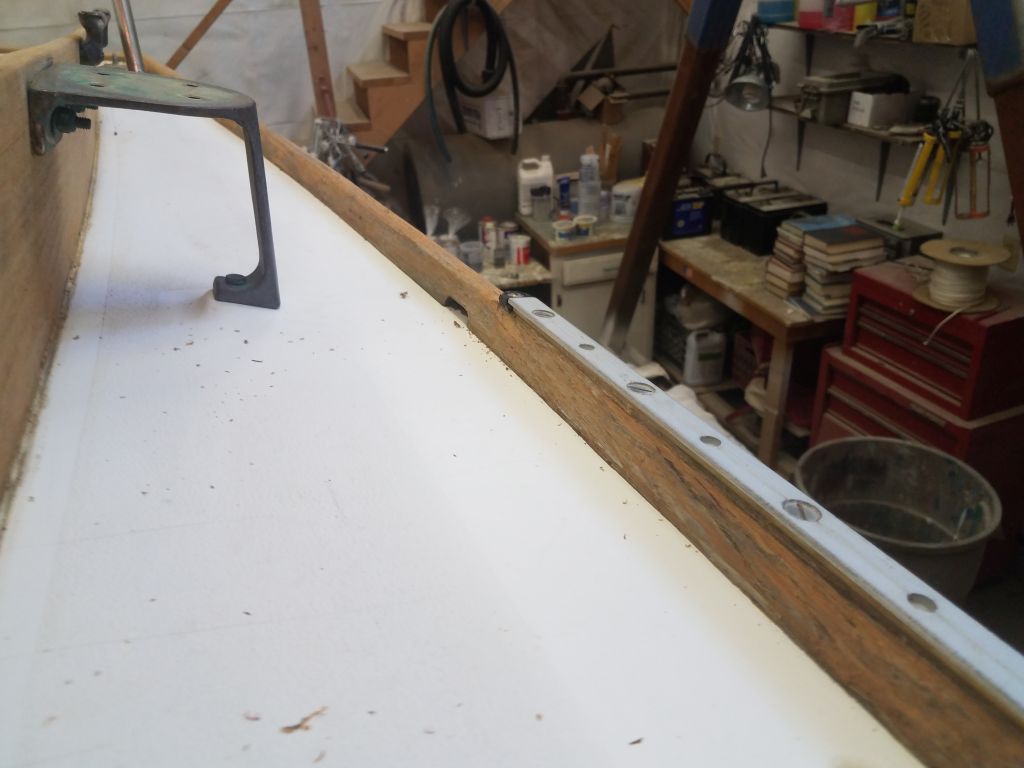
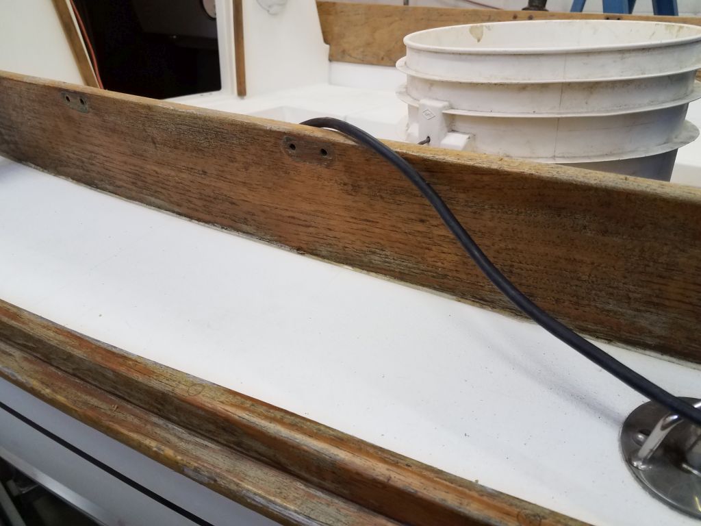
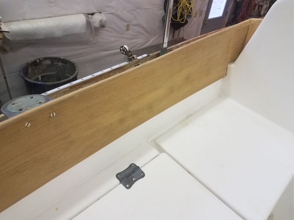
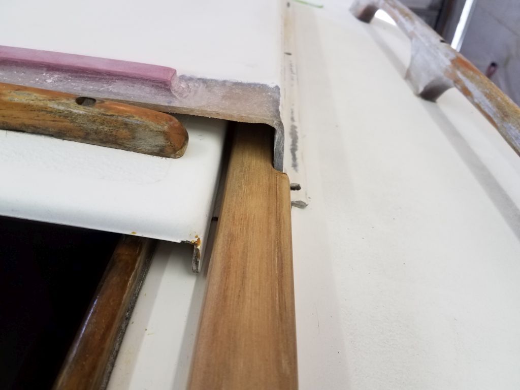
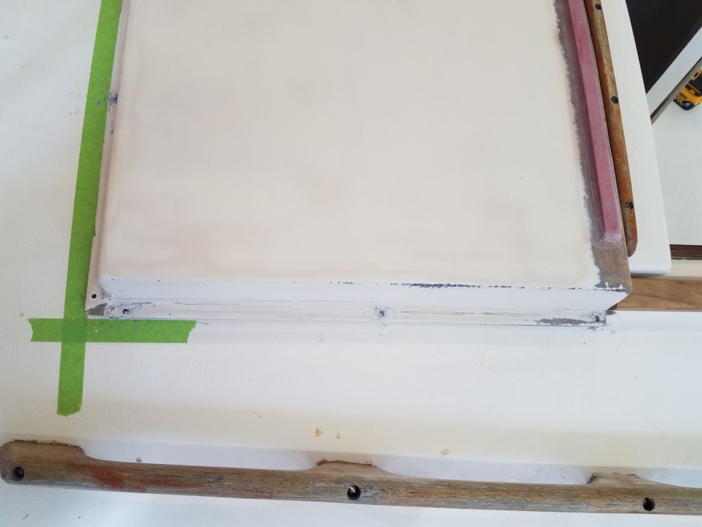
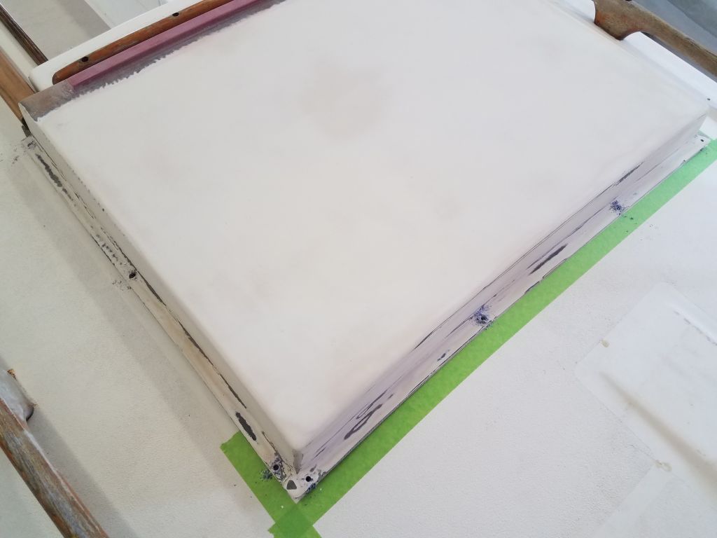
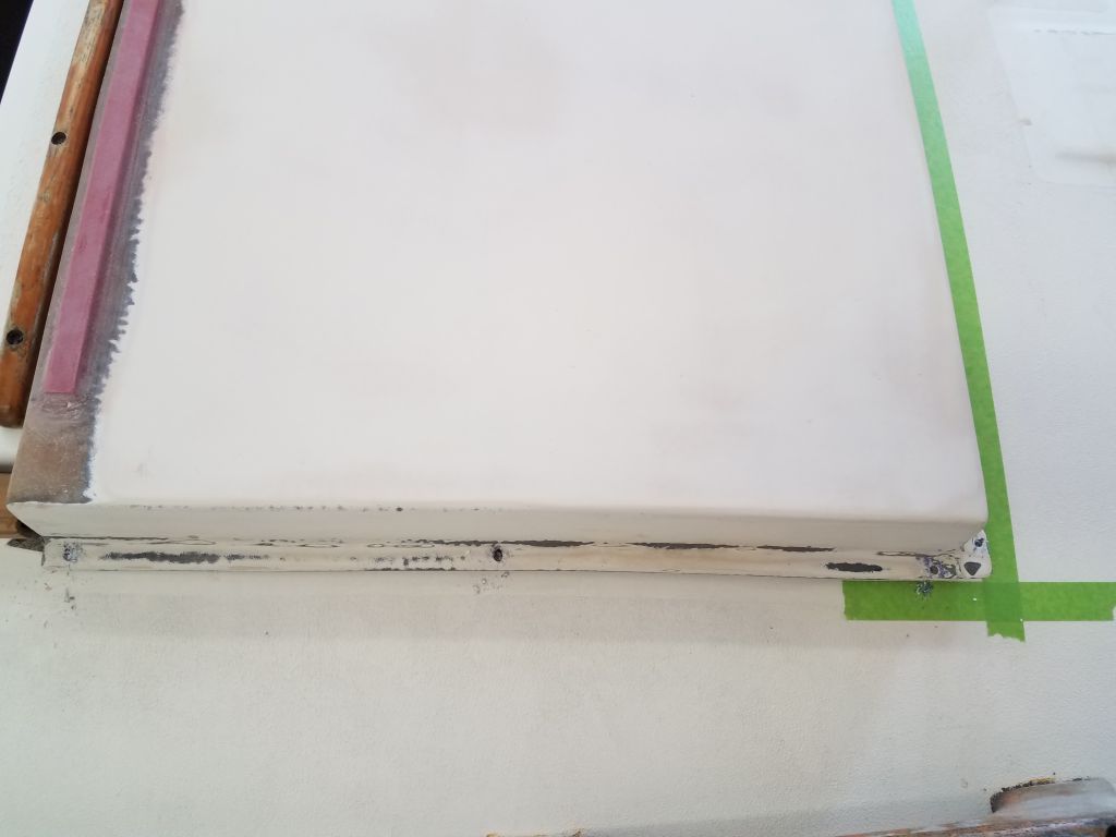
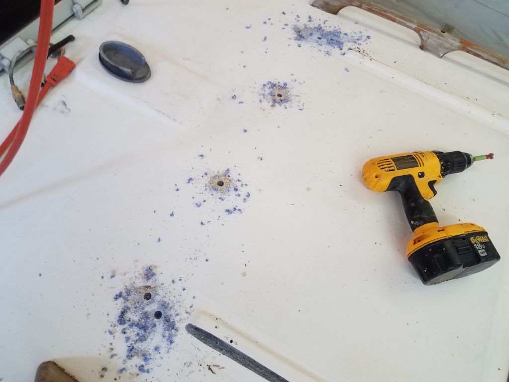
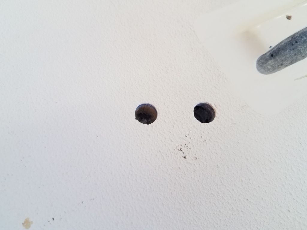
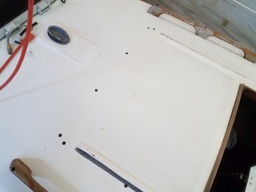
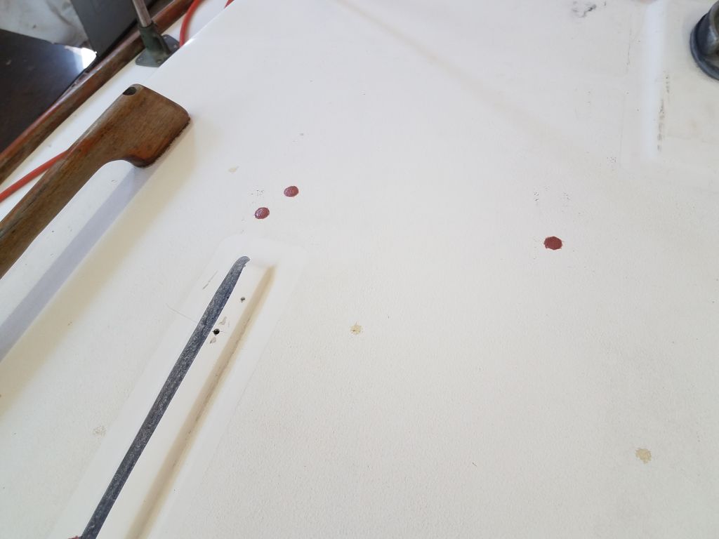
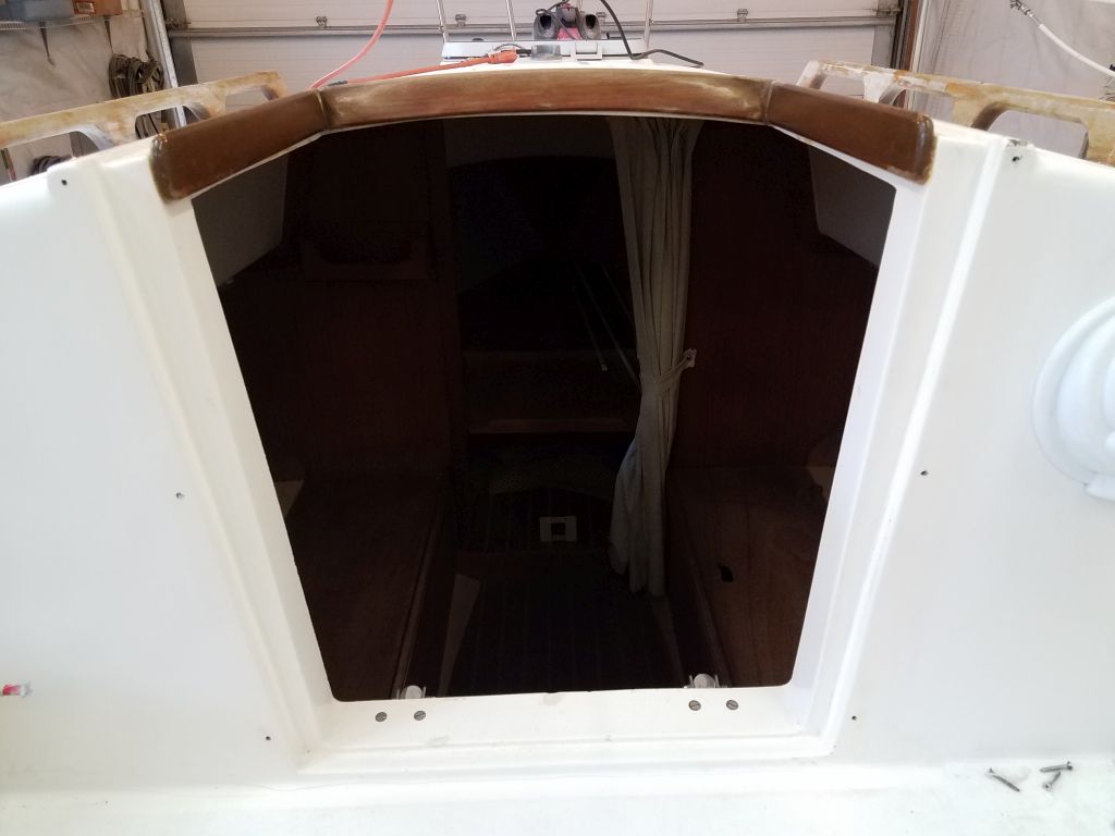
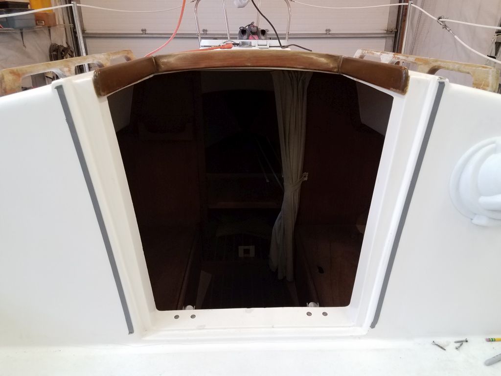
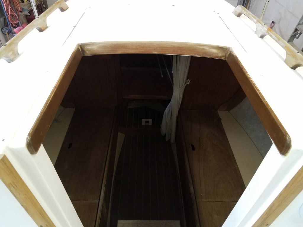
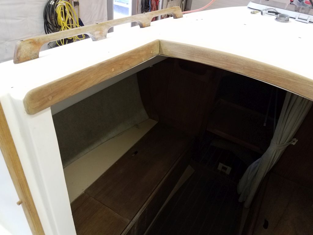
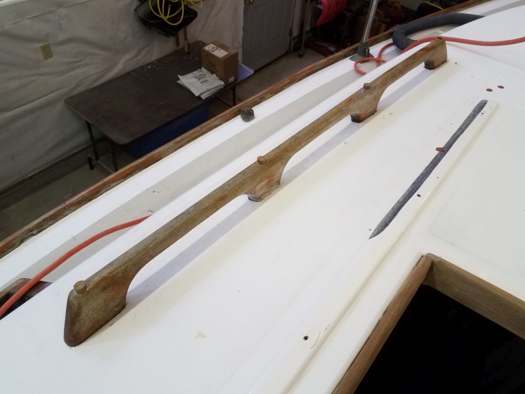
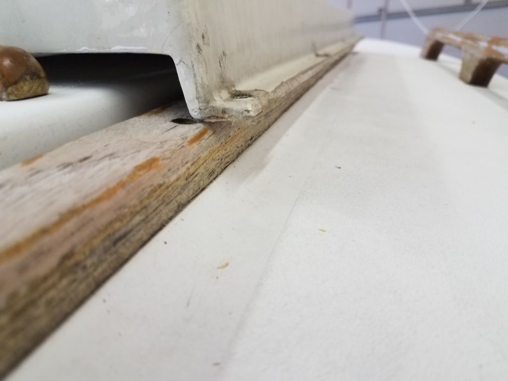
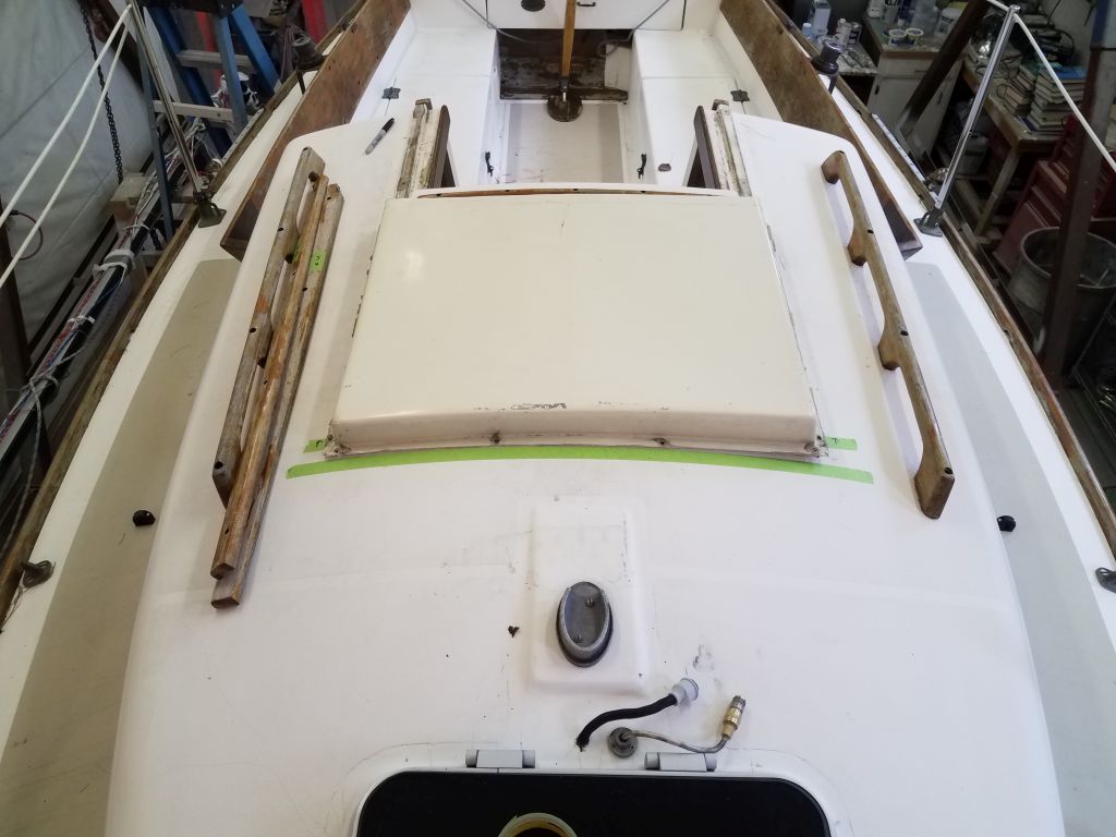
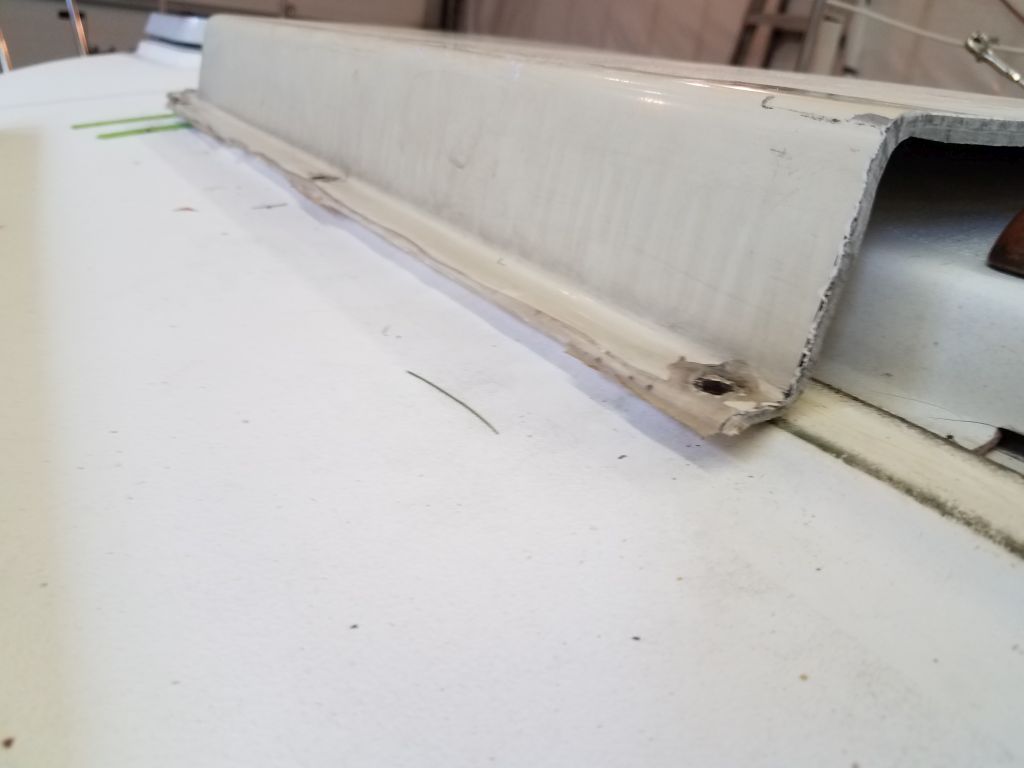
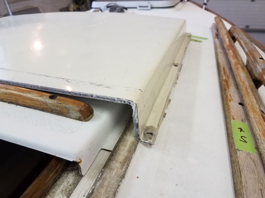
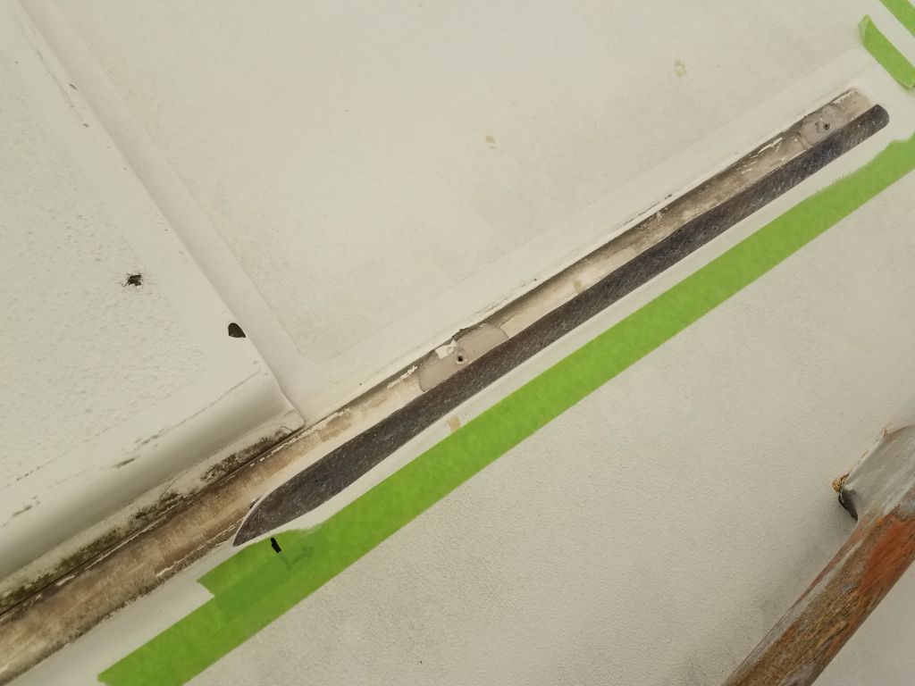
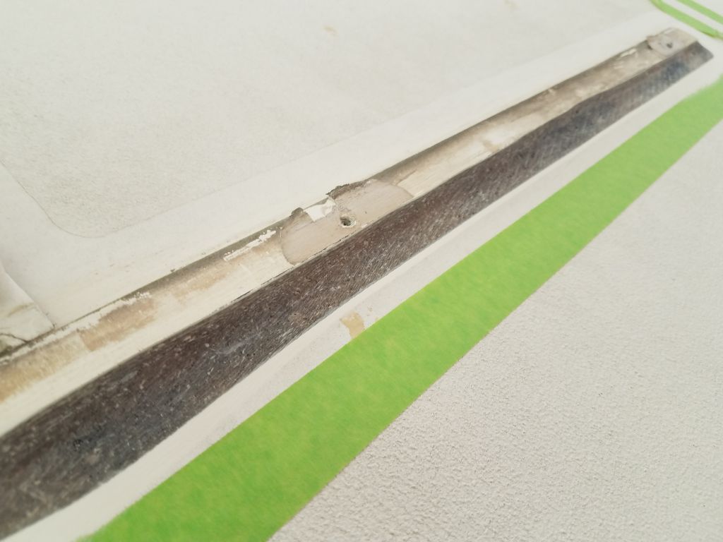
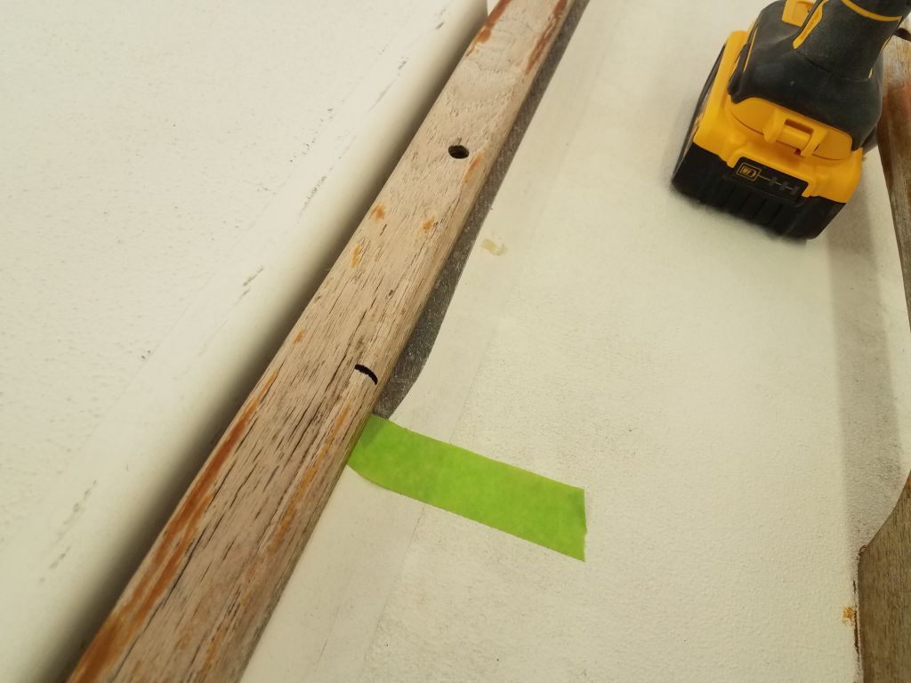
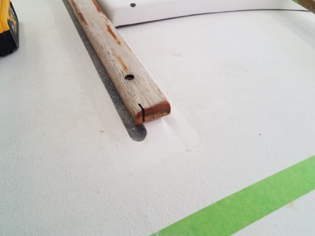
At the same time, I removed the teak trim on either side of the hatch; this was as easy as I’d anticipated, as there was little sealant and all the screws were exposed. I’d worry about the trim modifications later, but for now, with the interference removed, the sea hood flange sat nearly on the deck, though the little raised molded flats on either side of the hatch–designed to accept the wooden trims–prevented the hood from fitting properly on the deck itself. The raised flat was perhaps 1/4″ high, and I’d need to remove about the outer 1/4″ of its width, so the amount of material to remove was minimal.
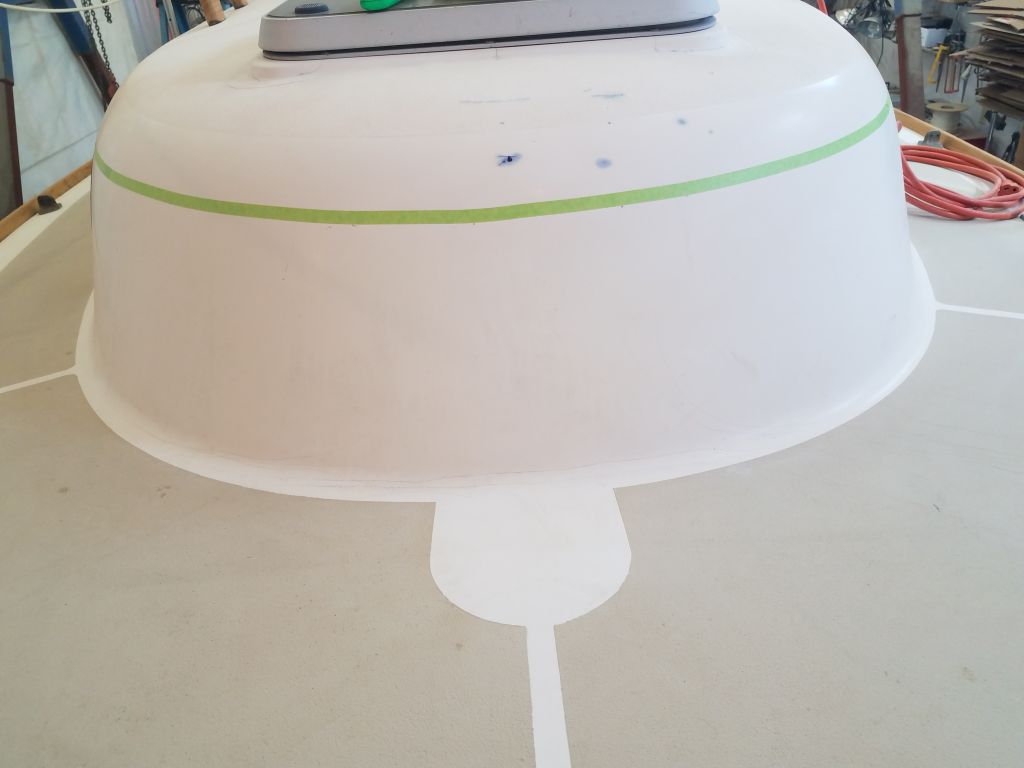
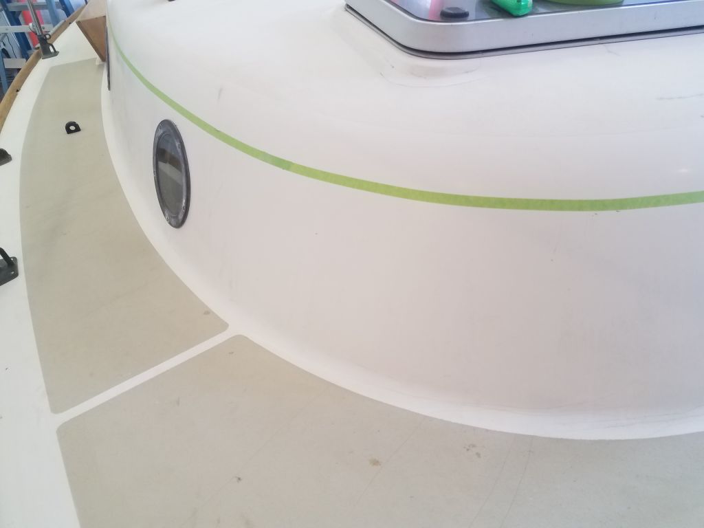
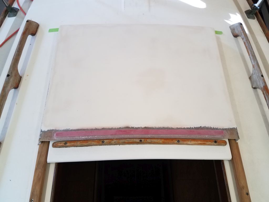
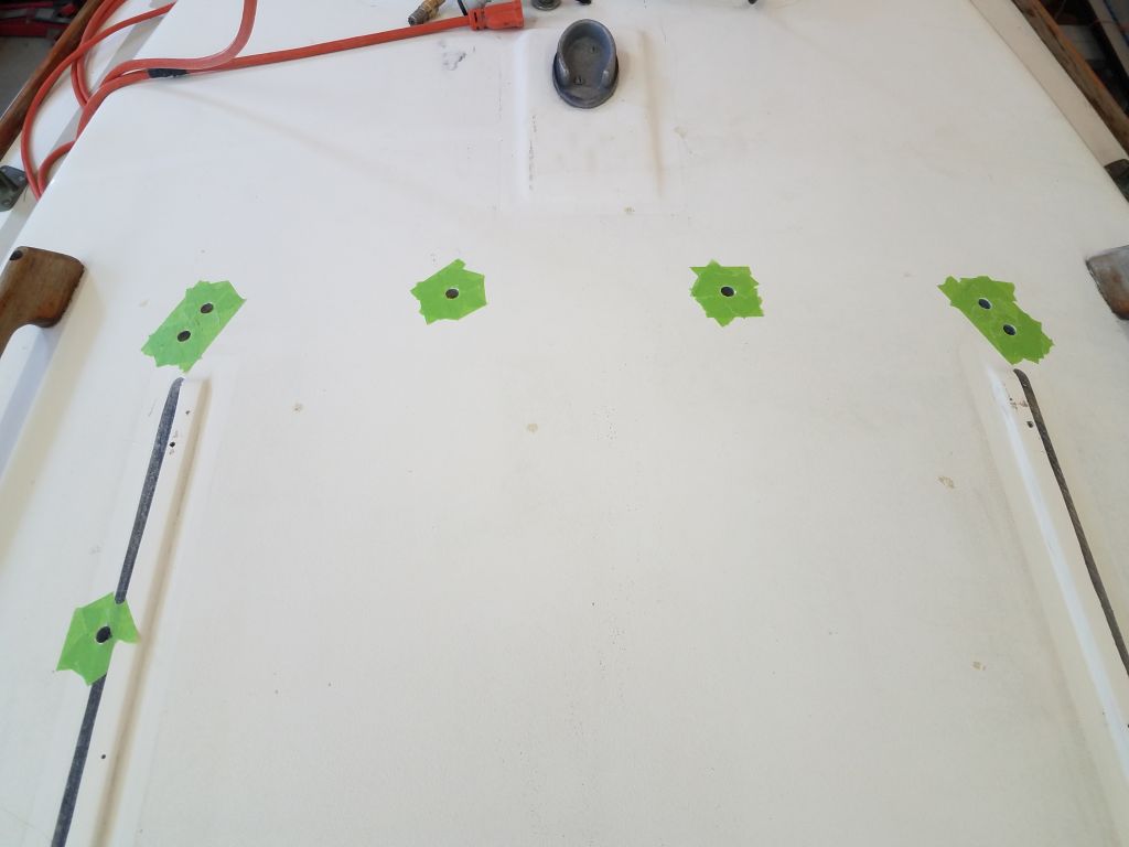
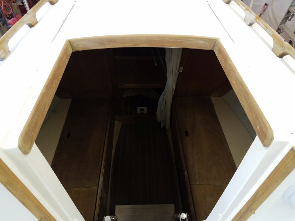
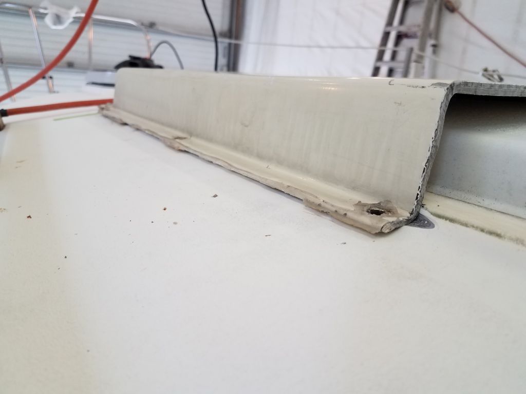
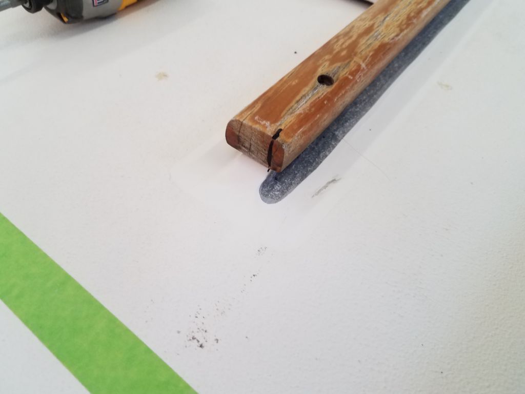
I figured those raised areas were solid fiberglass and therefore felt that it would be a pretty easy modification to trim the outer portions flush with the deck, which would allow the hood flange to rest flat on the deck; it appeared that the existing camber of the hood was a close (and workable) match to the cabin top. To prepare, I marked the deck at the outer edge of the sea hood flanges, indicating the drop-dead don’t-grind-beyond line, and made some marks to represent the inside of the sea hood, then drew reference lines where I needed to remove the material. Then, with a grinder and an angle flap disc, I carefully removed the offending material from each side, after which the hood fit quite well, as I had hoped.
Happy with those modifications, next I temporarily reinstalled the wooden trim pieces and marked where I needed to cut them as well, before removing them again and taking the whole arrangement down to the bench for some final work.
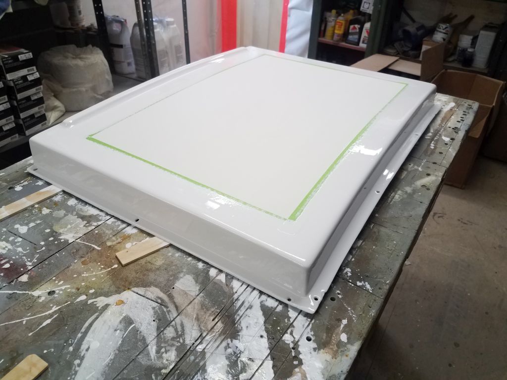
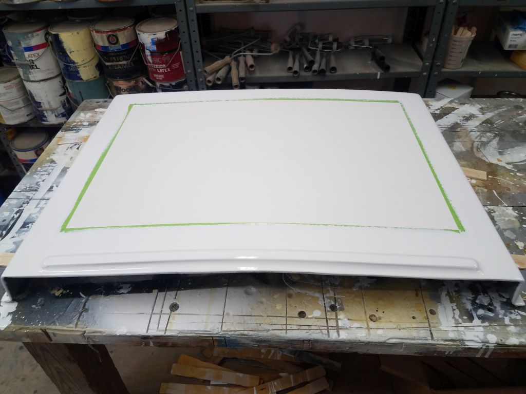
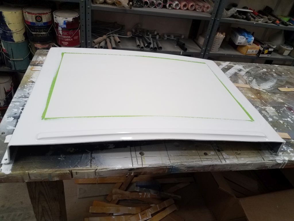
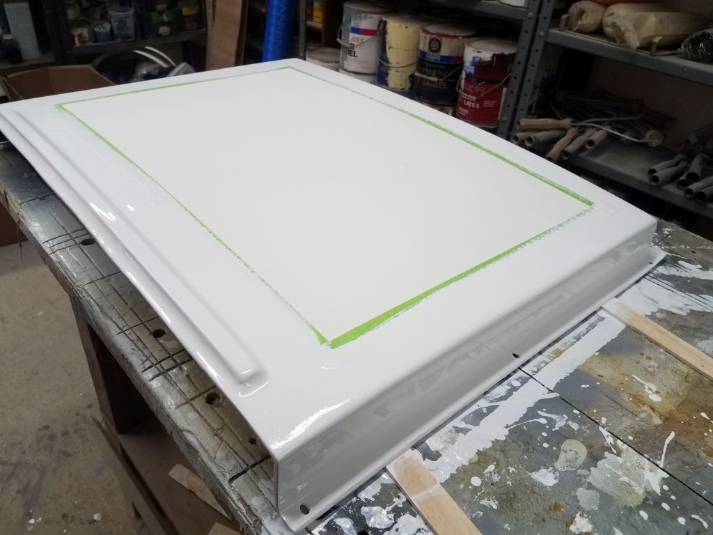
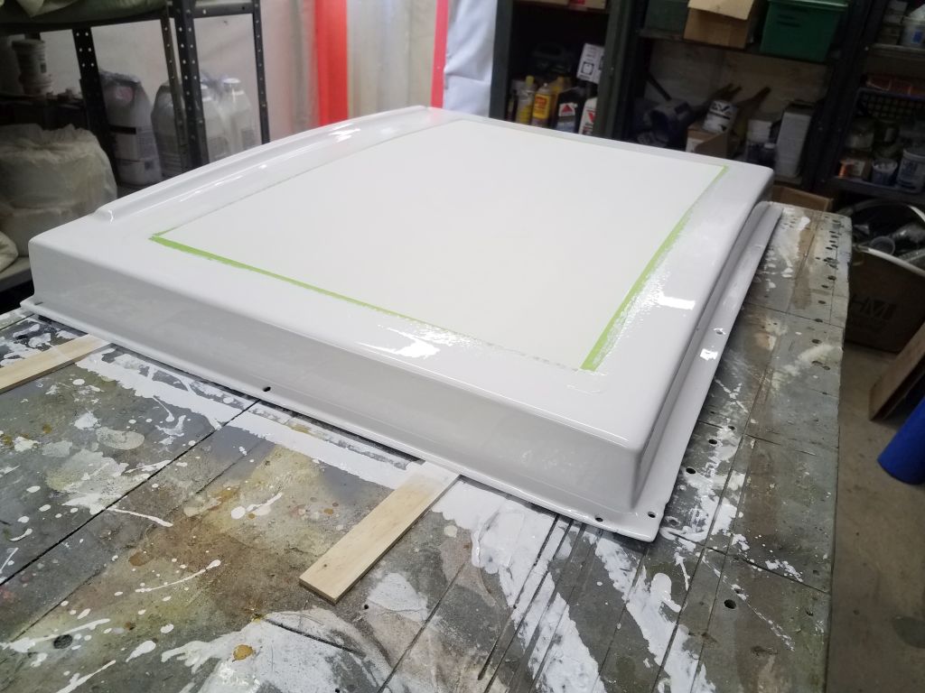
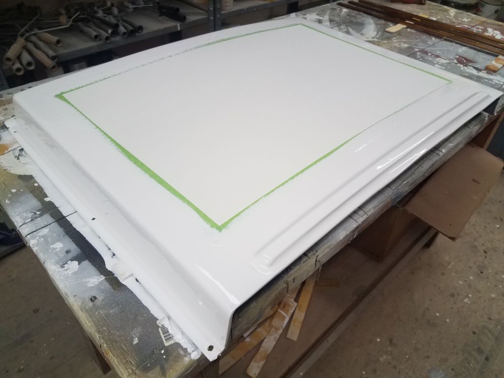
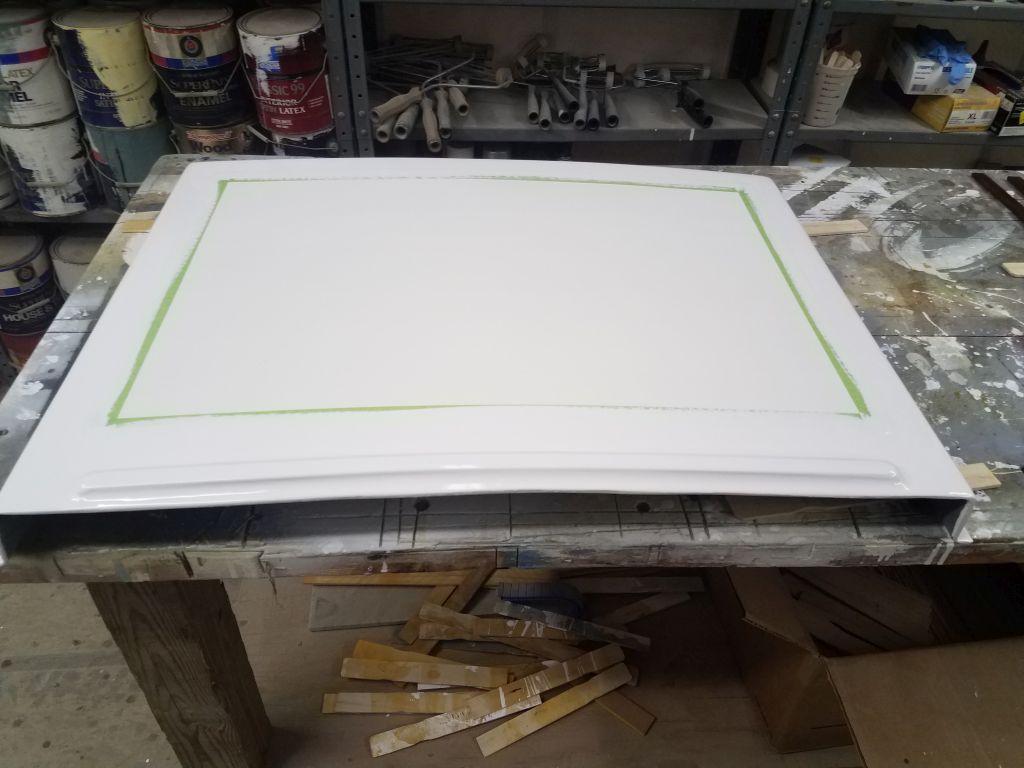
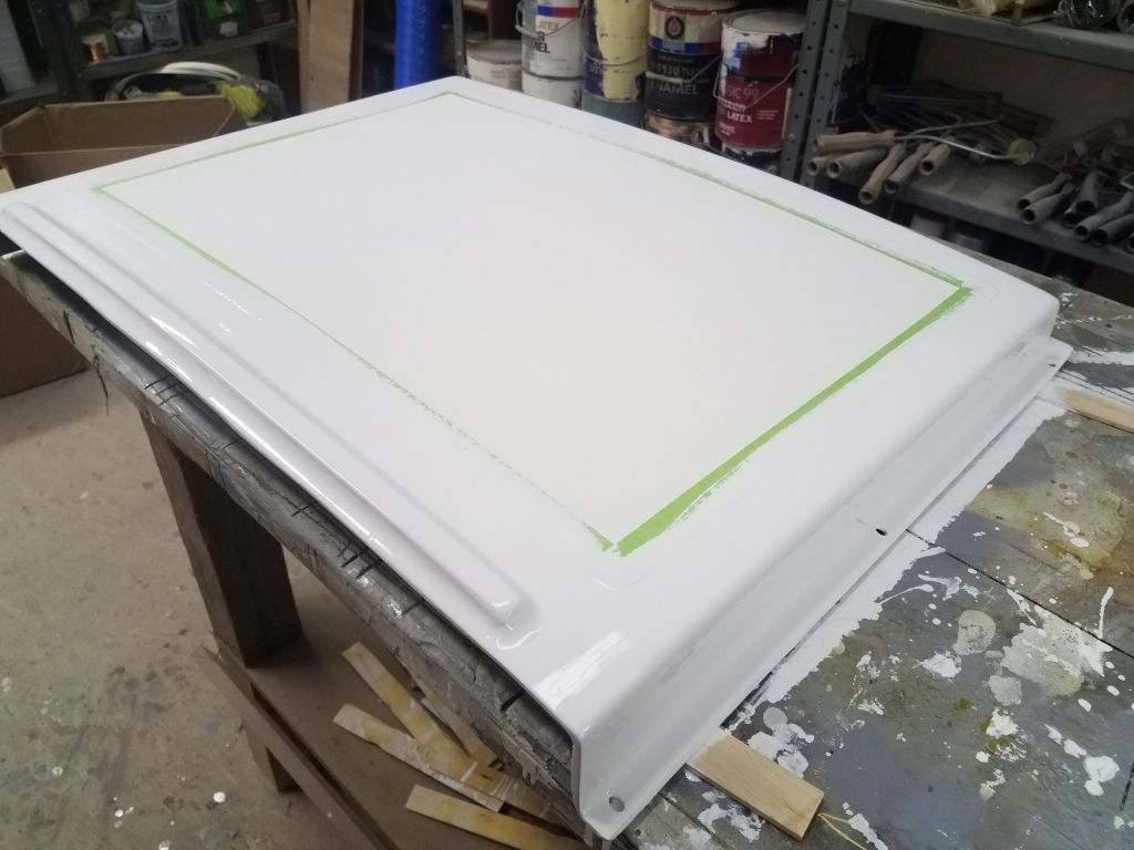
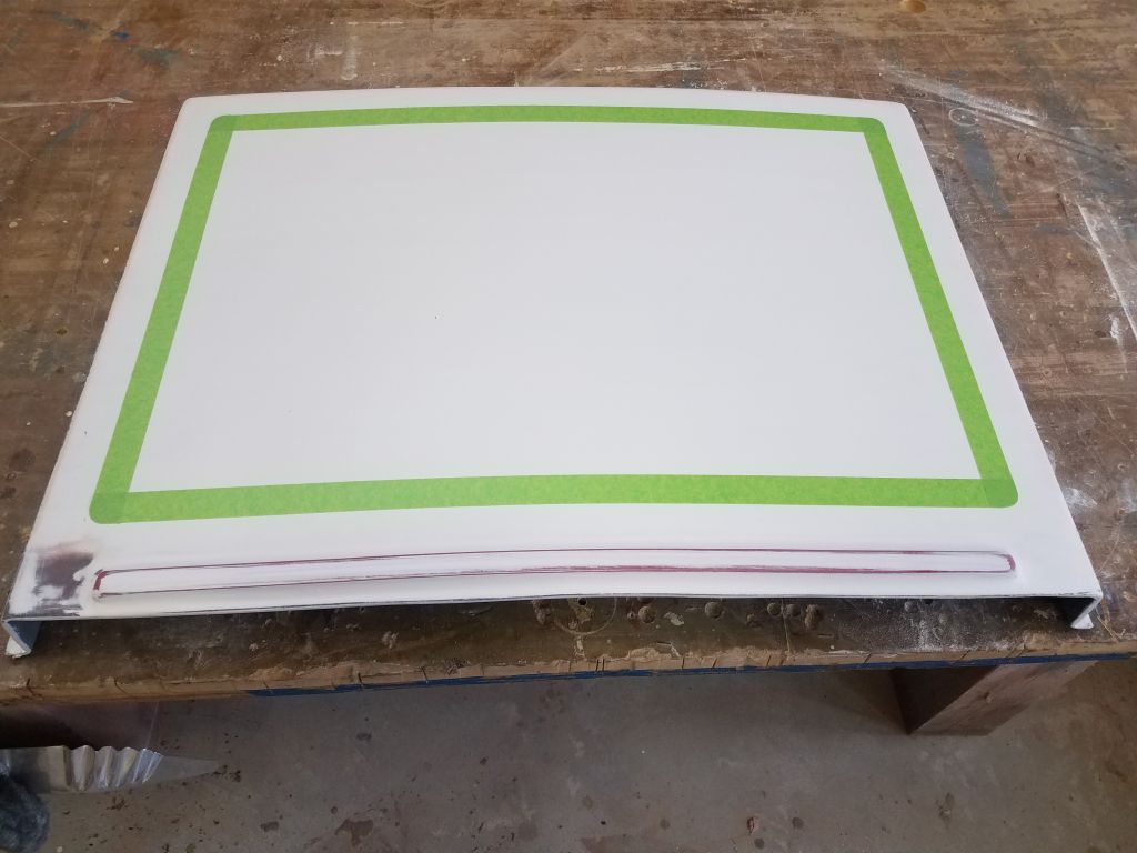
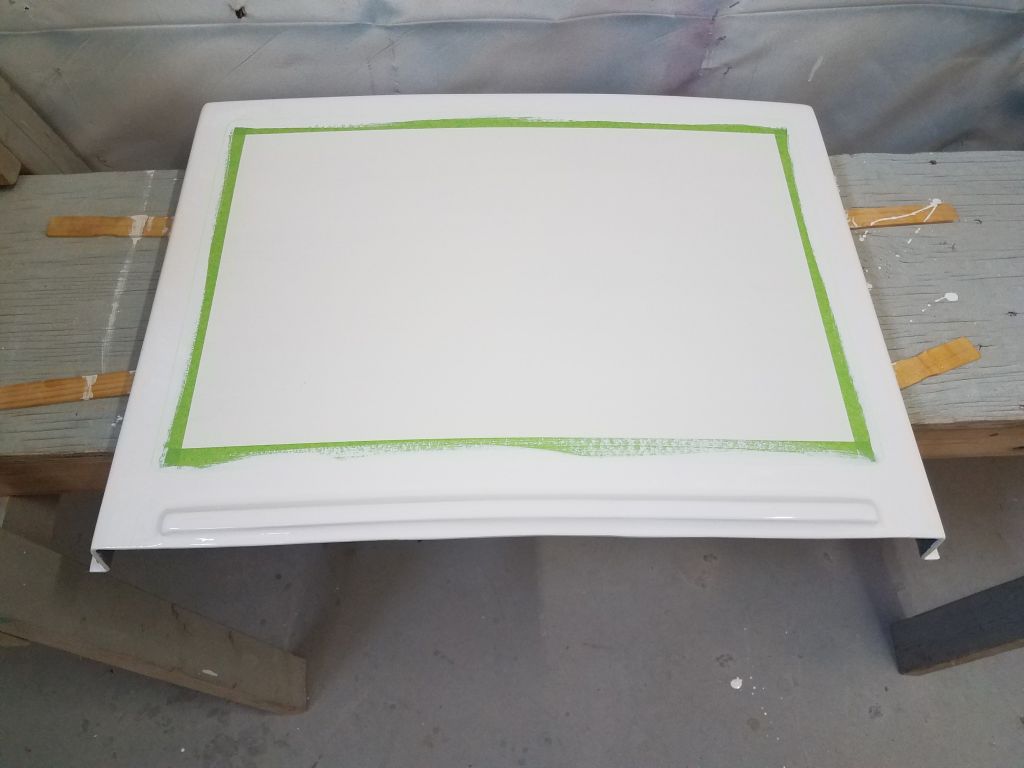
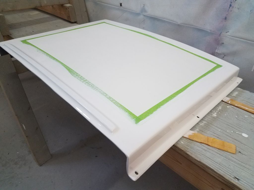
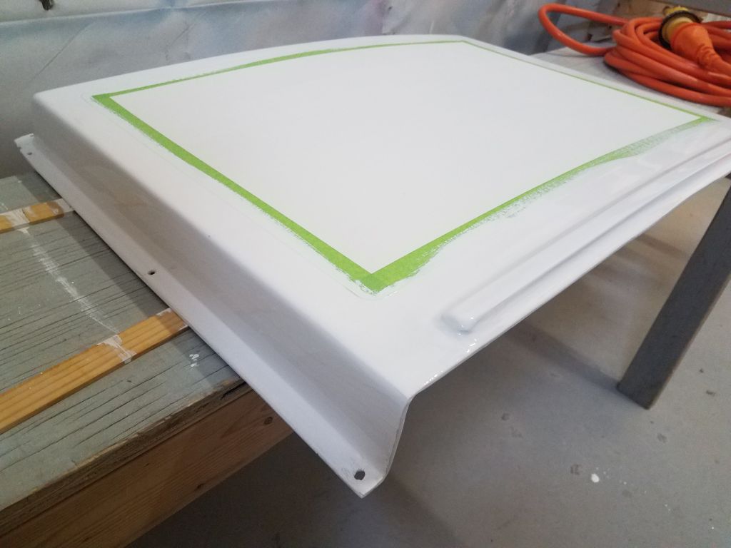
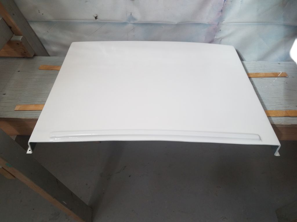
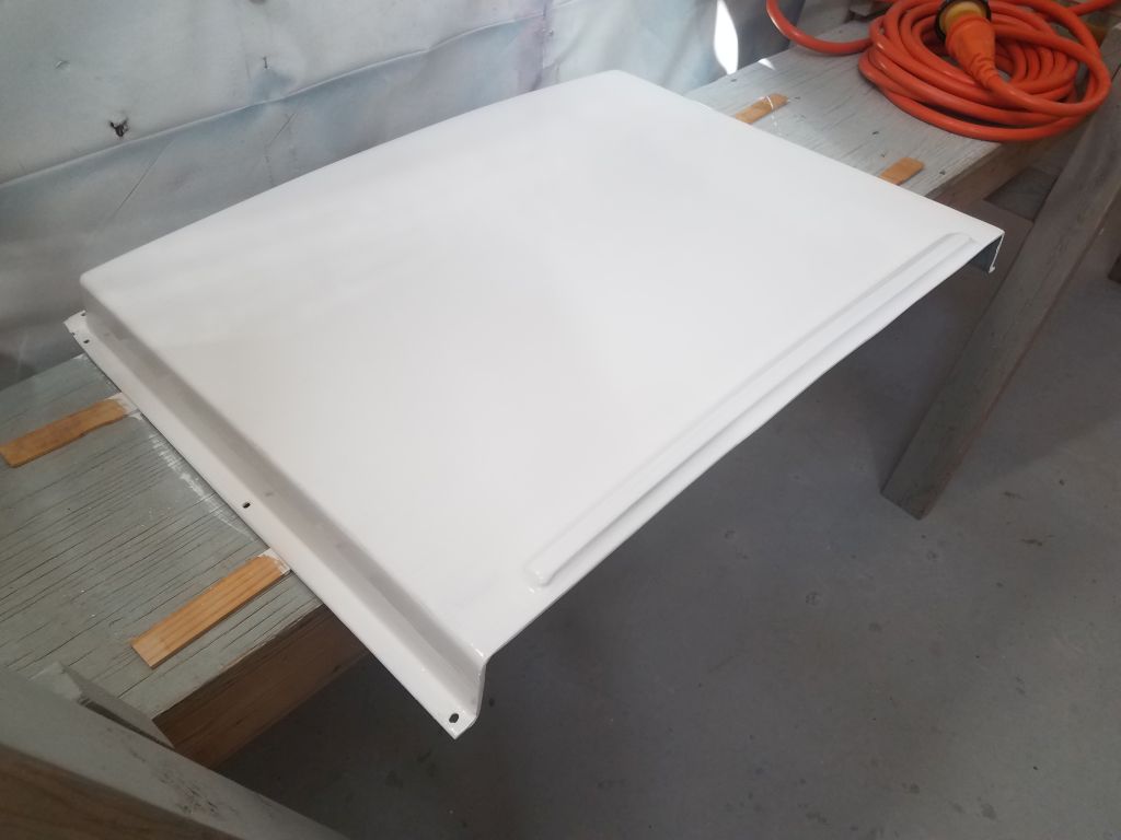
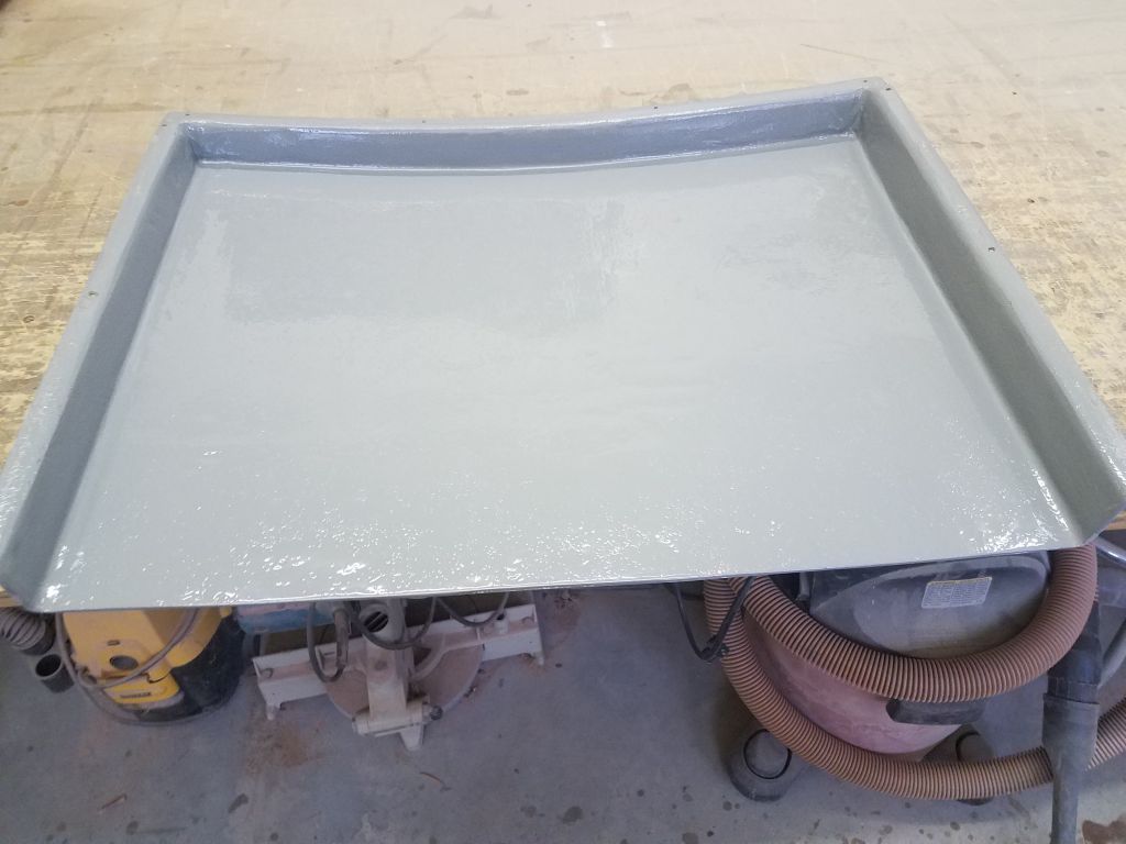
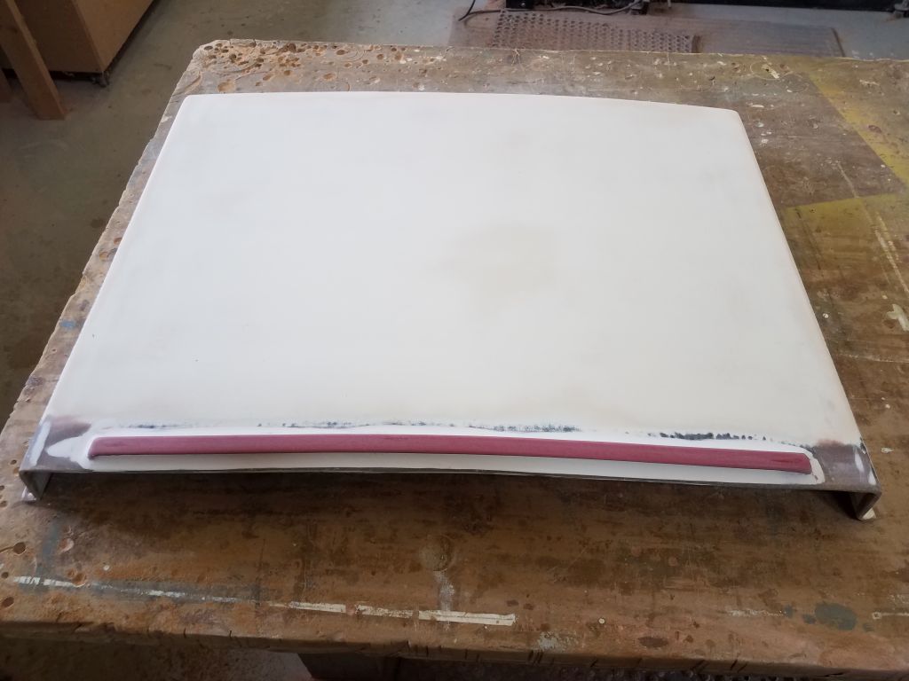
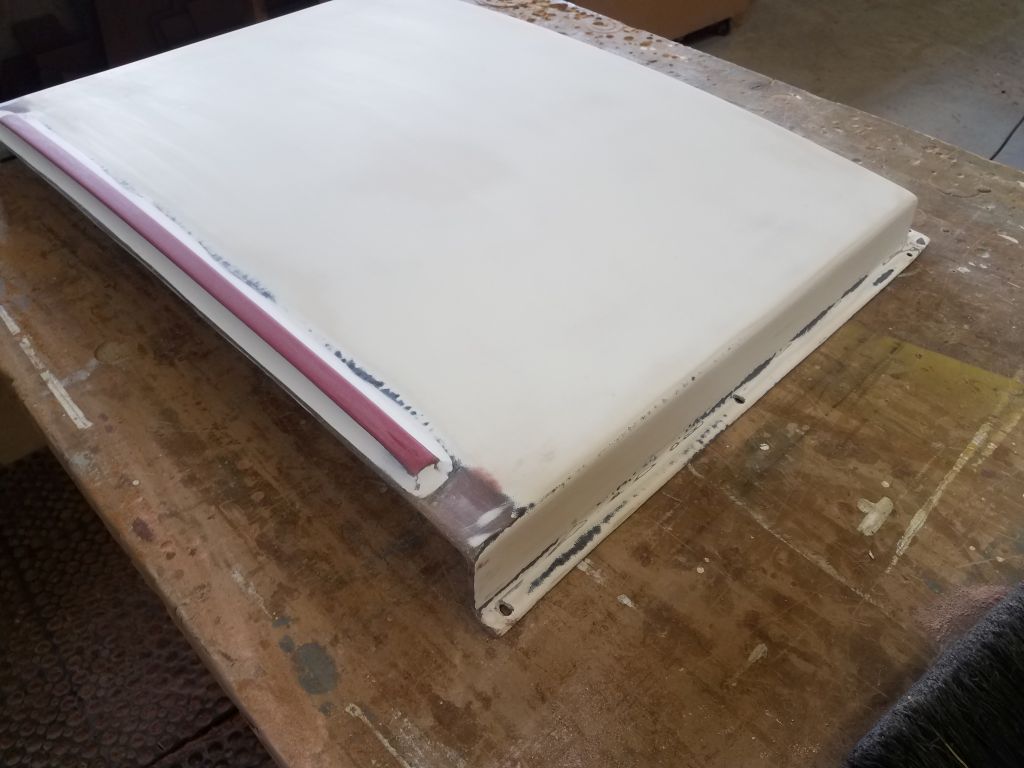
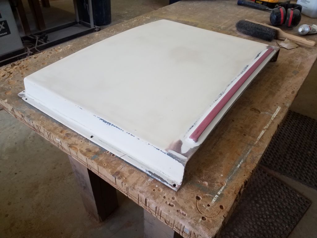
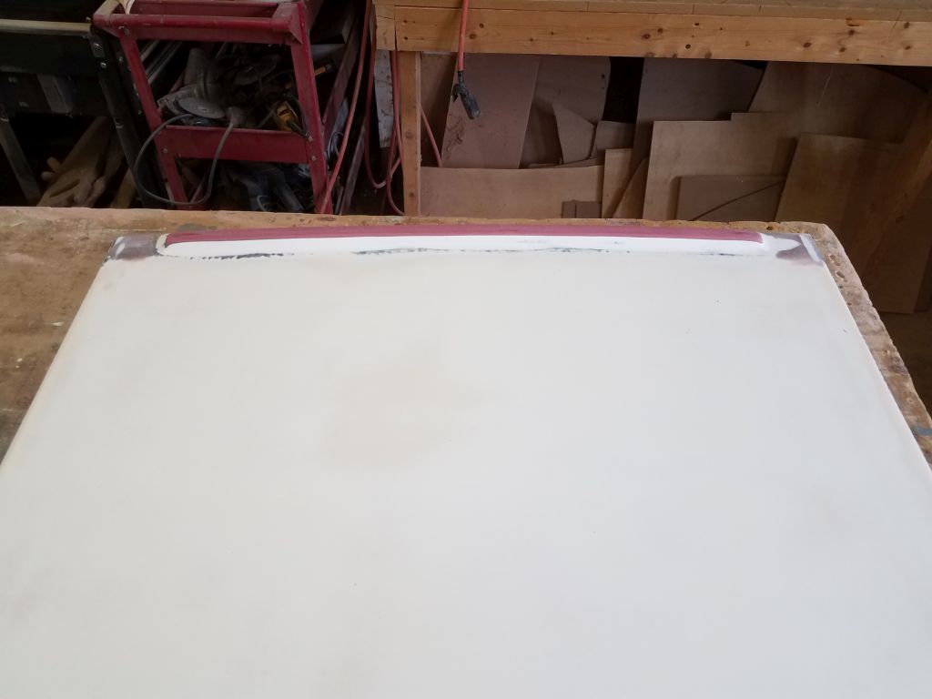
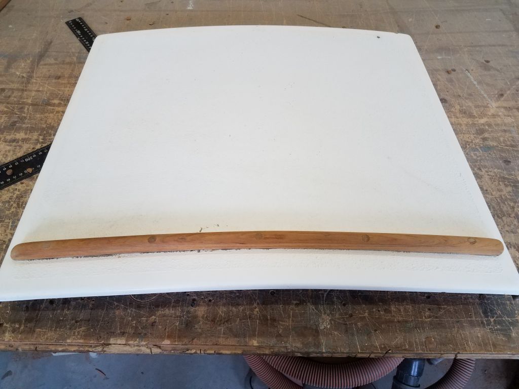
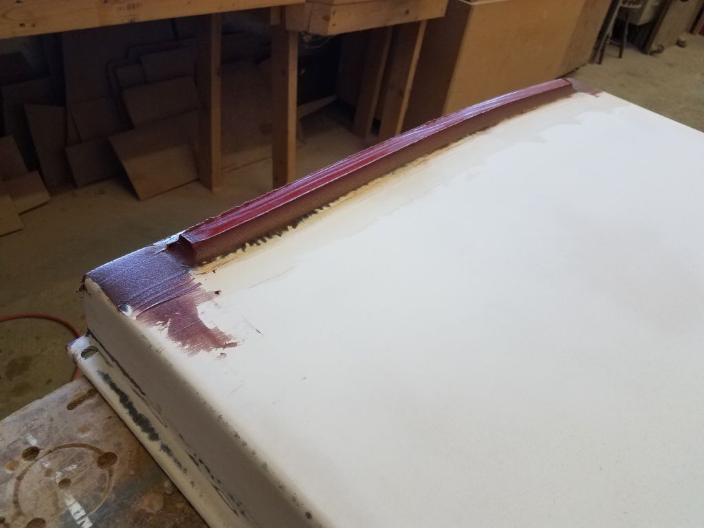
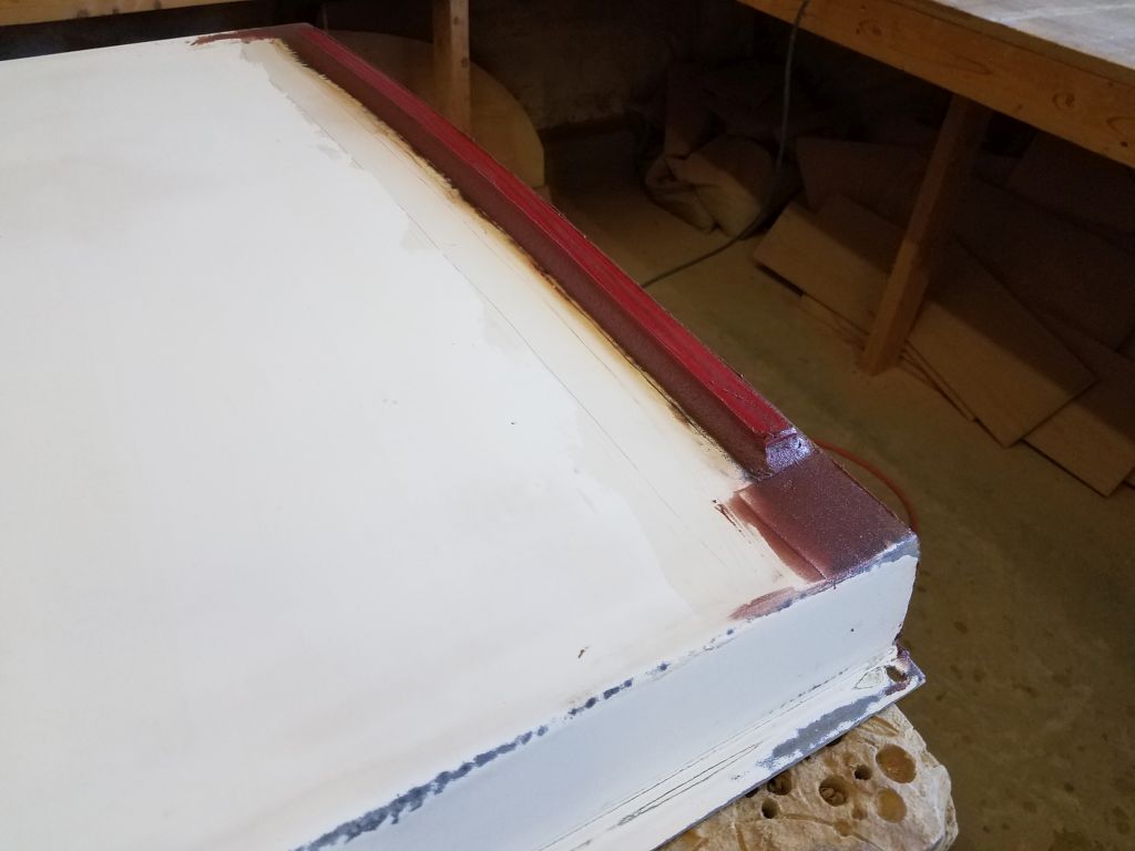
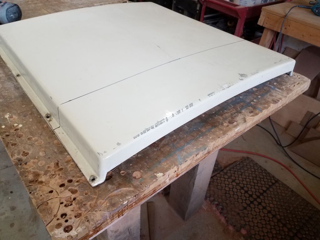
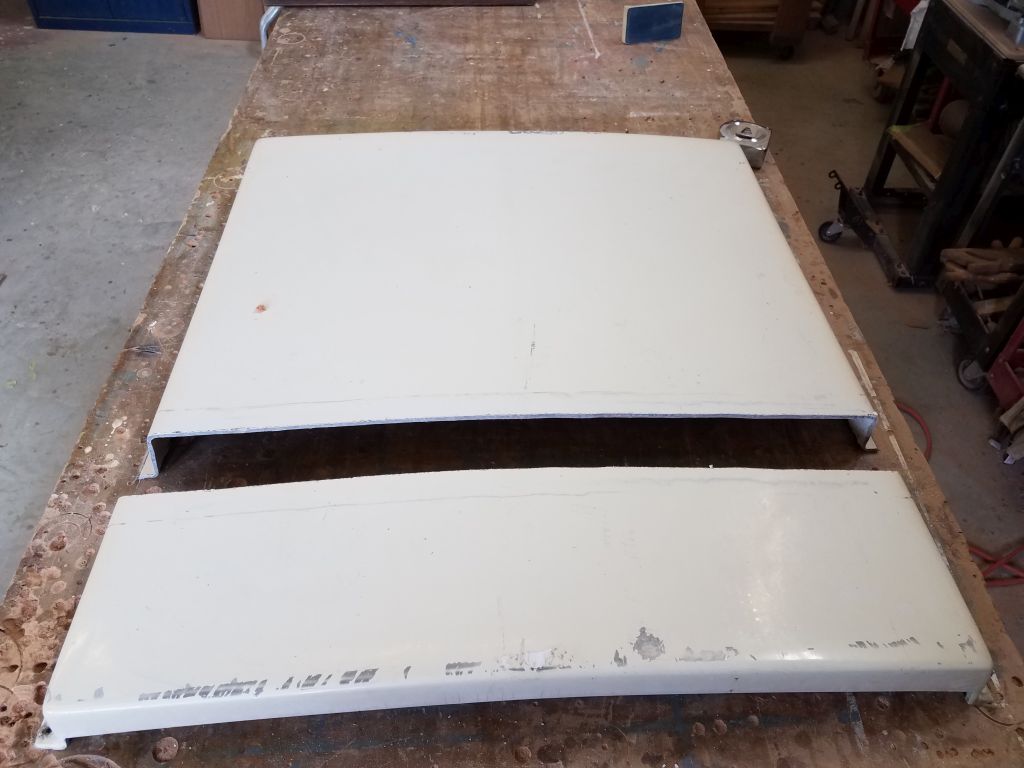
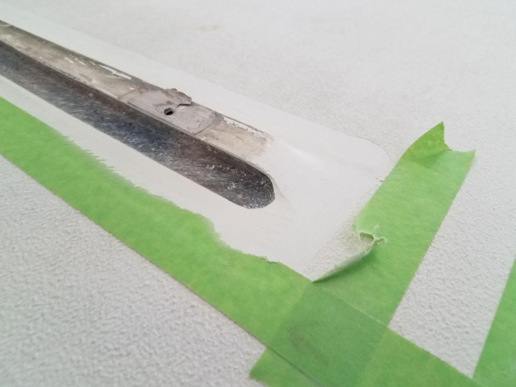
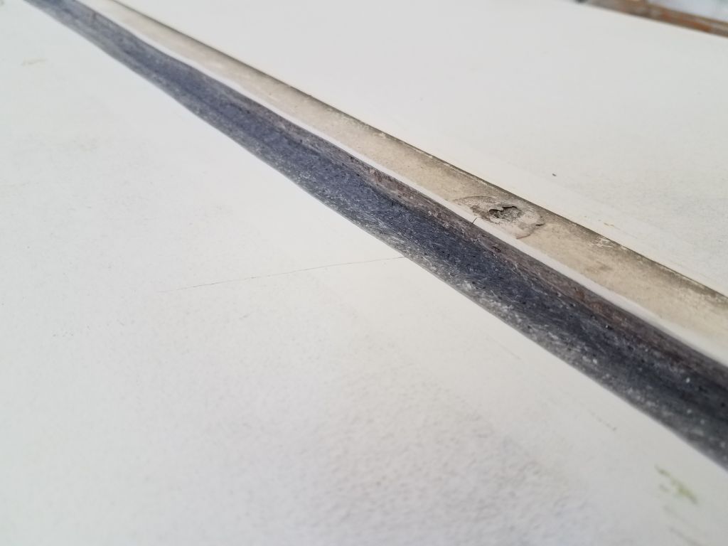
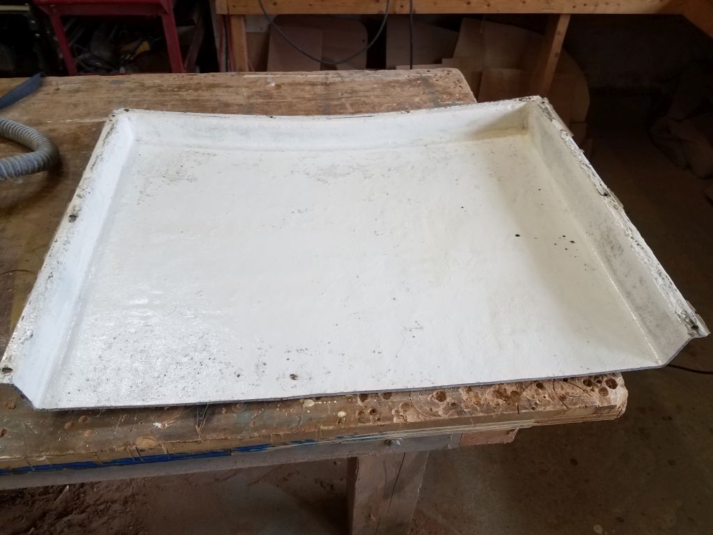
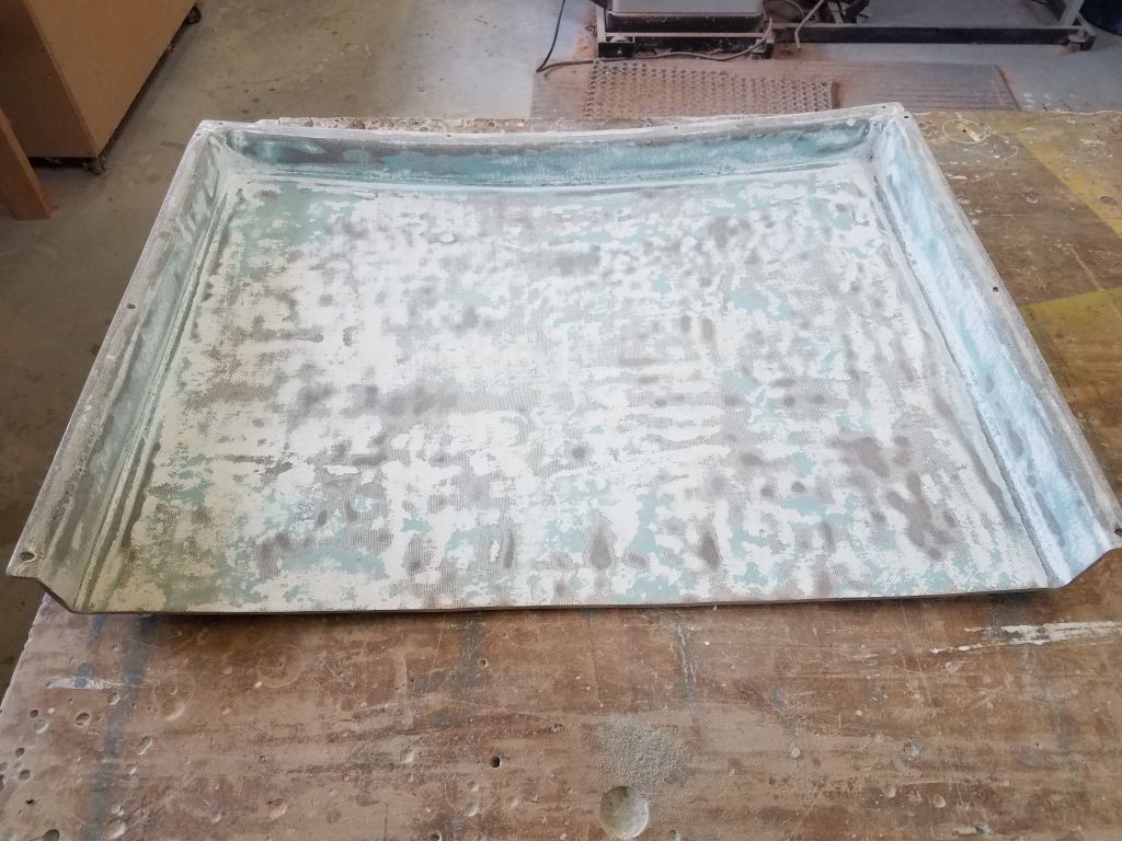
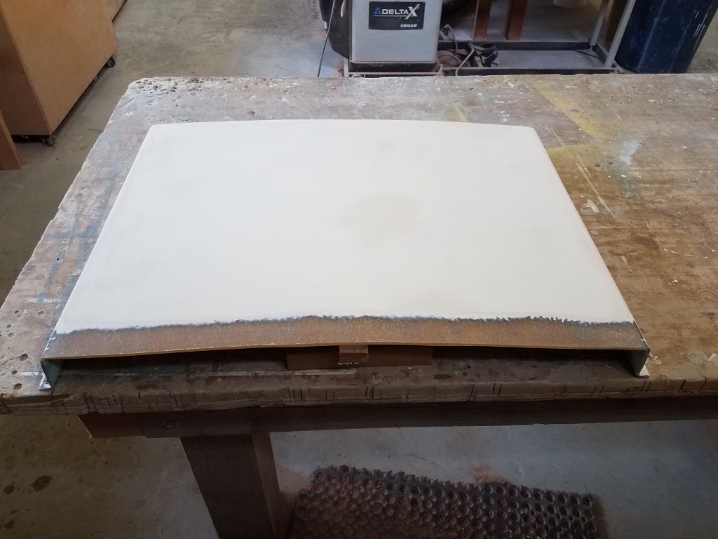
To prepare the sea hood for final touches and refinishing, I first sanded off the old paint from the underside, sanding enough to ensure good bonding but not overly worrying about removing all the paint since this part of the hood would never be visible once installed. On the top surfaces, I sanded away a layer of old paint and primer–both were in good condition and sound, but the color was an off-white that wouldn’t work as is–and sanded smooth the original gelcoat beneath. At the trailing edge, I removed a strip of the gelcoat down to bare laminate to prepare the surface for some needed reinforcement, as the hood was a bit flimsy there. I had hoped to build a small extension beneath the opening, as per the original, but the hood was now a close fit with the sliding hatch and there simply wasn’t room, so instead I planned to add a stiffener on the top edge.
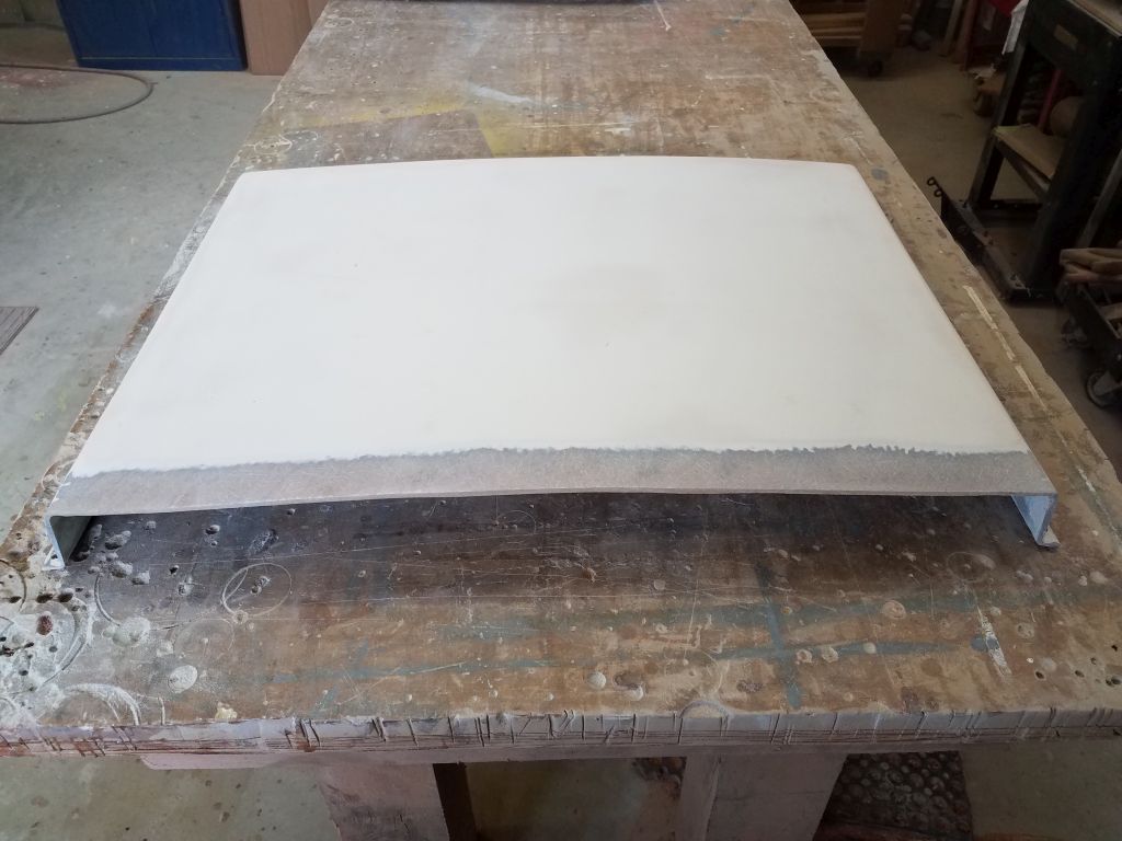
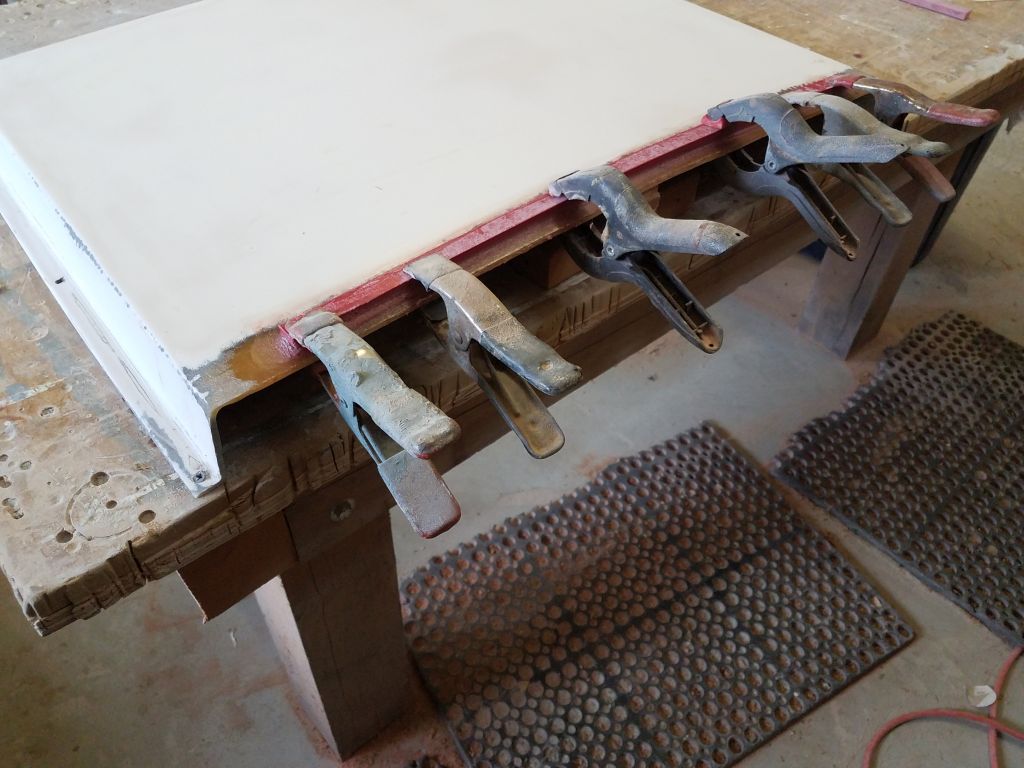
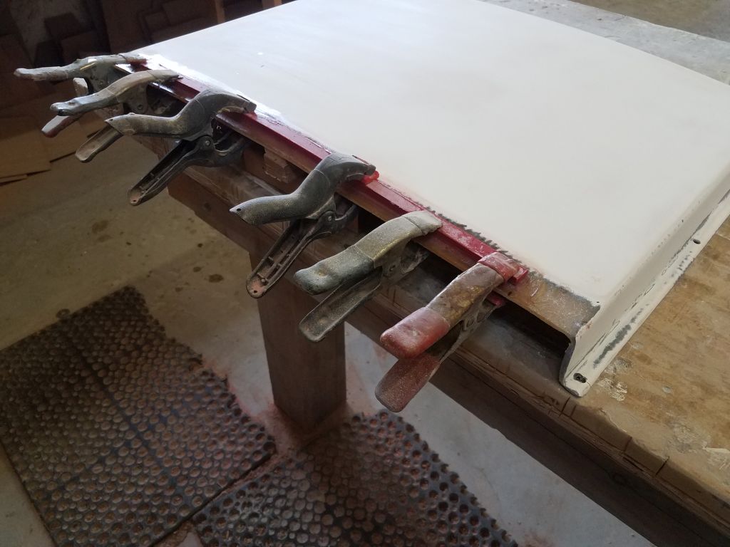
For that, I cut a strip of 3/8″ prefab fiberglass to fit, and after final preparations glued it in place with epoxy adhesive and epoxy fillets. To hold the shape of the hood, I temporarily screwed the flanges to the bench, and added some support beneath the center of the opening. Once the epoxy securing the new brace cured, it would hold the curvature nicely. At that time, I also planned to shape and blend the new reinforcement into the adjacent areas for a seamless and intentional appearance.
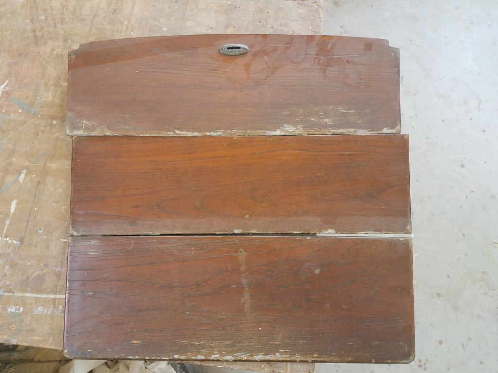
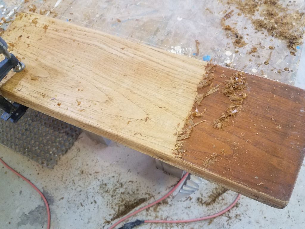
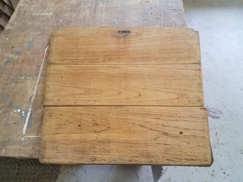
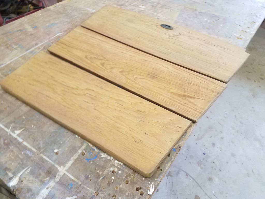
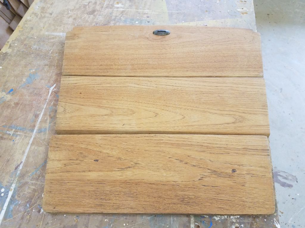
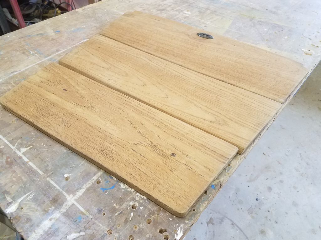
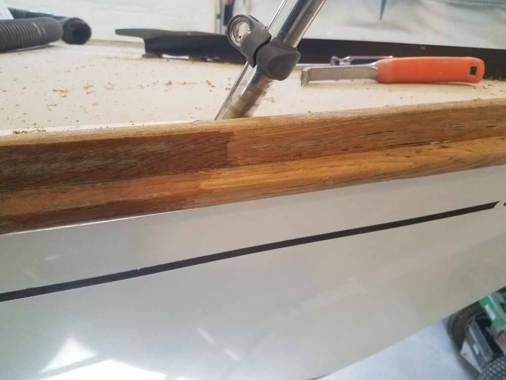
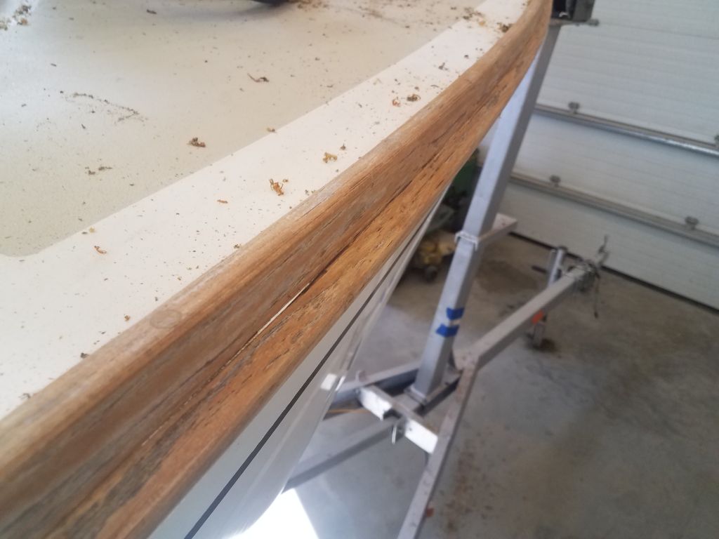
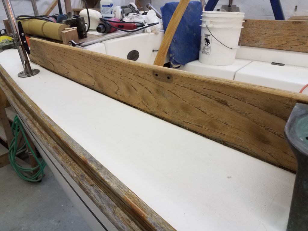
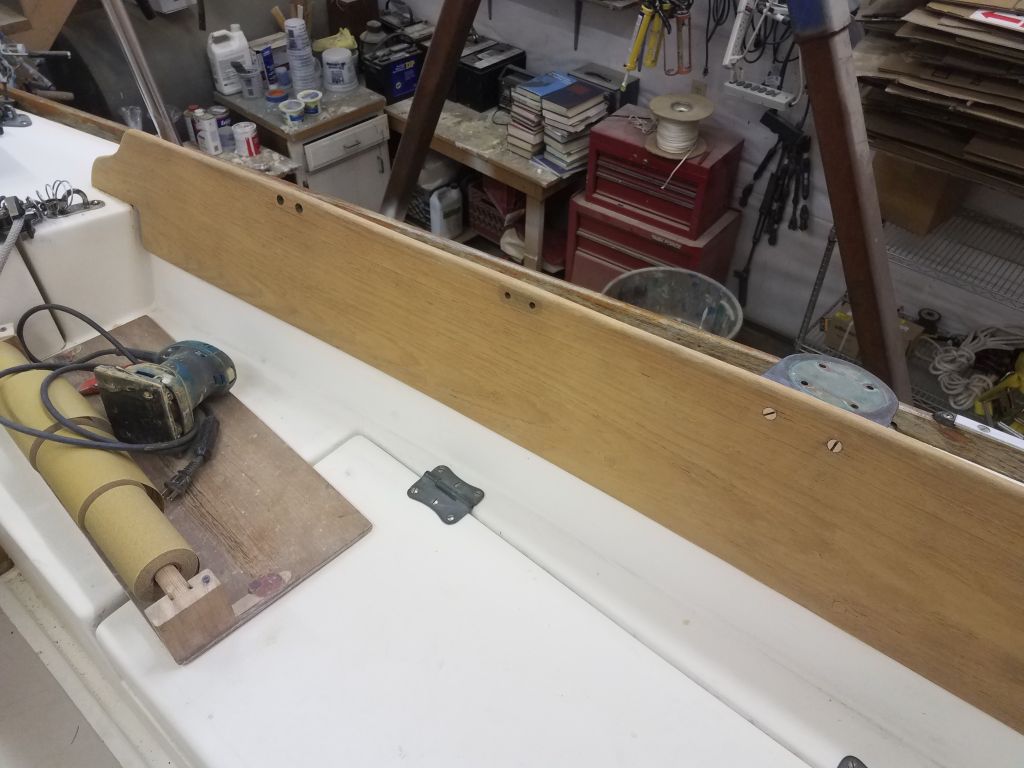
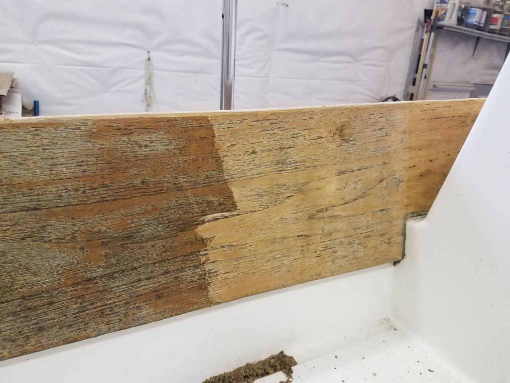
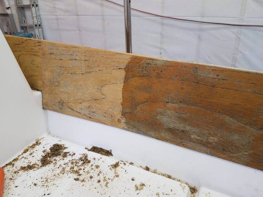
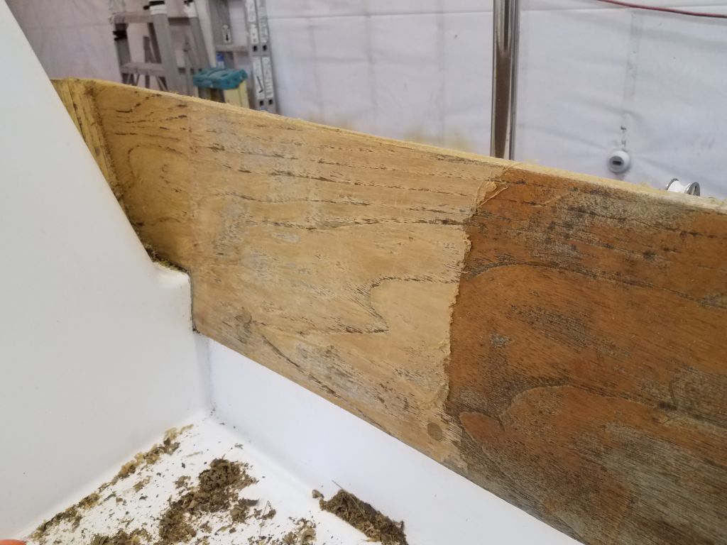
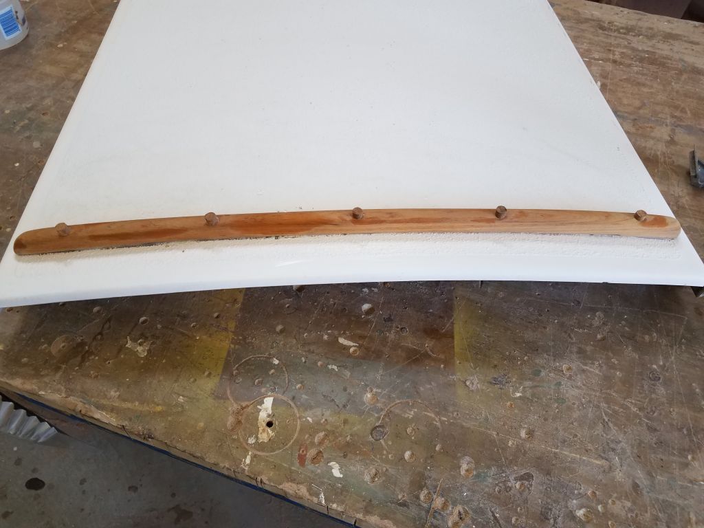
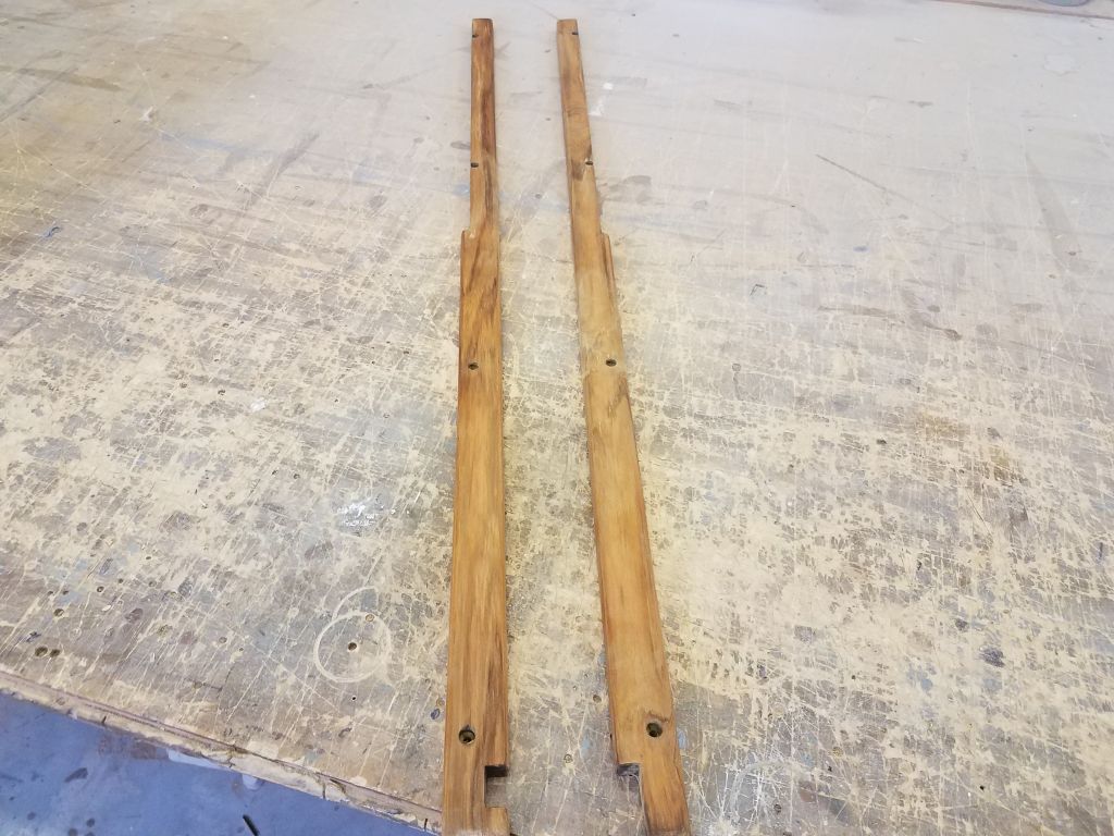
Finally, I made the cuts on the teak trims so they would clear the sea hood. With these pieces conveniently on the bench, I took a moment to sand off the old finish as needed, back to clean wood.
Total time billed on this job today: 4.5 hours
0600 Weather Observation: 32°, mostly cloudy. Forecast for the day: Mostly cloudy, 55°