Monday
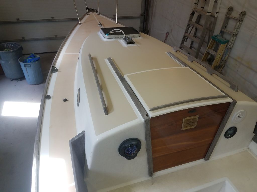
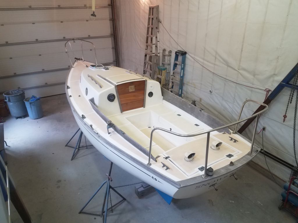
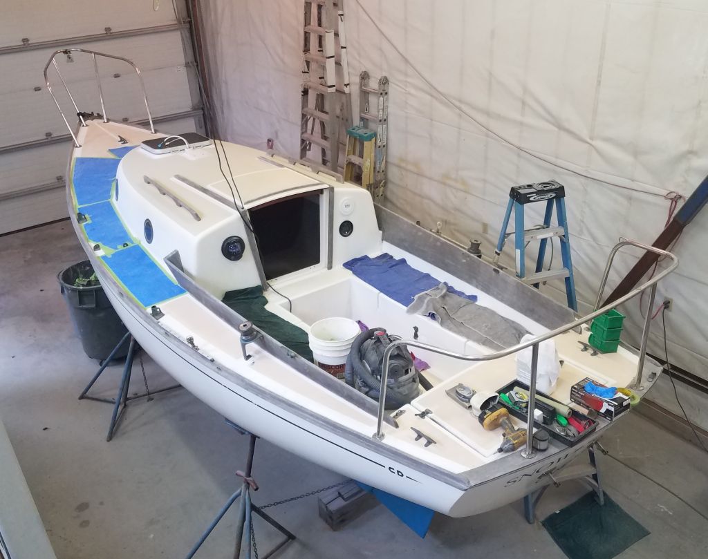
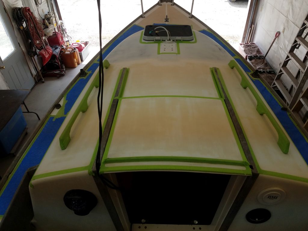
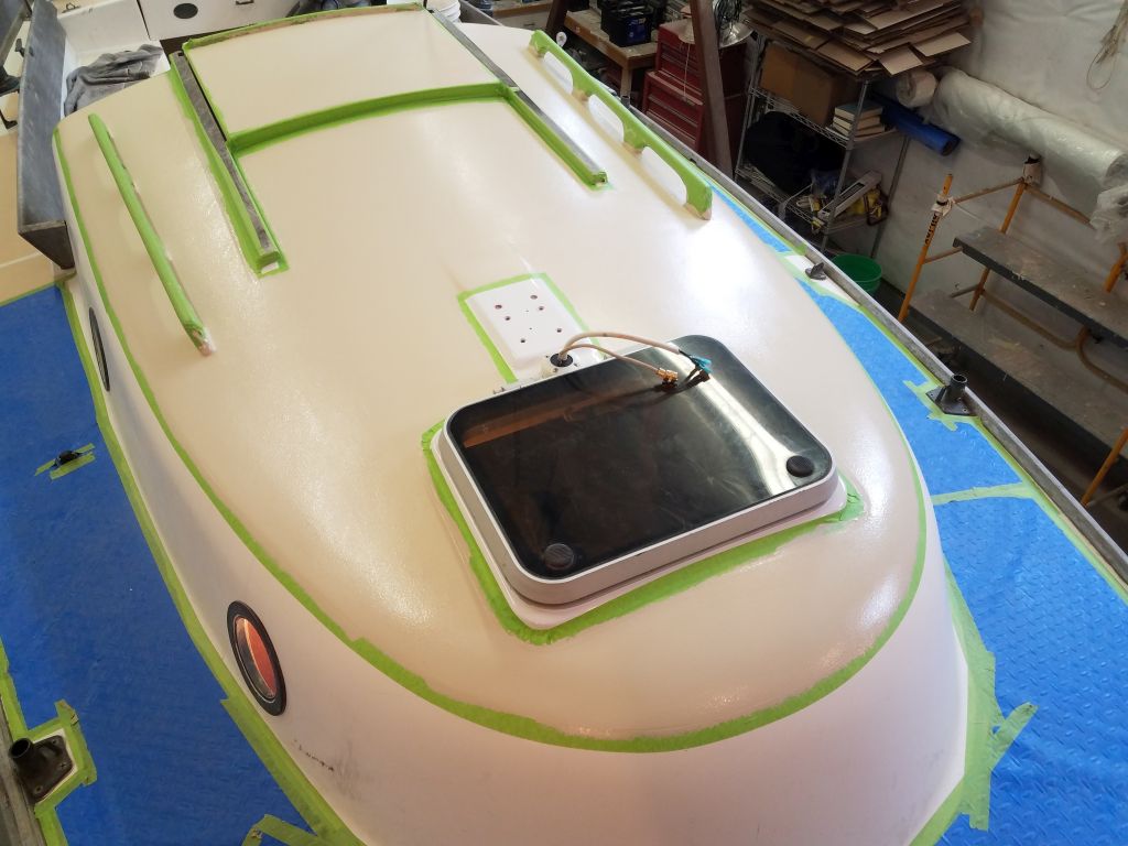
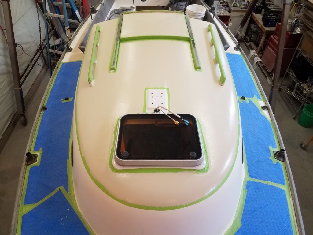
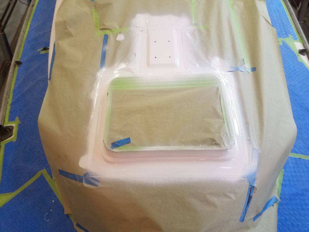
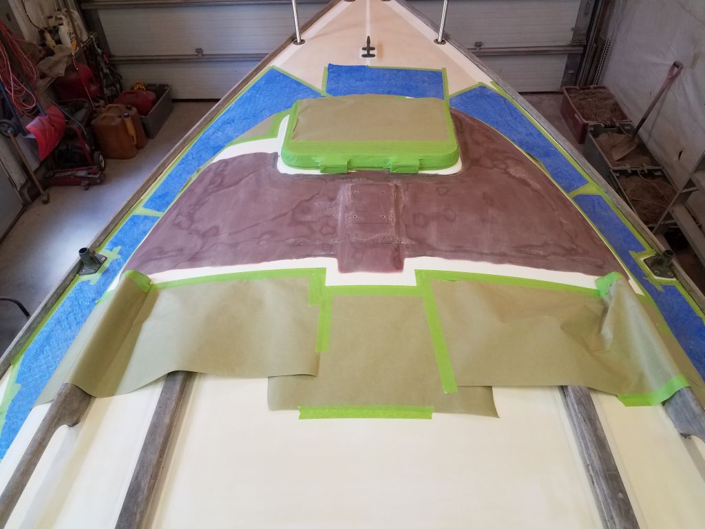
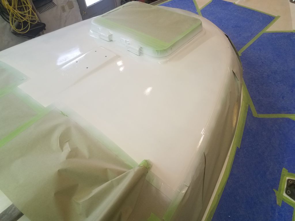
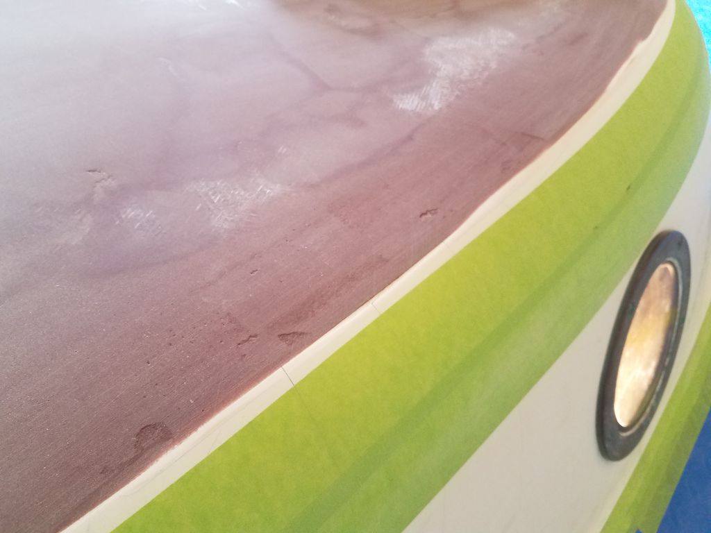
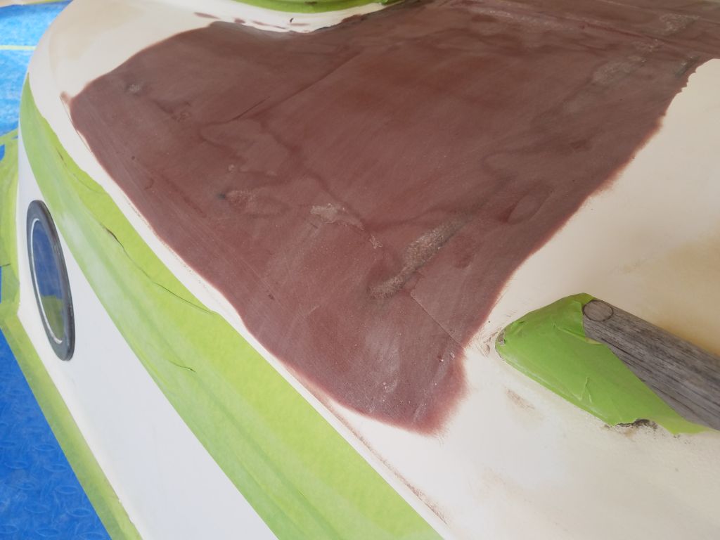
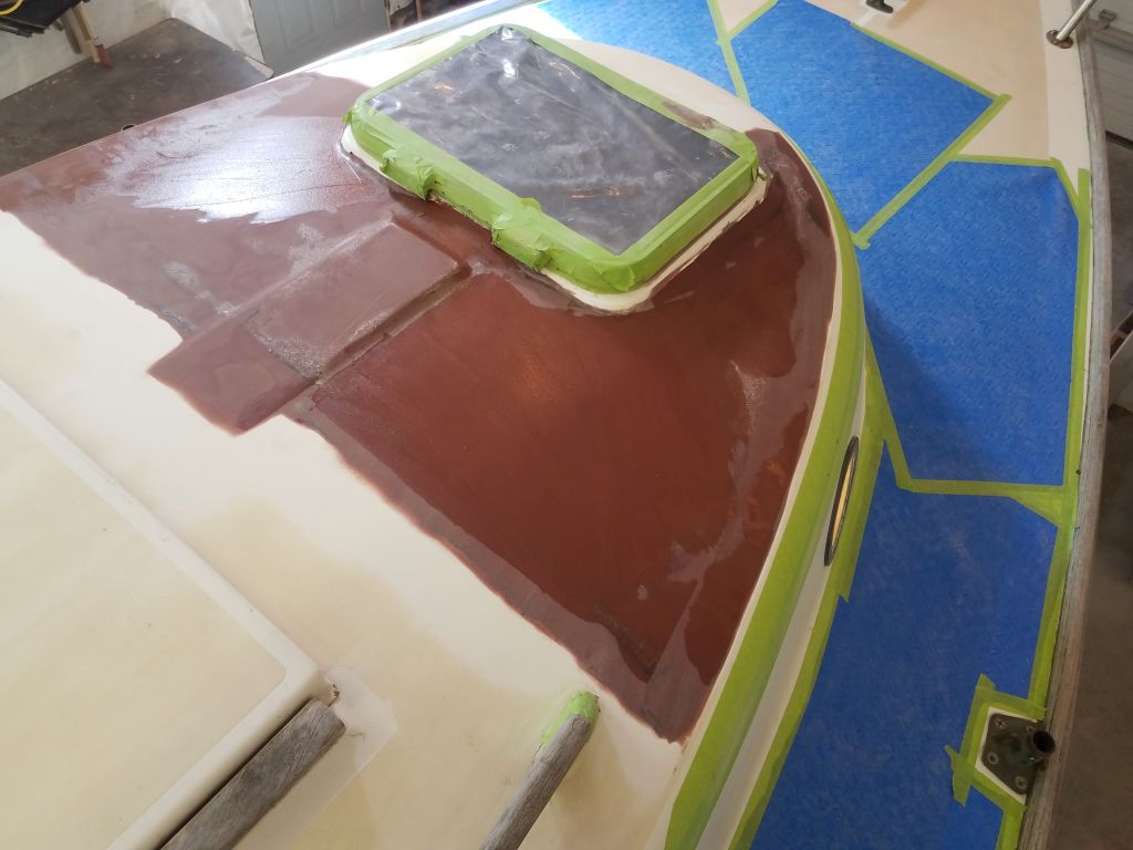
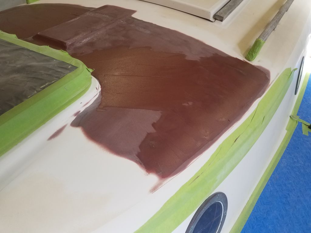
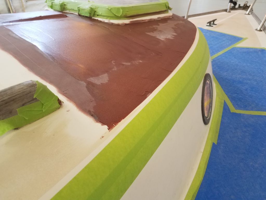
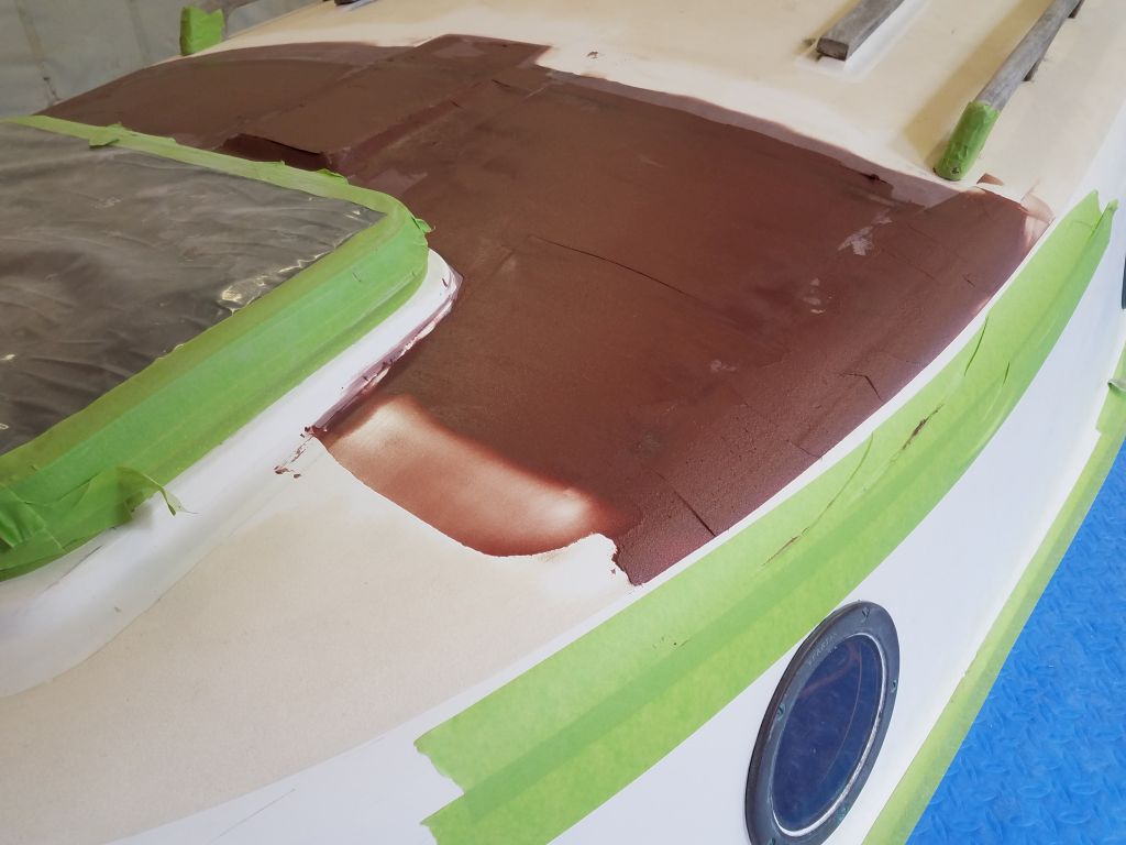
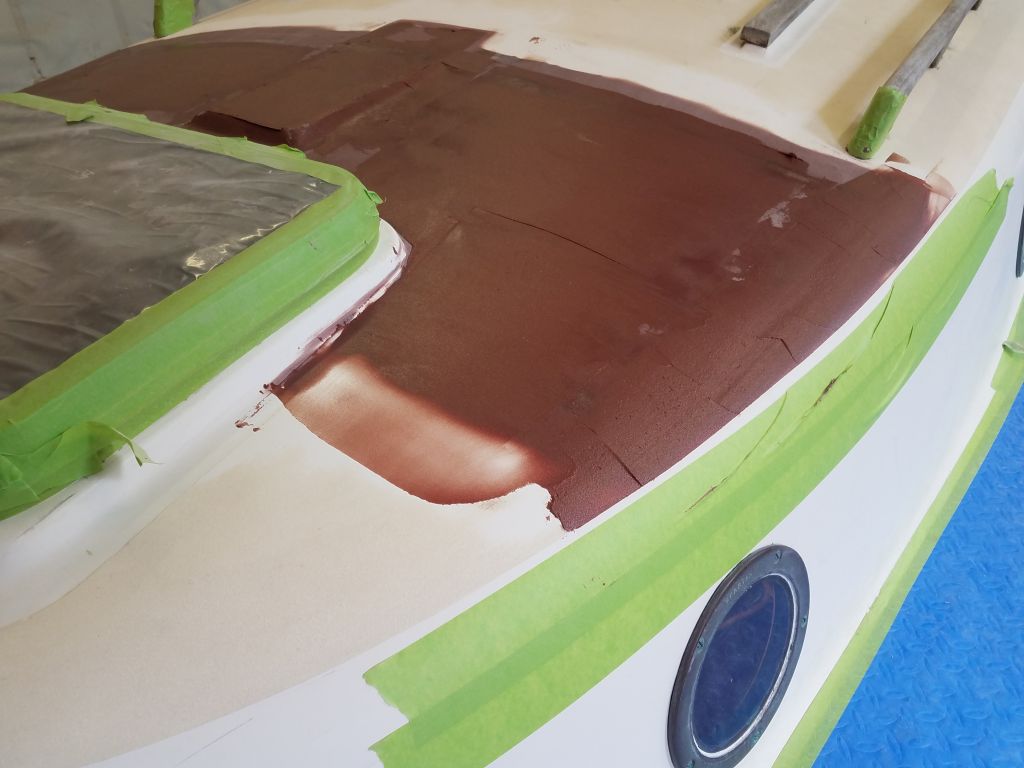
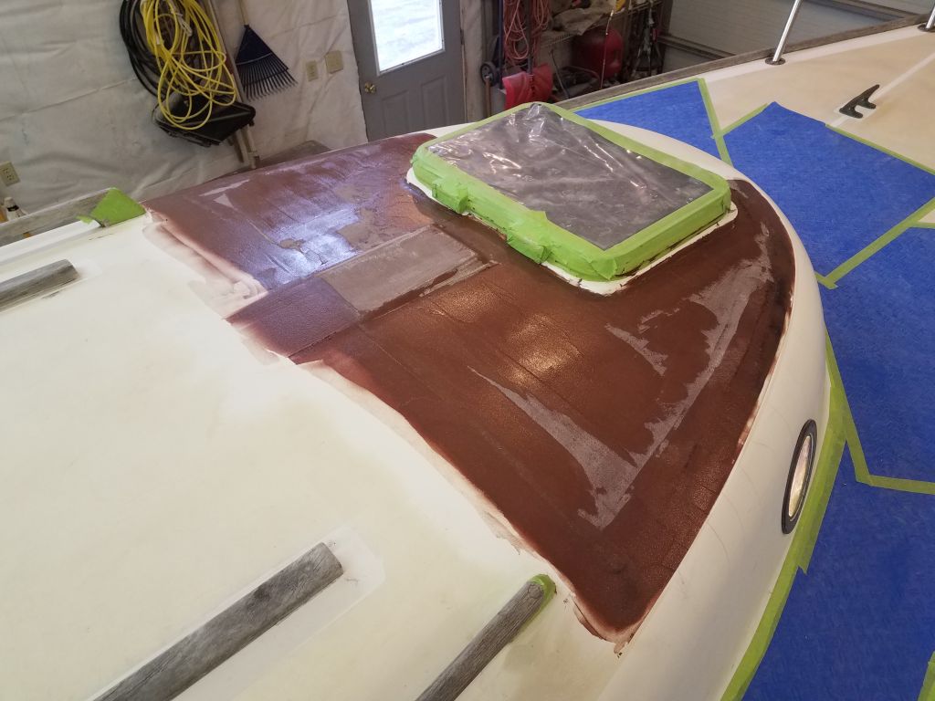
Over the weekend, I removed the masking from around the glossy-painted areas.
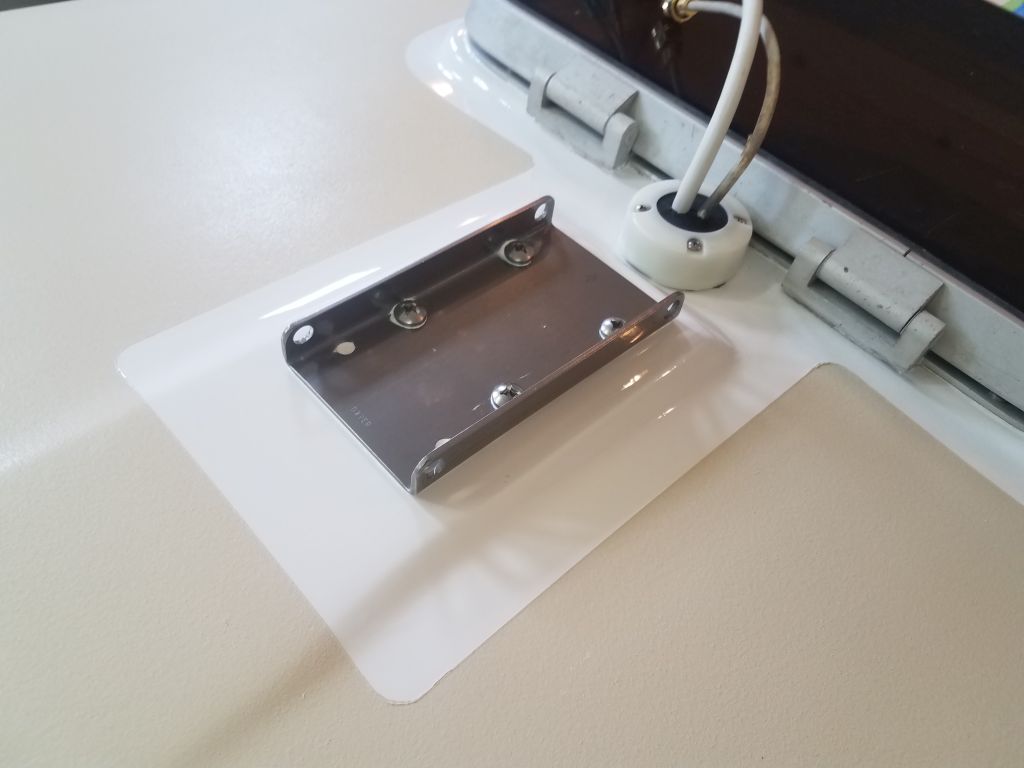
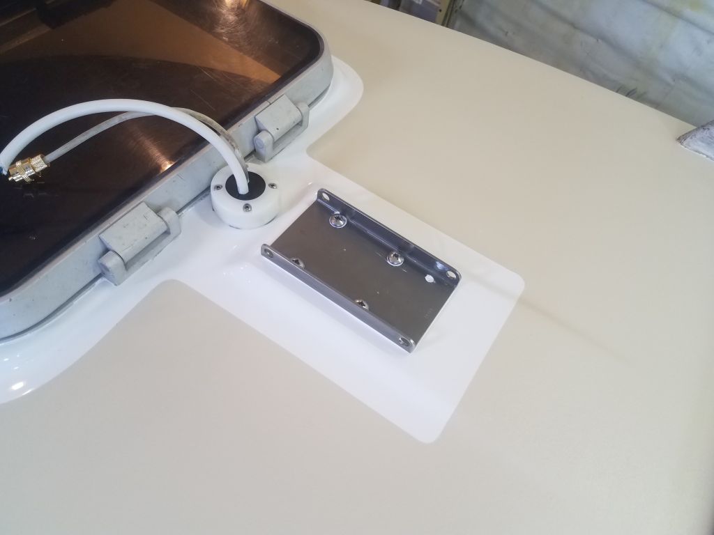
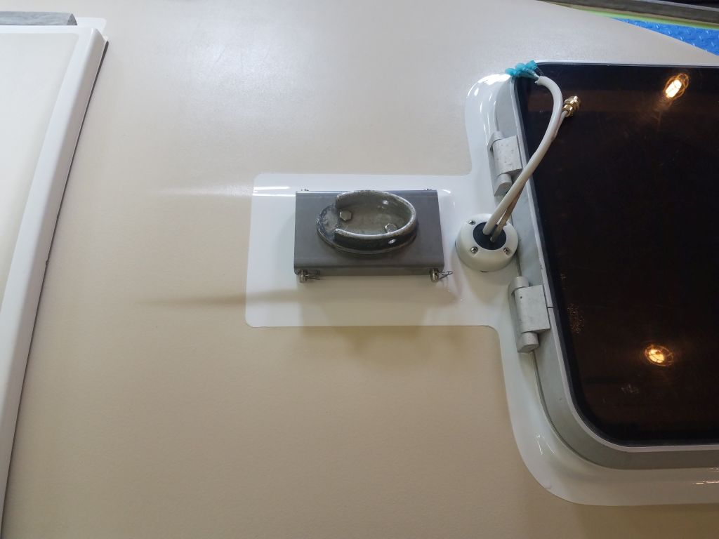
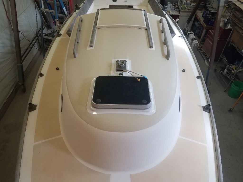
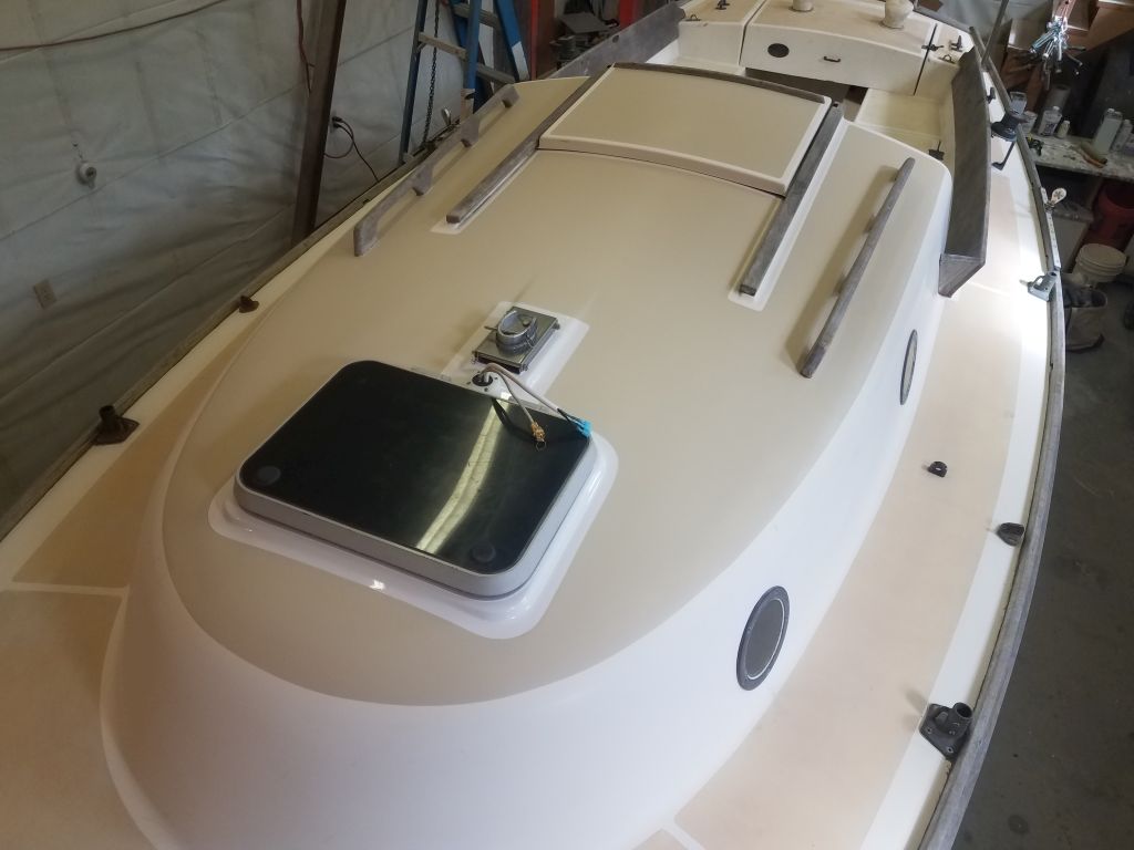
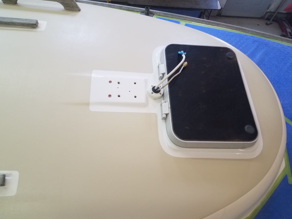
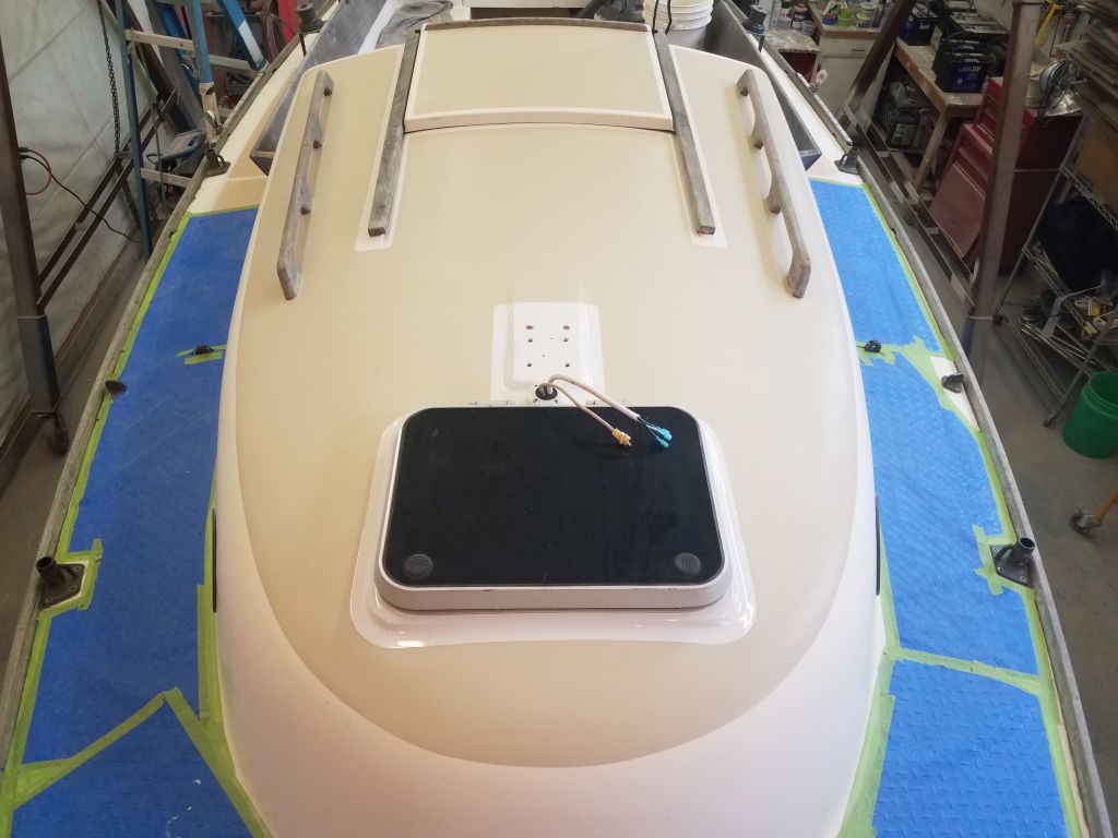
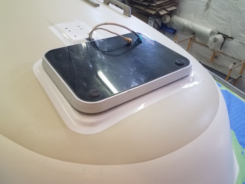
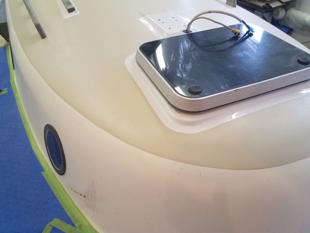
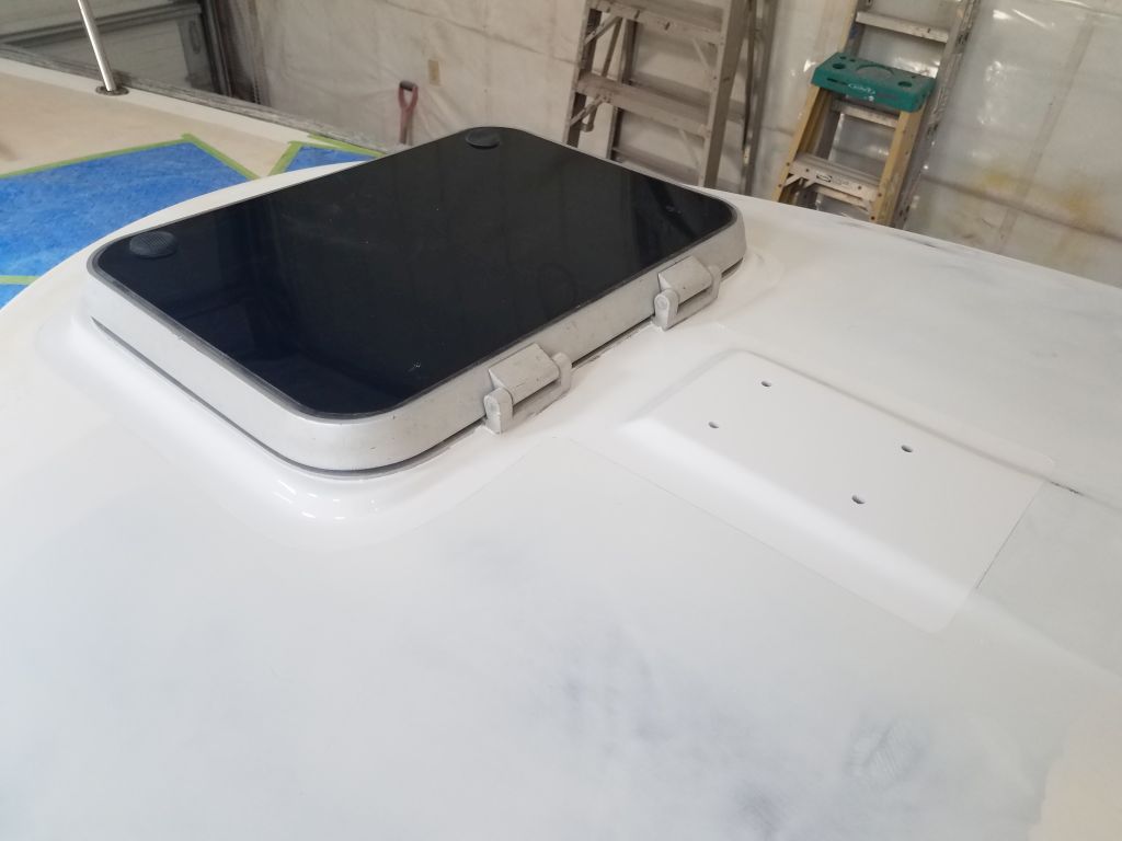
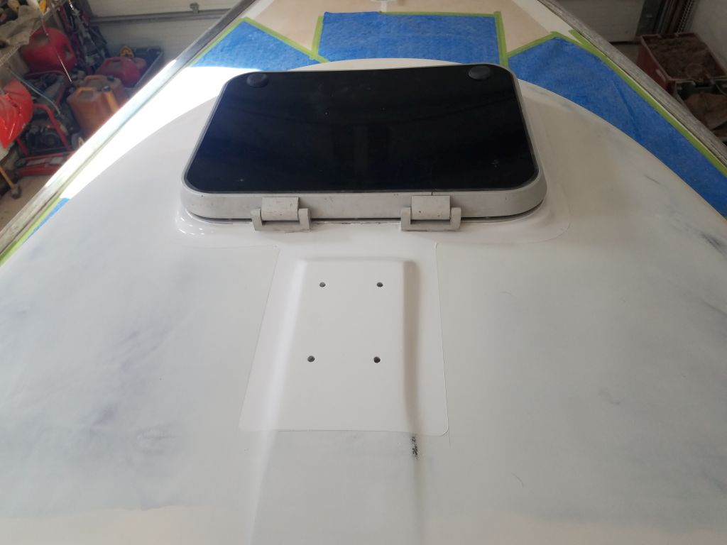
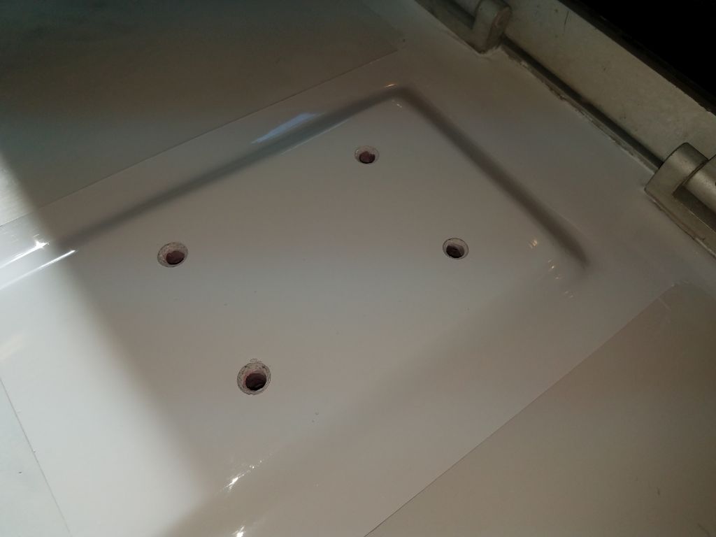
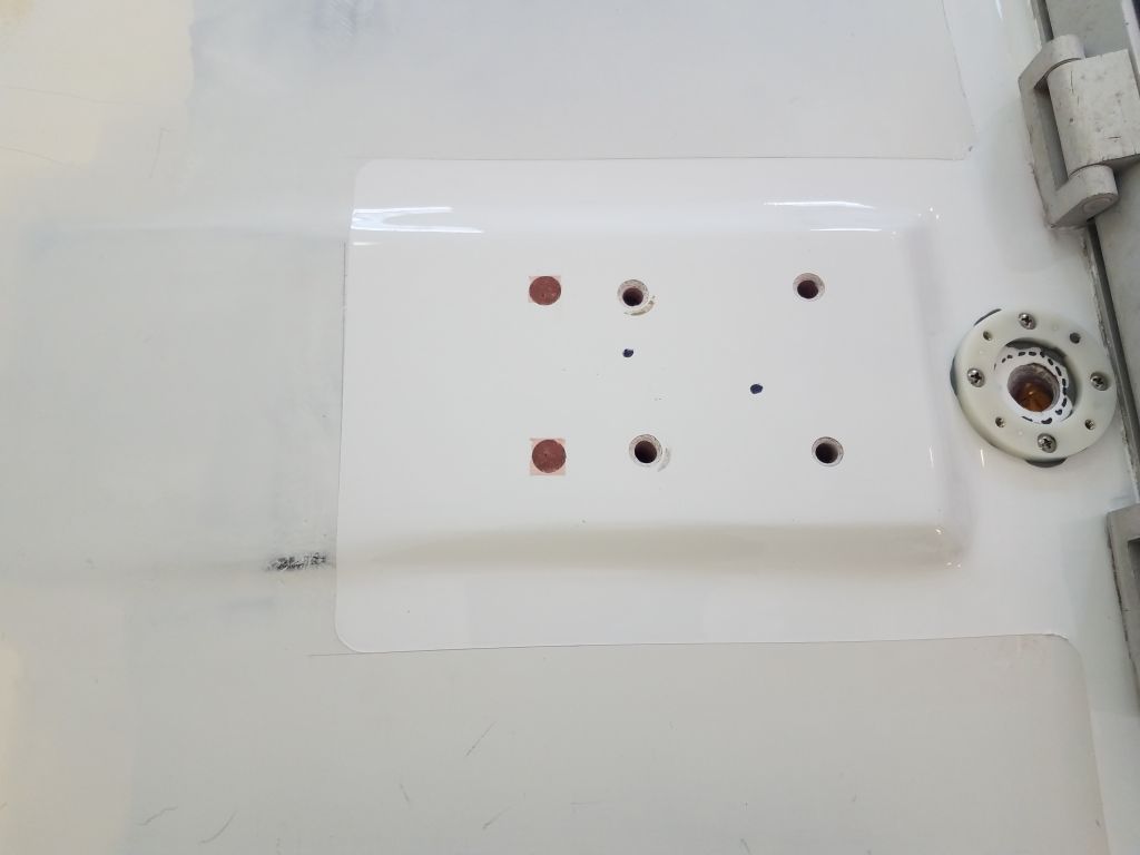
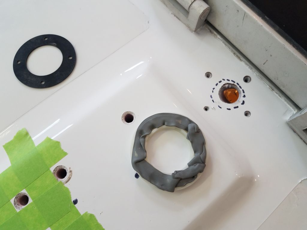
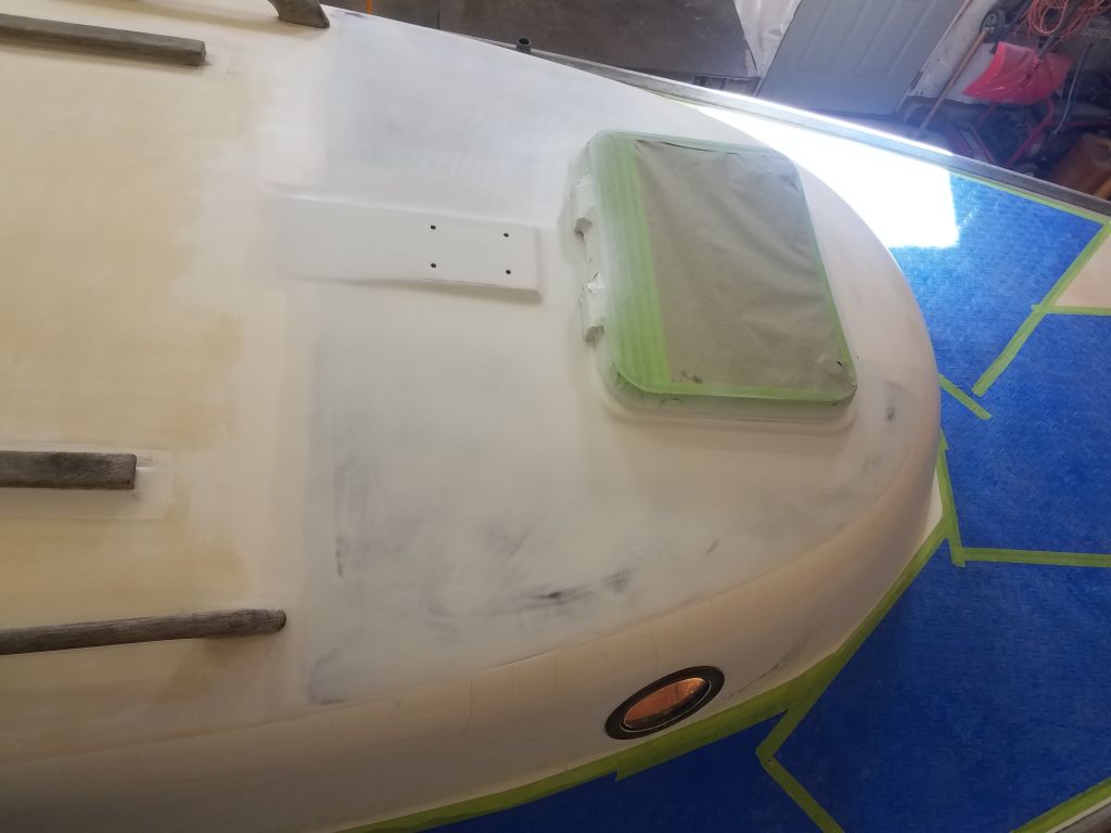
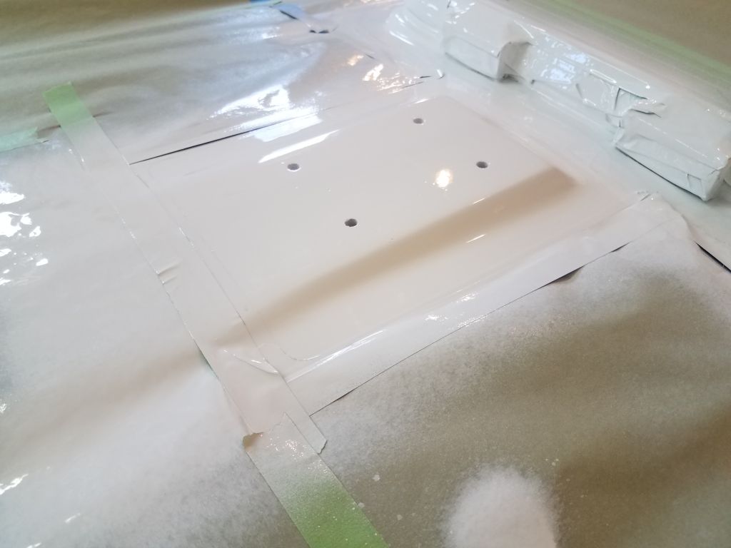
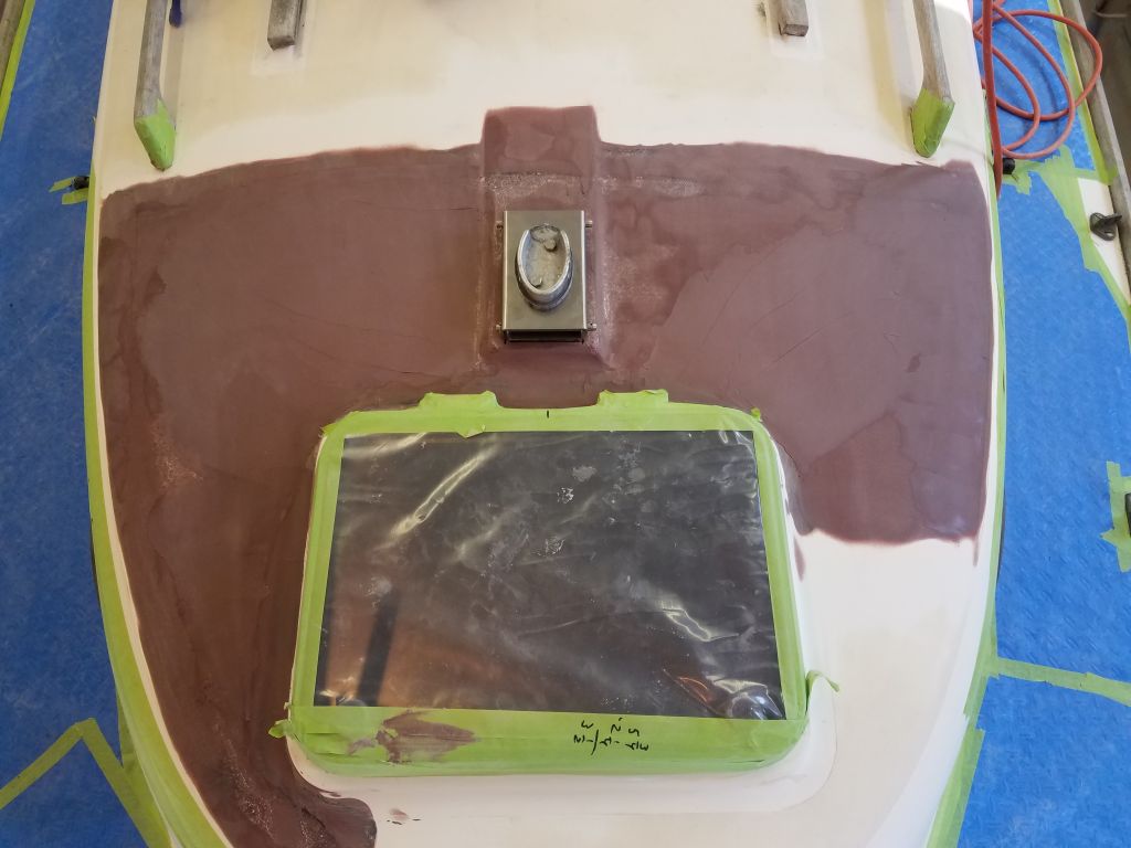
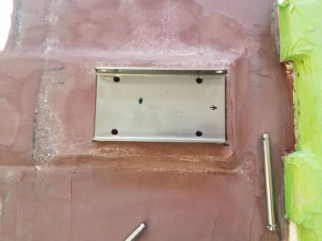
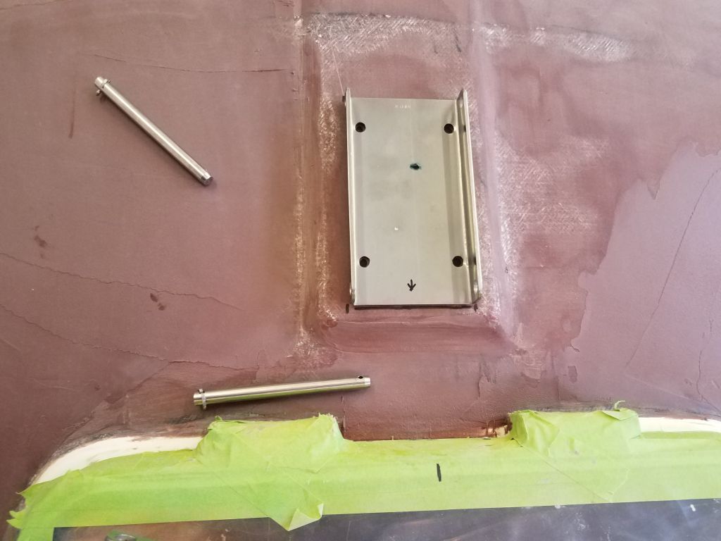
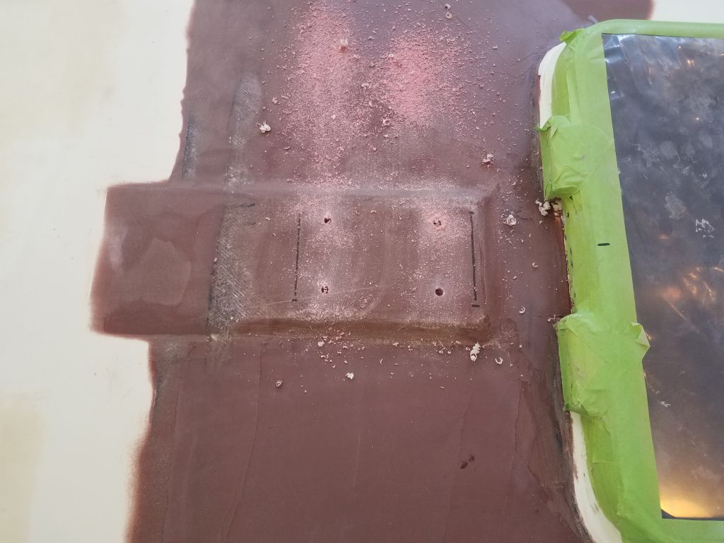
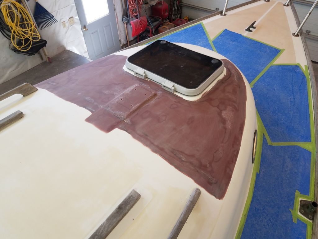
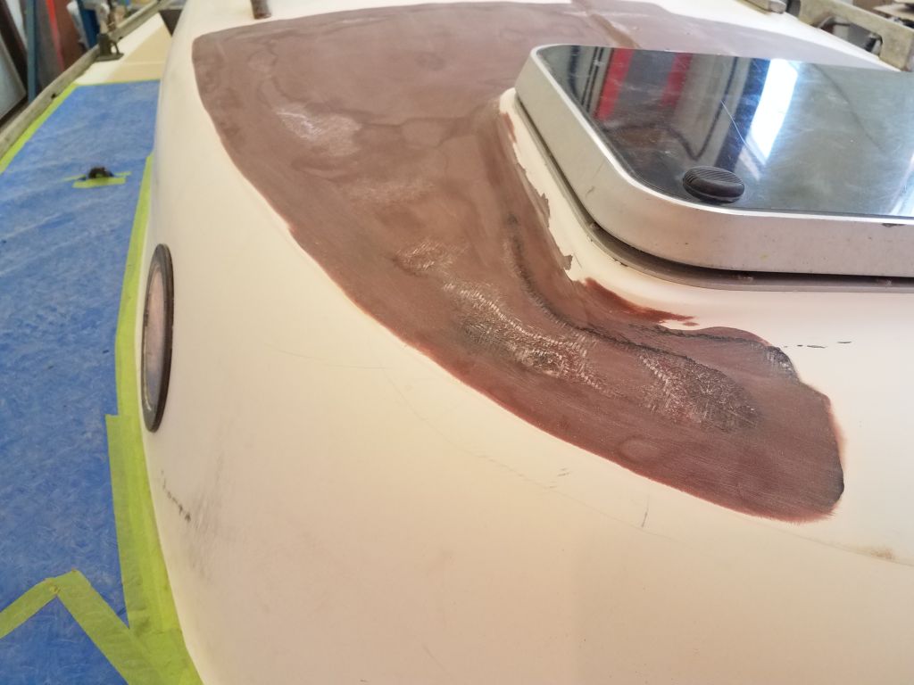
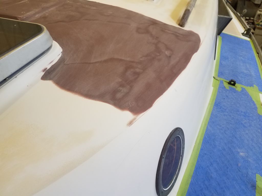
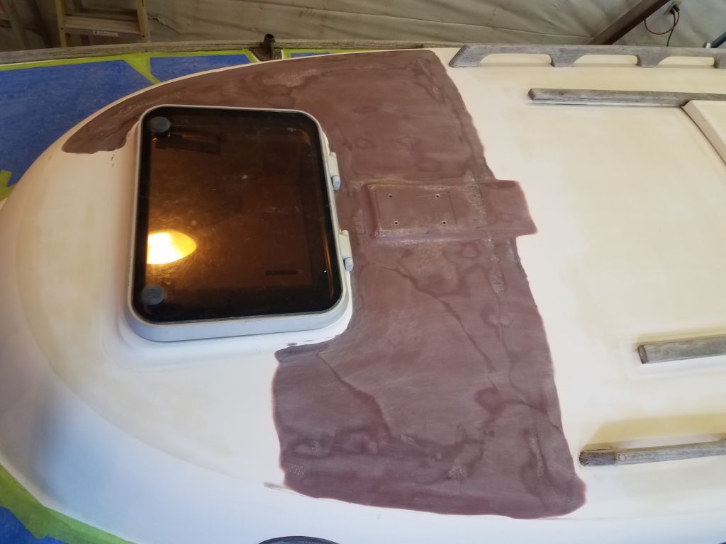
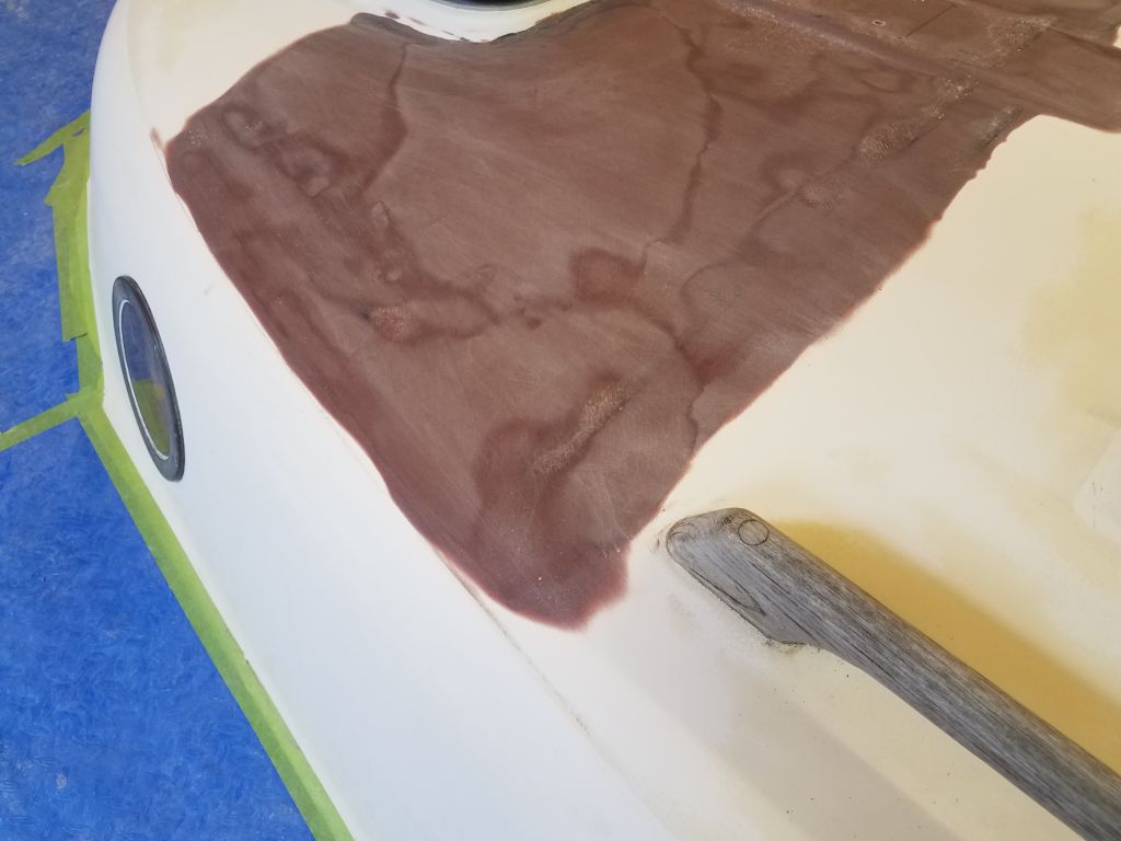
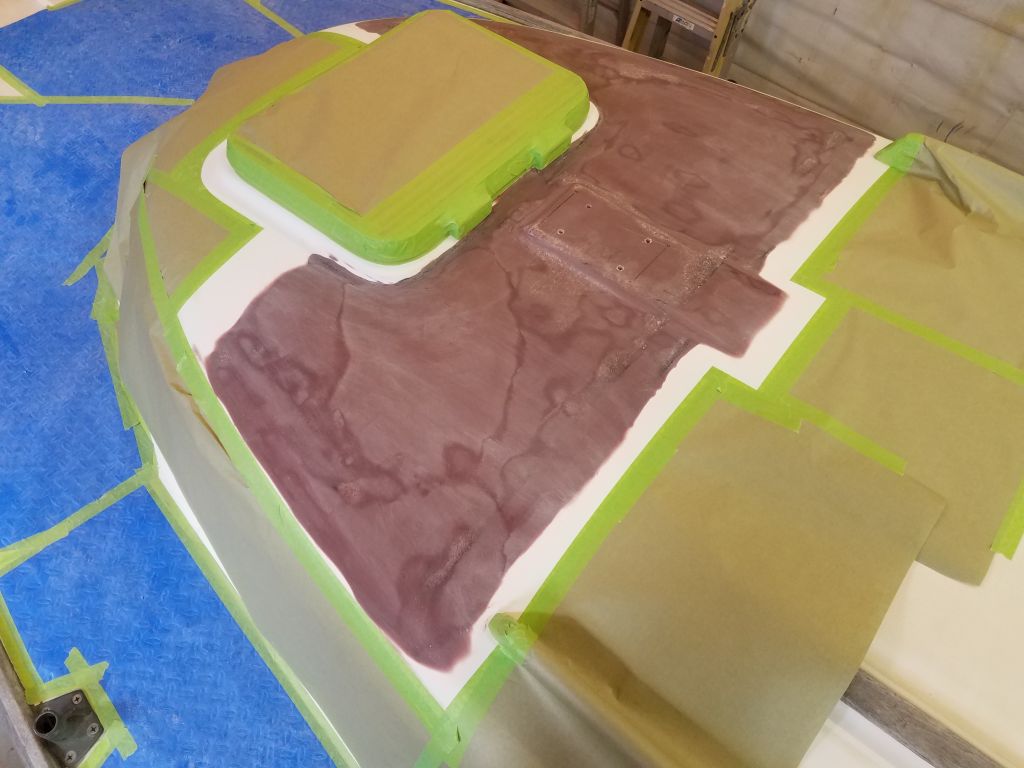
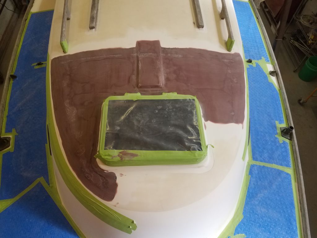
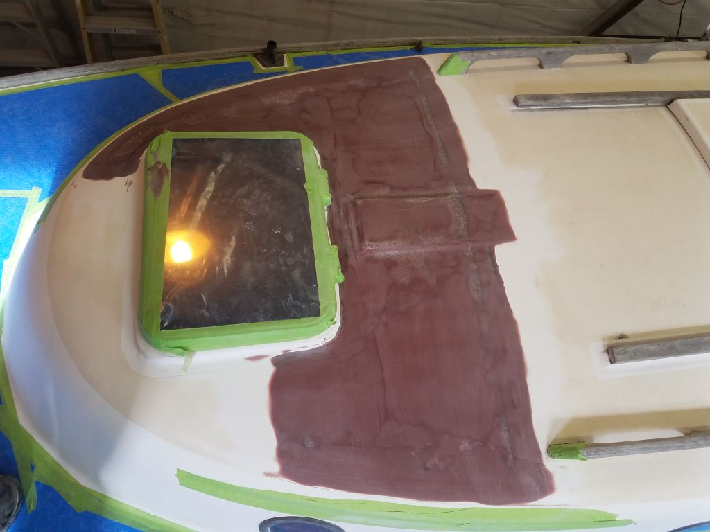
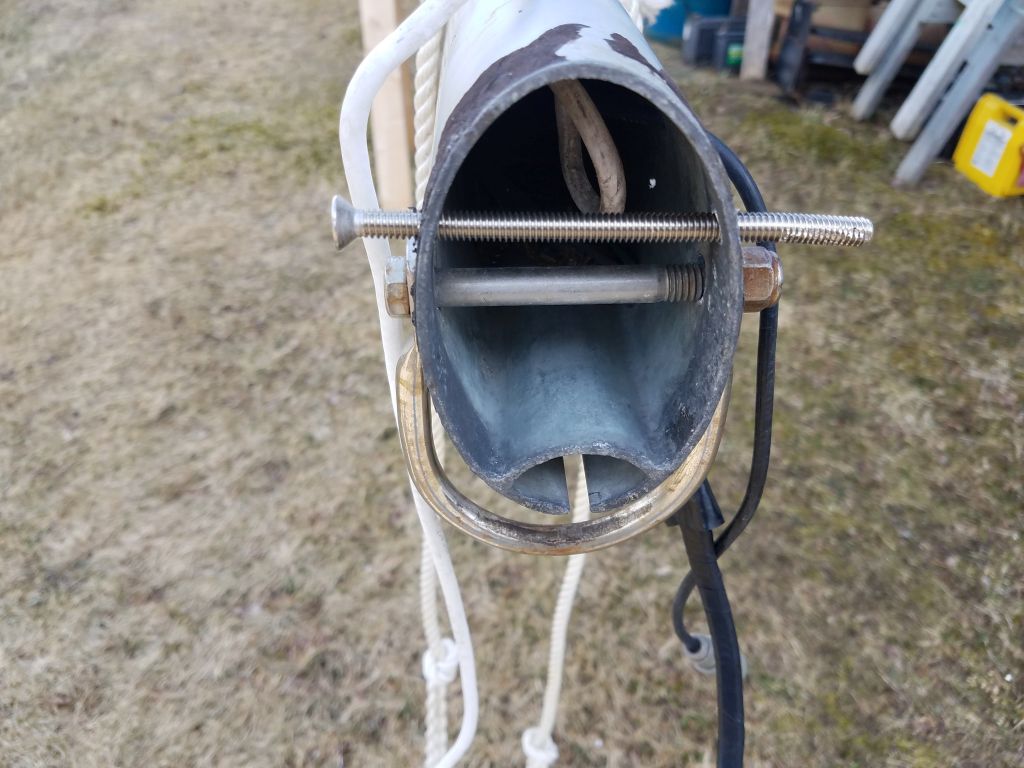
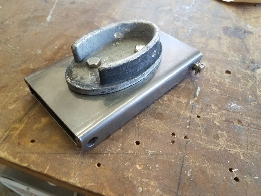
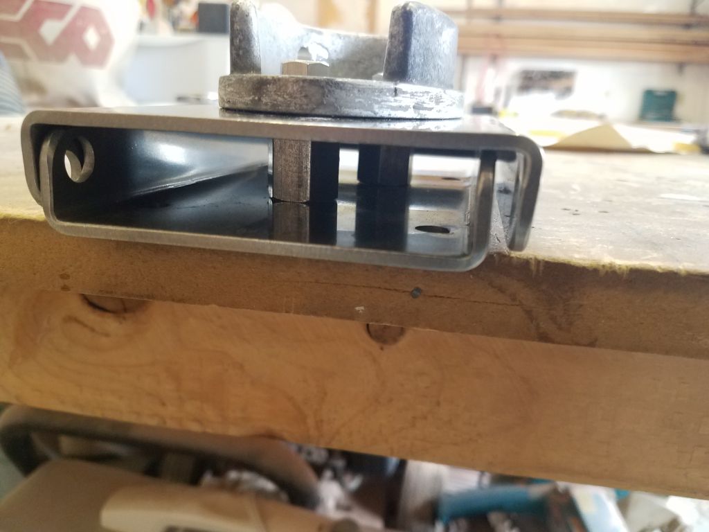
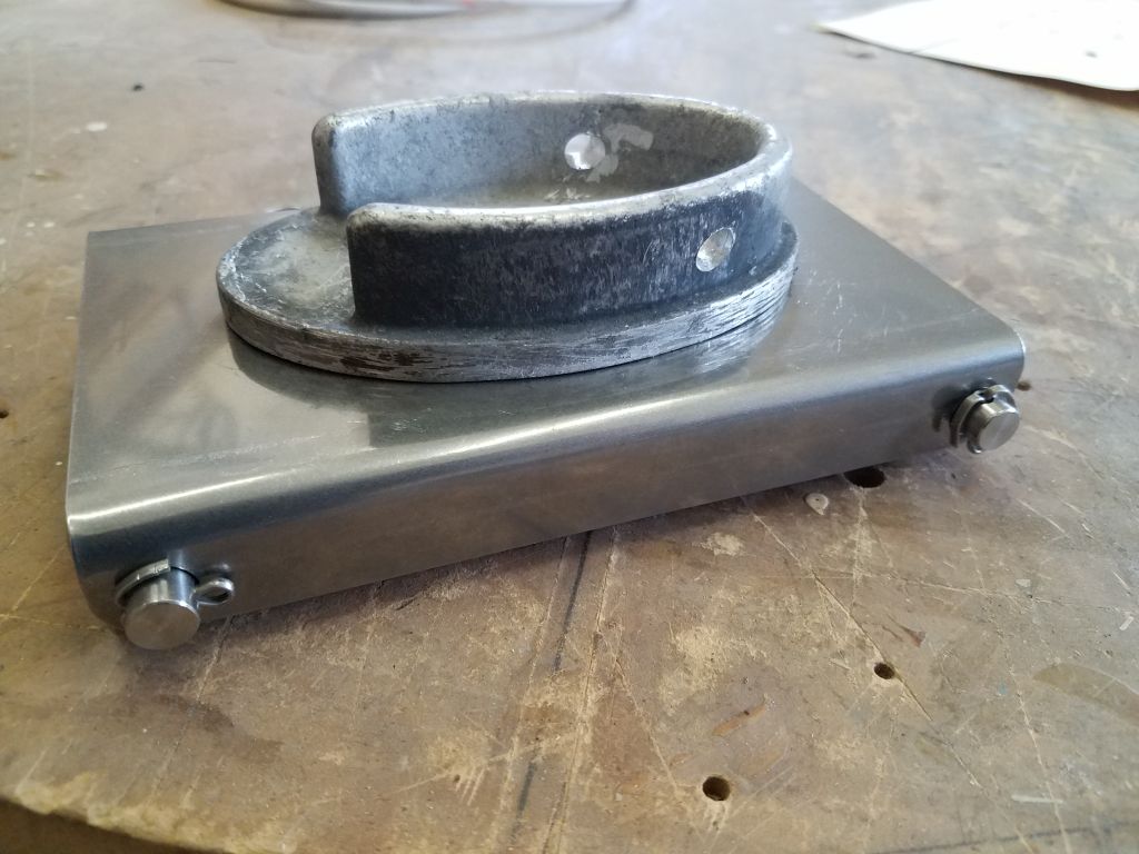
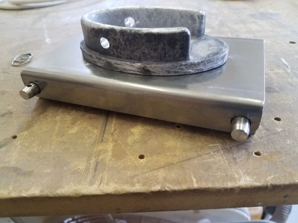
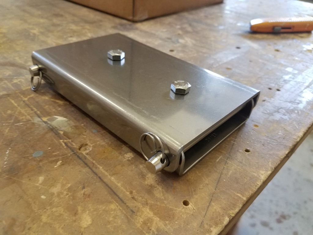
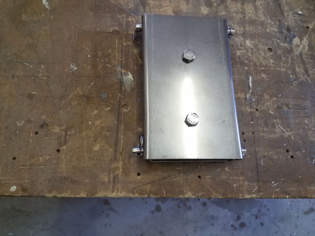
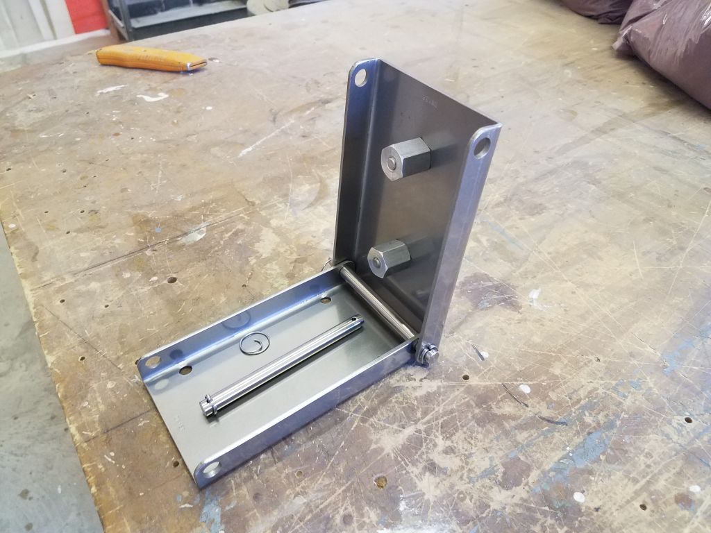
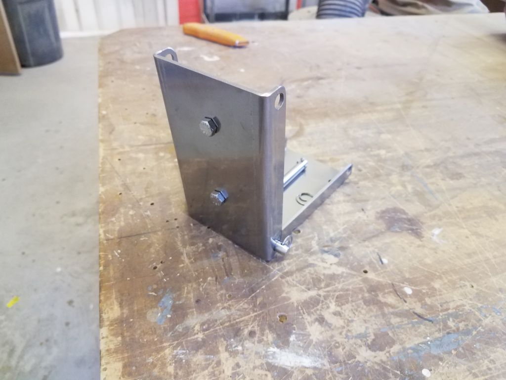
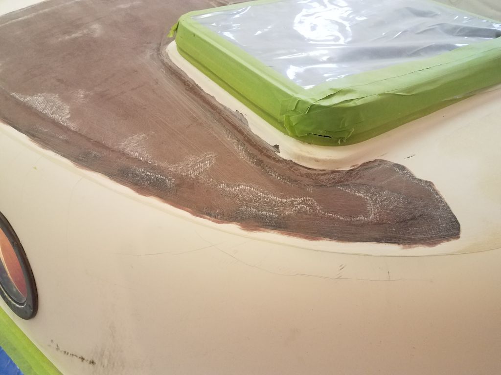
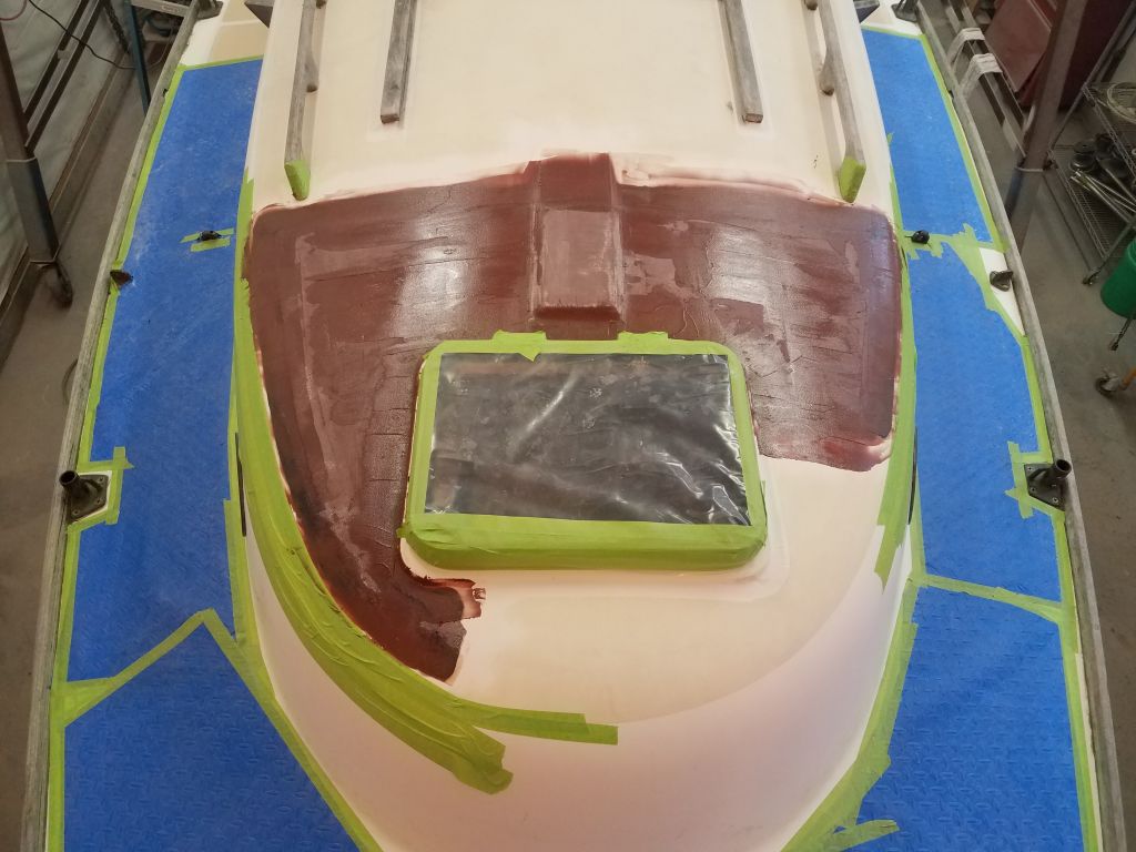
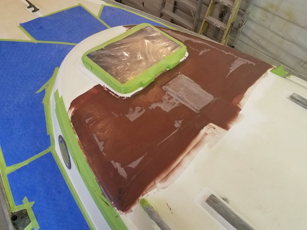
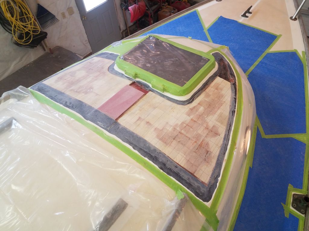
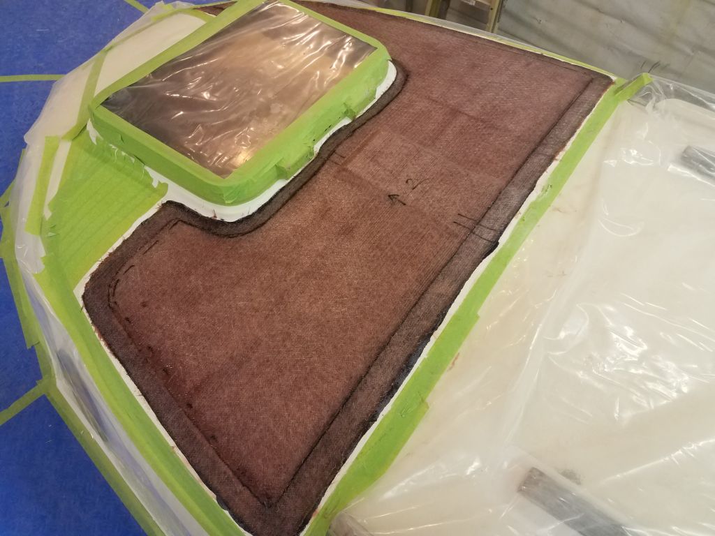
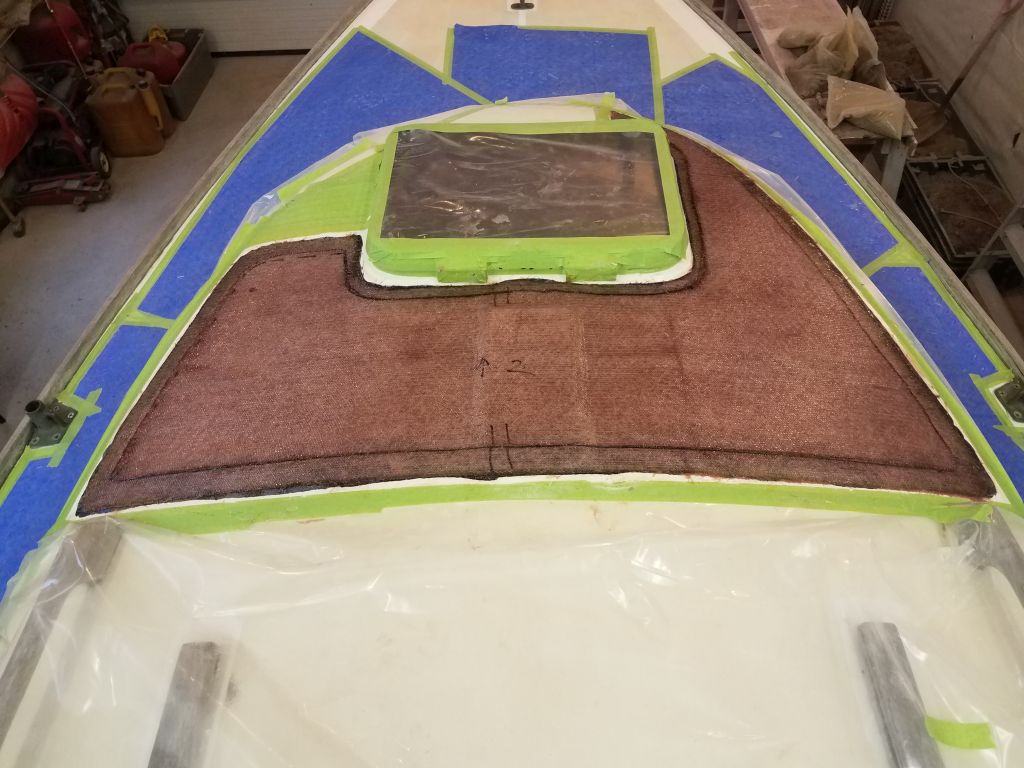
With the fresh paint cured sufficiently, I got to work on some of the final details of the project, starting with the new hinged mast step base. I’d already marked and partially drilled the mounting holes, so now I drilled through the deck at each location, using a long bit to get all the way through the thick mast beam and eventually the interior liner to mark the outline of the new hardware. To my annoyance–because I should have better anticipated it–I found that the after two mounting holes landed too far aft, just beyond the aft edge of the mast beam structure. These holes had been pre-drilled in the hardware and it wasn’t their fault that they didn’t align perfectly with this beam structure, but now I needed to drill a new set of holes through the deck plate and the deck itself a bit forward of the originals to ensure all four bolts passed through the reinforced part of the deck.
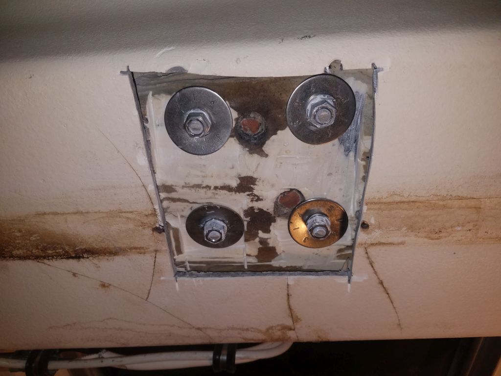
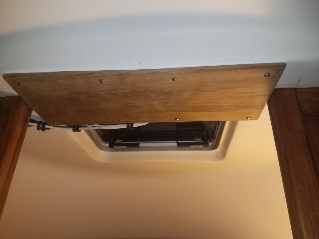
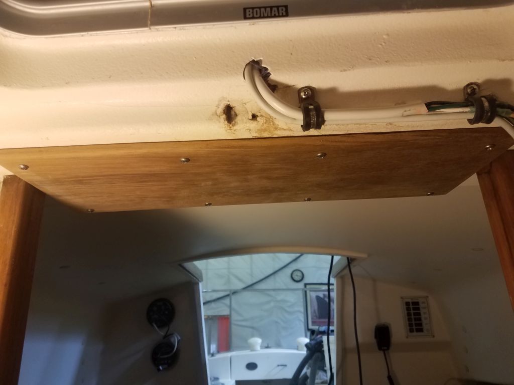
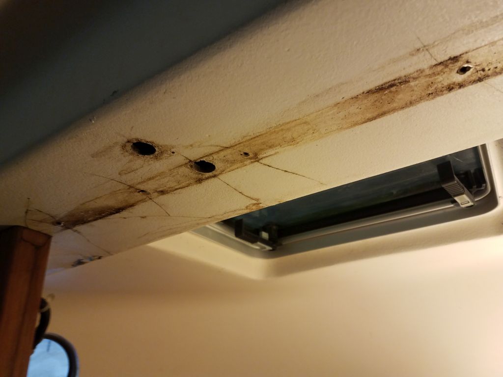
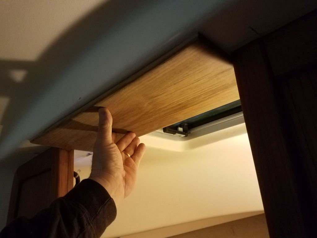
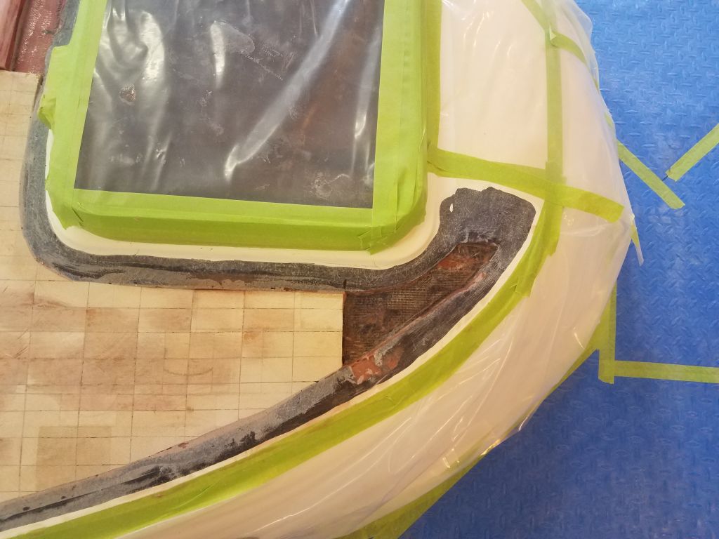
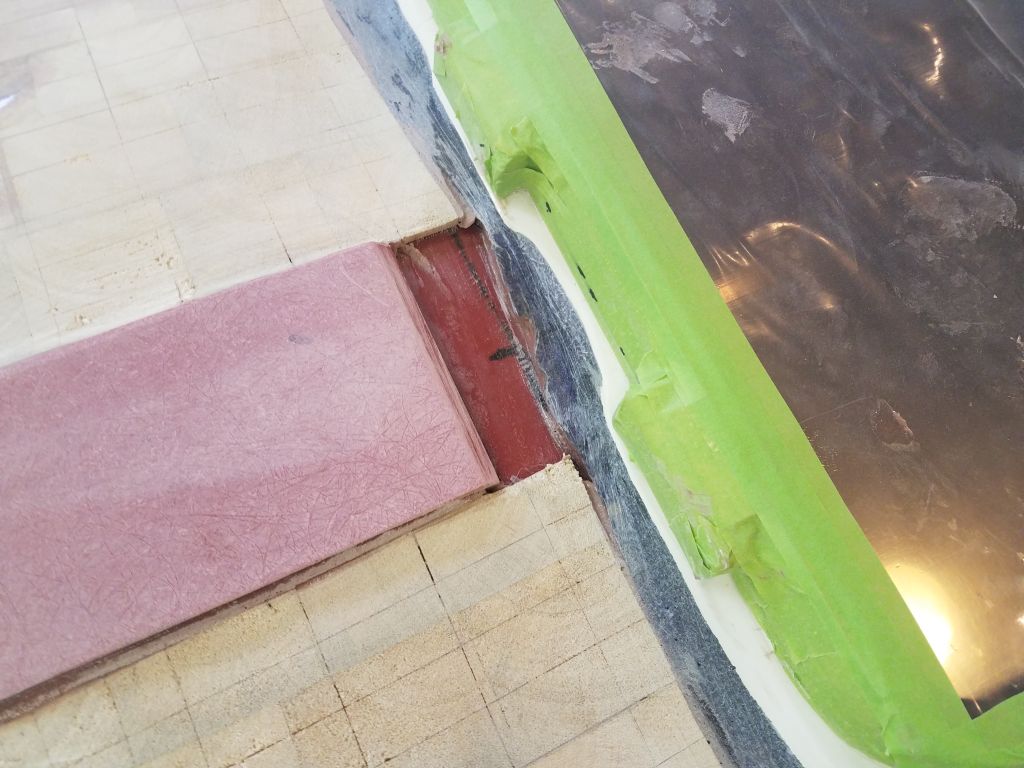
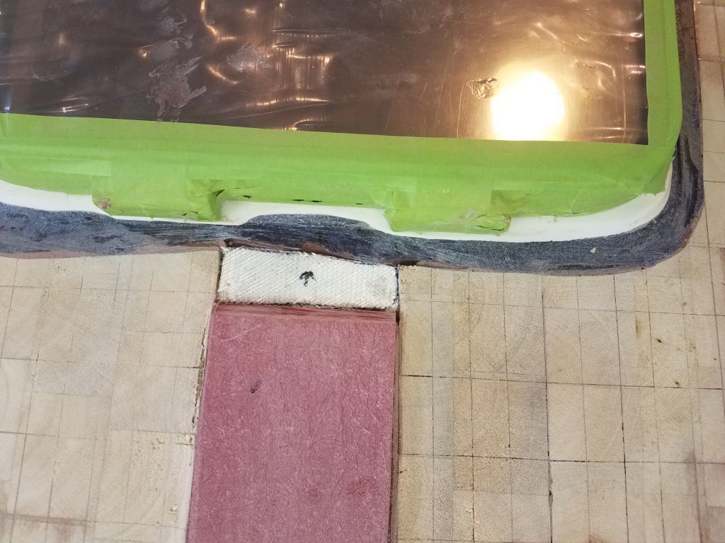
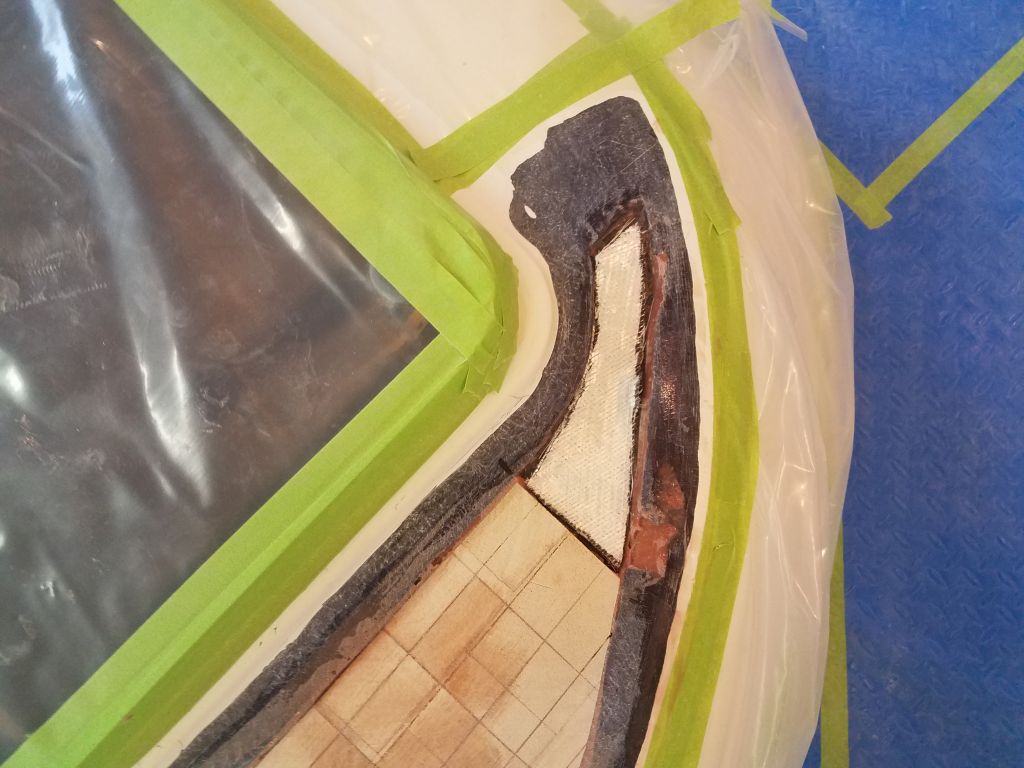
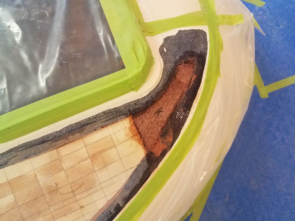
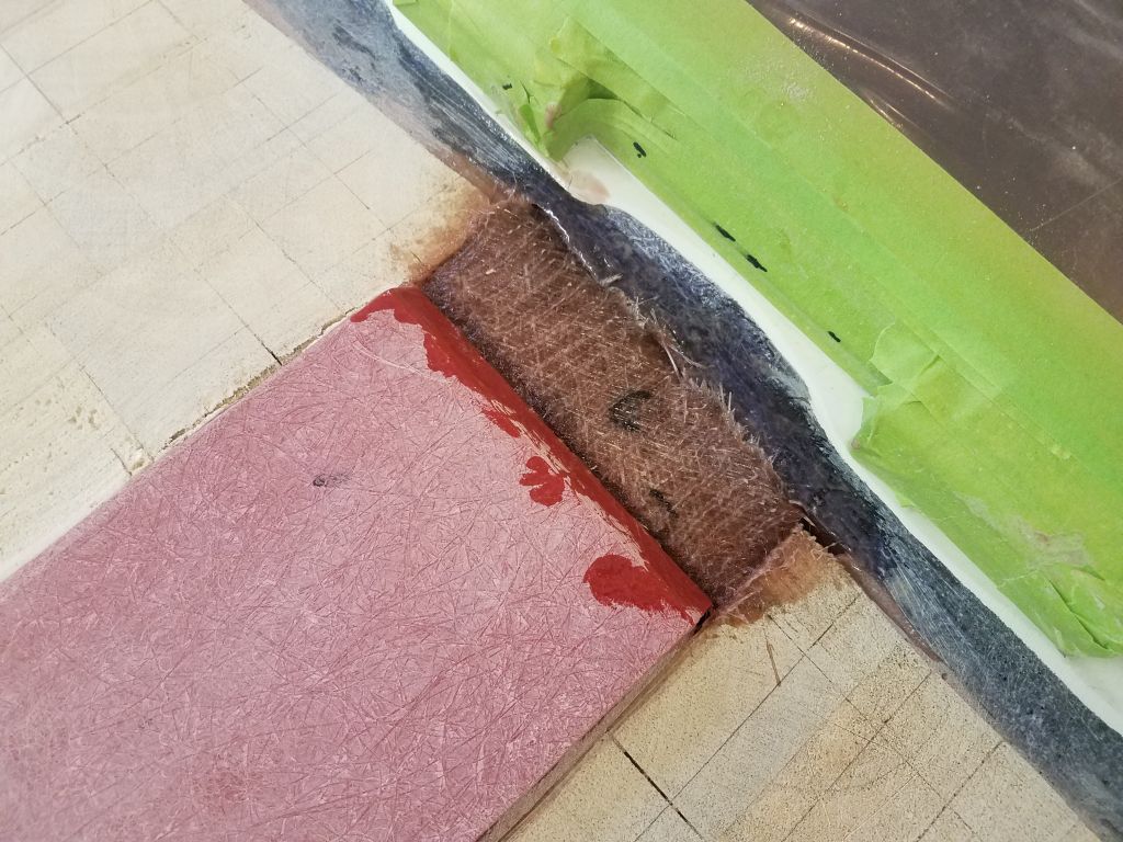
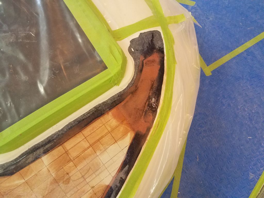
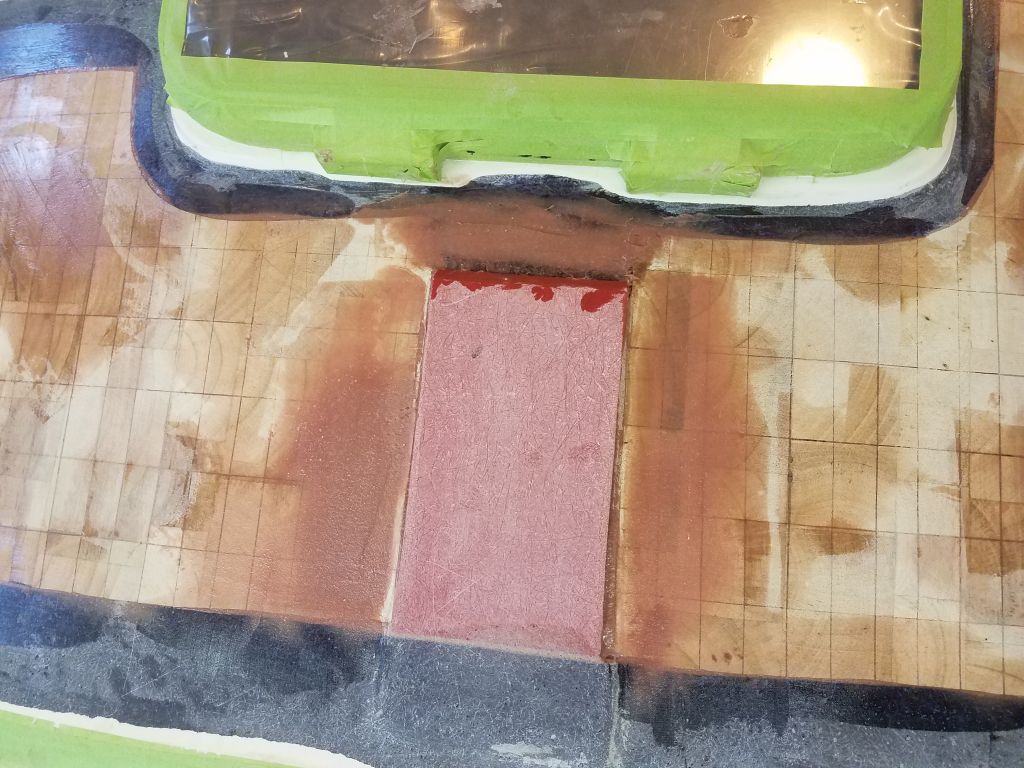
With the new holes drilled, I cut away a squarish portion of the liner from below, exposing the underside of the deck beam structure. There was a heavy notched layer of the putty used in the original construction to secure the liner to the underside of the deck, and I removed enough of this at each fastener location to accept the nuts and washers later. I’d planned to go ahead and complete the final installation of the mast plate, but now I had to fill the unwanted original bolt holes with epoxy and let that cure before I could finalize the installation. Those holes would be hidden by the deck plate once installed.
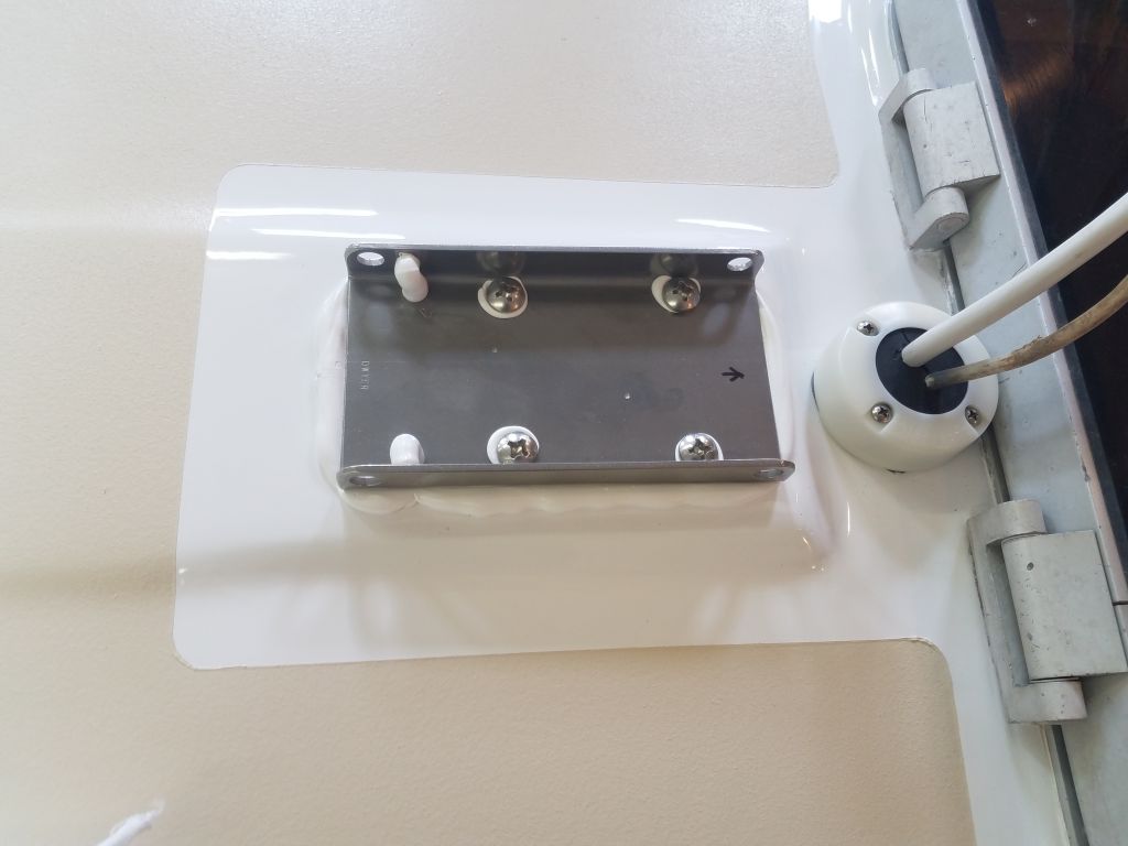
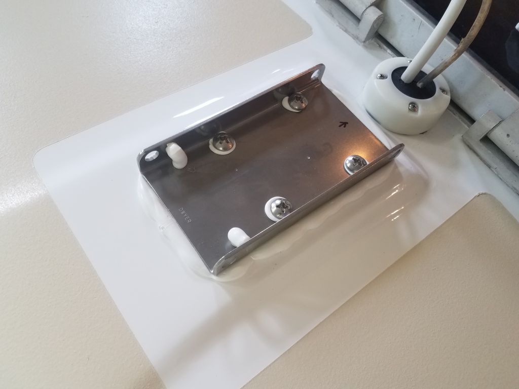
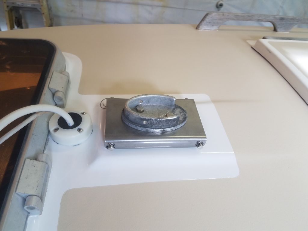
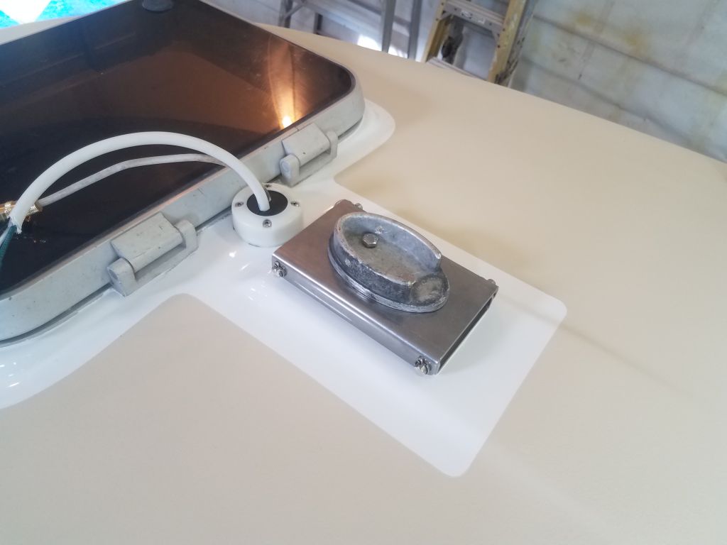
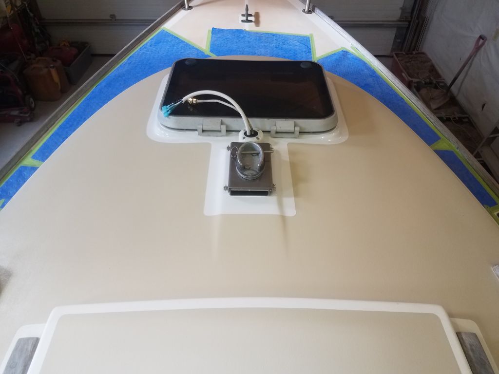
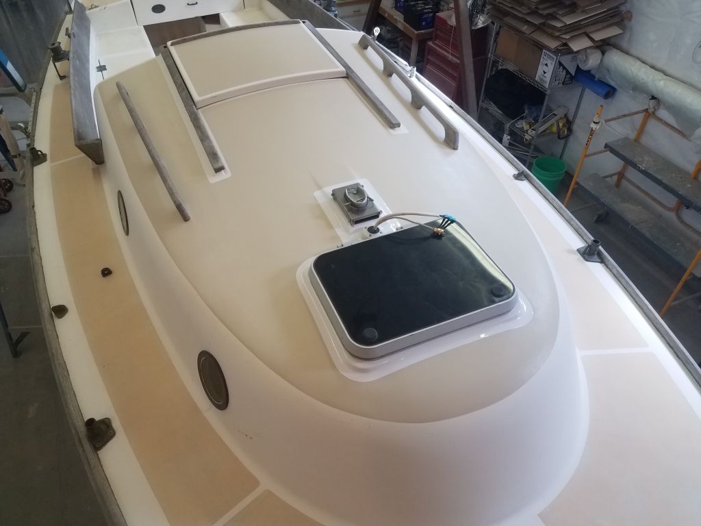
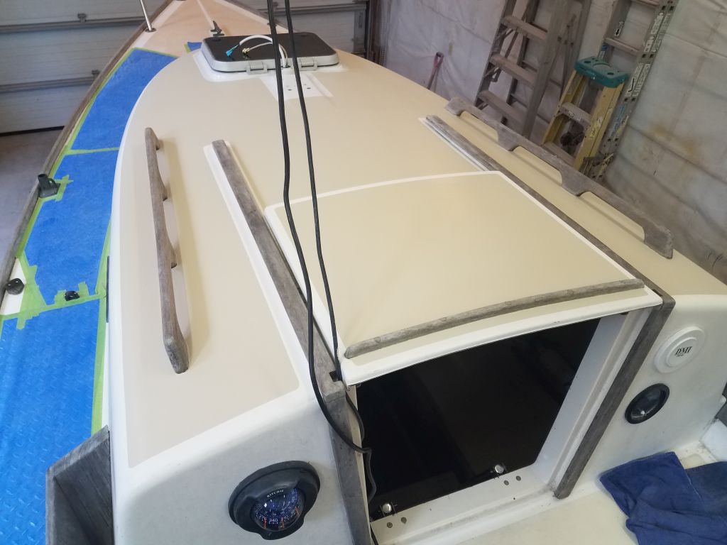
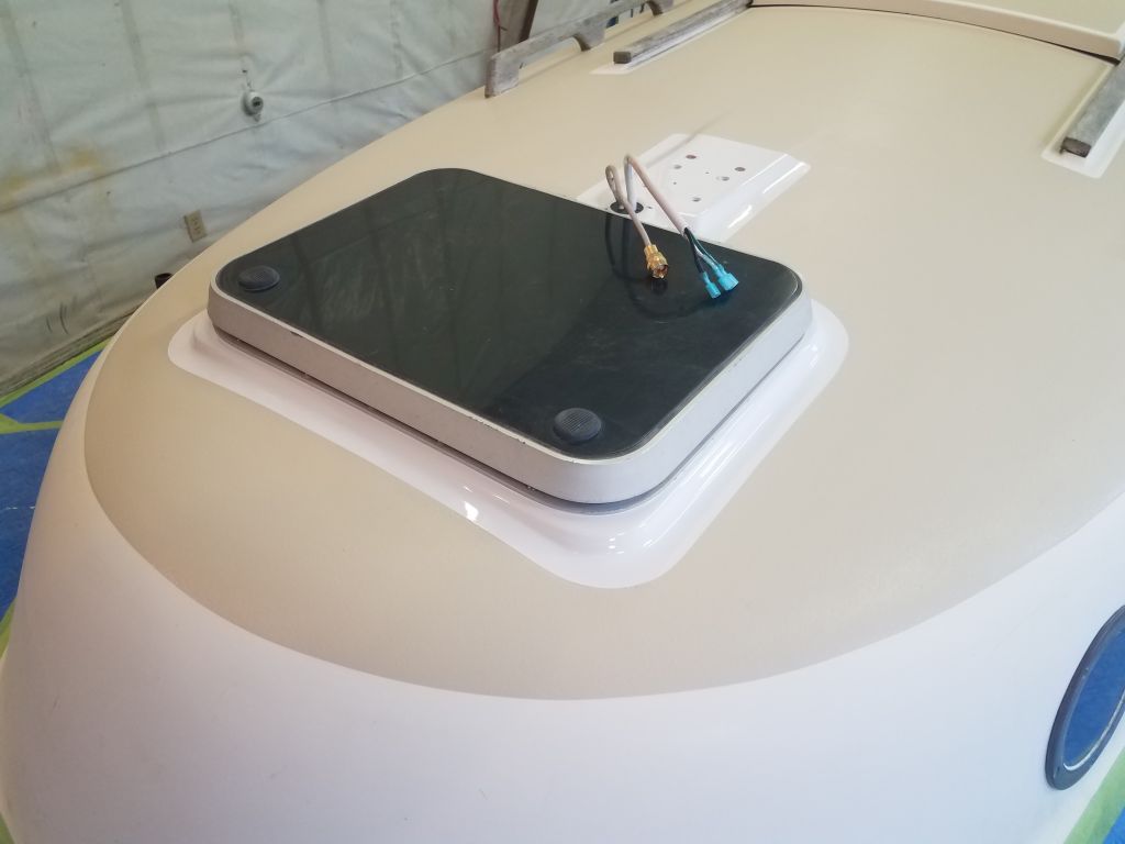
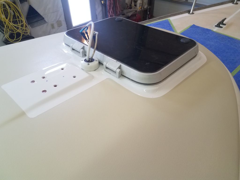
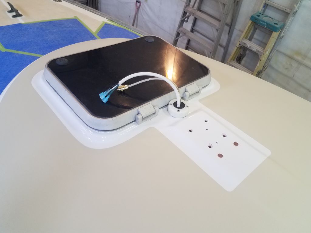
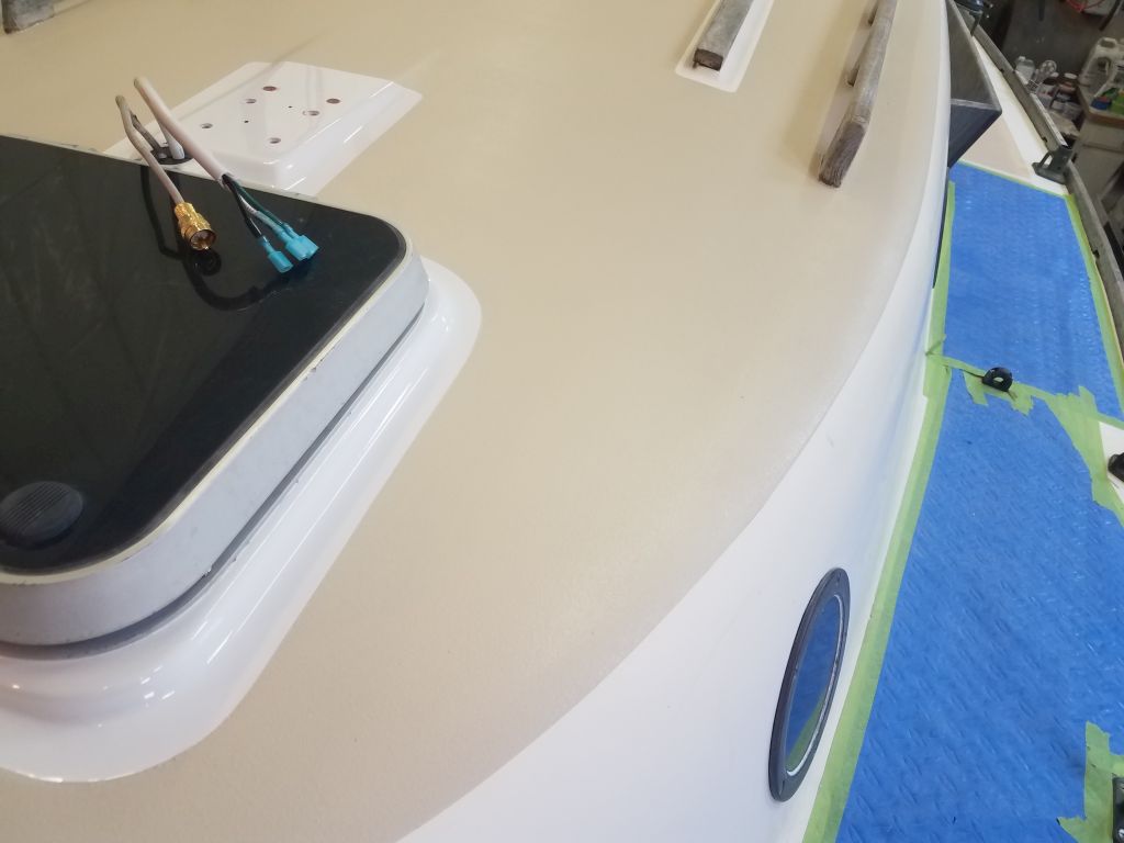
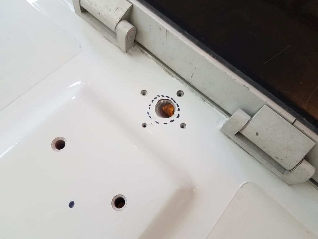
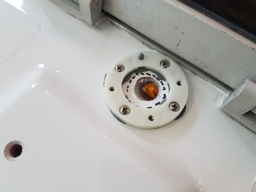
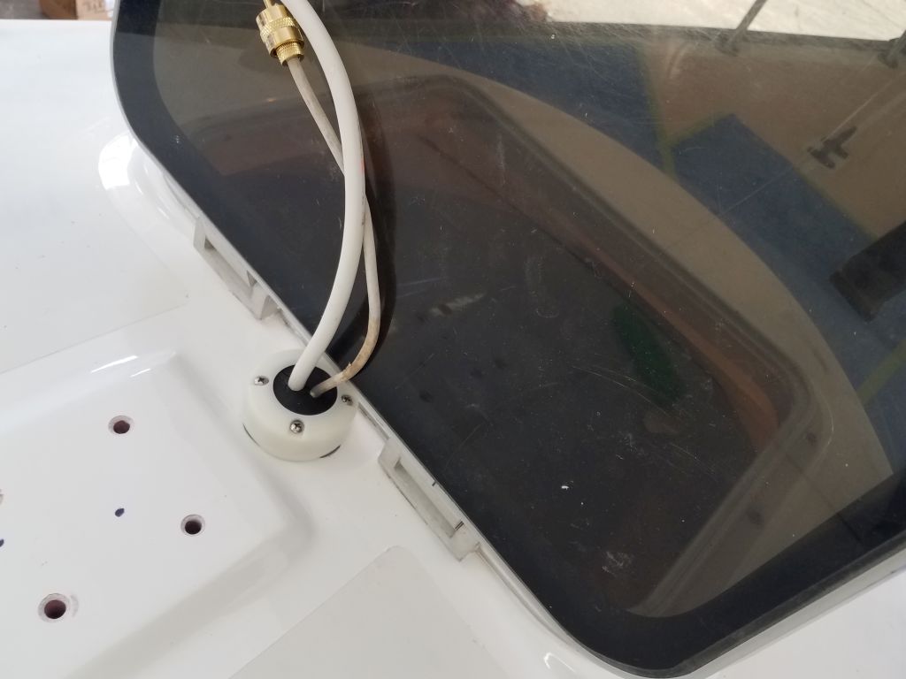
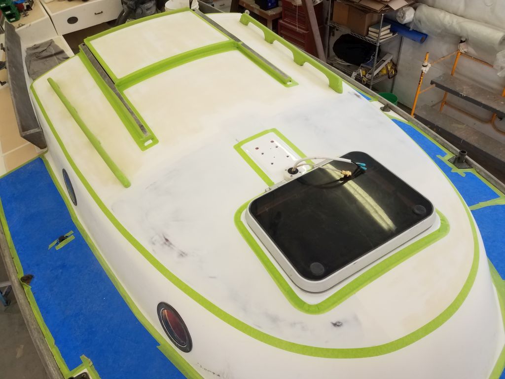
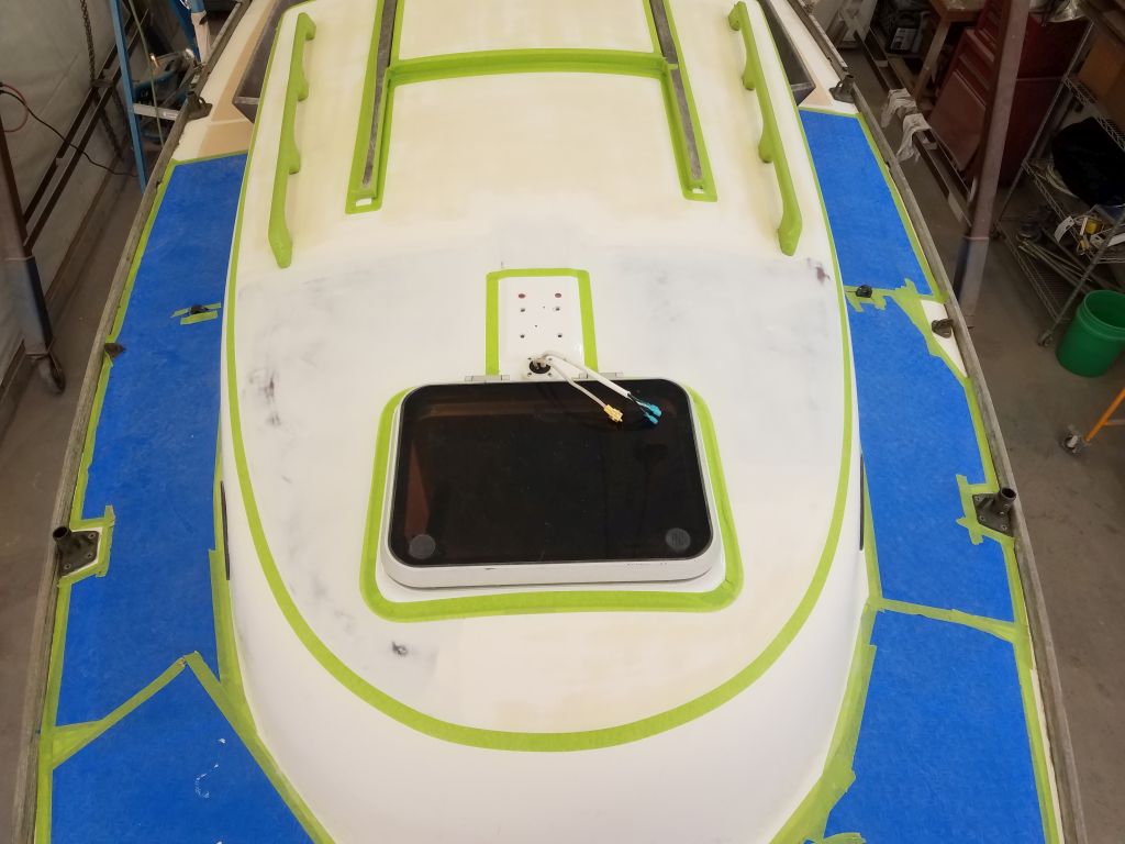
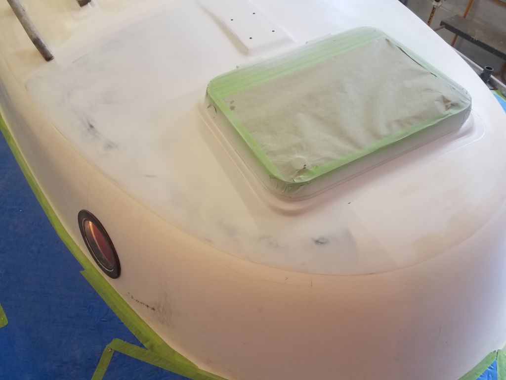
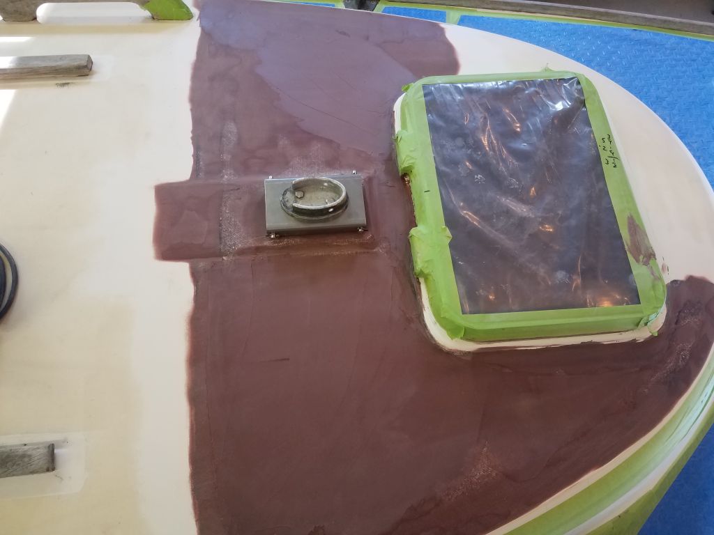
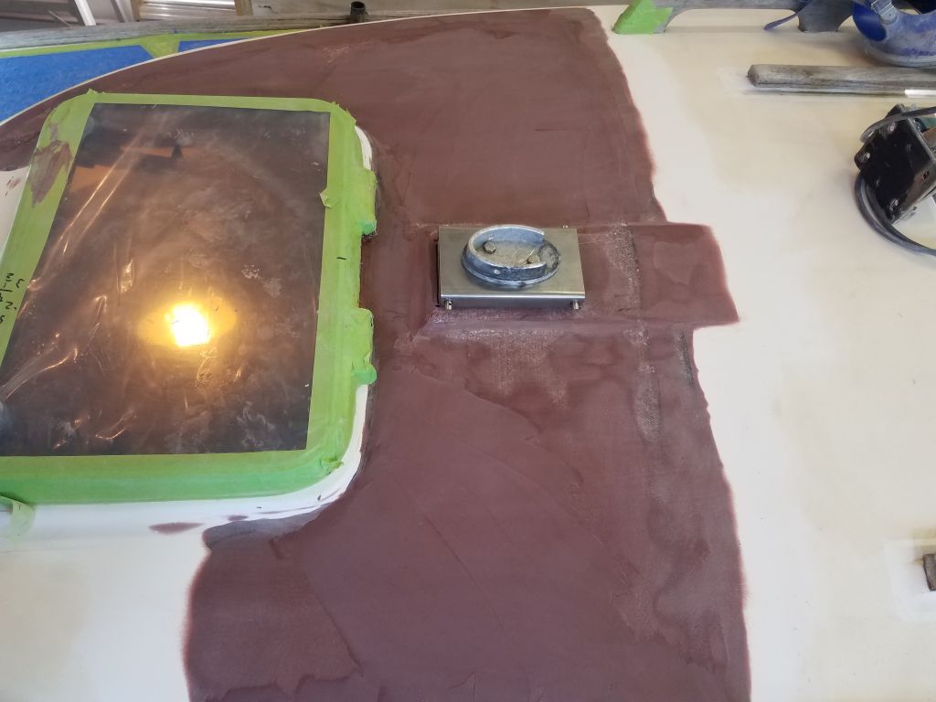
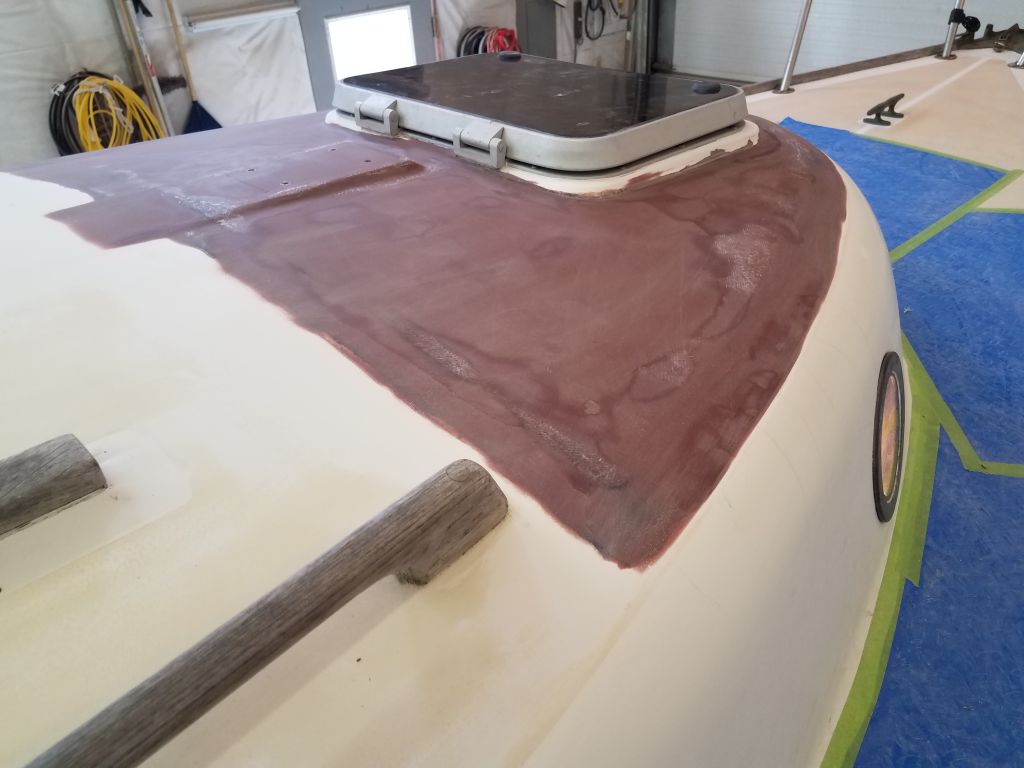
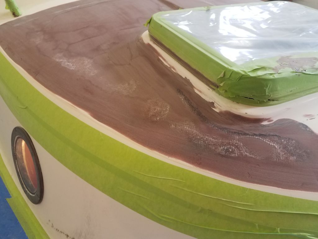
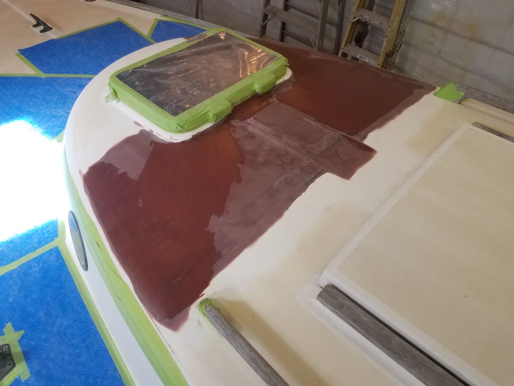
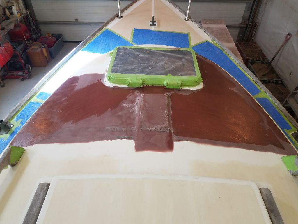
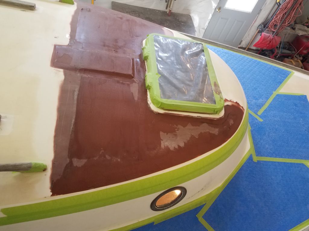
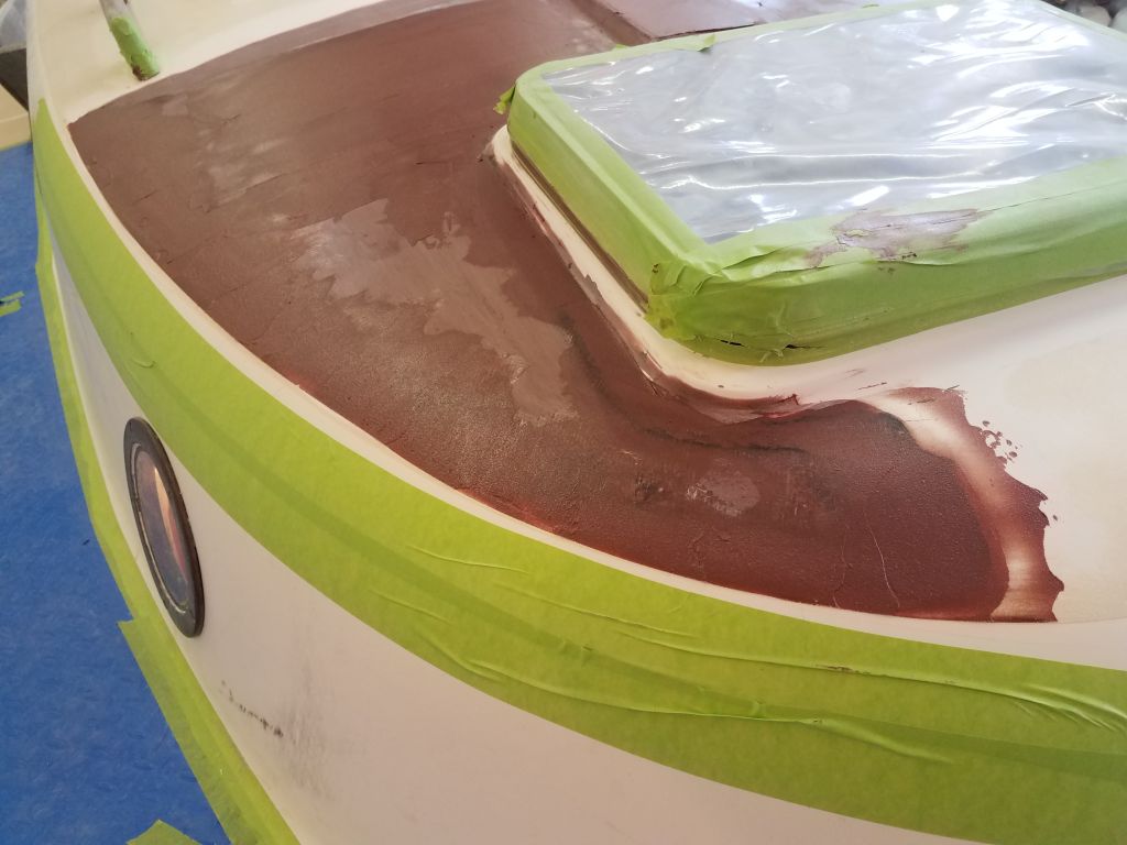
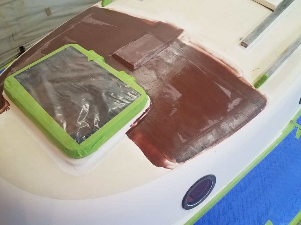
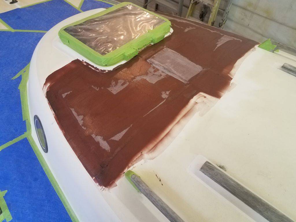
Next, I prepared a hole through the deck forward of the mast platform, through which I planned to run the mast wiring. I drilled a hole large enough to accept the VHF cable and 3-part wiring cable. The deck in this area was solid fiberglass, including a portion of the mast beam structure. I exited the hole through the liner in the forward cabin, where the wires had run through previously. On deck, I installed the base portion of a waterproof cable clam, one large enough that I could create two holes through the rubber insert for the cables in question. I secured the base plate with butyl sealant rather than the supplied gasket, as the after part of the housing just met the angled fillet at the forward end of the mast platform, and I felt it needed a better sealant to make up the slight height irregularity.
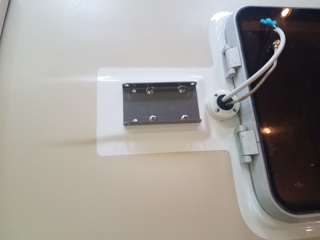
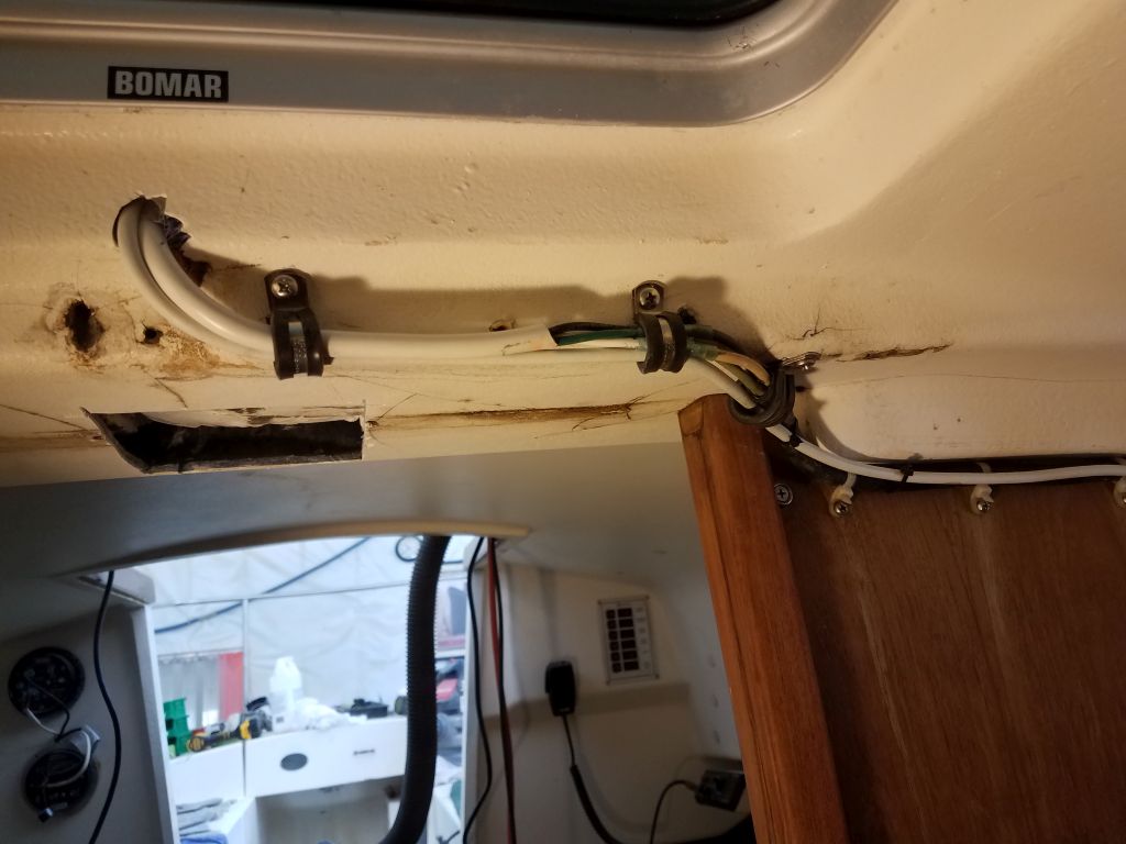
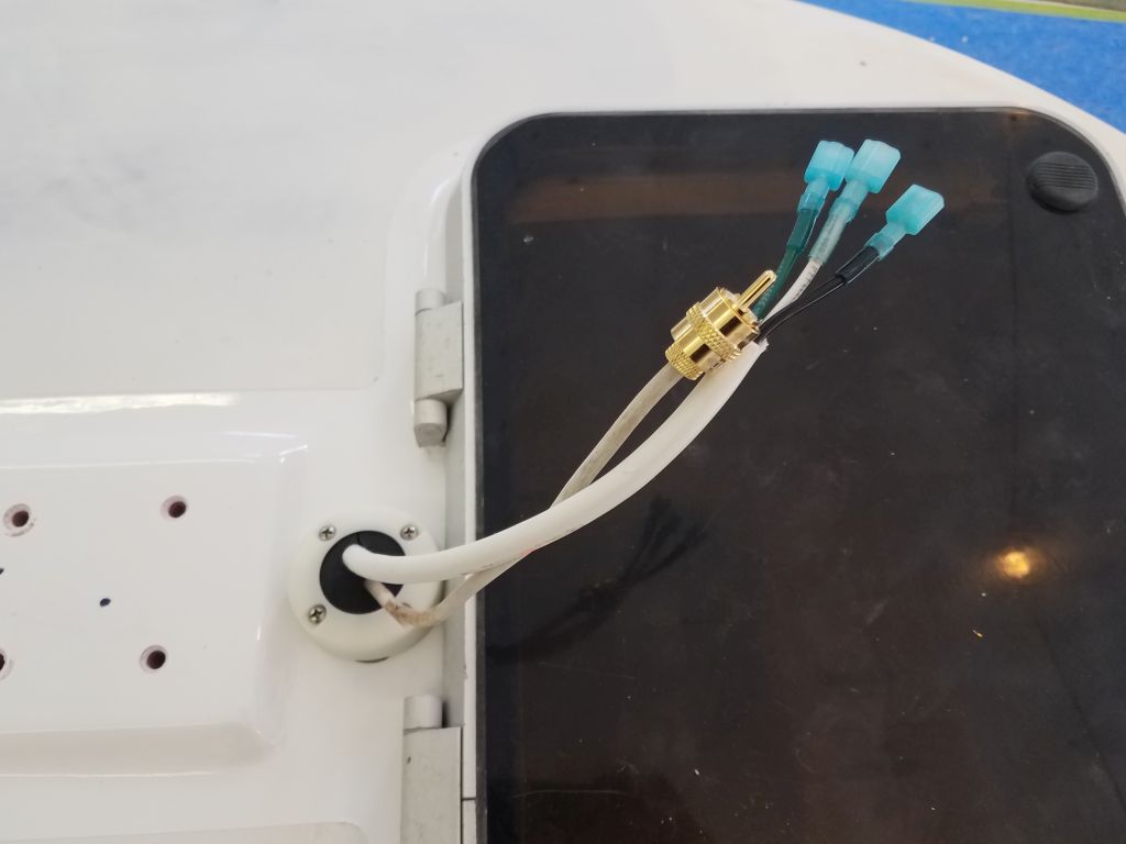
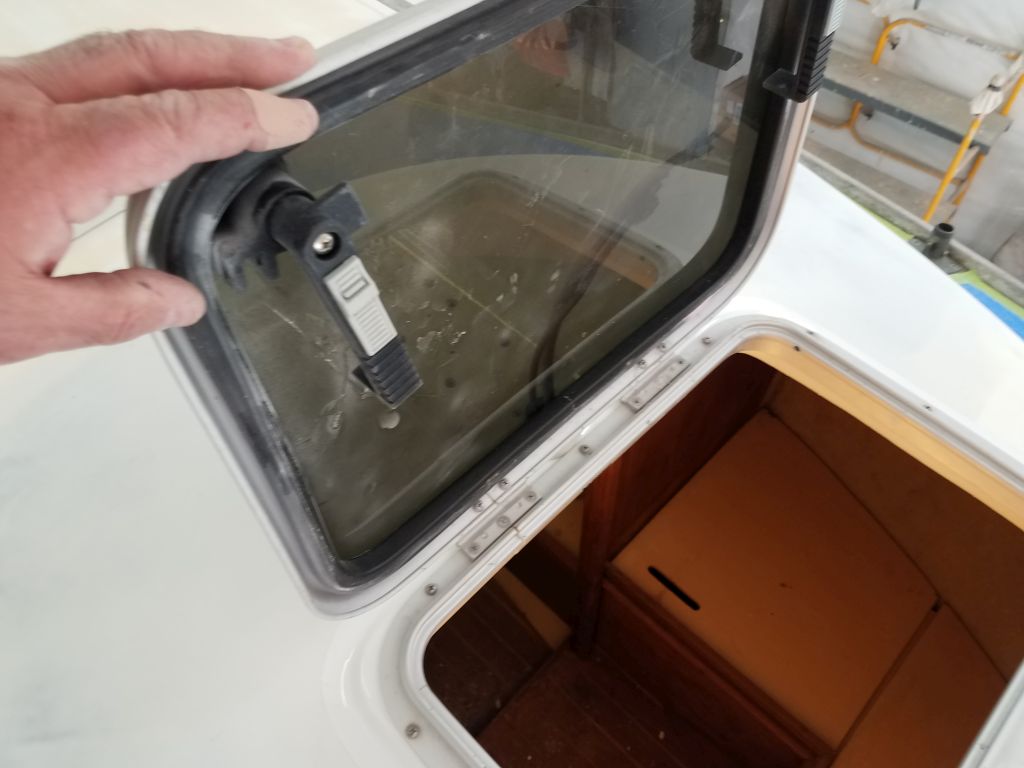
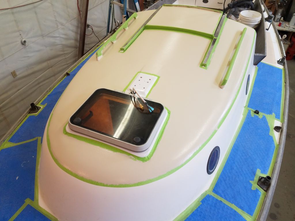
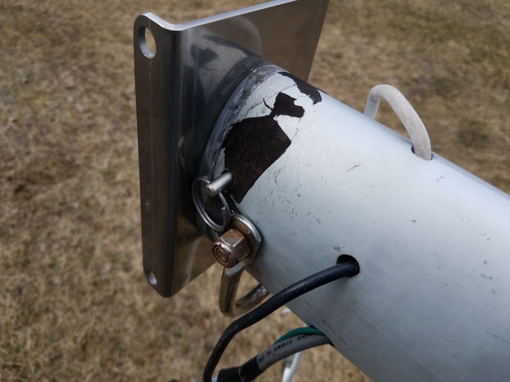
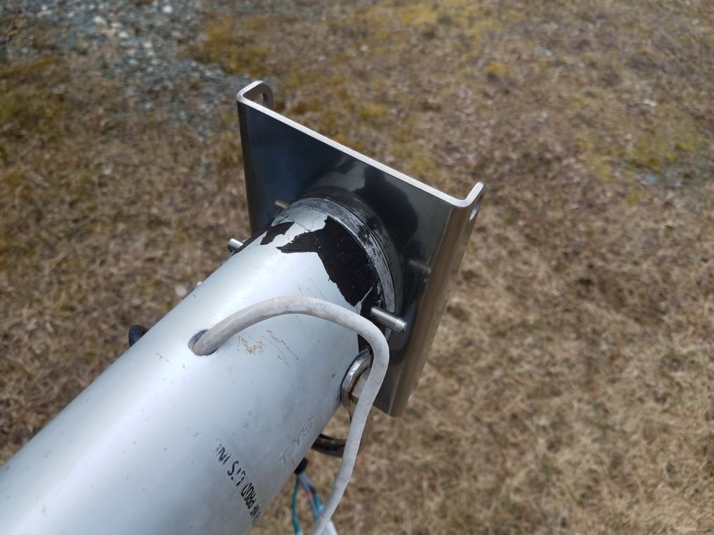
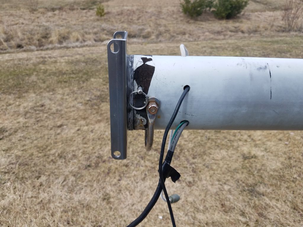
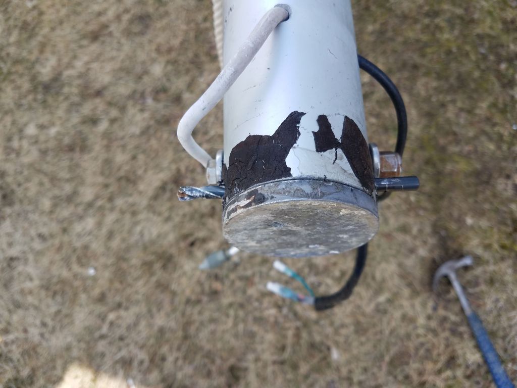
Since the original mast wires had been badly corroded where they passed through the deck, I cut back the original cable spliced in a length of new 3-conductor round cable, which I passed through the deck and gland fitting before making up the ends with insulated spade connectors; I also installed a new coax connector to the end of the VHF cable. The hatch cleared the cable gland when opened; I’d had a moment’s consternation earlier in the installation process when I feared there might have been an interference issue, but it was for naught.
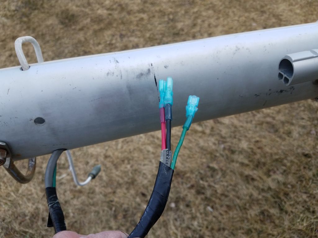
To complete the new wiring, which now had different ends than the original, I installed the appropriate mating ends on the wiring coming from the base of the mast. While the new tri-conductor wire I used inside the boat matched the colors of the original, I noted that the wires exiting the mast were slightly different; though I didn’t confirm it, I suspected that white (boat) matched red (mast); the black and green conductors were consistent between the two wiring sets.
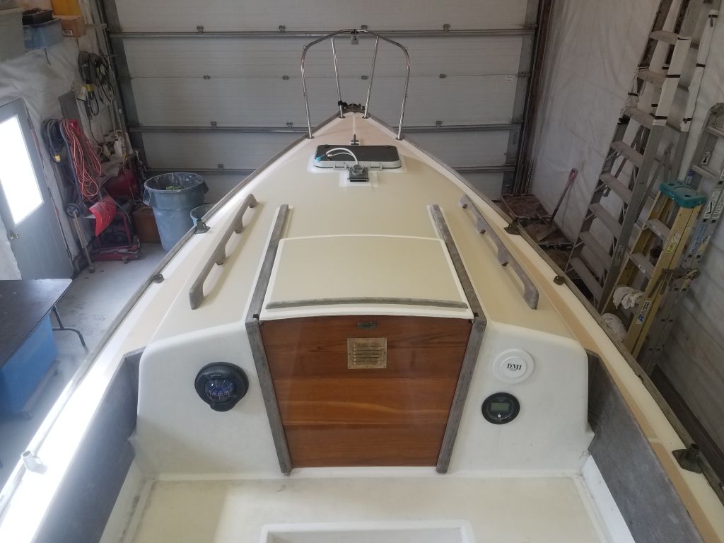
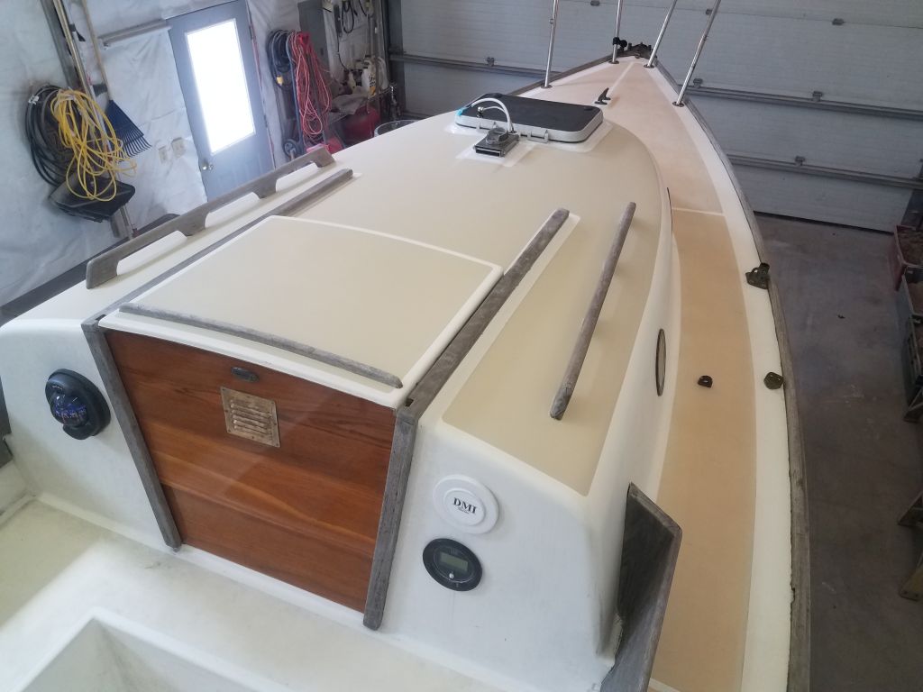
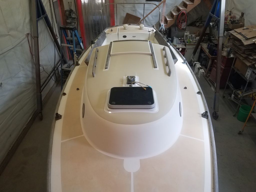
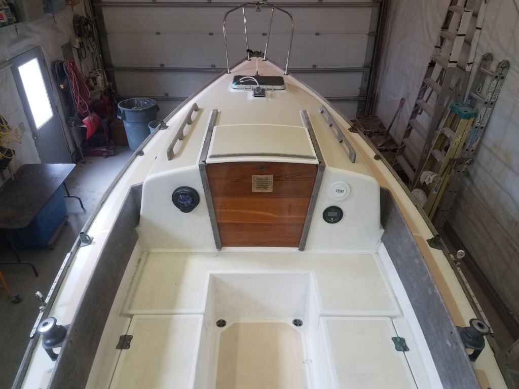
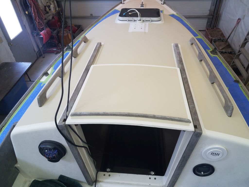
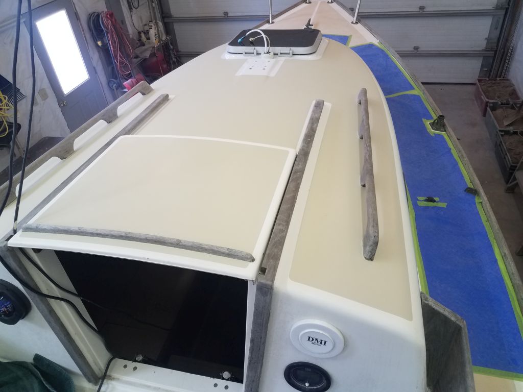
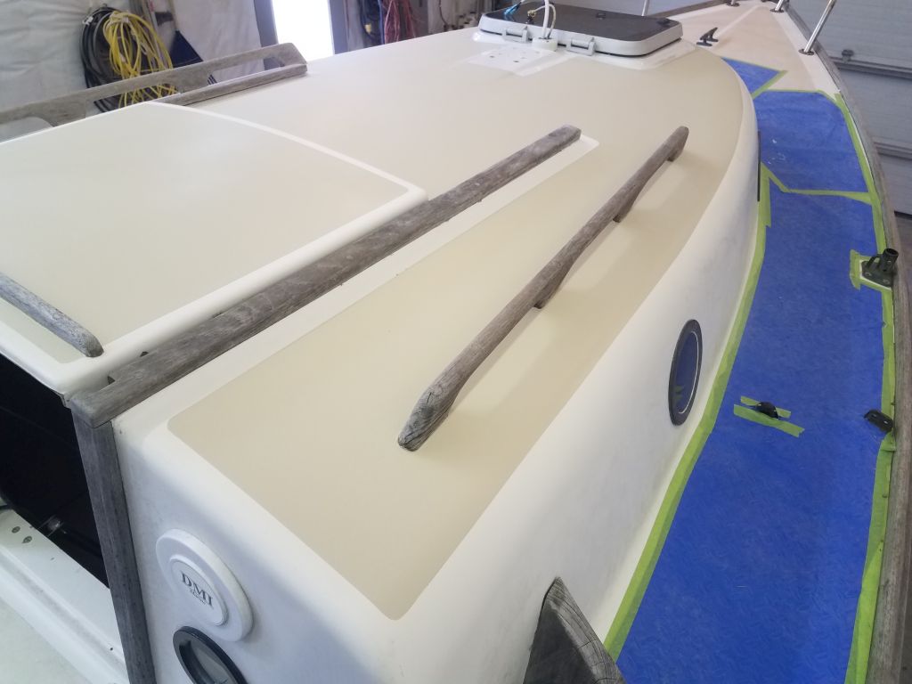
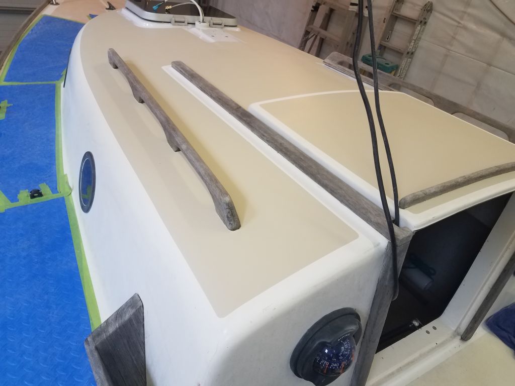
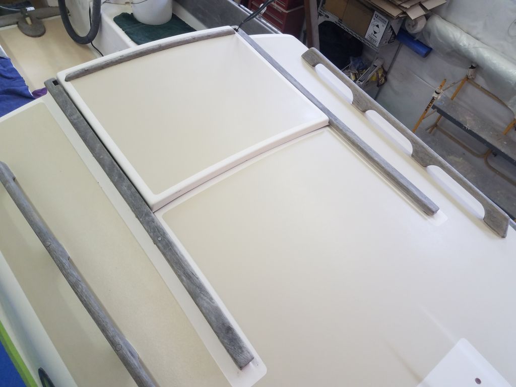
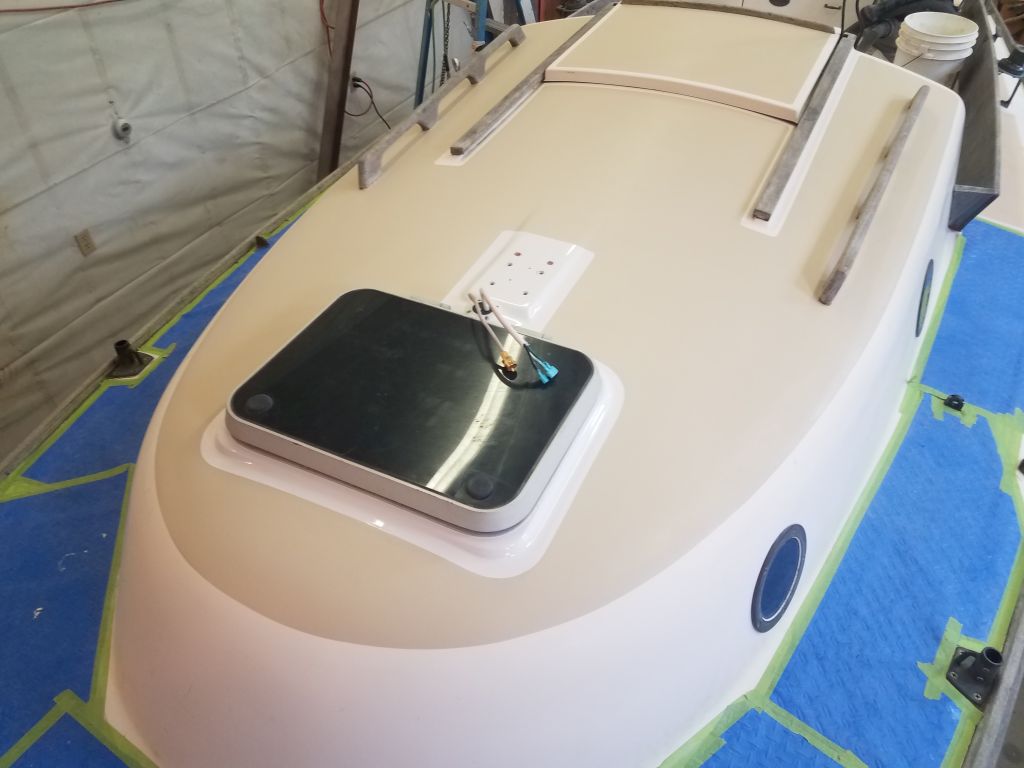
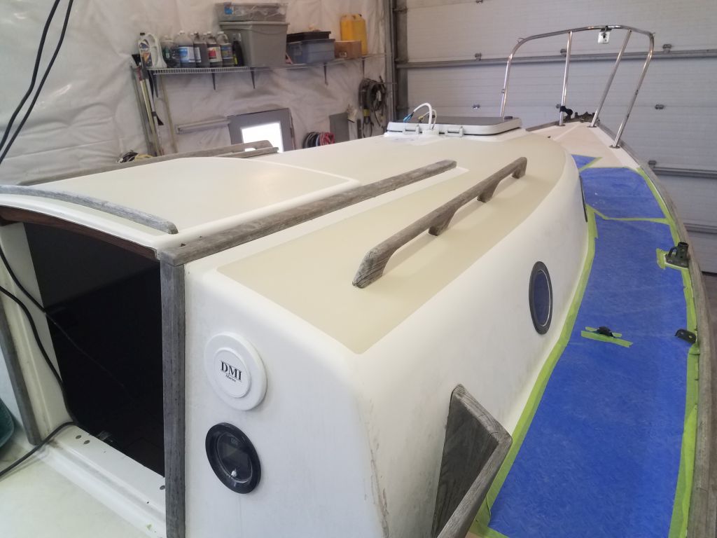
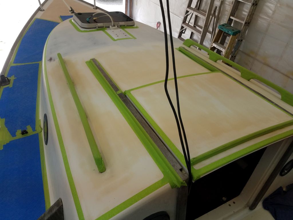
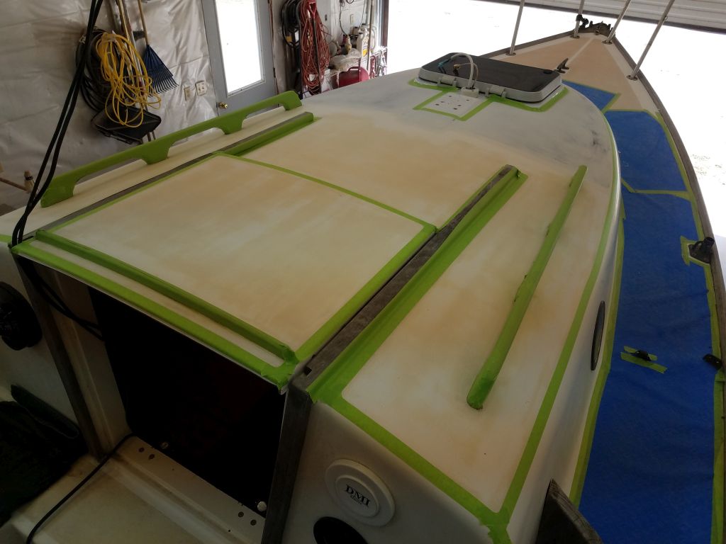
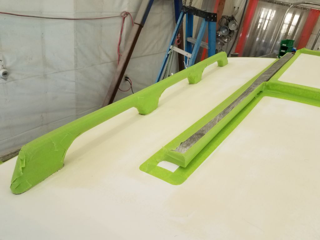
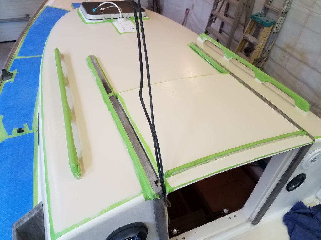
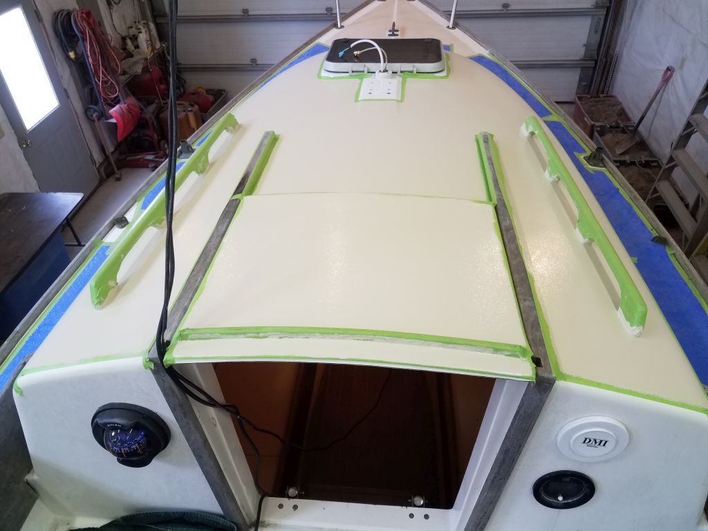
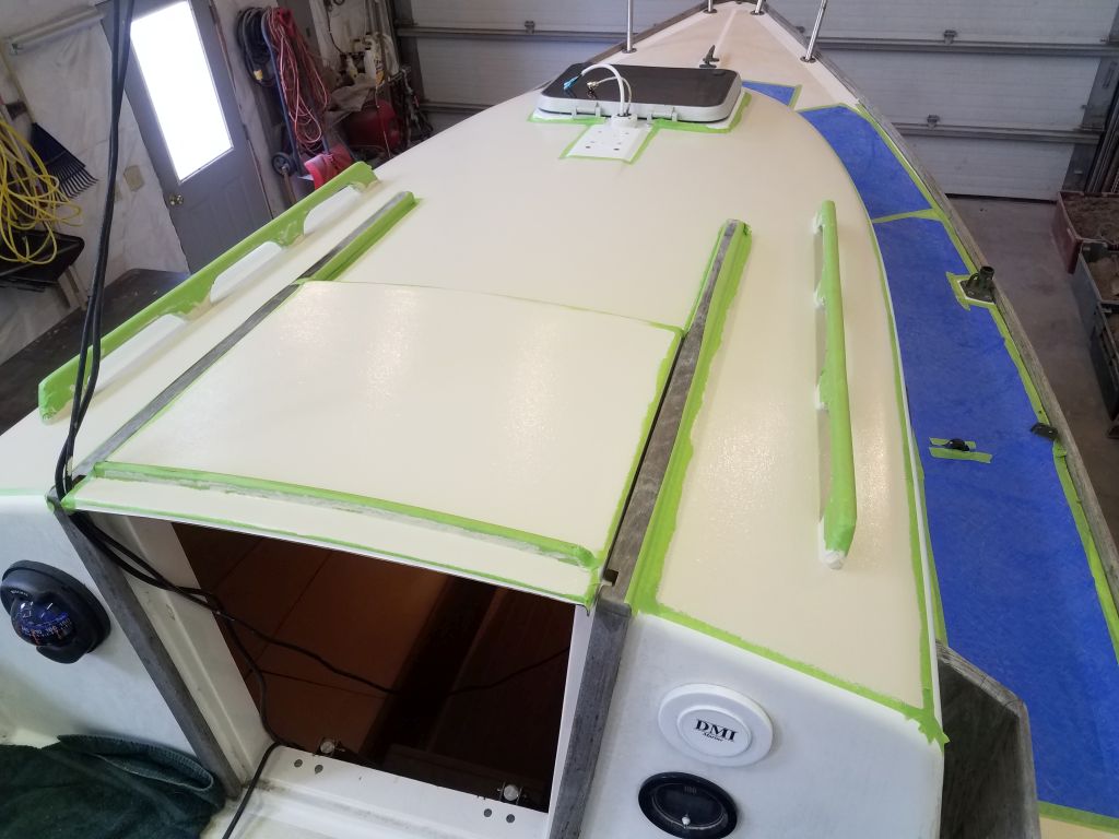
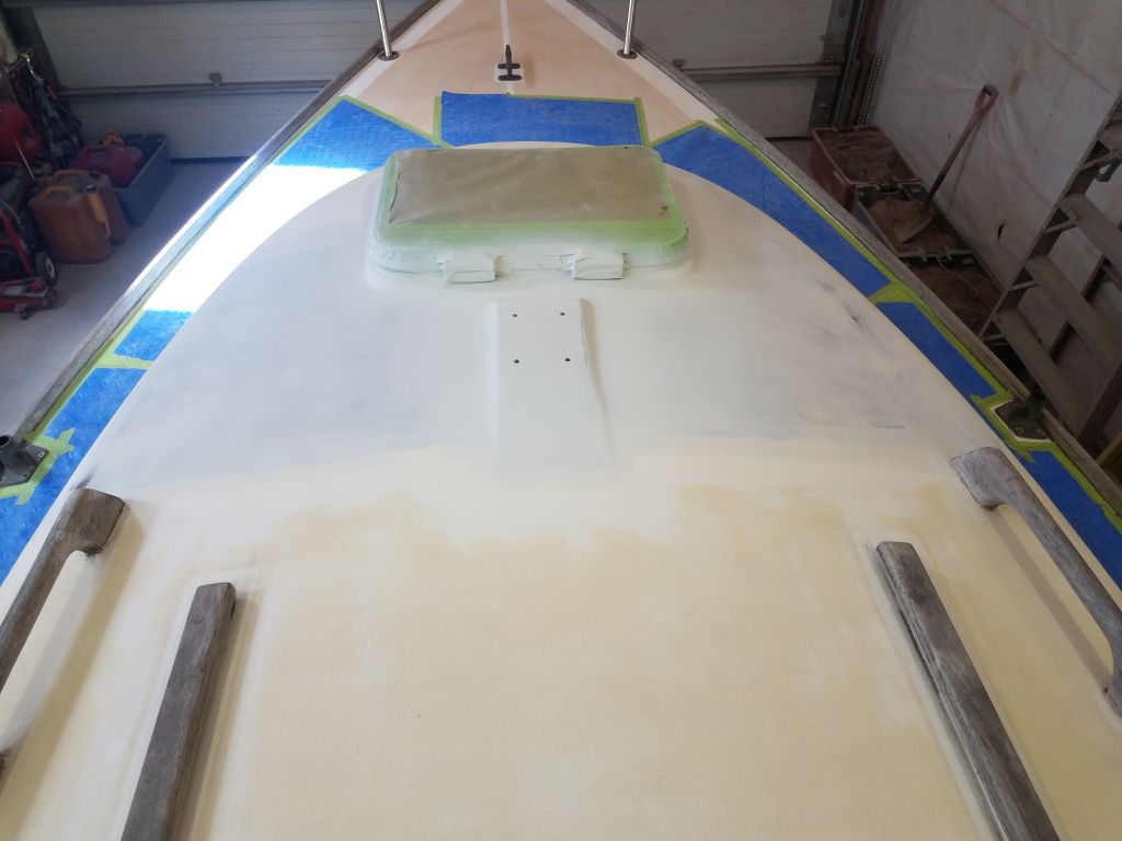
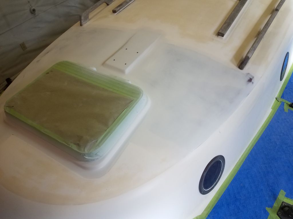
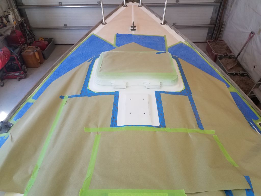
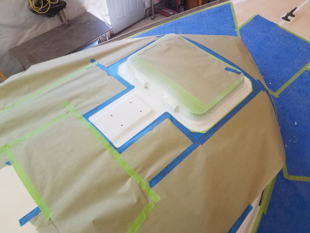
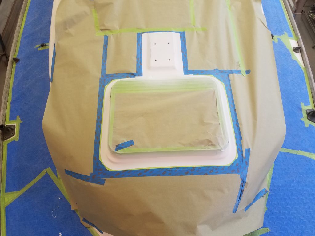
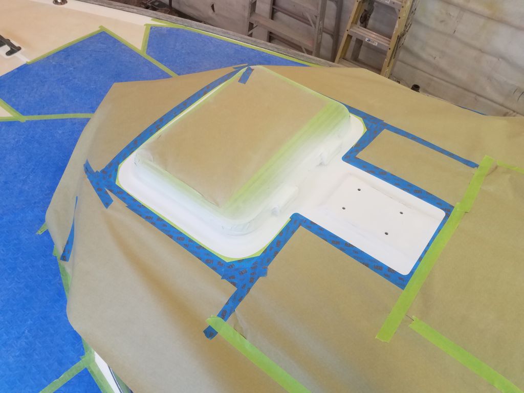
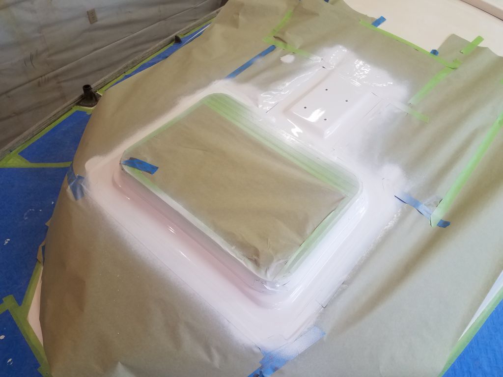
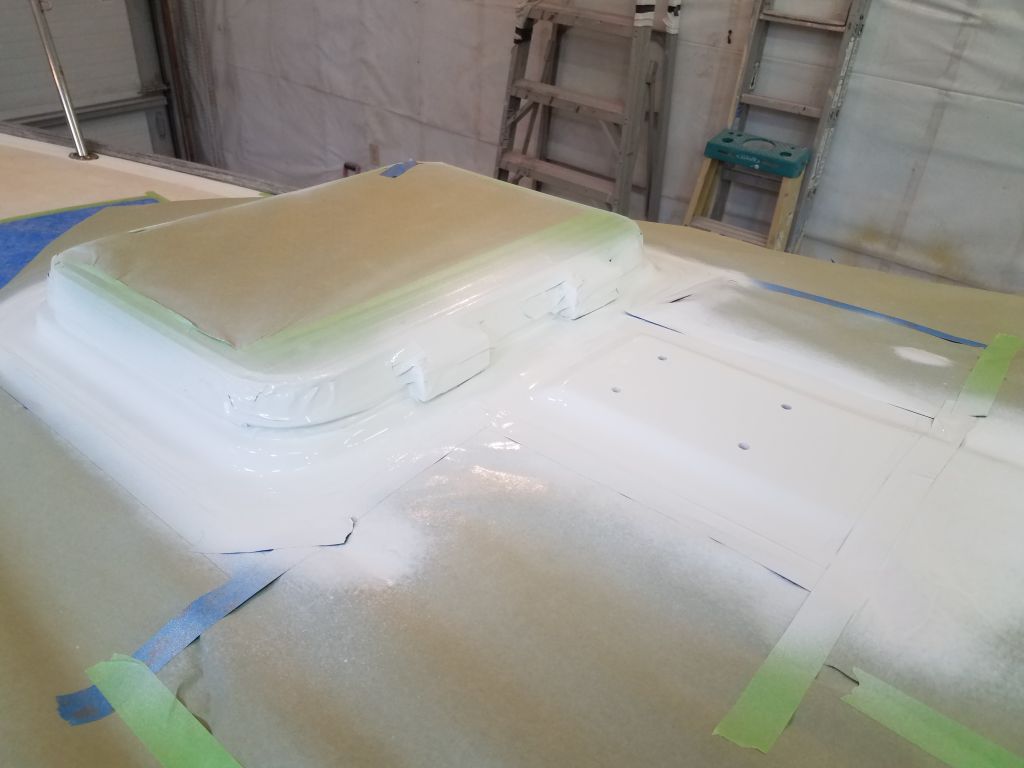
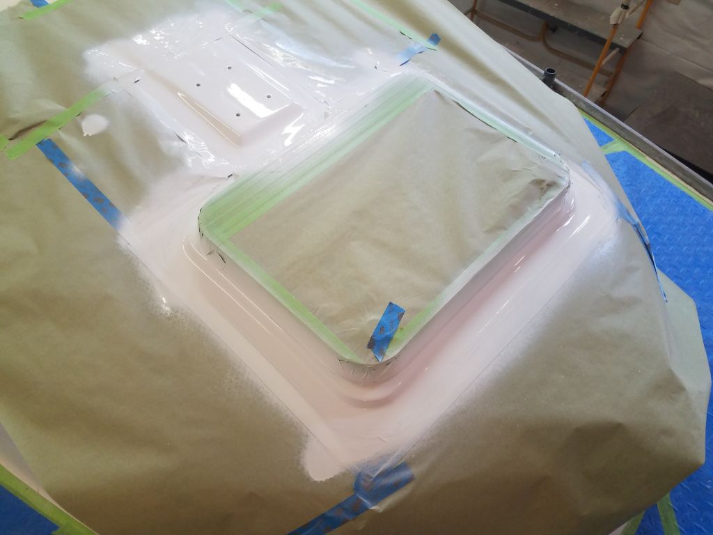
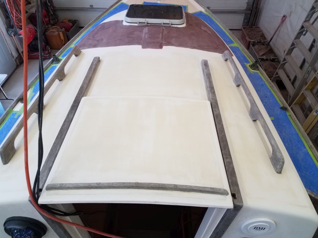
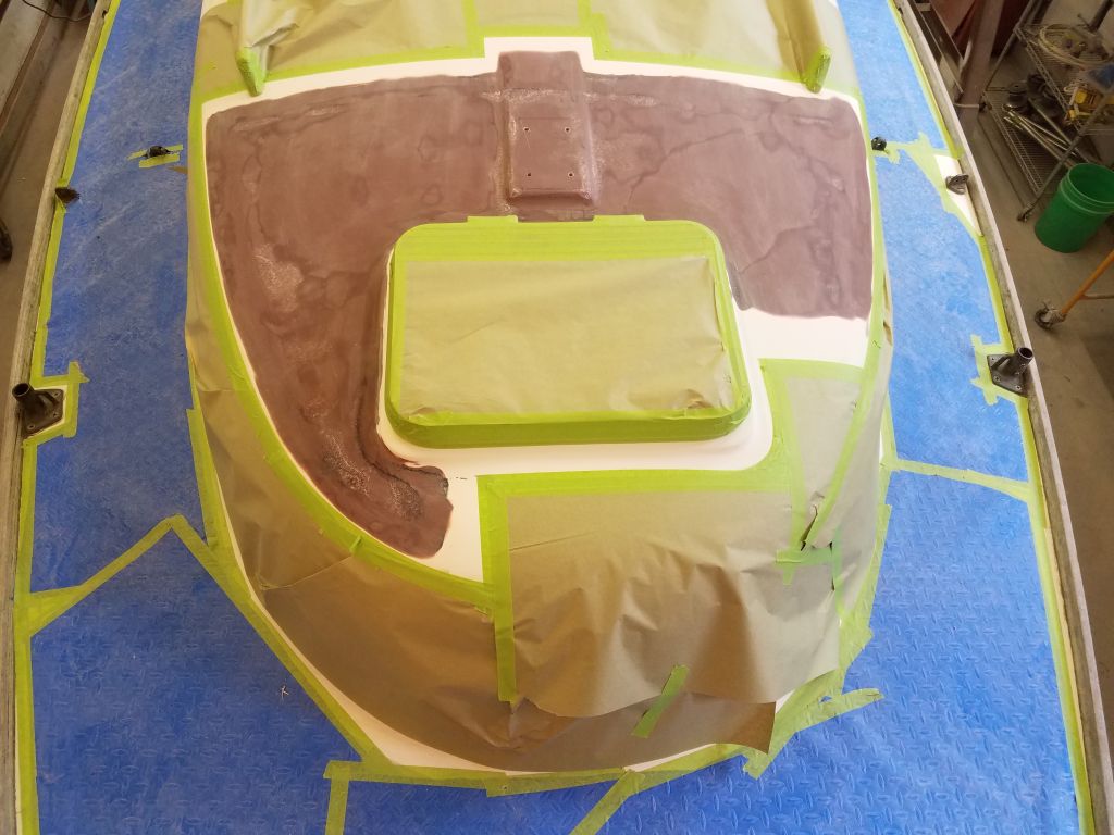
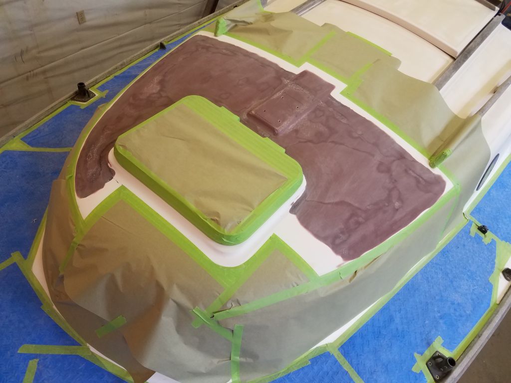
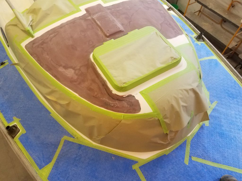
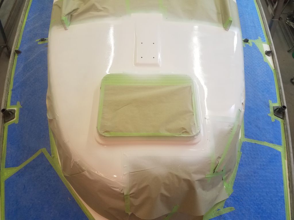
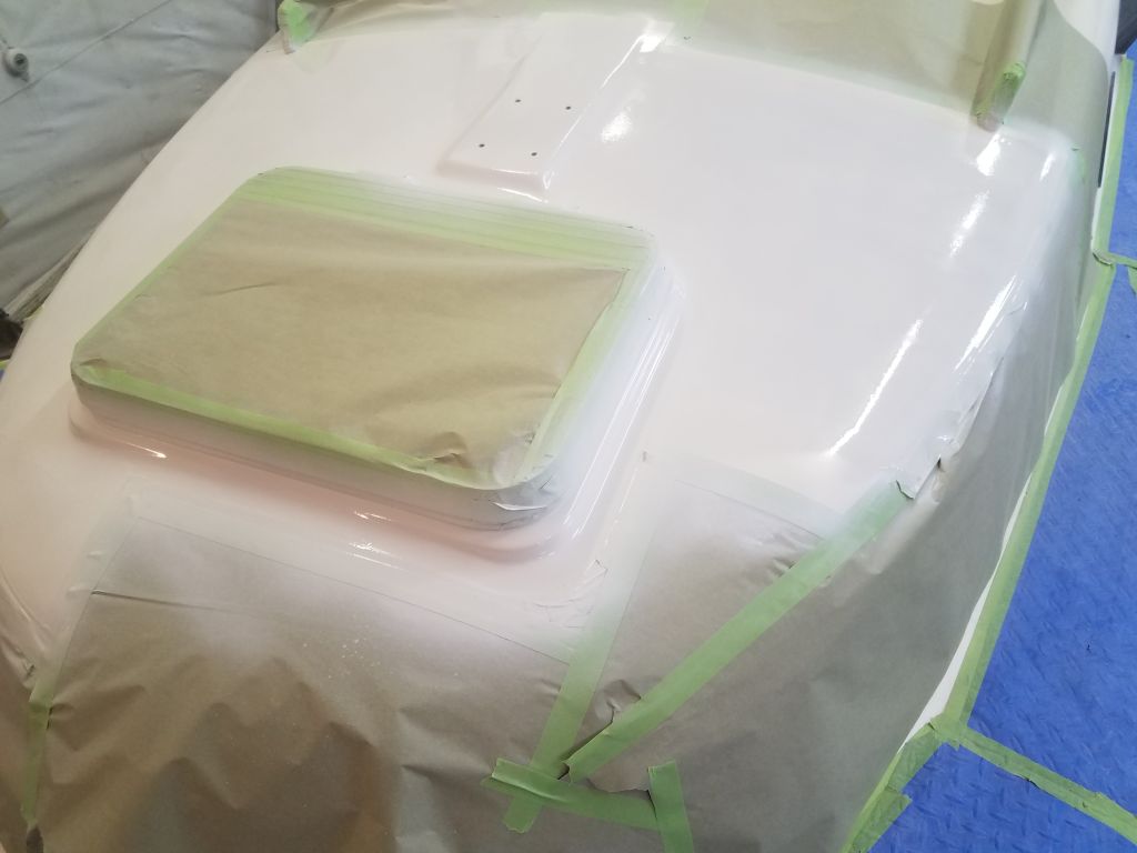
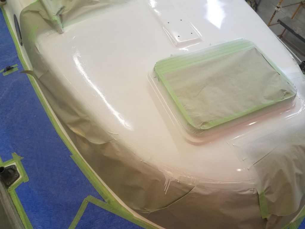
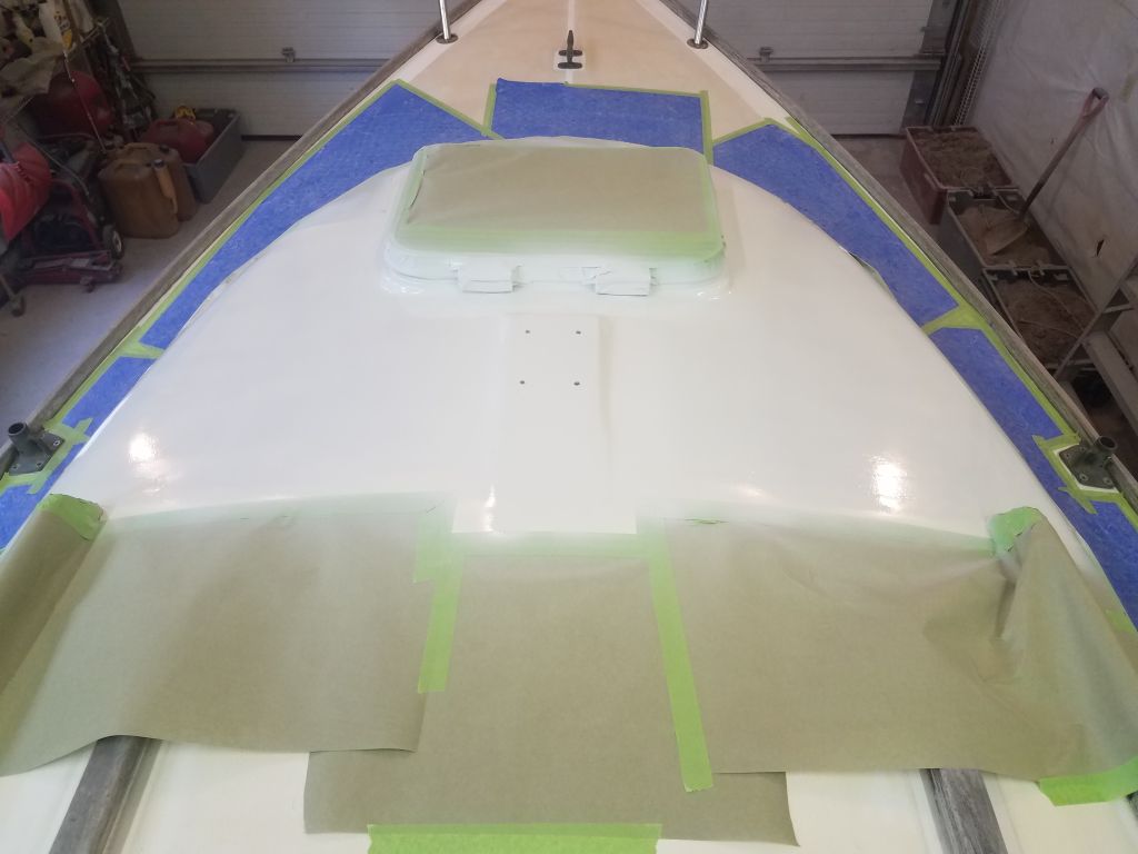
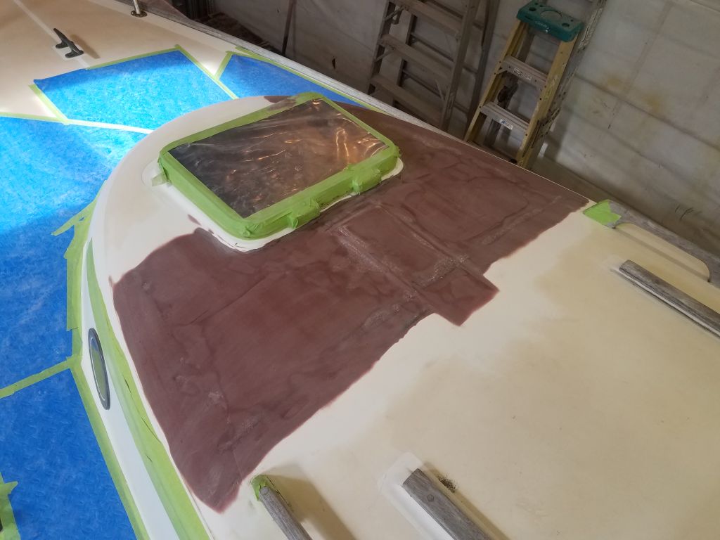
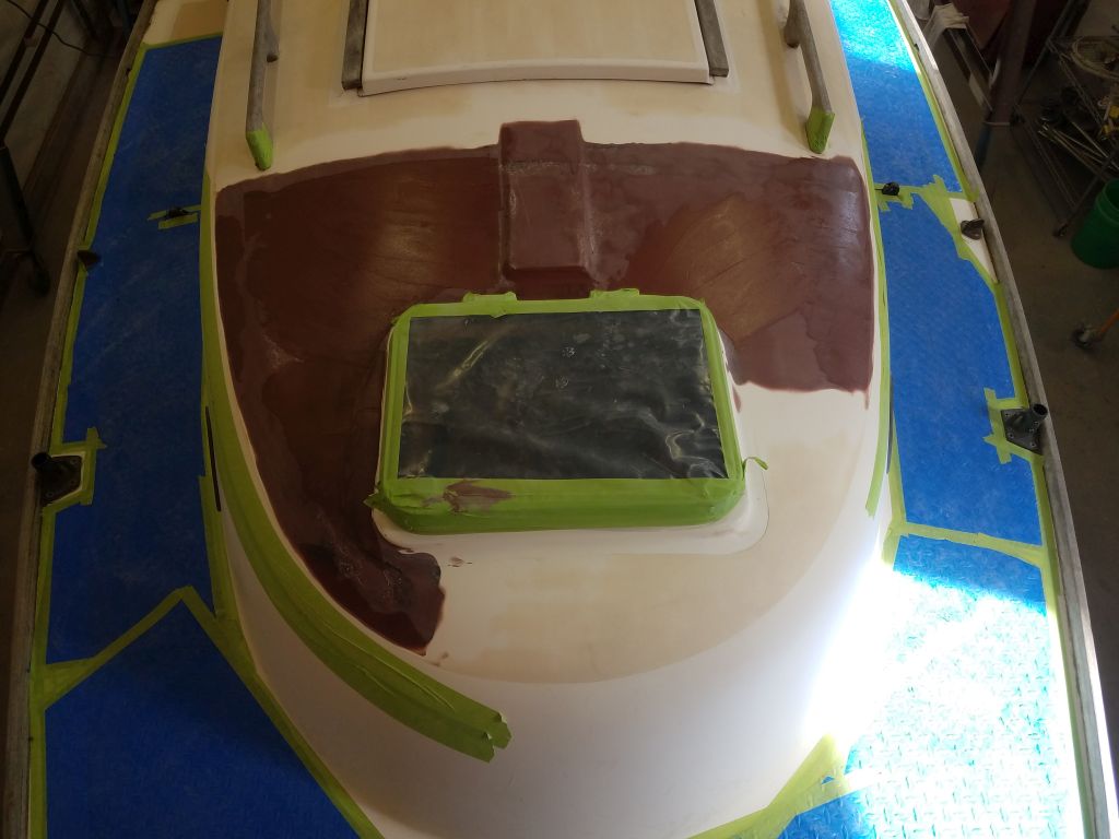
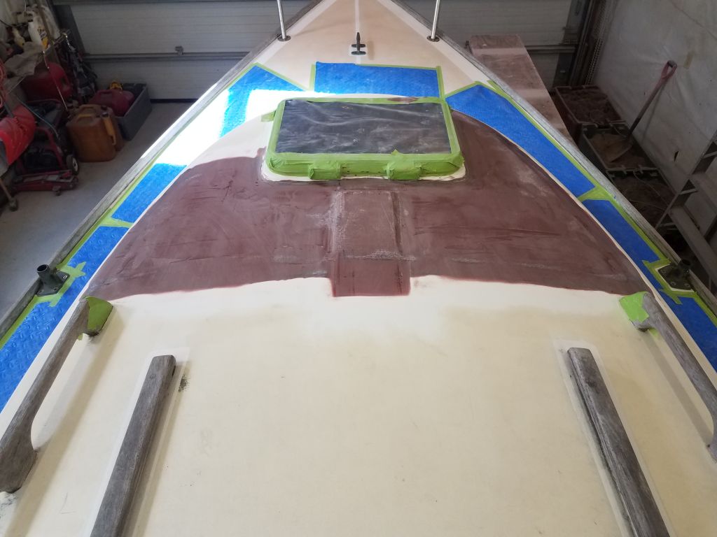
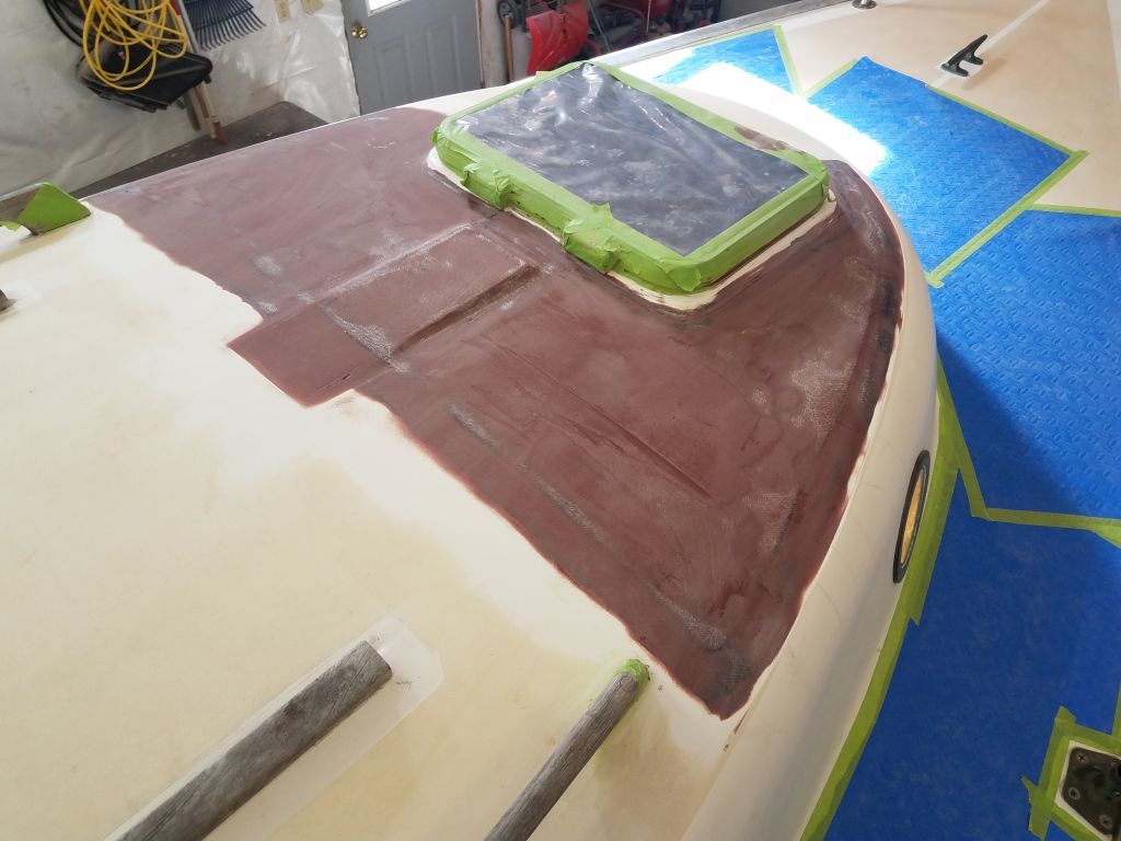
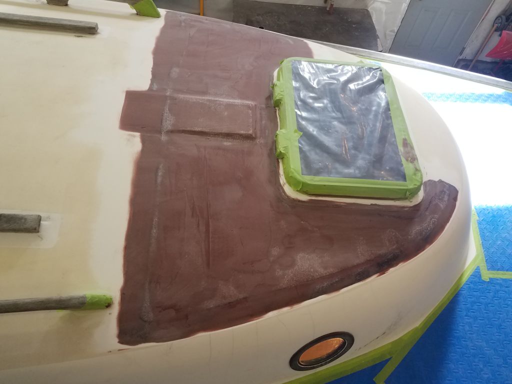
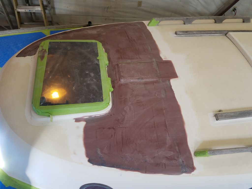
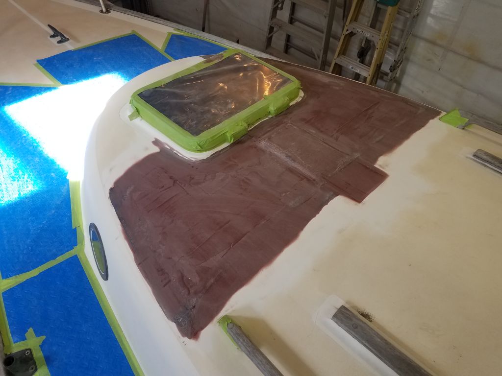
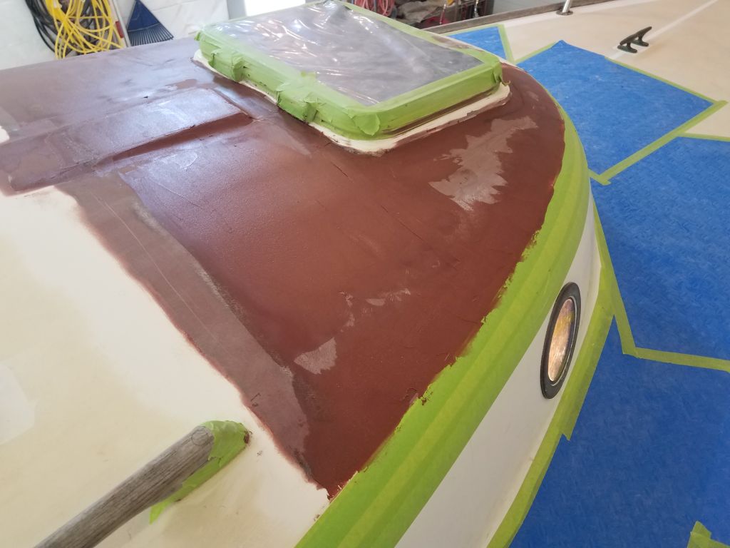
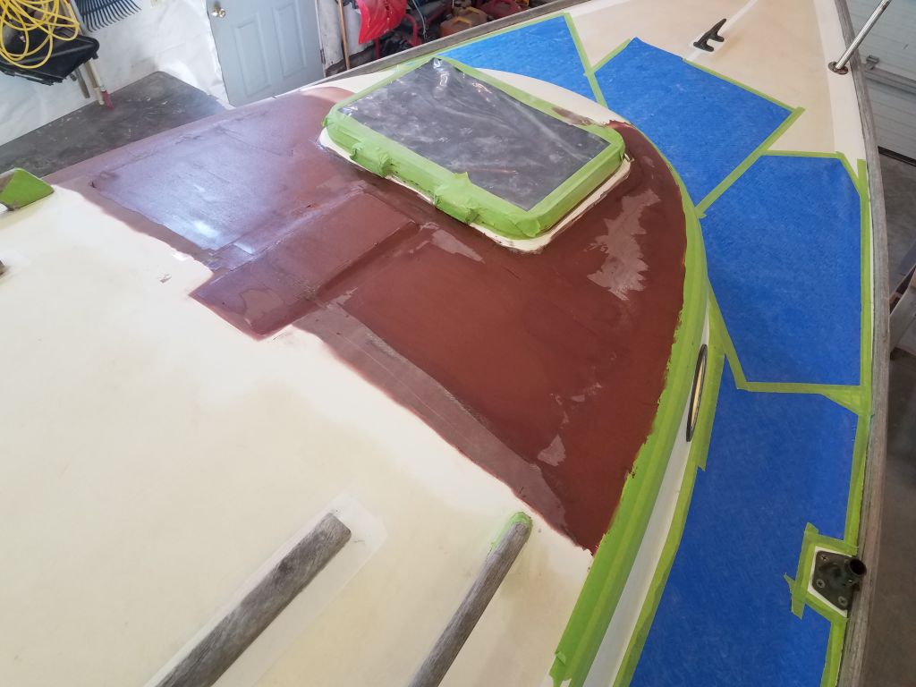
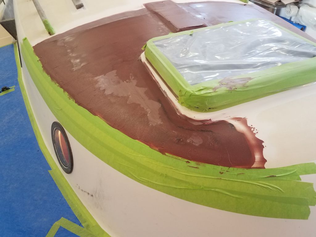
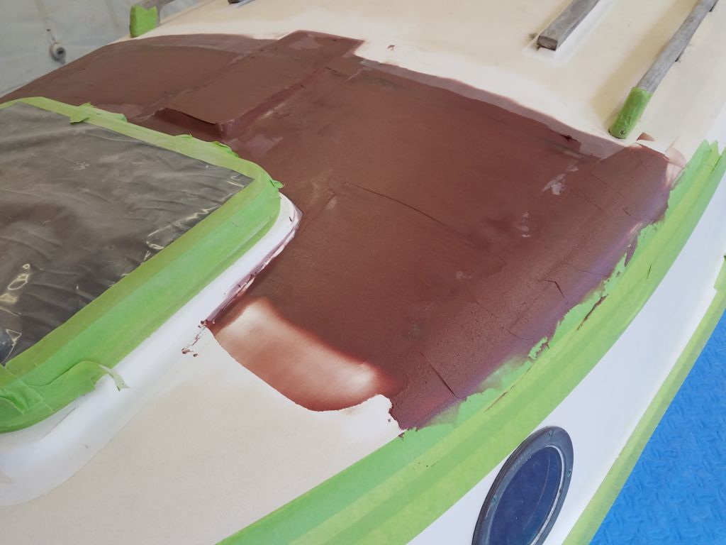
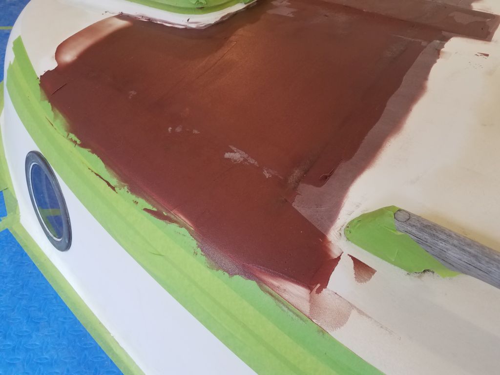
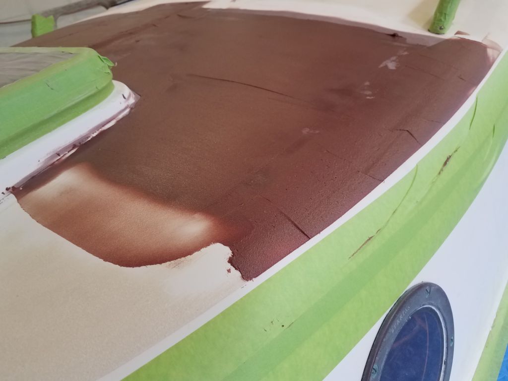
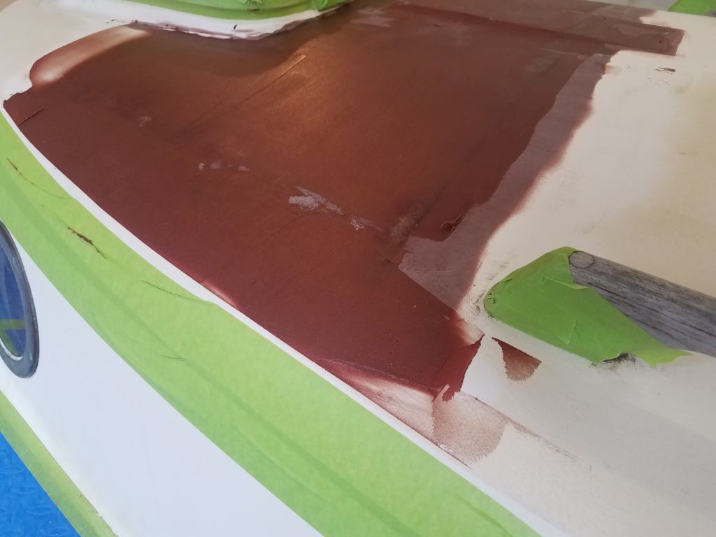
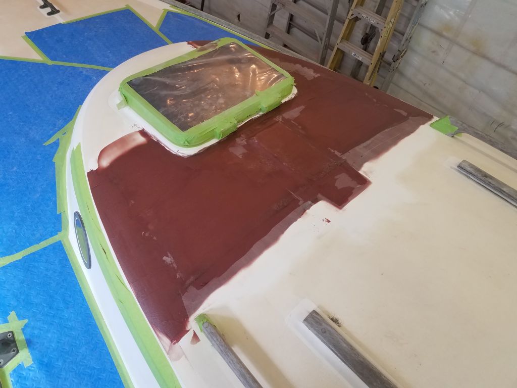
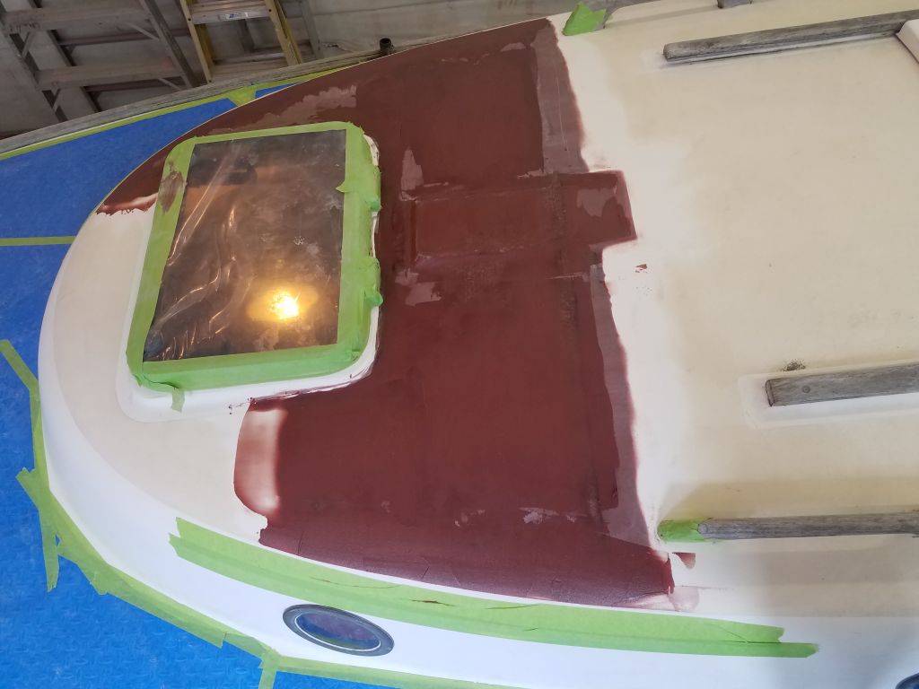
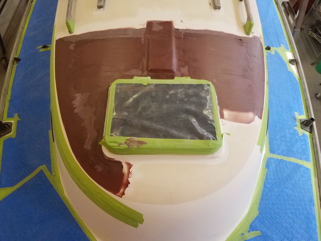
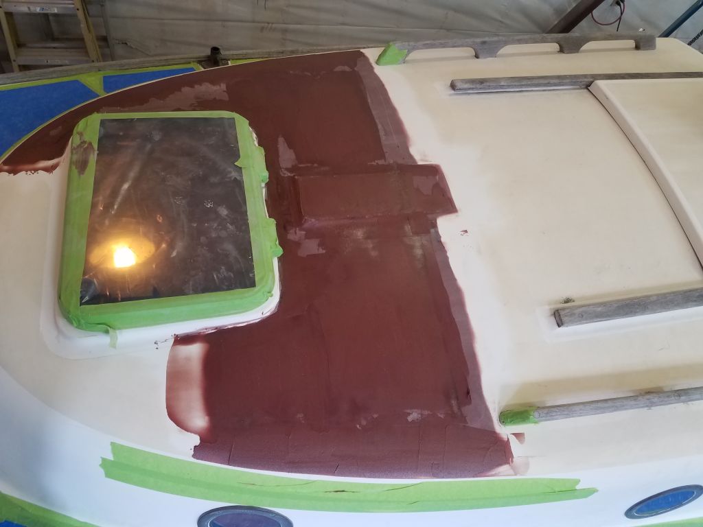
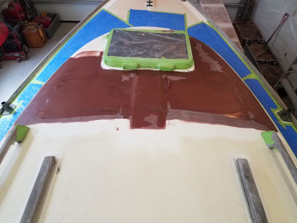
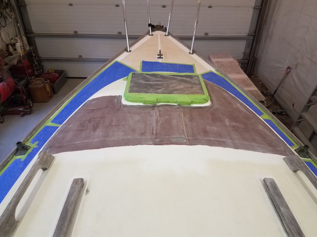
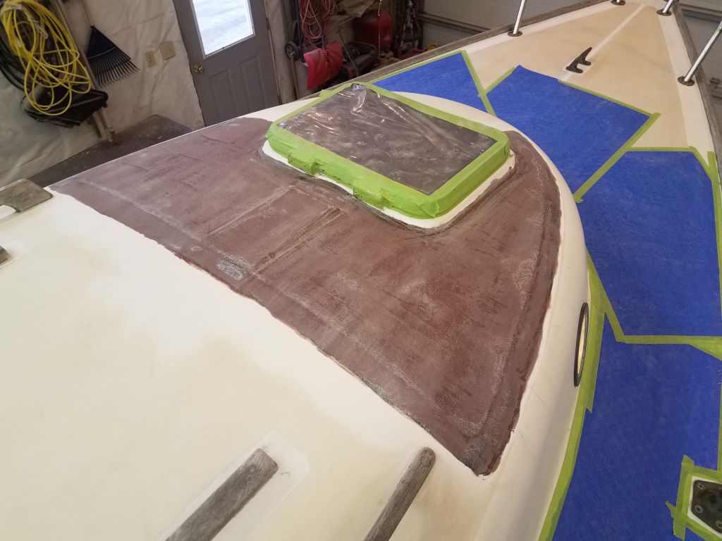
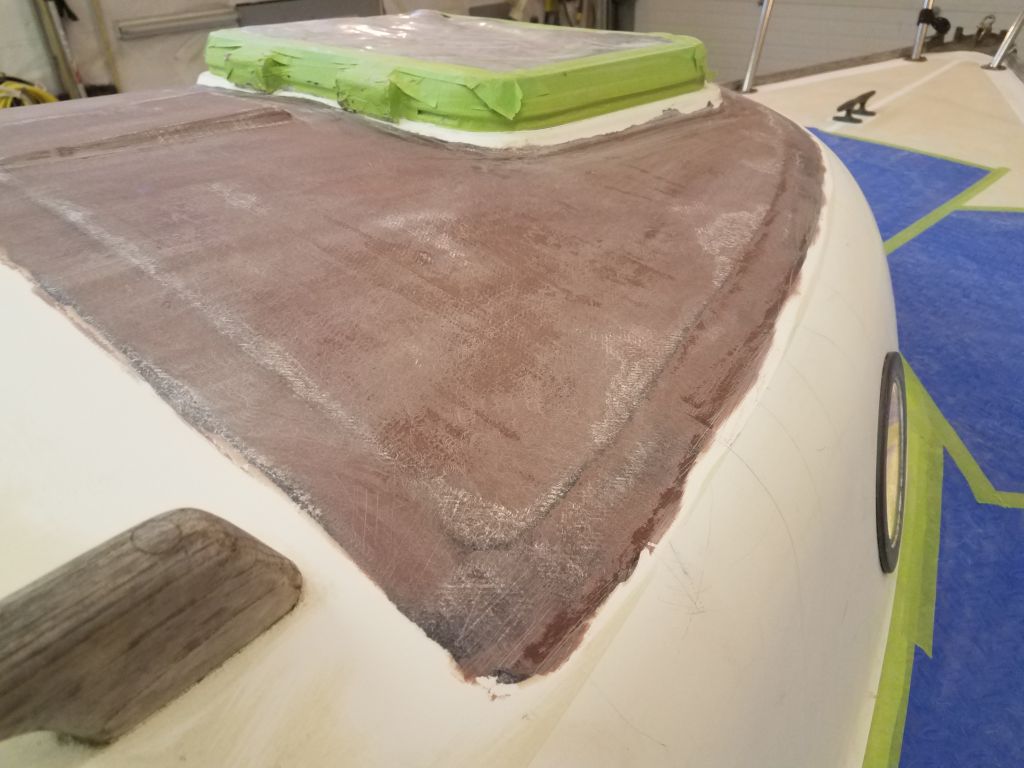
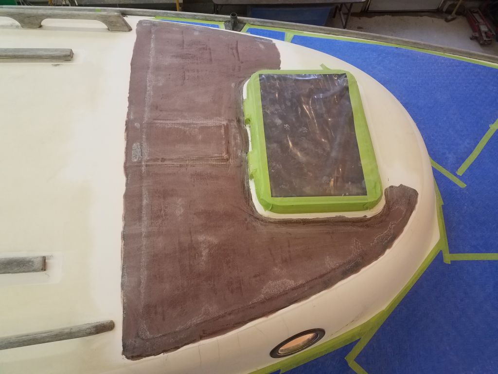
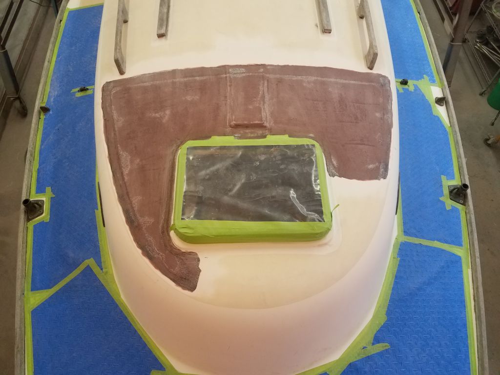
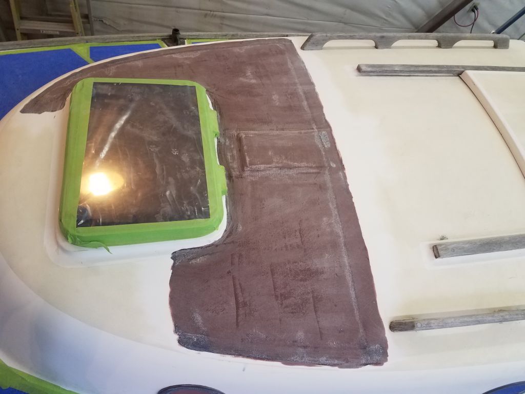
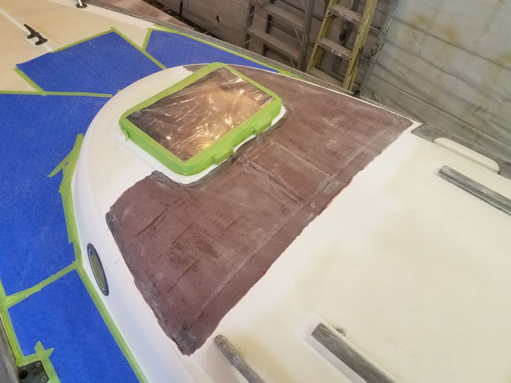
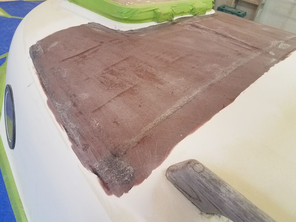
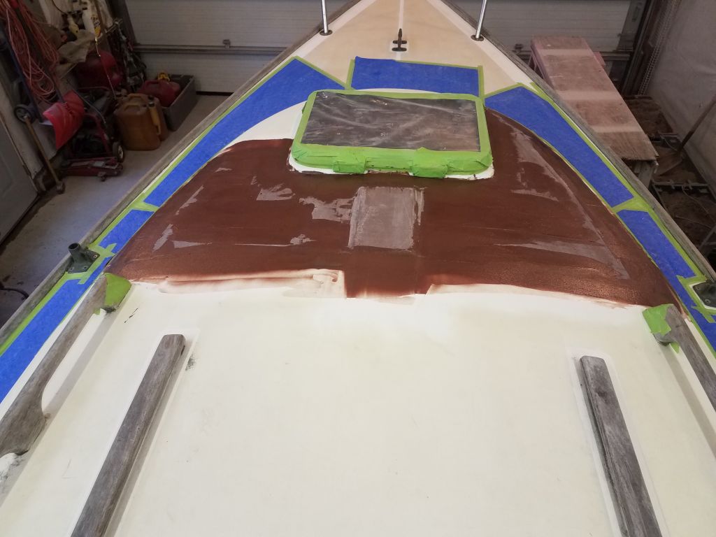
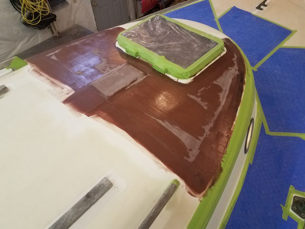
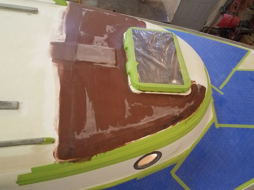
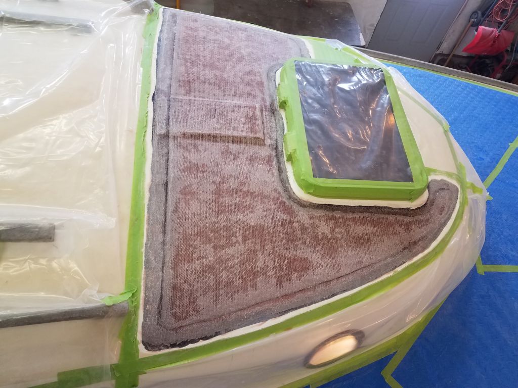
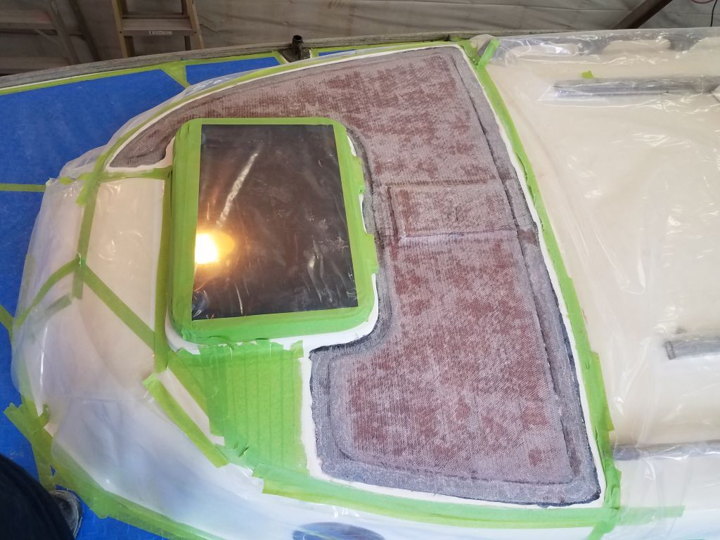
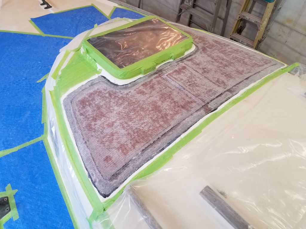
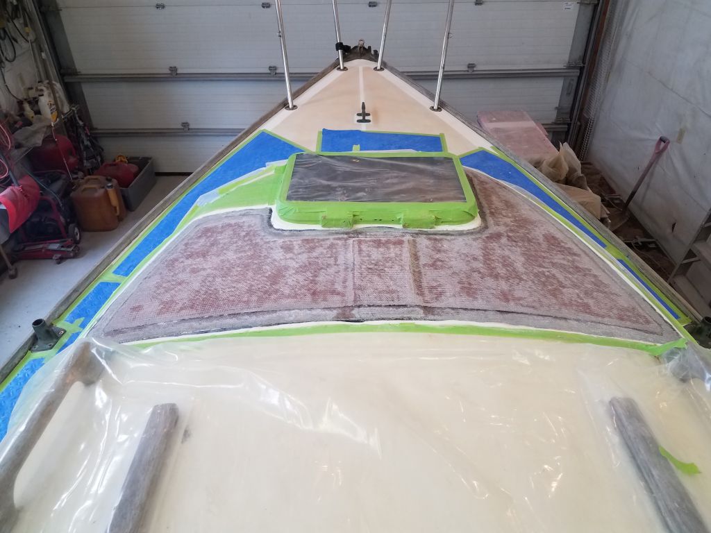
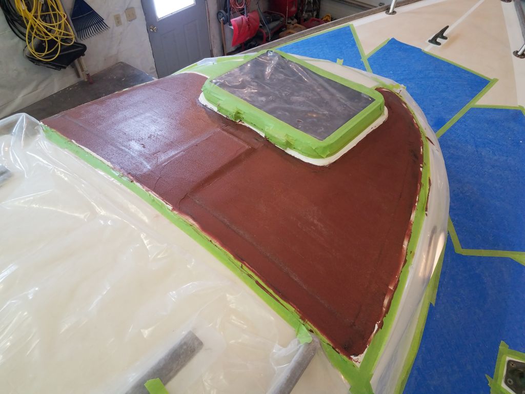
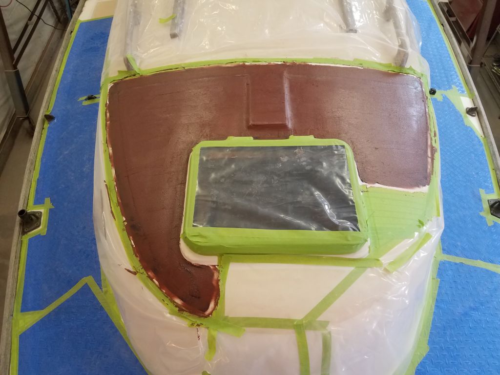
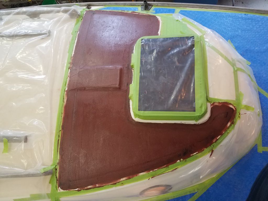
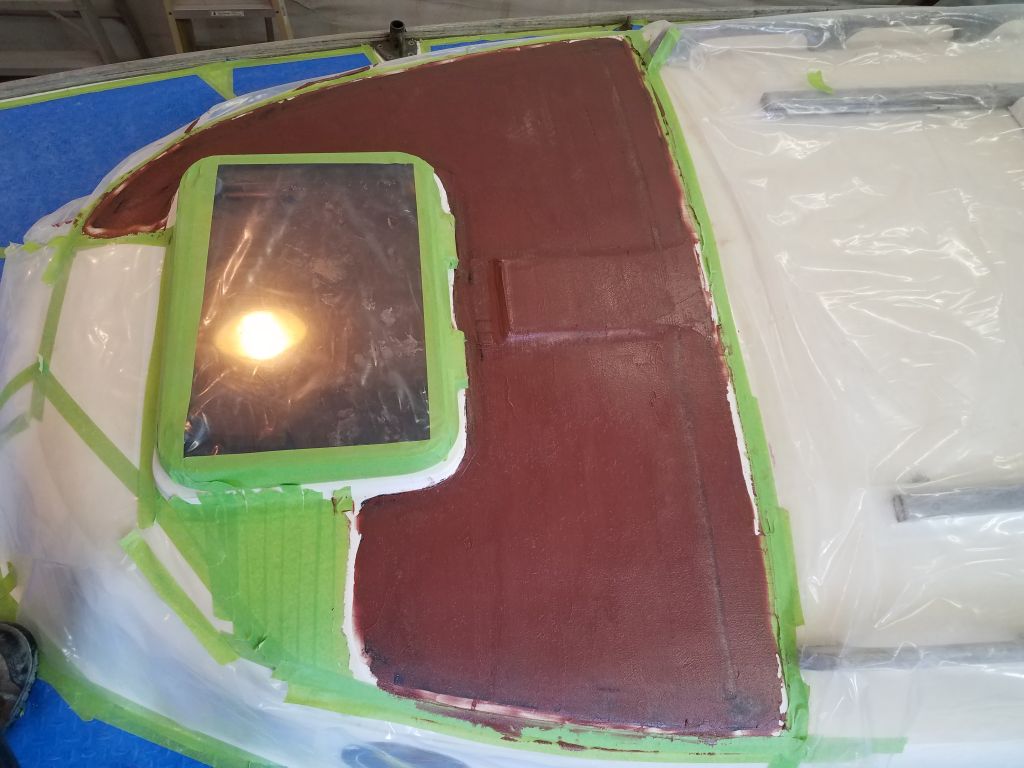
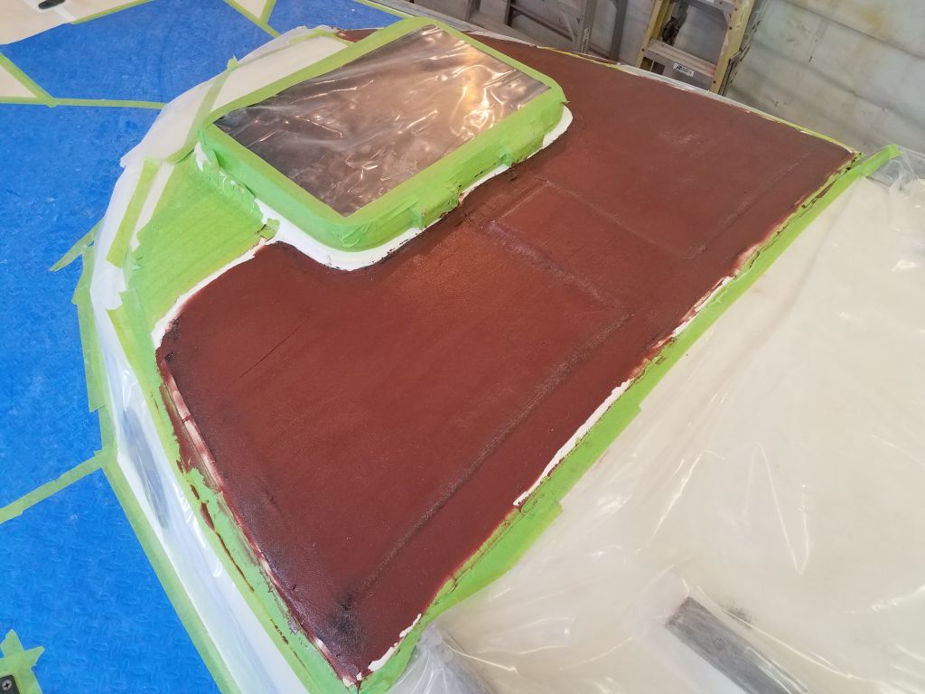
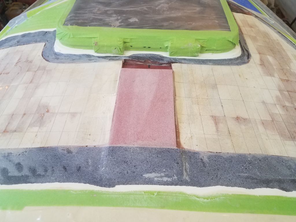
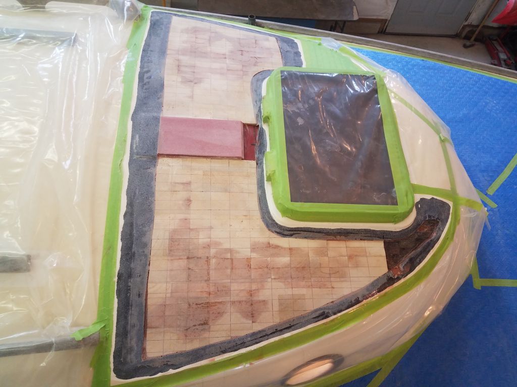
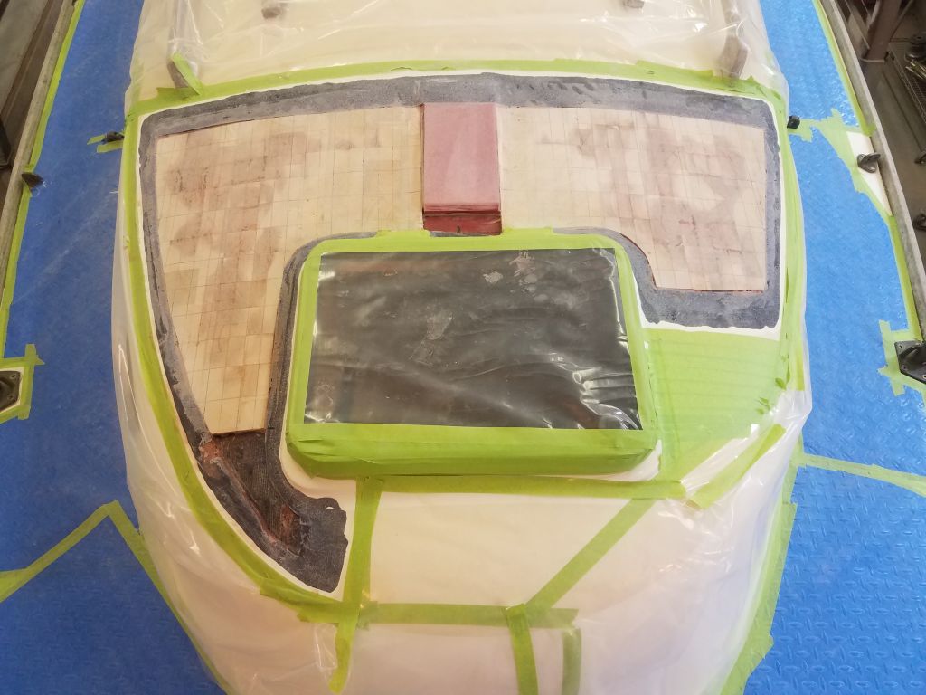
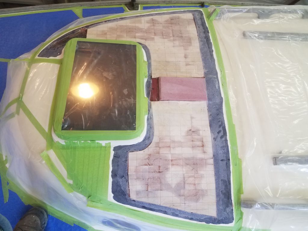
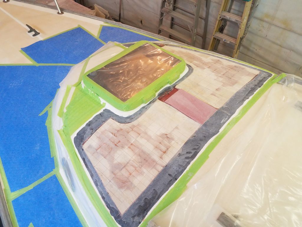
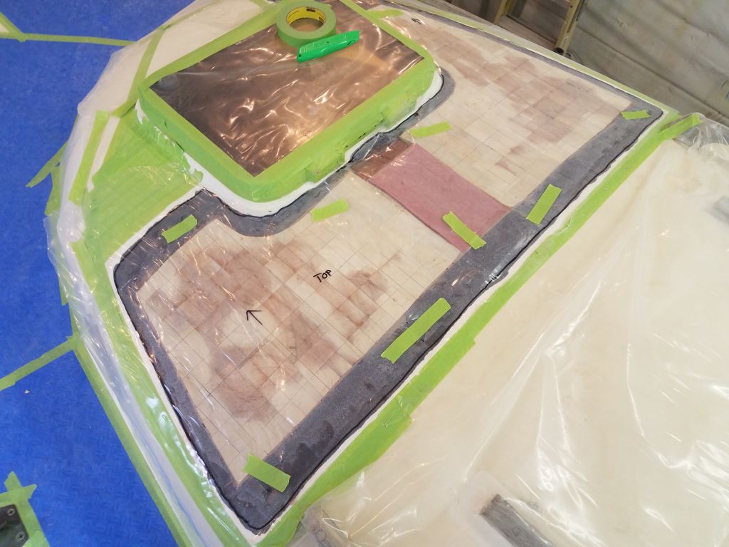
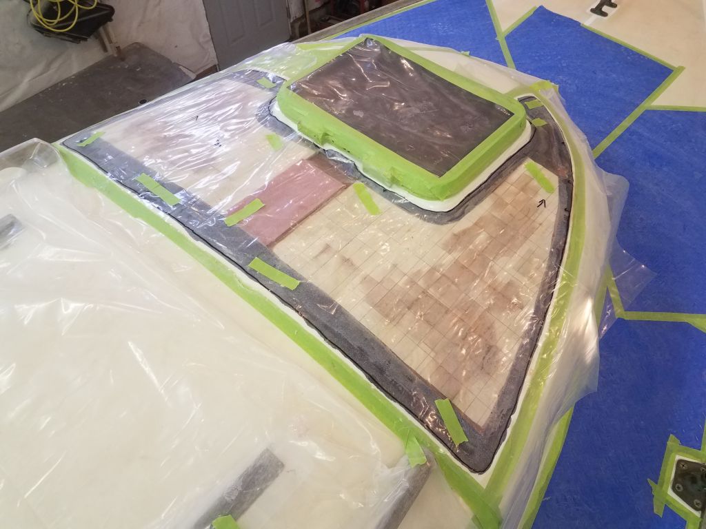
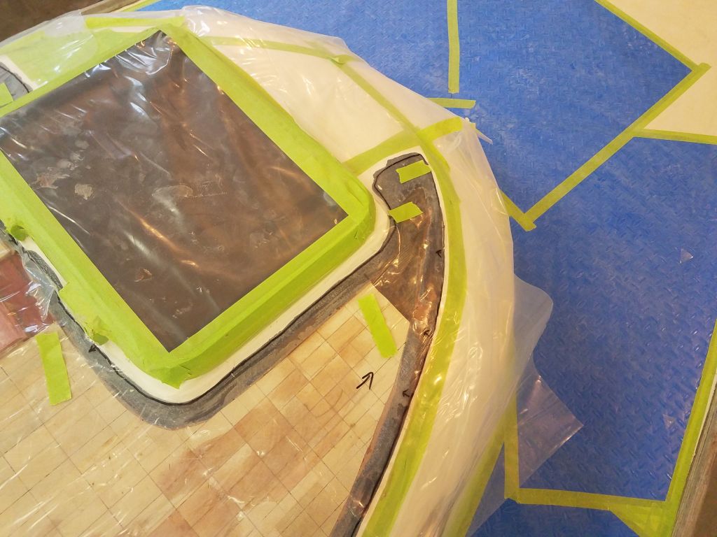
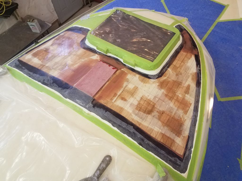
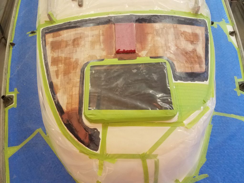
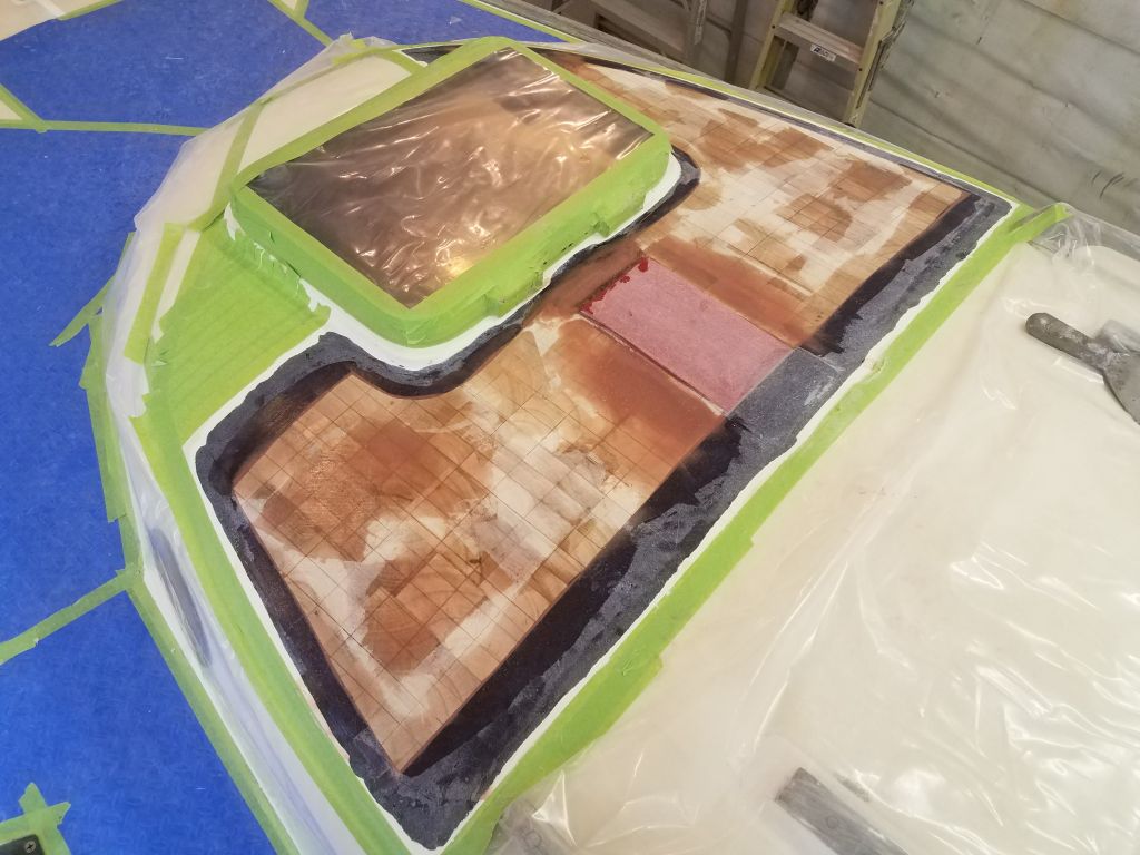
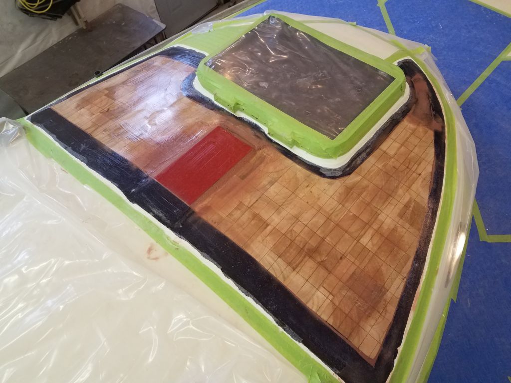
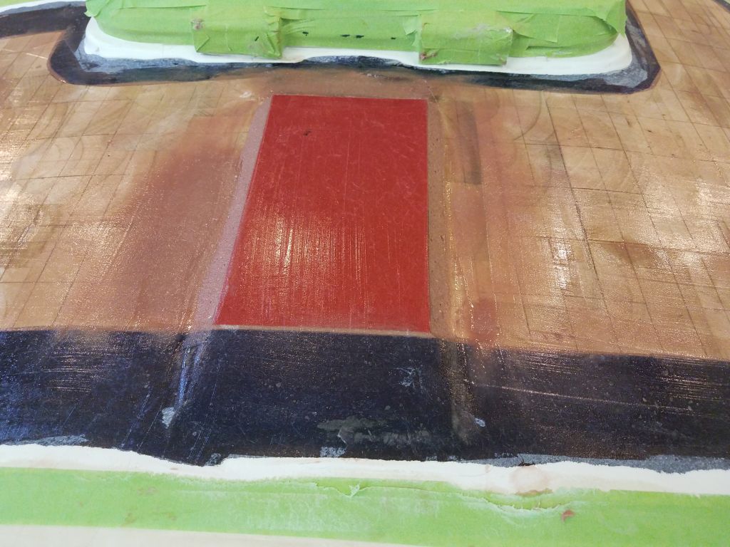
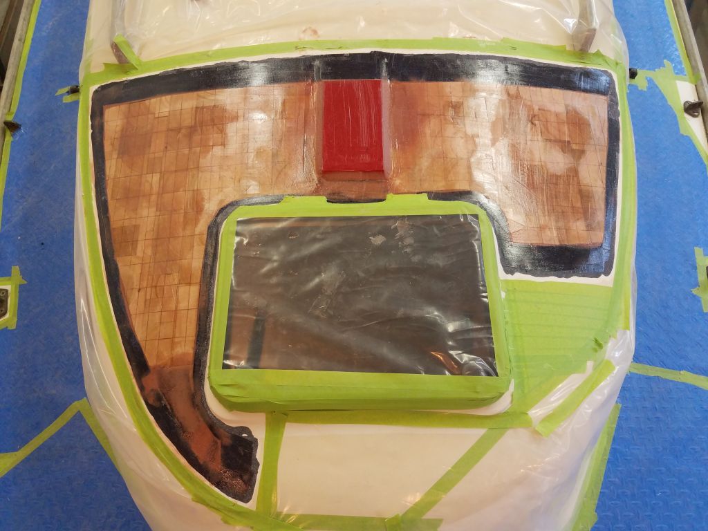
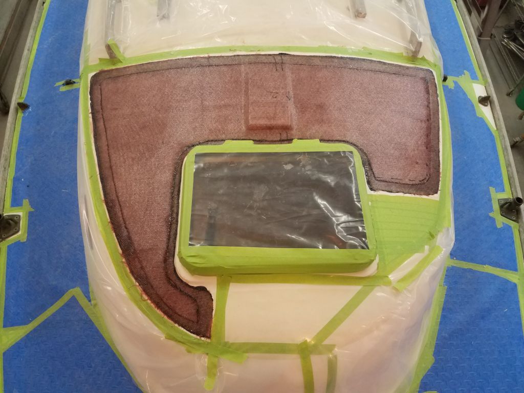
Next, I turned to the day’s main focus: finishing the cosmetic work on the coachroof. I masked around all the existing nonskid areas, hatch, and mast platform, following the original lines where applicable, and further masked off the handrails and other teak trim to protect it during painting.
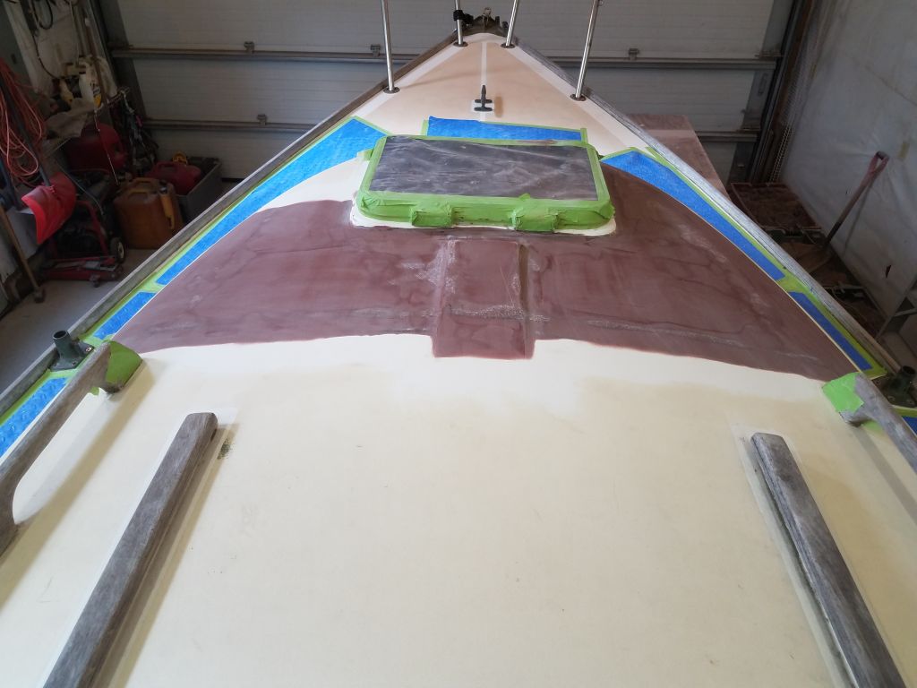
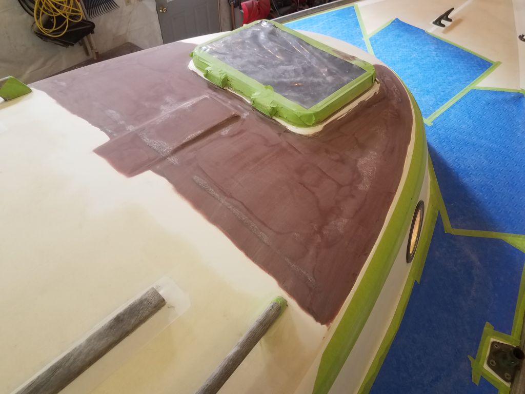
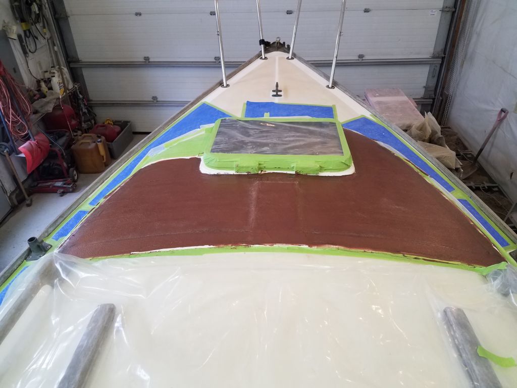
With masking, cleaning, and all other preparations complete, I applied the first of two coats of beige nonskid paint to the entire coachroof.
Total time billed on this job today: 6.5 hours
0600 Weather Observation: 35°, clear. Forecast for the day: Sunny, high clouds coming in, 50°