Tuesday
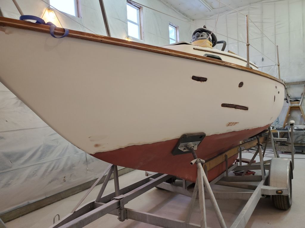
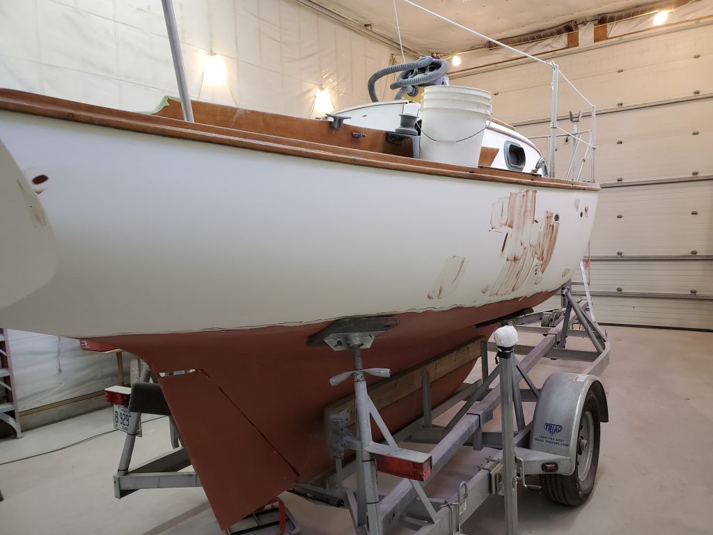
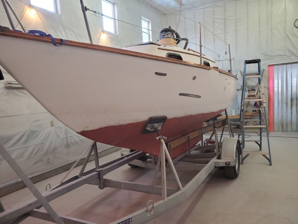
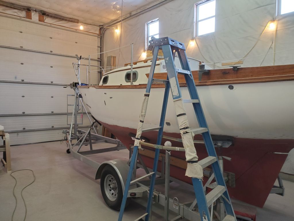
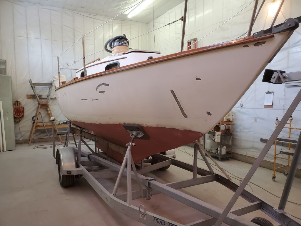
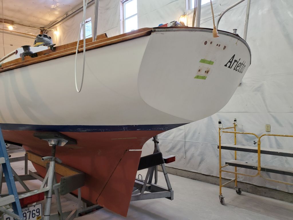
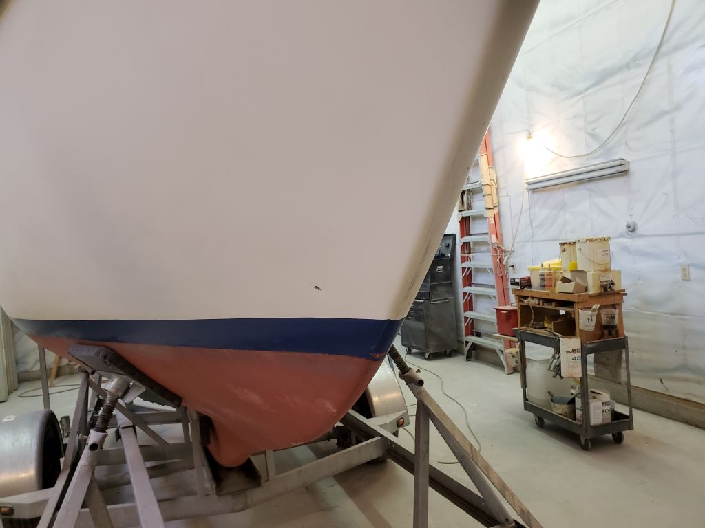
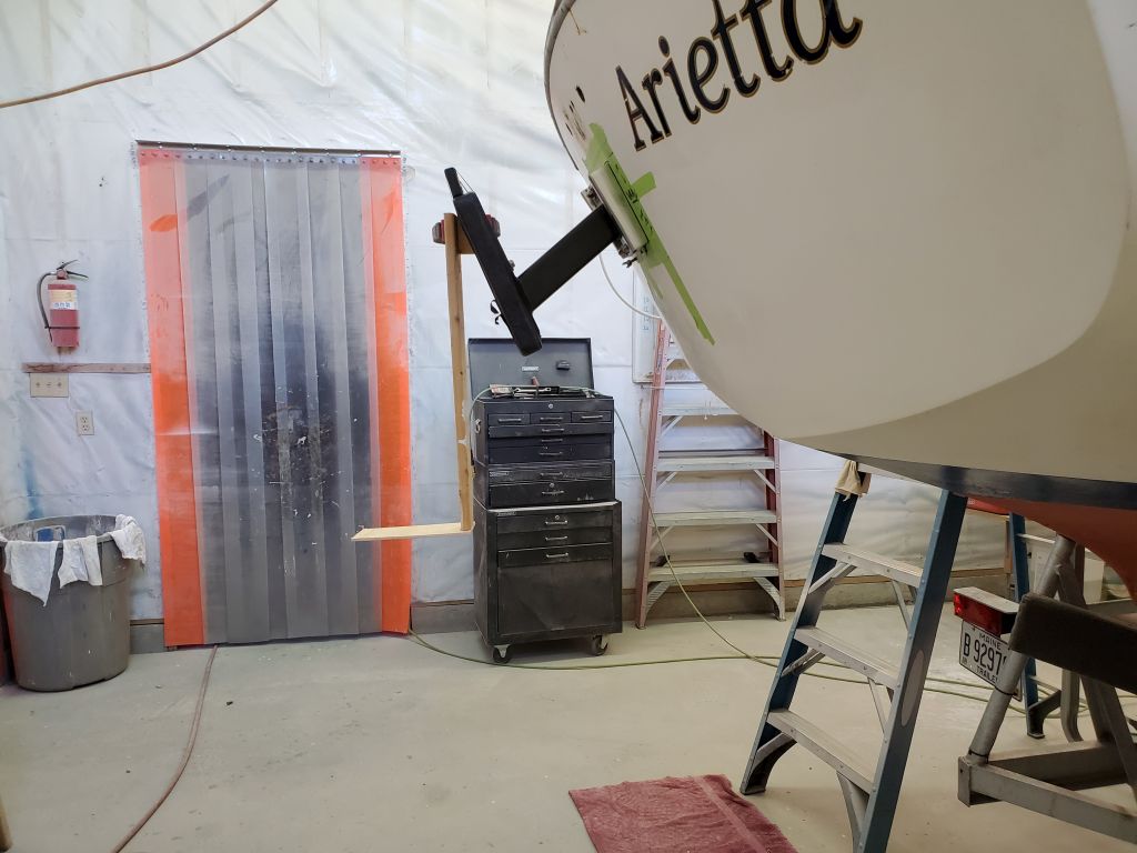
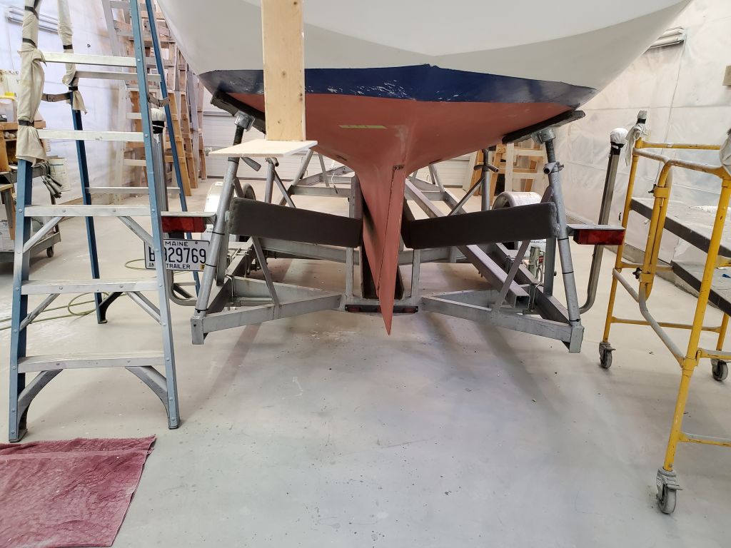
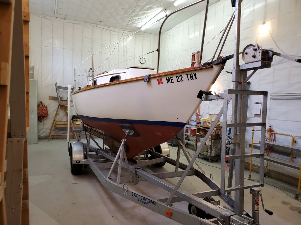
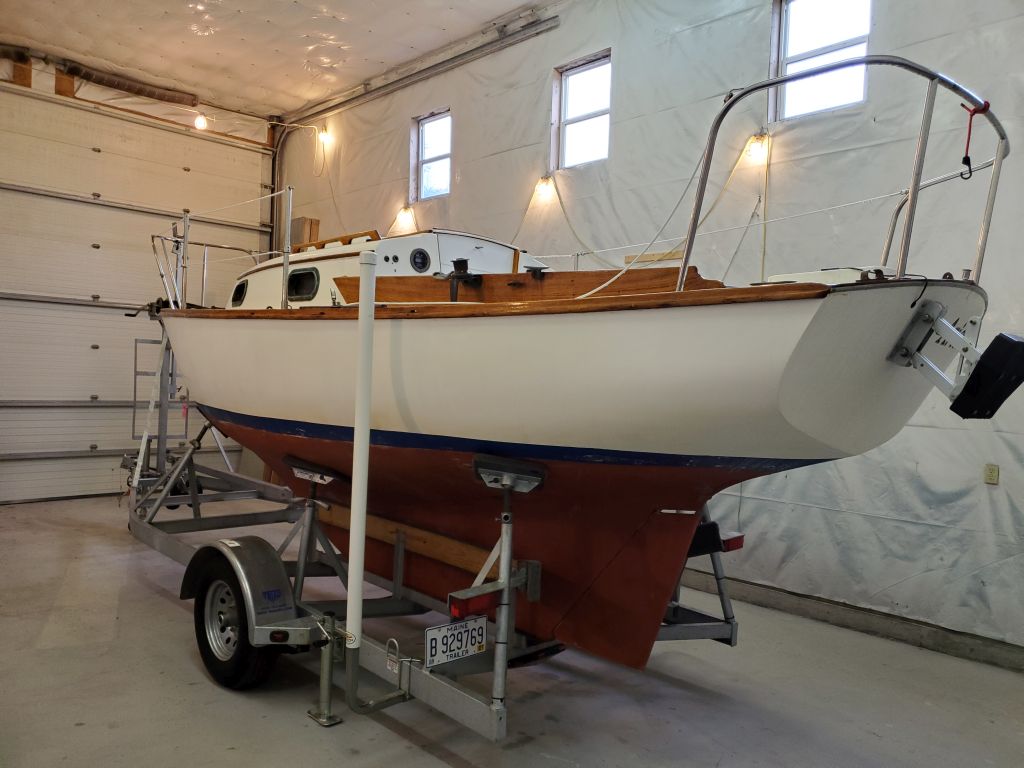
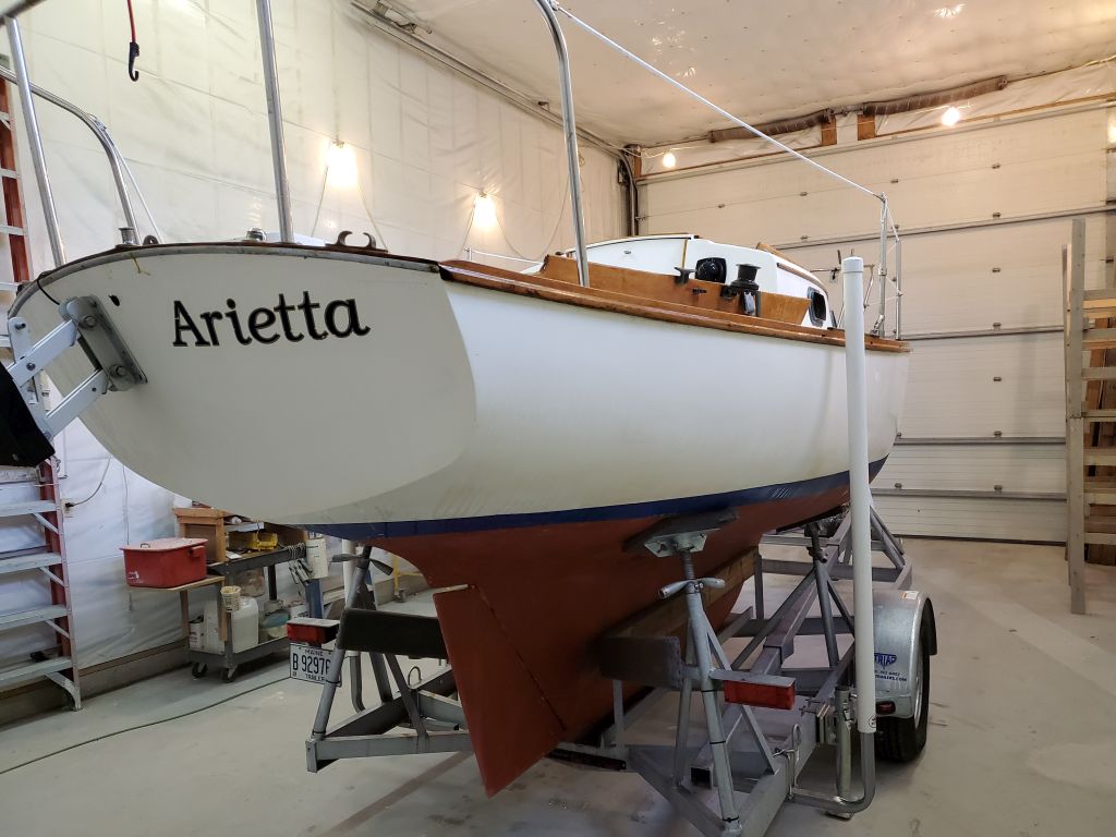
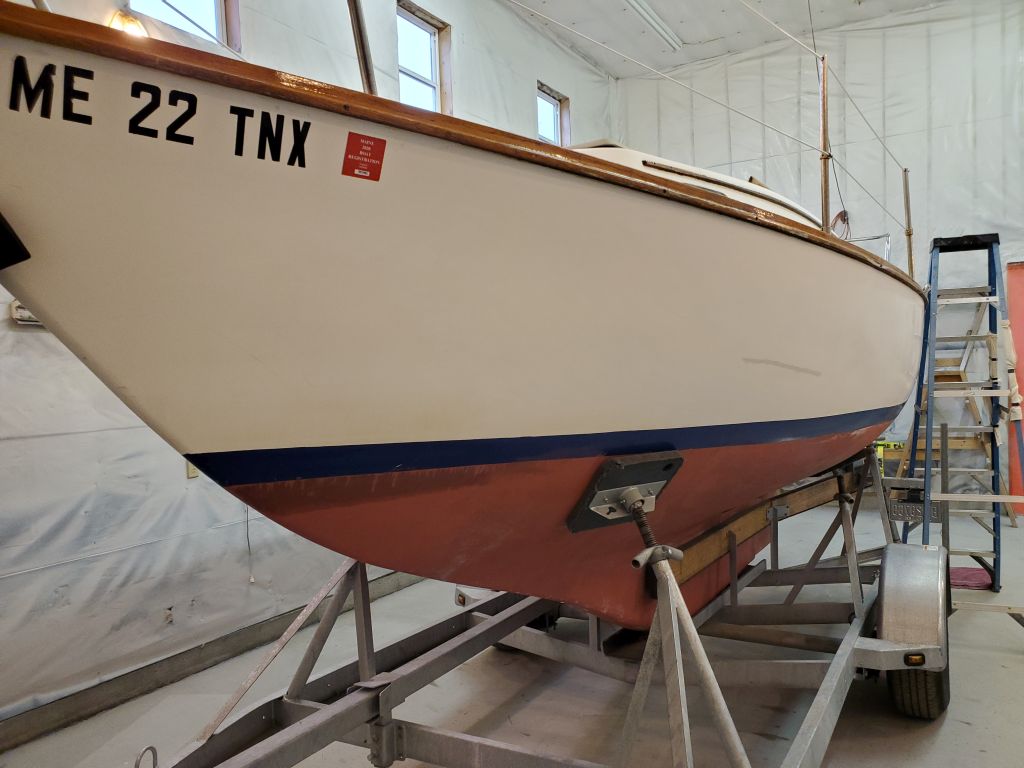
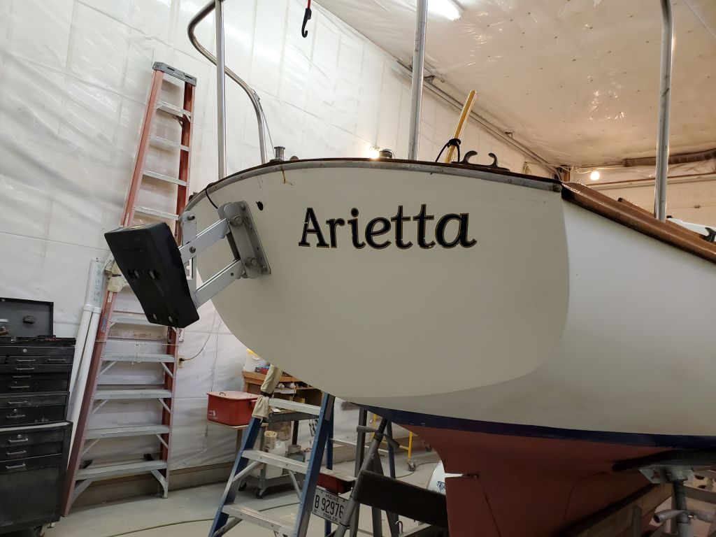
With the departure of one boat from the shop on Monday, I could move Arietta inside and prepare for the project ahead. The boat was wet from recent rain, and once she was indoors I chose to work on another project in the shop and let her dry off for a day.
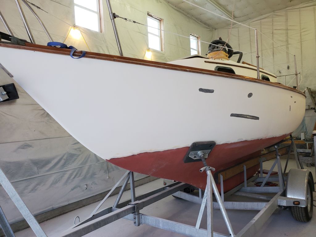
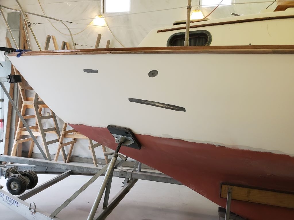
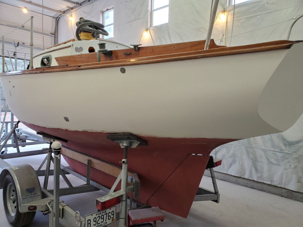
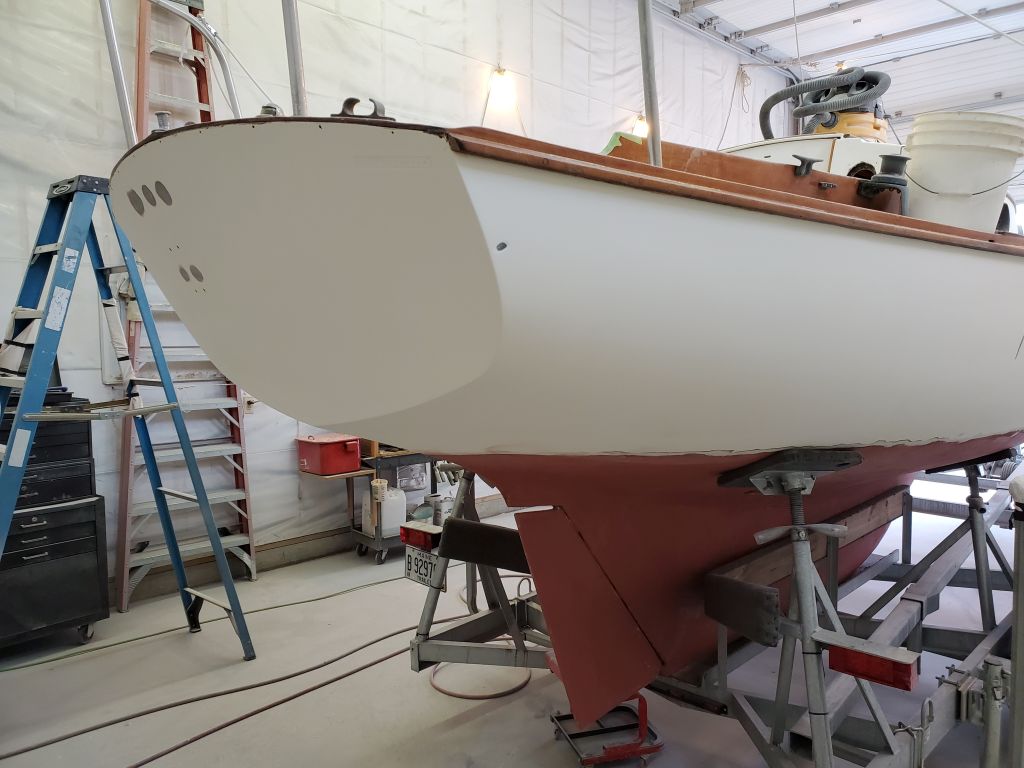
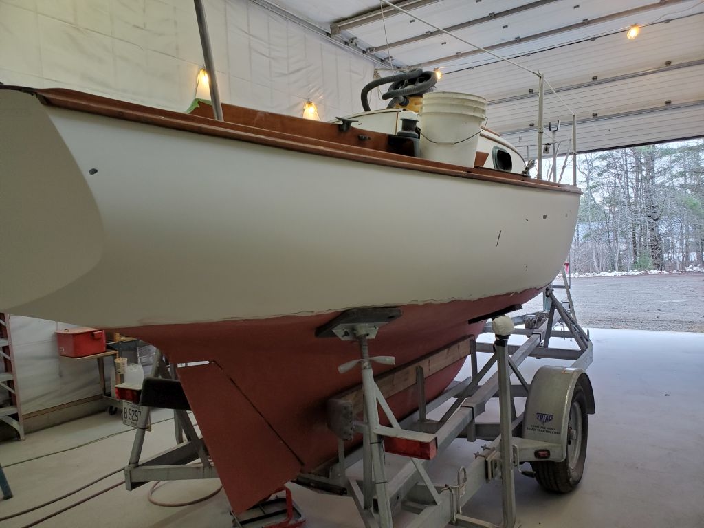
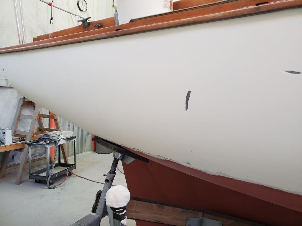
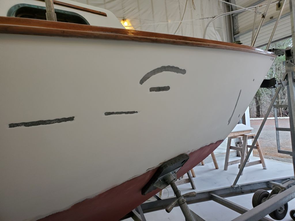
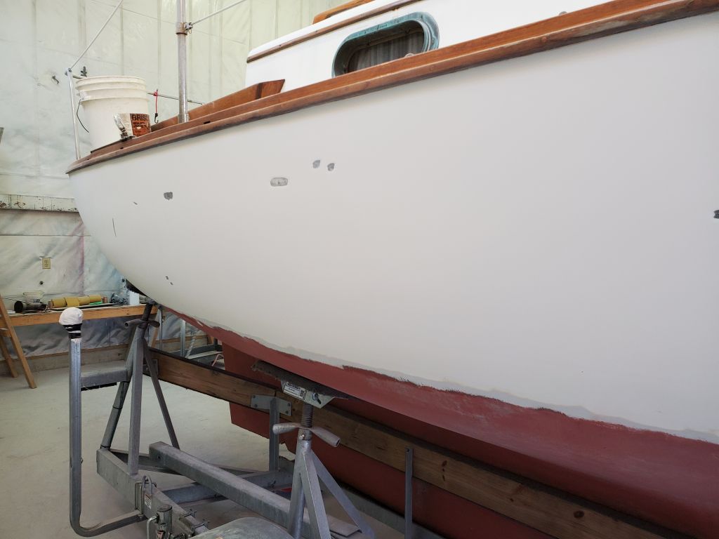
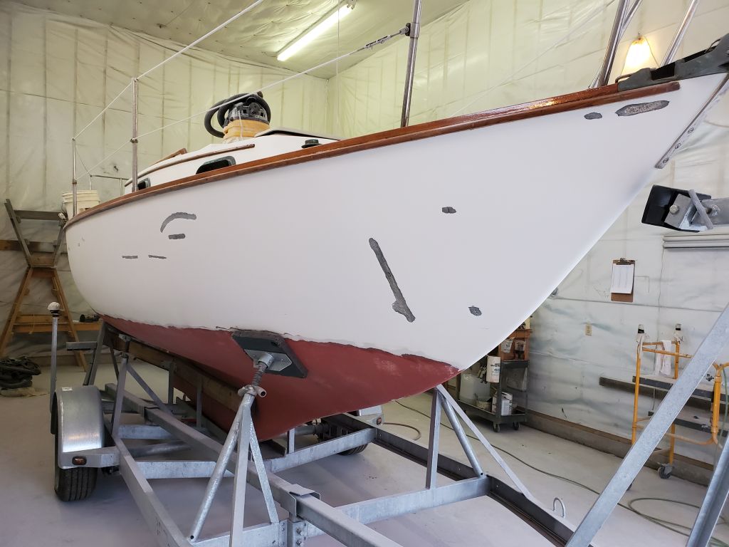
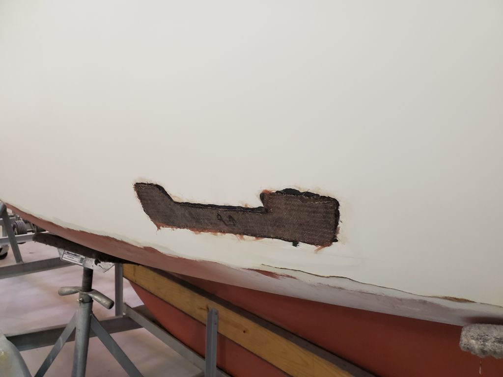
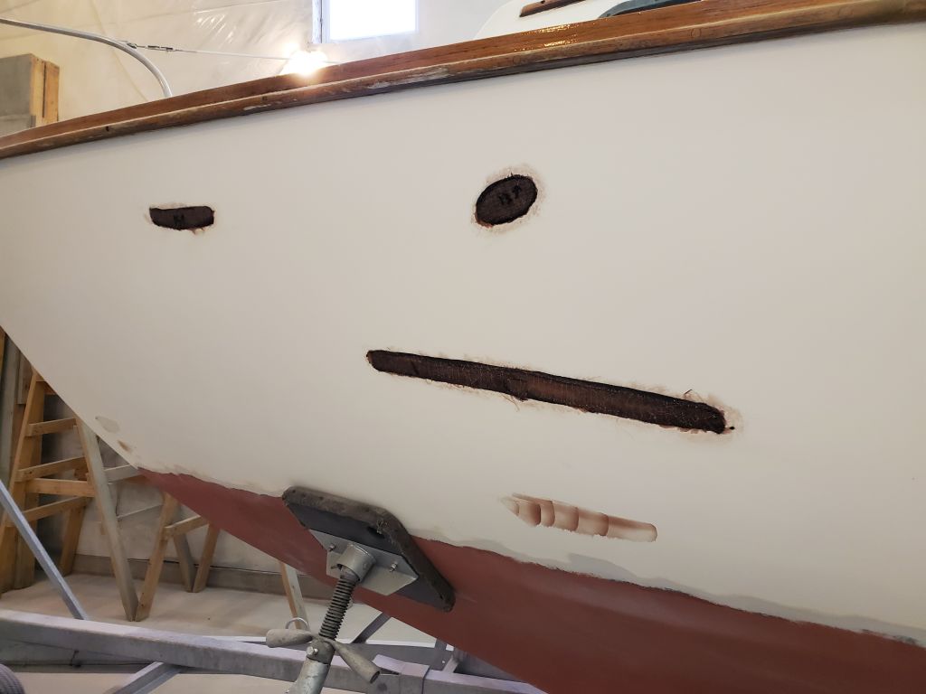
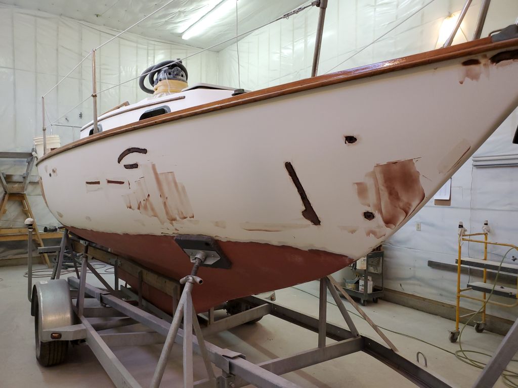
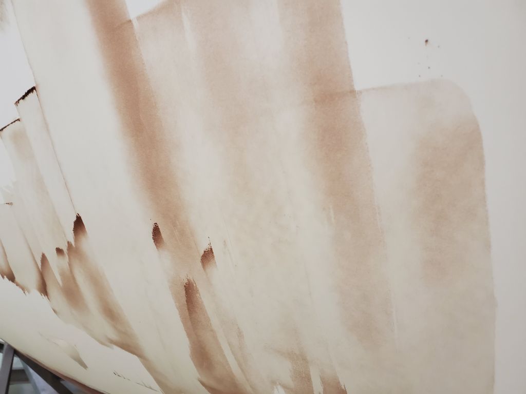
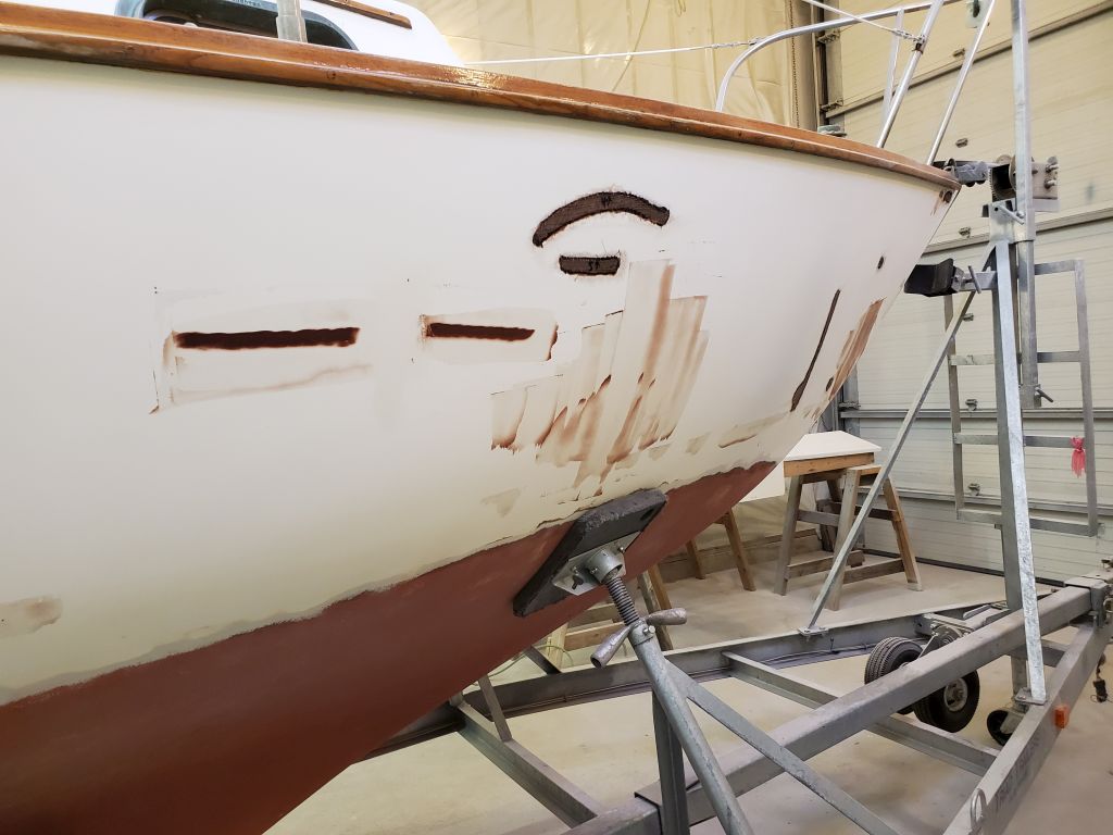
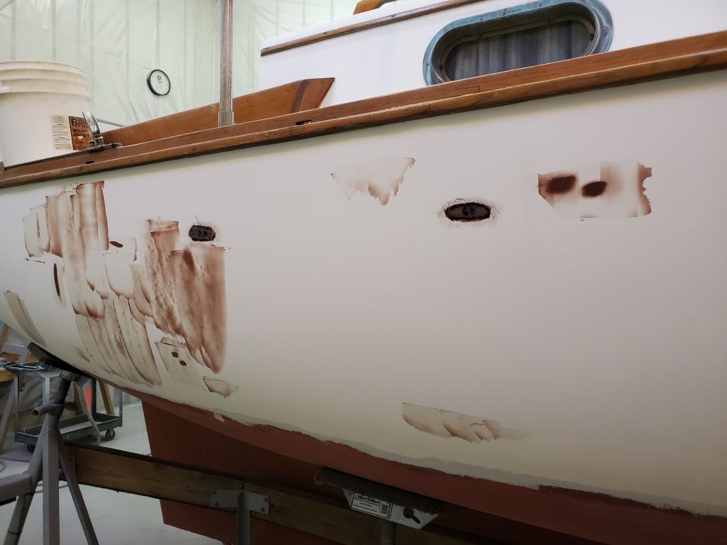
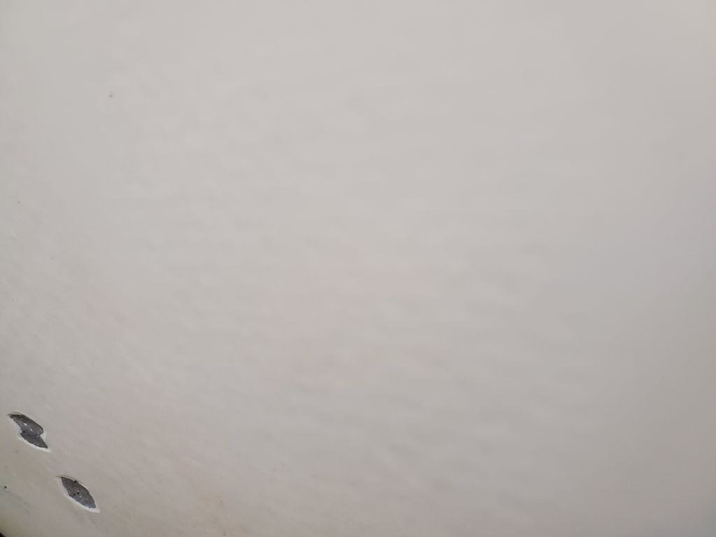
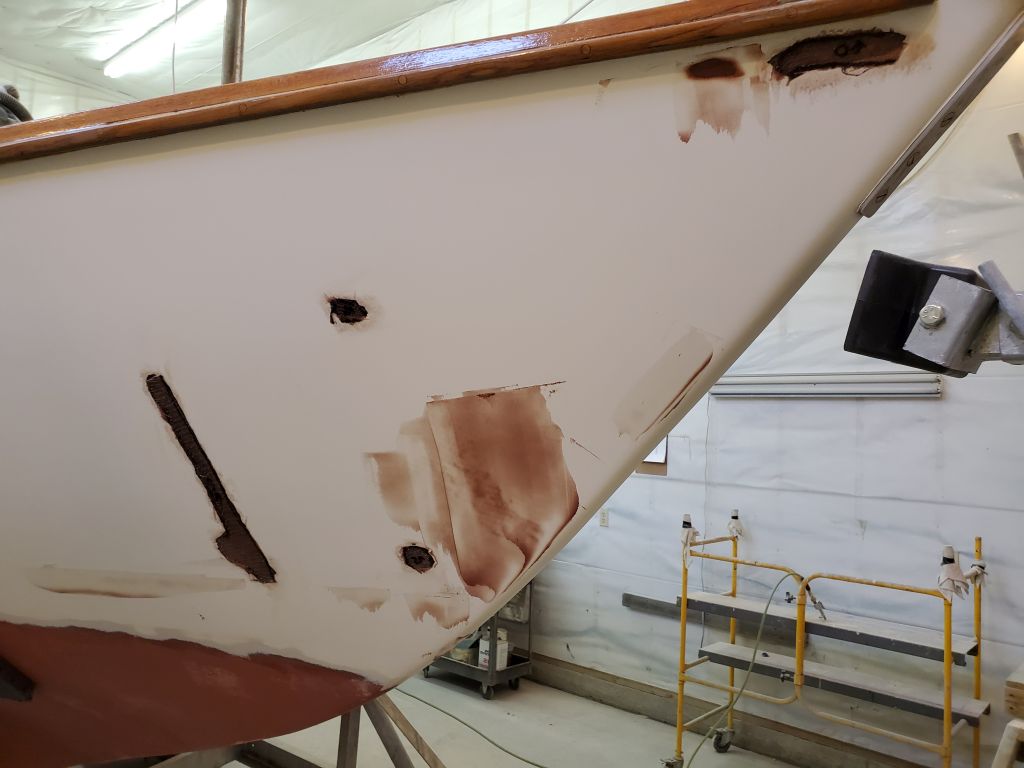
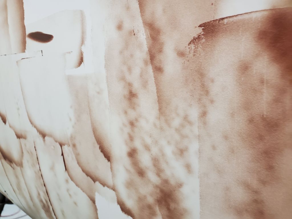
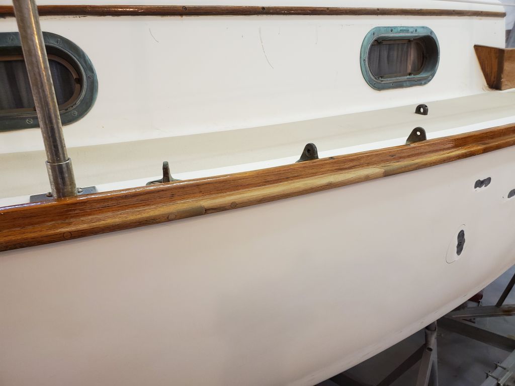
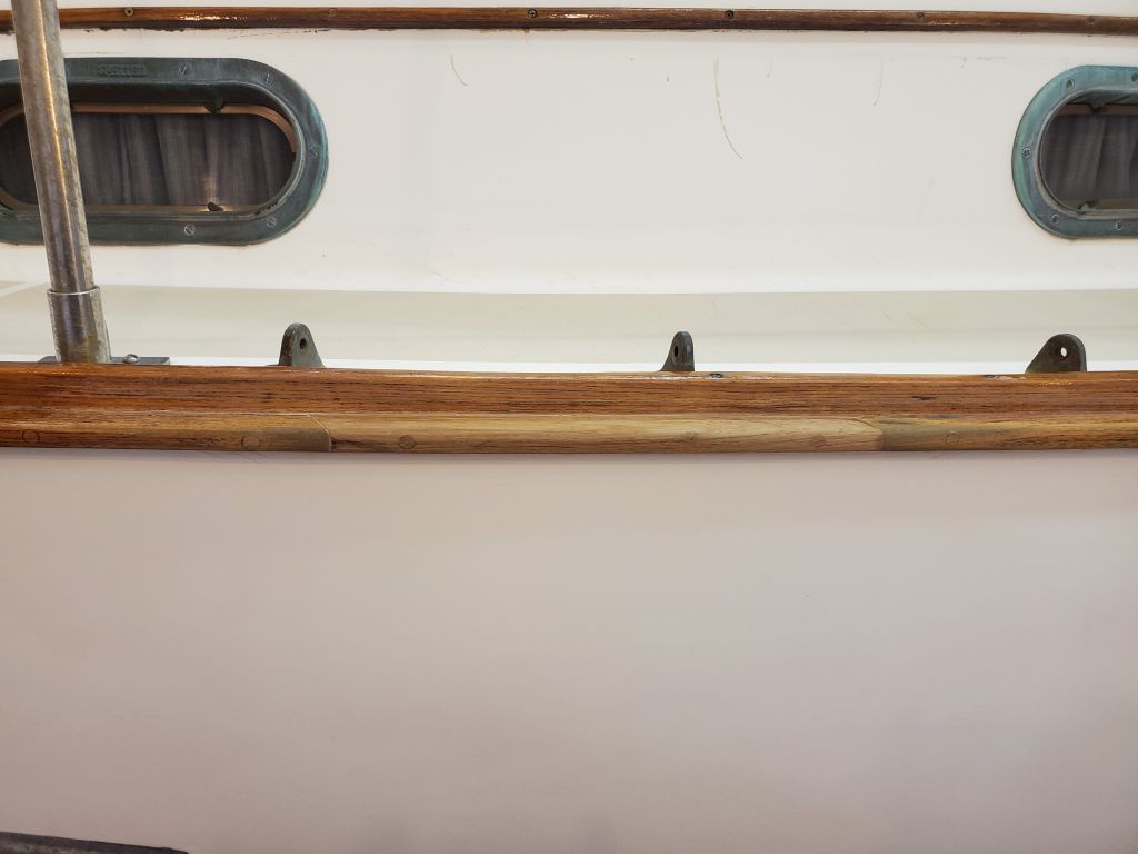
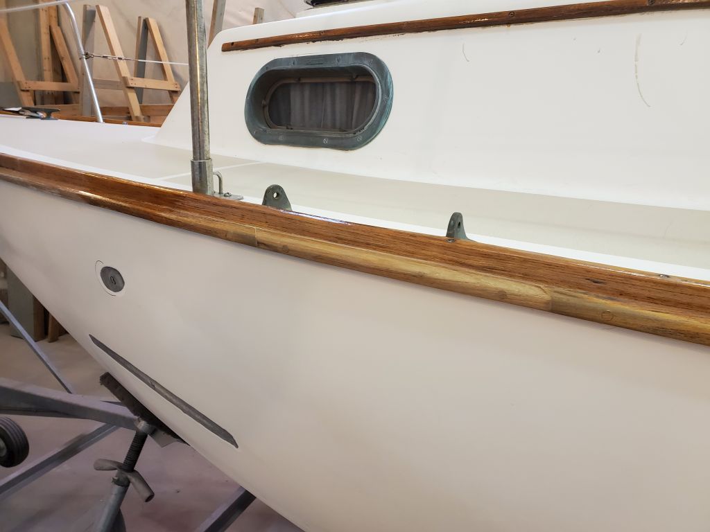
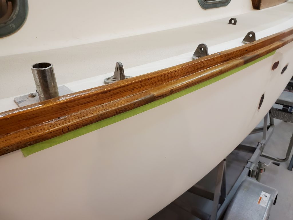
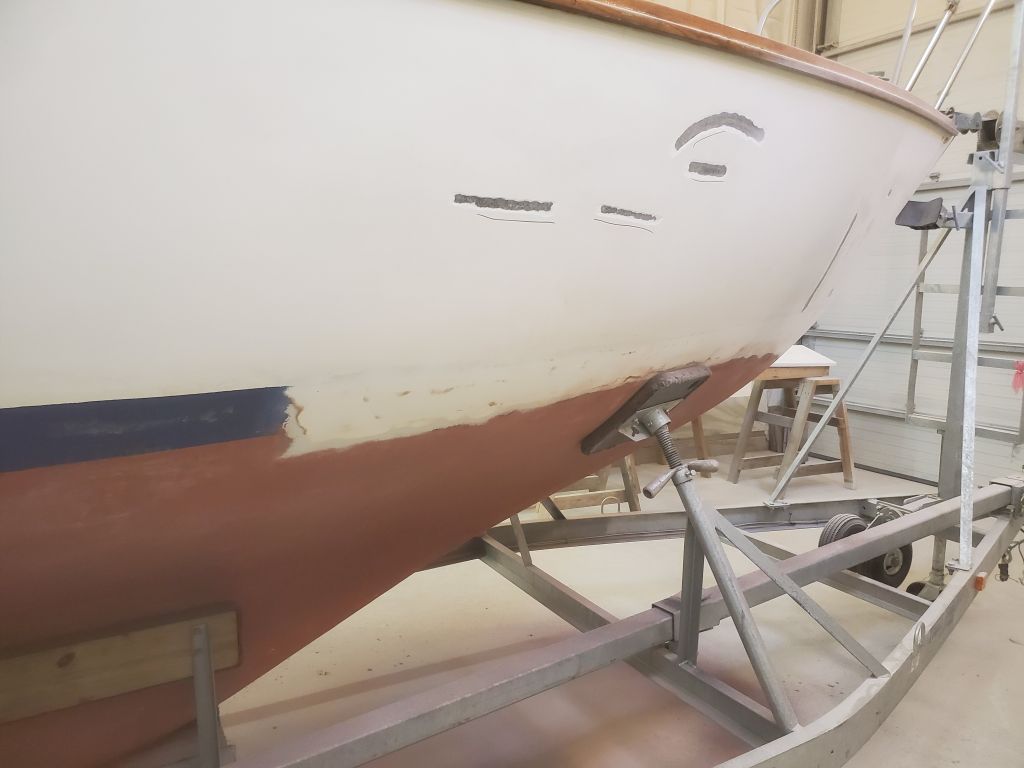
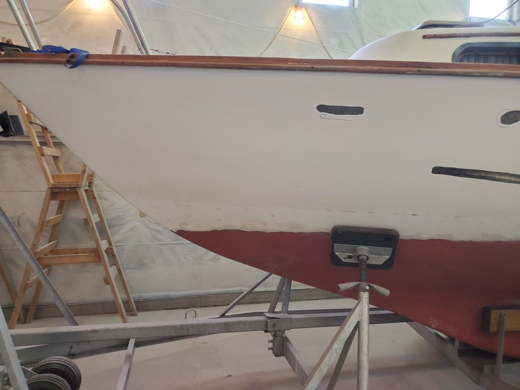
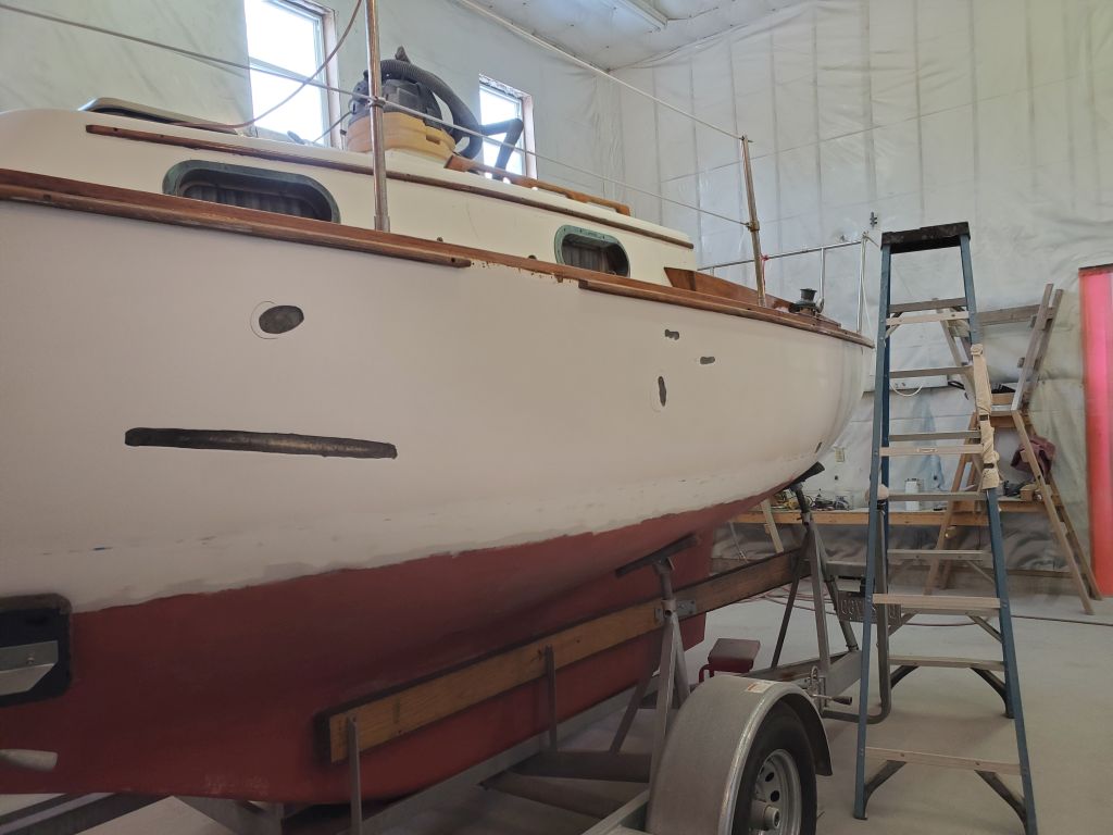
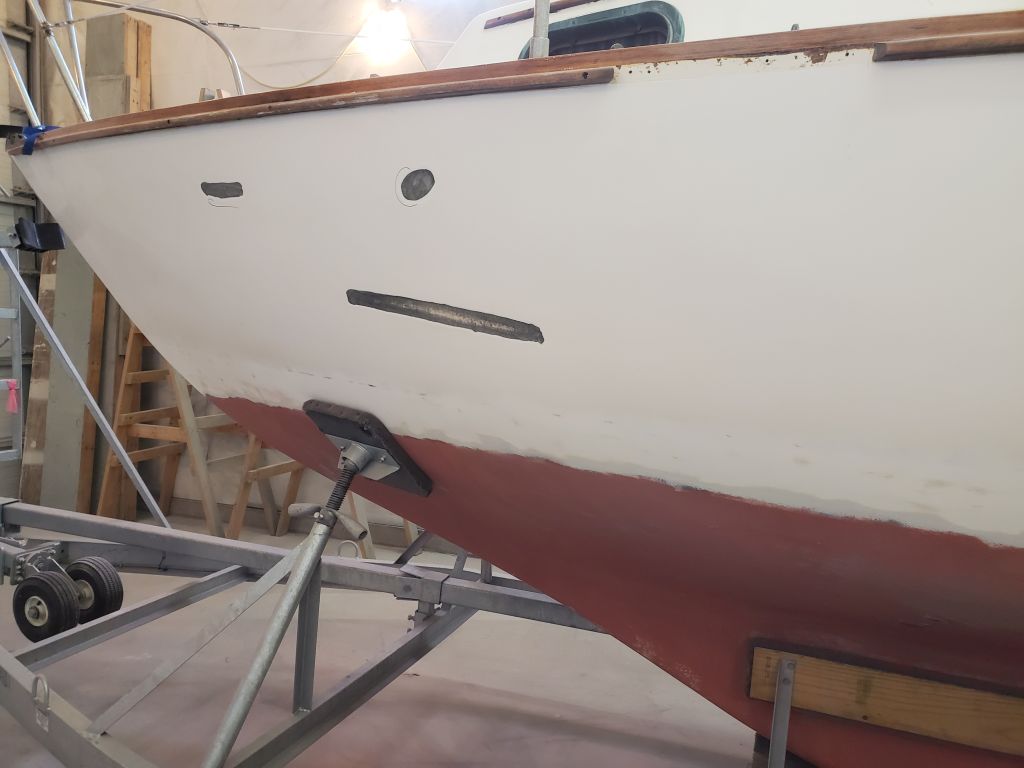
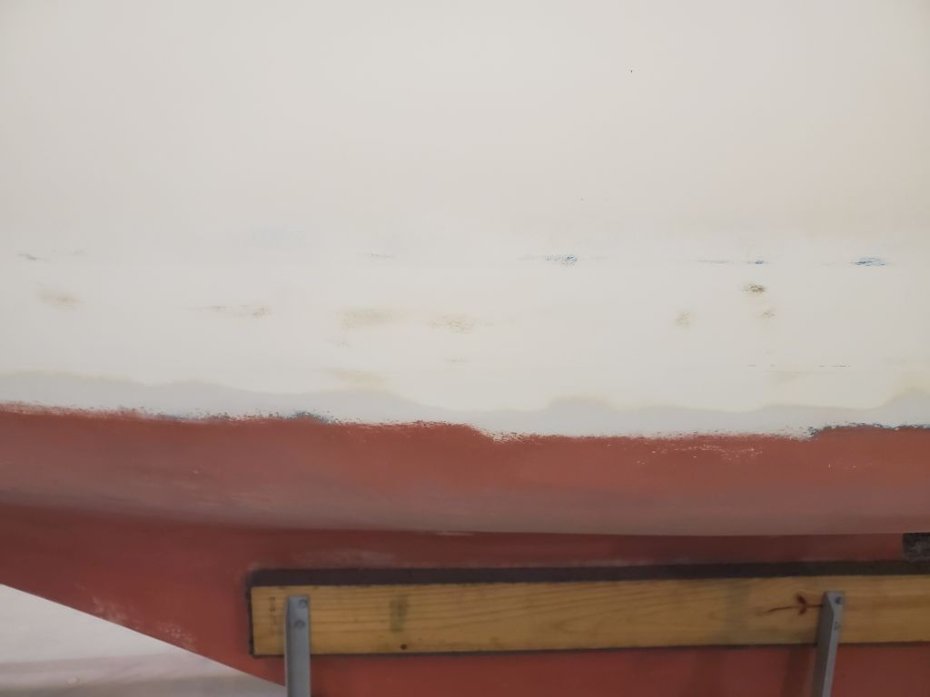
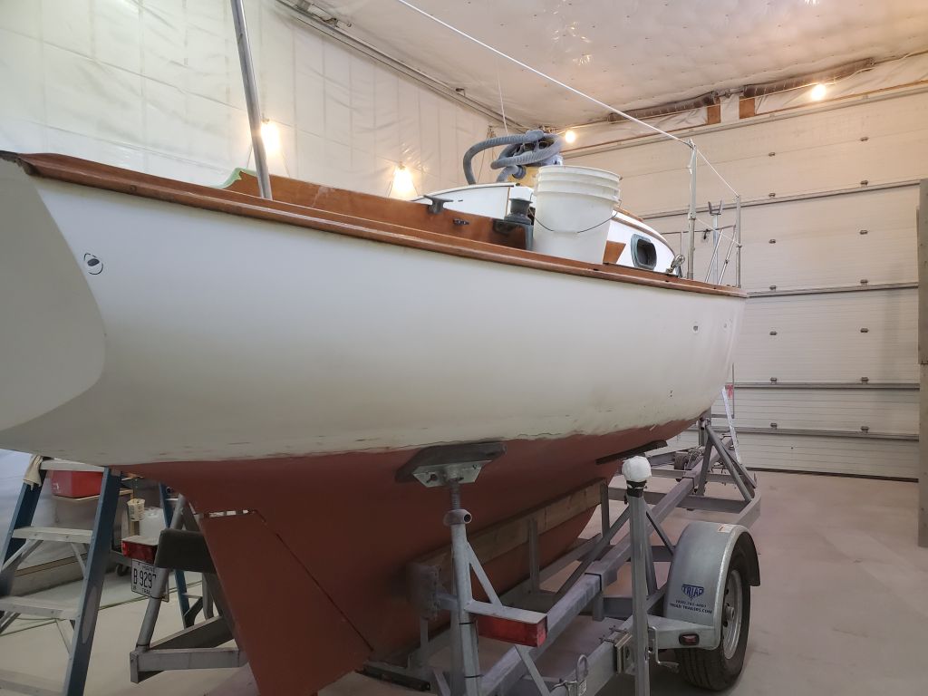
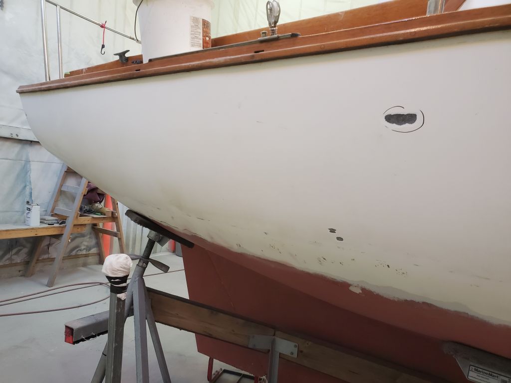
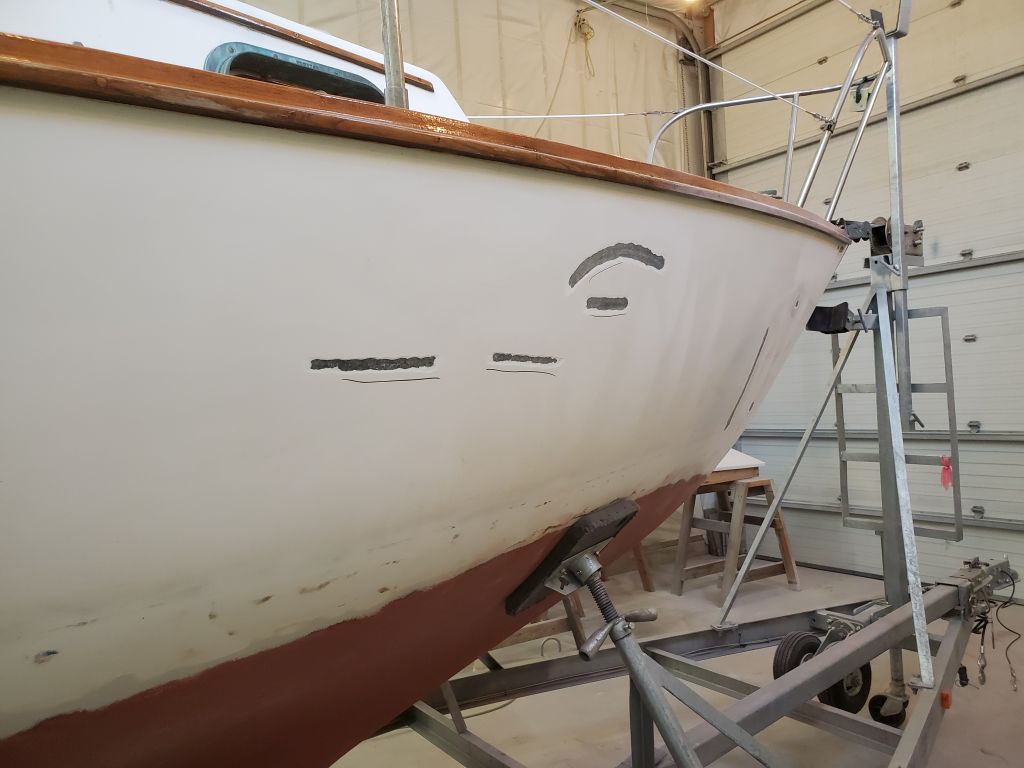
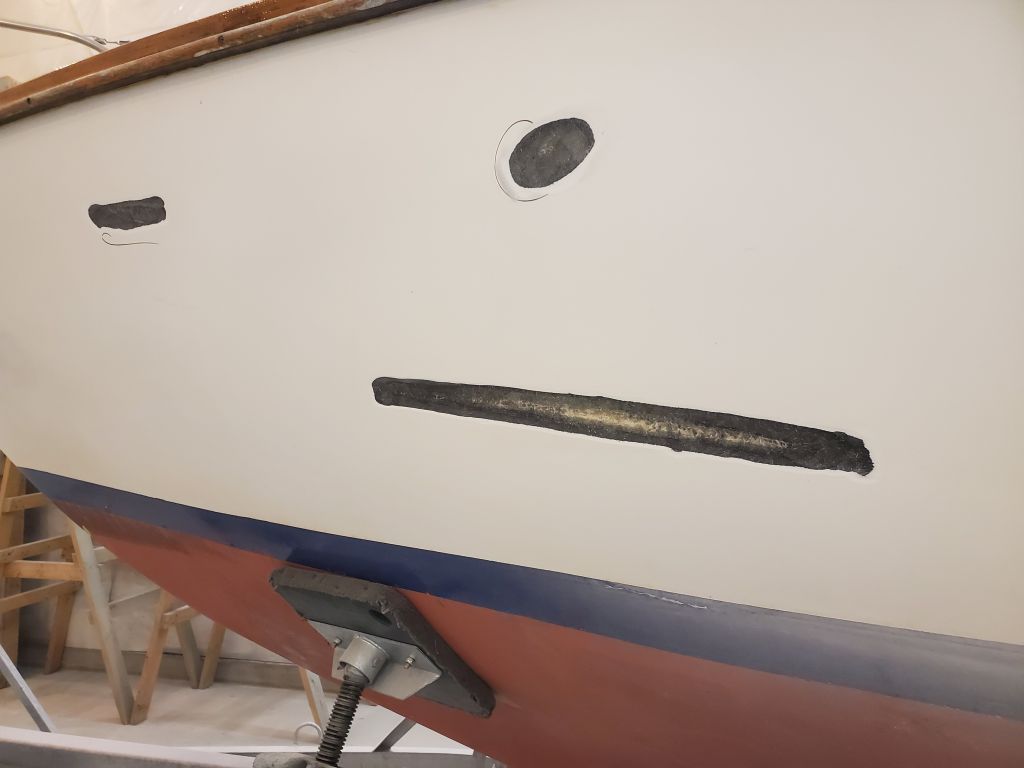
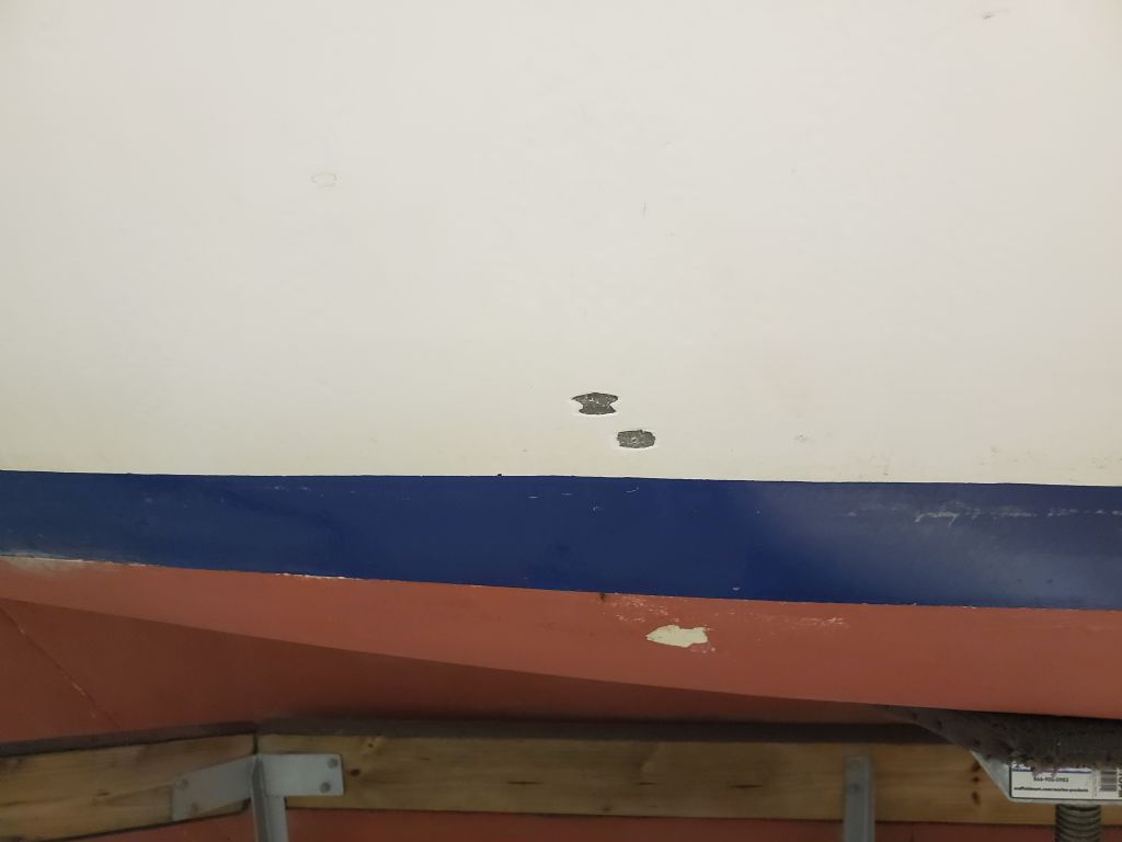
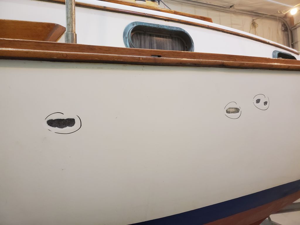
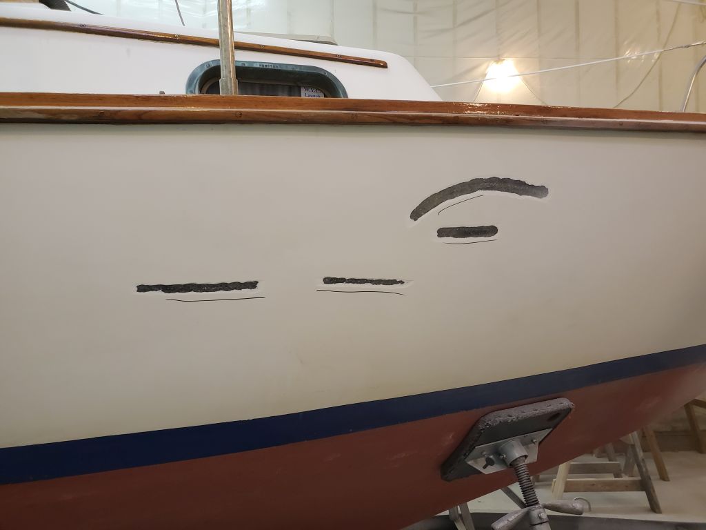
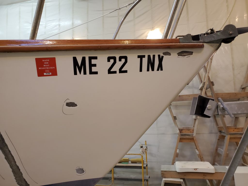
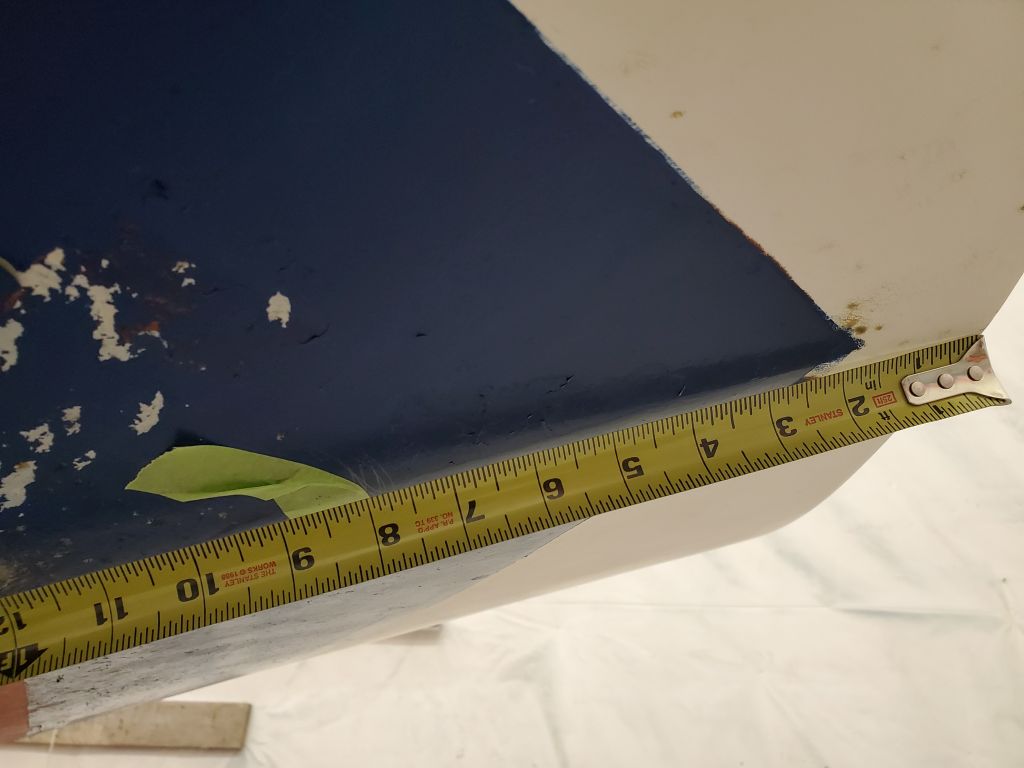
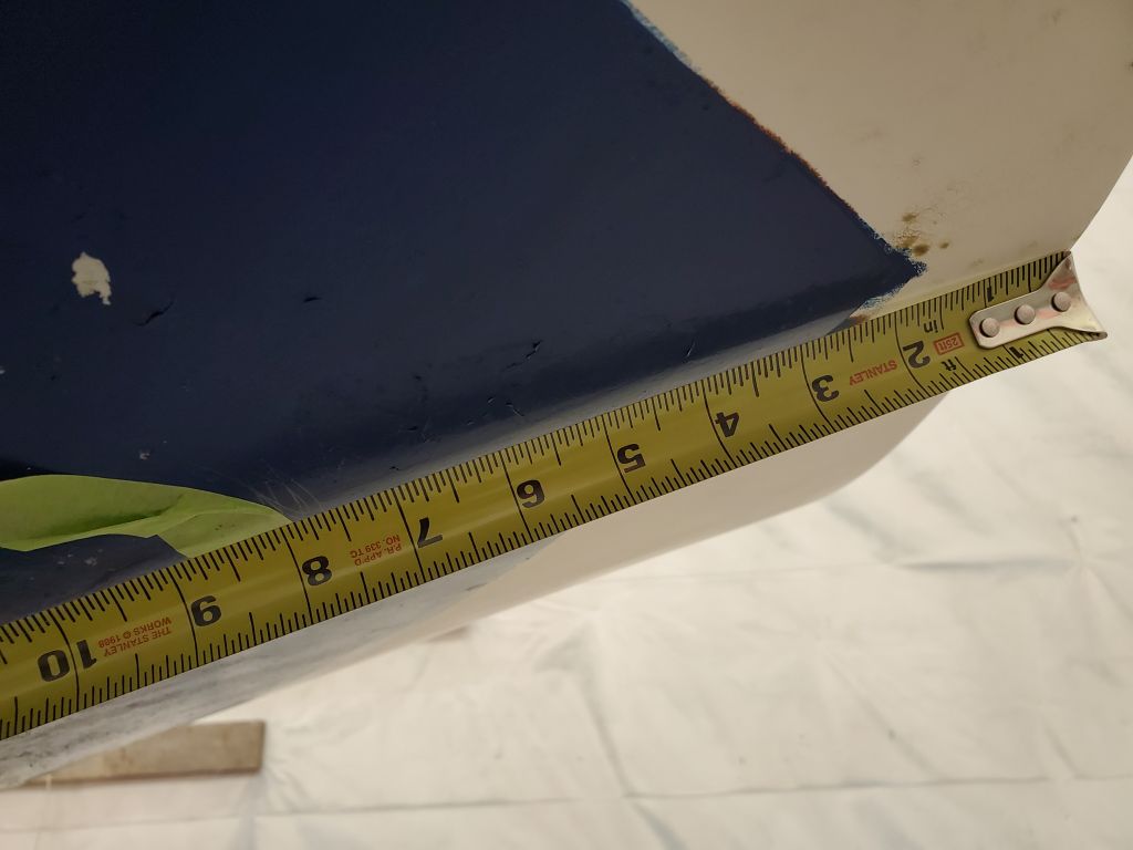
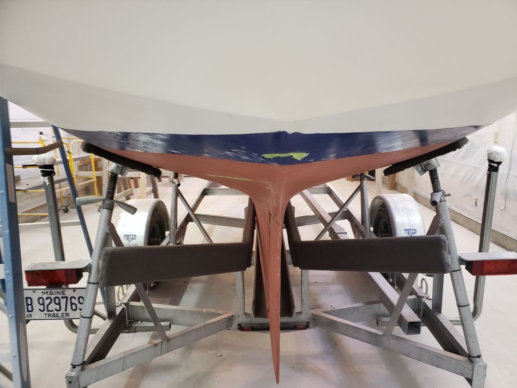
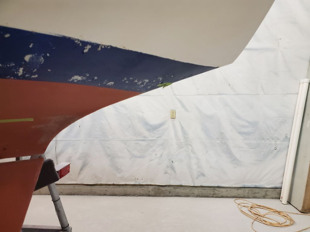
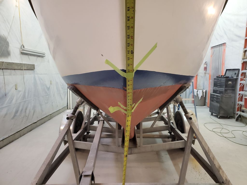
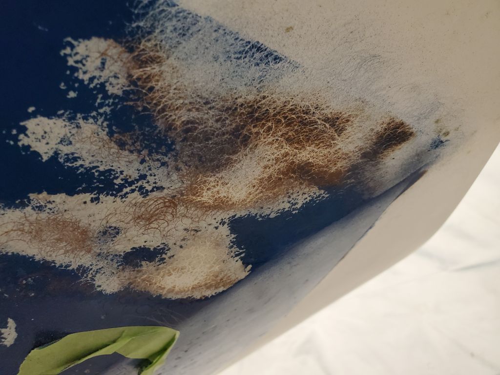
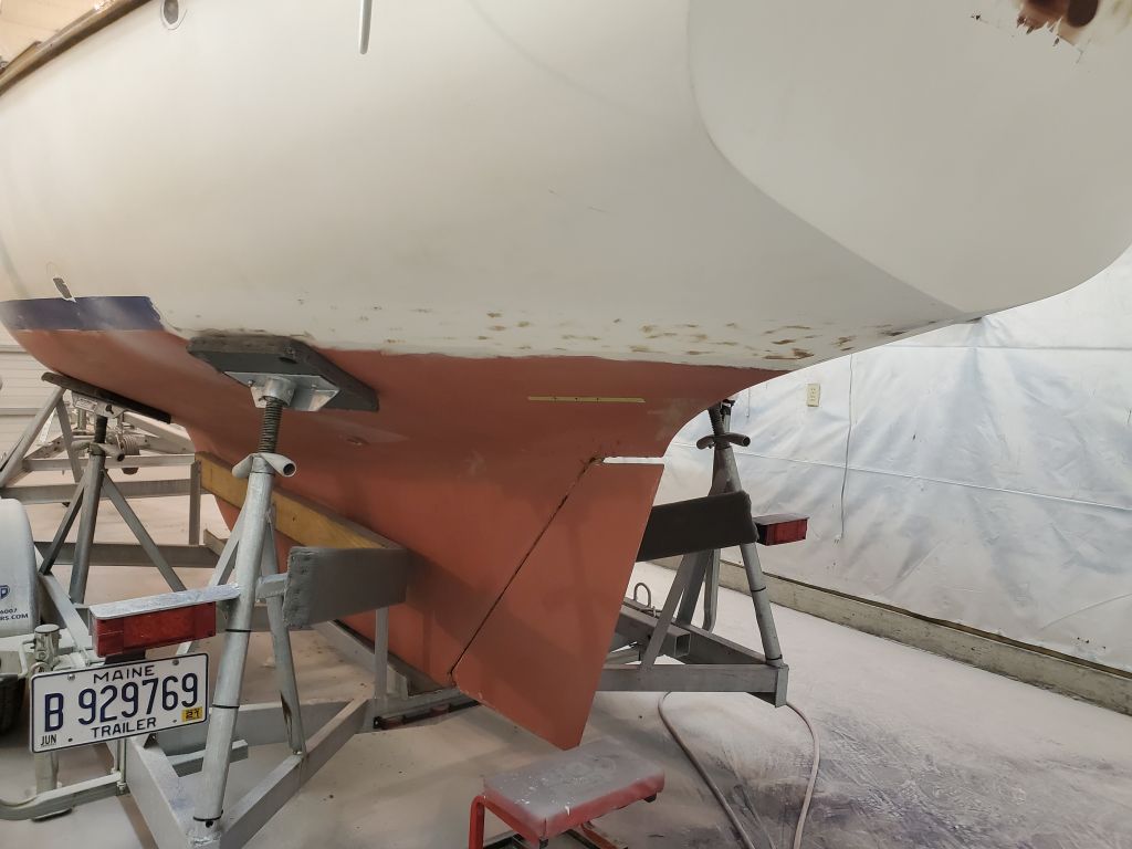
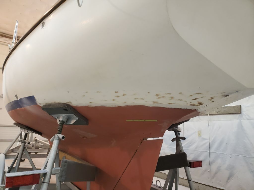
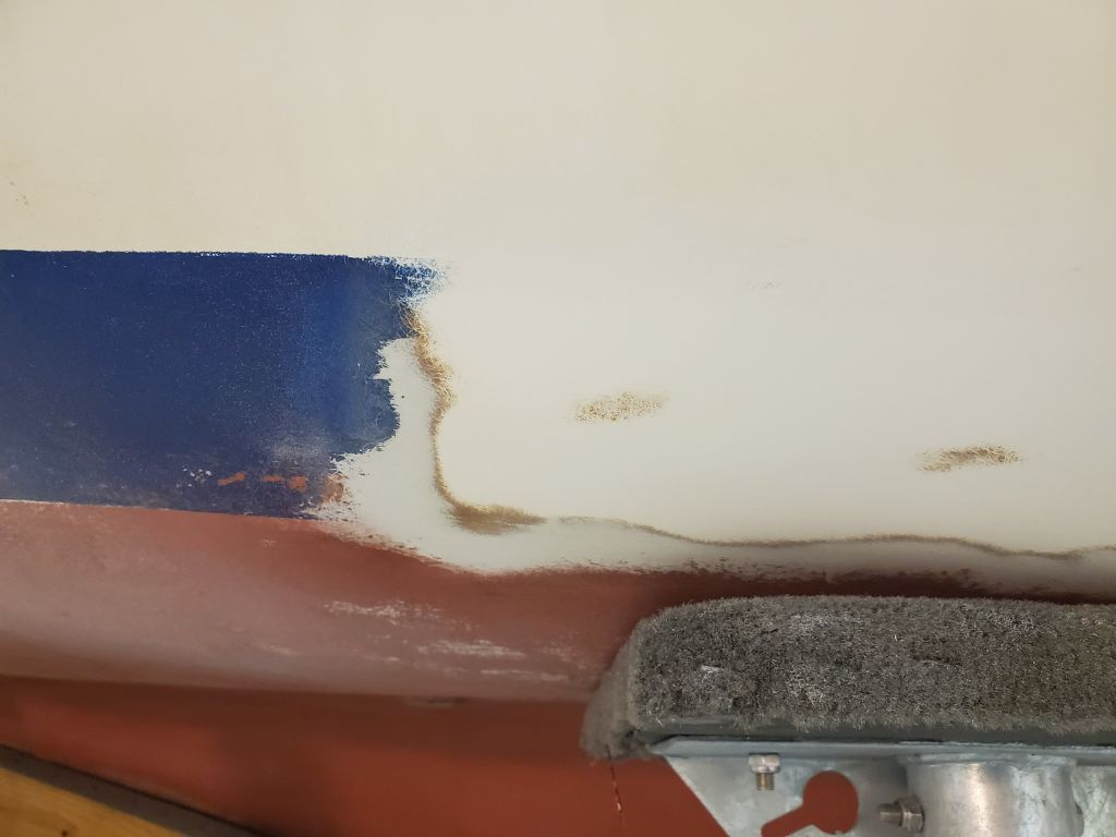
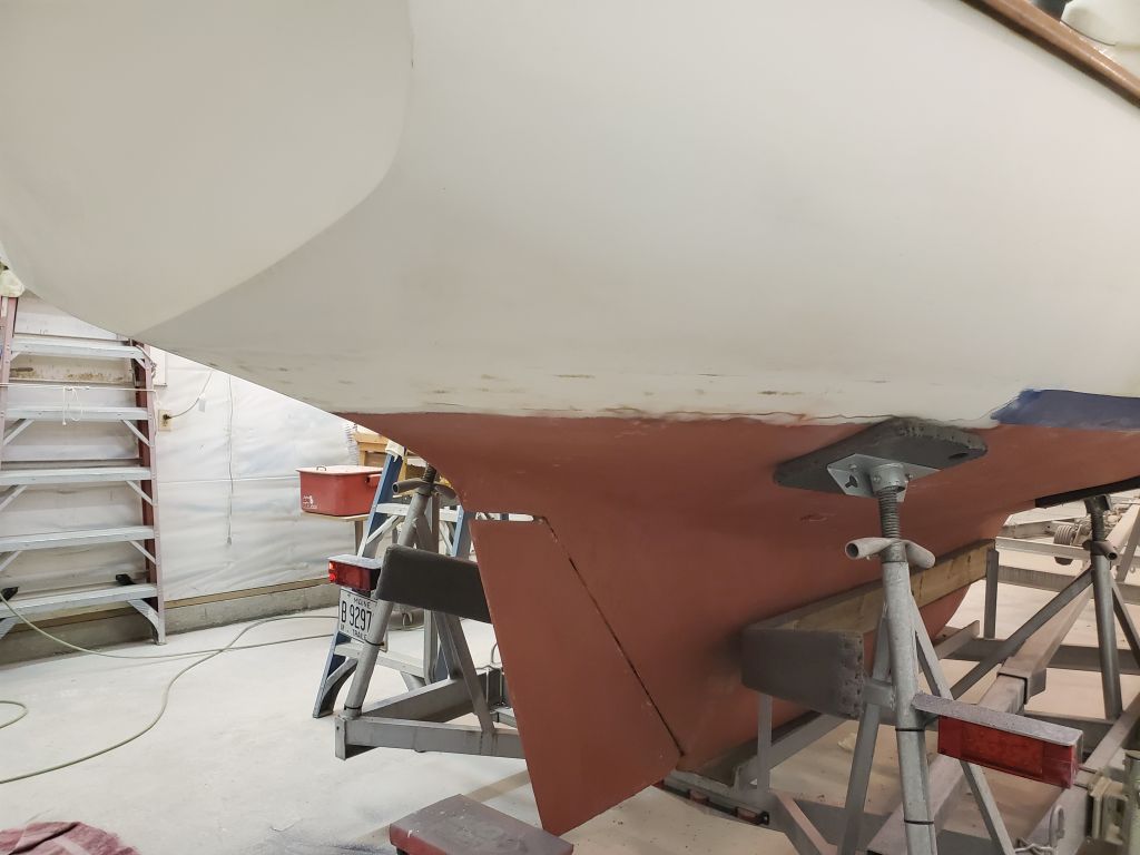
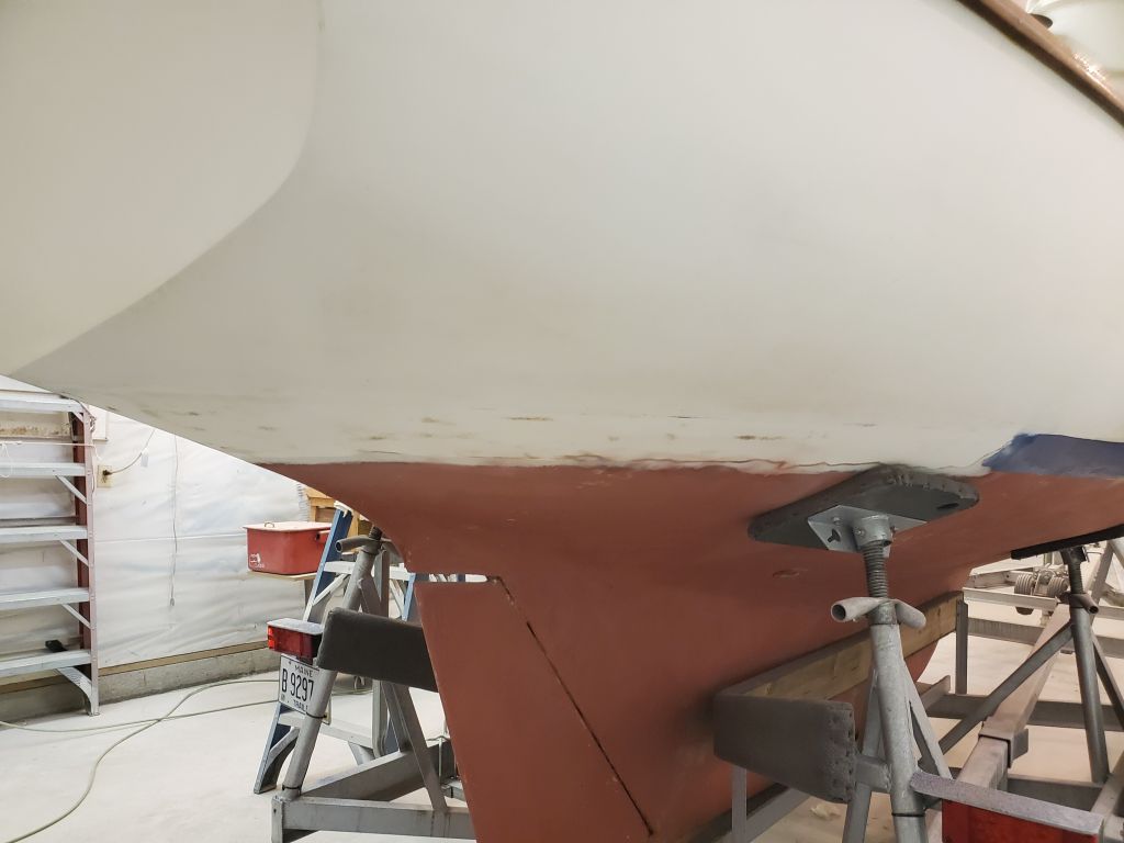
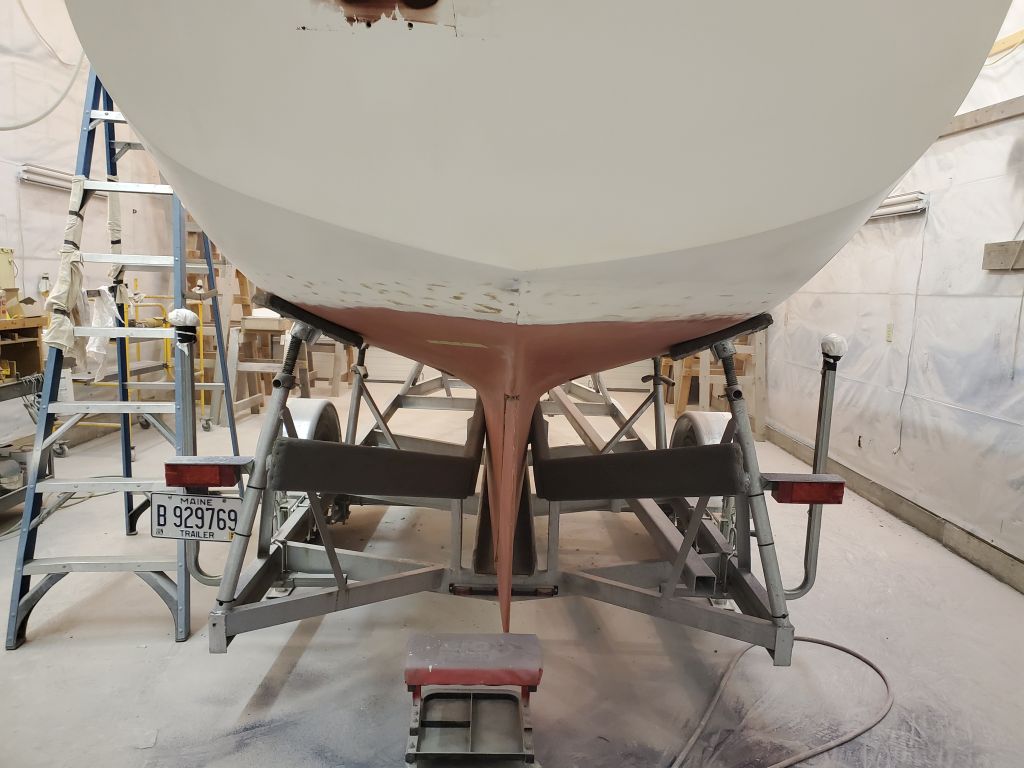
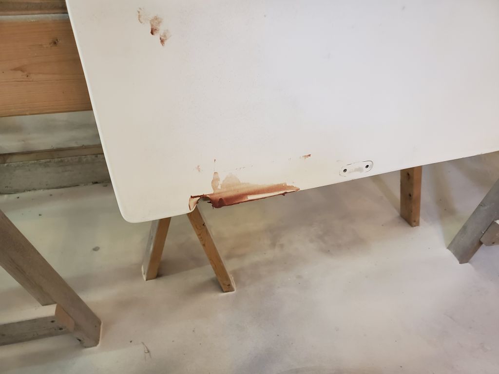
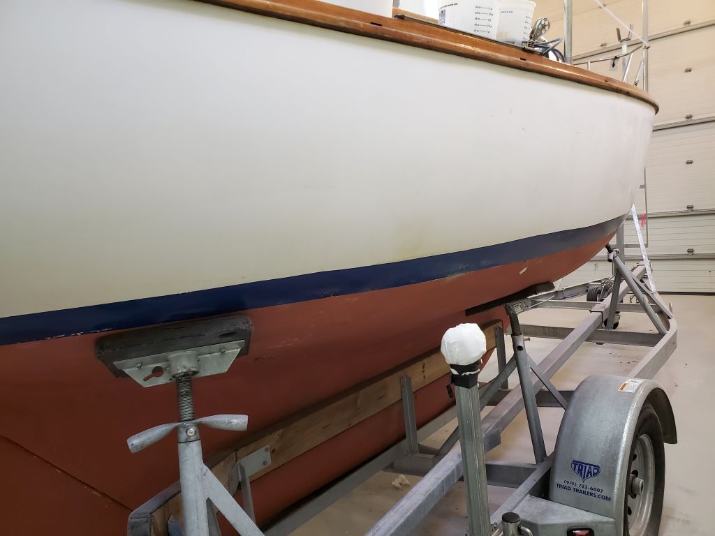
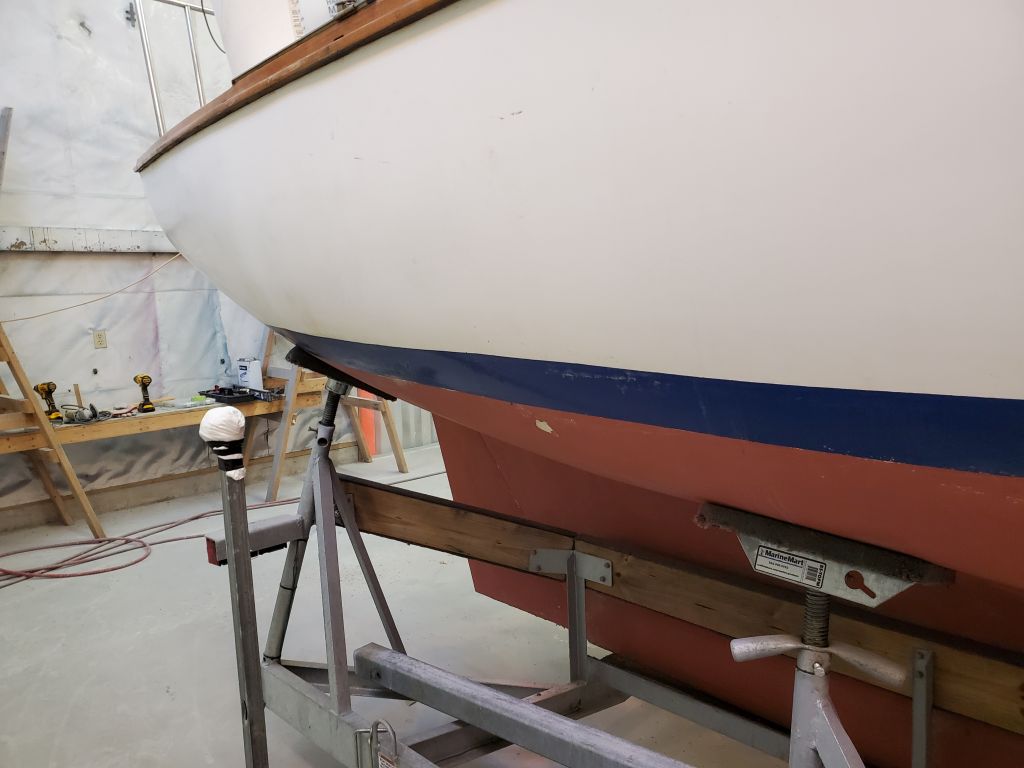
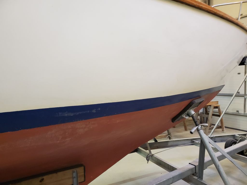
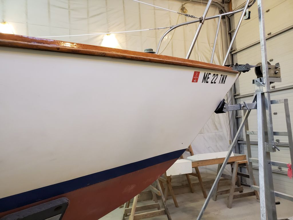
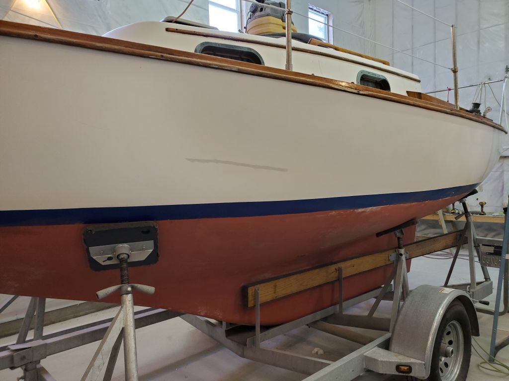
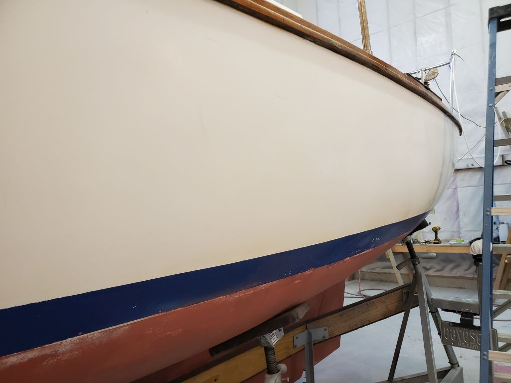
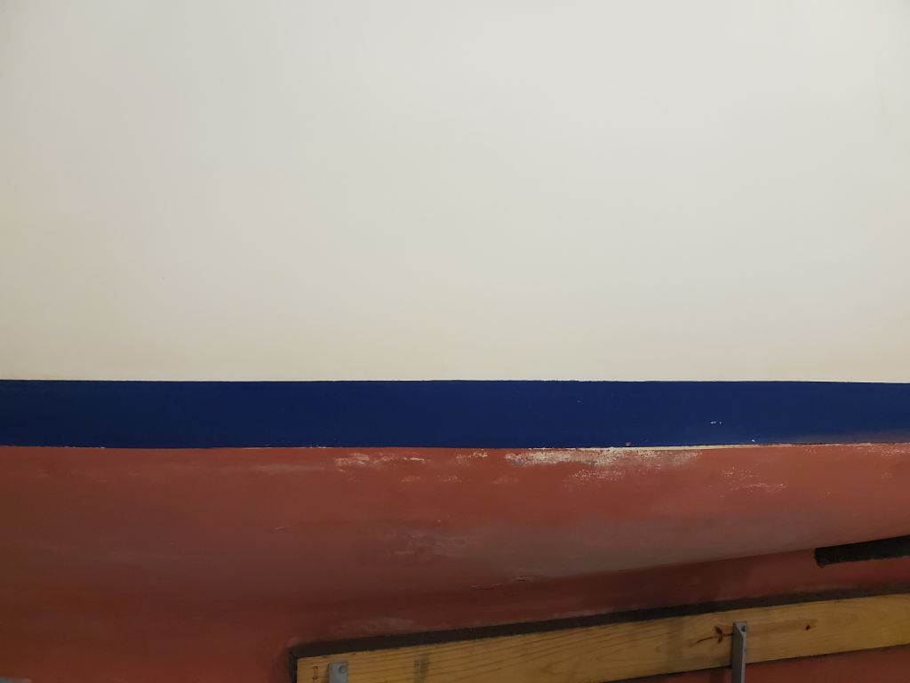
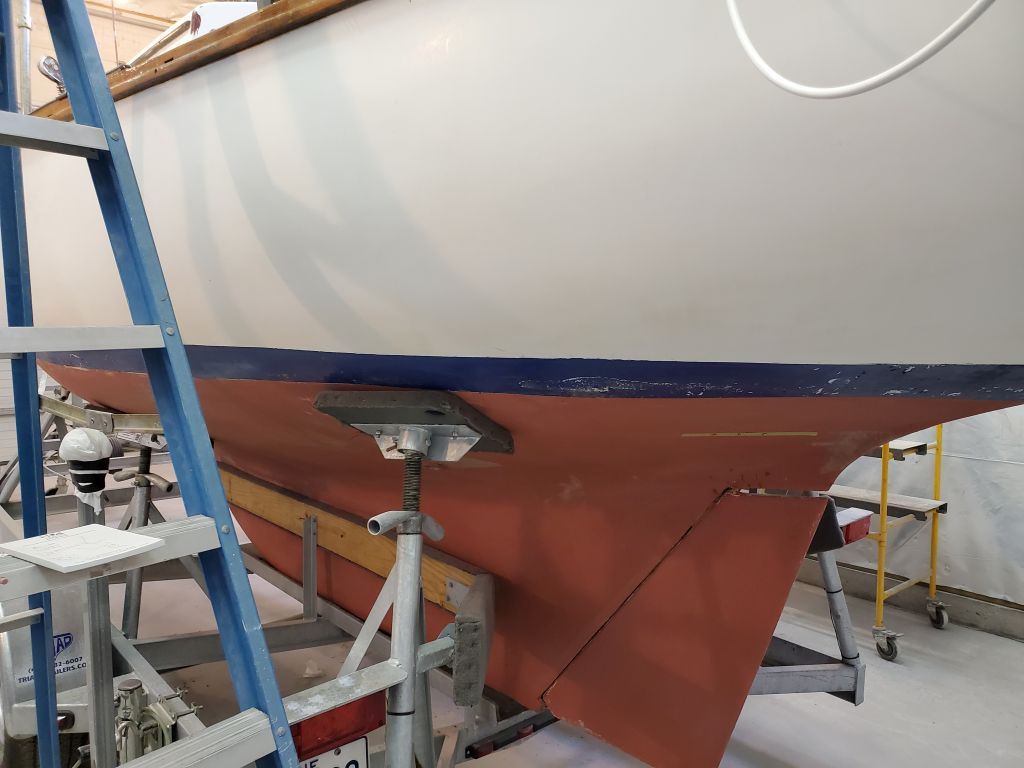
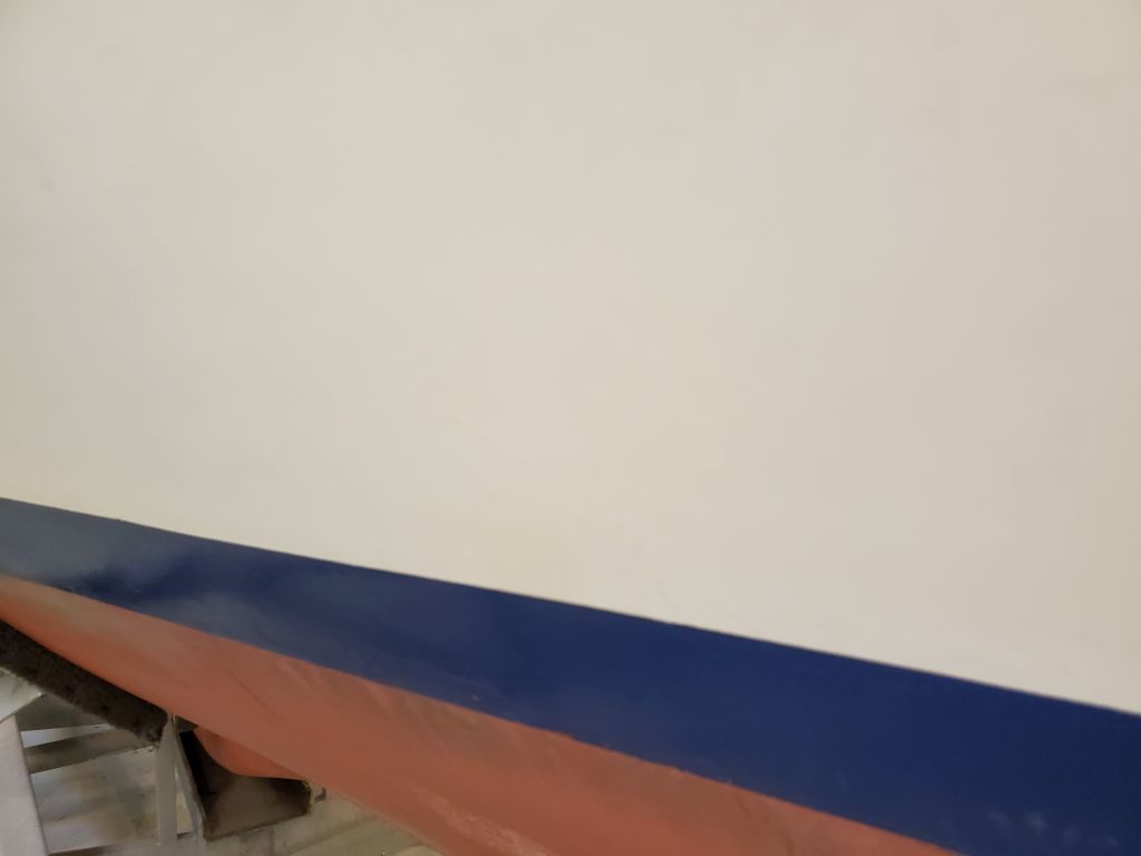
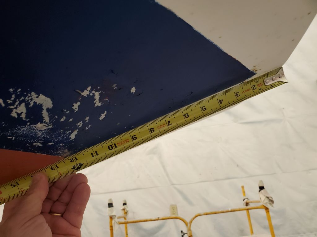
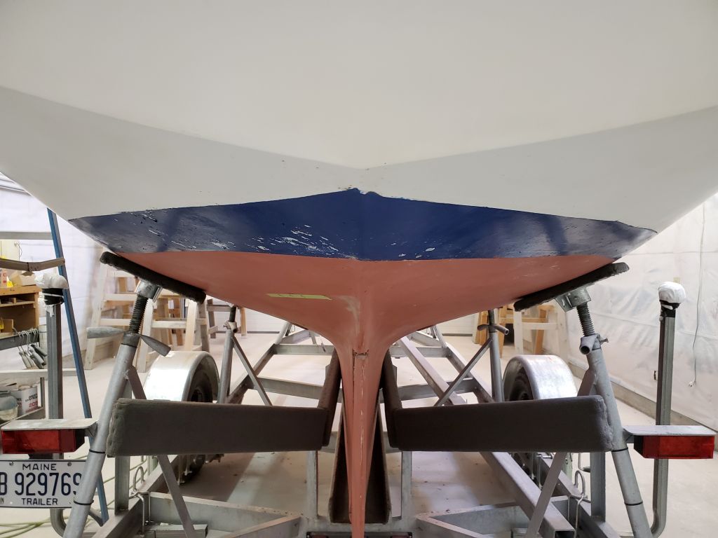
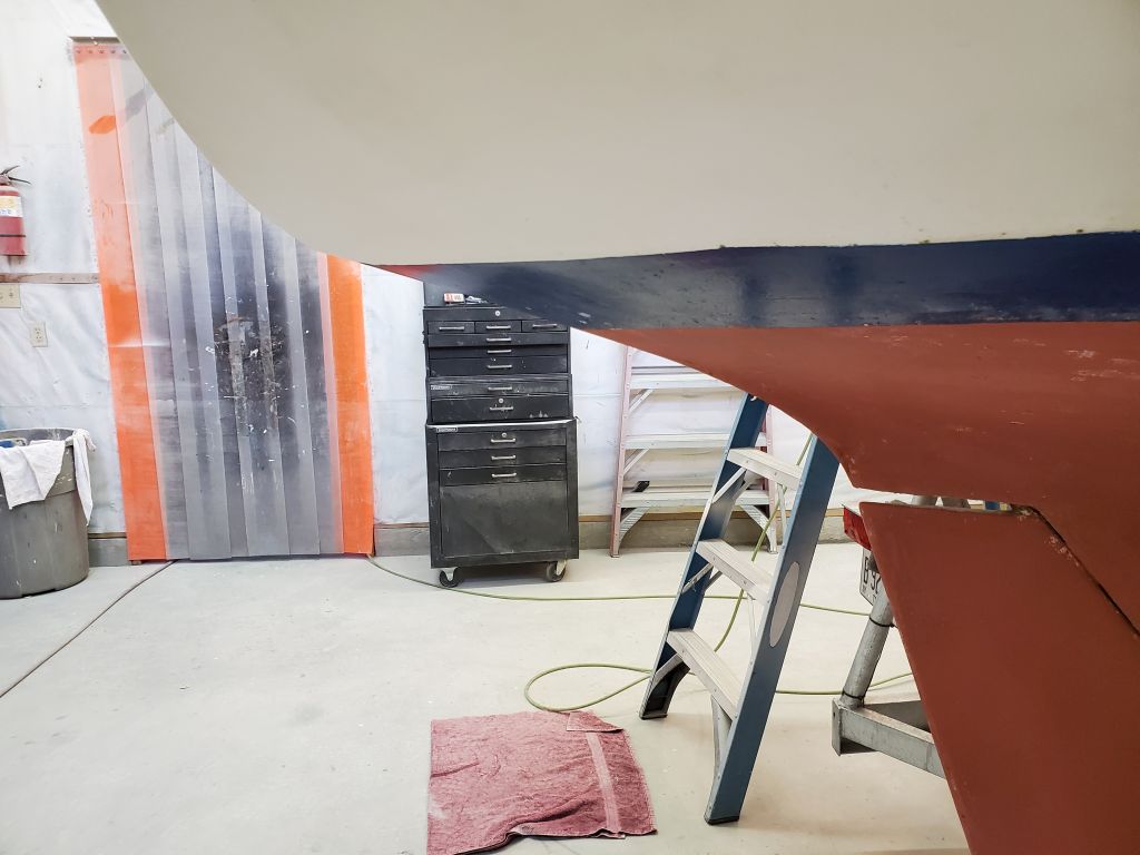
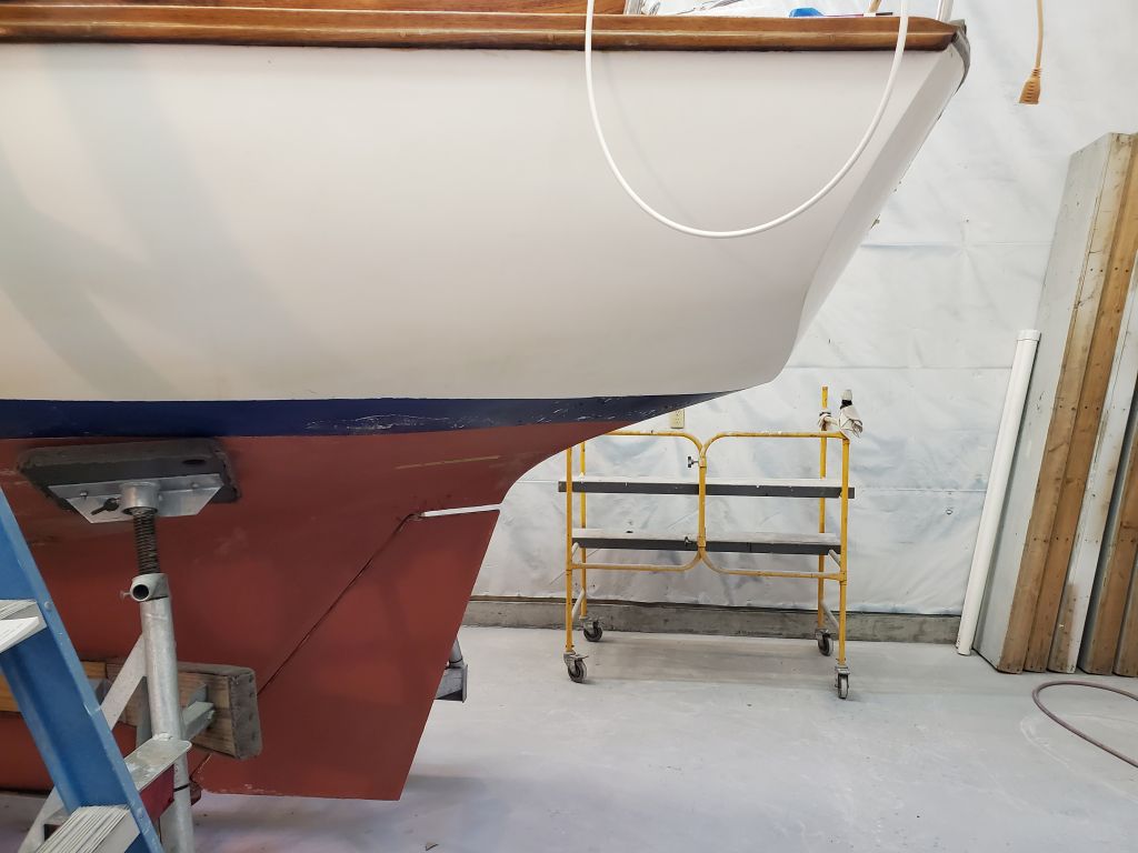
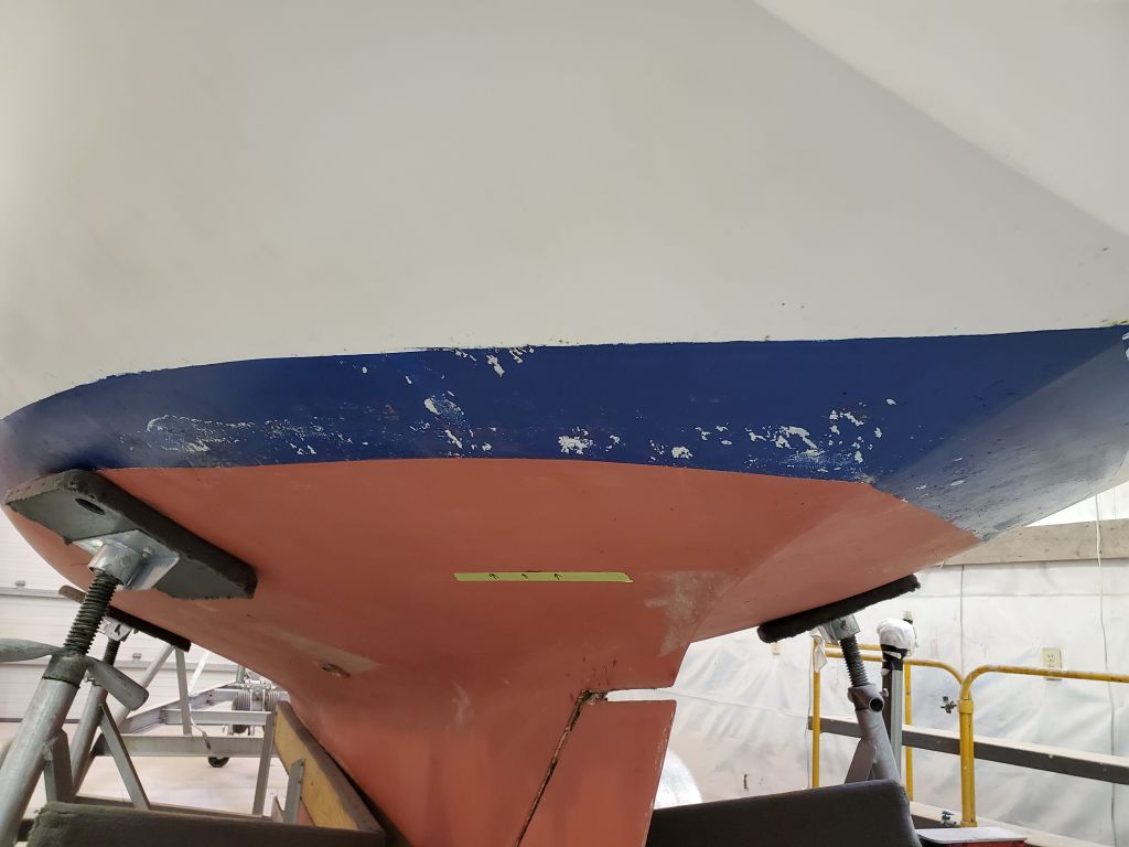
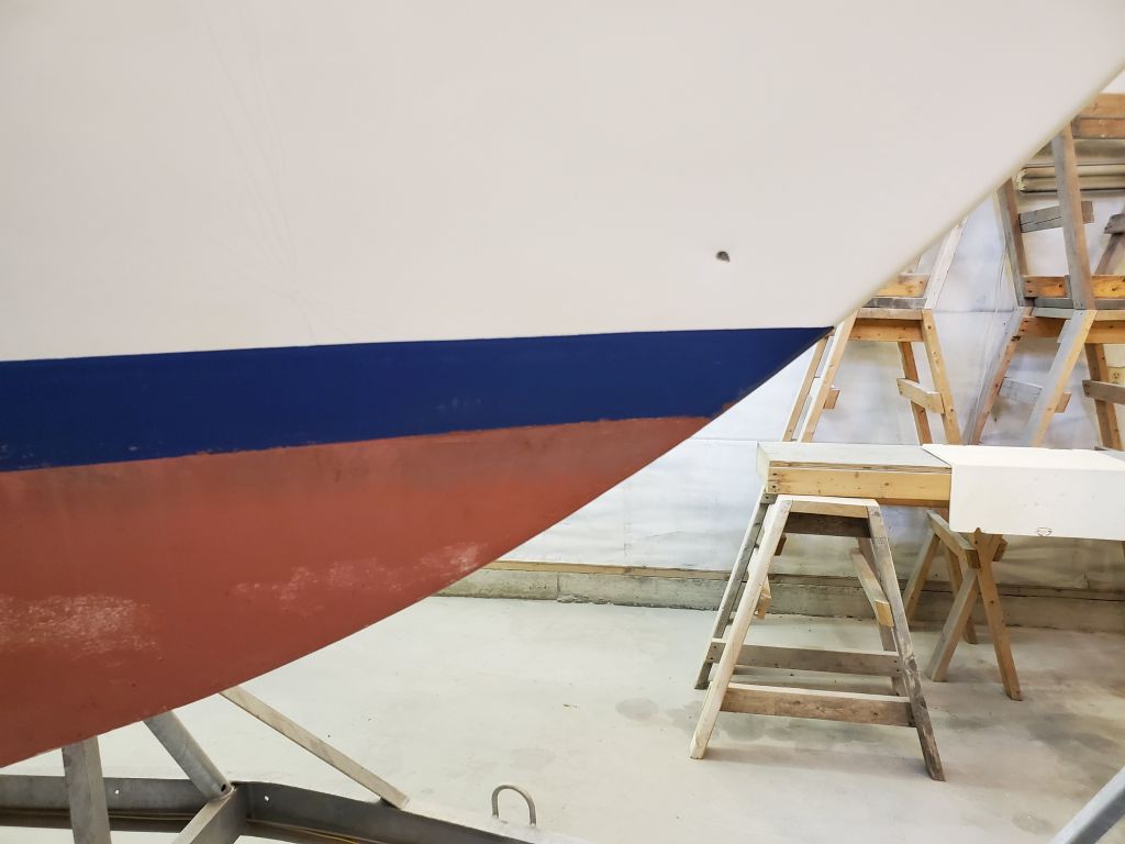
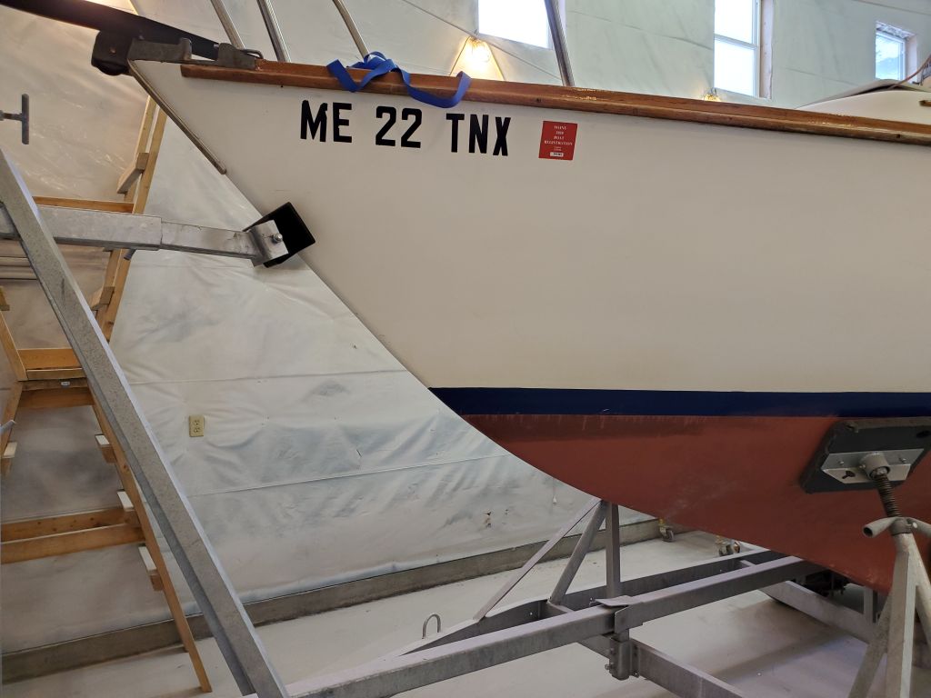
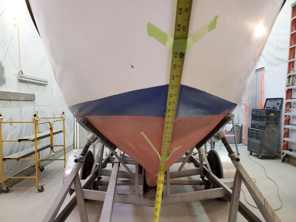
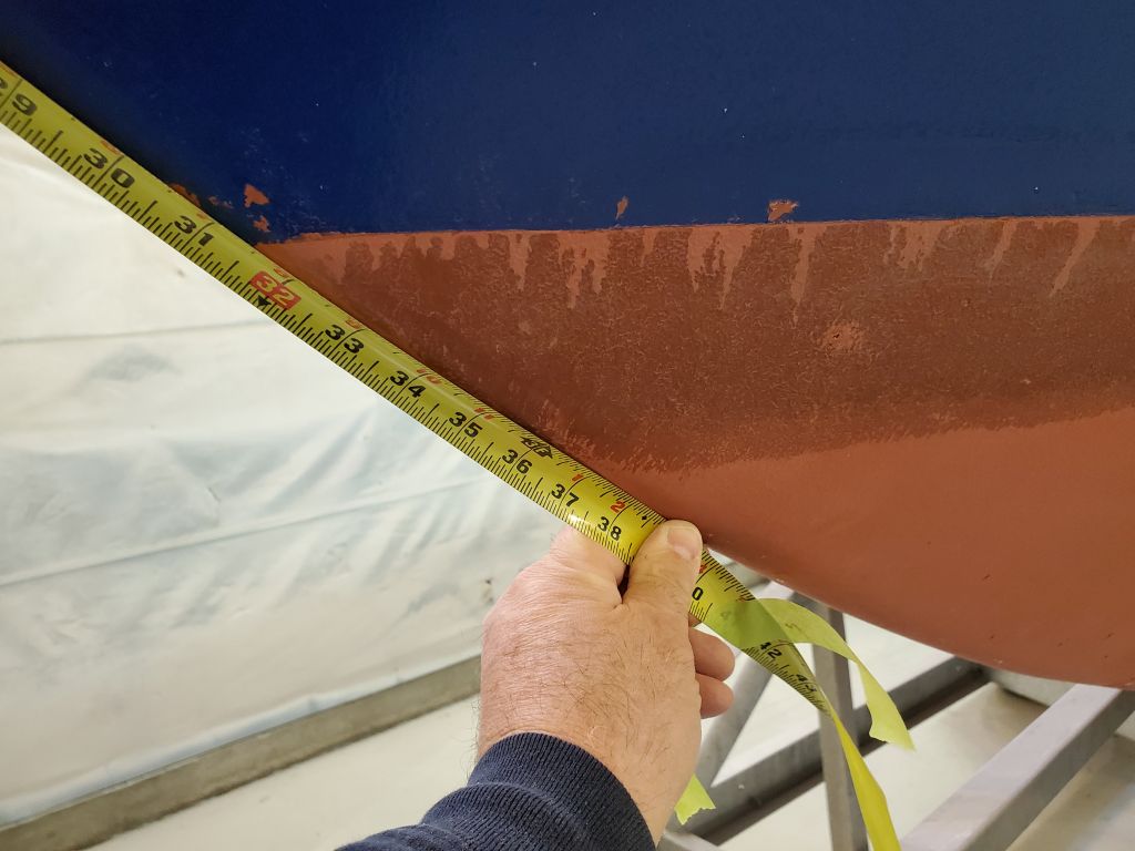
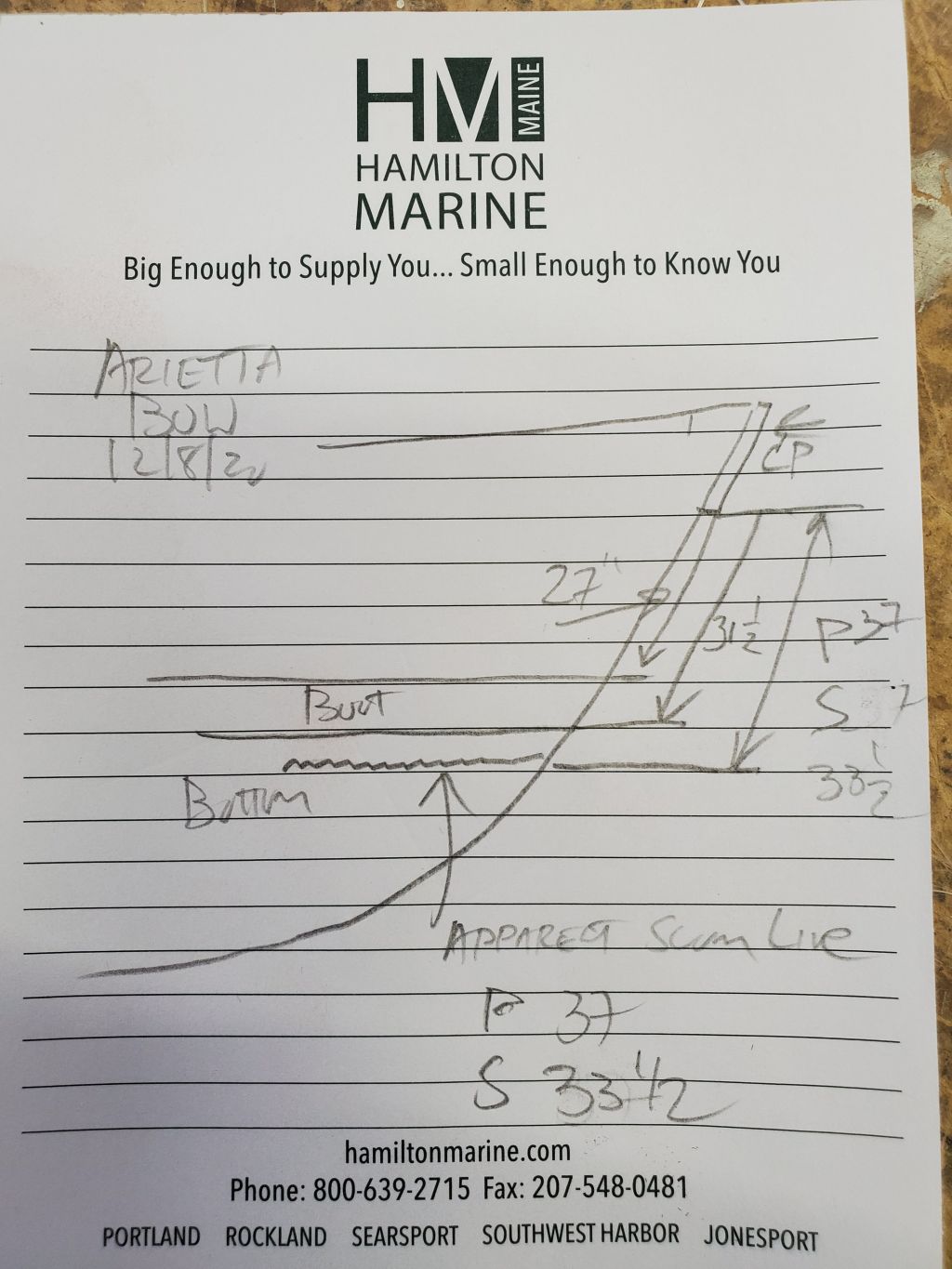
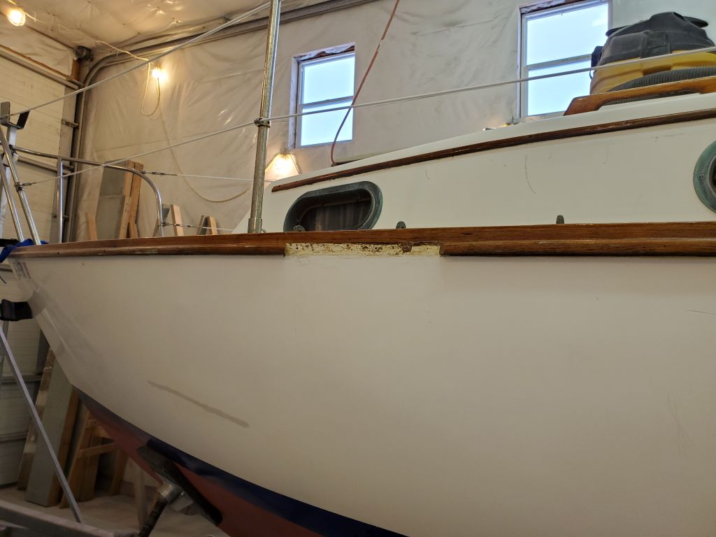
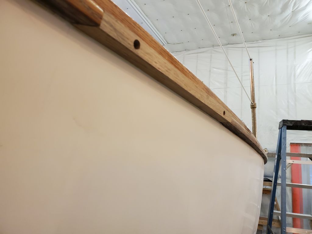
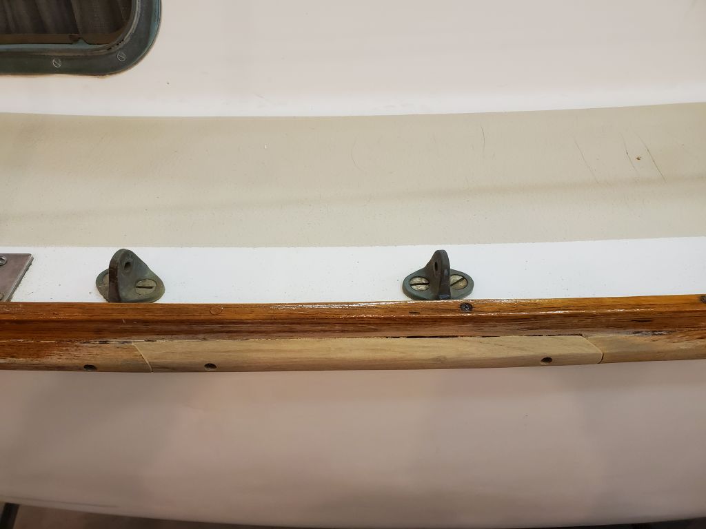
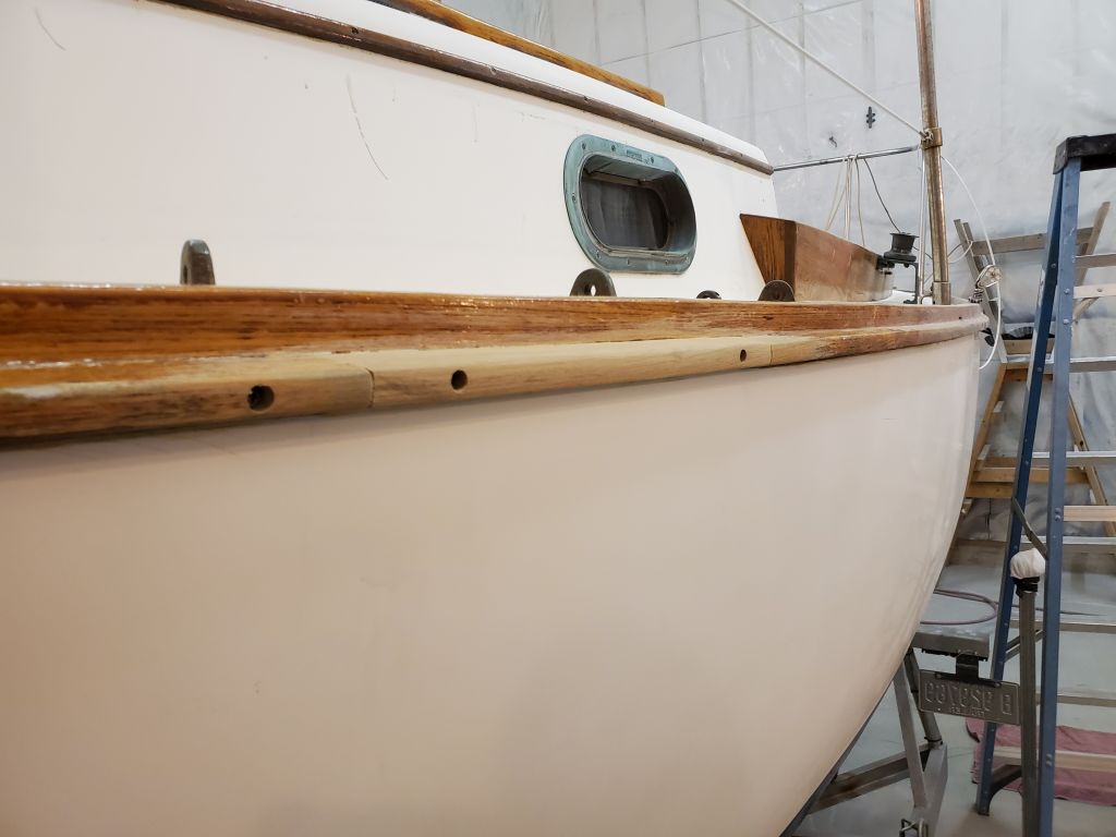
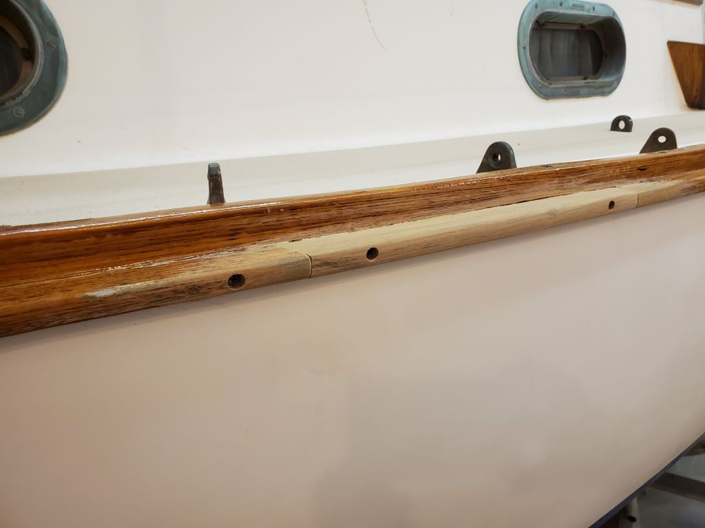
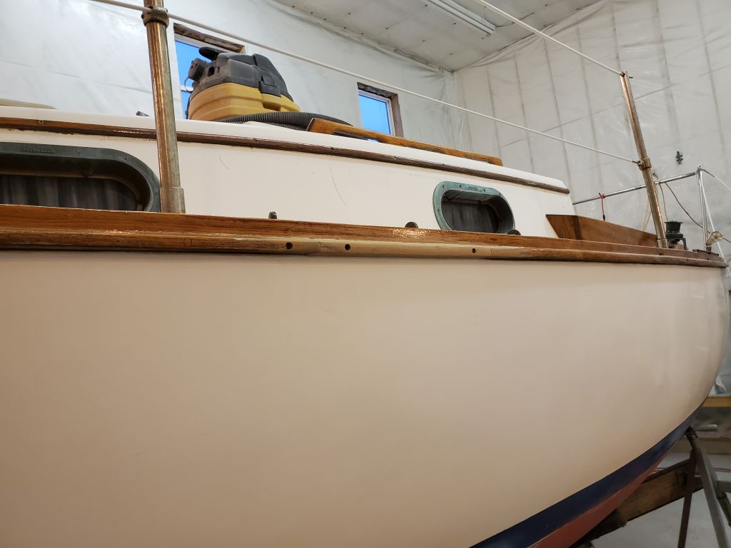
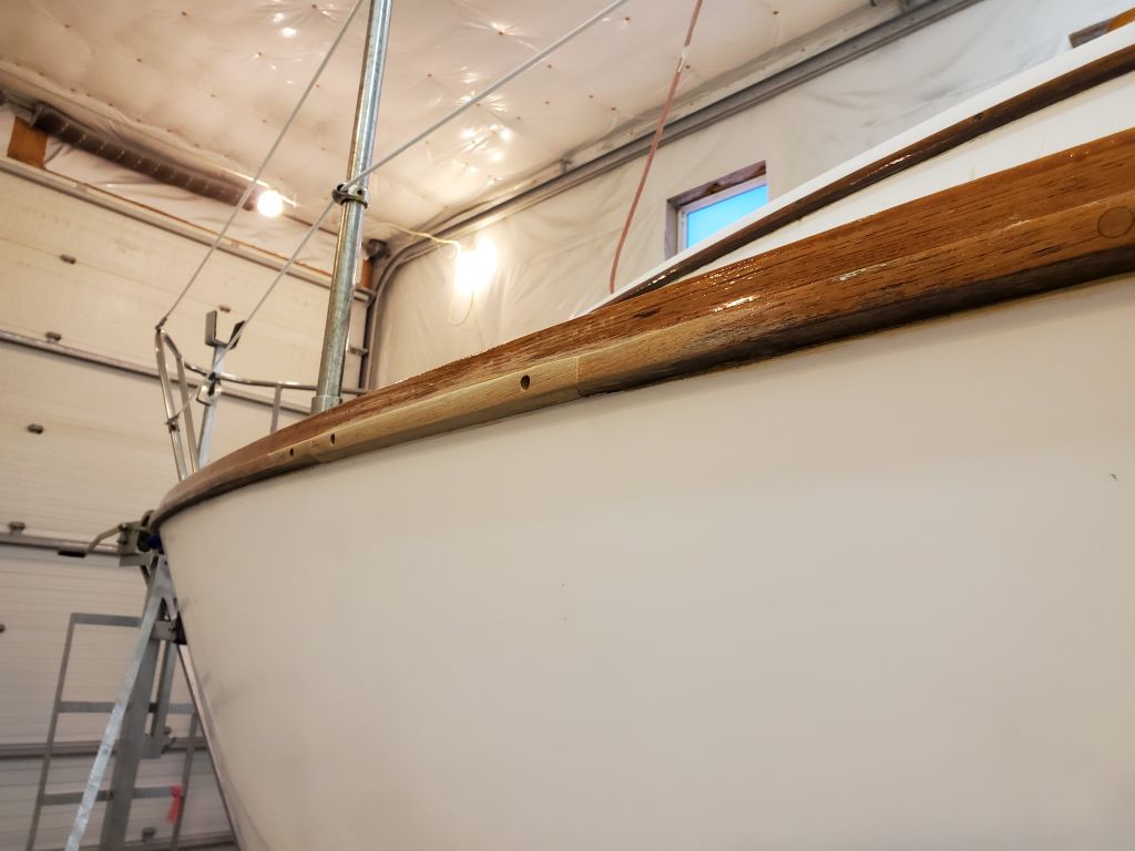
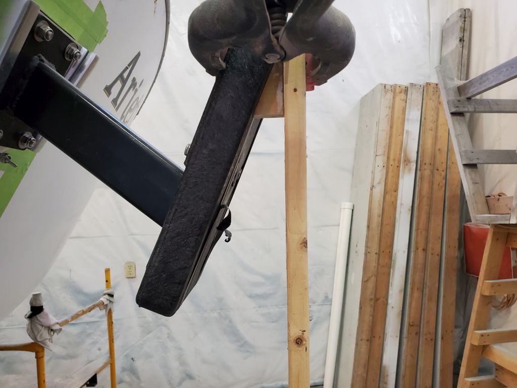
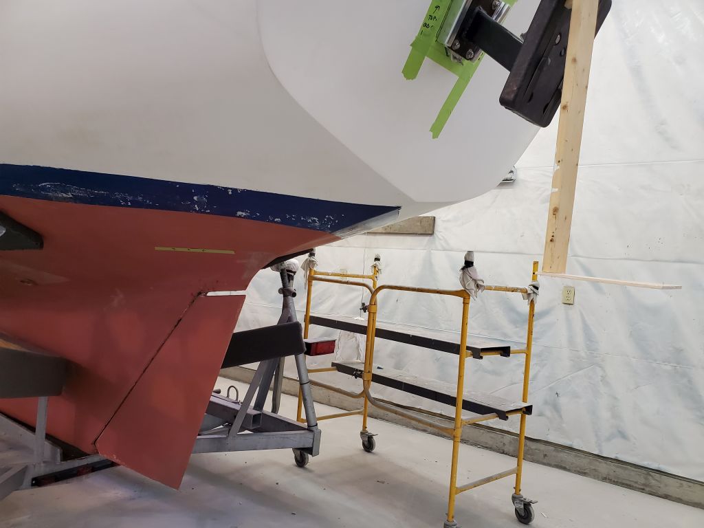
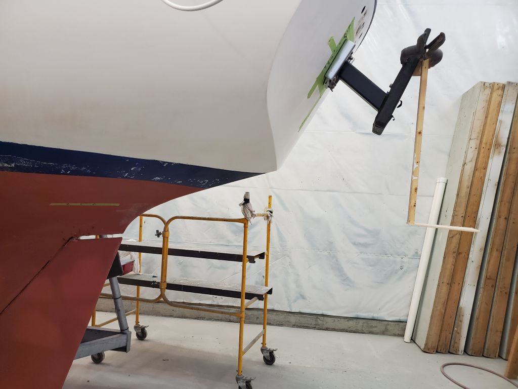
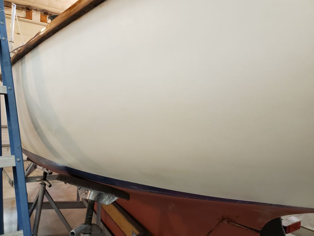
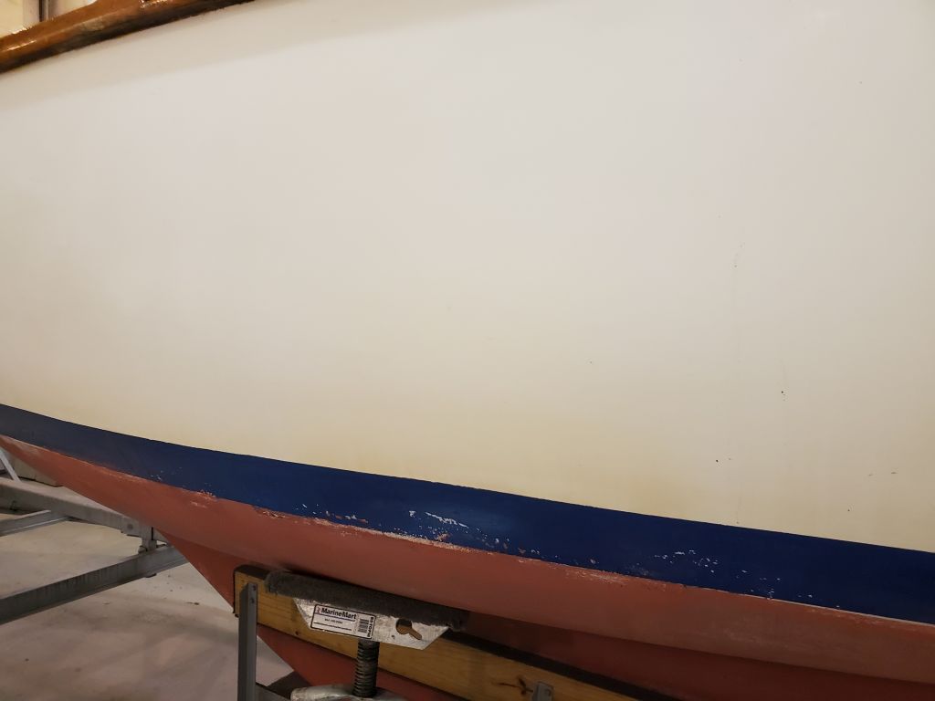
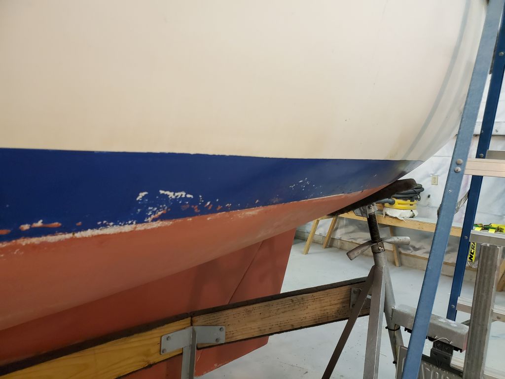
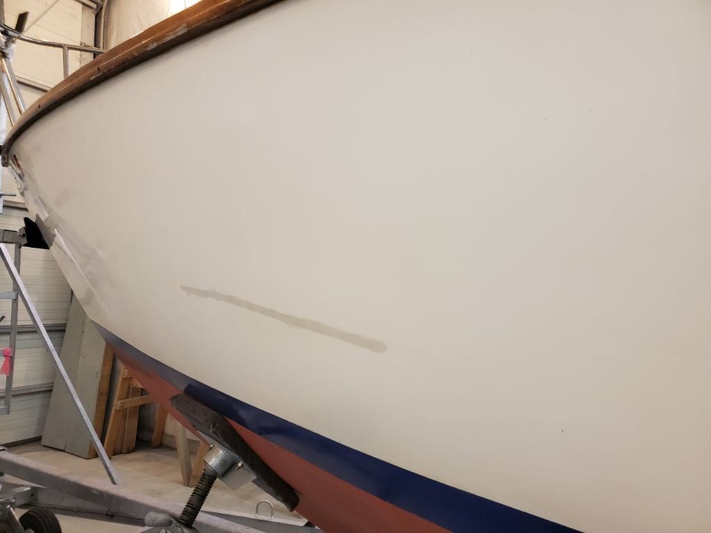
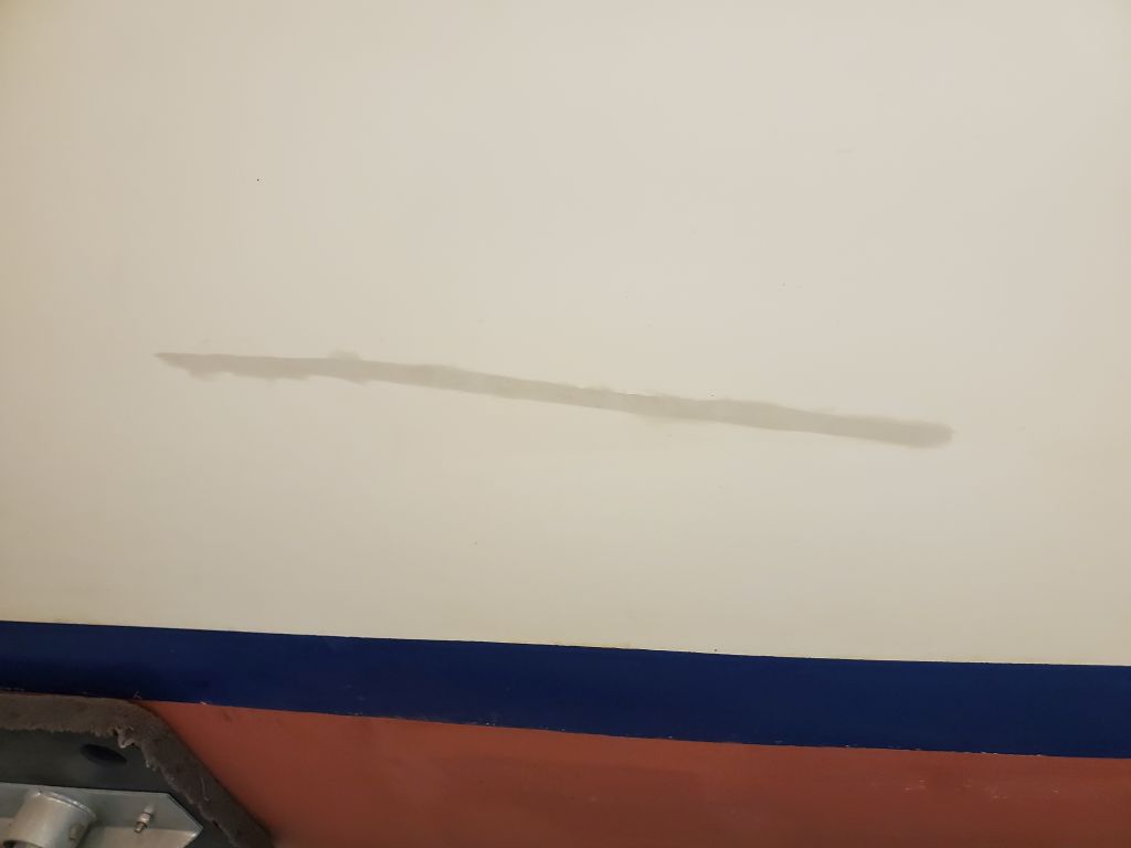
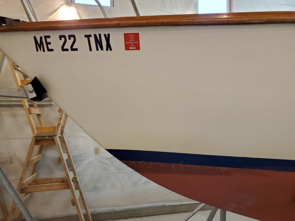
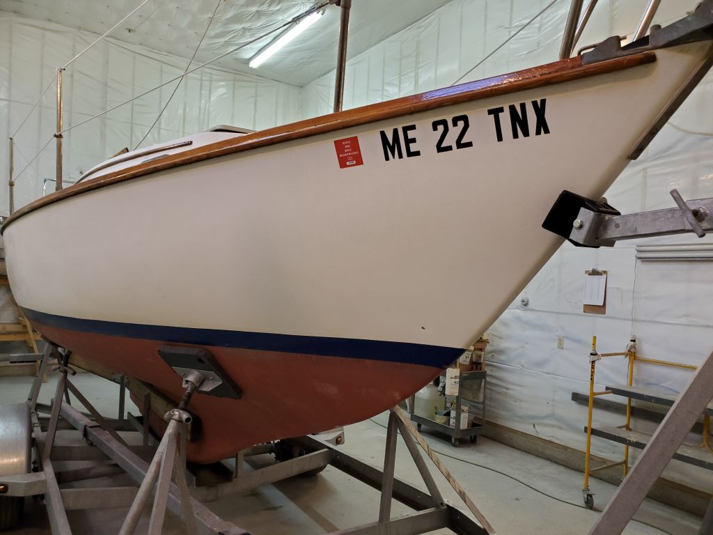
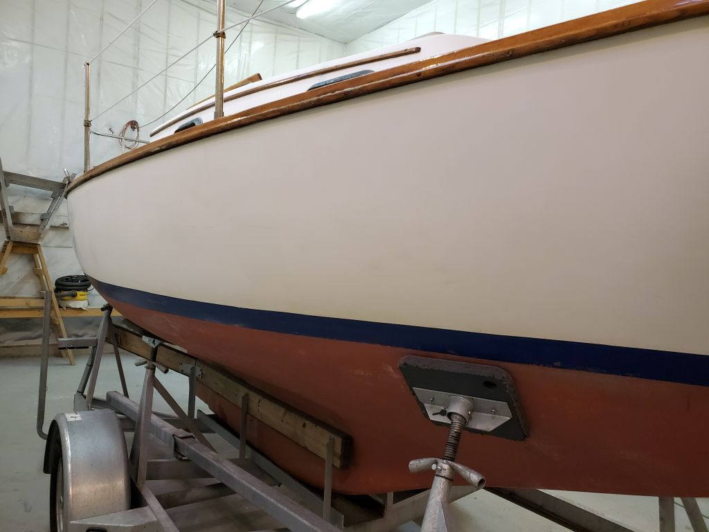
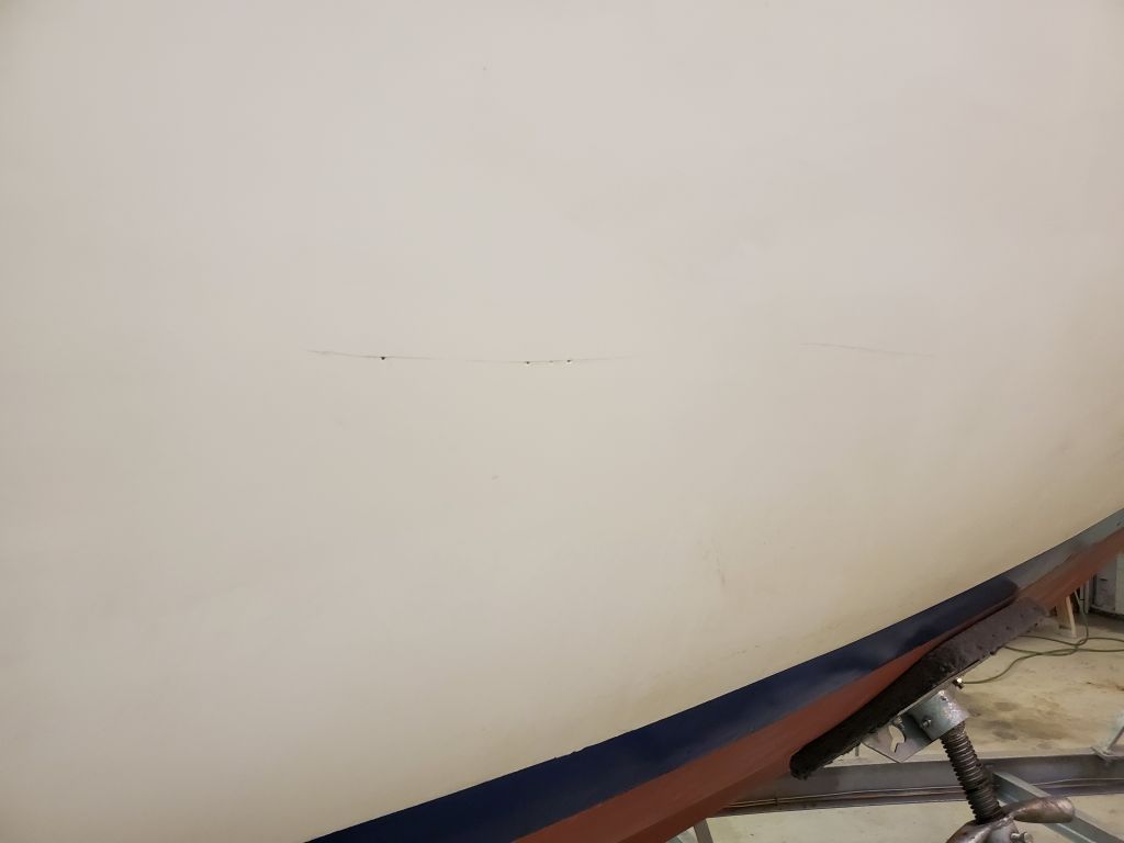
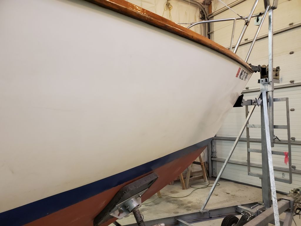
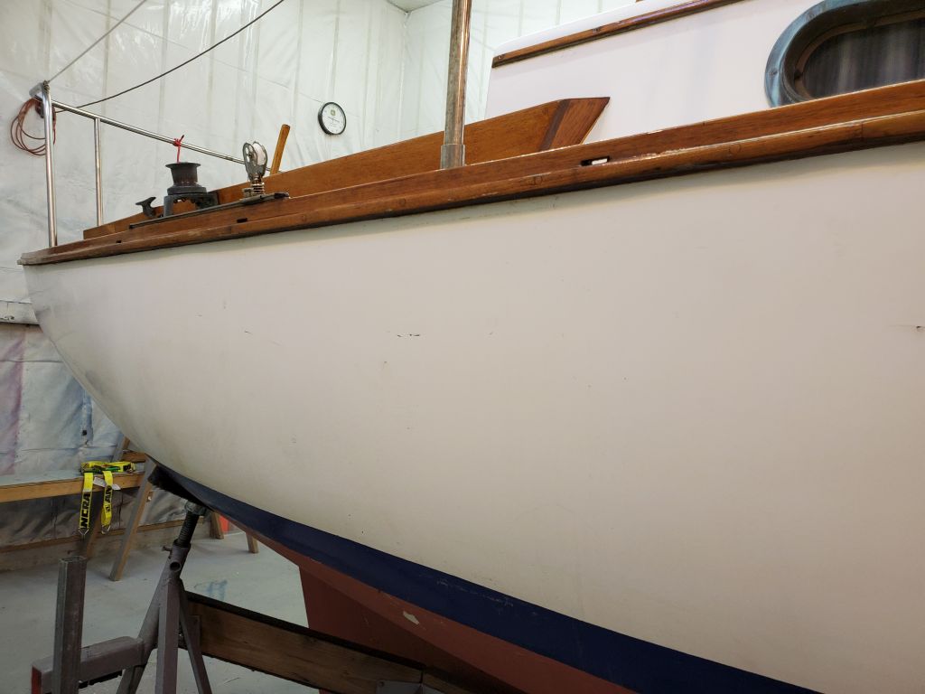
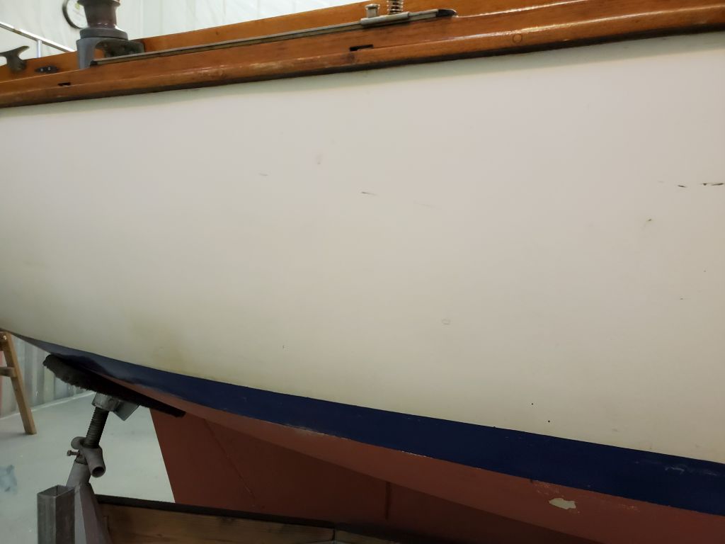
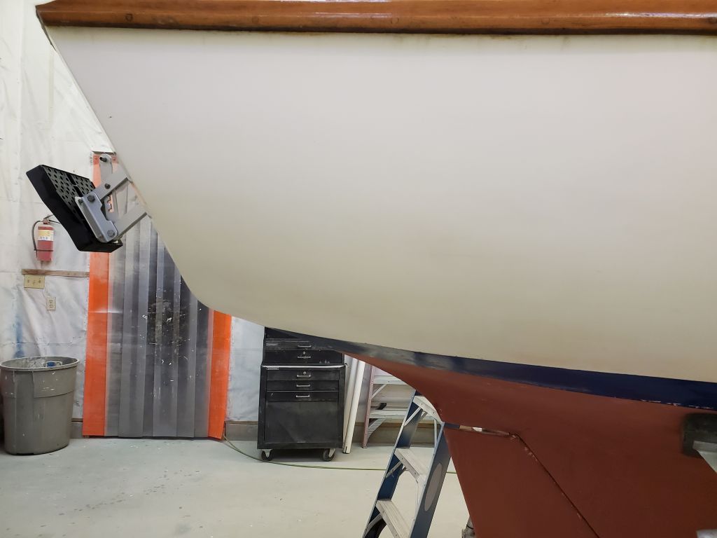
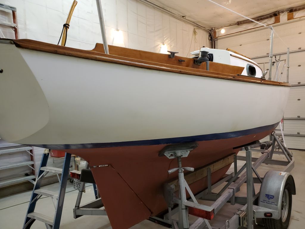
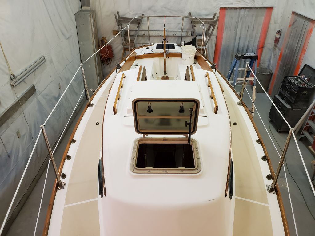
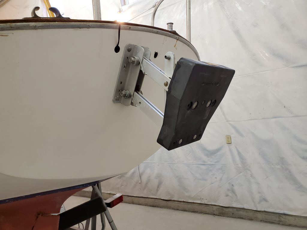
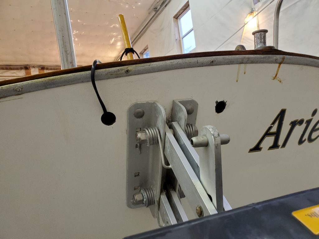
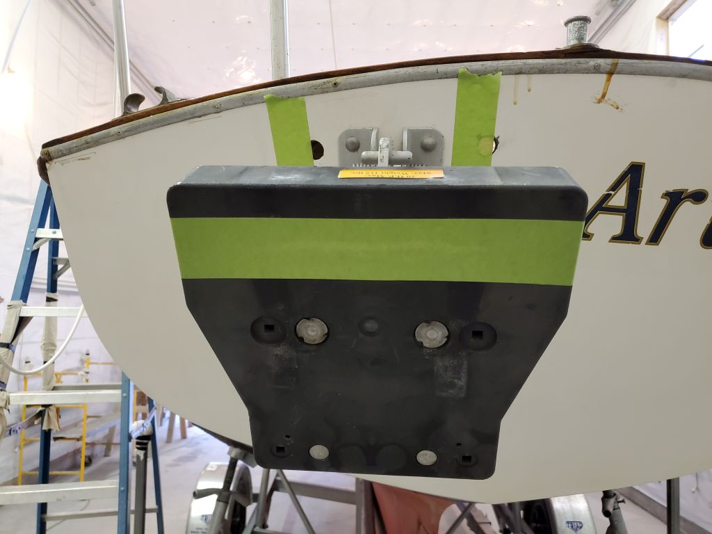
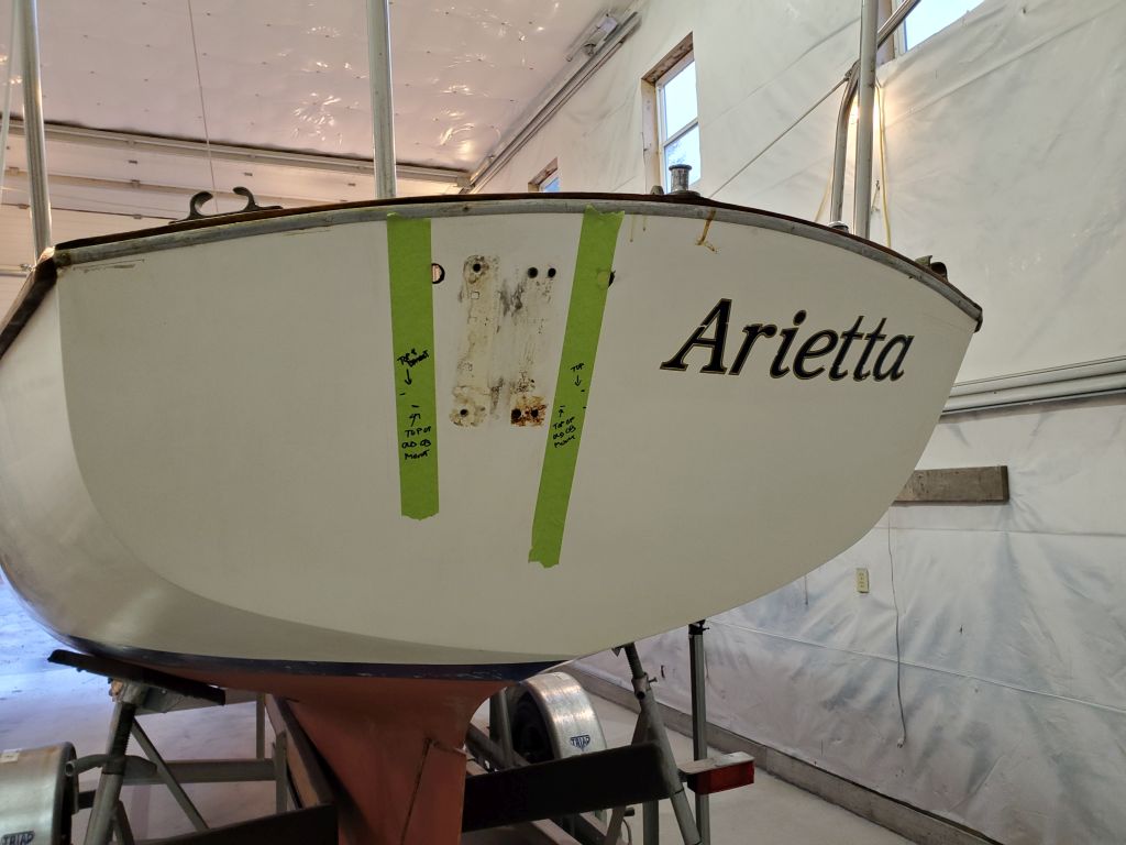
The known scope of work included some deck repairs in the cockpit and poop deck, plus a moderate list of smaller jobs and improvements. To get started, I inspected the hull and documented its initial condition. The original gelcoated surfaces were in generally good condition with a few minor stress cracks and the usual collection of dings and chips from docking and mooring accidents over the years, and the owners had indicated that the waterline as currently painted did not accurately reflect how the boat actually floated. Assessing whether, or when, to possibly address the hull cosmetics, bootop, and waterline was part of the inspection at this time, but for the moment the only planned hull work was to remove the existing, bulky, and non-functional outboard bracket on the transom and replace it with a new, removable one the owner supplied.
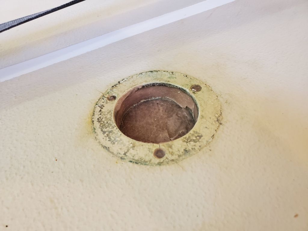
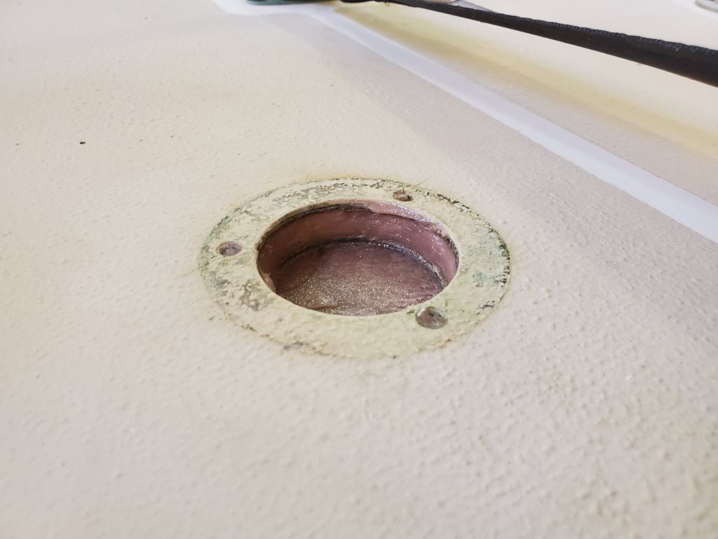
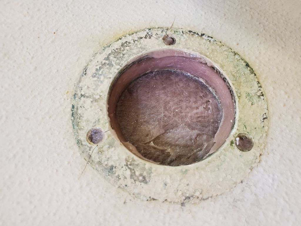
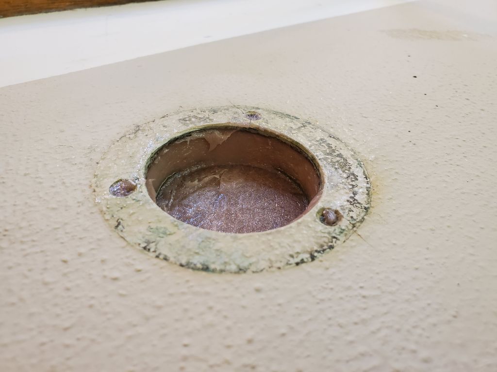
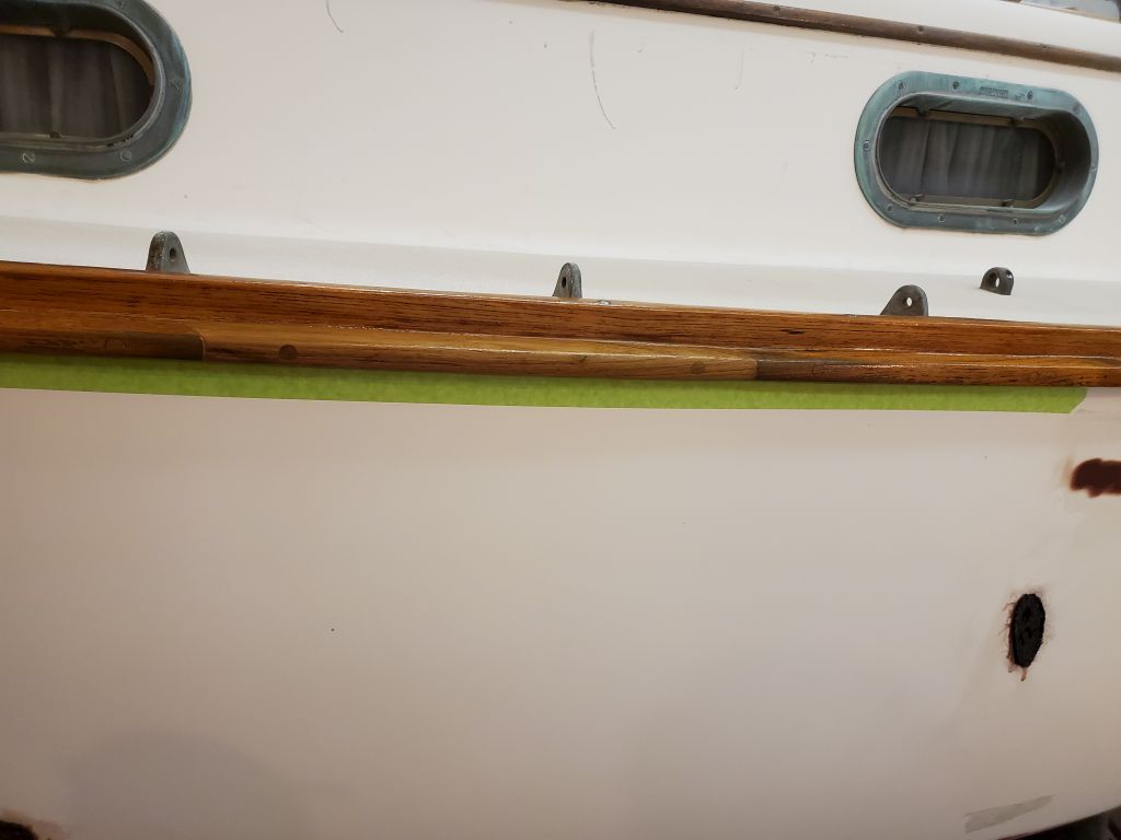
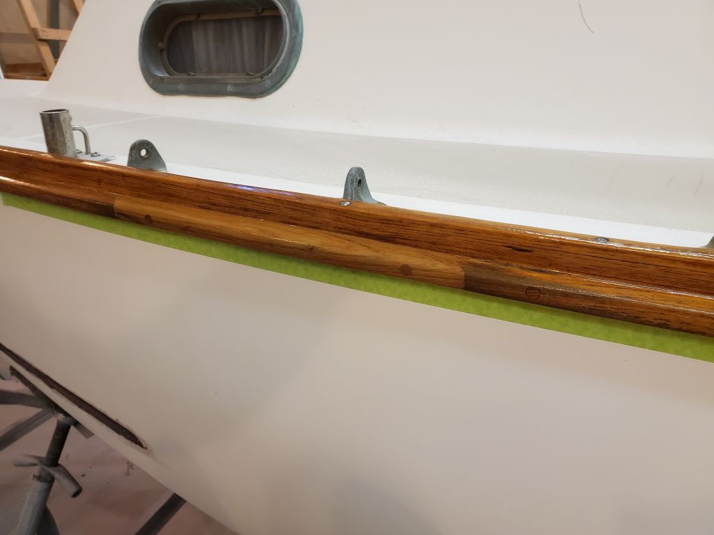
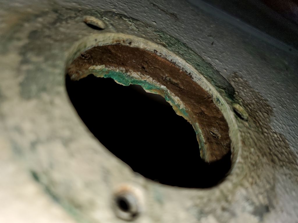
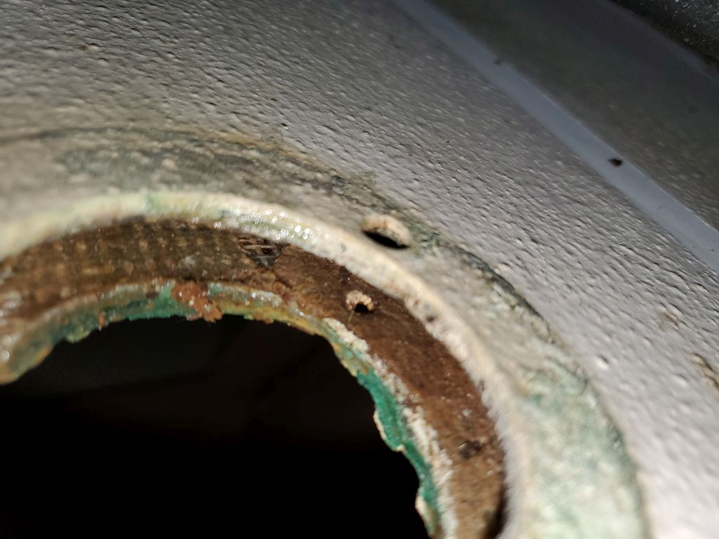
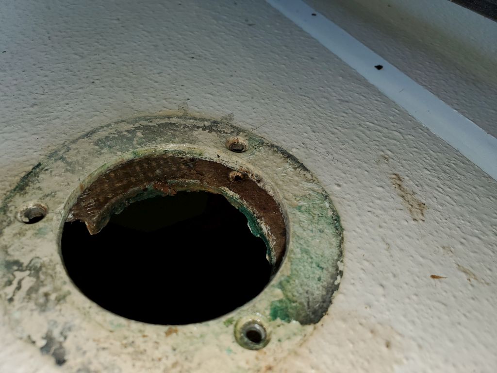
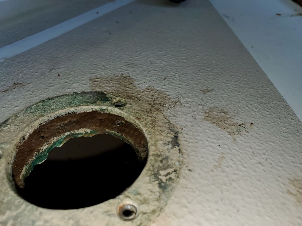
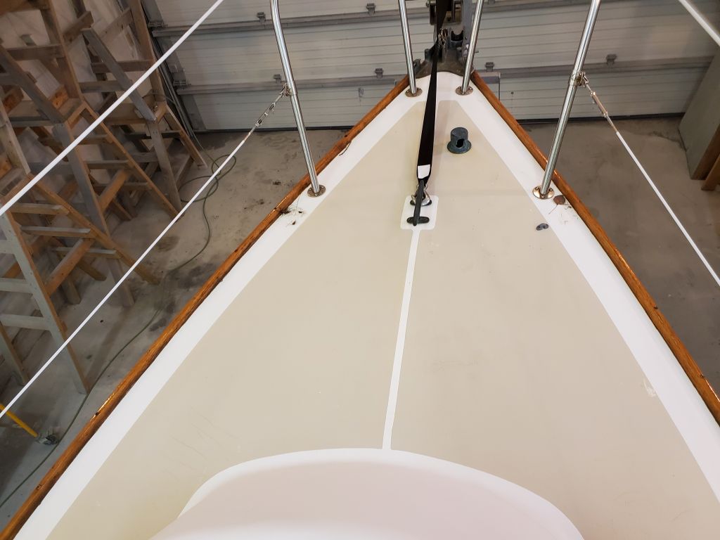
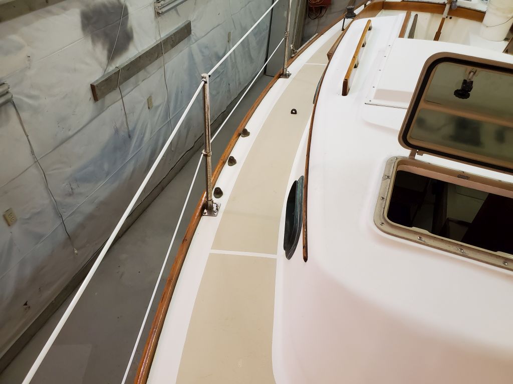
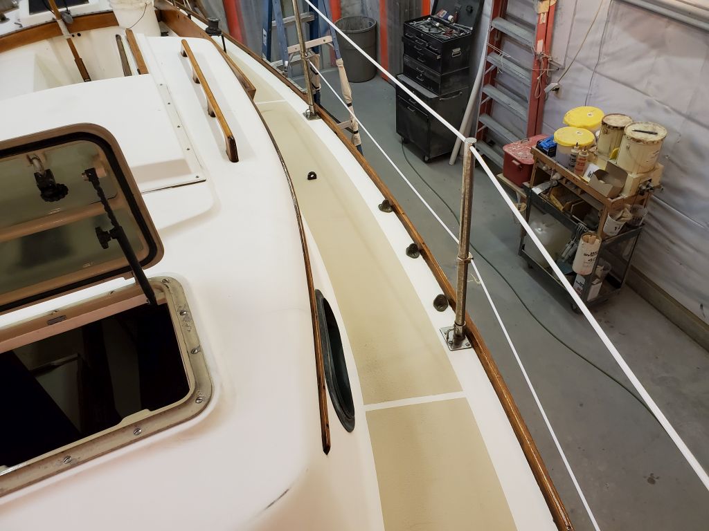
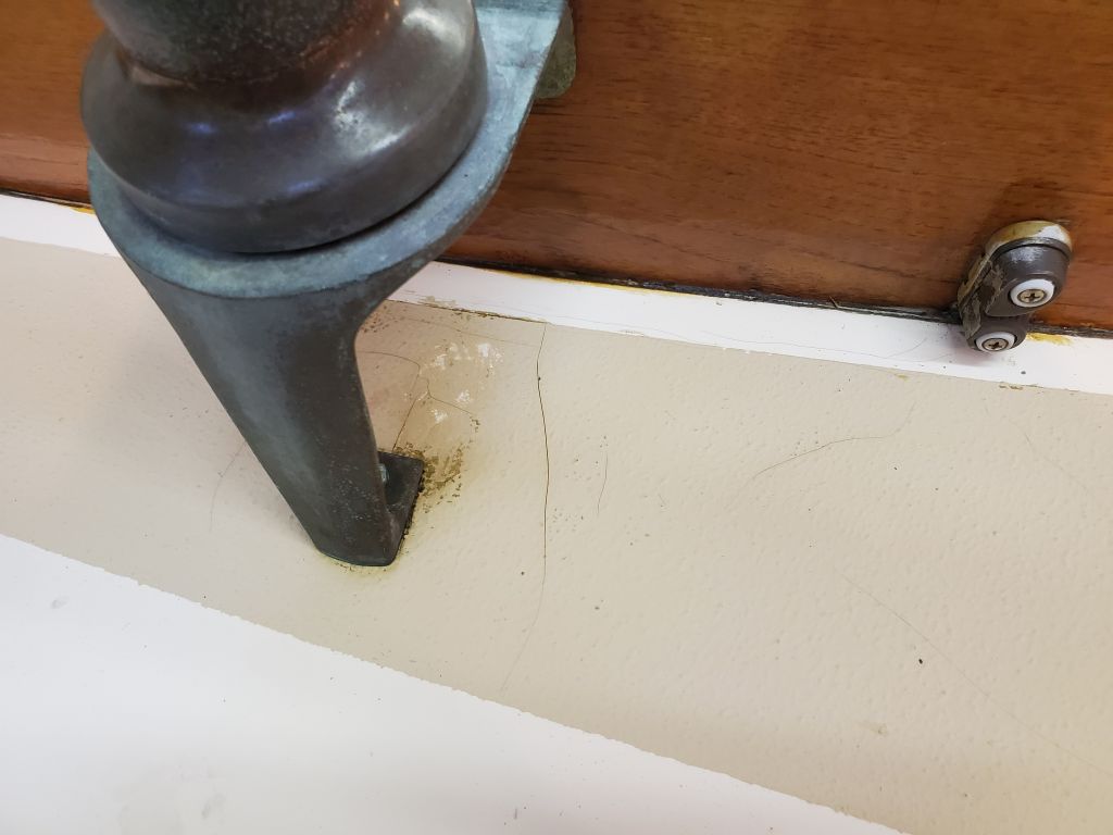
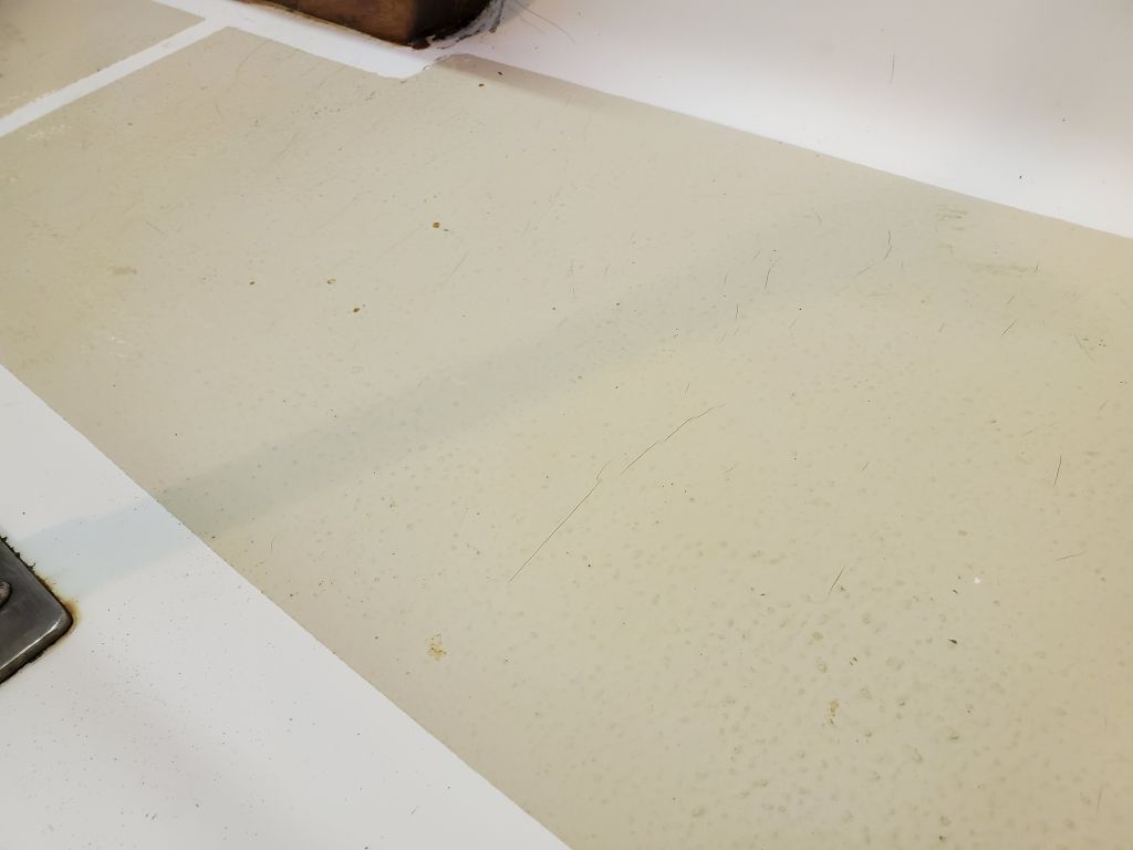
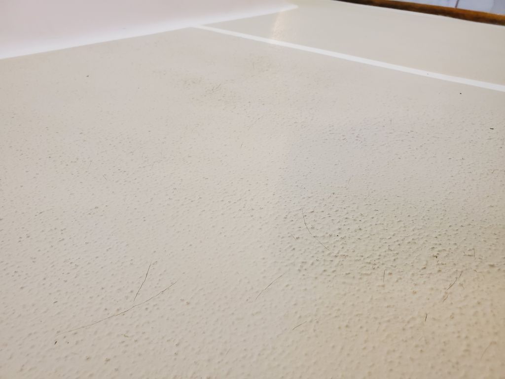
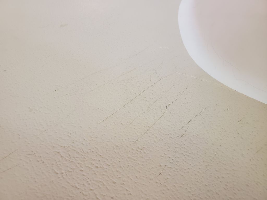
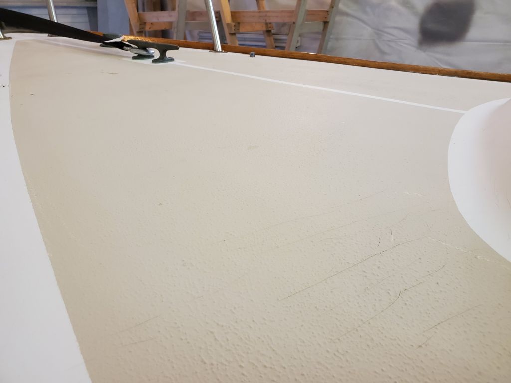
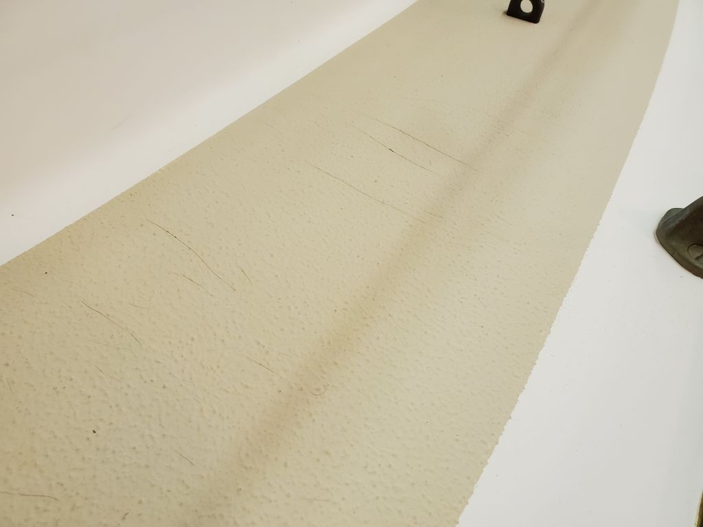
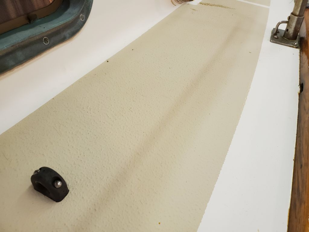
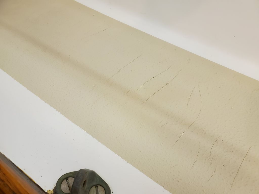
The decks also featured original gelcoat and nonskid throughout, and generally were in good condition for the age. The sidedecks featured various stress cracks extending athwartships across the decks in several areas, particularly amidships and near the rigging loads, but closer inspection and sounding revealed no noticeable problem areas within, other than obvious moisture in the deck immediately surrounding the foredeck-mounted hawsepipe.
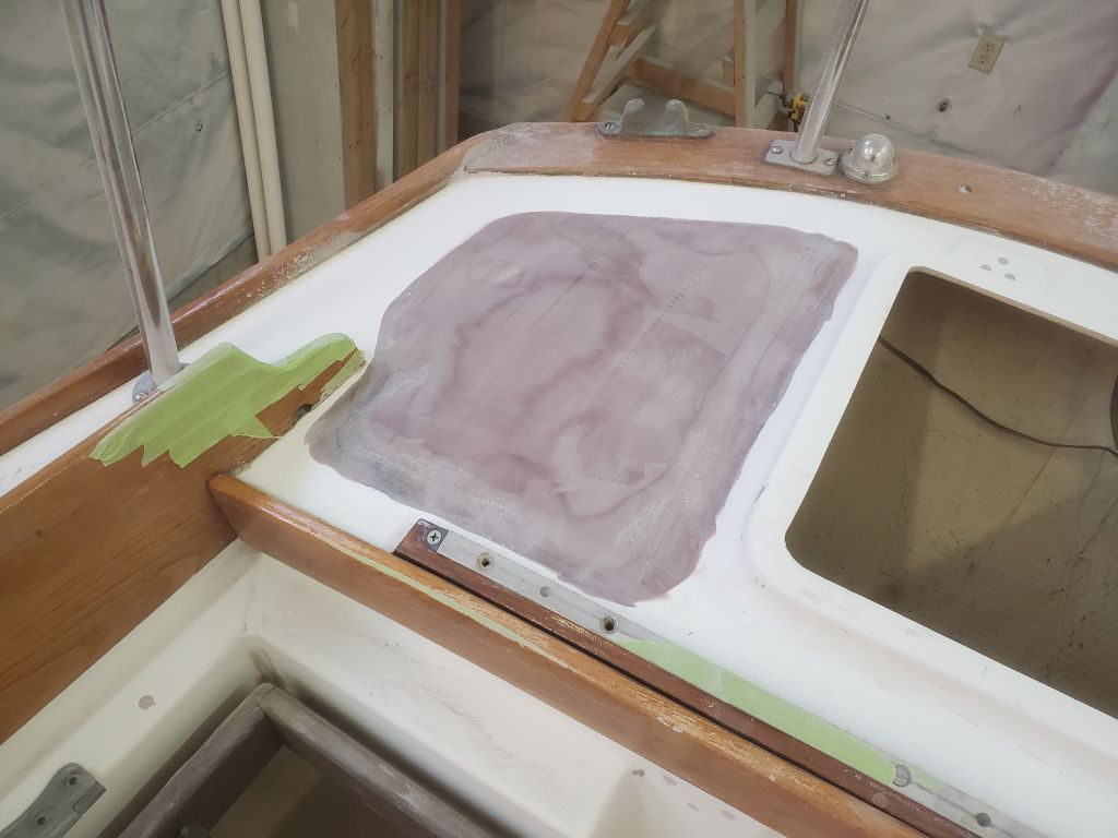
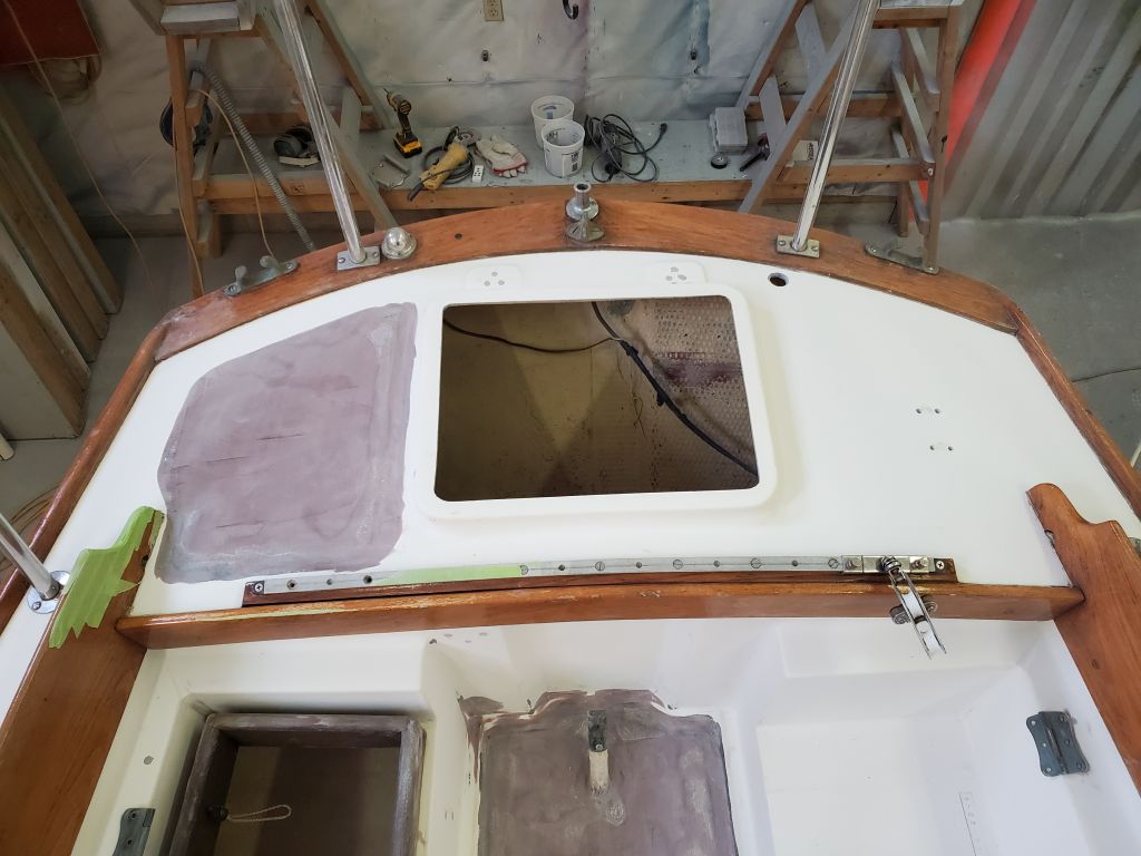
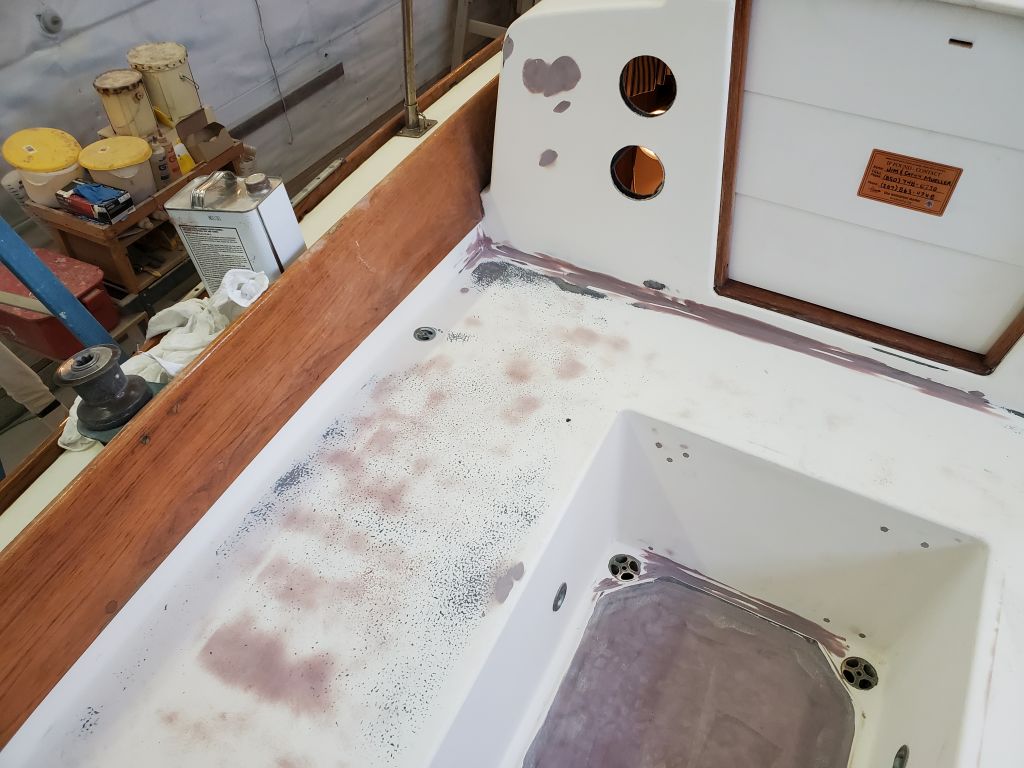
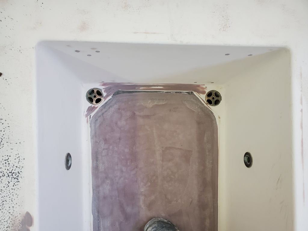
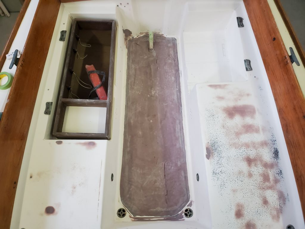
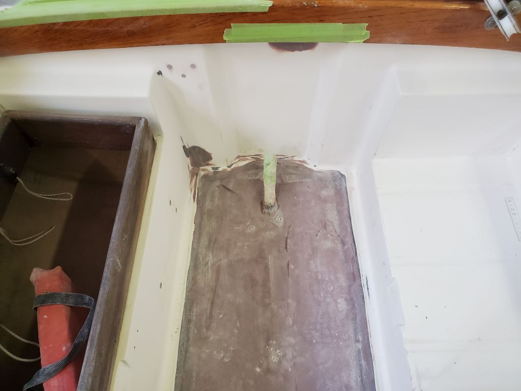
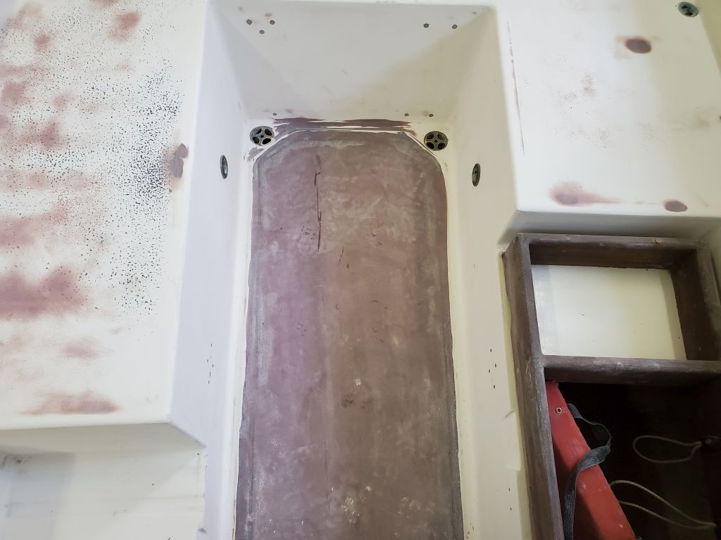
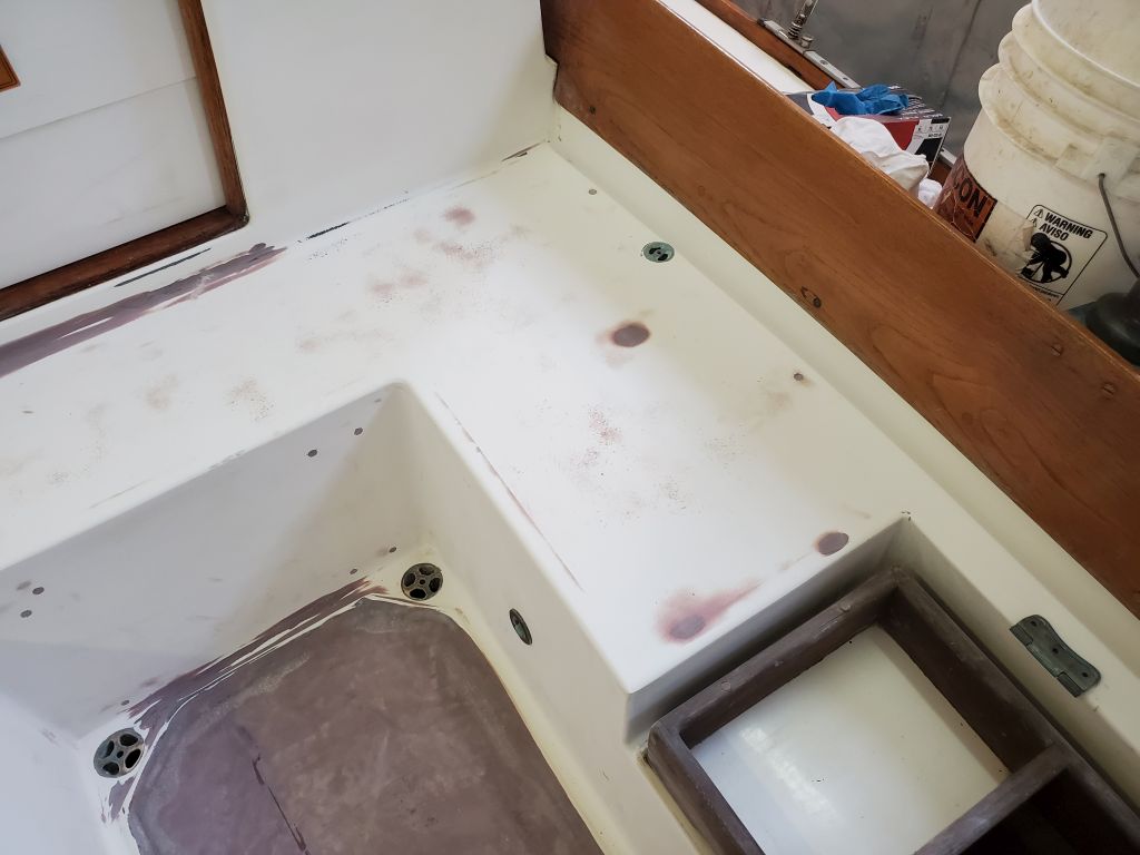
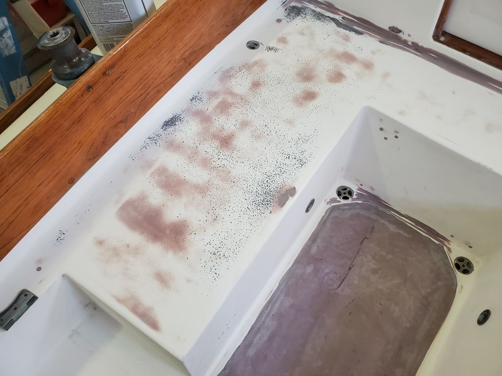
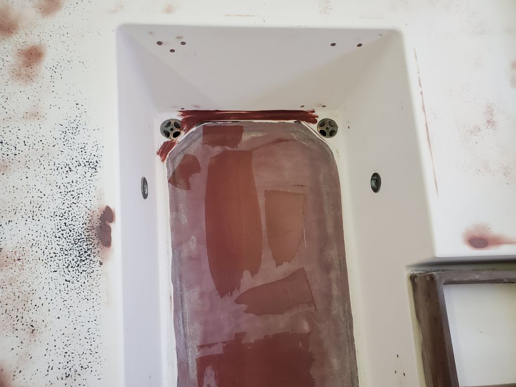
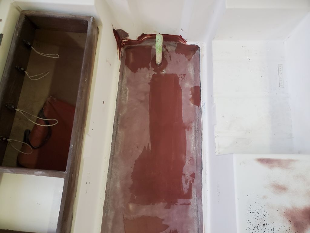
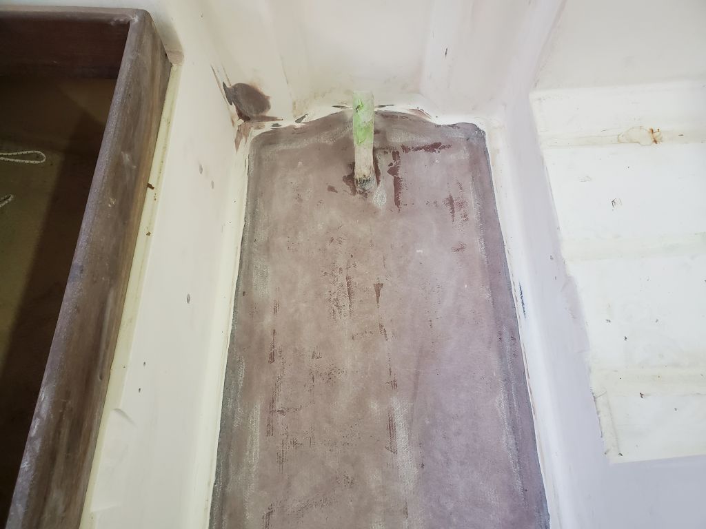
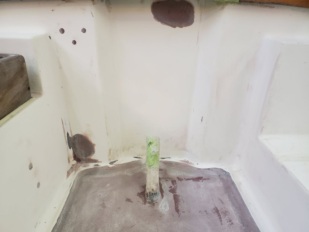
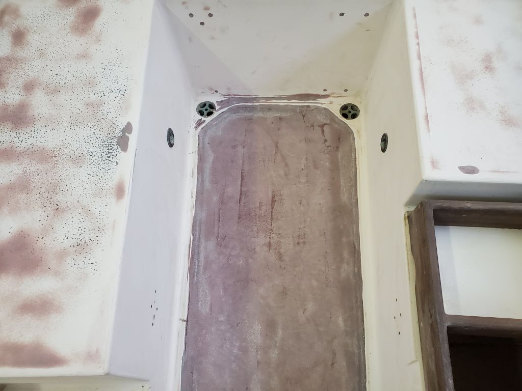
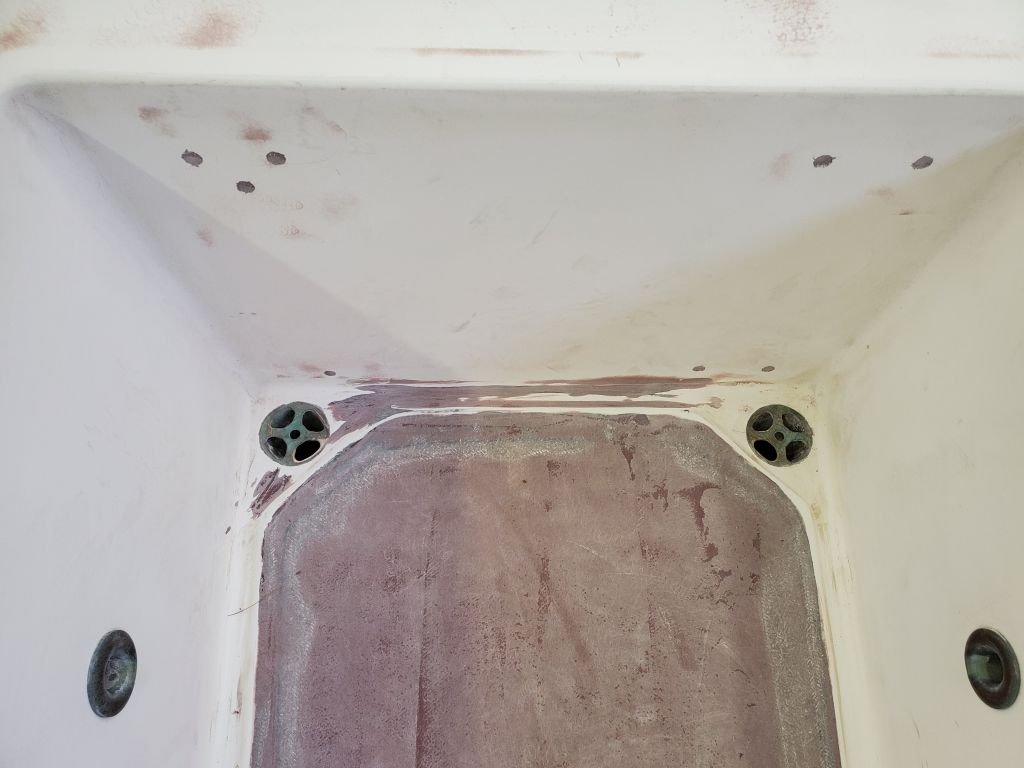
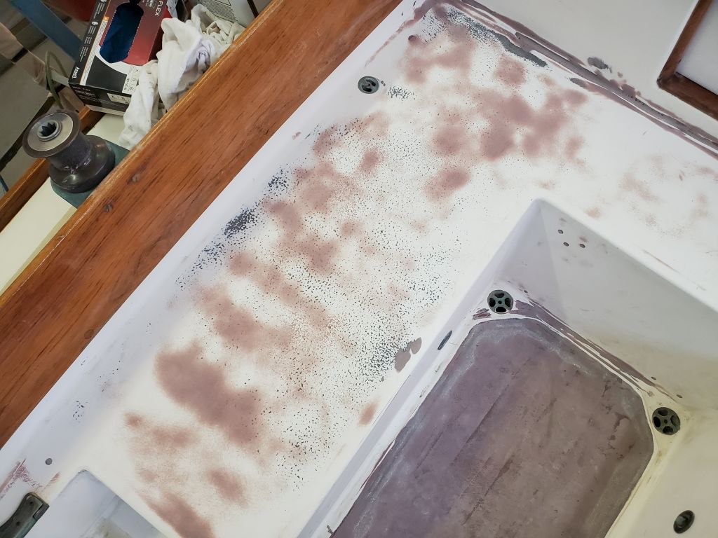
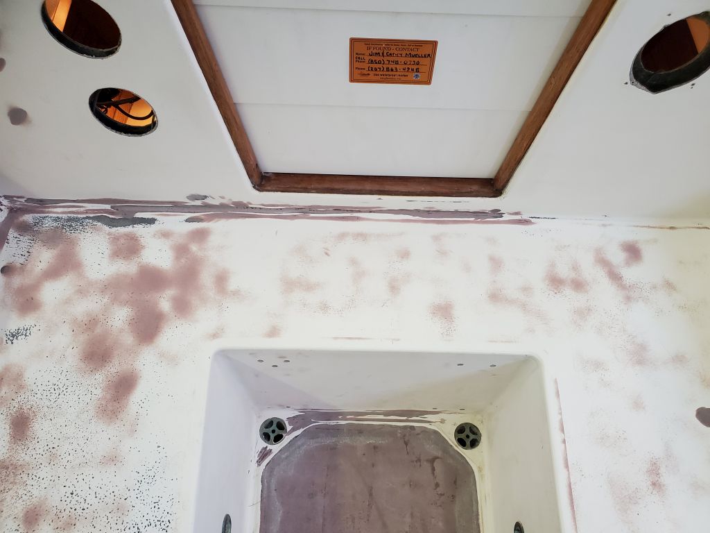
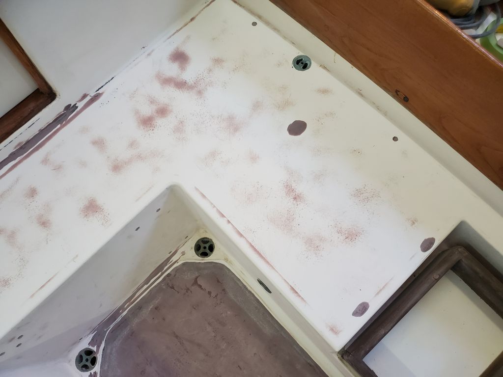
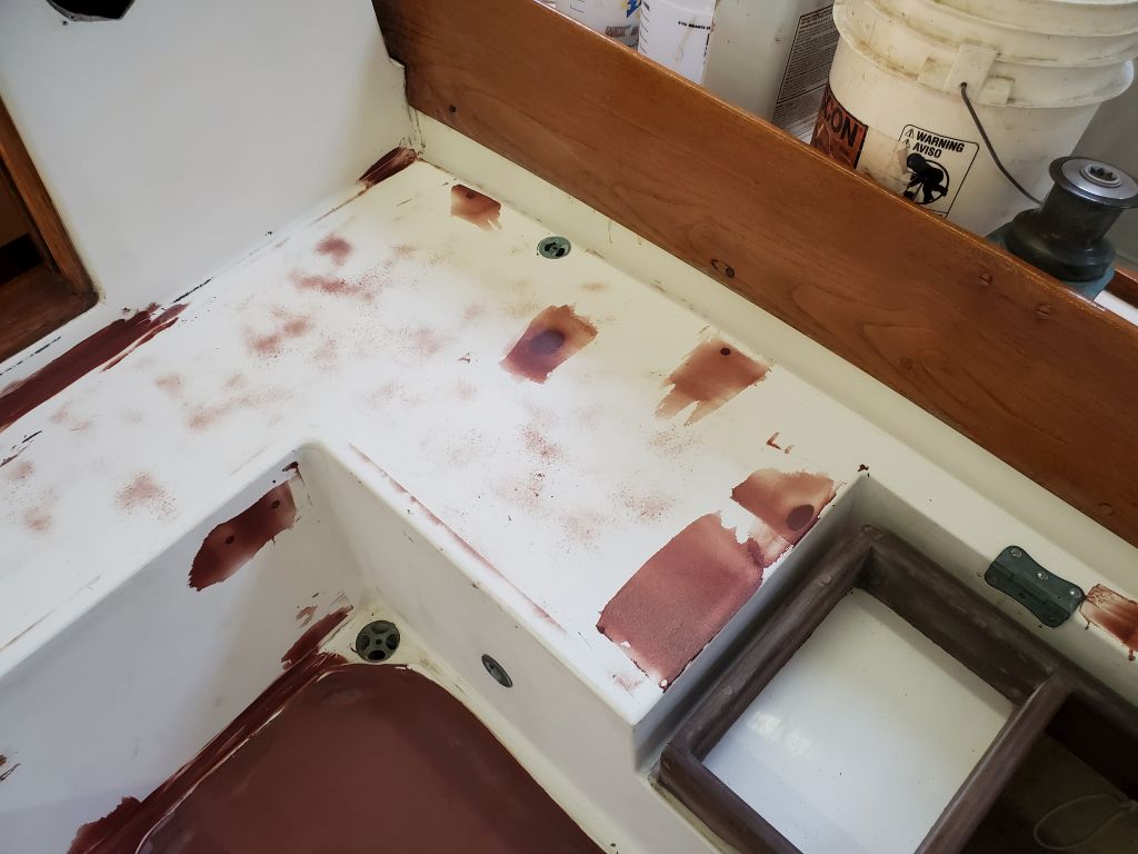
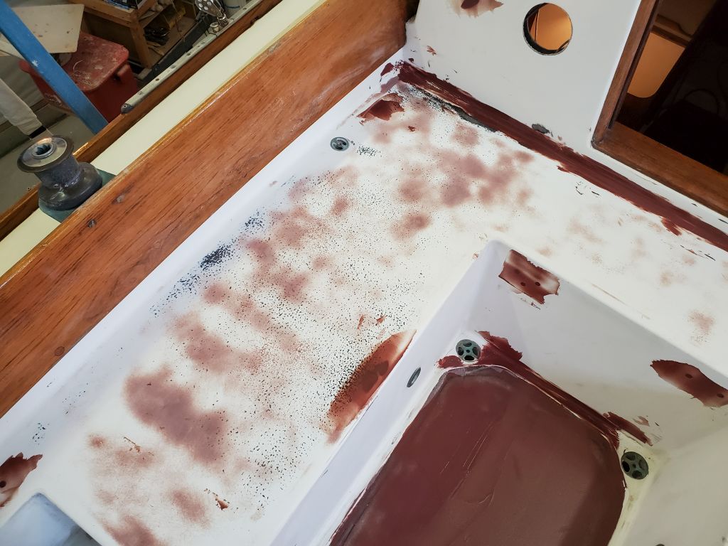
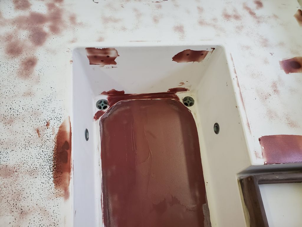
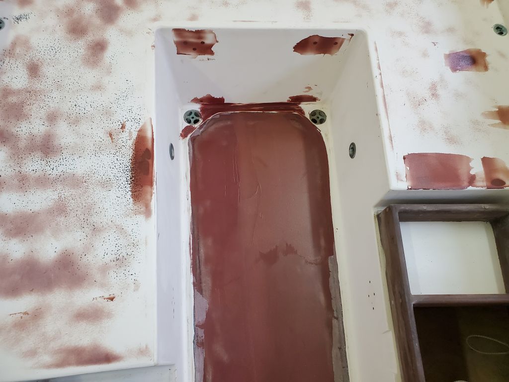
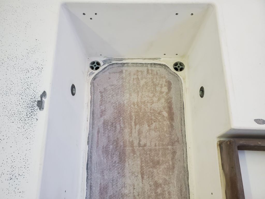
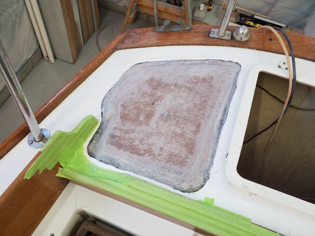
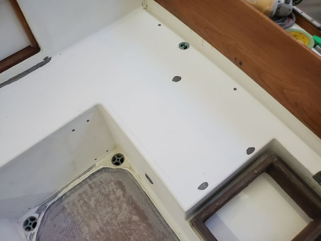
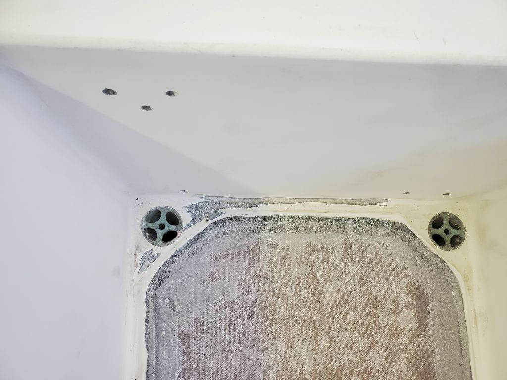
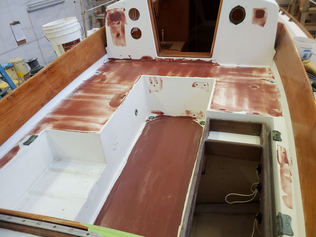
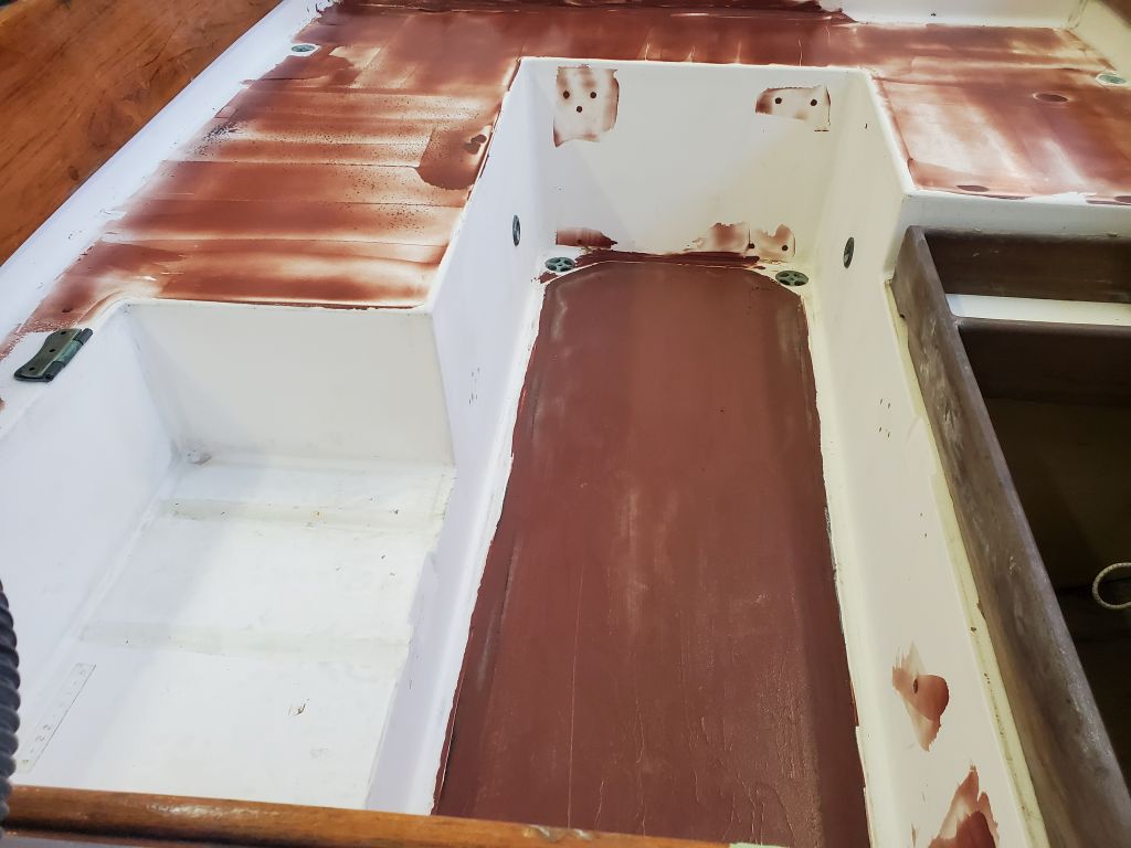
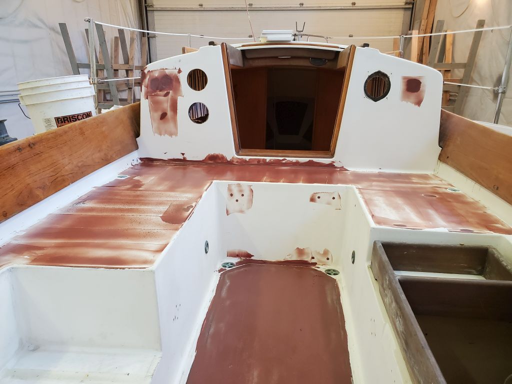
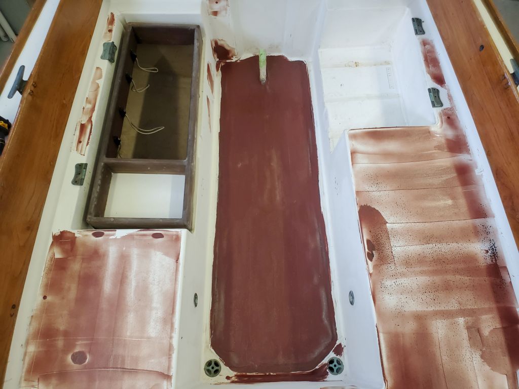
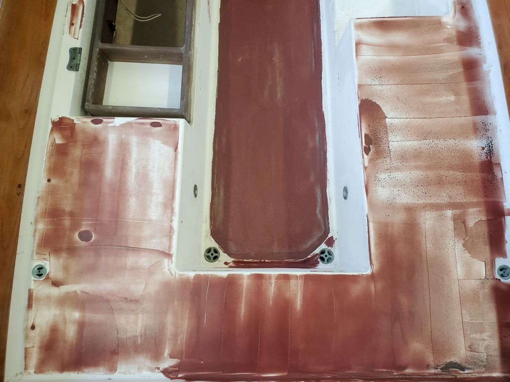
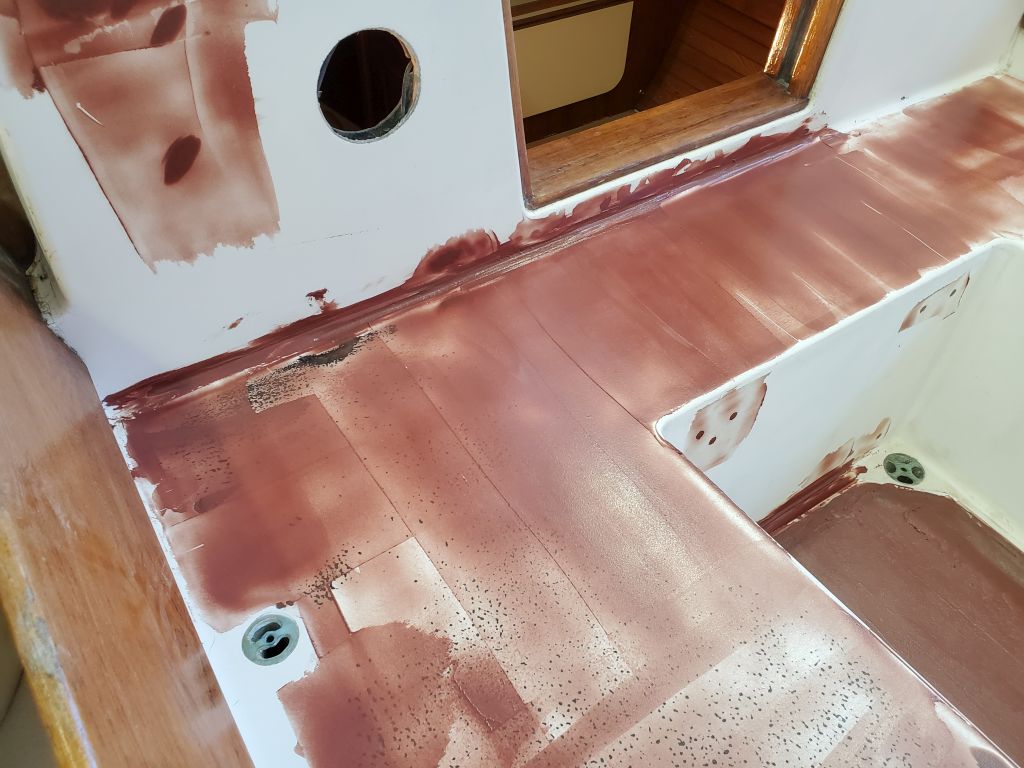
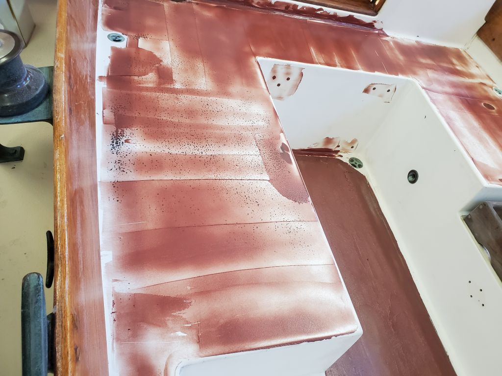
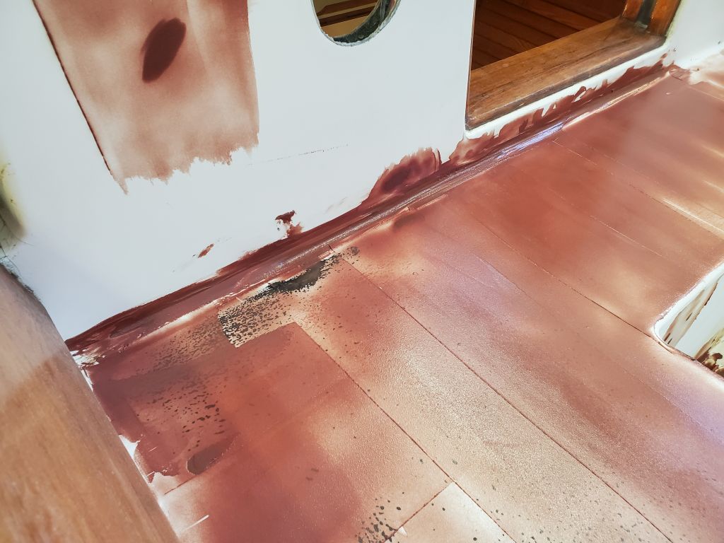
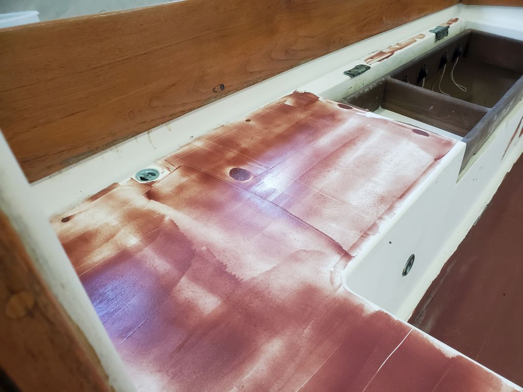
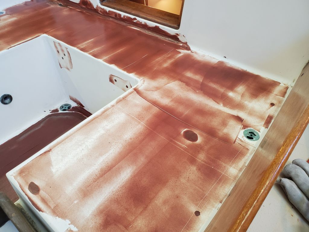
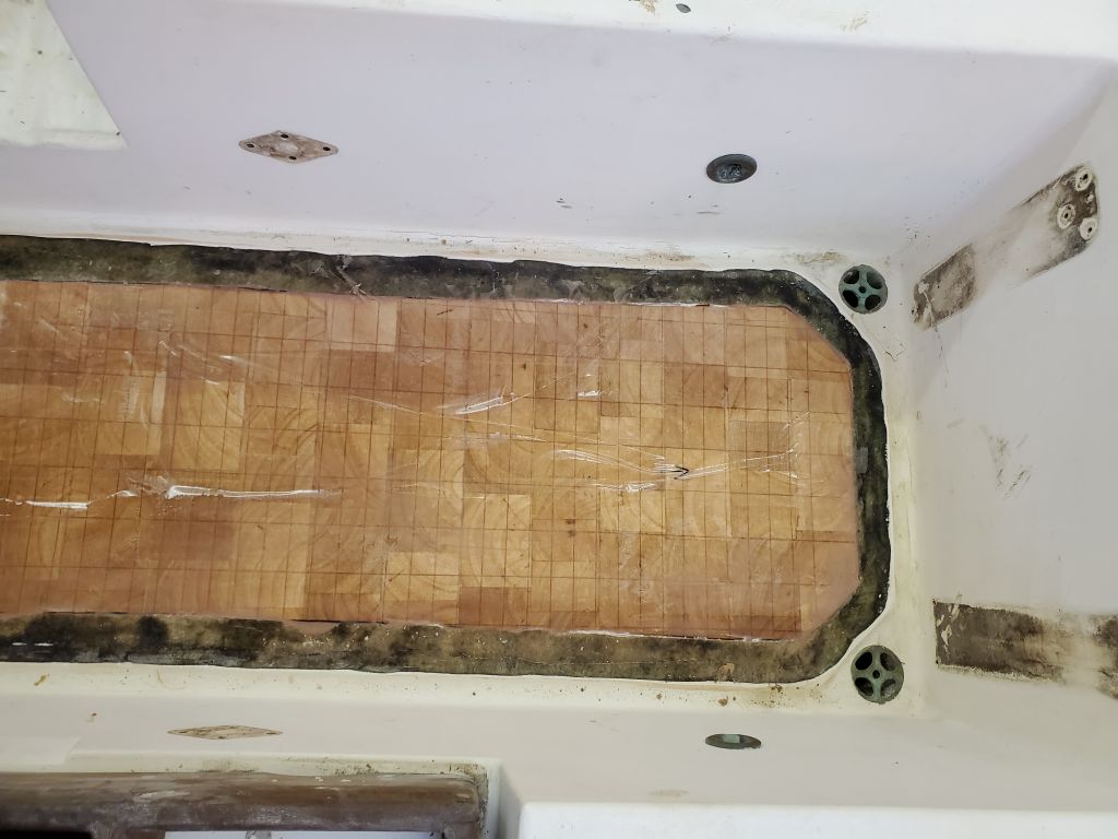
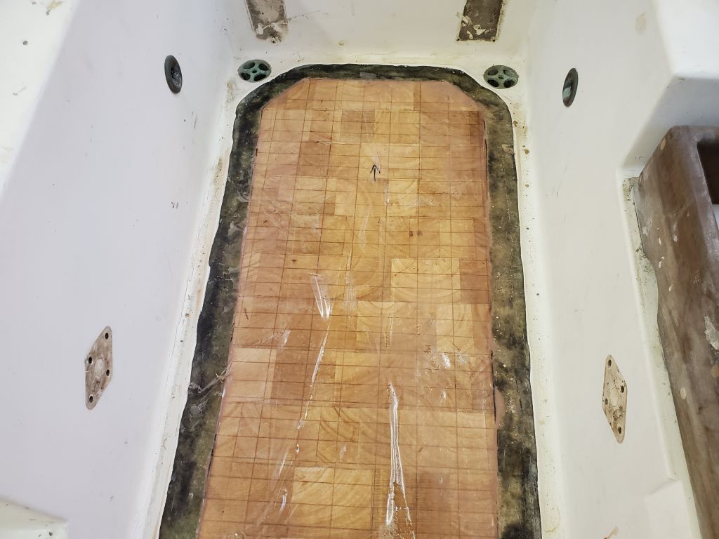
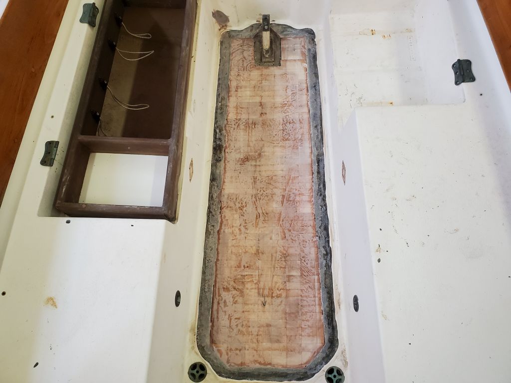
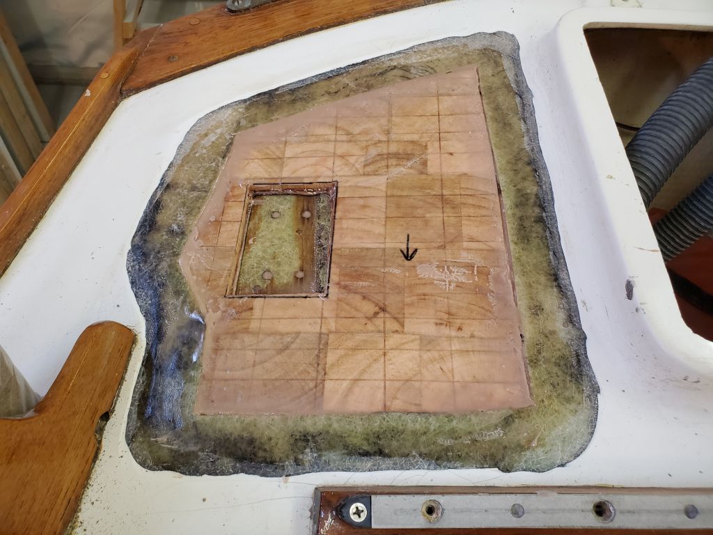
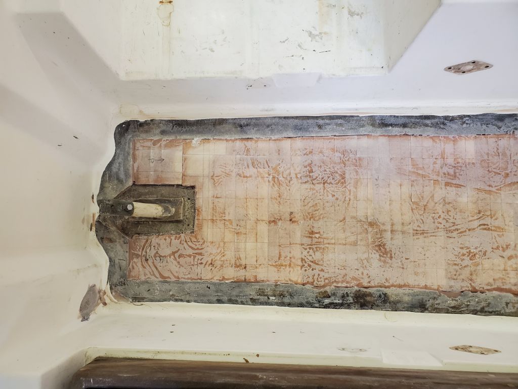
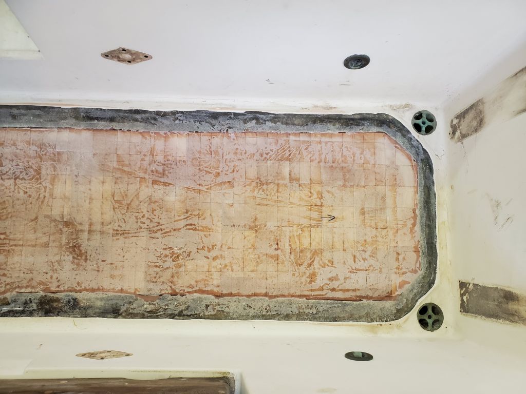
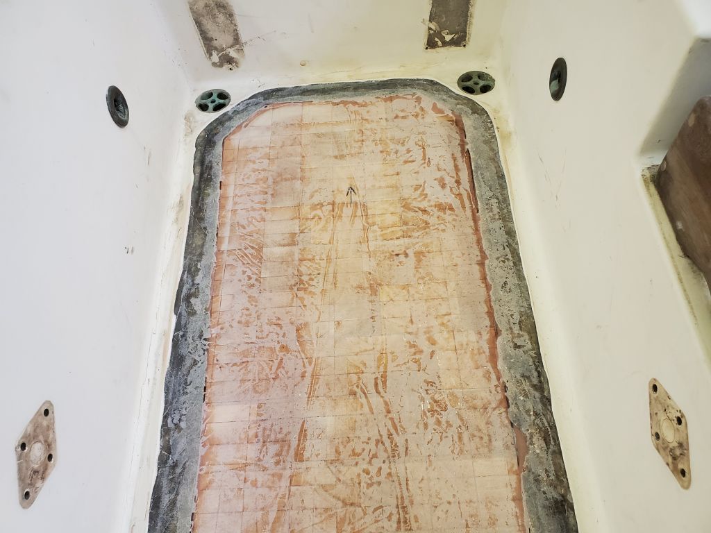
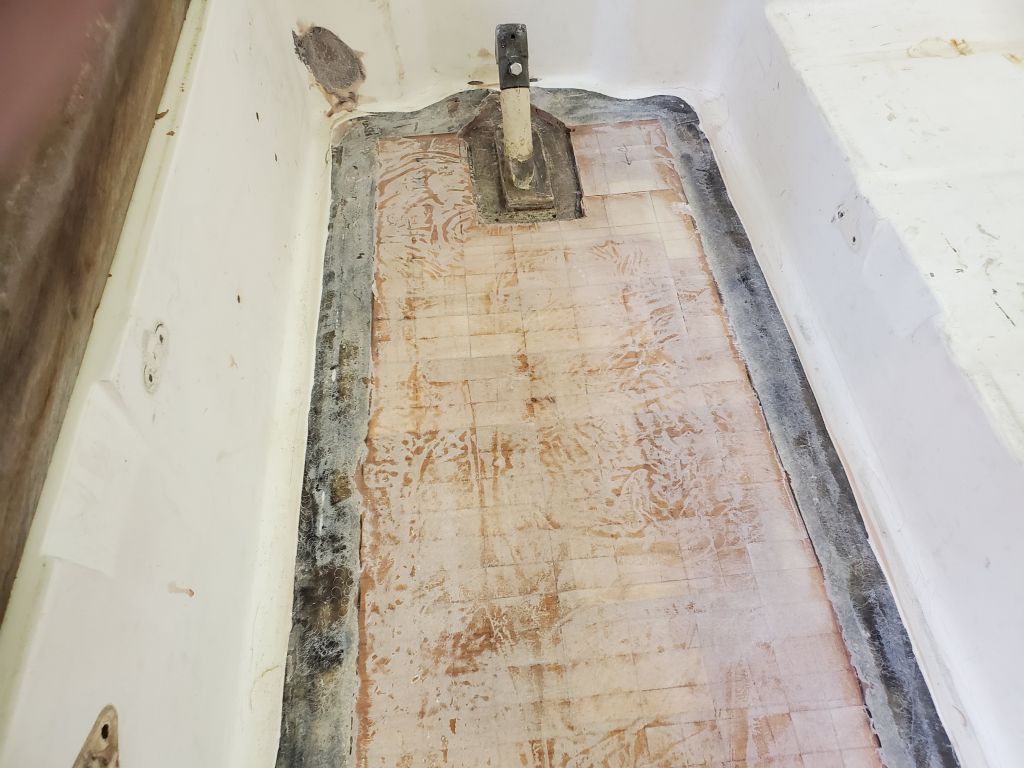
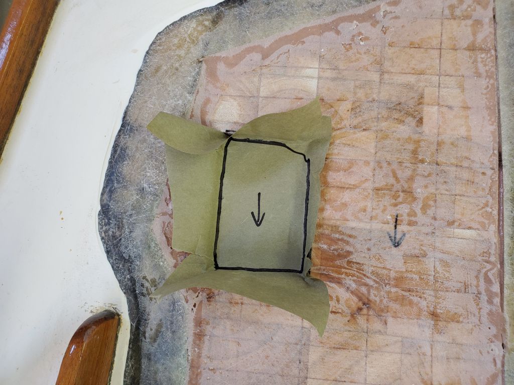
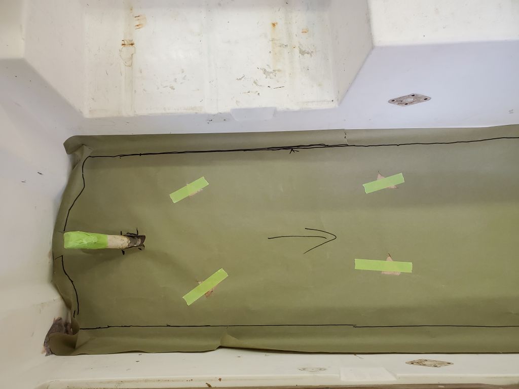
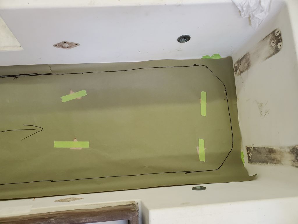
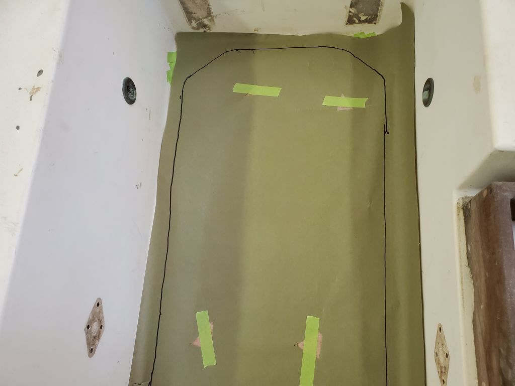
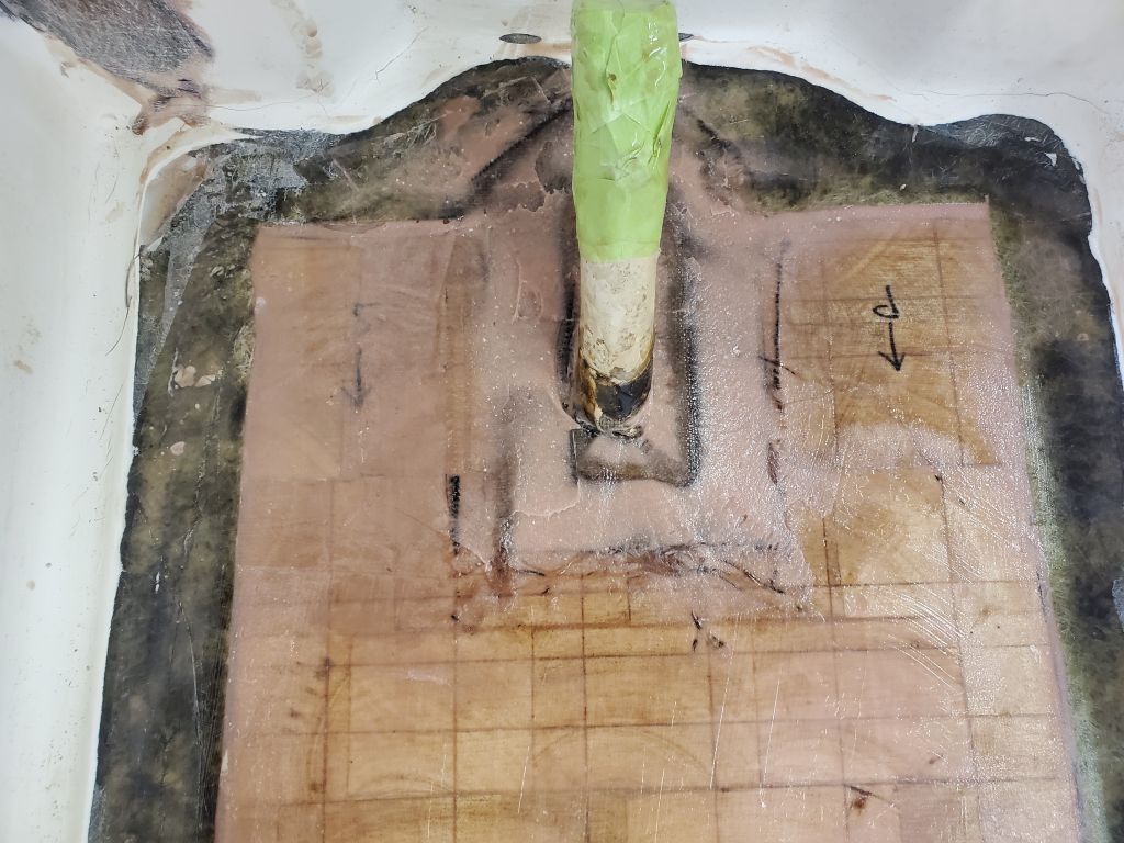
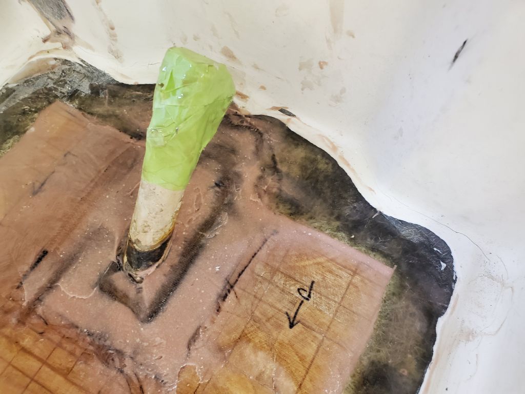
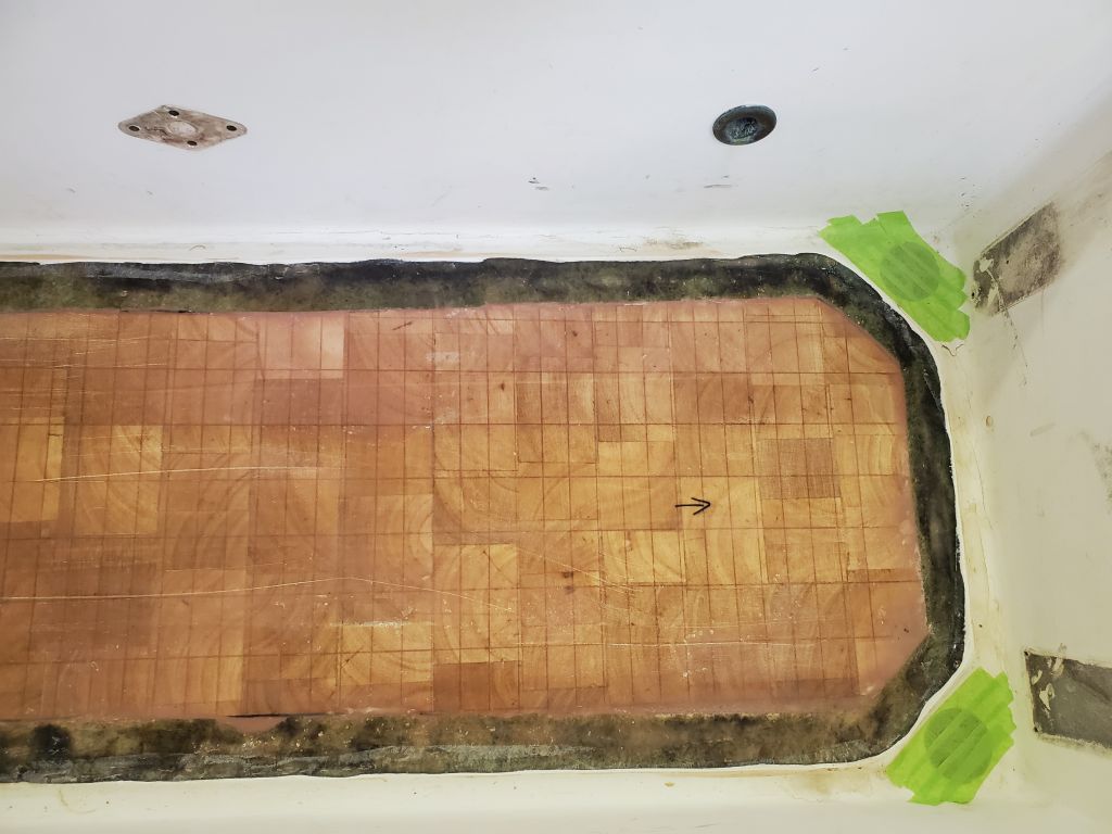
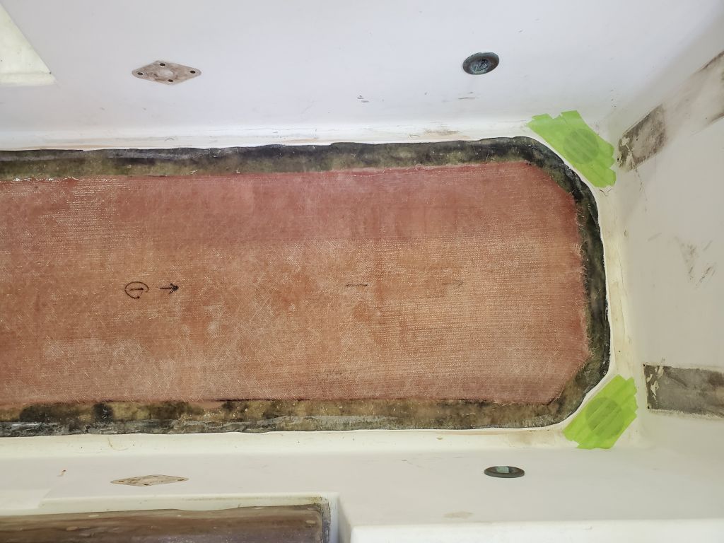
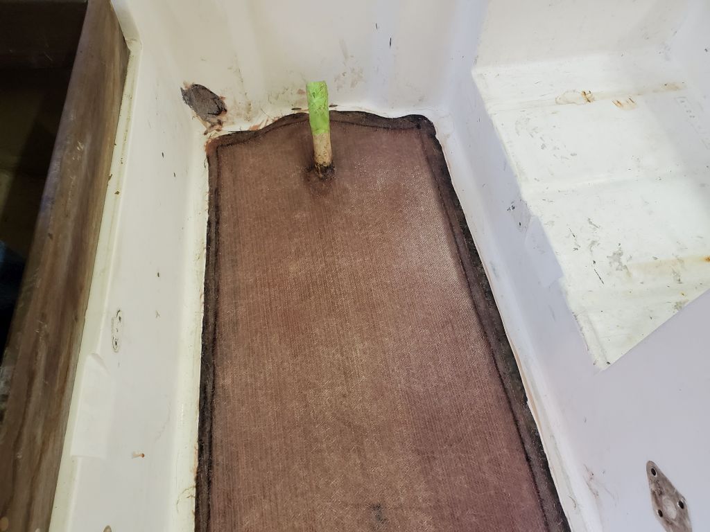
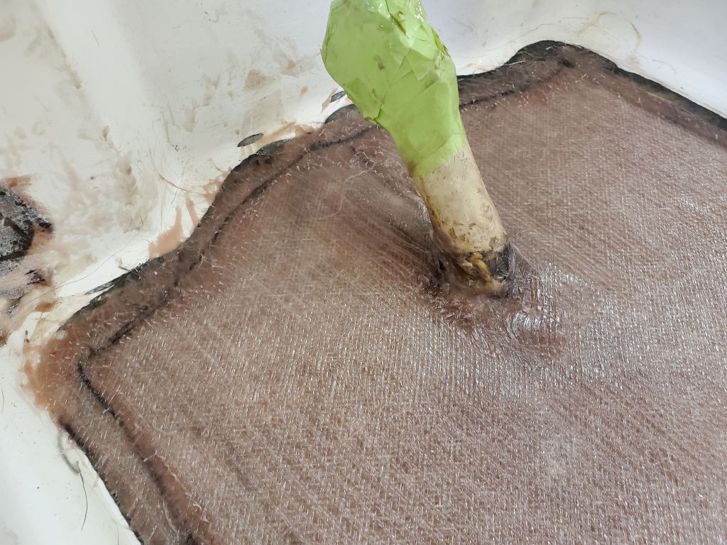
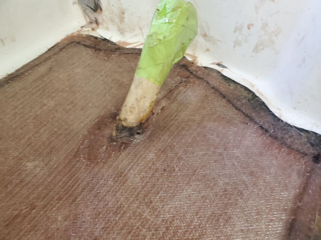
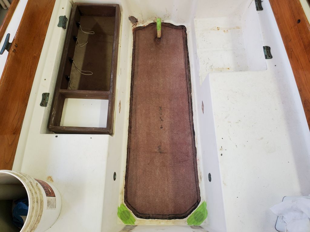
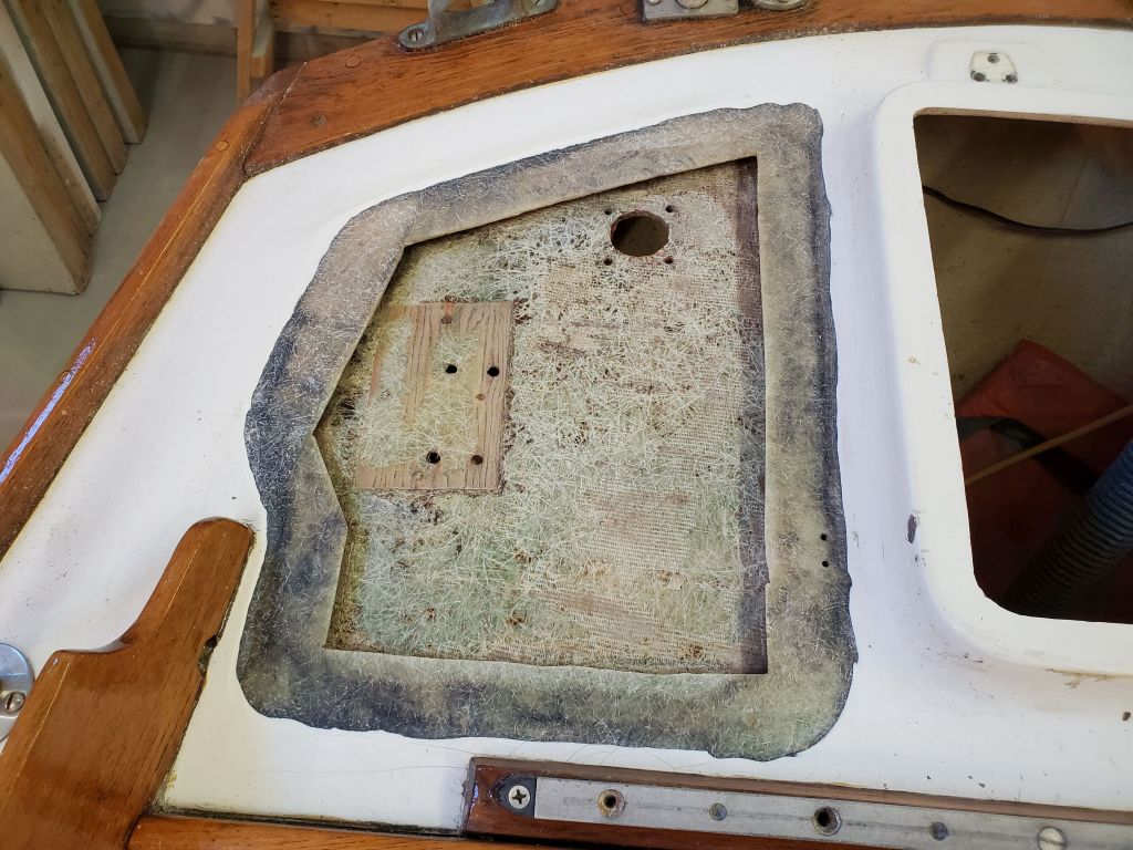
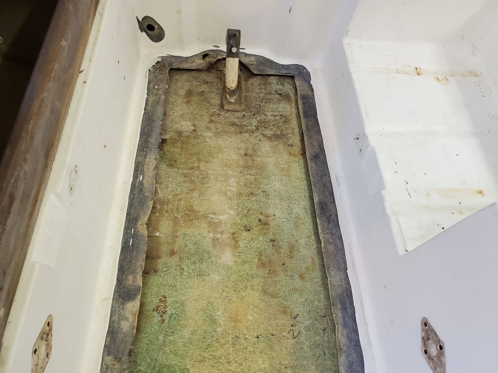
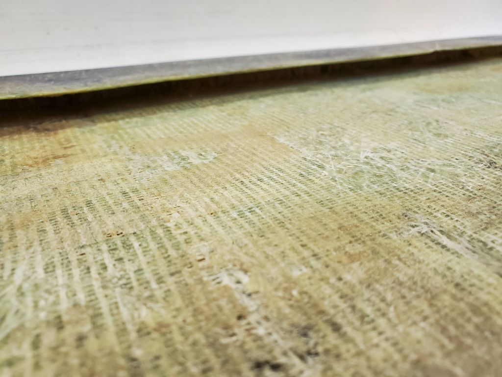
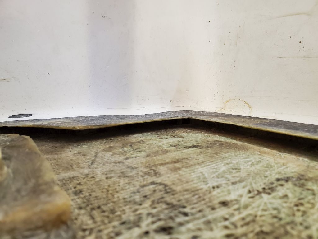
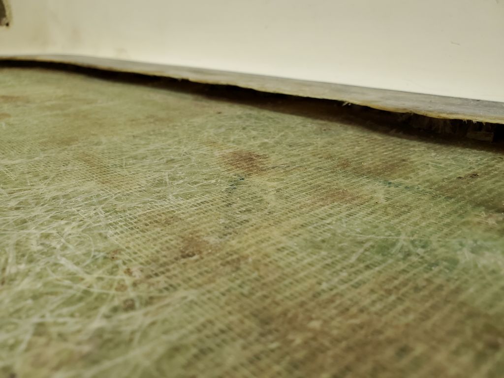
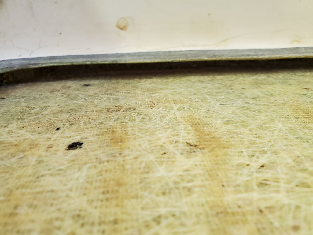
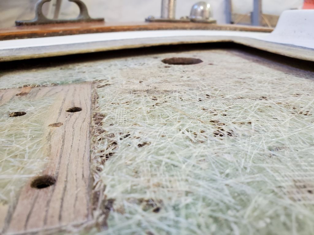
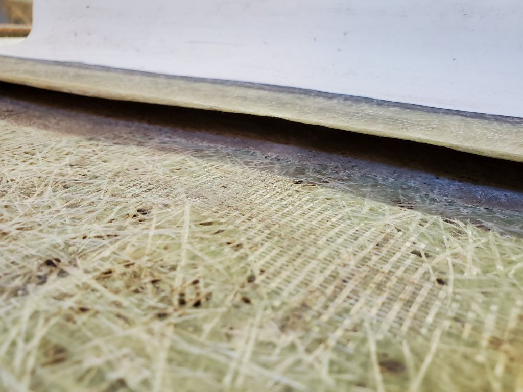
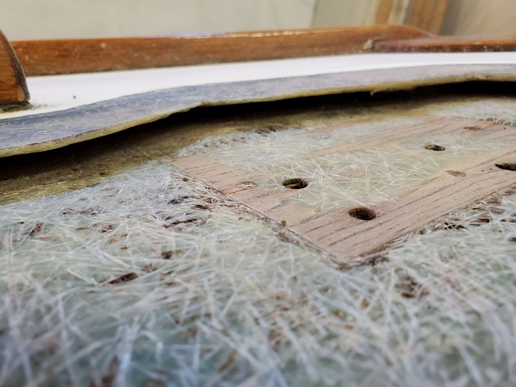
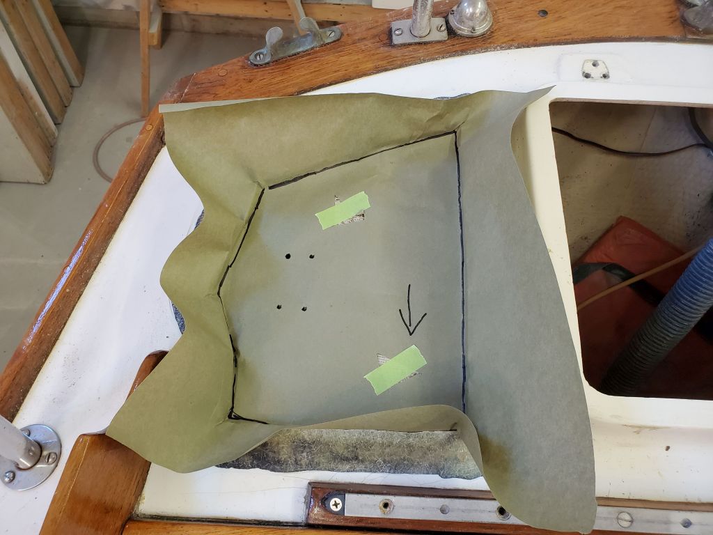
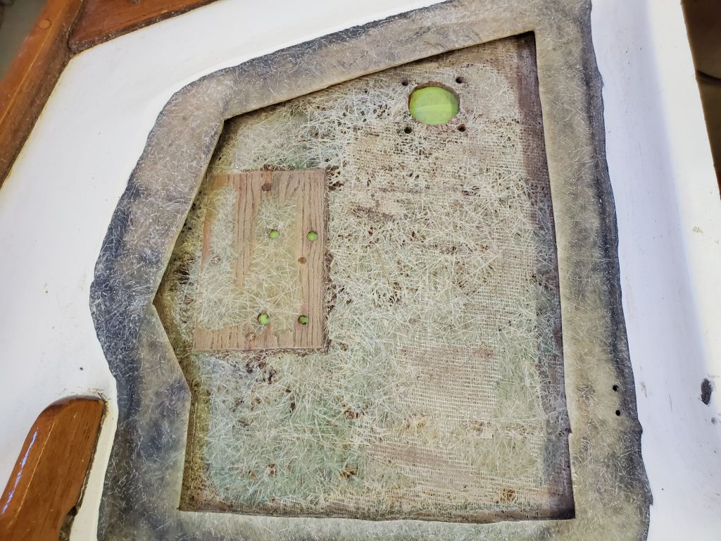
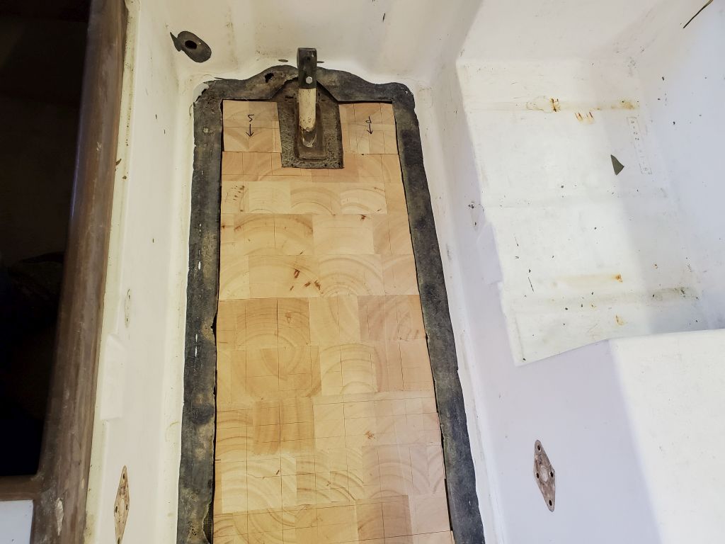
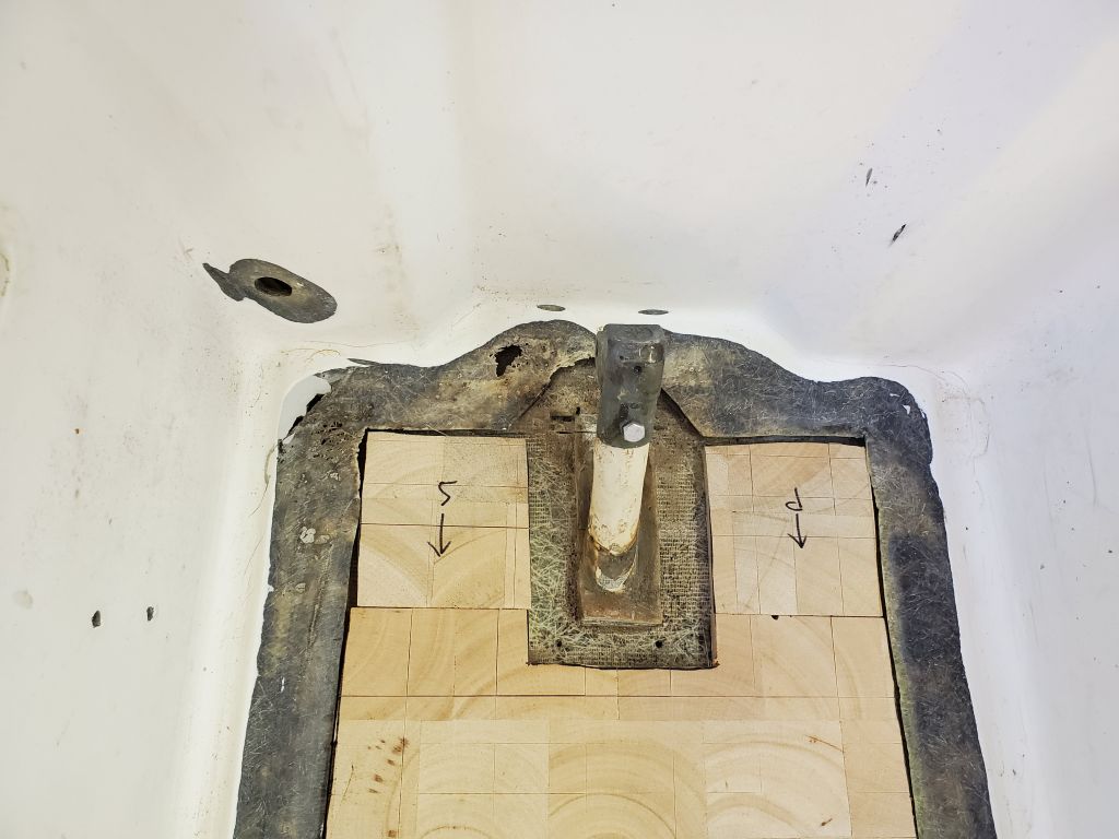
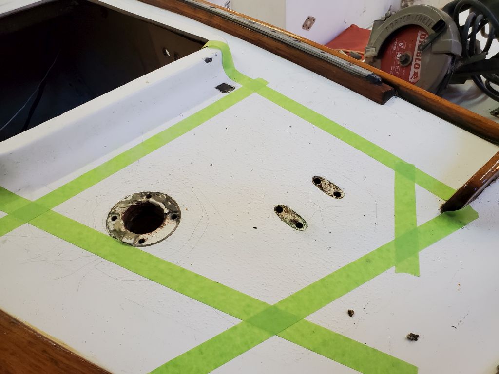
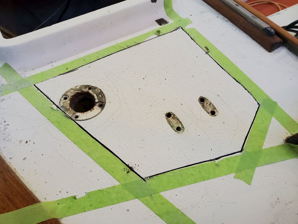
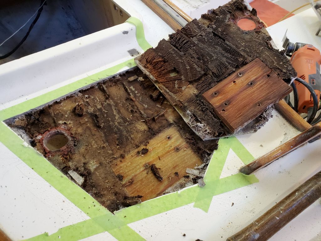
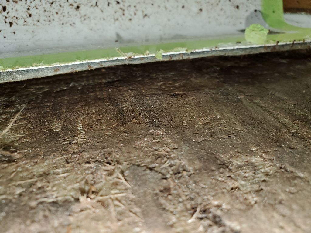
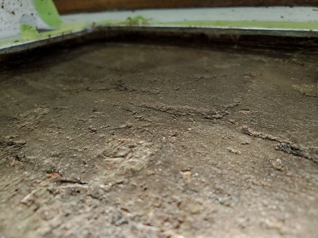
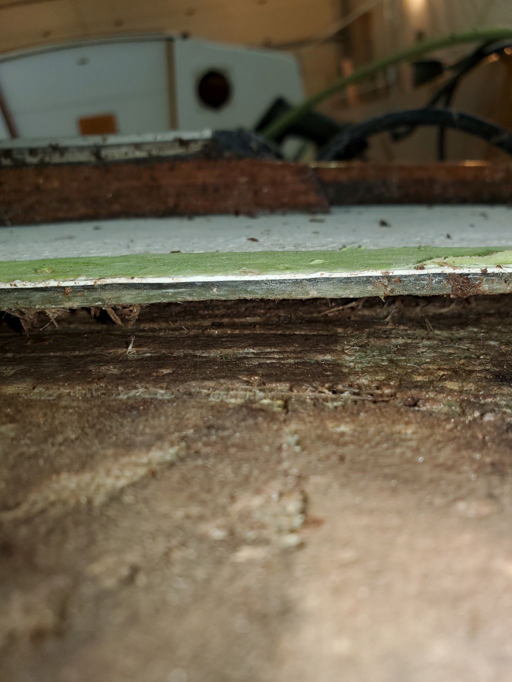
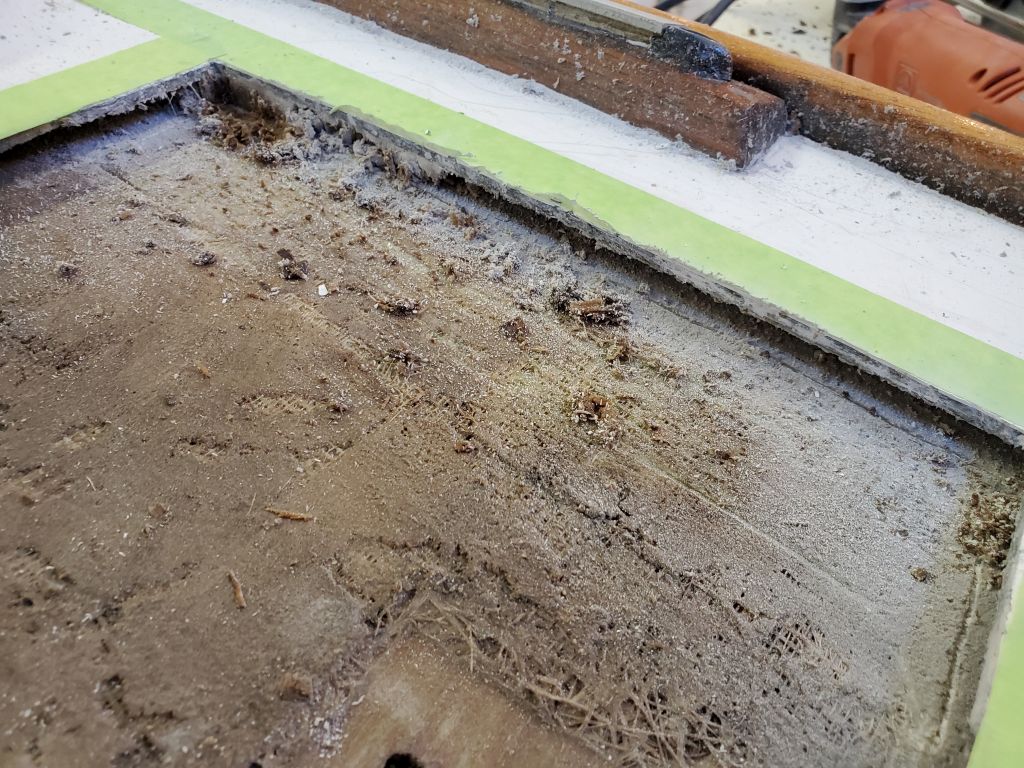
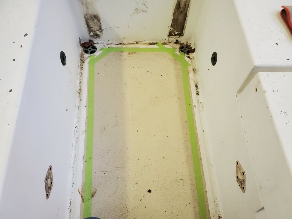
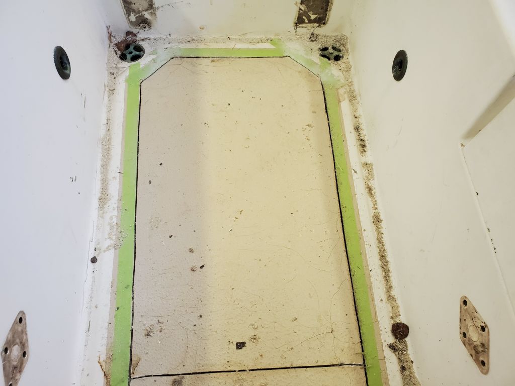
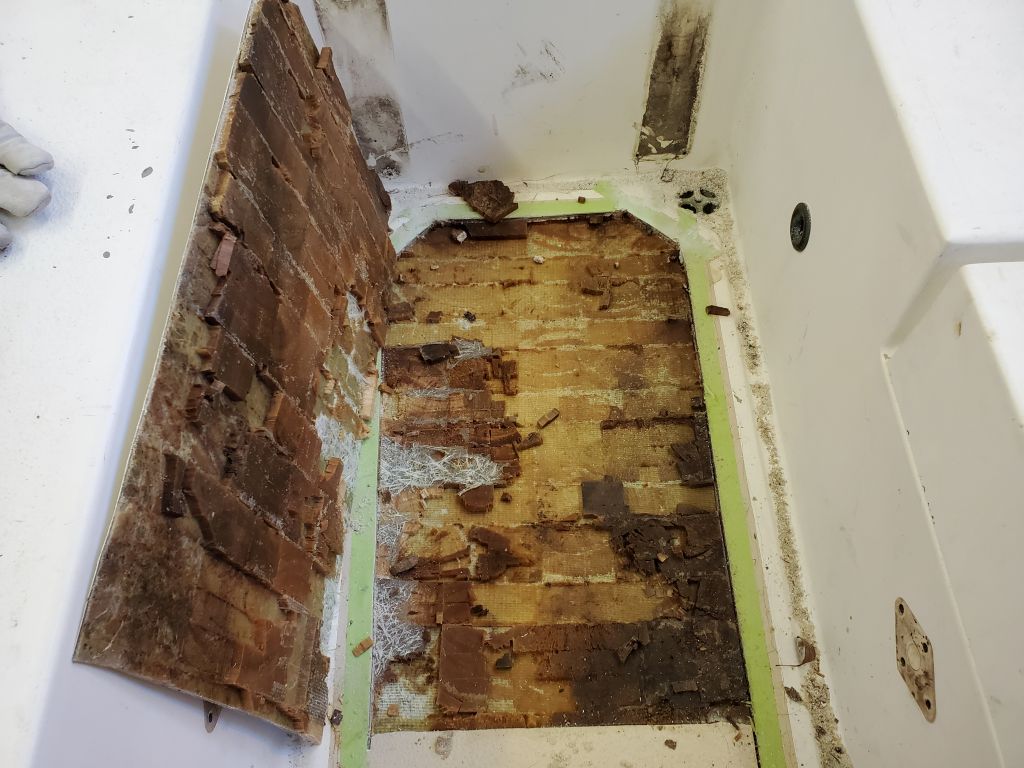
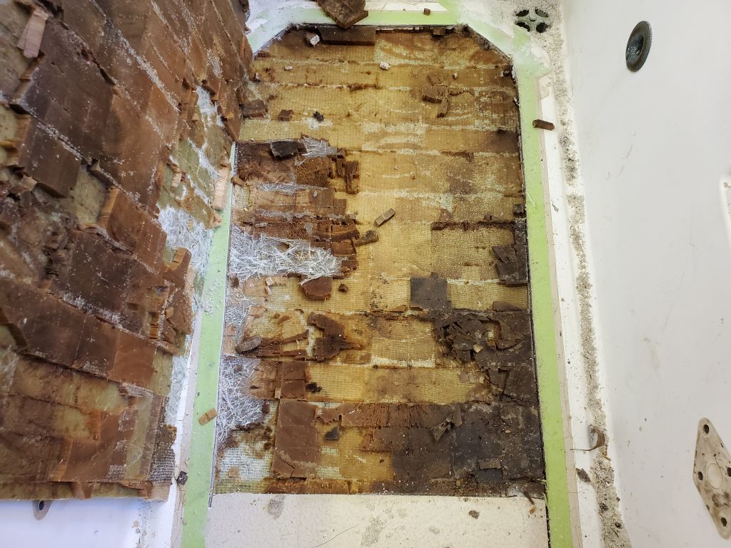
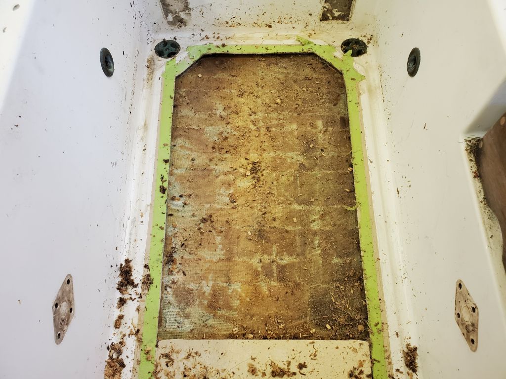
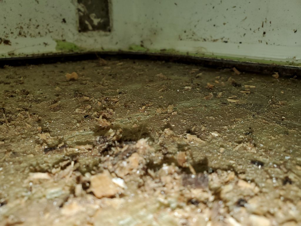
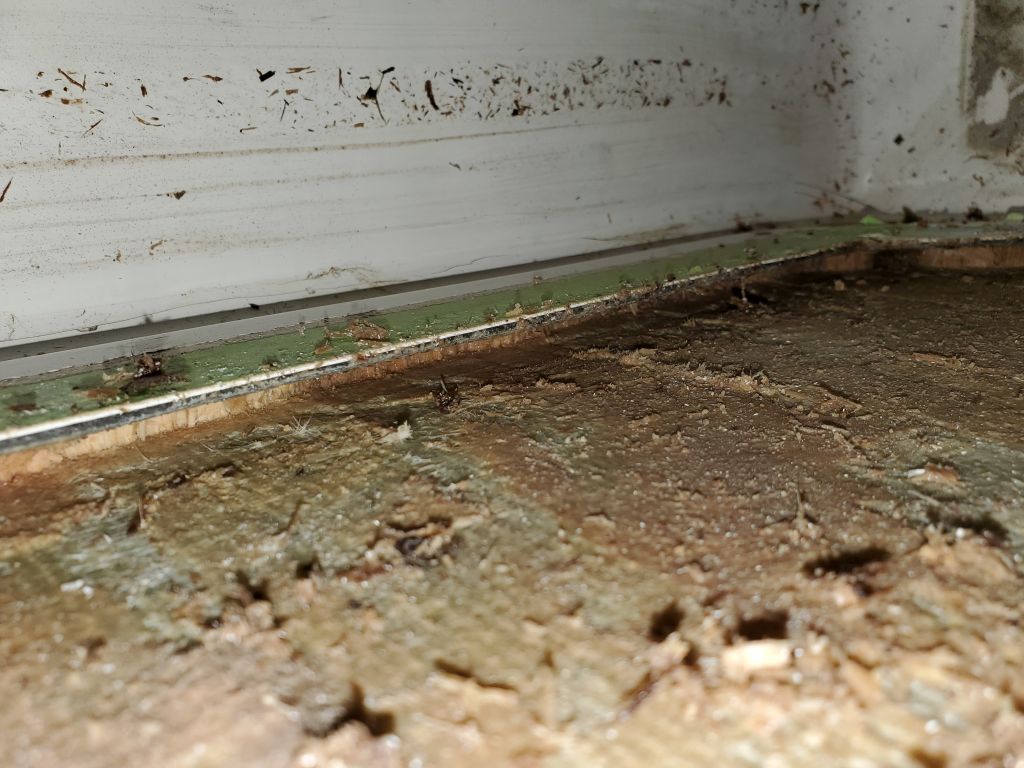
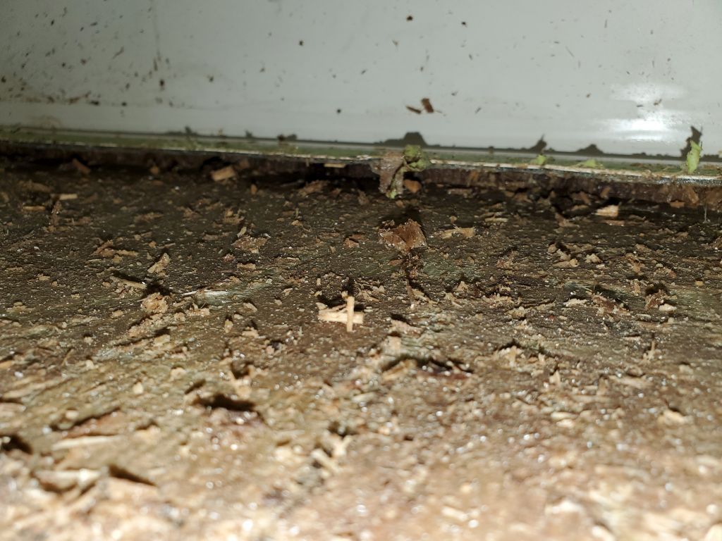
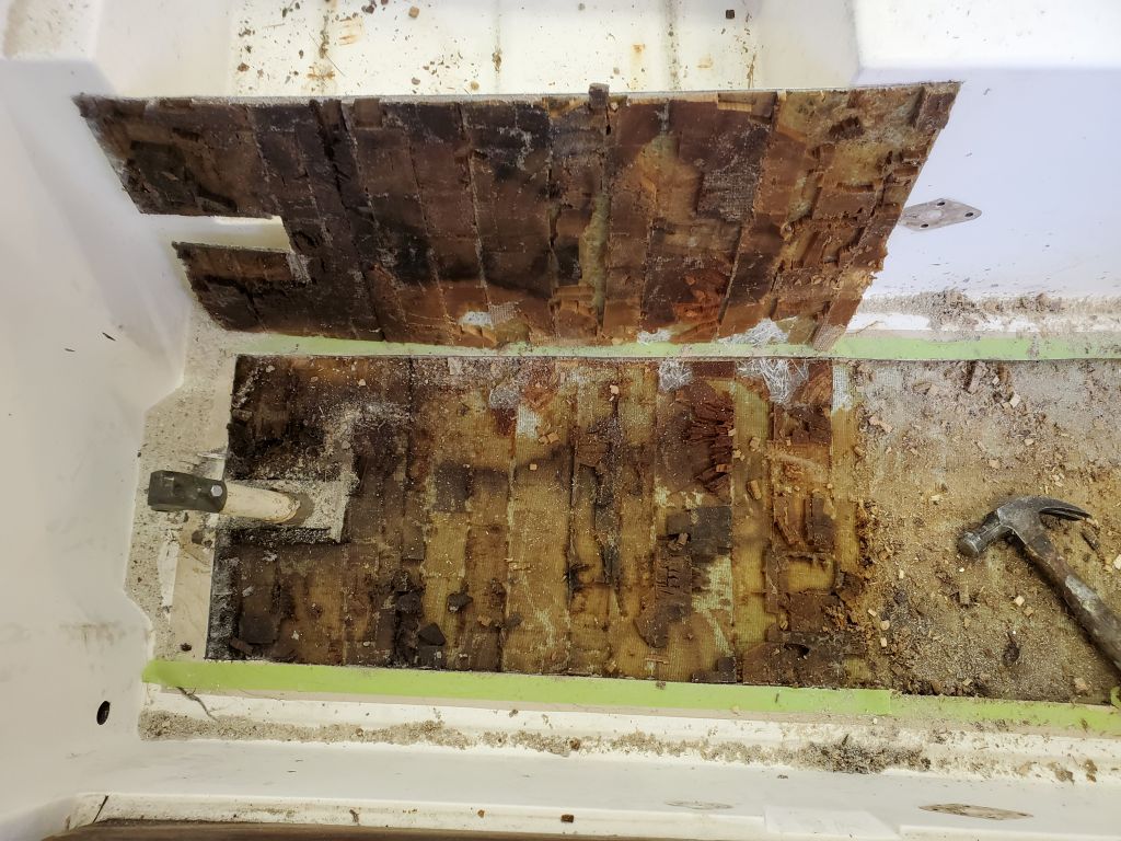
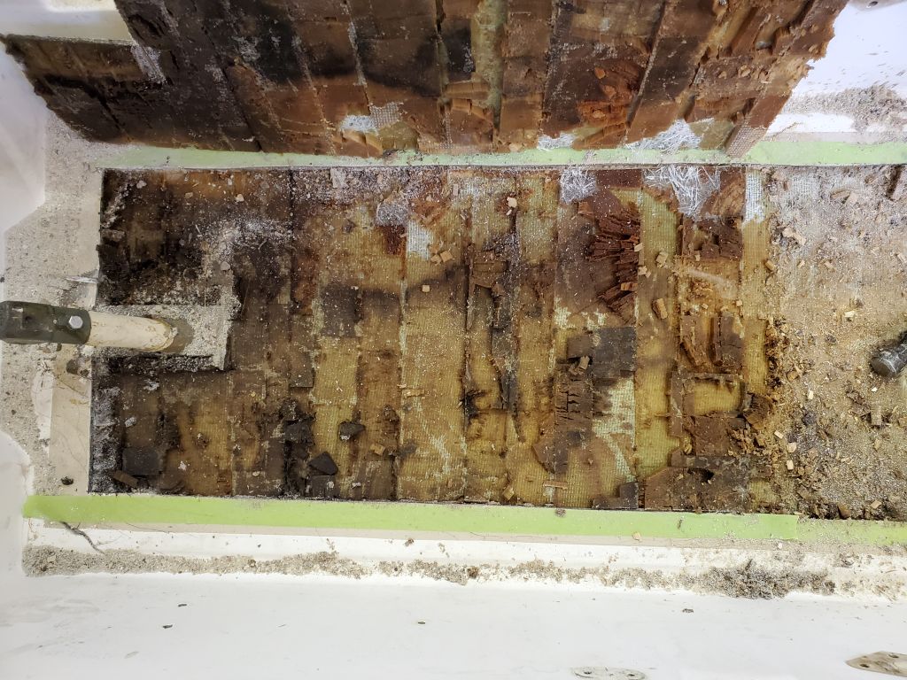
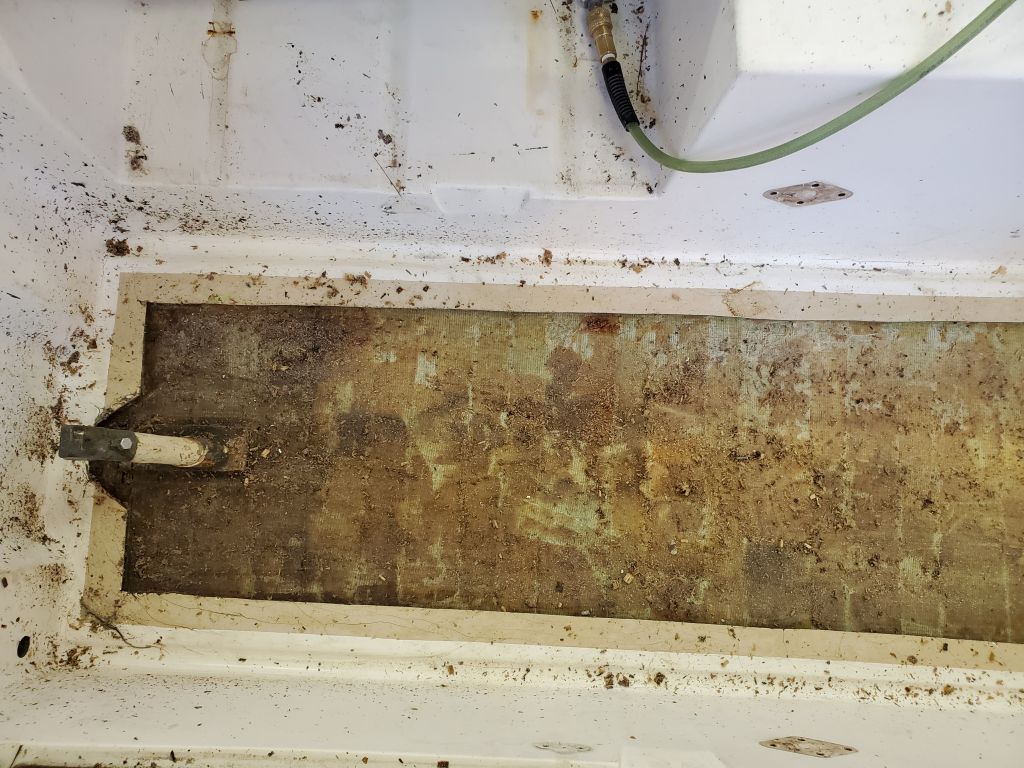
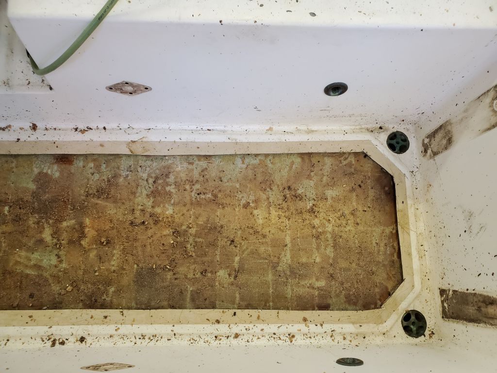
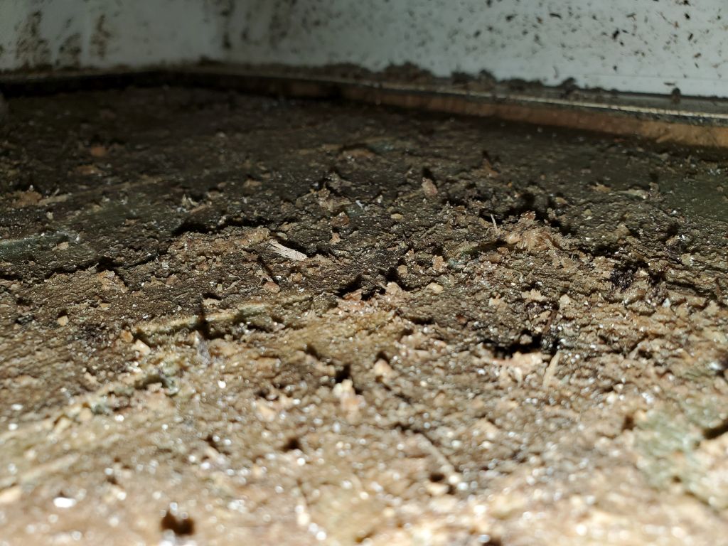
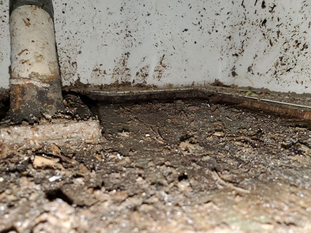
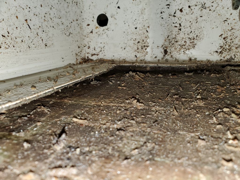
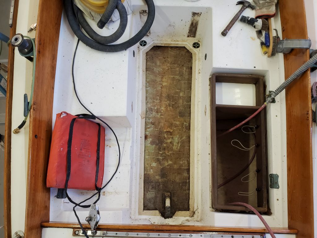
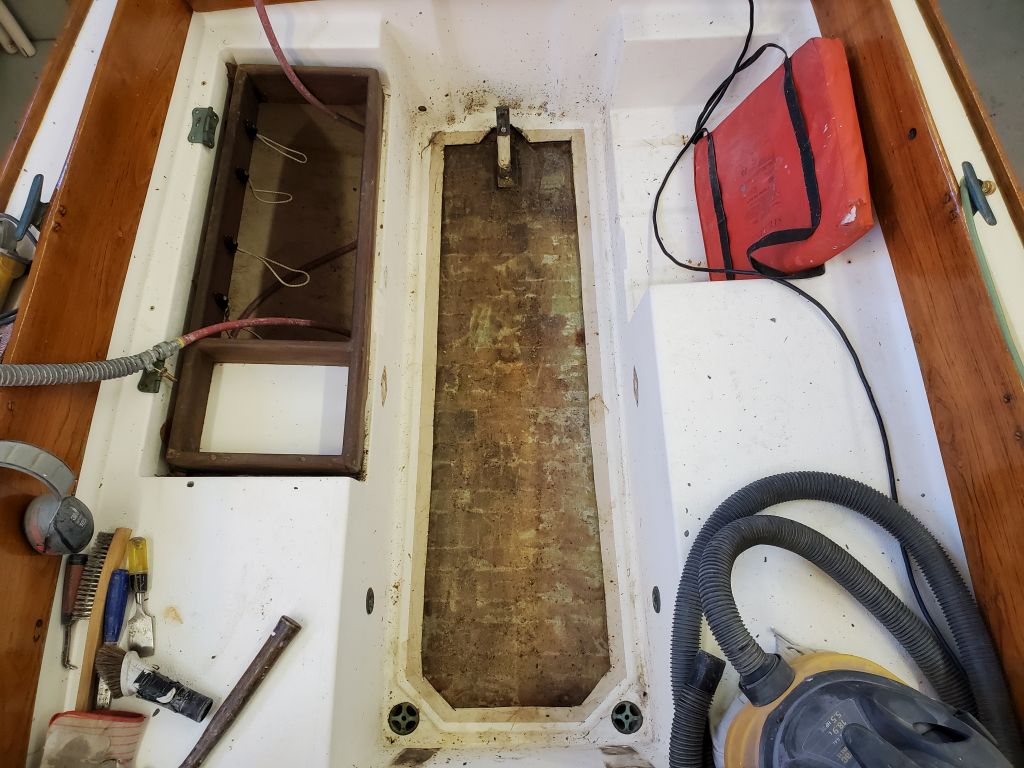
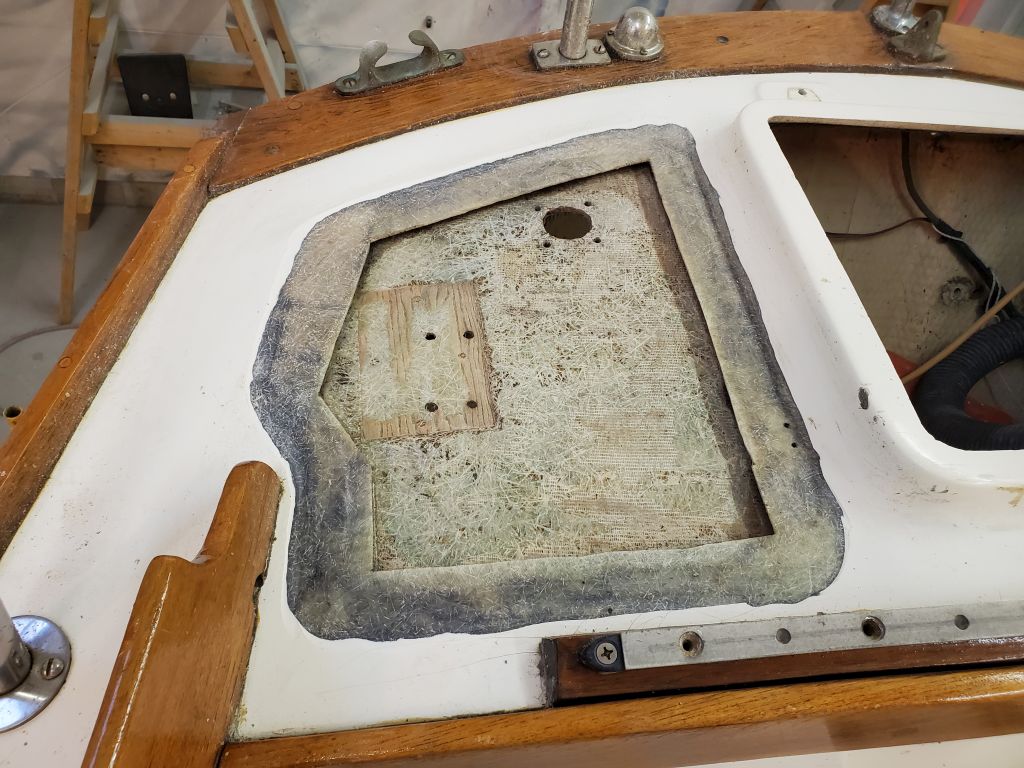
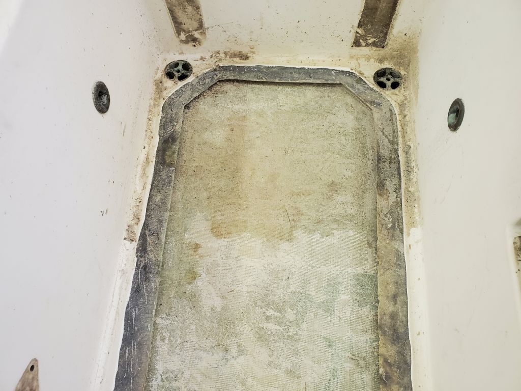
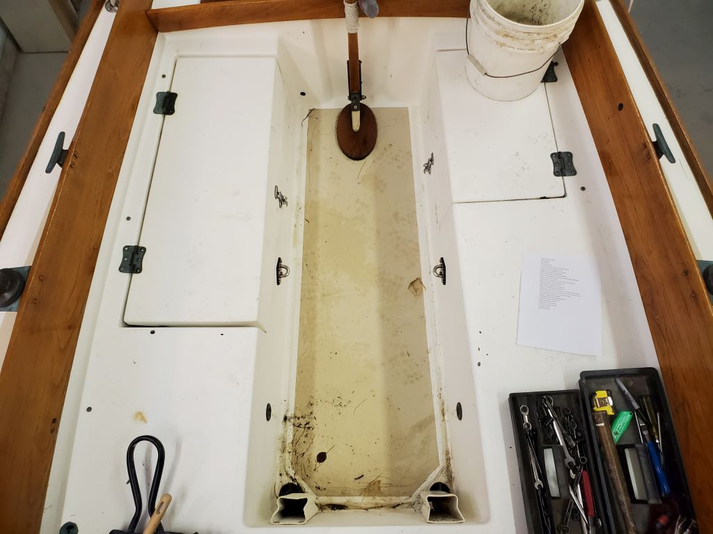
In the cockpit, the sole was heavily cracked with obvious core damage beneath, and repair of this area was already included in the project scope. The cockpit seats and bridgedeck appeared to be sound and would not require repairs, though with a variety of other small repairs in the cockpit, including patching numerous obsolete holes and removing additional old hardware, the project scope included refinishing the entire cockpit.
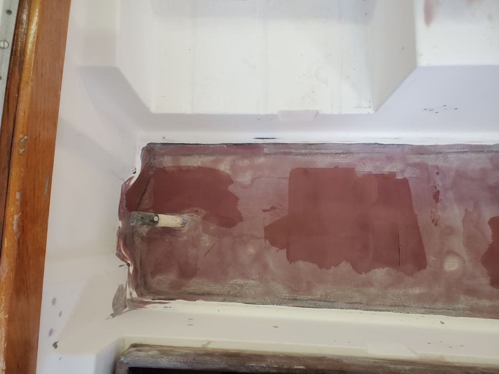
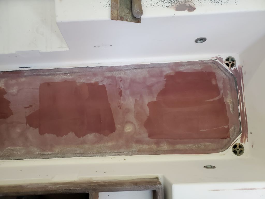
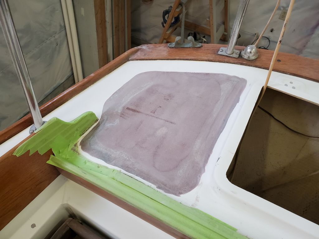
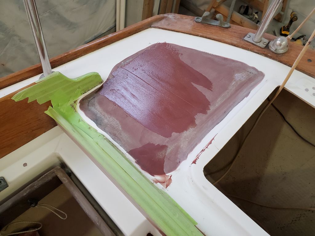
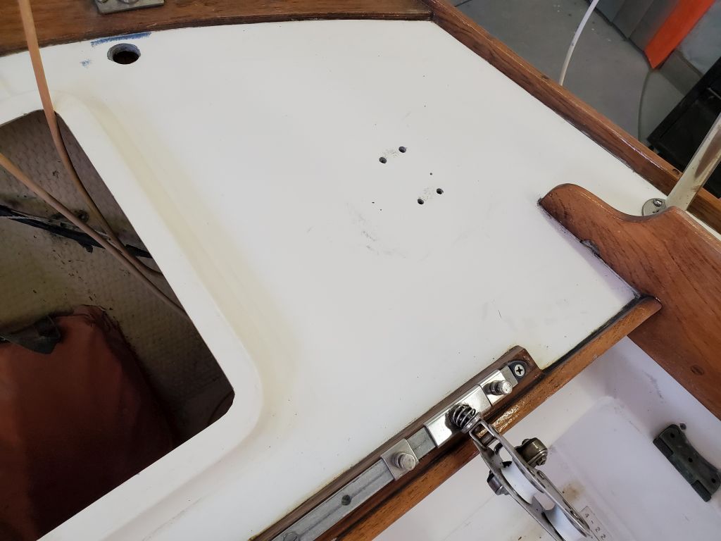
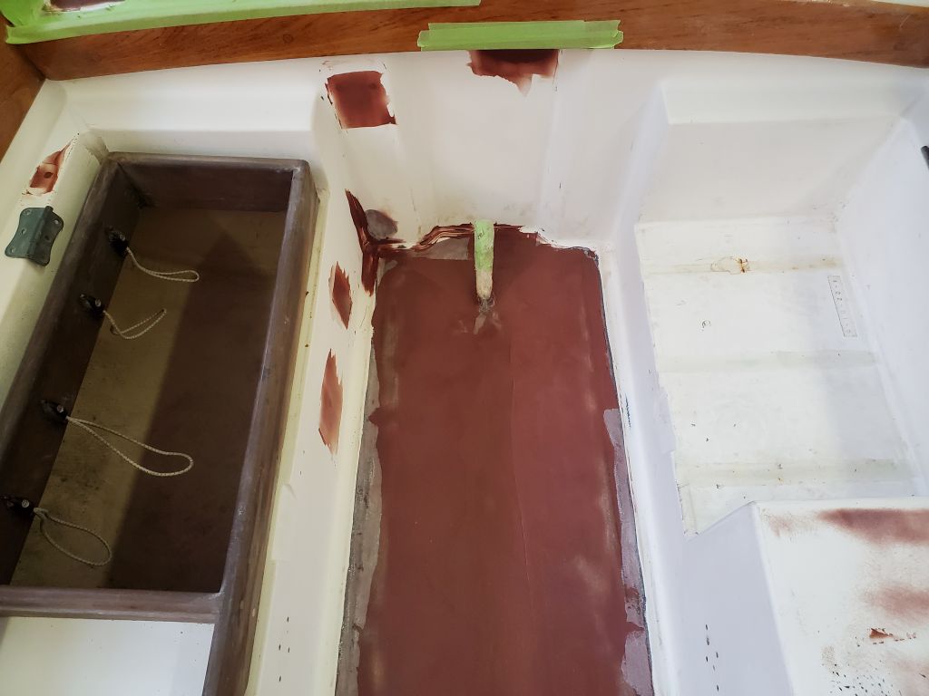
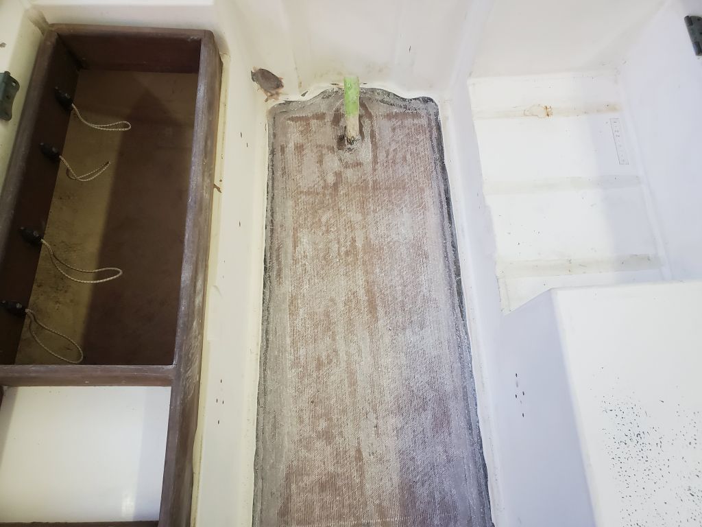
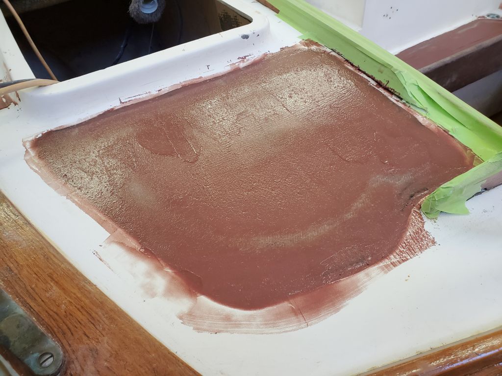
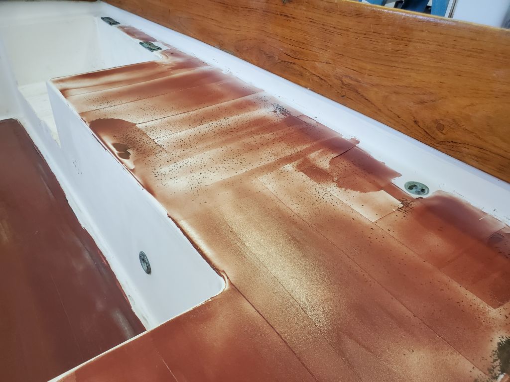
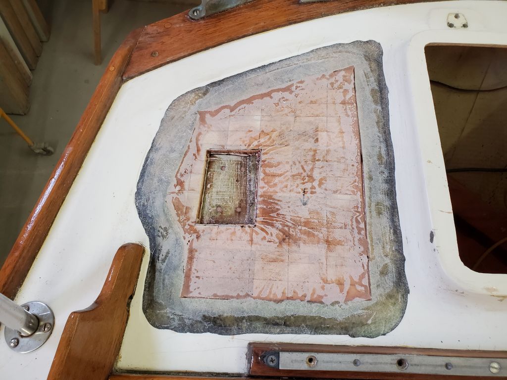
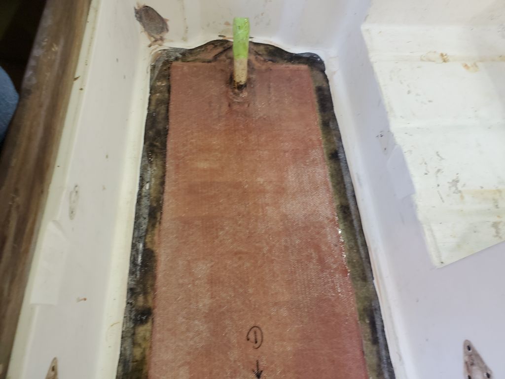
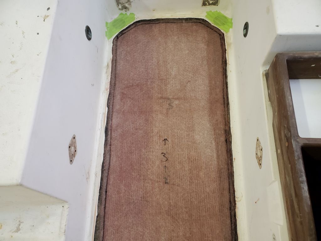
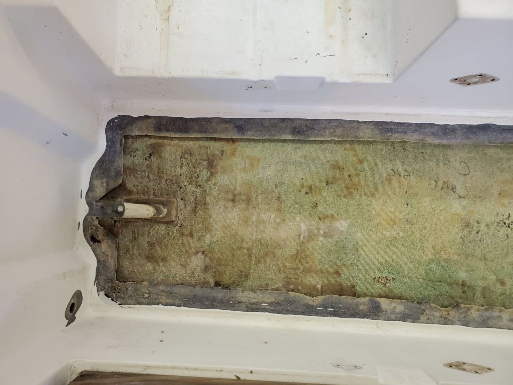
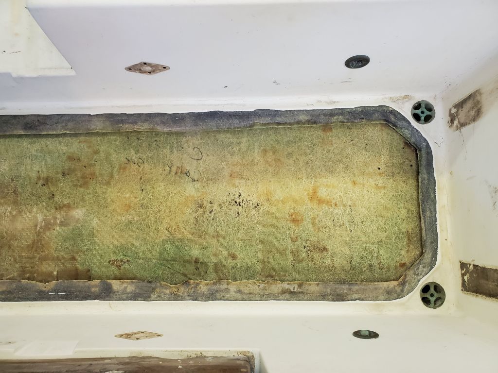
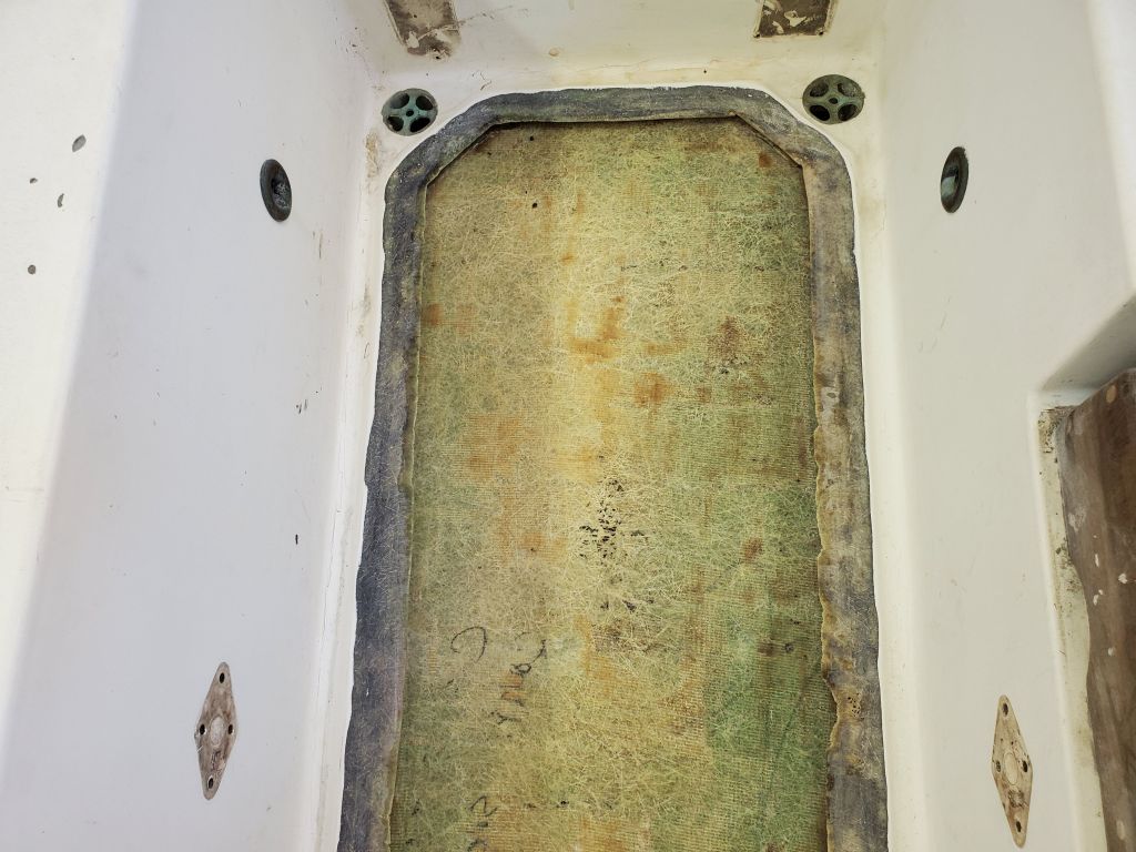
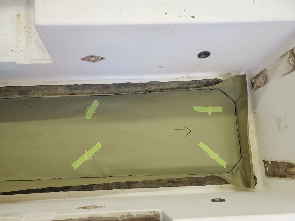
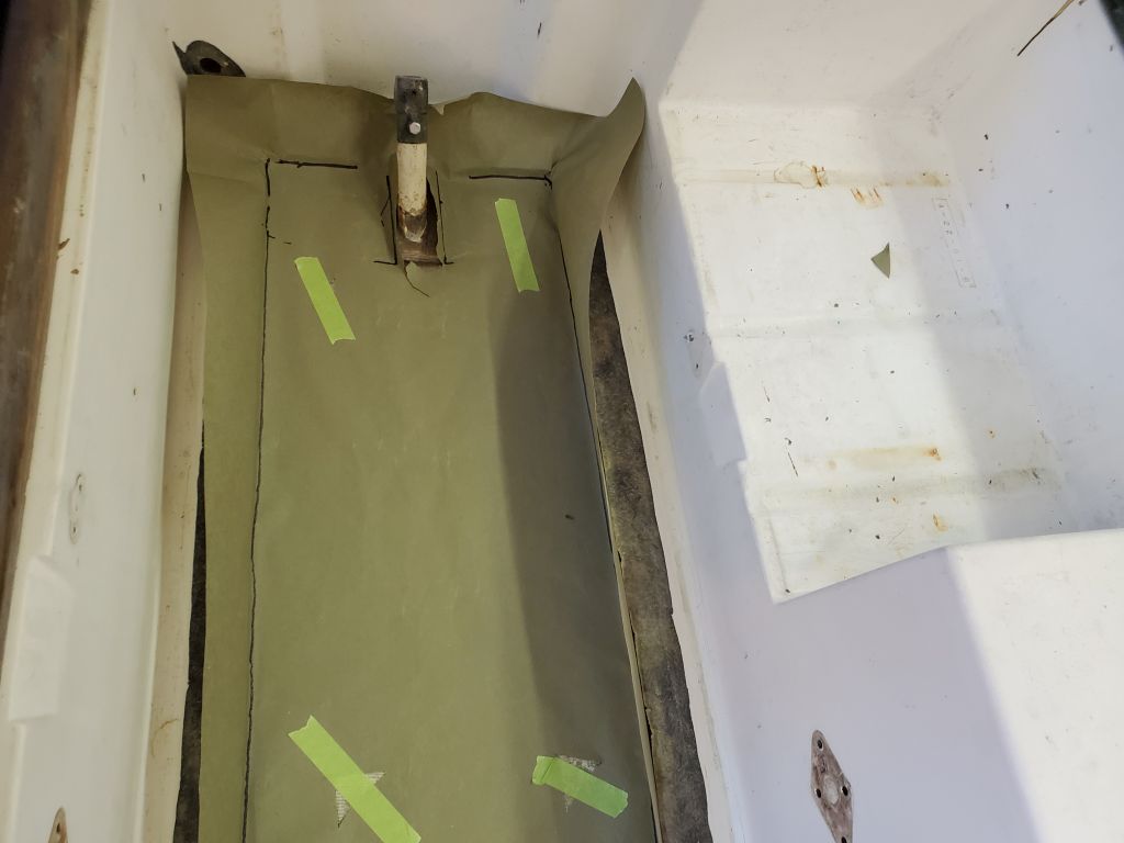
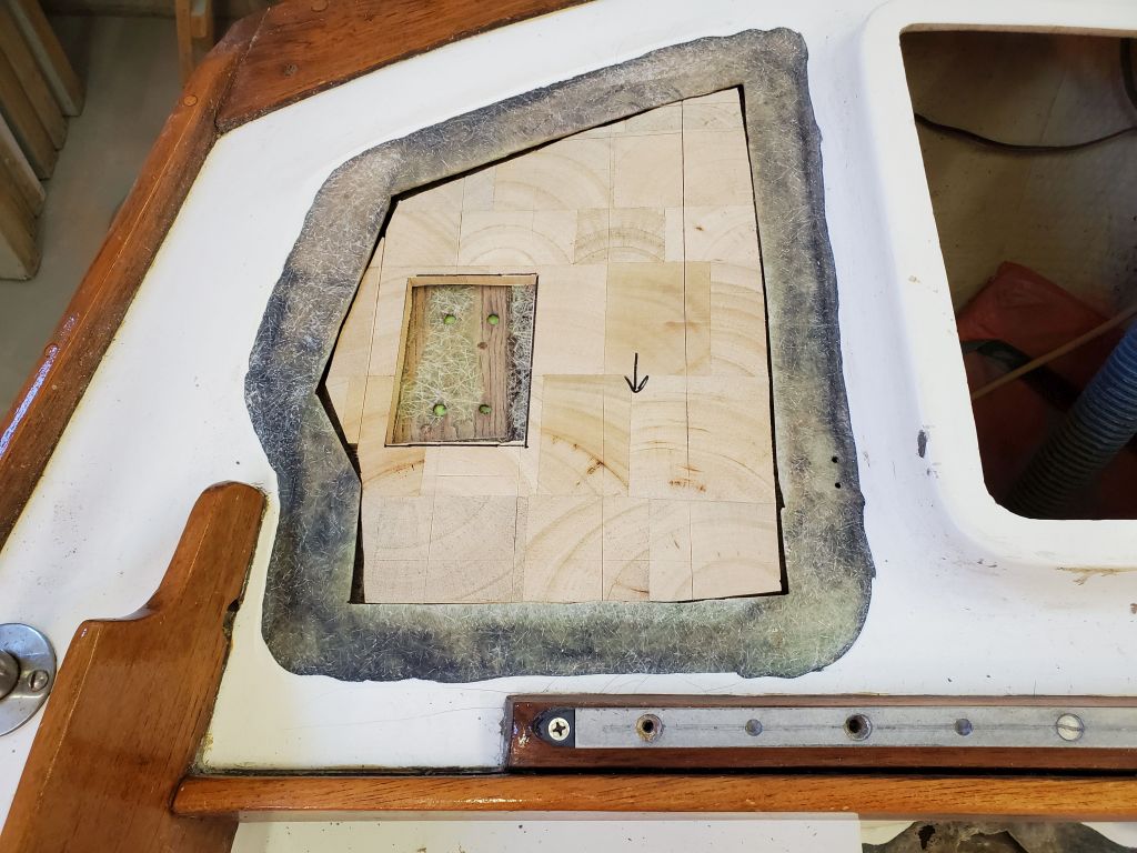
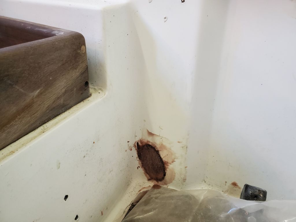
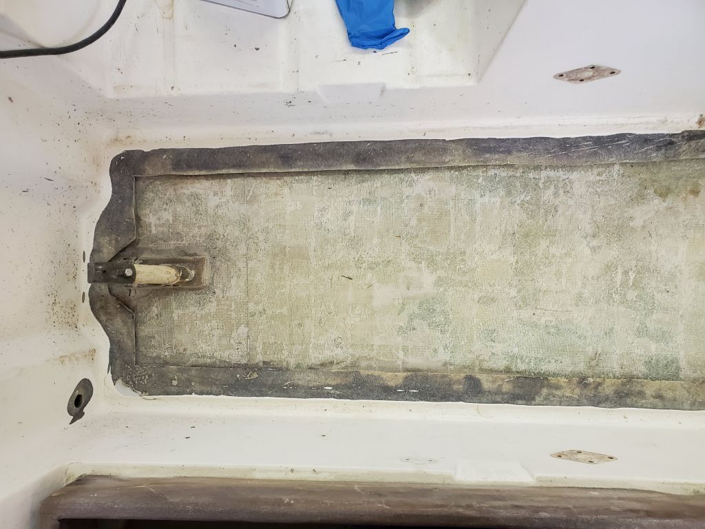
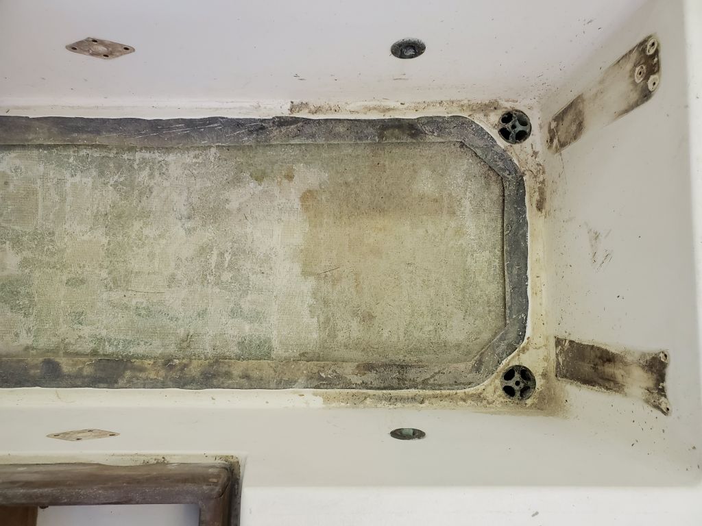
Additionally, the owner reported that the core was damaged on the starboard side of the poop deck, and inspection and sounding confirmed this. However, the port poop deck did not have any apparent damage, so repairs would be limited to the starboard side.
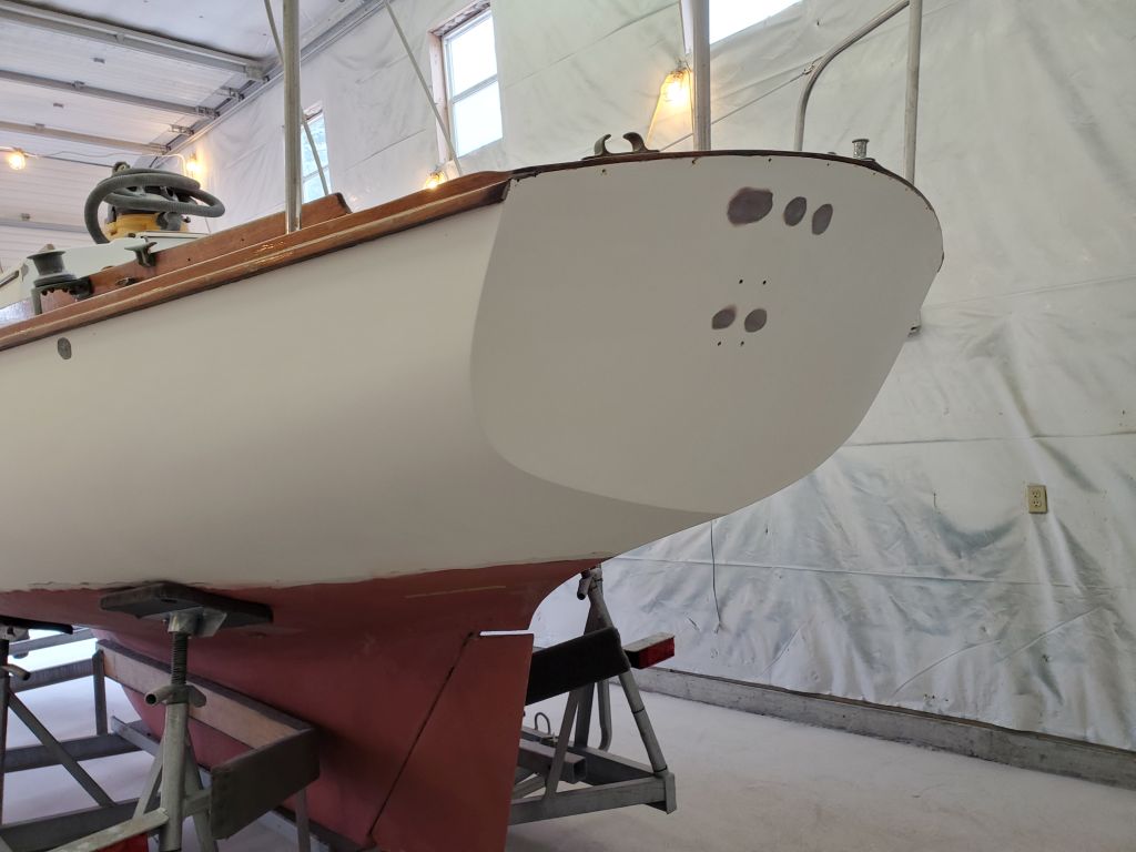
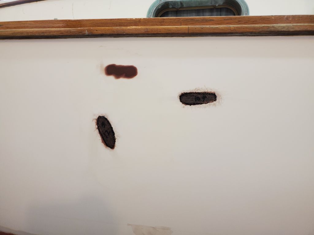
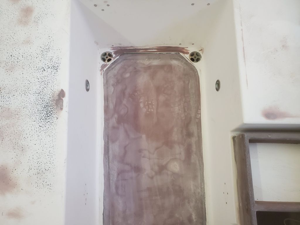
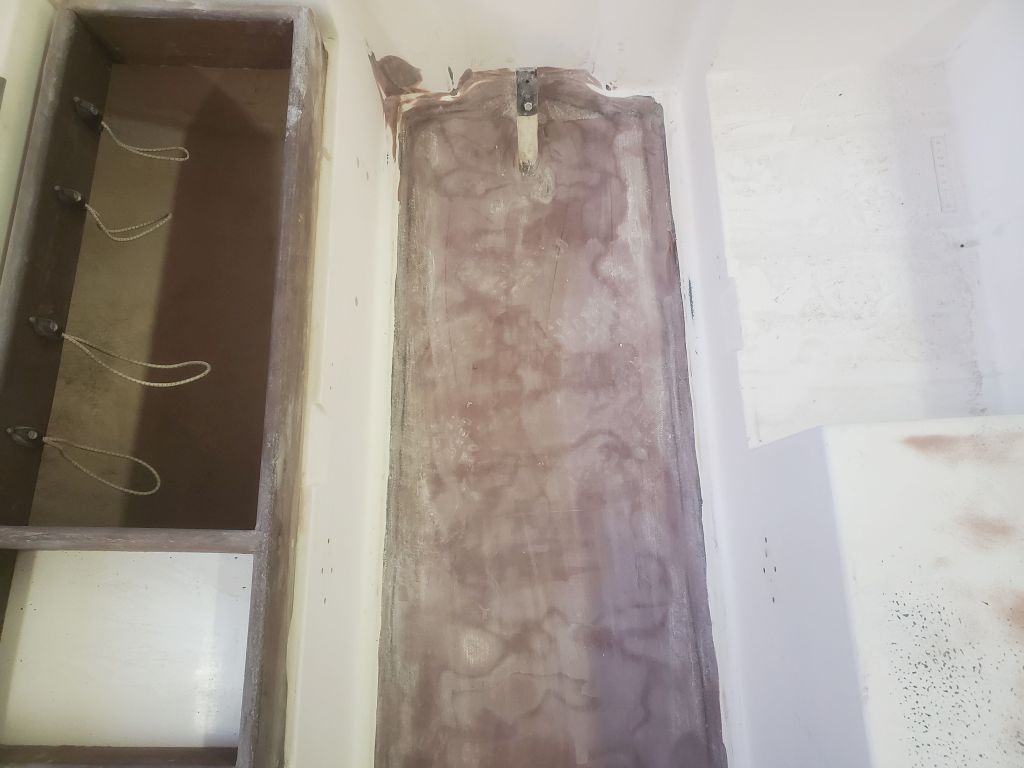
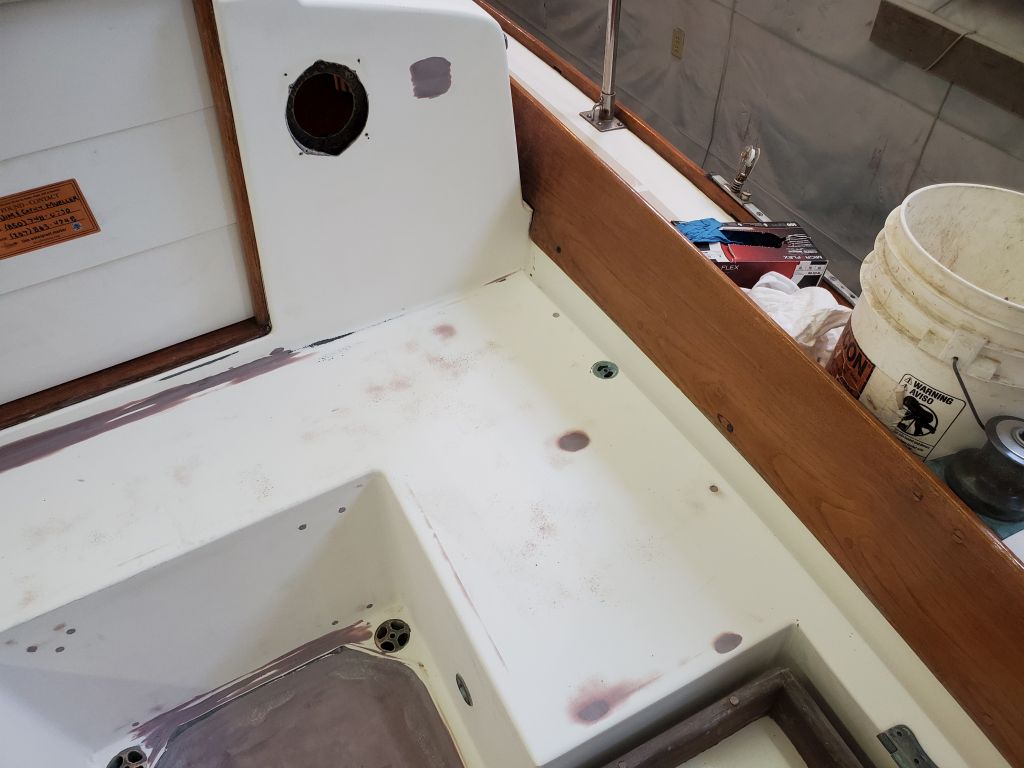
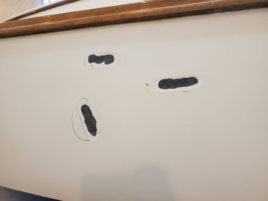
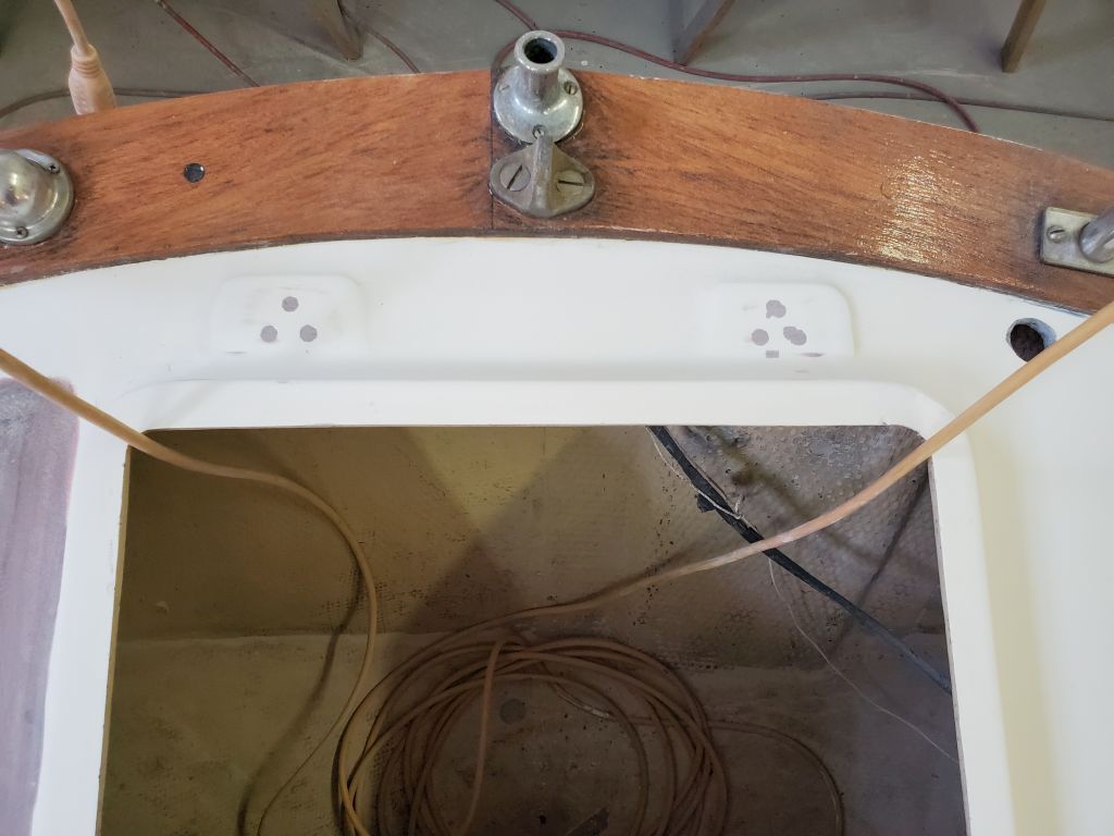
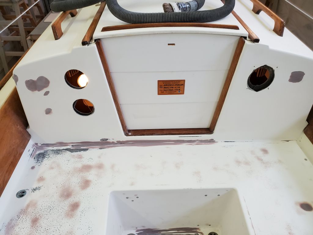
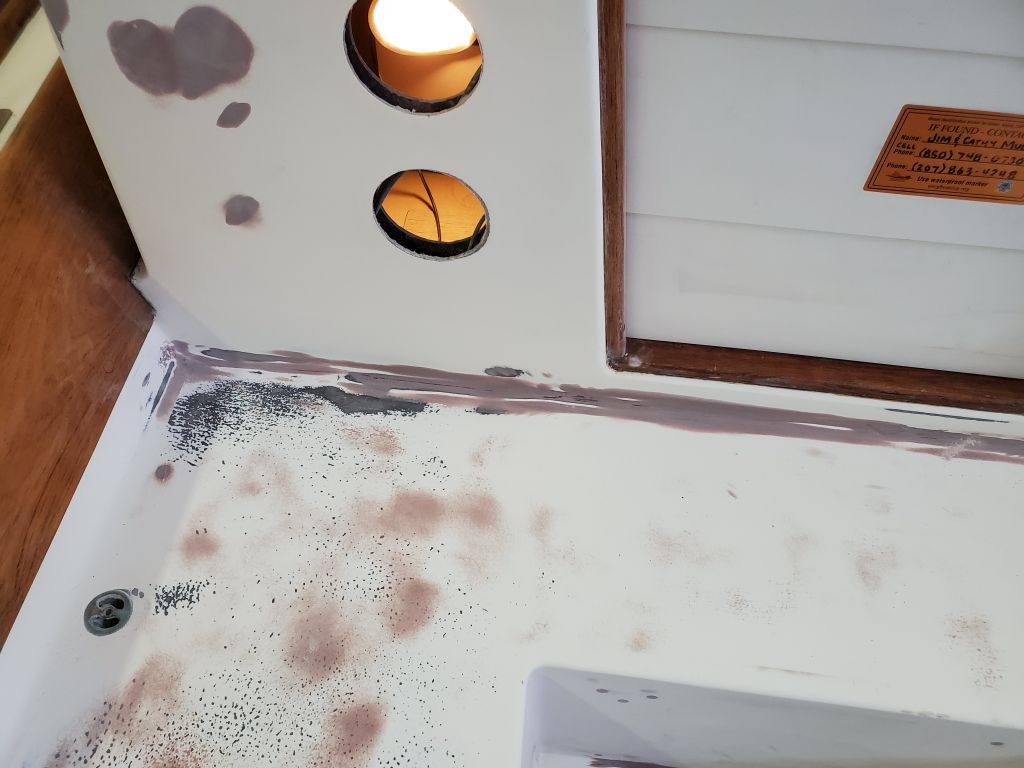
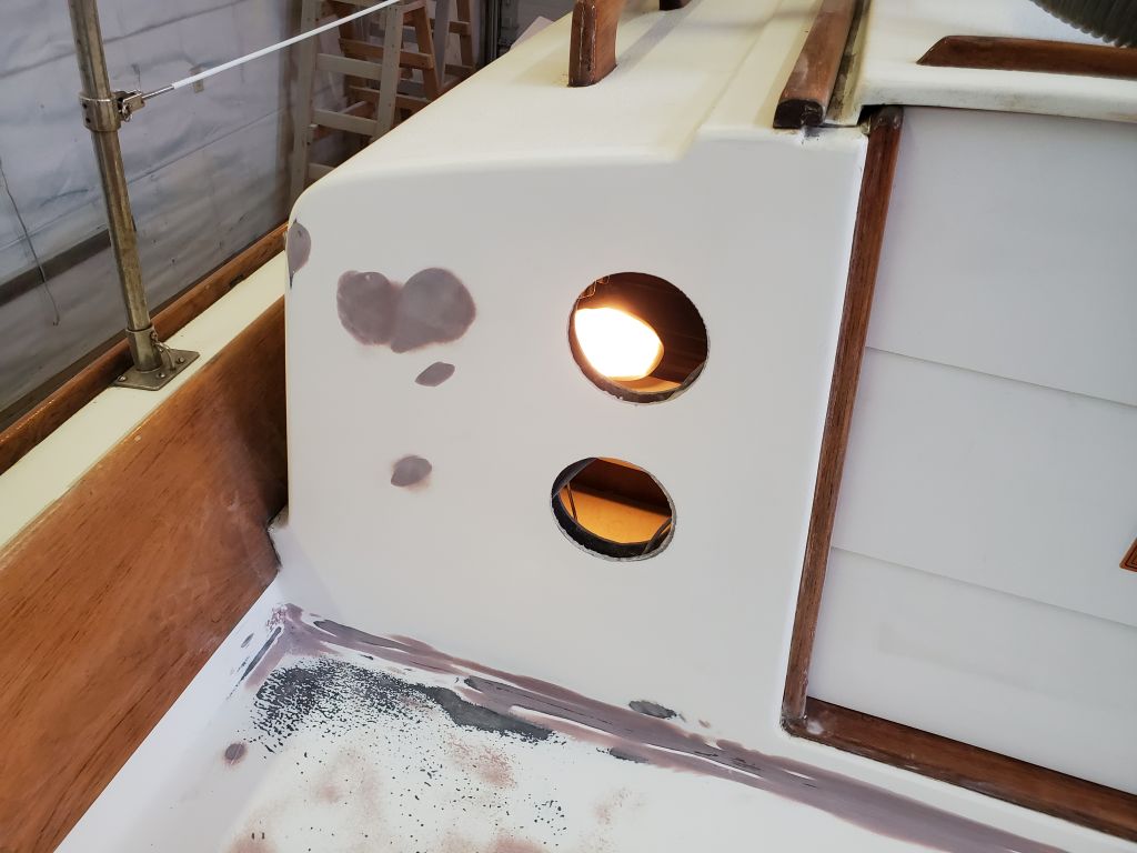
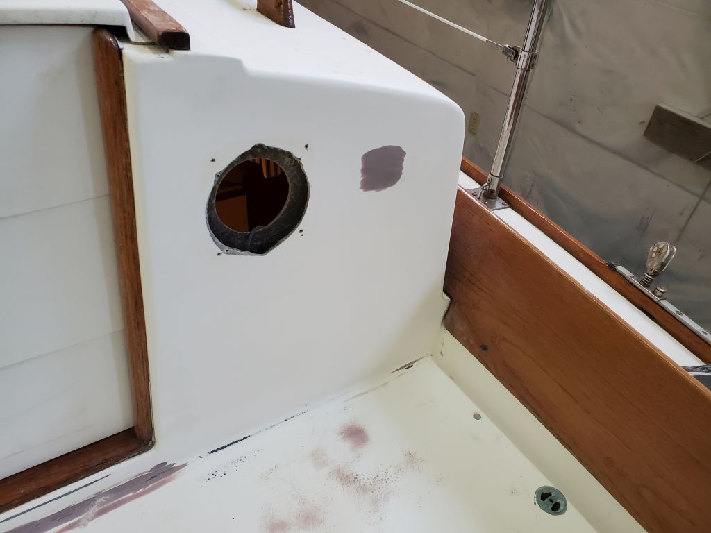
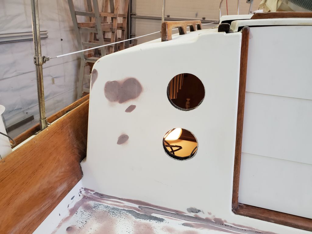
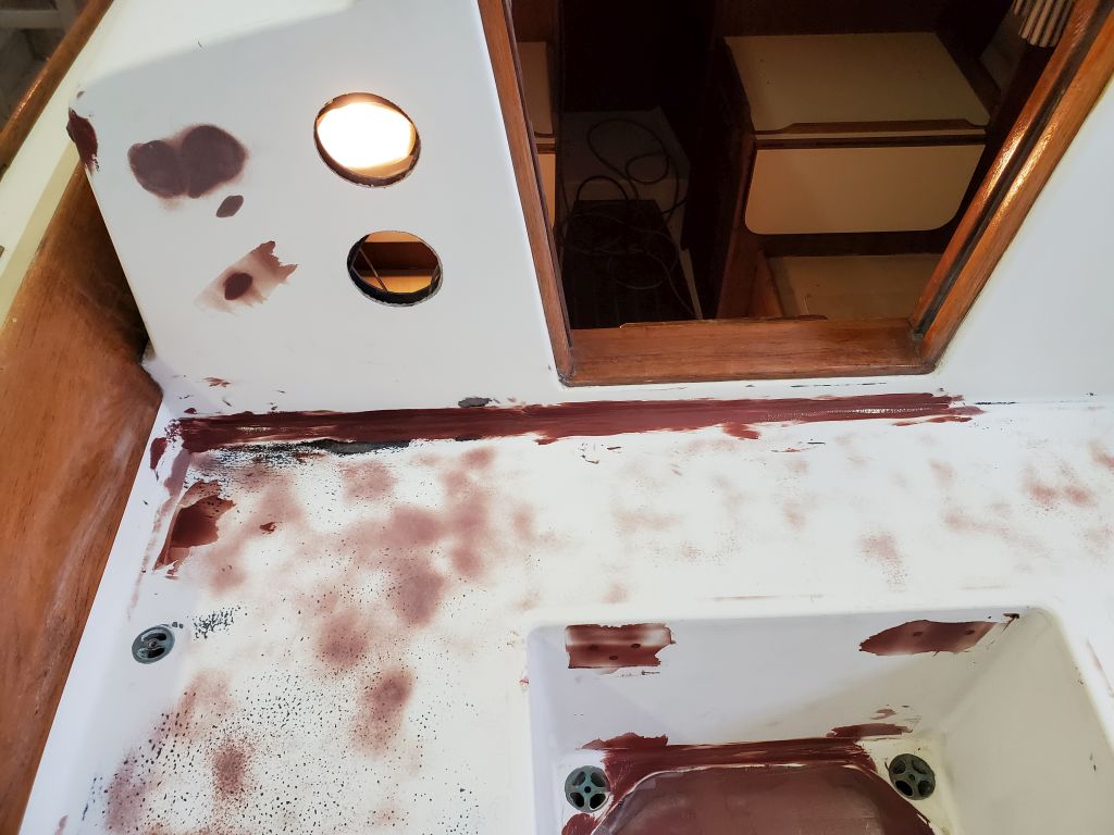
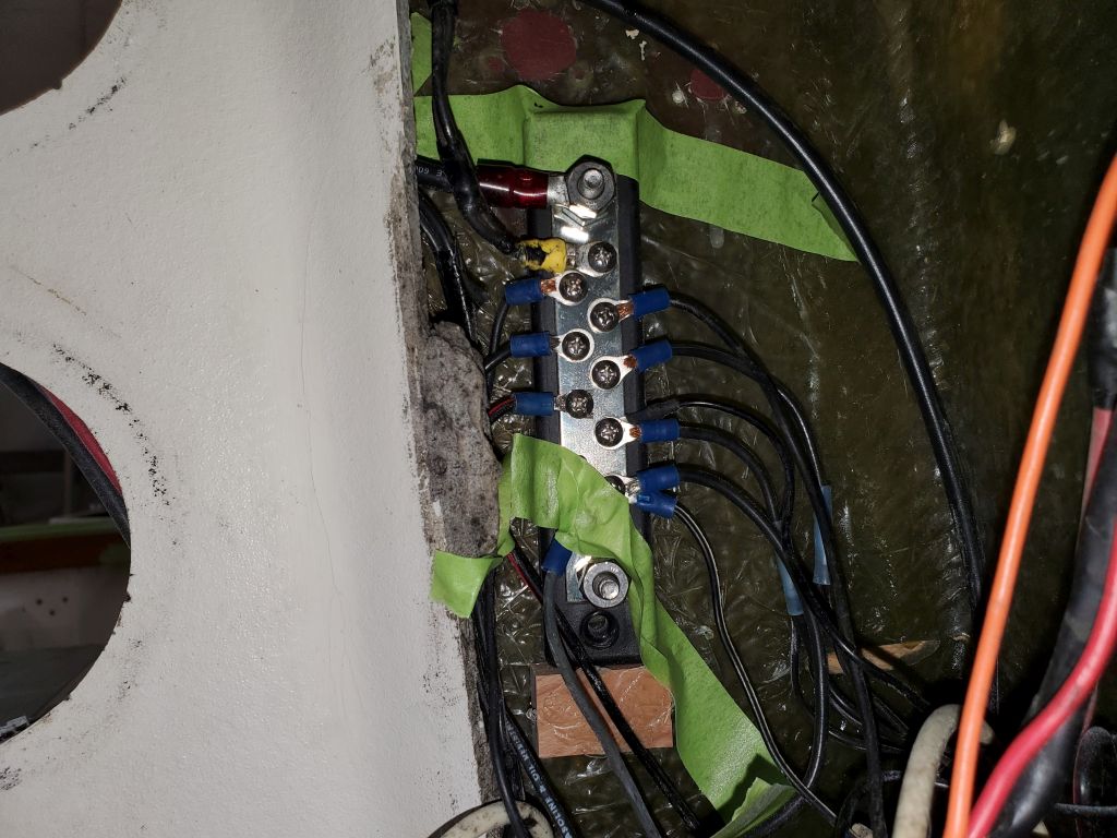
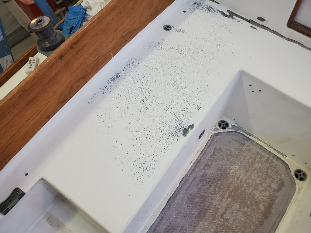
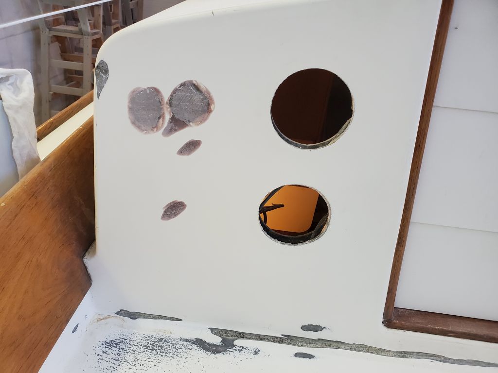
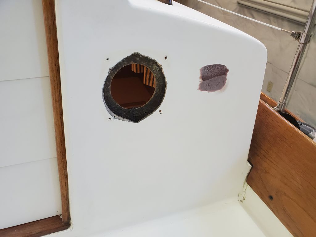
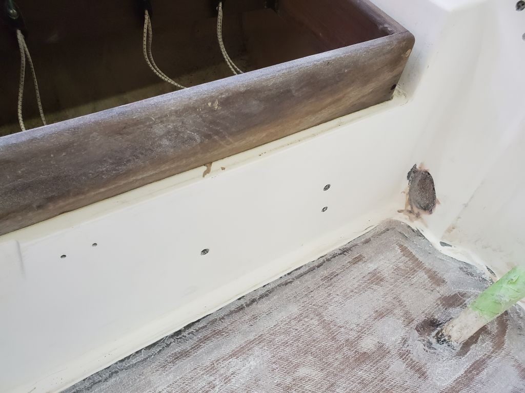
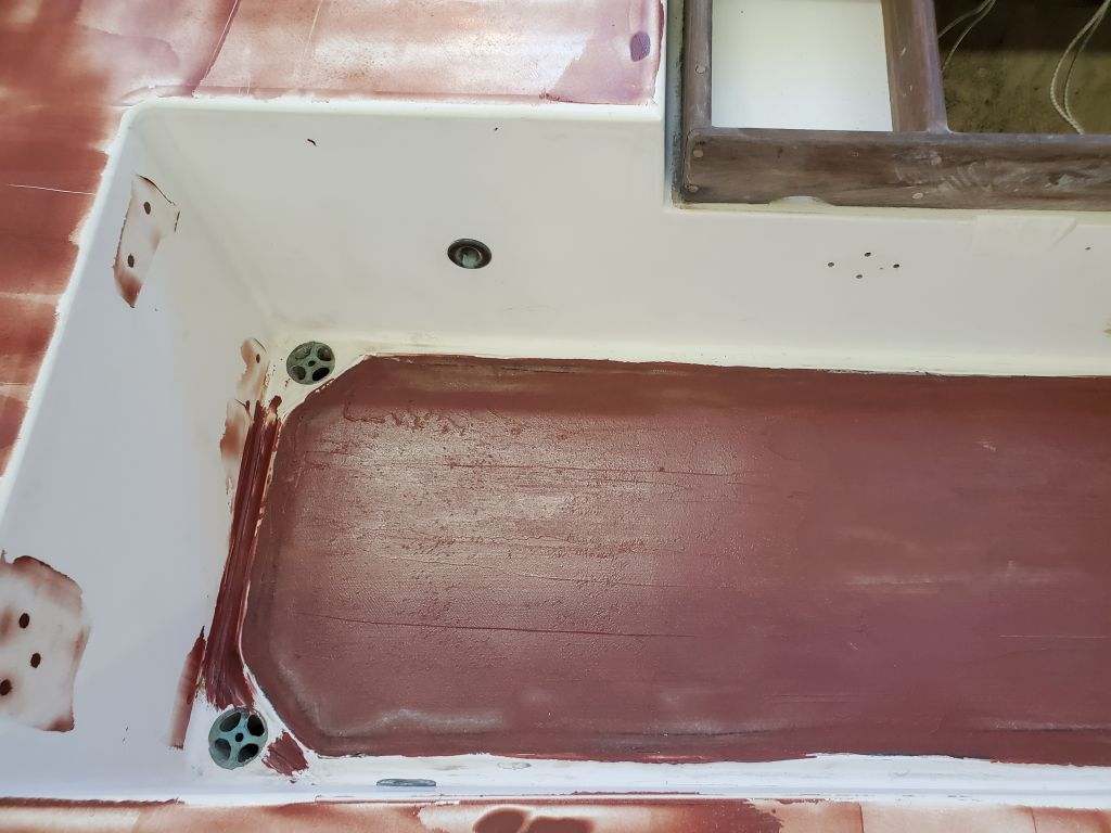
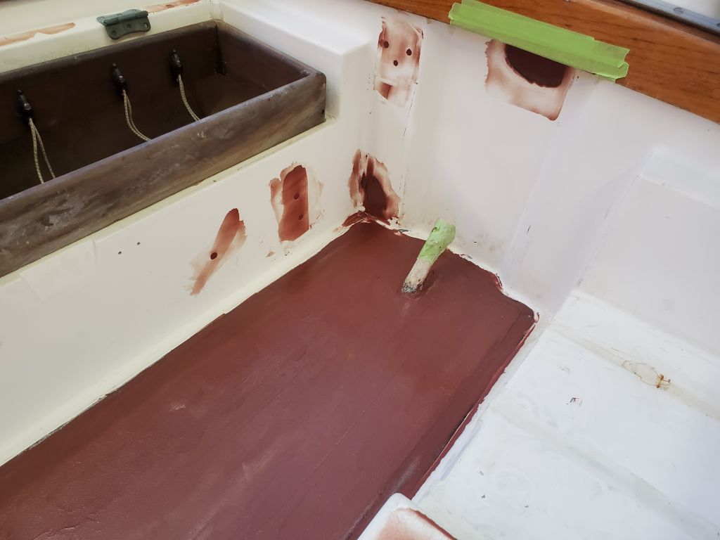
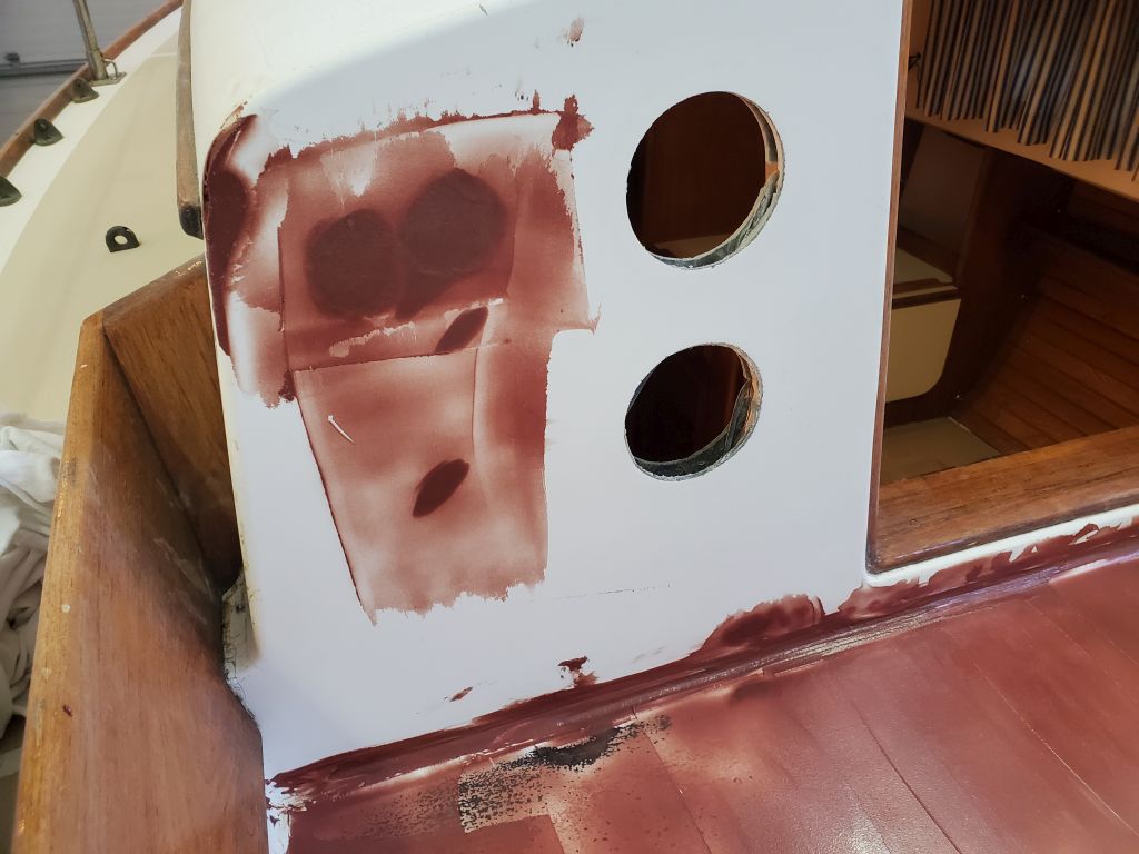
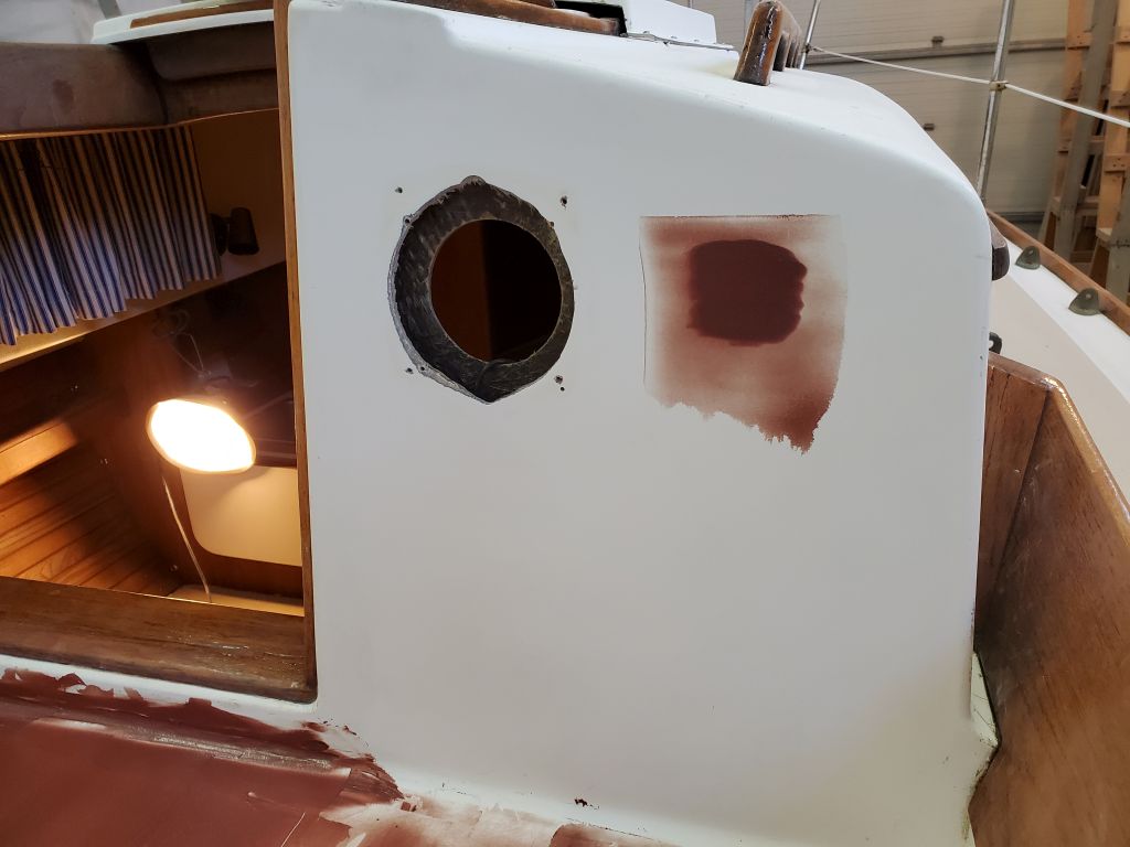
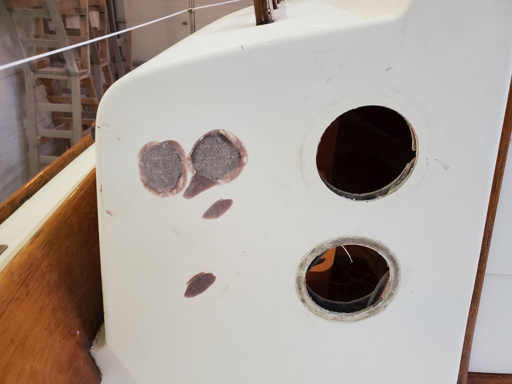
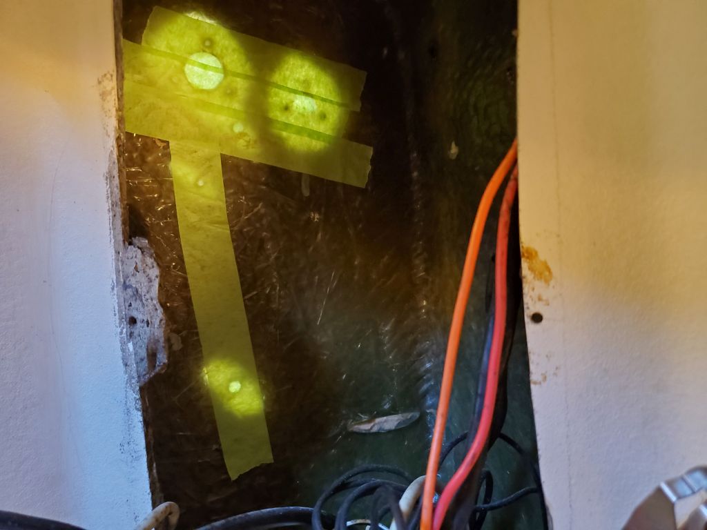
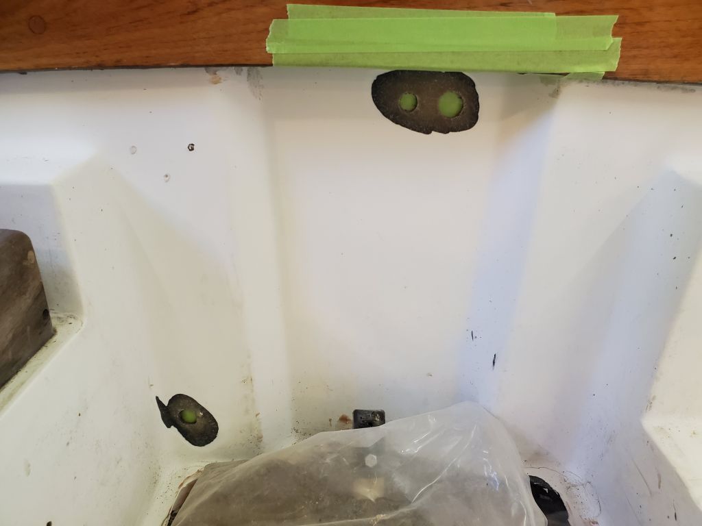
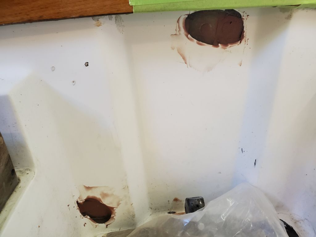
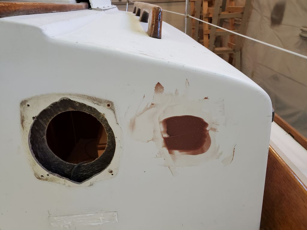
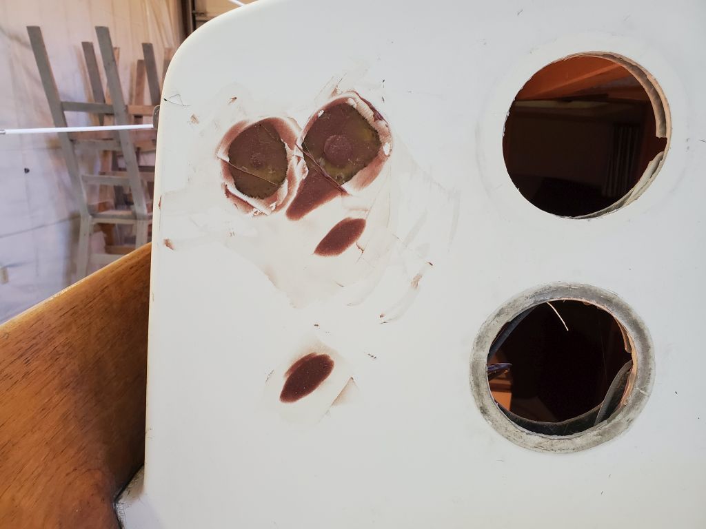
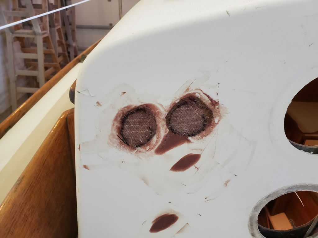
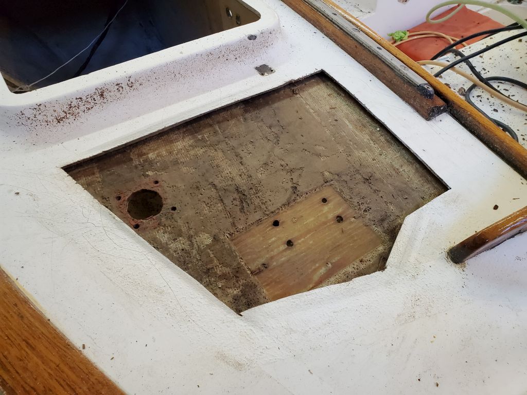
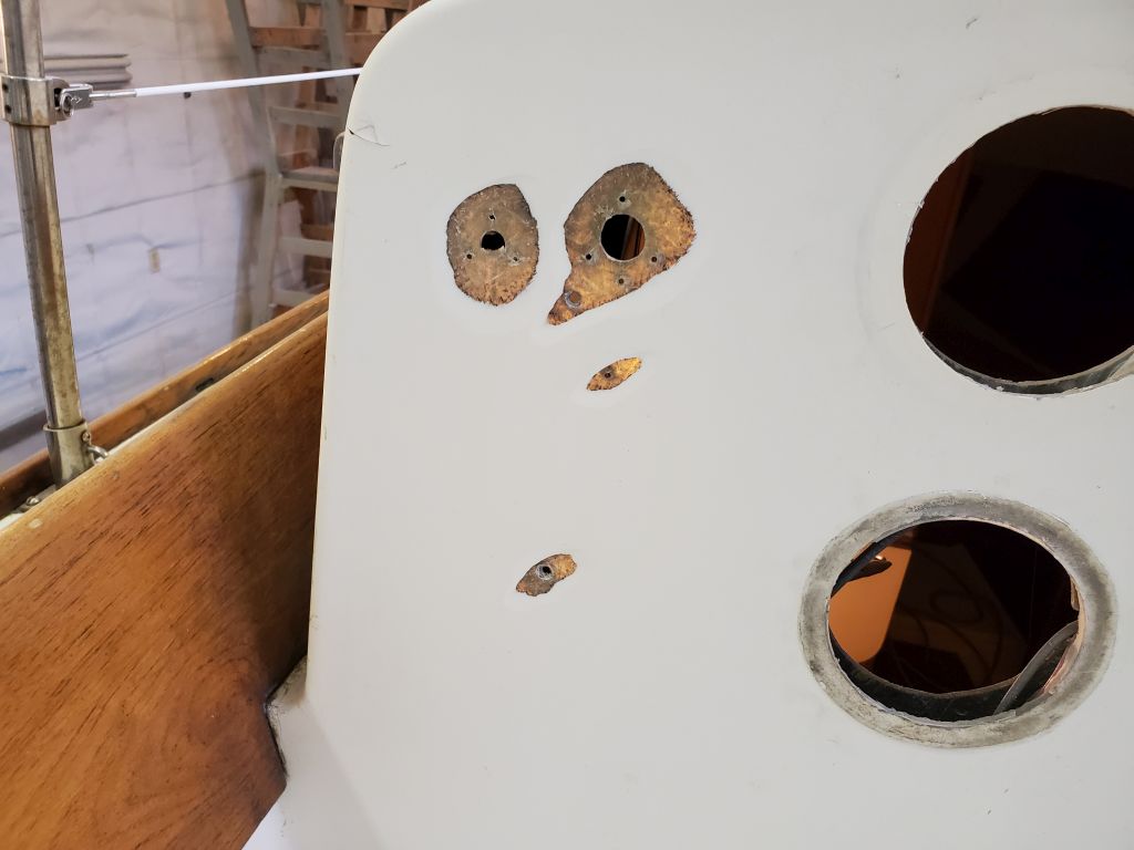
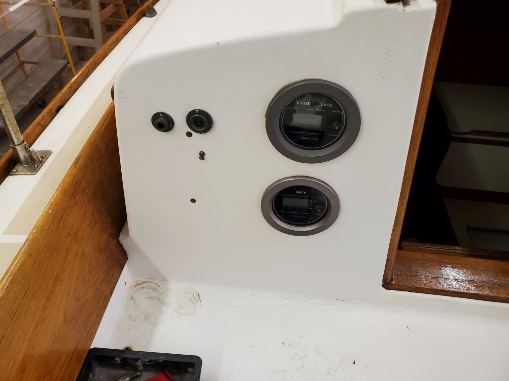
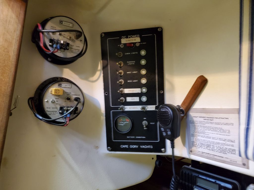
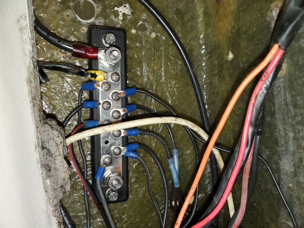
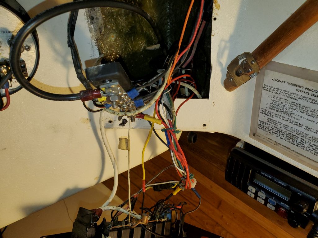
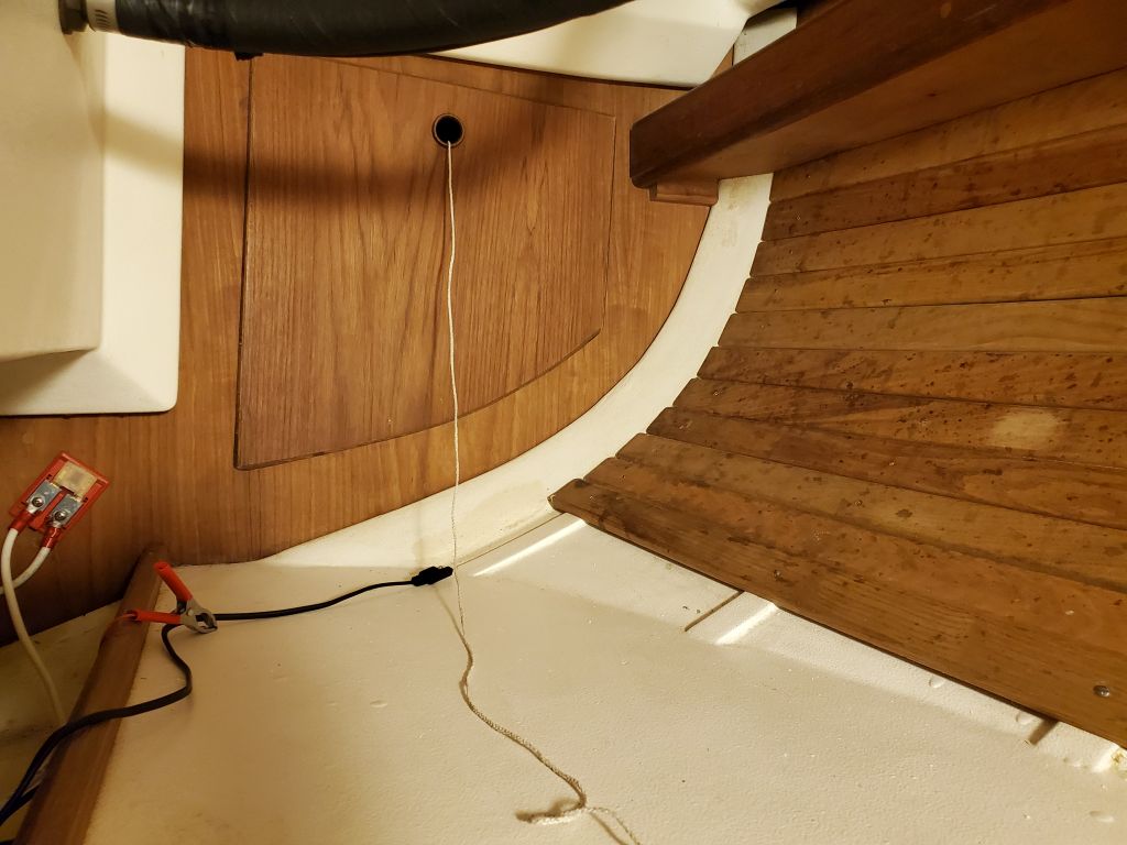
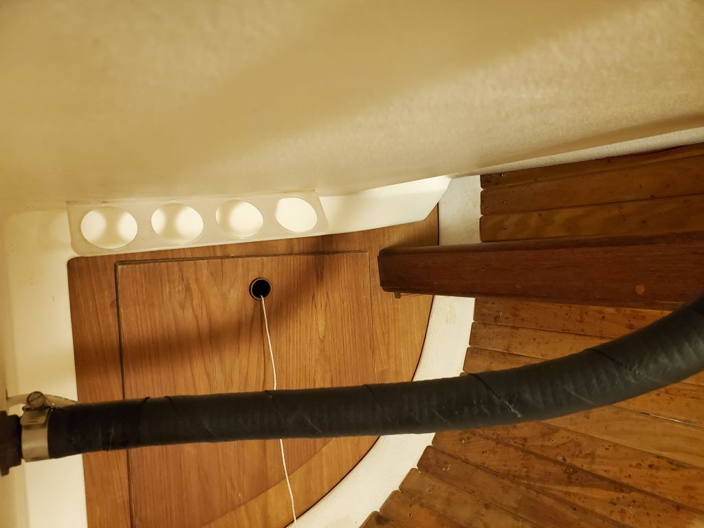
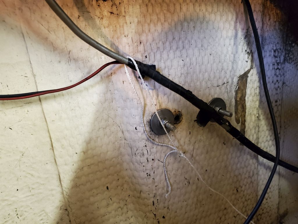
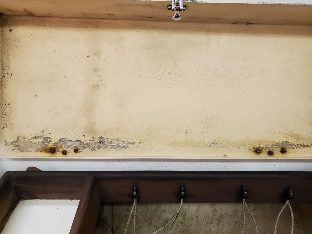
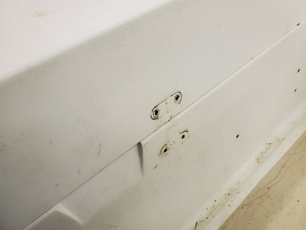
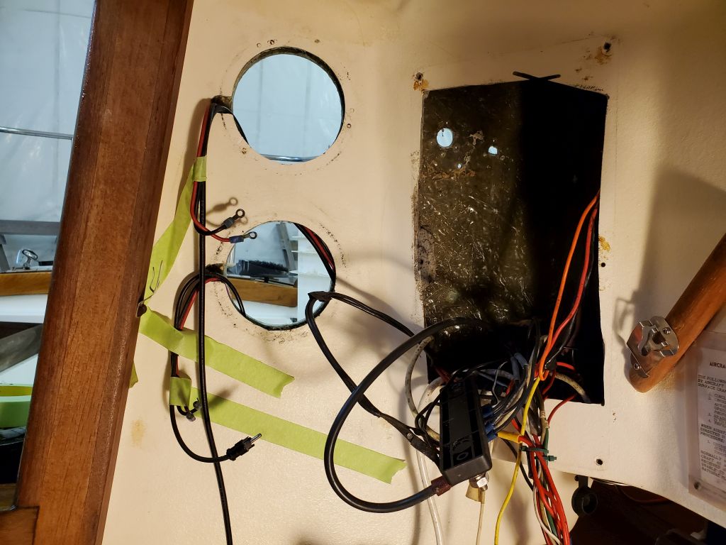
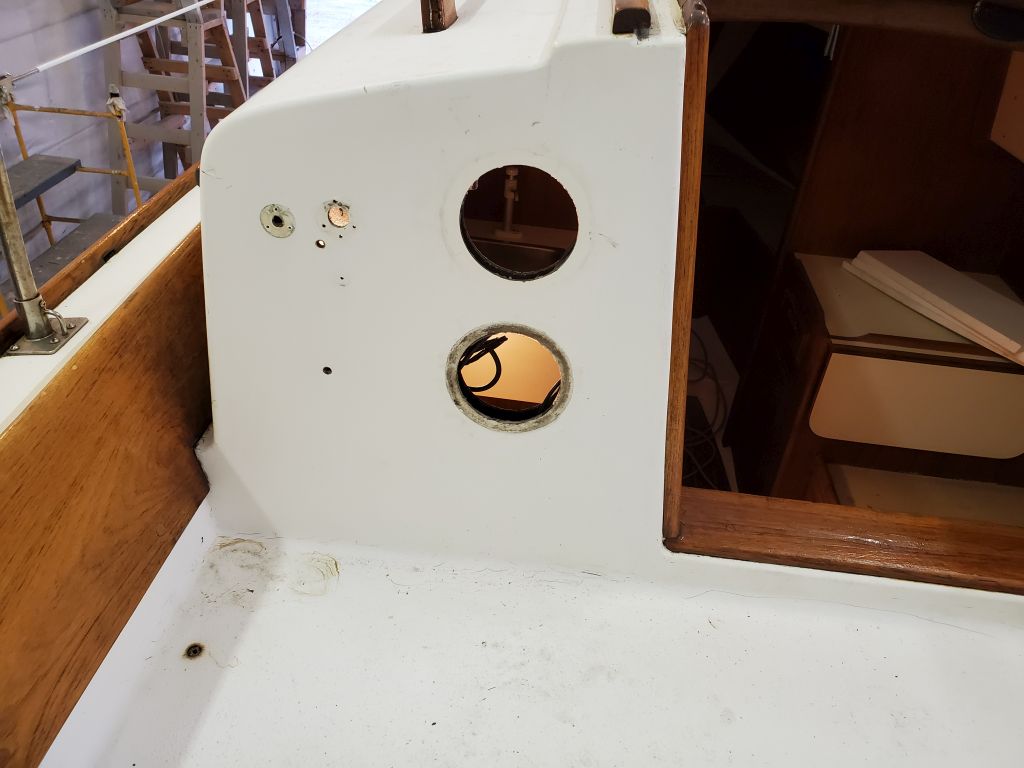
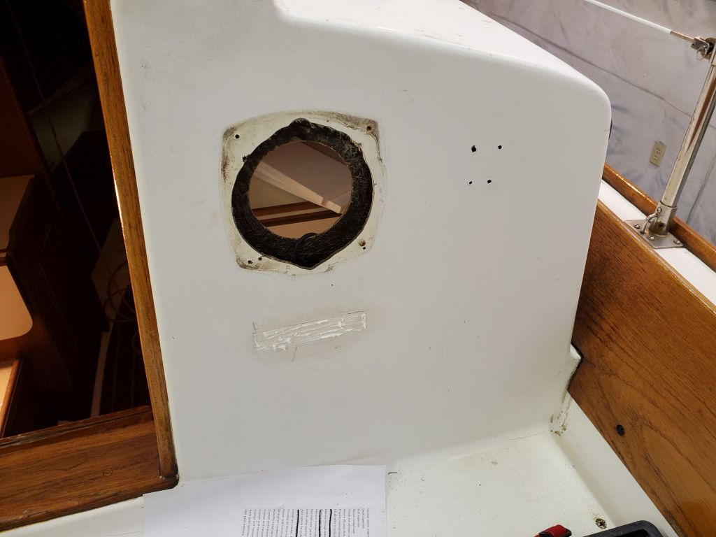
In the cockpit, there were several now-obsolete holes left over from a now-removed remote engine control and its cables, and on the aft cabin bulkhead were additional unused holes, plus a pair of old wiring plugs that the owner wanted removed and repaired. In addition, someone had secured a buss bar for the electrical system with bolts from the outside, leaving exposed screw heads, and the owner requested that I remove those and secure the buss bar in a different way from within.
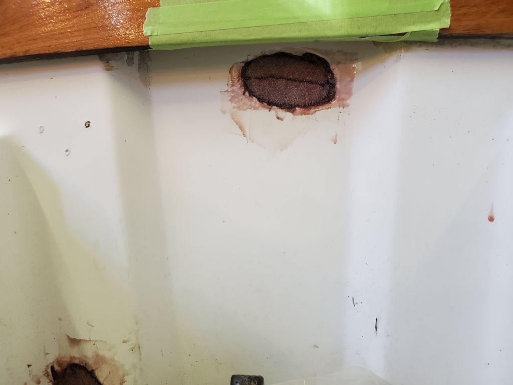
The obsolete wiring plugs to port were straightforward and quick to remove, and so was the buss bar once I opened the electrical panel inside. For now, I left the buss bar unsecured pending the completion of the repairs to the old holes in the bulkhead.
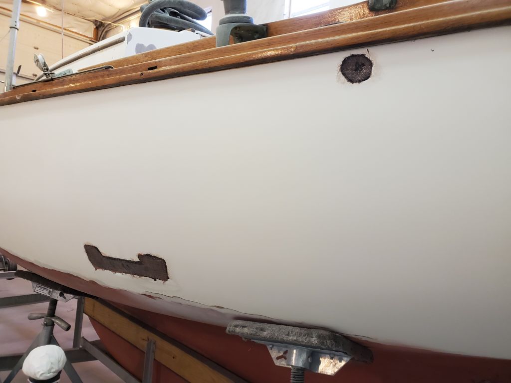
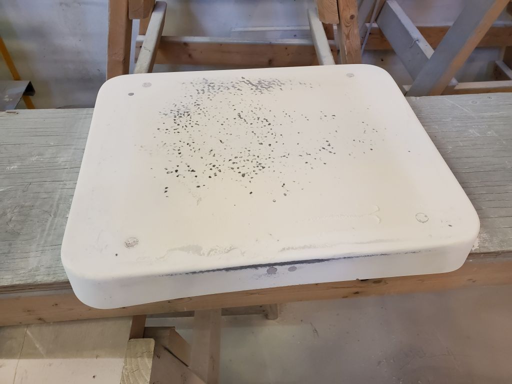
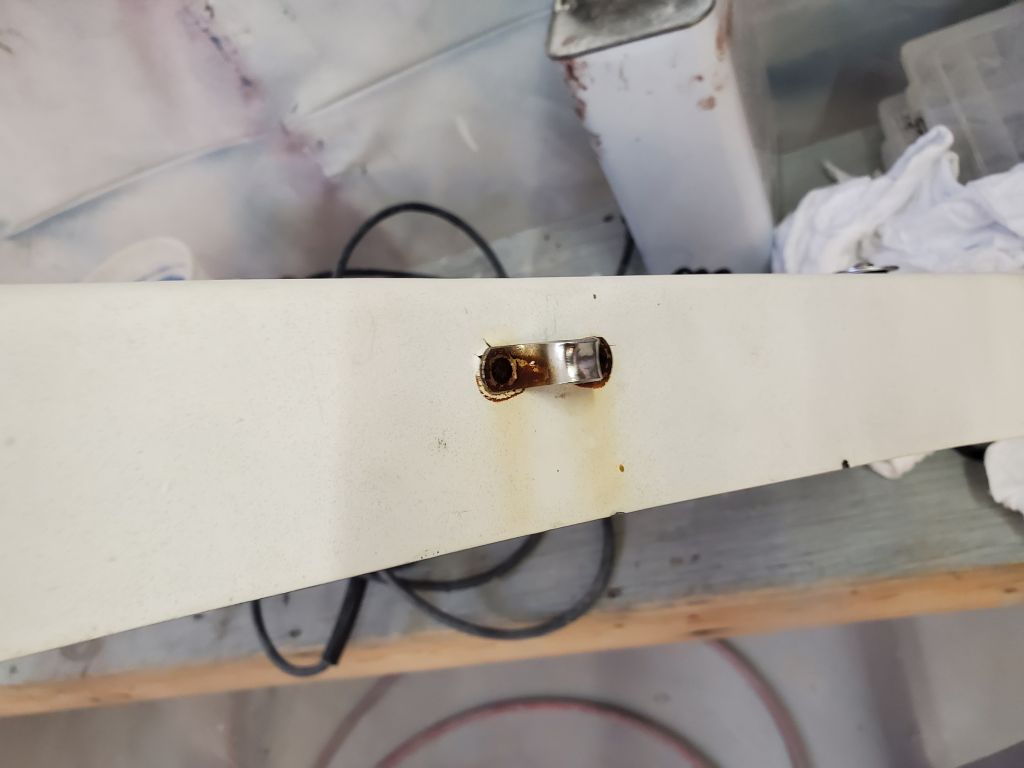
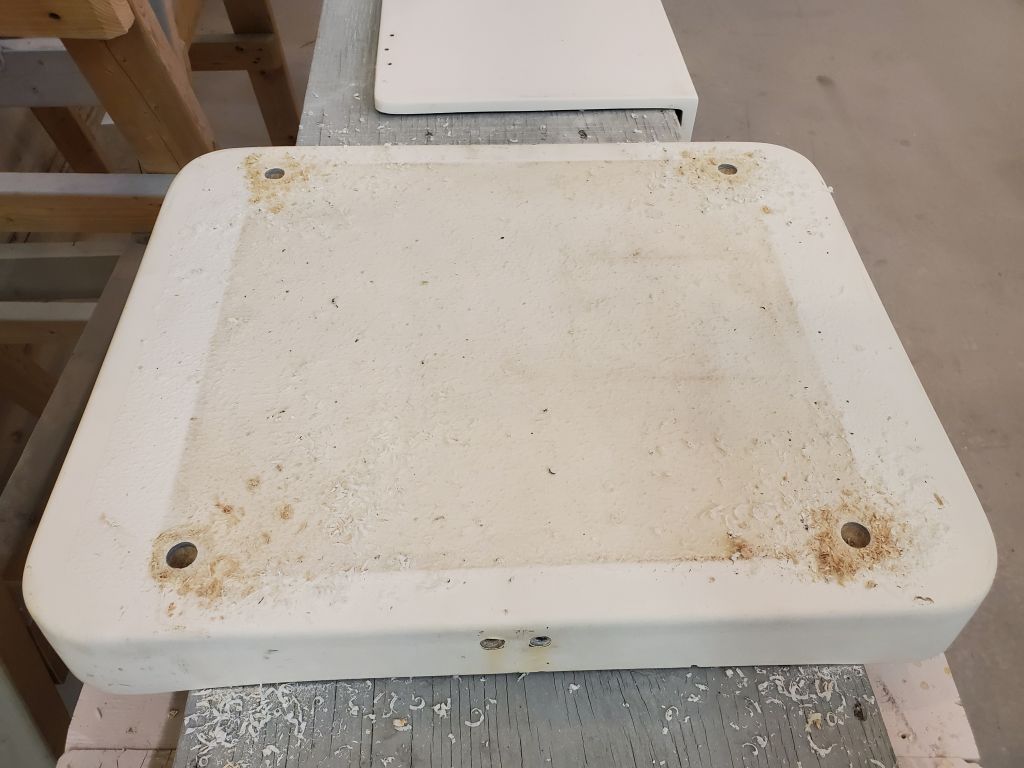
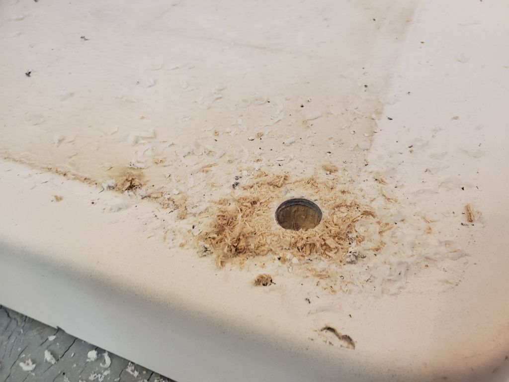
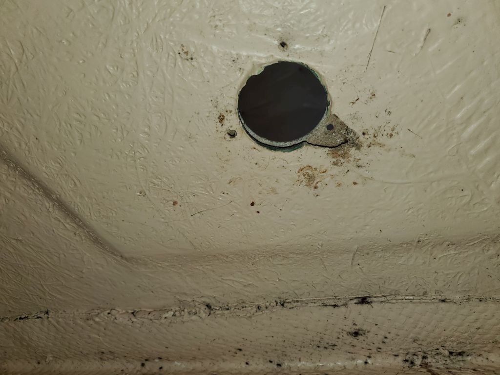
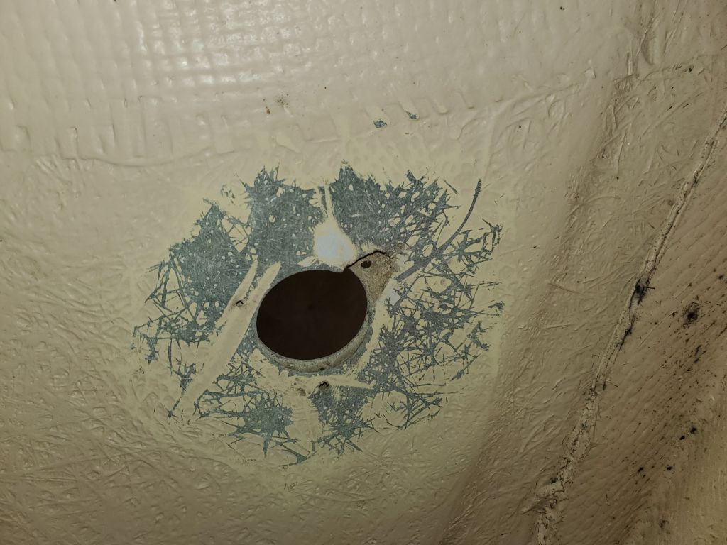
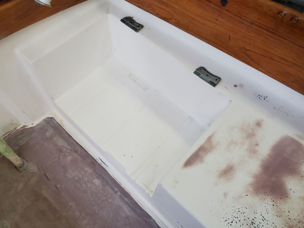
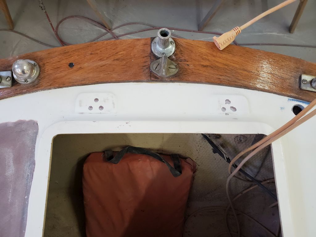
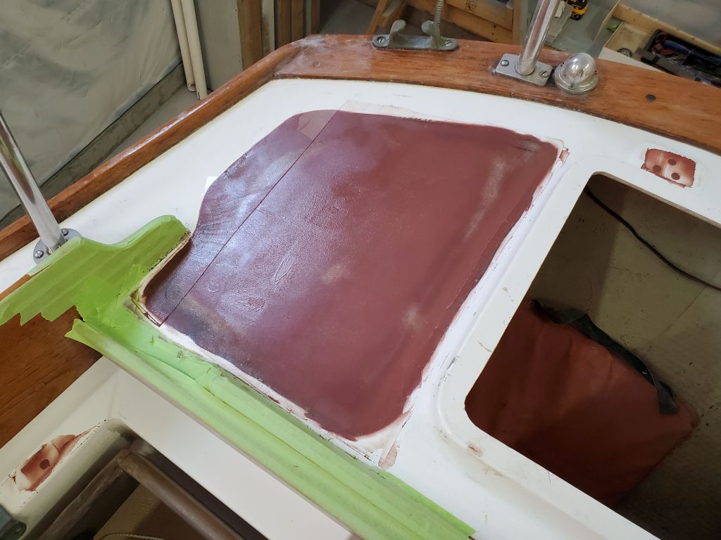
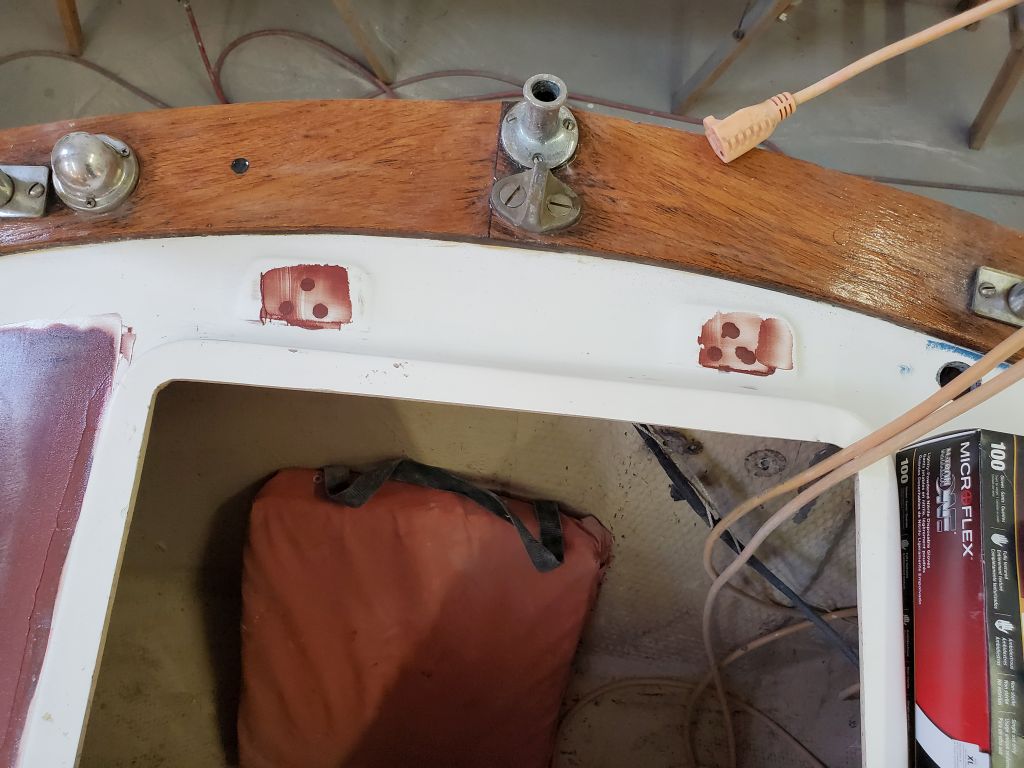
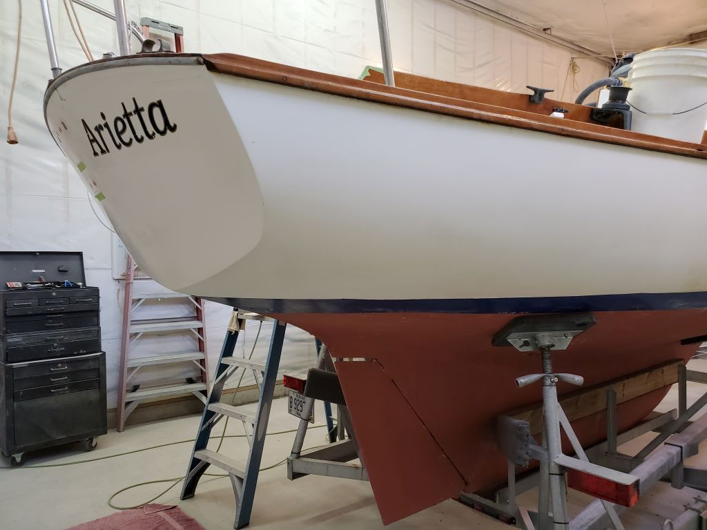
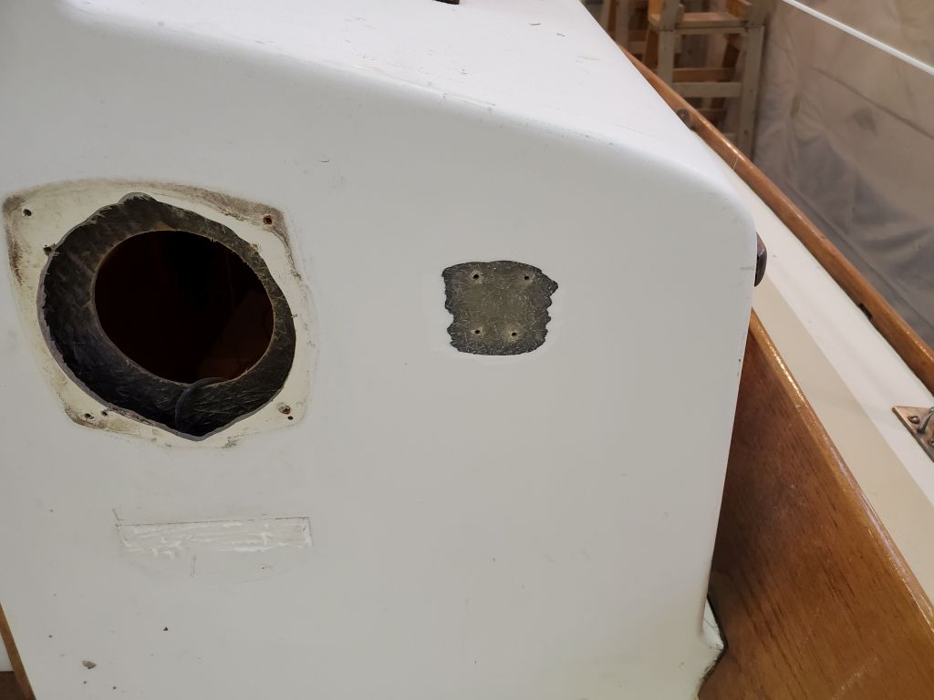
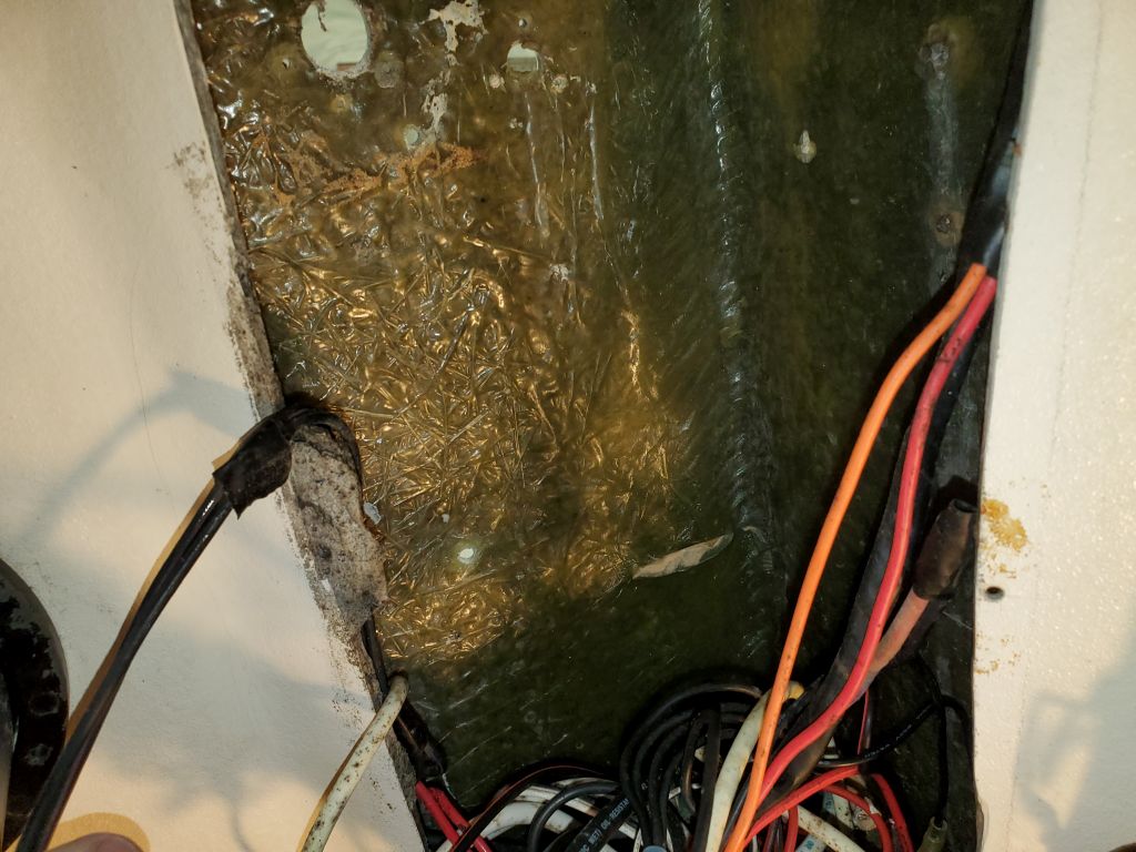
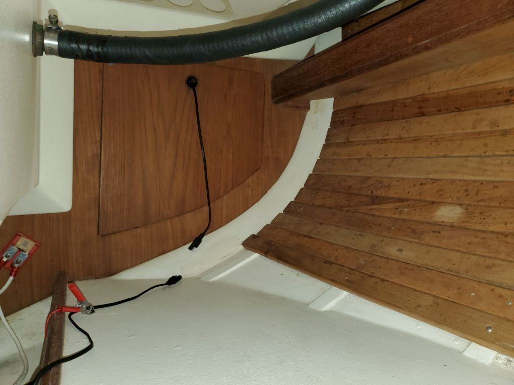
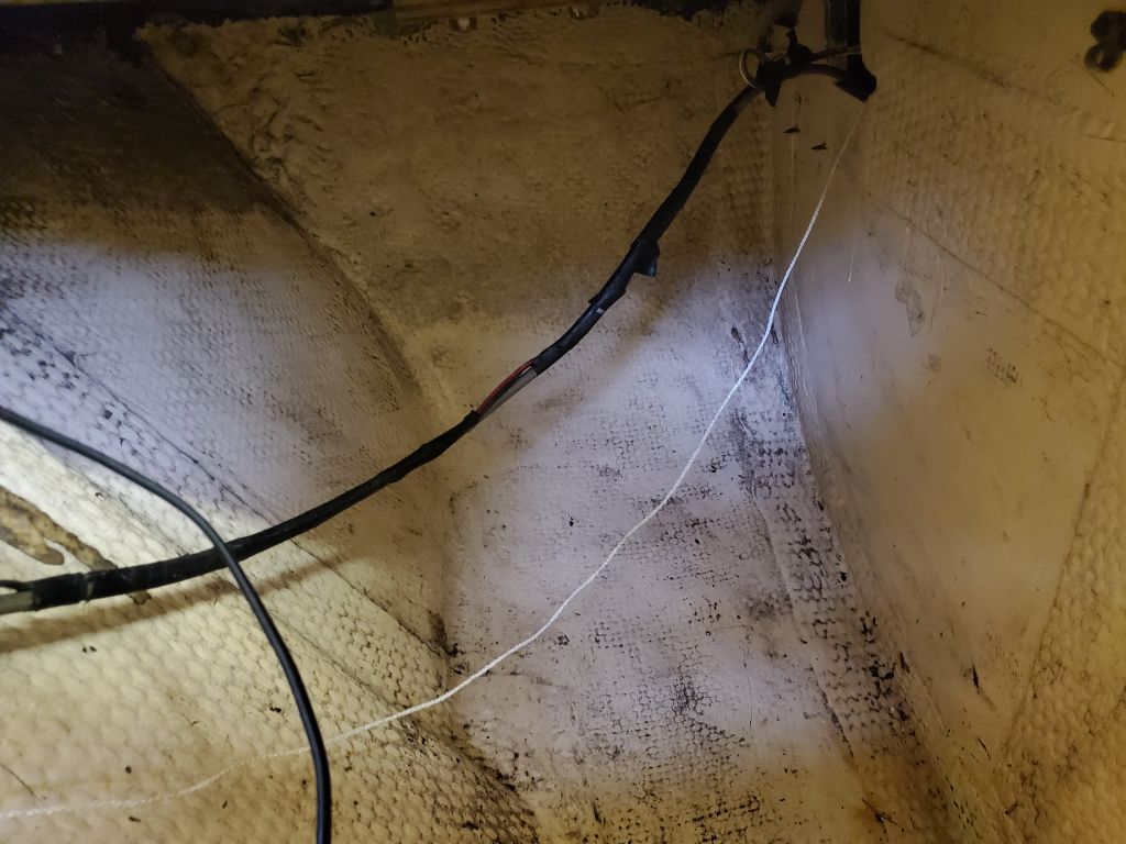
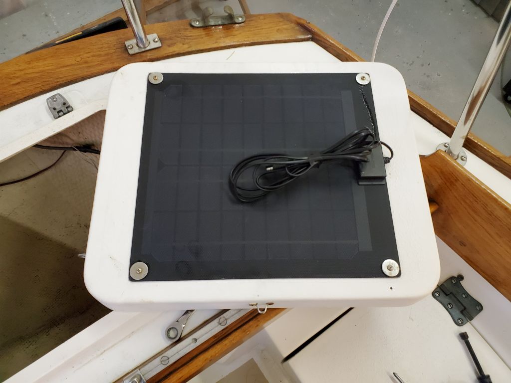
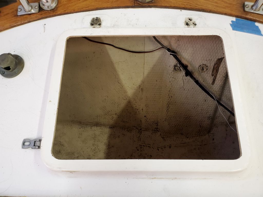
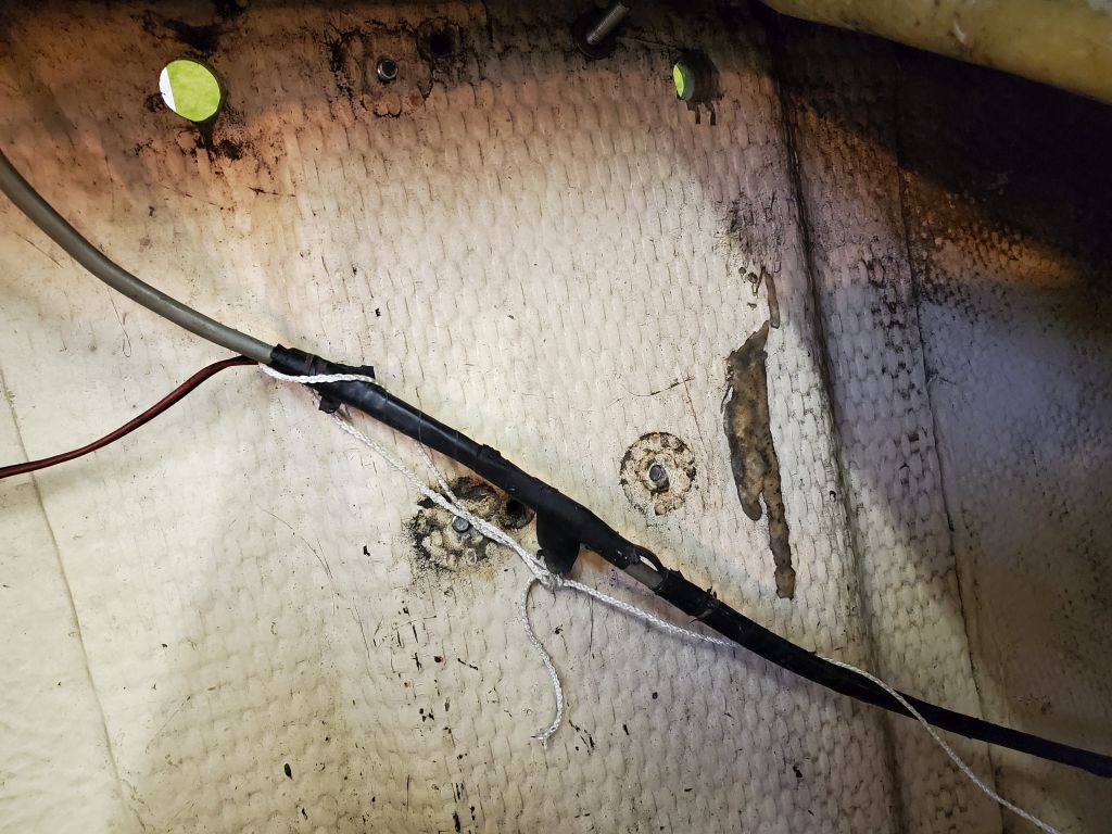
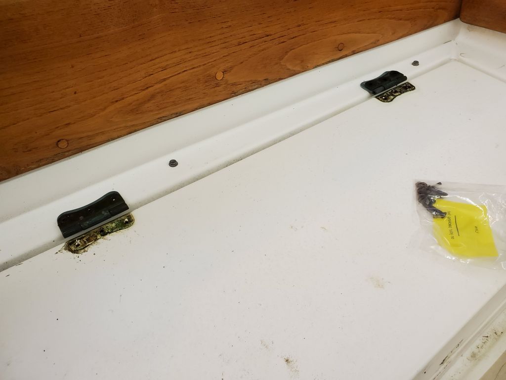
At the stern, I removed the lazarette hatch with its solar panel attached, which meant I needed to pull through the solar panel cable, which led through an old transom hole (to be patched) and into the main cabin through a hidden route. Not knowing what was in there at the moment, I attached a messenger line from inside before pulling the cable through. I removed the hatch partly for access, but also because the owner reported that the hatch hinges were slightly misinstalled and didn’t allow the hatch to operate properly. I planned to fill the old holes and reinstall the hinges appropriately during the course of the project. Later, during installation, I’d run the solar panel cable through a new waterproof deck fitting as well.
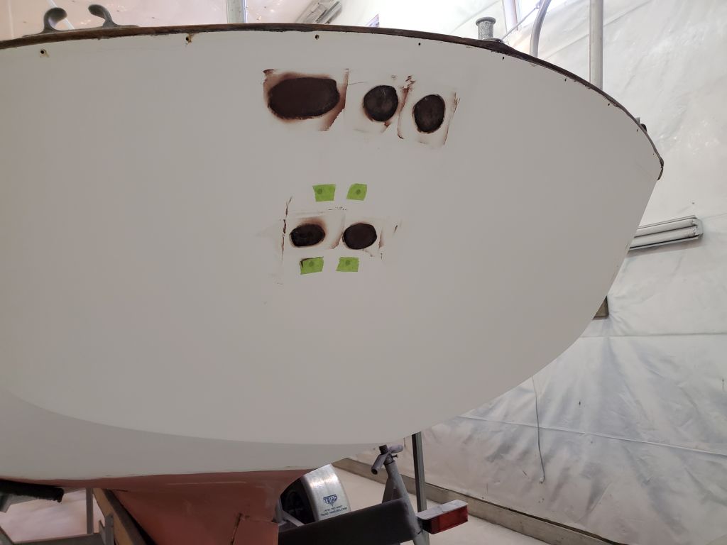
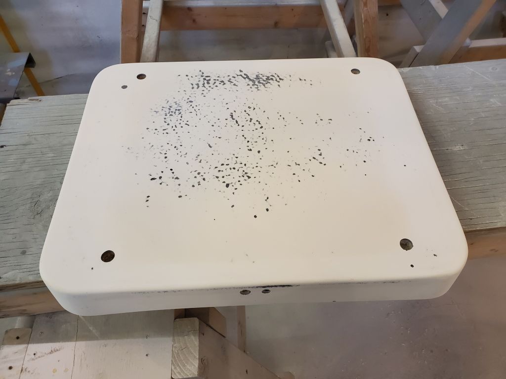
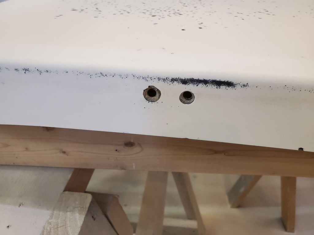
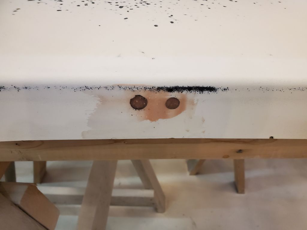
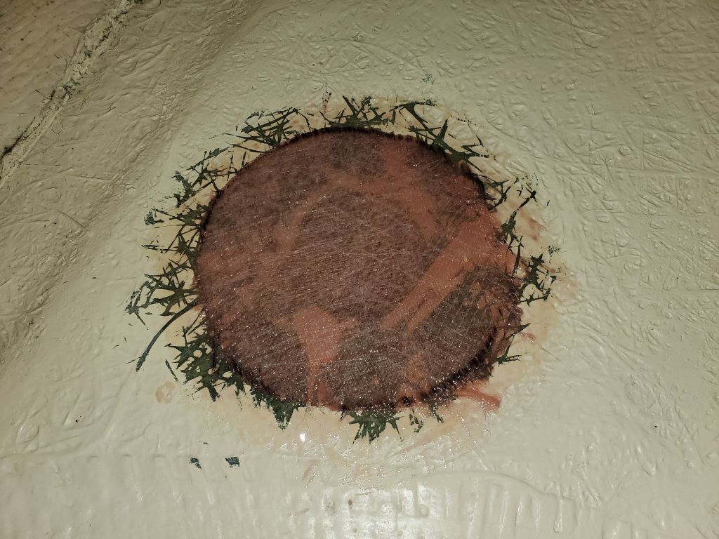
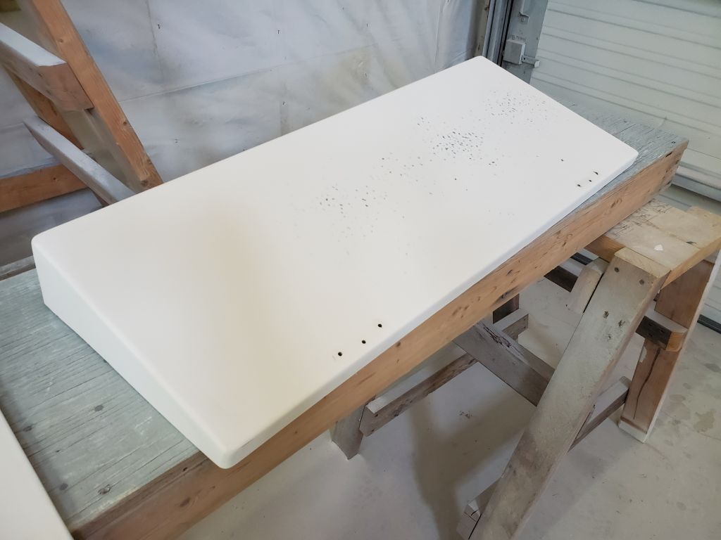
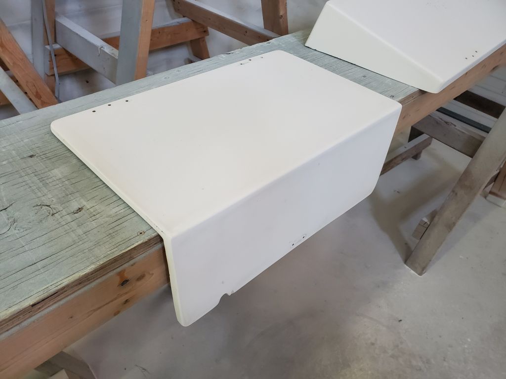
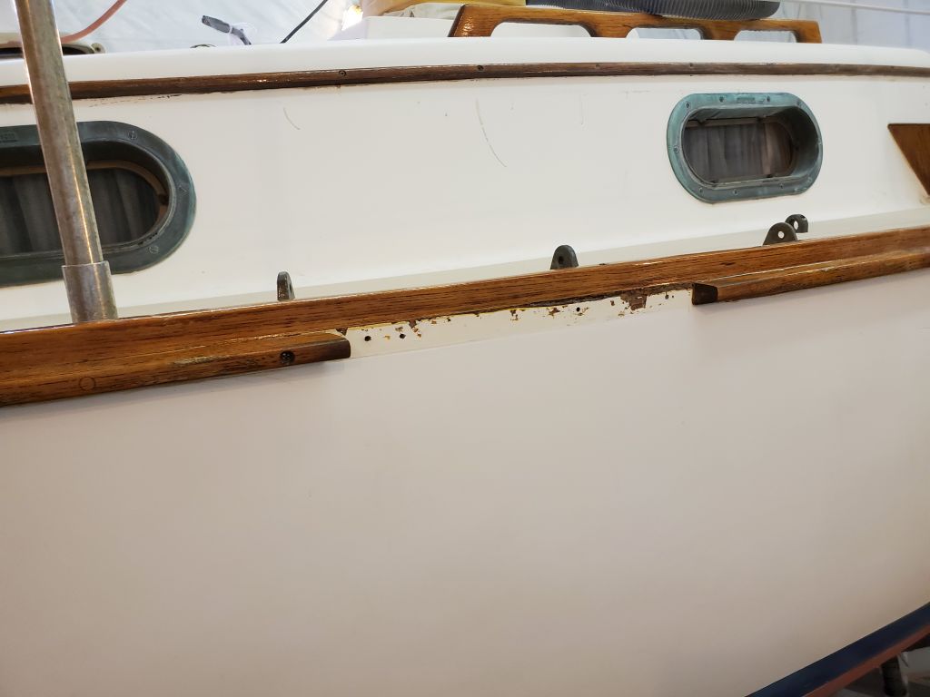
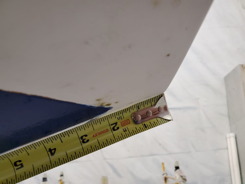
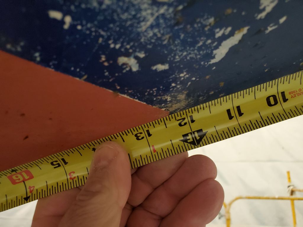
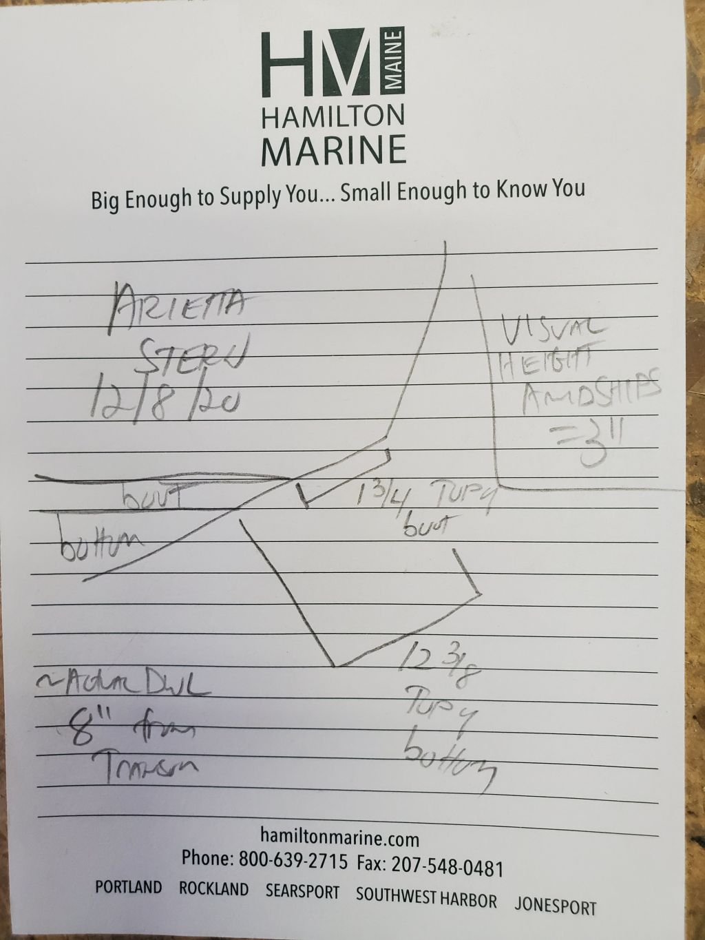
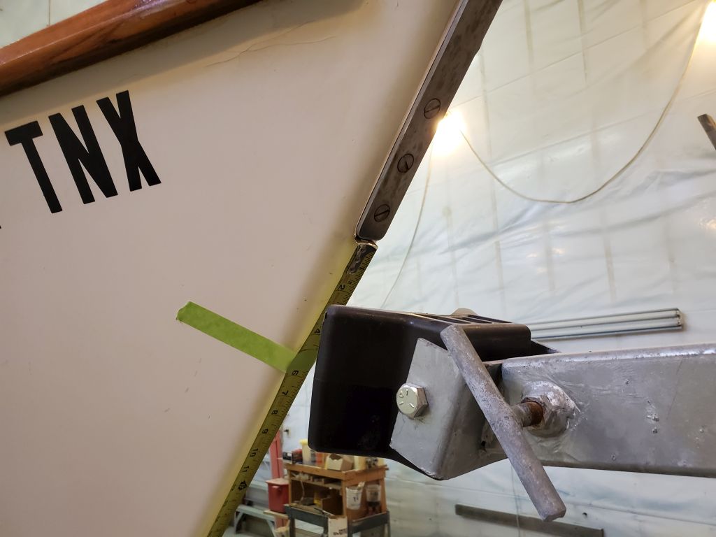
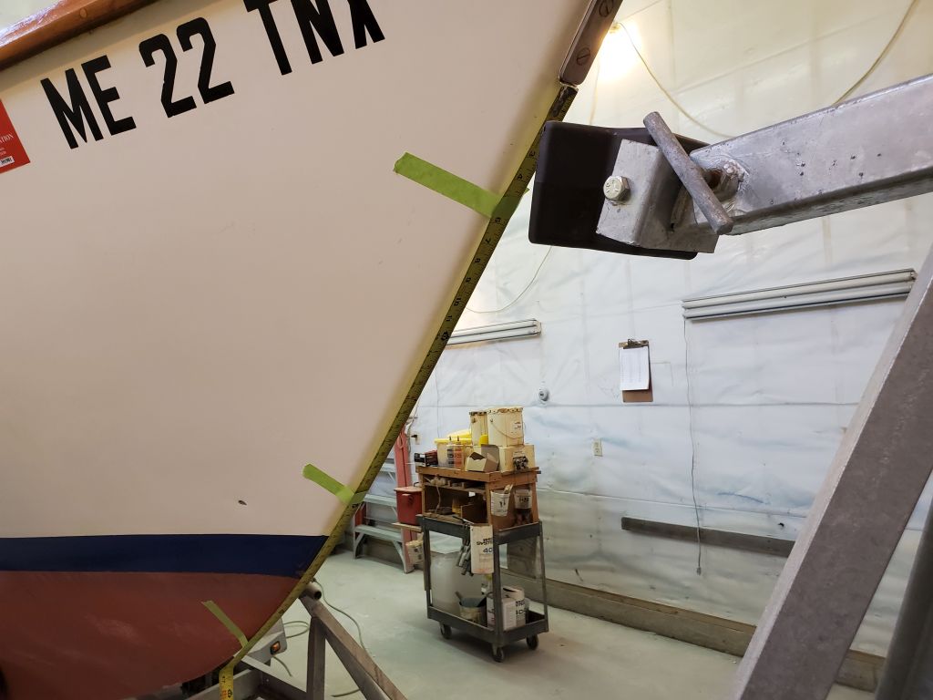
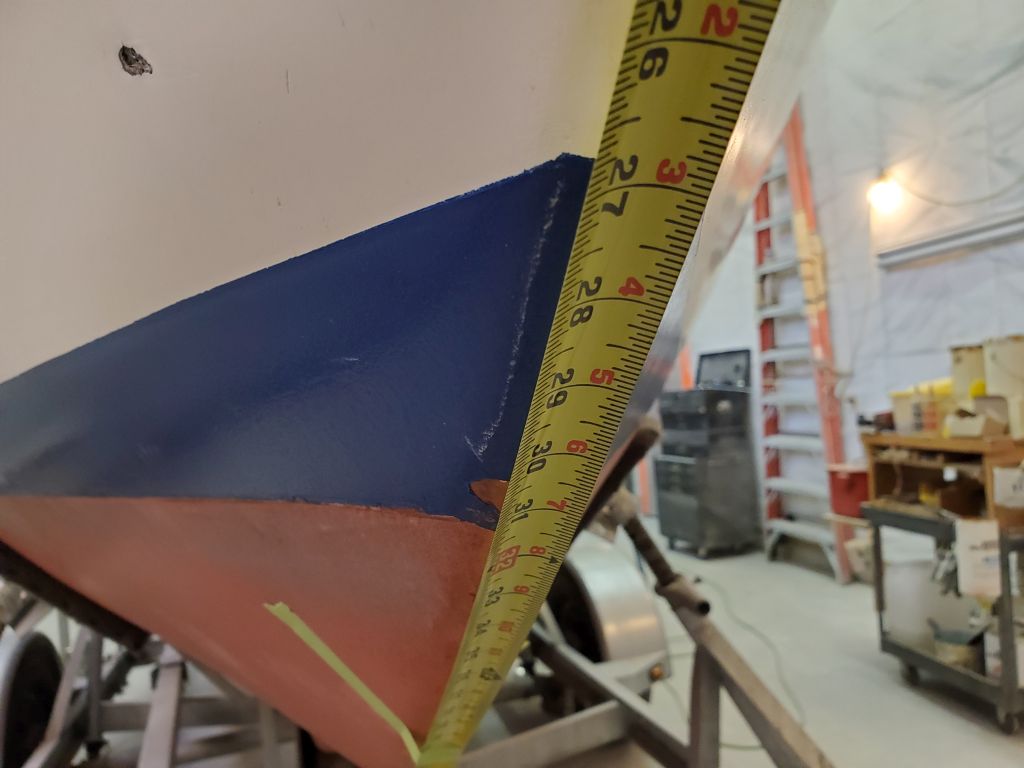
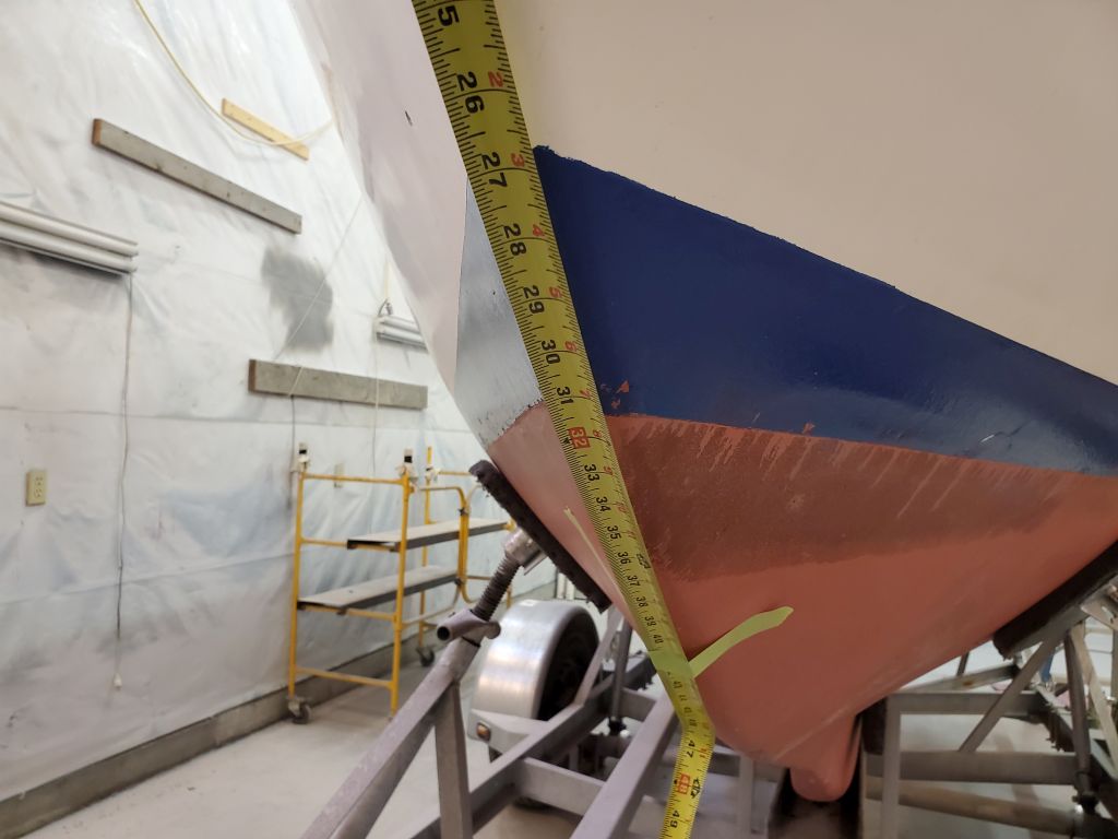
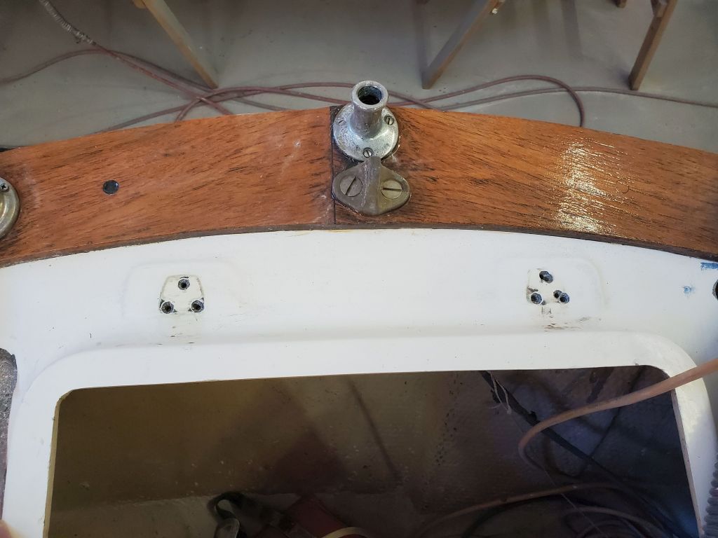
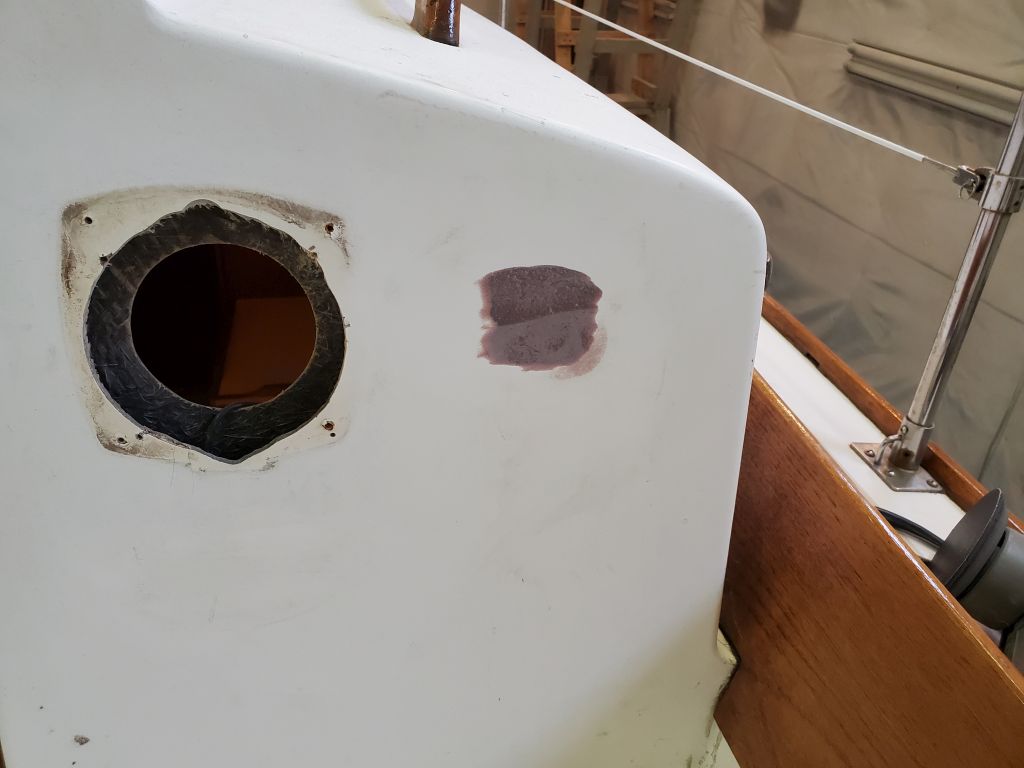
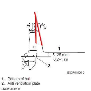
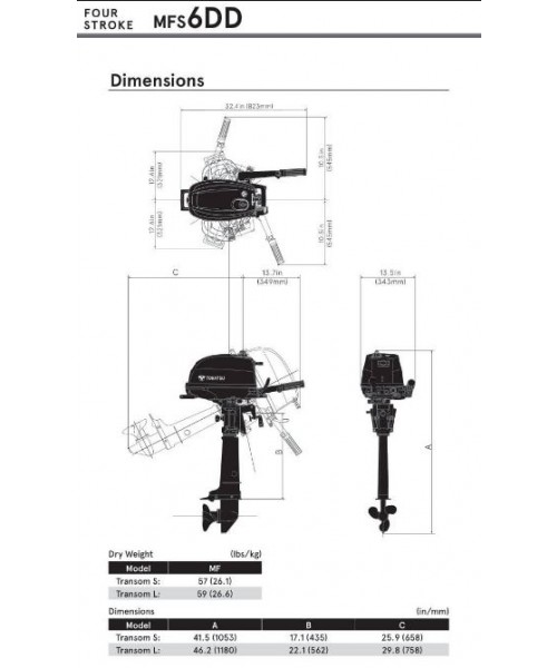
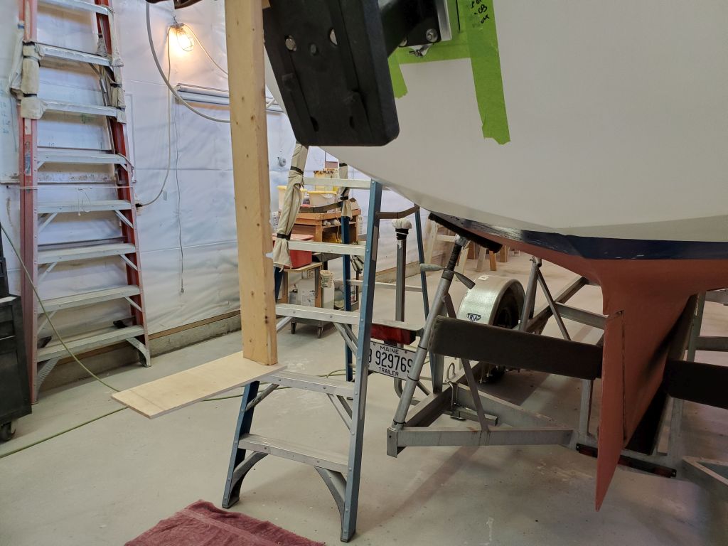
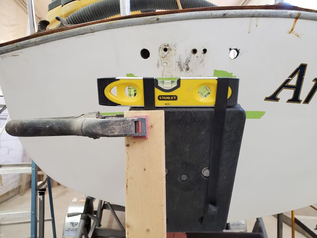
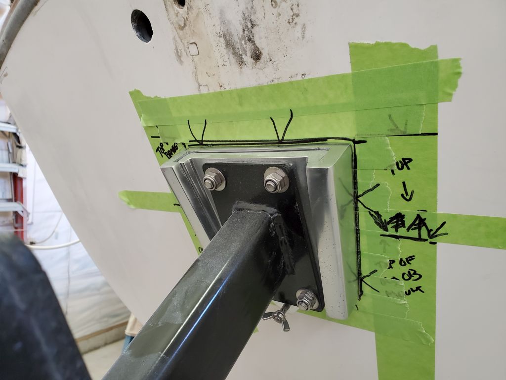
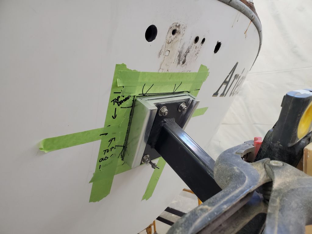
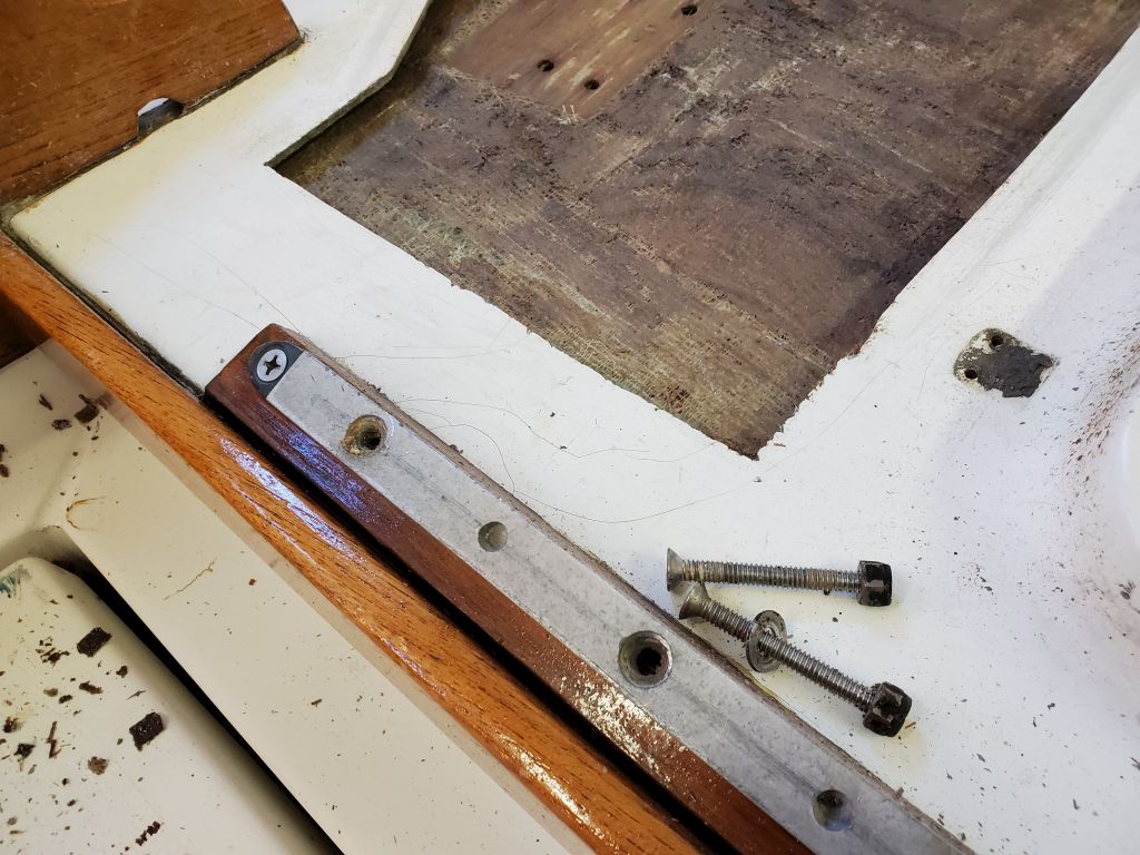
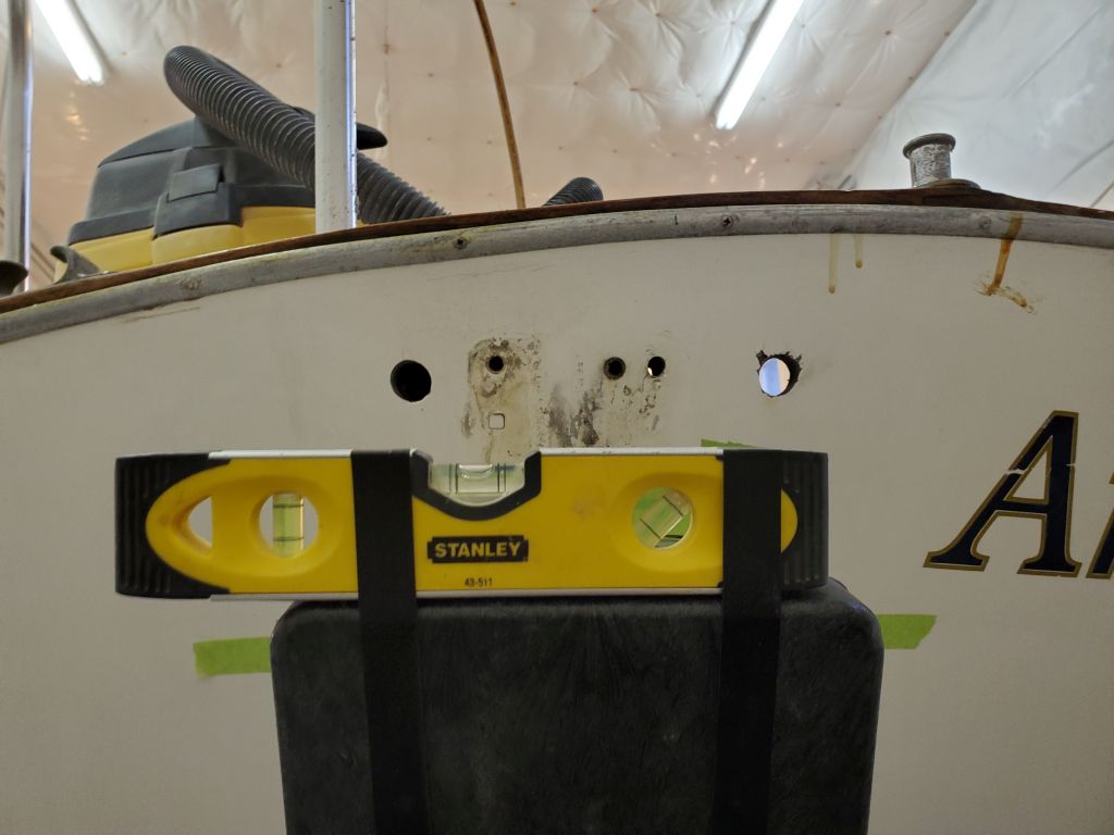
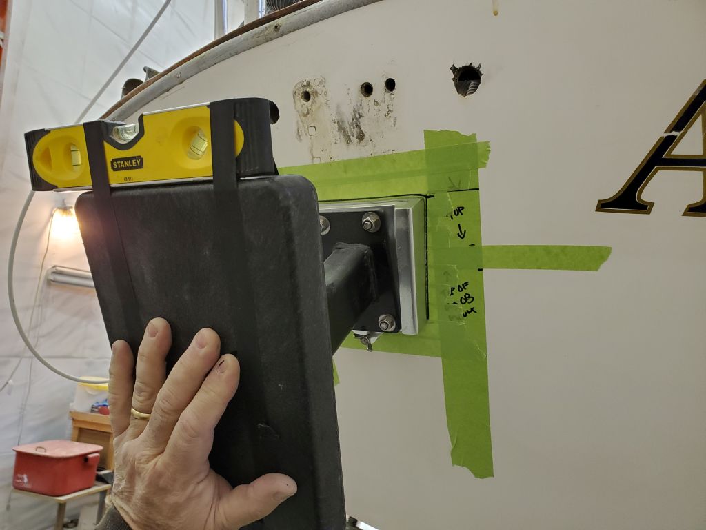
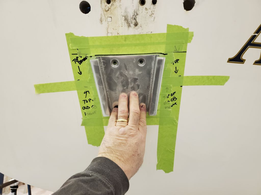
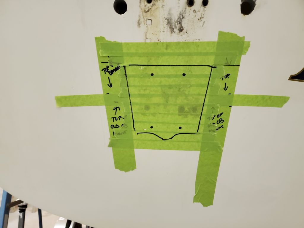
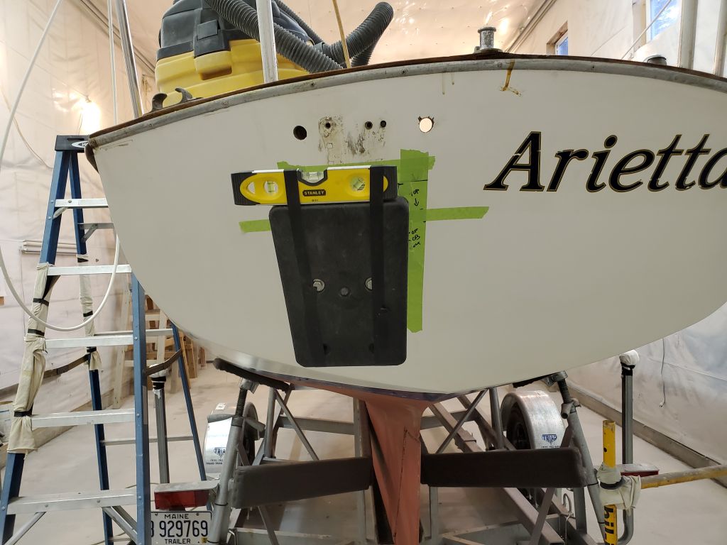
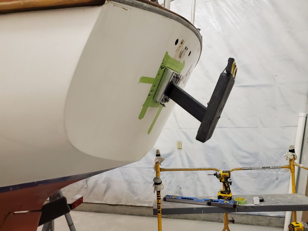
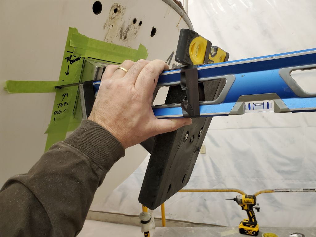
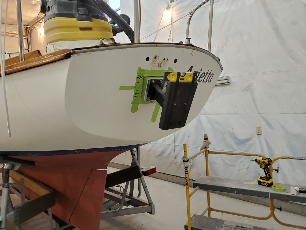
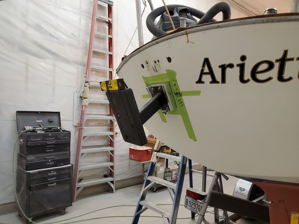
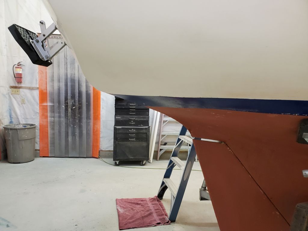
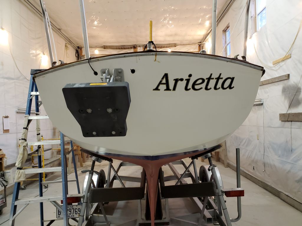
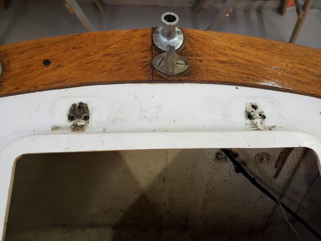
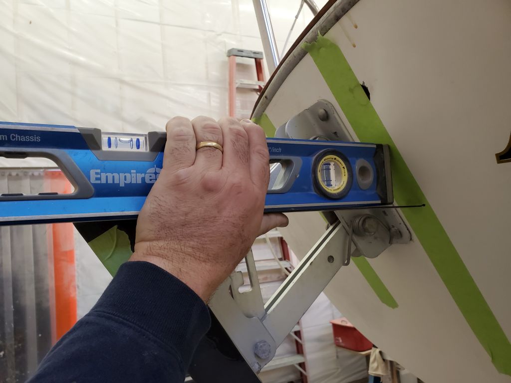
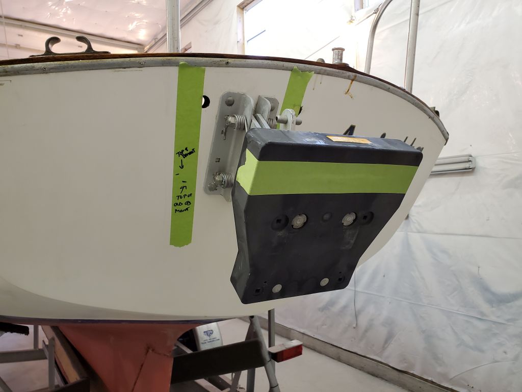
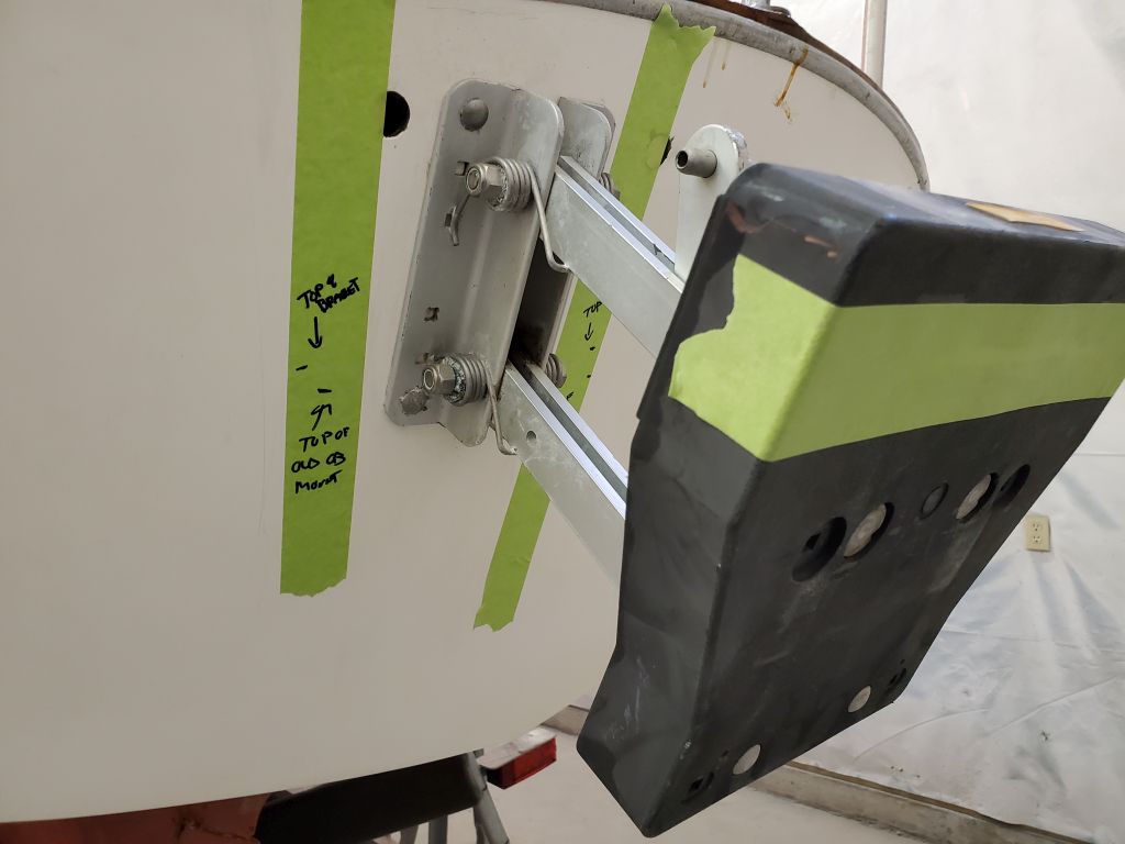
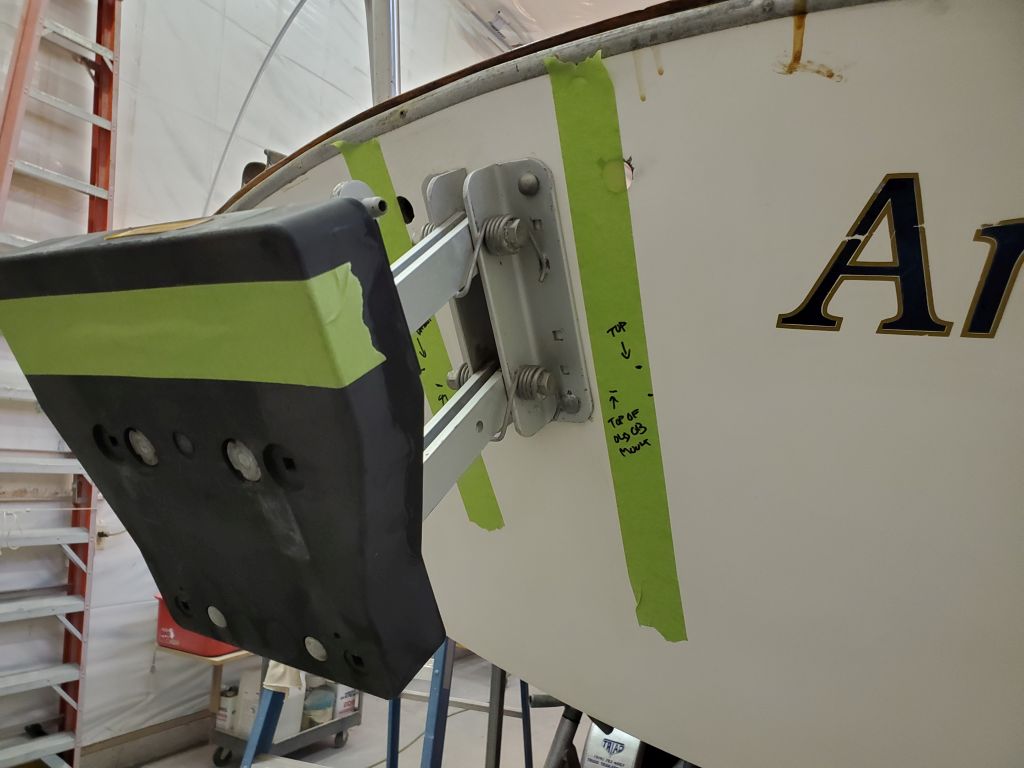
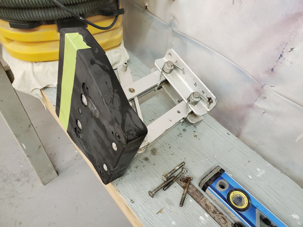
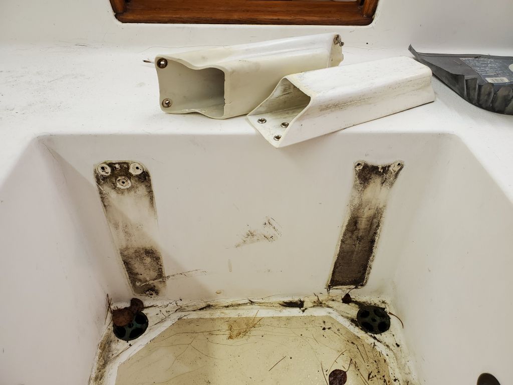
Next, I removed the old outboard bracket, which was secured with four carriage bolts through a reinforced area of the transom. But before I removed it, I made some notes on the height of the existing bracket pad so I could properly locate the new bracket at the right height later. For this, I used a level to transfer the height of the top edge of the old pad, plus another mark showing where the old outboard’s mounting bracket had actually been on the pad, as there was a slight discoloration and depression visible in the pad. These two pairs of marks would help determine the location of the new bracket soon.
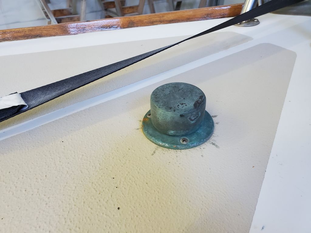
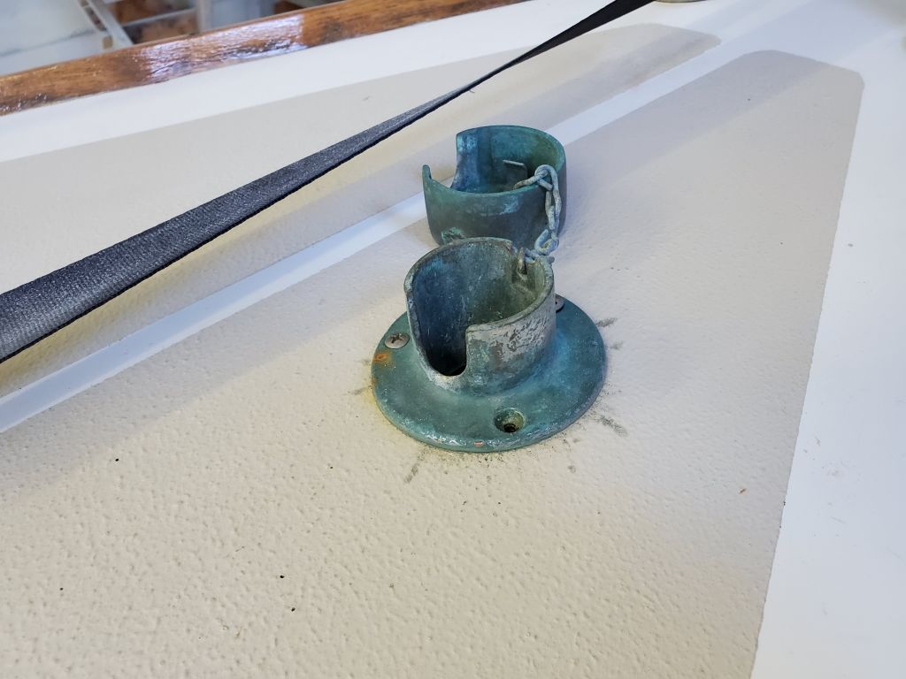
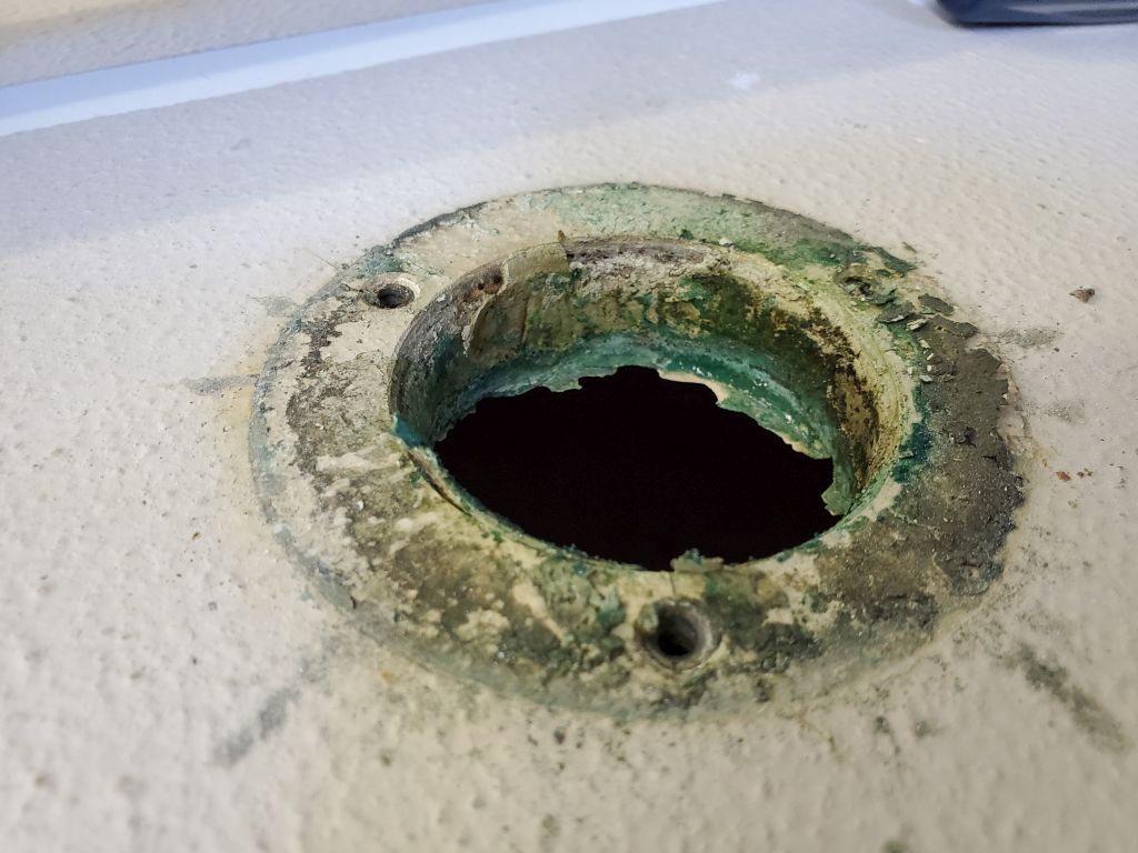
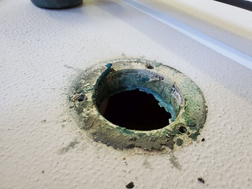
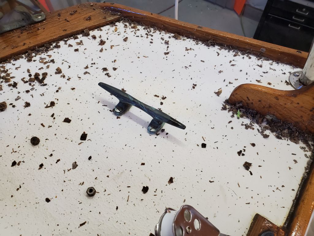
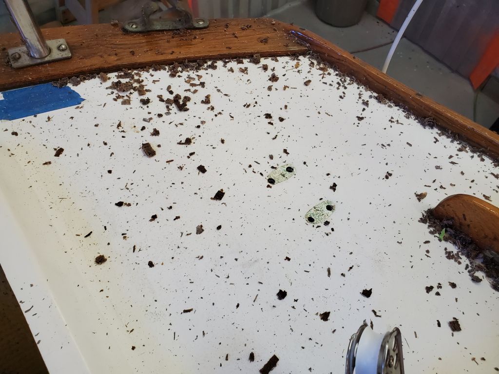
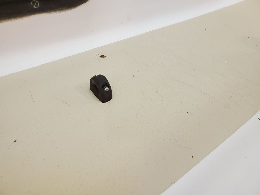
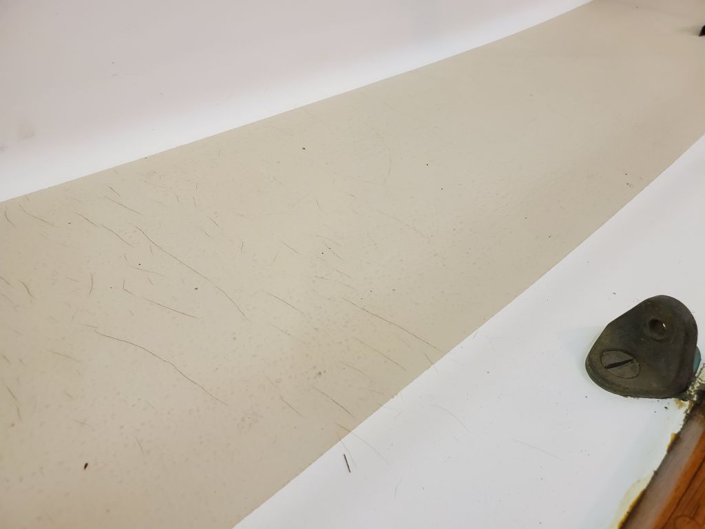
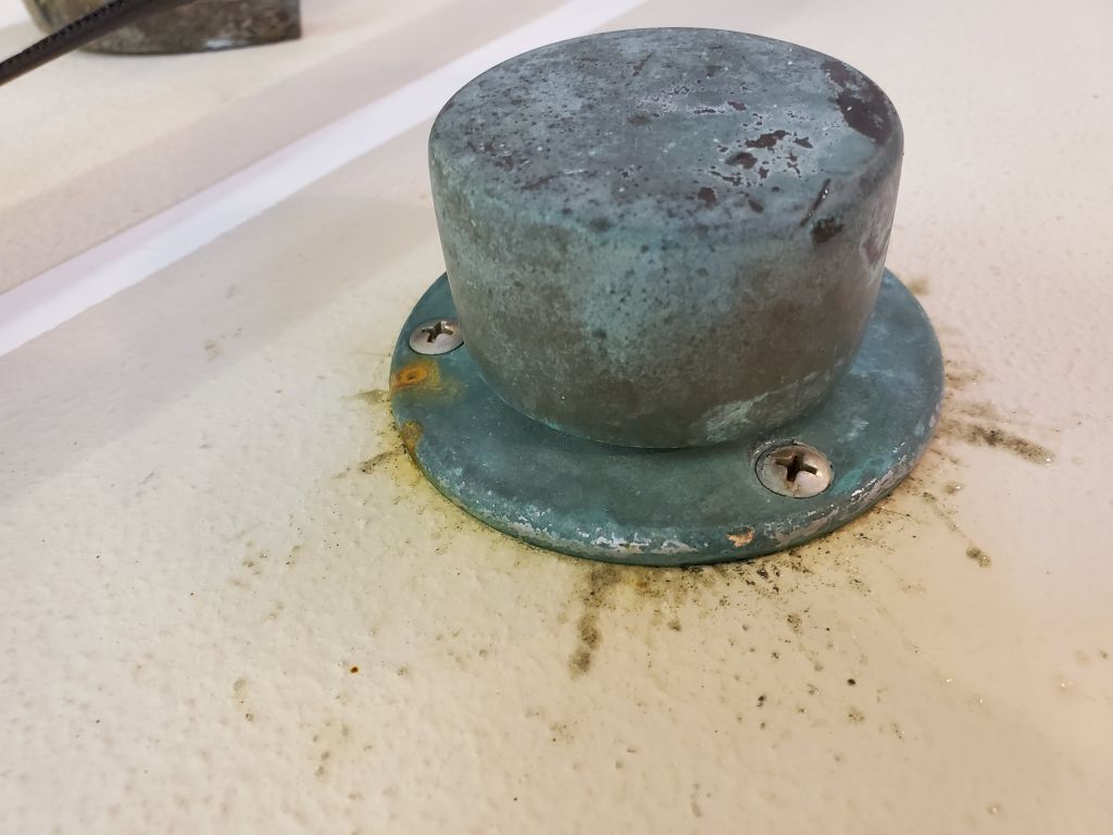
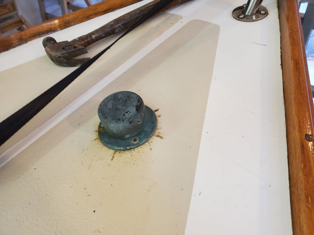
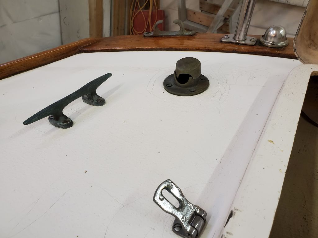
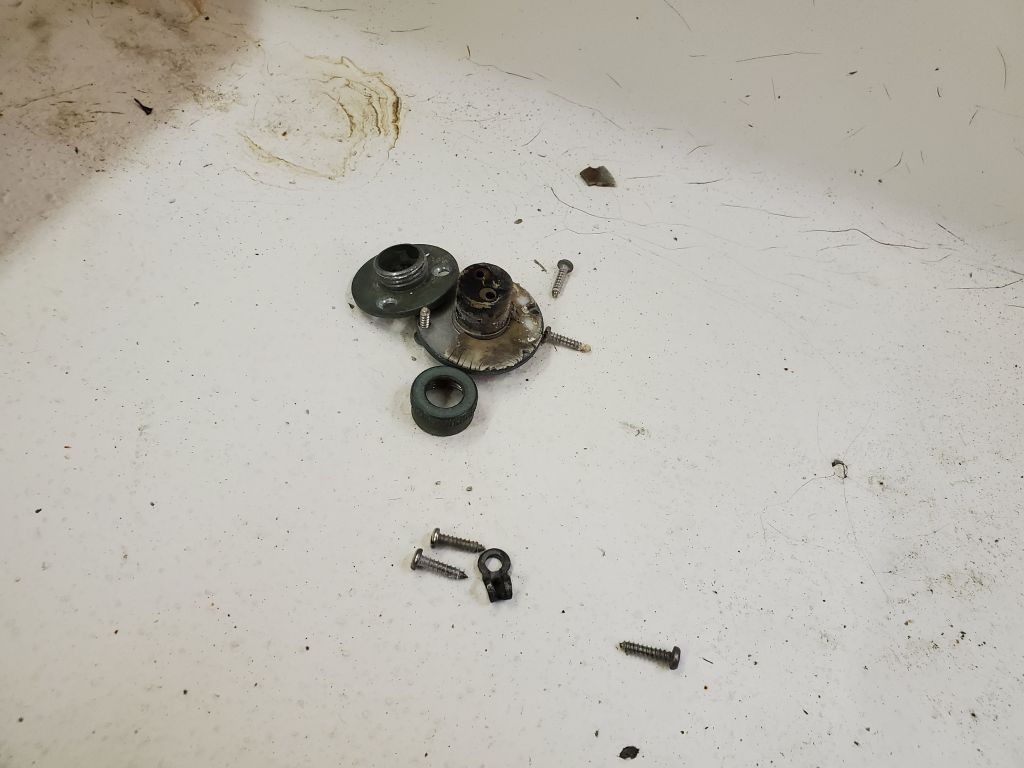
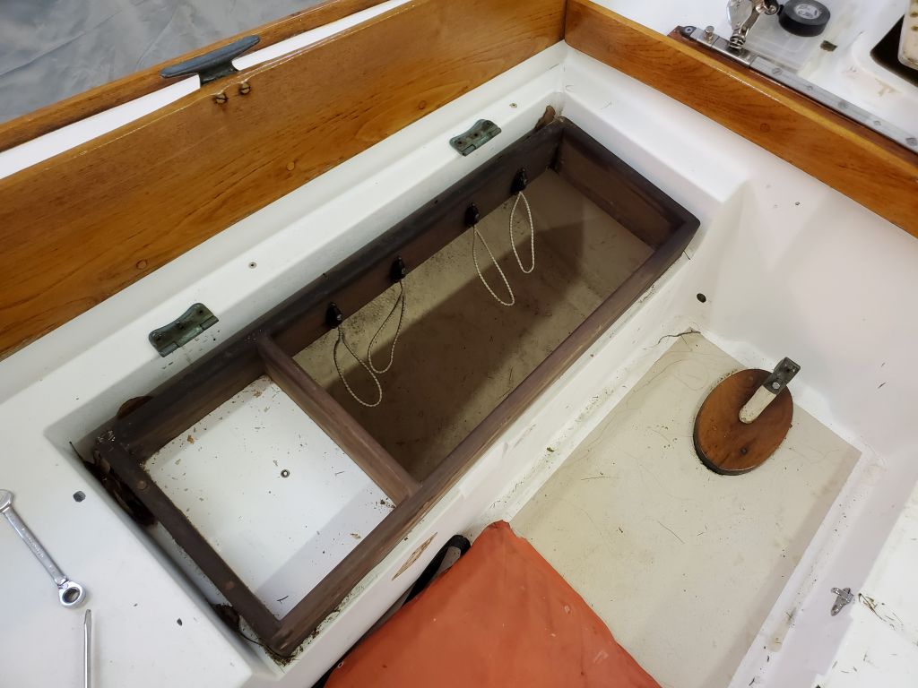
Continuing in the area, to prepare for the deck repairs, I removed an anchor hawse from the starboard poopdeck (not to be replaced later), a hasp from the lazarette hatch, and the starboard stern cleat.
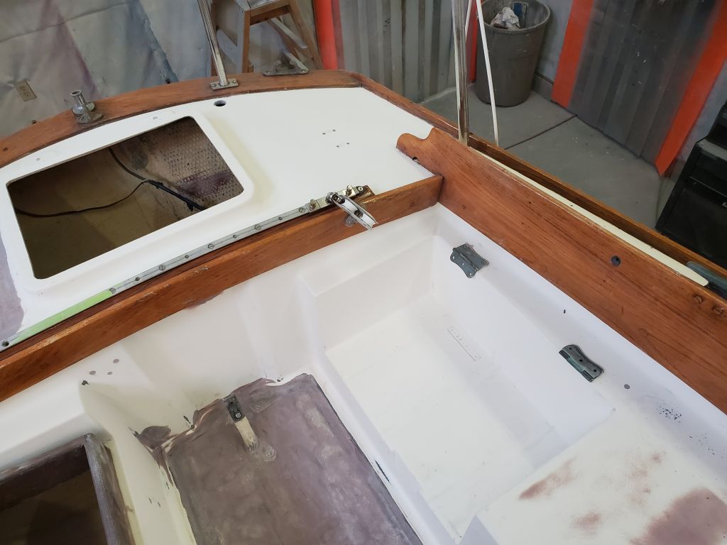
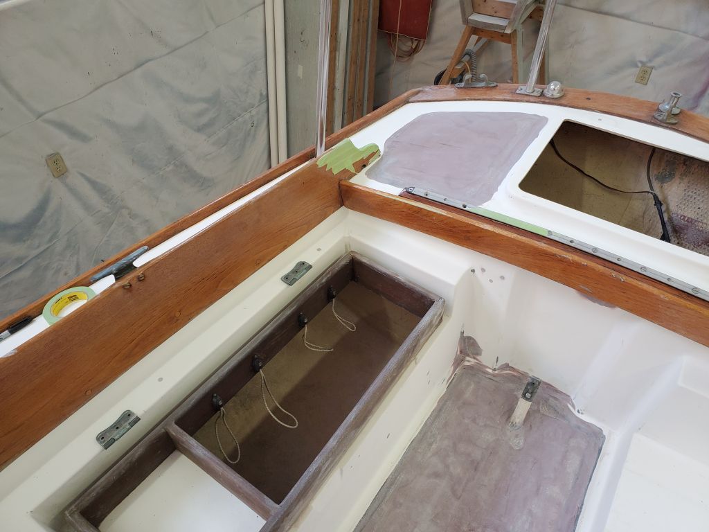
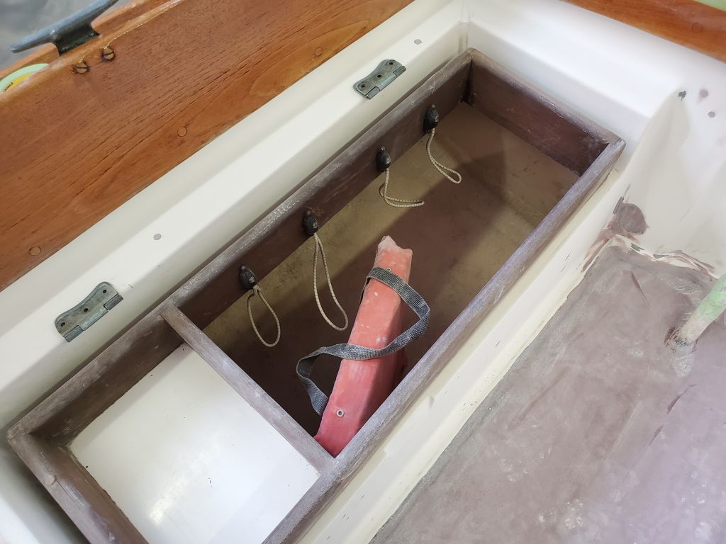
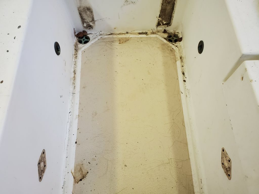
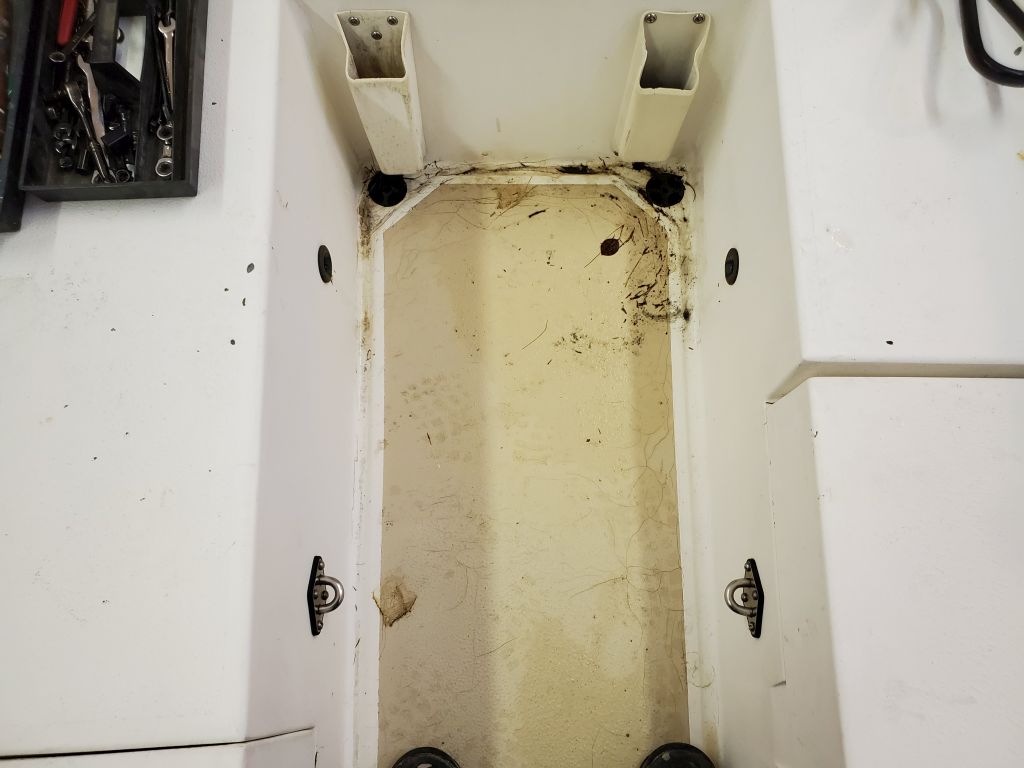
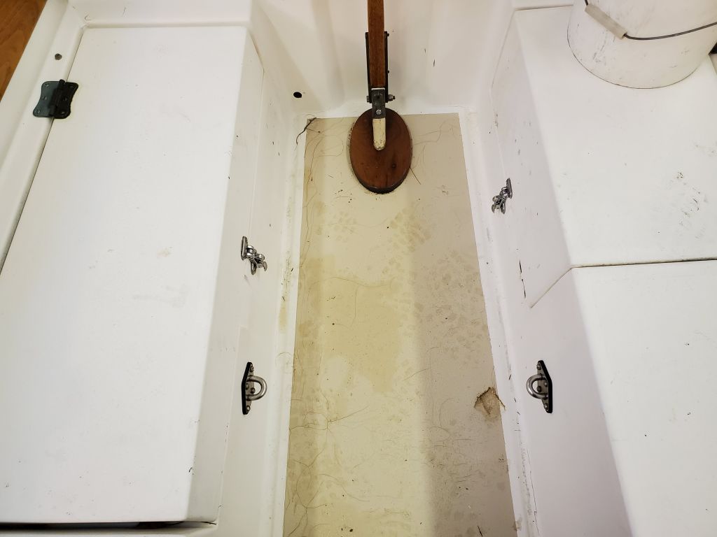
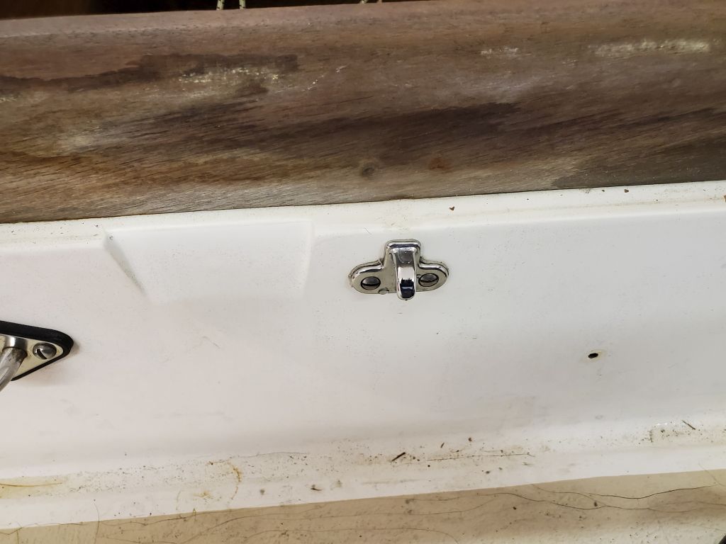
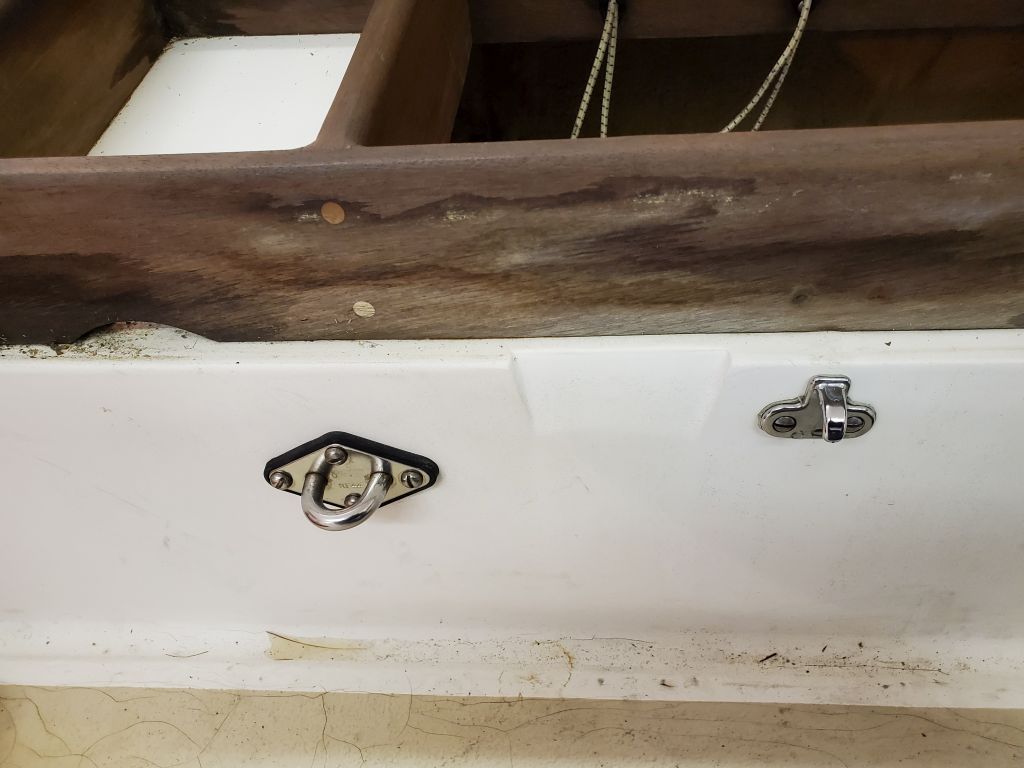
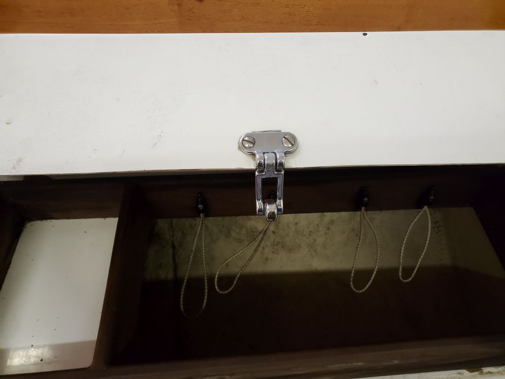
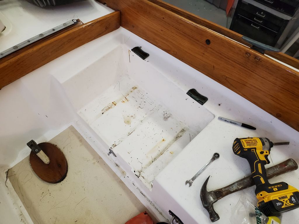
In the cockpit, I removed all the hardware I could, including cockpit locker lid hasps and hinges, a pair of padeyes in the cockpit well, some snaps from cockpit cushions, and a pair of old winch handle holders forward. I decided to leave the locker lid hinges in place on the decks since access was difficult to impossible, and the exisiting fasteners were extremely long and gave all indications of being recalcitrant to remove, so I thought the potential risks and time consumption far outweighed the minimal benefits of removal in this case.
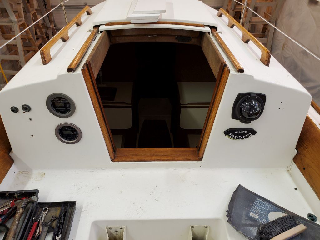
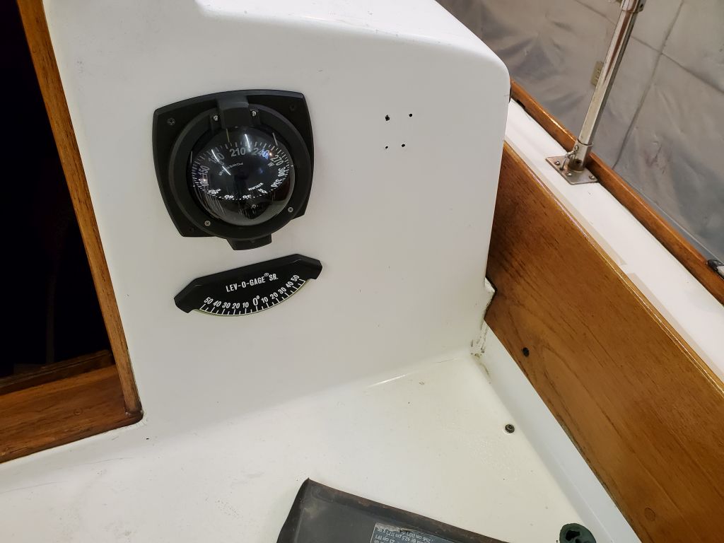
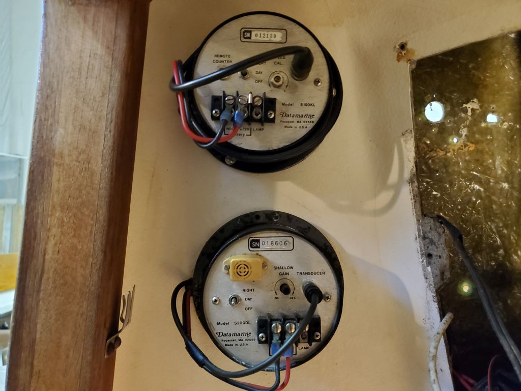
Preparing for the eventual paint work, I removed the compass and sailing instruments from the forward end of the cockpit, setting them aside for later reinstallation.
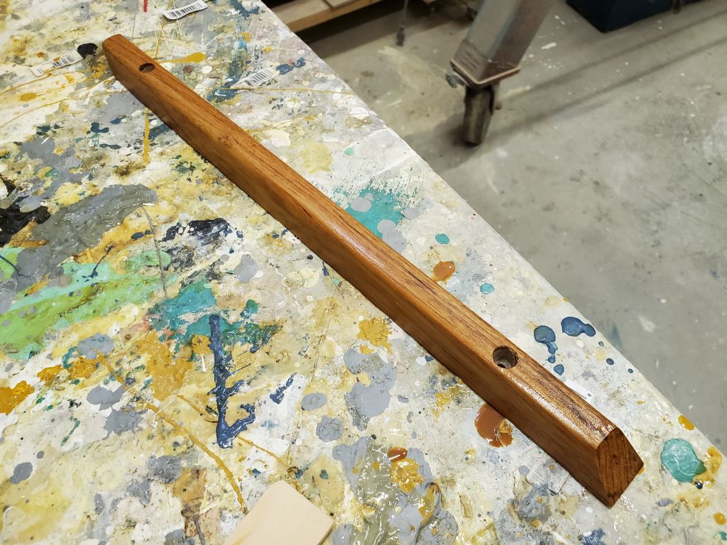
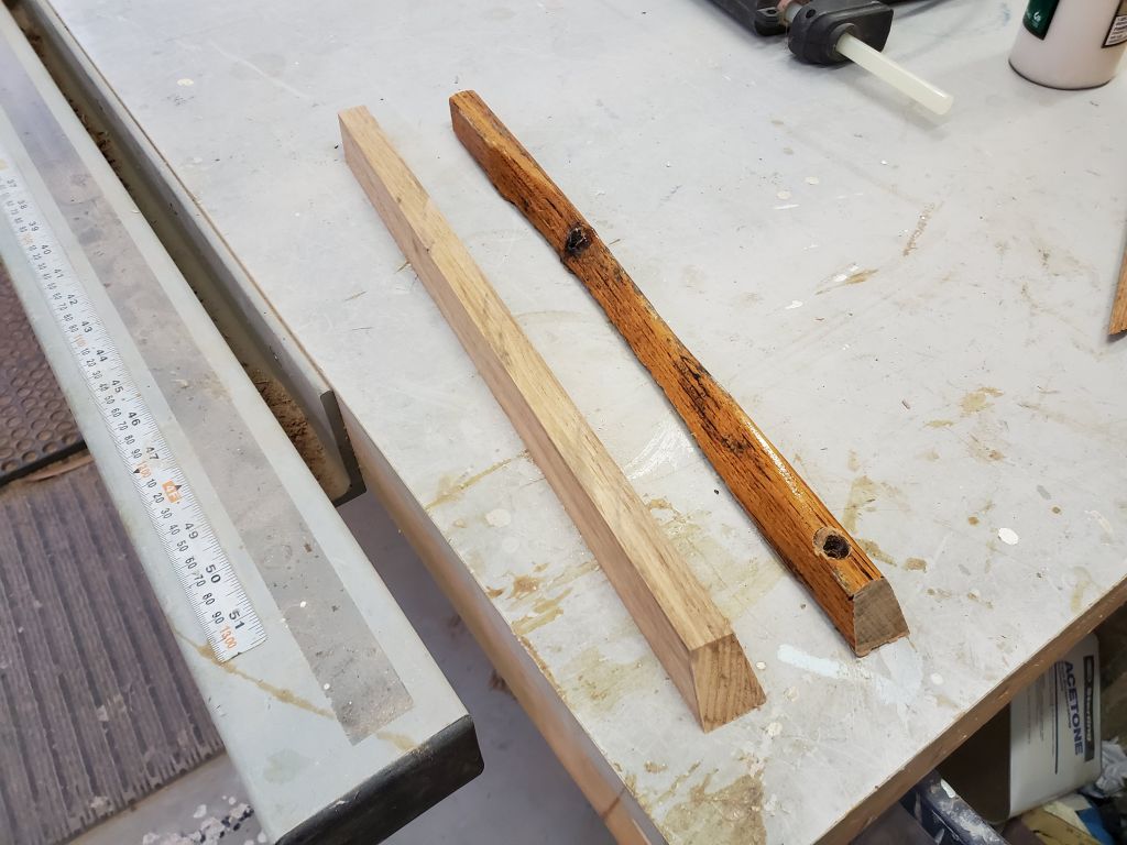
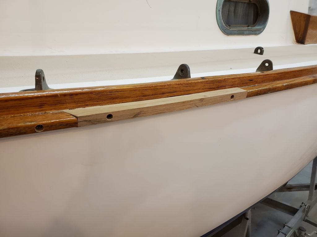
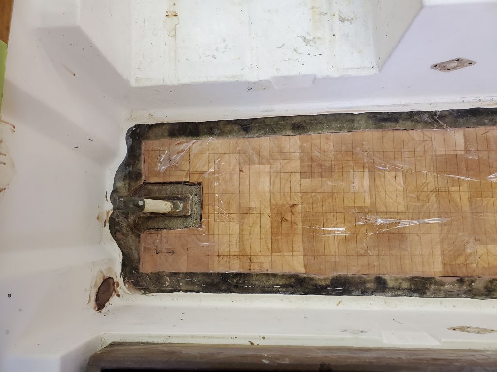
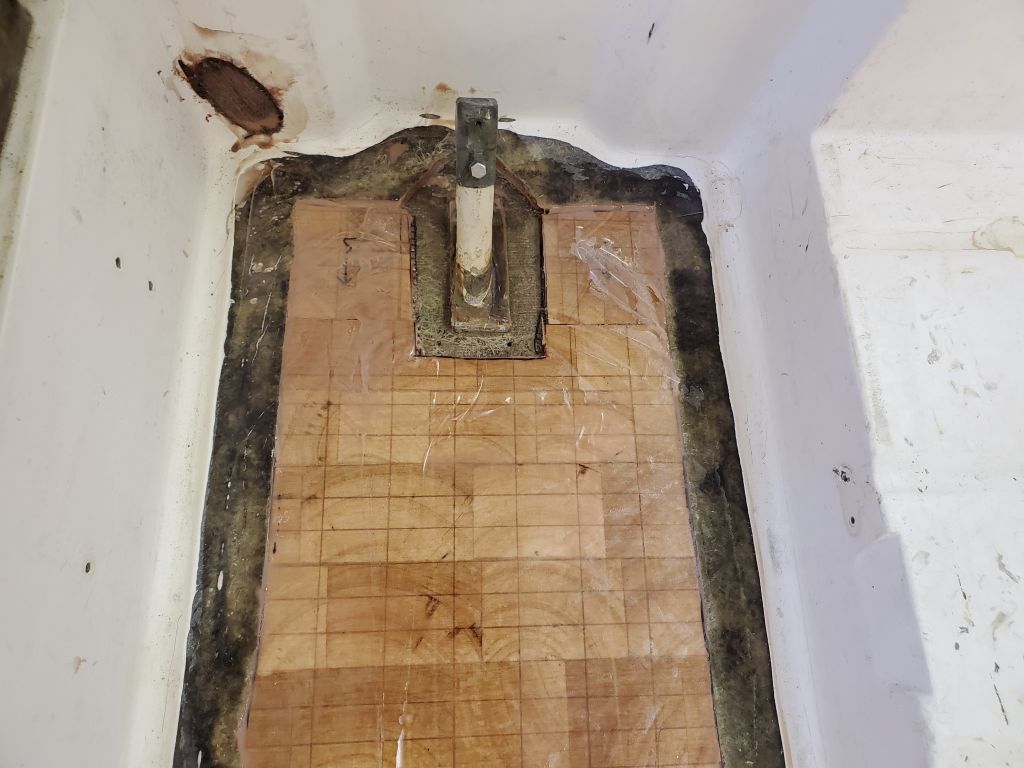
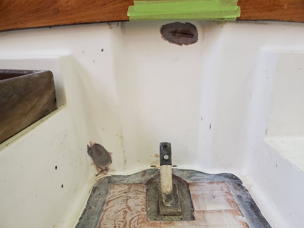
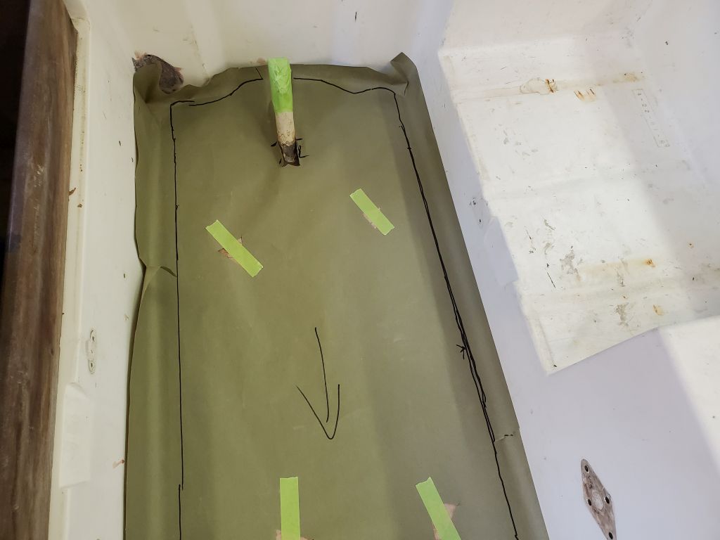
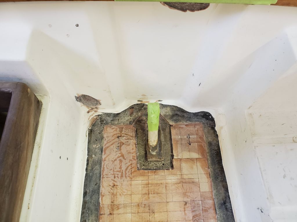
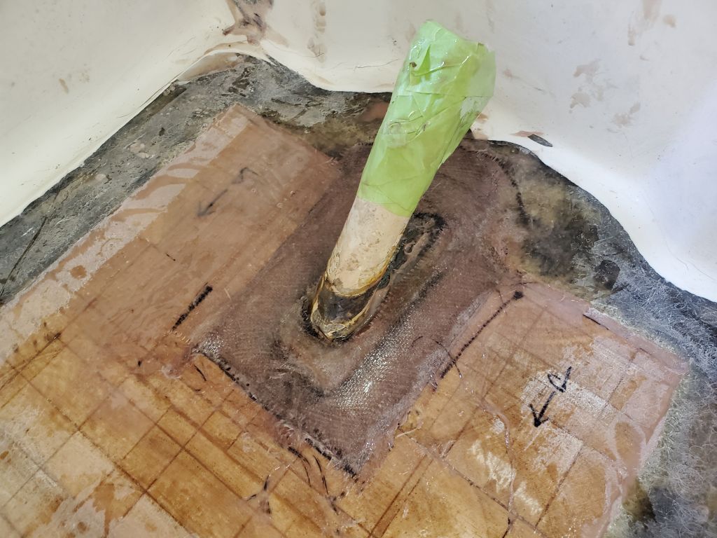
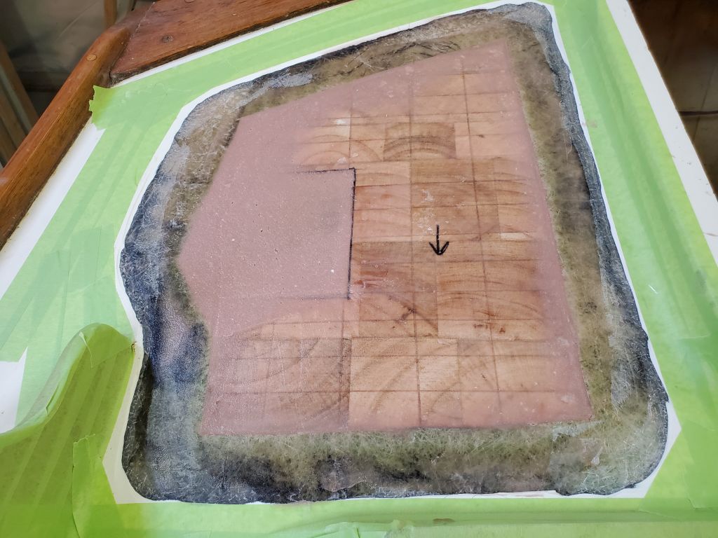
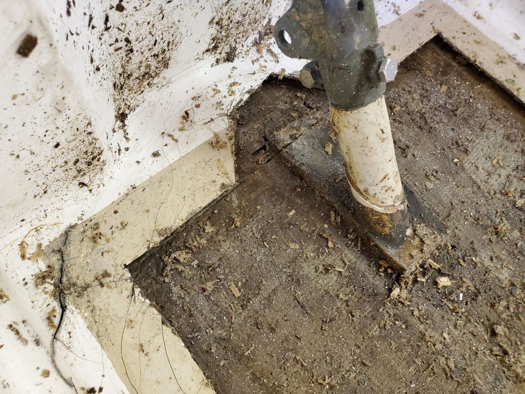
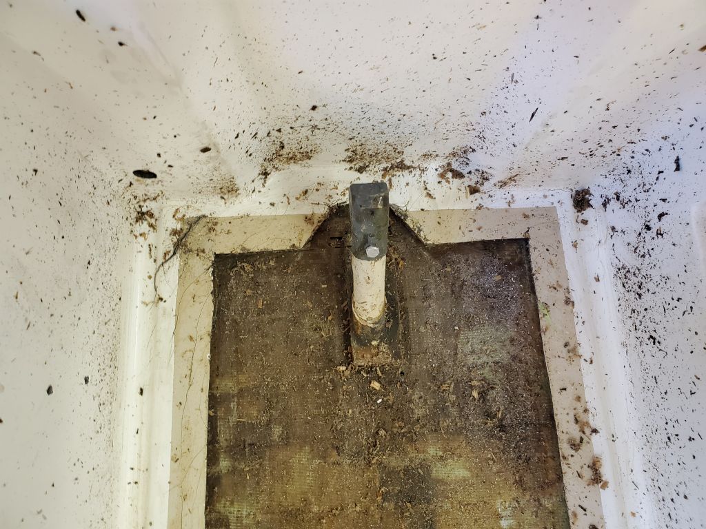
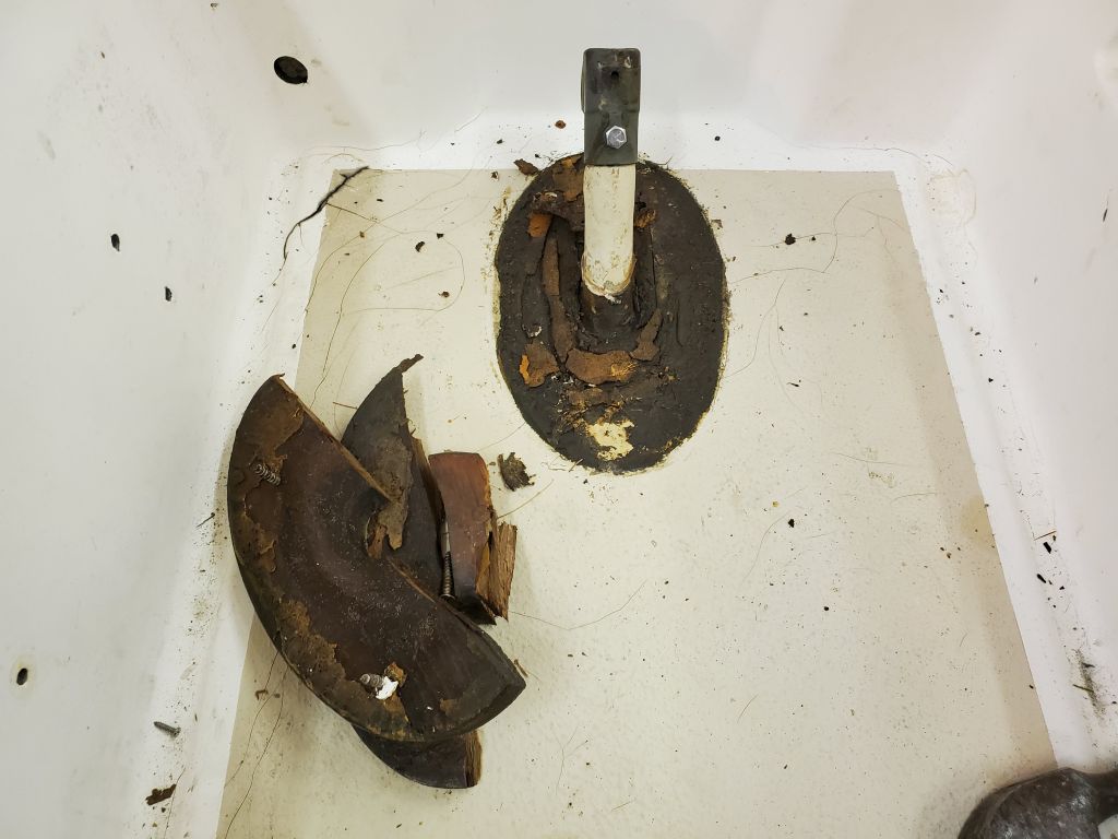
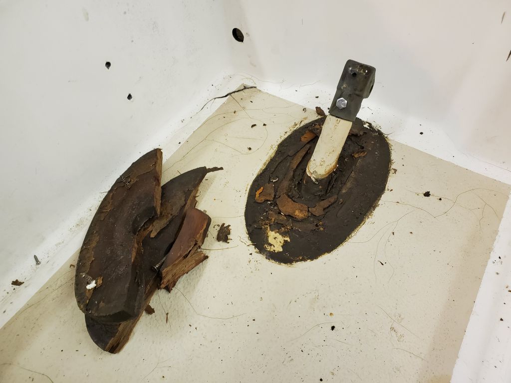
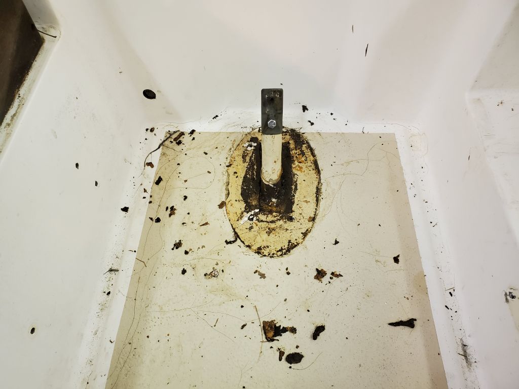
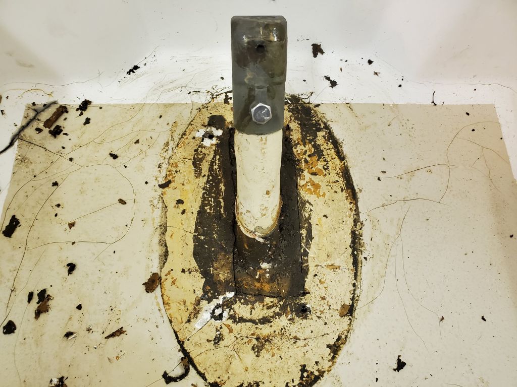
Finally, I removed a wooden trim block surrounding the rudderpost, which opened up access for the upcoming repair, and, to round out the day, I collected tools and equipment so I could get started on the deck repairs next time.
Total time billed on this job today: 6 hours
0600 Weather Observation: 58°, light rain. Forecast for the day: Cloudy, rain, and showers, 60°