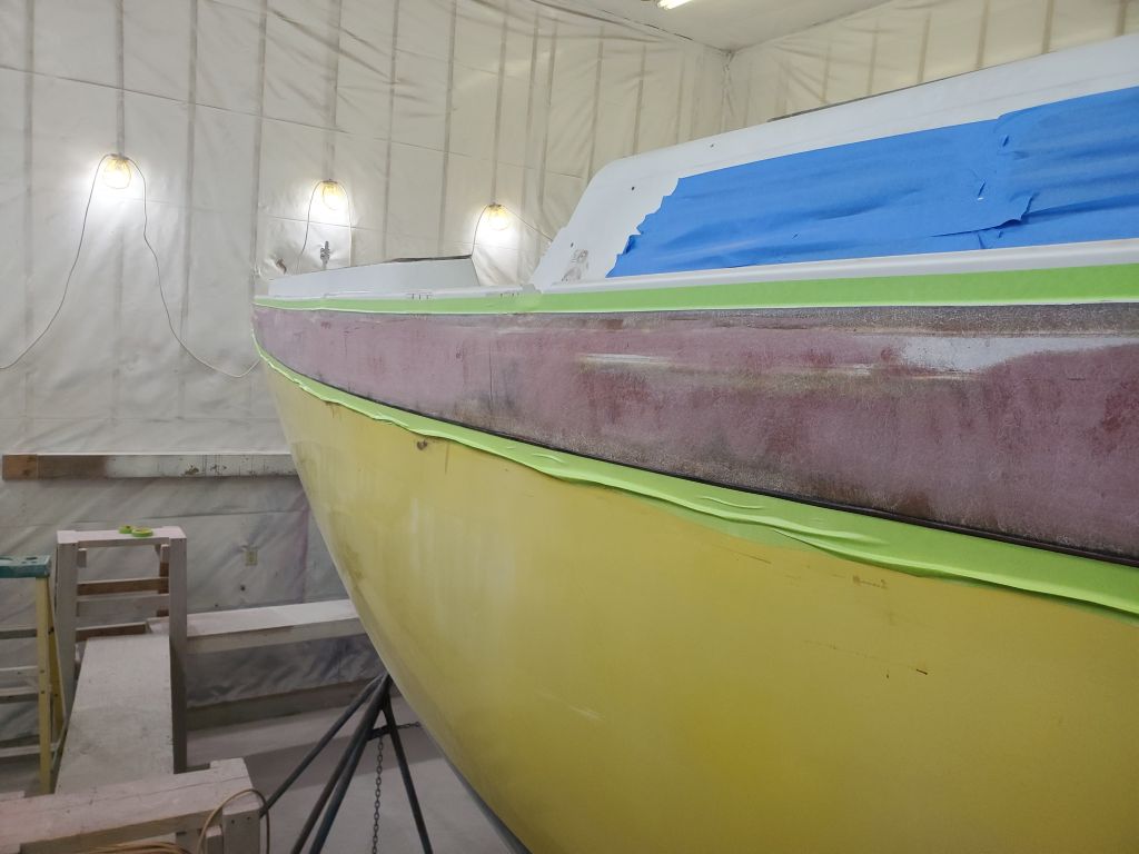
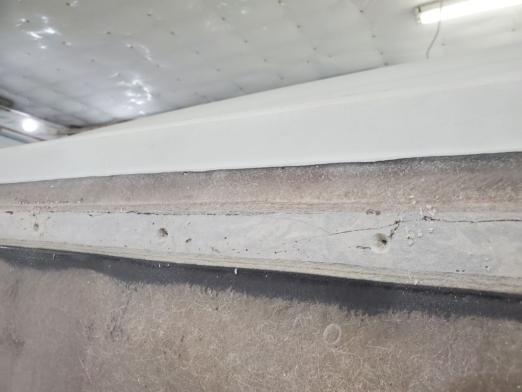
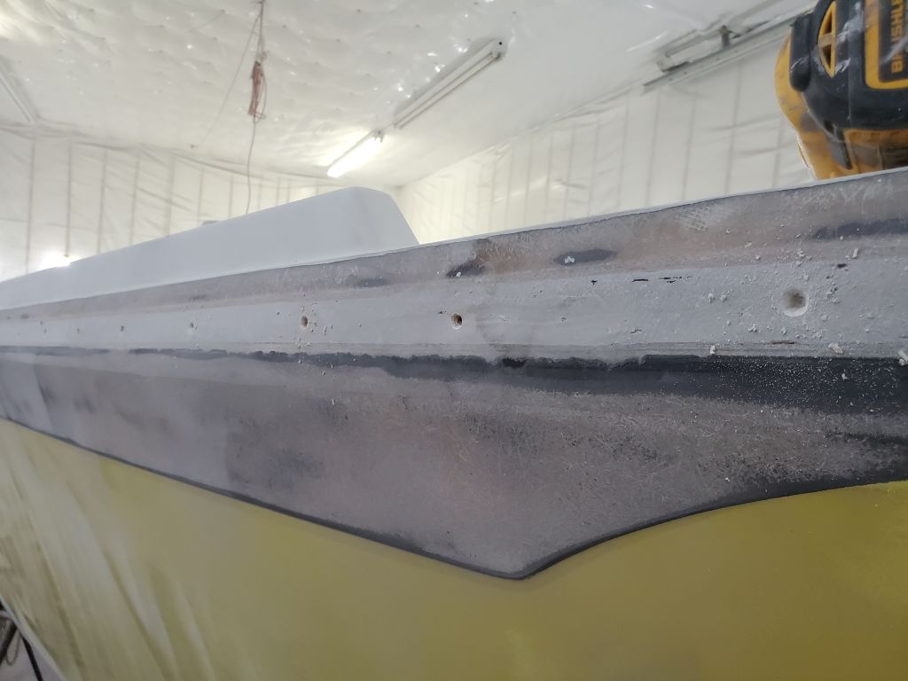
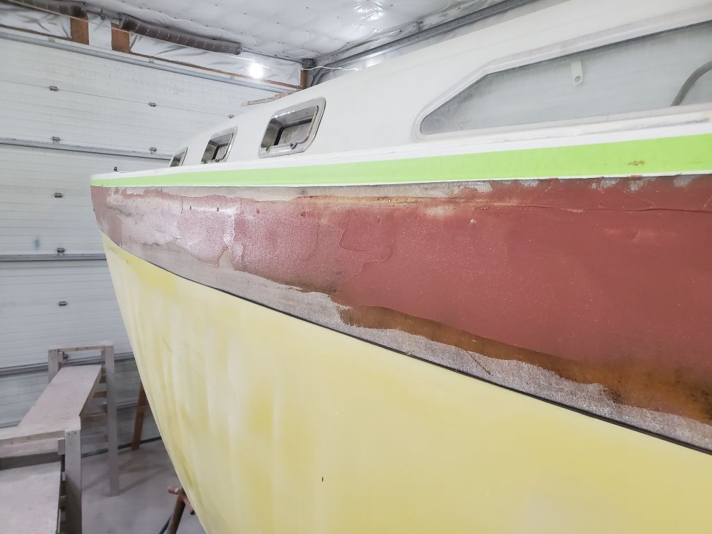
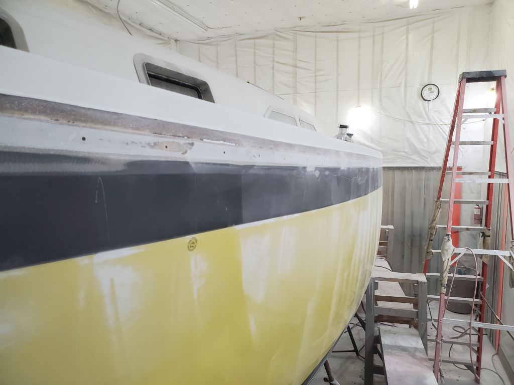
Another round of sanding brought the hull-deck joint to a point of readiness for the next step: fiberglassing. Since the immediate goal was an appropriately-flat, generally fair surface, but not a final finish, the few minor low spots leftover from trowel marks were either nothing to worry about, or something I could (and later would) fill with a skim of thickened epoxy before applying the tabbing.
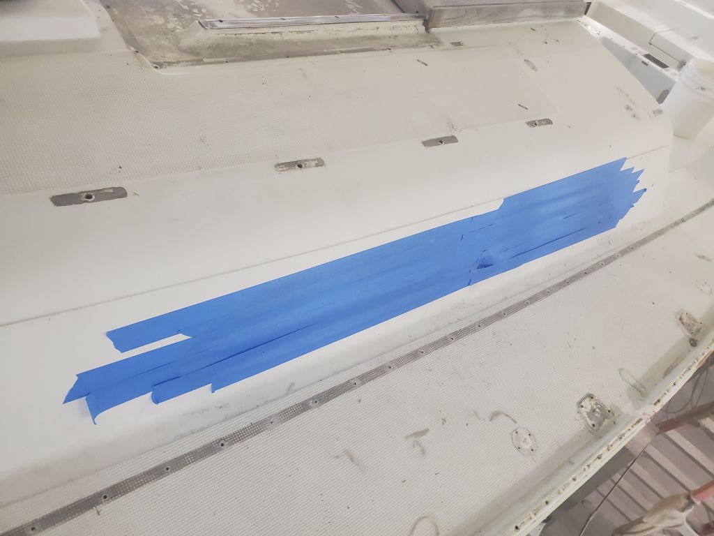
After cleaning, I applied tape to both sides of the area in question, using wider tape at the base to allow room to make a sort of drip edge to help avoid any resin runs down the topsides. A few minutes with the tape saves much potential labor in removing hardened bits of epoxy from adjacent areas.
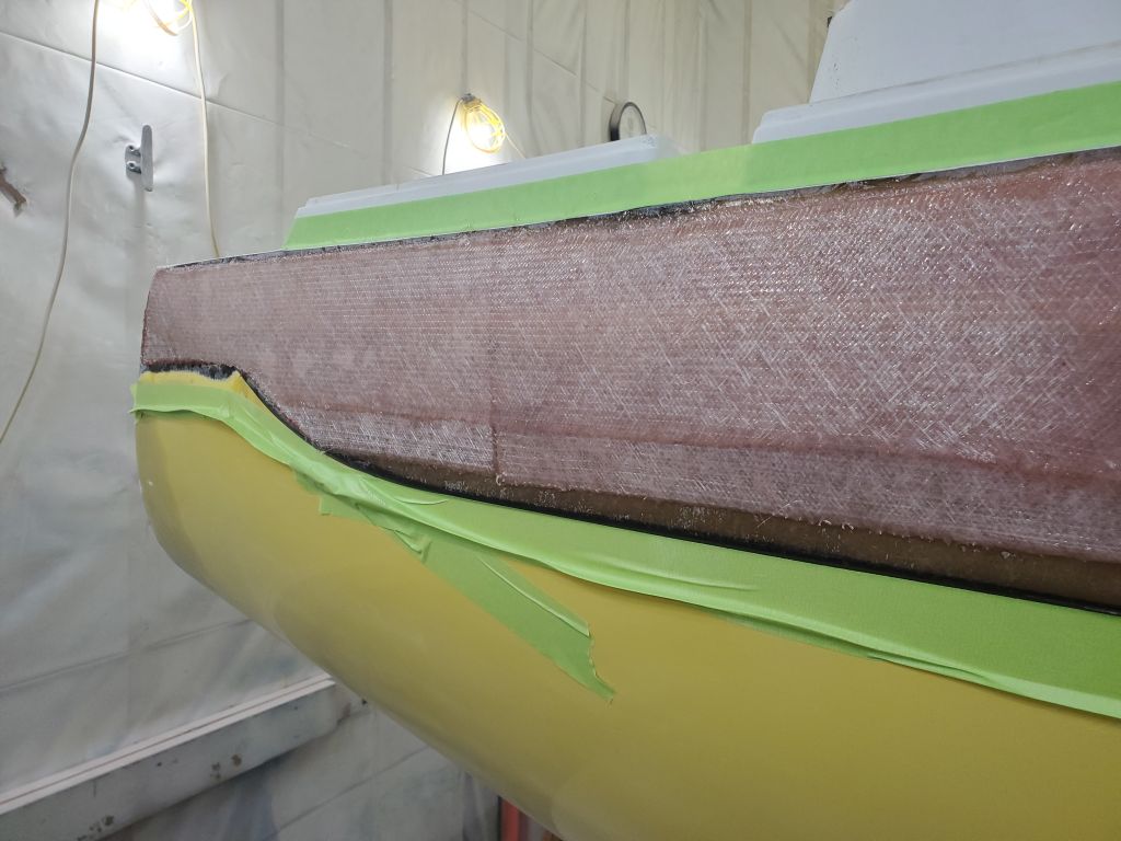
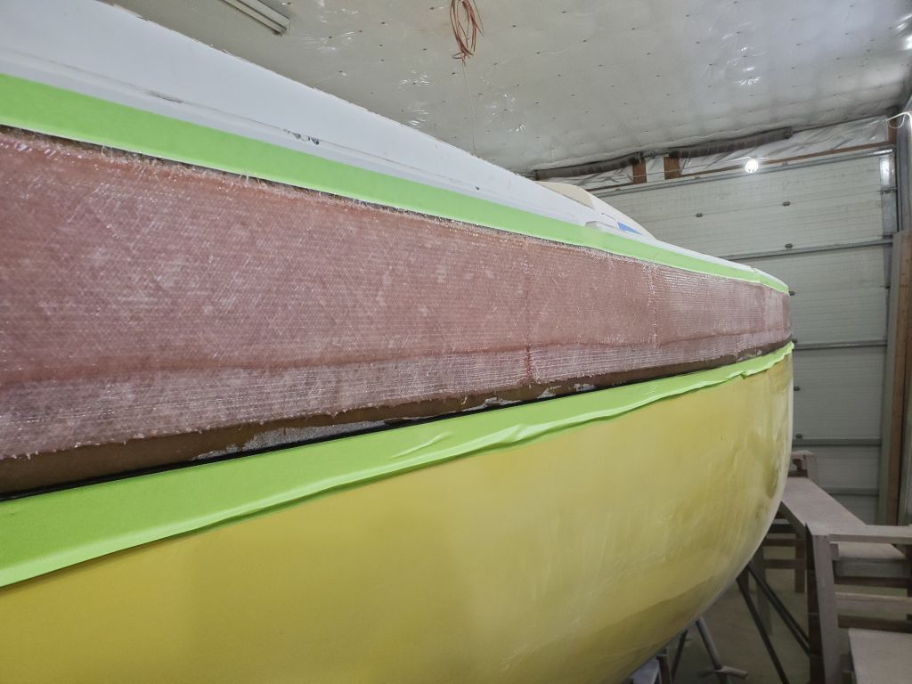
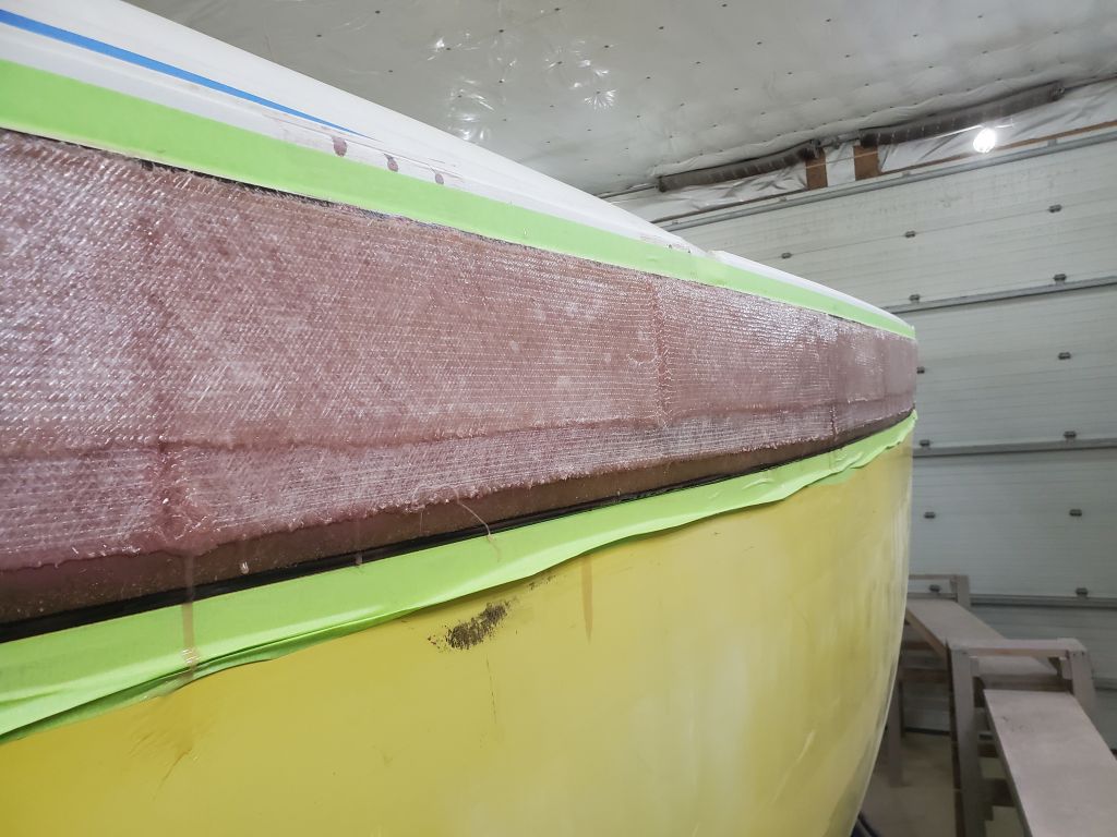
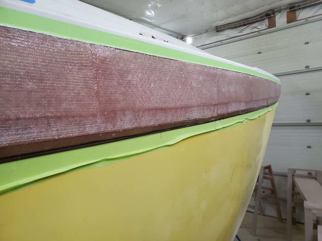
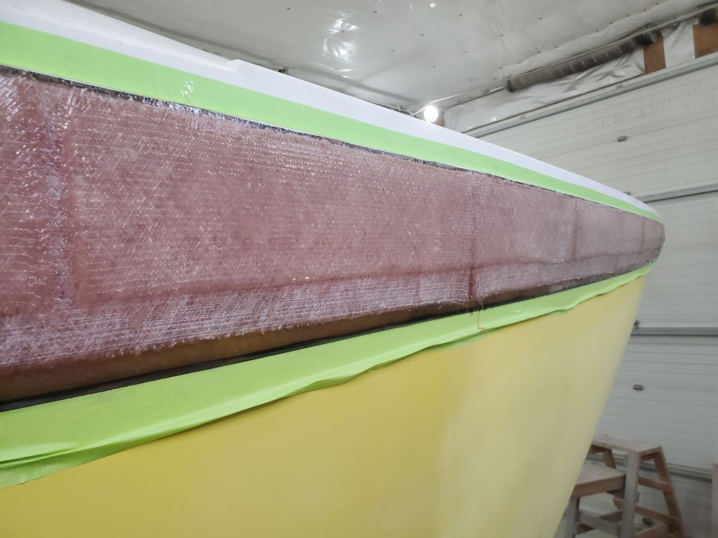
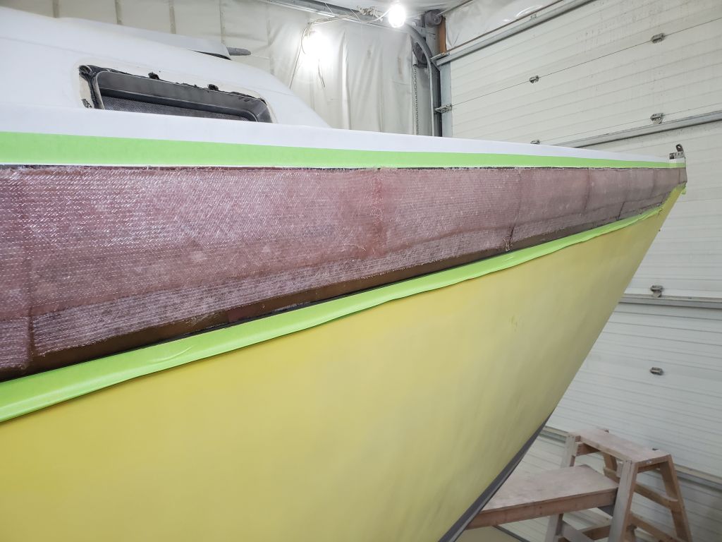
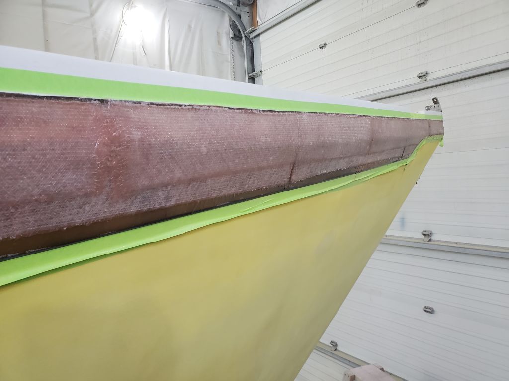
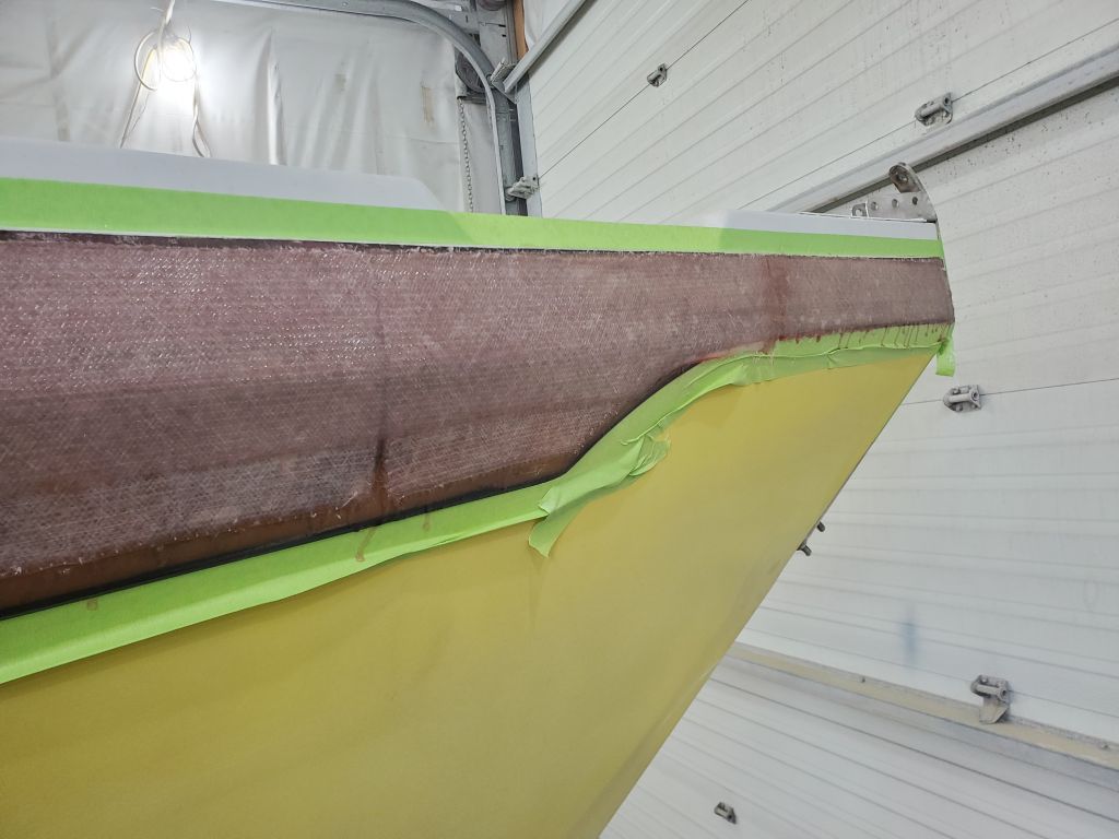
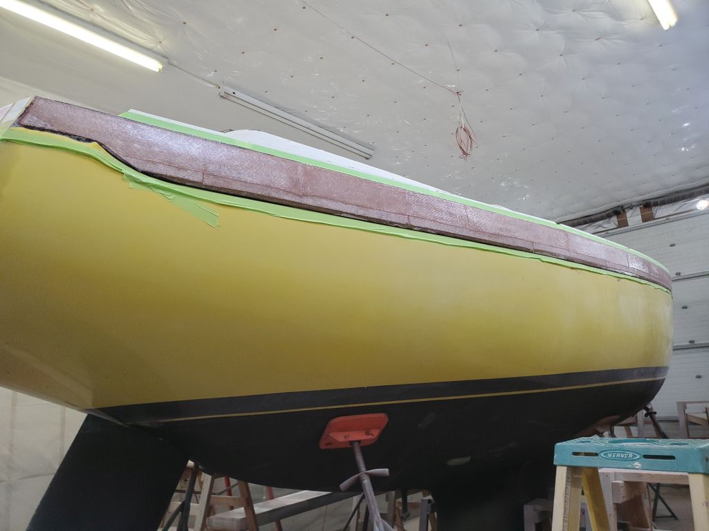
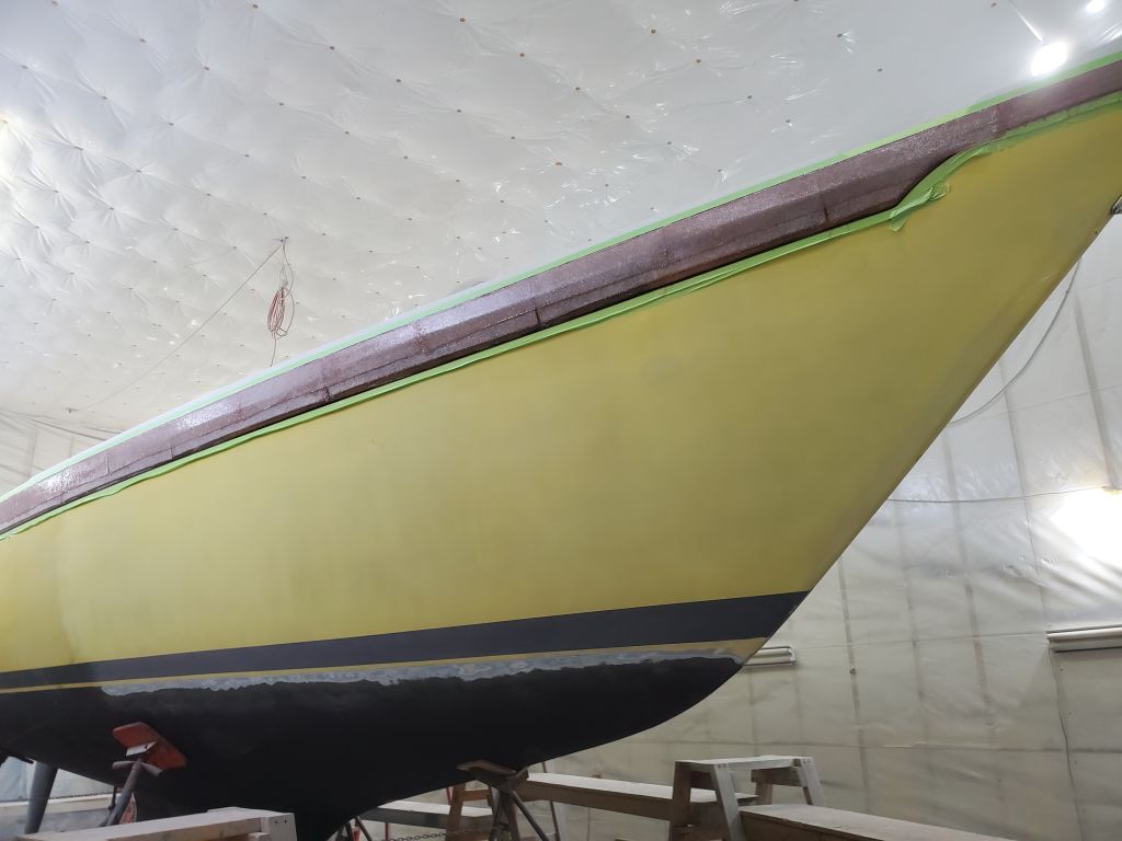
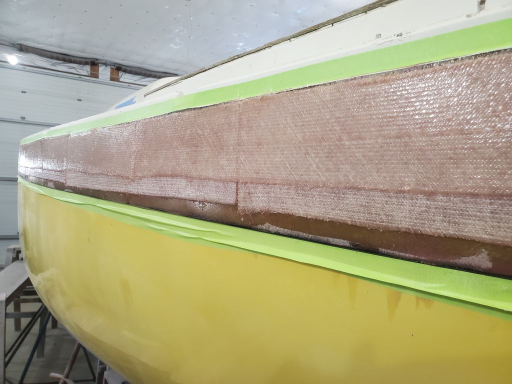
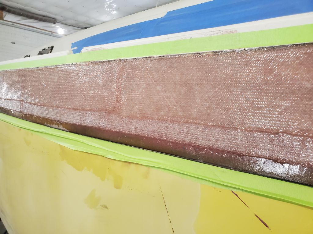
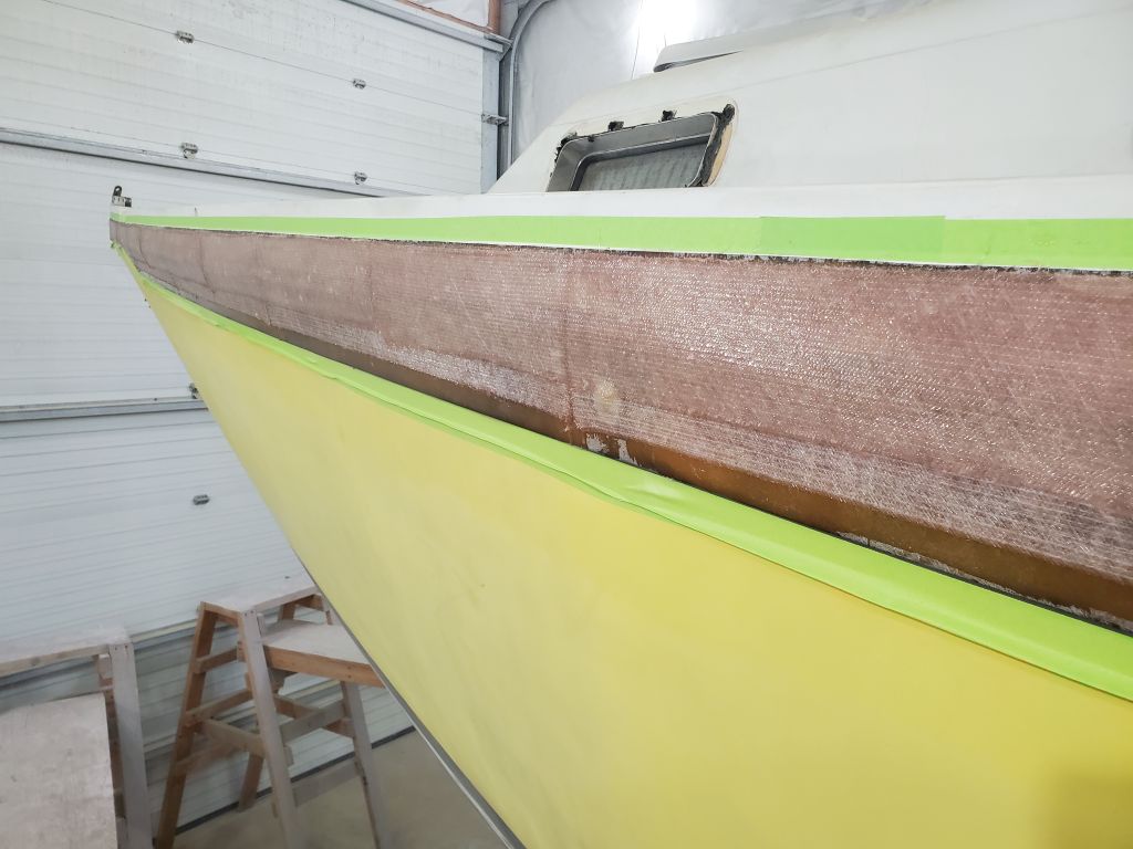
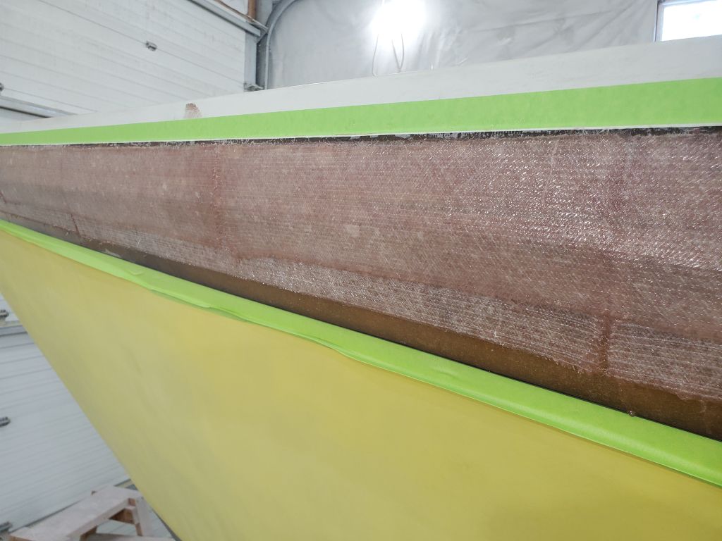
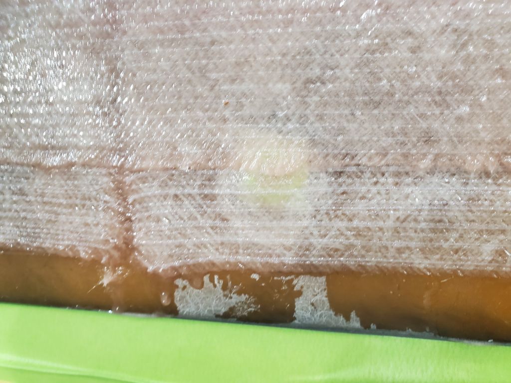
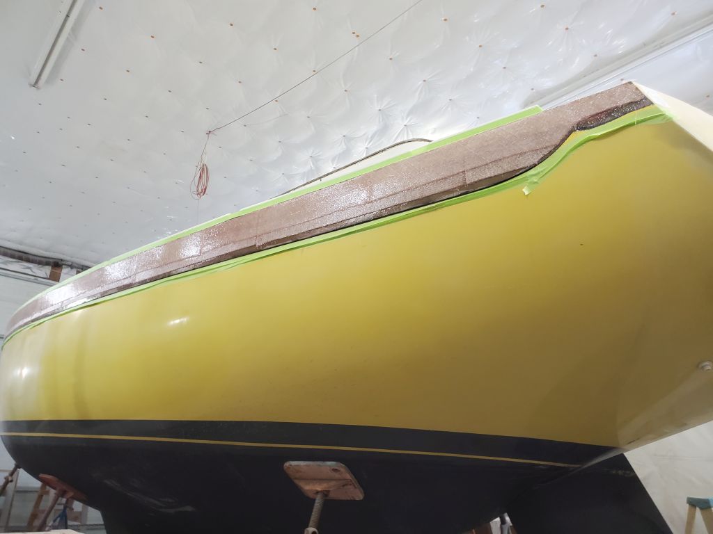
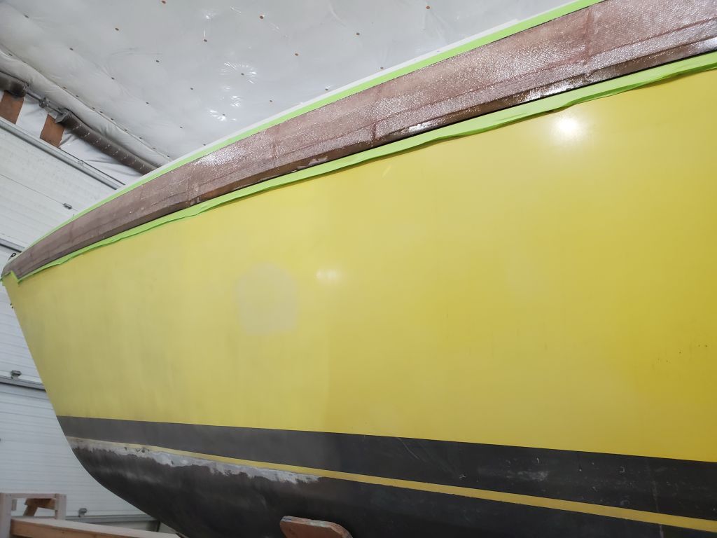
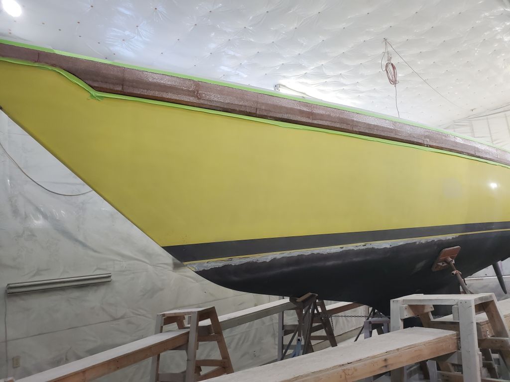
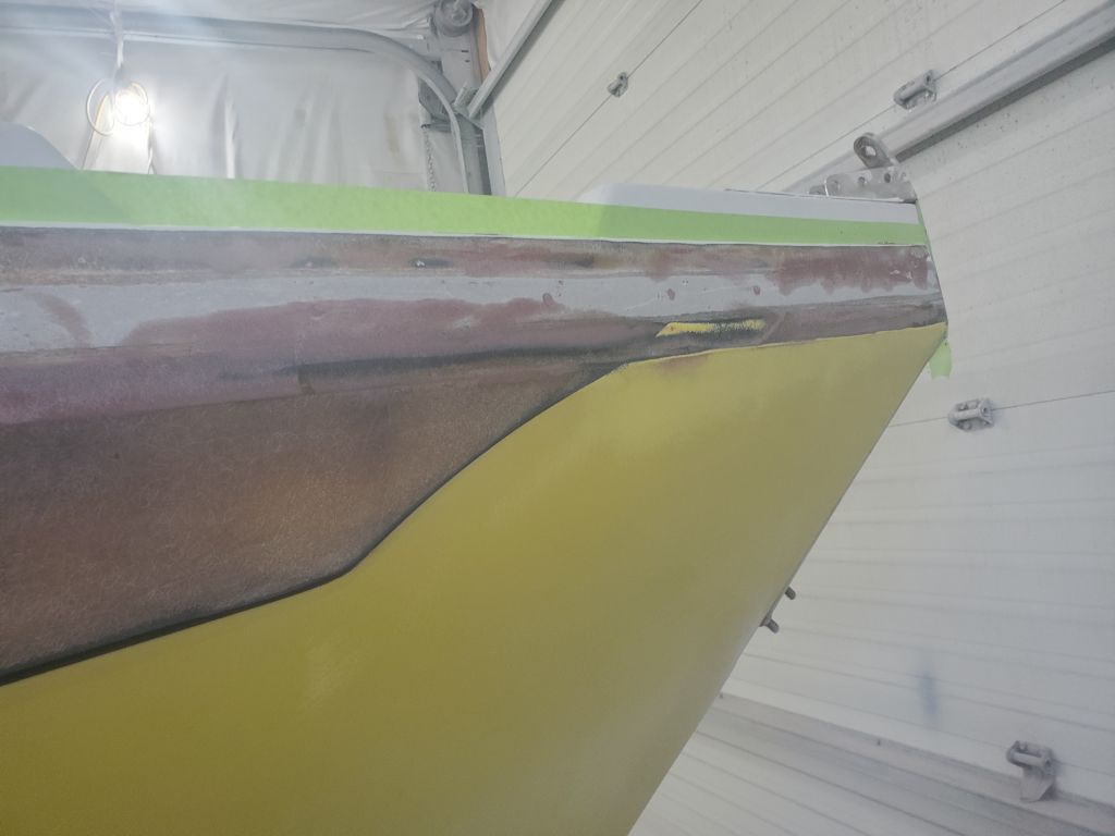
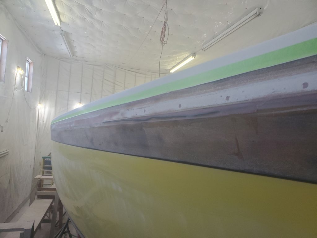
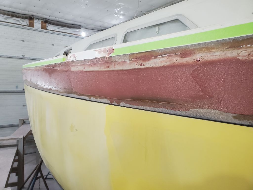
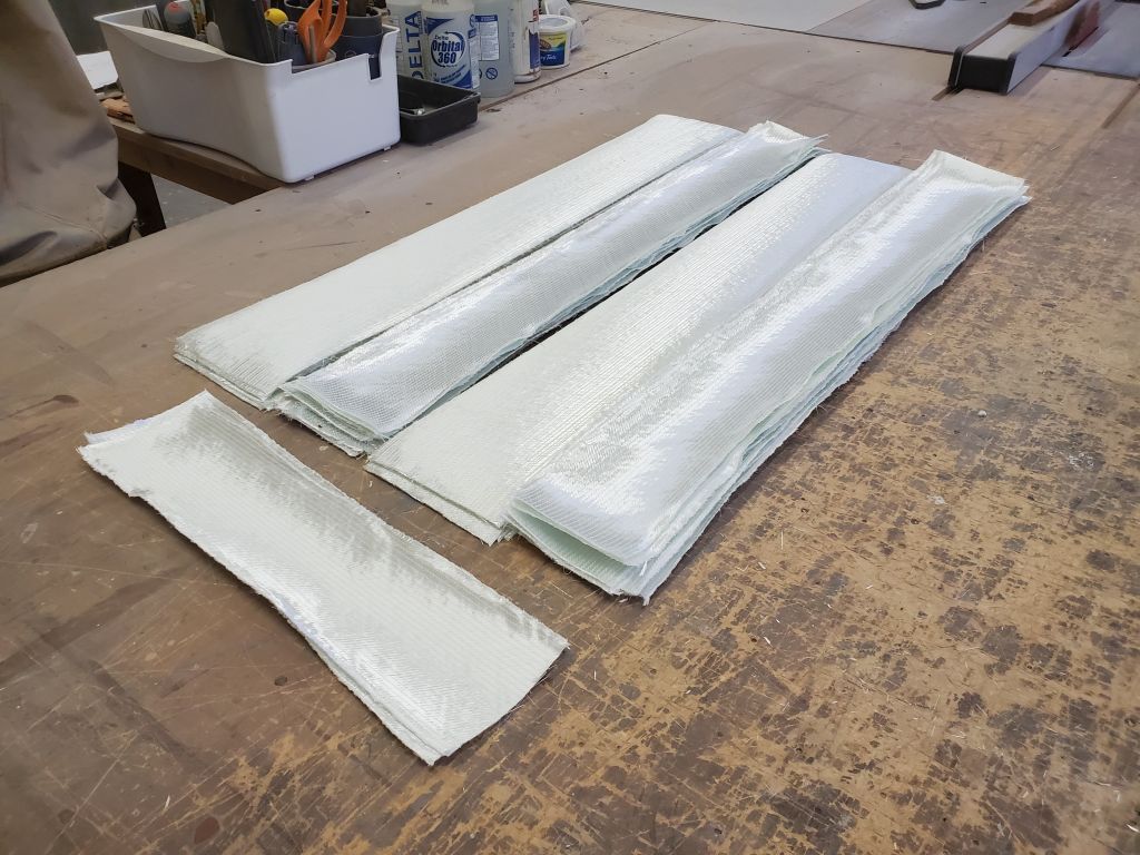
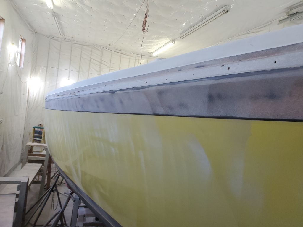
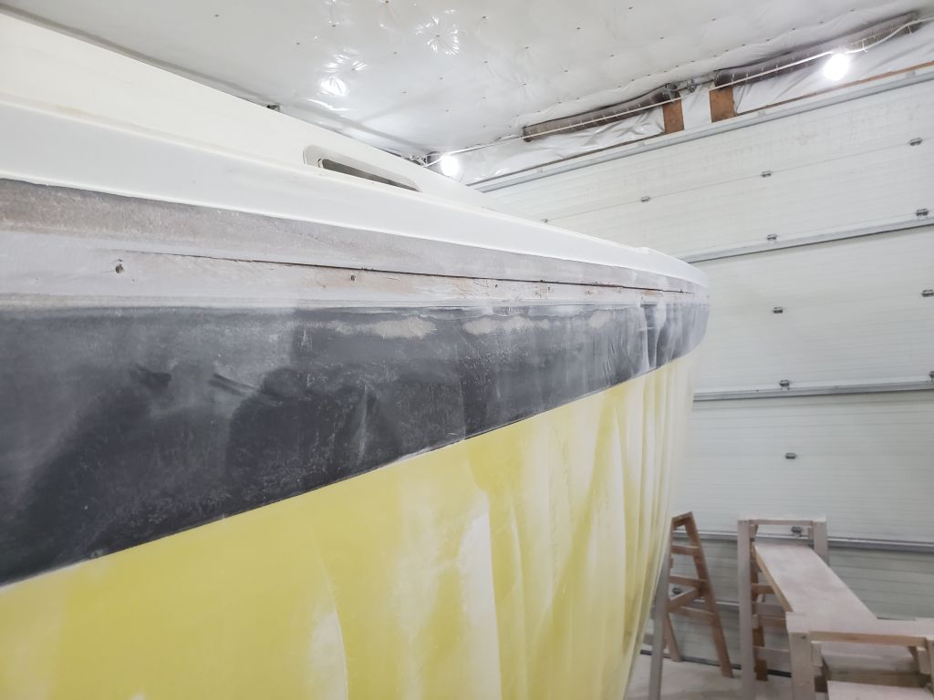
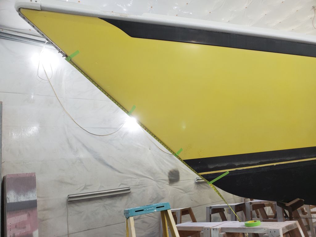
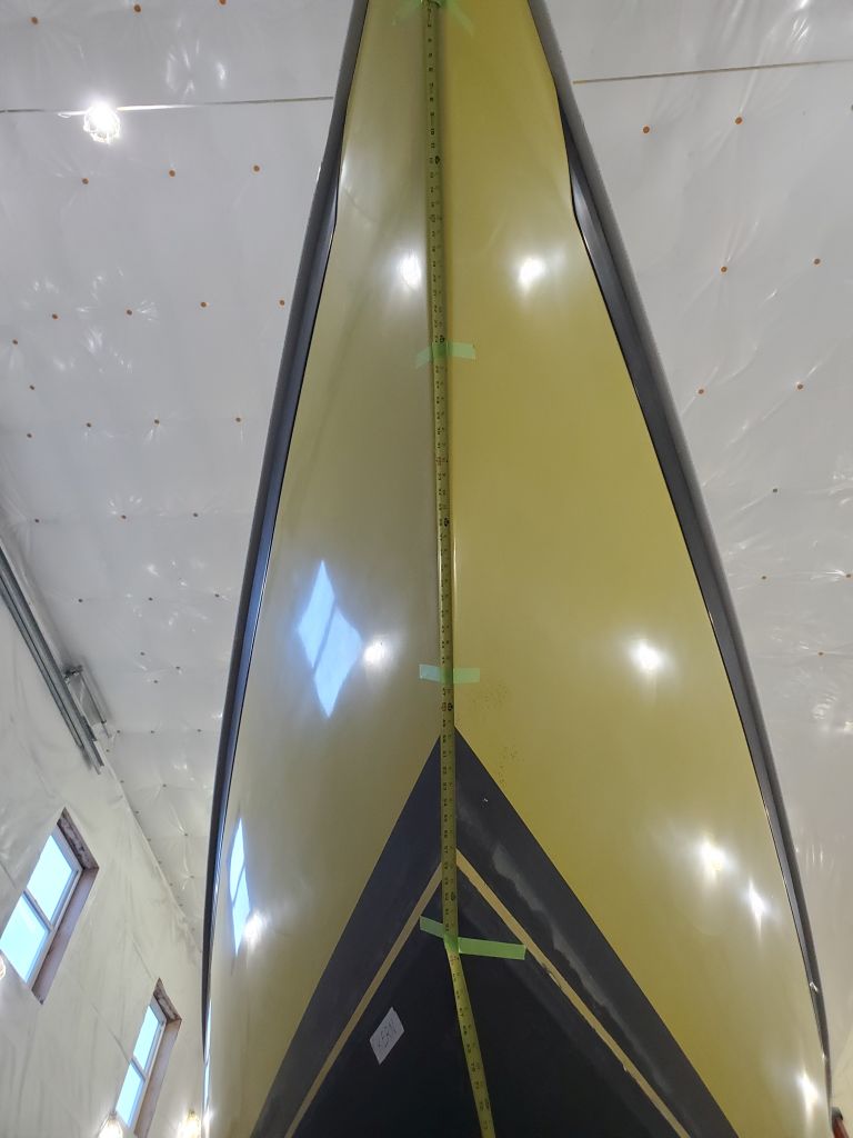
Starting on the starboard side, with a batch of thickened epoxy–just epoxy and silica–I skimmed the prepared area with a squeegee to fill some of the remaining lows, and also to wet out the entire area in advance. Afterwards, I applied two layers of 1708 tabbing–6″ and 4″–over the hull deck joint, keeping the layers aligned at their top edge, butting the adjacent pieces and staggering the joints between layers by half, like subway tiles.
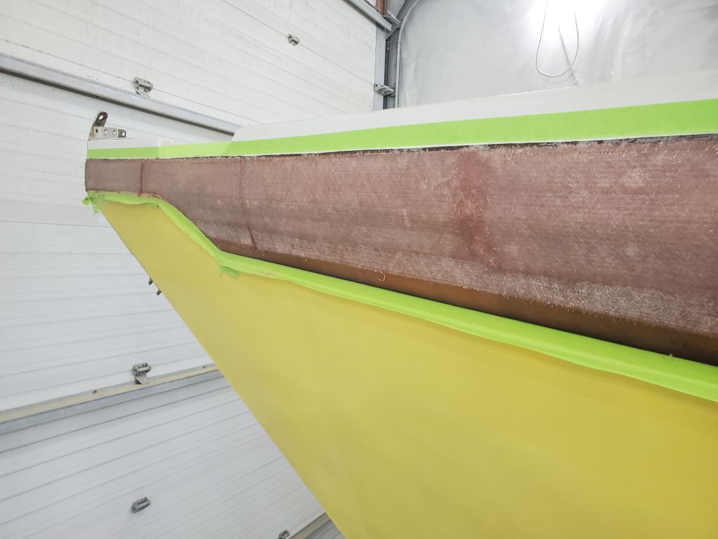
I repeated the process on the port side. Near the port bow, where a flared copper tube/tank vent protruded, I protected the open tube with a small square of tape, then glassed right over it; this would be easy enough to cut out and remove once the fiberglass was cured. I also glassed over the hole on the port quarter near the transom for another tank vent, but this could be redrilled later.
These processes consumed the day. I removed all the masking tape from each side once the resin had gelled to the point where runs were no longer an issue; the few runs that occurred happened mainly at butt joints between pieces of tabbing.
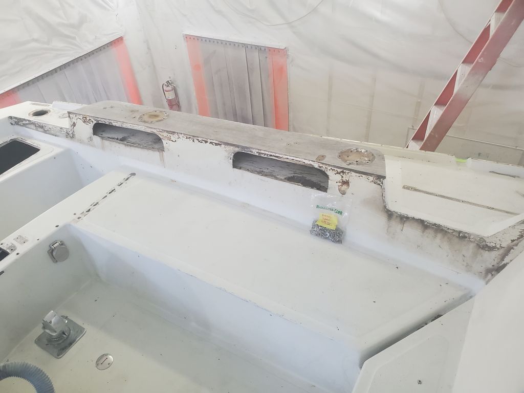
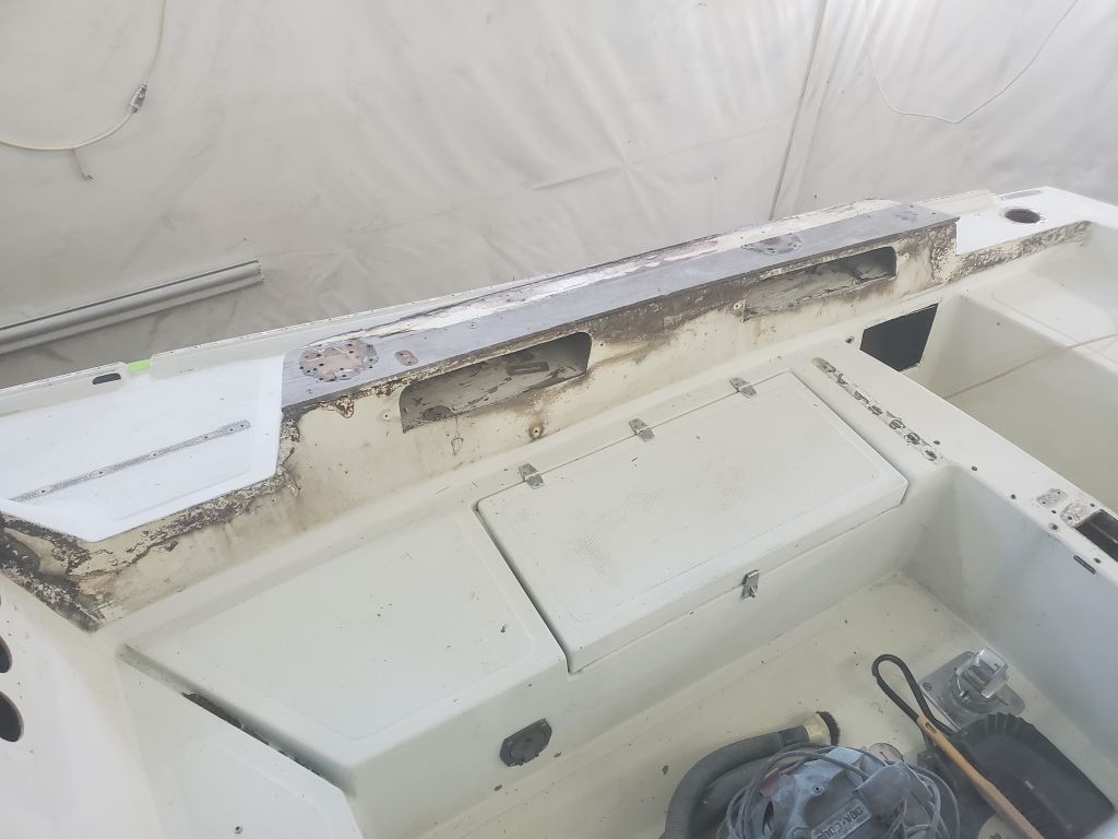
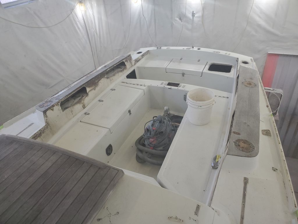
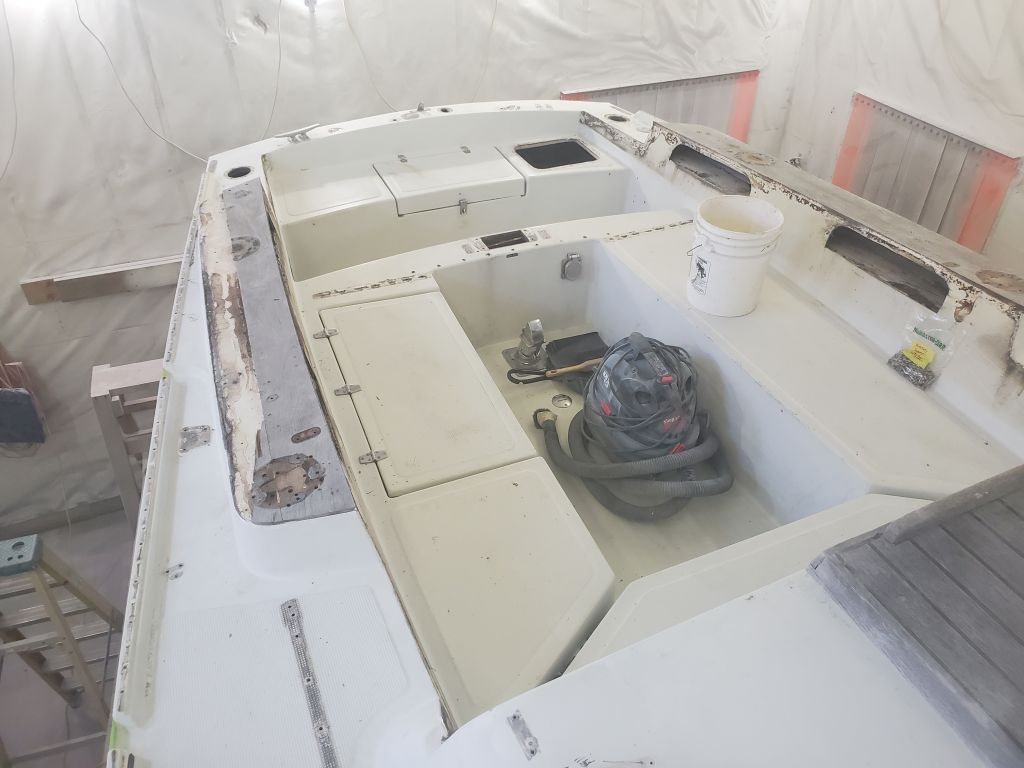
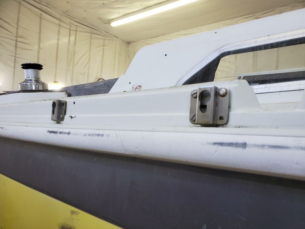
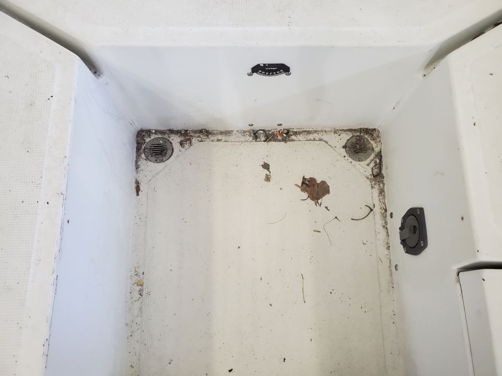
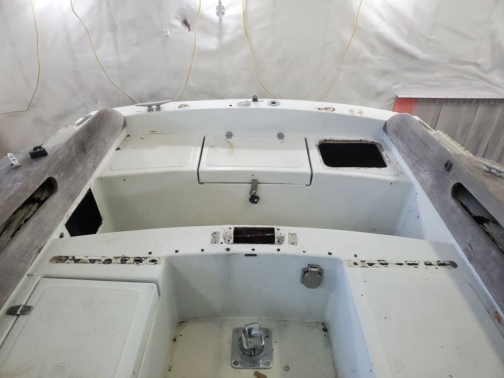
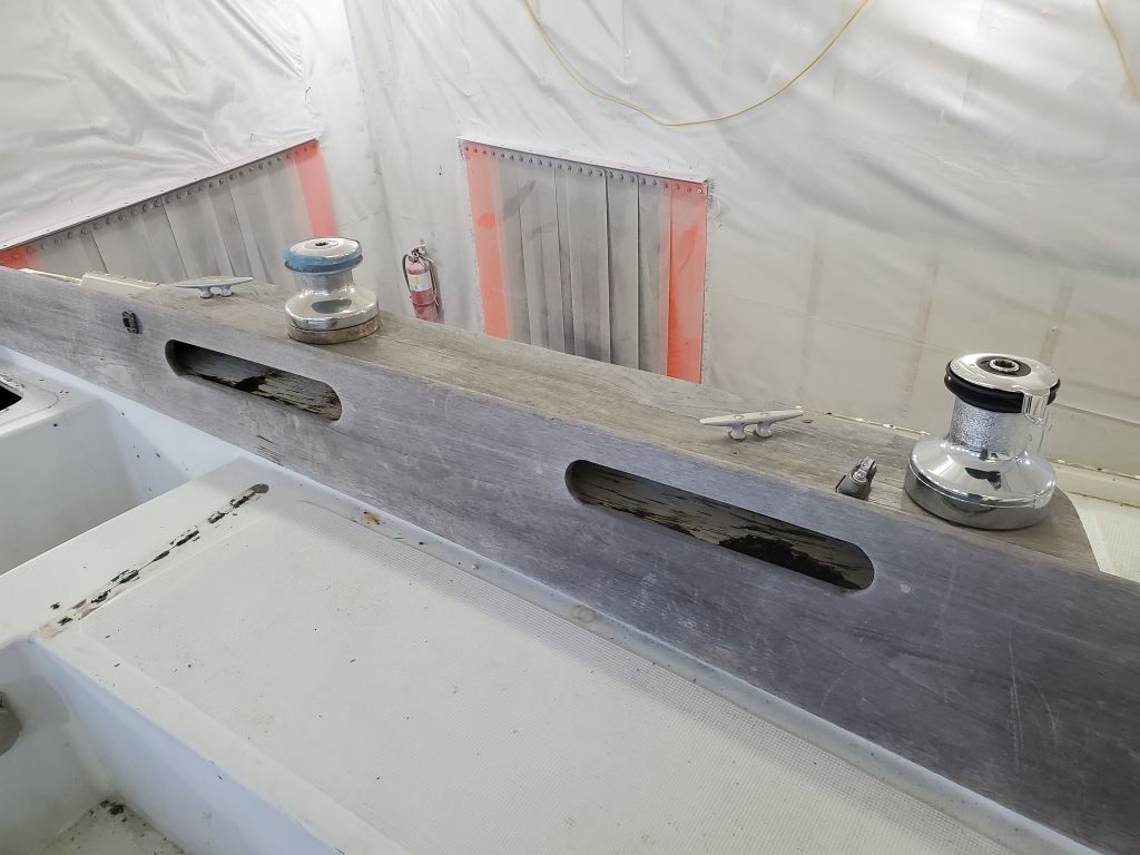
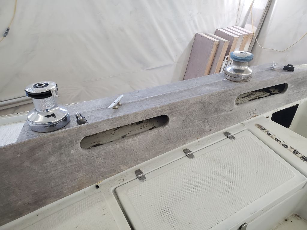
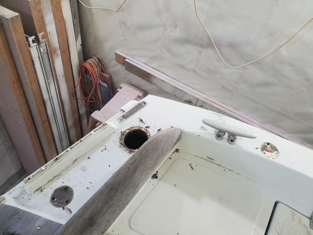
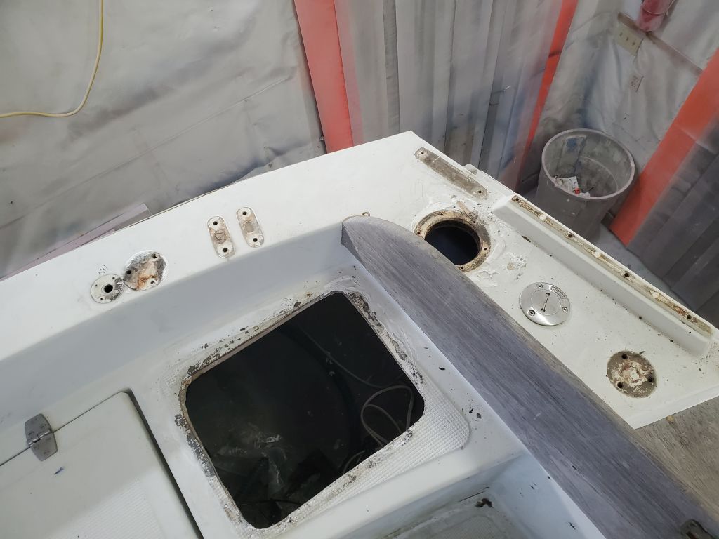
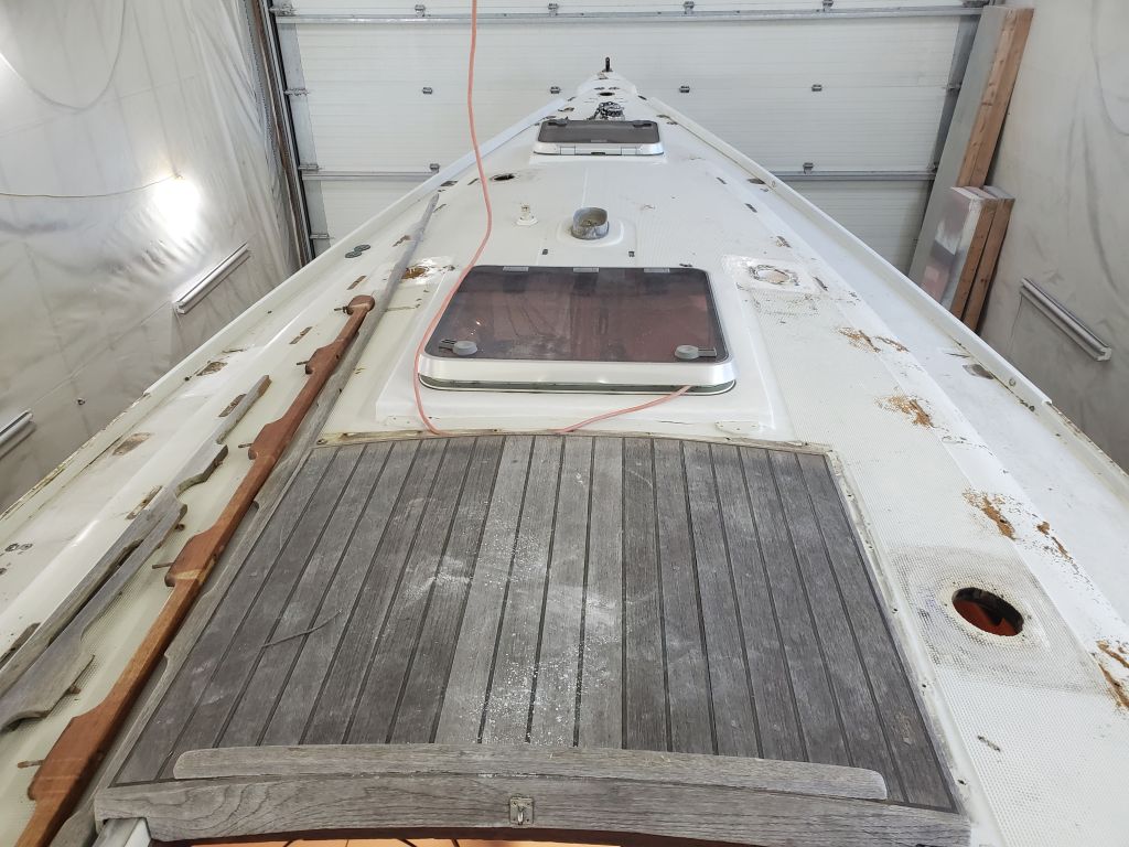
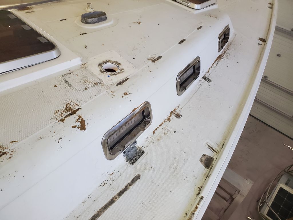
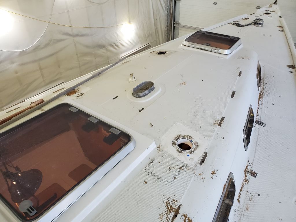
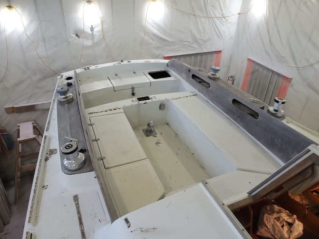
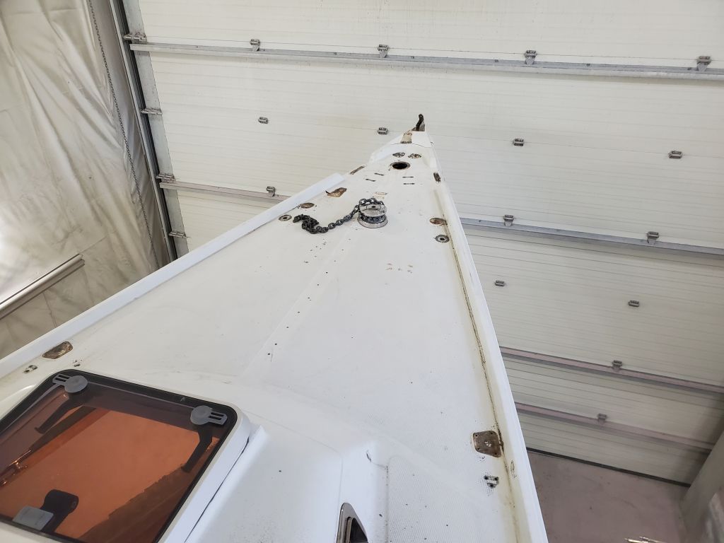
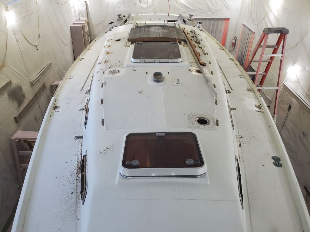
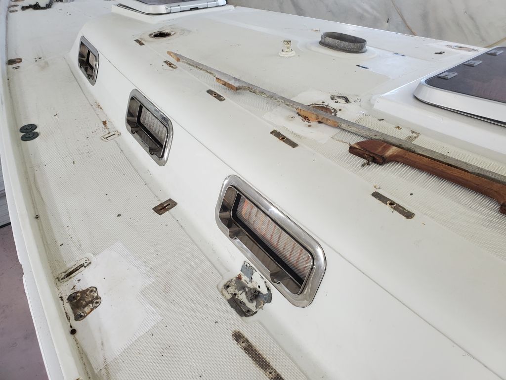
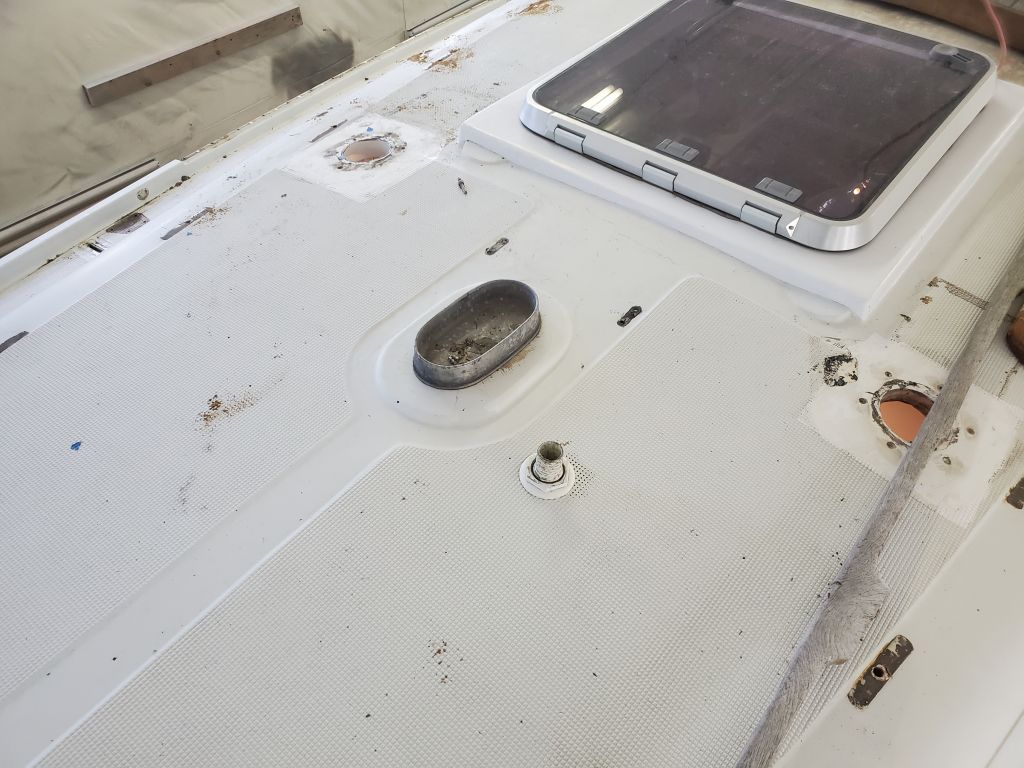
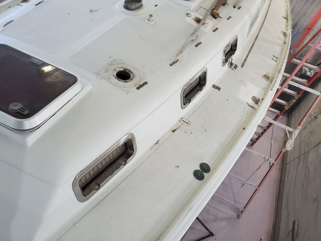
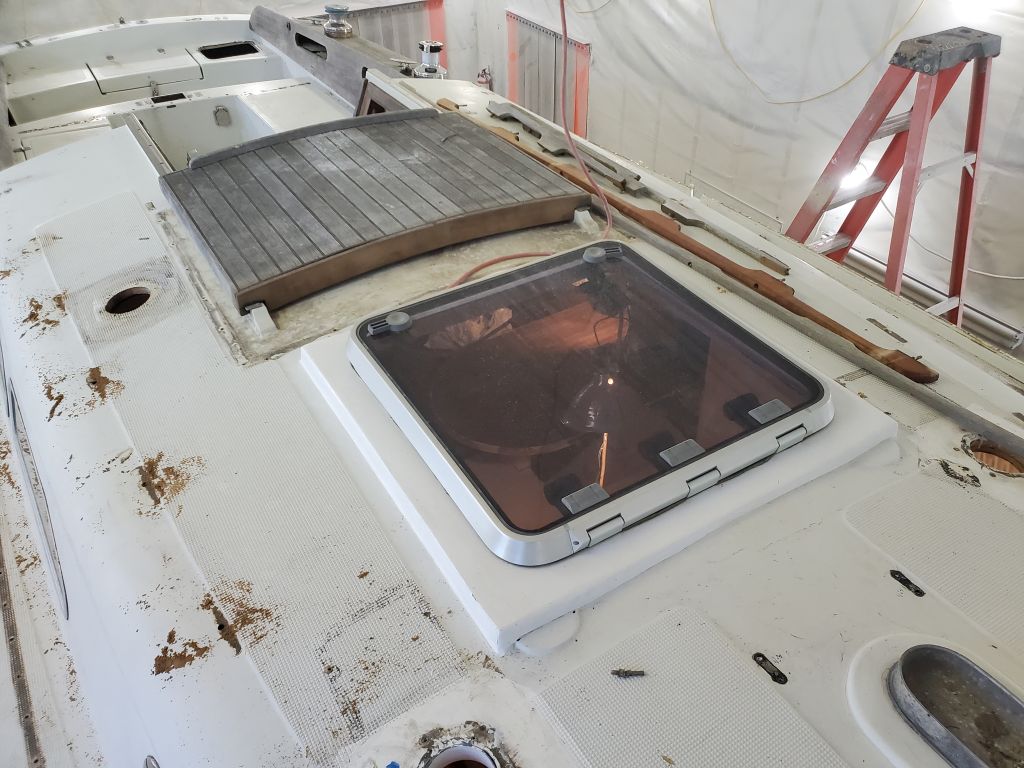
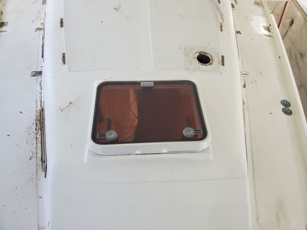
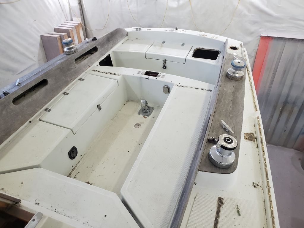
Over the weekend, the owner finished up hardware removal on deck, including the port frames and cockpit coamings. One of the jobs on the list coming up is to remove the existing winch islands at the cockpit and rebuild the sidedecks as needed to replace them. The “floors” inside these islands were badly-rotted plywood and, rather than attempt to find a way to repair them, the owners chose to reconfigure the decks and use stand-alone winch stands to support the winches. All this would happen in due course once I started work on the decks.
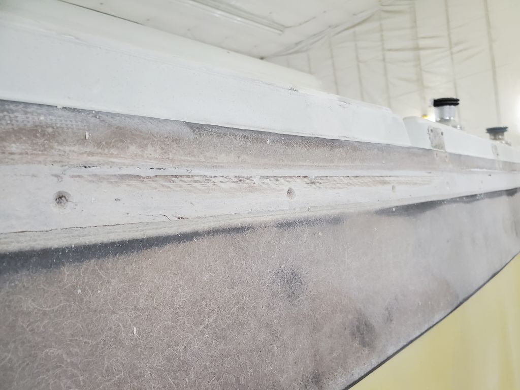
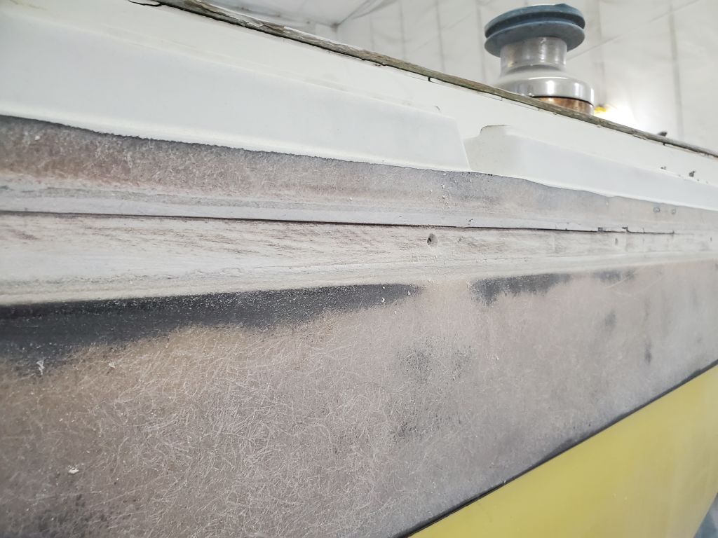
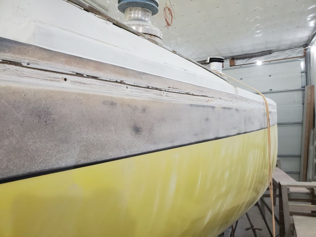
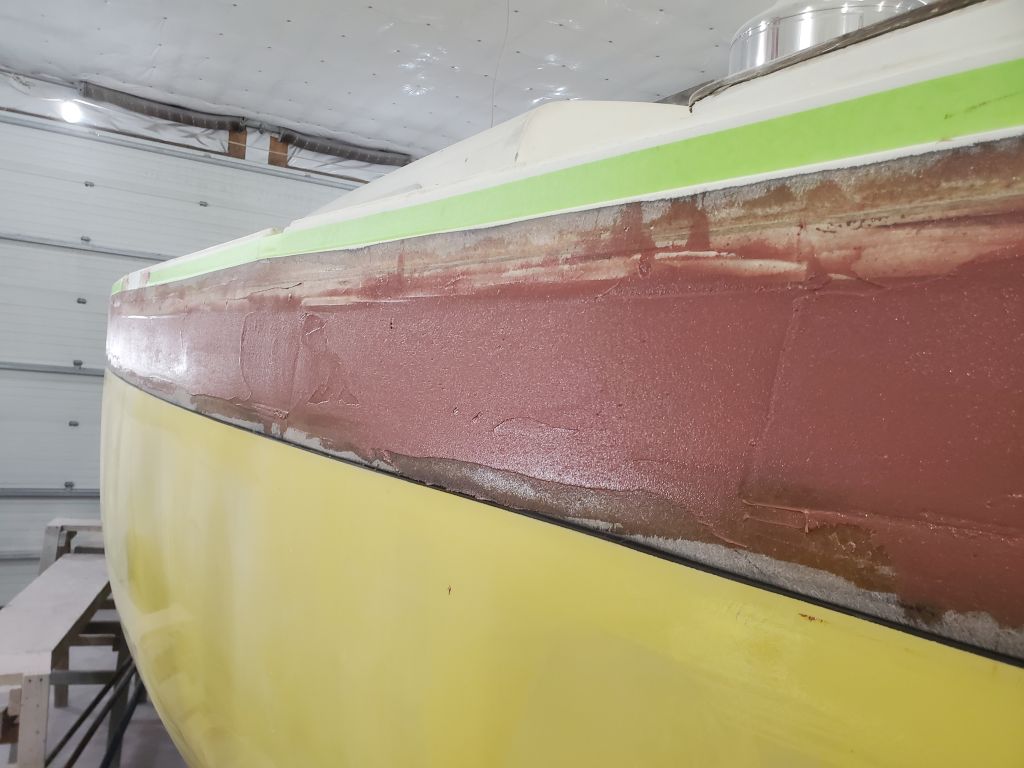
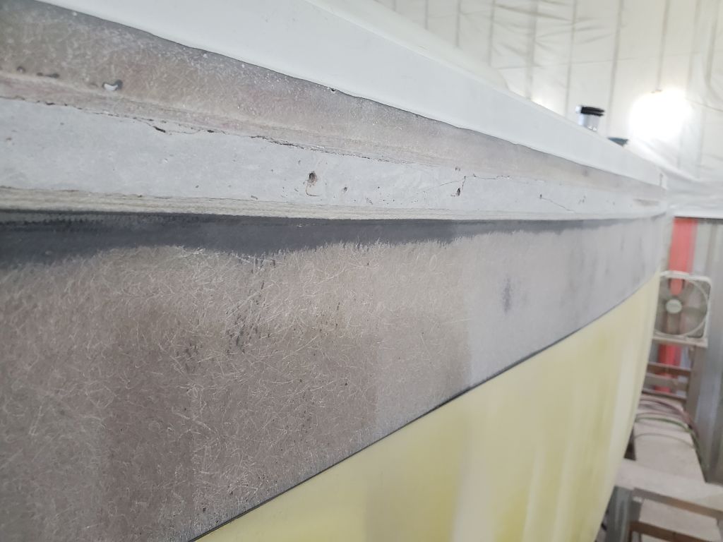
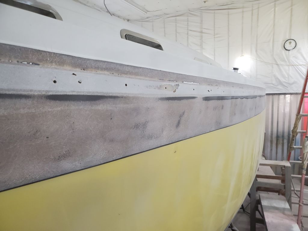
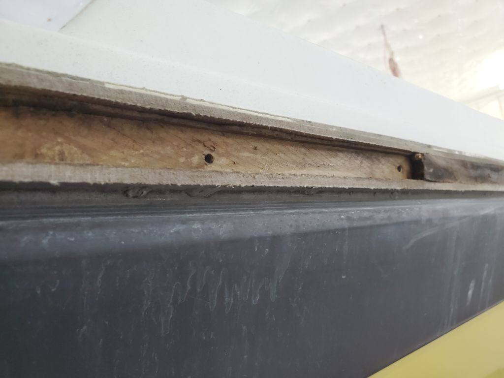
In the meantime, my focus remained on the hull. I began the day with a round of sanding to clean up the epoxy fill material I’d applied to the hull-deck joint last time.
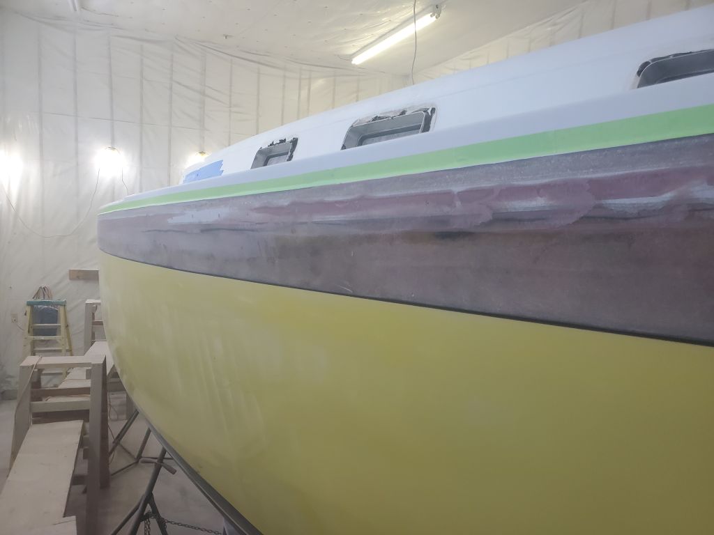
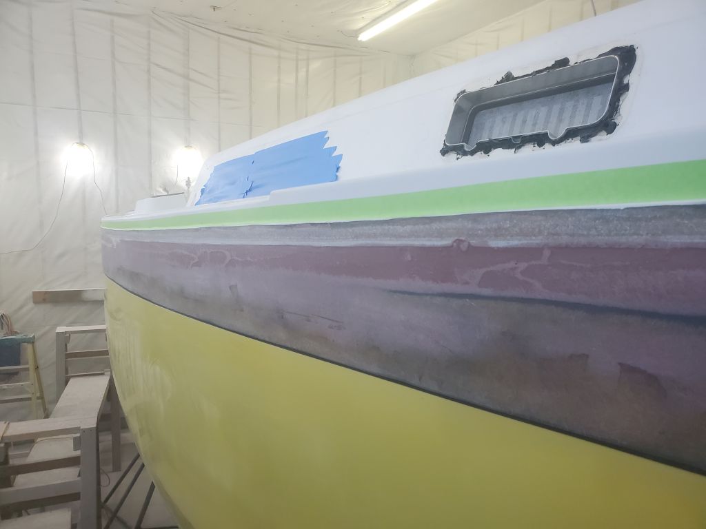
As expected, this left various low spots requiring another round of epoxy filler. The more fair the area was before applying the fiberglass over the joint, the more fair the fiberglass would be thereafter, making finishing the joint that much easier. I used a wider trowel as needed over portions of the seam in the midships-to-quarter sections of the boat to bring the whole area more fair from top to bottom in these “flattest” areas of the boat.
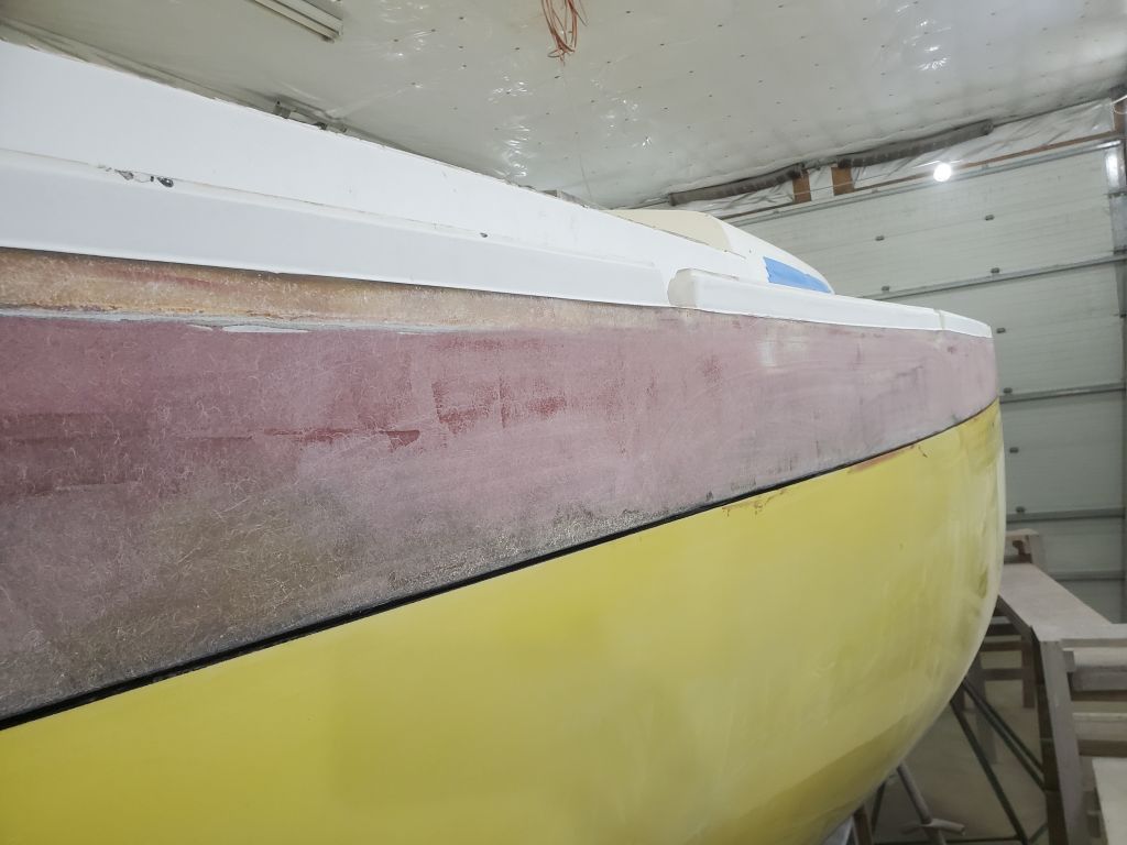
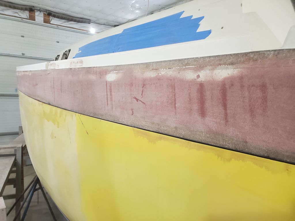
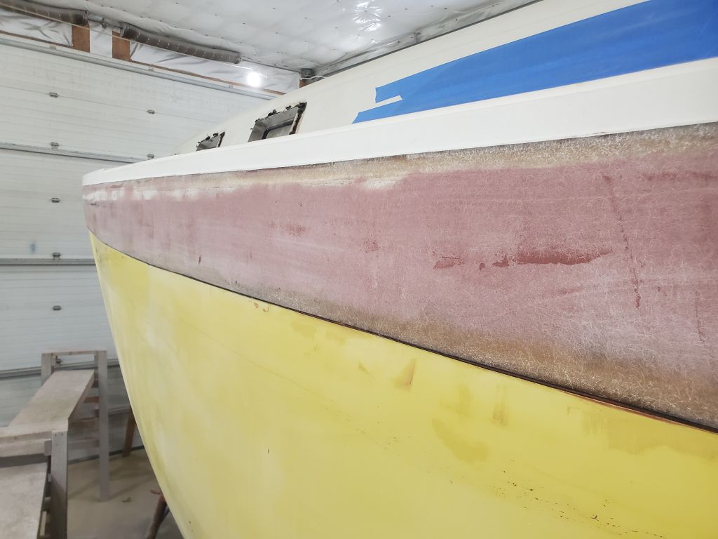
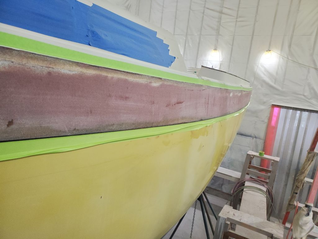
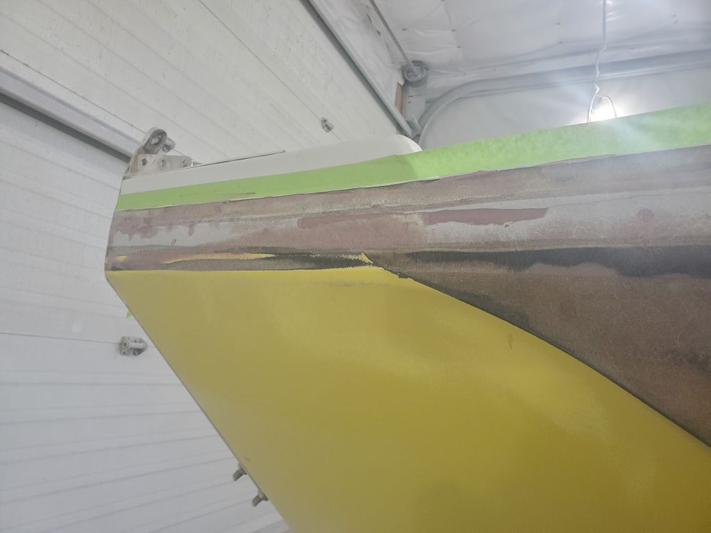
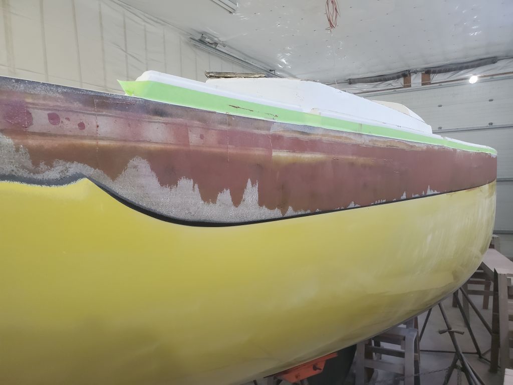
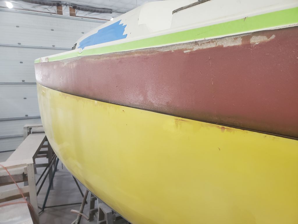
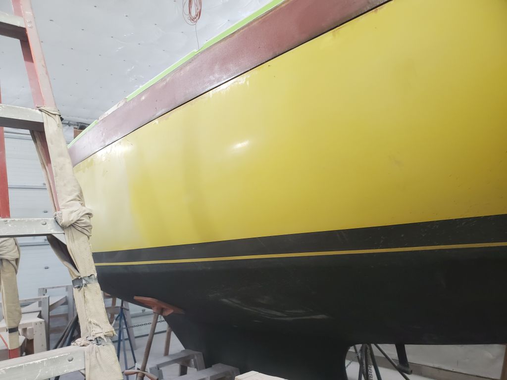
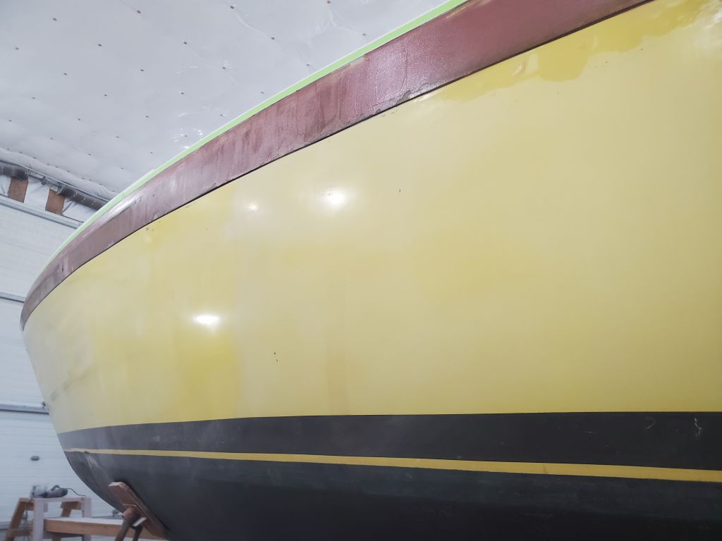
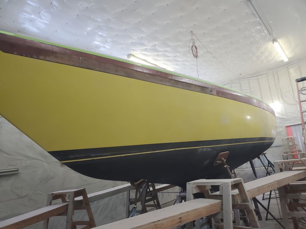
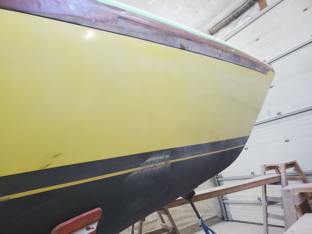
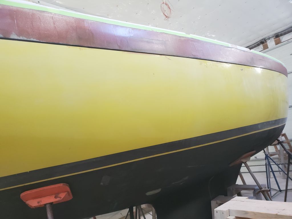
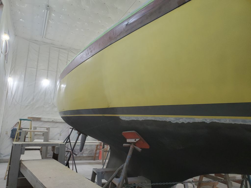
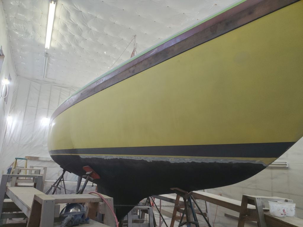
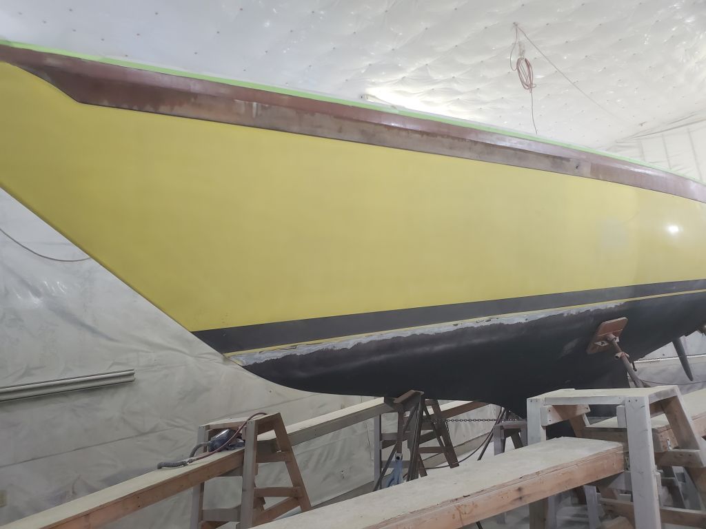
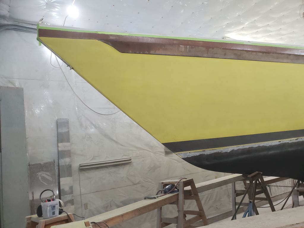
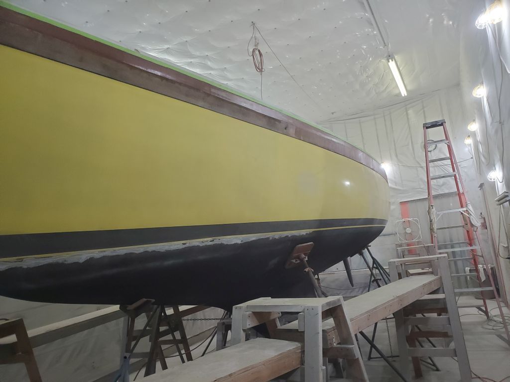
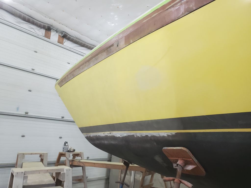
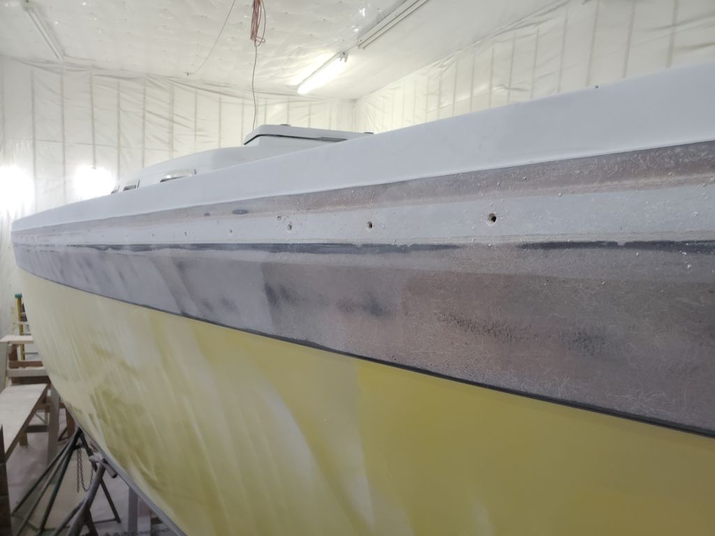
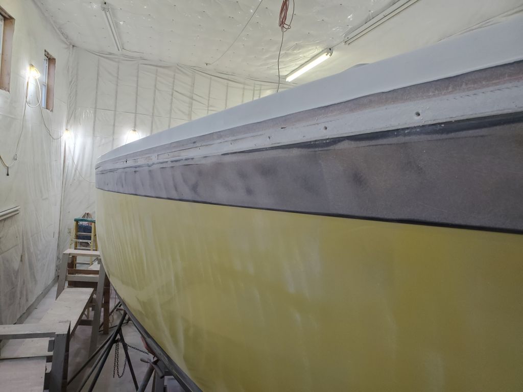
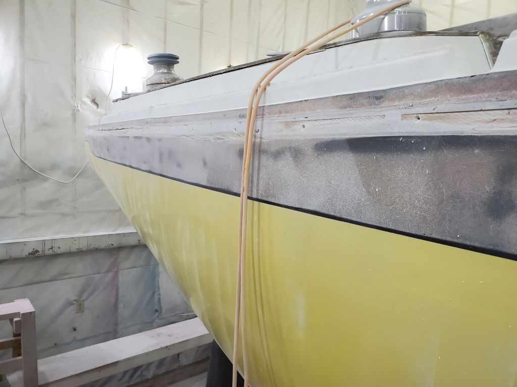
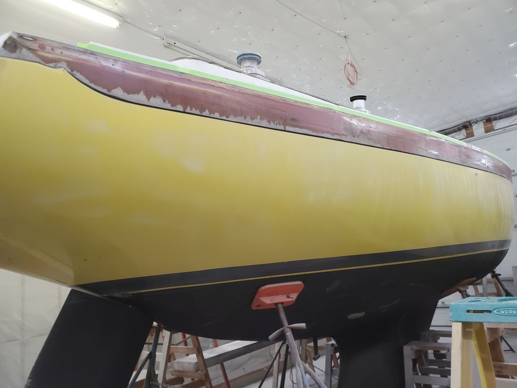
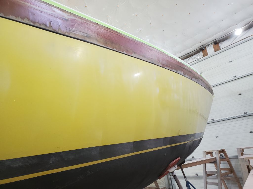
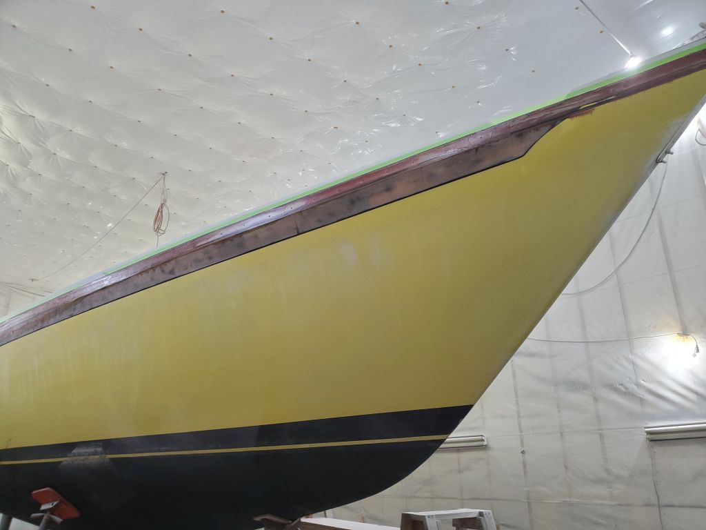
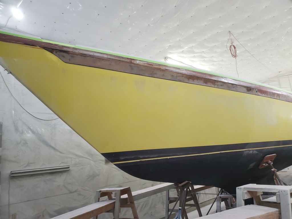
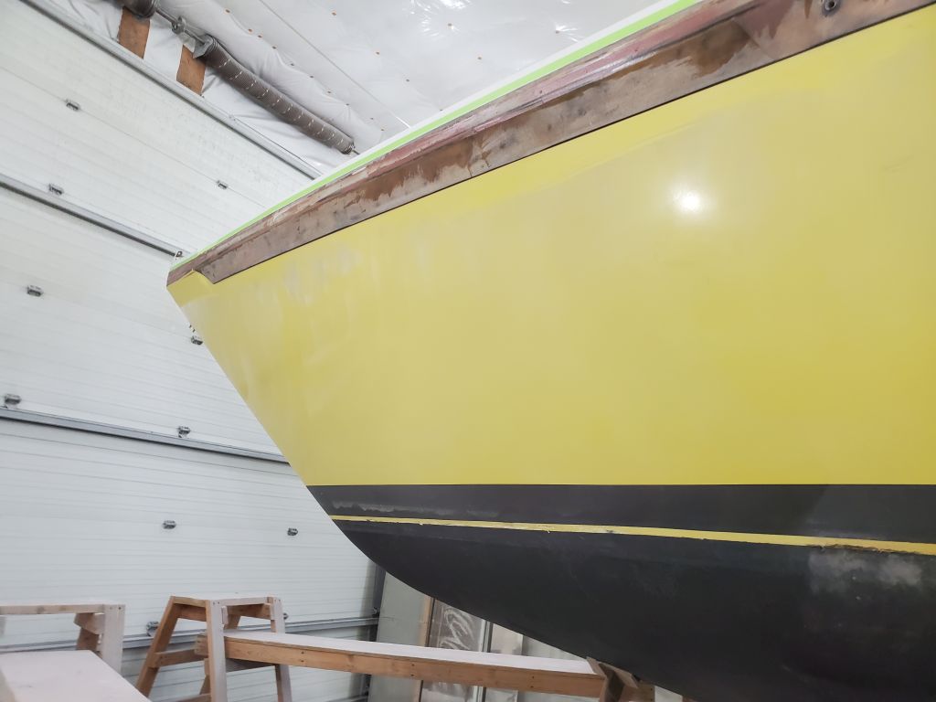
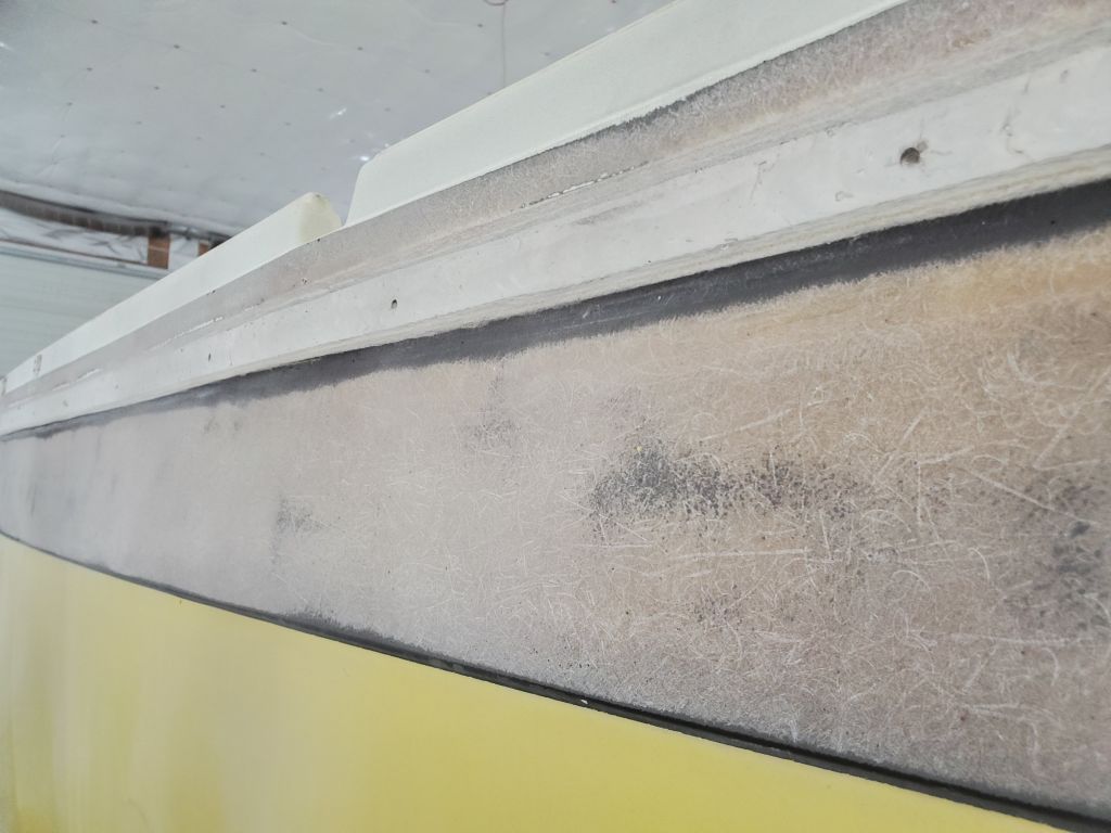
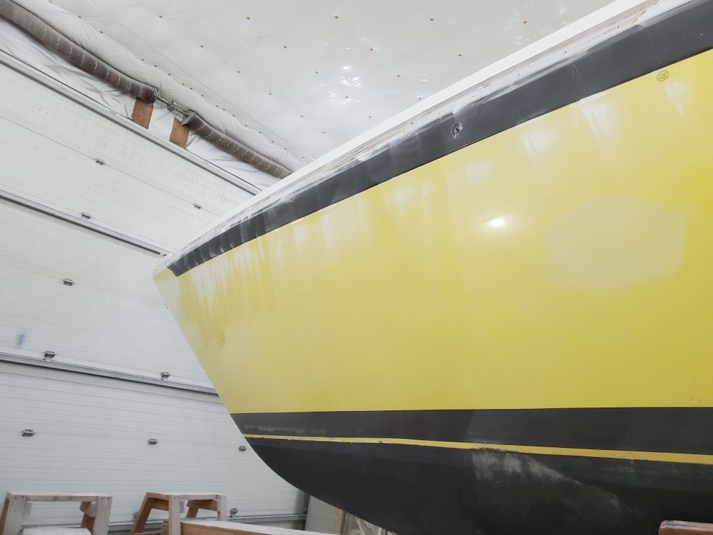
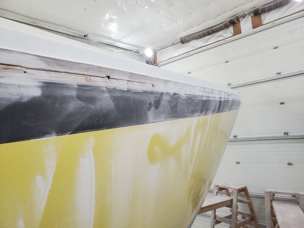
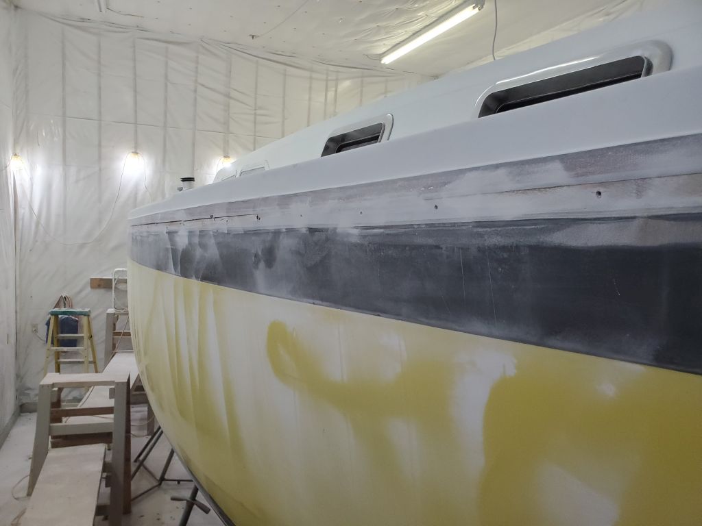
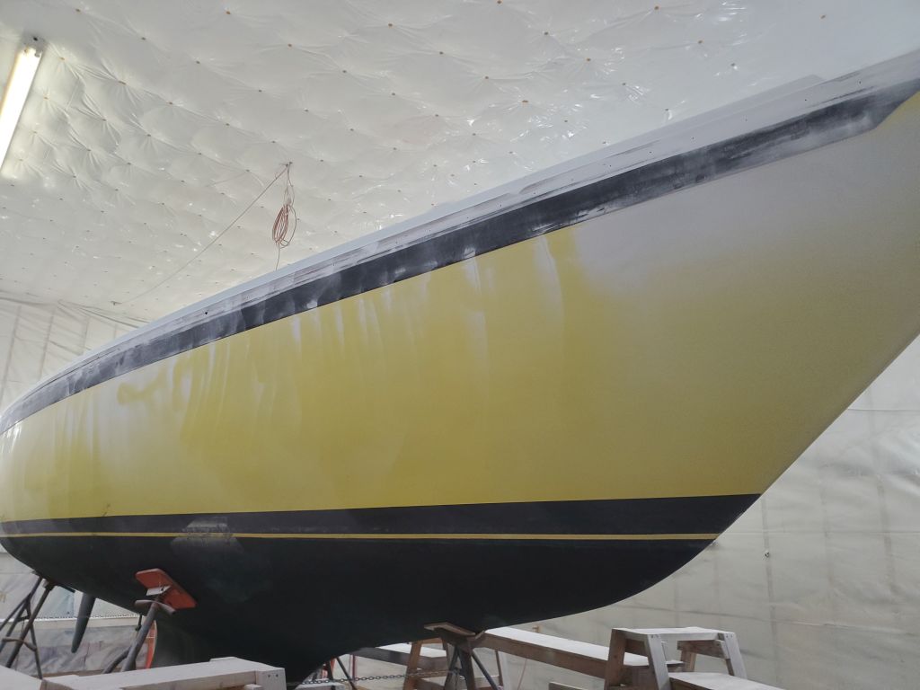
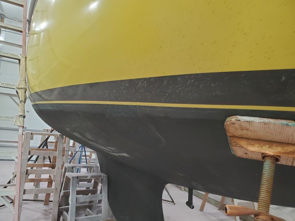
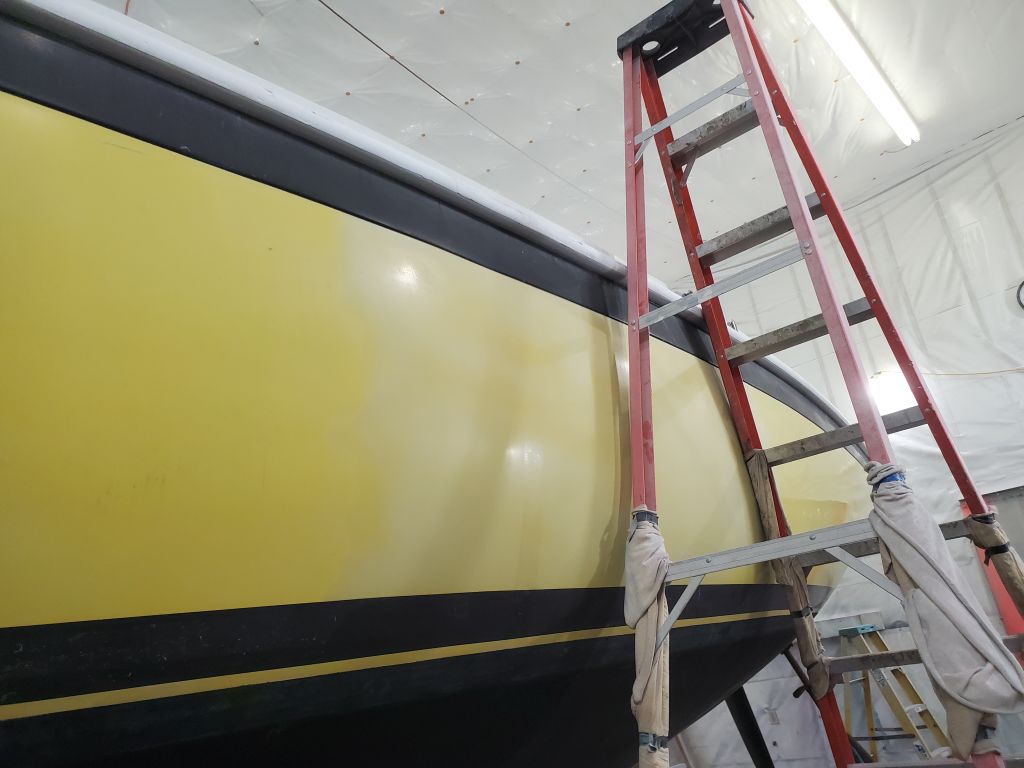
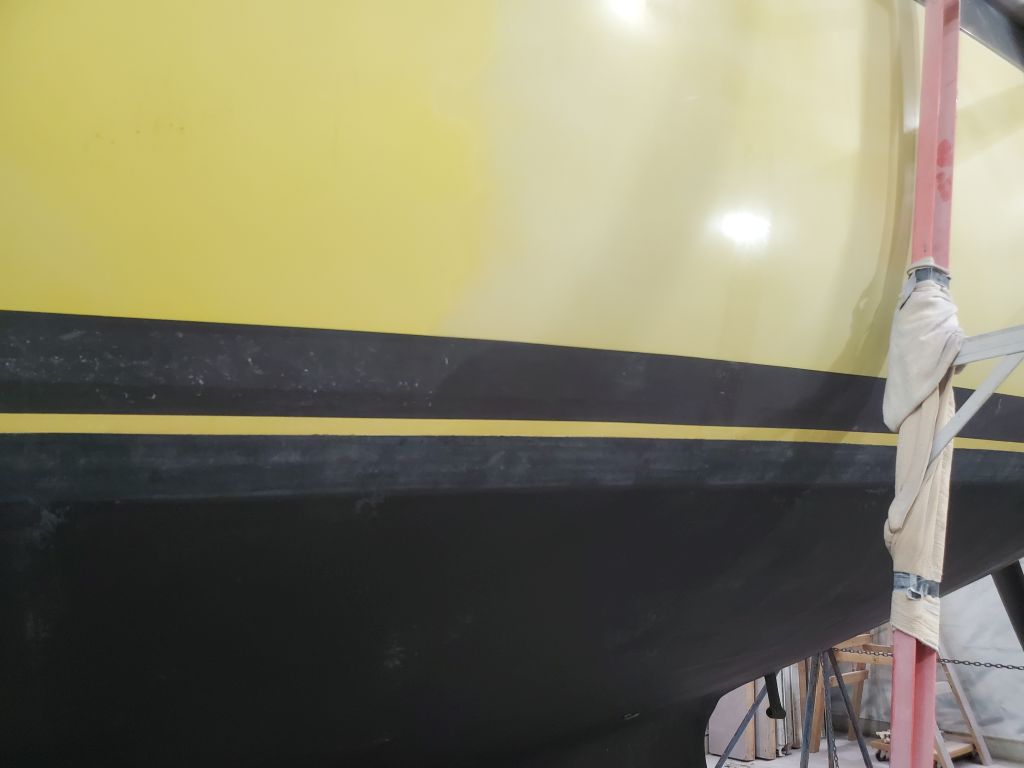
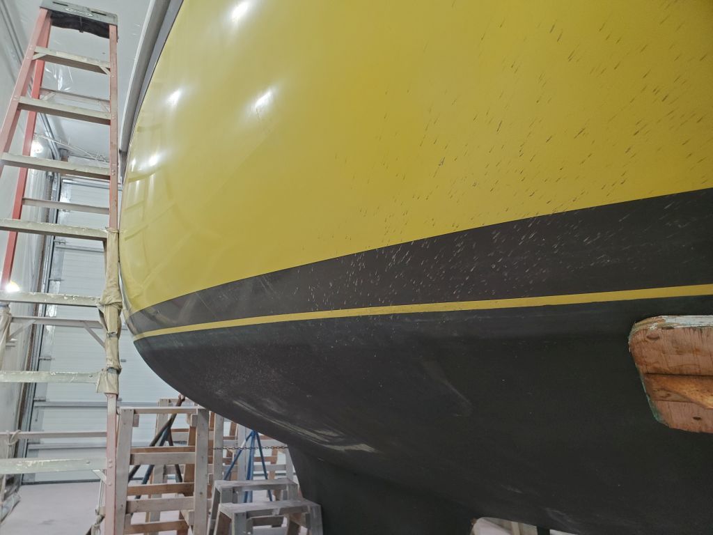
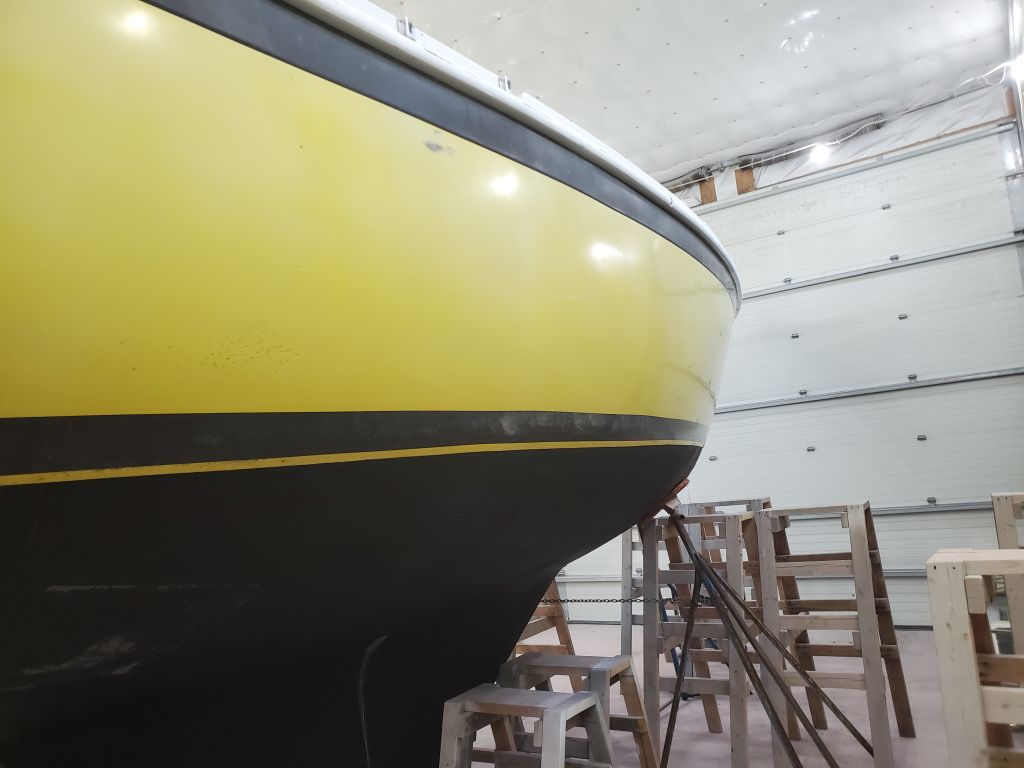
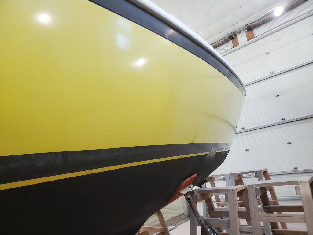
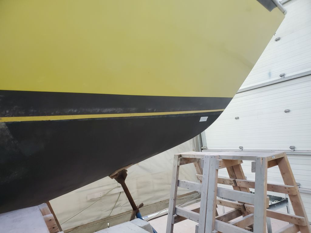
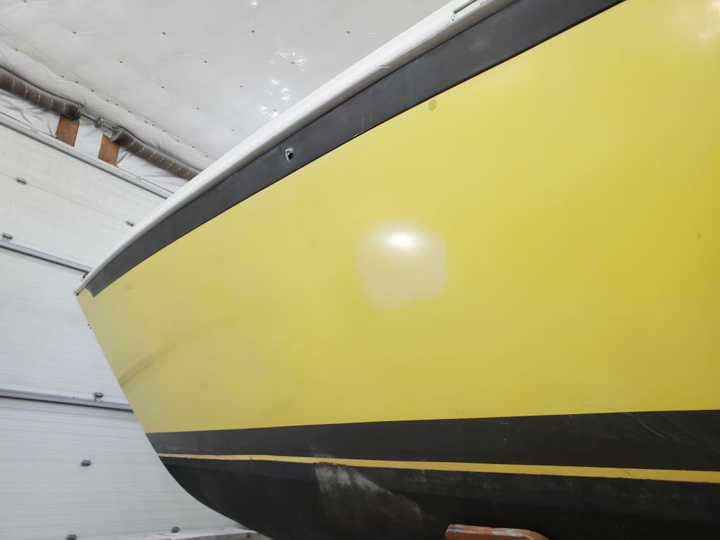
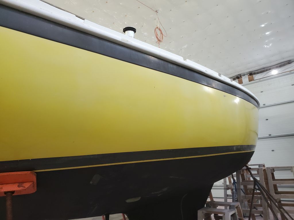
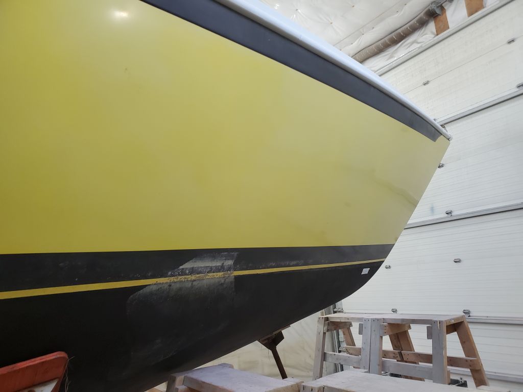
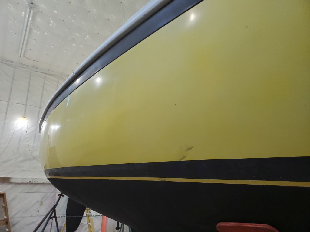
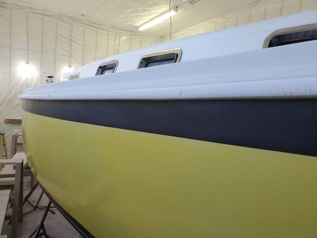
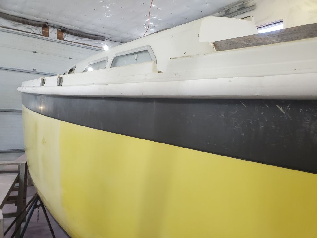
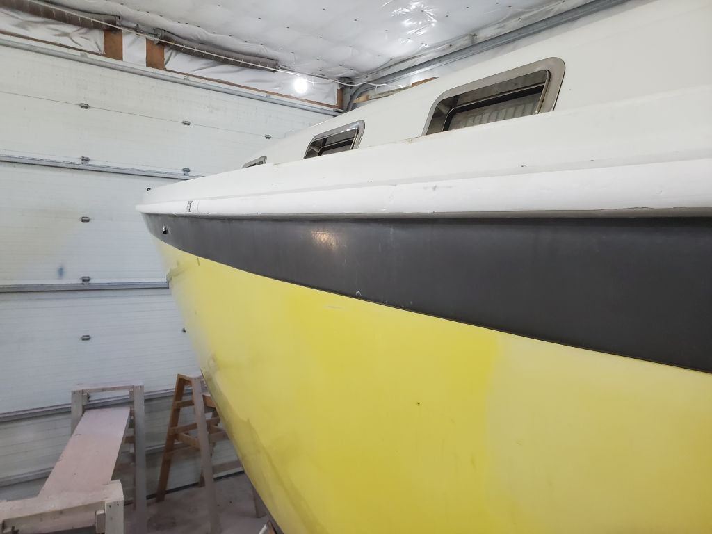
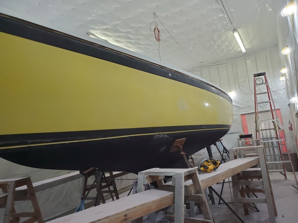
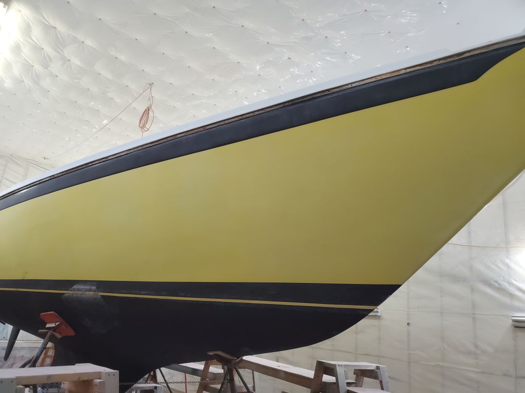
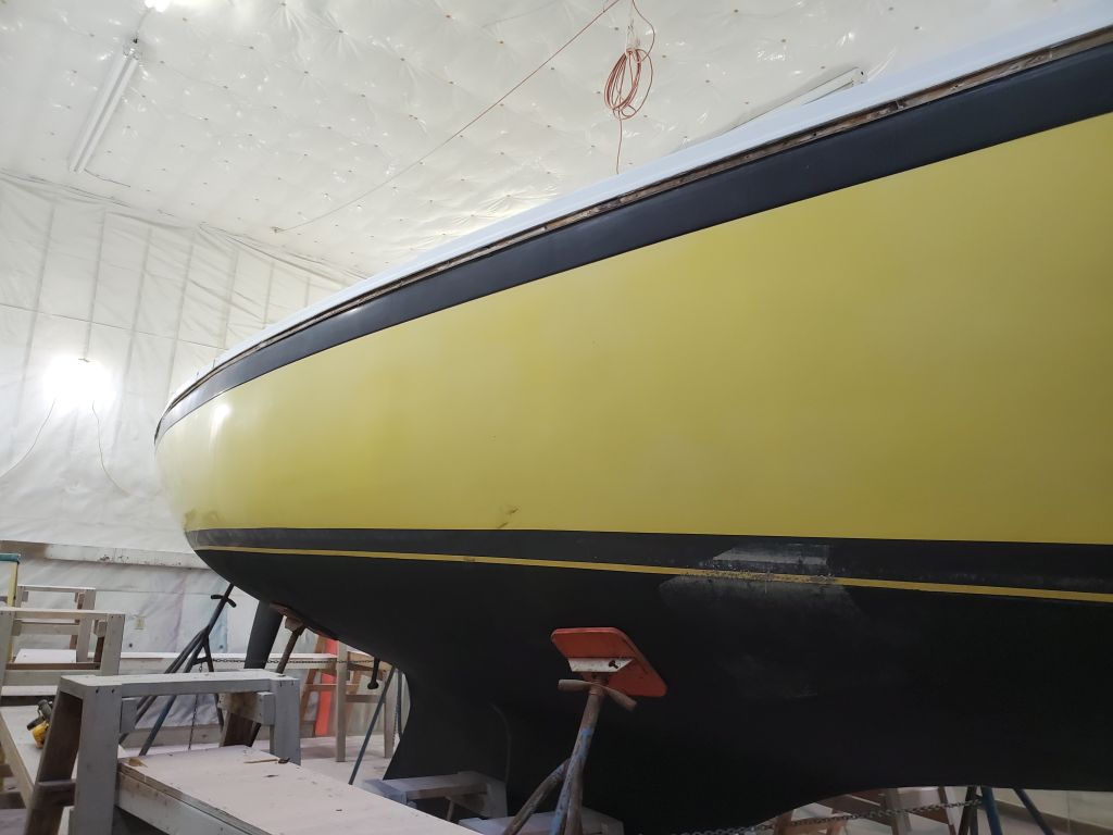
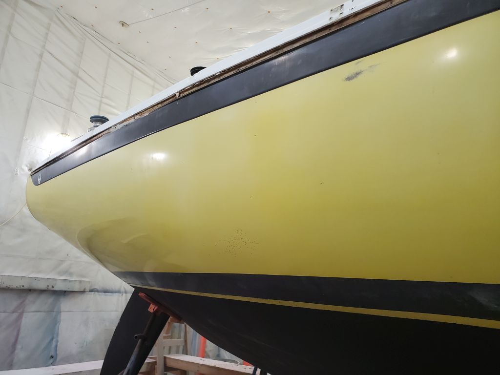
In the afternoon, with nothing more I could do at the rubrail for now, I got to work sanding the topsides to prepare them for minor repair work and eventually primer and paint. The topsides were original gelcoat–including the striping–and despite oxidation and wear from close to 50 years of life, were in generally good condition and wouldn’t require heavy sanding or paint removal. I chose my 6″ orbital finishing sander for the job, and chose also to start with the bow sections on both sides, as I think the bows are the part of the boat I like sanding least of all, so best to get them out of the way. I began at the waterline, working from floor level, and sanded up as high as I could (about a sanding pad’s width above the boottop) from the bow stand on the port side around to the same place to starboard. I also removed an inch or two of the bottom paint to help ensure I had a clean and smoother area to apply tape later on. I worked through 60 and 80 grits with the sander: 60 to break the surface, and 80 to smooth from there. Sometime later, after various minor repairs, I’d go over everything with 120, but that was later.
Once I was finished from floor level, I sanded the remainder of the topsides in these sections, bringing me to the end of the day.
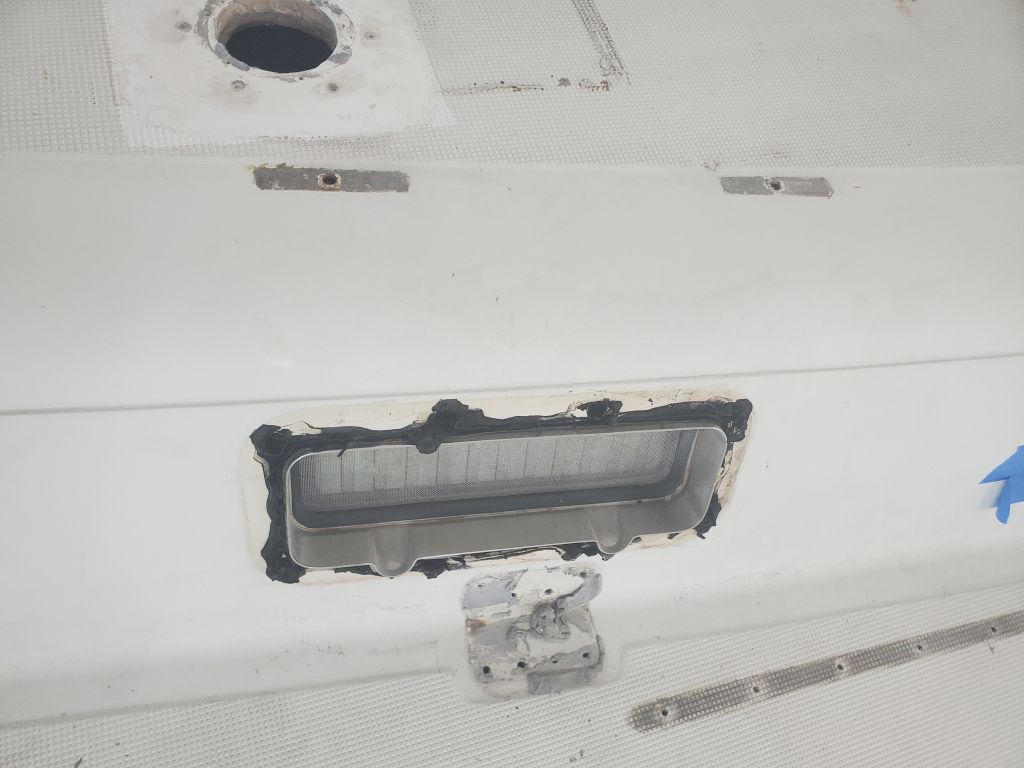
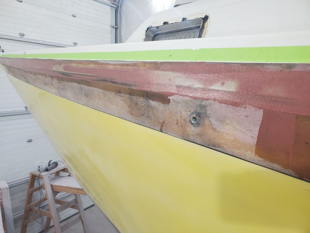
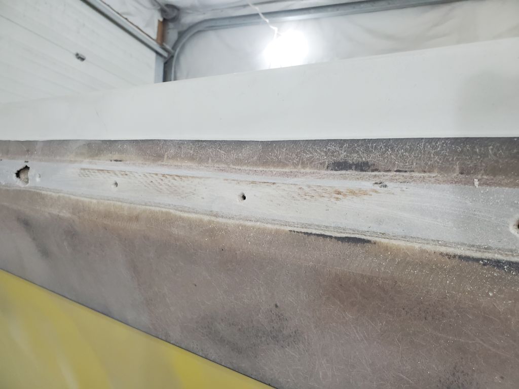
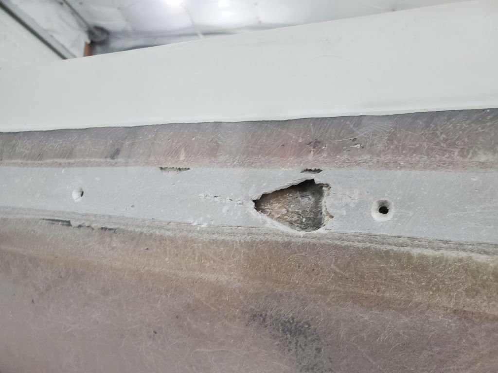
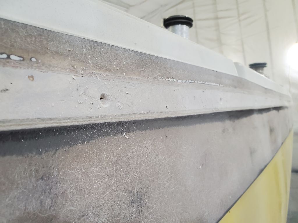
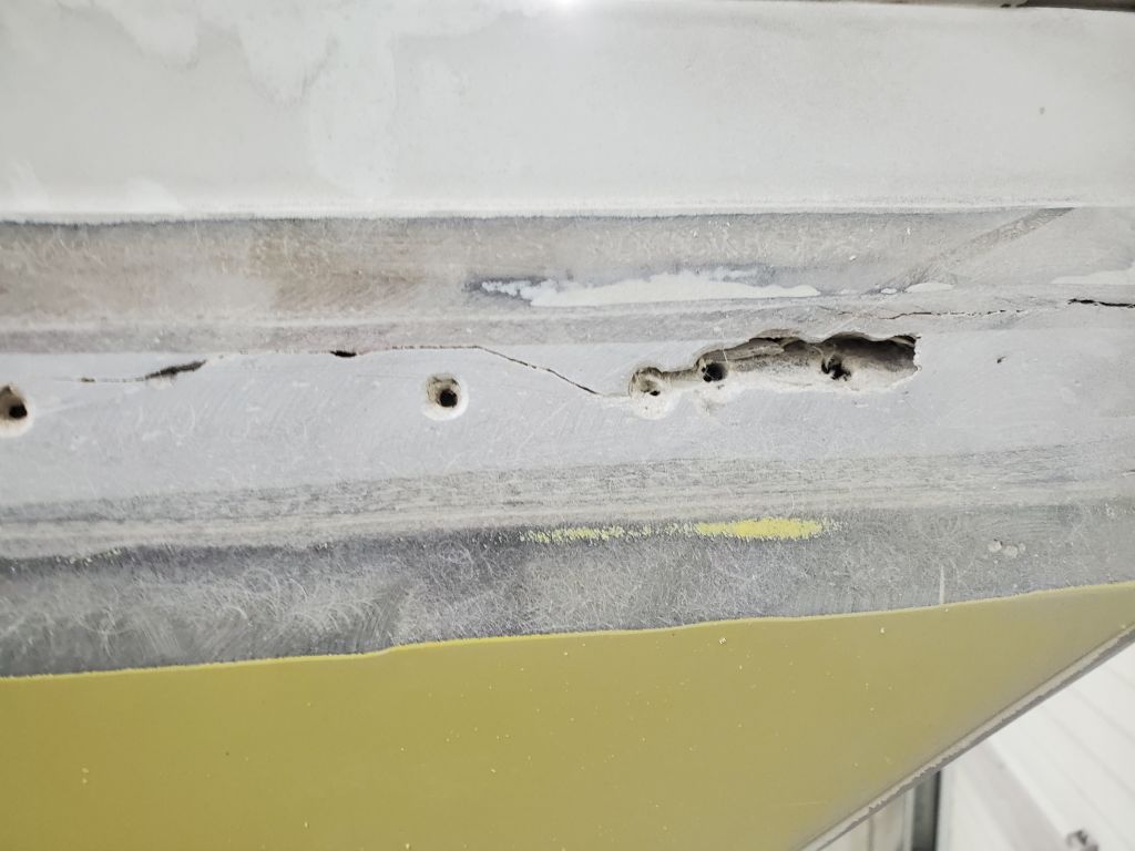
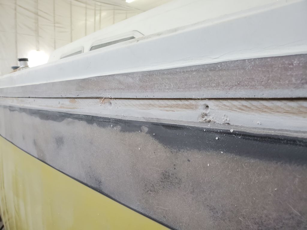
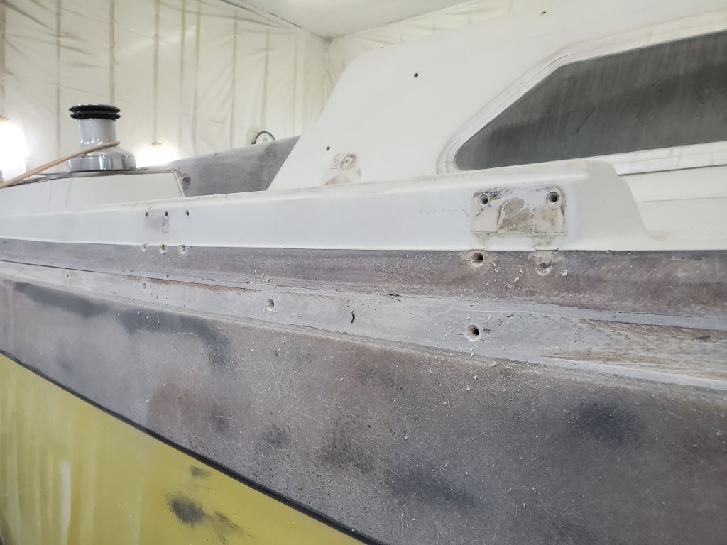
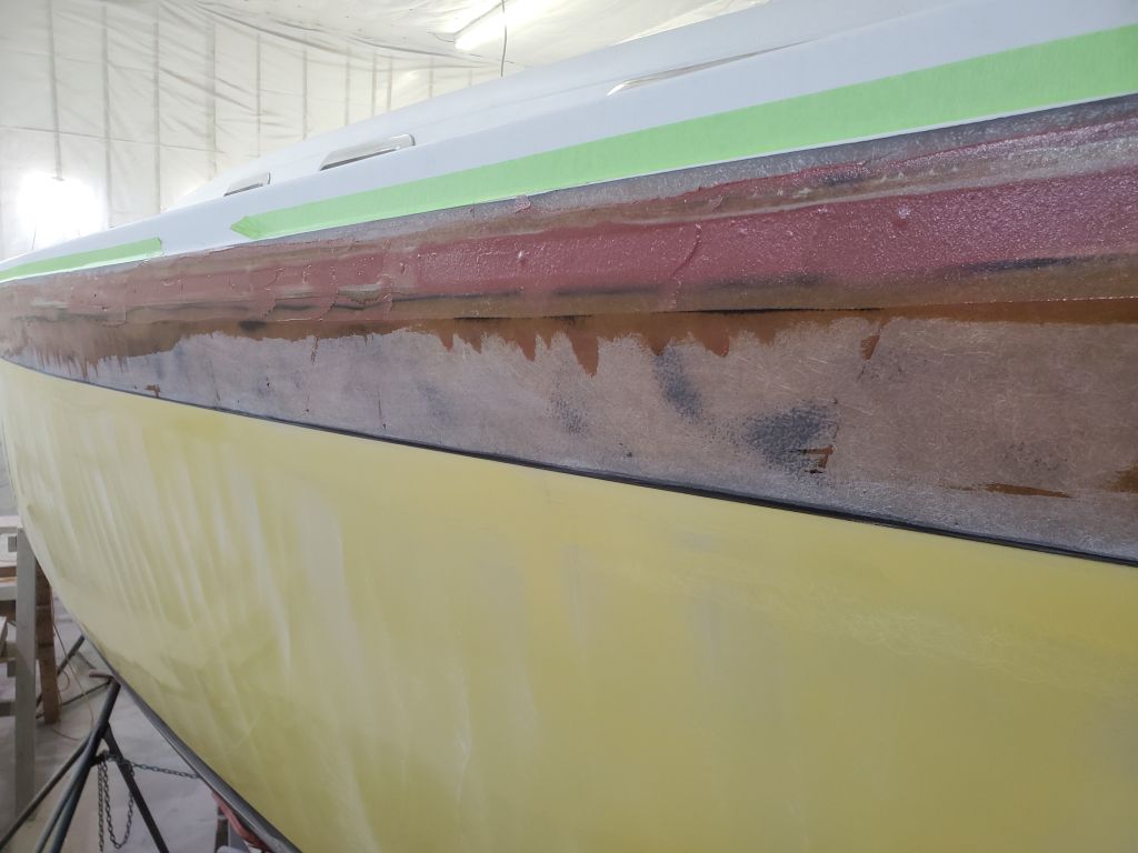
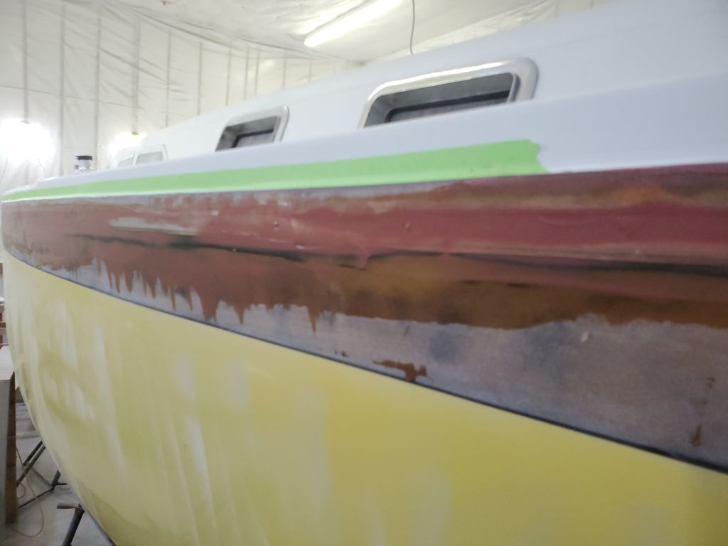
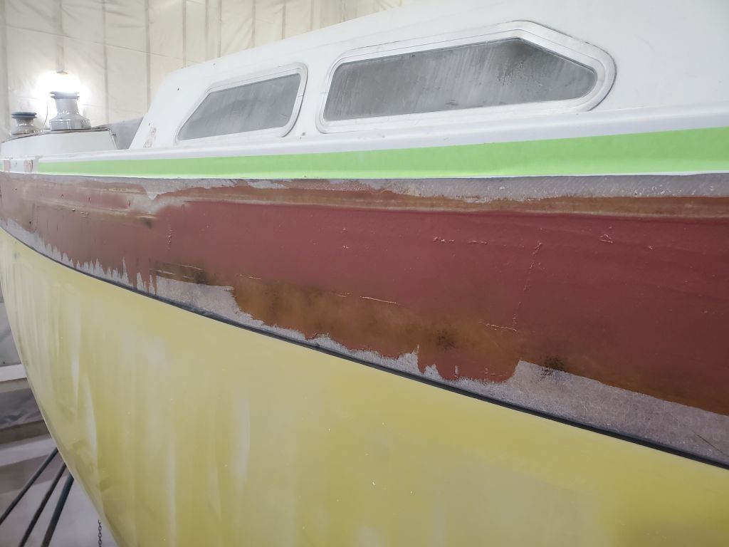
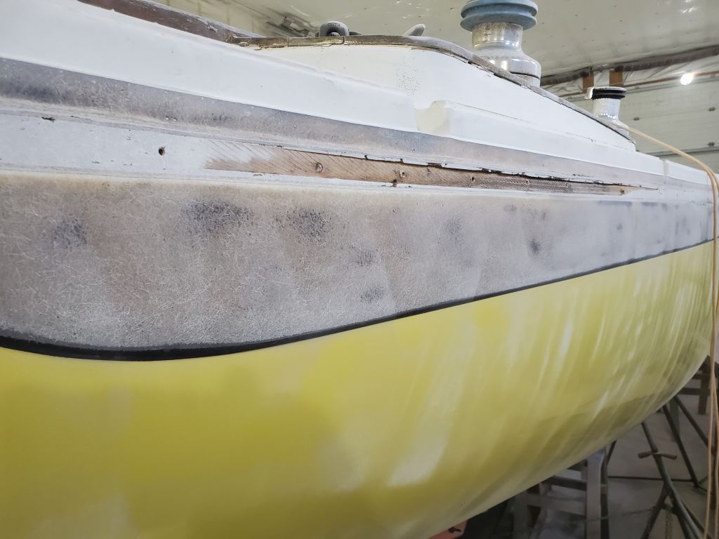
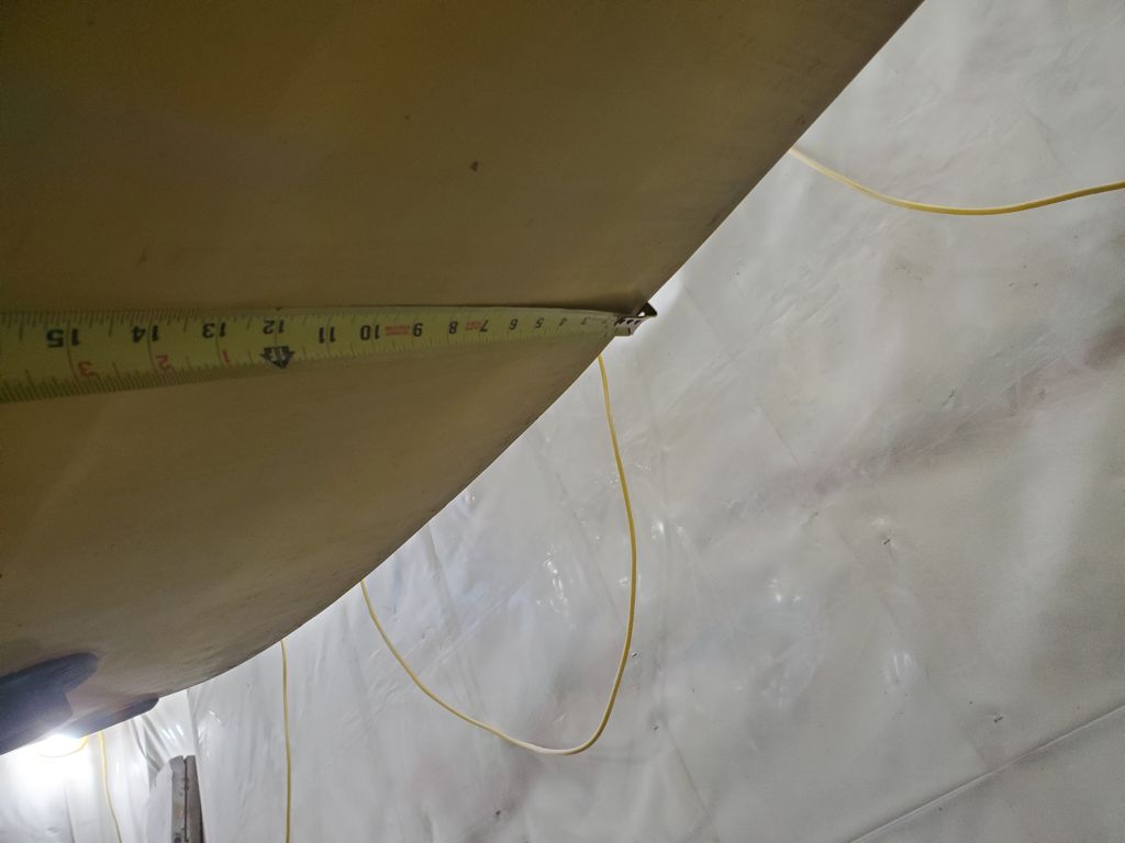
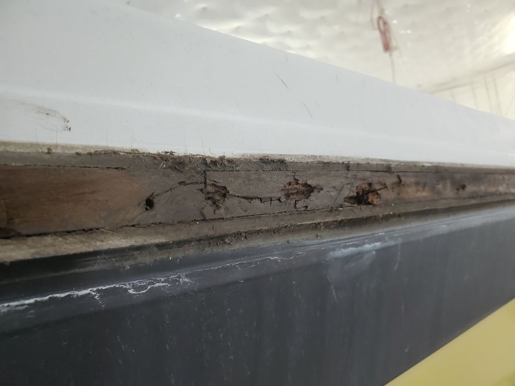
The final step before beginning to fill and fair in the hull-deck joint beneath the now-removed rubrail was to ream out the fastener holes, which would allow them to be successfully filled with epoxy, and also to prep as needed any recesses or voids present in the space between hull and deck moldings.
This was a good opportunity to highlight some of the specifics of the area on this boat.
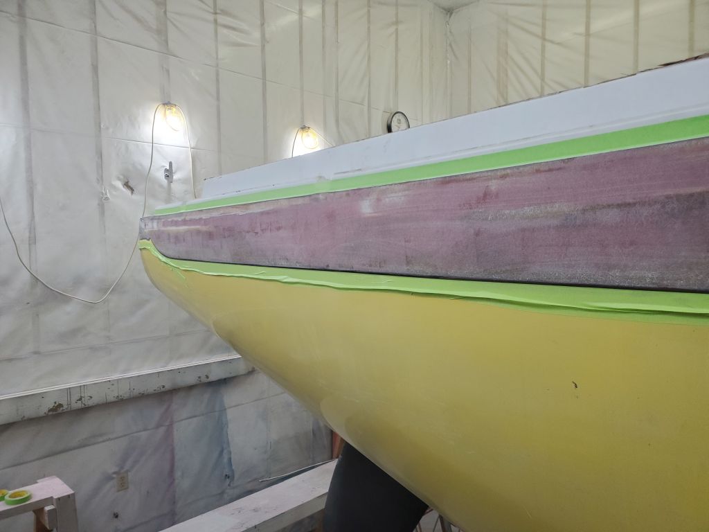
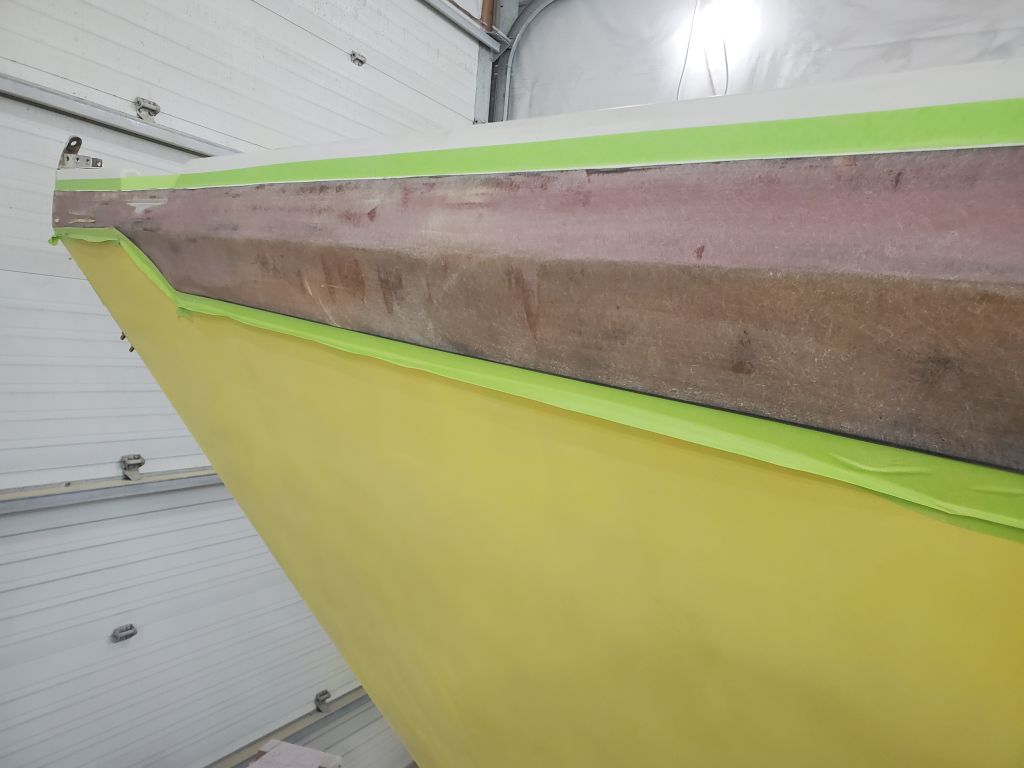
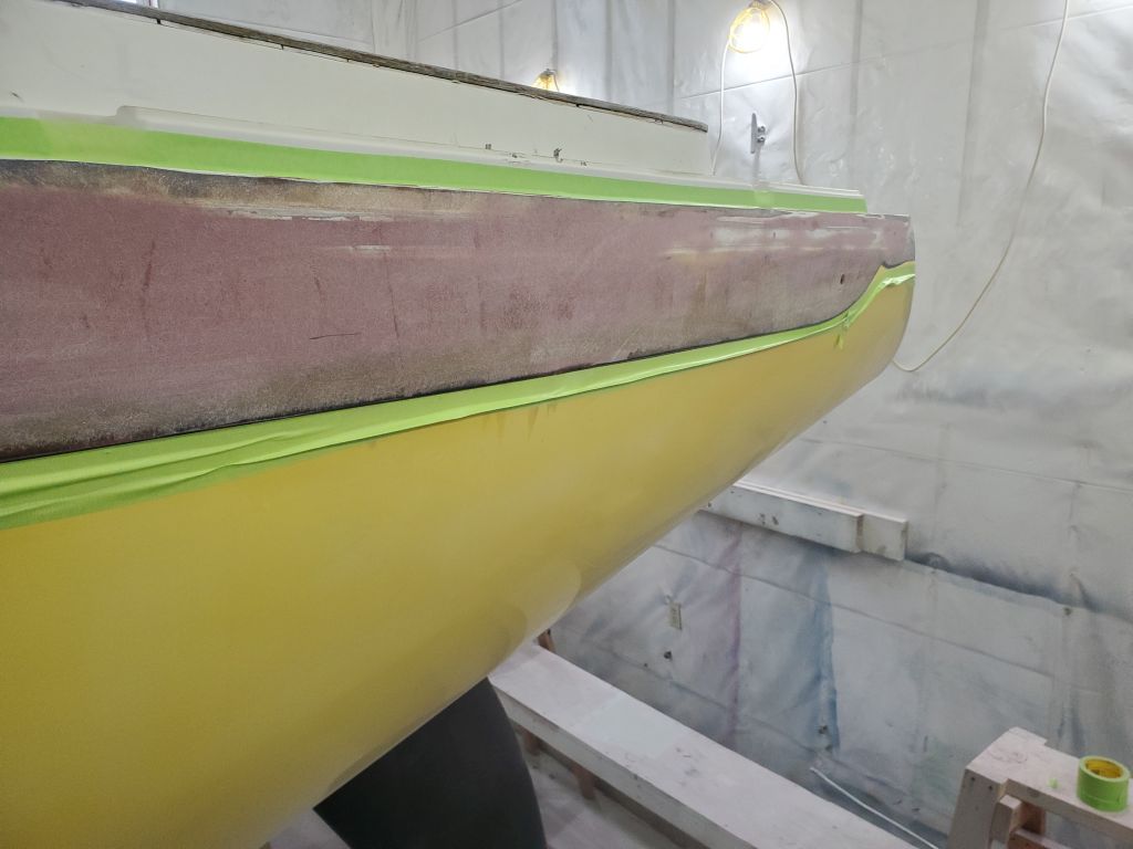
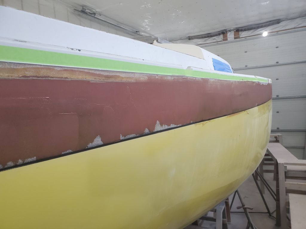
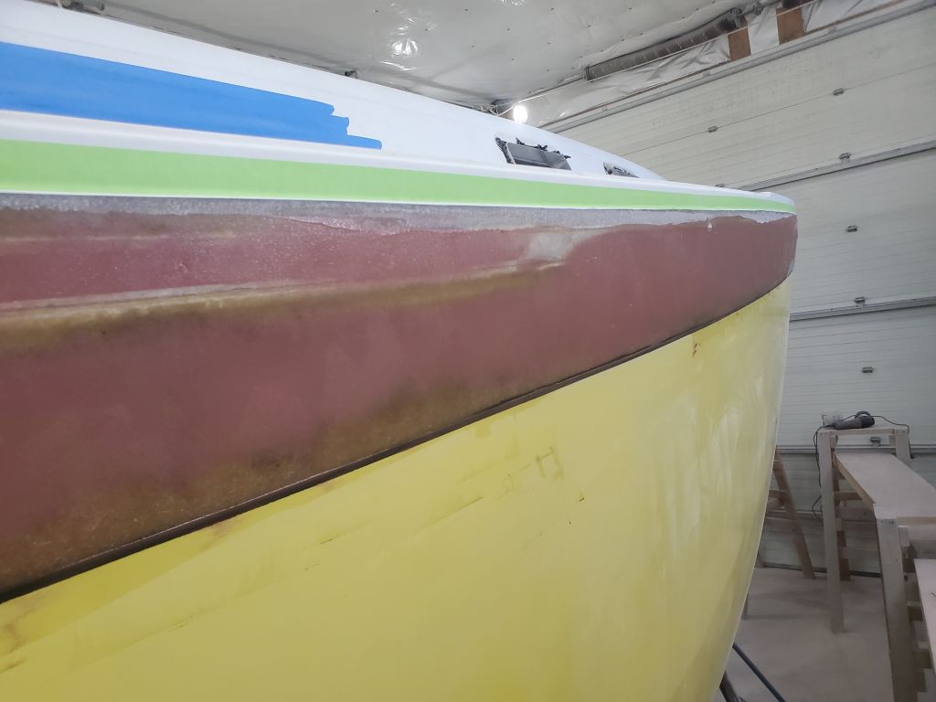
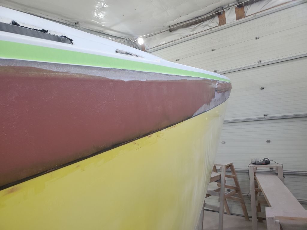
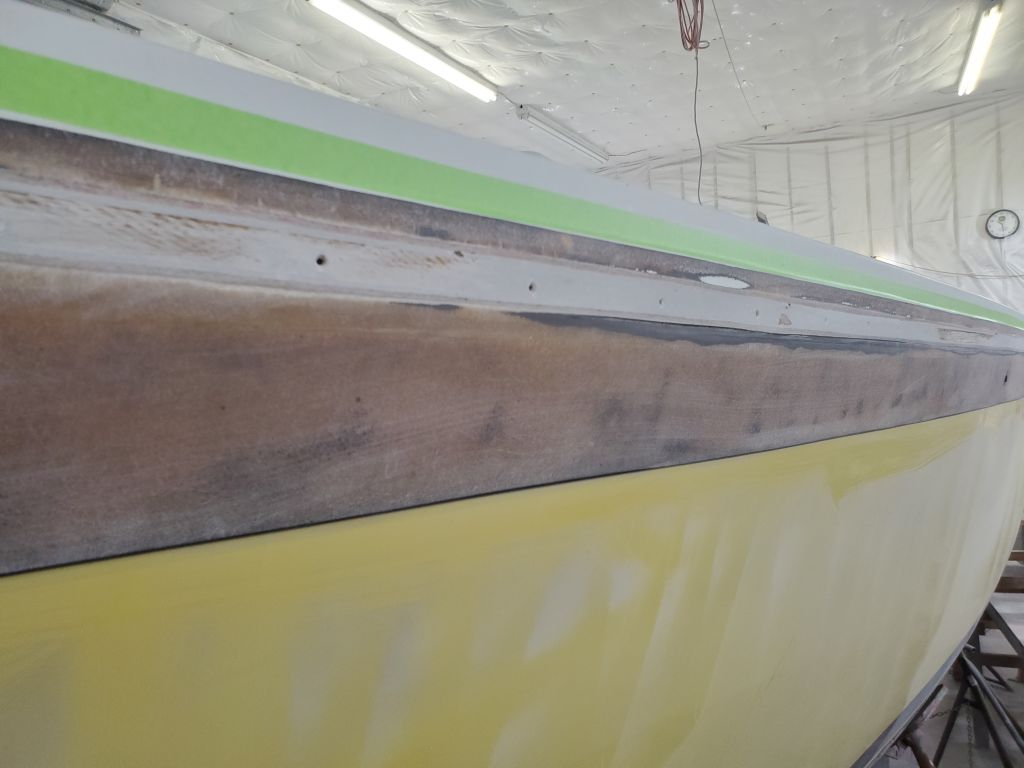
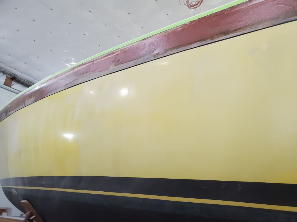
After cleaning and solvent-washing the joint, toerail, and sheer strake (and immediately-surrounding areas), I masked off the toerail just above the prepared area to keep it free from any epoxy during application below. Then, I applied thickened epoxy fairing filler as needed to fill the fastener holes, voids throughout the area, and begin to create a fair overall surface that I could fiberglass over when all was said and done. The first round of filler wasn’t going to complete the work, but began to form the required contours and would make it easy for a second round to complete adequately before glasswork could begin.
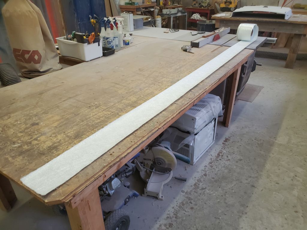
During the afternoon, I wanted to move the project forward, but the next logical thing to do was to start sanding the remainder of the topsides, which, frankly, just wasn’t a Friday afternoon kind of thing to do, and would have created a new mess to clean up before the weekend, as I don’t leave the shop a mess over the weekend (I can barely manage it over a night or two). So instead, I rolled out and cut 3′ long sections of 6″ and 4″ 1708 tabbing for the hull-deck joint–it had to be done eventually, and this was more the right speed for the end of the week. In the past I’ve found this to be a good size to manage during installation, butting the joints and offsetting the layers by half so each seam has good overlap.
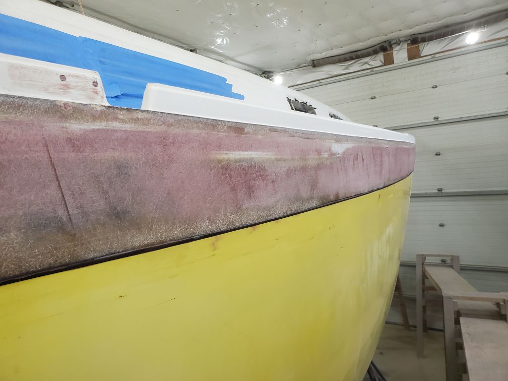
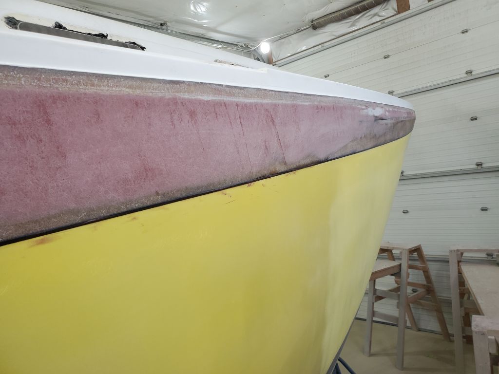
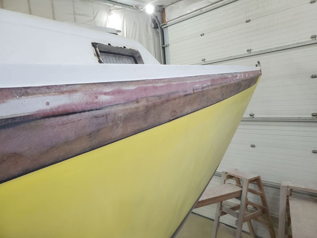
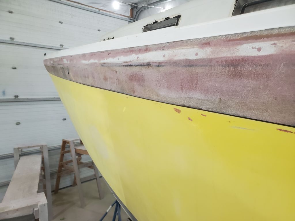
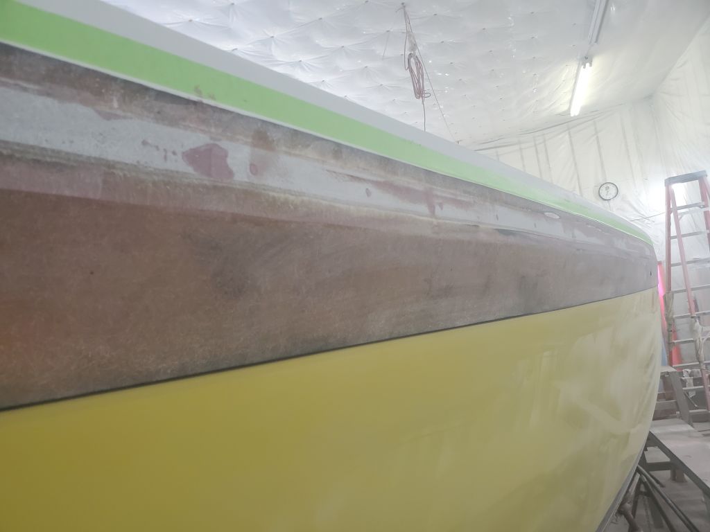
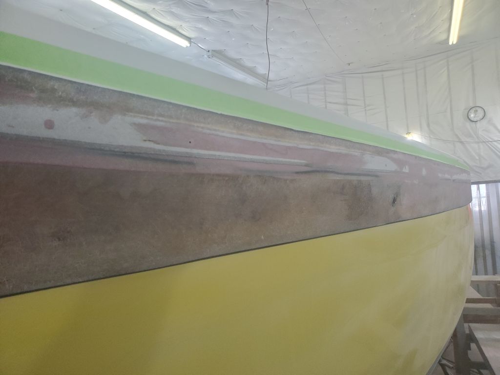
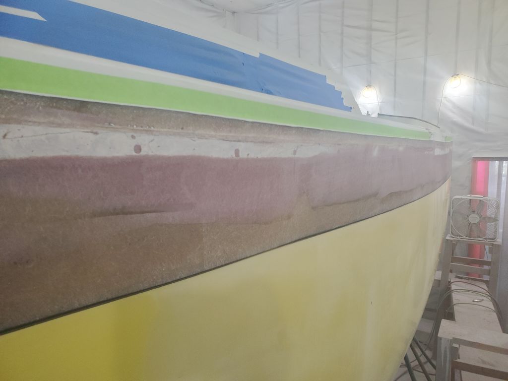
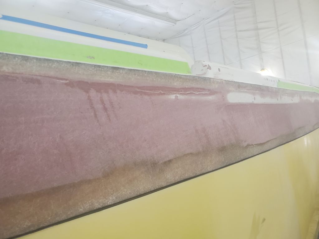
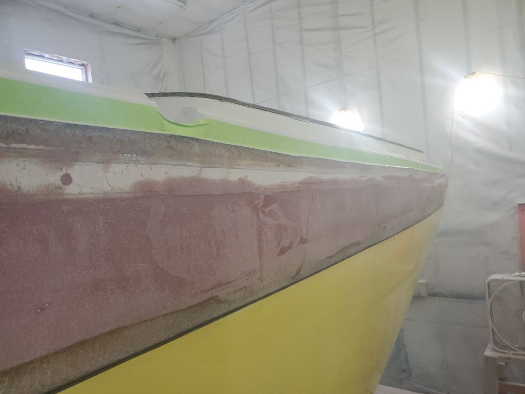
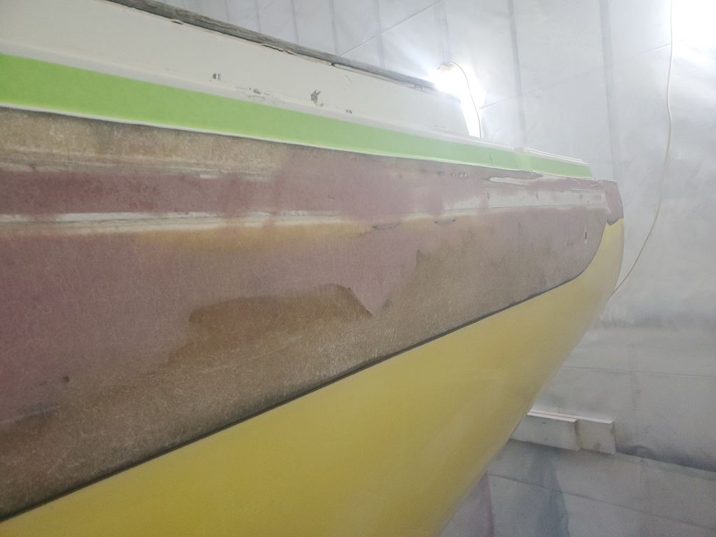
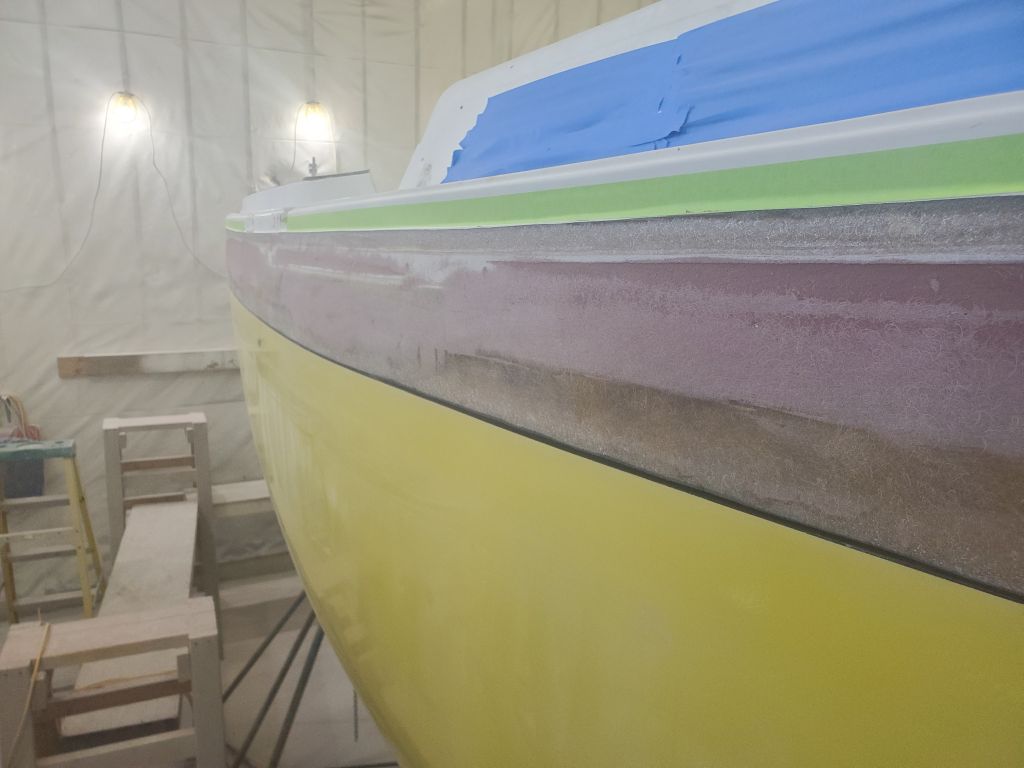
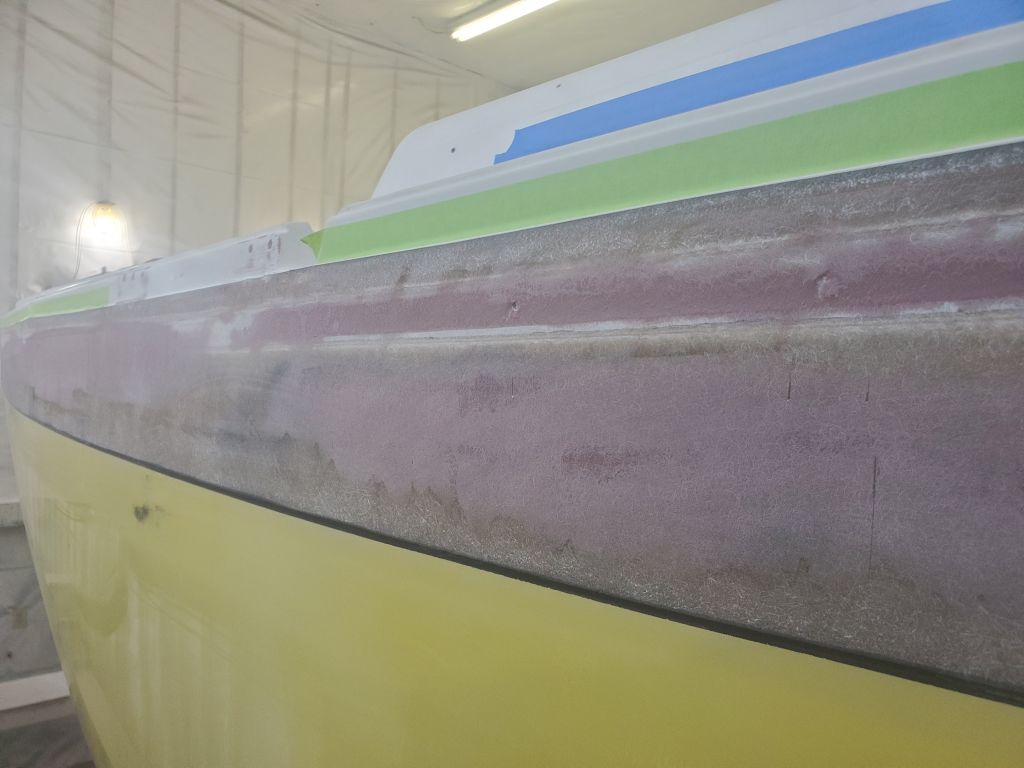
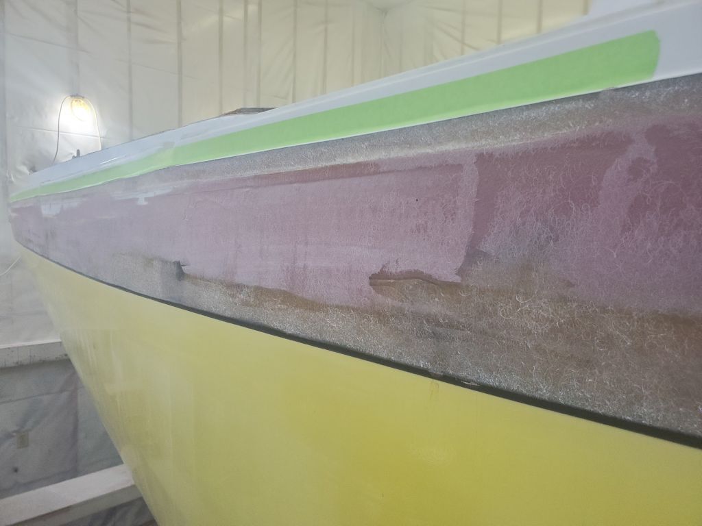
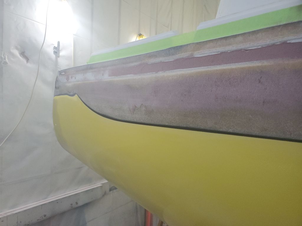
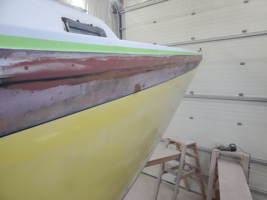
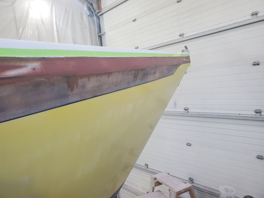
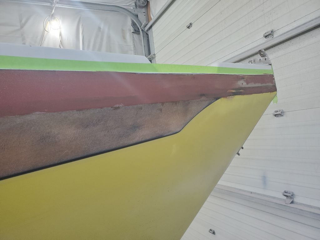
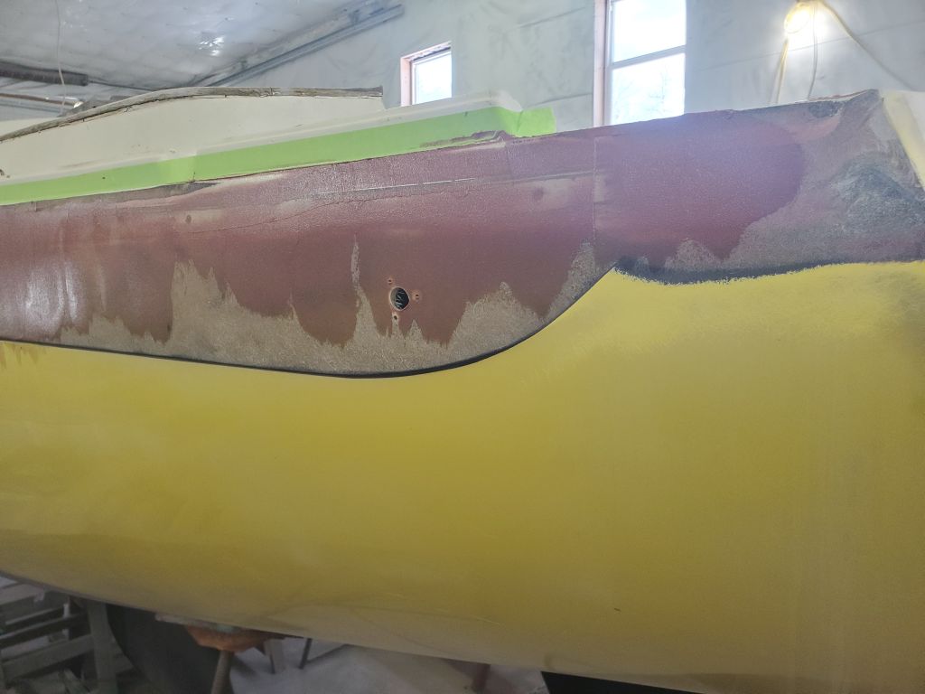
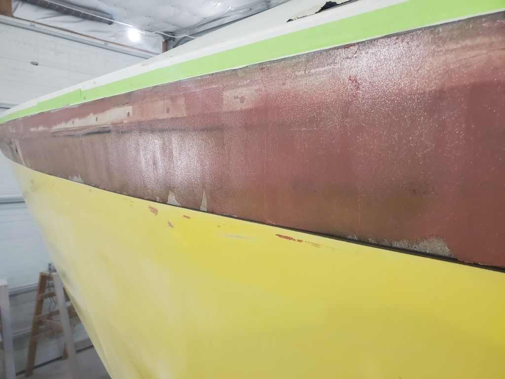
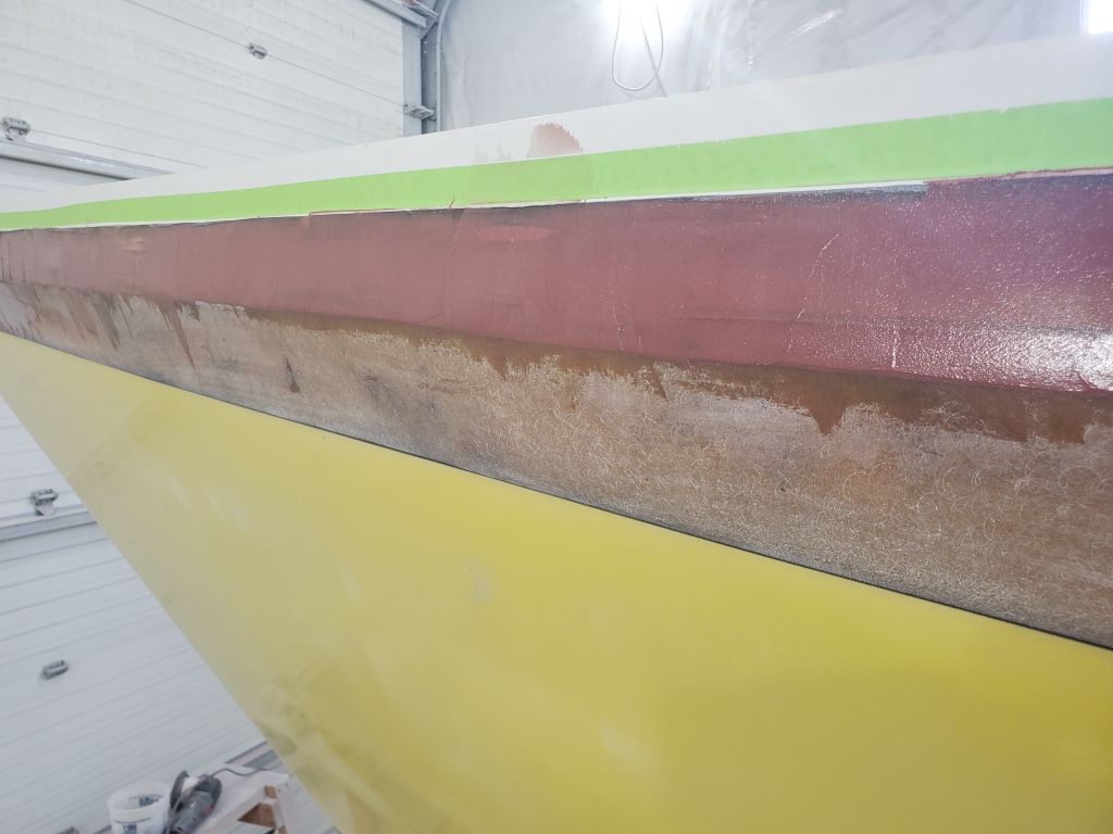
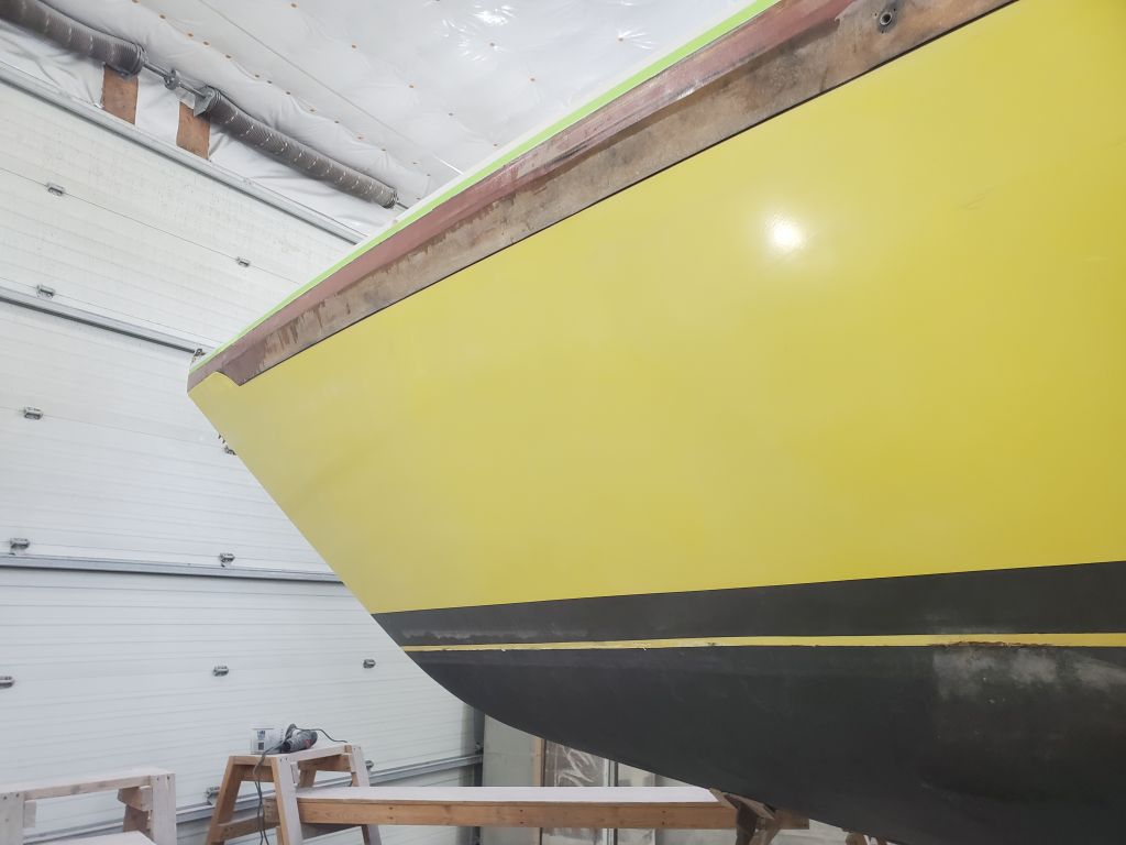
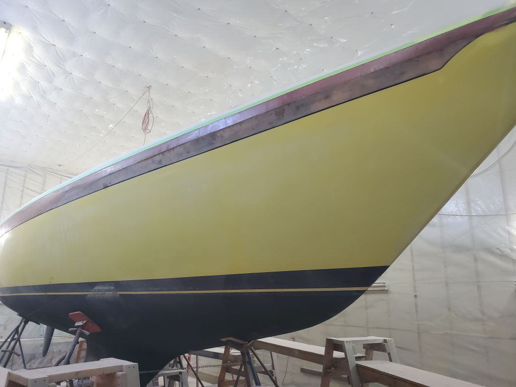
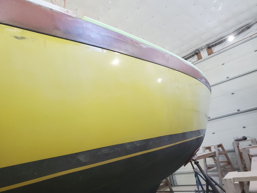
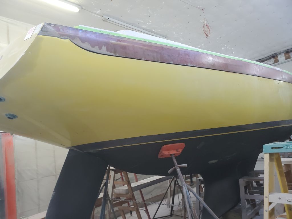
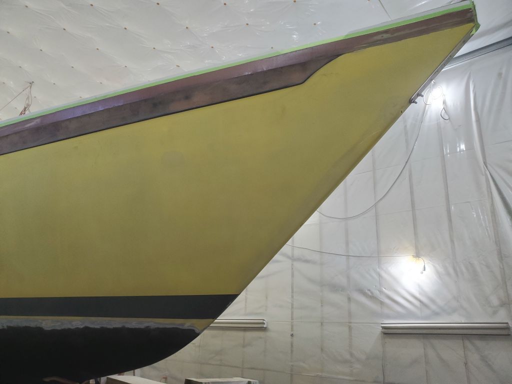
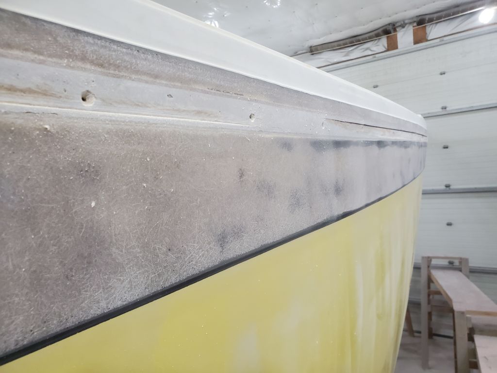
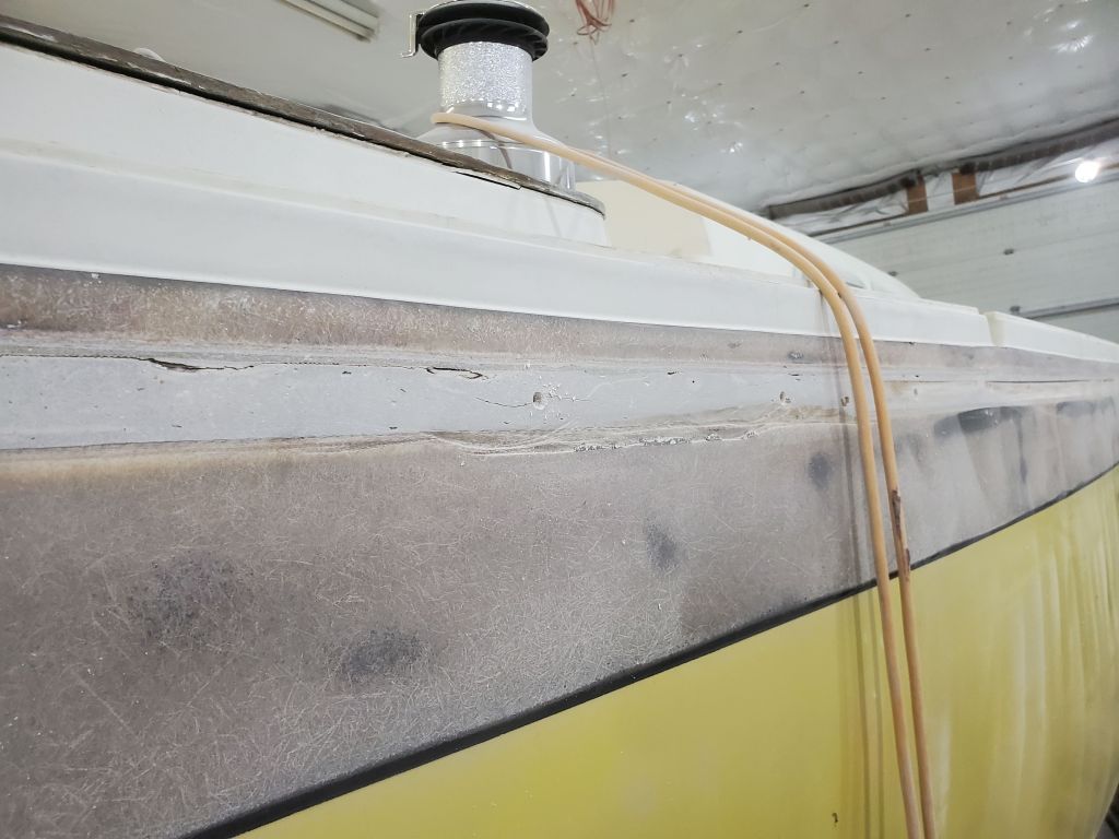
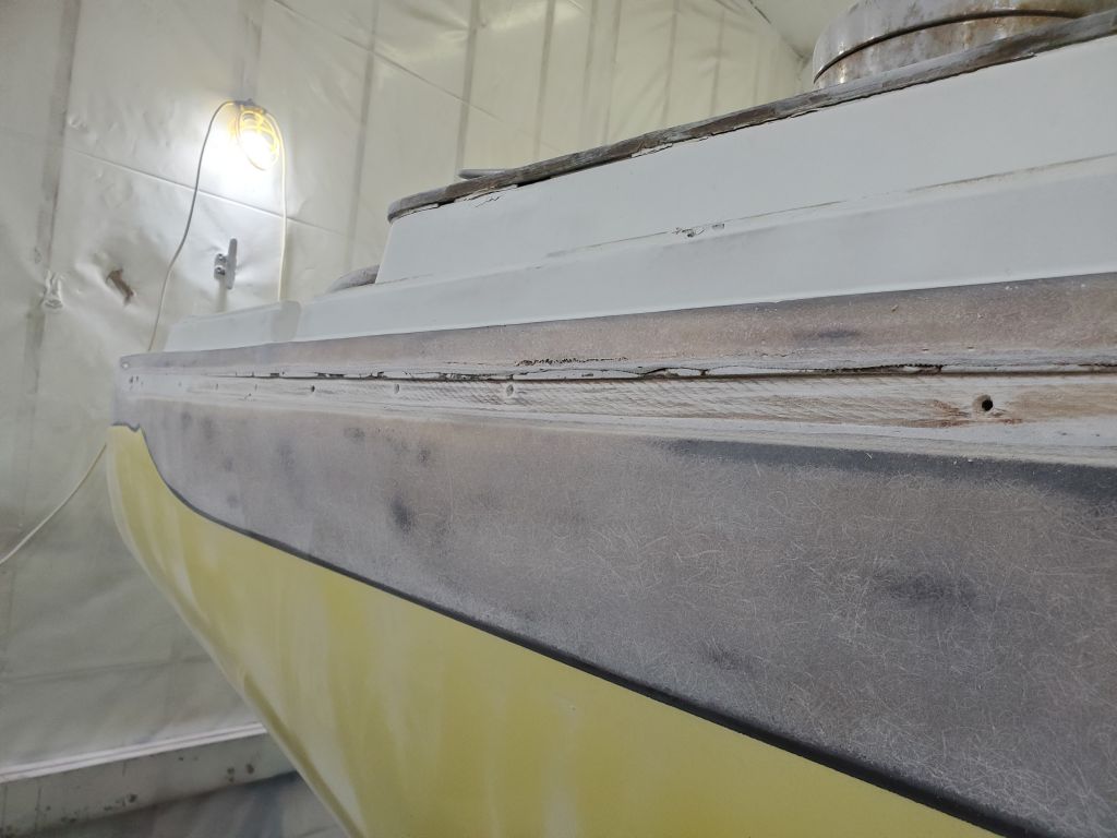
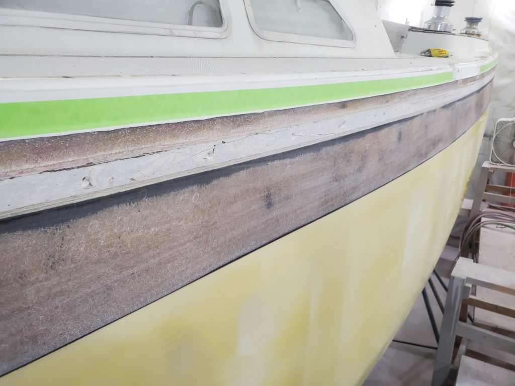
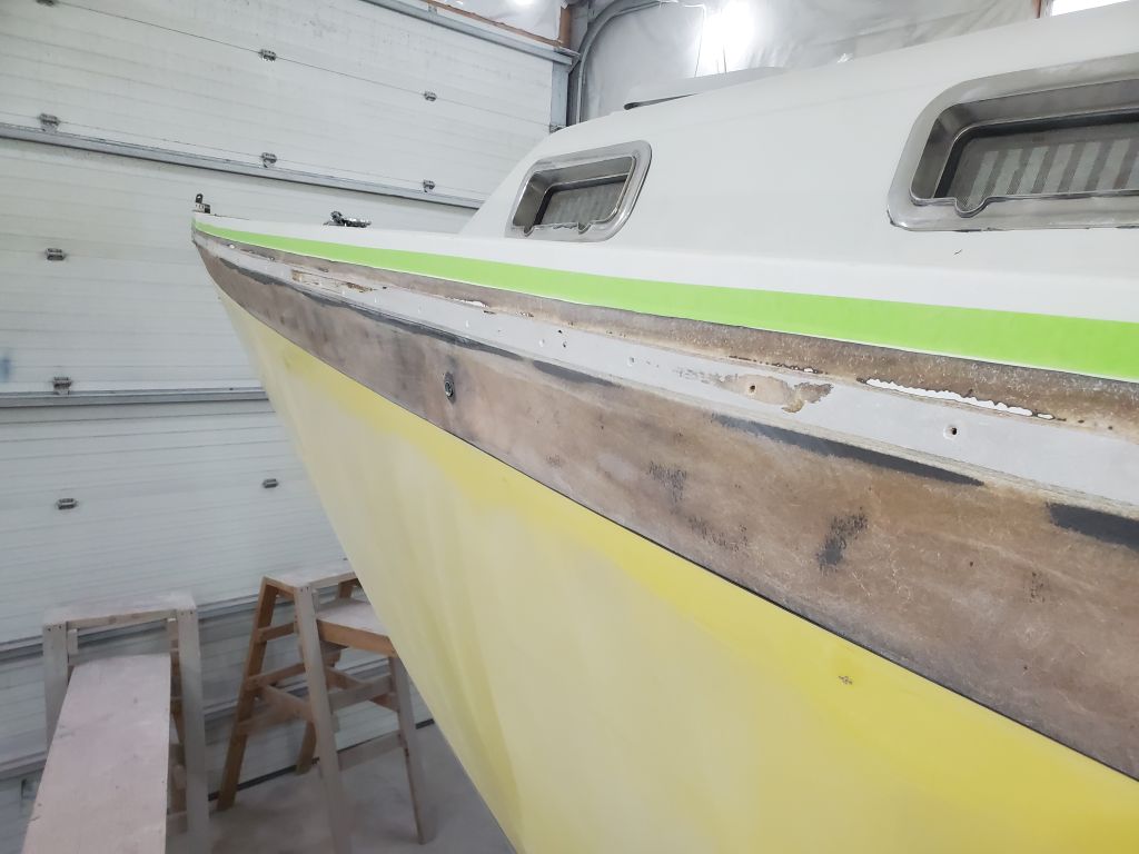
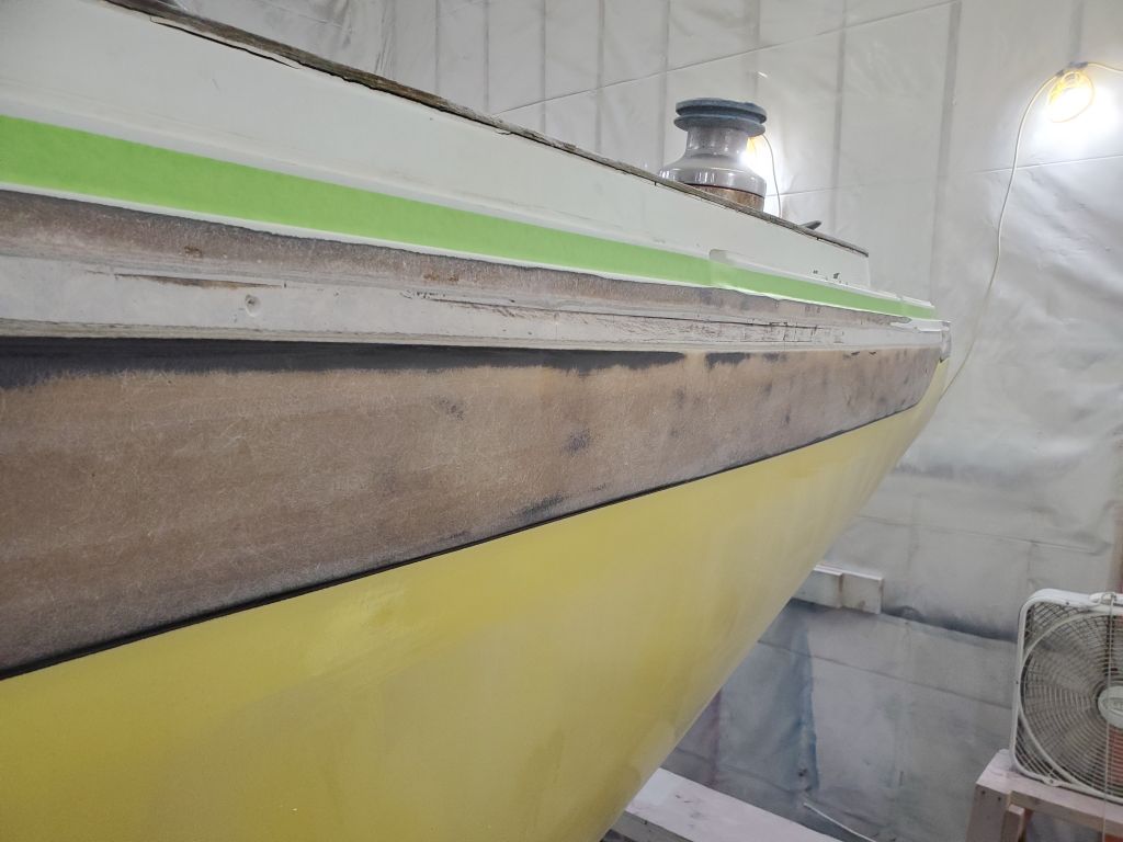
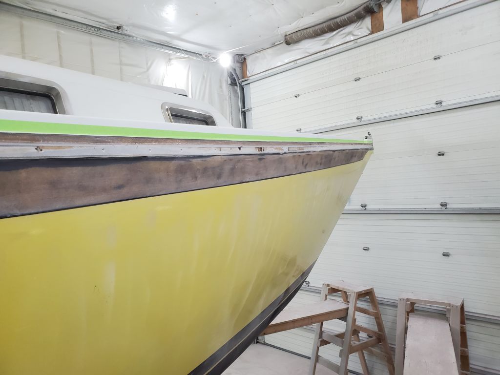
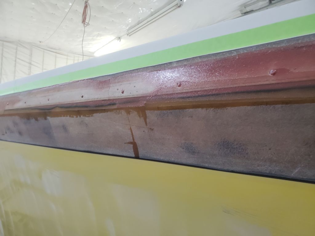
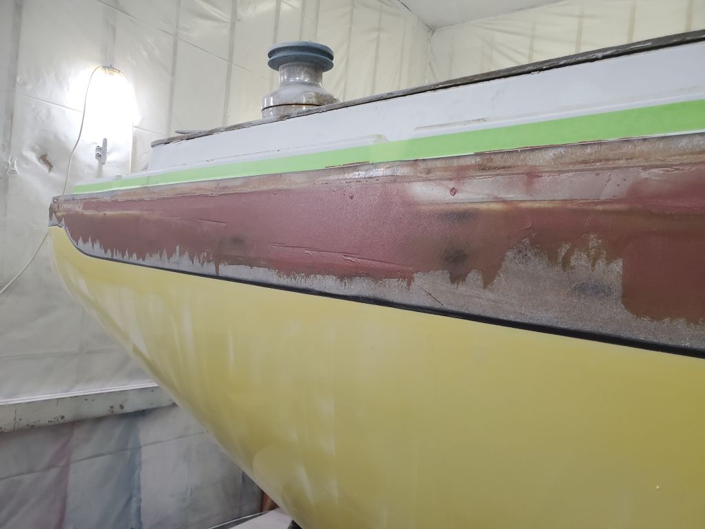
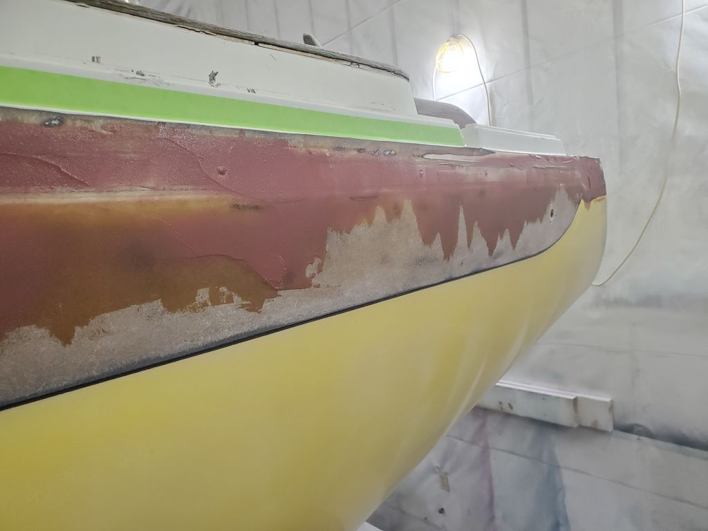
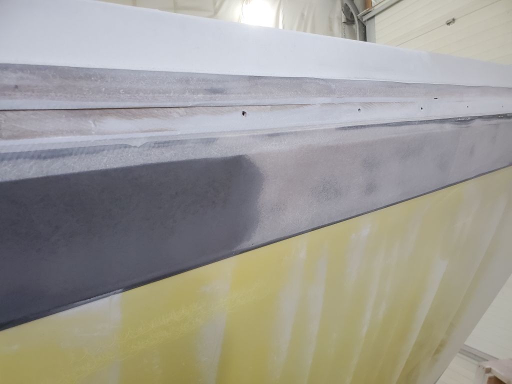
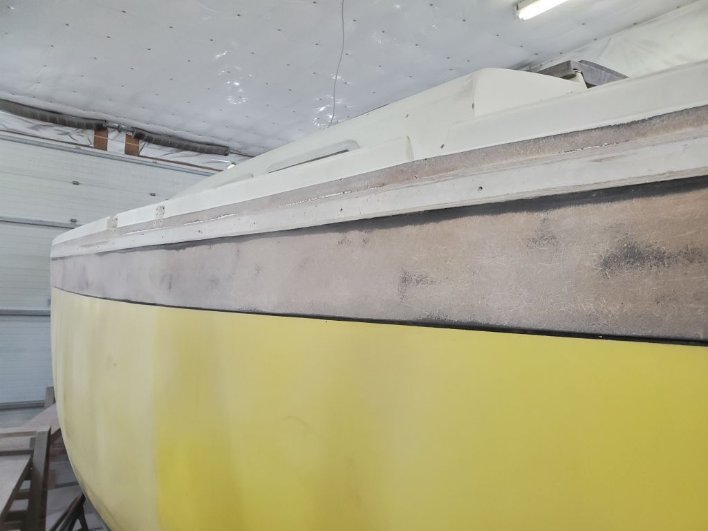
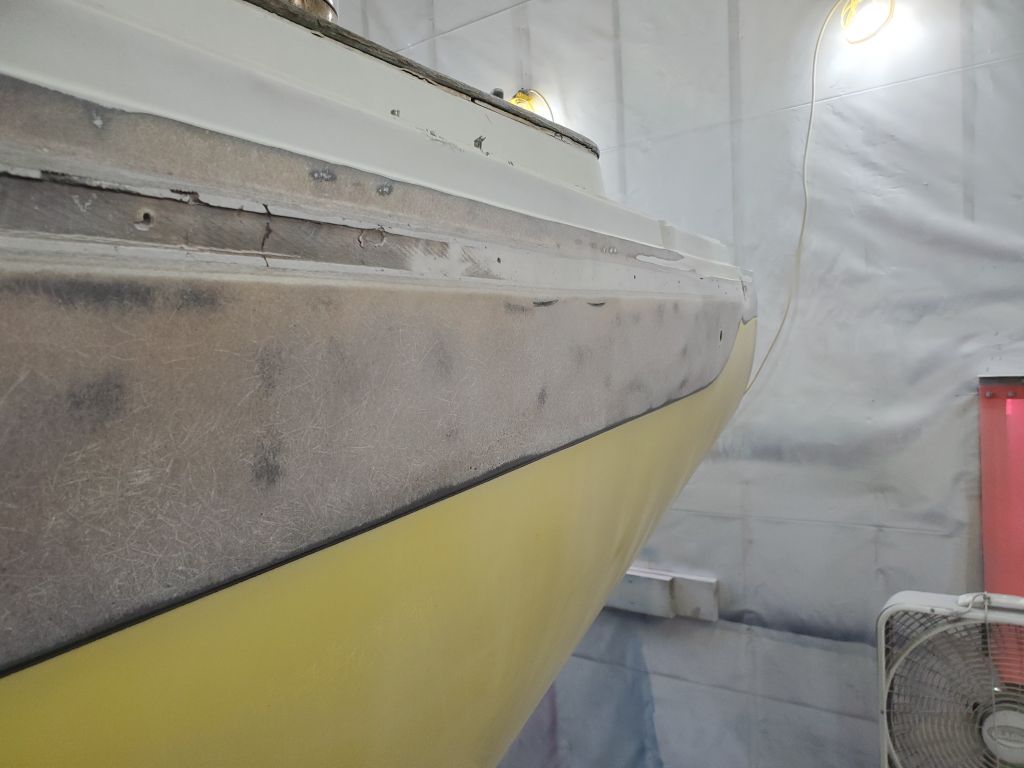
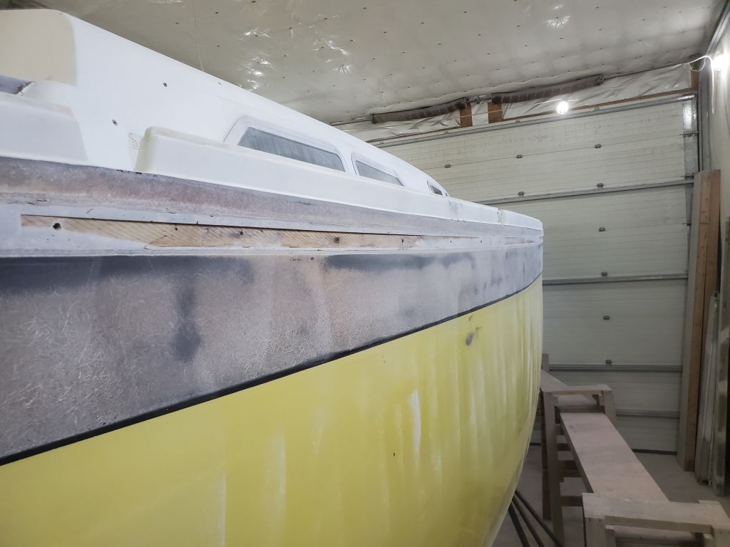
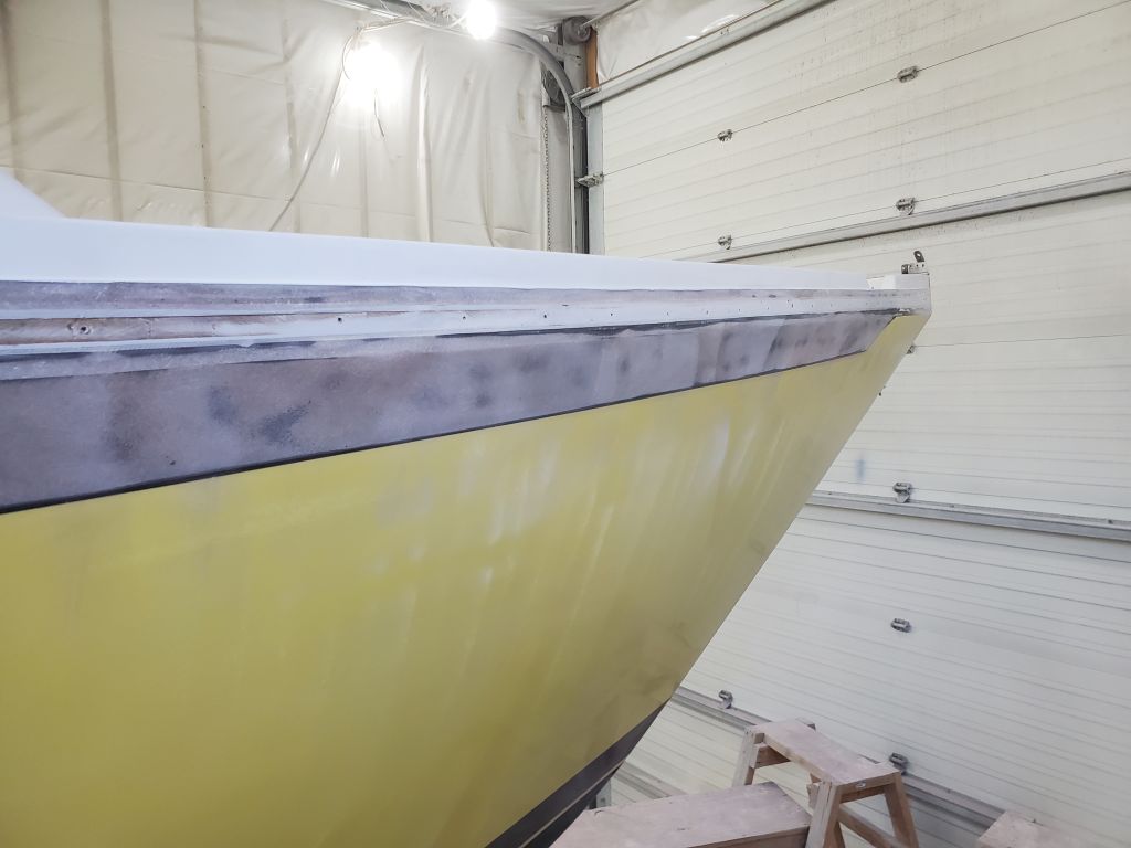
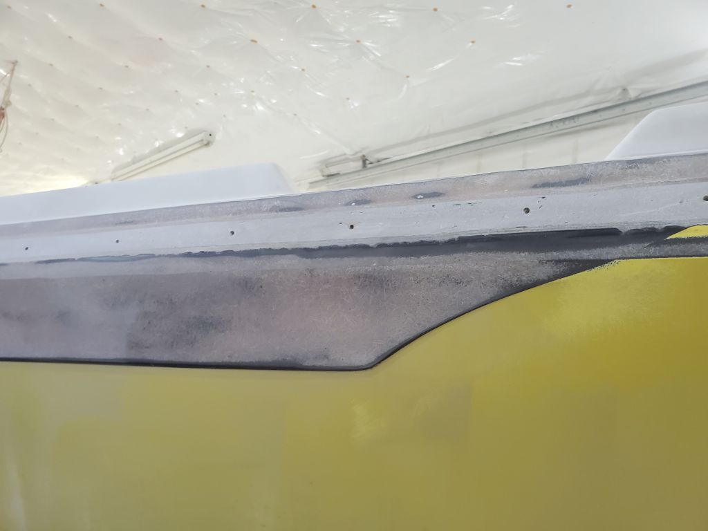
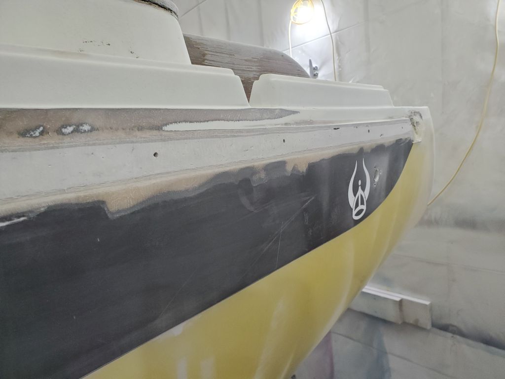
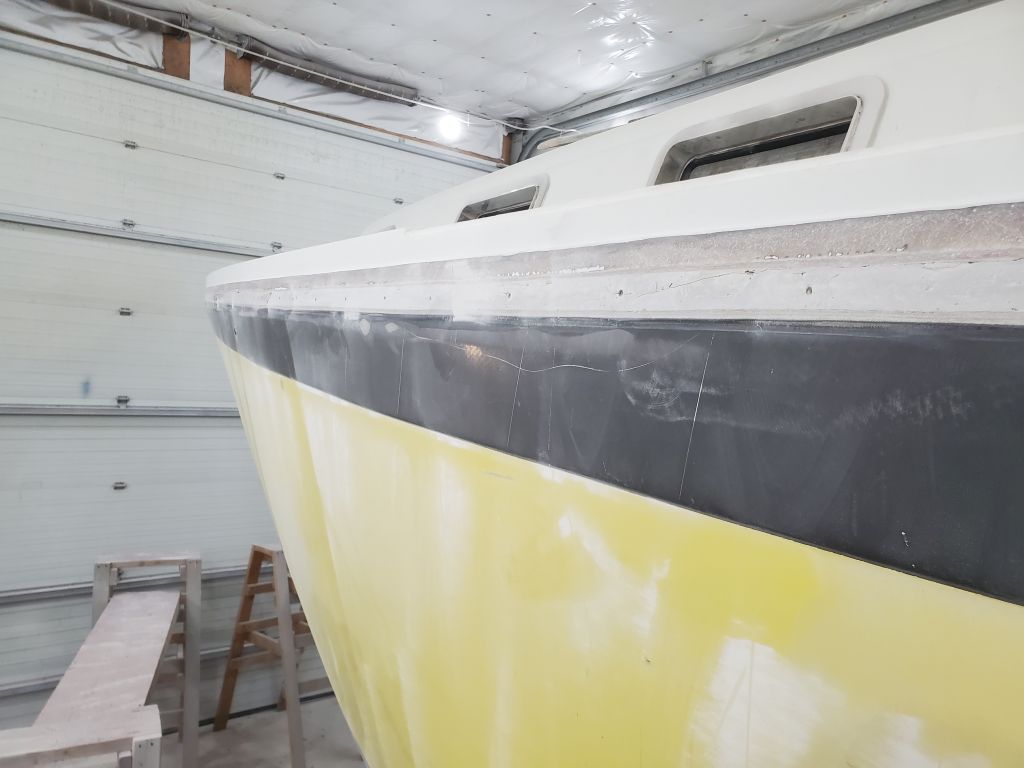
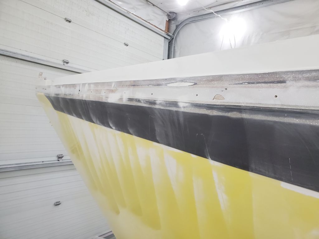
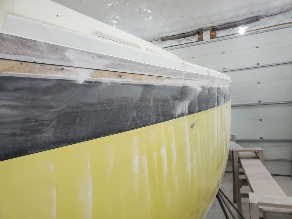
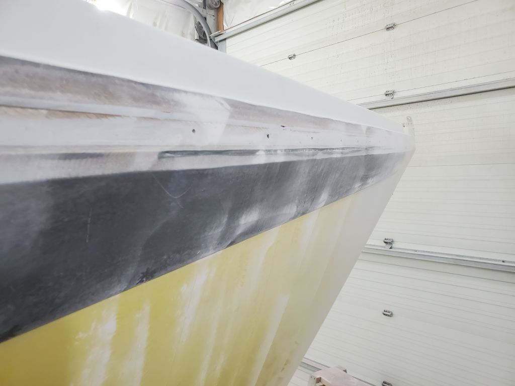
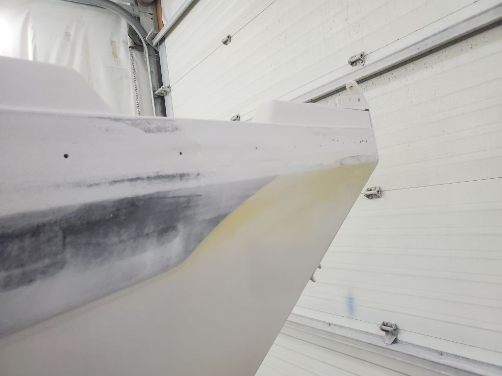
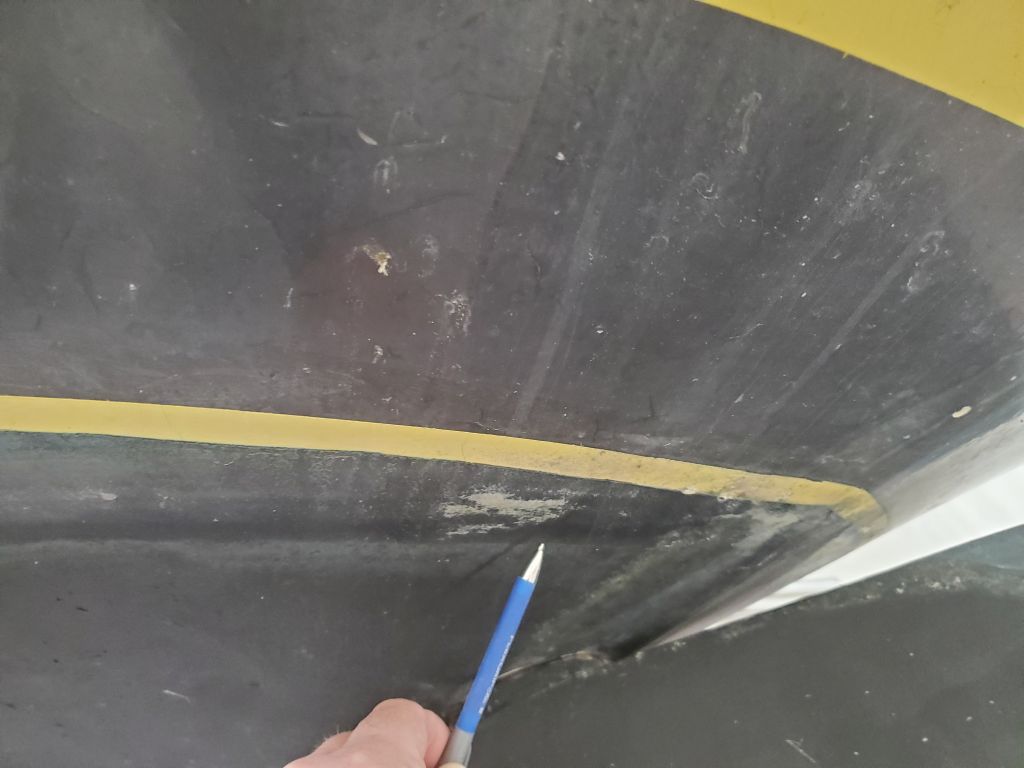
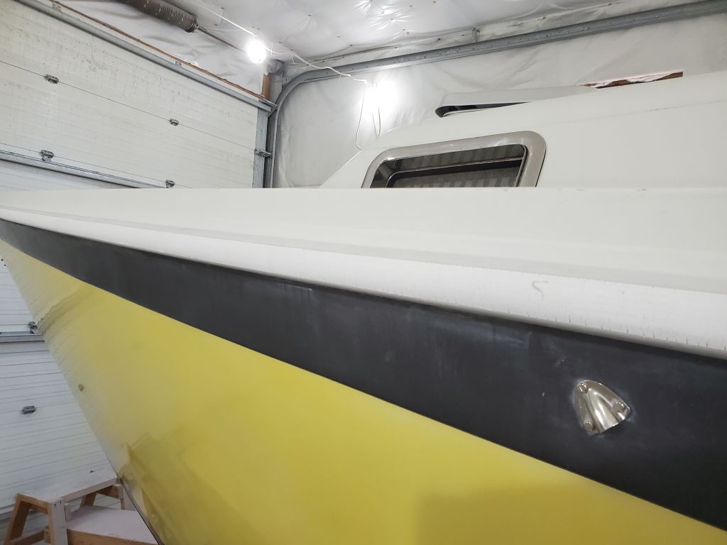
Armed with a different, less aggressive sander and coarse discs, I continued work on the hull-deck joint area, removing the gelcoat from the black sheer strake and going over the rest of the area I’d ground in way of the old rubrail. This sanding session prepared the area for the new epoxy and fiberglass work ahead. In removing the black gelcoat, I strove first to maintain the shape of the hull so that fairing the new fiberglass would be as straightforward as possible, so there low remained areas (still colored black) that required minor filling before the tabbing operation, as well as some of the still-recessed areas left from the original joint construction and where the wooden strip had been.
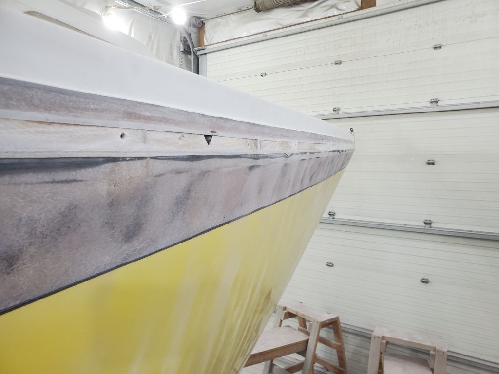
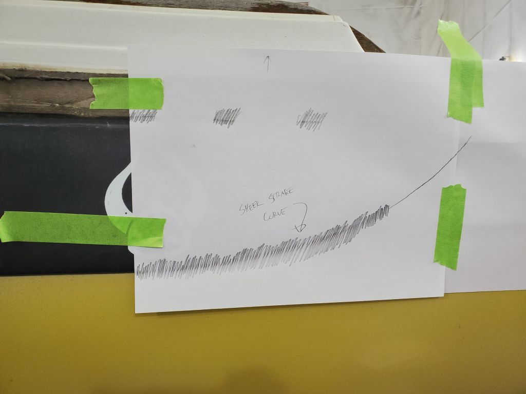
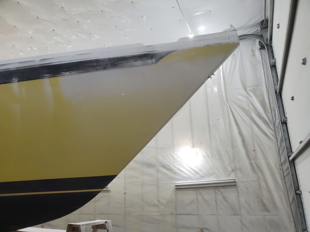
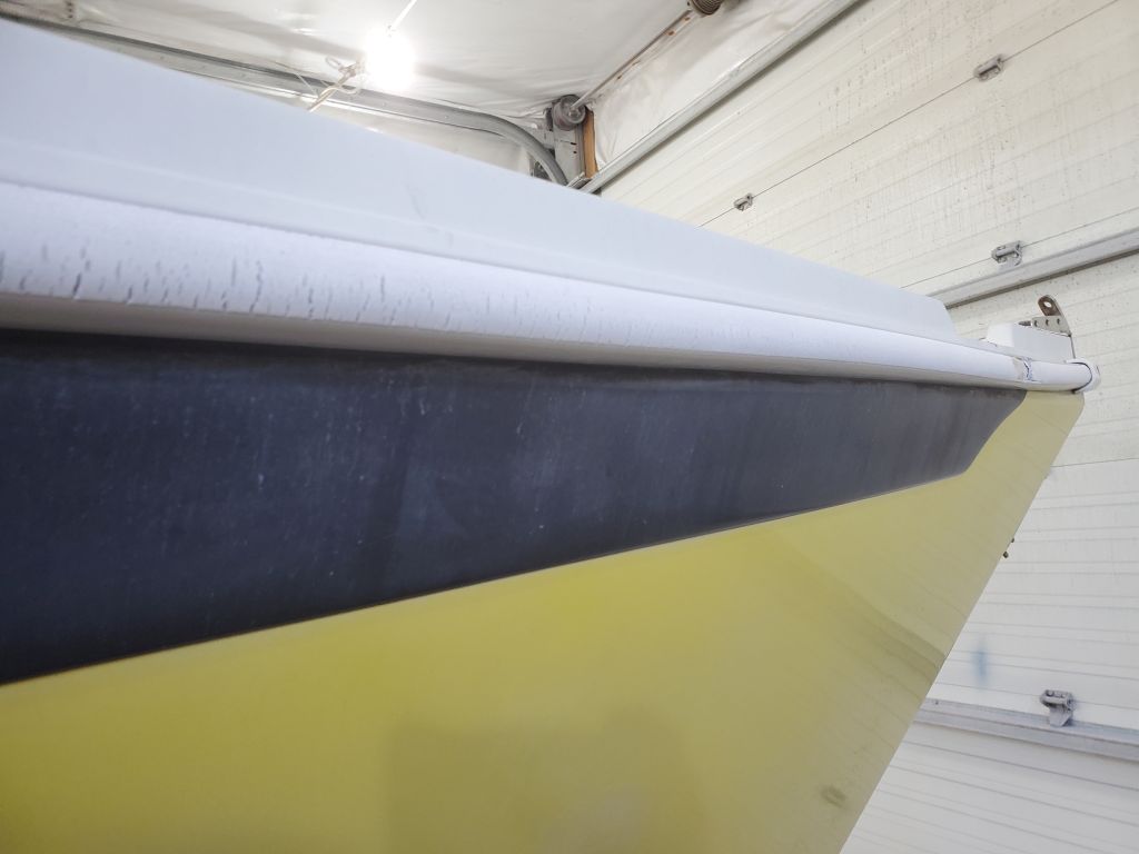
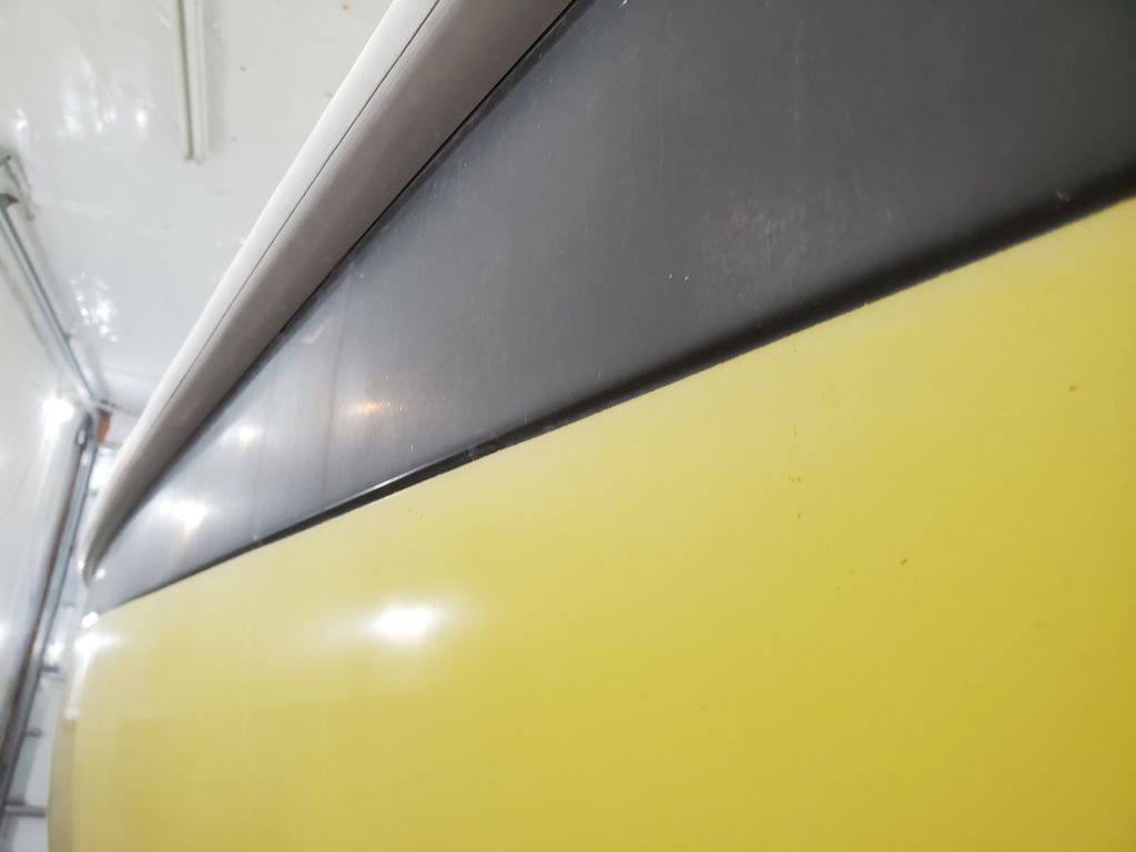
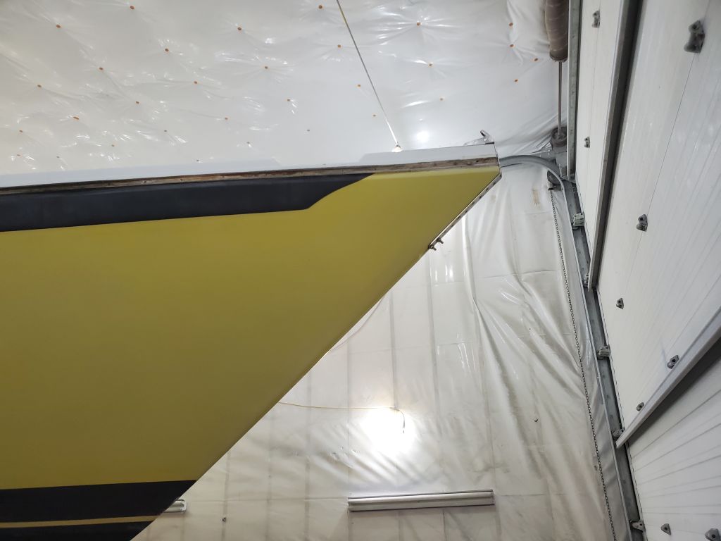
The sheer strake seemed almost tailor-made for this project, with its slightly raised (versus the rest of the hull) profile and perfect depth to allow easy installation of 6″ fiberglass over the seam later, which would span the joint between the molded character line in the deck molding at the top edge and the bottom edge of the proud sheer strake.
With sanding complete for the moment, I cleaned up the boat and shop to a tolerable level. It would have been nice to move on with some additional minor prep work and epoxy filling, but I didn’t have enough time to do this before I had to leave for an appointment, so I’d continue next time.
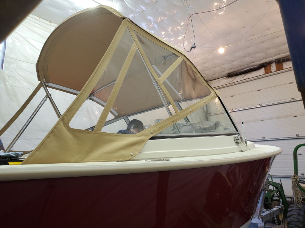
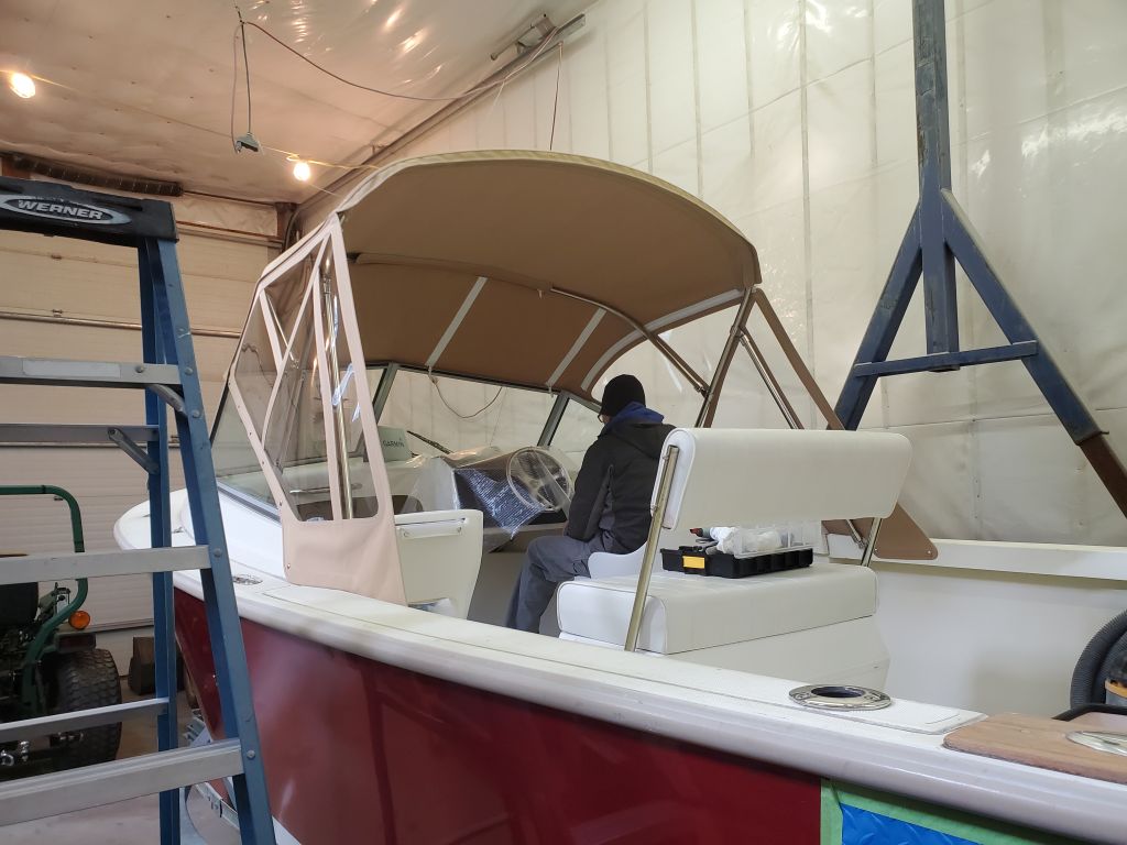
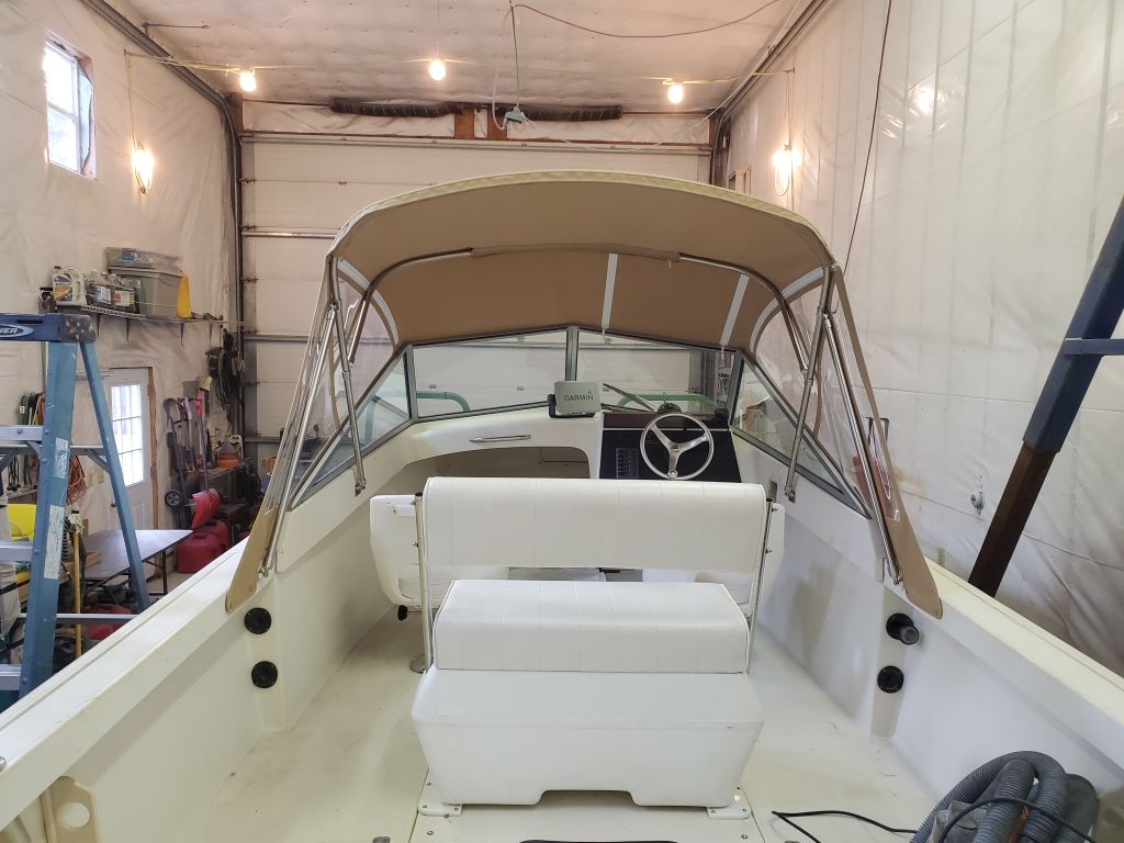
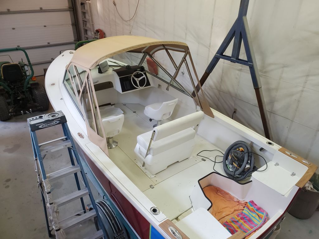
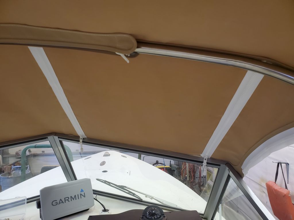
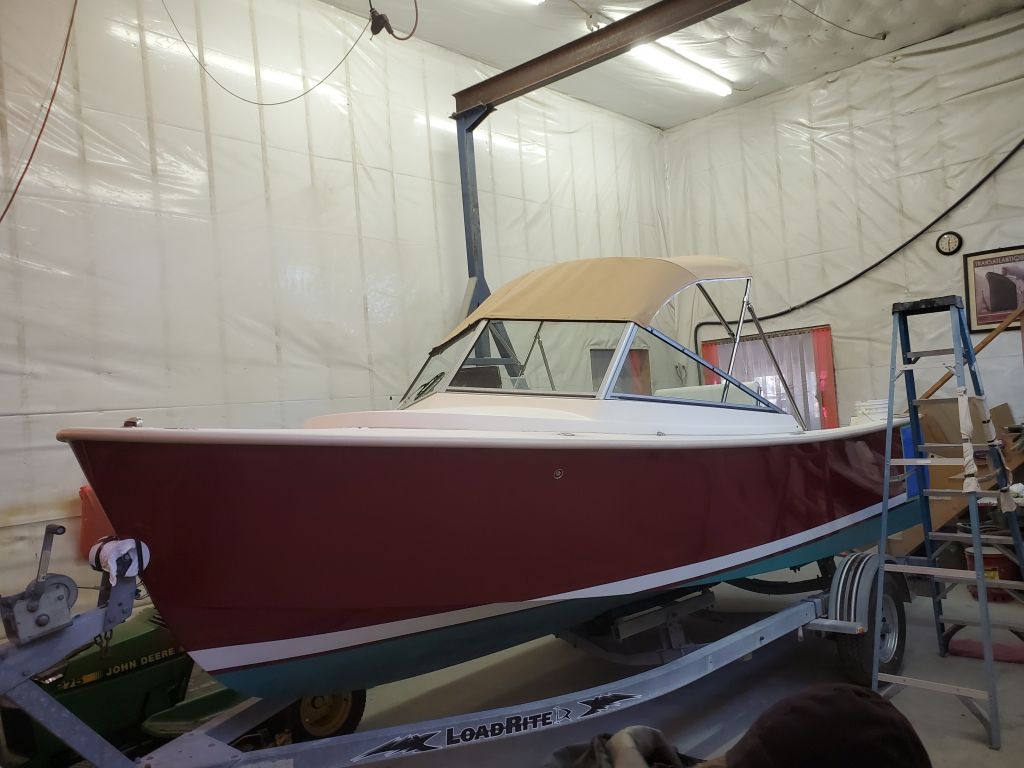
The final step in this project was finishing up the new canvas installation with the side curtains, which Jason had built over the past several days and now installed permanently.
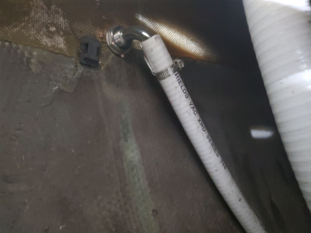
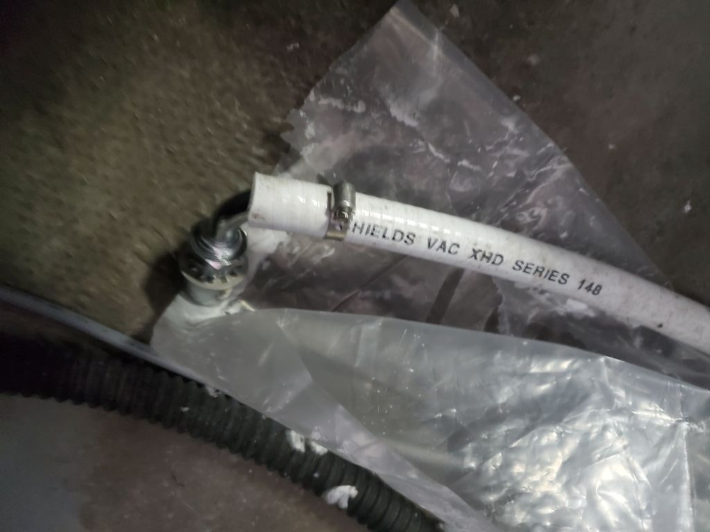
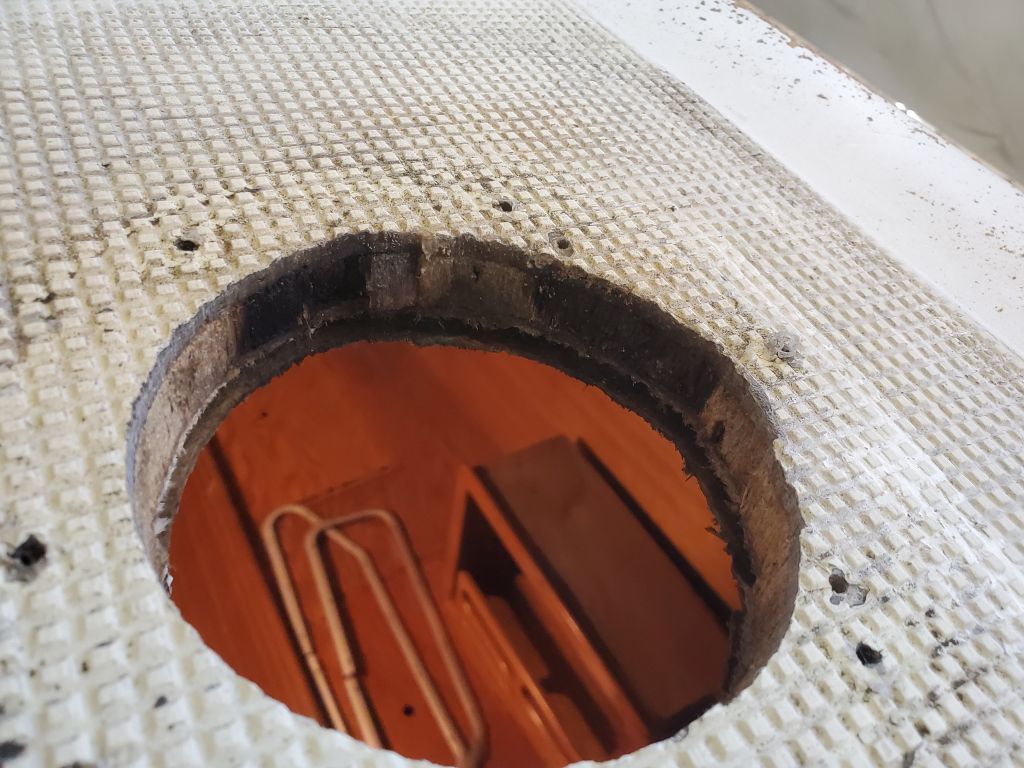
Before starting on the prep work at the hull-deck joint/rubrail, I removed a tank vent fitting from the port quarter, as the fitting would soon be in the way. The fitting was only hand-tight and easy to remove, and I stuck the vent back in the hose inside the locker for safekeeping.
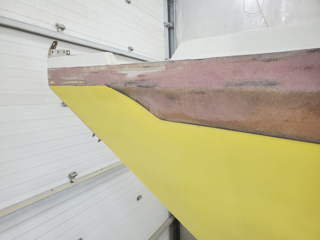
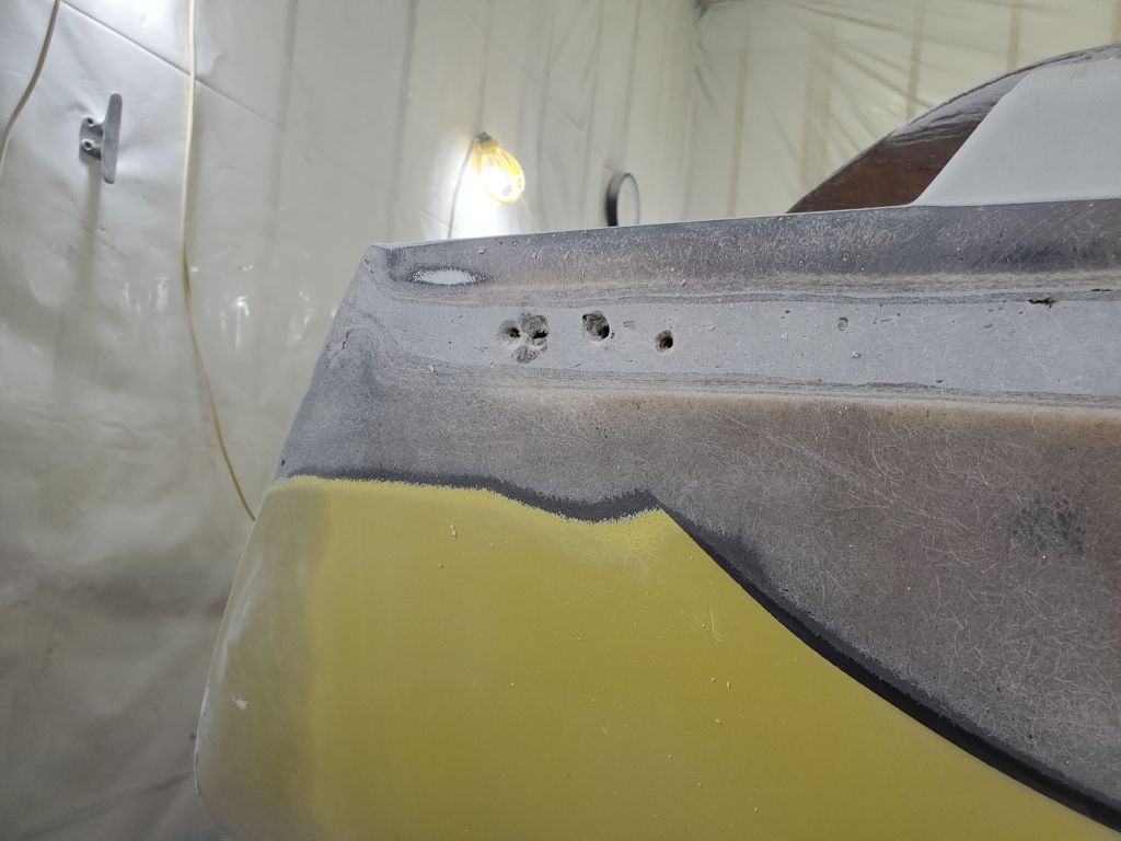
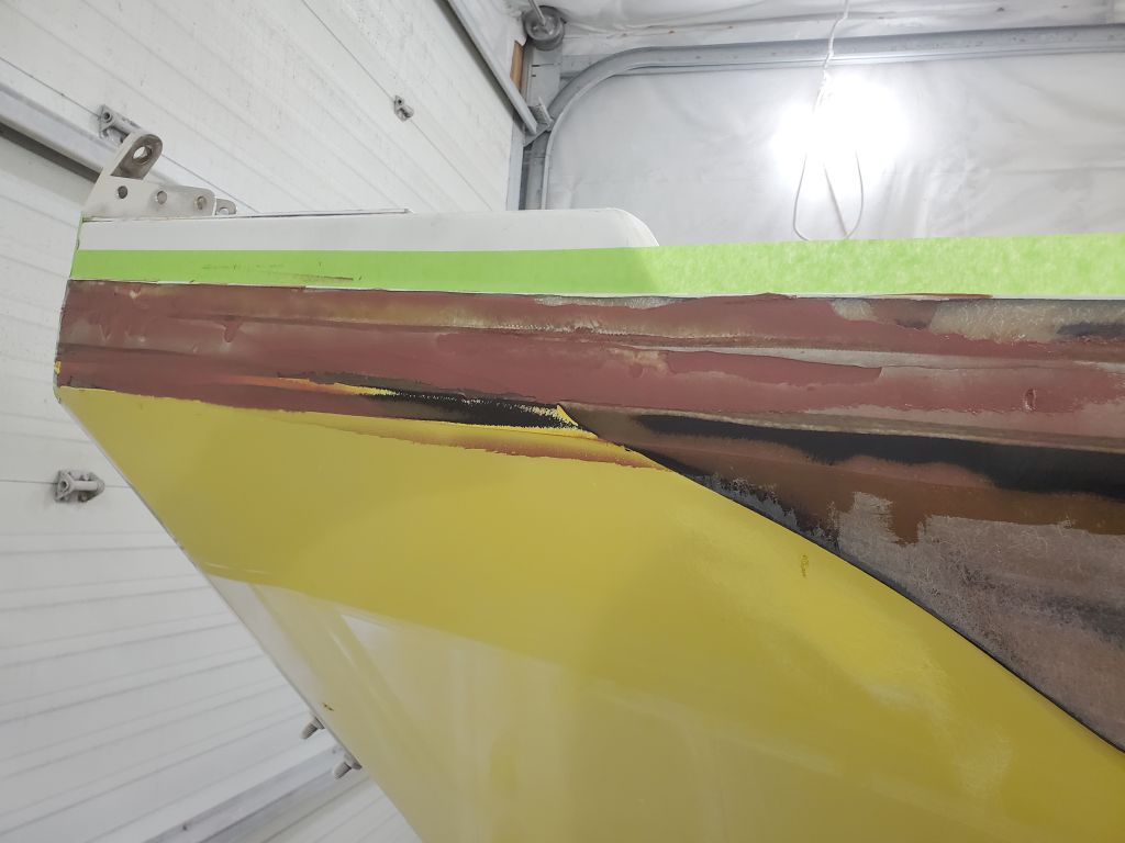
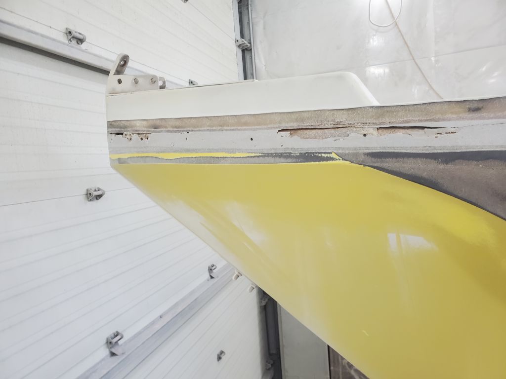
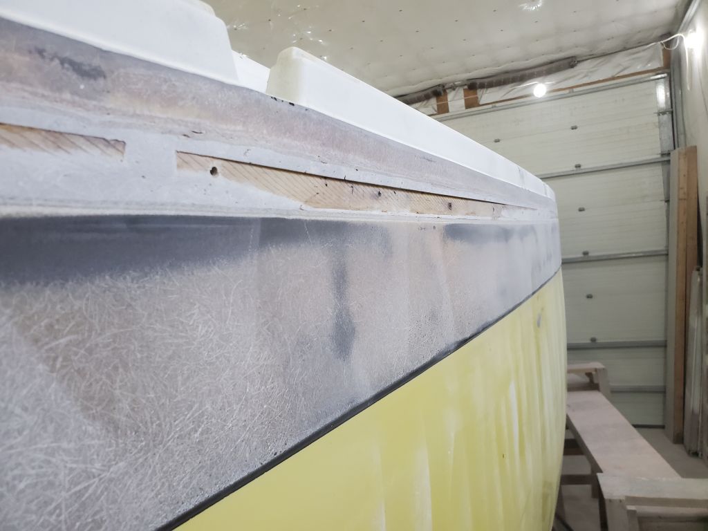
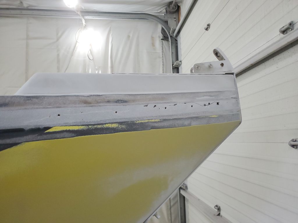
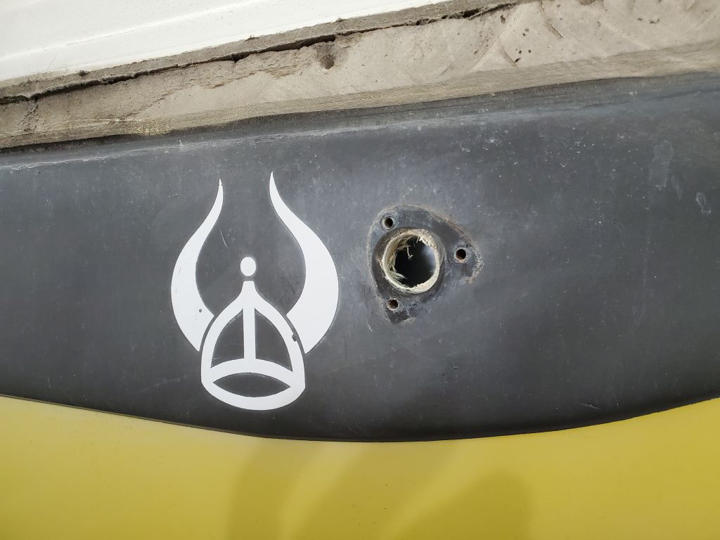
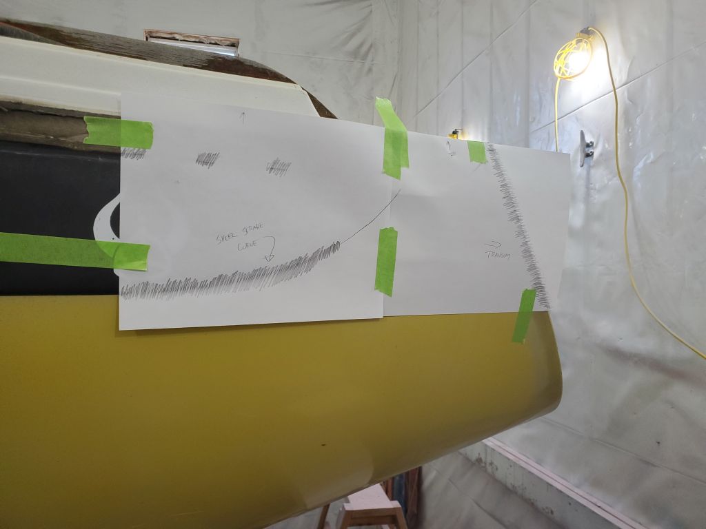
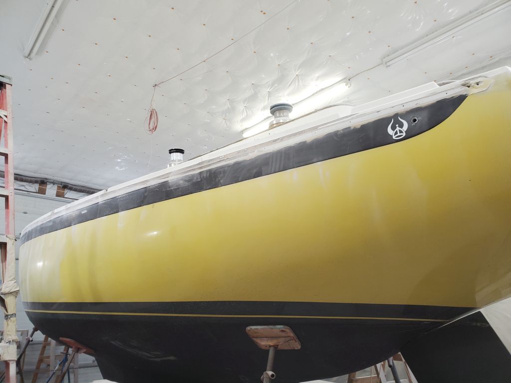
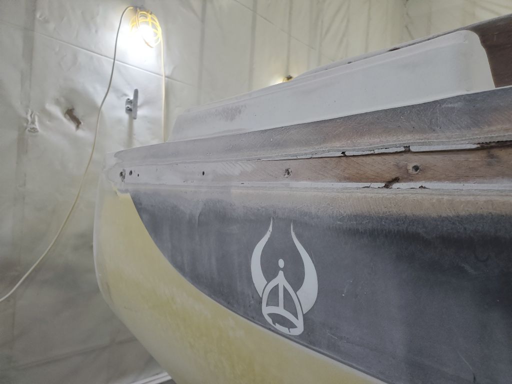
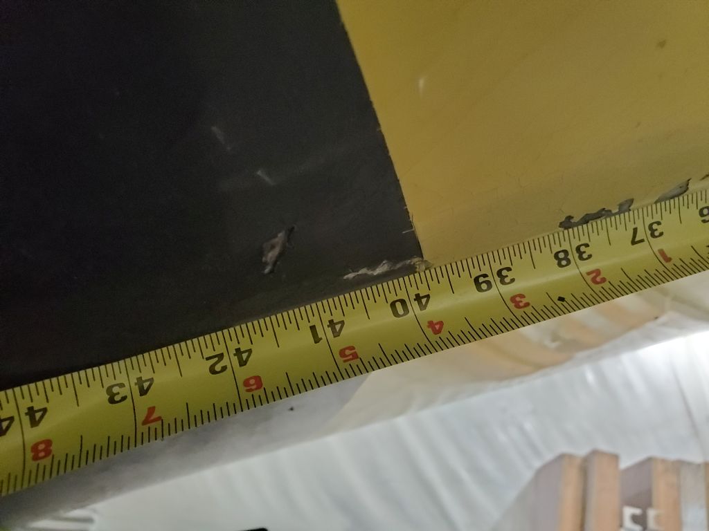
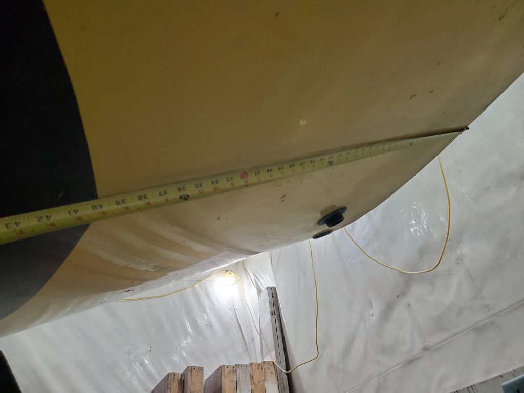
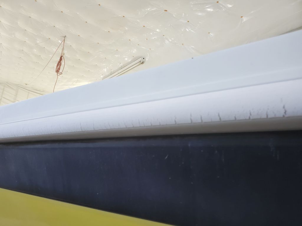
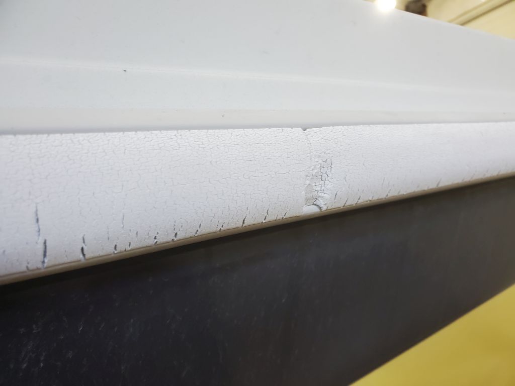
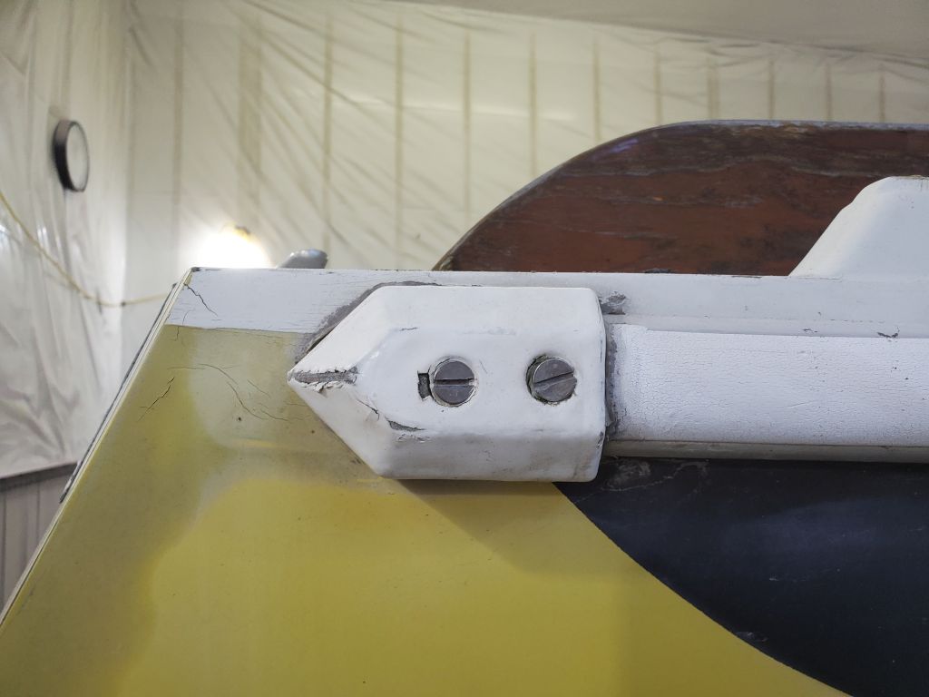
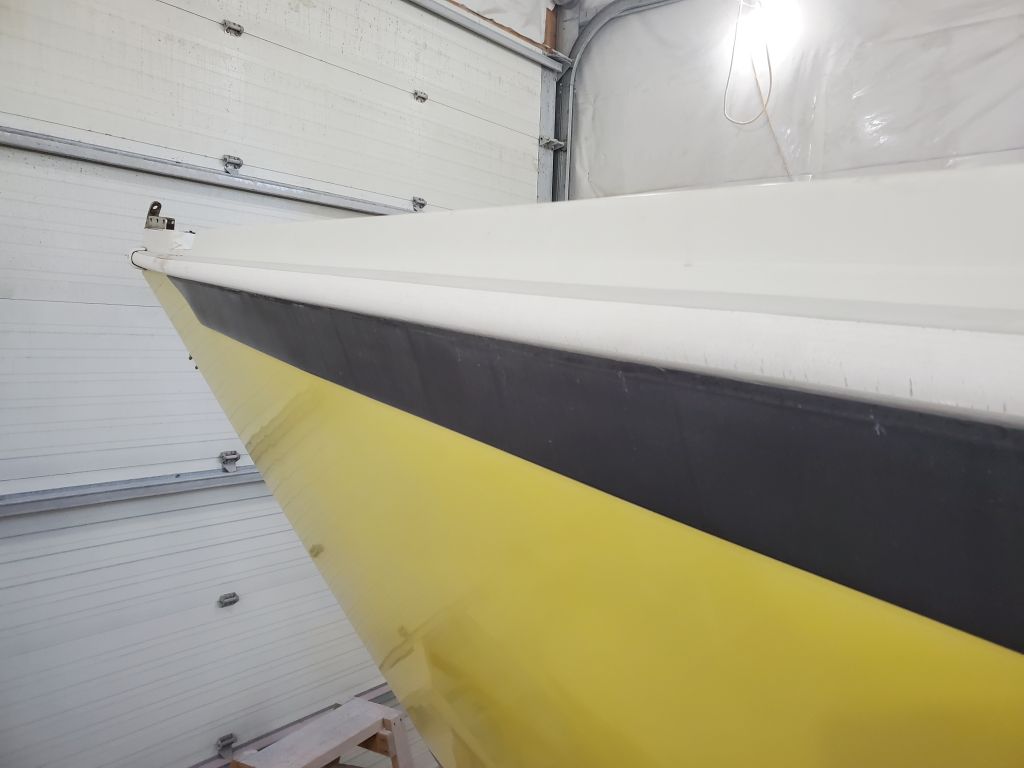
The black sheer strake was molded so as to be slightly proud of the rest of the hull, approximately 1/8″, but at the ends the protrusion tapered off to nothing a bit below the old rubrail location. To aid in recreating the shape later on, I took the time to make patterns of both the stern and bow on the port side; I could flip these for the starboard side so saw no need to make specific patterns for each corner. I also made a rubbing of the Ericson logo on the quarter in case it needed to be recreated later.
Before continuing, I closed up the companionway and other hatches to keep dust out of the boat as much as possible.
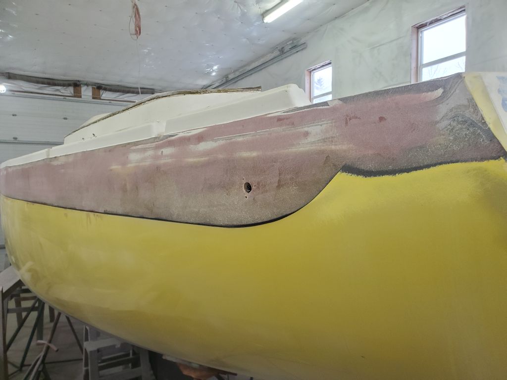
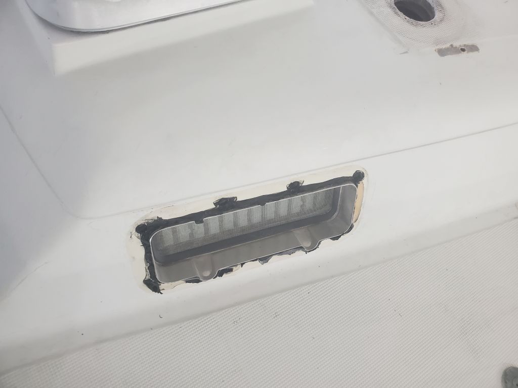
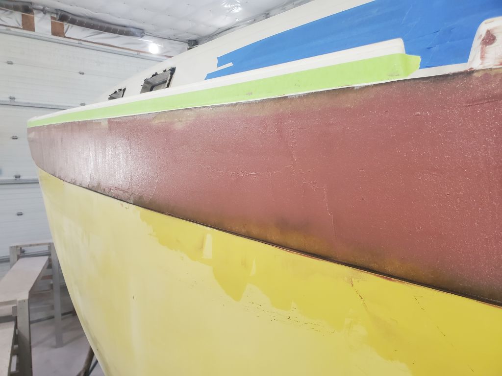
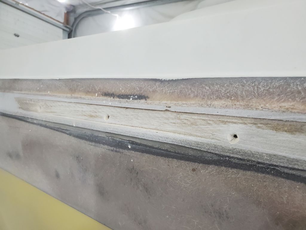
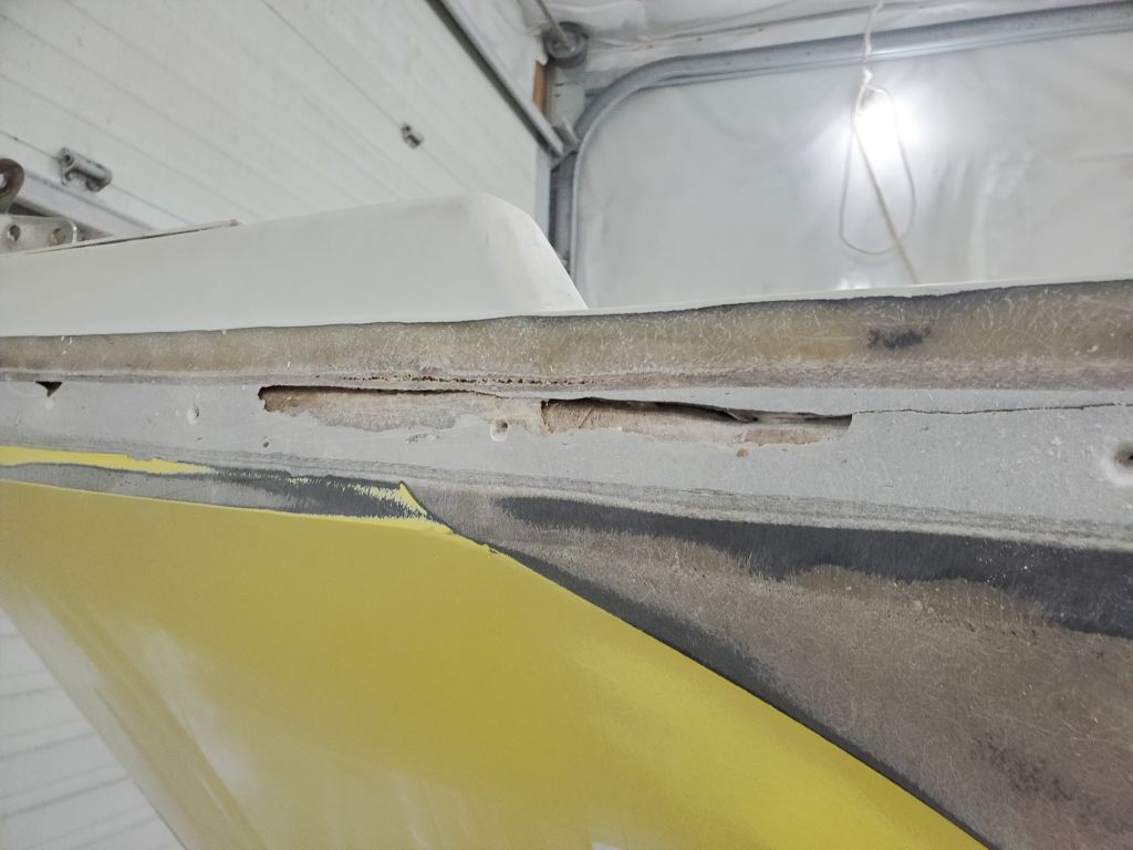
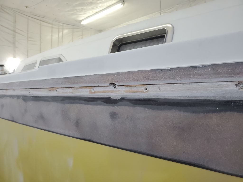
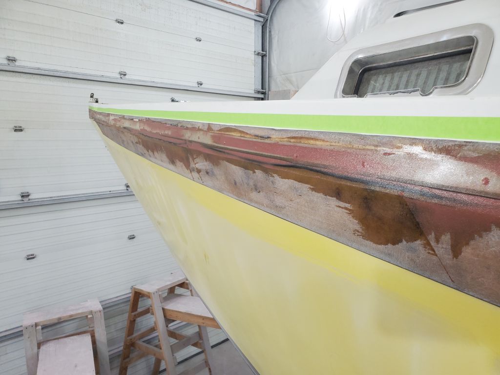
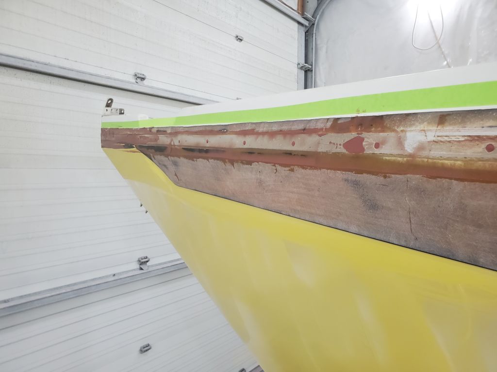
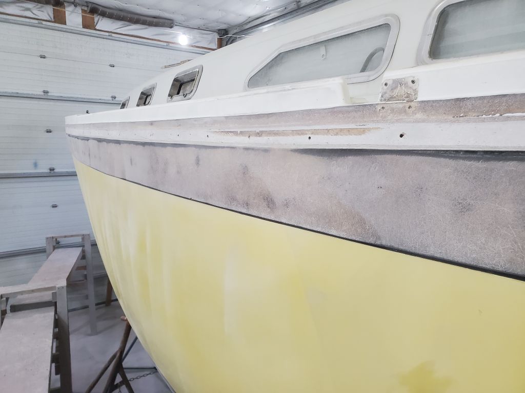
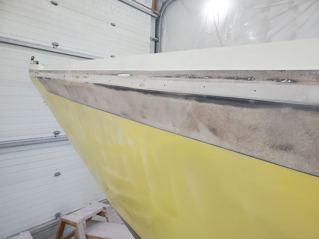
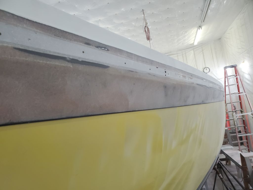
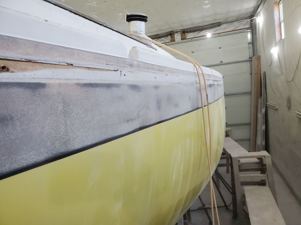
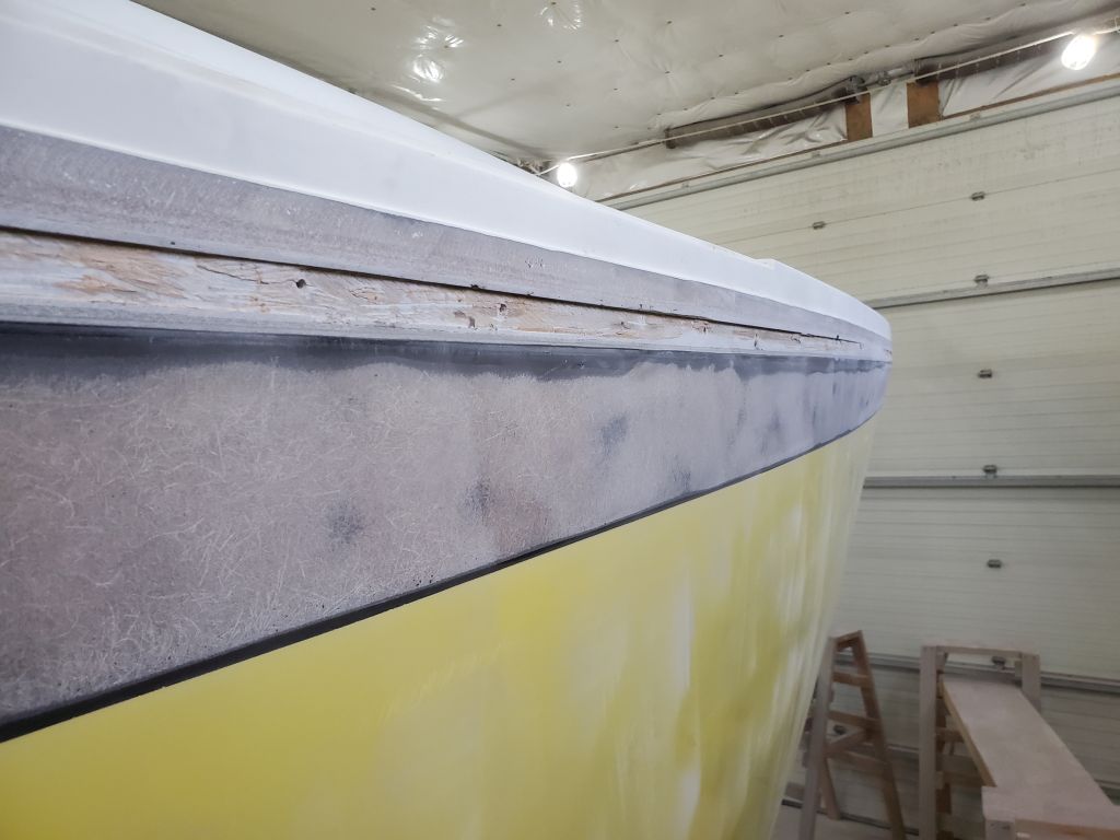
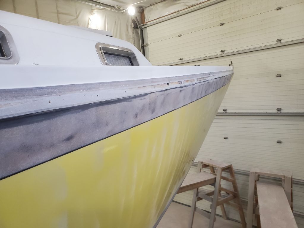
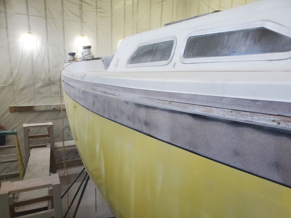
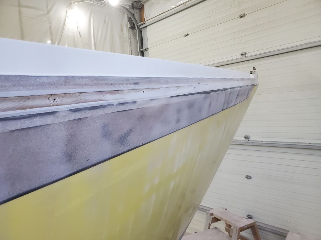
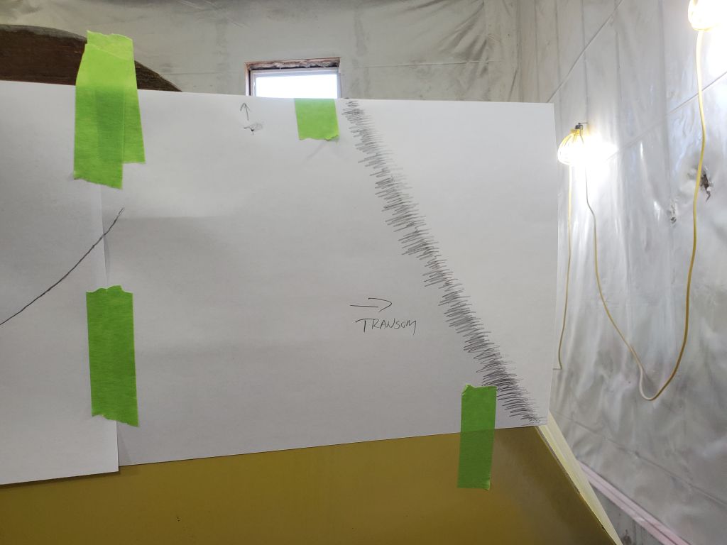
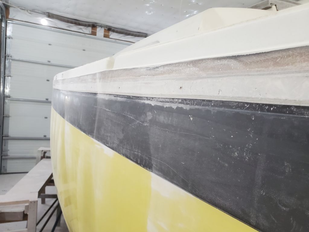
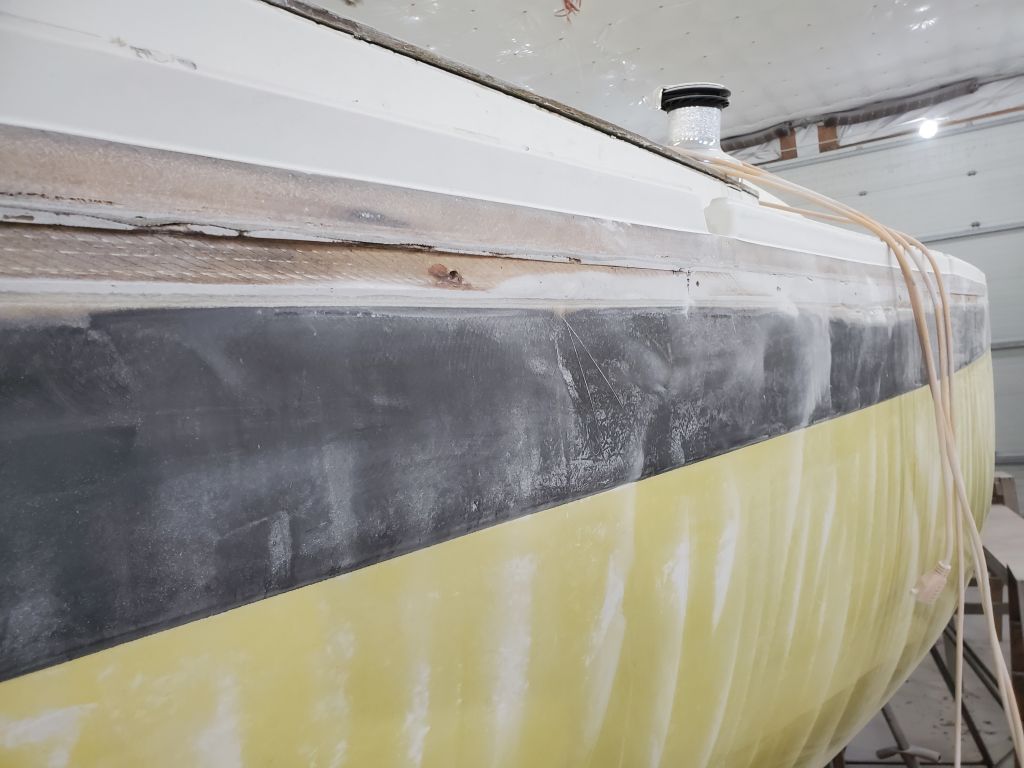
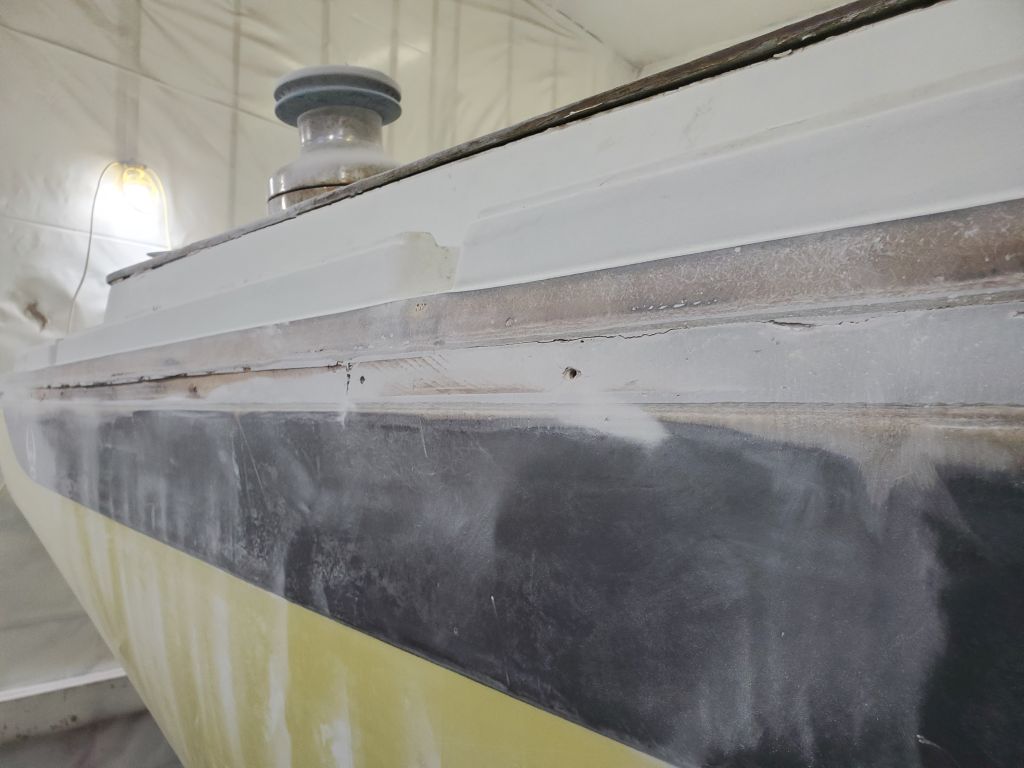
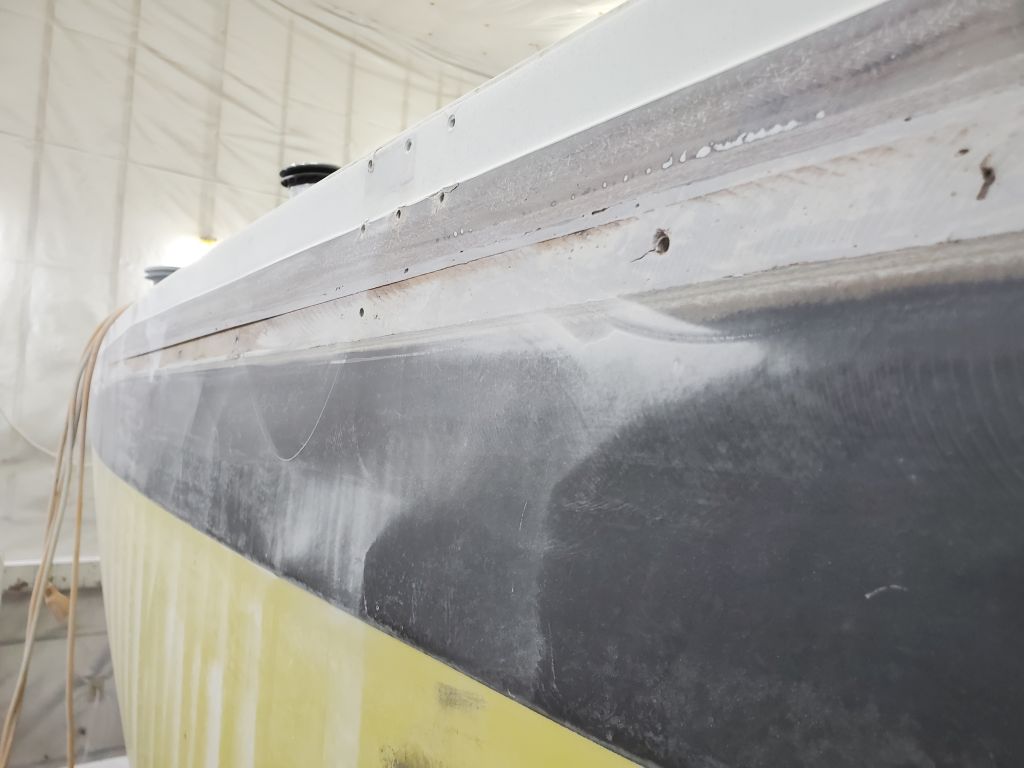
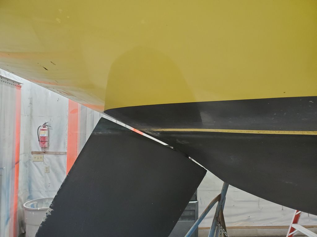
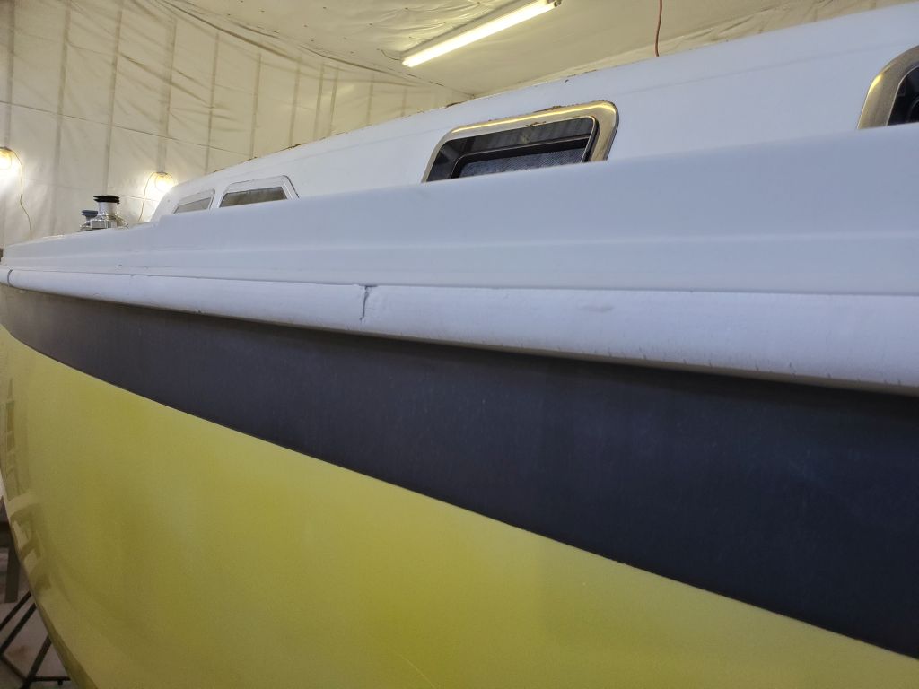
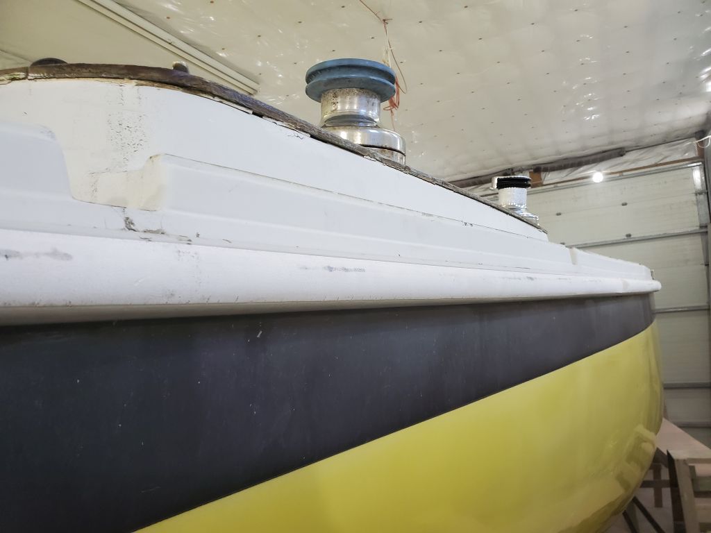
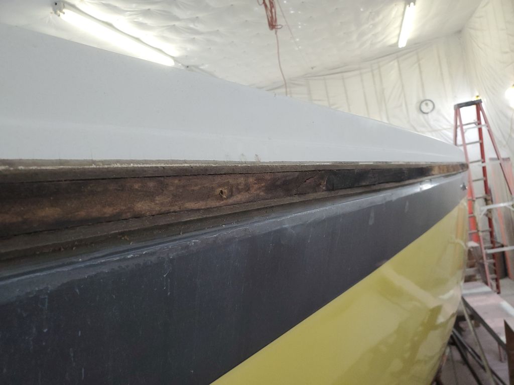
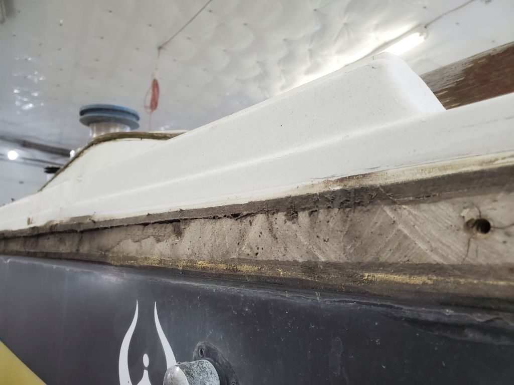
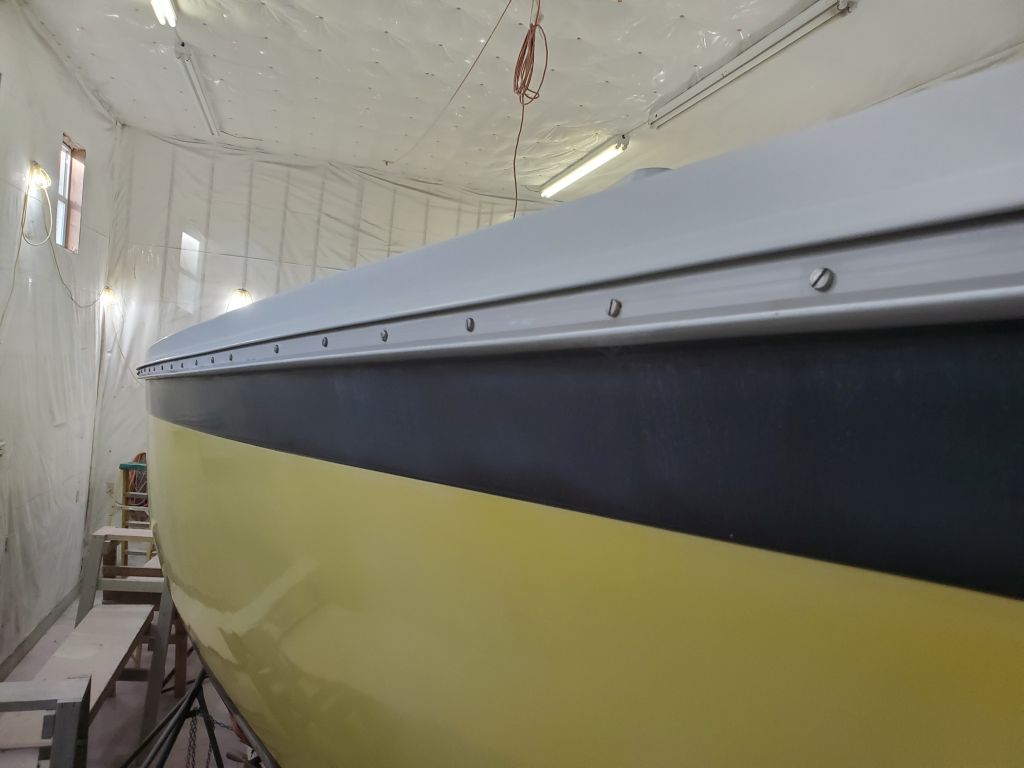
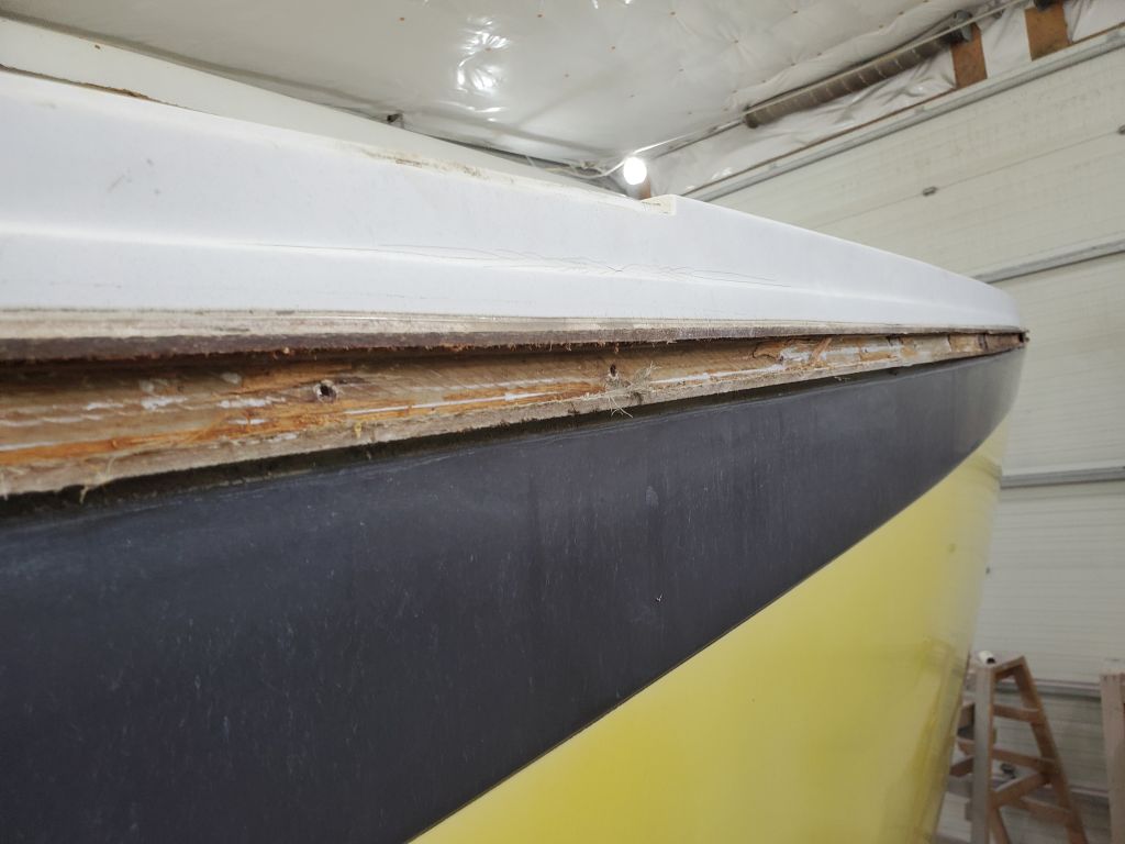
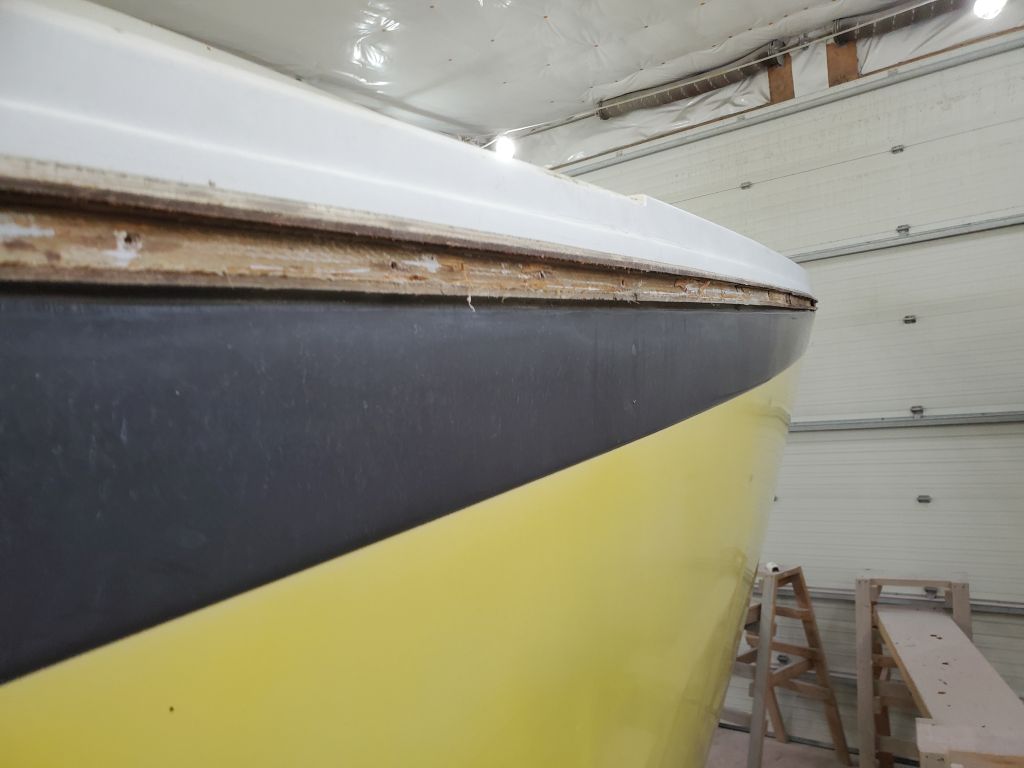
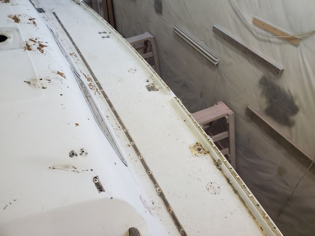
I spent the remainder of the day grinding the out-turned hull and deck flanges flush (or as nearly so as possible) to their adjacent surfaces. At the deck side, I also removed the gelcoat up as far as a molded “character line” in the toerail/deck edge, which logic and practicality dictated would probably be the end point for new tabbing in this instance. More on this later. I brought the flanges as flush as possible with the hull and deck moldings on either side, but had to balance this with removing too much material from the center, where the wooden strip had been and where other structural material, including interior tabbing and some kind of adhesive filler material, needed to remain in place.
Hull and deck moldings rarely, if ever, are perfectly fit and symmetrical all around, so some misalignment is standard; this is one reason manufacturers use external rubrails or trim to cover the seam. I’d make up the differences, where needed, with epoxy filler to bring things flush all over before tabbing over the seam, but essentially and practically speaking I ground the old flanges flush all around. I didn’t use the grinder for anything beyond the minimum required to remove the bulk of the material, and would finish up sanding and surface preparation with less aggressive tools to avoid excess fiberglass removal and maintain the existing contours of the moldings to minimize future fairing work. This all made a bit of a mess, but with more sanding in the immediate future I just gave the hull a quick blow down, leaving the rest of the shop for cleaning later in the week.
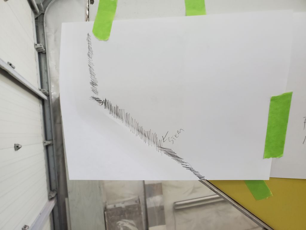
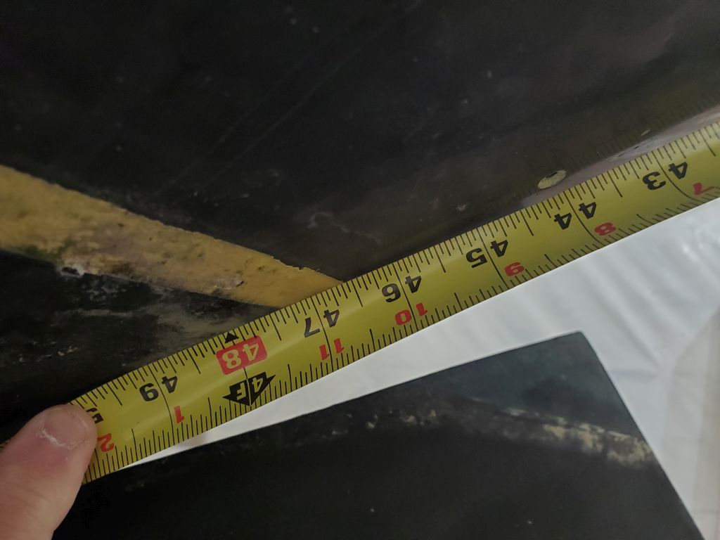
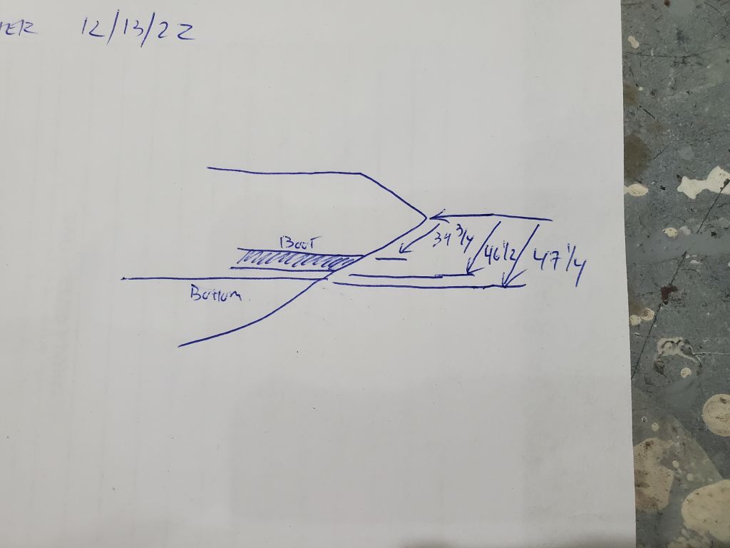
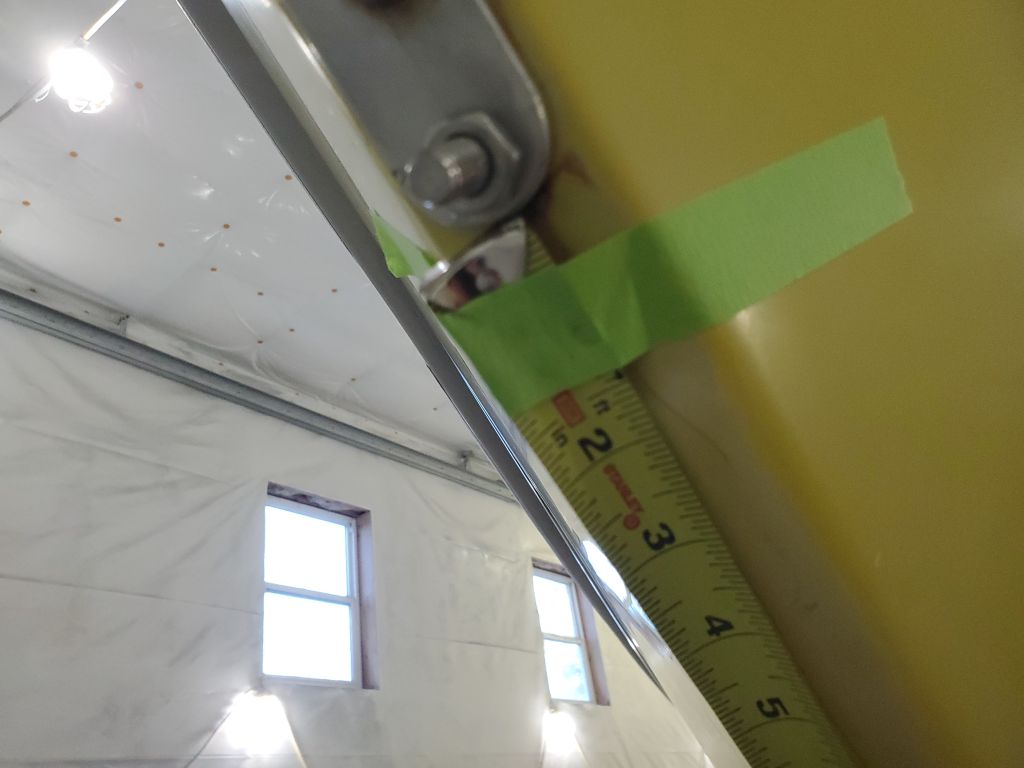
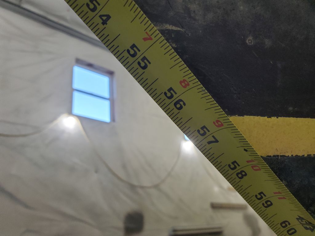
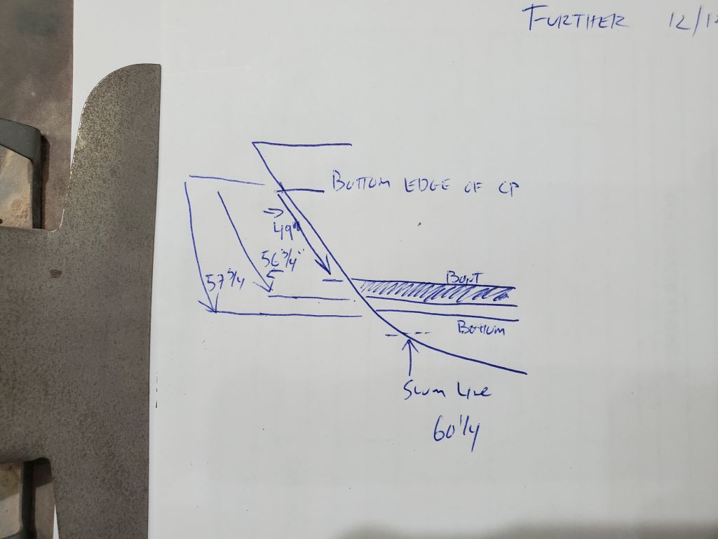
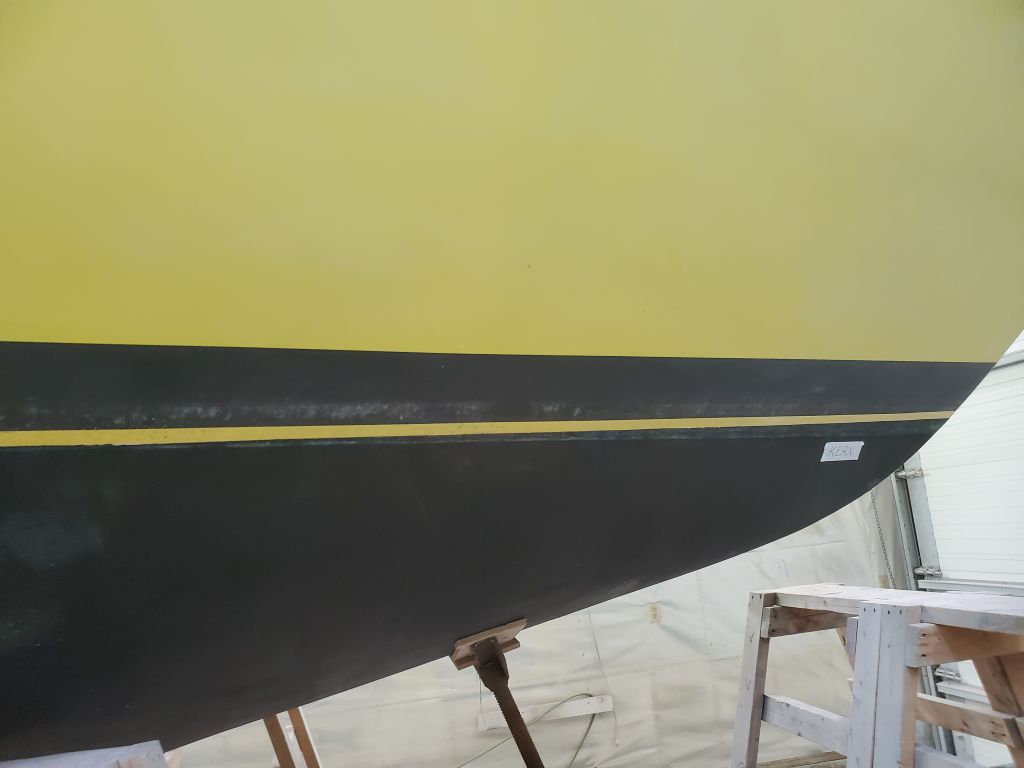
Easing into the project, my first order of business was to measure and record the existing positions of the waterline (i.e. the top edge of the bottom paint) and boottop at stem and stern. These references would give me the starting point for restriking these lines later on.
At the stern, I hooked my tape measure on the corner of the transom where it met the counter, and led it down centerline to measure the positions of the top and bottom edges of the boottop, and the waterline. I also noted the position of the visible scum line on the bottom paint and rudder for future reference. The molded boottop lines and bottom paint line drooped as they approached the stern cutwater (Robert Perry calls this the “buttwater”), which positioning I’d correct later on, but nevertheless these were crucial references for later. I noted them all on a meticulously-crafted drawing.
I repeated the process at the stem, using the bottom edge of the headstay chainplate as my reference point.
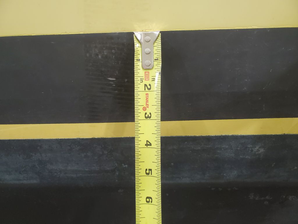
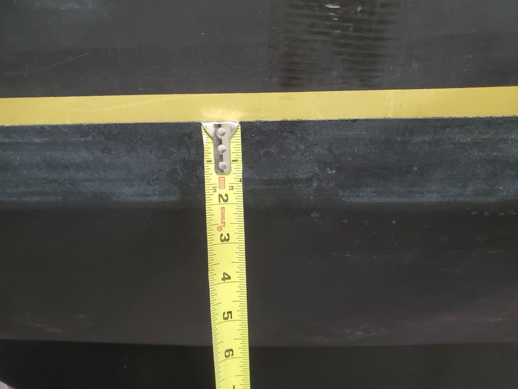
Amidships, I measured the visual height of the boottop (3″) and, on the port side, the exposed portion of the antifouling paint above the scum line (2″). I did note that the boat appeared to list to starboard, as the scum lines on that side showed the boottop may have been partially at or closer to the actual waterline there.
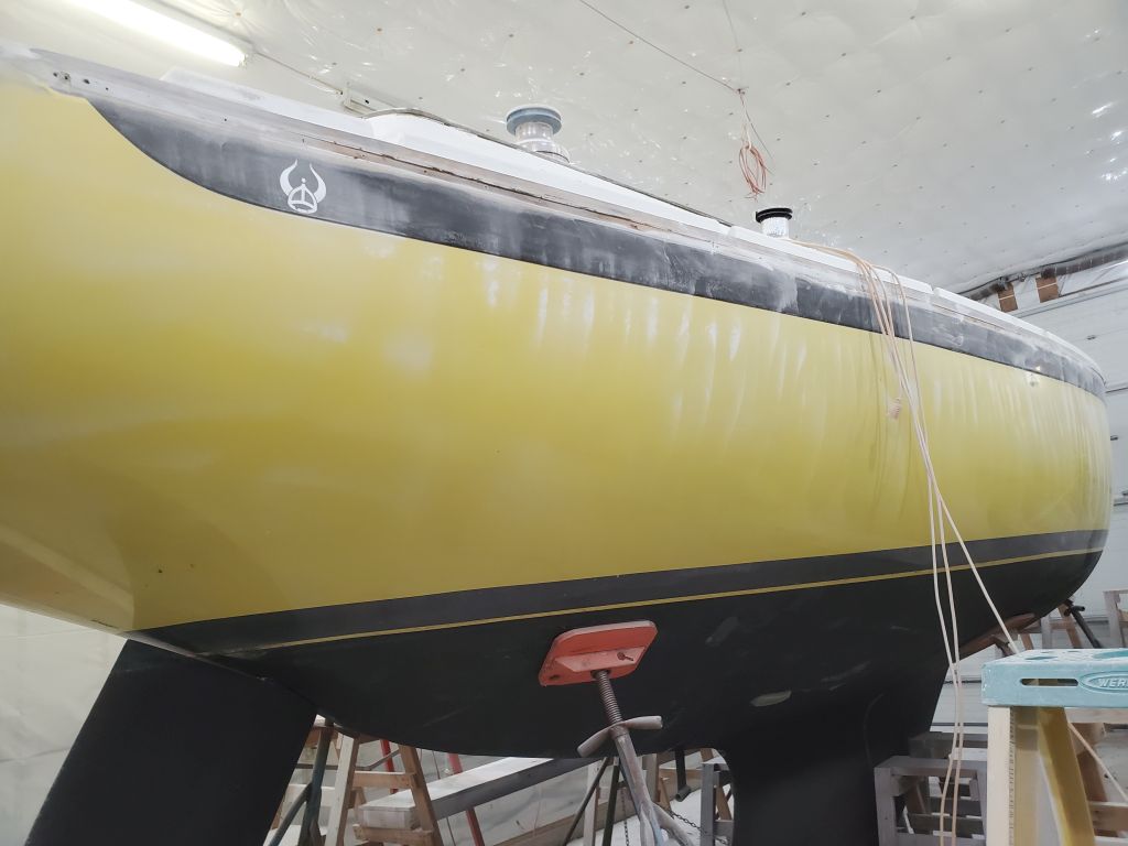
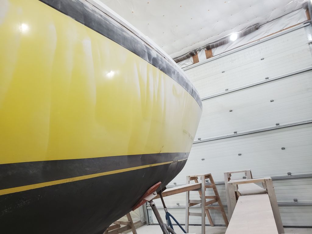
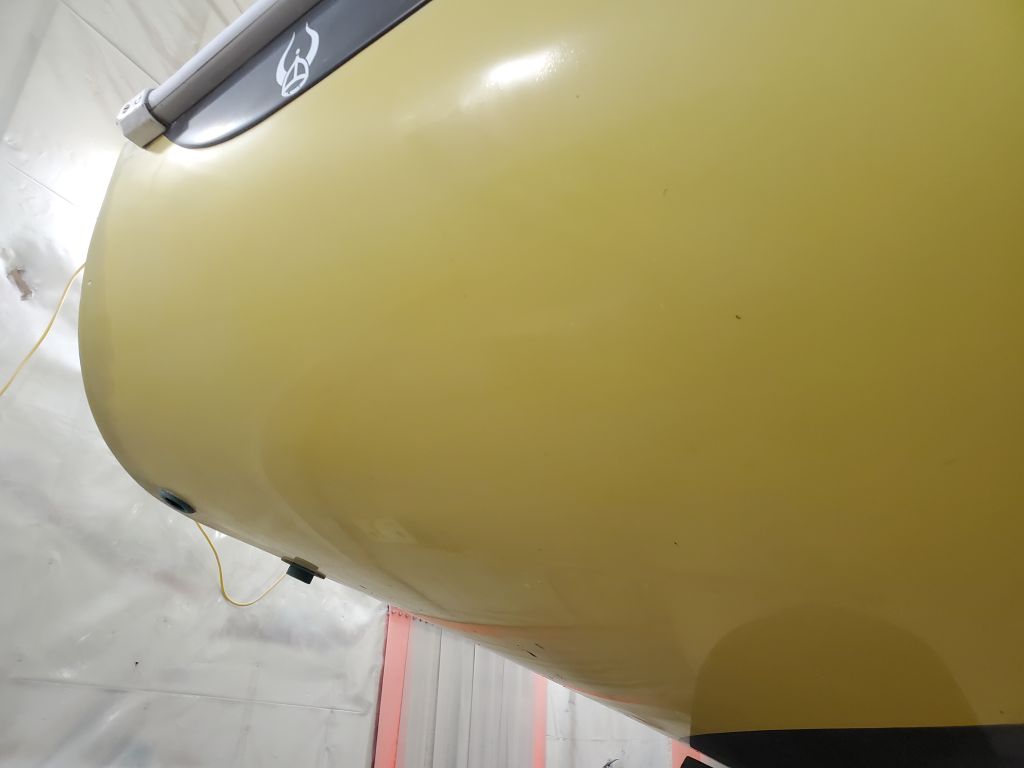
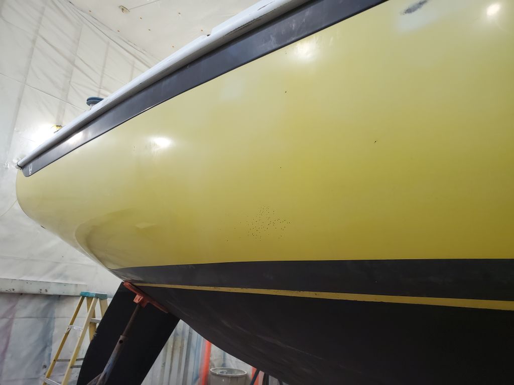
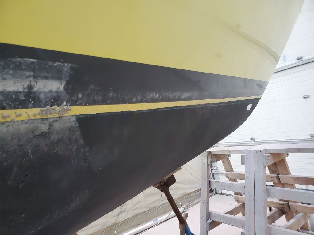
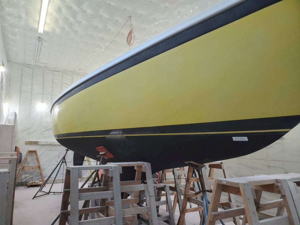
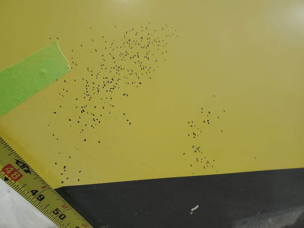
With these measurements noted, I documented the existing condition of the hull from various positions. The original gelcoat was oxidized and generally affected by wetsanding and years of polish, but mostly sound, with some pinholes, pockmarks, and other minor damage–nothing unusual or unexpected.
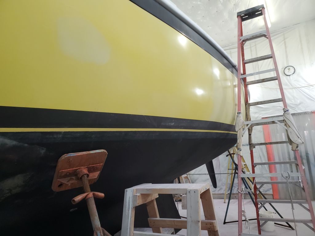
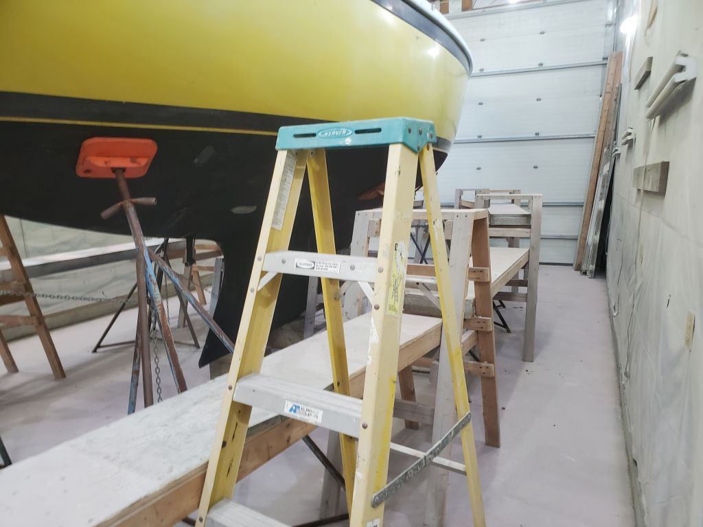
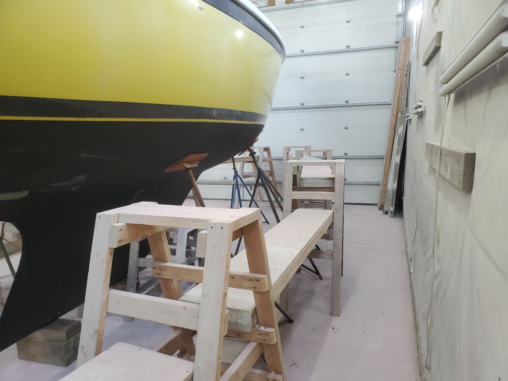
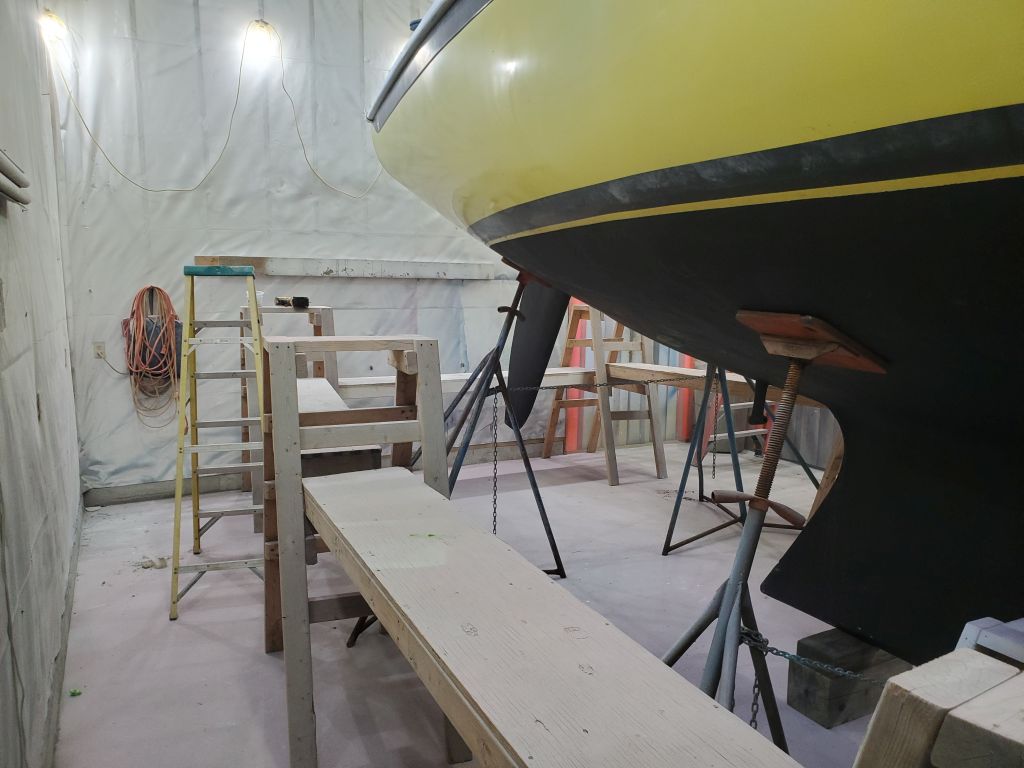
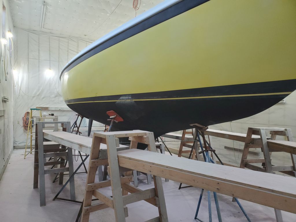
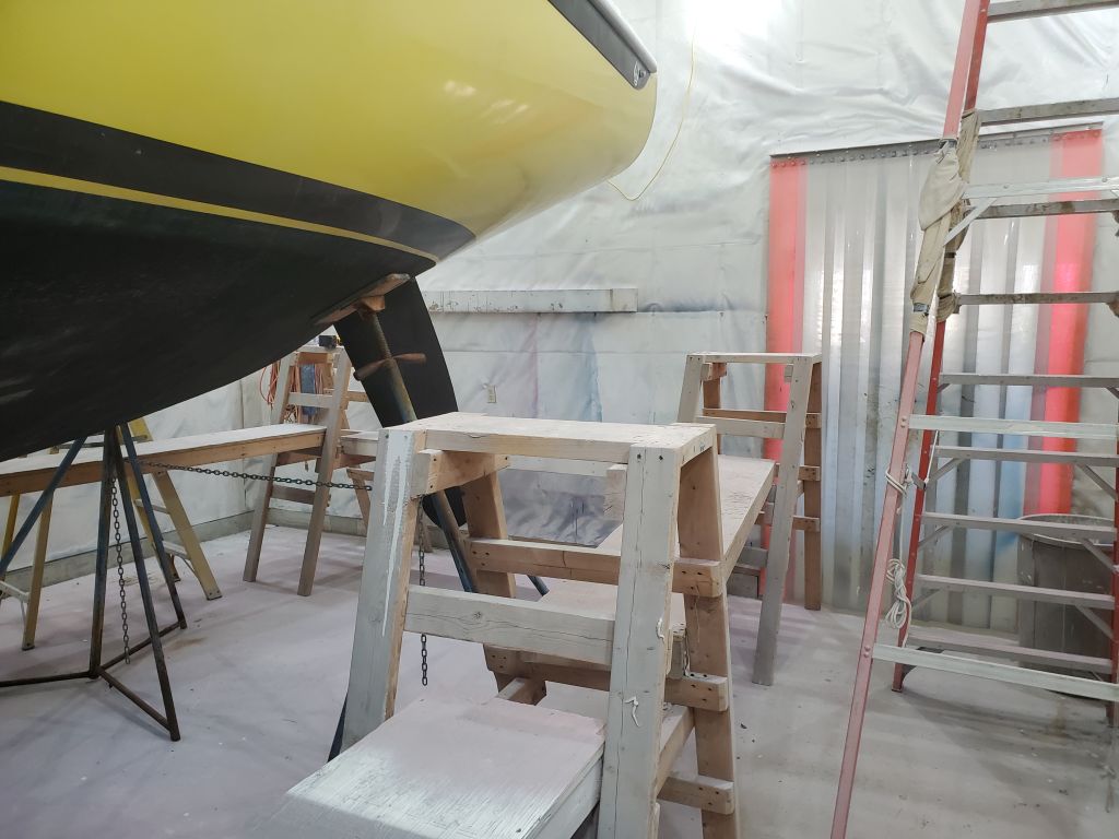
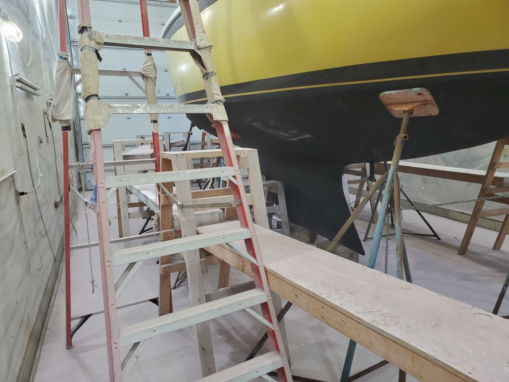
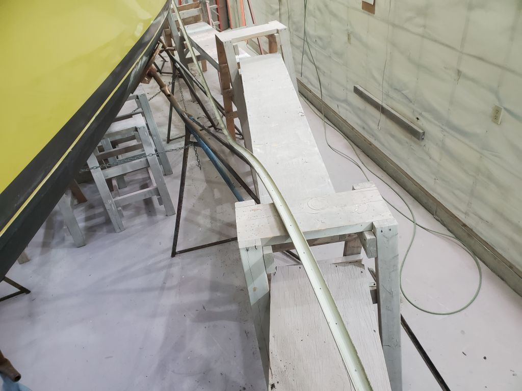
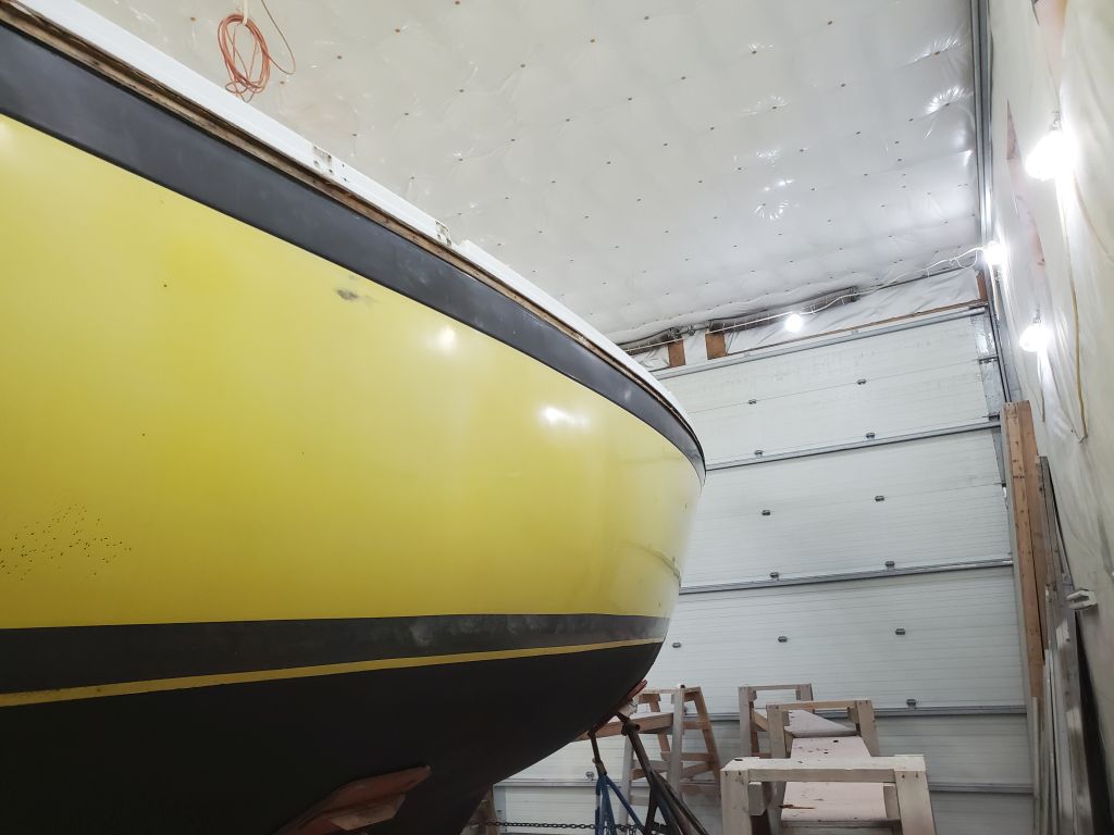
Next, I set up staging around the hull to give me access to the topsides and rubrail. Because the owner was still removing deck hardware, and also because in this instance it made sense to me to start from the bottom and work up, I chose to focus first on the hull prep before moving on to the larger project on the decks.
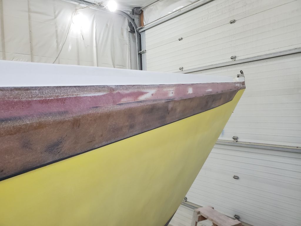
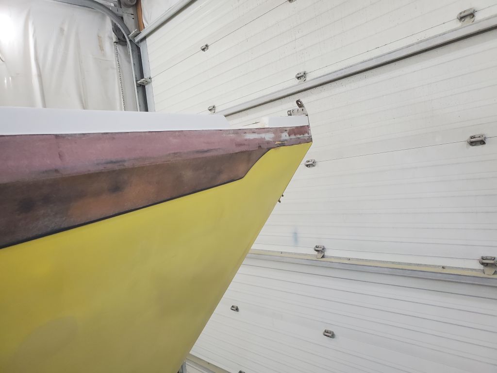
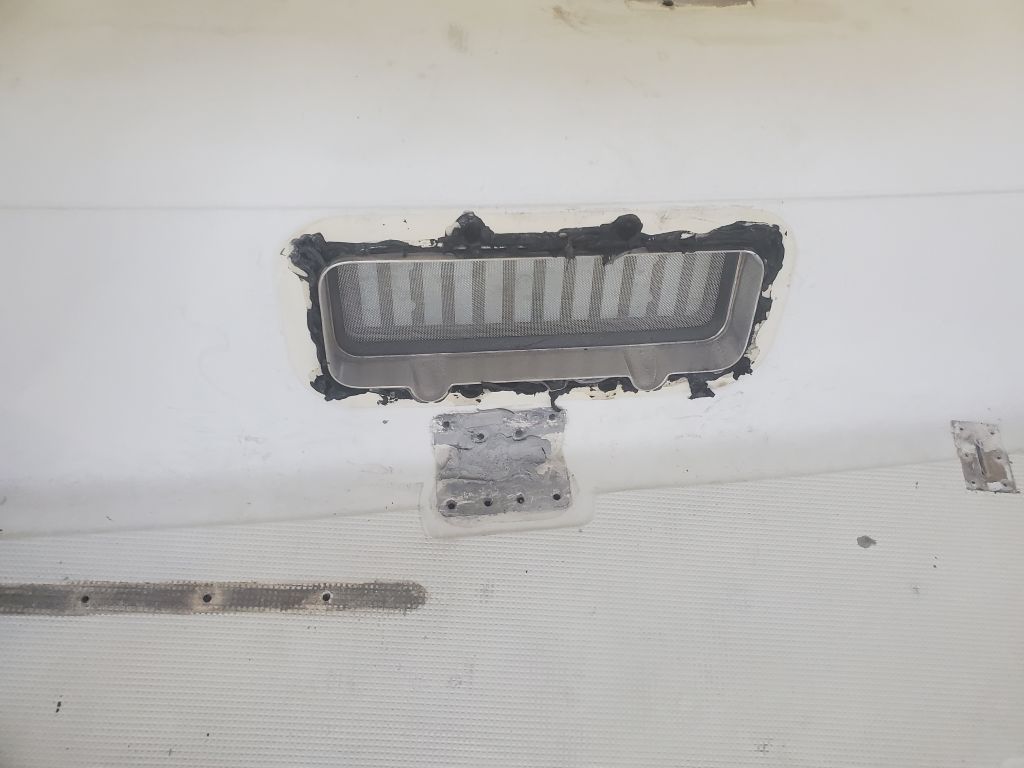
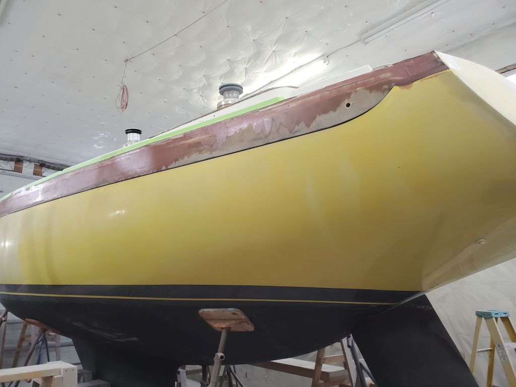
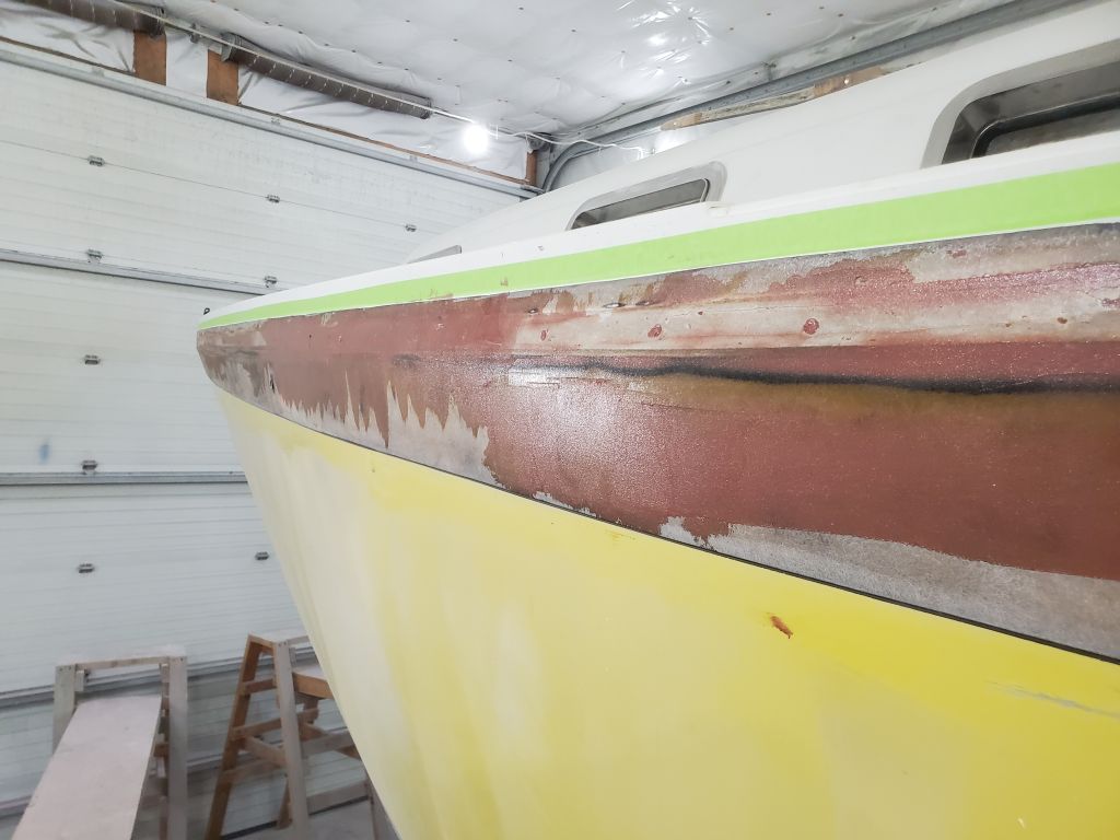
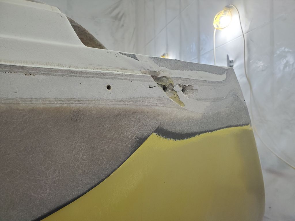
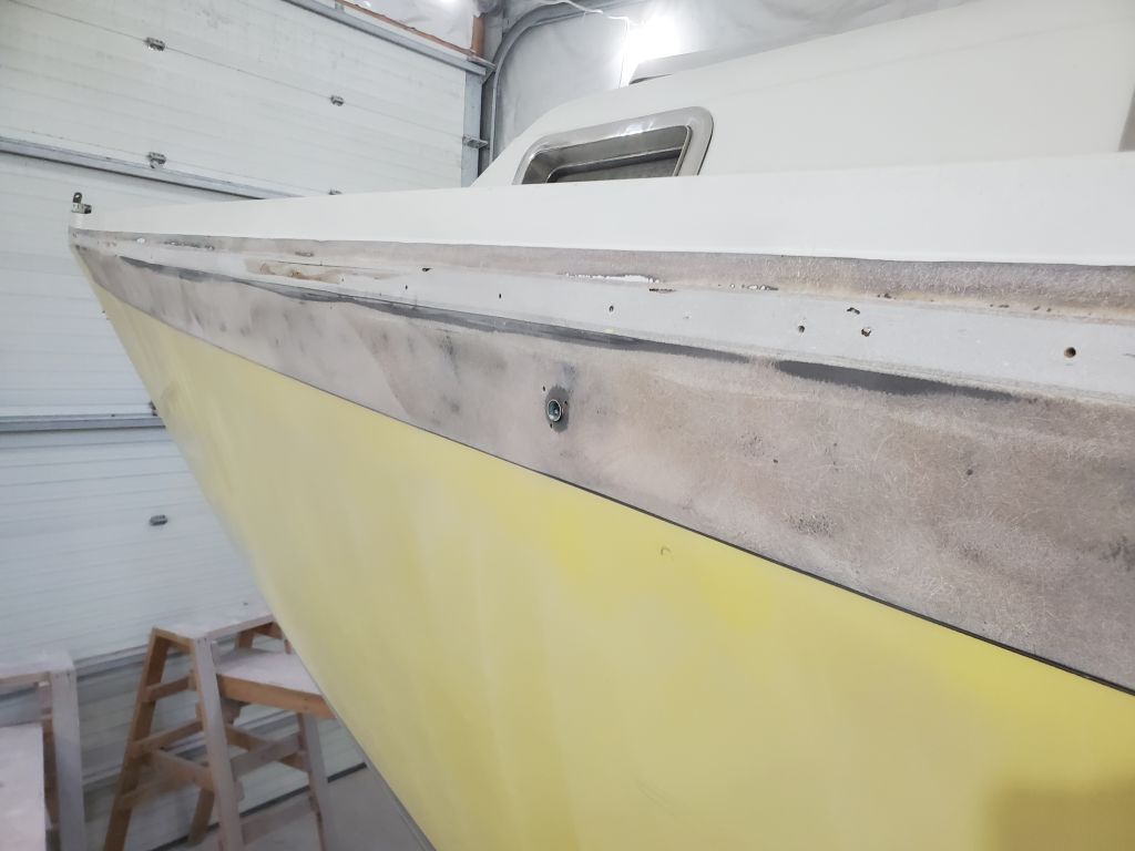
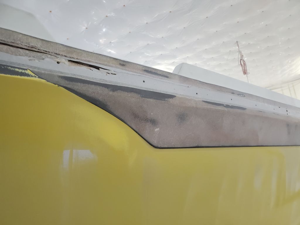
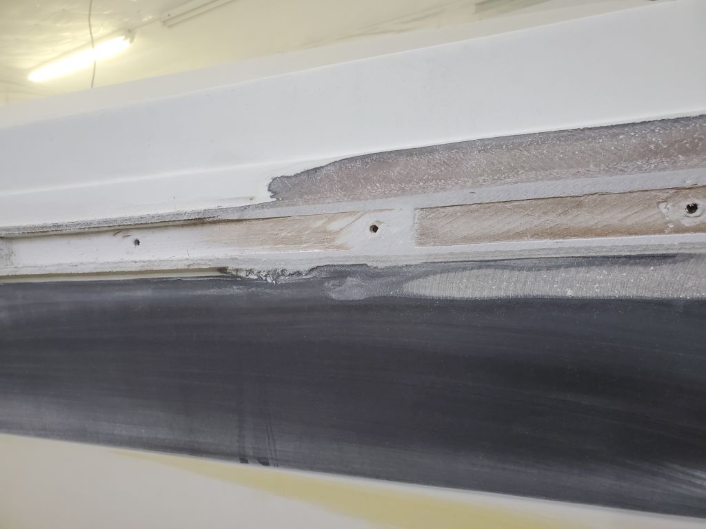
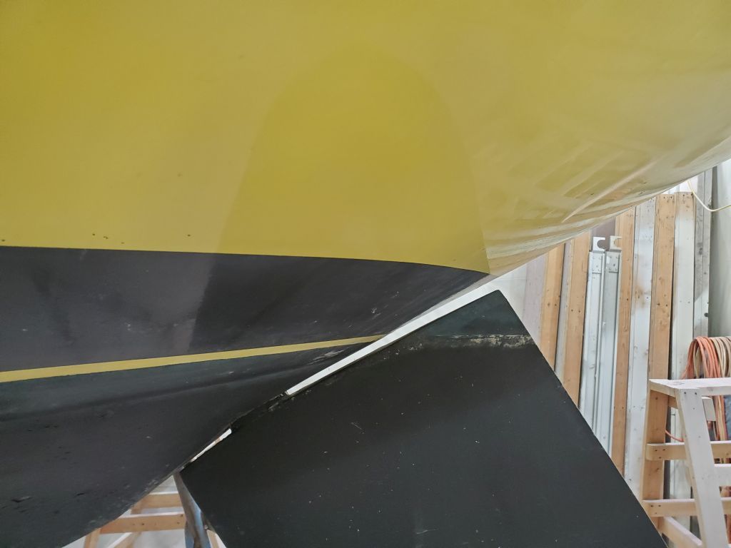
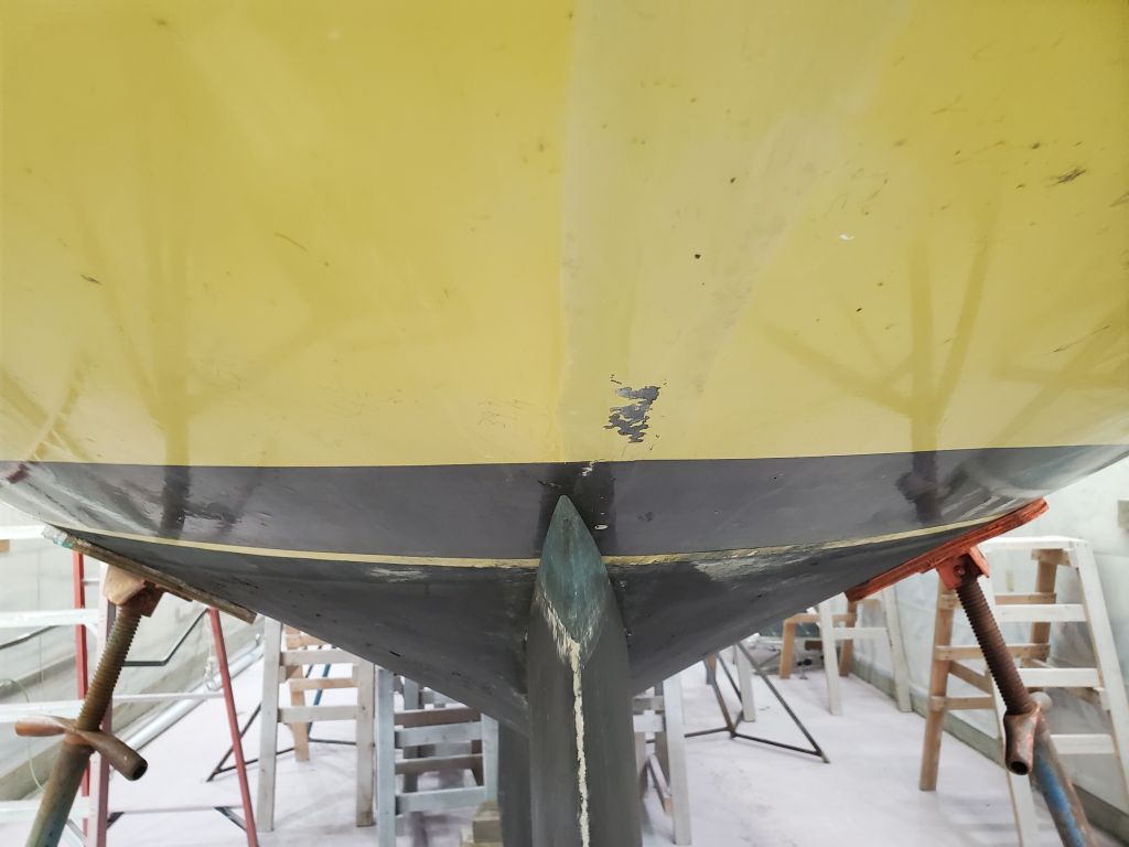
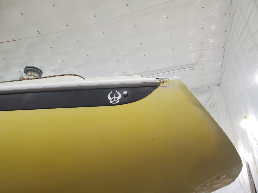
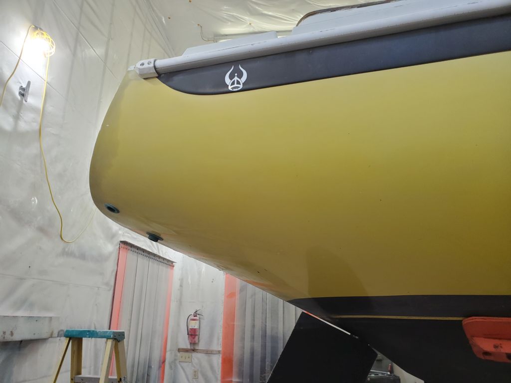
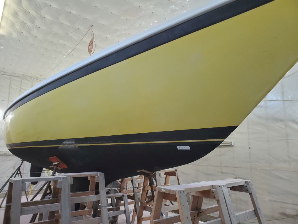
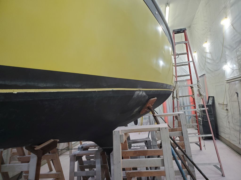
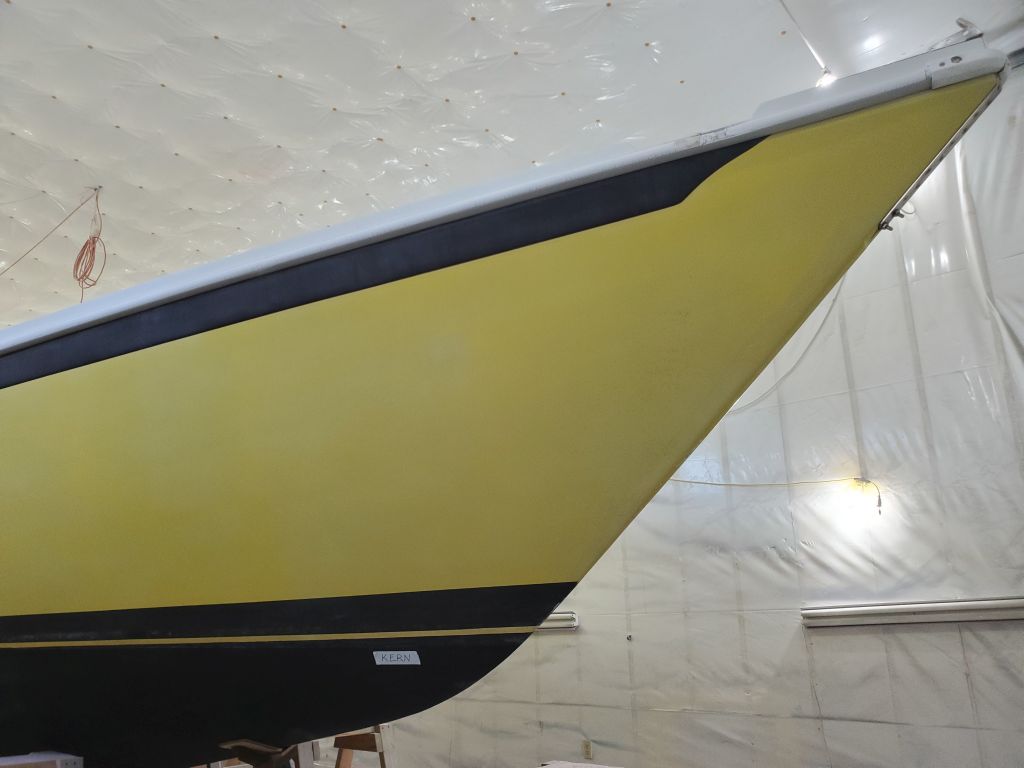
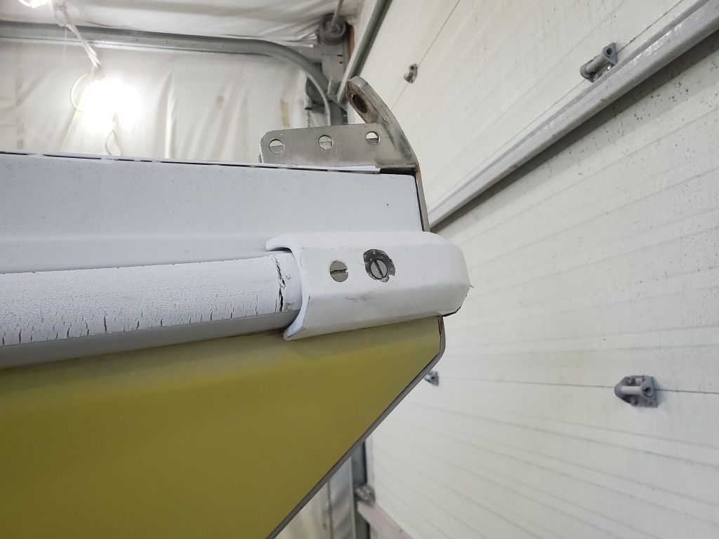
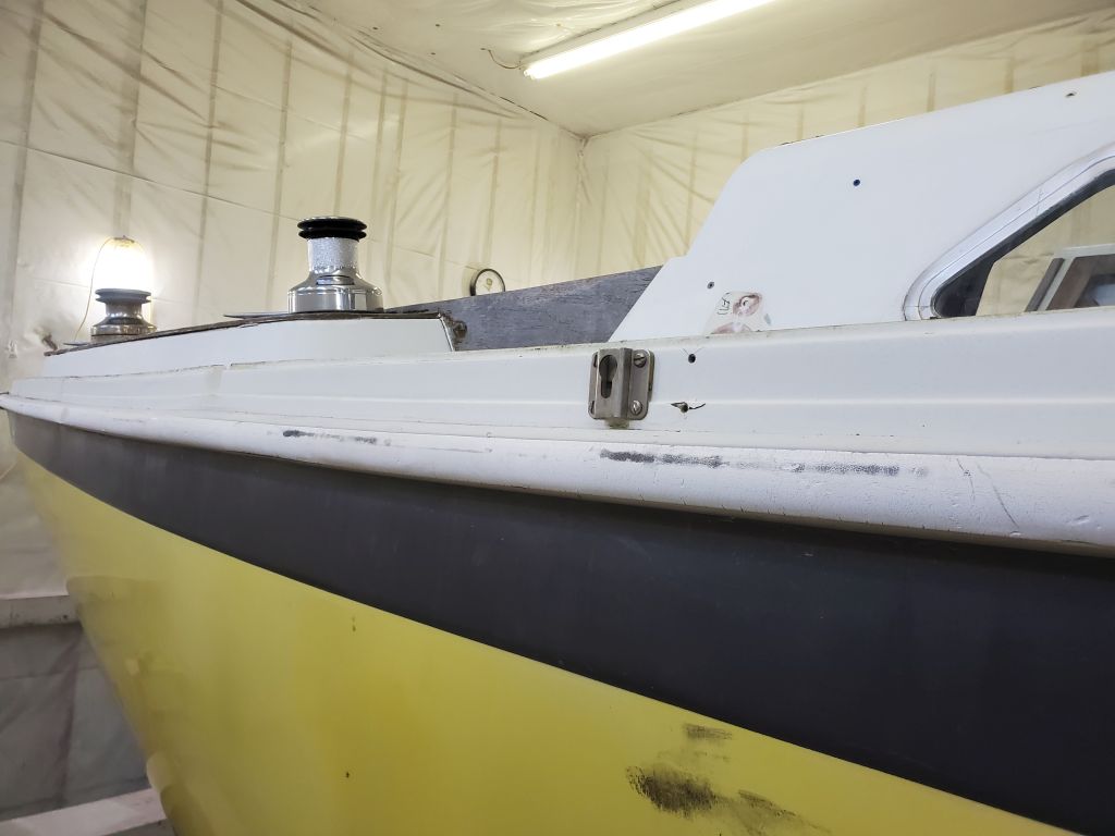
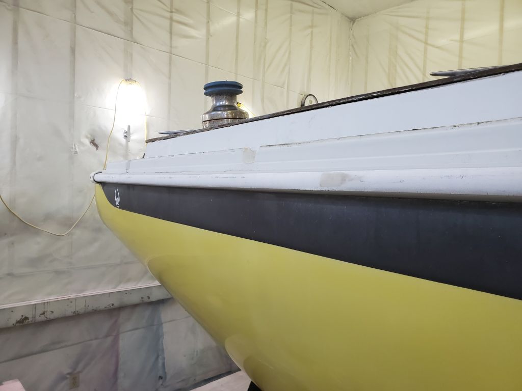
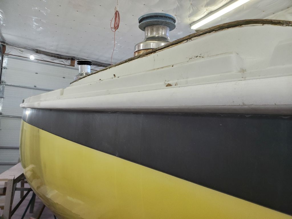
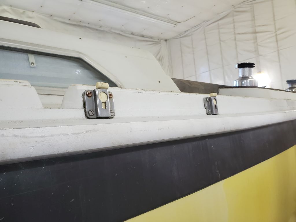
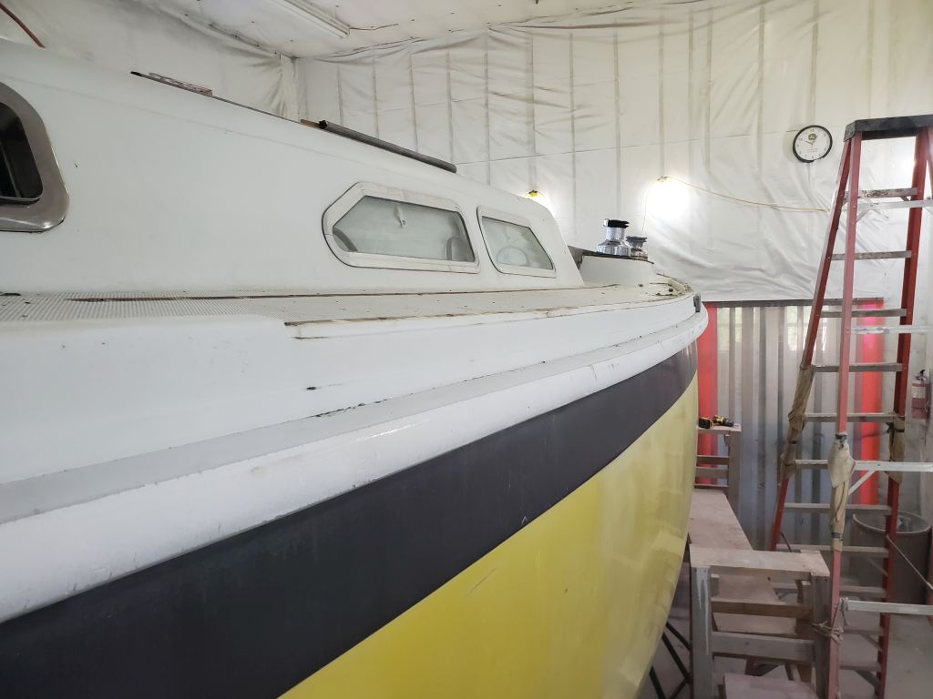
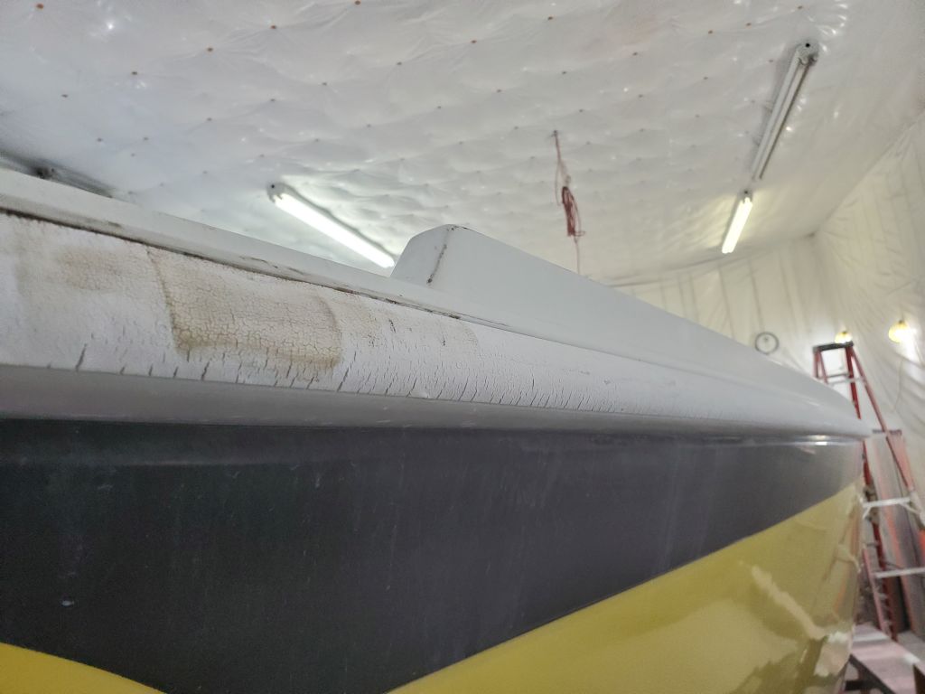
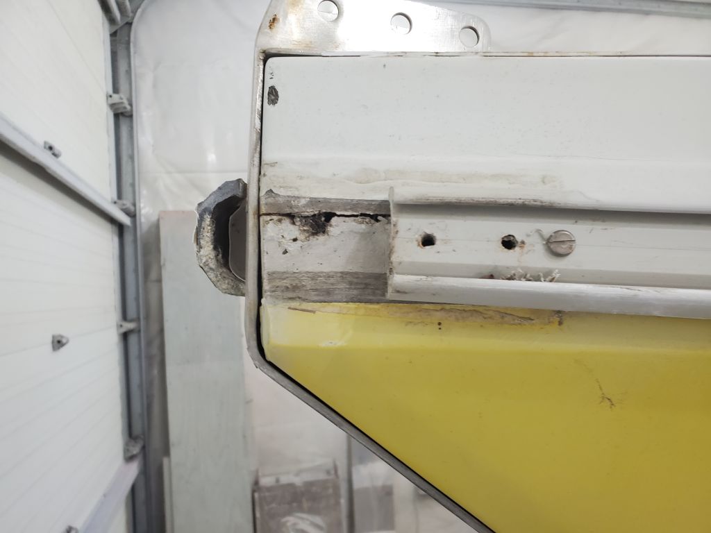
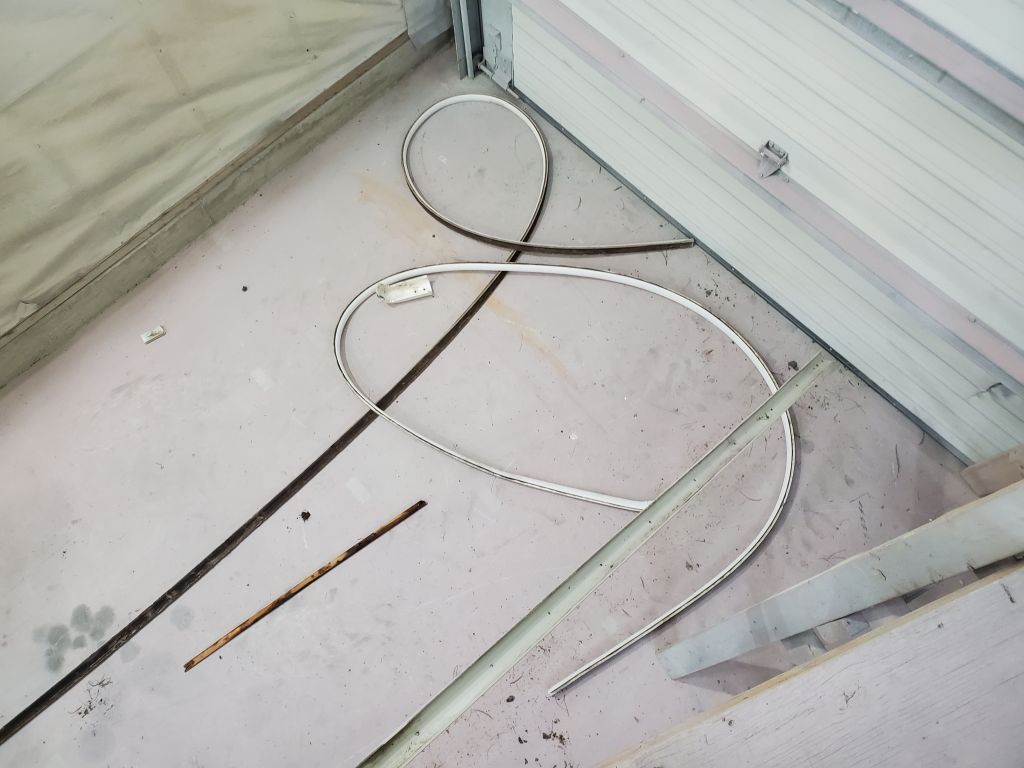
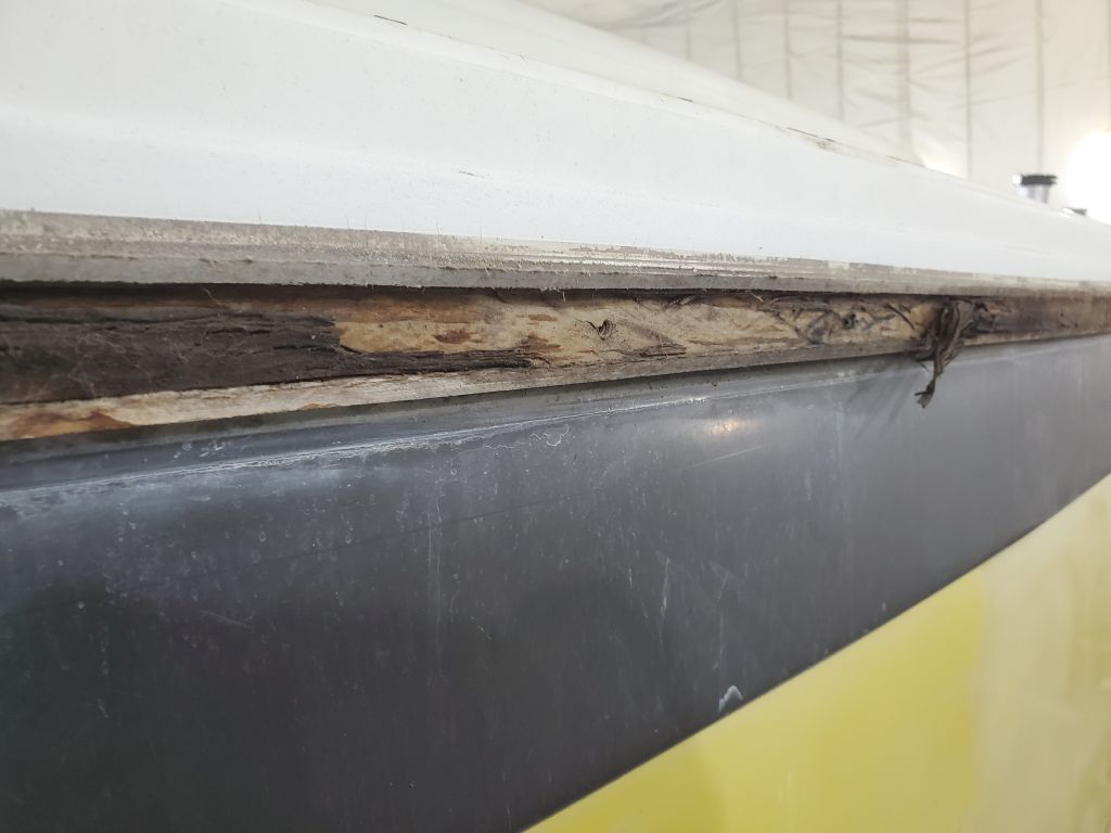
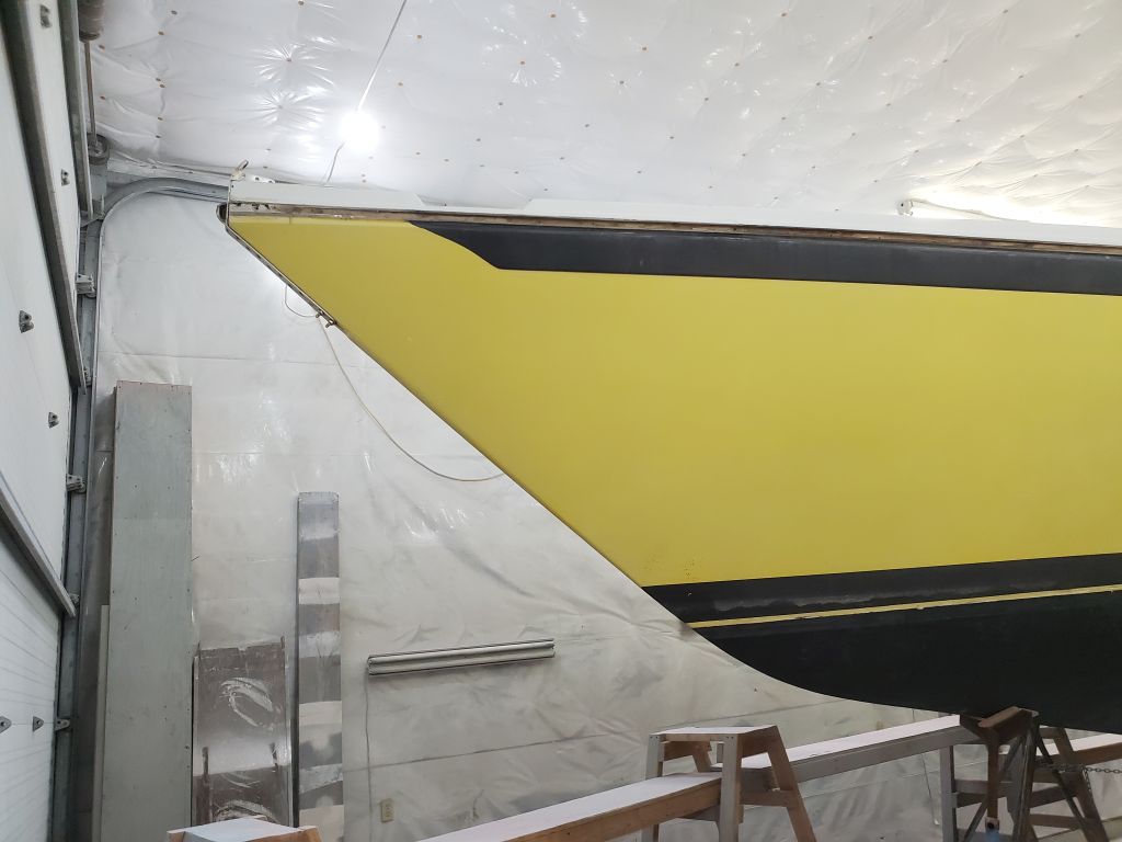
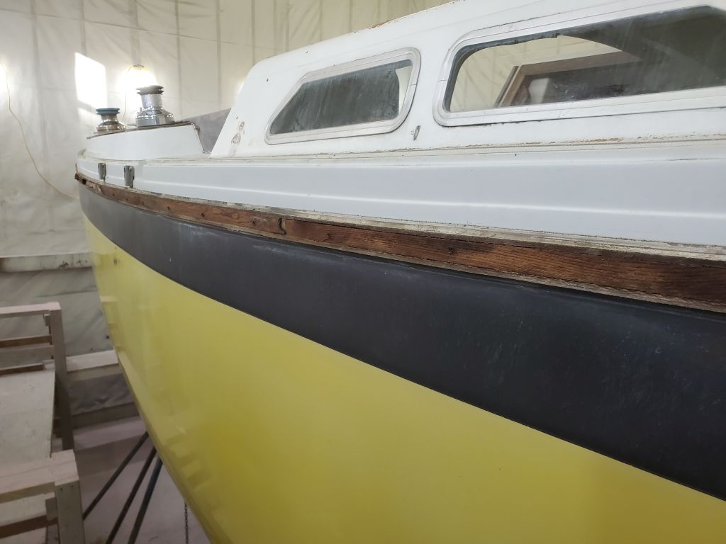
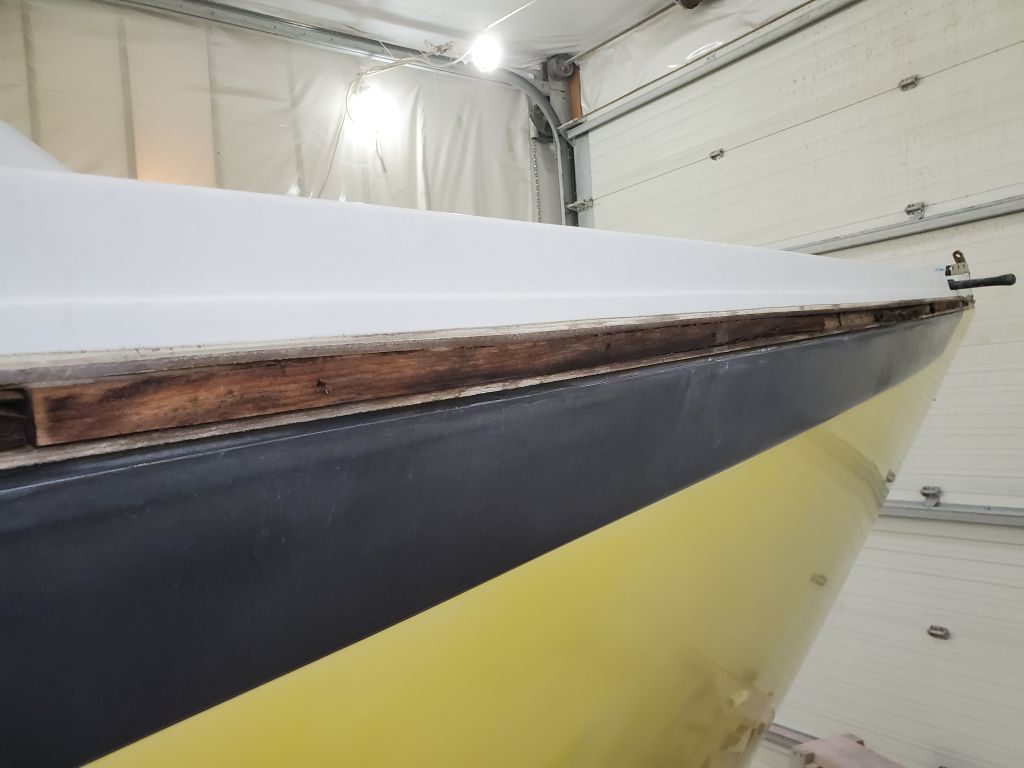
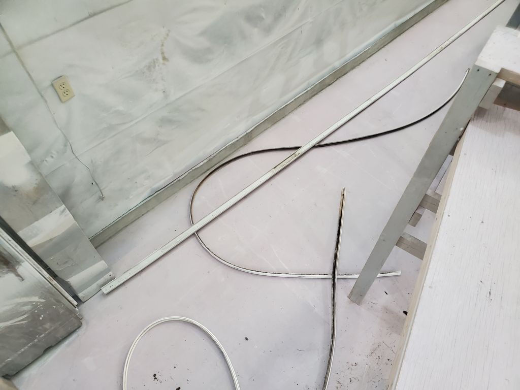
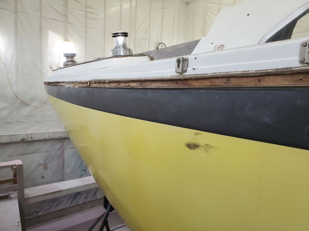
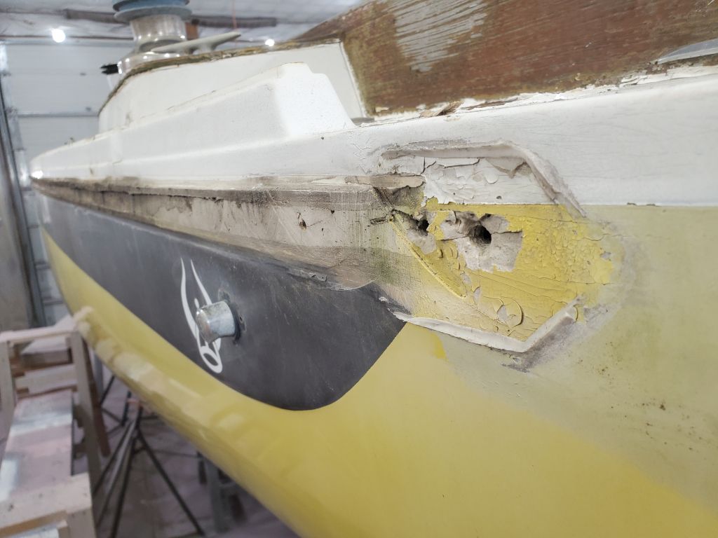
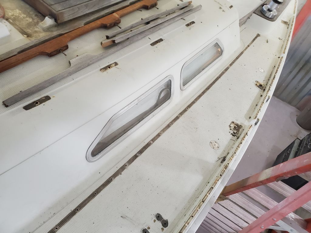
The owners requested that I remove the plastic rubrail assembly, which covered the hull-deck joint and was original in appearance. The rail was missing one of its endcaps, and the insert, which slipped into the hard PVC outer shell, was sun-damaged, cracked, crazed, and broken in some areas. The owners’ plan for me to put into effect was to glass over the exterior of the hull-deck joint, ultimately creating a flush and unadorned surface to replace the original rubrail.
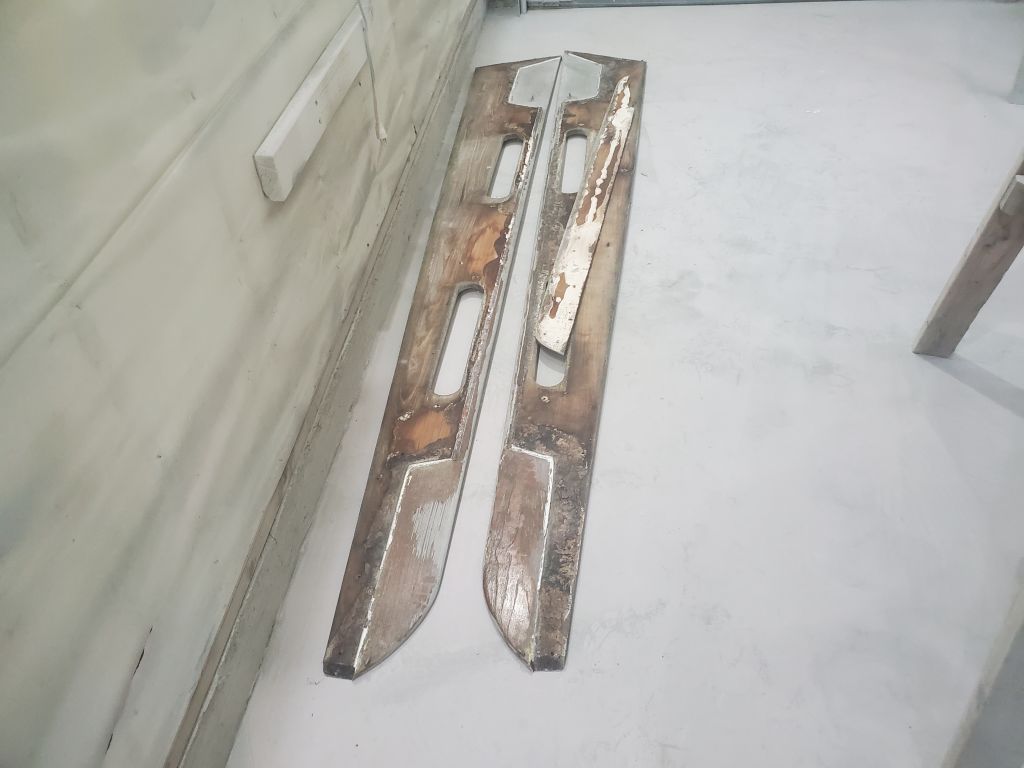
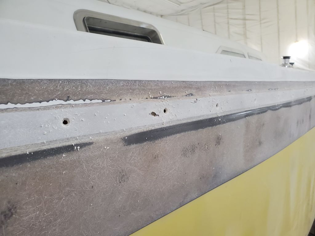
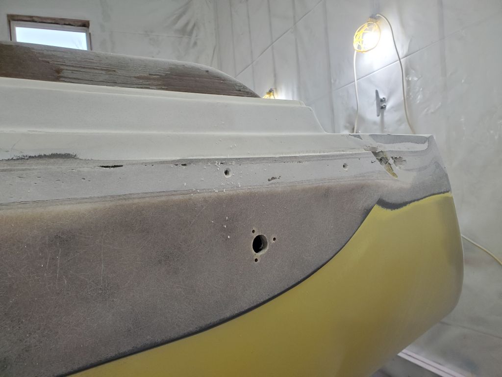
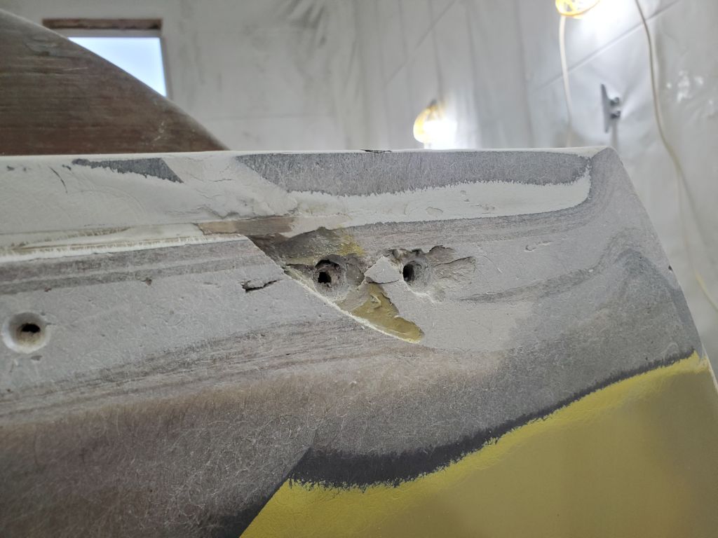
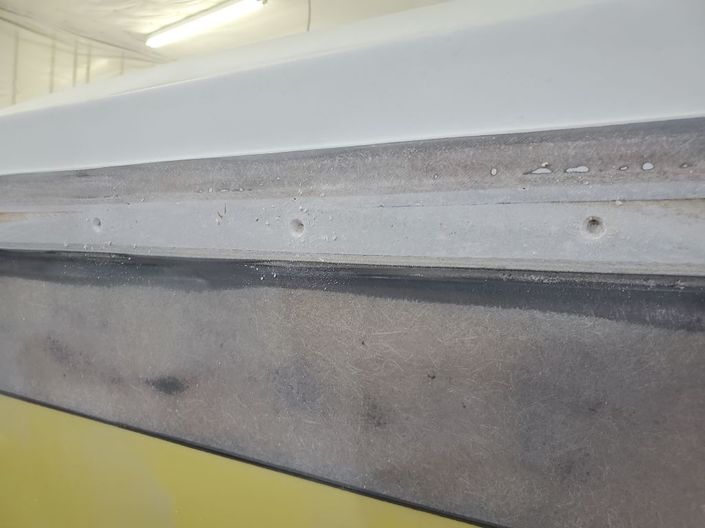
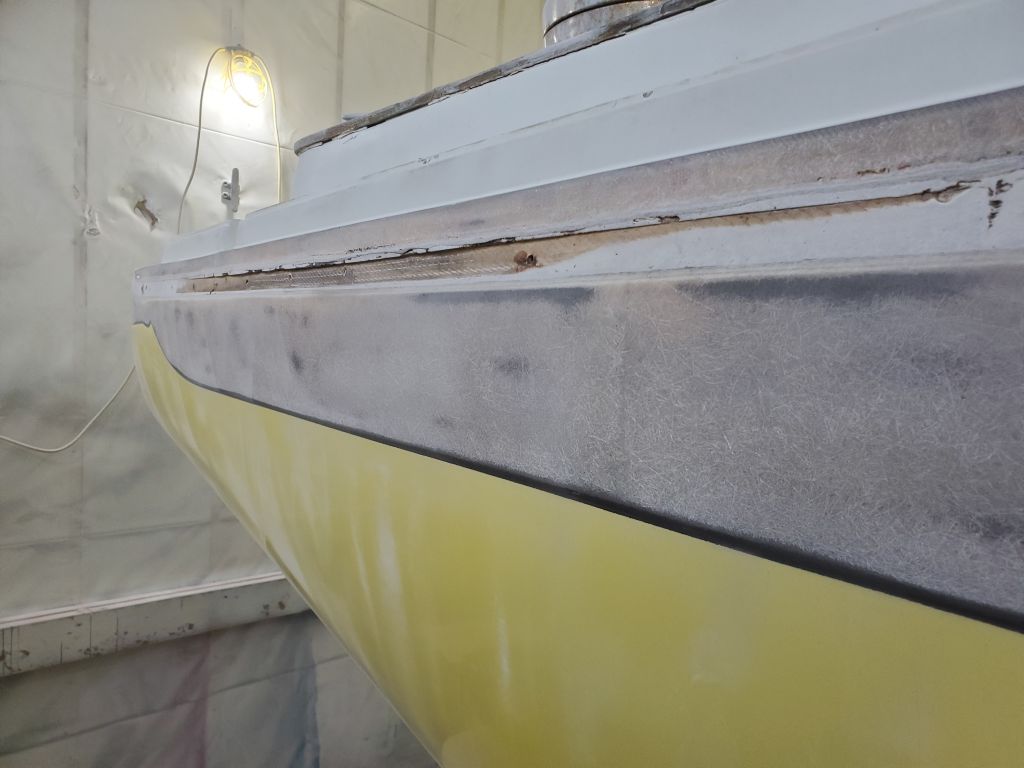
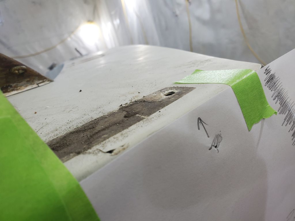
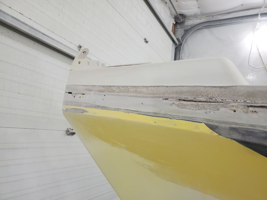
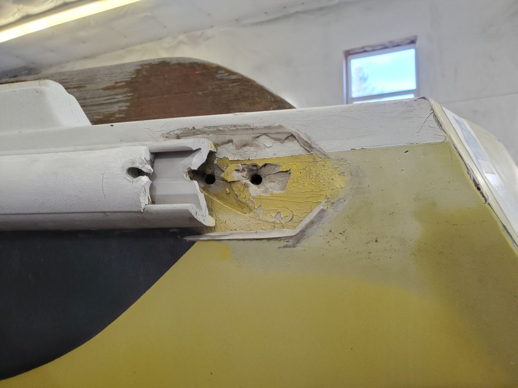
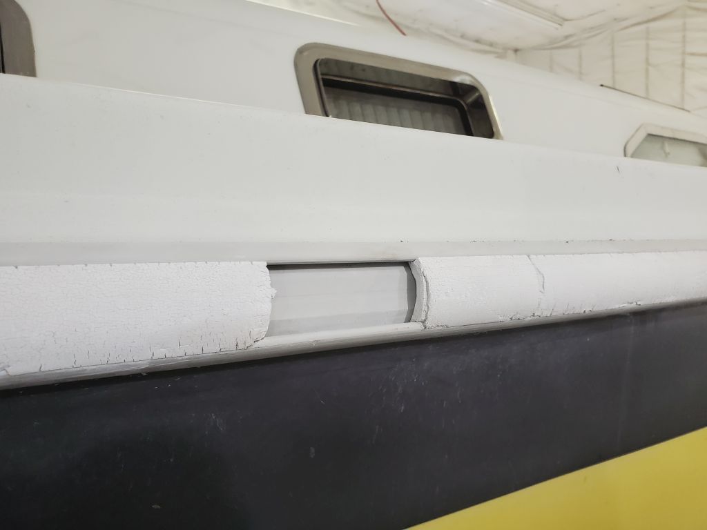
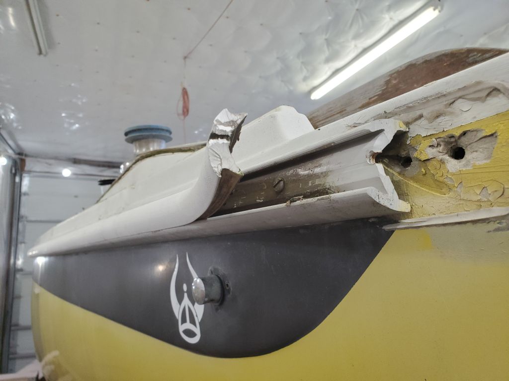
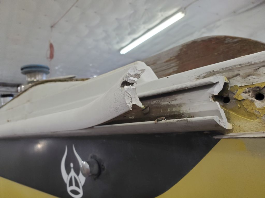
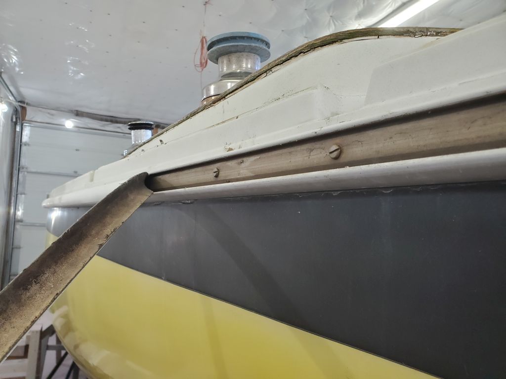
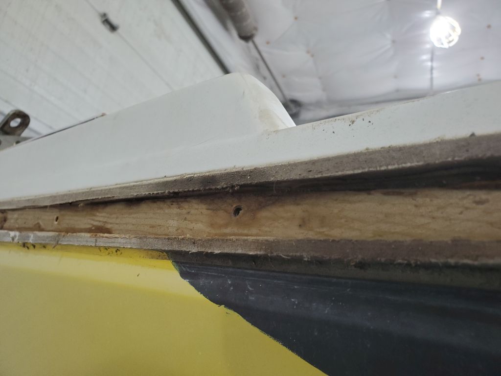
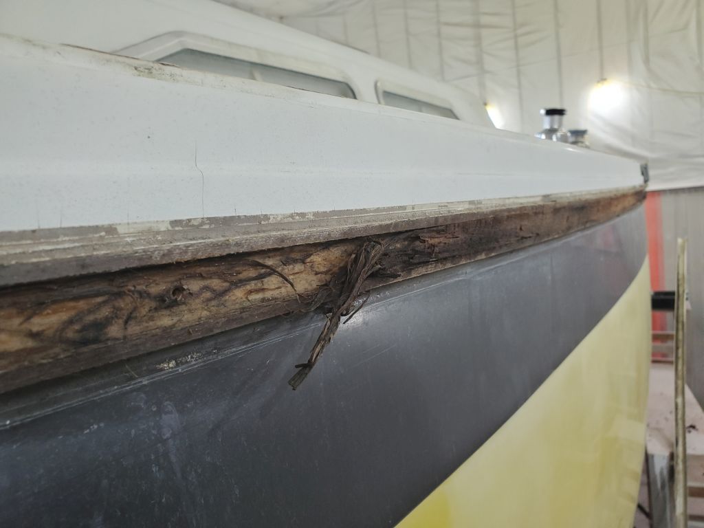
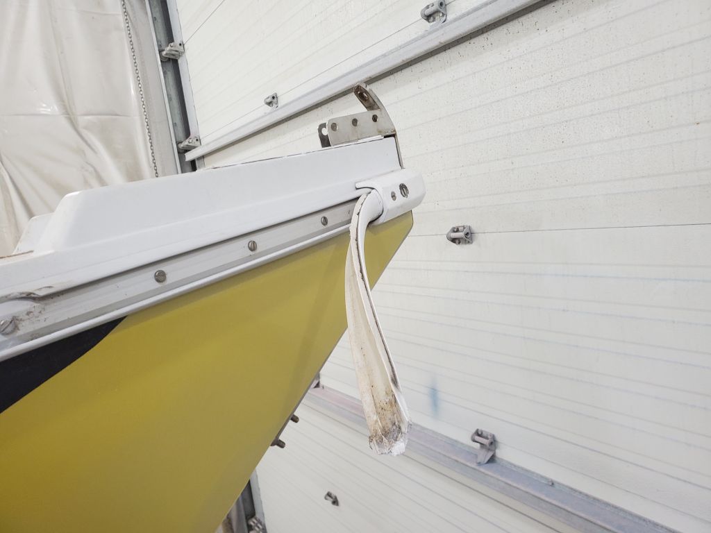
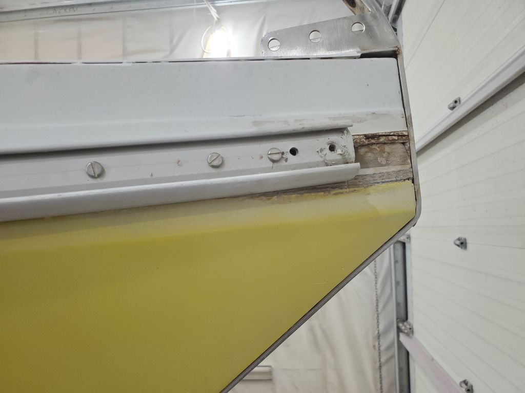
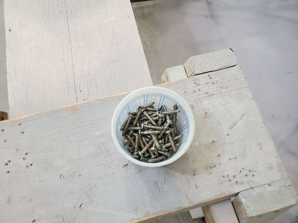
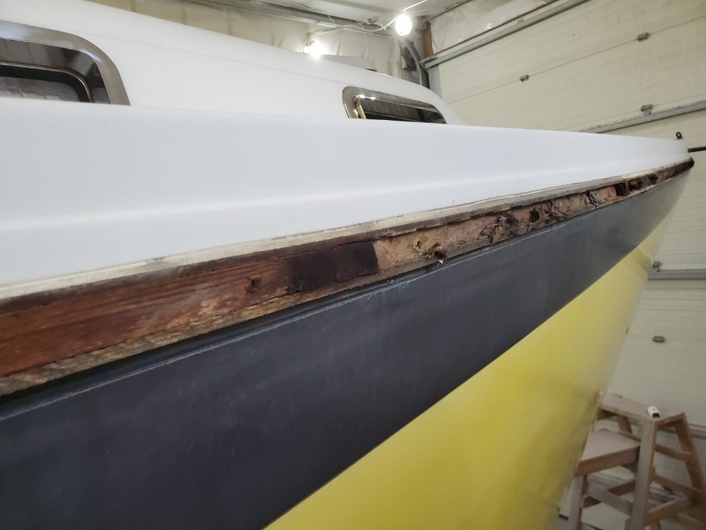
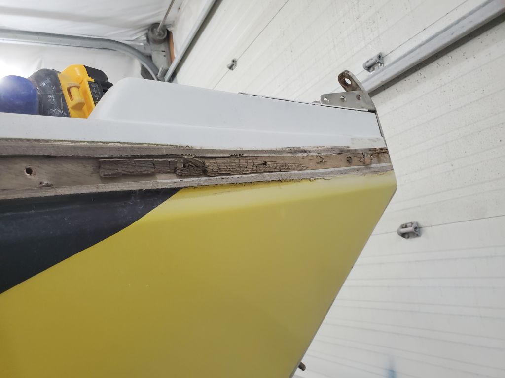
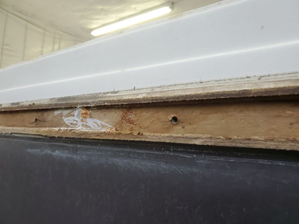
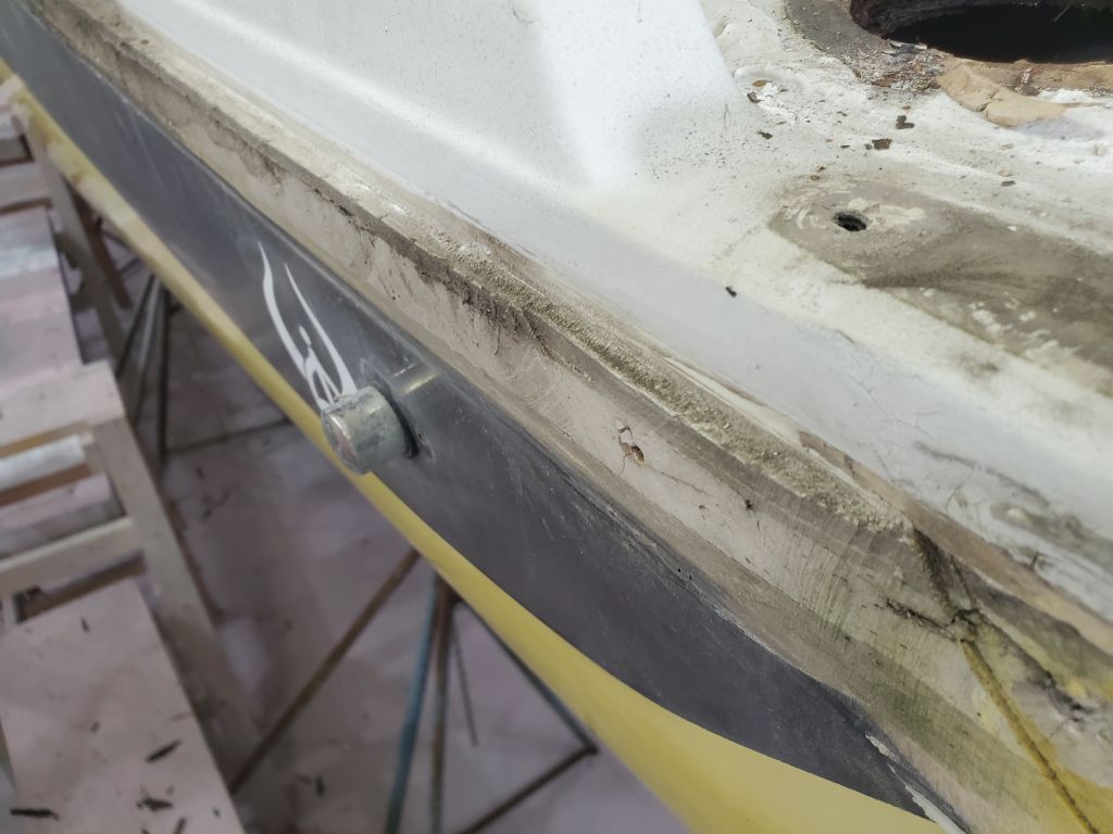
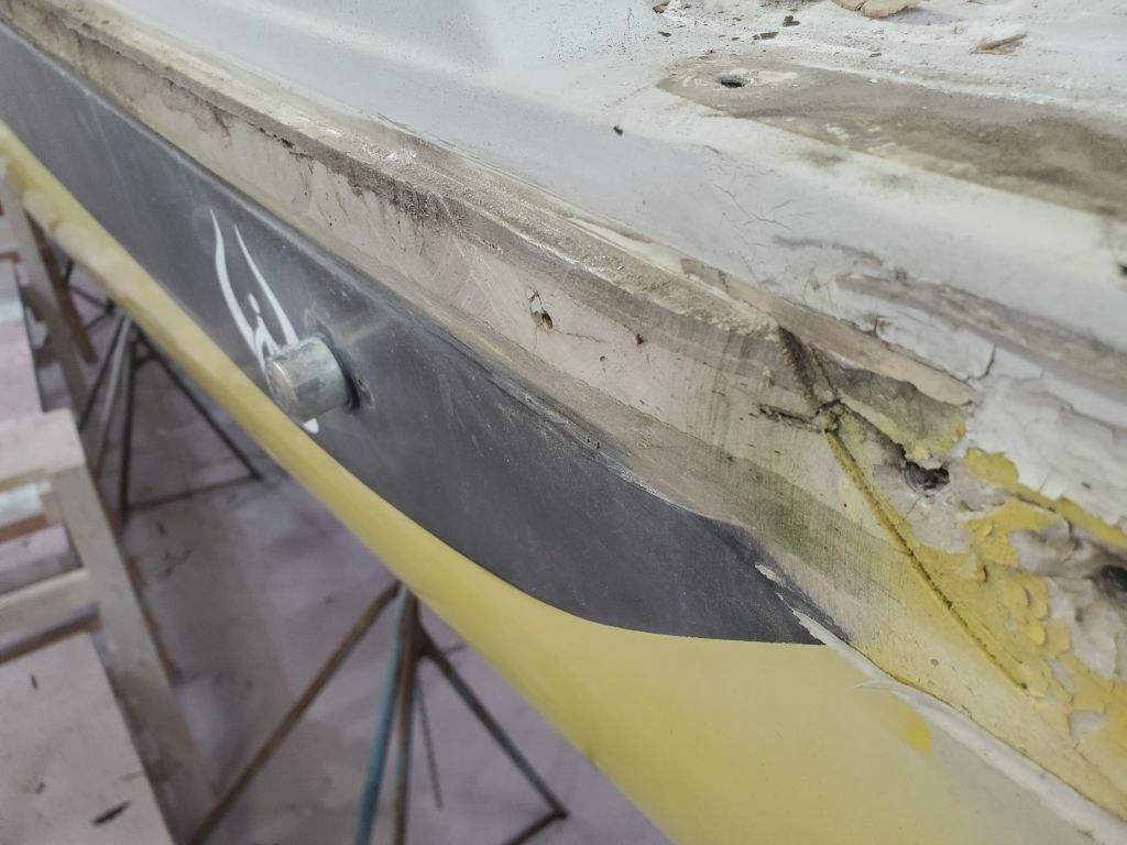
The first step was to remove the insert to gain access to the fixing screws beneath. From the general appearance of the insert, I feared it might have to be removed piecemeal, as it looked hard and brittle, so I was prepared to chip it out as needed with a chisel. To my pleasure and surprise, though, the insert was rubbery and supple and, once I got it started at one end, easy to remove by hand. Once I removed the insert, and the end trim at the bow (the end cap was missing from the port after side), I removed all the screws fixing the rubrail housing to the hull, roughly every 6-8″ on center. Beneath the rail itself was the actual hull-deck joint, which featured slightly outward flanges from hull and deck moldings with a 1″ tall wooden insert between. The owner had prepared me for this possibility during an initial meeting, and I’d done some online research, so I was prepared for the finding. My first glimpses of the wood beneath showed significant water damage and rot, but fortunately I found that the wood was a thin strip only about 1/4″ thick, and wasn’t adhered to the surrounding fiberglass, so it was easy to remove; beneath the wood was solid glass of the tabbing that actually secured the joint from the inside of the boat.
I repeated the removal on the starboard side, which exhibited similar overall conditions except there was a 6′ or so section of the wooden insert that required an extra minute or two to remove, which was only notable since most of the rest of the boat just sort of fell out almost on its own.
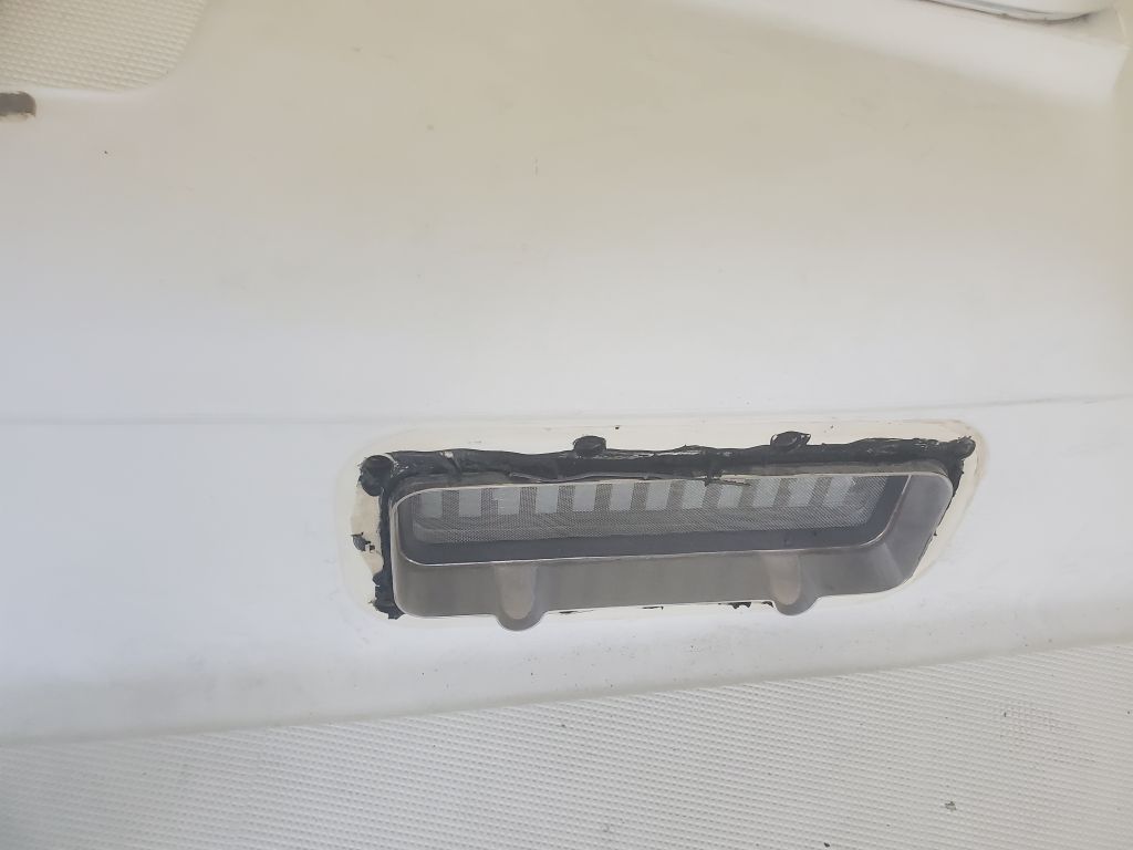
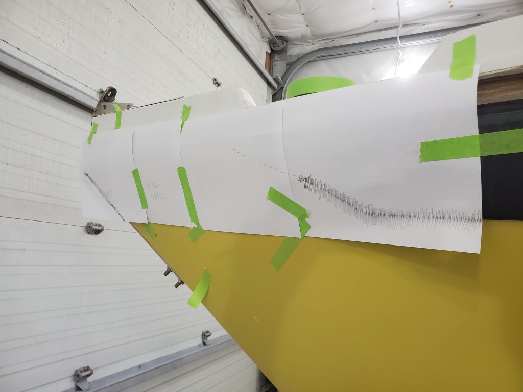
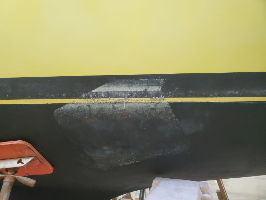
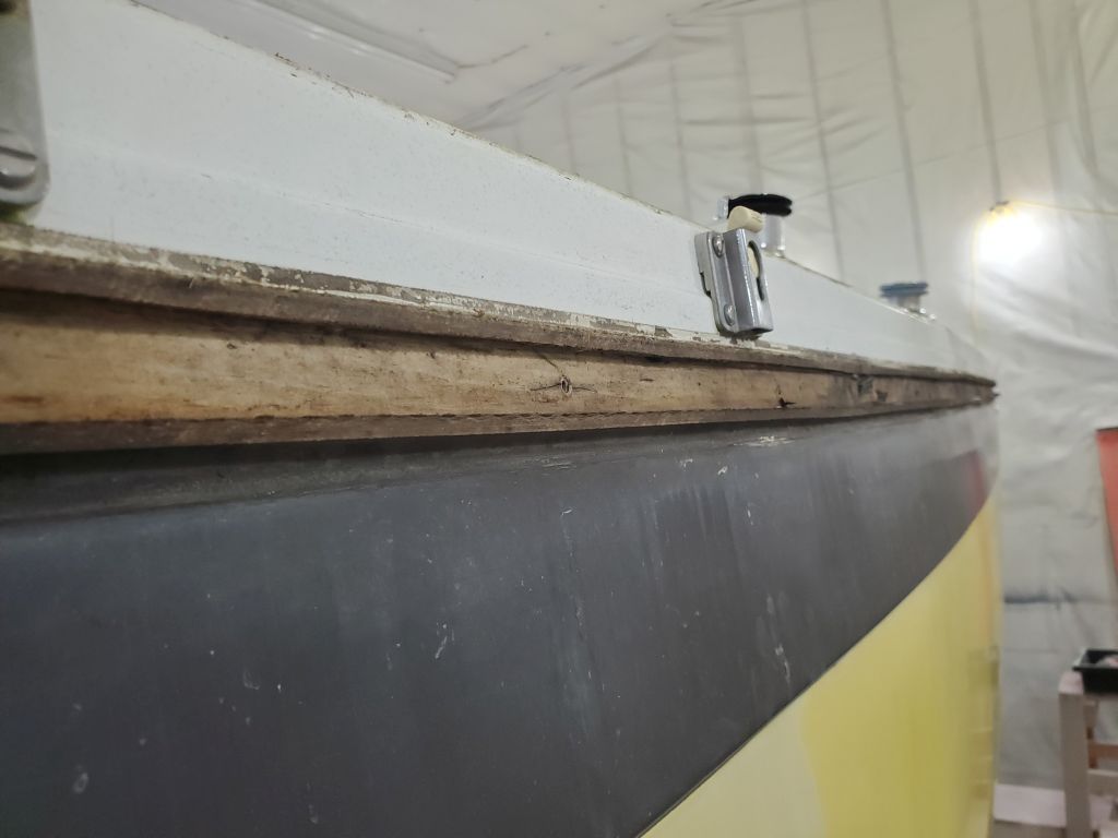
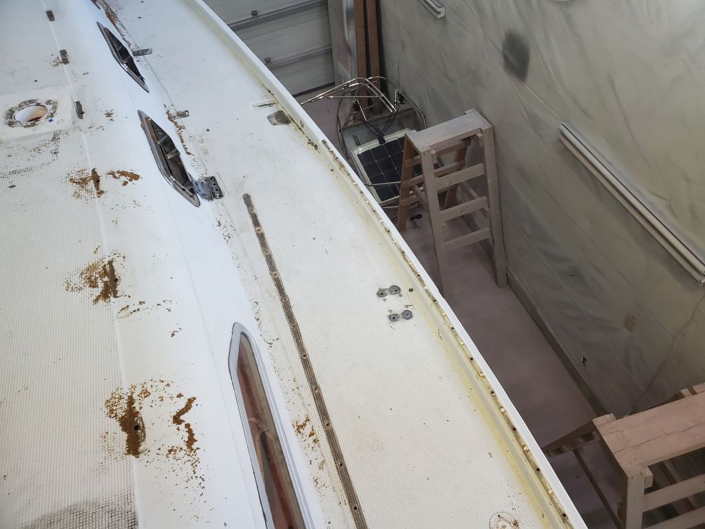
With the wooden insert removed, there remained roughly 1/4″ protruding flanges, with a box-shaped recess between and solid fiberglass behind. Grinding the flanges flush with the hull and deck moldings would basically bring the whole seam flush and ready for external tabbing to cover the whole area, with the exception of the last few inches of the port side near the transom, where the deck appeared to be just slightly wider than the hull and might require a bit more work to bring flush.
The next step would be to grind the flanges flush and otherwise prepare the adjacent areas for the new work ahead.
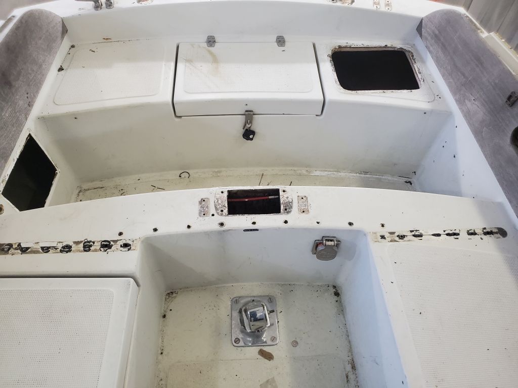
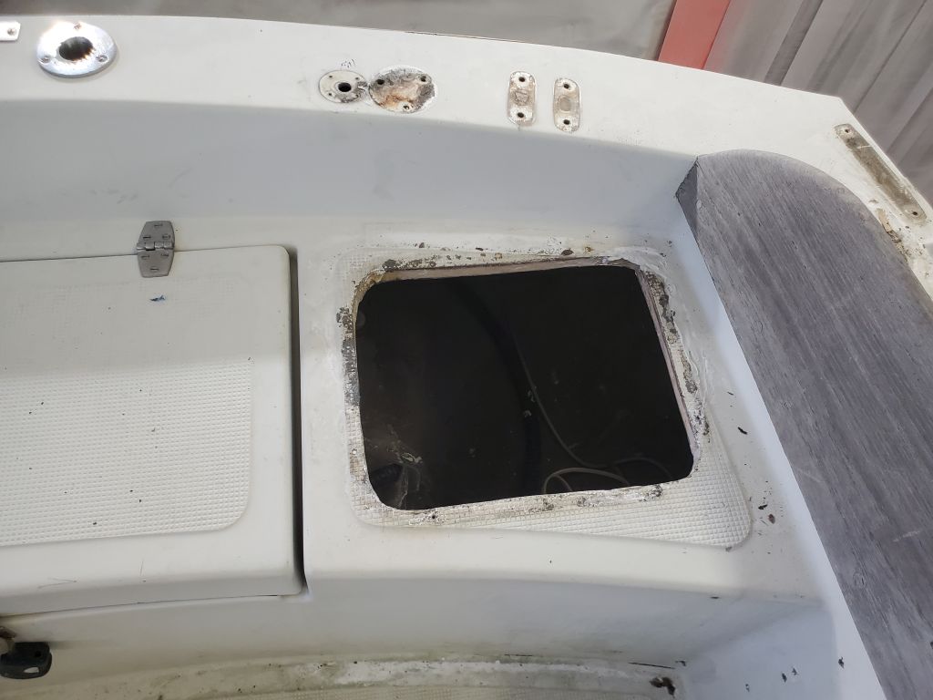
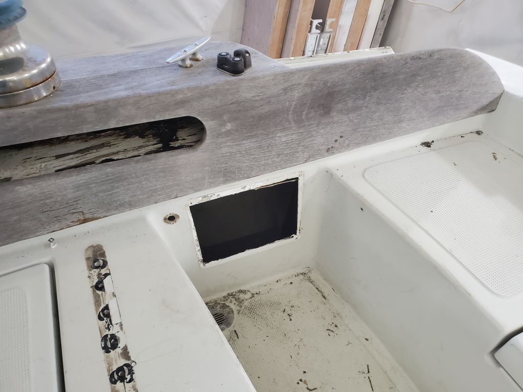
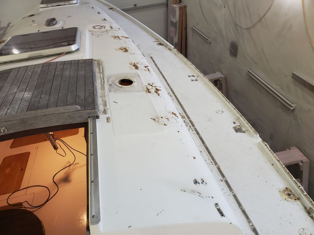
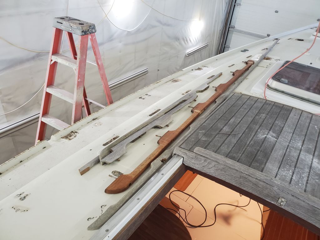
From the inception of the project the owners had agreed to undertake the deck hardware removal and installation themselves, and true to form, they worked over the weekend to remove nearly all of the deck hardware. This series of photos shows the results, and also documents the condition of the decks at the onset of the project.
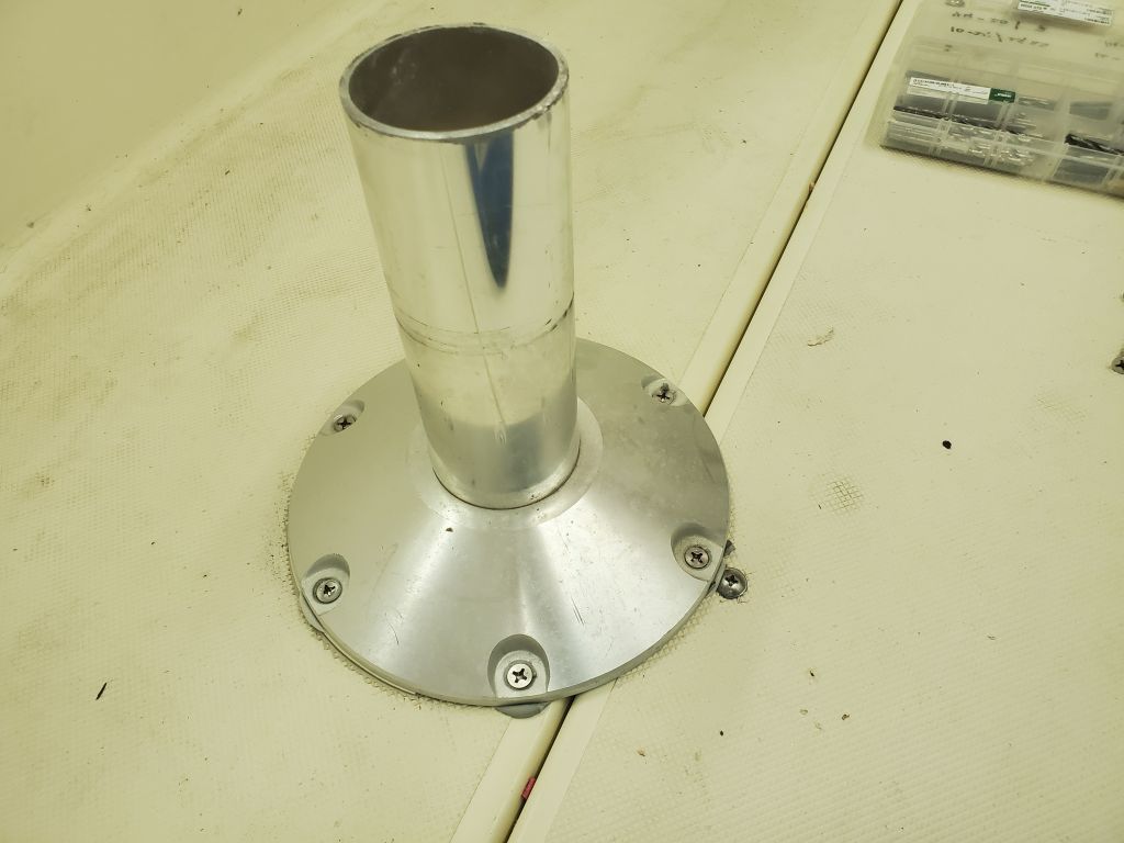
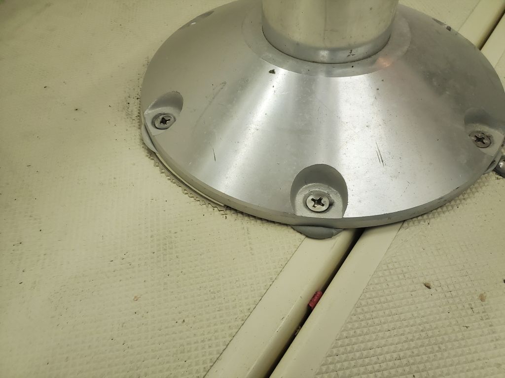
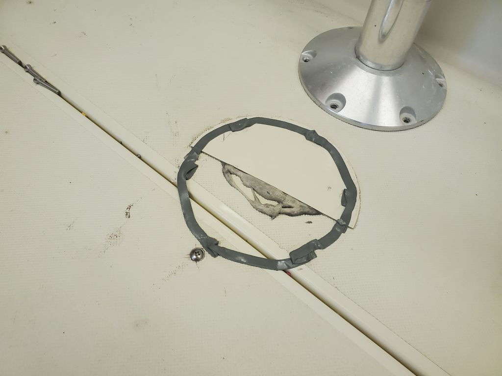
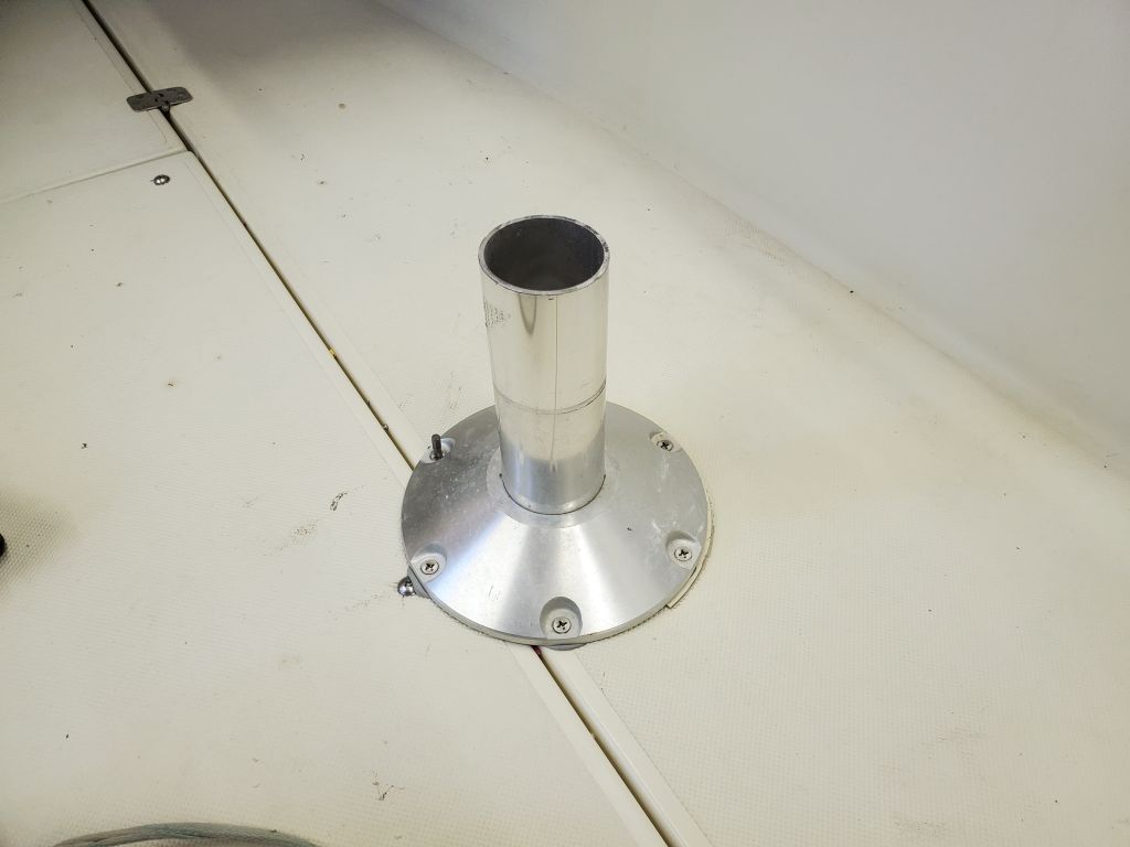
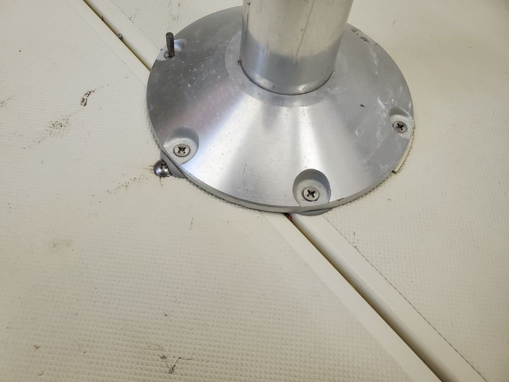
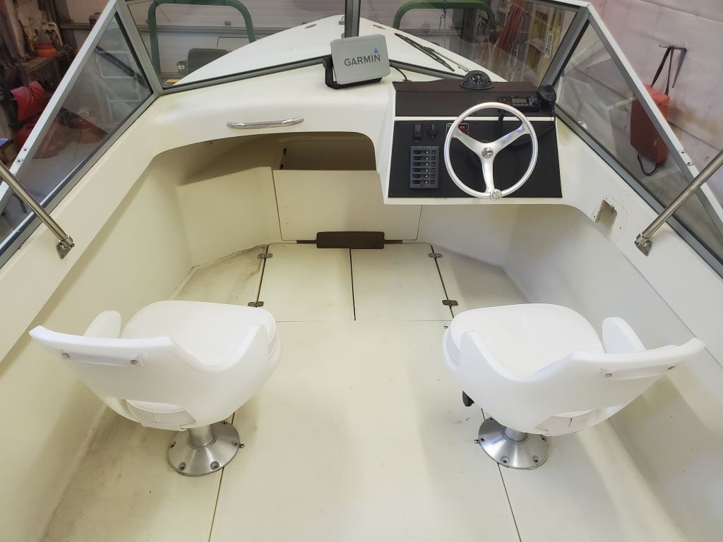
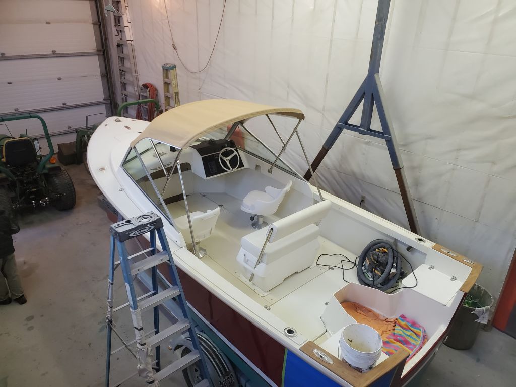
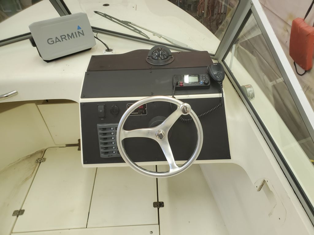
Wrapping up a couple final tasks on my list, I began with the two pedestal seats at the helm. These were straightforward to reinstall in their original locations (they’d been removed before the boat came to the shop) with new fasteners and sealant. The helm chair to starboard was missing its plastic bushing, so I ordered a replacement.
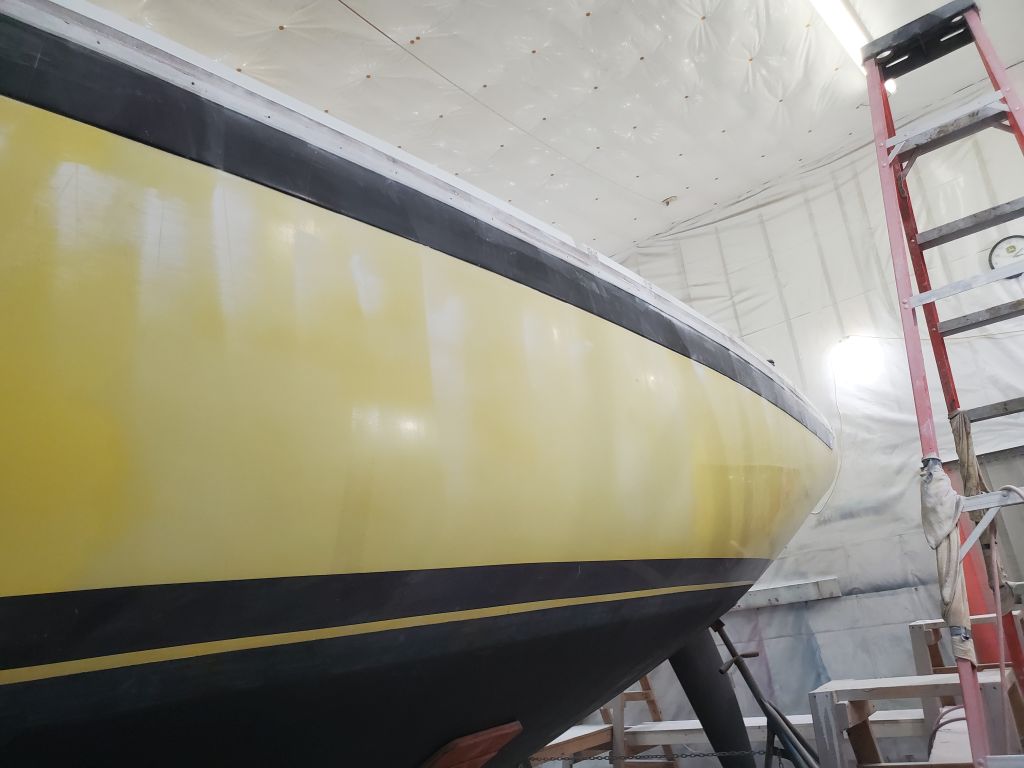
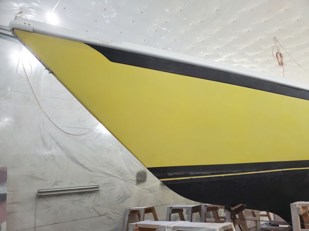
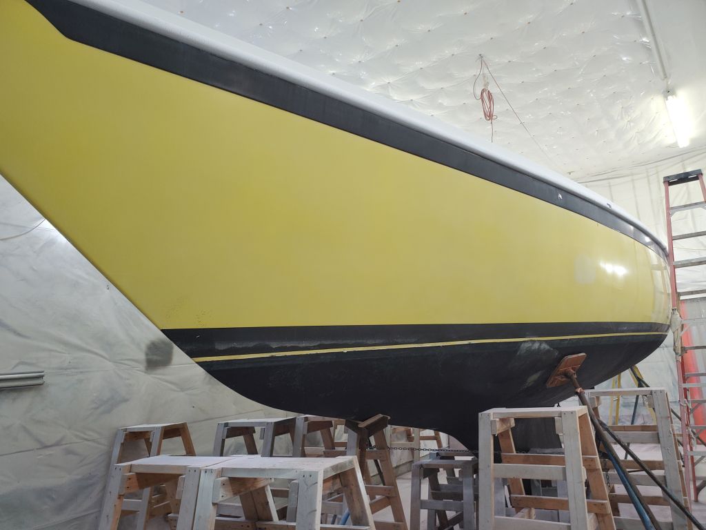
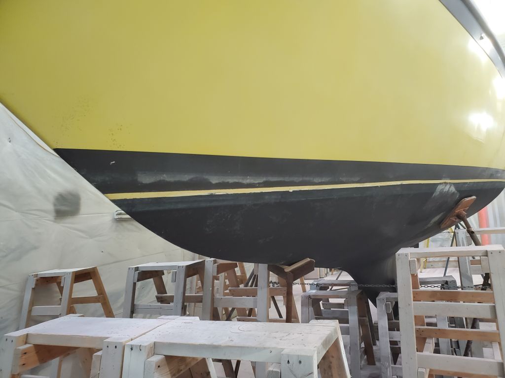
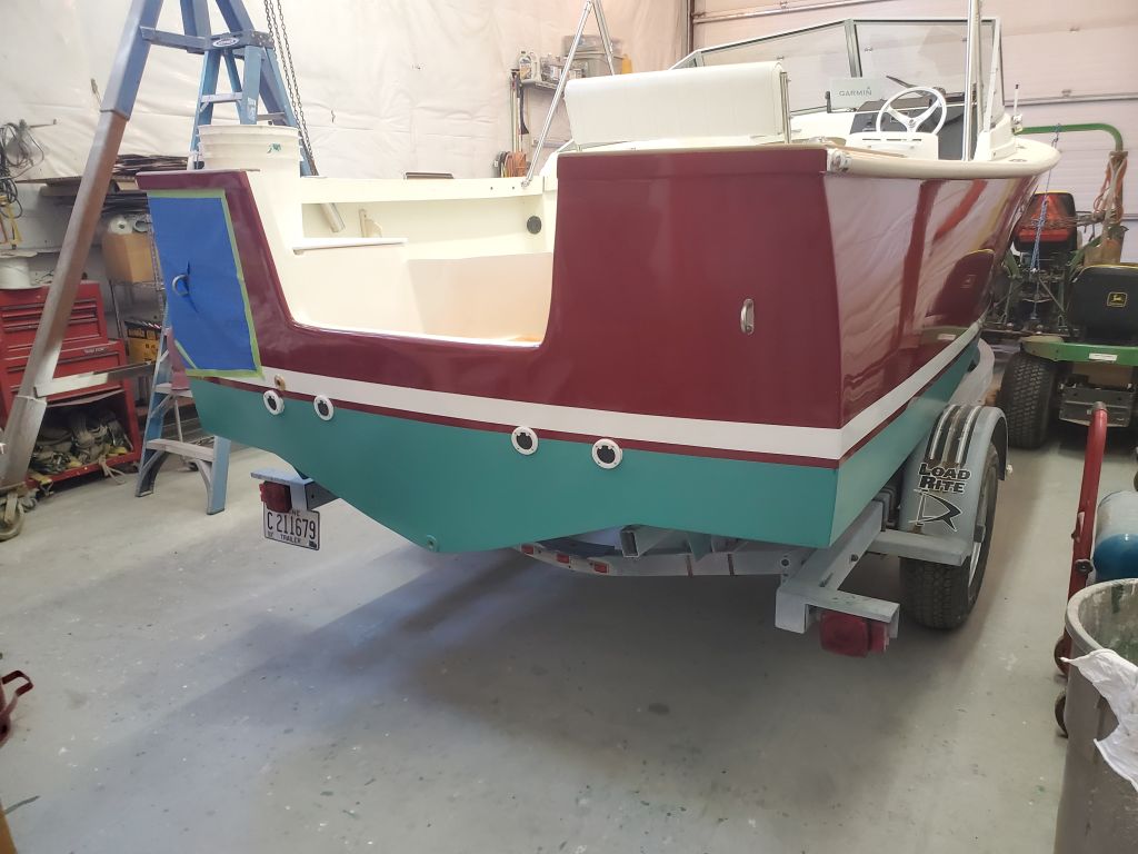
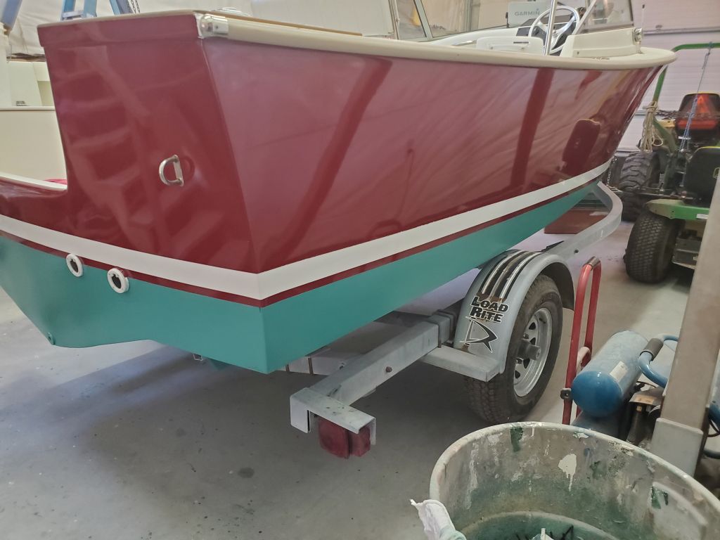
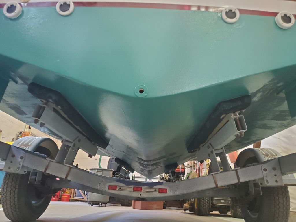
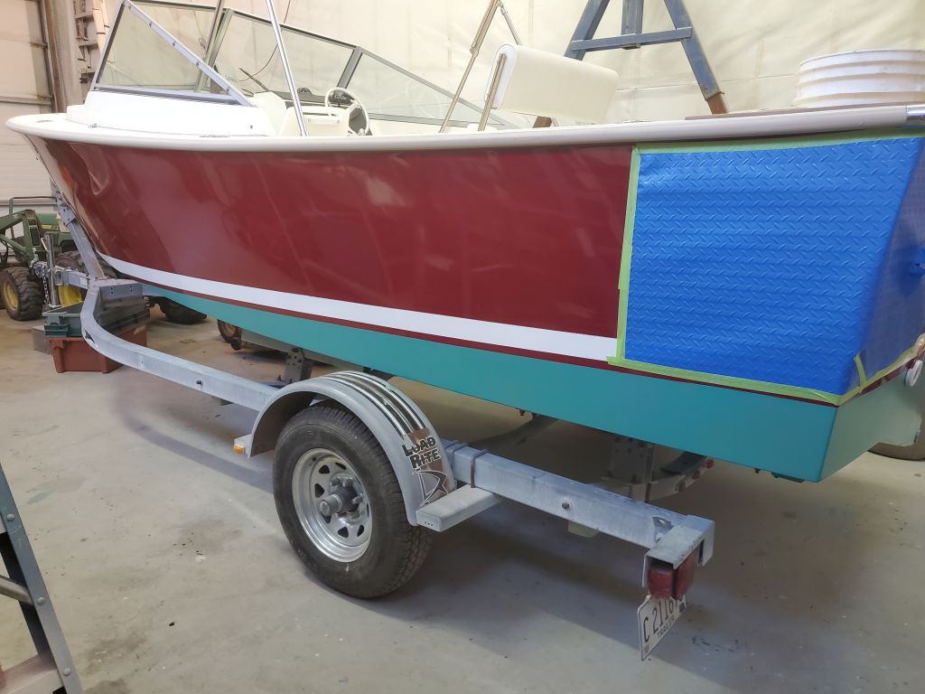
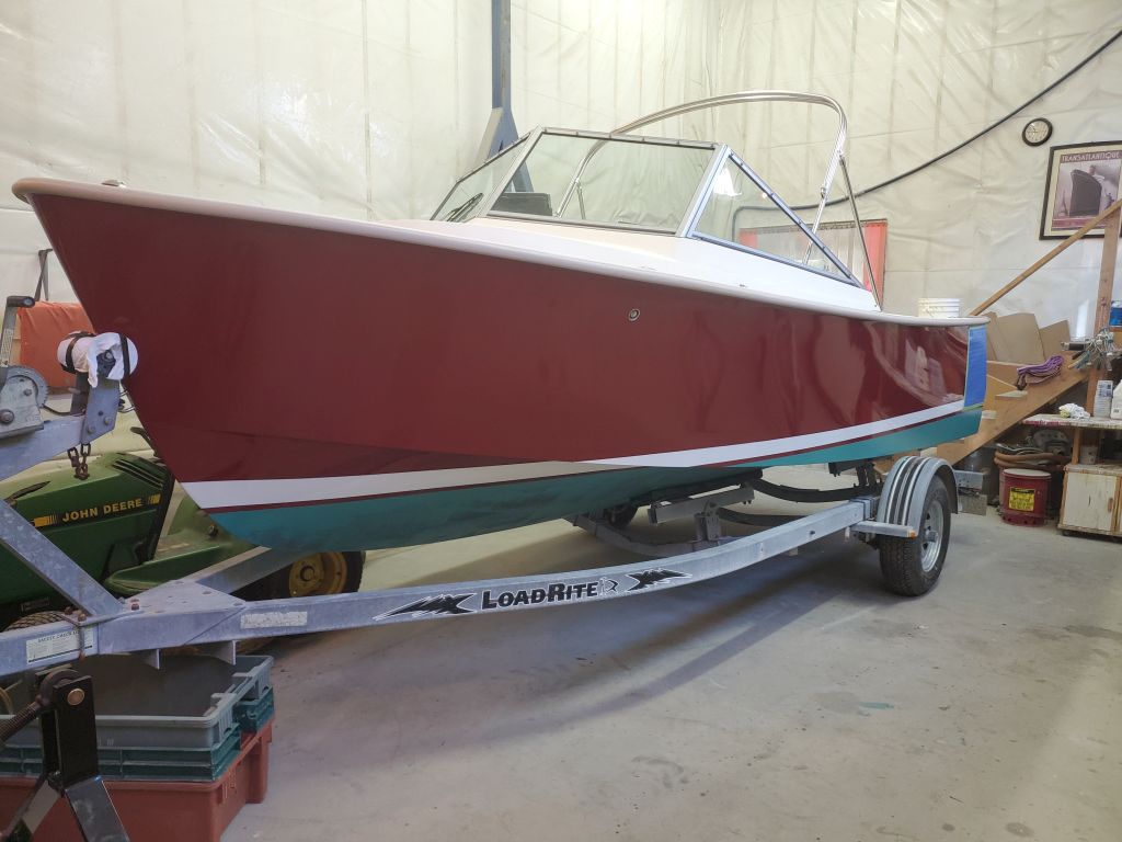
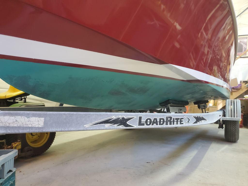
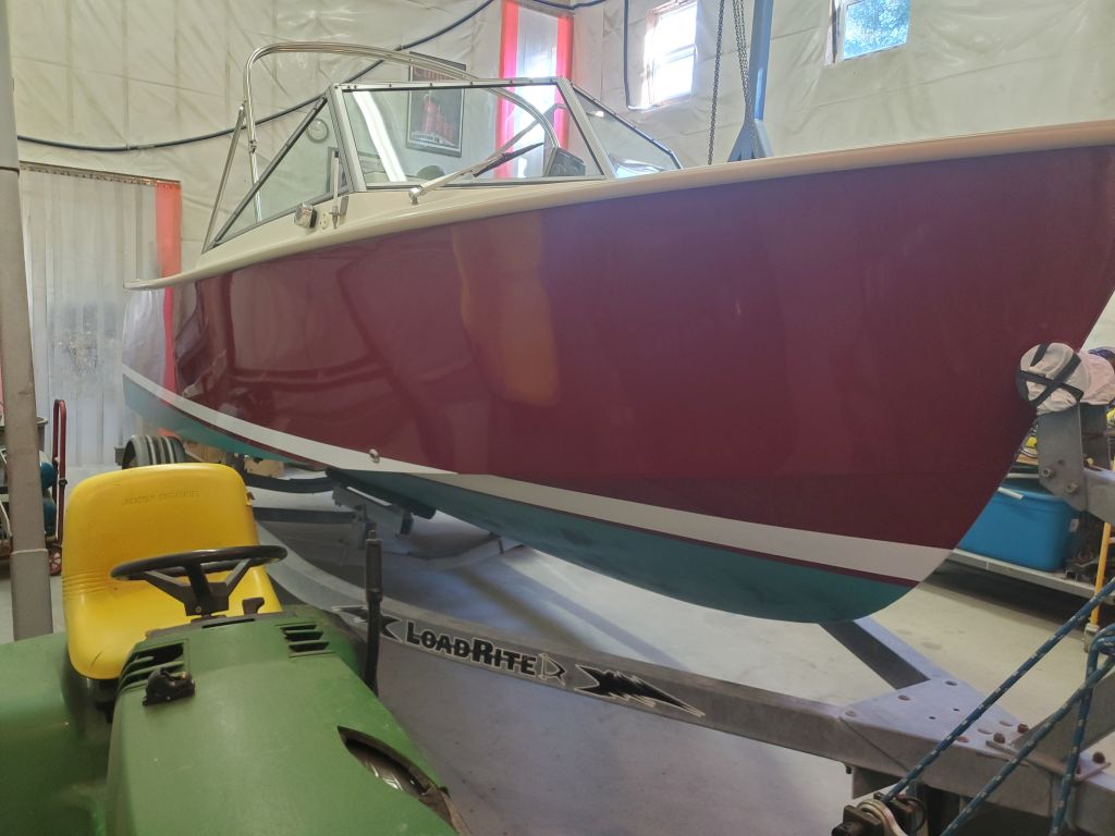
Afterwards, I masked off and painted the bottom. The owner selected green bottom paint, and this finished off the boat’s new appearance nicely. The blue plastic on the port quarter is there because the passageway there is narrow and frequently transited, so this simply provides some protection for the hull paint for now.
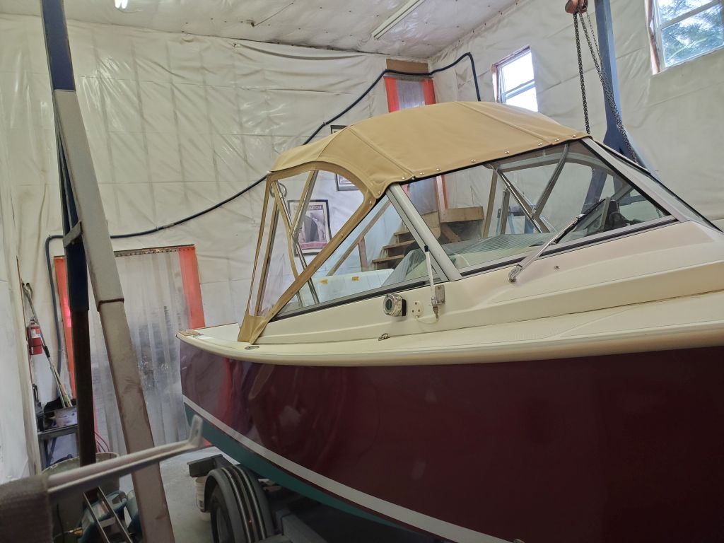
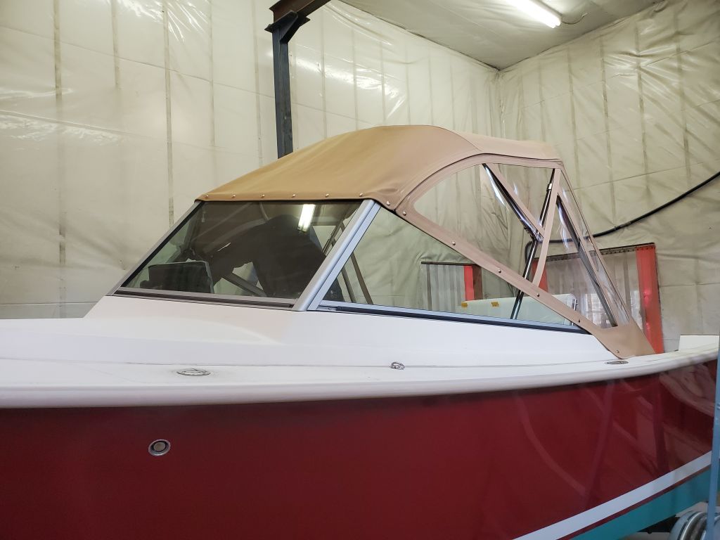
Later, Jason the canvas contractor was back with the new top, which he’d patterned earlier in the week. The top included a zippered panel over the helm station to allow the operator to poke their head through the canvas if standing was desired. With the top fitted, Jason could make the patterns for the side curtains, which he finished in my absence as I had to leave on other business. He anticipated having the new panels complete in the near future.
With that, the only task remaining on my list was to fabricate some trim for the top edge of the new outboard well (forward end), which I’d take care of sometime over the coming days.
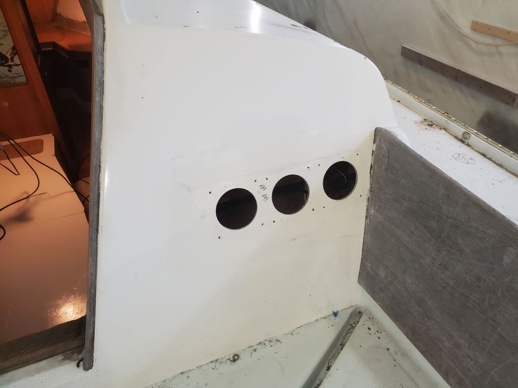
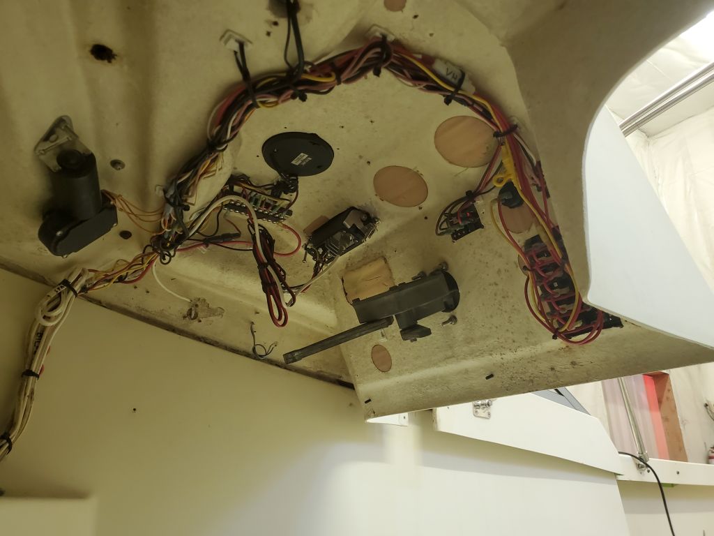
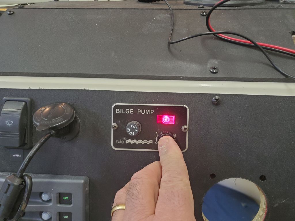
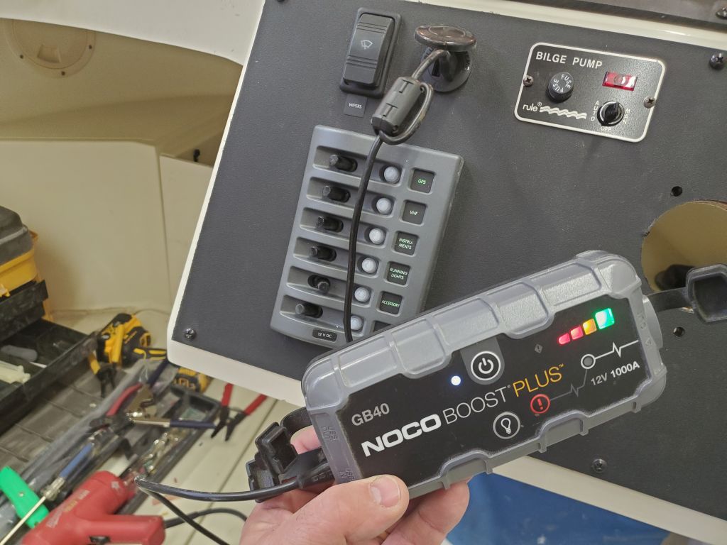
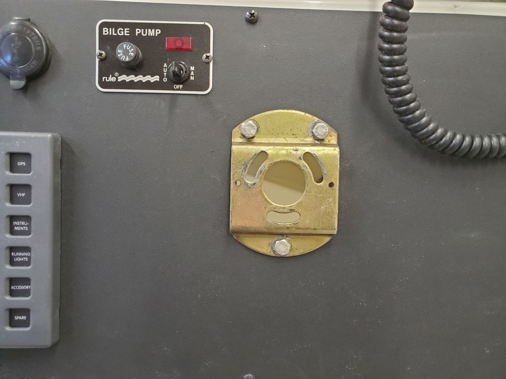
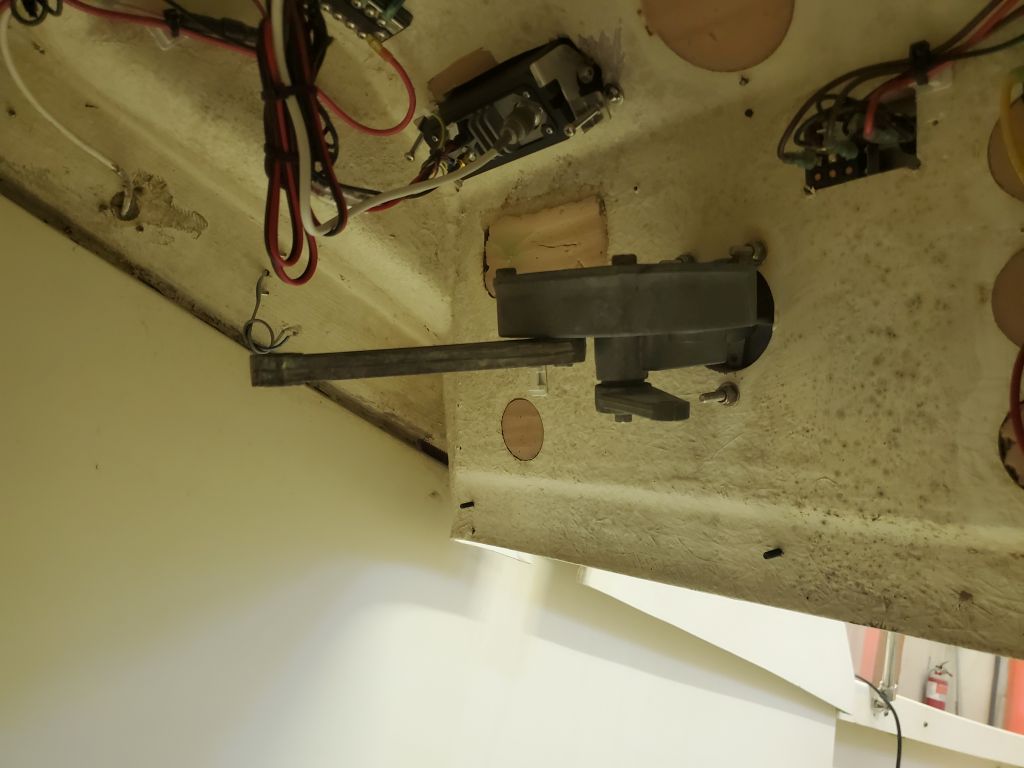
In a short afternoon at the shop, I finished up the final wiring tasks beneath the helm console, including permanent installation of the VHF radio, and secured the wire bundles as neatly as possible. I corrected a minor wiring issue with the bilge pump switch to activate the pump properly. Earlier, I’d failed to test the USB outlet pair in the accessory outlet, so now I grabbed the only thing I could quickly find with a USB power plug–my battery jump pack–and plugged it in to ensure the outlets were powered correctly.
With everything functional and now secured, I finished up work at the console by installing the original helm unit once more.