< Back to Danusia
Friday
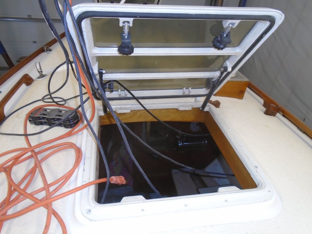
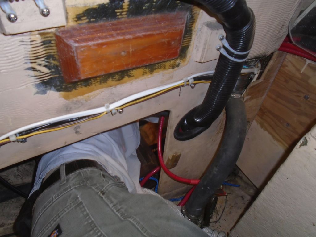
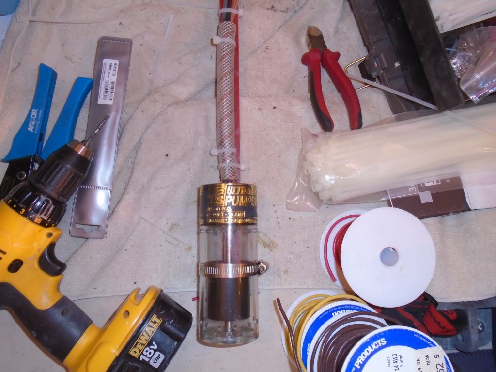
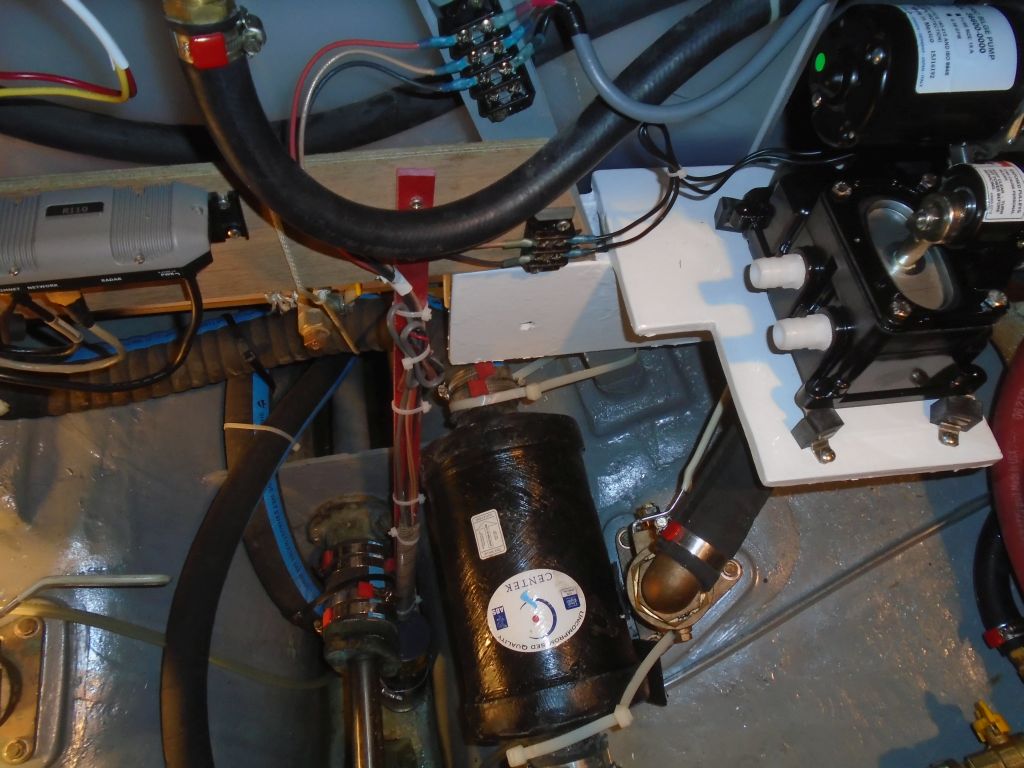
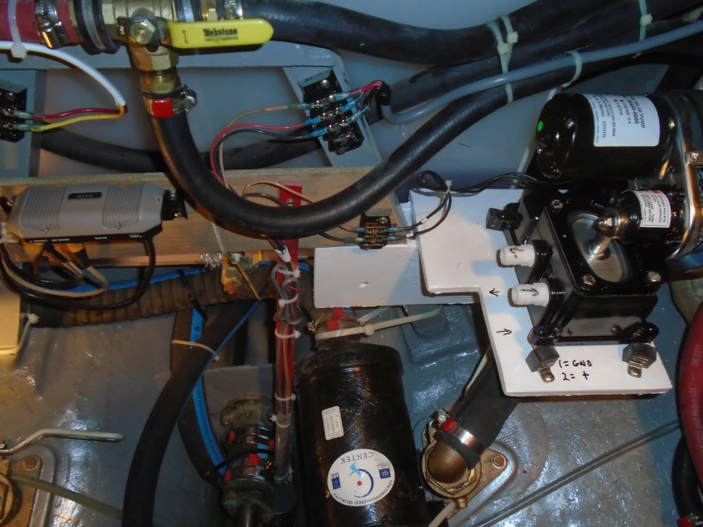
I’d lined up a helper to remove the shaft coupling and stuffing box, as I knew he’d fit in the space more easily than I. The shaft had to be removed in order to replace the stuffing box hose, and the owner had been unable to remove all the packing from the nut while it was in place (space was very limited and prevented access into the nut). Before Jason’s arrival, I worked to prepare tools I thought we’d need for the job, and once he was here I played gopher for a while, but tried to do some other jobs while I was not immediately needed for his assistance.
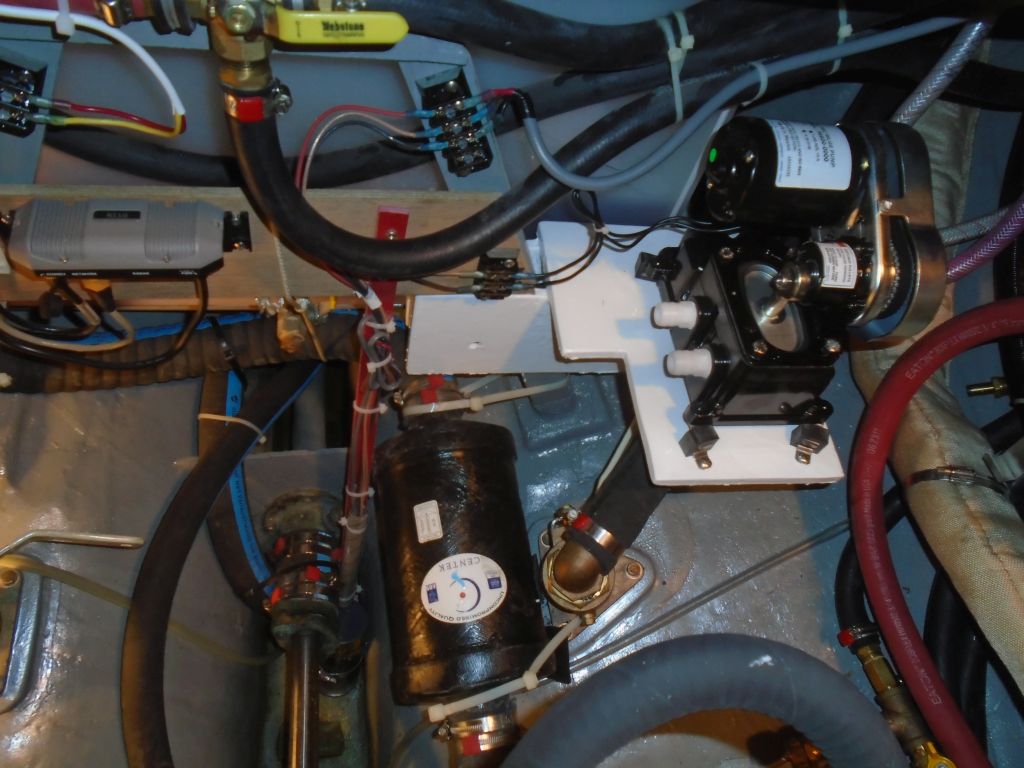
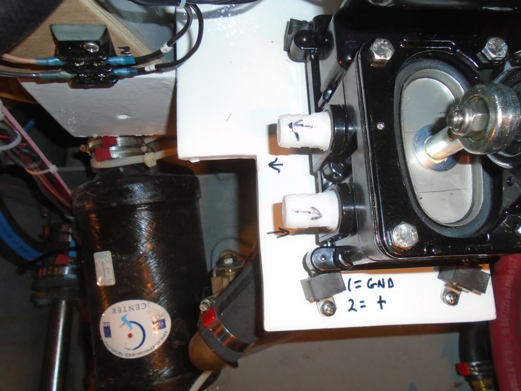
With Jason crammed into the locker beneath the cockpit, we got to work. The basic procedure was to unbolt the shaft coupling from the transmission, which went fairly well with no real issues other than trying about six different wrench sizes on the coupling bolts before he found the right one: they were oversized heads and turned out, finally, to be 17mm.
Once the coupling was free, with considerable effort (a harbinger of things to come) we pulled the shaft back enough in order to fit a spacer between the shaft and the transmission coupling. For this purpose I’d sourced a variety of 7/8″ diameter pipe nipples of various lengths. With a 1″ shaft, these would stay within the shaft footprint and allow us to pull the coupling off the shaft with long bolts threaded into the transmission coupling. A simple task in theory, but one greatly complicated by the challenging access and the minimal space available between the transmission and the stuffing box, which limited how far back the shaft could be pushed and spaced.
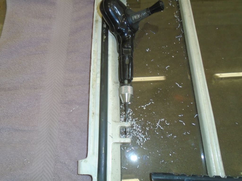
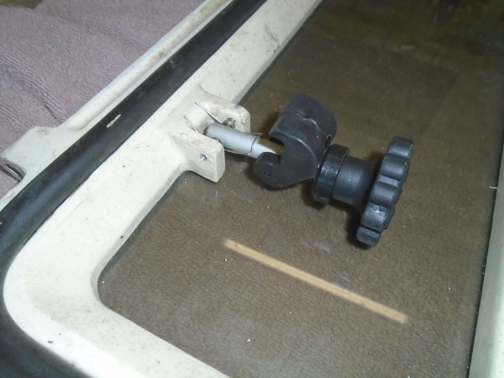
Over the next few hours, resetting the equipment several times (a few times because the threads on the bolts, as the coupling moved forward, contacted the transmission and had to be spaced further back, once to replace the spacer with a longer one), Jason eventually released the coupling–a long, tedious process, a snippet of which is shown below for all to enjoy.
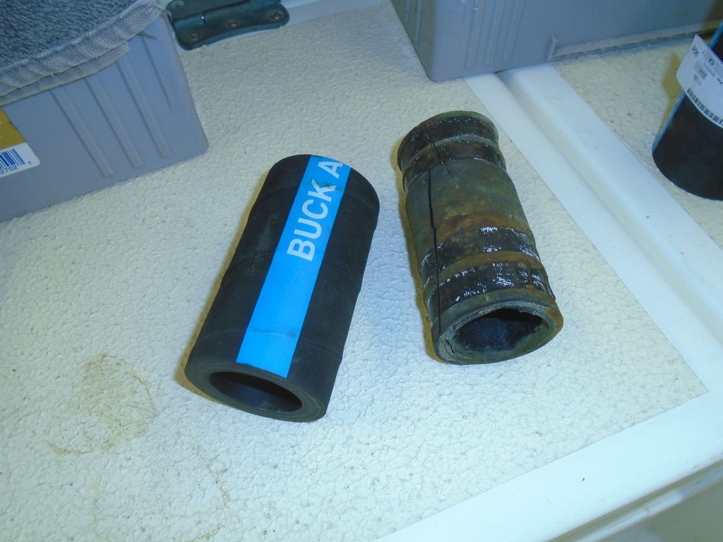
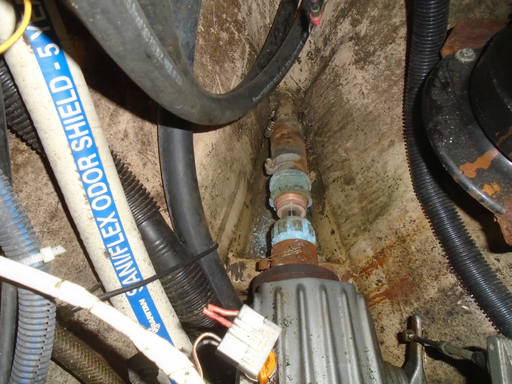
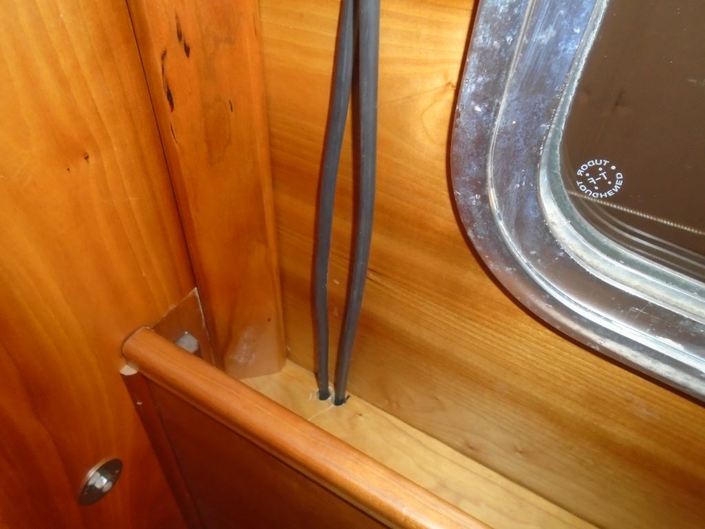
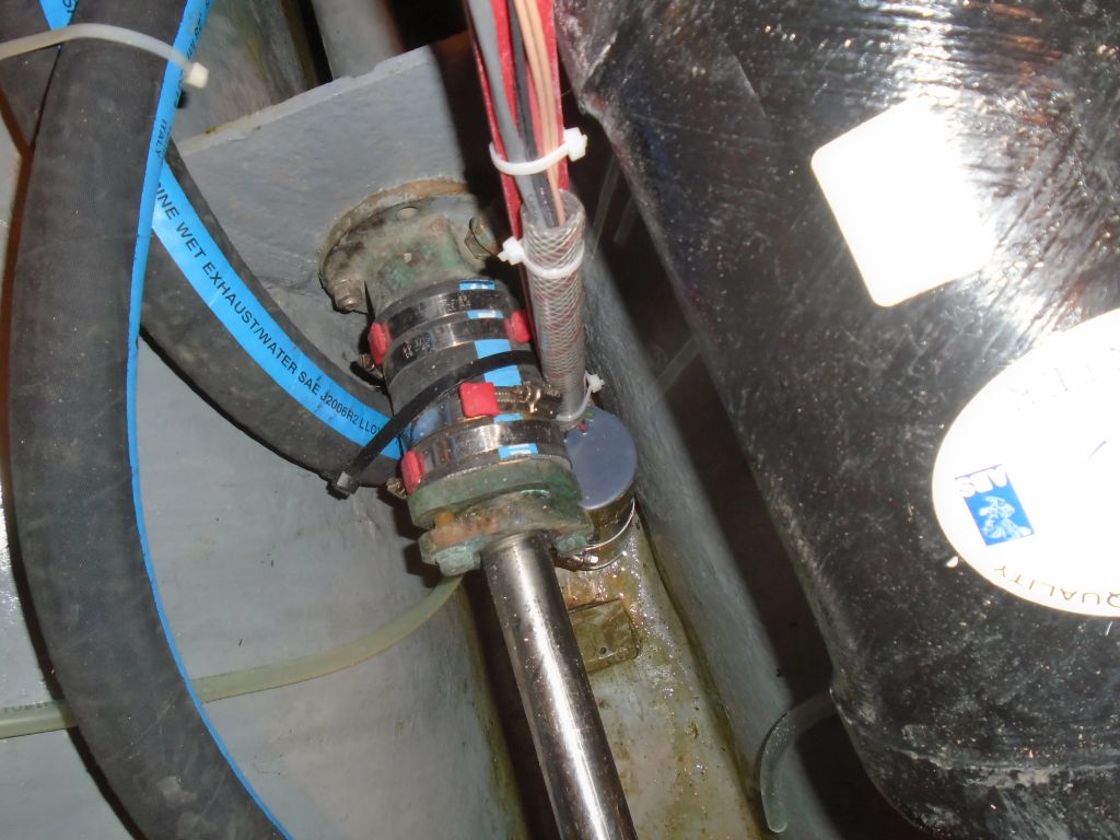
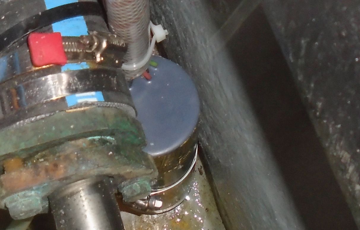
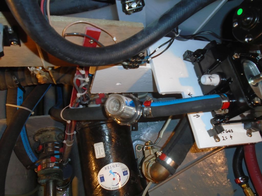
During this time, the shaft often became very difficult to turn at all, and seemed to be binding in the Cutless bearing. As the coupling moved forward, slowly, off the shaft, the exposed key in the shaft started to get close to the stuffing box nut, and with such tight clearances we eventually decided to cut off the old stuffing box hose to increase the room as much as possible. Fortunately, Jason found that the old clamps came off easily, and the old hose was easy to cut lengthwise and remove. Replacing this hose, and repacking the stuffing box, were the whole point of this operation in the first place, of course.
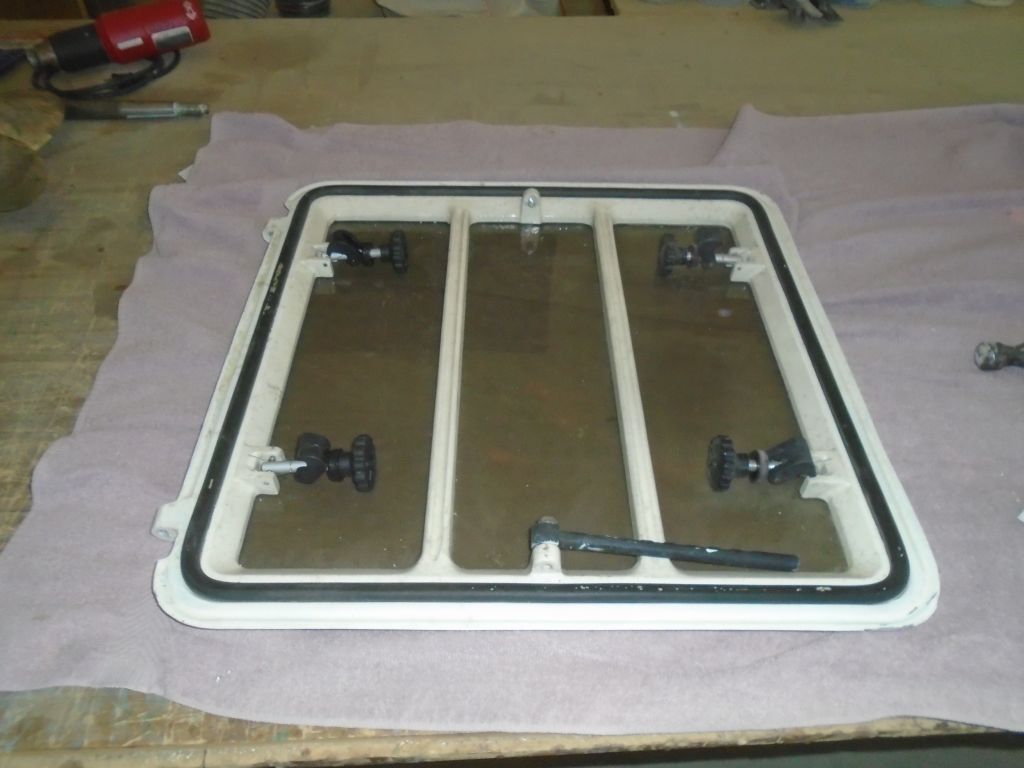
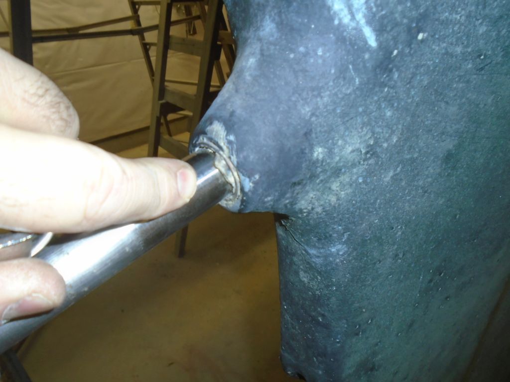
With the coupling finally off, it should have been quick and easy to pull the shaft. In fact, I’d hoped to do this, repack the stuffing box, and reinstall everything on this day. Alas, this was not to be. The earlier issues we’d encountered with the tightness of the shaft now prevented the shaft from moving basically at all. We couldn’t turn it, and couldn’t pull it. At the deadwood, I could see the problem: the Cutless bearing was coming apart, and the rubber inside was clearly binding the shaft.
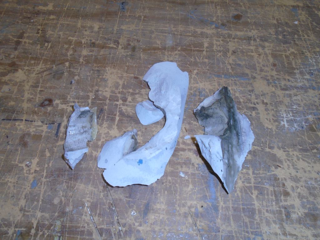
I’d neither wanted nor expected to worry about the Cutless bearing, but since the shaft was immobile there was no choice but to get it out. The bearing was housed in a molded (so I thought at the time) protrusion in the aperture, and I was initially unclear how best to proceed. Eventually, I cut away some of the material surrounding the bearing–it turned out to be only polyester filling material so the removal was easy with a grinder. This process exposed the end of the actual stern tube, with the bearing inside and secured with a pair of set screws, which were interestingly–and unusually–seized together with wire.
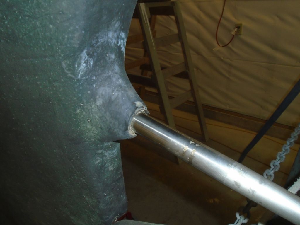
Now that I could see the situation, I proceeded a little more slowly, and cut and chiseled away enough additional material to fully expose the set screws, and cut away a bit extra of the fiberglass stern tube to expose the end of the bearing. This would allow me to get a wrench on the bearing and hopefully pull or twist it out. (Teaching Moment: always leave some of the bearing exposed at the end of the stern tube to allow for this without dramatic surgery!) With Jason still on hand to help, I put a large set of slip-joint pliers on the newly-exposed section of the bearing, and twisted, while Jason pulled. After some exertion the bearing (with shaft firmly stuck within) spun, and we had won. From there, the shaft came out easily.
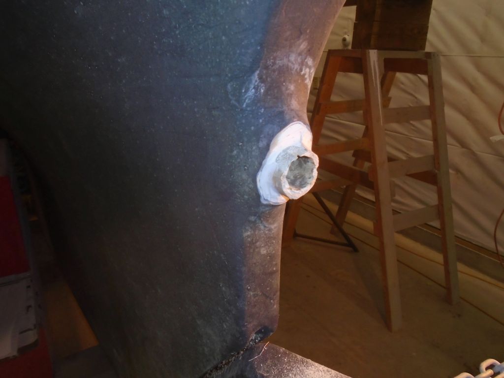
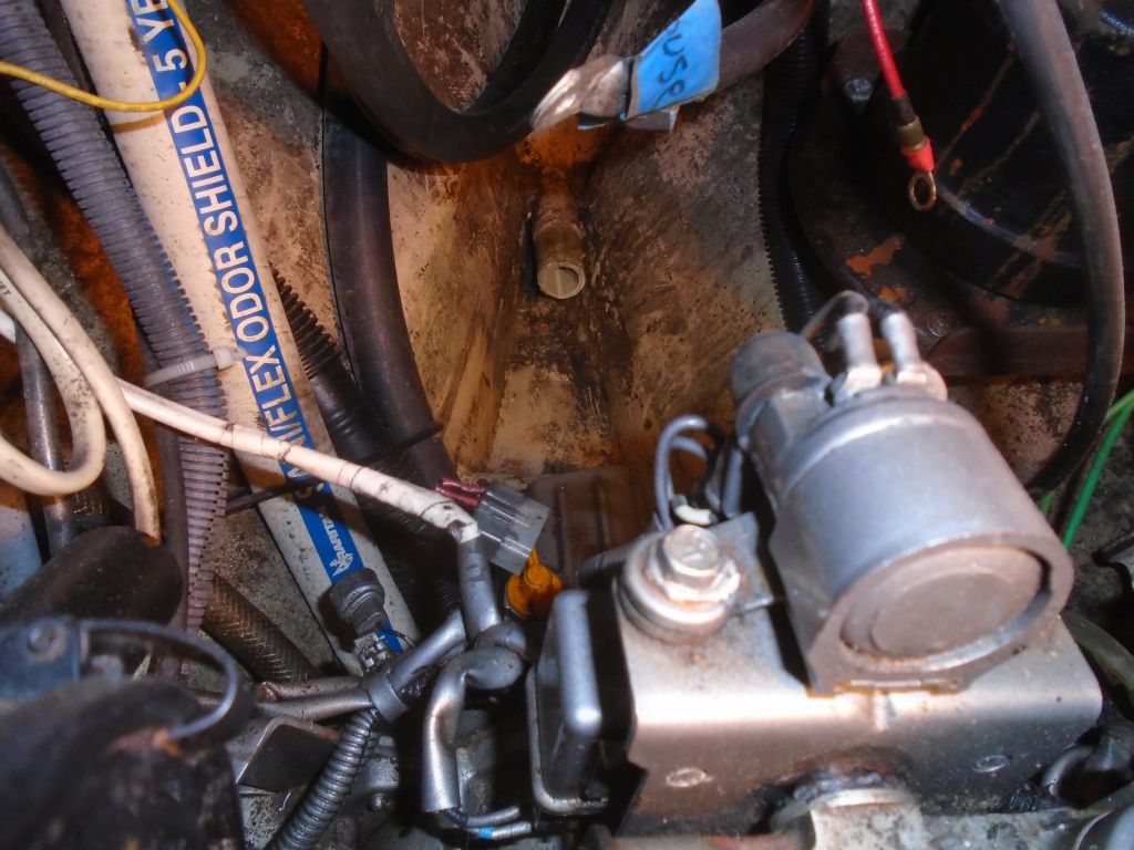
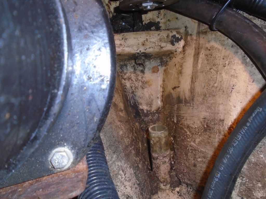
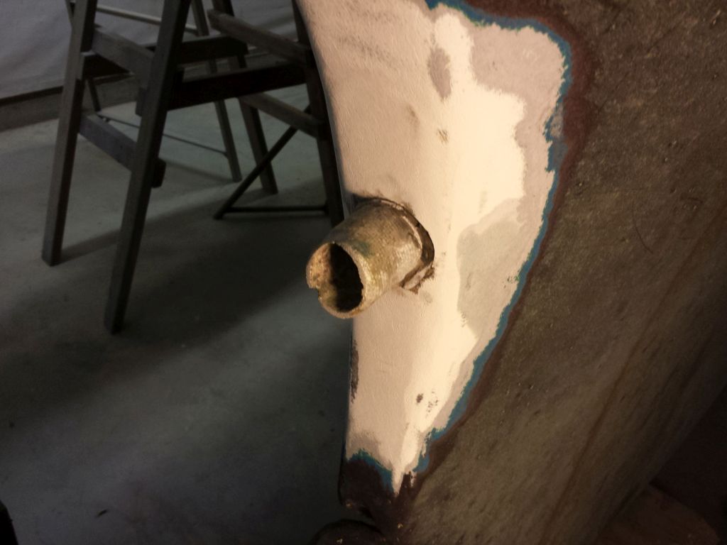
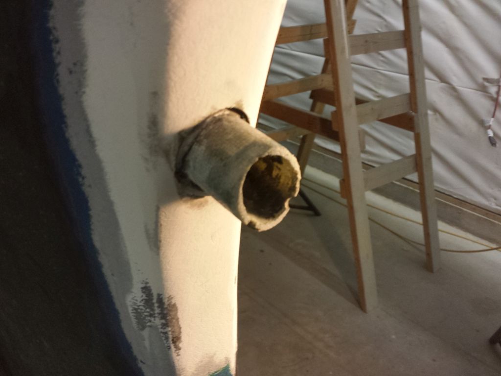
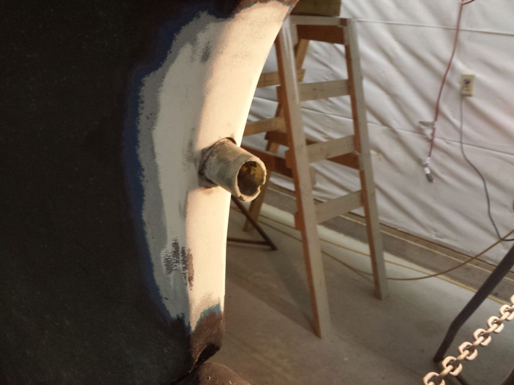
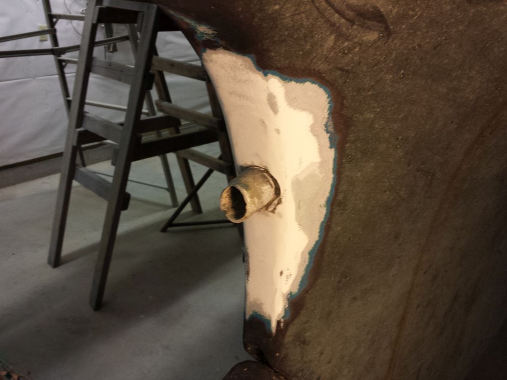
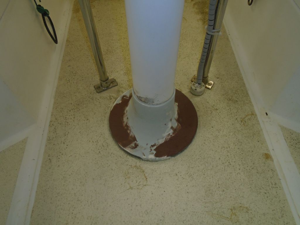
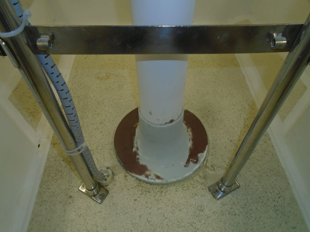
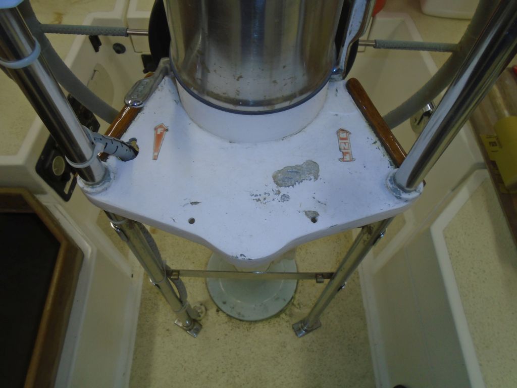
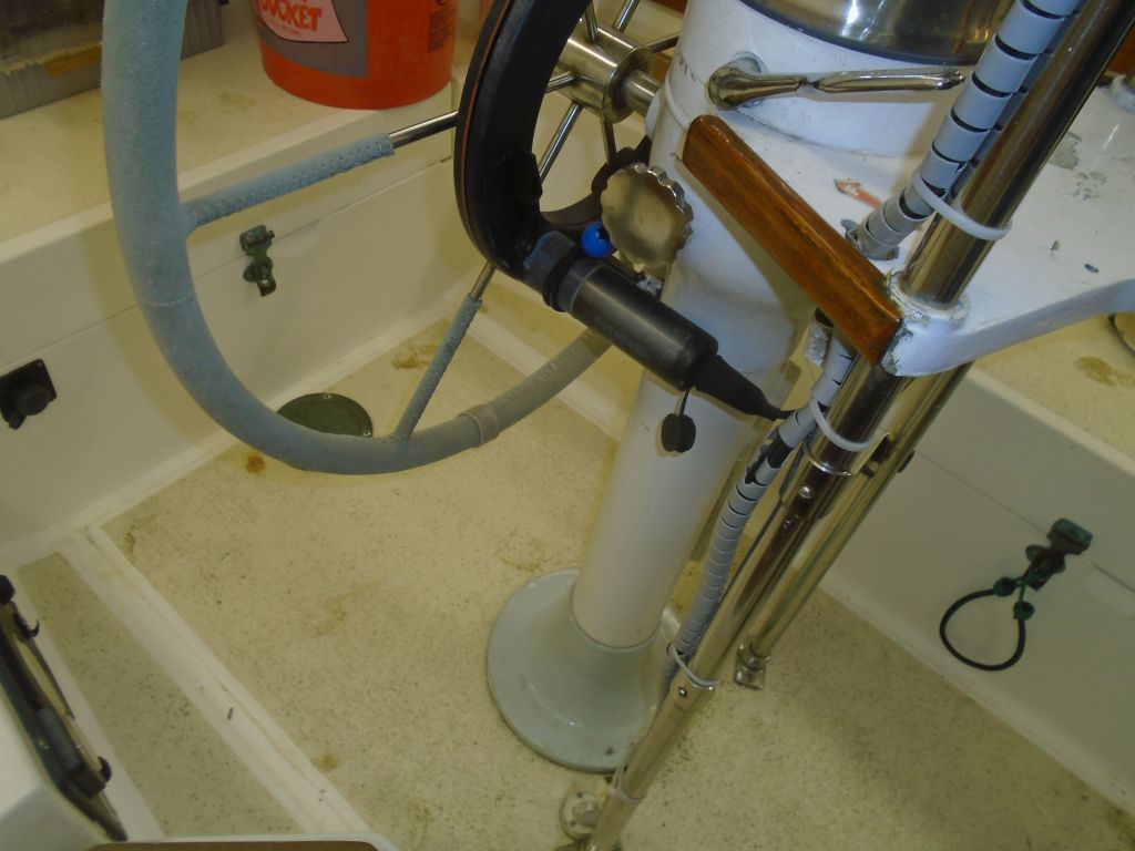
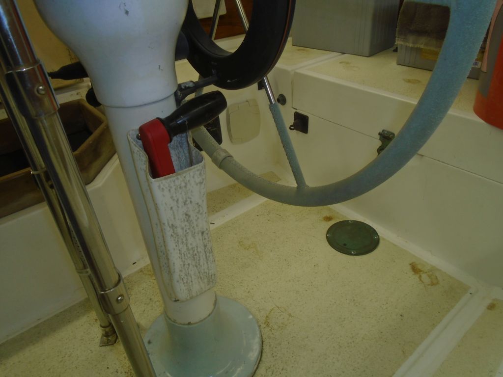
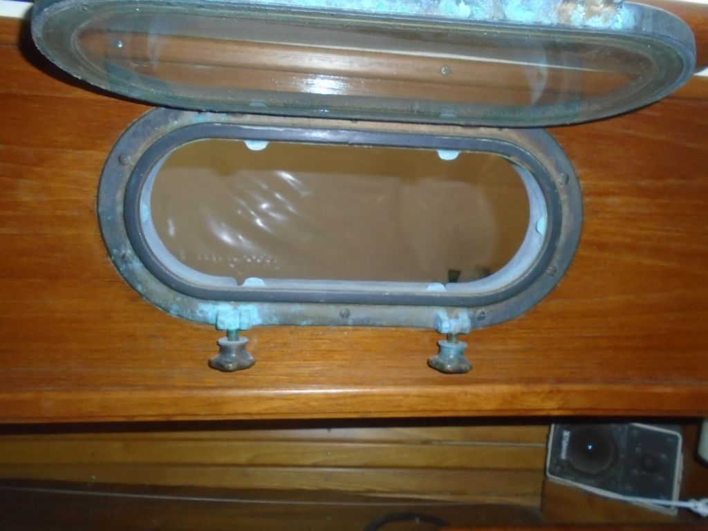
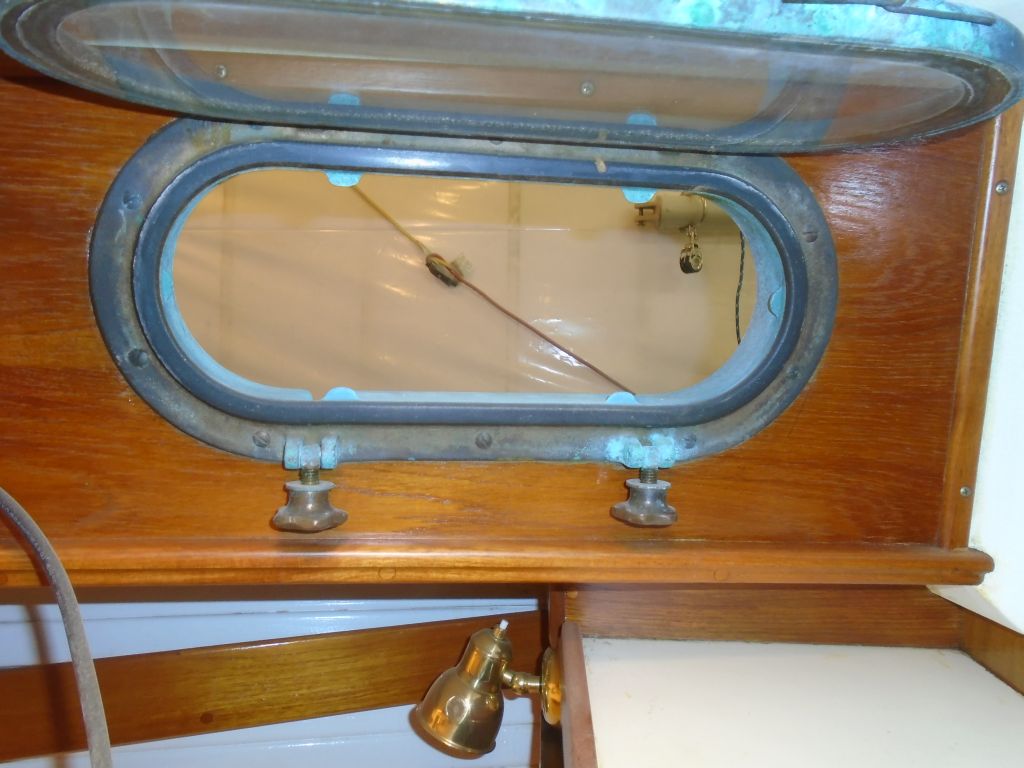
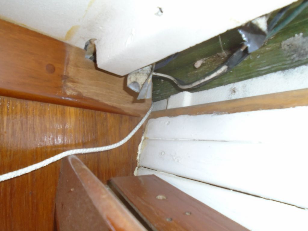
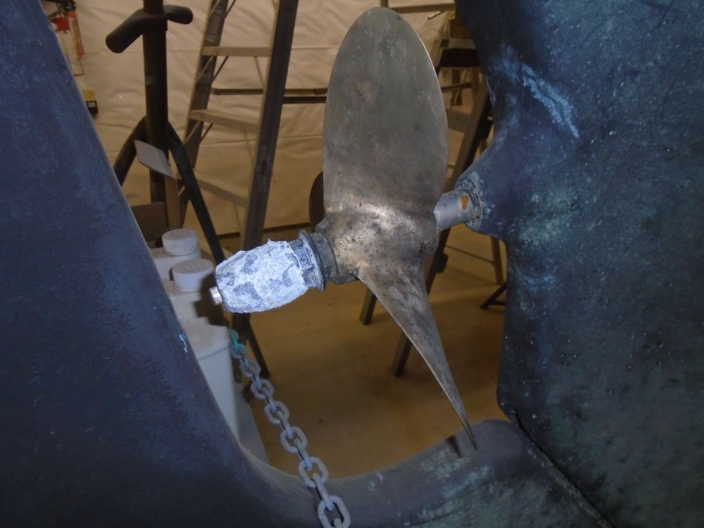
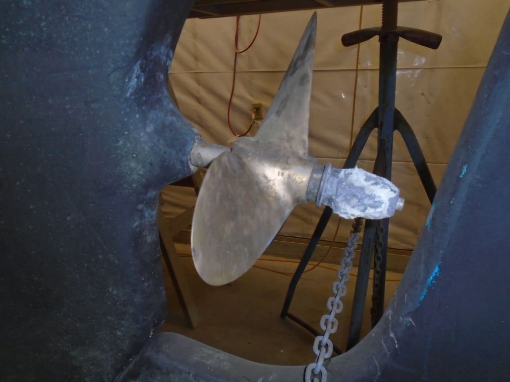
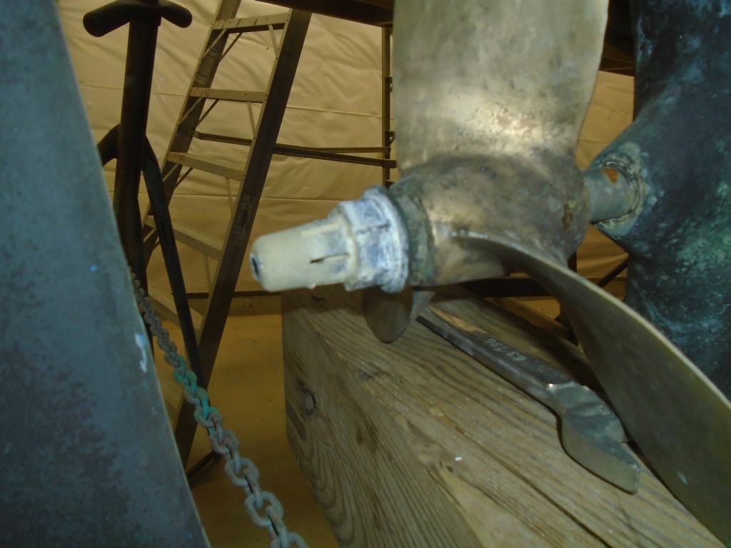
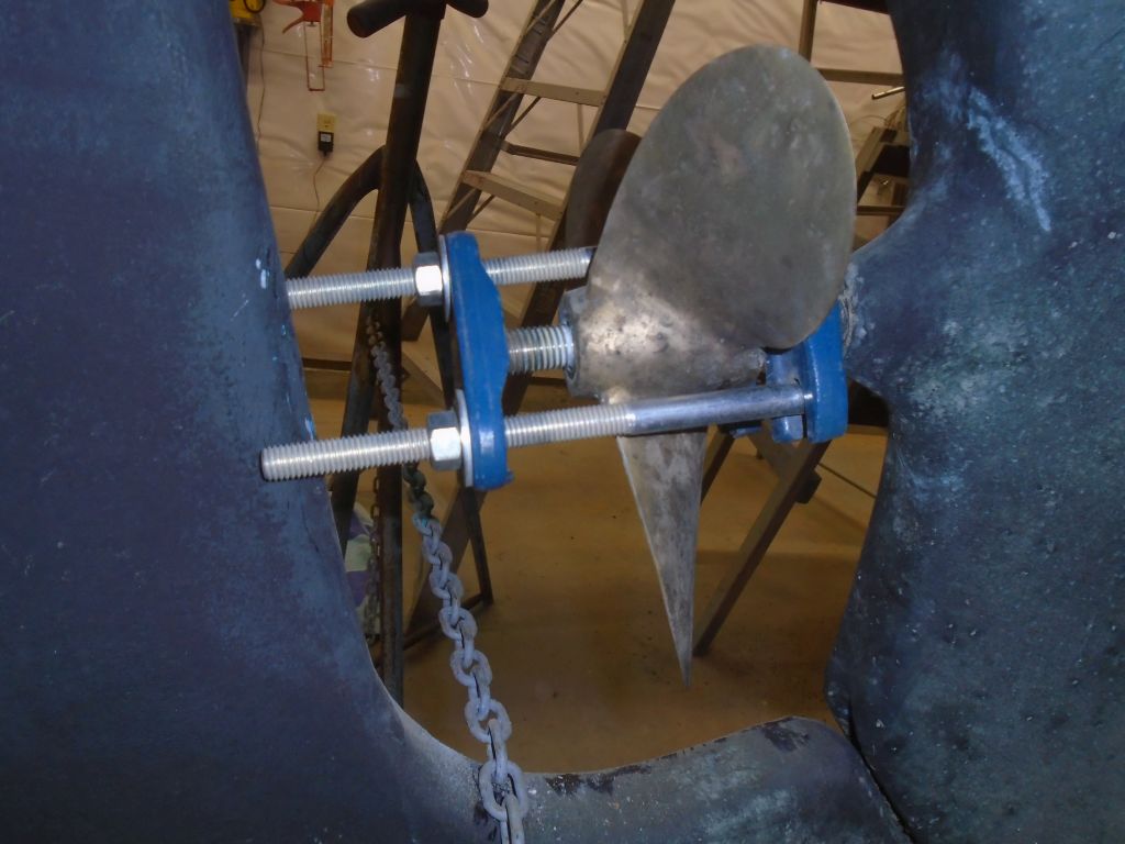
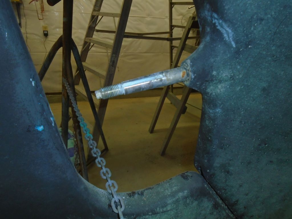
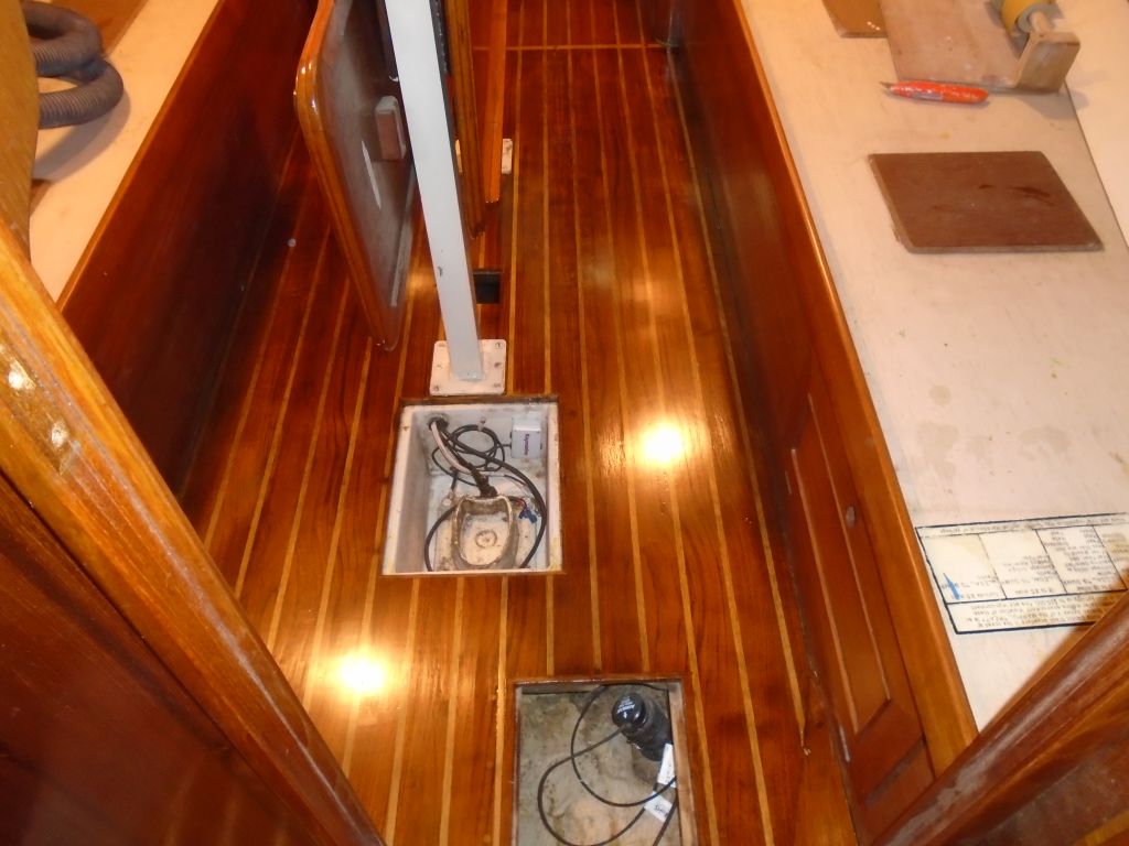
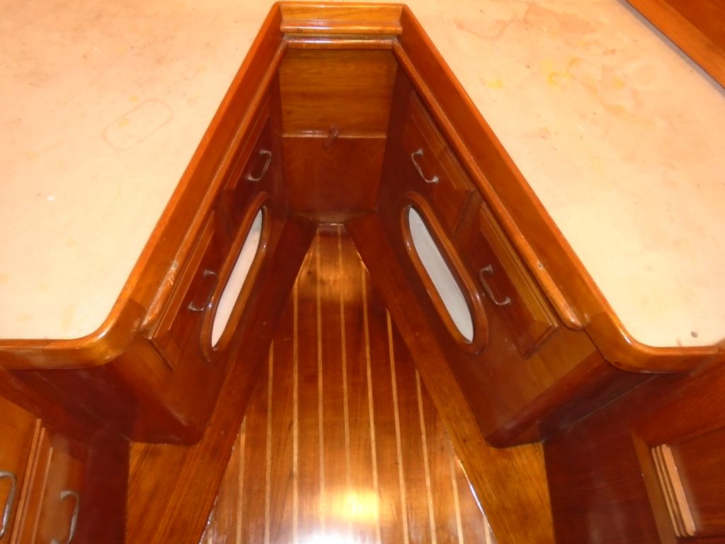
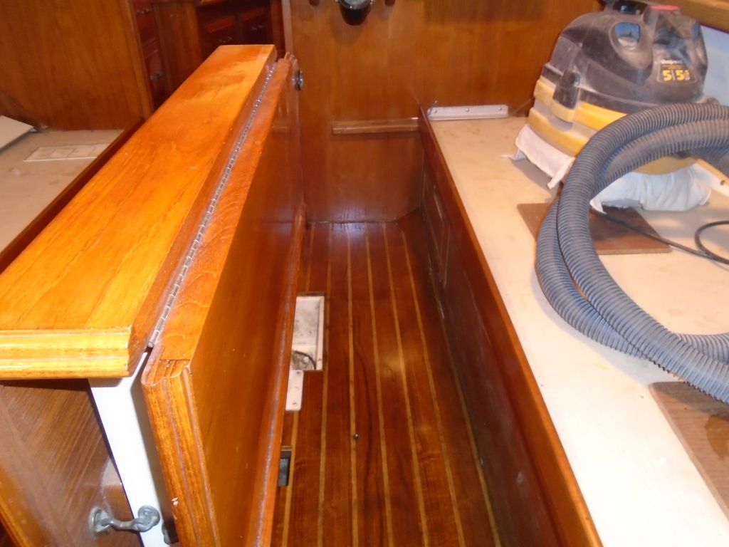
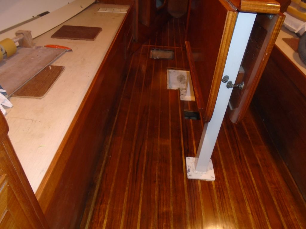
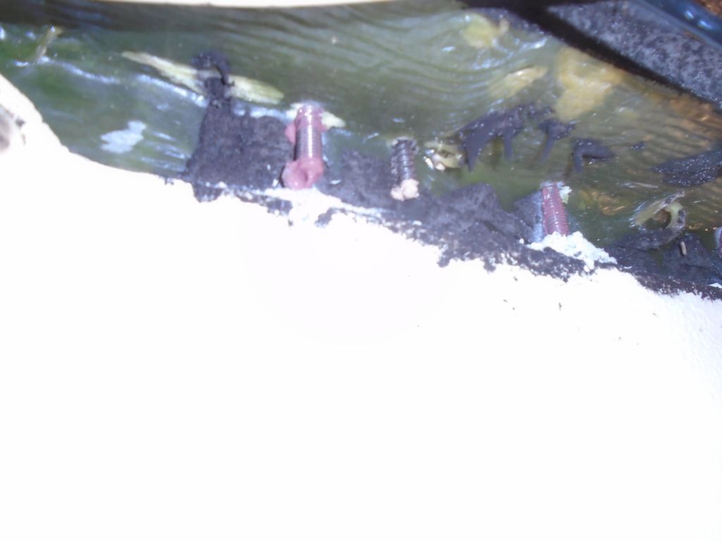
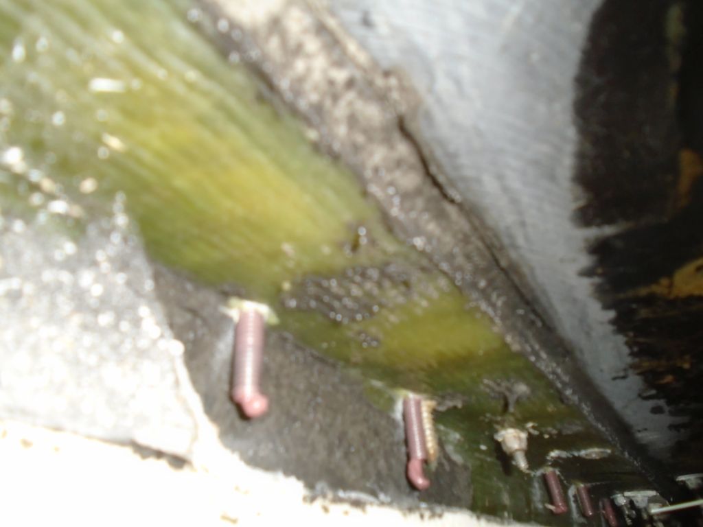
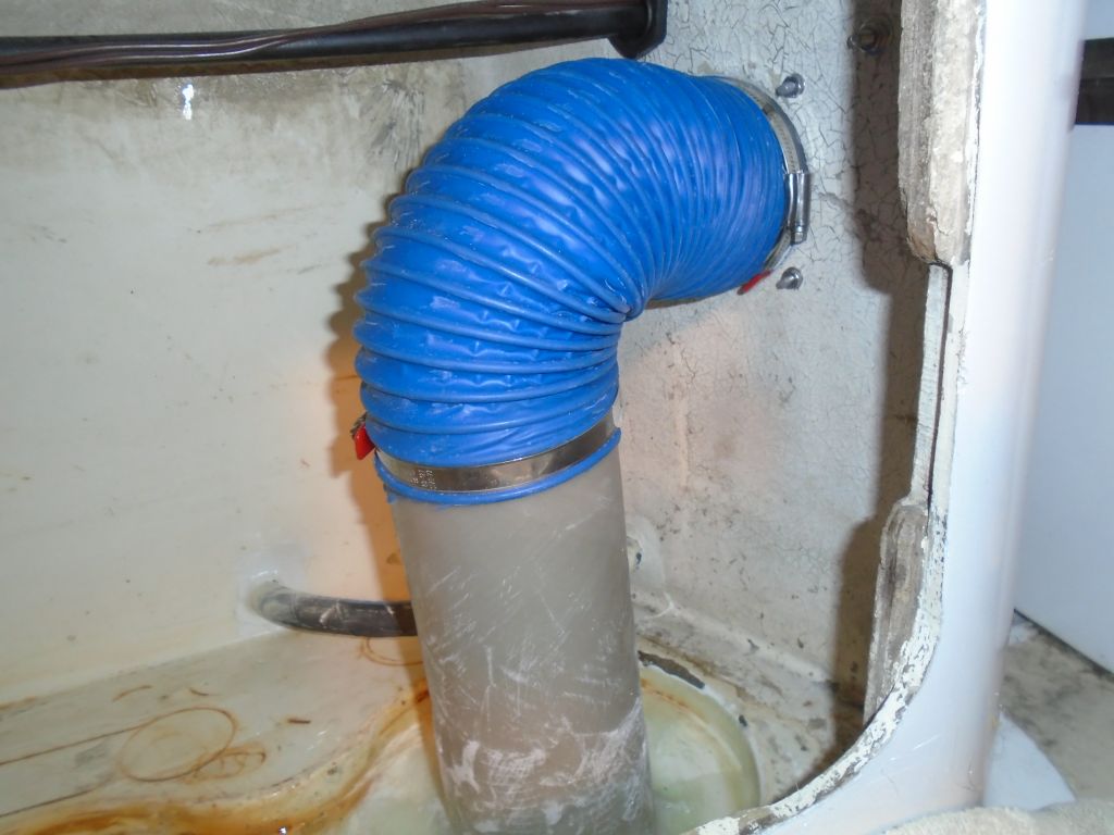
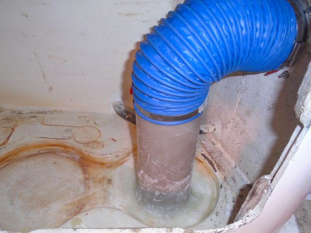
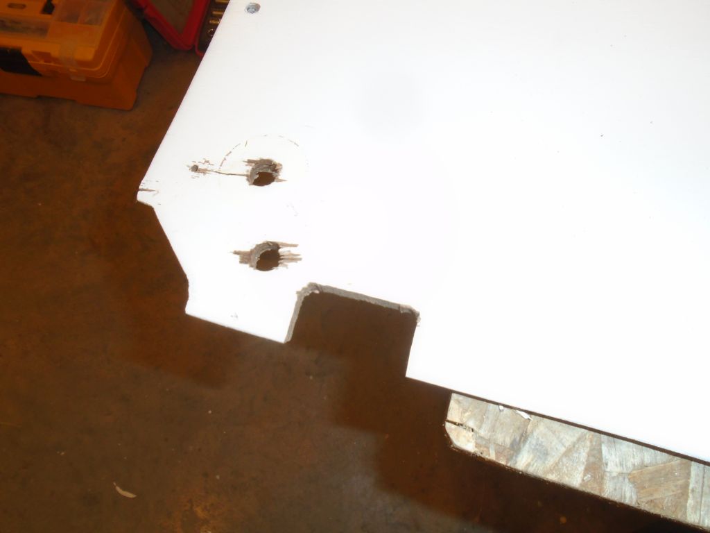
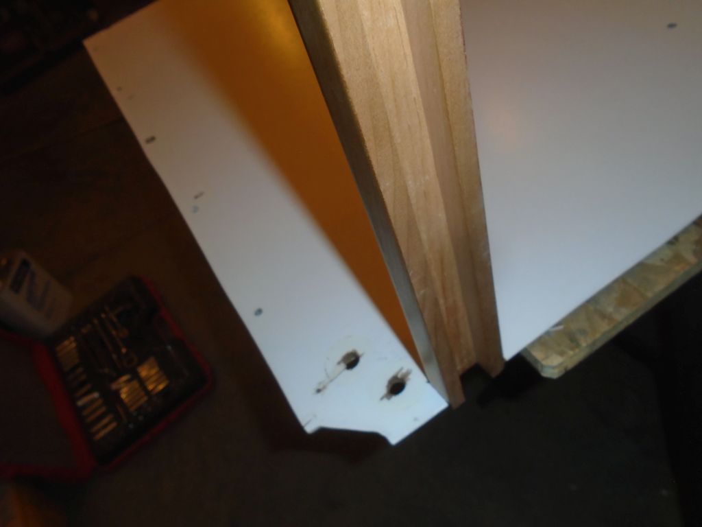
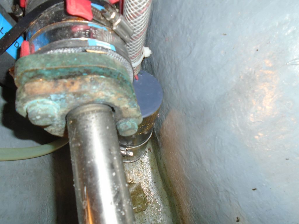
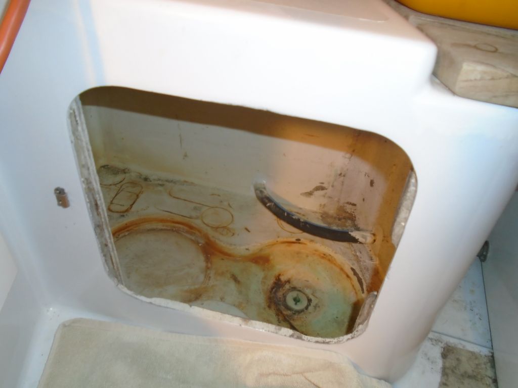
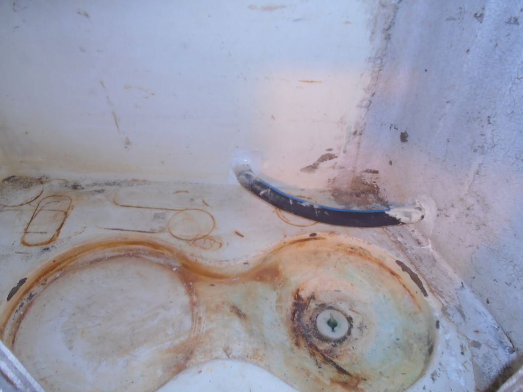
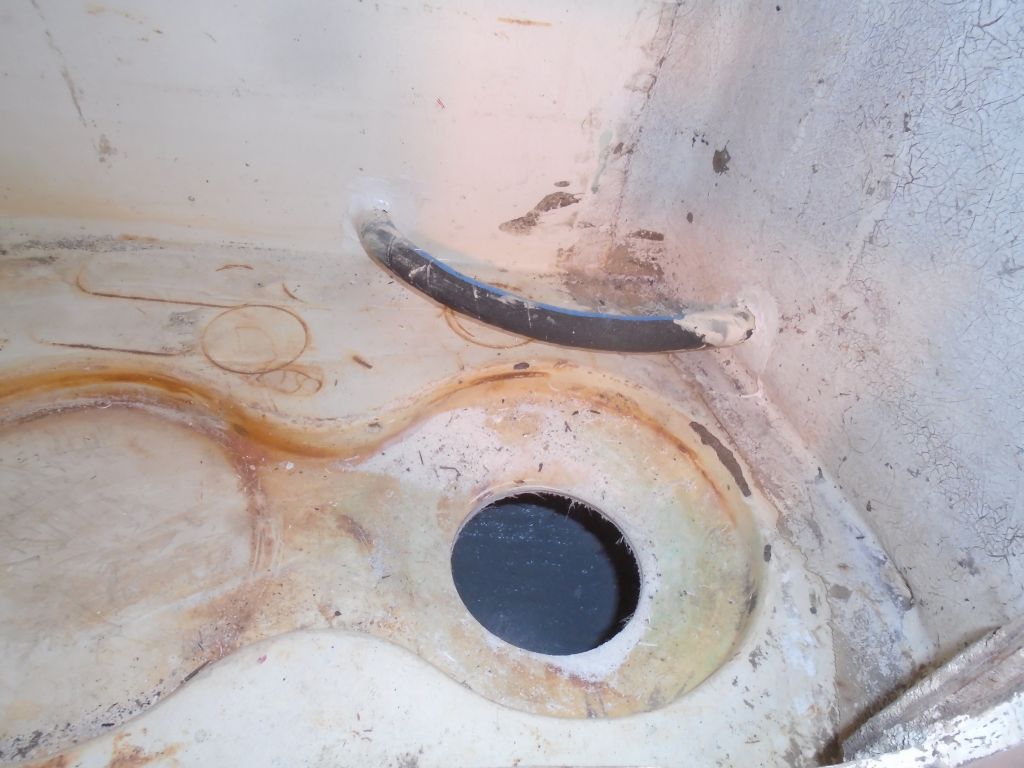
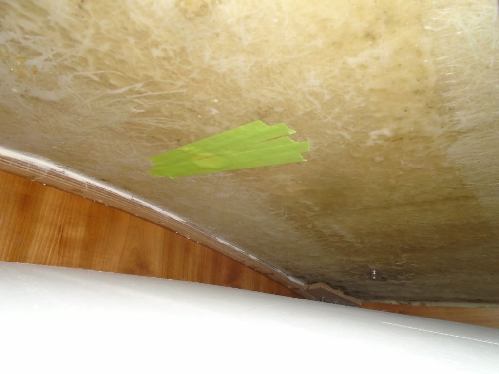
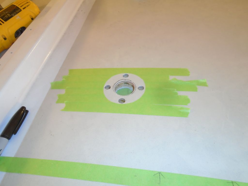
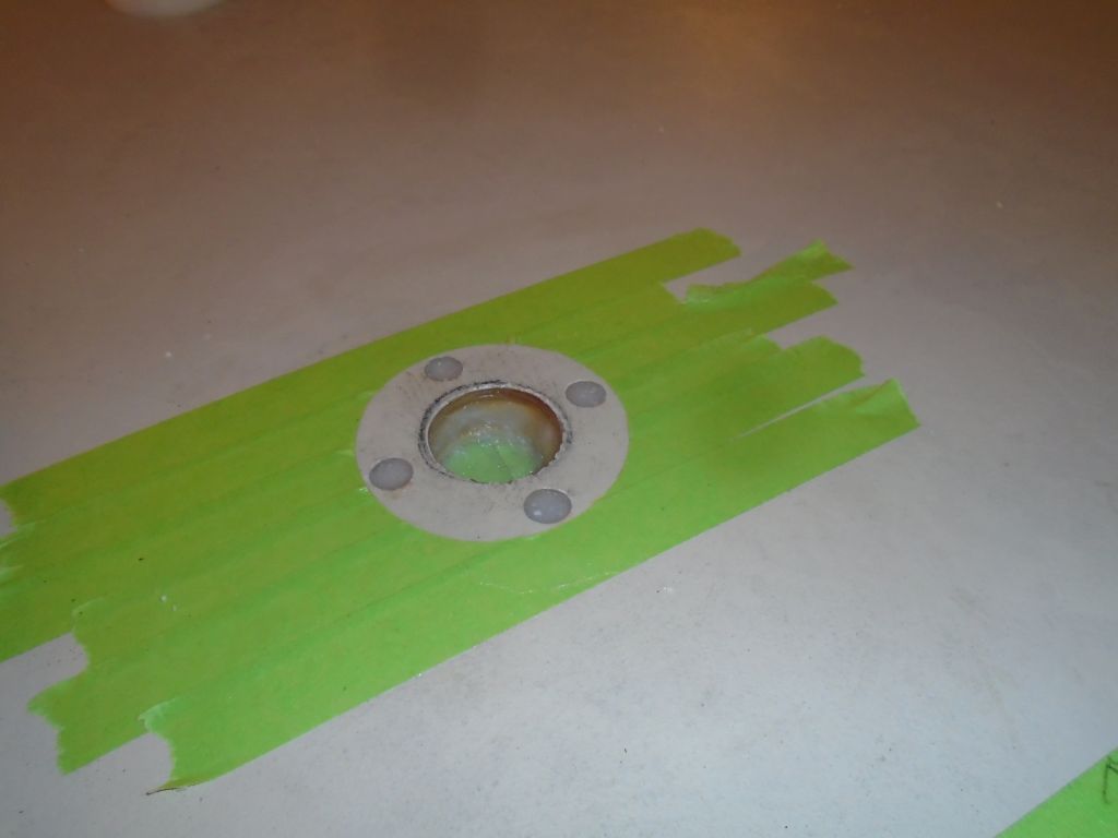
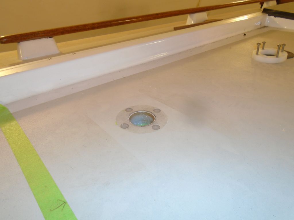
Annoyed and frustrated with this turn of events, I didn’t take pictures throughout the process, but these photos show the aperture shortly after shaft removal, showing the area where I ground and cut away material. This process also shortened the fiberglass stern tube a bit, but all that would be straightforward to rebuild now that the shaft was out.
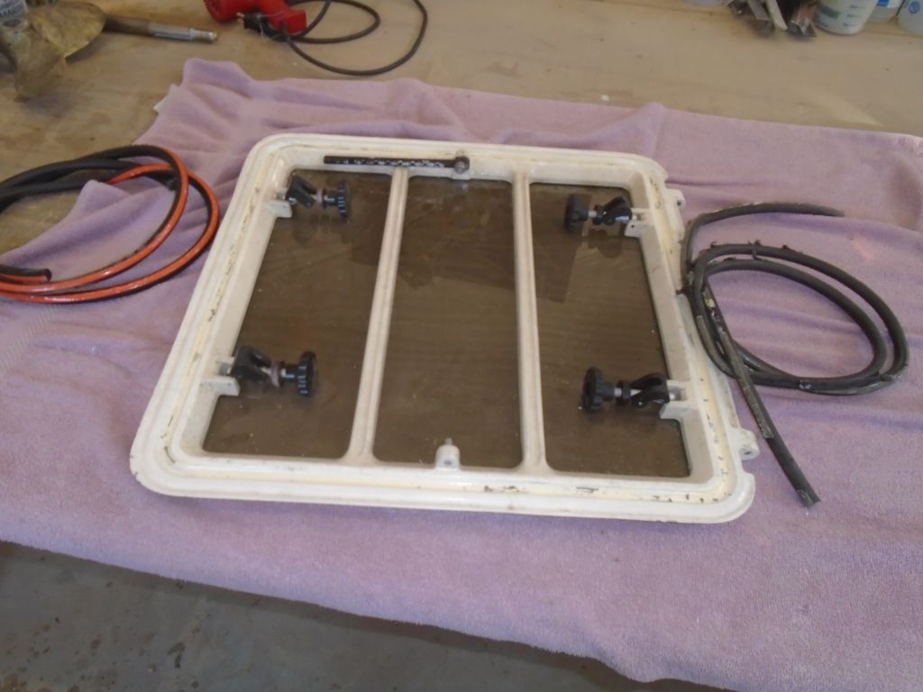
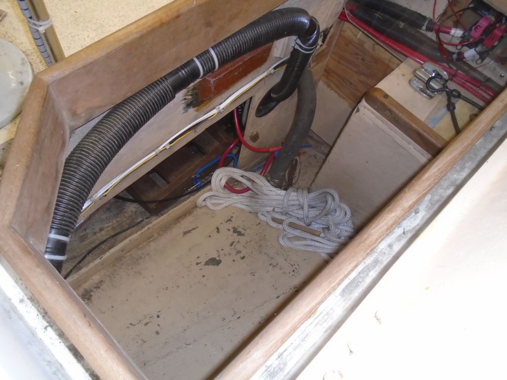
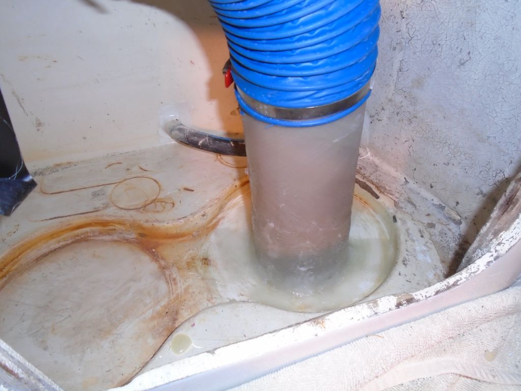
With the shaft out, Jason could clamber once more into the bilge to remove the remains of the stuffing box (we hadn’t been able to pull the shaft far enough back before to remove the stuffing box from the inside), and cleaned up the now-empty space, bringing his help to a close for now. Obviously reinstallation of the new parts would wait till another day.
Afterwards, I got right into the rebuilding of the stern tube and aperture. I started by sanding away the bottom paint and barrier coat all around the area to be rebuilt, and this eventually led me to notice small cracks at the seam where the old gray polyester filler ended, so with a chisel I knocked away the remains completely–better to start anew anyway, and it took only a pair of seconds (polyester= poor secondary bonding, i.e. adhesive ability= easy to knock away in a pair of seconds). Then I cleaned up the whole area to prepare for the new work.
The stern tube was 1-1/4″ inside diameter, which dictated the size of the new bearing, and I immediately ordered a replacement bearing so that would be on hand soon. Meanwhile, hoping to rebuild the now-truncated stern tube immediately, I searched through materials on hand looking for a larger piece of tubing to slip over the existing length of tube (1-1/2″ OD), or something to insert within to act as a mold for new fiberglass. I didn’t have anything on hand of the right size, so I ordered some slippery plastic rod that I’d use, upon arrival, to mold a tube extension as needed.
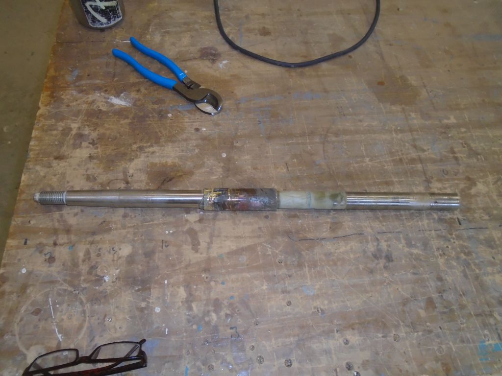
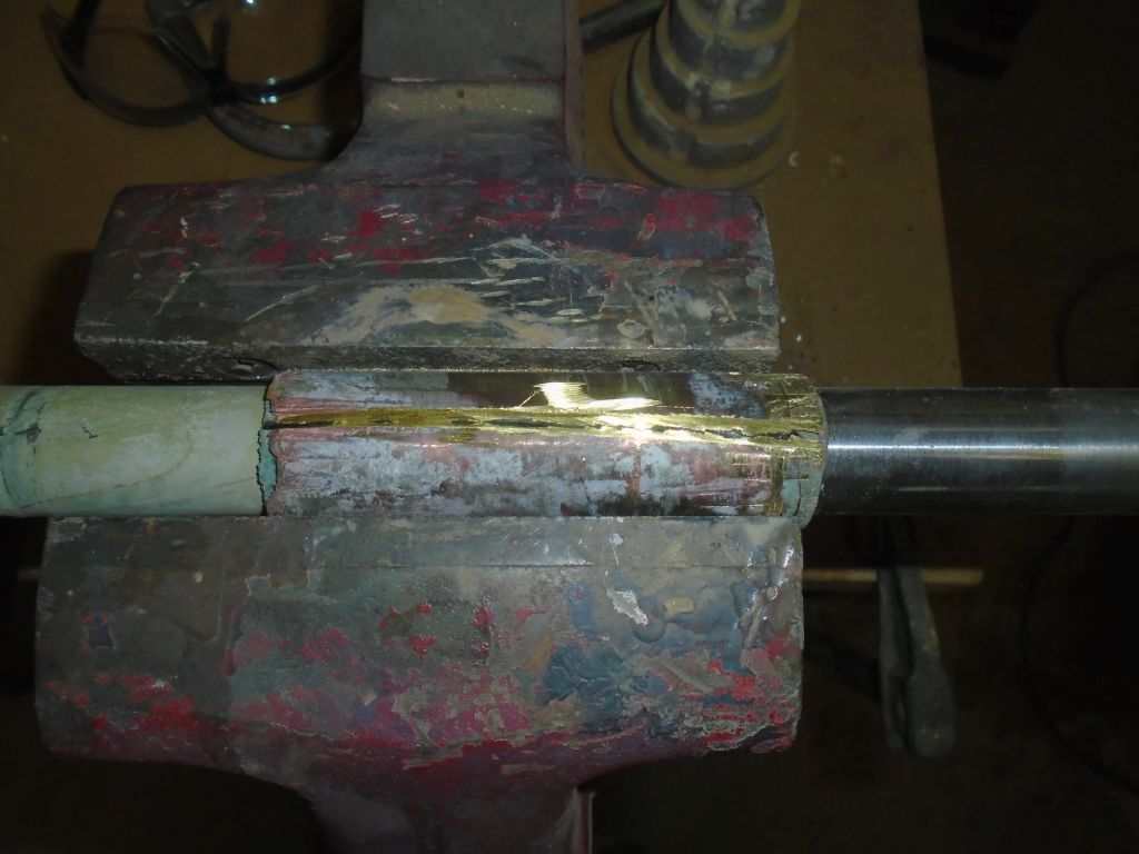
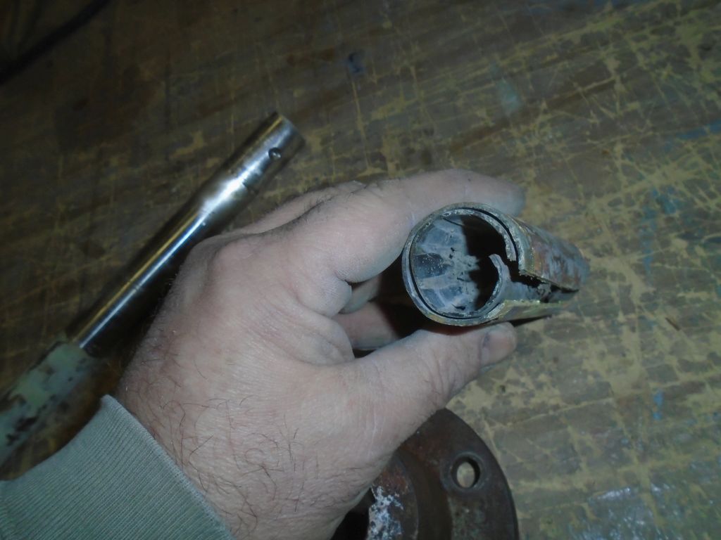
I moved on, and spent the rest of the afternoon cleaning up the existing parts and preparing everything for reinstallation. I began with the shaft and old bearing, which were firmly conjoined. With the piece held in a vice, I carefully cut through the shell of the bearing, which eventually–but still with surprising effort–allowed me to remove the offending thing. The rubber was trashed, and clearly it was just as well that this all happened now, so the whole shafting system would be good as new once reinstalled.
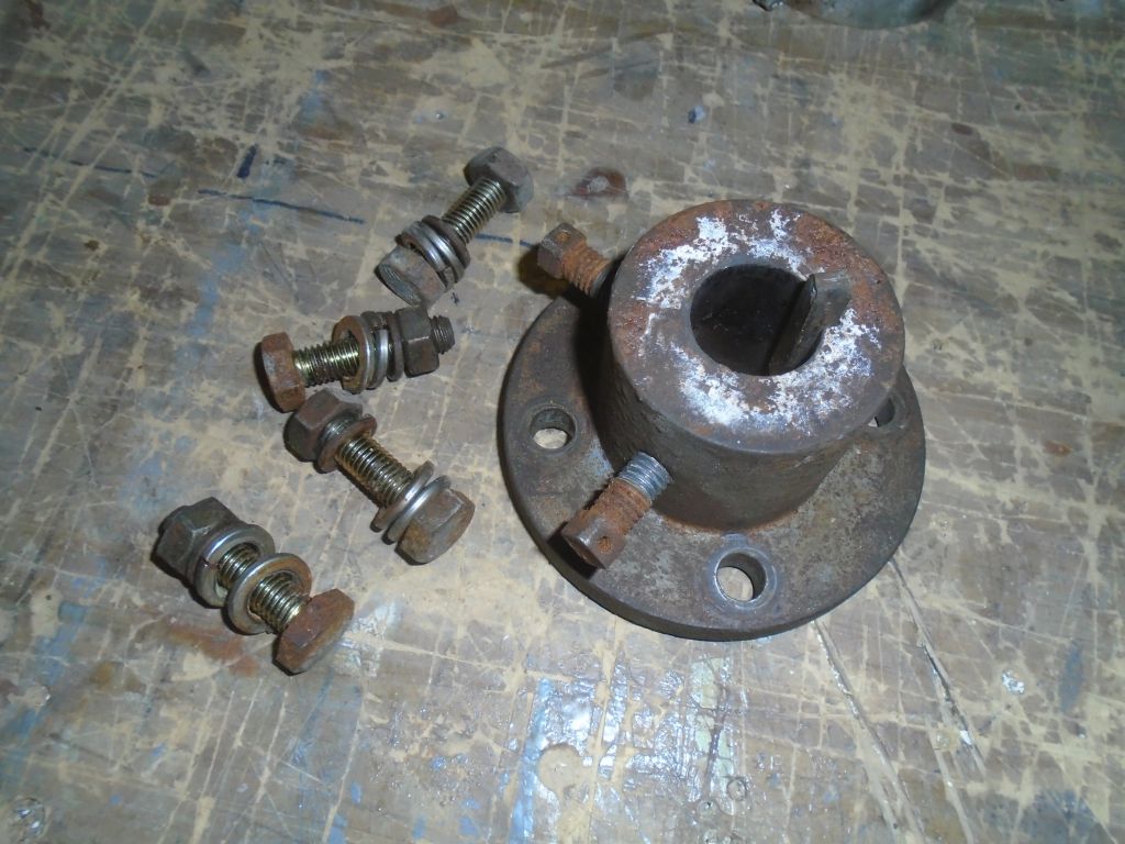
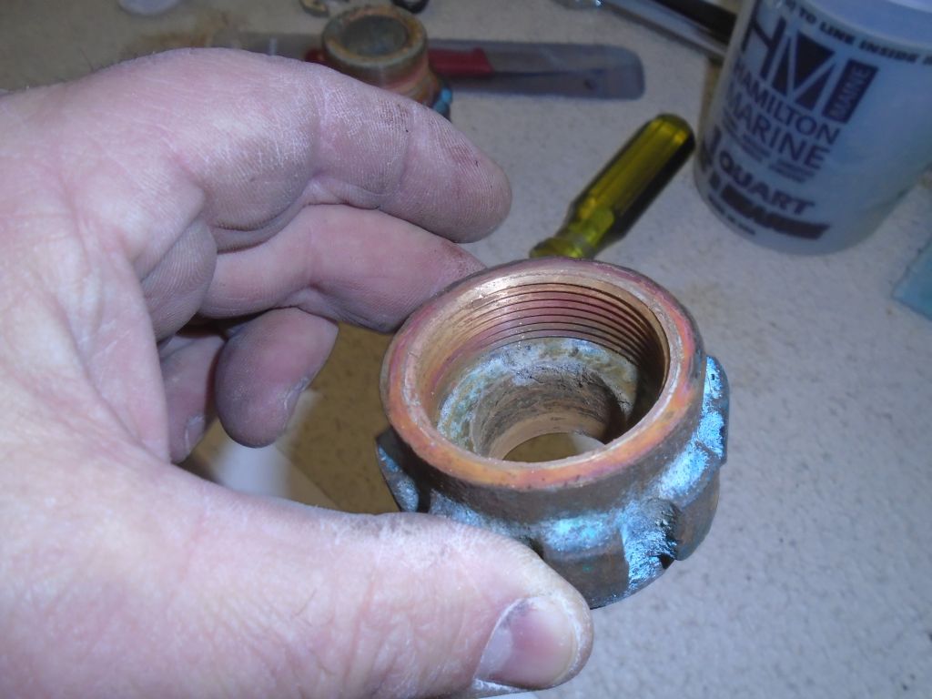
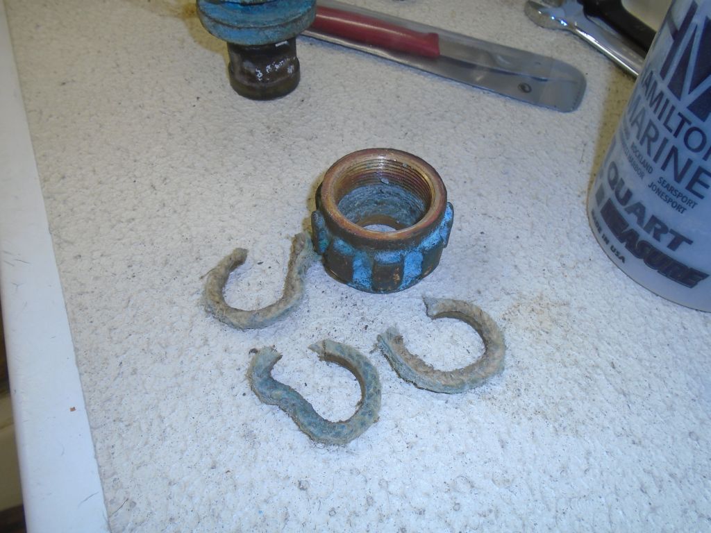
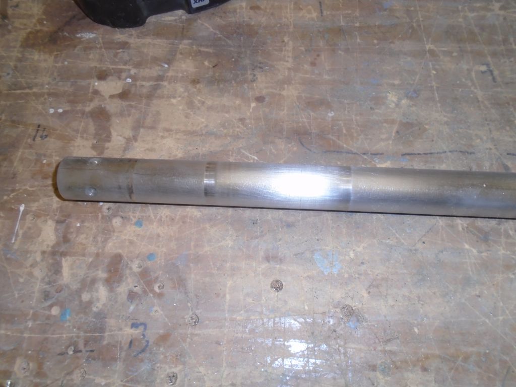
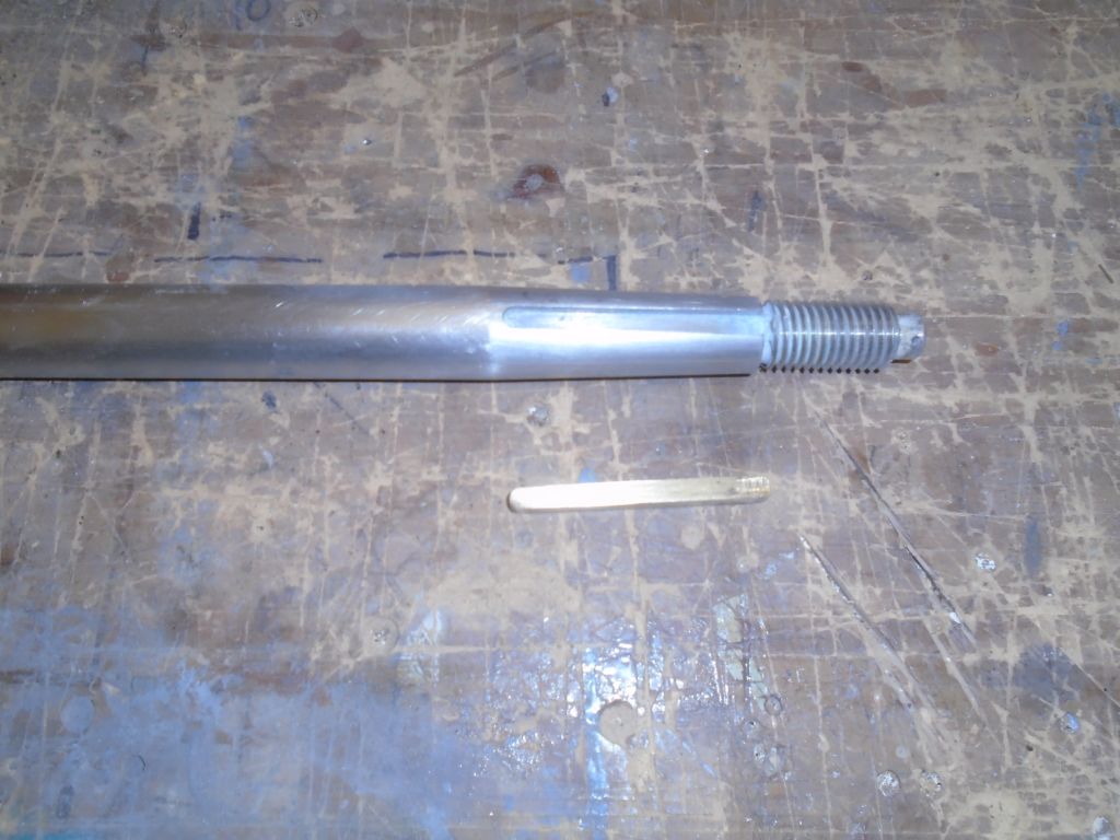
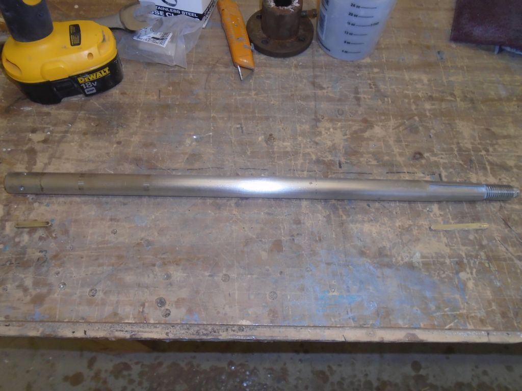
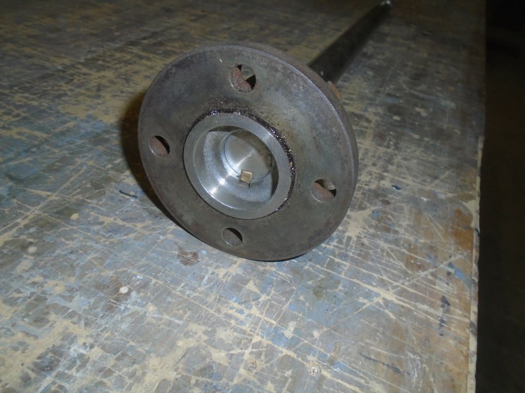
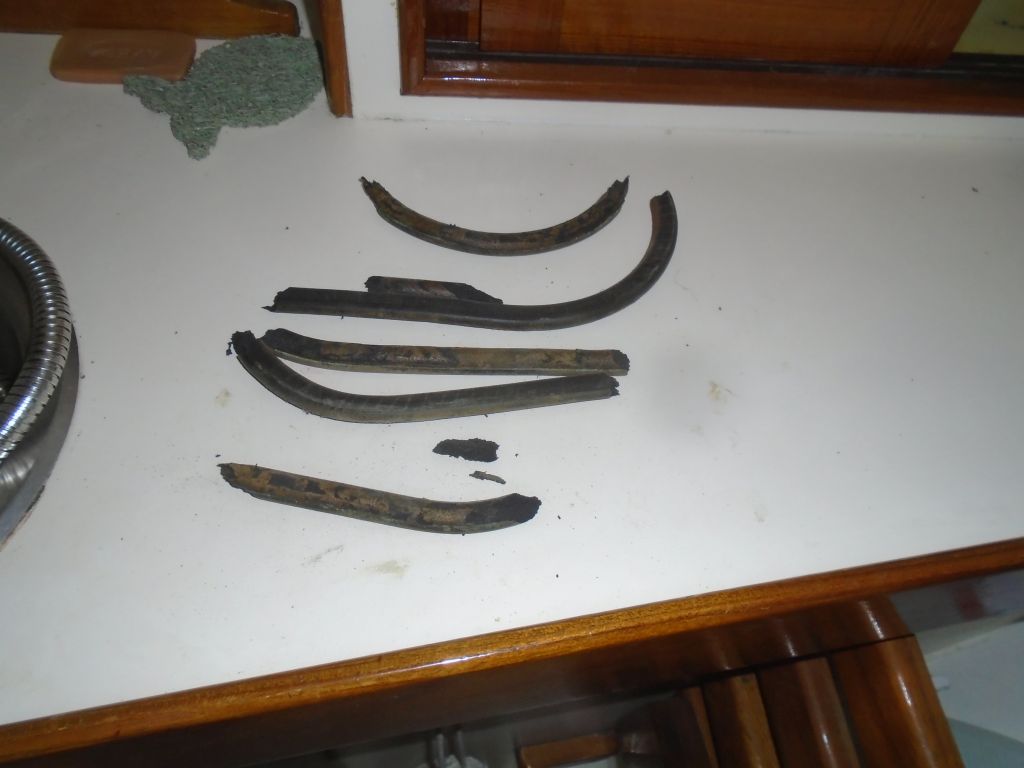
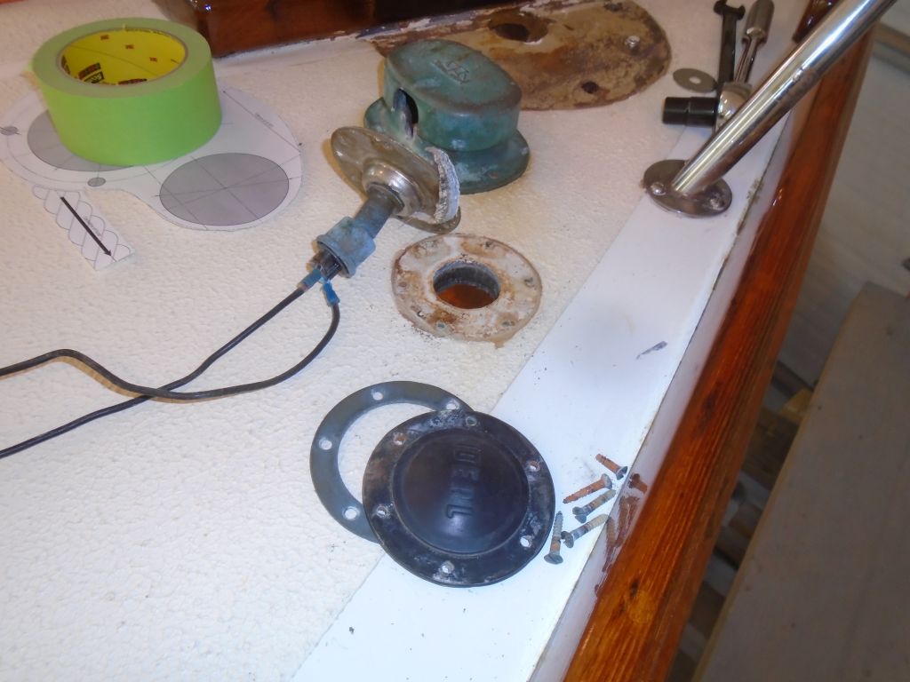
The shaft was in good condition despite it all, with just the most minor of scoring (virtually inevitable) visible at the location of the old, burned-out and rock-hard, flax packing, three old rings of which were still in the packing nut and were the root cause of this whole exercise. I cleaned up and polished the old shaft and its two brass keys.
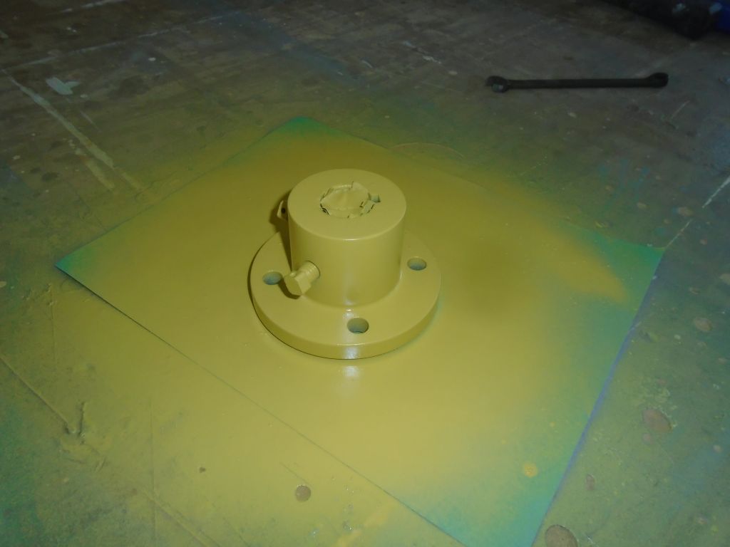
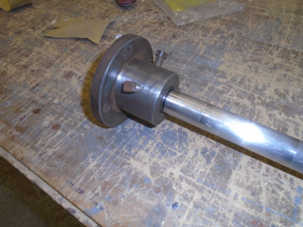
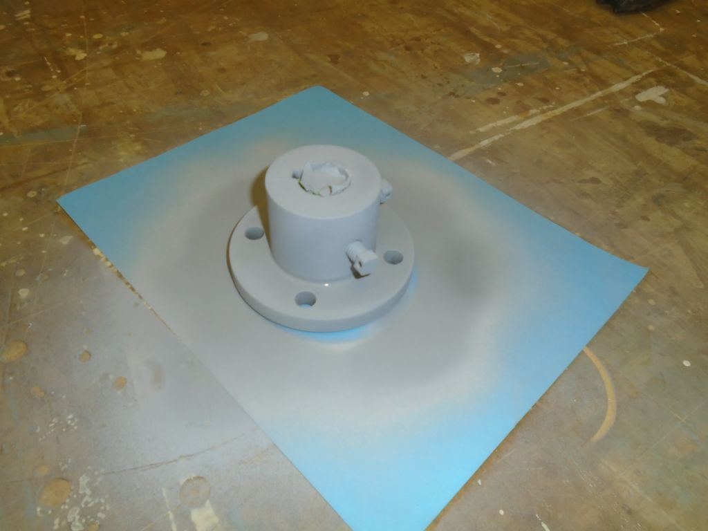
The steel coupling was in good shape, and with a little work I cleaned it up to remove rust and make it easy to slip on the shaft, which was important since reassembling all this in the boat later would be a trial in itself given the limited space available. I ordered replacement bolts for reinstallation. Once I was satisfied with how it fit on the shaft, and had cleaned up the exterior sufficiently, I sprayed some primer on the coupling to prepare it for paint that would limit further corrosion in years to come.
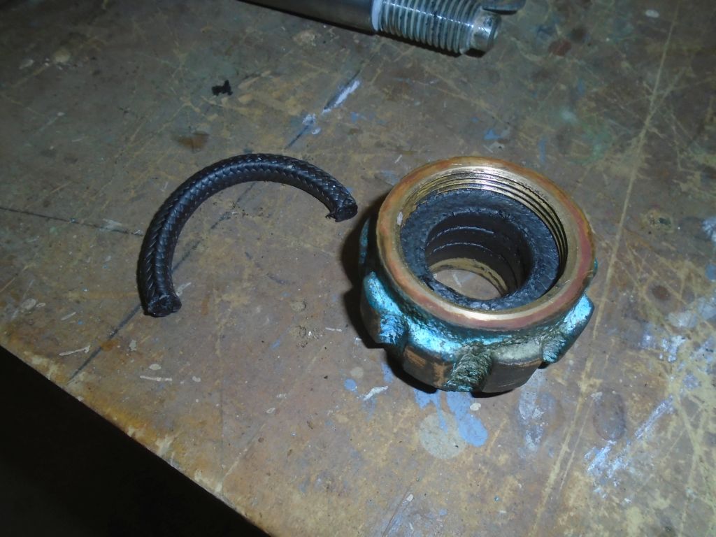
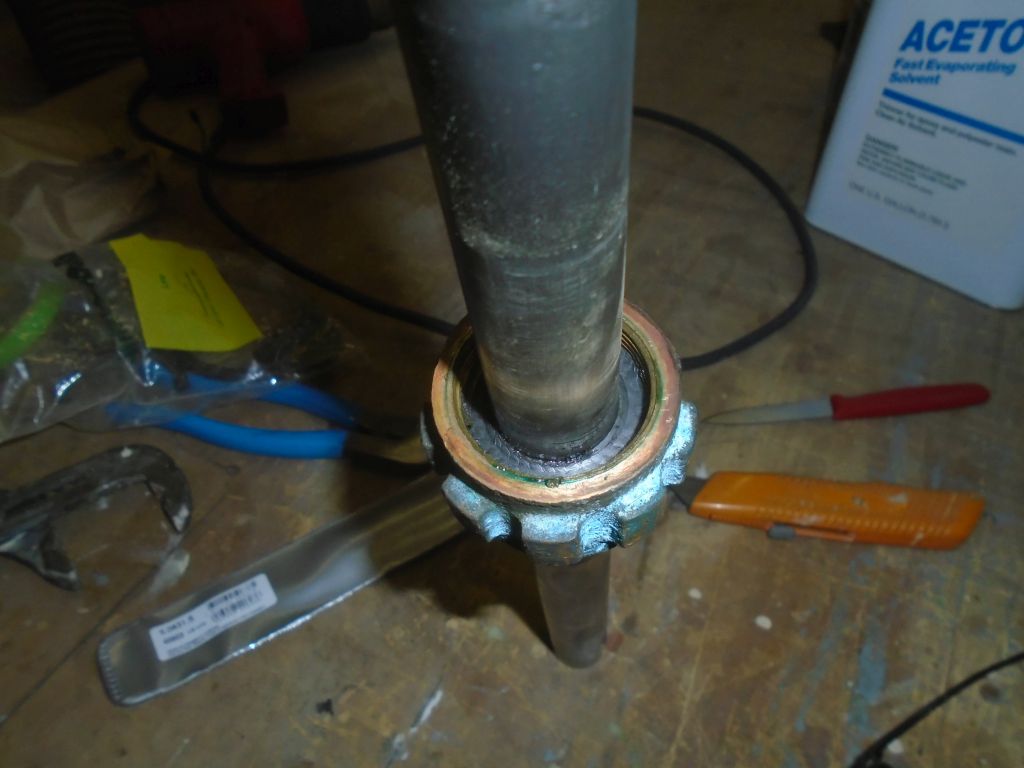
I cleaned up the bronze packing box as needed, and applied grease to the threads, which would keep it working well for many years. Now I cut new packing rings from graphite-impregnated packing, which was slippery and greasy where old flax was dry and hot. I tried for four rings within the nut, but this filled it too far to thread on, even after I tightened the nut (with three rings inside) onto the packing box body to attempt to compress it. Graphite packing doesn’t compress the same way as flax either, likely a good thing over time. In the event, and satisfied with three rings, I set the packing by installing the packing box over the shaft in a mock installation, which formed the packing nicely to the shaft and prepared it all for reinstallation.
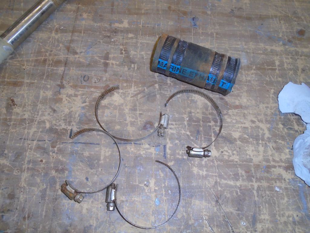
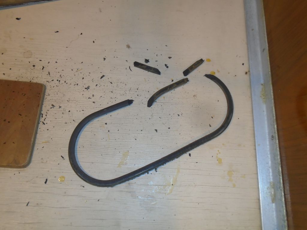
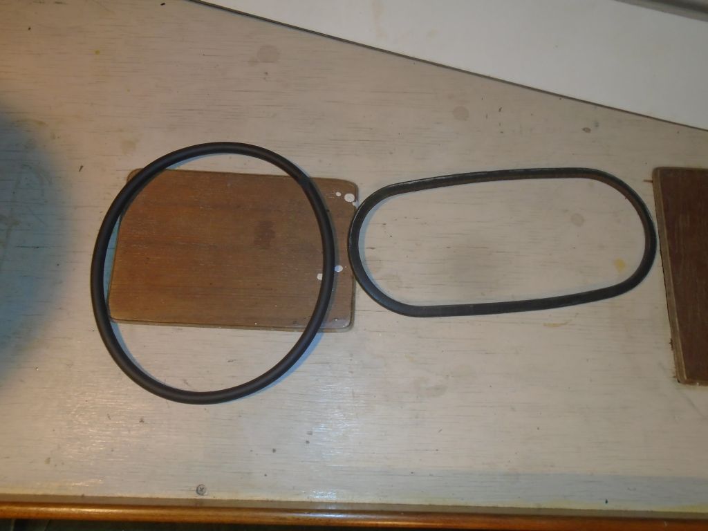
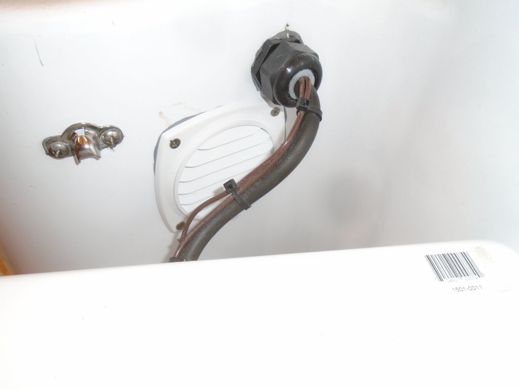
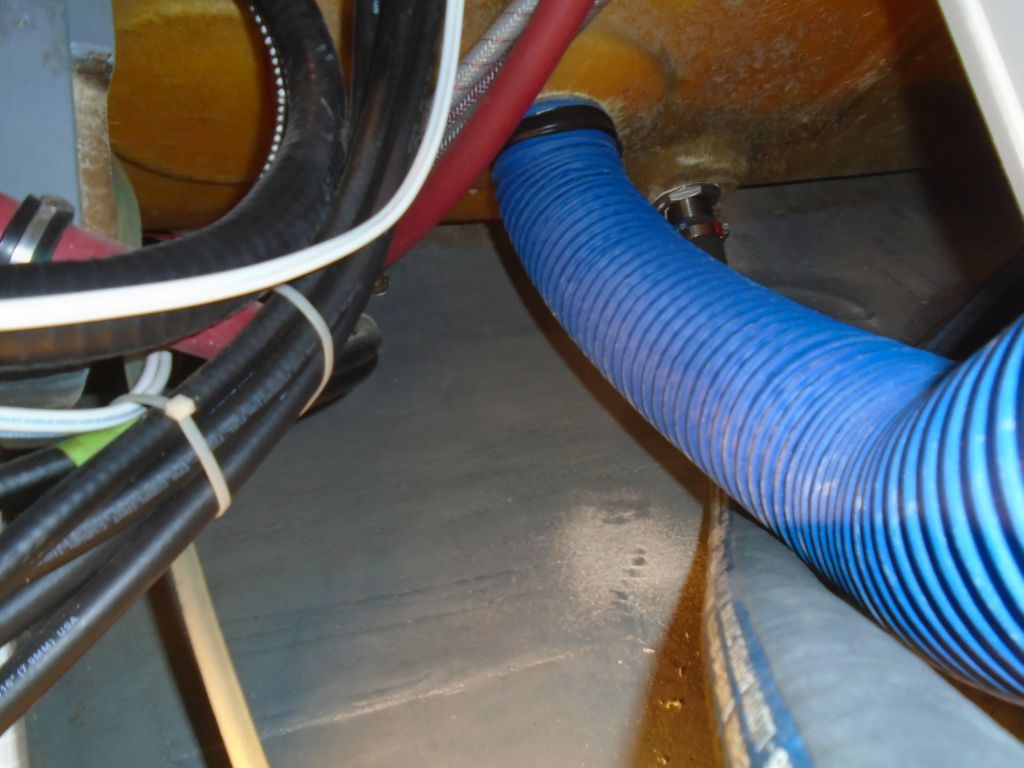
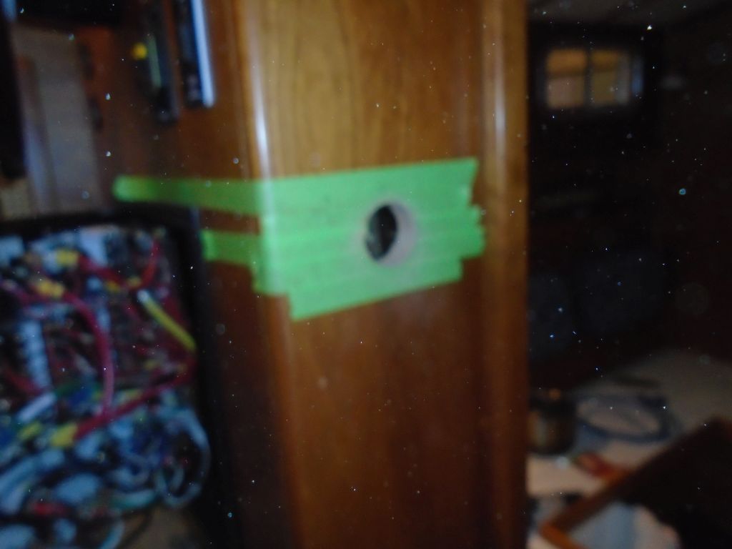
To allow more room for assembly and later packing box maintenance, before Jason had left we’d determined that the packing box hose could be a bit shorter than original. The old hose was already longer by a bit than the replacement, but to maximize room for the coupling and packing nut I trimmed about another 1/2″ from the new hose (taping off a nice straight cutting guideline first), which left plenty of hose for four clamps but didn’t waste any space. Frankly, the use of cheap clamps with non-stainless adjustment screws on the original hose had directly led to the potential failure of the whole thing–and this project. The hose itself was suspect only because the clamps had cut into it badly, and the rust from the clamps never did anything nearby any good. Better original materials might have saved a couple man-days of labor. The new hose and all-316 clamps cost a grand total of about $20, by comparison.
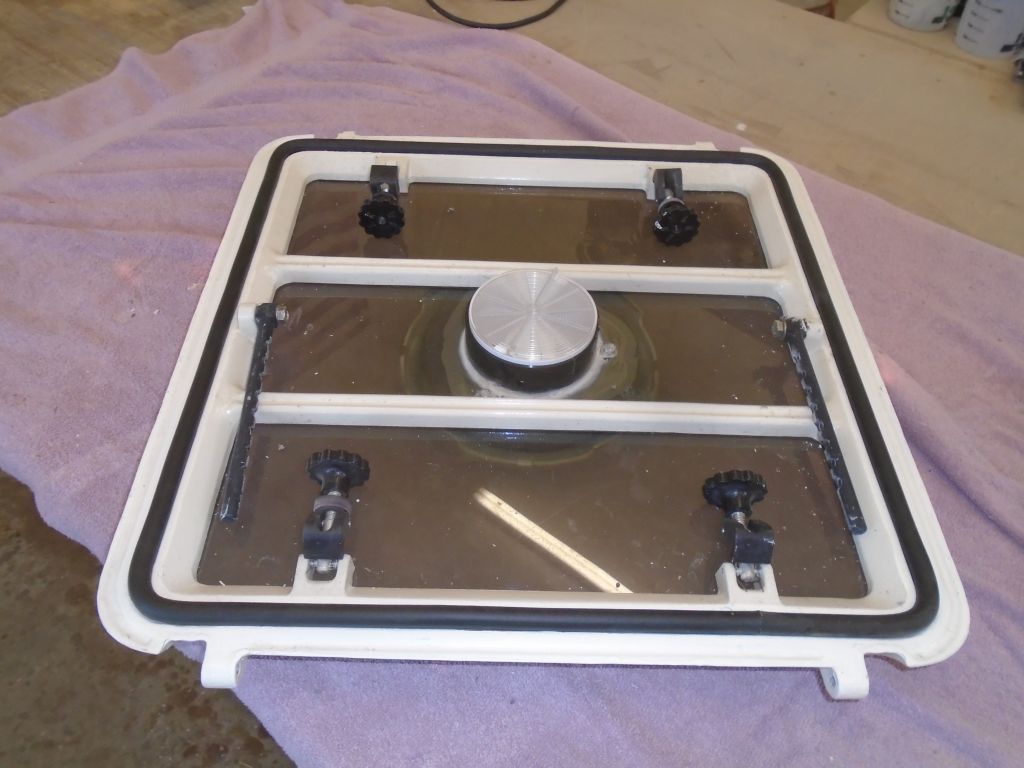
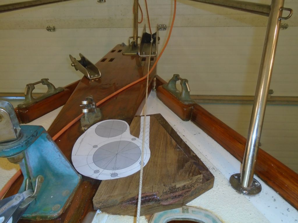
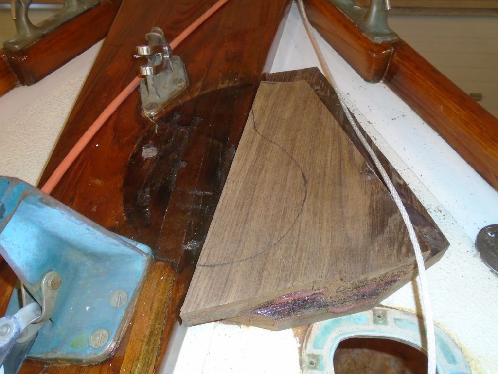
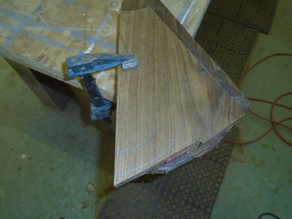
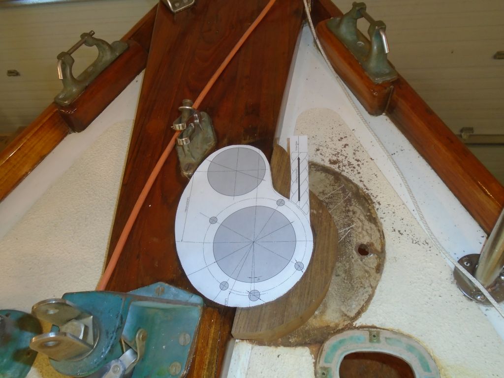
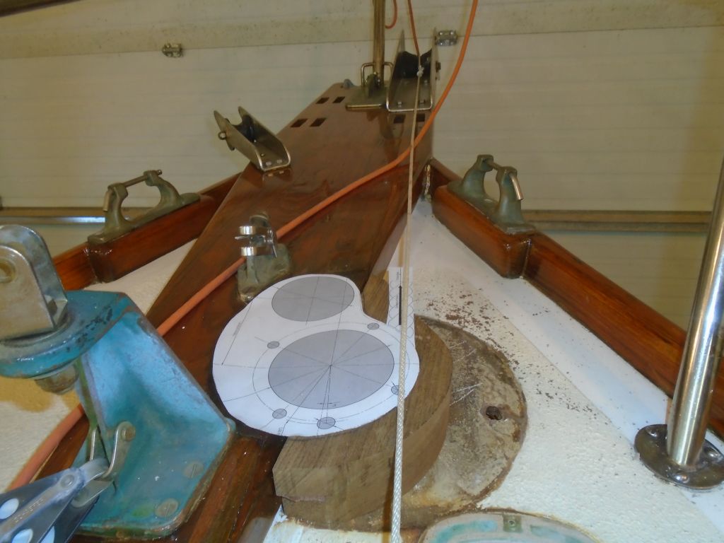
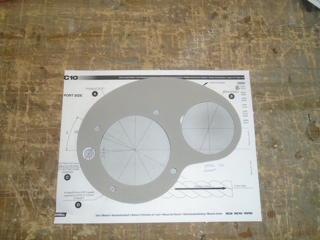
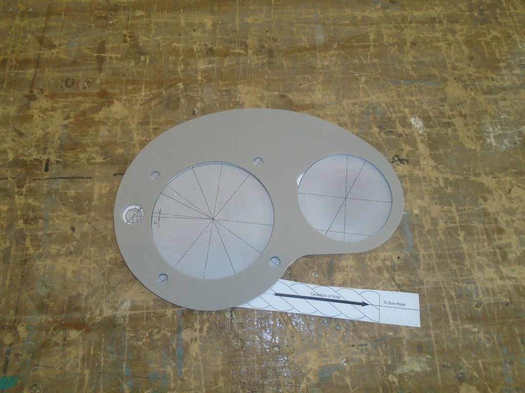
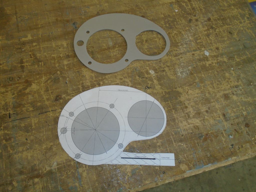
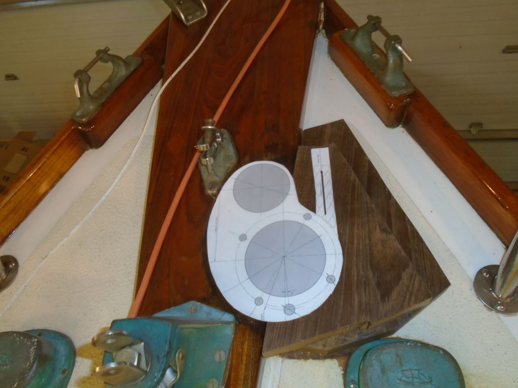
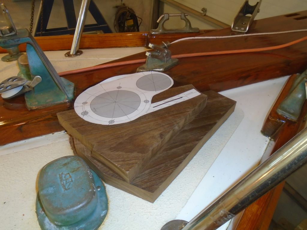
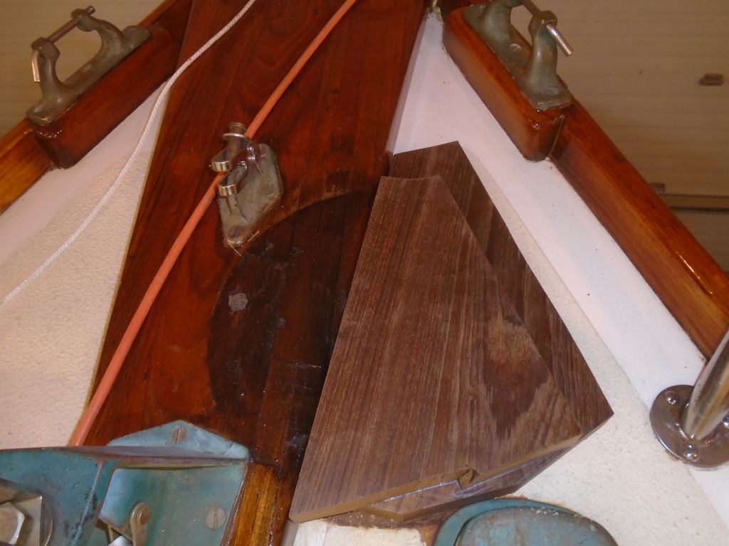
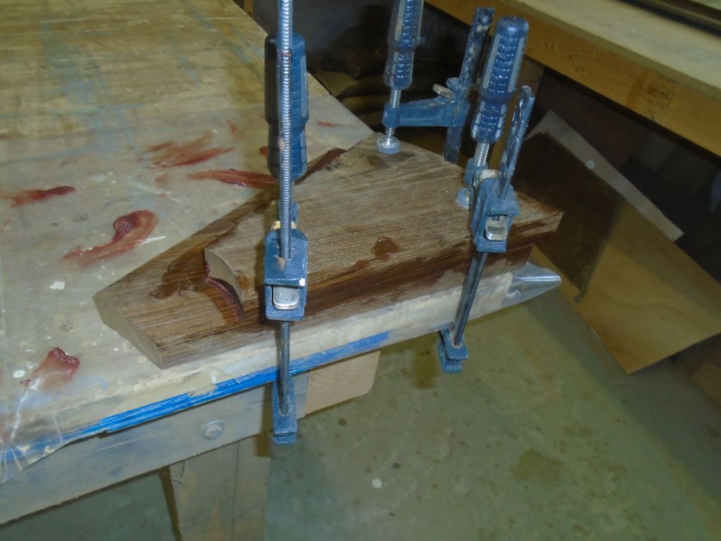
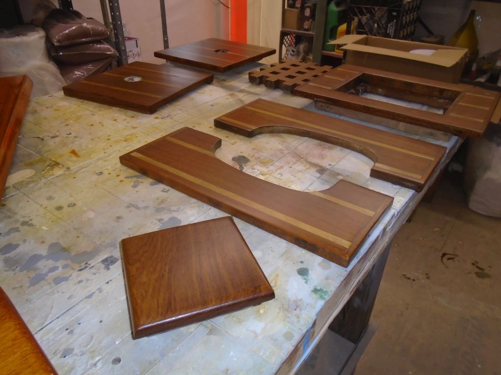
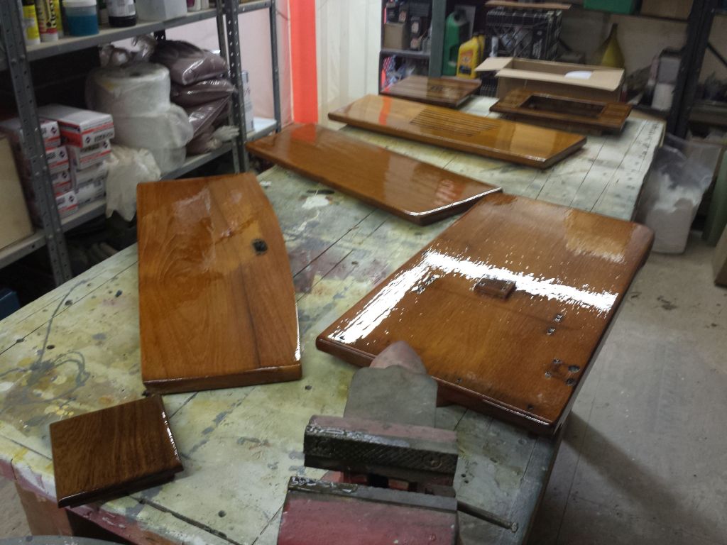
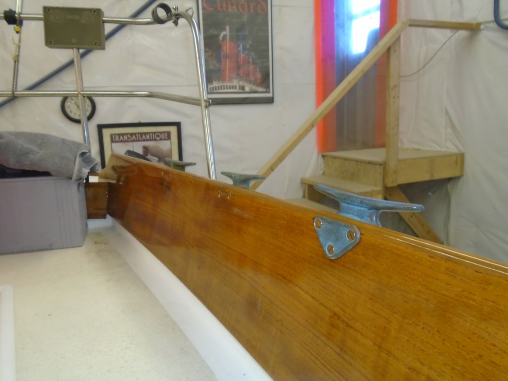
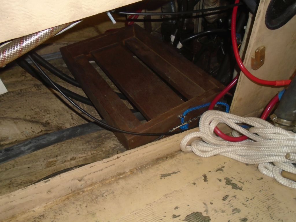
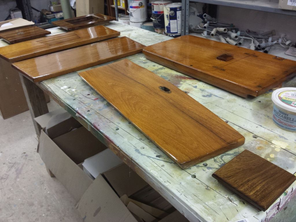
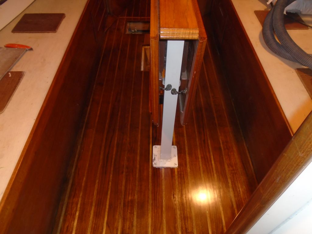
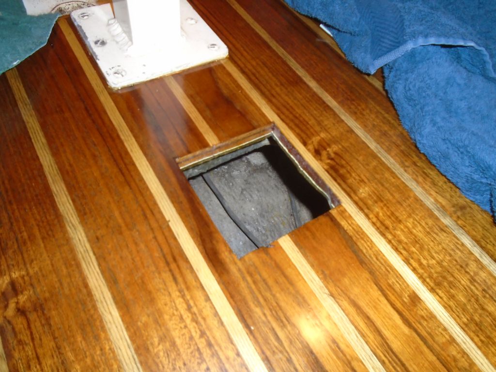
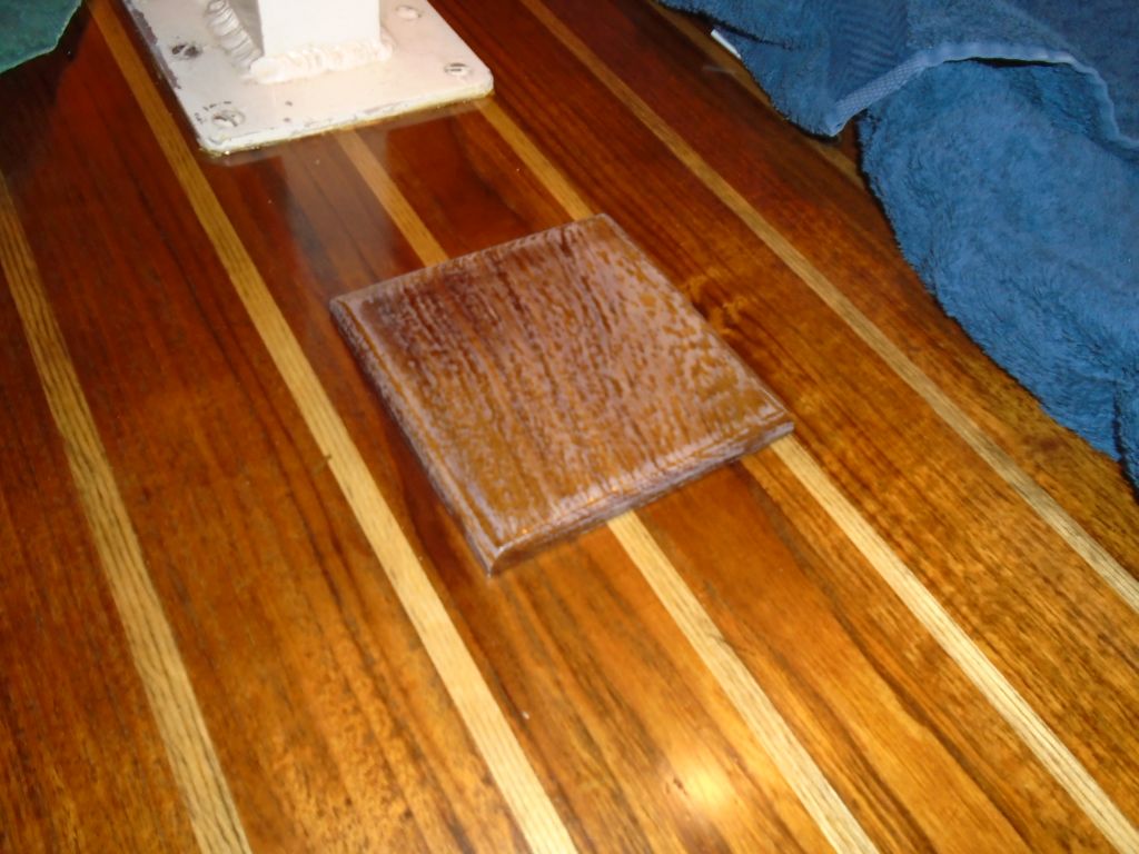
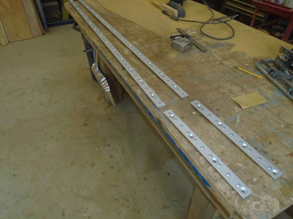
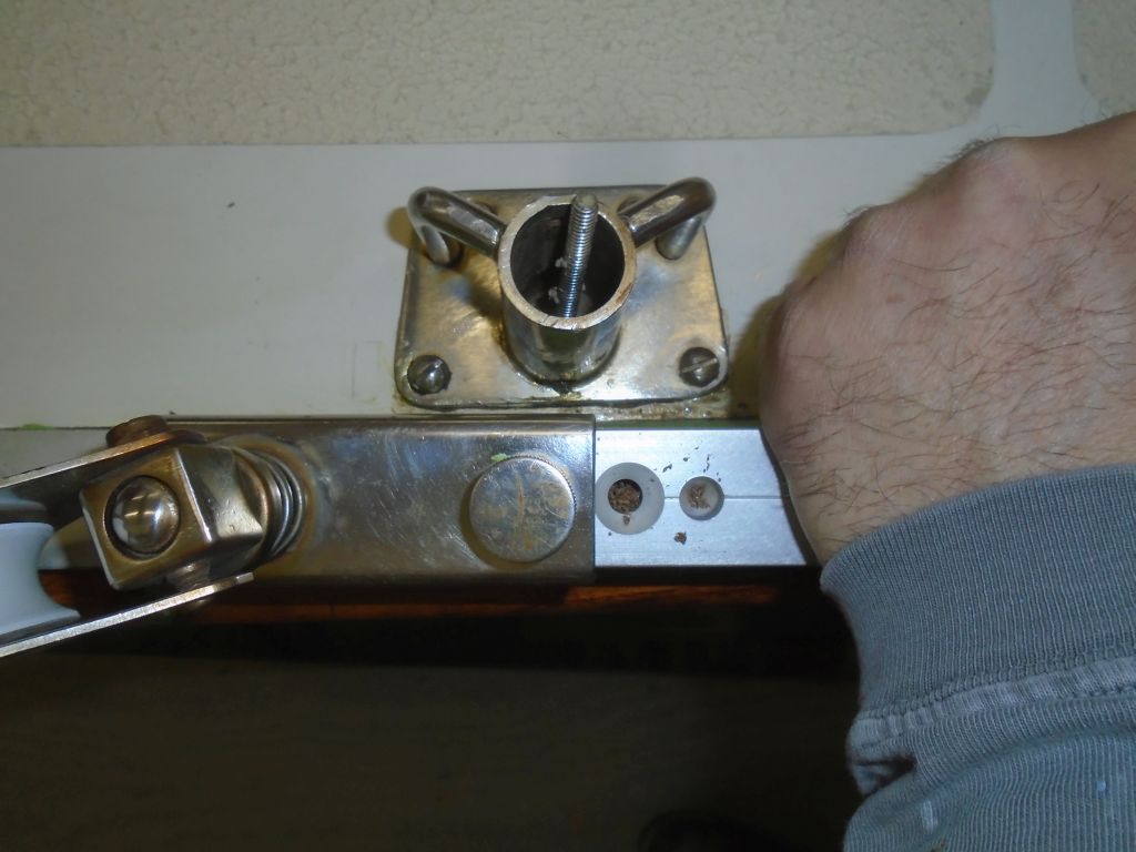
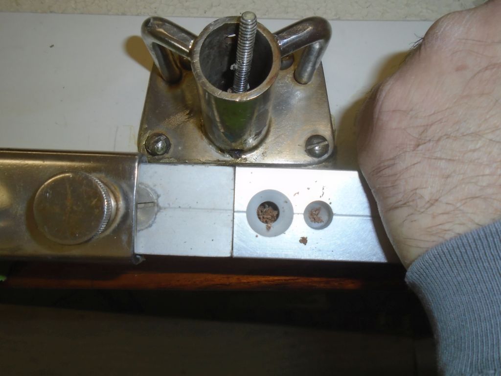
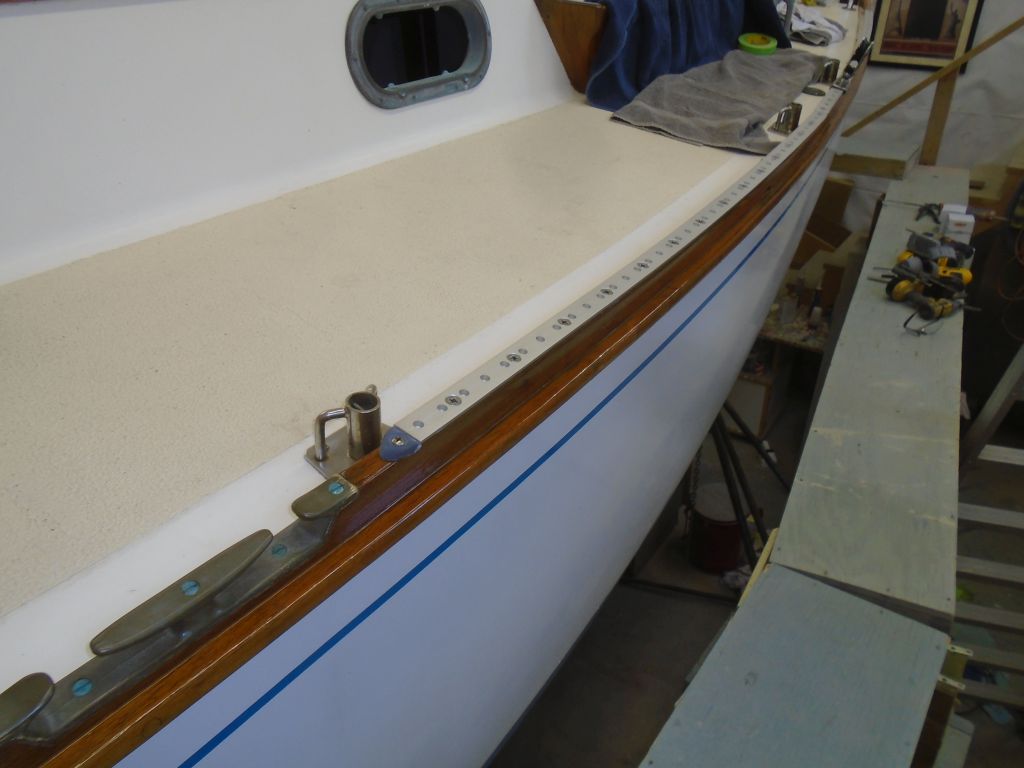
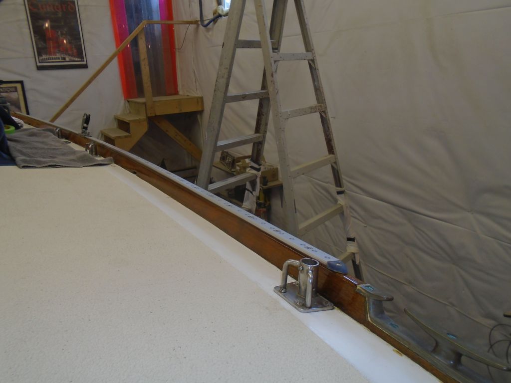
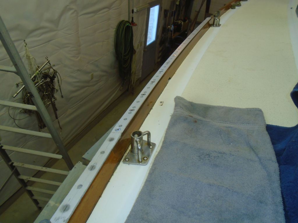
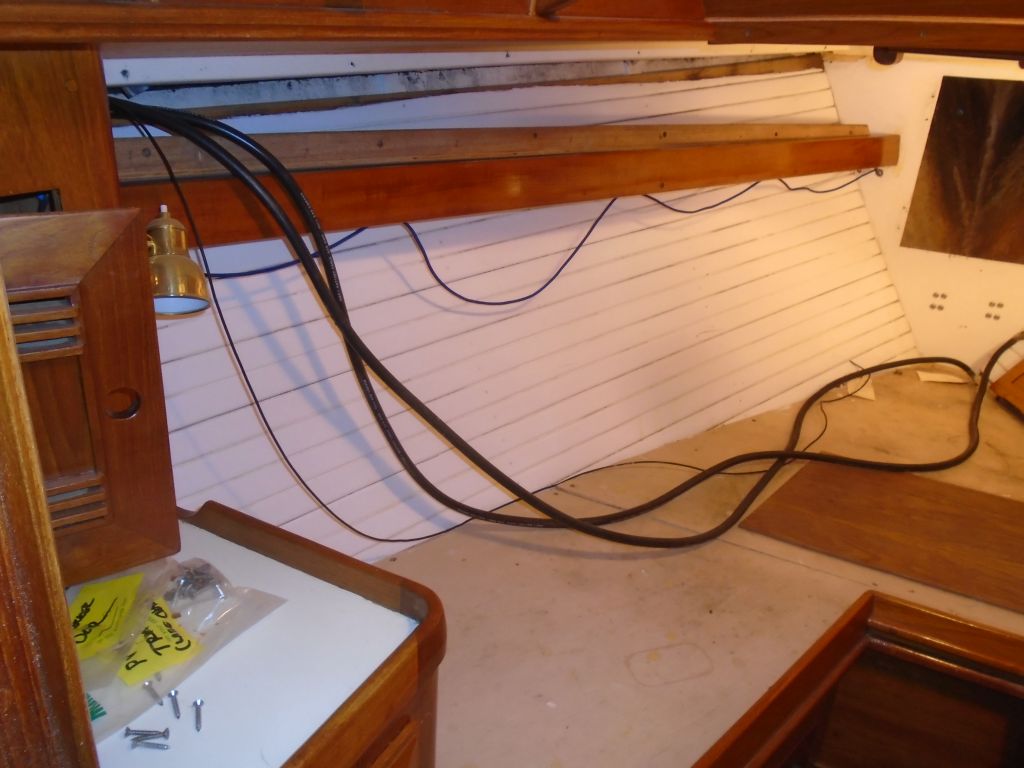
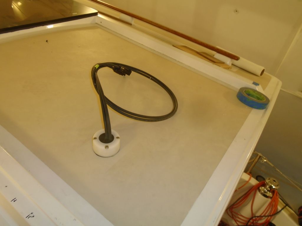
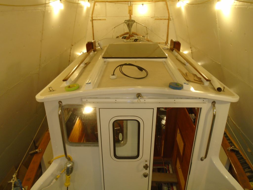
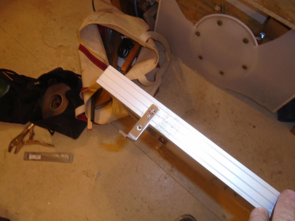
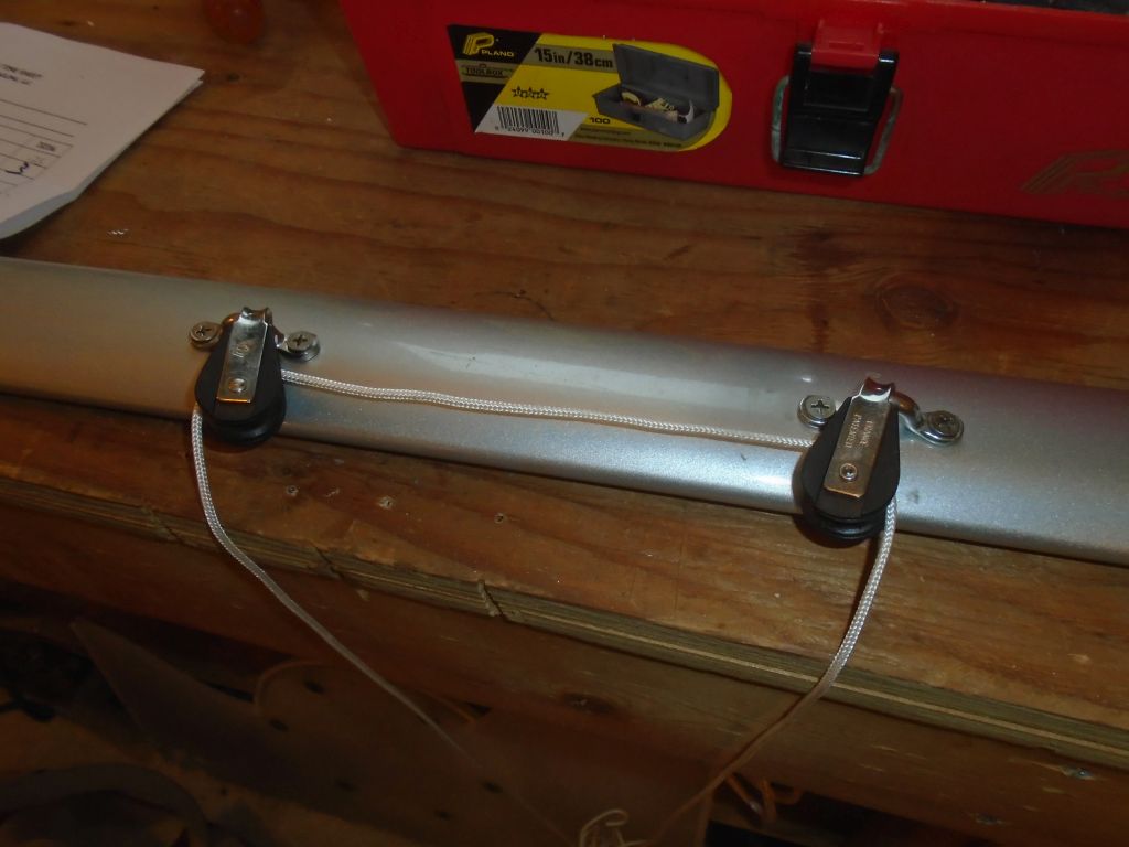
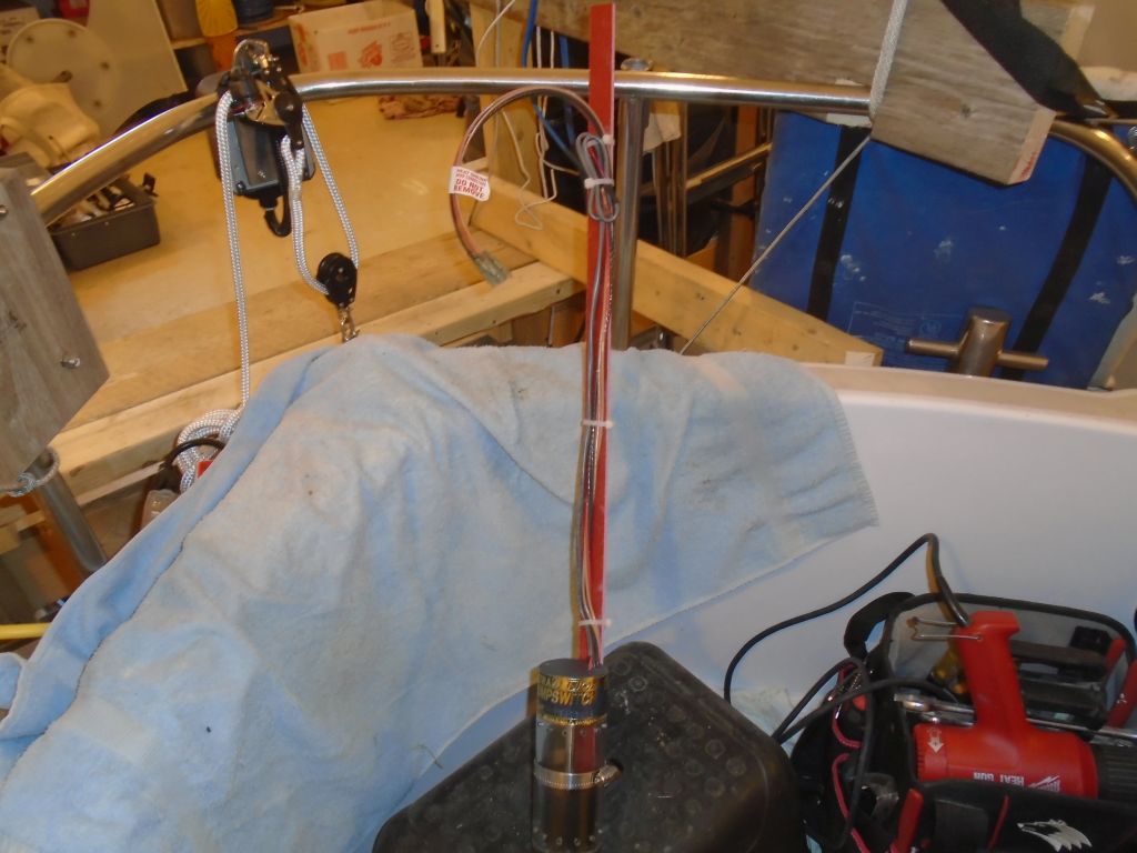
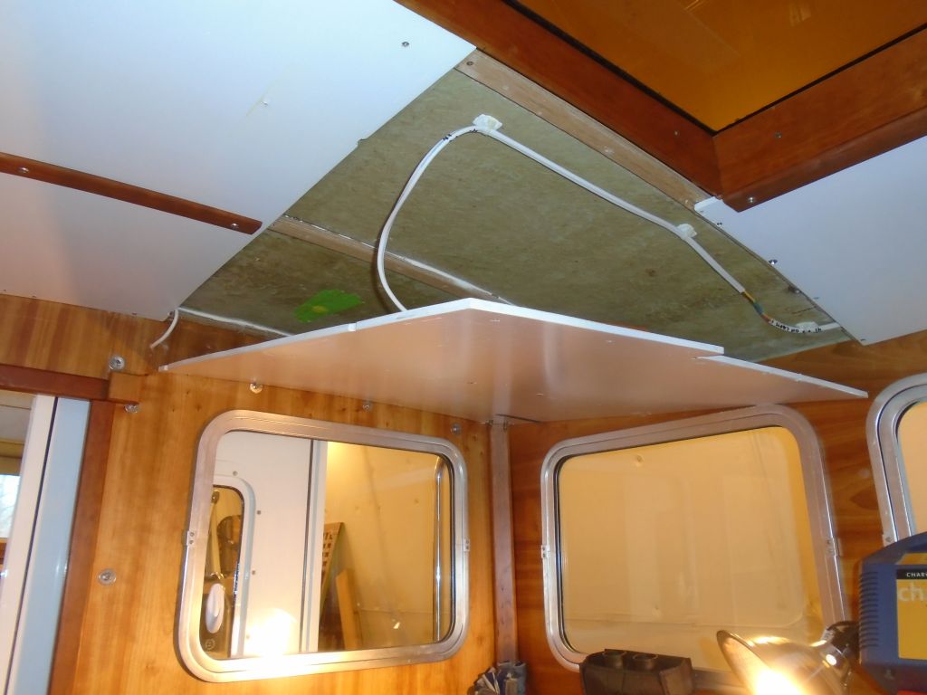
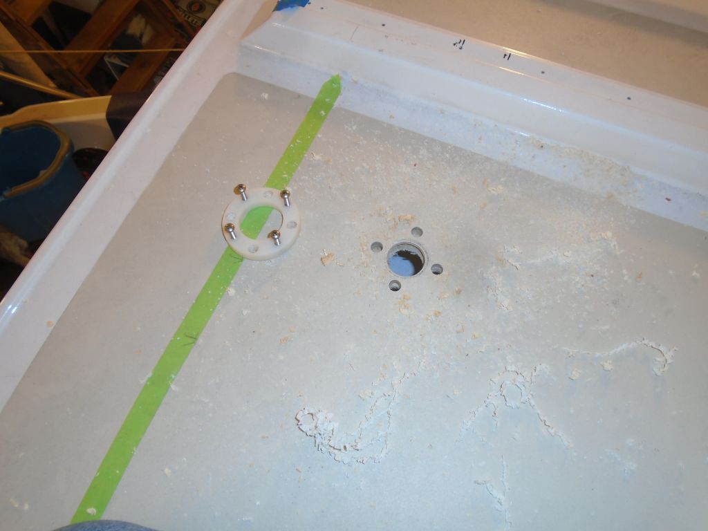
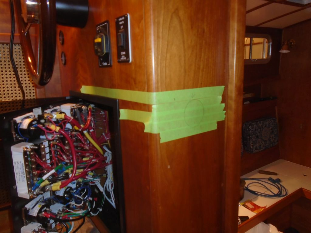
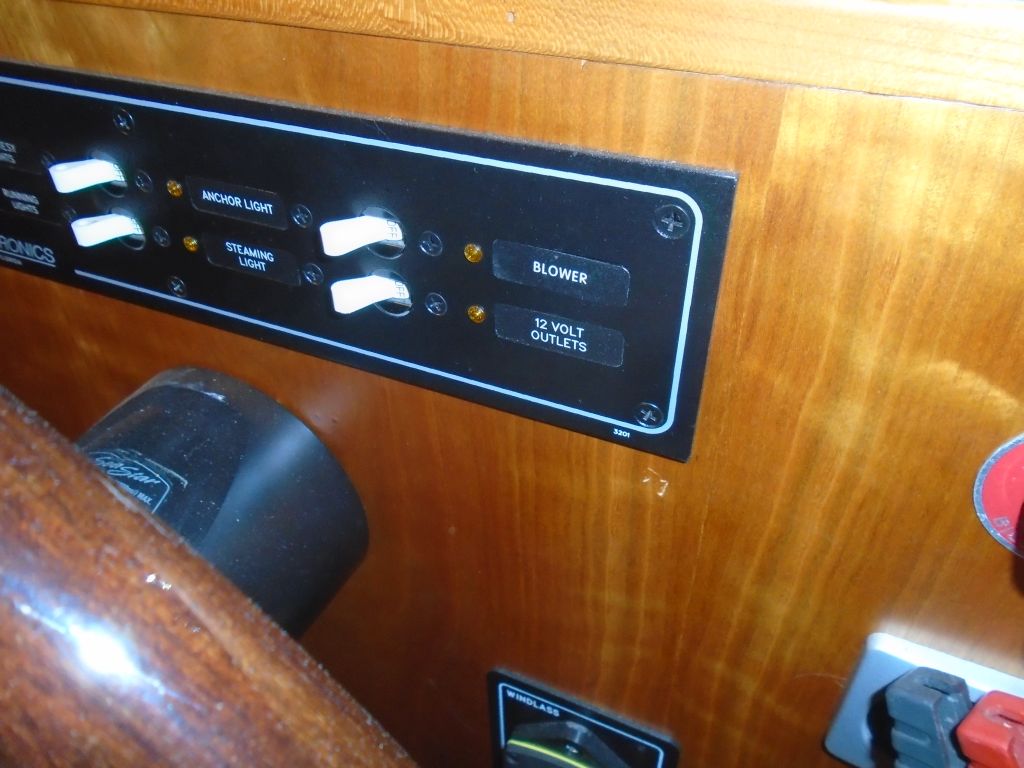
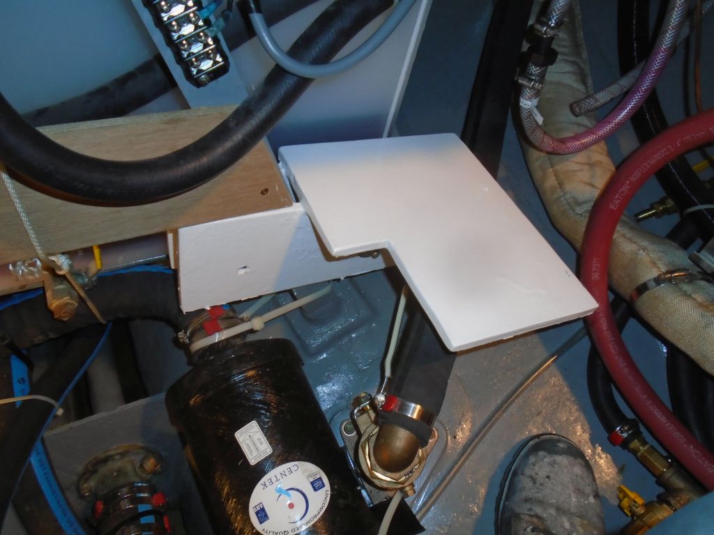
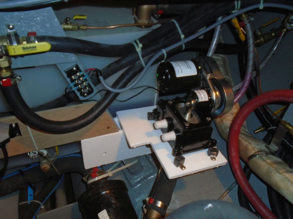
This all certainly took most of the day, but at the onset, before things got more complicated, I managed to steal several minutes here and there to work on the teak platform extension for the windlass. A little fine-tuning of the contour allowed the top to be flush with the adjacent platform, and with this complete I could lay out and cut out the shape according to the windlass base itself. I initially cut the platform 1″ larger than the actual base, but upon reflection I thought this was a little large, and I planned to trim the excess by 1/2″ for better appearance. But I didn’t get that far on the job on this day.
Total time billed on this job today: 7 (Tim) 4 (helper)
0600 Weather Report:
35°, cloudy, snow just beginning. Forecast for the day: Snow, 3-6″ predicted. 8-10″ received. Ground very soft from several warm days.