Thursday
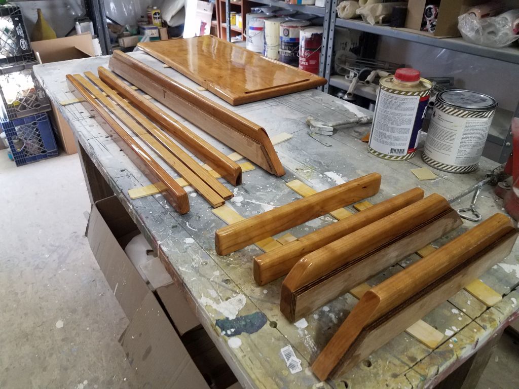
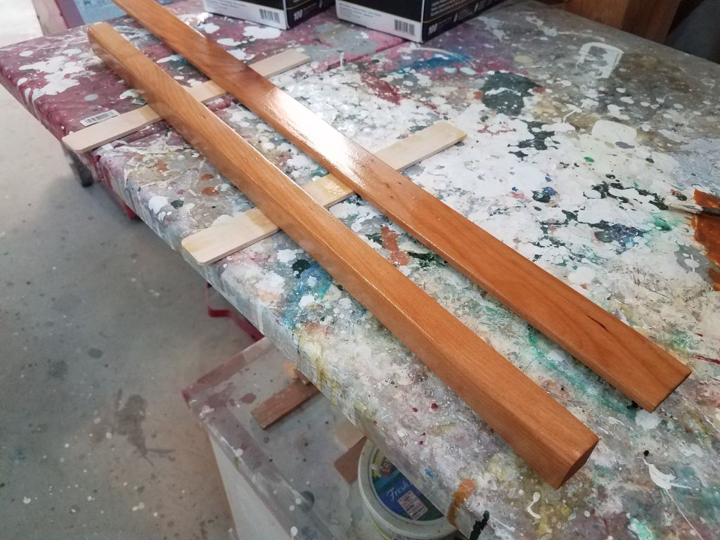
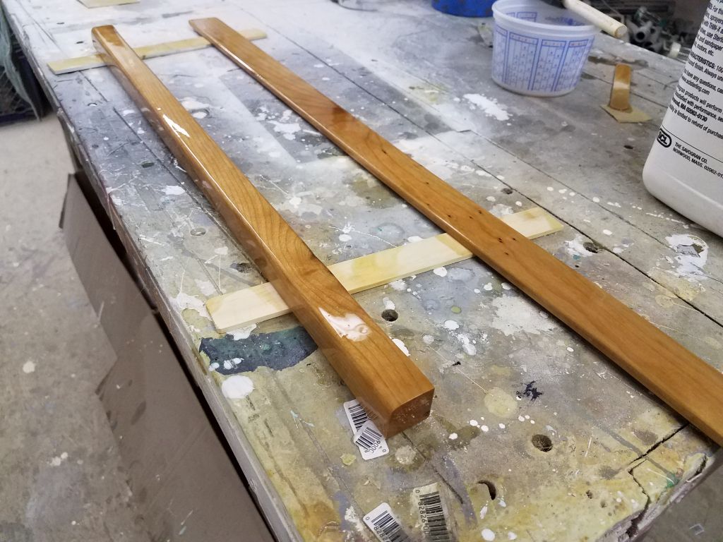
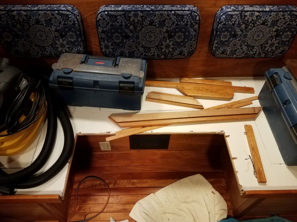
With the milling and varnish work complete, just a few details remained before I was ready to return to the boat for the final installation.
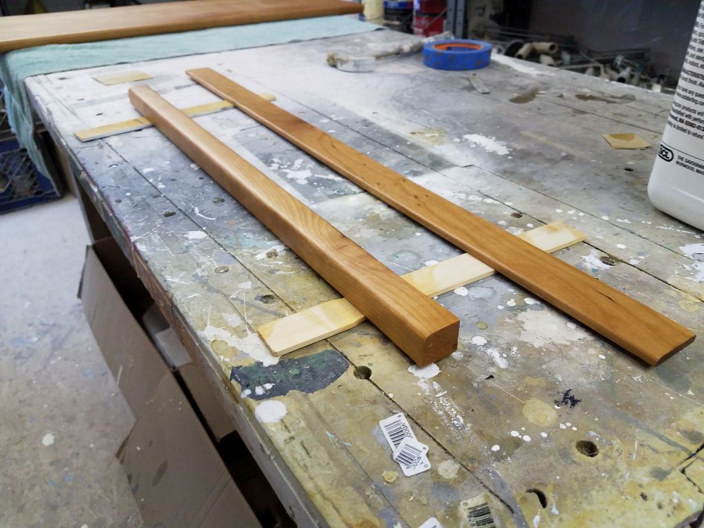
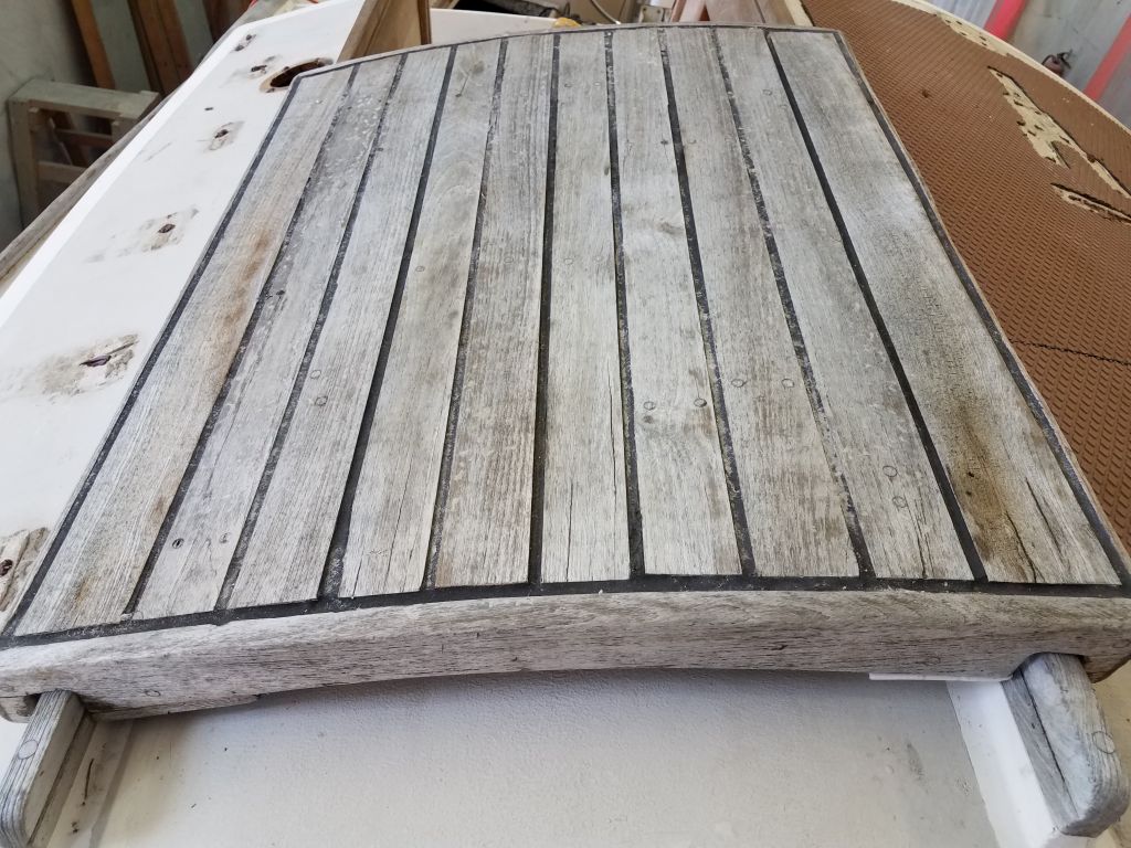
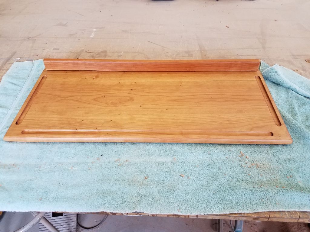
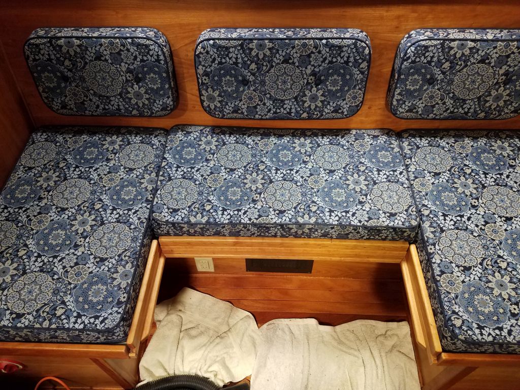
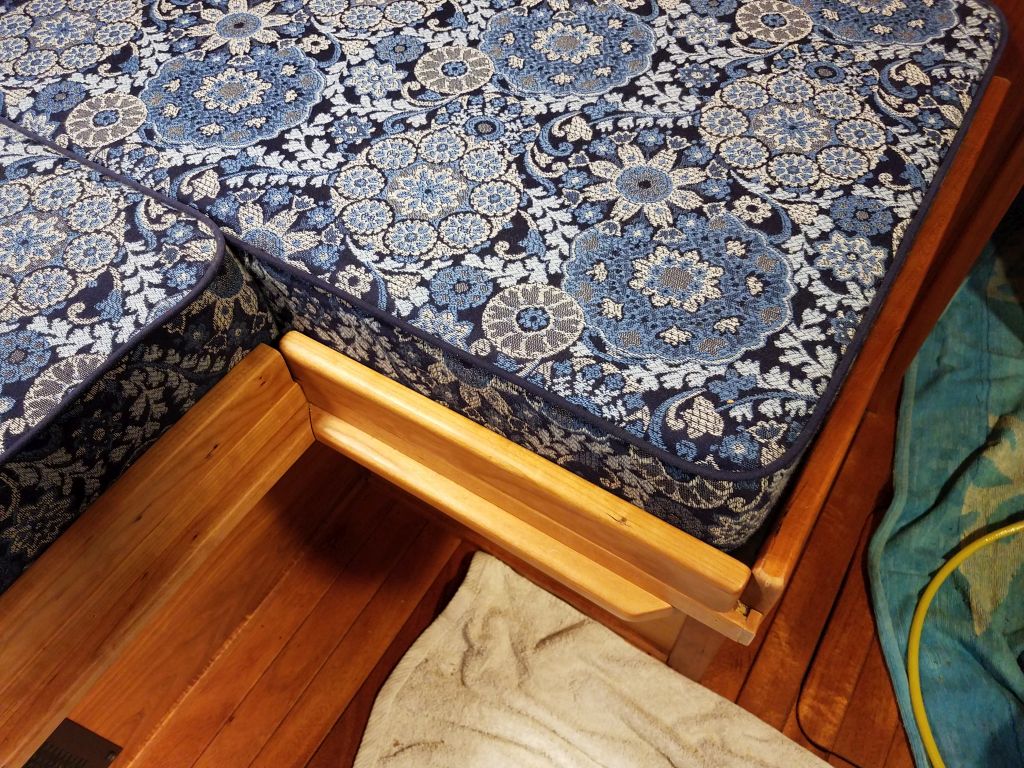
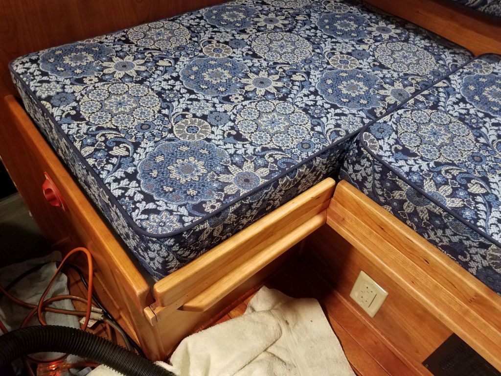
The new fiddles for the U-shaped original dinette were to be removable, so that there’d be no hard spots between the cushions when the area was converted in to a full-size berth, but were still needed for looks and to help hold the cushions in place during normal configuration. I also decided to make the fiddle on the outboard side of the table removable.
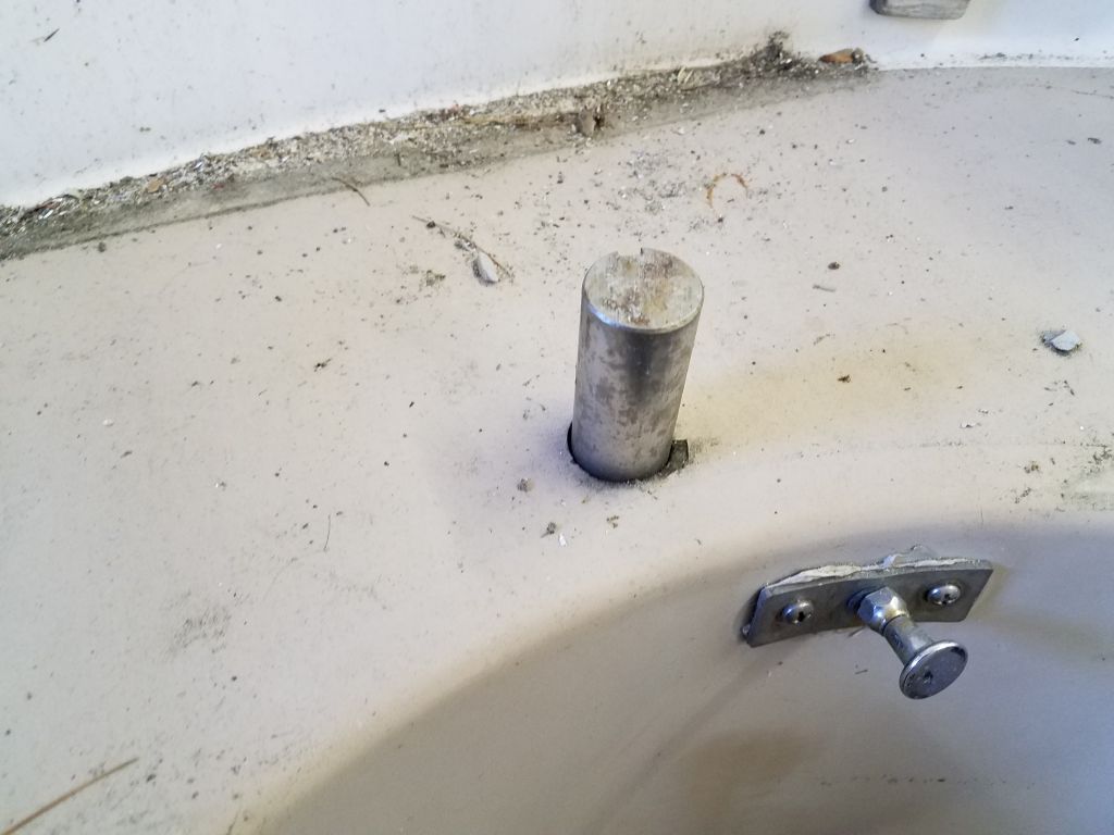
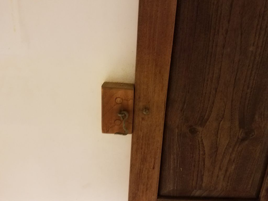
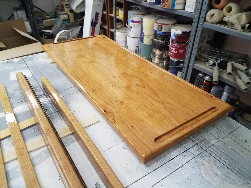
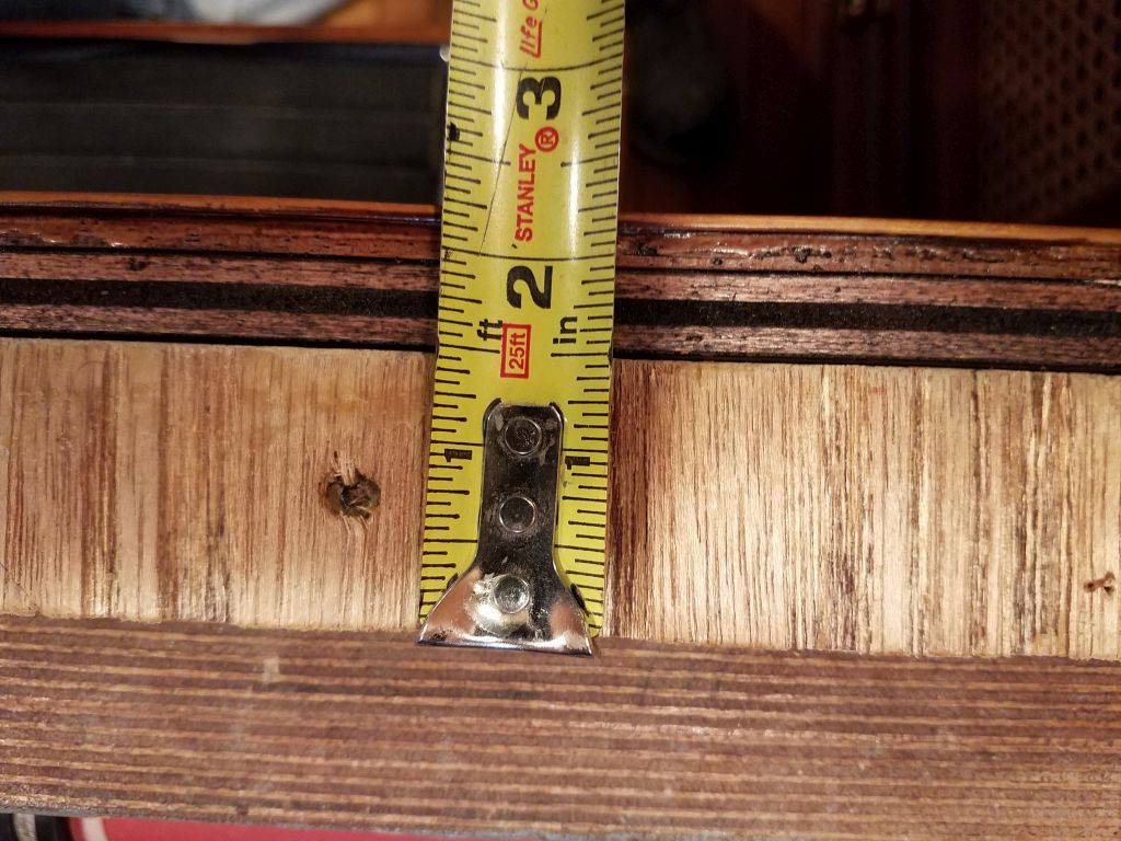
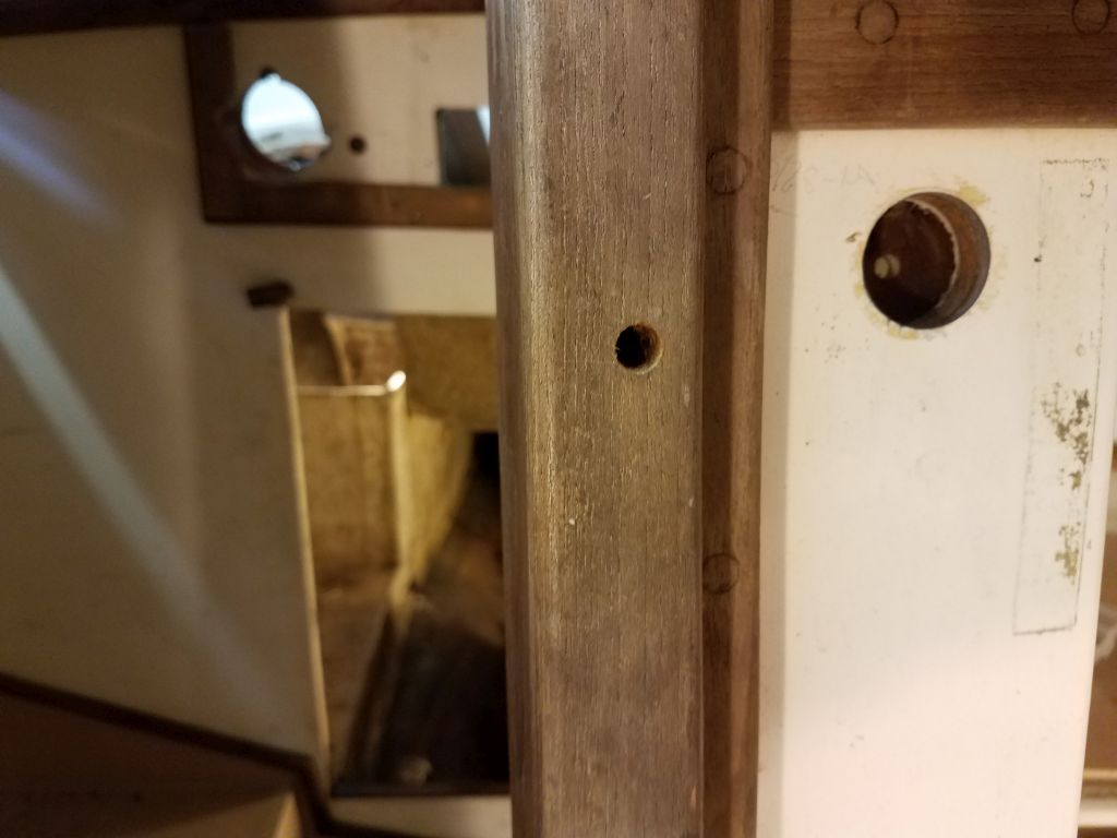
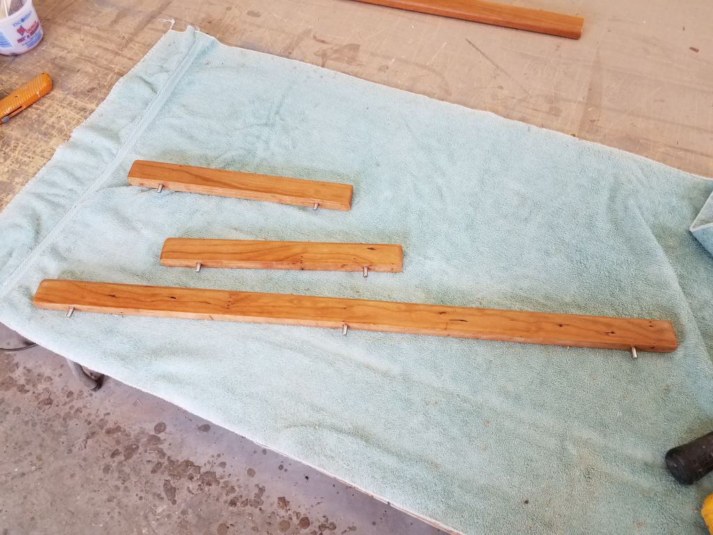
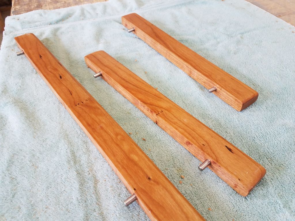
To hold the fiddles in place securely, while keeping them readily removable, I chose stainless steel dowel pins. Into each of the fiddles, I drilled 1/4″ holes for the pins, then glued them in place with epoxy, leaving about 1/2″ – 5/8″ of the pins protruding below the fiddles.
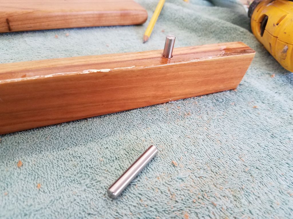
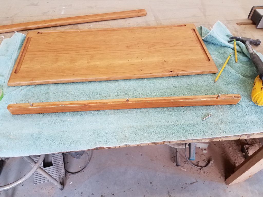
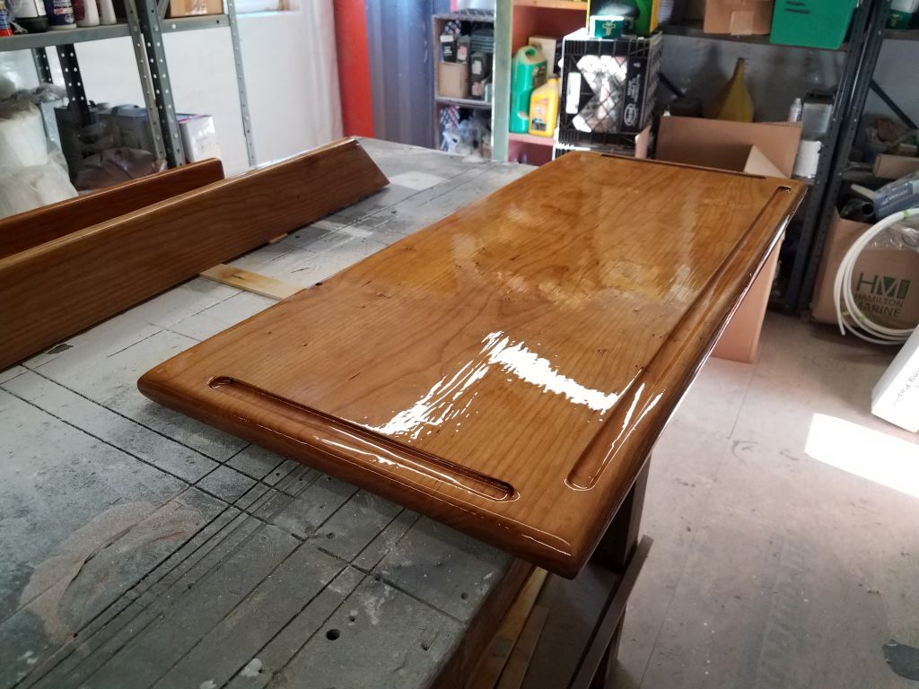
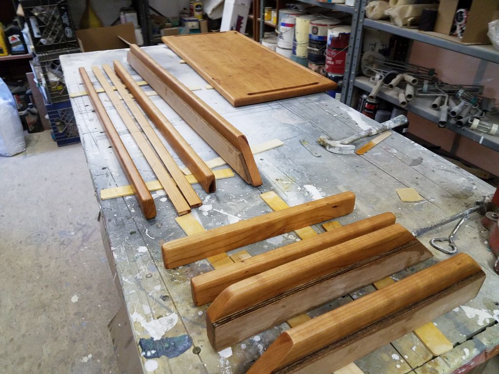
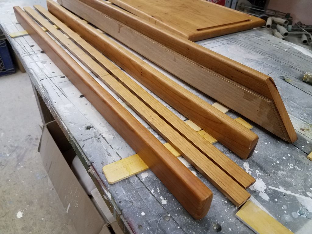
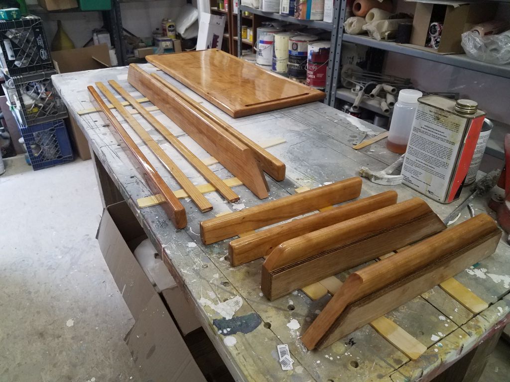
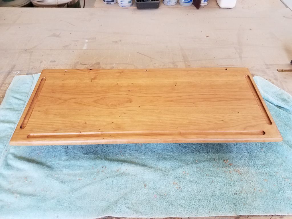
On the tabletop, I aligned the fiddle and its new pins over the top and drilled holes for the pins, using the next size larger drill bit to keep the fit tight, but not so tight that the fiddles couldn’t easily be removed. Note that in these test-fit photos, I did not push the fiddle all the way down, as the pins were just freshly glued in with epoxy here.
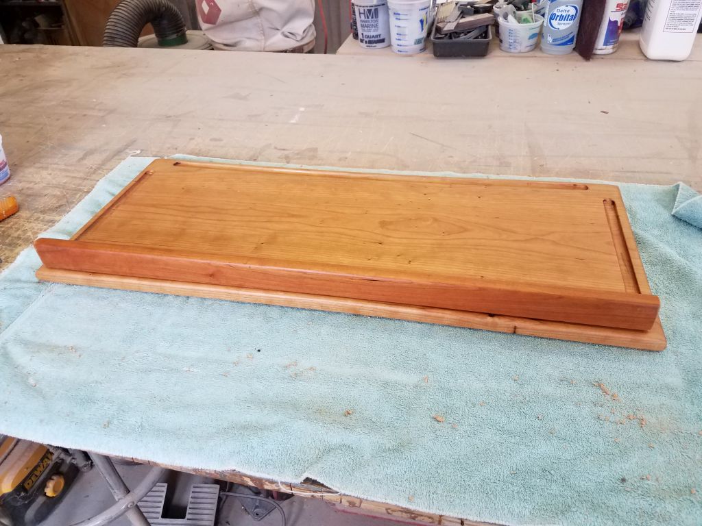
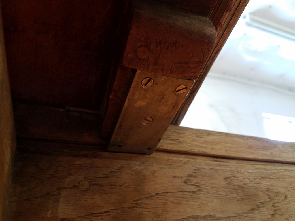
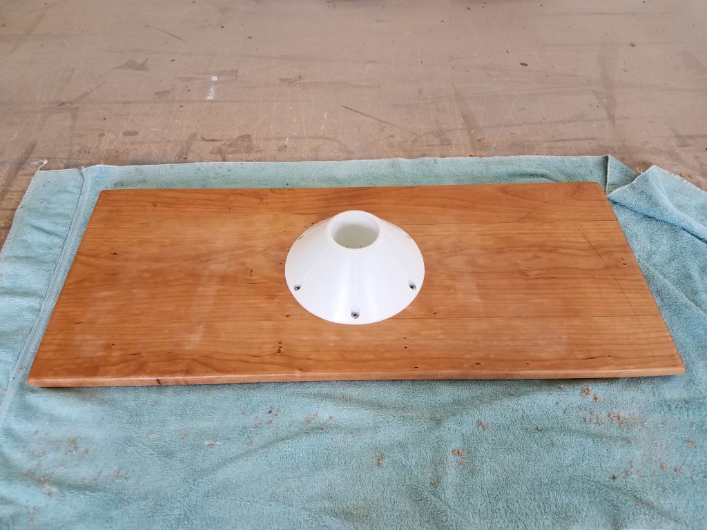
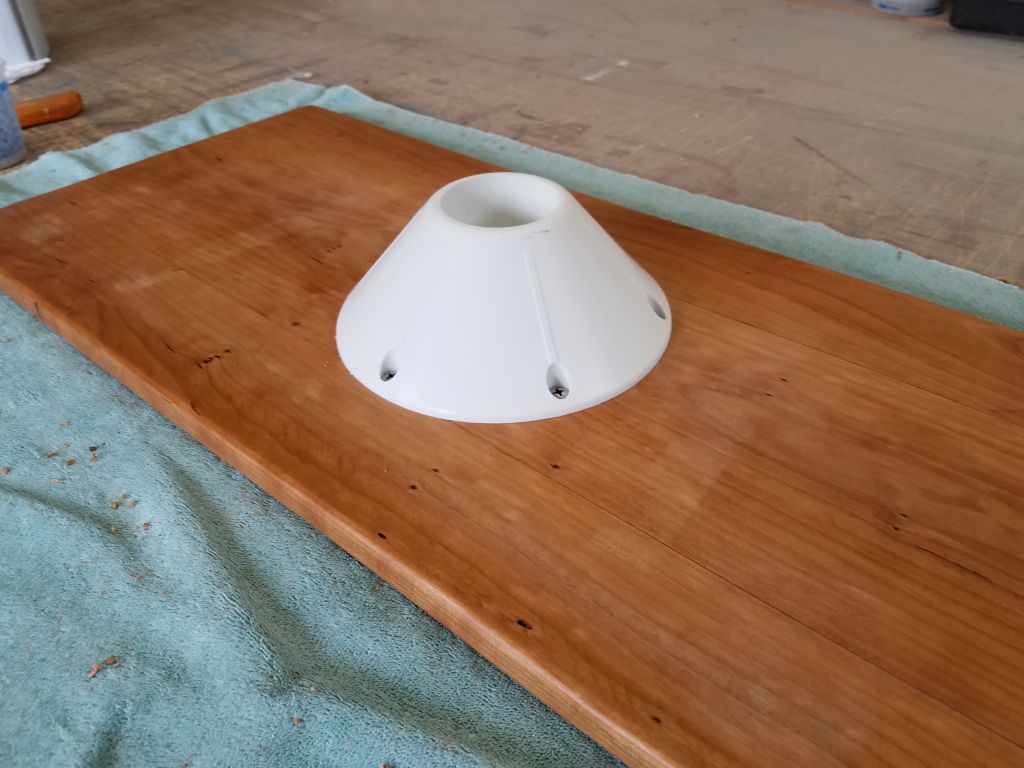
Finally, I installed the top end of the table pedestal to the center of the underside of the table with six #12 screws.

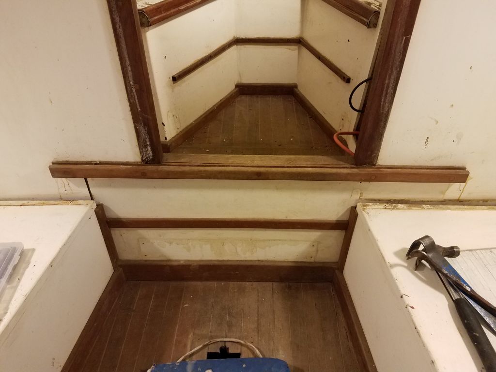
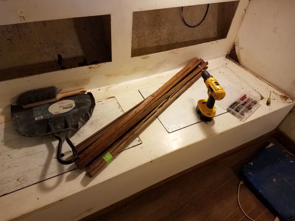
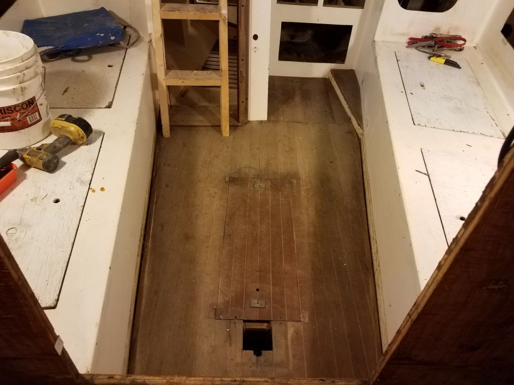
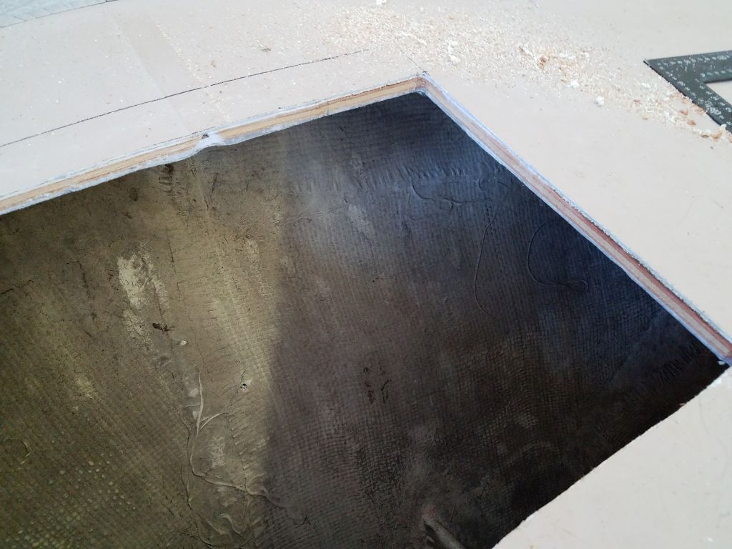
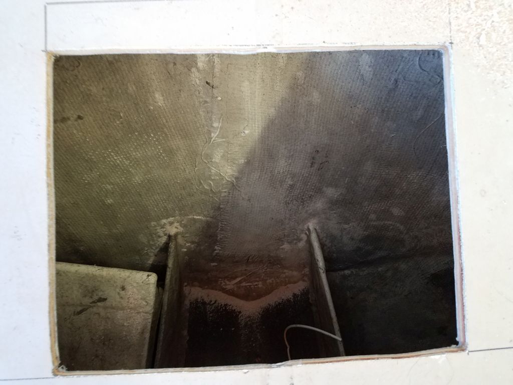
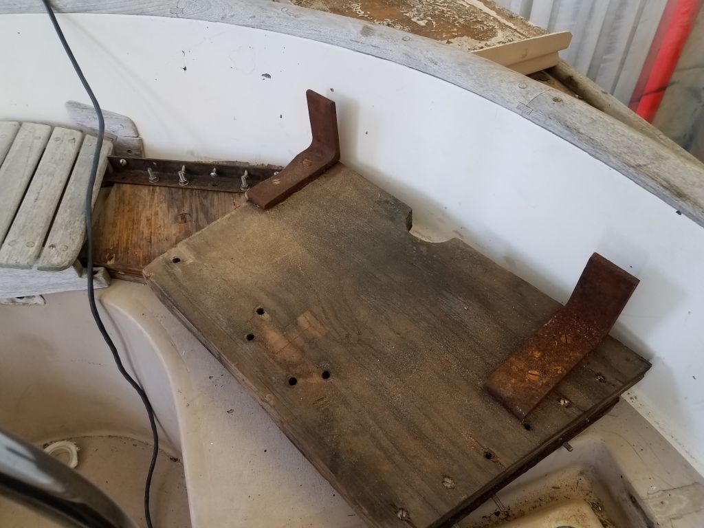
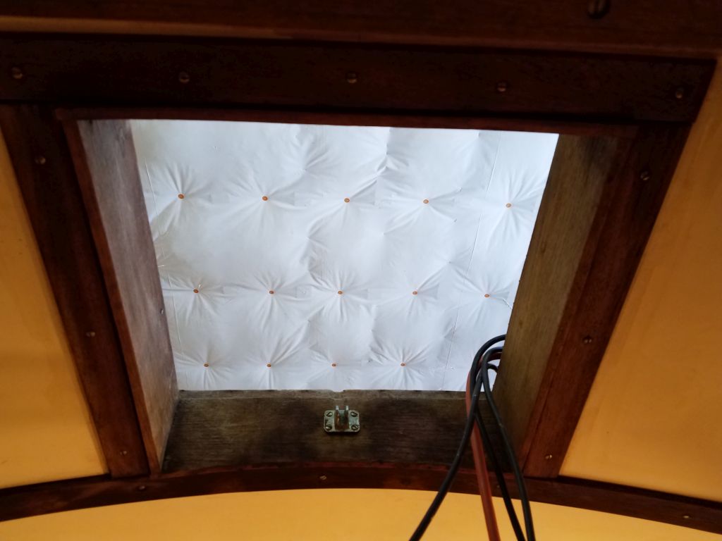
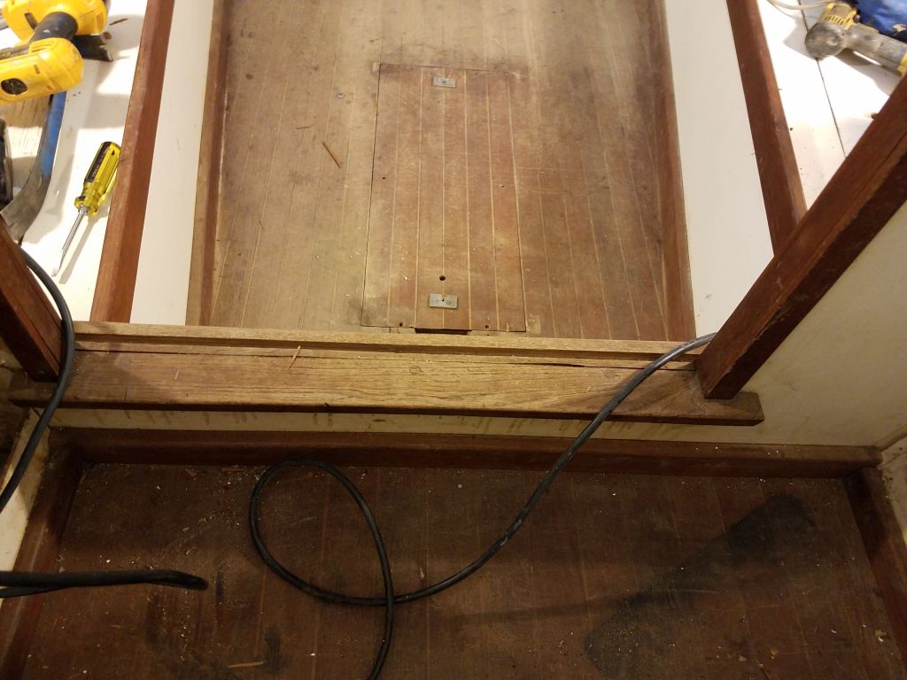
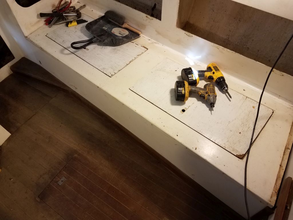
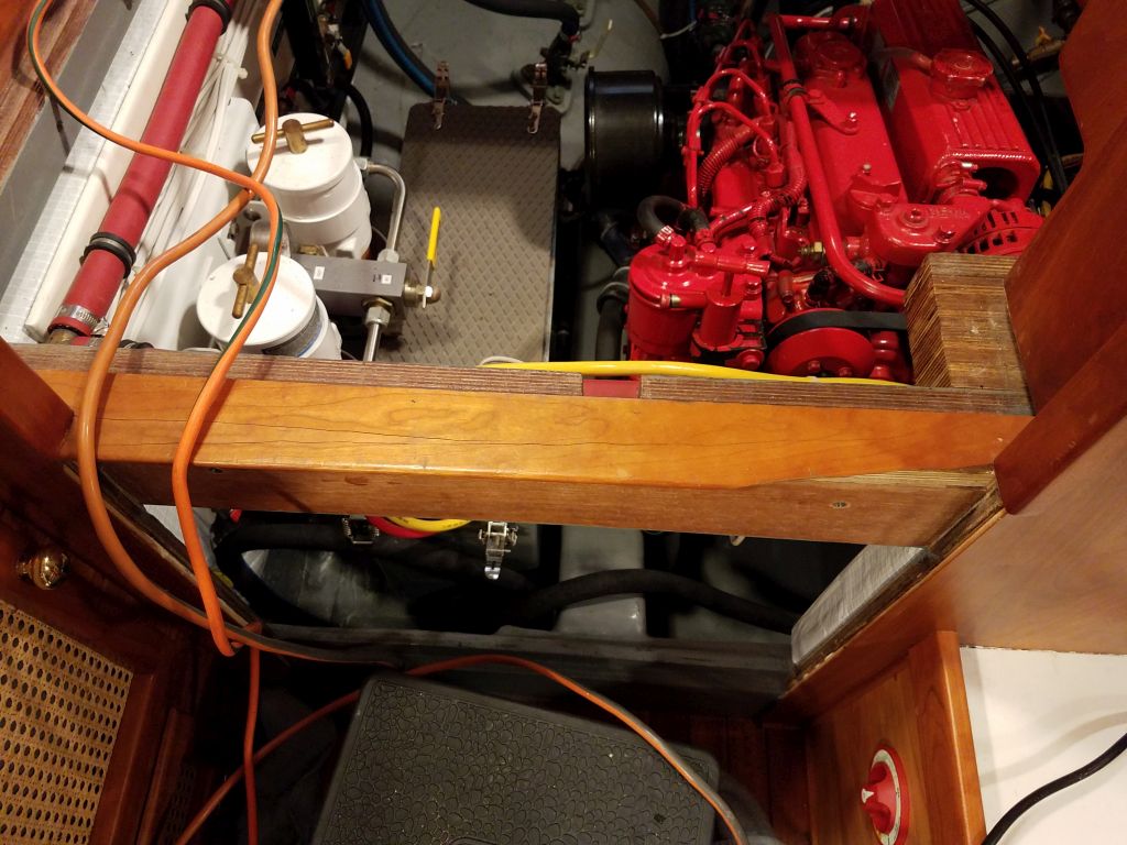
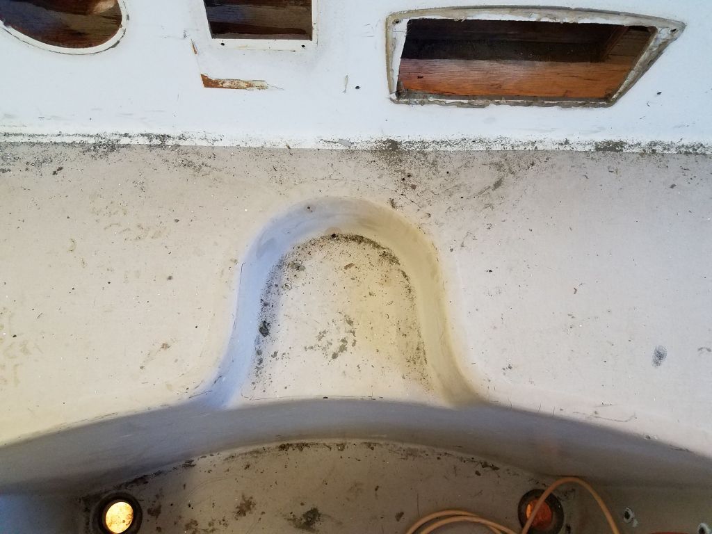
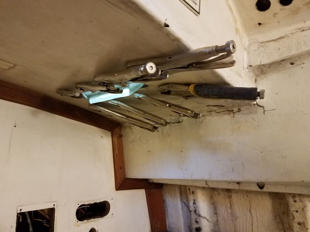
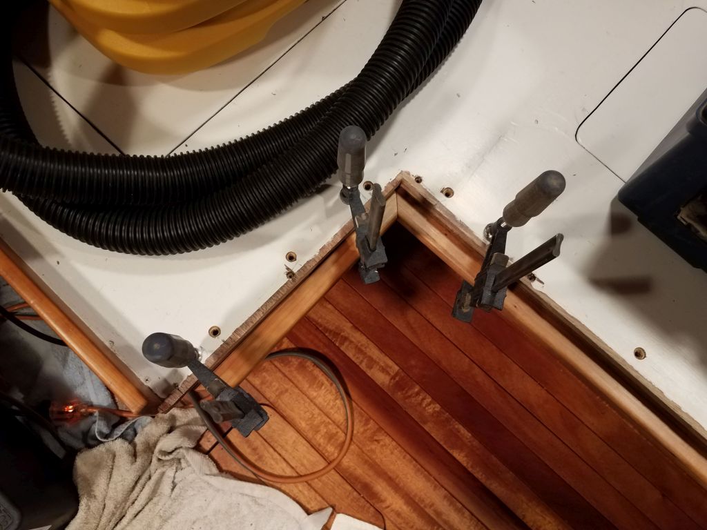
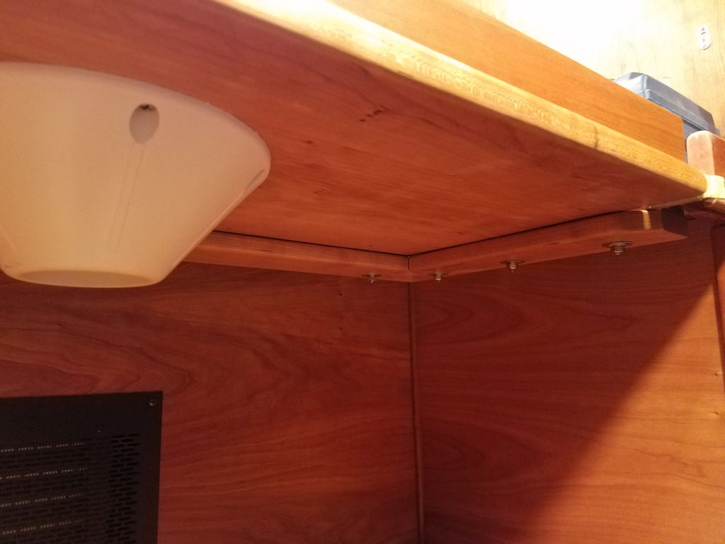
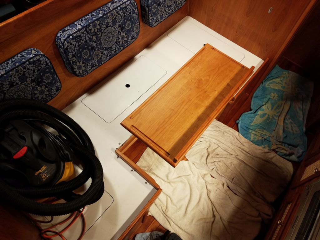
A few days later, back at the boat for the final installation, I got started by clamping the three pieces of the support cleat assembly in place beneath the opening in the settee. Everything fit well and as intended.
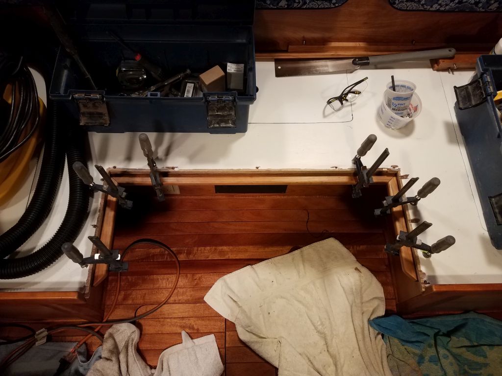
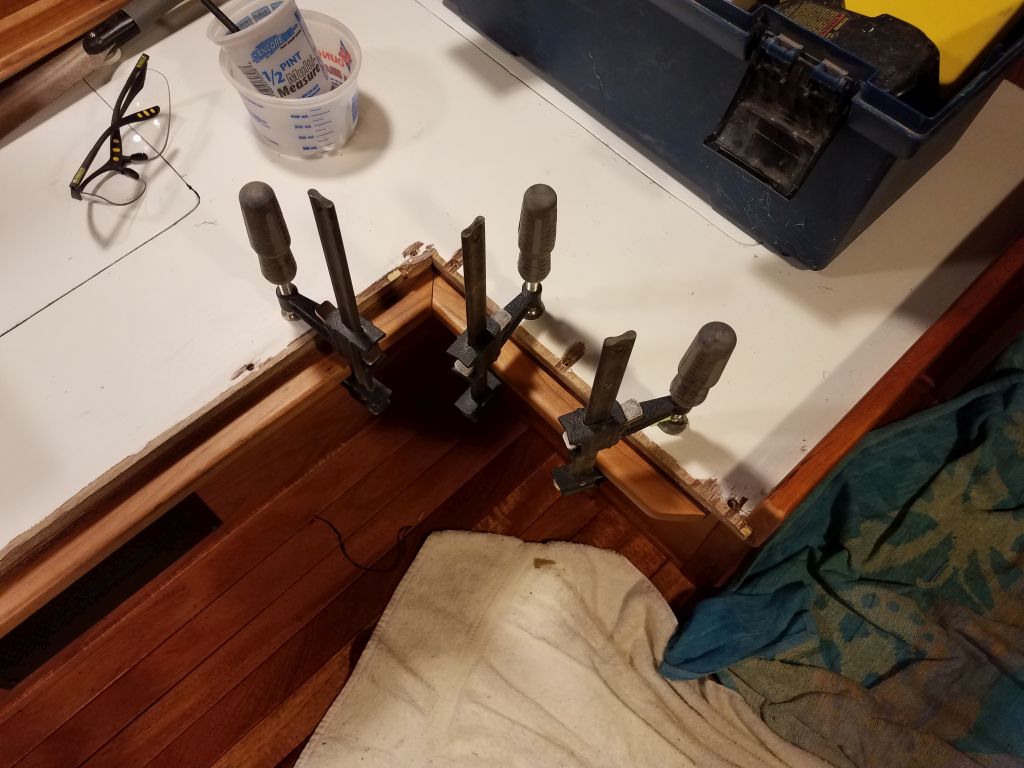

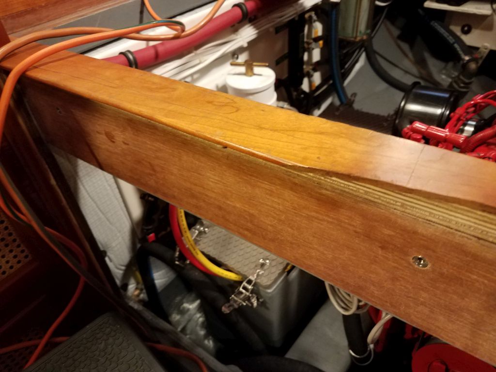
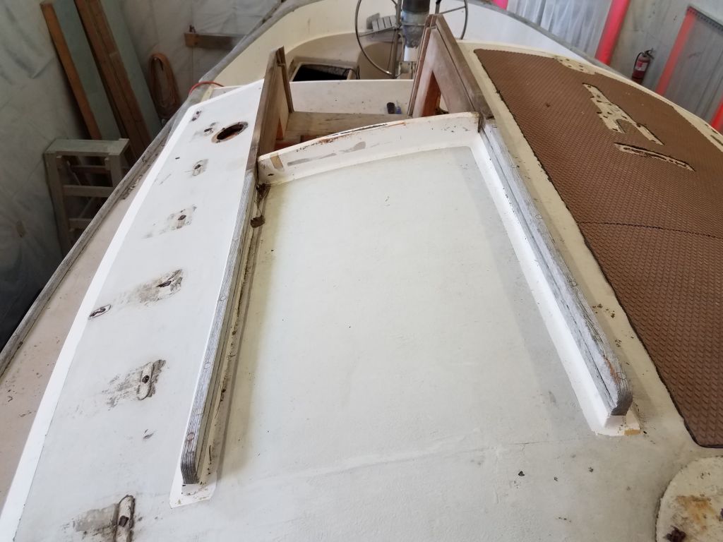
To secure the cleats, I drilled and countersunk bolt holes through the settee and through the cleats beneath: three locations on each of the short sides, and four on the longer center piece. I installed the cleats permanently with glue and 1/4″ flathead bolts.
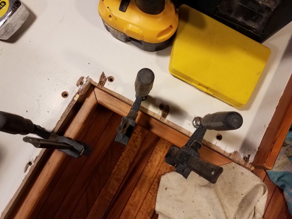


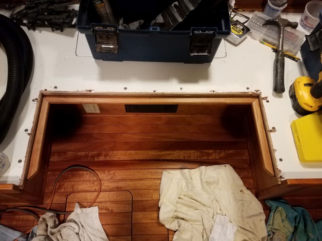
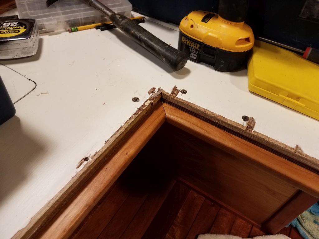
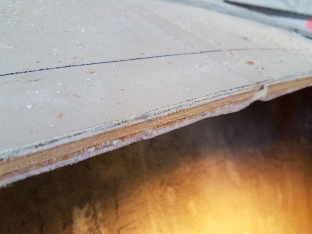
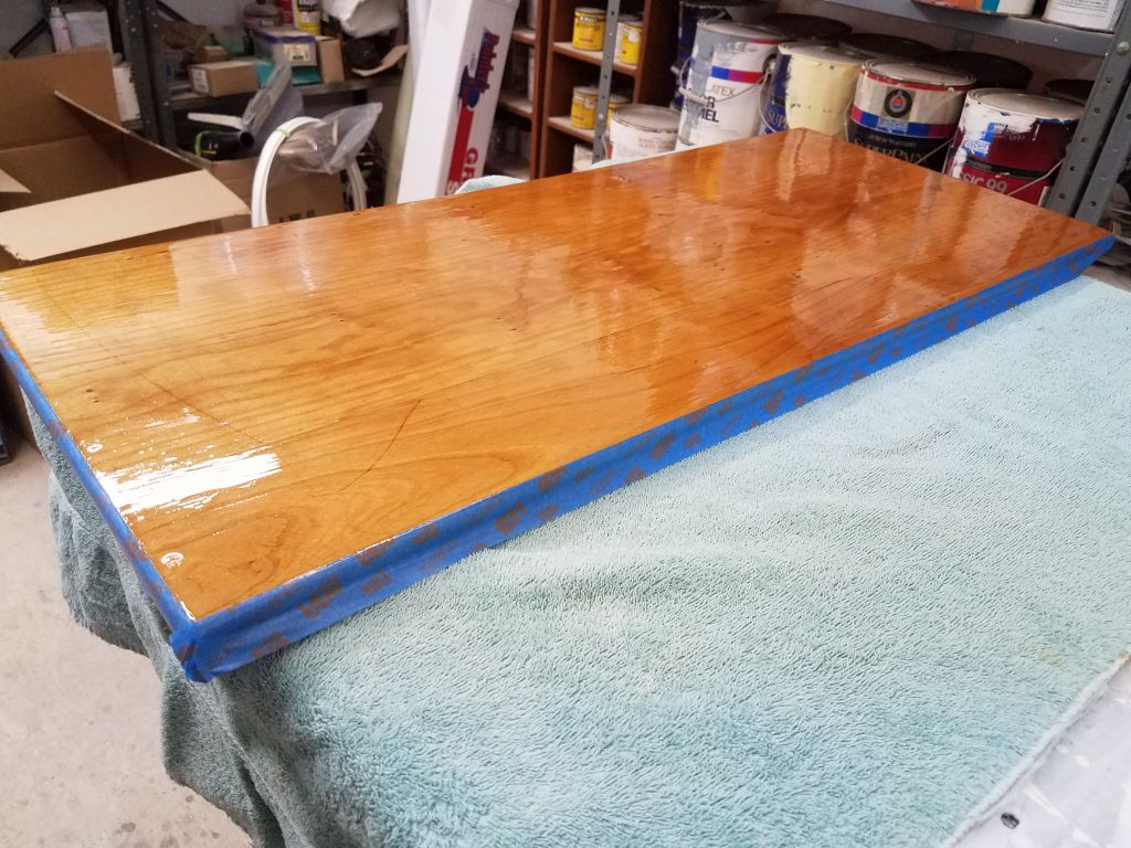
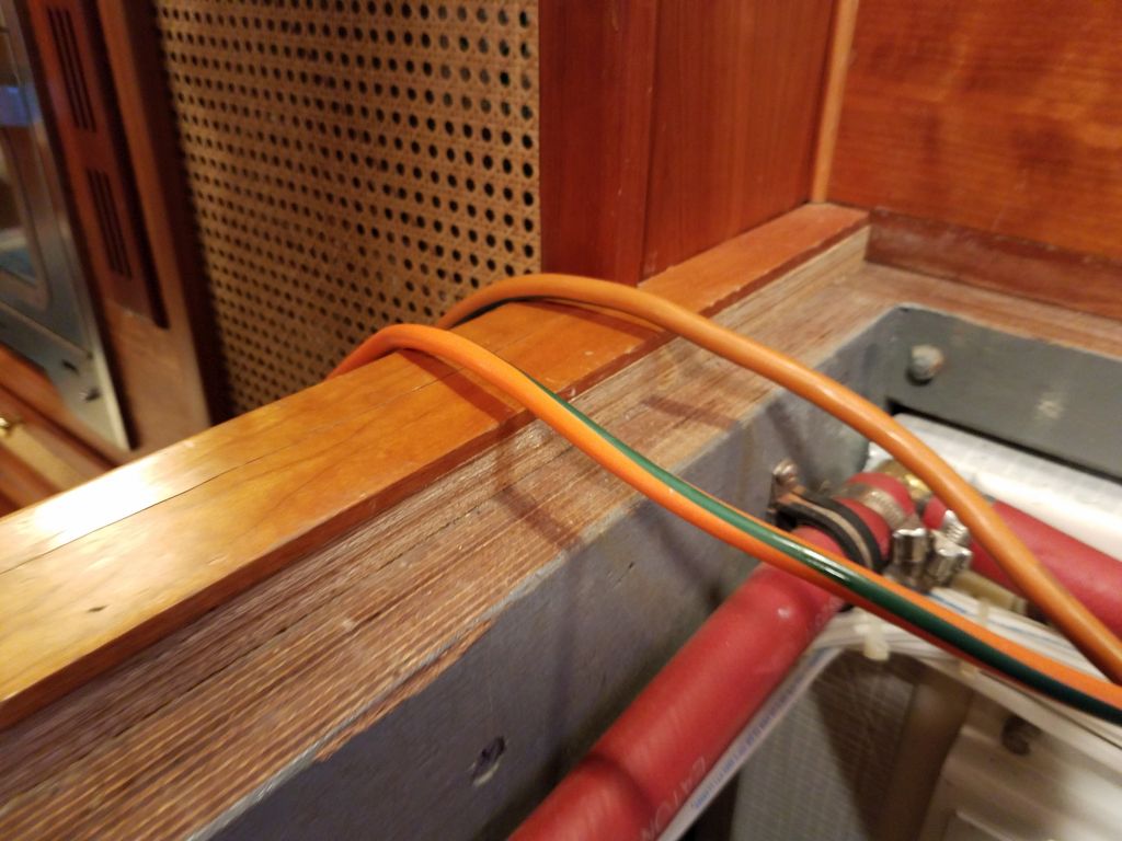
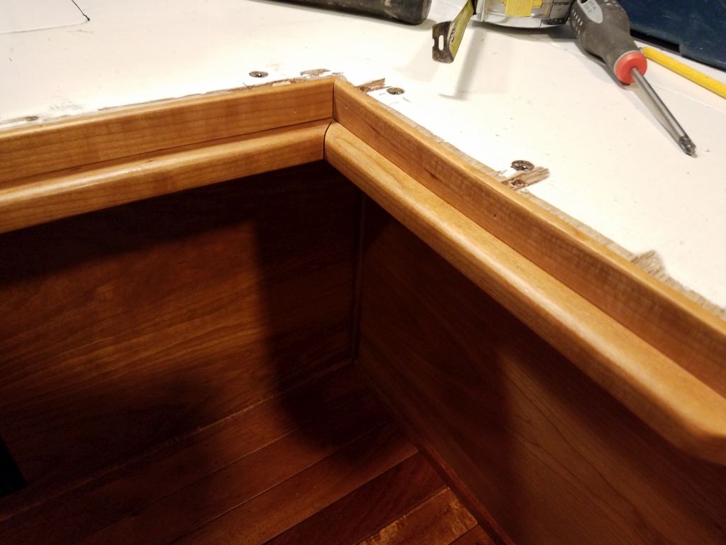
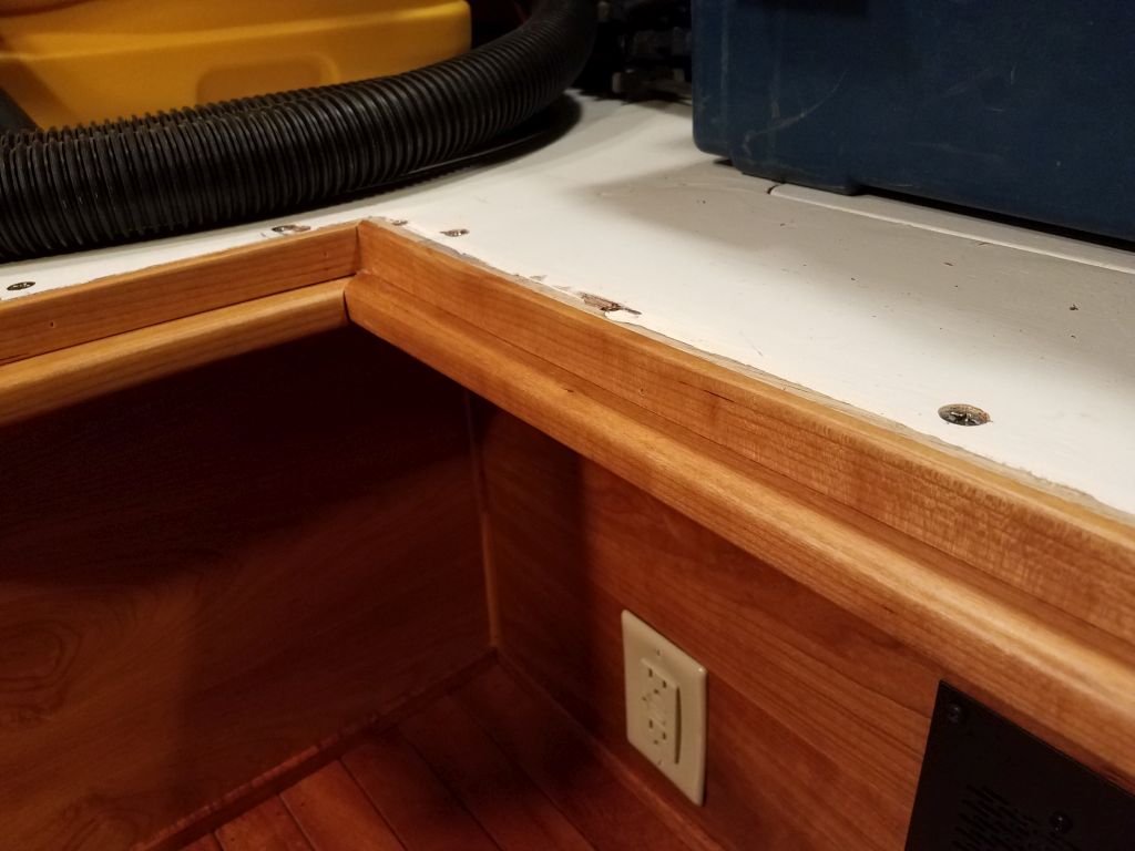
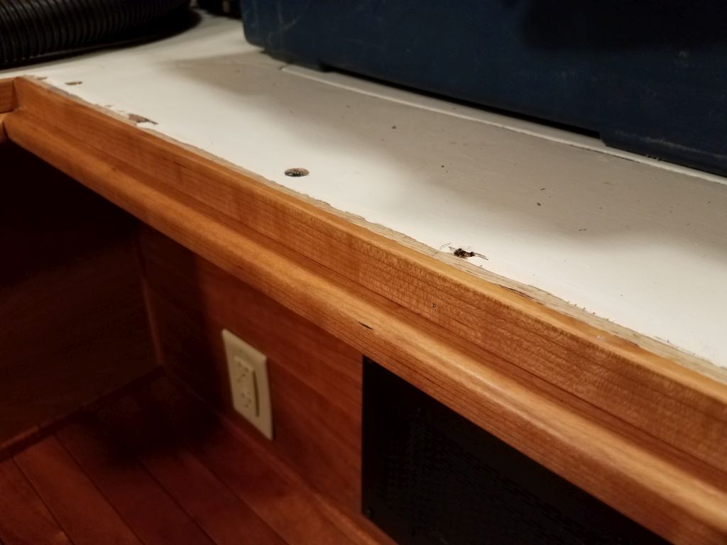
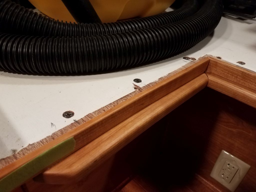
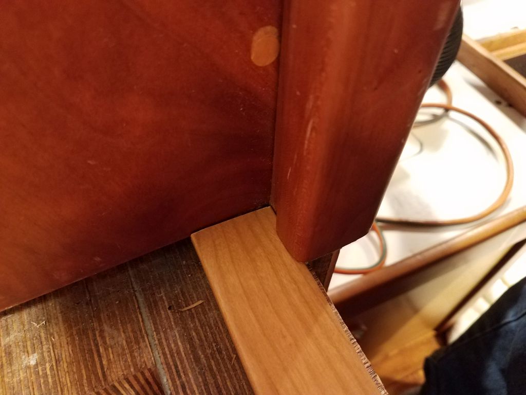
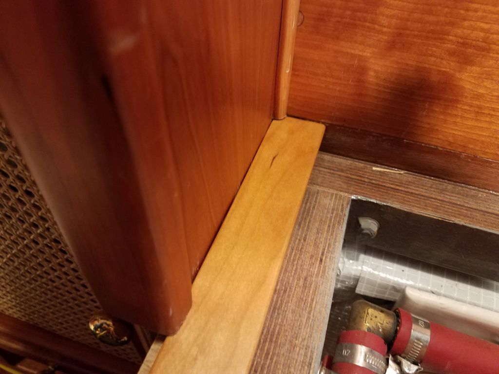
To finish off the opening and cover the exposed plywood end grain, I cut and installed cherry trim that I’d milled and pre-finished for the task.

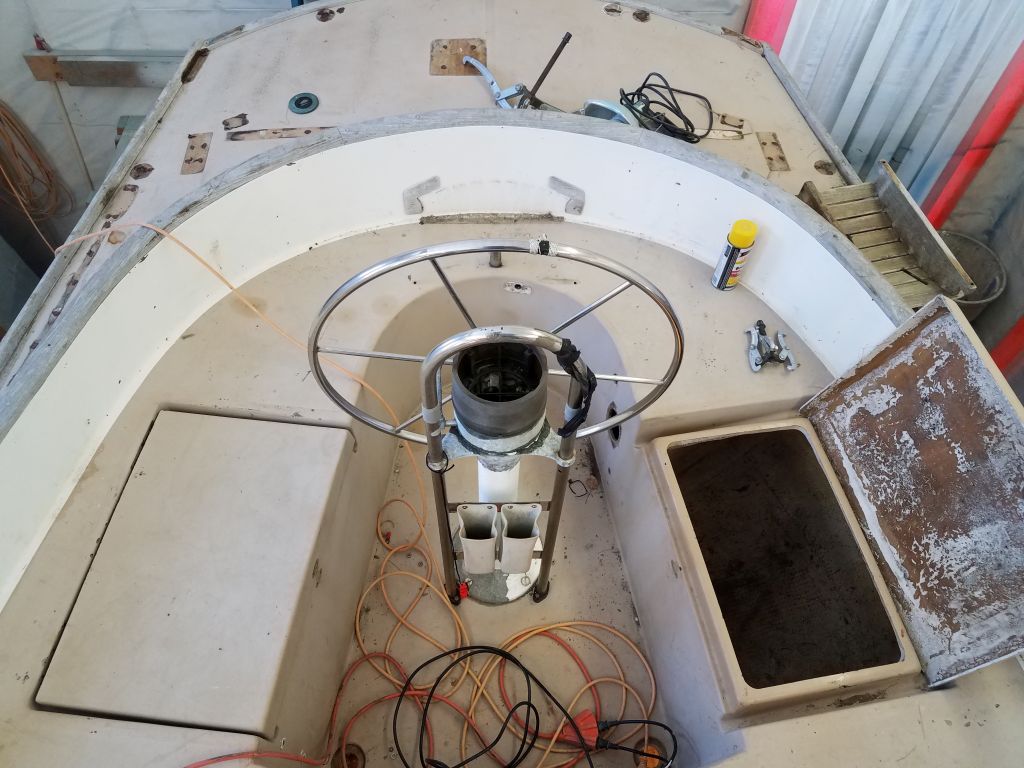
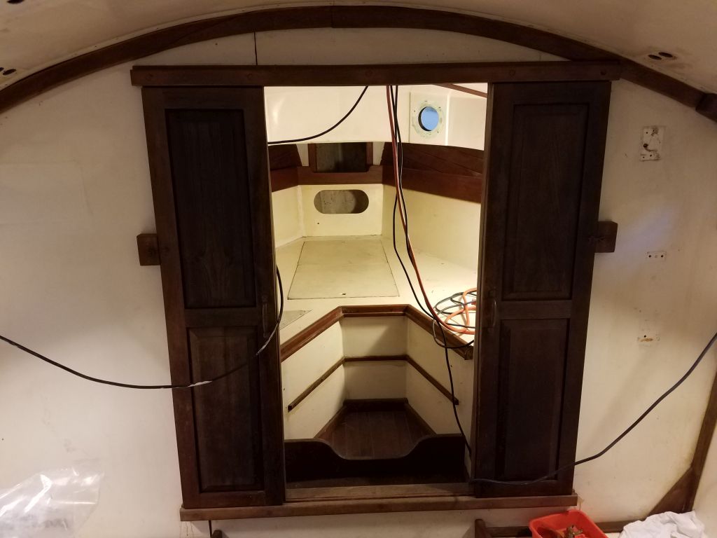
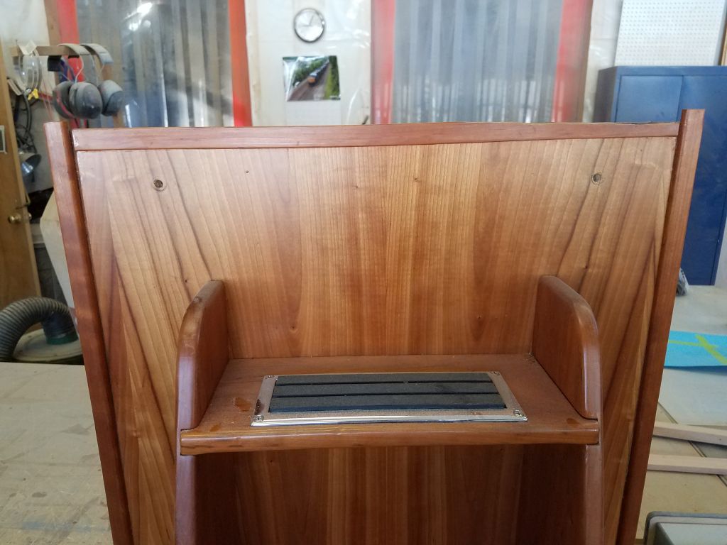
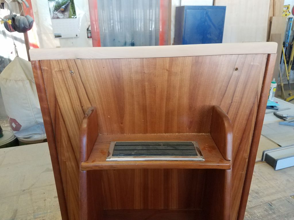
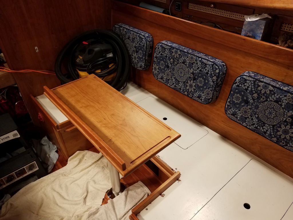
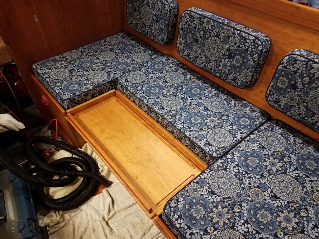
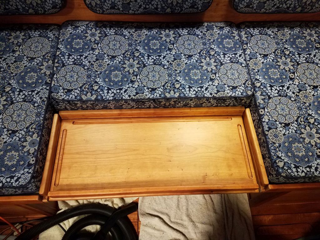
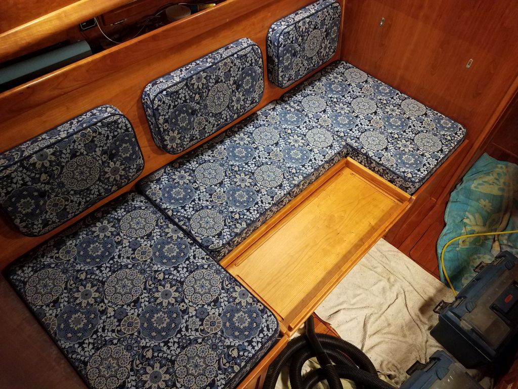
Now I could test-fit the table in place.
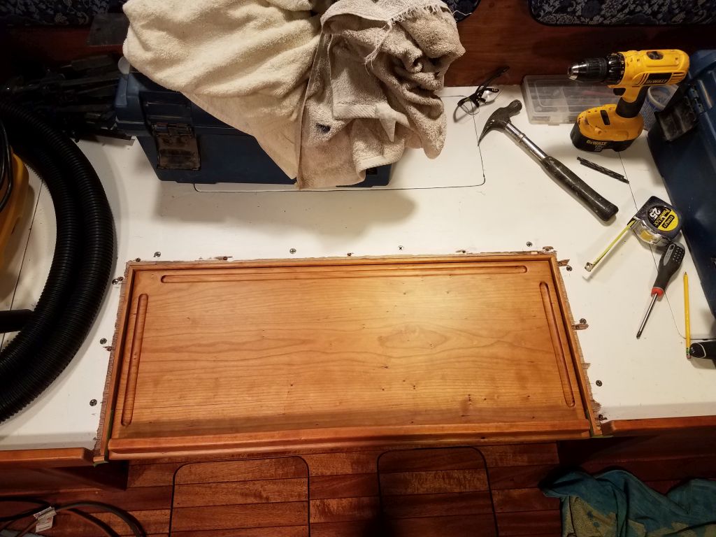
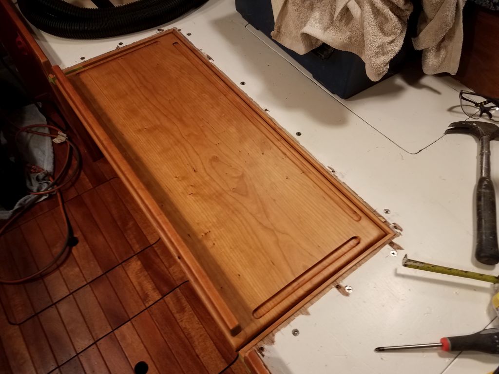
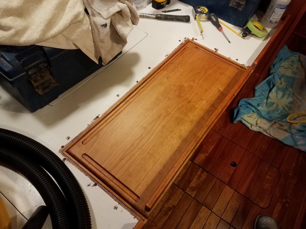
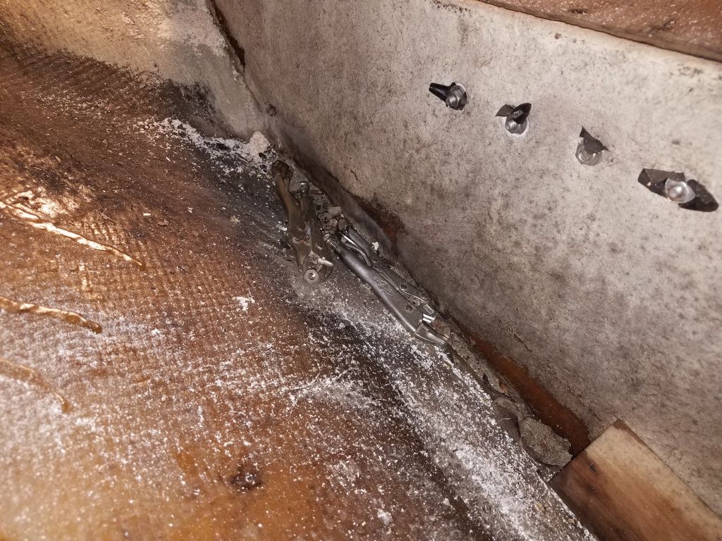
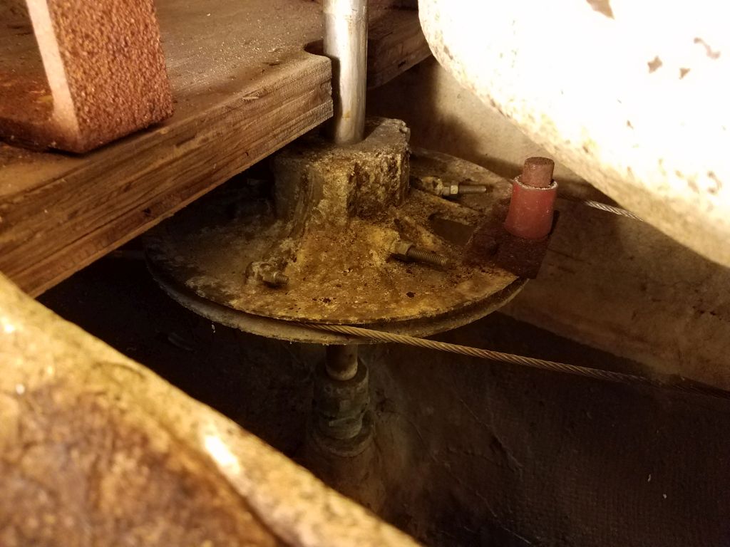
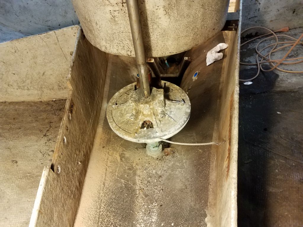
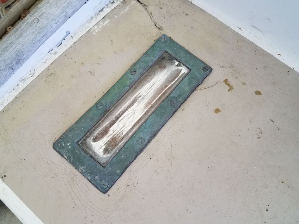
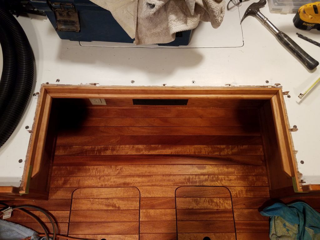
After determining the center of the opening, I located and installed the table leg base.

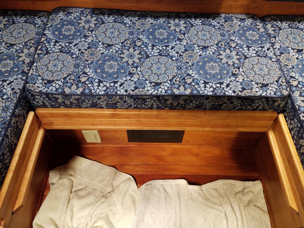
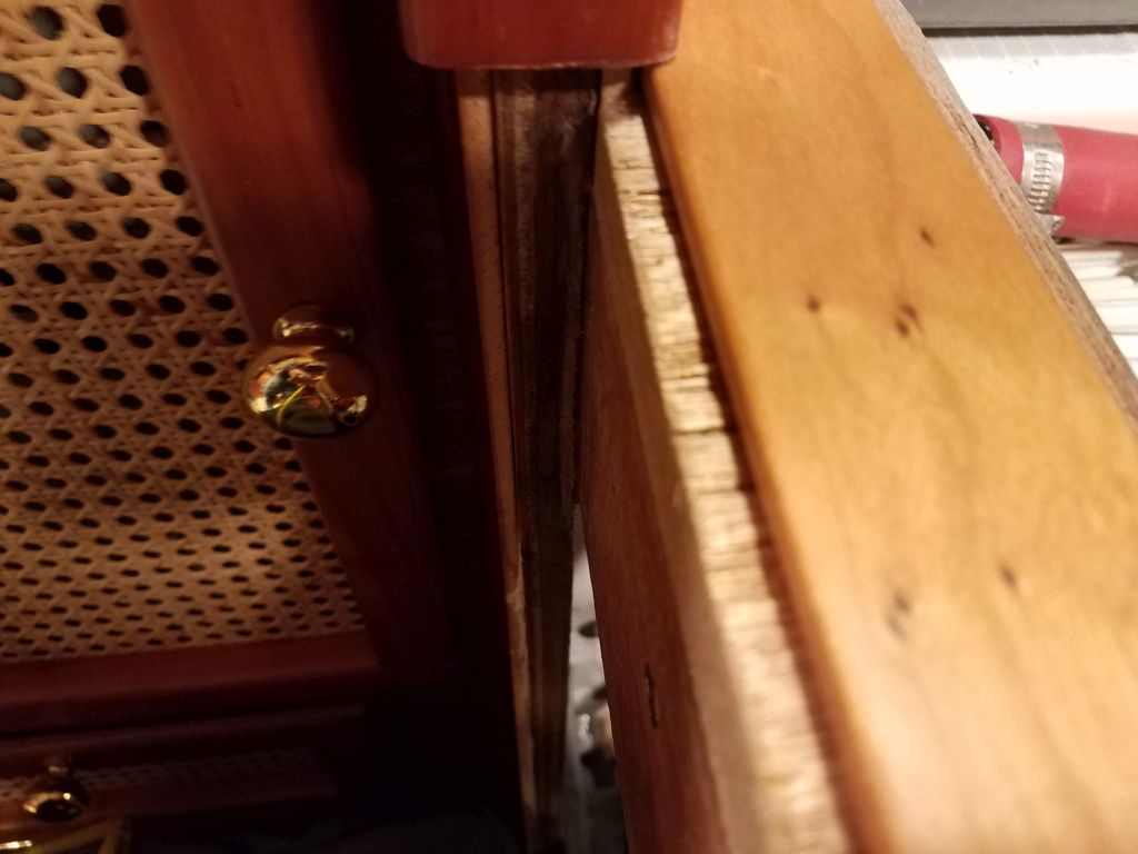
To finish up the installation, I marked and drilled holes in appropriate locations to accept the dowel pins from the removable cushion fillets. I had to trim the ends of the long center piece, which I’d made too long, which meant that I had to bring this piece back to the shop so I could smooth and refinish the ends as needed, but otherwise the fillets worked well. I took detailed measurements of the opening so I could have a filler cushion made to suit. Fortunately, I even had offcuts of the original fabric on hand for the job.
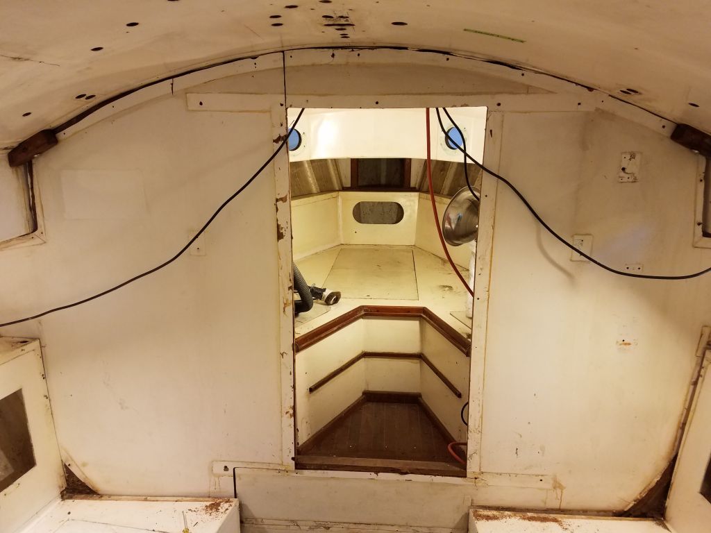
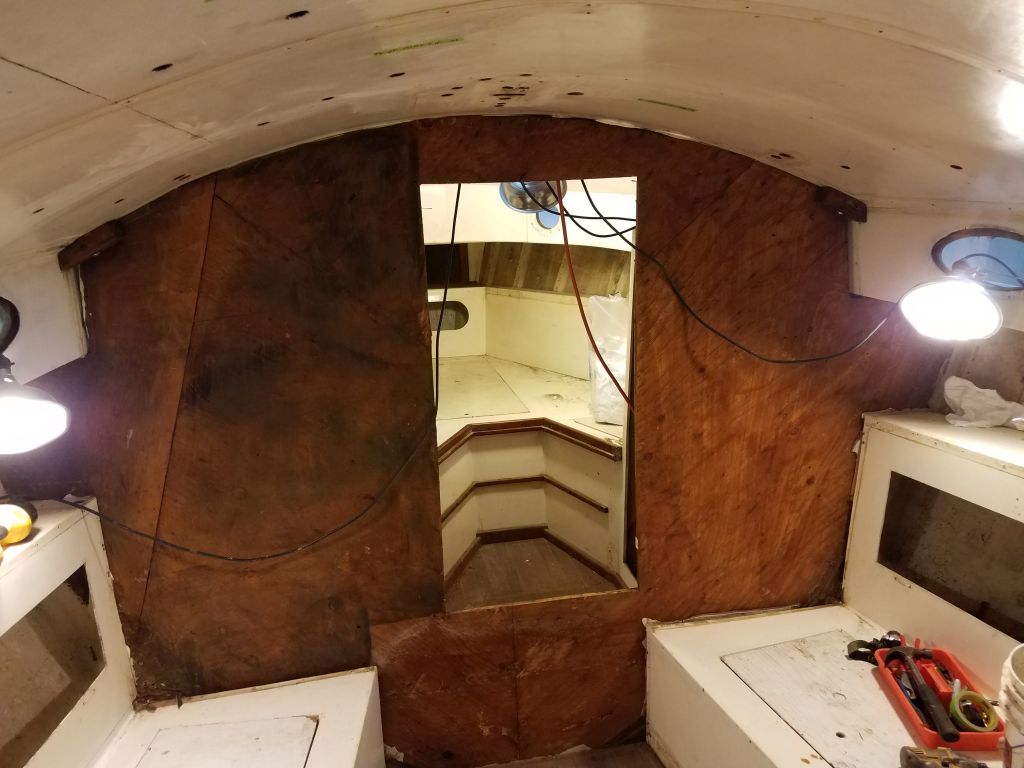
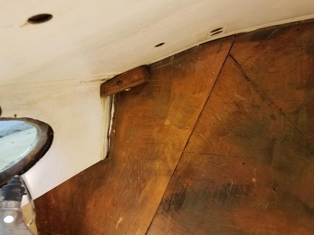
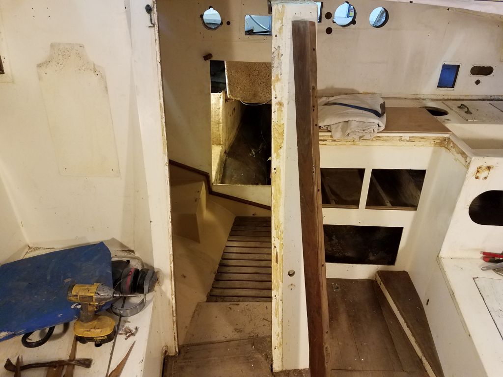
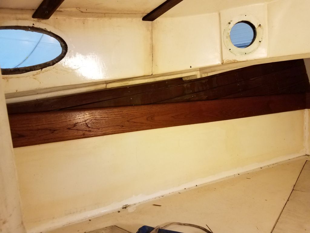
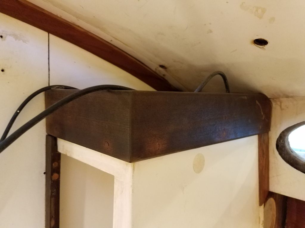
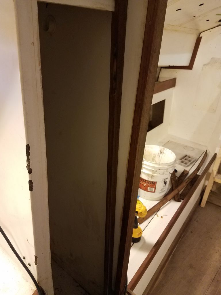
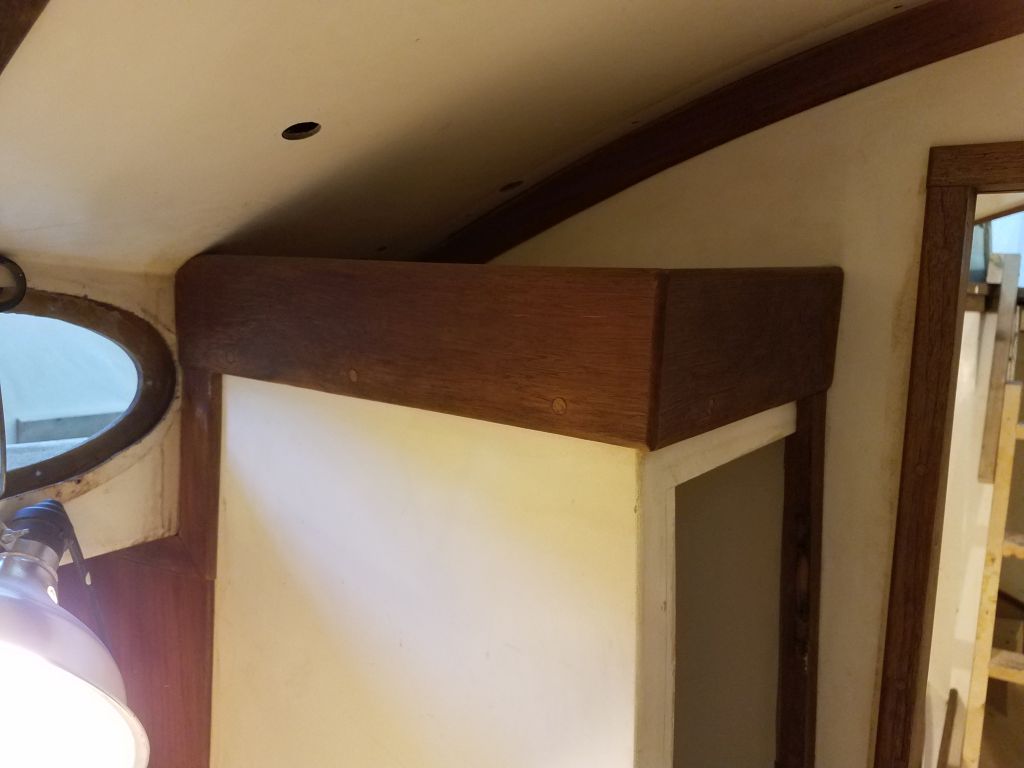
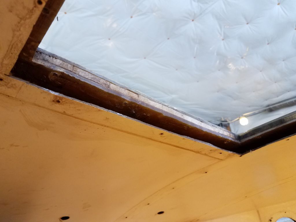
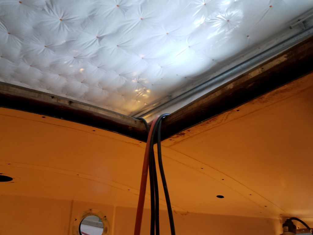
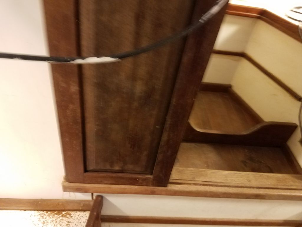
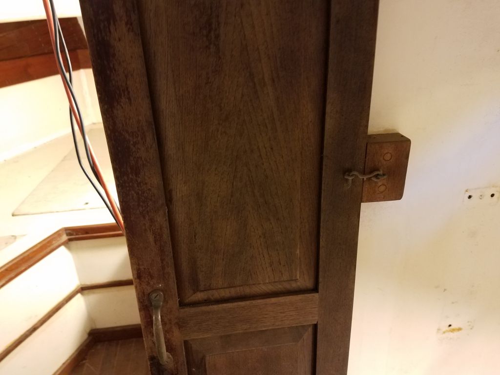
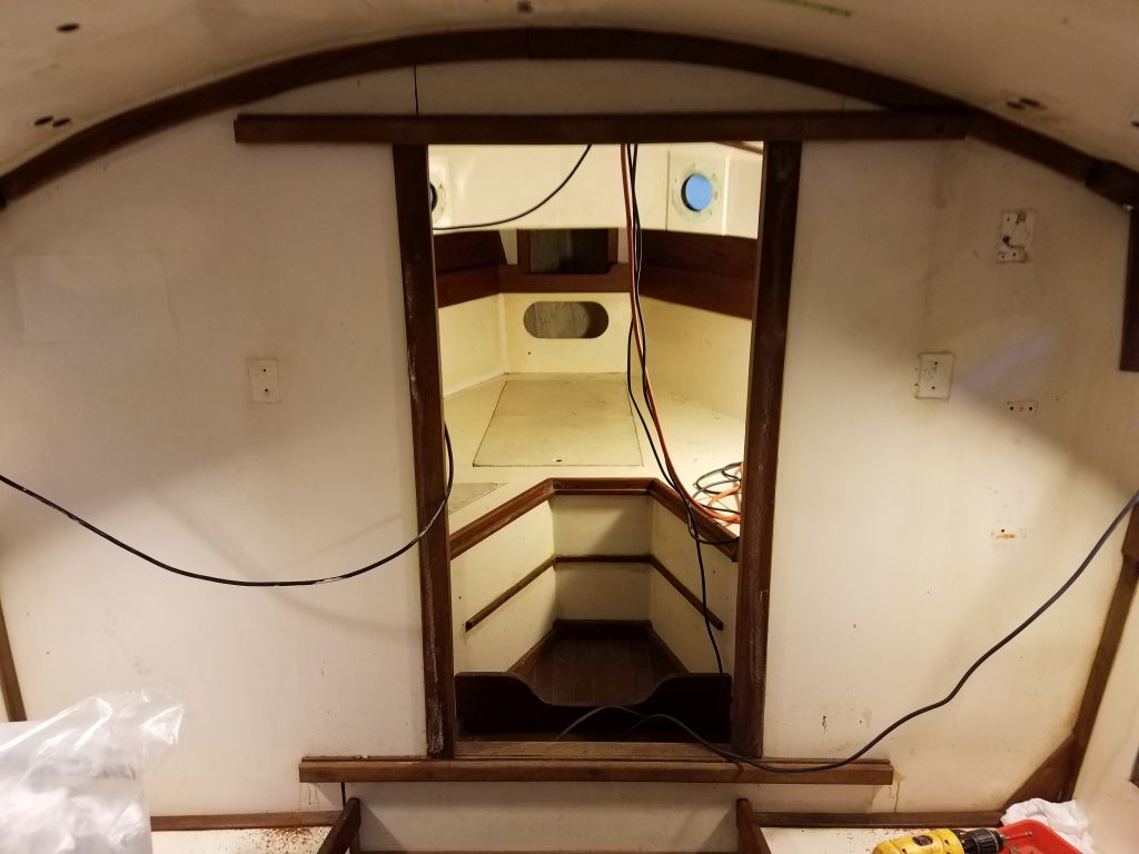
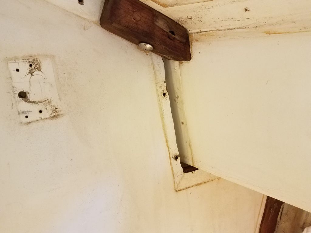
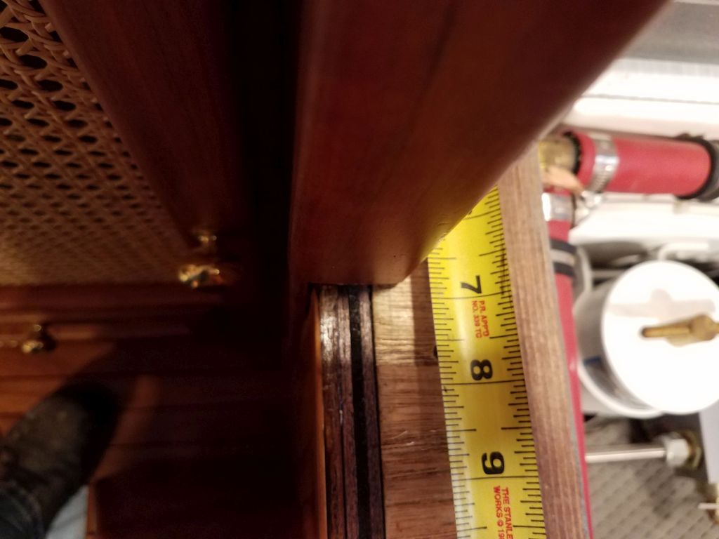
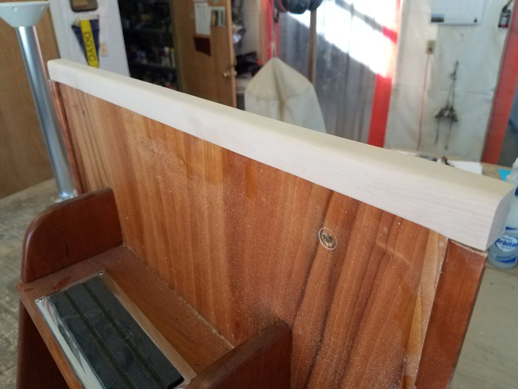
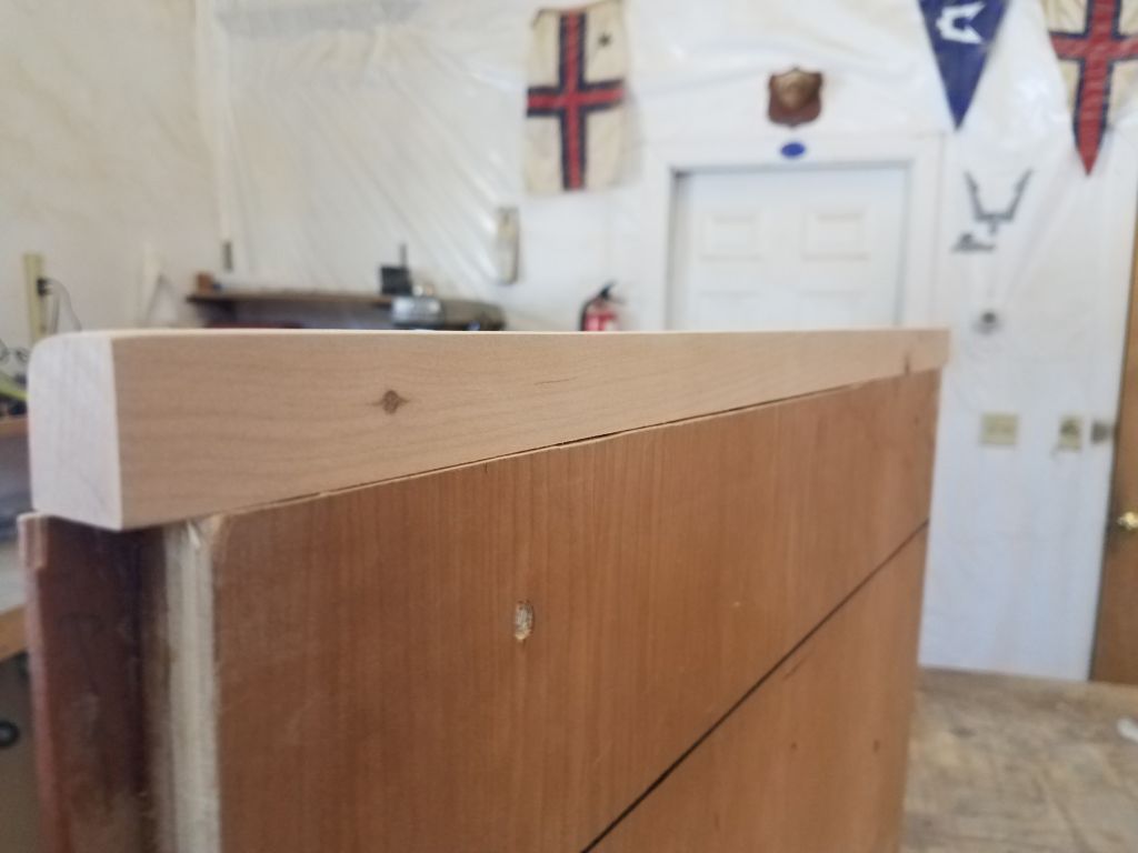
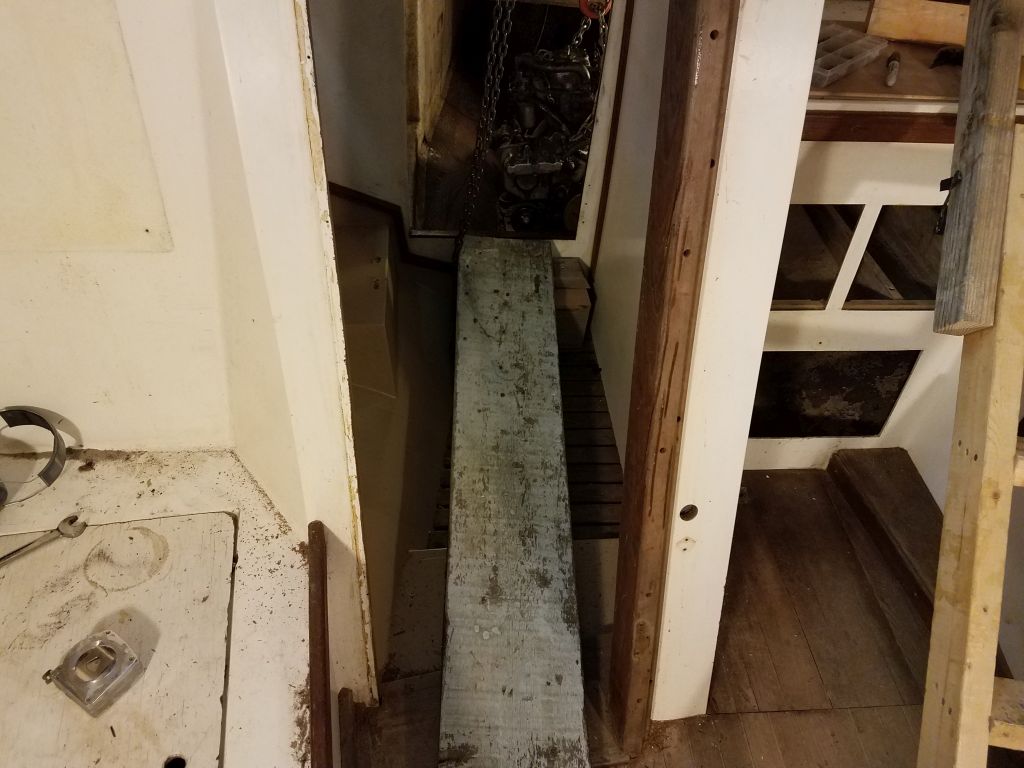
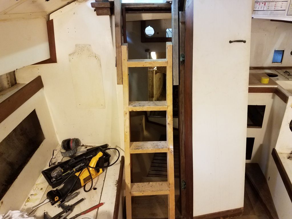
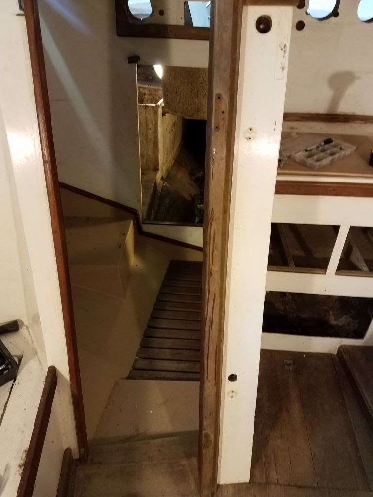
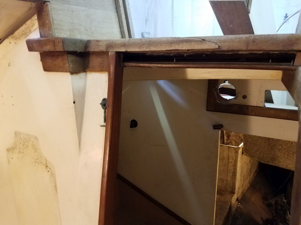
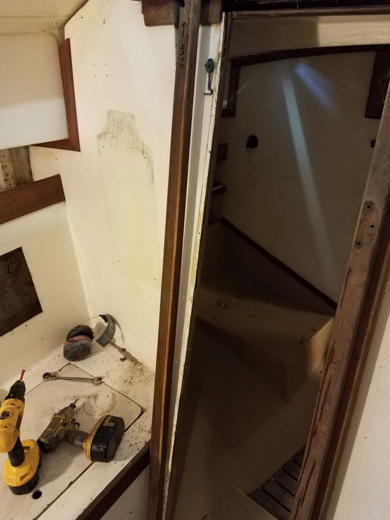
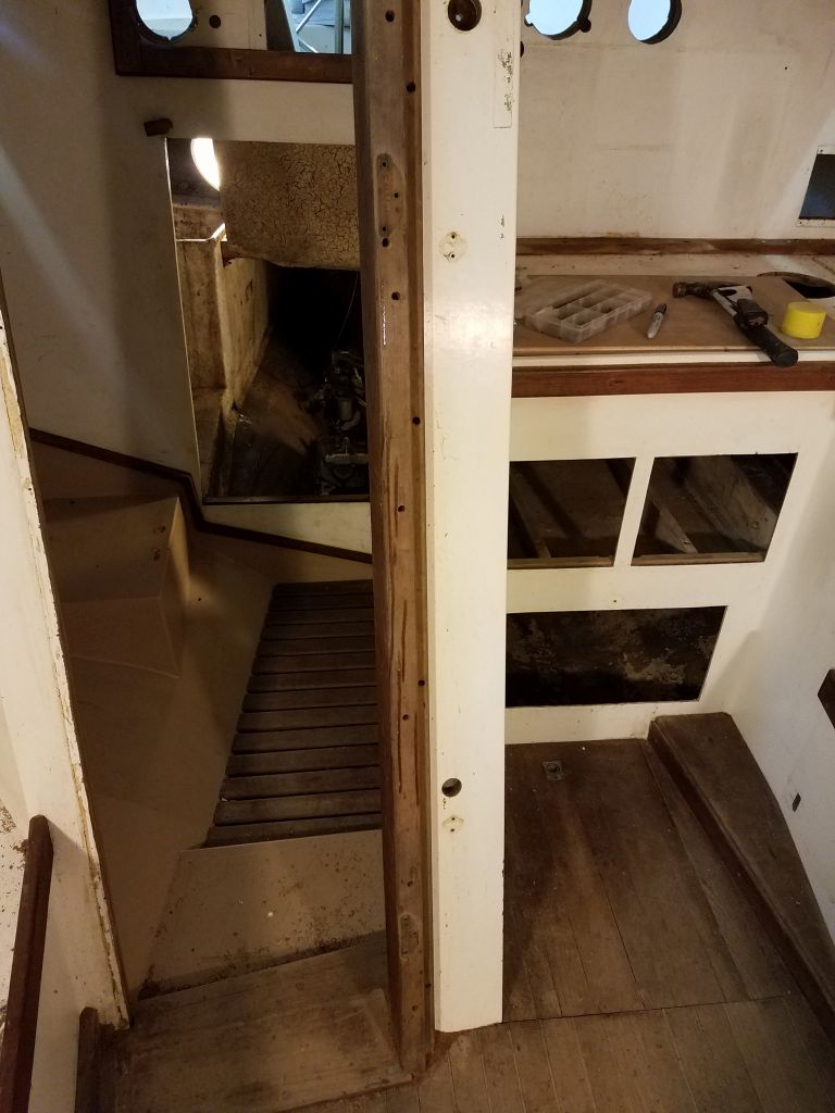
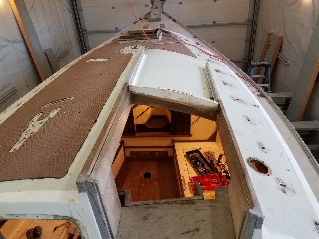
Now I turned to the companionway area. The slim trim I’d made for the threshold fit once I cut it to length, but I found that I needed to make relief cuts on each end to accommodate the thickness of the paneling in the pilothouse and allow the center portion–in the companionway opening itself–to extend fully through the opening. I didn’t have the tools I needed to make these cuts properly on site, so I noted the details and brought the trim back to the shop.
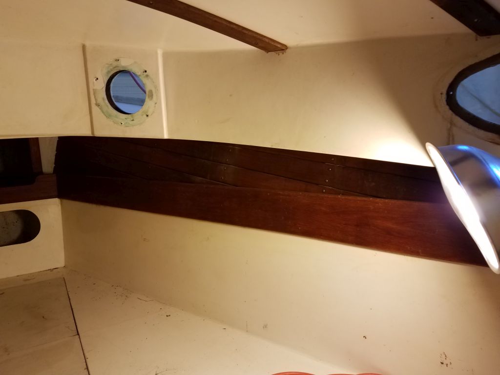
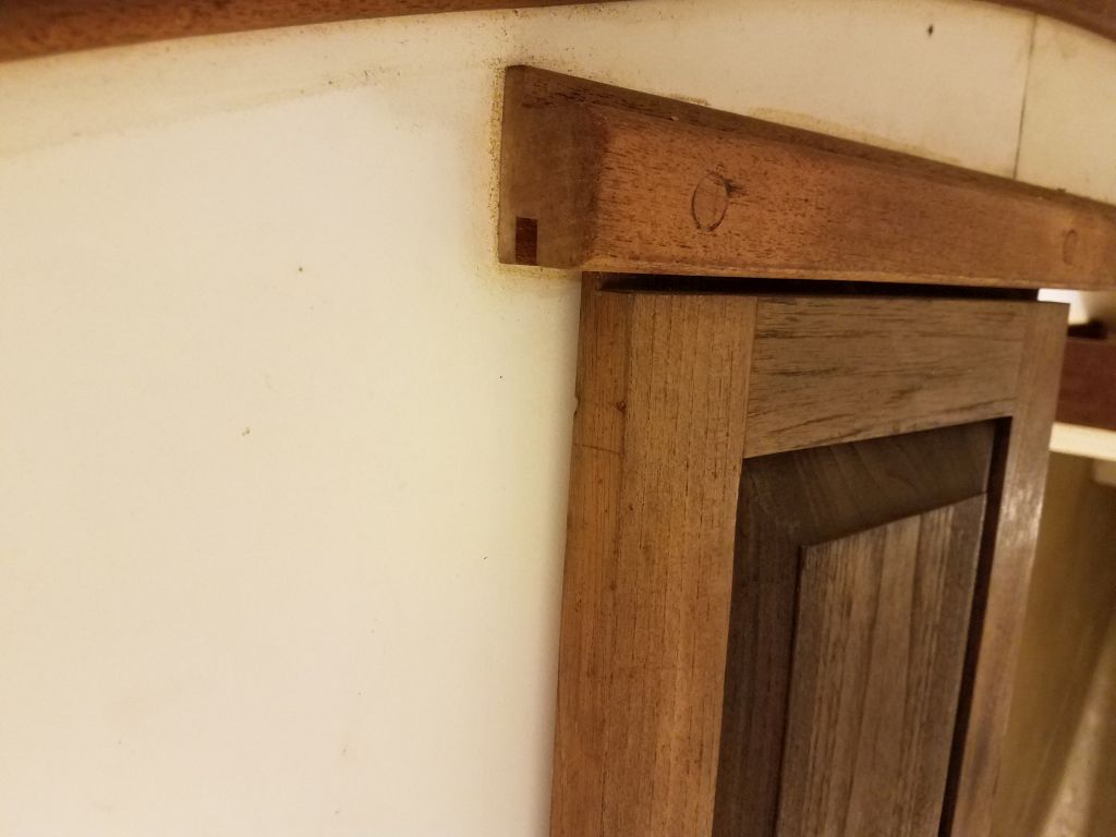
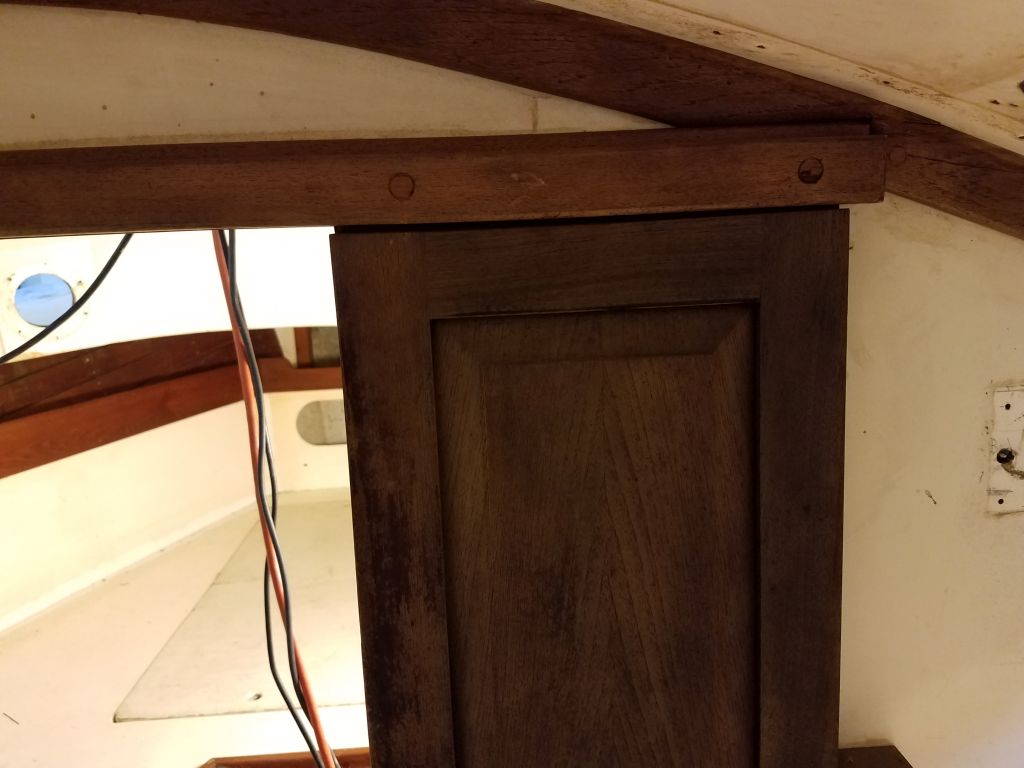
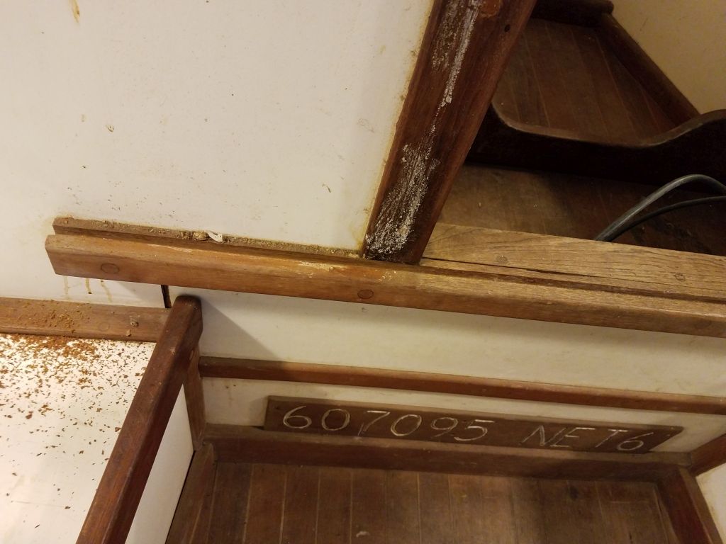
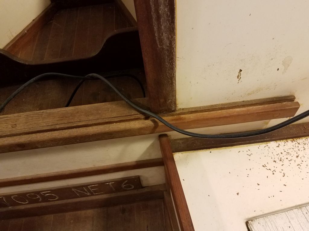
The corresponding piece for the top of the ladder assembly fit once I’d cut it to length and fiddled around a bit, and I glued it to the top of the plywood backing, pinning it with some brads till the glue cured. This piece was designed to butt up flush with the 1/4″ thick threshold.

I’d return once more to bring back the modified parts and complete the installation, as well as to deliver the filler cushion once completed.
Total time billed on this job today: 3.5 hours
0600 Weather Observation: 25°, clear. Forecast for the day: Mainly sunny, high around 50°, increasing clouds late in the day and light rain overnight