110 Cookson Lane | Whitefield, ME 04353 | 207-232-7600 | tim@lackeysailing.com
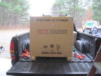
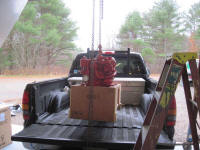
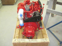
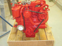
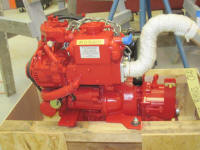
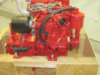
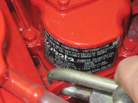
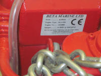
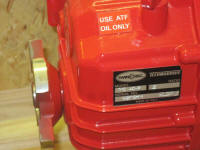
The first item on the day's agenda was to unload and inspect the new engine. The engine is a Beta 14 equipped with Twin Disc 2:1 transmission.
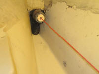
After confirming a few measurements between the engine drawing, my existing template, and the engine itself, I began preparations for the engine's final installation. To begin, I set up a string run through the center of the stern tube, which represented the center of the propeller shaft and transmission coupling and was the key reference point for locating the engine on the existing foundations.
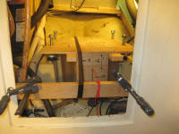
Once I'd the string in place and properly centered, I installed the supplied flex mounts on the template and adjusted things to allow the string to run through the appropriate reference points beneath the template. Even with the nuts adjusted all the way down at the aft end, I still found the aft end of the template was a bit high, so I ordered some thinner nuts to replace the tall ones supplied, which would give me the fraction of an inch more clearance required. I'd wait to make final engine placement decisions till the proper nuts arrived.
The black tape seen here is holding the template from sliding aft on the slick gelcoated engine foundations.
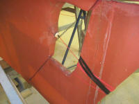
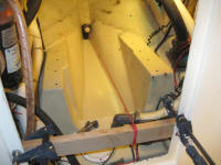
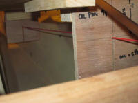
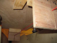
The molded opening to the engine room appeared to be a bit narrower than the overall width of the engine itself; it appeared that I'd be able to remove some of the material in the recessed area in which the plywood cover panel fit to accommodate the widest part of the engine (where a hose exits the heat exchanger on one side, and an oil dipstick fitting bracket on the other). Fortunately, the main engine body was narrower than the overall clearance required by its accessories, so I thought entrance modifications would be minimal. Only bringing the engine into place would highlight exactly what I'd need to modify.
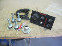
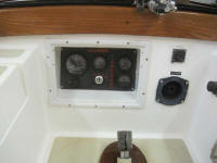
I continued work on some of the ancillary engine-related installations, beginning with the engine control panel. The panel was barely too large to fit inside the original molded panel recess, so I made some minor modifications to the edges of the panel till it fit into place, after which I secured it with screws and sealant. This is the optional Beta "C" panel.
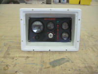
Next, I ran the supplied wiring harness from the engine room to the back of the panel area after determining its best course, then connected it to the back of the panel and set the panel enclosure back into position with screws and sealant. I installed some wire tie mounts along the proposed run and left the adhesive to cure before stringing up the remaining wiring harness.
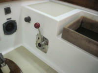
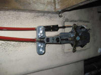
With the engine control cables now in stock, I could complete the installation of the control unit in the cockpit. Using historical information, I determined that the small Beta engines require a setup where the throttle cable "pulls" for throttle advancement, and the gear cable "pulls" for forward gear. With the control lever mounted on the port side, this led to the arrangement below. I ran the cables to the engine room but left them unsecured for now till I determined how they'd need to lead directly to their respective connection points as the engine went into place.
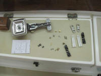
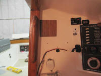
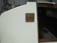
The varnish work for the two teak covers over the old depthsounder hole was complete, so I installed both pieces, using screws and sealant on the exterior piece and screws only on the inside. Note that the adjacent companionway is angled, not vertical.
To wrap up the day, I removed the kerosene from the heater's pressure tank, then pressurized the system with air to check for leaks at the connections. I noted that the tank's pressure gauge didn't seem to be operational, but otherwise found no leaks in the system.
Total Time on This Job Today: 7 hours
