|
Equinox Project |
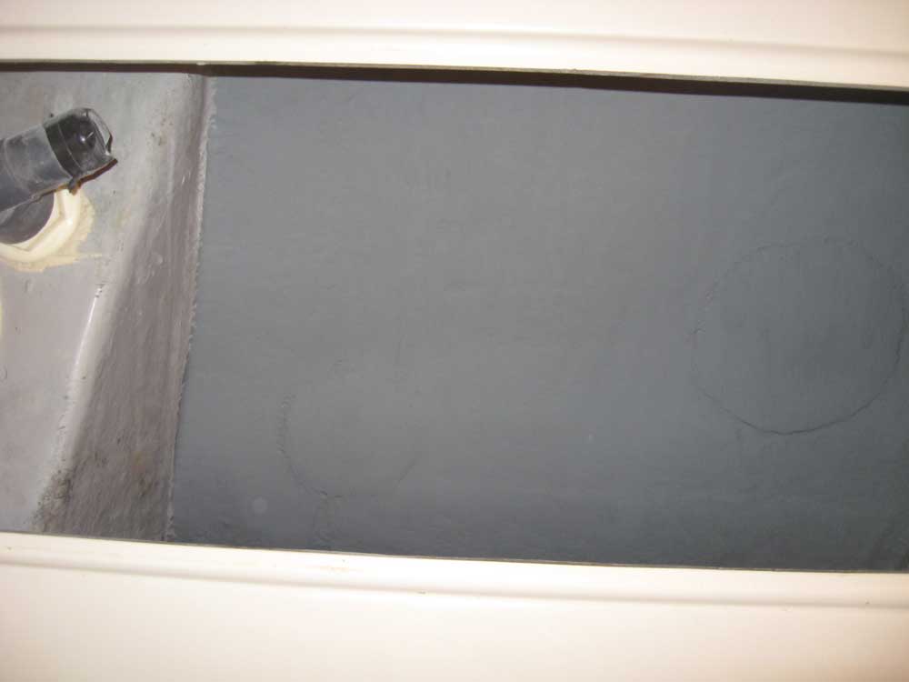
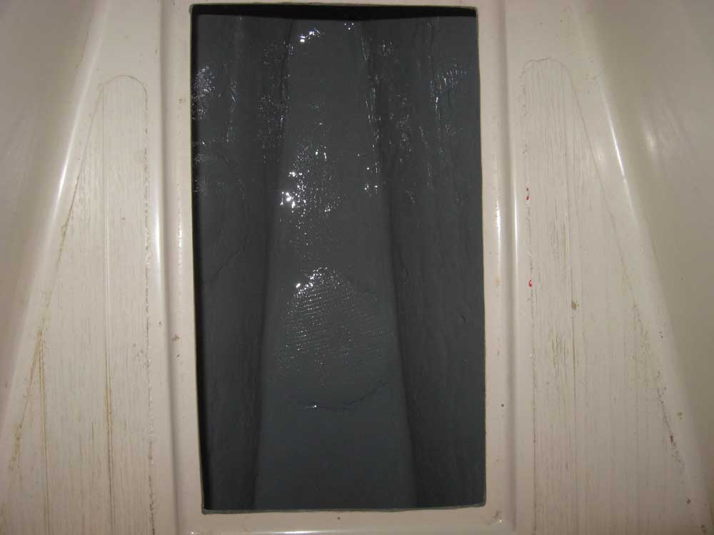
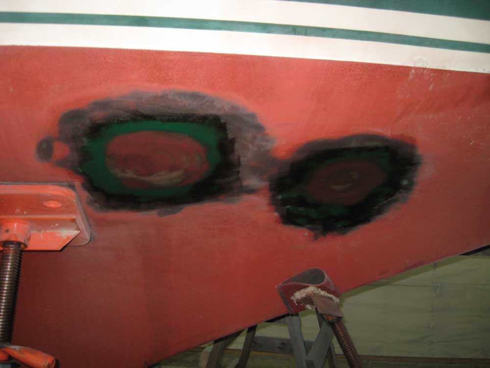
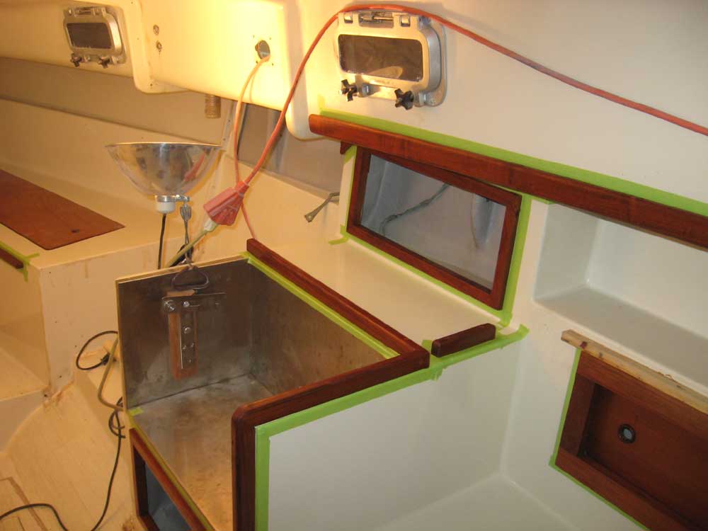
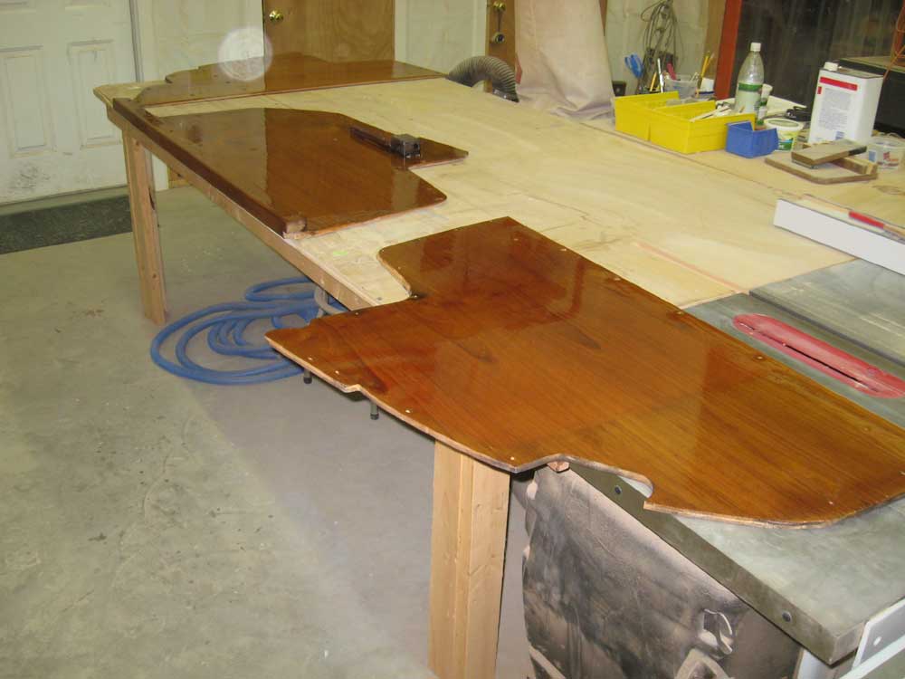
Friday, January 2, 2009 I took care of a miscellany of tasks during the morning, including cleaning and painting the insides of the lockers forward, where I'd applied fiberglass patches over some abandoned holes earlier, and sanding and epoxy-coating the exterior patches--now faired--over the through hulls. |
|
|
|
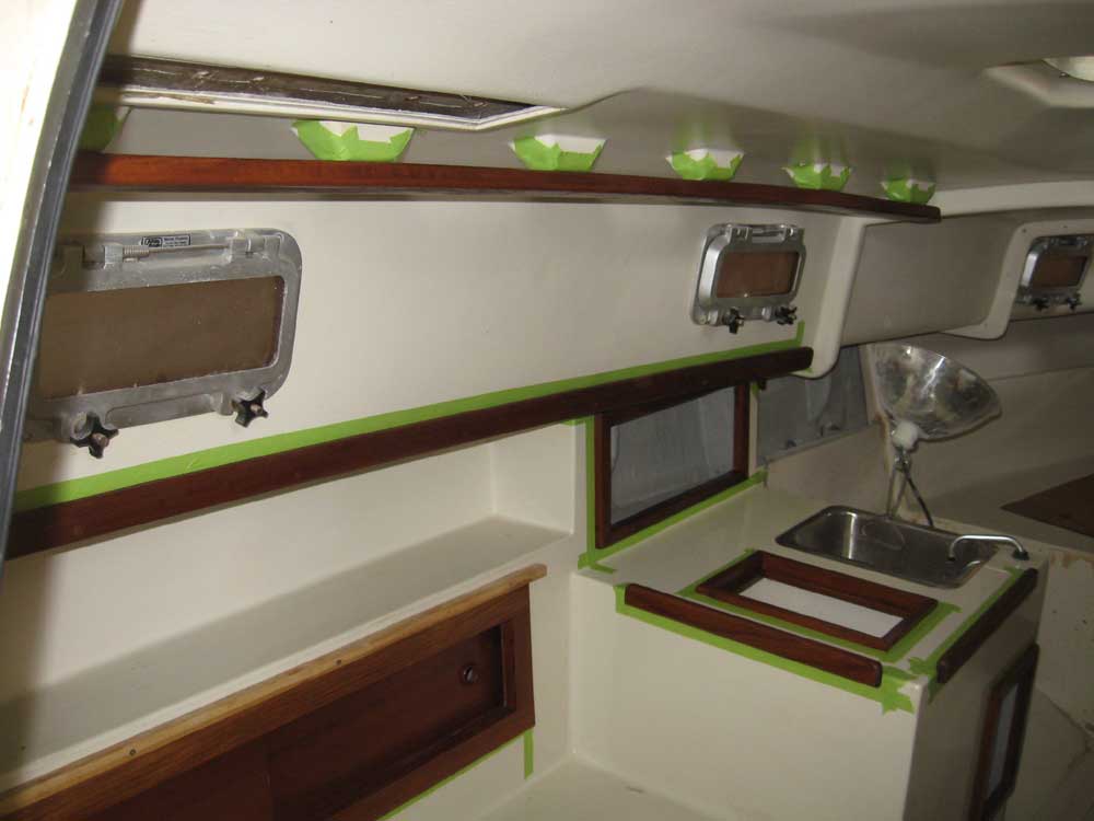
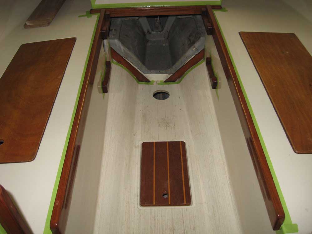
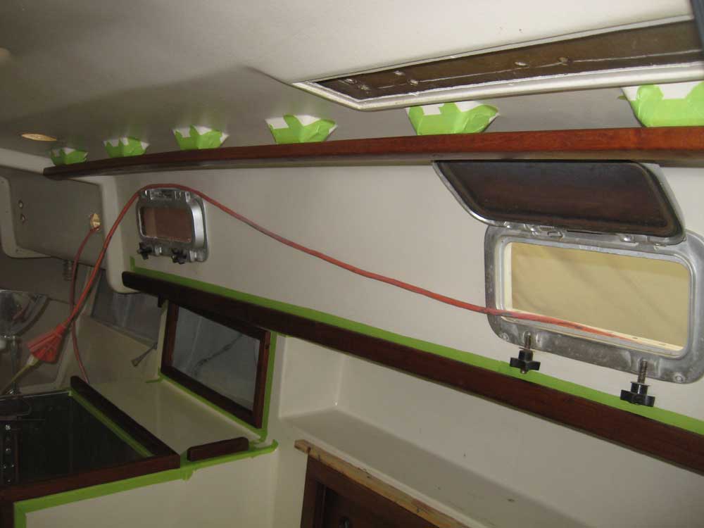
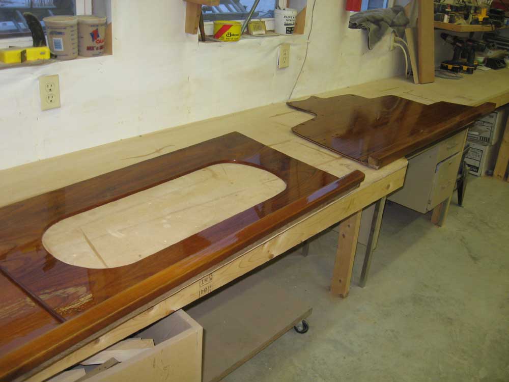
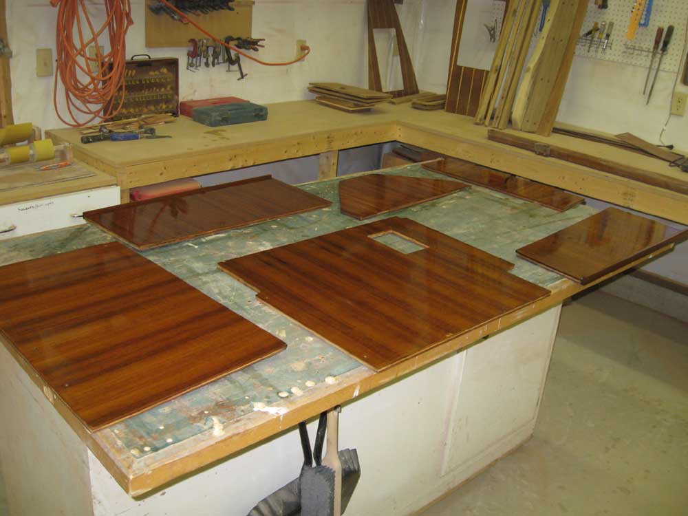
I also applied the first coat of varnish to all the interior trim, made a couple small repairs to some of the woodwork in the shop (loose veneer on the icebox hatch), and removed the hinges from and sanded the locker doors from the cabin. |
|
|
|
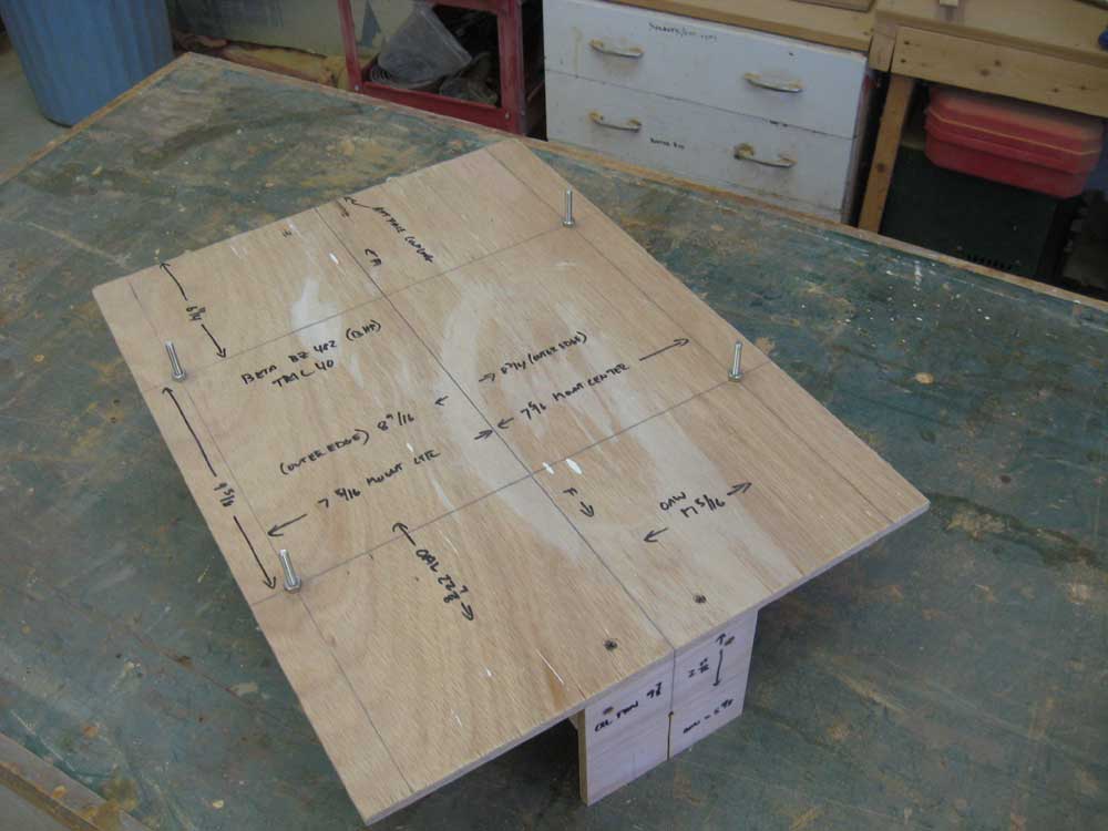
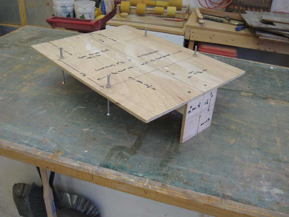
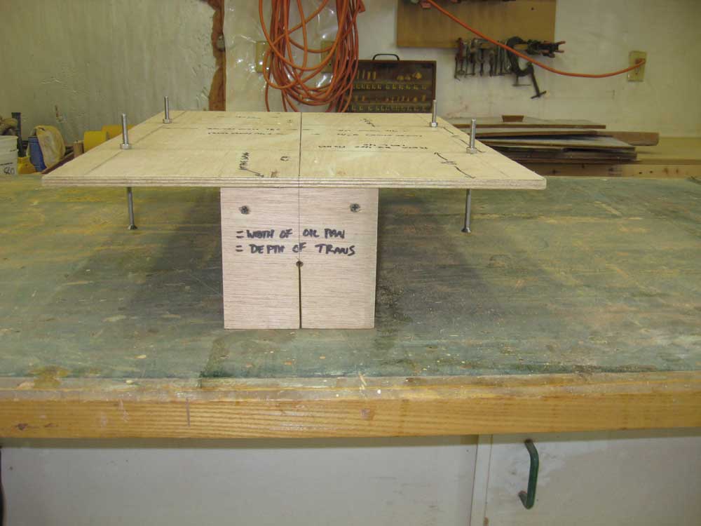
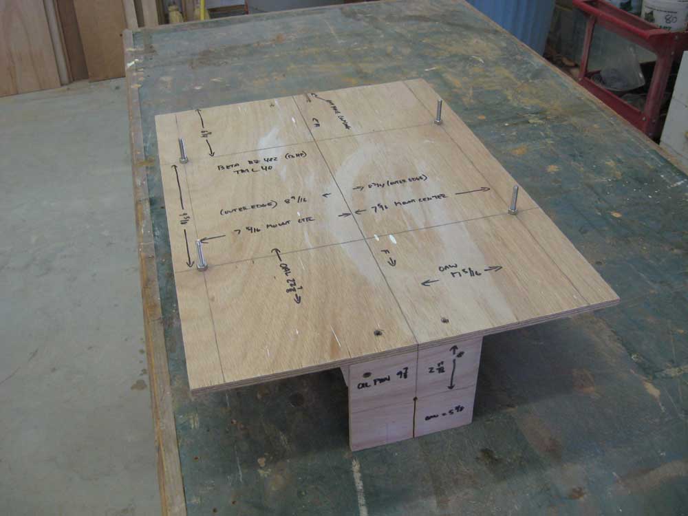
During the afternoon, I constructed a template for the new engine, which as of this writing was slated to be either the Beta 10 or the Beta BX482 (13HP), both of which share the same block and footprint. Using a measured drawing from Beta Marine's website, I built from a sheet of 9mm Meranti plywood that I had on hand a basic alignment template in the usual way. The outside dimensions of the plywood base equaled the overall (maximum) length and width dimensions of the engine; the bottom of the plywood sheet represented the bottom of the engine's built-in mounting flanges. I measured and marked the exact mounting centers, where I drilled holes and inserted some long bolts as avatars for the engine's supplied flexible mounts. For initial engine foundation construction purposes, I adjusted the "mounts" to a point about halfway through their overall adjustment range, which measurements I took from the drawing. To simulate the shaft coupling and line of the propeller shaft itself, I installed two identical plywood protrusions beneath the main platform, sized according to the offset information provided on the drawing. Since the maximum depth of the transmission below the mounting flanges--that is, the protrusion beneath the plane of the new, to-be-built engine foundations--was indicated as 5-1/8", I made my plywood pieces to this measurement; I cut the pieces 5-3/8" wide to equate to the width of the oil pan, which happened to be centered on the same line and represented the greatest width of any below-flange protrusion. Next, I marked the coupling center in the appropriate place, 2-11/16" beneath the engine mounting flanges. I drilled small holes through the shaft center in each piece, and cut a slit beneath the hole to allow me to eventually slip a shaft alignment string into the holes. I glued and screwed these pieces to the platform, even with the ends. This completed the basic engine template construction; later, during foundation rough-in, I could use the basic template platform to determine any clearance issues with the overall depth or height of the engine with some basic measurements, even though I didn't mock up the overall engine height and depth on the template. I marked some key measurements on the template for future reference. |
|
|
|
With the template complete, I sanded the varnished bulkheads and panels, and cleaned up the shop before applying another coat of varnish to these pieces. |
|
|
|
|
|