|
| |
|
From a Bare
Hull: Cabin Trunk
Carlin (Page
2)
|
|
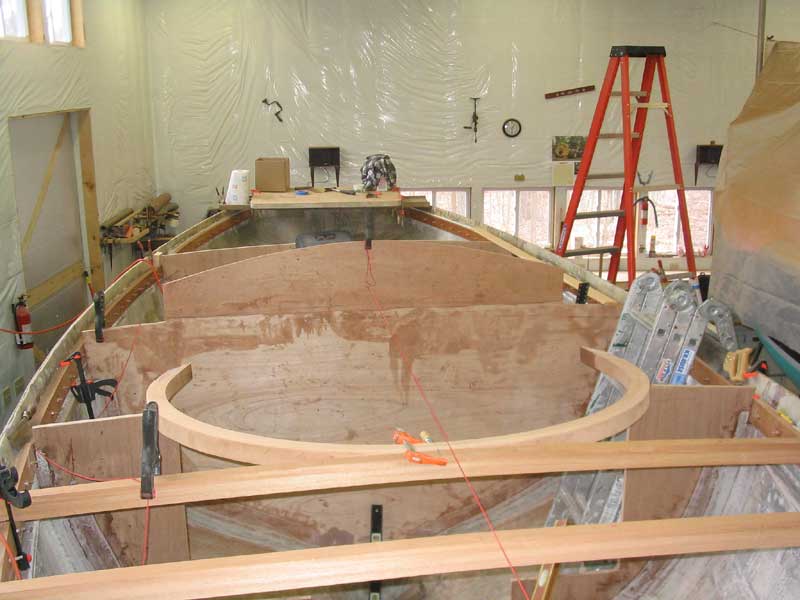
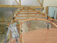
Test Fitting and Sizing the Curved Carlin
 The
laminated piece, as it came from the mold, was covered in a large amount
of glue squeezeout on both sides, so my first step was to clean up the
curved beam with a borrowed power planer (handheld) and my sander.
With that done, I measured for a centerline and then moved the piece into
the boat, where I clamped it in approximately the correct position with
the forward edge tangent to the last full-width deck beam and the sides
supported on top of the forward bulkheads. The
laminated piece, as it came from the mold, was covered in a large amount
of glue squeezeout on both sides, so my first step was to clean up the
curved beam with a borrowed power planer (handheld) and my sander.
With that done, I measured for a centerline and then moved the piece into
the boat, where I clamped it in approximately the correct position with
the forward edge tangent to the last full-width deck beam and the sides
supported on top of the forward bulkheads.
|
|
 The
next step was to properly align the two sides of the piece so that they
were the same distance from the edge of the hull on each side, measured at
the forward bulkheads. After a few minor adjustments it was even,
and I made some reference marks. The carlin was designed to sit on
the bulkhead for added support, but I had to cut notches out on each side
to allow the carlin to sit at the appropriate height--equal to the height
of the underside of the eventual deck sheathing, or the same as the tops
of the deck beams. To determine this height at this location, I ran
a string from a previously-made mark on the amidships bulkhead, which
correlated with the proper height, forward to the first deckbeam and
clamped it tight. Then, I measured down from the string a distance
equal to the height of the carlin. With this mark, in conjunction
with the marks indicating the inside and outside edges of the carlin, I
made the appropriate cuts in the bulkheads. Then I made a plumb cut
down the bulkheads to trim some excess from the inside edge, as the
bulkheads should be even with the inside of the carlin, and the way the
physical pieces ended up was slightly different than how it ostensibly
should have been on paper. Slight modifications such as this are par
for the course in a seat-of-the-pants type of construction. The
next step was to properly align the two sides of the piece so that they
were the same distance from the edge of the hull on each side, measured at
the forward bulkheads. After a few minor adjustments it was even,
and I made some reference marks. The carlin was designed to sit on
the bulkhead for added support, but I had to cut notches out on each side
to allow the carlin to sit at the appropriate height--equal to the height
of the underside of the eventual deck sheathing, or the same as the tops
of the deck beams. To determine this height at this location, I ran
a string from a previously-made mark on the amidships bulkhead, which
correlated with the proper height, forward to the first deckbeam and
clamped it tight. Then, I measured down from the string a distance
equal to the height of the carlin. With this mark, in conjunction
with the marks indicating the inside and outside edges of the carlin, I
made the appropriate cuts in the bulkheads. Then I made a plumb cut
down the bulkheads to trim some excess from the inside edge, as the
bulkheads should be even with the inside of the carlin, and the way the
physical pieces ended up was slightly different than how it ostensibly
should have been on paper. Slight modifications such as this are par
for the course in a seat-of-the-pants type of construction.
|
|
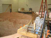
 Next,
I had to figure out where to cut the curved piece so that the remaining
carlins--those that define the edges of the cabin trunk and cockpit--could
conjoin properly. What I wanted was a smooth, flowing curve on the
inside edge. To determine where this joint should be, I mocked up a
carlin with a length of scrap pine. I clamped the pine on top of the
after two bulkheads, aligned with some marks I had made earlier showing
the location of the carlins, and then worked on bending and forming
the forward edge so that I could create the flowing curve I was
after. Next,
I had to figure out where to cut the curved piece so that the remaining
carlins--those that define the edges of the cabin trunk and cockpit--could
conjoin properly. What I wanted was a smooth, flowing curve on the
inside edge. To determine where this joint should be, I mocked up a
carlin with a length of scrap pine. I clamped the pine on top of the
after two bulkheads, aligned with some marks I had made earlier showing
the location of the carlins, and then worked on bending and forming
the forward edge so that I could create the flowing curve I was
after.
|
|
 Bending
the pine here and there with clamps, I eventually pulled it into a
pleasing shape that satisfied what I was looking for, so I made some marks
on the top of the carlin. Bending, observing, and adjusting took the
better part of an afternoon; it's these tasks that seem to be slowest,
with the least visual progress, but they are critical to the overall look
and ultimate construction of the various components, so I never rush the
process. Knowing the second (starboard) side should be more or less
identical to the port, to to help me locate the same spot on that side I
made reference marks where the carlin passed over the forward bulkheads,
so that I could use it as a known reference point for measuring. Bending
the pine here and there with clamps, I eventually pulled it into a
pleasing shape that satisfied what I was looking for, so I made some marks
on the top of the carlin. Bending, observing, and adjusting took the
better part of an afternoon; it's these tasks that seem to be slowest,
with the least visual progress, but they are critical to the overall look
and ultimate construction of the various components, so I never rush the
process. Knowing the second (starboard) side should be more or less
identical to the port, to to help me locate the same spot on that side I
made reference marks where the carlin passed over the forward bulkheads,
so that I could use it as a known reference point for measuring.
|
|
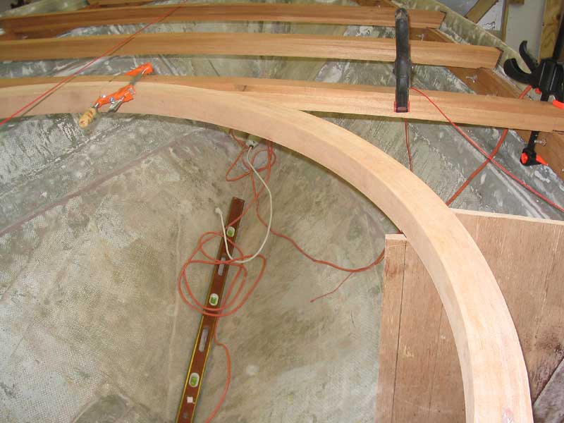
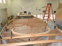
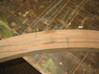
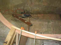 This
photo show the "tangent" line that I created with my pine
template. For observation purposes, please ignore the line of the
pine board to the left of the forwardmost (lefthand) orange clamp, as this
position has nothing to do with how the board curved. The tangent
line is located approximately in line with the lefthand clamp in the
picture. With a little vision, one can see how the carlin line
(which, in this view, is the defining edge of the cabin trunk, once built)
should sweep cleanly forward (left) and merge neatly into the curved
forward section of the carlin at approximately the lefthand clamp This
photo show the "tangent" line that I created with my pine
template. For observation purposes, please ignore the line of the
pine board to the left of the forwardmost (lefthand) orange clamp, as this
position has nothing to do with how the board curved. The tangent
line is located approximately in line with the lefthand clamp in the
picture. With a little vision, one can see how the carlin line
(which, in this view, is the defining edge of the cabin trunk, once built)
should sweep cleanly forward (left) and merge neatly into the curved
forward section of the carlin at approximately the lefthand clamp
|
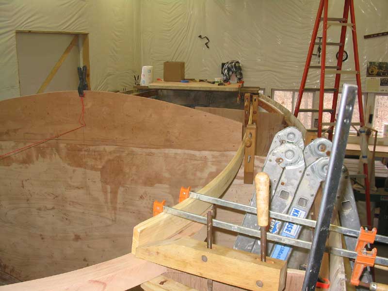
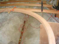
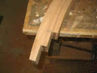
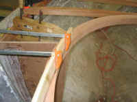 This
shows the same area from a different vantage point. The tangent mark
is just this side of the further orange clamp. This
shows the same area from a different vantage point. The tangent mark
is just this side of the further orange clamp.
When I was happy with the curve I had
created, I traced the board onto the carlin beneath, and removed the
various pieces, bringing the curved carlin down to the bench to make the
final cuts. |
I planned to build the remaining carlins of
three layers of 3/4" mahogany on edge. In this manner, I could
make up unlimited lengths (the side carlins are nearly 15 feet in length)
by staggering the joints on the boards and laminating them together in
place, much as I did with the sheer clamp.
Given the bends needed in the carlins, I figured it would also be easier
to bend them into shape a piece at a time. The laminated carlin
design would also allow me to create an easy-to-build staggered joint at
the curved carline, which joint would be extremely strong when glued but
simple to install.
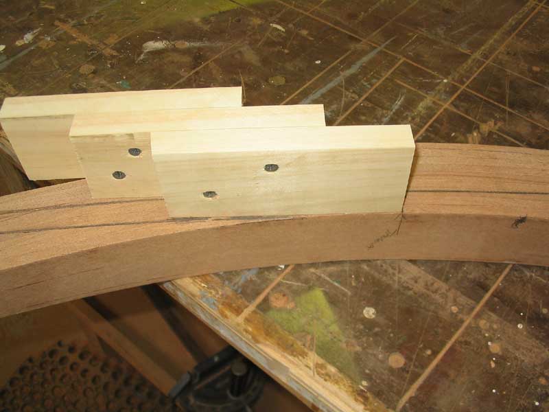
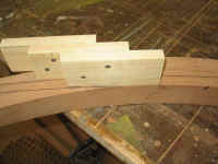 To
make the cuts for this joint, I built a small jig from three pieces of
3/4" pine. Using the tangent mark on the curved carlin as a
guide, I staggered the three pieces of pine (each representing one of the
laminations of the eventual carlin) in an appropriate manner so that the
end of the first (inner) piece ended up in the proper location at the
tangent line, and the outermost (third) piece ended up flush with the
outside of the carlin. The overlap for each piece ended up at
exactly 2". I screwed the pieces together and marked out the
stepped shape, first on the port side and then on the starboard by
flipping the jig over and remarking on the other side. I used my jig
saw to cut out the stepped shape on each side. To
make the cuts for this joint, I built a small jig from three pieces of
3/4" pine. Using the tangent mark on the curved carlin as a
guide, I staggered the three pieces of pine (each representing one of the
laminations of the eventual carlin) in an appropriate manner so that the
end of the first (inner) piece ended up in the proper location at the
tangent line, and the outermost (third) piece ended up flush with the
outside of the carlin. The overlap for each piece ended up at
exactly 2". I screwed the pieces together and marked out the
stepped shape, first on the port side and then on the starboard by
flipping the jig over and remarking on the other side. I used my jig
saw to cut out the stepped shape on each side.
|
|
|
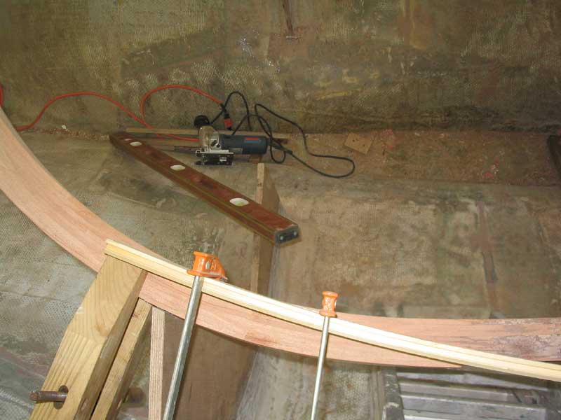
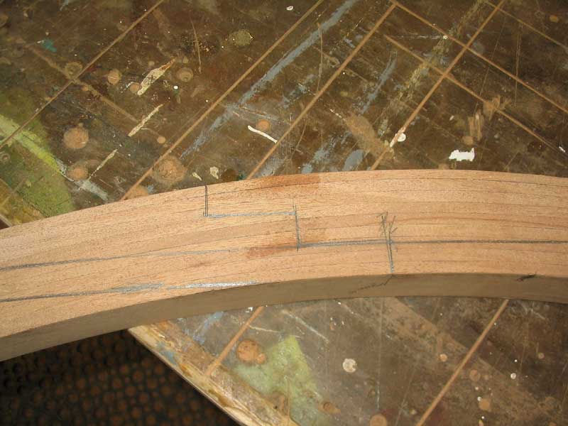
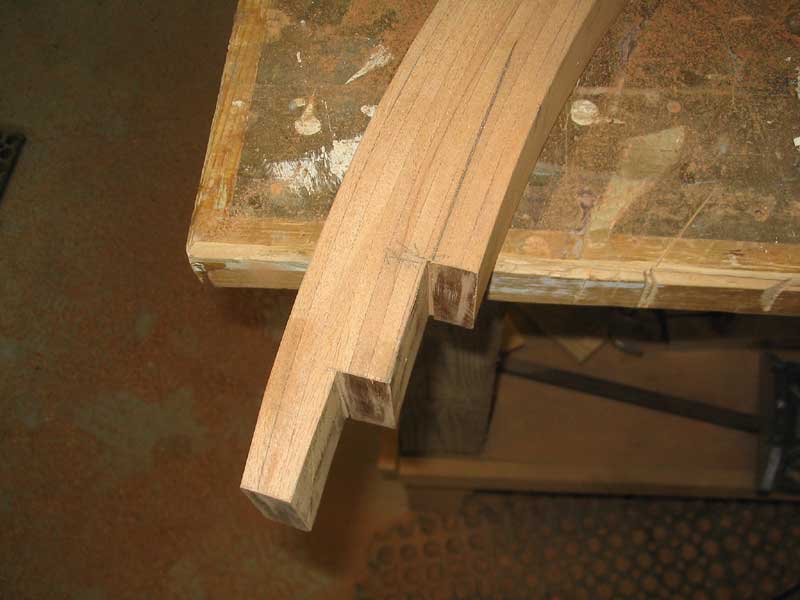
 In
this case, the inner edge of the curve is the one to which I needed to
match the sides for a smooth transition, so the outer curve will not be as
smooth a transition--nor does it have to be, as it won't be seen.
But the inner edge should end up as a smooth, visually seamless curve. In
this case, the inner edge of the curve is the one to which I needed to
match the sides for a smooth transition, so the outer curve will not be as
smooth a transition--nor does it have to be, as it won't be seen.
But the inner edge should end up as a smooth, visually seamless curve. |
|
Continue>
|
|

 This
shows the same area from a different vantage point. The tangent mark
is just this side of the further orange clamp.
This
shows the same area from a different vantage point. The tangent mark
is just this side of the further orange clamp.
 In
this case, the inner edge of the curve is the one to which I needed to
match the sides for a smooth transition, so the outer curve will not be as
smooth a transition--nor does it have to be, as it won't be seen.
But the inner edge should end up as a smooth, visually seamless curve.
In
this case, the inner edge of the curve is the one to which I needed to
match the sides for a smooth transition, so the outer curve will not be as
smooth a transition--nor does it have to be, as it won't be seen.
But the inner edge should end up as a smooth, visually seamless curve.