|
| |
|
From a Bare
Hull: Carlins
(Page 3)
|
|
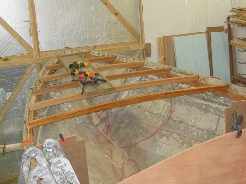
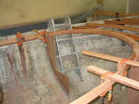
Curved Carlin: Final Fitting
 Next,
I installed the laminated, curved forward carlin permanently, so that I
could move on with the remaining carlins. Before I could do this,
however, I had to permanently install the full-width deck beam that is
located just forward of (and tangent to) the curved carlin, since the
carlin would rely in part on that beam for support. (Click
here for more about the deck beams.) Next,
I installed the laminated, curved forward carlin permanently, so that I
could move on with the remaining carlins. Before I could do this,
however, I had to permanently install the full-width deck beam that is
located just forward of (and tangent to) the curved carlin, since the
carlin would rely in part on that beam for support. (Click
here for more about the deck beams.)
|
|
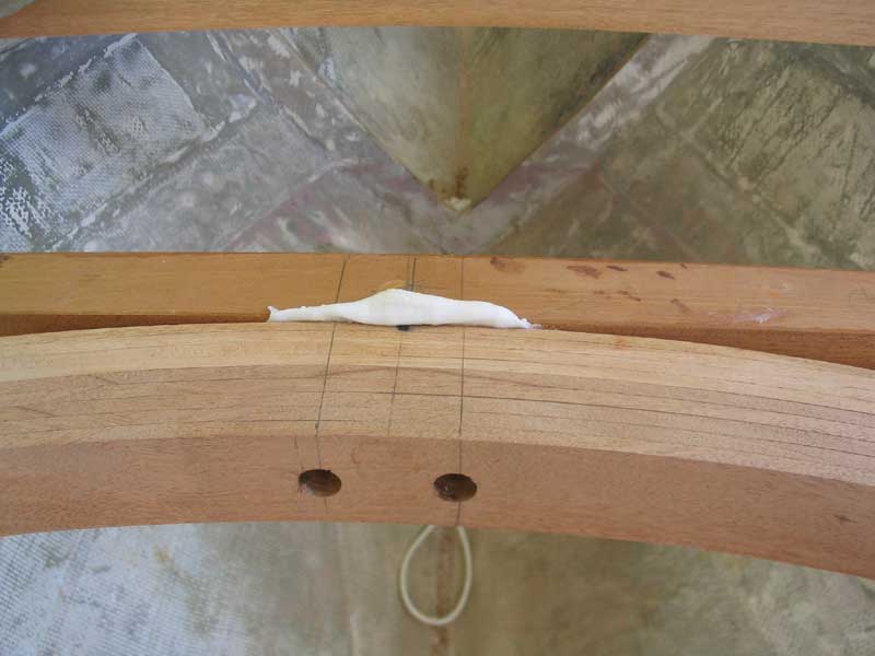
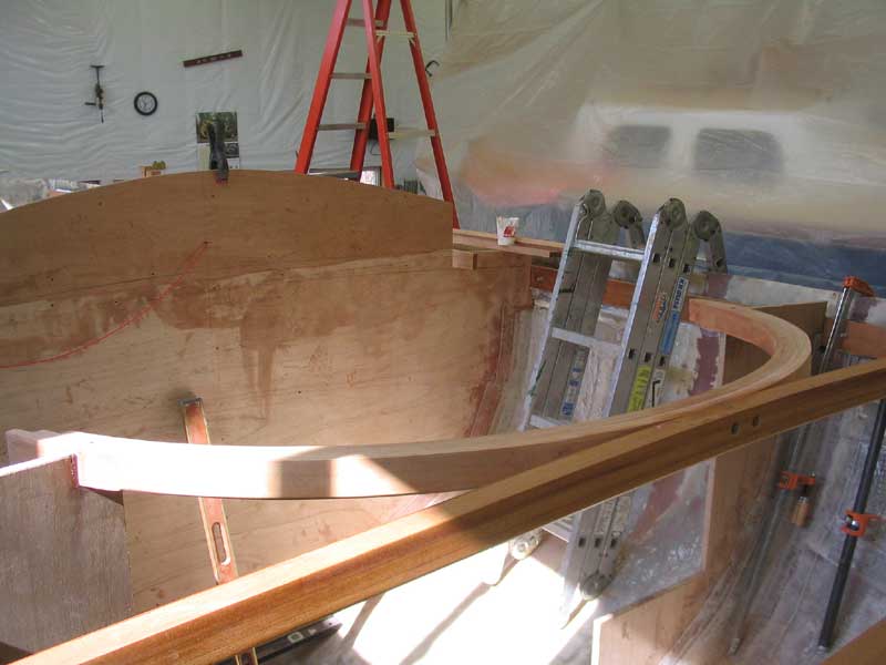
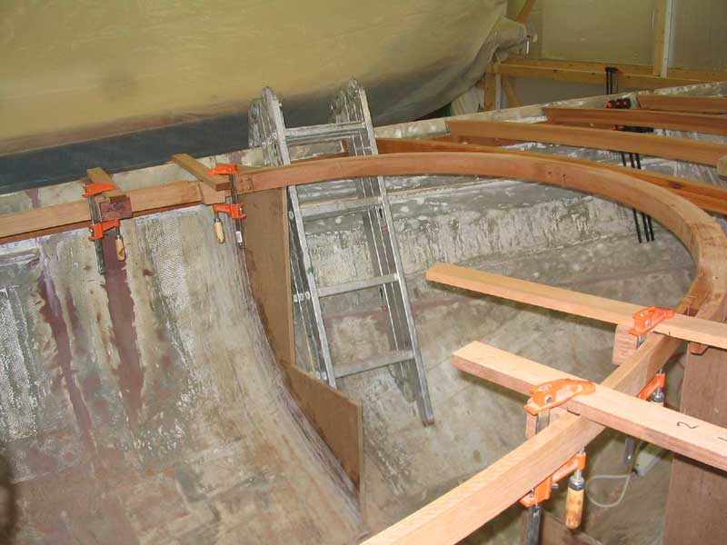
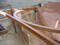
 With
the beam installed and securely fastened, I attached the curved carlin
piece. I secured the carlin to the beam with two bronze
through-bolts and some thickened epoxy adhesive at the tangent
point. I countersunk the bolt heads deeply for later plugging, and
also recessed the washers and nuts on the opposite side of the beam for
best appearance and to prevent any head-splitting protrusions. Then,
I attached the two sides of the carlin to the forwardmost bulkheads with
more epoxy and 3" bronze screws, through the carlin and into the
plywood. With
the beam installed and securely fastened, I attached the curved carlin
piece. I secured the carlin to the beam with two bronze
through-bolts and some thickened epoxy adhesive at the tangent
point. I countersunk the bolt heads deeply for later plugging, and
also recessed the washers and nuts on the opposite side of the beam for
best appearance and to prevent any head-splitting protrusions. Then,
I attached the two sides of the carlin to the forwardmost bulkheads with
more epoxy and 3" bronze screws, through the carlin and into the
plywood.
|
|
|
|
|
|
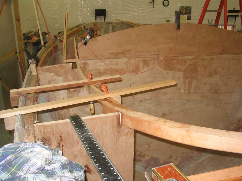
Cockpit Carlins
The bolts and screws held the carlin tightly in place, so I didn't have to
wait for the epoxy to cure before I could continue working on the cockpit
carlins, which run from the curved piece all the way aft to the after end
of the cockpit. The curvature of this piece was to be pretty much
determined by these four fixed physical point:
1. End of the curved
forward carlin
2. The edge of the cabin trunk at the midships bulkhead
3. A point on the after bulkheads taken off my design drawing
4. A point on the full-width deck beam at the after end of the
cockpit, also taken off the design drawing
Though I wasn't sure how it
would pan out, I had a feeling that simply bending the boards through
these fixed points would create a pleasing and appropriate flow to the
shape of the carlins--and, therefore, to the shape of the cabin trunk and
cockpit coamings, which shapes are directly dictated by the shape of the
carlins.
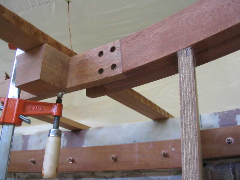
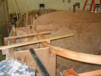
I built the carlins in place
using three thicknesses of 3/4" mahogany, for a total thickness of
2-1/4", which matched the size of the forward carlin. The use
of three thicknesses not only would allow a laminated section, which would
be strong, but also made would make dealing with the whole arrangement
much easier. Plus, since the carlins needed to be nearly 16 feet
long overall, the use of multiple layers meant that I could use the 10'
lengths of lumber that I had on hand, and which are common, and simply
stagger the joints between layers for a strong end result. Of
course, bending a single thicker piece also would have been much more
difficult, so by choosing laminated construction I solved many issues at
once. |
|
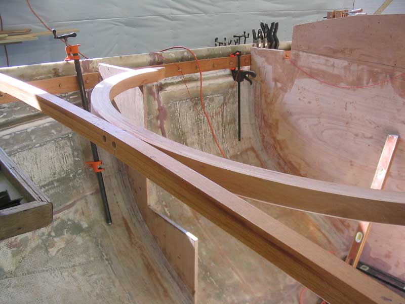
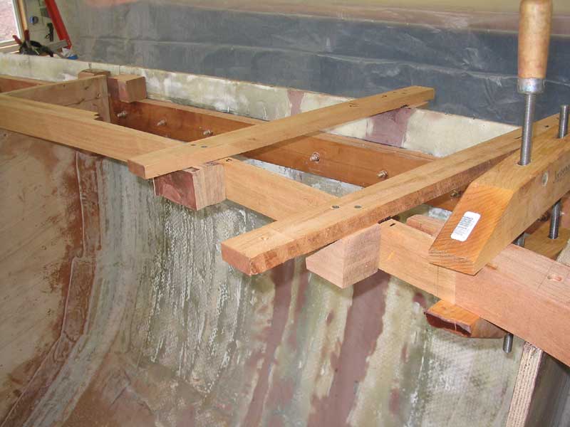
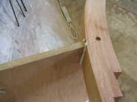
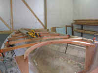
 began laying out the carlins with the innermost piece at the forward ends
on each side. This section was the most critical, as it had to blend
in with the curved forward seciton in a smooth curve to create the rounded
leading edge that I designed for the
cabin trunk. Parts of the inner edge of the carlins may be exposed
in the finished interior, so I wanted these joints to be as clean and
tight as possible. I dry fit each side in place and used several
clamps to bend an appropriate curve that blended well with not only the
curved section of the carlin, but also with the fixed point where the
carlins passed through the amidships bulkhead. With some trial and
error and minor adjustments, I got first one side, then the other side,
bent into place. To hold them in the proper shape through the next
few steps of the building process, I added some simple wooden braces
between the carlins and the hull to prevent the curves from straightening
out at all.
began laying out the carlins with the innermost piece at the forward ends
on each side. This section was the most critical, as it had to blend
in with the curved forward seciton in a smooth curve to create the rounded
leading edge that I designed for the
cabin trunk. Parts of the inner edge of the carlins may be exposed
in the finished interior, so I wanted these joints to be as clean and
tight as possible. I dry fit each side in place and used several
clamps to bend an appropriate curve that blended well with not only the
curved section of the carlin, but also with the fixed point where the
carlins passed through the amidships bulkhead. With some trial and
error and minor adjustments, I got first one side, then the other side,
bent into place. To hold them in the proper shape through the next
few steps of the building process, I added some simple wooden braces
between the carlins and the hull to prevent the curves from straightening
out at all.
|
|
|
|
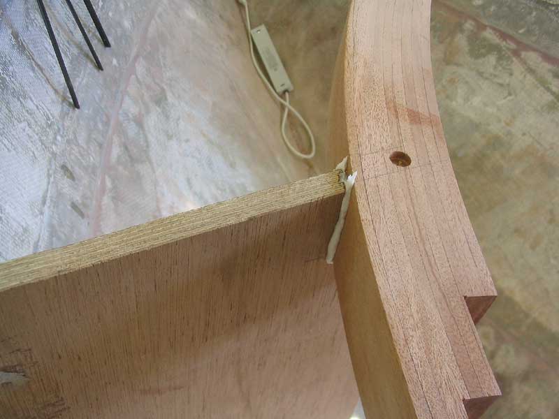
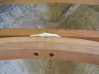
 When
I was pleased with these curves, I permanently installed the first
sections. I secured them to the rabbets in the curved carlin with
thickened epoxy and four bronze screws, which I countersunk for eventual
bunging later. I further secured the pieces against the midships
bulkhead with some cleats to hold them closely to the bulkhead, as
intended. I left the assemblies to cure overnight before I continued
with the remaining laminations. When
I was pleased with these curves, I permanently installed the first
sections. I secured them to the rabbets in the curved carlin with
thickened epoxy and four bronze screws, which I countersunk for eventual
bunging later. I further secured the pieces against the midships
bulkhead with some cleats to hold them closely to the bulkhead, as
intended. I left the assemblies to cure overnight before I continued
with the remaining laminations.
|
|
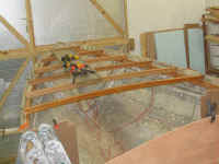
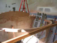
 With
only these first sections in place, the shape of the cabin trunk became
clear. I was pleased with the shape and the curvature of the
carlins. With
only these first sections in place, the shape of the cabin trunk became
clear. I was pleased with the shape and the curvature of the
carlins.
The next day, with the epoxy
in the first joints cured, I continued with the carlins' installation.
Please
click here to continue.> |
|