|
|
~MENU~ |
| Home |
| The Concept |
| The Boat |
| Bringing Her Home |
|
Weekly Progress Log |
|
Daysailor Projects |
| The Boat Barn |
| Resources |
| Other Sites |
| Email Tim |
|
|
|
From Concept to Design |
|
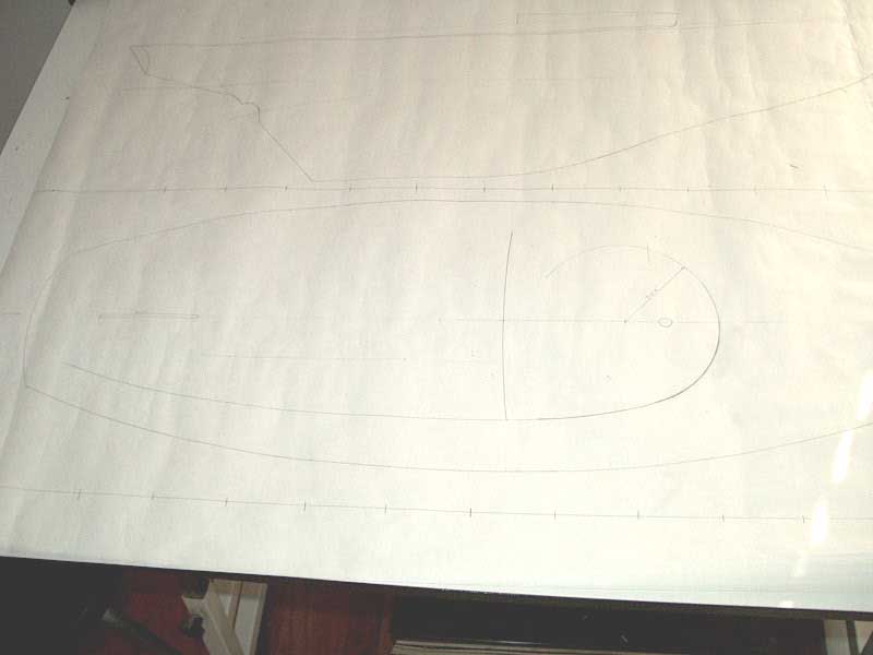
After a month of looking at the basic sketches of the concept, and working through several iterations thereunto, it was time to try and draw up a more detailed, precise version of the plan--one that would eventually become the basic construction plan for the new boat. Revisit Concept 3 (the final concept sketch) here. Using some copies of old Triton drawings that I had obtained some time earlier from another Triton owner who was kind enough to copy and distribute them, I traced out the hull profile and deck plan at a 1"=1' scale, and then set to work recreating the basic profile of Concept 3 on the new, larger, and more precise drawing. For this project, I dusted off (quite literally) my old mechanical drawing tools, including splines and "ducks", or spline weights. The old fashioned way, one of which Carl Alberg would surely approve. Armed with these near-antique (but certainly antiquated) tools of the trade, along with pencil and powerful eraser, I got down to business. First, I drew in a cambered foredeck, adding about 2.5" of crown to the widest part of the deck just forward of the cabin trunk (using the general guideline of 3/8" to 1/2" of camber per foot of beam), then penciled in the cabin trunk and coaming profile. These two items are integrated and must work in complete harmony in both profile and overhead views, since the concept calls for the coaming to sweep into and become the sides of the cabin trunk. Or, put another way, consider the cabin trunk to just be a covered portion of the cockpit coaming, with the coaming sweeping around the forward end of the cockpit. As a seat-of-the-pants kind of builder and creator, I knew there are limitations to what I can expect my "design" process to generate. The main goal I had during this process was to not only refine the general look of the plan on a larger, more readable scale, but also to create a basic construction plan for the new deck layout--as much for materials specifications budget planning as anything. With most of the profile drawing done--though I still hadn't finalized the sweep of the coaming or even the after extent of the coaming--I moved on to try and draw the overhead view of the deck plan. This was much more complicated, since now I had to take cockpit and human dimensional information into account. Because the ultimate shape and width of the cabin trunk is integrally tied to the shape of the cockpit coaming, it follows that the width of a comfortable cockpit well and seats is a substantial deciding factor in the overall shape of the entire deck plan. Consulting my old copy of Skene's Elements of Yacht Design, I used some human dimensional figures to work out what a comfortable cockpit seat and well would be, and double checked these measurements against the known quantity of the existing Triton cockpit off one of my old Triton drawings. I was striving to draw the cockpit width so that the occupants would be able to comfortably brace themselves against the leeward seats, and also so that the seats themselves were the proper, comfortable width. With these important dimensions determined (more on the final dimensions later), I had enough information to lay out the overhead view of the cabin trunk and cockpit--or at least the forward end. It was a challenge to get this just right to my eye. I decided that I wanted a constant radius to the forward edge of the cabin trunk/coaming--in other words, the arc of a circle--so I spent some time with a compass and all-important eraser to lay this single line out. With the profile already drawn above, it was a simple matter to transfer the forward and after extents of the cabin trunk down onto the plan view beneath. I experimented with several radii for the forward edge of the cabin trunk before finally settling on 2.5' radius for the curve. This radius provided enough width for the trunk, but not so much as to create an issue with the pre-determined cockpit width. Also, the cabin trunk/coaming had to be narrow enough to retain the sleek look I hoped for, and to allow for wide, spacious side decks alongside. |
 Next
came the hard part: drawing in the line that represents the edge of the
cockpit, or the coaming. Here I was attempting to create a line that would
have a pleasing shape from all angles, a line that would fair smoothly and
imperceptibly into the strong curve of the cabin trunk shape, and one that would
artfully follow, though not parallel, the curve of the hull. Combining
these factors into a single line was challenging, and it took me many tries to
get it to a point that just looked right to my eye, as well as
"working" from a practical standpoint. To fair properly into the
radius of the cabin trunk required meeting at a tangential point, but the
coaming line also had to form a sweeping curve from its origin near the stern
all the way to its eventual seamless blending with the radius forward. I
drew and rejected a number of lines as being too narrow, too wide, too straight,
unfair, and all manner of other problems before I managed to get one that seemed
"just right". The exact line on paper is important because, when
the time comes to build, I can take exact measurements off the drawing to
transfer to the actual framing, therefore recreating the design "in the
flesh". My apologies are extended for the poor photographic
representation of this line, but the drawing is too large to scan at this
point. I think the photo is good enough to get the idea across. In
this photo, it looks like the line is a little unfair around amidships, but
that's because of some bends and folds of the paper that, translated to a photo,
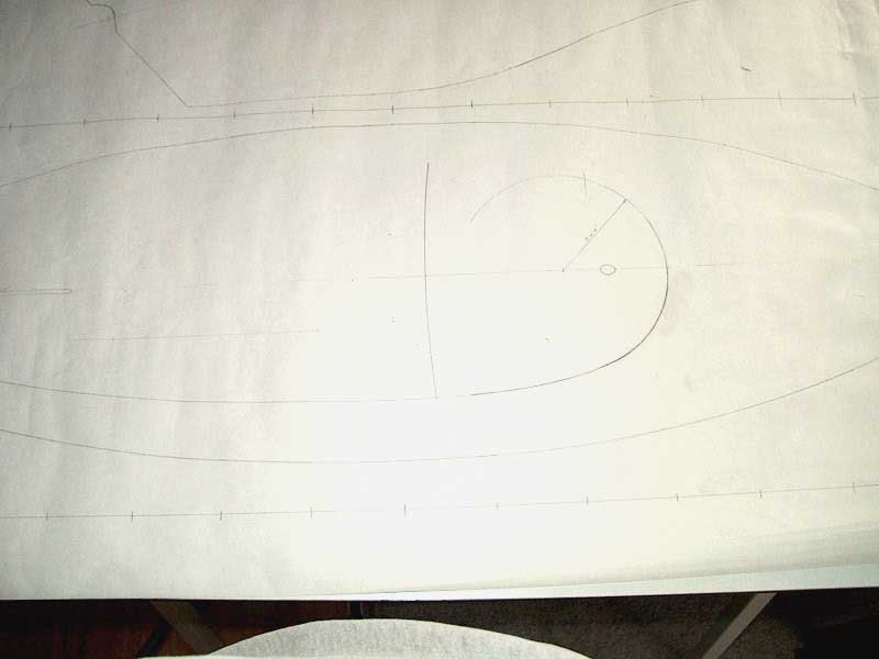
distort the image somewhat. Next
came the hard part: drawing in the line that represents the edge of the
cockpit, or the coaming. Here I was attempting to create a line that would
have a pleasing shape from all angles, a line that would fair smoothly and
imperceptibly into the strong curve of the cabin trunk shape, and one that would
artfully follow, though not parallel, the curve of the hull. Combining
these factors into a single line was challenging, and it took me many tries to
get it to a point that just looked right to my eye, as well as
"working" from a practical standpoint. To fair properly into the
radius of the cabin trunk required meeting at a tangential point, but the
coaming line also had to form a sweeping curve from its origin near the stern
all the way to its eventual seamless blending with the radius forward. I
drew and rejected a number of lines as being too narrow, too wide, too straight,
unfair, and all manner of other problems before I managed to get one that seemed
"just right". The exact line on paper is important because, when
the time comes to build, I can take exact measurements off the drawing to
transfer to the actual framing, therefore recreating the design "in the
flesh". My apologies are extended for the poor photographic
representation of this line, but the drawing is too large to scan at this
point. I think the photo is good enough to get the idea across. In
this photo, it looks like the line is a little unfair around amidships, but
that's because of some bends and folds of the paper that, translated to a photo,
distort the image somewhat. |
|
I continued researching my deck design and construction details, and started laying out the basic design on my paper drawings. The deck structure will be quite basic and traditional: sheer clamps along both sides, arched deck beams, and carlines surrounding the single opening in the deck (the cockpit/cabin trunk area). I figure on spacing the deckbeams 2' on center, and sized accordingly, depending on their construction: sawn beams may require a bit more thickness, while stronger laminated beams can probably be thinner. The largest single beam span is just over six feet, forward of the new cockpit/cabin trunk; most other beams, other than those on the foredeck, are only a foot or two in span. More to come. The design and specifications process is ongoing. Click here to continue.
|