| Bolero
Project |
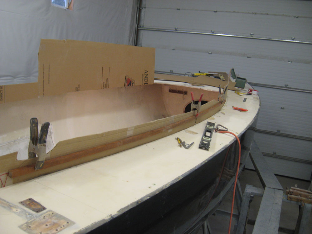
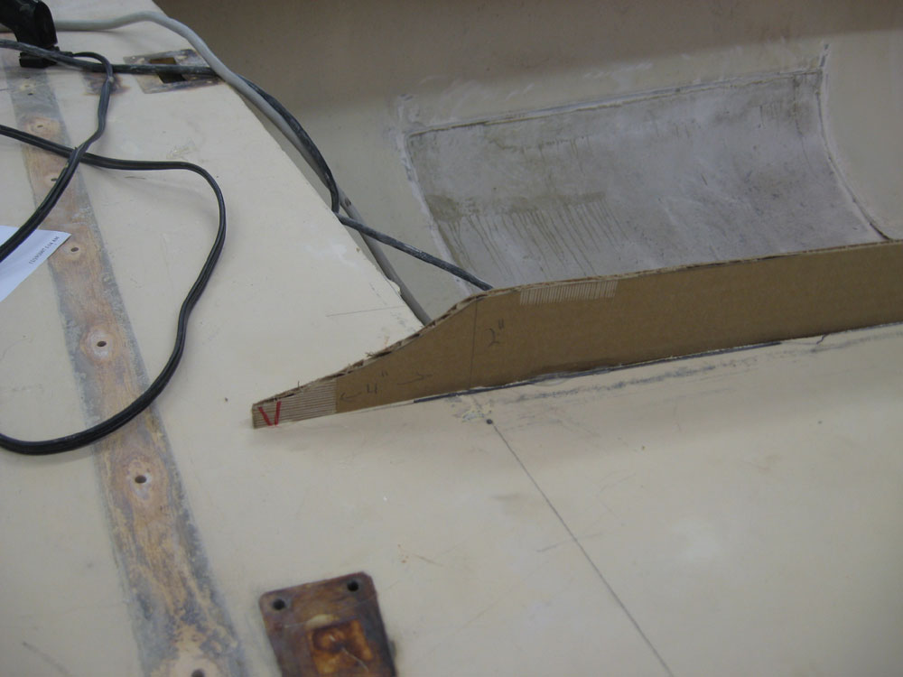
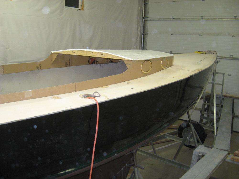
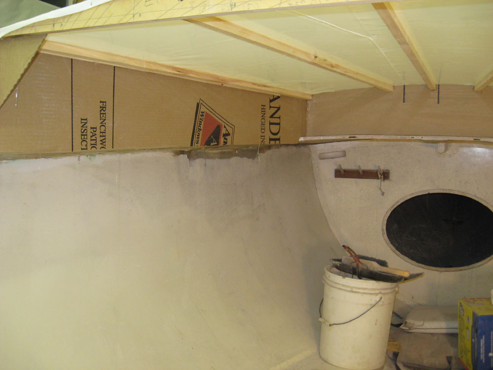
November 20, 2007 Armed with new information and answers to my questions from yesterday, I continued work on the cabin mockup today. I began with the starboard side cockpit coaming. It was abundantly clear to me that this coaming needed to taper downwards as it ran aft, rather than remain a constant height, so after looking it over and doing a few test measurements, I decided that the aft end should be 2" tall, with the forward end remaining at 3-1/2". With these two measurements marked on the cardboard, I clamped a stiff batten in place between the lines and made a mark, then cut off the excess. I formed an elliptical curve at the tail end of the coaming where it overlapped the aft deck, again using one of the port frames as a template. |
|
|
|
I confirmed the marks I'd made on the starboard cabin trunk yesterday, and then went ahead and made the cut there as well. At the forward end, I decided to add a 2" strip of cardboard to bring the mockup up to the location shown on the concept drawings, even though we weren't yet sure how far aft of the mast partners the actual front would have to end up. |
|
|
|
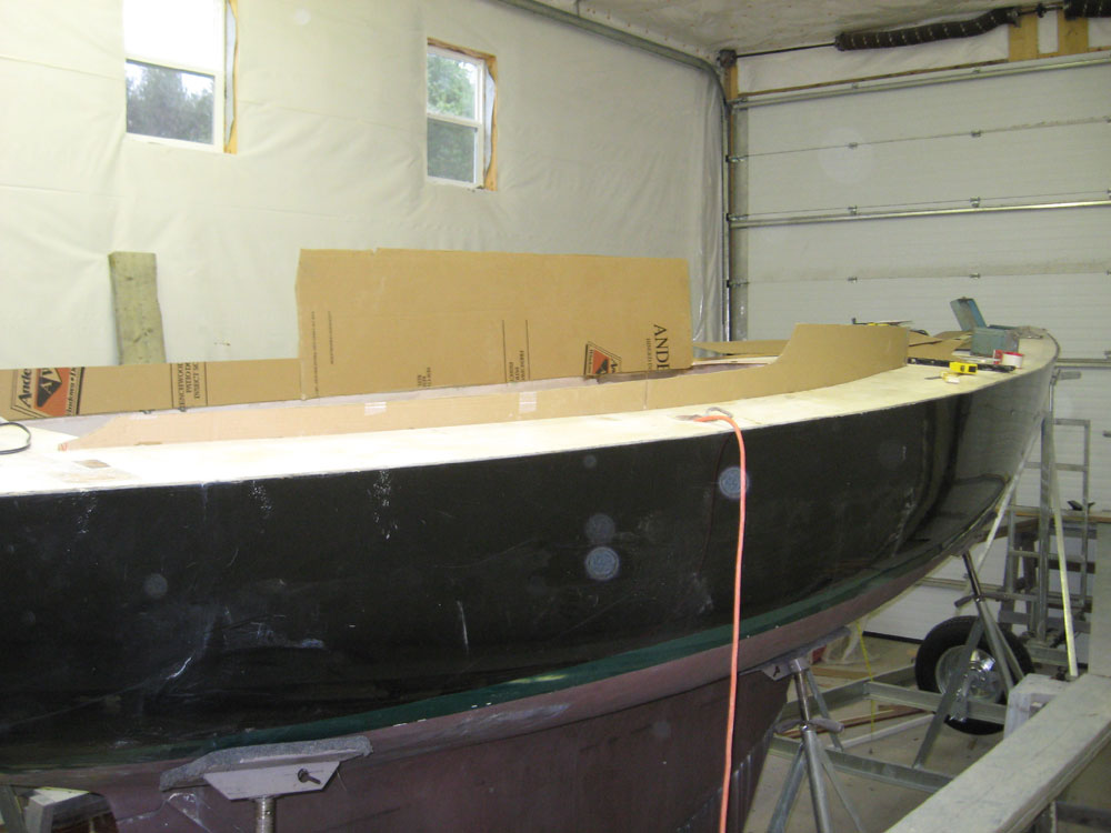
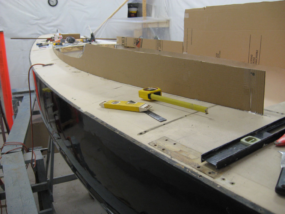
Generally satisfied with the look of the starboard side, I moved over to the port side and duplicated the marks and cuts. |
|
|
|
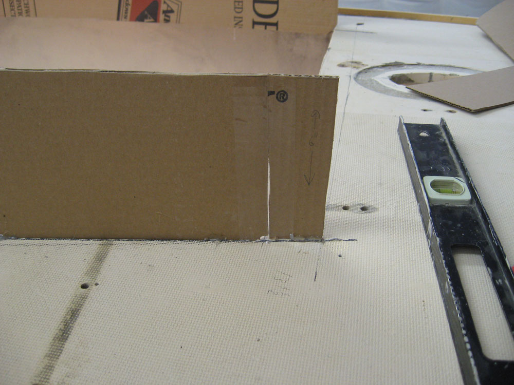
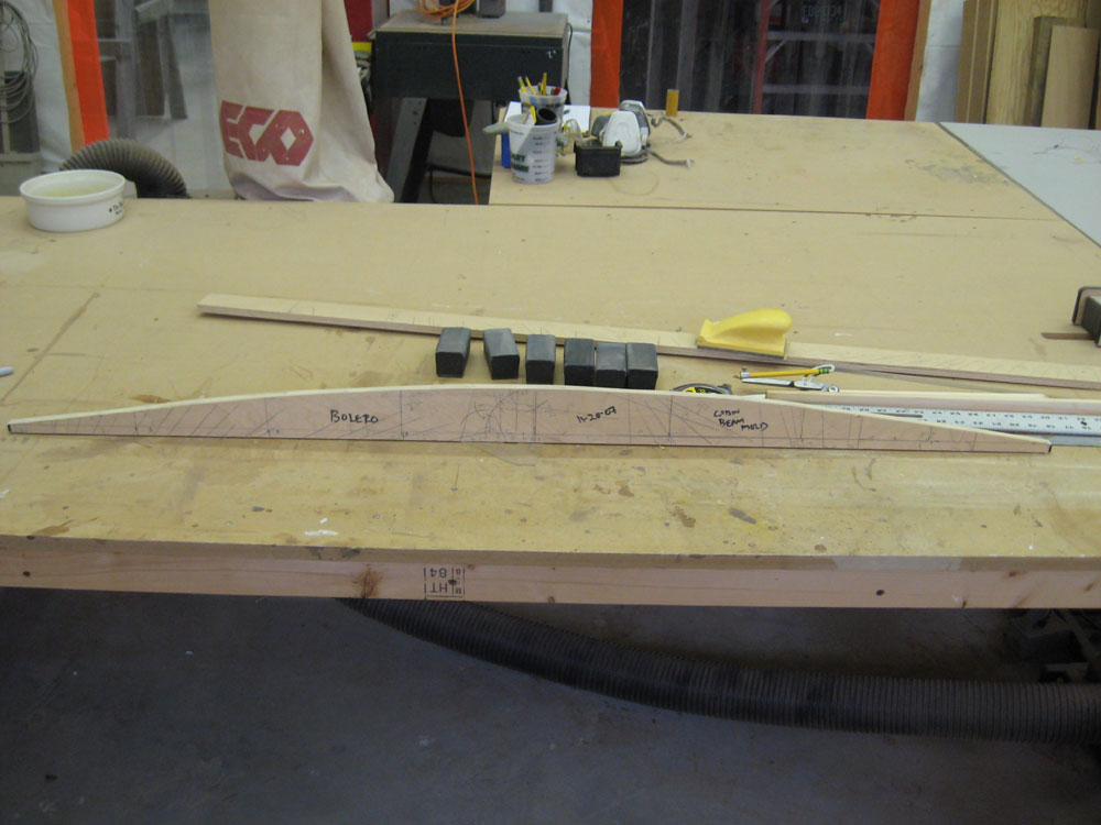
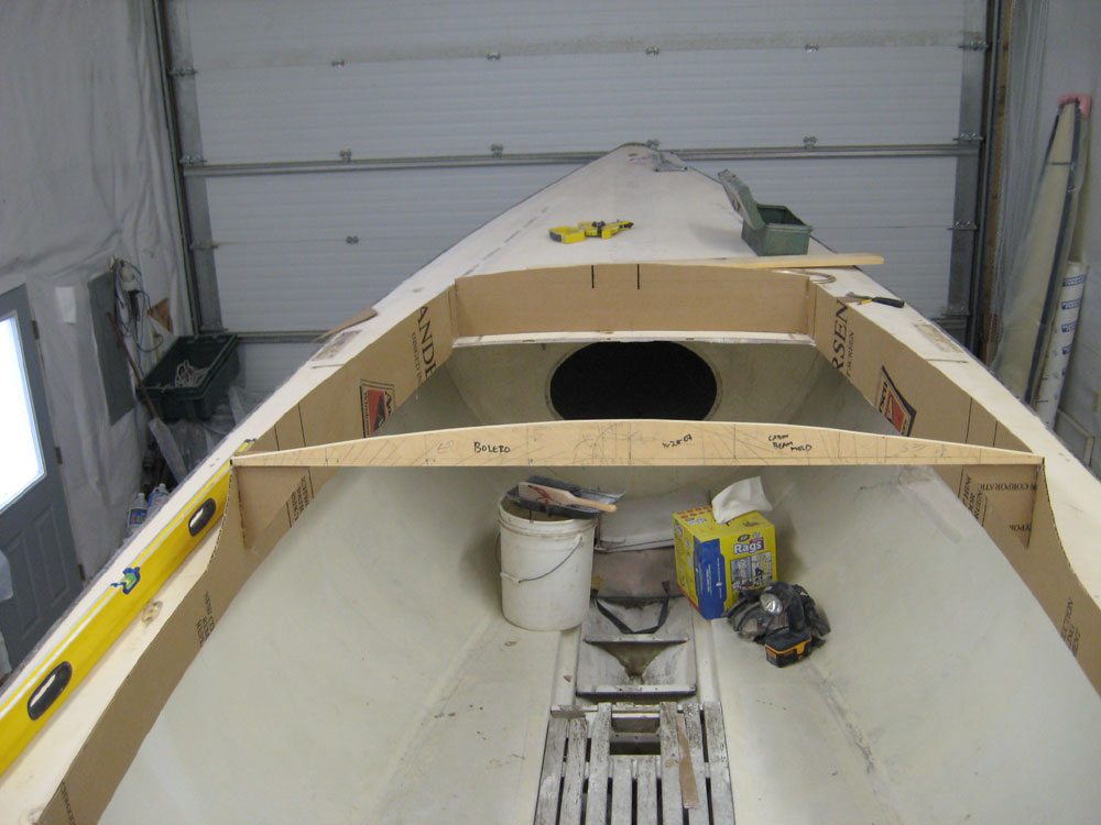
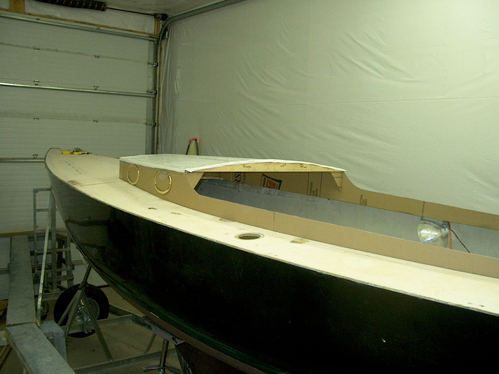
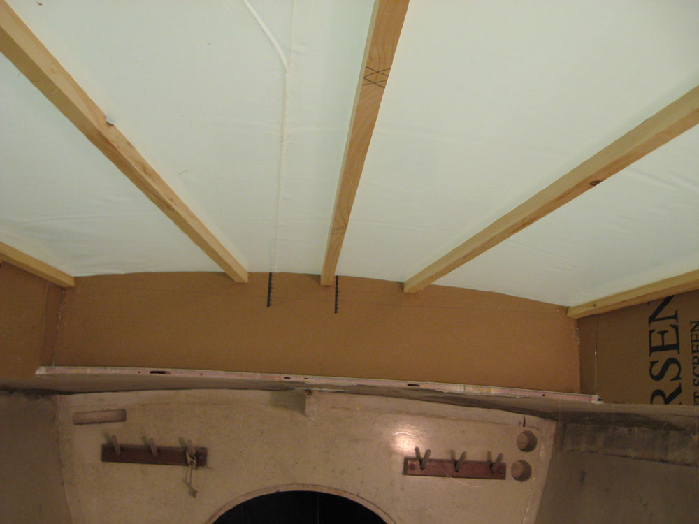
With the basic shapes now defined, I pressed on with the coachroof mockup. The owner and I had determined that the maximum crown of the coachroof would be 3", so to get started I cut a scrap of plywood into a 3" wide strip, and temporarily glued it in place across the aft edge of the mocked-up cabin trunk sides. I marked where the piece overlapped on each side, and then marked a centerline. To simulate the eventual thickness of the coachroof structure, I made marks 1/2" up on each side of the plywood so that the mockup would roughly simulate the final height of the cabin. A bit of discussion seems in order here. The concept drawings didn't take into account the thickness of any coachroof structure, which meant that the visual height would have to either be a bit higher to accommodate it, or the thickness of the top would protrude a corresponding amount into the cabin below. With potential headroom a precious commodity, and with an already-defined need to slightly increase the height of the cabin trunk sides to better accommodate the port frames we had on hand, I decided that only the framing for the coachroof would be below the tops of the cabin trunk, and the actual top--probably two laminated layers of 1/4" plywood--would protrude above, the edges to be covered with trim. Removing the plywood strip to the bench, I laid out the curve for the coachroof crown. Rather than simply strike an arc between the three known points, I used a layout process that provides a dynamic curve that creates a more pleasing overall shape. I first researched this process a few years ago for another project and won't repeat the details here, but more detail is available at the following link. Sidebar: Details on the Beam Crown Layout (Opens in new window) Once I laid out both sides, I cut the curve with a jigsaw, and faired it by hand. |
|
|
|
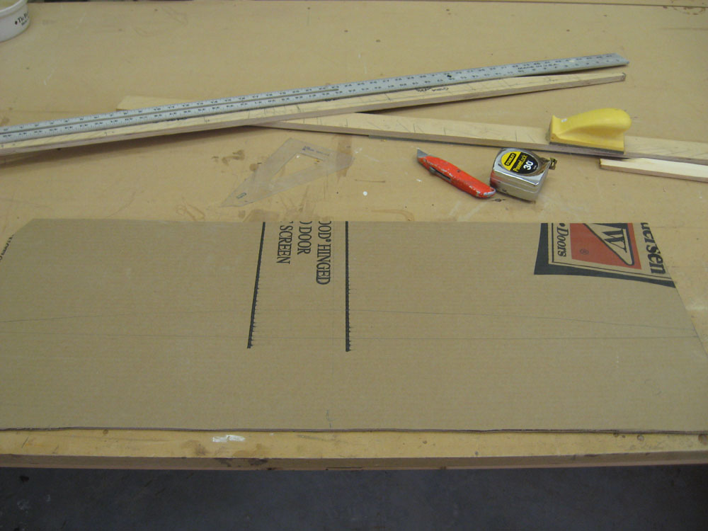
Since the camber shape would be constant along the entire length of the coachroof, I traced the plywood onto a piece of cardboard for the forward side of the cabin trunk. Before tracing the curve, I first scribed the cardboard to the shape of the existing deck (since this piece was actually sitting on a portion of the deck that I had not yet cut out), and marked the width against the pre-existing cabin trunk sides (which I held plumb for the marking, since the trunk sides would be vertical). I cut out the cardboard front and glued it in place on the boat, then glued the plywood beam template in place at the after end. With this, the basics of the coachroof shape were in place. |
|
|
|
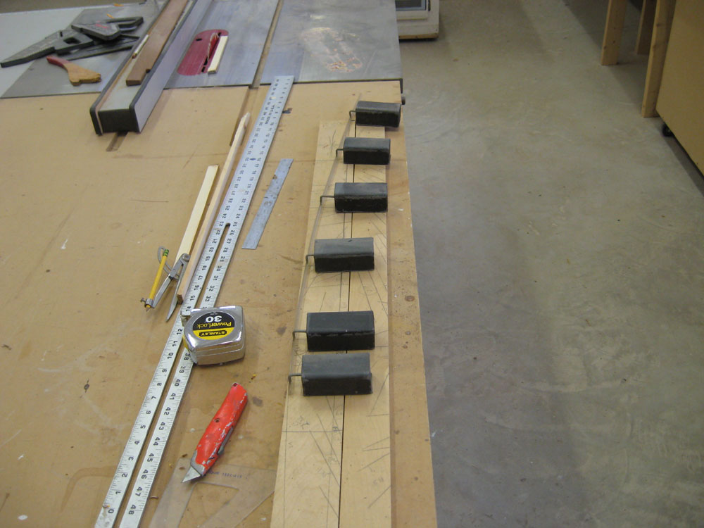
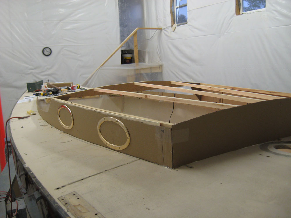
For mockup purposes, I decided that some basic longitudinal supports were the easiest way to generally replicate the proposed coachroof. From scrap lumber, I milled a series of 3/4" square lengths, and then glued these in place between the fore and aft ends of the cabin trunk mockup, cutting each one to length as I went. |
|
|
|
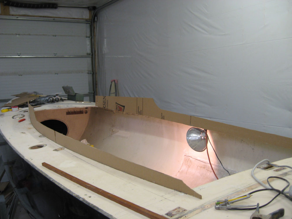
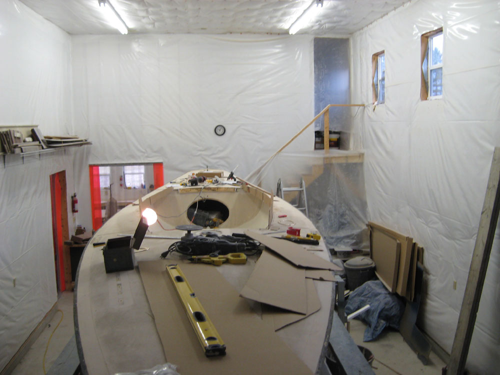
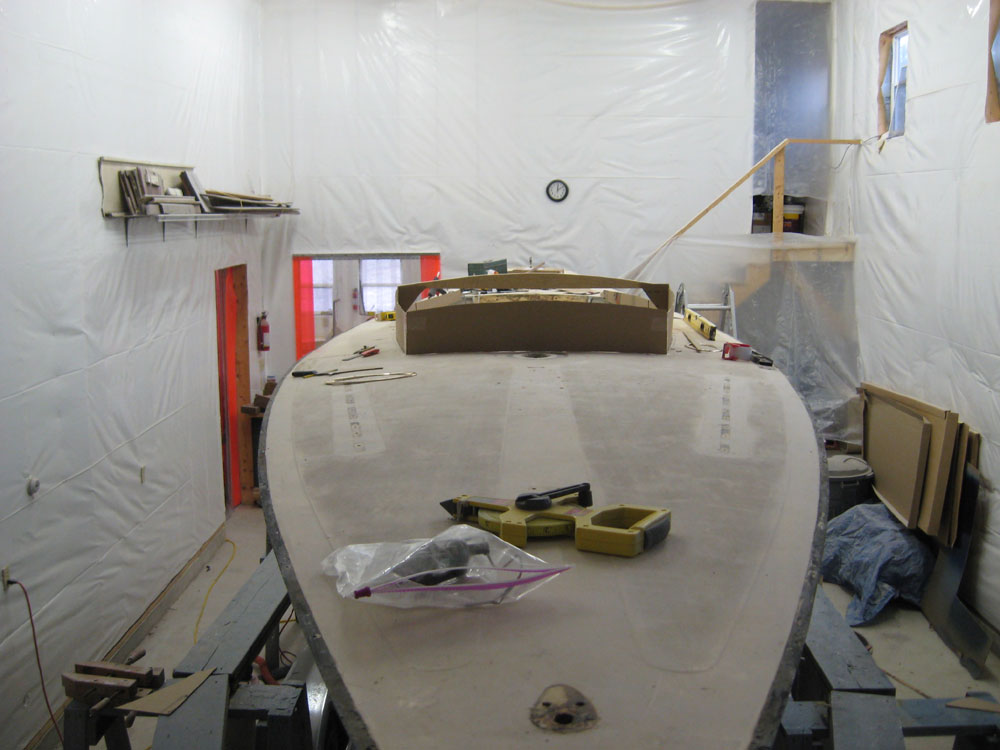
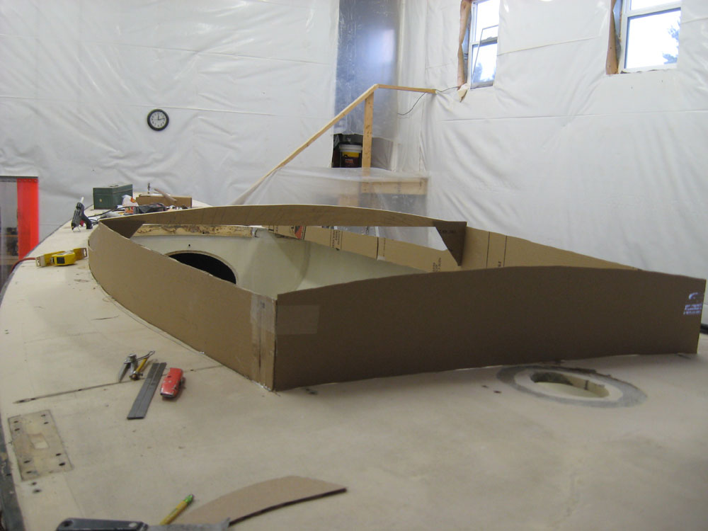
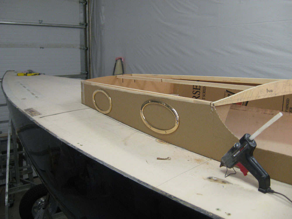
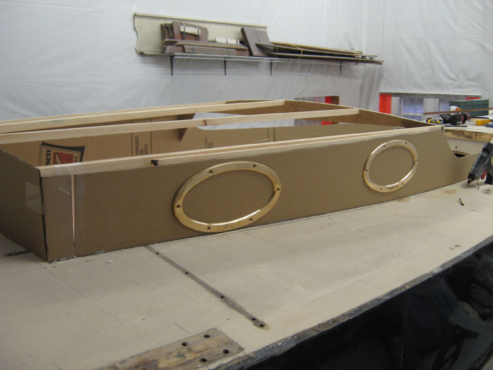
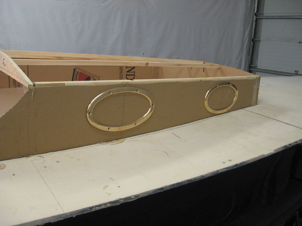
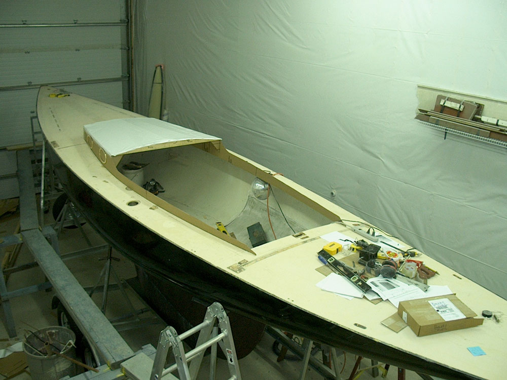
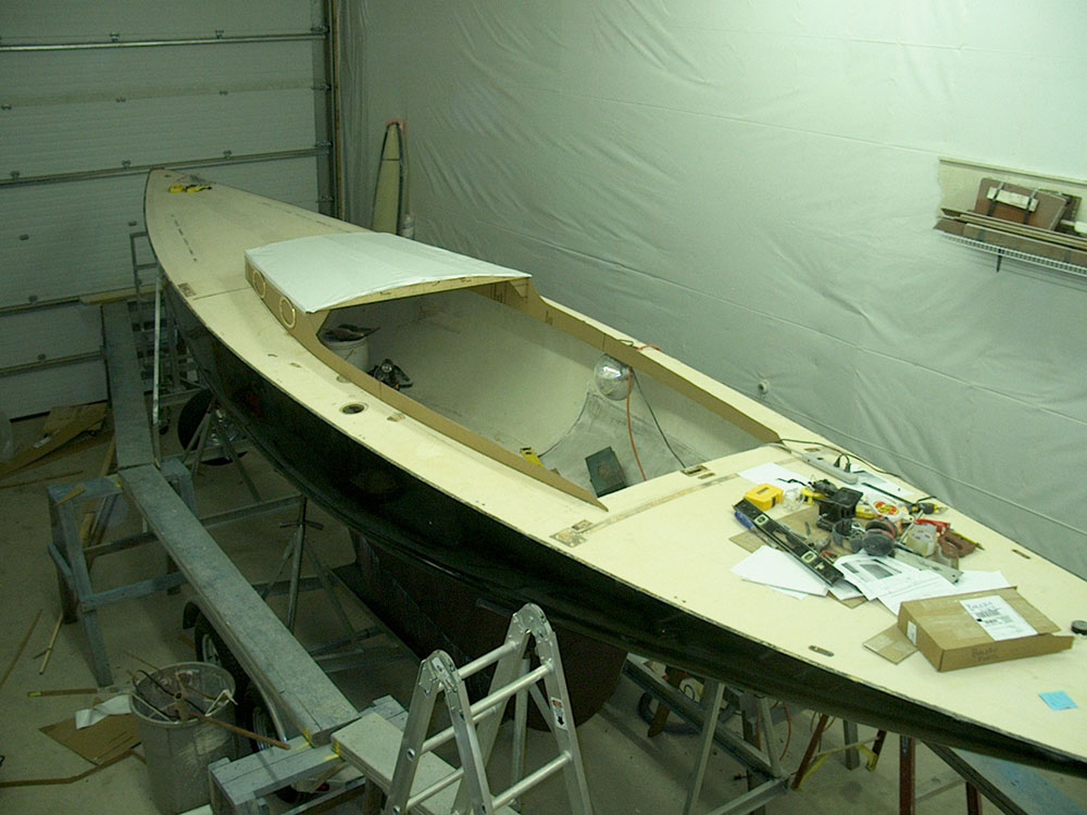
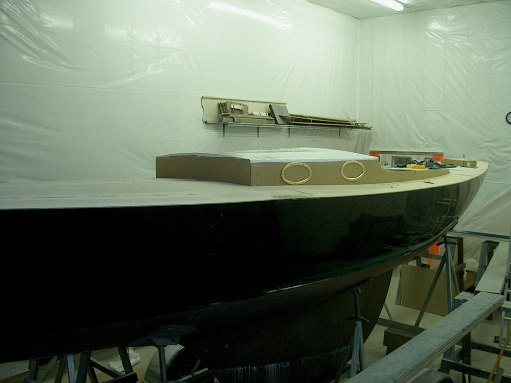
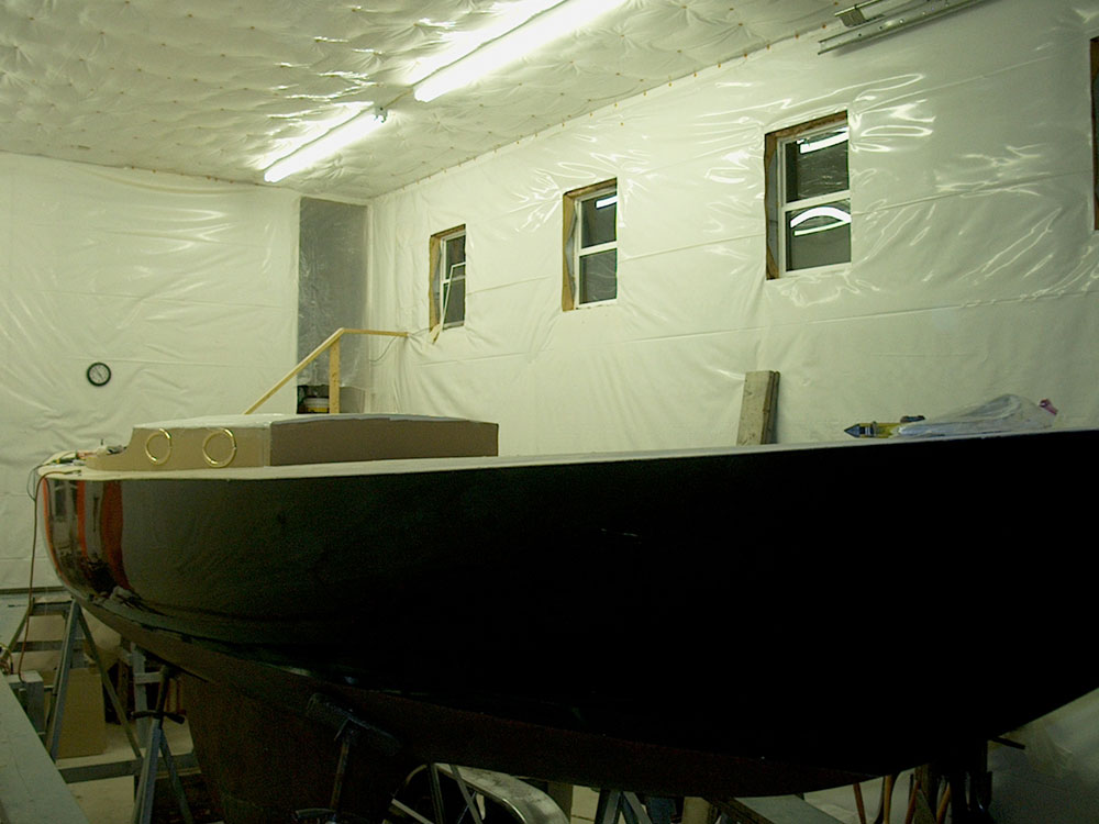
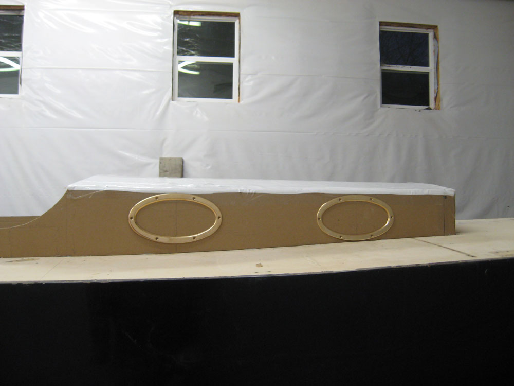
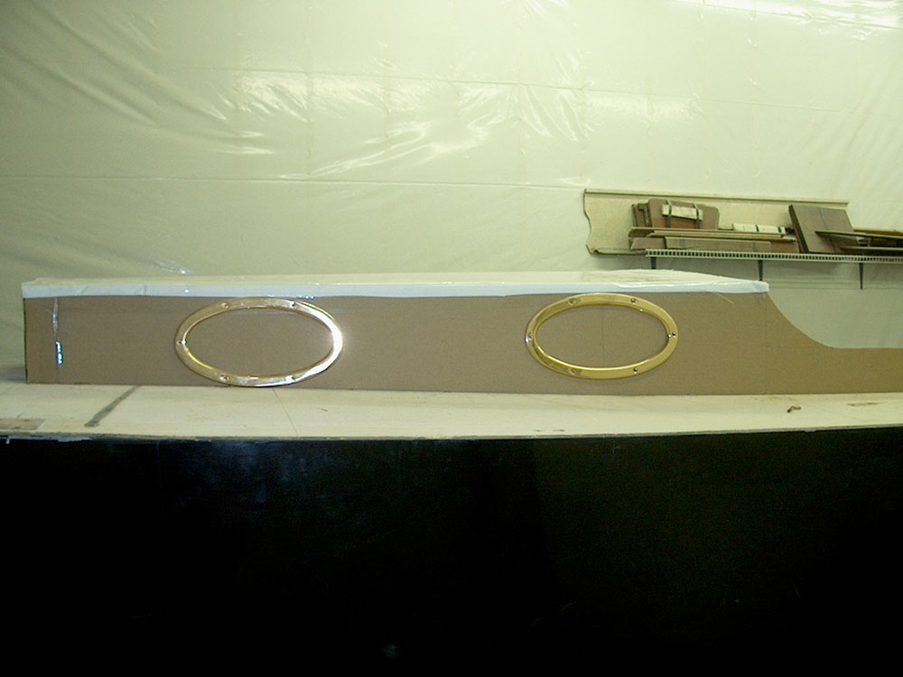
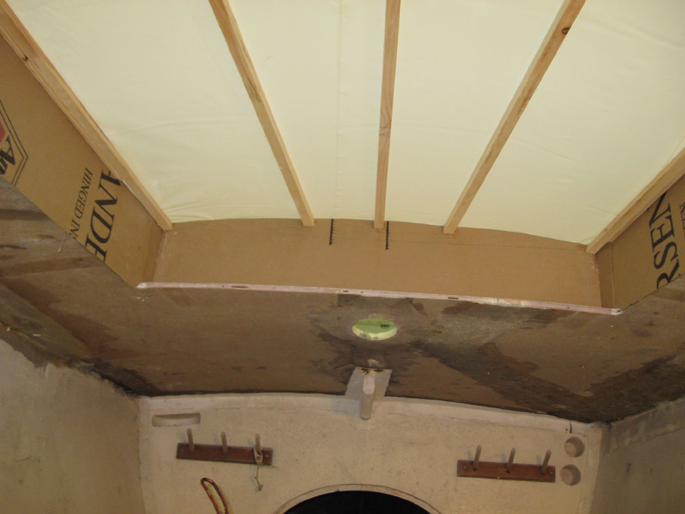
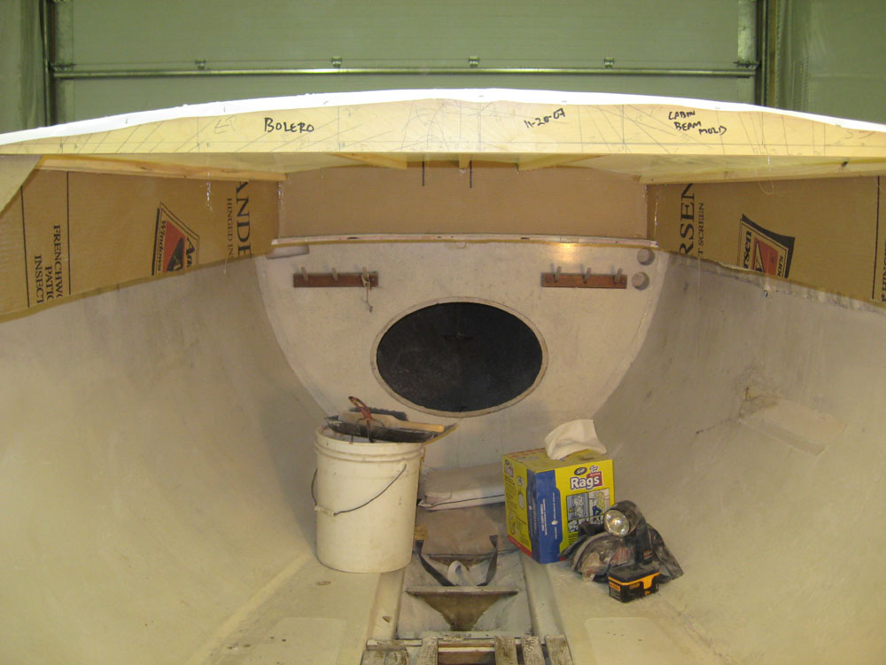
Finally, I attached some plastic over the framework, stretching it tightly before stapling and taping it into position. This completed the mockup, and for the first time offered a glimpse into the space that would be available inside the cabin--as well as the exterior appearance of the boat. To further enhance the mockup, I glued the port frames in place on the cabin trunk. Rather than locate them symmetrically from each end, as shown in the concept drawing, I chose to bring the forward port aft by a few inches, which improved its clearance between the top and bottom of the cabin trunk, and also looked just a bit better to my eye. The after port's vertical center is 13" forward of the aft end of the cabin trunk; the forward port's vertical center is 16" aft of the forward end of the cabin trunk. Please pardon the poor quality of some of the final mockup photos. My new camera took a little bounce with the lens extended (i.e. camera turned on), and this seemed to damage irreparably the operation of the lens--and therefore the camera. So I had to switch to an very old camera that I keep as an emergency spare--though this old HP is still the best camera, in terms of longevity and ability to take whatever's been thrown at it, that I've had to date. Miniaturization and consistently downward prices are nice and all, but sometimes large and heavy has some advantages. Yet another new camera is on the way for tomorrow, after which I'll send off the old for hopeful warranty repair. (It's only one month old.) With luck, timing and weather tomorrow will allow me to pull the boat outdoors for some pictures once the new camera arrives. |
|
|
|
A few things to keep in mind about the mockup: 1. This represents a reasonably accurate first approach to replicate the conceptual drawing. There may be adjustments needed here or there. 2. In the end, it's only cardboard and plastic. While it does a fair job in helping to envision the final product, it's far from perfect, and these flimsy materials don't necessarily bend and curve the way wood will when it is used to actually build the structure. 3. I am not yet sure about the port placement. In the photos of the mockup, the ports are equidistant from the top edge of the cabin trunk, a distance set by the forward port based on the possible clearances. This ends up being 1/4" down from the top in this case. This is a first guess, and I'm struggling with whether the ports should be aligned according to the deck line, or equidistant from the top edge of the cabin trunk, or some other alignment. I did not find any true guidance from my sources, and have had a little difficulty truly determining how ports should be aligned when the cabin trunk is shaped like this. A more distant view of the boat will be telling, and I plan to pull the boat outdoors so that we can get a better view. Before gluing the ports in the position you see here, I went back and forth about it, and held the after port in place the same distance off the deck as the forward one to see if that was the right position; that didn't seem to look right somehow, at least not from up close. One thought I have had since installing the ports is that perhaps they ought to be aligned along a horizontal centerline from the forward to the aft side of the trunk--that is, mark 3" up from the deck at the forward end (half of the total 6" height) and 4" up at the aft end (half of the 8" height there), connect the two points with a line, and align the horizontal centers of the ports along this line. This would bring the after port down somewhat, while the forward port would stay where it is. |
|
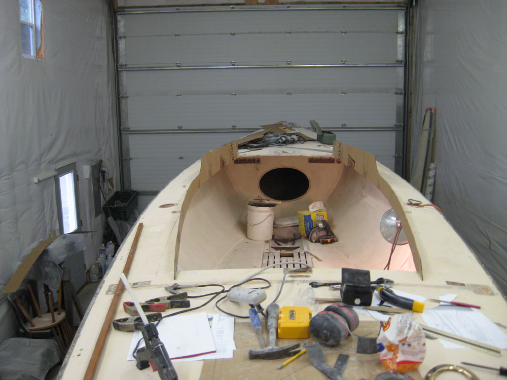
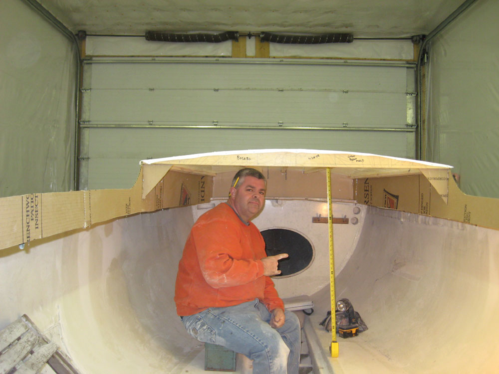
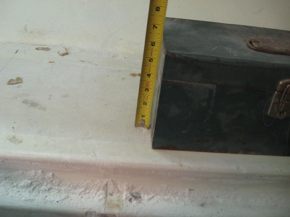
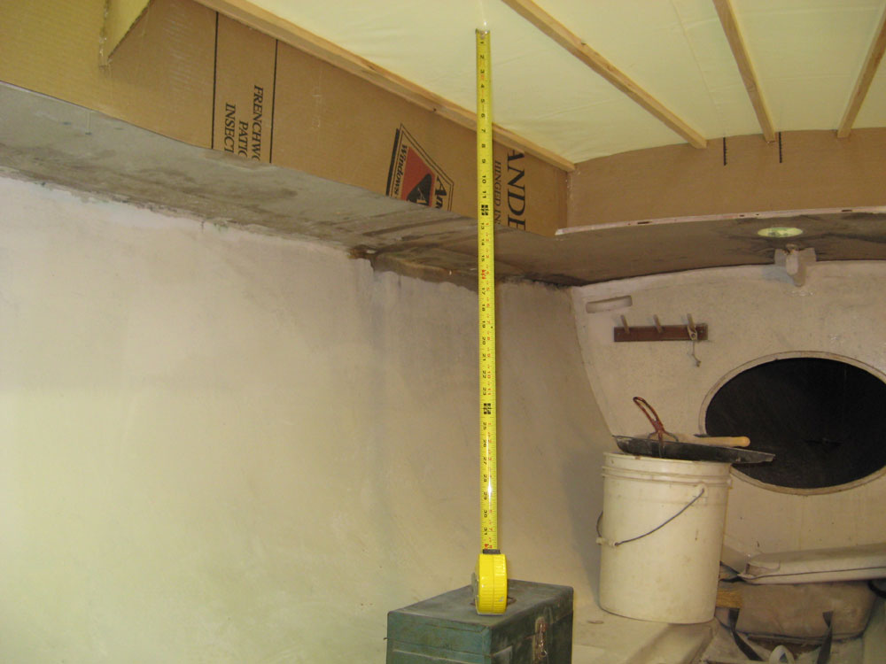
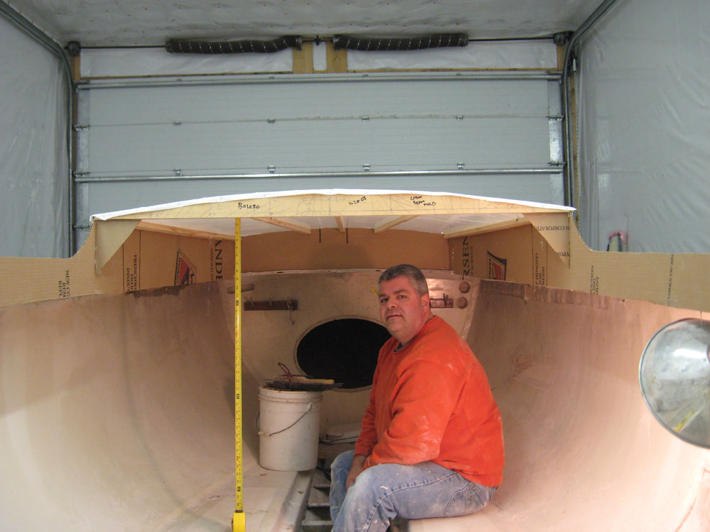
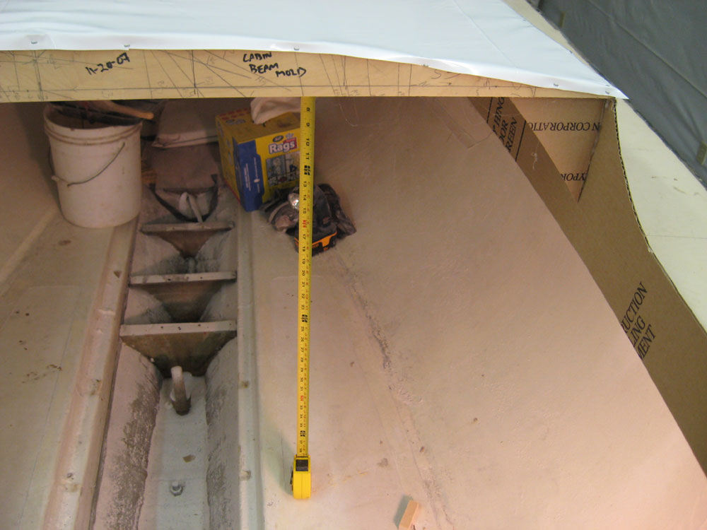
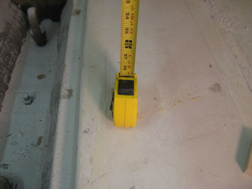
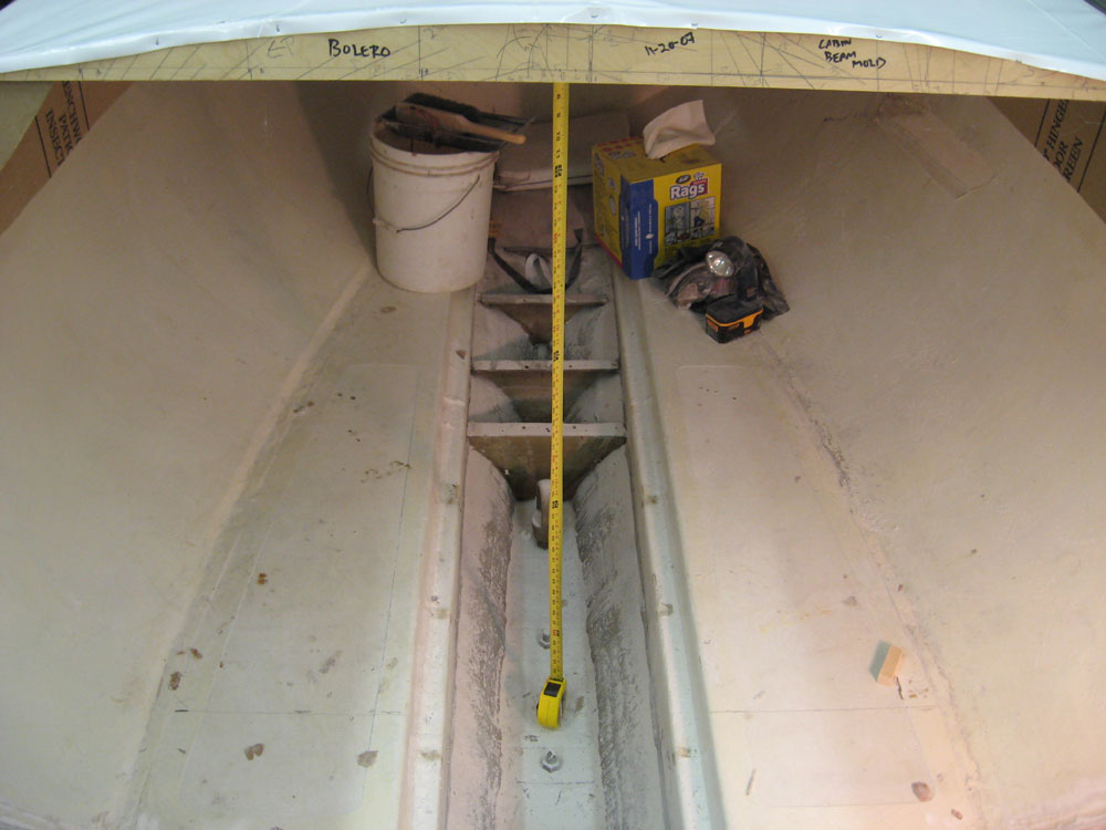
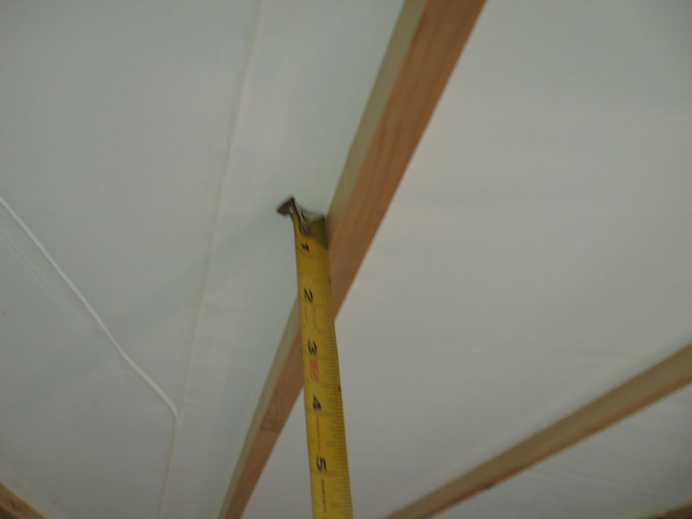
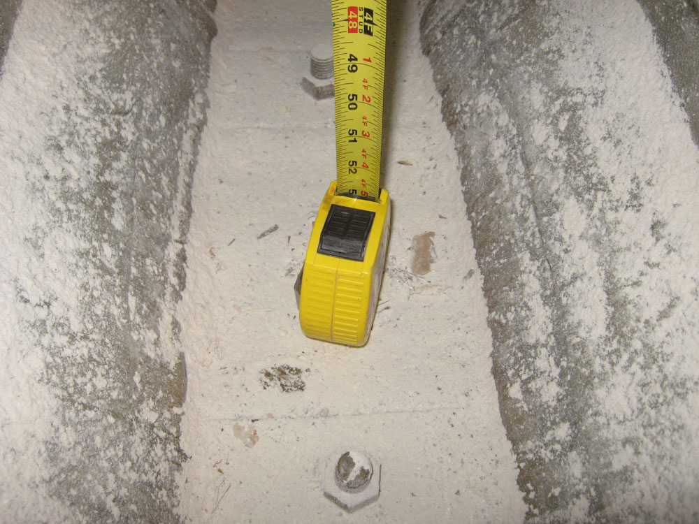
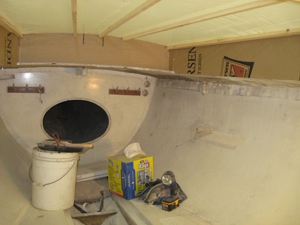
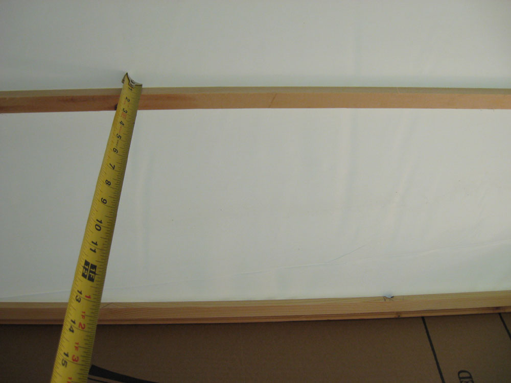
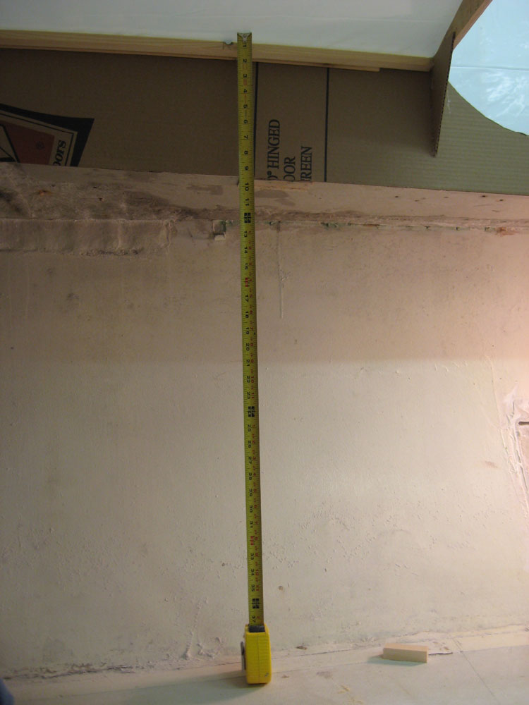
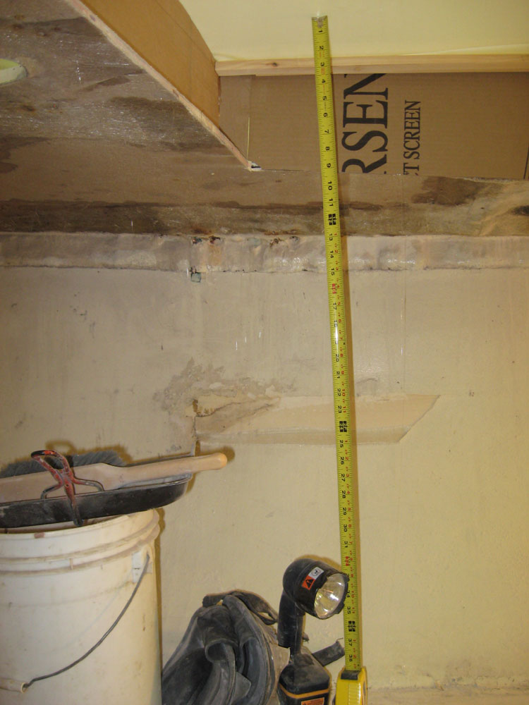
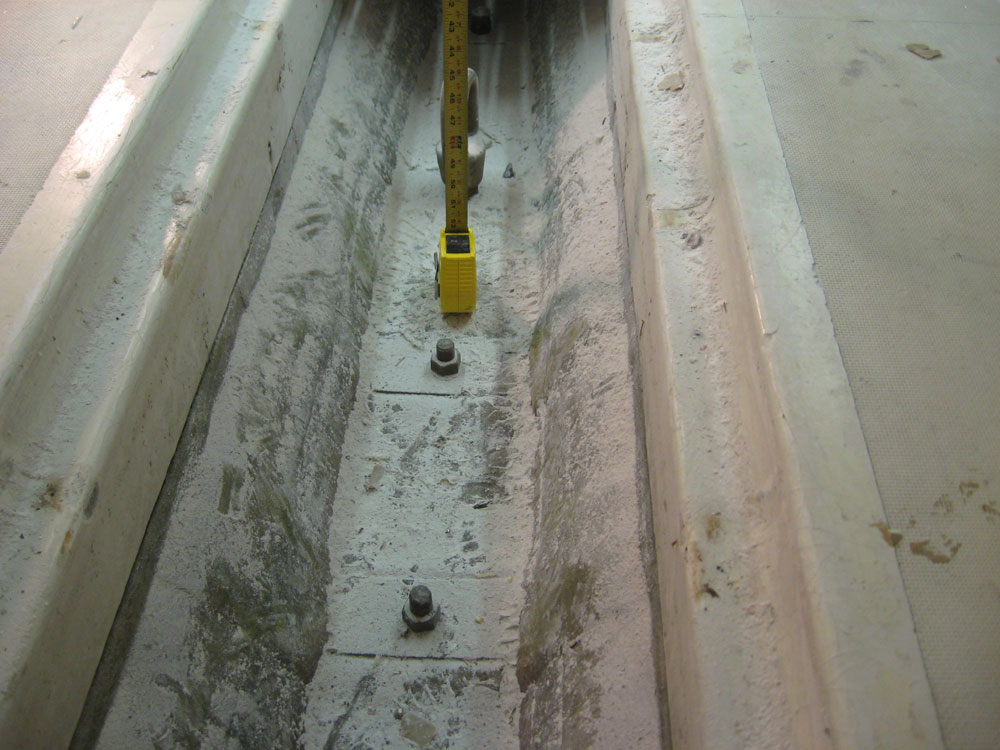
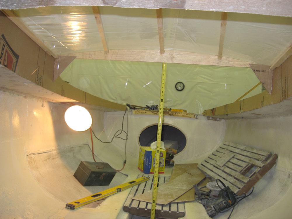
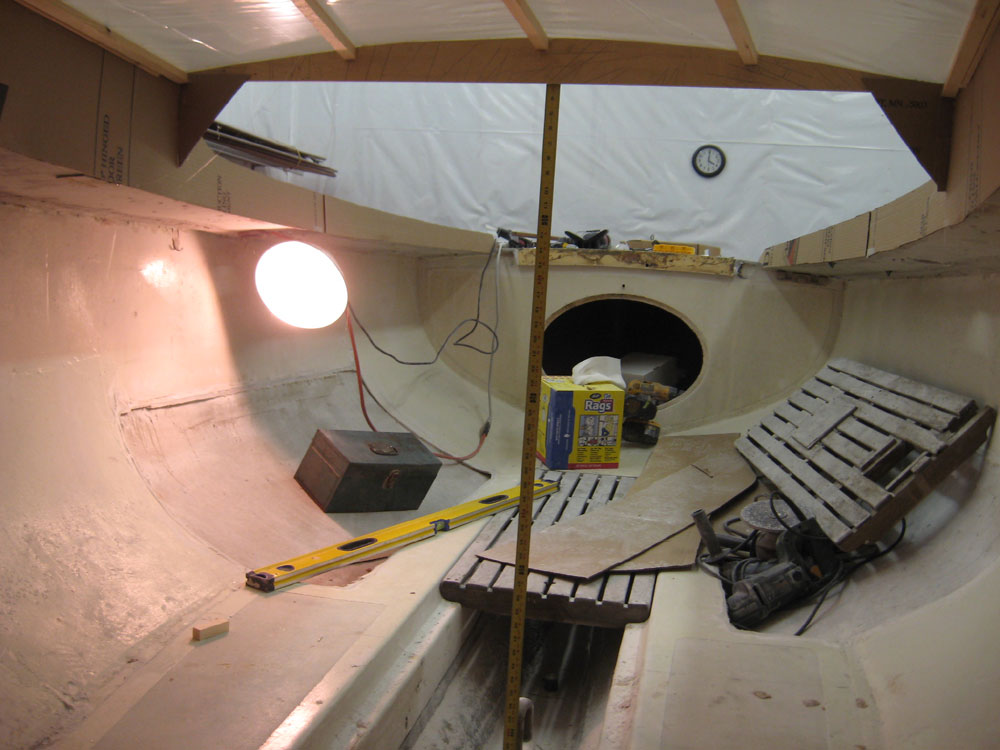
I took a series of measurements inside the cabin to determine potential headroom (sitting headroom, that is). These photos show some of my measurements, as well as a few showing me inside the cabin as a reference. In some of the photos, I am sitting on a small toolbox to help simulate a possible seat height; on others, I sat right on the existing cabin sole. There's space for foot room to be expanded slightly by installing a new, lower cabin sole just above the level of the keelboat heads in the bilge, but the potential area, however deep, is narrow. Removing the molded sole liner from the cabin area is a definite, which will potentially open up space a bit more. Note that the tape measure housing requires that you add 3" to the measurements shown. In this series of photos, each set of three photos goes together in an attempt to show where and how I located the tape for each measurement. |
|
|
|
The realities are that the space is tight any which way, though it is workable and sufficient headroom for sitting is available at some level; how much headroom there ends up being will be determined by the seat or berth height chosen, which in turn will affect how much, if any, foot well room there is. There is plenty of length between the new after cabin bulkhead (represented in some of these photos by the yellow level spanning the boat) and the existing forward bulkhead--something over 7' in length, so berths with stretch-out room are possible. Depending on the seat height, there is room to sit against the new after bulkhead and facing forward. The mast, when installed, will of course impact the cabin design in inalterable ways |
|
|
|
|
|