| Bolero
Project |
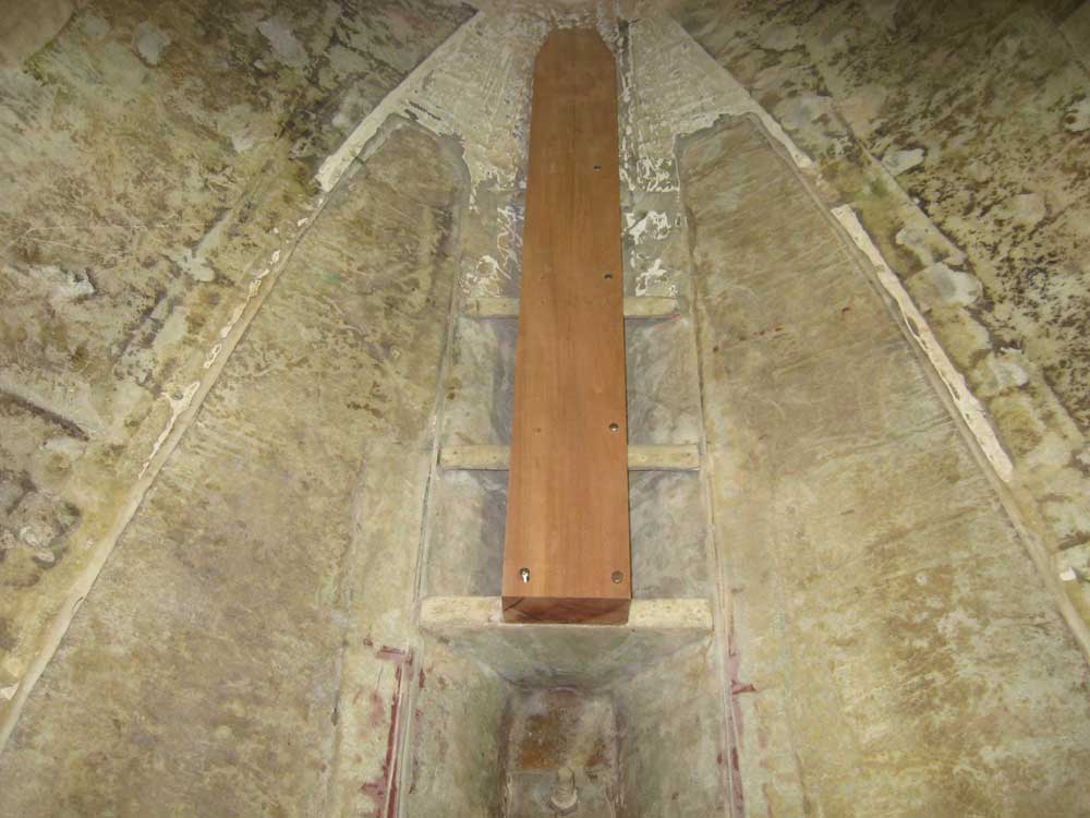
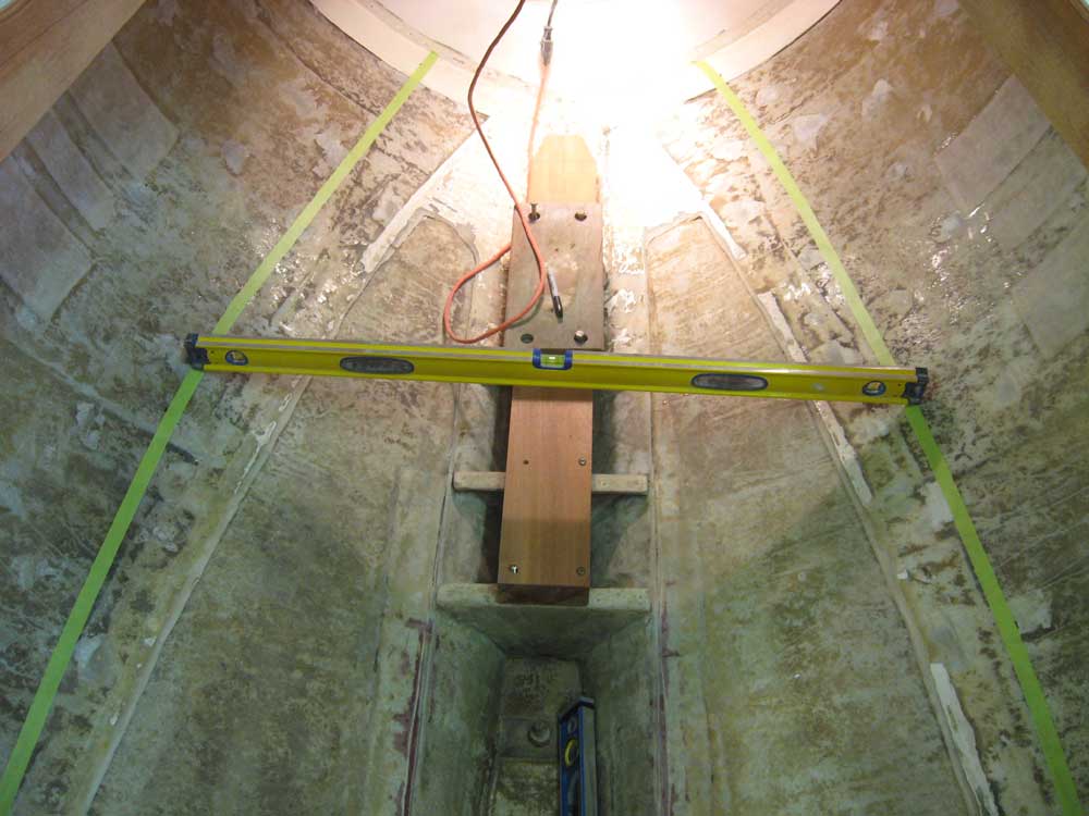
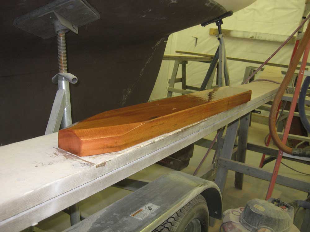
Friday, March 28, 2008 First thing, I sanded yesterday's small areas of fairing compound in the cockpit, and chiseled and sanded the bungs smooth on the newest trim. Then, I spent most of the day working on the basic cabin layout and concept. Before beginning, though, I milled a new mast support beam to replace the old one, which had been full of rot and which I'd removed back during the demolition stage. But now I needed this in place, since whatever the interior became would have to work in and around this critical piece of timber. From a piece of 10/4 mahogany stock purchased for the purpose, I cut a new piece using the old one as a guide, and placed it temporarily in the boat. |
|
|
|
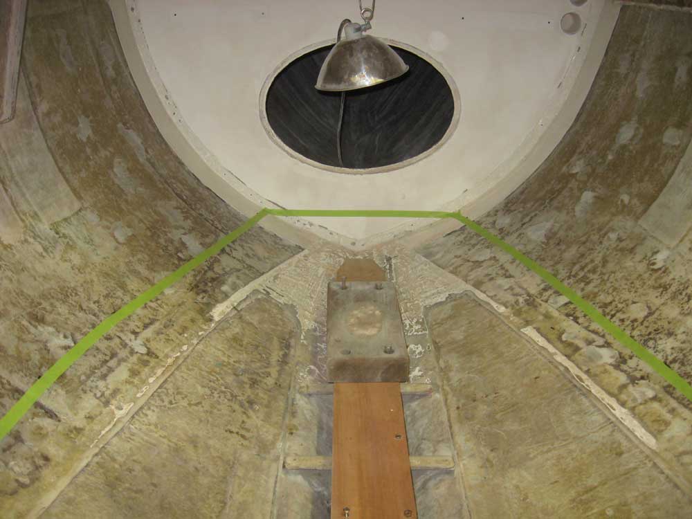
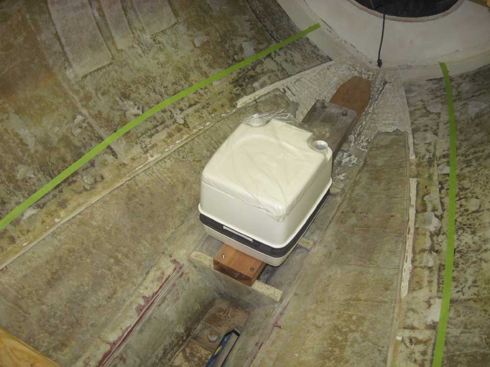
It may seem silly to conceive a layout around a Porta-Potty, but that was the next "critical" piece of the puzzle that I temporarily set in place, as making room for the device would be a necessary factor in all decisions. My initial thought, at least, was to place the head just aft of the mast, on top of the new beam. To help determine its location more closely, I temporarily installed a second large mast block, which had been in place in the original setup and on which the actual mast step would be installed. This placed the Porta-Potty front and center in the cabin, and conveniently situated just aft of the cabin trunk front, which provided usable headroom above--33" above the seat, in fact. The straightedge across the cabin top represents the overhead height in the final picture below. Note that later layout steps raised some additional questions about the head placement, which I'll discuss below. |
|
|
|
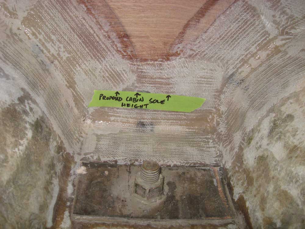
By sheer necessity, if not design mantra, the cabin layout would be very simple: basically a V-shaped berth/settee filling the sides and forward area, with a narrow cutout/footwell between. However, getting to a workable point in determining the basics of the layout was not necessarily simple. Several factors came into play, changes in any one of which forced changes or compromises in another. In the end, the key dimension required for user comfort in practice would be the headroom available above the top surface of the berth. I played around with a few randomly-chosen dimensions for several minutes, trying to see how things like the headroom over the berth would coordinate with available height (from the cabin sole) of the berth top, and the foot room that might be available at those various heights. To maximize the depth of the footwell, I planned to locate the new sole as deep in the existing bilge as possible. For practical purposes, I decided upon 1" above the top of the highest keelbolt for this, and marked it on the bulkhead for reference. At this depth of bilge, this translated to about a 7" sole width at minimum. |
|
|
|
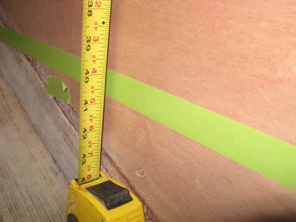
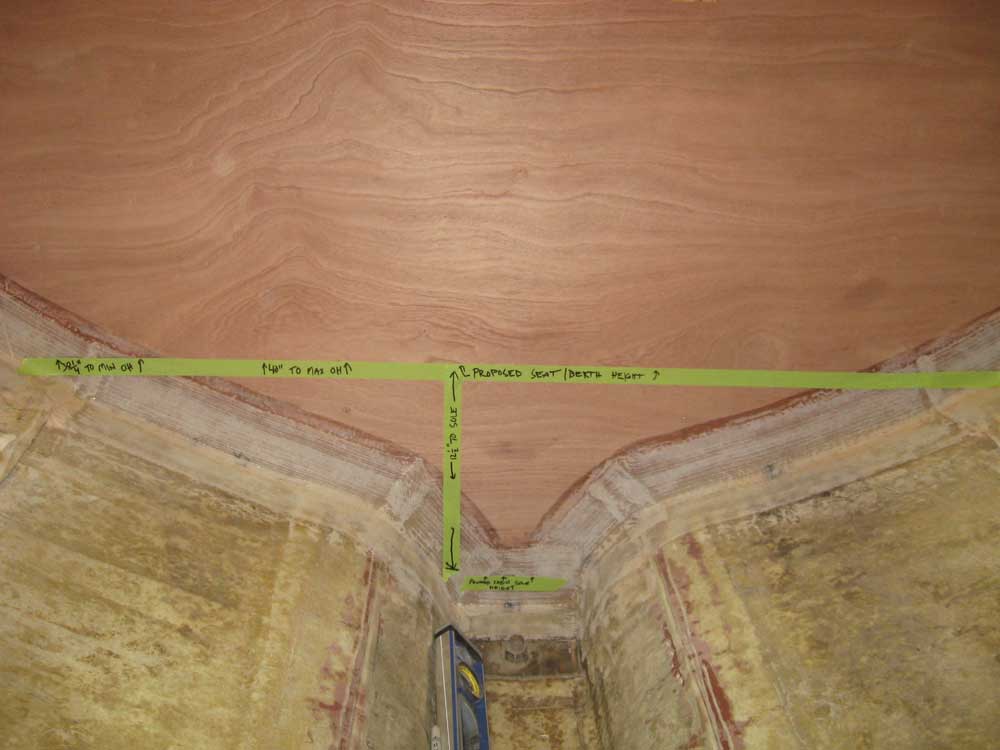
Eventually, I discussed at length with the owner some of the critical dimensions, and came away with, among other valuable information, the critical dimension that would ultimately drive the entire layout: sitting headroom of 40" above the berth required for the owner's comfort. With this measurement in hand, I laid out some information on the aft bulkhead, including a proposed berth top height and proposed cabin sole height. With 40" of headroom available at the companionway edge, the coachroof camber reduced the headroom to 38-1/4" next to the cabin trunk. |
|
|
|
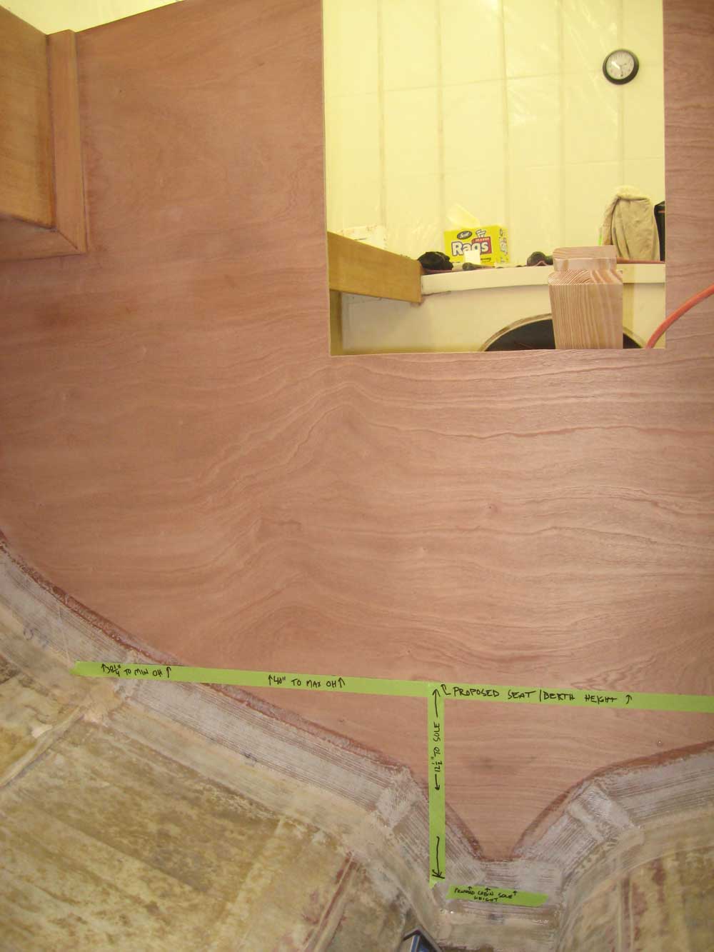
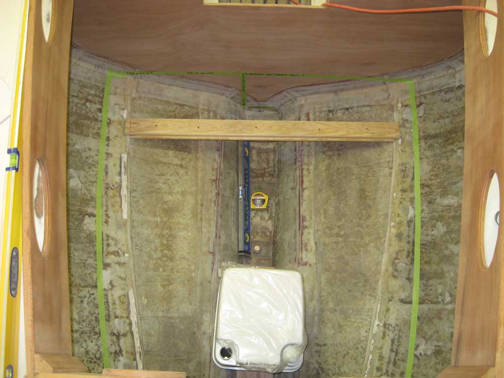
With the basic layout lines in place, I used a level to transfer marks around the hull forward of the bulkhead, and then roughly outlined the shape of the berth platform in masking tape. For the last picture, I sat on the narrow board spanning the hull just forward of the bulkhead; this board was just a little bit lower than the proposed berth height. Again, the straightedge represents the eventual cabin overhead. I'm several inches shorter than the owner; hence the "wasted" head space above me. |
|
|
|
Overall, I thought this layout was pretty workable. The width of the berth at the forward end came out wider than I expected, which was good news. 40" headroom above the berth allowed for 12" depth of footwell to the cabin sole, which was pretty workable from a practical standpoint, if not ideal; but ideal in all ways was not something we were going to achieve. However, afterwards I thought of a few things that might need additional tweaking:
|
|
In any event, at least now we had some basic information from which to work and modify as necessary. To wrap up the day's work, I removed the new mast support beam to the bench and milled some chamfers on the corner where necessary (necessary to me, that is), sanded it smooth, and applied a coat of epoxy resin to the bottom side and edges; while I expected that the bilge areas inside the cabin would stay rather dry, it seemed some additional water protection on the underside of this piece was warranted. |
|
|
|
|
|