| Bolero
Project |
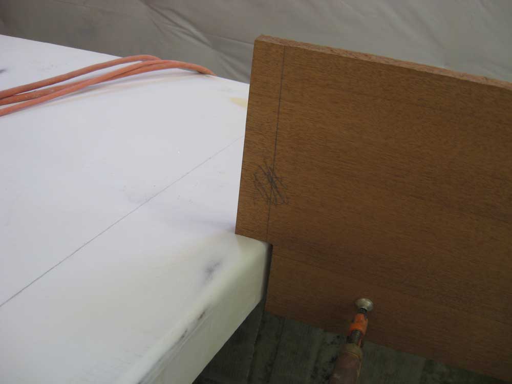
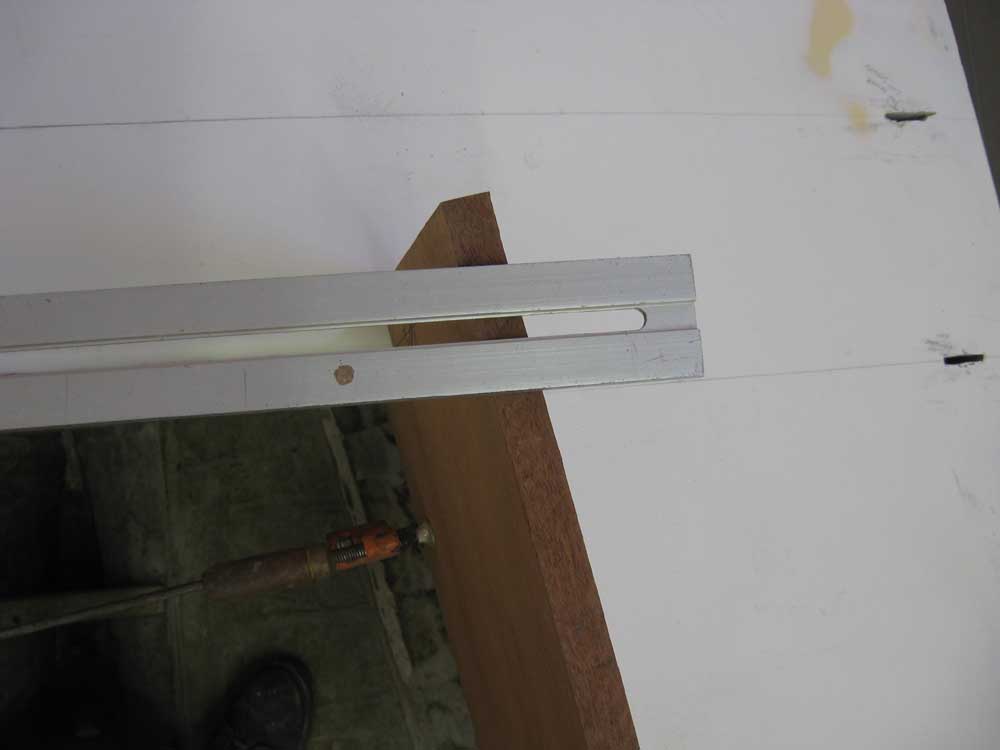
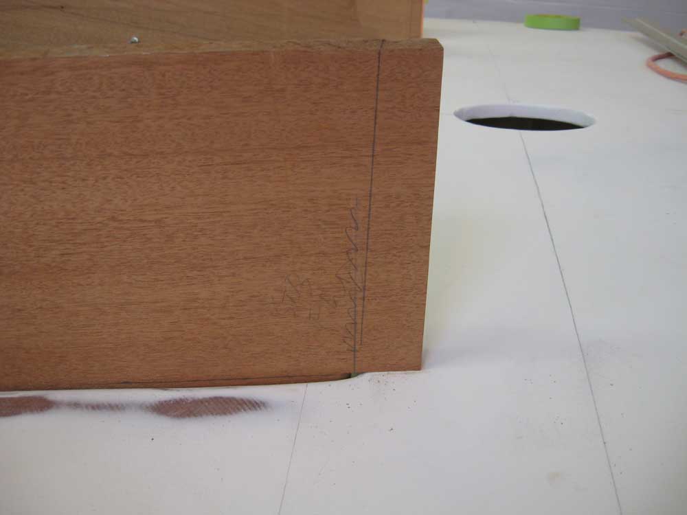
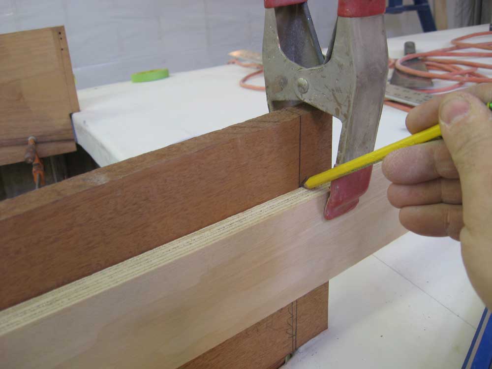
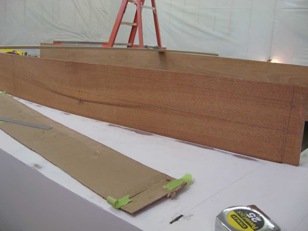
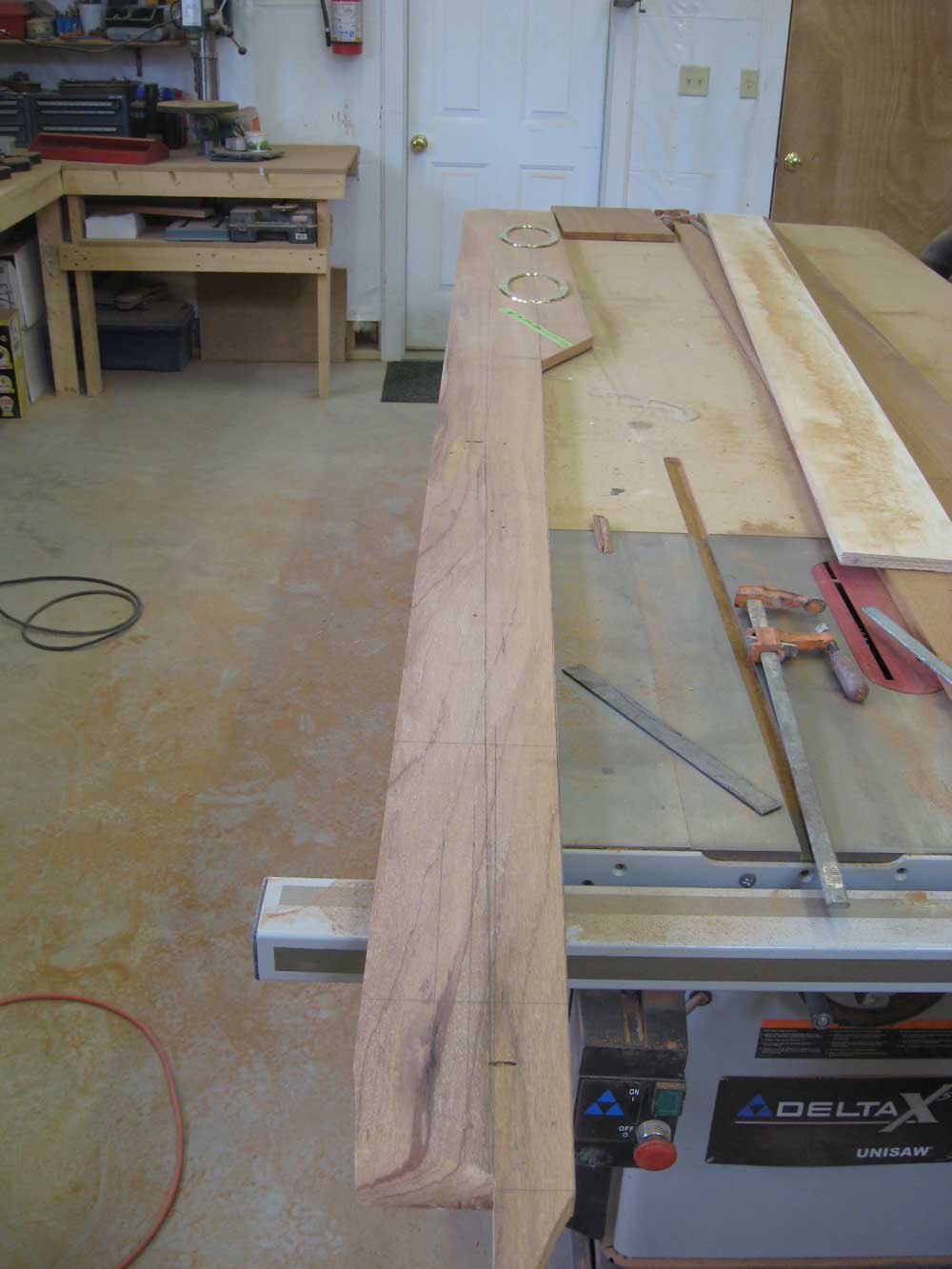
Friday, March 14, 2008 I continued work on the cabin trunk today. I began on the starboard side, and spent most of the morning carefully laying out the actual shape of the cabin trunk (cut lines) on the mahogany. I ended up making a couple minor tweaks to the original mockup design, which I'd anticipated all along. Then, once I had the first side marked and all the tough decisions made, marking and laying out the second (port) side went much more quickly. To begin, I marked the actual forward edge of the cabin trunk. I'd left a bit of an overhang at the forward end so that I could trim it properly to exact length later. From inside the boat, I drew a plumb line starting from the forward edge of the deck opening. I did this on both starboard and port sides of the cabin trunk while I was in there, and then used a long metal straightedge run between the plumb marks to mark the tops of the two boards at the correct bevel for the final cut. |
|
|
|
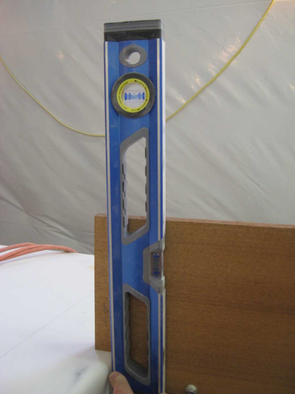
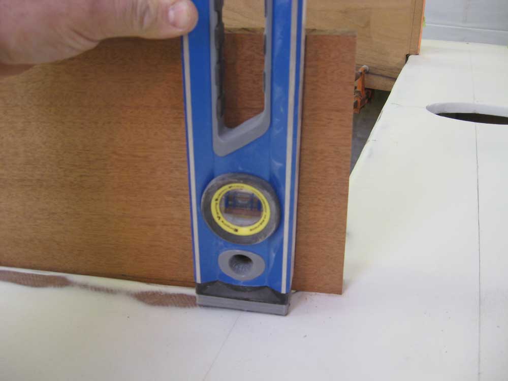
Then, working outside the boat, I transferred the line from the top of the board down the outer face of the board, using a level to draw the line plumb (since the design called for the forward end of the cabin trunk to be a plumb line). |
|
|
|
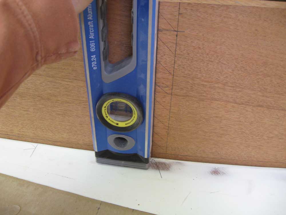
Next, I laid out the after end of the cabin trunk: a line drawn plumb from the bulkhead location, which I'd marked on the deck previously. |
|
|
|
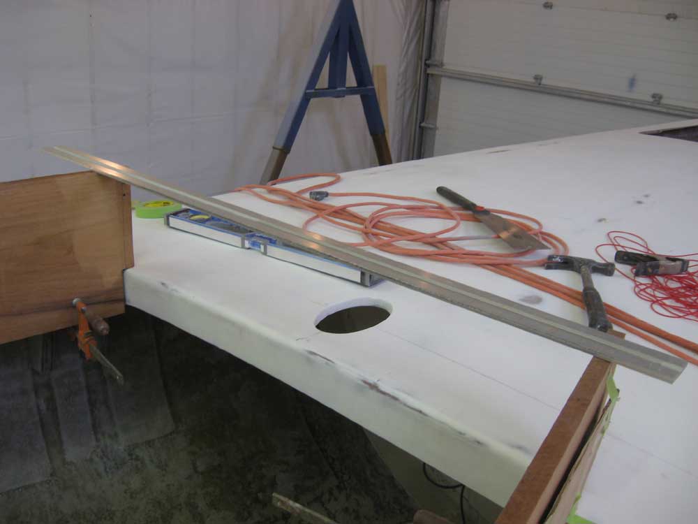
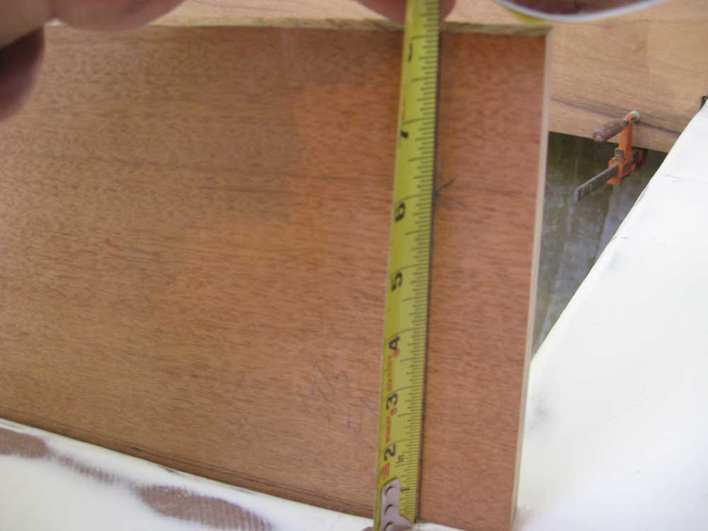
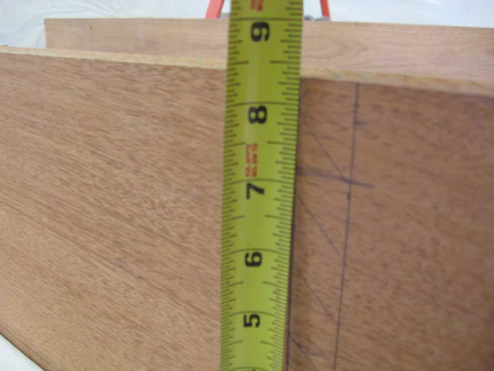
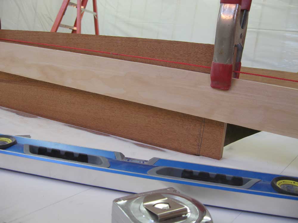
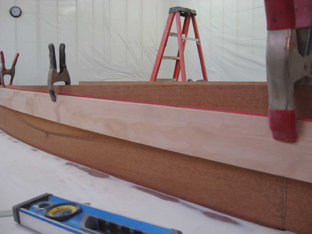
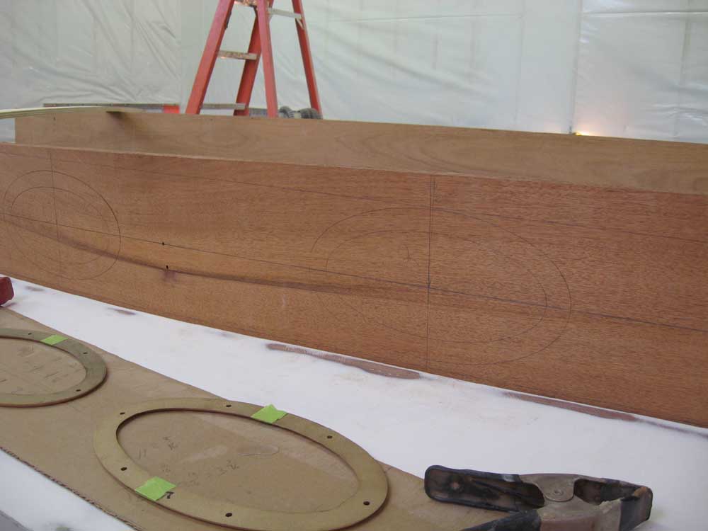
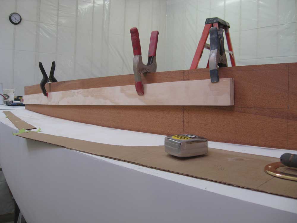
With the two major lines marked, I measured up an appropriate distance from the deck, according to the mockup I'd made from the concept drawings. I marked 6" above the deck at the forward end, and 8" at the aft end. Then, I clamped a straightedge in place between the two and got ready to mark the top line--the top edge of the cabin trunk. To double-check the measurements, though, I once again ran the string from the stem to the aft mark of the cabin trunk to see that it aligned properly. It had seemed to with the mockup, but now I discovered that the forward end of the straightedge was a bit lower than the string. I decided to raise the forward end to meet the string; this turned out to be an increase in height of 3/8". Now satisfied, I drew a pencil line along the straightedge and removed the clamps. |
|
|
|
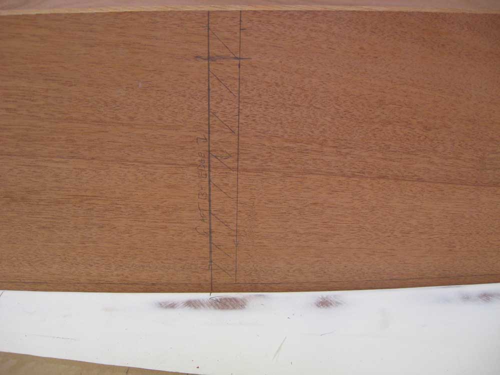
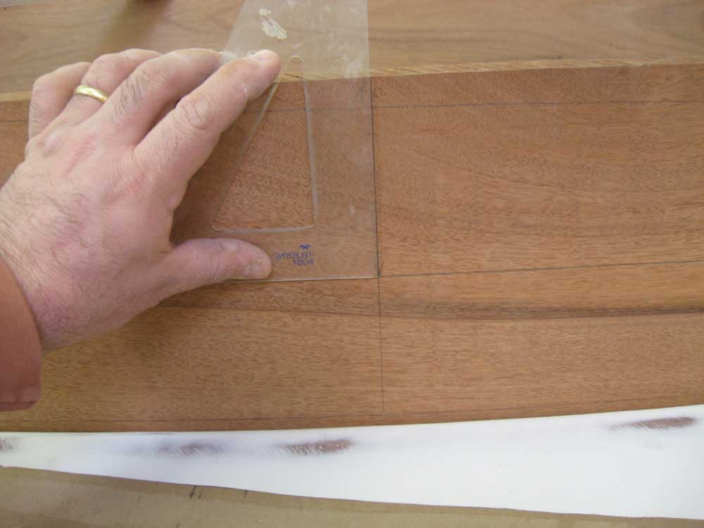
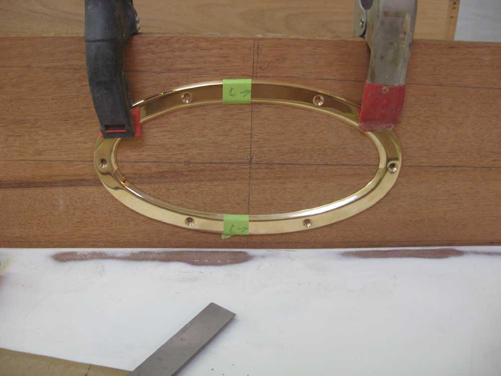
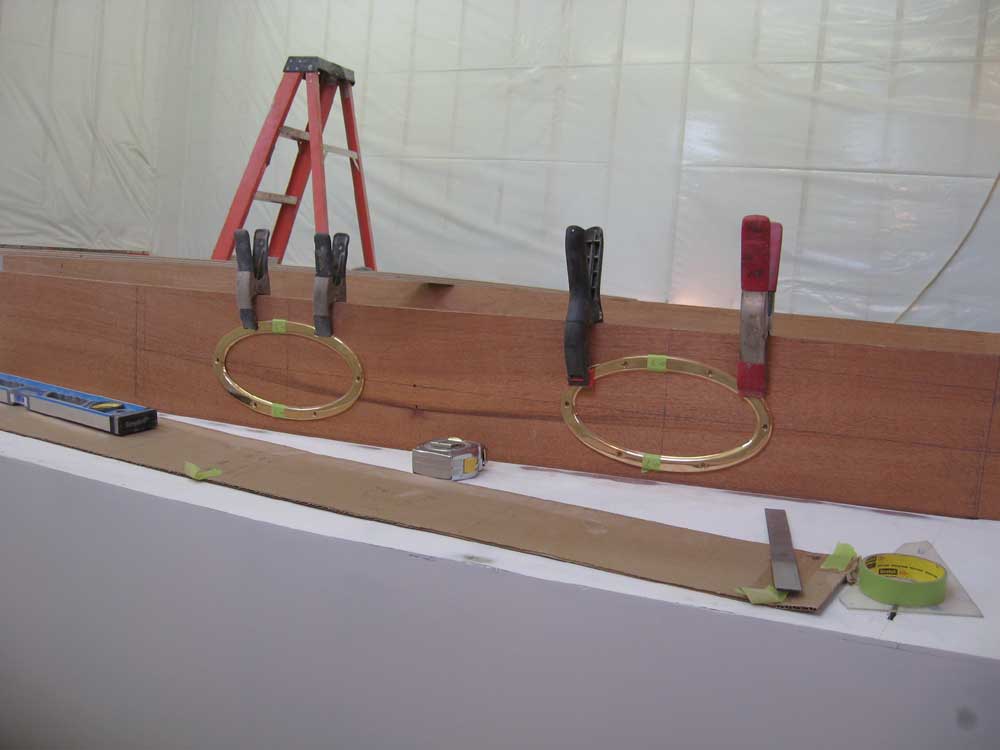
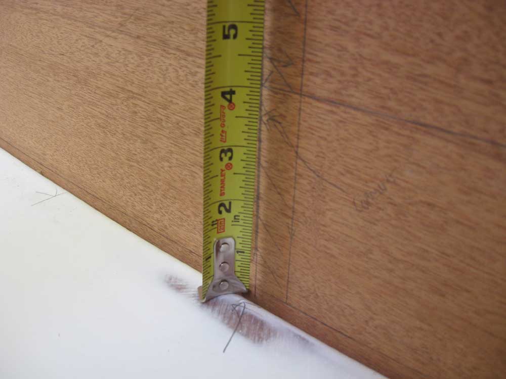
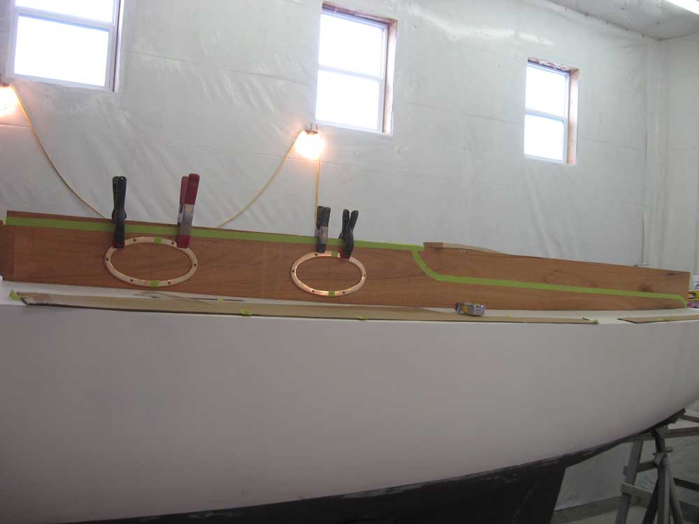
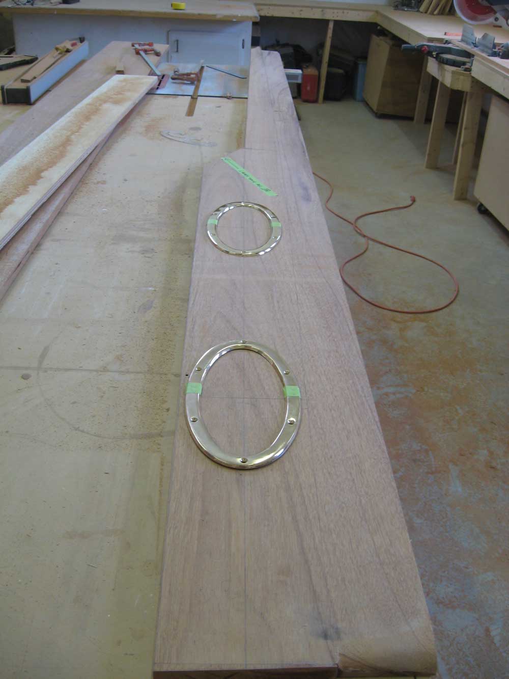
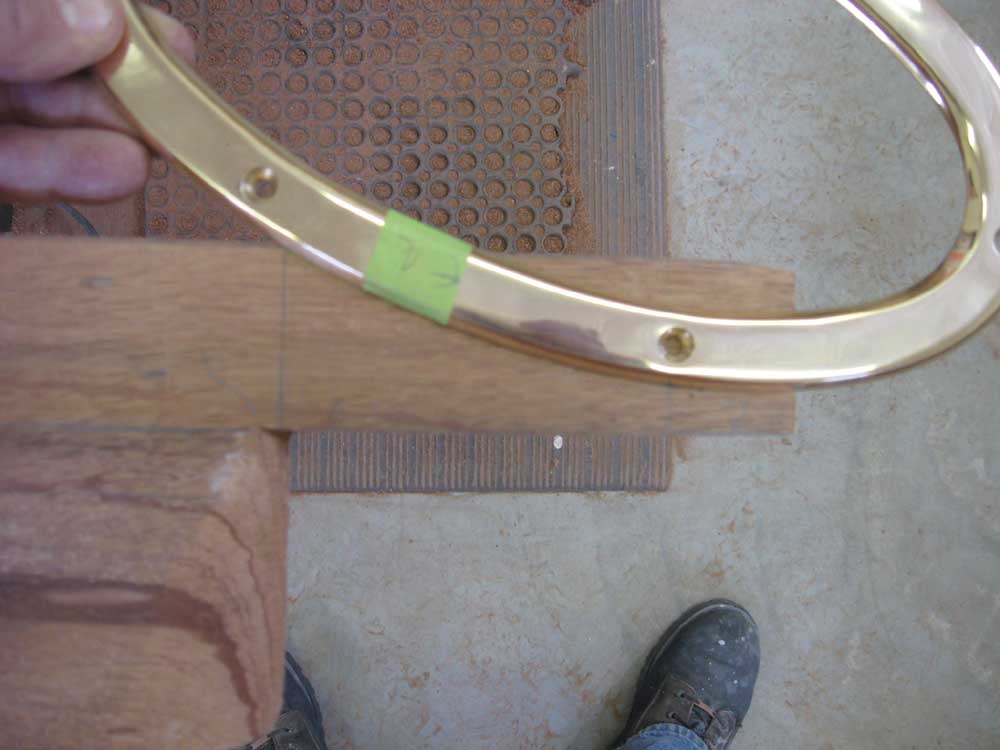
To lay out the porthole locations, I measured up half the height both fore and aft--3-3/16" forward, 4" aft--and connected these marks with the straightedge and a pencil line. Tests with the mockup in November had indicated that the ports should be aligned along this vertical centerline from front to rear. Using measurements I'd determined during the mockup stage, I marked for the centers of the ports: 16" aft of the forward edge of the cabin trunk for the forward port, and 13" forward of the aft edge for the after port. I drew perpendicular lines from the horizontal layout, and then clamped the port frames in place for a look. Afterwards, I marked the inner and outer edges of the frames on the mahogany and removed them for now. |
|
|
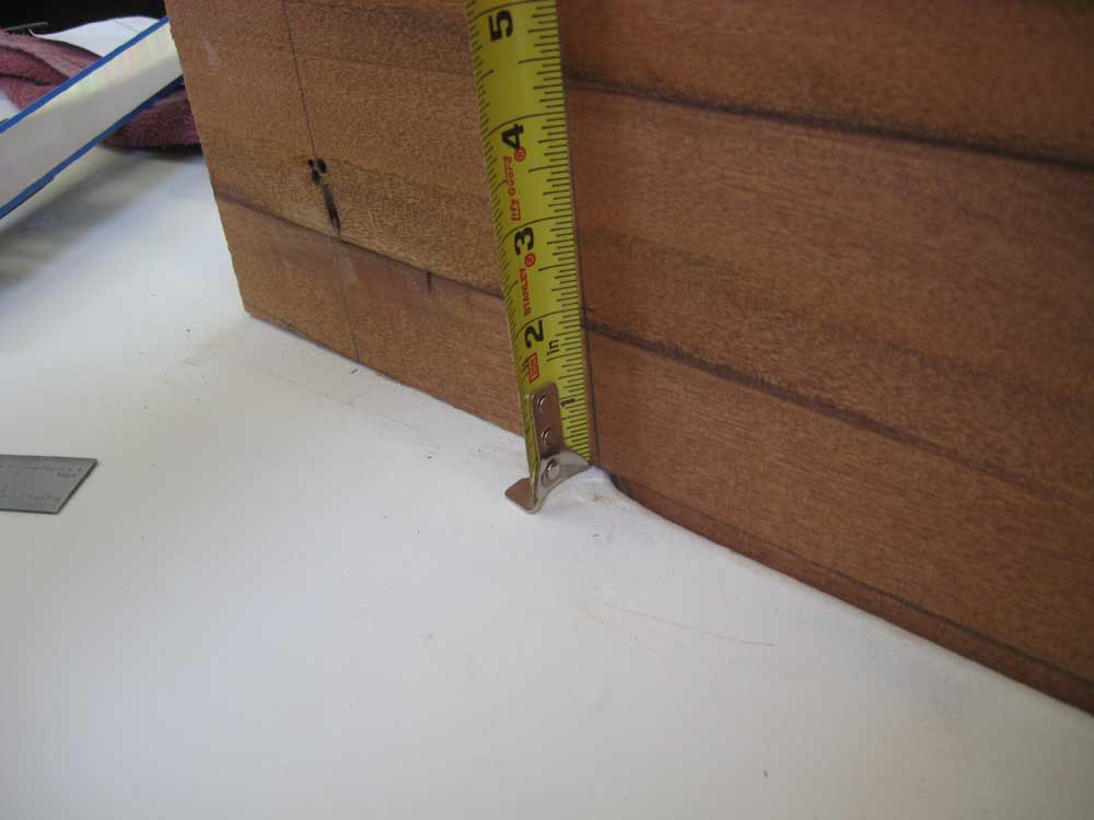
| I continued the main layout with the after part, which would be the cockpit coaming. The mockup called for a 2" height at the after end (where the cockpit opening ended, plus a 4" decorative overhang onto the aft deck), and a 3-1/2" height at the forward end, at the bulkhead, with a decorative curve of some sort connecting the lower coaming with the higher cabin trunk. I made these marks and clamped the straightedge in position. |
|
|
|
This looked fine, but with further
reflection I decided to raise the forward edge 1/2", to 4", to preserve
subliminal continuity with the height of the porthole centers. It
was a small change, but somehow it just seemed like this would make more
visual sense, though I was doubtful anyone would have ever noticed one
way or another. Like buildings designed around the Golden Ratio,
sometimes it's these invisible alignments that make a design flow
better.
Or maybe not, but in the event this is what I did because it made more sense to me. With the slight adjustment complete, I drew the line as required, which completed the layout for the starboard side. For now, I decided to refrain from laying out the exact transitional curve between the cabin trunk and cabin, figuring that it would be best to complete this only after the cabin trunk pieces and bulkhead were permanently affixed. In my mockup, I'd used one of the port frames as a template for this curve, and while I thought I'd still do this, the exact position might change by fractions of an inch here or there, so since I knew I could cut that curve with the coaming in place, I left it for later. |
|
|
|
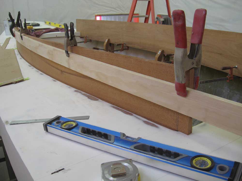
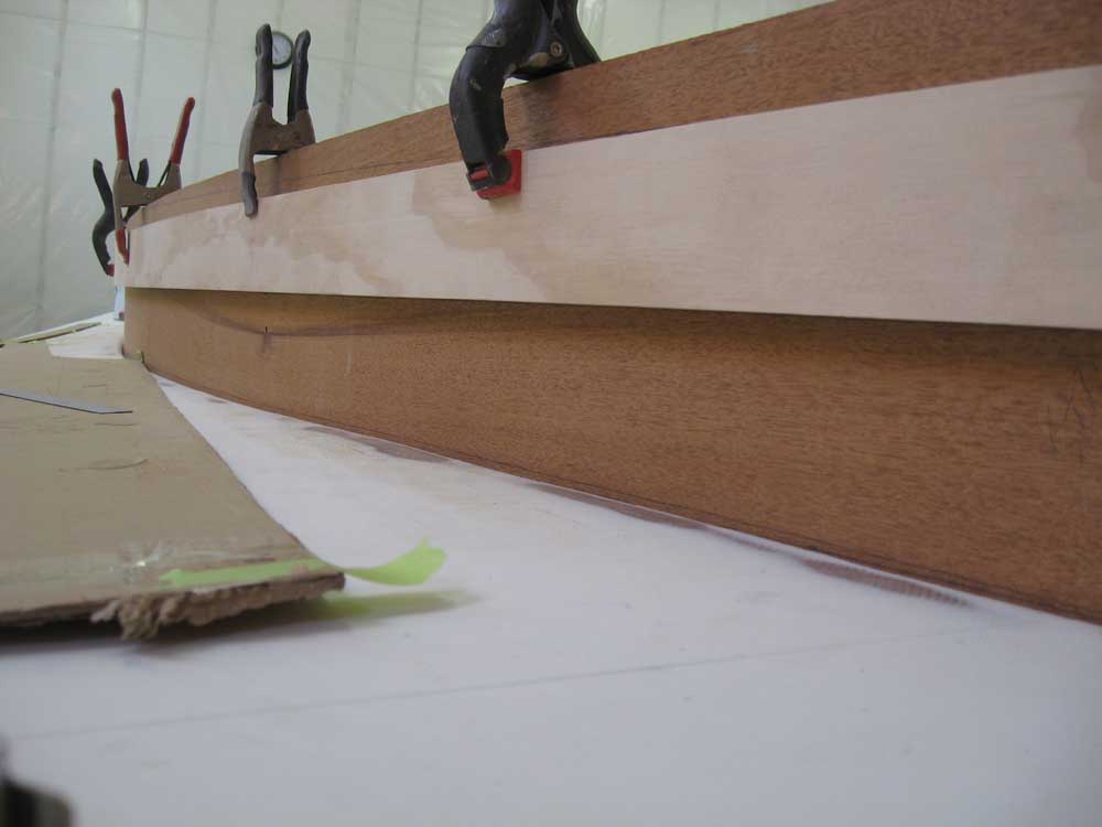
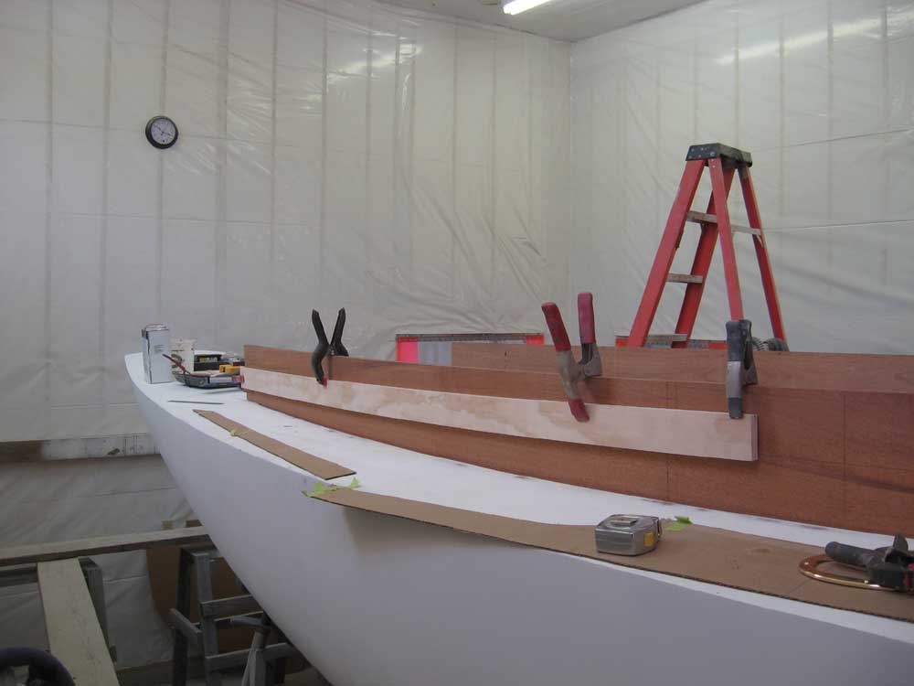
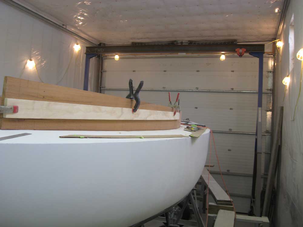
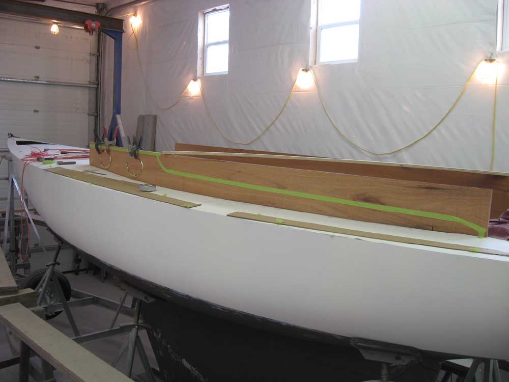
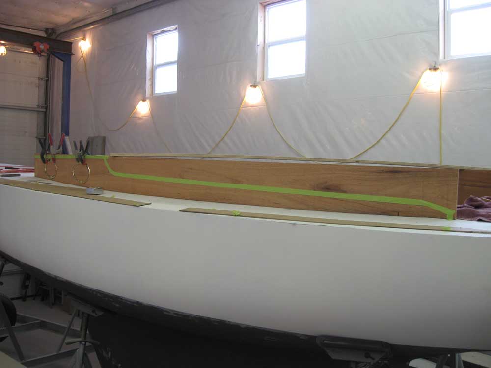
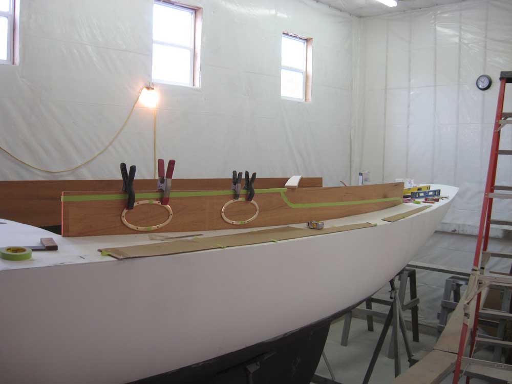
This process took all morning, but in the afternoon I repeated the steps above on the port side, and the process went much more quickly now that I knew exactly what I was doing. To help visualize things, once I'd laid out the pencil lines I outlined them with masking tape; the bottom edge of the masking tape represents the eventual cut line. |
|
|
|
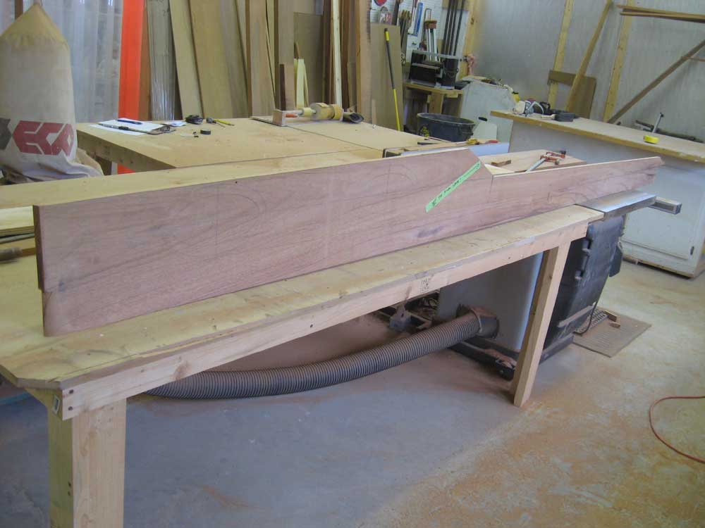
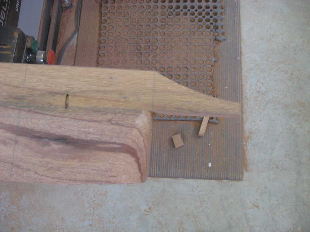
I removed both pieces from the boat down to the bench, and then cut out the pieces according to the layout lines. I began with the compound angles at the forward ends--a 9-1/2° angle to match that formed between the cabin trunk sides and forward end, and a shy 2° angle for the plumb vertical forward edge. The long layout lines were straight, so cutting was simple and accurate with a straightedge and circular saw. At the transitional point between coaming and cabin trunk, I left excess material so that I could fine-tune the layout and curve later on. |
|
|
|
Using one of the port frames as a template, I laid out the decorative coaming tails, and made the cuts. I used the port frame as a template partly because it had a nice elliptical curve, and also because use of that curve for the coaming tail would maintain a visual continuity between the various shapes (again, something no one will probably ever notice). |
|
|
|
With the basic pieces cut, I had a number of steps remaining before I could reinstall them. I wanted to reinstall them only once more--permanently--so before doing so, I'd need to confirm the port locations, cut the port openings, make a router template for the port glass inlays and then rout the rabbets, rout decorative edges on the insides of the port openings (the inside would be frameless), rout the top edges of the coamings as required, sand the pieces smooth, drill for the fastening bolts and countersinks, and probably apply a sealer coat of varnish. I decided to call it quits for this day and continue the process on Monday. |
|
|
|