(page 8 of 8)

Acadia 4

< Back to Acadia

Thursday

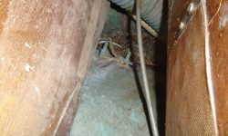
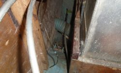
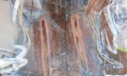
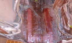
To get started, I washed and lightly sanded the epoxy filler I’d applied in the engine room and stern tube, bringing these areas smooth and flush with their surrounds as required.  Afterwards, with the heavy grinding work behind me, I spent some time cleaning up the work area to prepare for moving forward with new work.

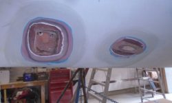
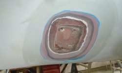
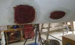
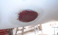
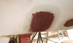
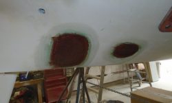
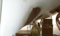
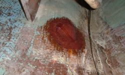
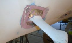
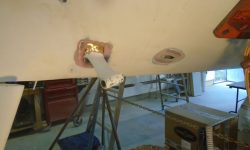
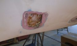
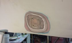
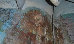
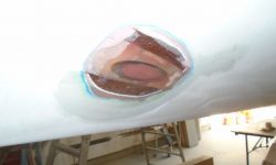
Outside the boat, I completed some final preparations on the old strut location, digging out the fastener holes to remove old sealant, and then preparing the holes for filling.   After masking over the holes from inside, I filled them with a thickened epoxy mixture before installing several layers of fiberglass over the entire area, along with the stern tube location.

Later, I added several additional layers of fiberglass in the recessed portion of the strut location, bringing the area more or less flush with its surrounds, then covered the area with one additional layer over the whole thing.  Inside the boat, I filled the exposed end of the old stern tube with thickened epoxy, then applied two layers of fiberglass set in epoxy over the top to seal the inside of the old opening.

Meanwhile, I made various measurements as I prepared for some of the new work ahead.

Total time billed on this job today:  5 hours

0600 Weather Observation:
50°, mostly clear.  Forecast for the day:  mostly sunny, around 80

Acadia 3

< Back to Acadia

Wednesday

The propeller shaft support strut was now obsolete and no longer required, so I turned to its removal.  From inside the boat, there was a narrow slot providing marginal access to the fixing bolts and nuts.  My initial efforts to remove the nuts and free the strut proved fruitless, as the bolts spun on the outside when I attempted to wrench off the nuts within.

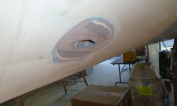
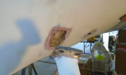
Back outside the boat, I used a grinder to remove the paint and fairing compound that covered the base of the strut where it was secured to the hull, exposing the flathead screw heads and the edges of the strut base itself.  This confirmed for me that the strut used standard bolts, not integral studs.  While I had the grinder going, I ground a beveled area around the nearby stern tube opening, which I’d also be filling and patching.

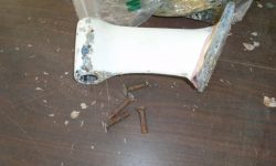
Back inside the boat, I used a reciprocating saw and long blade to cut off the nuts and bolt ends securing the strut.  Access was limited, and I had to remove a nearby cleat on the bulkhead so the saw body had enough room to reach all four bolts.  Since the bolts were bronze, cutting was fairly easy, and with the nuts and excess bolt length removed, I could easily spin out the bolts from outside–they seemed to be threaded through the hull–and remove the strut itself.  Afterwards, I prepared the hull around the old strut location (which was recessed into the original laminate) by grinding a beveled area about the location.

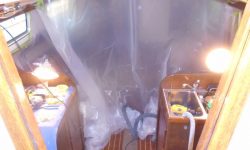
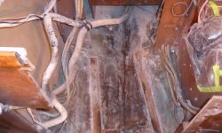
The original engine foundations were in excellent condition and were strongly installed, but the new installation required their removal, so I spent some time preparing tools and equipment for the job.  Because cutting and grinding away the old fiberglassed engine beds would make a mess, I installed plastic curtains to help prevent dust from entering the saloon and forward parts of the boat, and also covered over the galley and nav station cabinets with plastic.

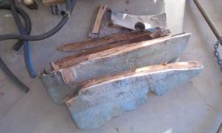
The engine foundations were indeed very strong, and removing them proved to be a lengthy and arduous process.  As ever, access was tighter than one might like, so fitting in grinding wheels and saw blades required various positions and care to prevent damaging any of the nearby installations and critical parts of the tool operator.  The foundations were built from laminated plywood heavily encapsulated with multiple layers of fiberglass, and heavily fiberglassed to the hull.  It was a nice installation that had held up well over nearly 40 years, and the engine beds fought removal to the end.  I cut through the fiberglass as much as possible using a grinder and cutoff wheel, then used the saw (with fewer good blades on hand than I’d hoped and planned to have) to cut through the wood and, as needed, additional fiberglass to the point that I could finally pry off the heavy foundations.

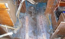
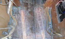
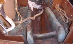
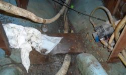
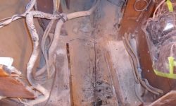
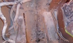
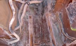
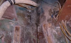
This left behind remnants of wood in the now-recessed areas inside of the old tabbing, and I pried out the wood and rough-cleaned the area before proceeding.  Then, to smooth out the cut edges of the old fiberglass and prepare the area for new work, I ground away the remains of the tabbing to the extent possible, leaving the edges of the old foundation locations flush with the surrounding hull.   There was no hope of removing the old foundation tabbing left on the hull–nor was there a need–so I strove for as flat and flush a result as possible, other than the recesses where the wood had been glued to the hull during original construction.  I also cut and ground away the inside portion of the stern tube, electing to leave the heavily-glassed bump at the aft end where the builders had done a nice job fairing and glassing in the original tube.

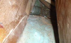
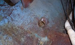
This chore made a mess and took quite a bit of time, but after cleaning up the area thoroughly, I solvent-washed the now-flush engine bed locations and applied some thickened epoxy filling material into the grooves left behind by the old plywood, bringing these areas up level with the surrounding hull so I’d have a relatively consistent and smooth substrate from which to work going forward.  I also masked over from inside and filled the old stern tube opening through the hull, the first step in patching this area permanently.

Total time billed on this job today:  7.5 hours

0600 Weather Observation:
50°, clear.  Forecast for the day:  Sunny, 80s


Acadia 2

< Back to Acadia

Wednesday

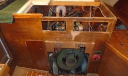
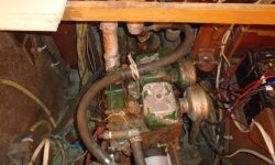
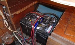
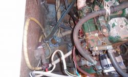
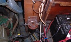
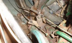
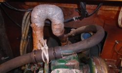
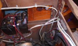
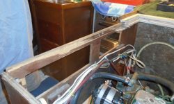
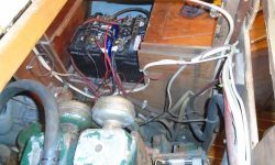
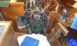
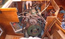
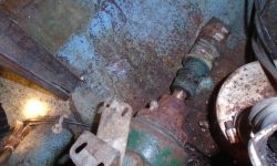
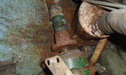
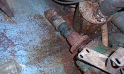
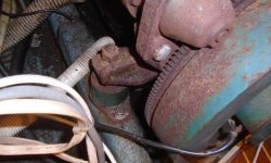
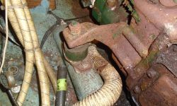
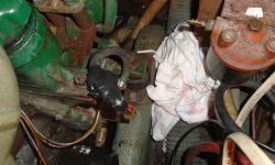
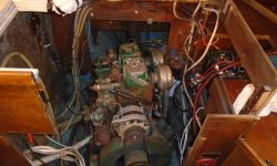
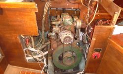
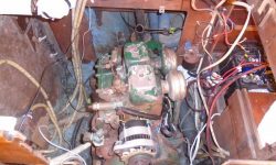
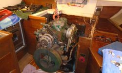
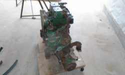
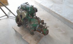
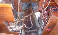
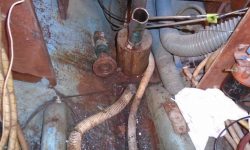
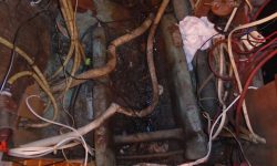
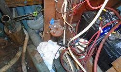
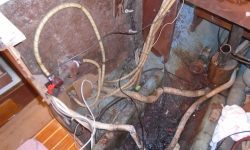
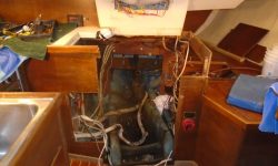
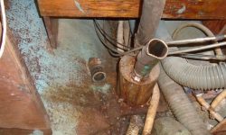
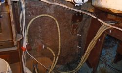
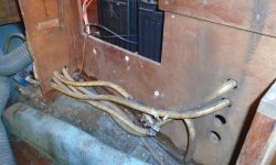
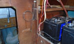
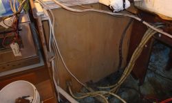
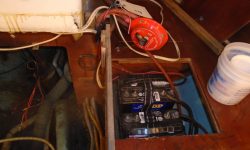
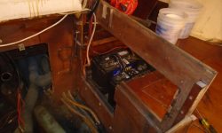
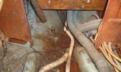
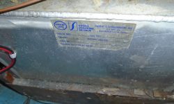
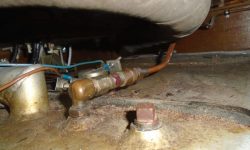
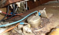
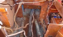
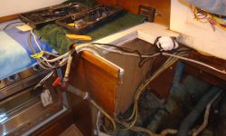
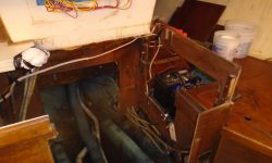
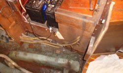
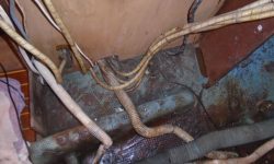
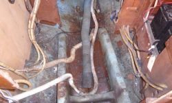
Before beginning on the engine removal, I took some time to thoroughly document the original condition of the engine and engine room.  These photos show the general state of things, but I took many more for posterity and to help later in reassembling some of the existing systems (mainly wiring runs, since most of these would end up remaining intact).

To begin, I had to remove the front panel, as well as a side panel–basically everything I could remove to improve access for disassembly and, later, removal.  To remove these panels, I also had to remove various wiring and plumbing runs that were in the way.  For now, I draped the wires over the engine for later attention.

Now, I systematically went through the space, documenting as necessary, to remove all the connections to the engine itself to release it for removal.  This included various plumbing, raw water bypass for a defunct water heater; raw water cooling hose; exhaust hose and riser (which unbolted easily from the engine, making removal of the bulky riser possible), and fuel line (supply only; no return on this old engine).  I also removed the wiring harness to the nearby gauge cluster, positive battery supply and grounds, and anything else directly connected to the engine.

With most of the ancillary clutter out of the way, I could lean over the top of the engine (made possible thanks to the easily-removed exhaust riser) and remove the coupling bolts.  I was briefly vexed when it seemed the rusted nuts were rounded over, but quickly I determined they were Allen head bolts, so with the correct wrench and a breaker bar, I could remove the four bolts relatively easily, releasing the engine from the shaft.

Finally, I unbolted the engine mounts–two machine screws and/or lags at each corner, or eight total–which released the engine for removal.

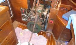
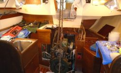
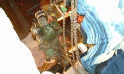
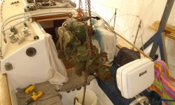
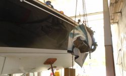
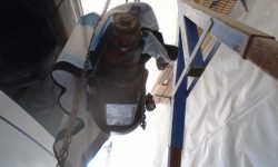
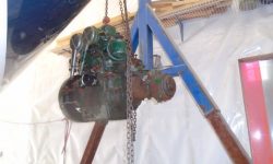
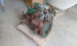
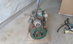
Next, I hooked up the gantry crane and carefully lifted the engine from its beds, out of the cabin, and finally over the side to the shop floor, leaving an empty and filthy engine room behind.

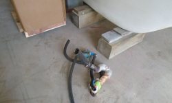
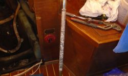
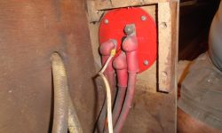
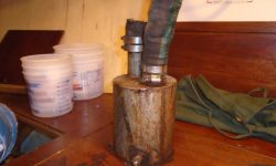
I spent the remainder of the day working to remove whatever else I could, including unnecessary wiring (i.e. old gauge wires), the old fuel filter, waterlift chamber, propeller shaft and stuffing box, and disassembling the rest of the engine room to make room for the work ahead, as well as to remove some old sound insulation on one side.  To make it easier to get the old wiring out of the way, since the existing wire bundles were a mishmash of old and new additions that criss-crossed in unfortunate ways, I removed the battery switch and redirected some other wiring as needed so I could finally drape the wires out of the way on both sides of the engine room, leaving the main part of the space clear for the work ahead.  Any wires I could get rid of at this point went in the trash bin, but there’d likely be more thinning out later as I determined whether other wires were obsolete.   I also cleaned out the worst of the oily/rusty/dirty debris from beneath the engine as a starting point.

Total time billed on this job  today:  7.5 hours

0600 Weather Observation:
52°, mostly clear.  Forecast for the day:  sun and increasing wind and humidity, showers and thundershowers in the afternoon.  High in the 80s

Acadia 1

< Back to Acadia

Tuesday

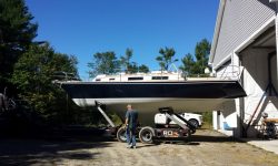
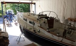
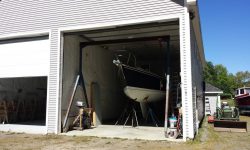
Late in the morning, Acadia, a 1979 Sabre 34, arrived at the shop.  I had the hauler put her right indoors, as I was ready to begin the project at once,
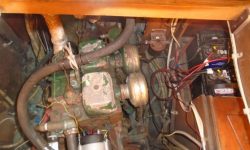
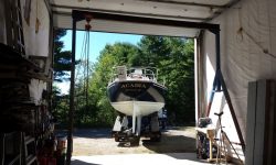
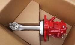
The boat was in very good condition overall, as her owner had had a lot of work done over the years, so for now the scope of work was limited to replacing her aging green monster Volvo diesel with a new engine and, in an interesting twist, a Saildrive unit, which would replace the traditional shaft arrangement which, on this boat, exited the hull offset to starboard.

prop1-91316

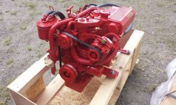
The new engine and propulsion unit were already on hand, as the owner had ordered them well in advance.

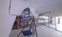
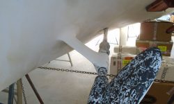
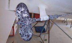
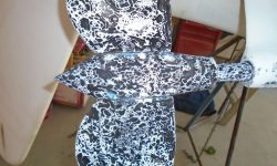
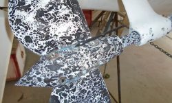
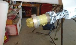
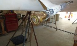
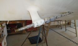
Late in the day, after familiarizing myself with the boat a bit, I started work by removing the two-blade feathering prop, a relatively simple process once I’d looked up some details about the propeller, as I’d not had opportunity to remove one of these before.  The unique patterns on the propeller and shaft come from the bottom paint that had been applied over all surfaces.

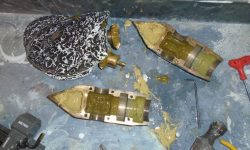
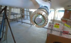
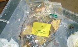
The body of the propeller was secured together with six set screws locked in place by tiny cotter pins.  After scraping away paint buildup and accessing the cotter pins, the screws came out easily, releasing the two blades and gear arrangement within.  Then it was a simple matter to remove the prop nut hidden inside and, with minimal use of a prop puller, remove the inner works of the prop from the shaft.  I also removed the two shaft zincs, leaving the shaft clean and free for removal later.

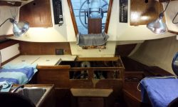
Inside the boat, I took a moment to set up some lighting and power to prepare for the work in the engine room.

setup1-91316

Total time billed on this job today:  1.5 hours

0600 Weather Observation:
46°, clear.  Forecast for the day:  sunny, 80

Newer posts