Tuesday
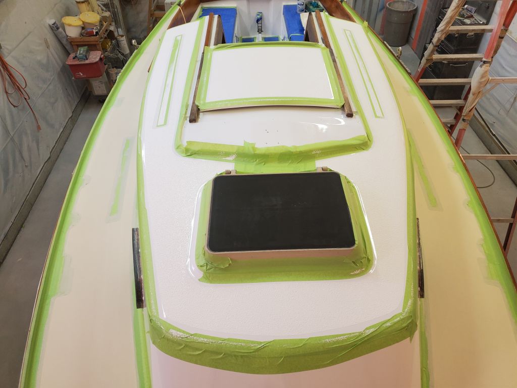
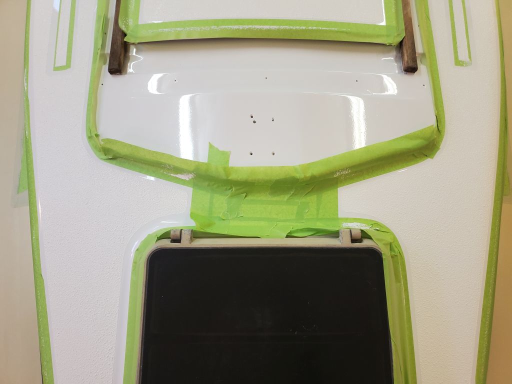
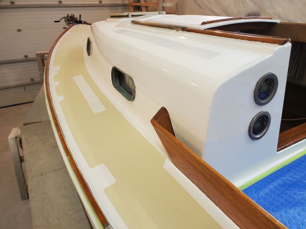
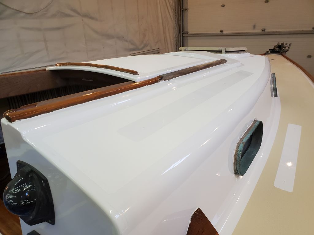
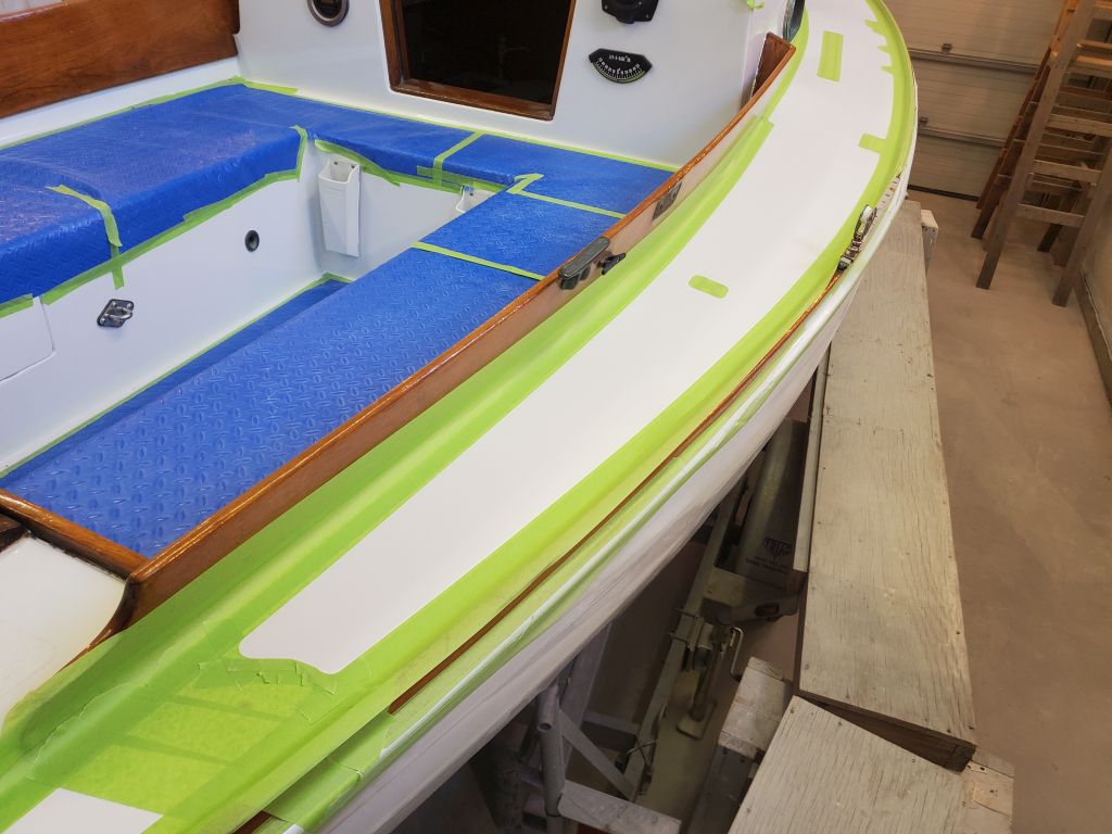
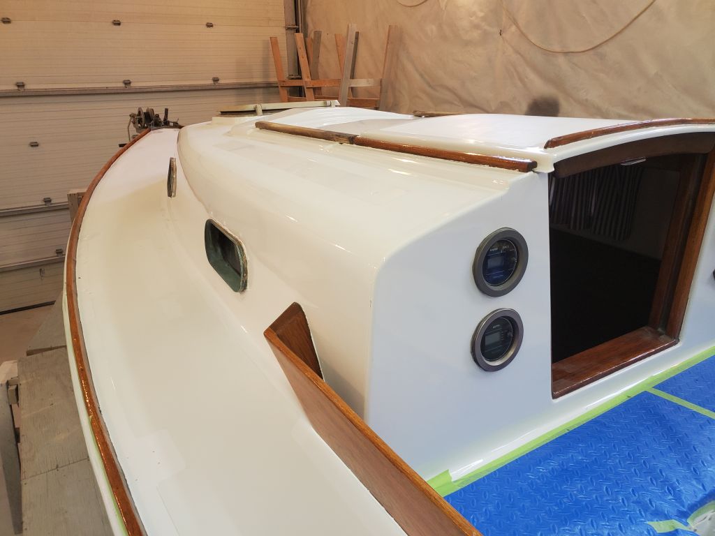
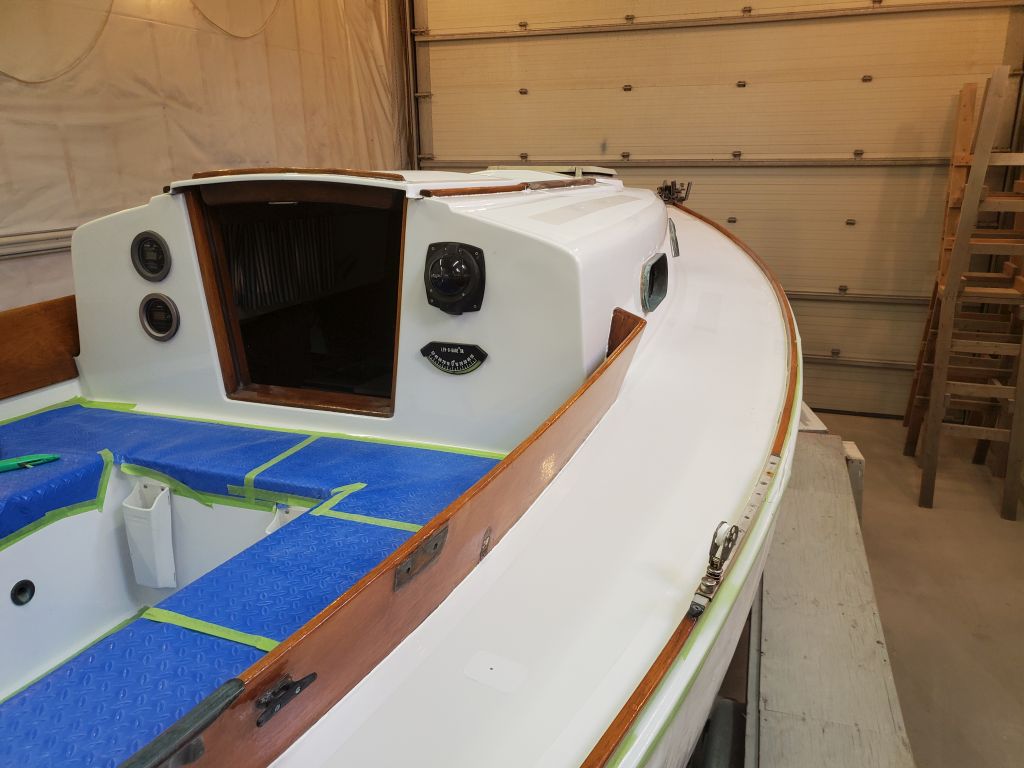
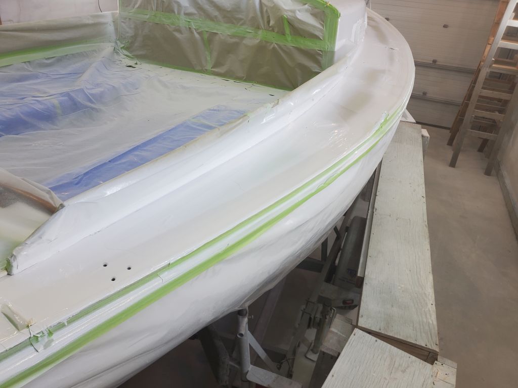
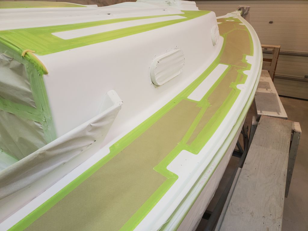
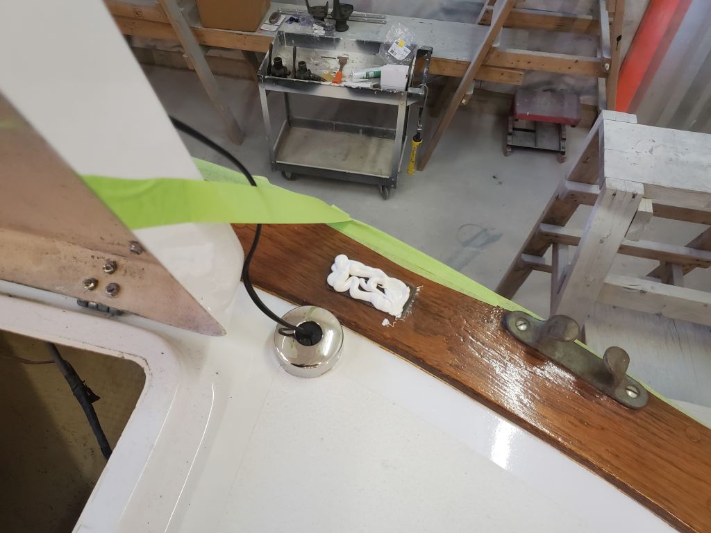
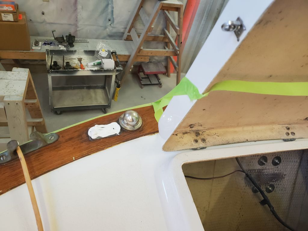
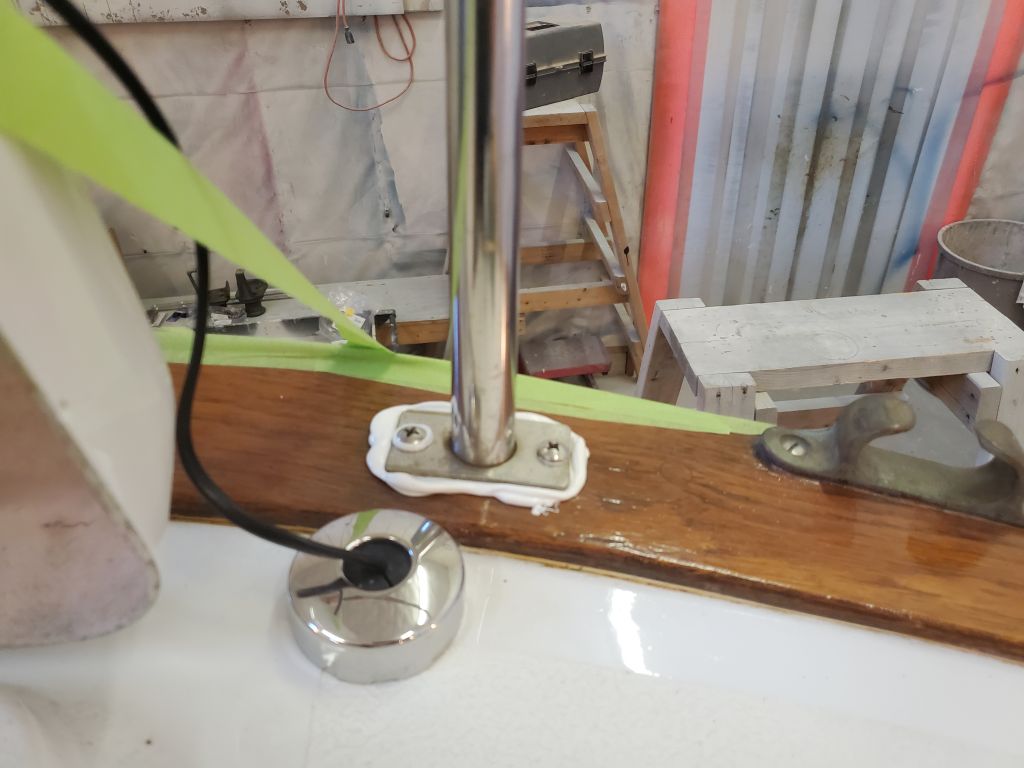
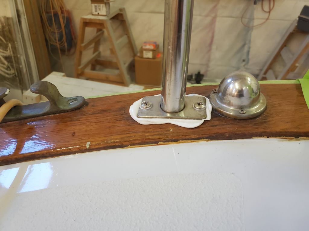
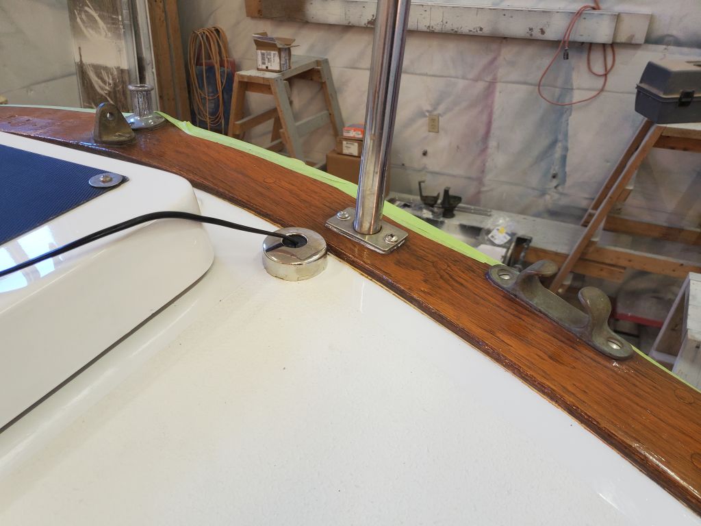
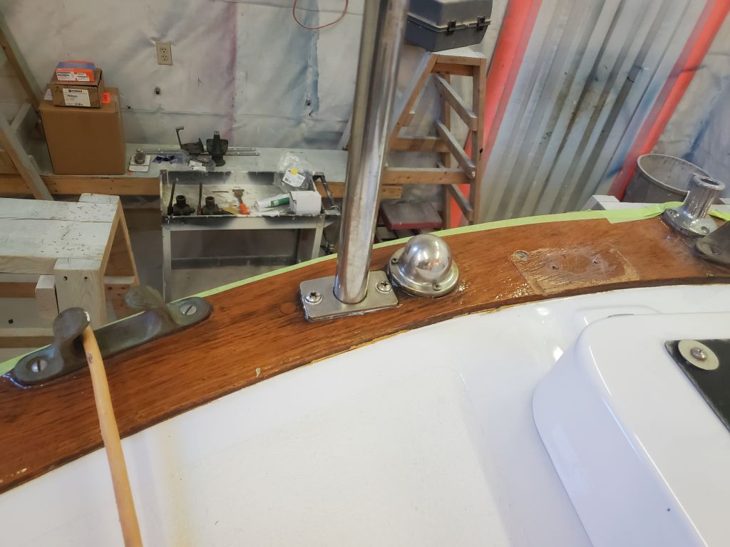
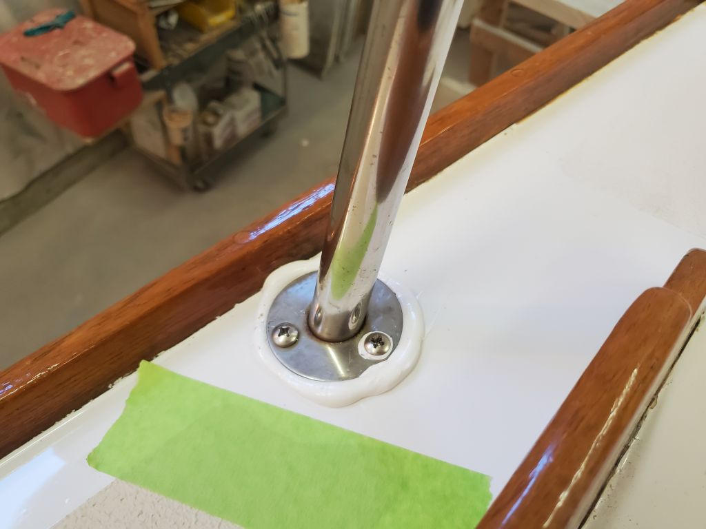
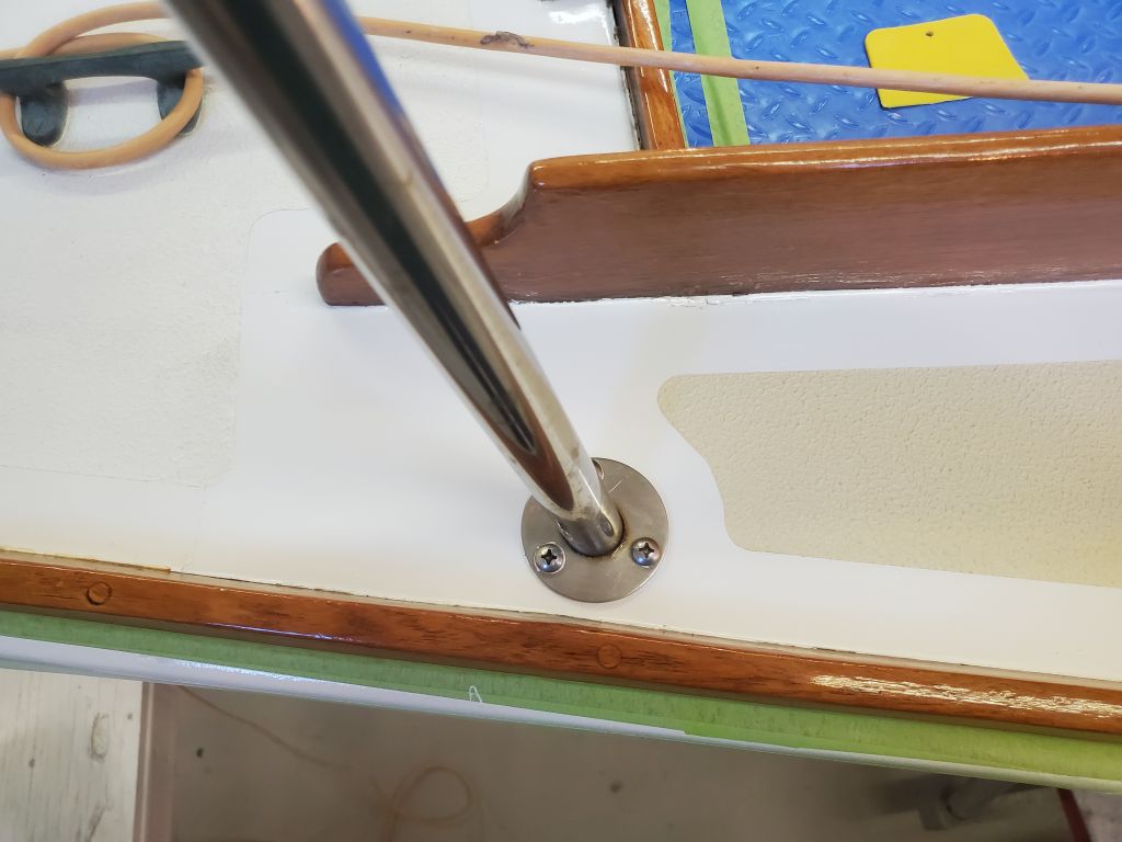
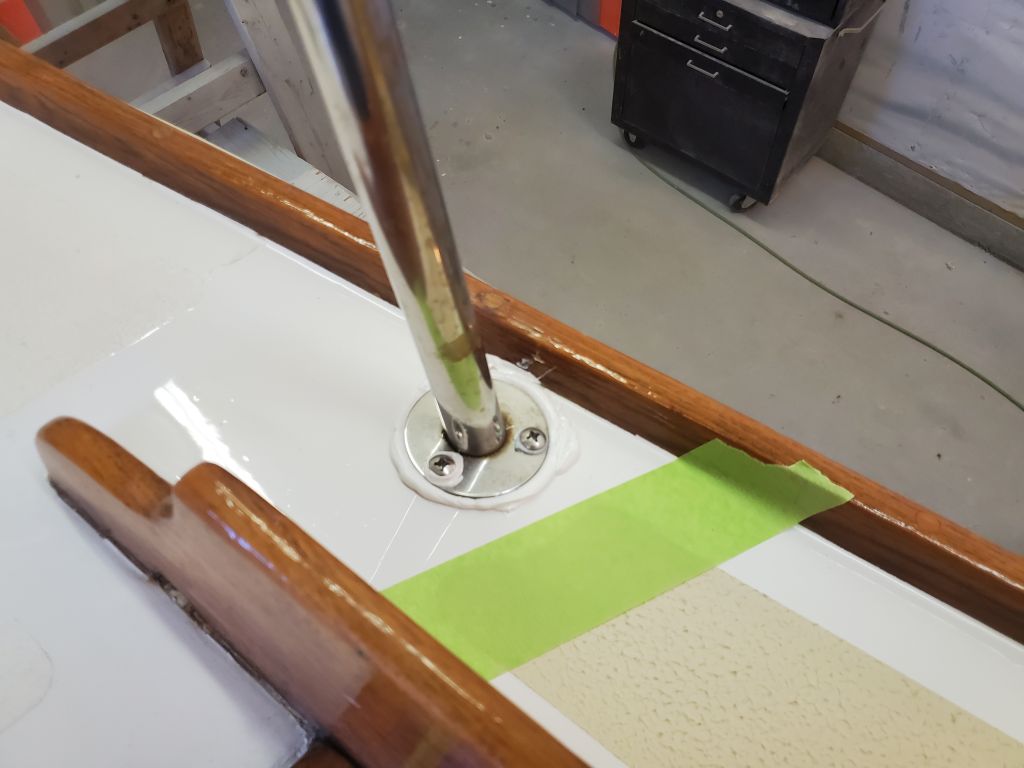
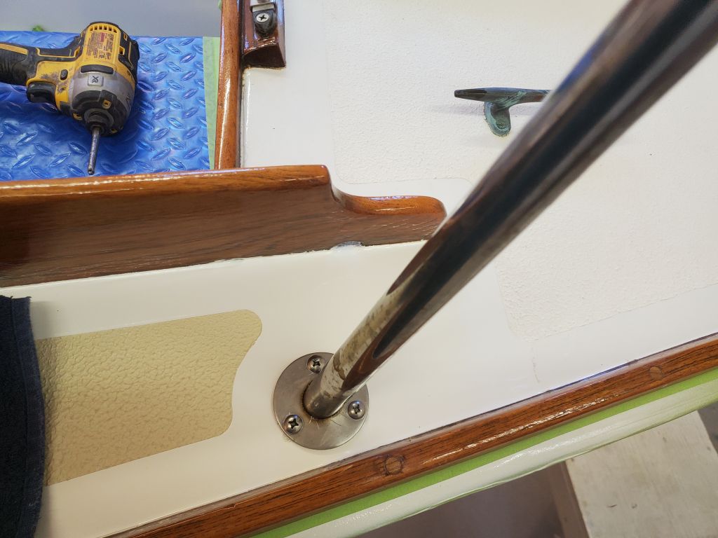
To begin the morning, I installed the stern pulpit, beginning with the two after bases on the taffrail, then the two forward bases.


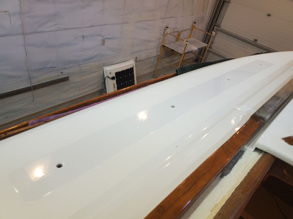
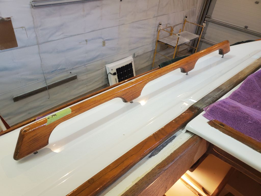
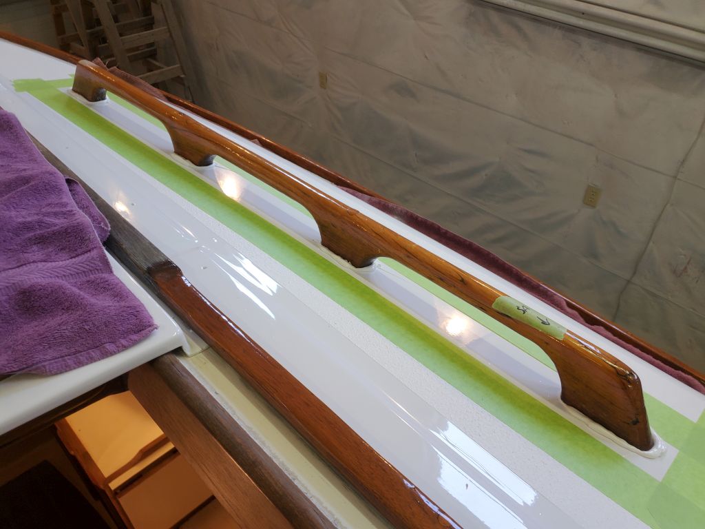
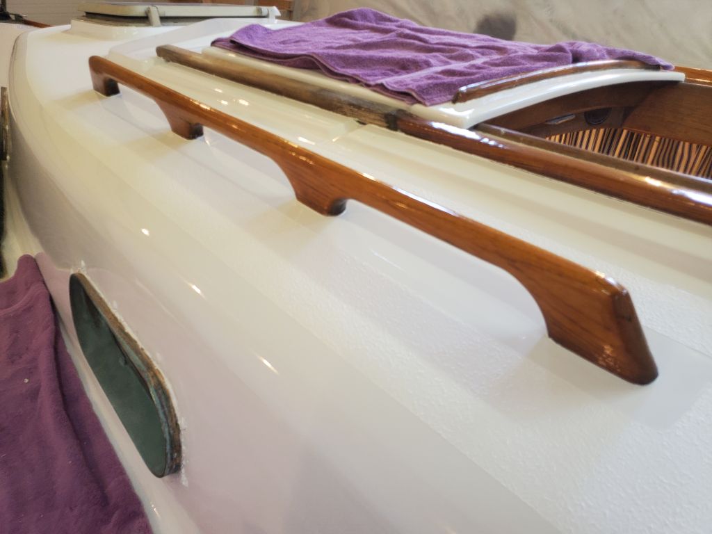
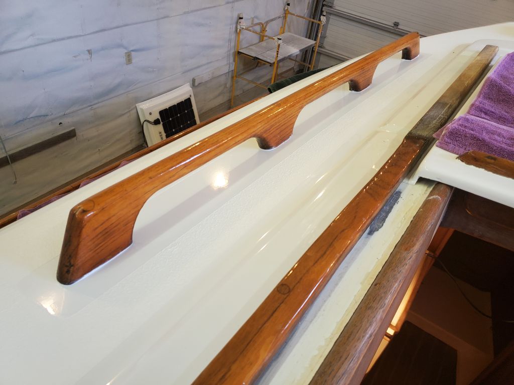
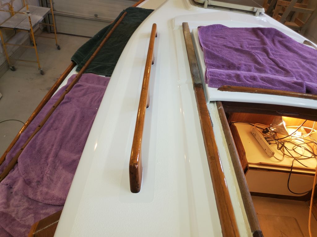
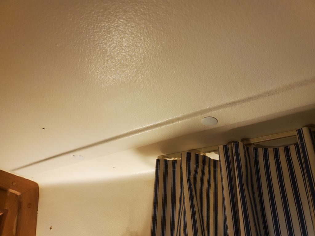
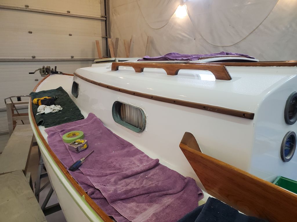
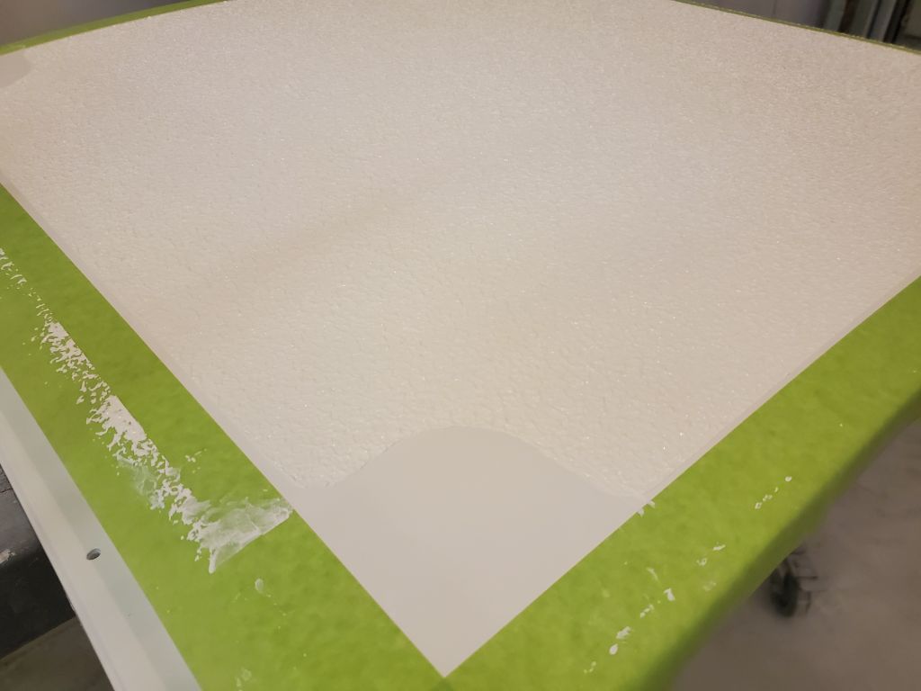
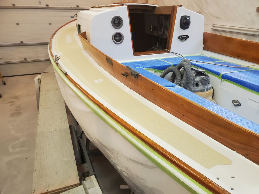
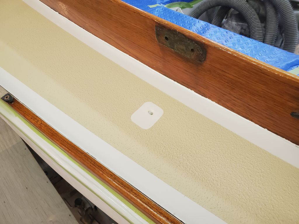
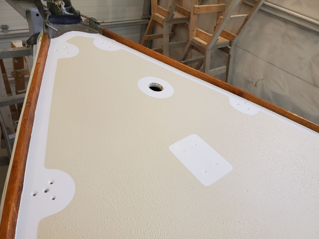
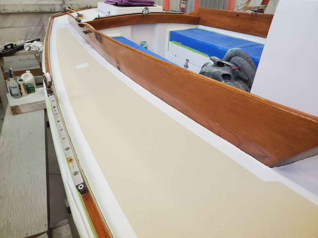
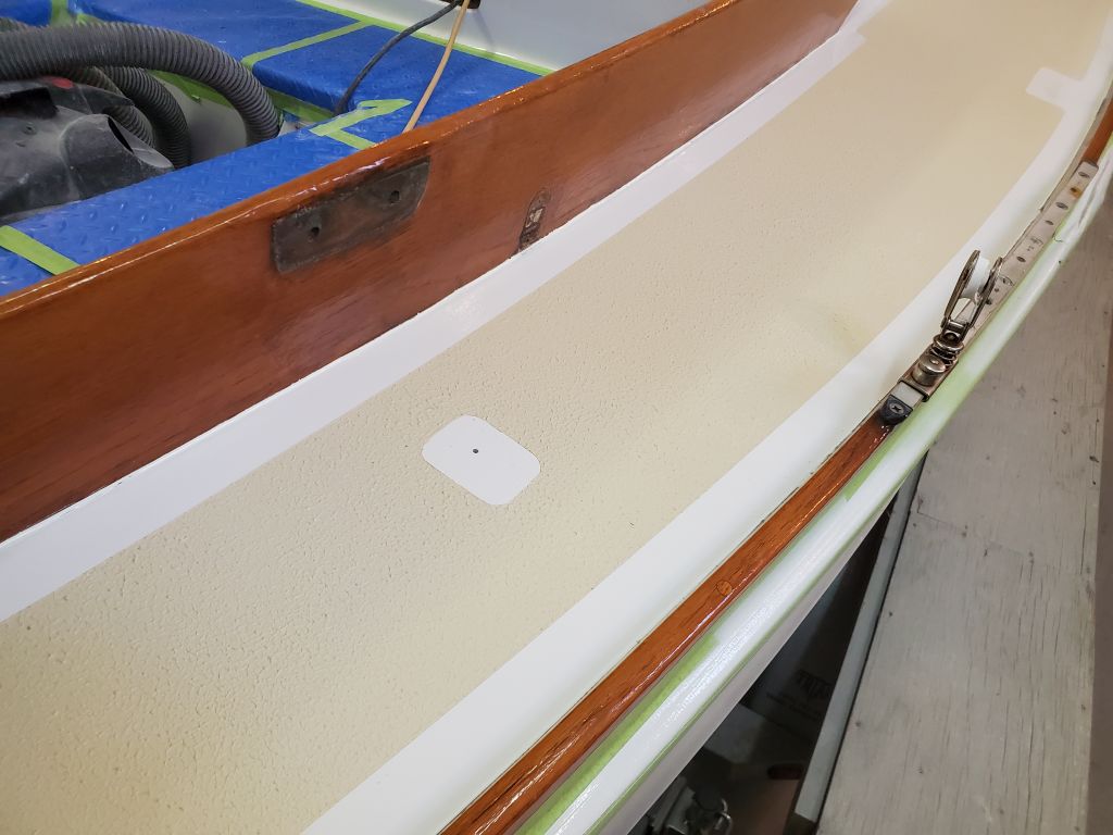
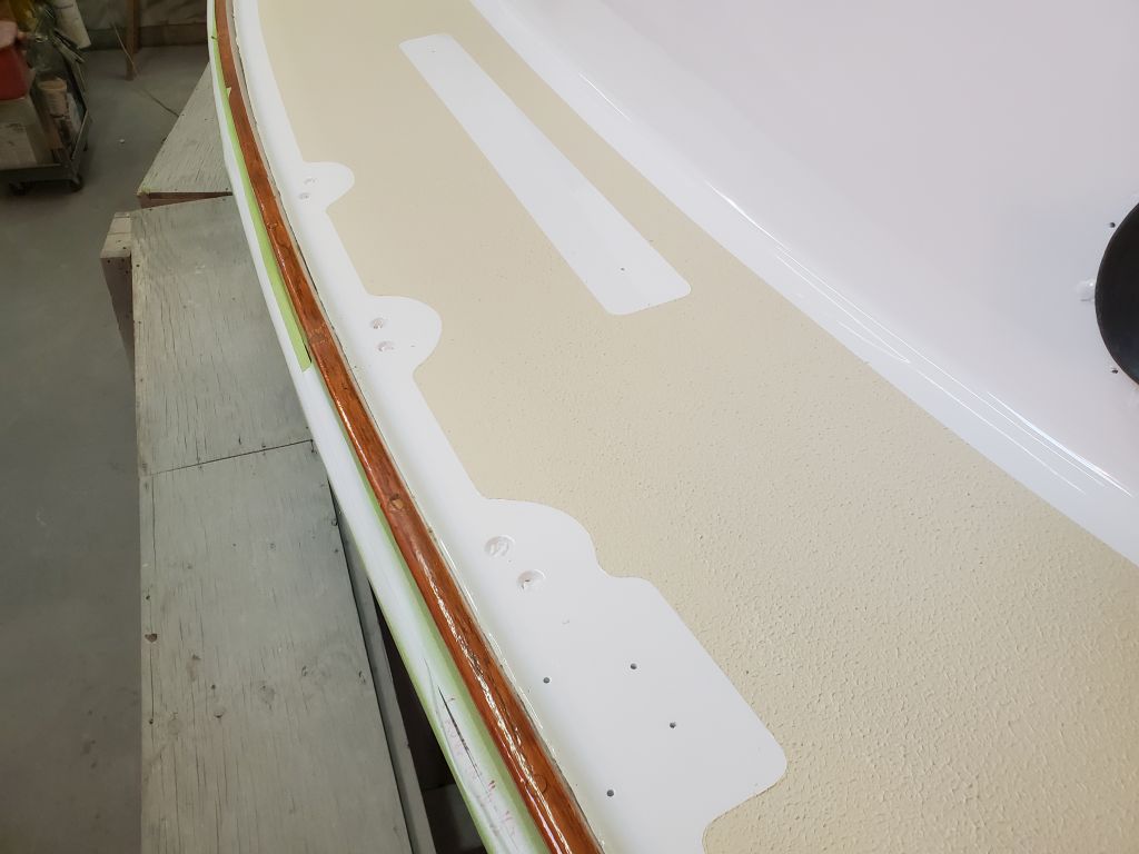
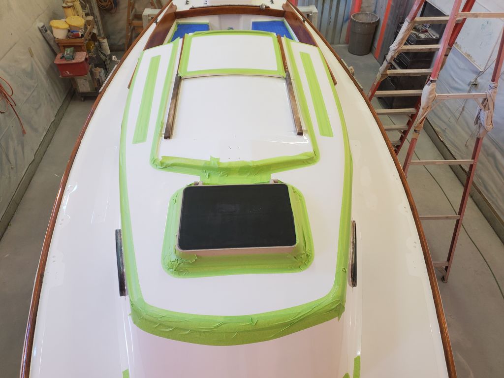
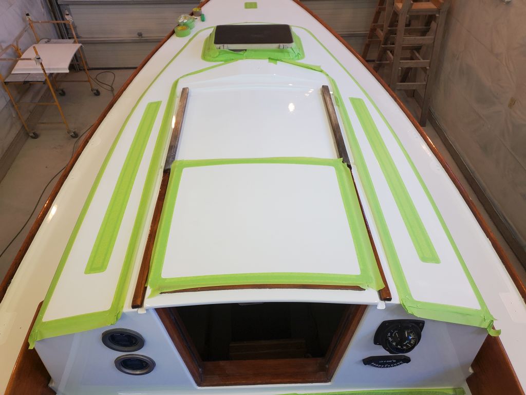
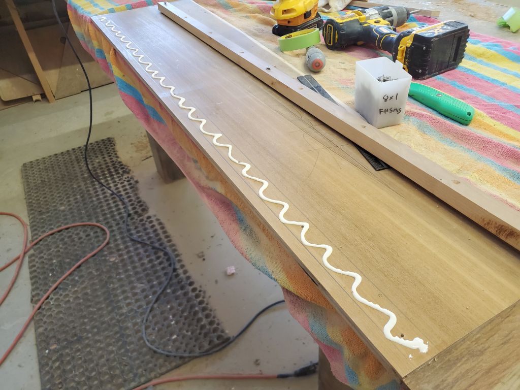
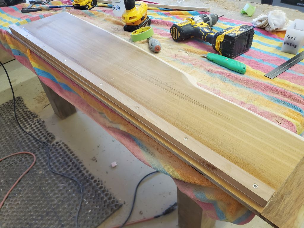
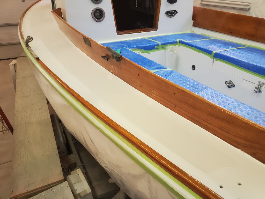
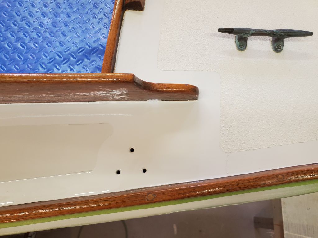
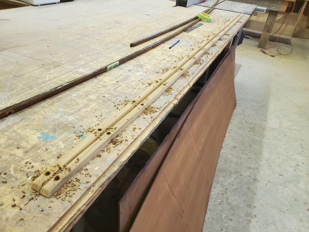
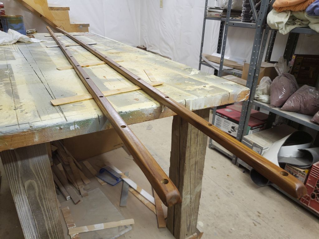
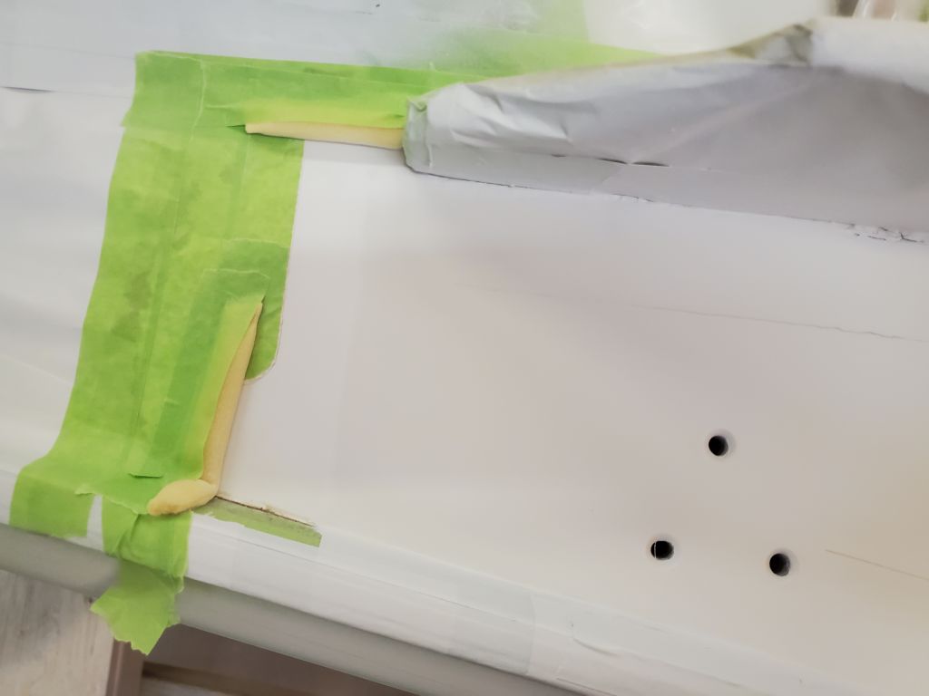
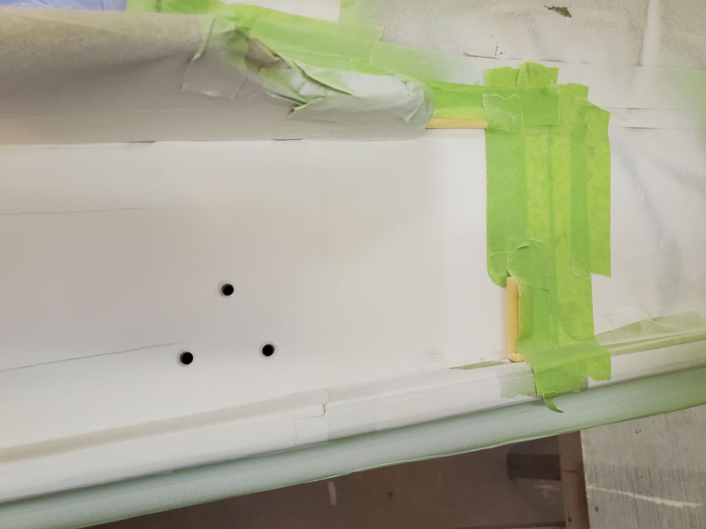
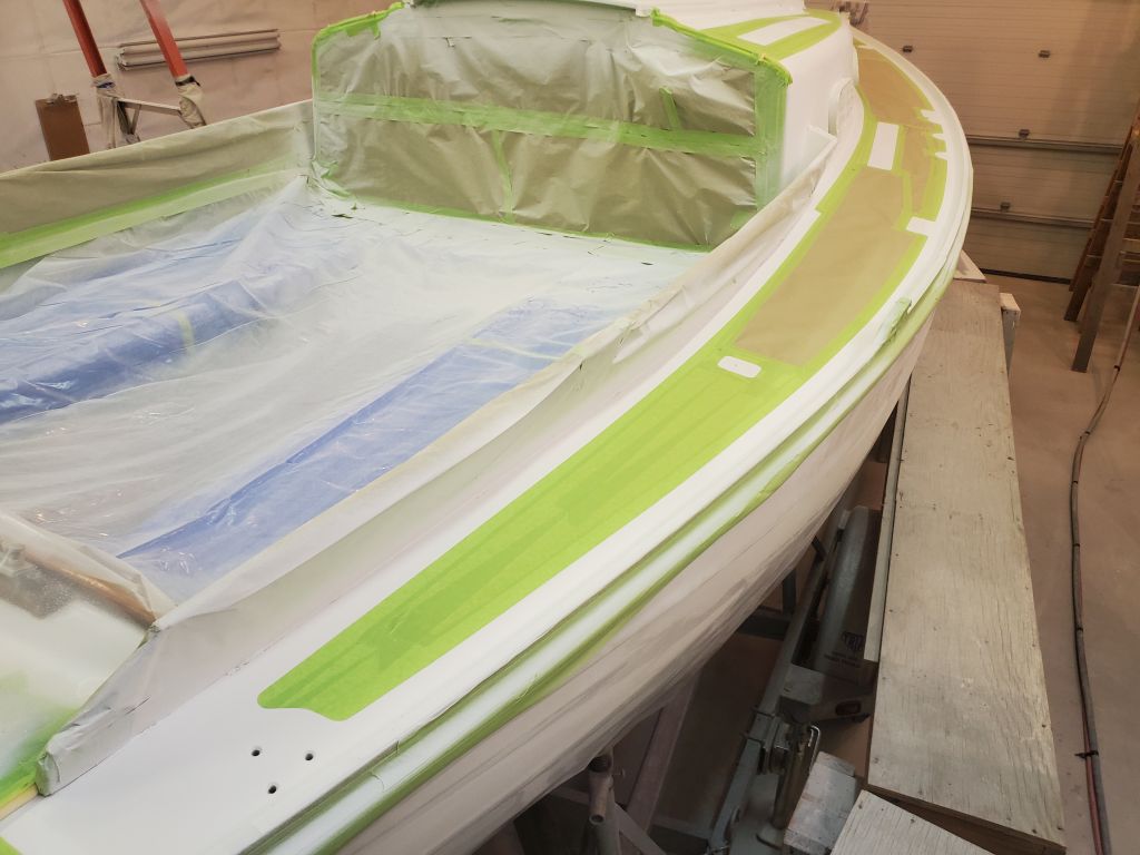
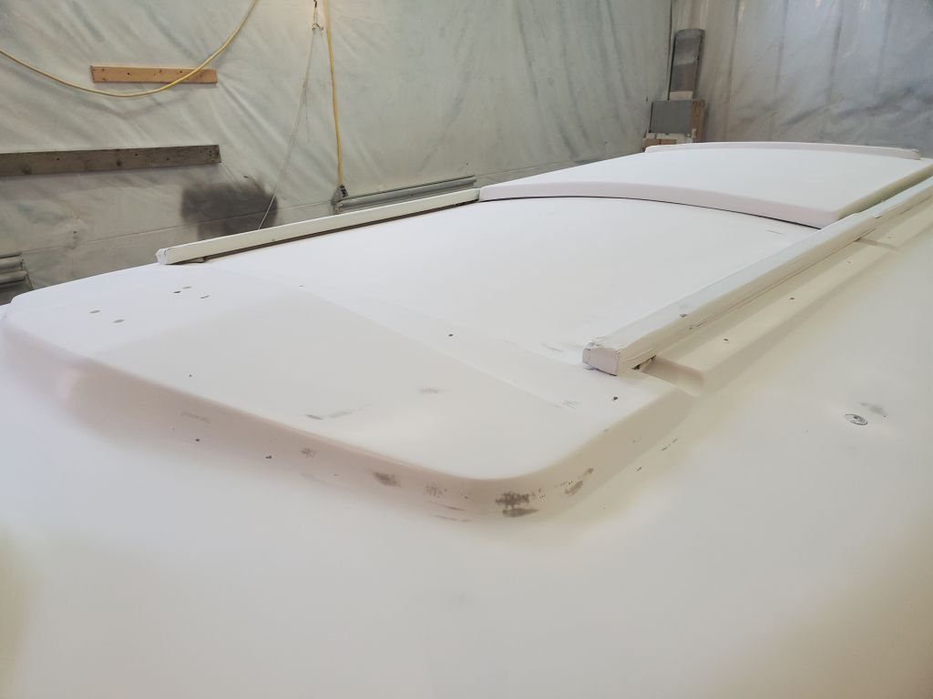
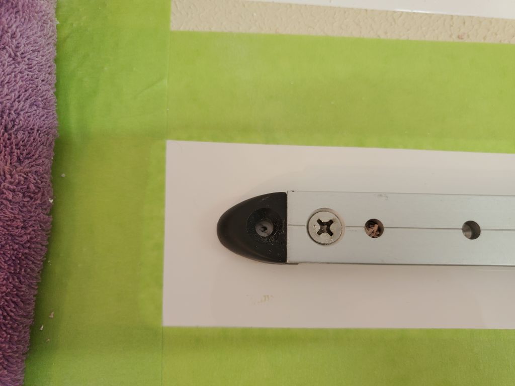
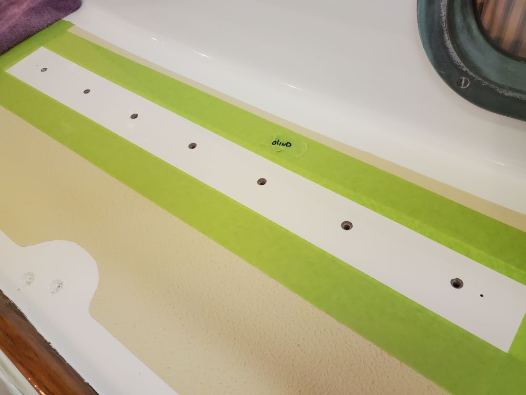
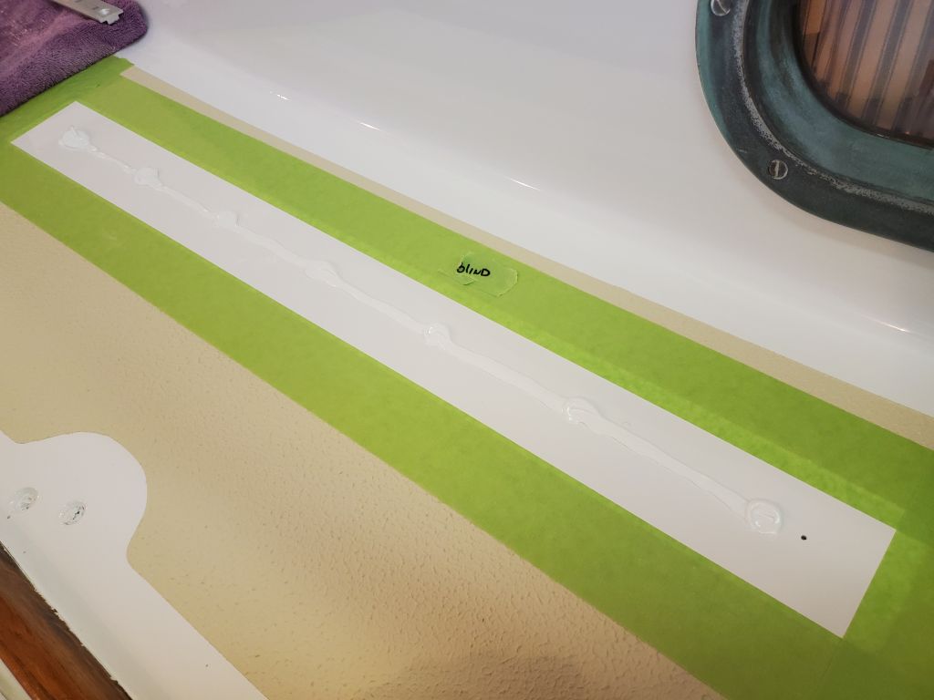
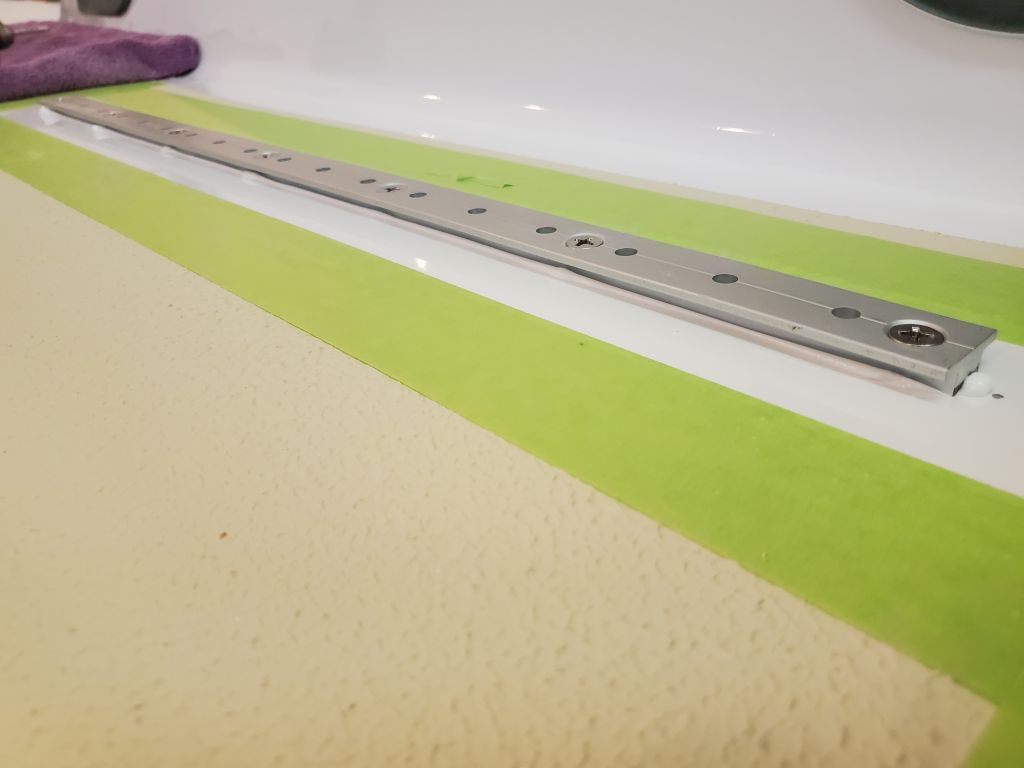
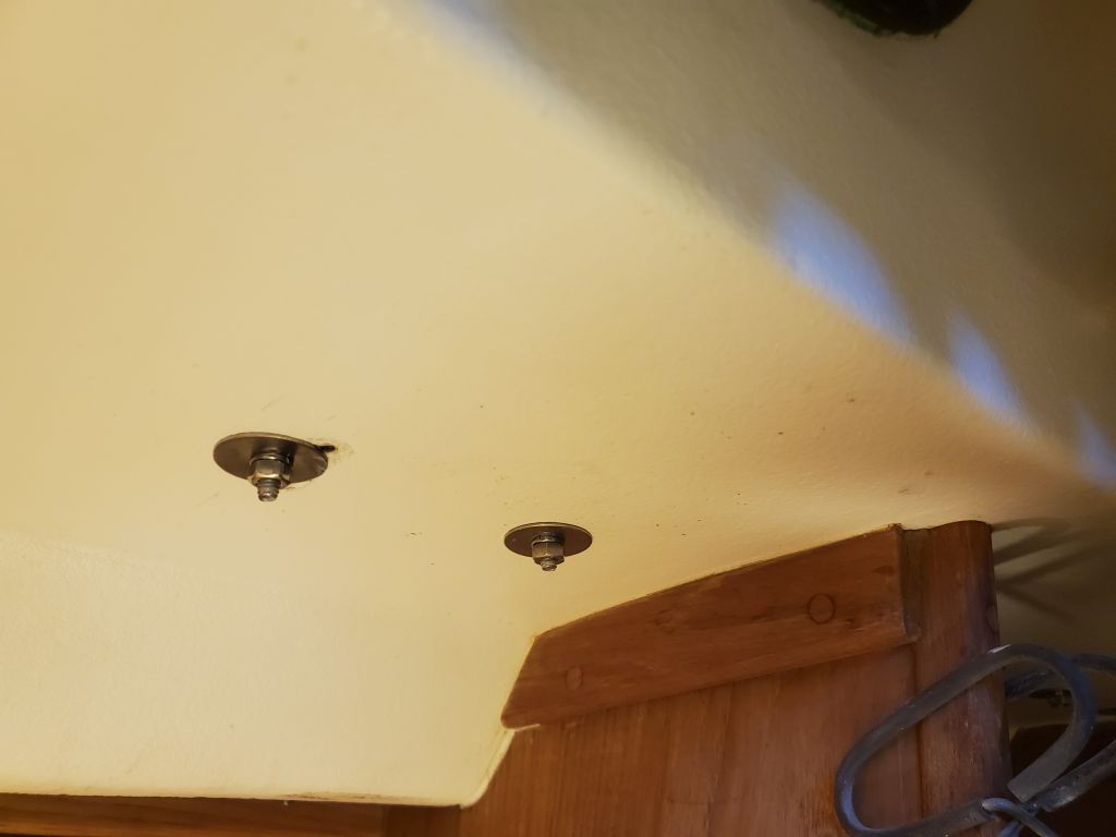
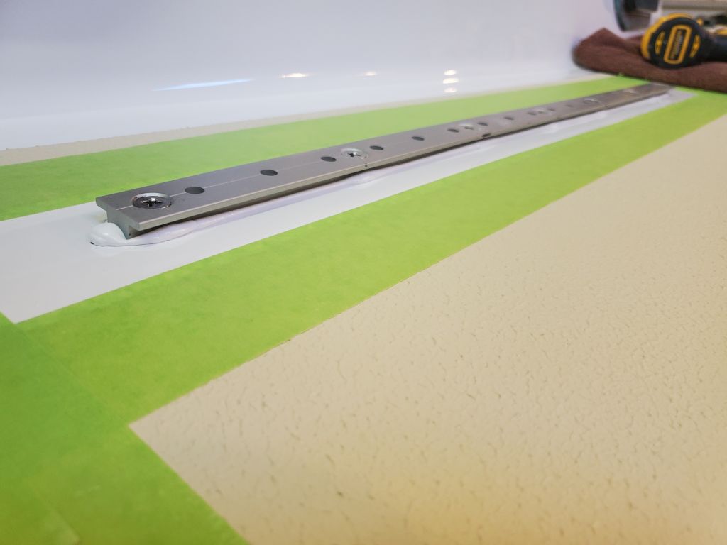
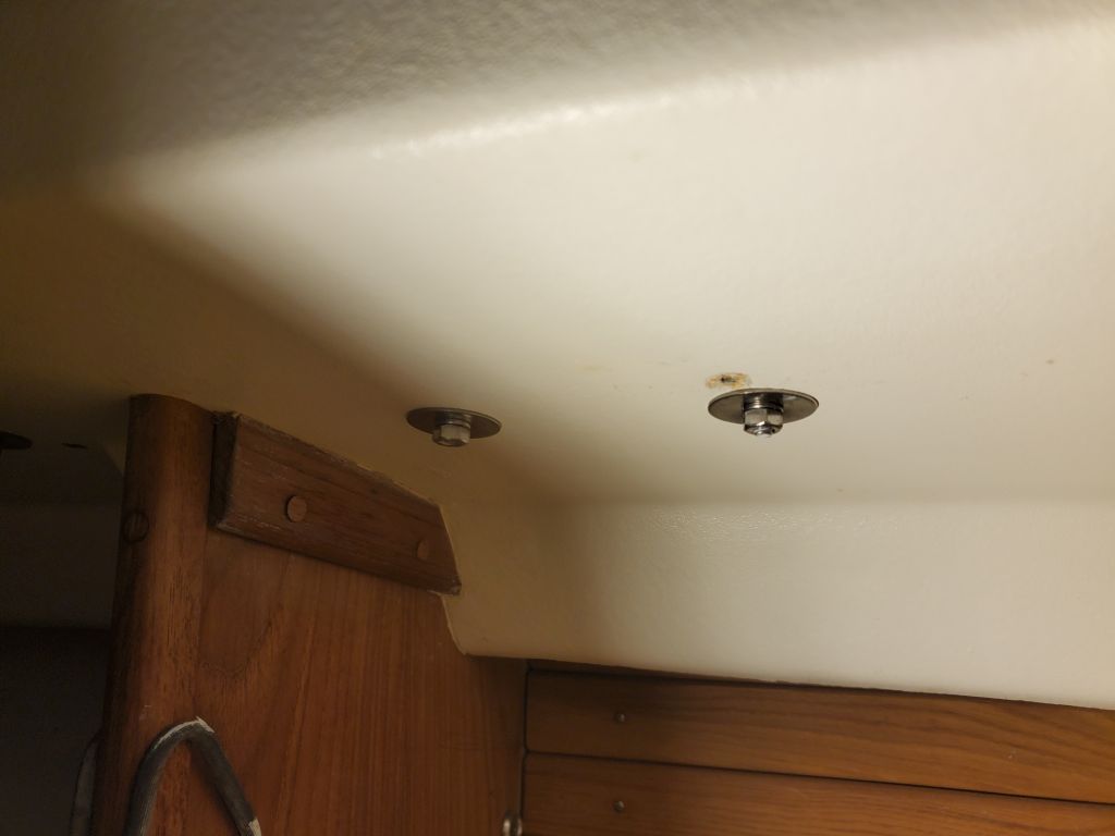
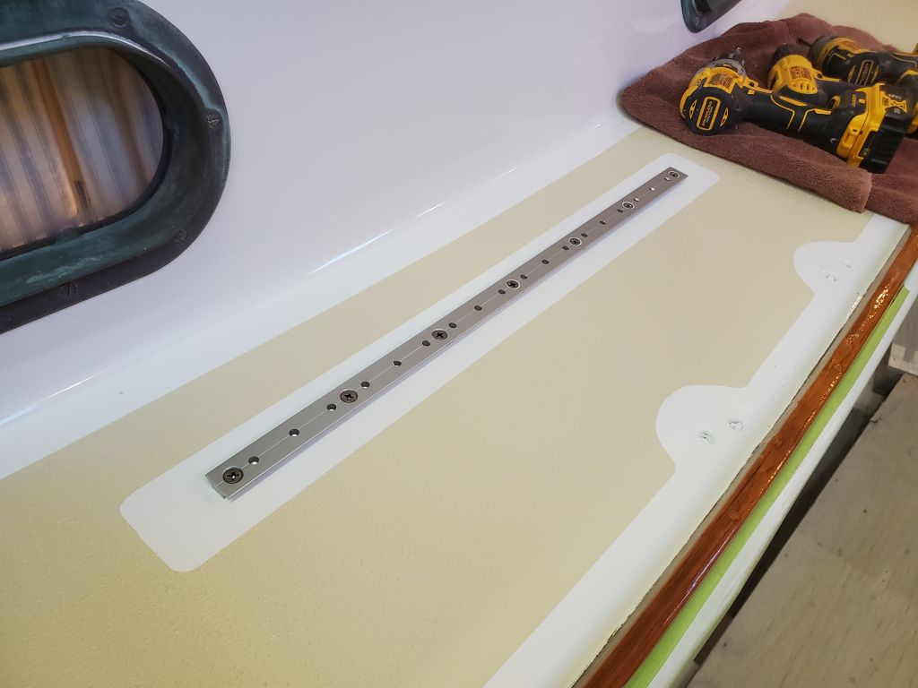
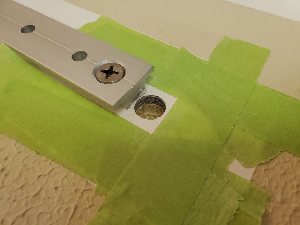
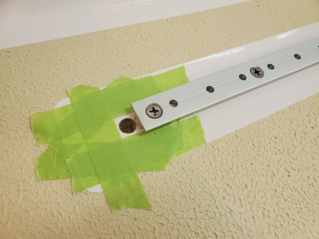
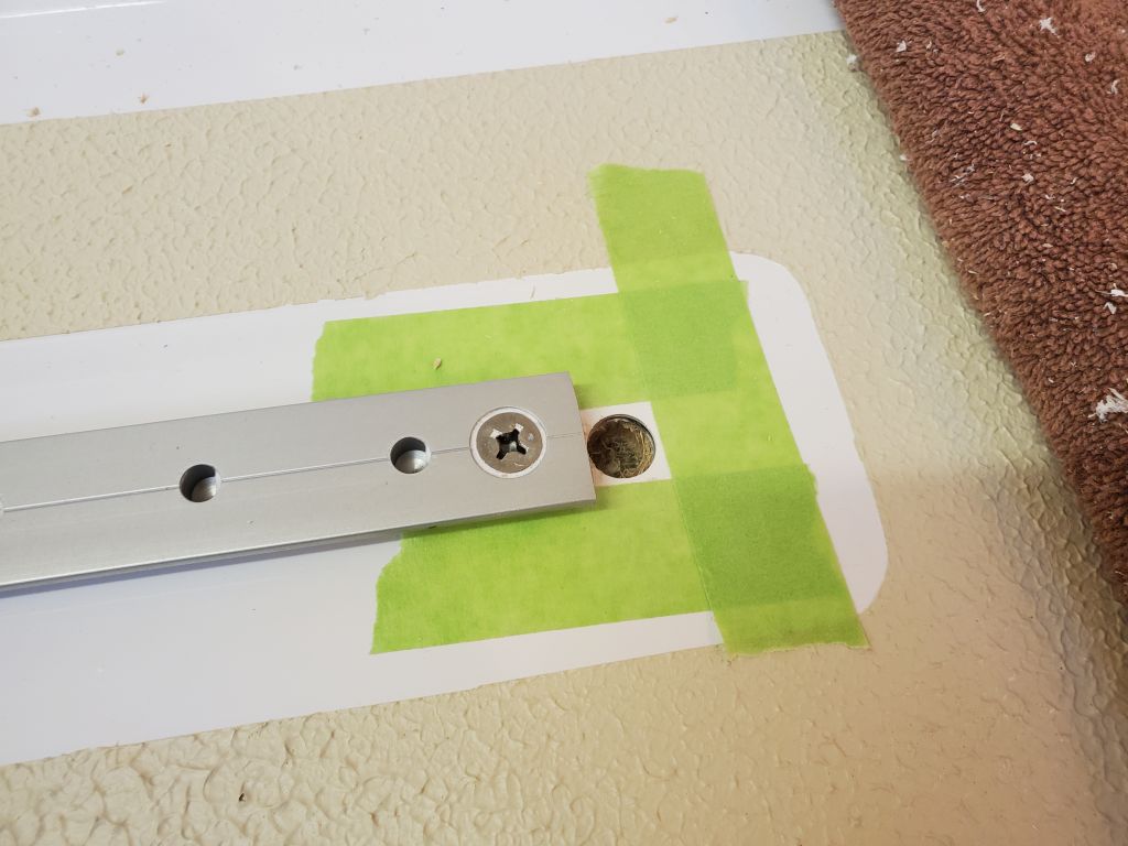
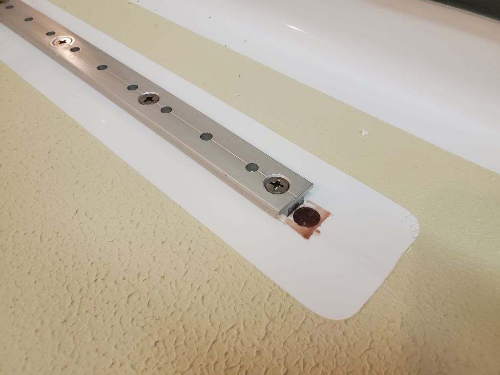
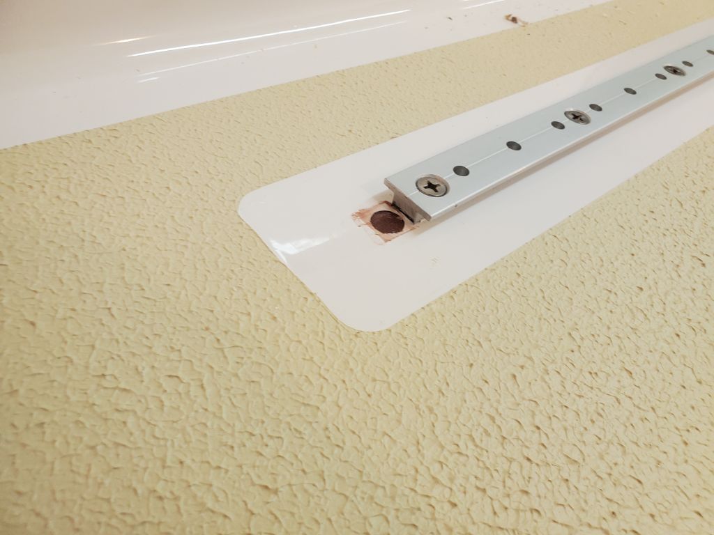
Next, I installed the new working jib tracks on the sidedecks. Using the pre-marked holes at each end, I drilled and tapped the deck for 1/4″ machine screws at each fastener location. At the track ends, I used a small drill bit to mark the centers of the holes for the end caps, as these needed to be overbored and epoxy-filled to accept their screws, as I’d forgotten to do so during the earlier deck work. Afterwards, I finished preparing the fastener holes with the usual small countersink, then applied sealant and secured the tracks in place with machine screws, nuts, and washers from below. In these locations, the cabin liner was tight against the underside of the decks. A few of the fasteners would require trimming below later for cosmetic purposes.
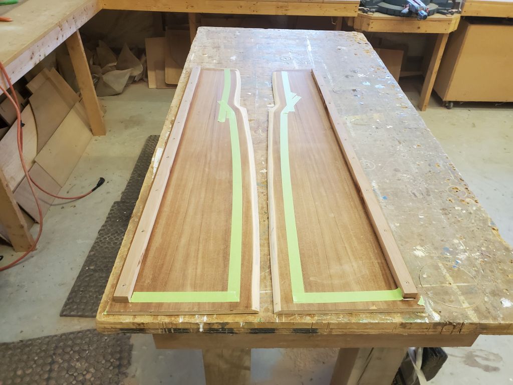
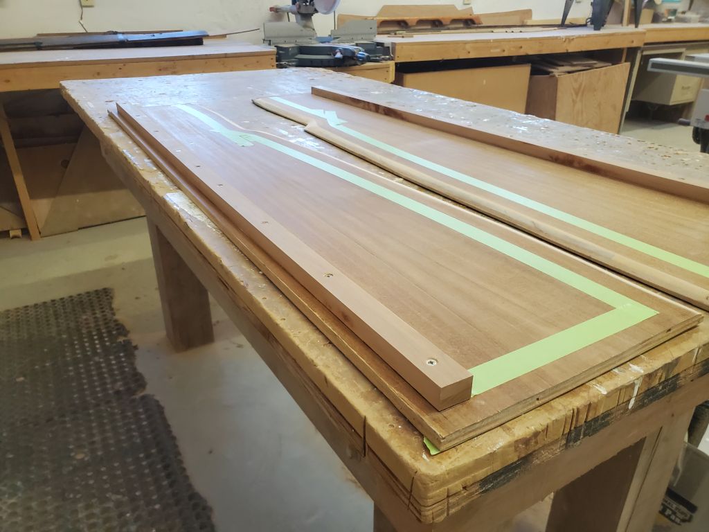
Port side:
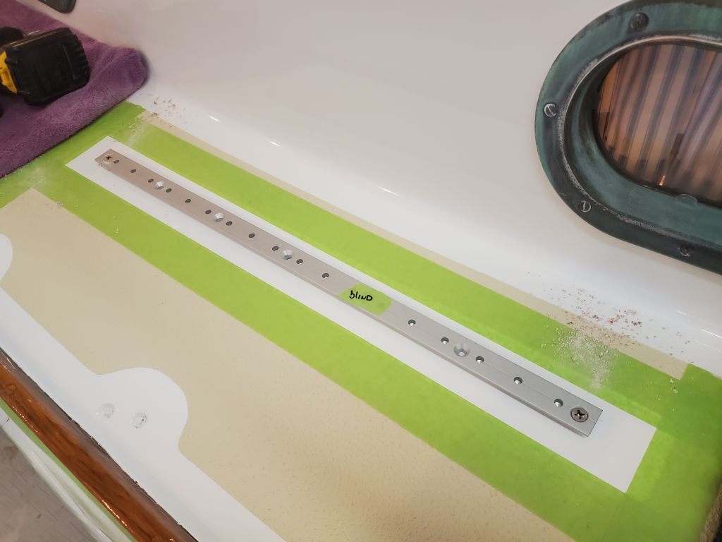

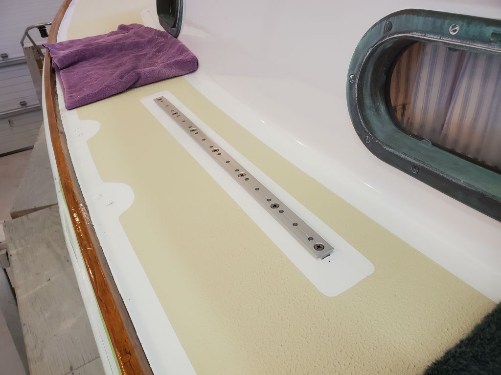
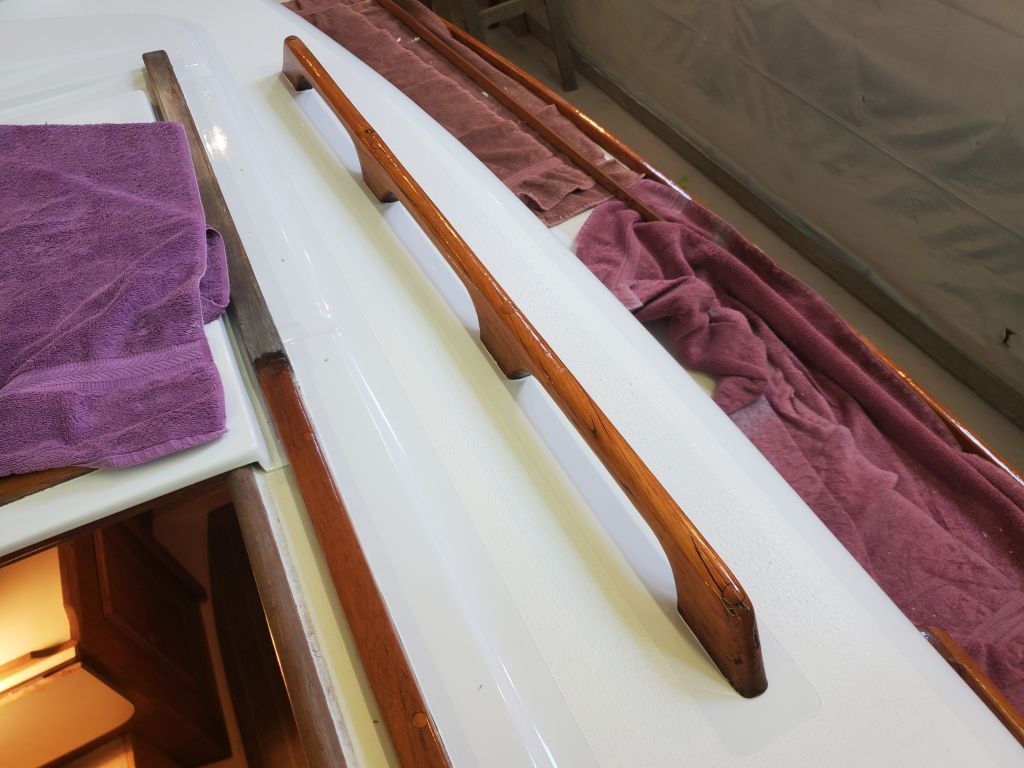
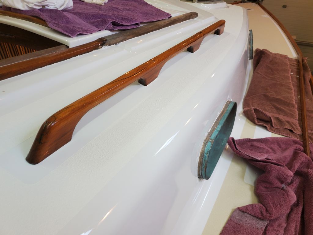
Starboard side:
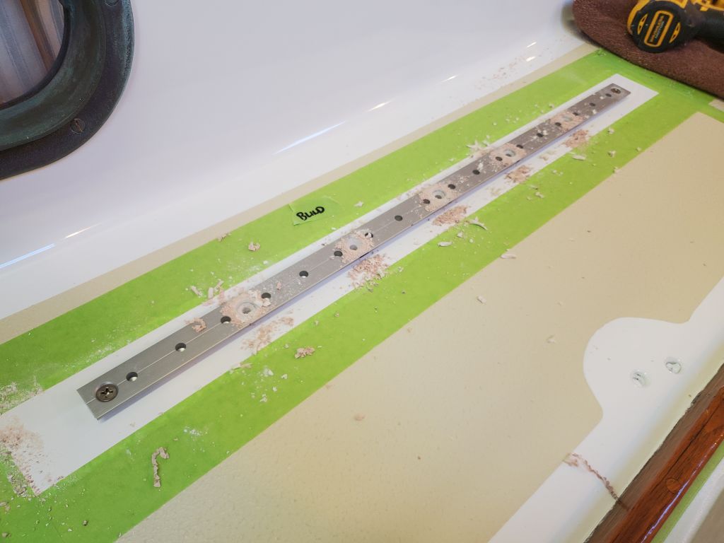


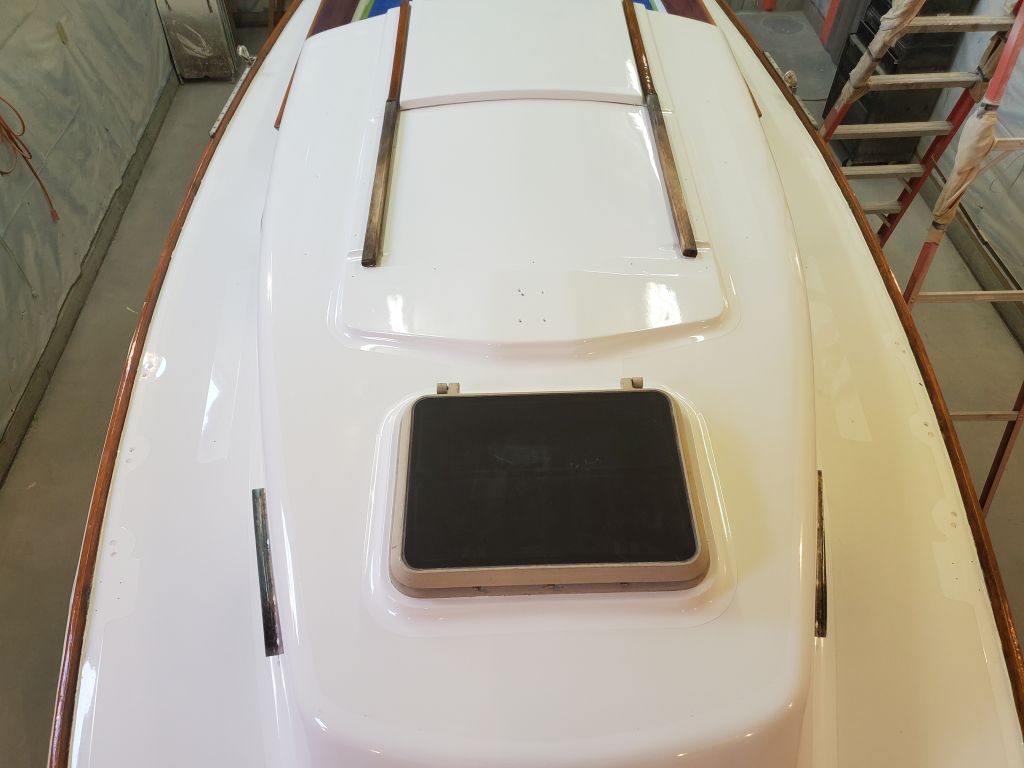
With the tracks in place, I used a 1/2″ Forstner bit to drill out the top skin and core from the end cap fastener locations, then filled the voids with a thickened epoxy mixture, leaving that to cure before installing the end caps.


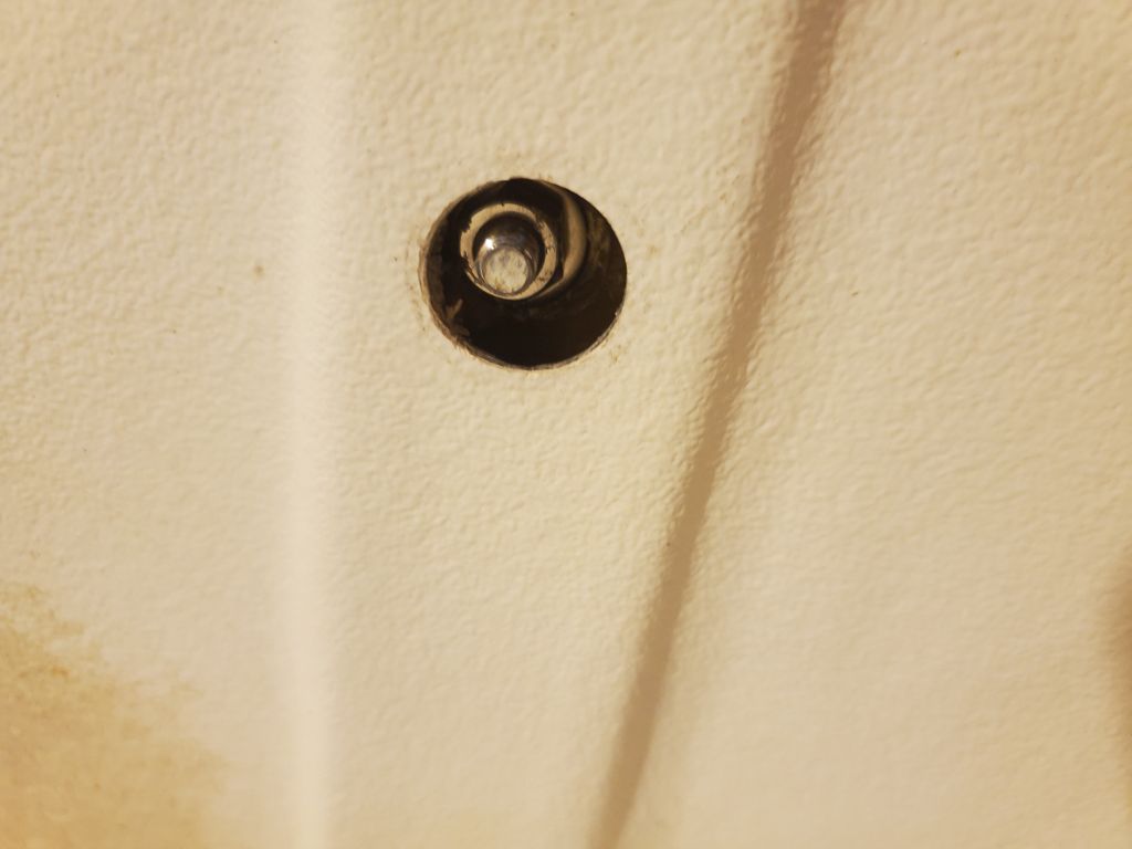
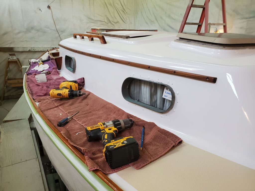
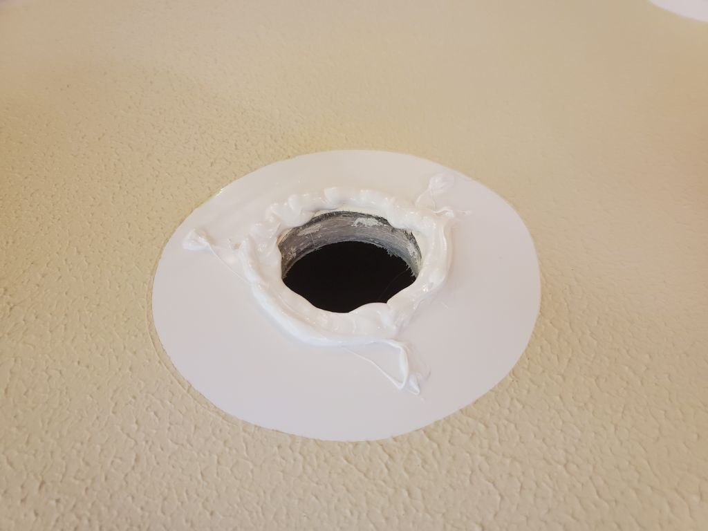
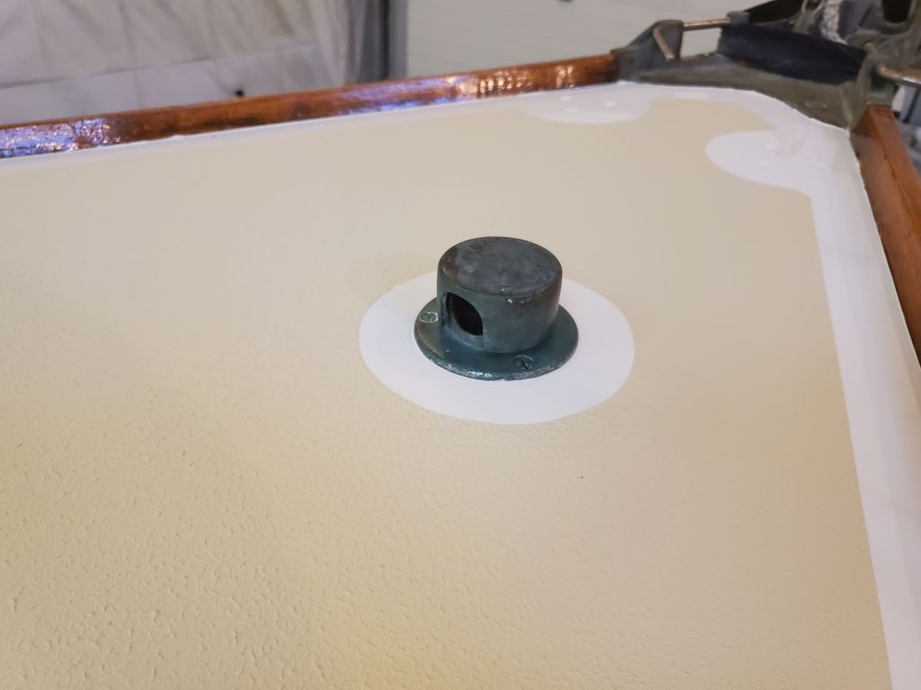
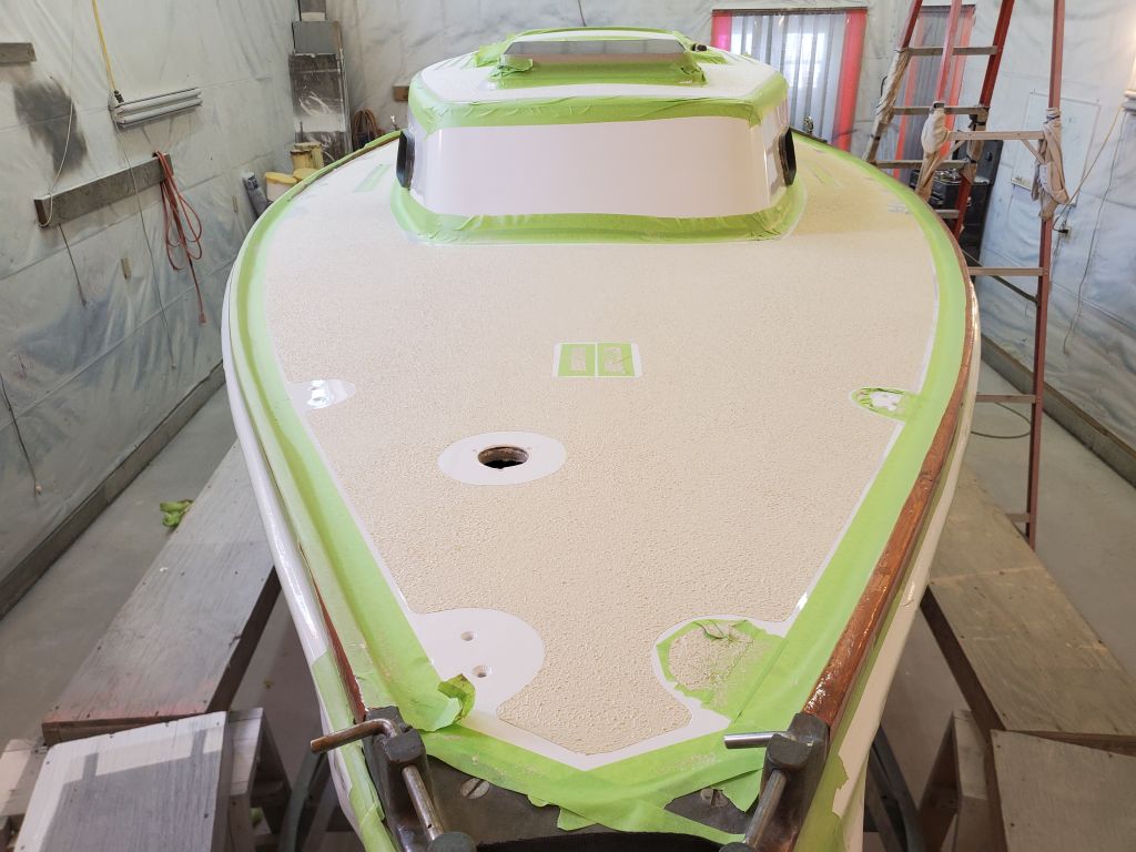
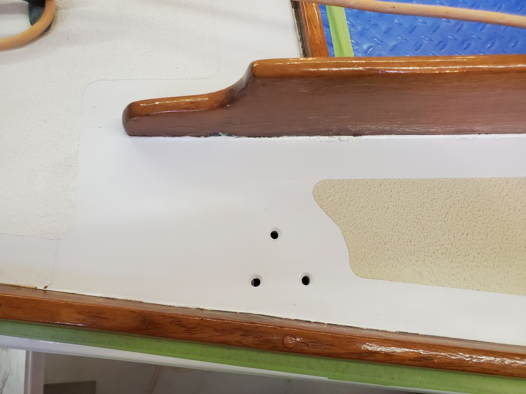
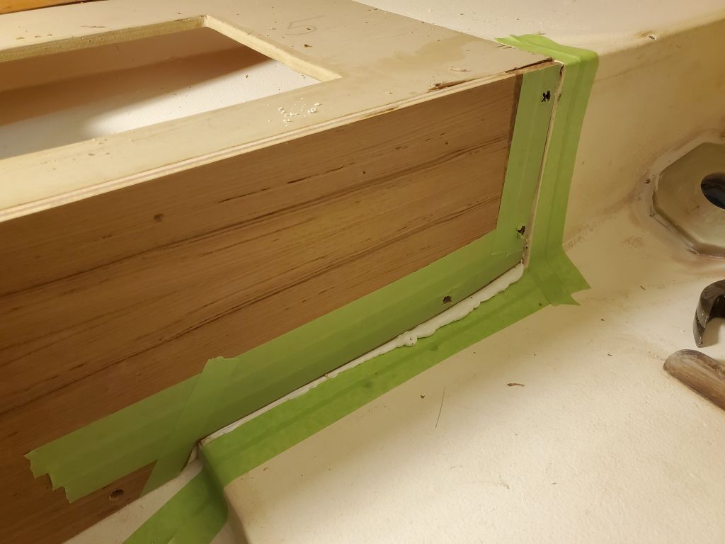
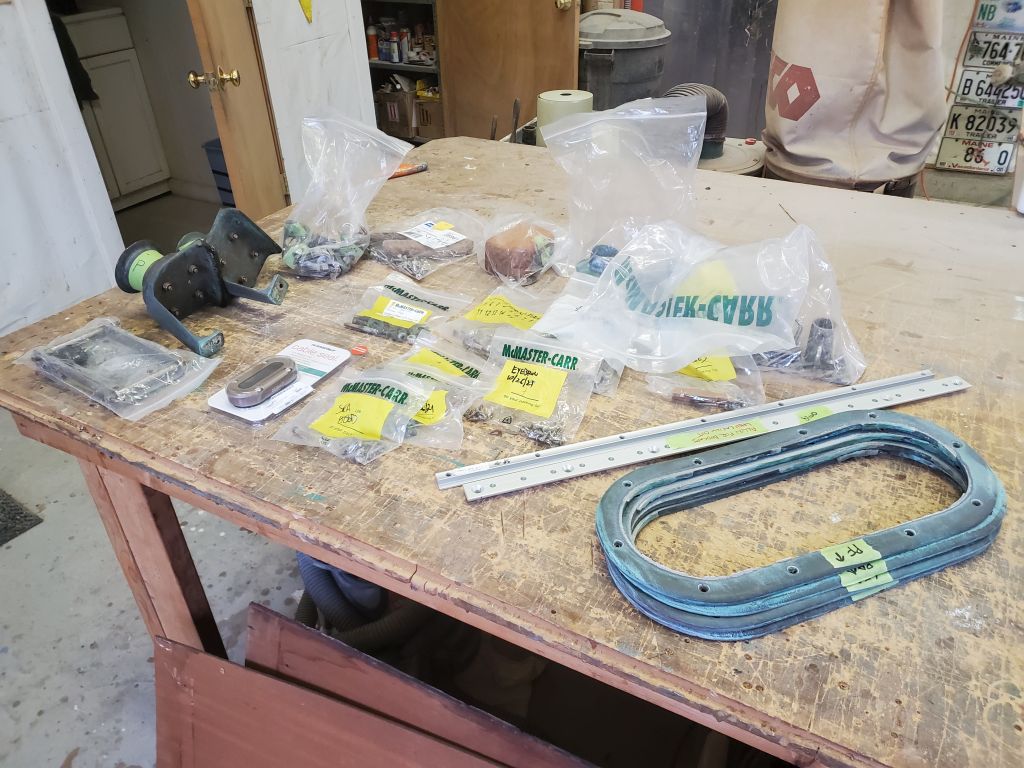
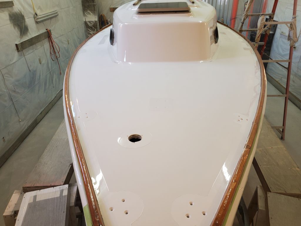
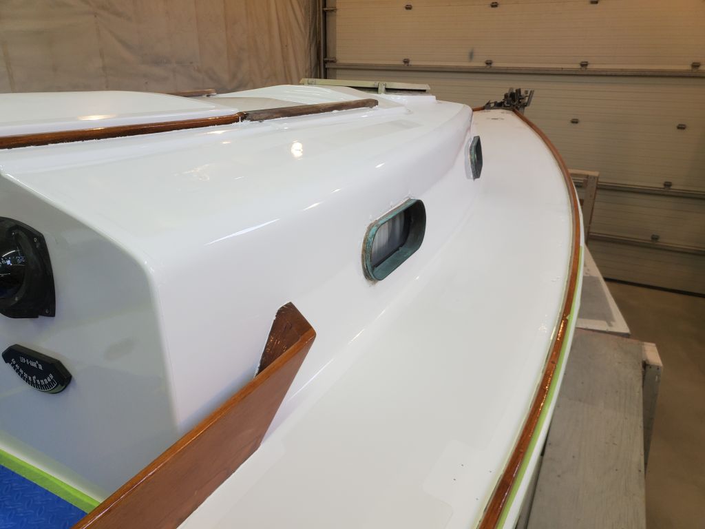
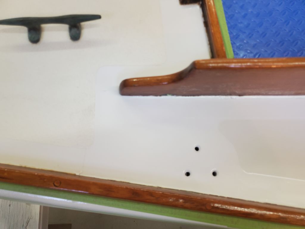
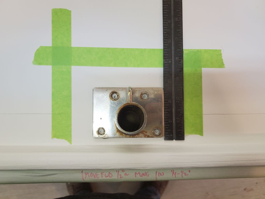
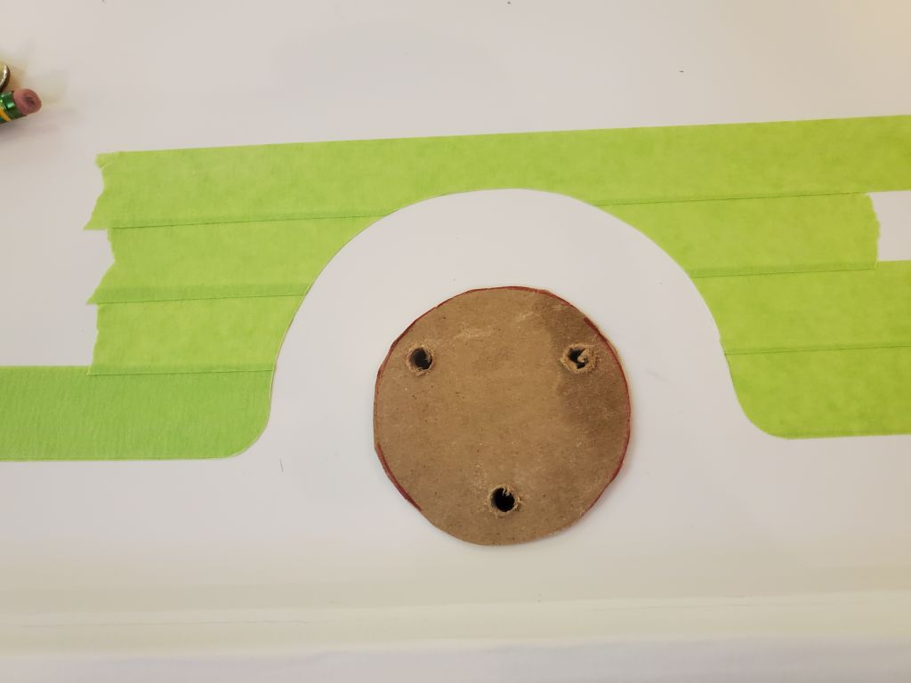
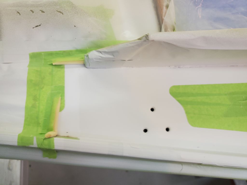
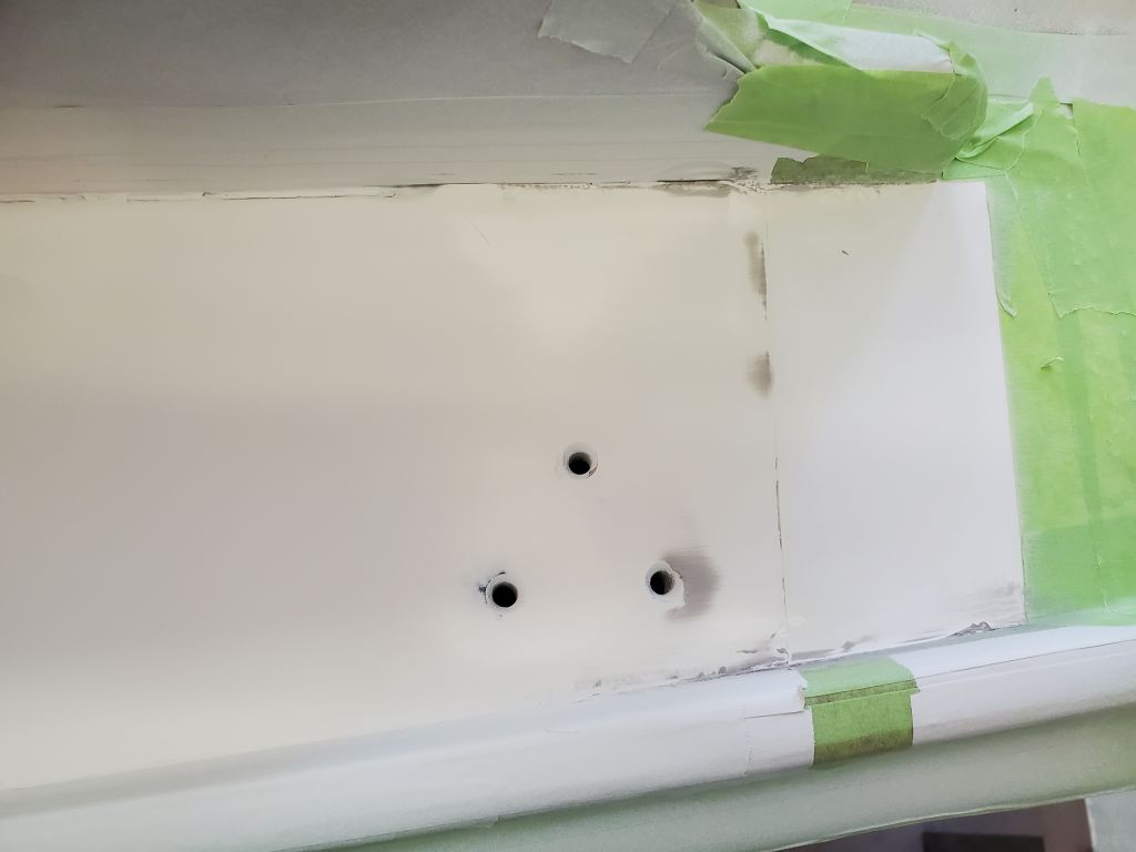
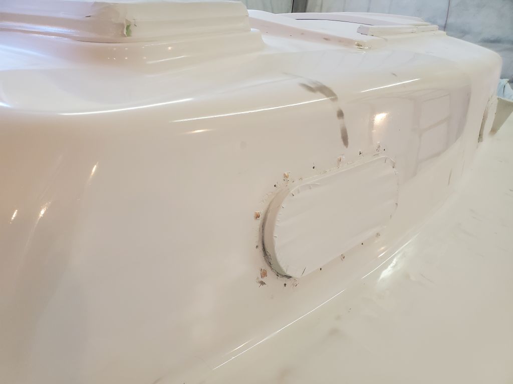
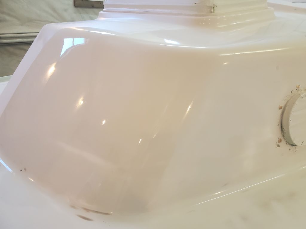
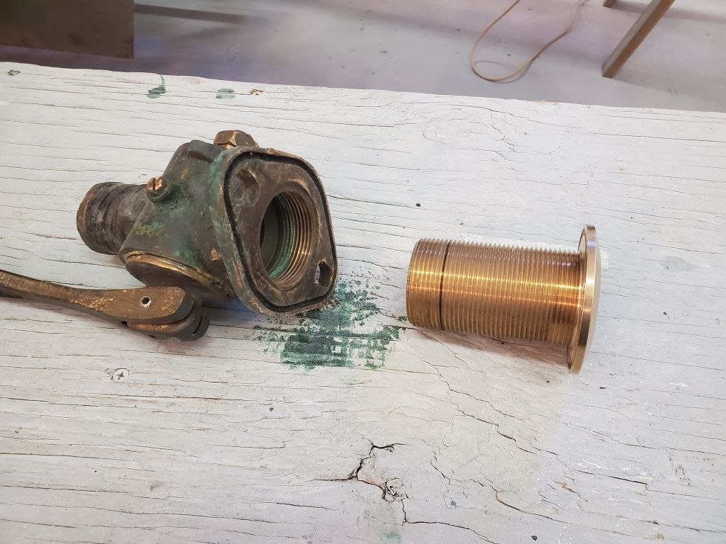
New fasteners were due later in the day, which would then allow me to continue with the rest of the deck hardware, but for the moment I decided to reinstall the cockpit drain seacocks and through hulls I’d removed earlier. To begin, and using the old bolt holes as a starting point, I drilled up through the hull with a 5/16″ bit, enlarging the original holes (which were just 1/4″) and extending them through the new fiberglass backing plates. I test-fit the seacocks in place to ensure that the slots lined up with the holes and made minor adjustments.
For each side, I first threaded the new through hulls as far as they’d go into their respective seacocks, making a mark on the neck for reference when I next dry-installed the fittings through the hull to see how much of the threads would need to be cut off before installation. As expected, the through hulls were somewhat longer than needed.
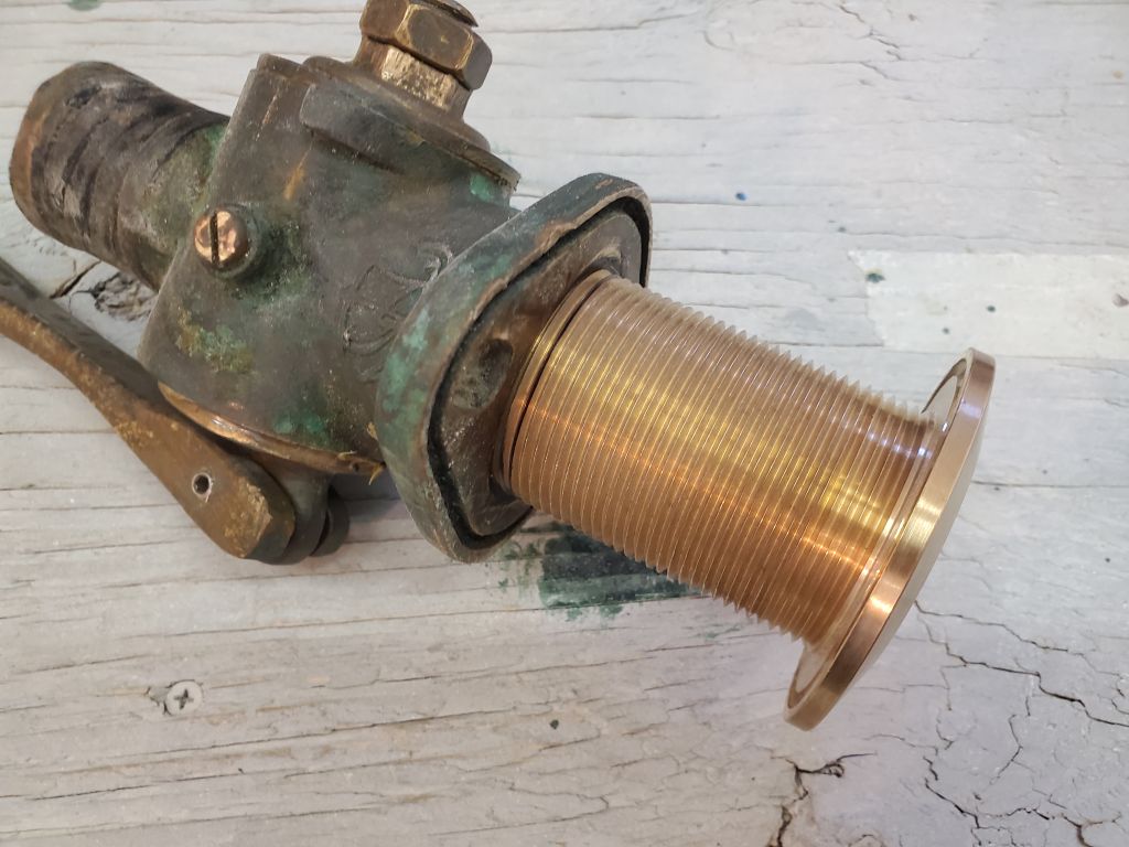
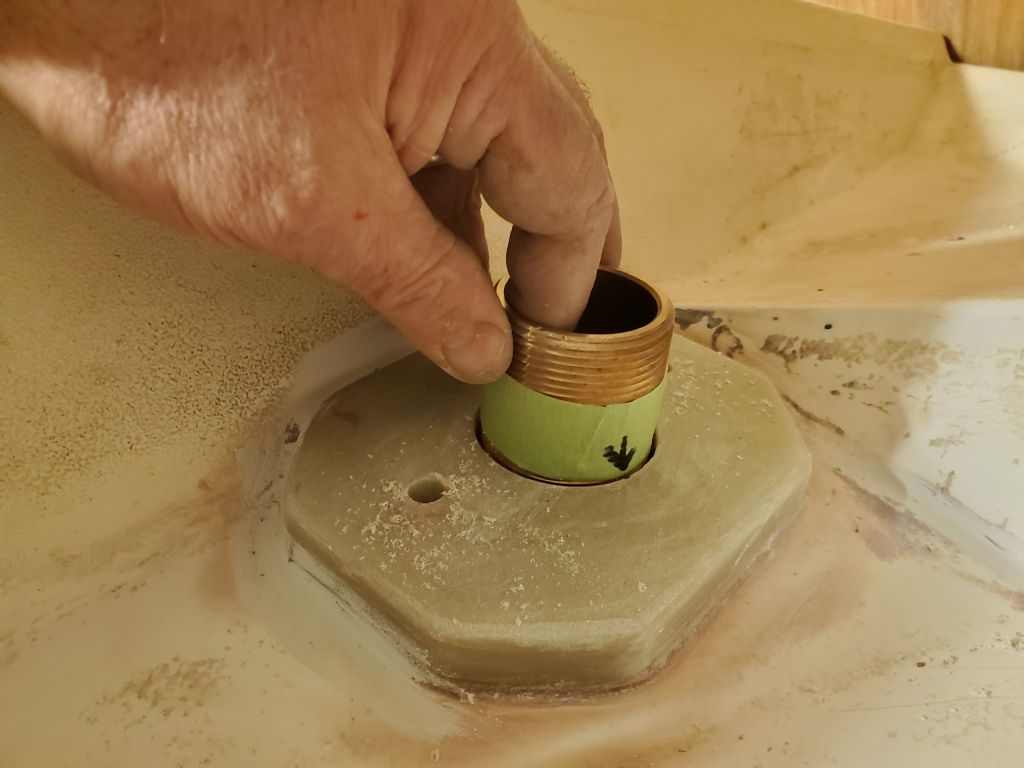
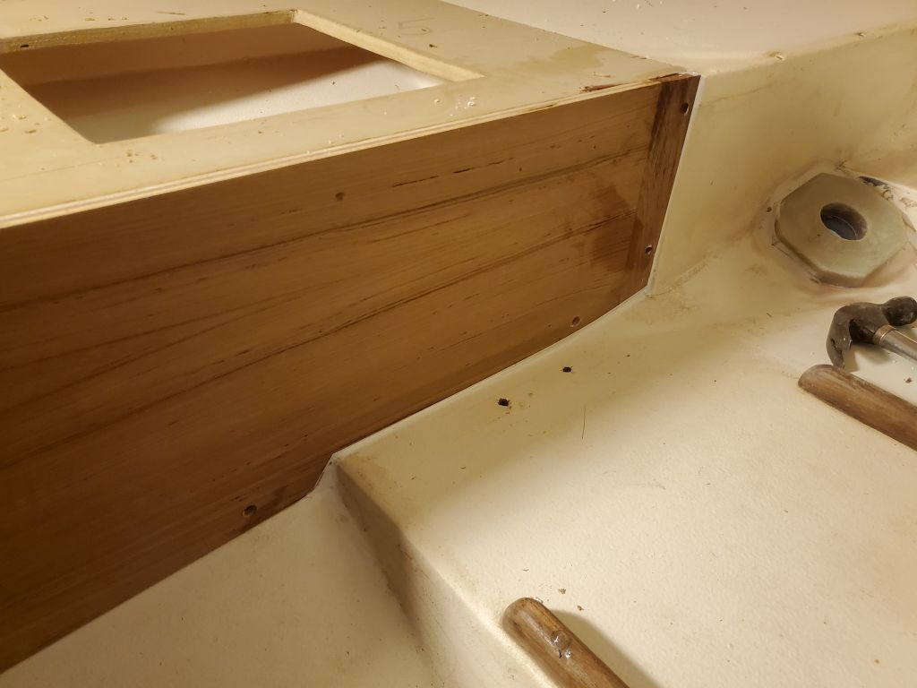
With the seacocks pinned in place with a couple bolts from above, I threaded the through hulls up from beneath till they bottomed out, then noted the excess length from below. This acted as a real-world confirmation of the various other measurements, as well as an opportunity to test the fitment of all components together. Then, I cut off the excess length on each fitting and cleaned up the threads before dry-fitting all the pieces together again to ensure the cut through hulls threaded easily into their seacocks.
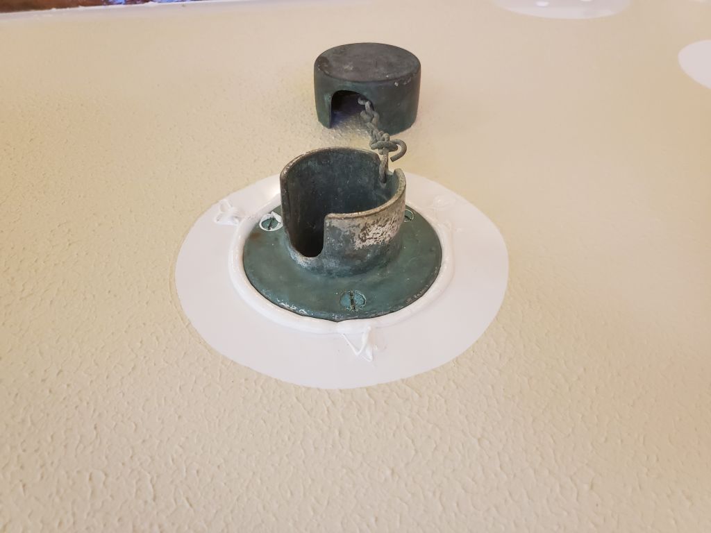
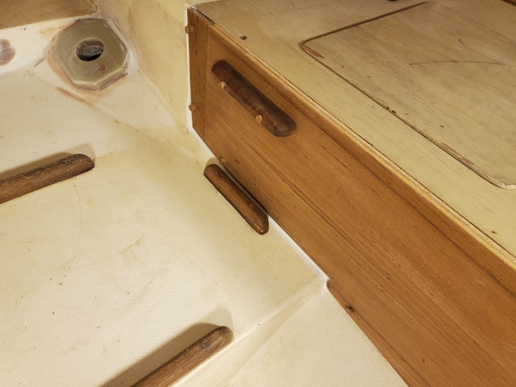
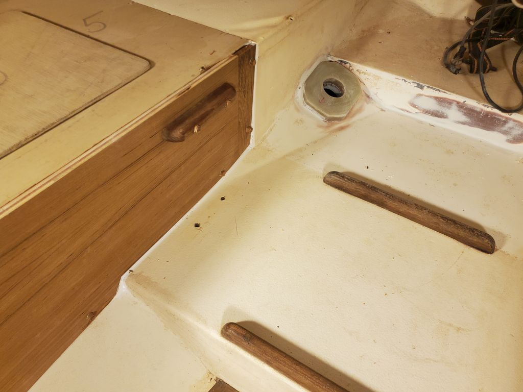
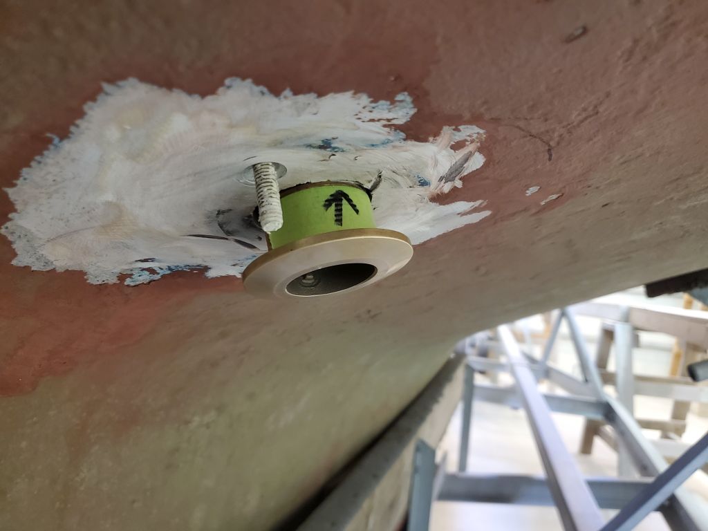
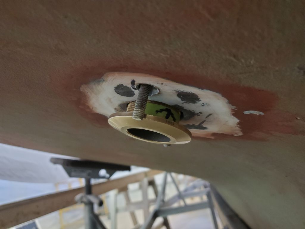
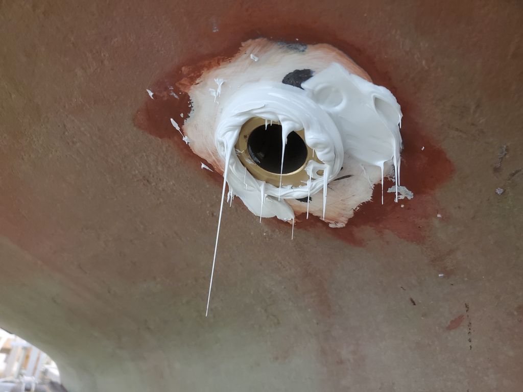
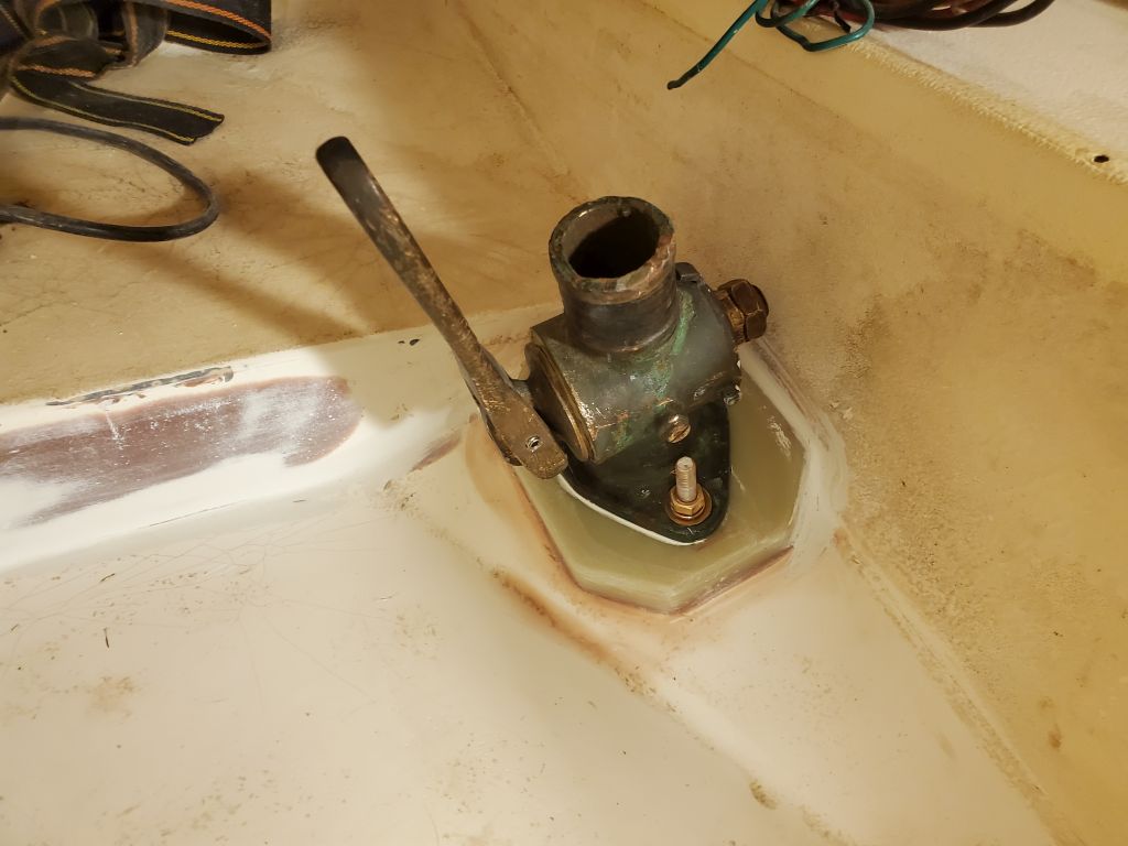
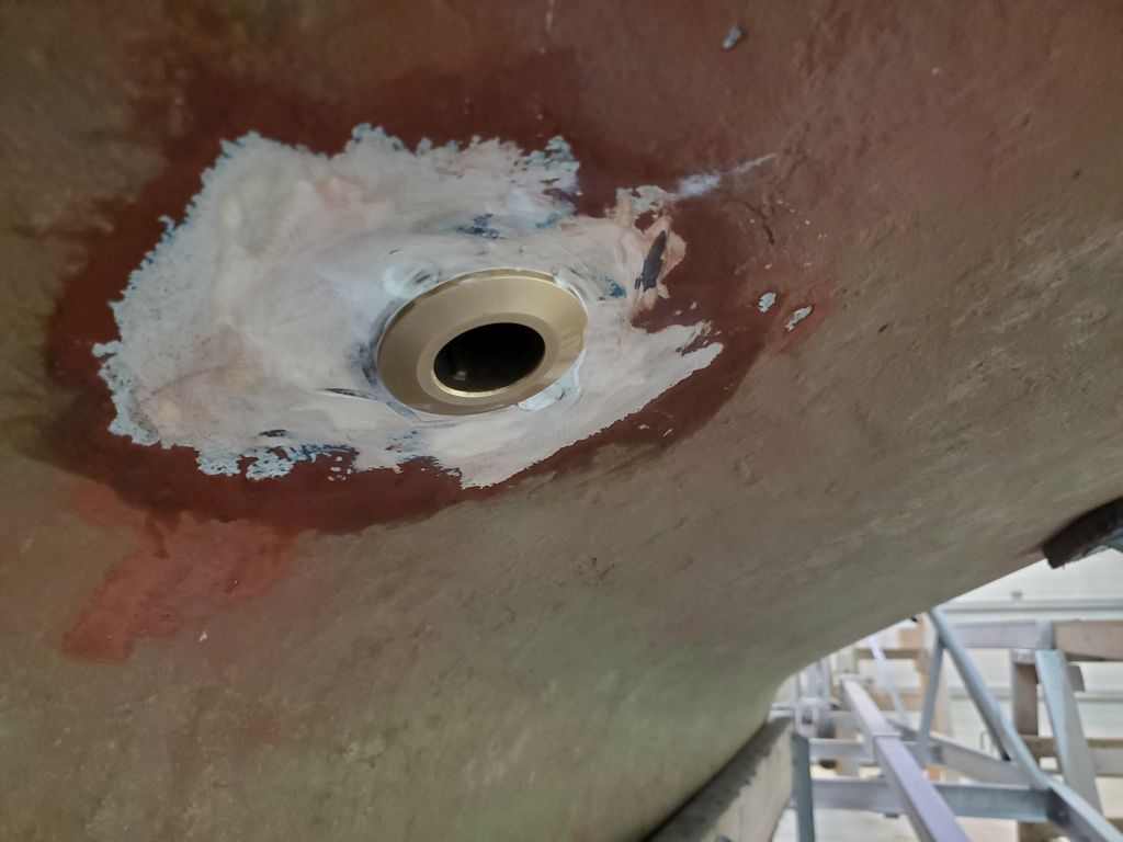
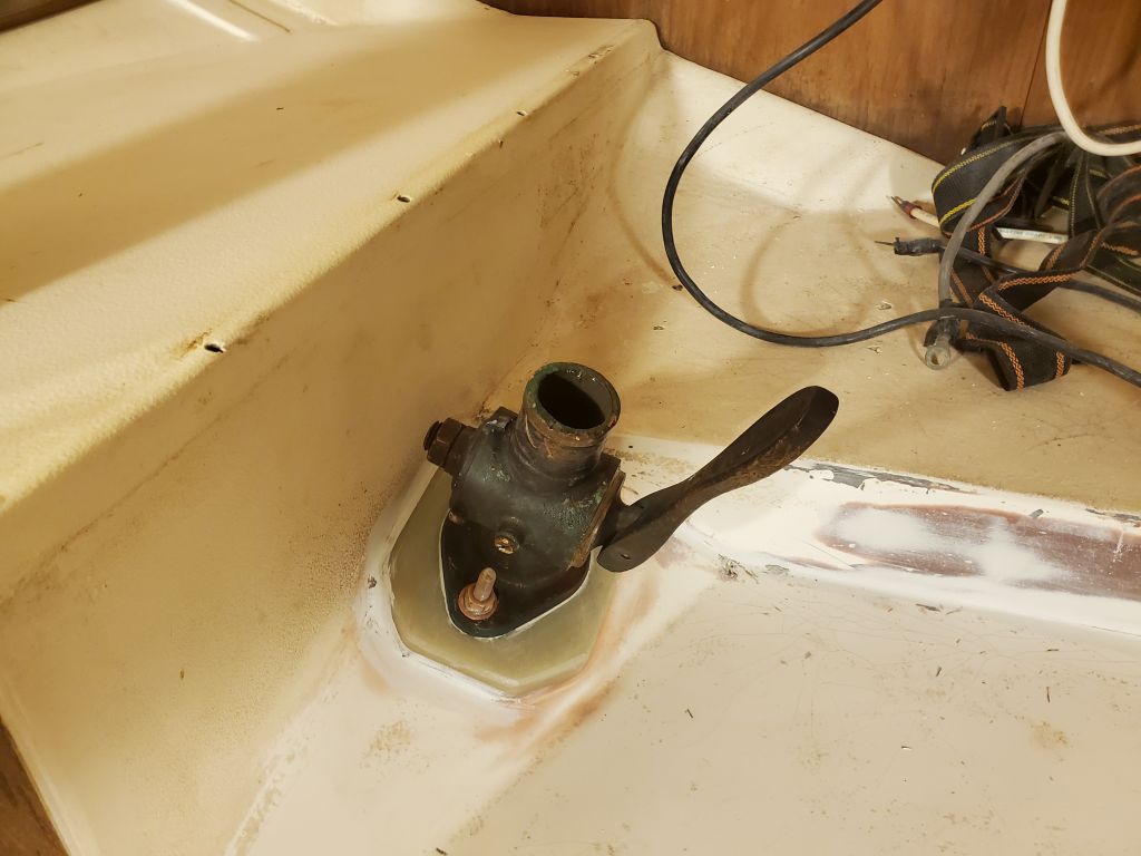
The installation process thereafter got a little messy and hectic, with numerous trips back and forth between the bottom of the boat and the cabin to get things properly aligned and the threads started (it never fails that despite numerous successful dry-fits, alignment and threading difficulties only come to light once the sealant is applied), so there are fewer photos of the process than I’d planned, but for each fitting I installed the through hull and mounting bolts in heavy beds of 4200, with additional sealant around the hole beneath the seacock flanges. I left everything loose till I got the through hull threads started, then could tighten the new 5/16″ mounting bolts and finish up the through hull installation tightly from below, finally ending with the usual sealant cleanup. Later, I cut off the excess bolt length at the seacock flanges (not shown here).


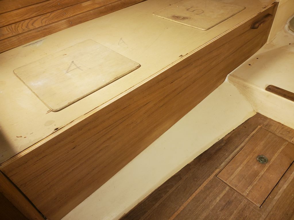
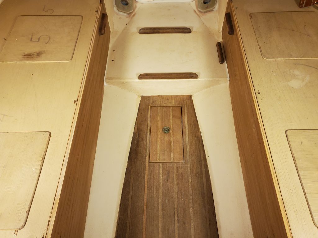
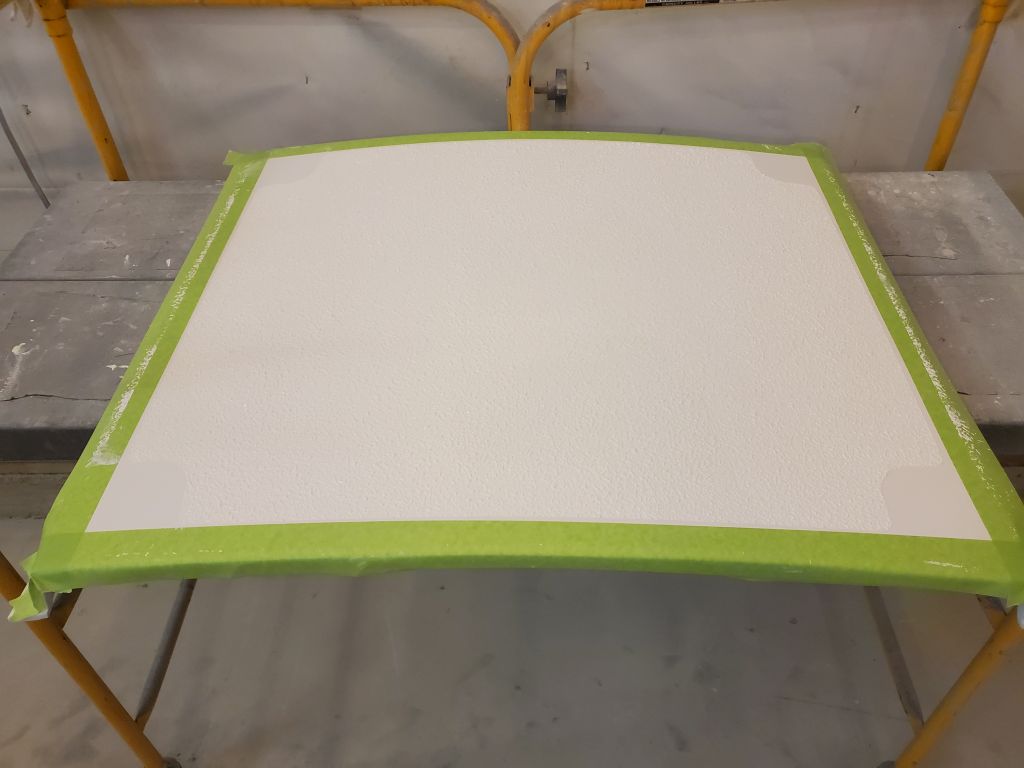
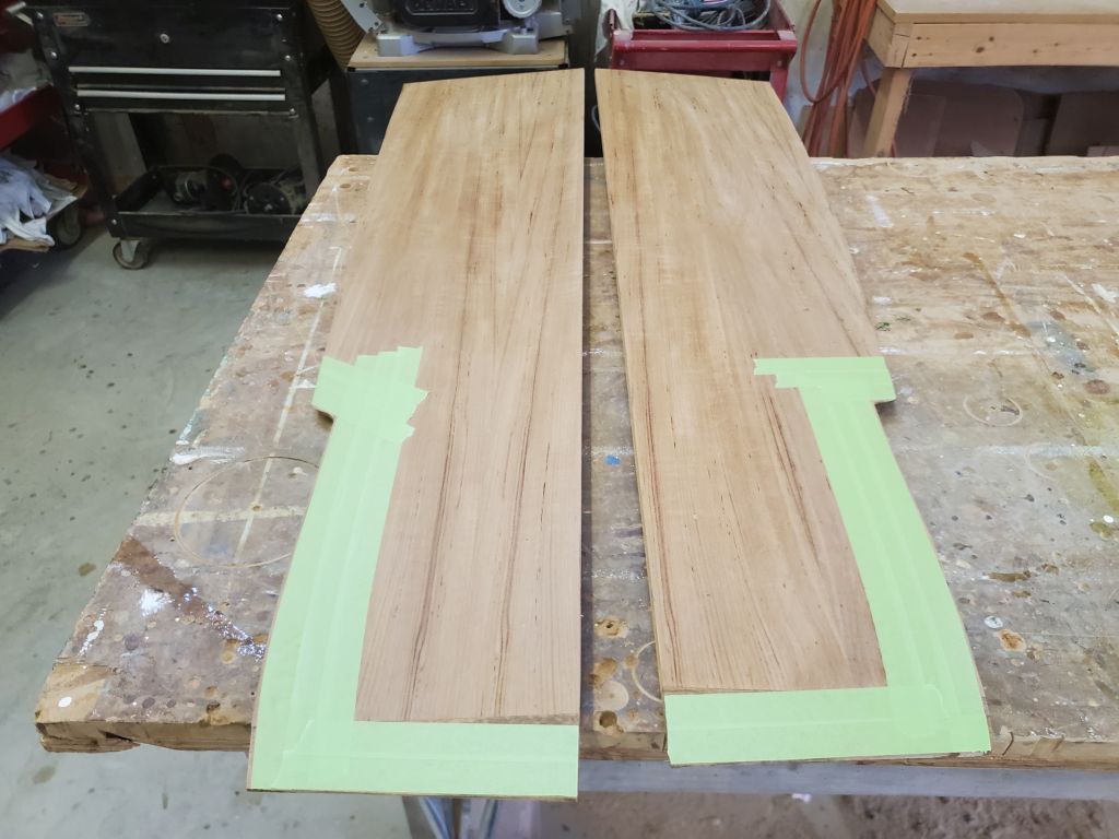
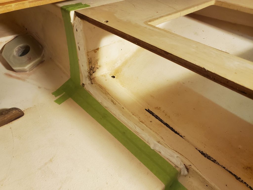
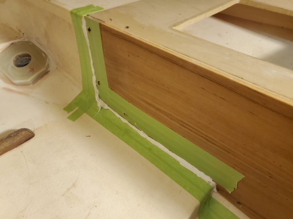
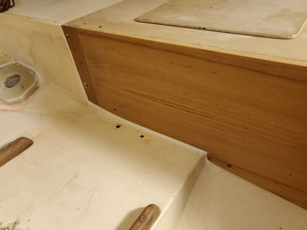
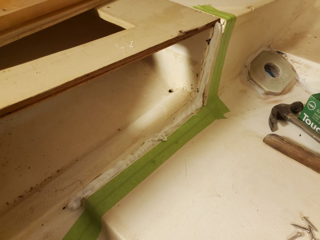
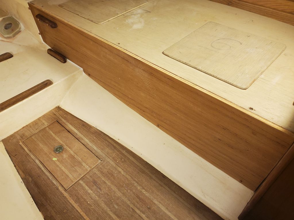
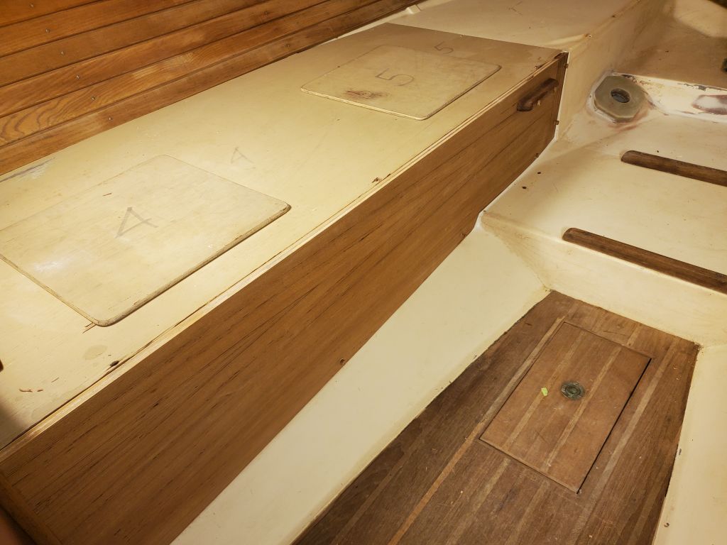
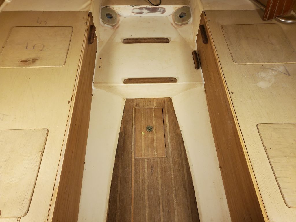
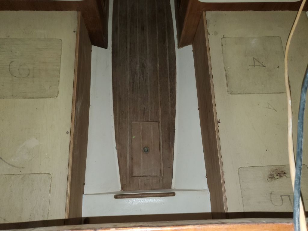
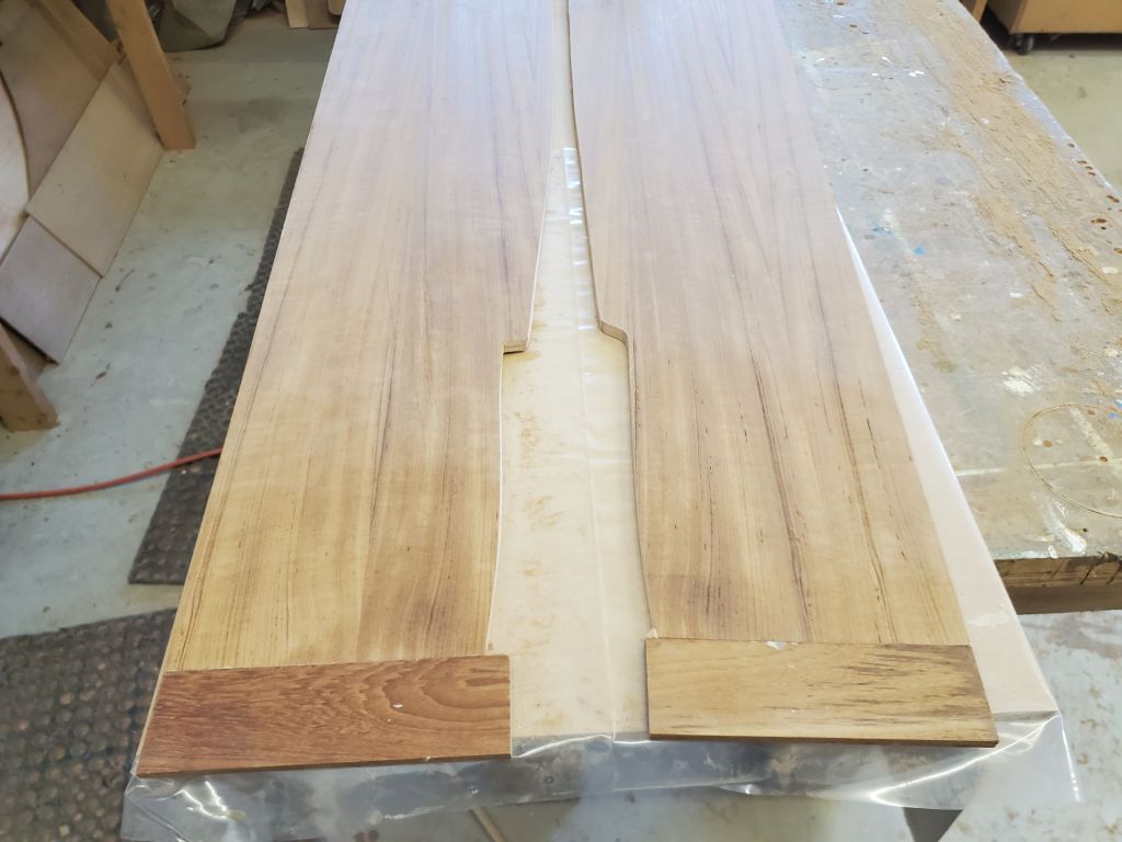
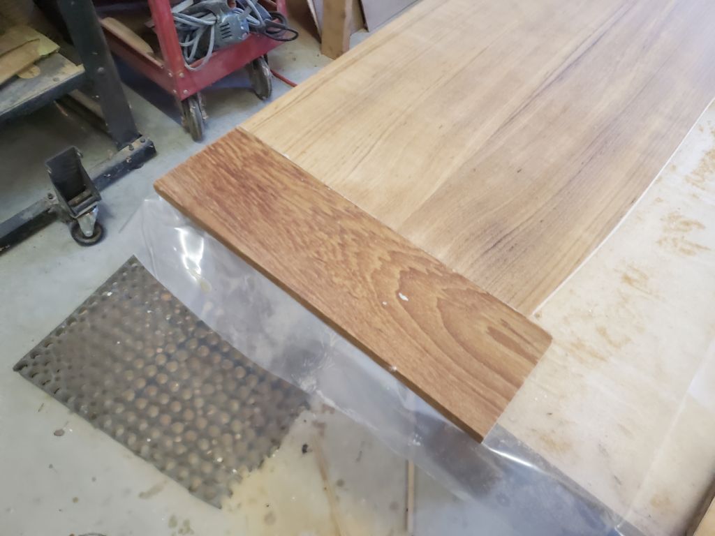
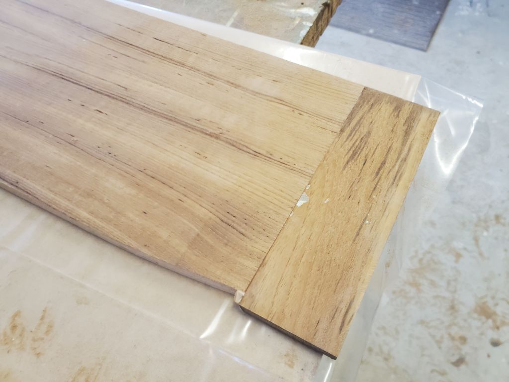
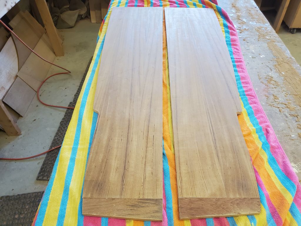
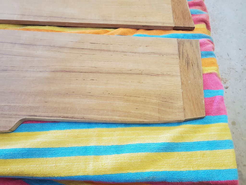
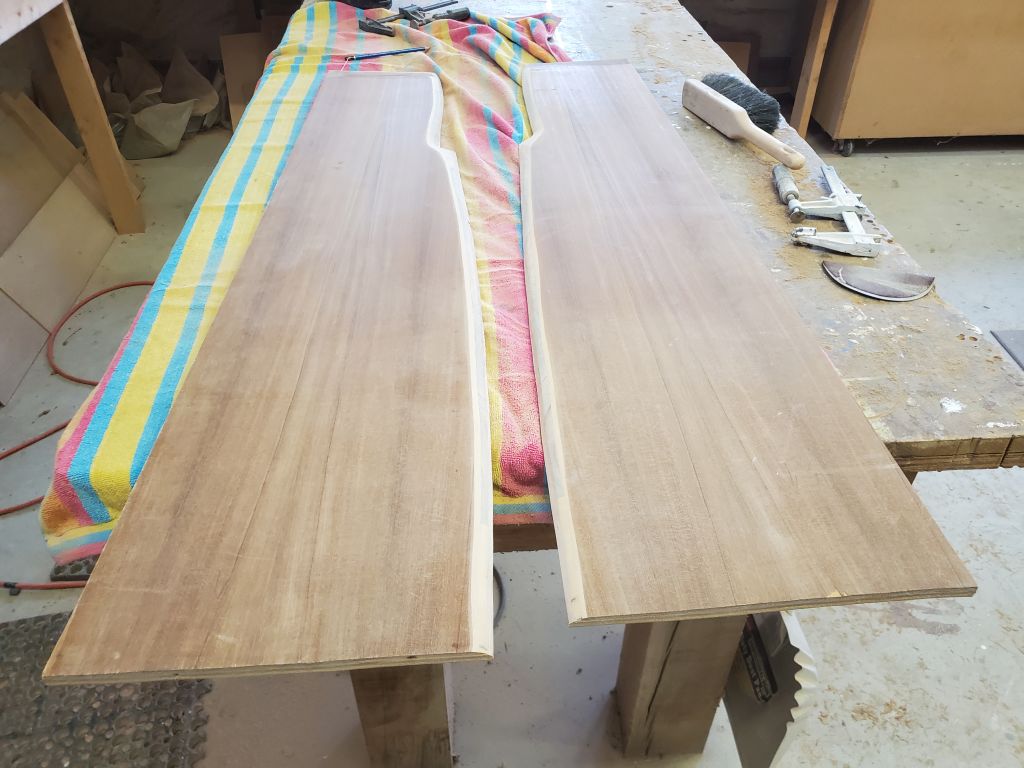
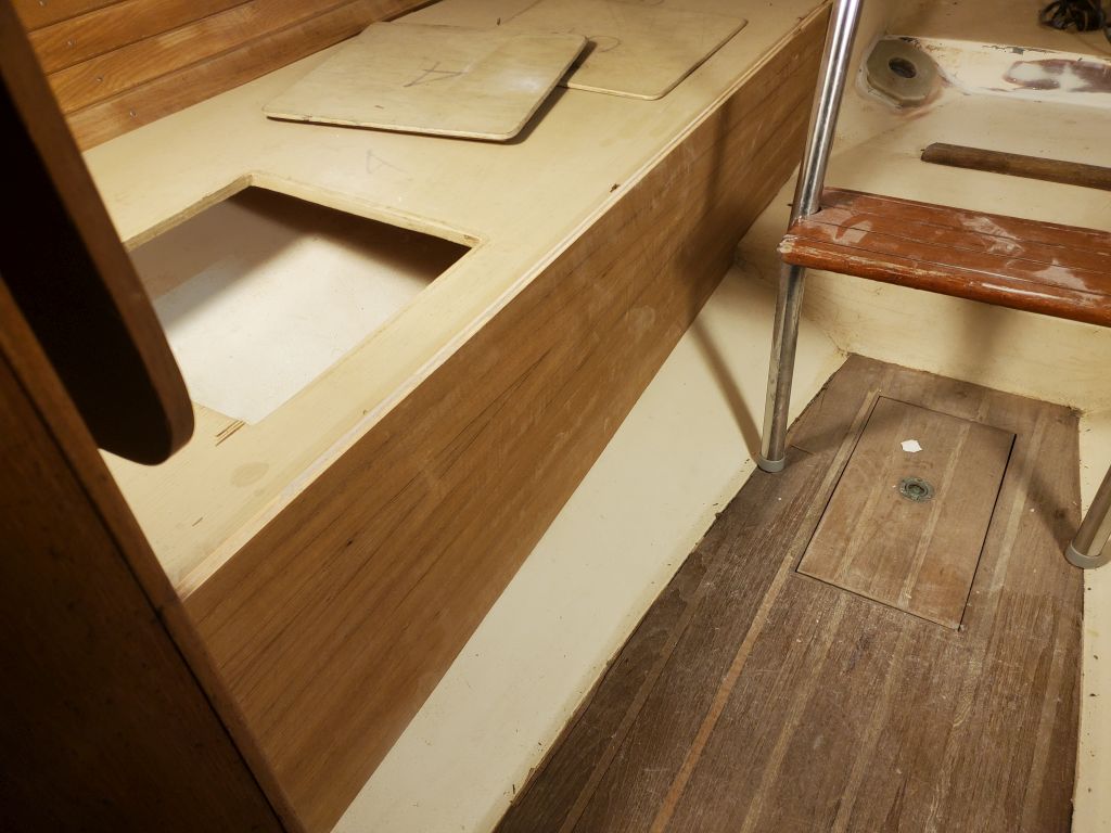
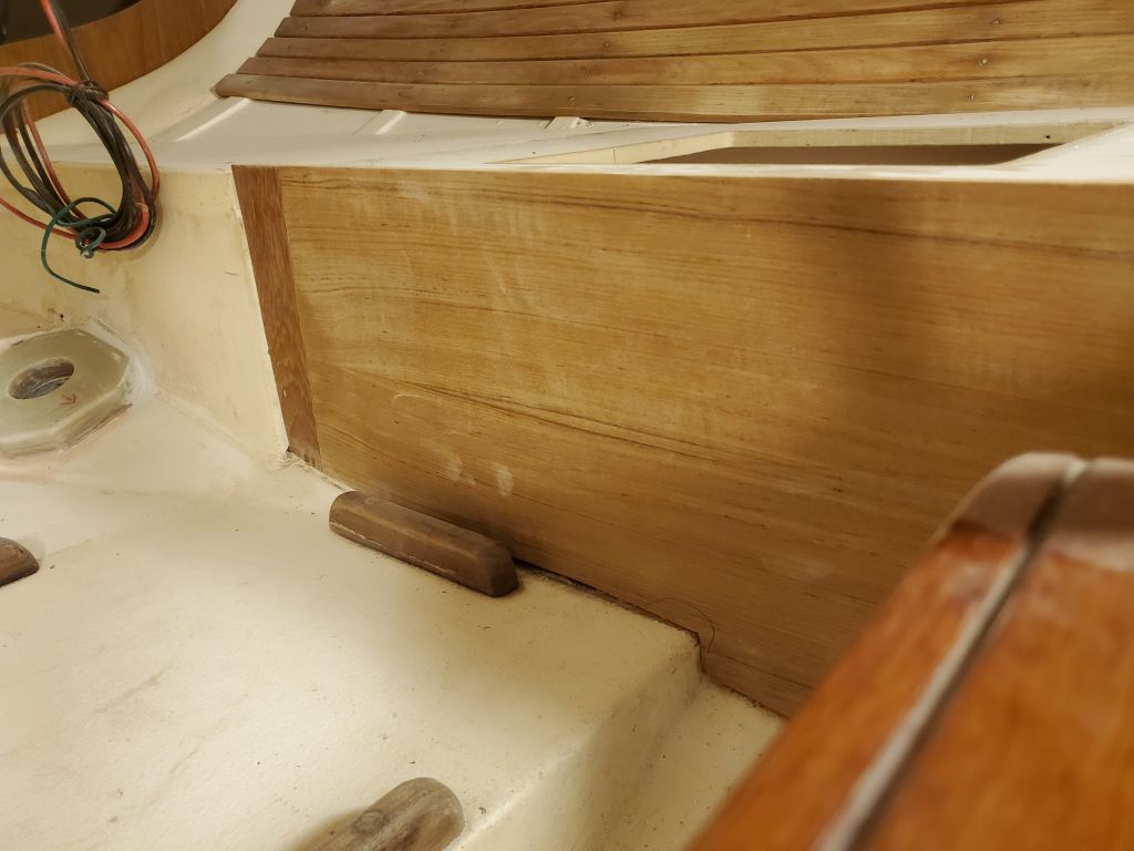
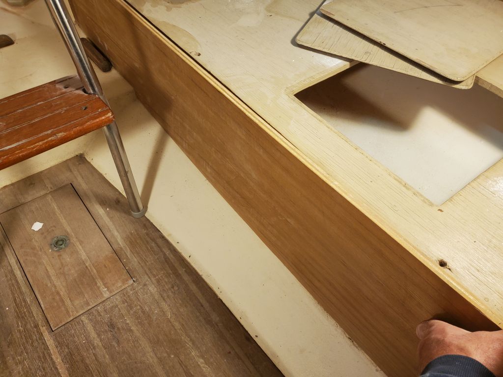
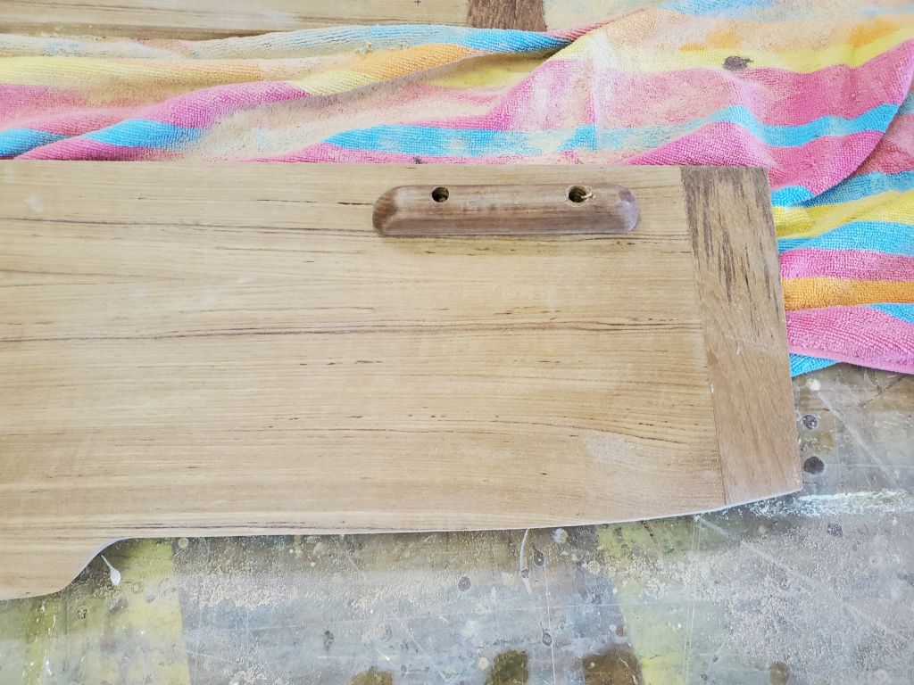
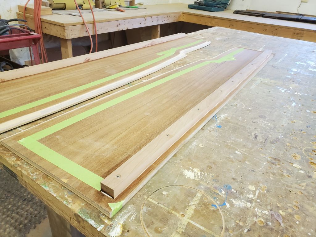
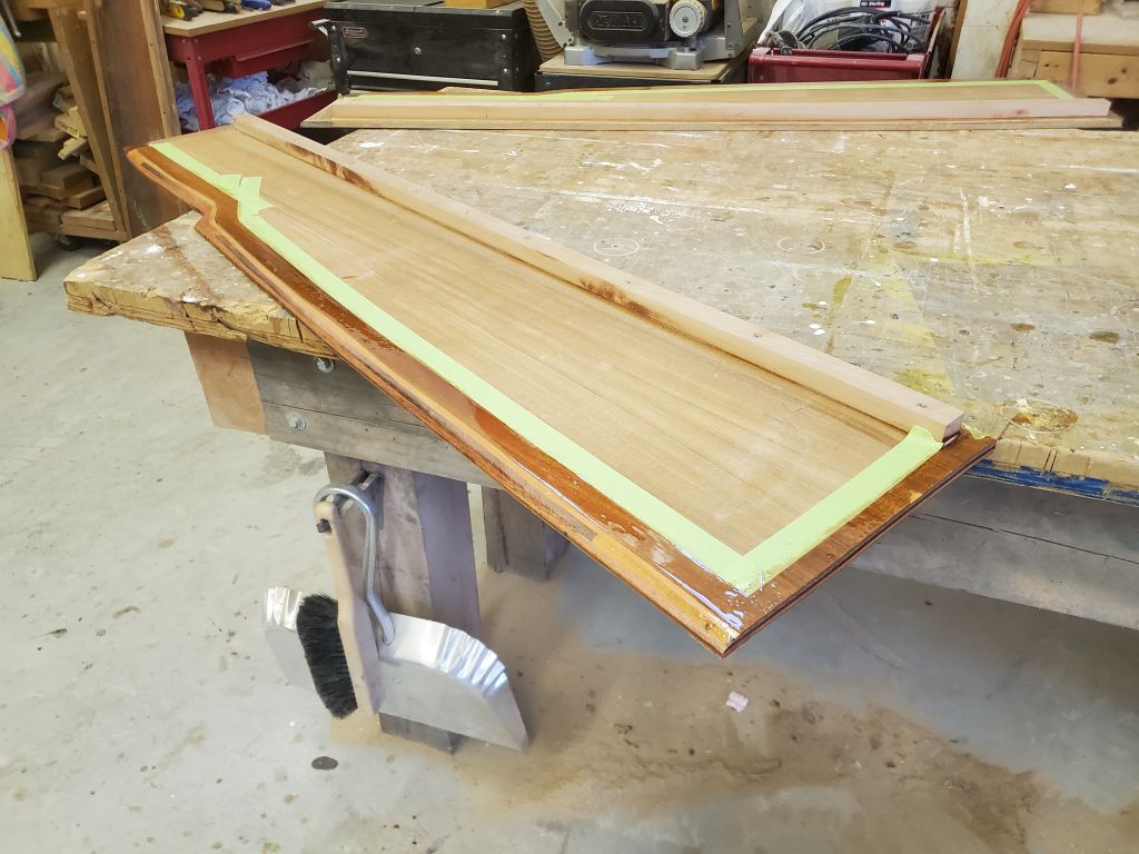
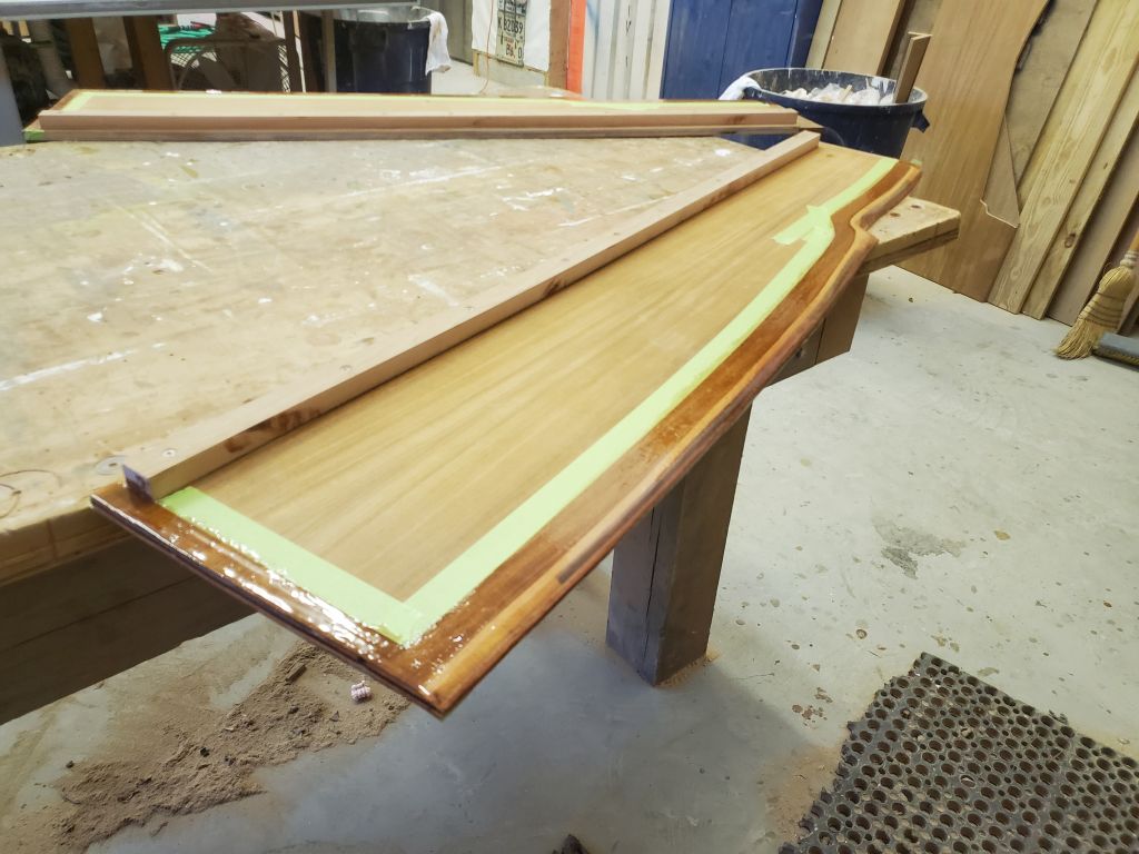
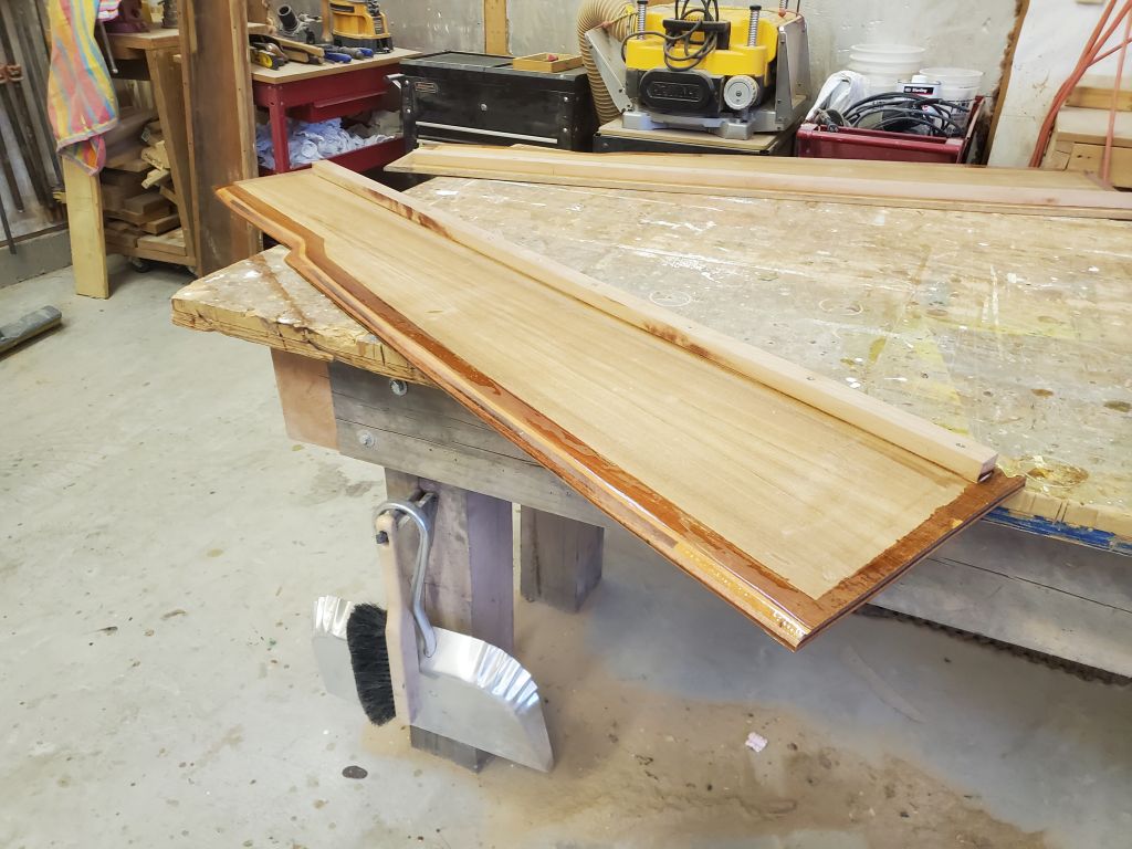
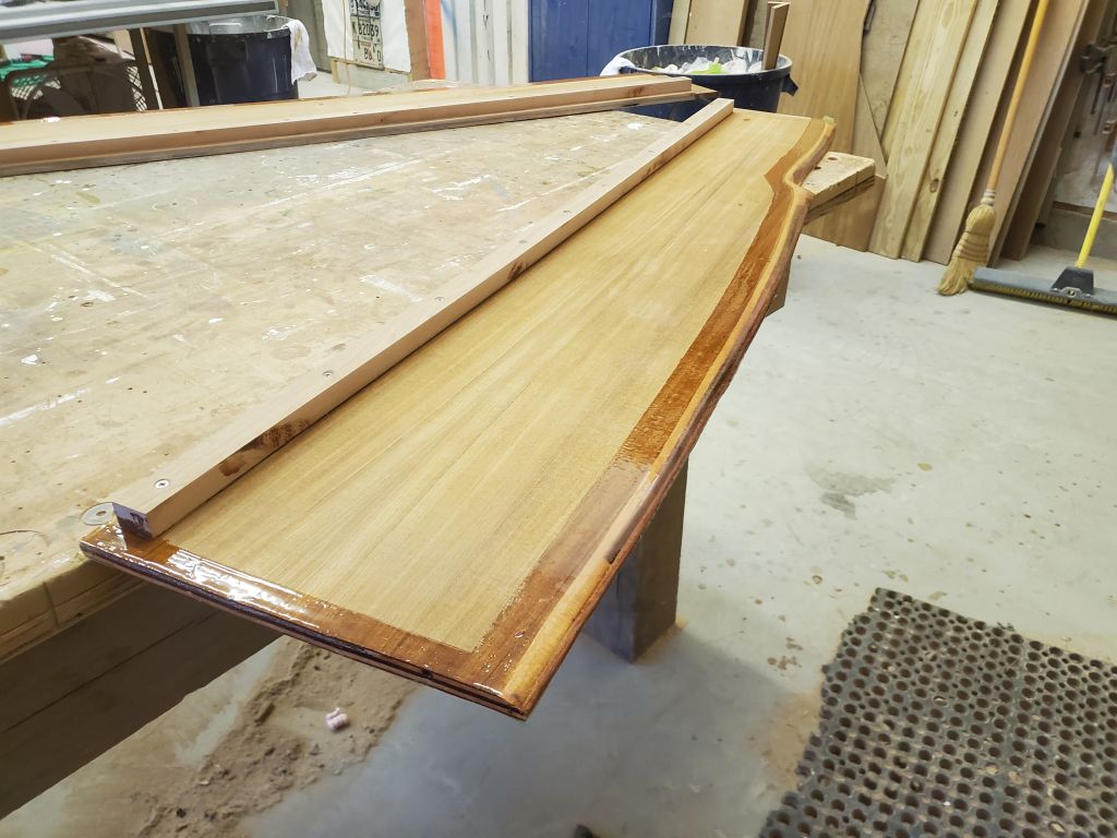
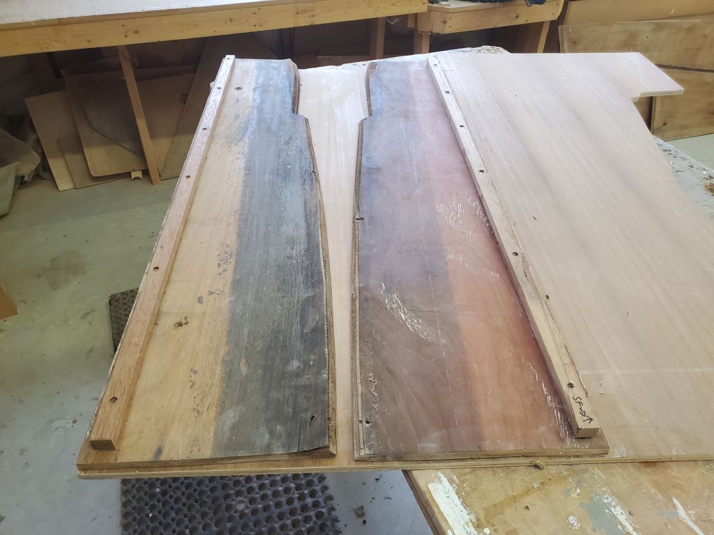
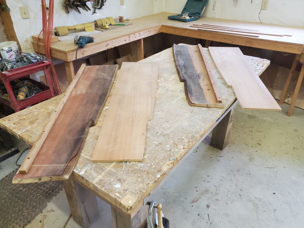
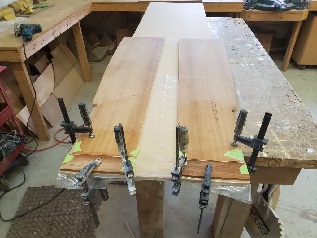
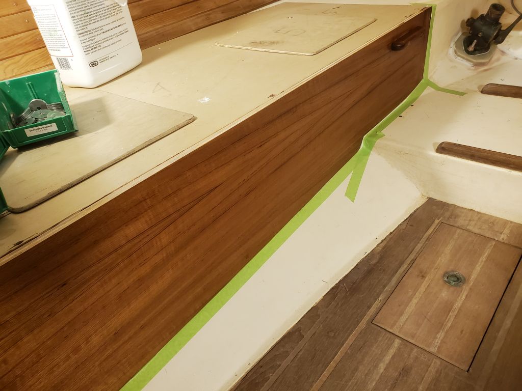
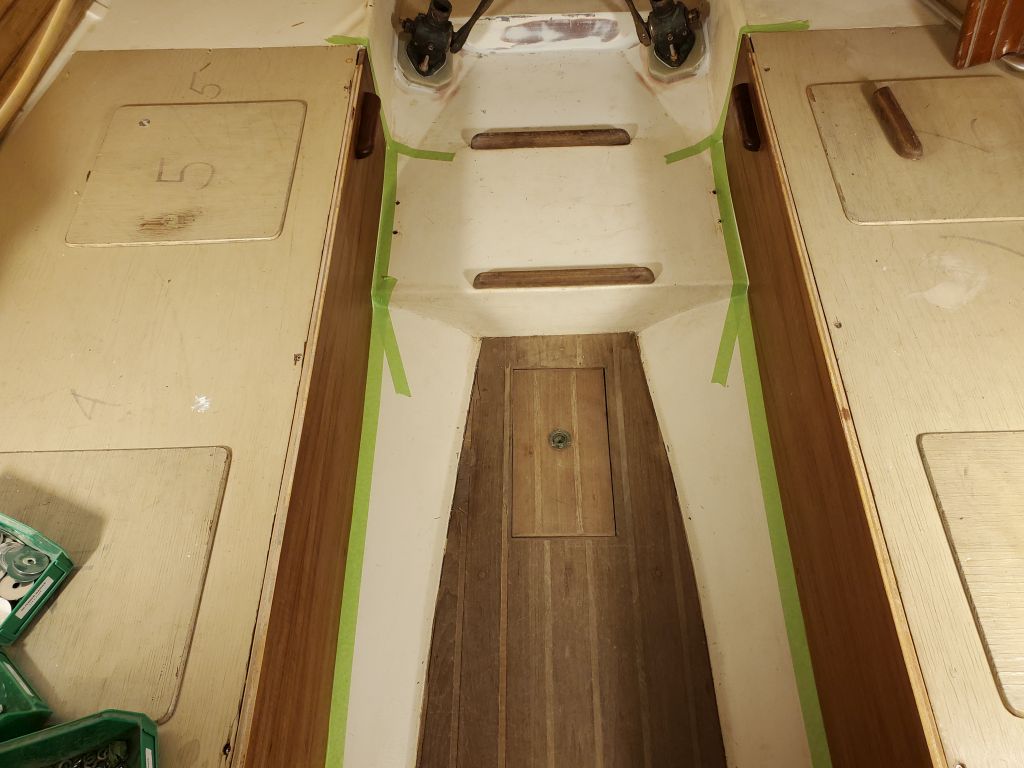
The through hulls took longer than expected, but I had enough time at the end of the day to prepare and apply a coat of oil to the new settee panels.


Total time billed on this job today: 6.75 hours
0600 Weather Observation: 38°, mostly clear. Forecast for the day: Sunny, 4o°