(page 53 of 166)

Arietta Phase 2-33

Tuesday

Investigating so that I could run the new transducer cable, I found that the existing cable–where it disappeared into the liner inside the settee locker–ended up in the bilge area beneath and aft of the main cabin, where it led eventually into the port utility/locker space outboard of the cockpit and, from there, beneath the liner and up to the electrical locker, and henceforth to the nearby opening in the bulkhead.  This is a camera view held inside the small bilge access hatch, looking to port, up, and aft.

I couldn’t get a snake through the existing hole in the liner, which also contained a couple large gray grounding cables, and since the new transducer cable was larger than the old, and the old cable was already tight in the opening, I didn’t think I’d ever get the new cable pulled through that way, so instead, after confirming that the liner continued to open up into the bilge further aft, I drilled a new access hole beneath the after settee hatch in an area of clear access.  With the transducer sensor loosely in place in the through hull to position it and give me a sense of how much cable slack would be required to allow for its removal and proper alignment, I led the rest of the cable aft through the bulkhead and then down the new hole into the bilge, where I could grab the end and pull it up through the bilge hatch for now.  I secured the new cable, and resecured the existing grounding cables, along the way inside the locker with rubber-lined clamps, replacing the tired old cable ties that I’d had to remove to take out the old transducer cable.

Now I could tape the new cable to the end of the old one, which ran aft through an inaccessible area of the bilge and surfaced again beneath the cockpit, and pull through the new cable into the locker space there.

It would have been nice if I could have used the old cable again to pull the new one through the space beneath the liner, which would have provided a clean and simple way forward to the electrical locker where it needed to end up, but alas, this was not to be:  The old cable was tightly bound somewhere within, and I couldn’t pull it from either direction.  So instead, I cut off the excess and now-obsolete cable at both ends, and ran the new cable through the space at the outboard upper corner of the bulkhead, and along the accessible section  of the liner (the outboard area that allowed access to the hull/deck joint and hardware locations), then drilled a hole in this part of the liner to run the cable the short distance to the bottom of the electrical locker, where another new hole allowed me to pull in the cable.  I also led in the new bow light cable through these same holes and, after securing the cable appropriately and tying up the excess in the aft locker near the excess speedo cable, covered these briefly exposed wires with some split loom and cable clamps for a neat installation.  Running the cable end the short distance through the liner between the electrical locker and the lower instrument opening, I left enough excess cable there to make the wiring connections to the instrument.

I prepared the end of the old speedo cable by cutting off the BNC connector and, as advised by DMI, stripped back the sheathing to expose the core (speed sensor) and shielding (ground).  Now, I could install and hook up both speed and depth instruments.  These instruments use an aluminum trim ring to secure them from behind:  The trim ring uses setscrews to pinch the instrument housing, then three additional set screws through the face of the ring press against the bulkhead and pull the instrument tightly into position.  I treated all the holes and threads with Teflon gel to stave off corrosion between the parts, and, with some new butyl sealant on the backs of the instruments, installed them tightly, then made up the wiring connections as directed.

So simple in description, but this all took 4-1/2 hours when it was said and done.

I connected the new bow light wires, which finished my work in the panel area for now.

My new solar wire arrived ahead of schedule, which meant during the remains of the day I could start the process of installing these, and the other mast wires.  After some additional double-checking and final layout, I drilled two holes through the deck for the pair of solar wires, and managed to run them from above and out the existing liner opening below without too much difficulty, though I couldn’t directly access the openings from beneath.  Then, before the end of the day, I drilled another hole for the 4-wire connector harness the owner liked for the mast wiring (a trailer wiring plug-type), and led these below as well.  These wires would all eventually run through the compressed rubber oblong gland designed for this purpose, but at the moment I didn’t need any of its components in place.  All that remained was the larger hole for the VHF cable, which I’d have to lead from the bottom up, and that would be the first task for next time, after which I could straighten up and lead the wires belowdecks.

Total time billed on this job today:  6 hours

0600 Weather Observation:  26°, clear.  Forecast for the day:  Sunny, 35°

Arietta Phase 2-32

Monday

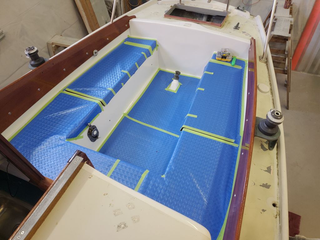
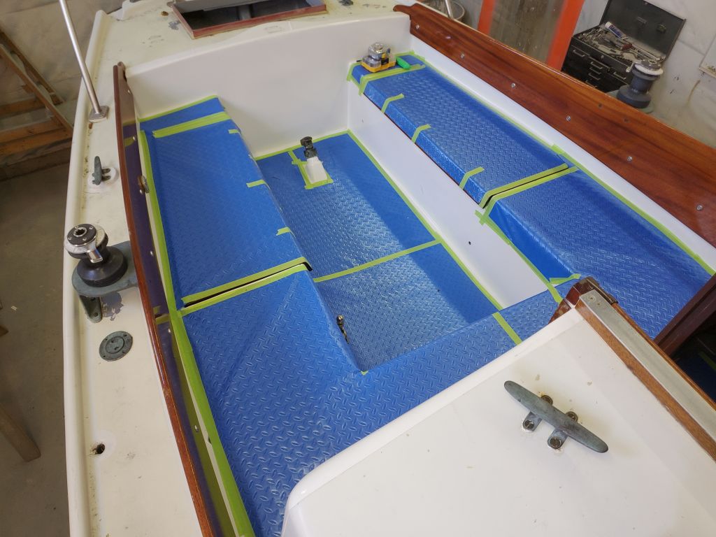
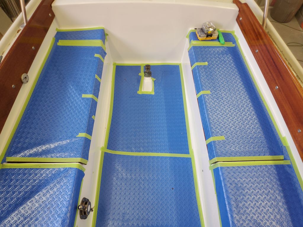
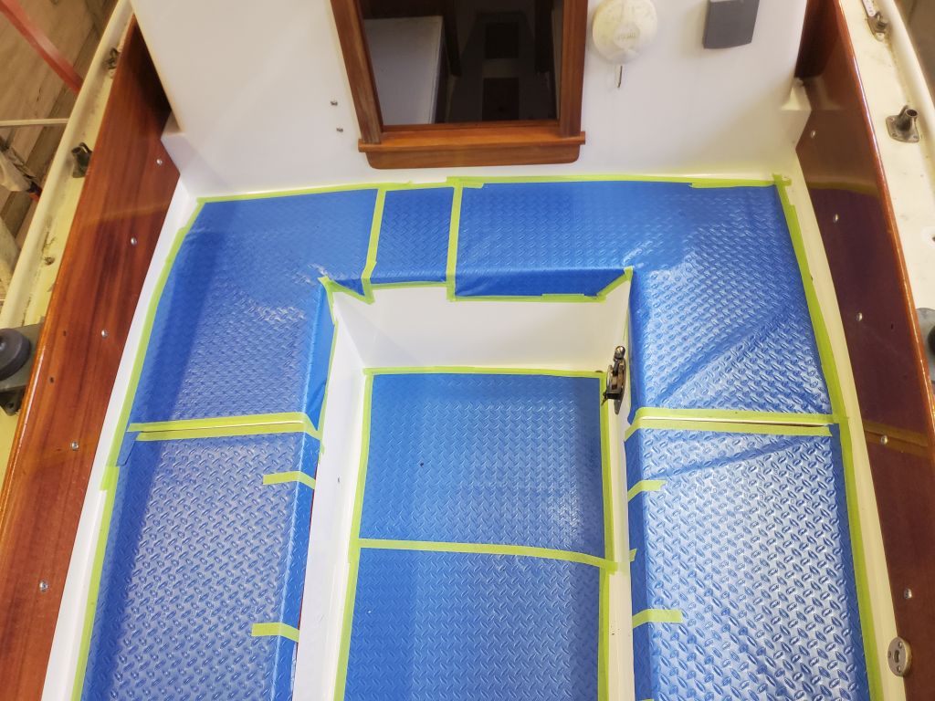
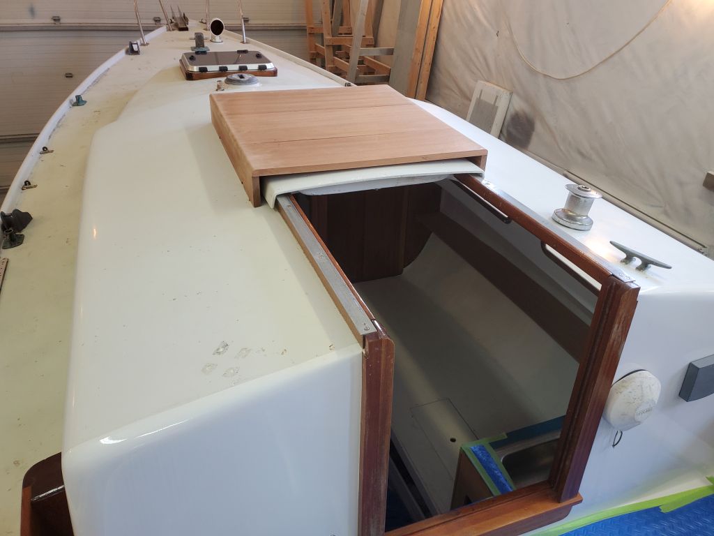
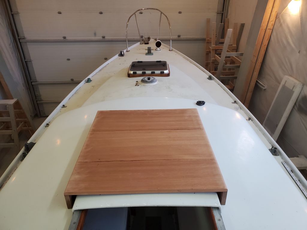
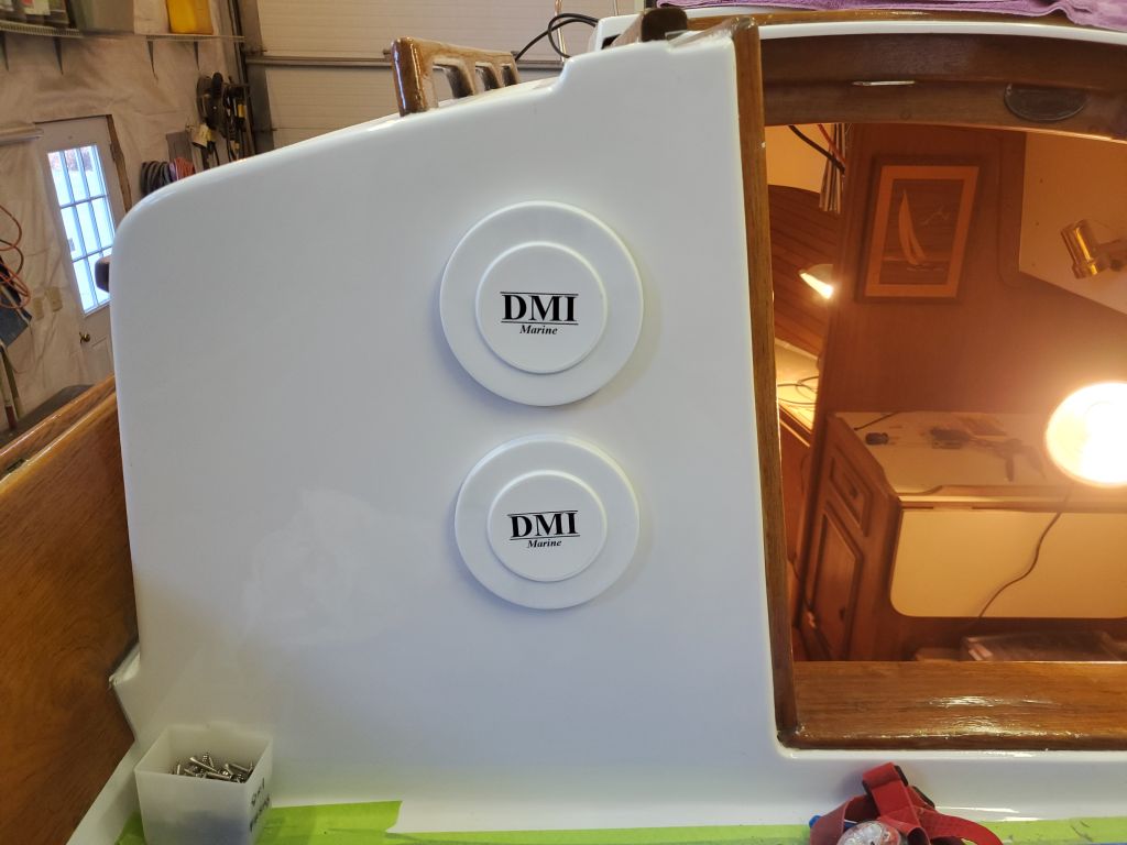
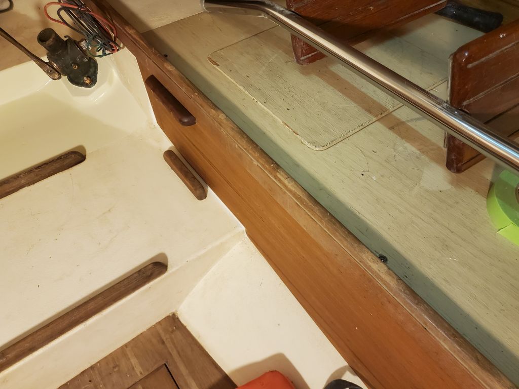
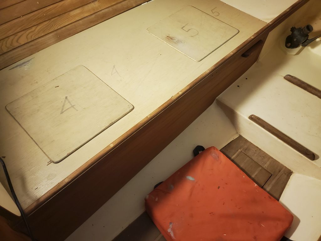
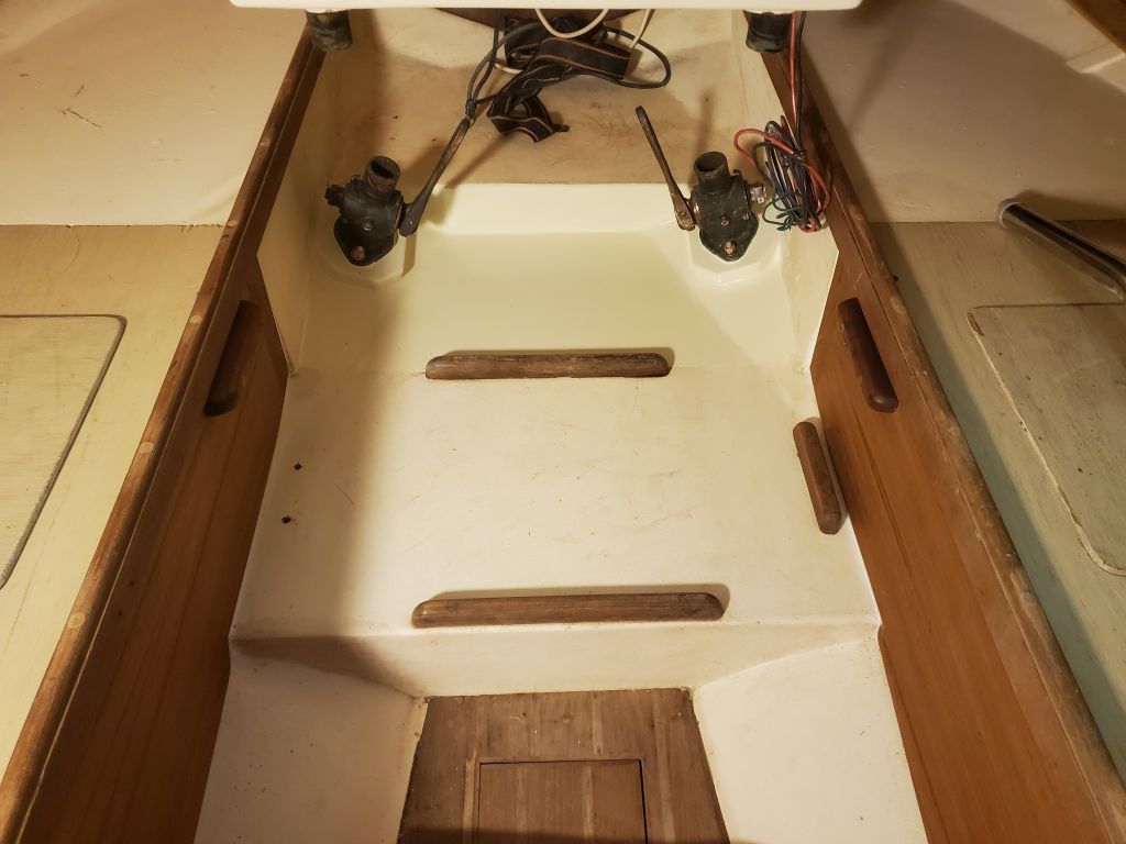
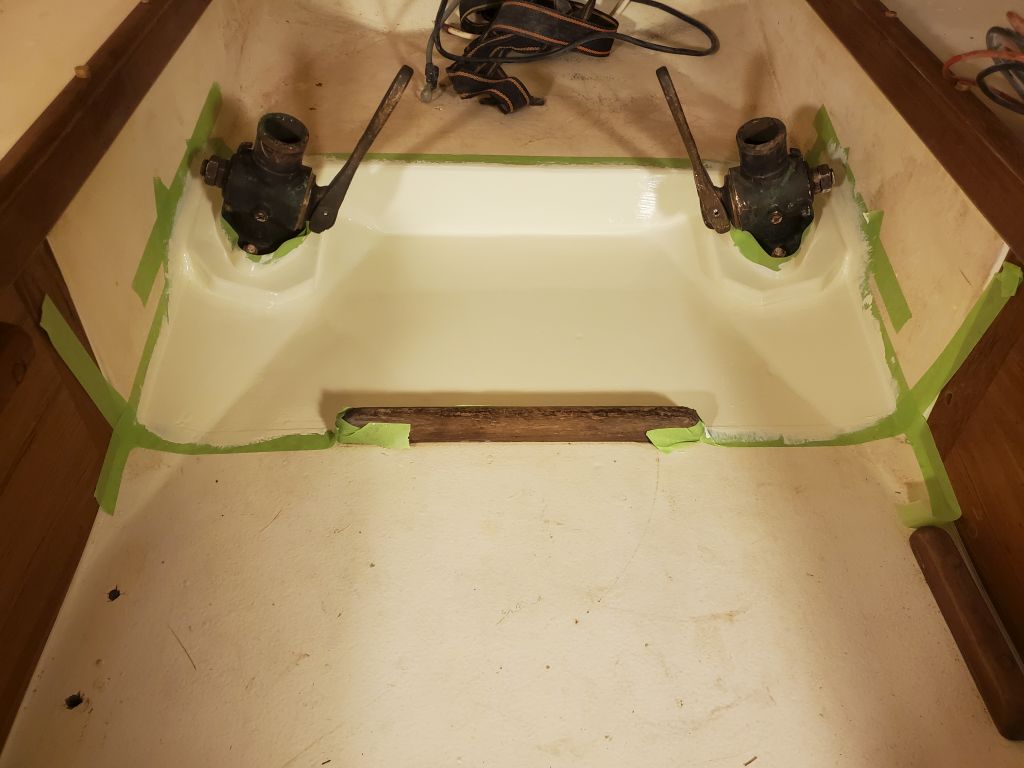
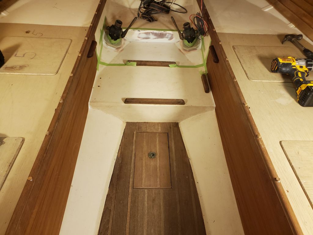
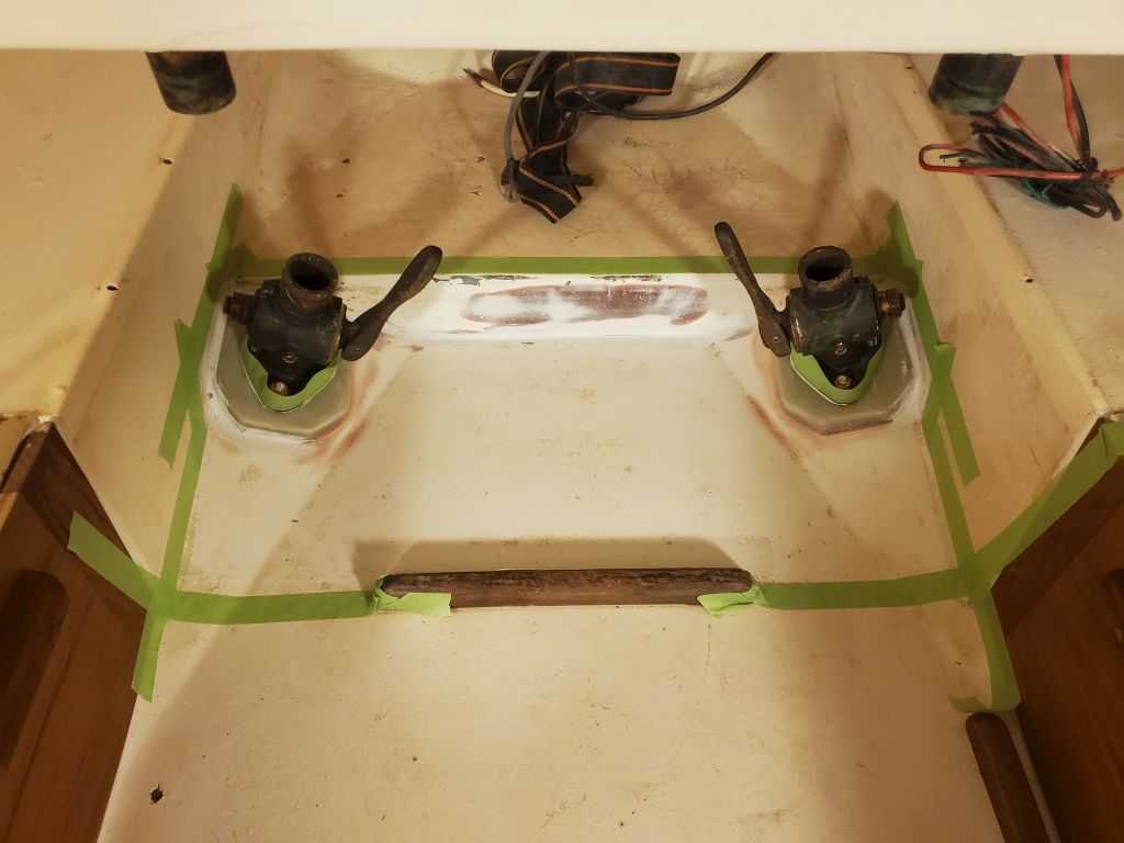
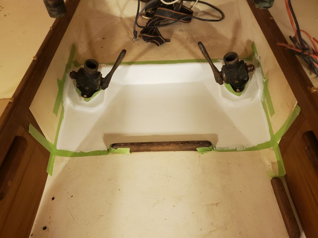
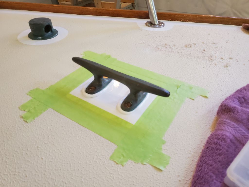
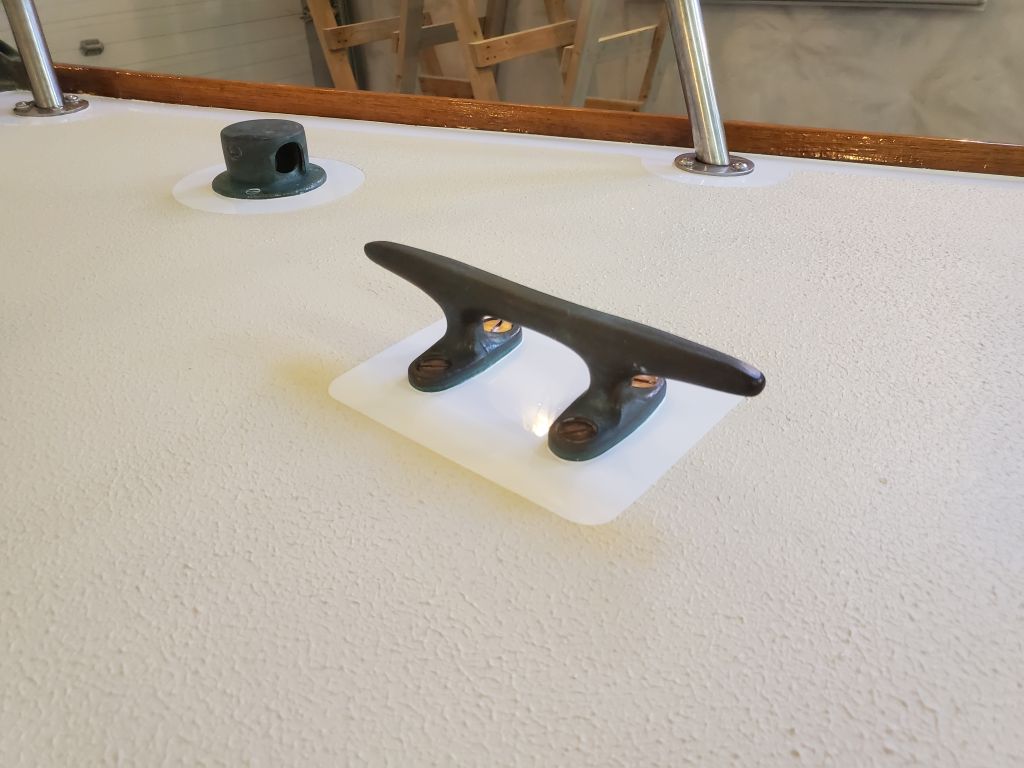
Over the weekend, I applied another coat of paint to the area beneath the cockpit.  Later, when the paint was dry, I removed the tape to complete the job.

My remaining work list was short, and on the surface the jobs seemed straightforward, but as with most things the potential simplicity was deceiving, and from my goings on around the boat I knew some of the work was likely to run into various challenges.  Therefore, I decided to simply start knocking off the items on my list one at at time, starting with those that I thought would be easier to finish.

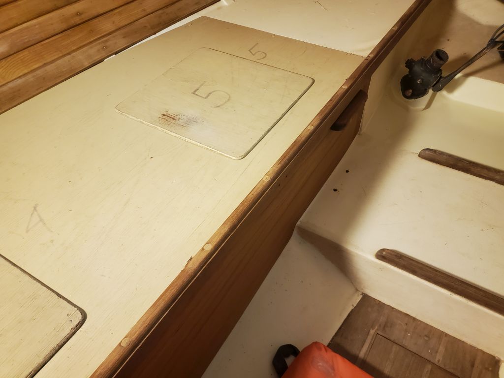
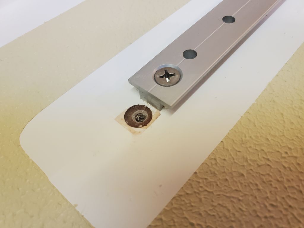
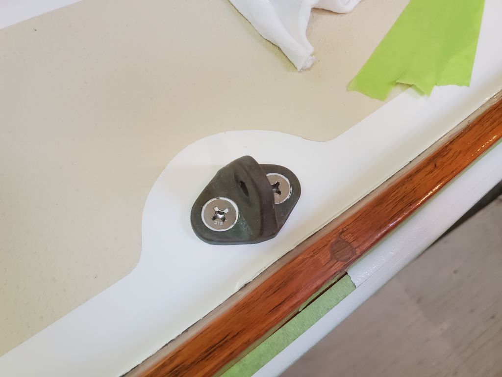
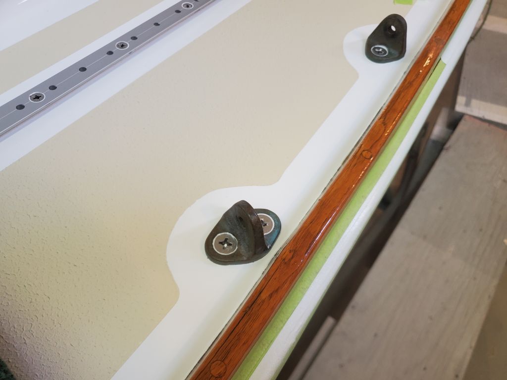
With the paint finished, I could pare off the new bungs over the screw holes securing the berth fiddles.

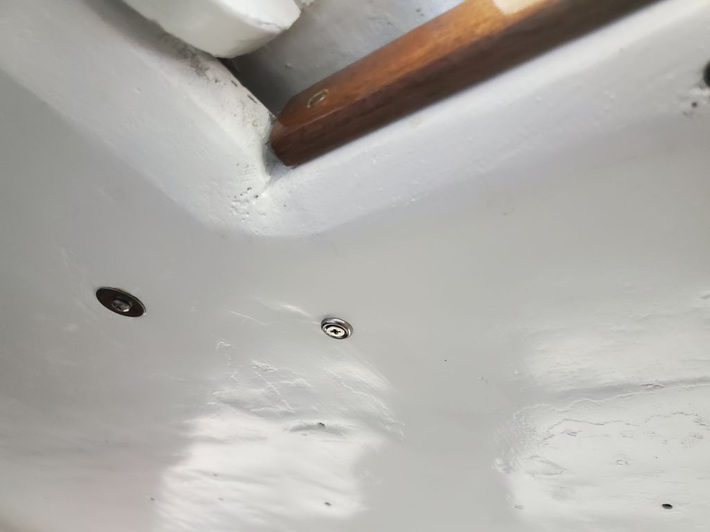
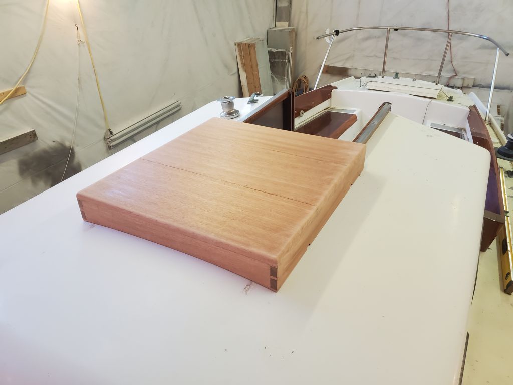
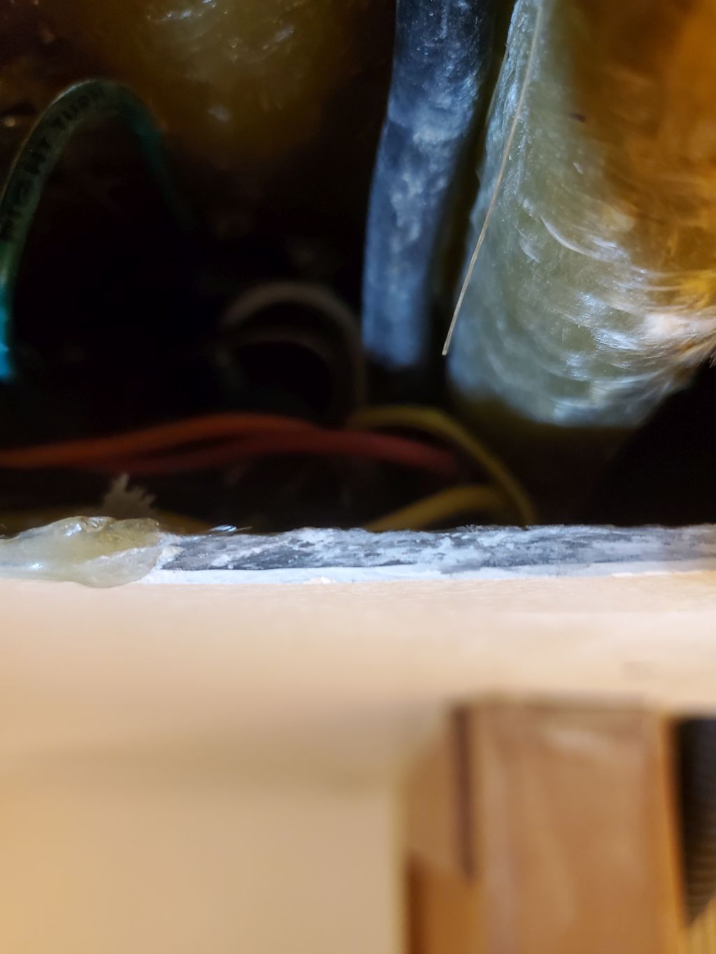
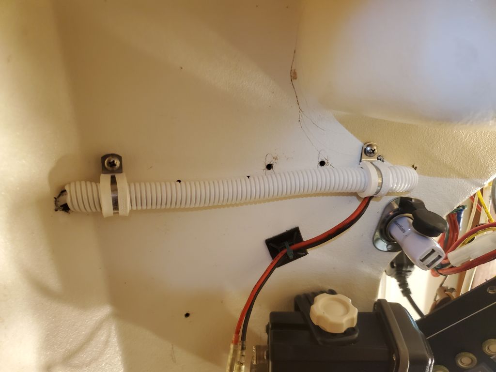
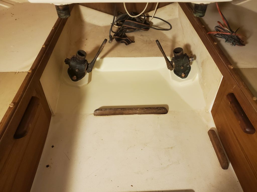
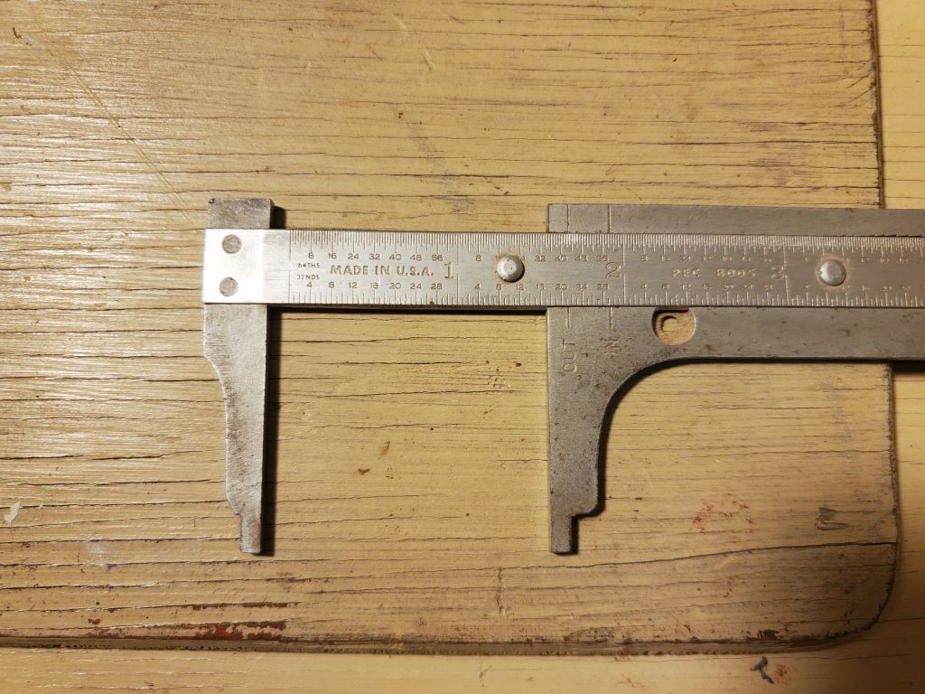
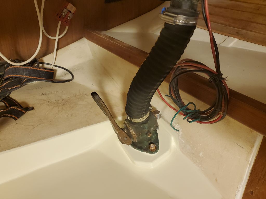
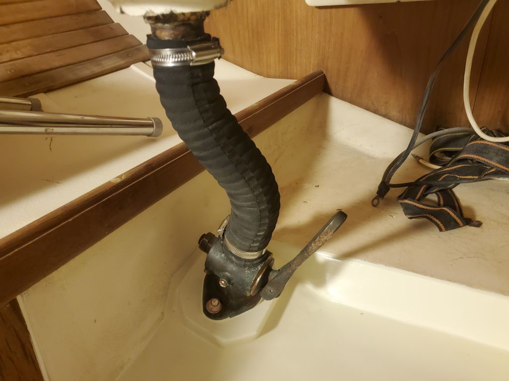
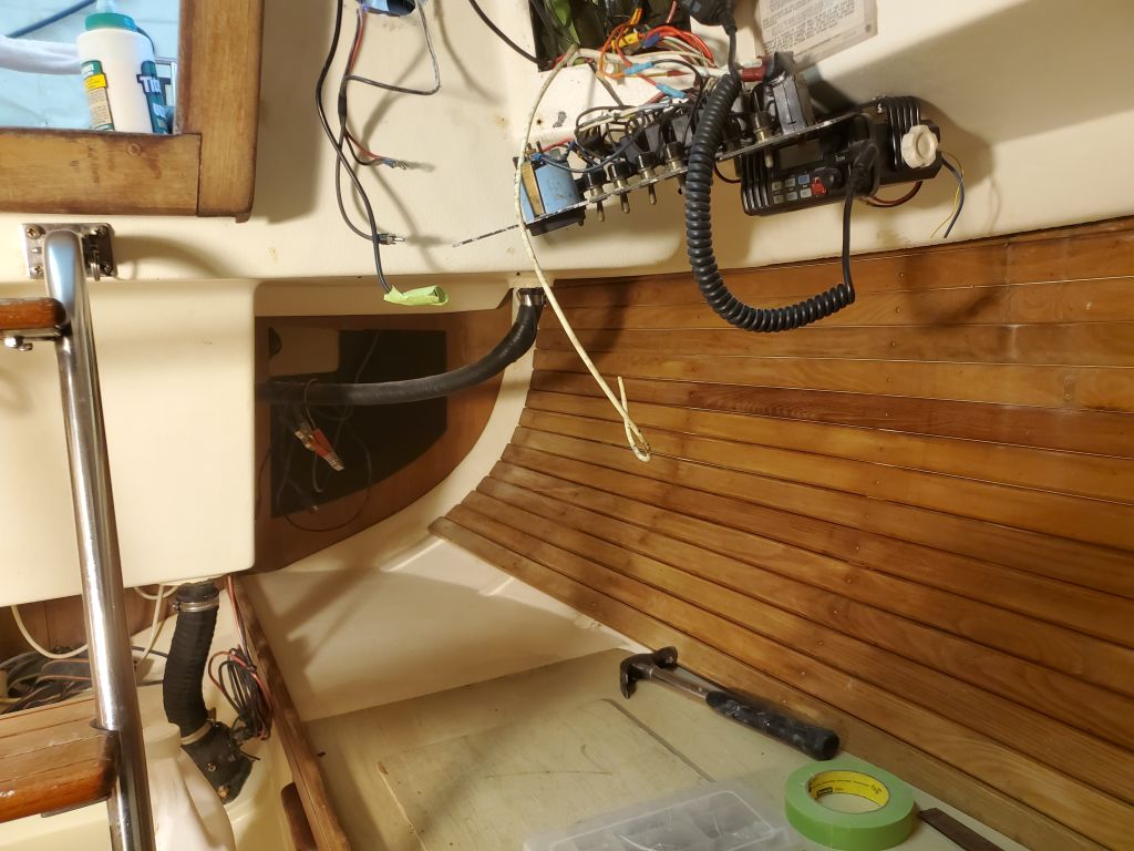
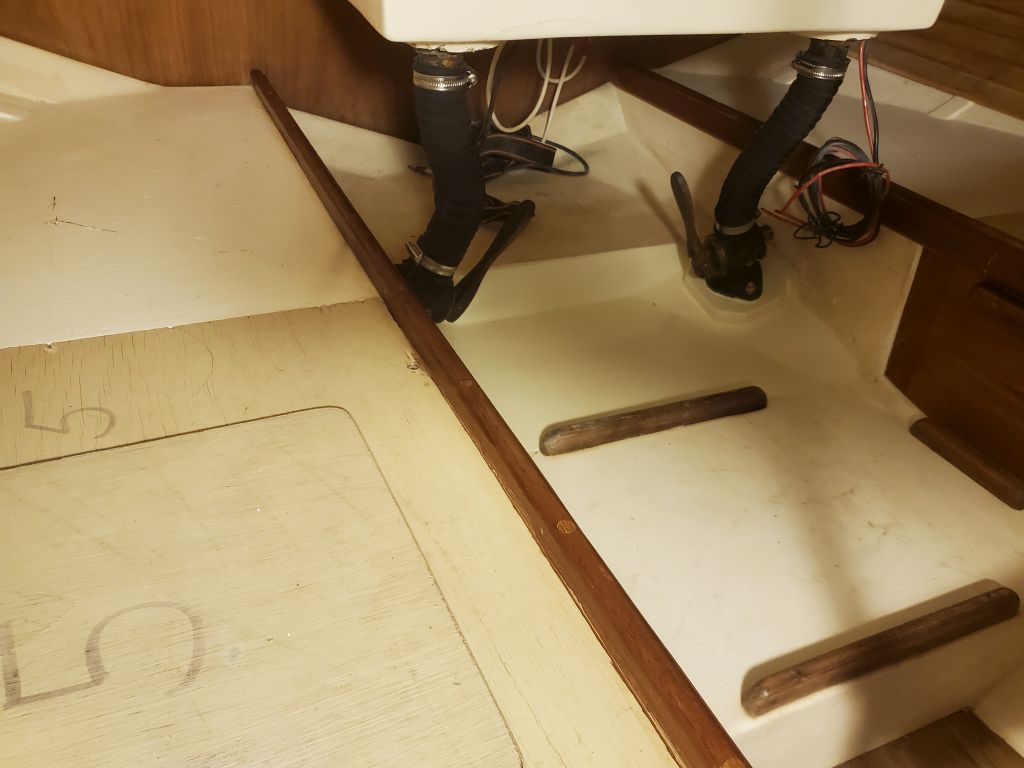
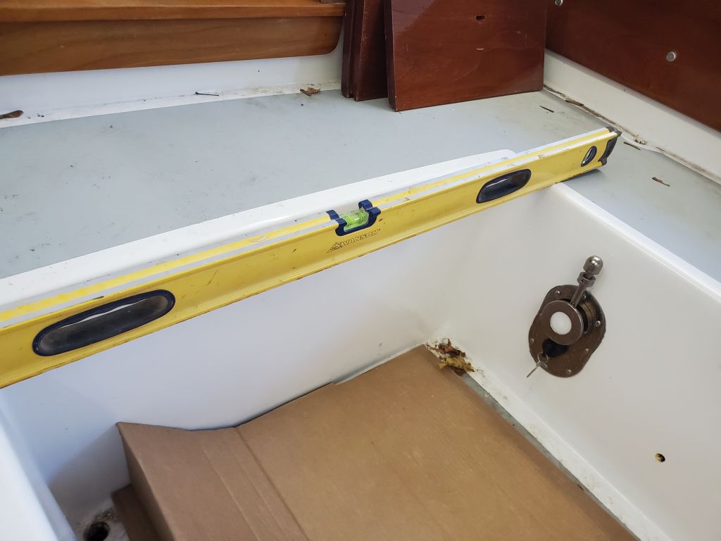
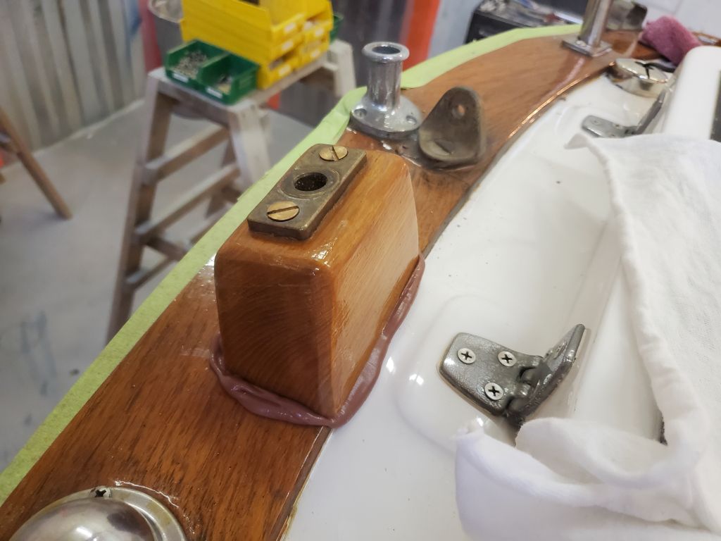
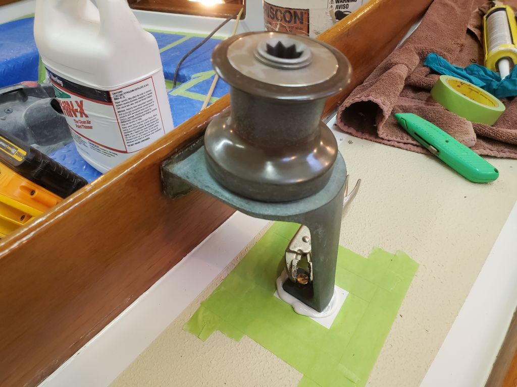
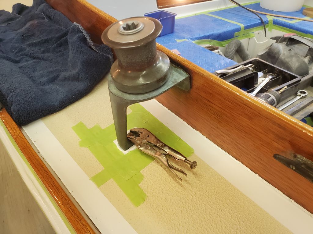
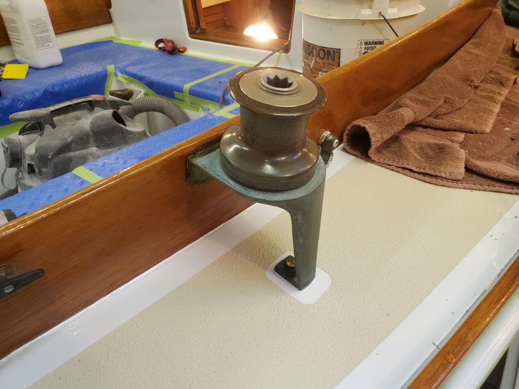
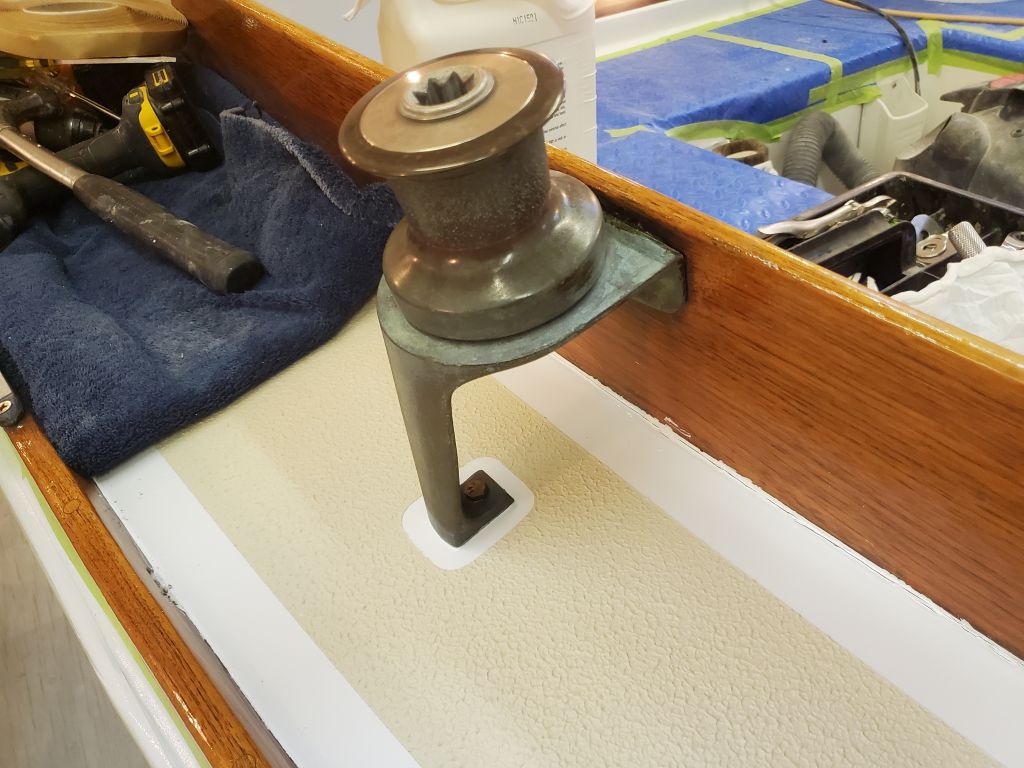
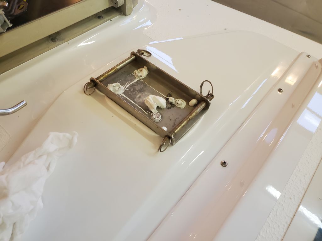
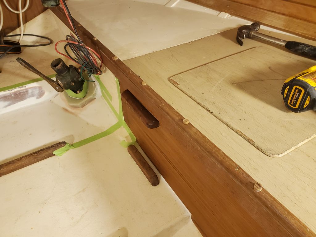
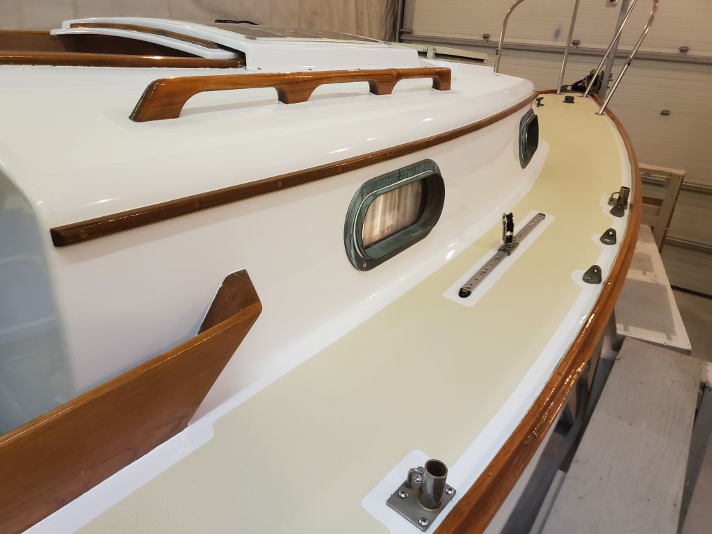
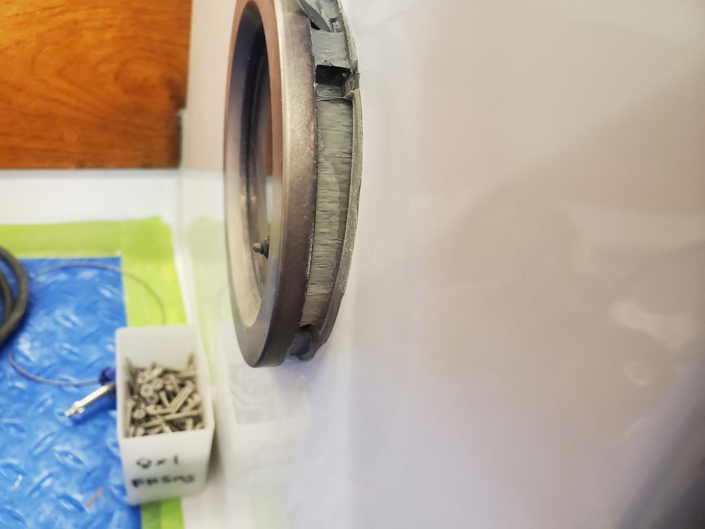
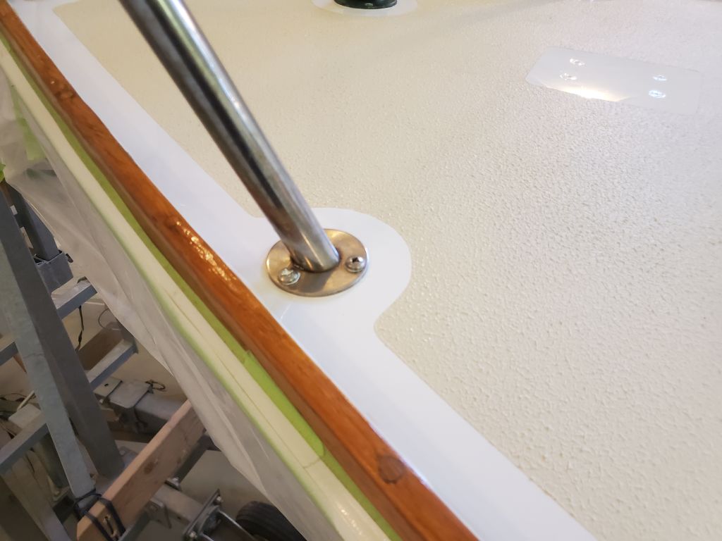
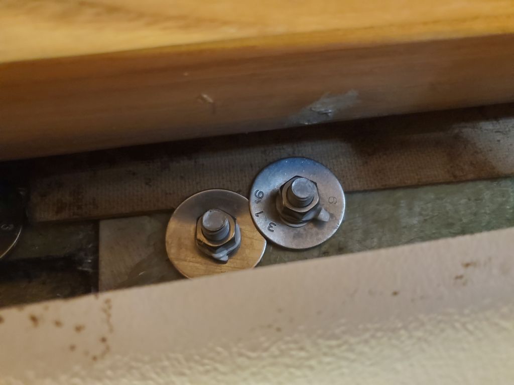
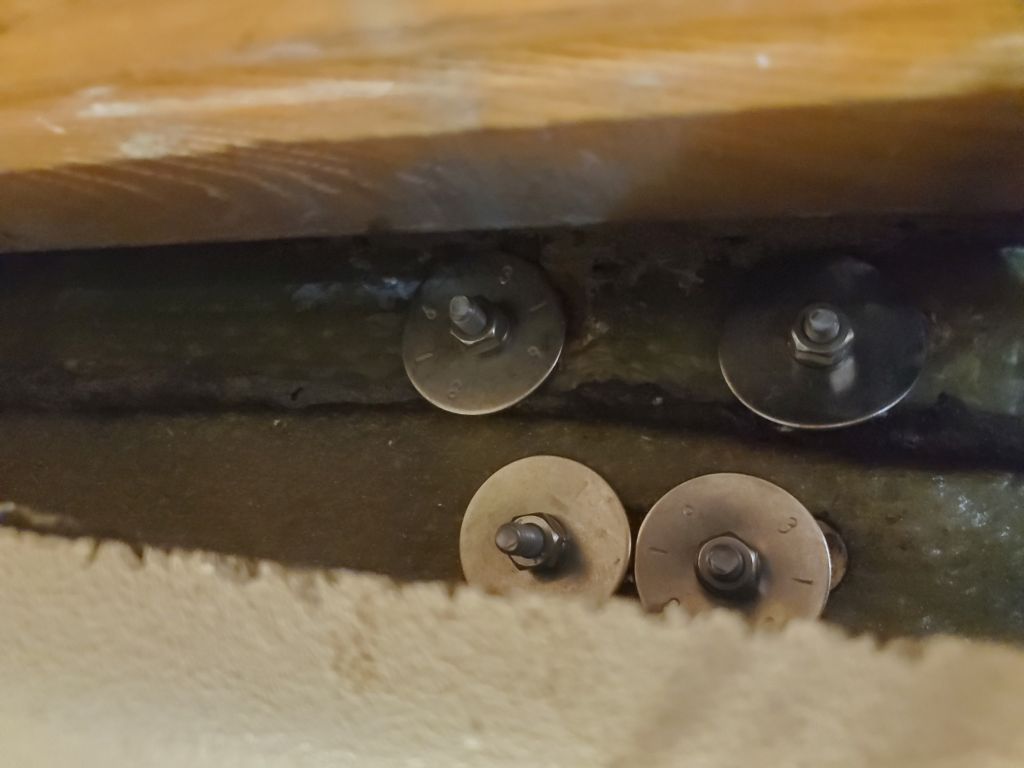
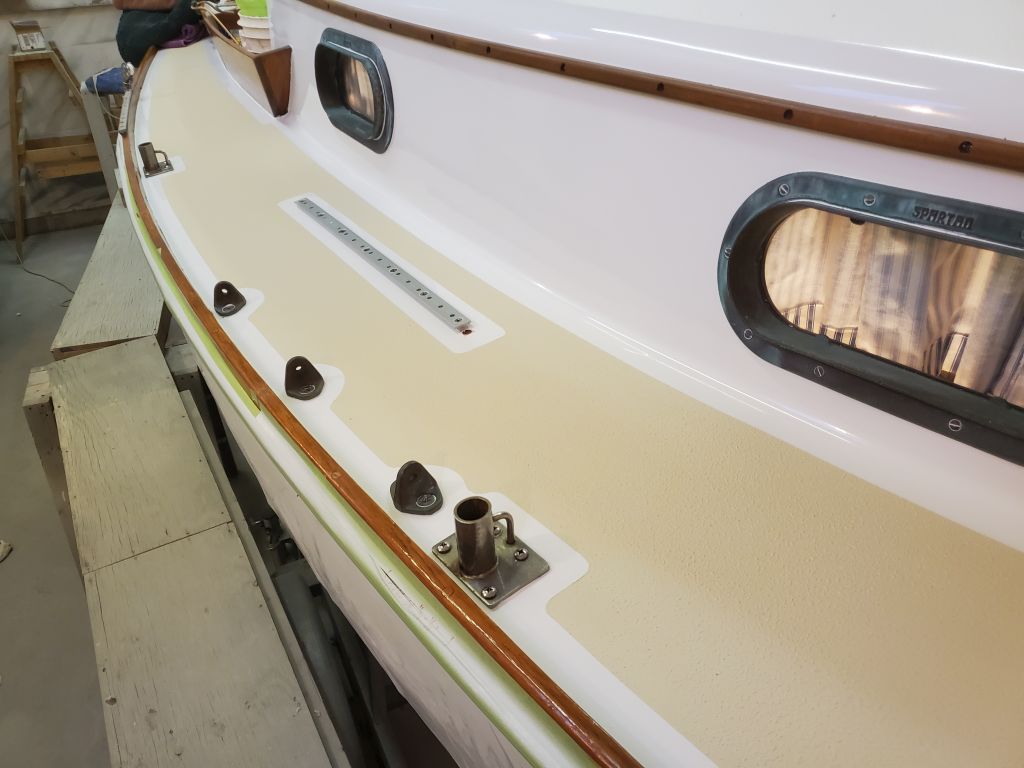
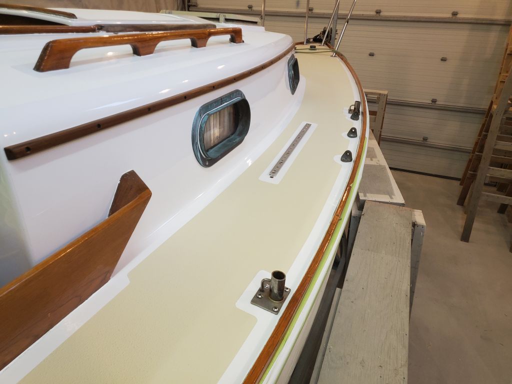
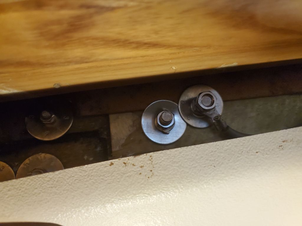
Next on the list:  New scupper hoses, now that the work in the immediate area was done.  I didn’t expect any great challenges here, and I pulled a short length of 1-1/2″ hose from my stock for the job, but of course right off I discovered to my dismay that the hose diameter was too small for the Spartan seacocks and cockpit drains–something I dimly remembered from work past.  Try as I might, there was no way the heavy wire-reinforced hose was going to stretch over these fittings, which I measured now at 1-5/8″ (or even slightly larger at the end of the seacock barb, as represented by the measurement in the photo below).

I didn’t have this unusual size of hose on hand, of course, but digging further I did find a short length of 1-9/16″ hose suitable for the job, and fortunately it fit over the fittings without undue struggle, allowing me to finish the task at hand.

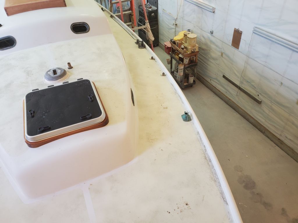
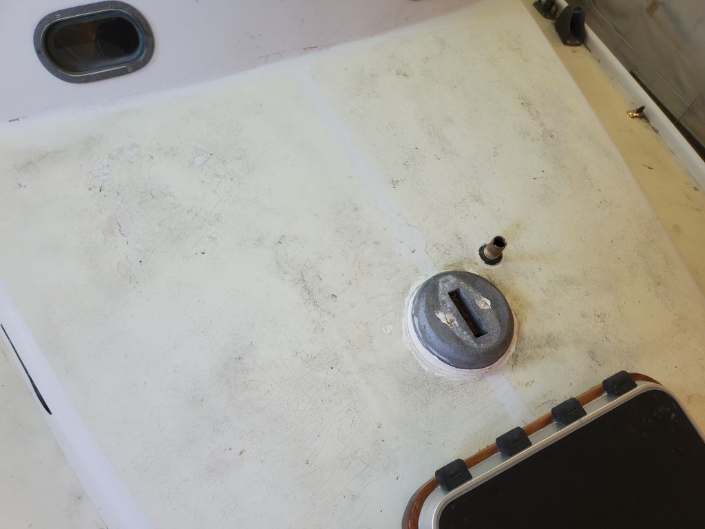
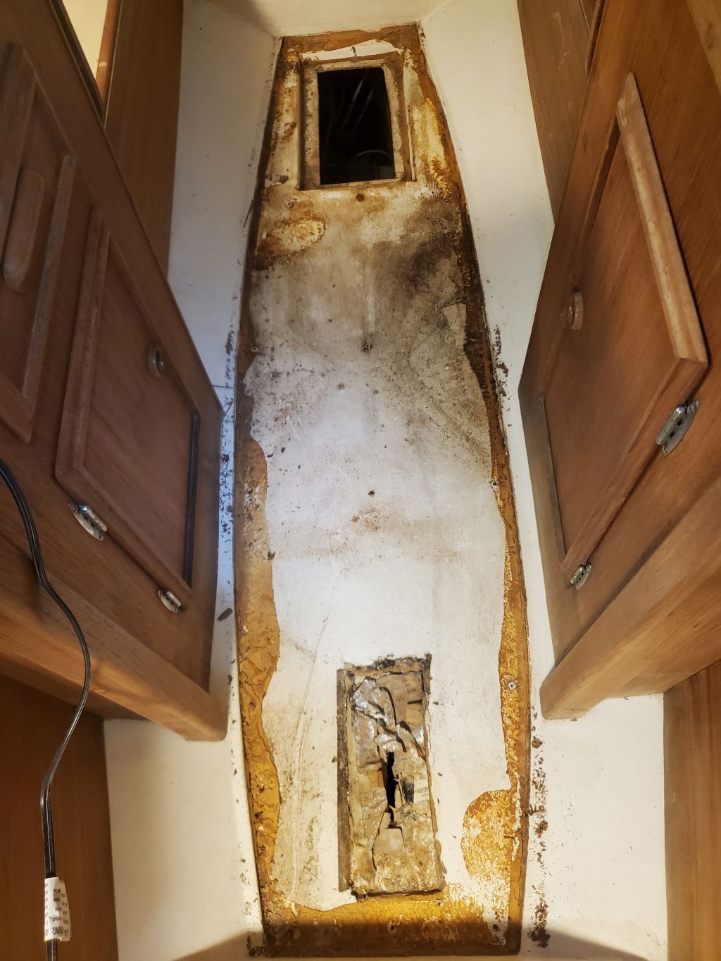
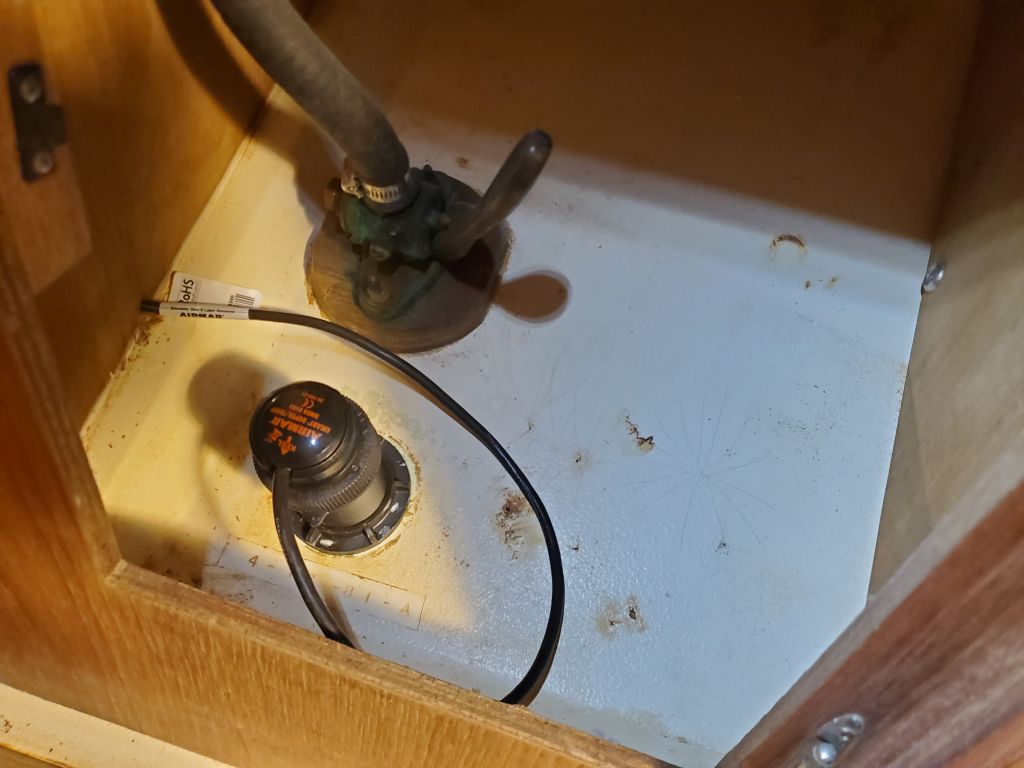
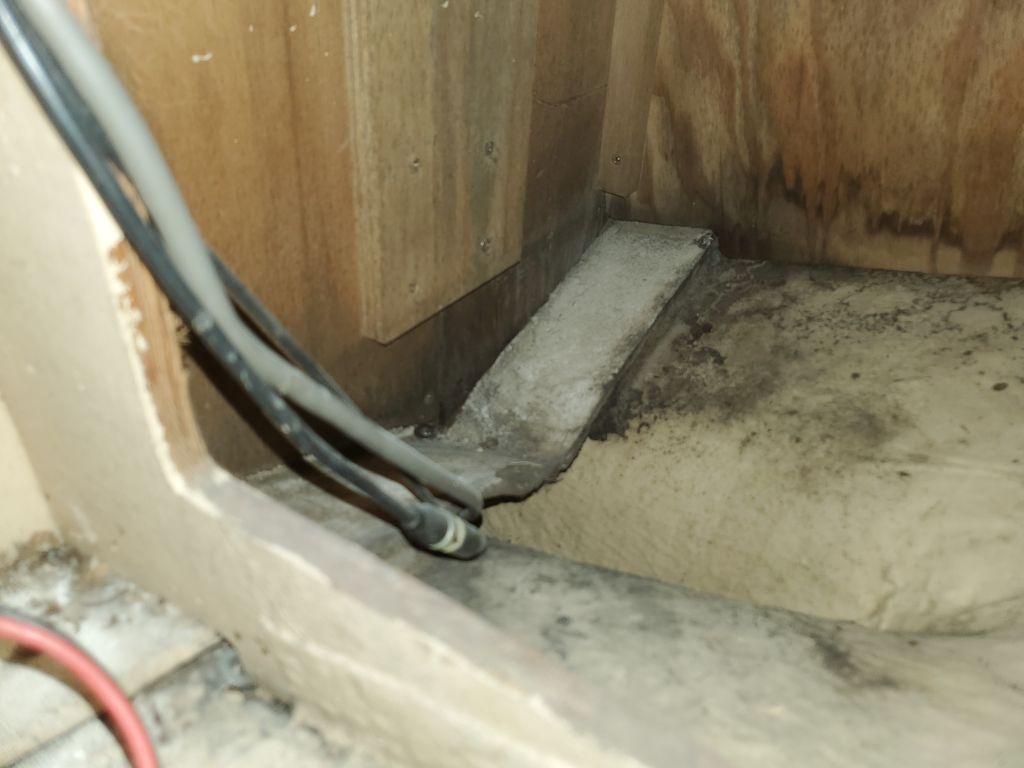
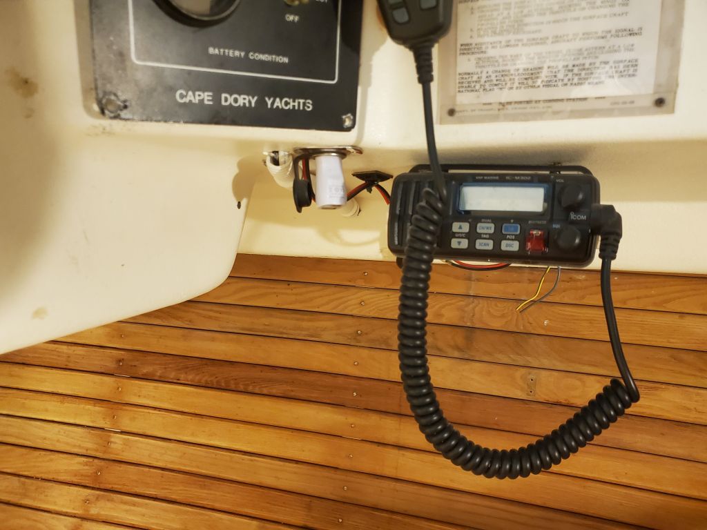
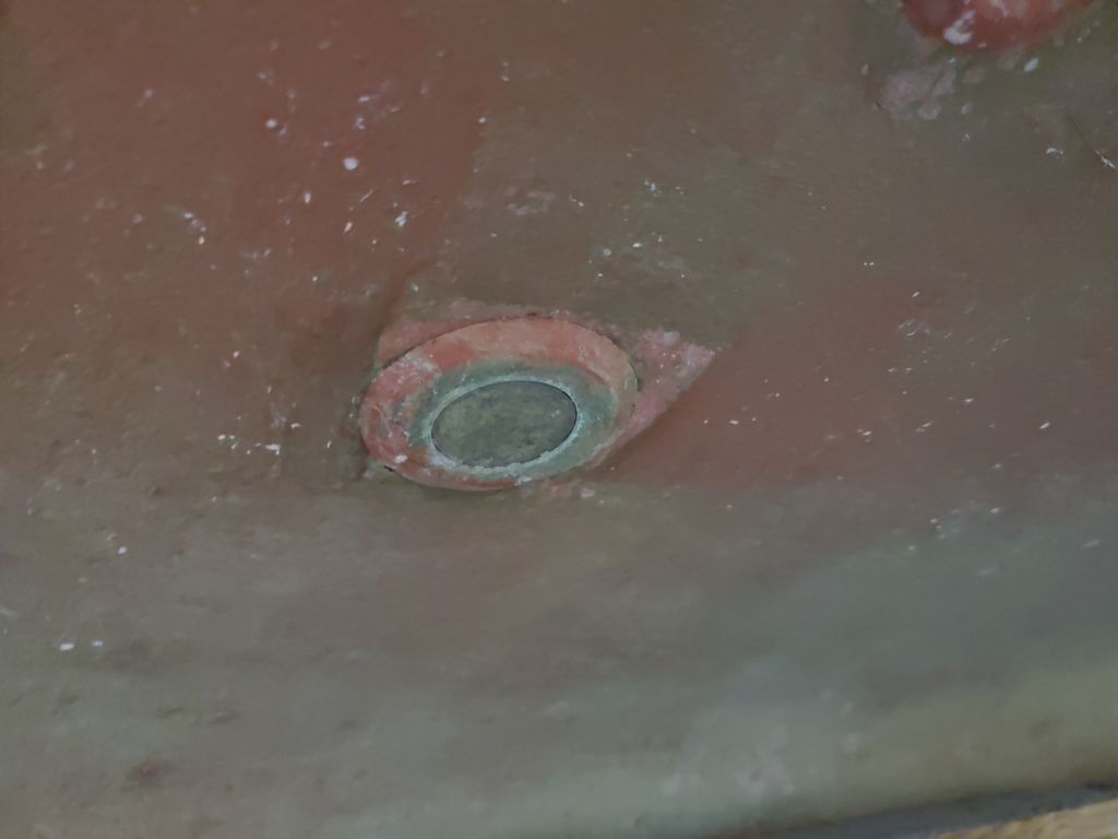
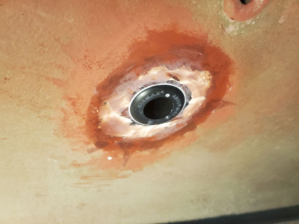
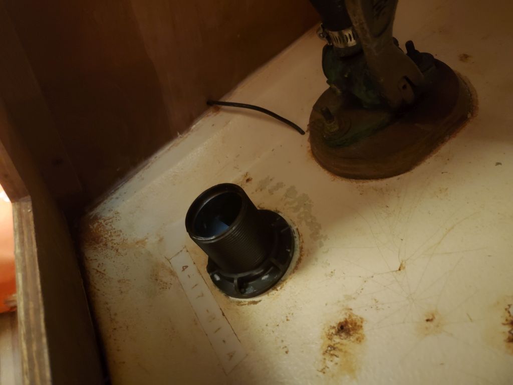
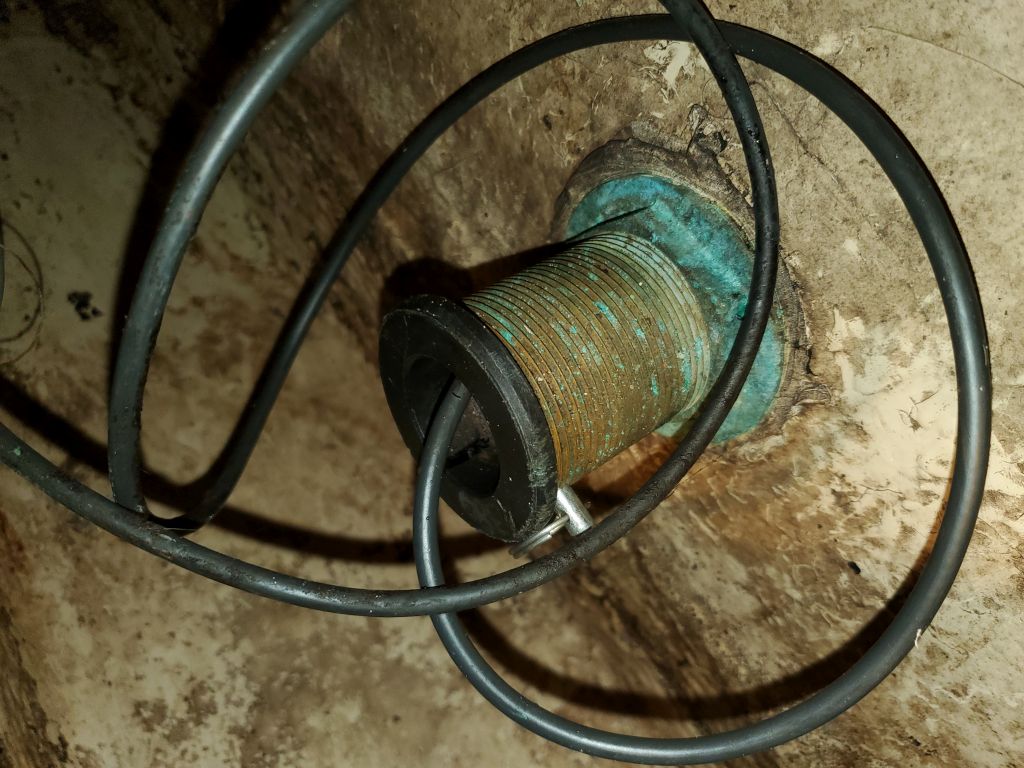
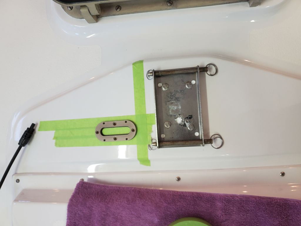
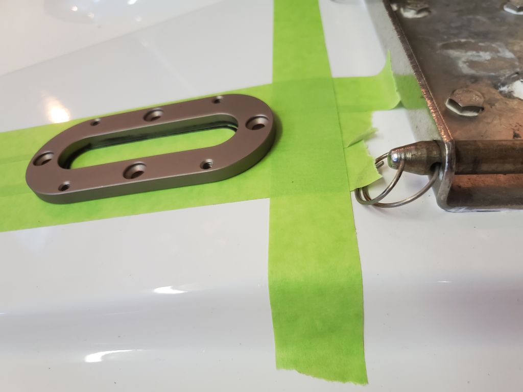
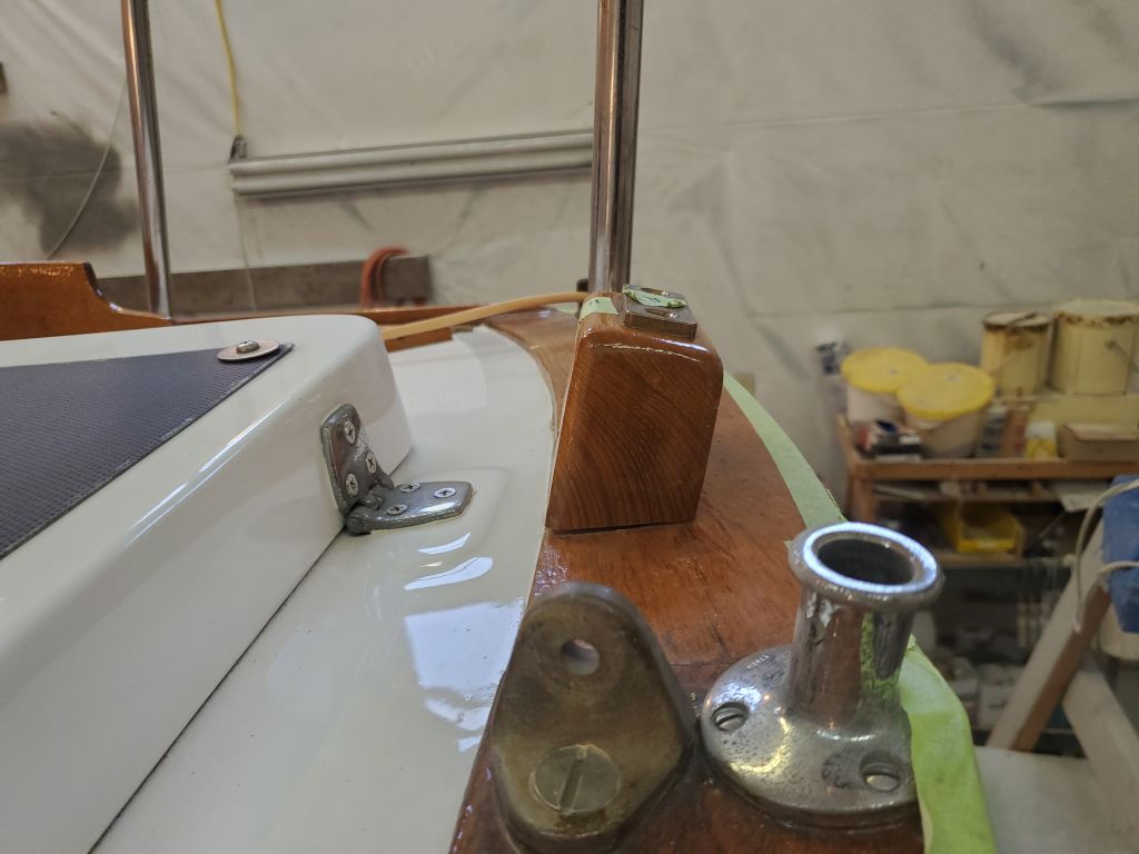
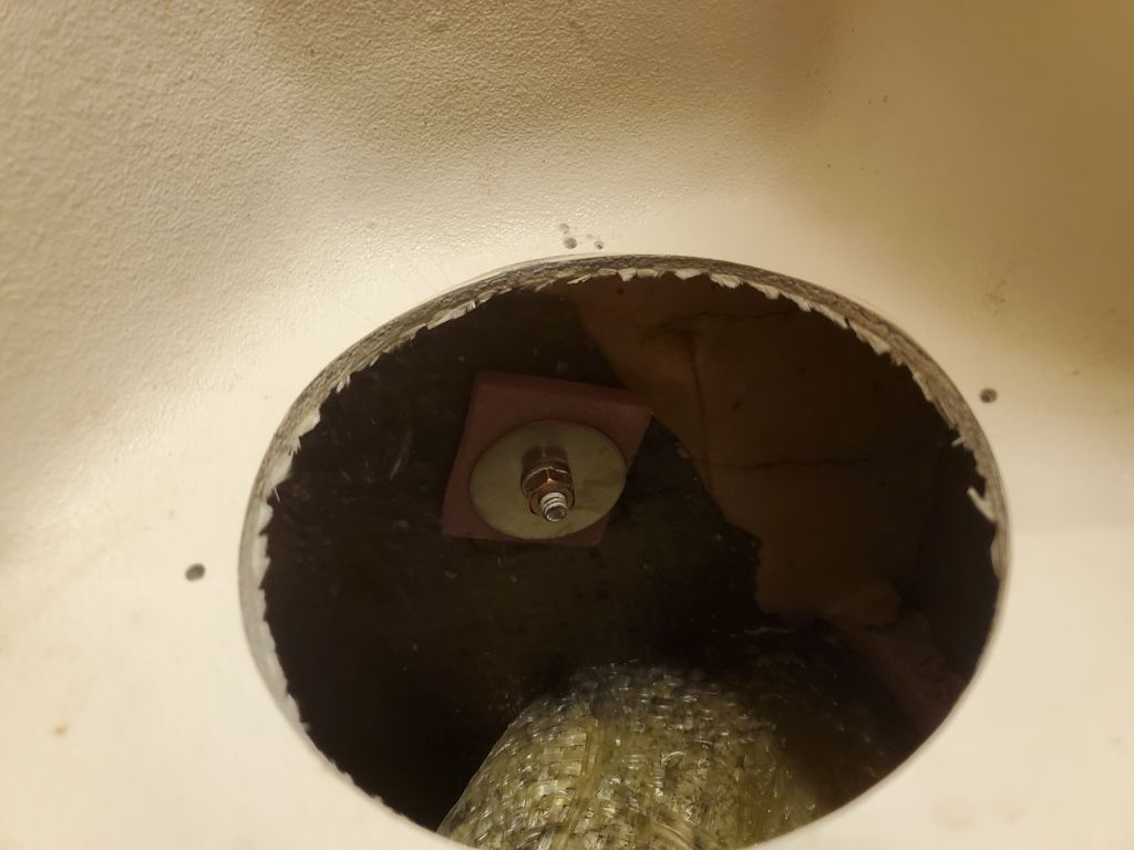
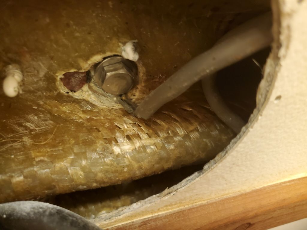
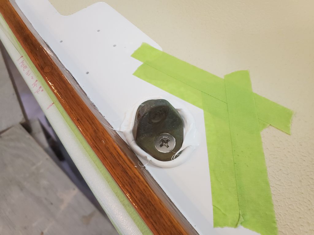
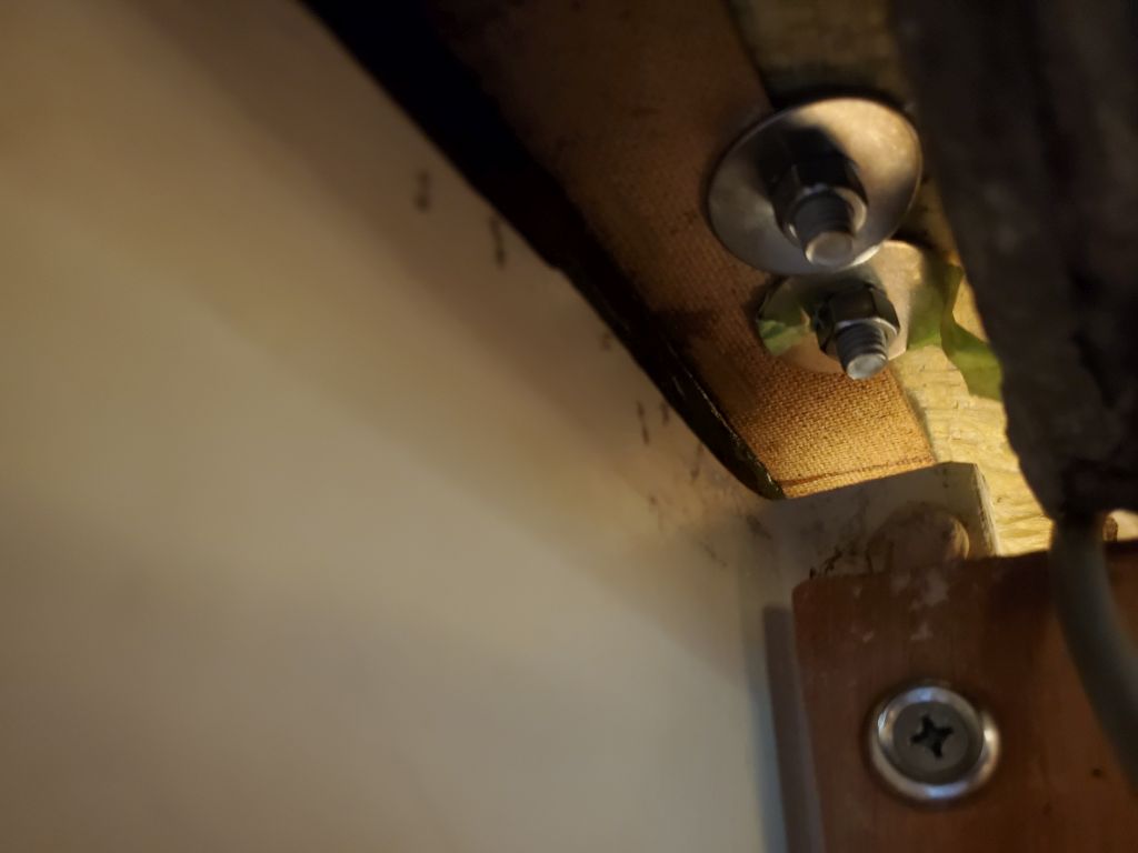
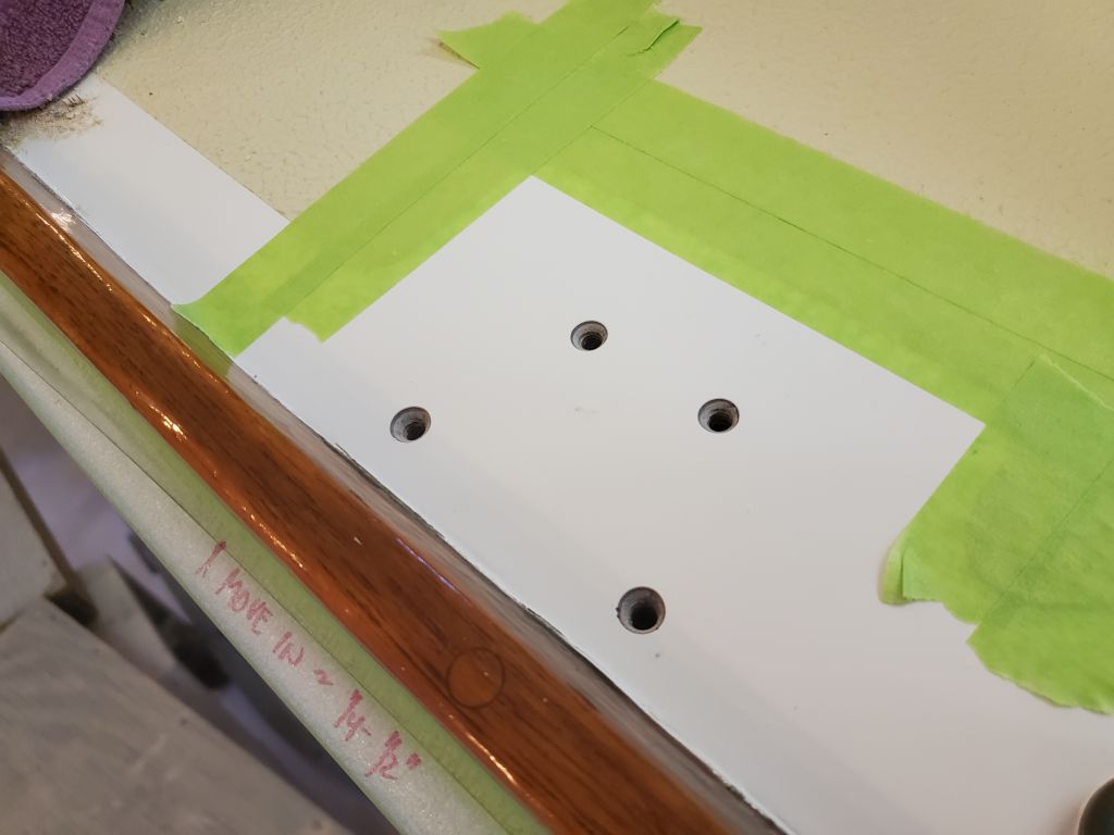
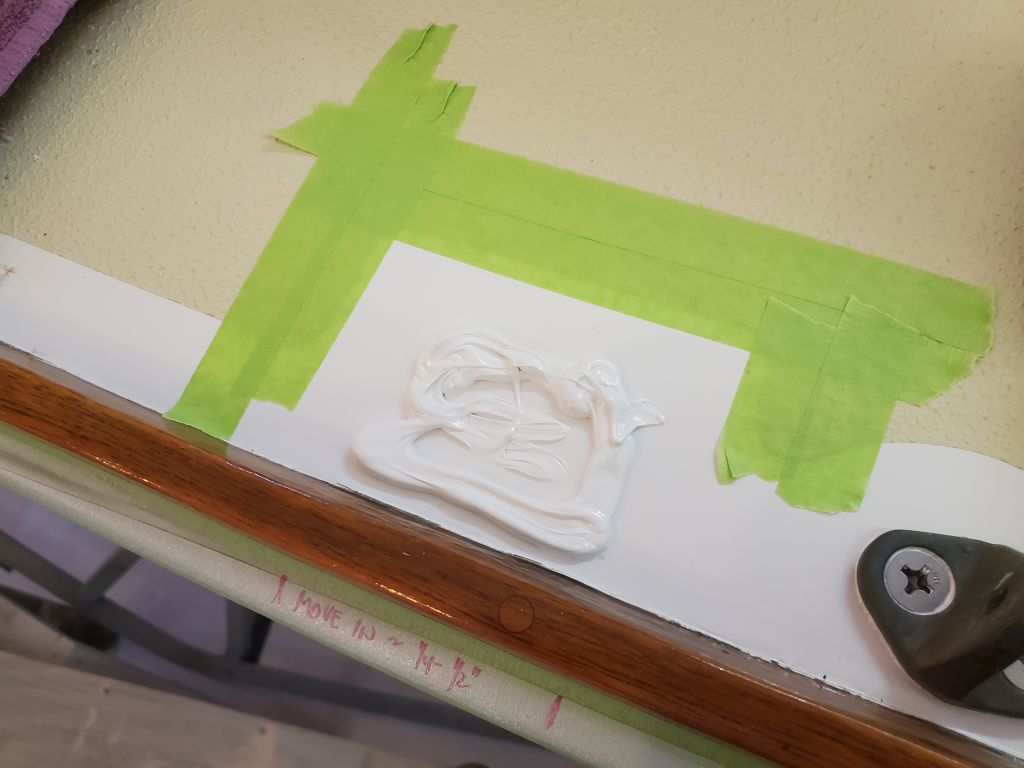
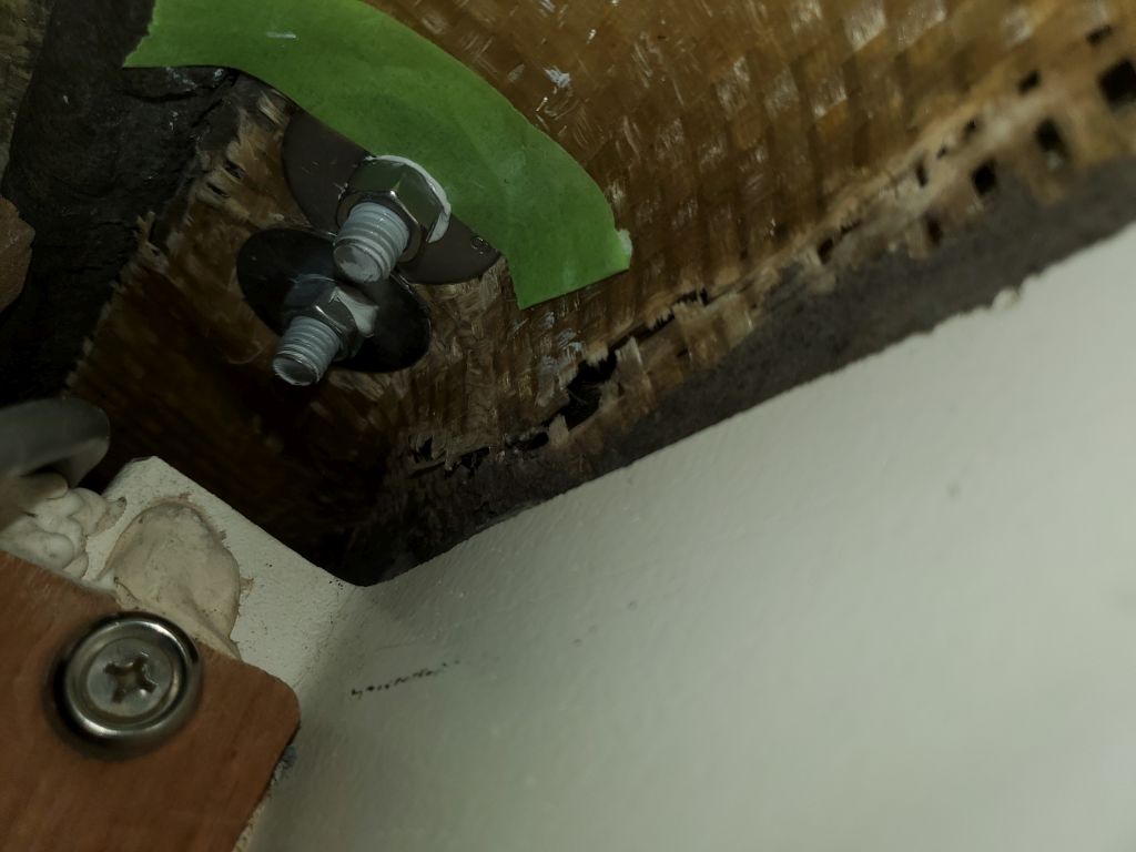
Next on my agenda was to replace the old depthsounder transducer with the new one supplied along with the replacement instruments.  I couldn’t break free the fixing nut on the inside of the old bronze fitting, and with limited access and space to work in the small locker, I removed the fitting by grinding it off from the outside, as I hate wasting time fiddling when there’s a known solution.  Not my favorite thing to do, but better now than later, after additional wasted effort.

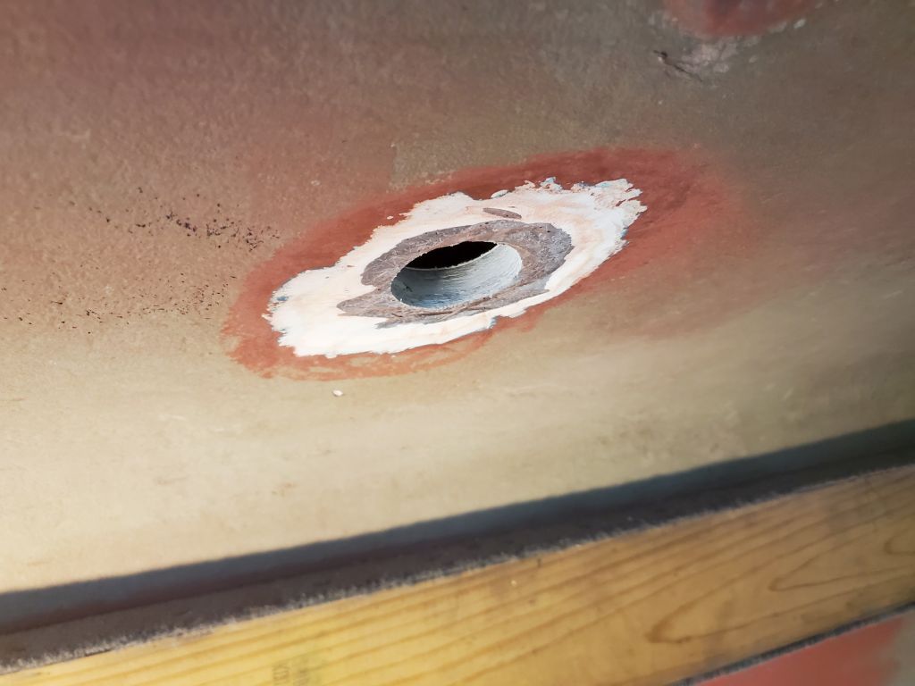
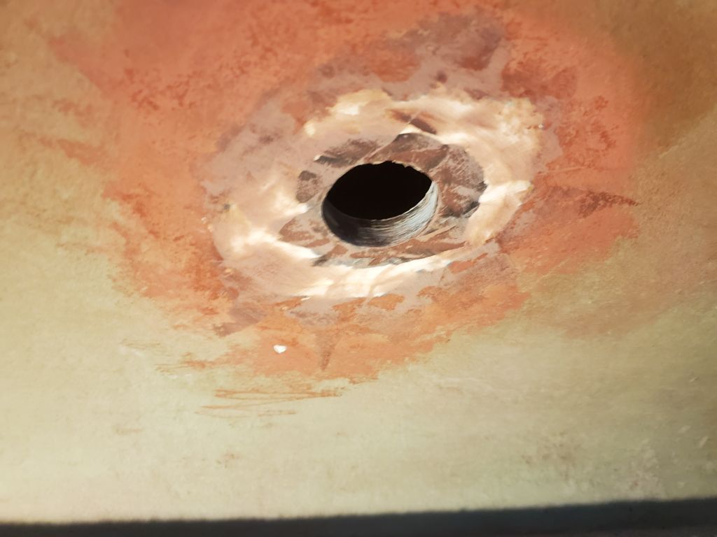
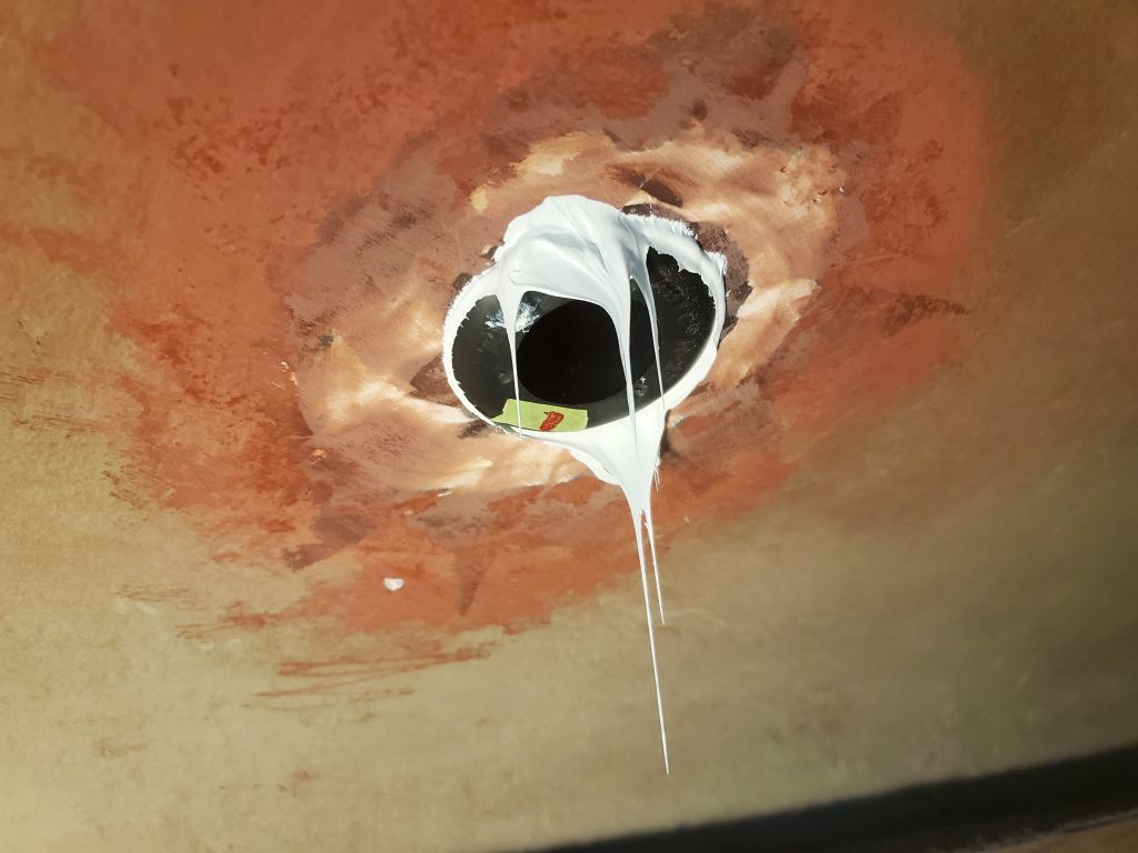
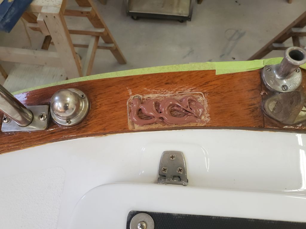
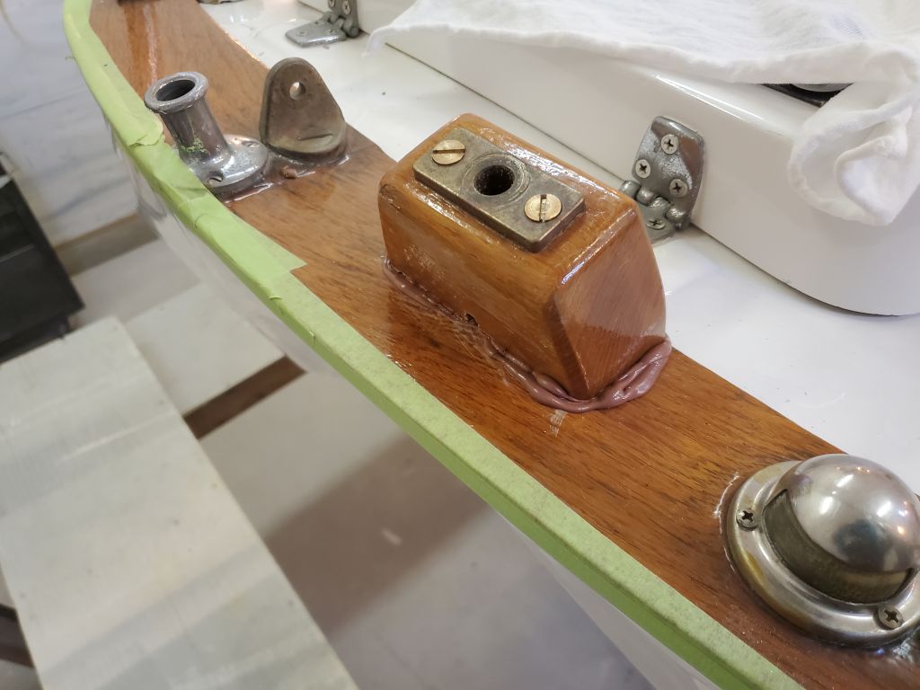
With the old fitting out of the way, I spruced up the hull a bit with some epoxy where I’d ground it during the removal, ensuring it was flat and smooth, and put a heat lamp on it to accelerate the curing process.  After a couple hours, I could lightly sand the small ridges, then install the new transducer housing (just a threaded nylon fitting that accepted a removable transducer unit) with sealant and its cushy washer and nut from within.  I left this to fully cure before thinking about installing the insert.

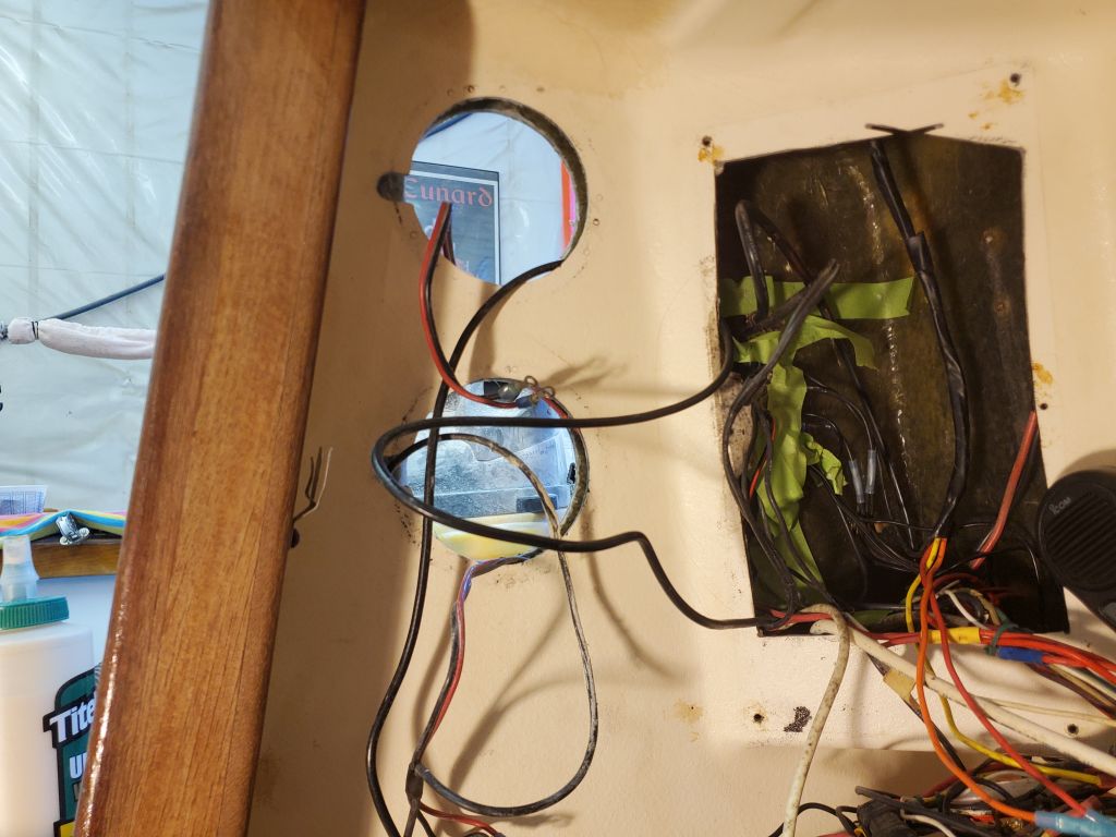
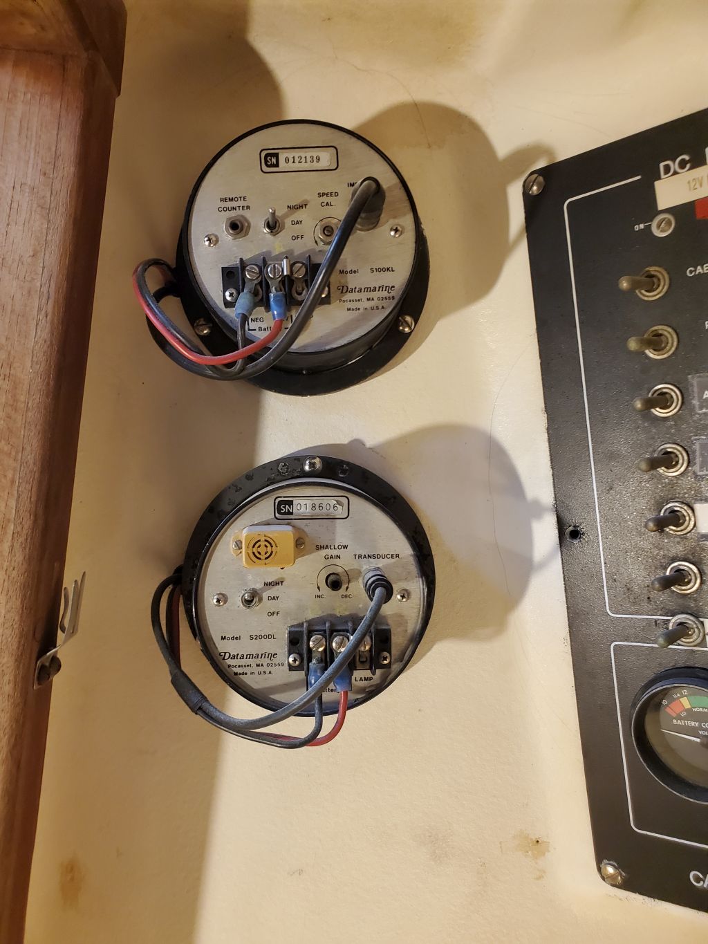
The old depthsounder wire ran from this locker, through the bulkhead, and then down into a hole in the molded liner, leading aft somewhere and then miraculously showing up again at the electrical panel and bulkhead openings where the instruments were to be installed.  Running the new cable was a job for another day soon, but I had low expectations that I’d be able to lead it through the same path as the old.  Time would tell, but I was already calculating other possibilities (likelihoods?).

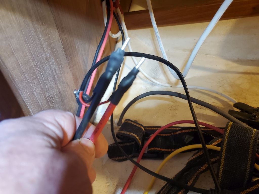
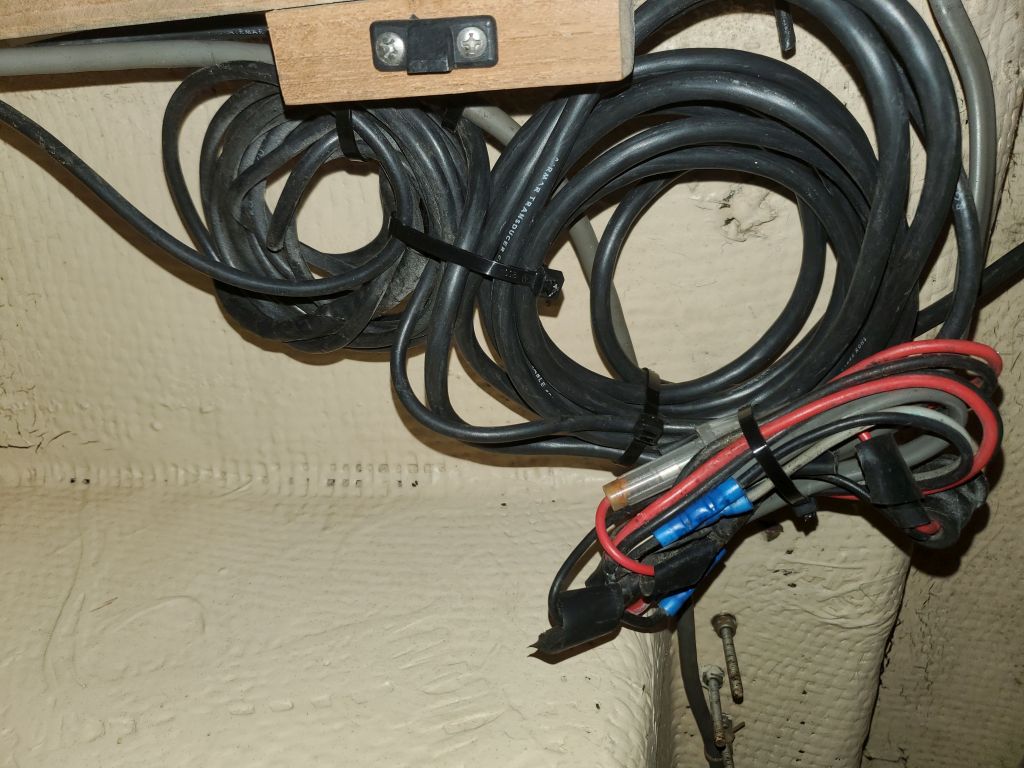
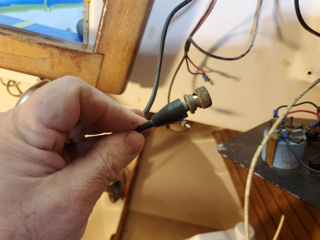
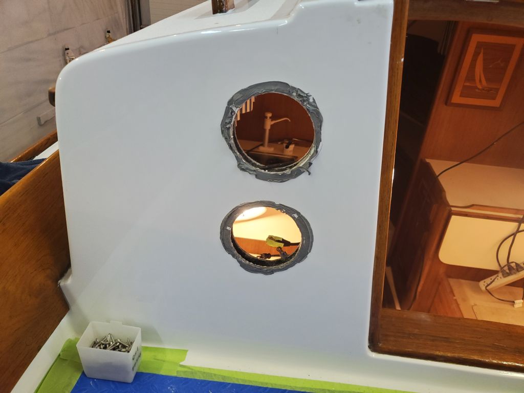
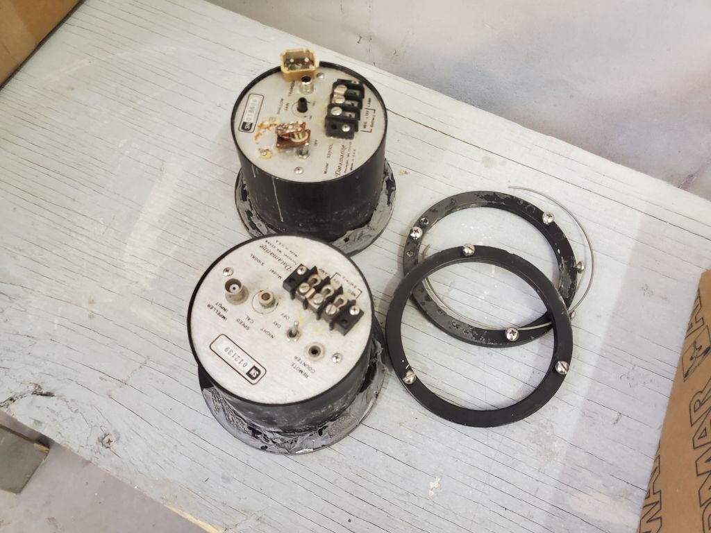
The speed transducer was not to be replaced, as the existing one and its cable were compatible with the replacement instruments.  I had to check with the instrument builder because the old speed cable had a BNC connector at the end, while the new instruments had only screw terminals for wiring, but fortunately I learned I could cut off the old connector and use the core and shield as the connections required on the new instrument.  This would happen in the near future, but for now I needed the instrument holes open so I could eventually lead in the new depth transducer cable.

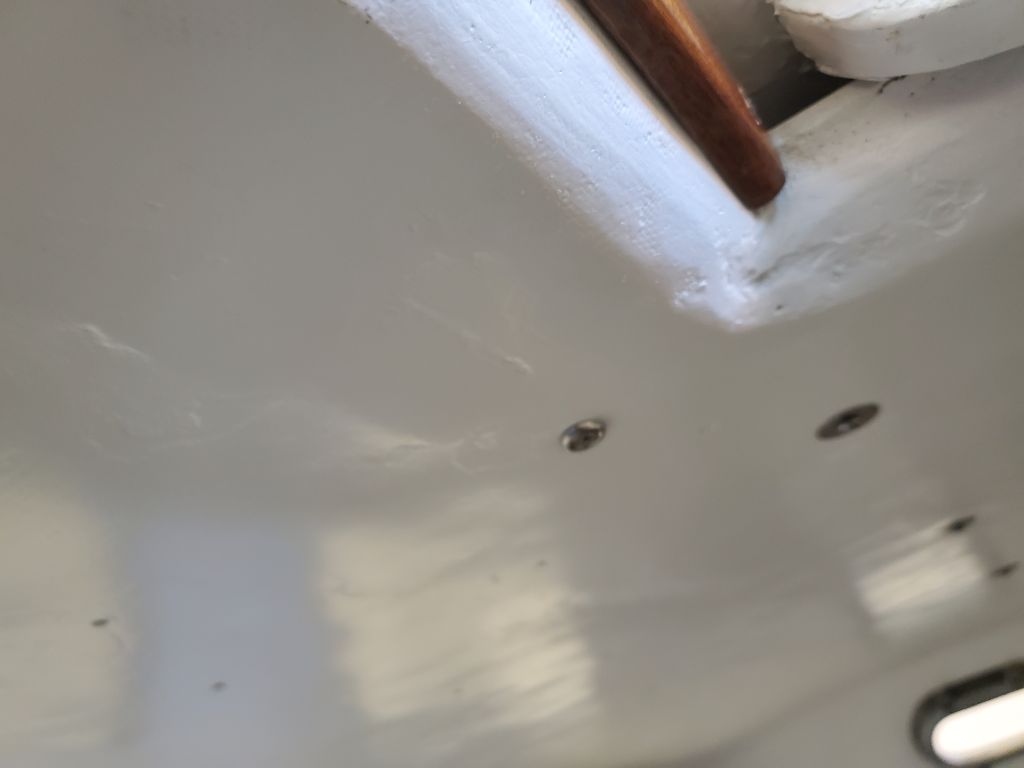
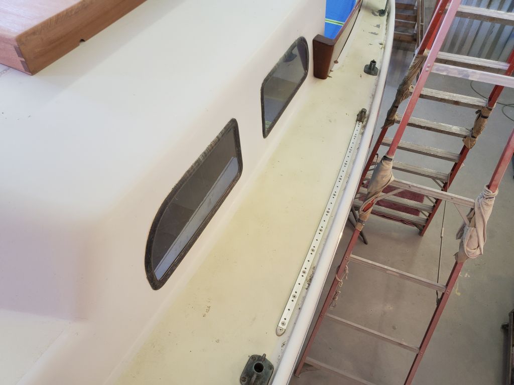
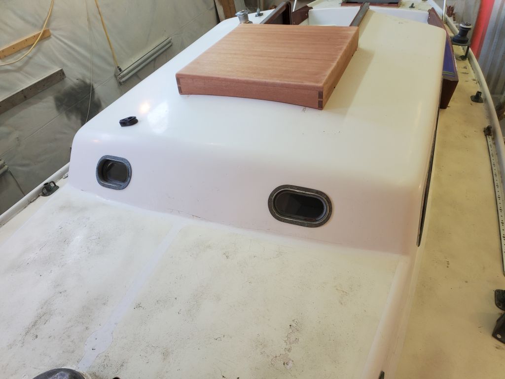
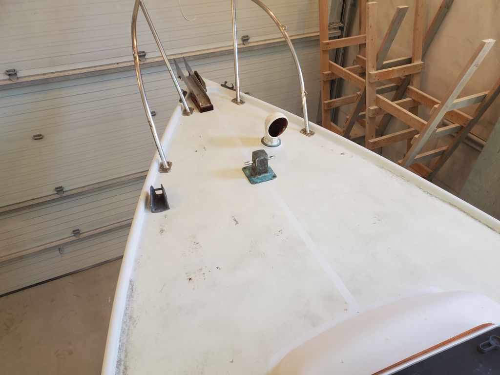
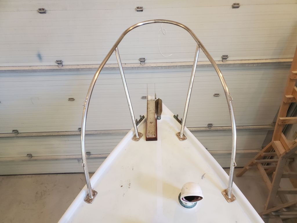
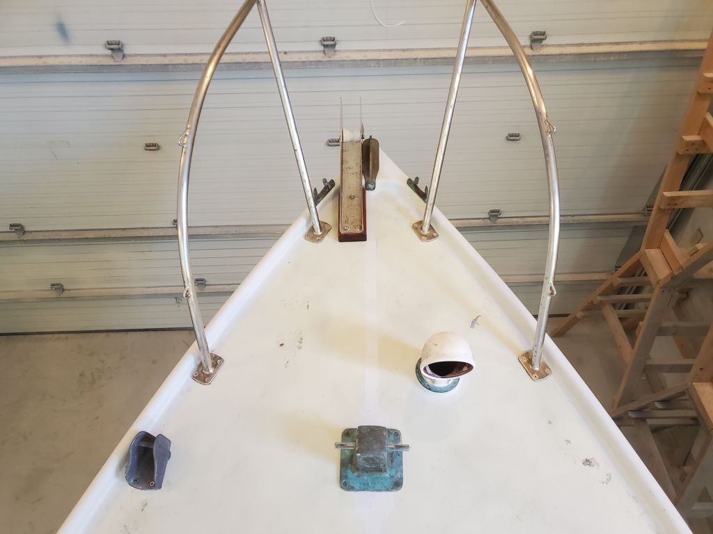
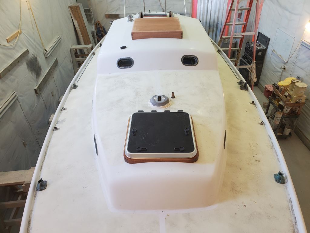
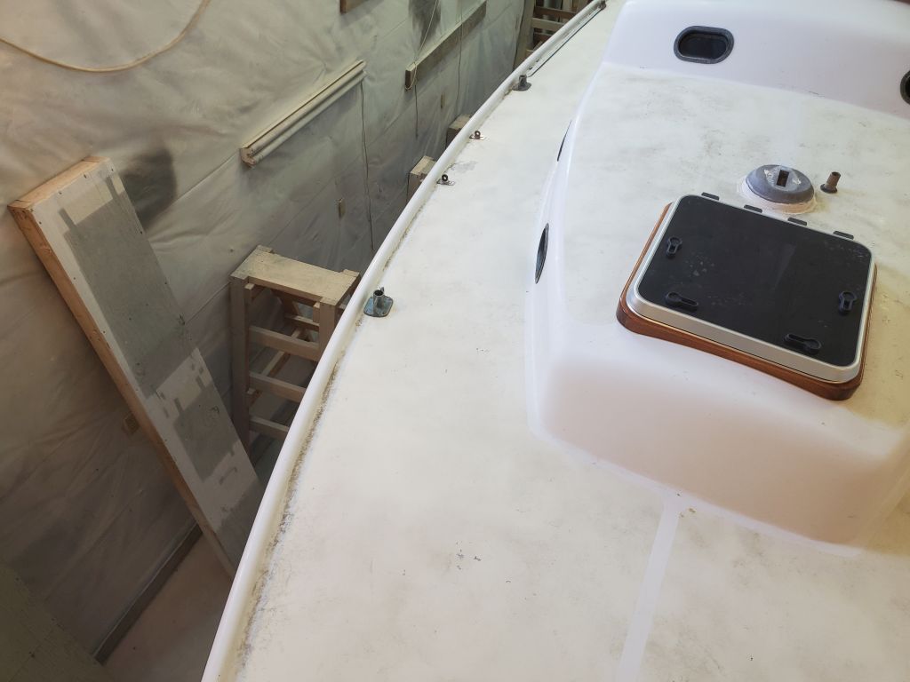
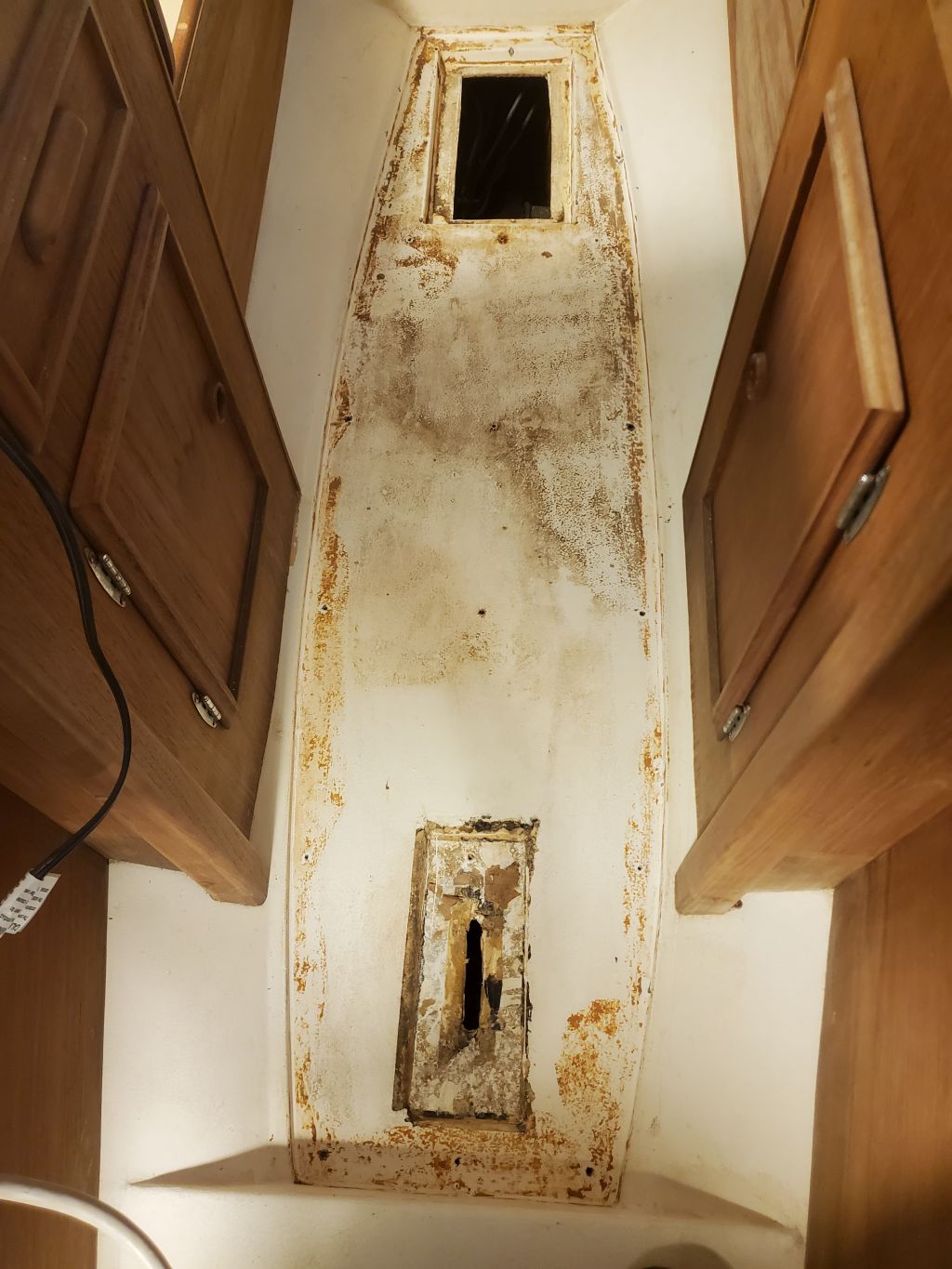
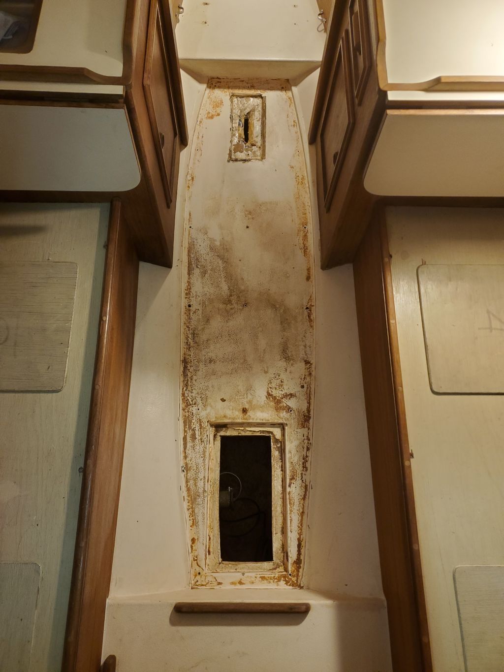
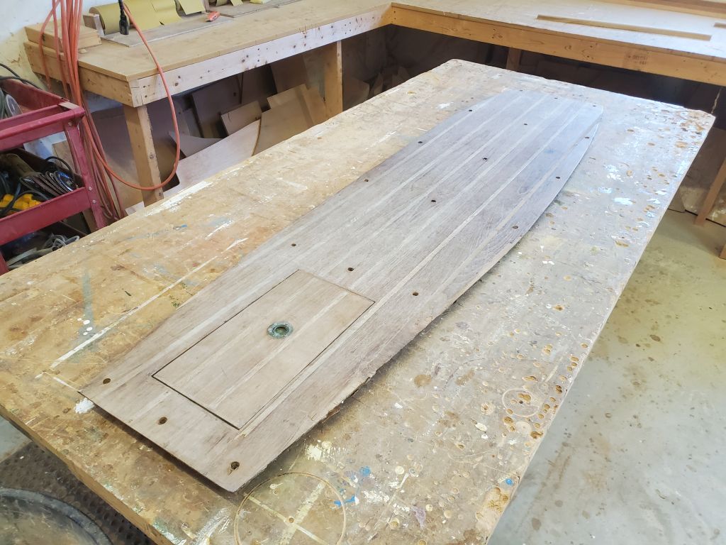
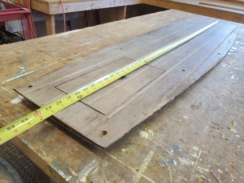
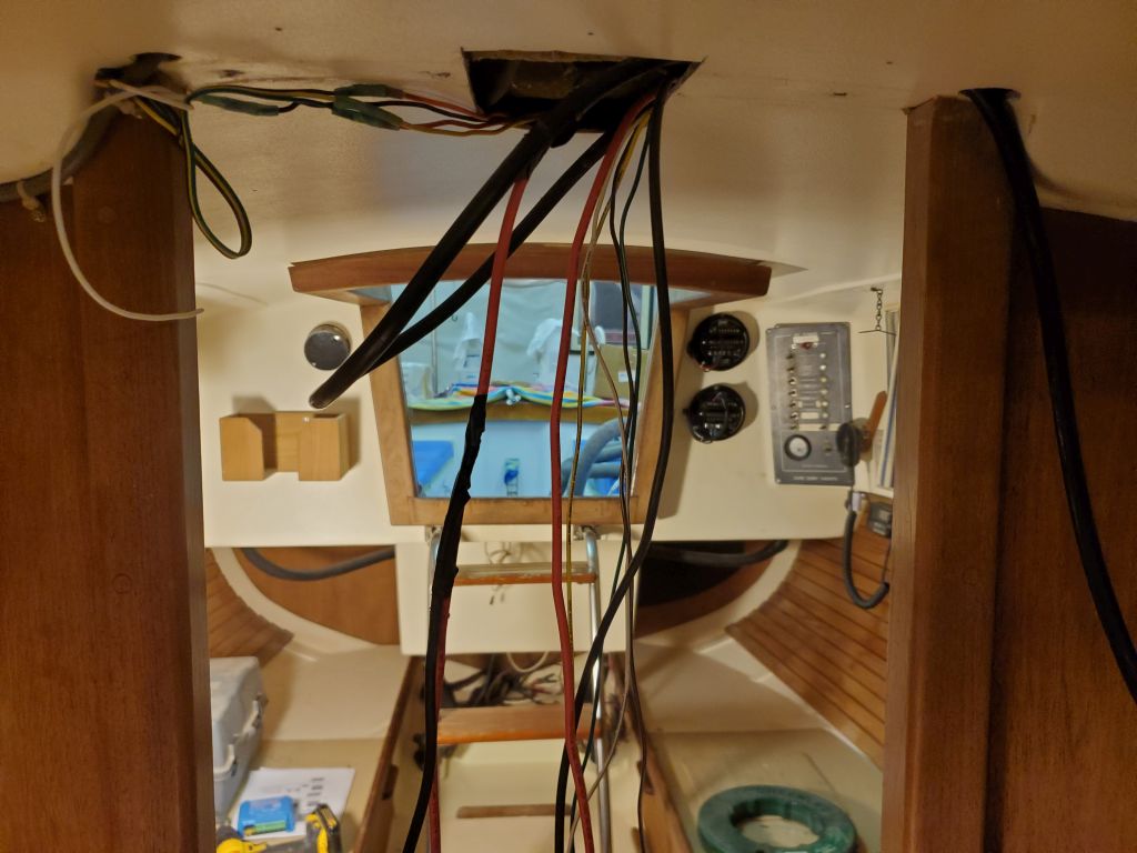
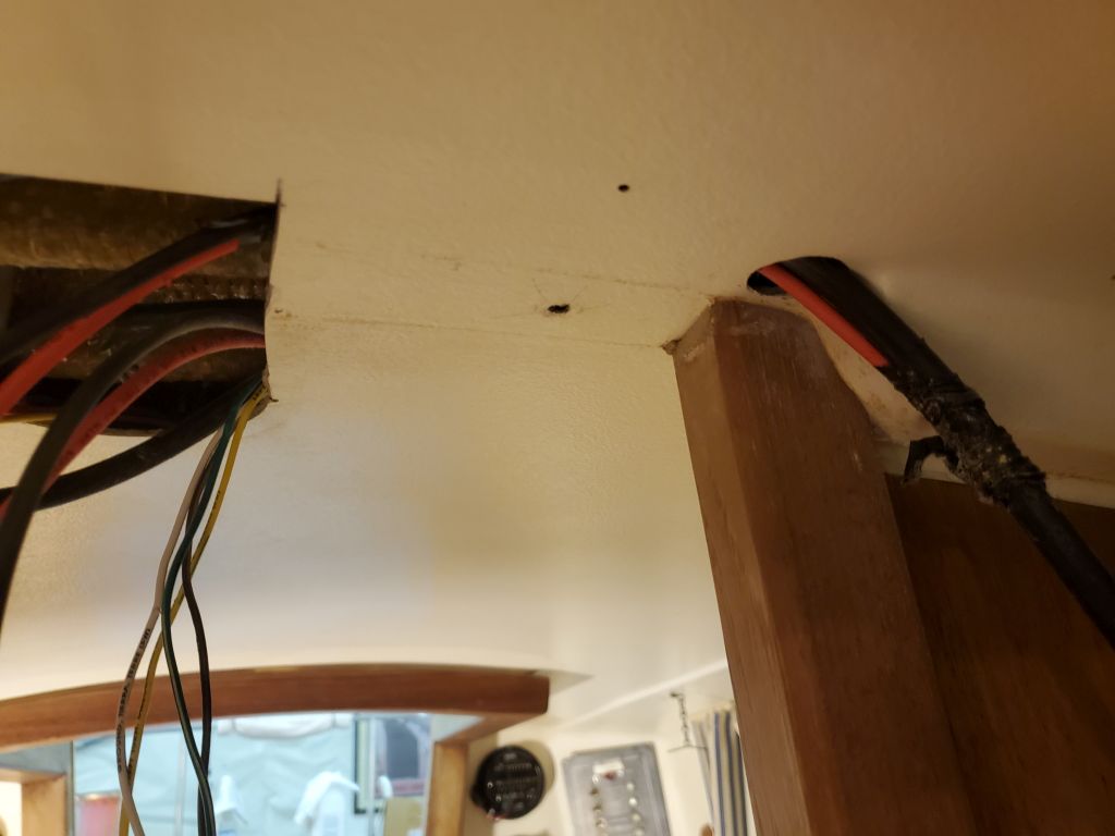
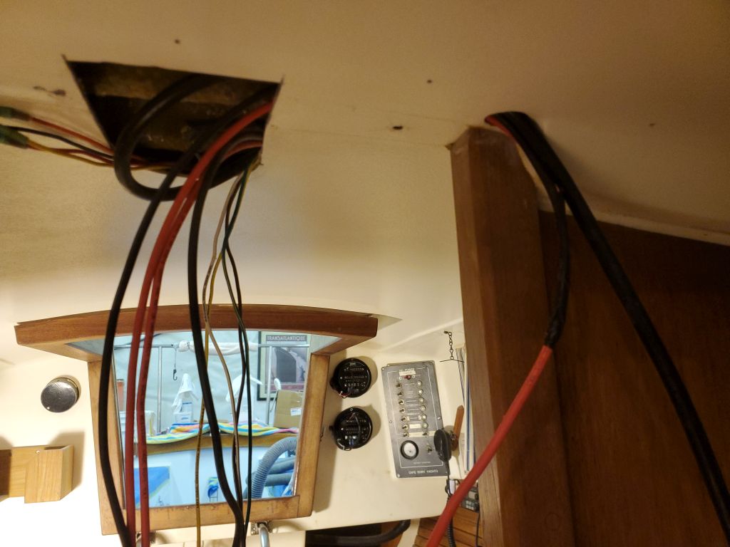
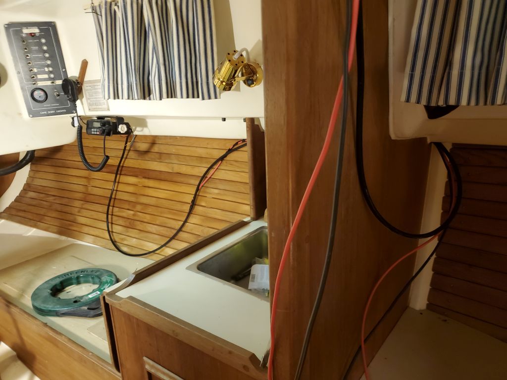
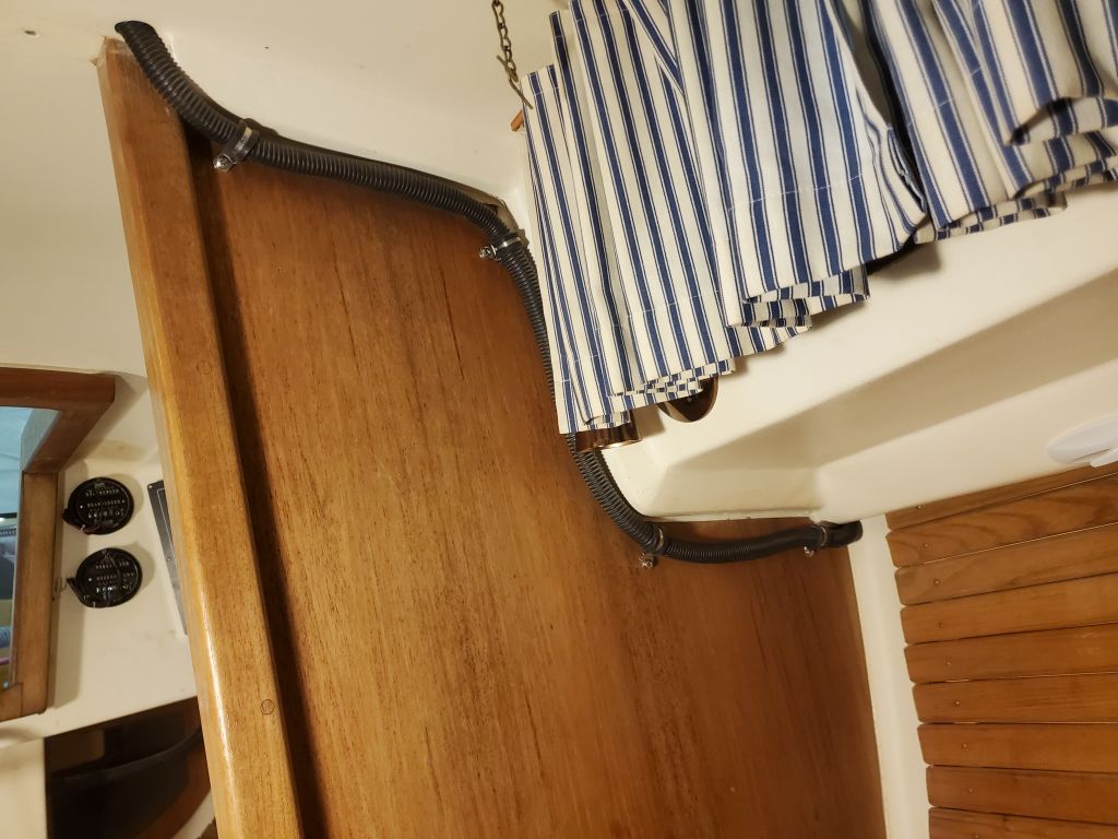
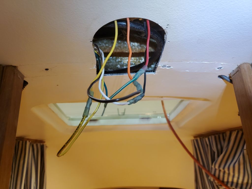
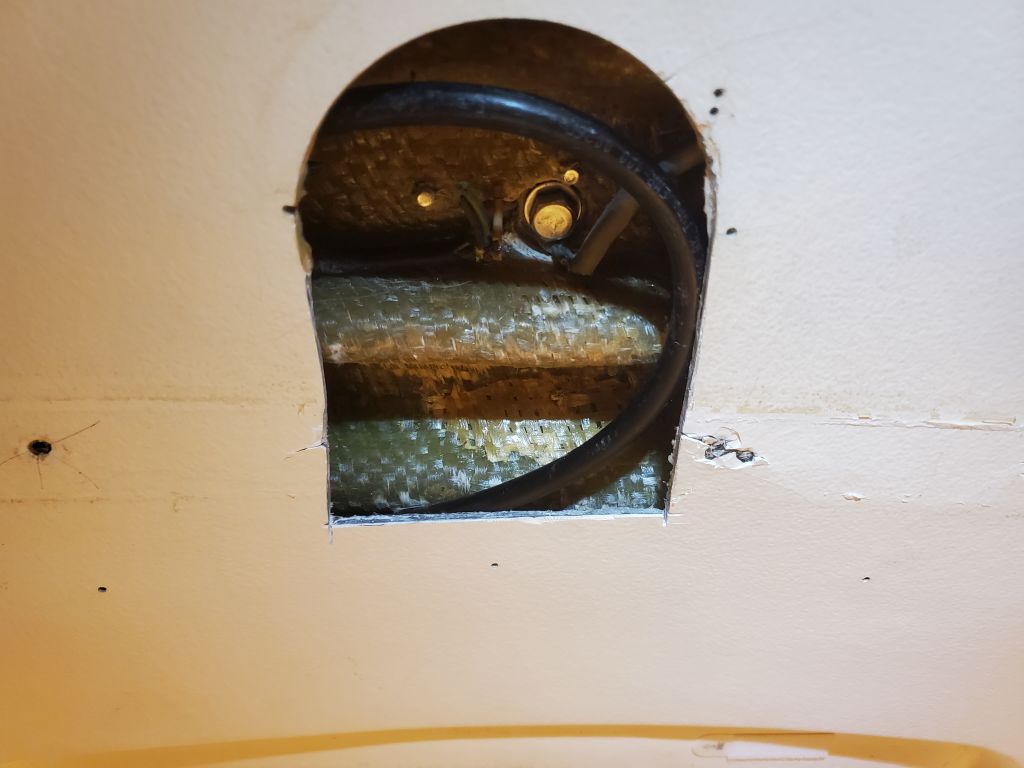
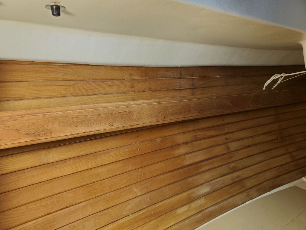
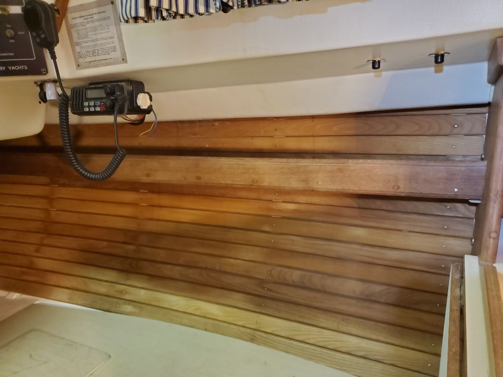
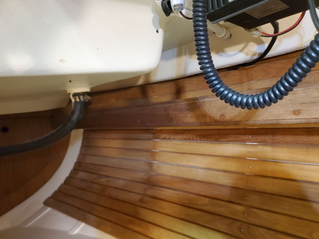
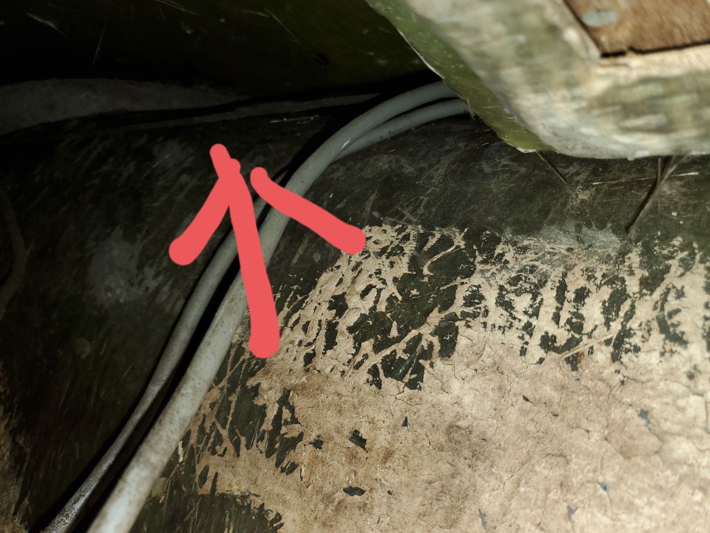
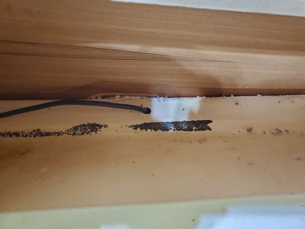
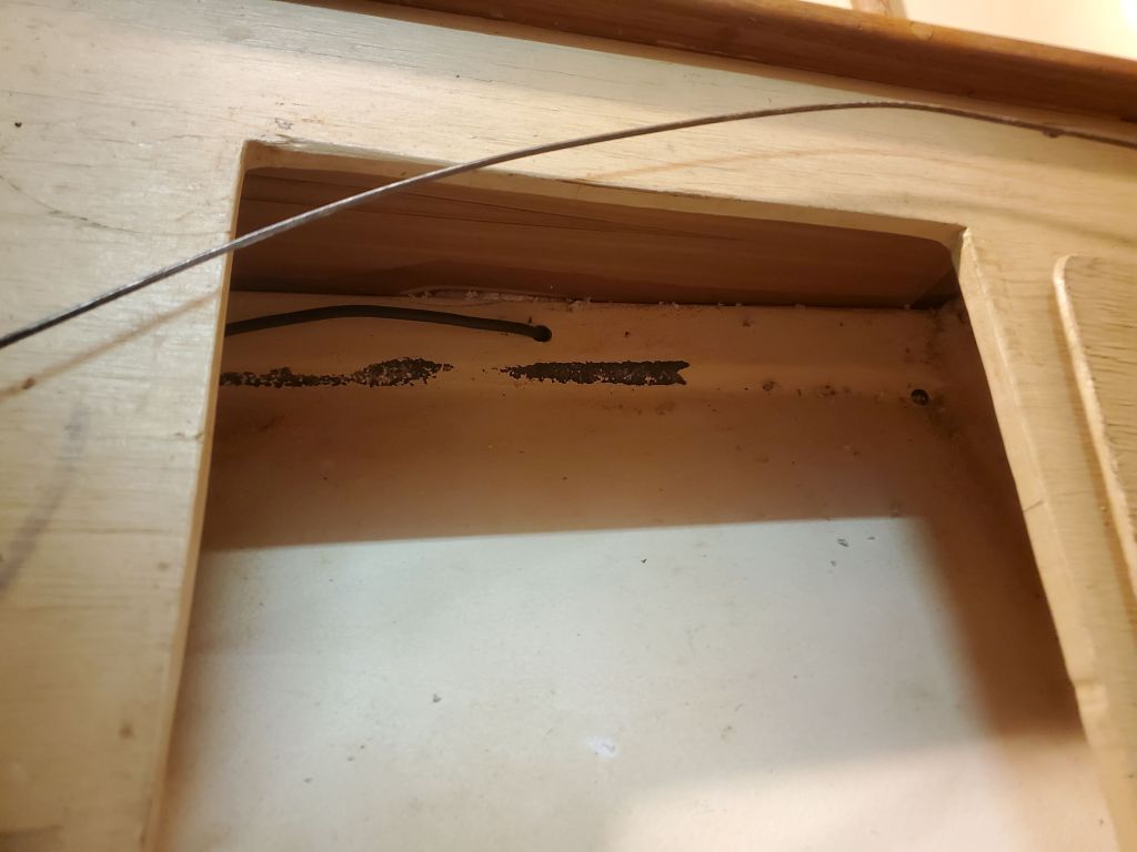
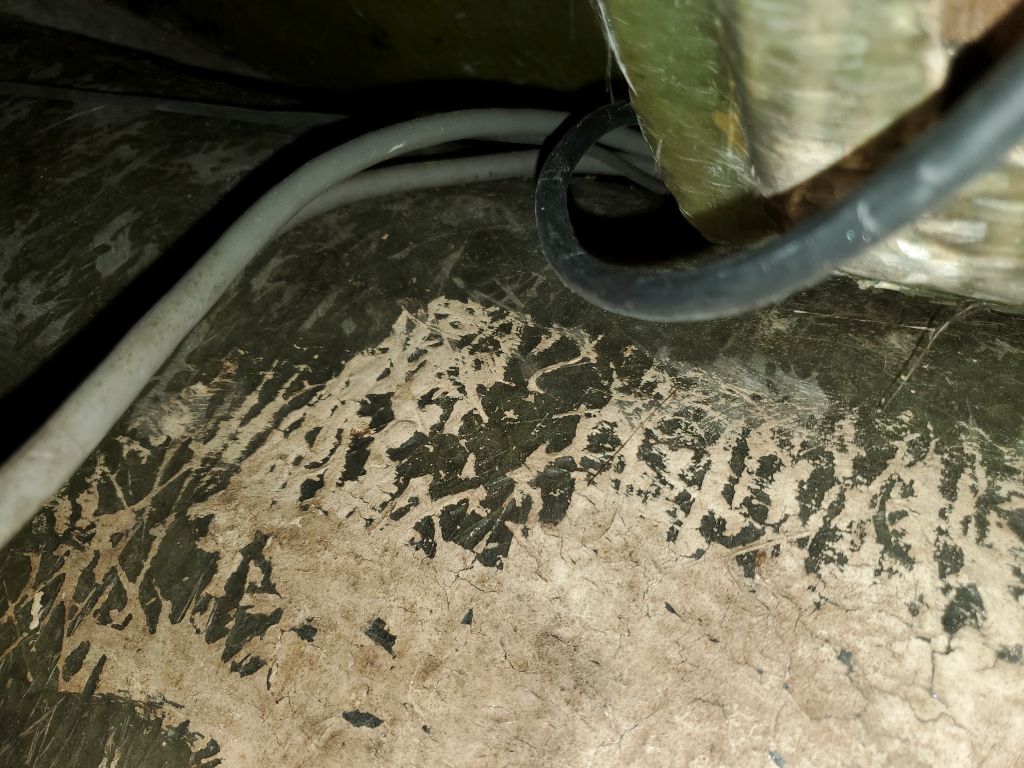
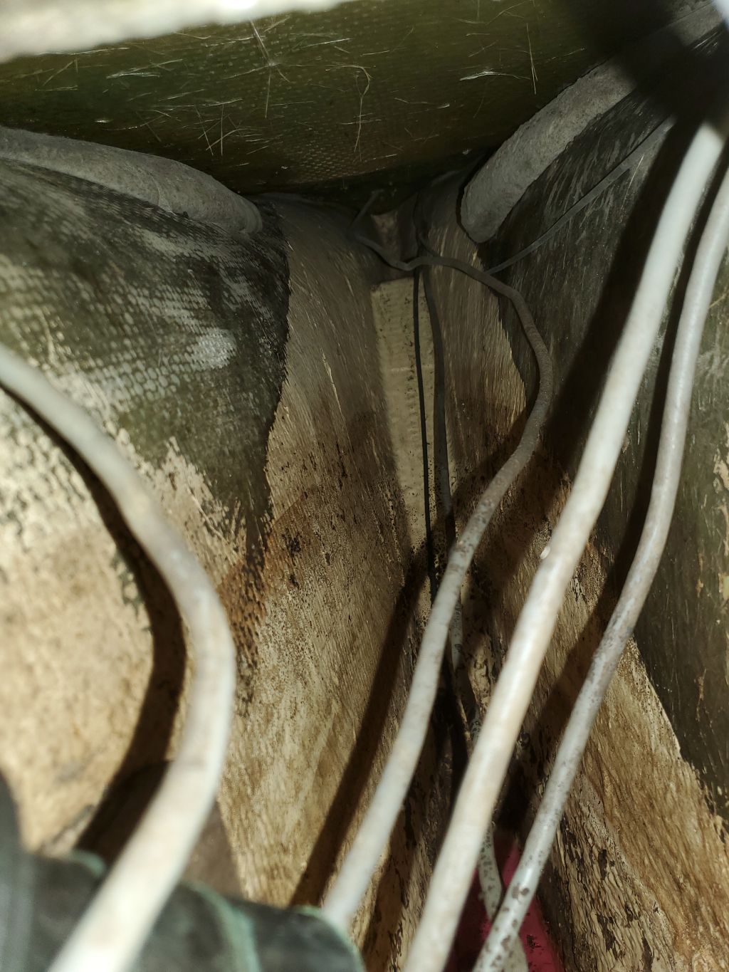
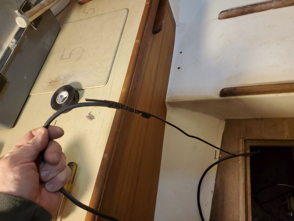
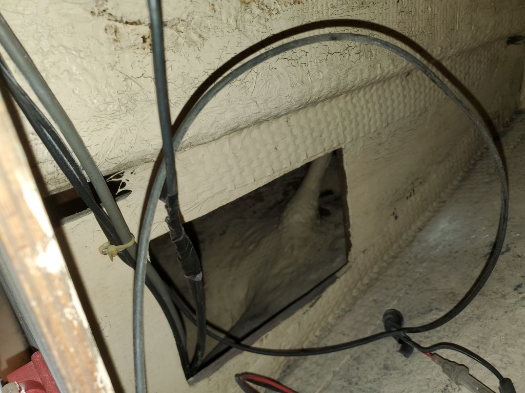
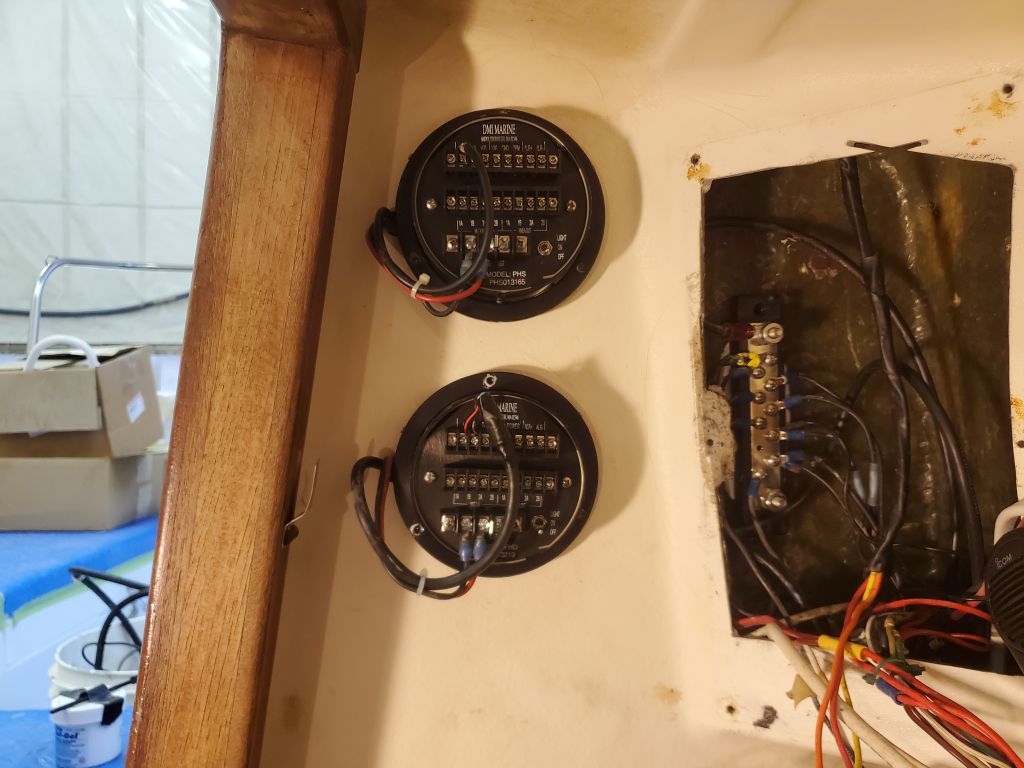
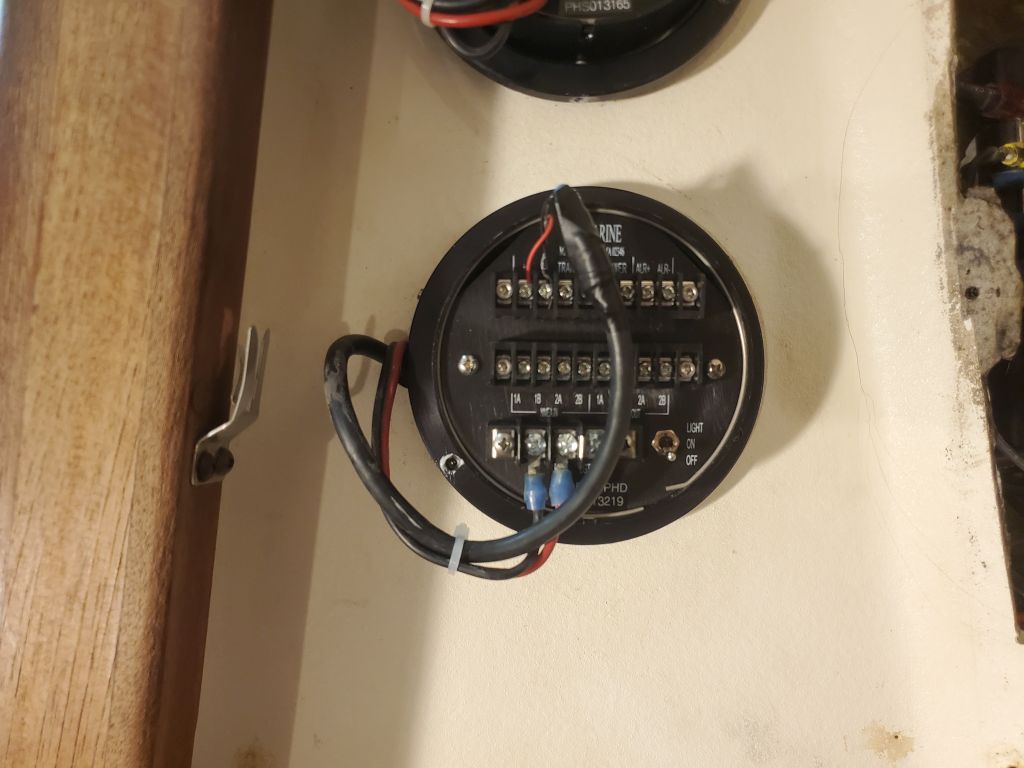
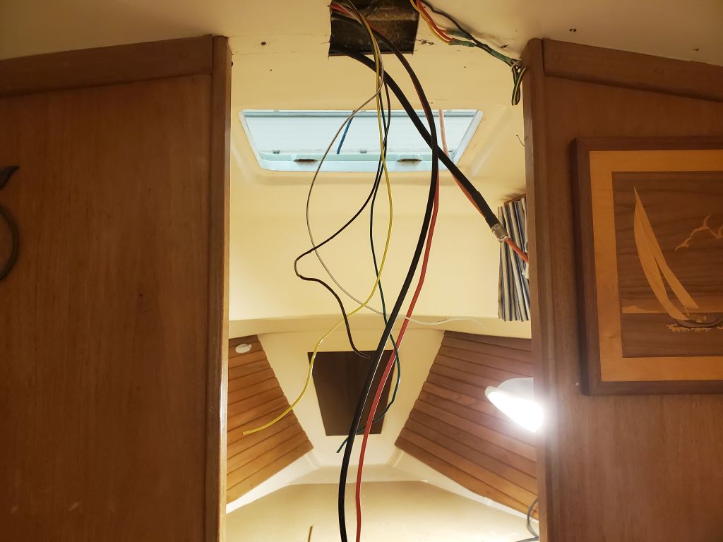
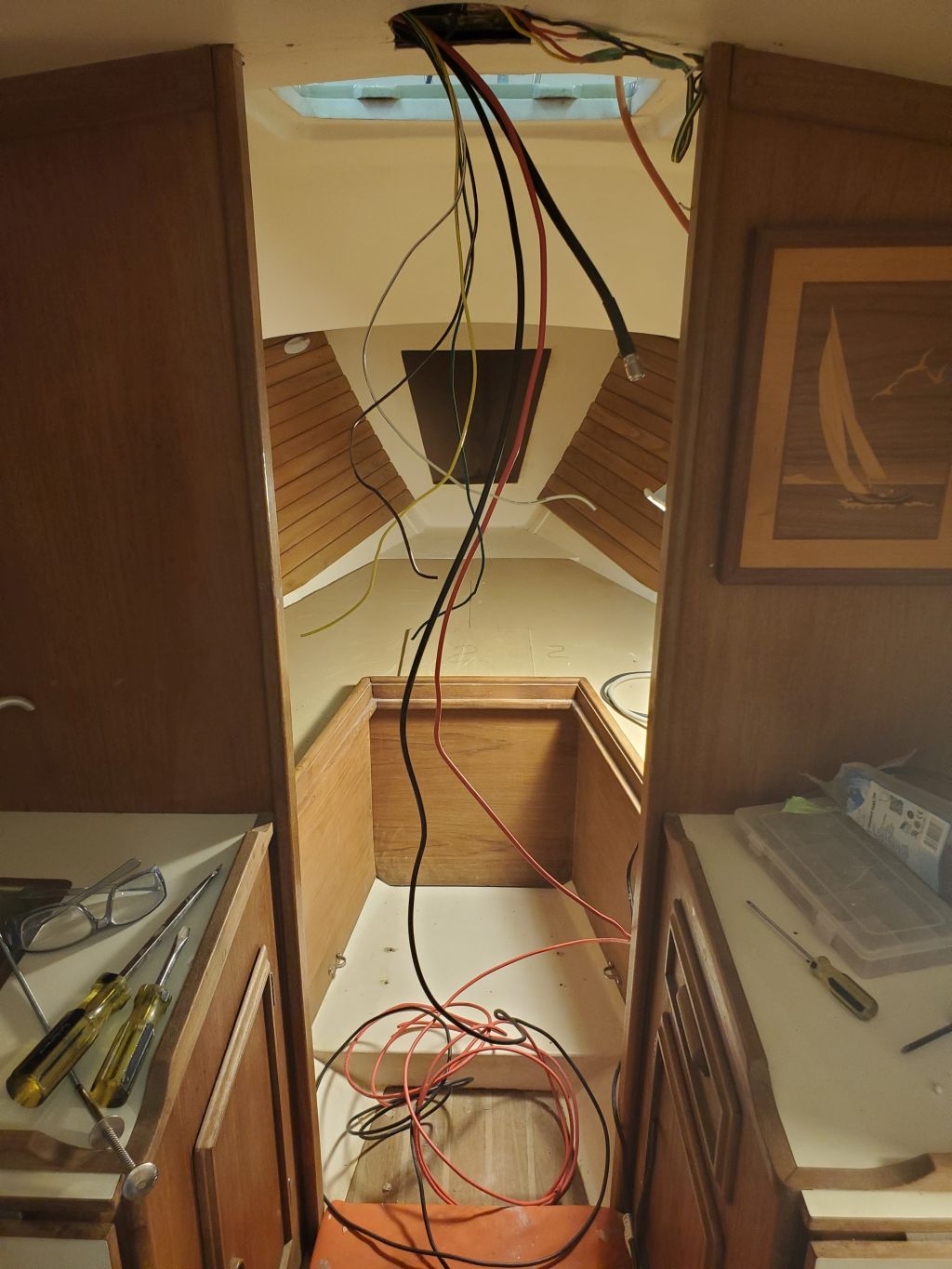
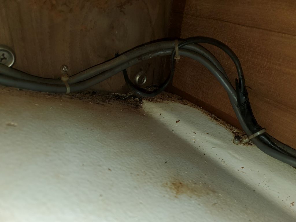
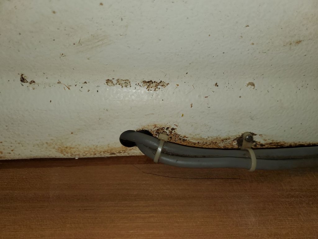
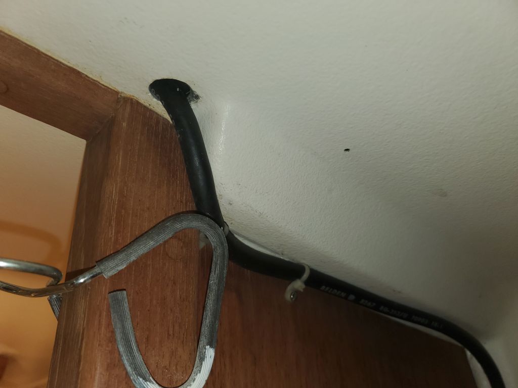
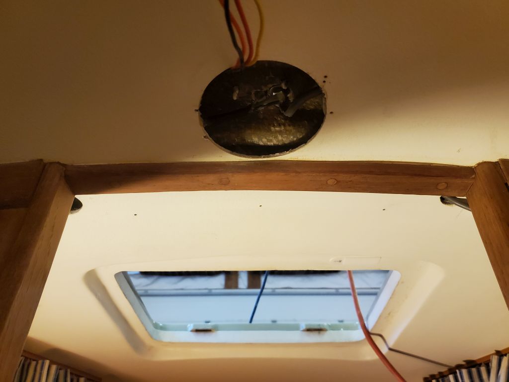
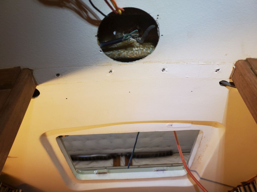
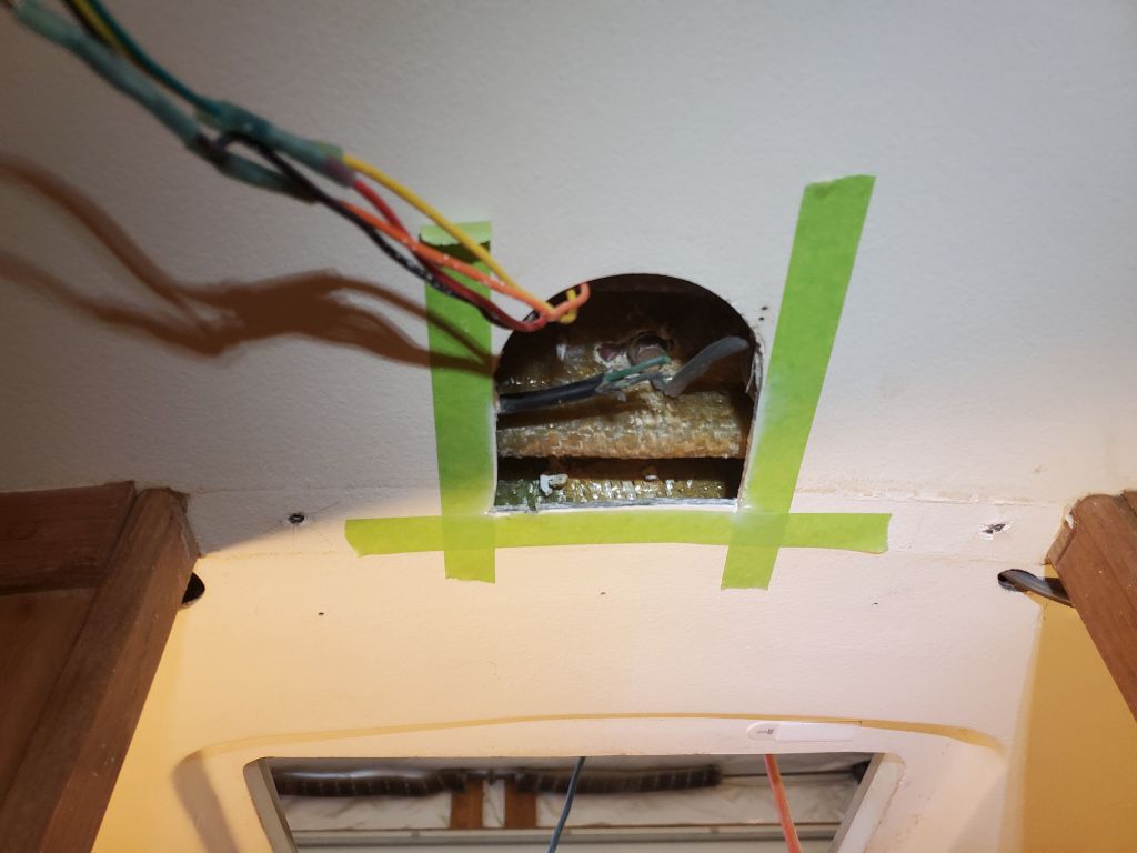
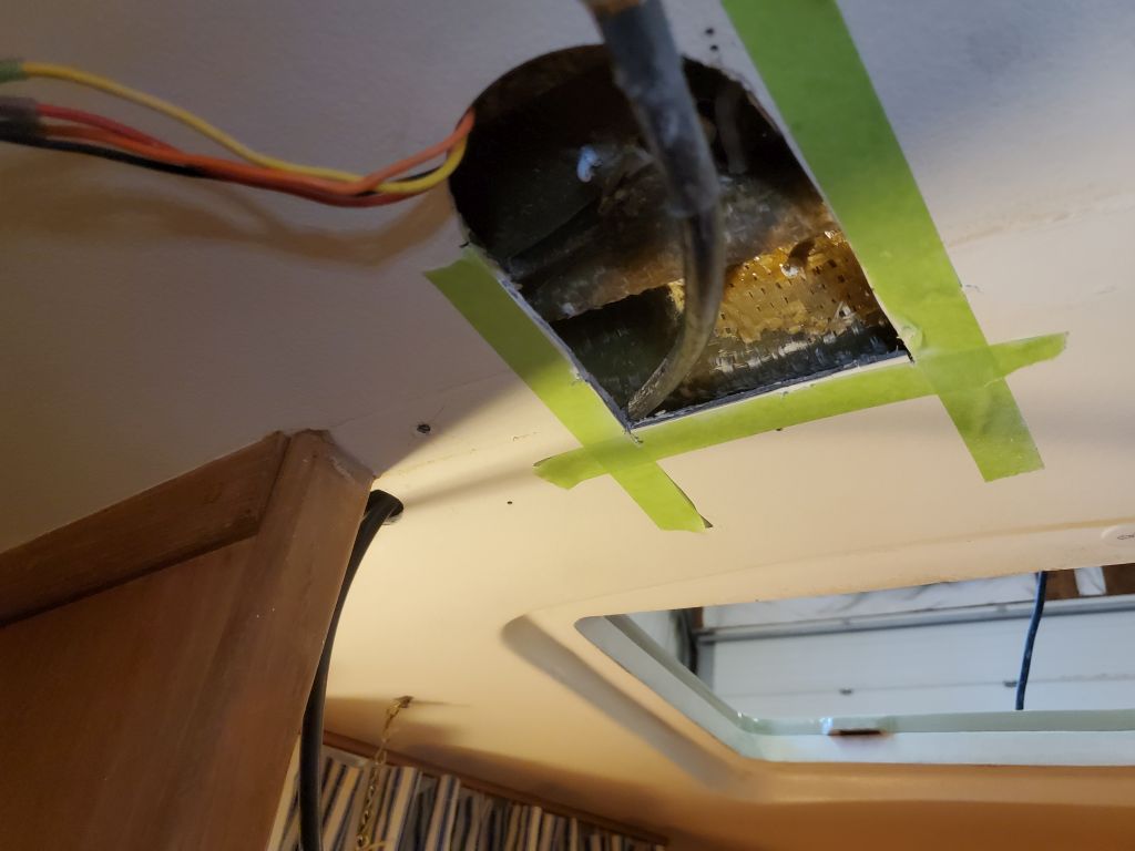
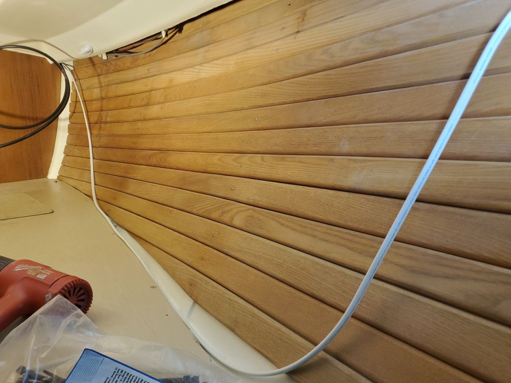
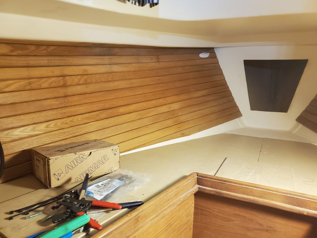
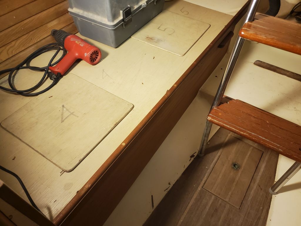
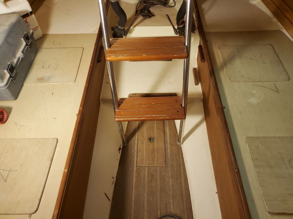
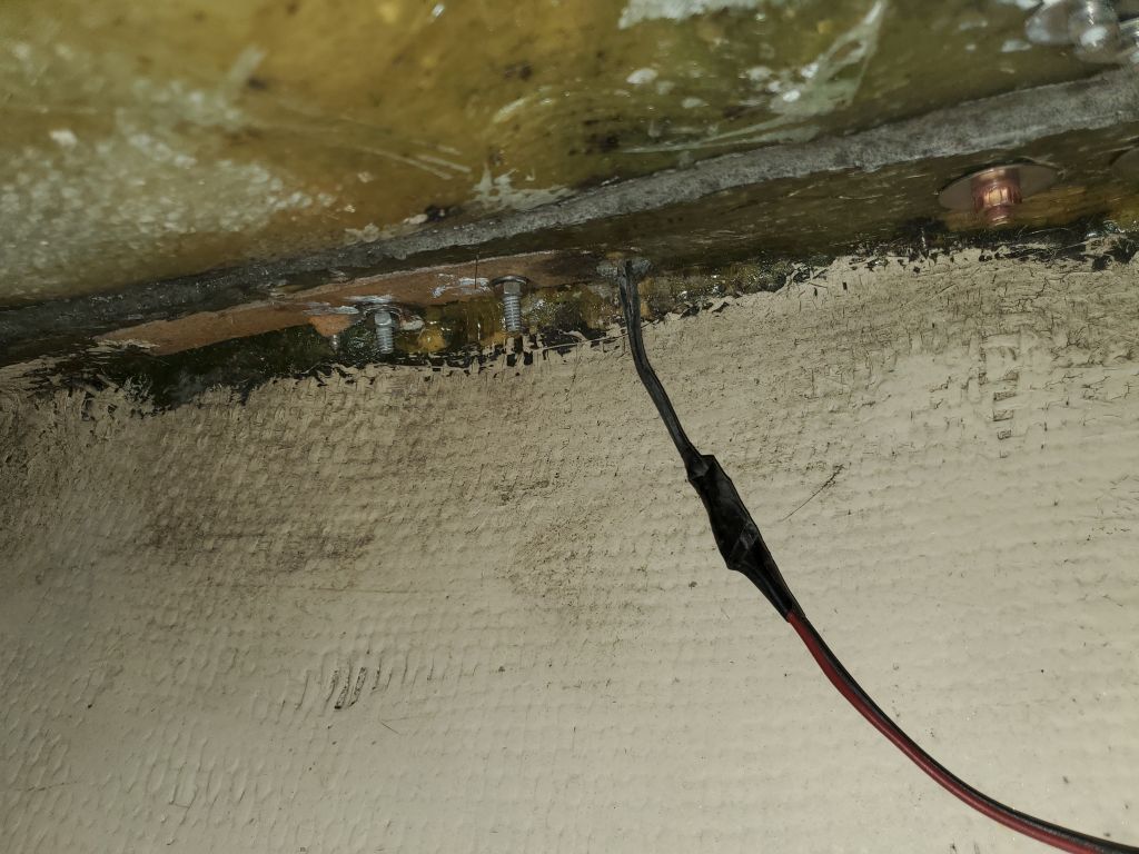
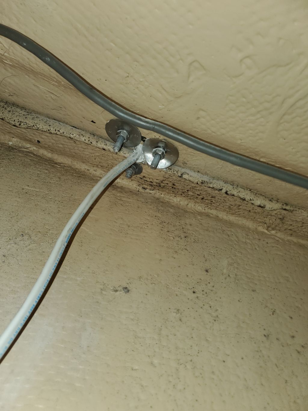
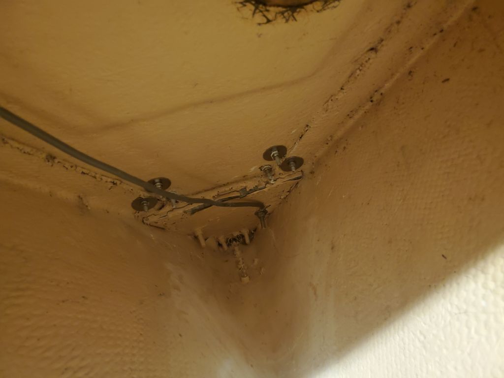
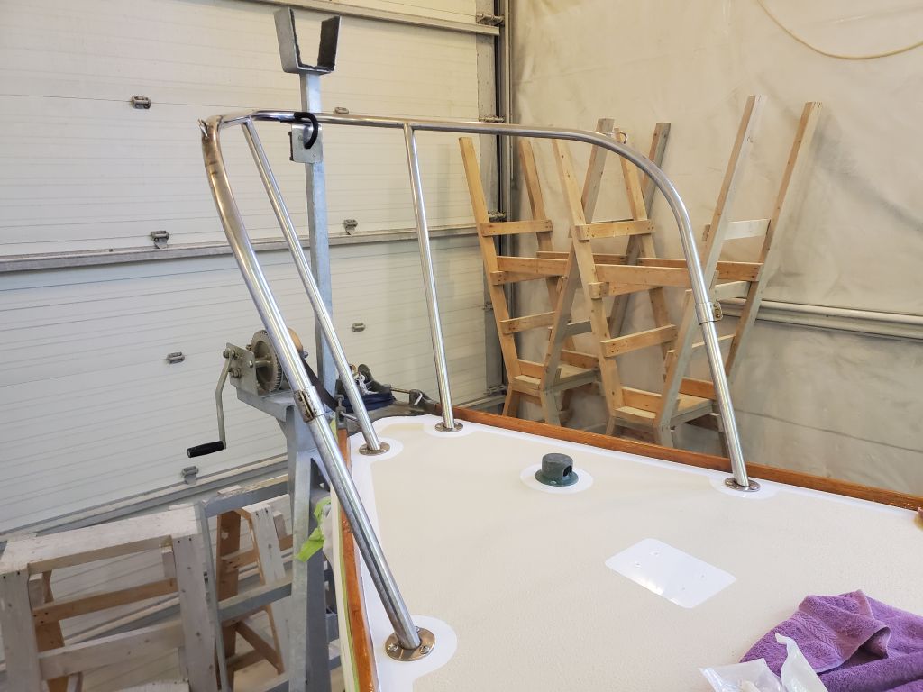
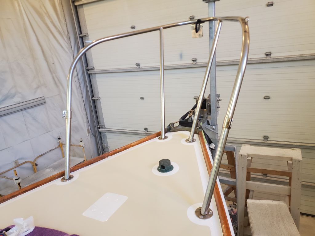
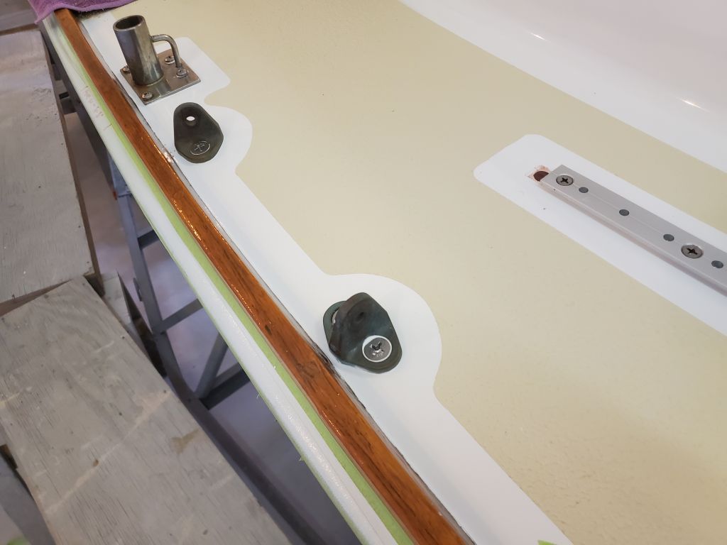
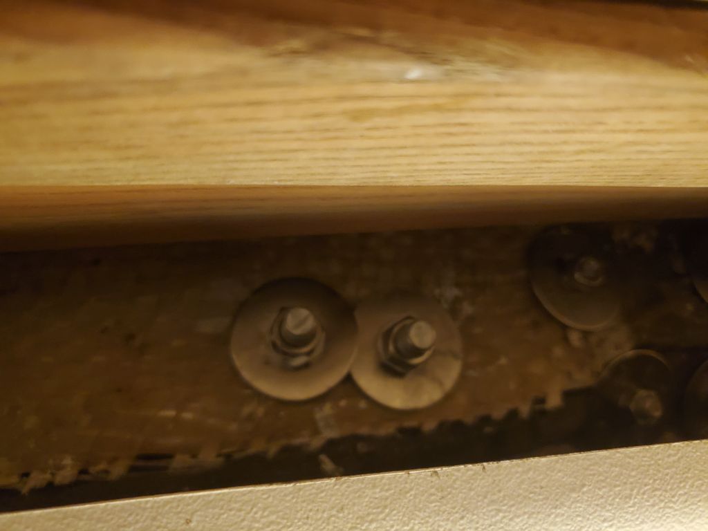
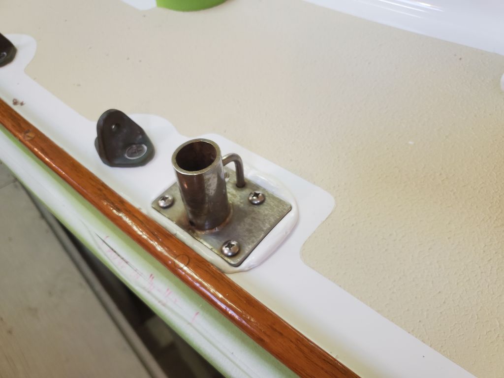
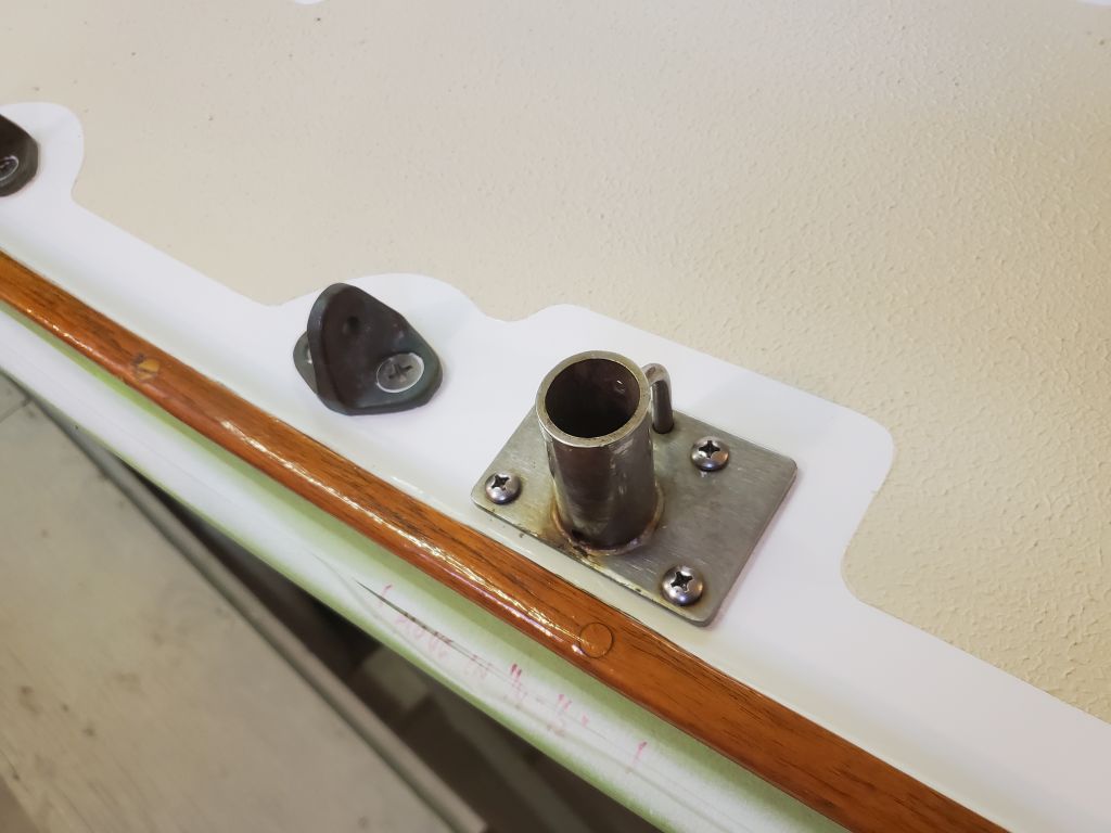
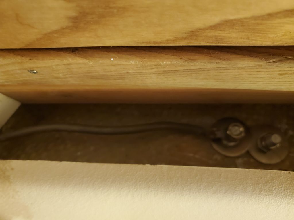
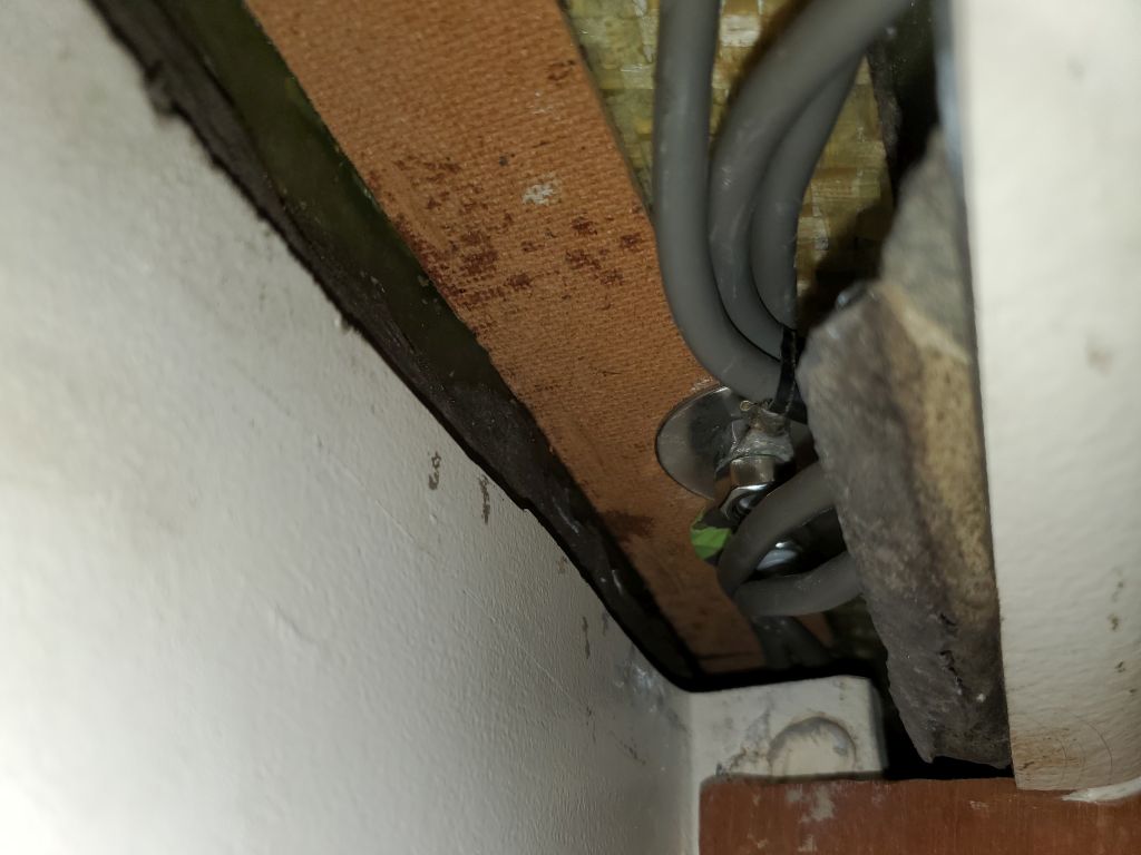
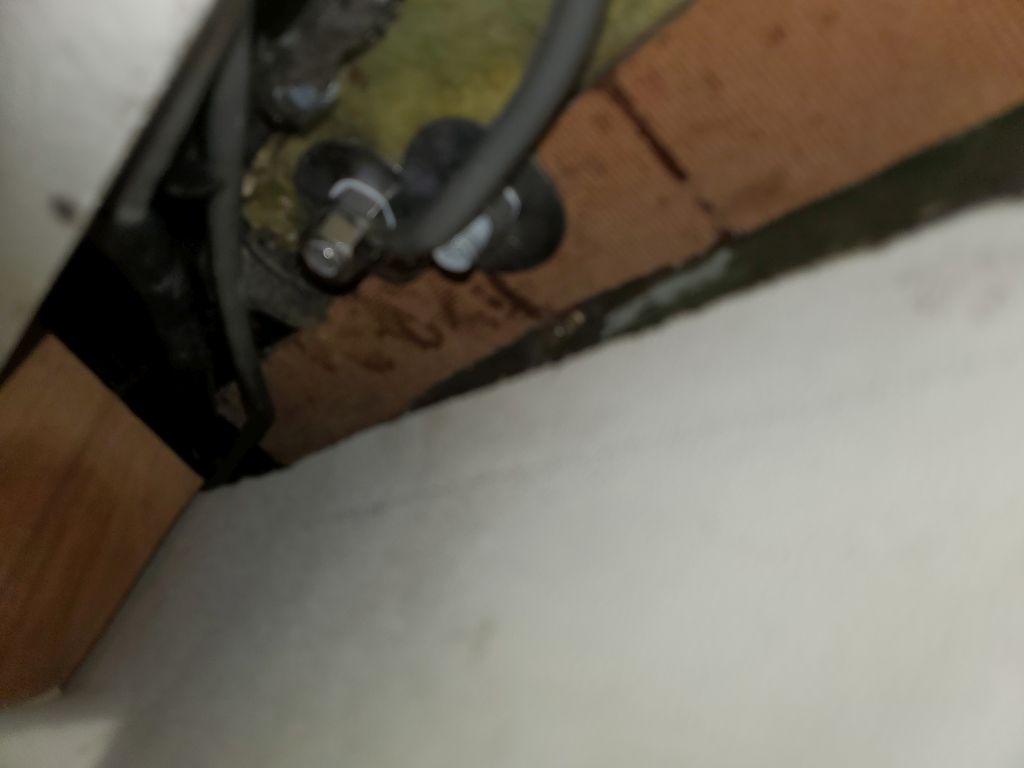
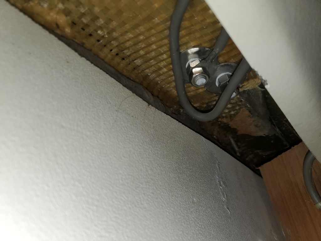
I purchased a new VHF antenna cable to replace the one I’d had to cut apart to remove from the deck earlier, but a few days before I’d run into difficulty getting it through the same path the original had taken–a small hole at the bulkhead in the forward cabin, then a frustratingly short–but now impenetrable–distance aft to the mast wiring opening, and to where I’d eventually lead it again through the deck through a new, yet-to-be-installed fitting.  These photos, dating to November 20, 2021, show the original cable and its route, which I planned (from necessity if for no other reason) to follow anew.

I tried nine ways to Sunday to get the new cable through, but was stymied each time.  There just wasn’t enough clearance between the liner and the deck above to get the cable through a surprisingly complicated passage containing several ribs glassed beneath the deck, the erstwhile mast beam and stiffening.  It was only a few inches, but there was just no way to force the cable through, nor to grasp it from the nearby opening.

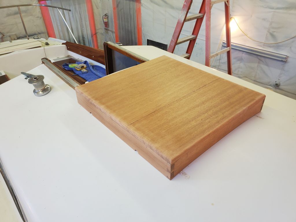
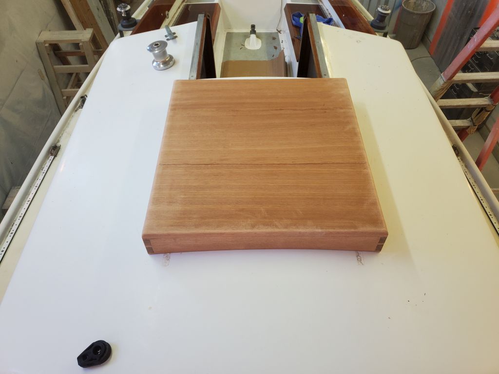
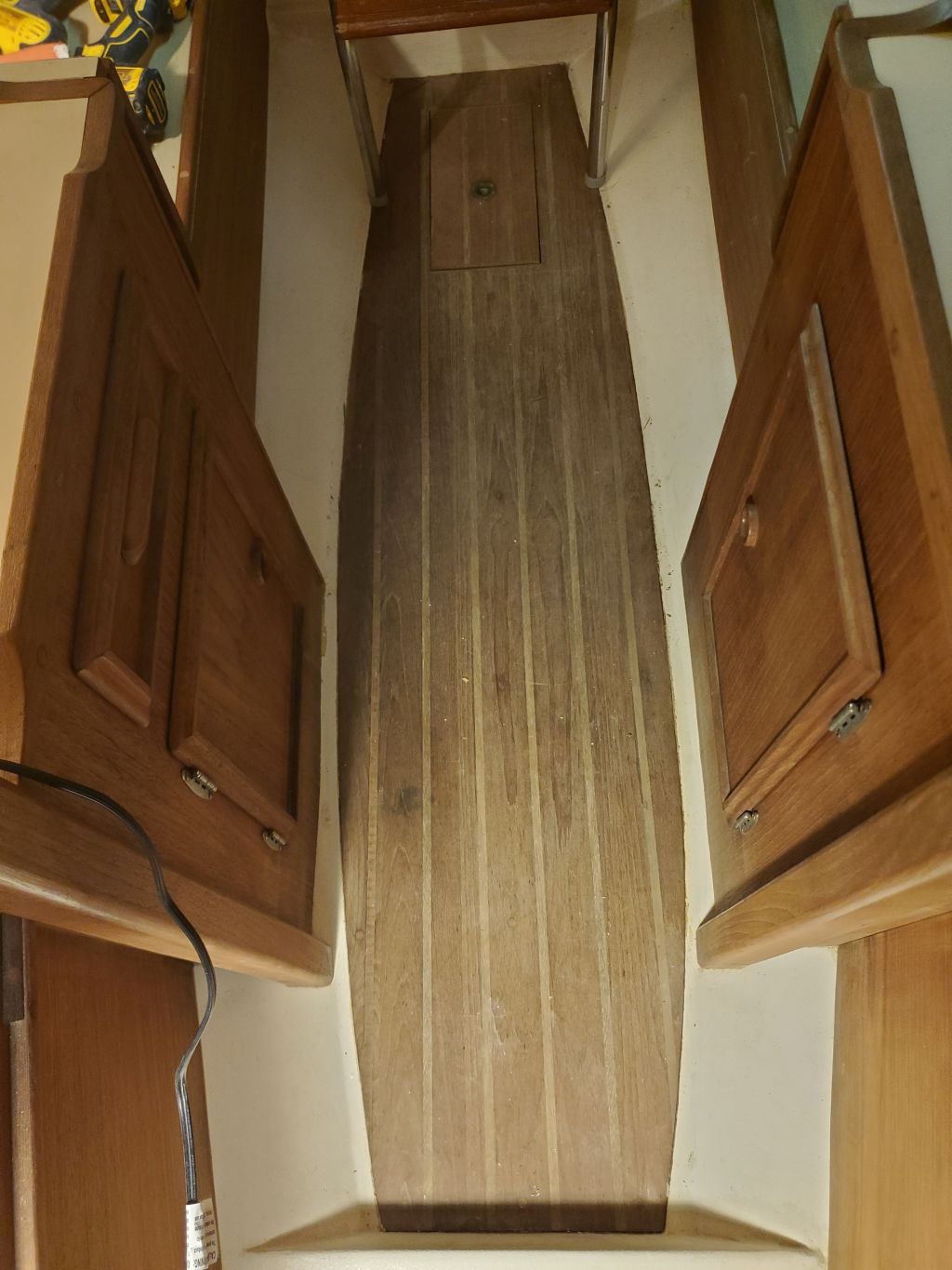
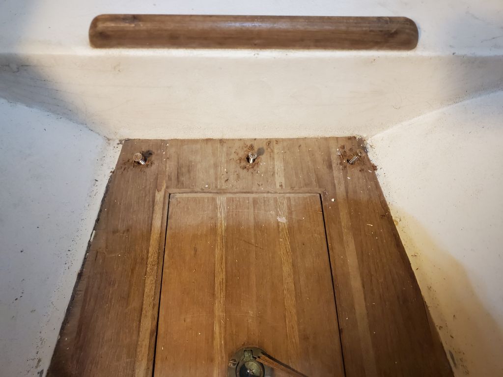
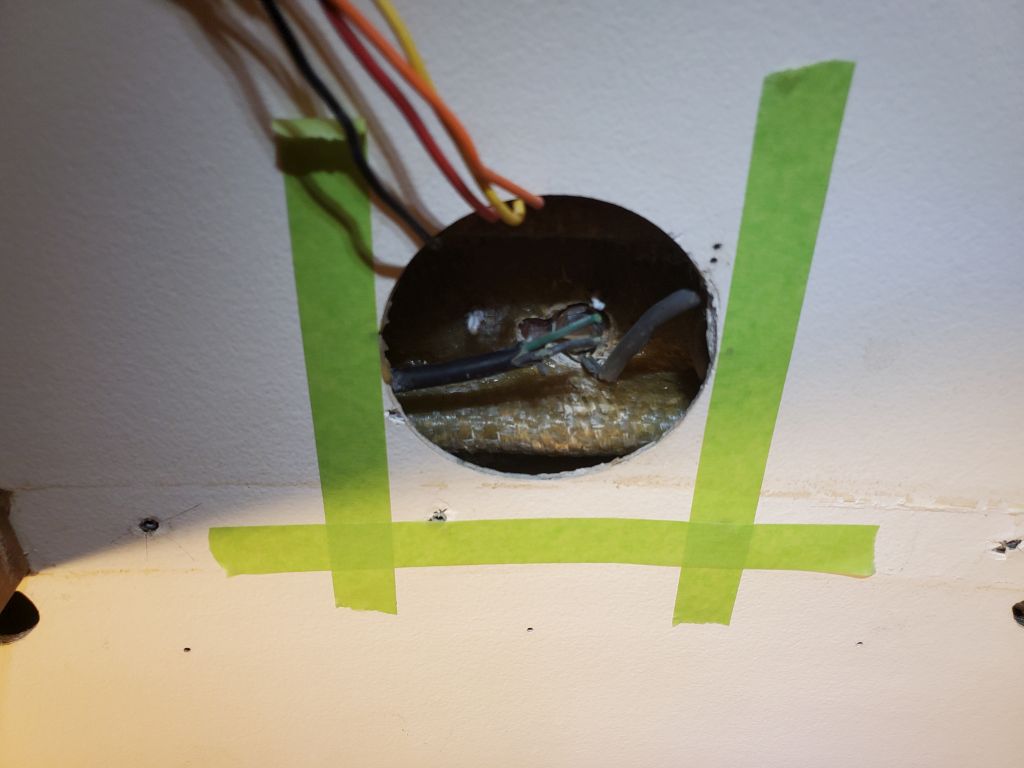
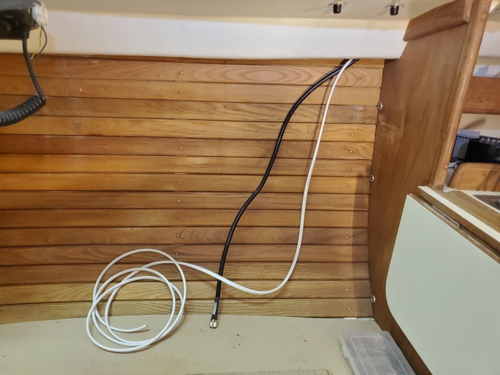
We’d already discussed the possibility, if needed, of opening up the liner more for better (or to provide actual) access to where the wires would eventually pass through the deck, a limited area not currently directly accessible (there’s an issue for the near future), but I decided I had to increase the liner cutout going forward so I could get this new cable run.  I began by removing a trim piece that spanned the passageway to the forward cabin, hoping perhaps there’d be a seam in the liner there that I could spring open further.  The liner was one piece, as it happened, but now I could extend the opening slightly further forward into the center of the area the trim had covered.  This proved not to be quite enough, so I extended the opening about another inch (I’d build a new cover panel and trim later), and finally succeeded in getting the new cable through the tight spot.  And so it goes with liners:  Convenient for the builder, challenging for everyone forever after.  I led the other end of the new cable aft into the main cabin and would eventually secure and neaten up the new cable run once I’d run it through the deck.

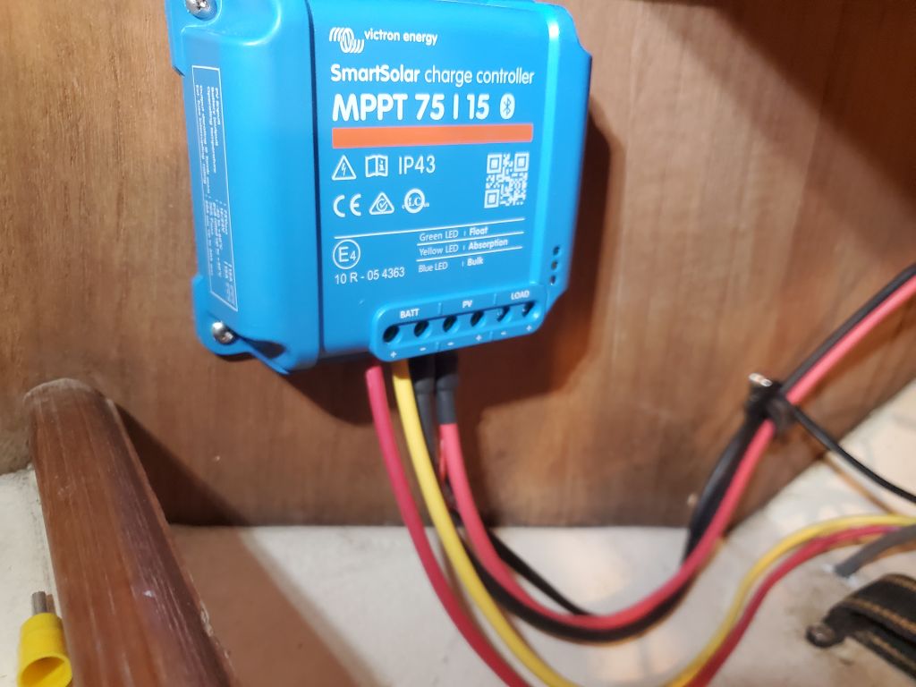
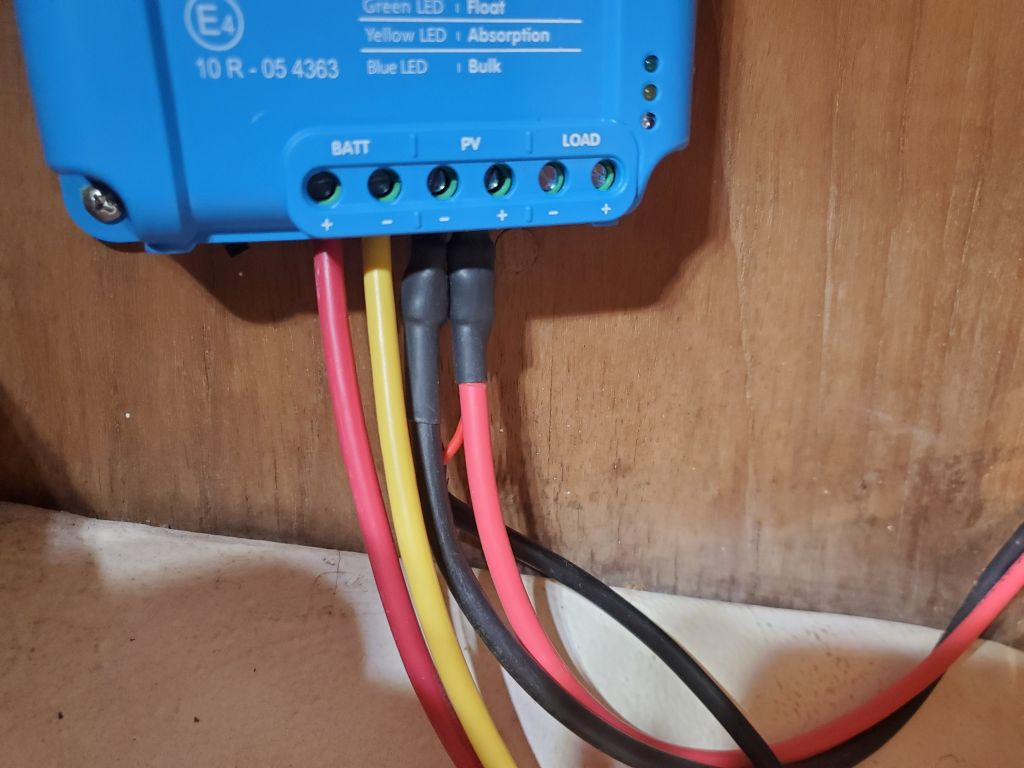
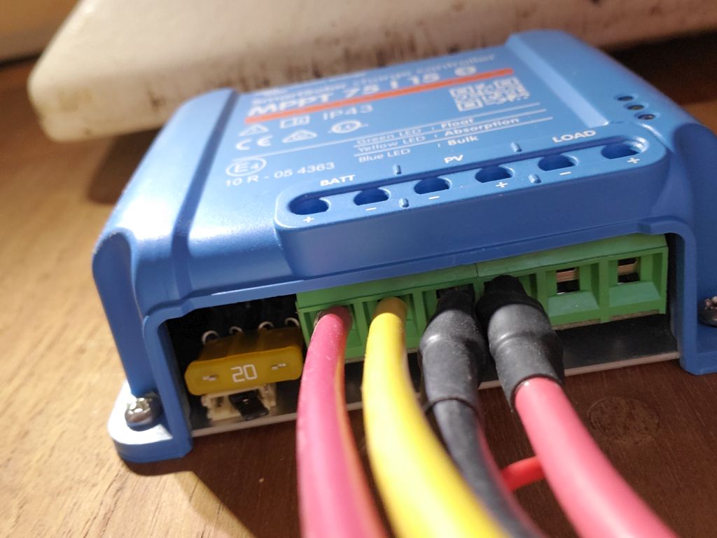
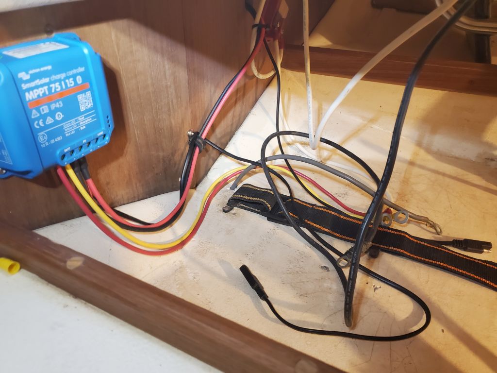
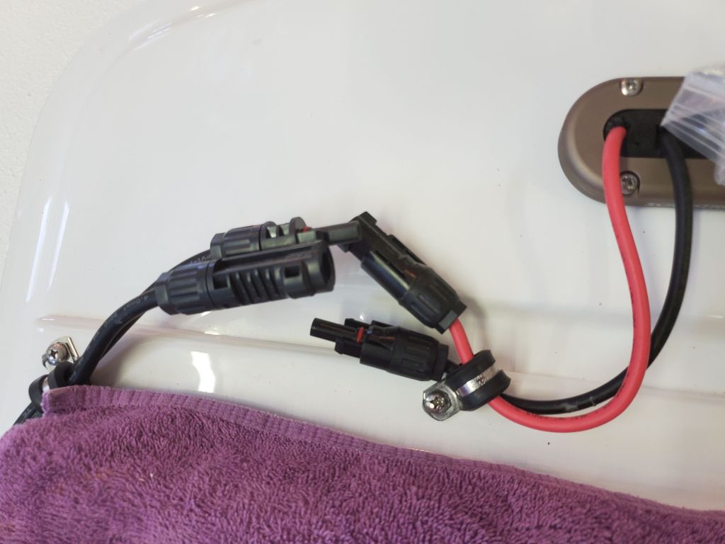
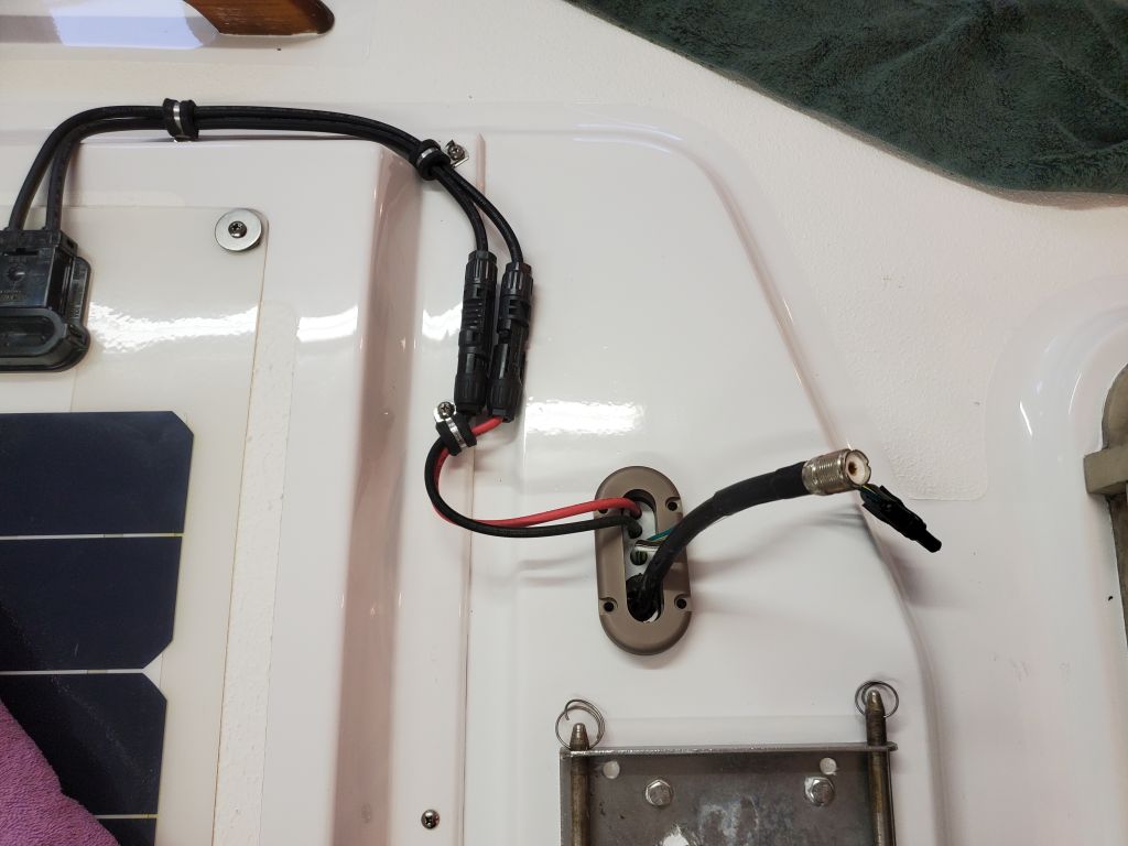
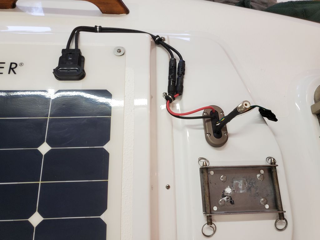
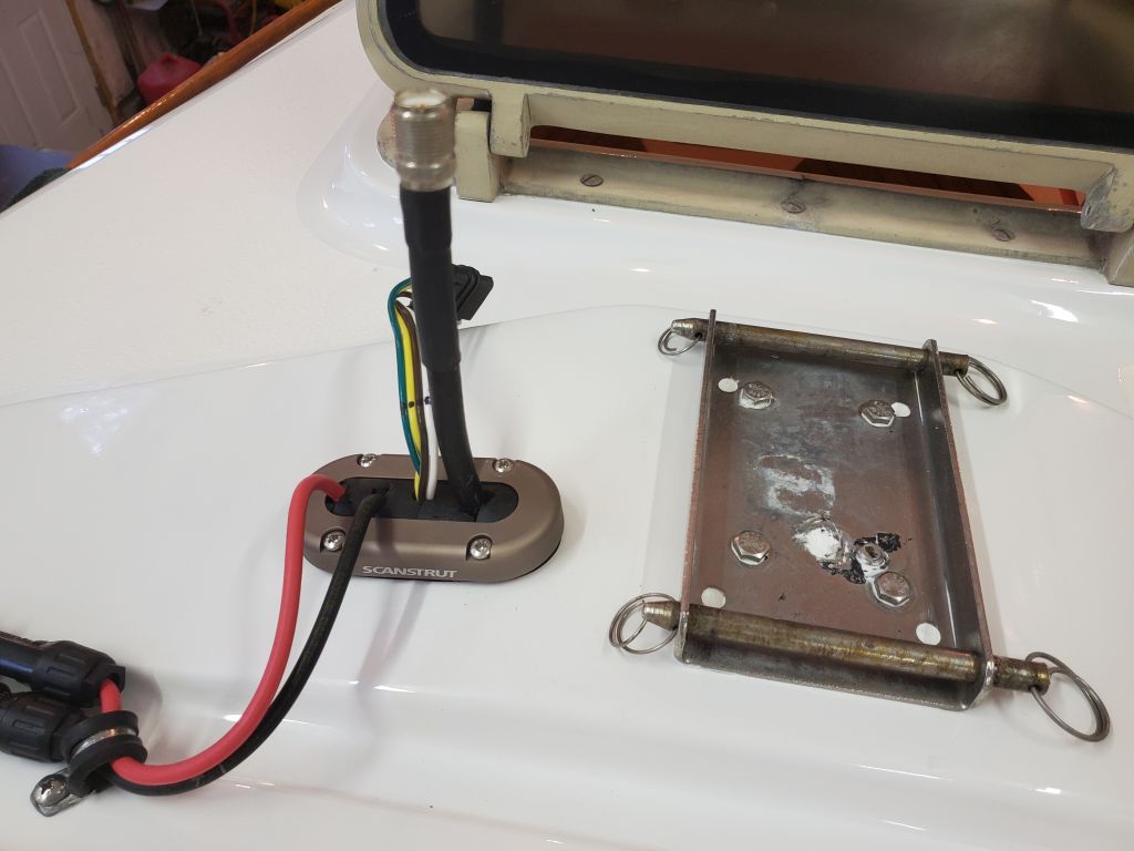
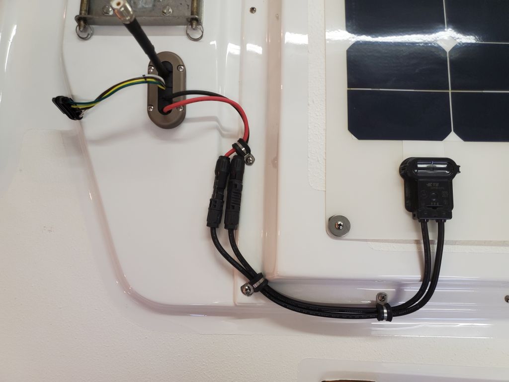
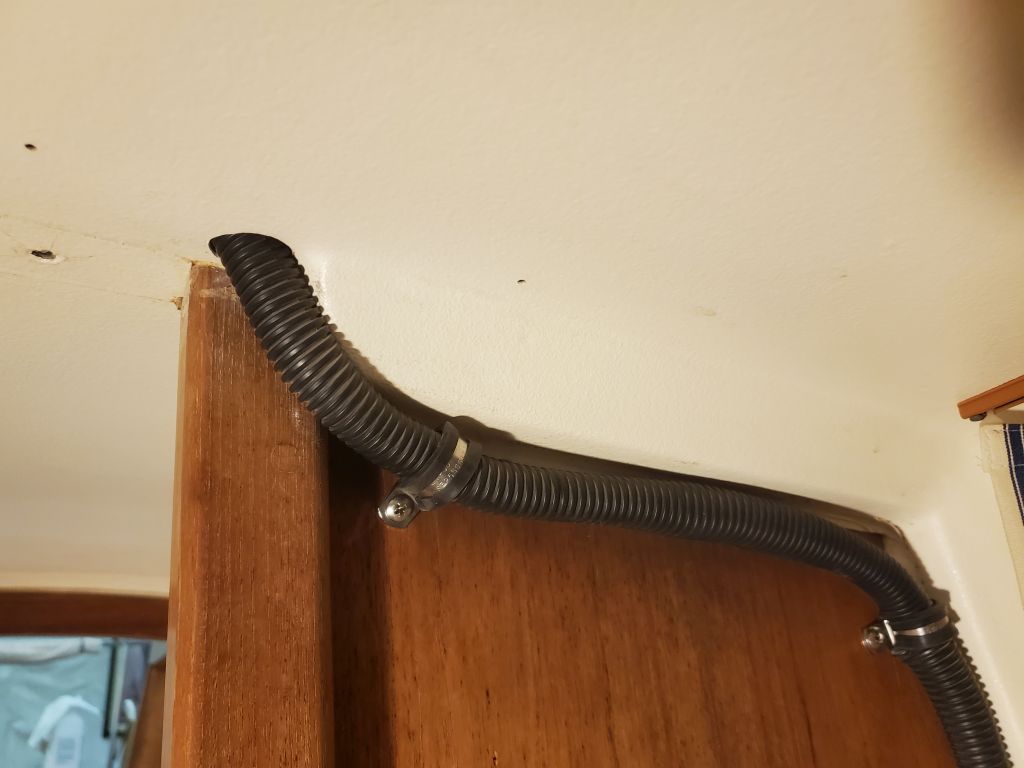
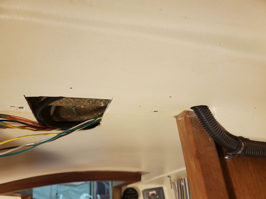
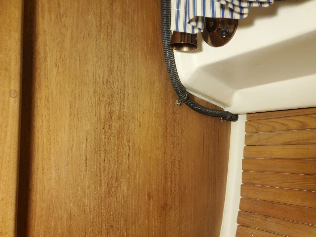
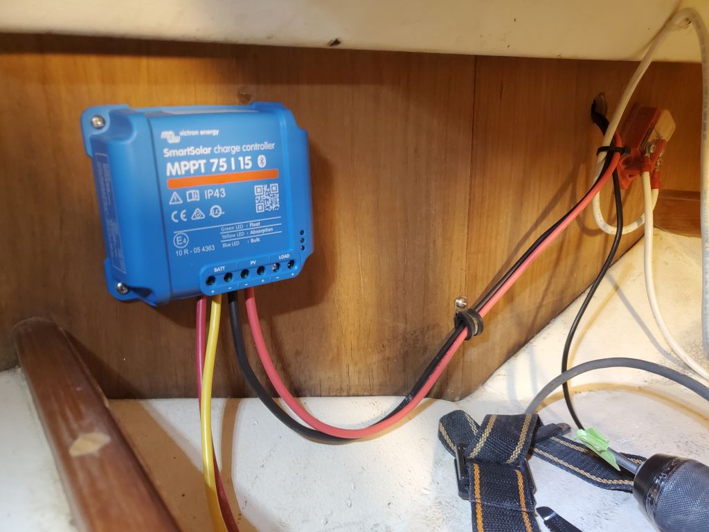
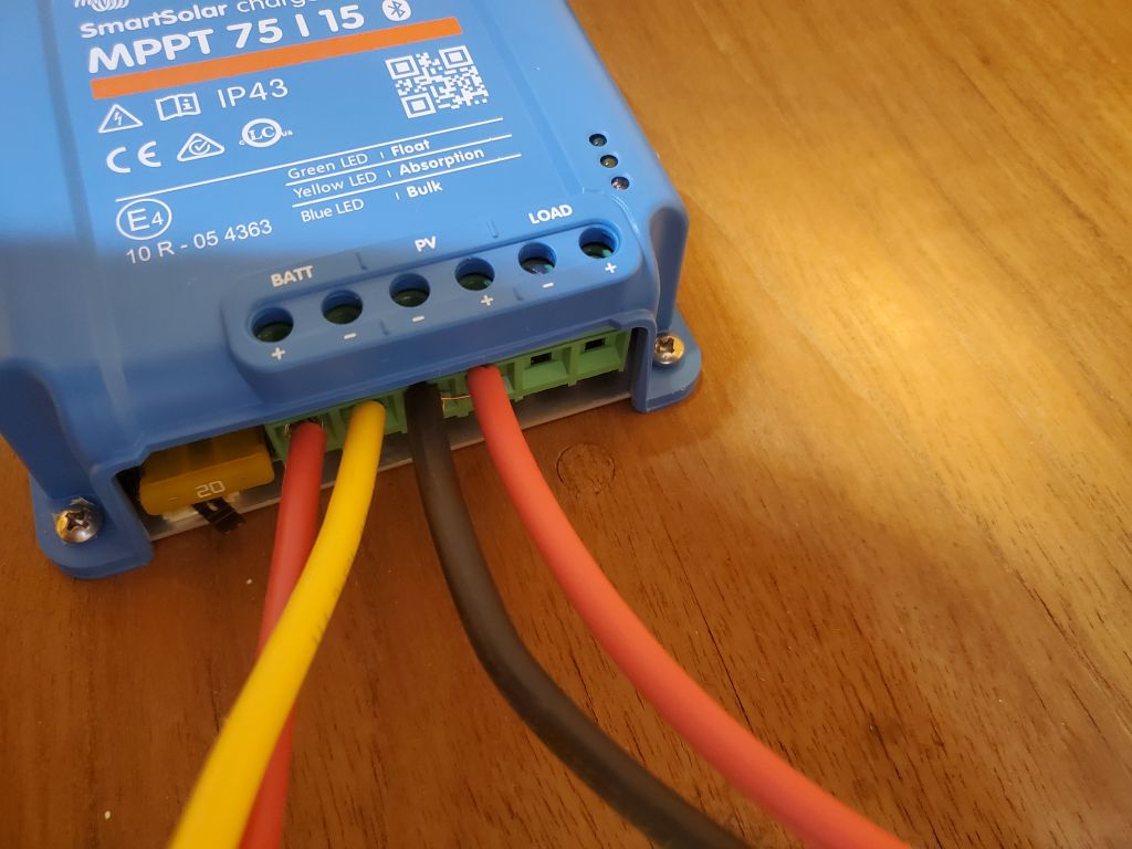
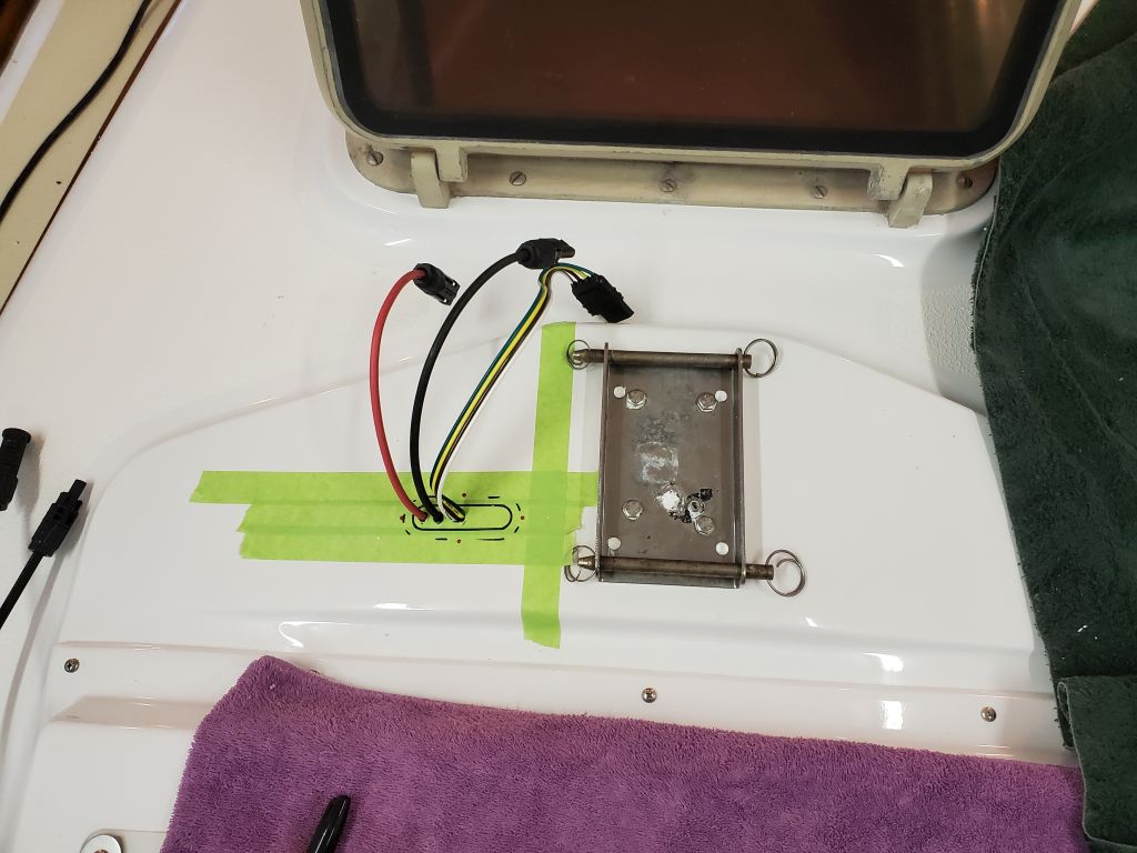
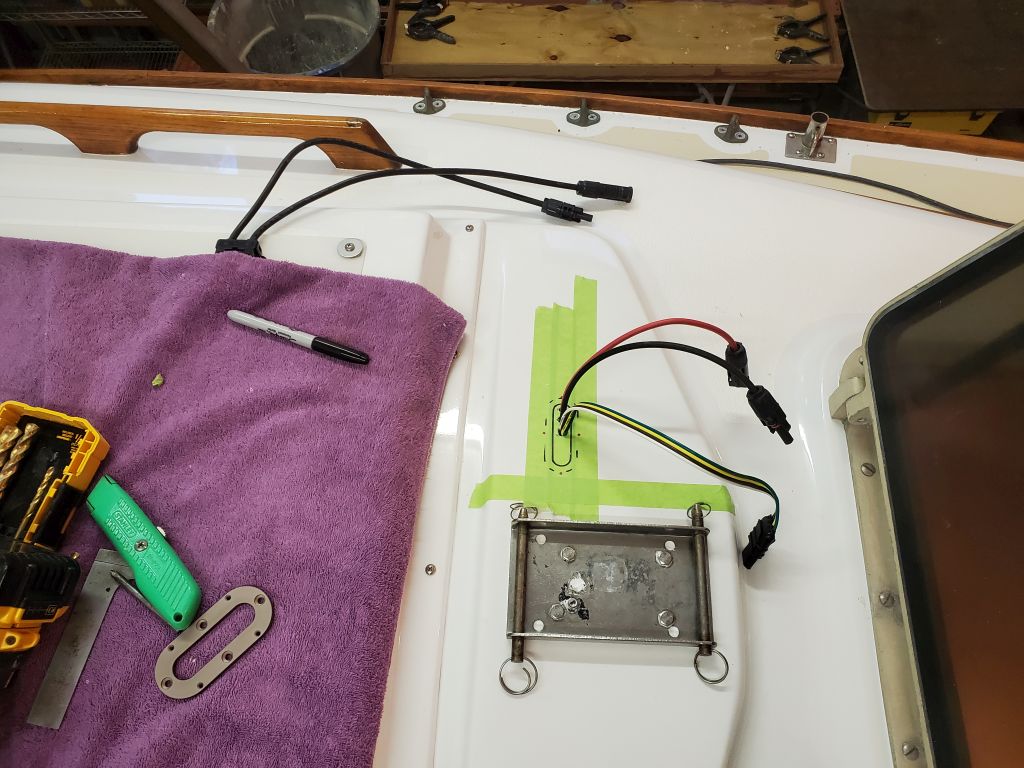
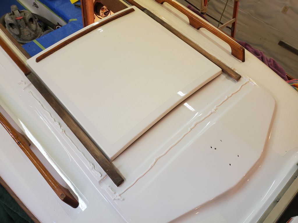
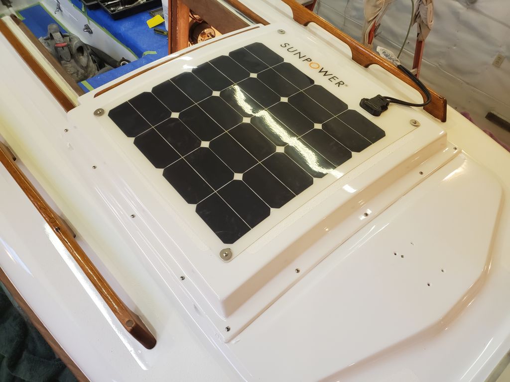
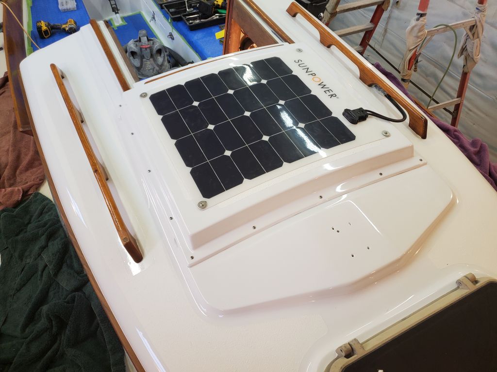
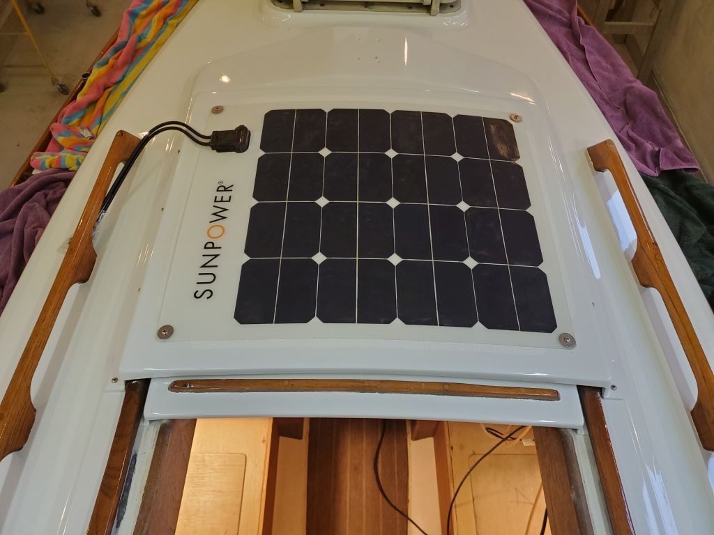
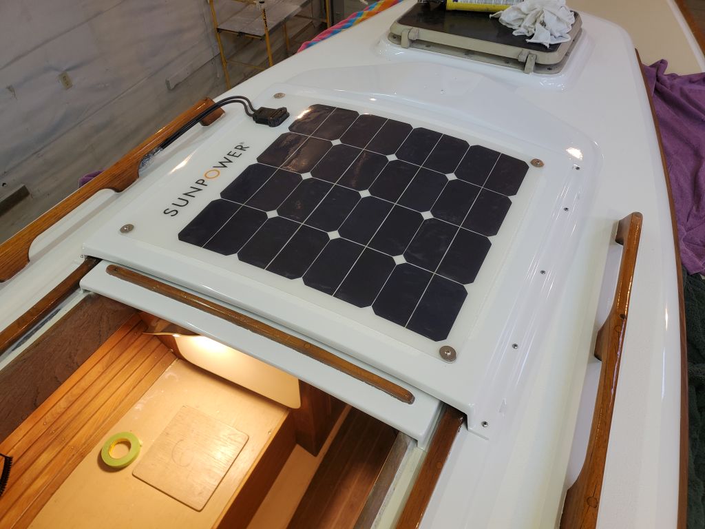
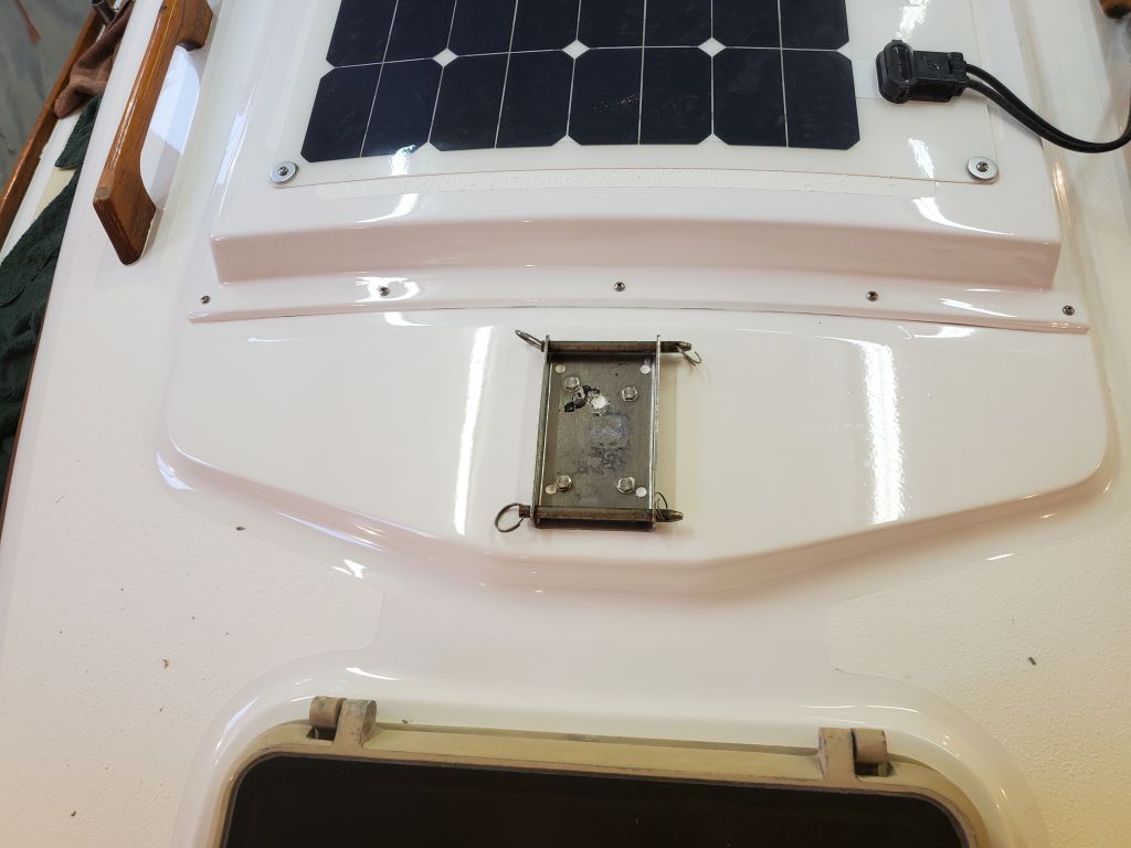
The liner and how to run wires through the boat looked to post additional challenges for the new wires required for the solar panel, which wires I didn’t have on hand yet (due in a couple days), but would need to run from the through-deck gland near the mast, and where the panel connections would be to the sea hood panel, then somehow aft to the battery space beneath the cockpit, aft of the scuppers.  There was no passage through or beneath the overhead liner, as the space was simply too tight, and I figured these wires would have to follow the path of the VHF cable to the side of the boat, where they could run aft hidden by the liner along the top of the hull and deck edge.  This was a problem for a few days hence, when I had the wires, but it was pretty clear that none of these basic wiring jobs would be conquered in the easiest or most convenient way.

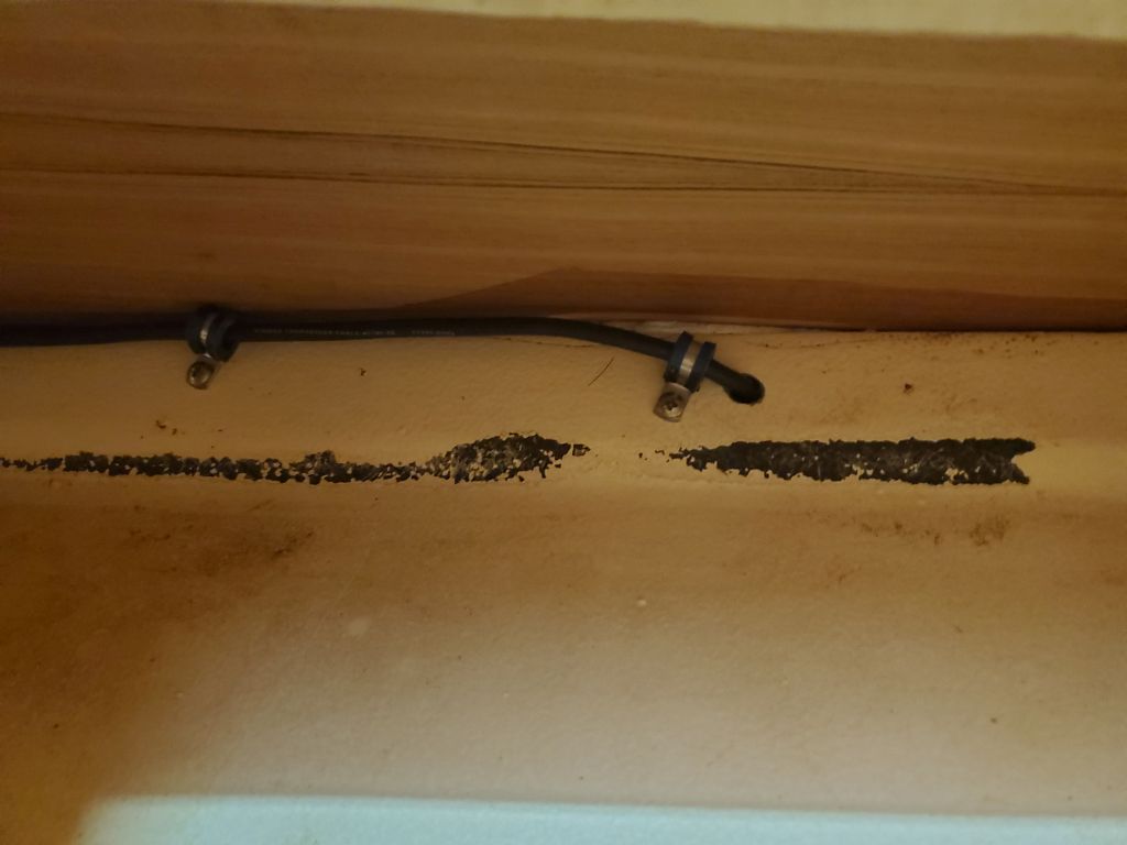
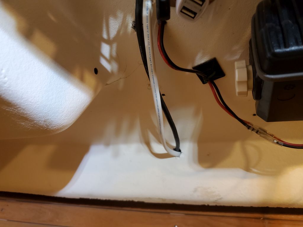
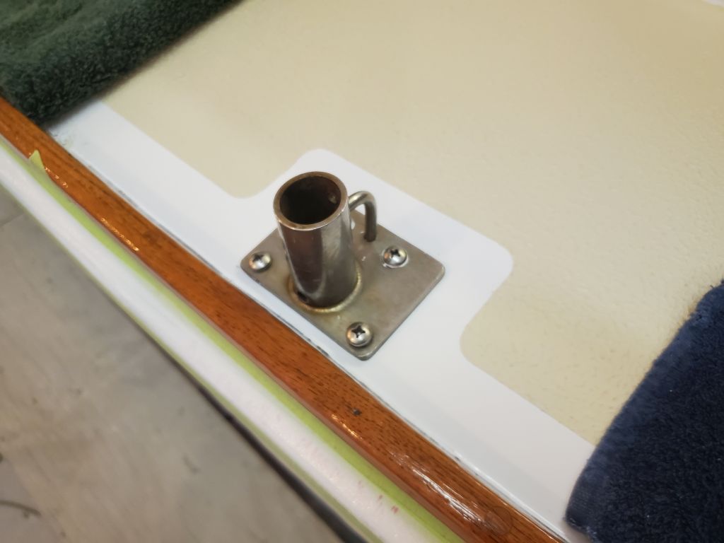
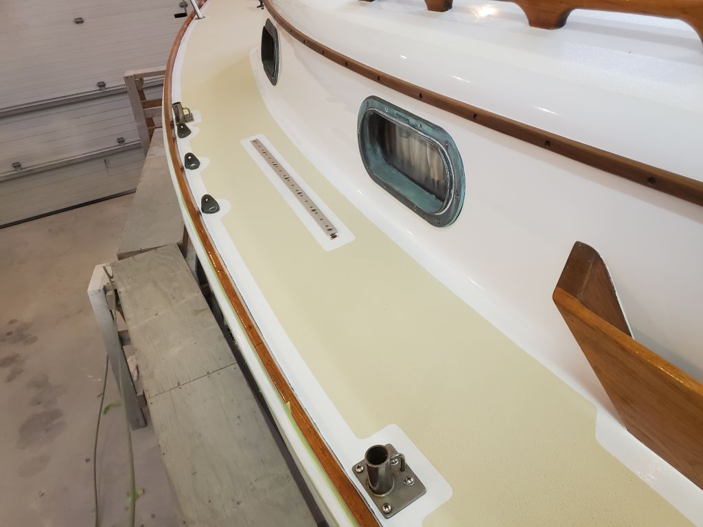
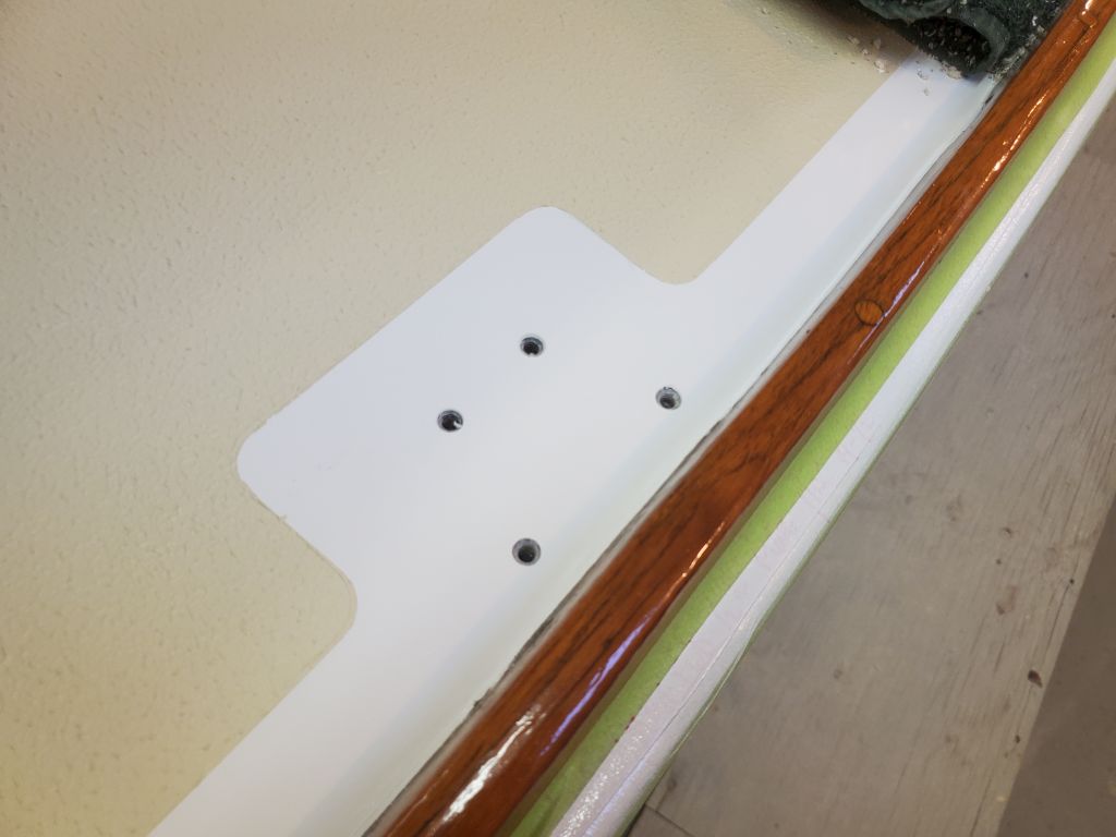
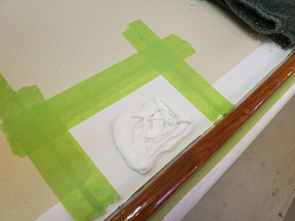
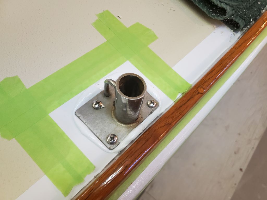
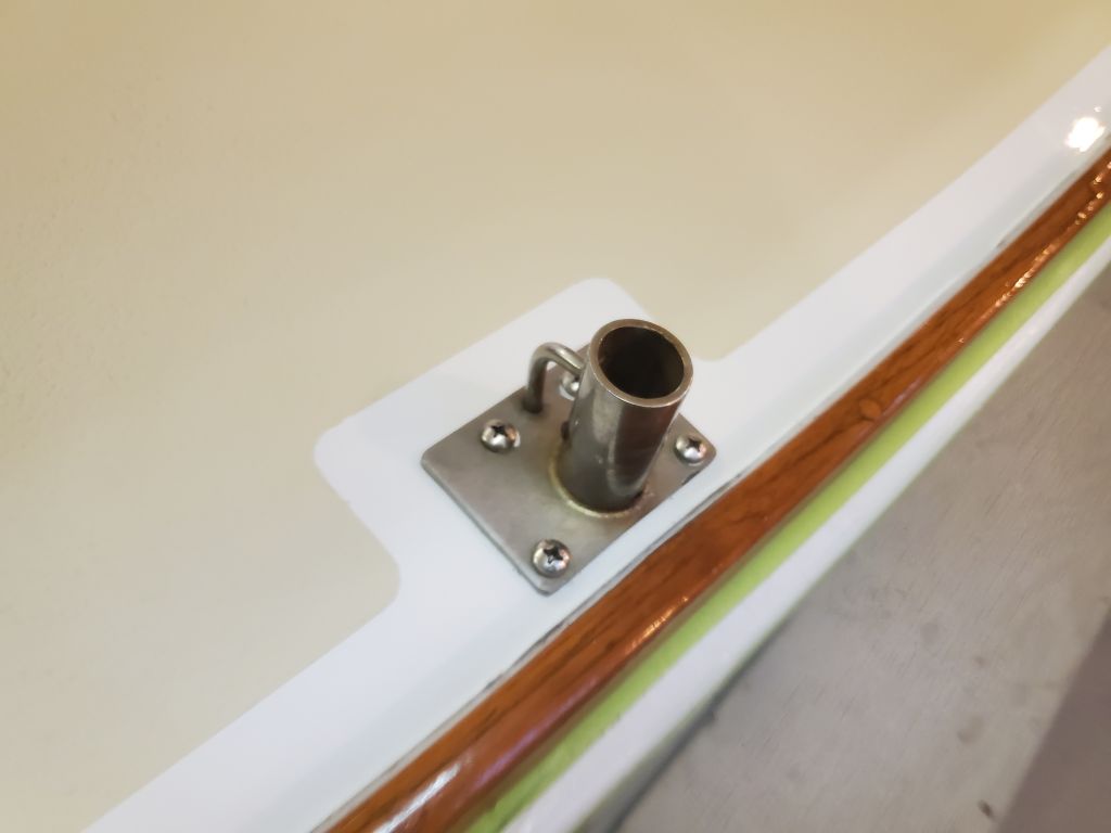
One wiring job I thought I could mostly figure out now, and to satisfy another punch list item, was to lead a new wire pair forward to the bow pulpit, where I connected it to the wires leading from the running lights, then secured the slack to the existing wire bundle hidden in the open space outboard of the overhead liner.  I’d finish leading this wire into the electrical panel area soon, though even this was likely to present a challenge thanks to the liner (all the original wire harnesses on the boat were built and installed before the boat was completely assembled, hence the difficulties today).

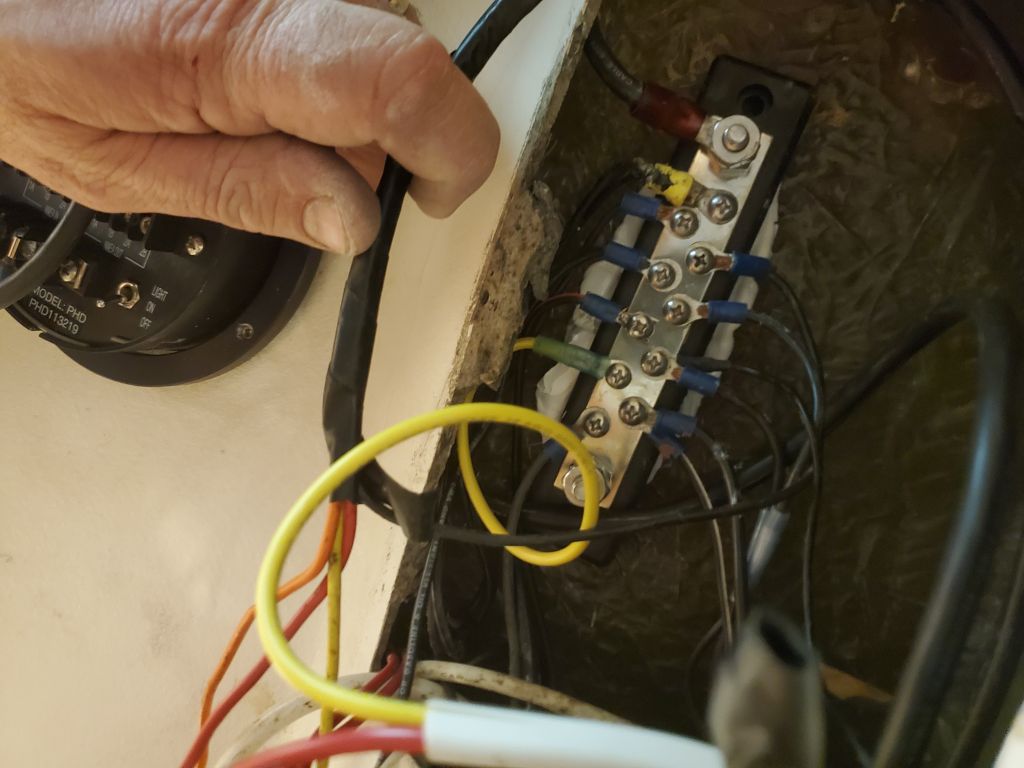
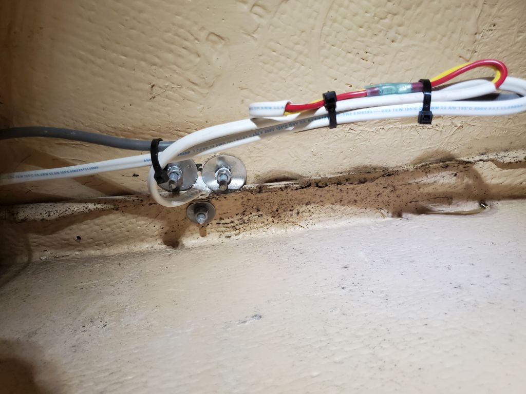
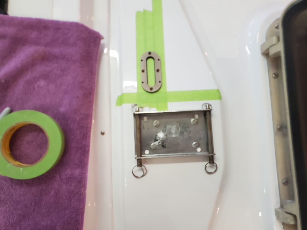
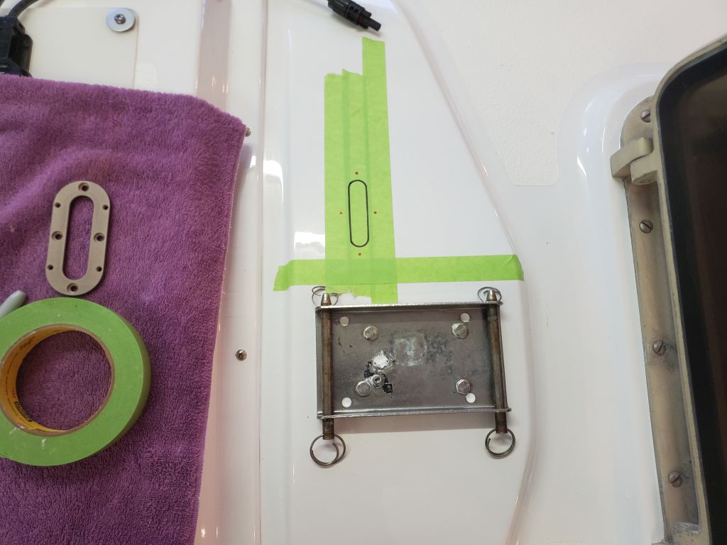
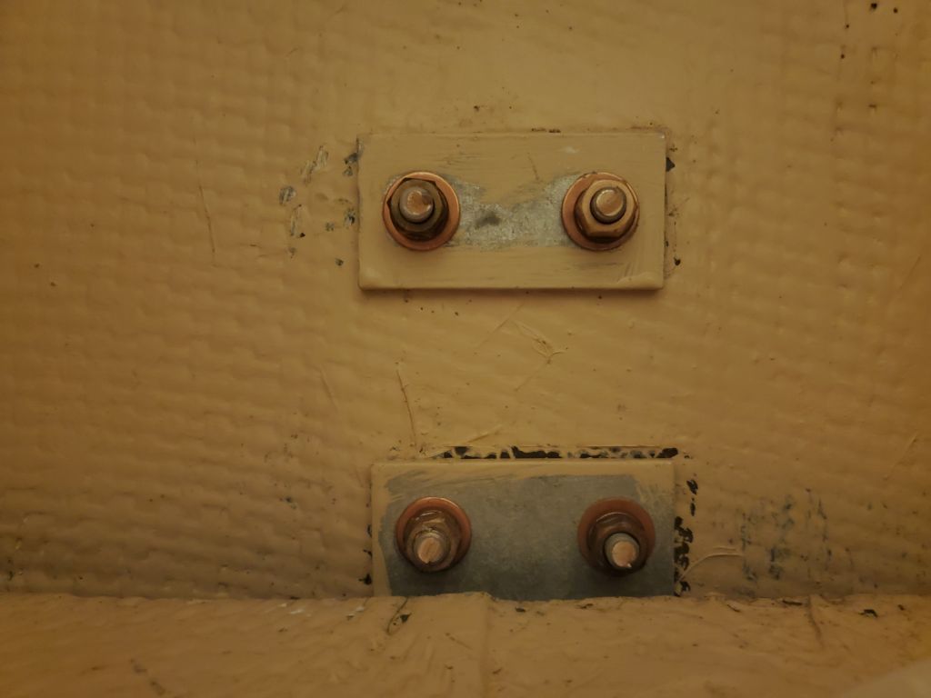
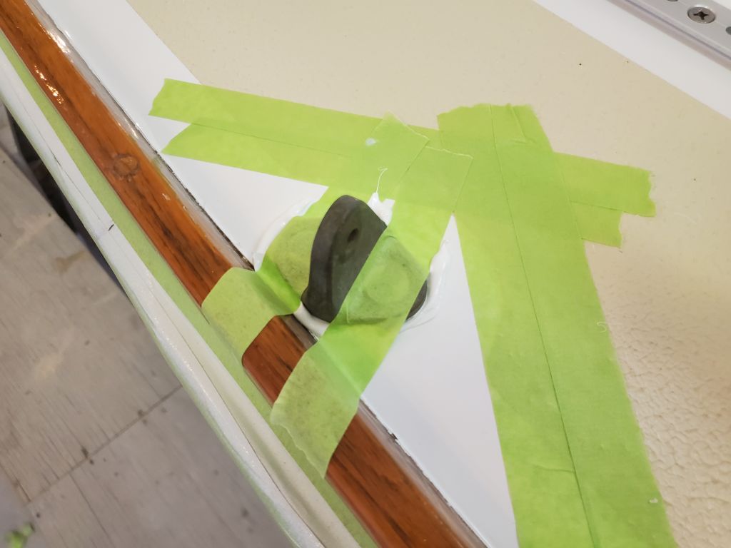
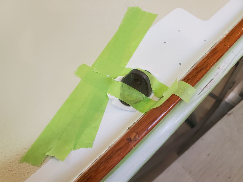
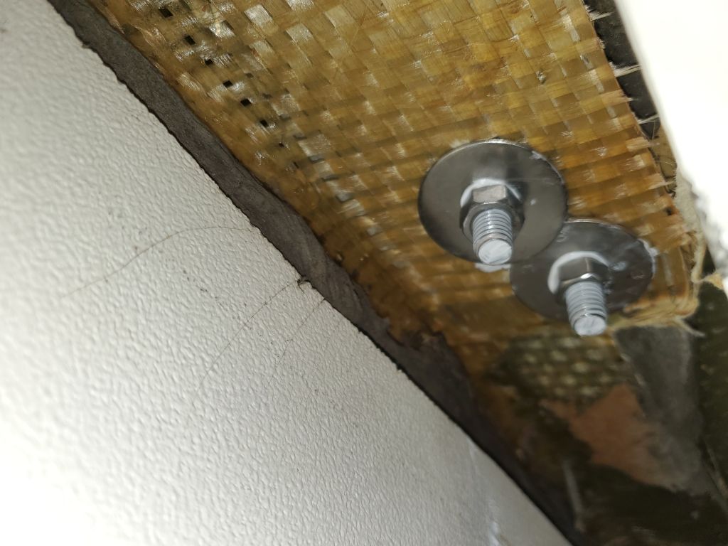
The wiring buss in the electrical locker that I’d glued in place last season when the boat was here had come loose, so I resecured it as needed.  (The tape is just holding it while the adhesive cured.)

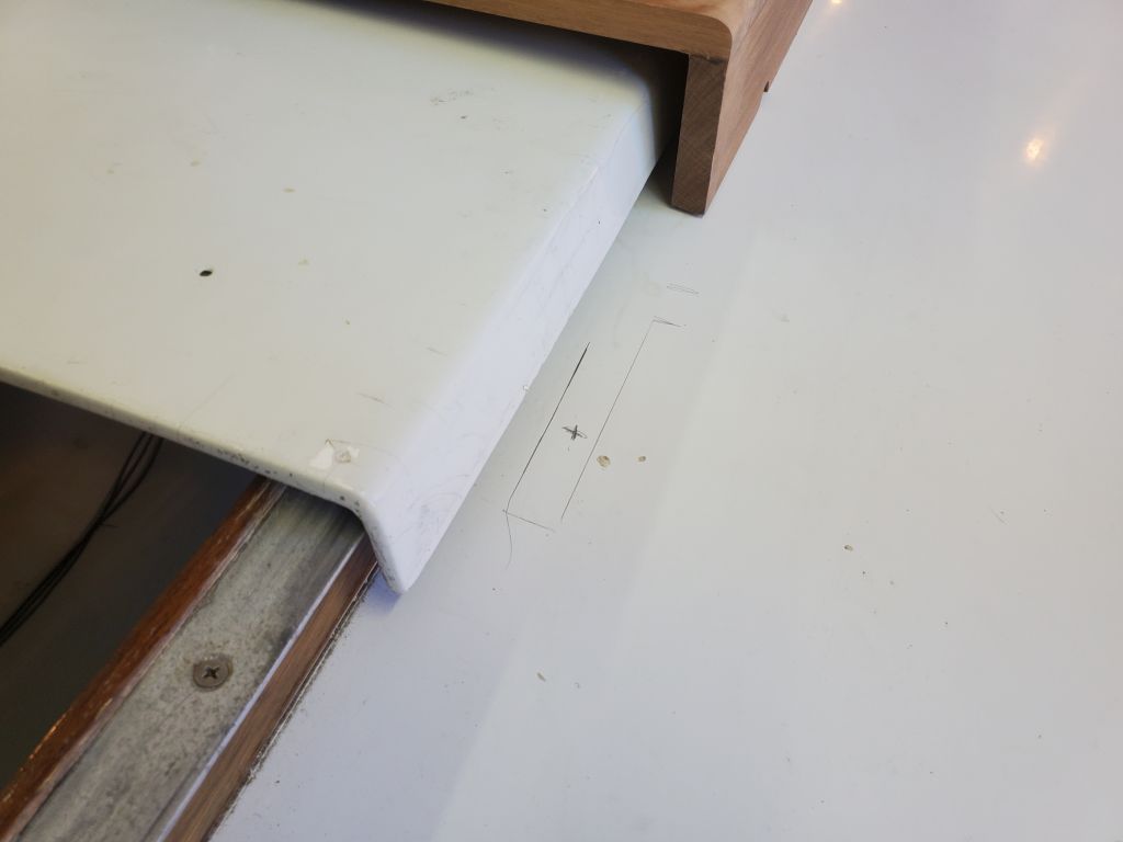
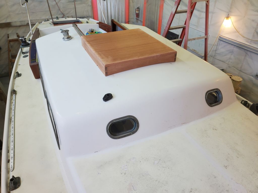
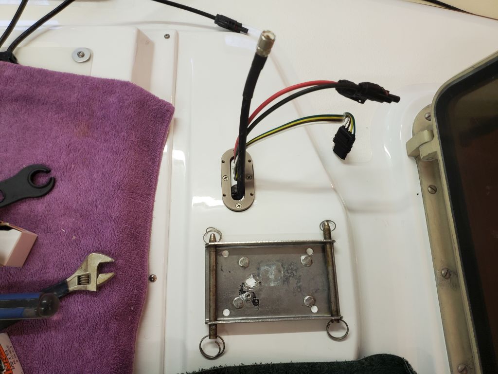
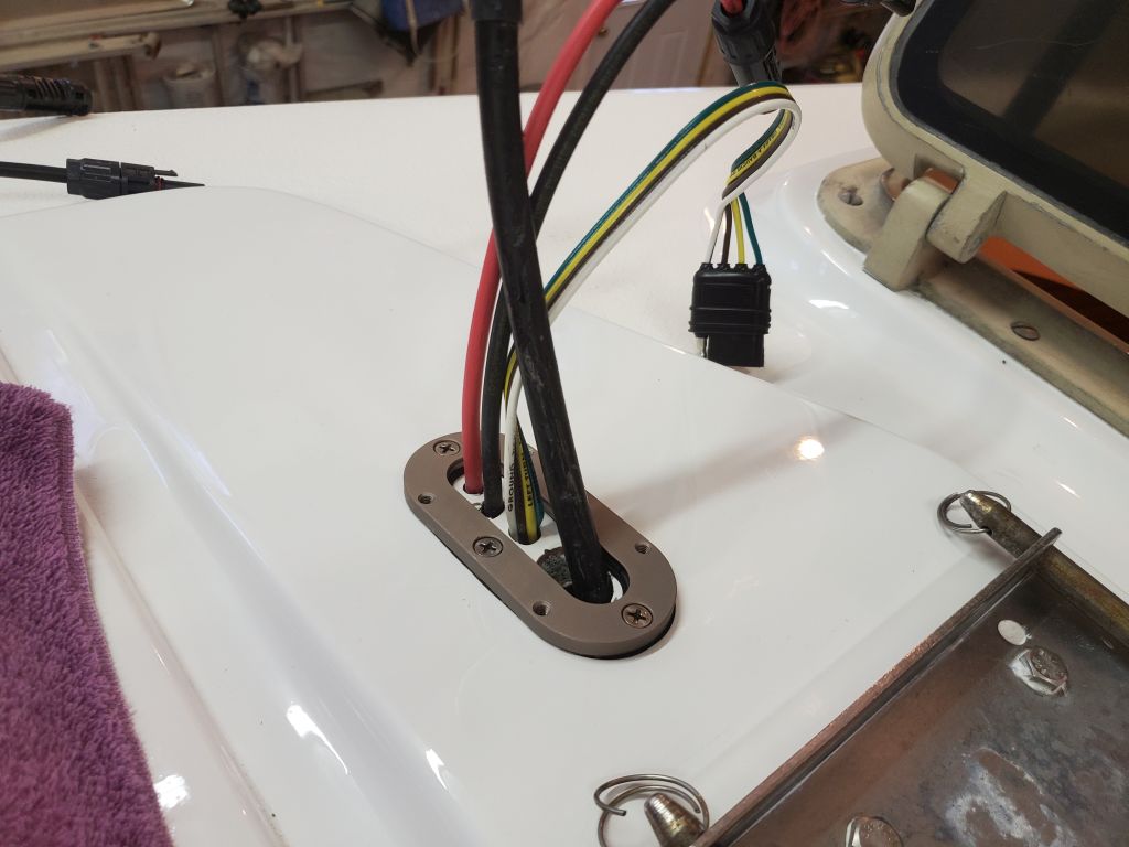
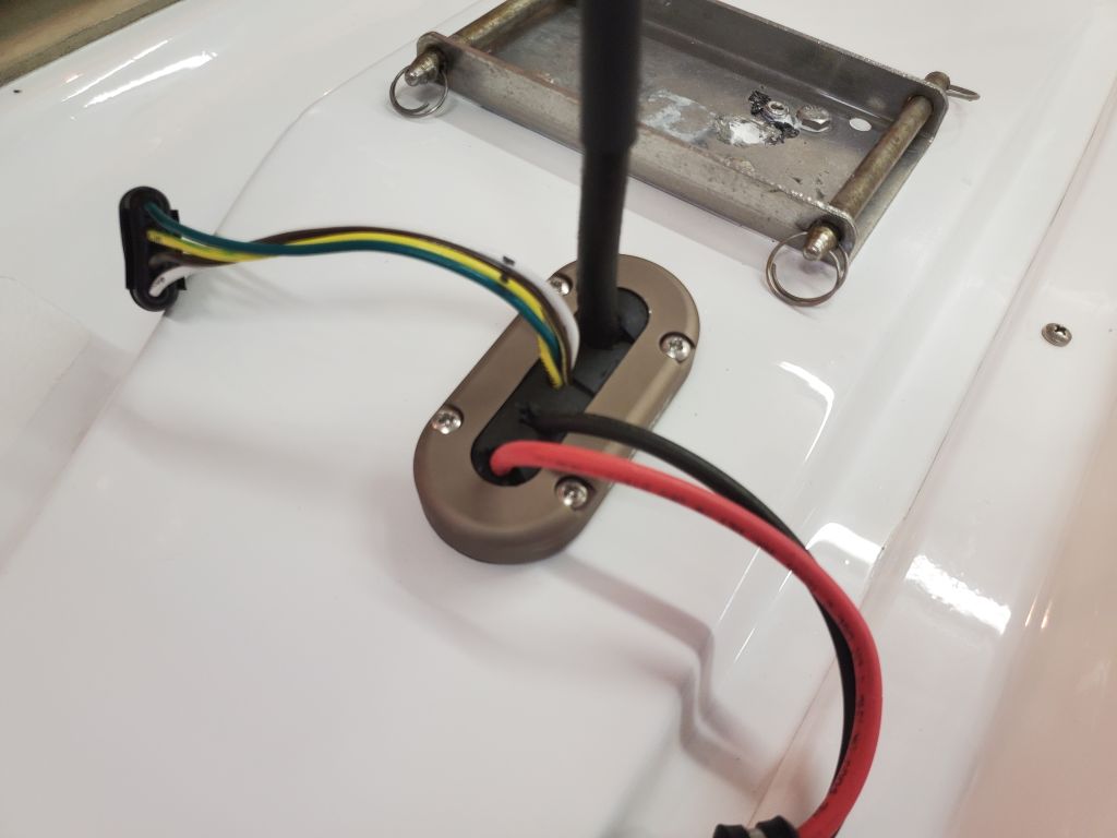
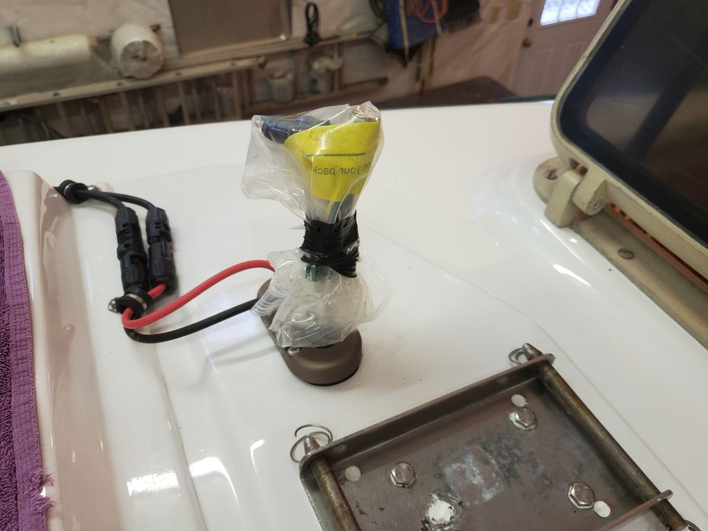
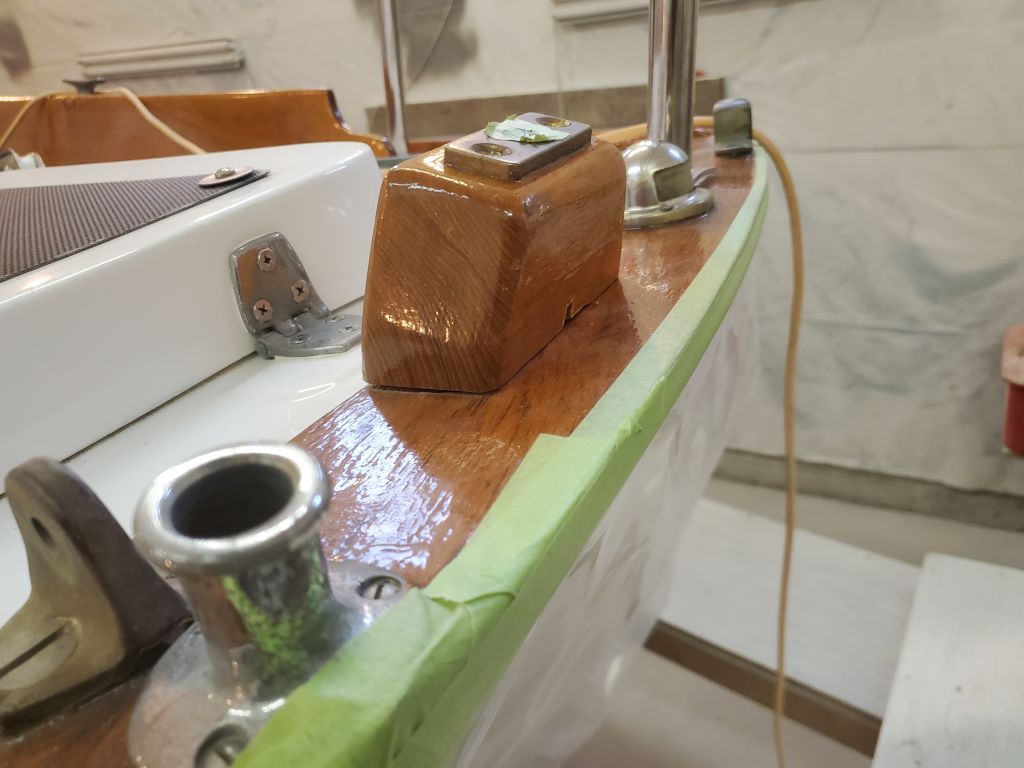
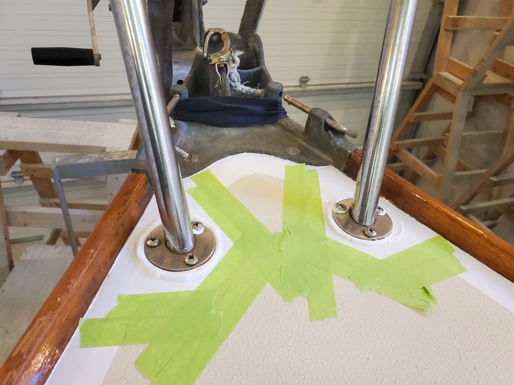
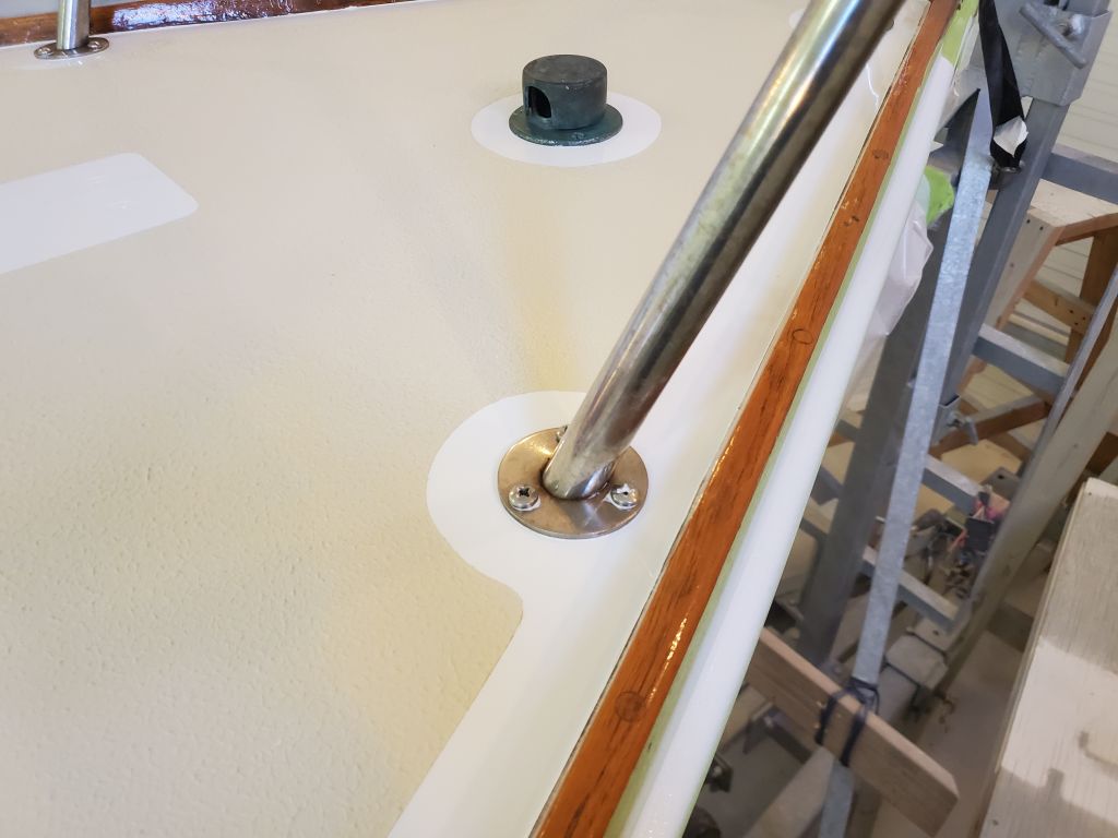
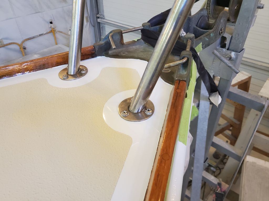
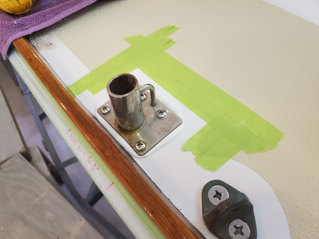
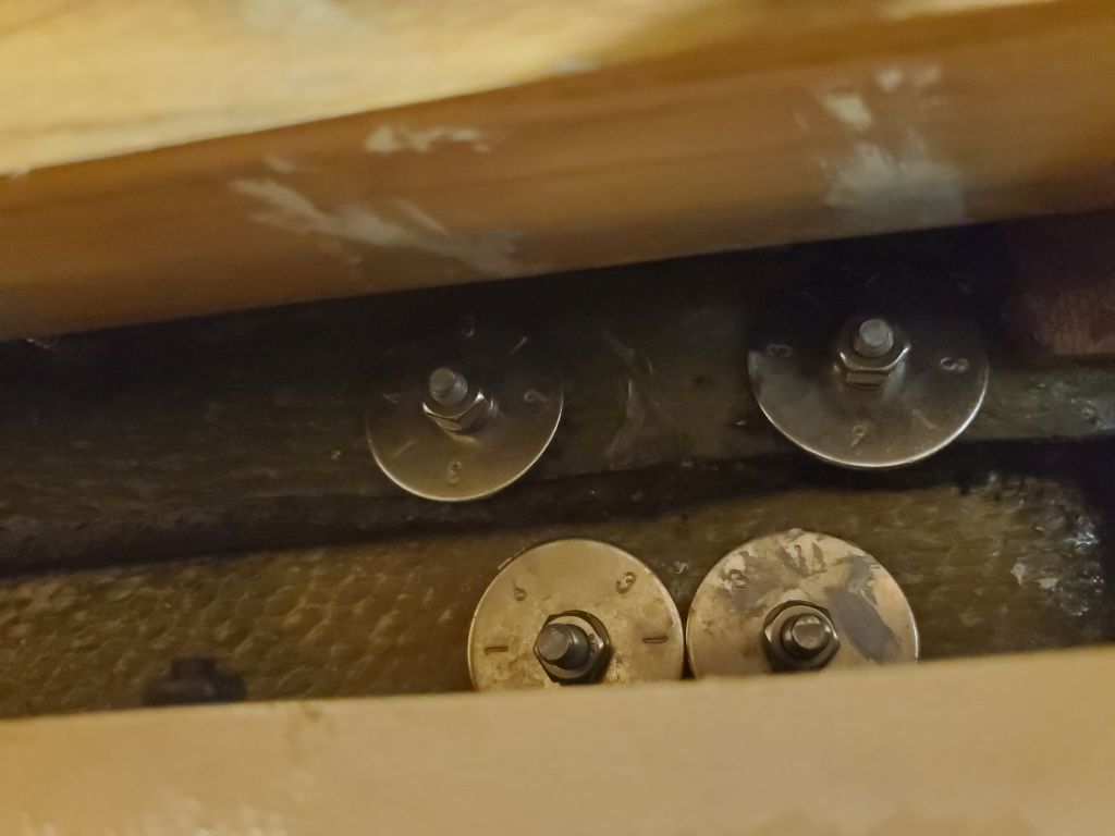
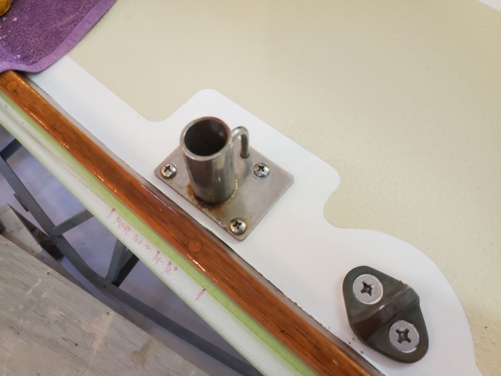
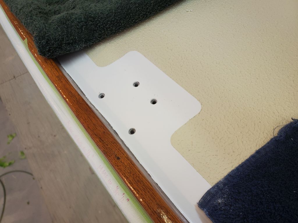
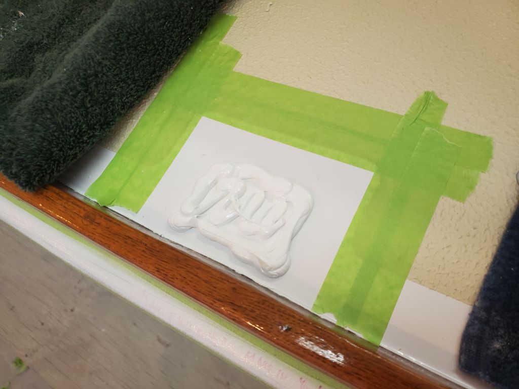
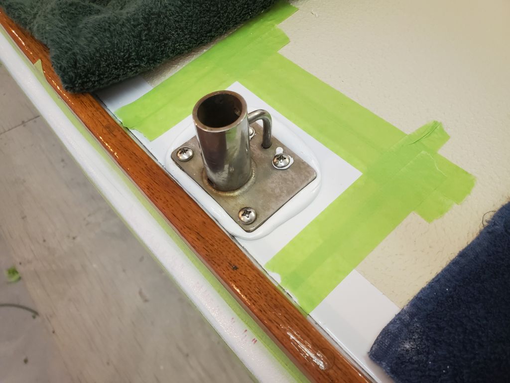
At the mast, I laid out the position for the new wiring gland, which the owner requested remain clear of the pins on the hinged mast step, and which the construction of the mast beams and structure futher limited to a narrow possible space.  I’d wait to drill any holes till I had all my wiring on hand so I could lay things out correctly.

With my other main works complete for now, I finished up the day with a coat of oil on the settee fiddles, to blend the new bungs with the older wood.

Total time billed on this job today:   7 hours

0600 Weather Observation:  10°, clear.  Forecast for the day:  Sunny, 30°

Lyra Phase 2-1

Friday

When Lyra was delivered here a few weeks earlier, I’d put her in my secondary shop bay for safekeeping, since this space was open and available.

Planning for the beginning of the project in earnest in January, I took advantage of a good weather forecast with mild temperatures and a still-snowless property to shuffle the boats between the shops, moving Lyra into my main shop where I planned to complete the work ahead.  I set her up pretty close to level side to side (things had shifted just a bit after I’d completed the stands and blocking, but easily adjustable from there), and eyeballed her longitudinal level vis-a-vis the obvious “real” waterline vice the painted version.  Keeping her as close to level in both directions would help when it came time to set up for striking the new waterline and boottop later during the hull work.

Total time billed on this job today:  1 hour

0600 Weather Observation:  40°, fair.   Forecast for the day:  Sunny, 48° but falling in the afternoon.

Arietta Phase 2-31

Friday

I’d been planning all week to take advantage of an unseasonably mild day in our still basically snowless winter to shuffle boats, as the Arietta project was nearing its end (with a few small jobs remaining to complete), and I would soon be moving onto the next project, which was in the other side of the shop, but I wanted to have it in my main work bay and these transfers were always easier and more pleasant when it wasn’t cold, icy, or snowy outside.

To begin, I broke down and removed the staging from around the boat, clearing the way for me to move her into the other, newly-vacated, side of the shop.  I also moved in the mast from where I’d had it outdoors so it’d be ready to put back aboard the boat when the project was done after the next week or two.  Then I spent some time getting reorganized and set up in the new side of the shop so I could continue working.

The remaining punch list for this project included the new instruments, which I spent some time reading about and looking into the details of installation, particularly regarding the transducers.  The old depth  transducer would need to be removed, and my first minor attempt at removing the nut from inside went exactly nowhere, but gave me the information I needed in terms of planning the replacement.  While I’d hoped I could spin off the nut and easily remove the transducer now, I hadn’t really expected it to be like that, and now I could focus on the actual removal and other aspects of the instrument replacement in the coming days.

Similarly, for the first time I looked at the solar charge controller the owner had provided and that I needed to install and connect with the new solar panel on the sea hood, and I planned for this installation by ordering supplies I’d need (wiring and the correct crimping tool), and attempting to figure out just how I was going to run the wires through the boat.  This would all come together a bit later, once I received the supplies.

In the days ahead I also had to finish up some minor interior work, including reinstalling the shelves I’d removed earlier in the project (though for now I decided to await this till I figured out some of the wiring paths), and also finish up with the settee fiddles and that sort of thing.  But right now, a bigger priority was to finish up the paint work around the new through hulls and at the repaired liner at the aft end of the cabin, and I applied a coat of cream-colored semi-gloss paint to coordinate with the color of the existing liner.  I’d probably need to do a second coat over the weekend to wrap this up so I could finish with the new scupper hoses in the near future.

Total time billed on this job today:  5 hours

0600 Weather Observation:  40°, fair.   Forecast for the day:  Sunny, 48° but falling in the afternoon.

Arietta Phase 2-30

Thursday

The owner requested that I modify the oarlock I’d installed for him last year, as he’d found that it required an angle to help the oar reach the water effectively.  Earlier in the project, I’d removed the oarlock and its spacer block, and now with the block on the taffrail I eyeballed the angle required to match that of the transom, which the owner had said was about right.  This turned out to be 15°.  Because the block was too small to cut safely, I covered it with tape and hot-glued it to a plywood scrap so I could use my saw to make the cut.

After recreating the little drain at the bottom of the block, to prevent water from collecting through the oarlock hole, I installed the block in the same position with sealant and new fasteners.   I had planned to use the angled offcut as a wedge belowdecks to properly support the washers and nuts, but it turned out to be unnecessary.   I’d bought longer (2″ longer, as I could get only 4″–the original bolt length which had barely been enough before–or 6″) bolts for the job for this reason, but cut off the excess length afterwards.  (My photo of the trimmed bolts was misaligned but one is visible to the right of the third photo).

Next, I reinstalled the winch bases, which required a single bolt each  through the deck along with the two through the coamings.  Belowdecks, I secured the bolts with nuts, large washers, and, on the starboard side where there was room, a small backing plate.  The angle of the liner through which the bolt protruded on the port side precluded effective use of a backing plate, so I allowed the large washer to bend itself to the contours as needed.

After applying a bead of sealant all around, I installed the sea hood with new fasteners.

The final piece of deck hardware for now was the mast step, which I installed next.  Belowdecks, there was a 3/8″ bolt to which the grounding wire had originally been secured, and which passed through the deck to thread into the mast step from beneath.  Later, I’d install the new wiring gland and wires, but now right now.

I prepared the fastener holes for the jib track end stops, drilling into the deck about 3/8″ and tapping the holes in the new epoxy.  I installed the ends with some butyl sealant and 3/4″ machine screws, after installing the lead cars on the tracks.

In the cabin, I reinstalled the teak berth fiddles, and bunged all the fastener holes.

I masked off and prepared the small area around the scuppers and where I’d repaired the liner earlier, then applied a coat of primer.

Back outside, I bunged all the screw holes in the eyebrows.  Late in the day, I pared these off, sanded as needed, and applied a coat of finish over the raw bungs.

The owner purchased replacement instruments designed to have the same footprint as the old round originals, and to begin the process of replacing them I removed the old instruments.

Total time billed on this job today:   7 hours

0600 Weather Observation:  39°, light rain.   Forecast for the day:  Rain and showers, 46°

Arietta Phase 2-29

Wednesday

I began the day’s work with the bow pulpit, installing it with new fasteners and sealant through the existing holes.

Continuing aft, I installed the bow cleat.

I’d not been looking forward to reinstalling the chainplates, since the access (particularly for the middle ones) was so difficult, so these were next on my list, starting with the port side.   Other than the expected challenges in getting the nuts started belowdecks, with the invisible access, tight quarters, and awkward hand angles required, the installations were otherwise straightforward enough.  I used some tape to help hold the washers in place on a few of the fasteners, which gave me the time to get the nuts started without the washers continually falling off the stud.  I also found I had to tape over the fasteners from above so that my efforts belowdecks wouldn’t push the fasteners up, as these existing holes were unthreaded.

Next, I installed the two port stanchion bases, using my little pilotholes to locate each stanchion base correctly, then drilling and tapping and countersinking the fastener holes in my habitual way.  The outer pair of fasteners in each case went through the thick hull flange at the perimeter of the deck, and the inner holes were located in solid laminate outboard of the deck core.

I shifted my operations to the starboard side, and repeated the process, starting with the three chainplates.

Then I continued with the two starboard stanchion bases.

To finish up the day’s work, I reinstalled the grounding cables to the six chainplate locations.

Total time billed on this job today:  7.25 hours

0600 Weather Observation:  19°, partly clear.   Forecast for the day:  Mostly sunny, 33°

Arietta Phase 2-28

Tuesday

To begin the morning, I installed the stern pulpit, beginning with the two after bases on the taffrail, then the two forward bases.

Next, I installed the new working jib tracks on the sidedecks.  Using the pre-marked holes at each end, I drilled and tapped the deck for 1/4″ machine screws at each fastener location.  At the track ends, I used a small drill bit to mark the centers of the holes for the end caps, as these needed to be overbored and epoxy-filled to accept their screws, as I’d forgotten to do so during the earlier deck work.    Afterwards, I finished preparing the fastener holes with the usual small countersink, then applied sealant and secured the tracks in place with machine screws, nuts, and washers from below.  In these locations, the cabin liner was tight against the underside of the decks.  A few of the fasteners would require trimming  below later for cosmetic purposes.

Port side:

Starboard side:

With the tracks in place, I used a 1/2″ Forstner bit to drill out the top skin and core from the end cap fastener locations, then filled the voids with a thickened epoxy mixture, leaving that to cure before installing the end caps.

New fasteners were due later in the day, which would then allow me to continue with the rest of the deck hardware, but for the moment I decided to reinstall the cockpit drain seacocks and through hulls I’d removed earlier.  To begin, and using the old bolt holes as a starting point, I drilled up through the hull with a 5/16″ bit, enlarging the original holes (which were just 1/4″) and extending them through the new fiberglass backing plates.  I test-fit the seacocks in place to ensure that the slots lined up with the holes and made minor adjustments.

For each side, I first threaded the new through hulls as far as they’d go into their respective seacocks, making a mark on the neck for reference when I next dry-installed the fittings through the hull to see how much of the threads would need to be cut off before installation.  As expected, the through hulls were somewhat longer than needed.

With the seacocks pinned in place with a couple bolts from above, I threaded the through hulls up from beneath till they bottomed out, then noted the excess length from below.  This acted as a real-world confirmation of the various other measurements, as well as an opportunity to test the fitment of all components together.  Then, I cut off the excess length on each fitting and cleaned up the threads before dry-fitting all the pieces together again to ensure the cut through hulls threaded easily into their seacocks.

The installation process thereafter got a little messy and hectic, with numerous trips back and forth between the bottom of the boat and the cabin to get things properly aligned and the threads started (it never fails that despite numerous successful dry-fits, alignment and threading difficulties only come to light once the sealant is applied), so there are fewer photos of the process than I’d planned, but for each fitting I installed the through hull and mounting bolts in heavy beds of 4200, with additional sealant around the hole beneath the seacock flanges.  I left everything loose till I got the through hull threads started, then could tighten the new 5/16″ mounting bolts and finish up the through hull installation tightly from below, finally ending with the usual sealant cleanup.  Later, I cut off the excess bolt length at the seacock flanges (not shown here).

The through hulls took longer than expected, but I had enough time at the end of the day to prepare and apply a coat of oil to the new settee panels.

Total time billed on this job today:  6.75 hours

0600 Weather Observation:  38°, mostly clear.   Forecast for the day:  Sunny, 4o°

Arietta Phase 2-27

Monday

Some of the hardware reinstallation would have to wait till I received my new supply of fasteners in a day or so, but in the meantime there was no shortage of things I could do.  After working on a couple unrelated projects and an errand in the morning, I got to work on the sea hood, where I installed the new solar panel the owner had provided.  I secured the panel through its four mounting eyes with sealant, machine screws, and fender washers in tapped holes in the corners of the sea hood, ensuring that the fasteners didn’t protrude at all through the sea hood since there was little clearance to the sliding hatch beneath when installed.  As I was awaiting a supply of the correct fasteners for the sea hood itself, I set it aside for now to await final installation soon.

In the cabin, I took a few moments to pare away and sand smooth the excess bungs on the new settee fronts.  These were complete except for applying finish to the new wood.

Using the previously-marked holes as a guide, I drilled the coachroof for the handrails on each side, then reinstalled these with ample sealant and new nuts and washers from below.  I covered the holes in the interior liner with new plastic cosmetic plugs, and cleaned up the excess sealant to complete the installation.

Earlier in the project, after I removed the original eyebrow trim, I made a note of the position of the trim for future reference:  the top edge of the trim was 3″ above the port spigots at each location.  Now, to install the new eyebrow, which I’d prepared with several coats of finish on the bench first, I began on the port side because that’s where I began, and made a mark 3″ above each of the port spigots.  With a third known position at the aftermost end (because it is where I had stopped the cockpit paint a year before and was still visible), I easily laid out the new trim, securing it with a few screws aligned with the three known marks.  Once the trim was thusly in place, I drilled pilot holes at all the remaining locations before removing the trim again and finishing the holes with small countersinks at the surface.

I applied a bead of sealant about halfway the length of the trim from the aft end, then installed a few screws to hold it securely before continuing the sealant and securing the forward end, and installing all the remaining fasteners between.  After cleaning up the excess sealant, the new trim was complete except for the 15 bungs required to hide the screw holes.

After shifting my operation to the starboard side, I repeated the whole process to install the eyebrow there.

After removing a few vestiges of old sealant from the bronze port trim rings, I reinstalled them at all four locations with their original fasteners (still in fine condition) and “bo-koo” sealant around the spigots and beneath the trim rings.

Finally for the day, I installed the bronze hawsepipe on the foredeck.

Total time billed on this job today:  5 hours

0600 Weather Observation:  30°, mostly clear.   Forecast for the day:  Sunny, 46°

Arietta Phase 2-26

Friday

I got started right away with the second coat of nonskid paint–this time applied with the special textured roller–beginning on the coachroof with white paint.  The heavy textured coating requires that the masking tape be removed while the paint is still wet, and I’d planned the masking accordingly so that I could easily (at least in theory) remove the strip of tape immediately adjacent to the paint, but not necessarily all the extra tape I’d applied to widen the boundaries.  This is a messy and hateful part of the job with this particular paint.

With the coachroof and sea hood done, I switched to the beige (tinted as moon dust) texture coat for the main decks, and removed the first round of tape there.

Near the end of the day, the textured paint had cured sufficiently that it was safe for me to go back and remove all the remaining masking tape from the decks.

Once I finished the paint application, I worked on the settee bases, starting with a light sanding to clean up any layout marks (on the back sides) and to smooth and clean the visible sides as needed.  Then, at the aft ends of each panel, where they would sit on the raised molded platform behind the companionway ladder, I masked off the teak to protect it from the sealant I planned to use to bed the panels in this area, mainly as a hedge against future water damage like that which had ruined the original panels.  With the epoxy-coated end grain and the planned bed and slight fillet of sealant, along with management of whatever seepage had caused the original problems, the new panels should last at least as long as the originals.

After loading all sorts of tools and supplies into the boat (carefully boarding at the transom to avoid all the fresh deck paint), I prepared the installation areas by cleaning up any old sealant, dirt, and grime.

For each panel, I dry-fitted and from the inside marked the extent of the molded fiberglass mounting surfaces on the backs of the panels, which then gave me a boundary within which to drill pilotholes for the mounting screws:  two on the aft edge, and four along the bottom edge on each panel.  Then I drilled pilot holes into the fiberglass mounting surfaces, and counterbored each hole for bungs.

One side at a time, I masked off the fiberglass adjacent to the panels on the raised platform, applied sealant to the base and aft edge, then installed the teak panel with the six mounting screws along the edges, and reinstalled the screws at the settee tops into the cleats on the backs of the panel to secure the whole arrangement fully once more.  I cleaned up the excess sealant, forming small cosmetic fillets as needed, reinstalled the original teak cleats at the upper aft ends, and then bunged all the screw holes.  Once the sealant cured and I removed the excess bungs, I’d finish the faces of the panels to tie in with the original cabinetry, and then install the teak fiddles to complete the work.

I rounded out the day by going through the deck hardware to check my fastener stock and order any new fasteners I’d need to begin the hardware installation in the immediate future.

Total time billed on this job today:  6.5 hours

0600 Weather Observation:  17°, mainly cloudy.   Forecast for the day:  Cloudy with snow showers, 32°

Arietta Phase 2-25

Thursday

The first order of the day was to mask off the fresh gloss paint on deck so I could get going on the nonskid.  Beginning on the coachroof, and then around the main decks, I lavishly masked off the surrounding areas, providing wide taped borders to protect against the inherent sloppiness of the special application tool for the chosen nonskid, which was Kiwigrip to match that in the cockpit, which had in turn been chosen originally to generally match the boat’s original texture.

With the masking and other final preparations complete, I applied an untextured light layer of the nonskid coating with a smooth-nap roller, an extra step that I’d found provided the necessary consistent base of color beneath the heavily-textured final coat to come, which otherwise risked leaving the occasional color void.  For this boat, as specified by the owner and in keeping with the way the pattern was originally laid out from the factory, I applied white nonskid to the coachroof and sea hood, and beige nonskid to the main deck areas.

Leaving the first coat to cure overnight, I worked on the new settee fronts for the remainder of the day.  These small pieces were critical to the continuation of other parts of the project since the settees were structurally unsound while the fronts were removed, so to be ready to reinstall deck hardware and work below I needed the settees back in business.  The solid teak end caps had cured sufficiently and now I could use the original fronts to finish patterning and cutting the aft ends of both sides.

I sanded a curved bevel into the bottom edge of the back sides of the plywood to allow it to fit against the molding in the boat, and after a test-fit found only one place on the port side where I was required to remove a touch more material so the new panel would fit properly.  In these photos, the panels are somewhat awkwardly held loosely in place for illustration only, and I’d not yet installed the support cleat for the settee tops.

On each panel, and working off the originals as a guide, I marked the screw locations for the solid teak cleats that I’d removed from the originals, part of the ice cooler-retention system in this area of the boat.  I’d reinstall these cleats a little later in the process.

I cut a pair of hardwood cleats, 3/4″ x 1″, to mount to the inside top edges of each panel; these formed the critical support for the berth tops.  Using some strips of 1/2″ plywood (the same thickness as the settee tops) as a guide, I secured the new cleats in place with glue and screws 6″ on center to ensure a firm mounting for the settee system in accordance with its original configuration.  Afterwards, I masked the panel faces (not shown) and a border a couple inches above the bottom edges of the panels (and along the vertical front seam) so I could coat the plywood end grain and a portion of the panel backs with epoxy for added moisture protection once in place.  The tape on the (unseen) front protected the epoxy from staining the visible teak, and on the back side provided a neat border for the application.  I removed the tape once the epoxy was applied so there’d be no difficulties in removing it later.

Total time billed on this job today:  6.75 hours

0600 Weather Observation:  16°, partly clear.   Forecast for the day:  Becoming mostly sunny, 30°

Older posts Newer posts