Wednesday
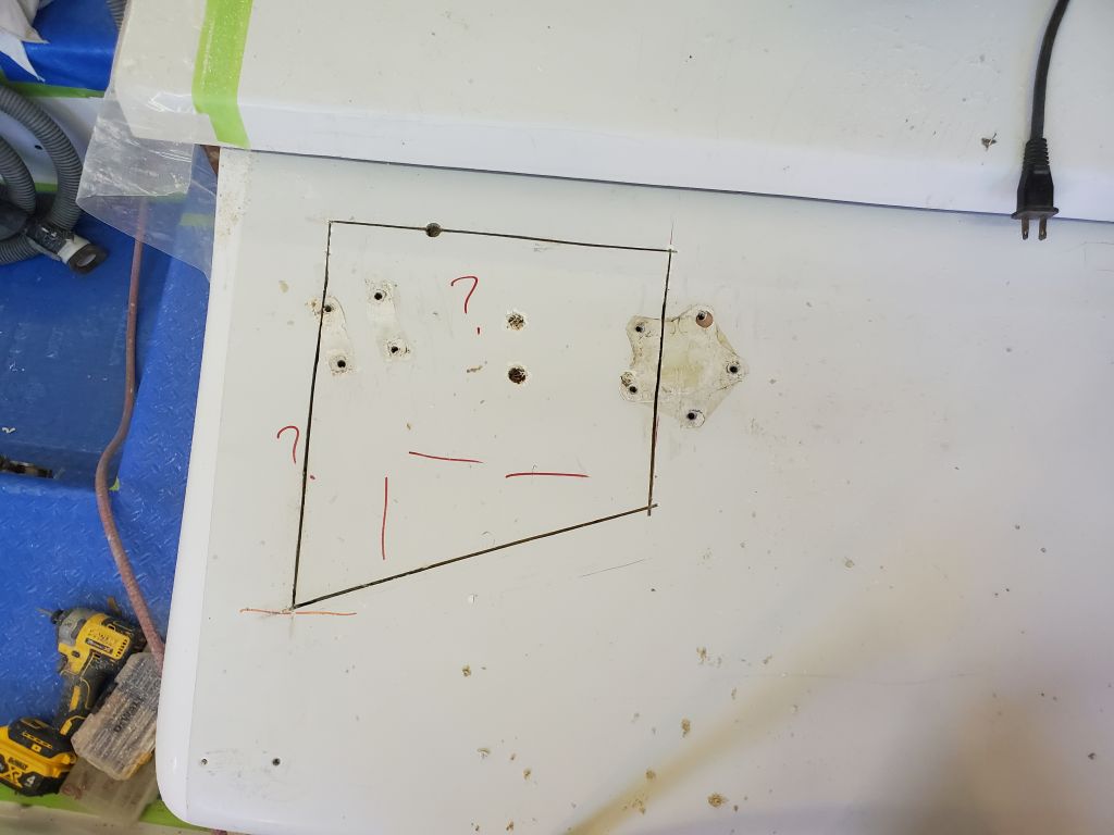
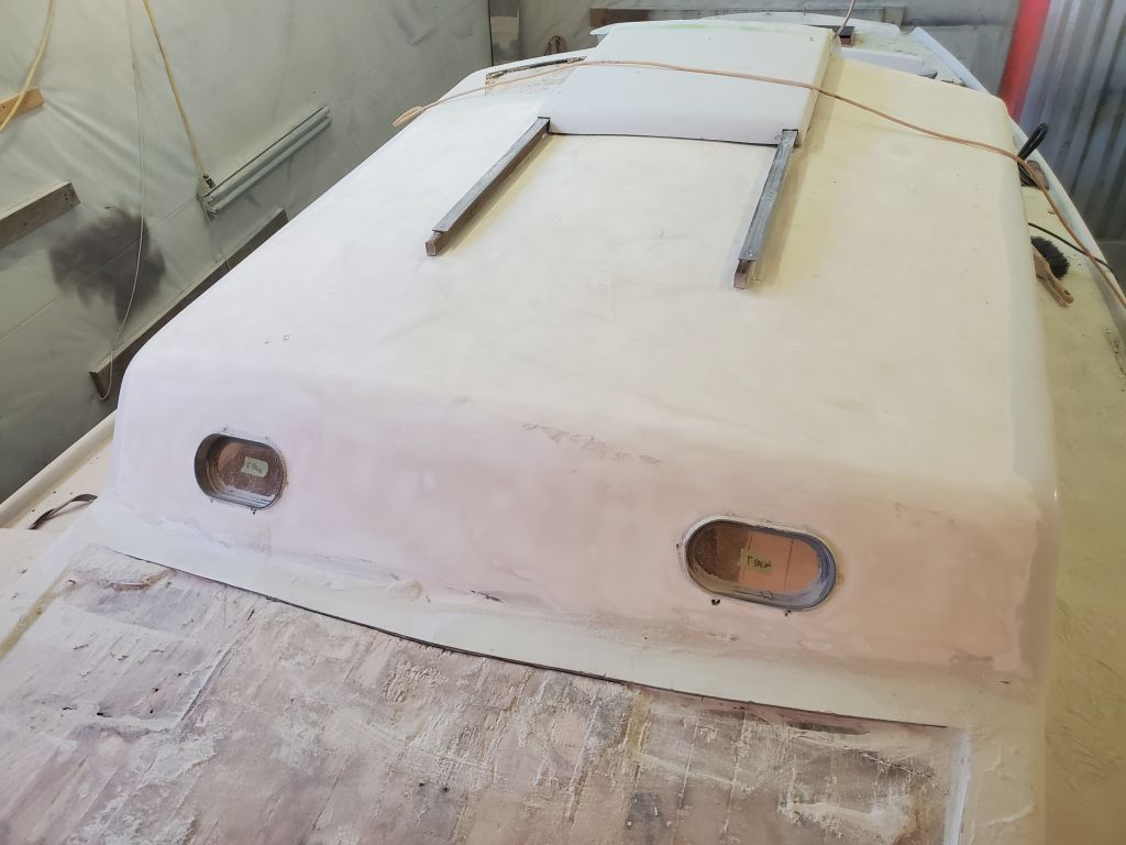
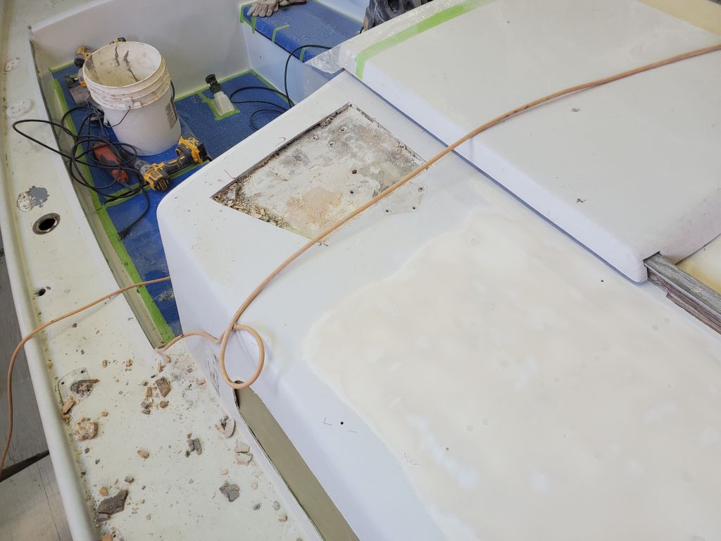
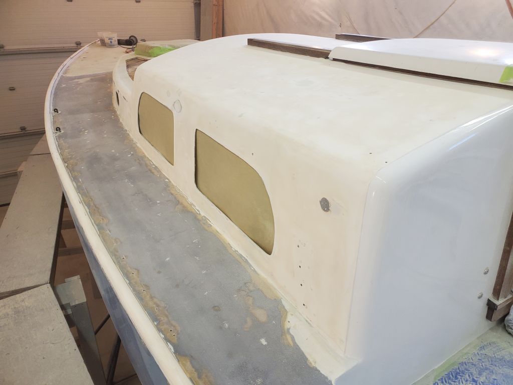
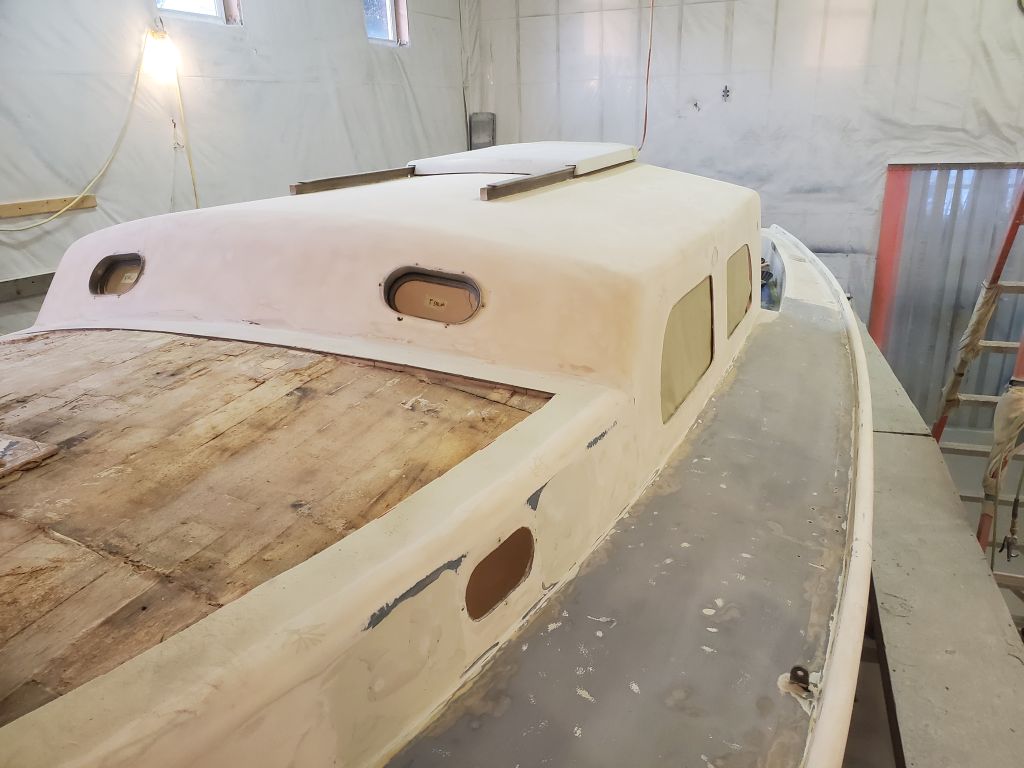
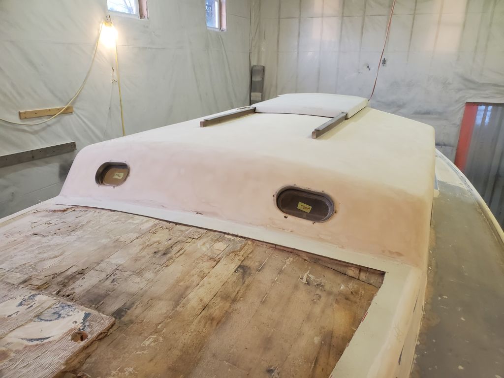
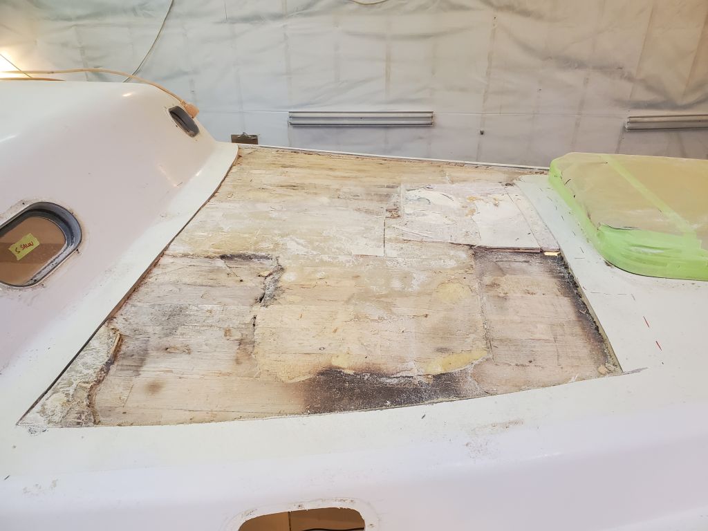
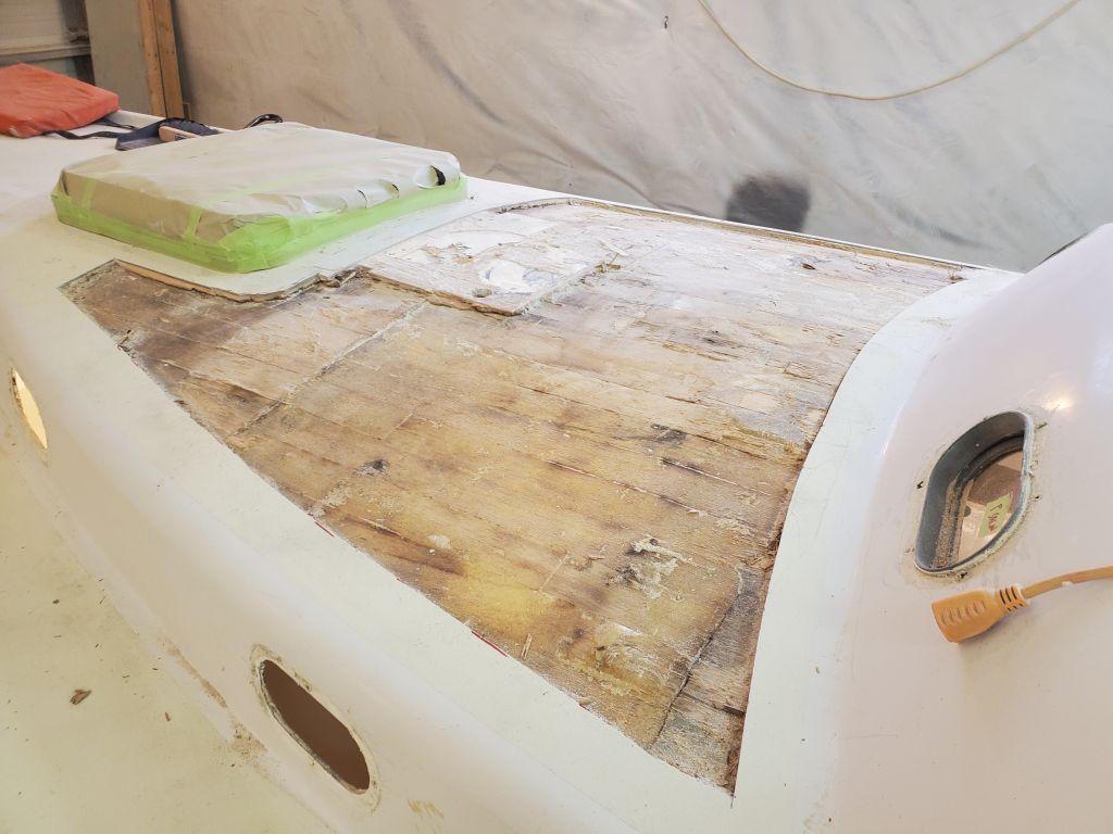
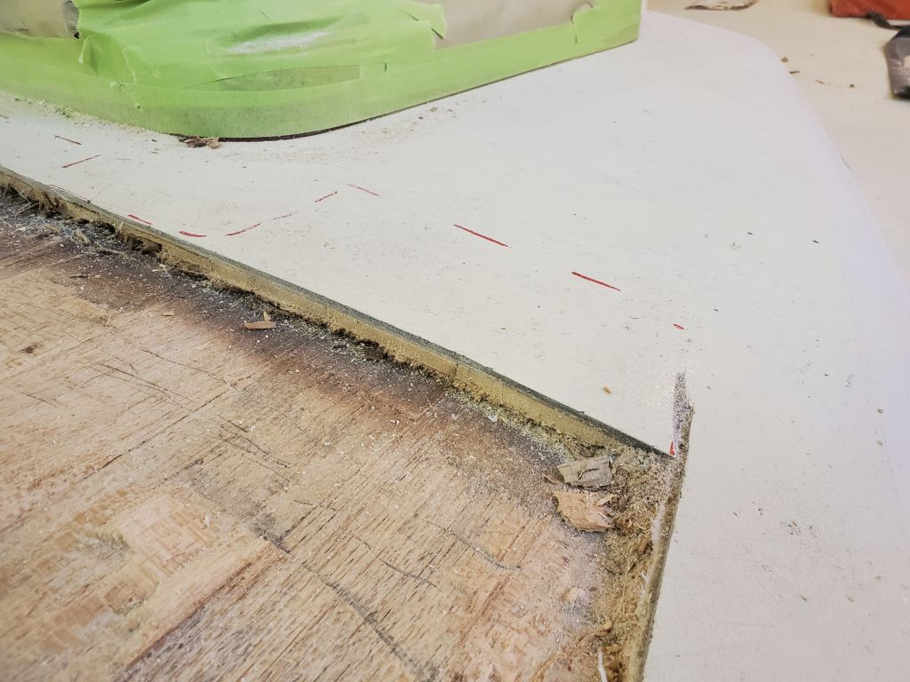
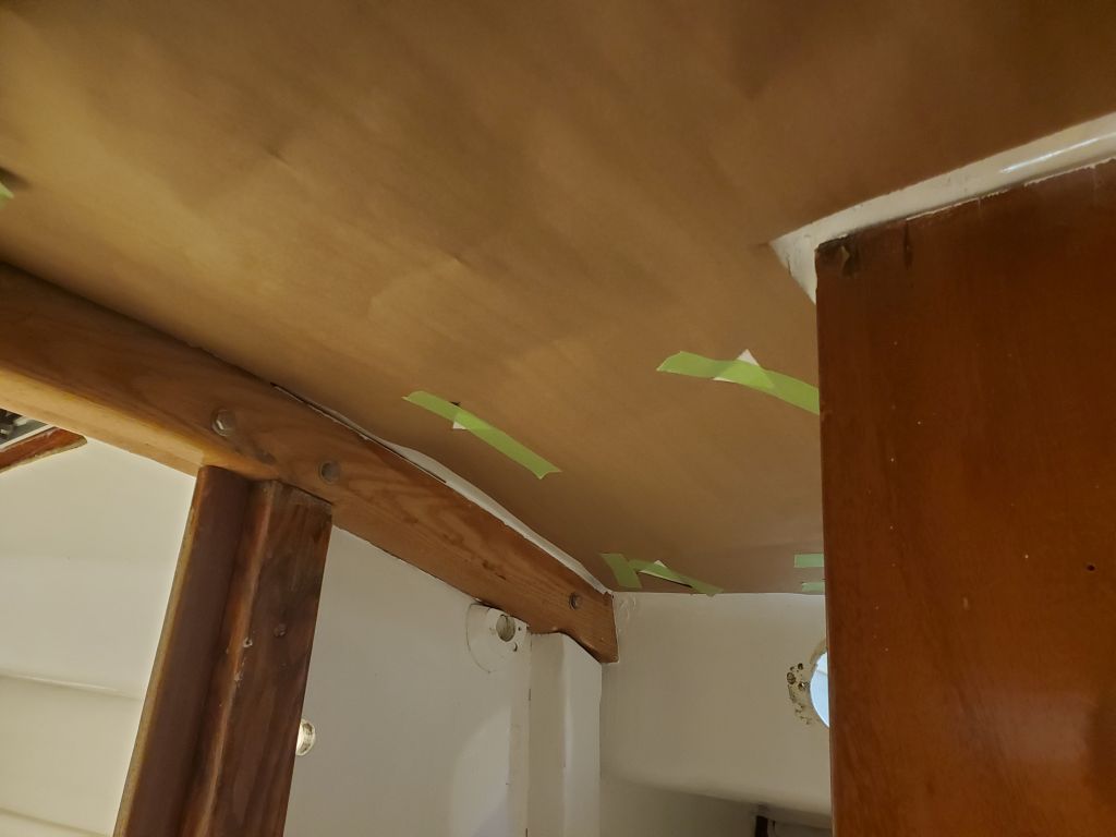
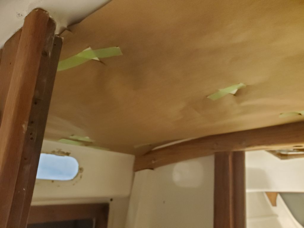
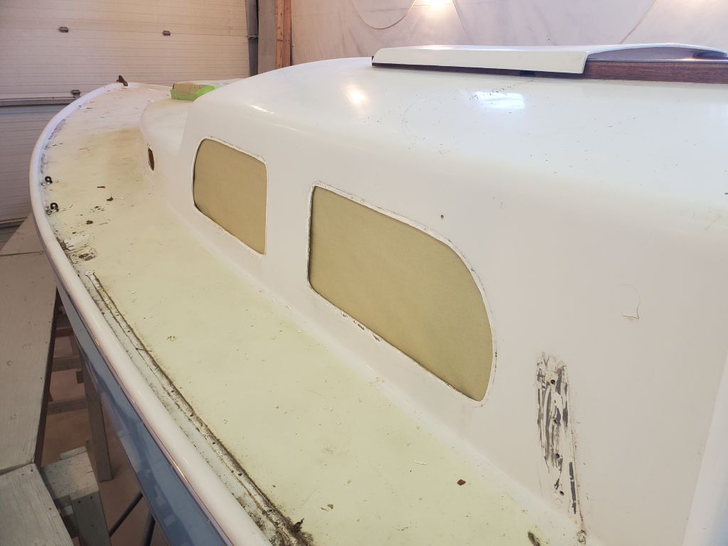
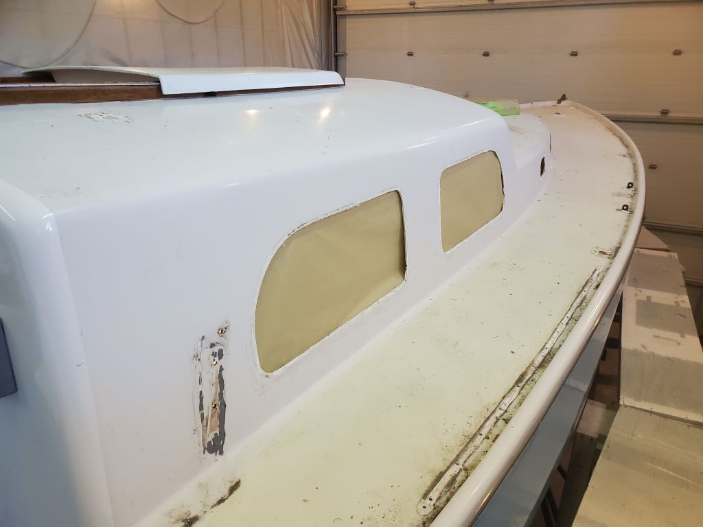
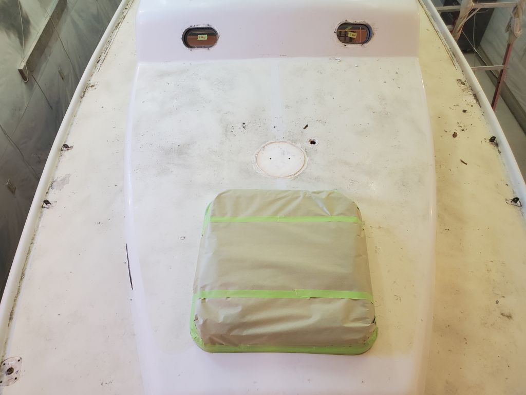
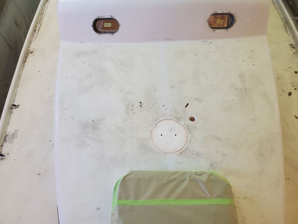
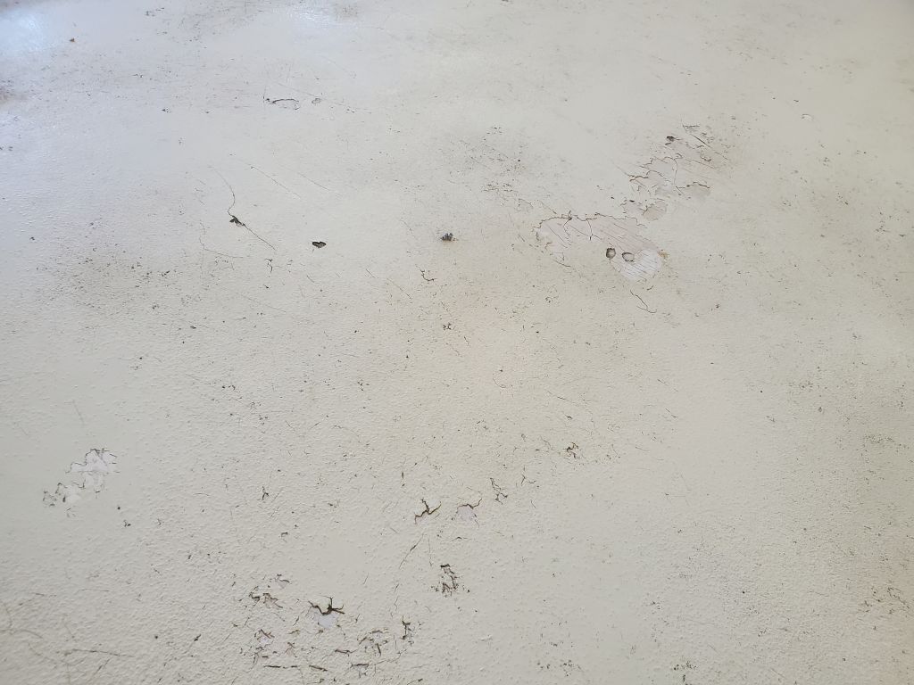
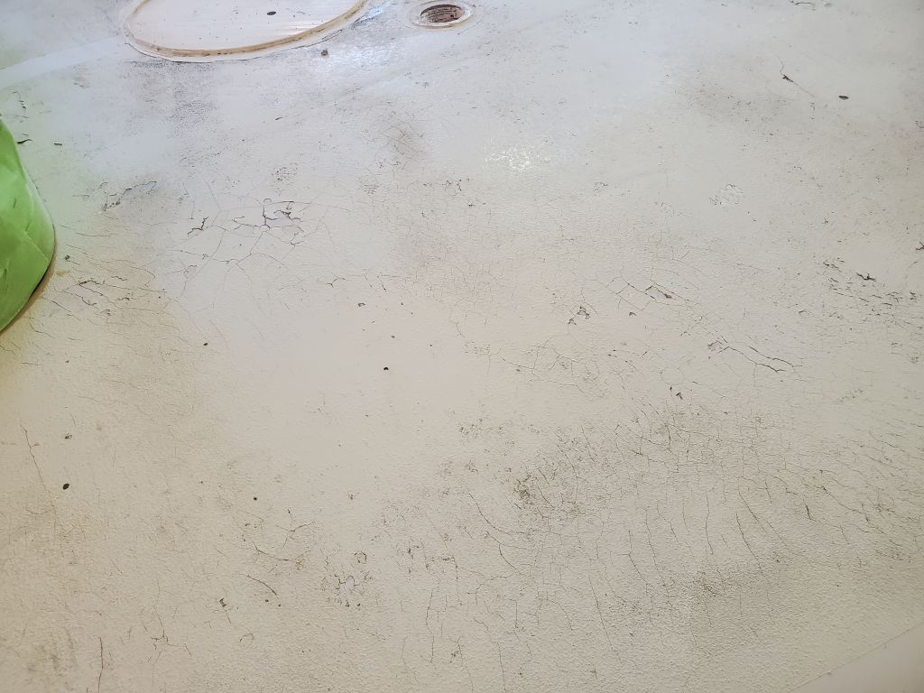
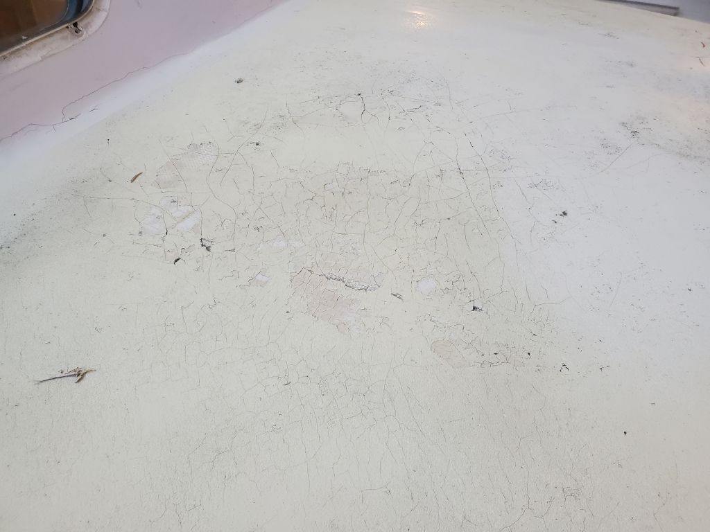
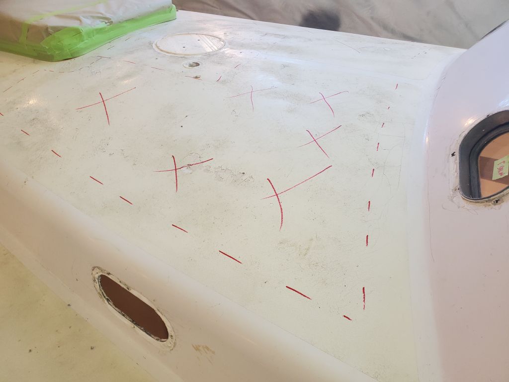
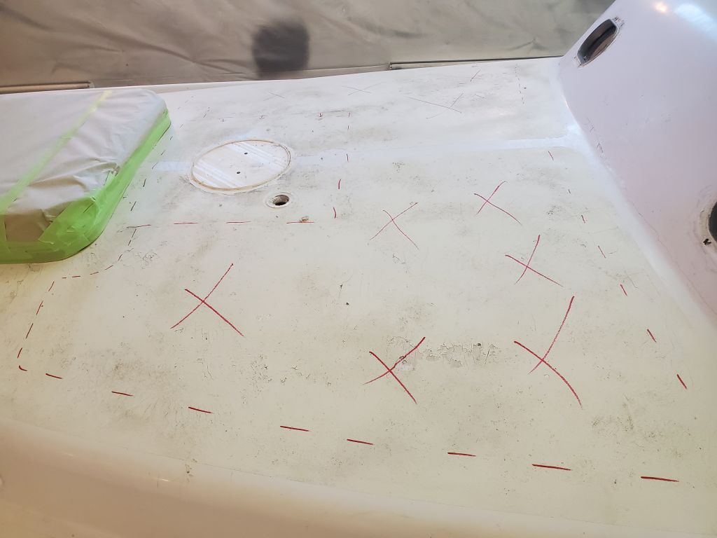
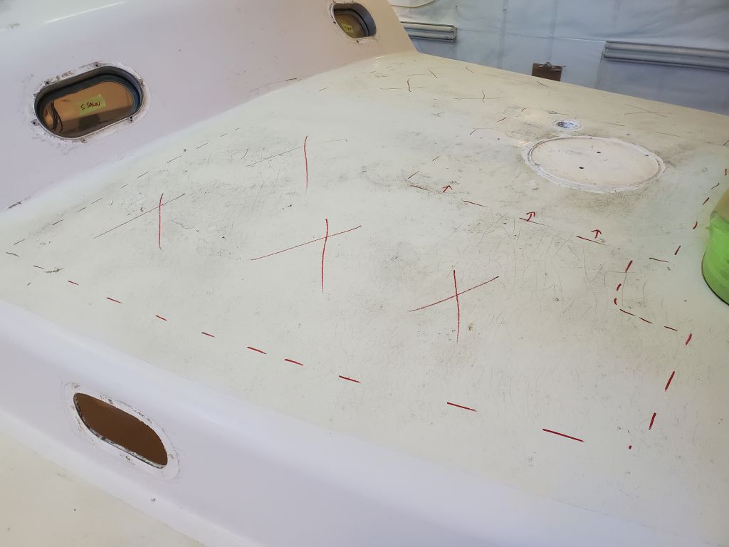
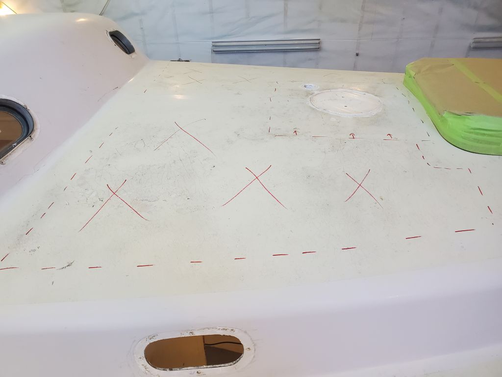
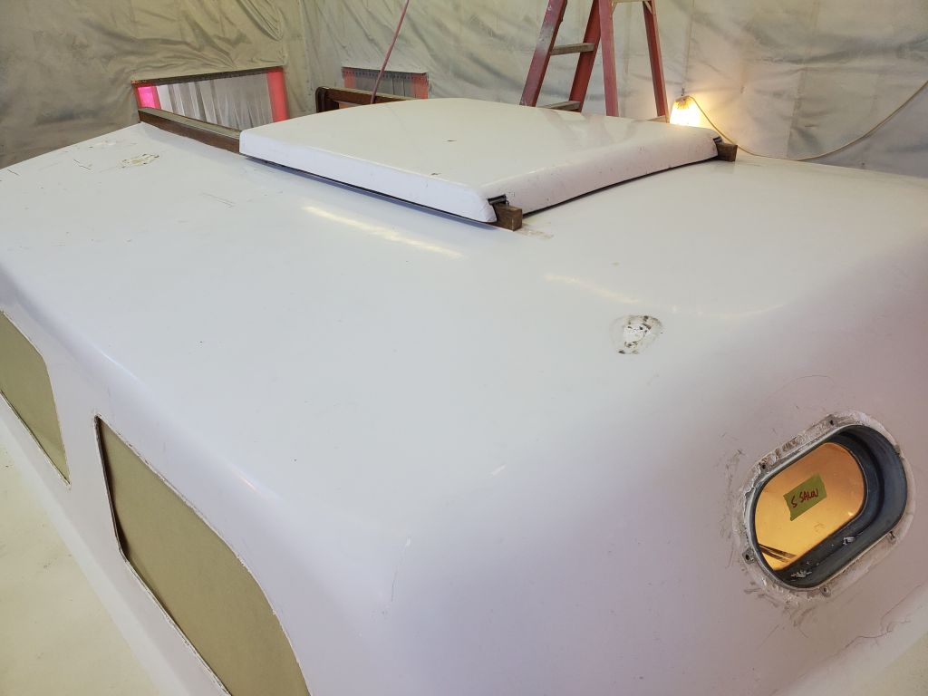
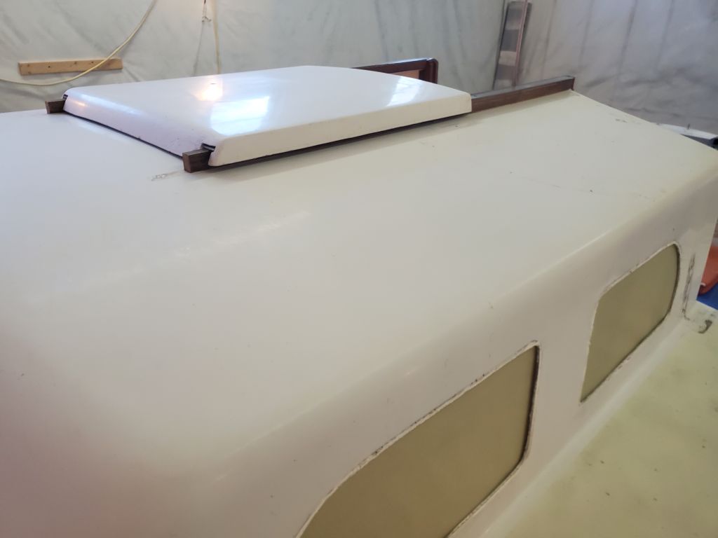
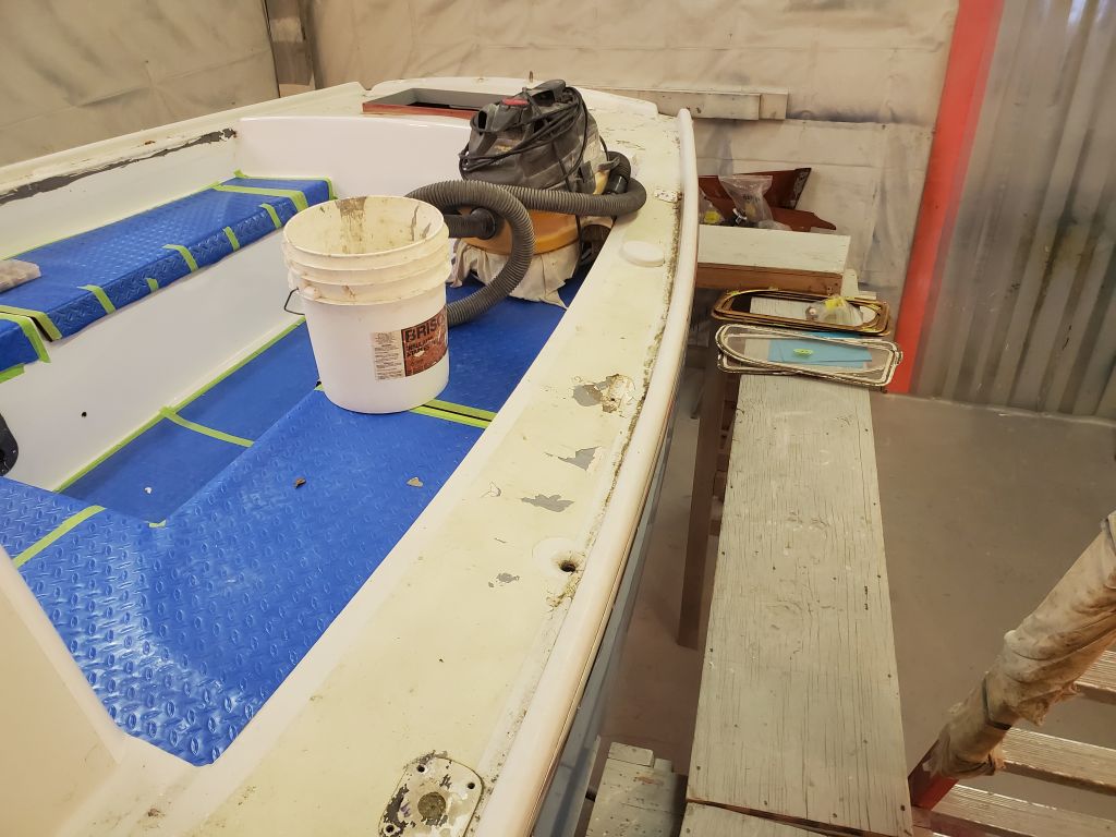
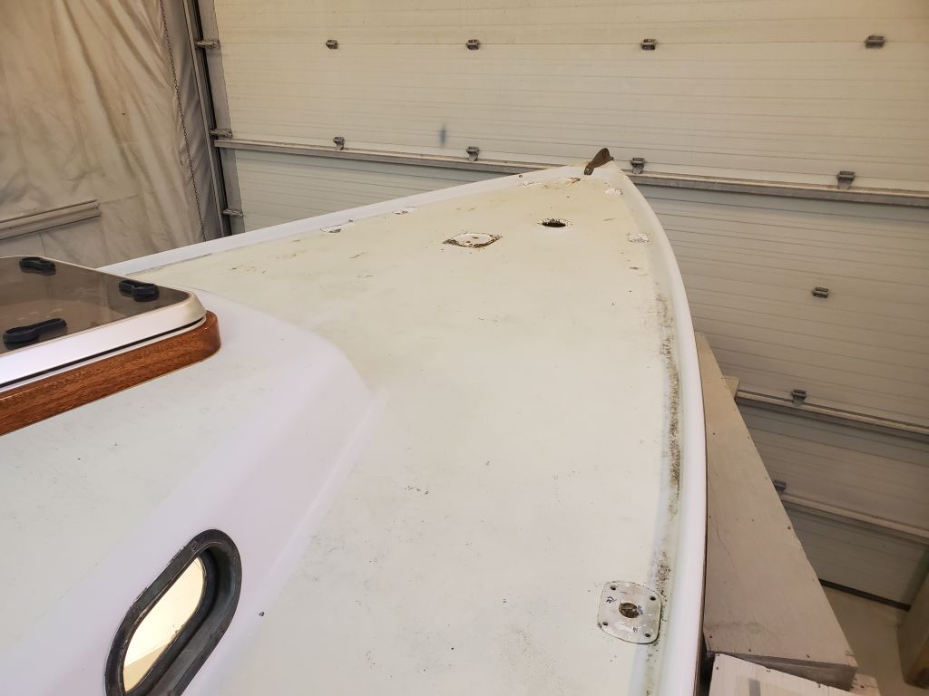
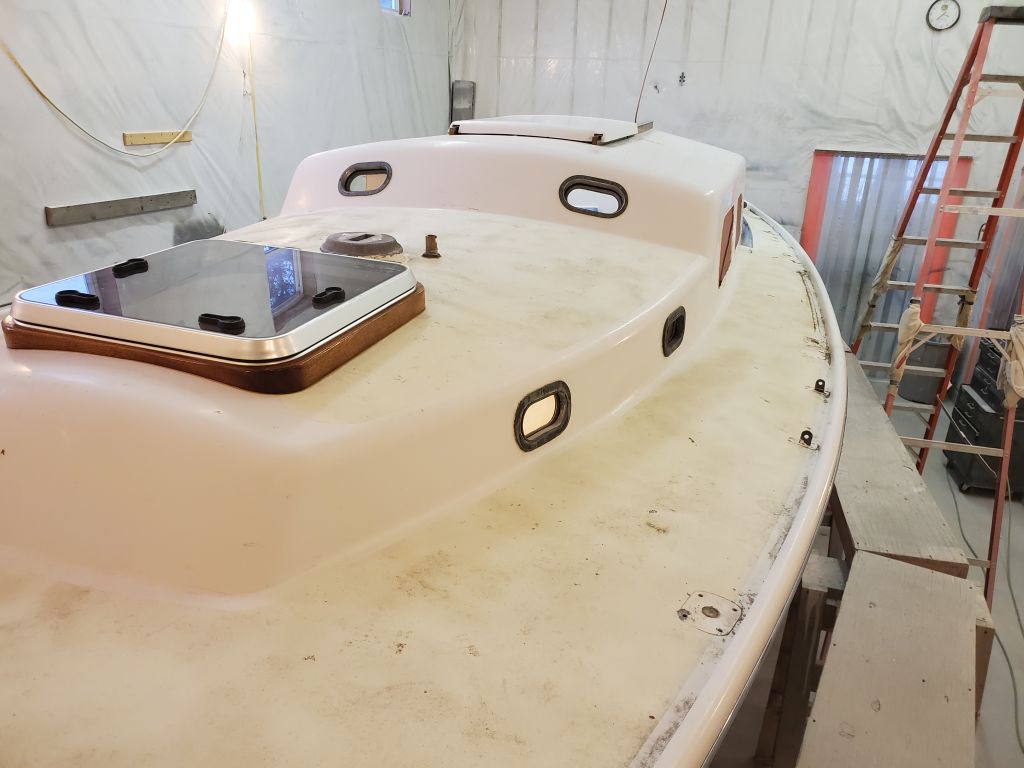
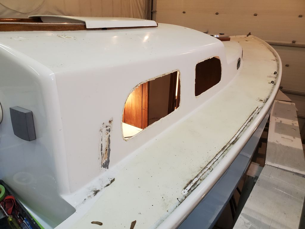
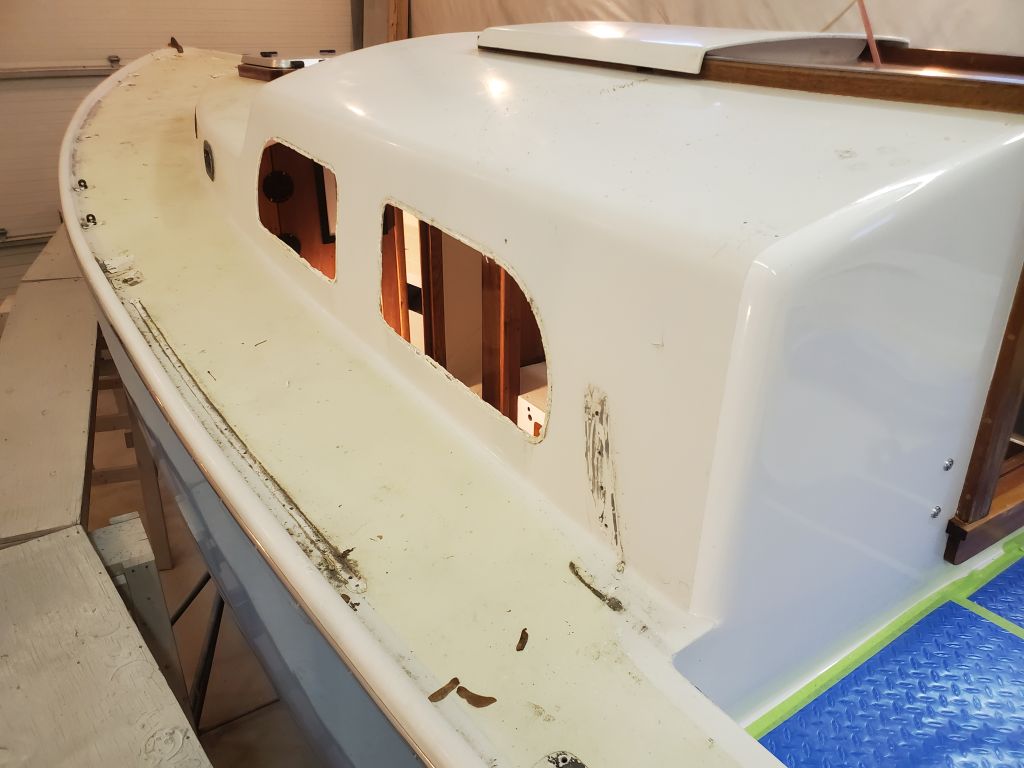
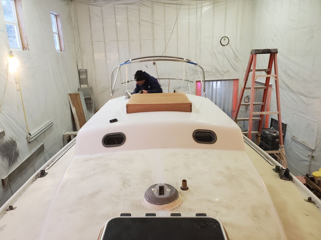
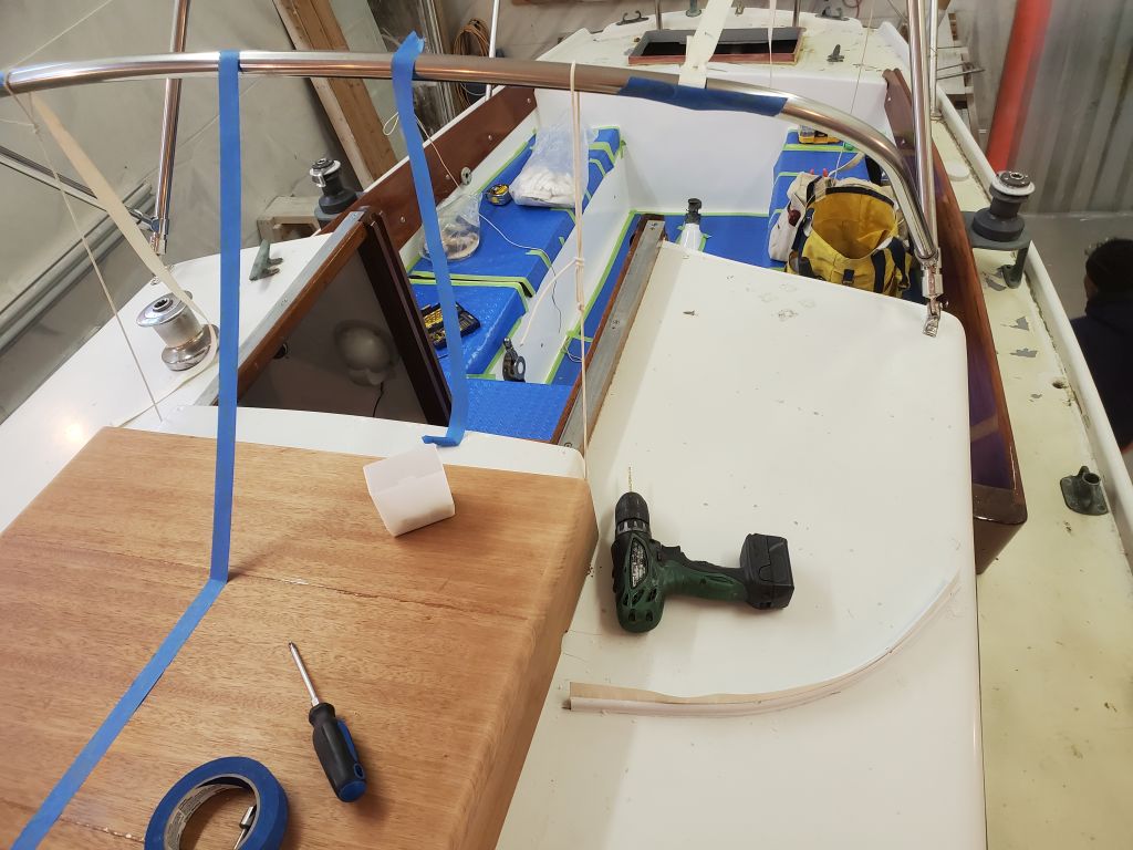
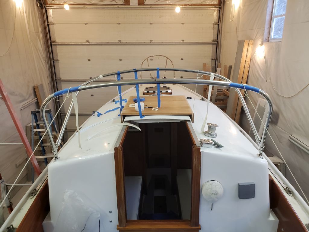
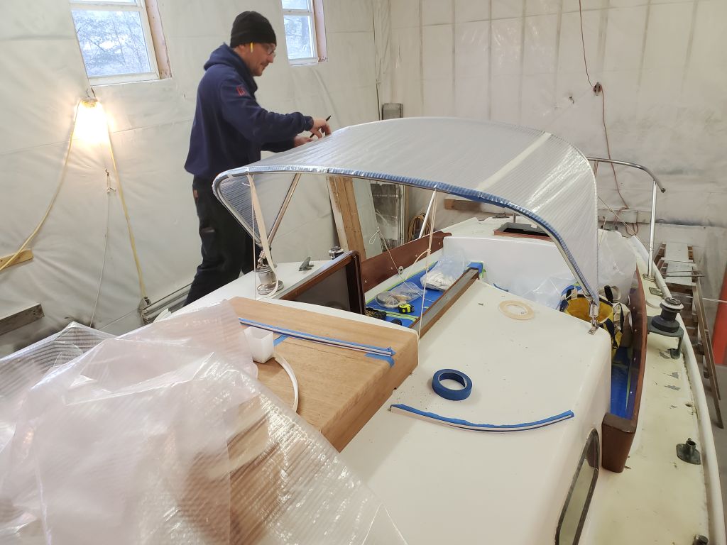
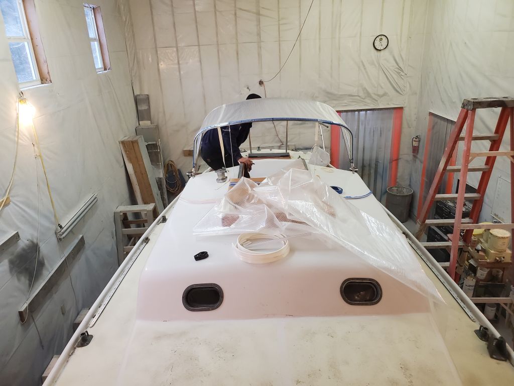
Beginning the repair work on the forward coachroof, I proceeded in the usual way. The condition of the deck seemed clear enough–extremely soft underfoot on either side, with paint damage and surface cracking to confirm the softness in a visual way. I’d already laid out my general cut lines, designed to leave ample deck surface at the edges for tying in the new work with the old, and now I set my saw to an appropriate depth to cut through the top skin and made the first cut along the aft edge of the deck, a few inches forward of the bump-up to the after section of the doghouse.
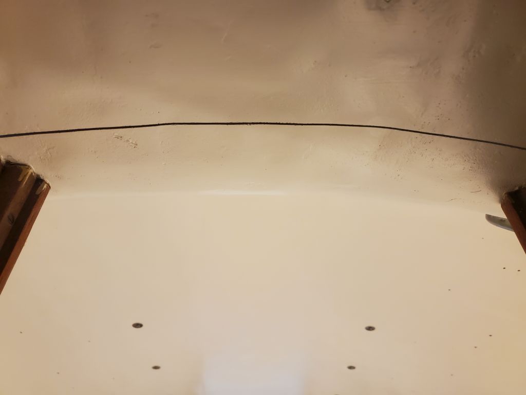
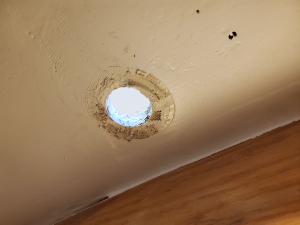
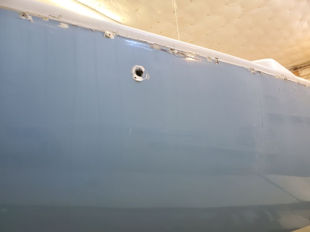
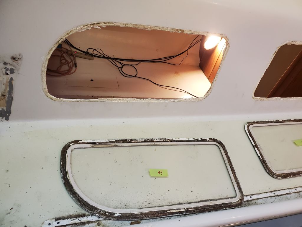
Finishing the cut, I was aghast to see light (coming from belowdecks) through the saw kerf. How could I have cut all the way through the deck?
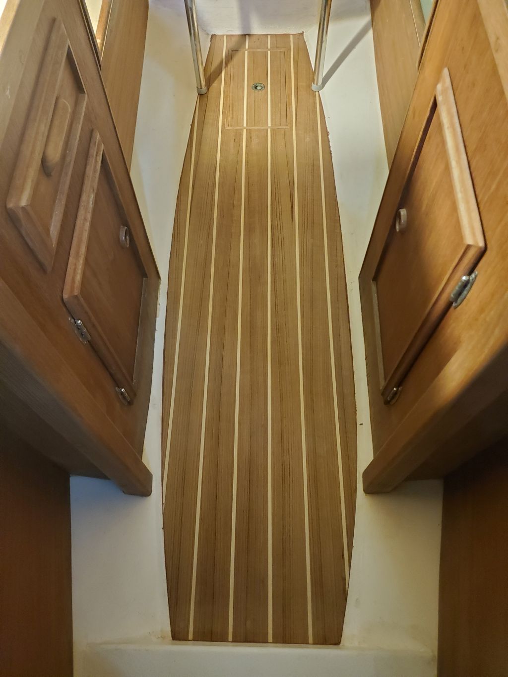
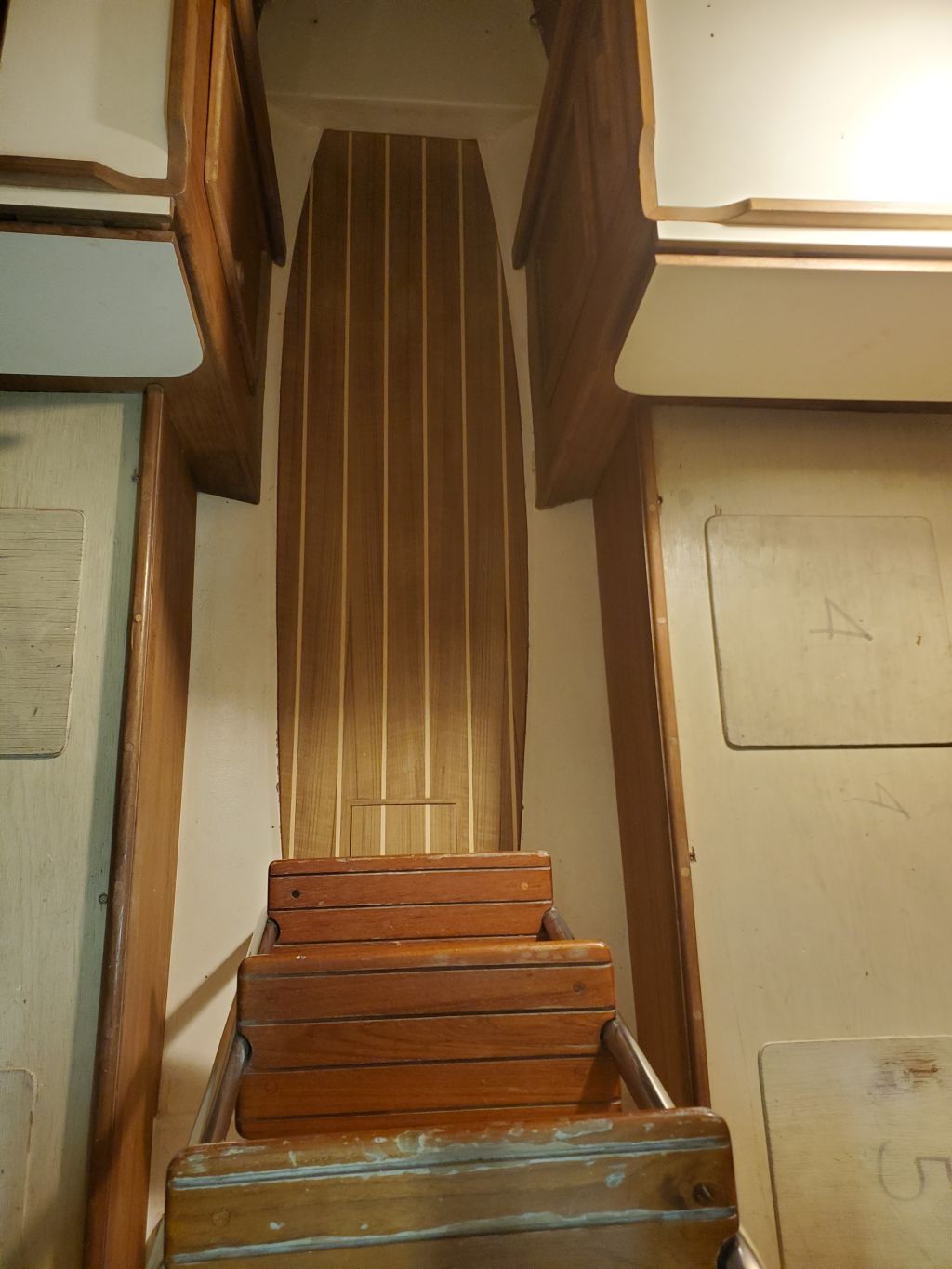
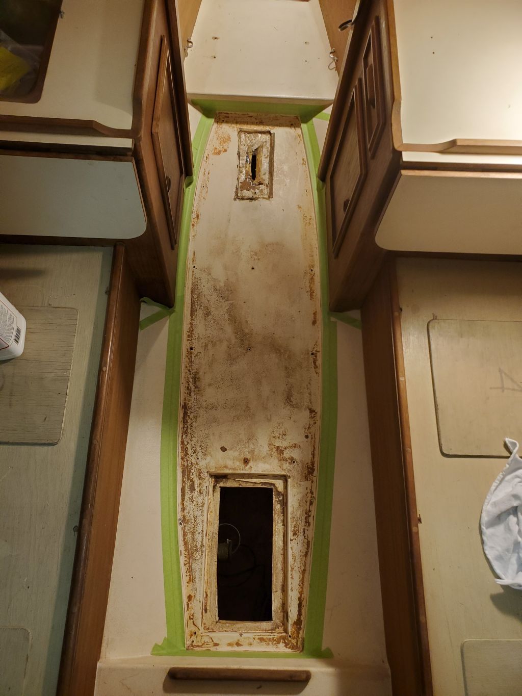
This did not compute, so I immediately went below, to discover that indeed the saw had come through the bottom skin in the center portion of the head, just forward of the passageway opening. I was horrified, but still couldn’t–and didn’t–understand how that could have happened. But OK, I could and would deal with the mistake, and no substantial harm.
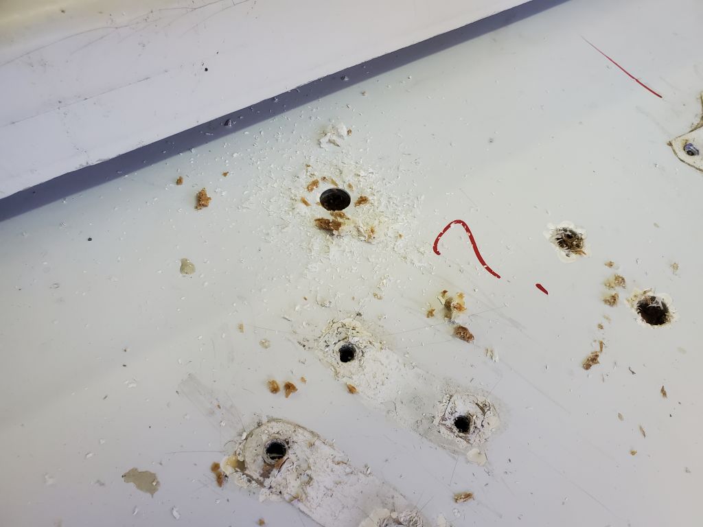
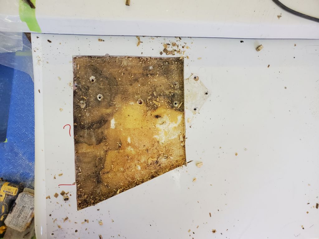
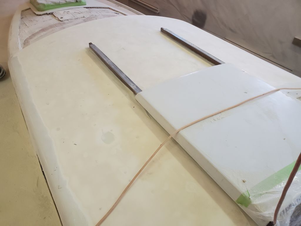
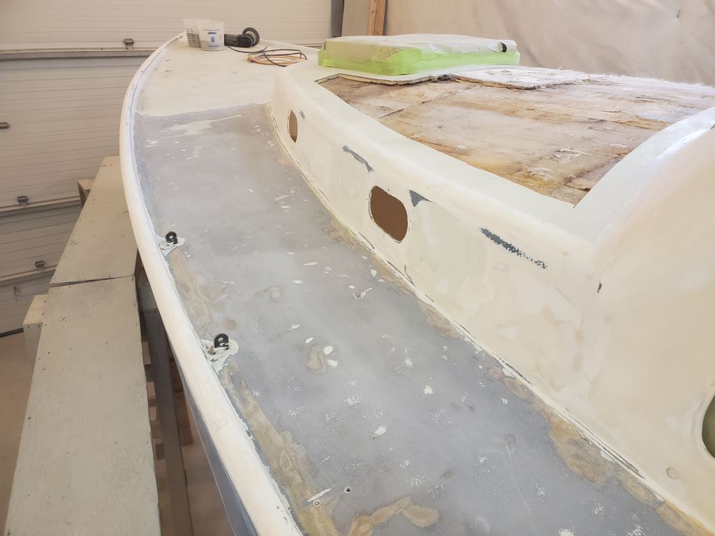
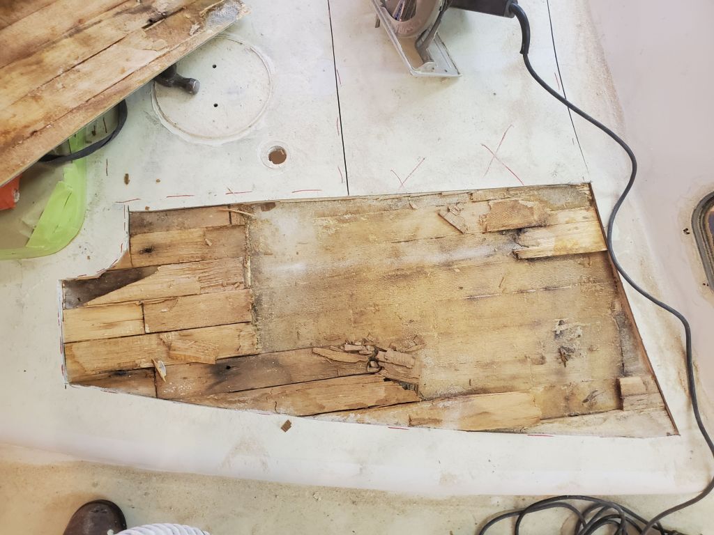
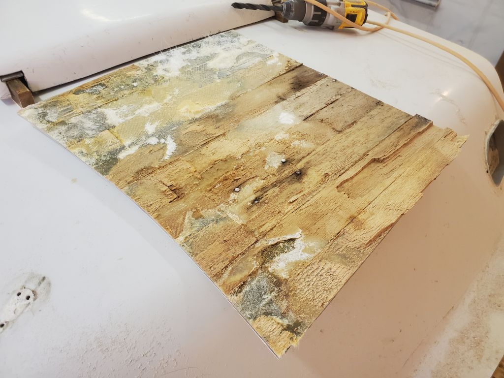
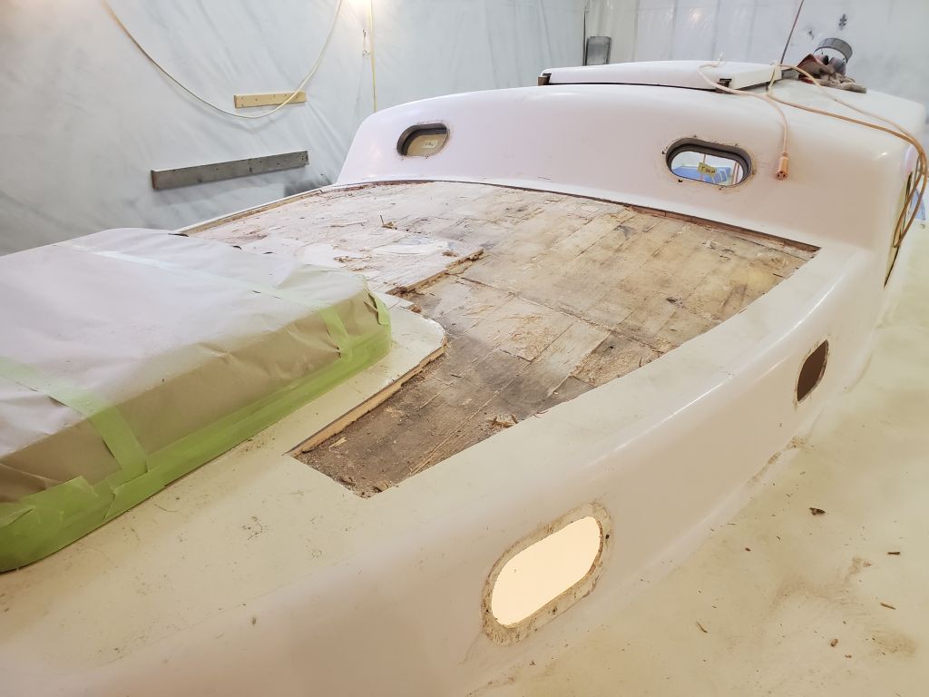
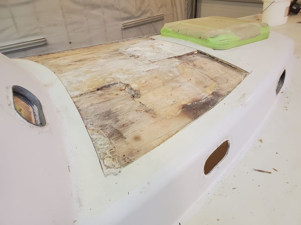
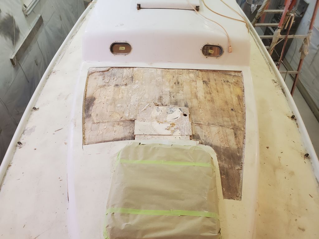
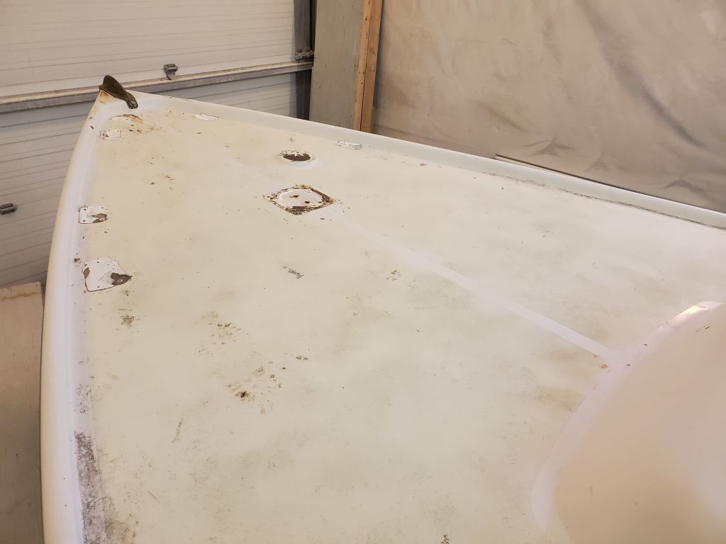
The cut line disappeared on either side of the passageway, which cheered me up a bit, so I carefully proceeded with additional cuts to release the first section of top skin for removal , a large piece on the port side, the area where the deck had been softest. To my horror, I found a few more sections of cut–and I’d even exposed less of the saw blade for these cuts out of an abundance of caution–where the kerf had gone through the inner skin again. How could this be? Eventually, and carefully–though the deck had to come apart one way or another–I removed enough of the top skin where I could begin to piece together what was happening beneath, keeping the saw cuts a bit further back from where I’d originally intended to cut, and with the blade set as shallowly as possible. In this way, I exposed most of the structure throughout the part of the deck I’d intended to quickly cut open and dismantle.
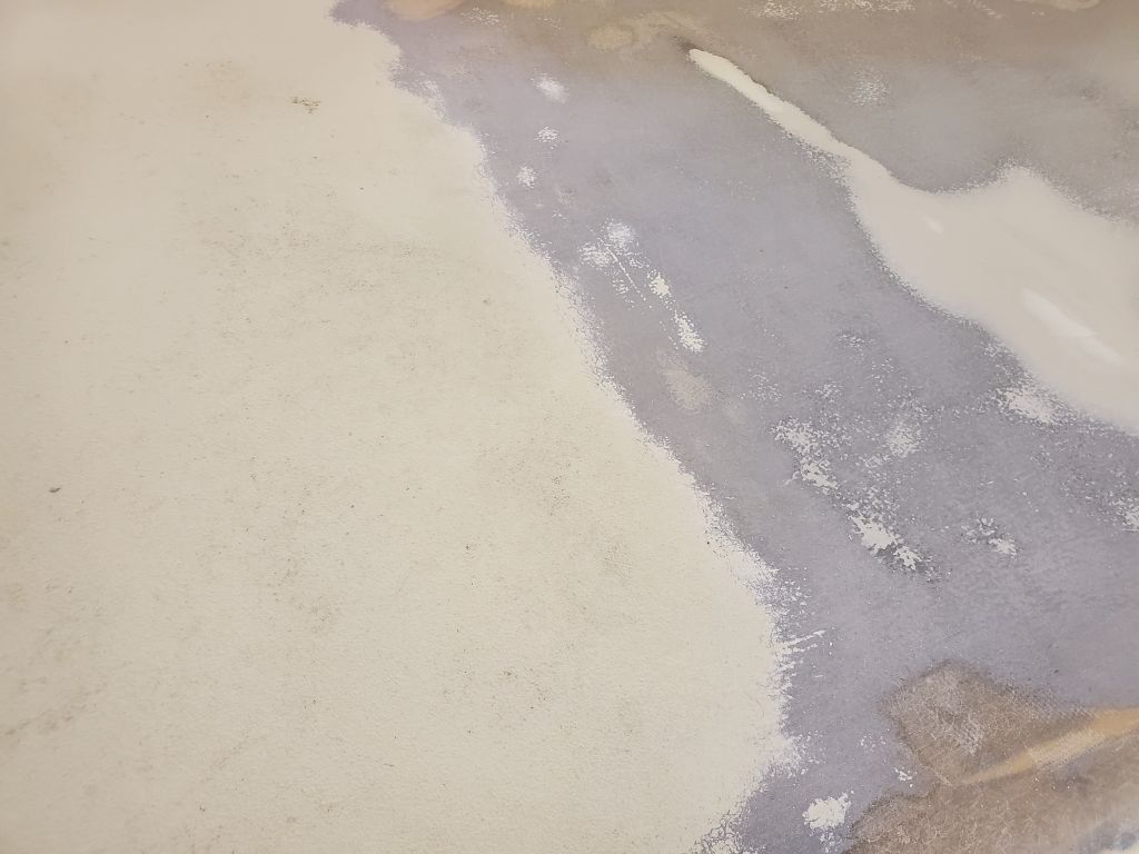
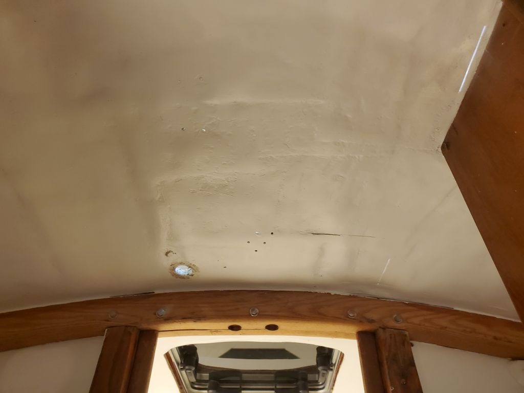
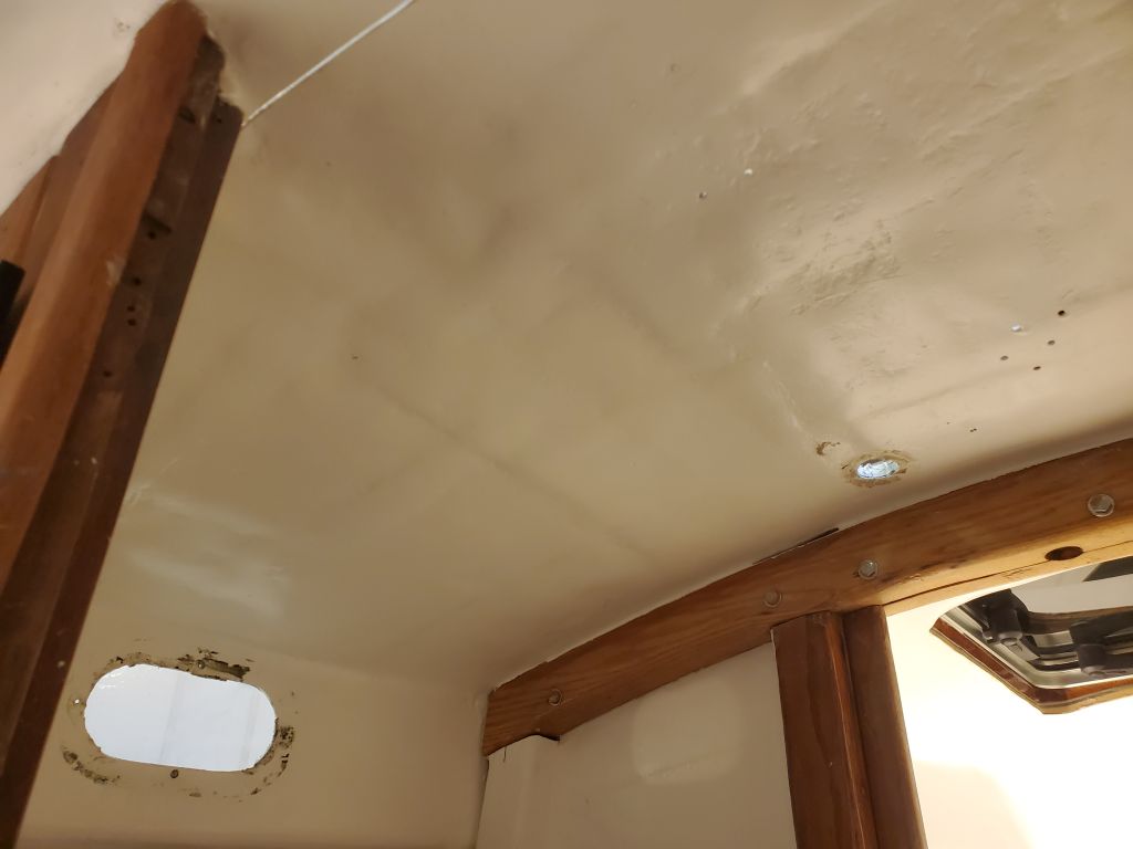
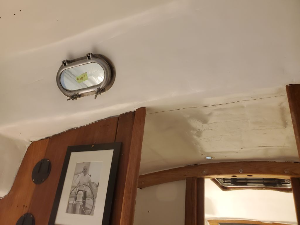
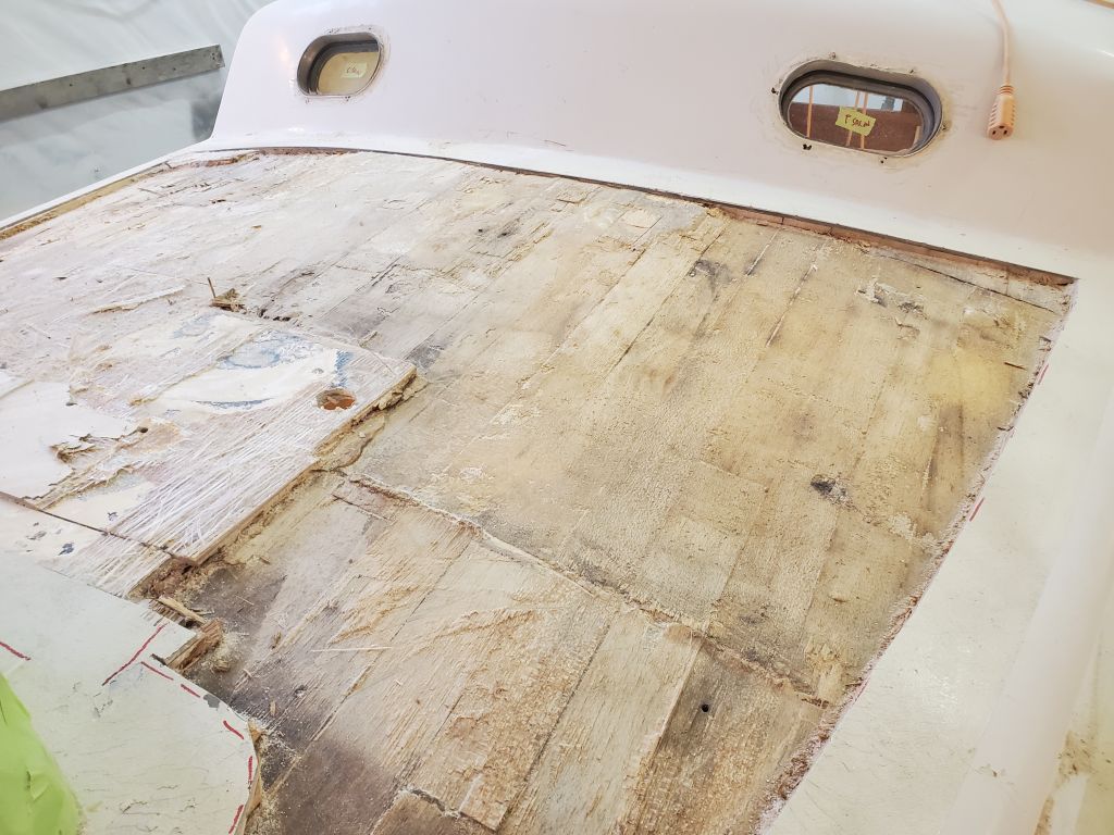
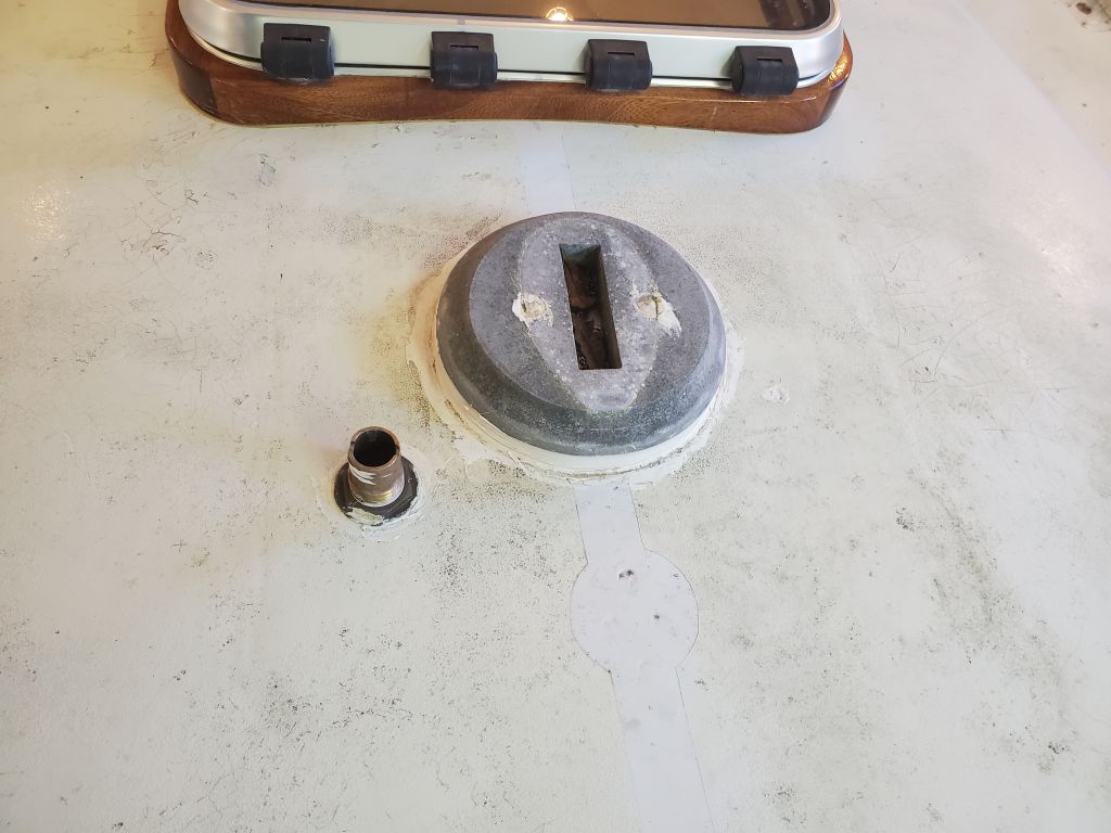
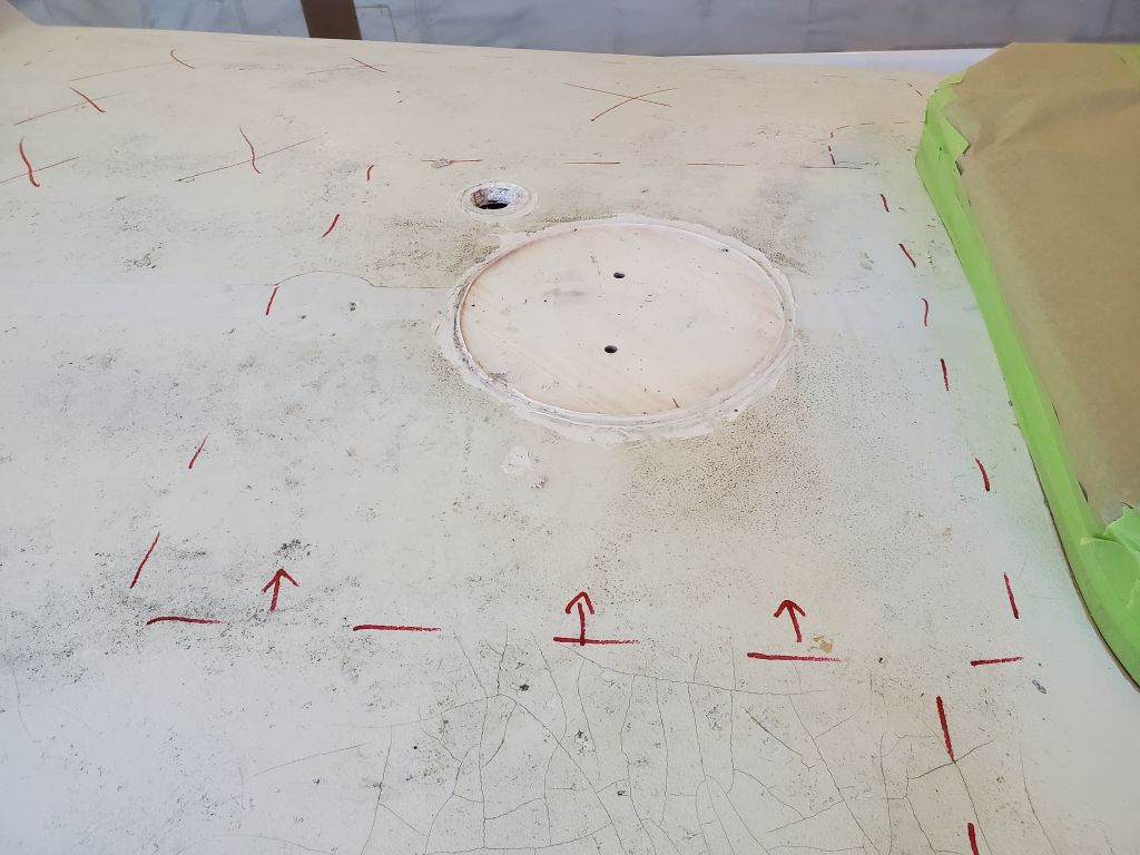
First of all, the old core was the balsa planks used in the earlier Tritons, before they switched to end-grain blocks later in the production series. I’d forgotten about that particular bit of Triton lore, but it didn’t explain the other things I was seeing and experiencing. The core planks were generally dry, but the adhesion between both top and bottom skins was poor to nonexistent, which had ultimately led to the overall structural failure. All normal and expected, and still unrelated to the way the saw had gone through the deck in the center. But now I could see that the inner skin, as it were, came right up and met the top skin in the centerline area where I’d had the kerf problem. It’s notable that the top skin here peeled away cleanly and with only minimal bonding to the fiberglass below, highlighting again the inadequacy of the previous work. The only place I had any trouble removing the top fiberglass was over the mast step, which area featured some sort of solid material directly beneath the step (some sort of prefab material, as yet undetermined).
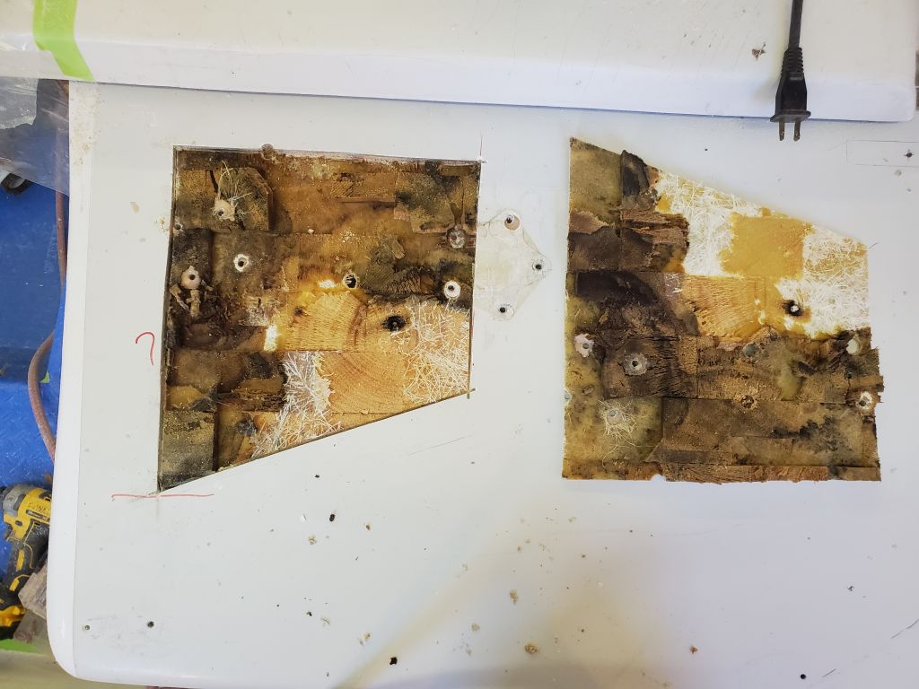
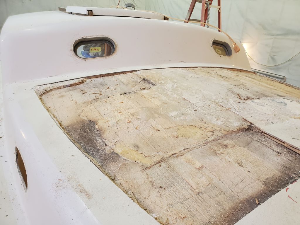
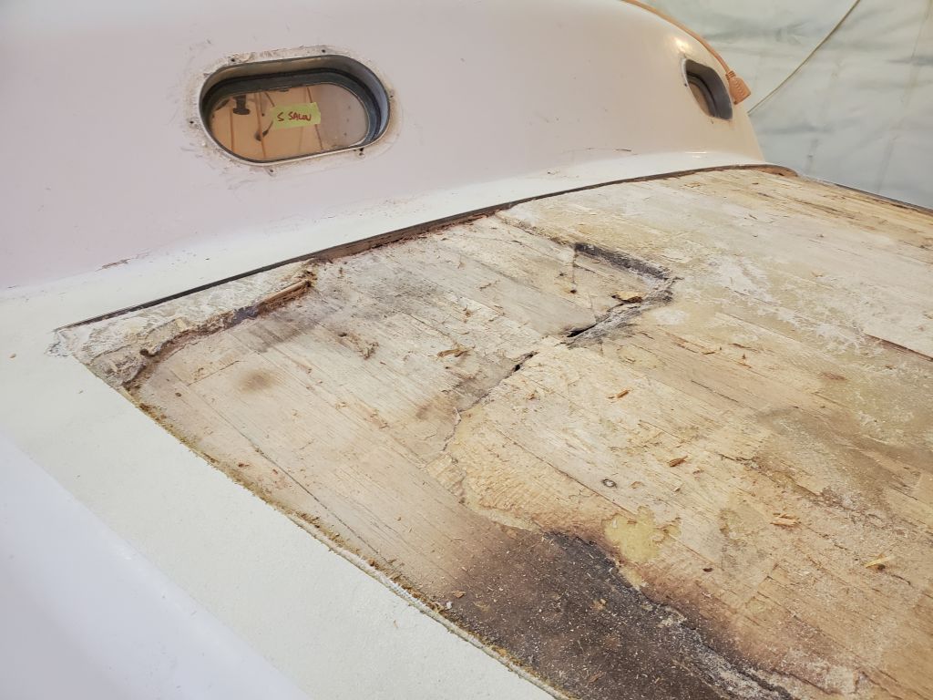
Apparently, some person (and I use the term generously) had done some horrendous work to the area from below. The previous “repair” apparently had replaced some of the core (from below) with solid glass, so there was now a newer inner skin applied directly to the underside of the original top skin. This previous repair person had just removed whatever core was bad, left the rest in place, and put on some fiberglass from beneath. Now, exposing things from the top, the picture finally began to come together. When I did my interior work to the boat during phase 1, I’d certainly noticed the lumpy-bumpy characteristics of the underside of the deck in the head, but it wasn’t anything unusual as far as Tritons go: the older ones, especially, all feature that sort of sloppy and rough glasswork, and there were no signs that pointed to this sort of issue. Because the deck had never been repaired from above, there were no signs of this weirdness from the surface either. Given the known history of this boat, and some of the previous repair work (under previous ownerships) for which we have documentation, there were other strange and semi-catastrophic things that had been dealt with previously, so from that perspective these findings made more sense than they might have otherwise, but this still hadn’t been enough to actually “expect” to find this sort of atrocity.
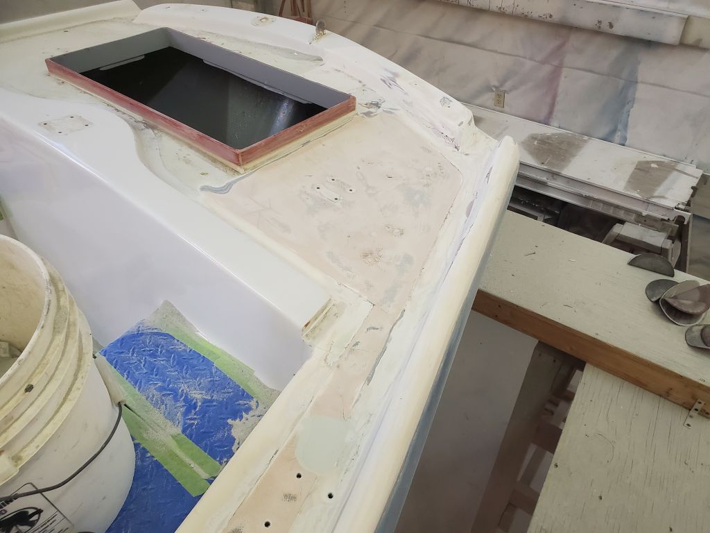
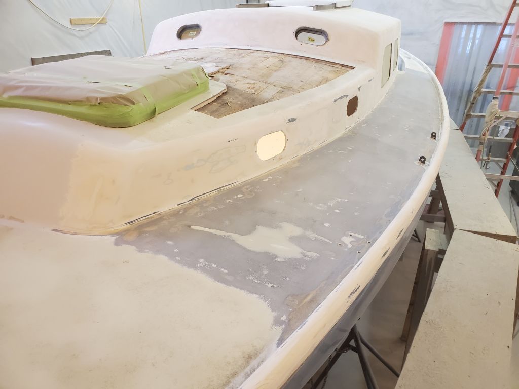
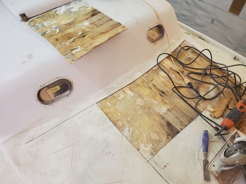
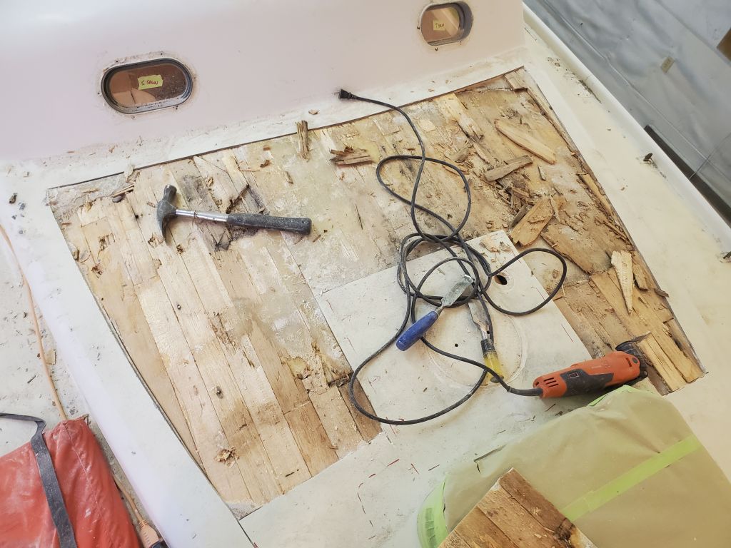
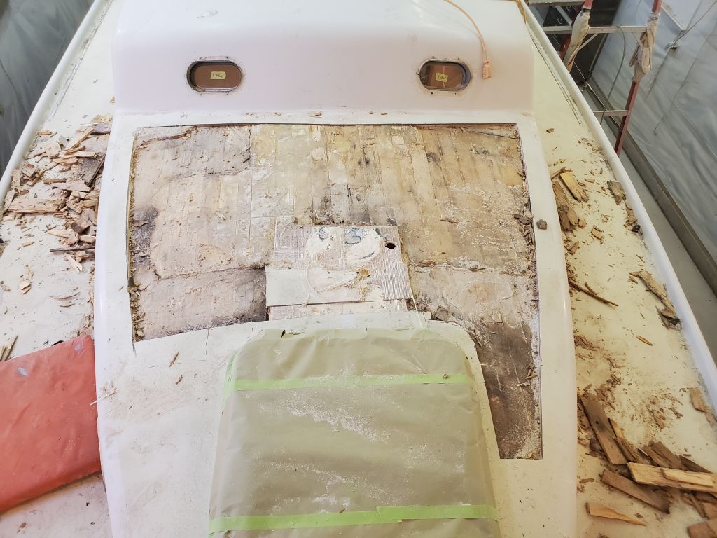
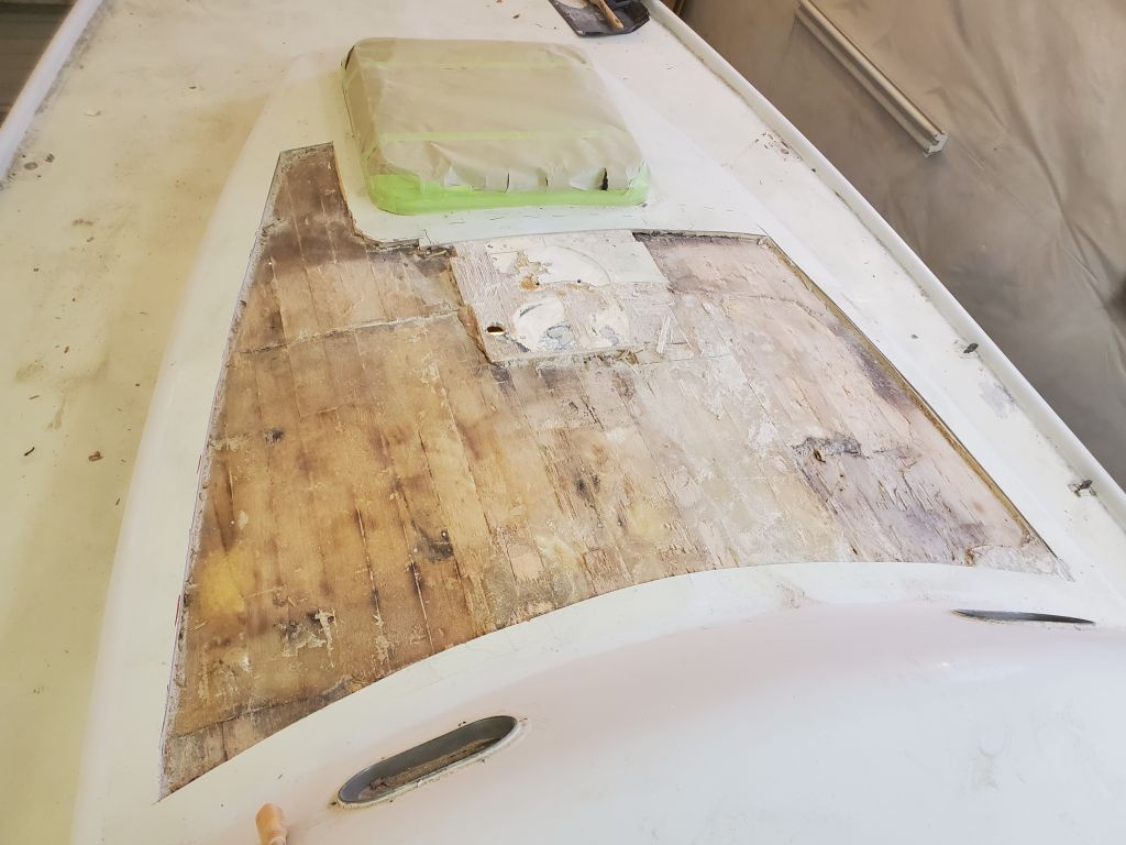
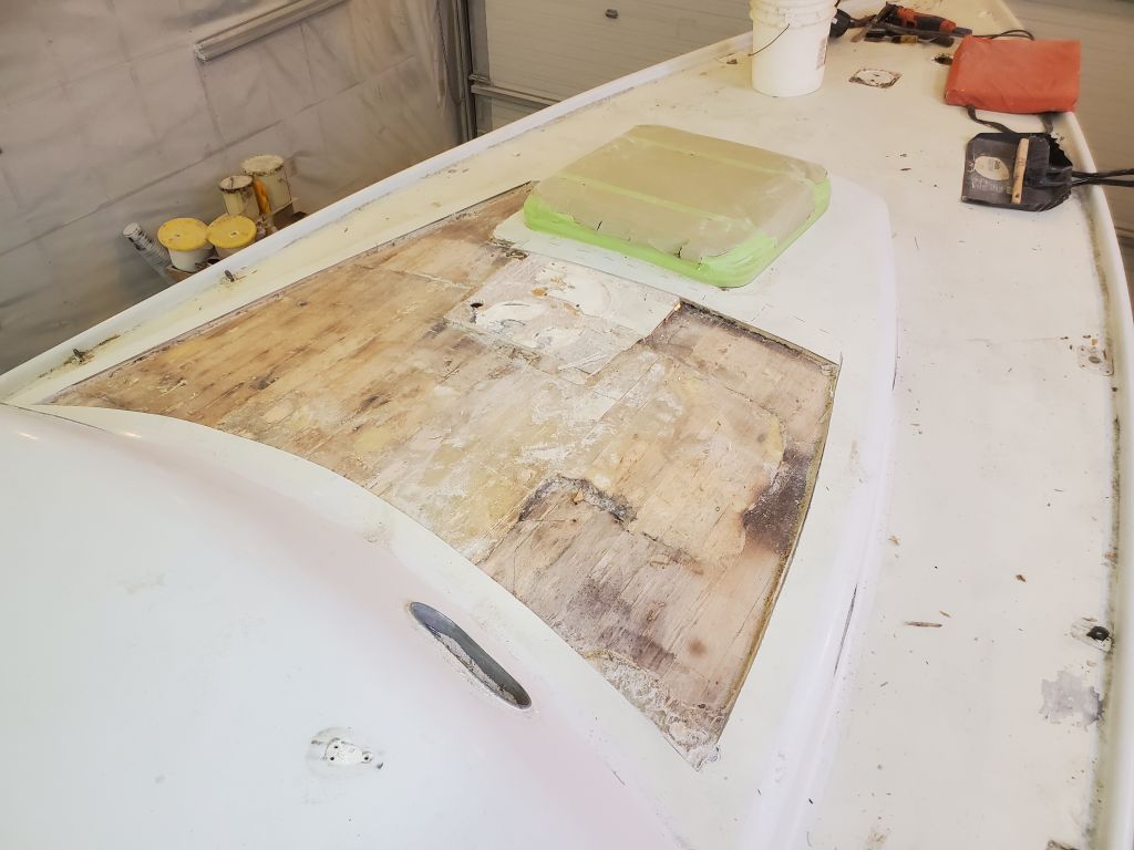
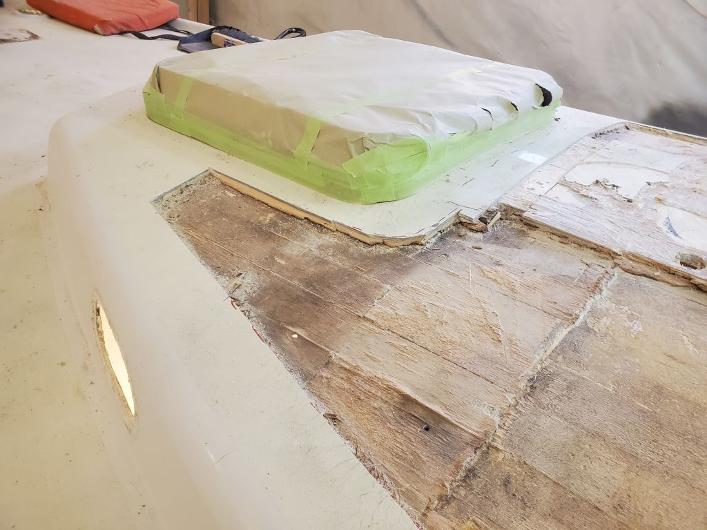
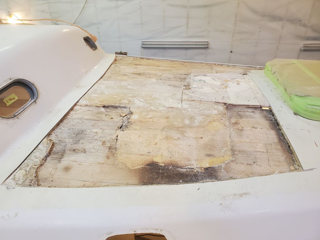
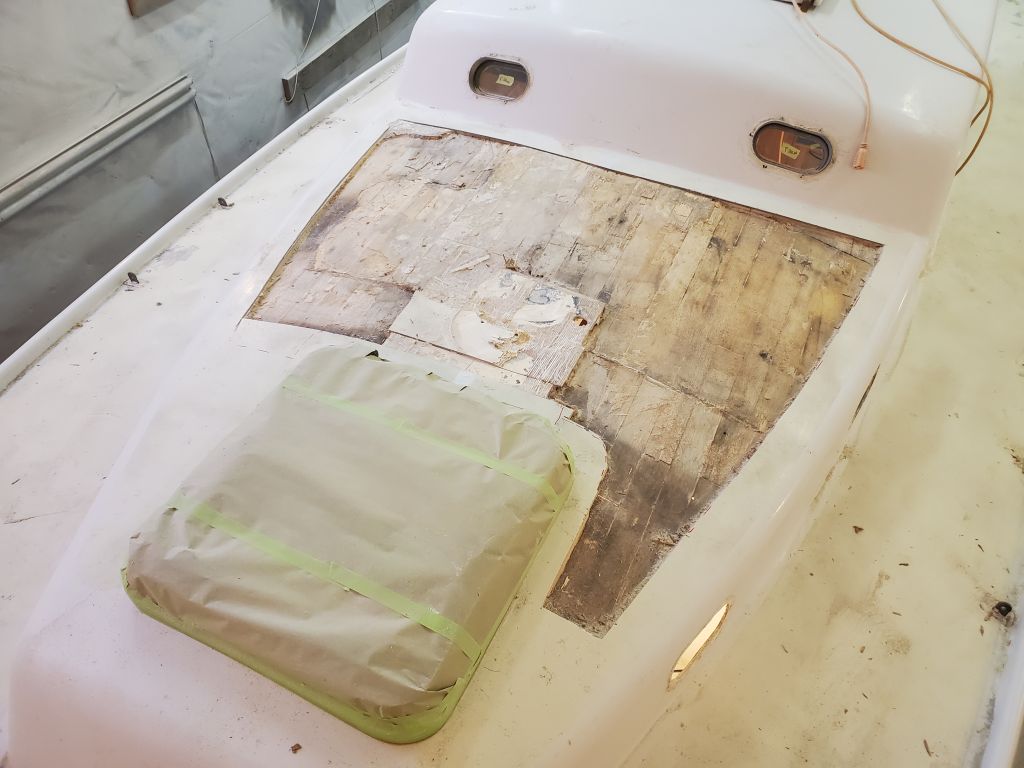
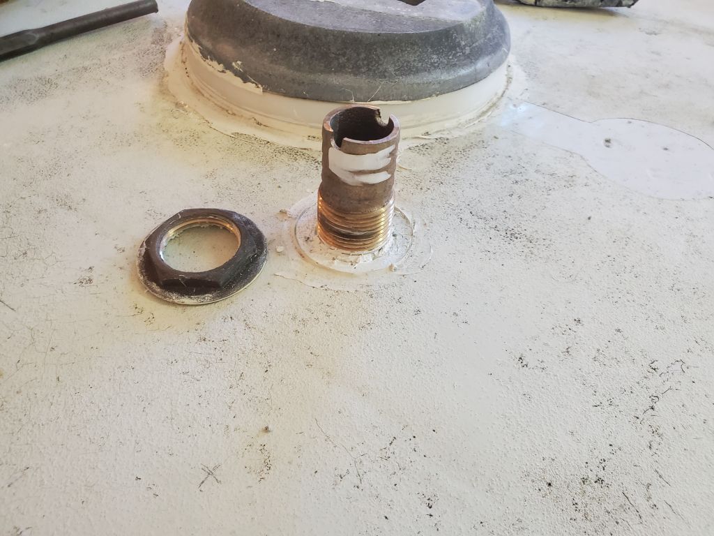
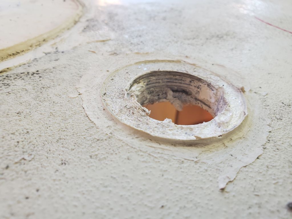
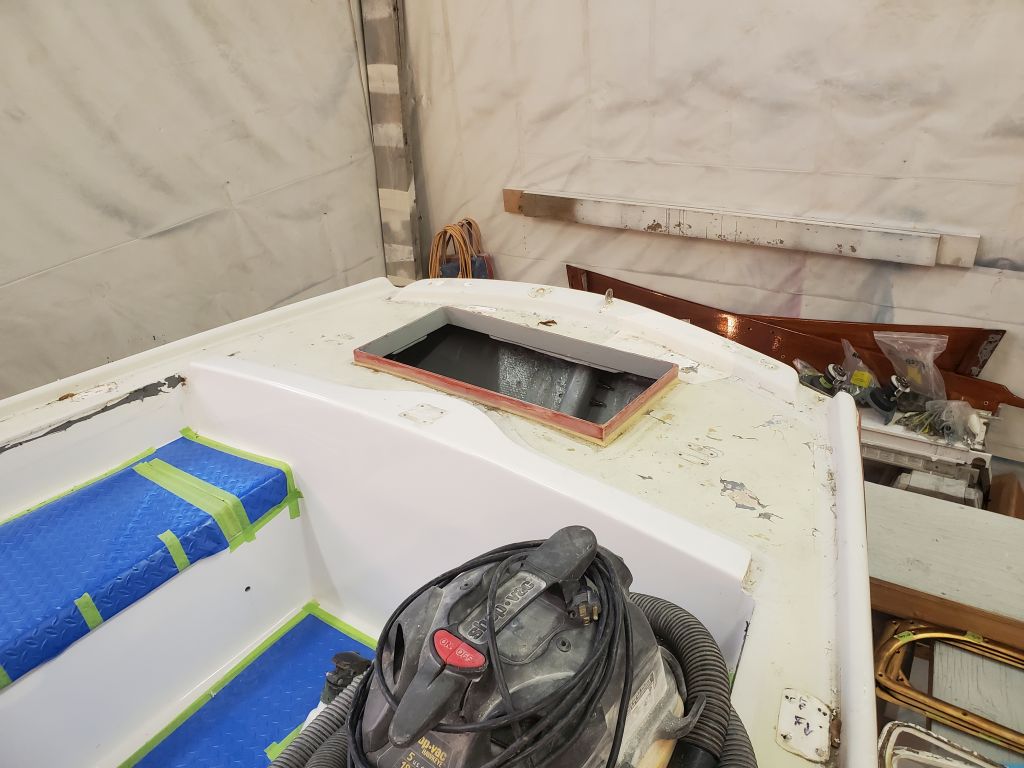
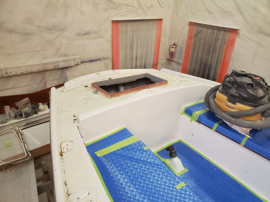
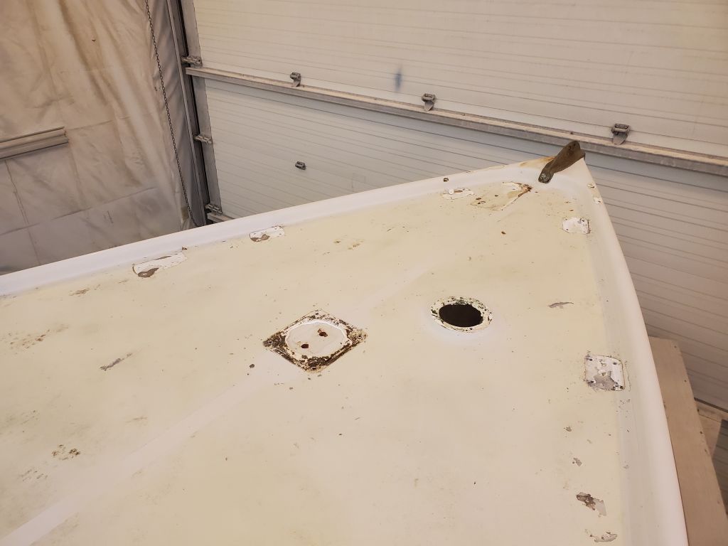
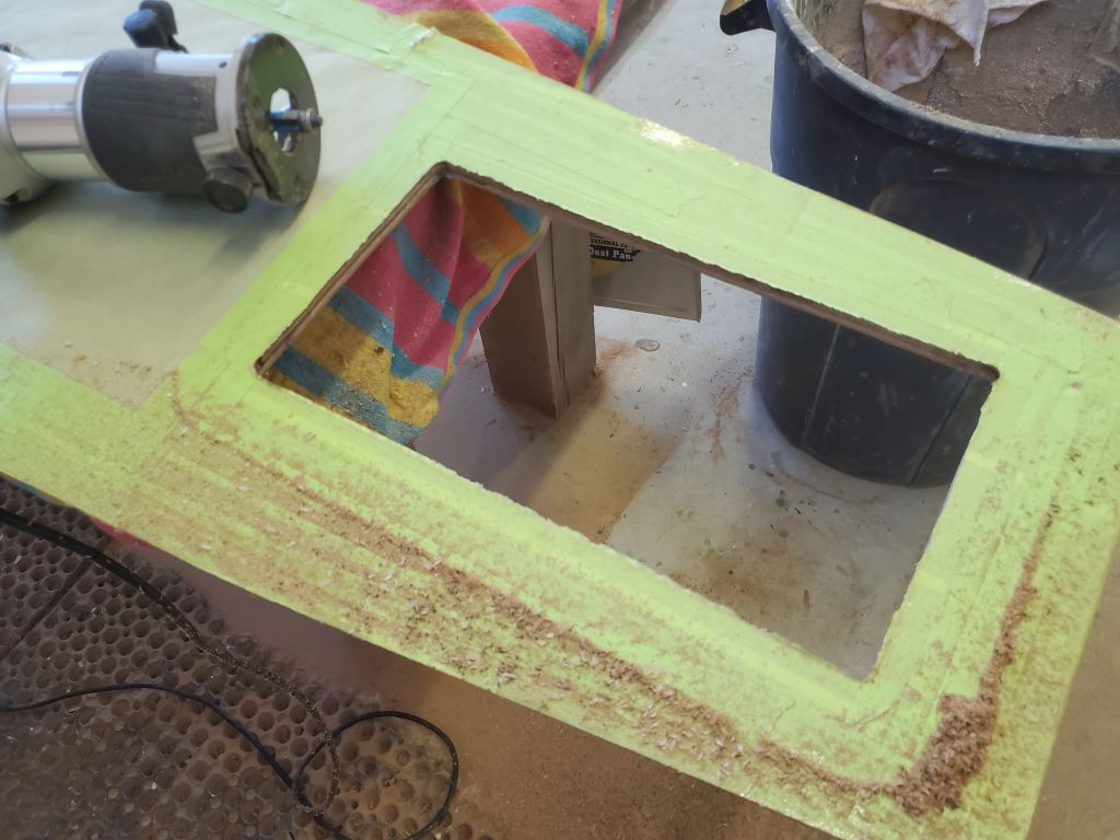
After some more careful, but still necessary, demolition work, I exposed most of the area and removed the old coring. There was indeed some solid material in way of the mast step itself, as I’d suspected, and I slowly cut towards it till I could remove all the surrounding core, and then peel back, with effort, the fiberglass over the top. Any new work to repair this area would of course have to properly incorporate the mast step area, and I now just needed a real sense of what was going on, and to help me come up with some means of repair.
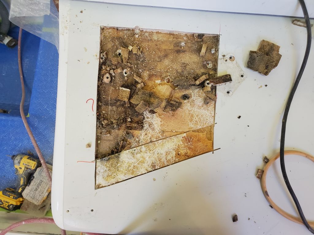
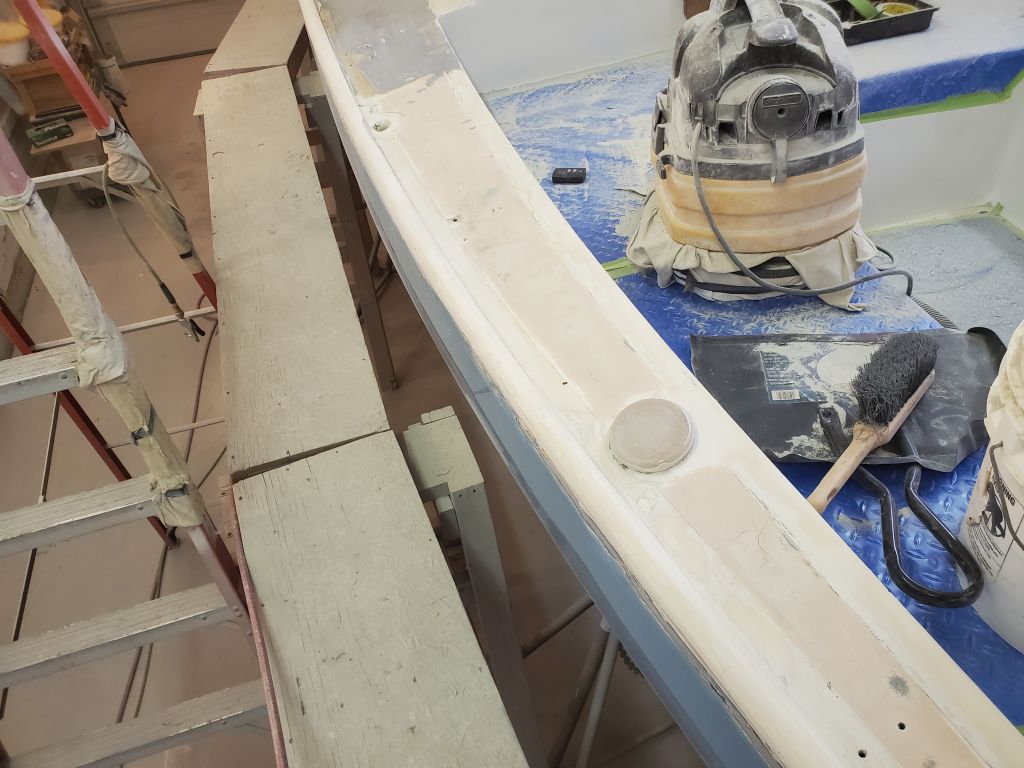
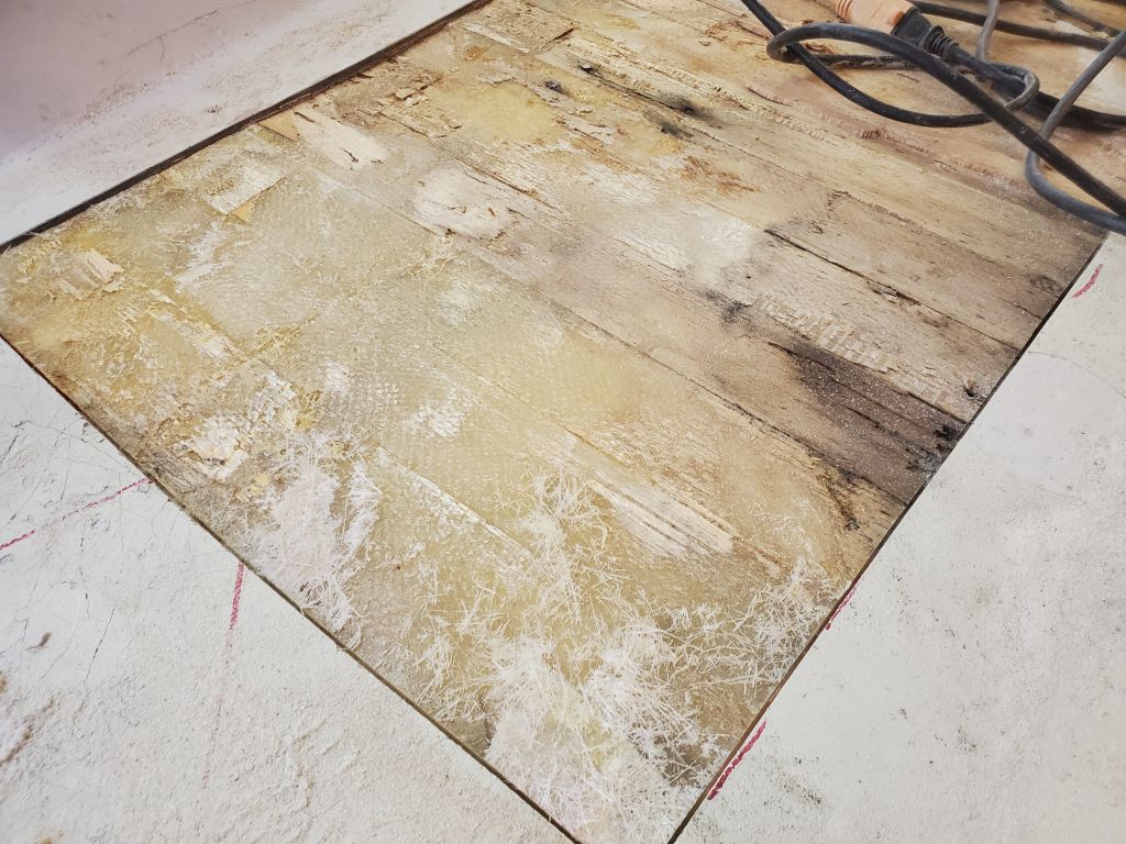
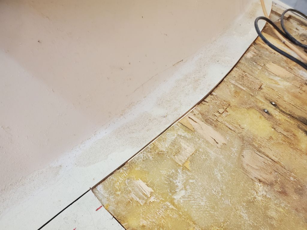
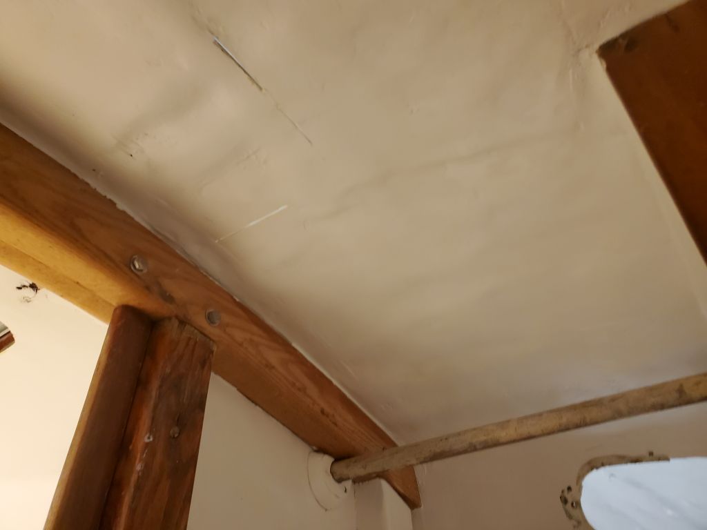
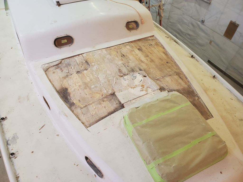
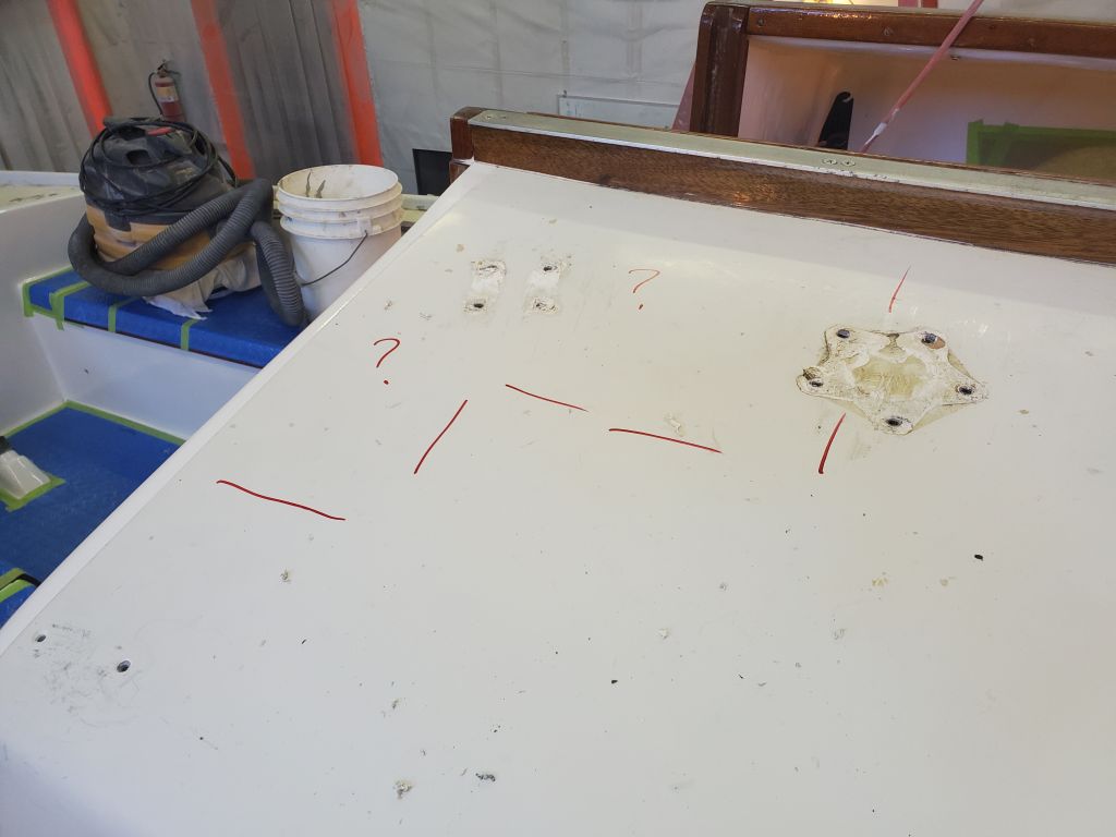
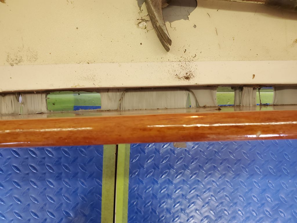
With the detritus cleaned up, the geography of the previous “repair” became more clear. The “solid” part of the deck (the part badly repaired from below) extended along the basic centerline, aft of the mast step. In this area, the bottom skin contacted the remaining top skin along the center portion between the ports; on either side, as the deck extended outward, the normal contour of the construction, with space for the standard 3/8″ core, became visible once more.
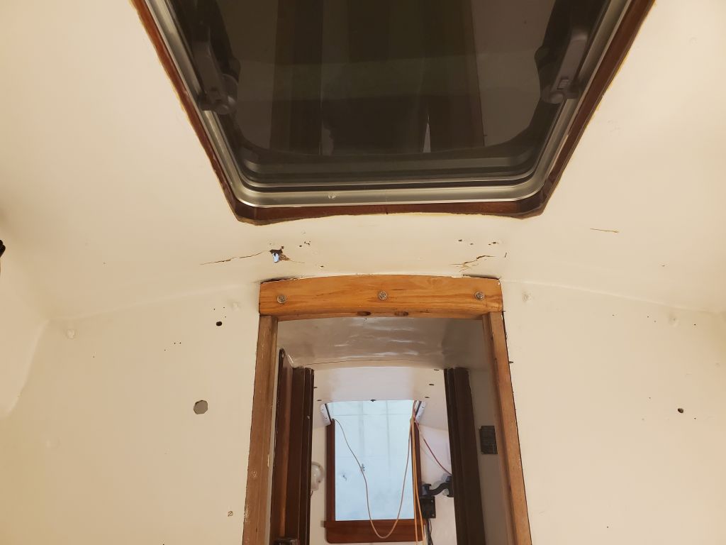
In addition to the first, largest, saw kerf that came through the inside, right along the aft side of the head at the passageway opening, there were a couple other places (also along the center area where there was no longer any core, just the roughly 1/4″ of fiberglass) where the saw had cut through, and some damage through the inner skin forward of the bulkhead in the forward cabin, caused during removal of the core from above.
These findings put a damper on my intended progress for the day, and I immediately got in touch with the owner to notify him and begin discussions about what it meant for the overall project. Meanwhile I tried to think about the best way to go about repairing this area properly. Clearly the miserable old work would have to be removed, which essentially meant cutting out this portion of the deck (i.e. head overhead), and rebuilding the inner skin (overhead) as well as new core and top skin above. There were various limitations, practical, financial, and otherwise, to how this might be accomplished, with an eye towards minimizing collateral damage, working within the spaces defined by existing structures (bulkheads on either side), and successfully tying the new bottom skin (overhead) in with the existing and adjacent structures. The change in elevation of the cabin top right at the boundary of the repair complicated things as well, because the deck requiring repair literally ended as it raised itself to the upper level. So there was limited room for tying the new in with the old as a purely physical thing.
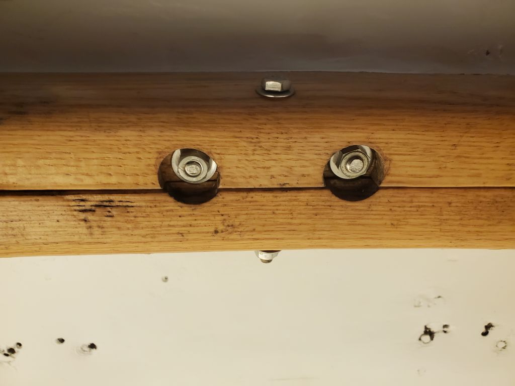
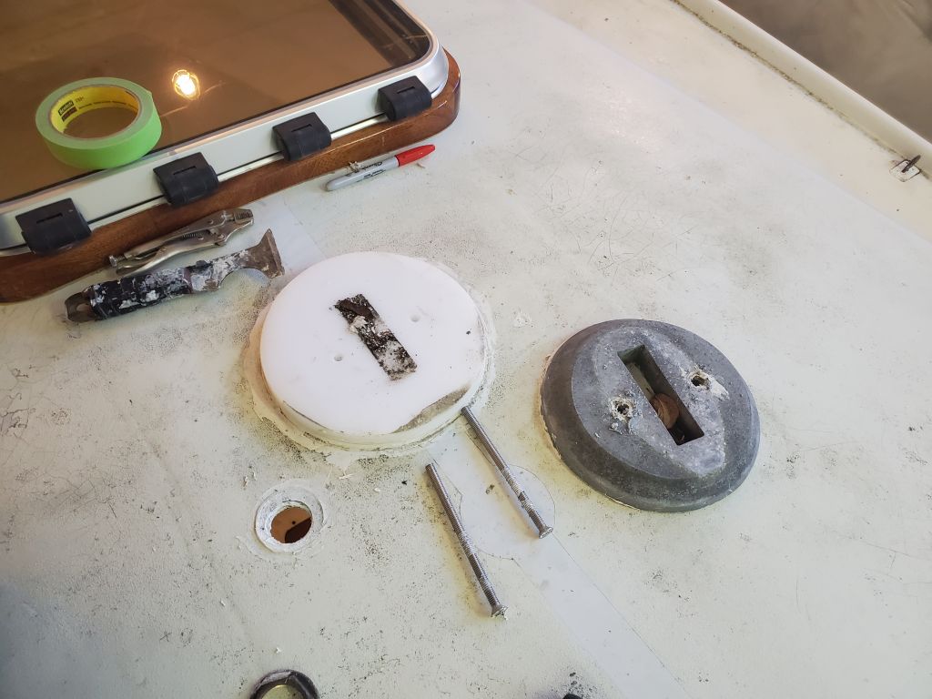
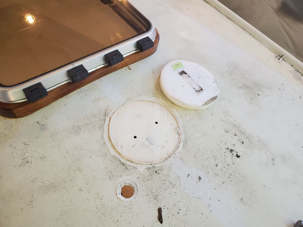
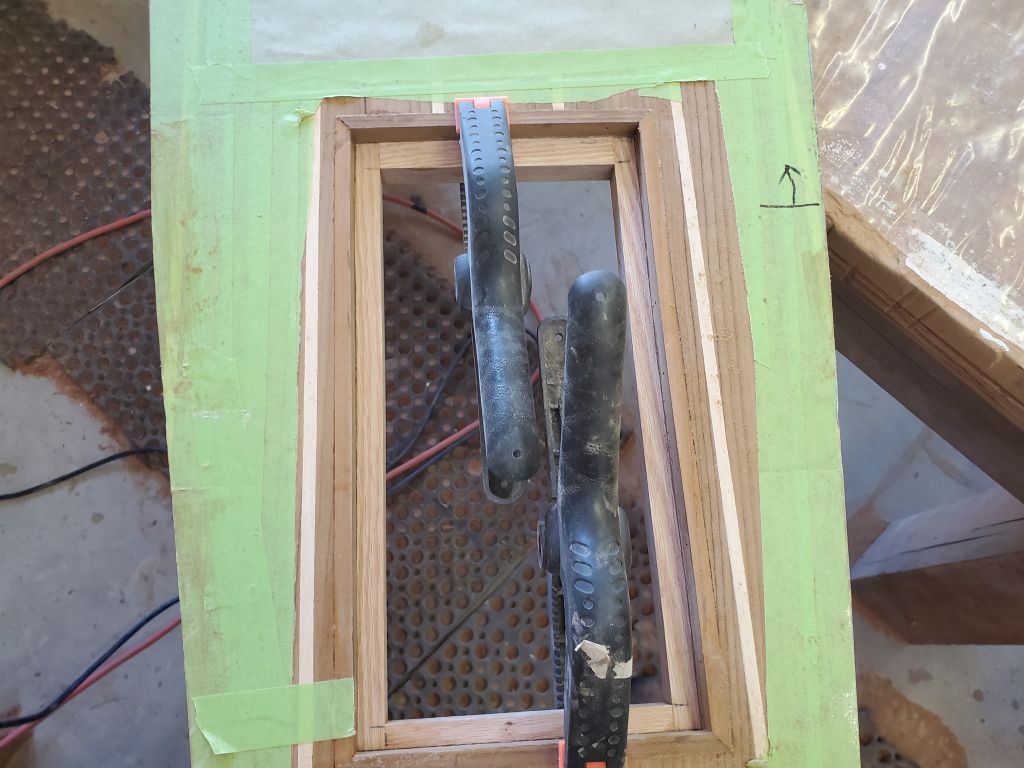
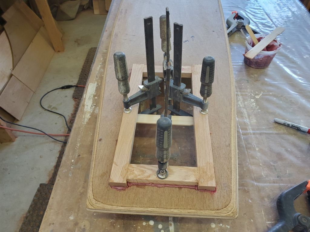
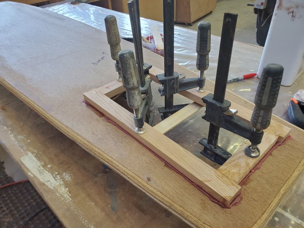
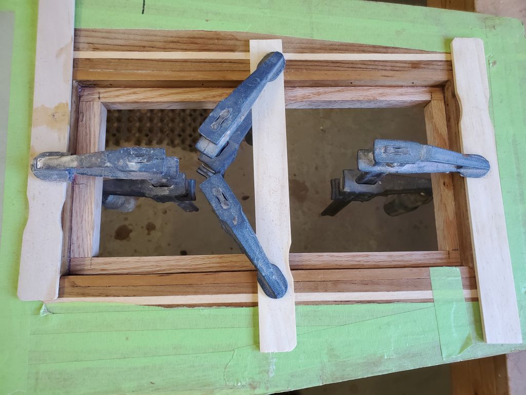
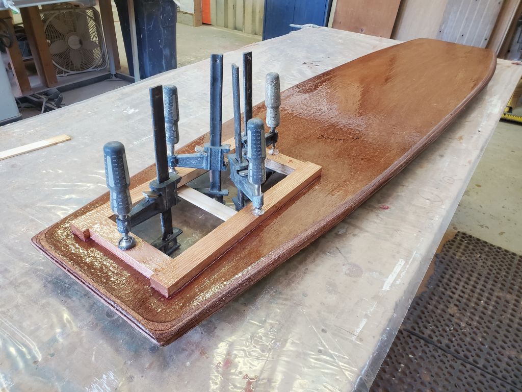
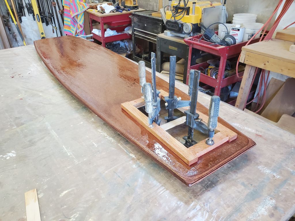
What I thought I might do was to actually build a new inner skin panel off the boat, flat on a bench, then, after cutting out the old deck as much as possible (leaving ample material at the edges for bonding and to avoid the bulkheads) mold and adhere the new skin from below, re-creating the proper 3/8″ depth for the new core. My reasoning for this approach was that I could bond the new skin panel from underneath, epoxying and tabbing it along the edges of the cutout; otherwise, there was no clear way to incorporate the new bottom laminate in with the existing structures. Once the new inner skin was in place and bonded, rebuilding the rest of the deck would be normal, basic, and quick. To bond the new material sufficiently beneath the mast step, the critical structural element of this whole space that made the repairs that much more important, I figured I should remove the mast beam so I could bond through the passageway, which was directly beneath the step. This would afford the opportunity to clean up the mast beam installation, which was sort of a sloppy mess anyway.
The exact mechanics of this process would make themselves better known once I got going. For now, it was an idea, and I’d continue to mull and refine it over the hours and days to come.
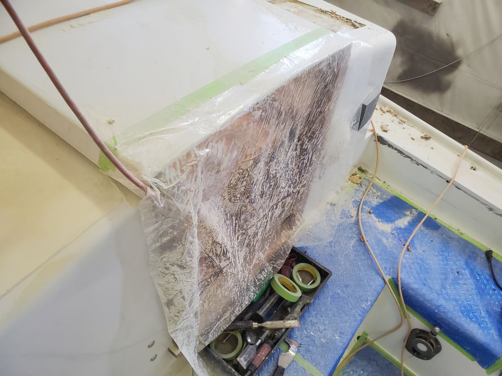
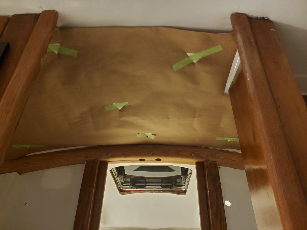
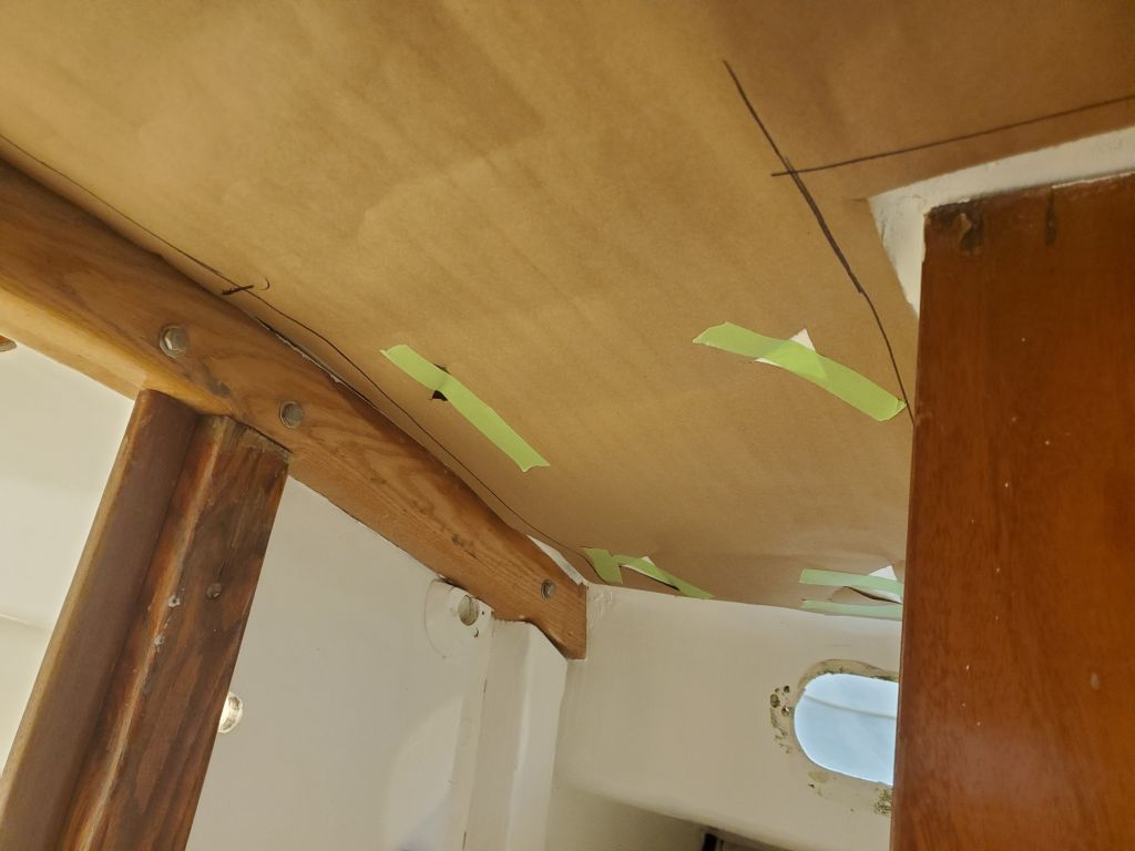
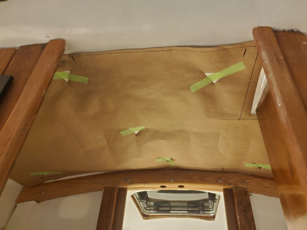
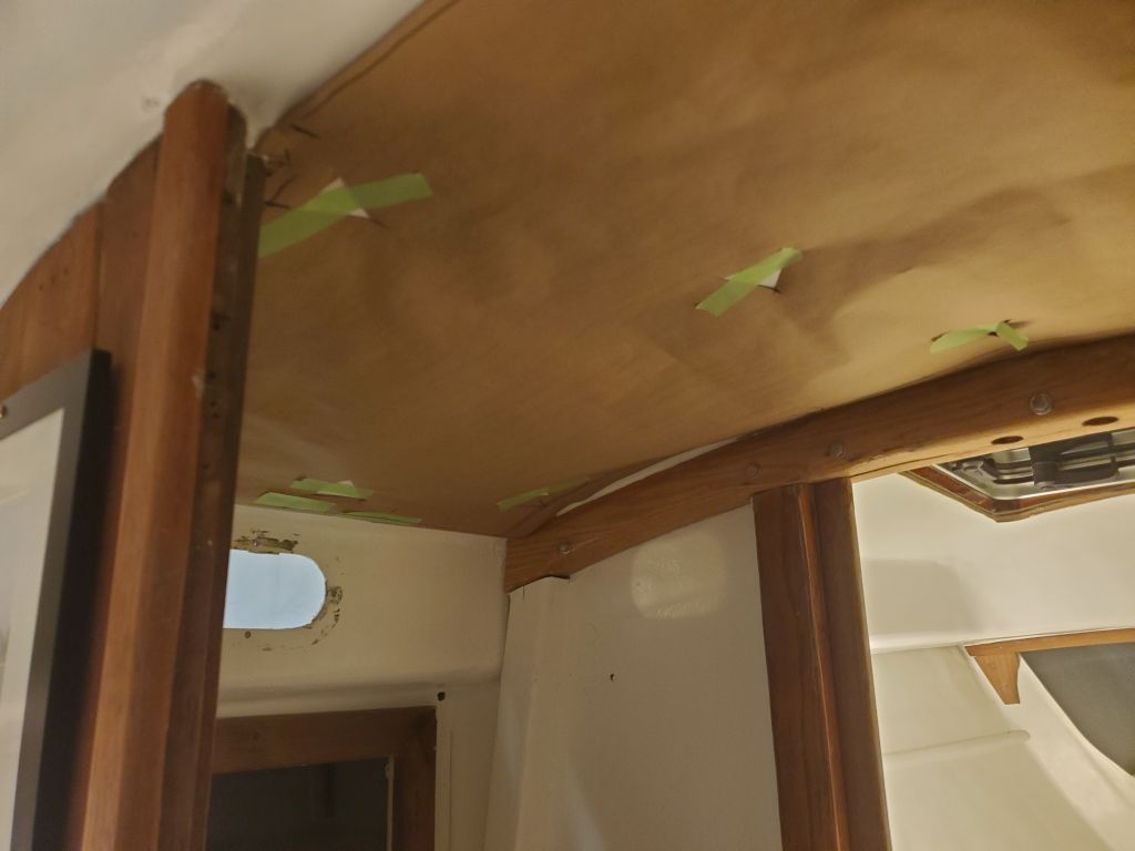
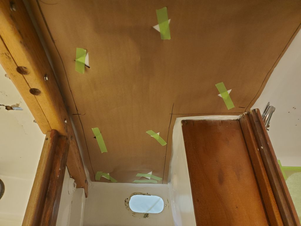
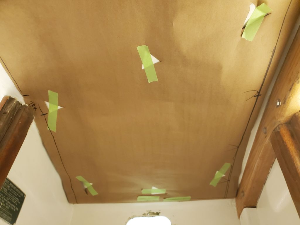
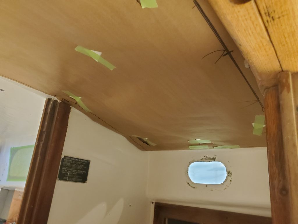
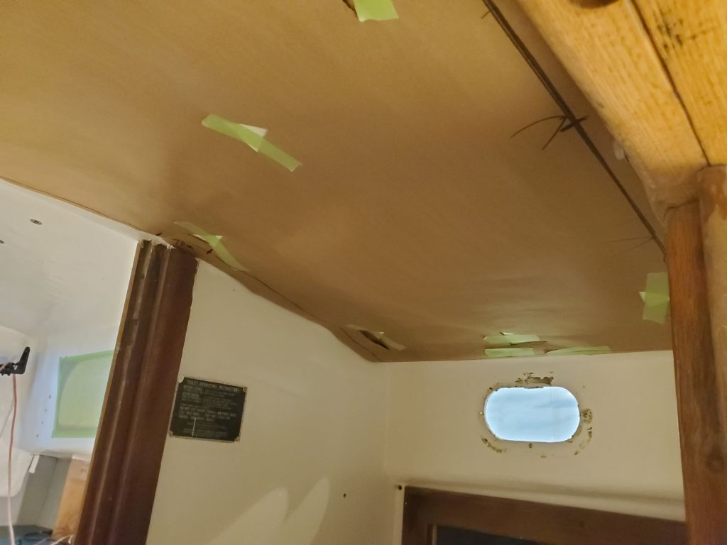
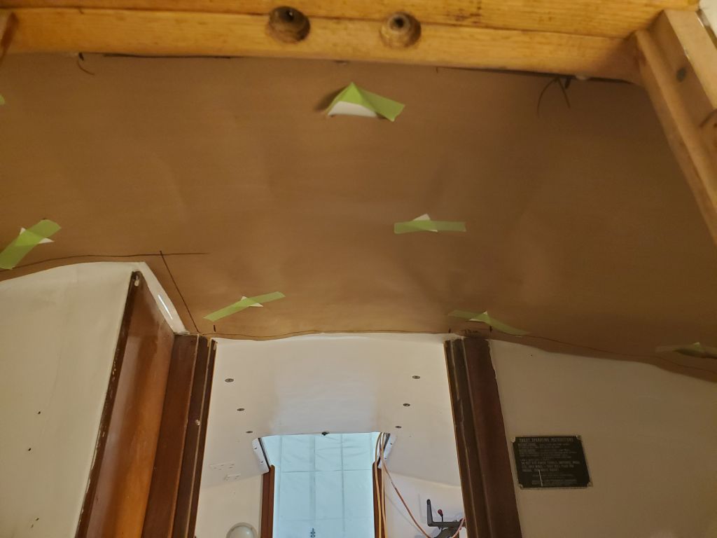
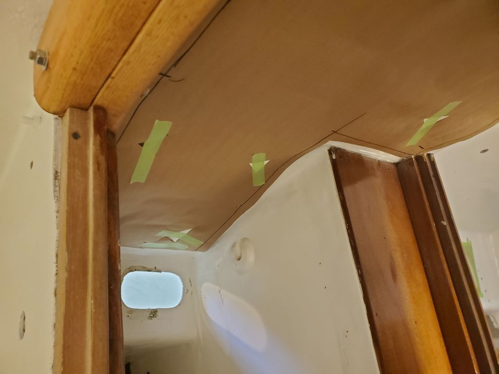
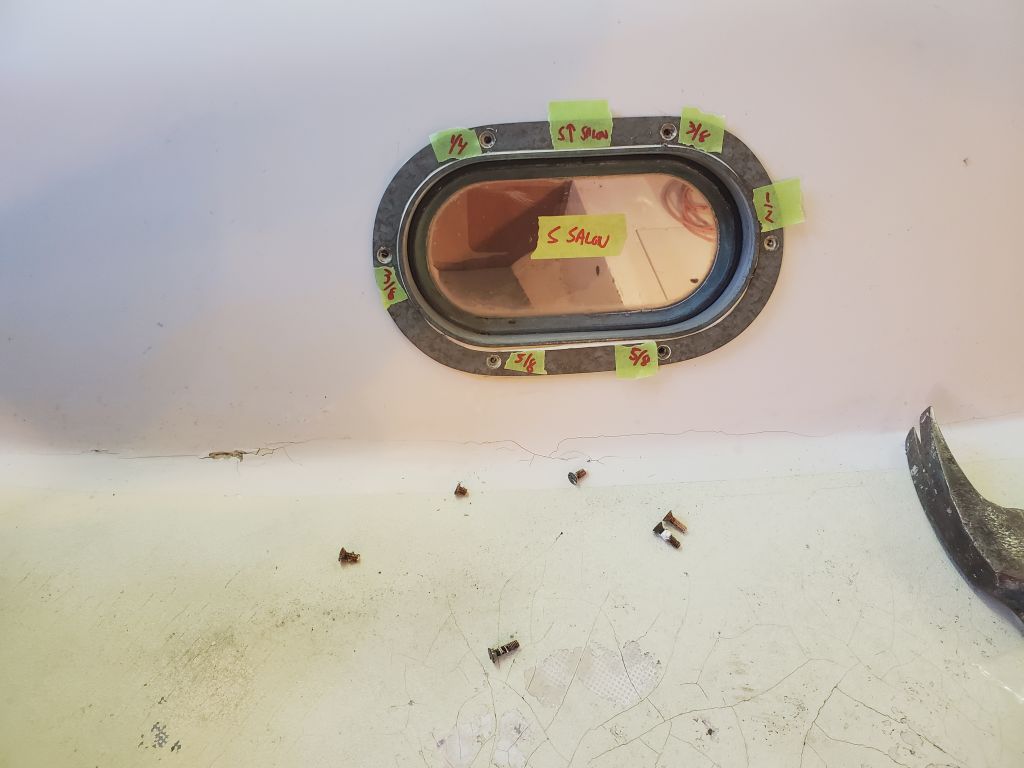
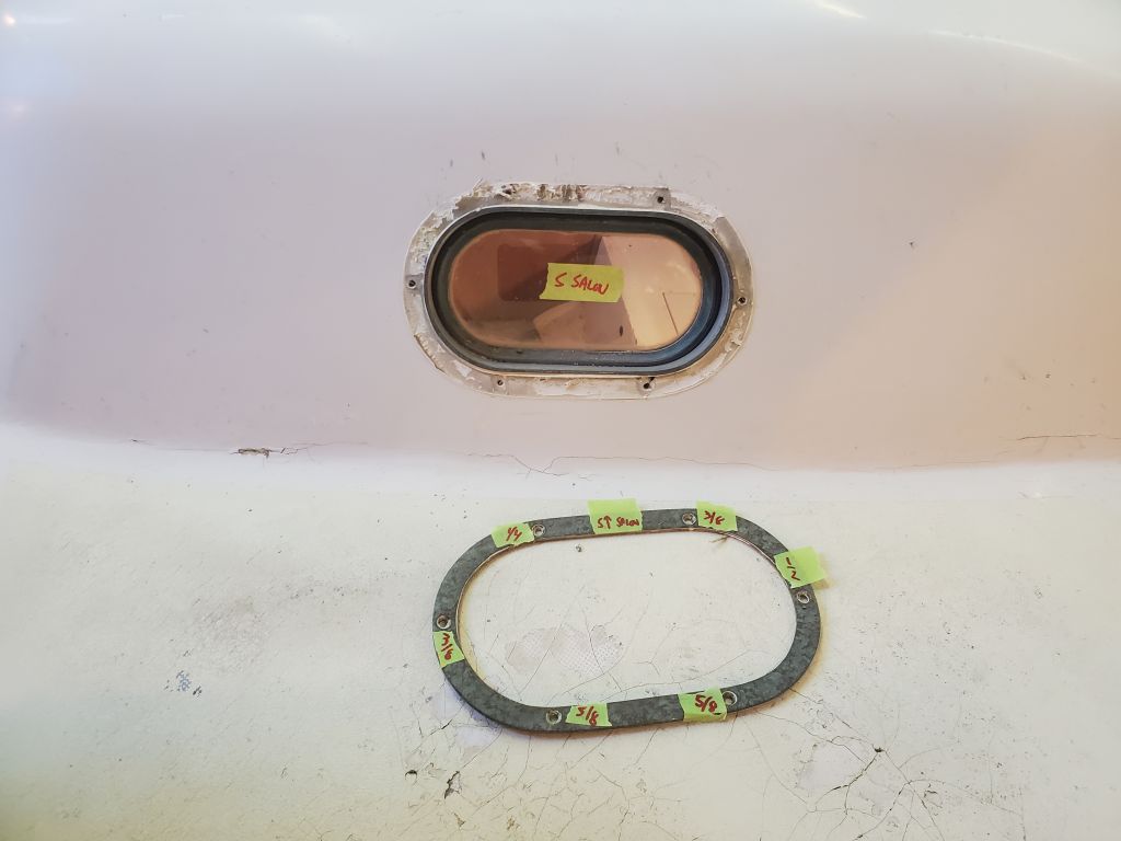
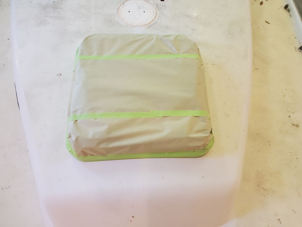
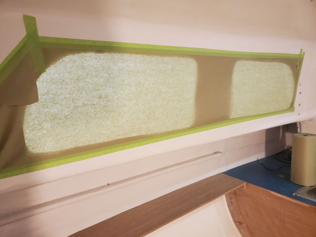
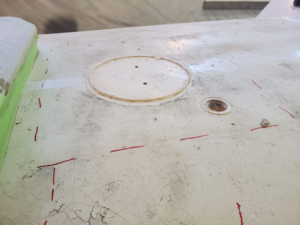
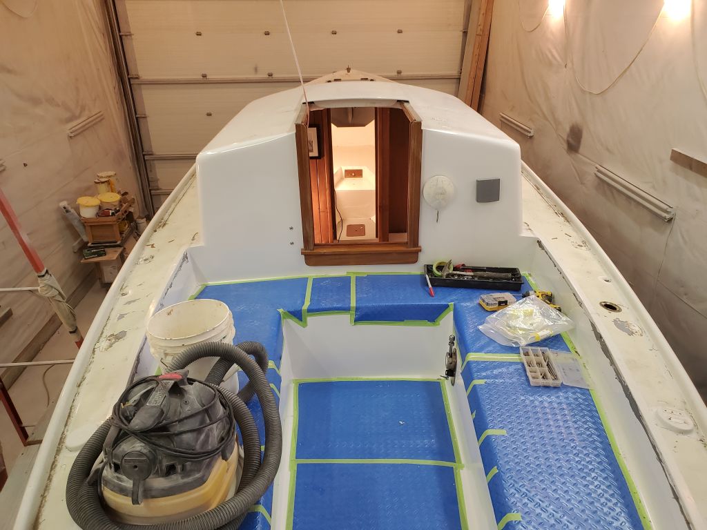
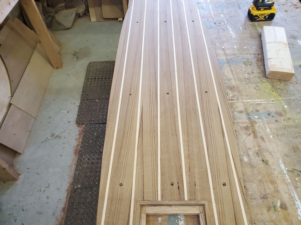
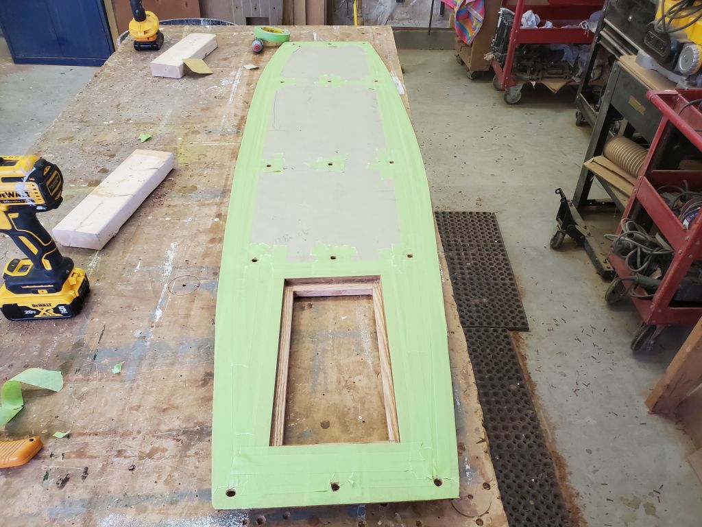
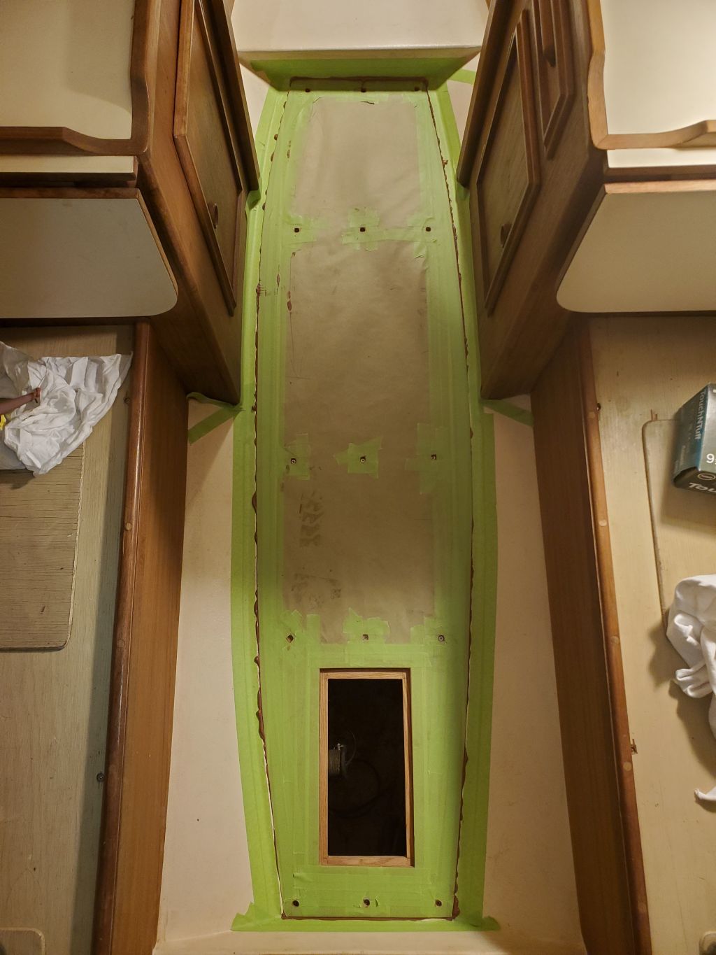
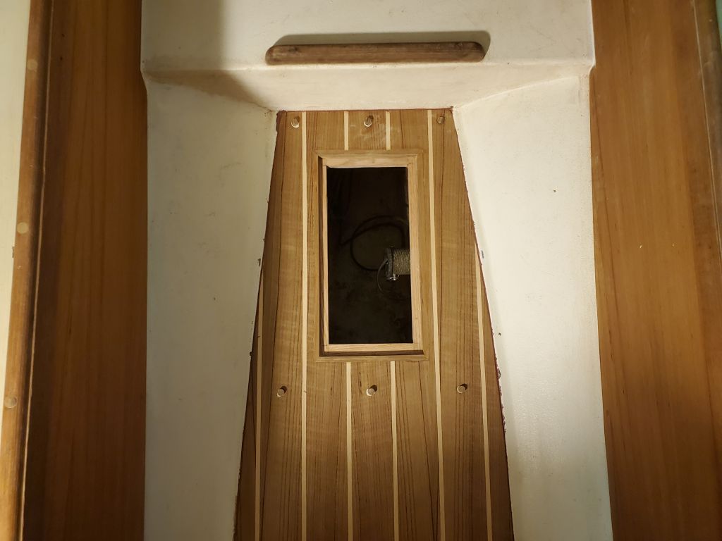
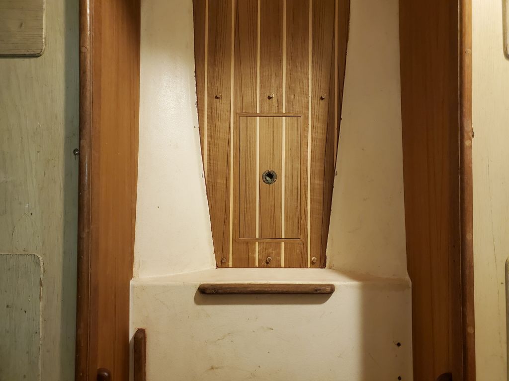
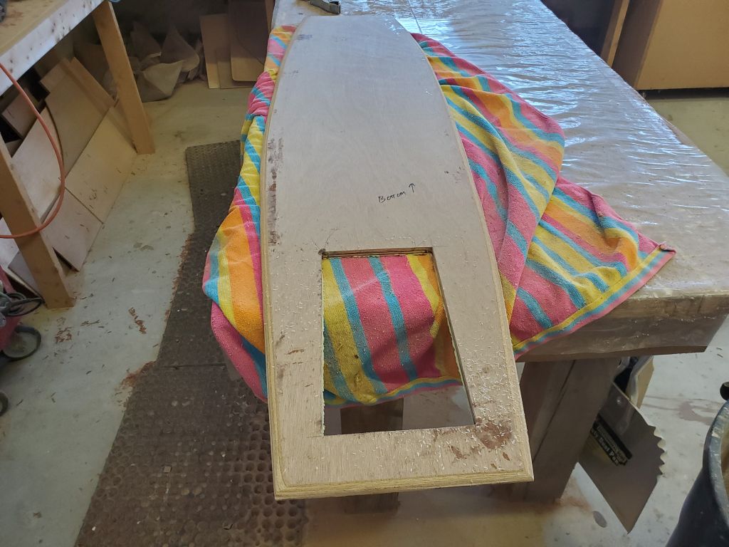
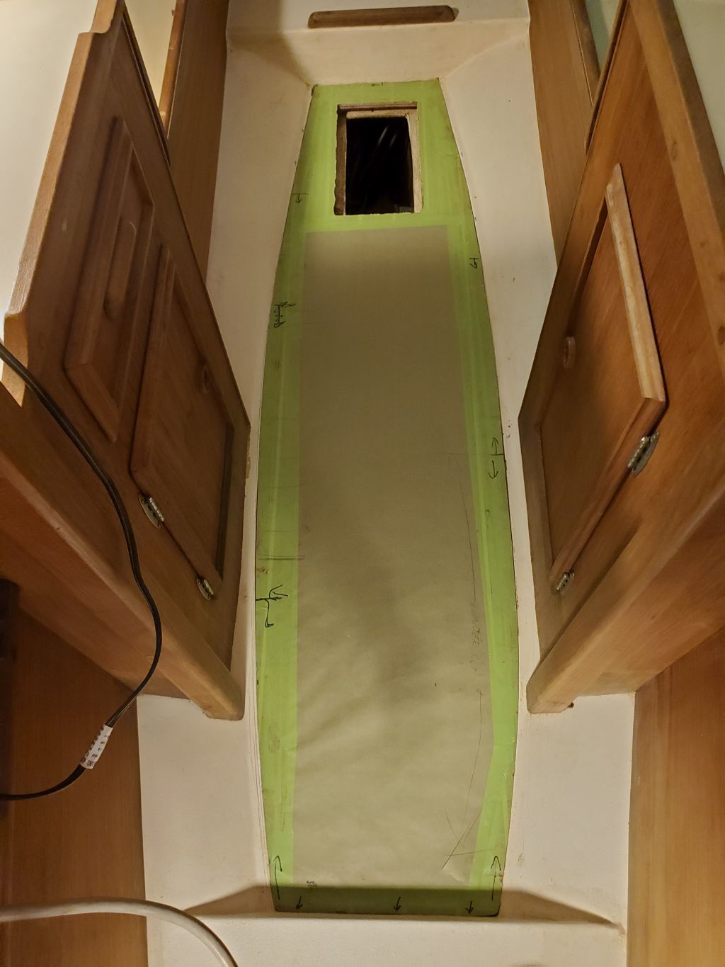
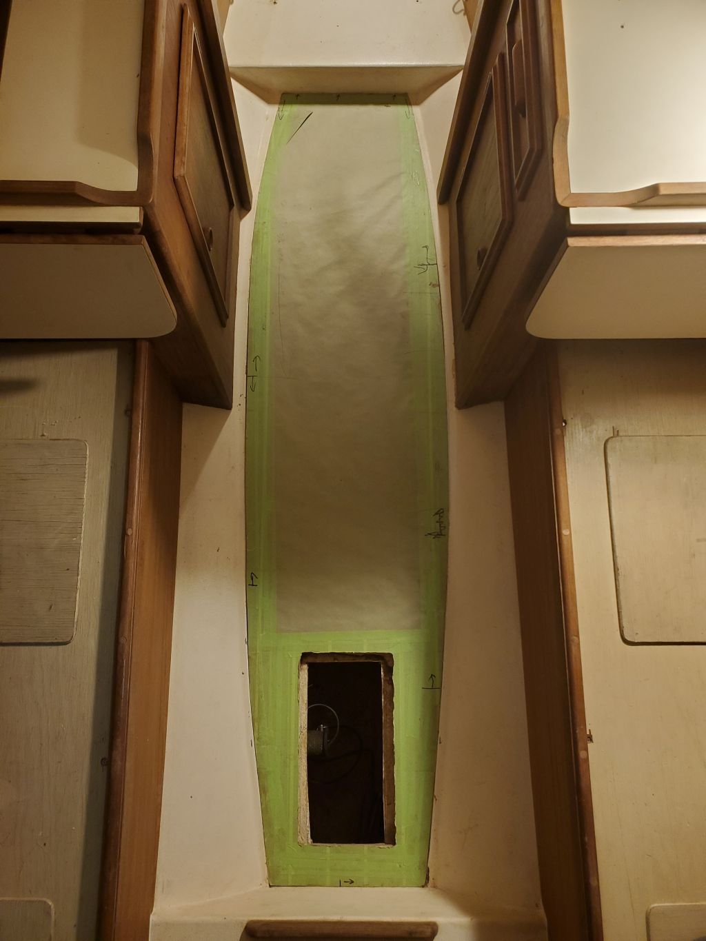
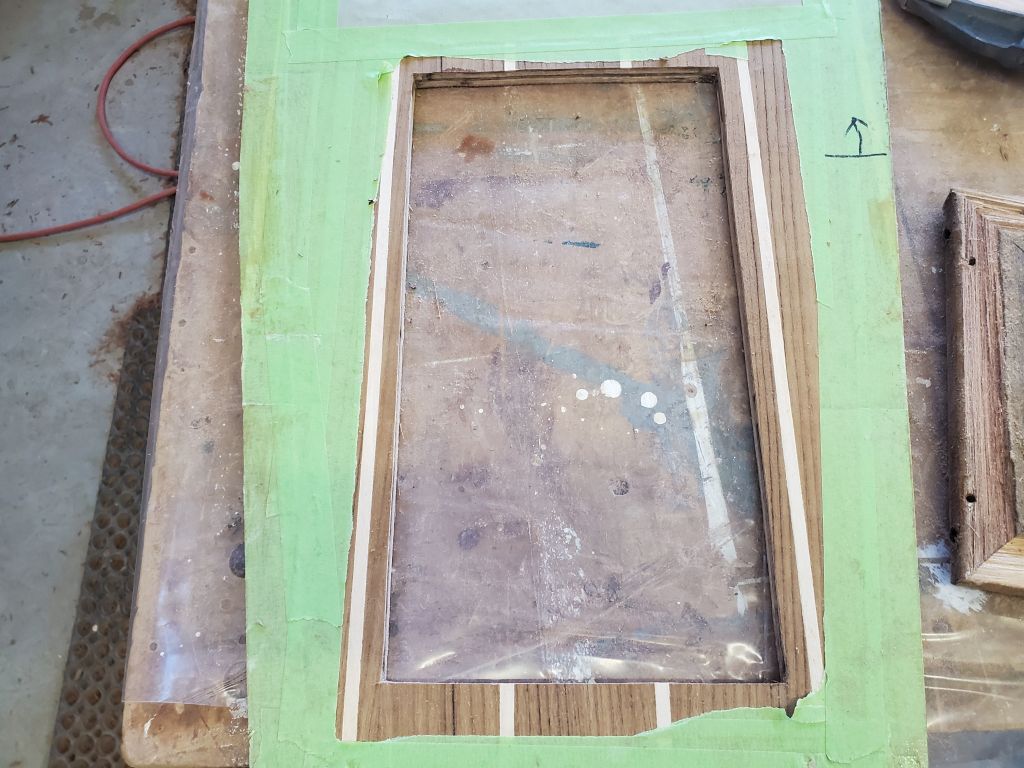
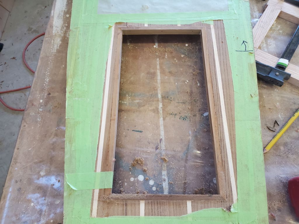
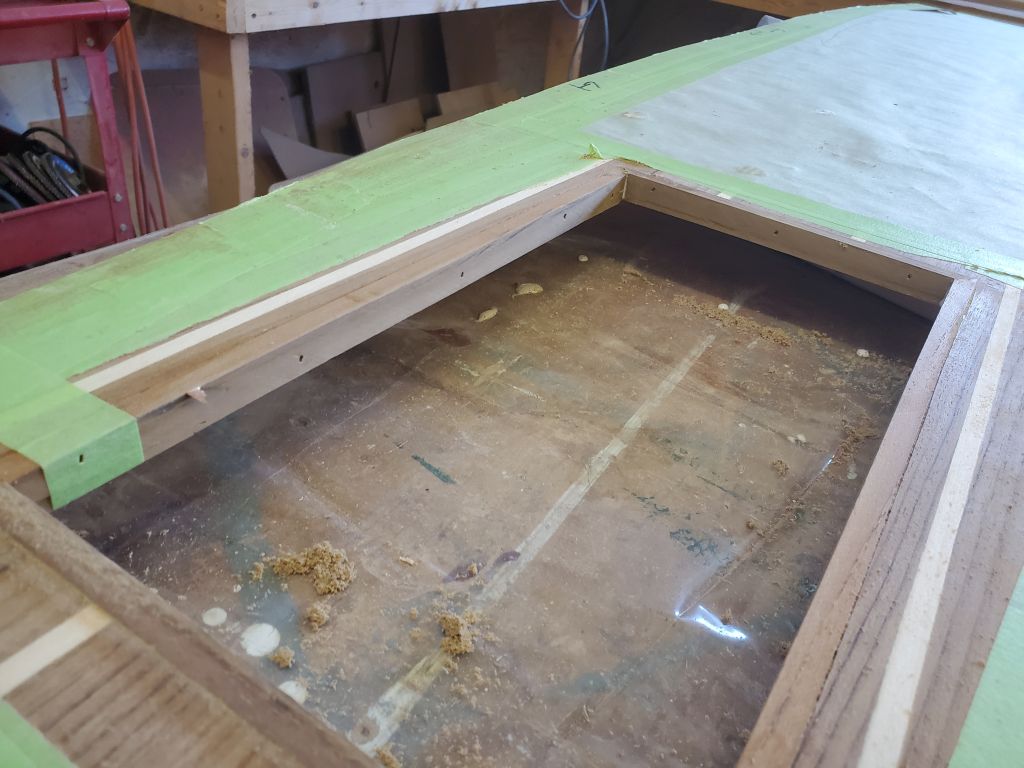
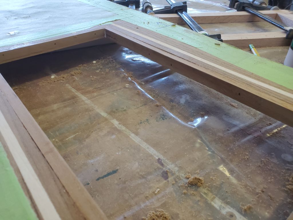
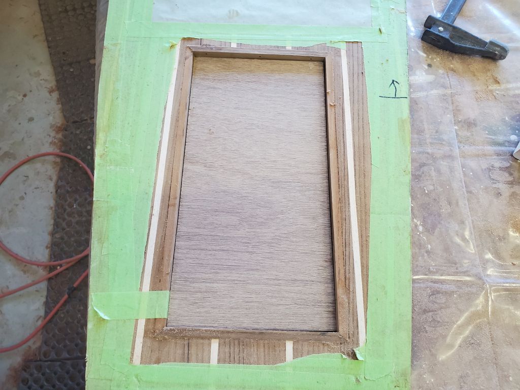
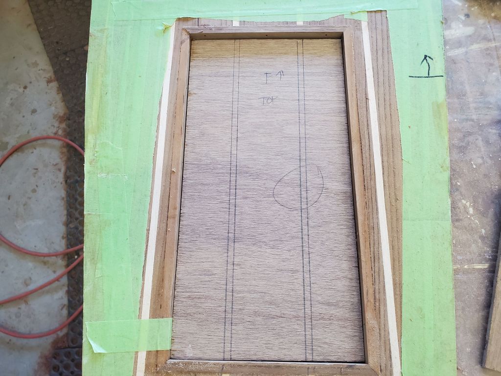
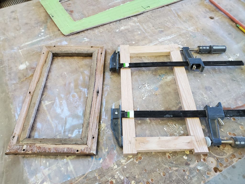
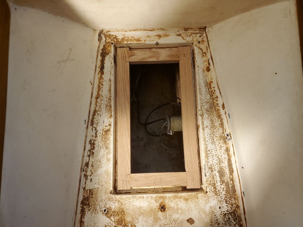
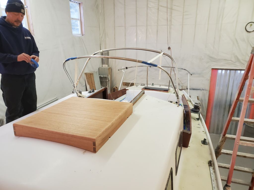
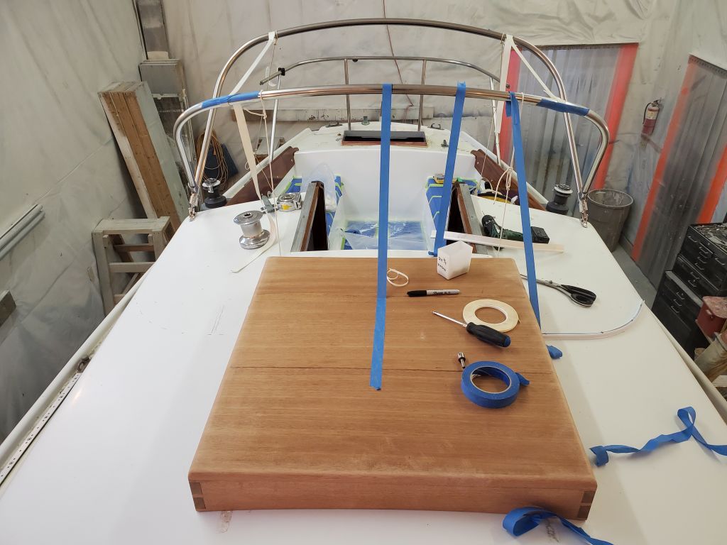
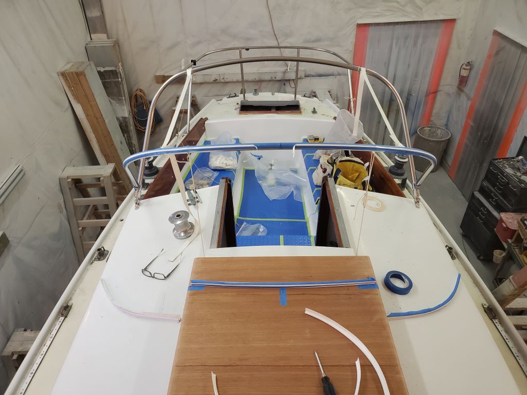
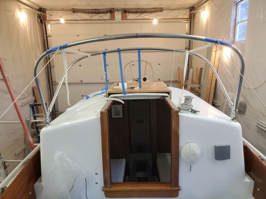
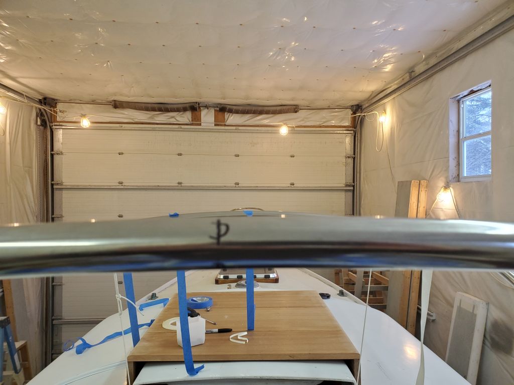
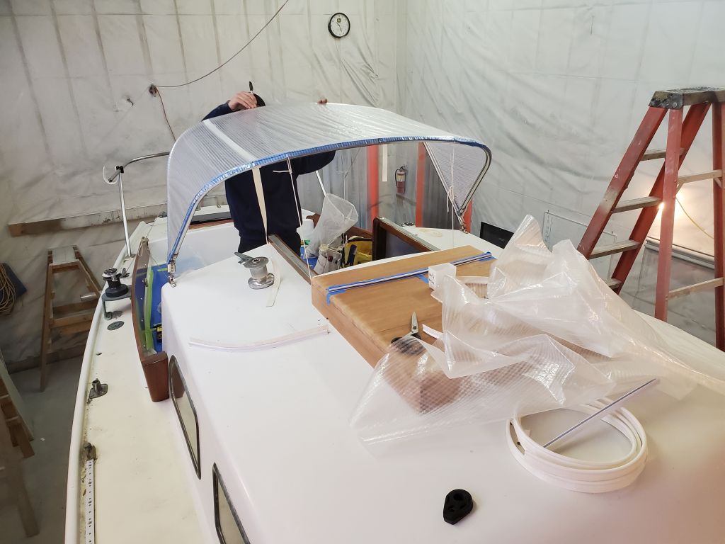
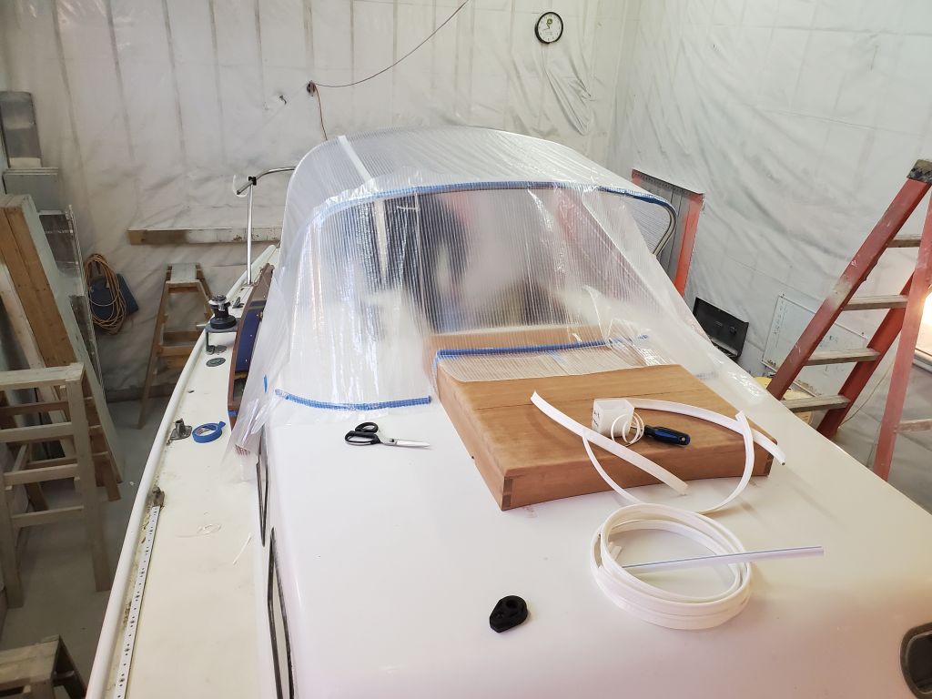
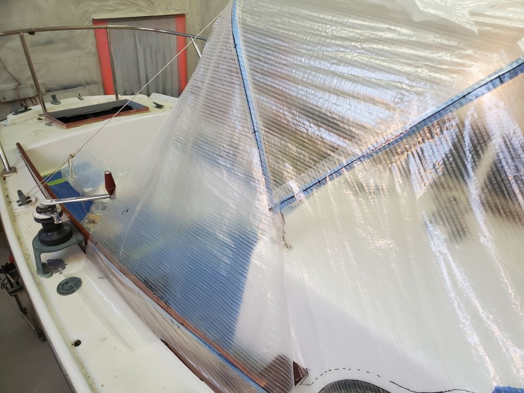
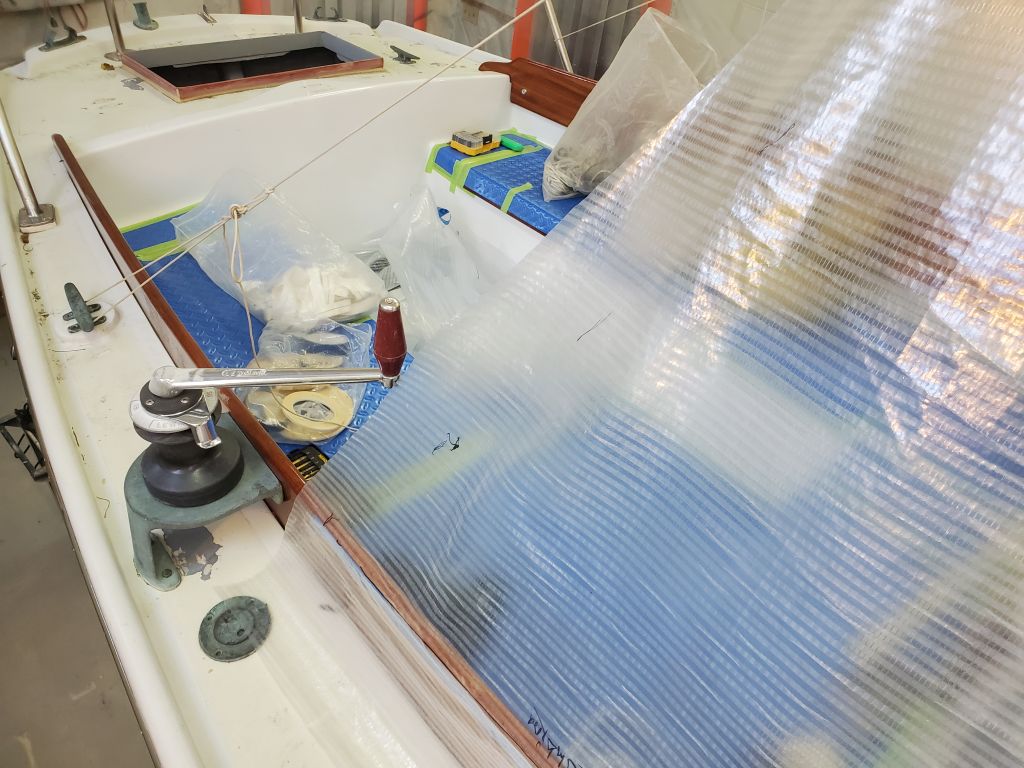
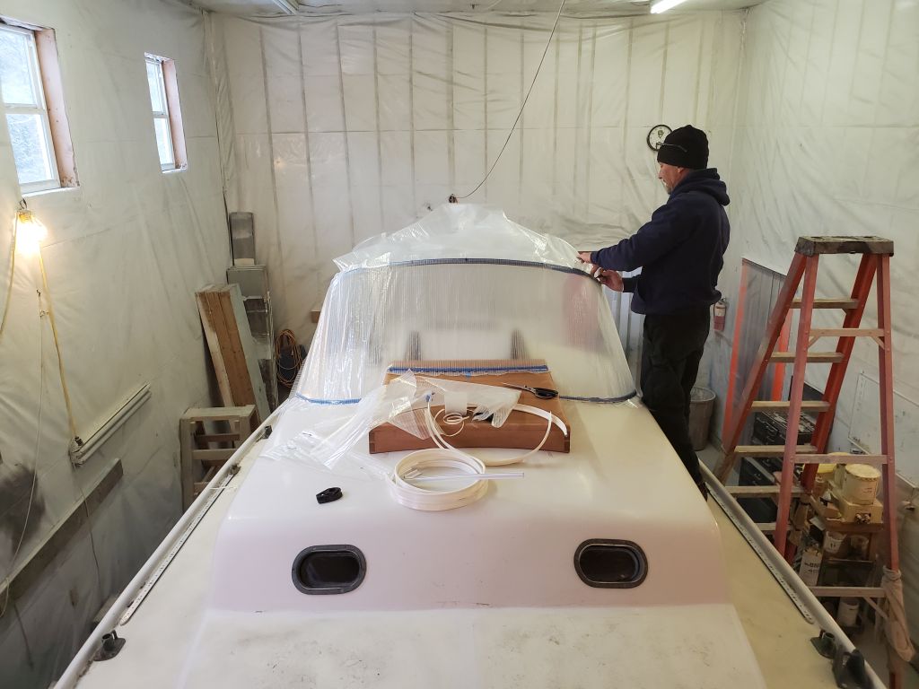
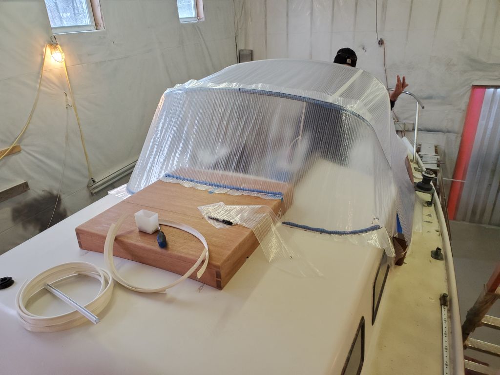
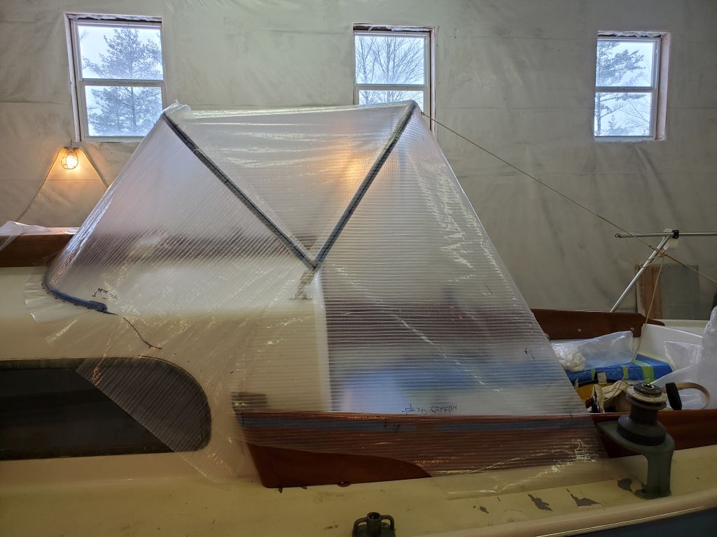
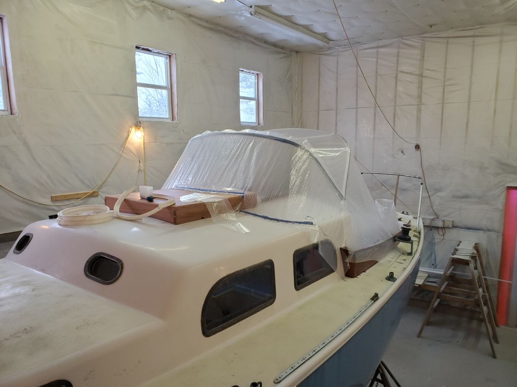
While waiting to hear back from the owner, and not wanting to delve too deeply into the next steps of whatever repair till I had approval to proceed, I decided for now to start with a pattern of the head overhead, which I could use to start my rebuilding process. With some basic measurements of the space, I cut a paper template slightly smaller all around; then, with the template taped in place, I marked the exact shape of the space all around, using a flexible 1-1/2″ wide ruler (and, in the tightest spot, a compass) to draw the offset directly on the paper template.
With that, for now I called it a day on this project and focused in other directions. Later in the day, I heard back from the owner with approval to continue the repairs as necessary, so I looked forward to continuing the overall deck prep–as well as effecting this unexpected repair–in the coming days.
Total time billed on this job today: 4.5 hours
0600 Weather Observation: Mostly cloudy, 18°. Forecast for the day: Drizzle, freezing drizzle, then rain, 45°