Monday
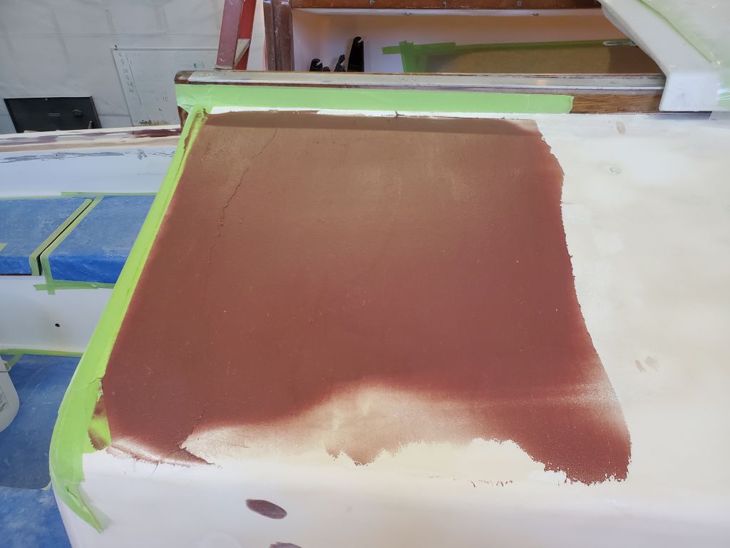
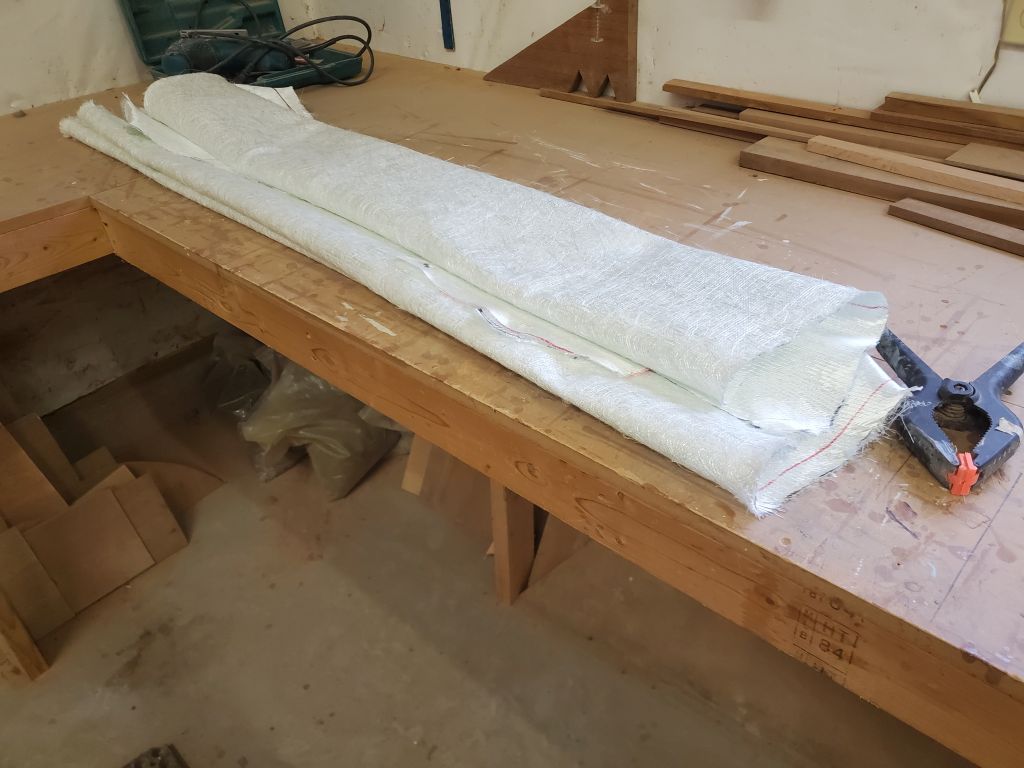
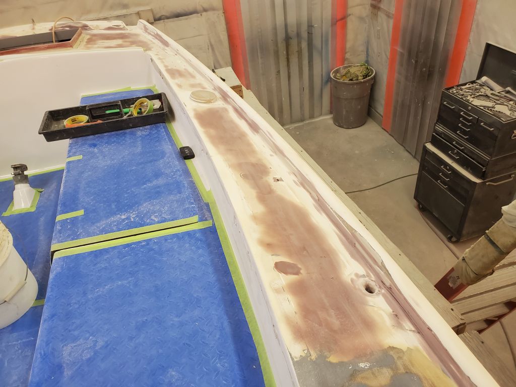
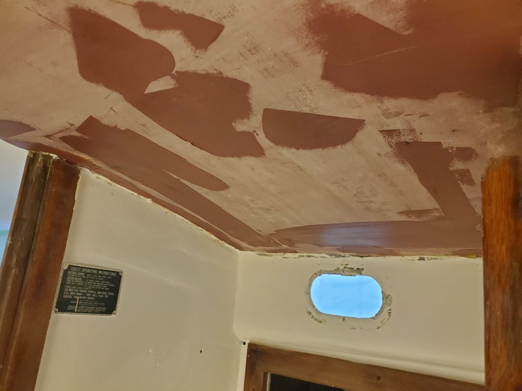
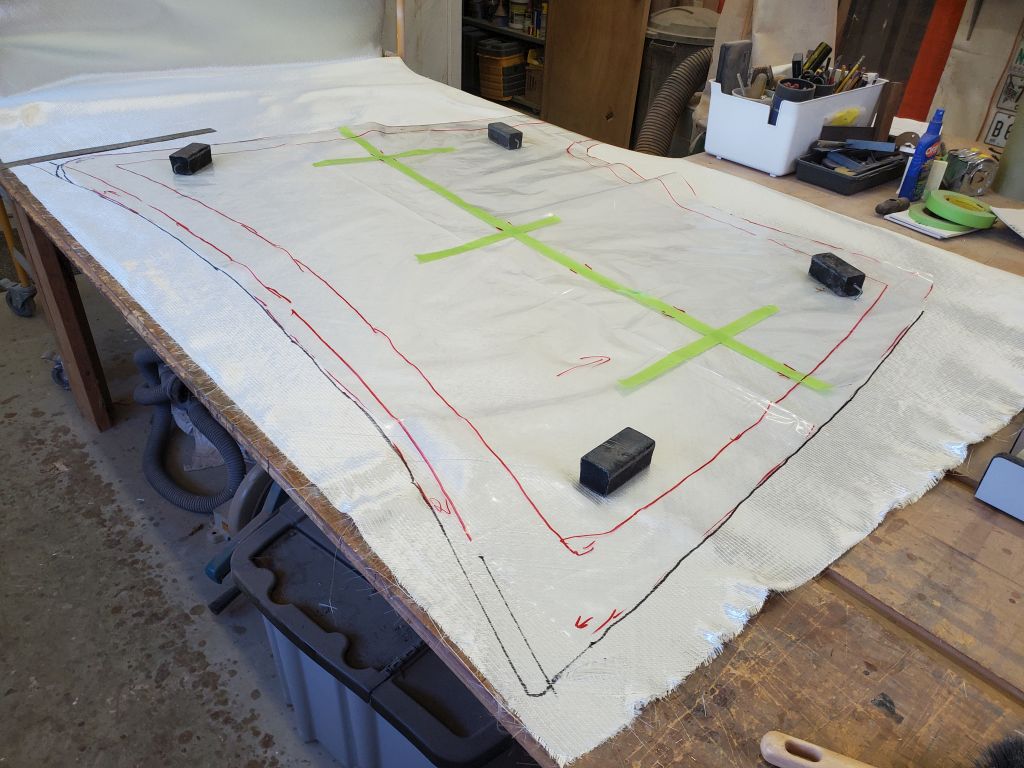
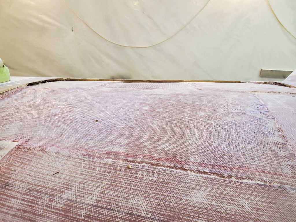
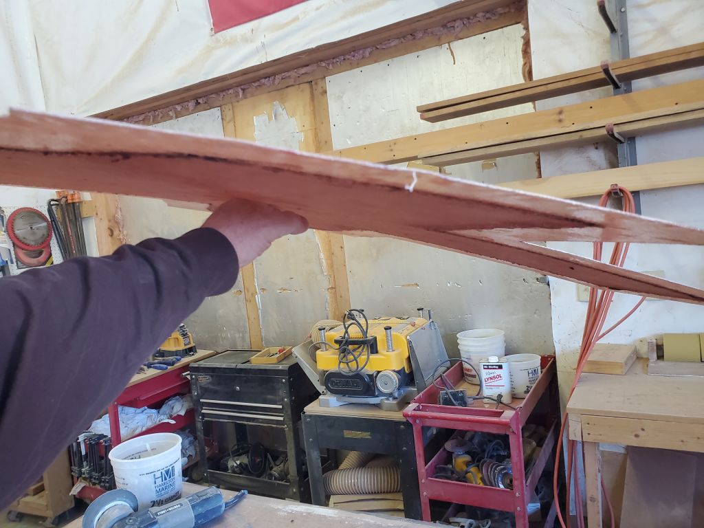
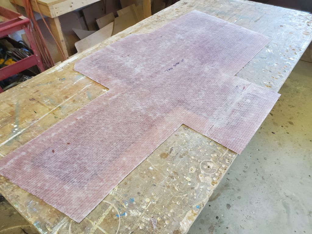
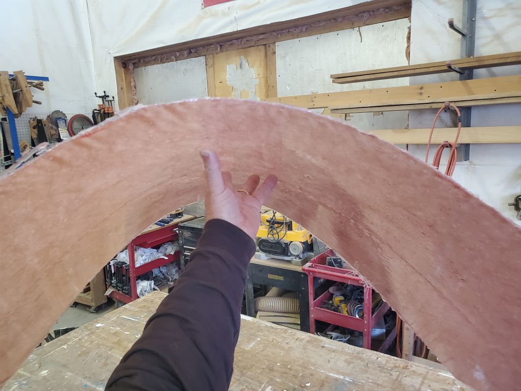
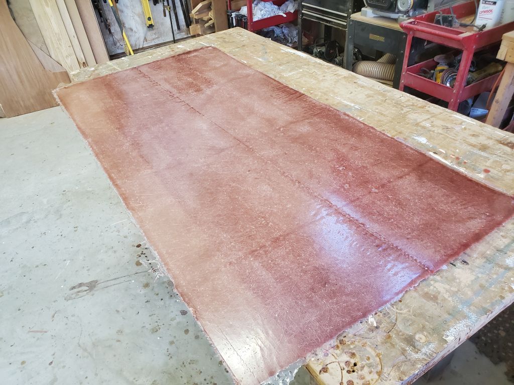
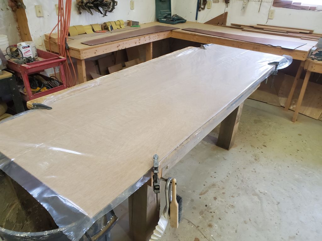
The new laminate I’d built to create the new inner skin (and overhead) for the coachroof repair was a bit more flexible than I’d hoped, but not necessarily than I thought it might be. Built of a single layer of 1708, I’d hoped it might be a bit less floppy than it turned out to be, and I thought I’d add another layer to stiffen the panel before installation. Otherwise, it was a good basis for the work to come, and to prepare it for the next steps I water-washed both sides and, later, sanded them lightly to remove the gloss from the “mold” side and lightly scuff both surfaces.
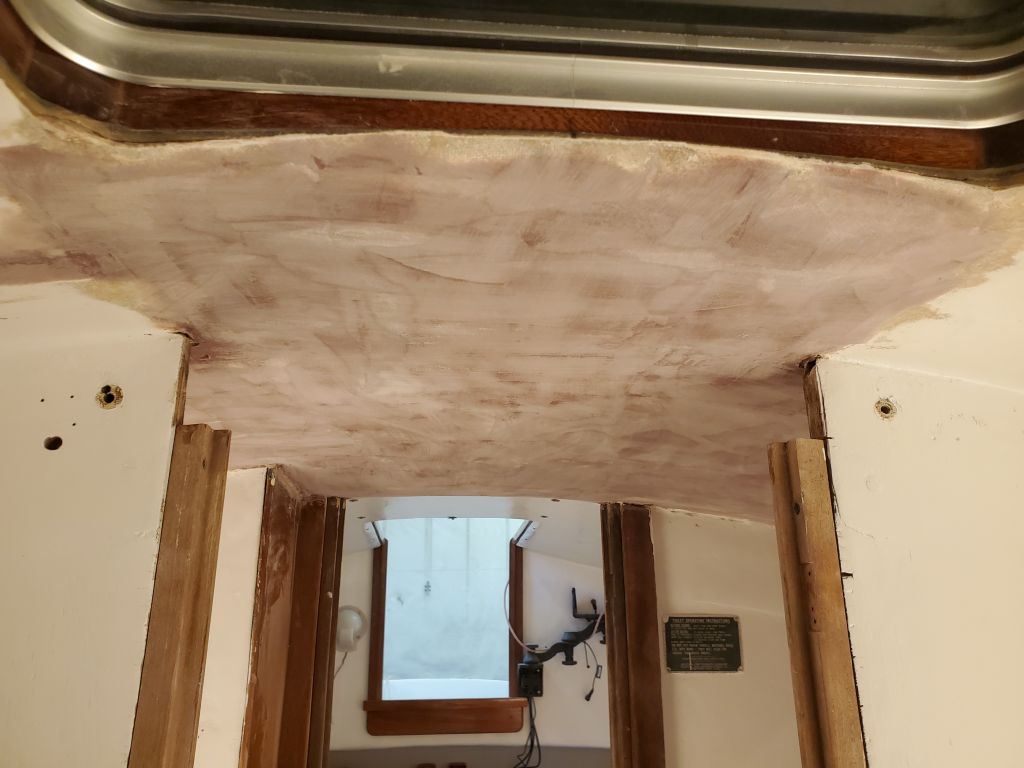
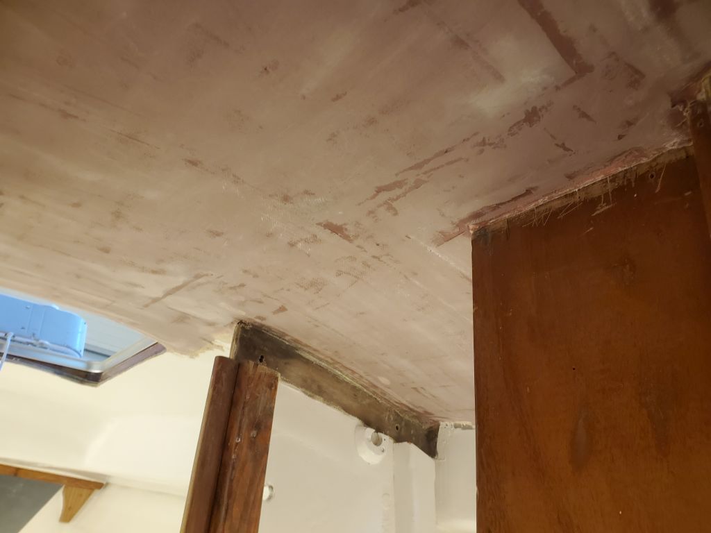
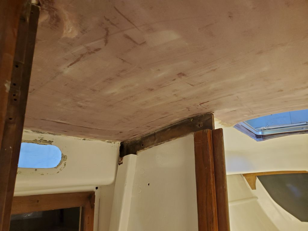
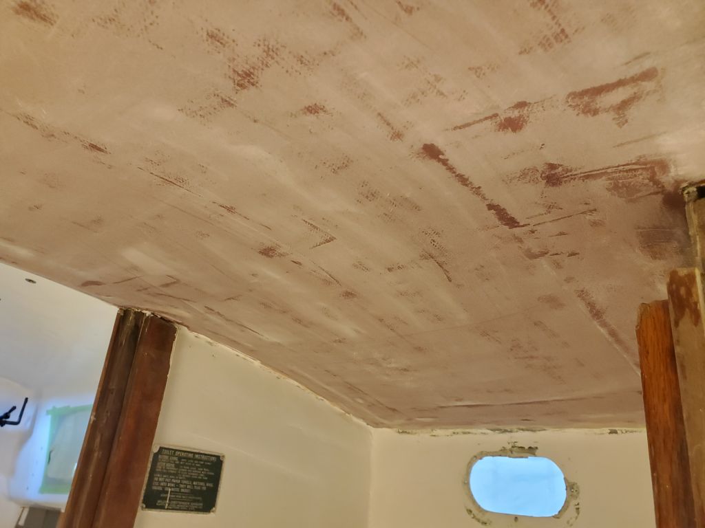
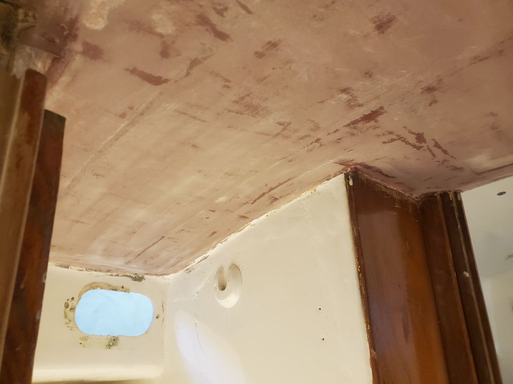
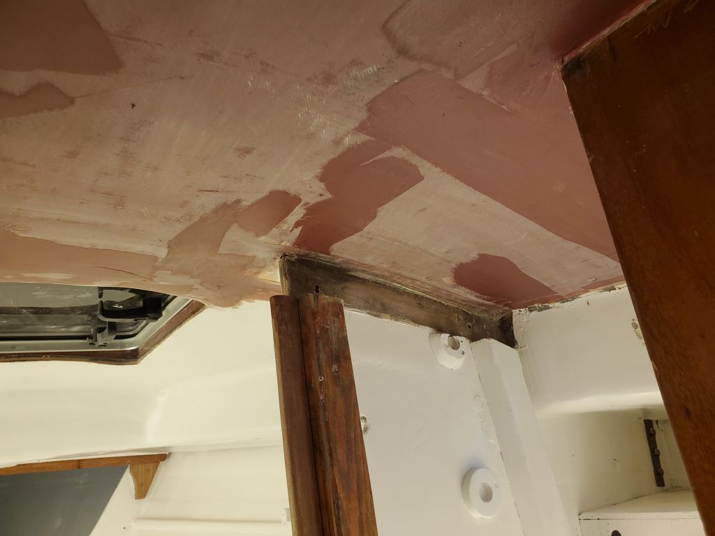
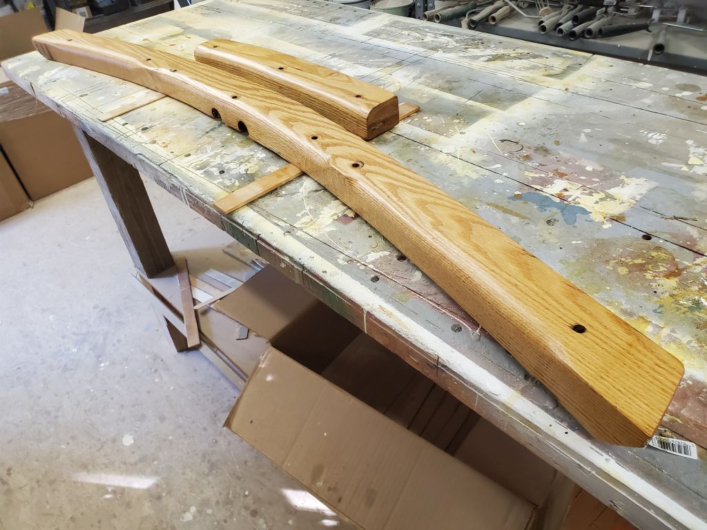
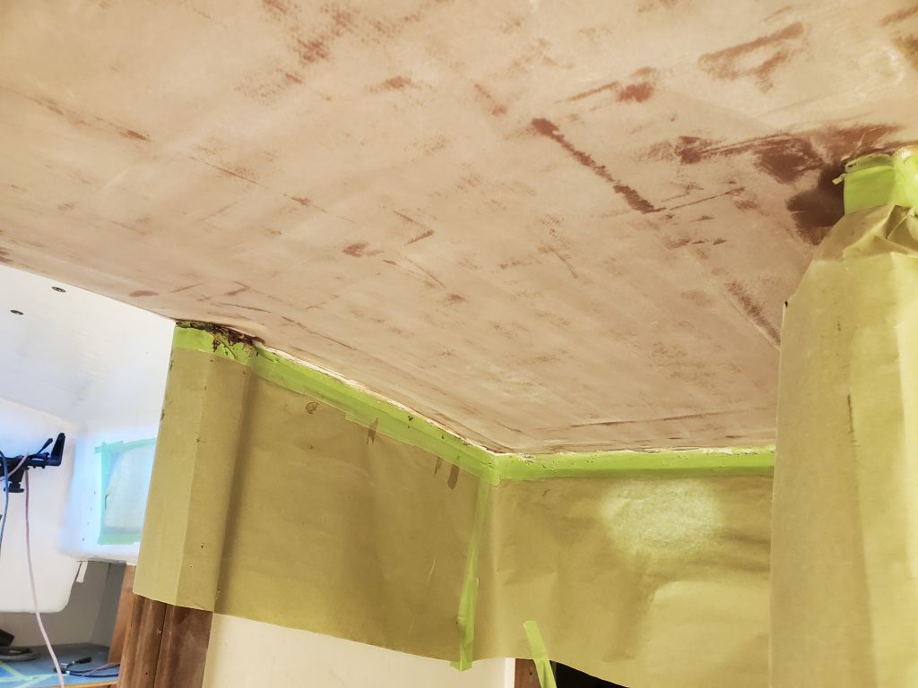
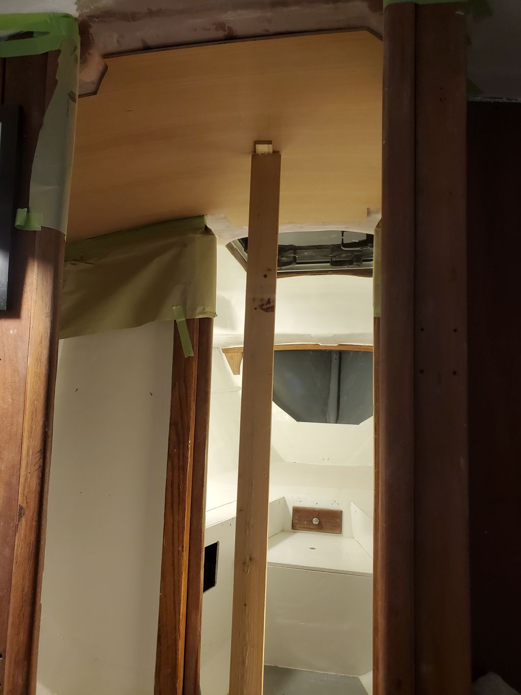
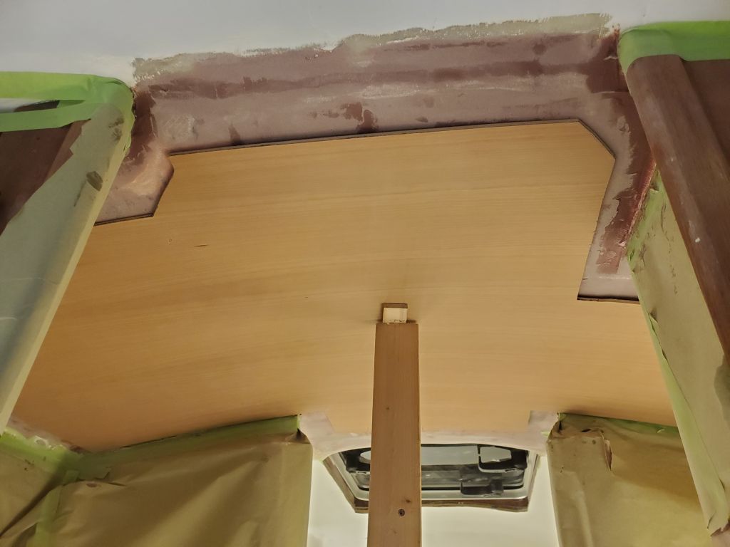
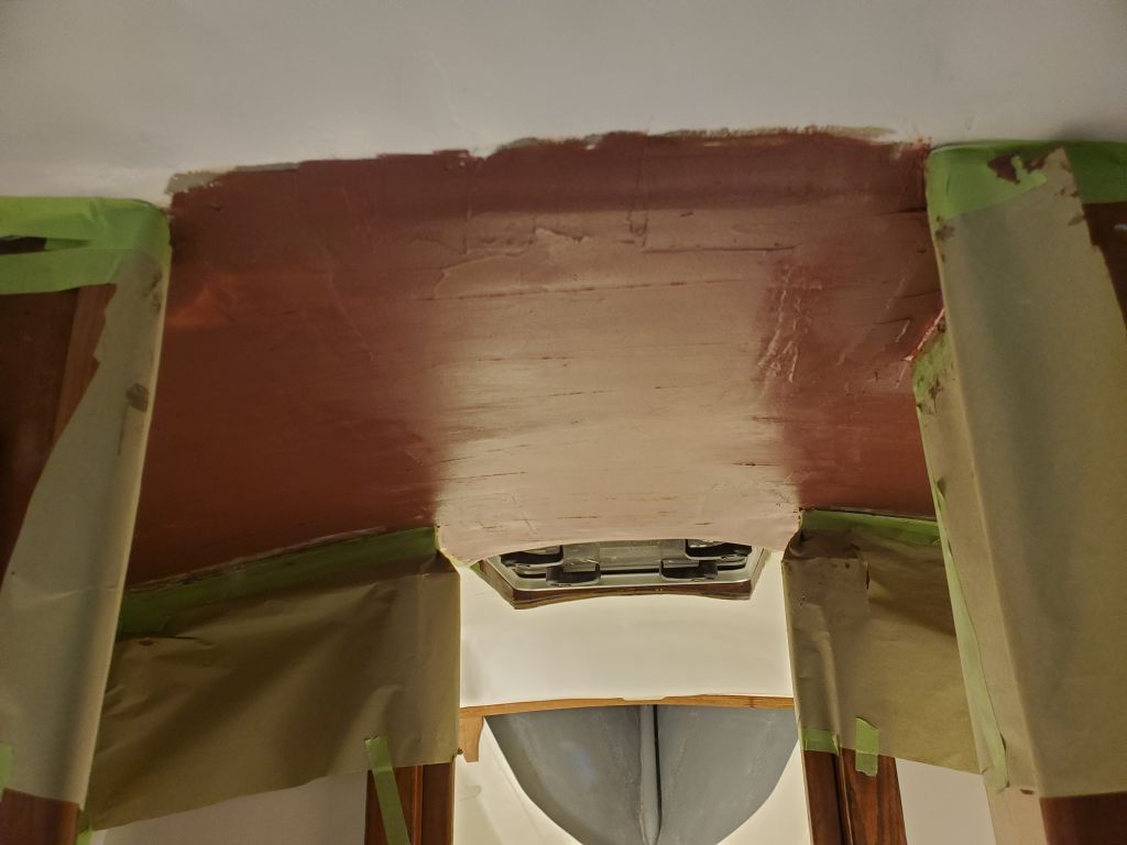
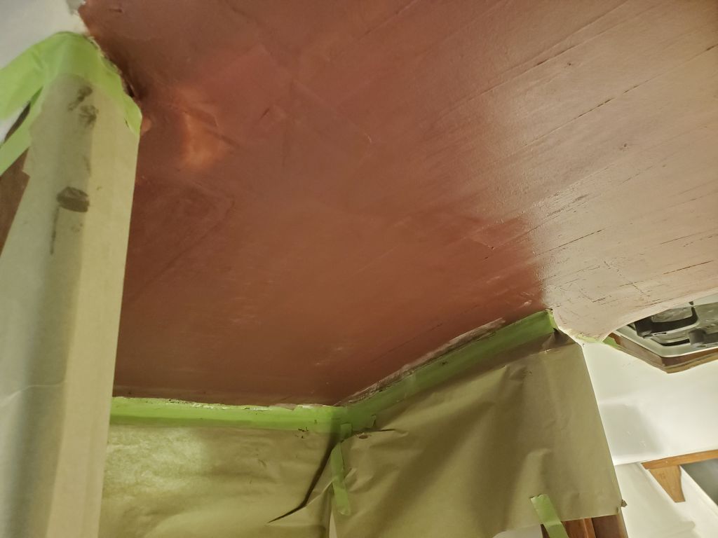
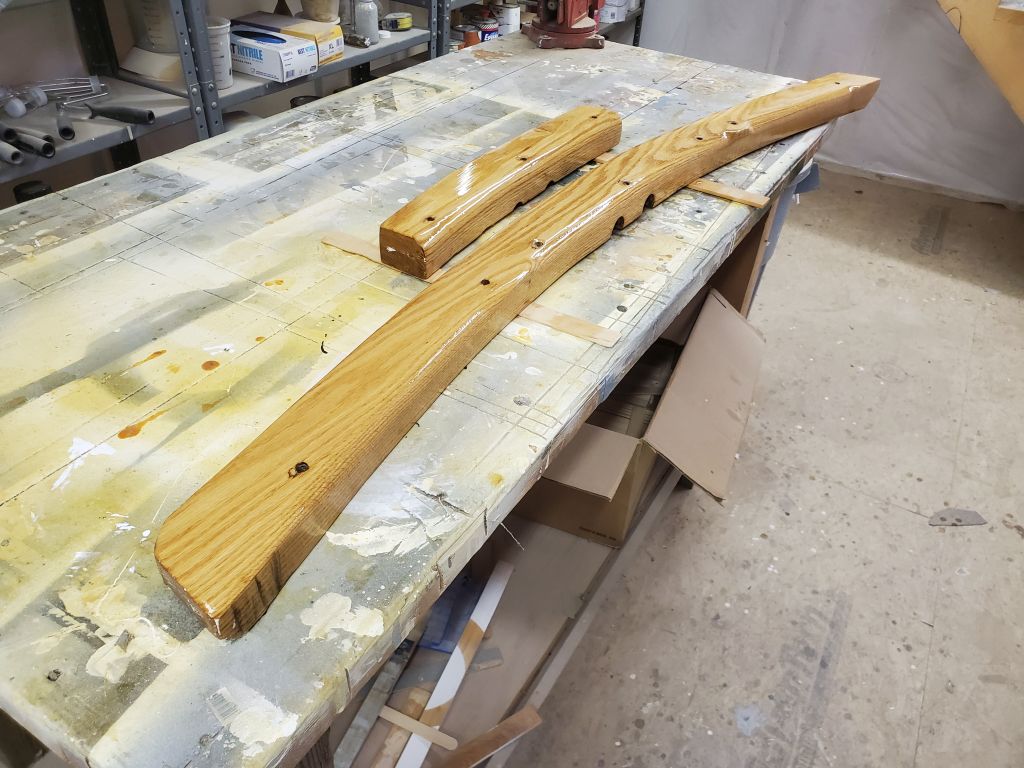
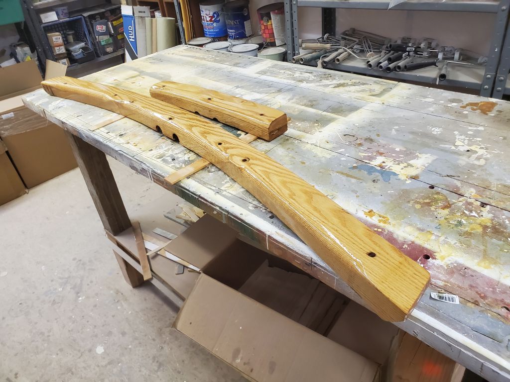
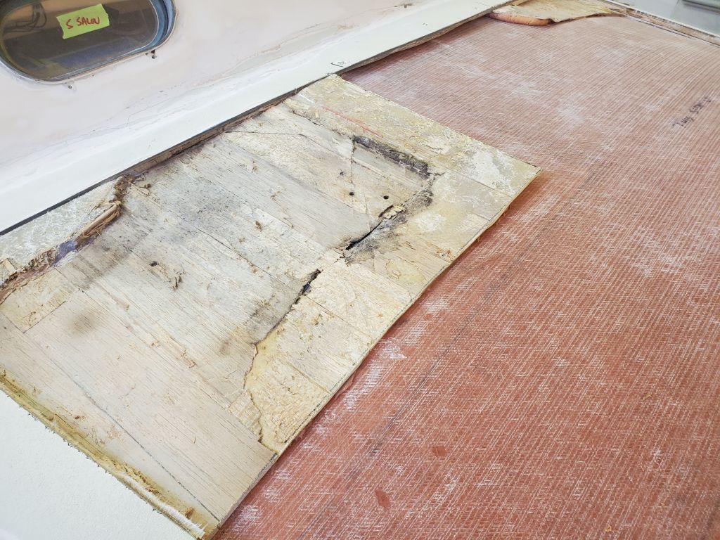
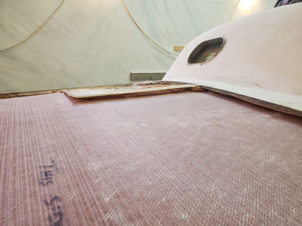
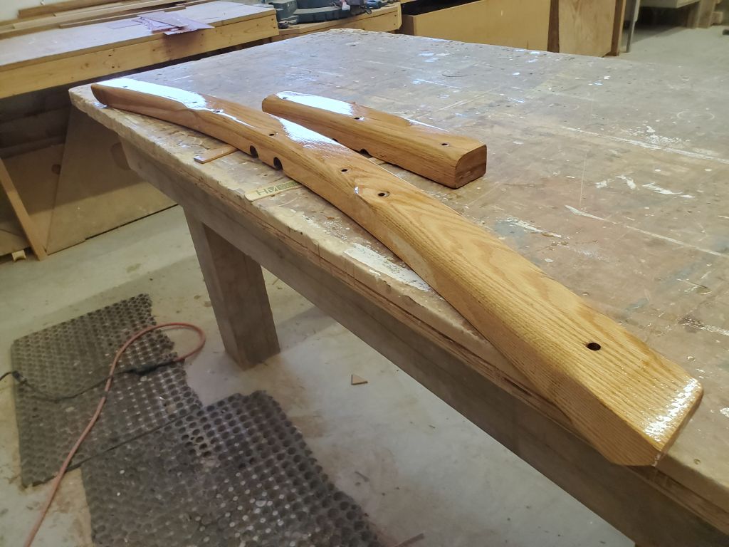
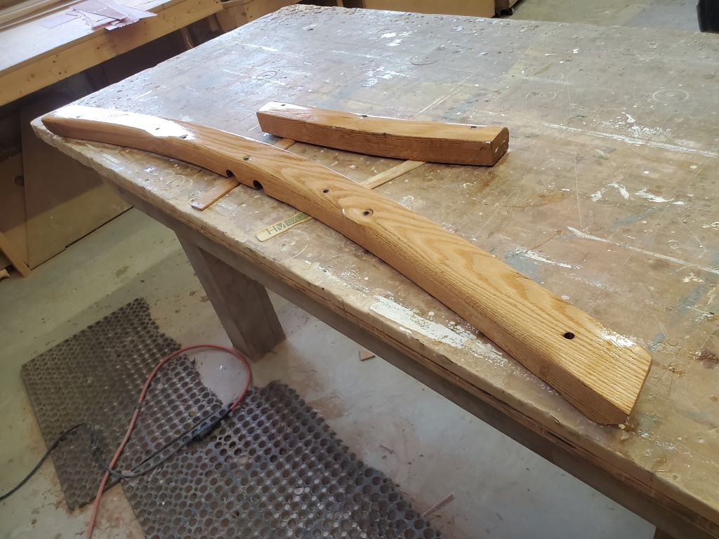
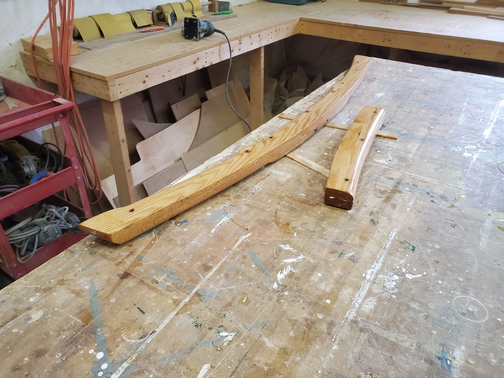
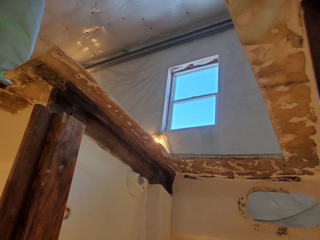
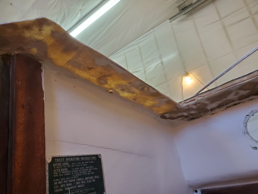
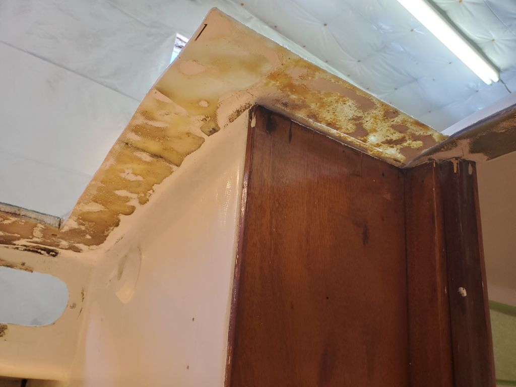
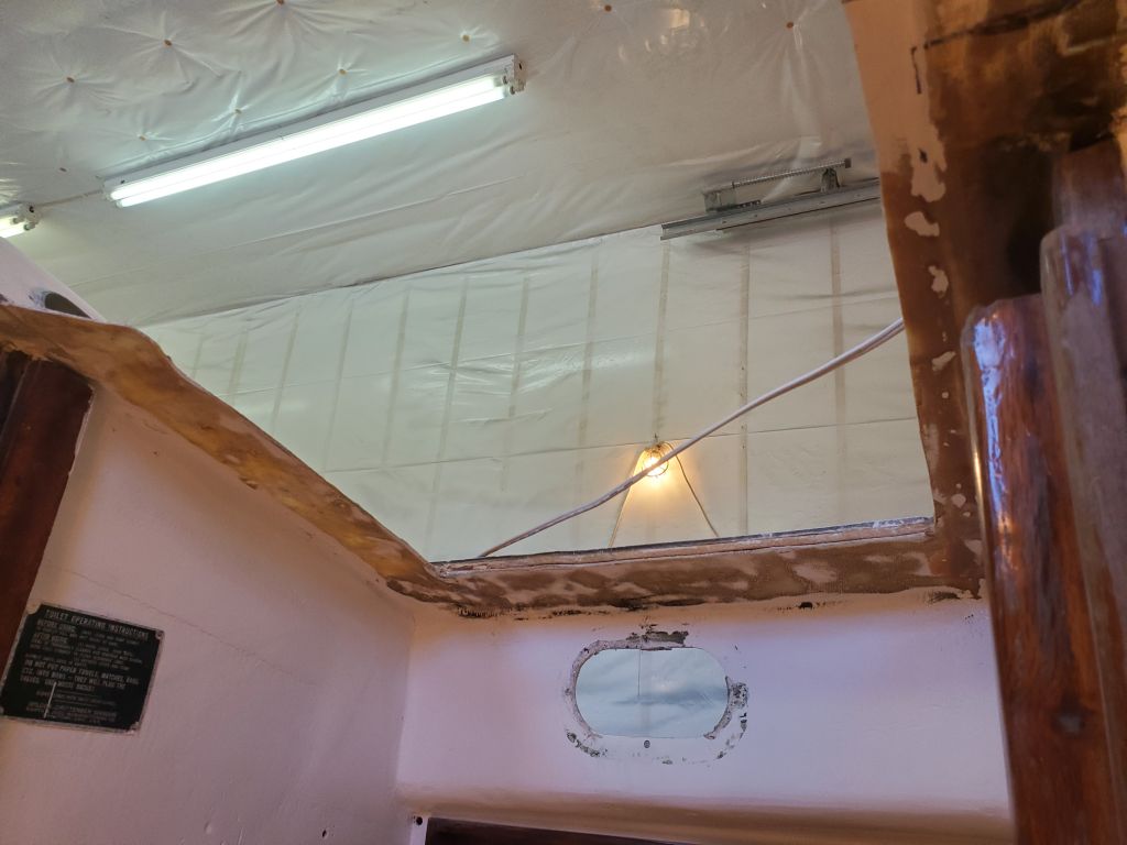
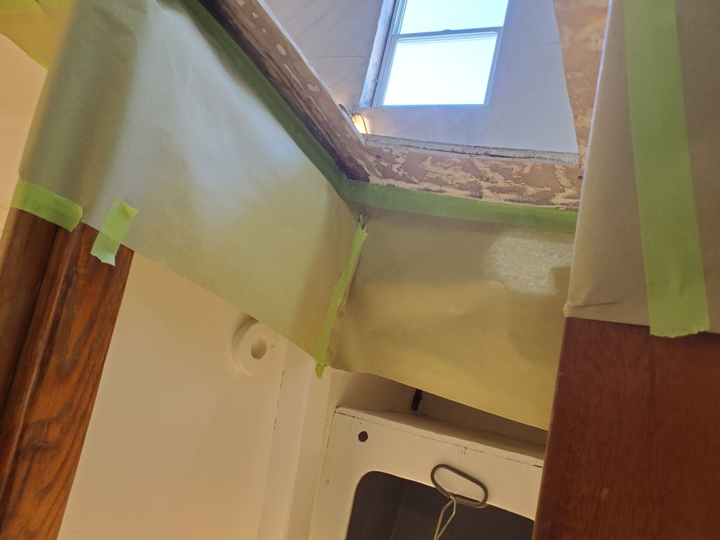
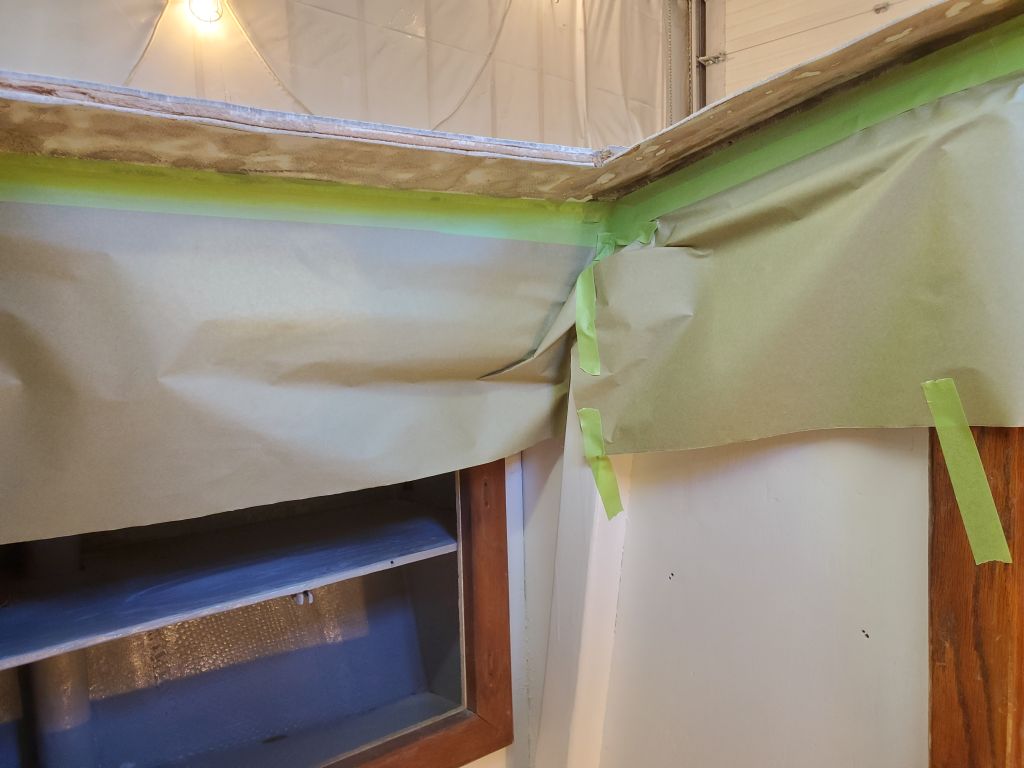
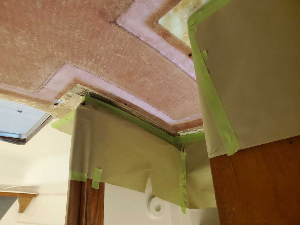
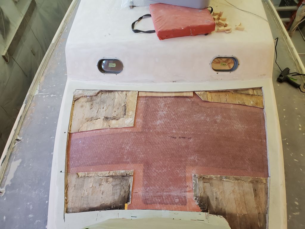
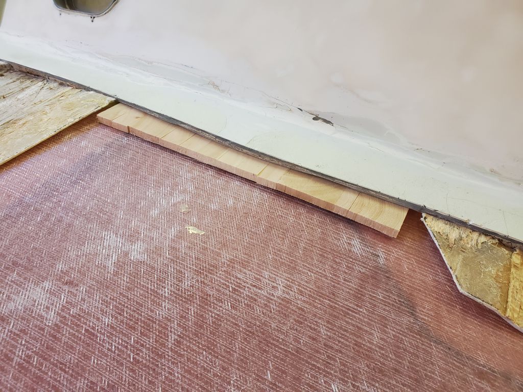
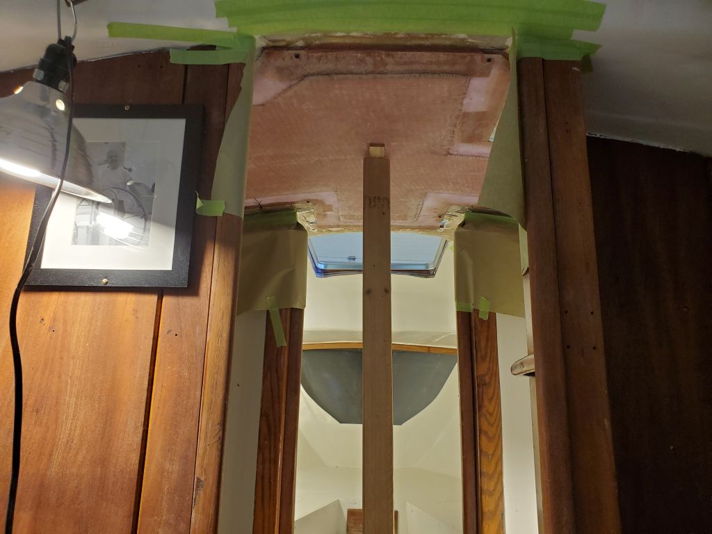
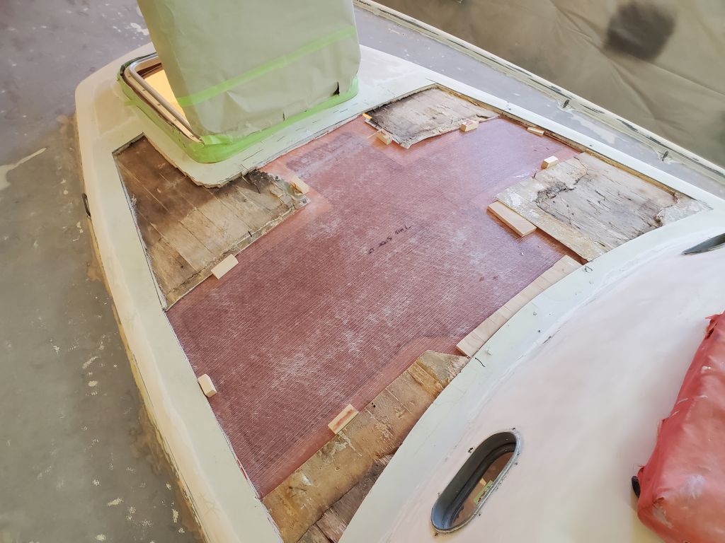
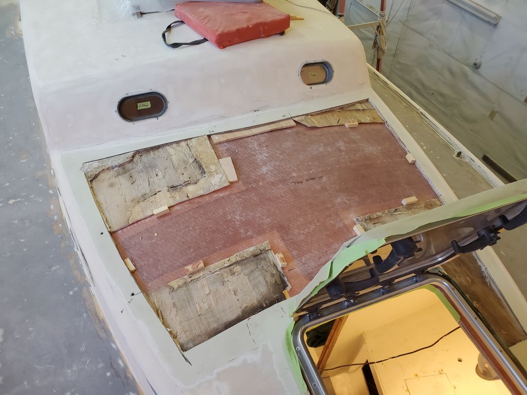
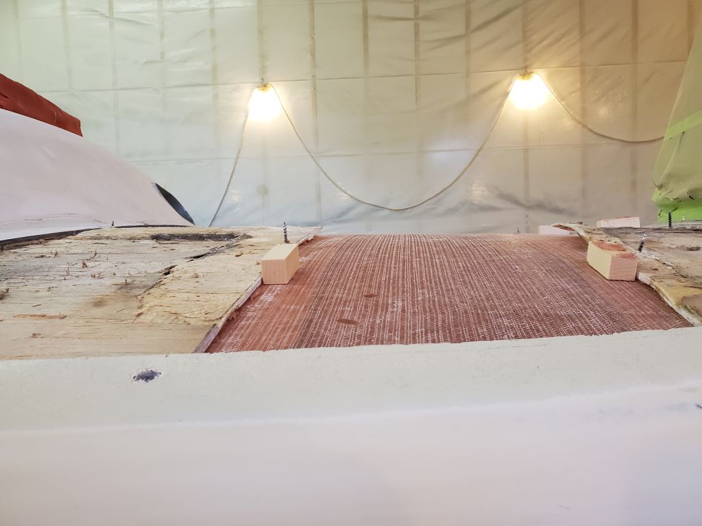
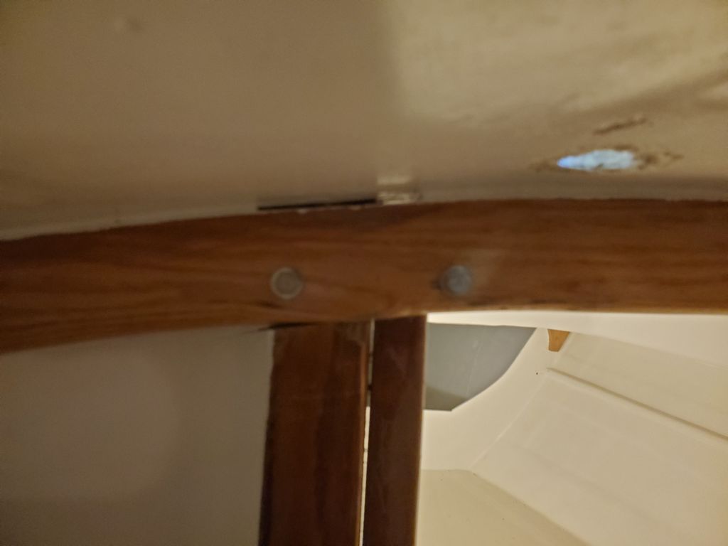
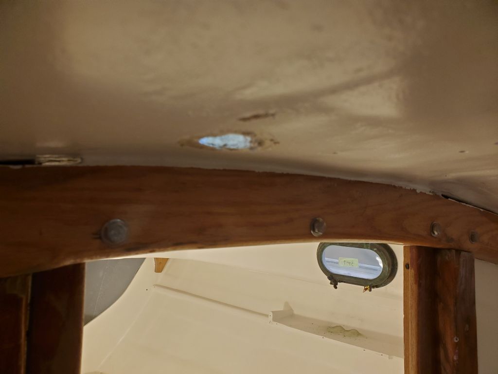
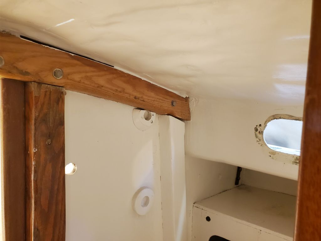
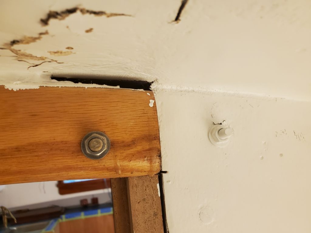
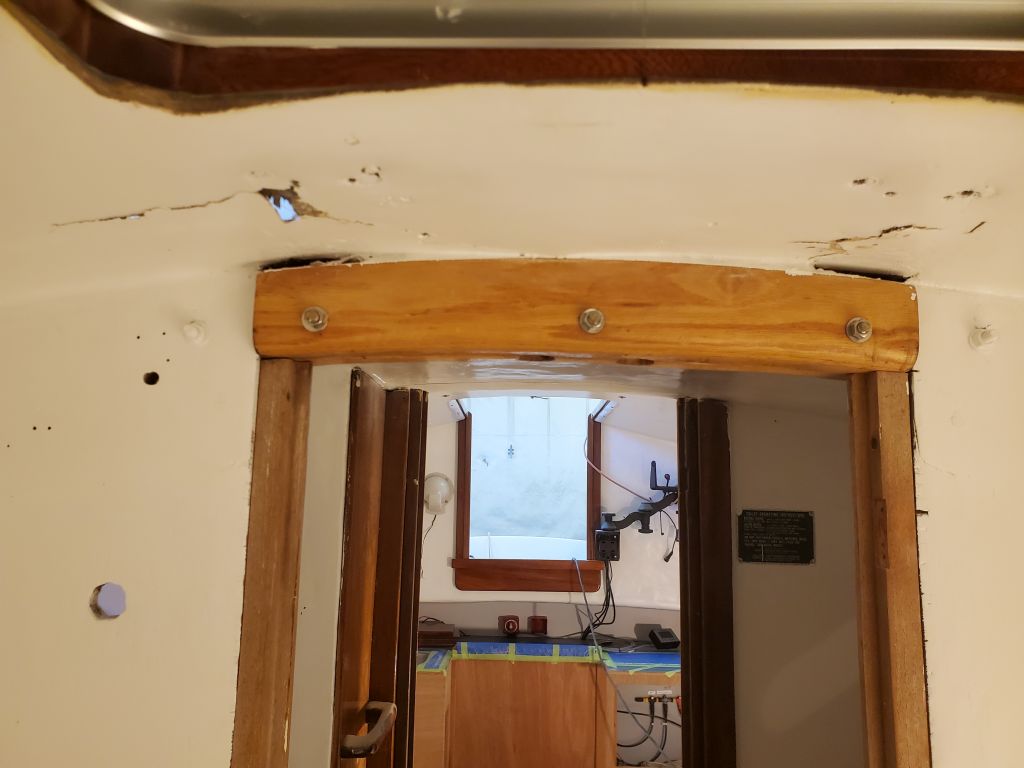
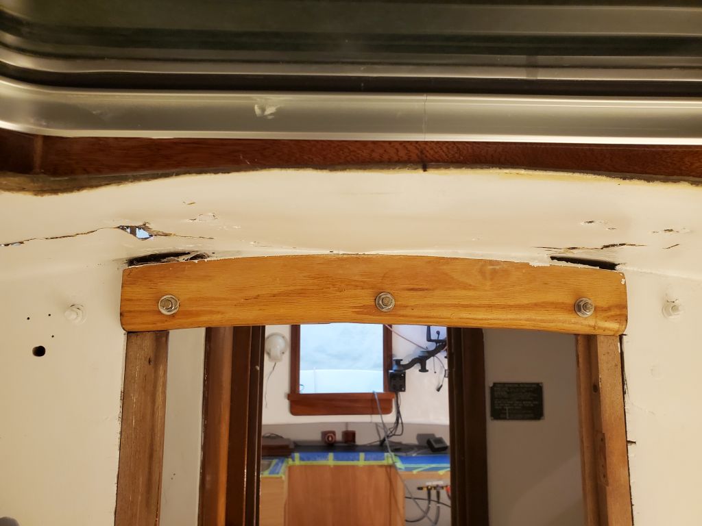
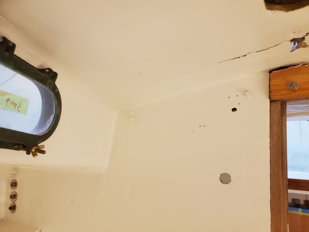
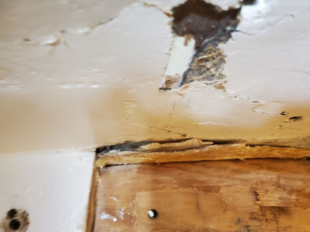
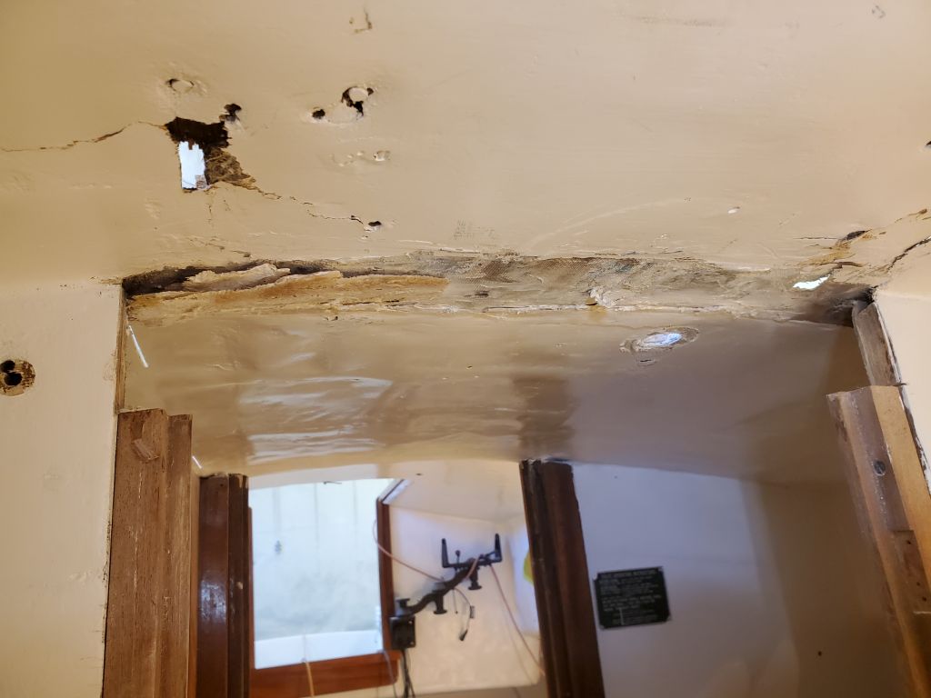
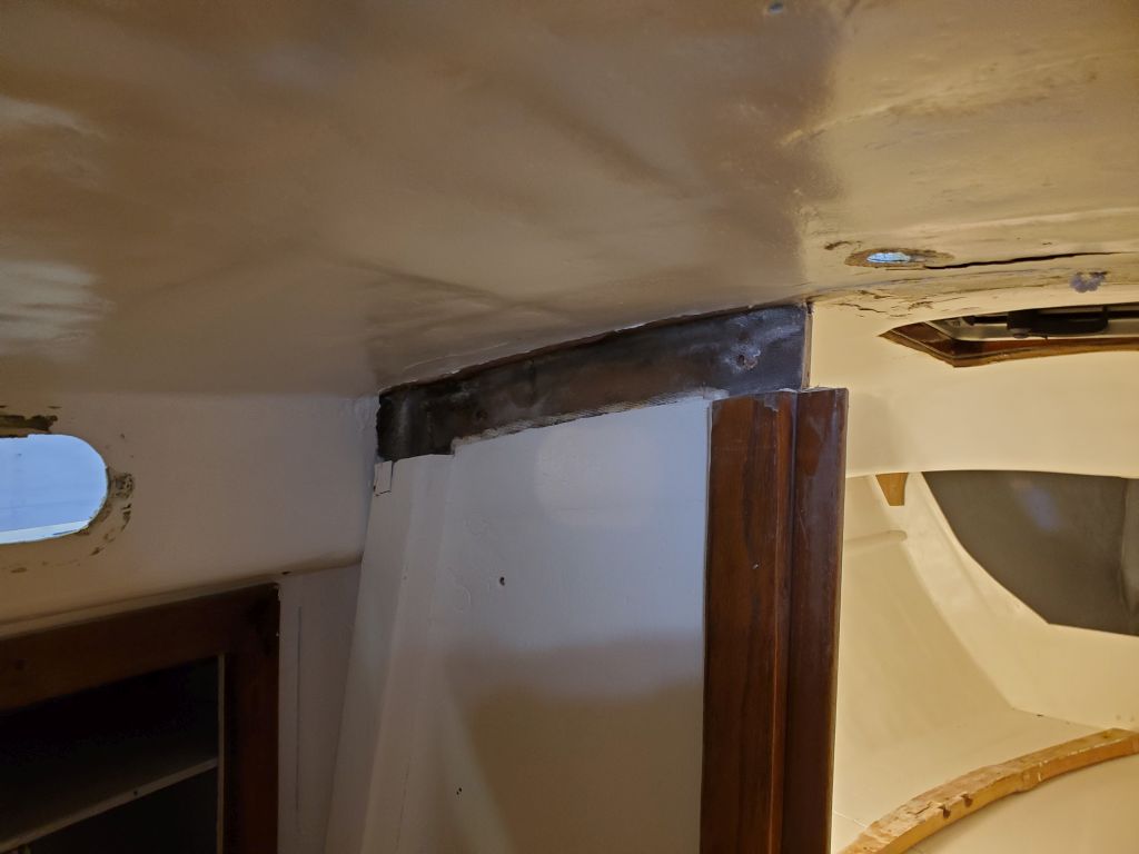
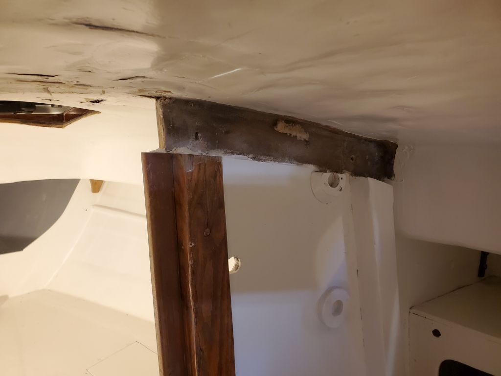
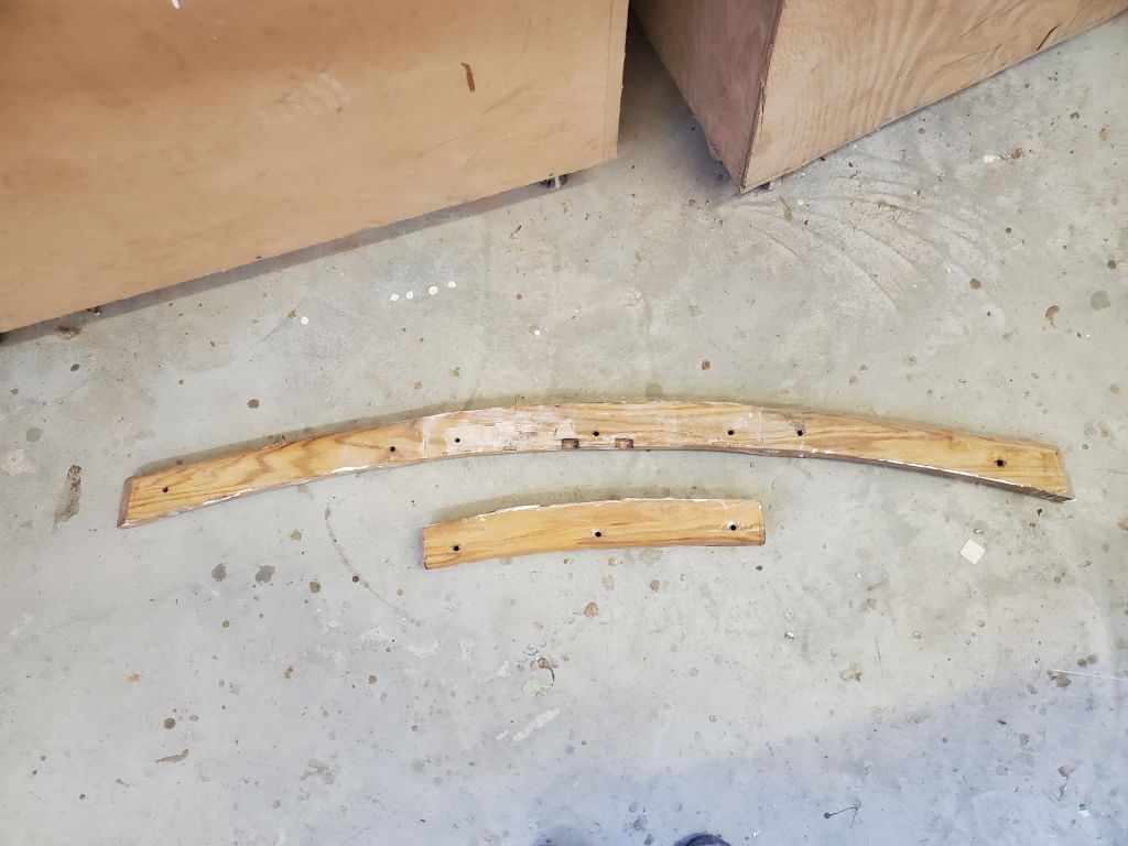
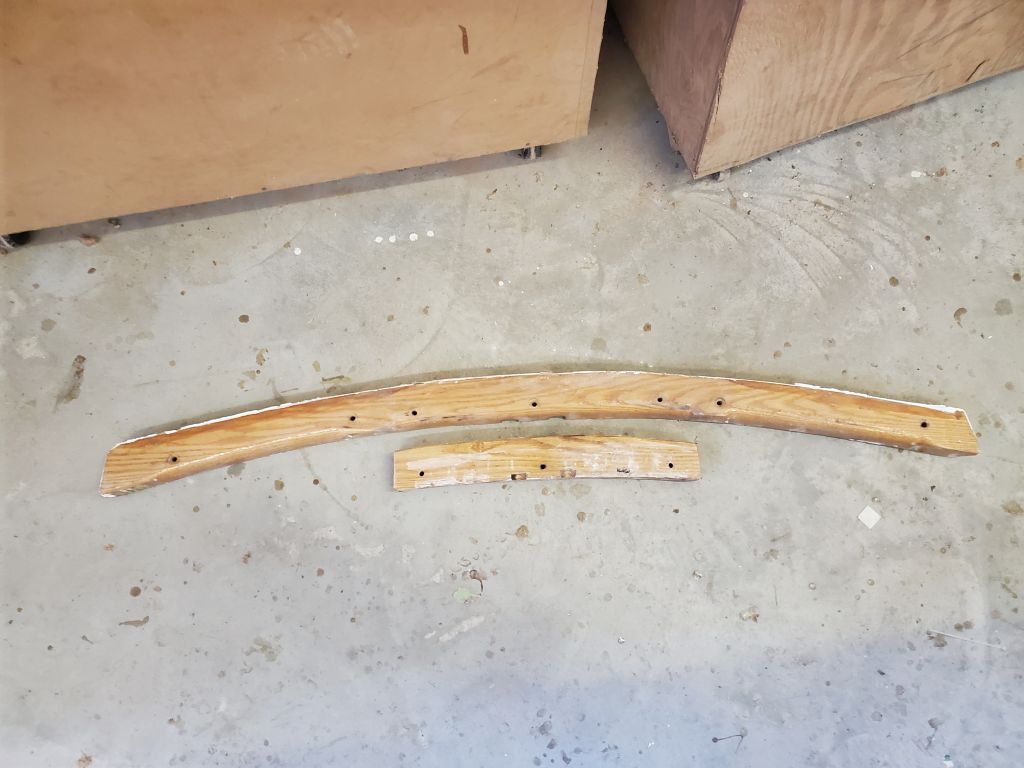
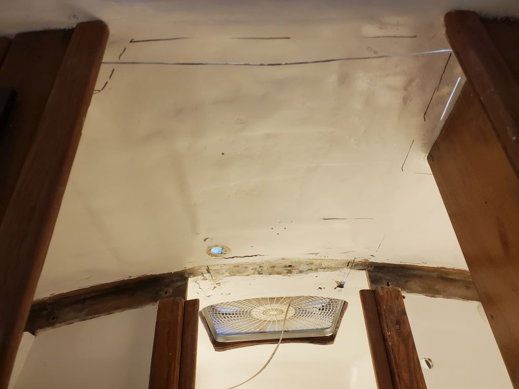
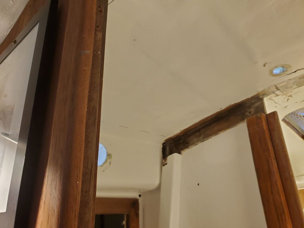
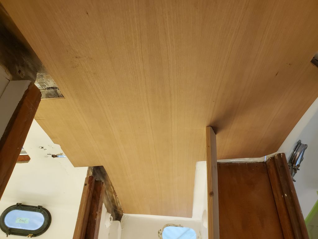
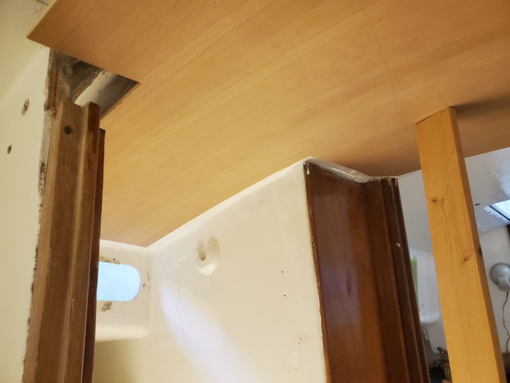
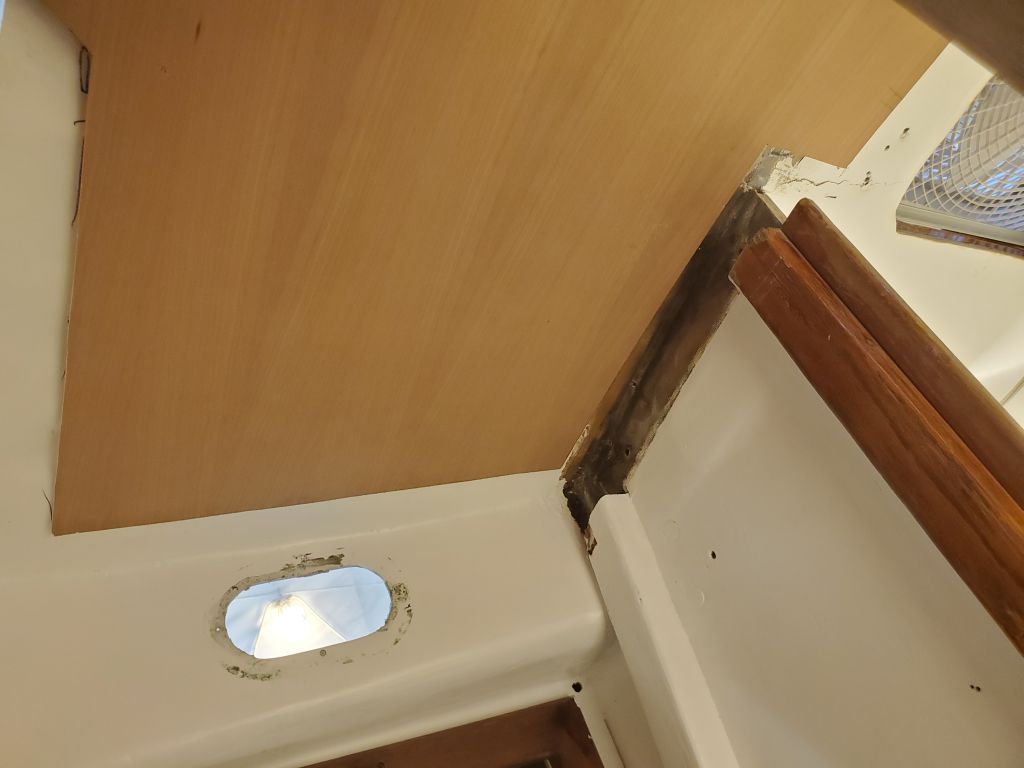
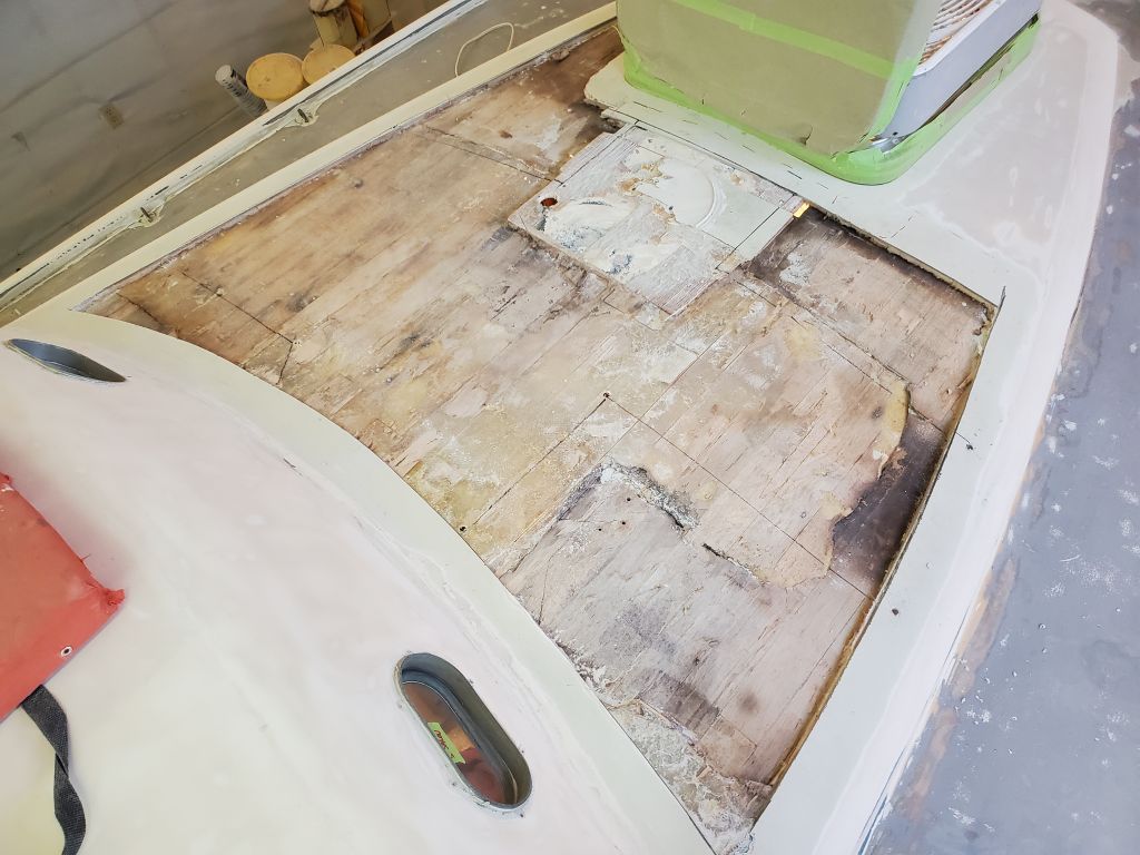
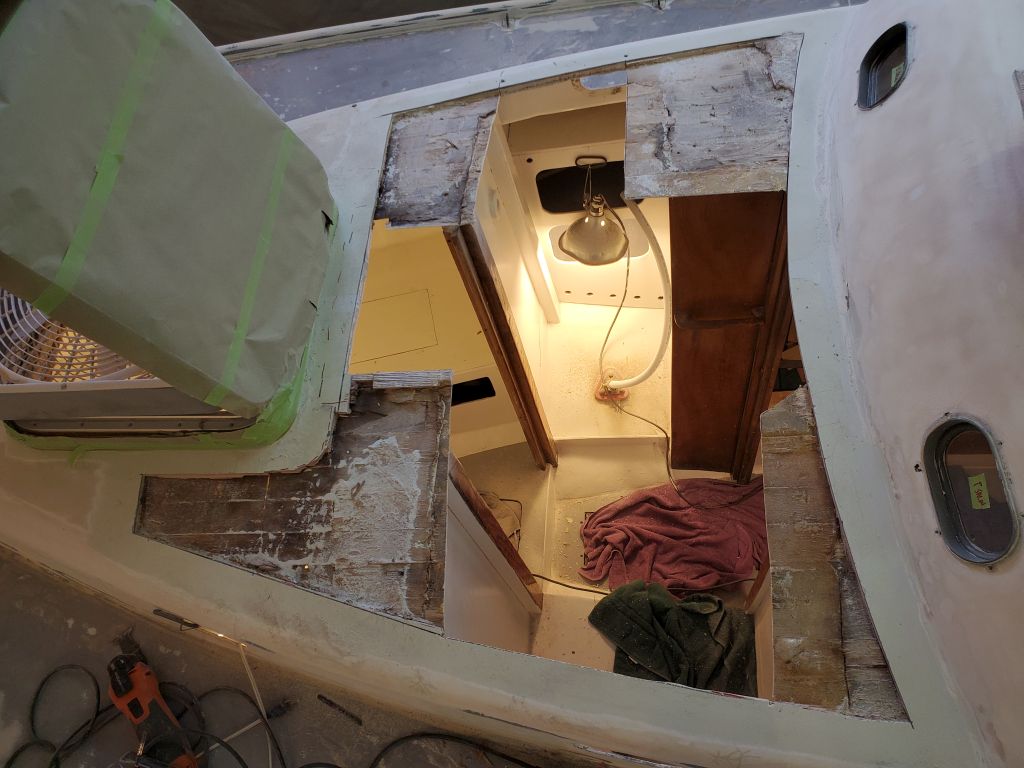
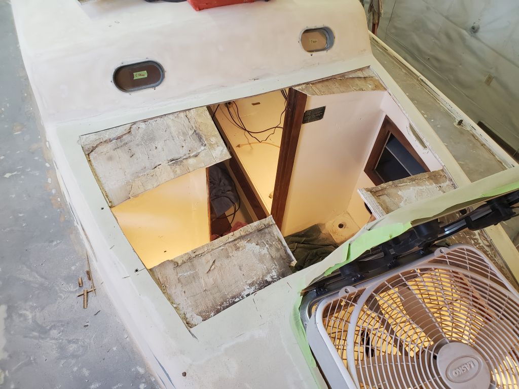
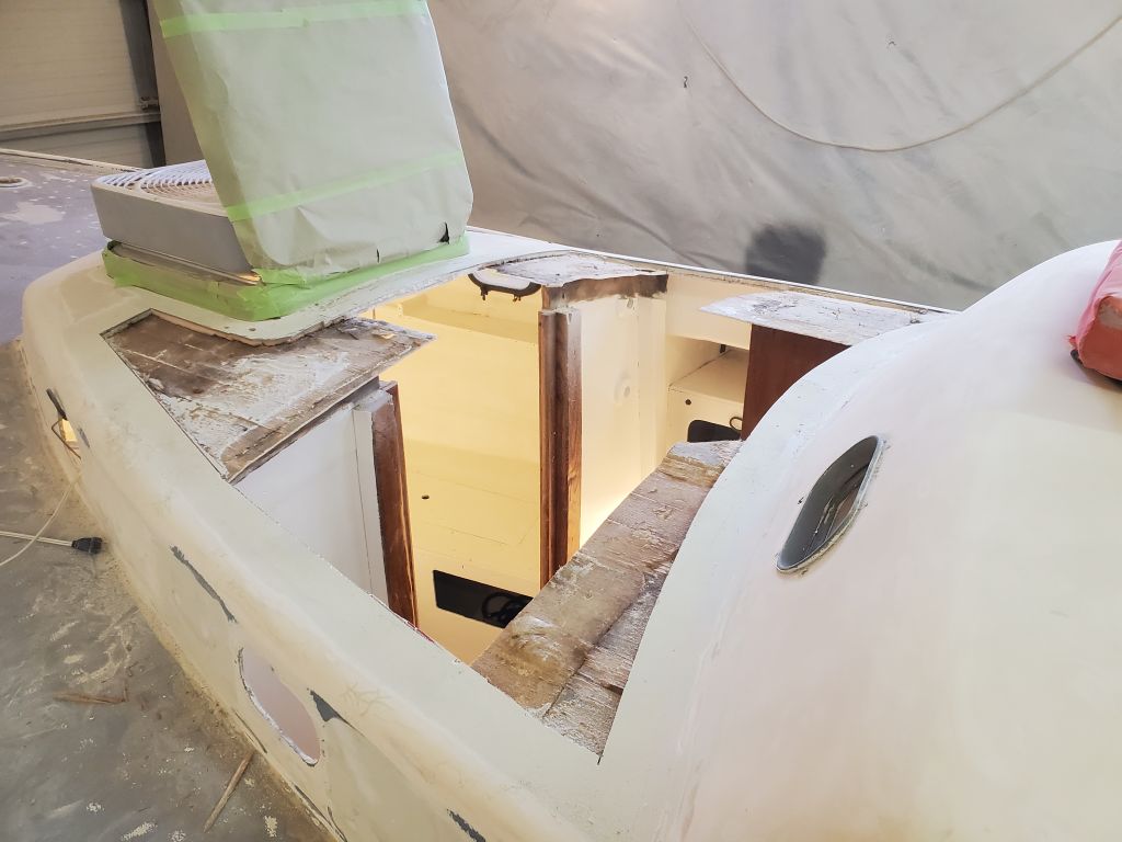
To gain access to the coachroof deck from beneath in order to make the required repair, I needed to remove the wooden mast support beam, which arched beneath the mast step and notched into the vertical support structure of the forward bulkhead. Several bolts held it in place, and in this case, there was some messy fiberglass work that looked to pose at least some removal challenges for the beam. A second, shorter beam extended the support a bit further into the forward cabin along the forward side of the opening. These beams were newer than original and were themselves in serviceable condition, though the overall installation left something to be desired.
Because of the way I felt the deck needed to be rebuilt, eliminating as much of the old repair work as possible and, more importantly, tying in the repairs and other new work with the critical mast step area, I needed clear access through the passageway to the forward cabin, across which the beam now spanned.
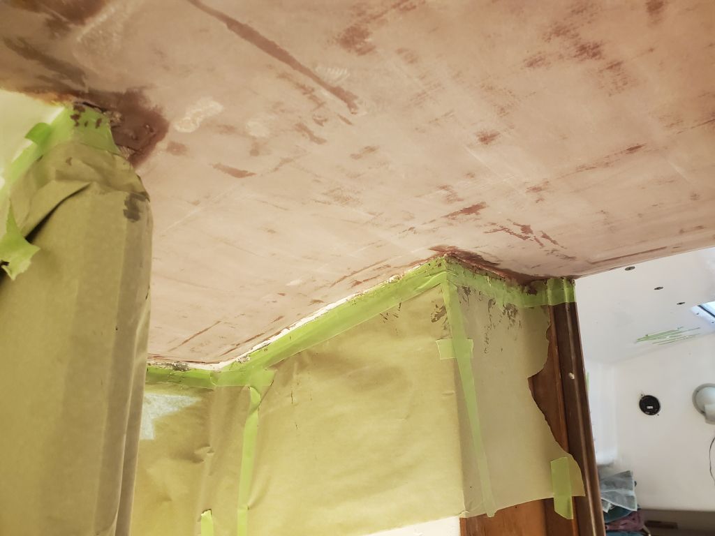
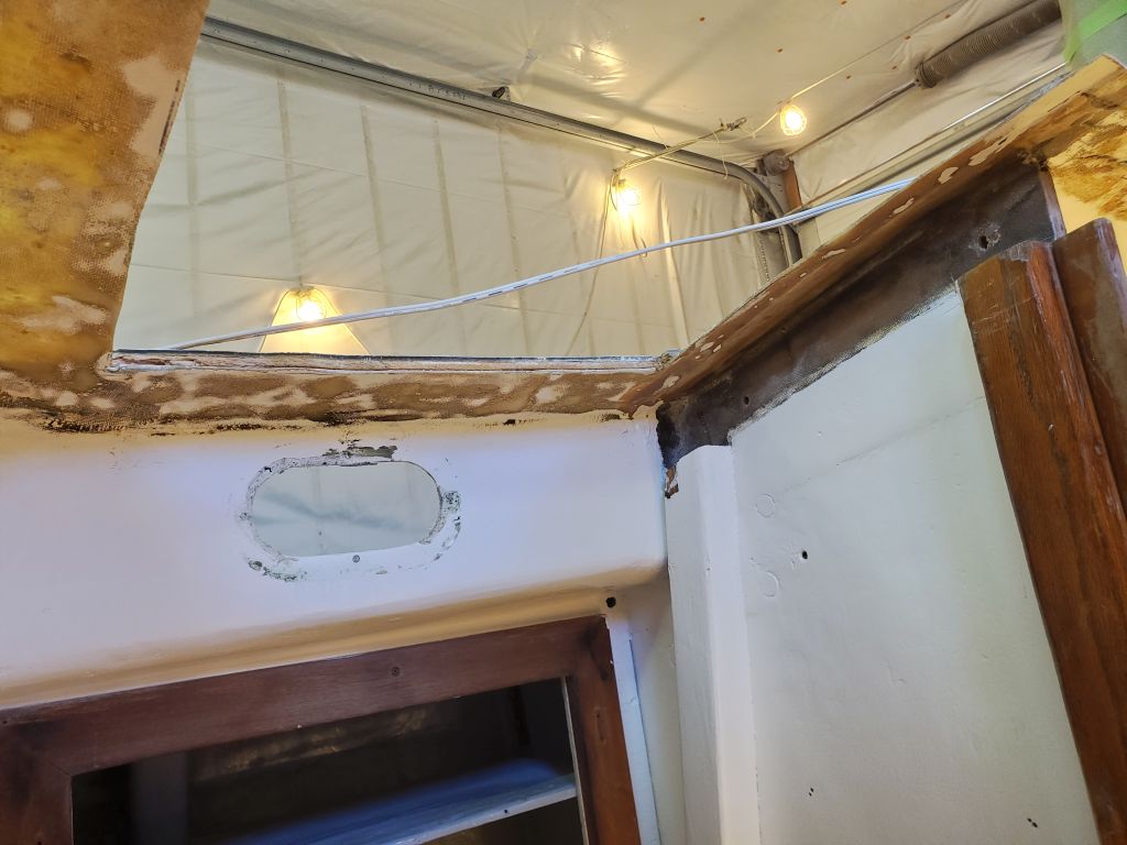
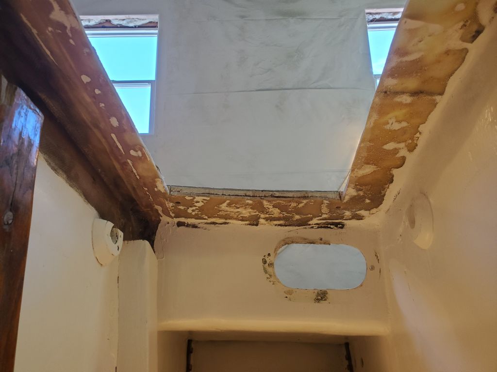
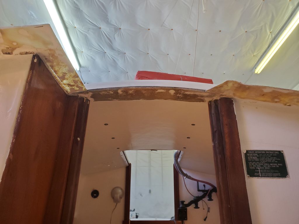
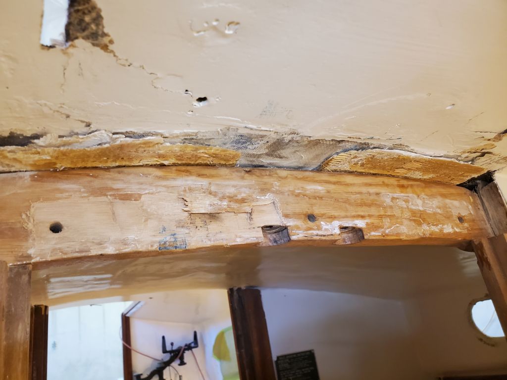
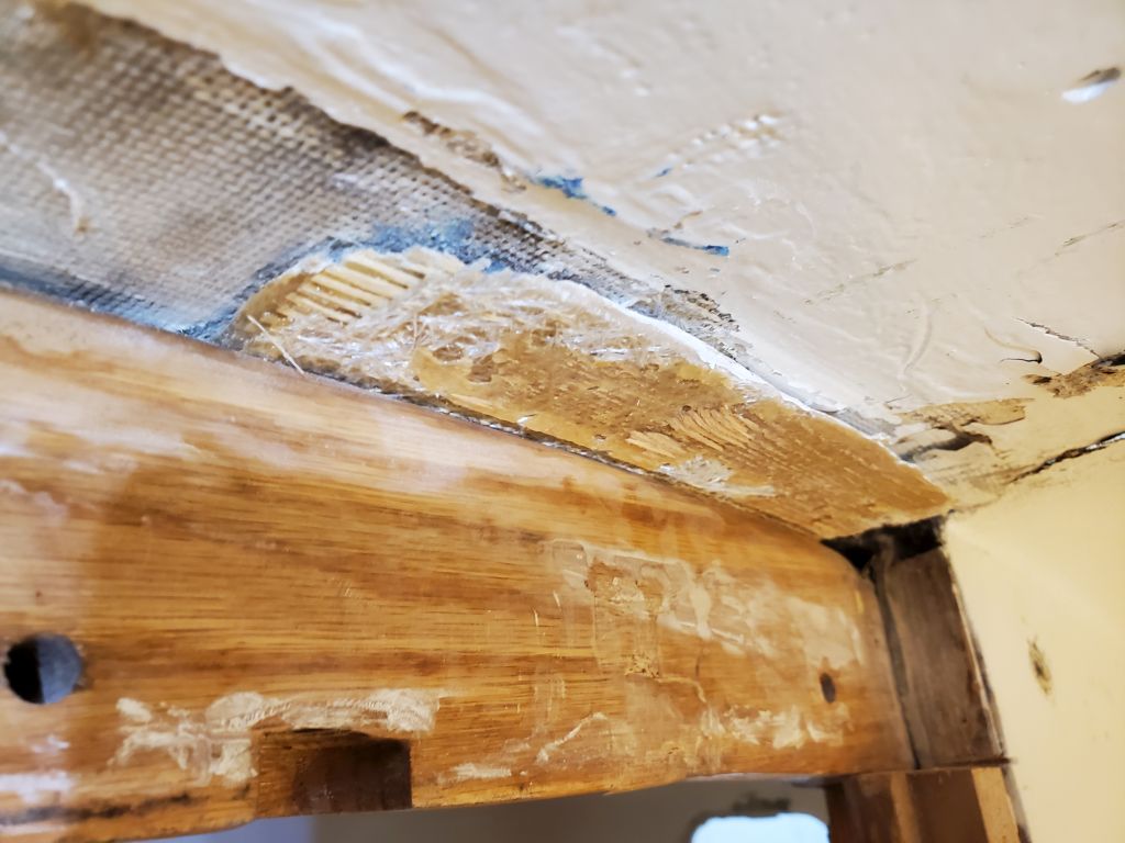
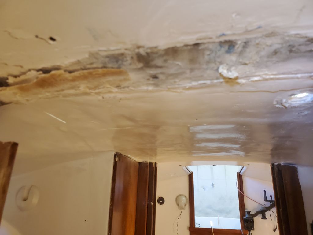
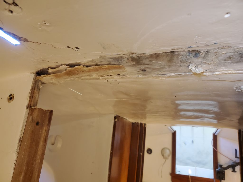
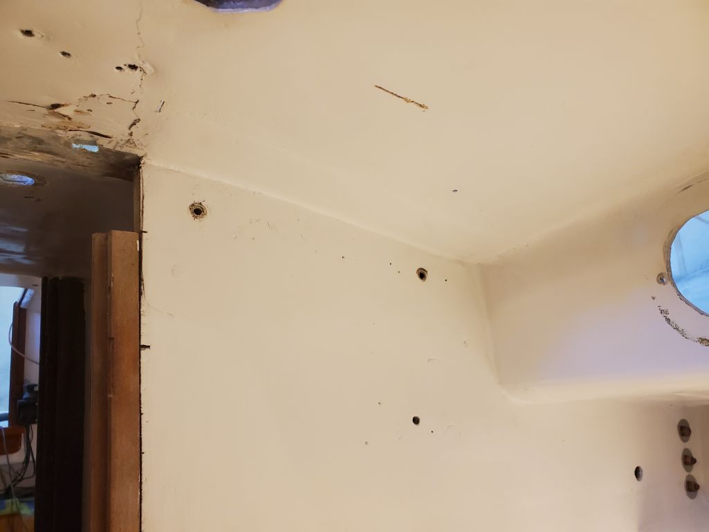
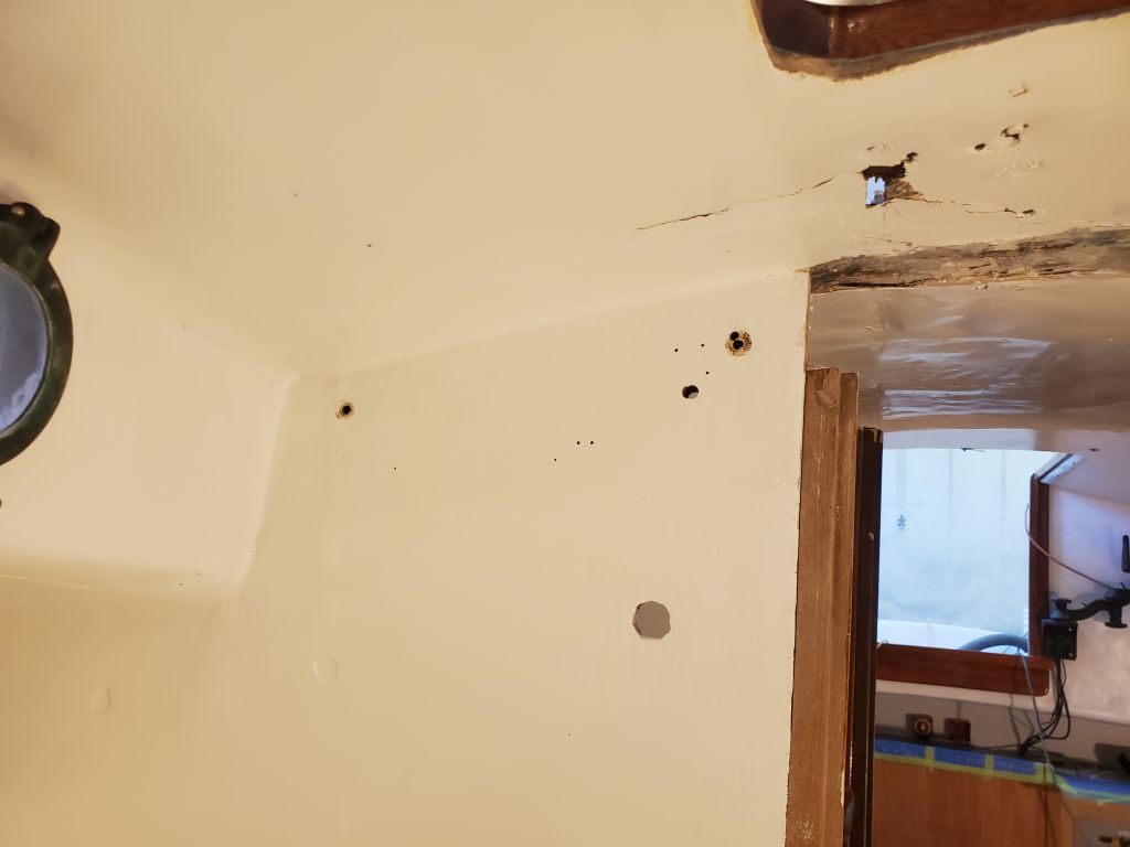
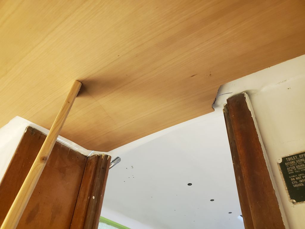
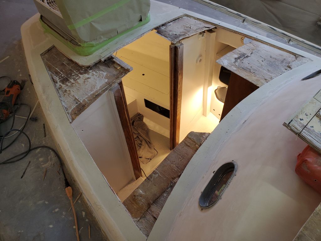
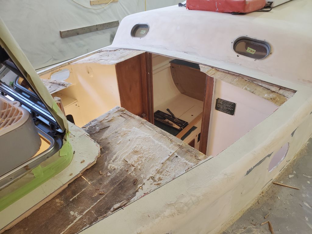
I removed all the bolts without issue, then worked to remove the forward section of the beam. I cut through the fiberglass between the beam and the overhead, used various prying devices, and, when it became apparent that this short beam was at least partially tacked to the main beam behind with adhesive, ran my slim multi-tool cutter between the beam sections from beneath, eventually releasing the forward beam section.
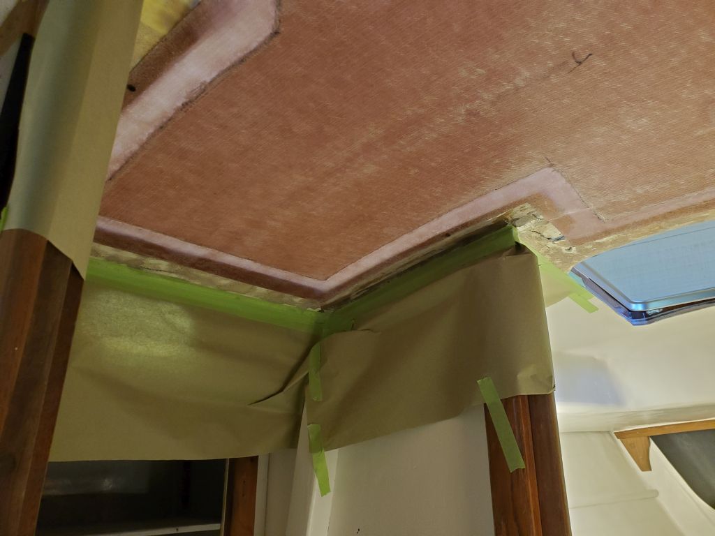
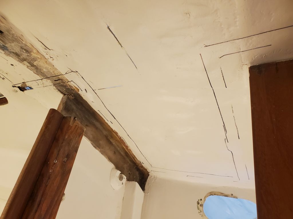
With a few additional cuts to release the fiberglass above the main beam, now accessible from both sides, it was relatively easy now to remove the main beam as well.
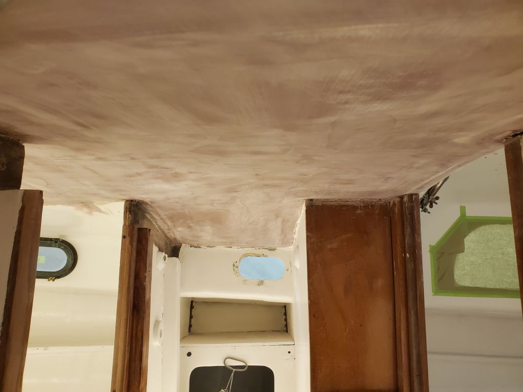
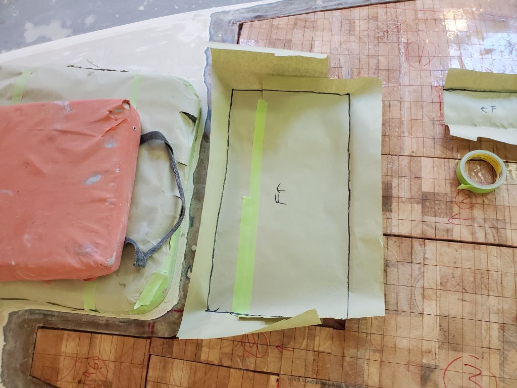
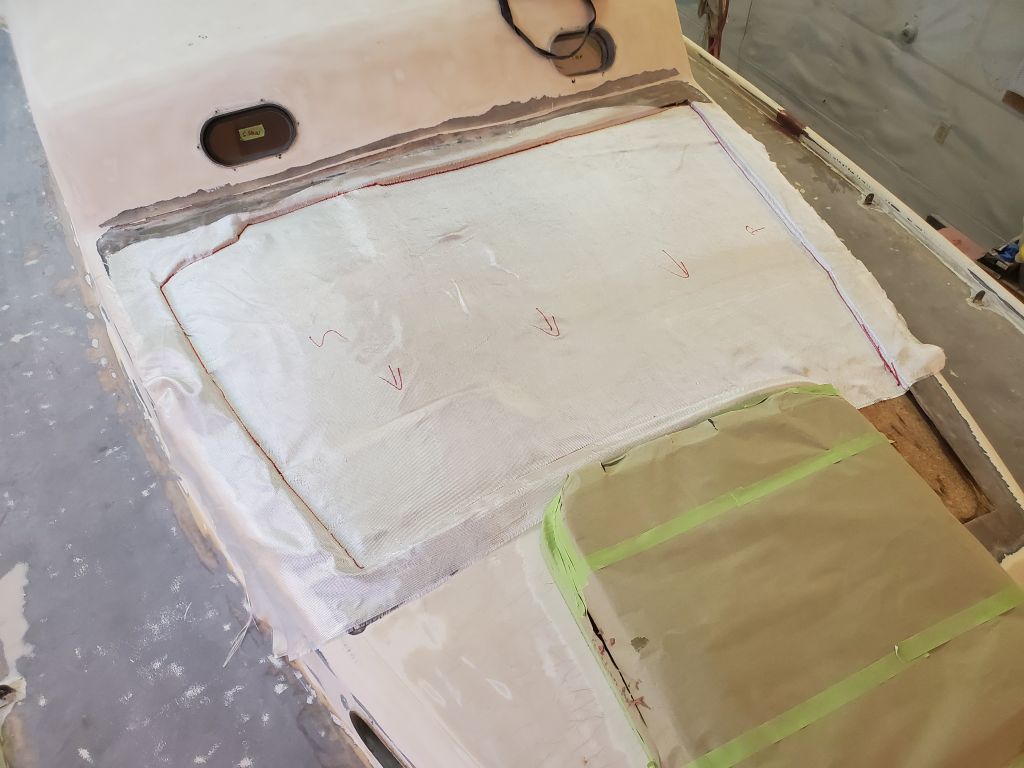
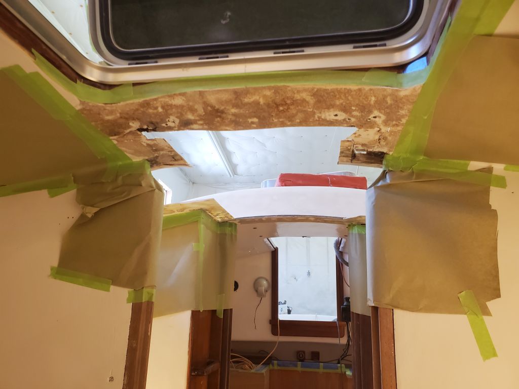
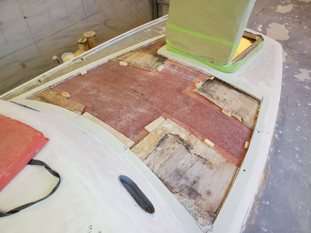
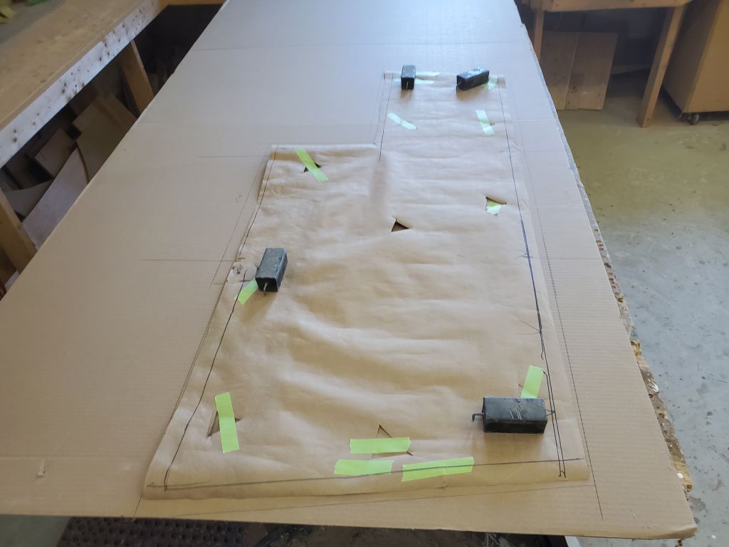
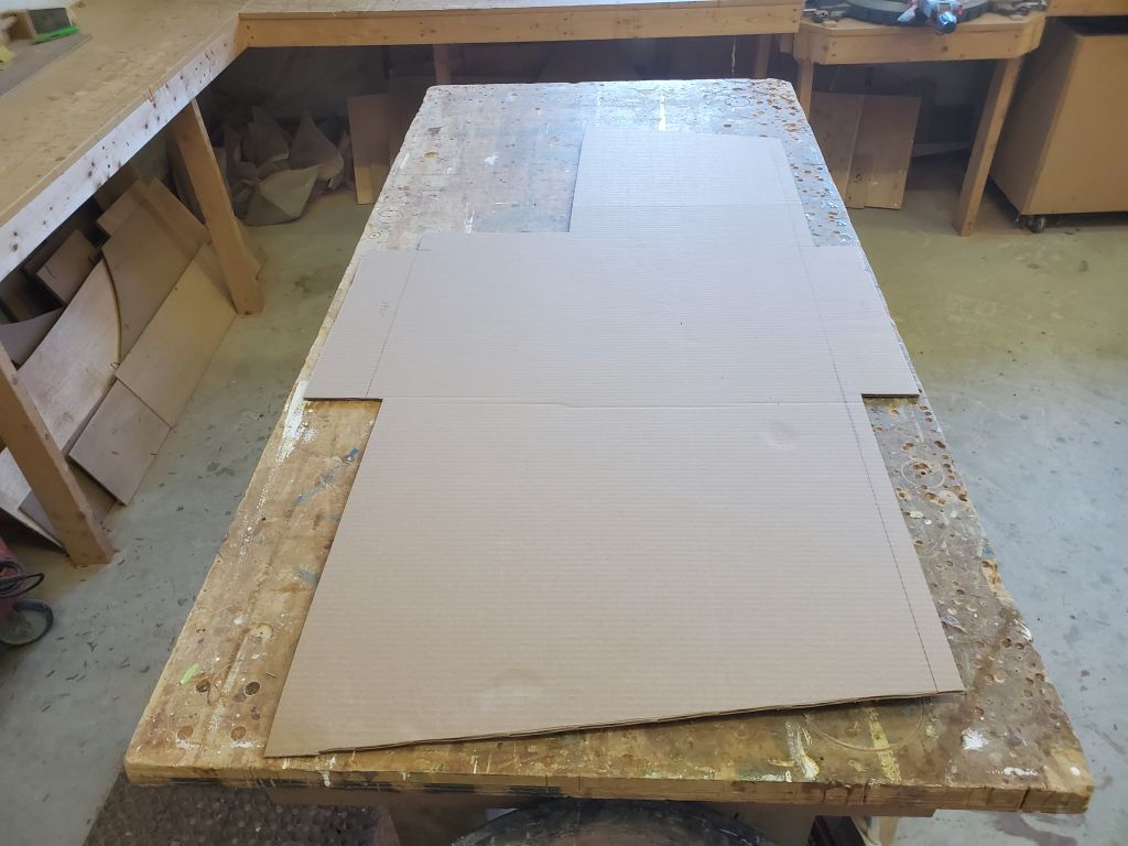
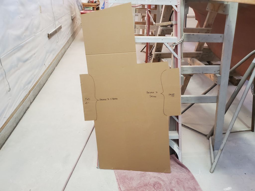
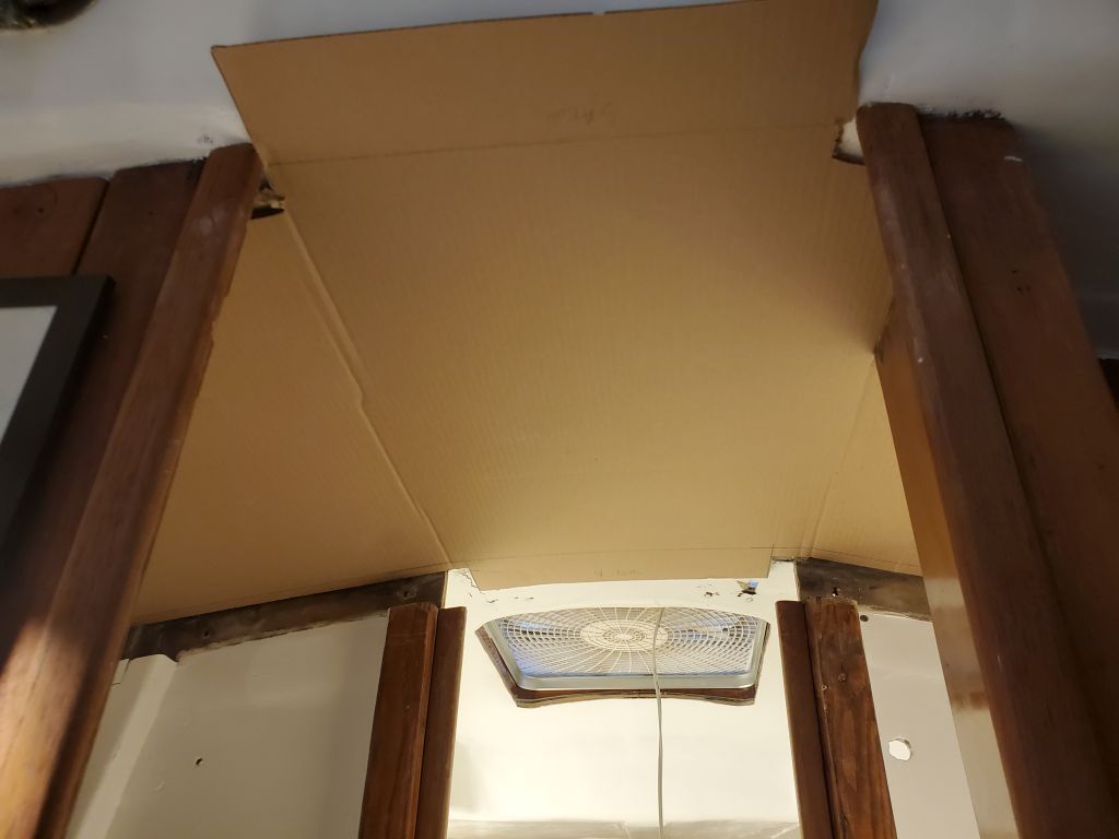
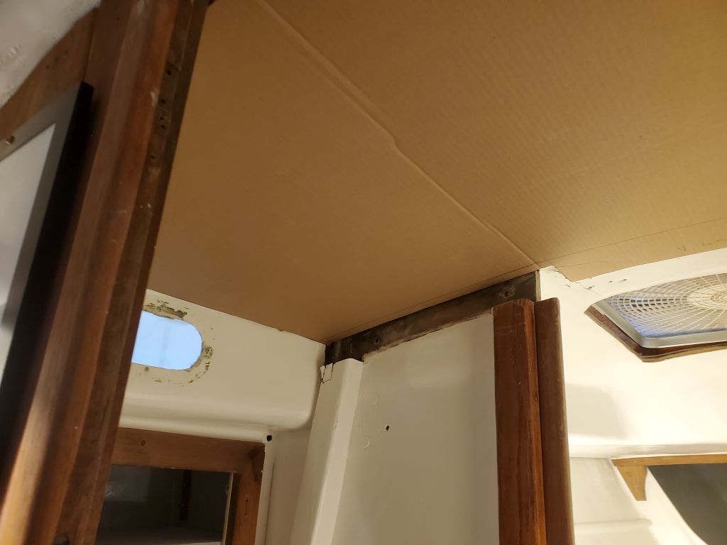
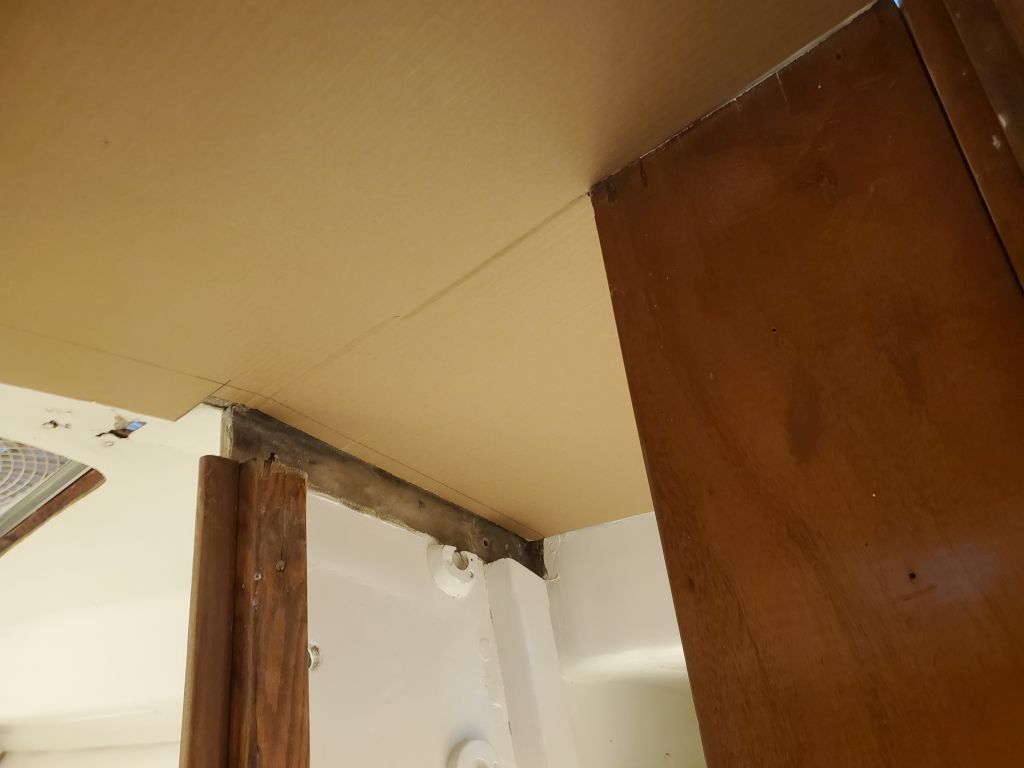
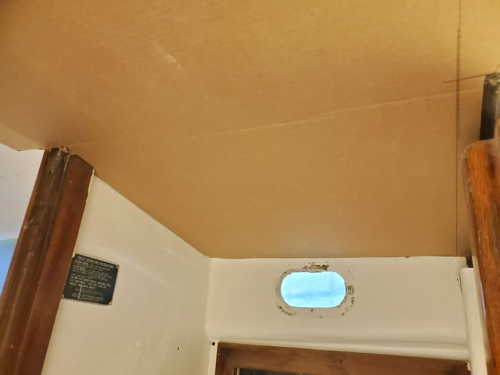
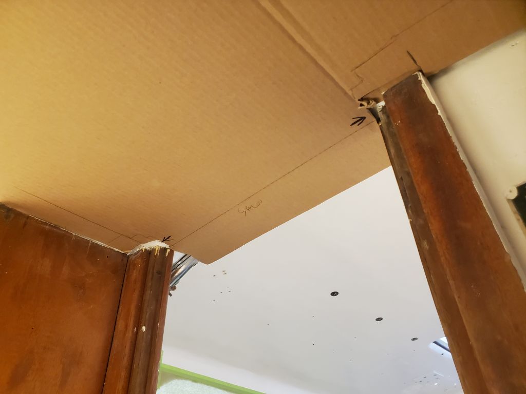
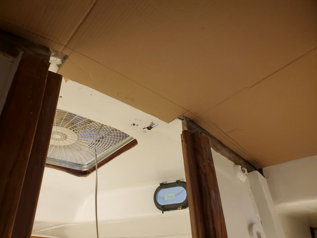
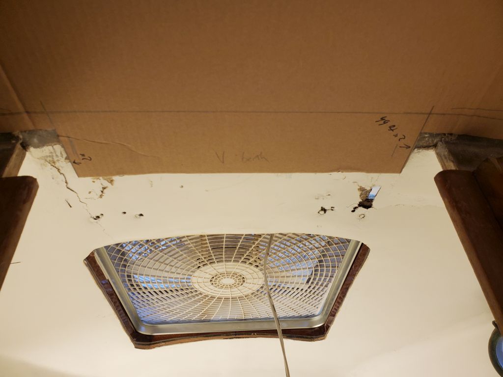
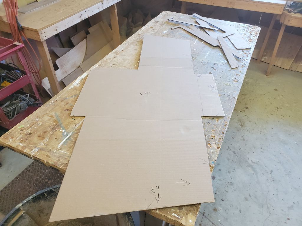
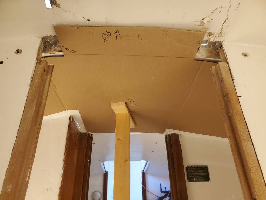
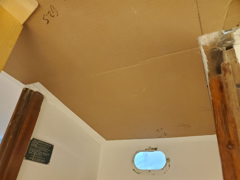
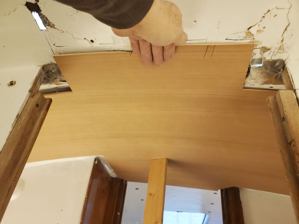
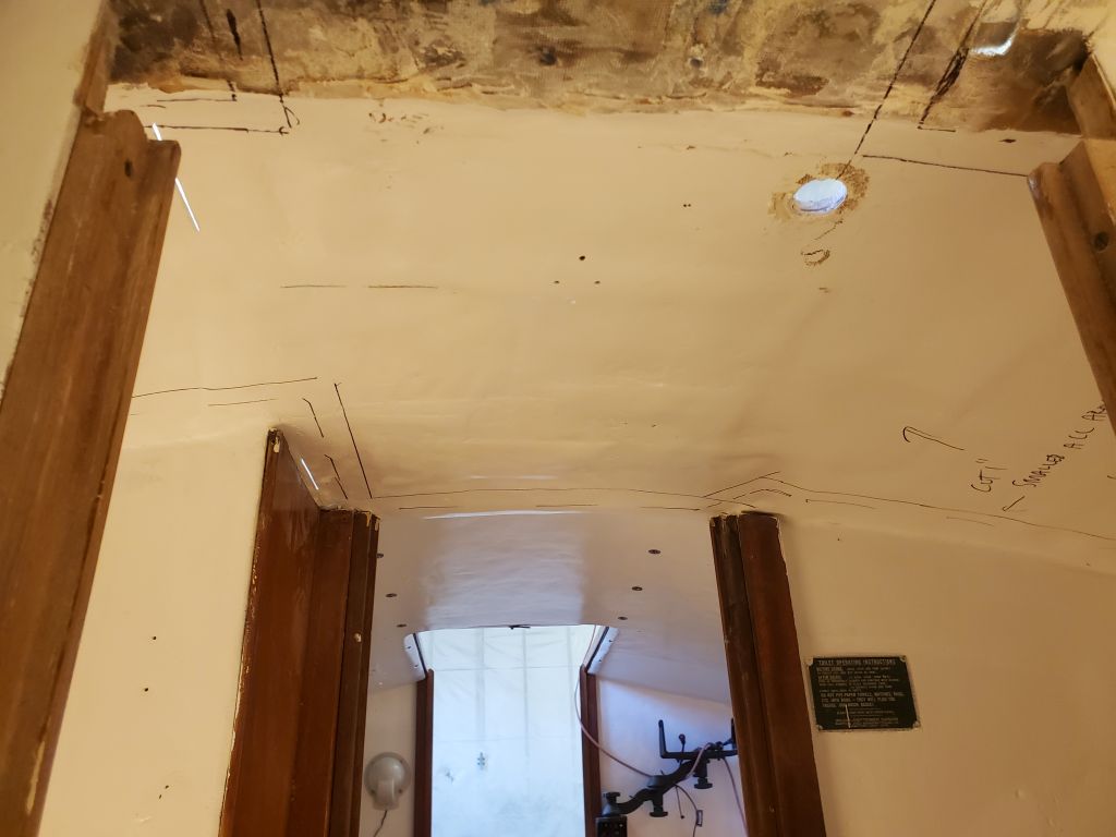
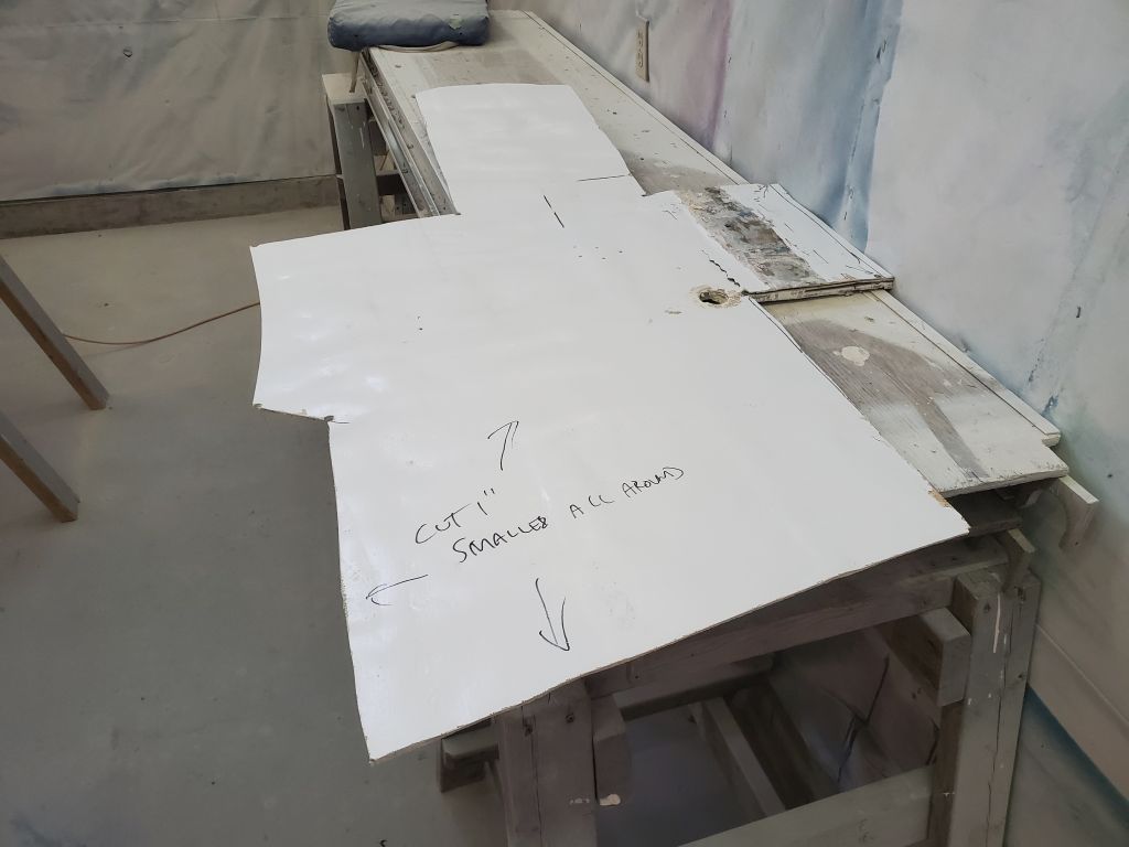
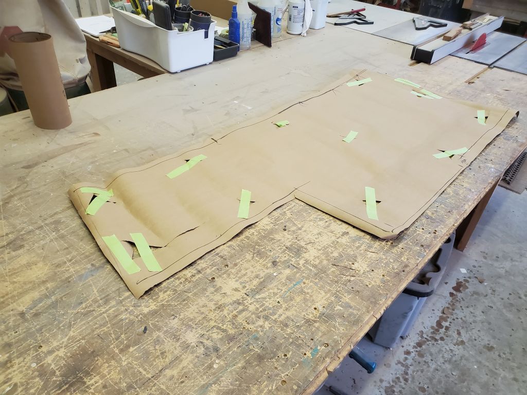
I used the paper pattern I’d made earlier to create a template of the overhead from cardboard, which I test-fit in place and made minor adjustments. This template was now the overall size of the overhead, filling the space more or less entirely with no offsets. I’d built in extensions to allow the template to pass through both openings to the head (from the saloon and into the forward cabin), as the repair work would encompass both areas, but at the forward side the extension needed to be a few inches longer to pass far enough into the forward cabin, so I made a little add-on piece for the template.
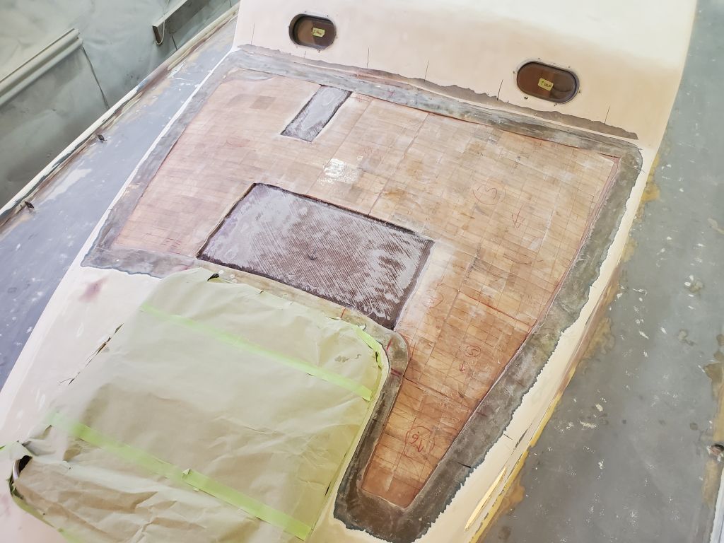
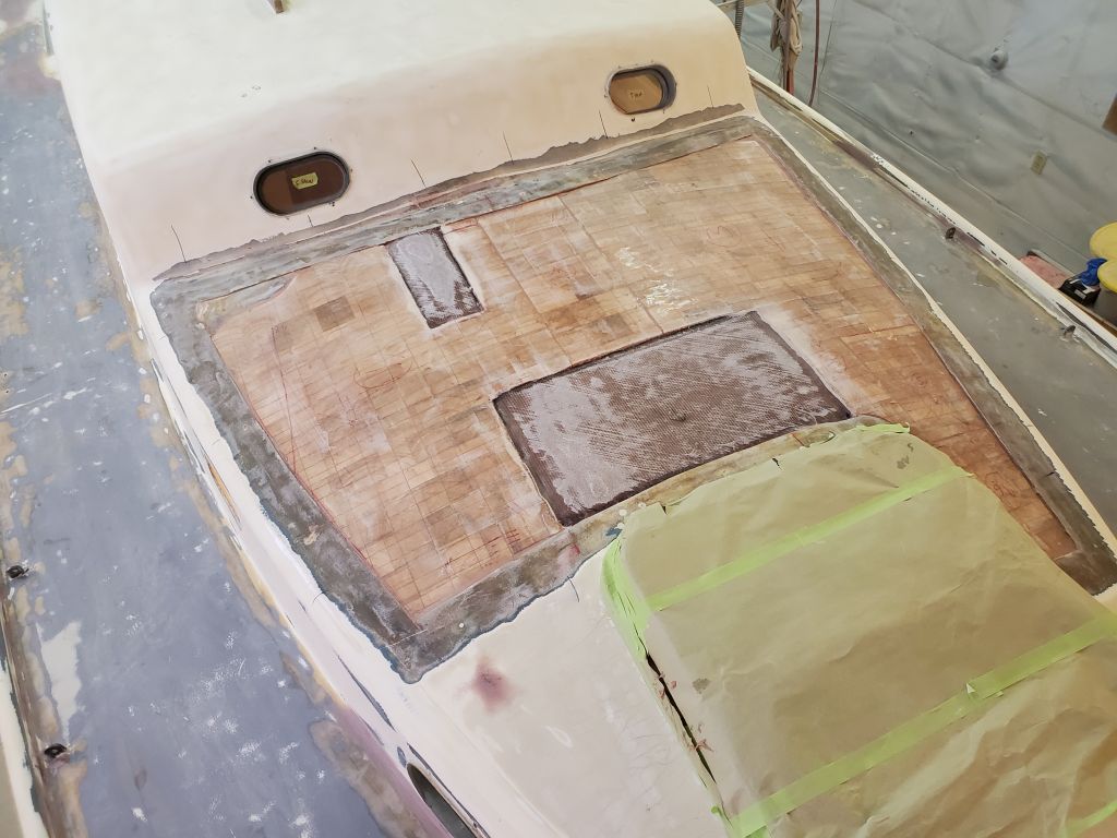
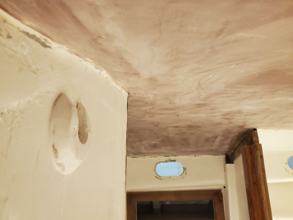
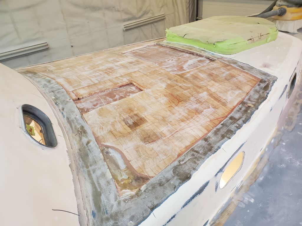
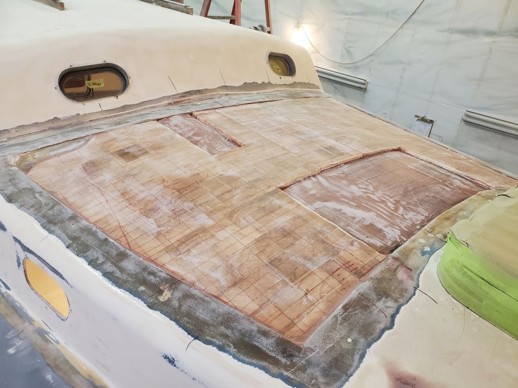
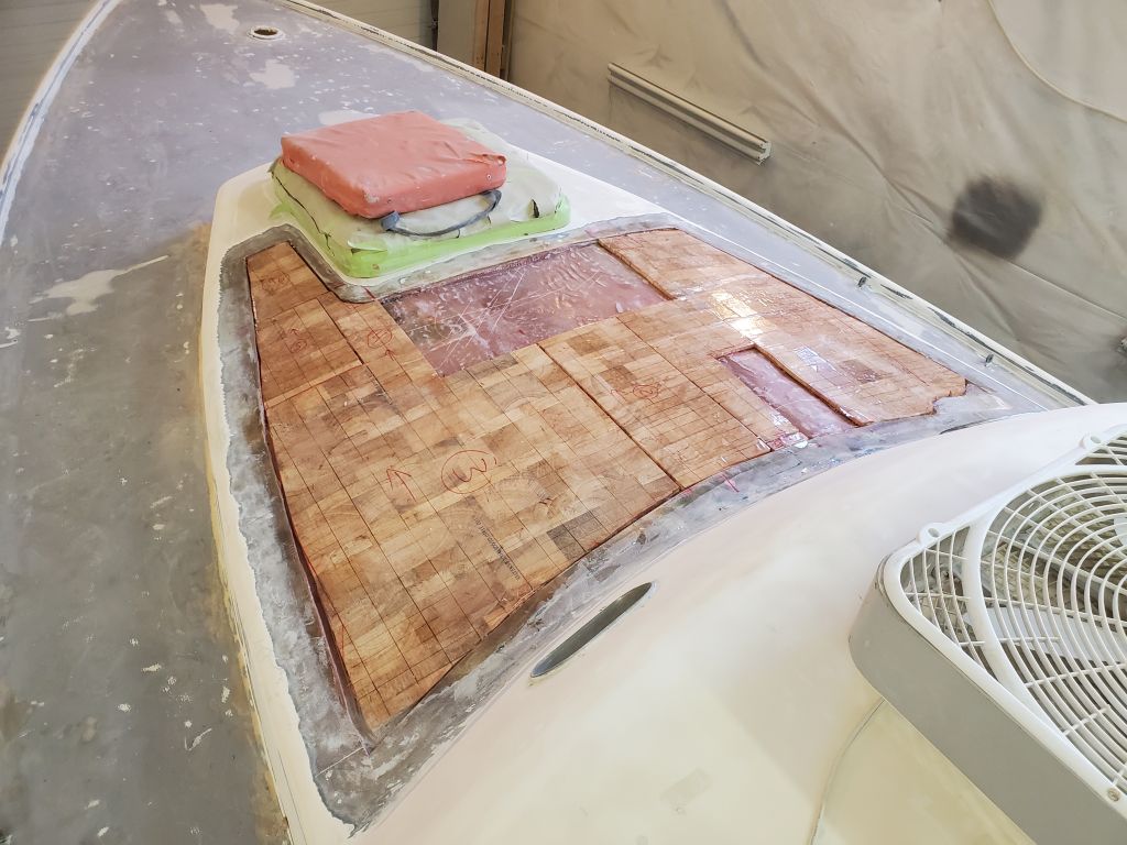
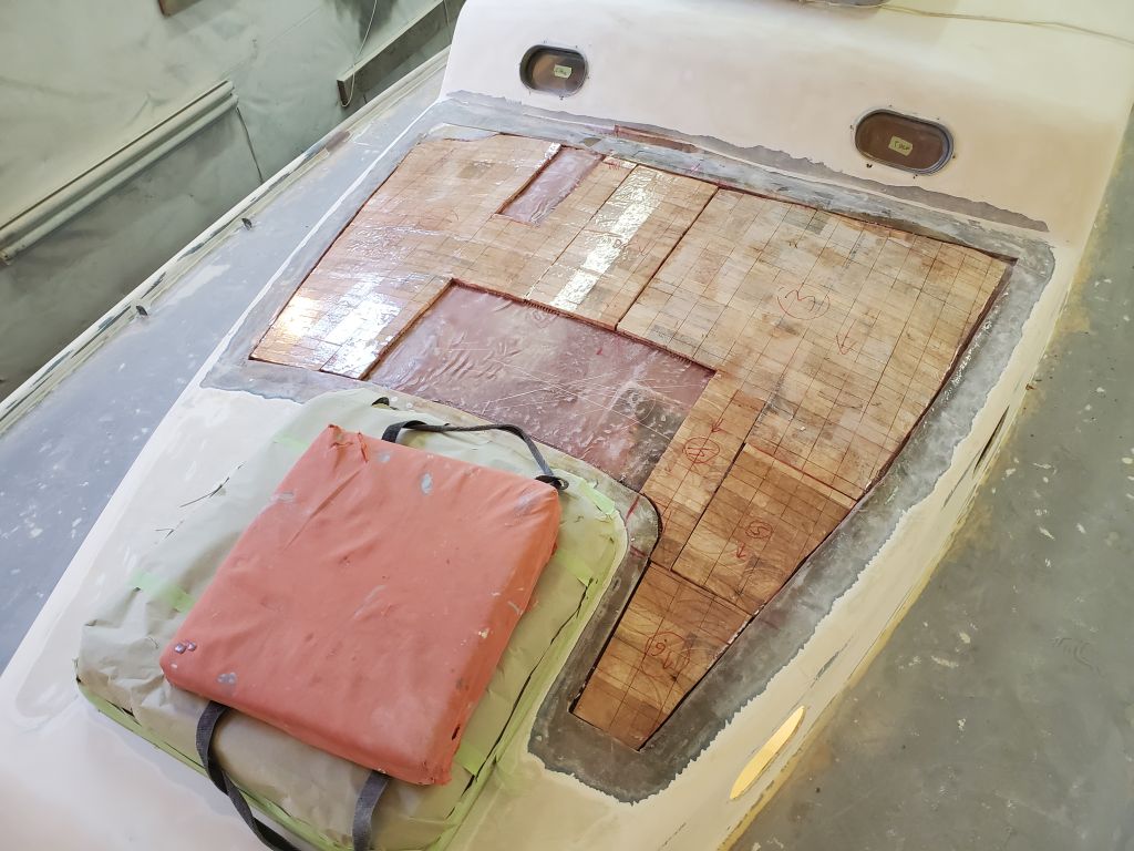
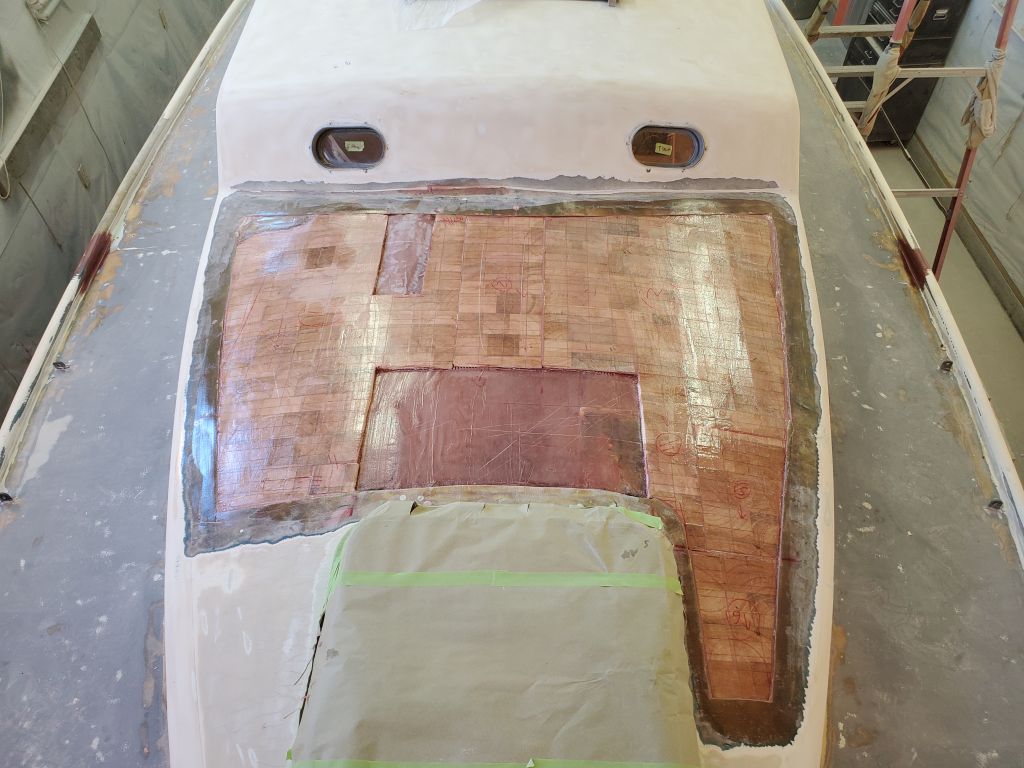
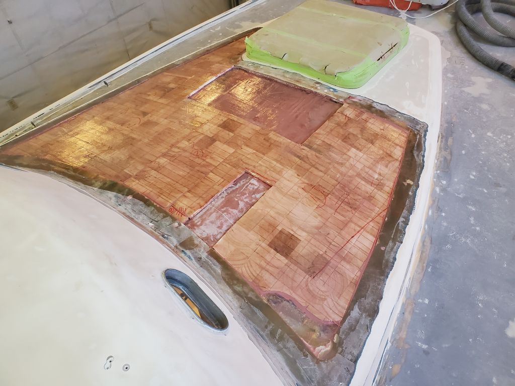
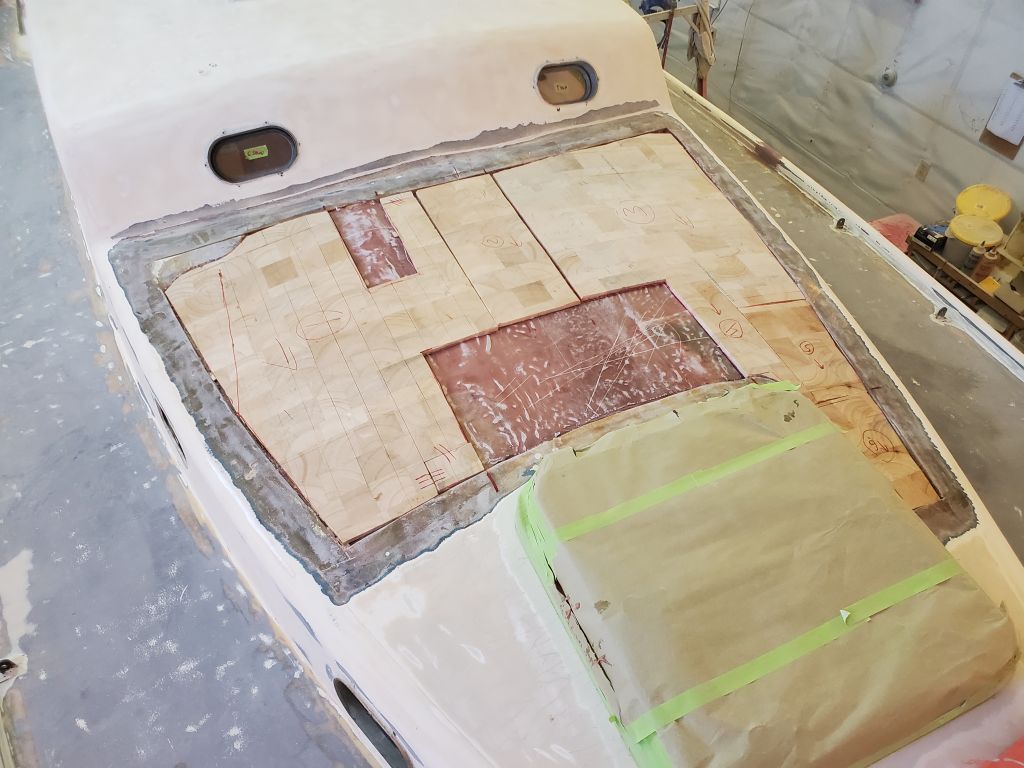
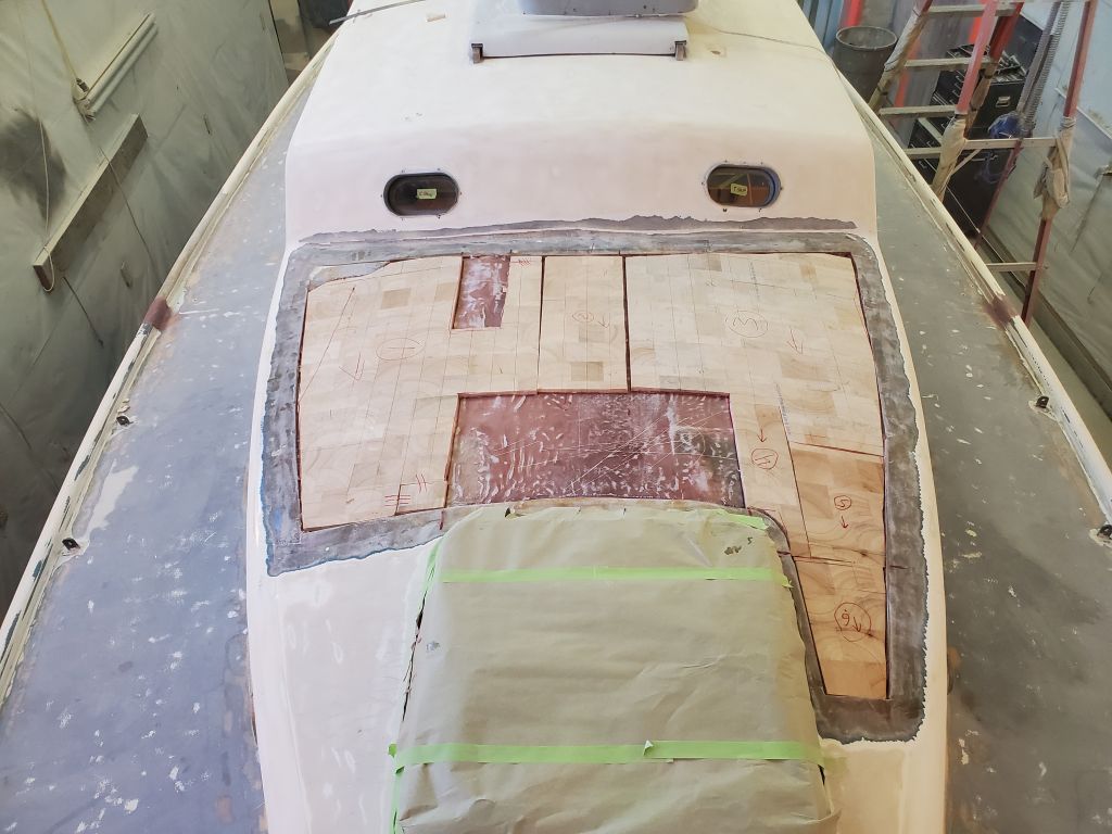
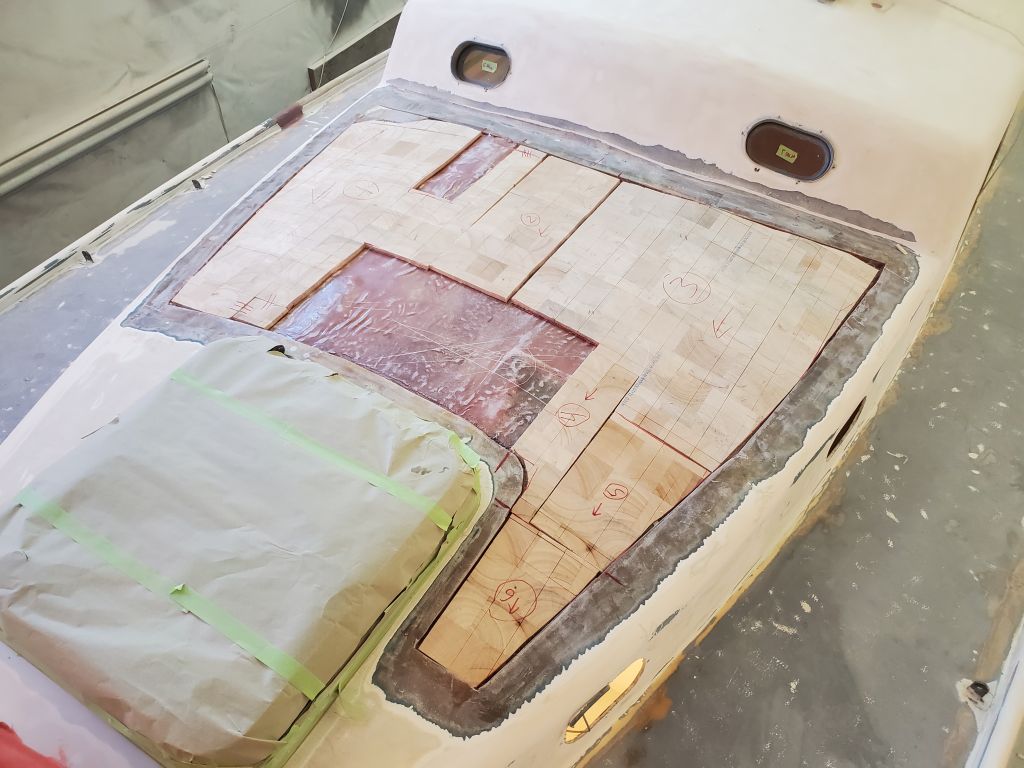
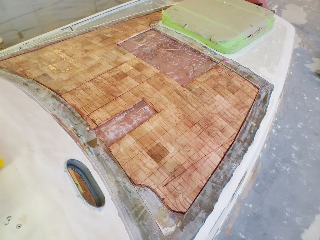
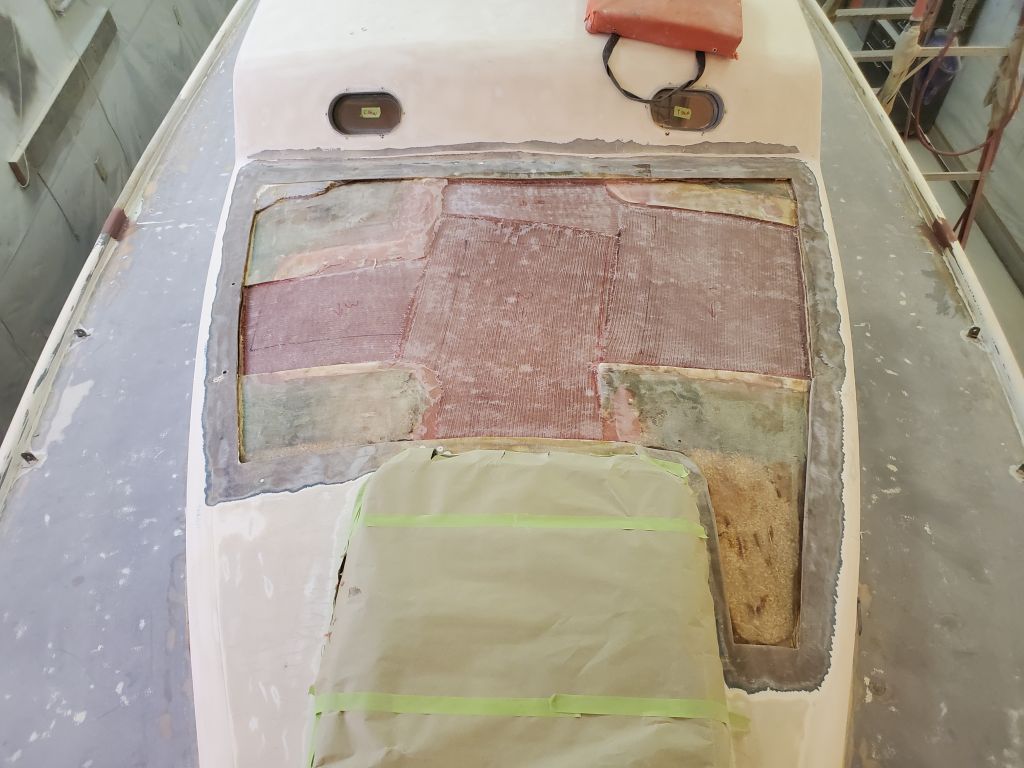
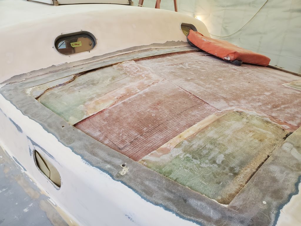
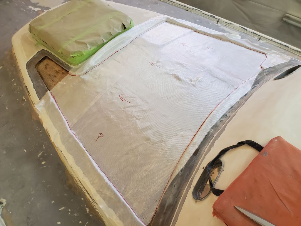
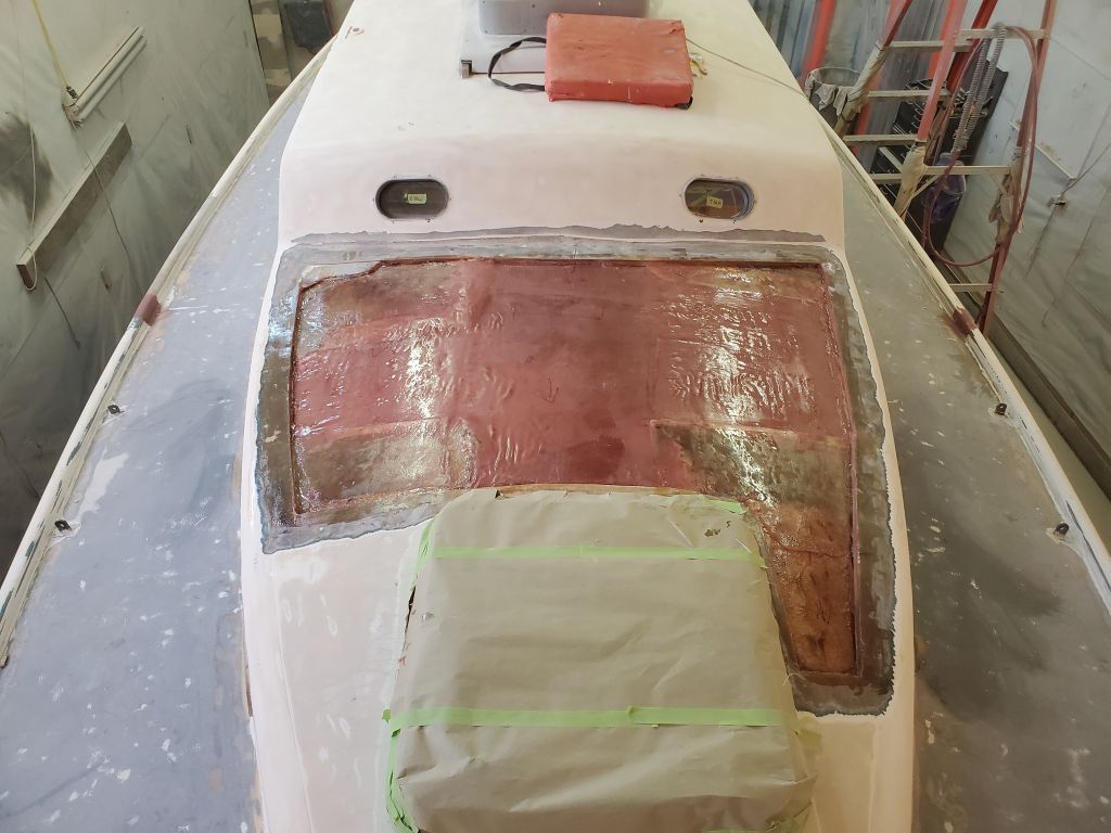
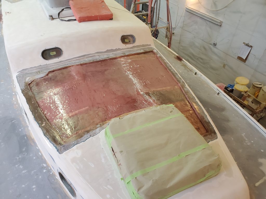
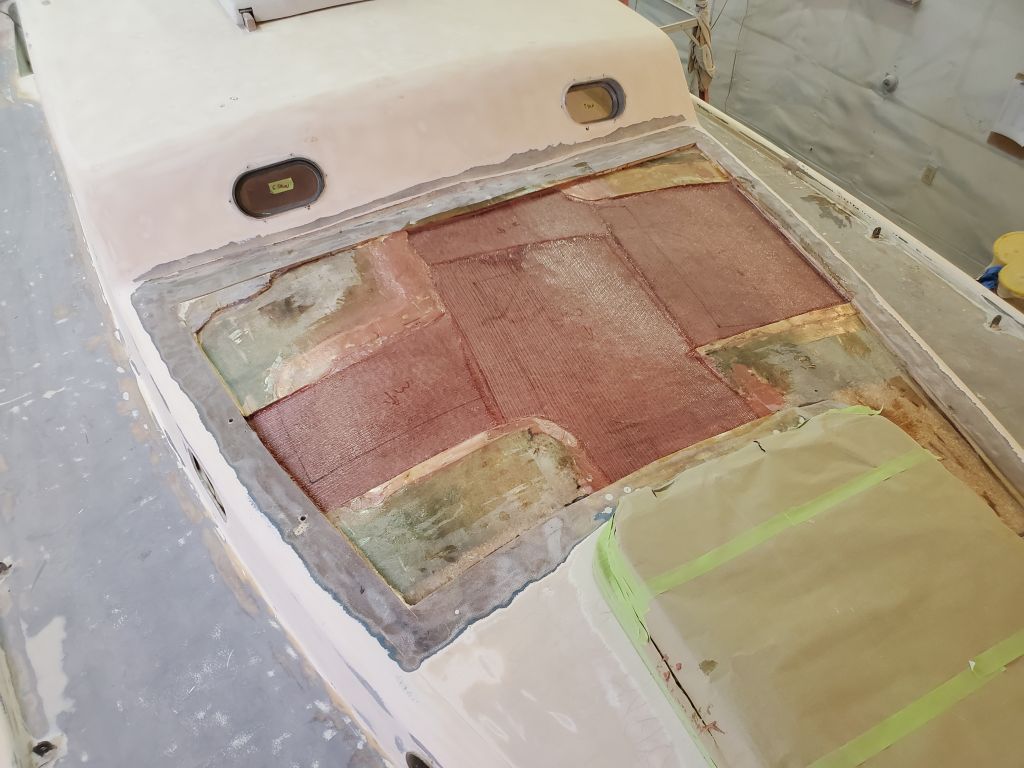
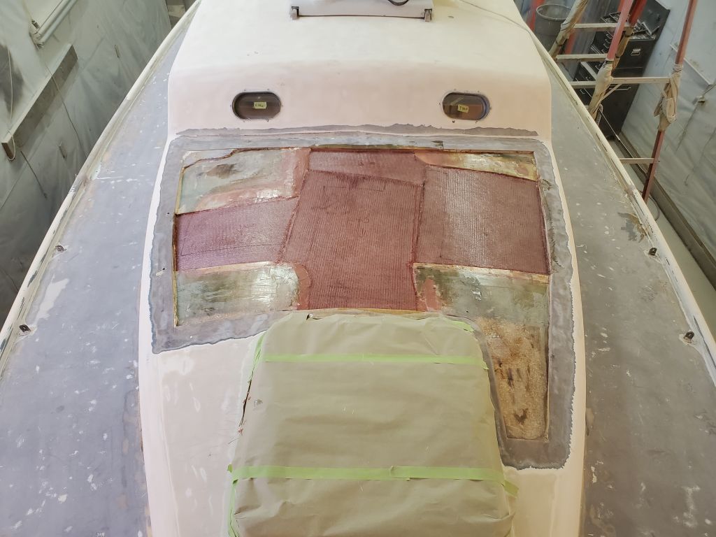
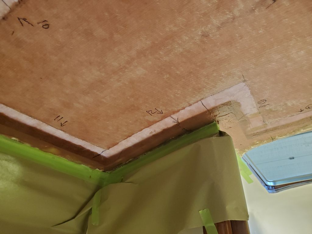
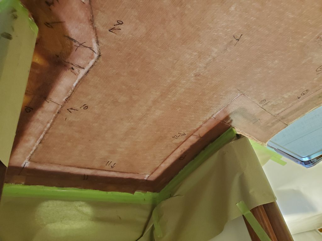
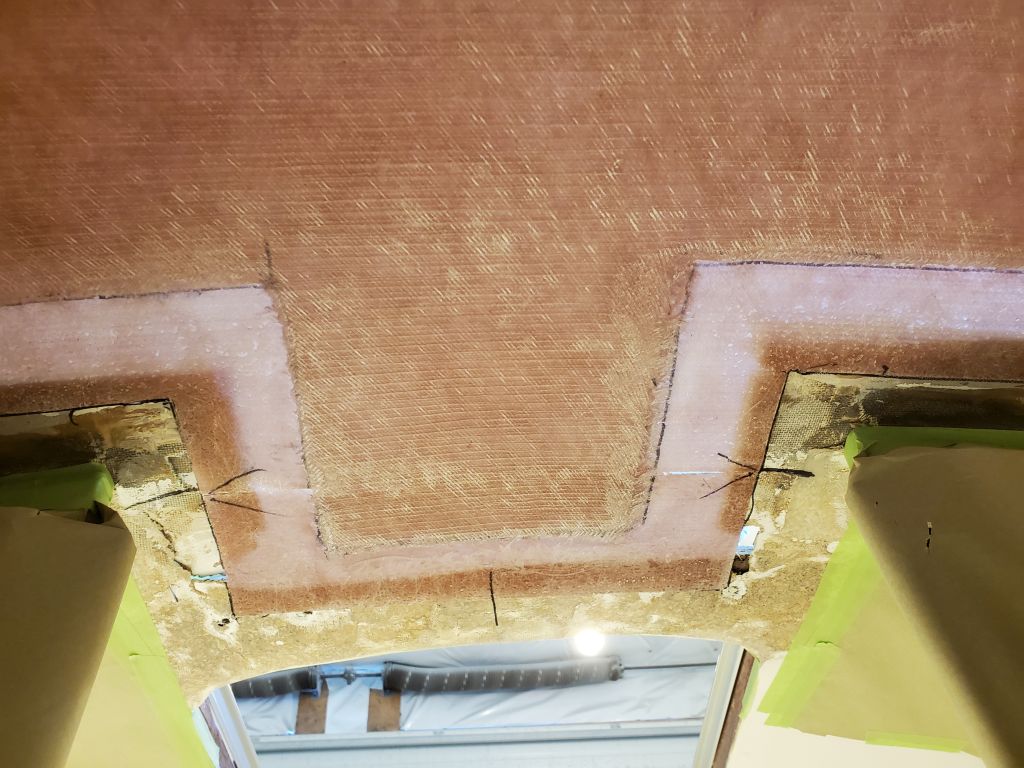
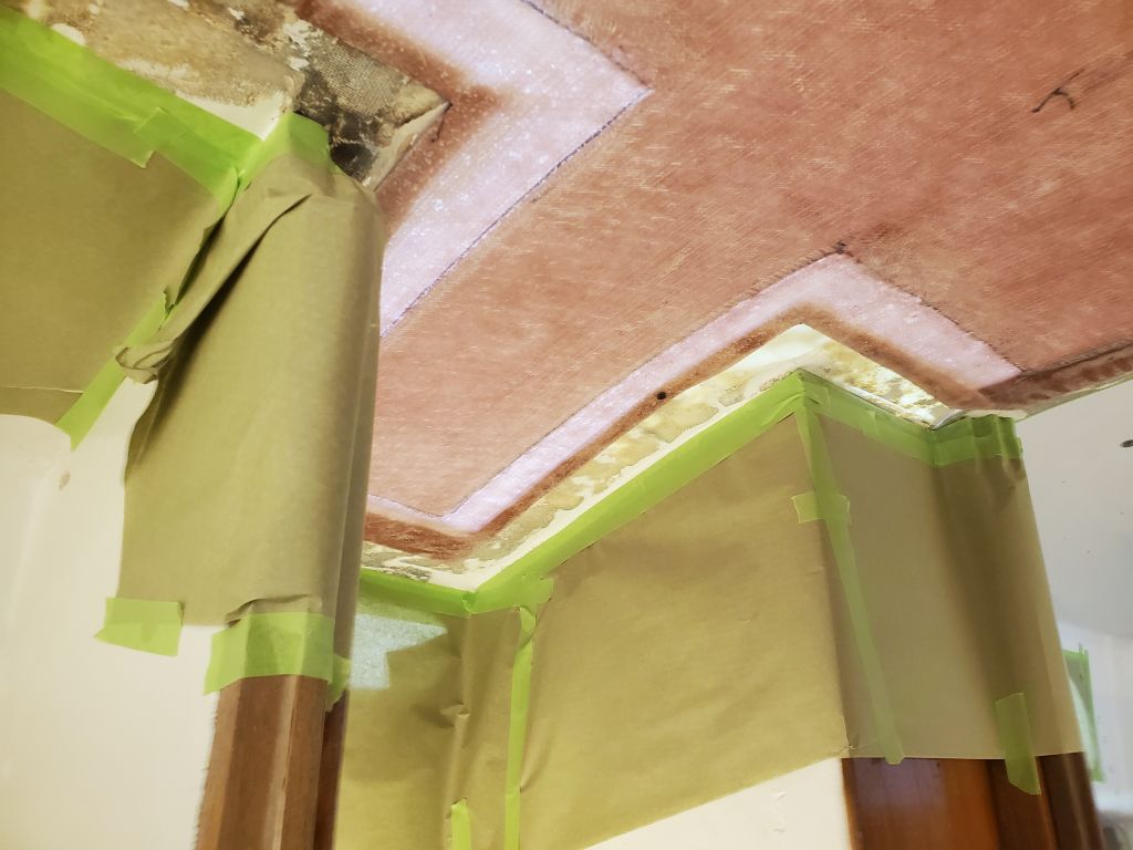
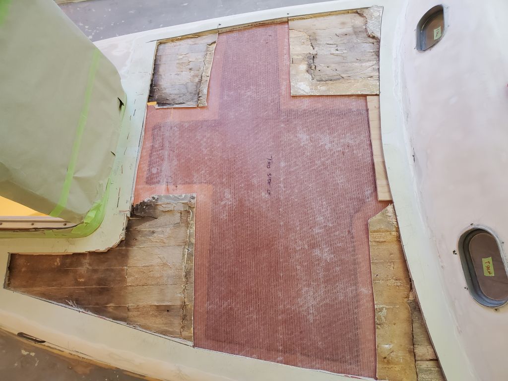
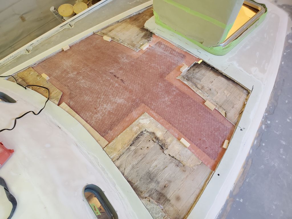
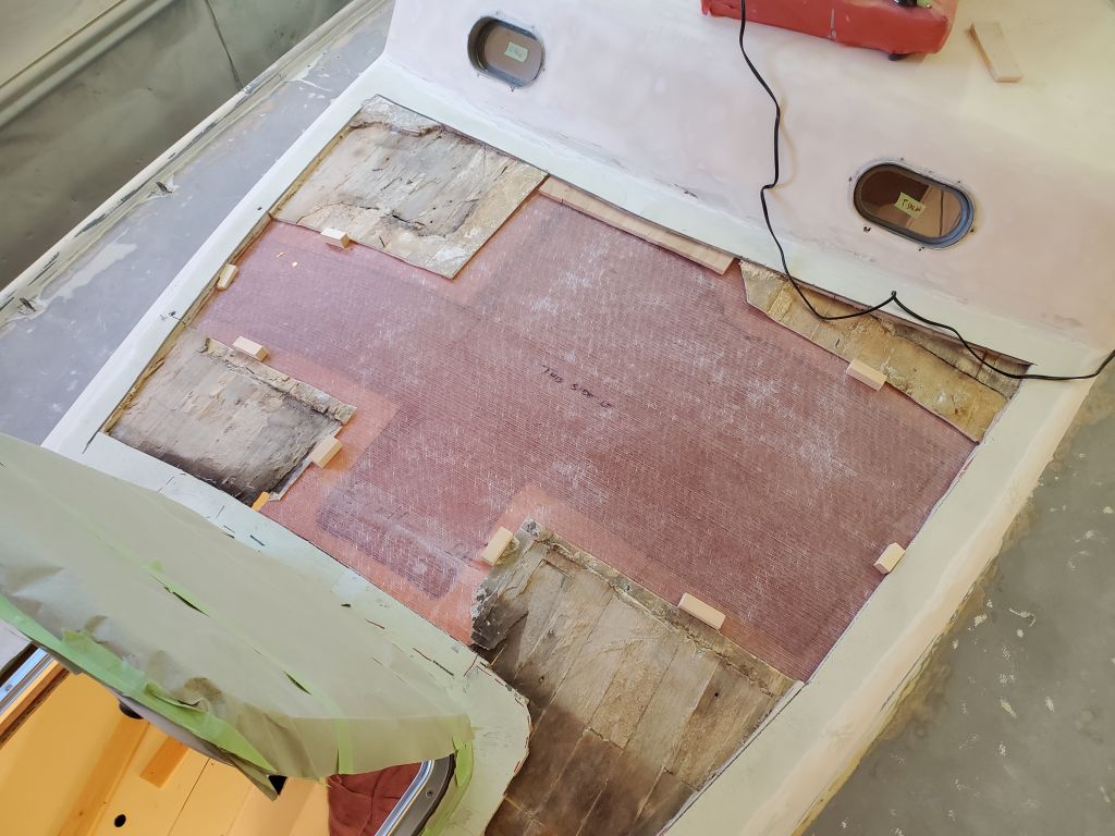
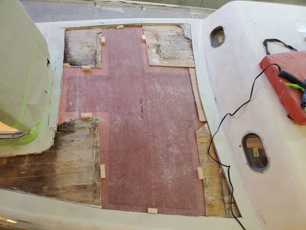
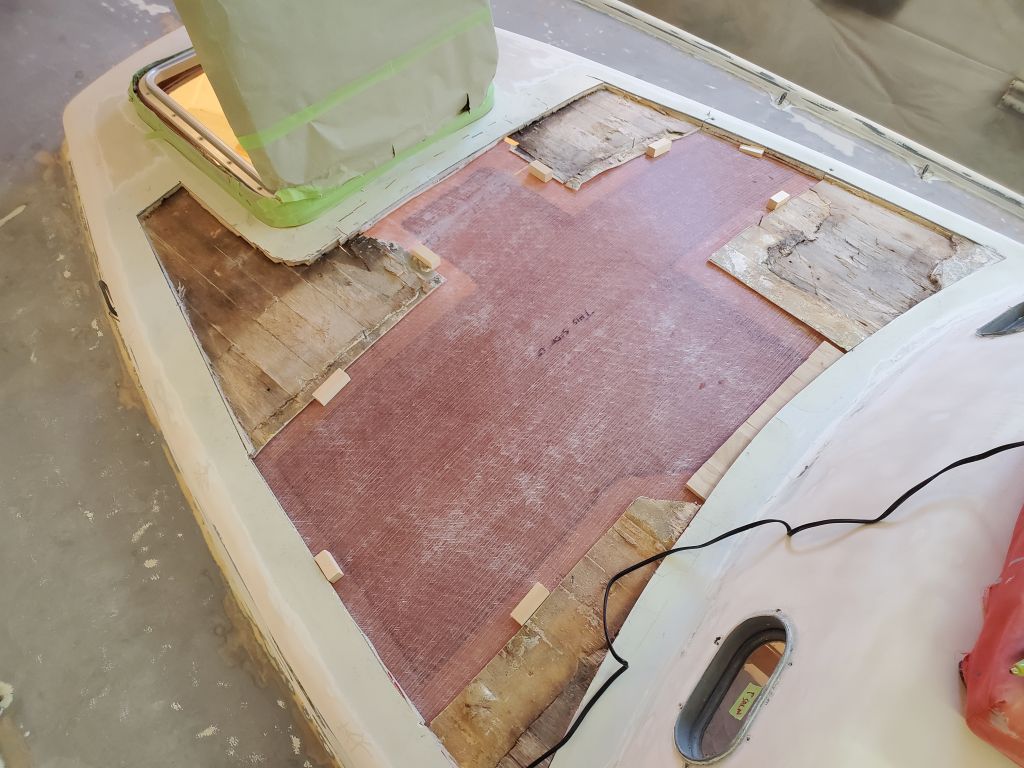
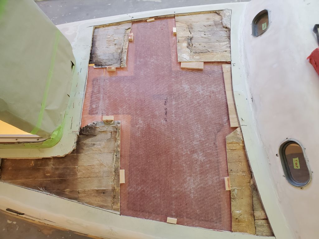
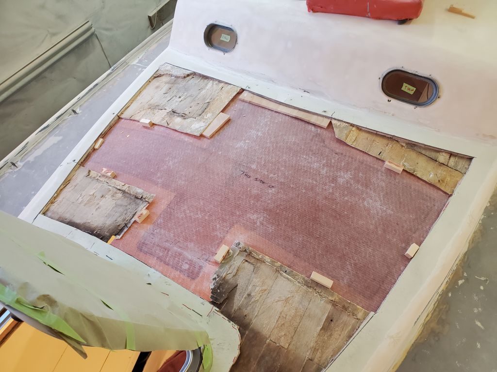
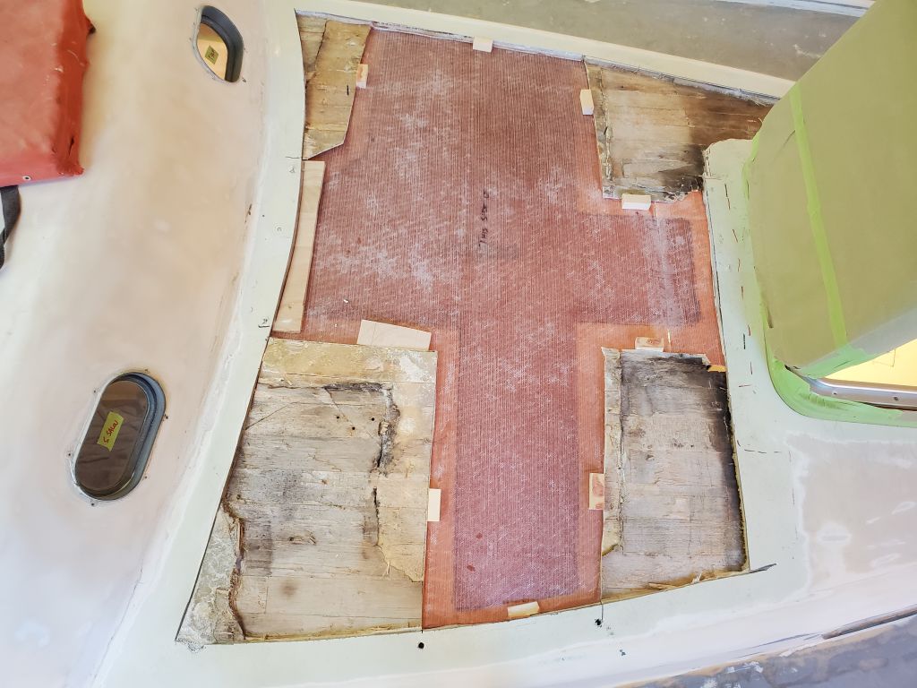
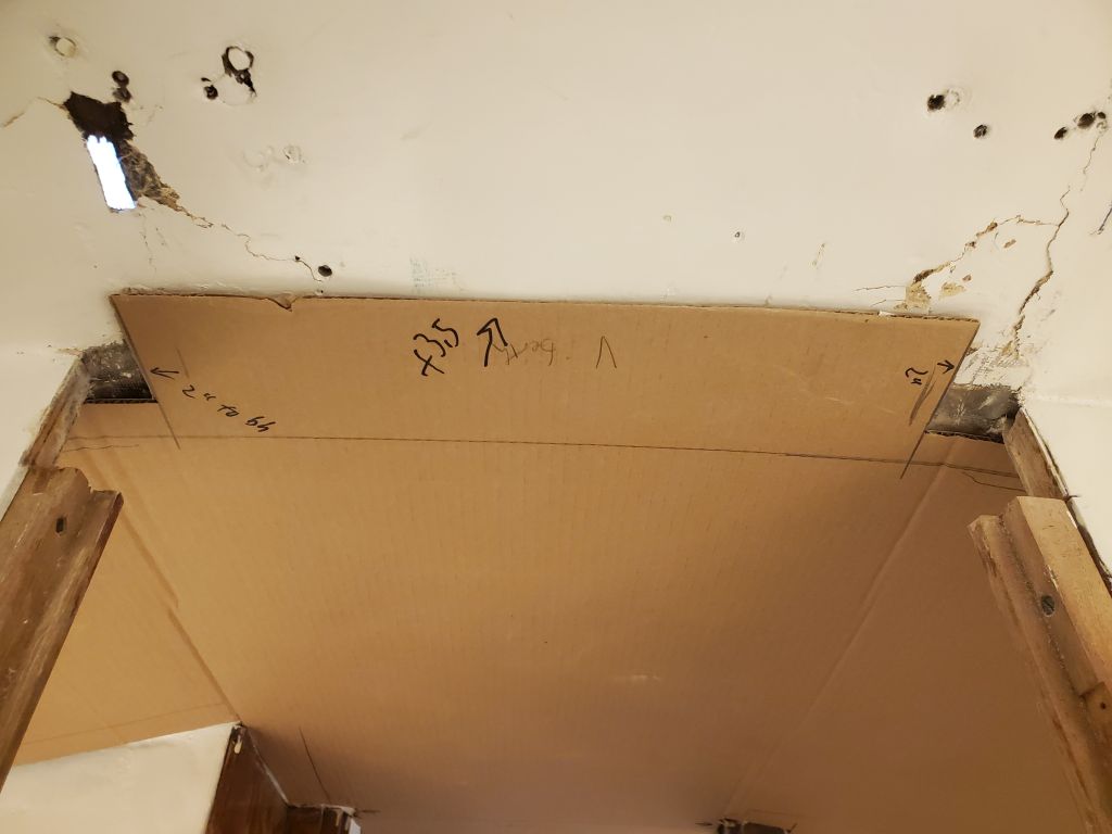
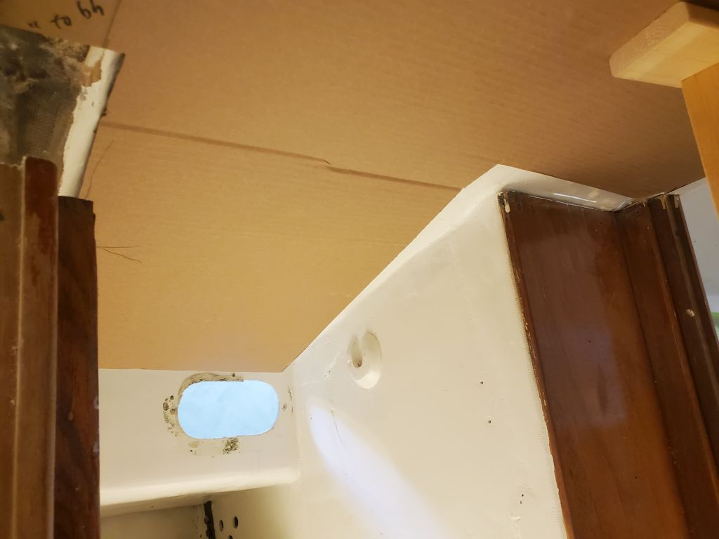
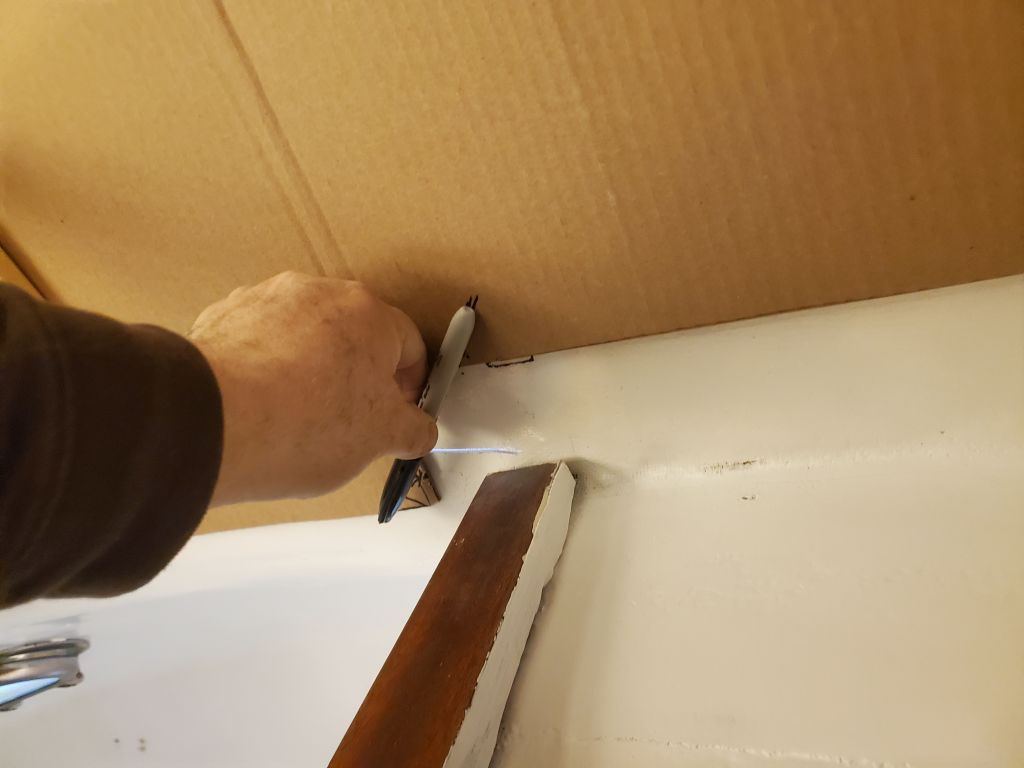
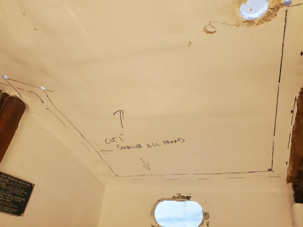
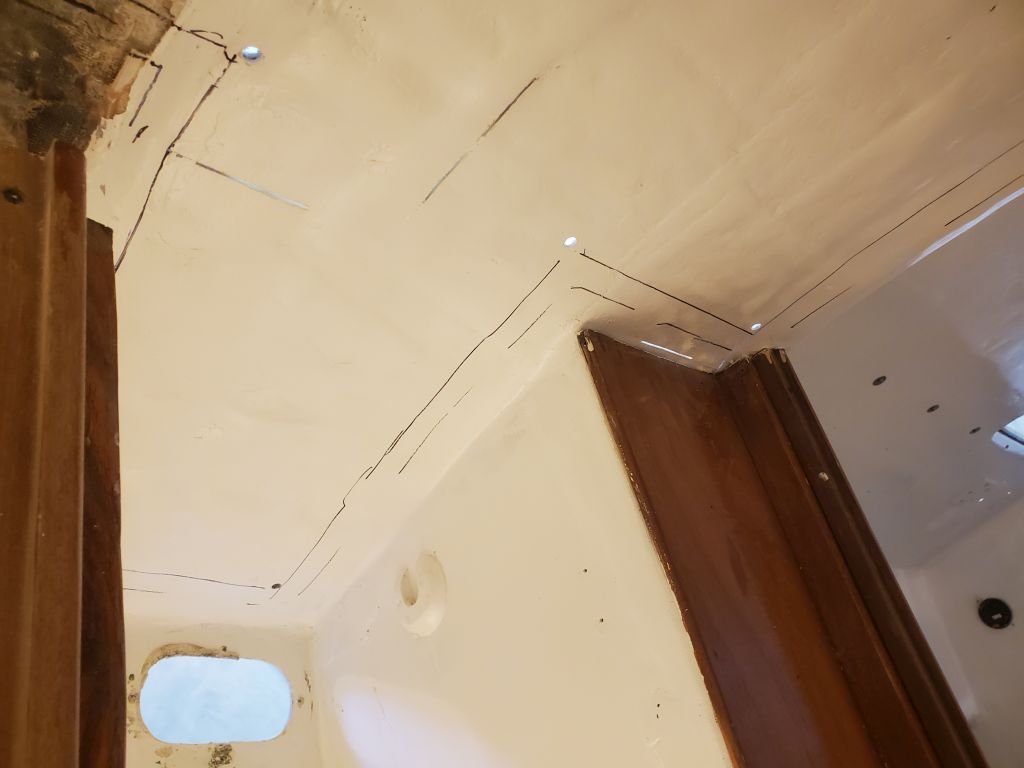
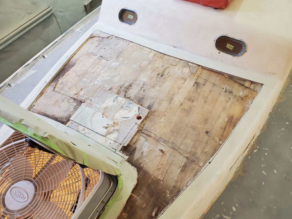
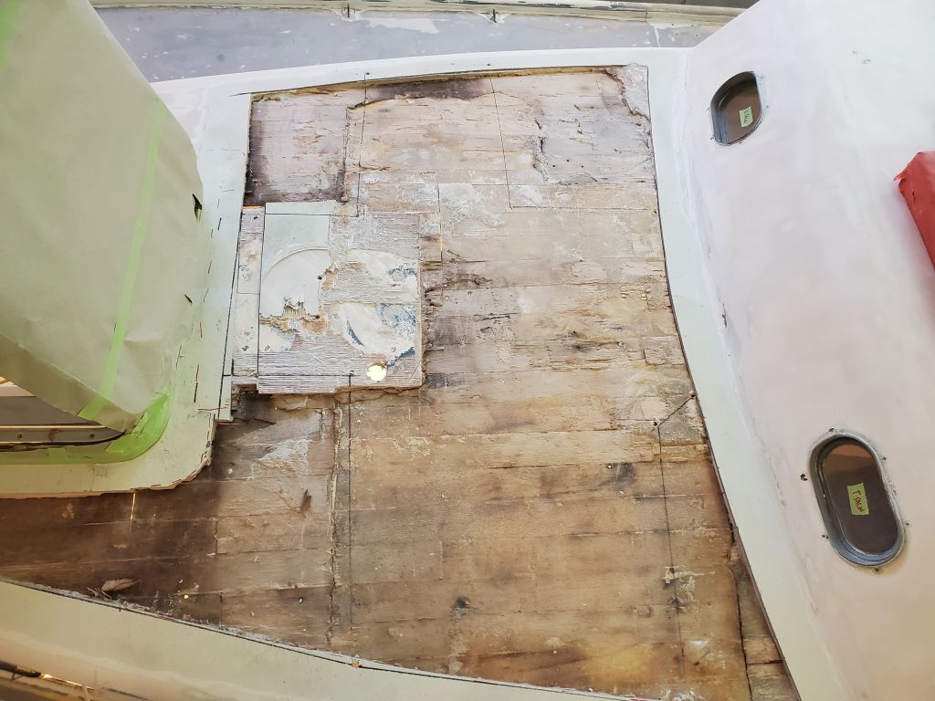
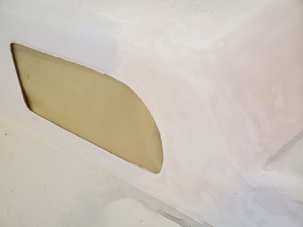
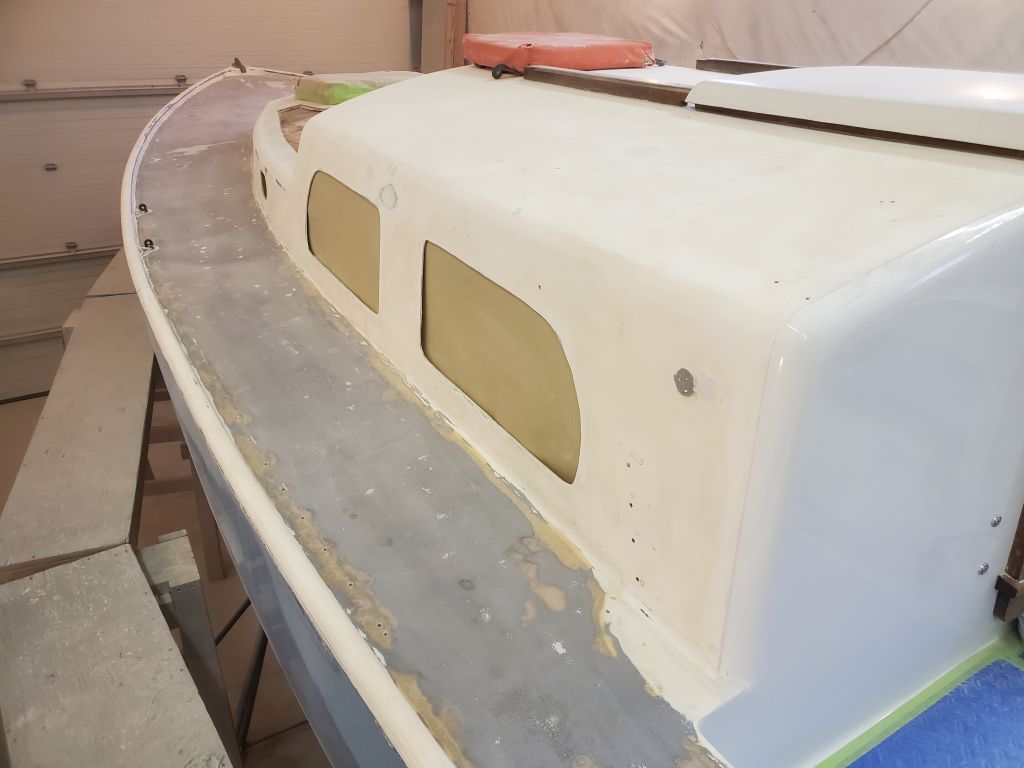
To leave room around the edges of the repair area and give me space to secure and tab in the new panel, I planned to leave a 2″ border on all sides, enough space for the bonding required while removing as much of the lousy old work as I could, and remain within the workable area. Ideally, it would have been nice to remove all those pesky bulkheads and rebuild the entire bottom of the forward coachroof in a clear area, but obviously that was impractical and wasn’t about to happen; fortunately the repair work could, and would, be done within their confines. So now I marked the cardboard 2″ in all around, and cut the new shape. With the slightly reduced template propped in place and positioned according to some rough marks I’d made in key areas, I marked its outline with a dashed line all around. This template, and the dashed line, represented the final size of the new panel.
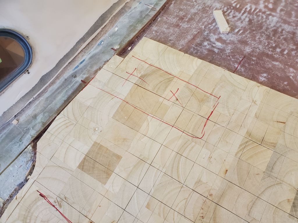
I transferred the cardboard to a piece of 1/4″ plywood for the final template, which I also thought I might use during installation of the fiberglass panel as a backing and for support. This repair process was working itself out one step at a time, with only a rough idea of the plan from the getgo, but becoming more clear all the time. I test-fit the plywood panel in the space to confirm the overall measurements.
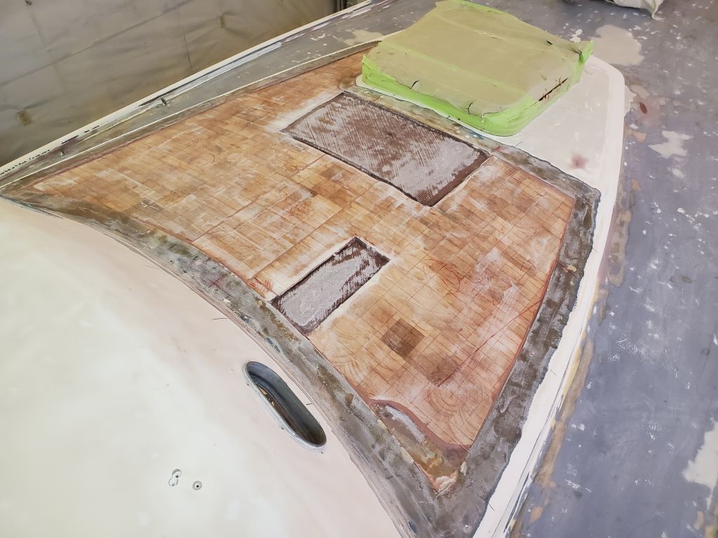
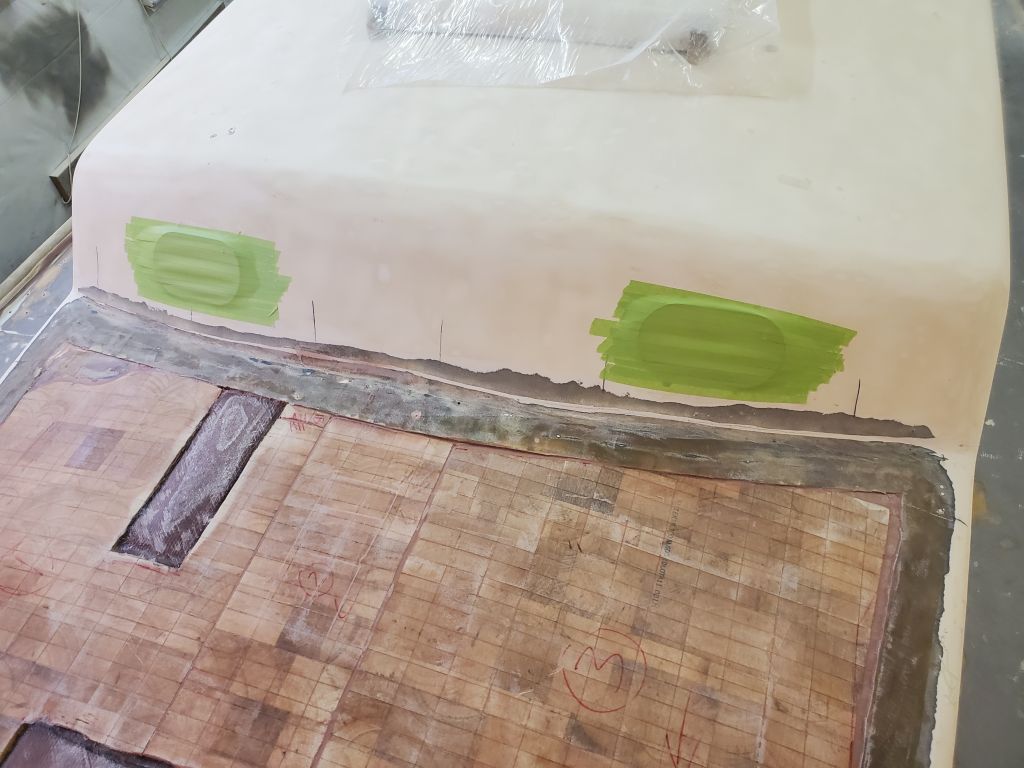
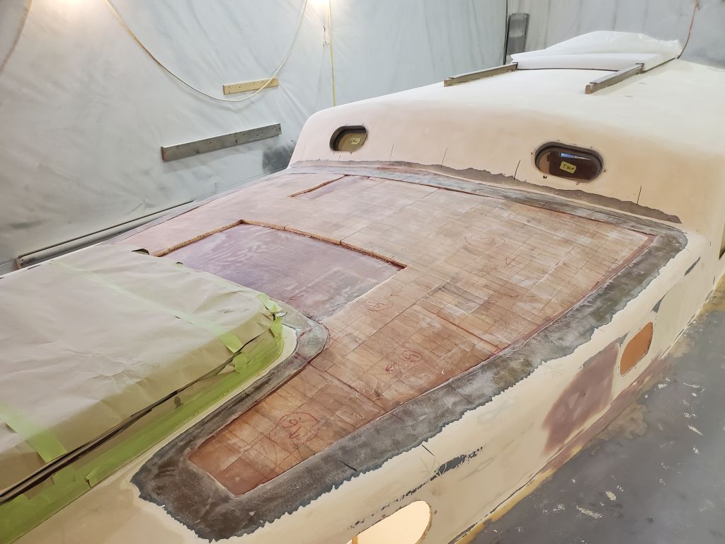
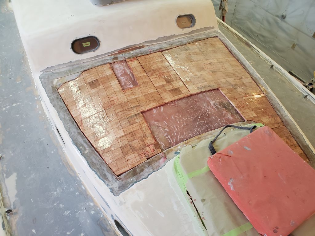
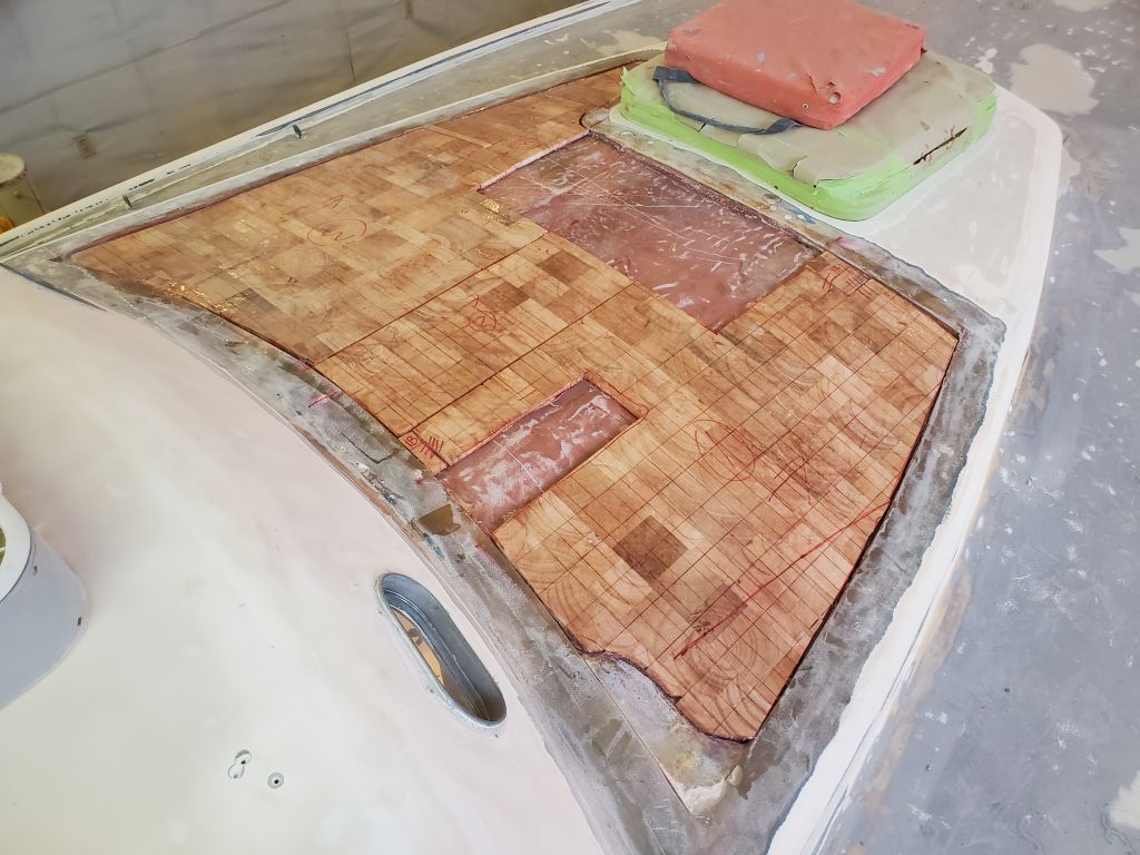
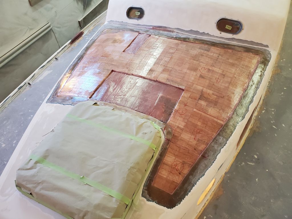
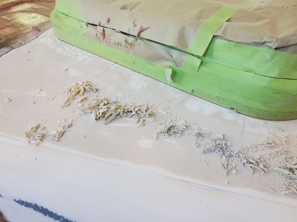
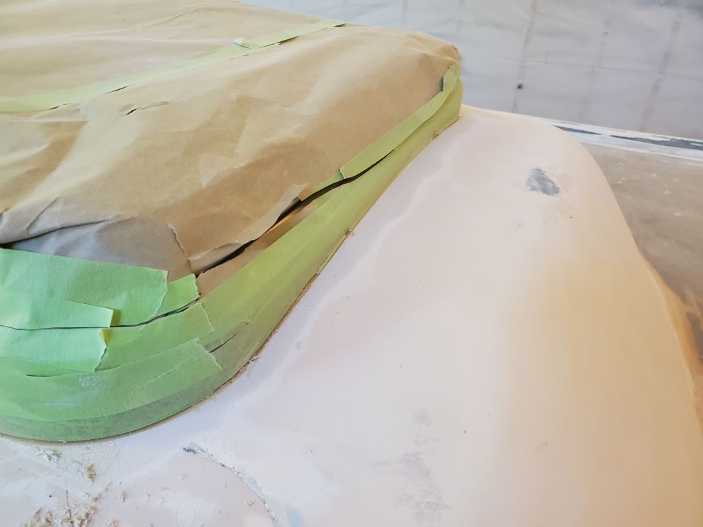
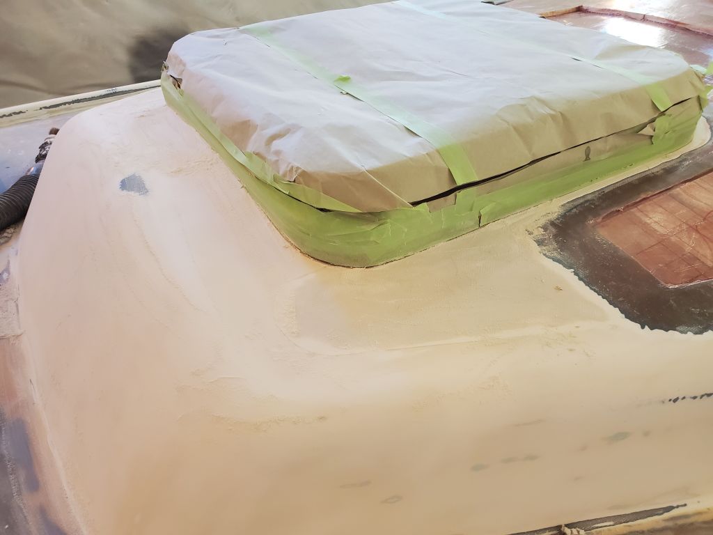
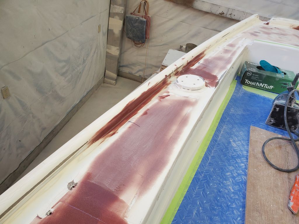
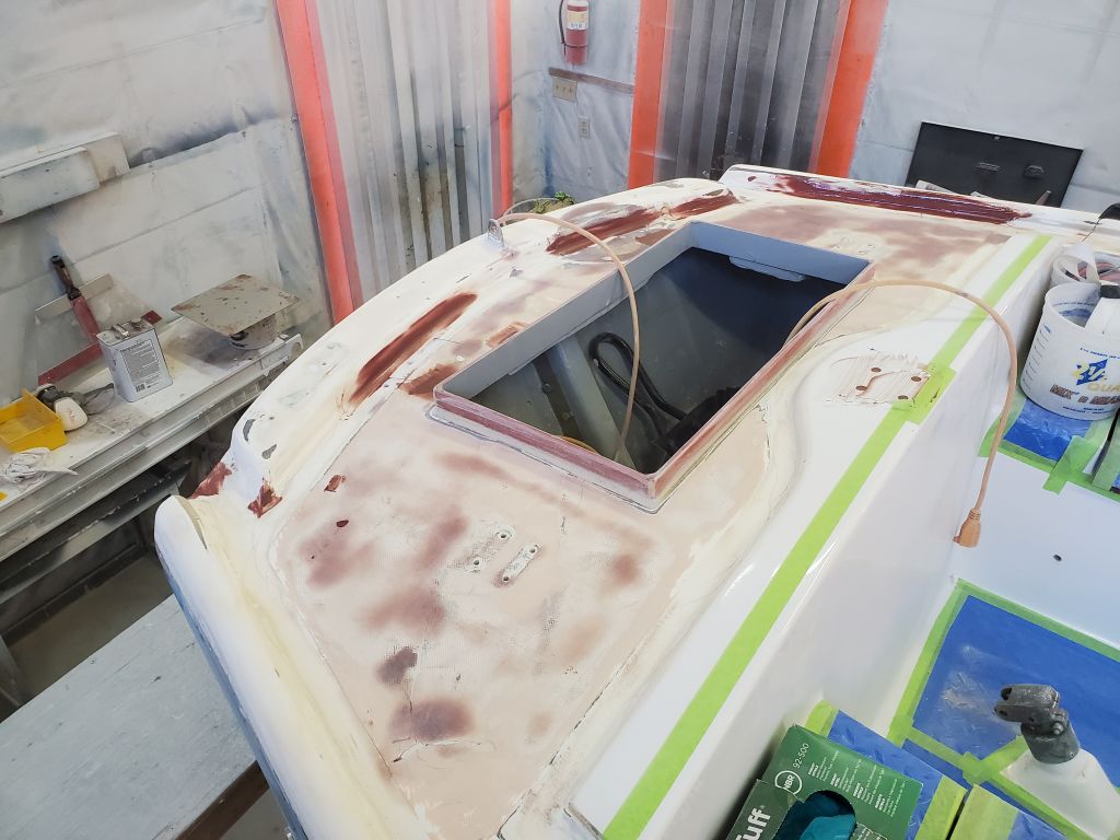
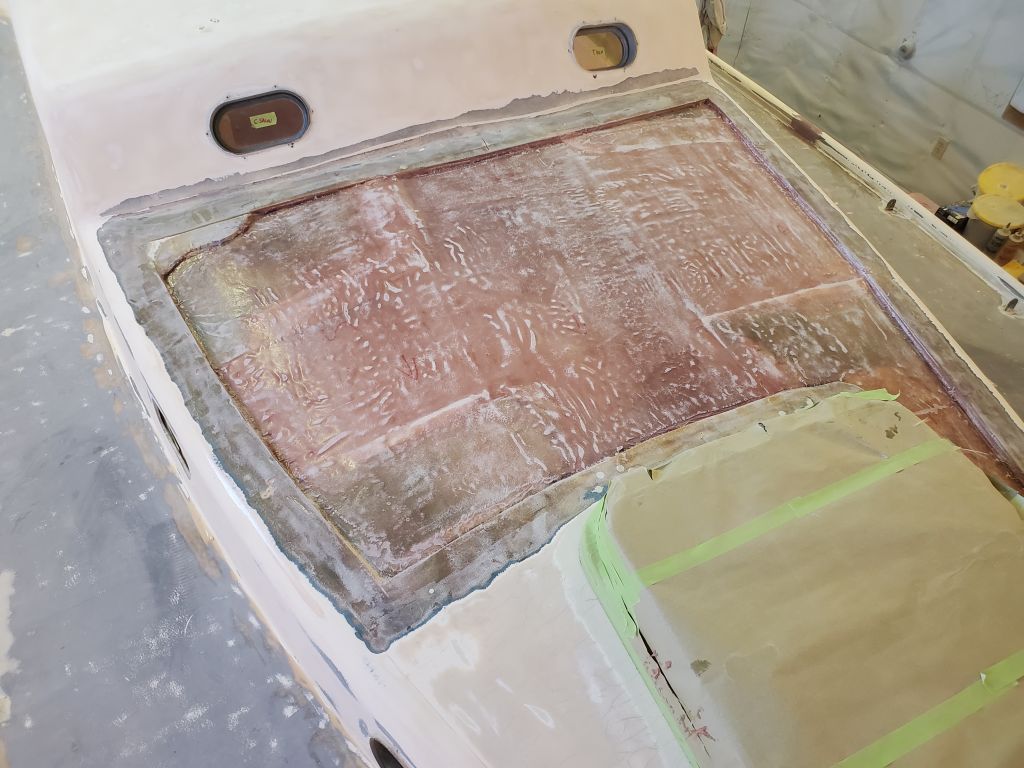
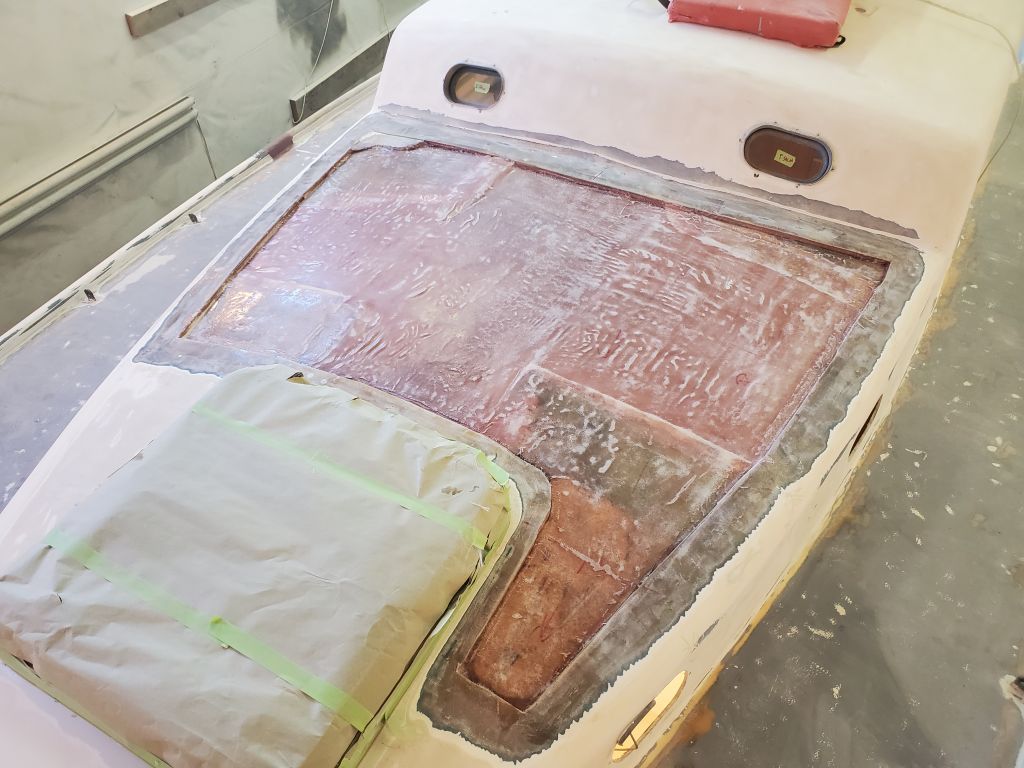
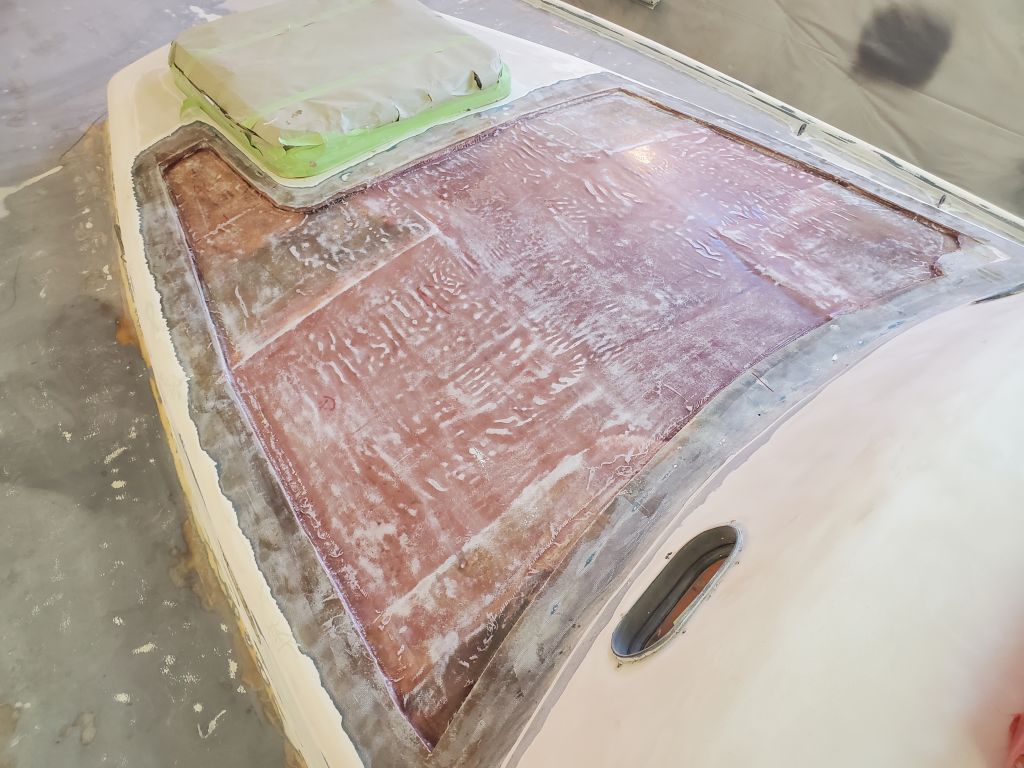
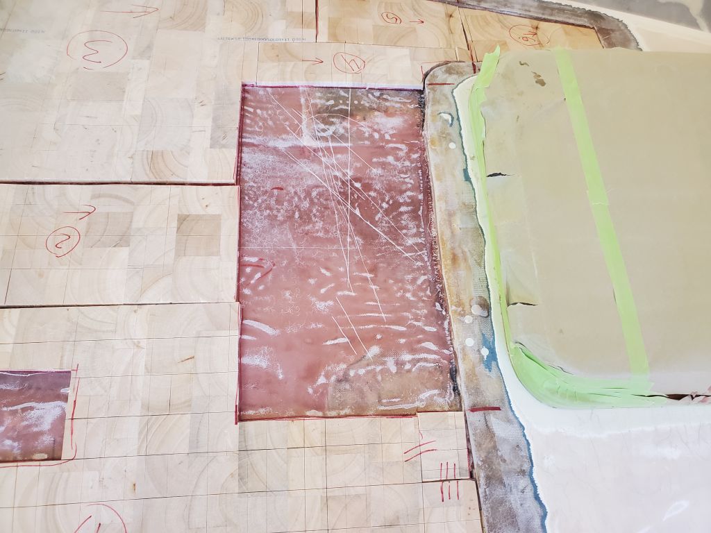
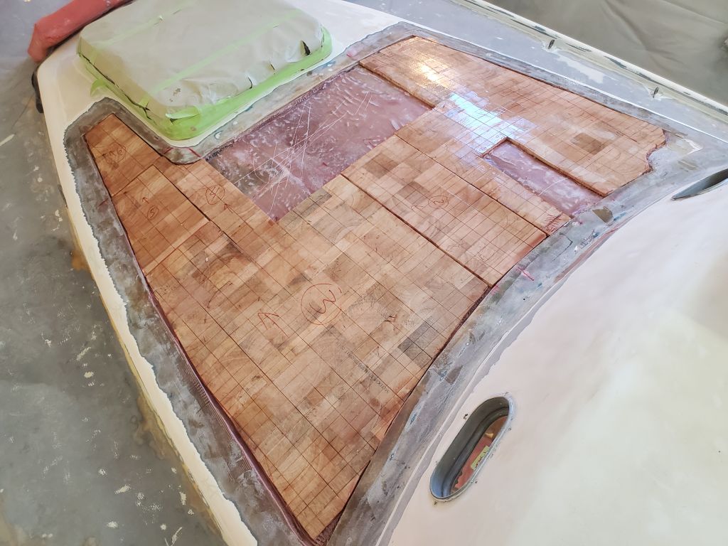
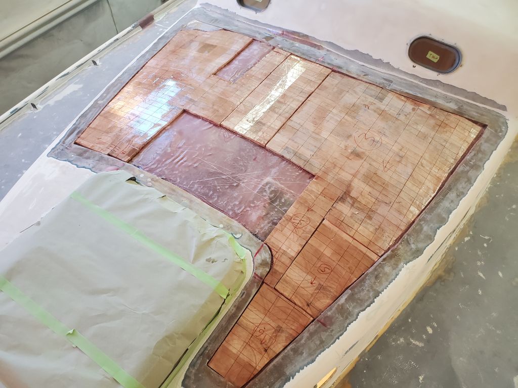
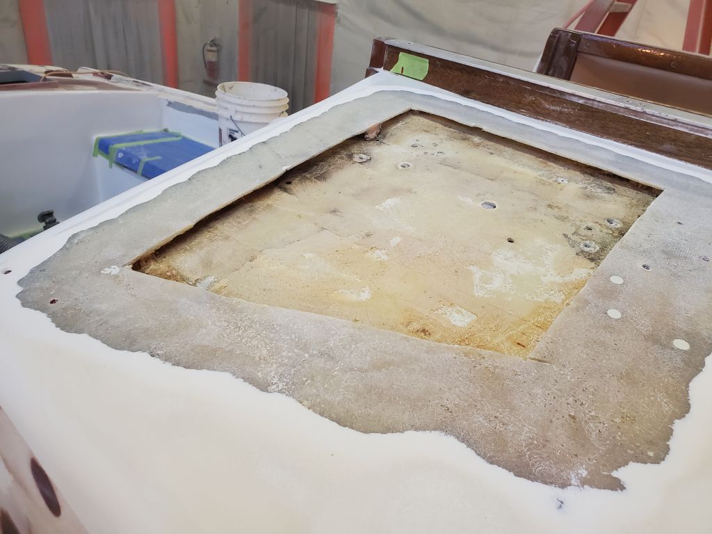
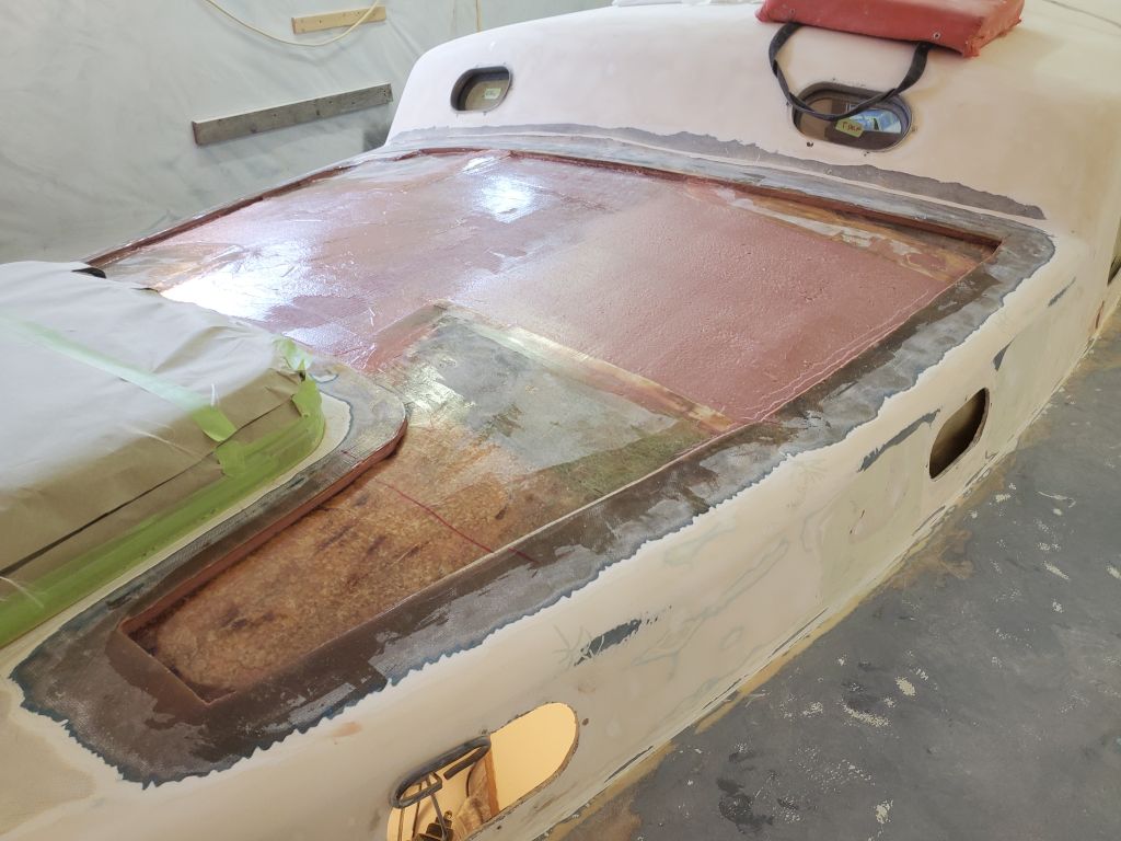
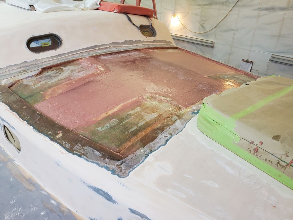
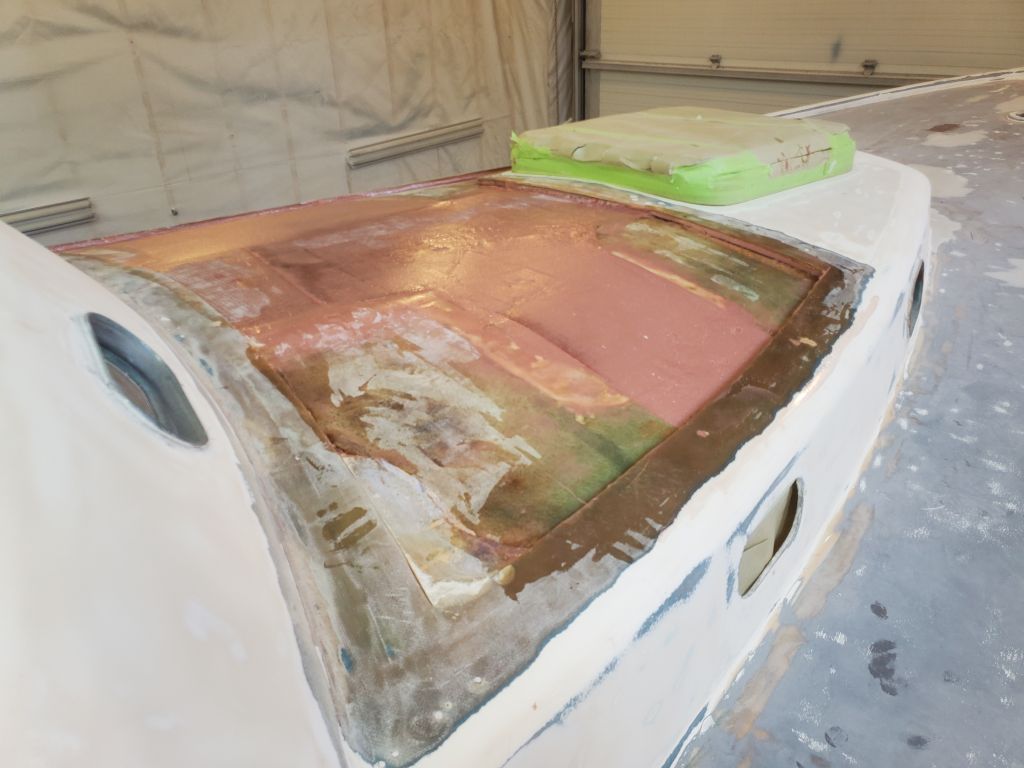
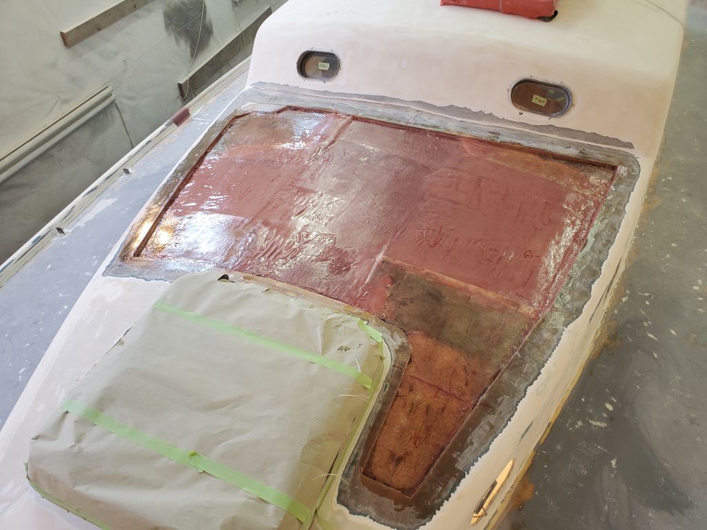
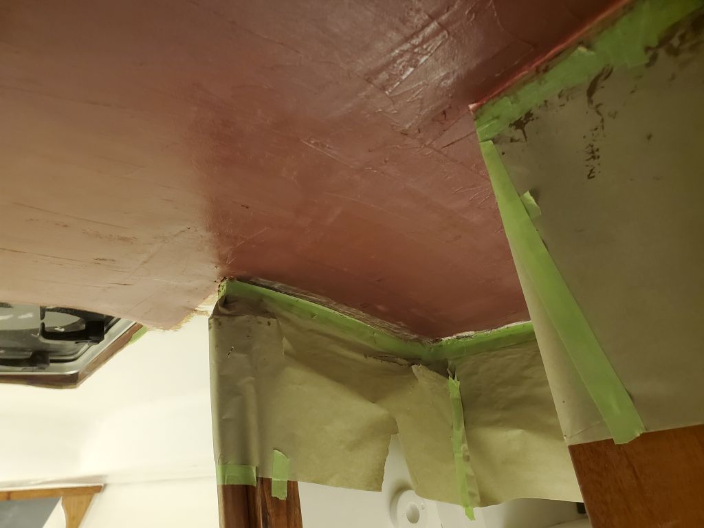
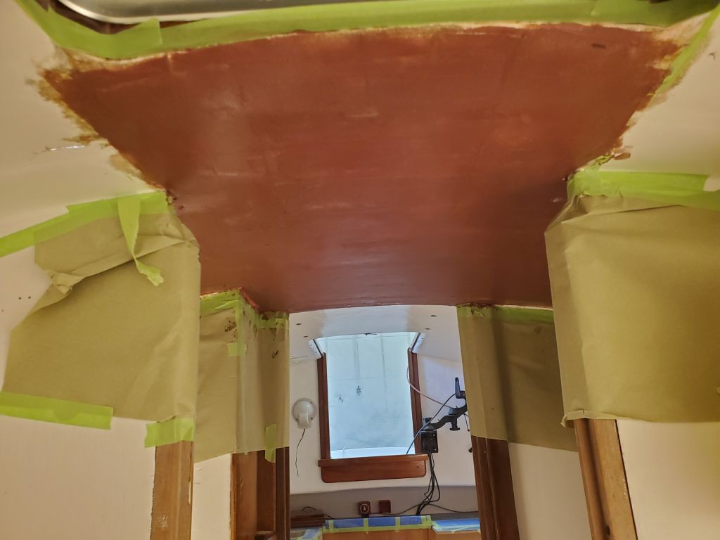
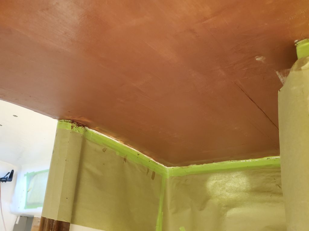
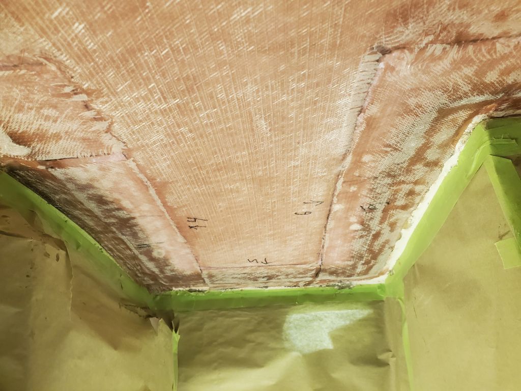
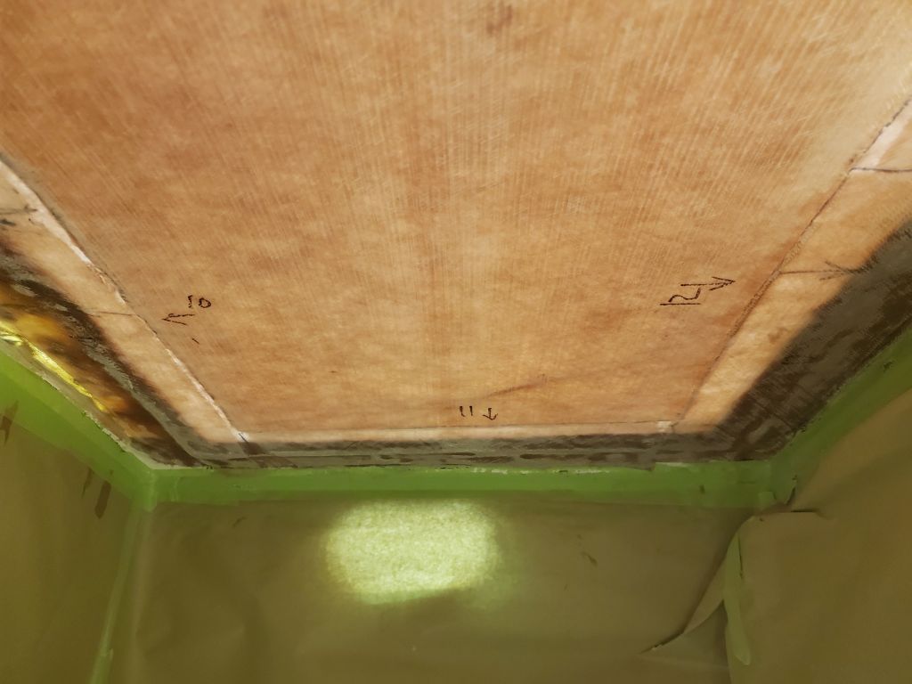
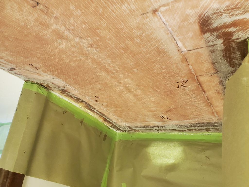
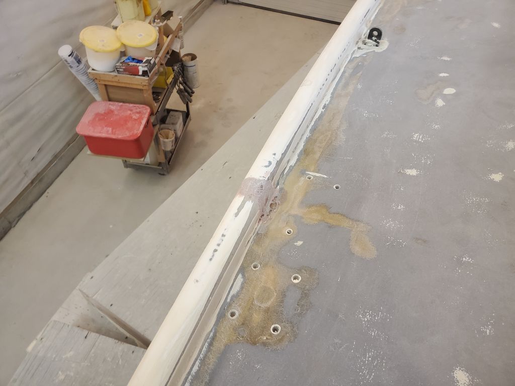
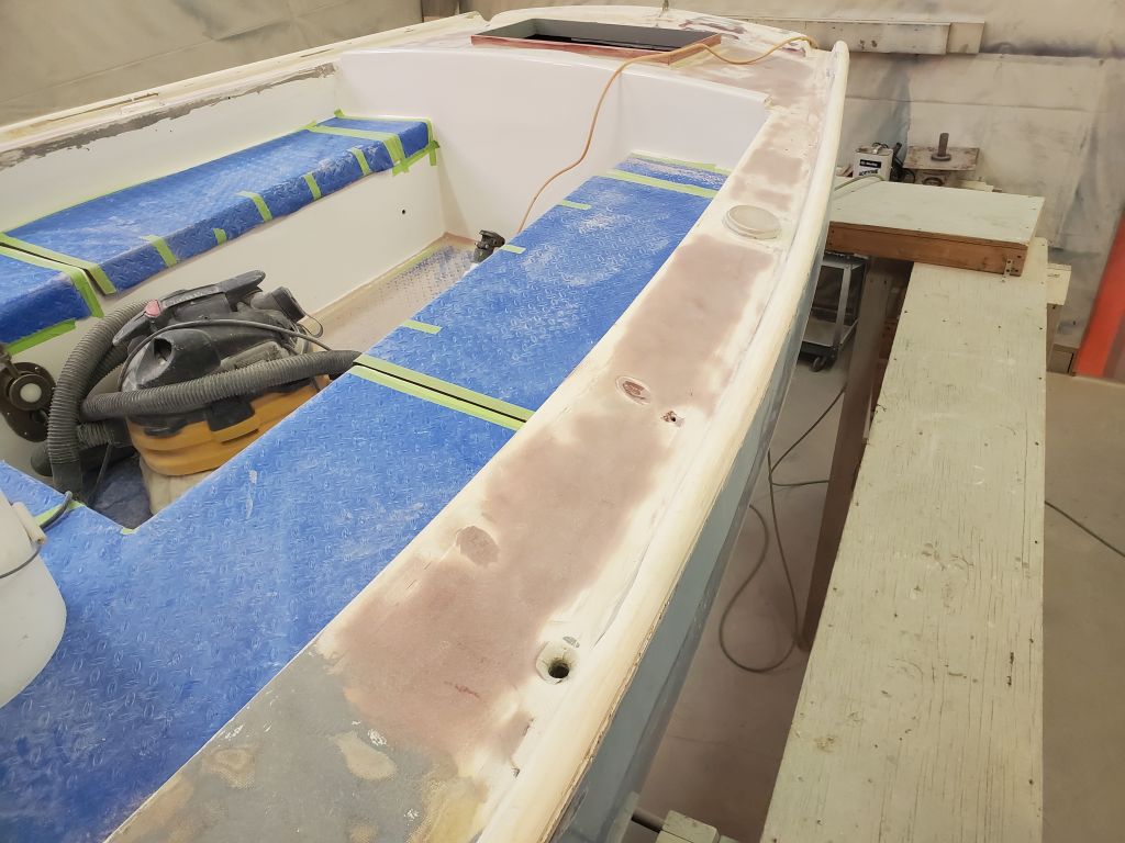
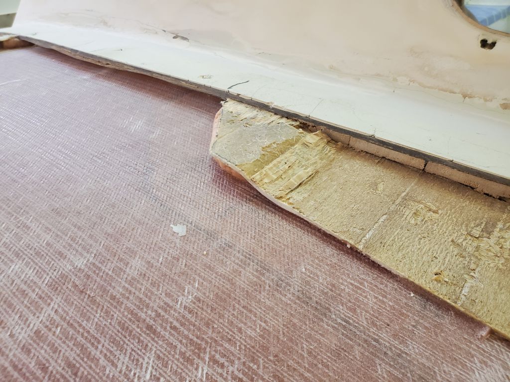
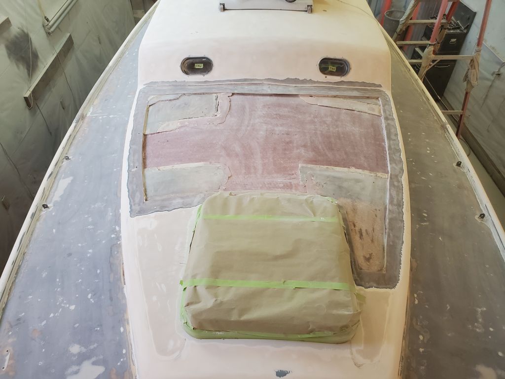
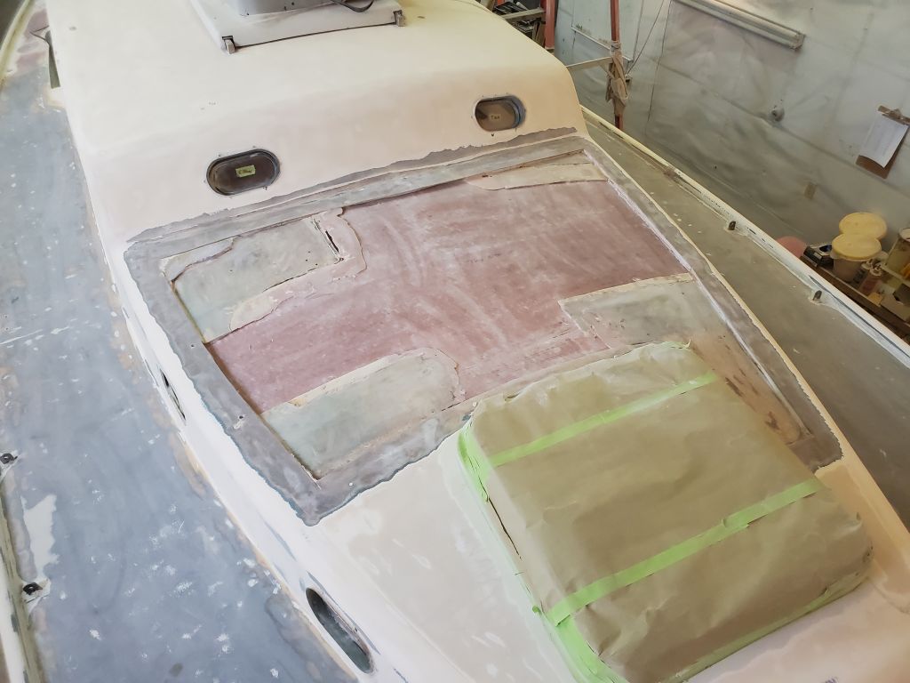
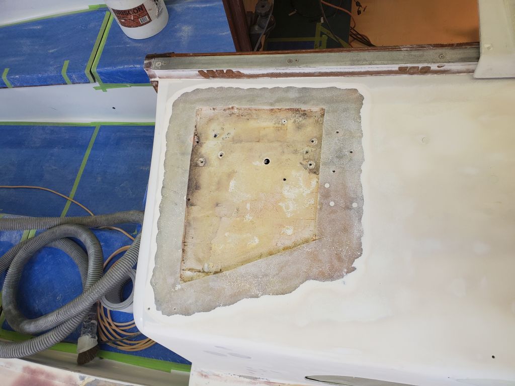
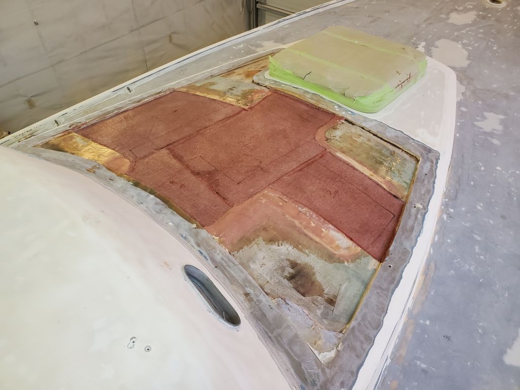
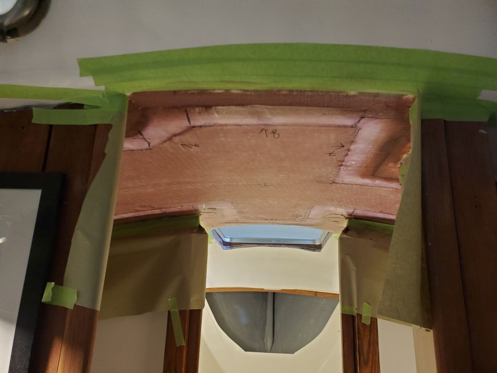
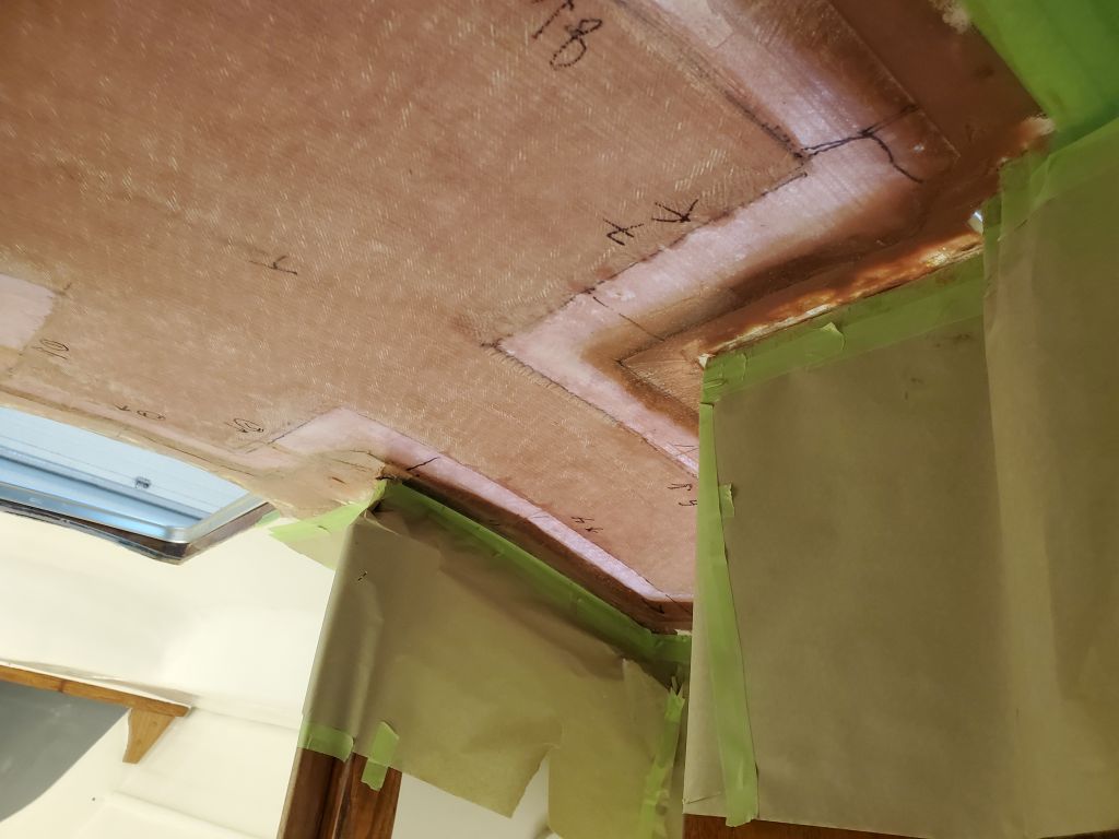
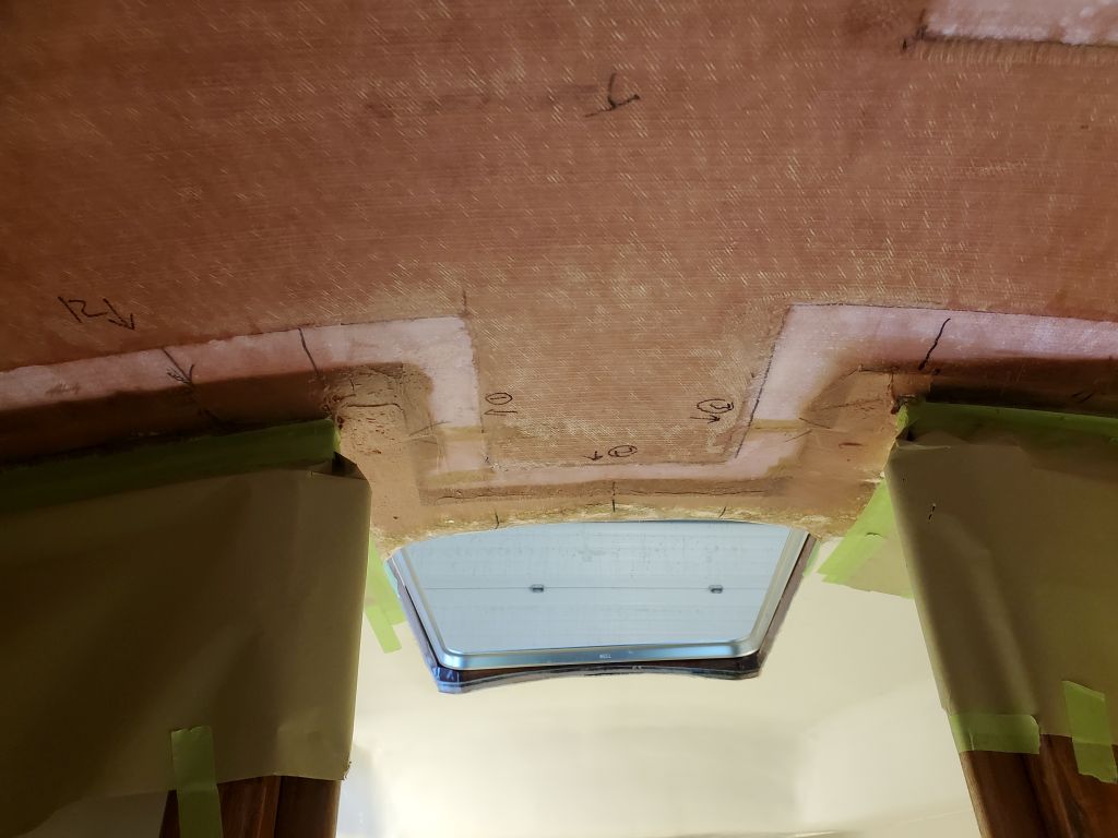
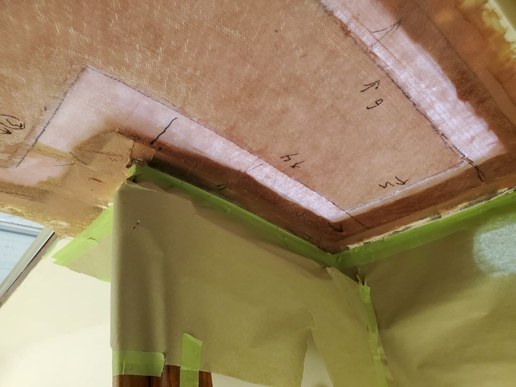
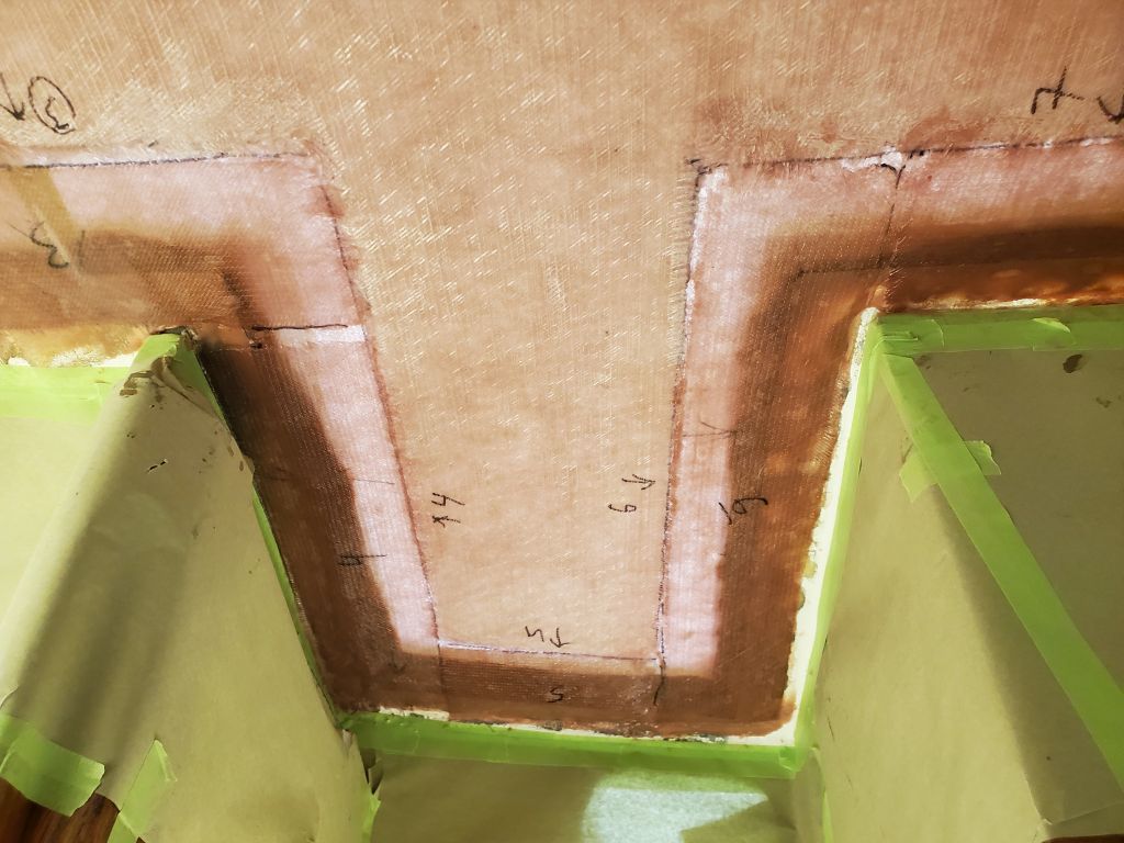
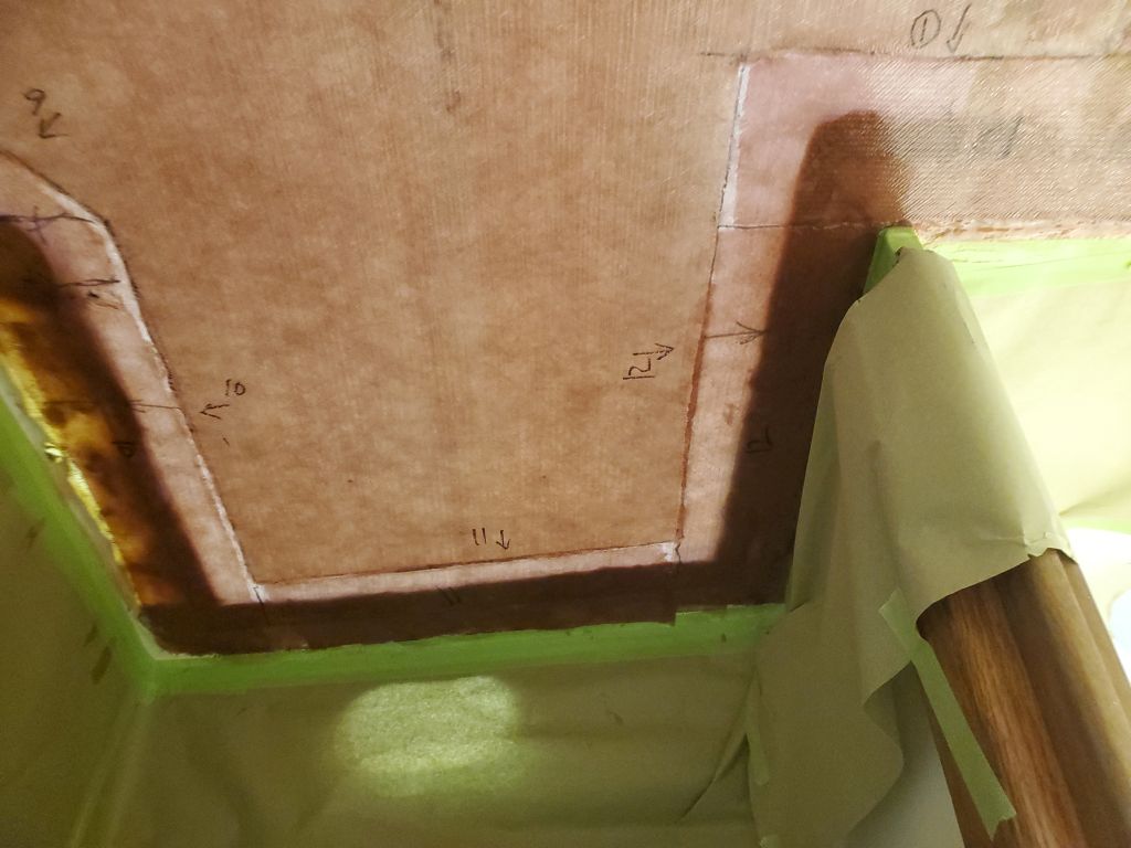
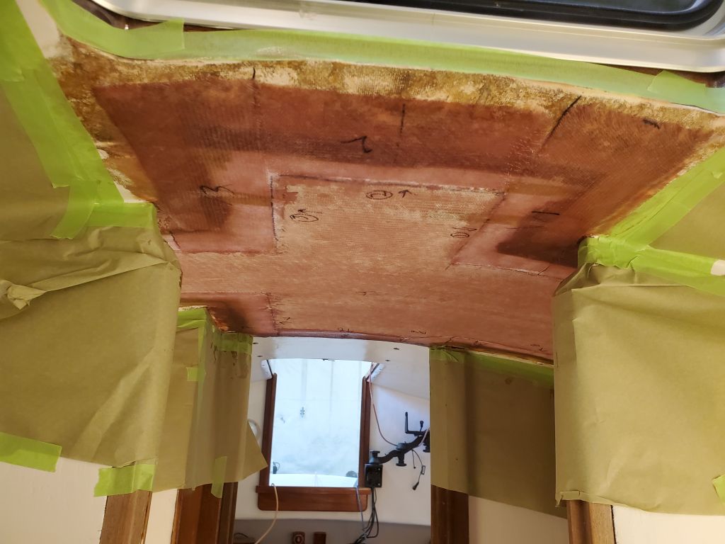
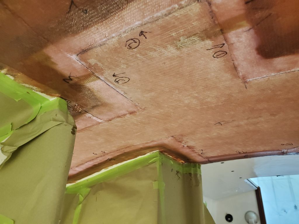
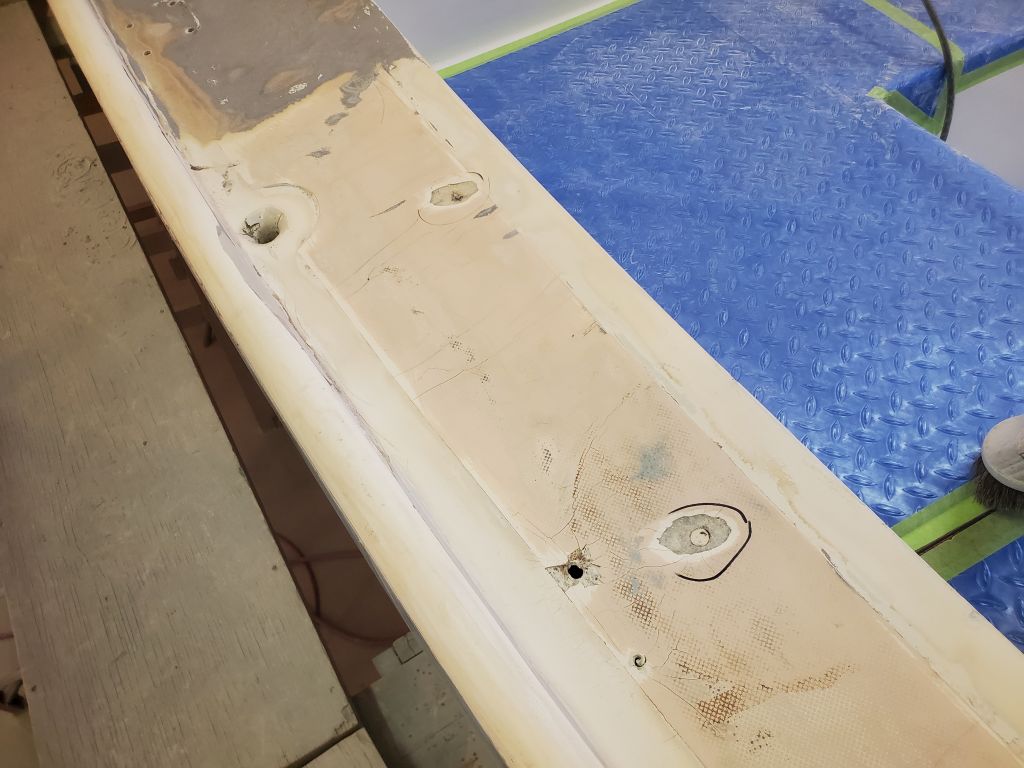
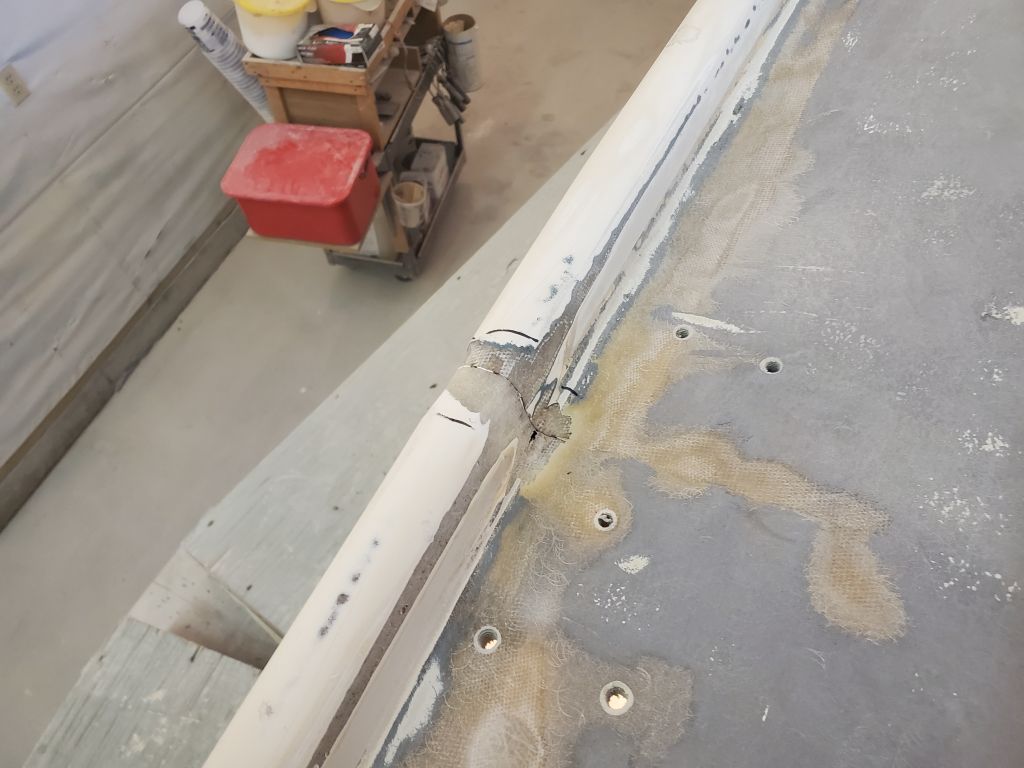
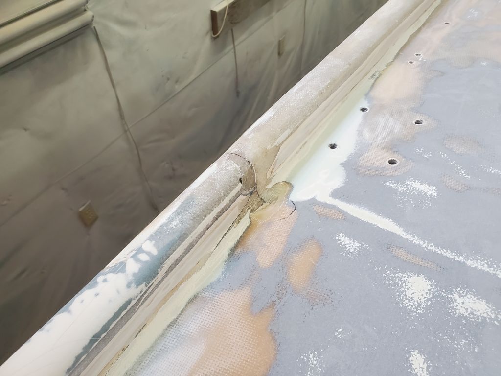
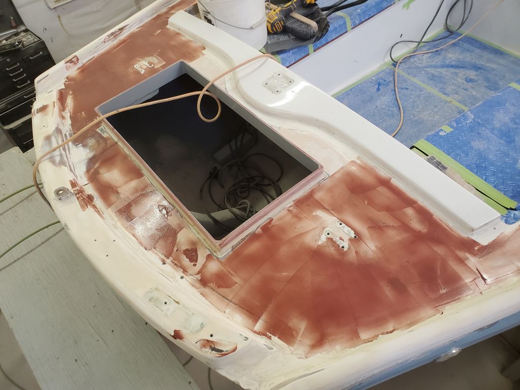
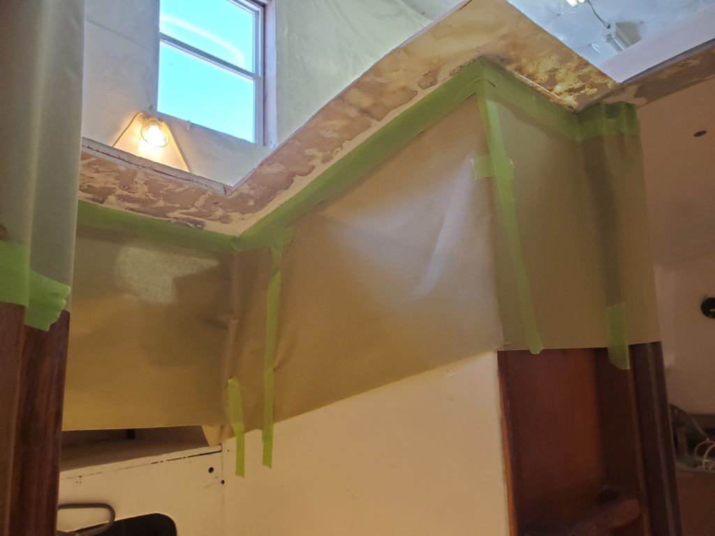
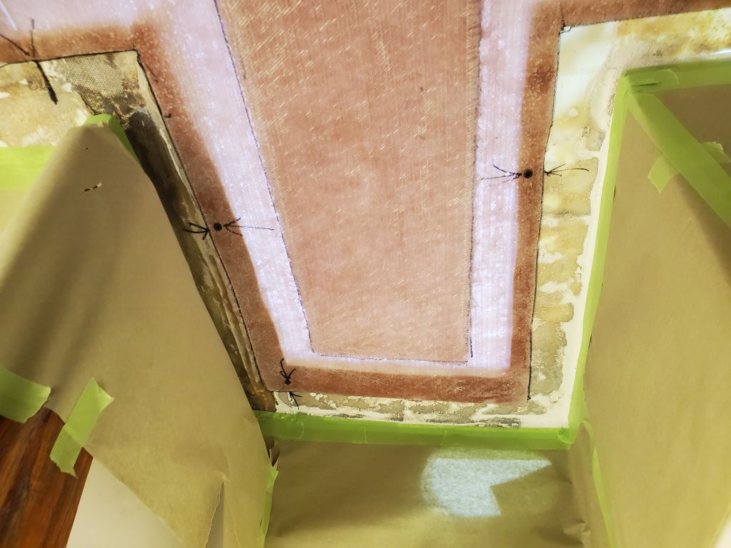
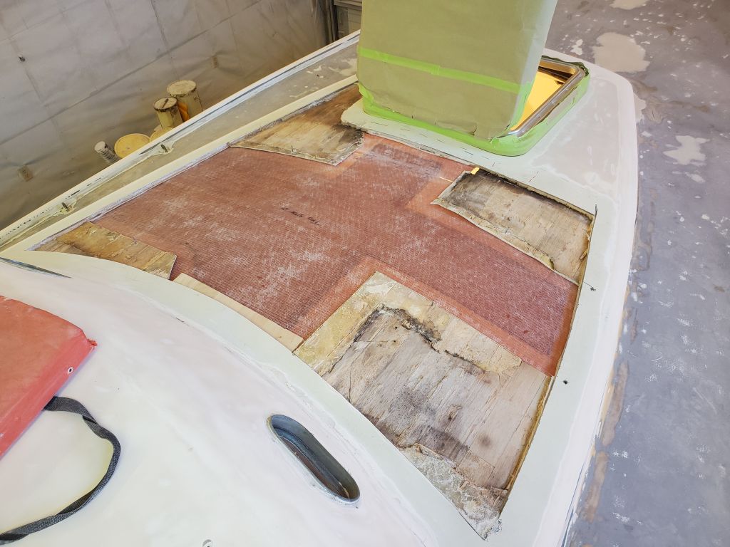
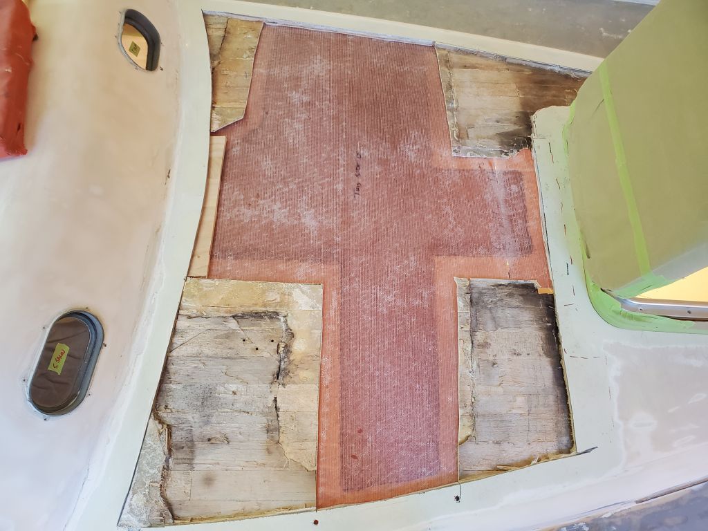
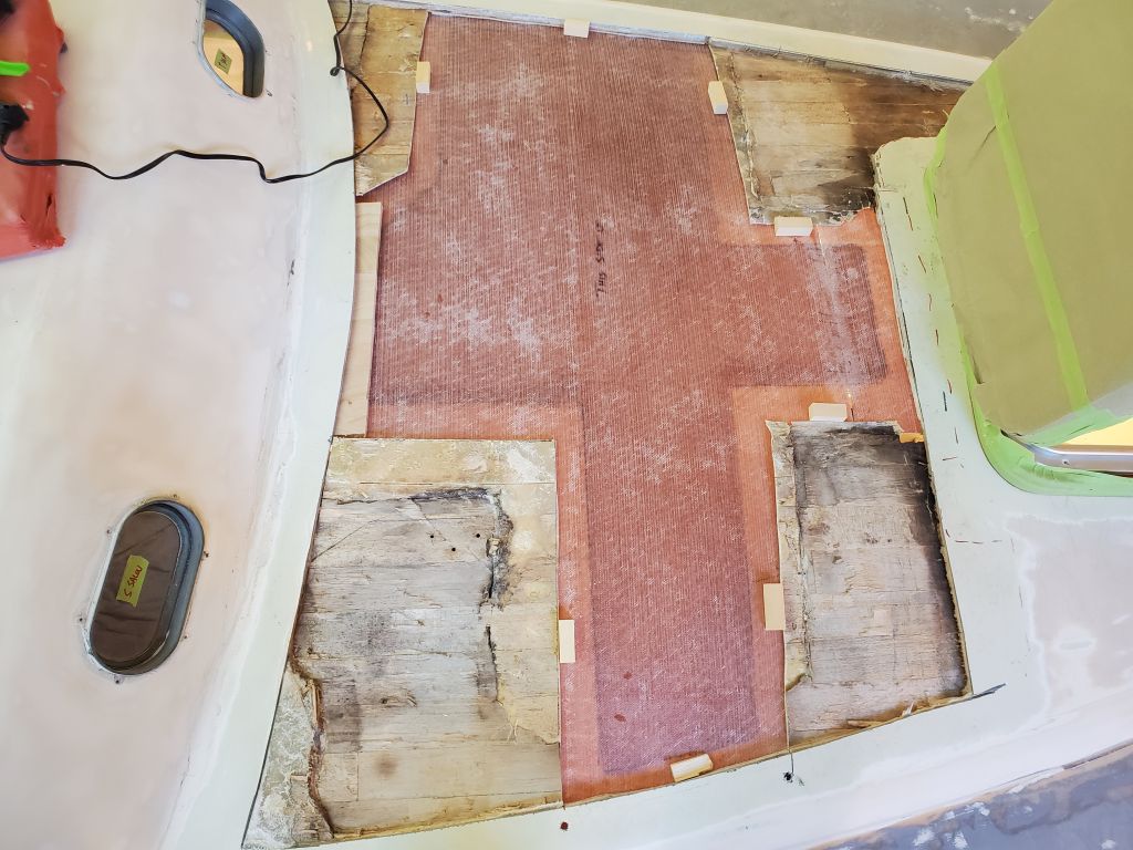
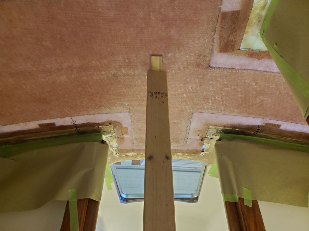
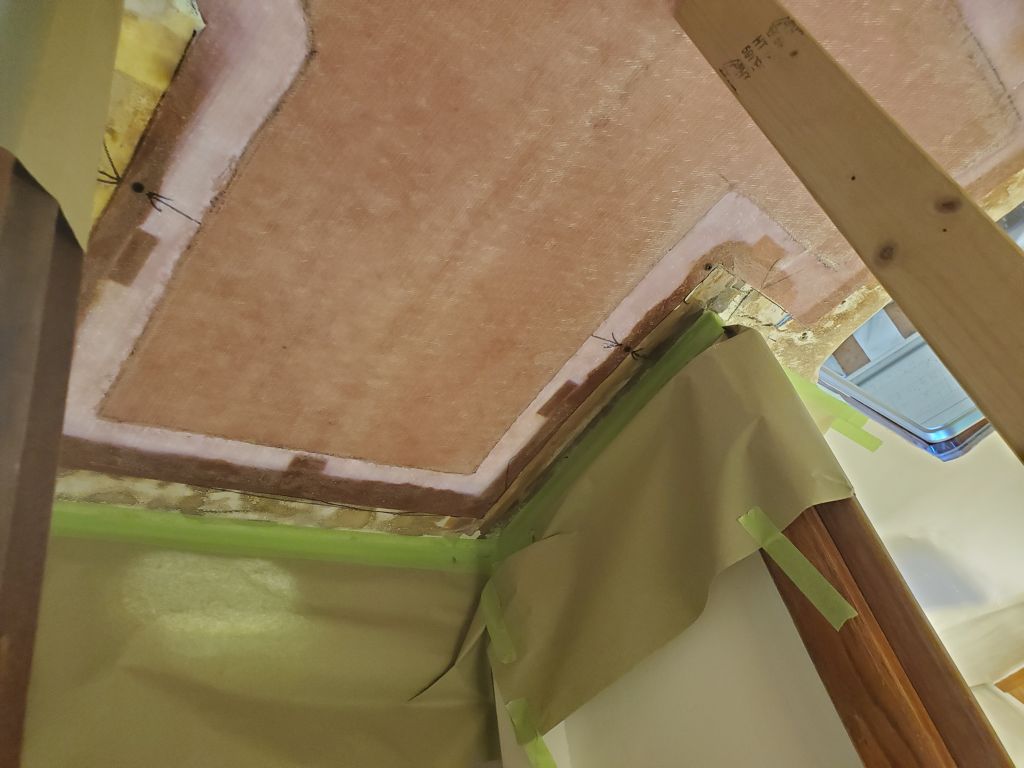
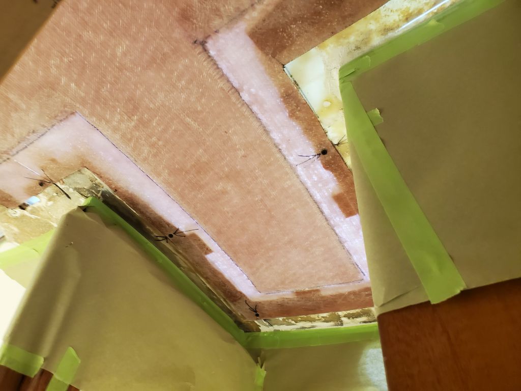
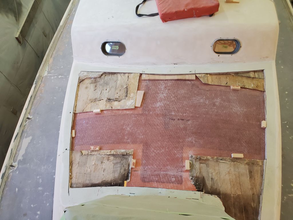
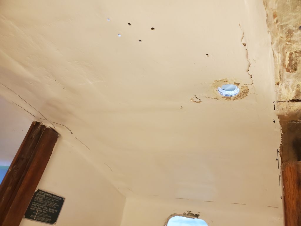
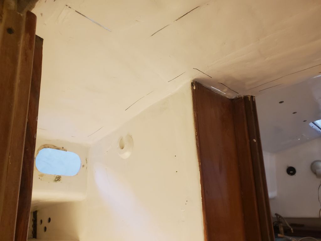
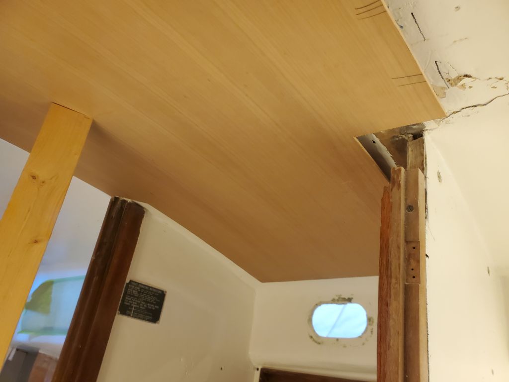
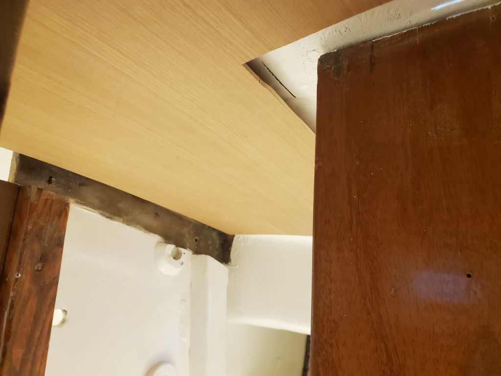
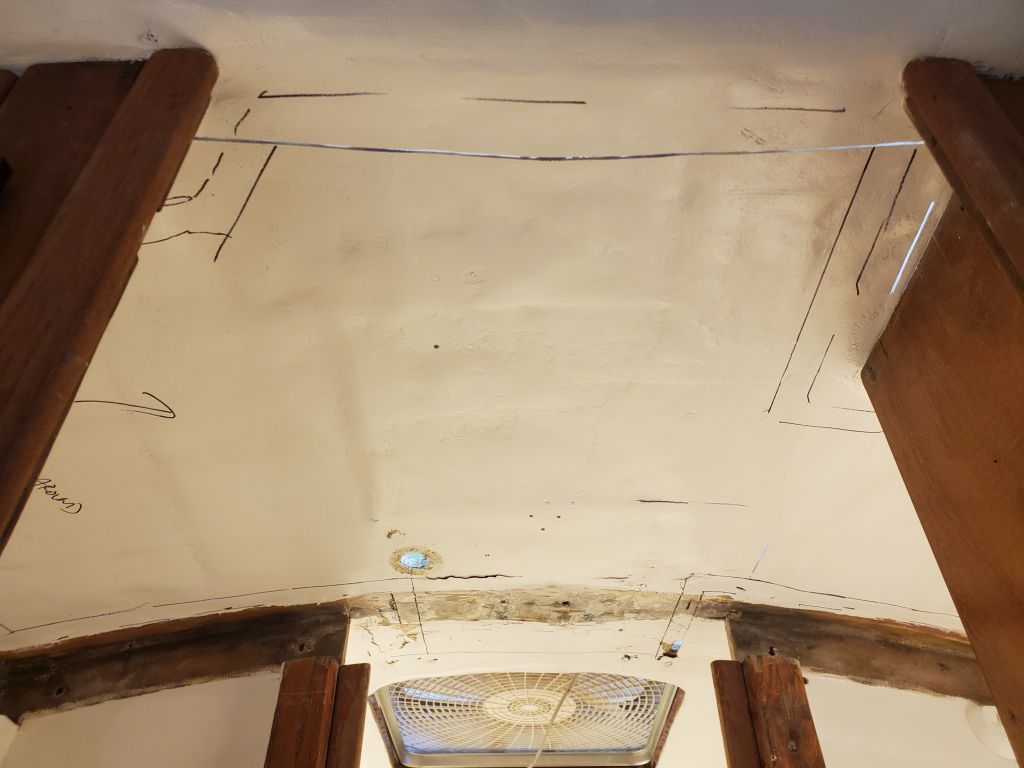
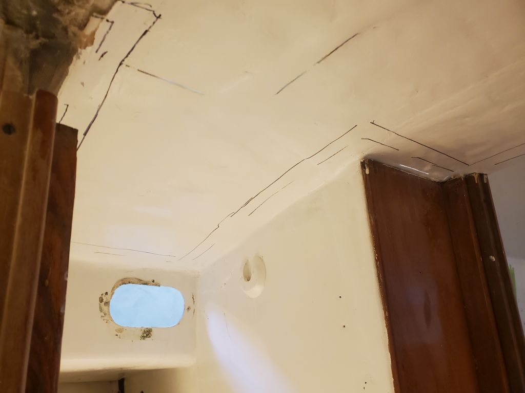
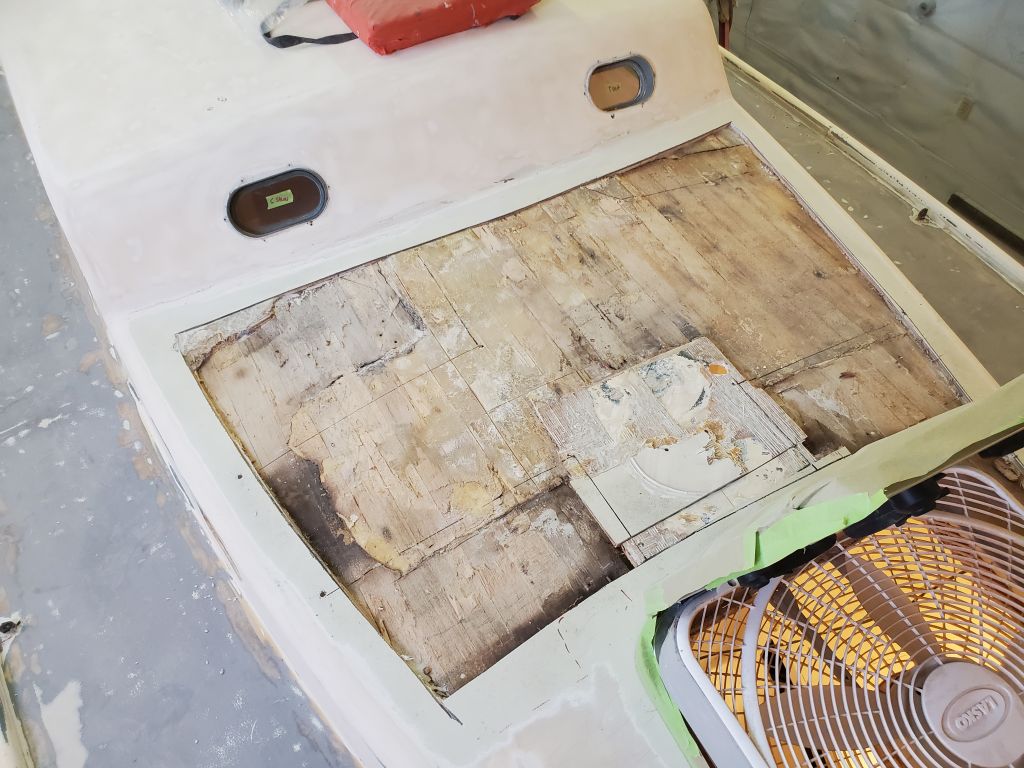
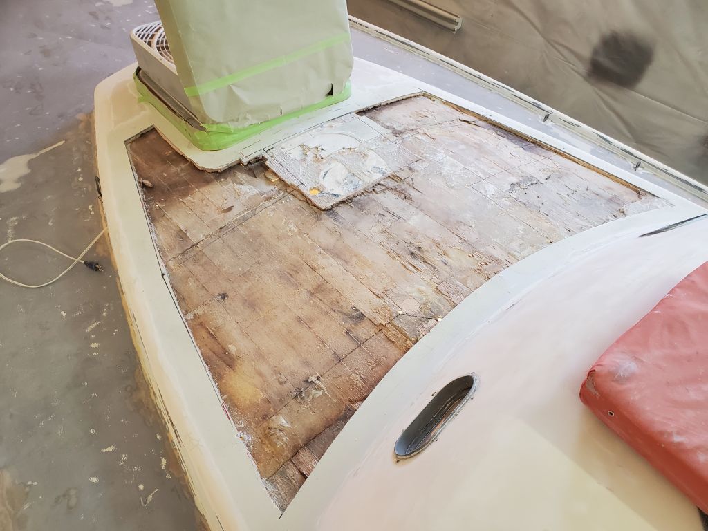
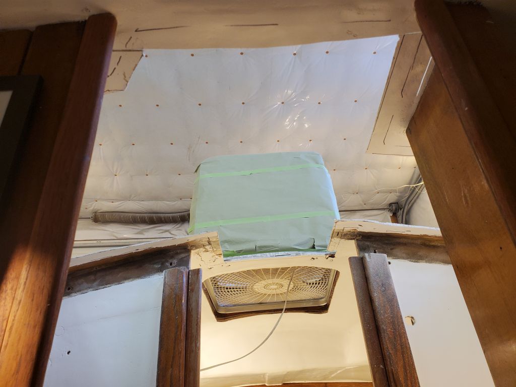
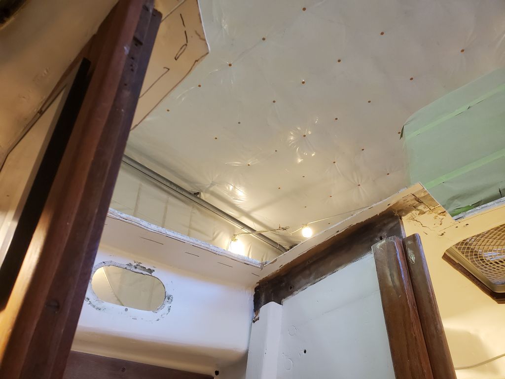
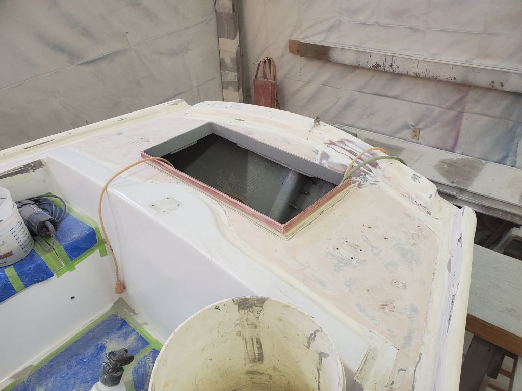
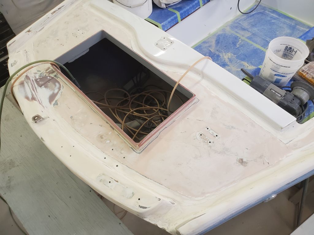
Now the overall limits of the new work were defined, and to mark the actual lines where I’d cut the deck out, I marked a new line 1″ in from the dashed lines representing the size of the panel. This would leave a 1″ flange for bonding the panel directly to the adjacent deck, with the 2″ beyond for tabbing later. With a drill, I marked each corner of the cutout area from below so I could recreate the shape abovedecks and make the cut from there.
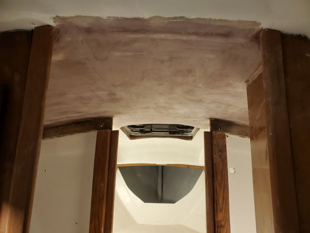
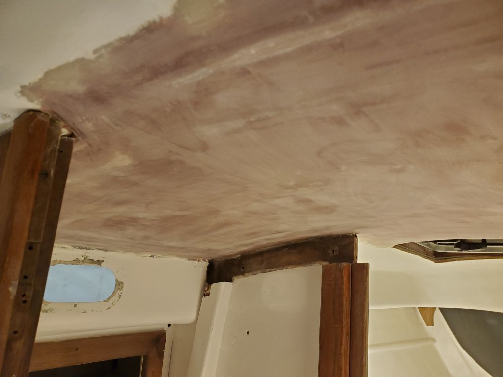
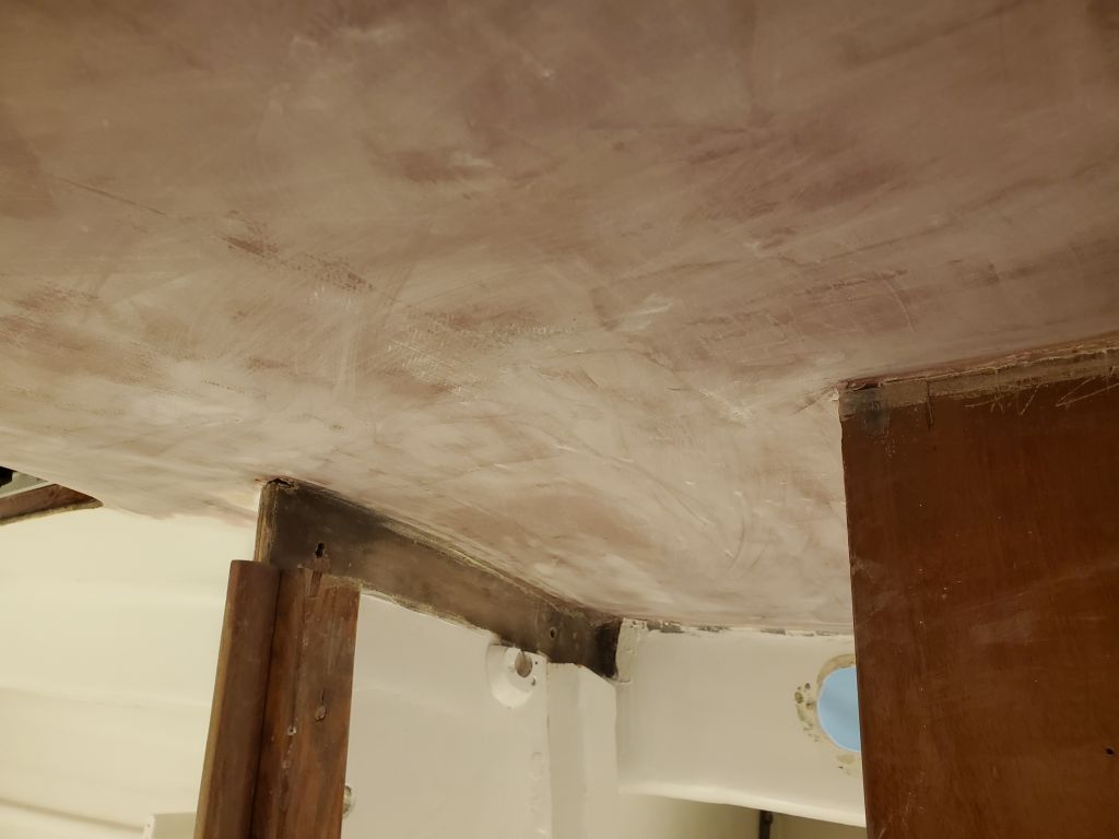
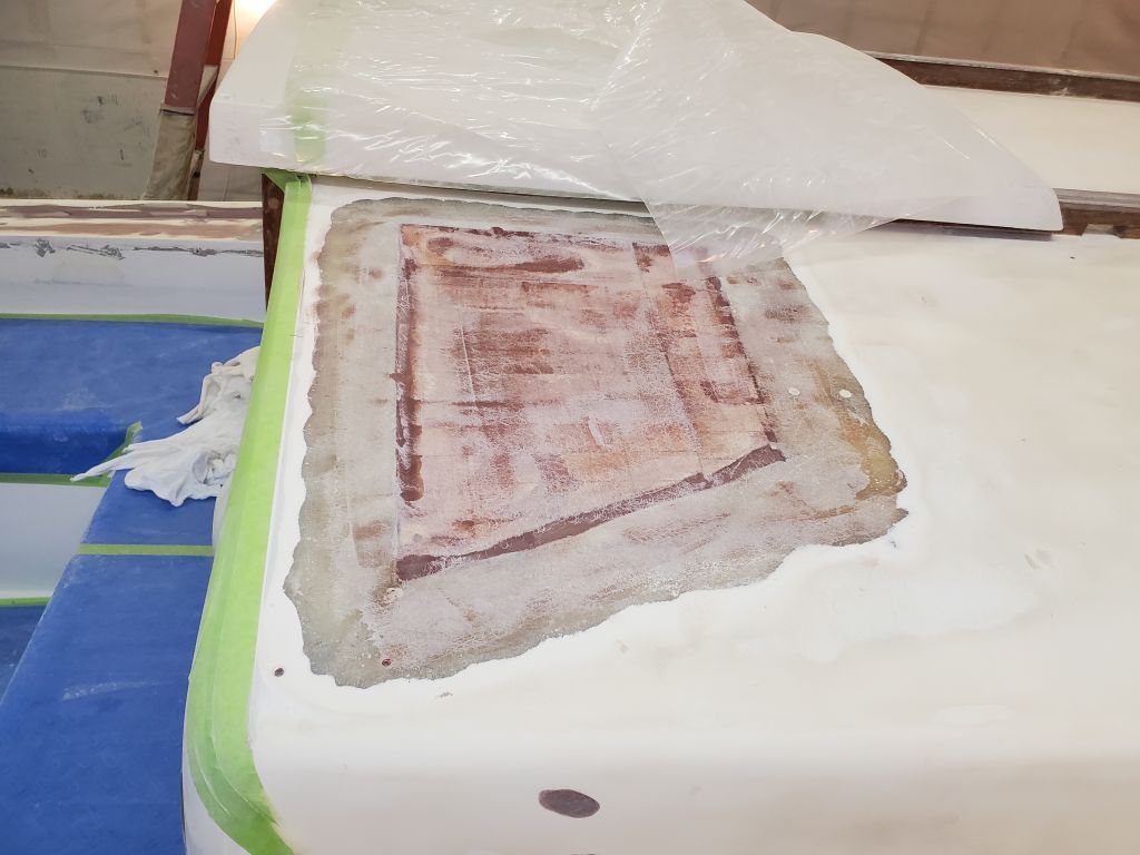
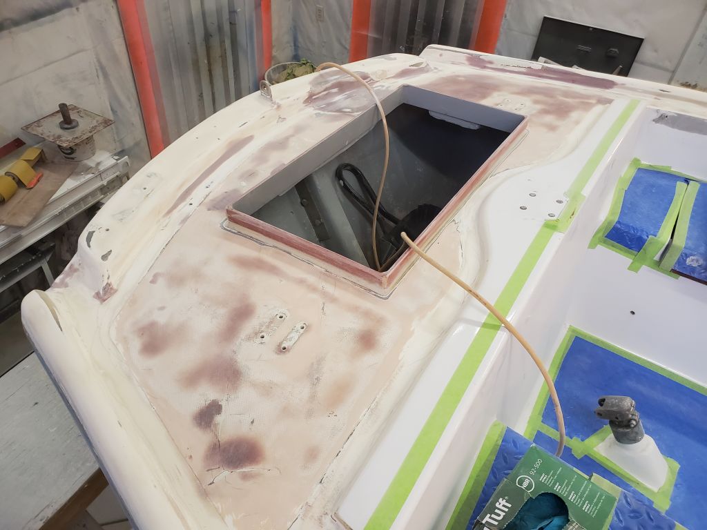
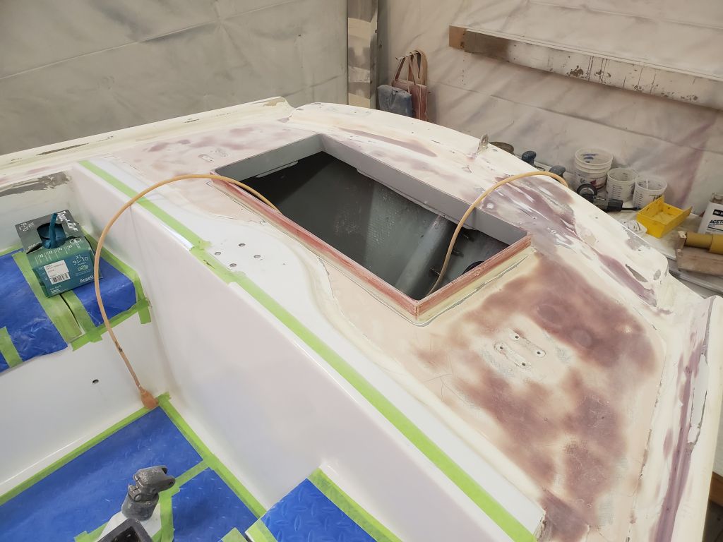
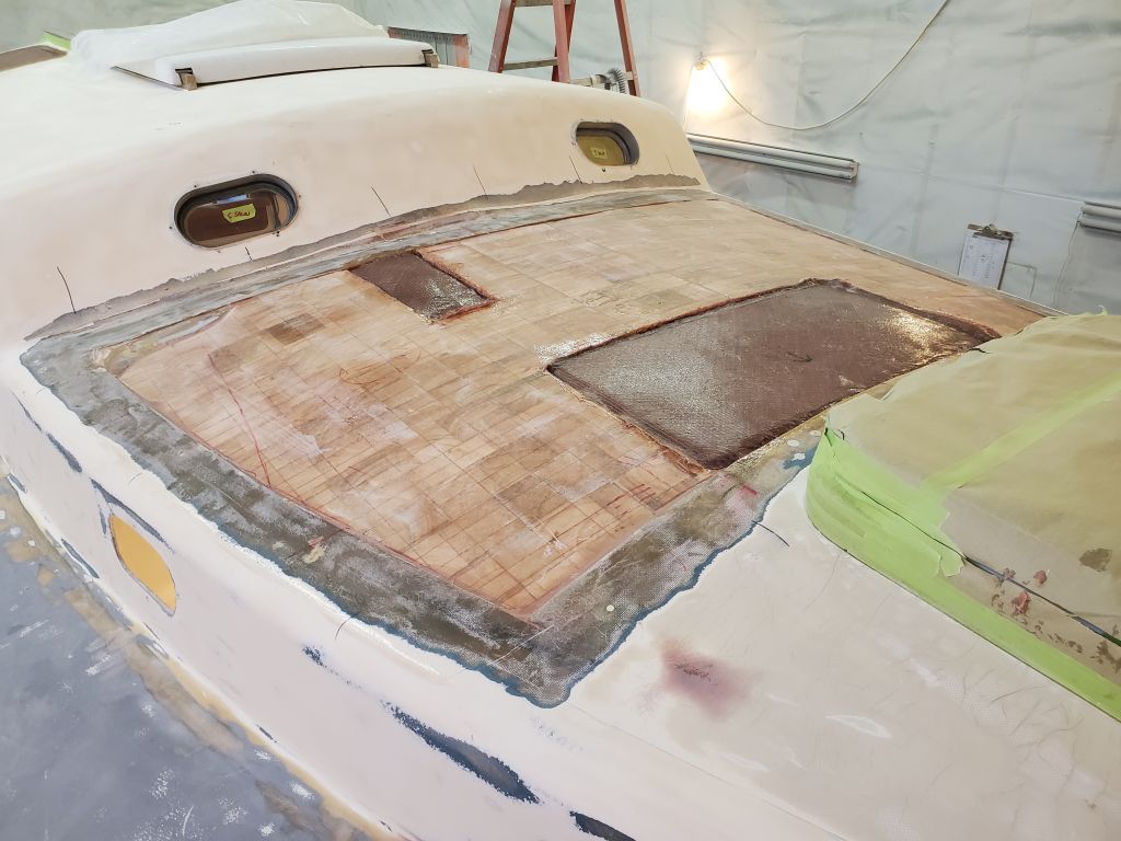
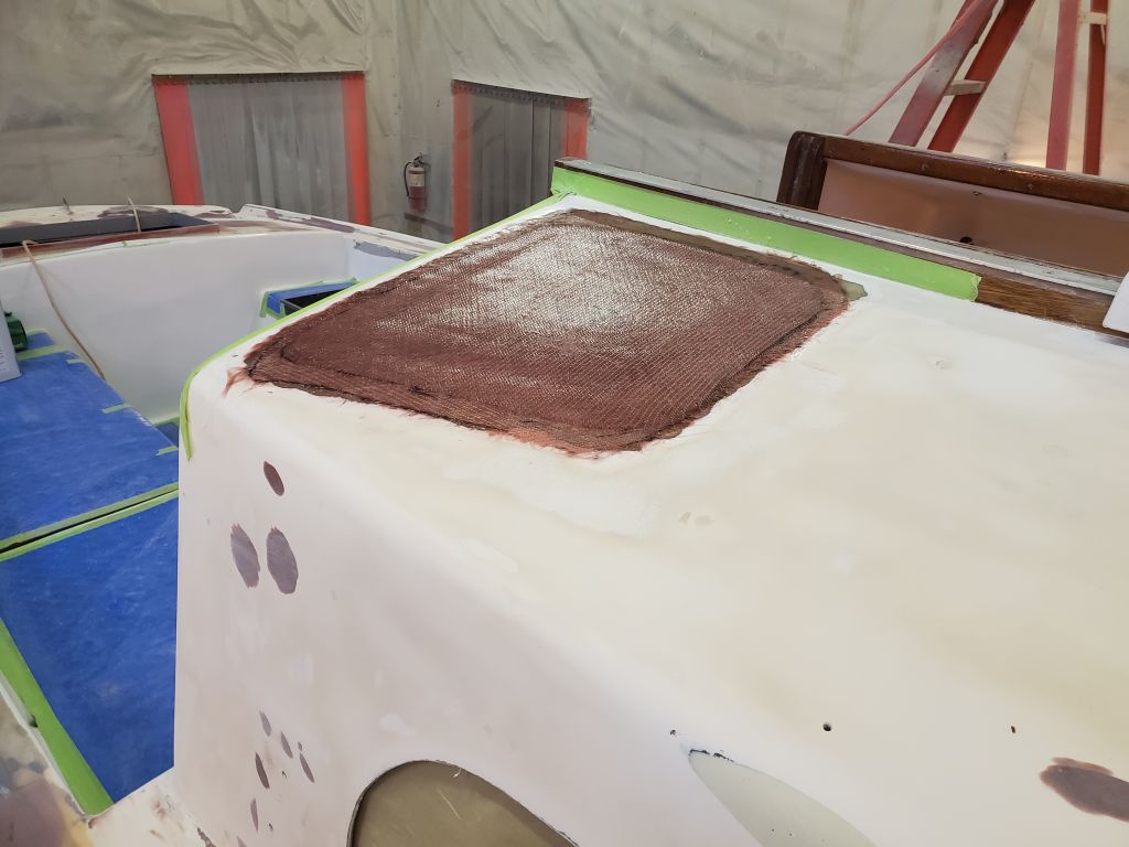
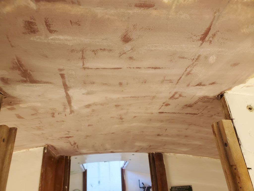
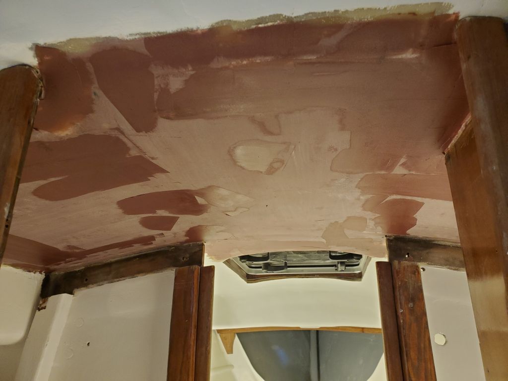
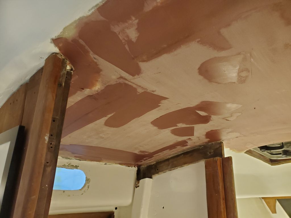
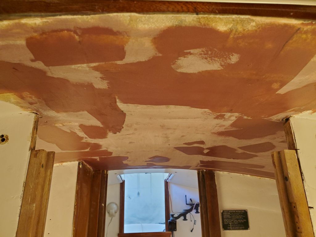
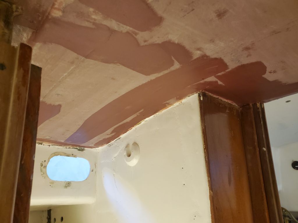
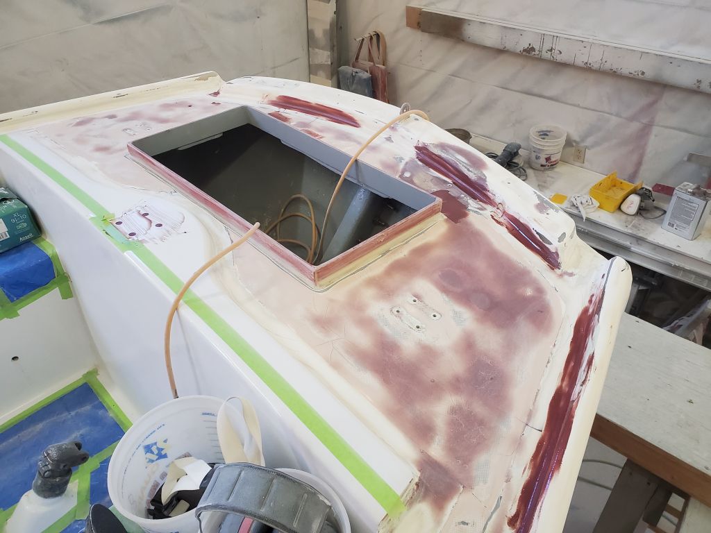
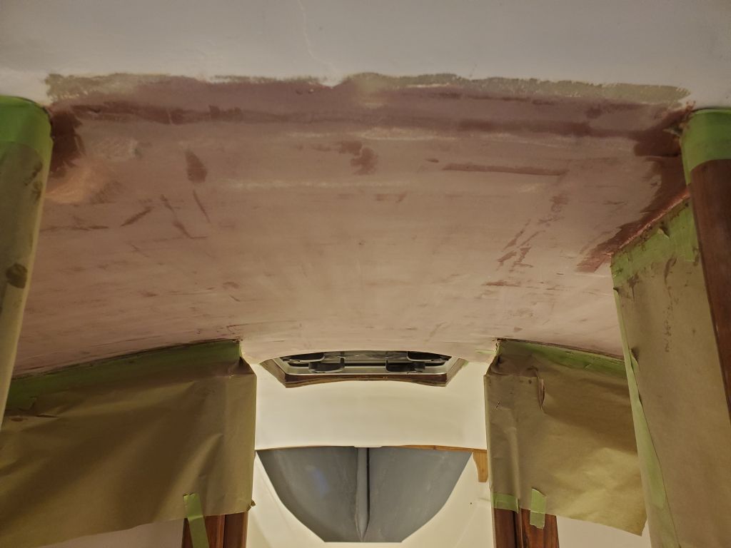
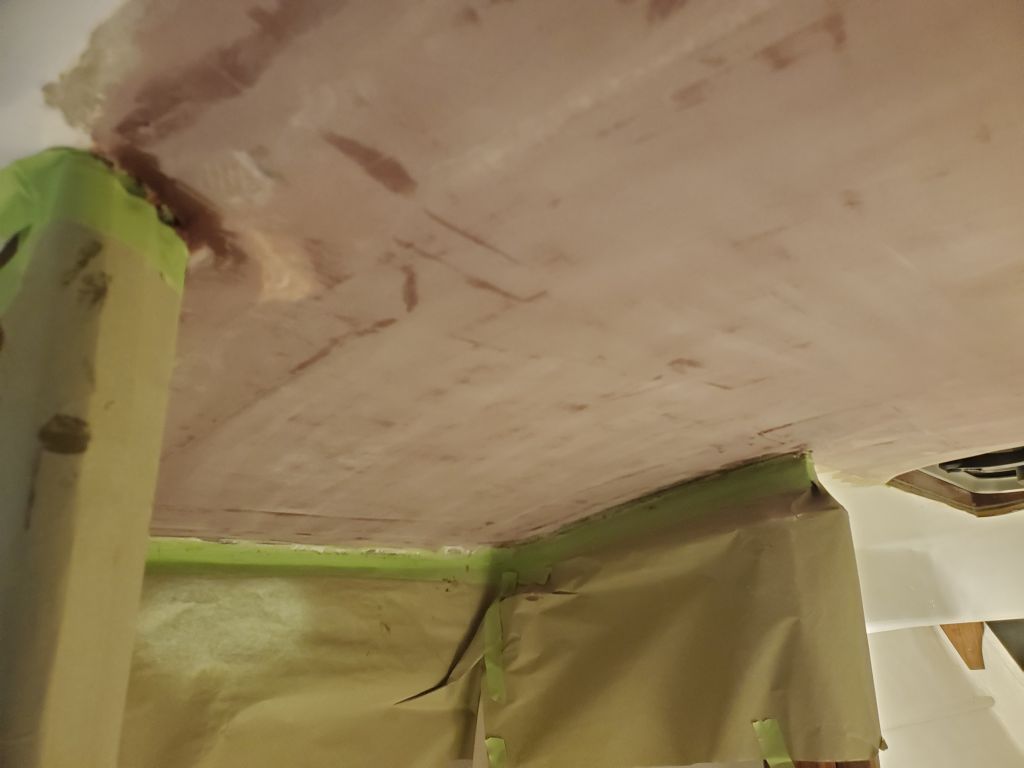
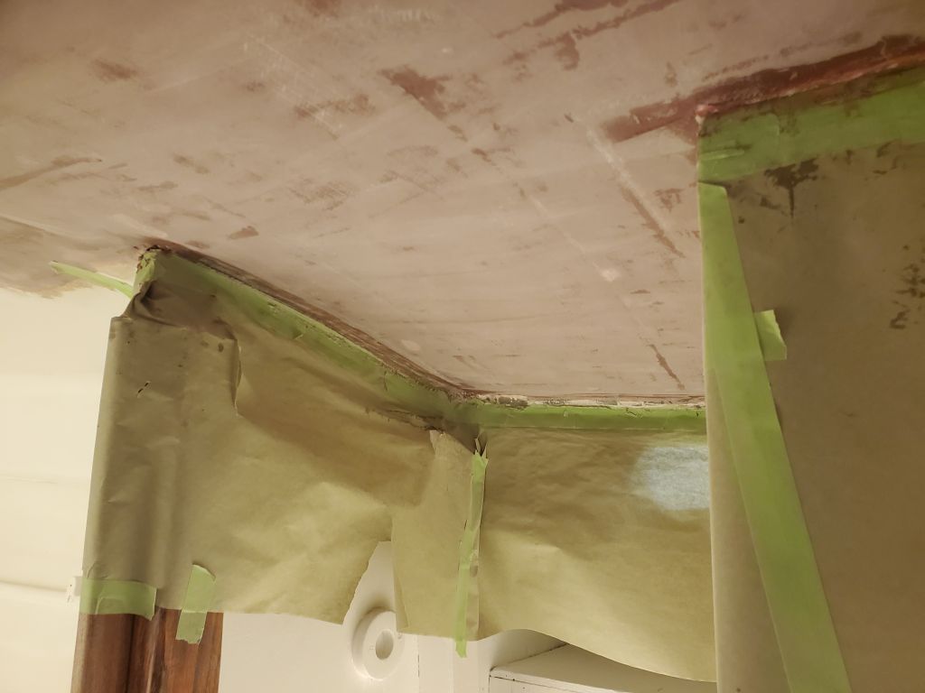
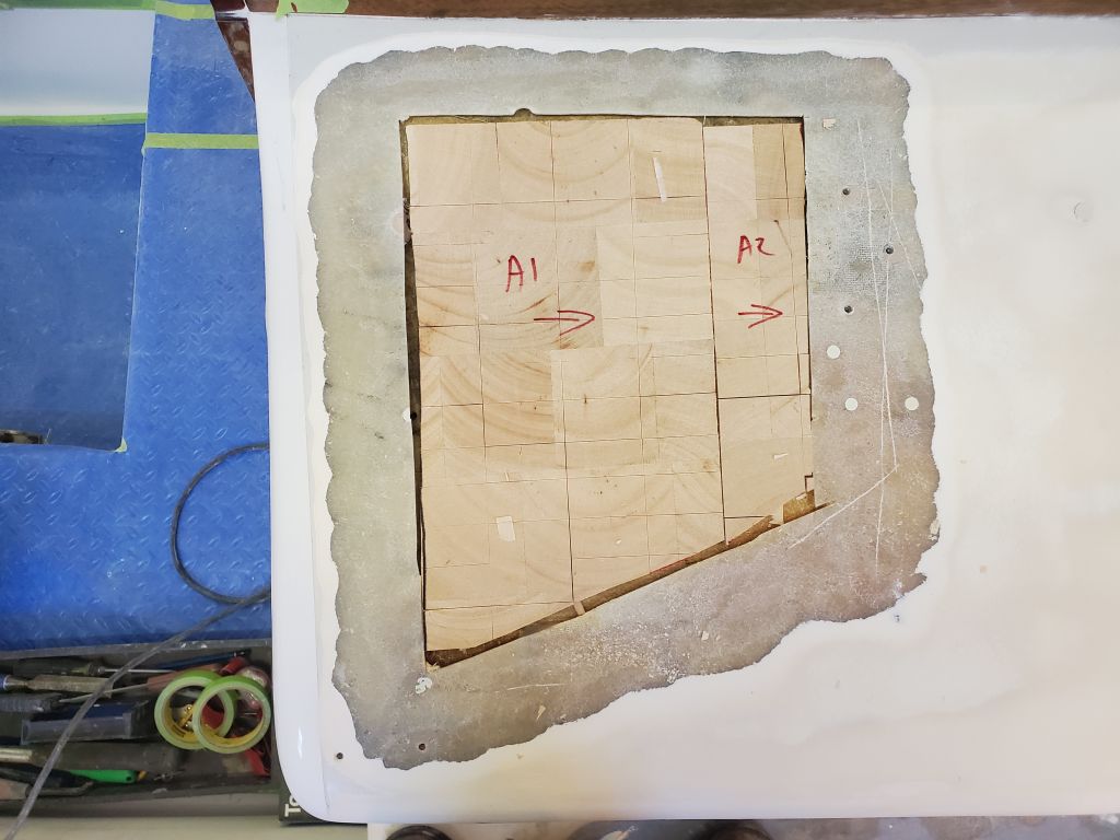
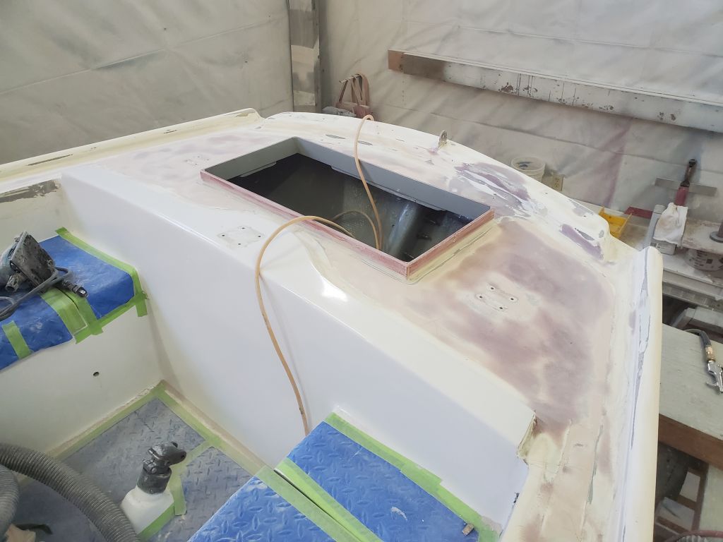
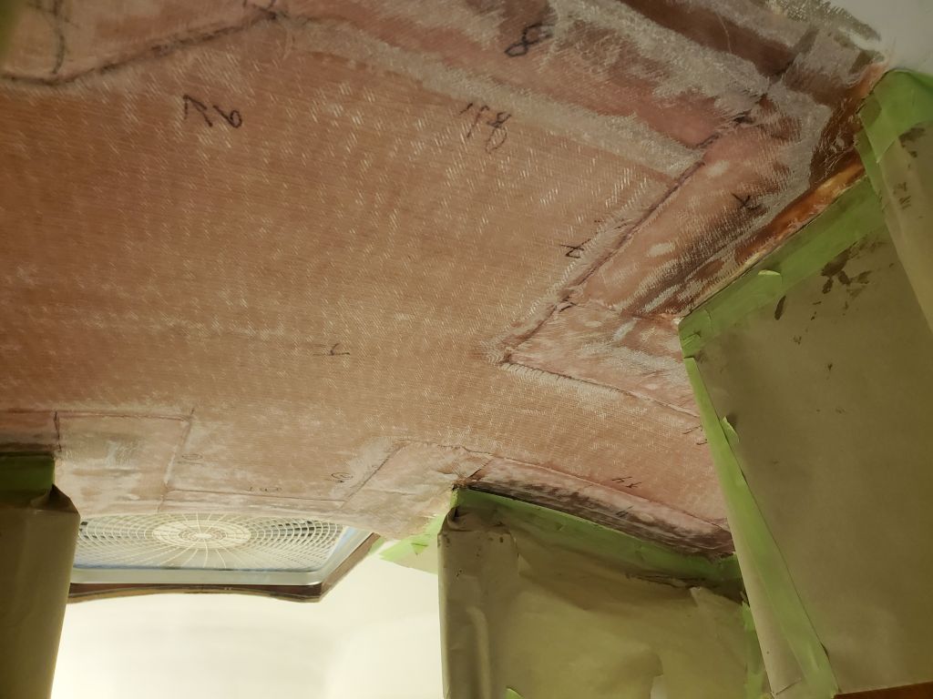
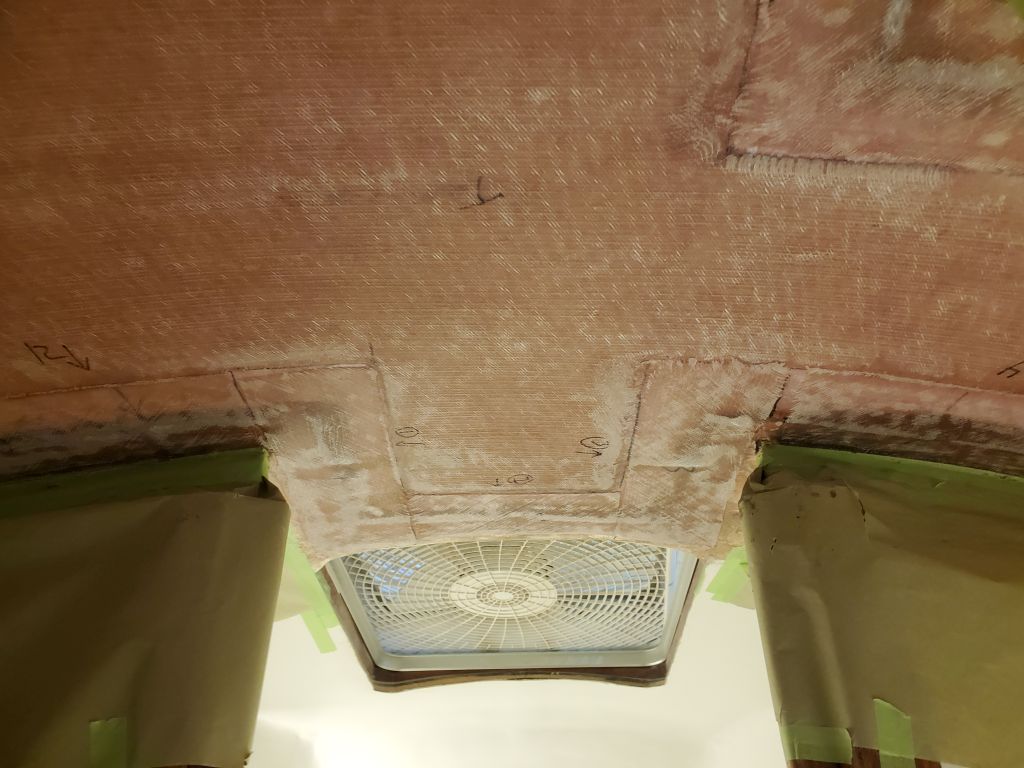
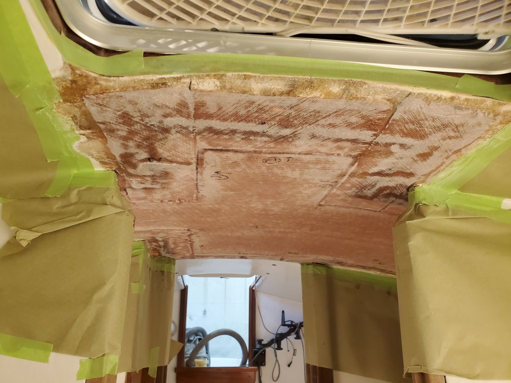
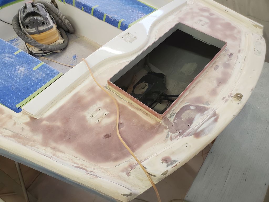
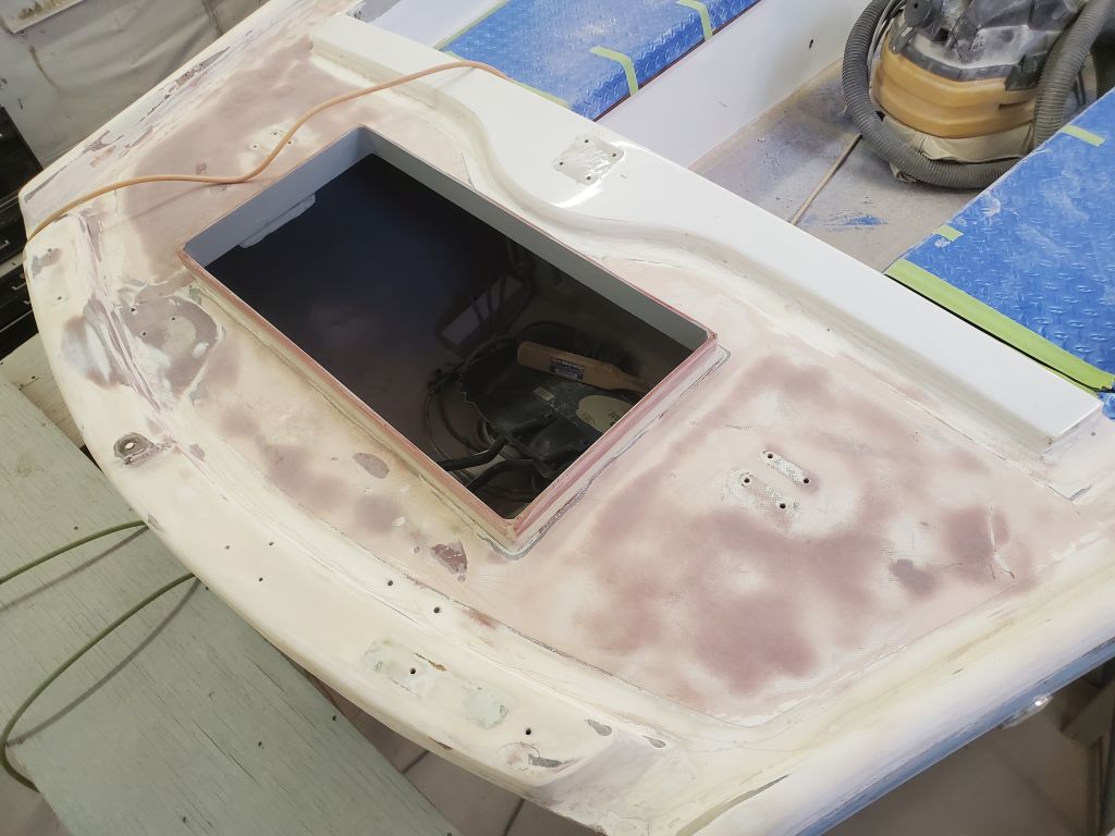
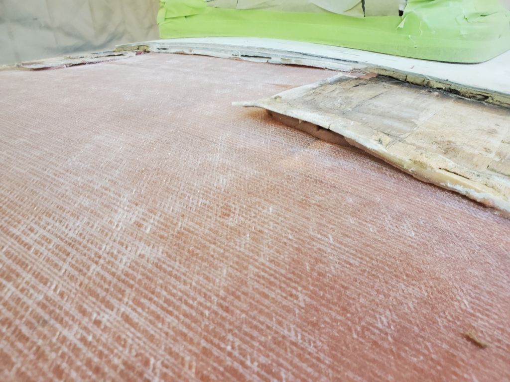
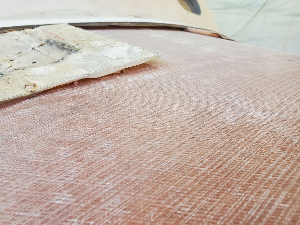
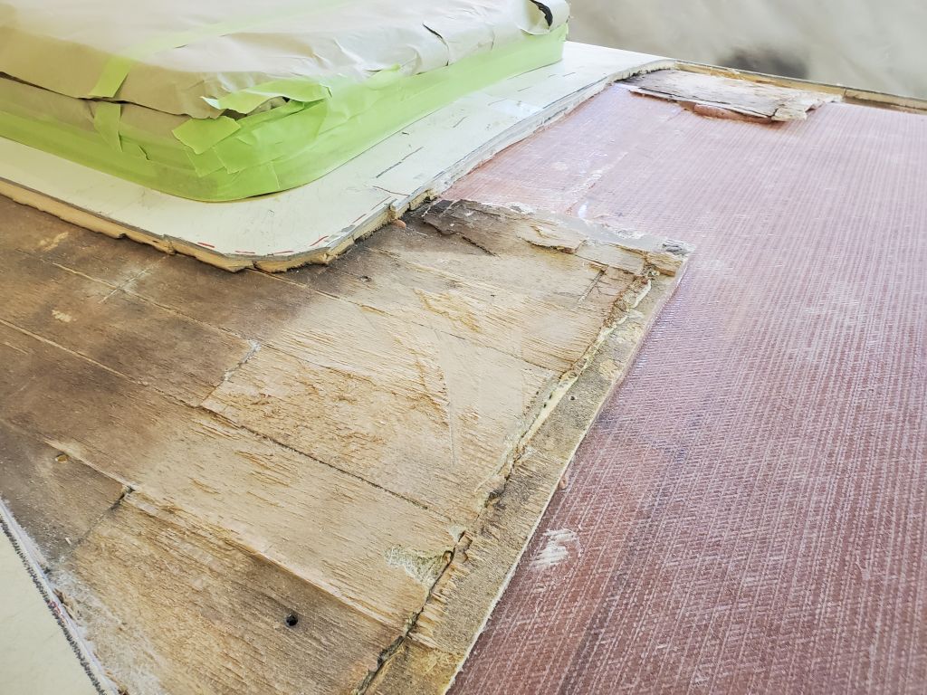
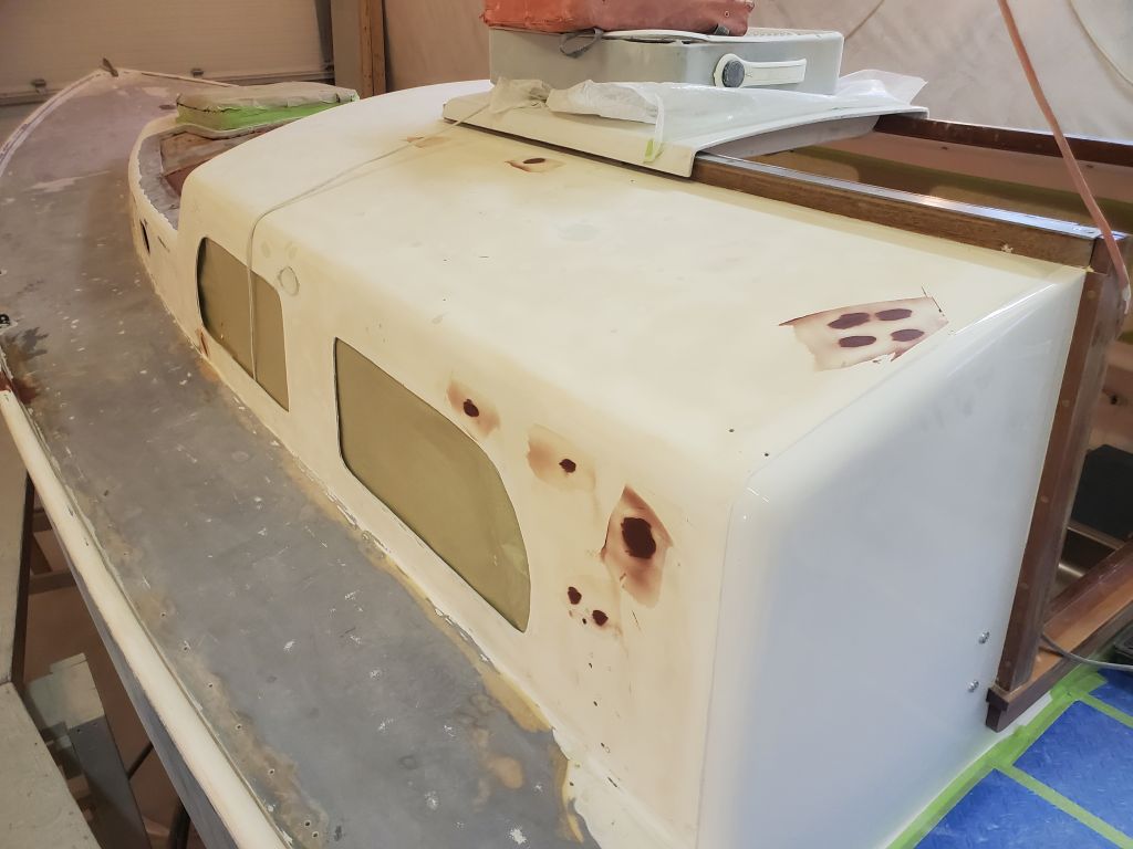
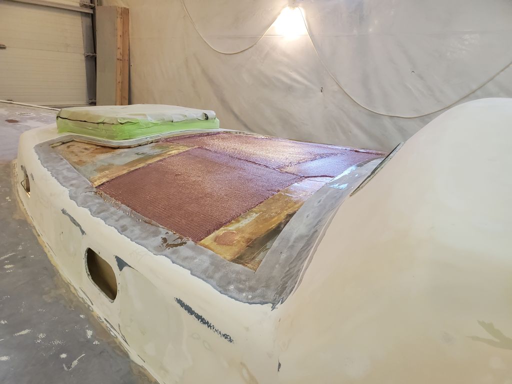
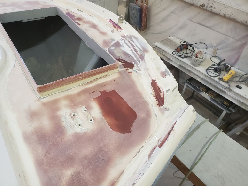
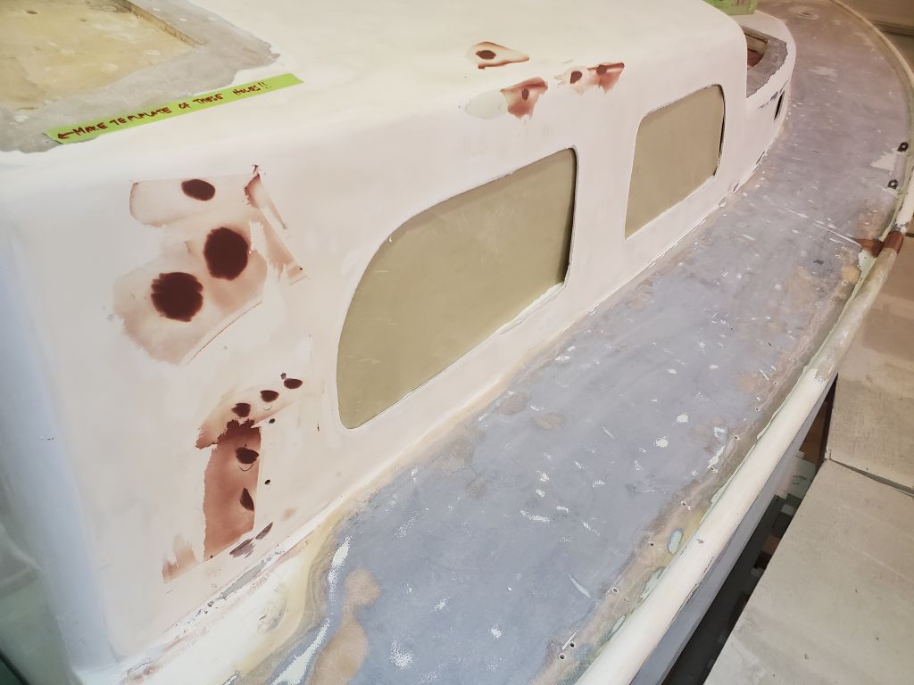
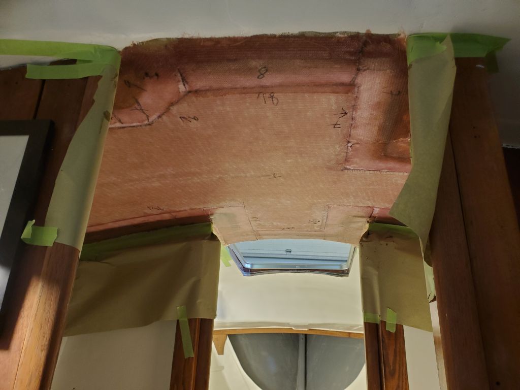
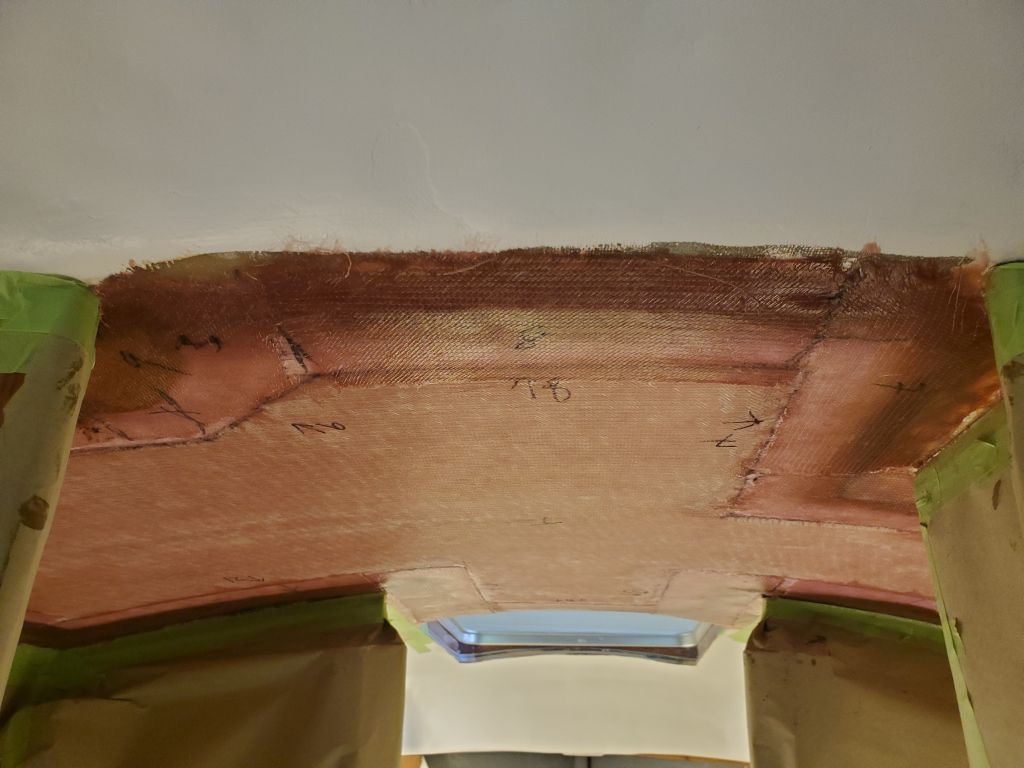
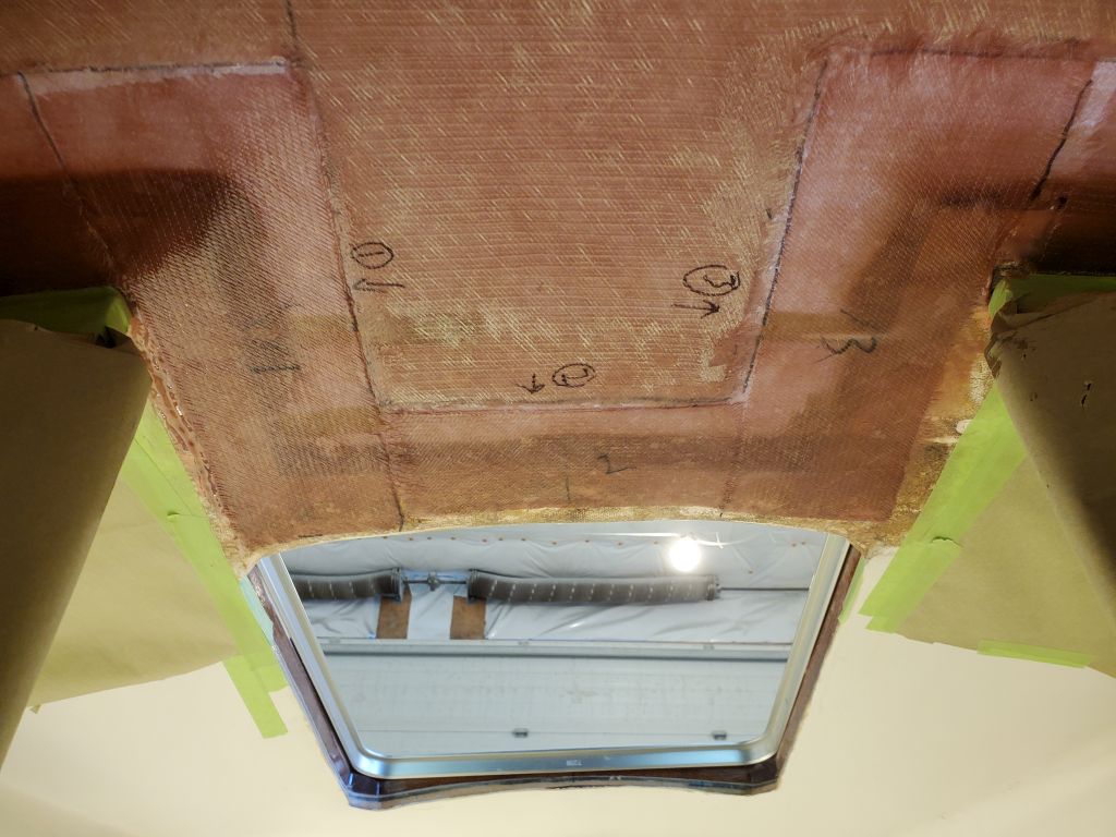
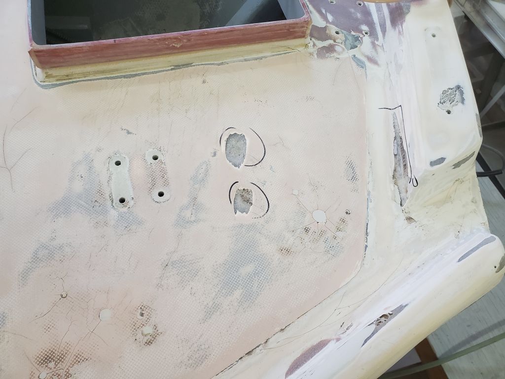
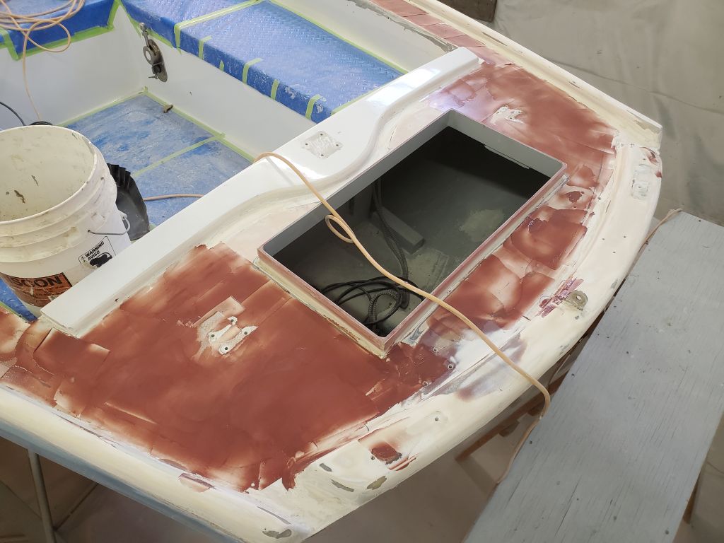
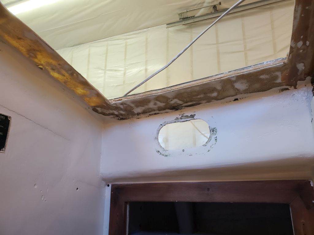
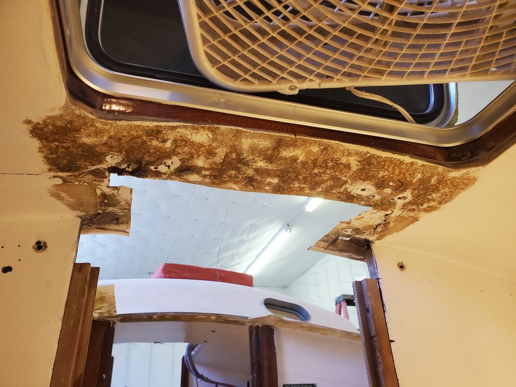
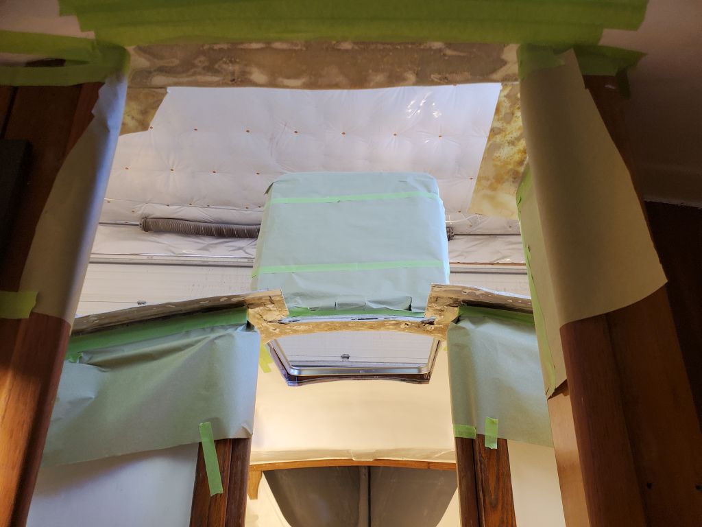
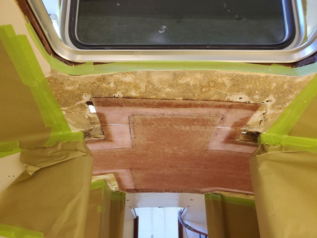
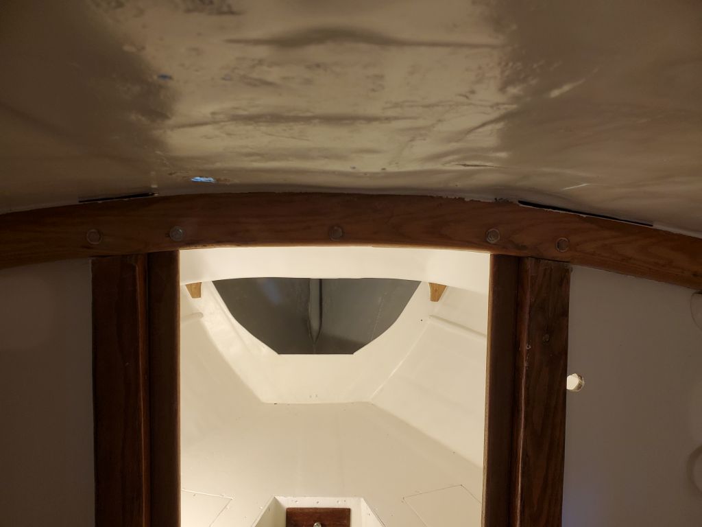
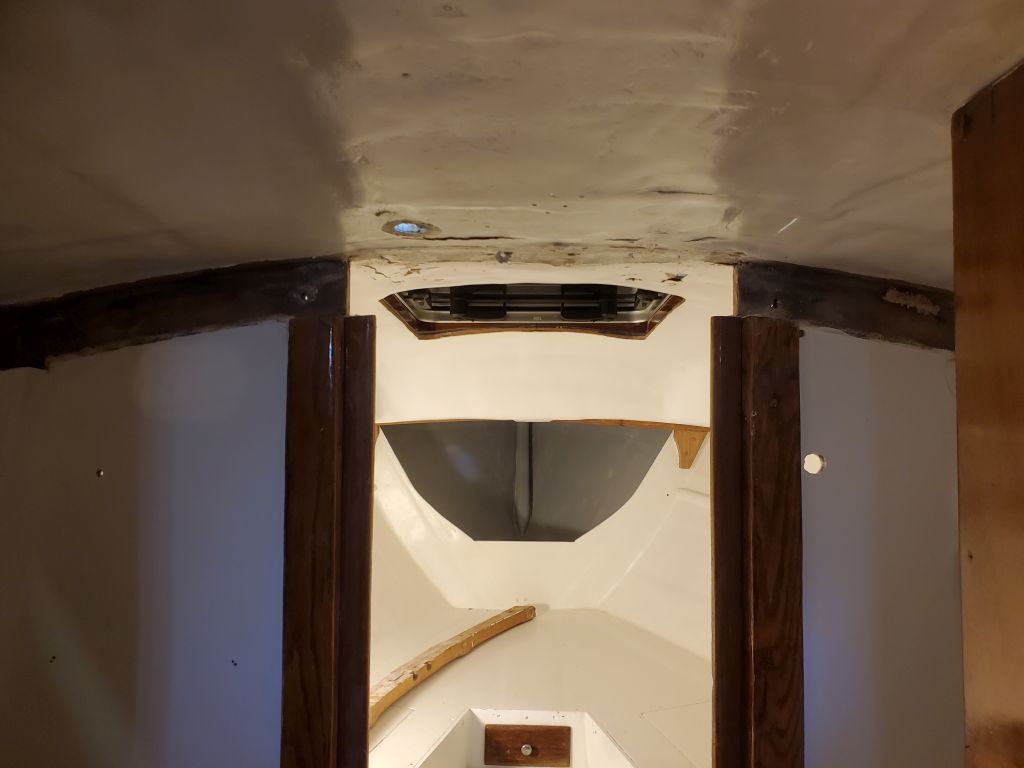
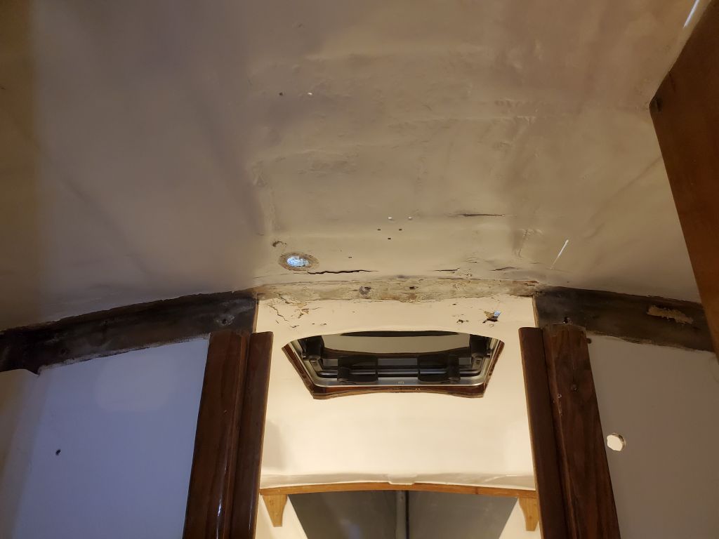
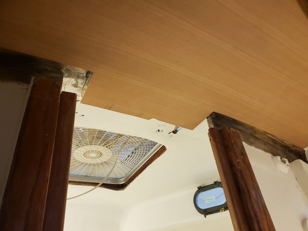
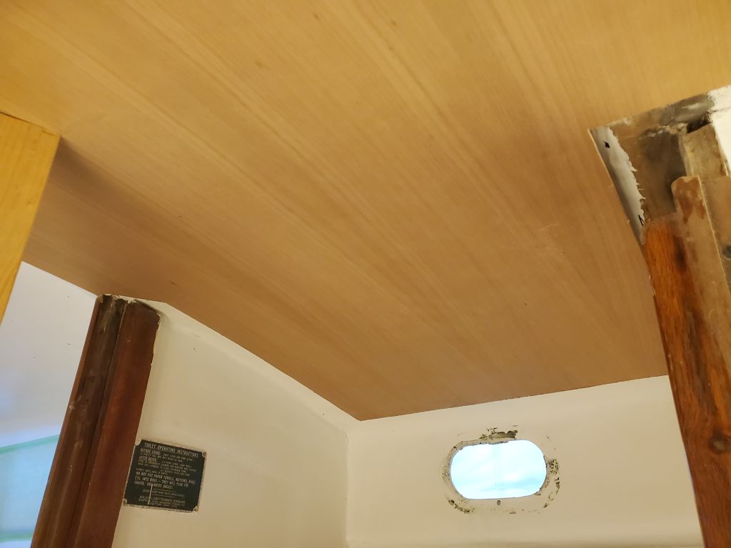
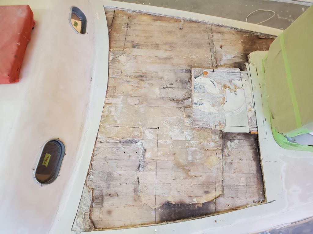
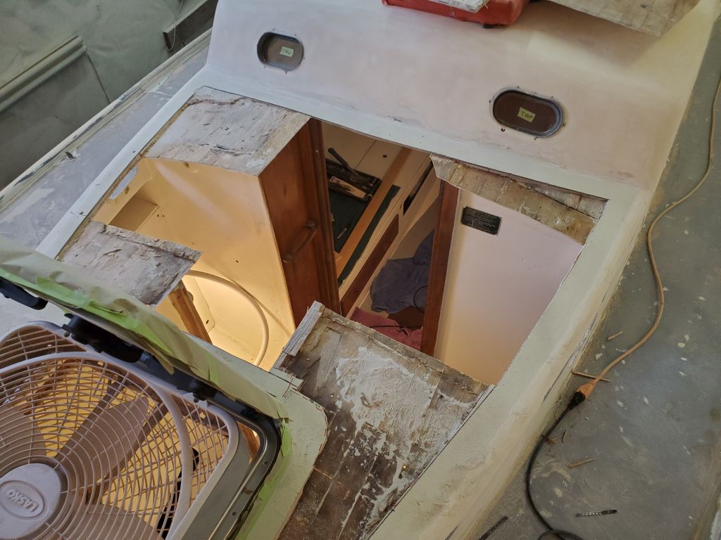
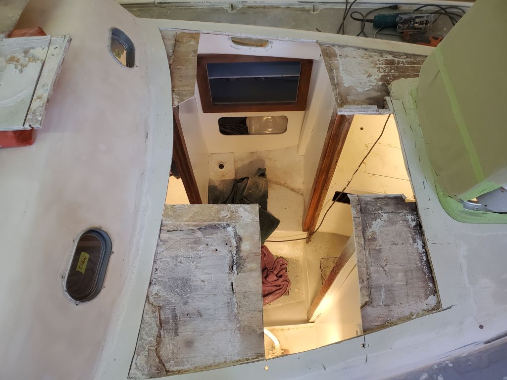
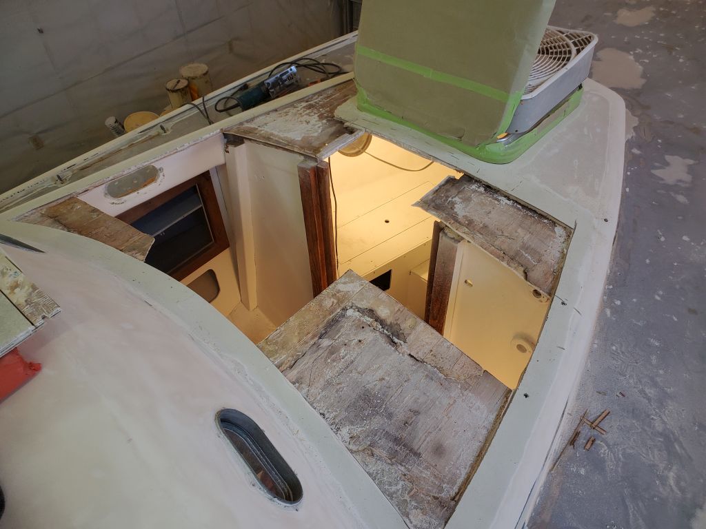
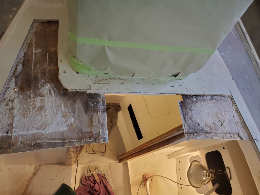
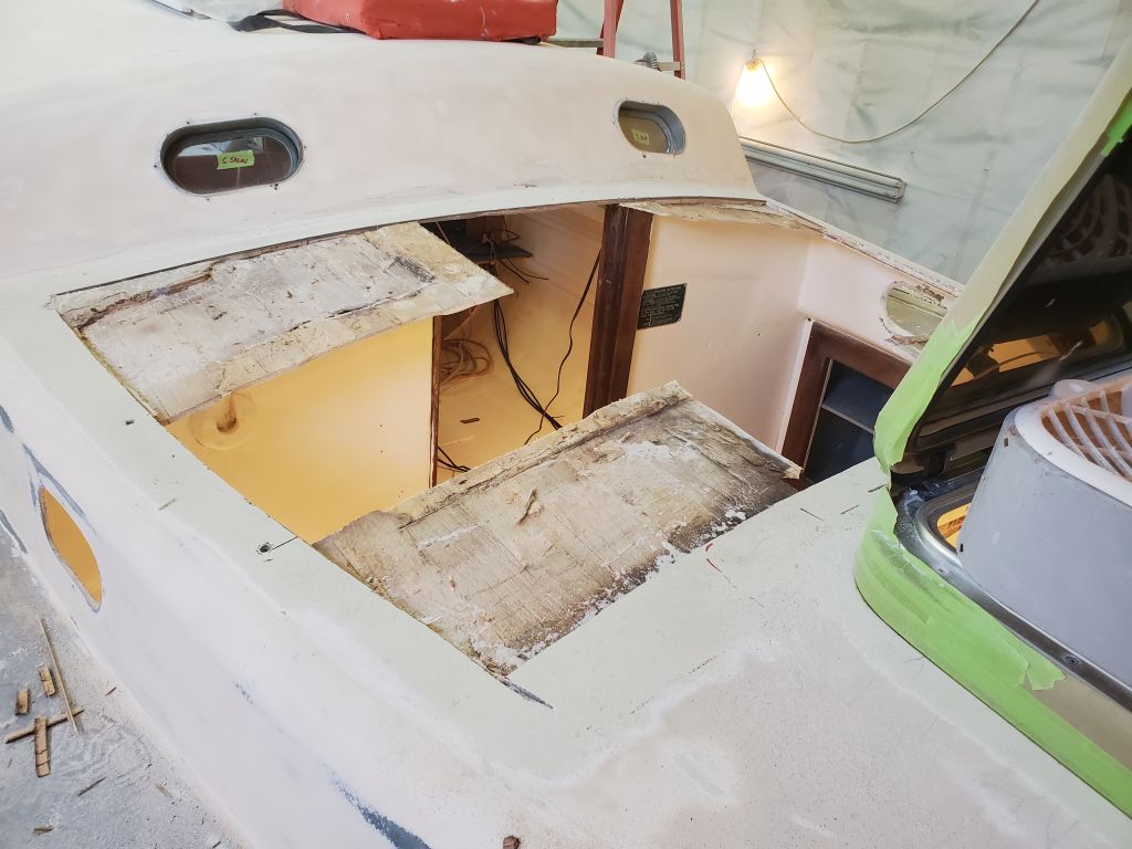
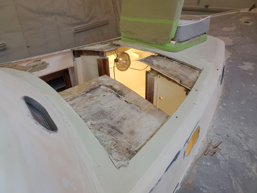
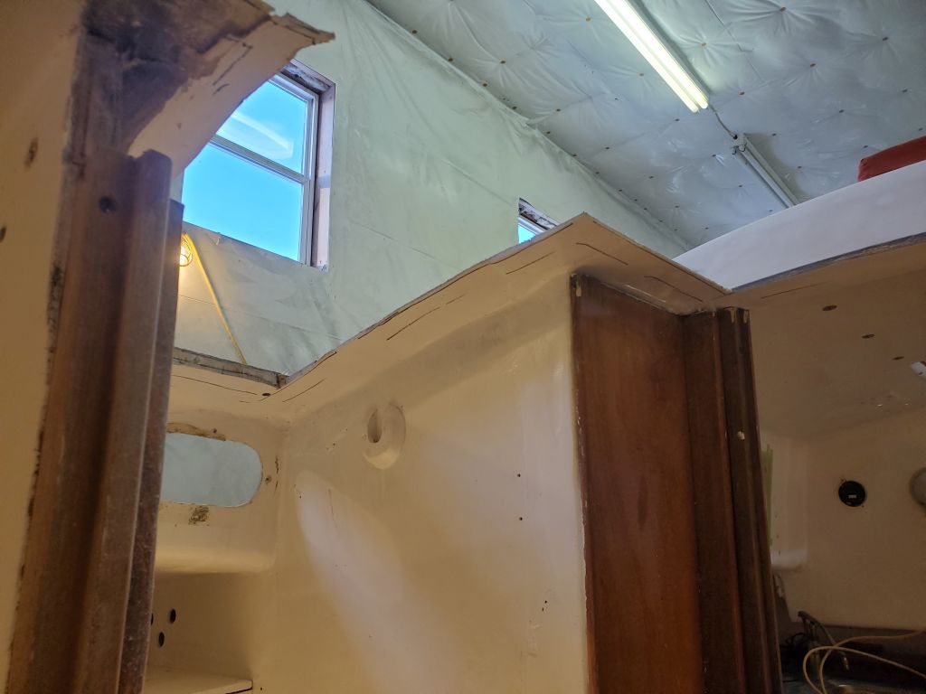
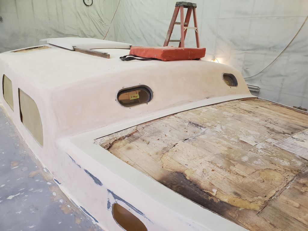
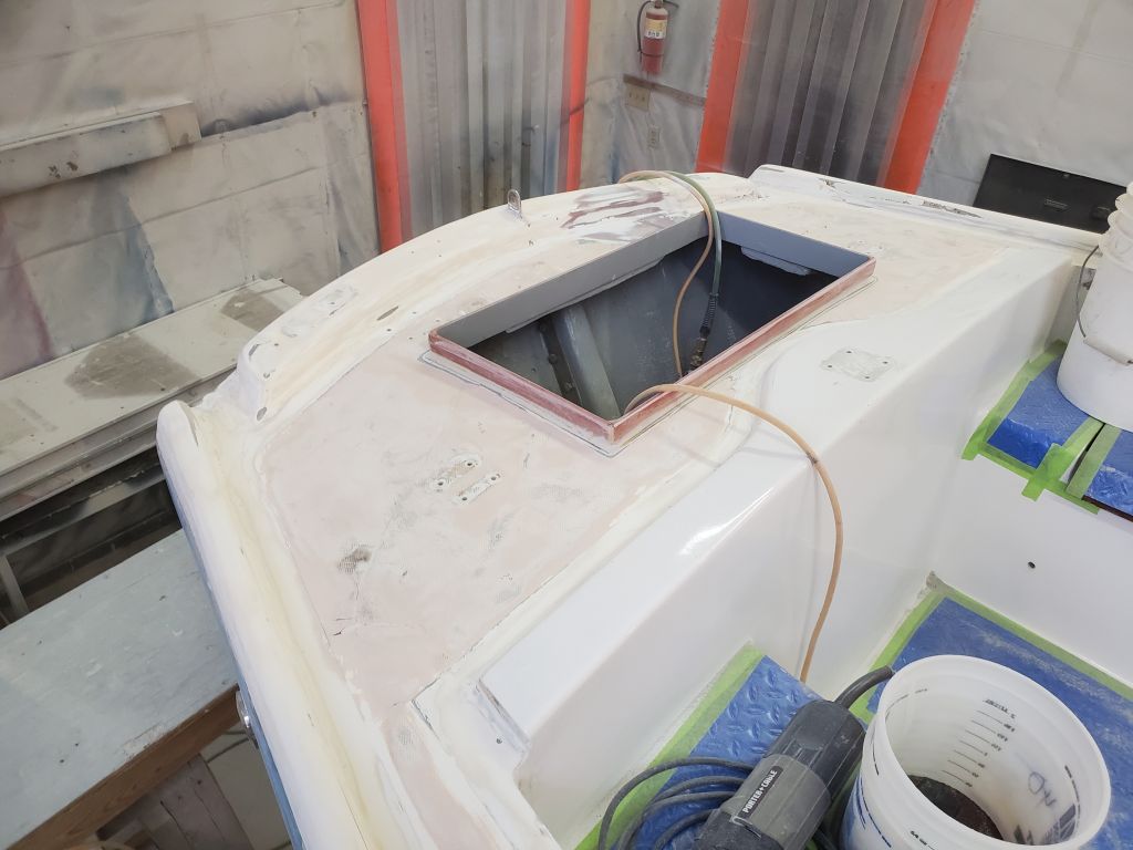
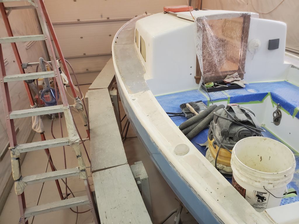
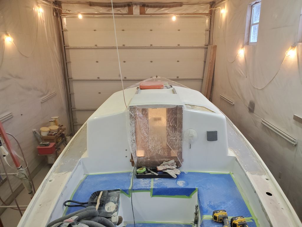
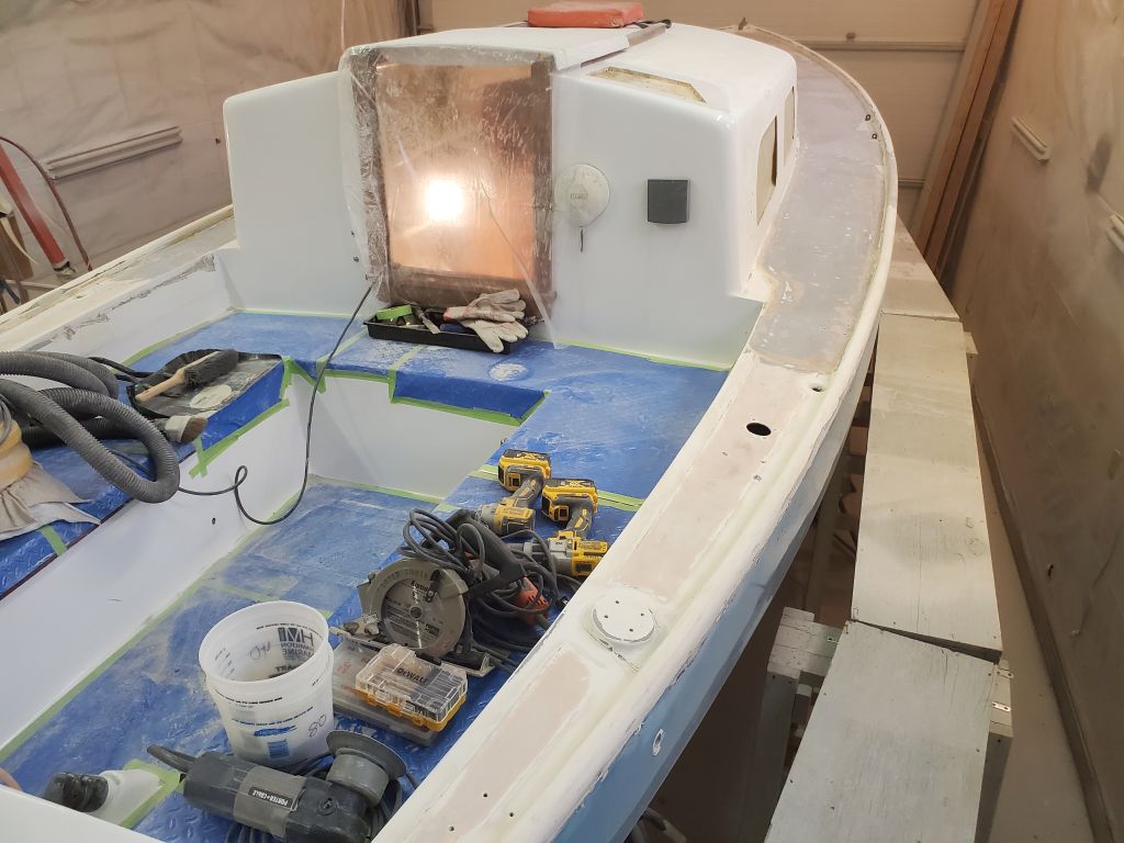
Now all that was left was to cut out the deck along these lines. This made the head seem exceedingly roomy and airy from below.
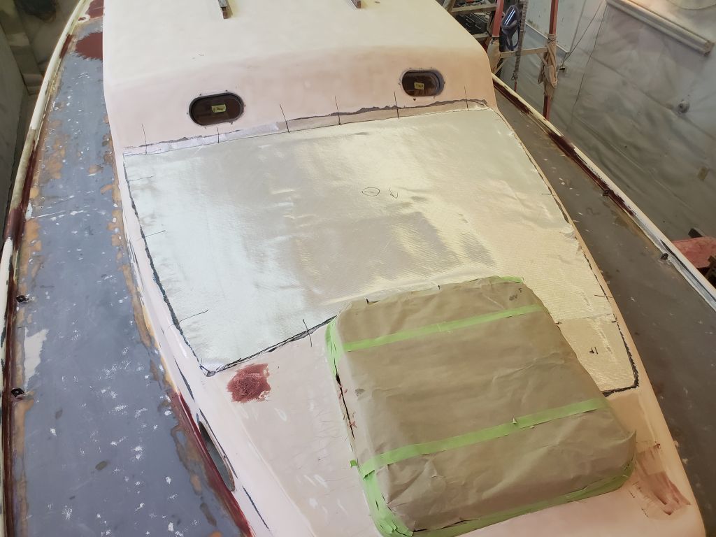
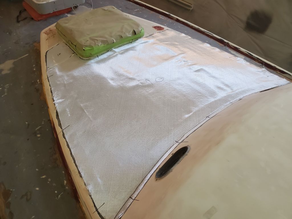
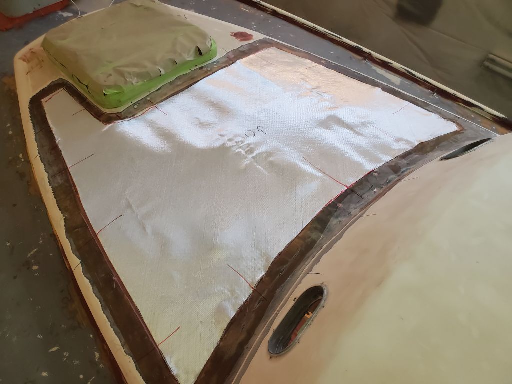
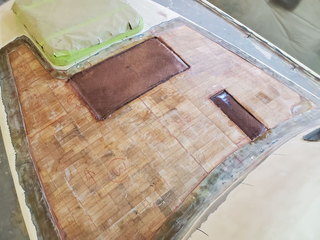
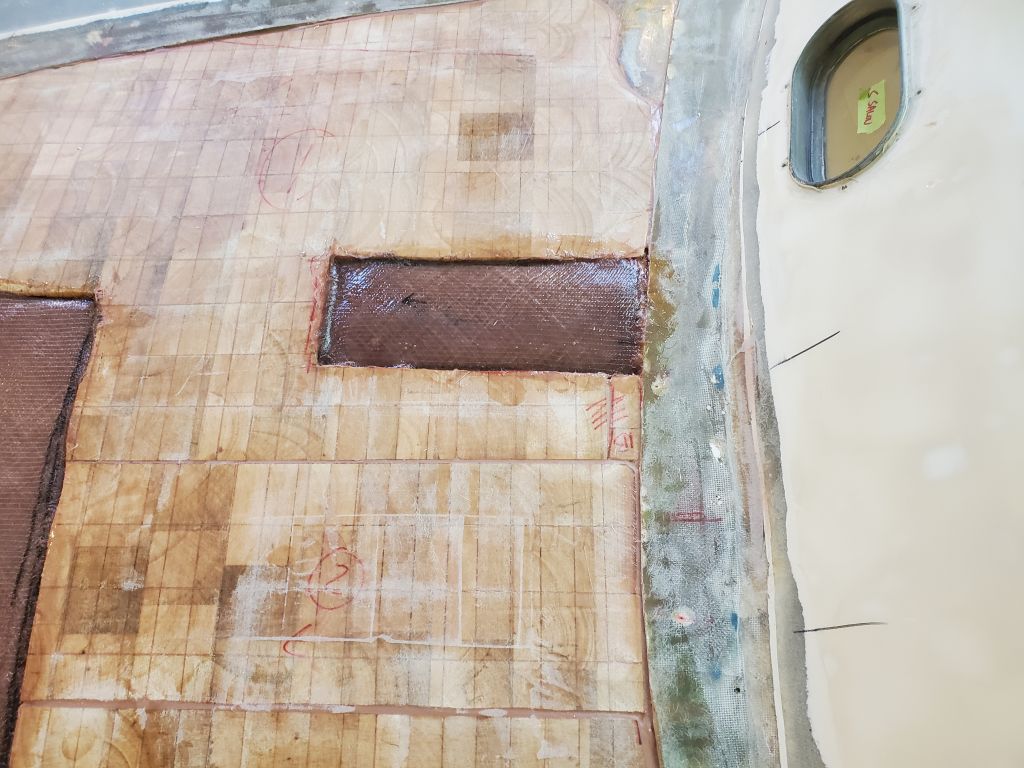
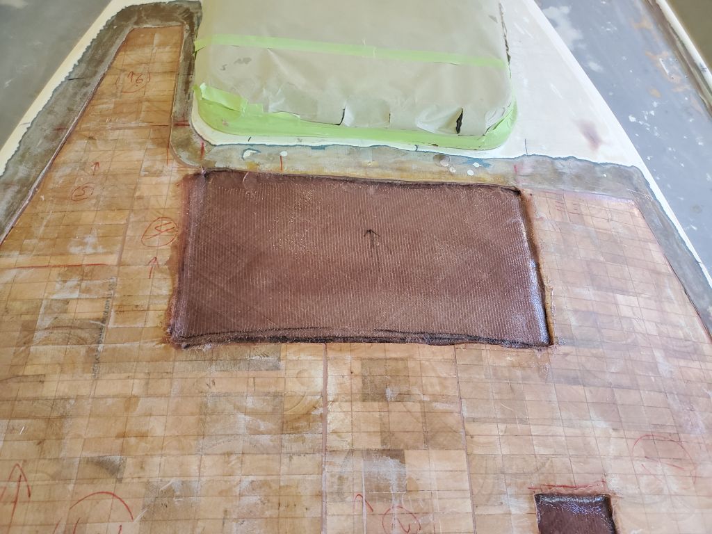
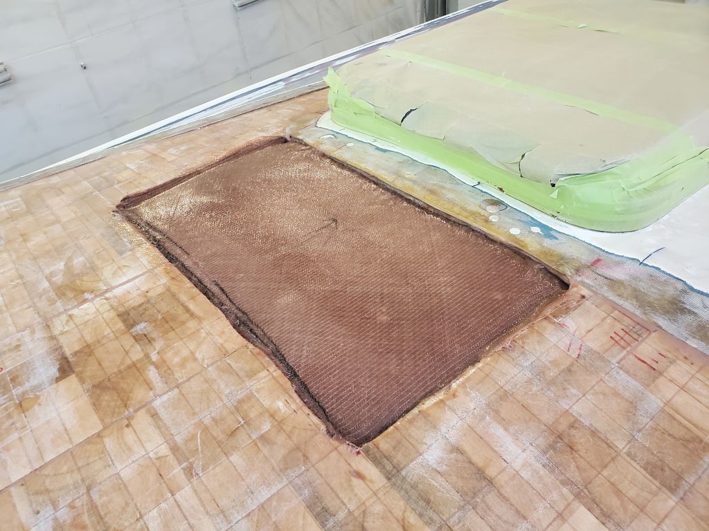
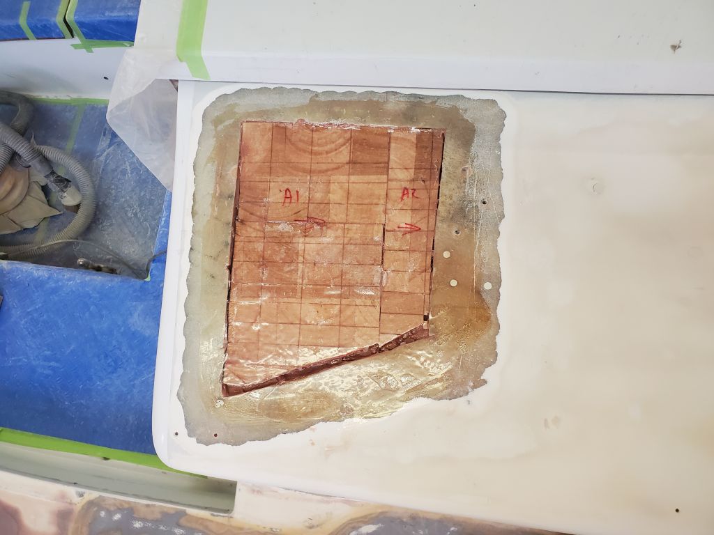
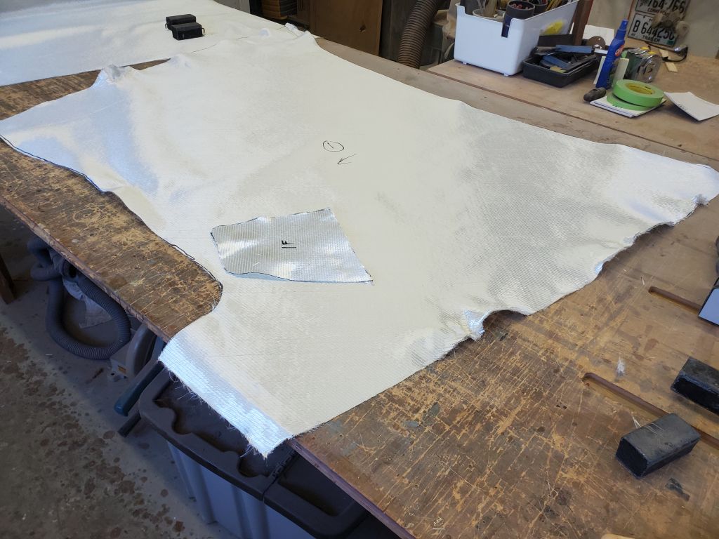
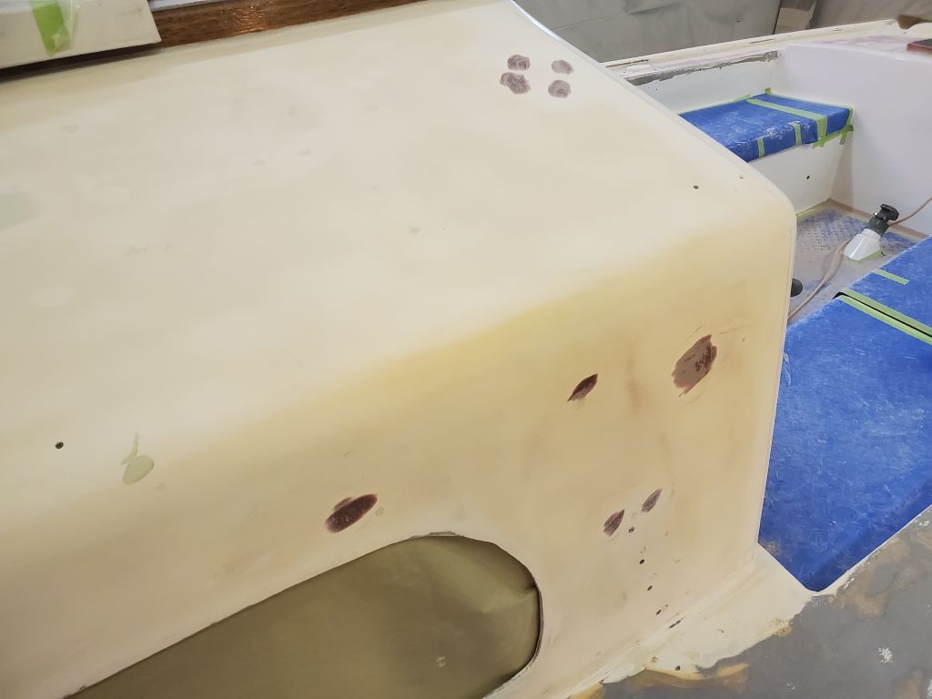
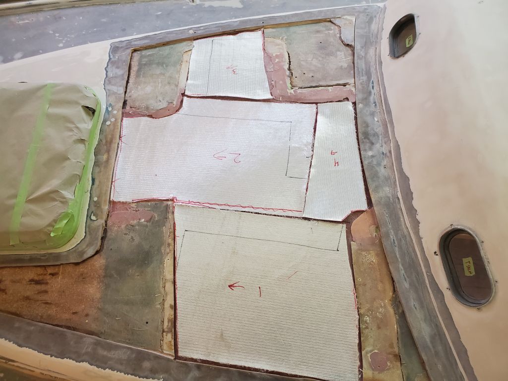
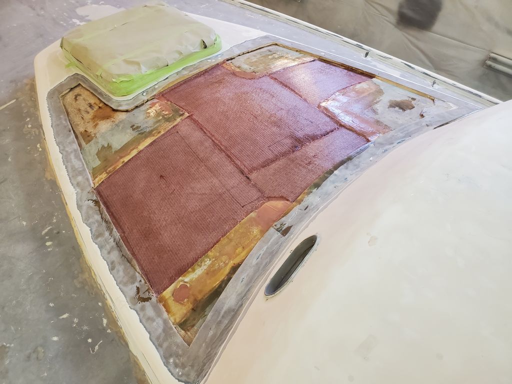
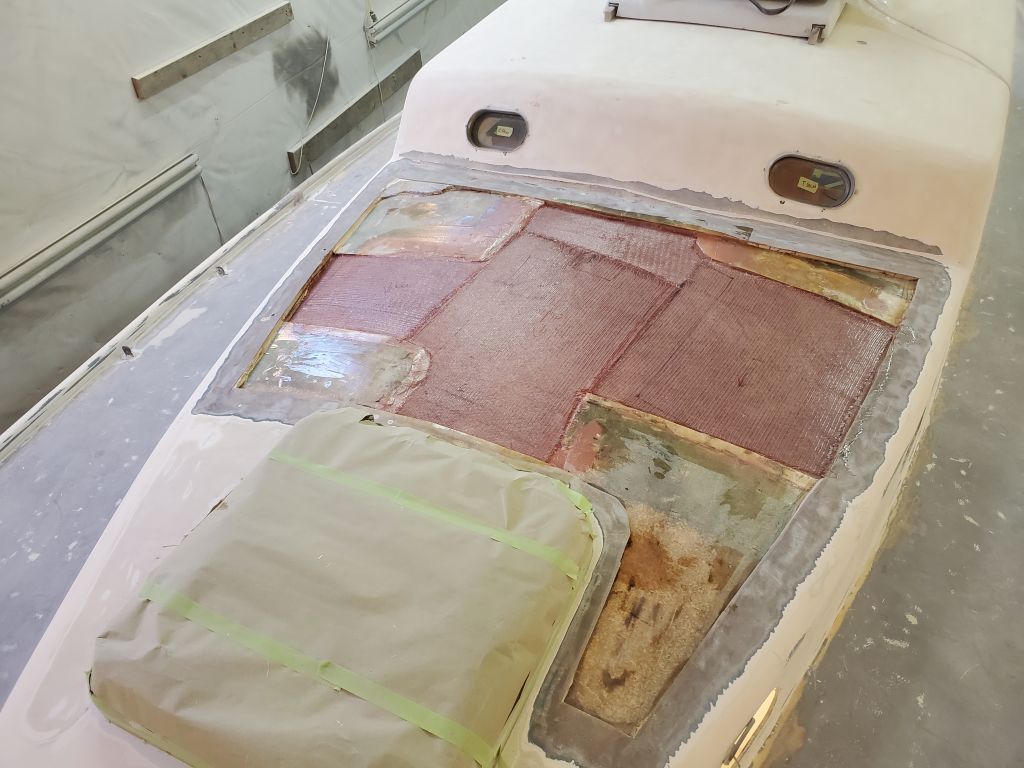
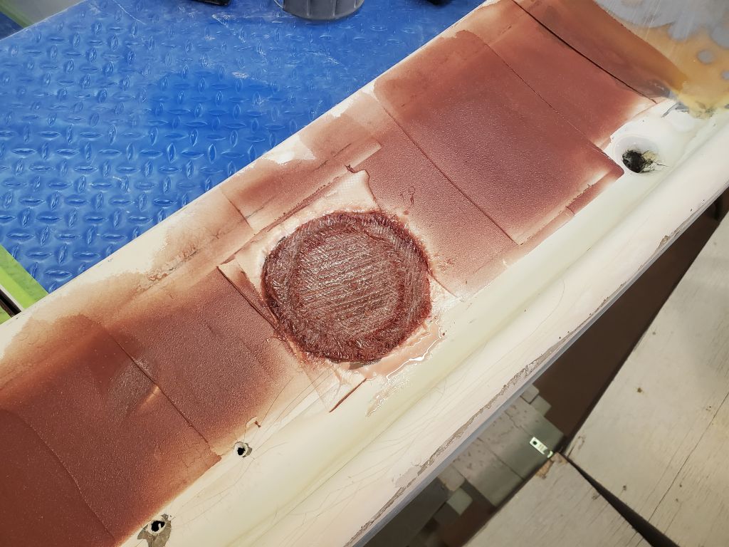
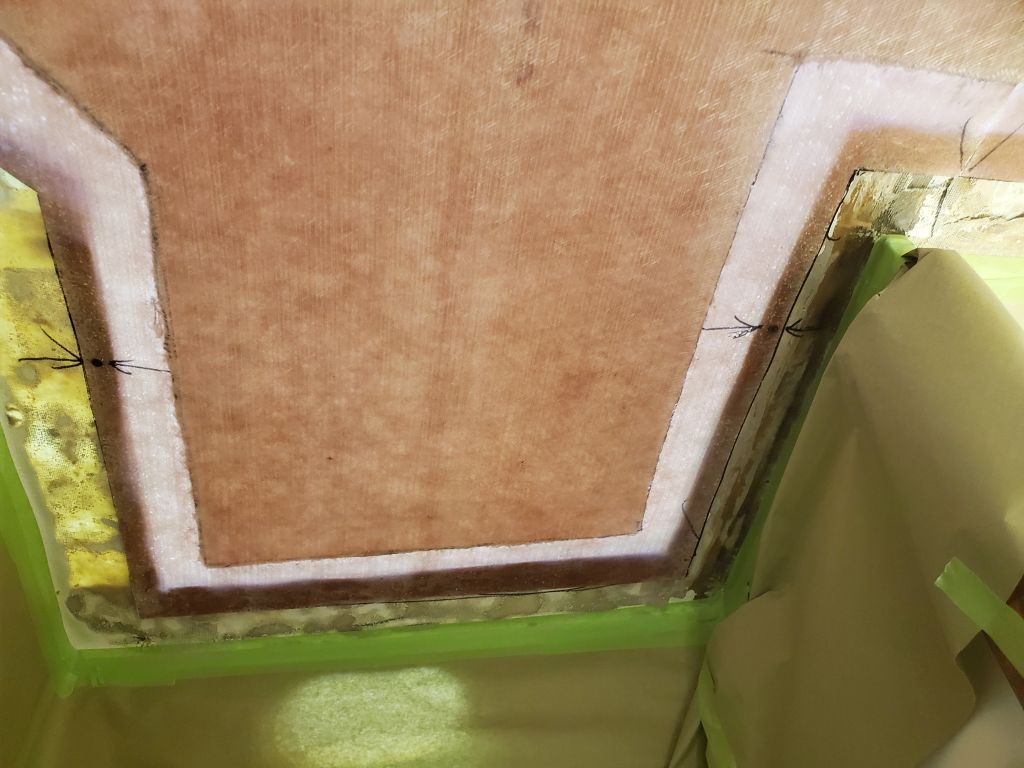
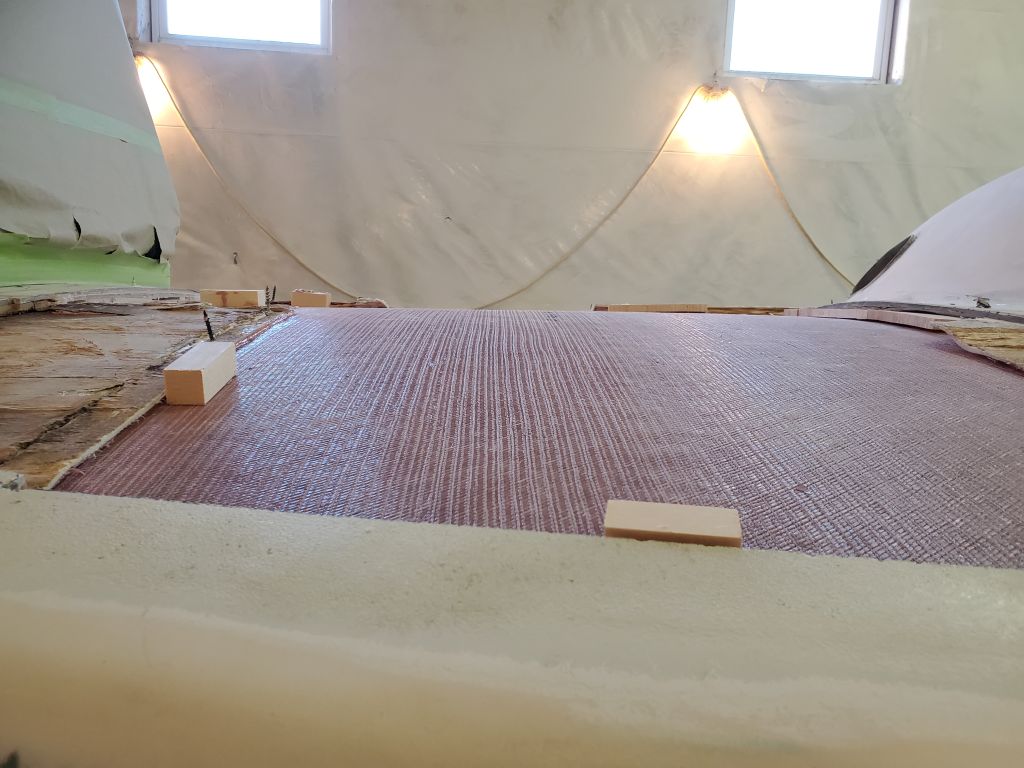
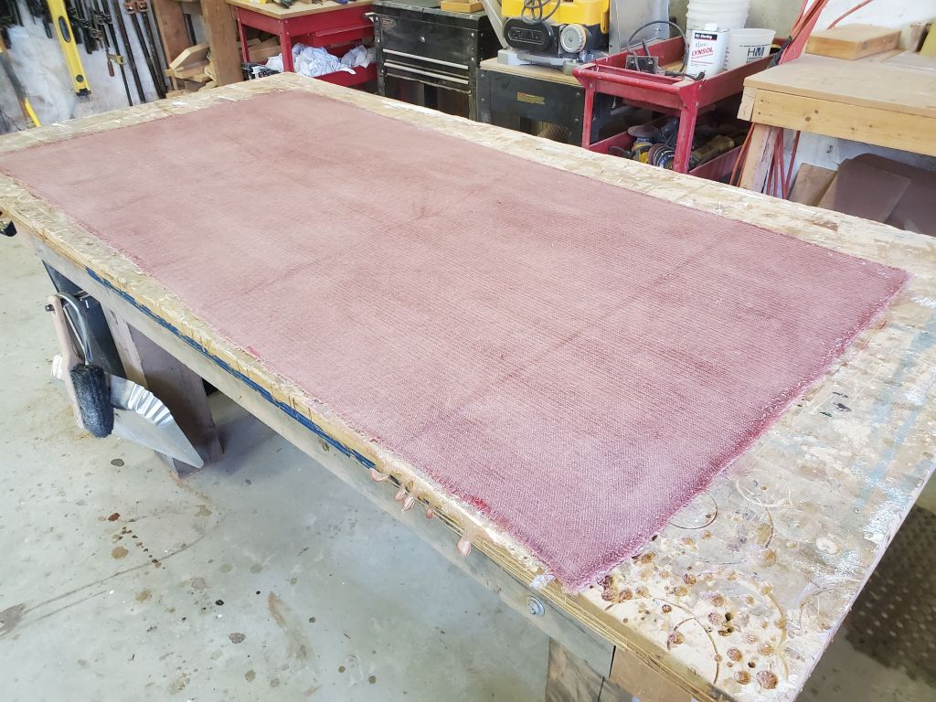
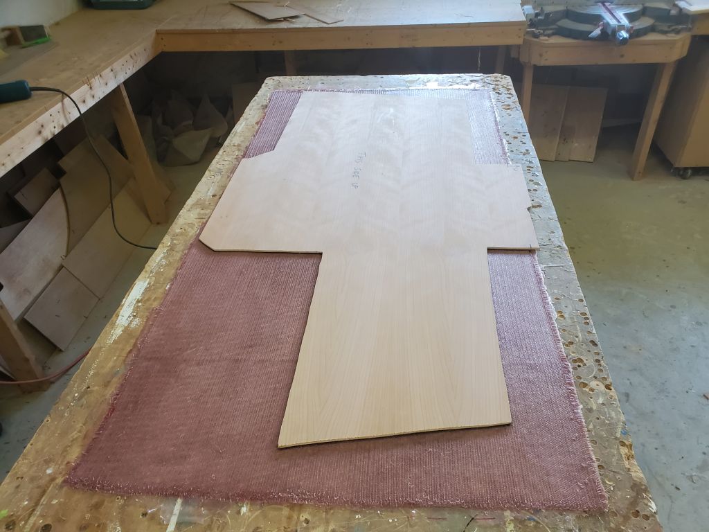
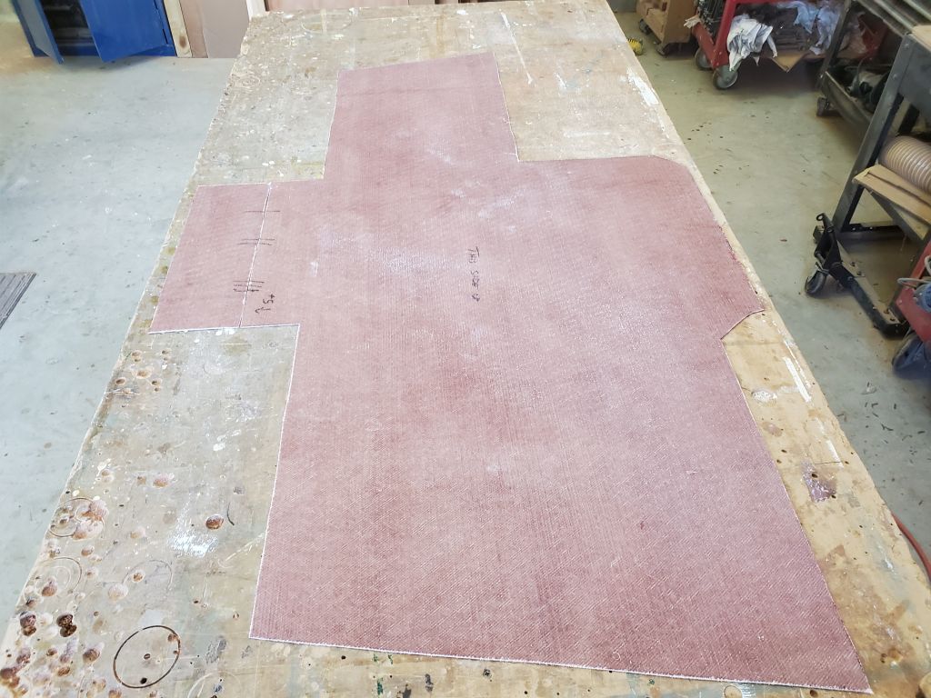
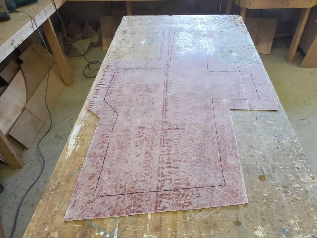
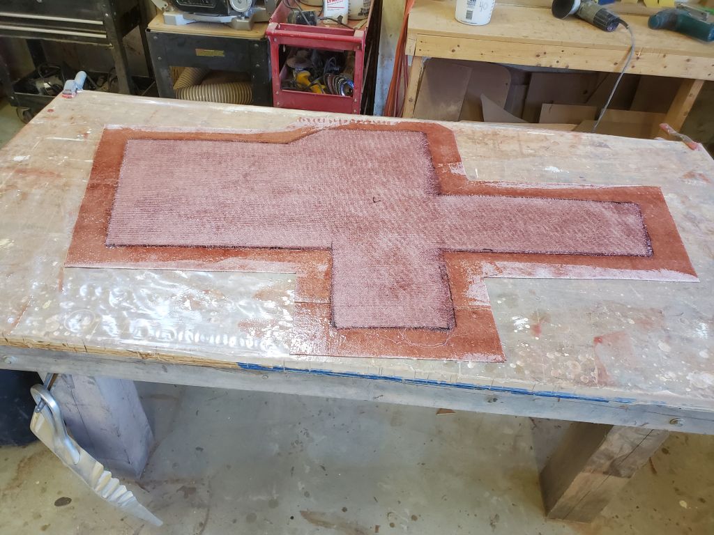
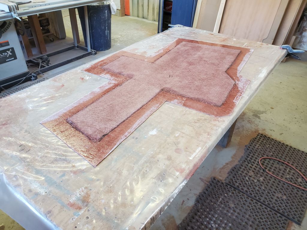
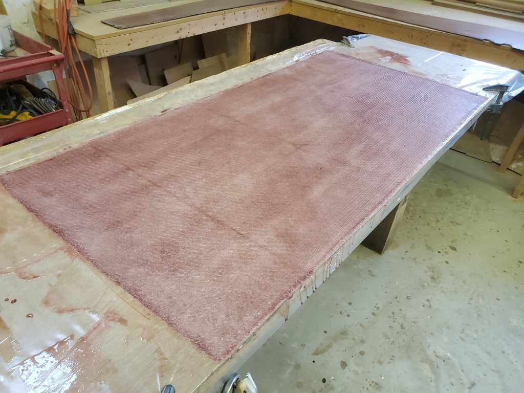
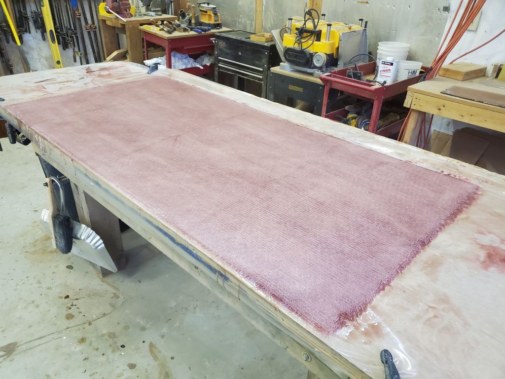
I used the final plywood template to mark and cut the fiberglass panel to the correct shape. To reinforce and further prepare the new fiberglass panel, I marked 3″ in from the edges along the bottom (i.e. exposed/overhead side) and cut a second layer of cloth to fit, then laminated it in place. This would stiffen the panel somewhat. The offset along the edges would allow room for the tabbing that would ultimately secure the panel to the boat, while maintaining a generally flush appearance from beneath for improved cosmetics and ease of fairing.
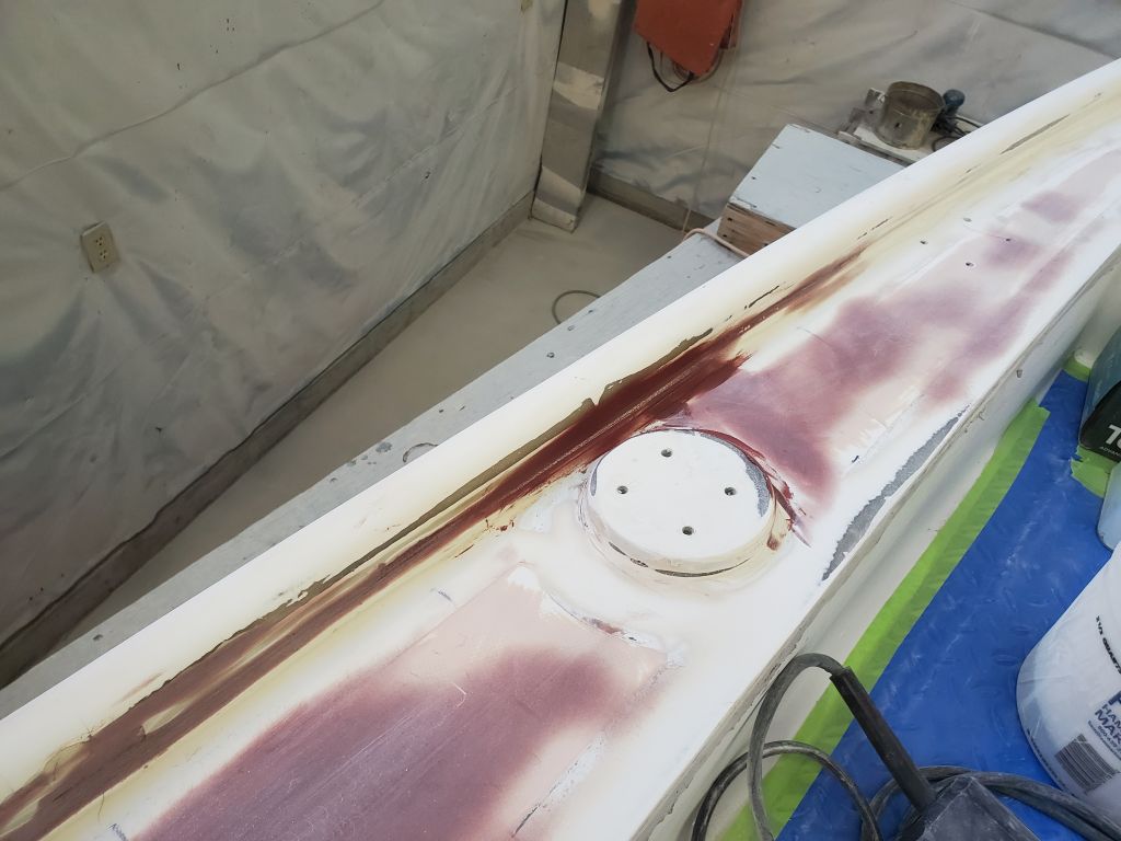
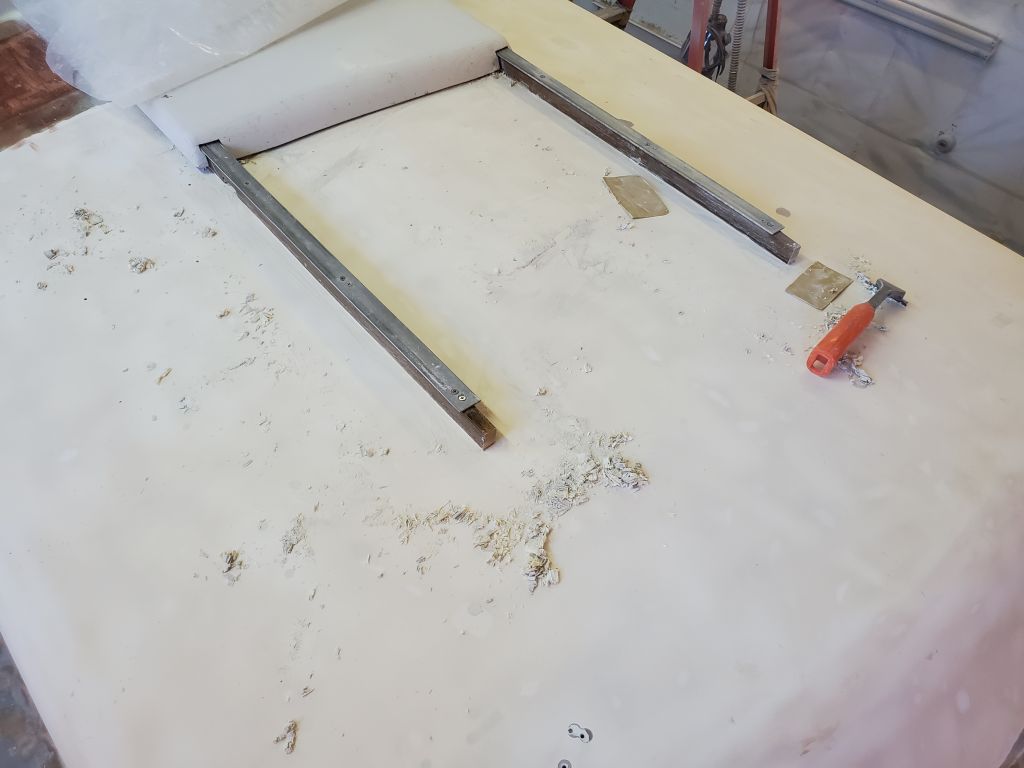
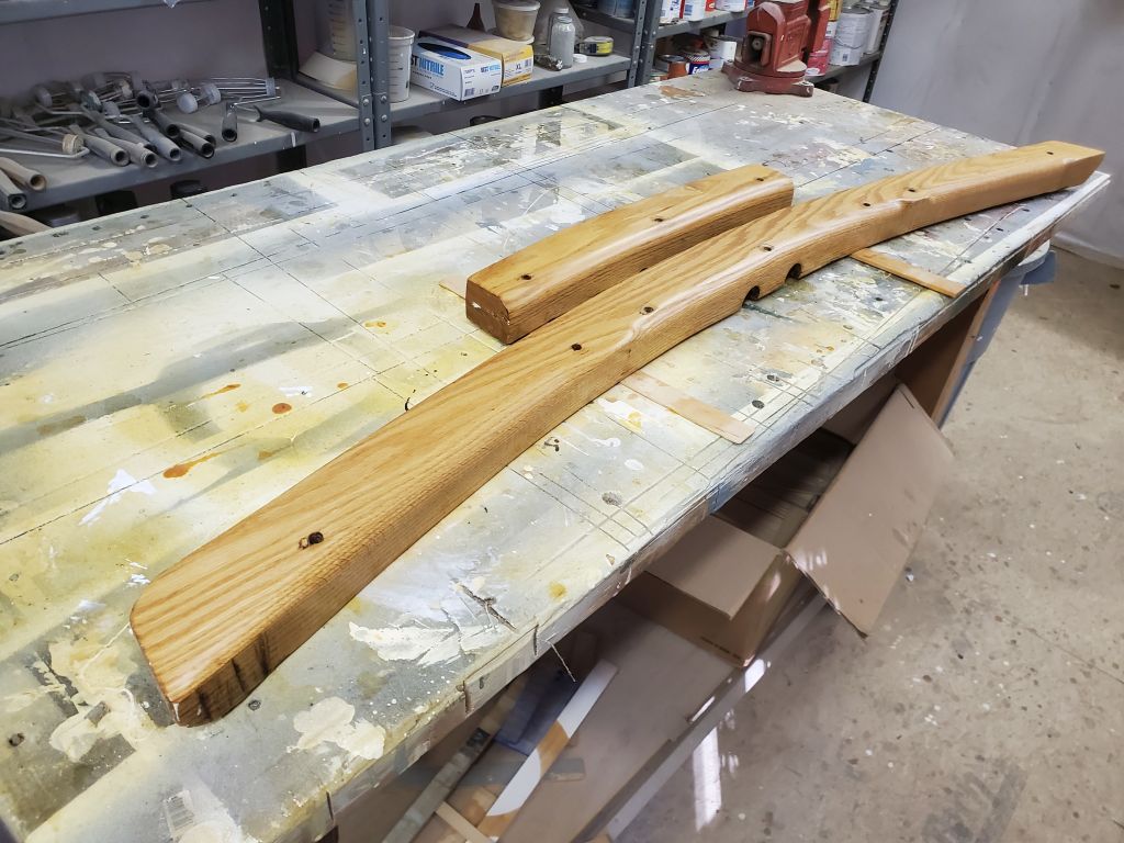
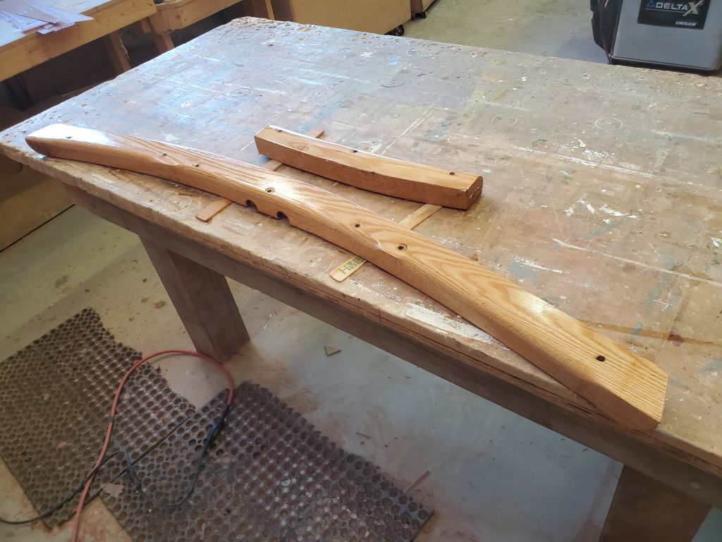
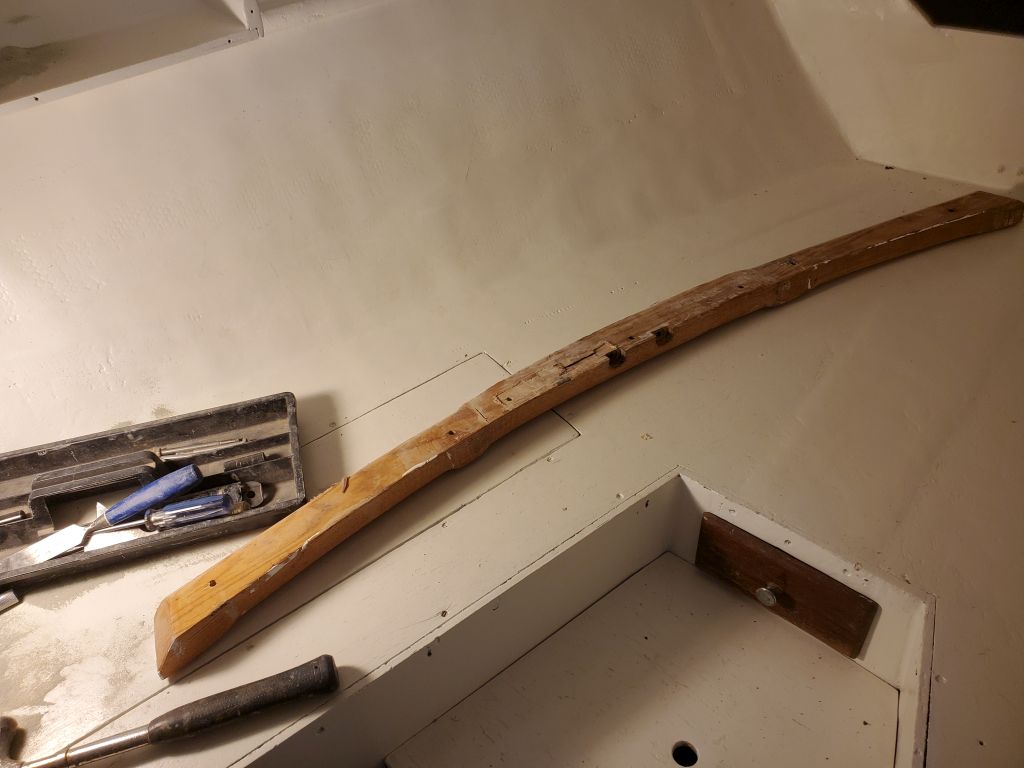
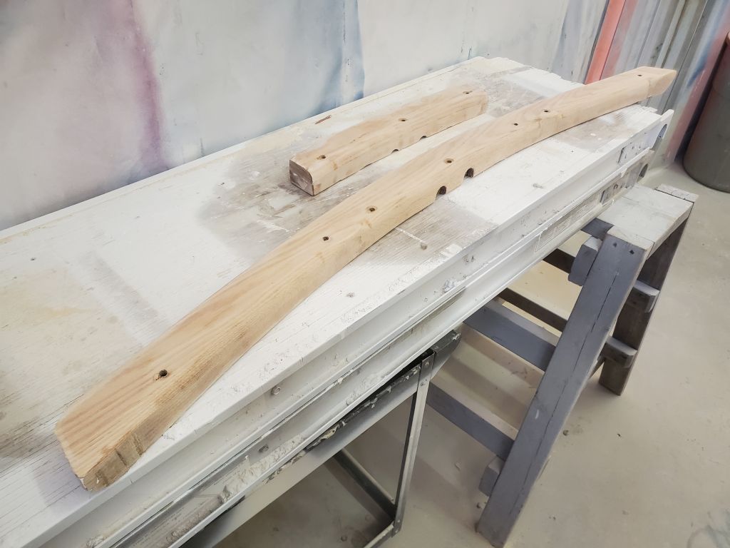
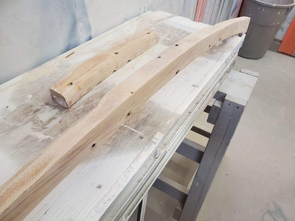
To round out the day, I cleaned up the mast beams, removing the old fiberglass from the top edge as needed and sanding clean and smooth the resin-dripped, bumpy surfaces over the oak. Of course the old fiberglass and resin had to be removed, but what better opportunity to improve the mast beams’ appearance before reinstallation as well.
Total time billed on this job today: 7 hours
0600 Weather Observation: 25°, clear. Forecast for the day: Windy, sunny, temperature dropping