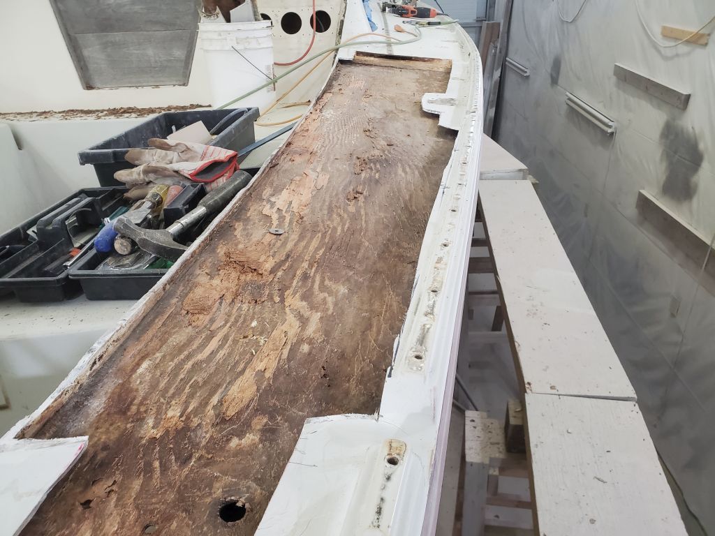
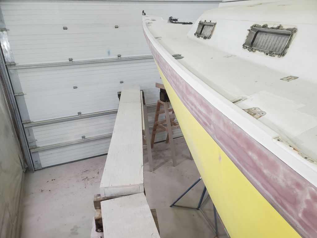
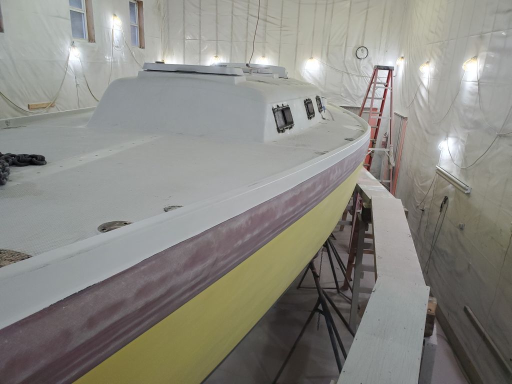
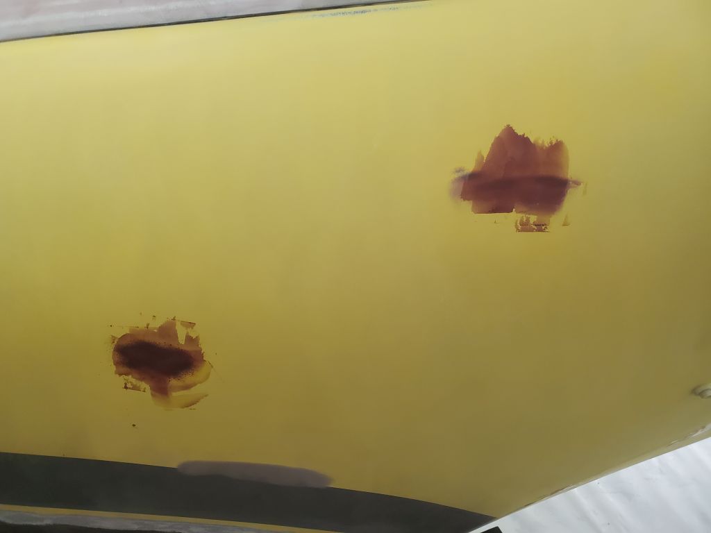
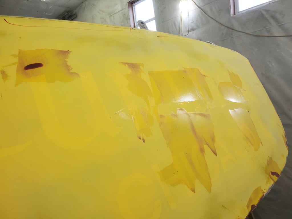
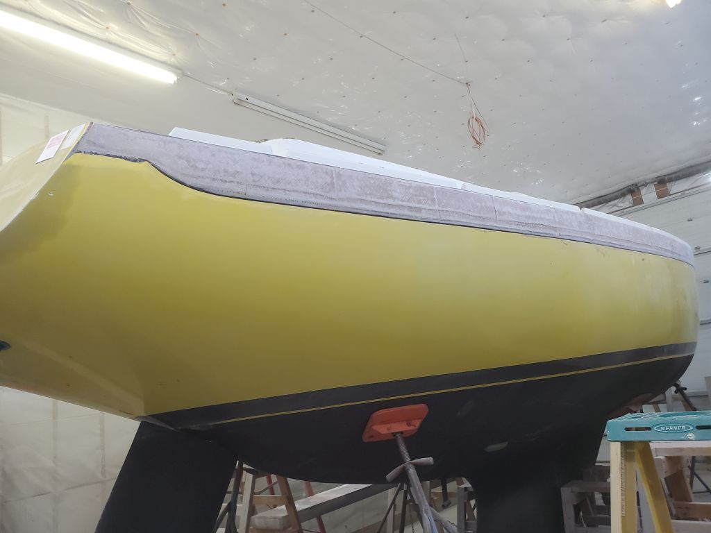
With a hammer, I inspected the sidedecks and foredeck, sounding for core damage or significant voids from debonding, latent construction flaws, or other issues. In this way, I identified and marked several areas requiring additional attention on both sidedecks, including small sections just forward of the areas where I’d removed the winch islands. There was also a large section at the forward end of the foredeck, though for some reason I didn’t photograph the markings.
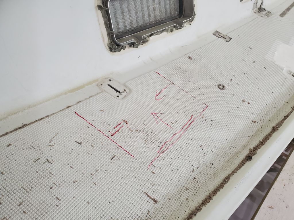
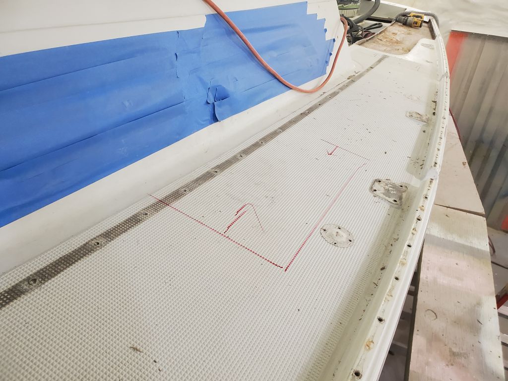
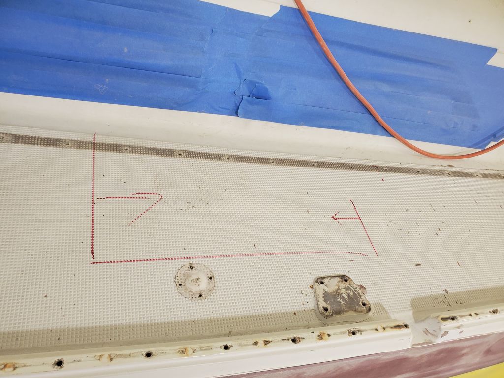
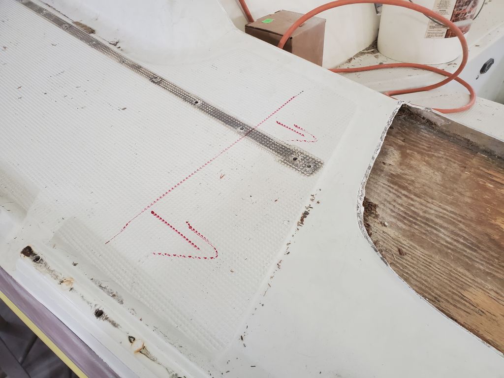
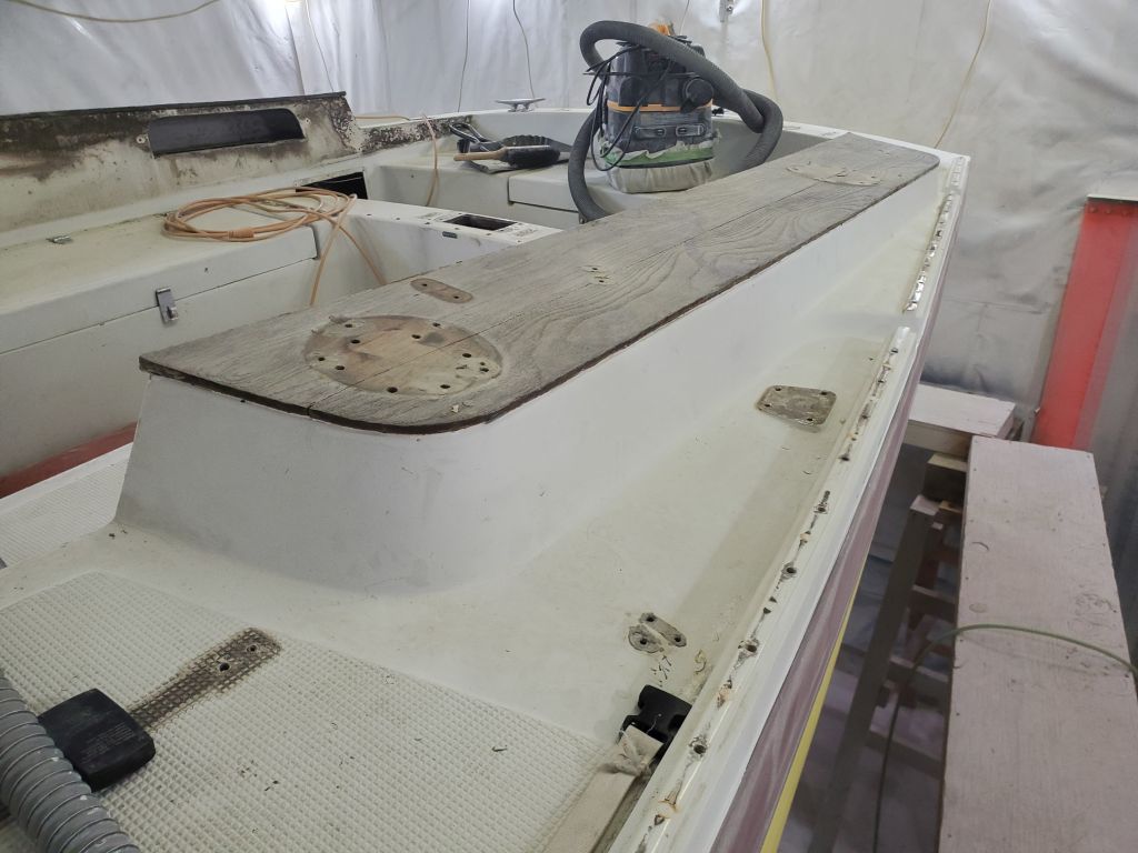
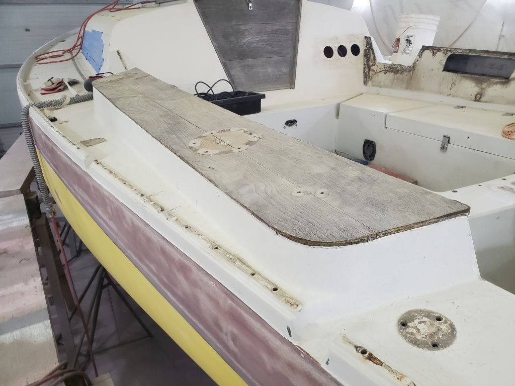
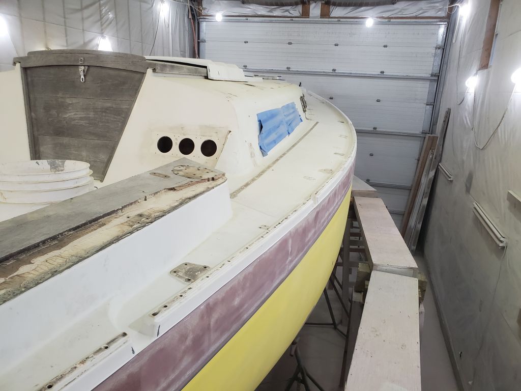
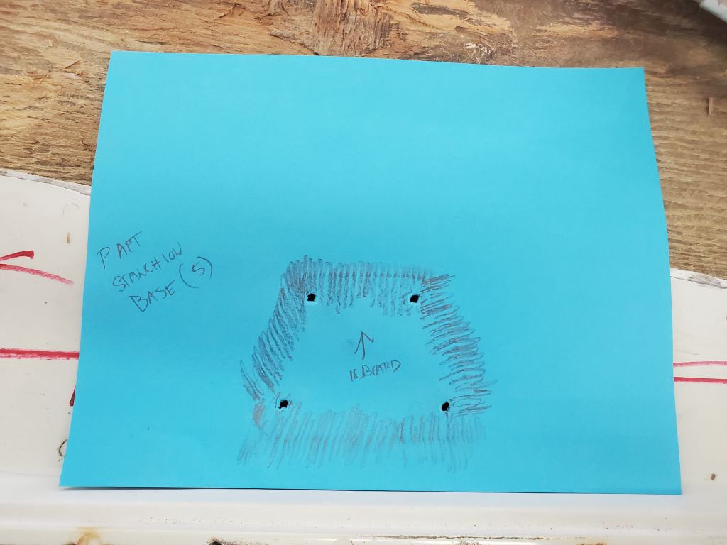
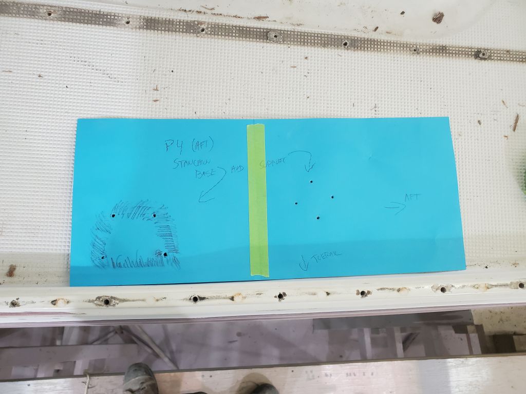
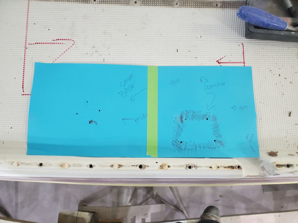
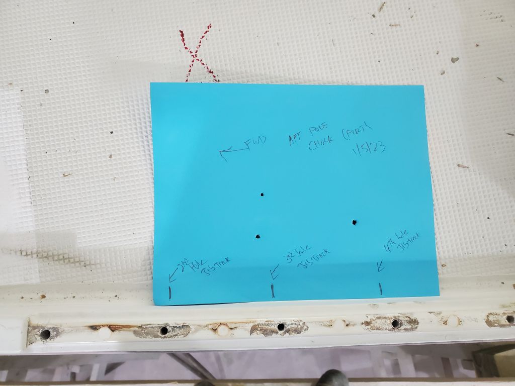
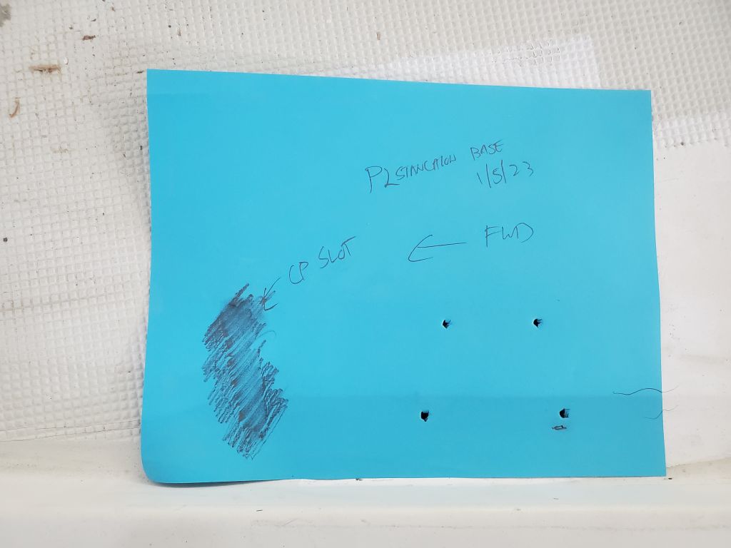
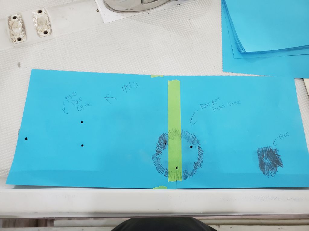
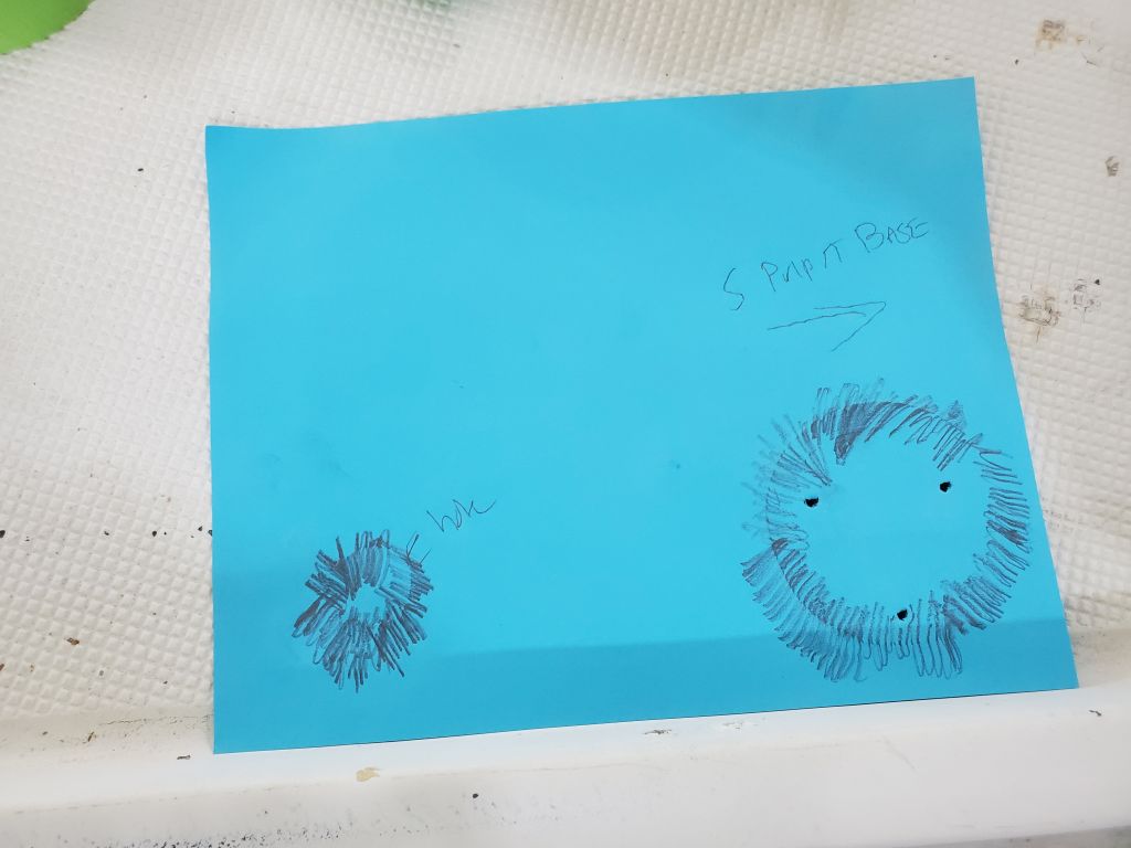
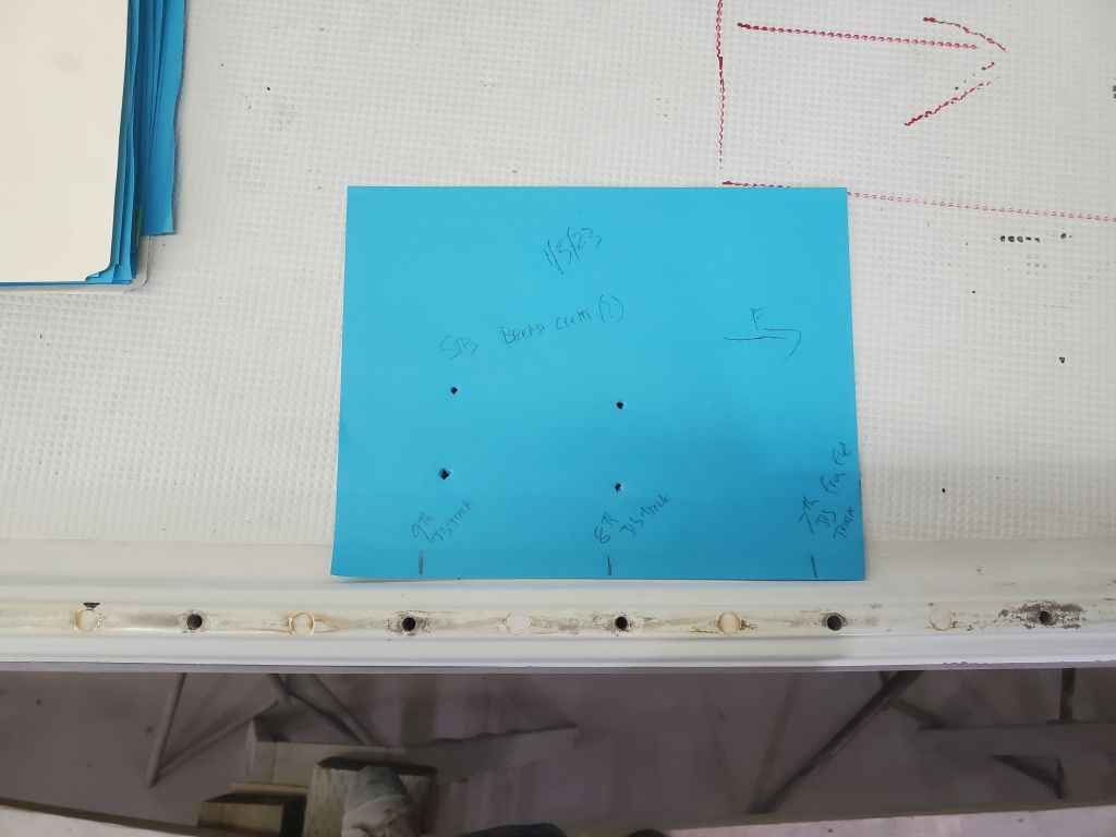
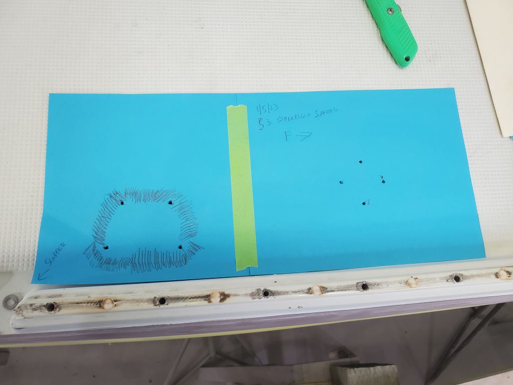
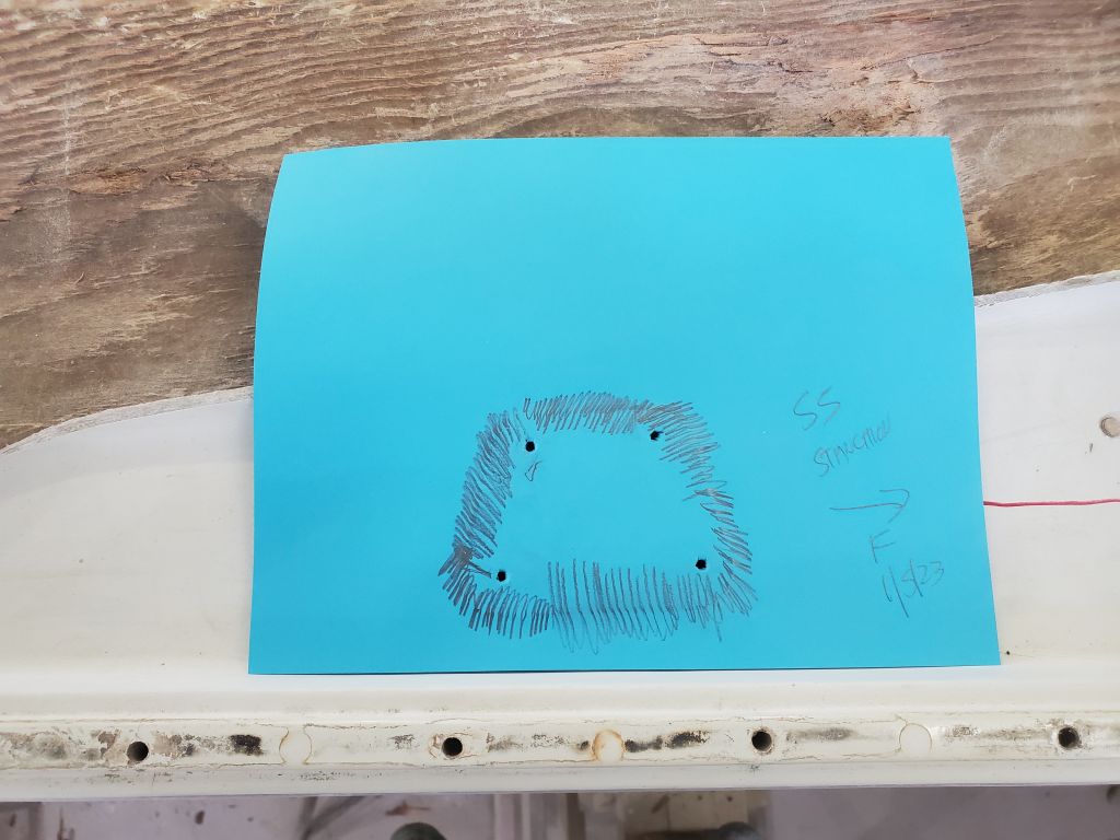
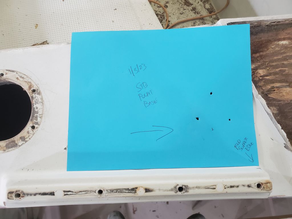
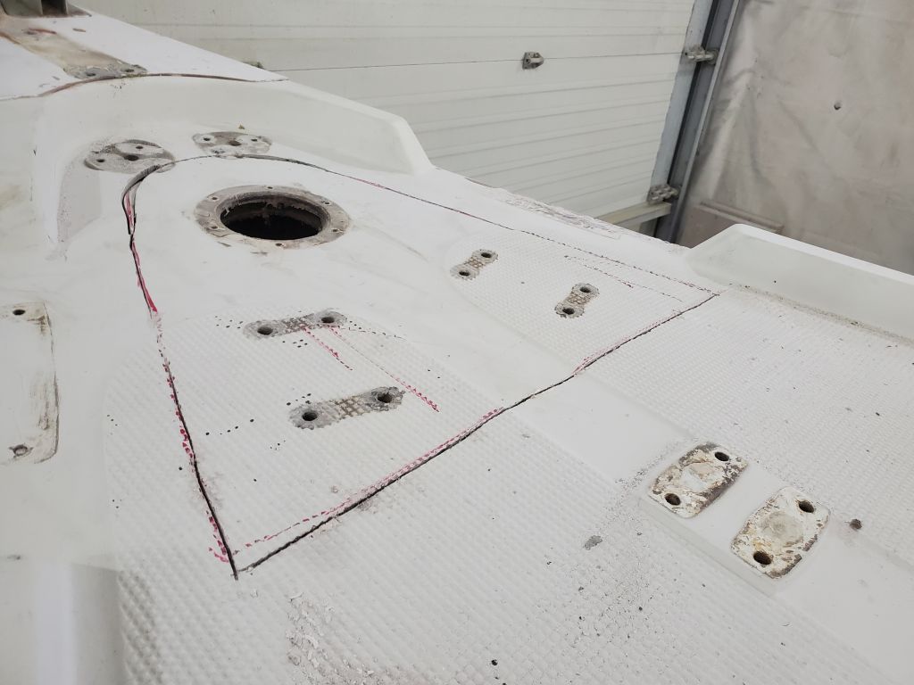
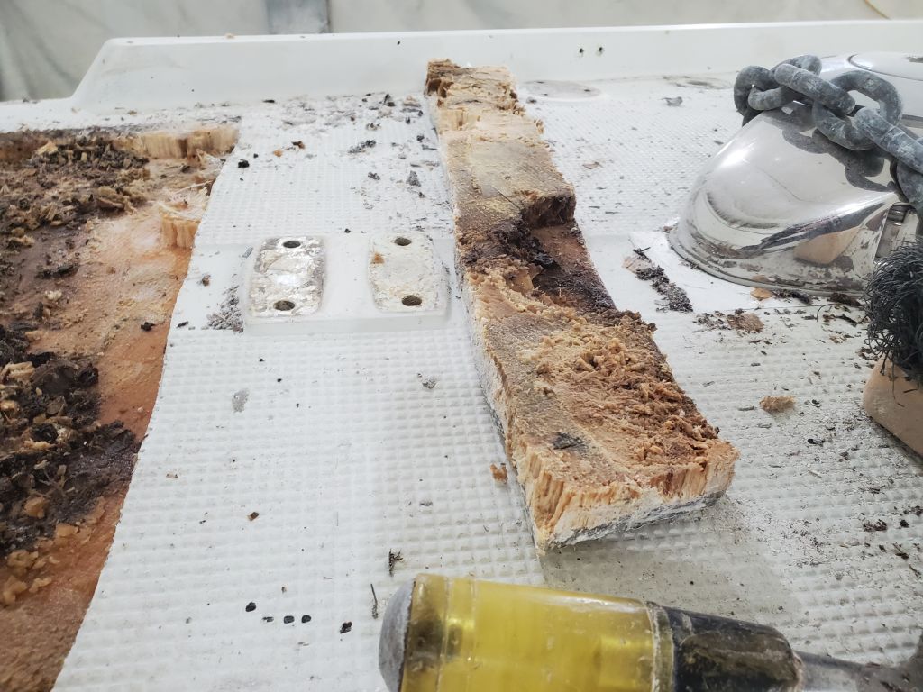
Preparing to expand the open deck area on the port aft deck, both behind the winch islands (where the core was visibly damaged) and forward as well, I got off on a tangent when I started to make some measurements and notes regarding the position of the stern pulpit mount, which I wanted to note so I could add solid fiberglass beneath it when the time came. As I made the measurements, I realized it would be better to make a simple pattern of the hardware and its fastener pattern, and this led to me making patterns of all the necessary hardware on the sidedecks. At a minimum, I planned to fill all the fastener holes as a matter of course, and then mark these locations with small pilot holes so the hardware could be easily relocated after paint; in other areas, deck repairs would cover or eliminate certain hardware locations as well. I also didn’t have the hardware itself on hand for marking fastener locations later, so taking the time to make the patterns for all salient hardware served a number of useful ends. As needed, I either registered the patterns with something indelible on the boat nearby or, in the case of the stanchion bases, made rubbings of the molded bases in the deck to help relocate the holes correctly.
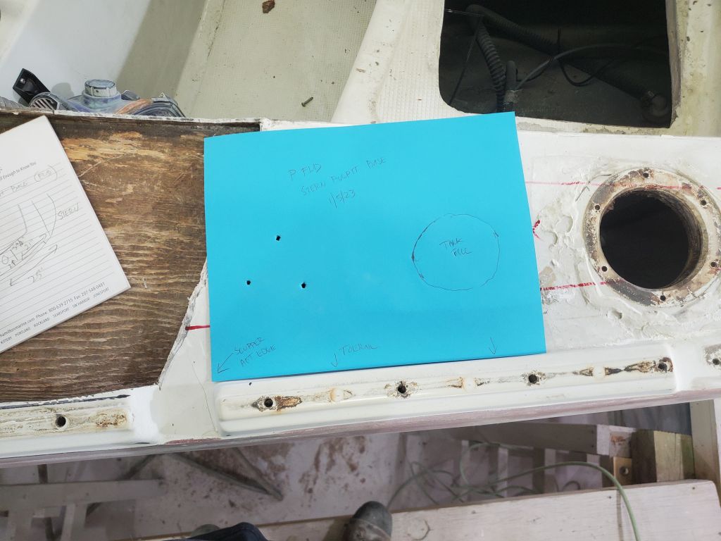


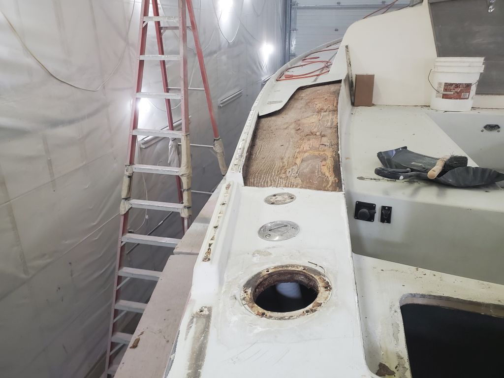
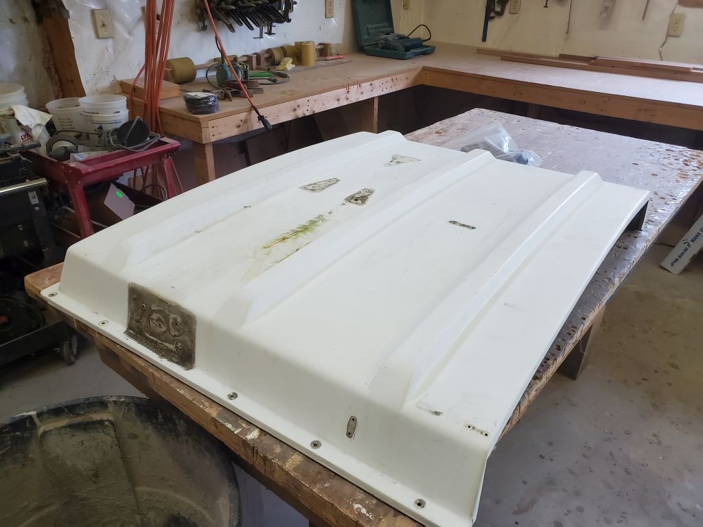
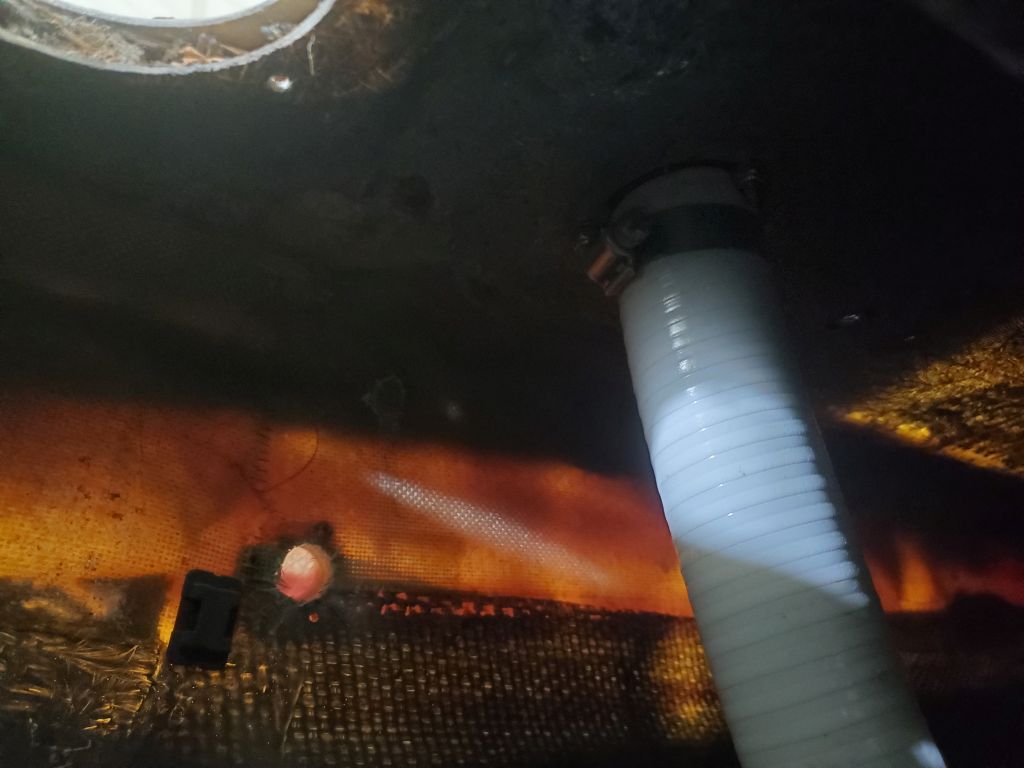
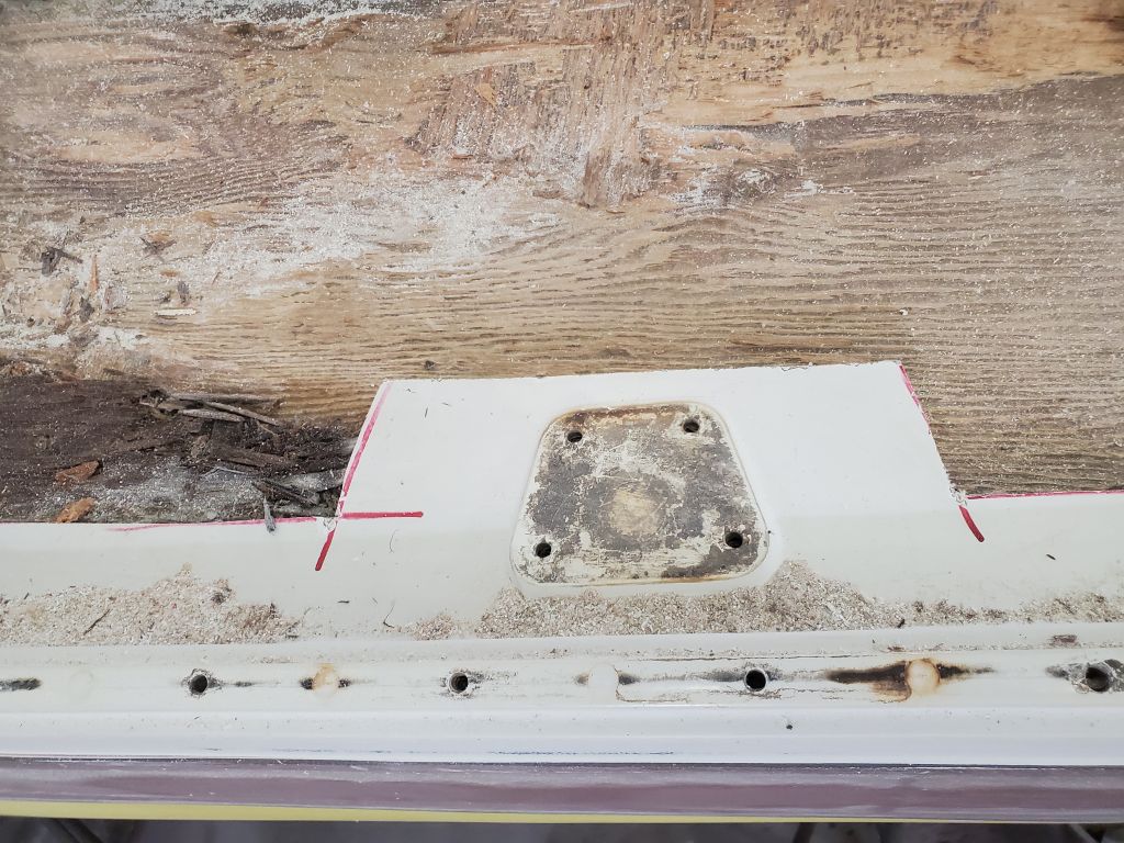
Before continuing work on the port aft deck, I removed a water tank deck fill that was in the middle of the space, a relatively quick diversion.

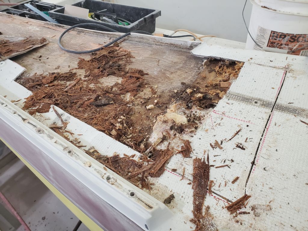
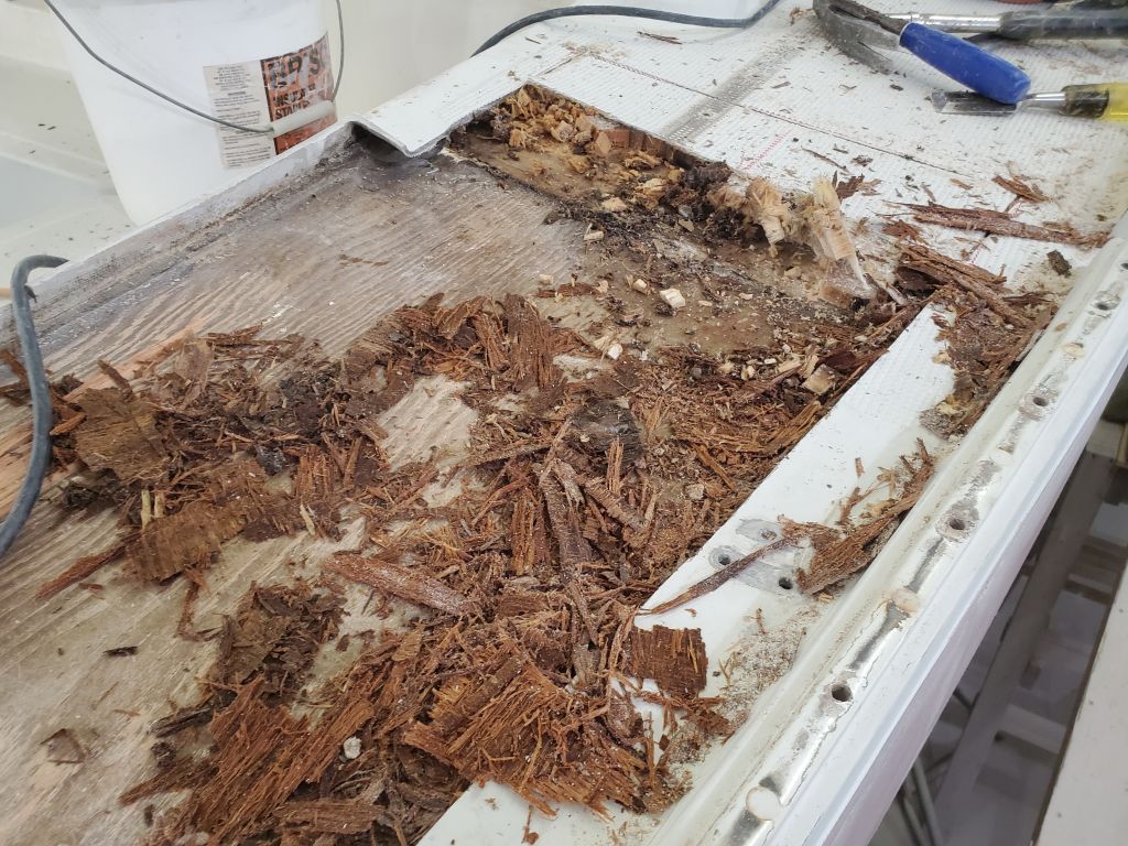
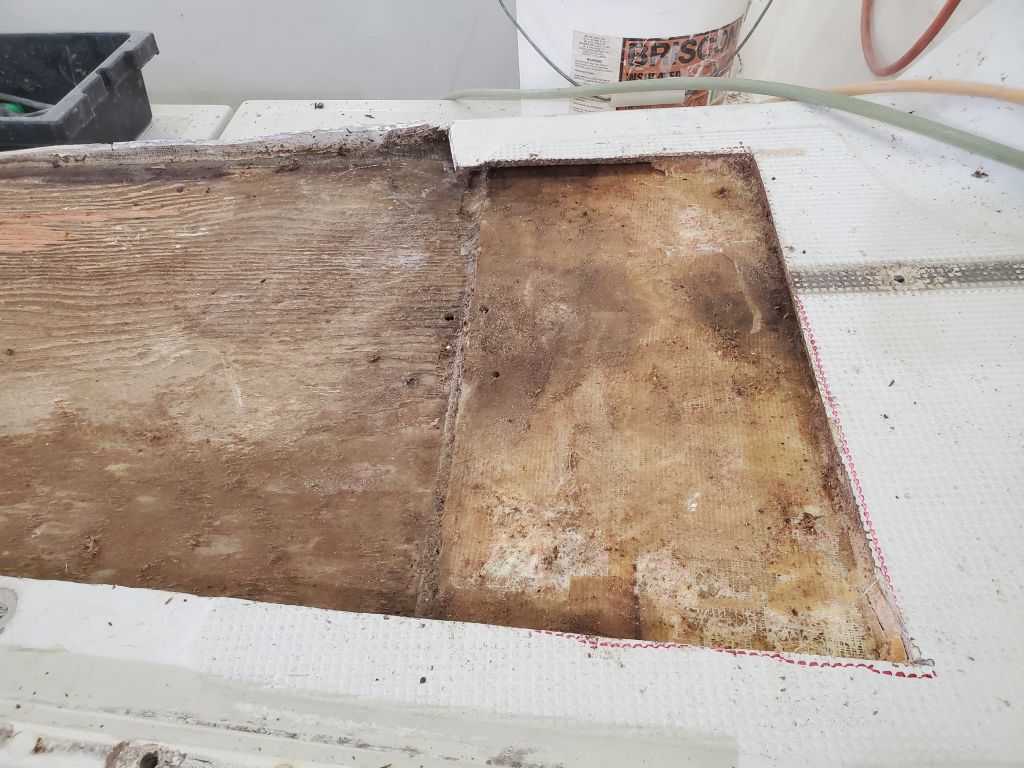
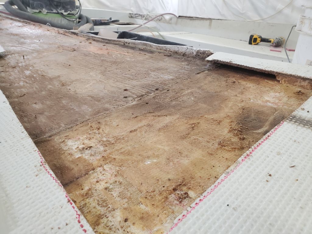
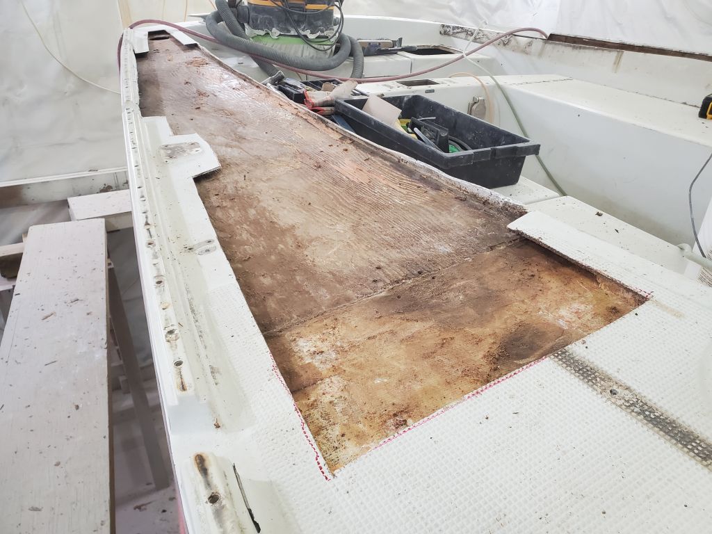
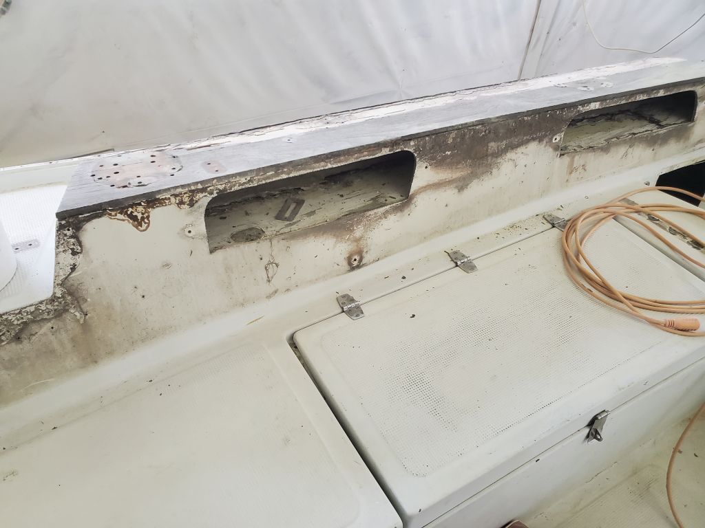
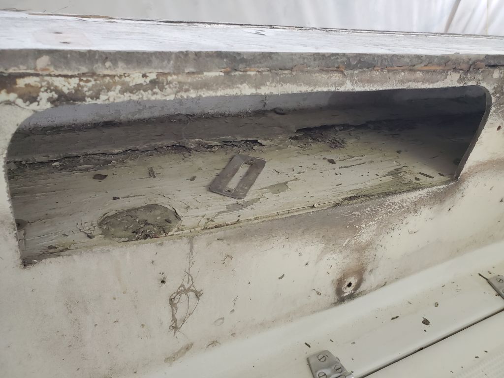
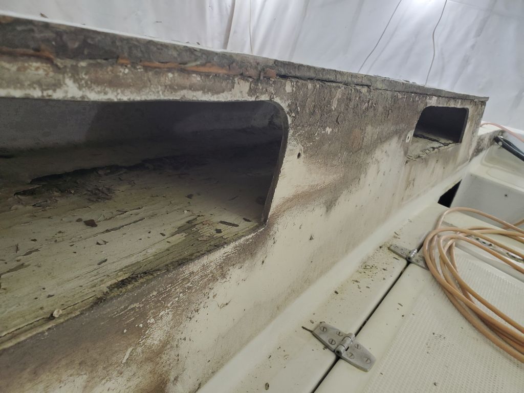
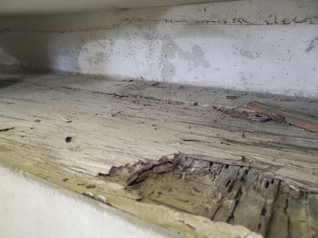
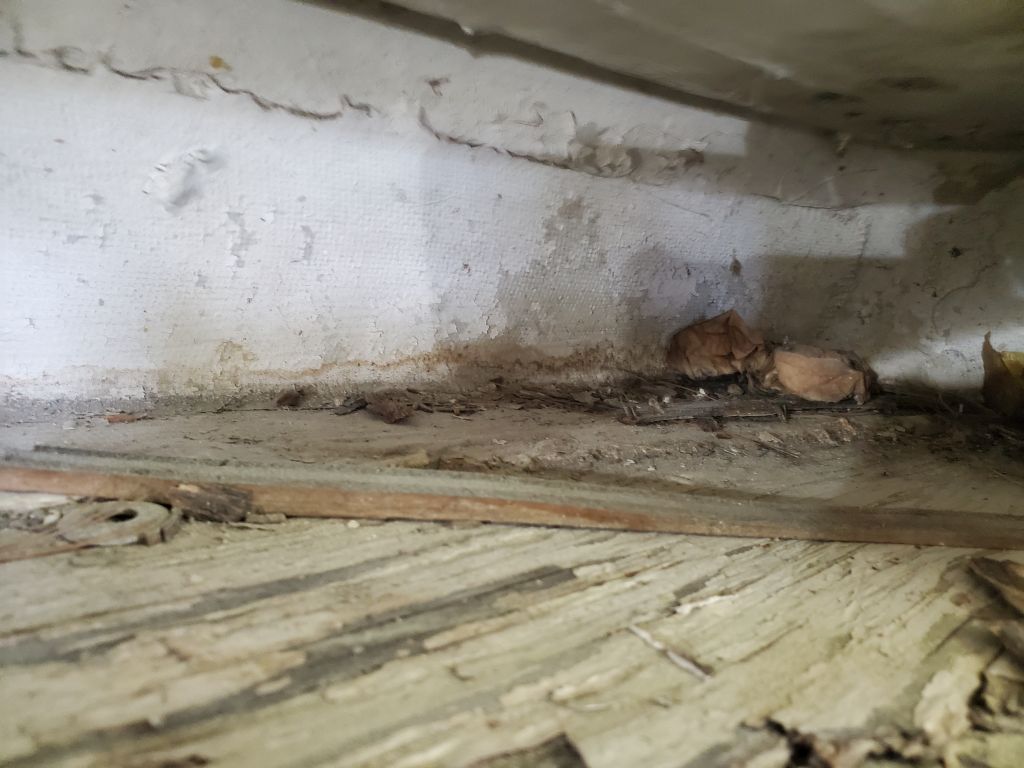
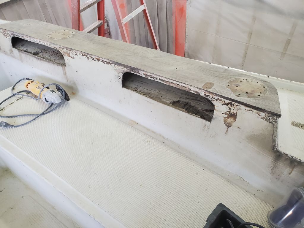
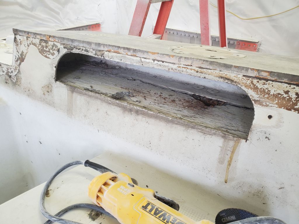
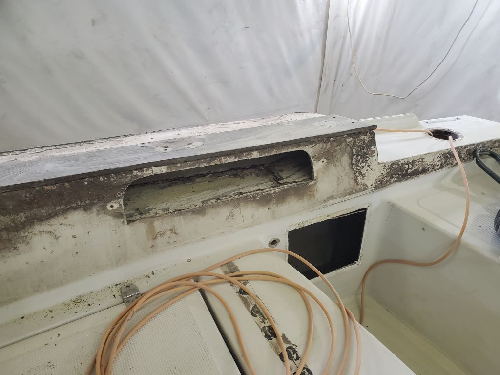
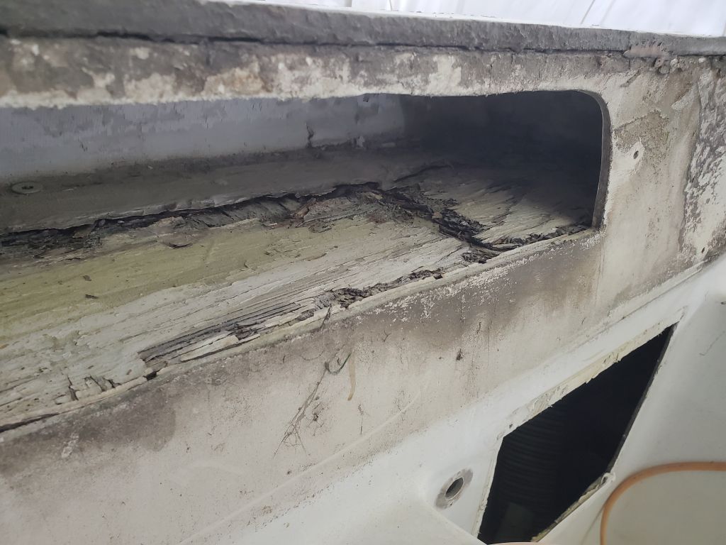
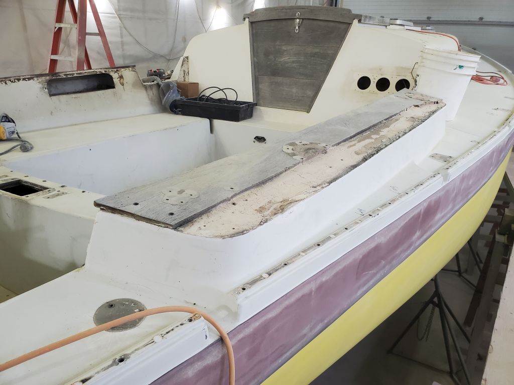
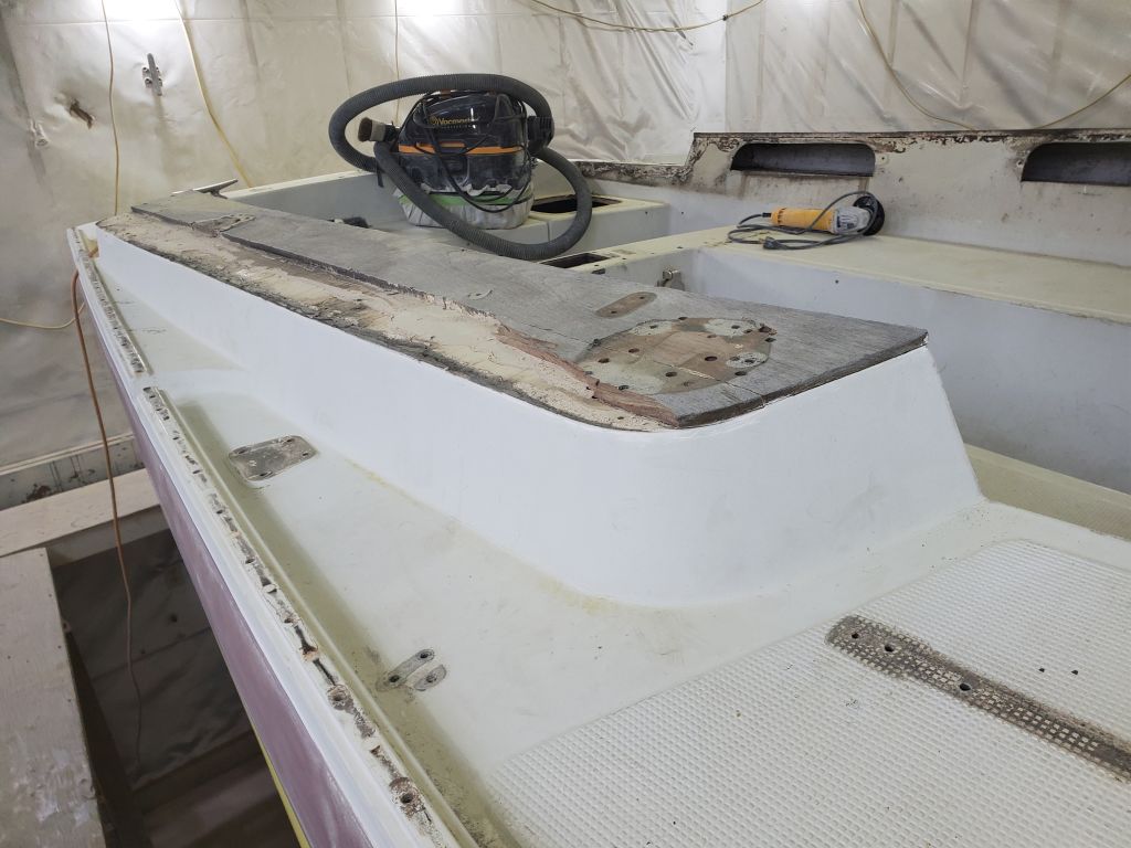
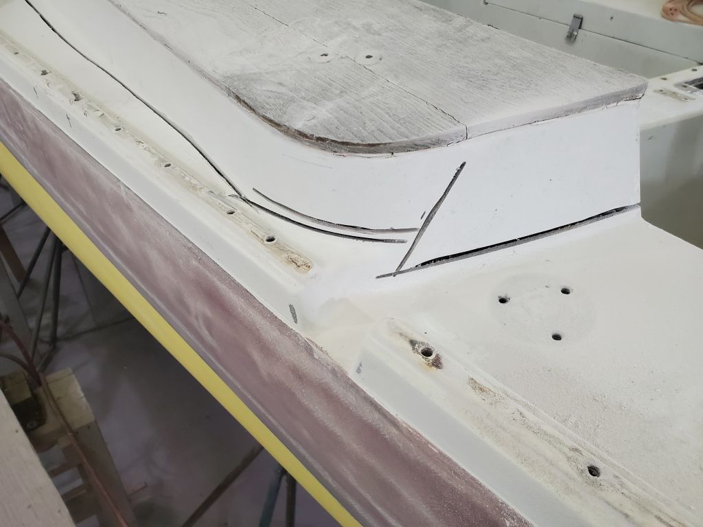
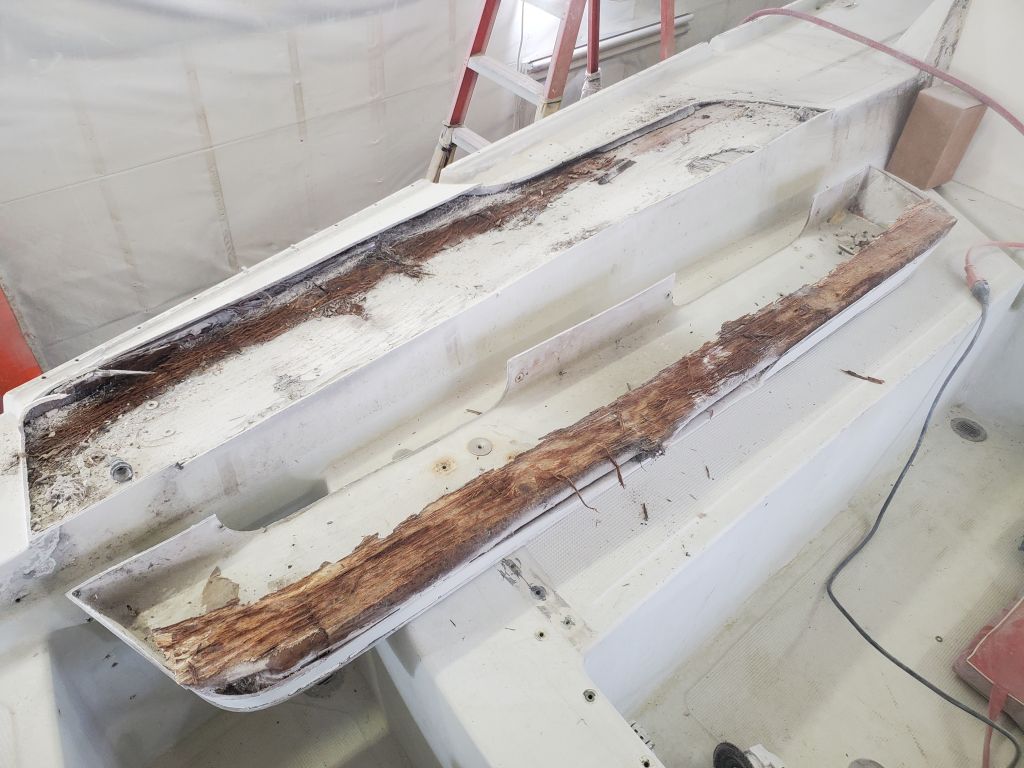
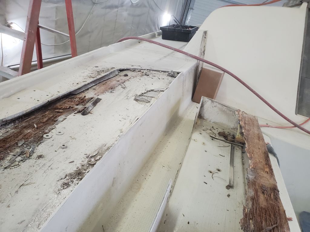
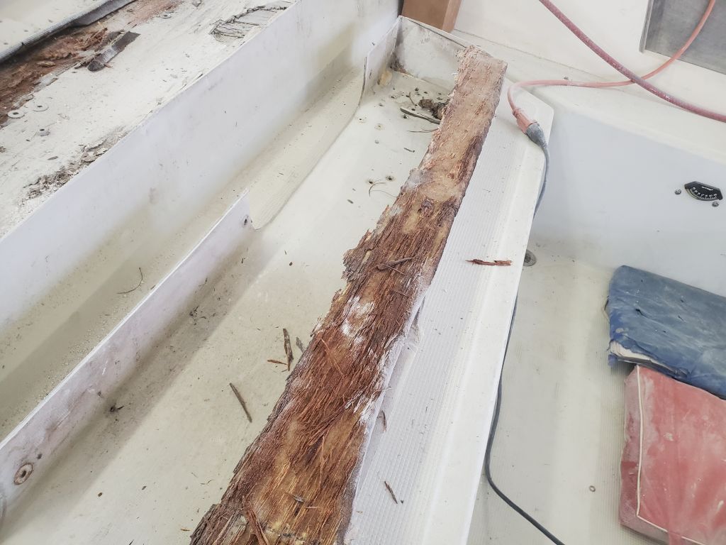
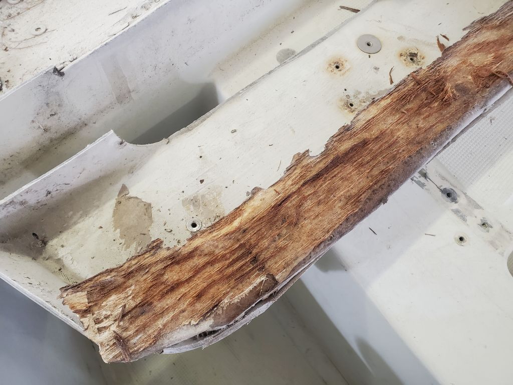
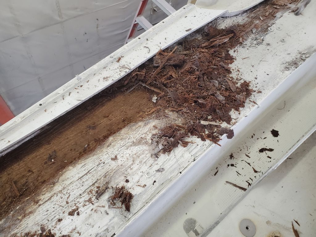
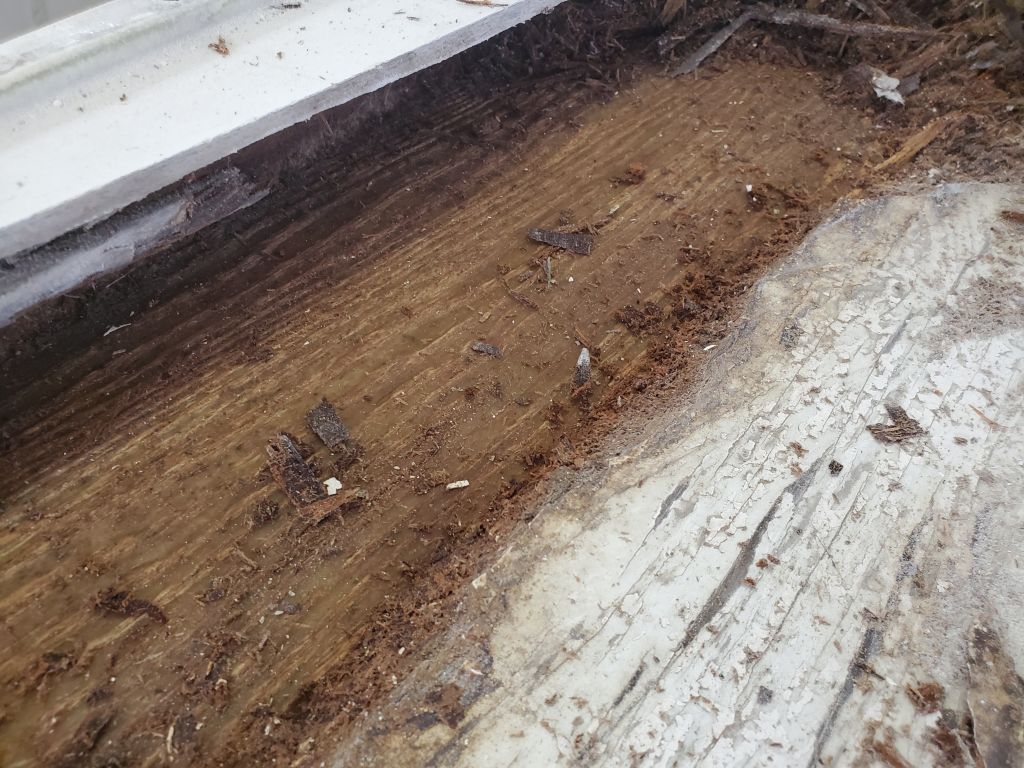
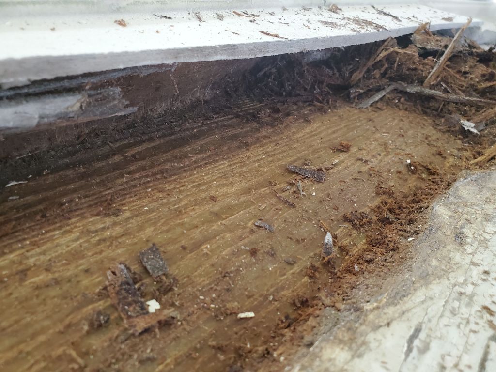
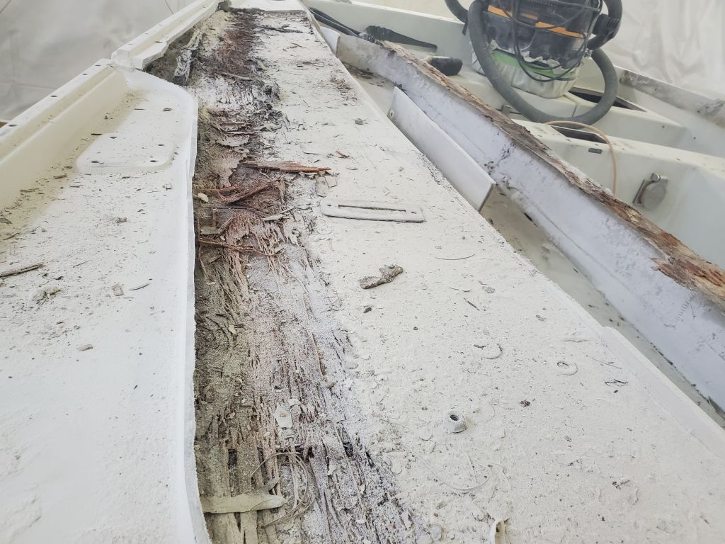
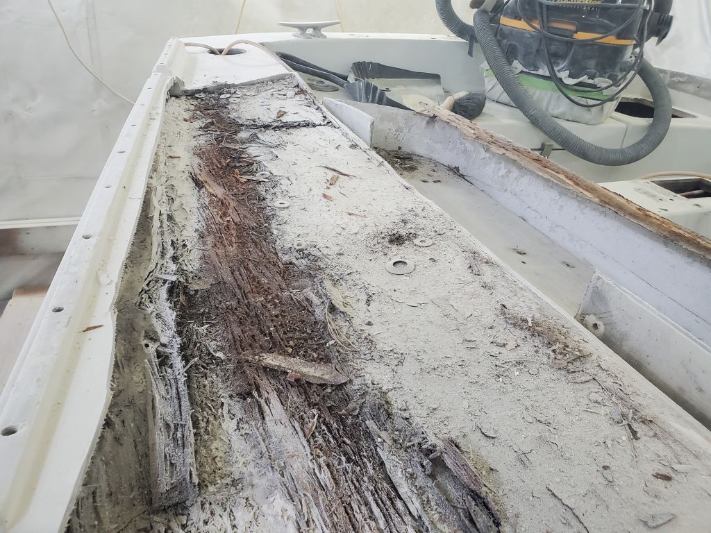
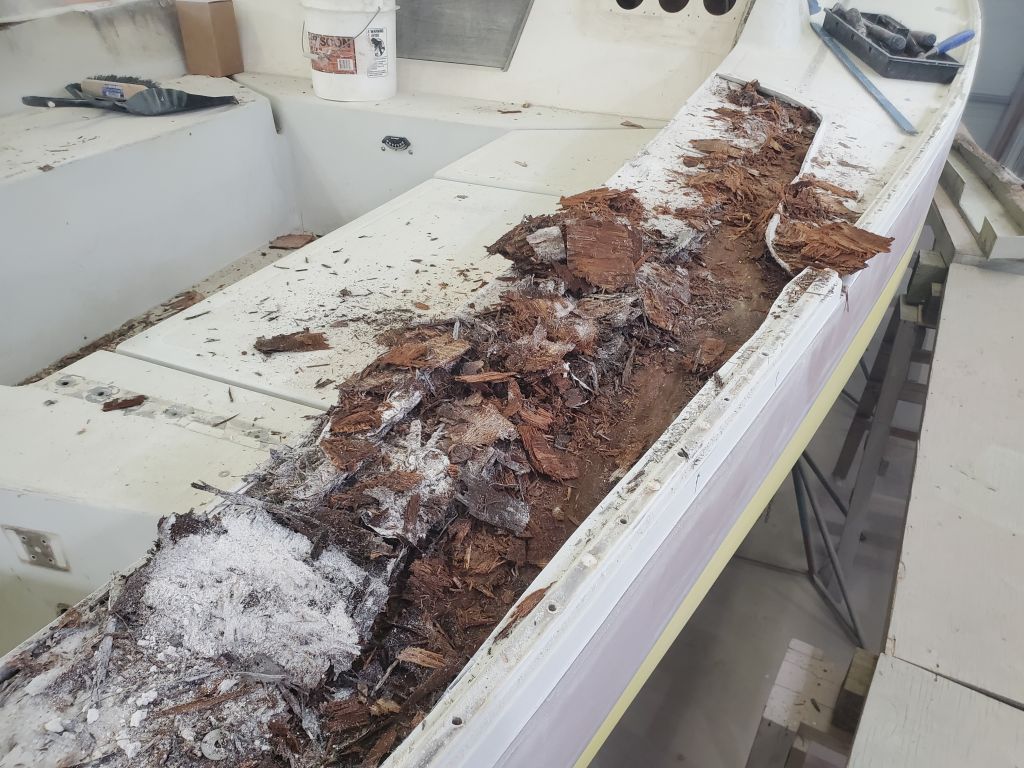
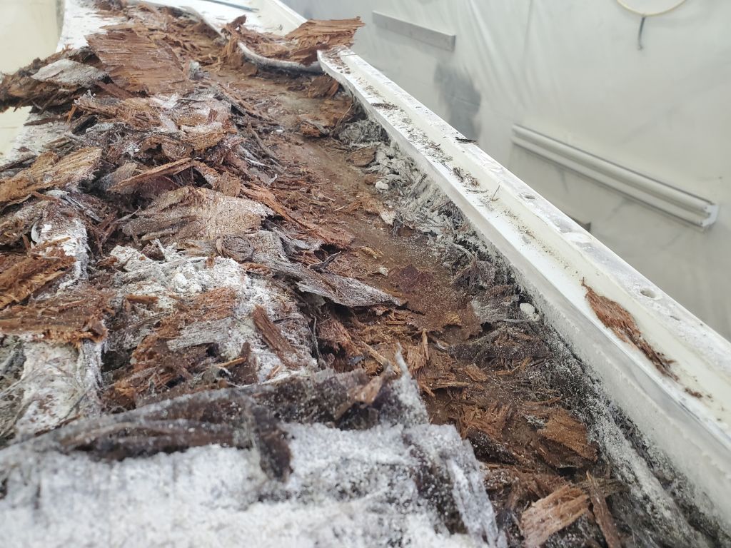
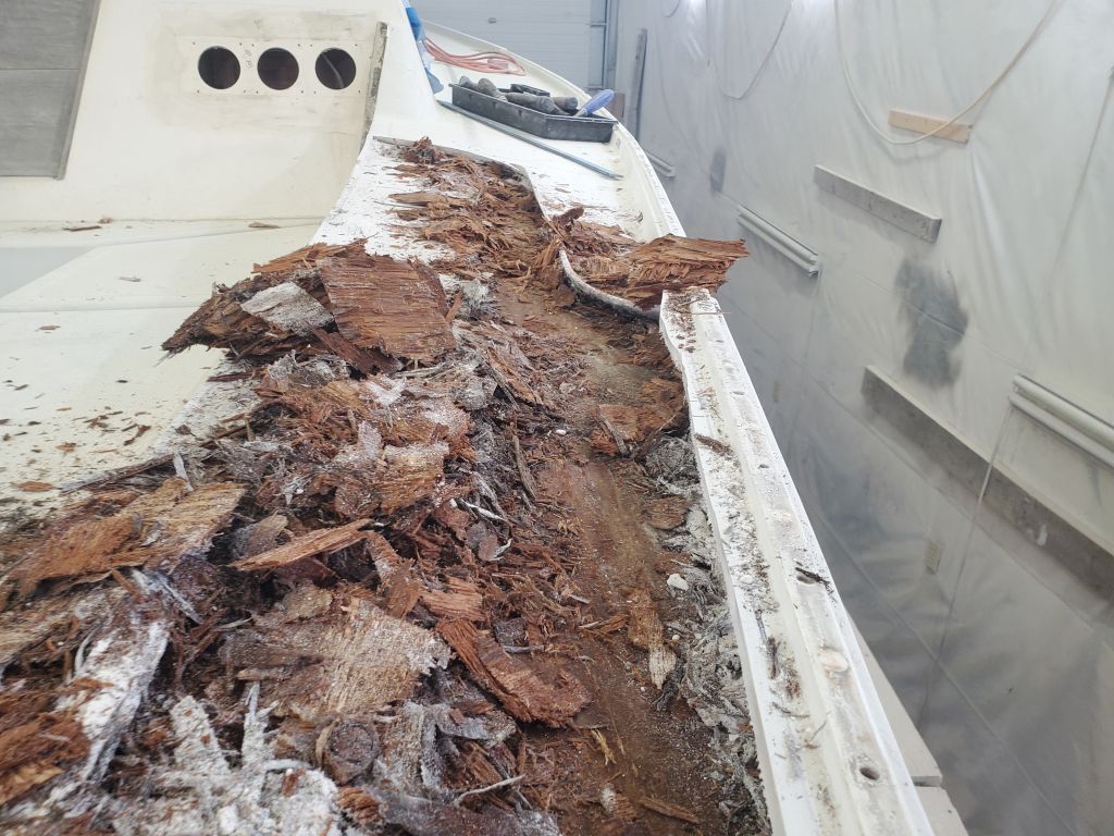
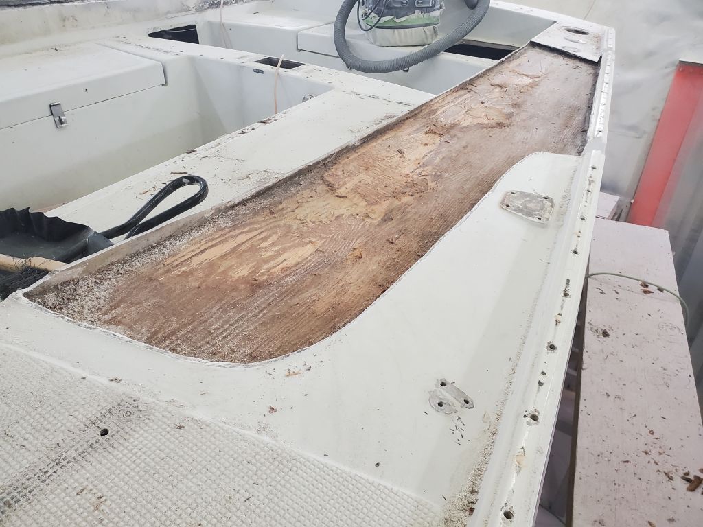
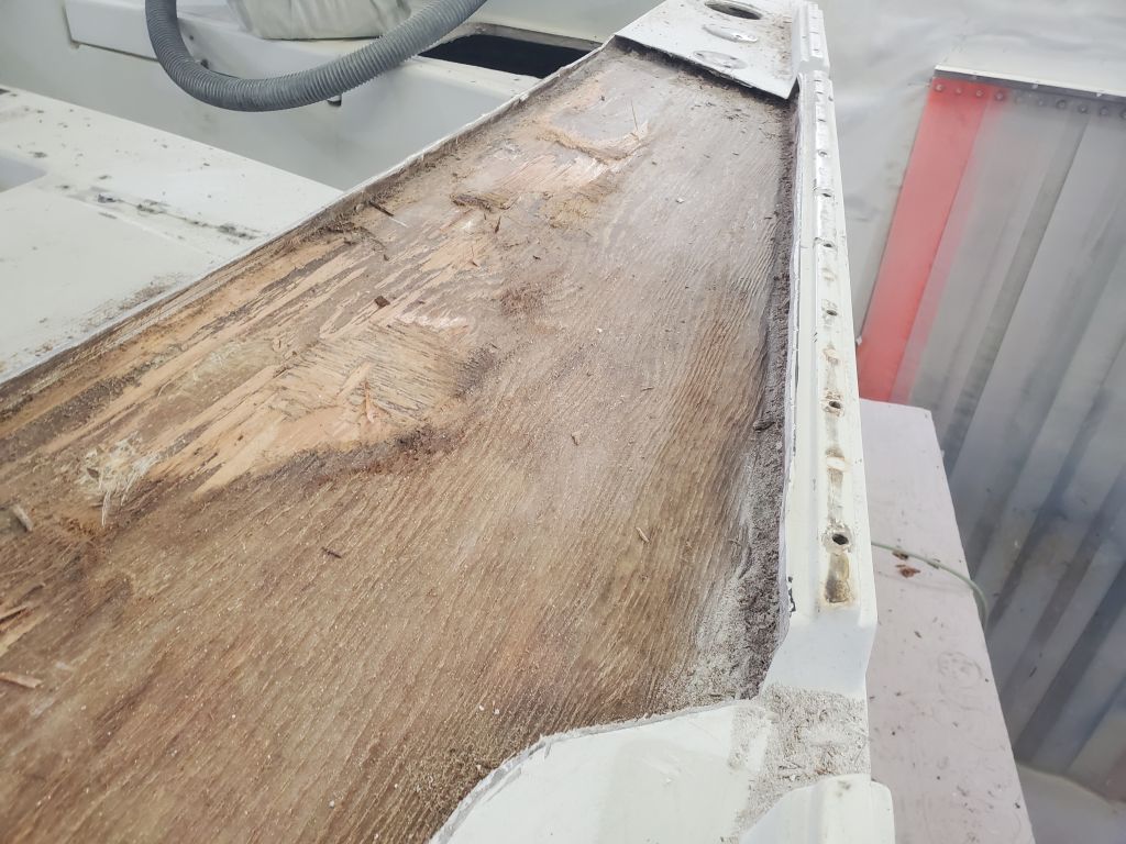
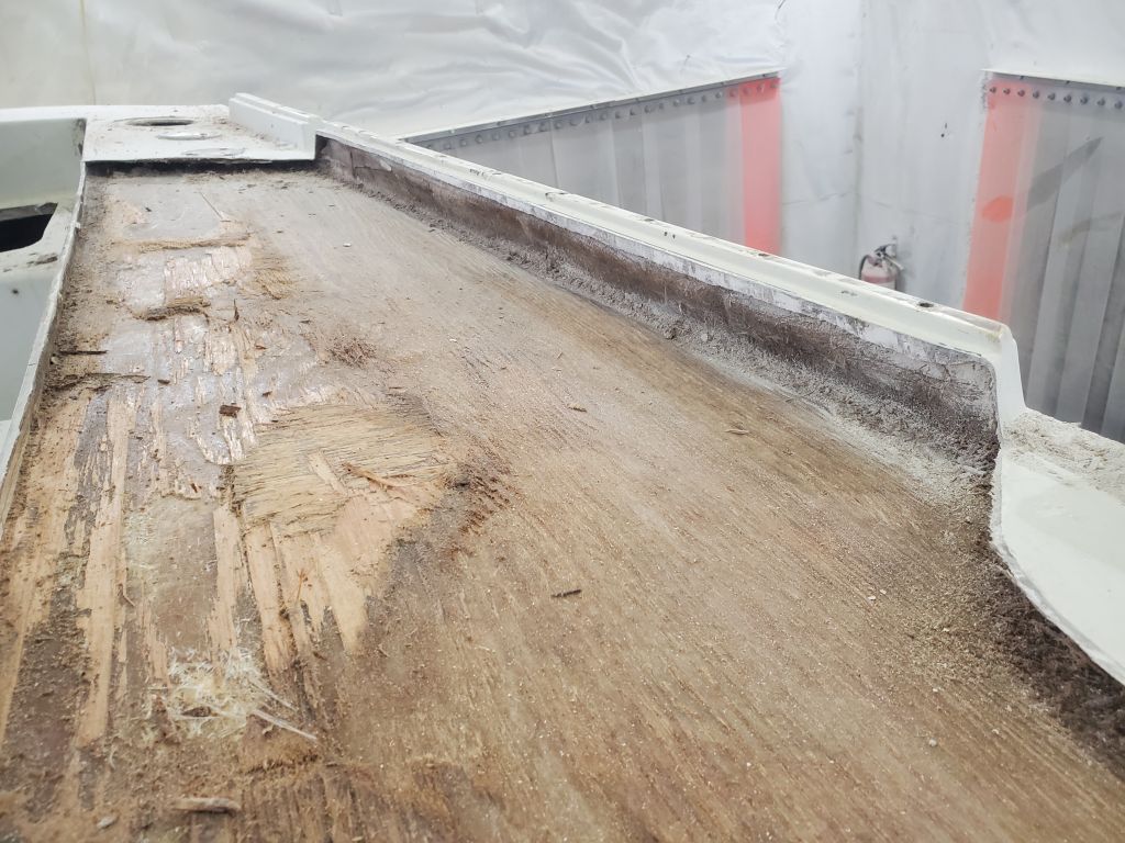
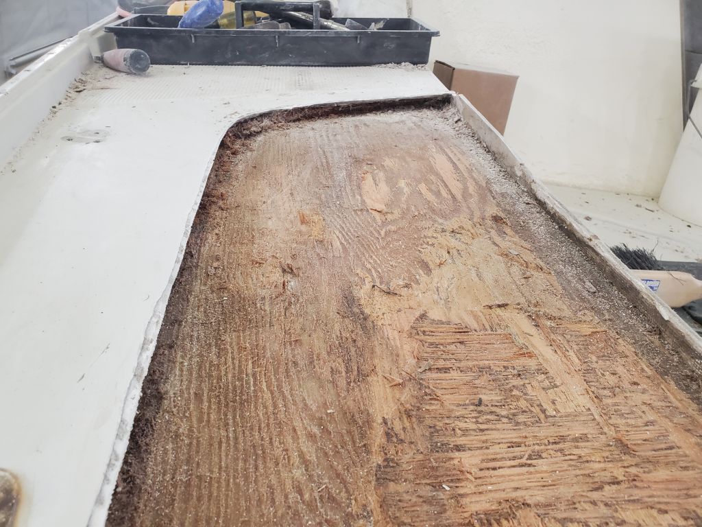
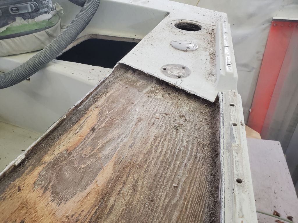
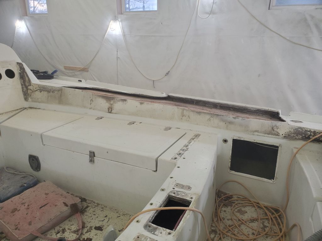
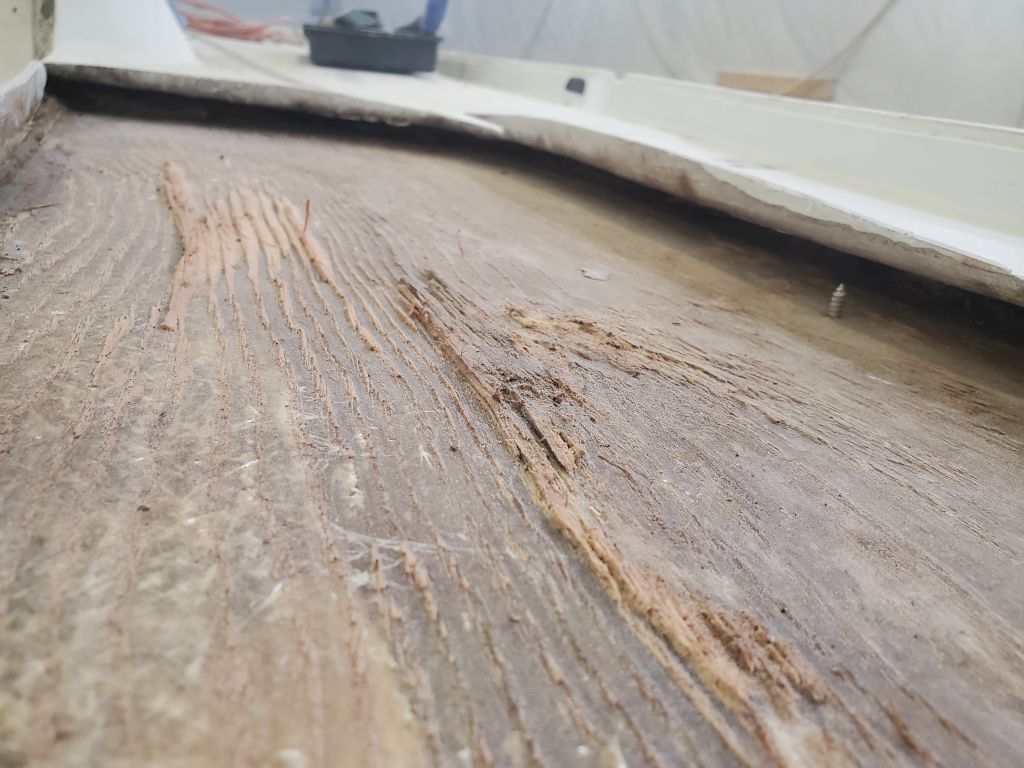
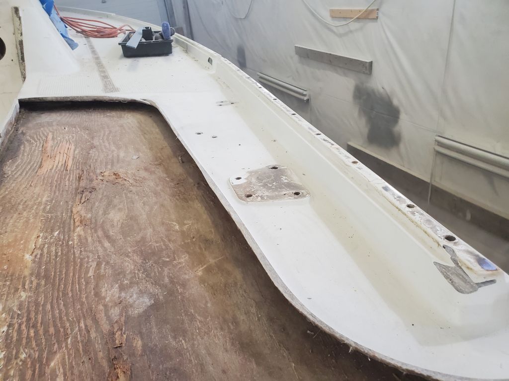
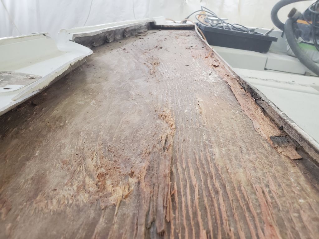
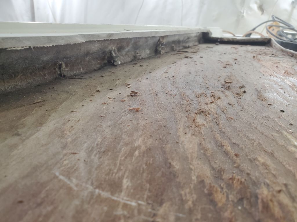
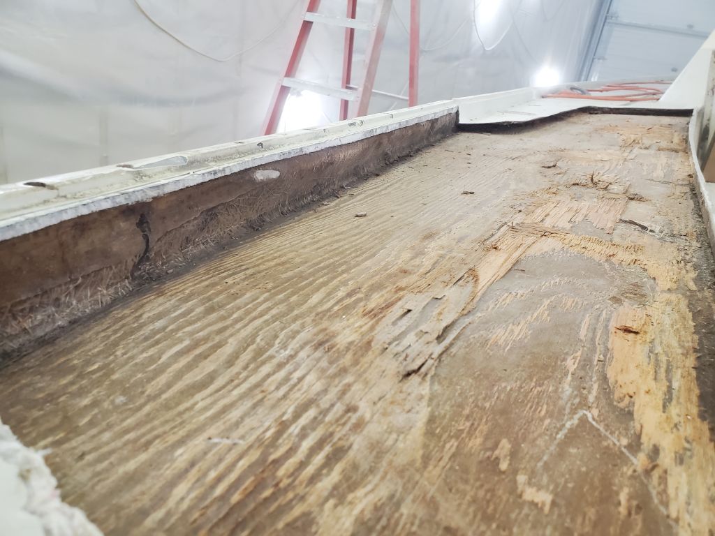
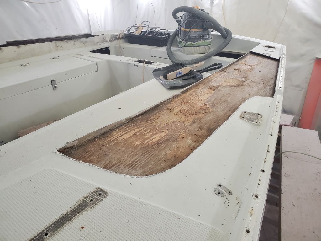
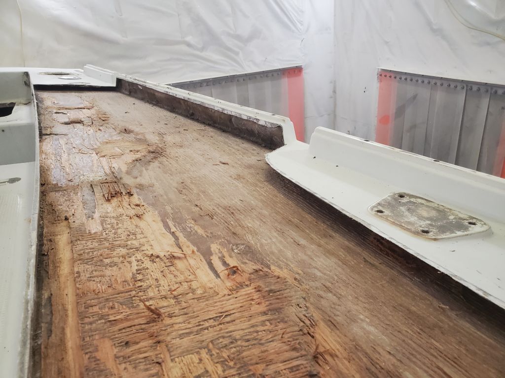
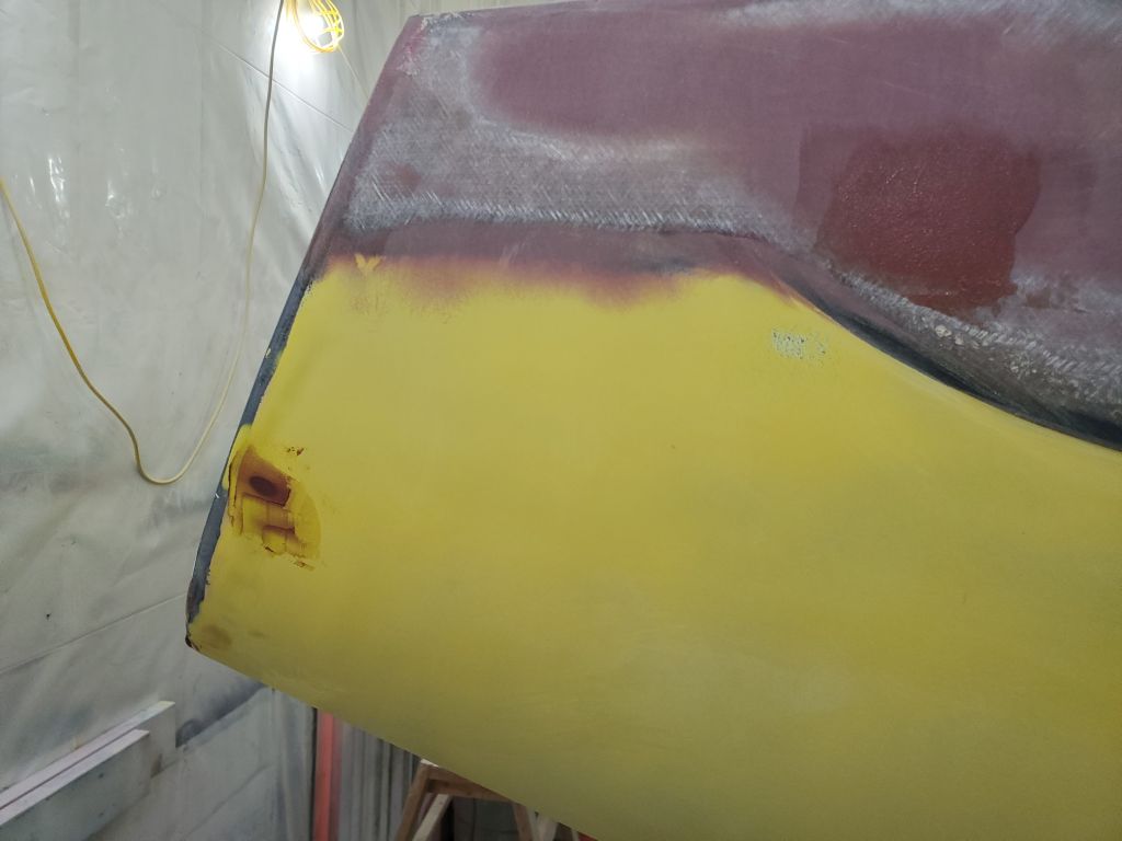
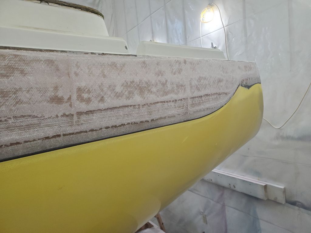
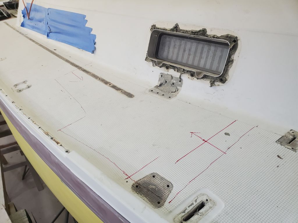
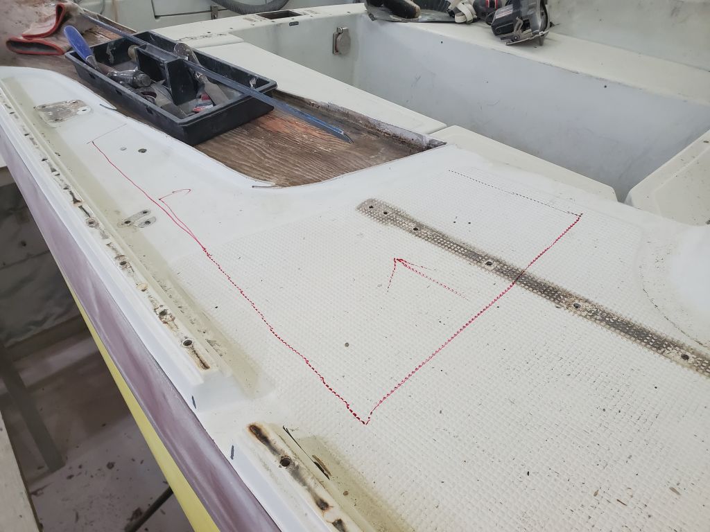
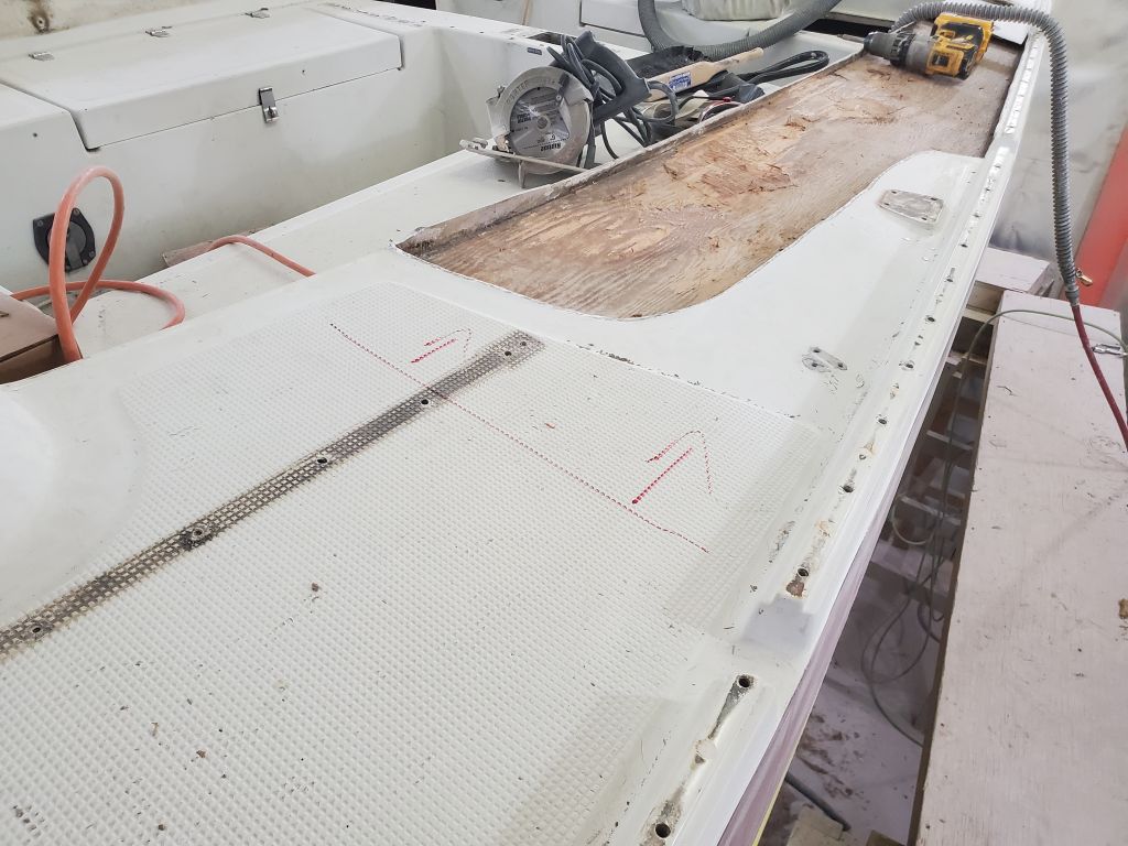
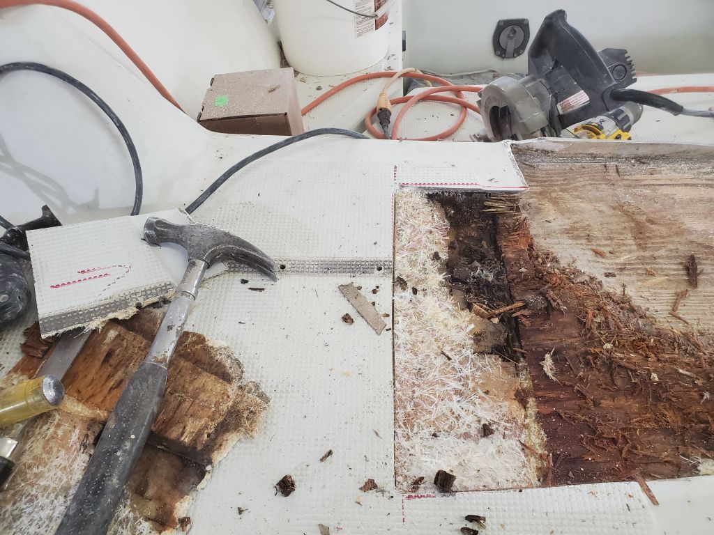
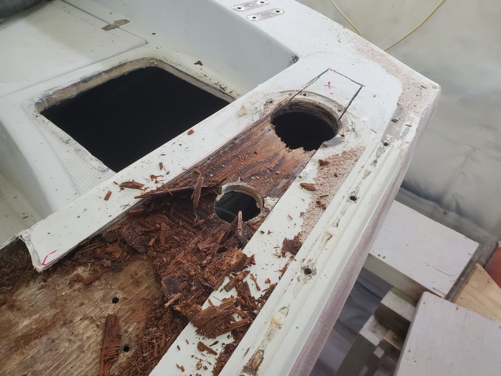
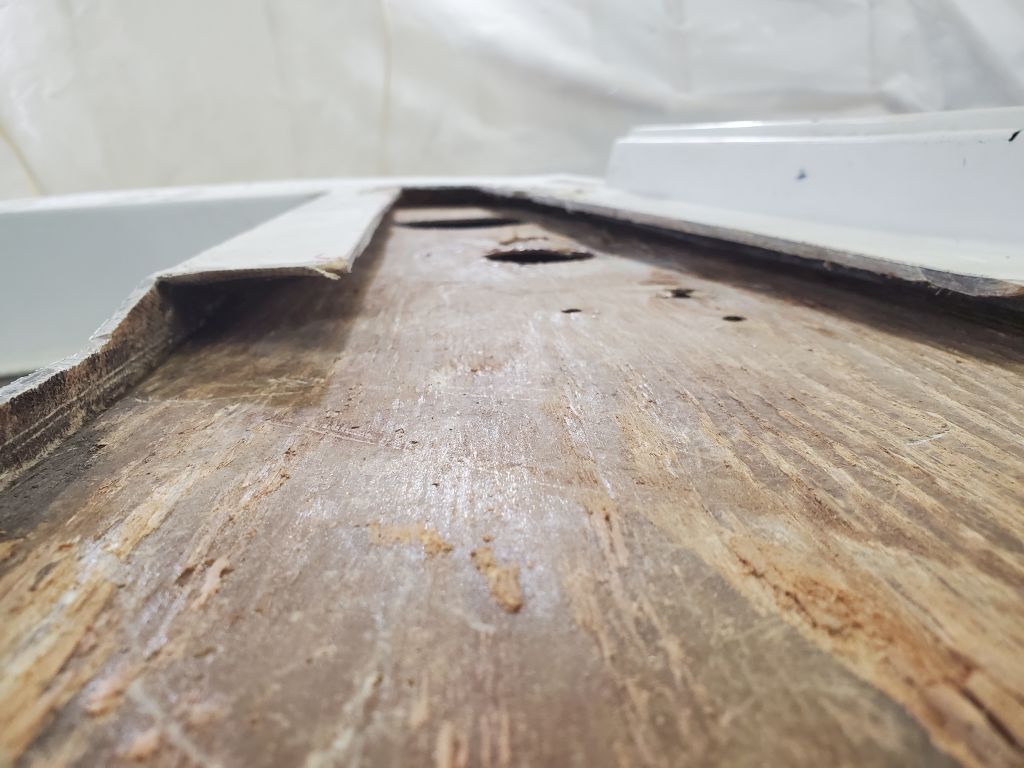
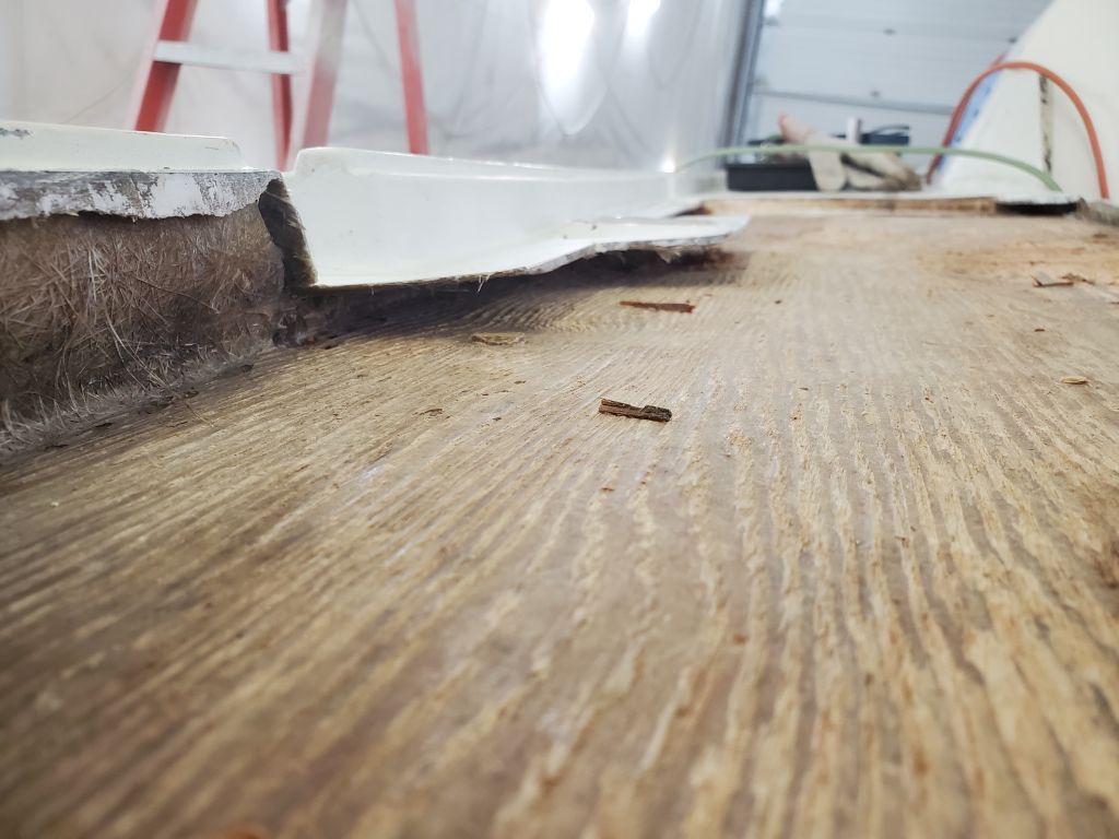
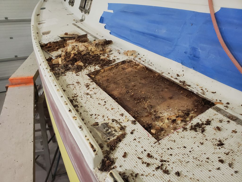
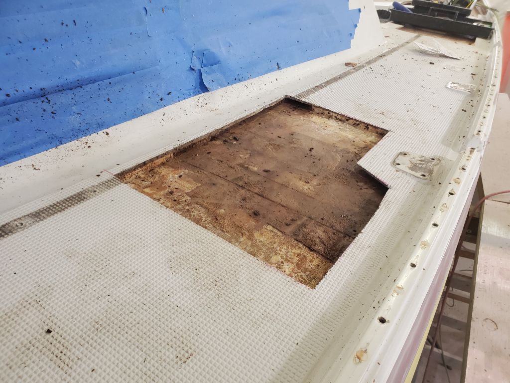
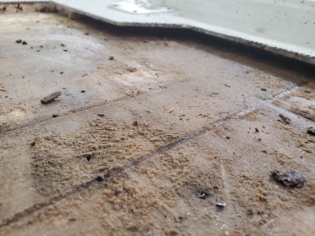
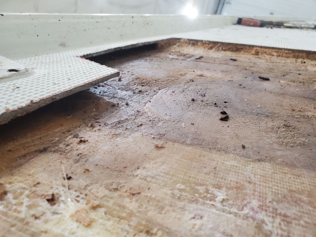
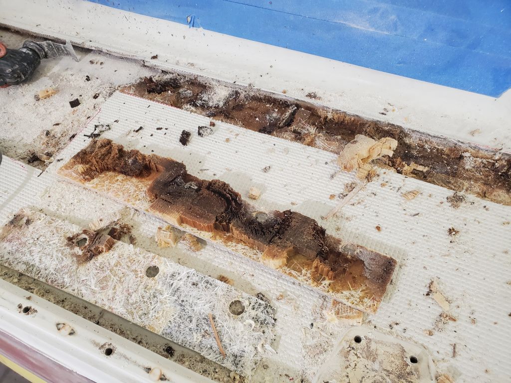
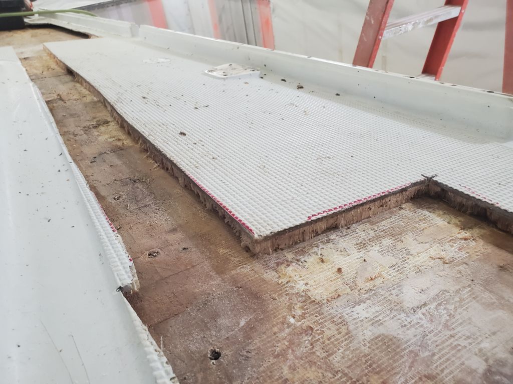
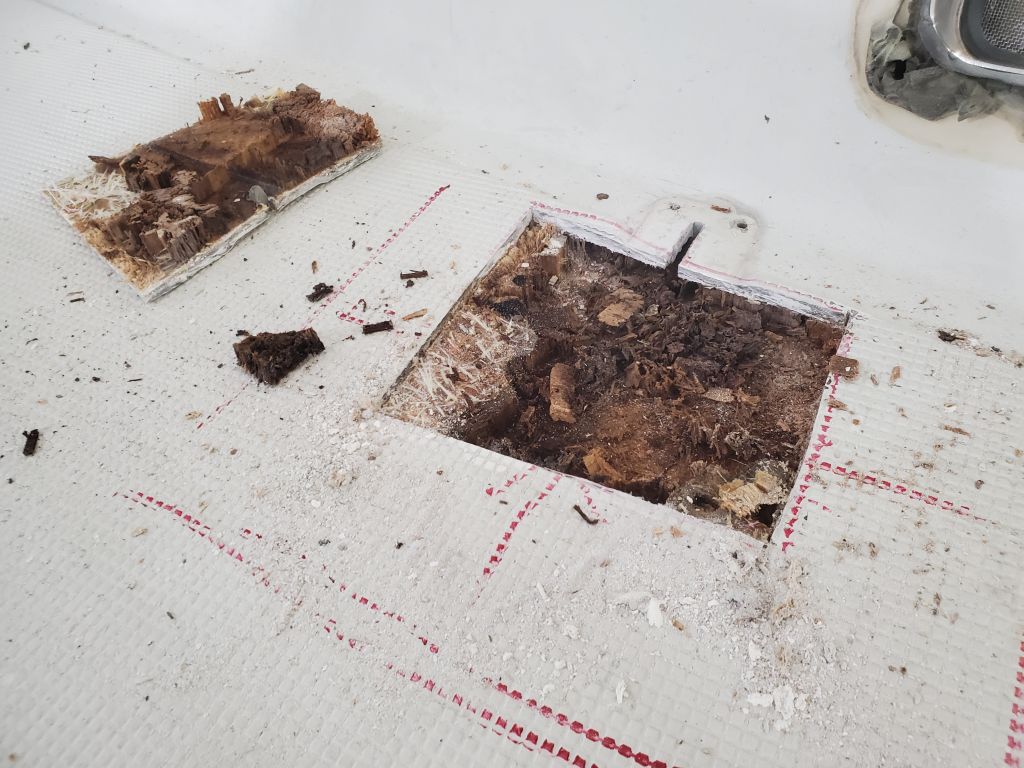
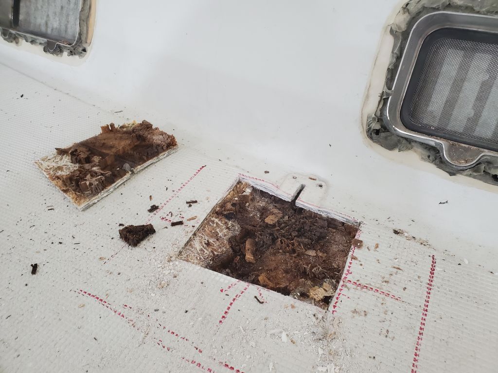
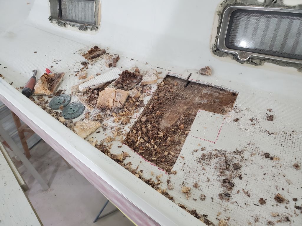
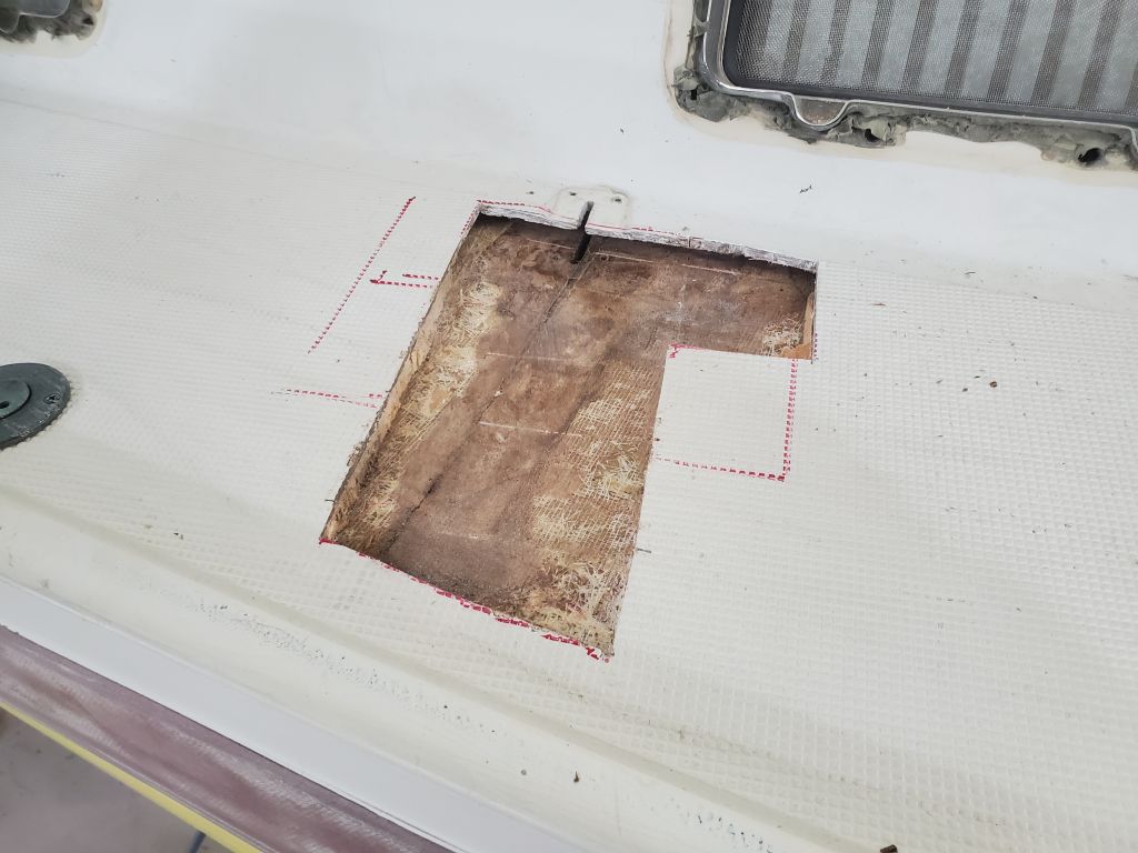
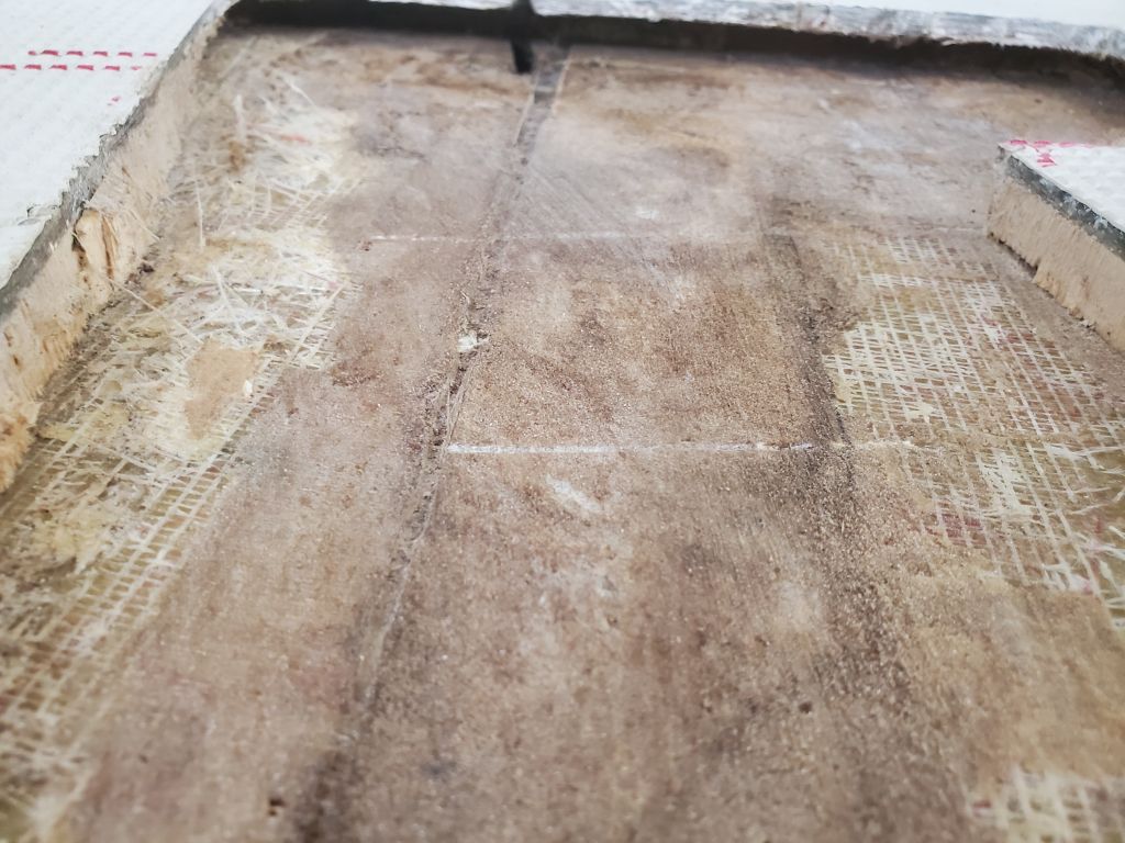
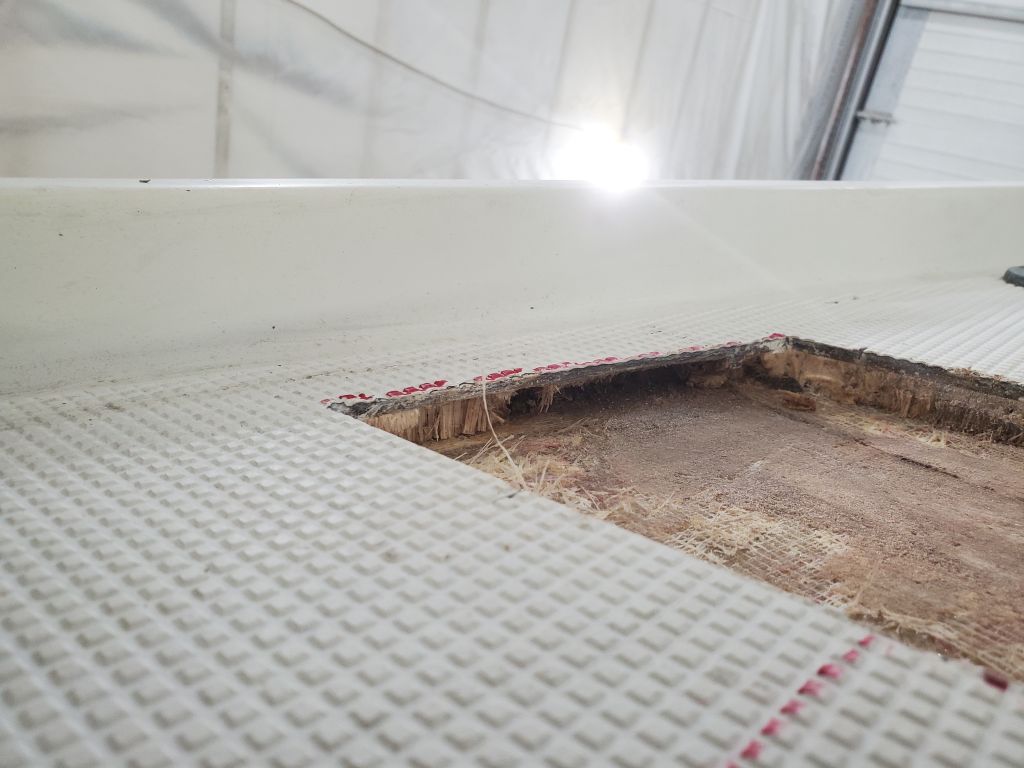
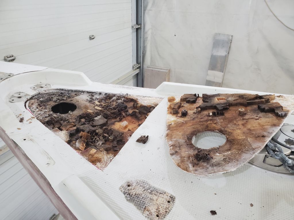
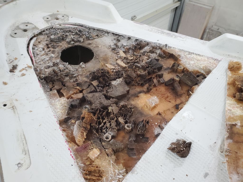
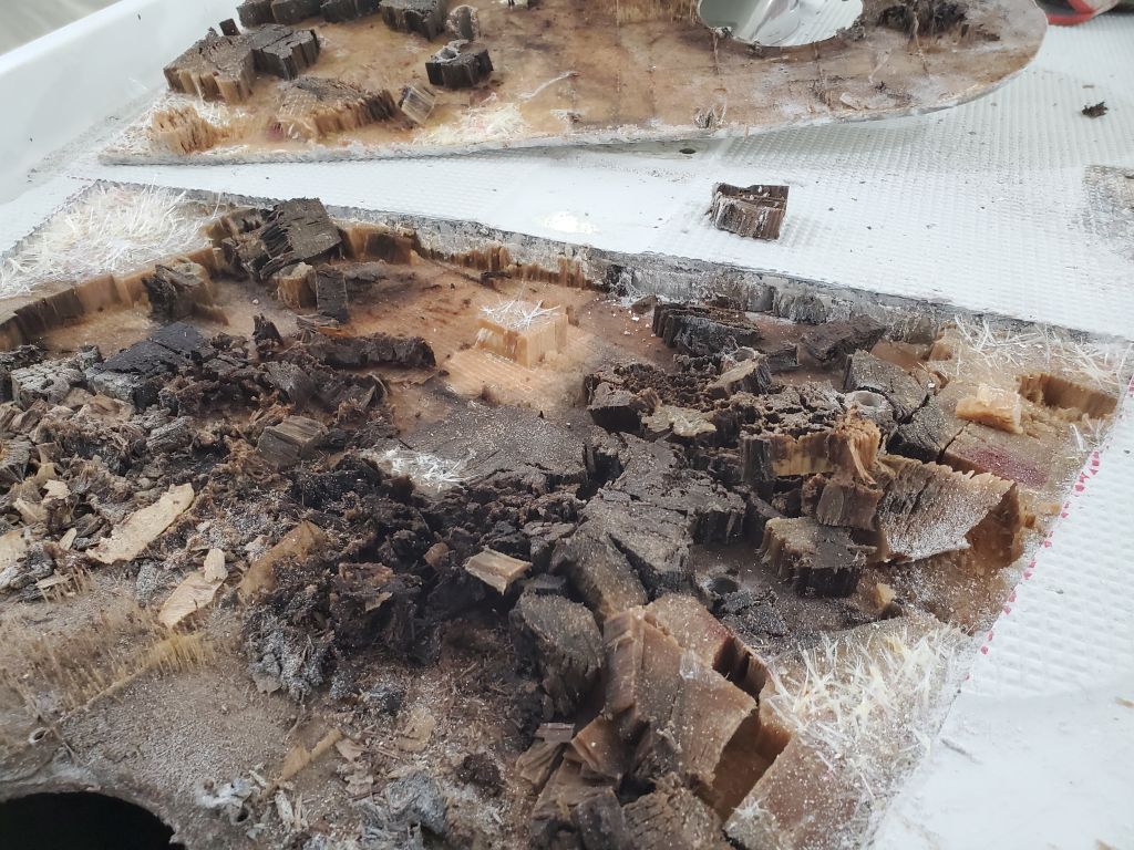
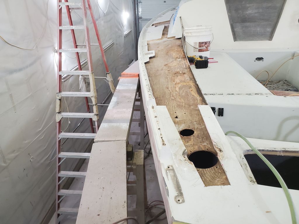
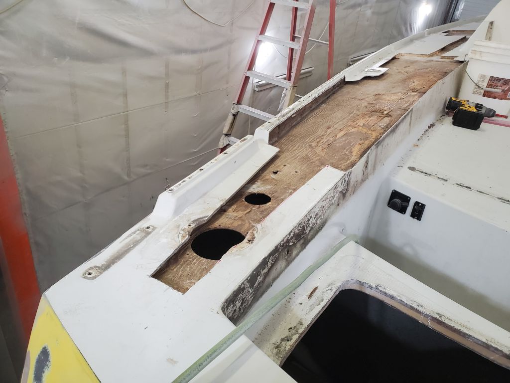
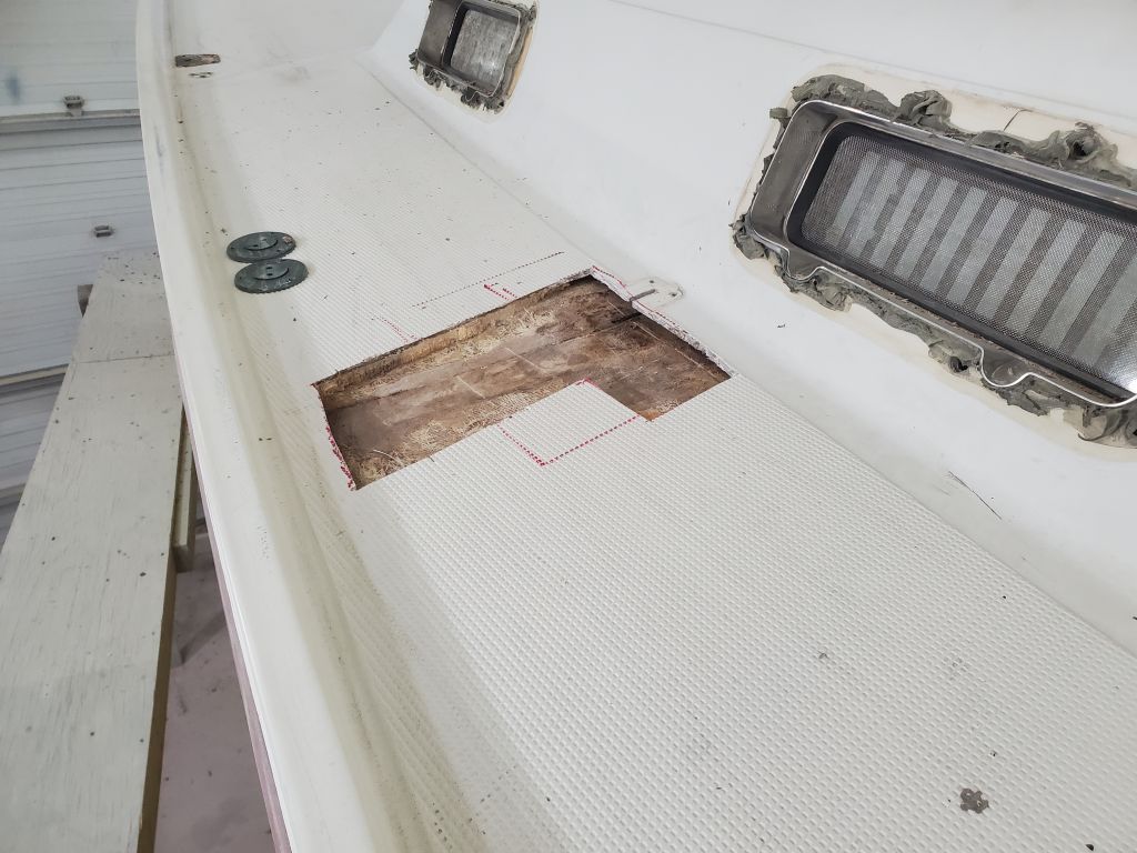
Now, as needed, I cut the top skin of the deck away on either end of the port winch island area, leaving sufficient flanges in the adjacent decks for tying in the repairs and digging out the old core all around. At the forward end, the water damage extended a couple inches through what remained of the plywood core, and slightly into the balsa core that began several inches forward of my original cutout. I opened this area enough to ensure sound core all around. I cut around the molded stanchion base, leaving enough of the deck for the new work to tie in later.
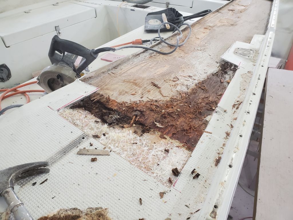
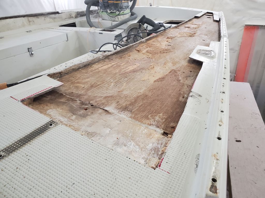
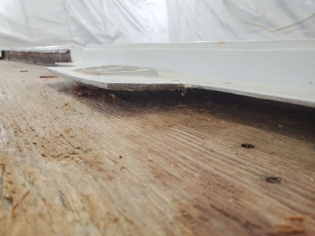


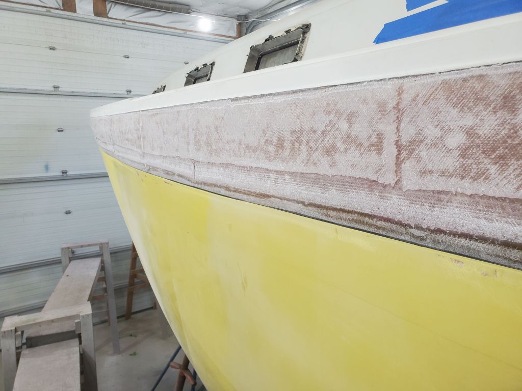
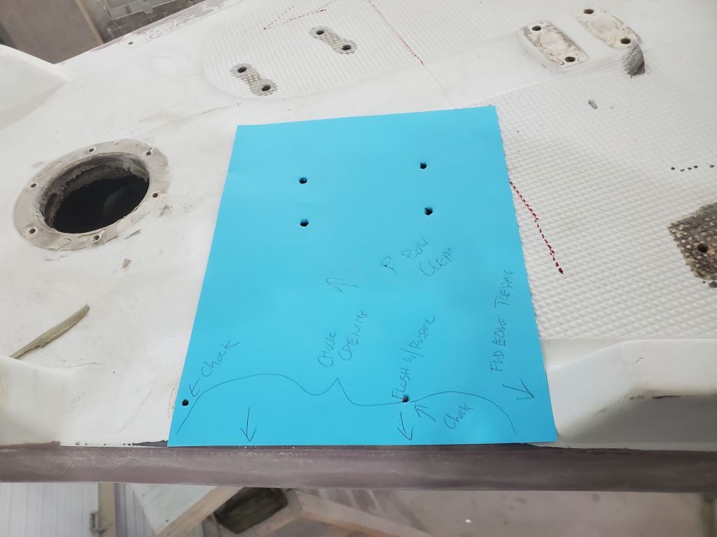
Continuing, I moved forward to a section of the sidedeck that seemed to be compromised because of some of the genoa track fasteners near the cabin trunk. Already a large-ish area, I found once I opened the top skin that the damaged core continued towards the deck edge (toerail), so eventually I had to expand the opening further towards the toerail, again choosing to cut around the little molded stanchion base to preserve its shape, which was molded at each location to ensure the stanchions stood straight and upright.


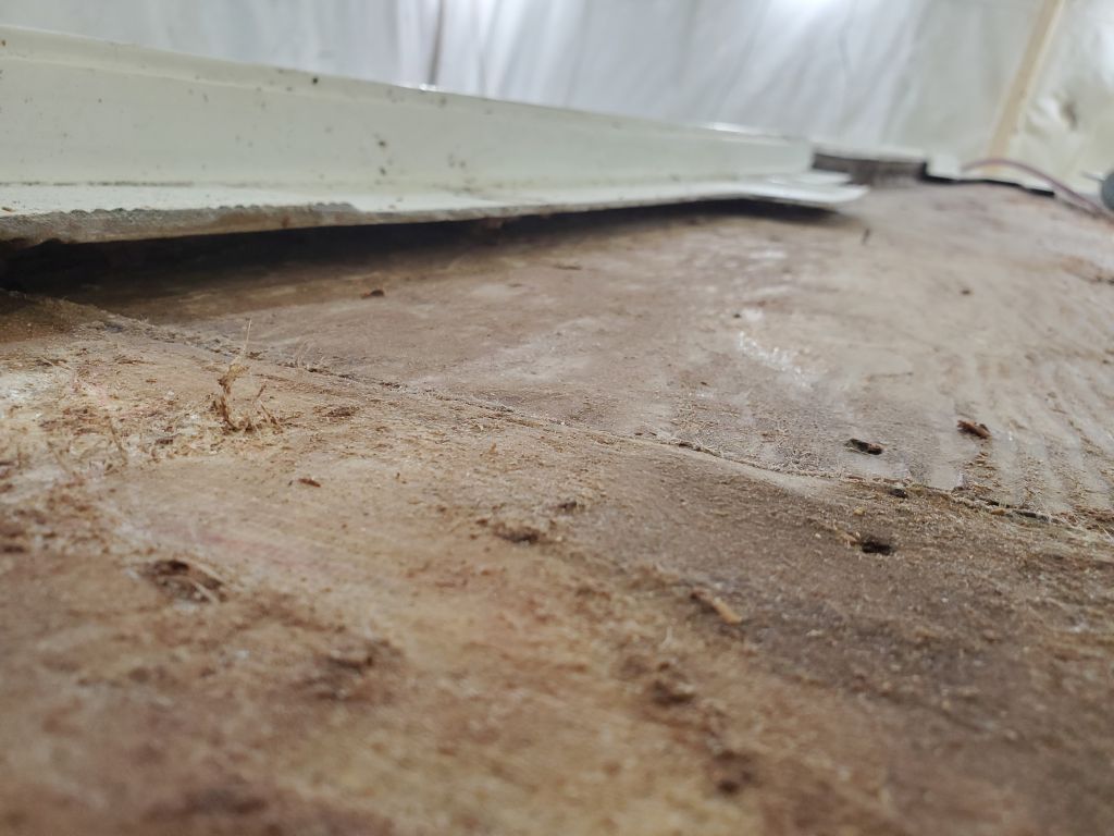
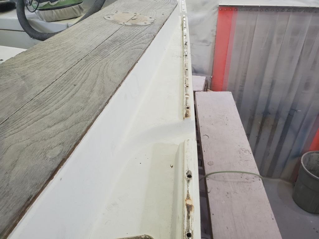
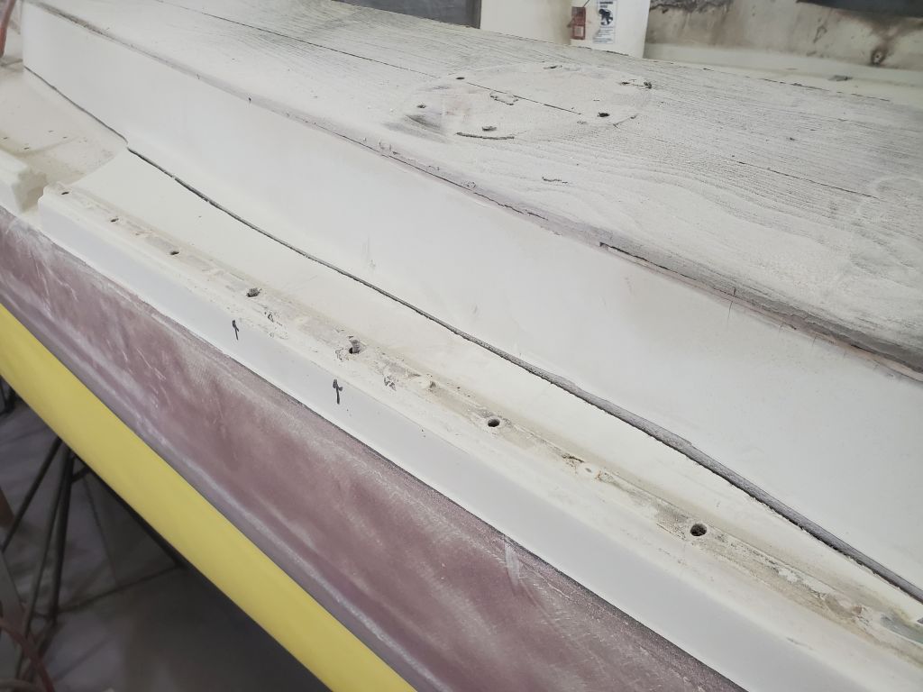
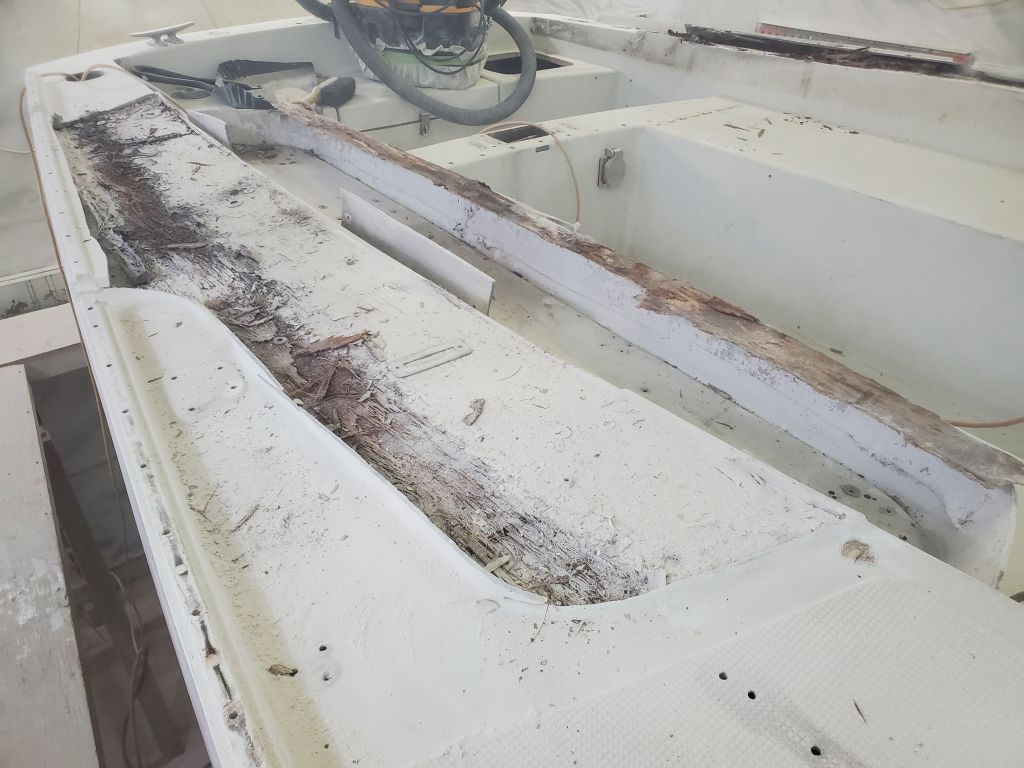
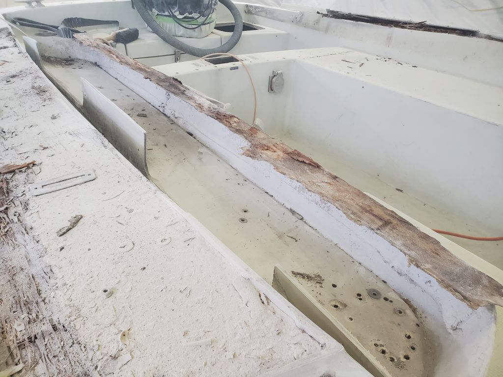
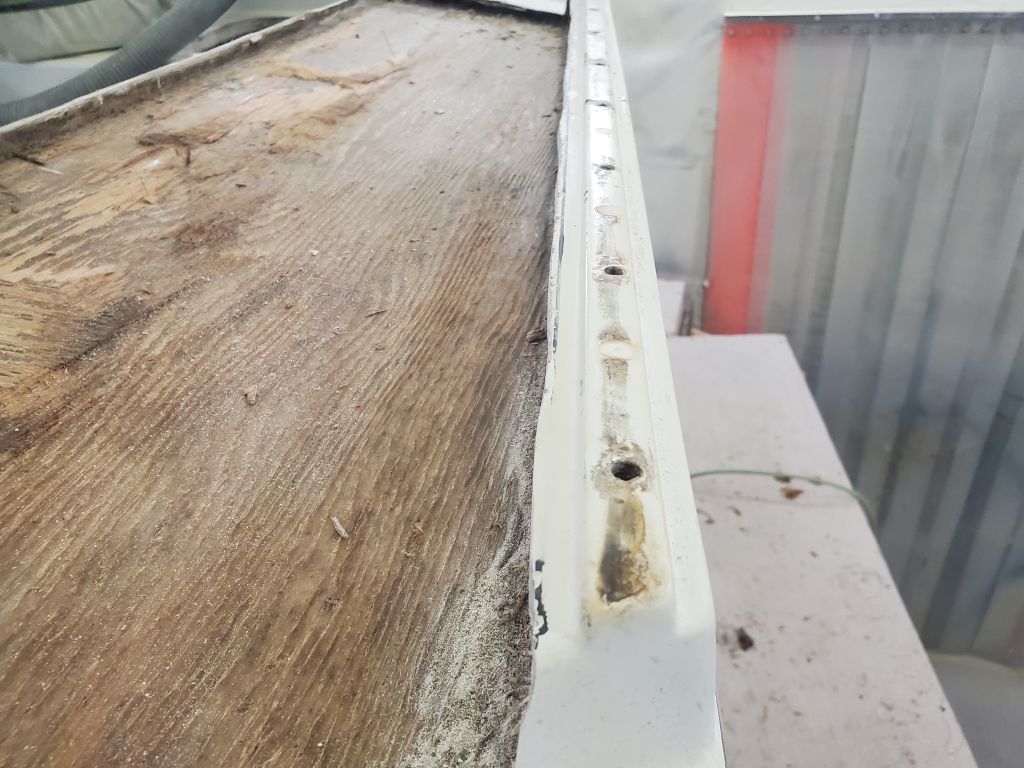
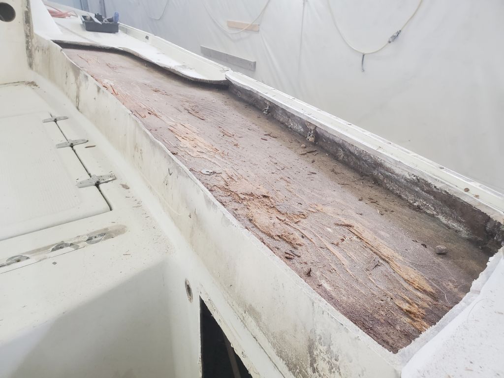
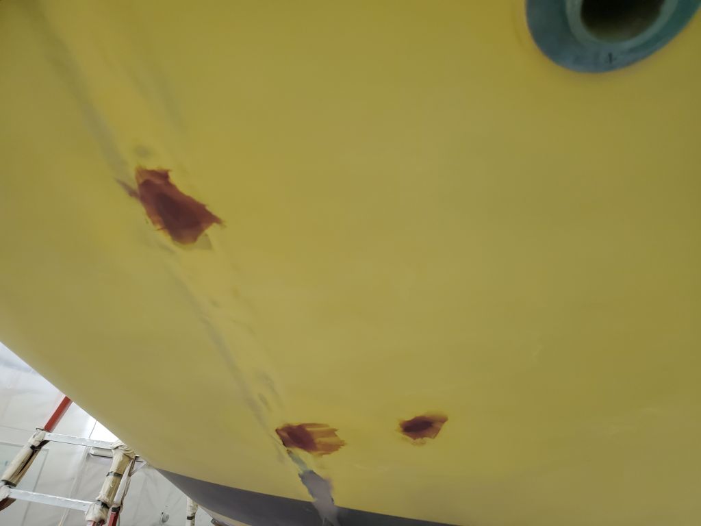
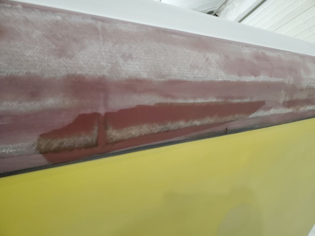
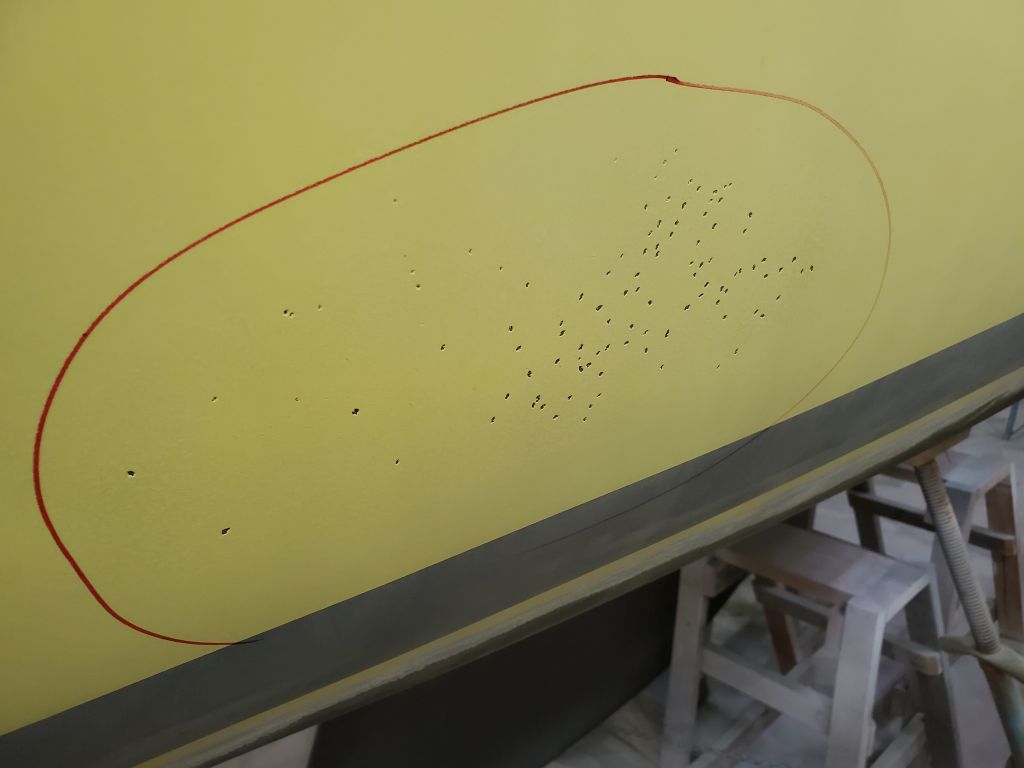
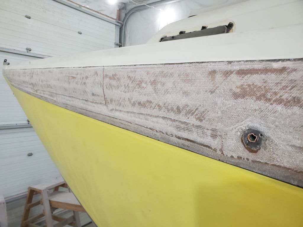
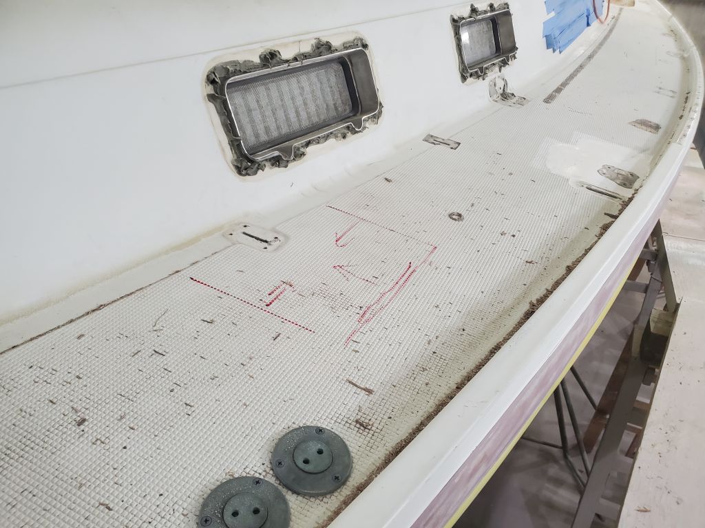
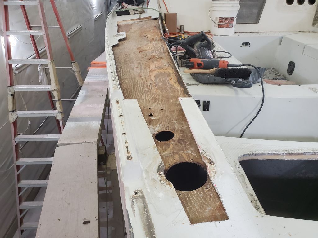
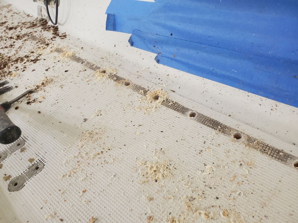
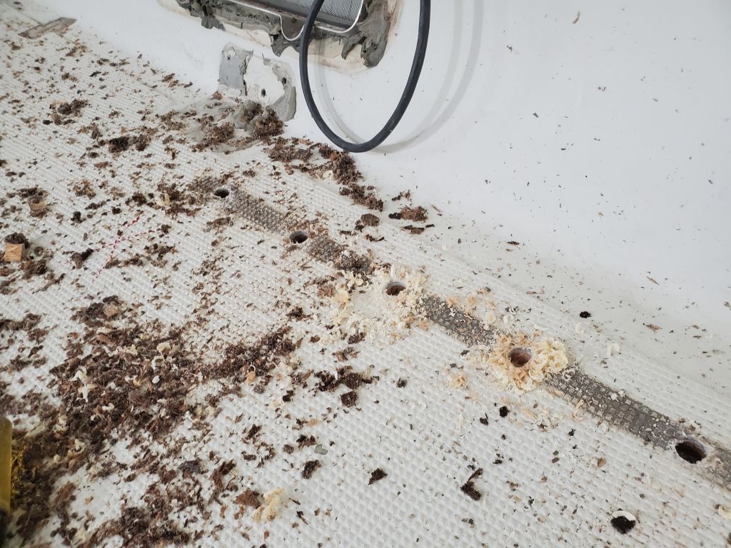
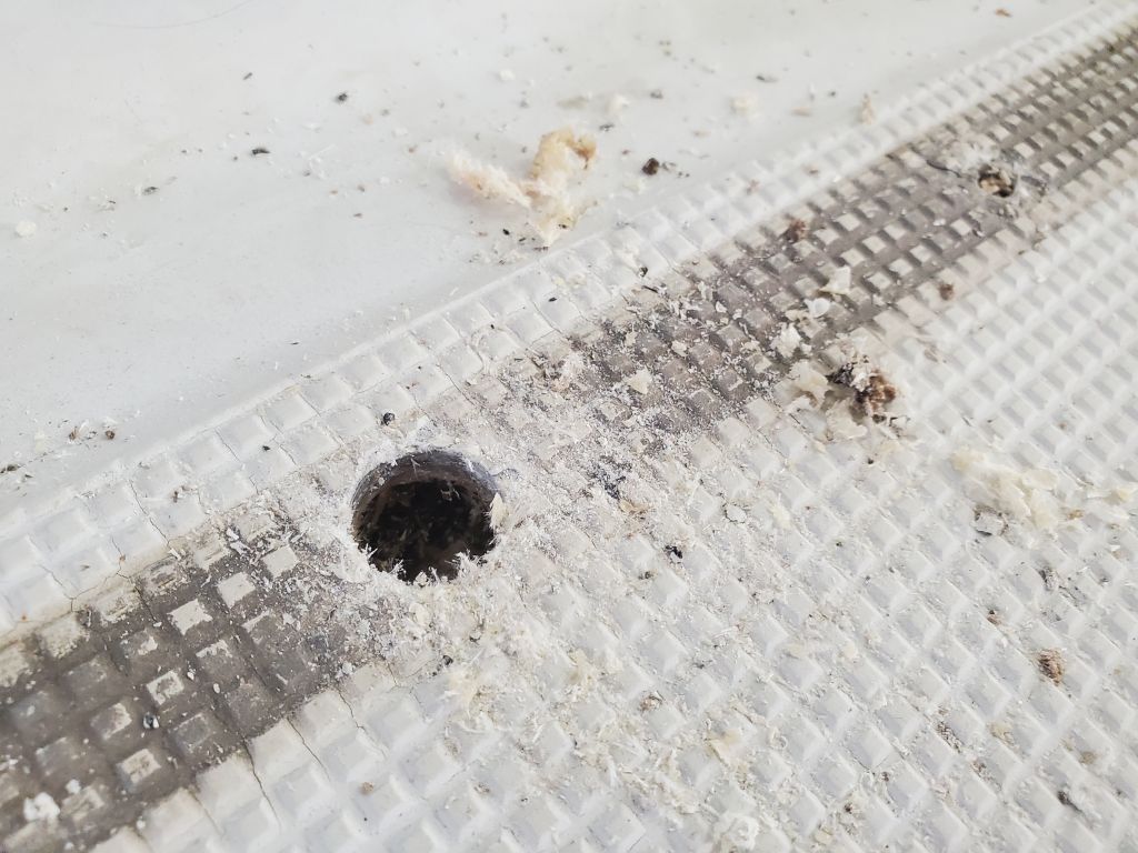
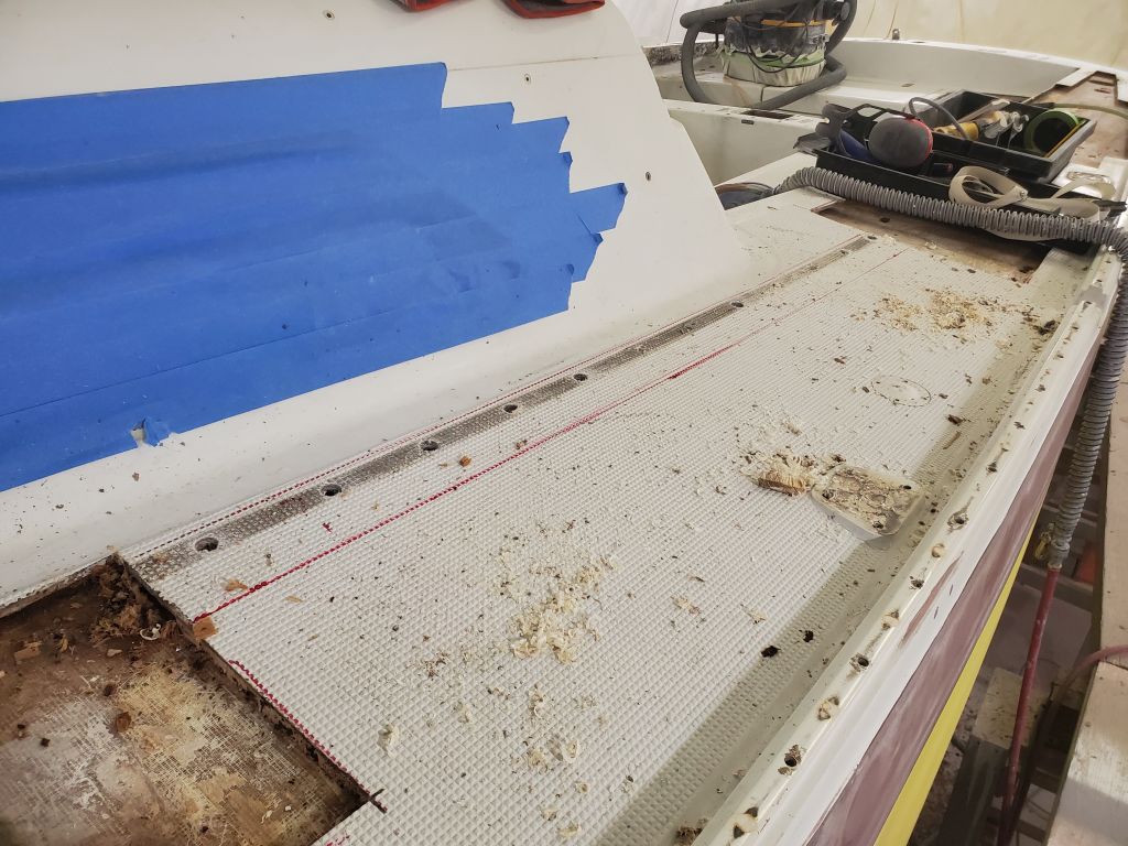
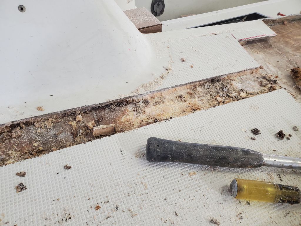
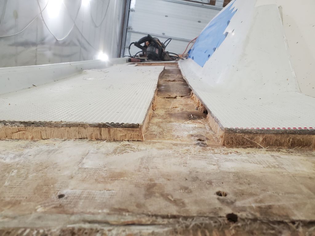
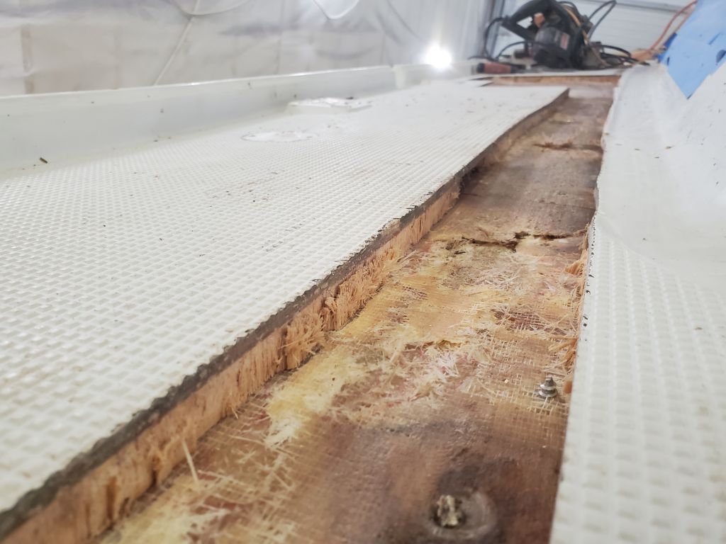
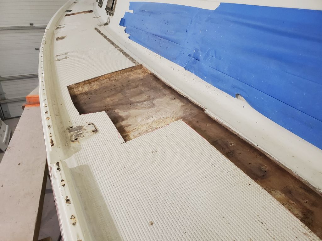
With a 5/8″ bit, I drilled out all the fastener holes from the long inboard genoa track. The owners didn’t plan to replace this track, as they had other plans for the sheet leads, so at a minimum I’d be filling all these holes, but all the holes aft of my core repair showed damaged core, while most of the holes forward seemed to display sound core. Ultimately, I decided to remove a strip of the deck encompassing all the holes along the aft half, leaving me a 3″ wide strip to recore and repair. For now, I left the forward half as is, but would expand the openings into one or two holes that seemed to be dark with moisture infiltration a little later.


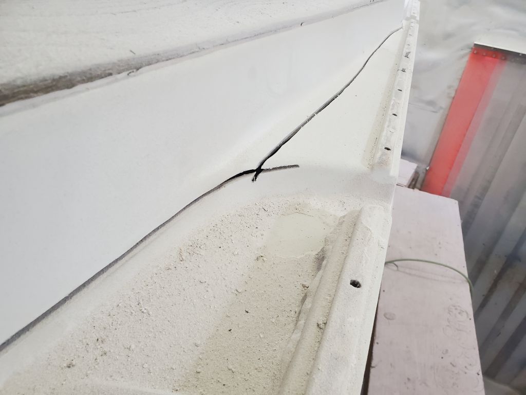
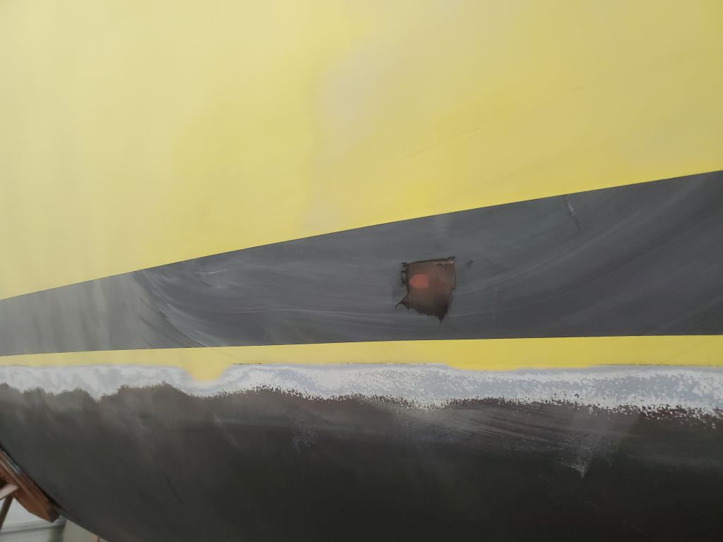
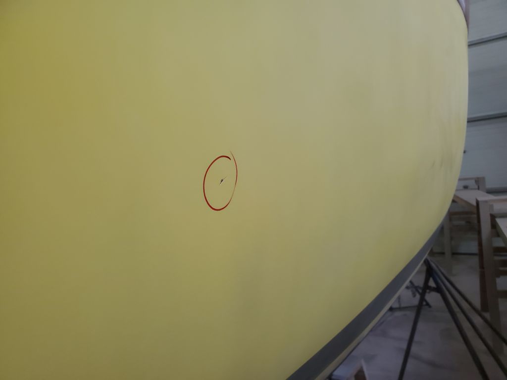
The next spot requiring attention was outboard of one of the chainplate slots alongside the cabin trunk. Here, I eventually followed the damaged core in a narrow band from the slot towards the toerail, expanding my opening only as needed to remove the damaged material.
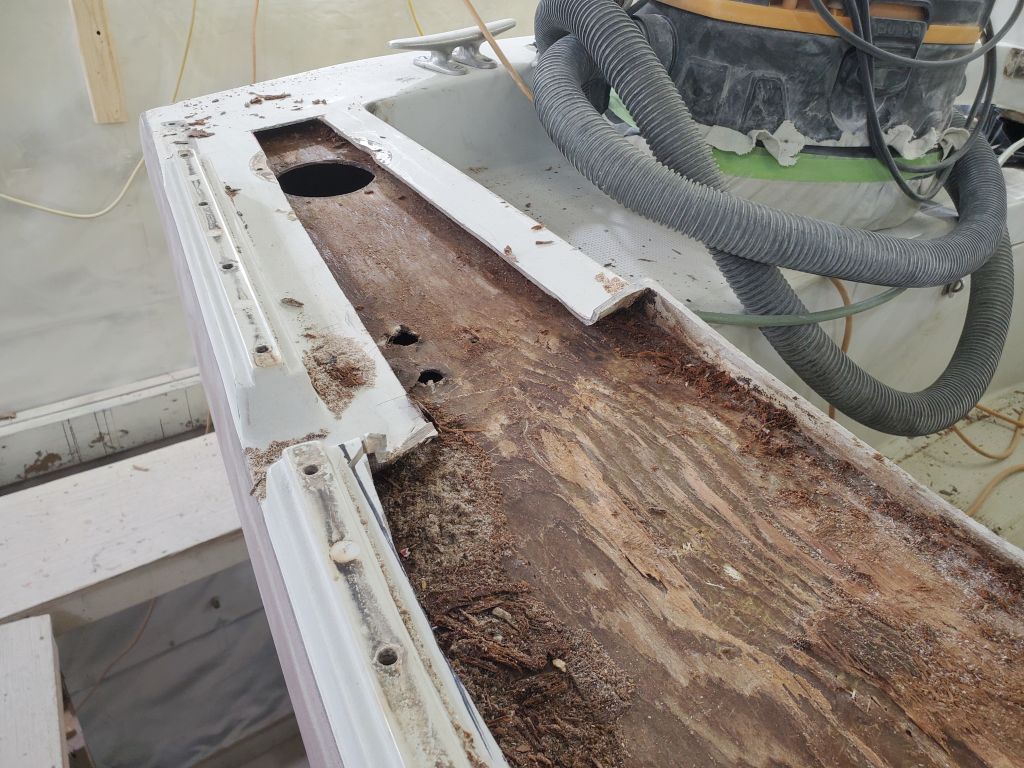
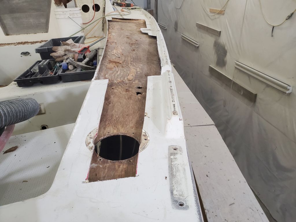
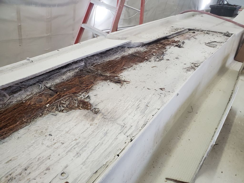
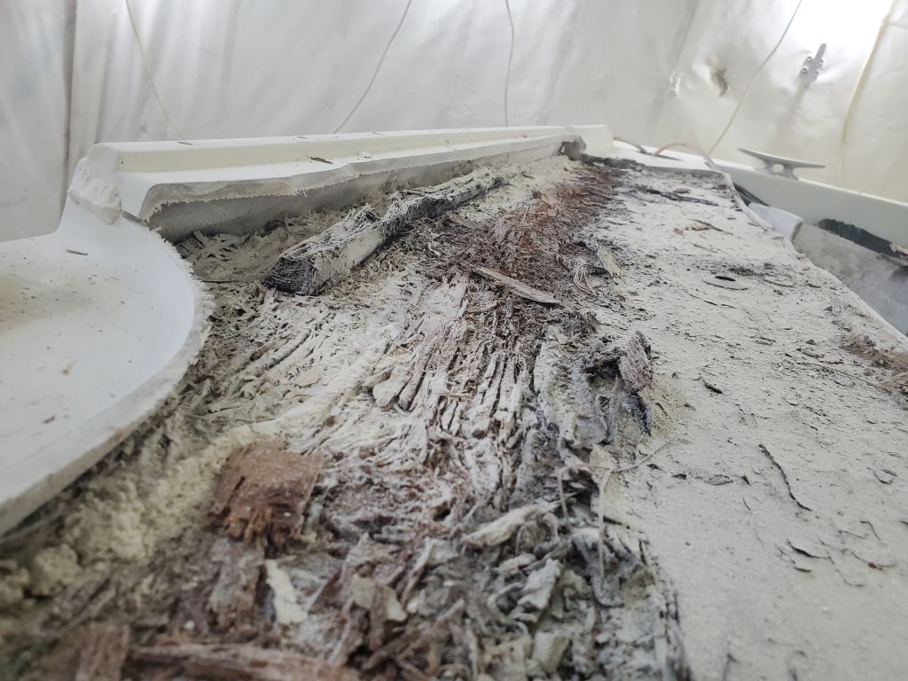
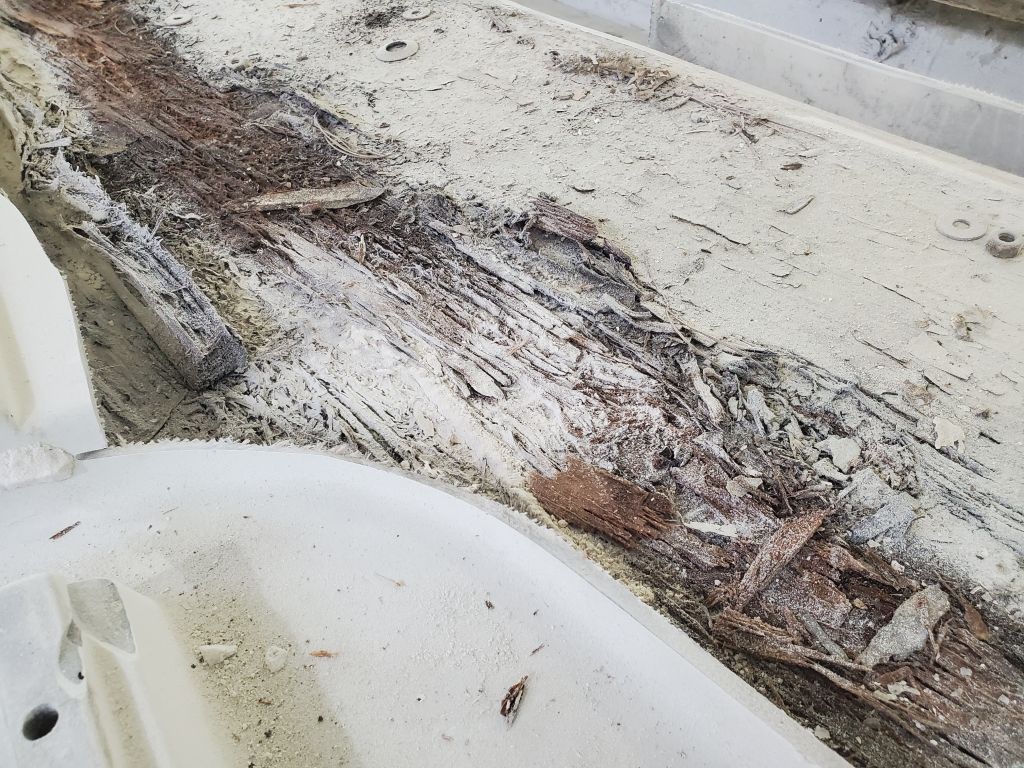
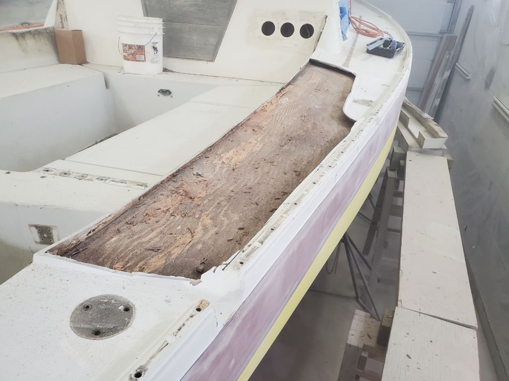
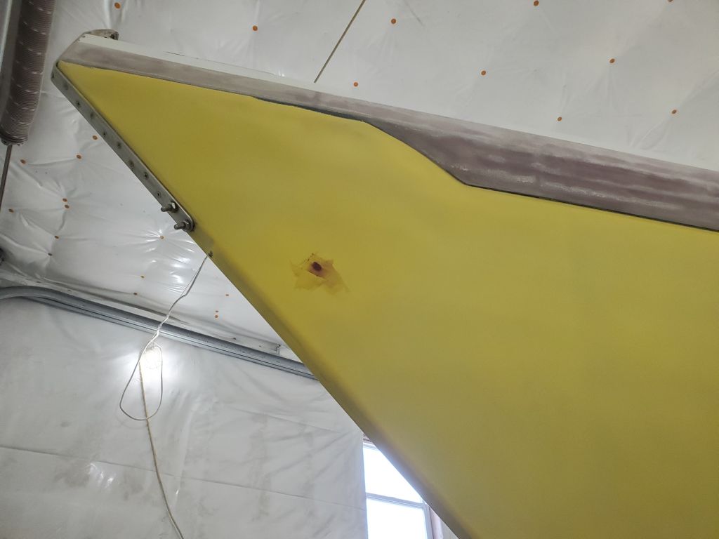
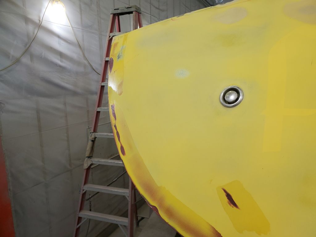
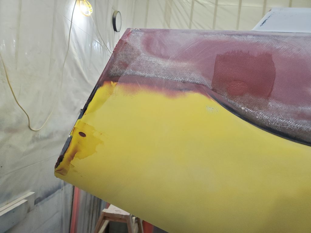
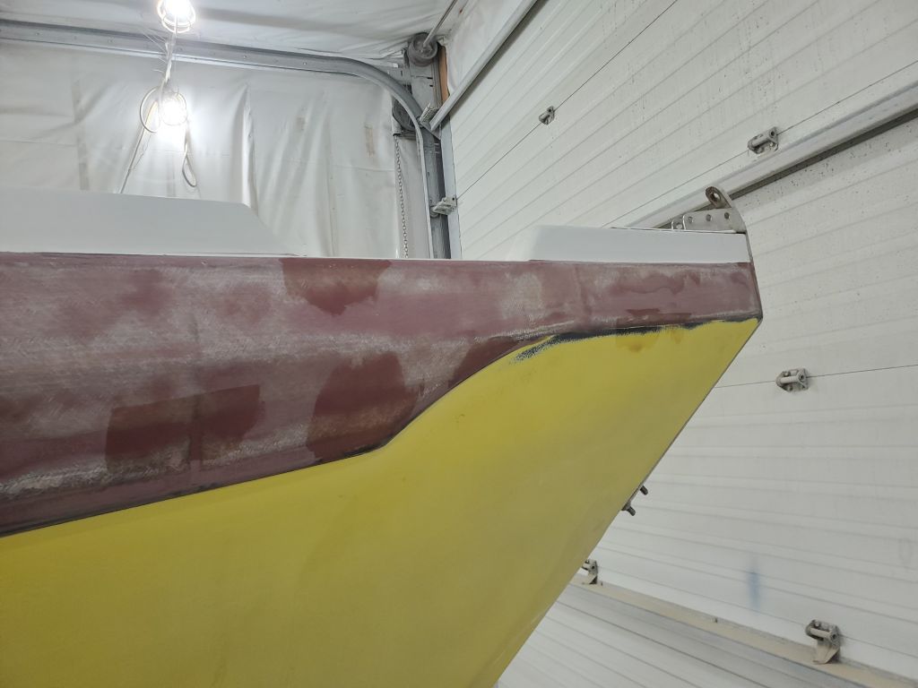
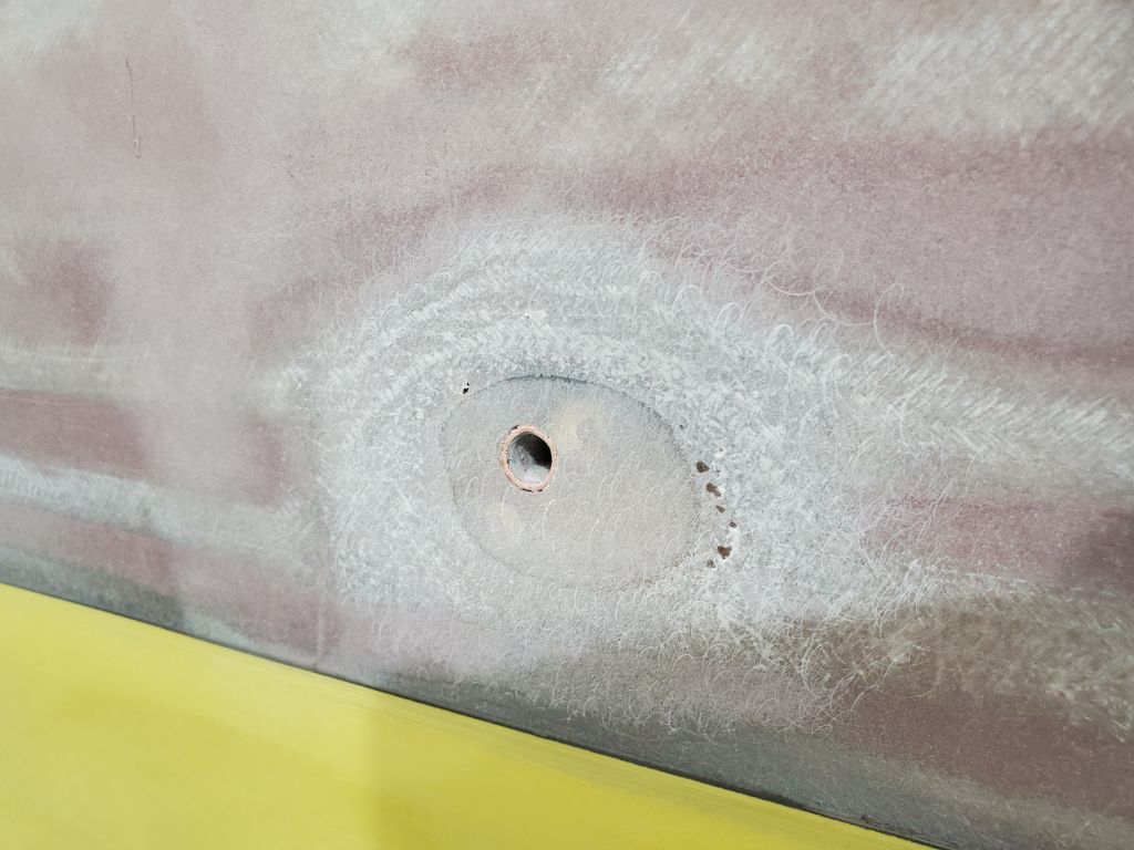
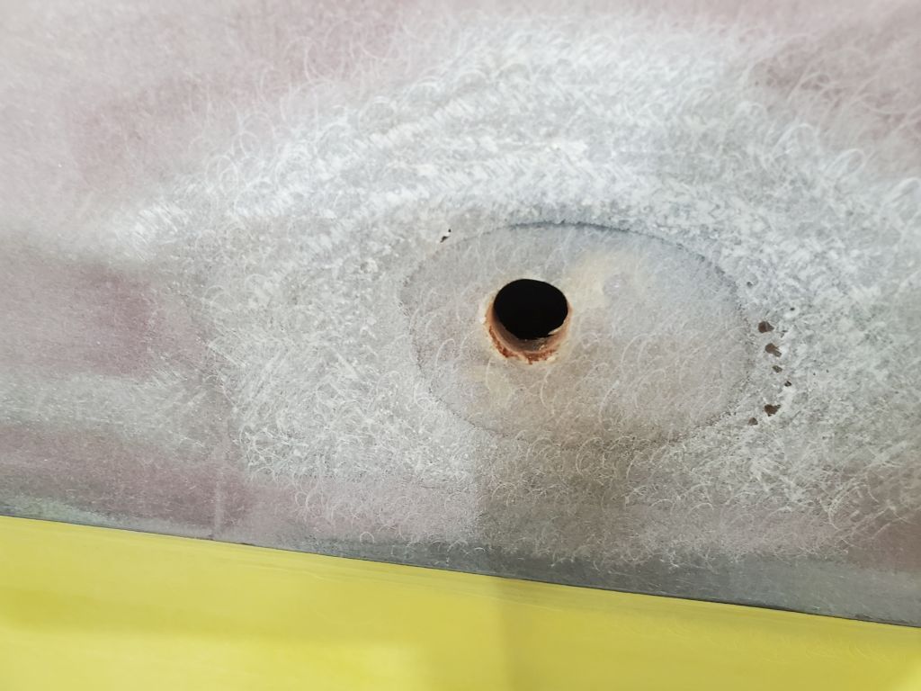
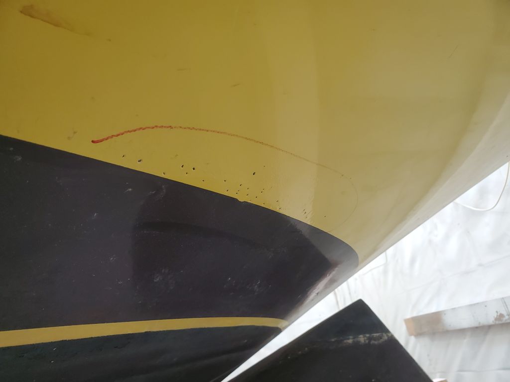
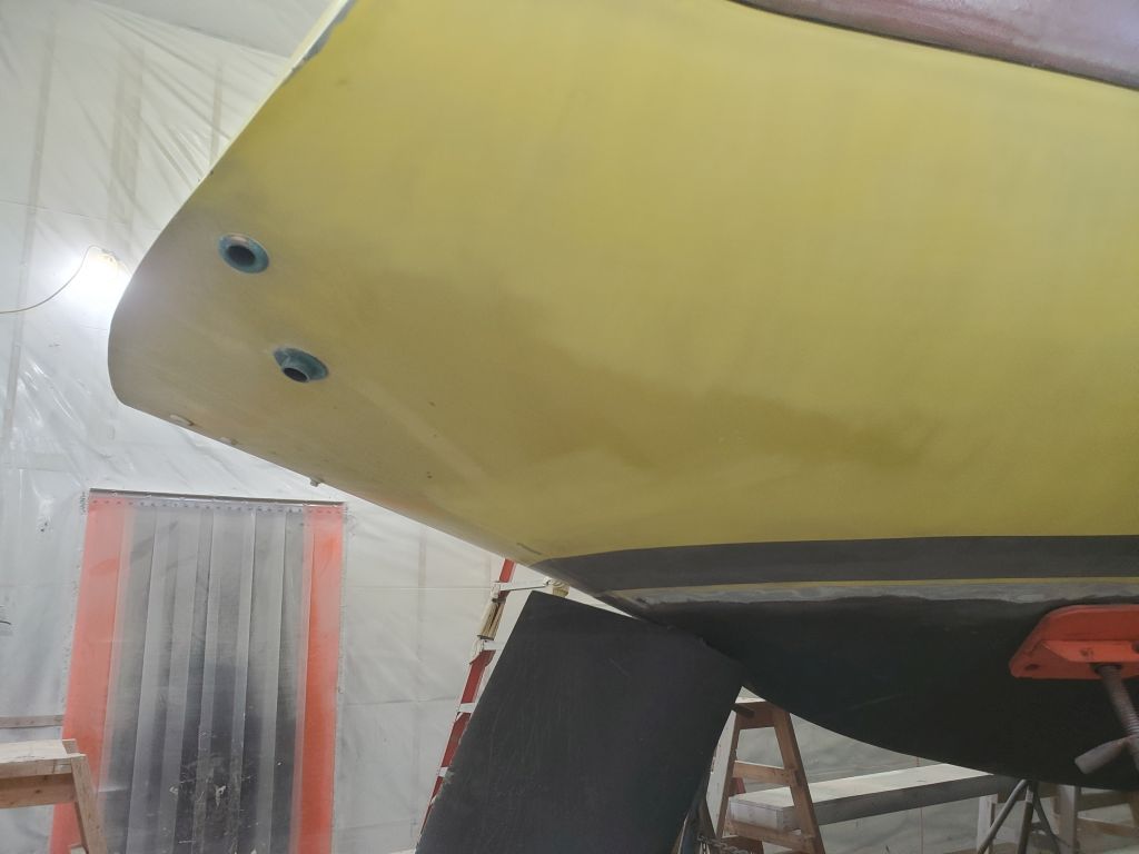
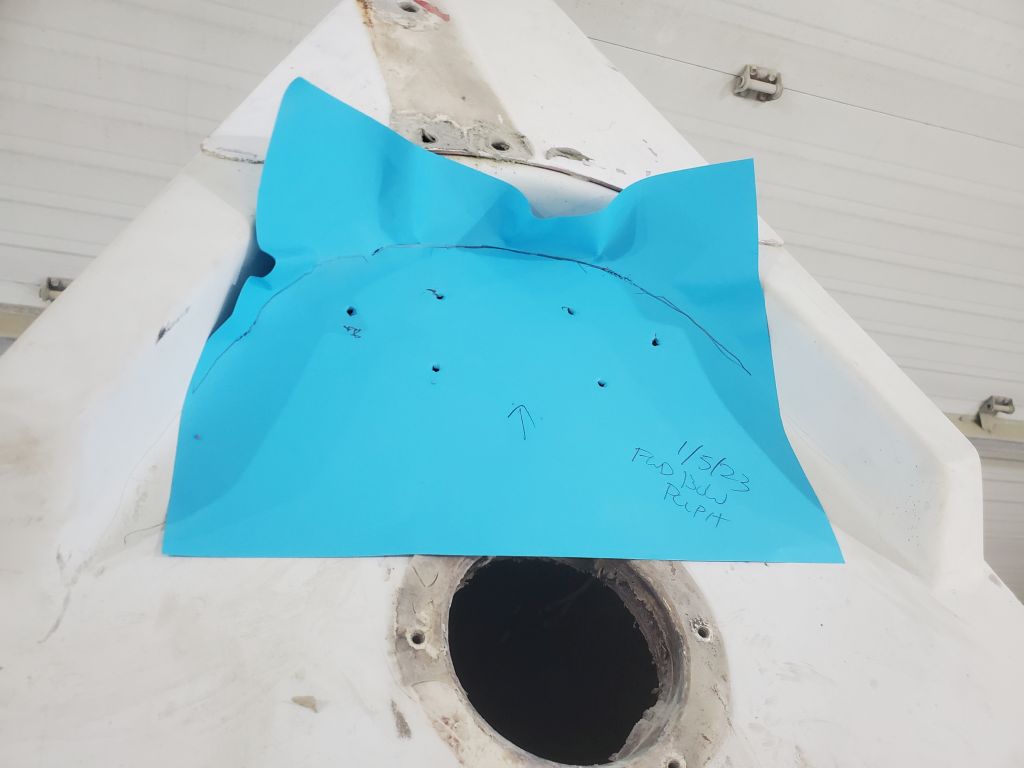
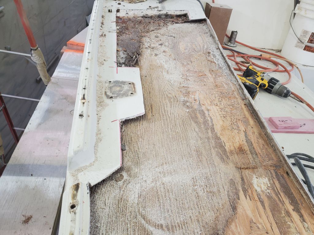
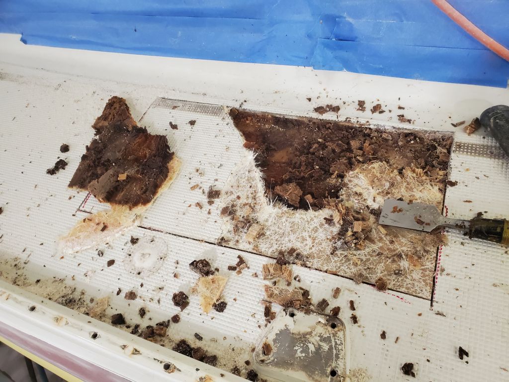
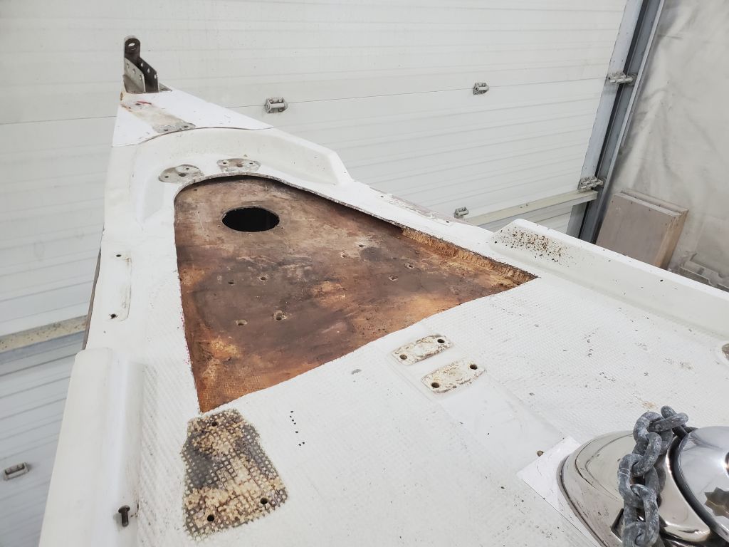
Just aft of the stem, the pulpit, large round opening from a deck plate, and forward cleats had turned the core to mush from extended leaking. I cut out a couple square feet of the top skin, then found I had to extend aft another few inches to capture all the damaged core.

For now, this completed the major demolition work on the port side, though there was more work ahead to complete the preparations in each of these areas, and a few smaller question marks to investigate.

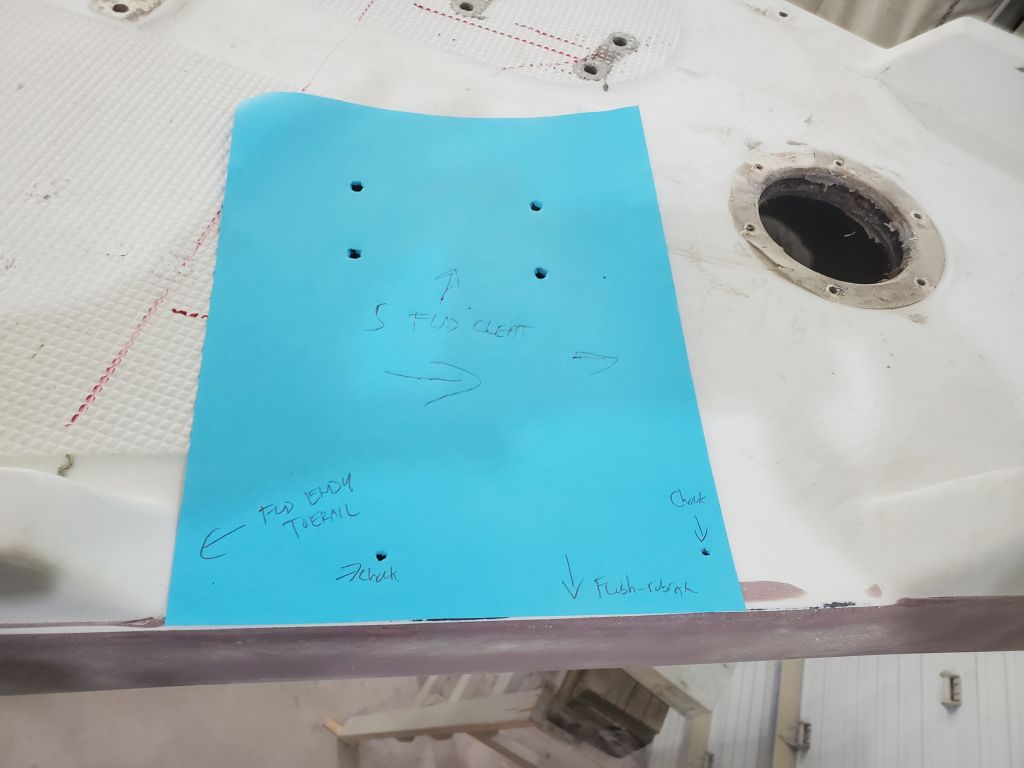
I moved my operation to the starboard side, and began work around the starboard winch island, both forward and aft much the same as on the port side. I had enough time before the end of the day to make the necessary cuts, remove the old core, and ream out the edges as needed. I’d continue with the rest of the starboard side deck next time.