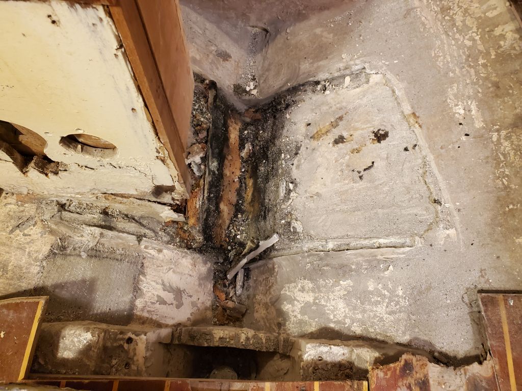
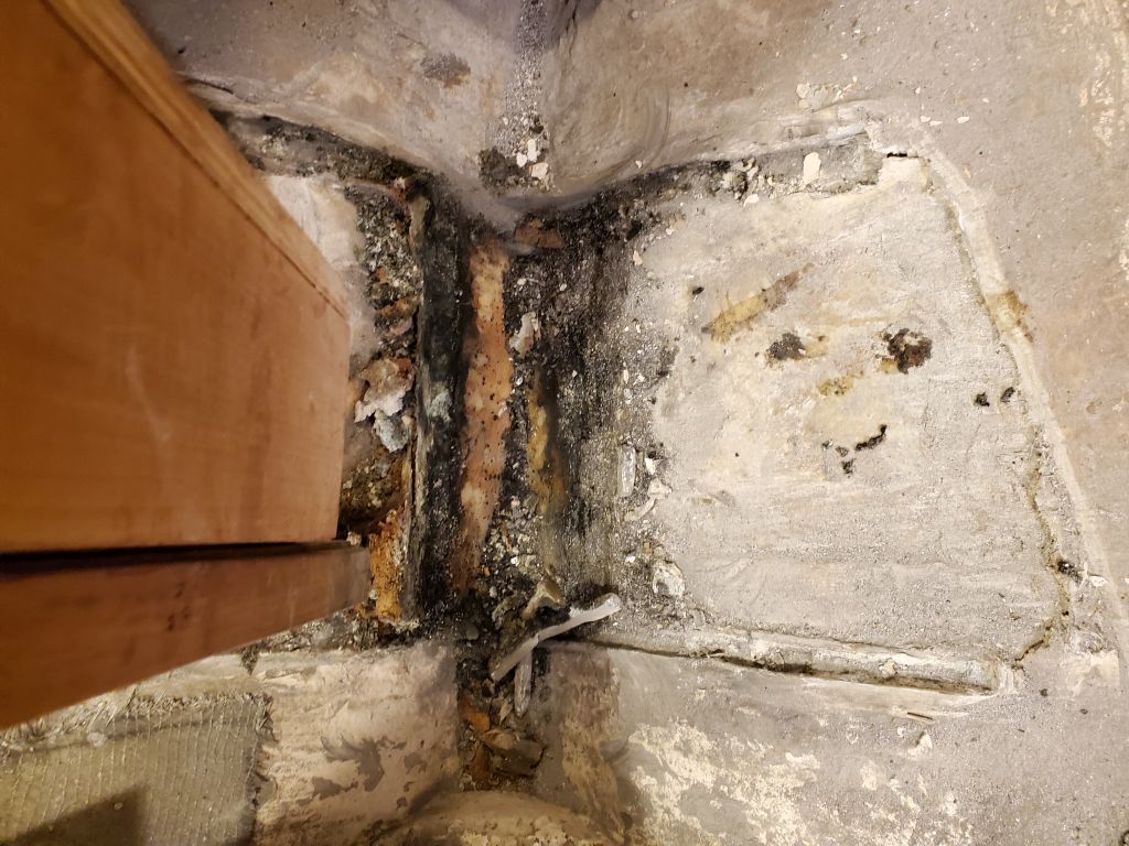
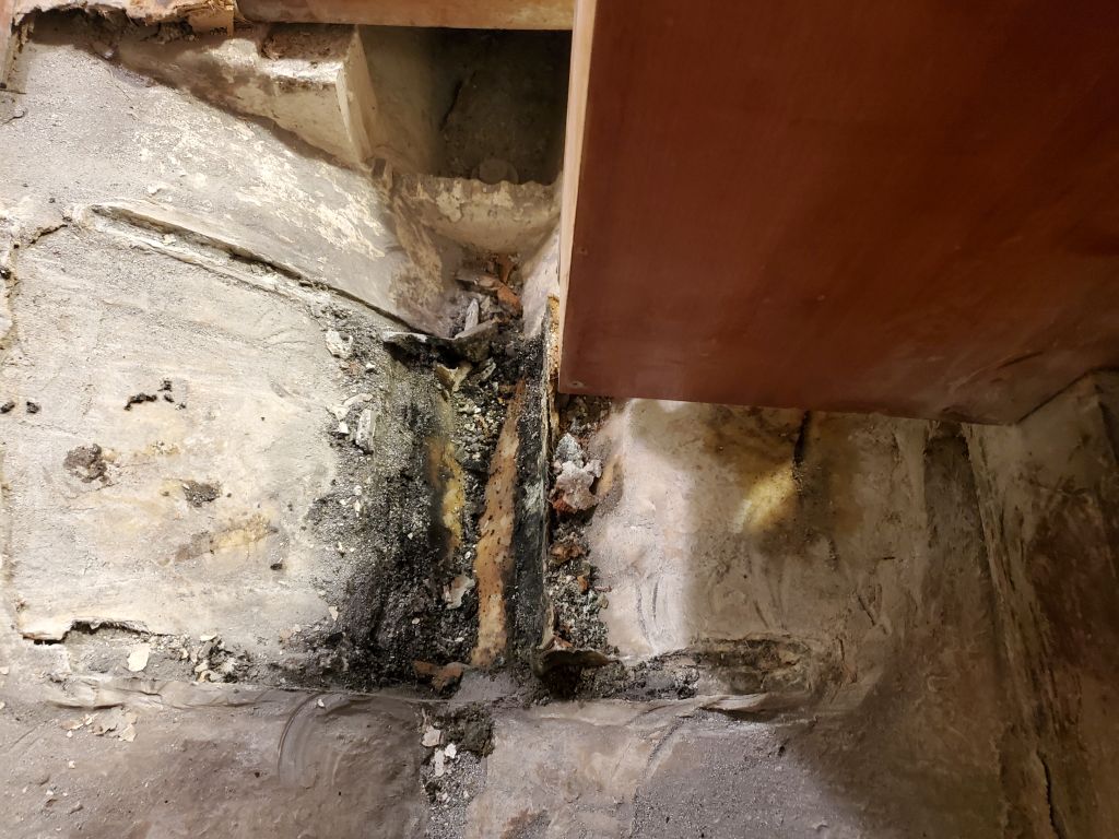
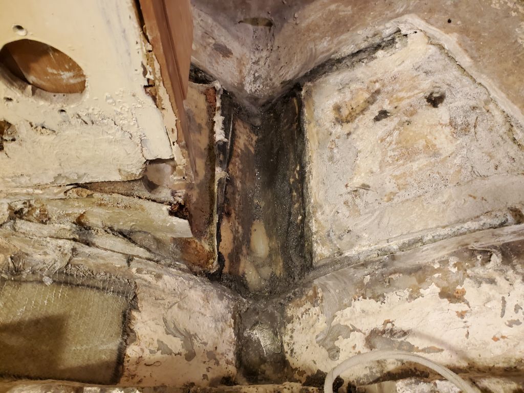
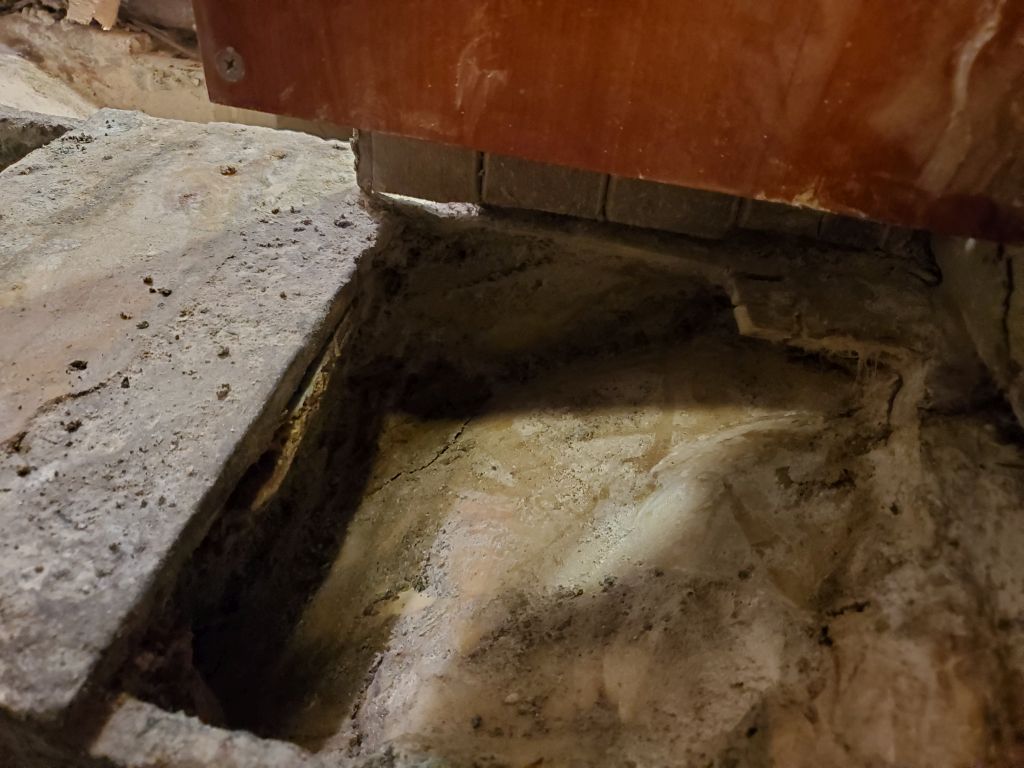
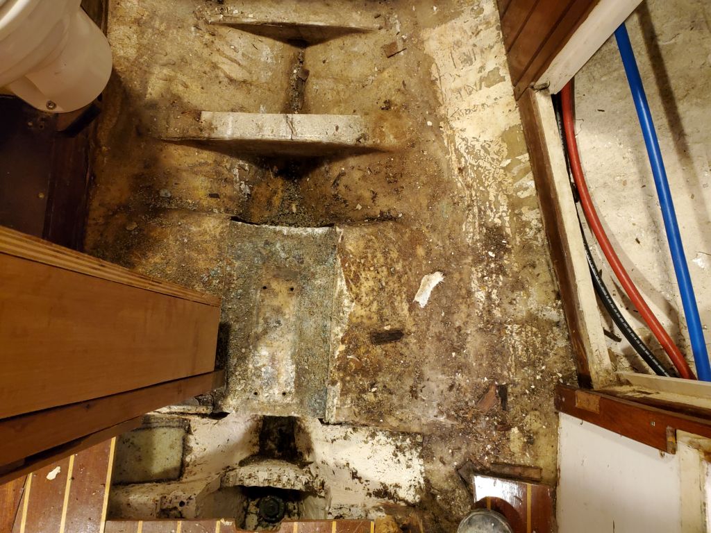
With a new arsenal of cutting wheels and blades on hand, it was do or die time for the mast step. I started with fresh cutoff wheels and cutting through the aluminum at the forward and after ends of the step, where it curved down into the bilge. Cutting the old aluminum was much more difficult than one would expect (never mind the access), and ate through the discs quickly.
The longitudinal portion of the step that I could access from the relatively open starboard side was too deeply inset in the V between the top plate of the step and the hull for my grinder wheel to fit, so with a tough demolition blade in a reciprocating saw I made a cut here from forward to aft. The step had seemed to well-adhered that there seemed no option but to do this cut at a minimum; on the port side, there wasn’t really any usable access for tools so after making the starboard cut I decided to see if I could get at least part of the assembly to move or break out before continuing.
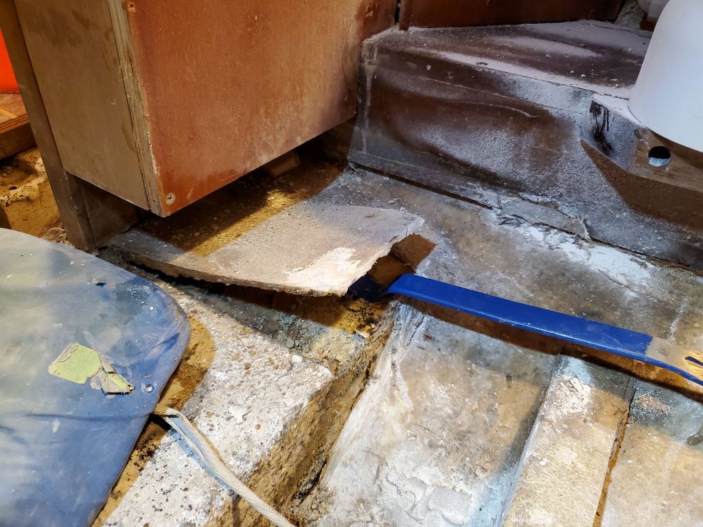
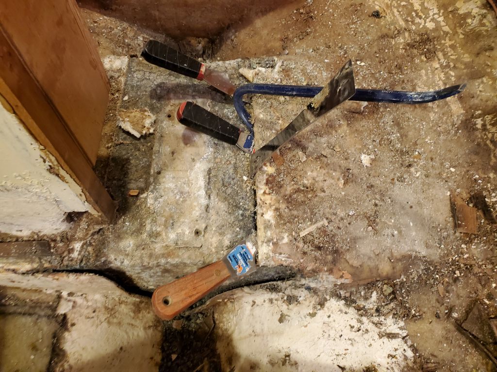
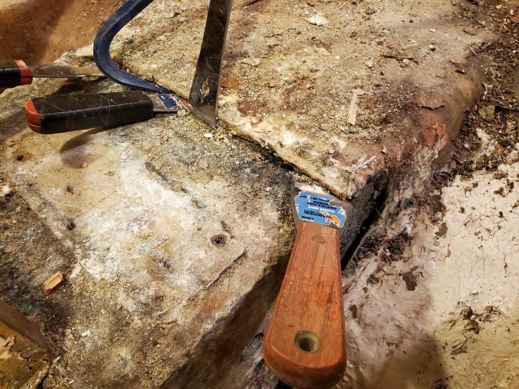
I tried a big pry bar in the slotted cuts I’d made, first at the “easy” aft end, then at the forward end. Of course there was no perfect angle or access available for the bar, but with some fiddling I got it to work. At first, it seemed like I’d made no progress despite these fatal cuts. This was discouraging.
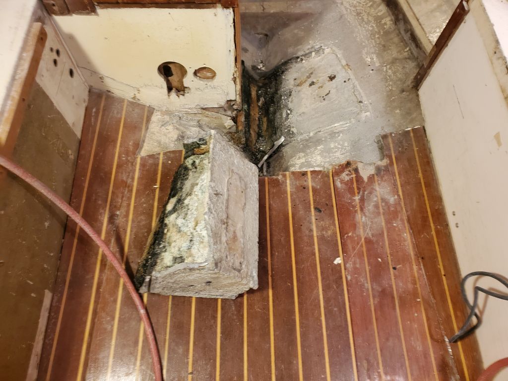
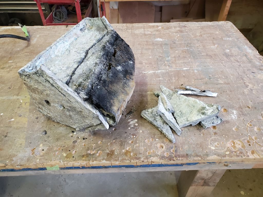
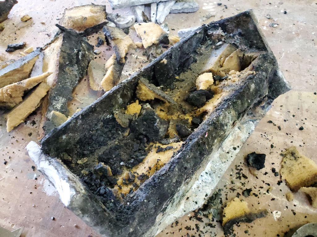
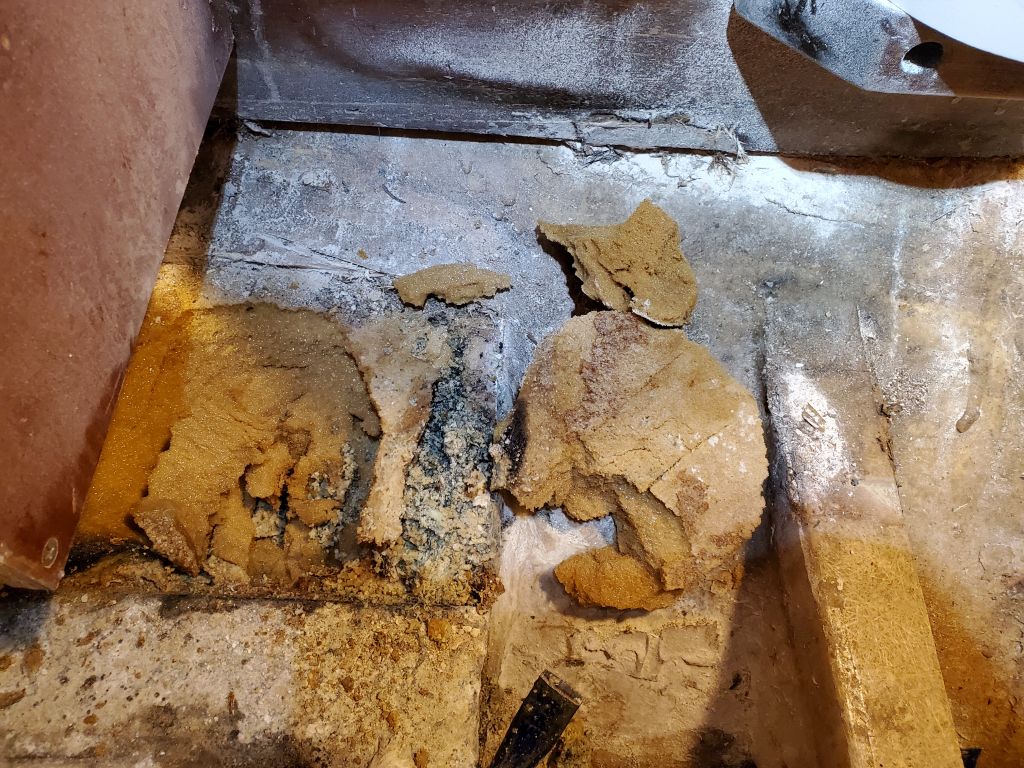
But then, suddenly, the step was loose at the forward end, and after some minor jostling to clear the bulkhead and cabinetry partially overhanging it to port, it was out and clear. Interestingly, despite the cuts I’d made in the aluminum, the entire remains of the step came out in one piece. The only thing that had actually been holding it in place before I began the day’s efforts had been a mass of pour foam that filled the hollow center of the step and the entire area to the bilge; this foam came out in a more or less solid mass along with the step.
I didn’t care so much about the mechanics of it: I was just happy to have it out, having far passed the point of no return with the structure and, given the challenges in removal, I’d been growing increasingly worried about what I’d have to actually do to get it out, as I was nearing the limits of what I could do with the tools and access available.
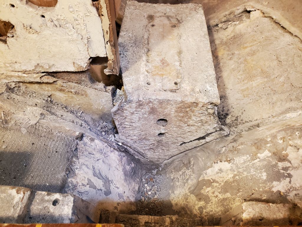
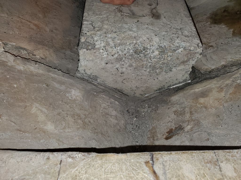
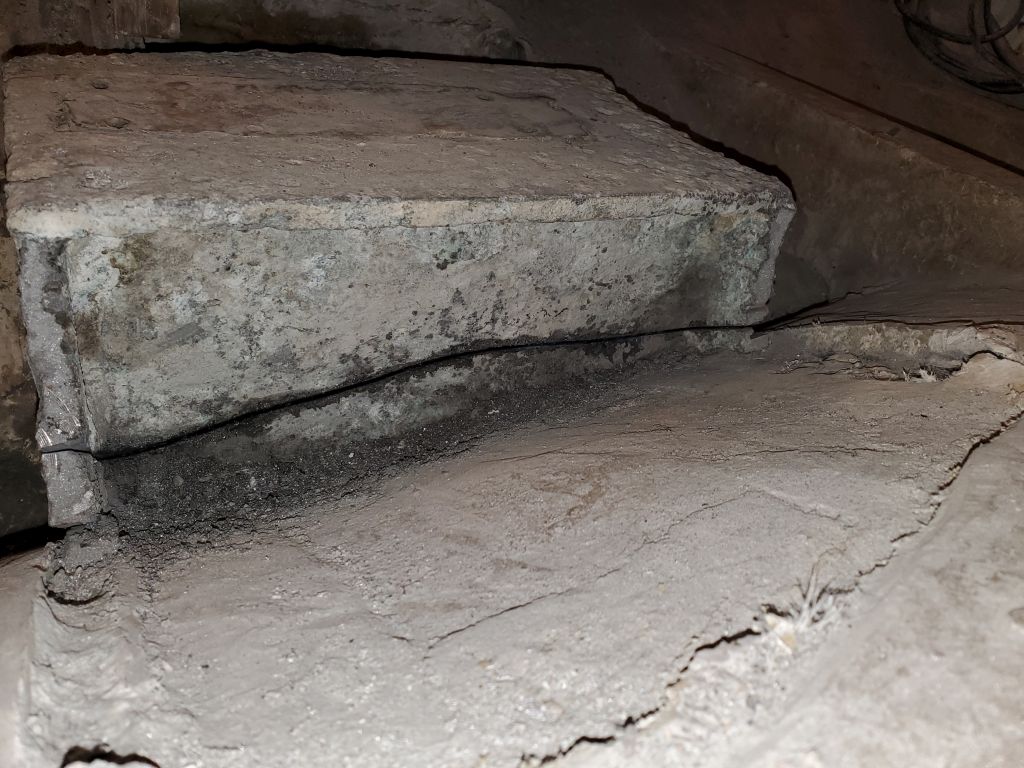
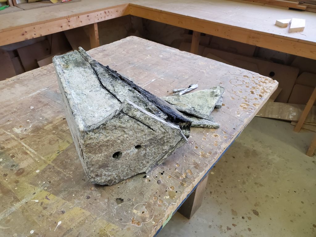
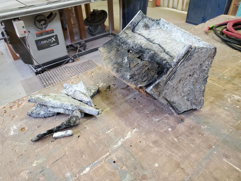
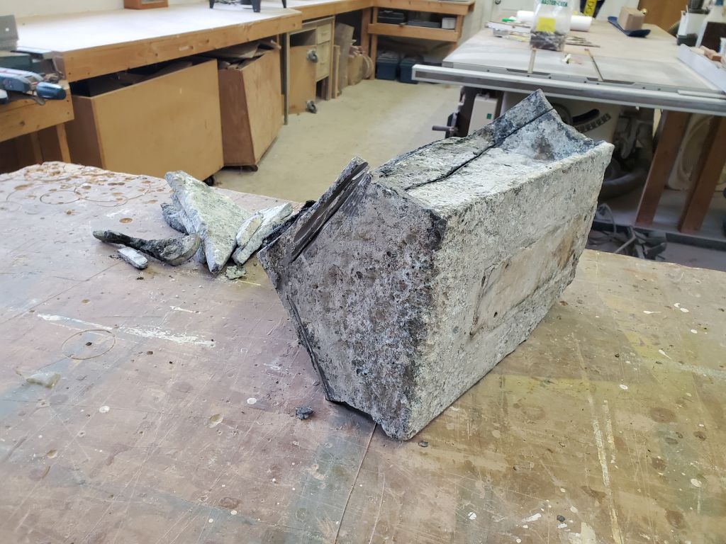
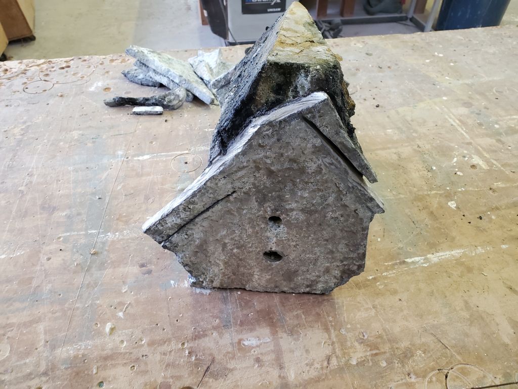
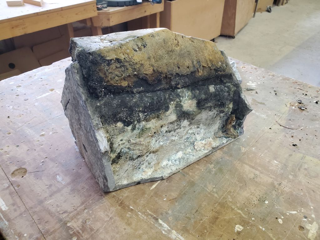
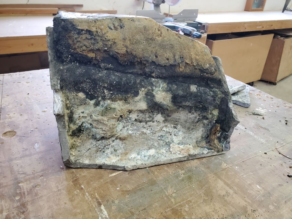
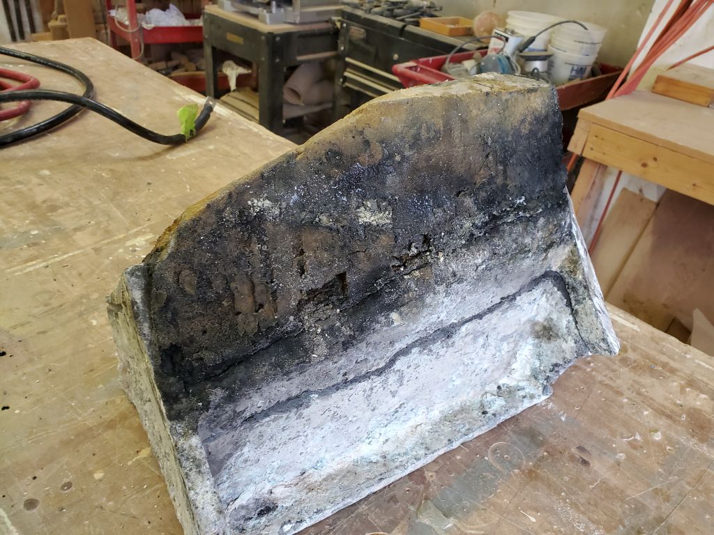
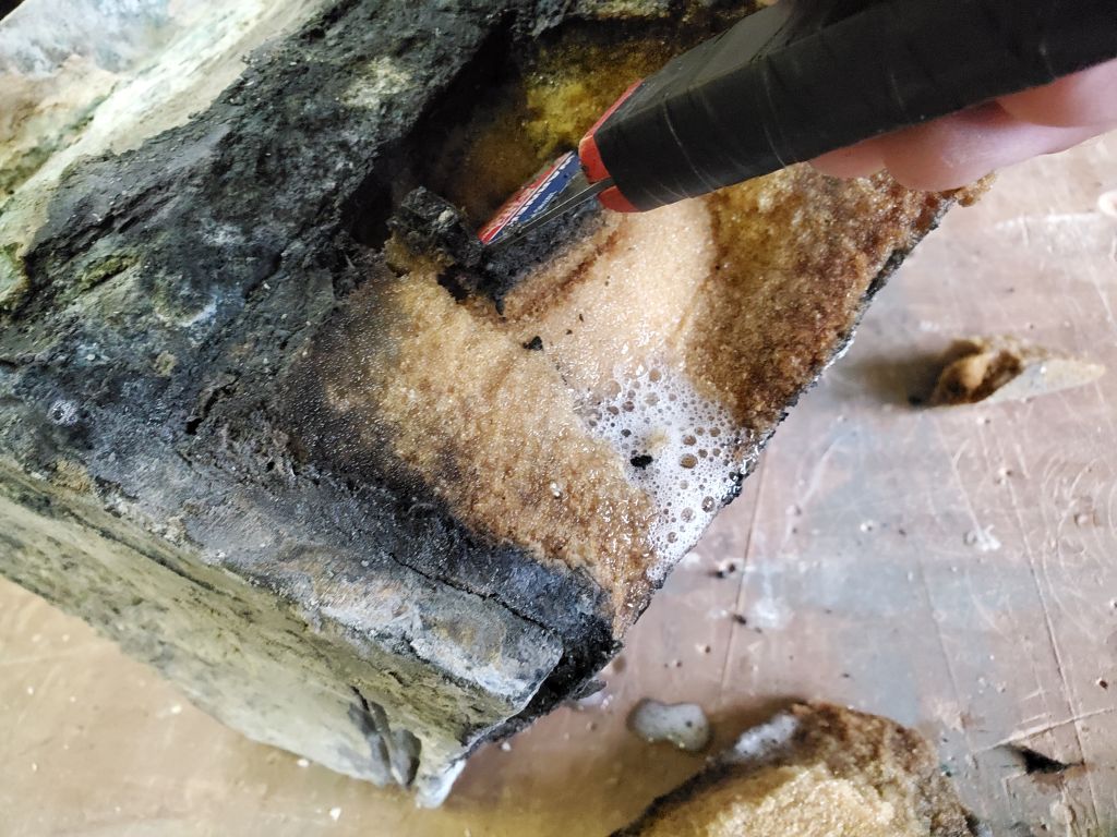
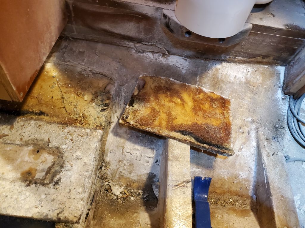
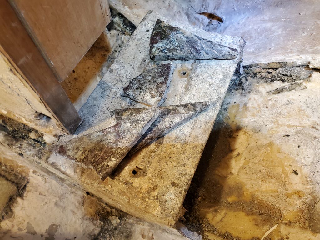
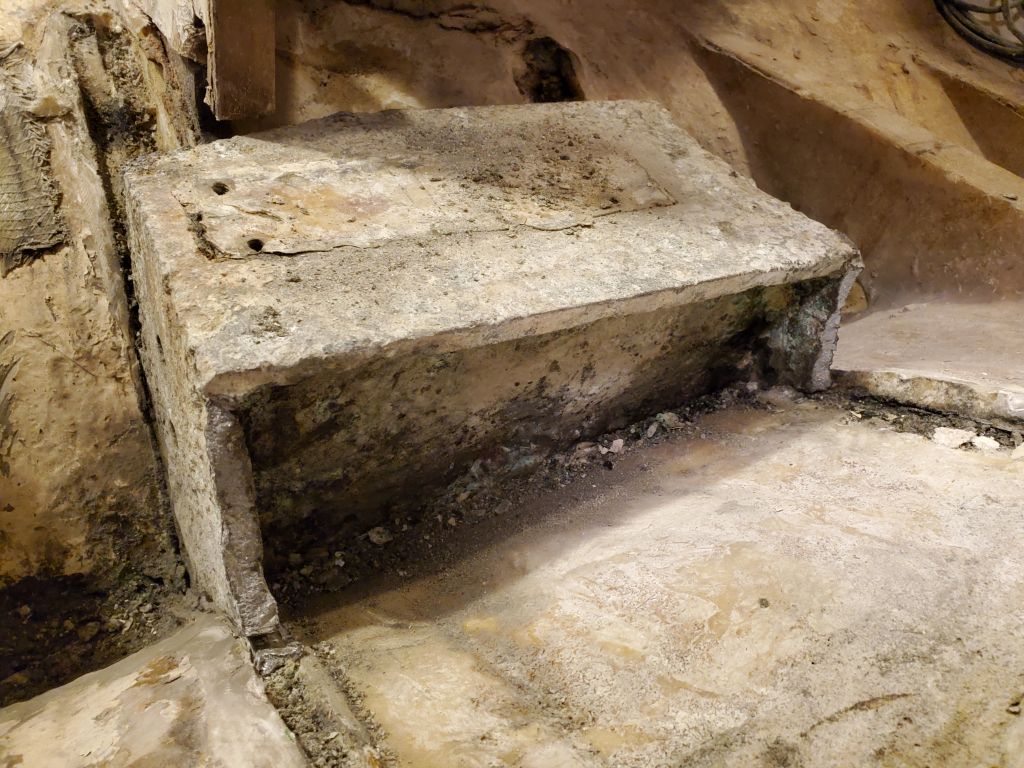
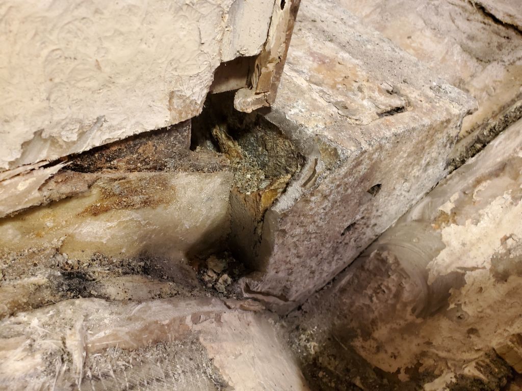
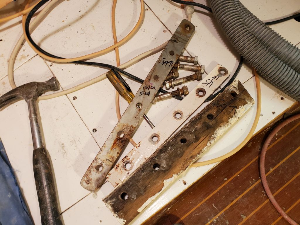
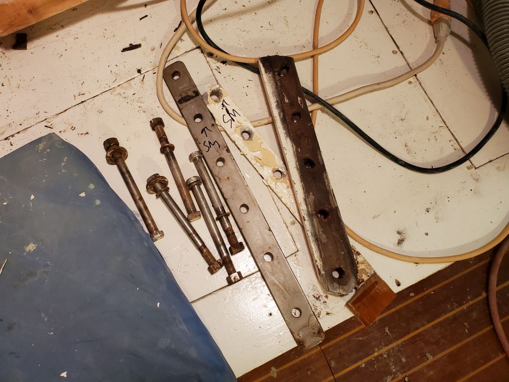
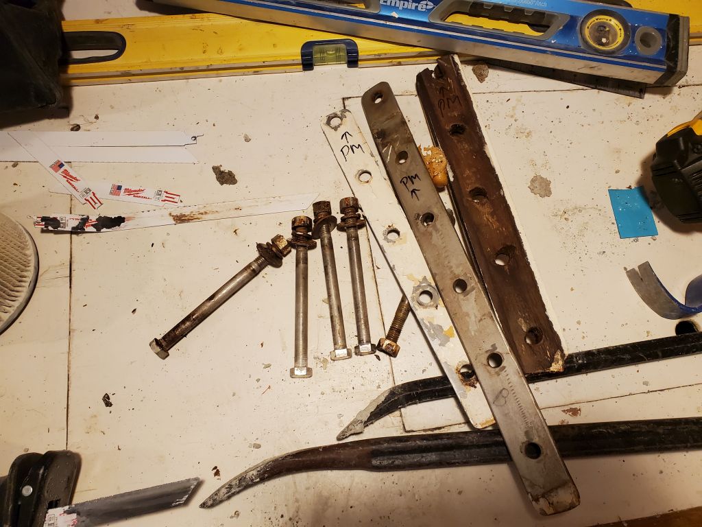
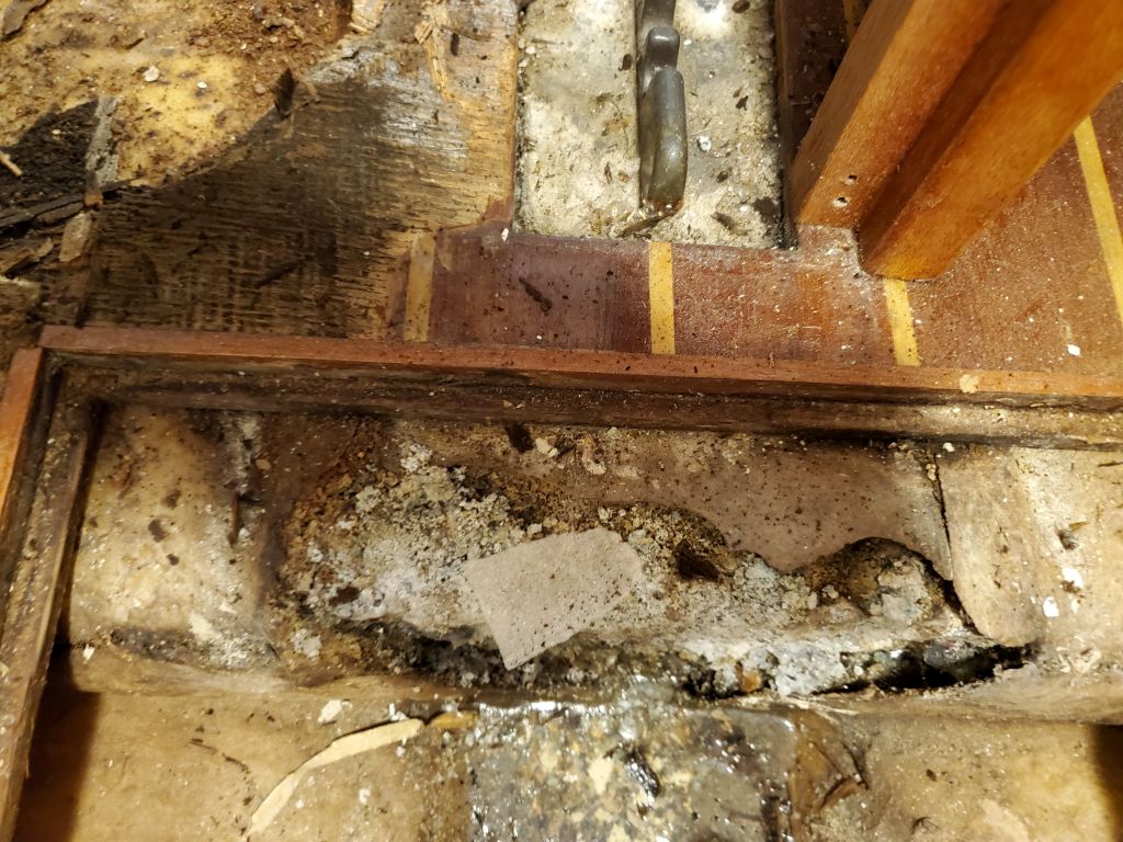
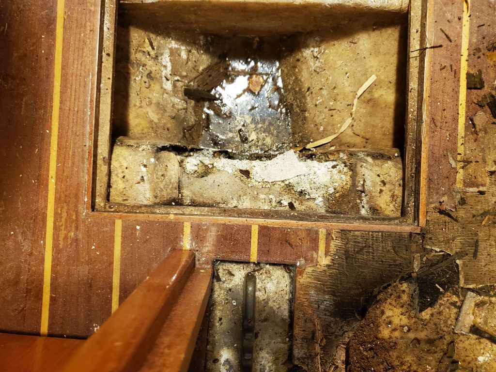
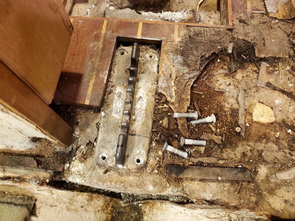
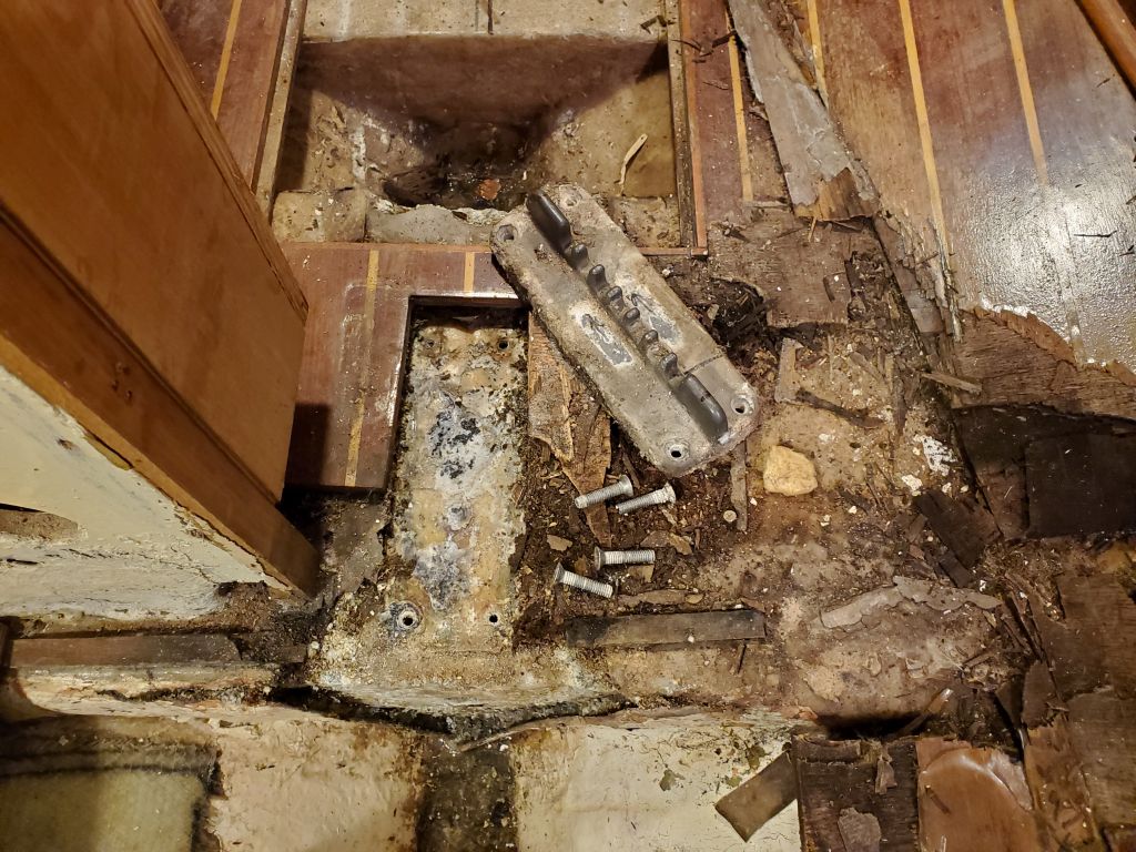
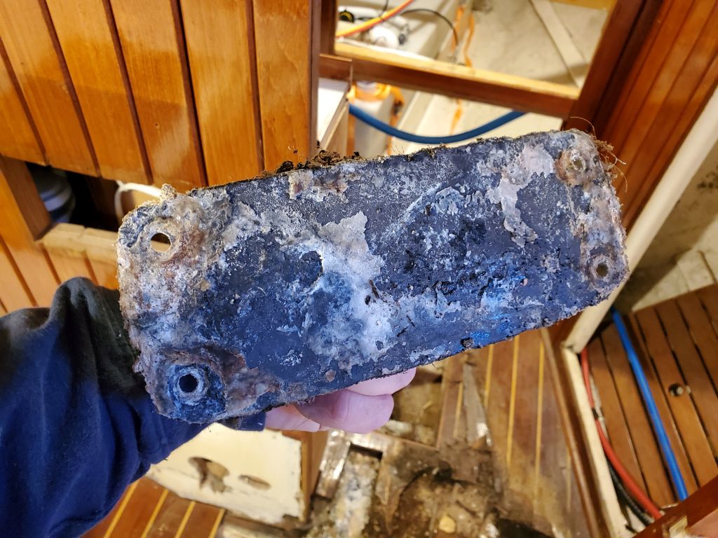
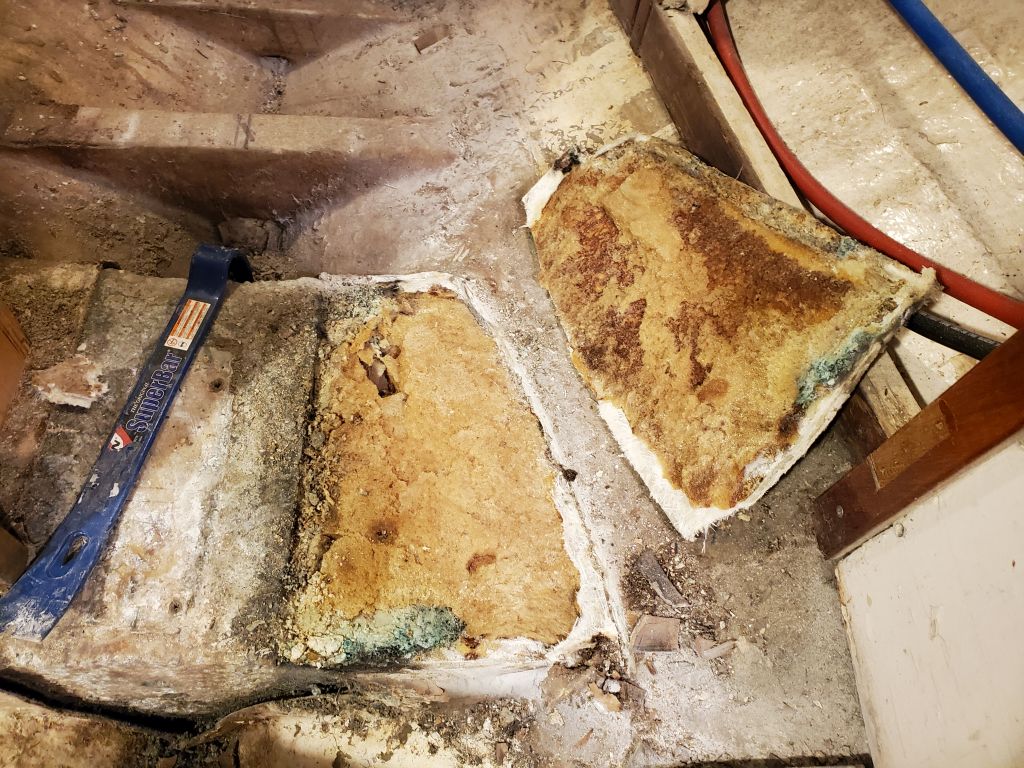
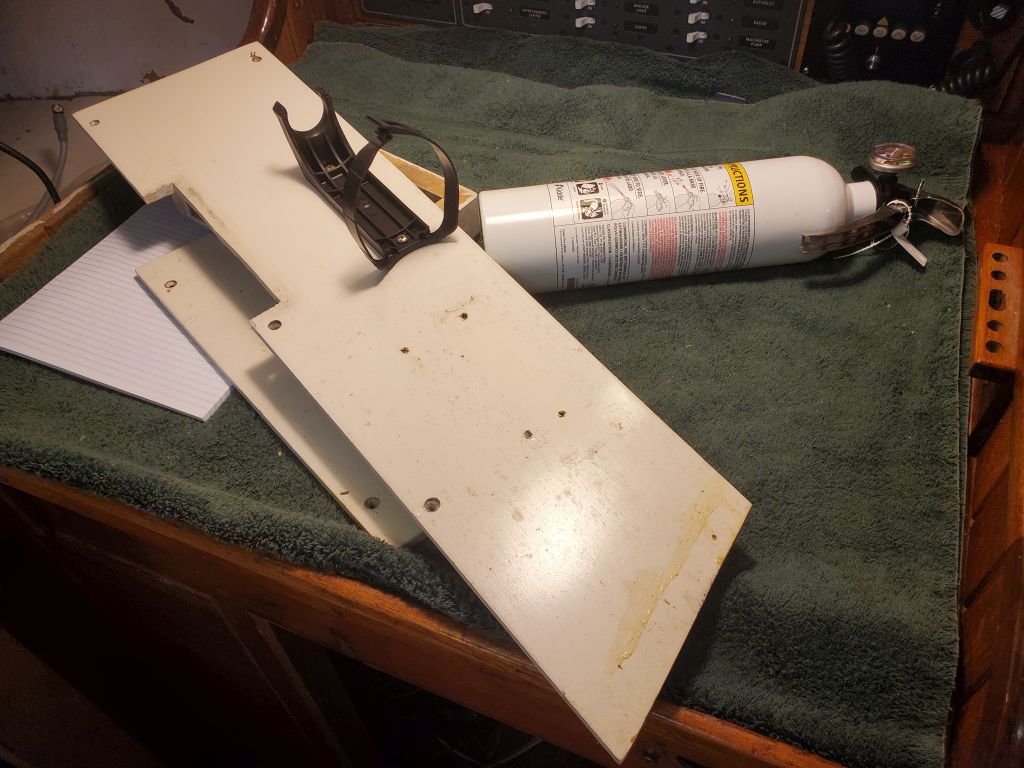
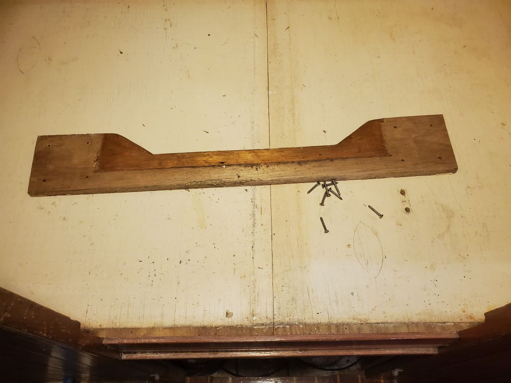
But the worry was moot now, and I cleaned up the worst of the debris from the boat and inspected the step assembly down on the bench just as a point of interest. Of course the foam was saturated, but it appeared that my starboard saw cut had actually been the key to removal, as this fresh cut through the foam was clearly visible and must have released whatever adhesion the foam had with the hull just enough for me to start to pry the assembly out. There seemed to be no other sort of adhesive involved in the initial installation of the step: It appeared to have been plunked down into the mass of pour foam, then tabbed fore and aft and over the additional foam poured into the side cavities.
The aluminum was heavily corroded all over, but still quite substantial. Without any intervention, this imperfect yet originally very strong structure probably would have continued its job for years to come, though clearly it was far from ideal. It was out of the boat now and that was all that mattered, and now it was time to move forward.
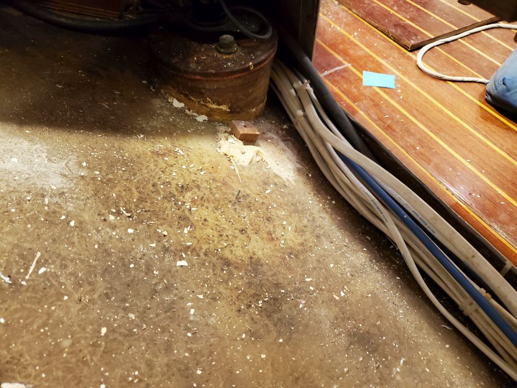
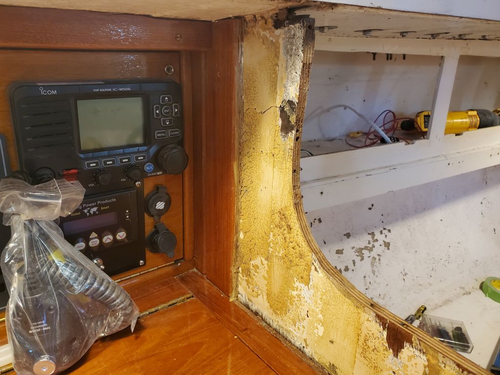
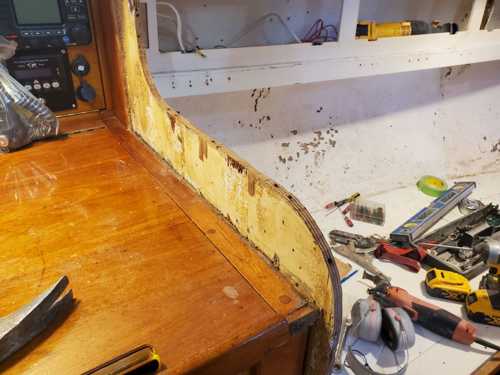
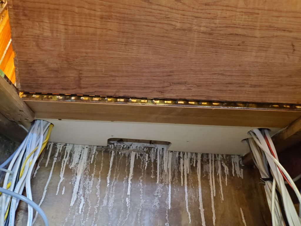
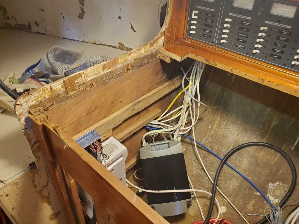
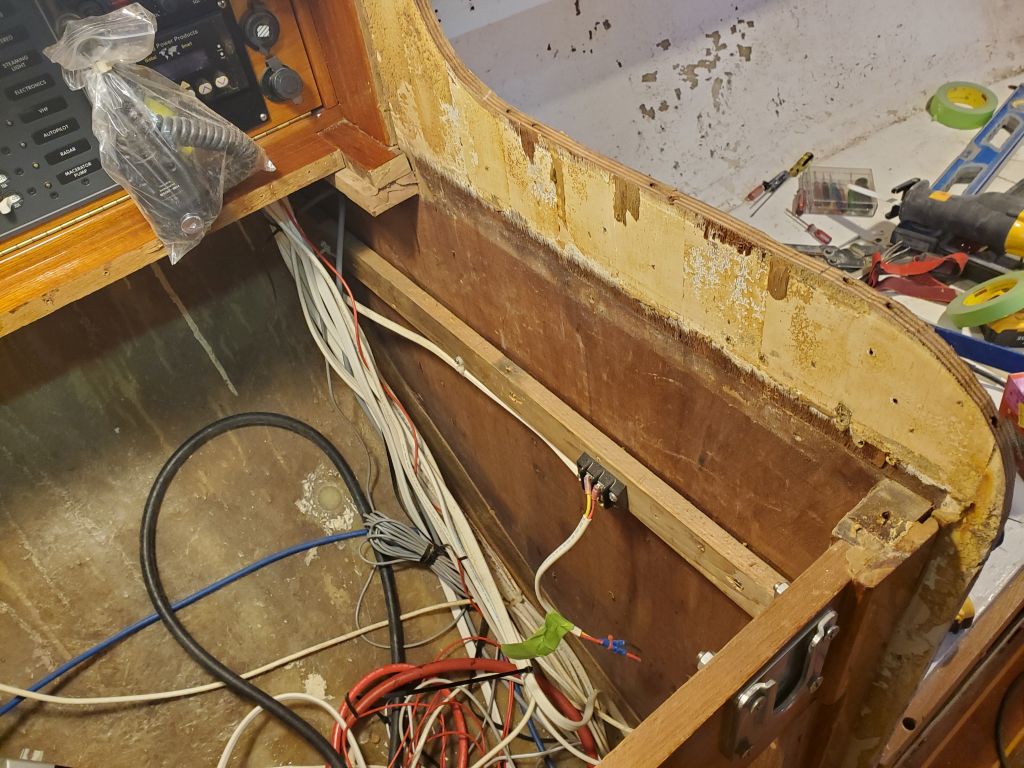
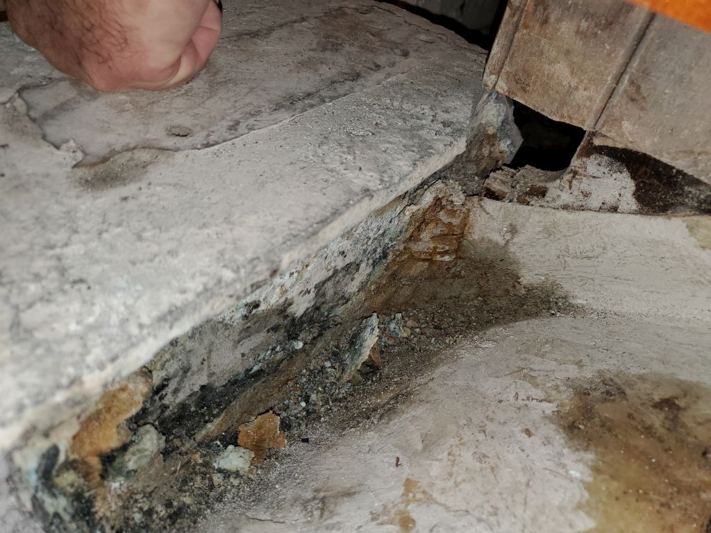
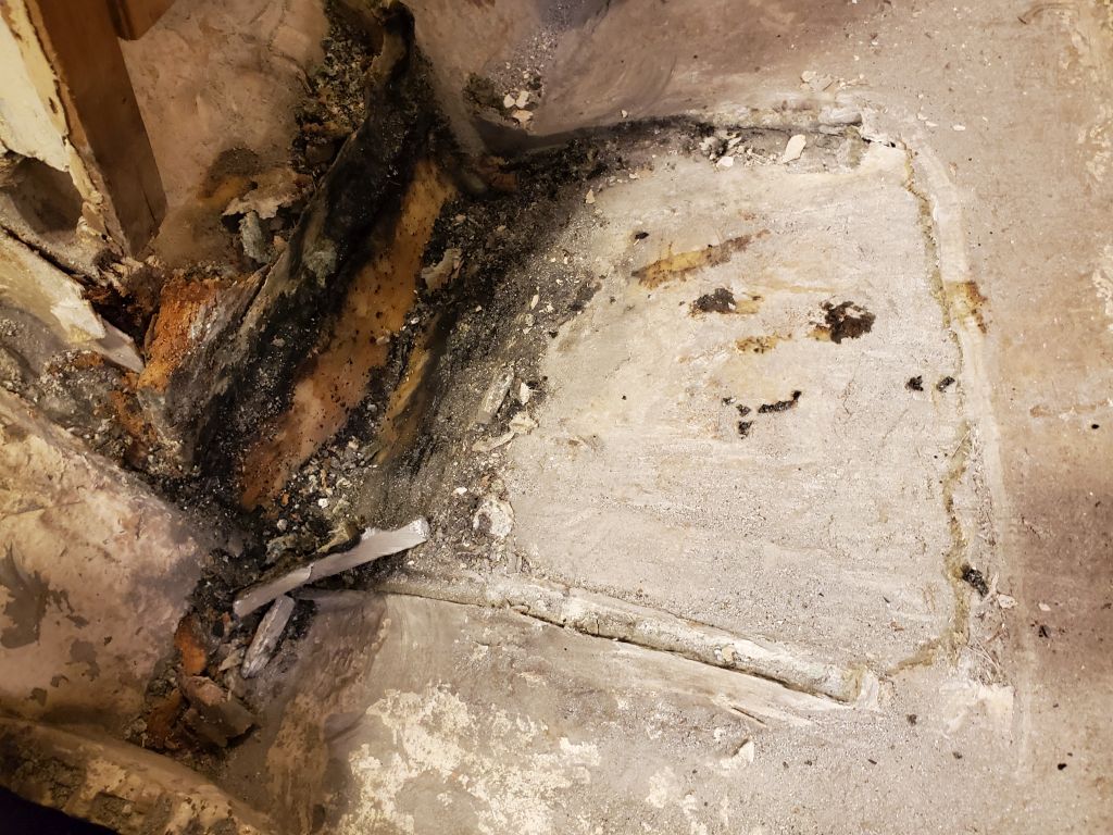
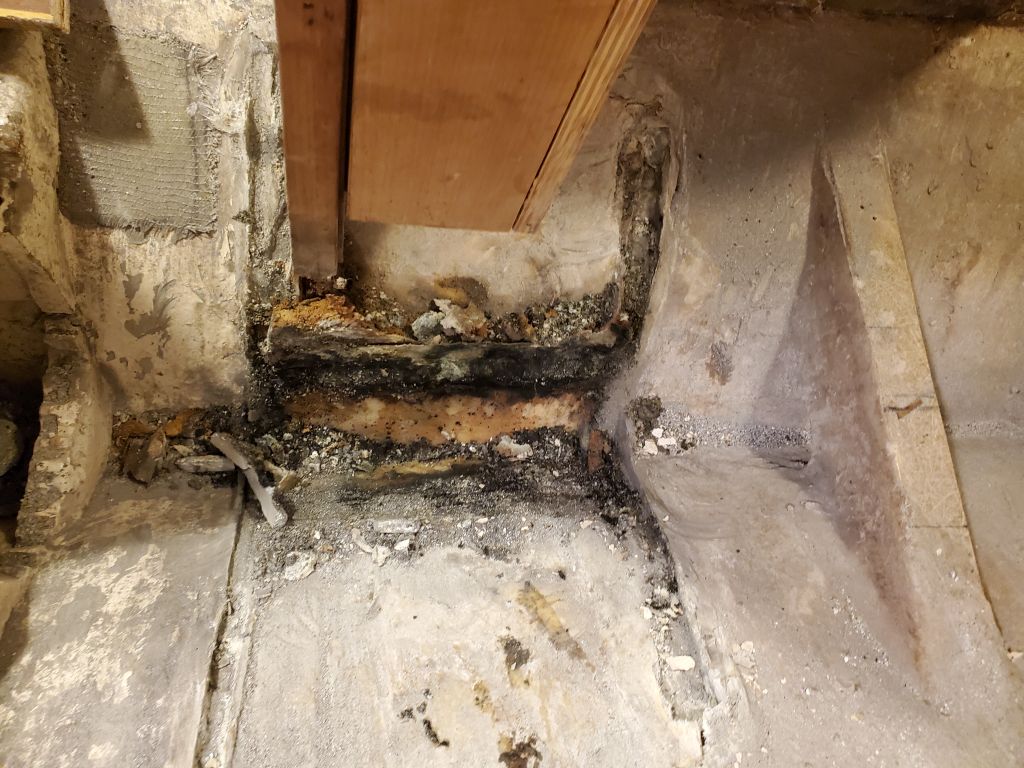
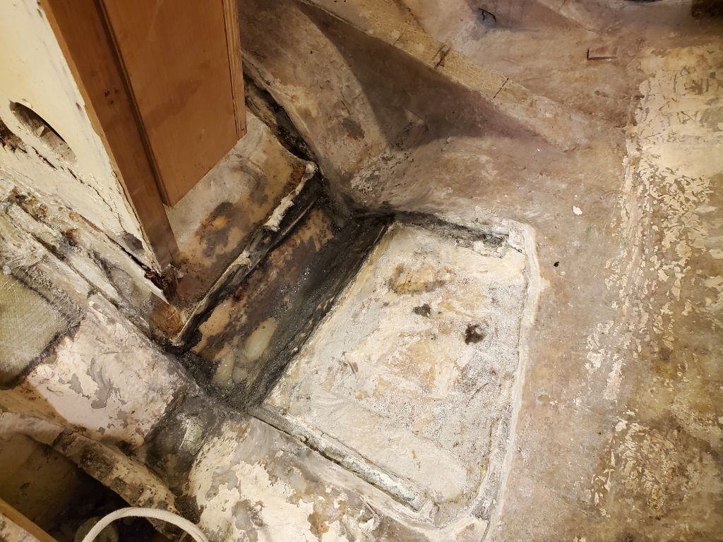
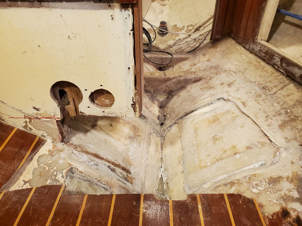
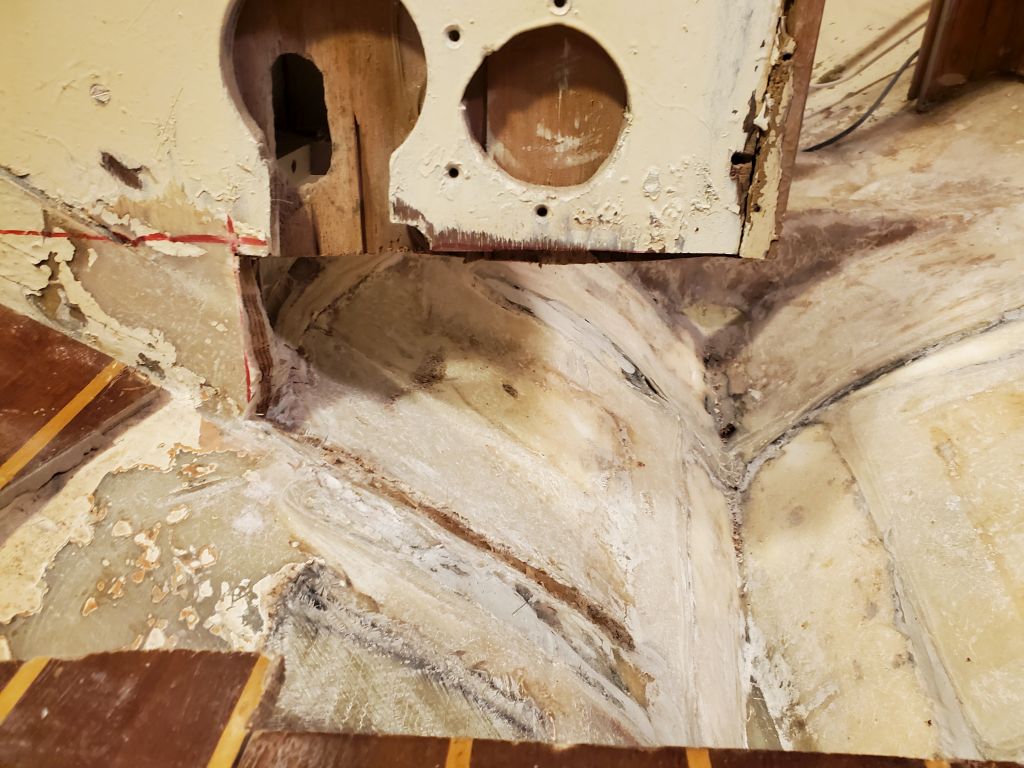
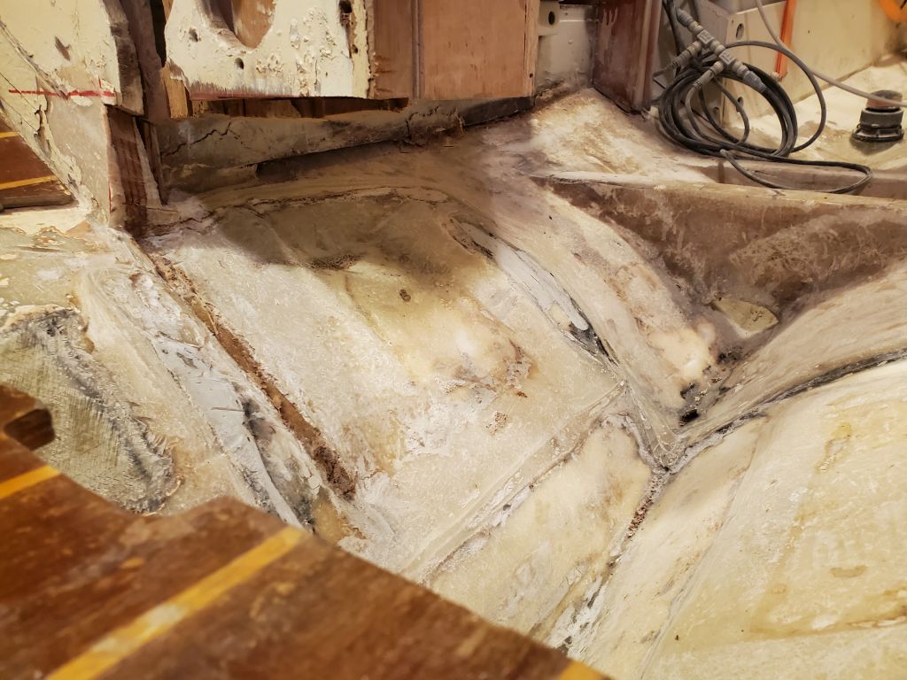
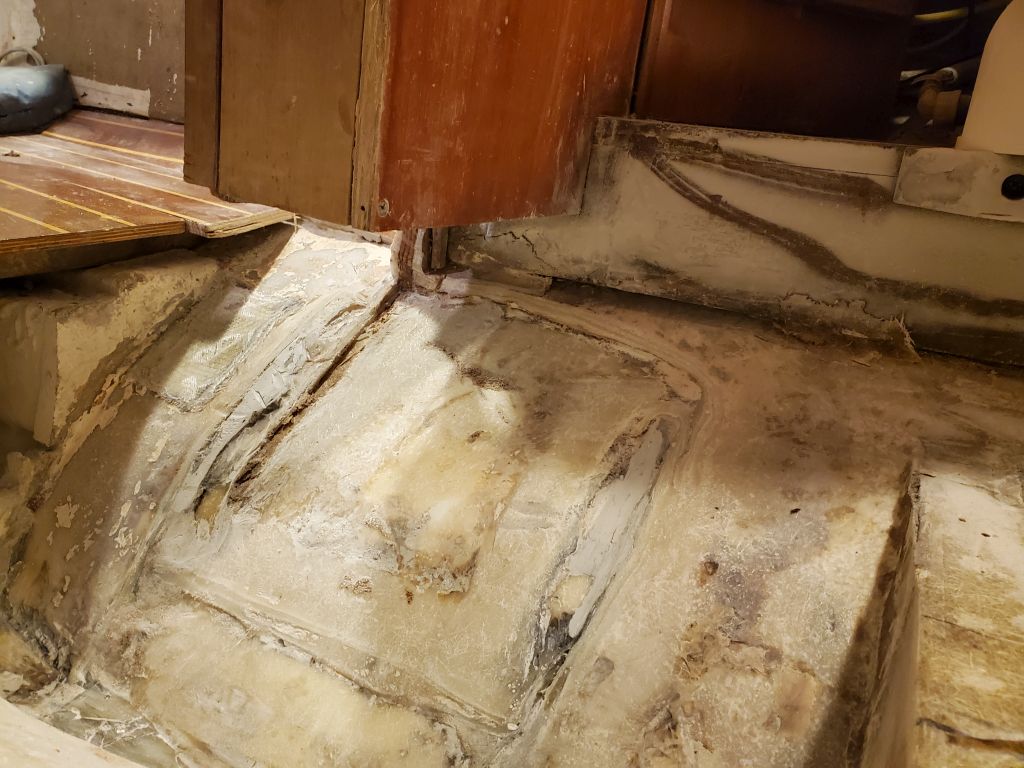
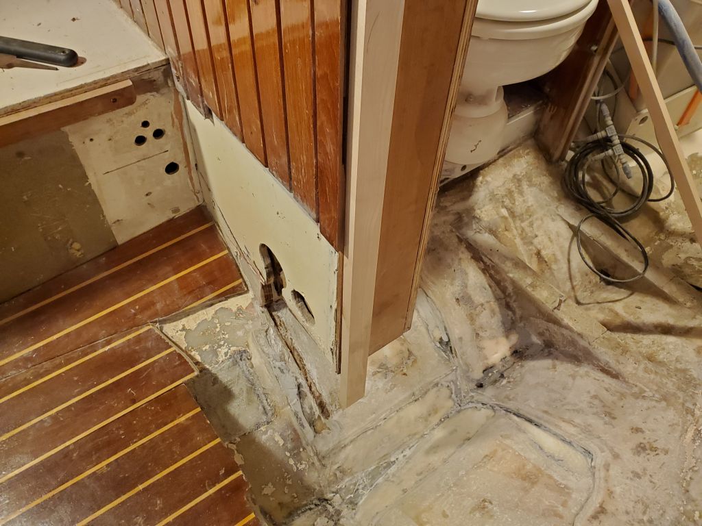
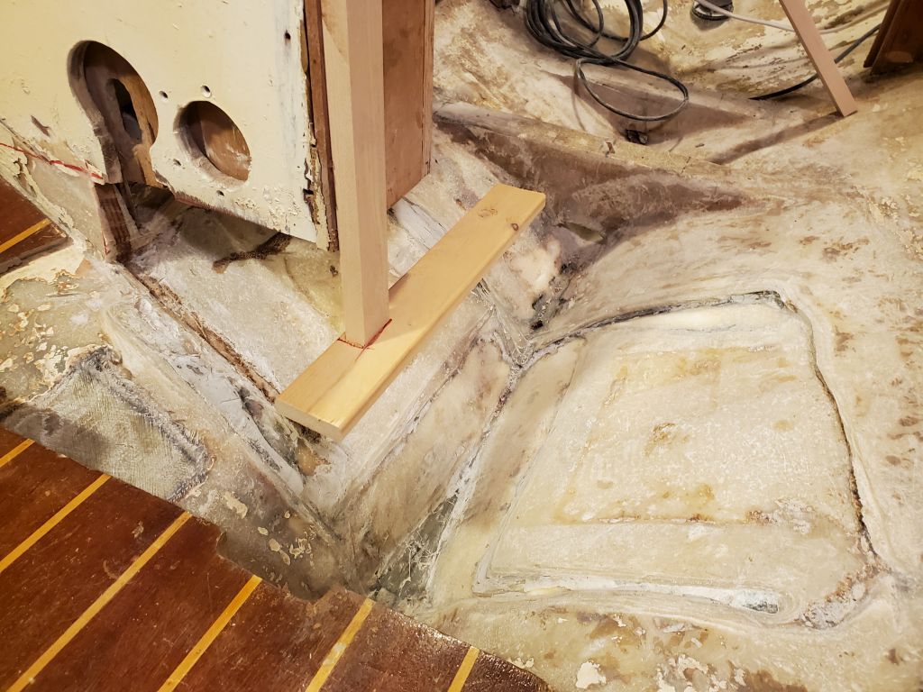
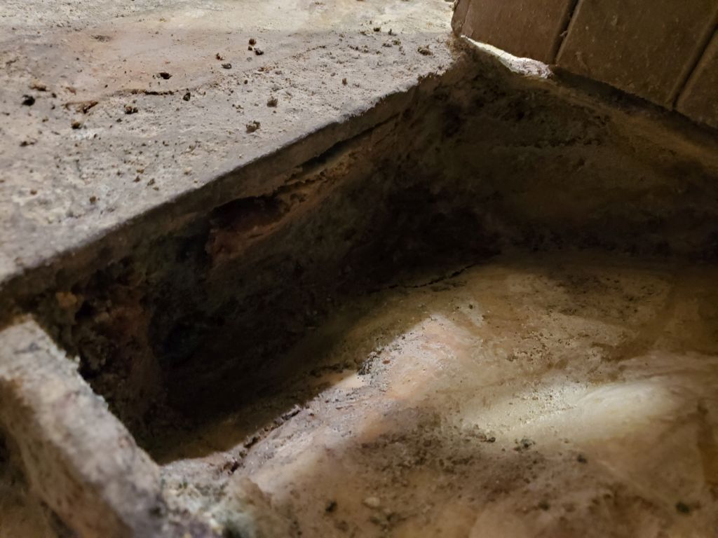
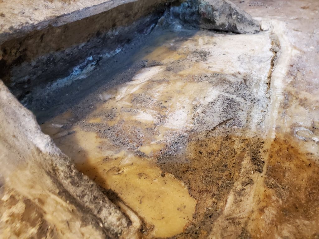
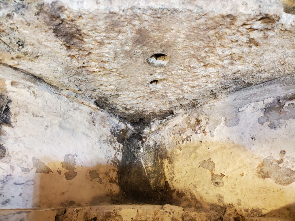
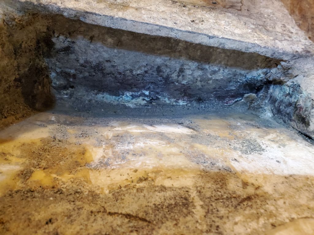
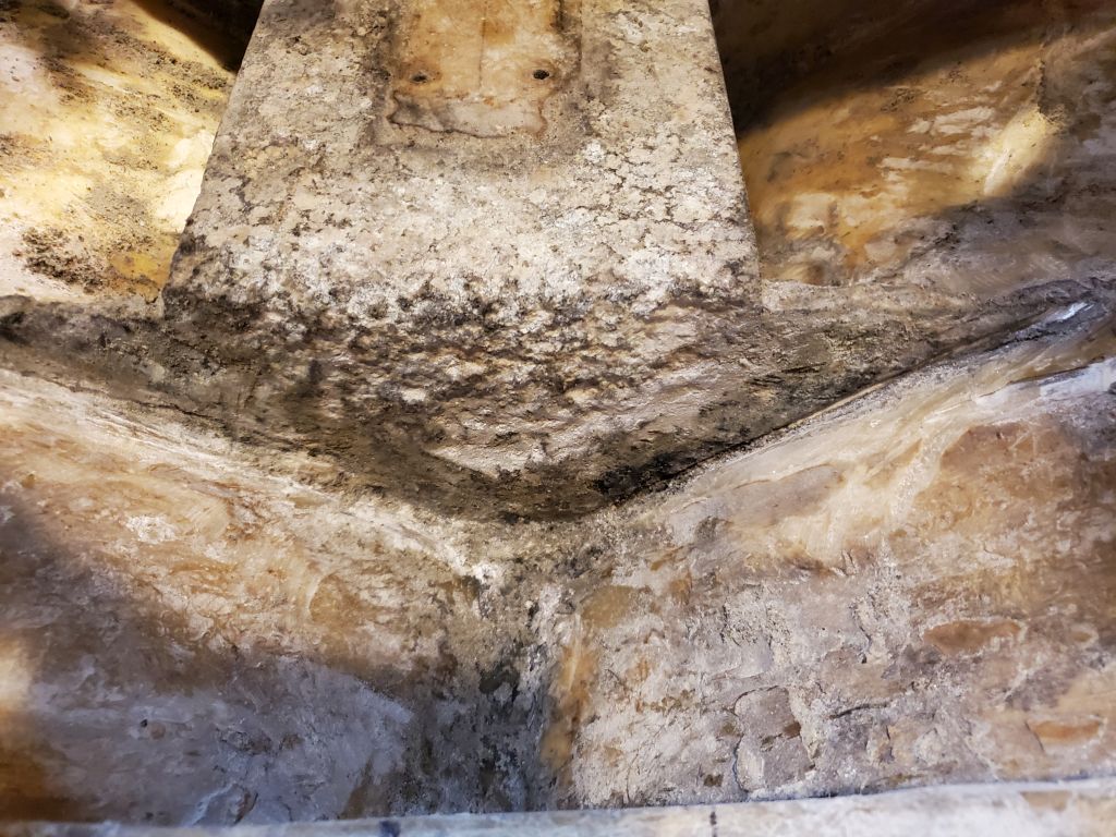
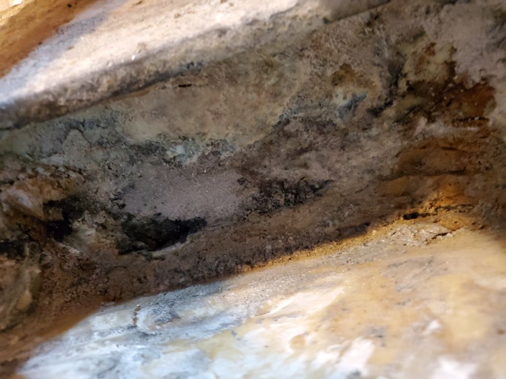
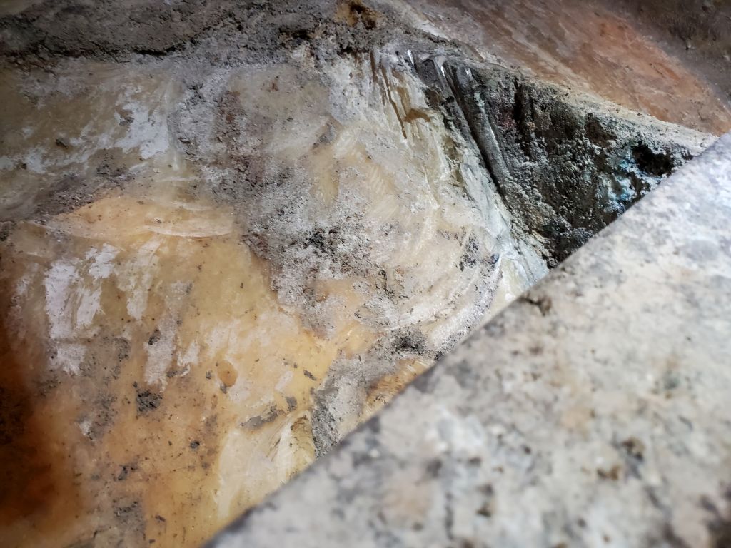
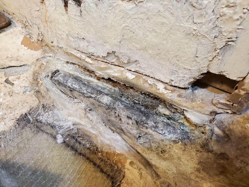
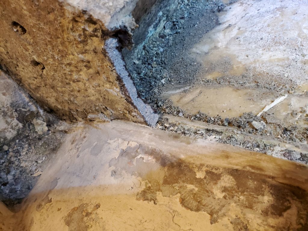
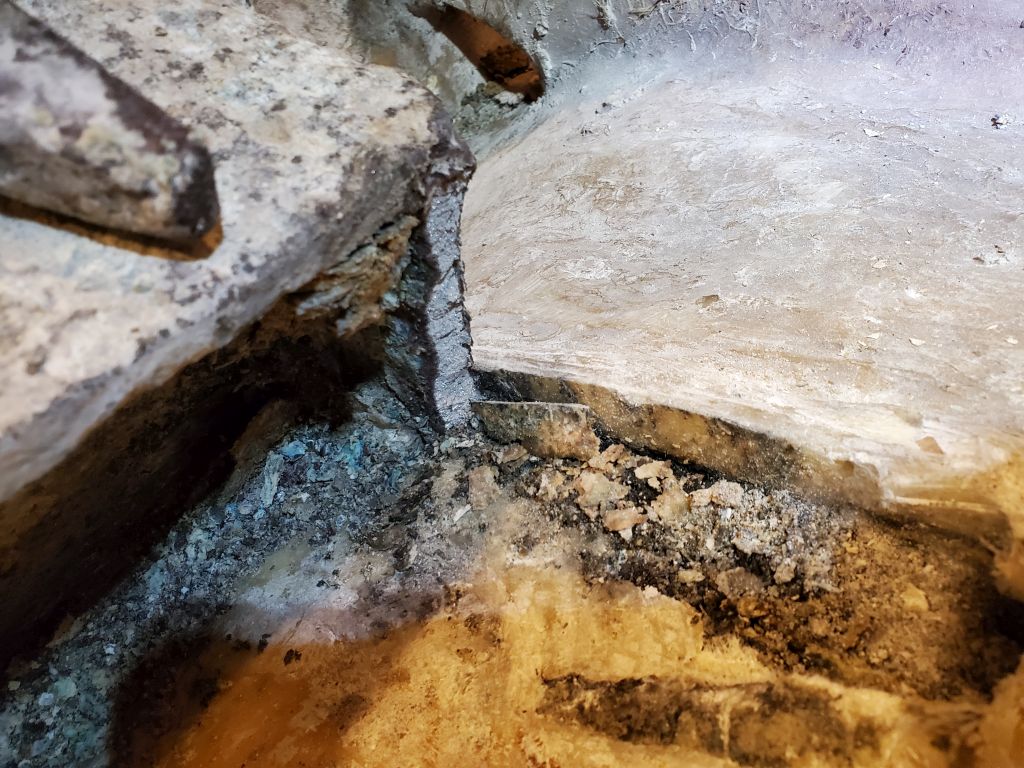
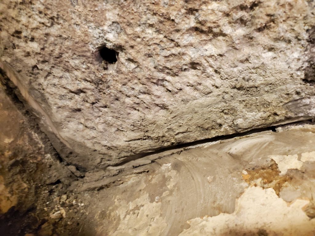
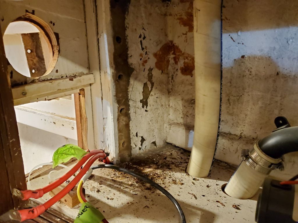
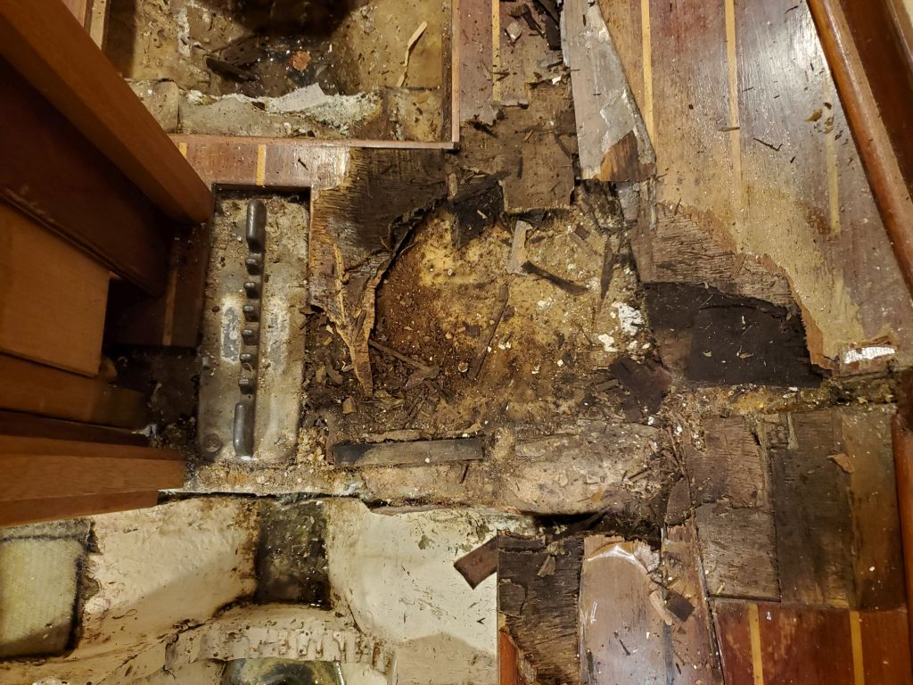
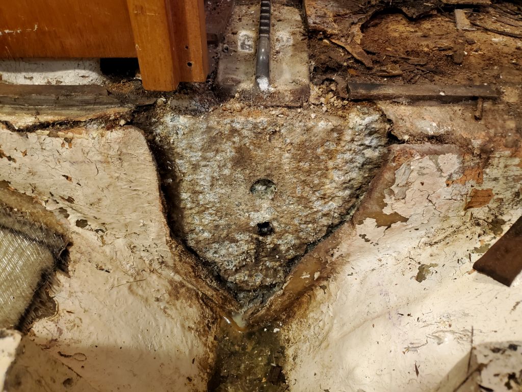
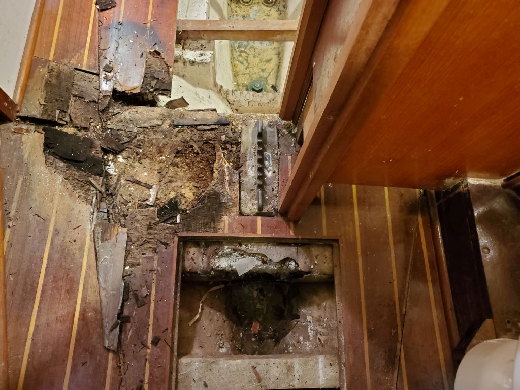
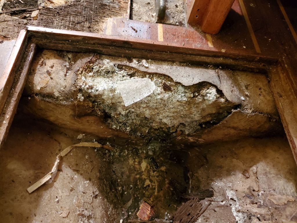
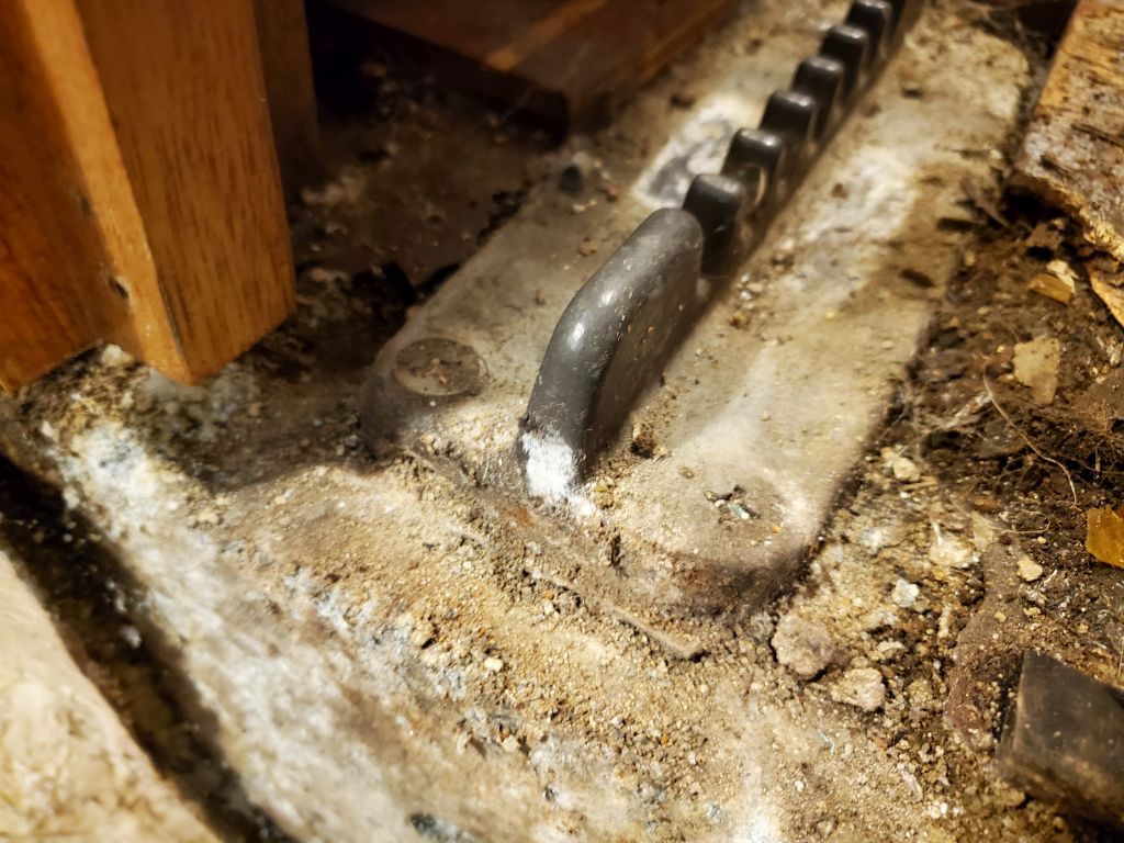
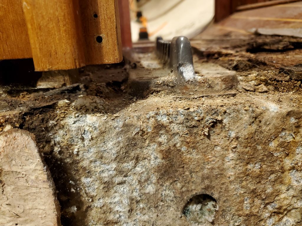
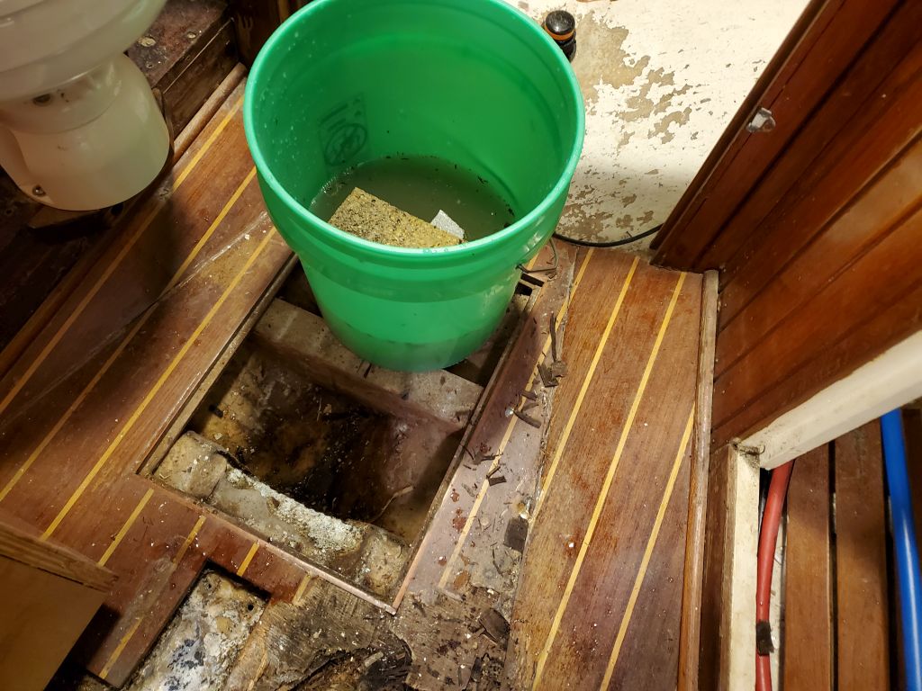
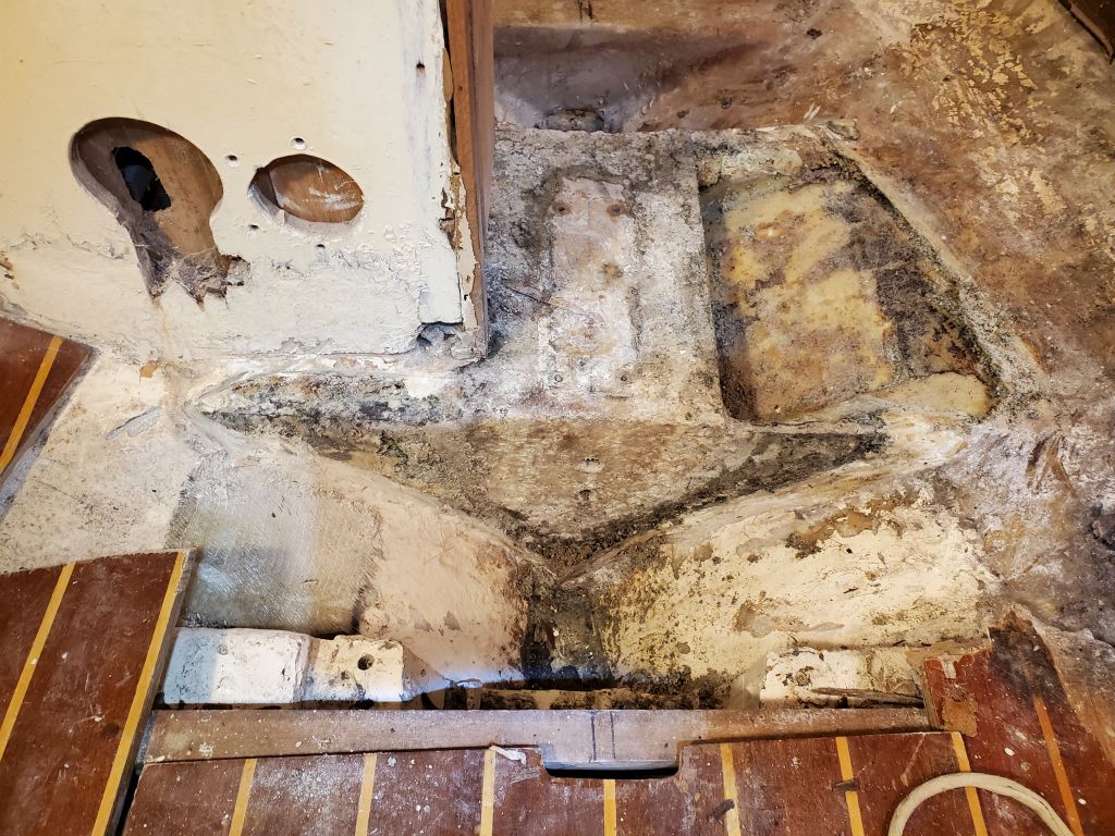
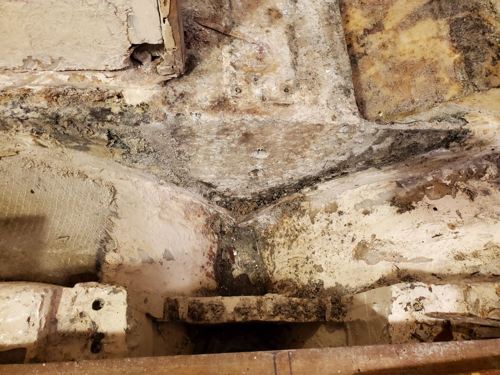
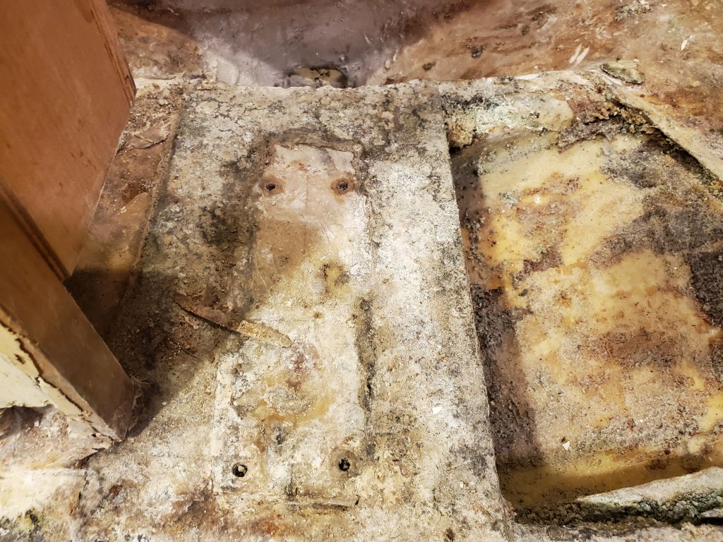
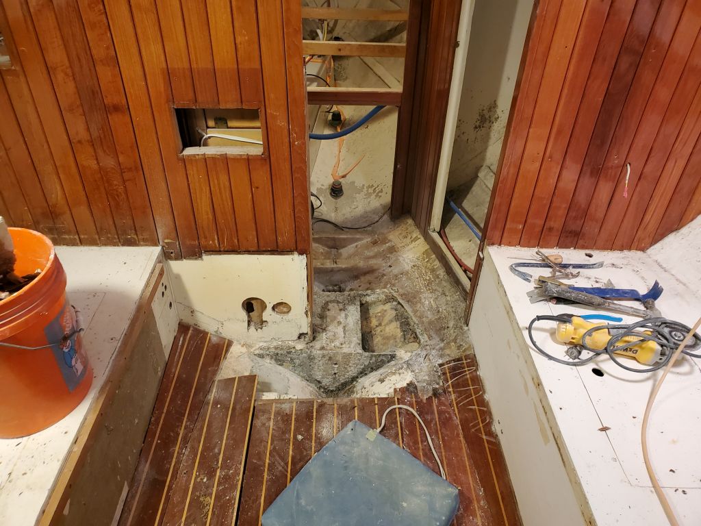
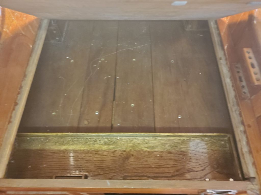
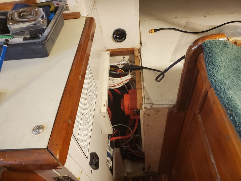
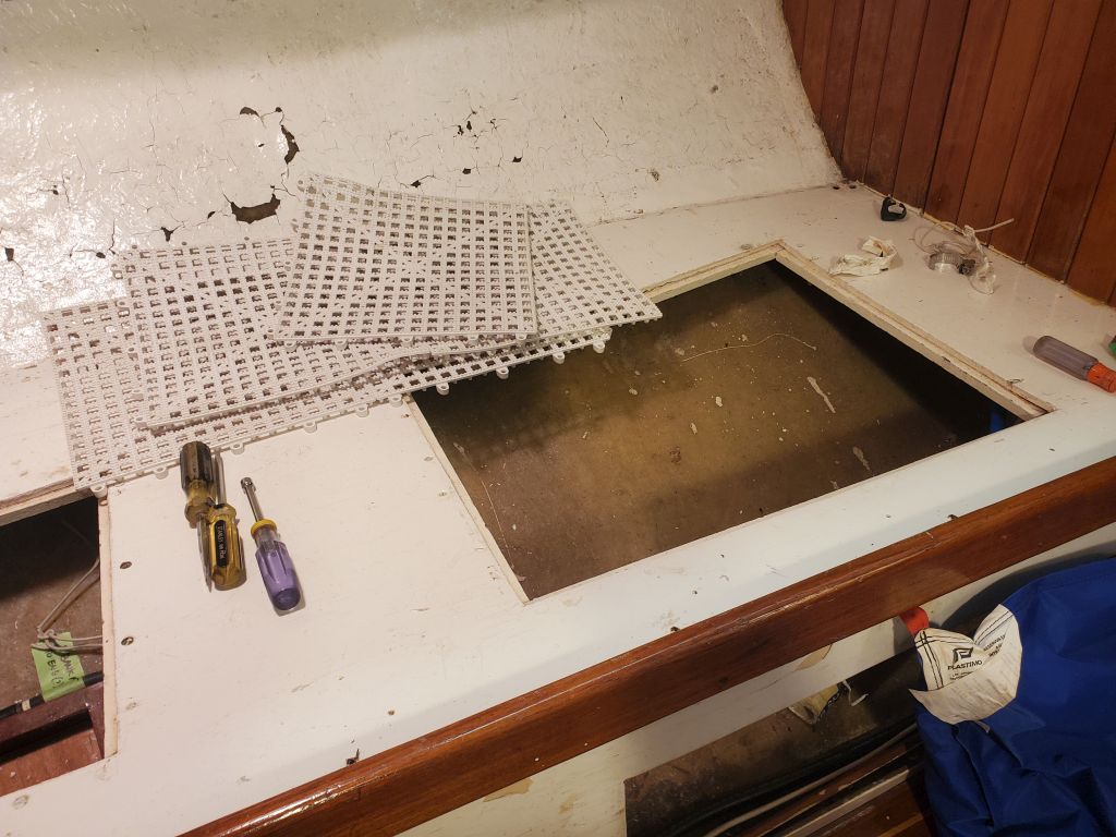
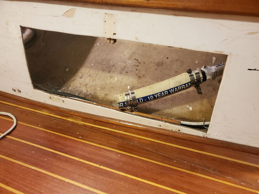
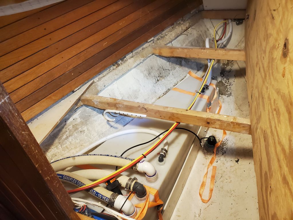
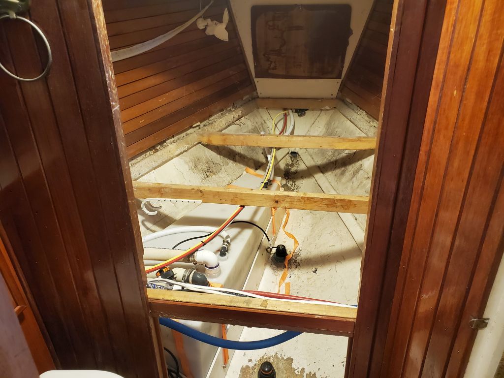
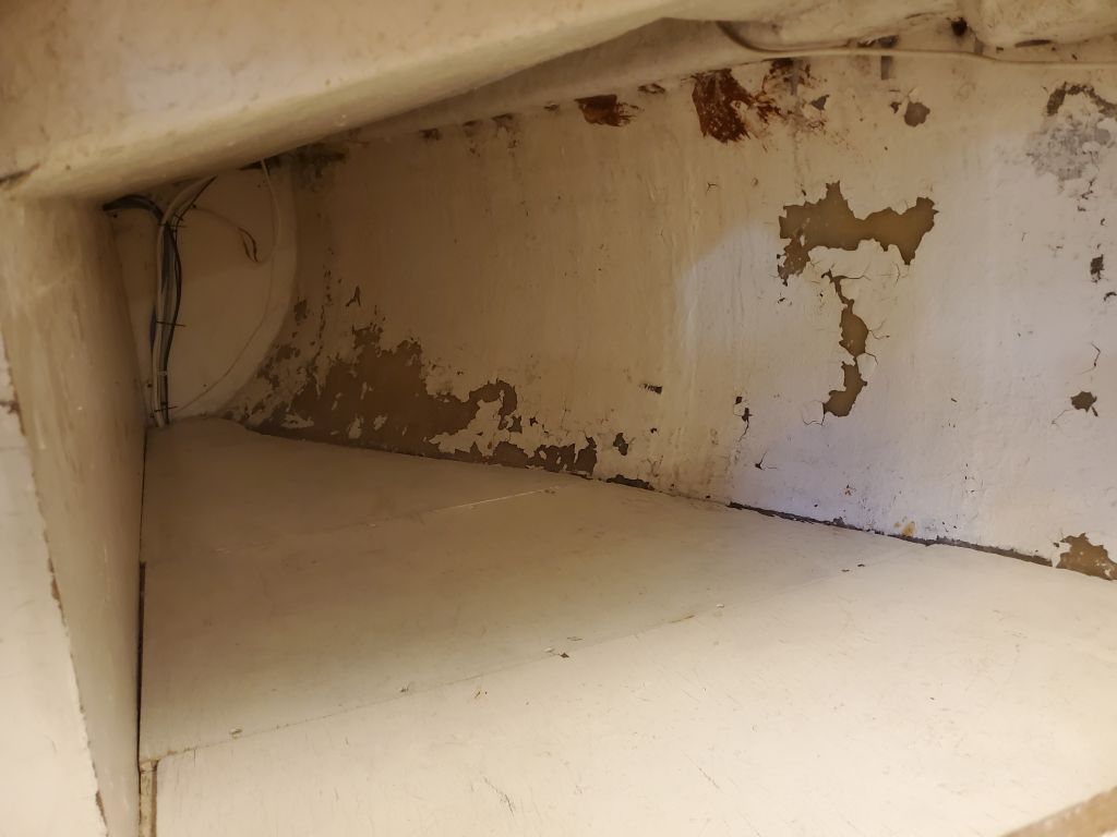
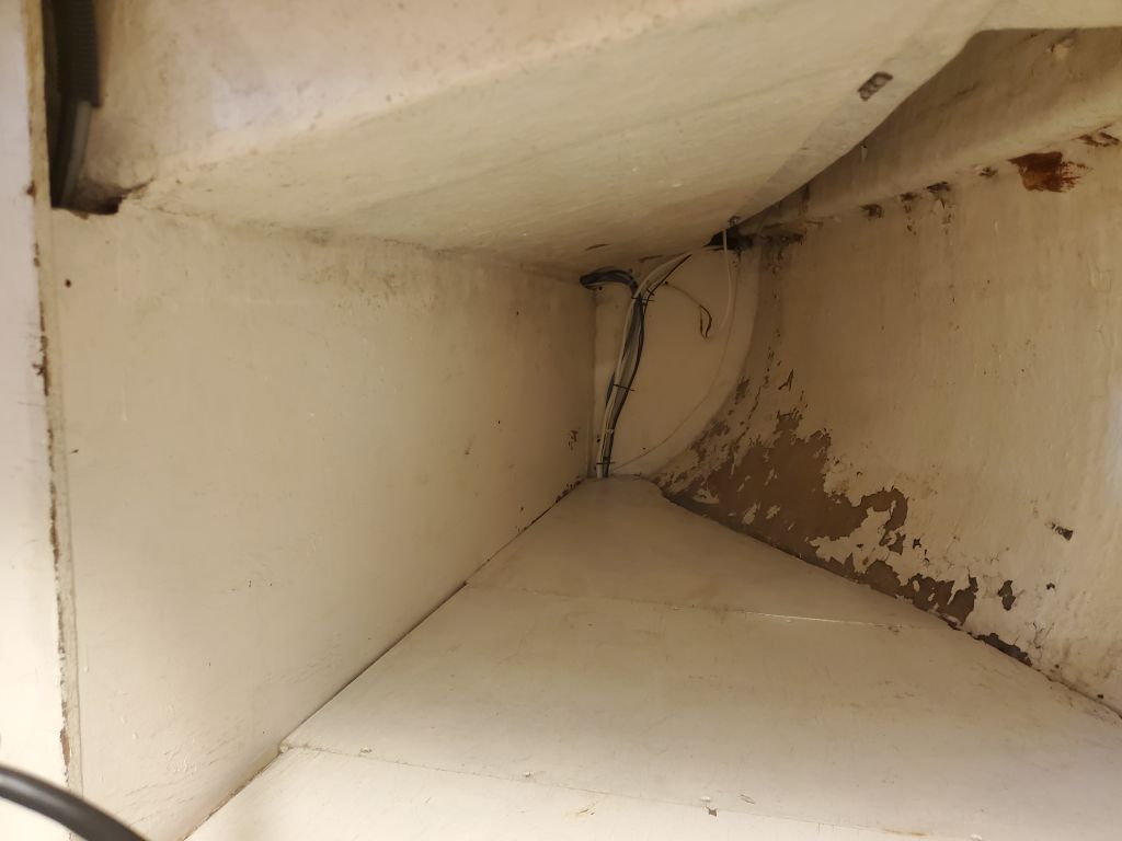
There was no better time than present to get going with cleaning up the hull in way of the old step, so I cut tabbing remains and ground the area as clean and smooth as I could to allow for new work, then thoroughly cleaned up so I could work in safety and comfort.
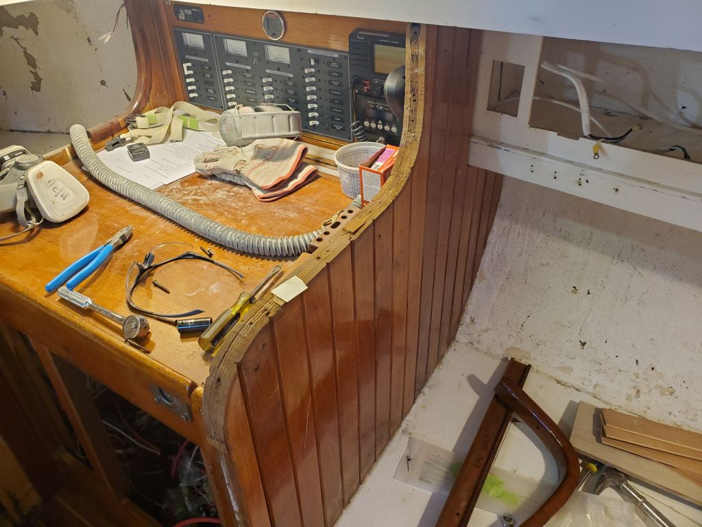
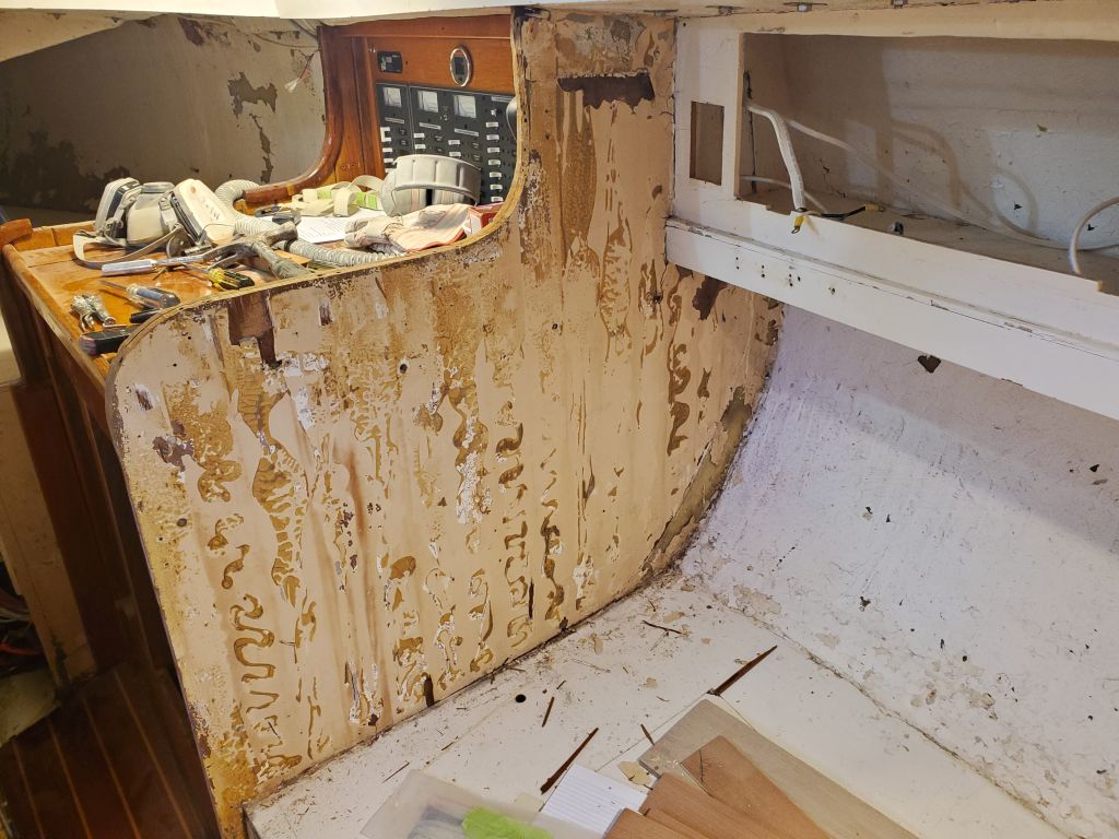
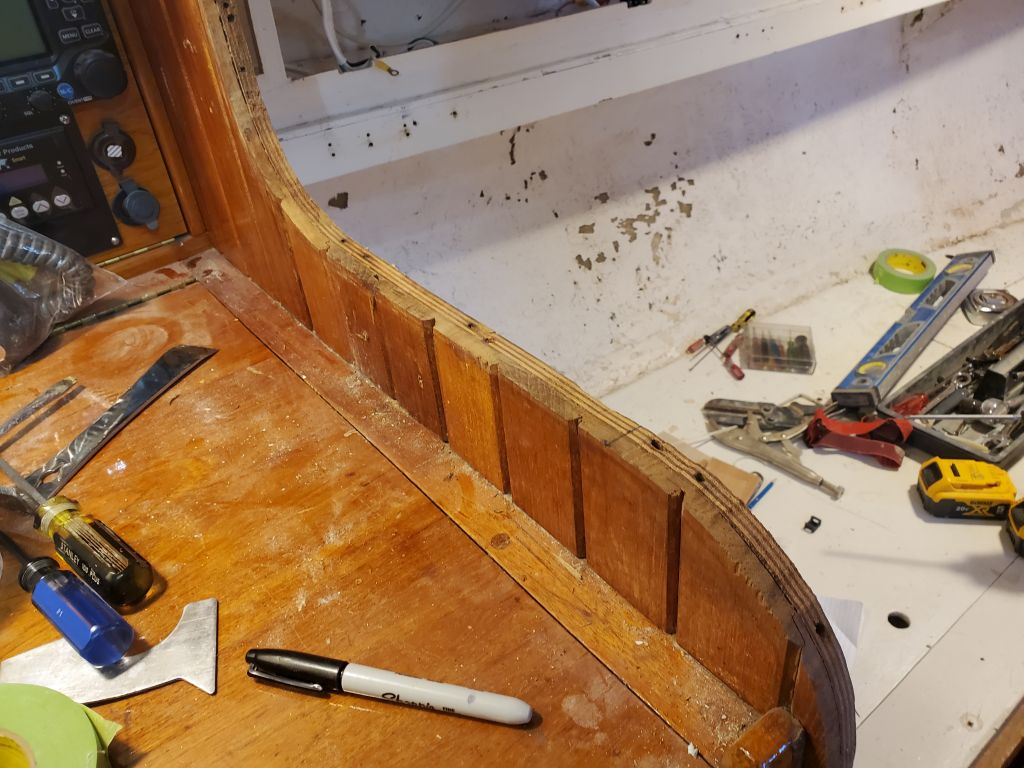
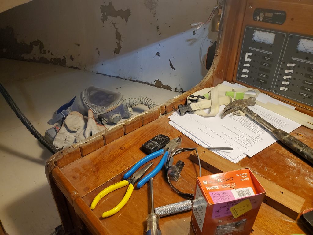
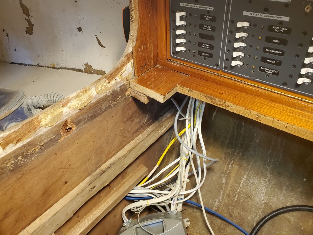
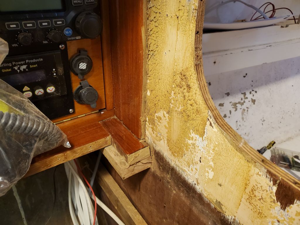
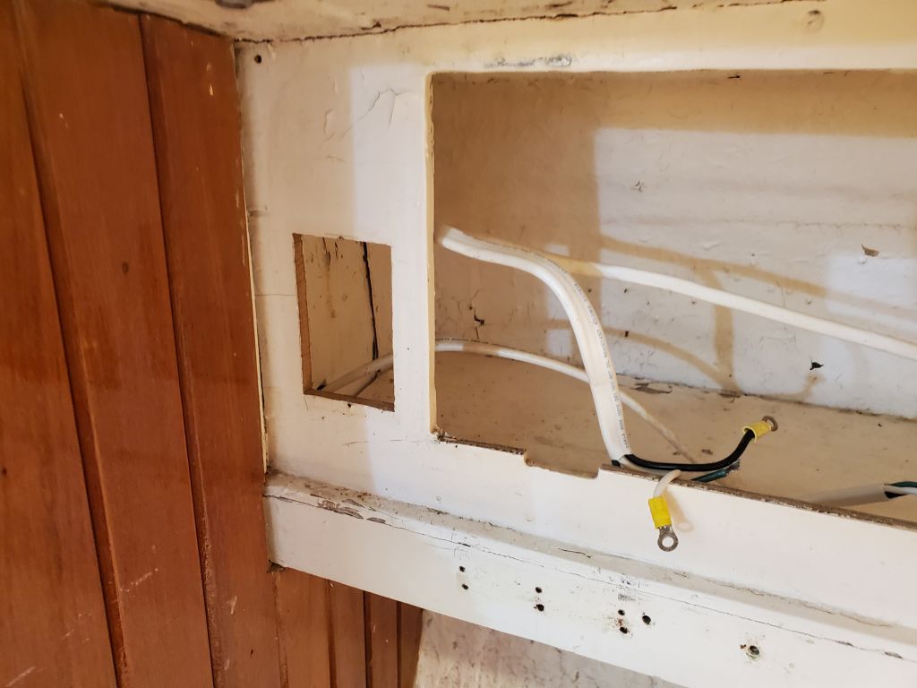
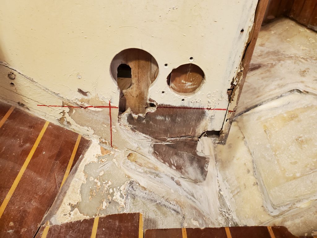
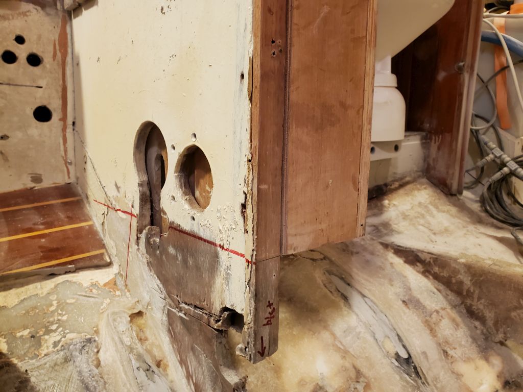
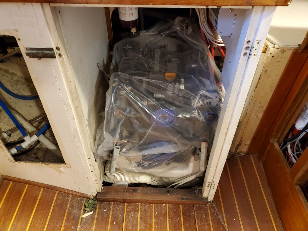
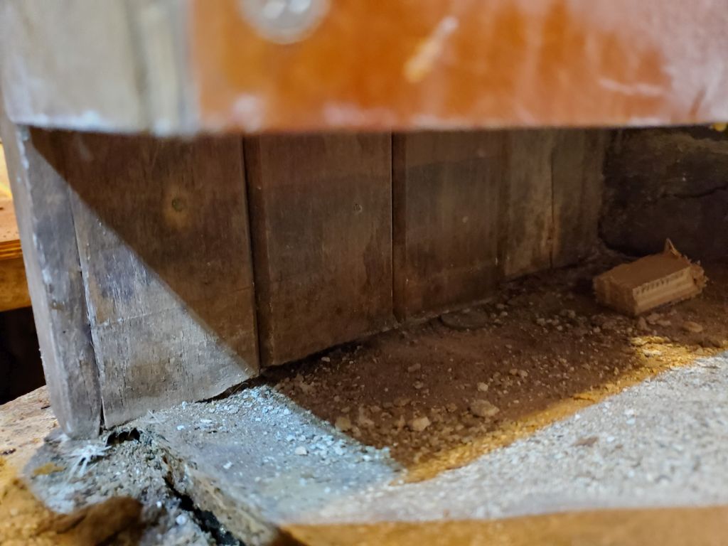
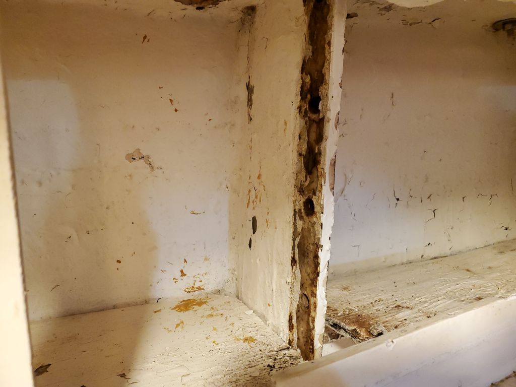
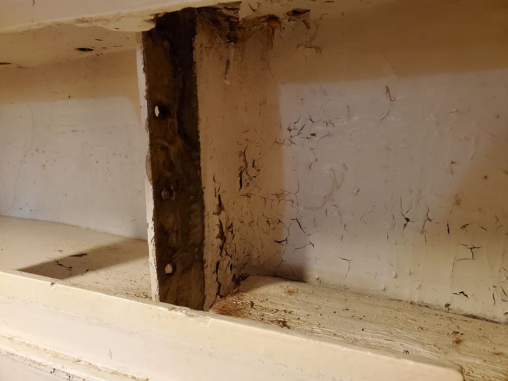
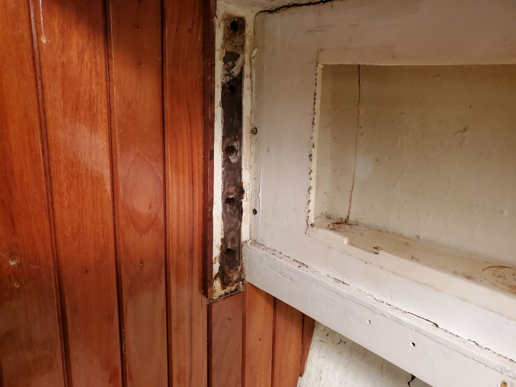
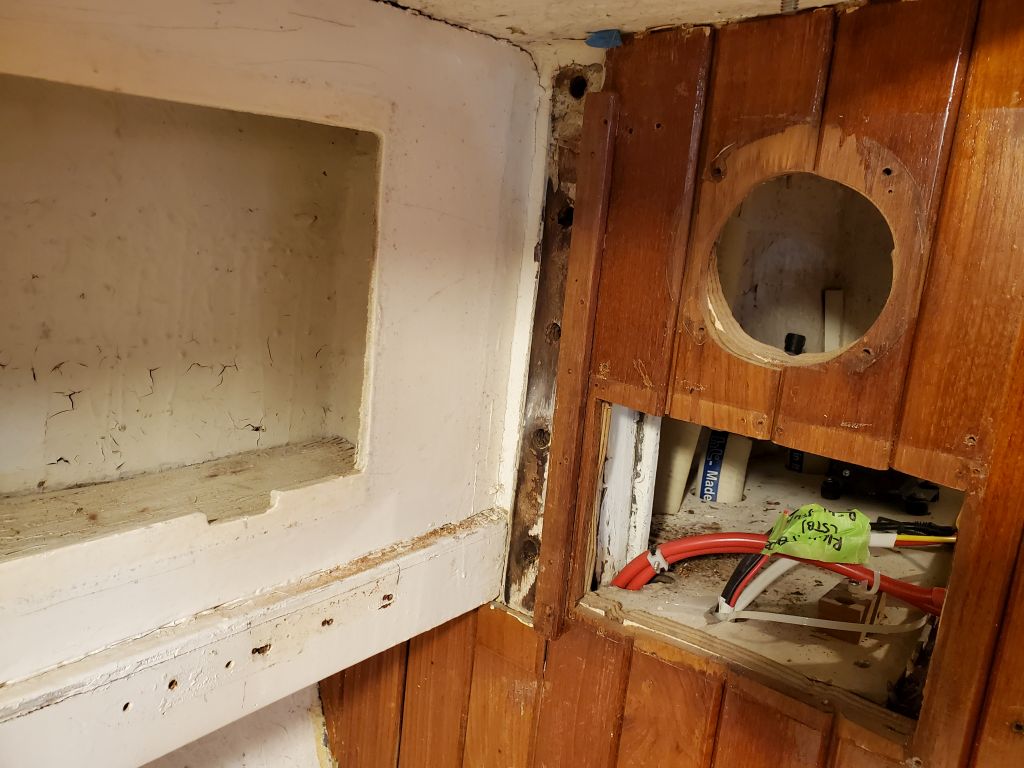
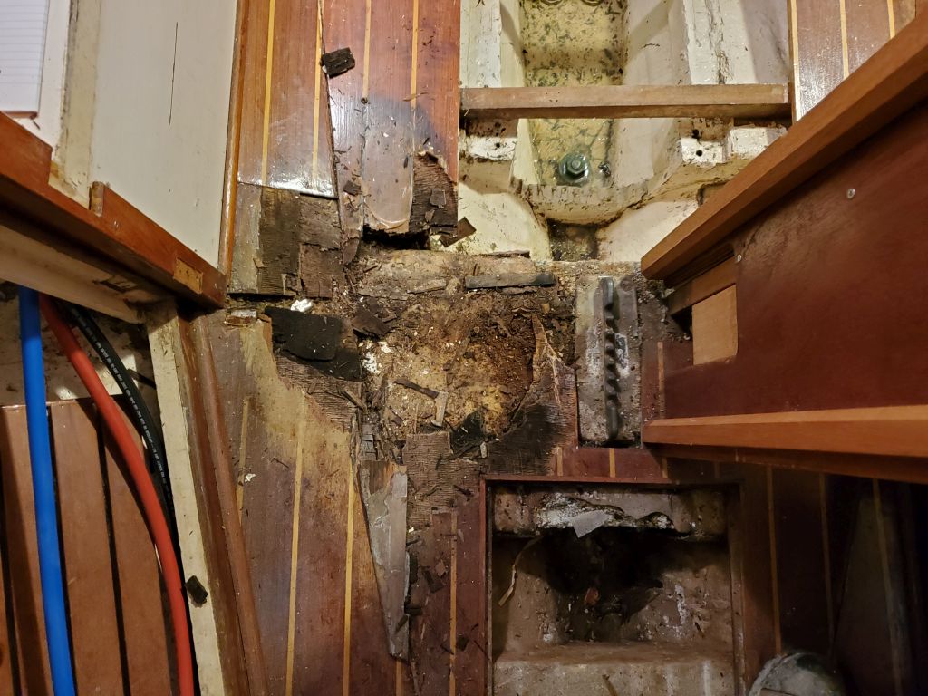
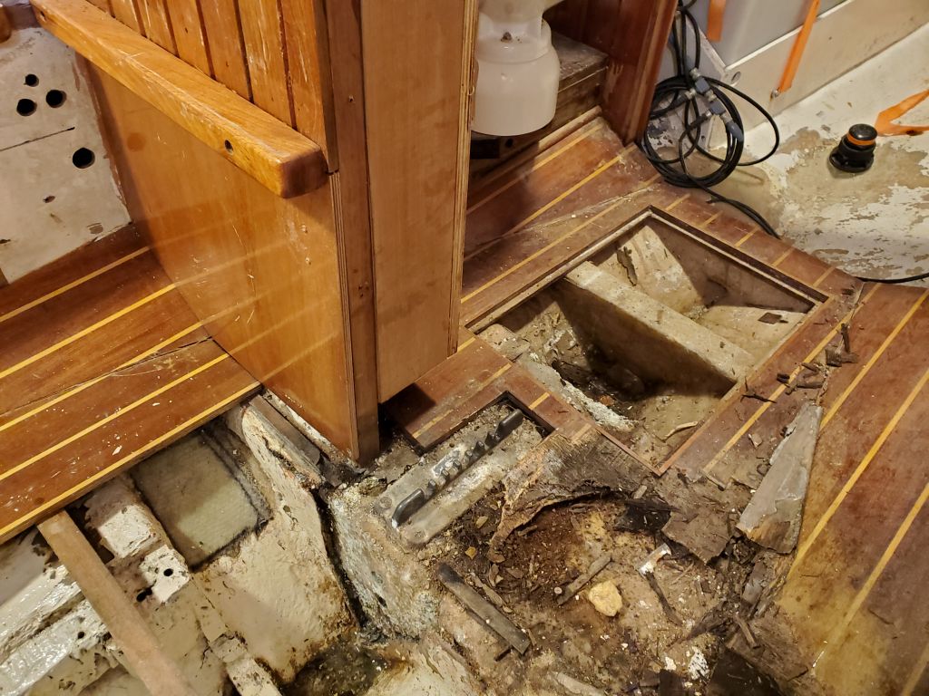
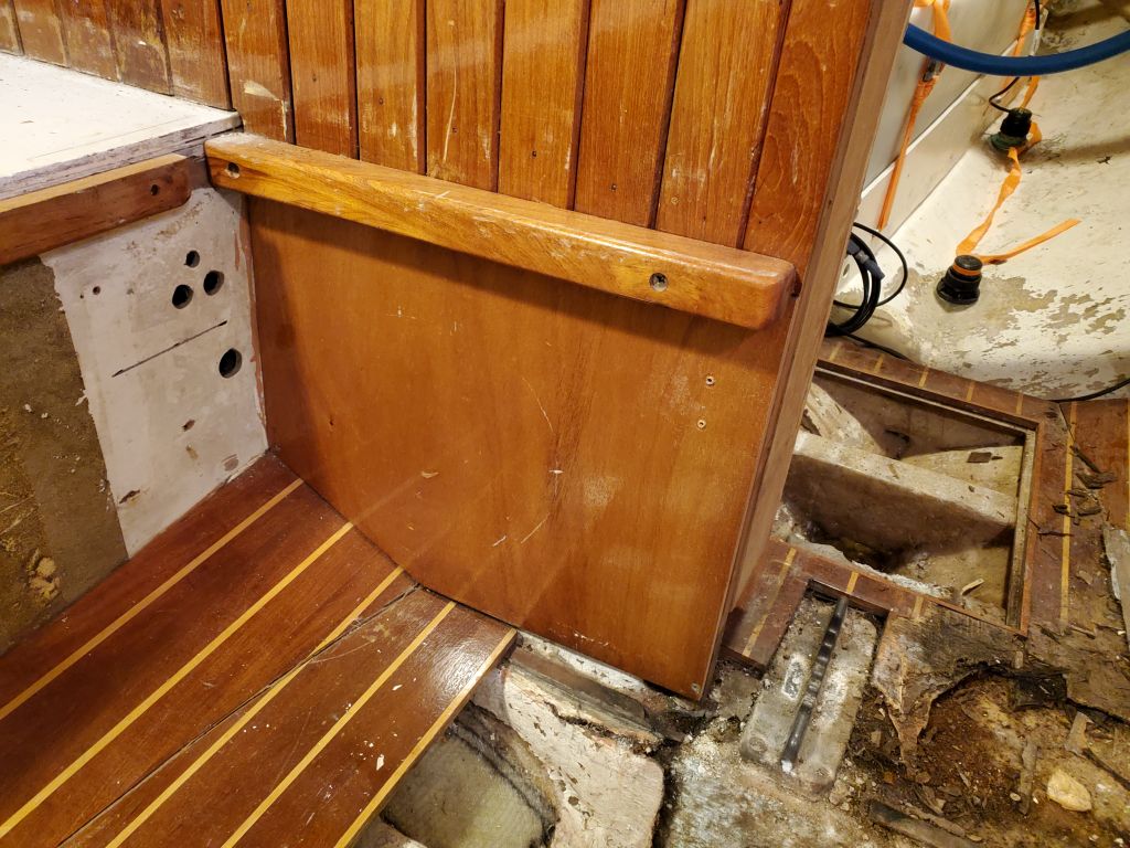
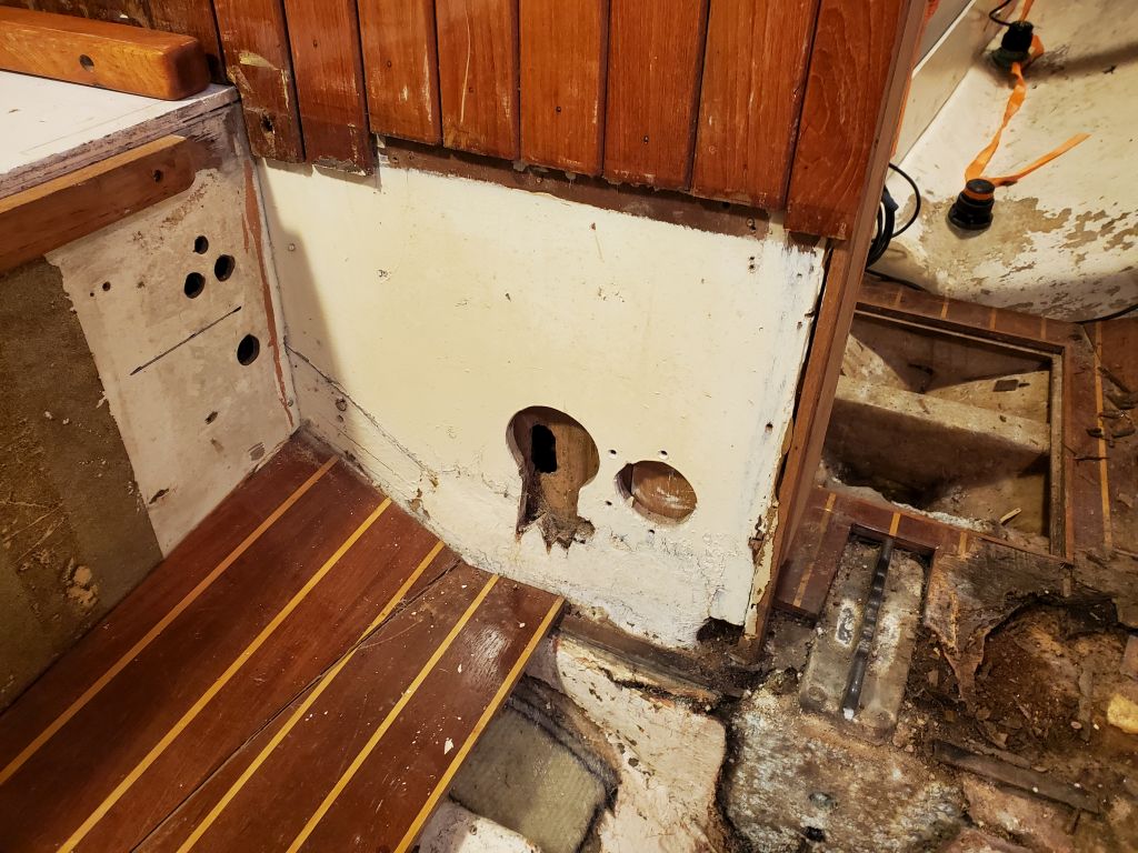
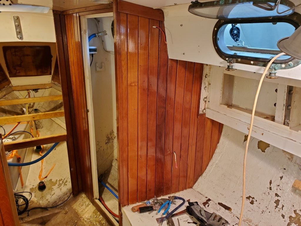
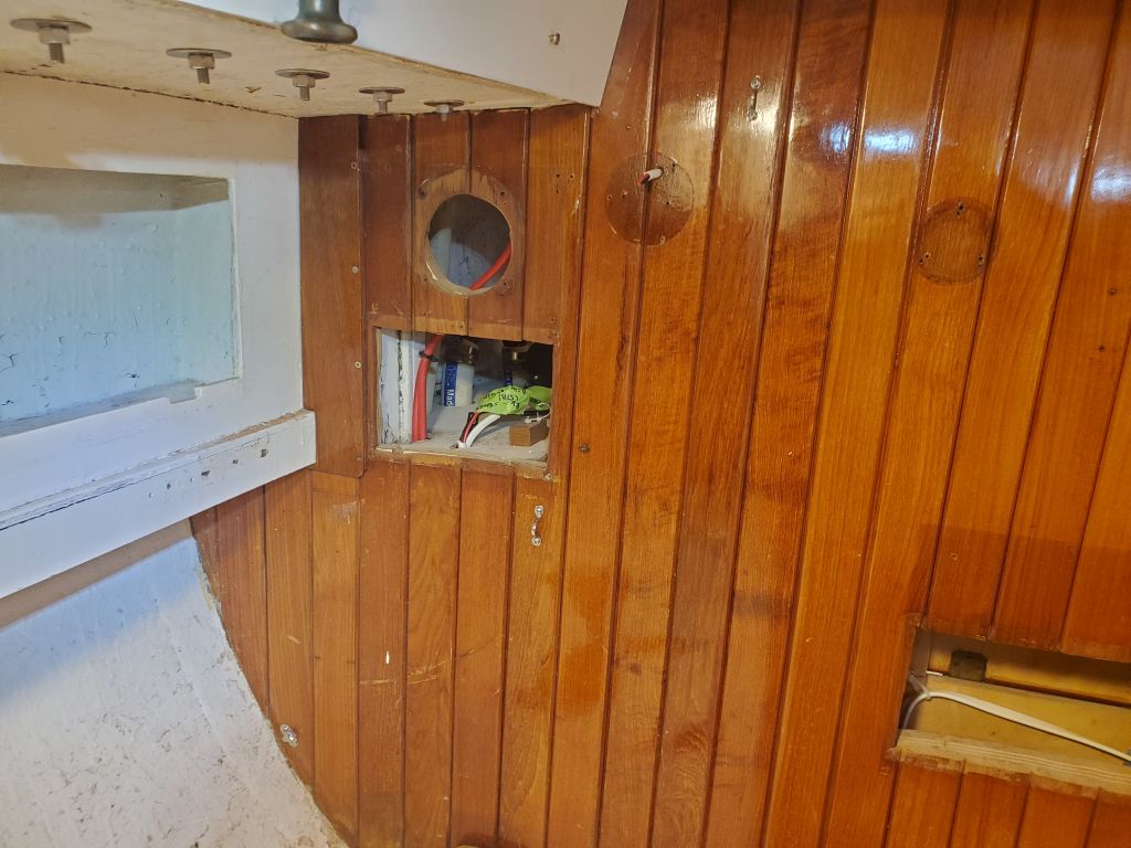
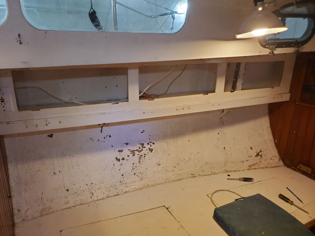
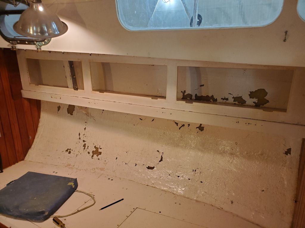
The small section of the main bulkhead where the old step had been was in the way, had some damage at its lower corner, and already had some large holes left over from (presumably) the original engine installation, which had once been on centerline just aft of the bulkhead. To provide better access for the new step construction, I decided to remove this small piece even with the lower edge of the head cabinetry on the forward side. I made level and plumb cut lines as needed and cut out the section, then cleaned up the remnants of tabbing as needed. Later, I’d patch this back in over the new step and retab the area as needed.
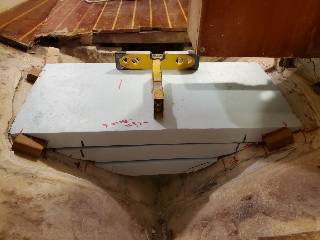
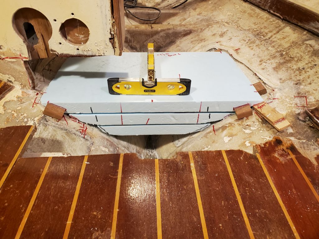
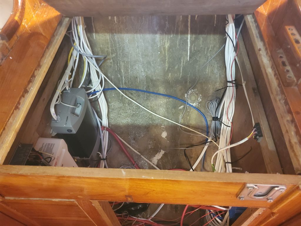
For the moment, I decided to continue on the mast step, which at least immediately would be easier while I still had nearby flat surfaces to store tools and equipment (soon the settees and other structures would be removed). My idea for the new step was to create a massive block of G-10 fiberglass to span the area, well-tabbed in to all surrounding areas, and provide more than substantial support for the spar compressive forces, while leaving a sizeable limber beneath to allow free passage of bilge water, something that had been impossible with the old step, and which the owner had specifically complained of. After various considerations and inquiries into the material available, I decided that a 4-1/2″ thick block, made from three laminated layers of 1-1/2″ G-10, would provide a good starting point.
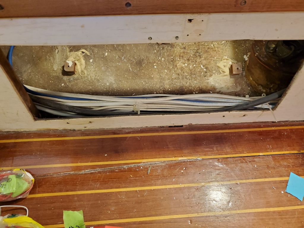
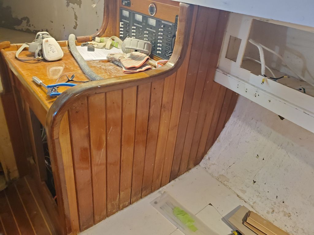
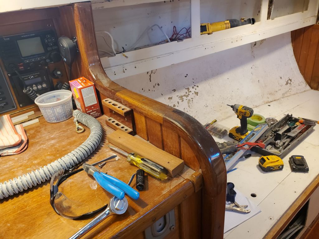
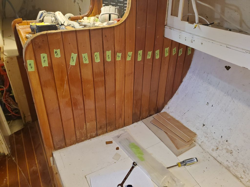
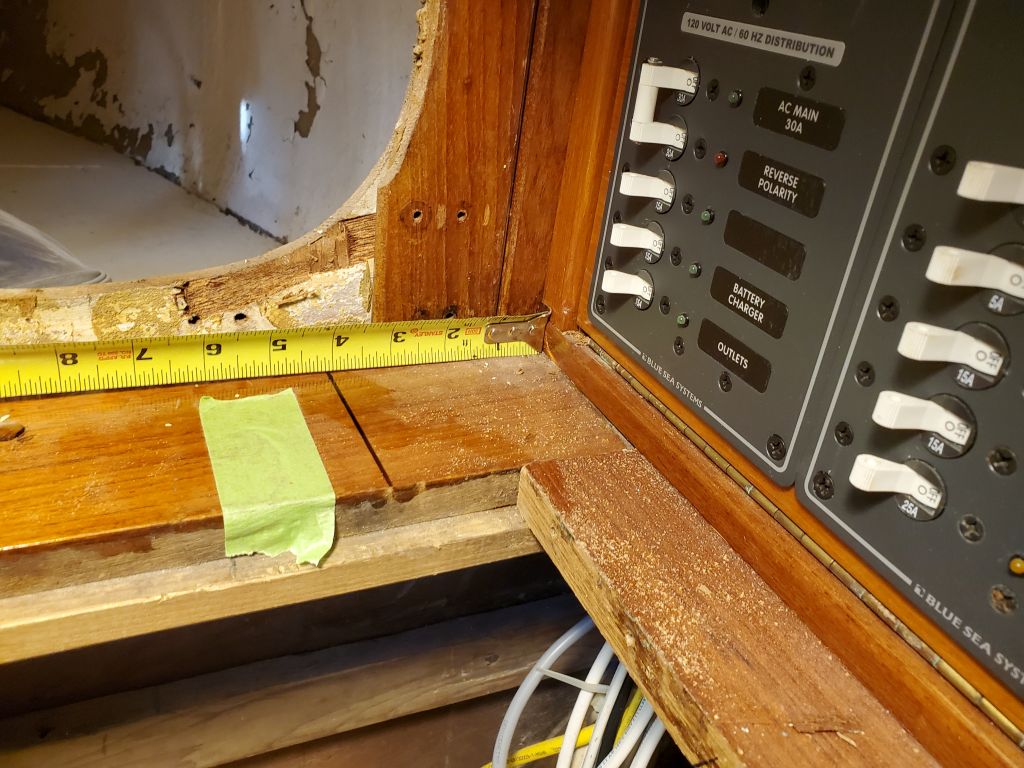
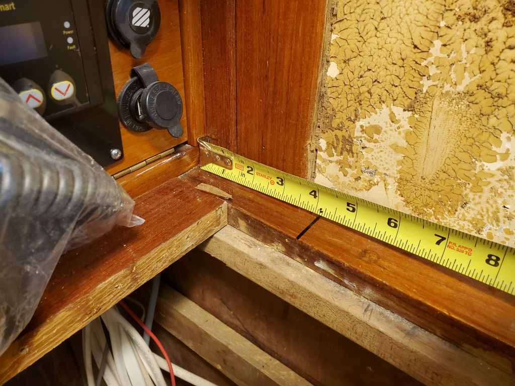
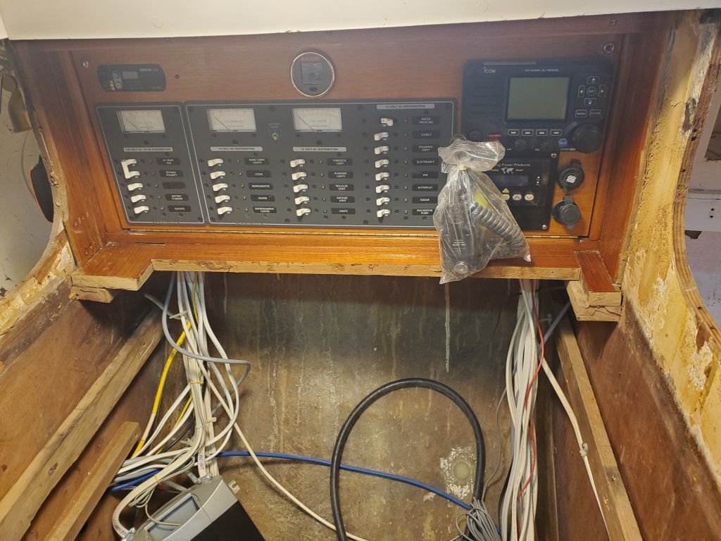
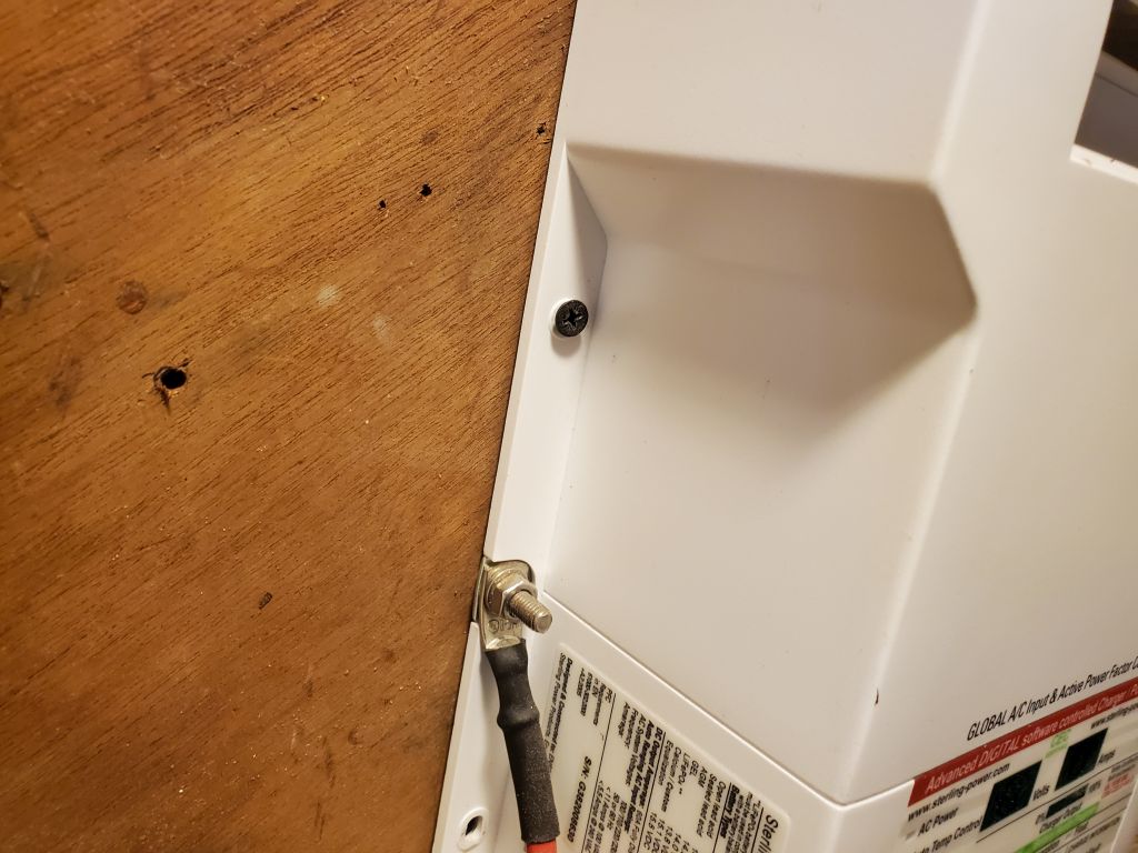
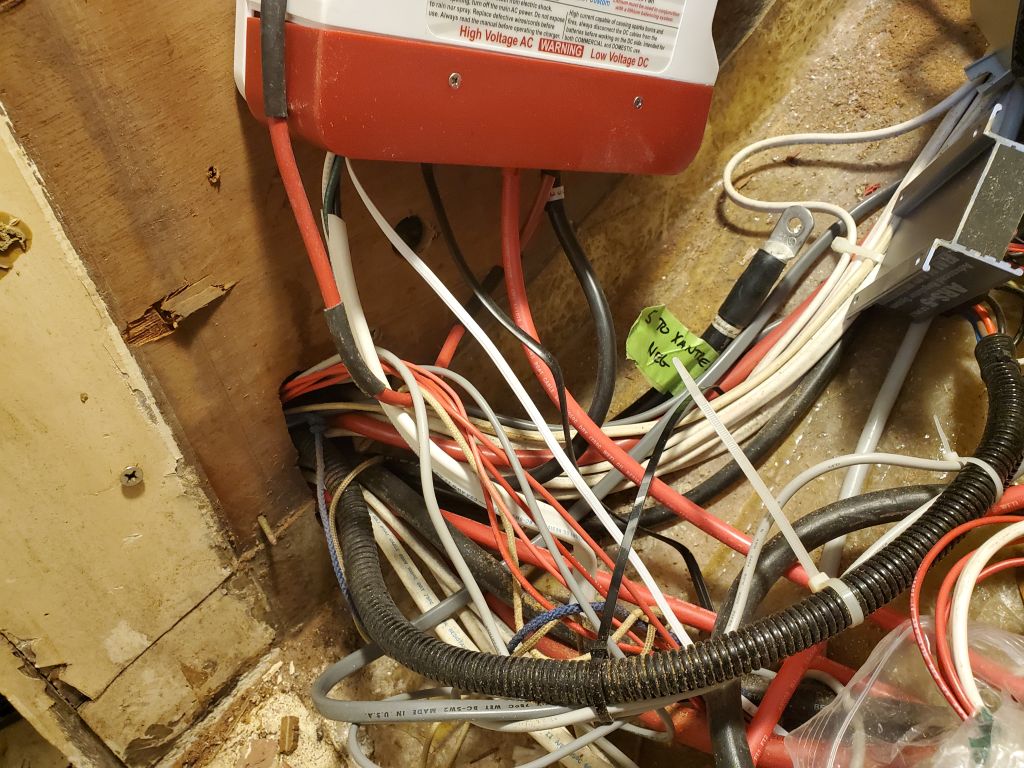
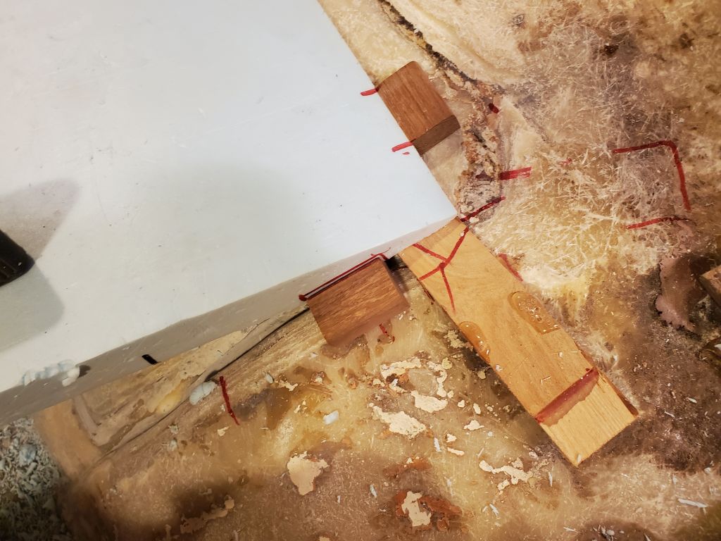
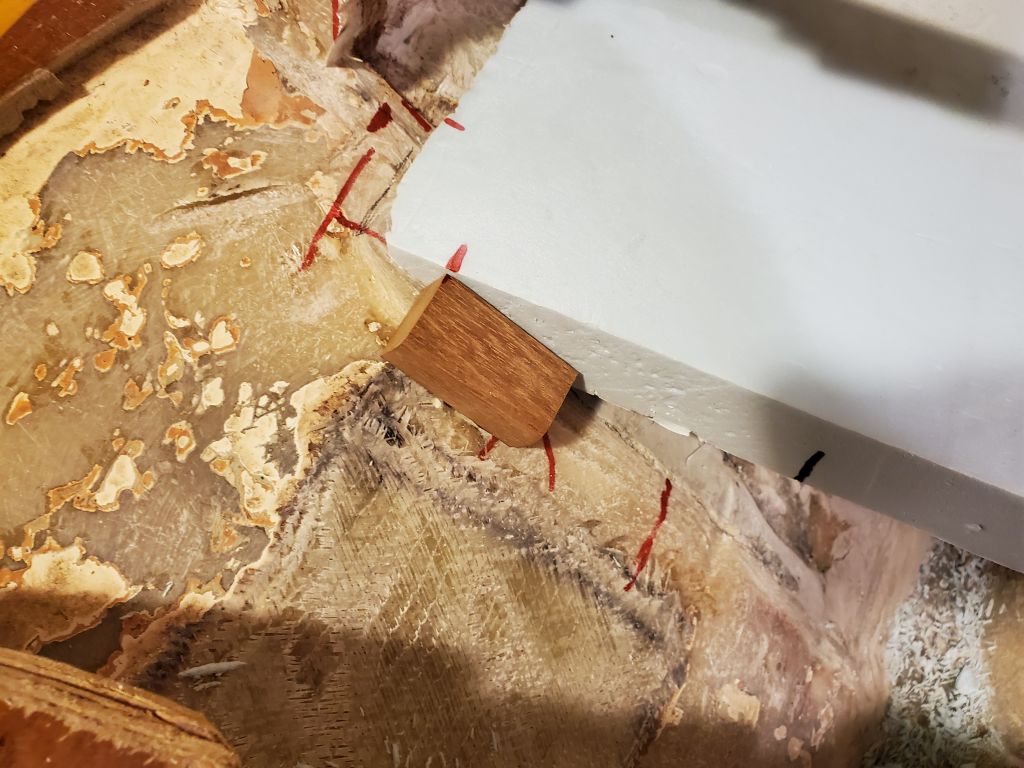
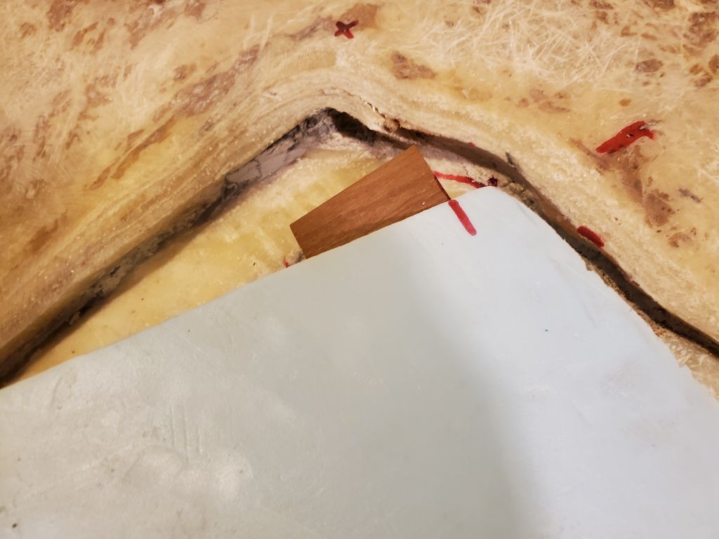
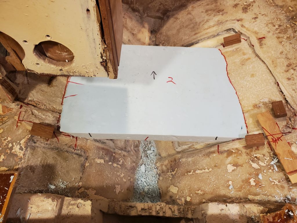
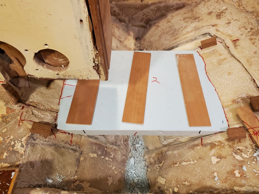
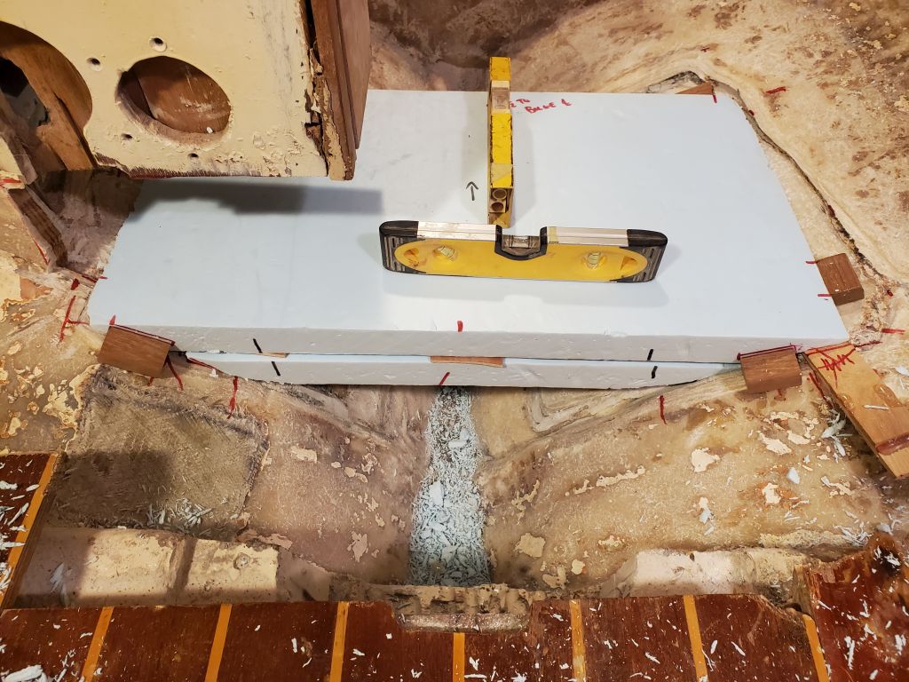
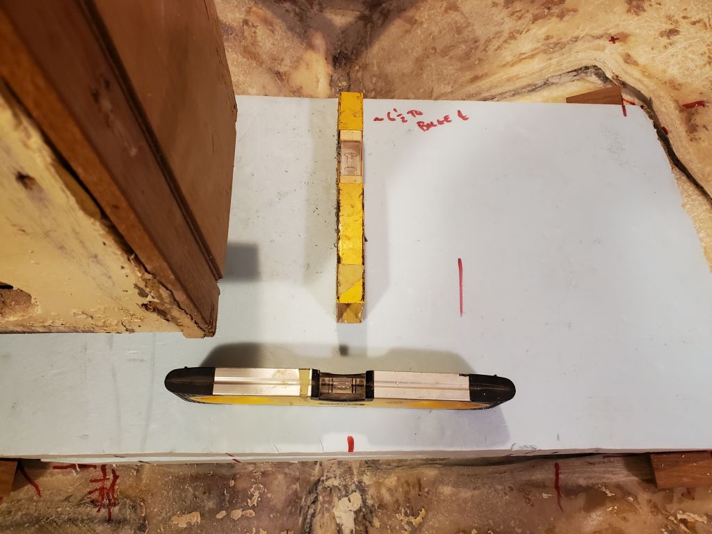
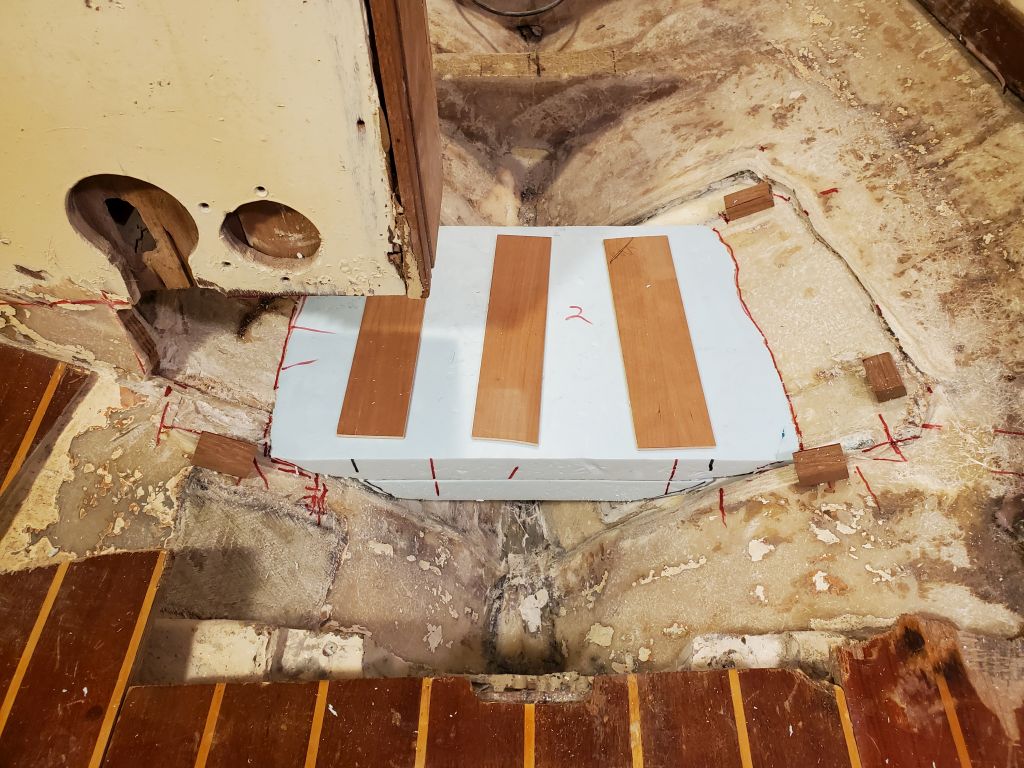
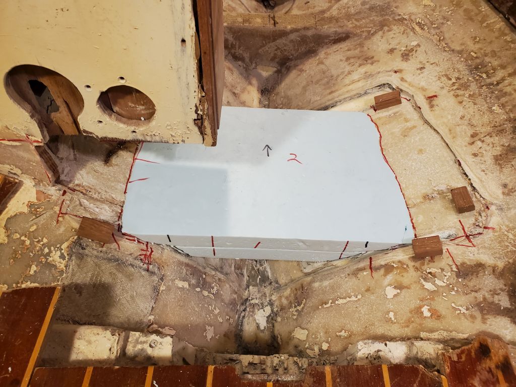
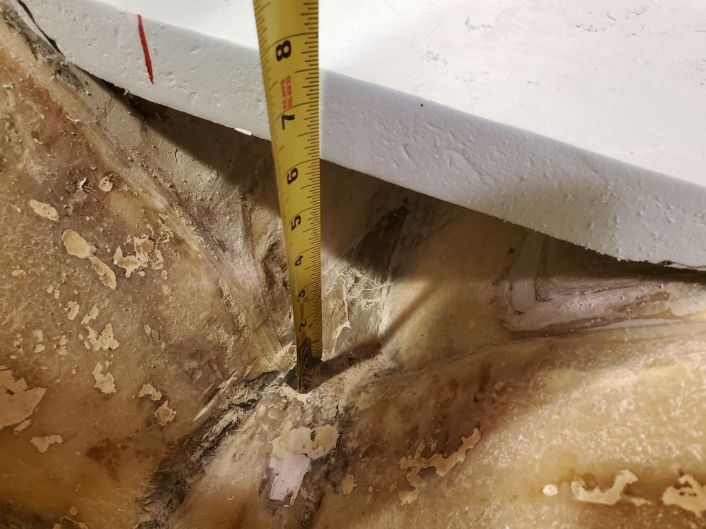
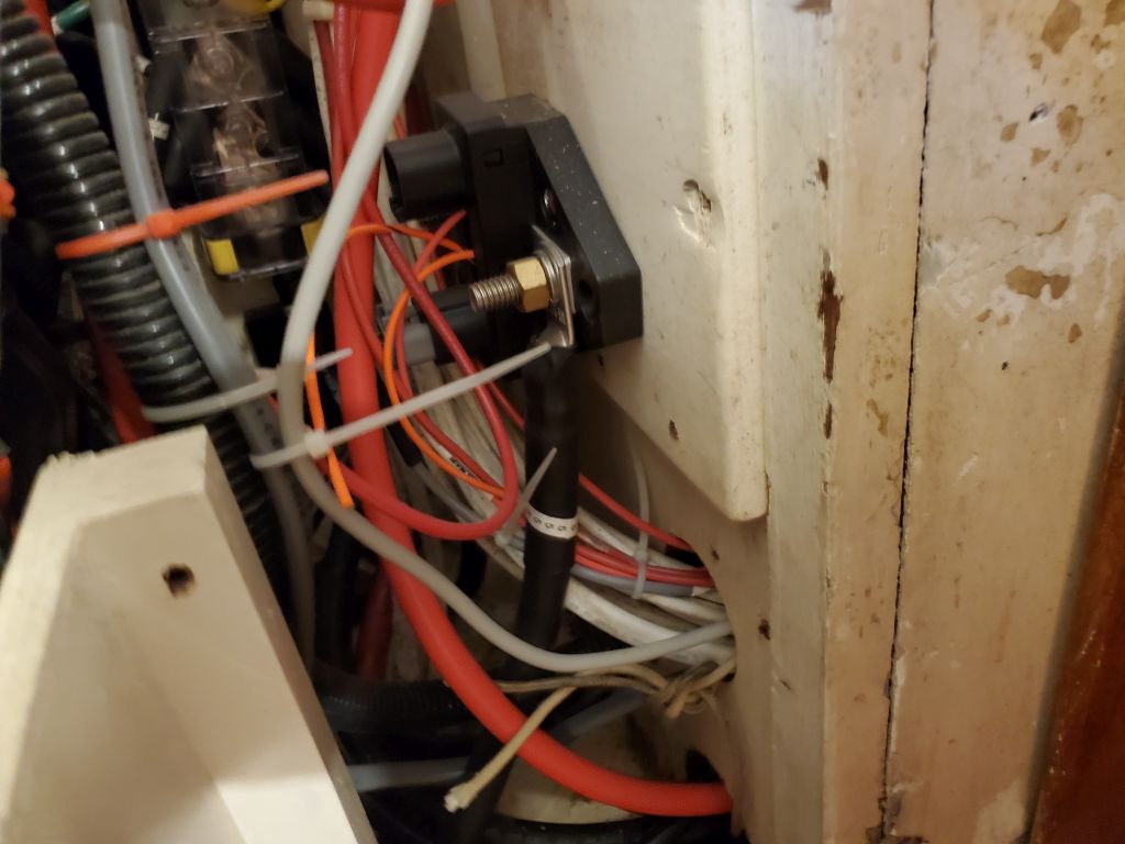
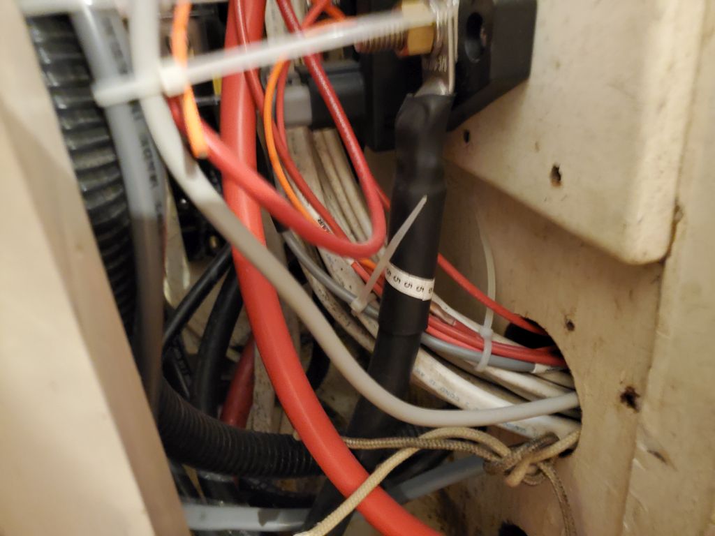
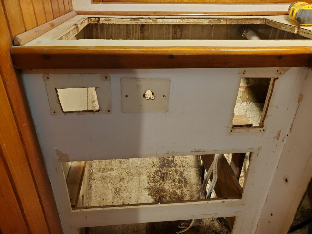
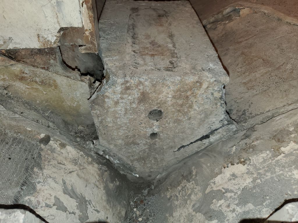
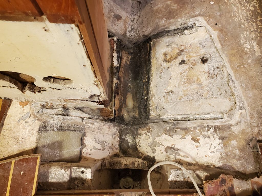
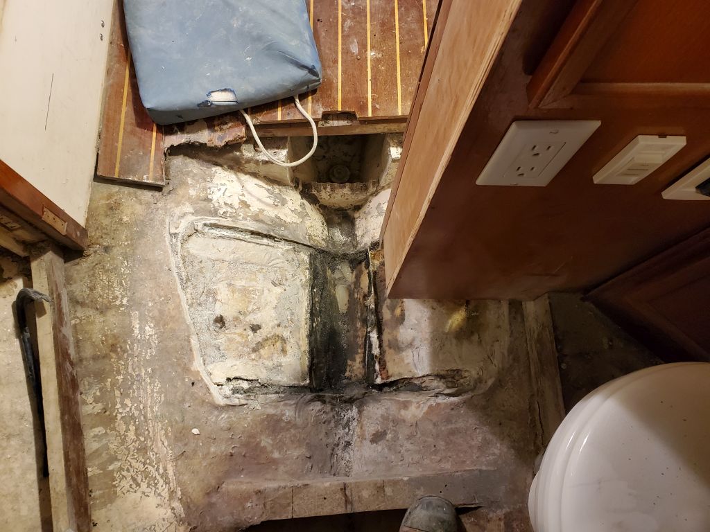
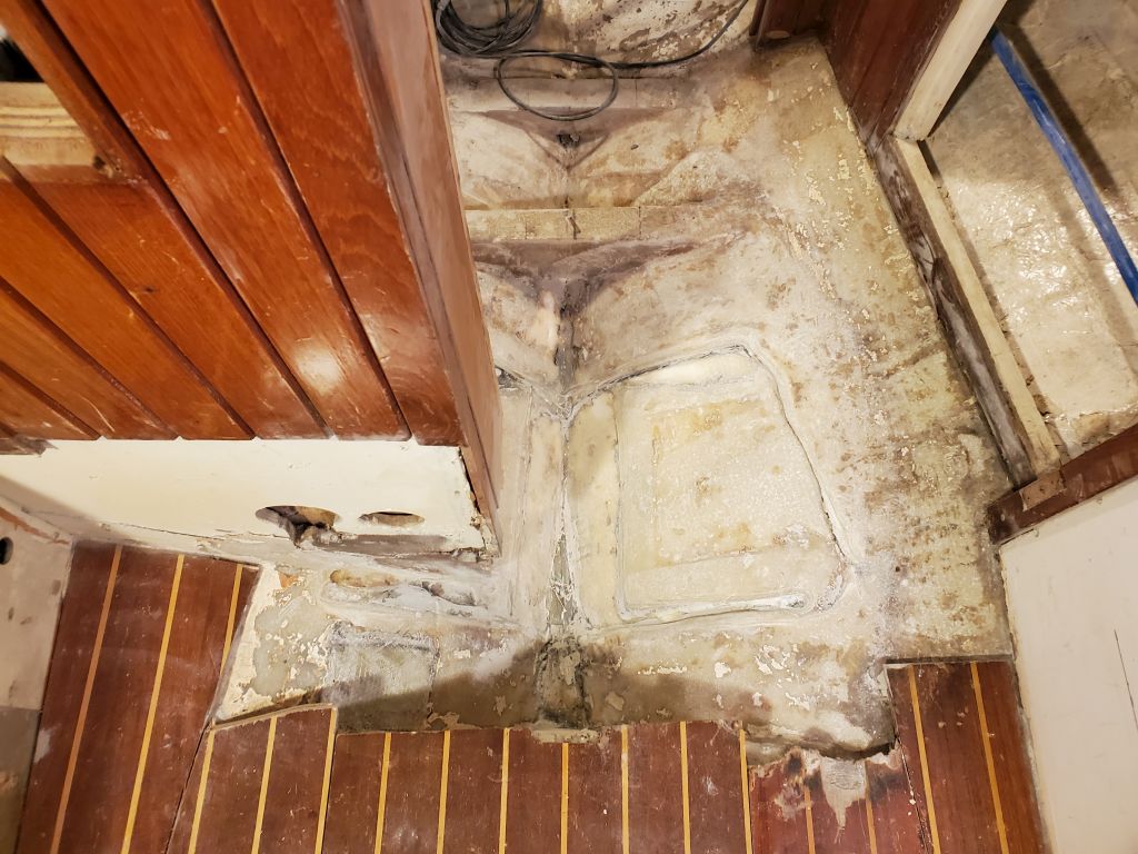
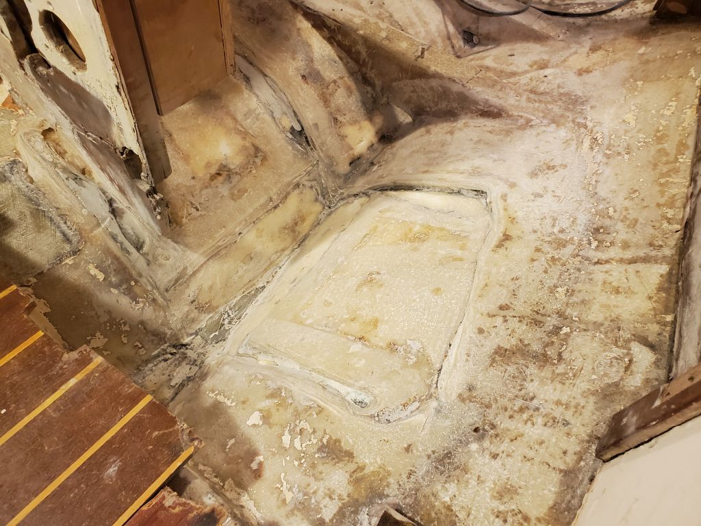
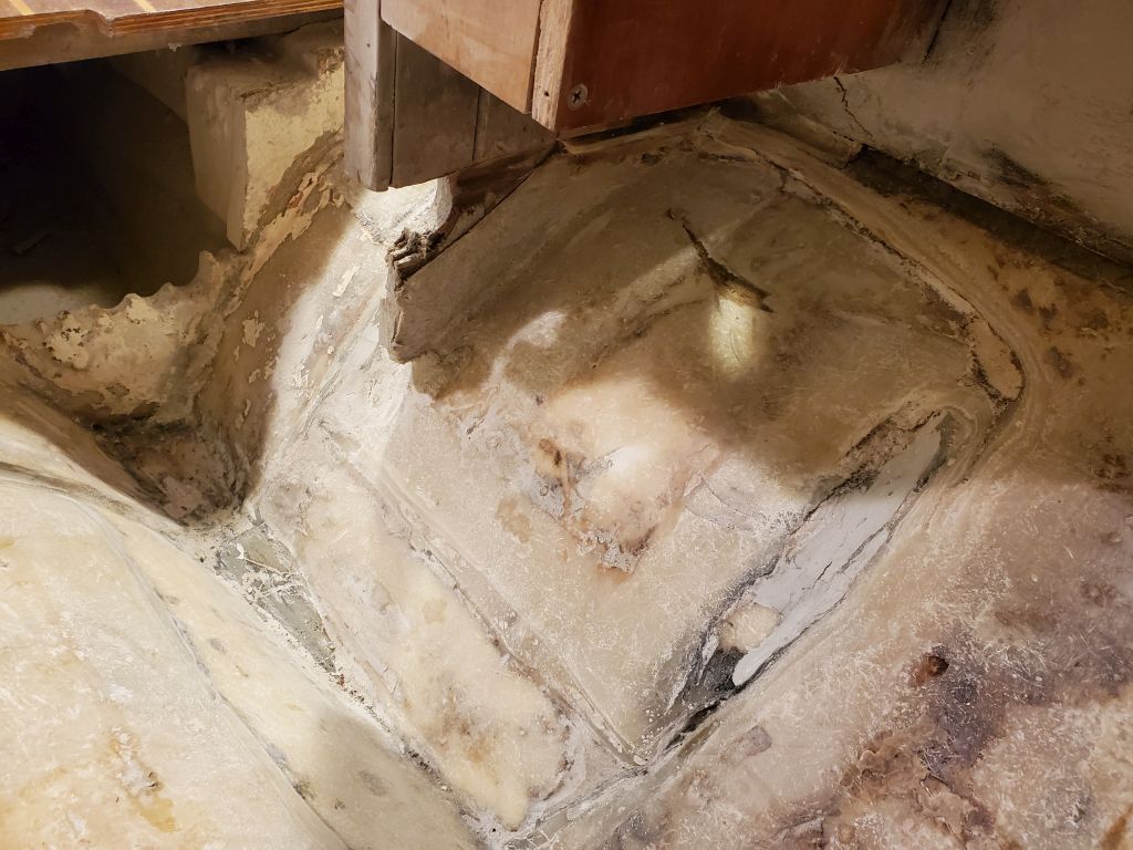
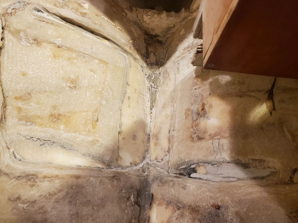
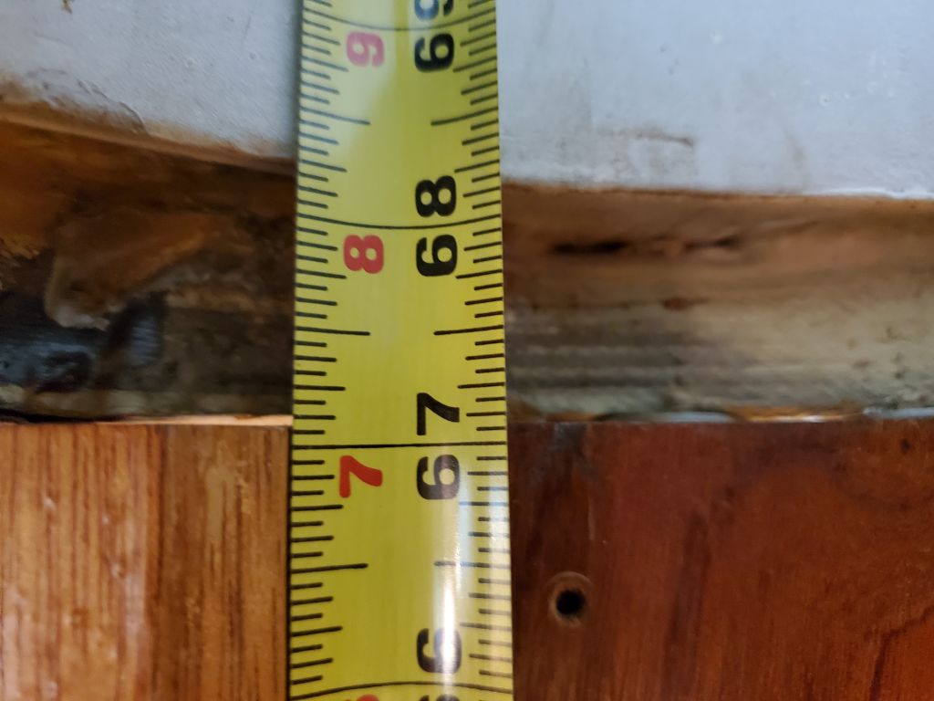
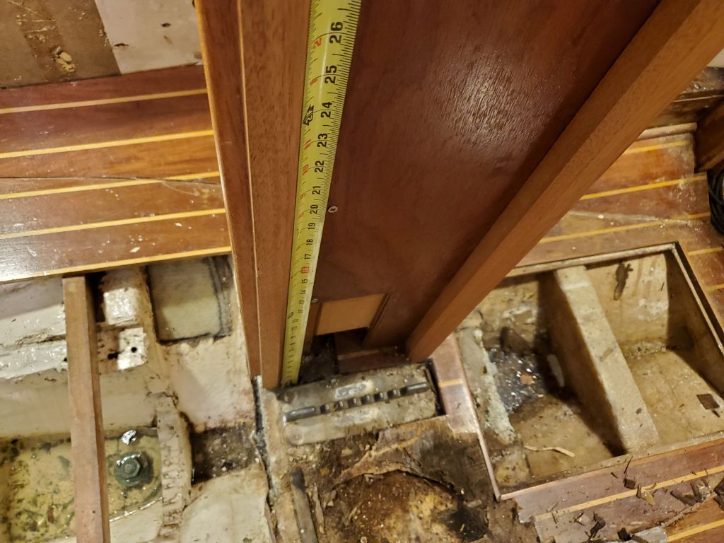
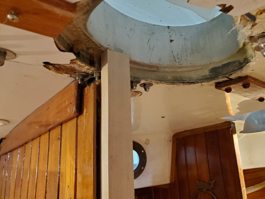
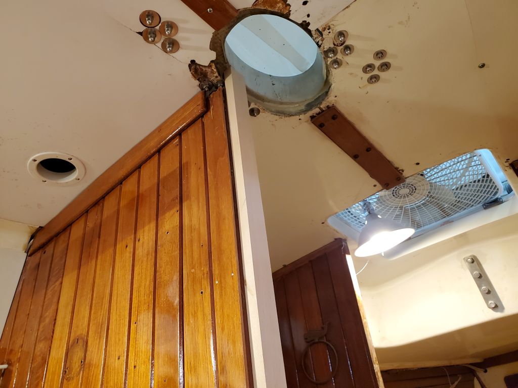
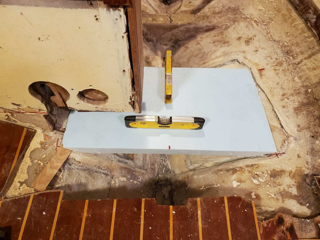
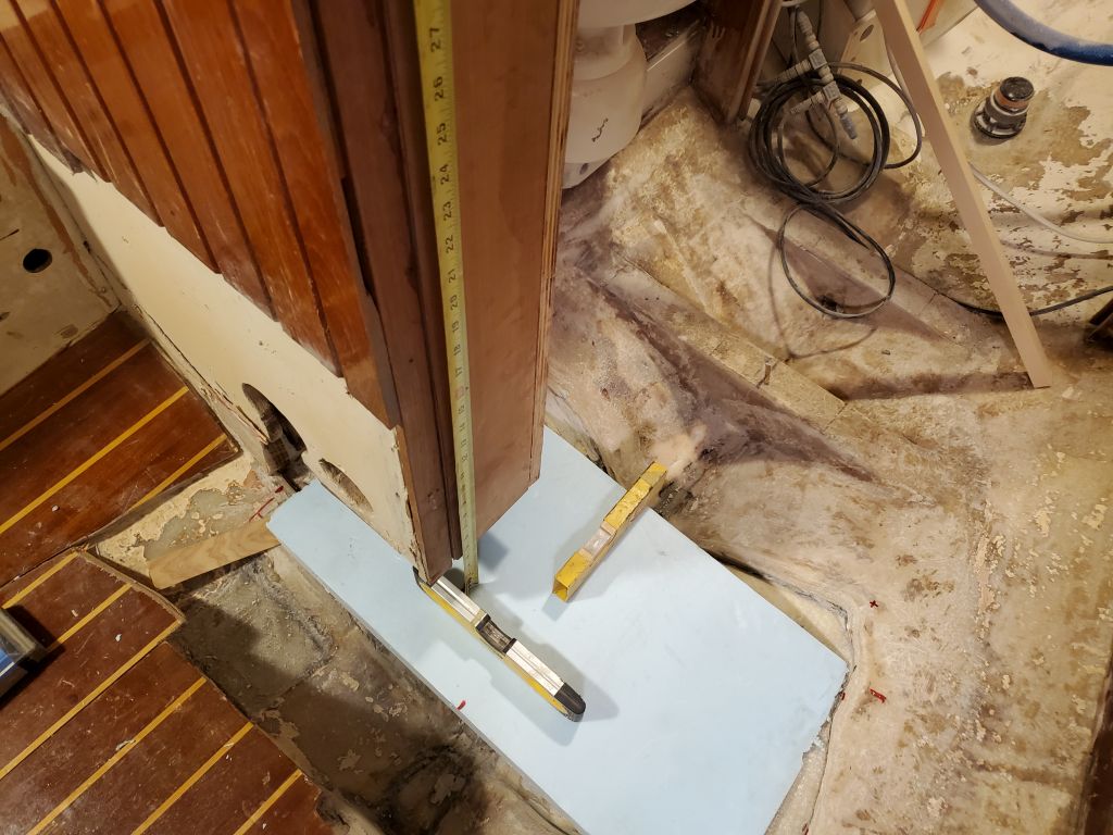
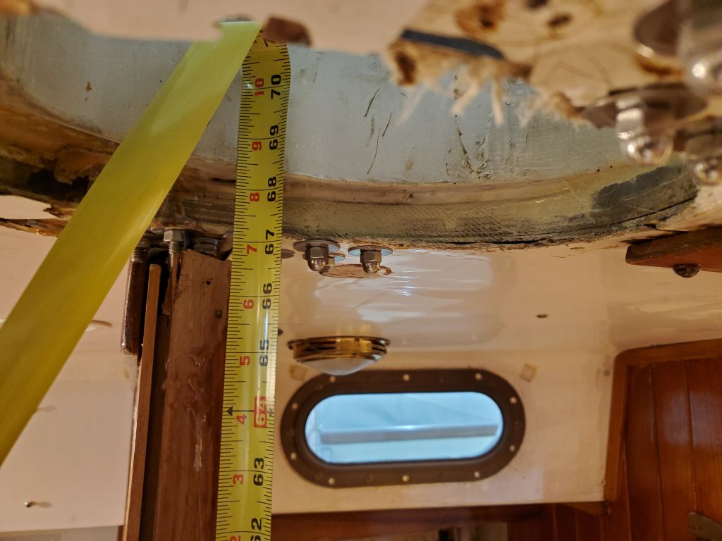
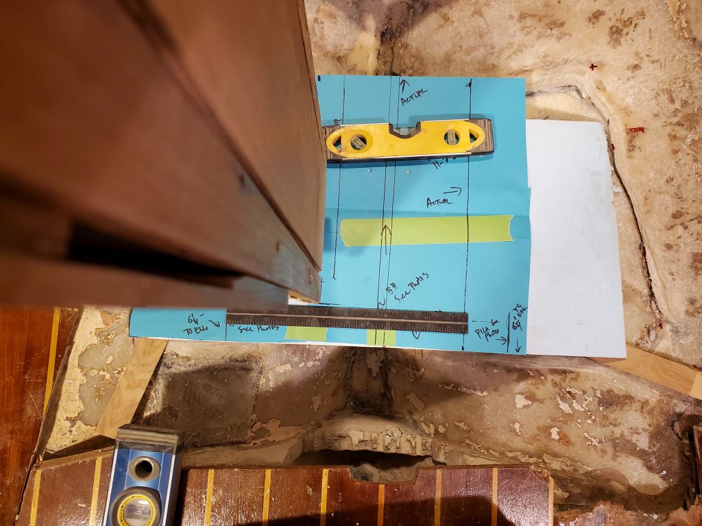
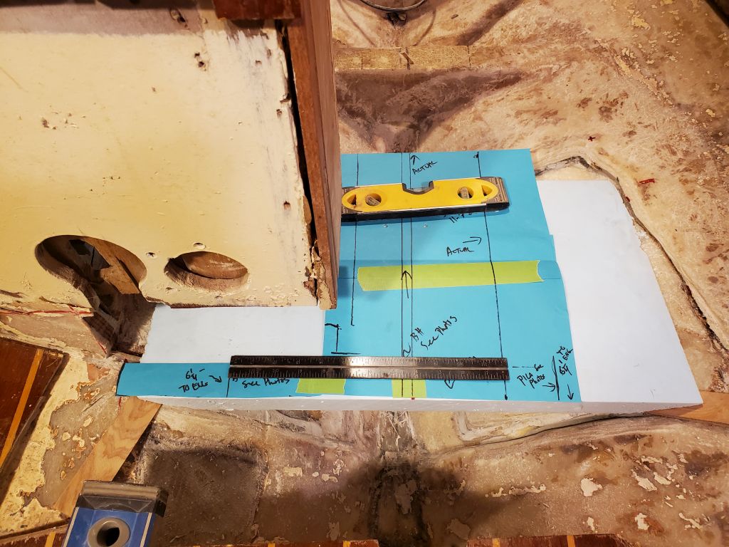
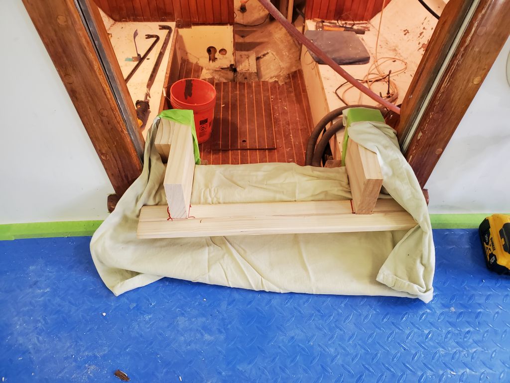
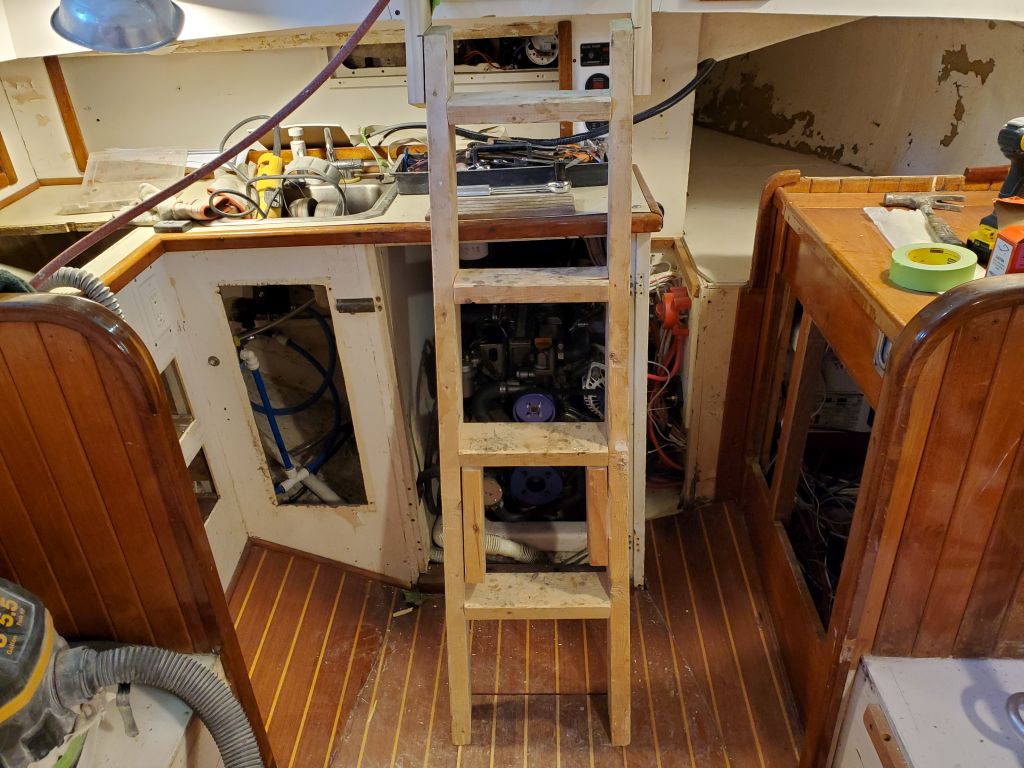
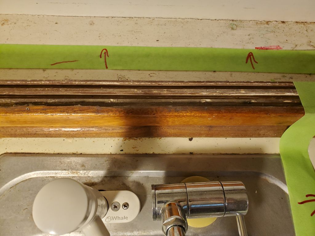
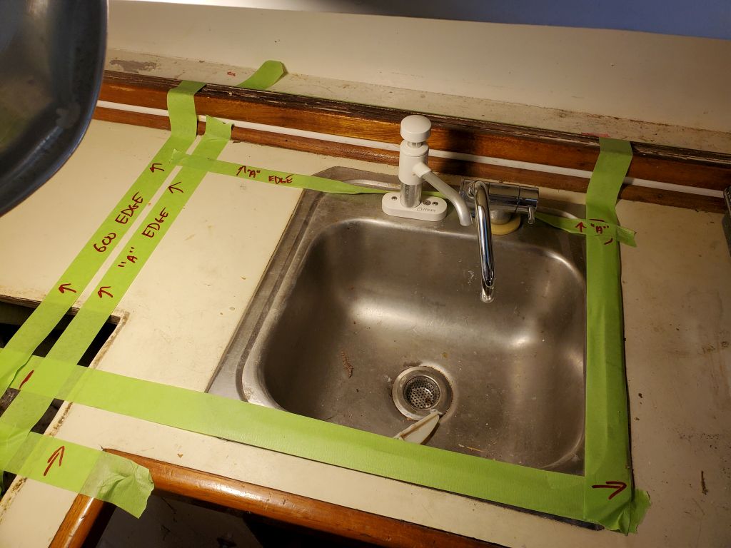
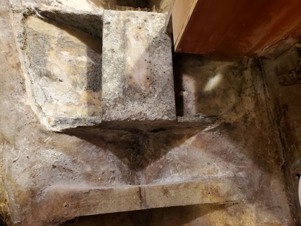
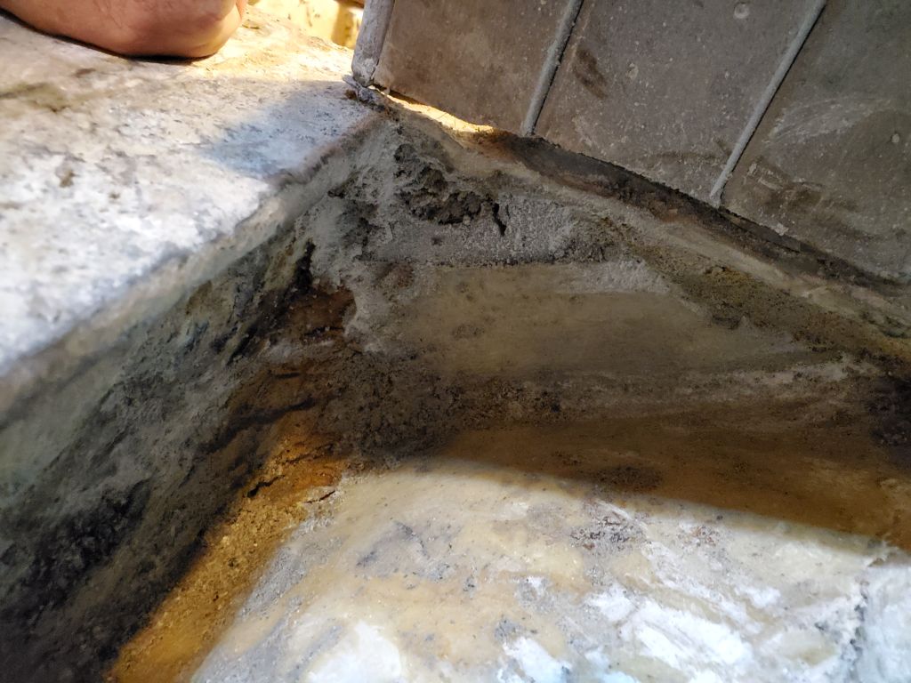
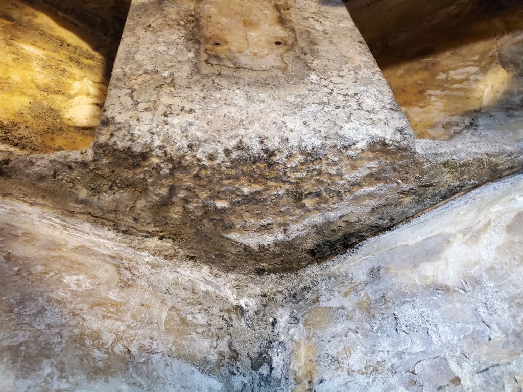
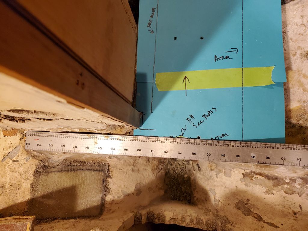
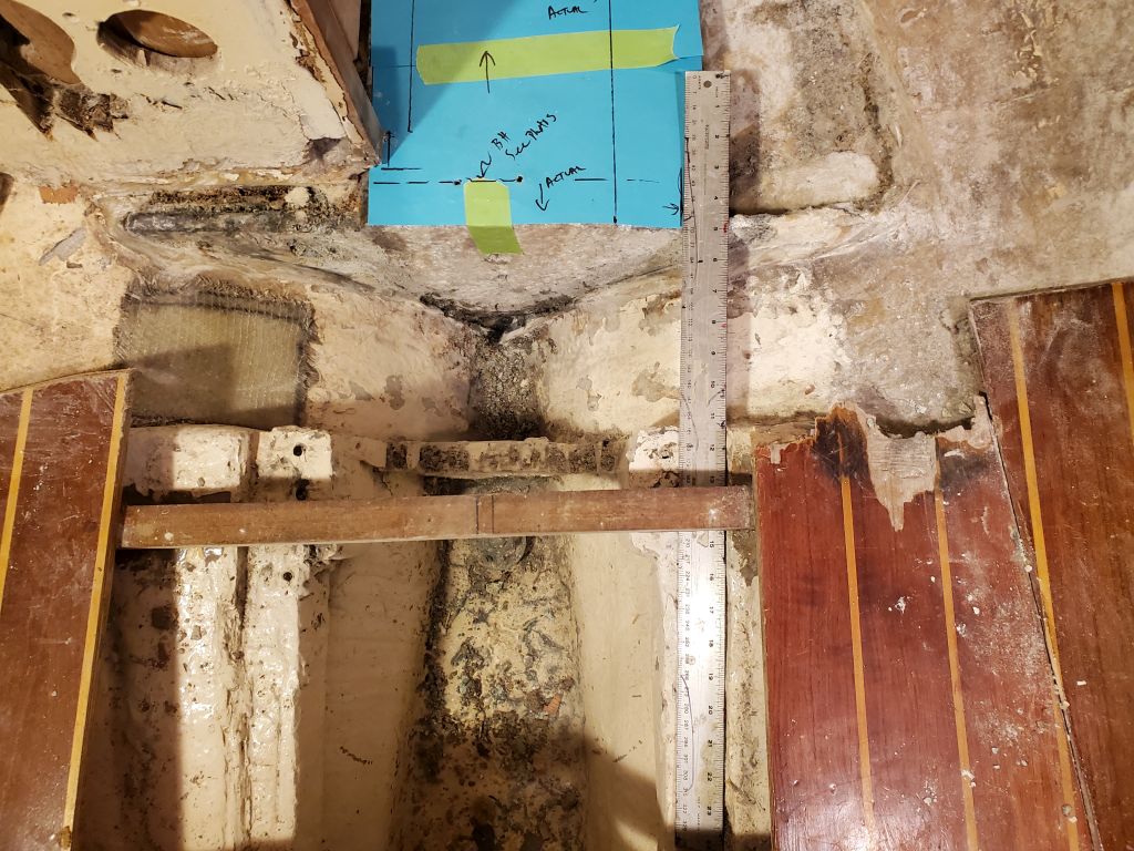
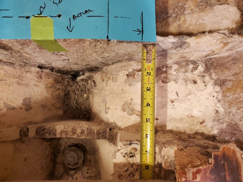
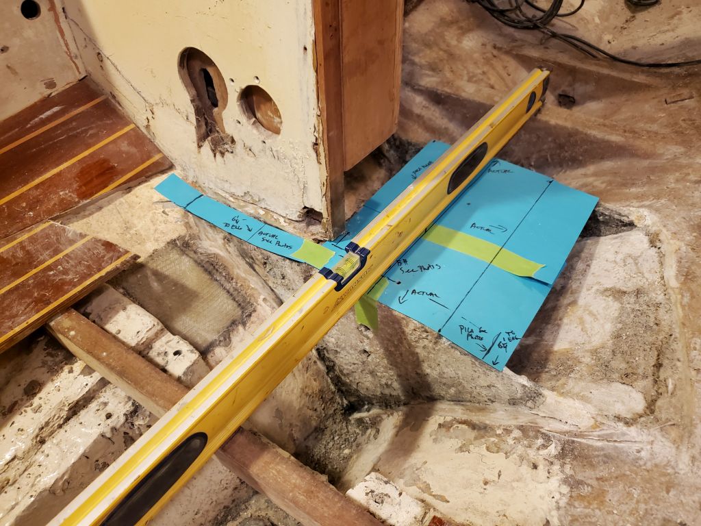
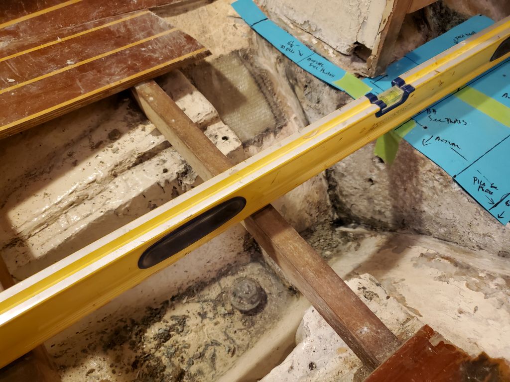
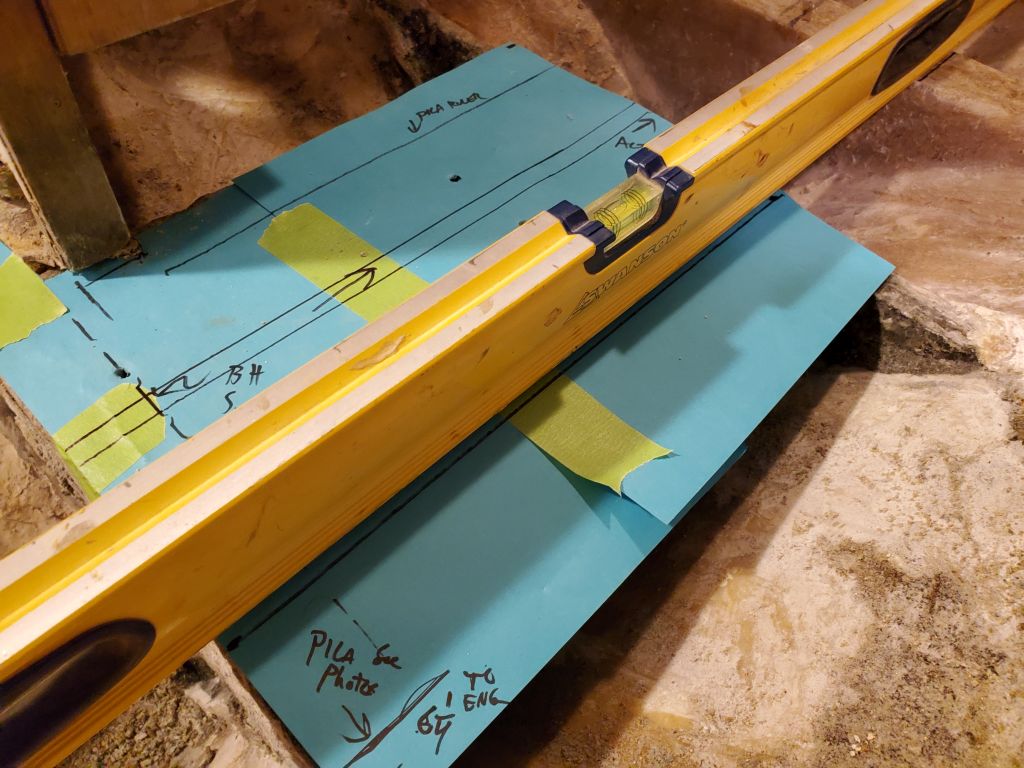
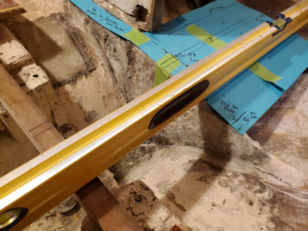
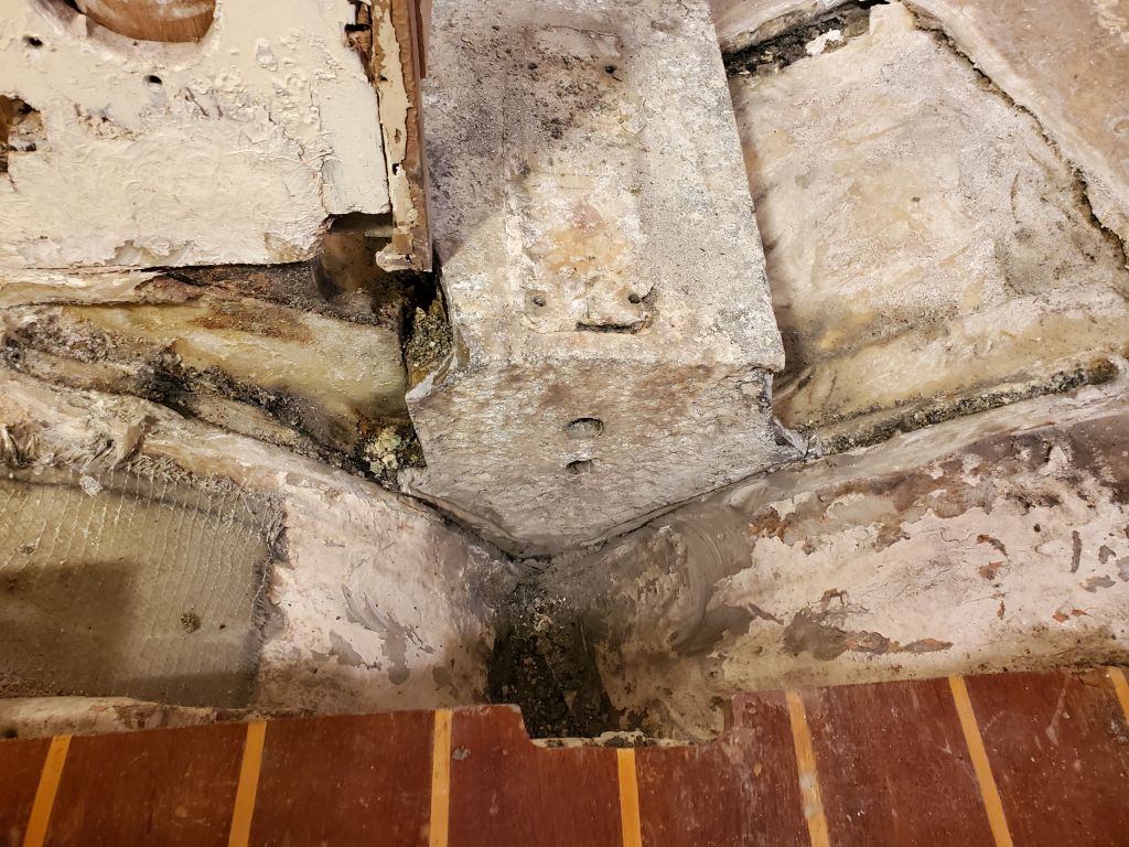
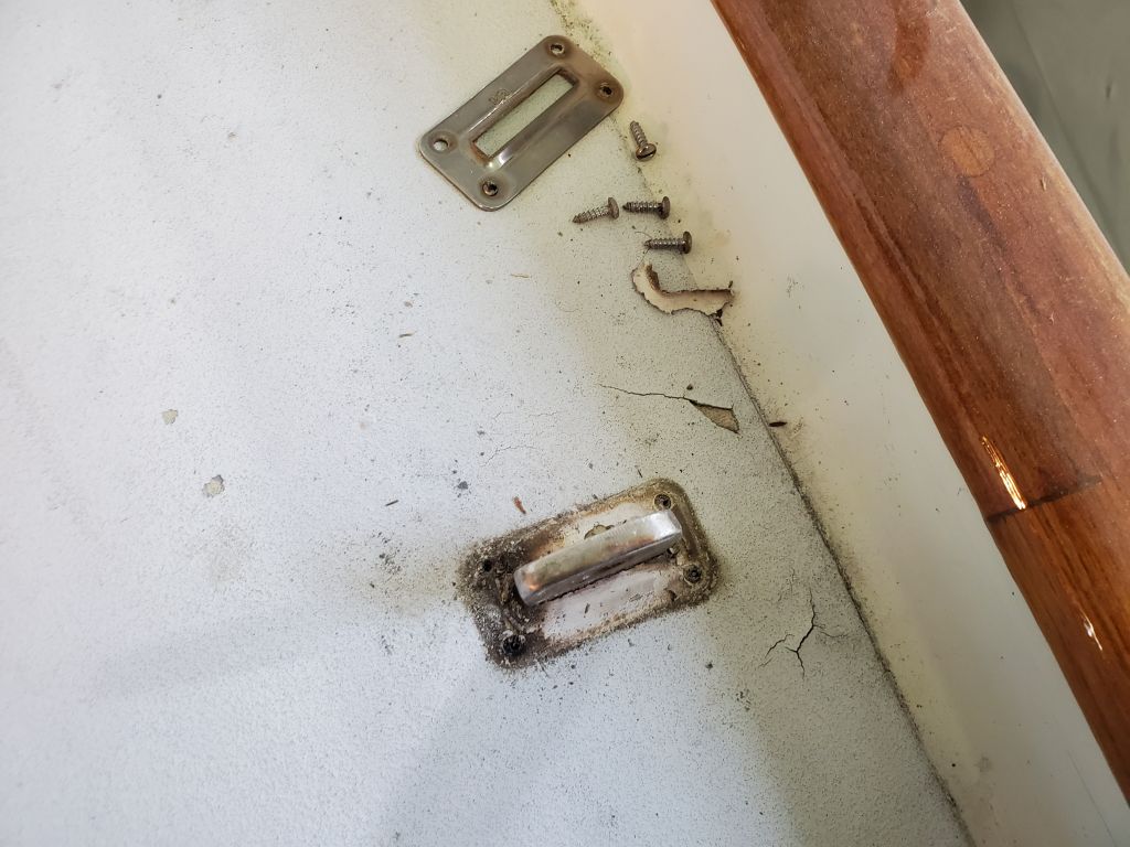
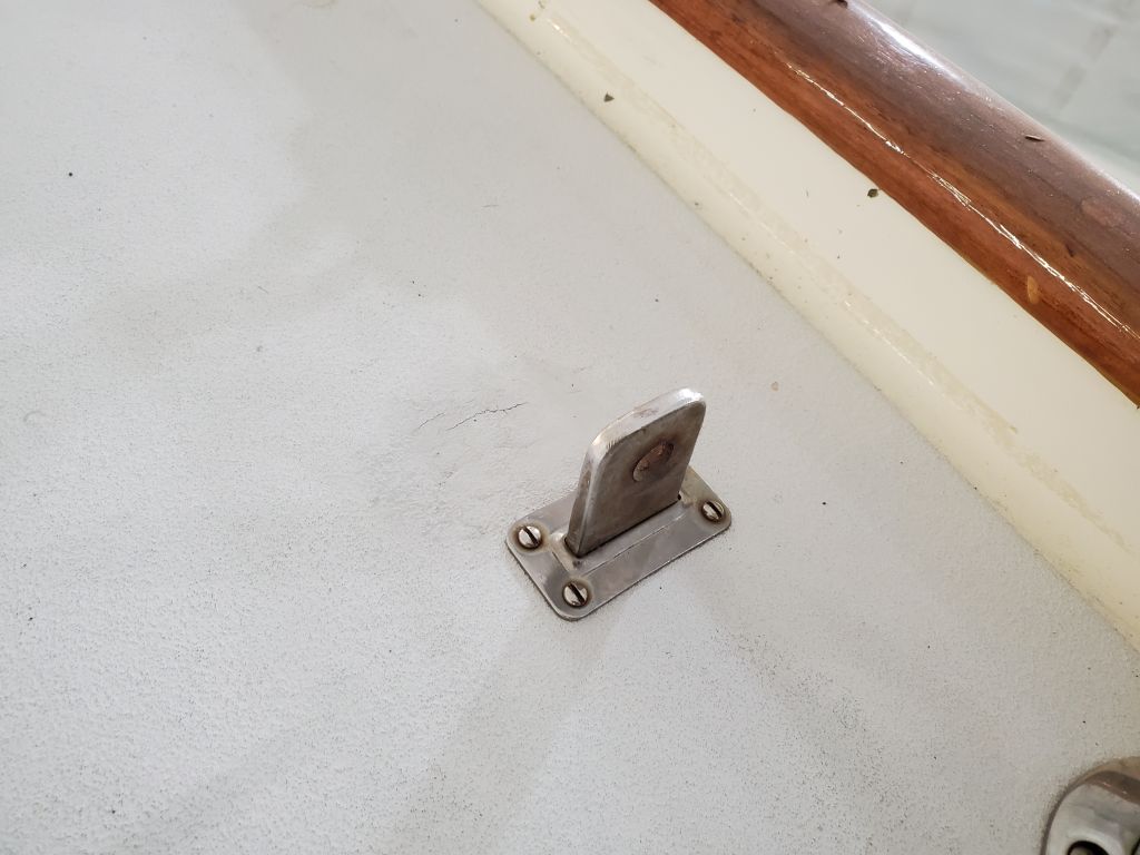
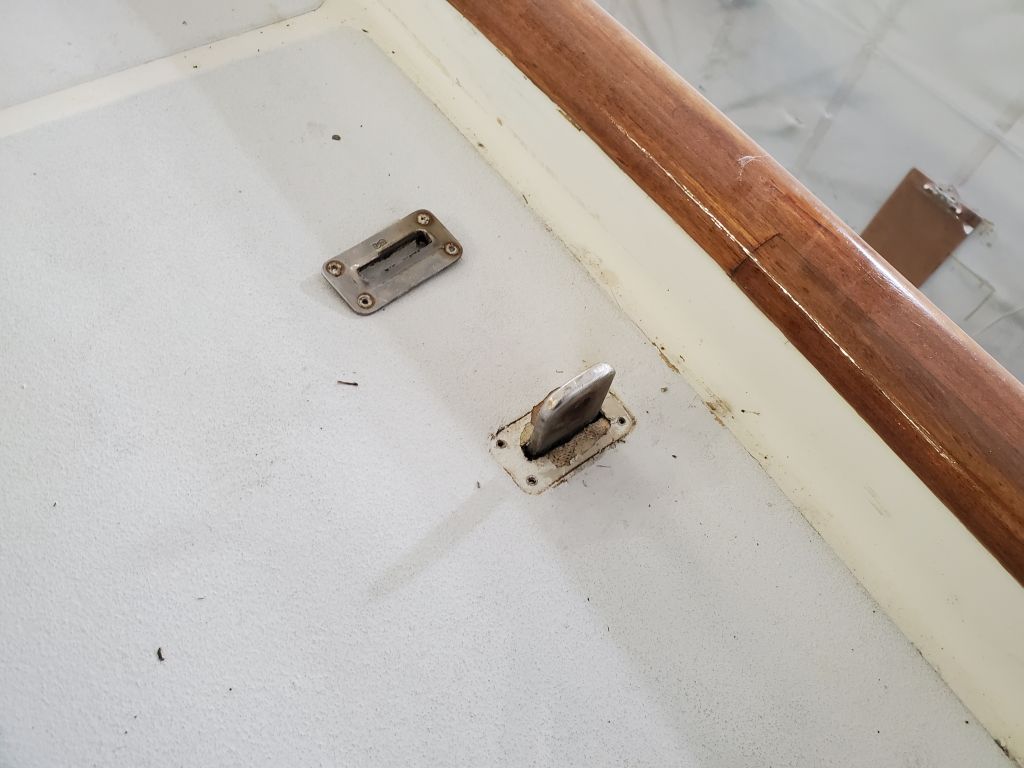
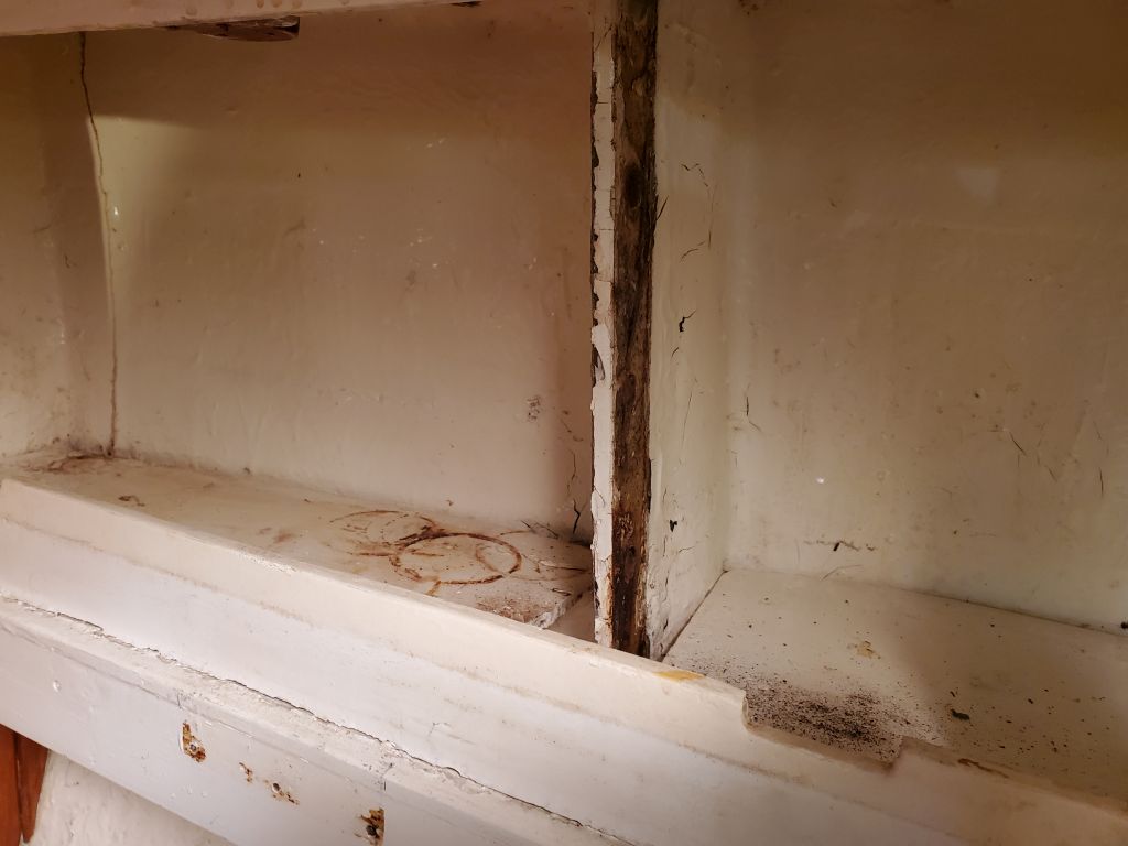
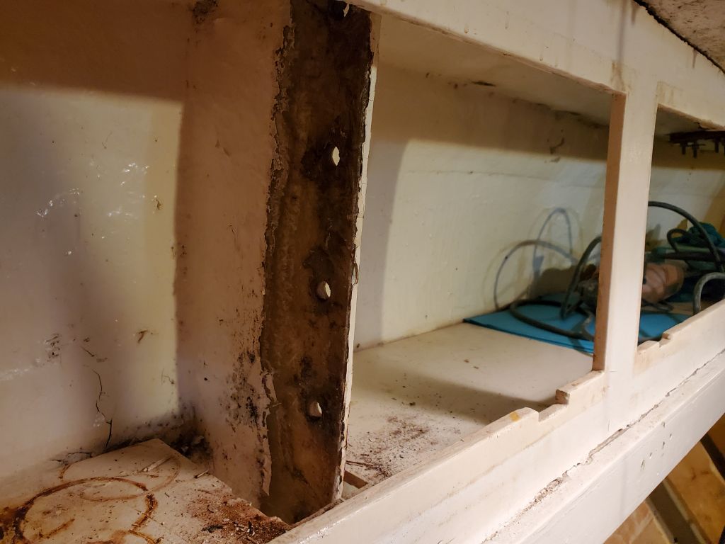
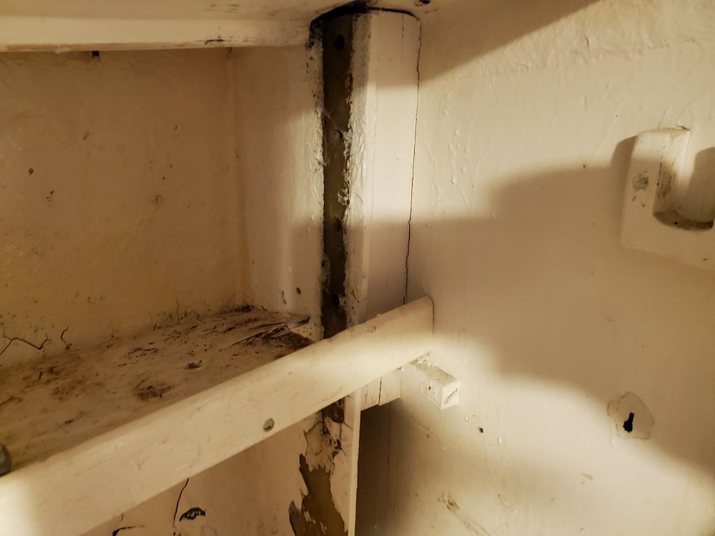
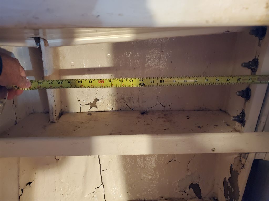
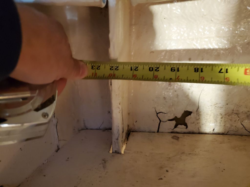
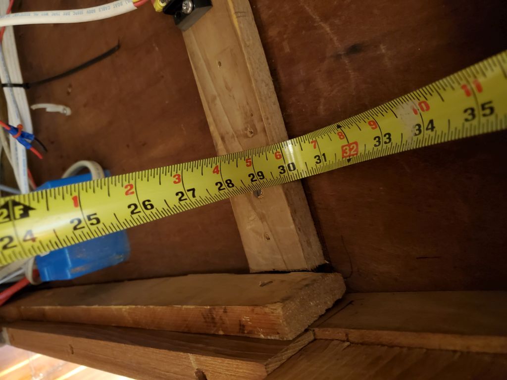
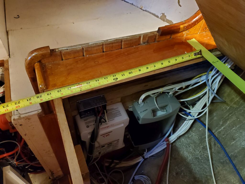
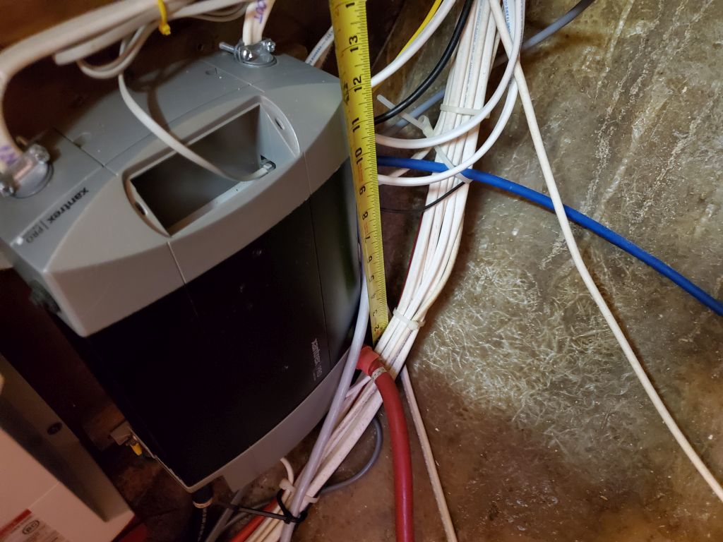
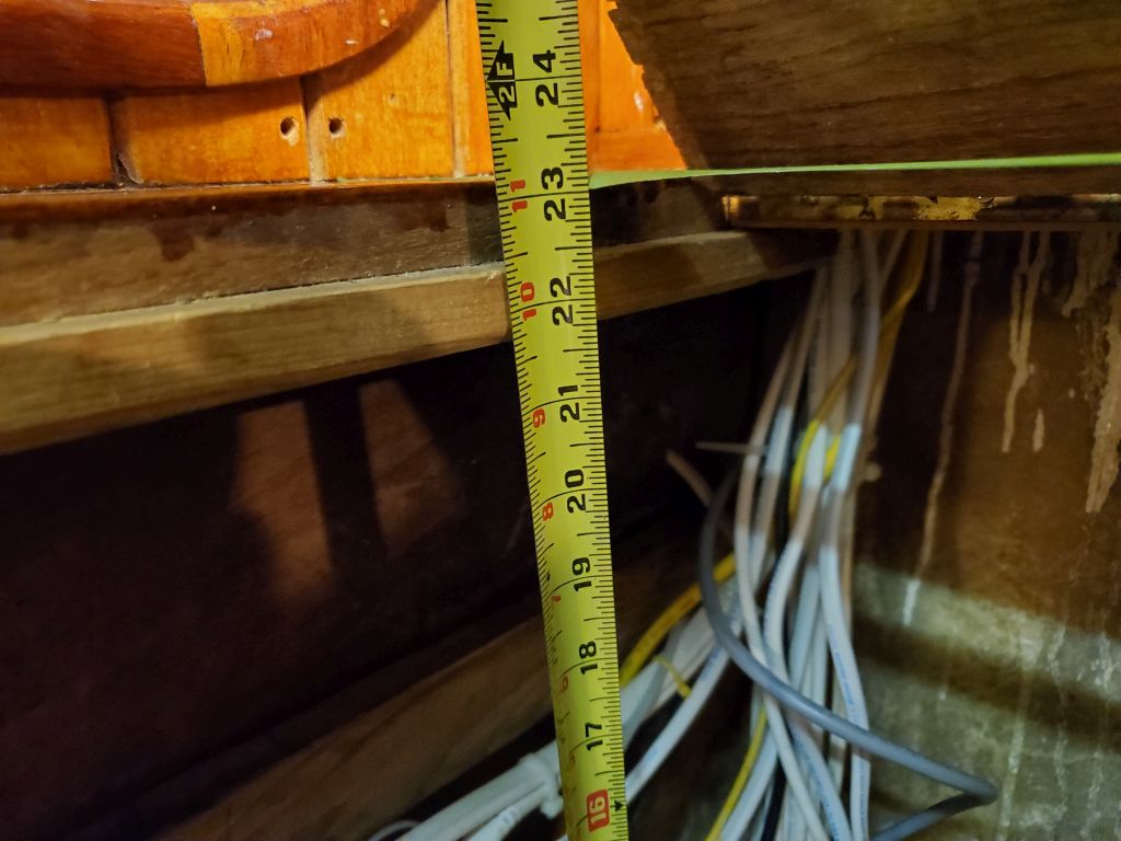
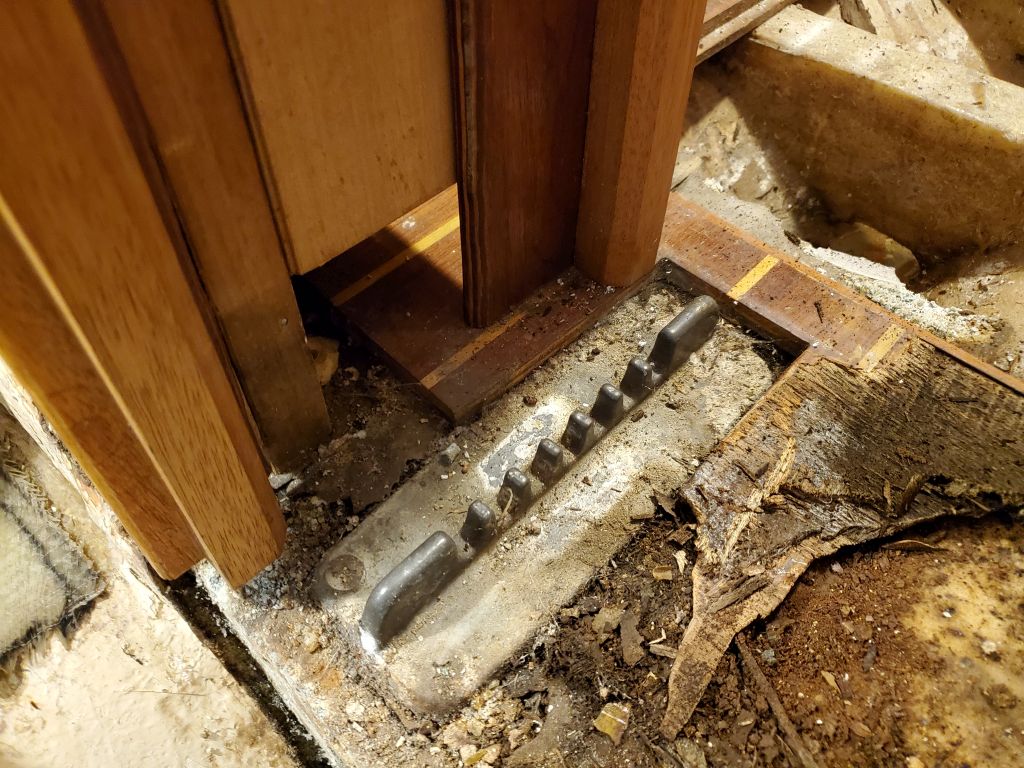
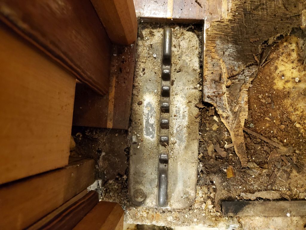
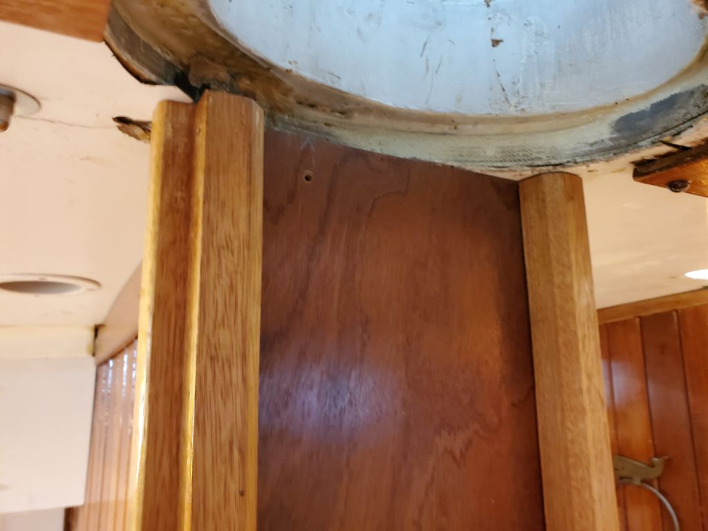
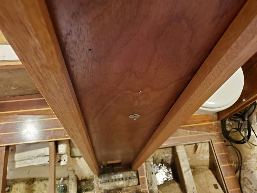
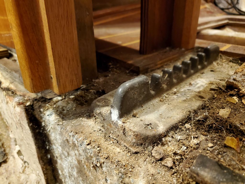
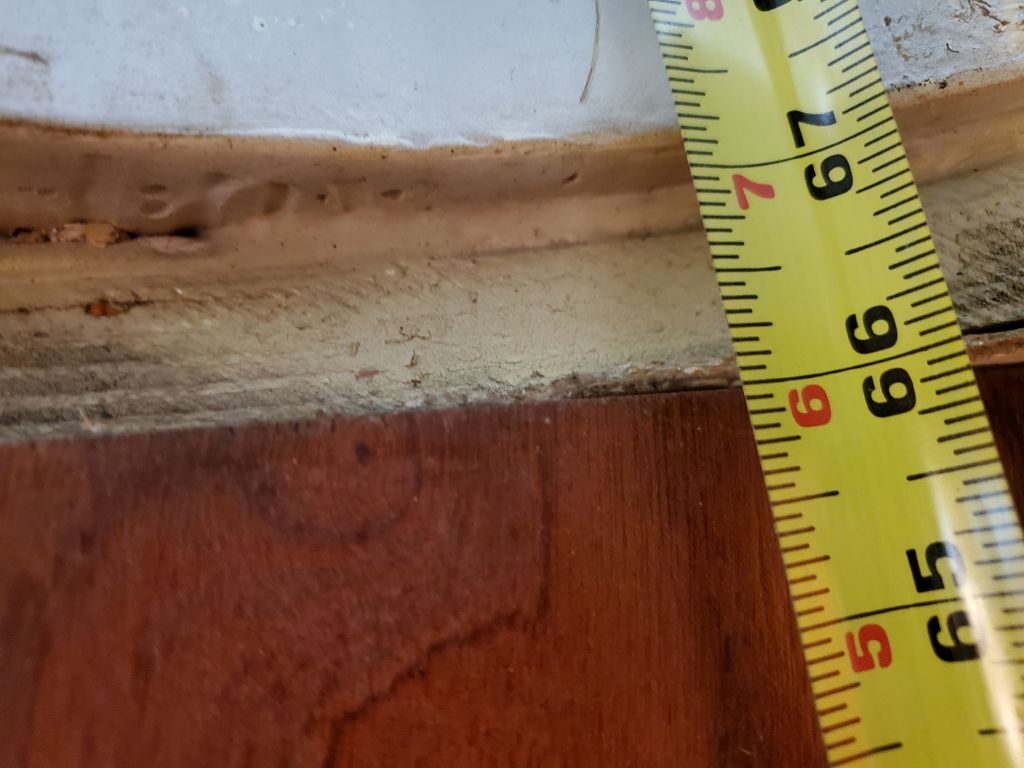
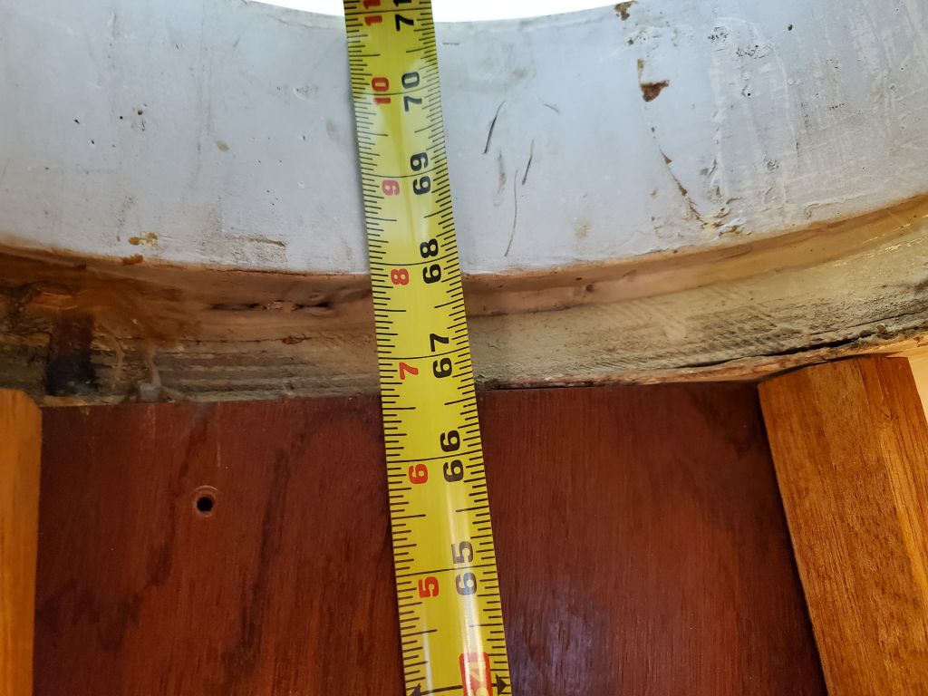
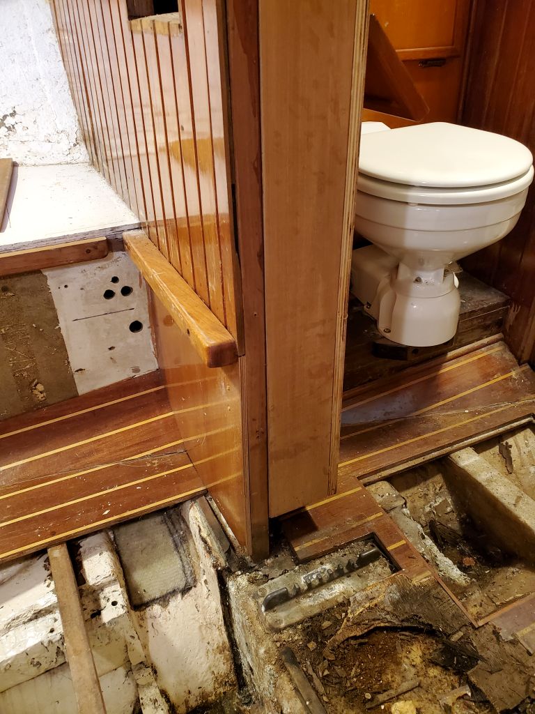
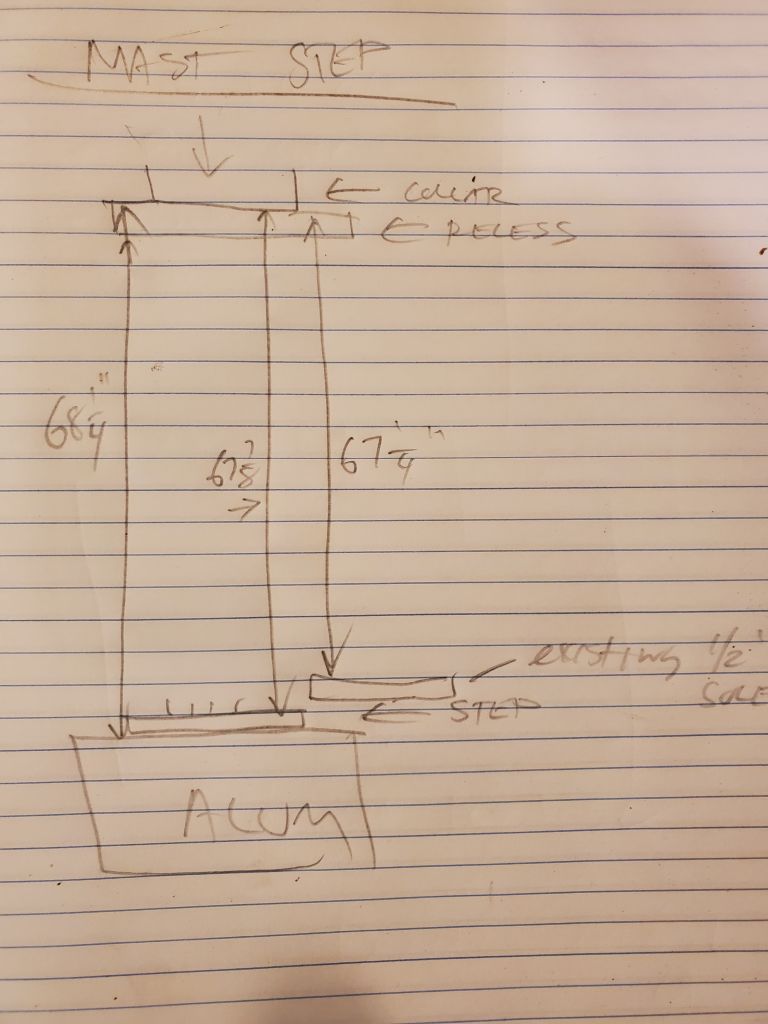
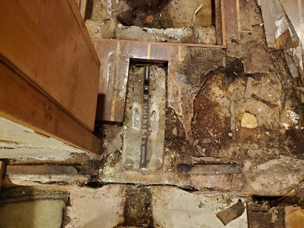
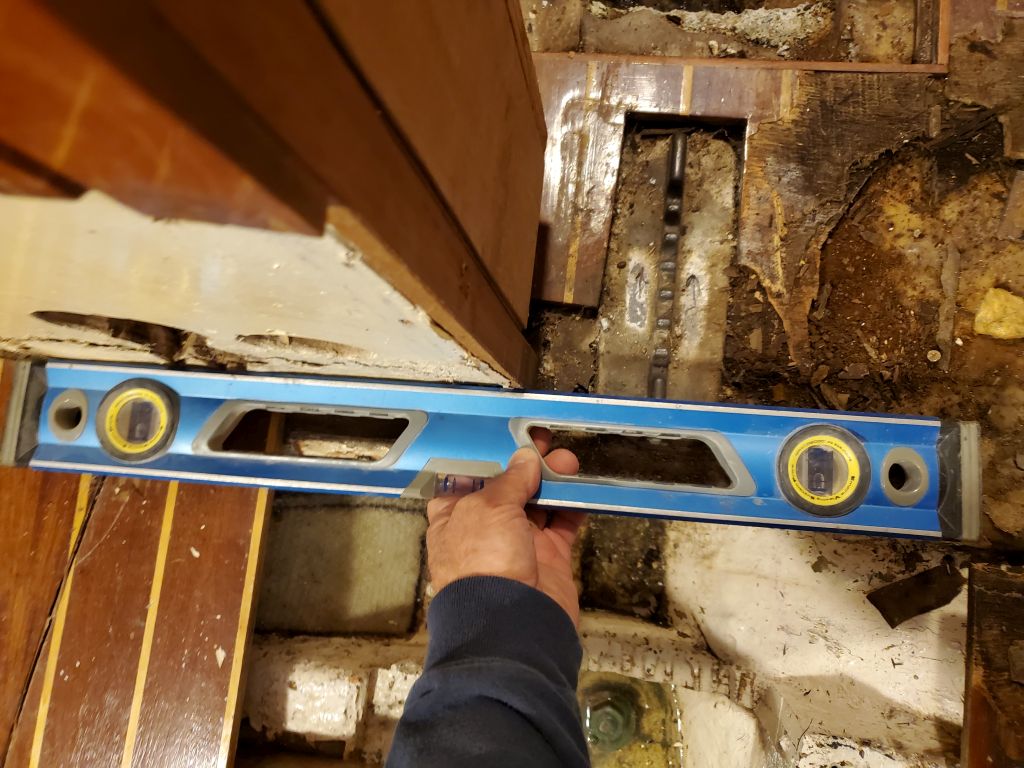
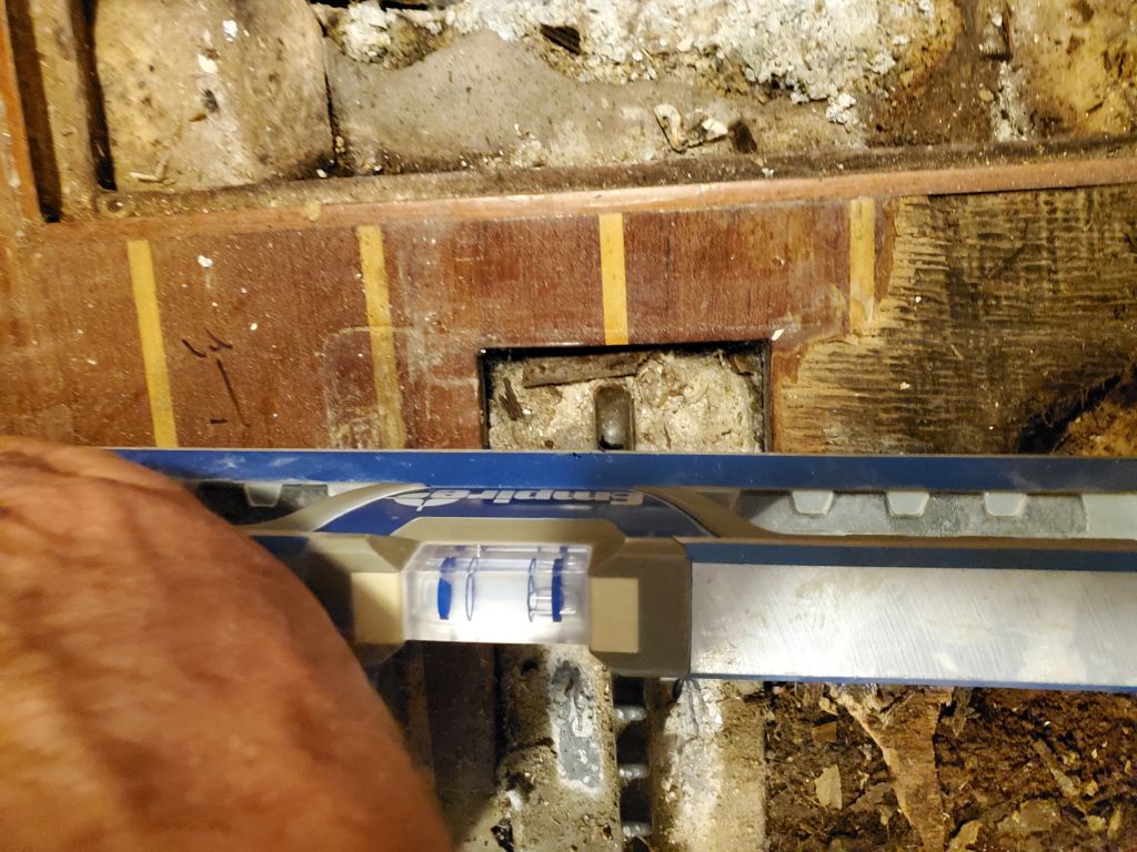
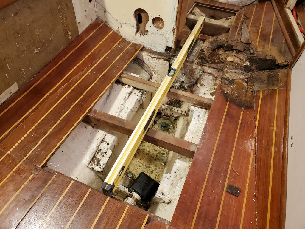
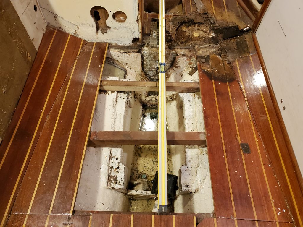
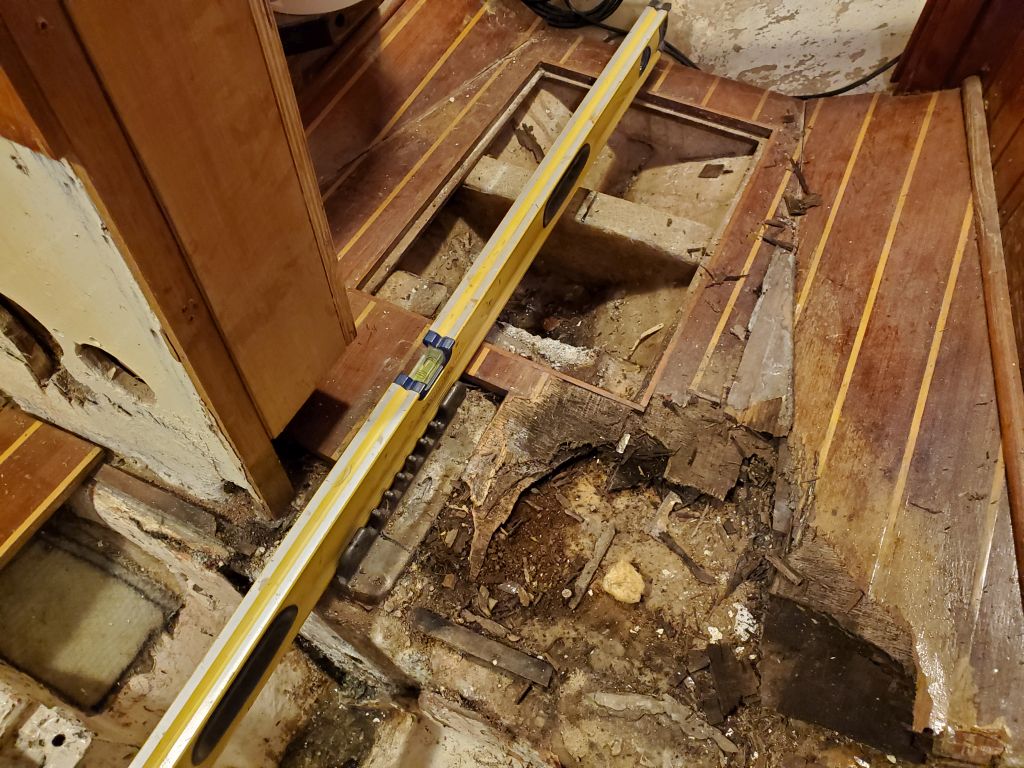
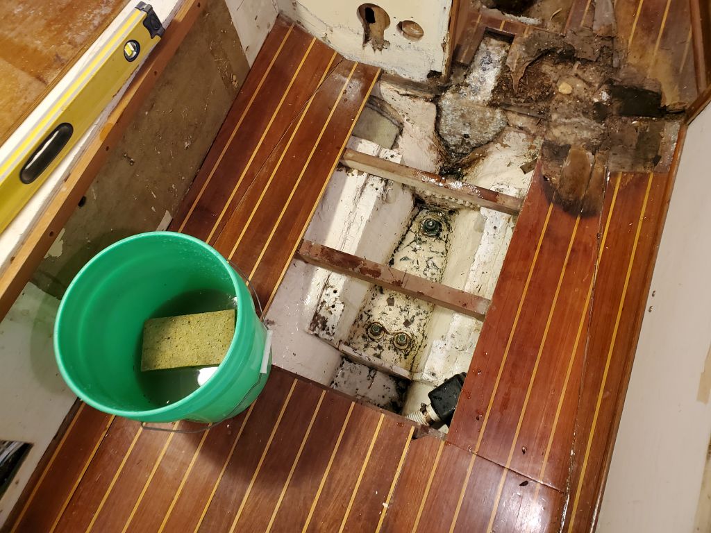
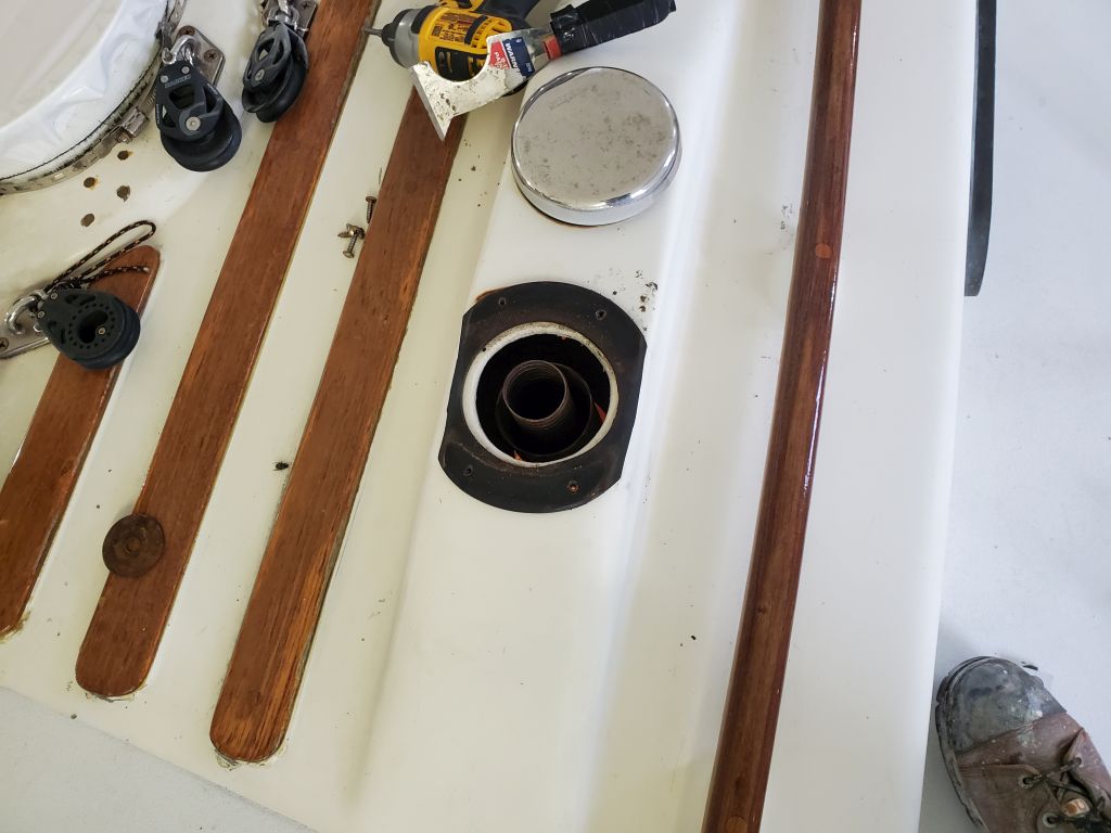
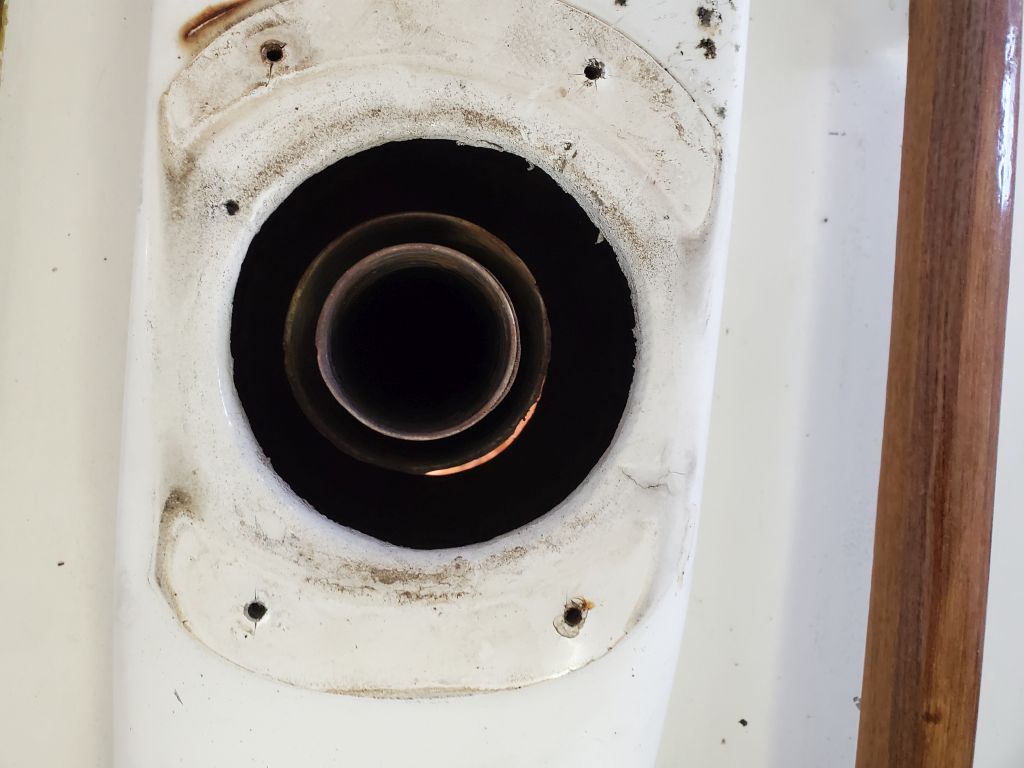
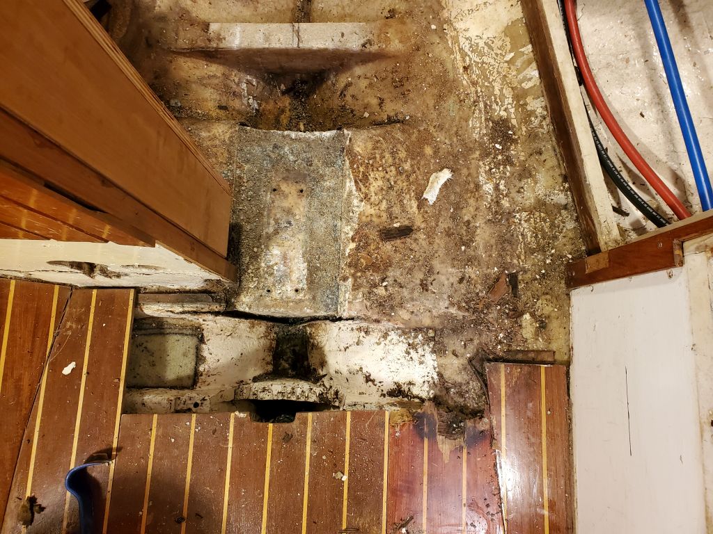
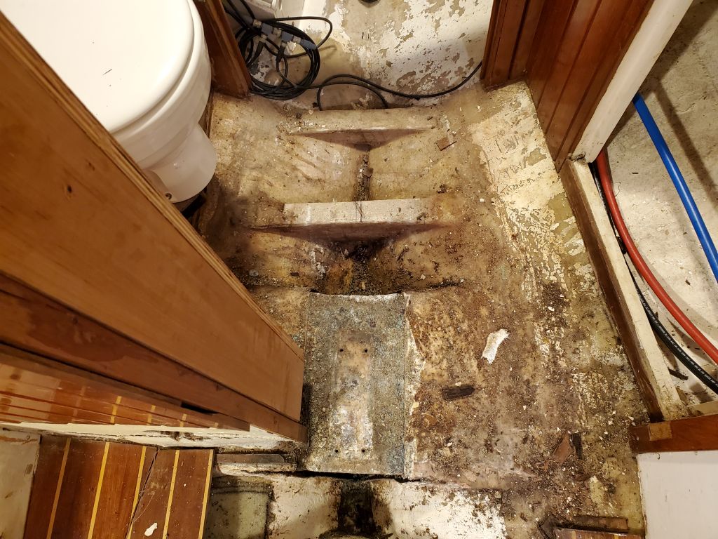
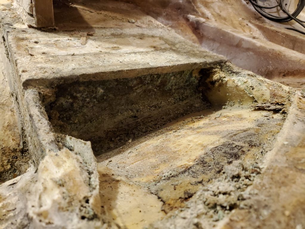
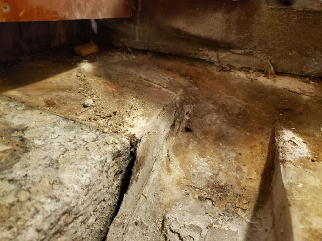
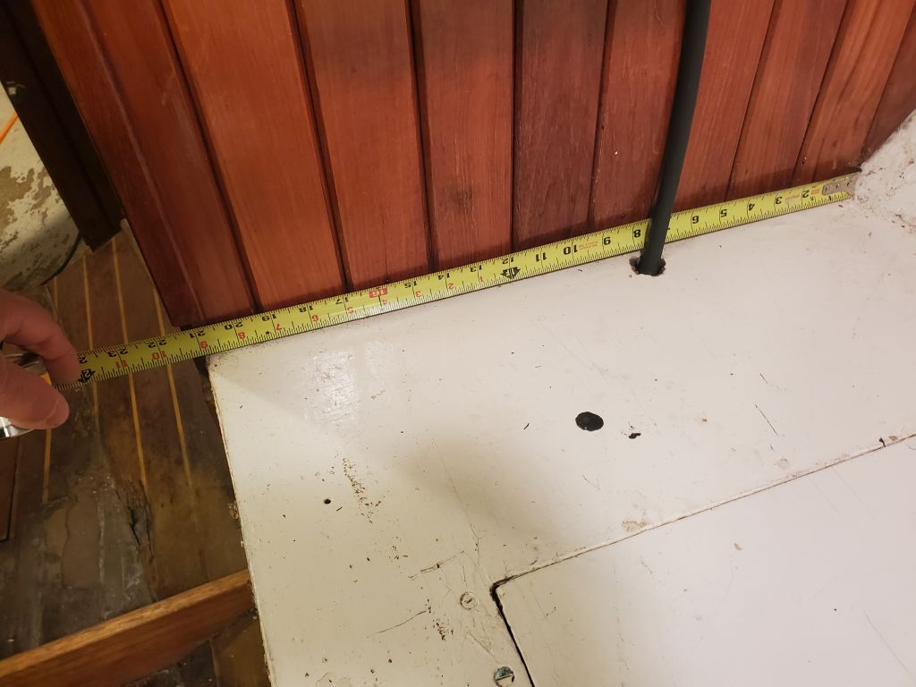
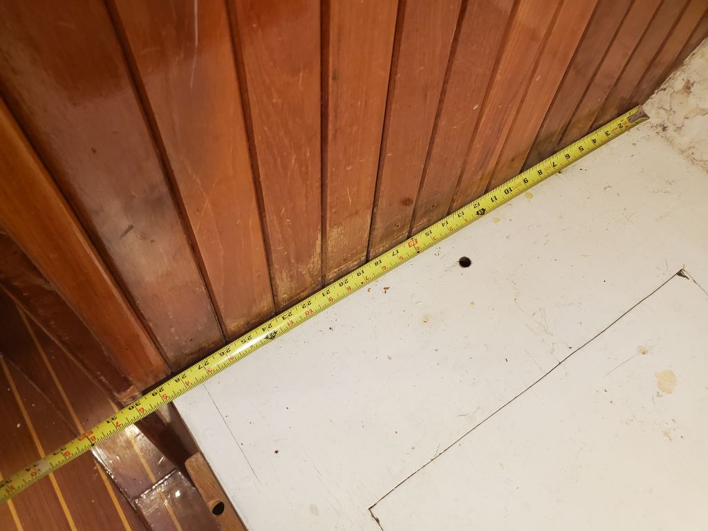
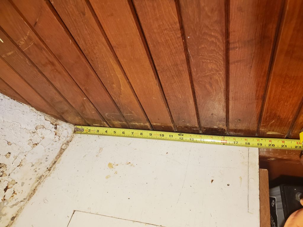
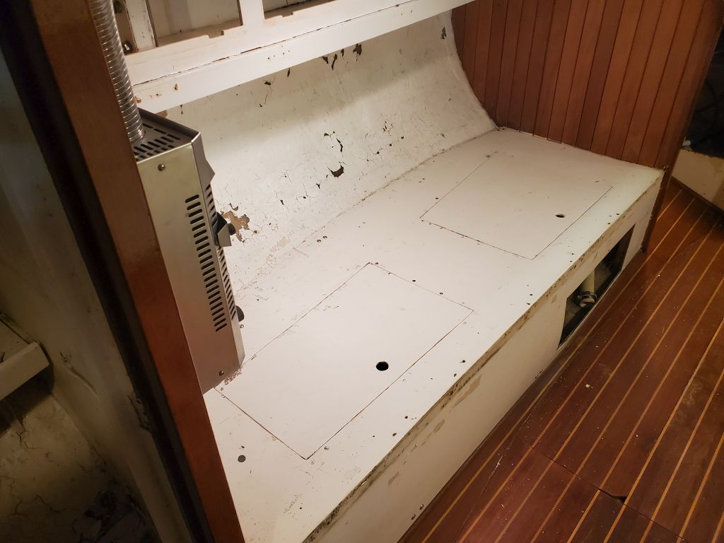
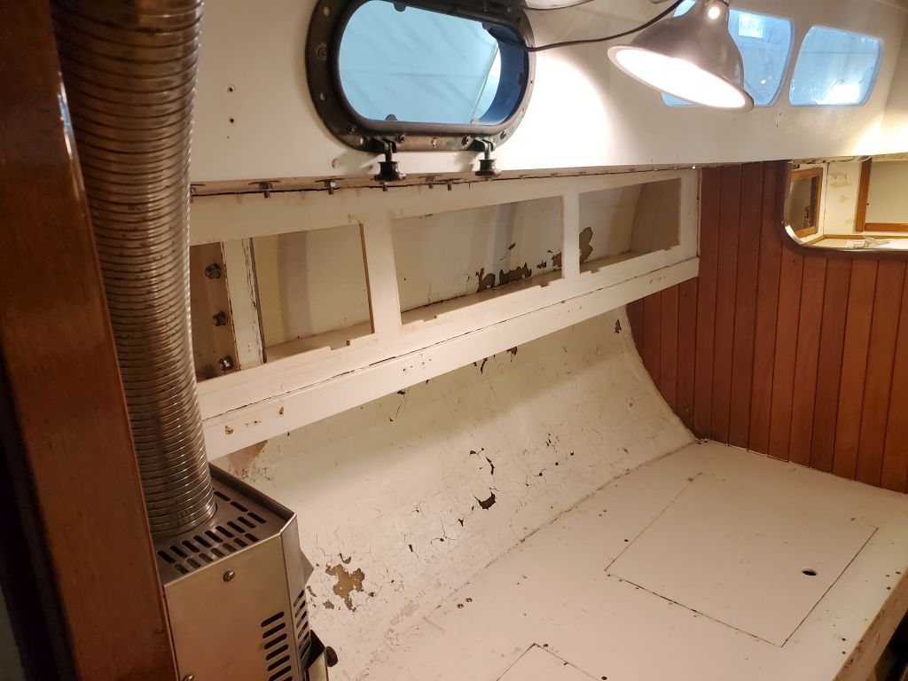
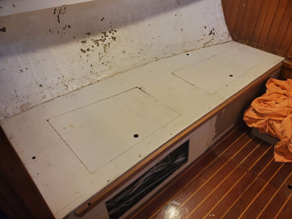
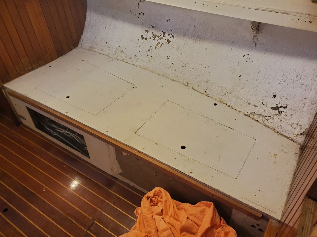
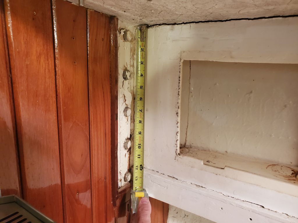
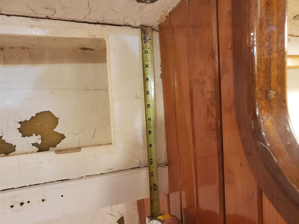
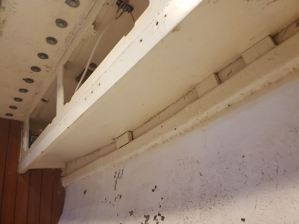
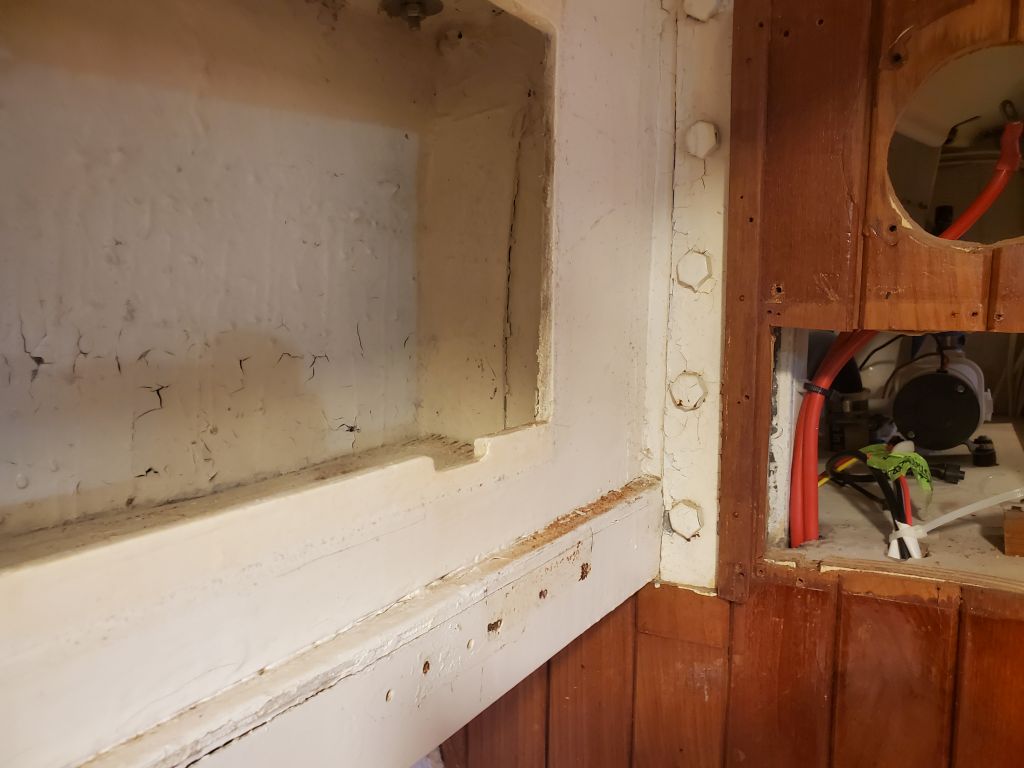
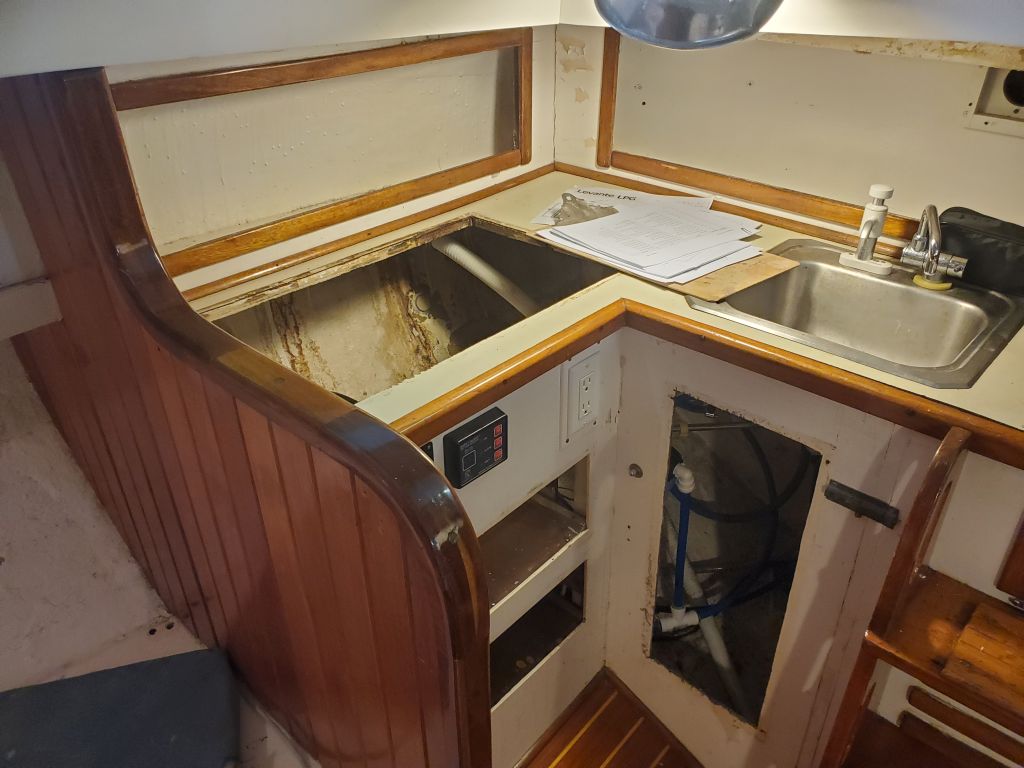
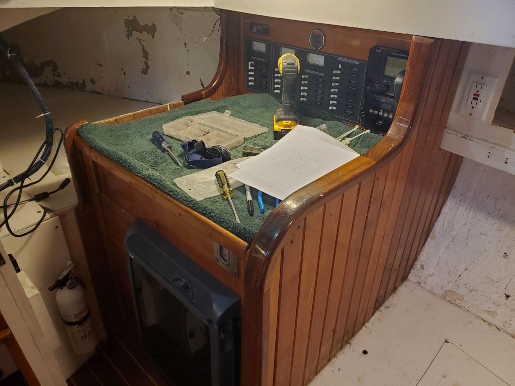
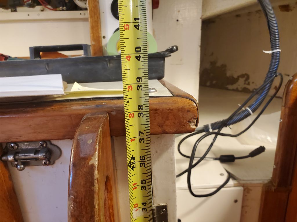
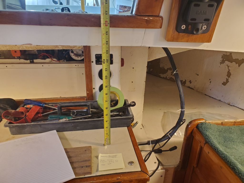
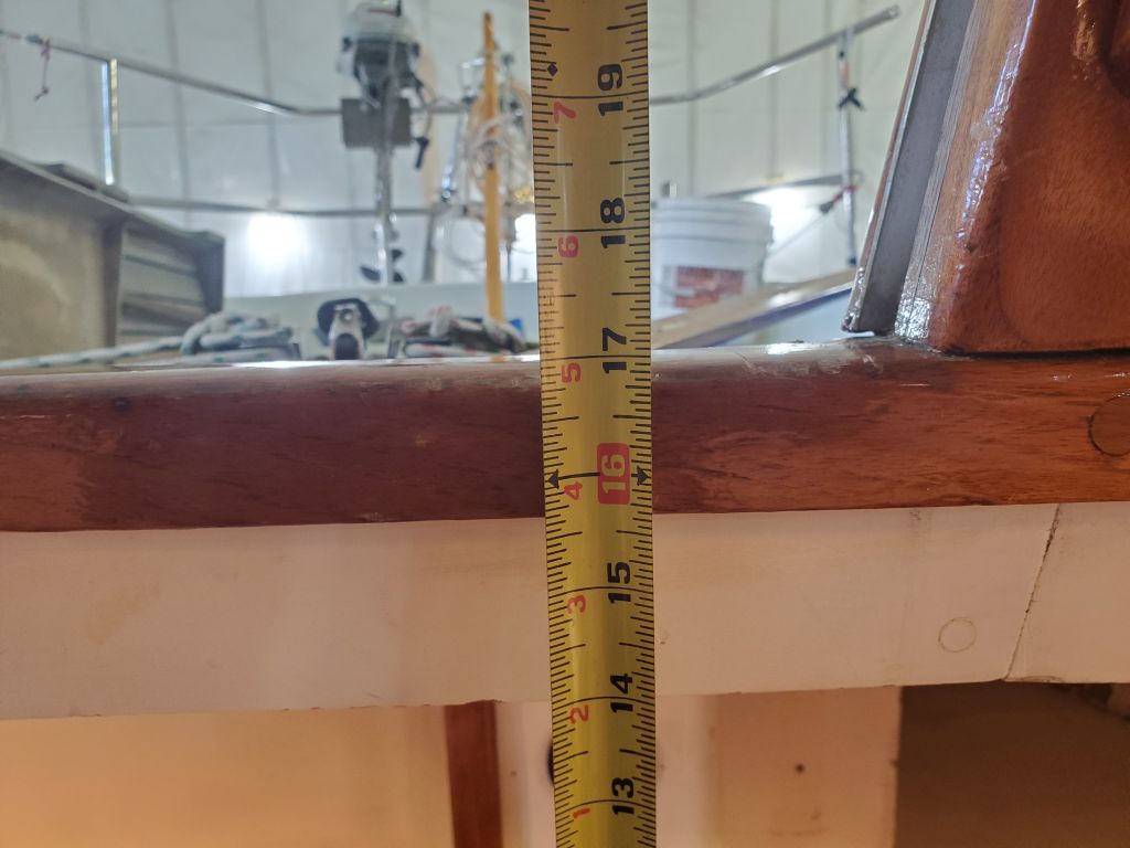
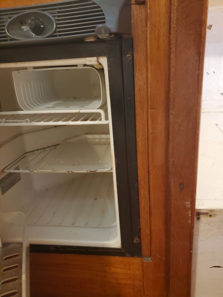
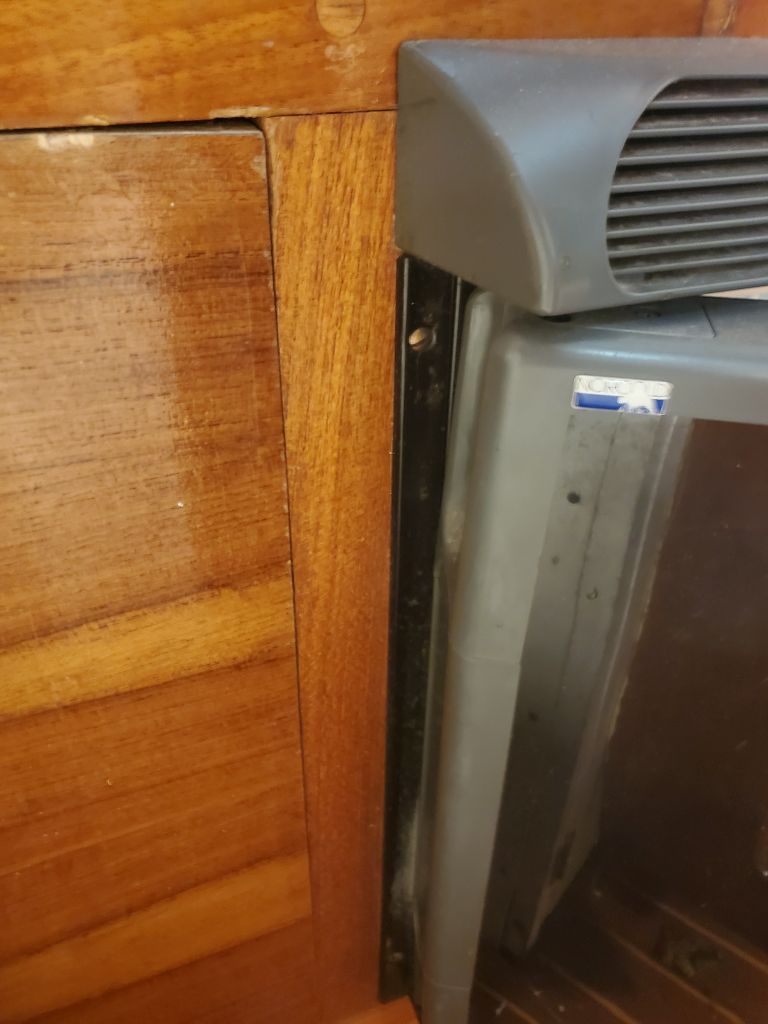
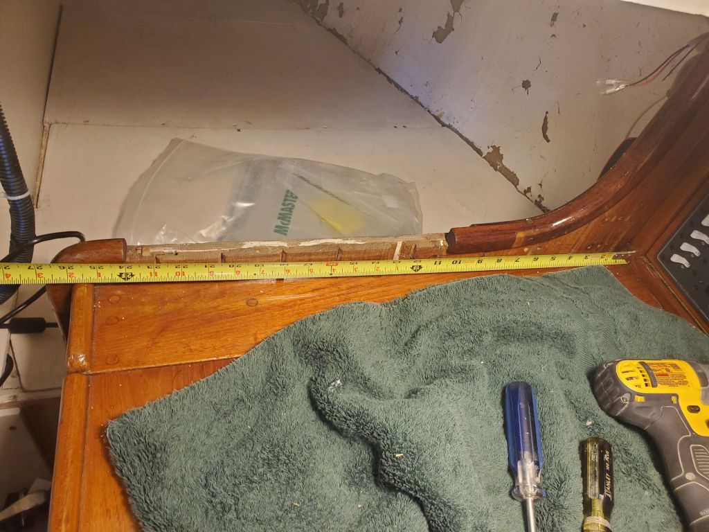
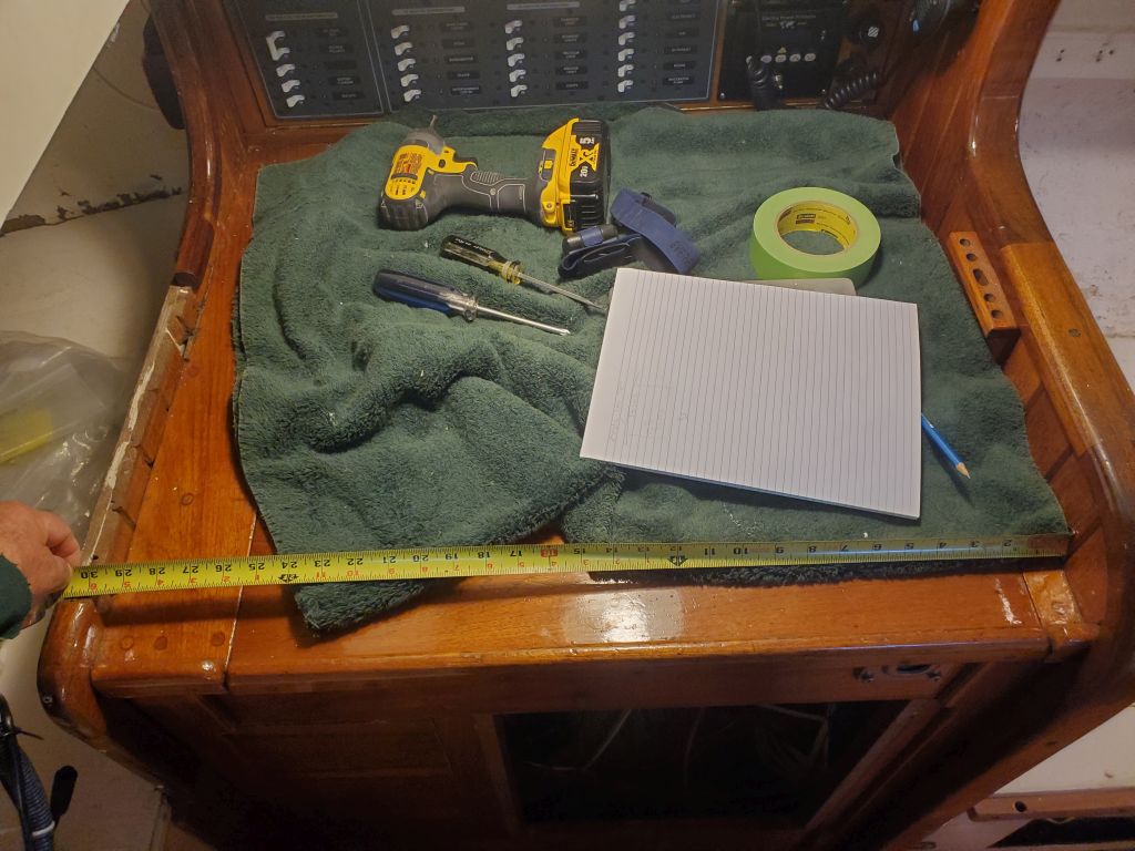
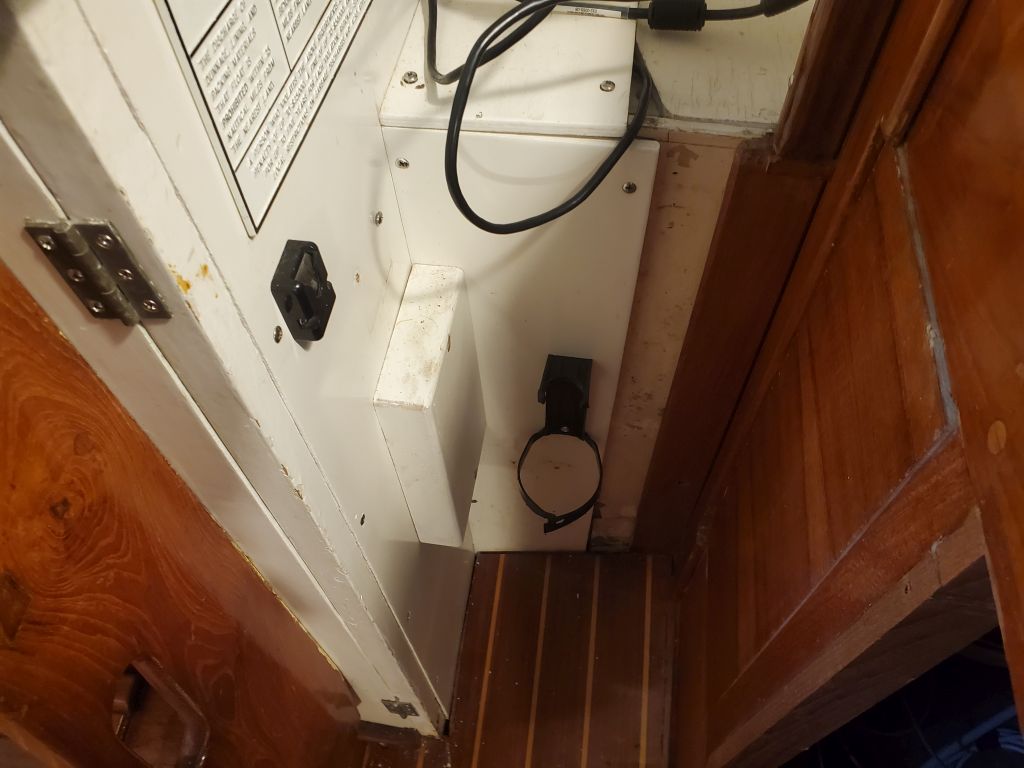
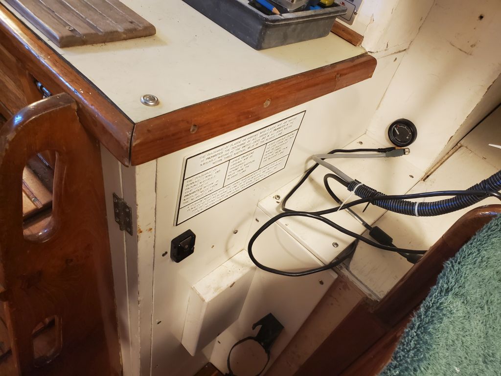
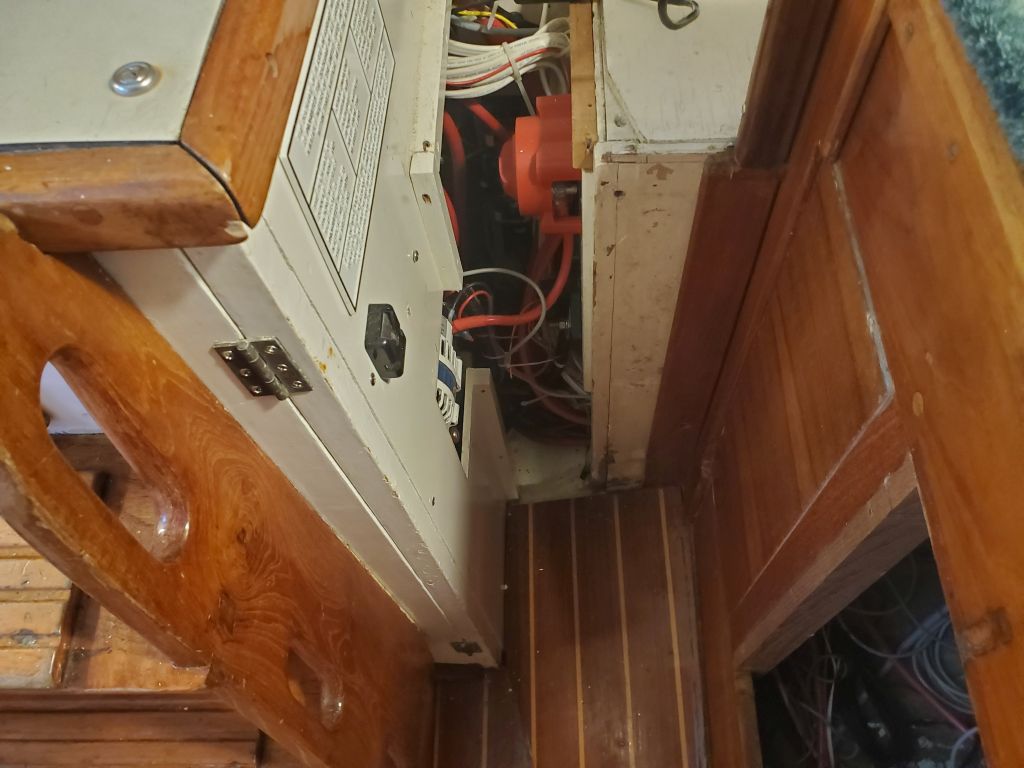
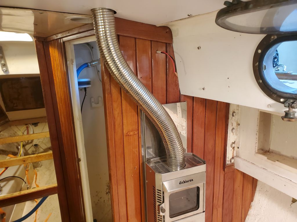
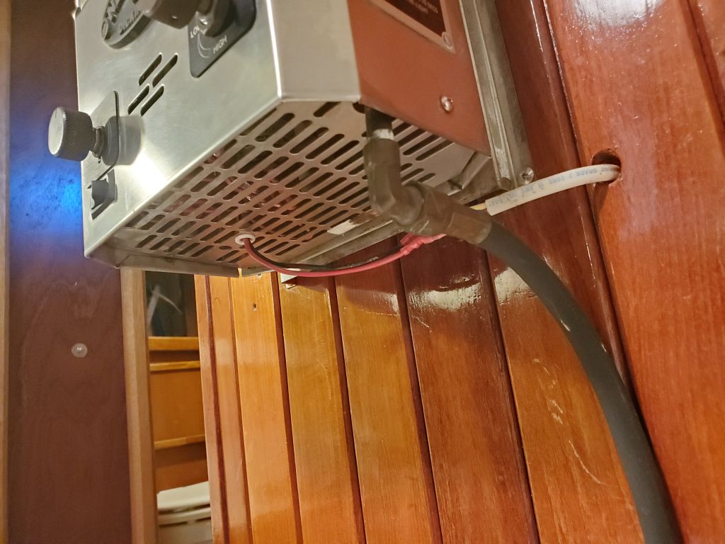
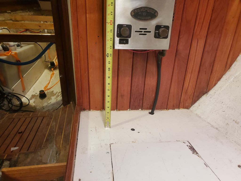
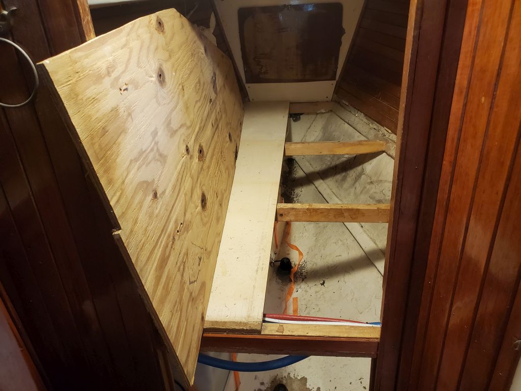
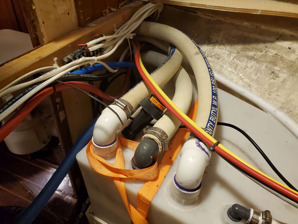
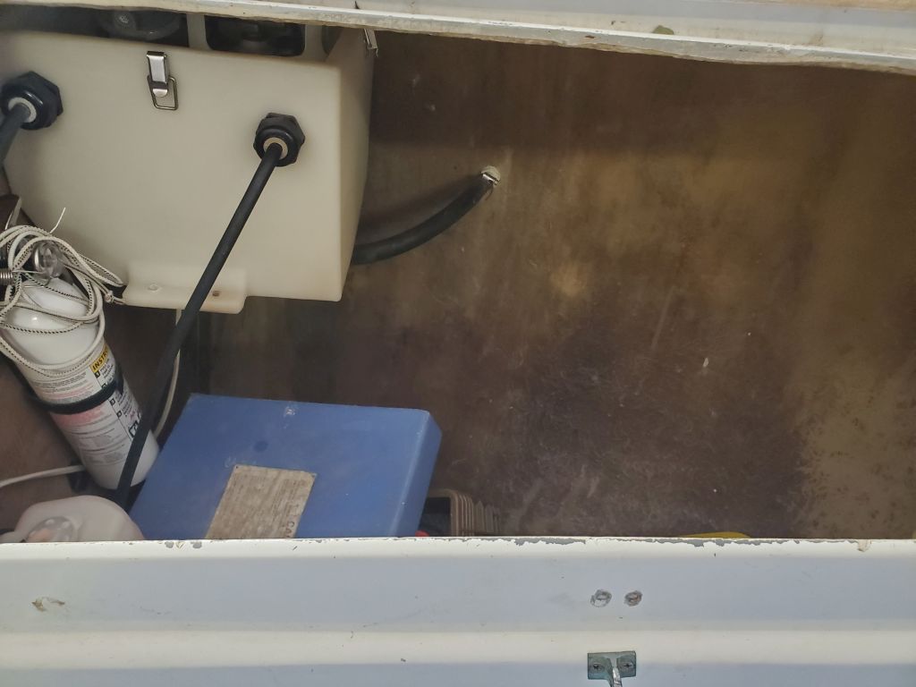
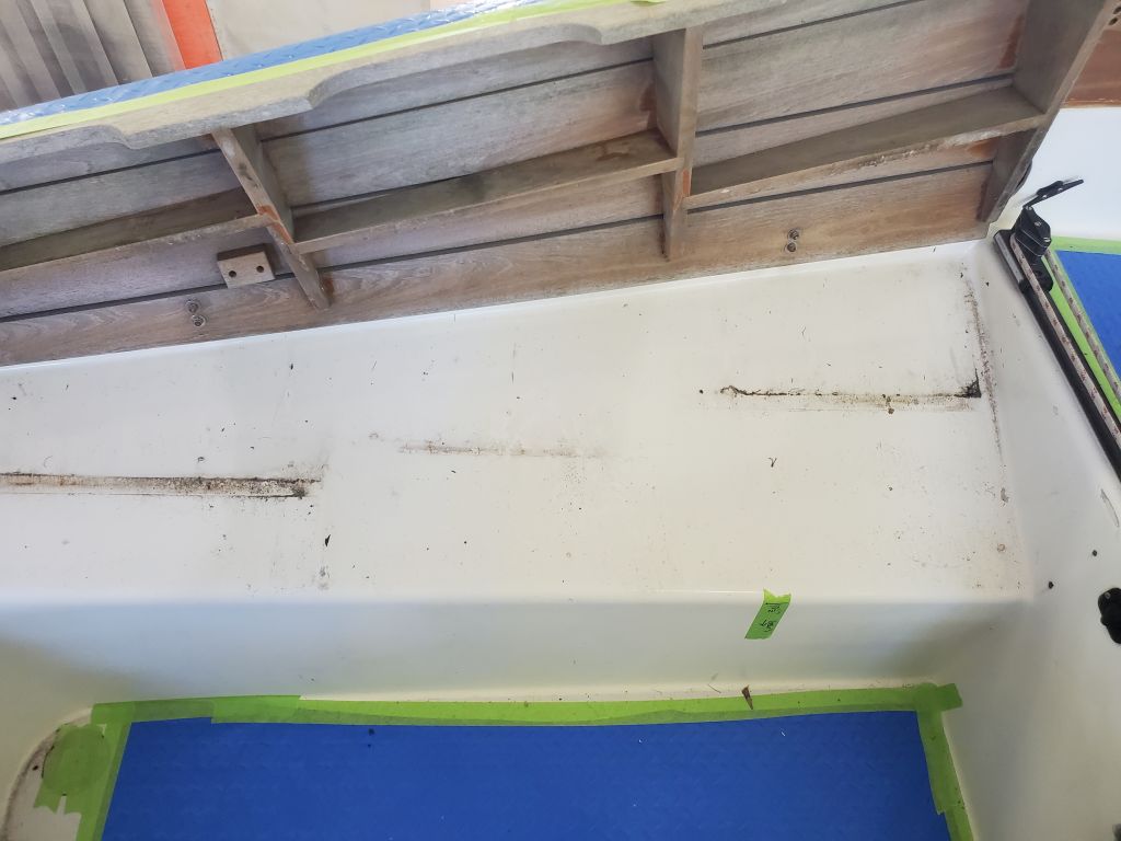
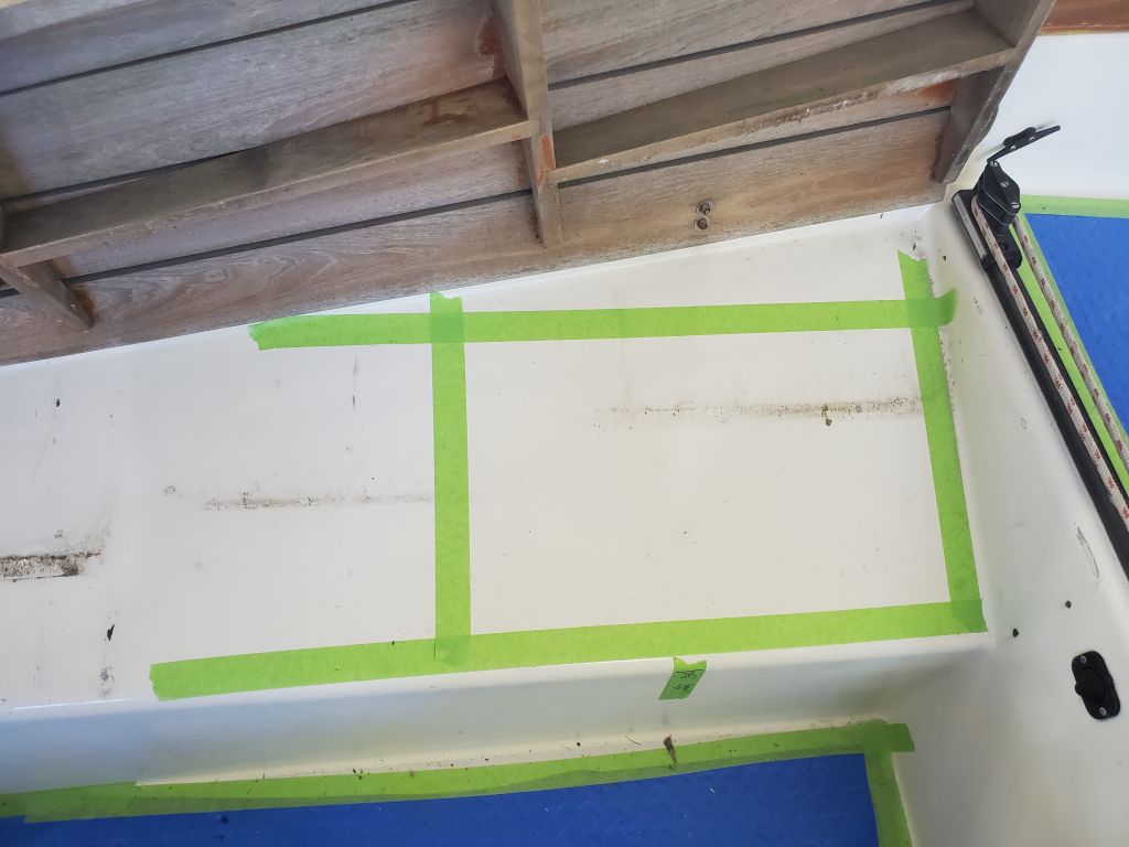
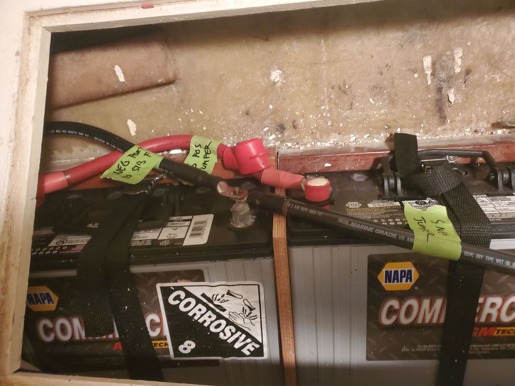
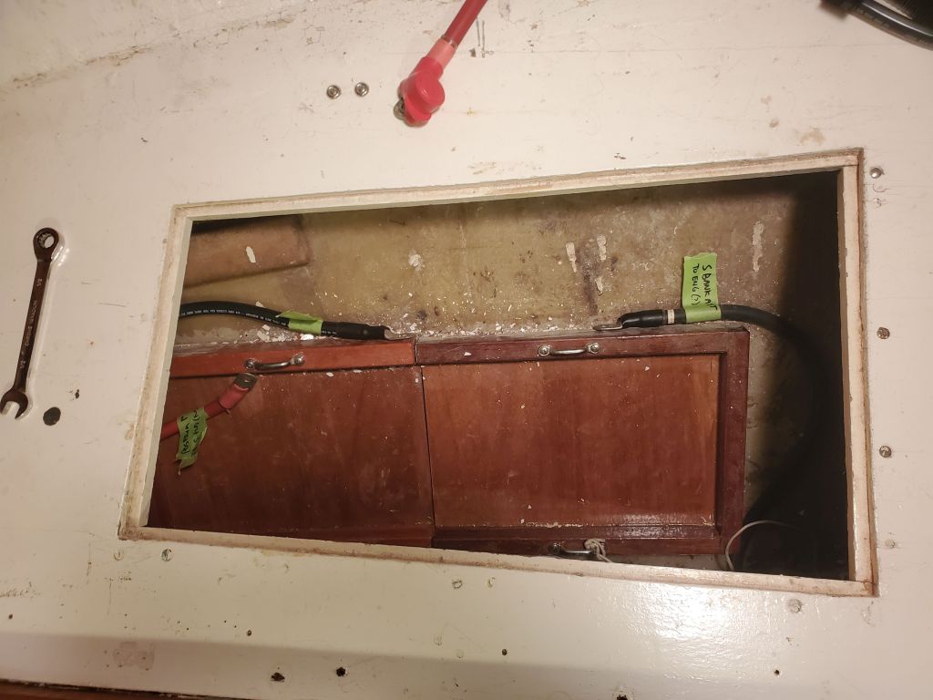
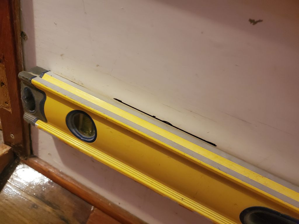
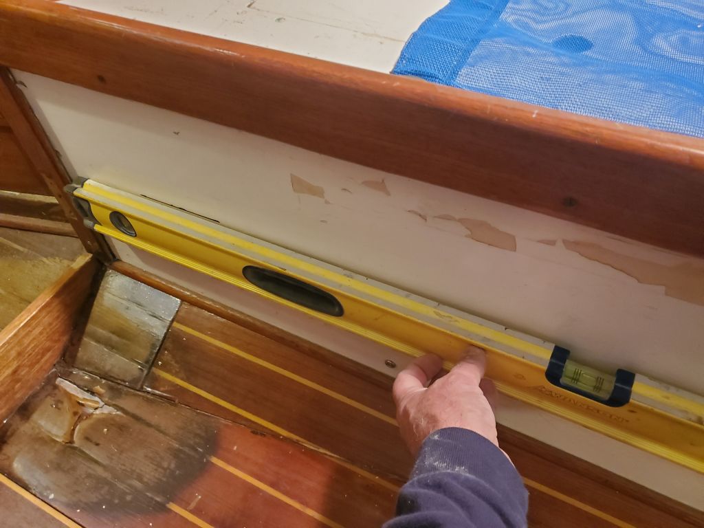
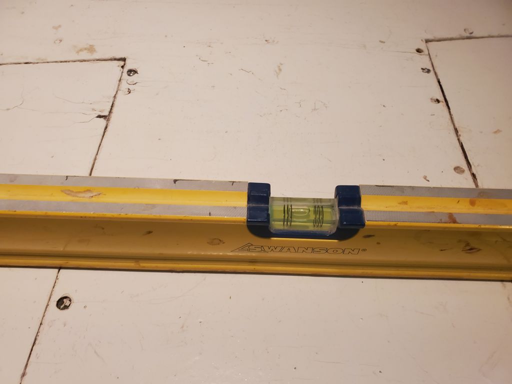
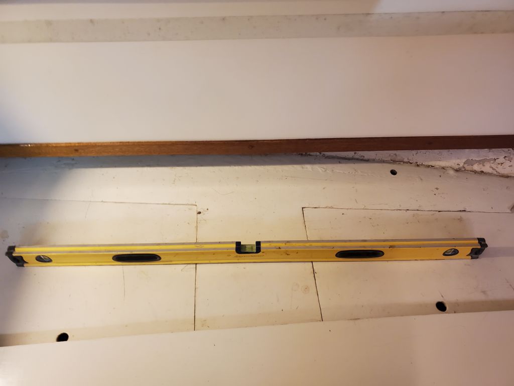
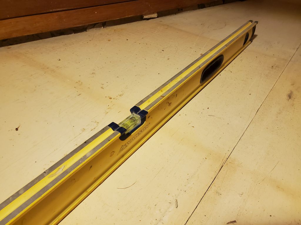
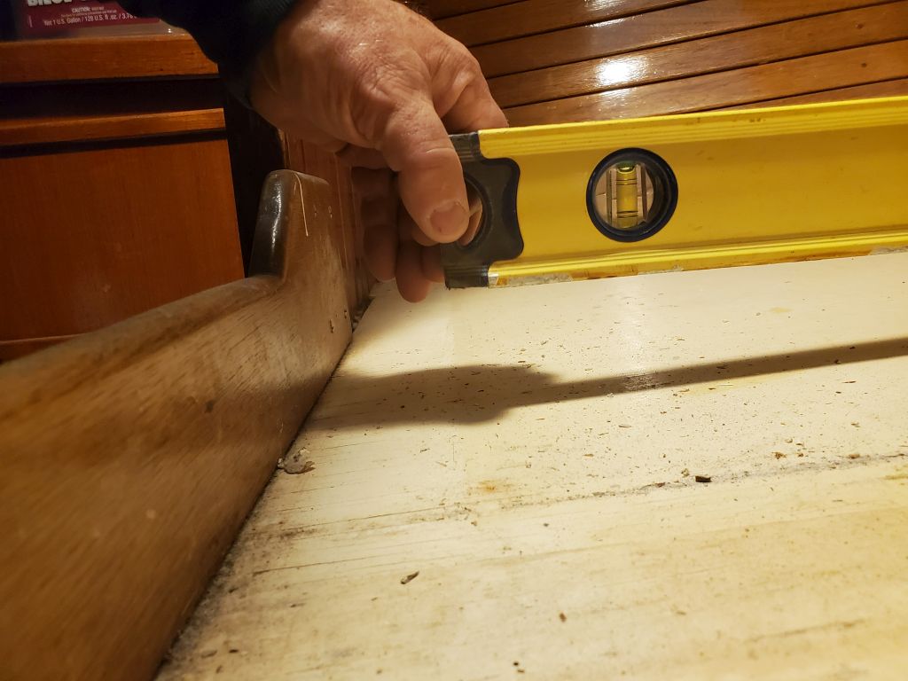
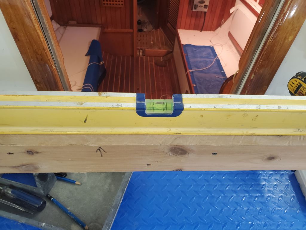
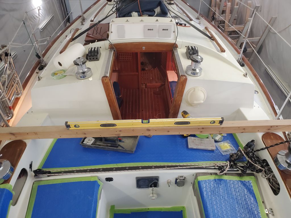
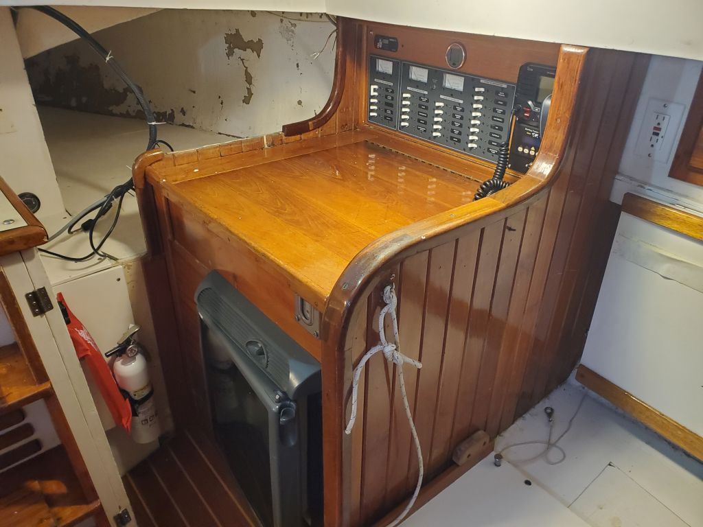
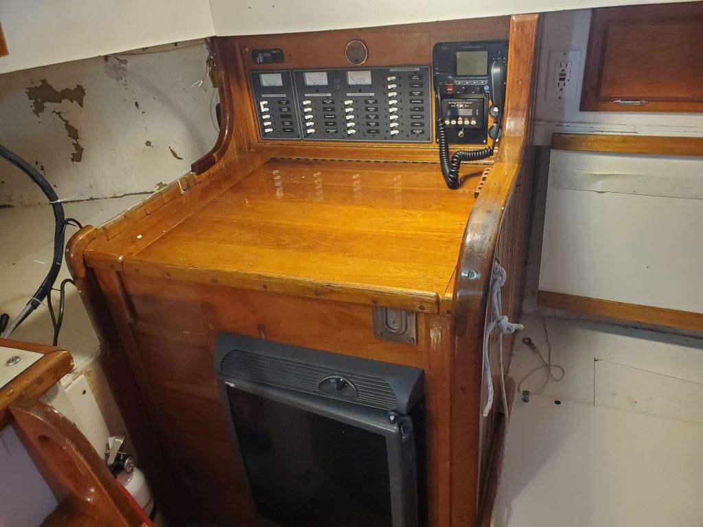
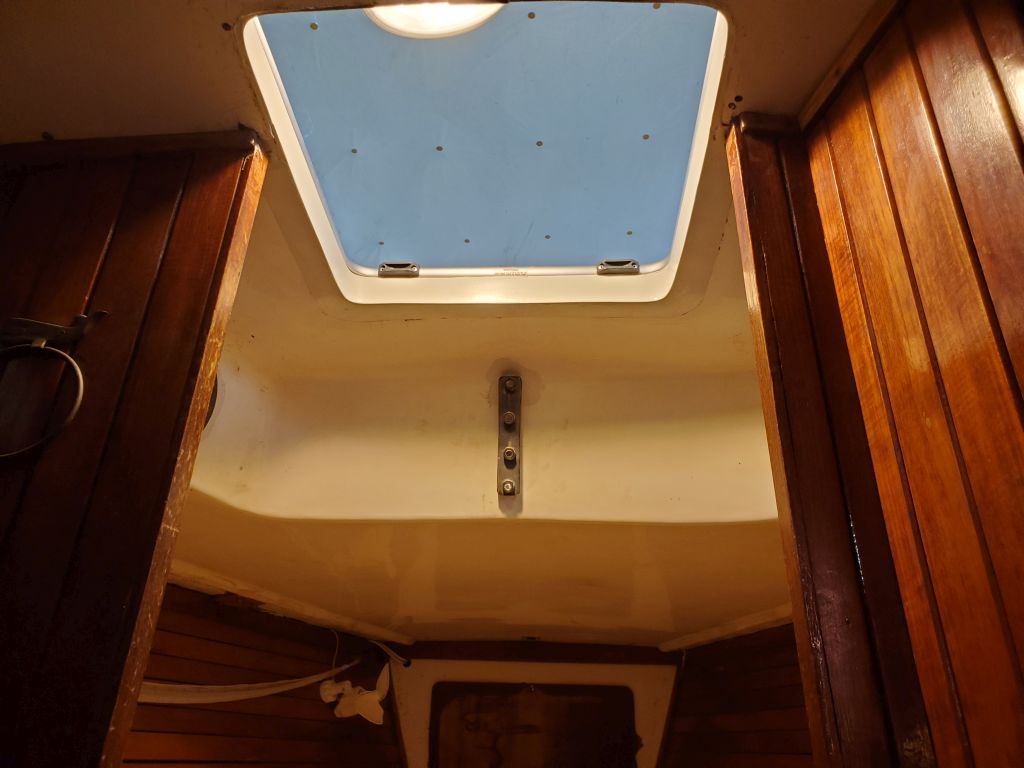
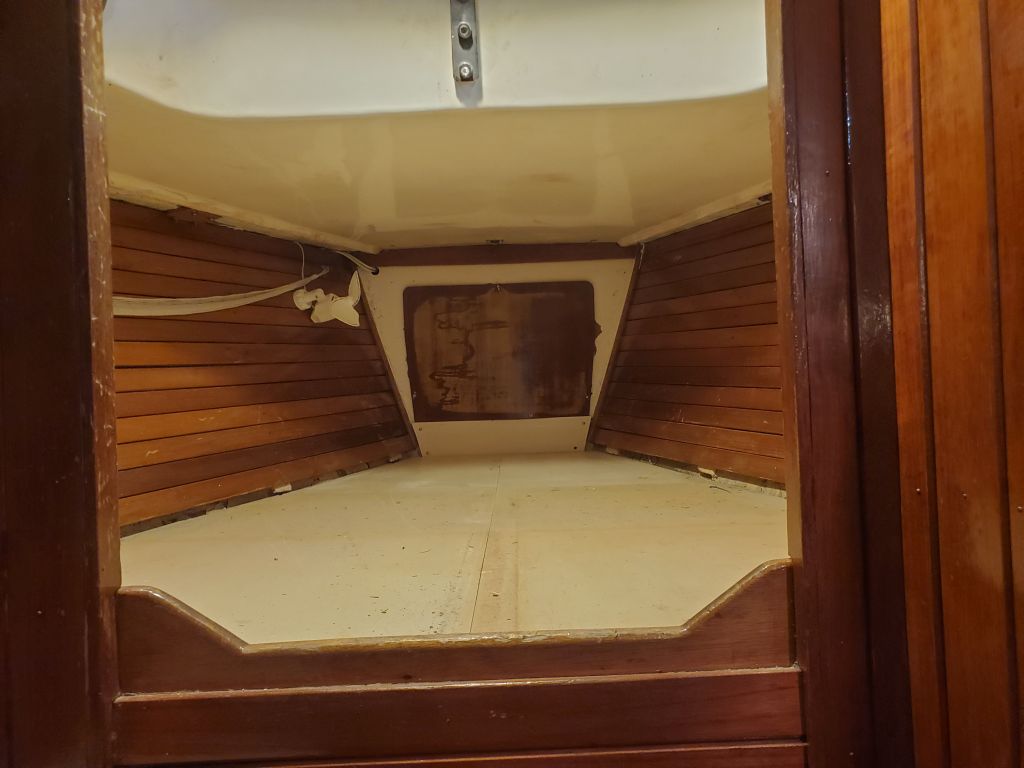
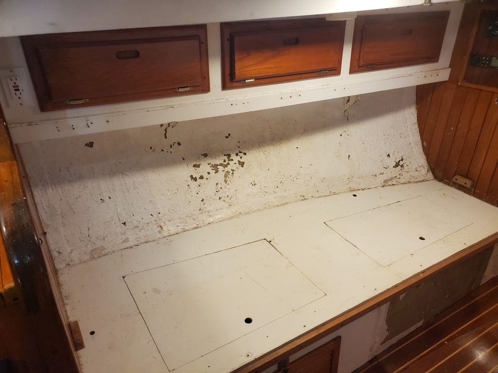
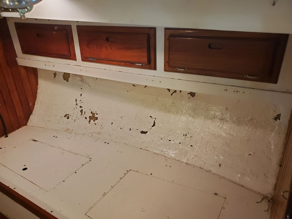
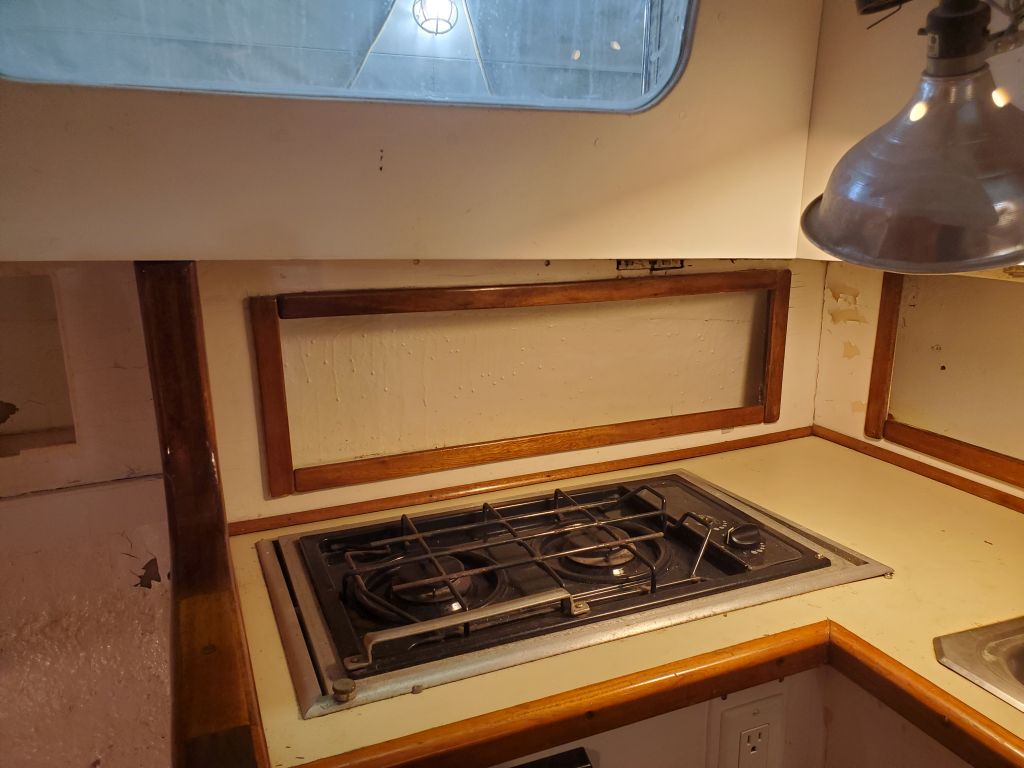
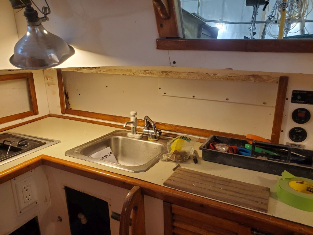
The most critical datum for the new step was its final height when all was said and done. The original step top plate (seen in the first two photos below) had been 68-1/4″ down from an easily-replicated reference point in the mast collar above, and that is where the final surface of the new step would also need to be. To help me get set up at this crucial height for mockup purposes, I prepared a simple stick and bottom plate from scrap wood so there’d be an easy physical representation of the measurement to work from. I allowed an extra 1/4″ of space because it would be easier to make up extra height than to end up too high, so I made my mockup stick 68-1/2″ to the bottom side of the bottom plate. I tacked the stick in place with hot glue to give me a reference point in mid air.
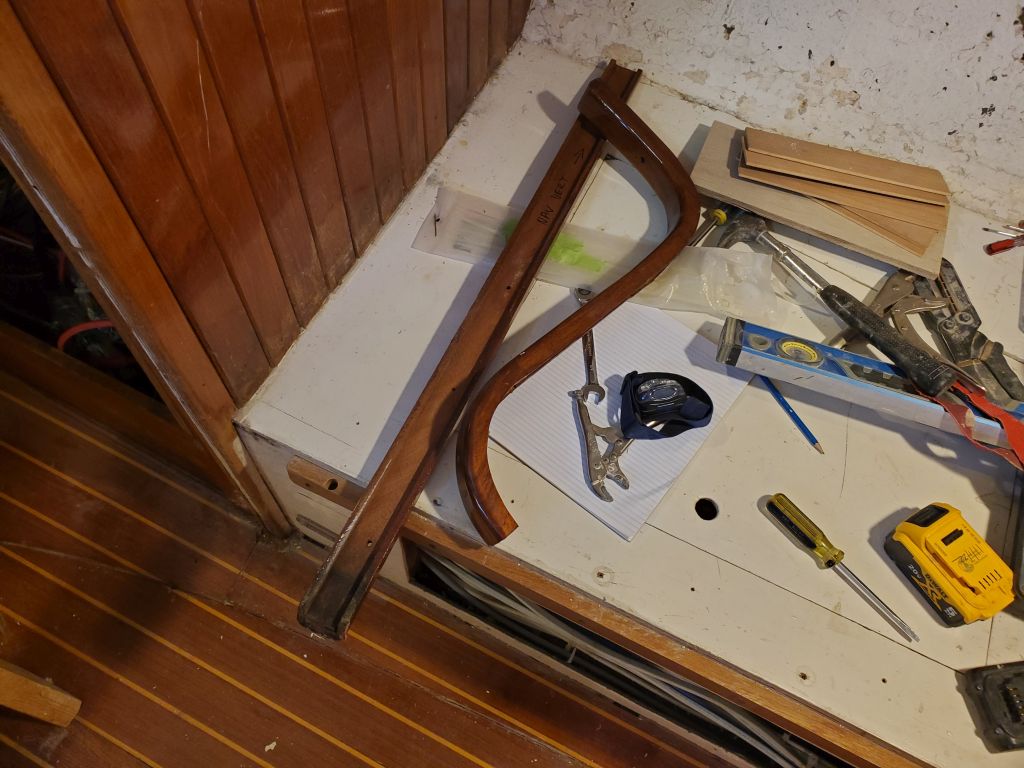
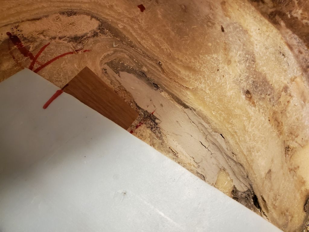
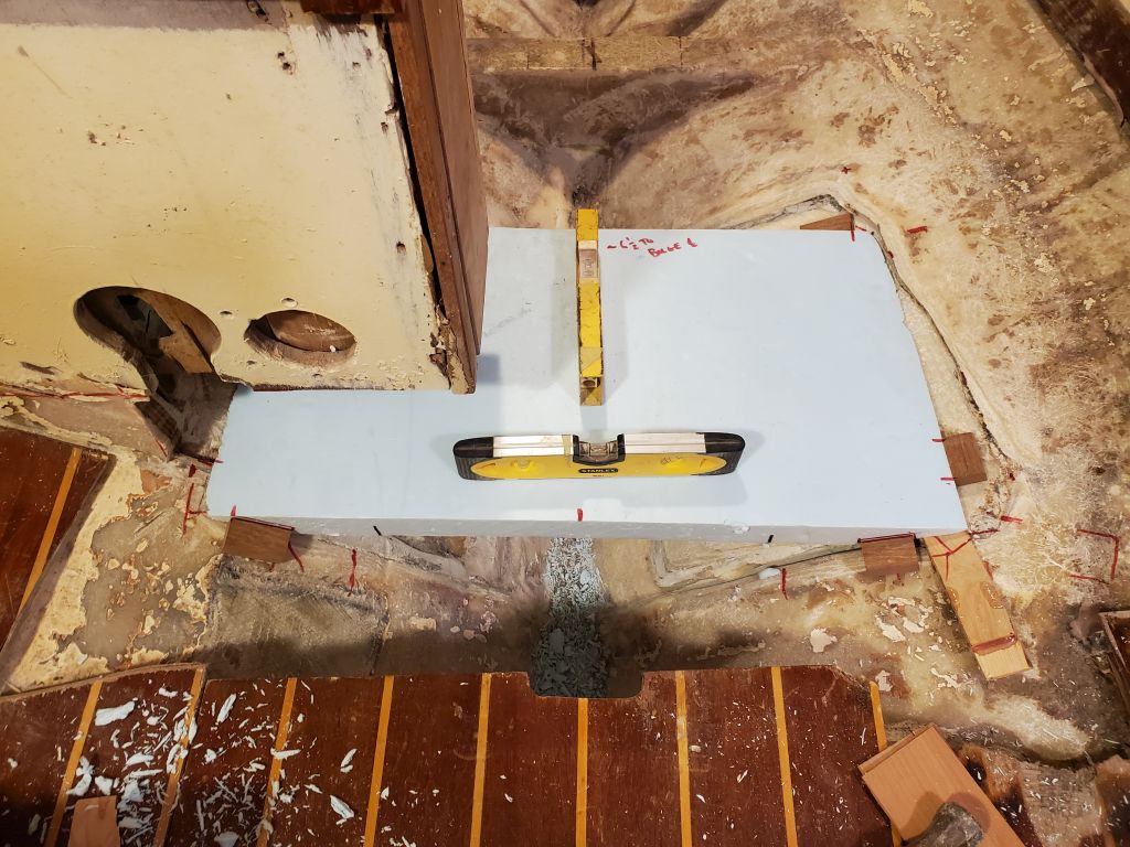
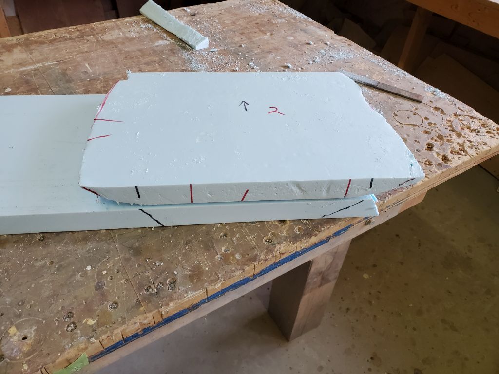
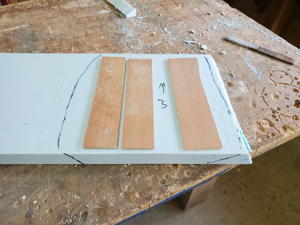
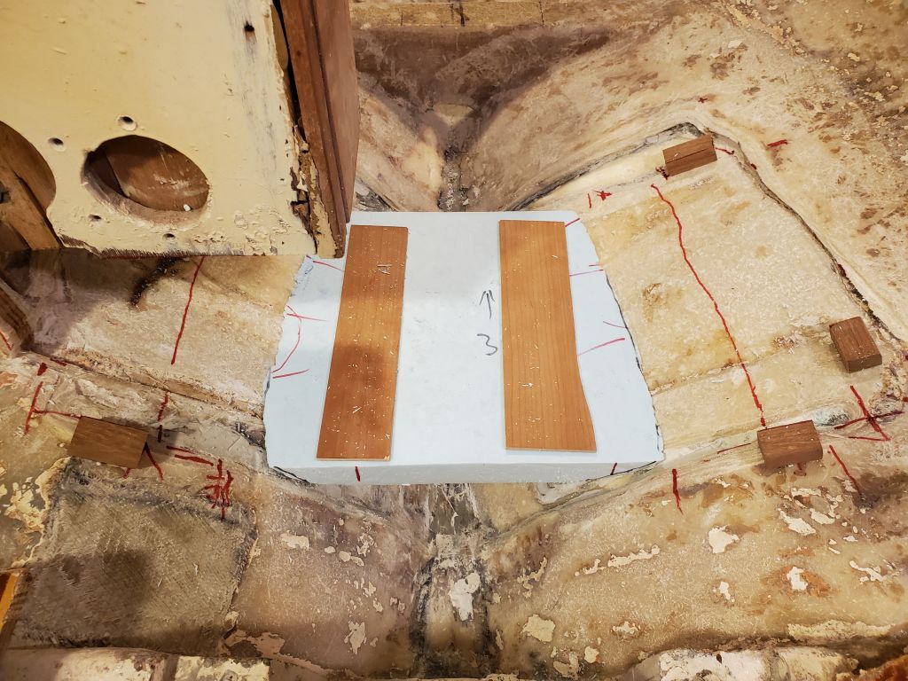
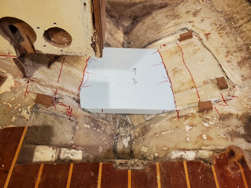
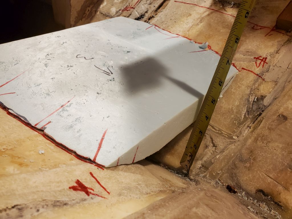
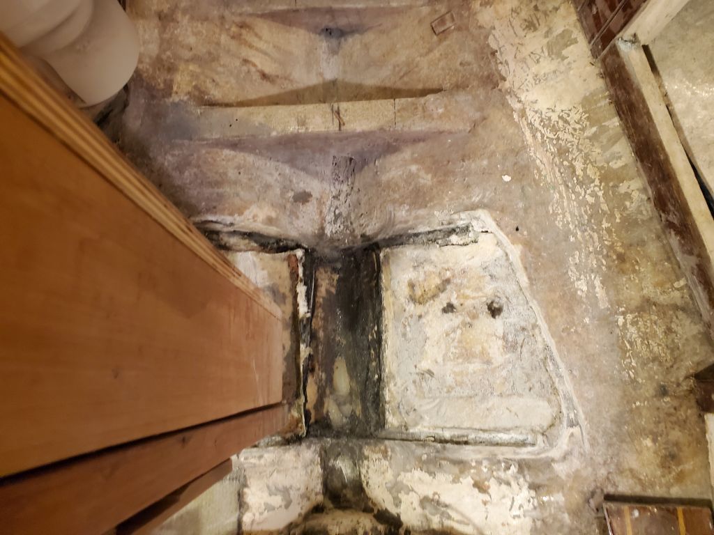
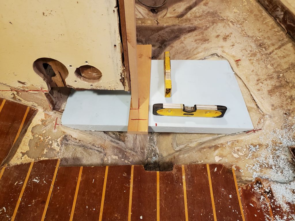
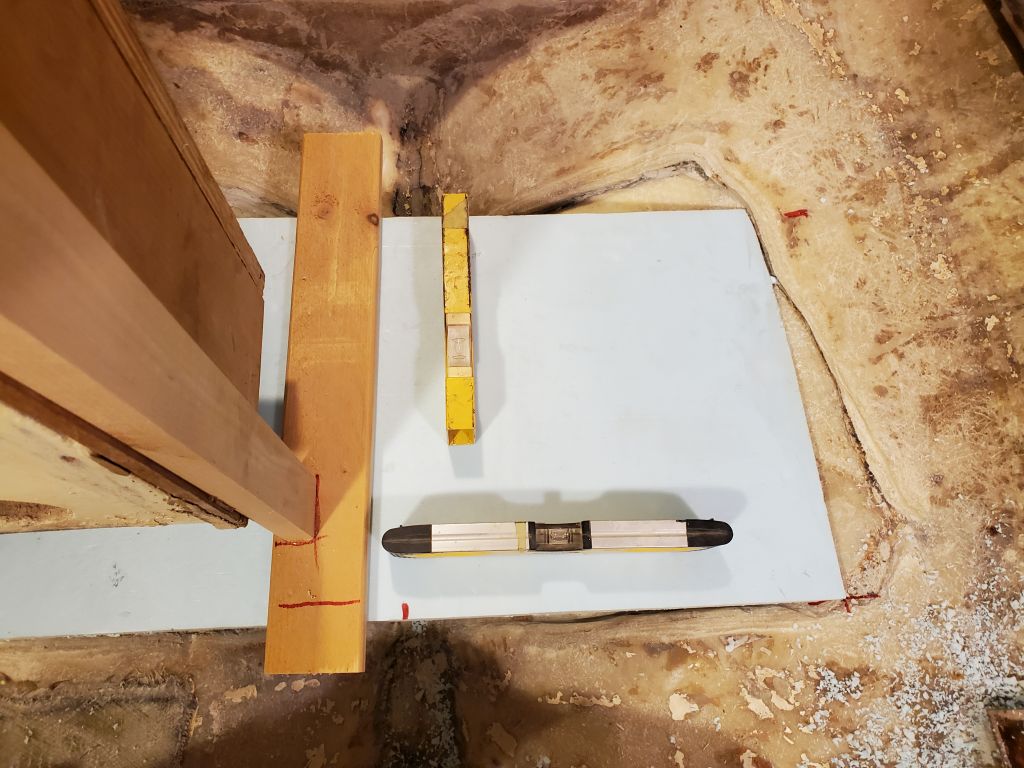
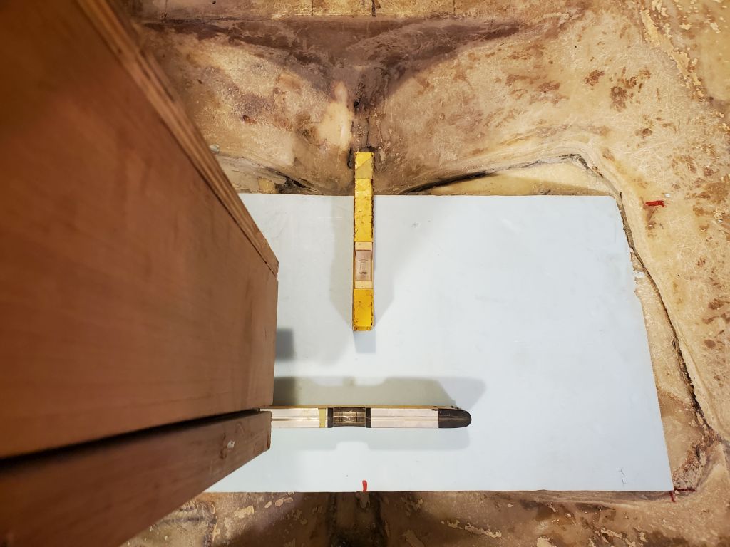
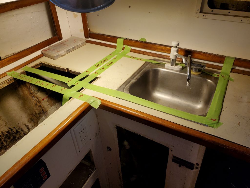
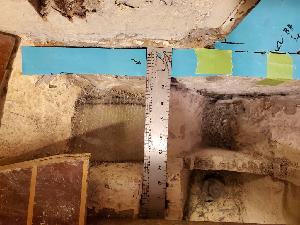
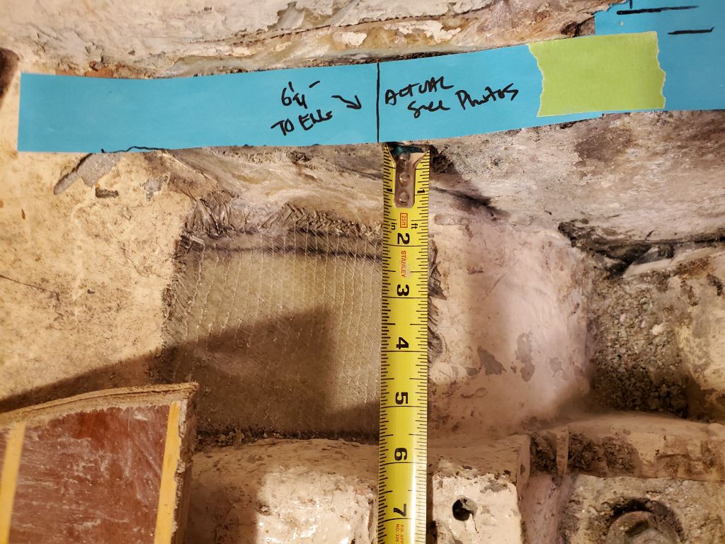
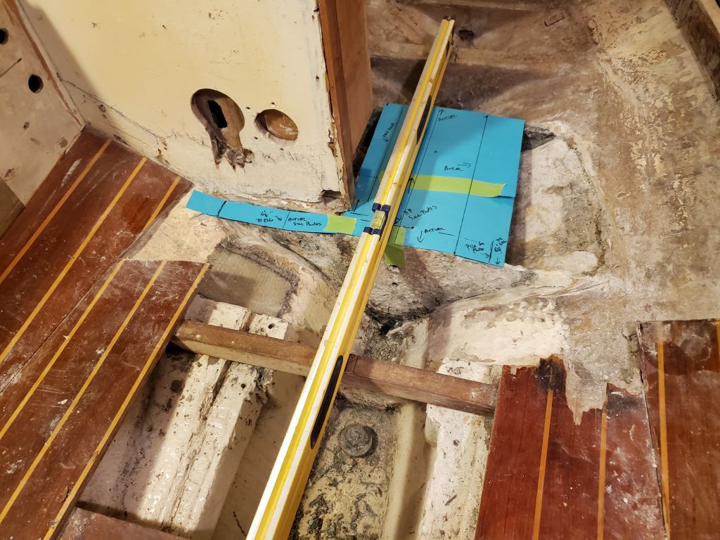
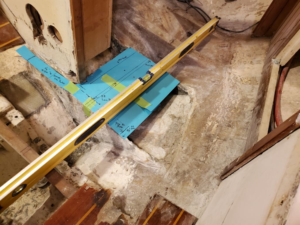
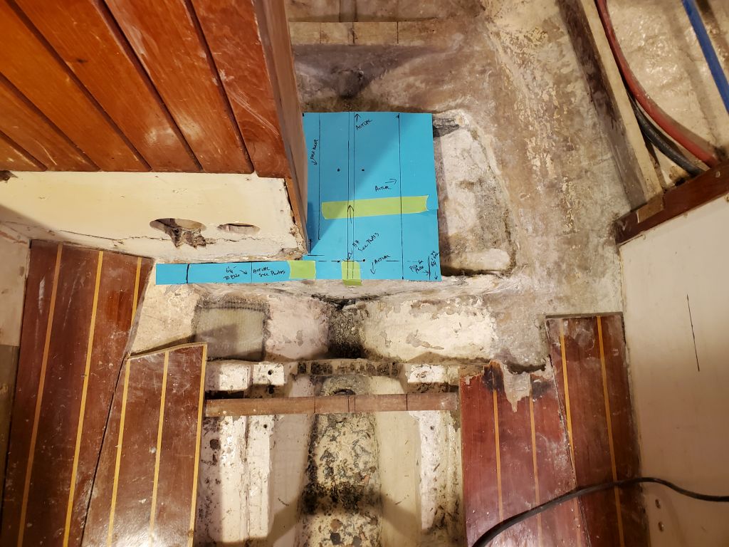
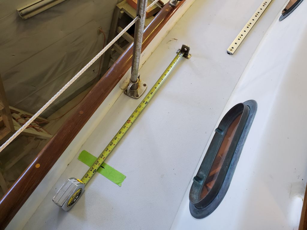
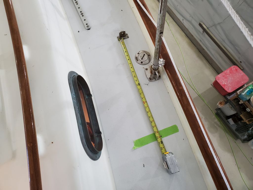
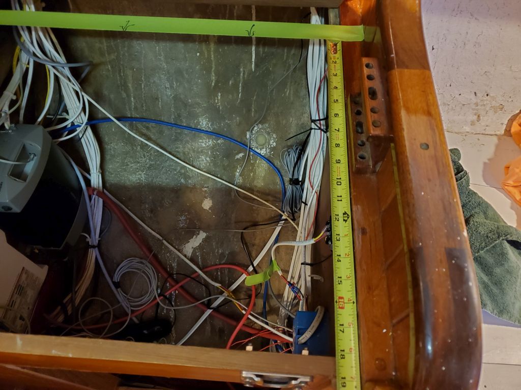
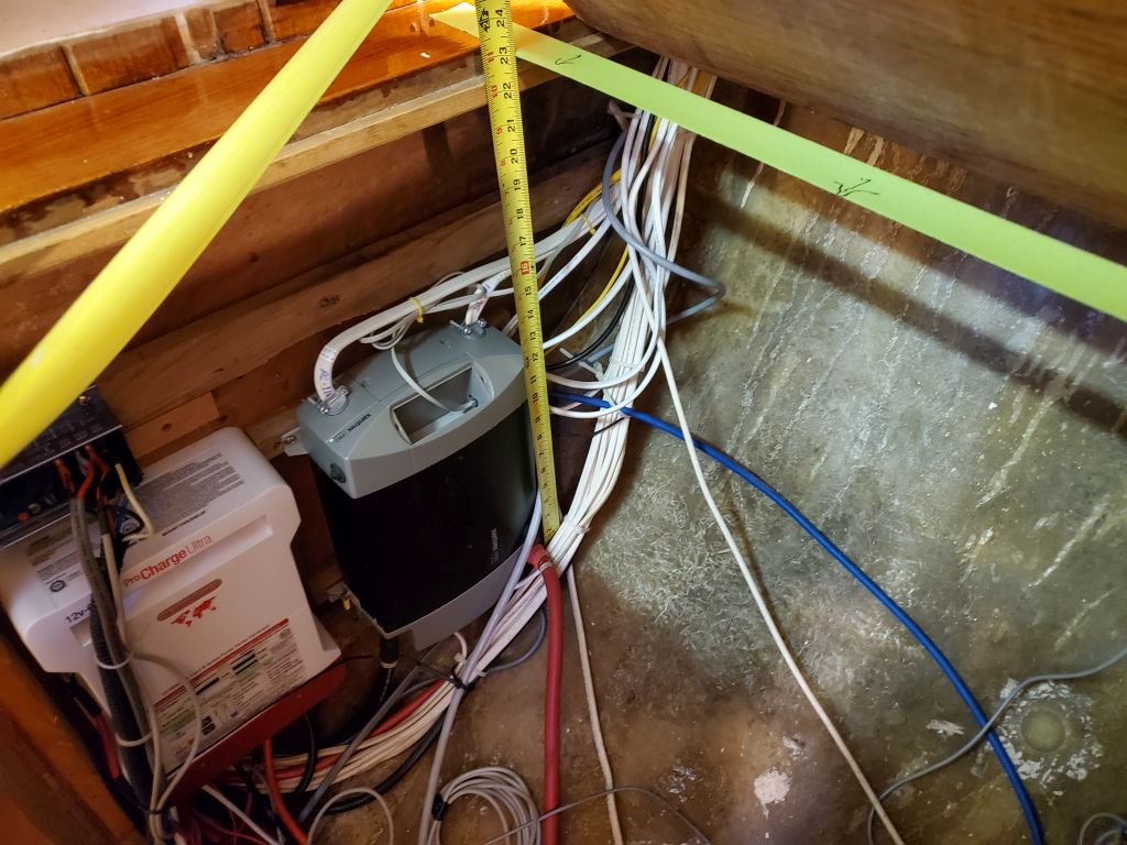
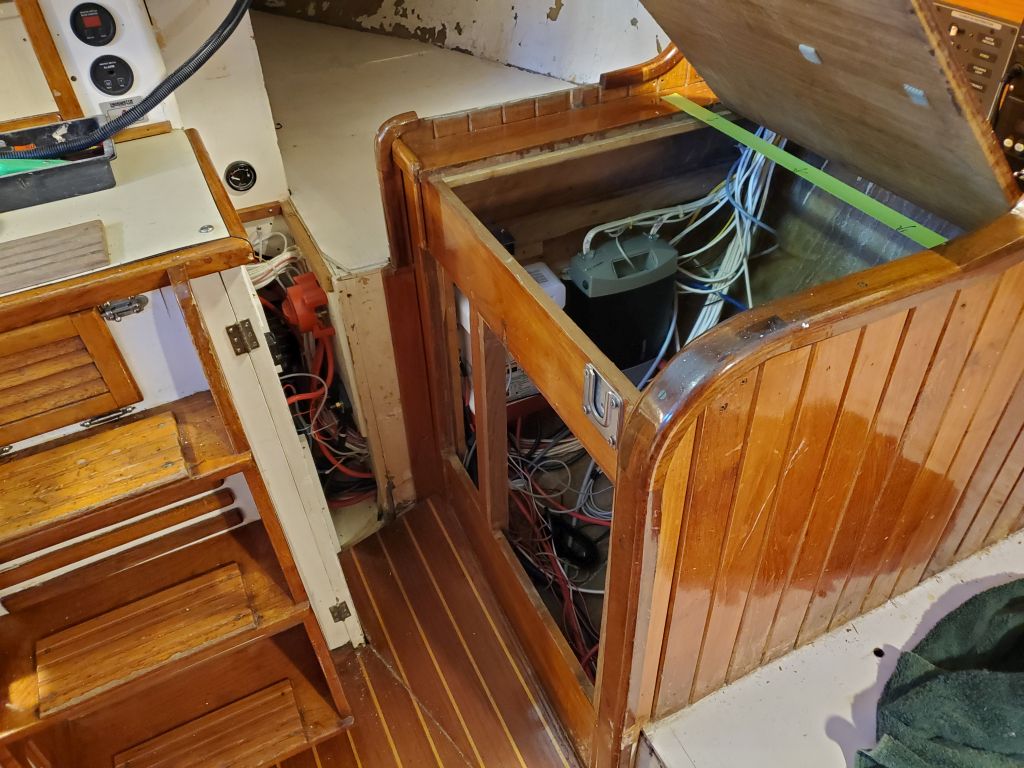
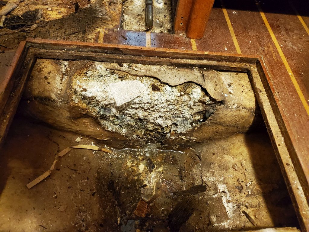
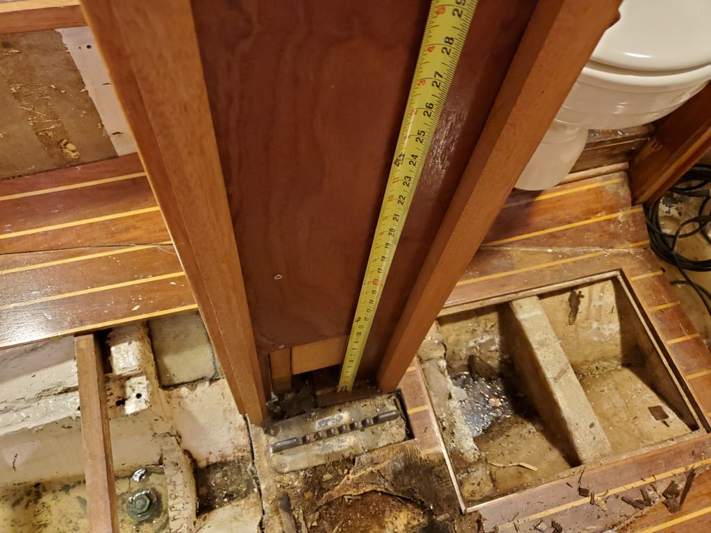
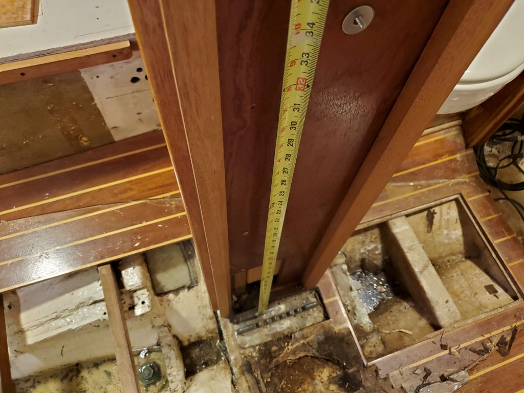
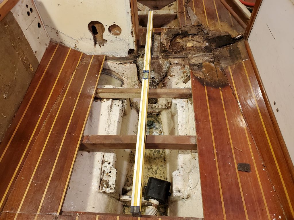
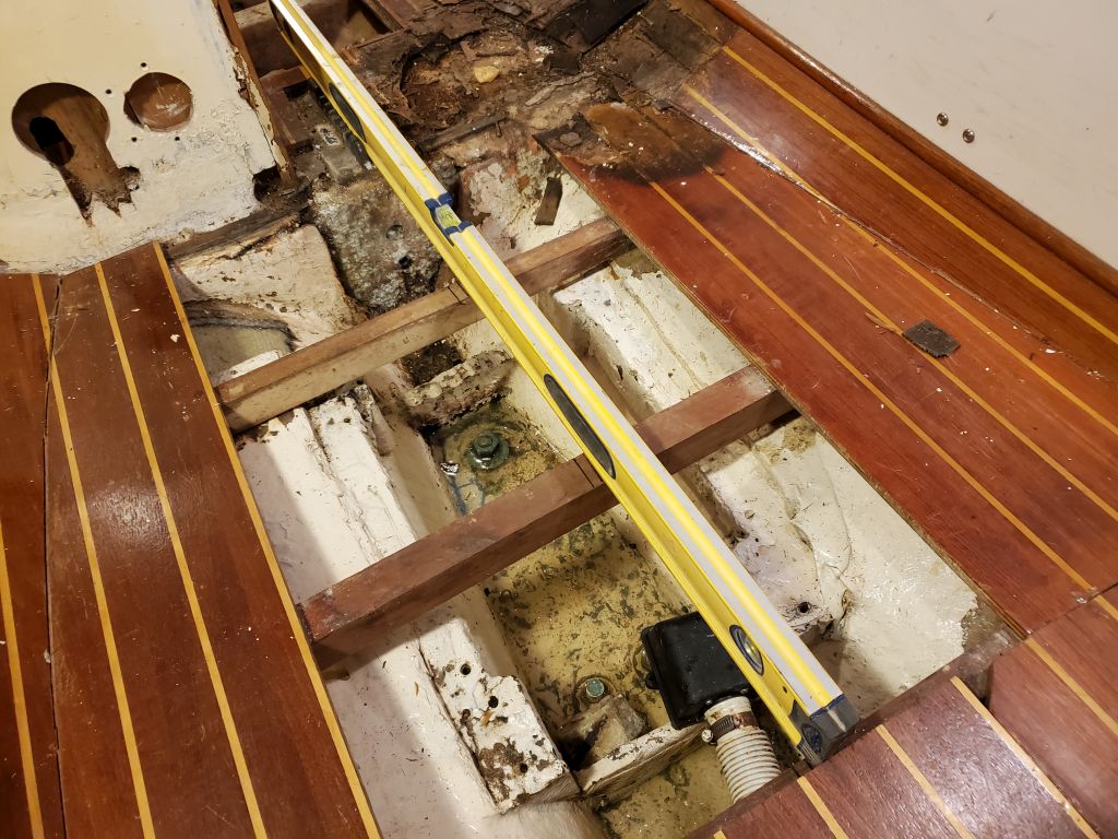
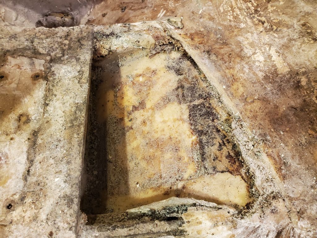
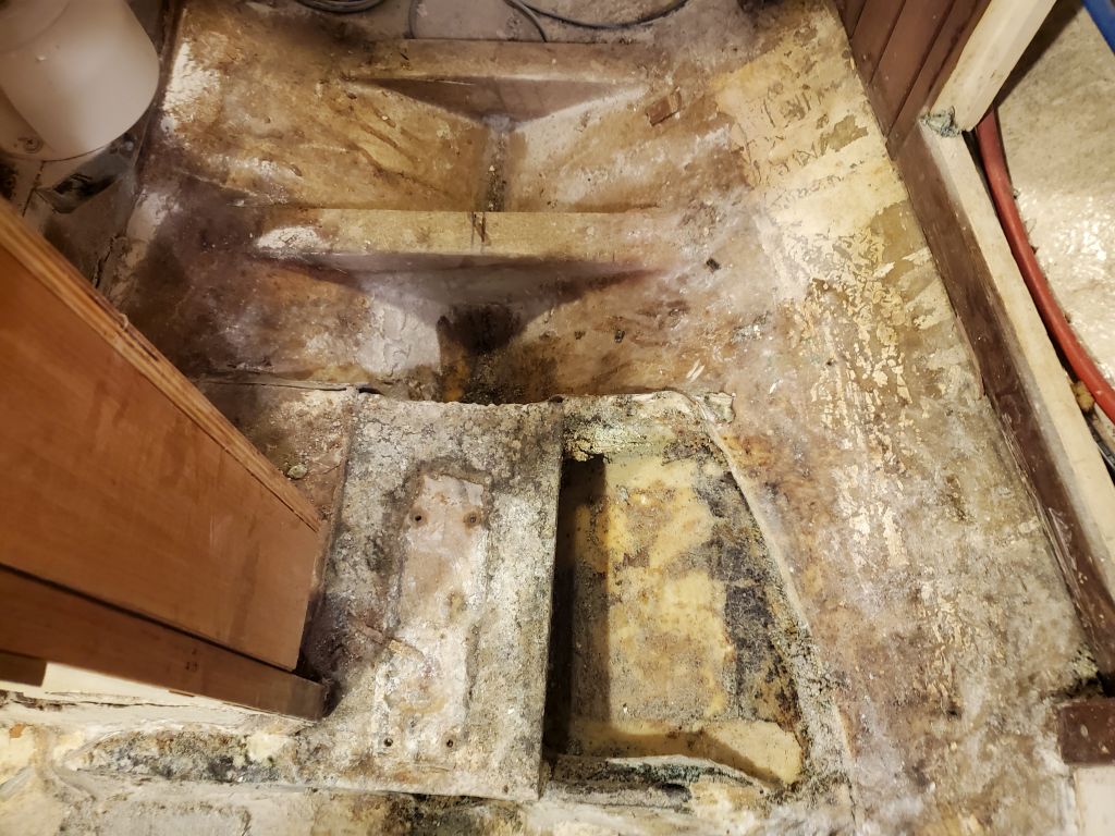
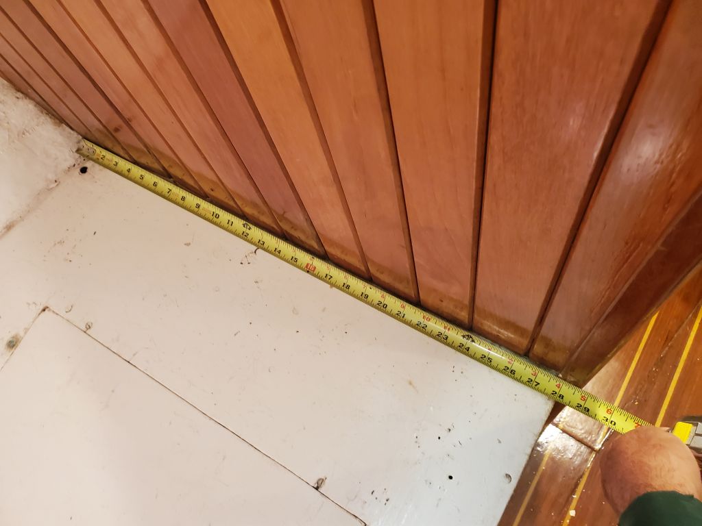
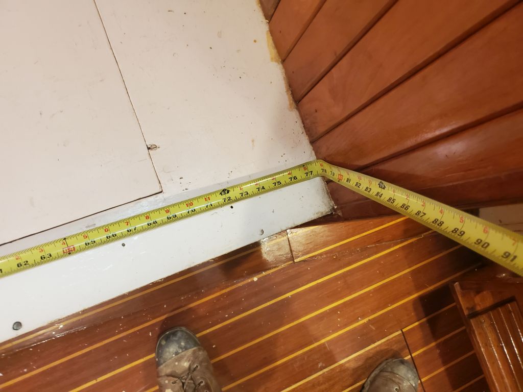
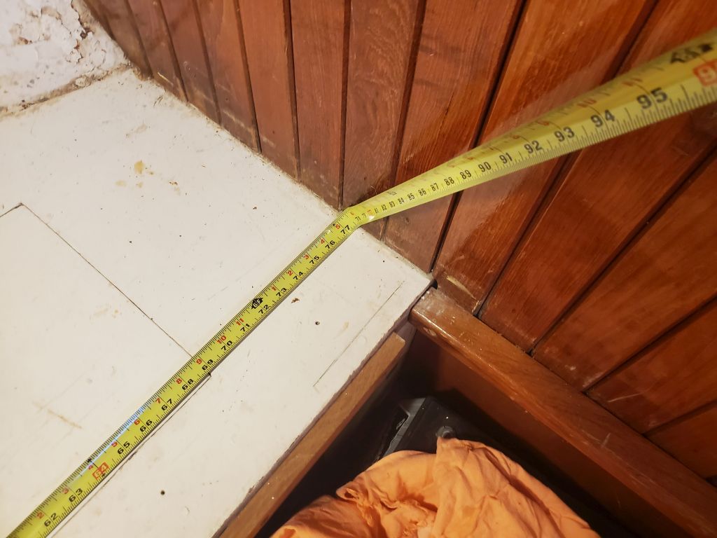
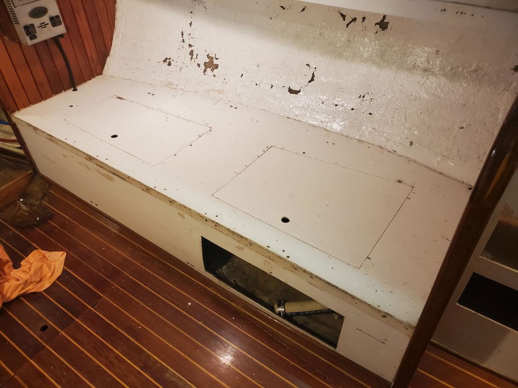
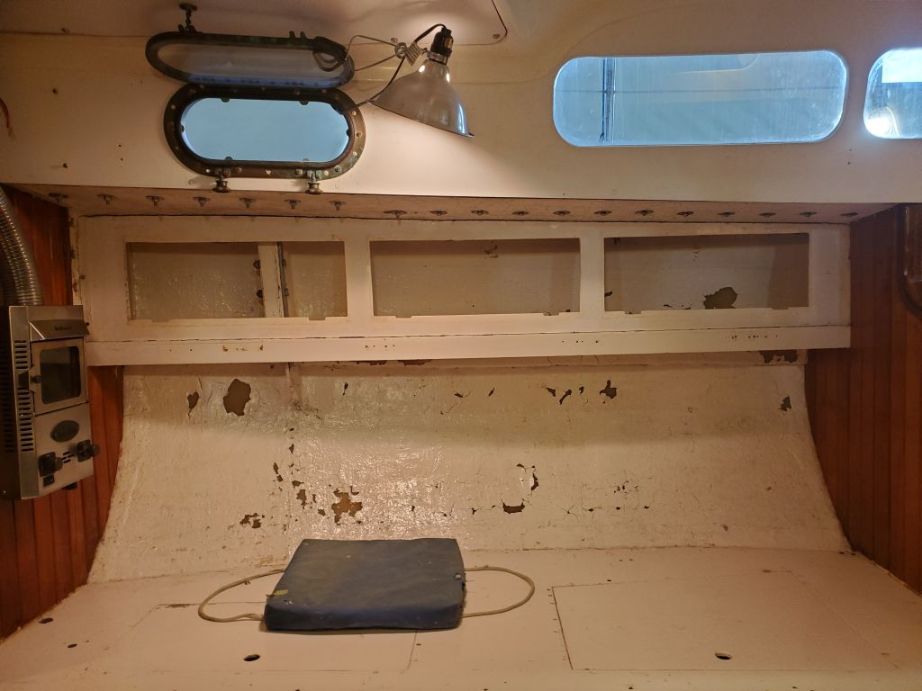
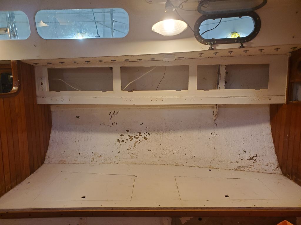
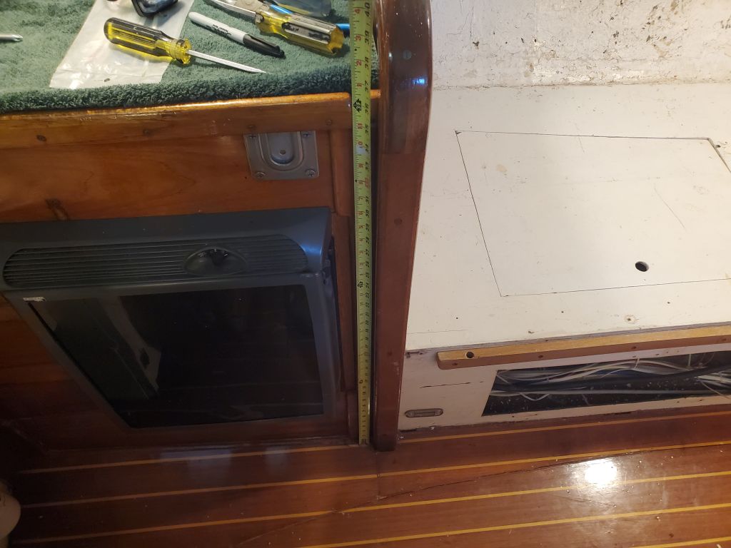
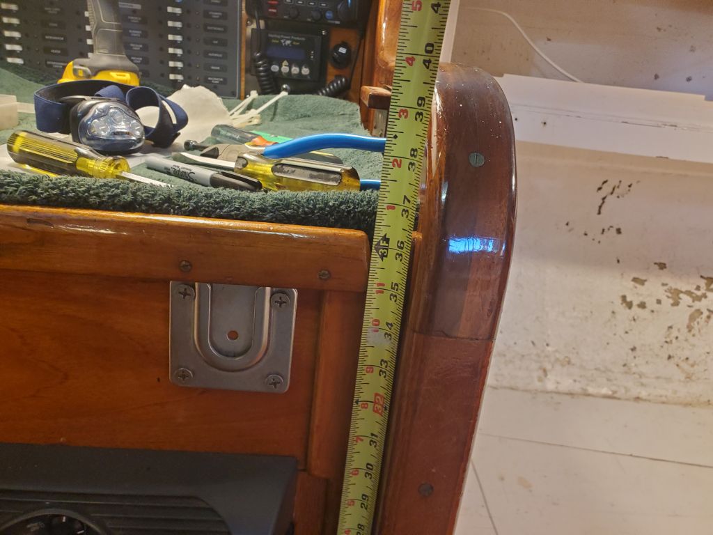
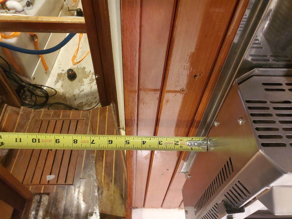
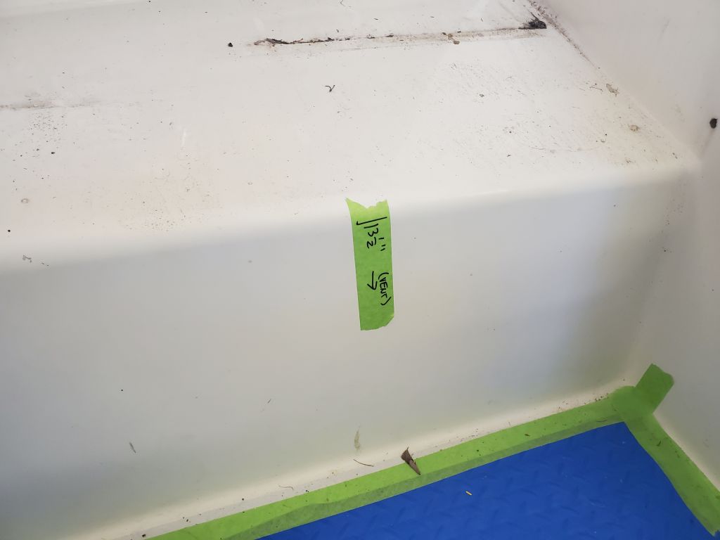
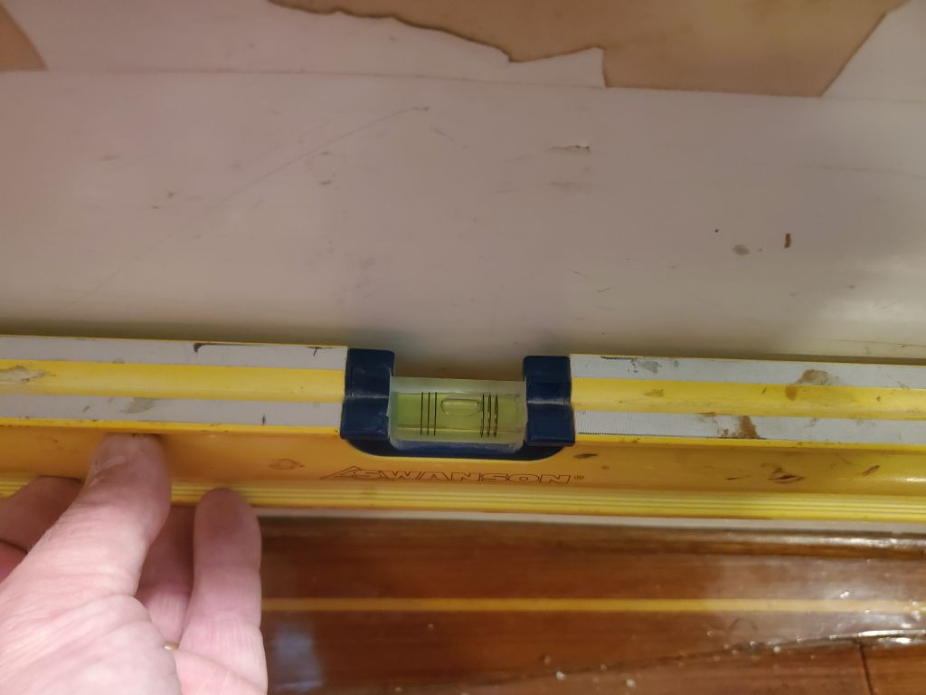
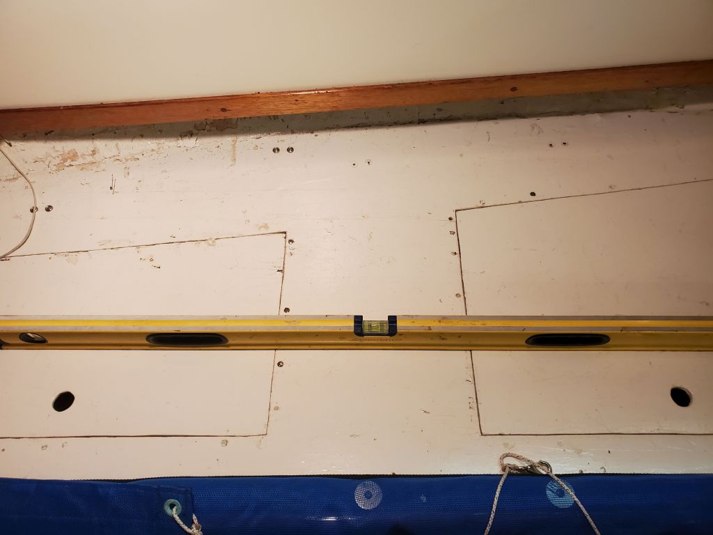
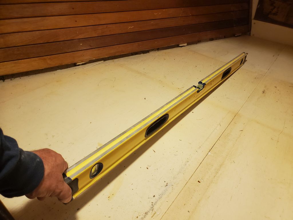
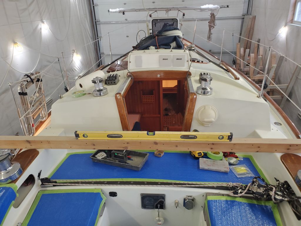
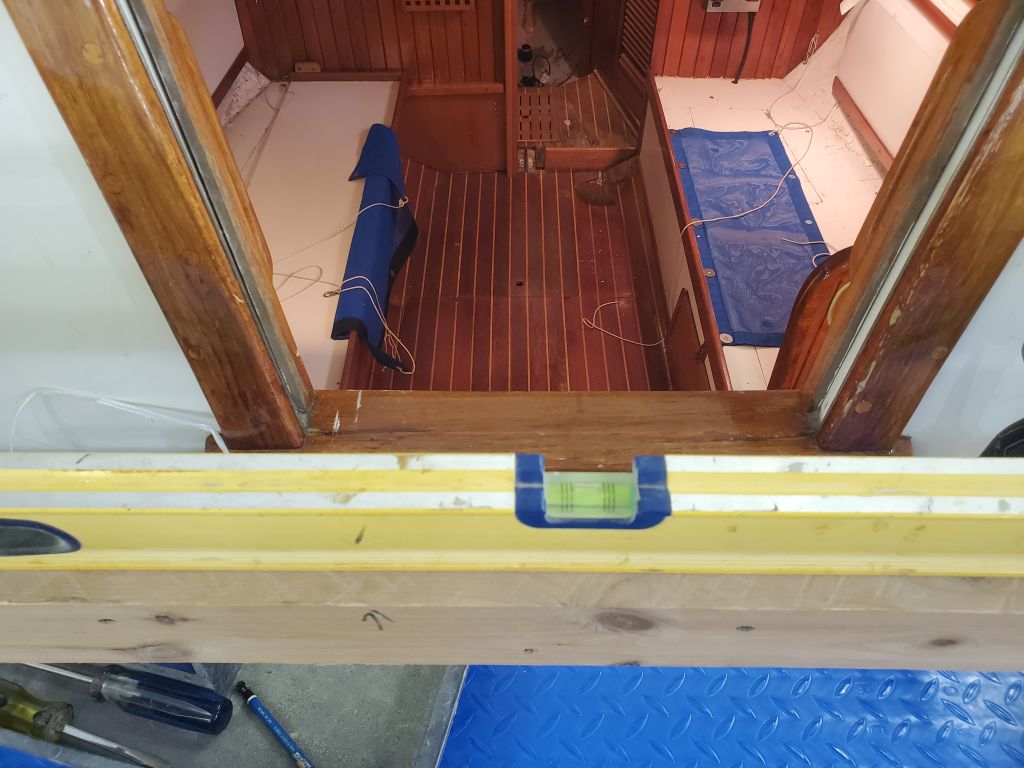
To begin a mockup and also help with later shaping of the final product, I cut a piece of 1-1/2″ styrofoam to 12″ x 24″ to match the fiberglass sheet and fit the space at hand. With some shaping, I fit the foam in place beneath the mockup stick and leveled it in both directions. After various minor manipulations and adjustments, I had this where I wanted it. I aligned the aft edge of the platform with where the original aft edge of the step had been, according to my pattern as shown in the final photos. Of course this so far was only a rough beginning and simulation of the final product, but for the moment it confirmed the position and gave me additional information and insight I’d need to continue. The top surface of my new platform was 68-1/2″ down from the mast collar, as desired. (Upon reflection I thought might take this down just a bit more to allow for the construction I had in mind and to provide plenty of room for final fiberglass layers over the top.)
For now, the day was over, but I’d continue work on the mockup next time to give a sense of the final structure I had in mind. Till then, bear with me.