With an unavoidable absence planned later in the week, I worked on New Year’s to make up the time and keep making progress.
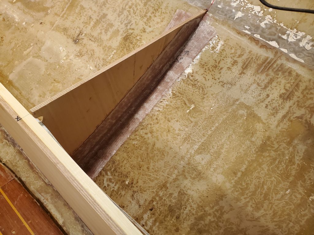
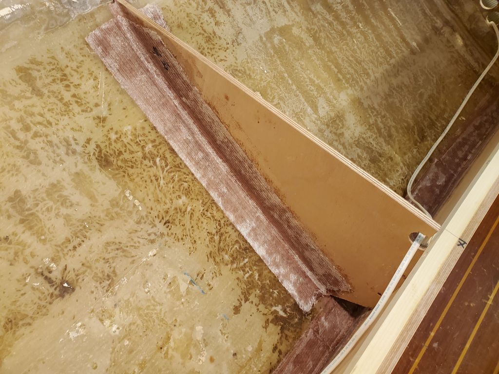
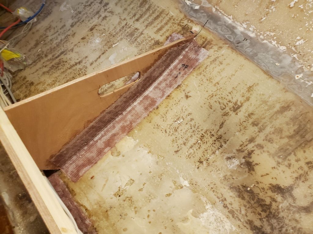
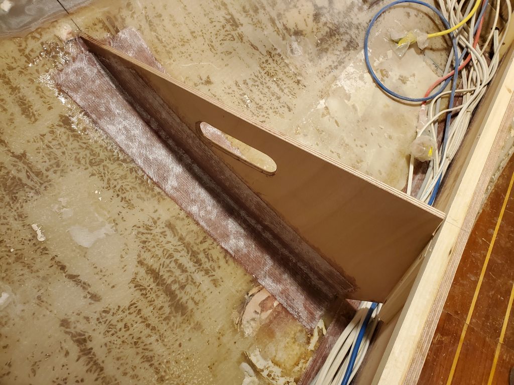
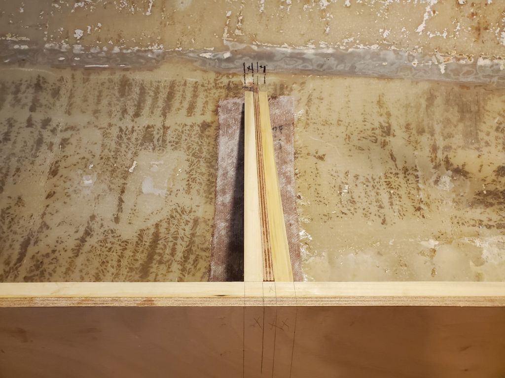
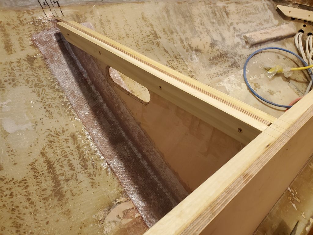
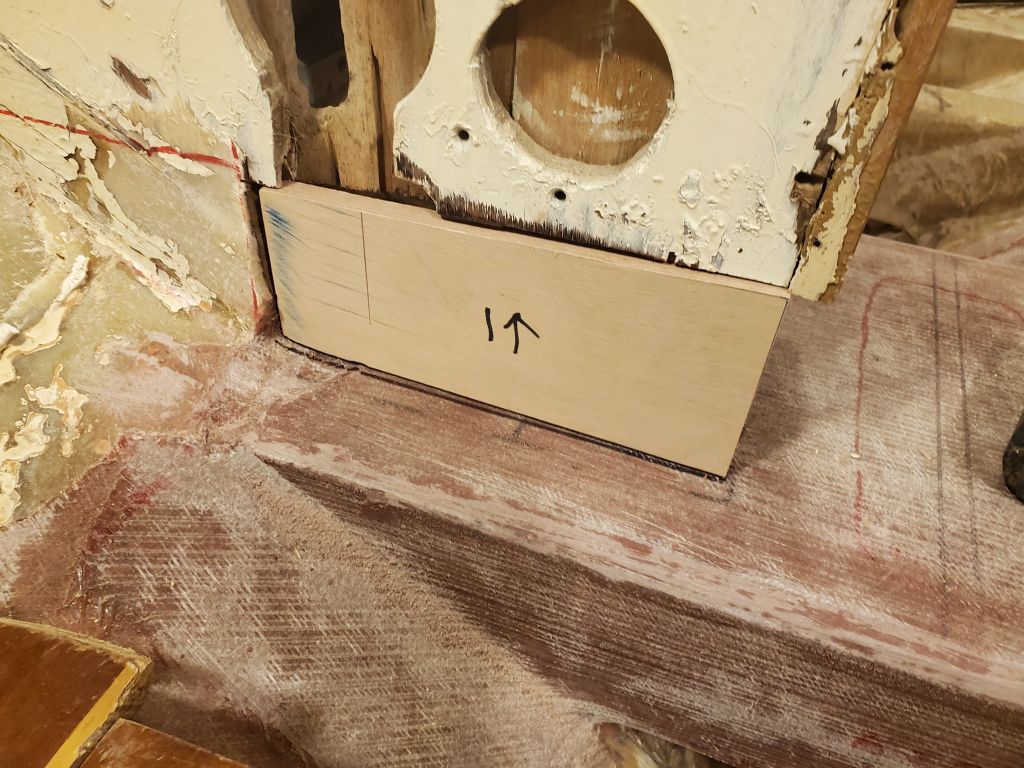
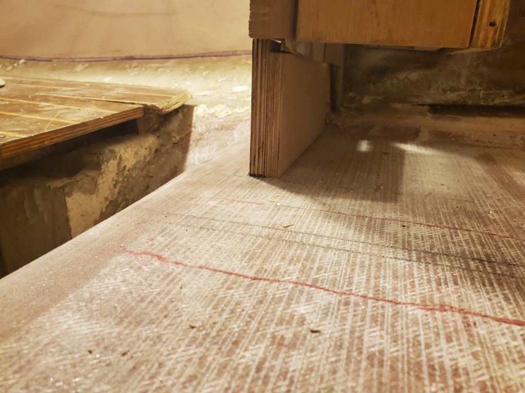
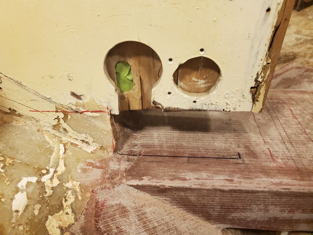
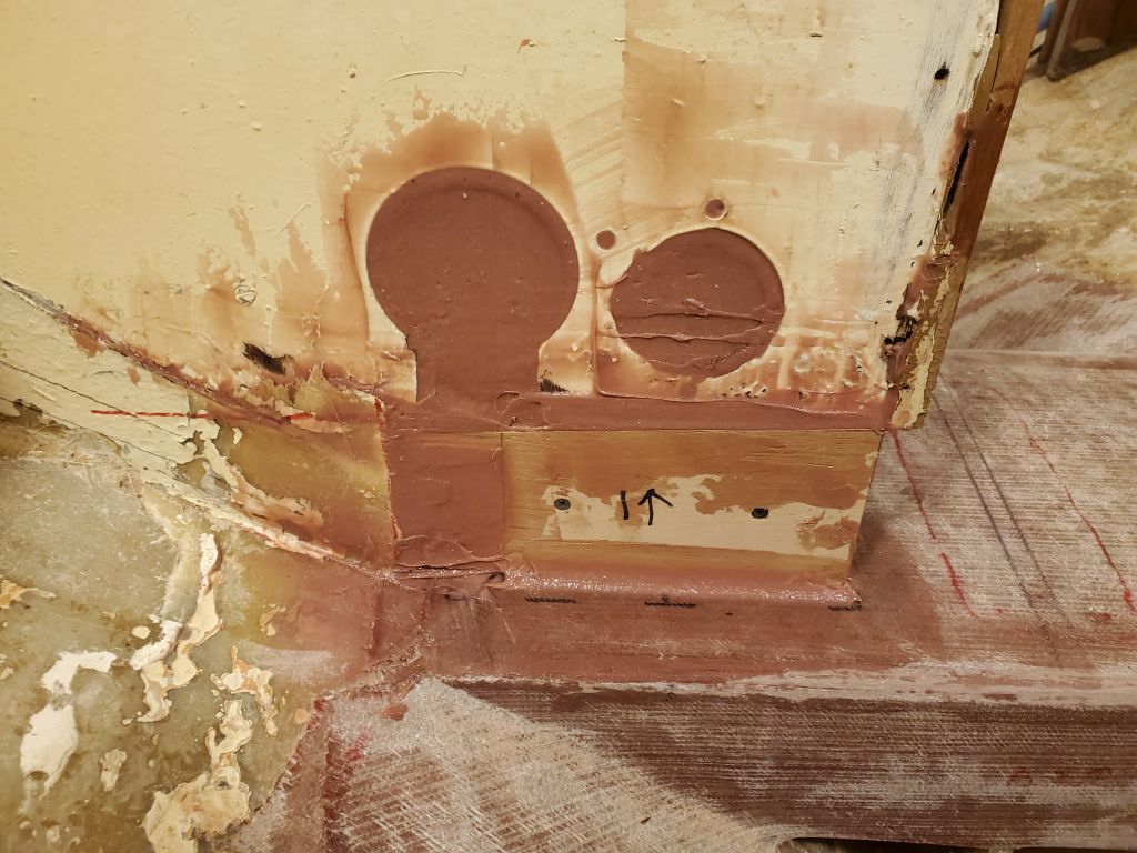
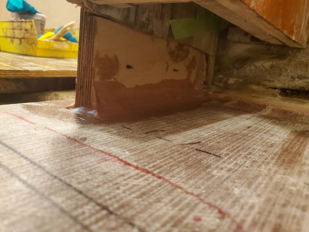
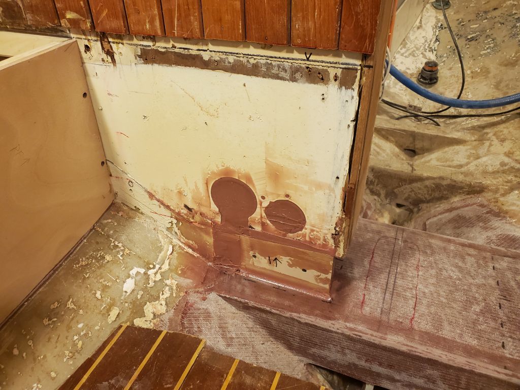
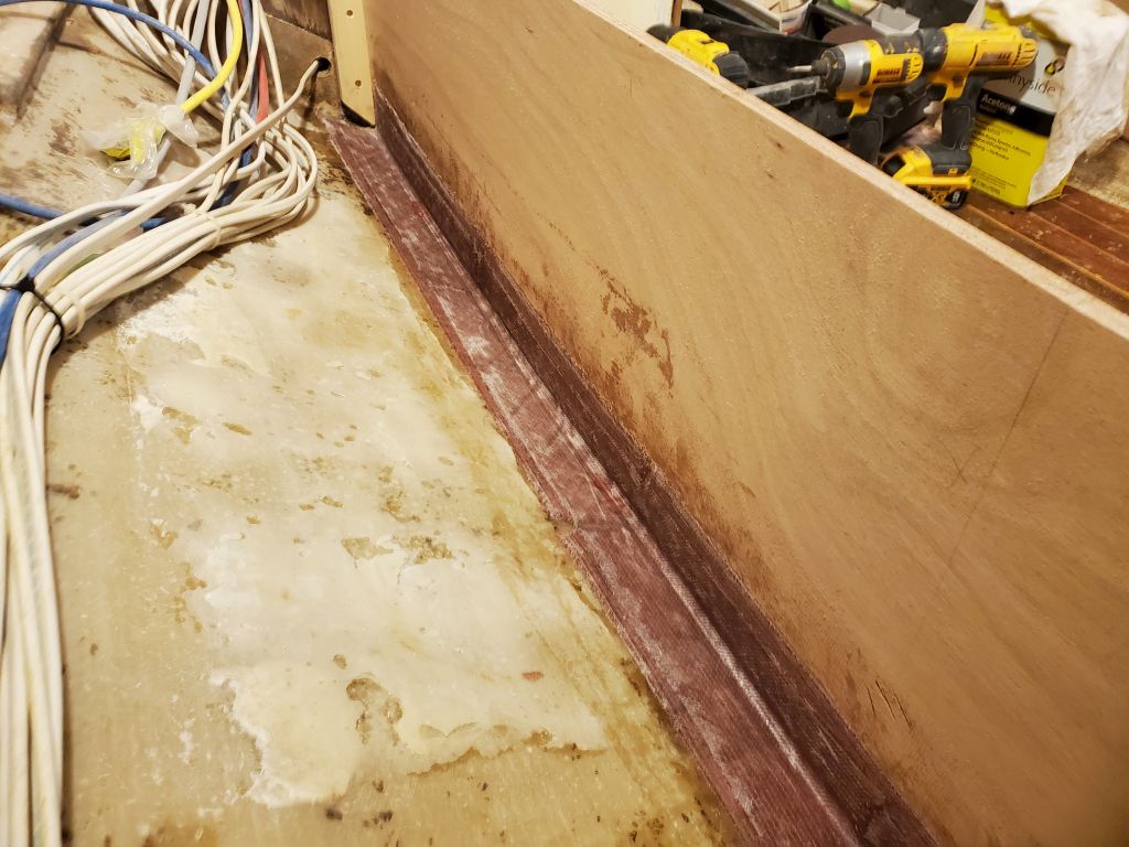
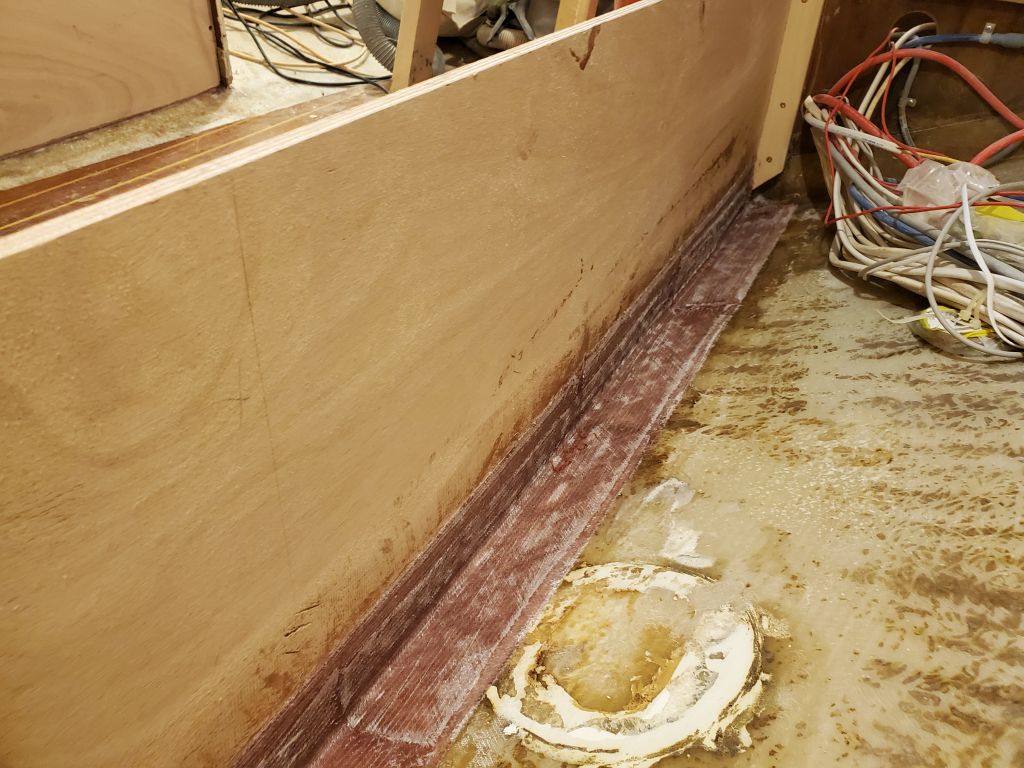
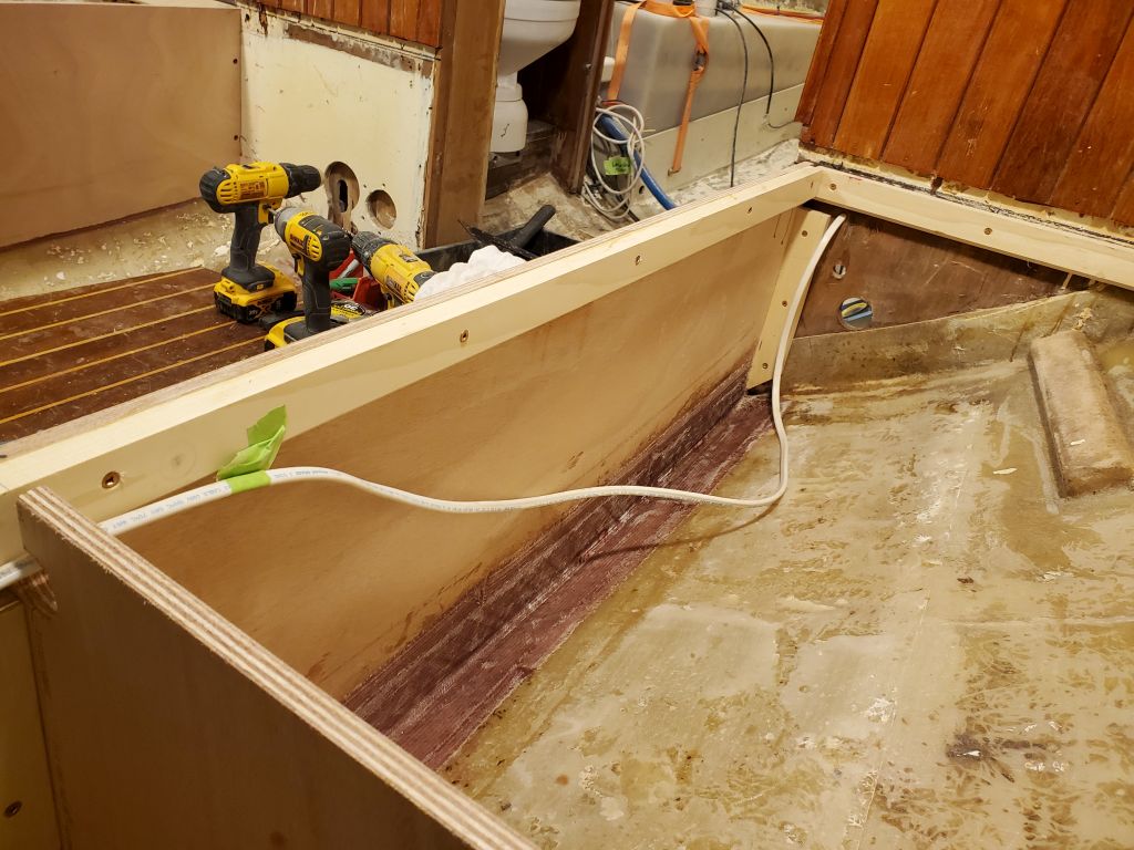
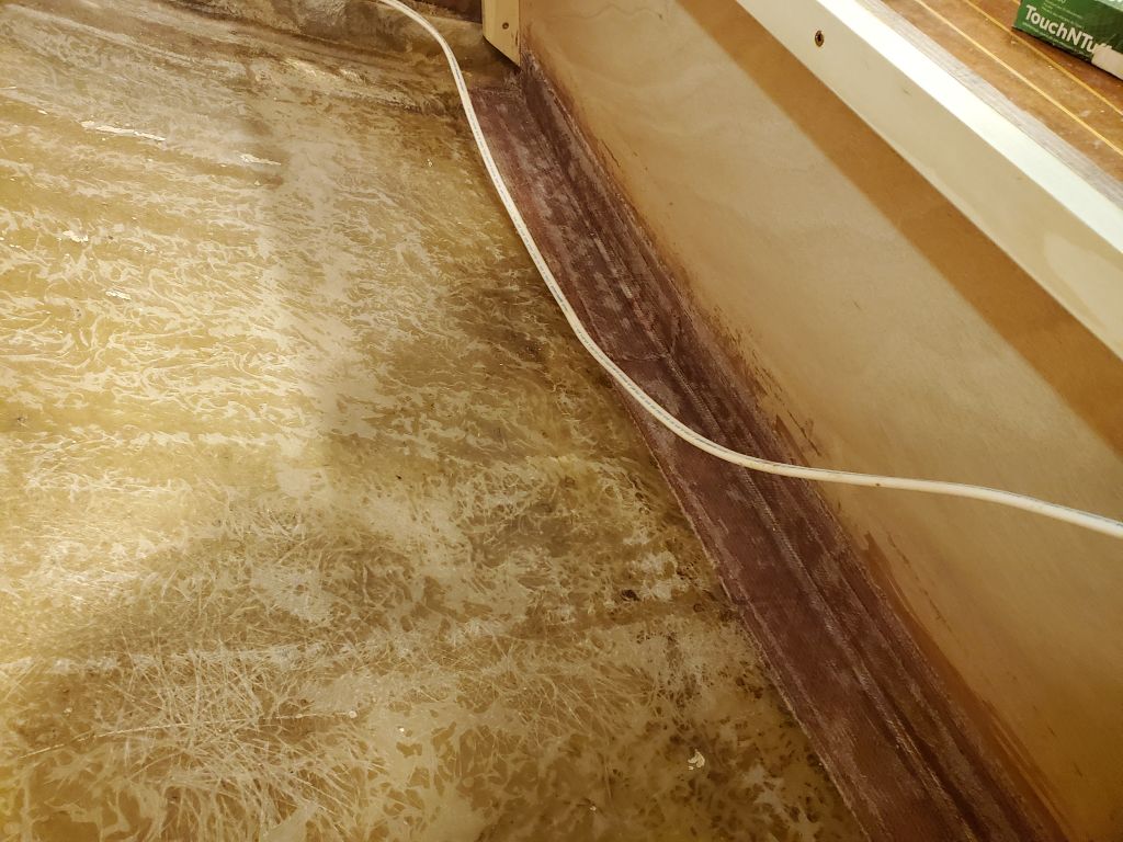
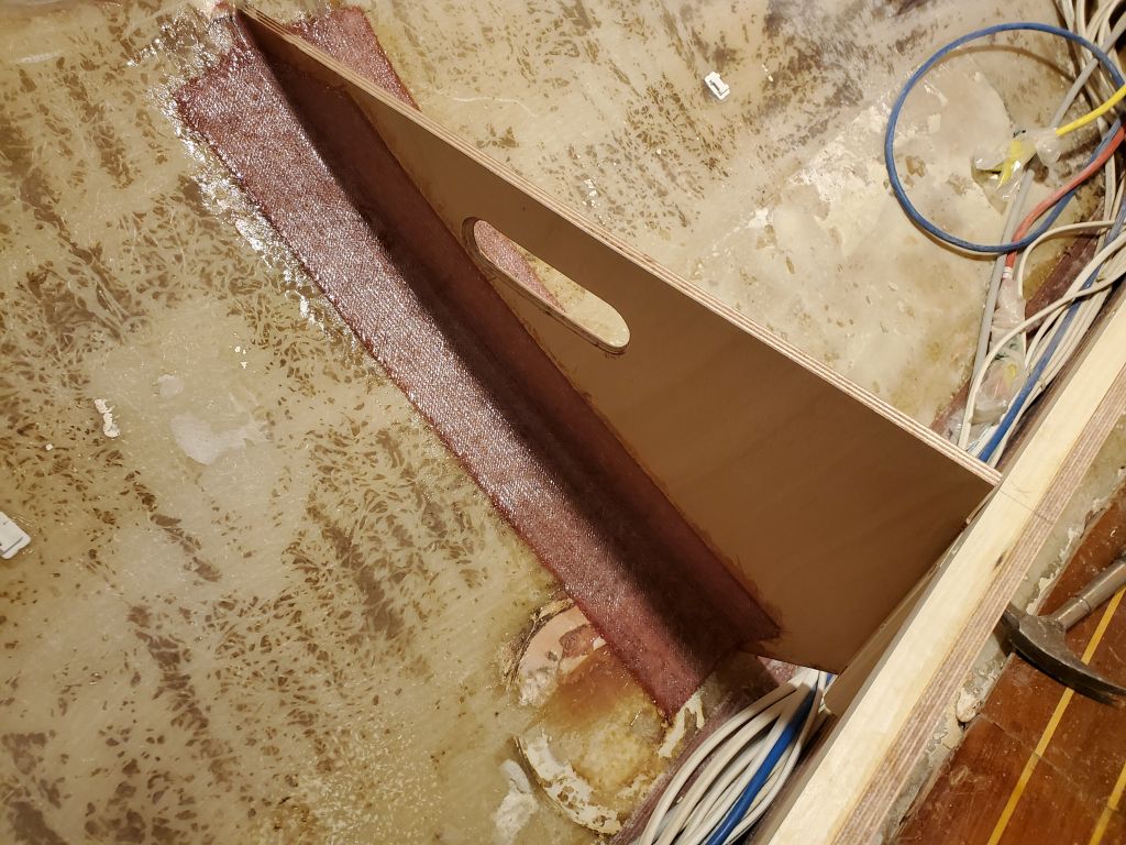
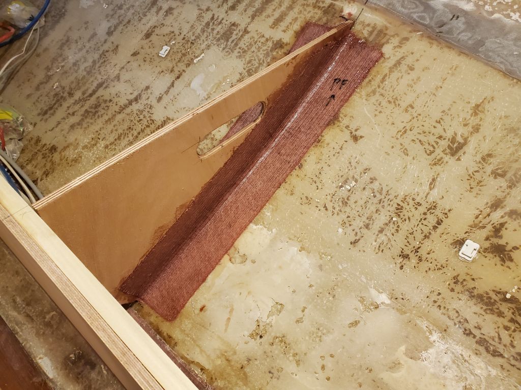
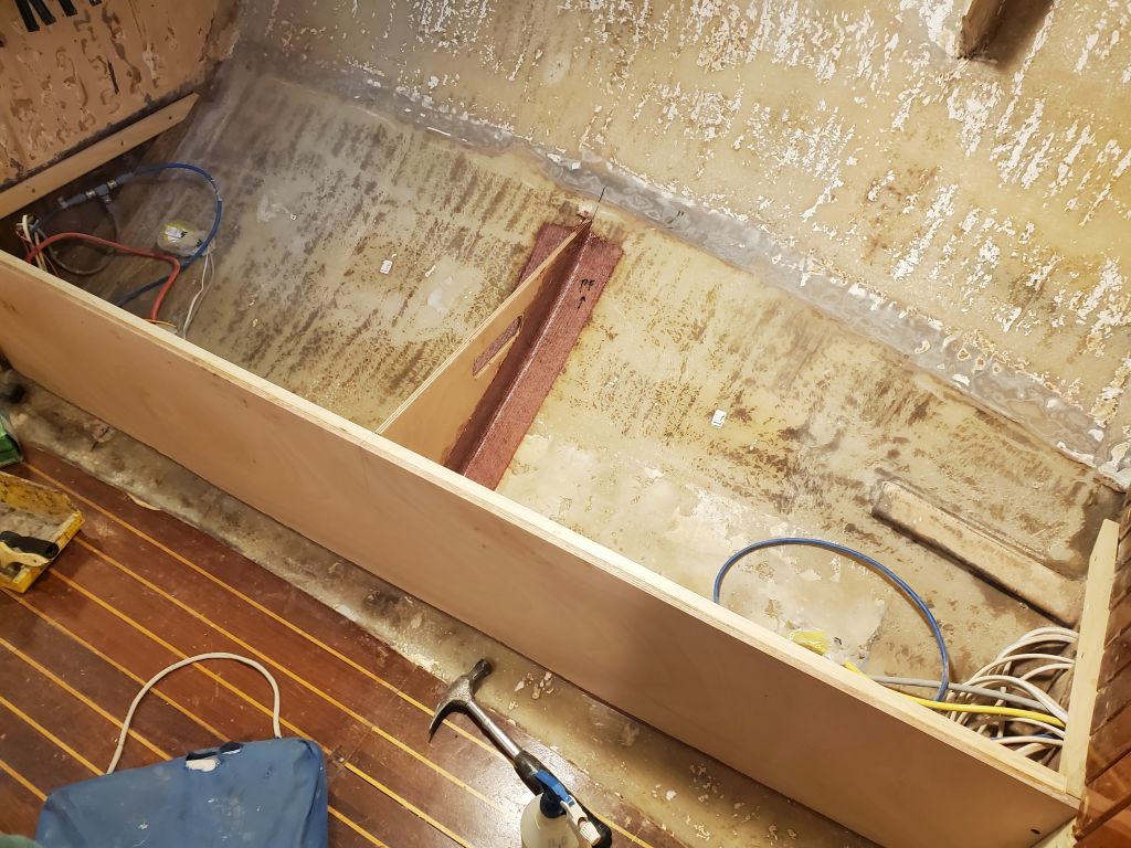
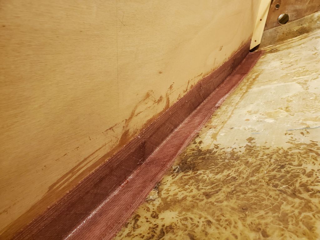
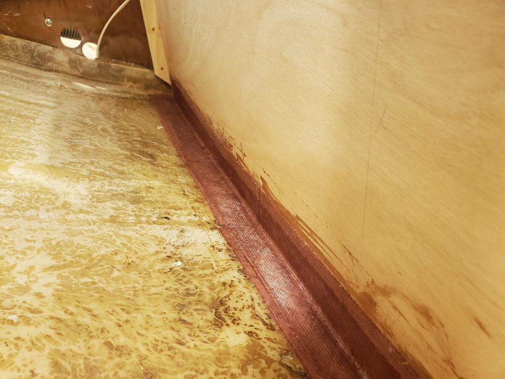
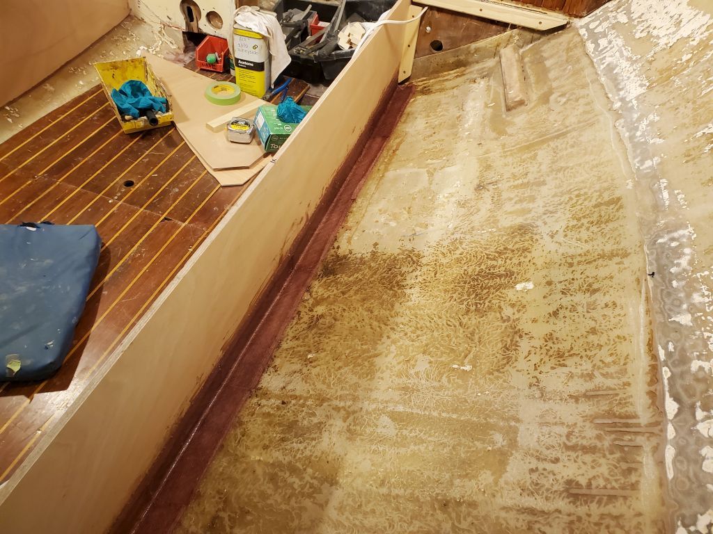
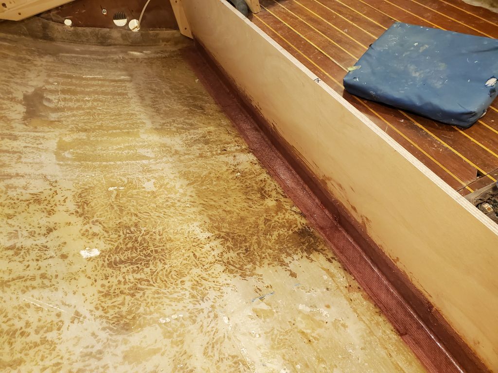
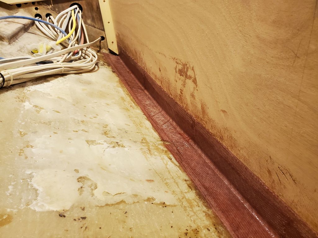
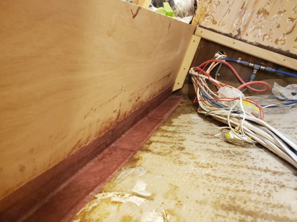
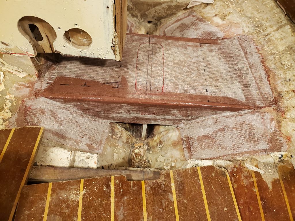
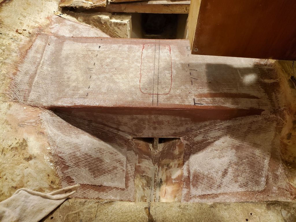
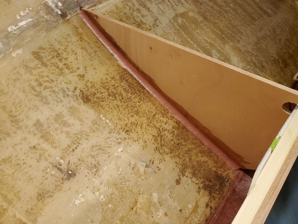
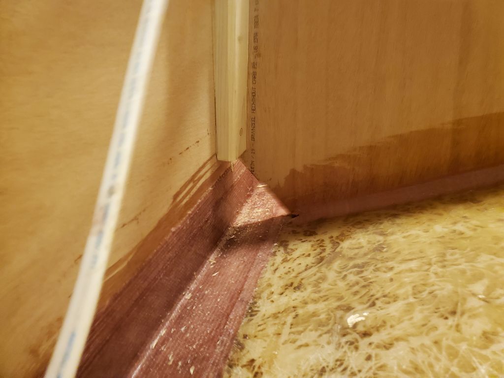
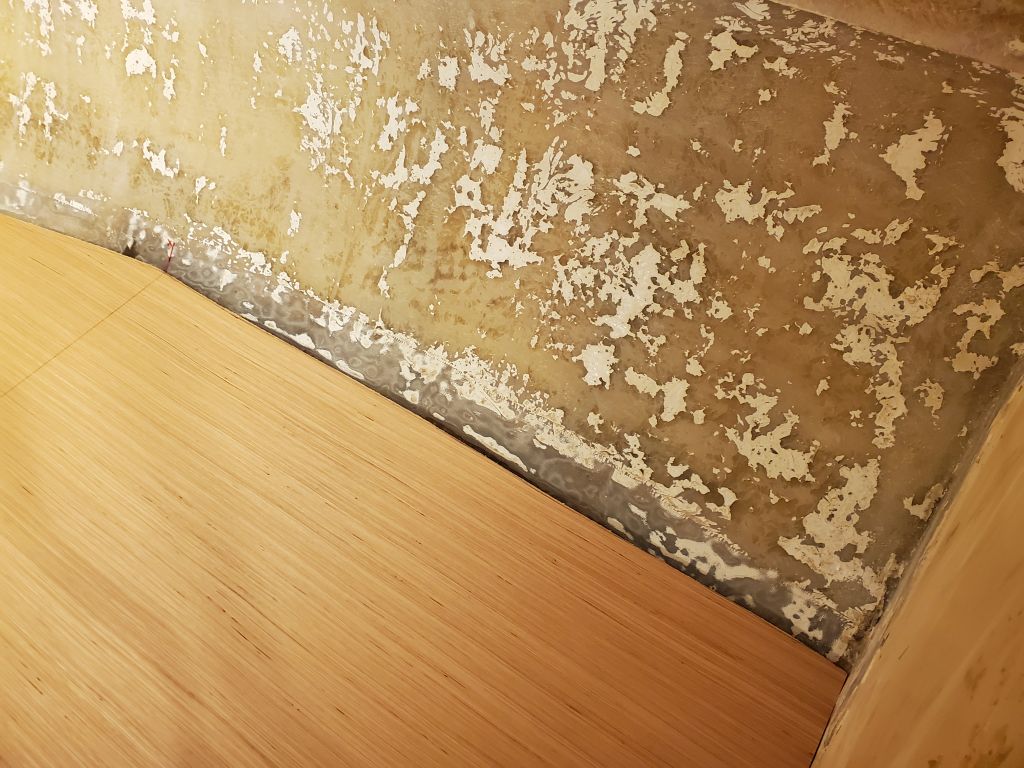
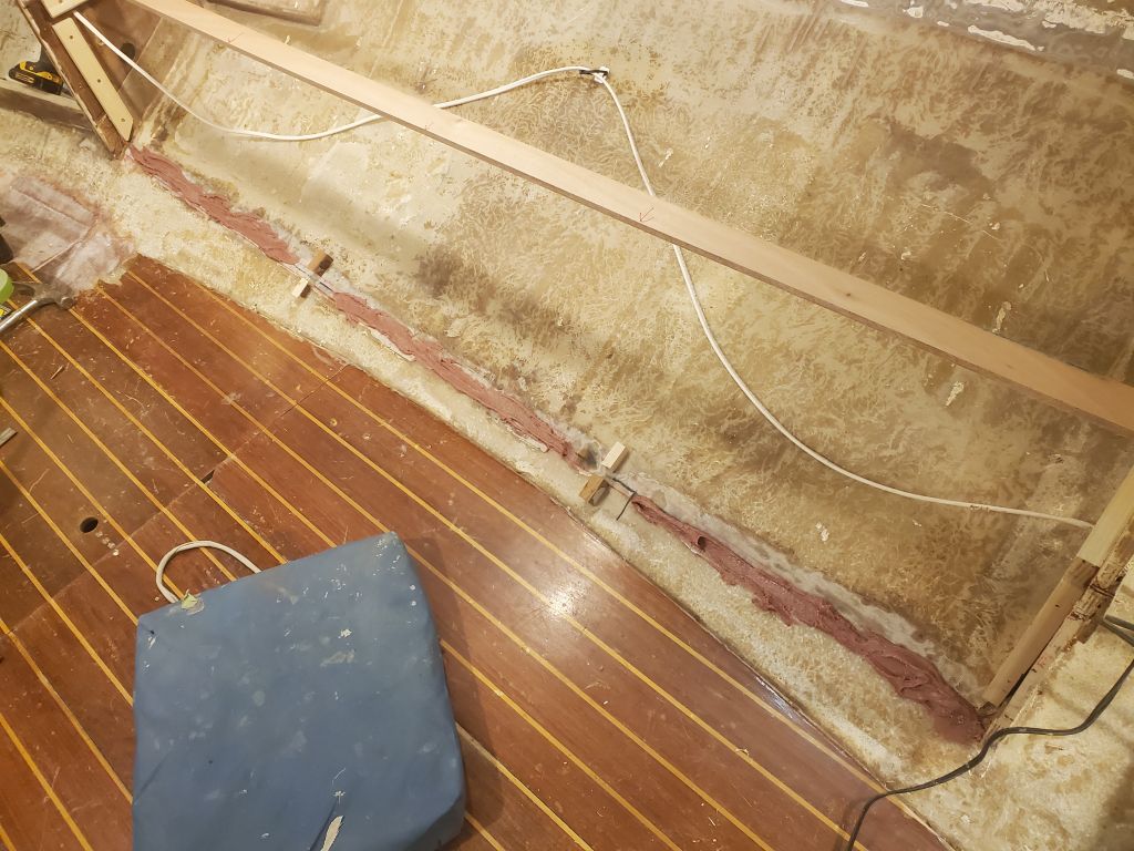
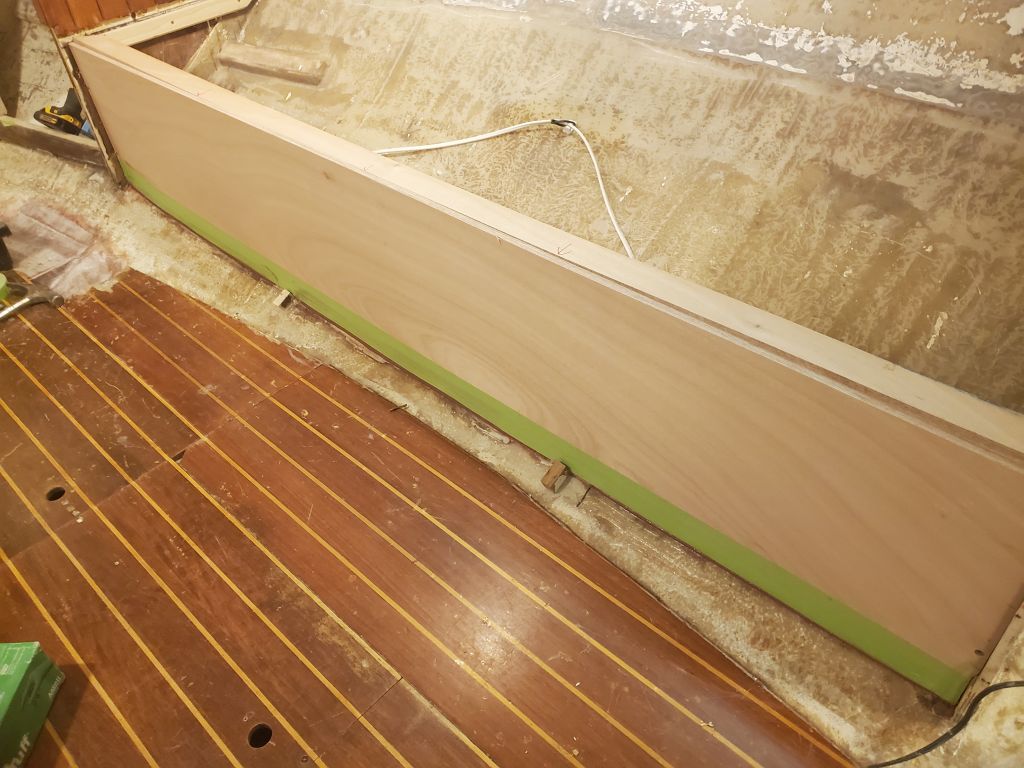
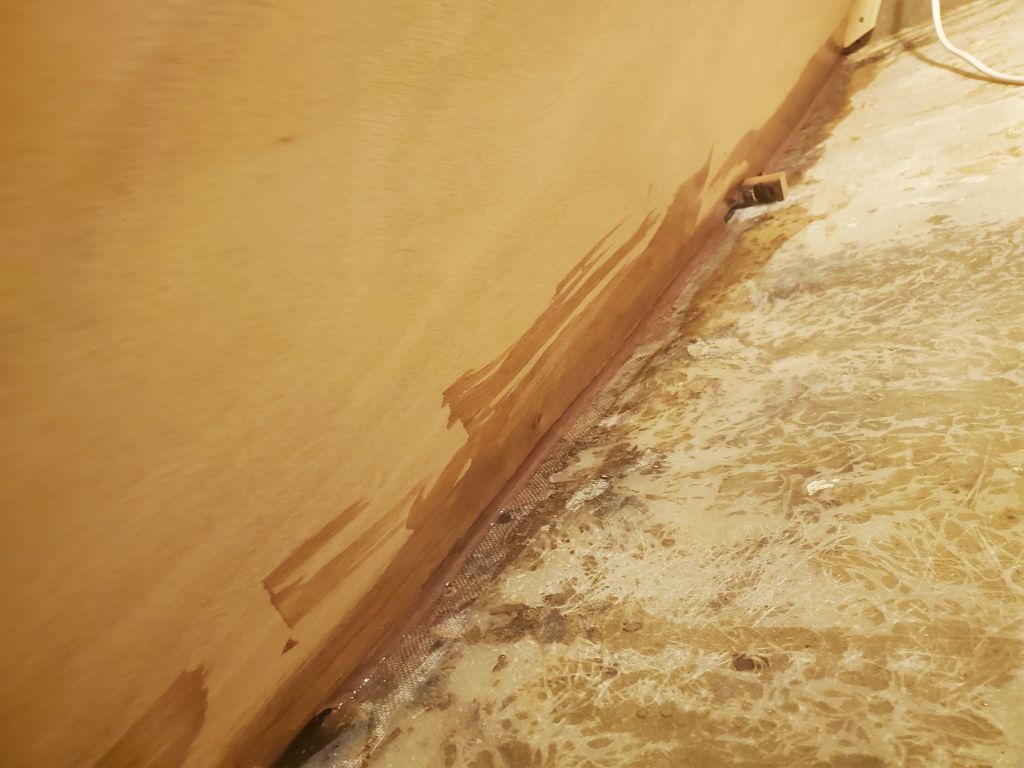
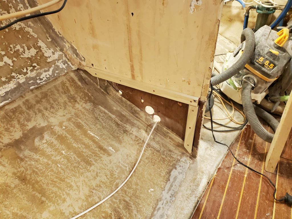
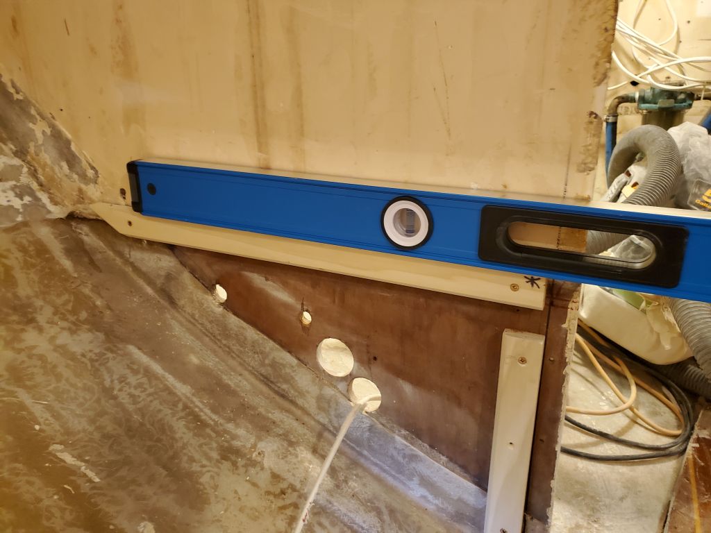
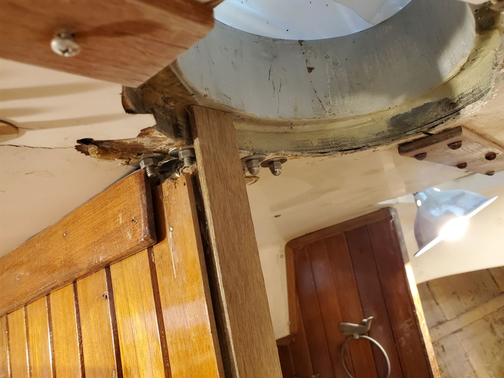
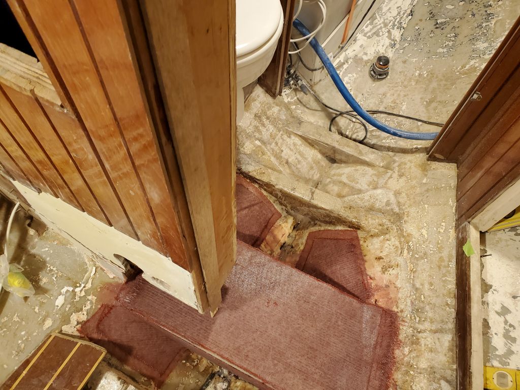
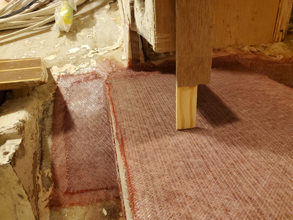
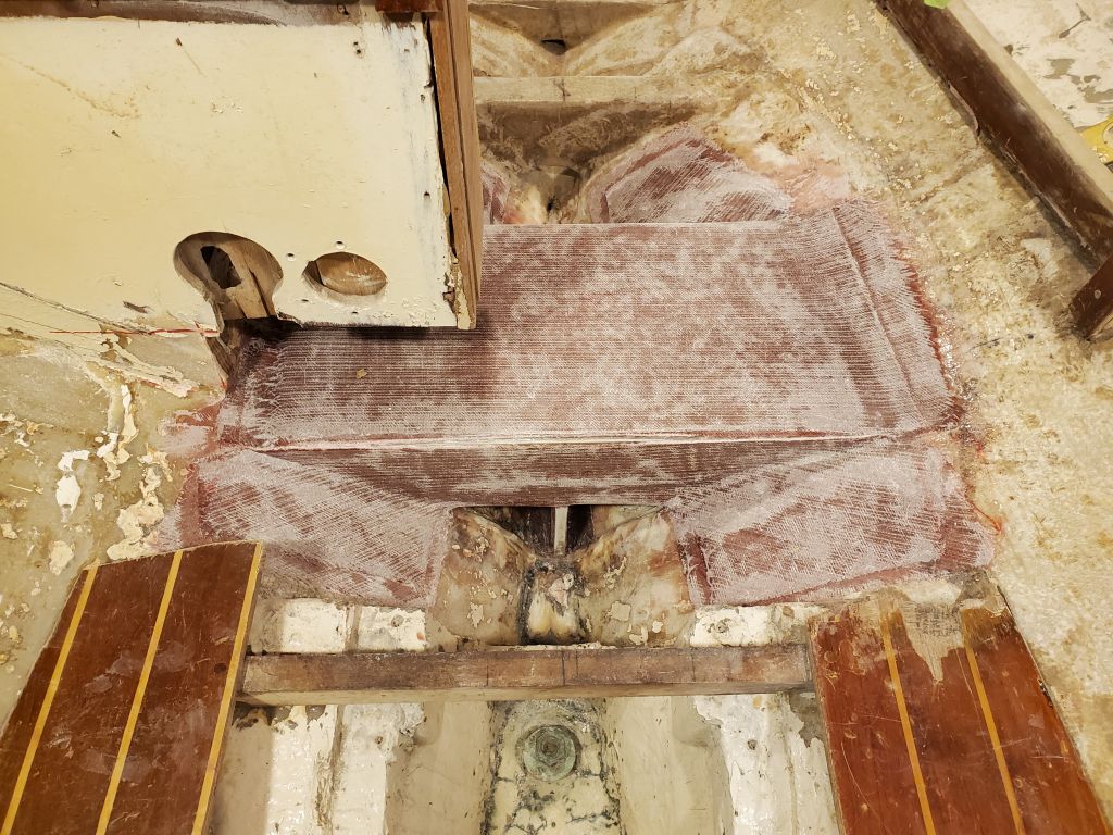
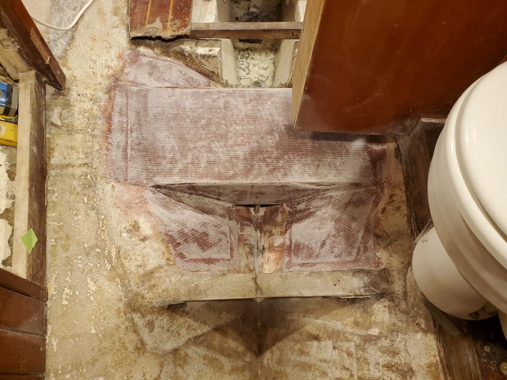
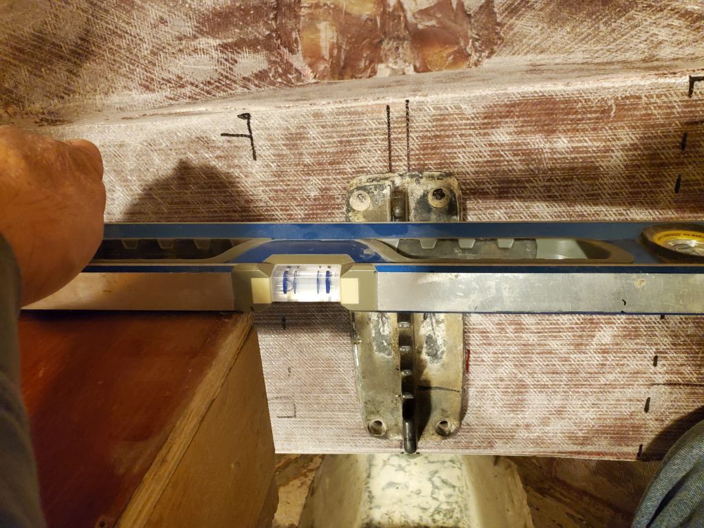
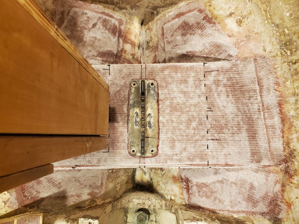
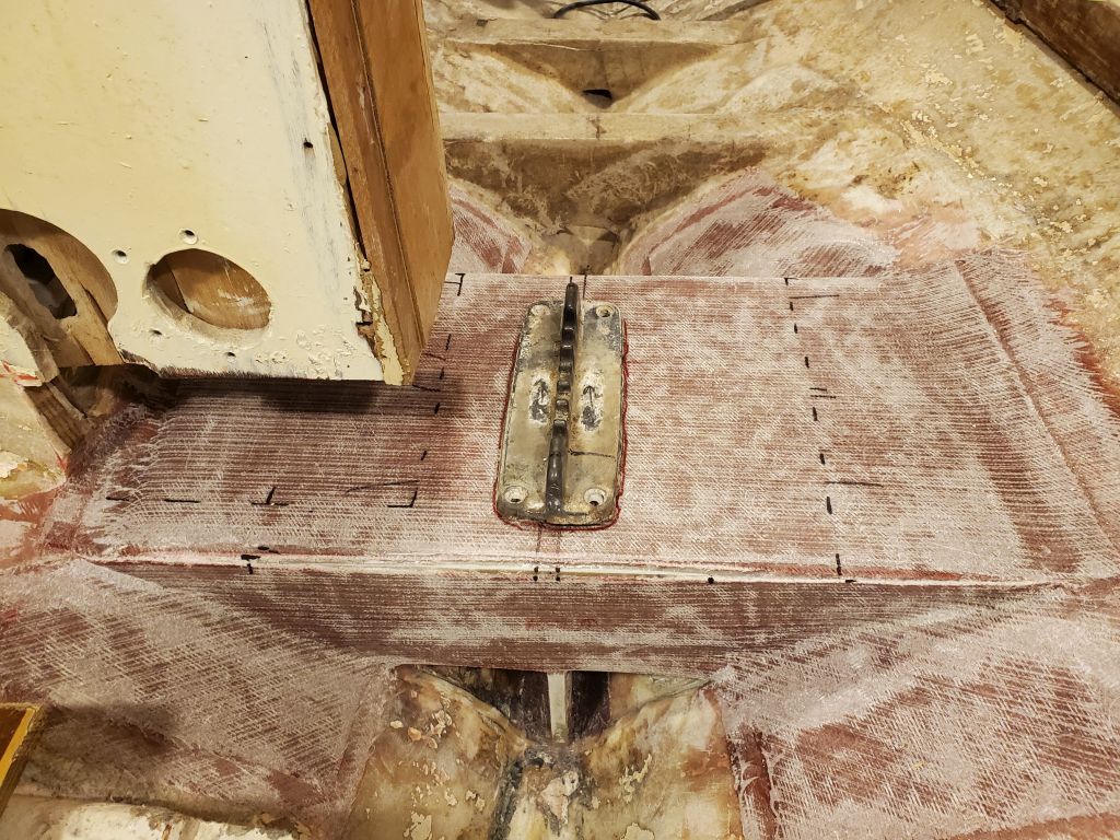
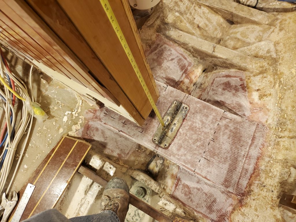
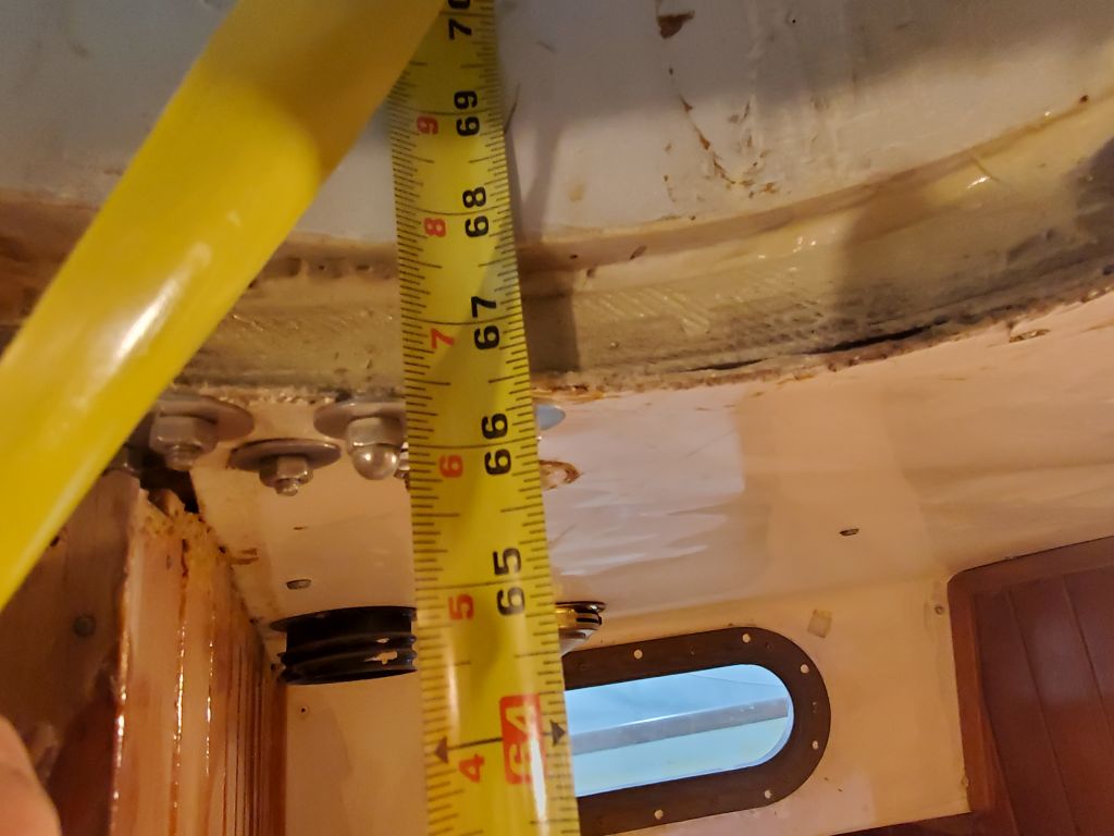
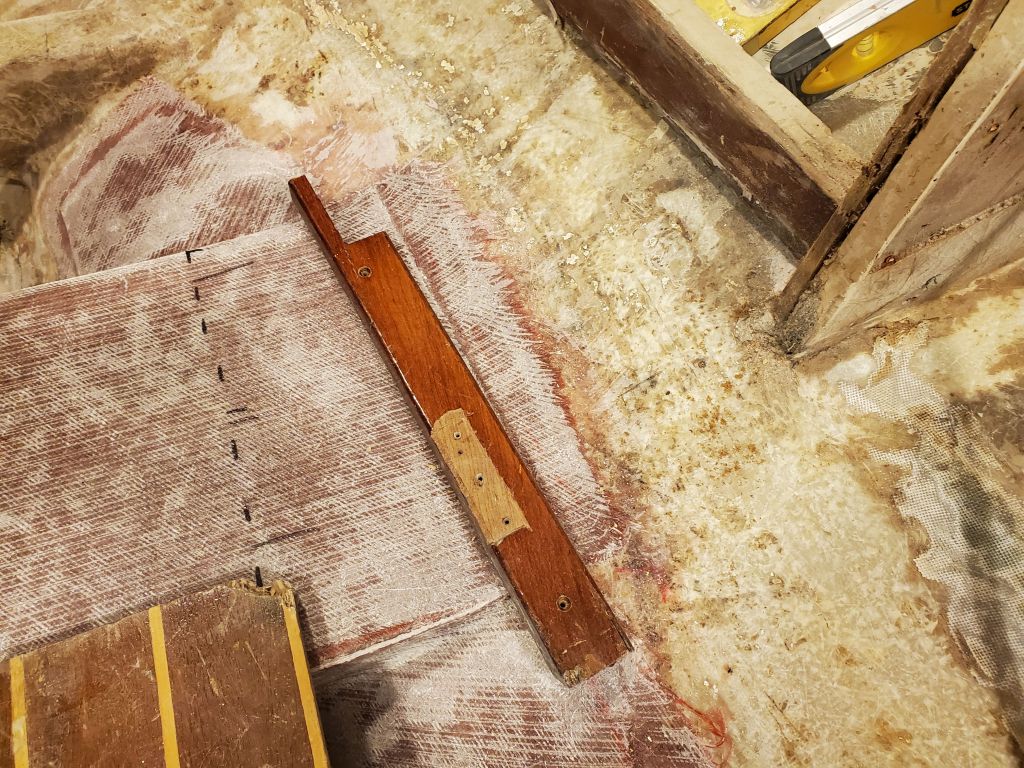
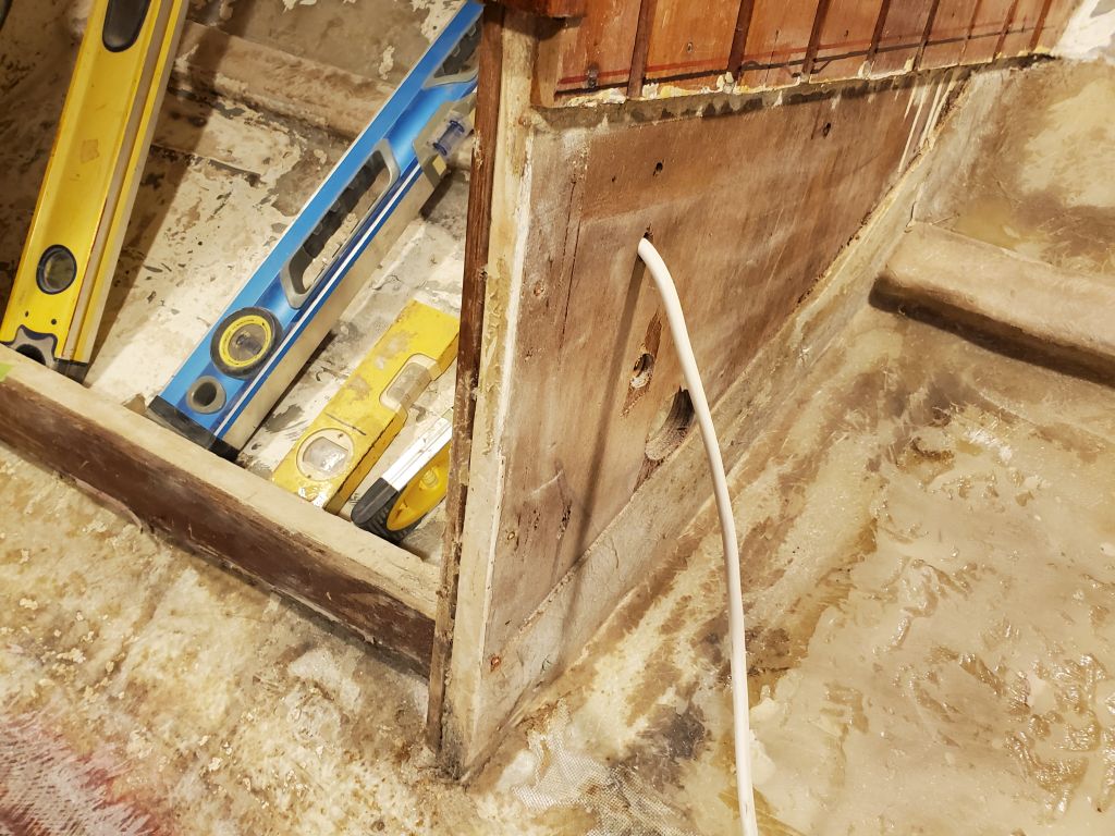
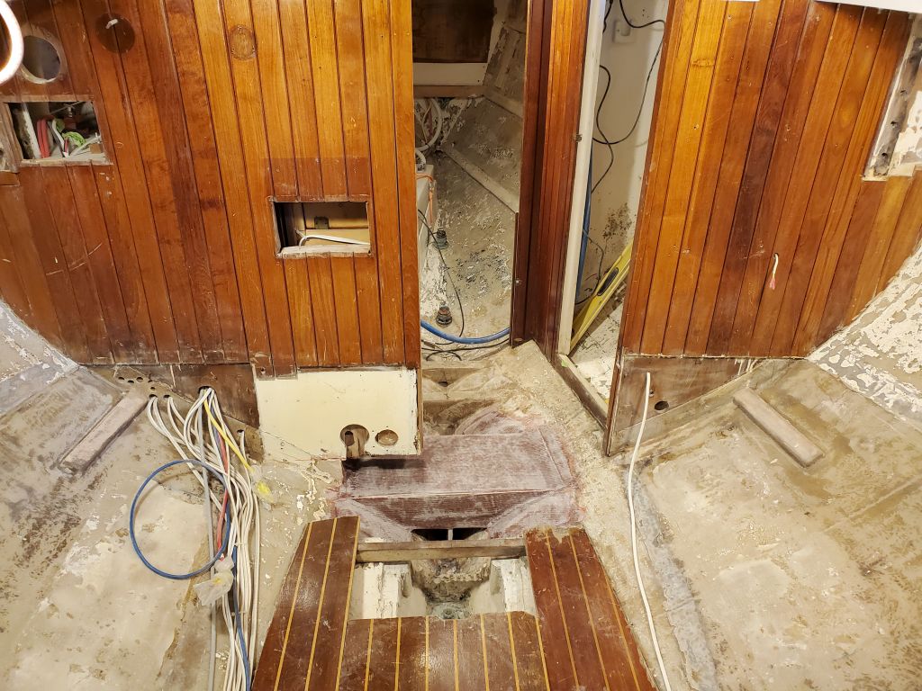
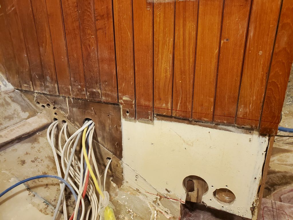
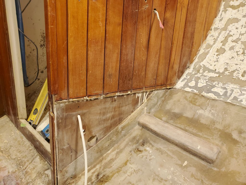
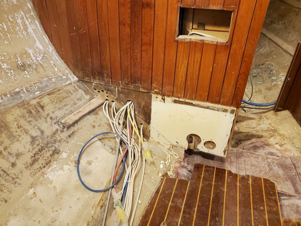
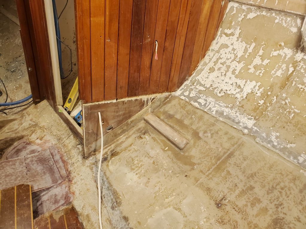
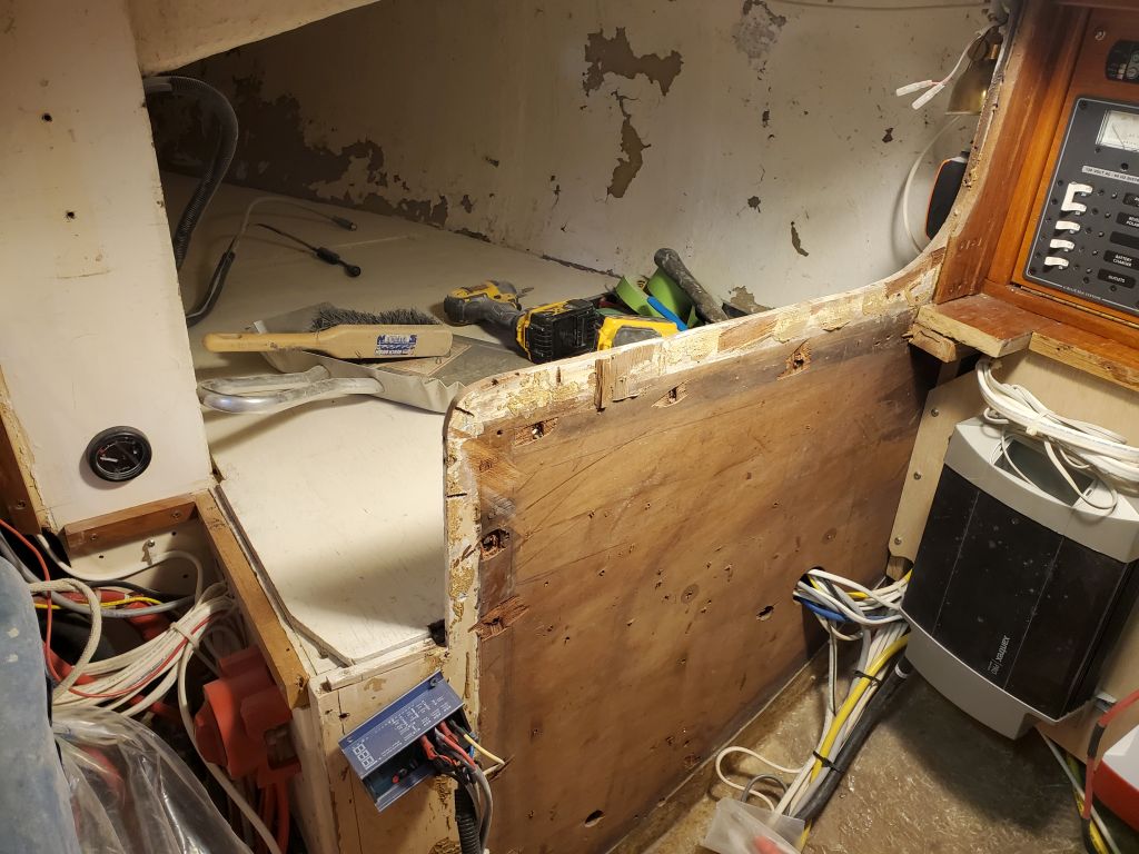
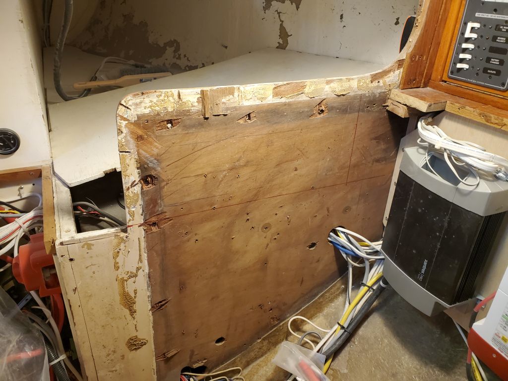
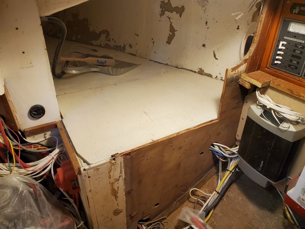
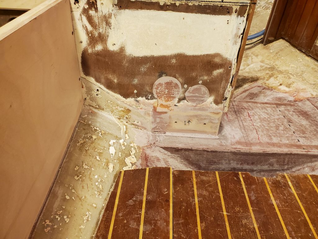
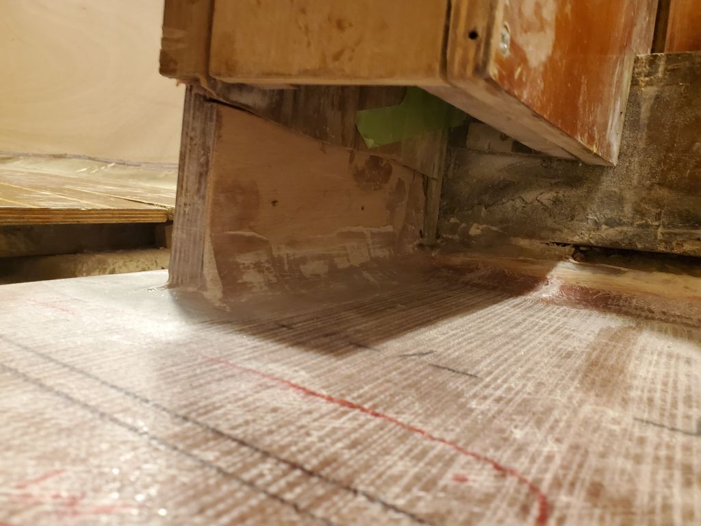
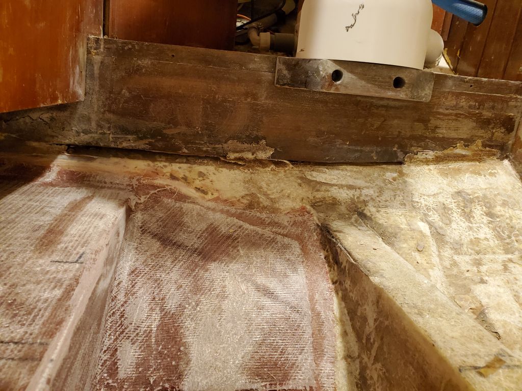
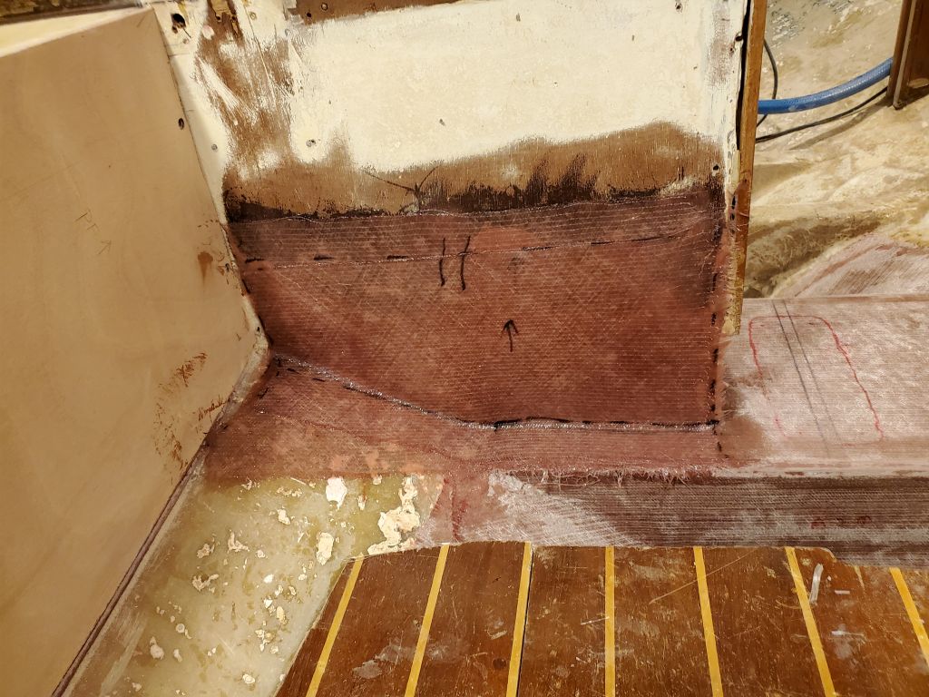
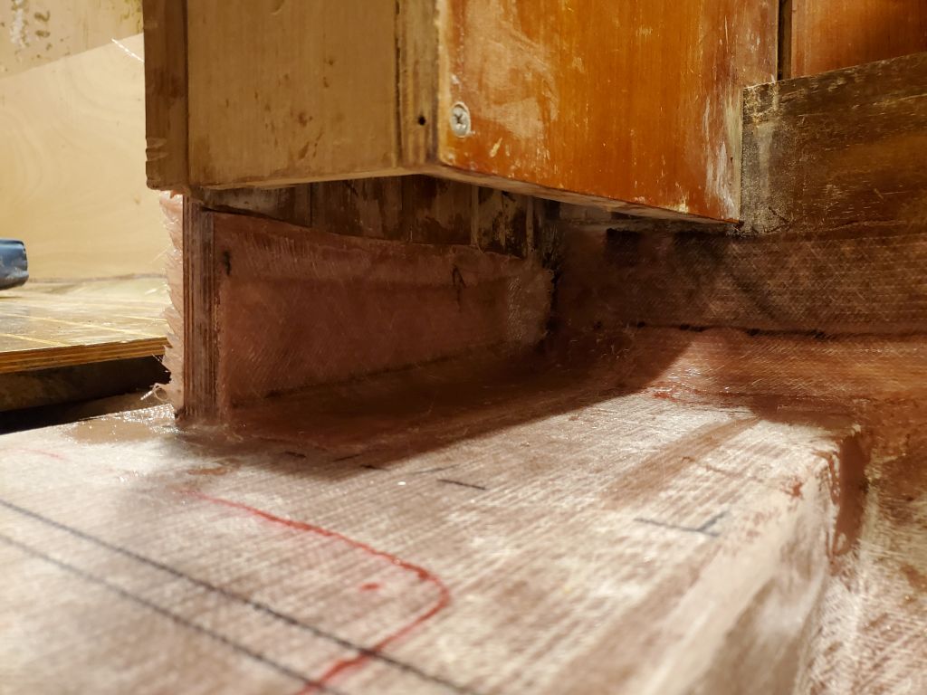
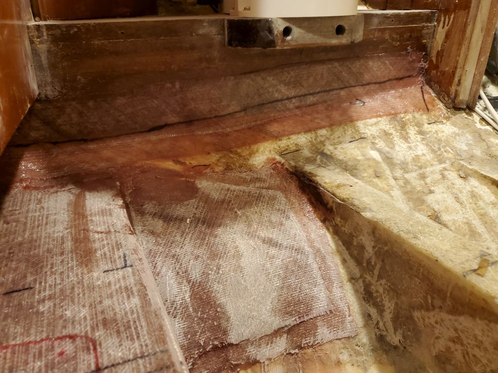
To begin, I cleaned and sanded the recent work on the main bulkhead, removing paint from the aft side of the bulkhead to prepare for tabbing, and lightly sanding the epoxy fillets and filler left from when I installed the small plywood bulkhead patches. The small bulkhead beneath the marine toilet needed some attention also to close a large gap and weak tabbing, so I prepared this area too. Afterwards, I cut tabbing to fit as needed, applied some additional thickened epoxy to clean up the earlier filler and fillets, and to make a new fillet at the head platform, then wet out and installed two layers of tabbing (on each side of the main bulkhead) and a single layer on the head platform.
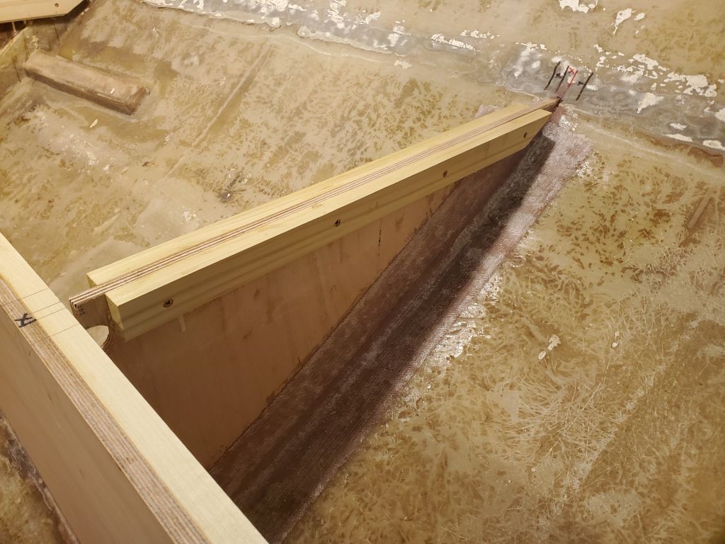
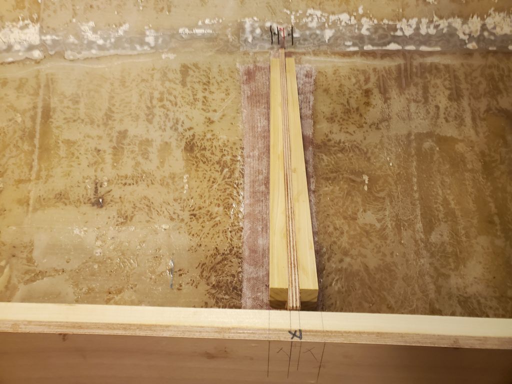
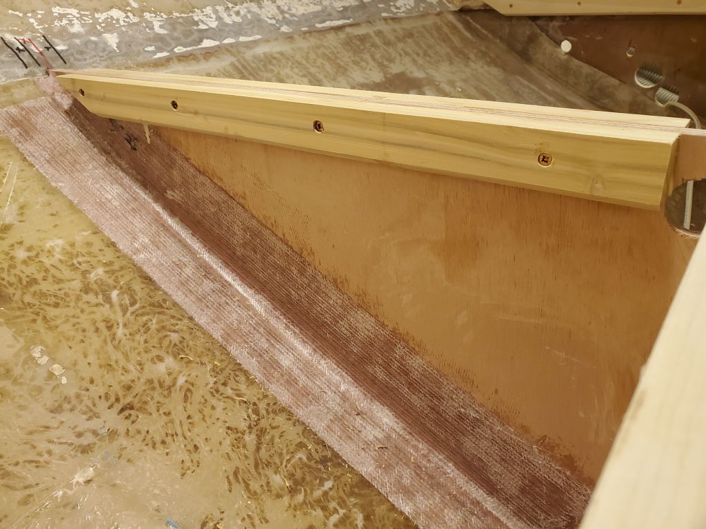
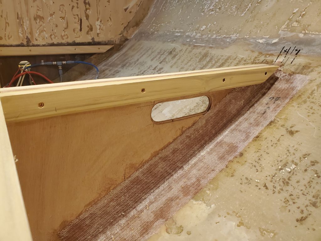
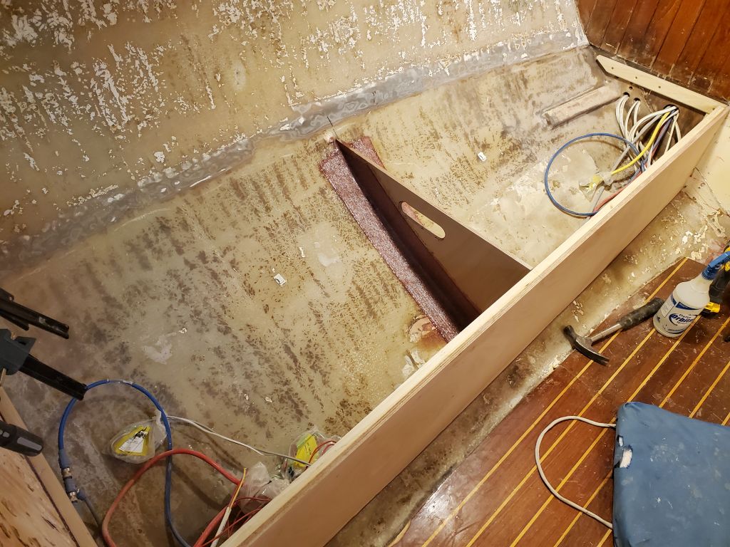
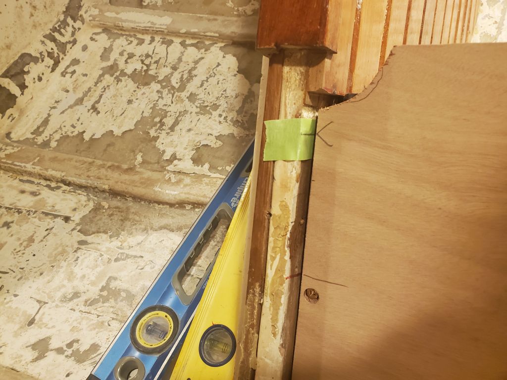
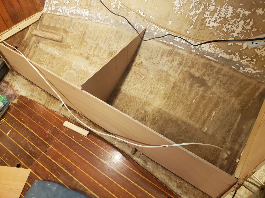
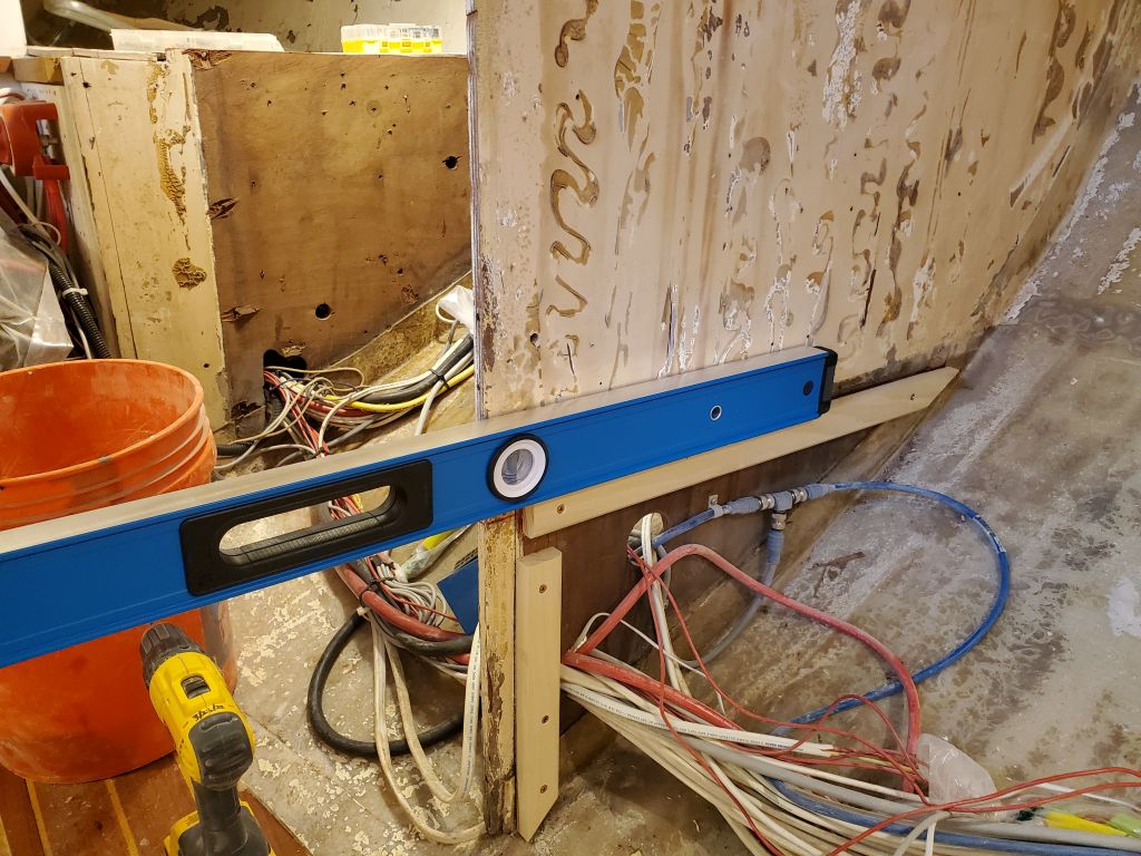
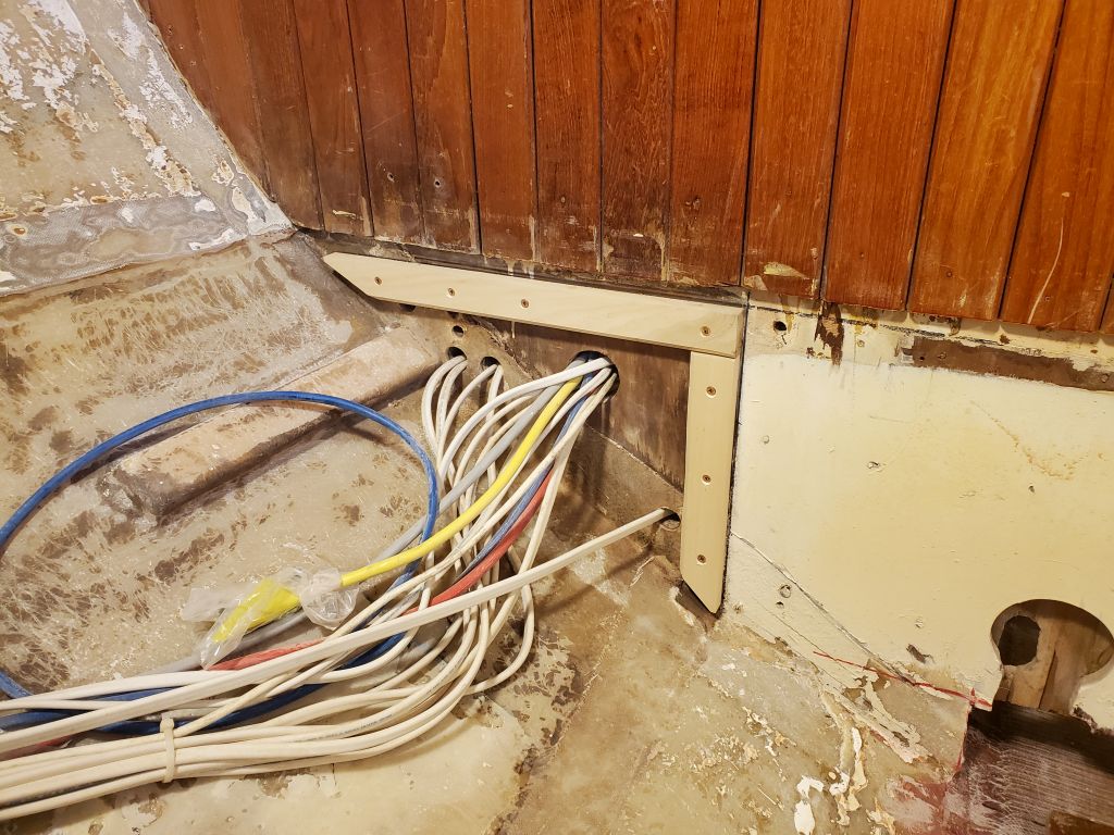
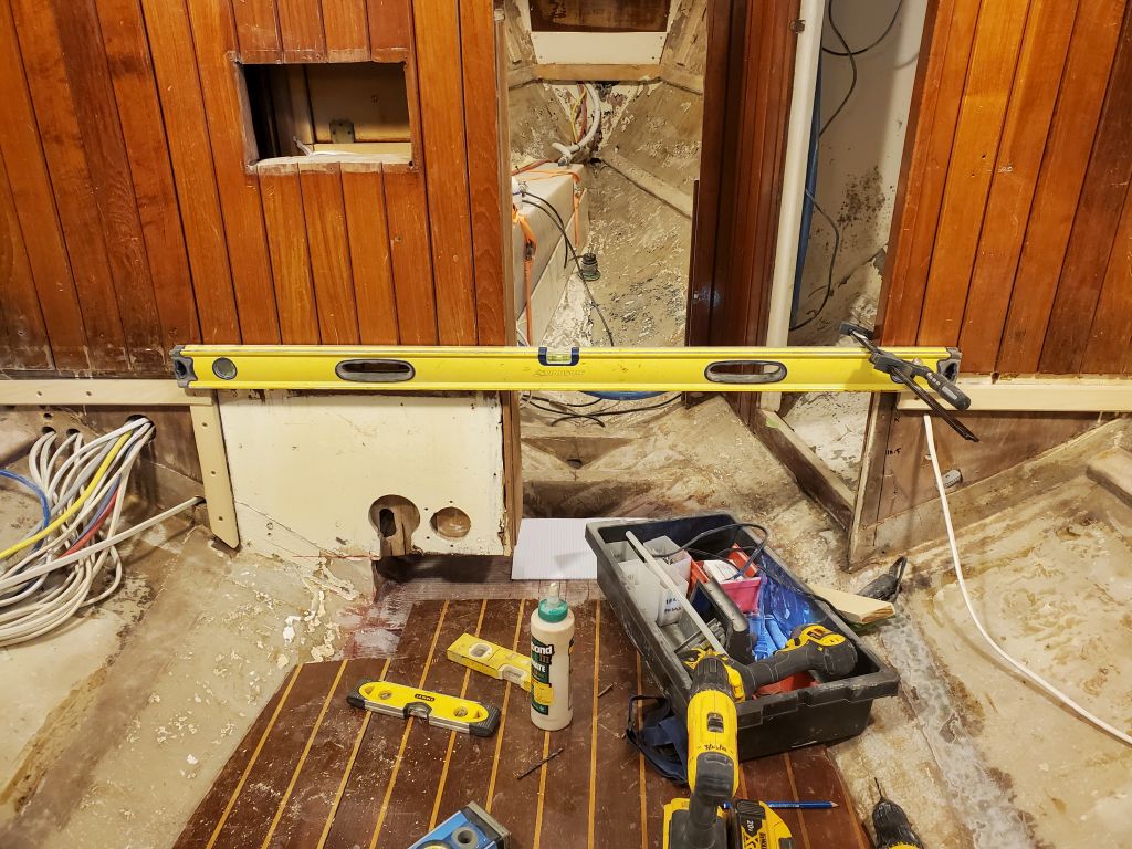
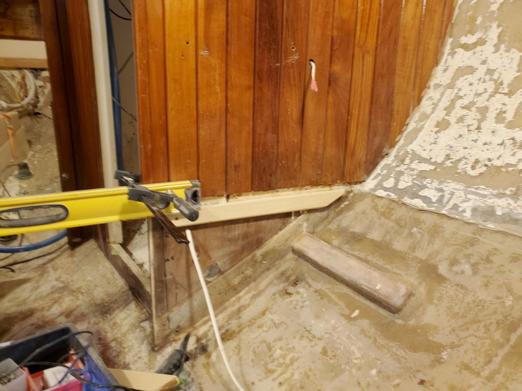
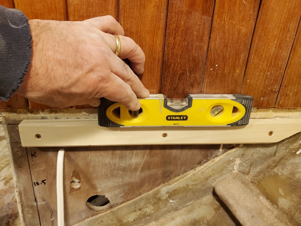
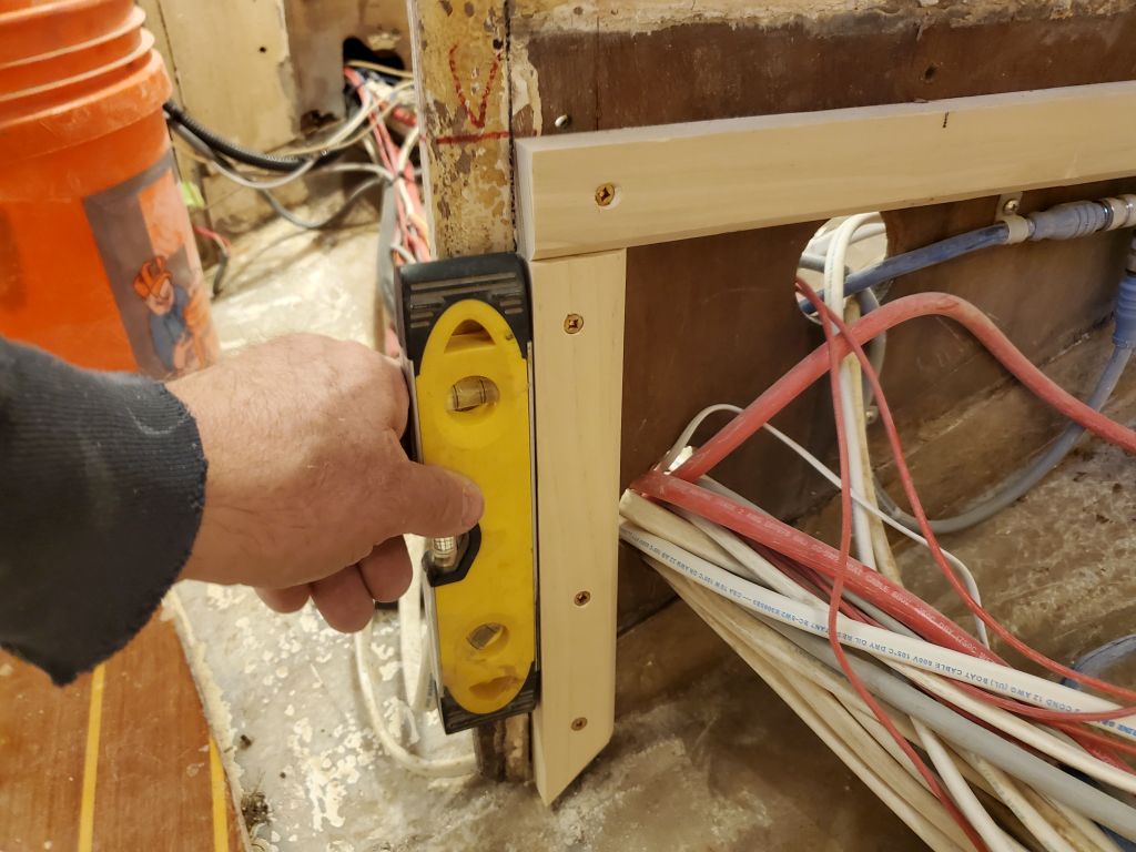
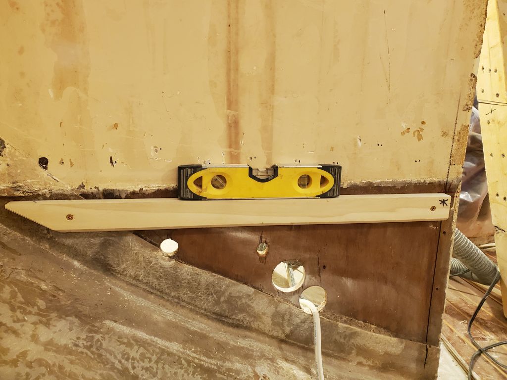
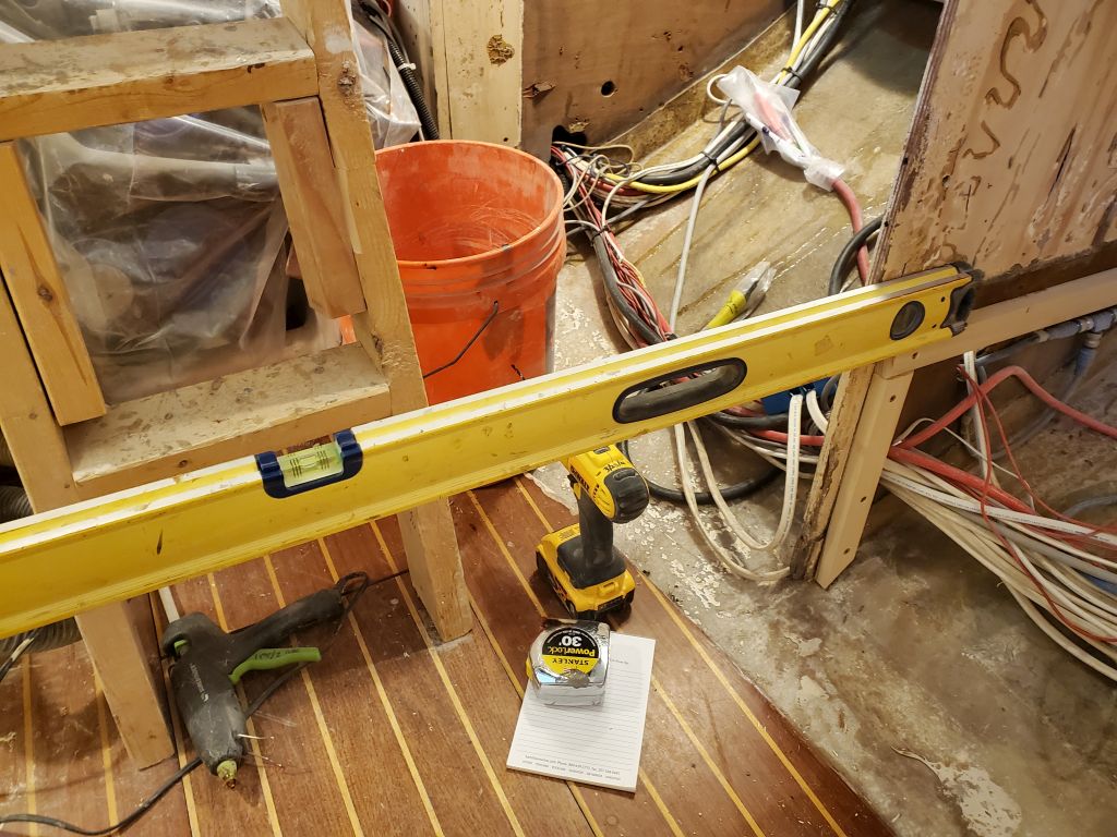
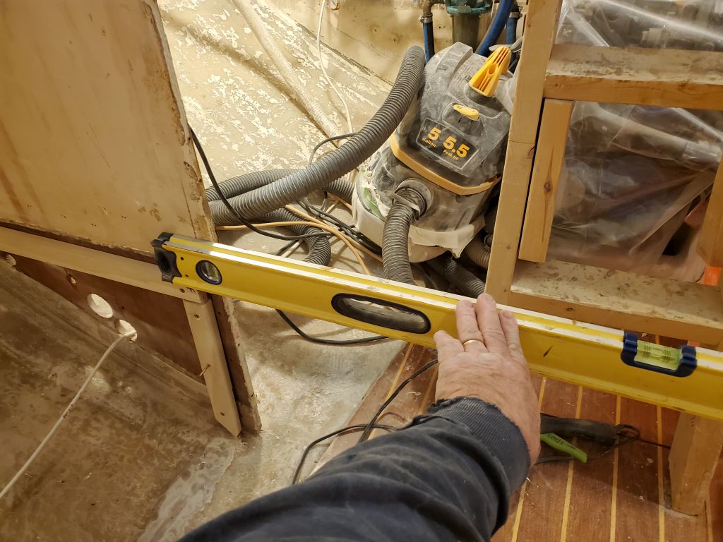
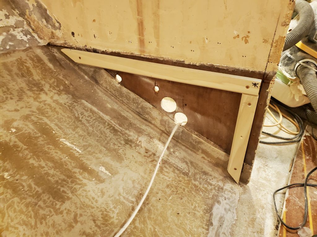
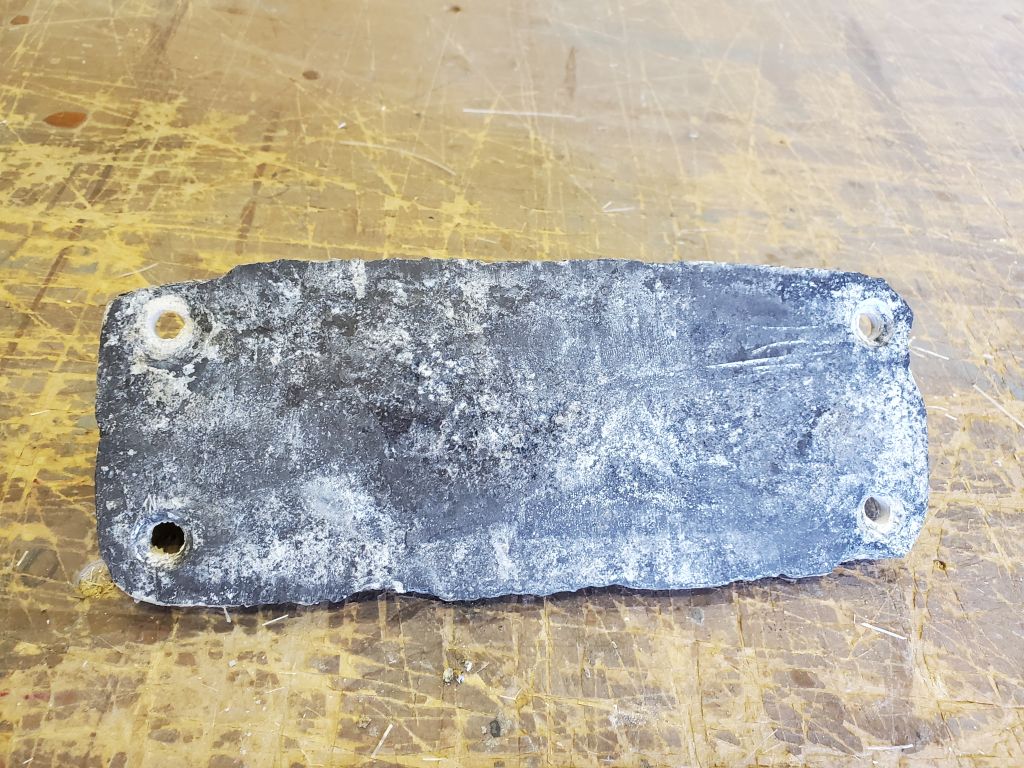
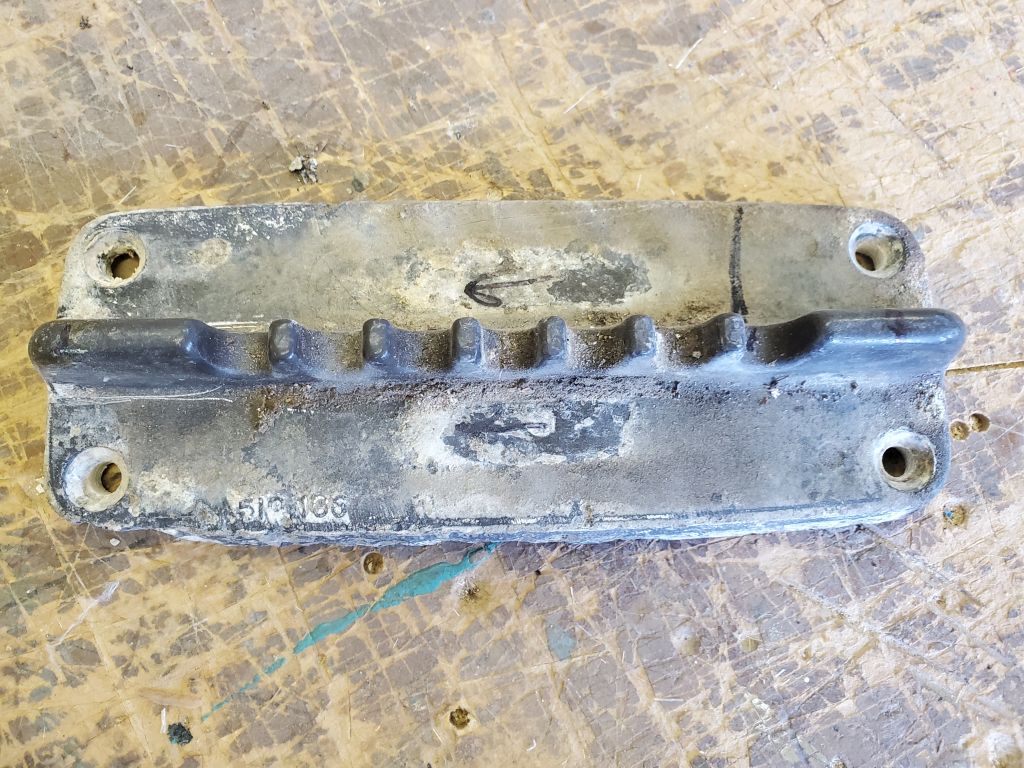
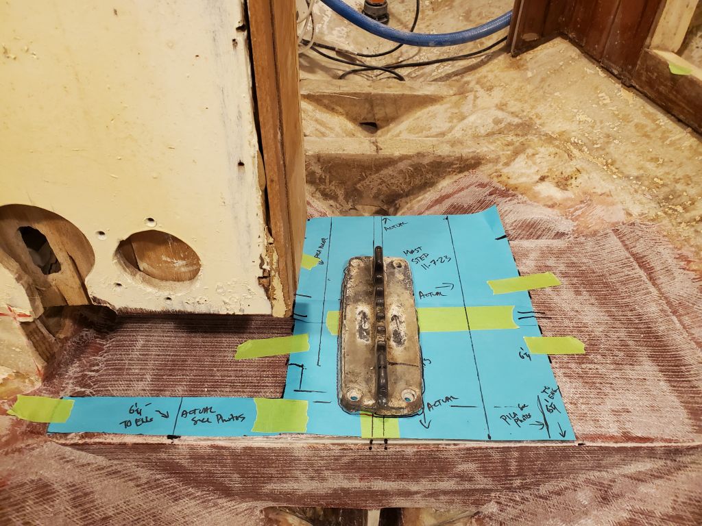
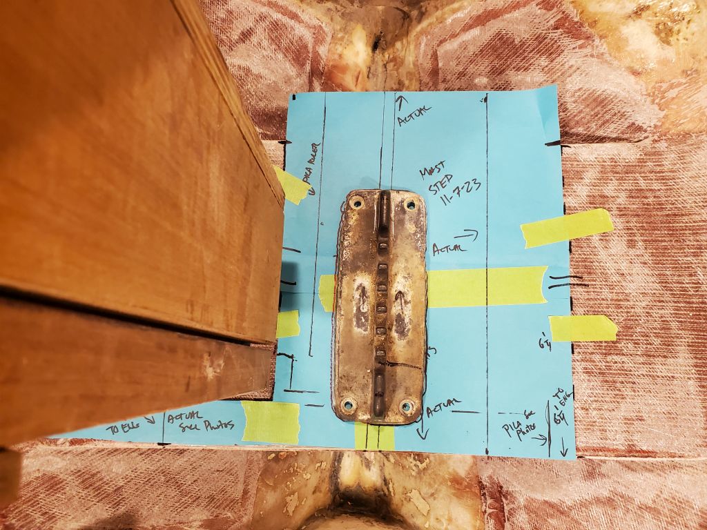
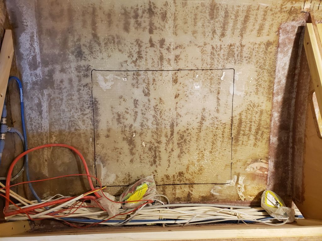
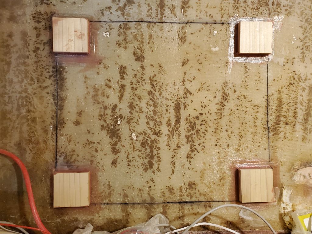
Next, I used the battery switch panel that I’d removed from the port after settee locker earlier to mark its own outline on the hull so I could install new hardwood blocks for securing the panel. I secured the new blocks with epoxy adhesive.
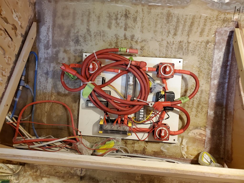
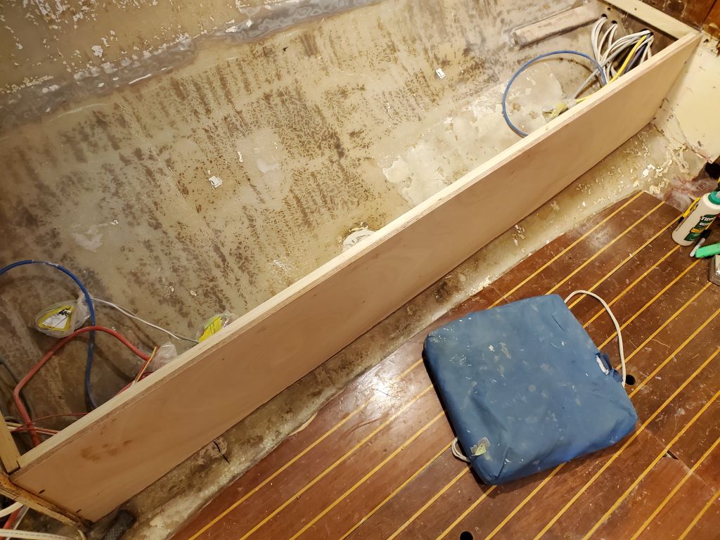
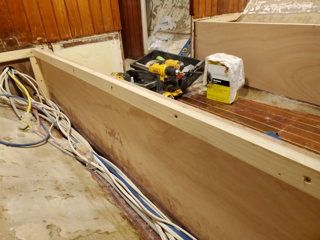
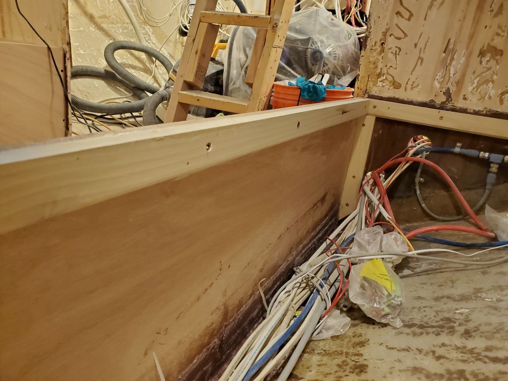
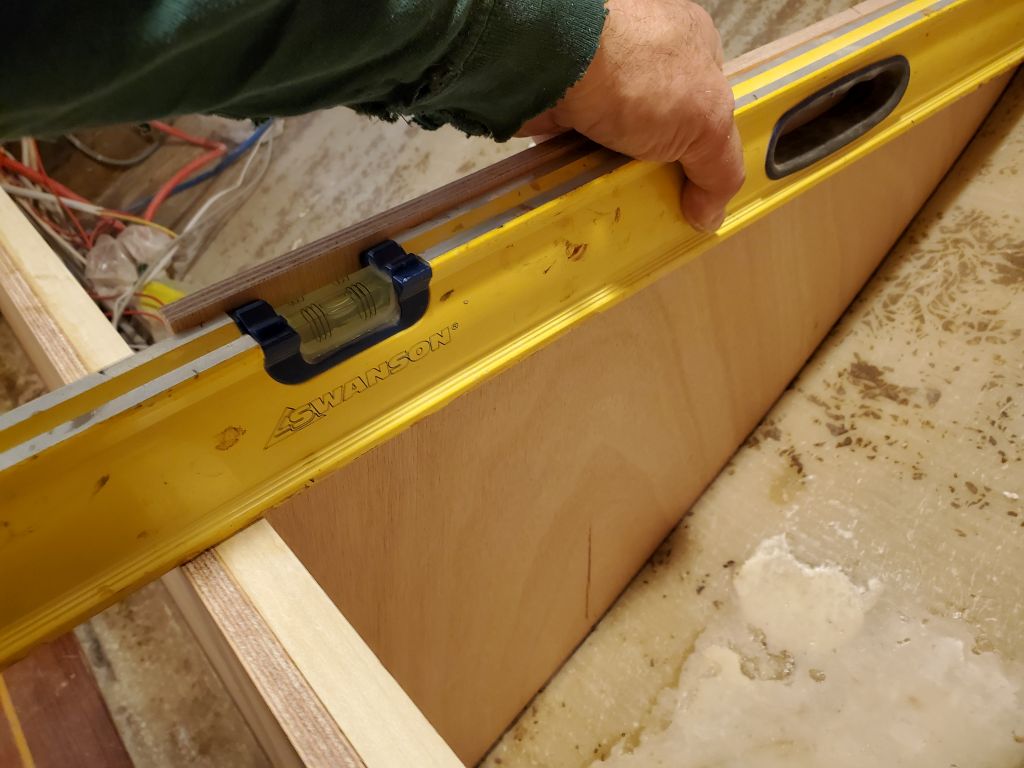
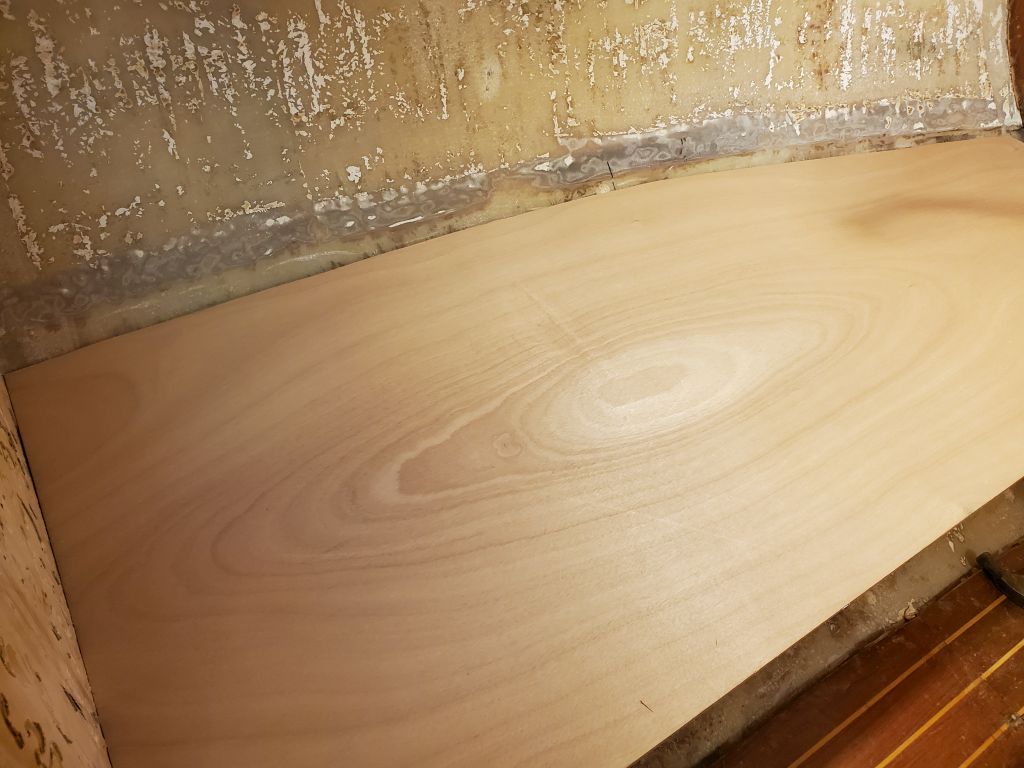
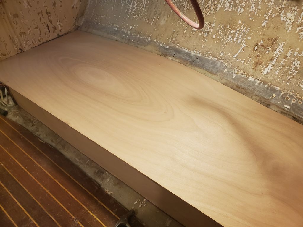
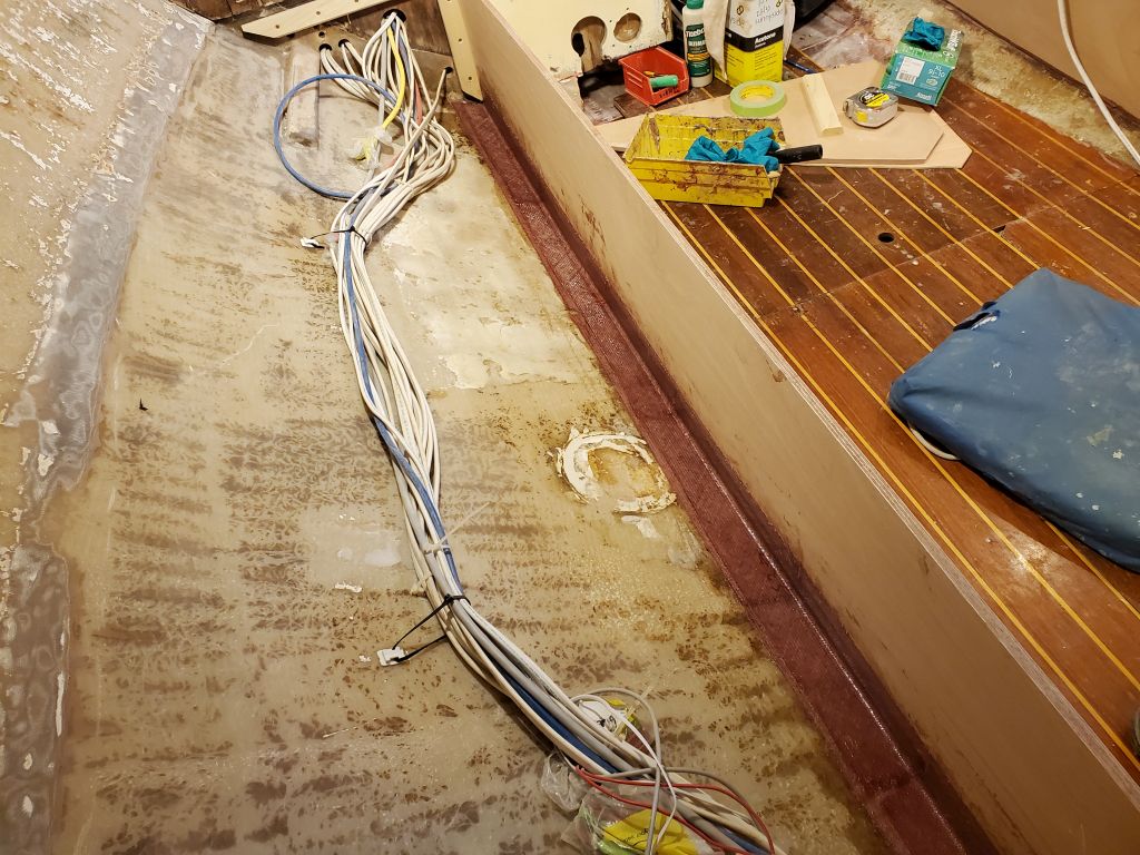
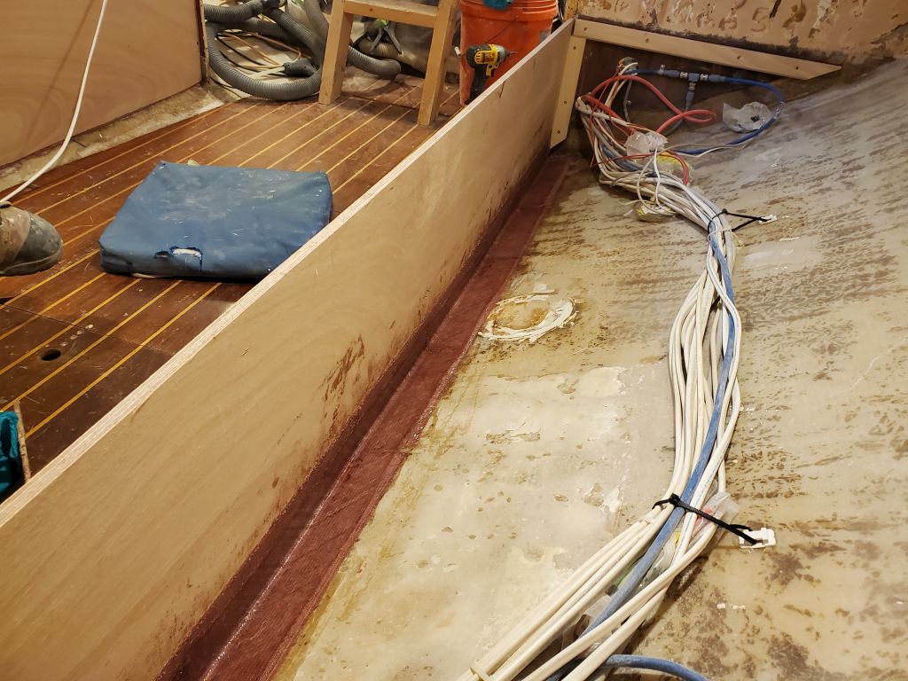
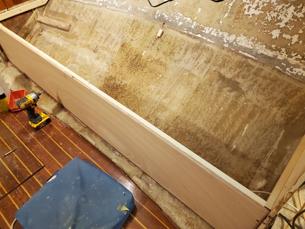
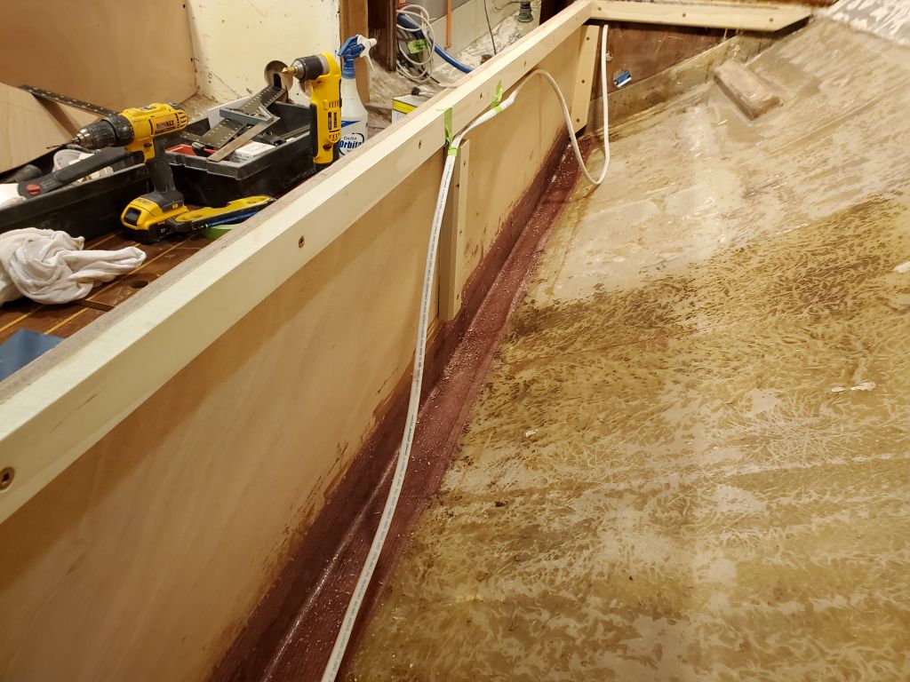
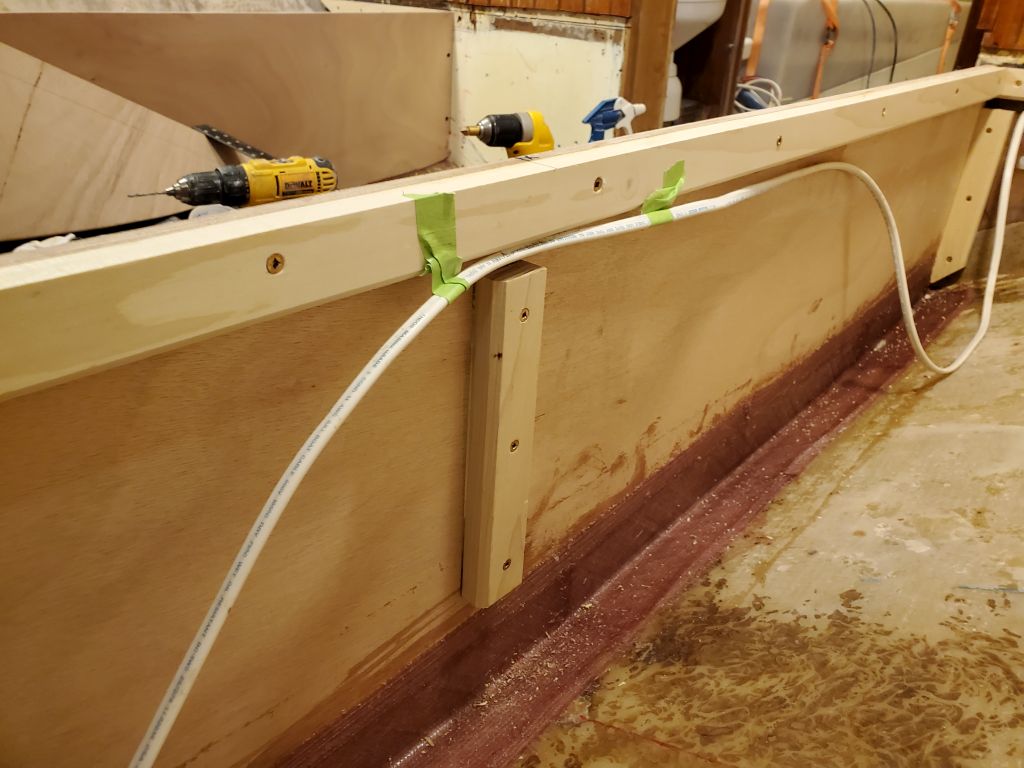
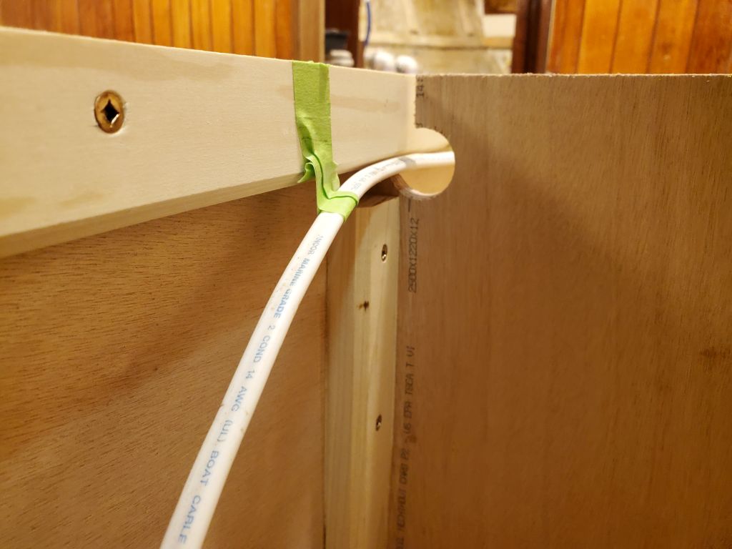
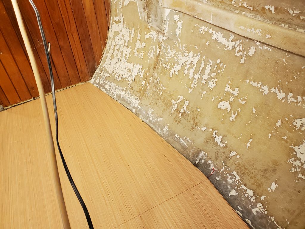
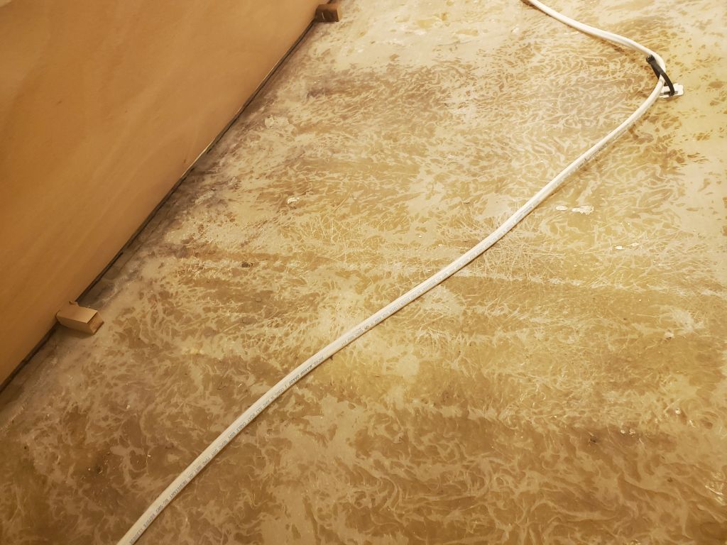
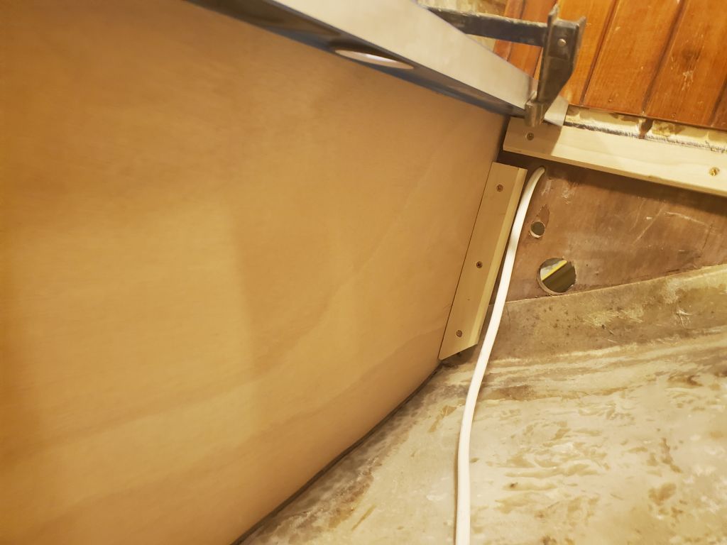
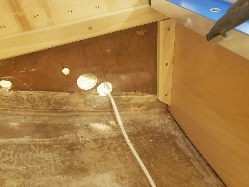
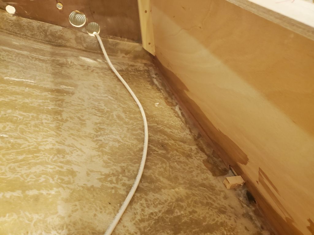
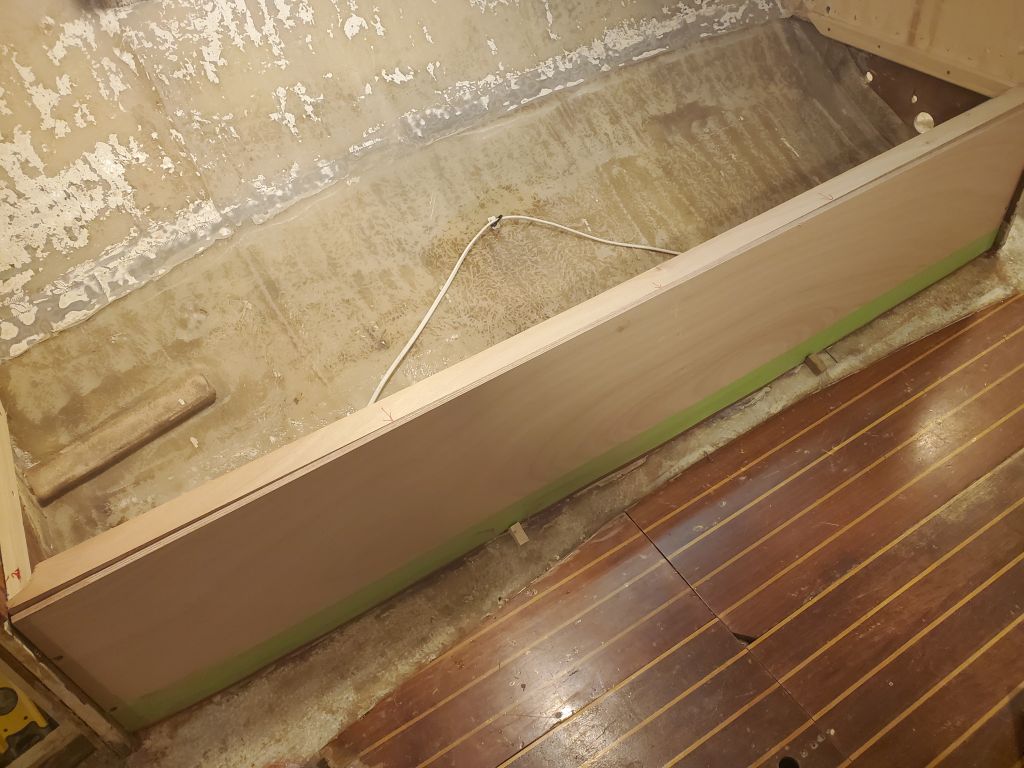
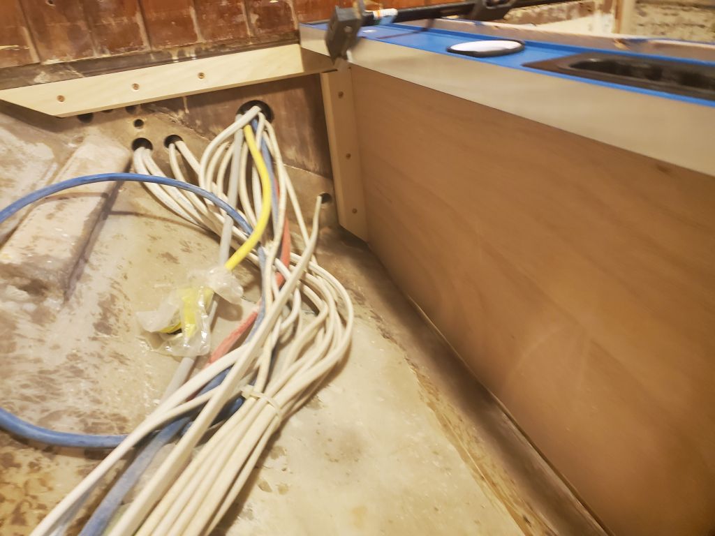
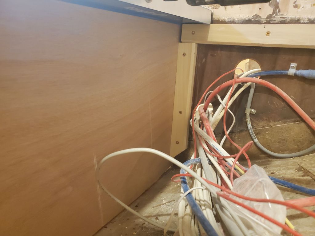
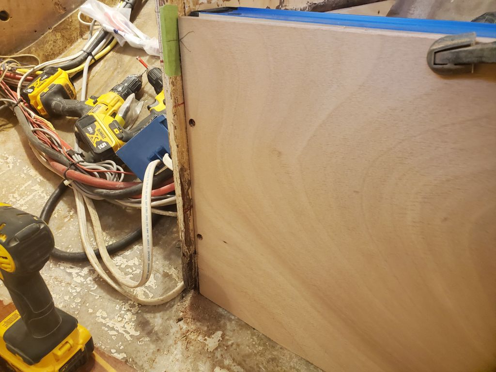
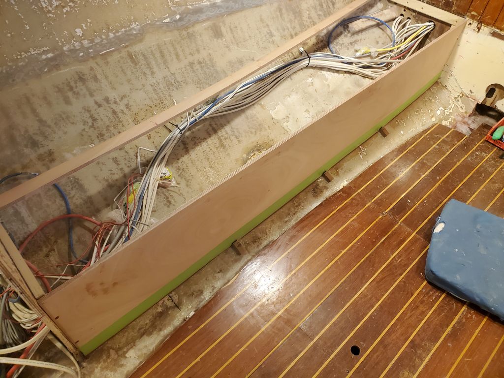
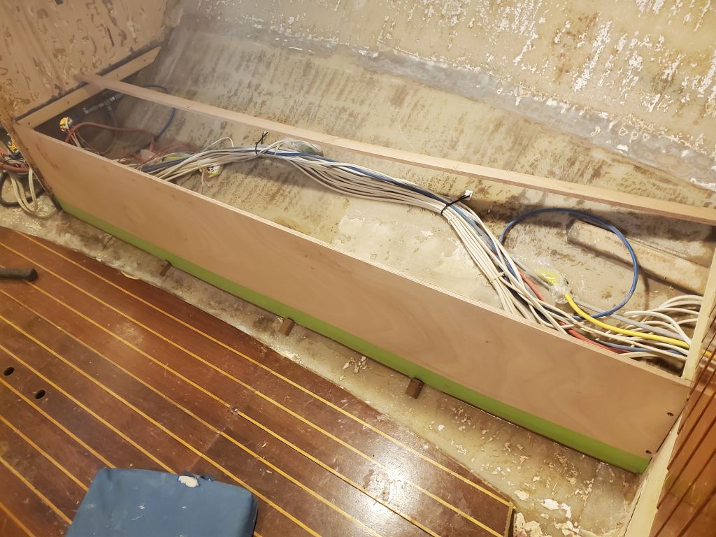
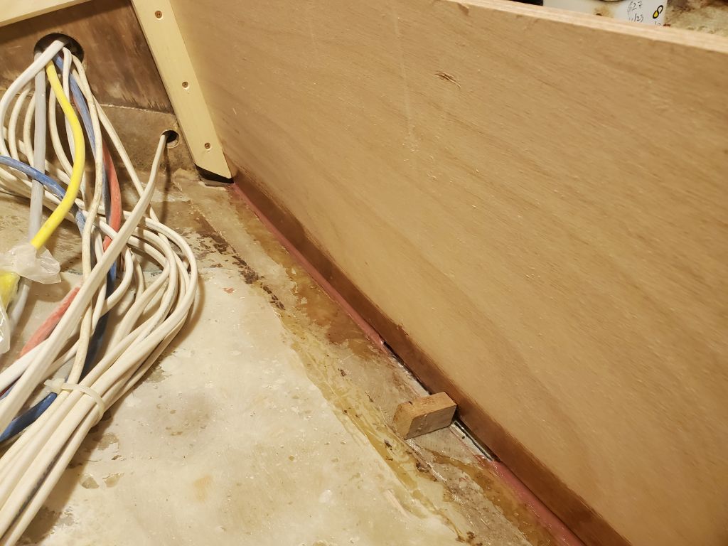
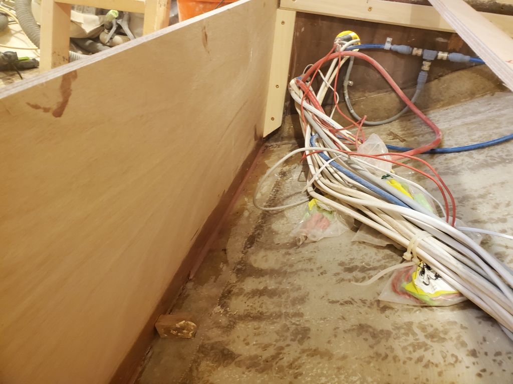
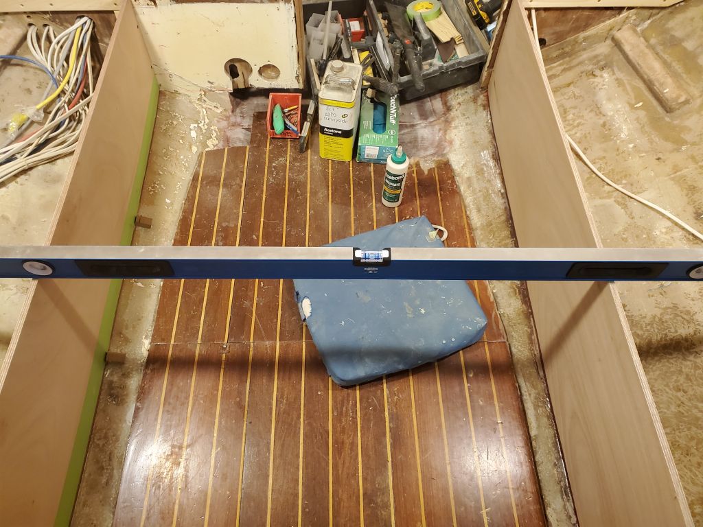
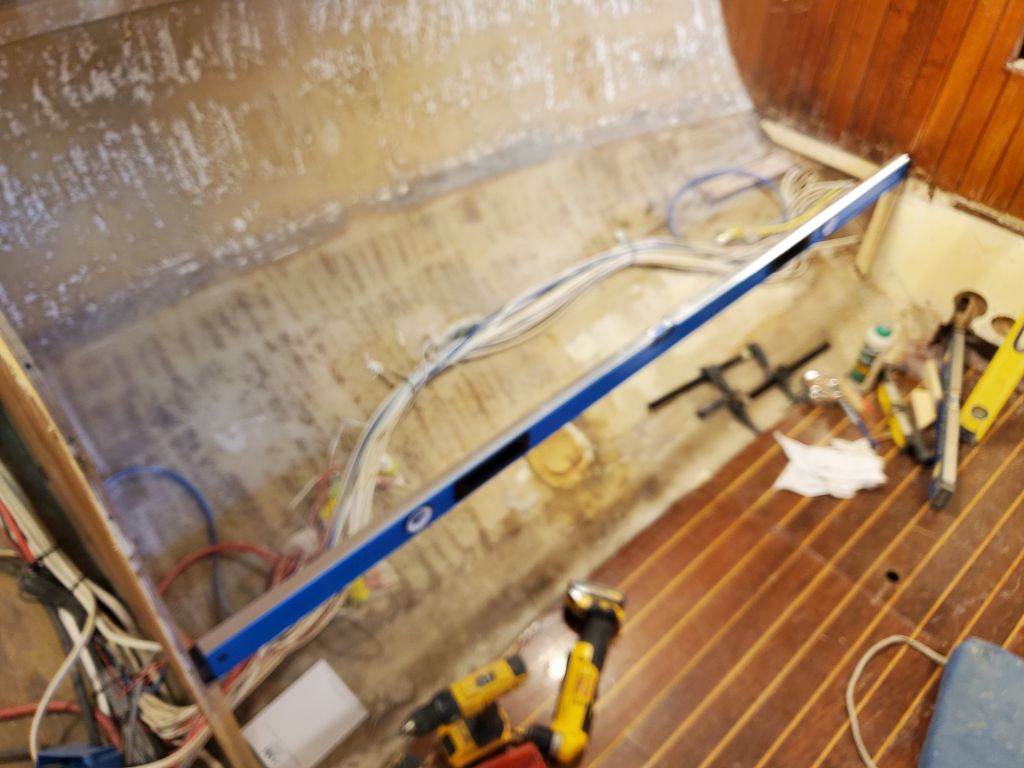
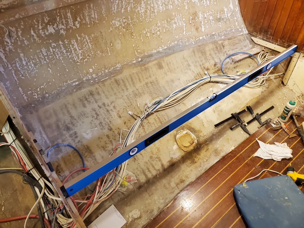
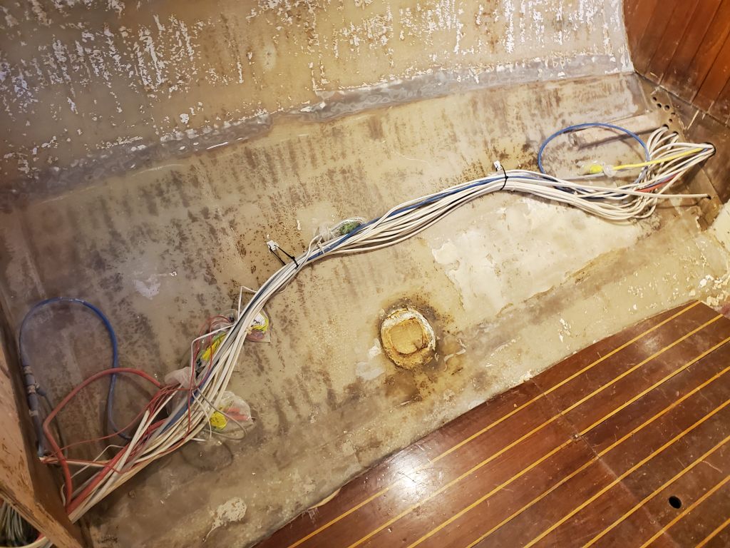
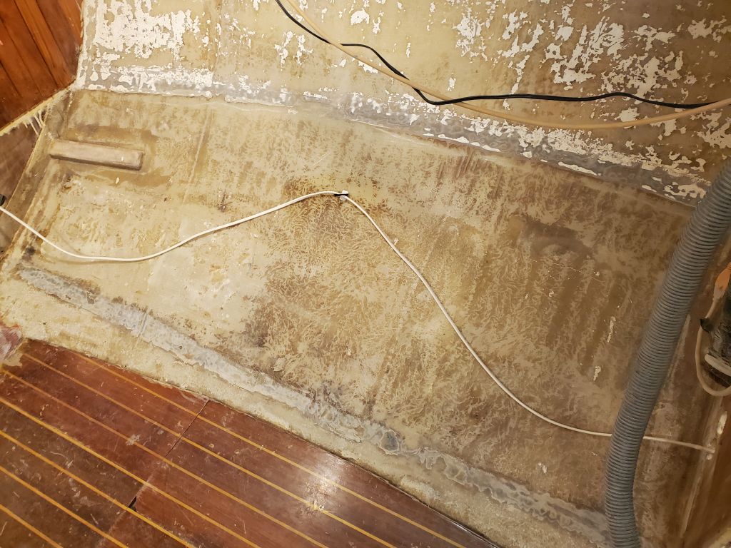
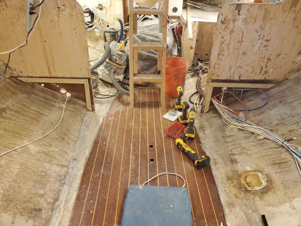
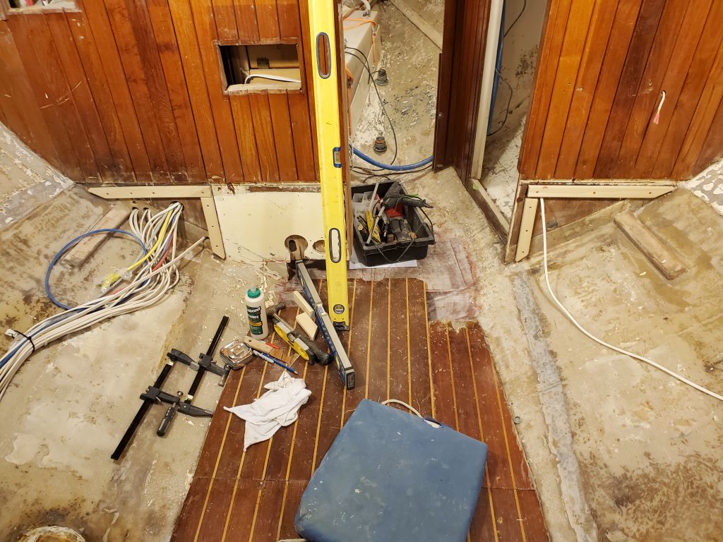
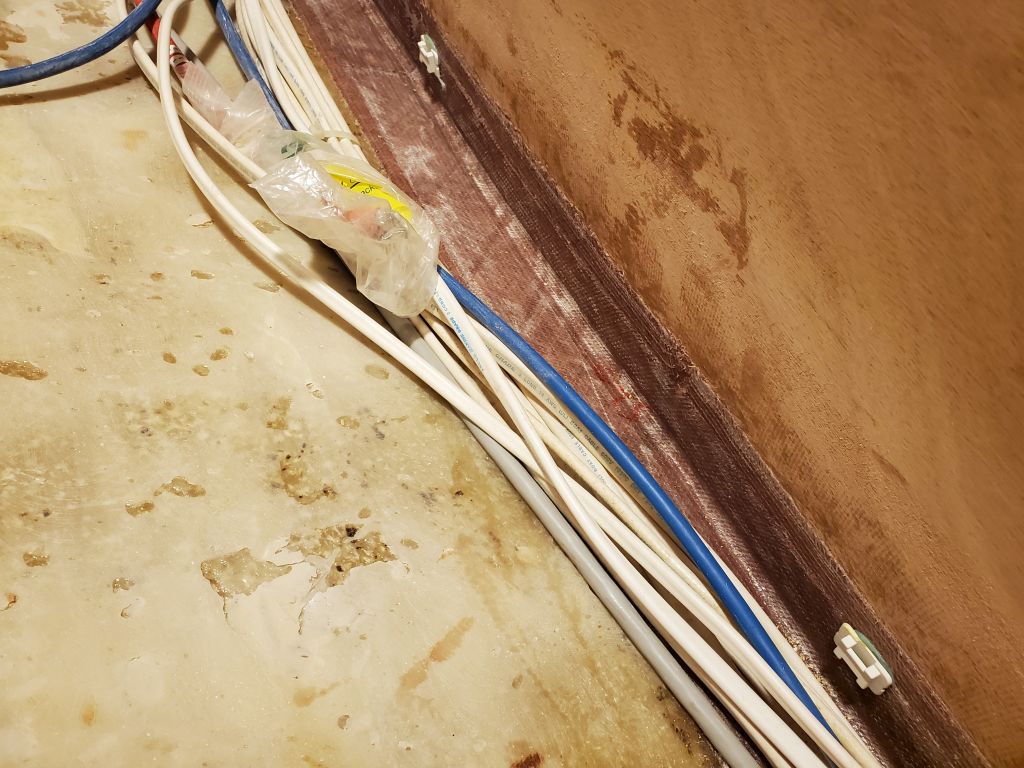
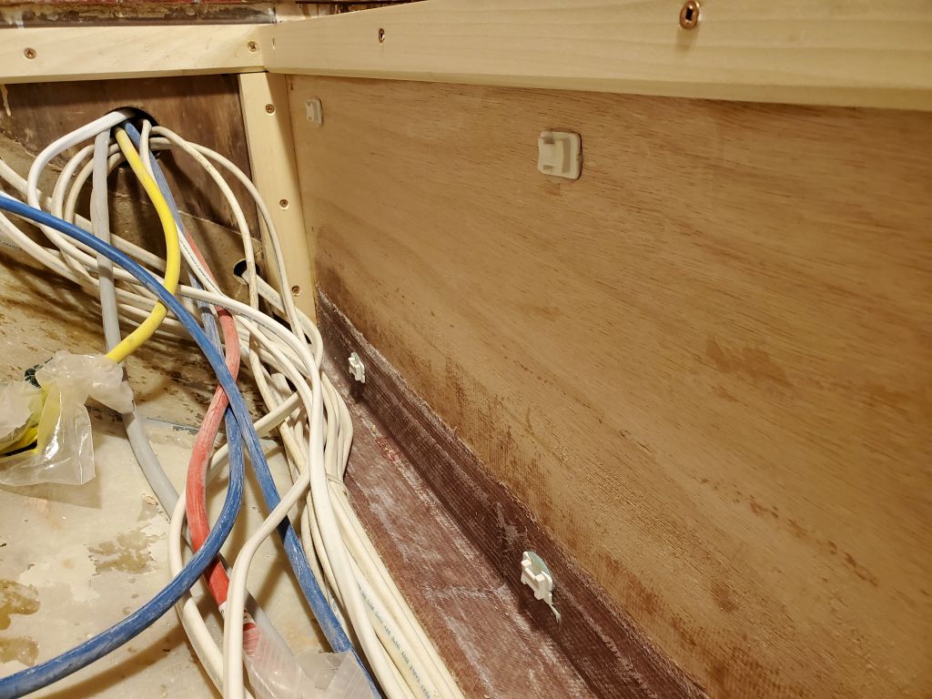
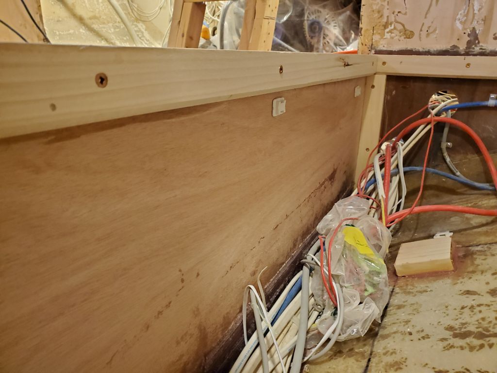
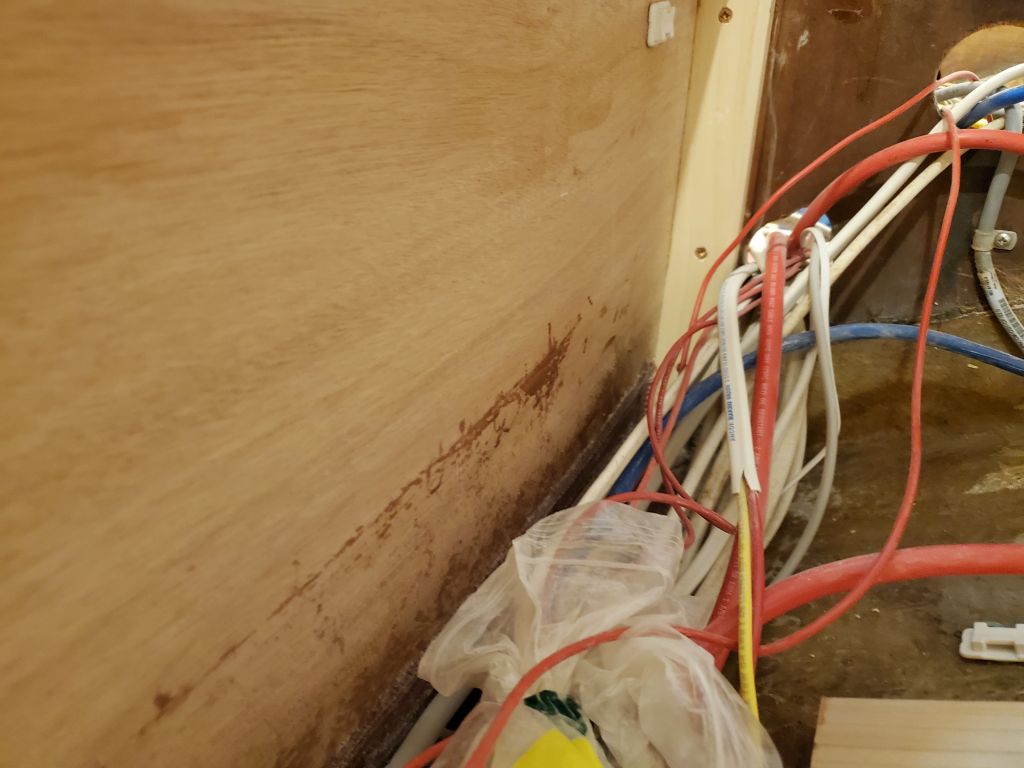
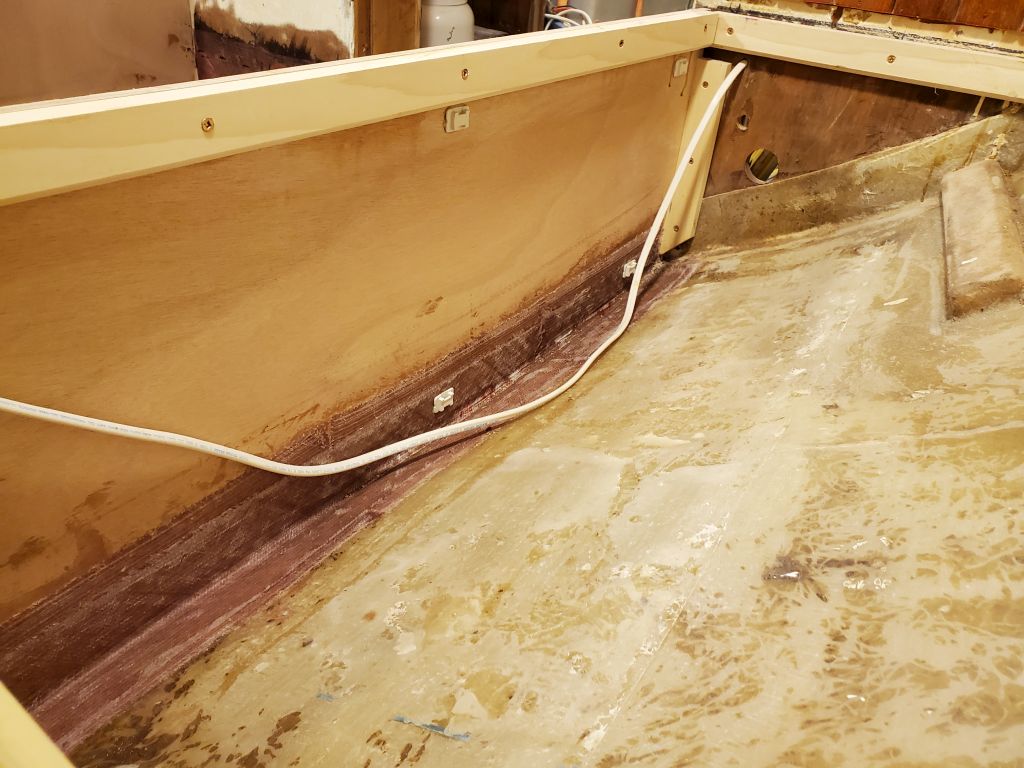
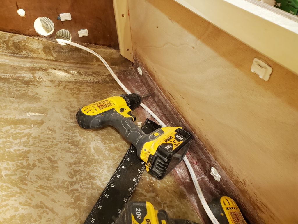
Continuing with a punch list of work required before I could paint the settee lockers–itself a job I had to complete before I could install the berth tops–I installed a series of wire tie mounts throughout the spaces on both sides, both to eventually secure known wires, as well as for future possibilities. These mounts are best installed before paint, as otherwise the paint has to be spot-removed at each location.
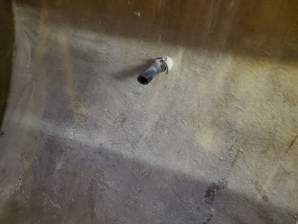
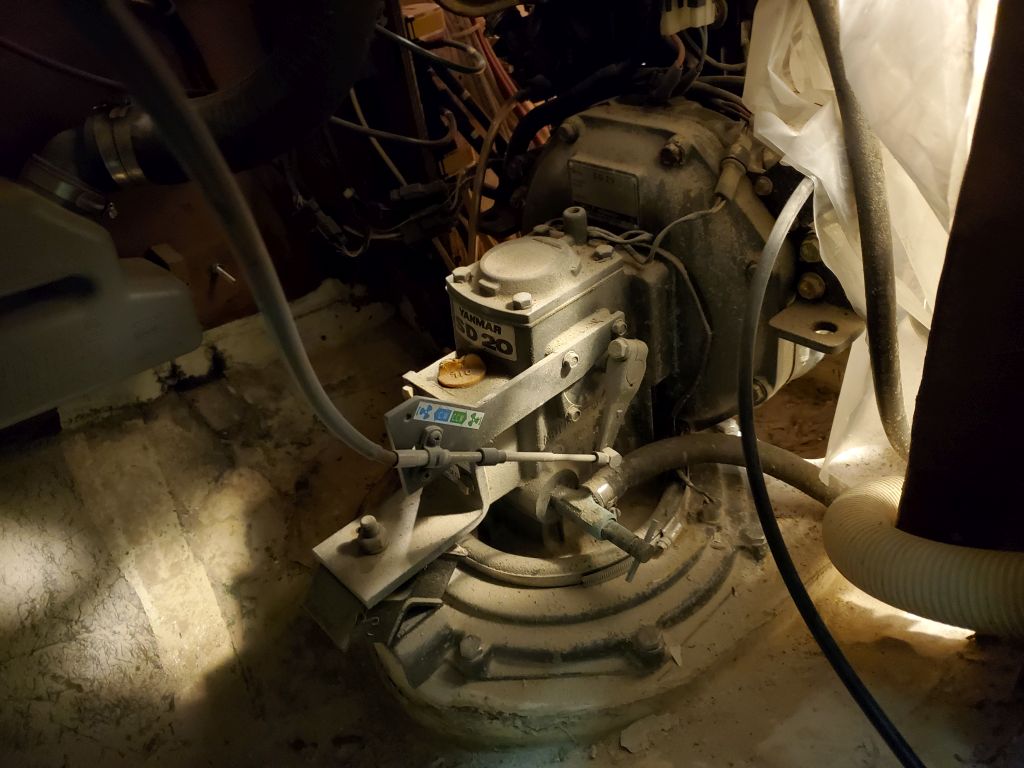
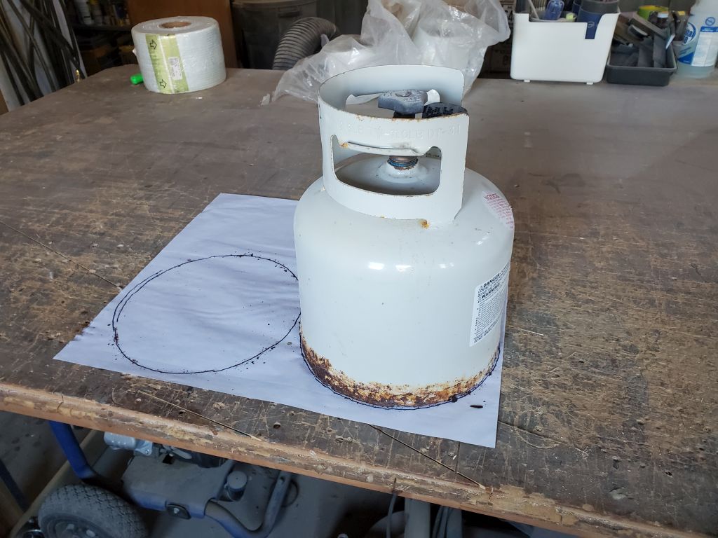
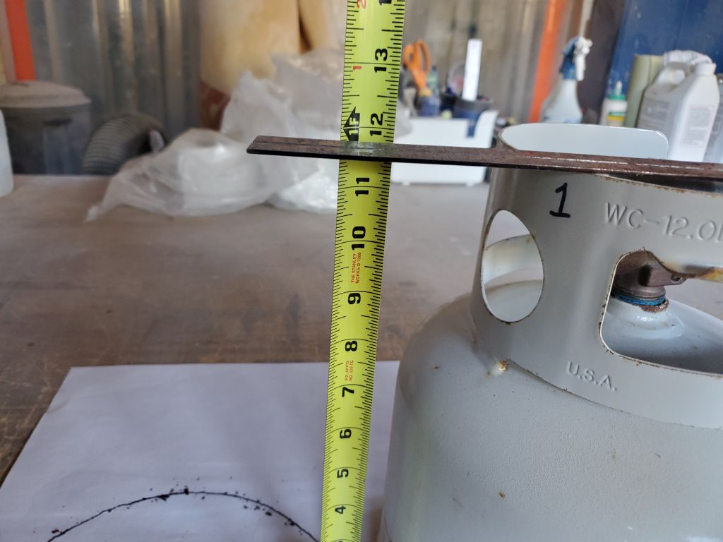
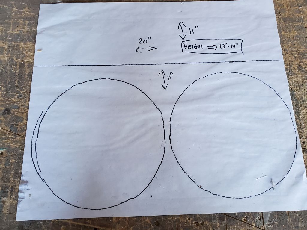
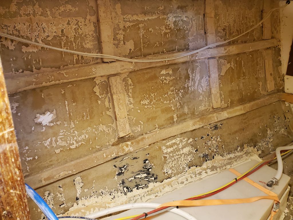
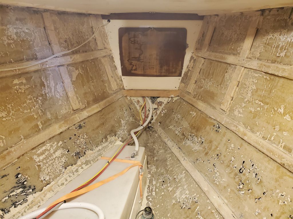
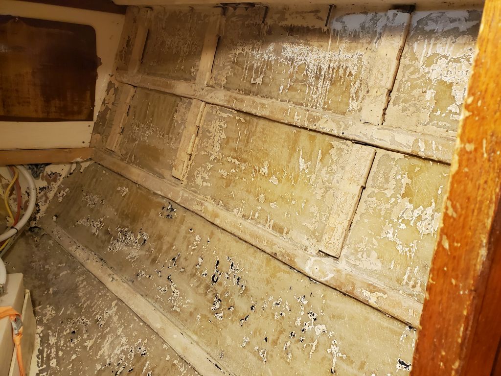
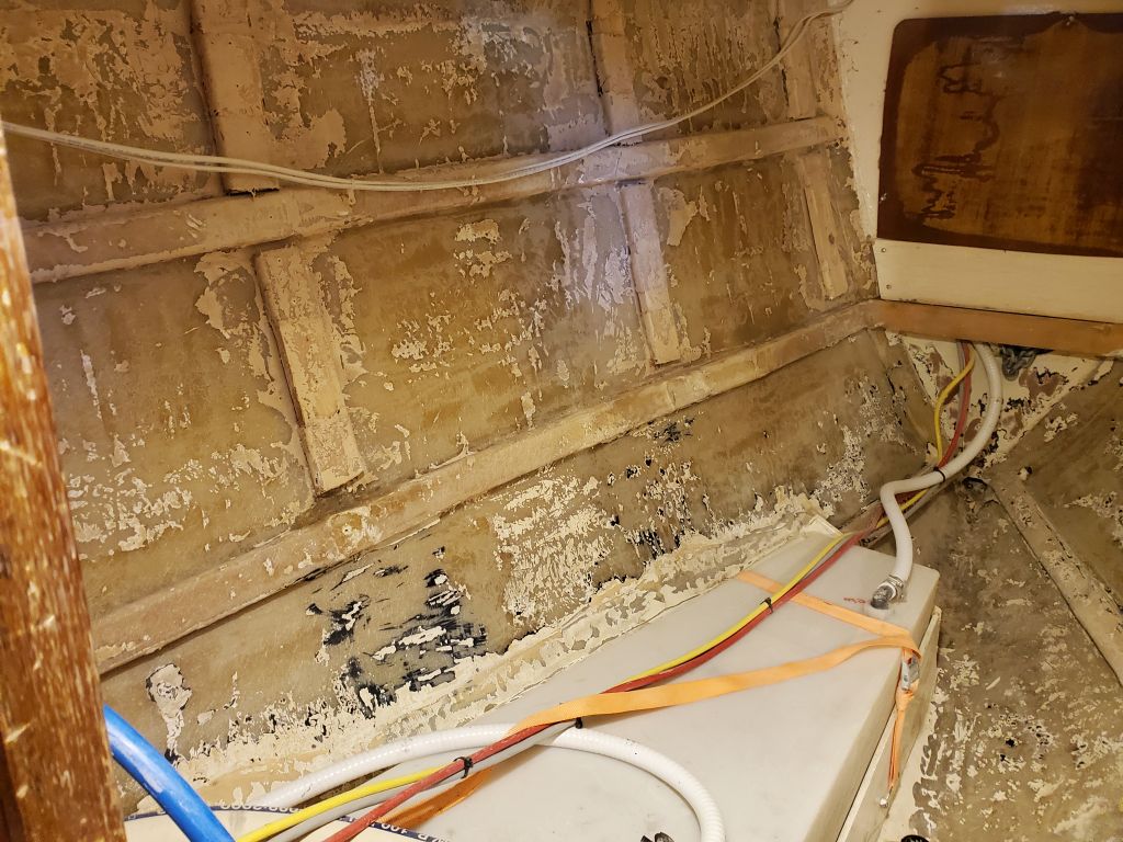
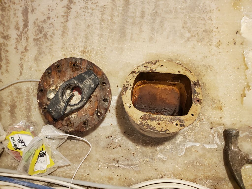
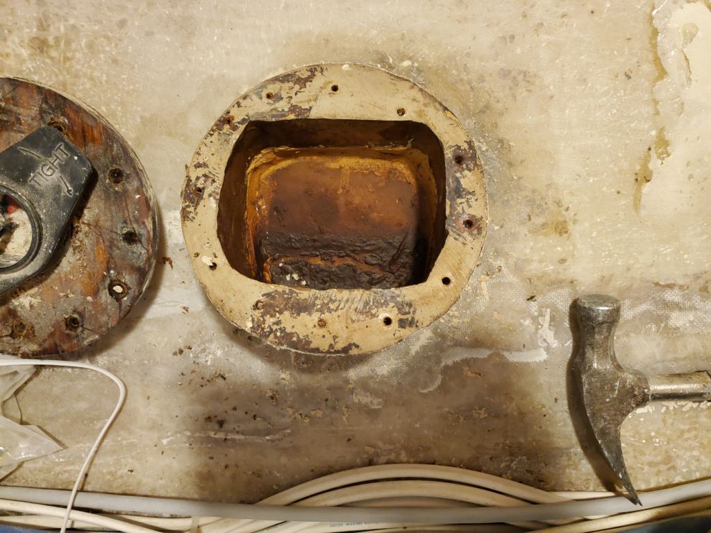
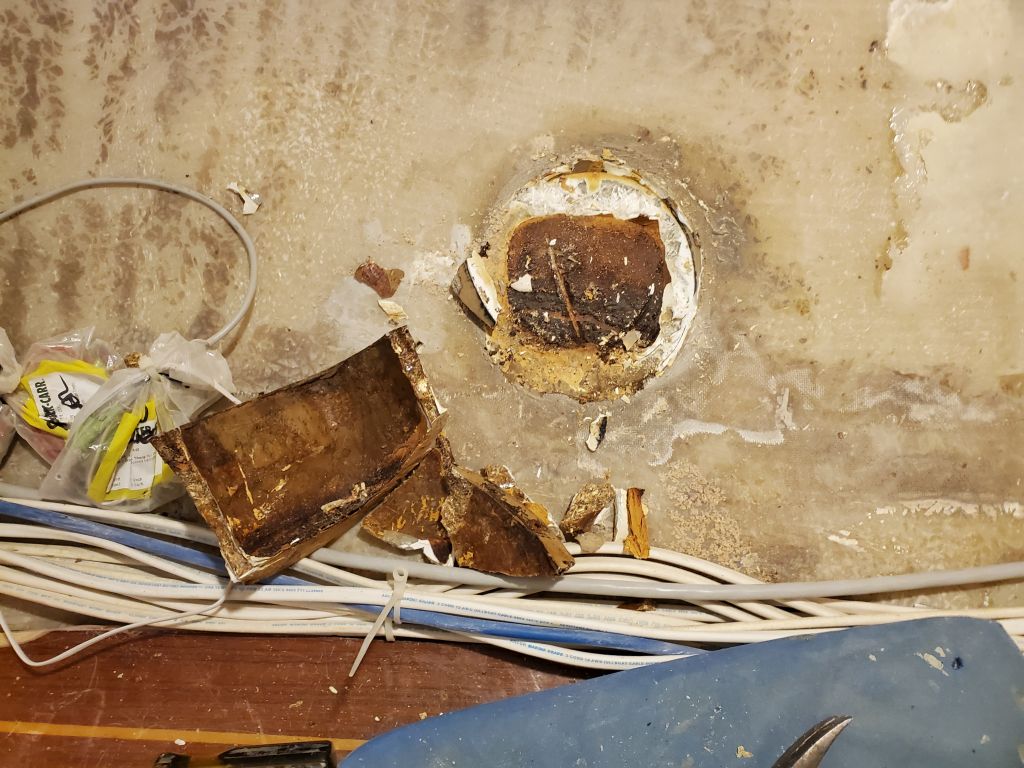
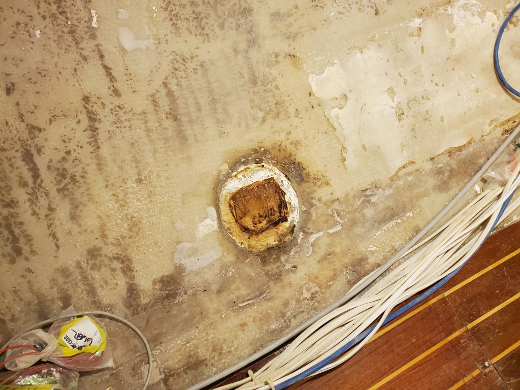
That was about all I could do with the settees for the moment, so, changing tacks, I turned to the engine intake. The owner had requested that I install a new through hull fitting for the engine intake, as its current setup brought cooling water in through the Yanmar SD20 saildrive drive leg. I planned to do the through hull work before I started building the new galley, and with that coming up soon, now was a good time to get into the cockpit locker and access the hose connection at the drive leg, and also see what exactly the situation was there so I could block off this intake as needed. First, I had to remove some gear from the locker, along with the mostly-disconnected small LPG locker that would no longer be needed (and was also on my list to remove), leaving a stub of the LPG drain hose attached to its skin fitting for now (it would require a plug later).
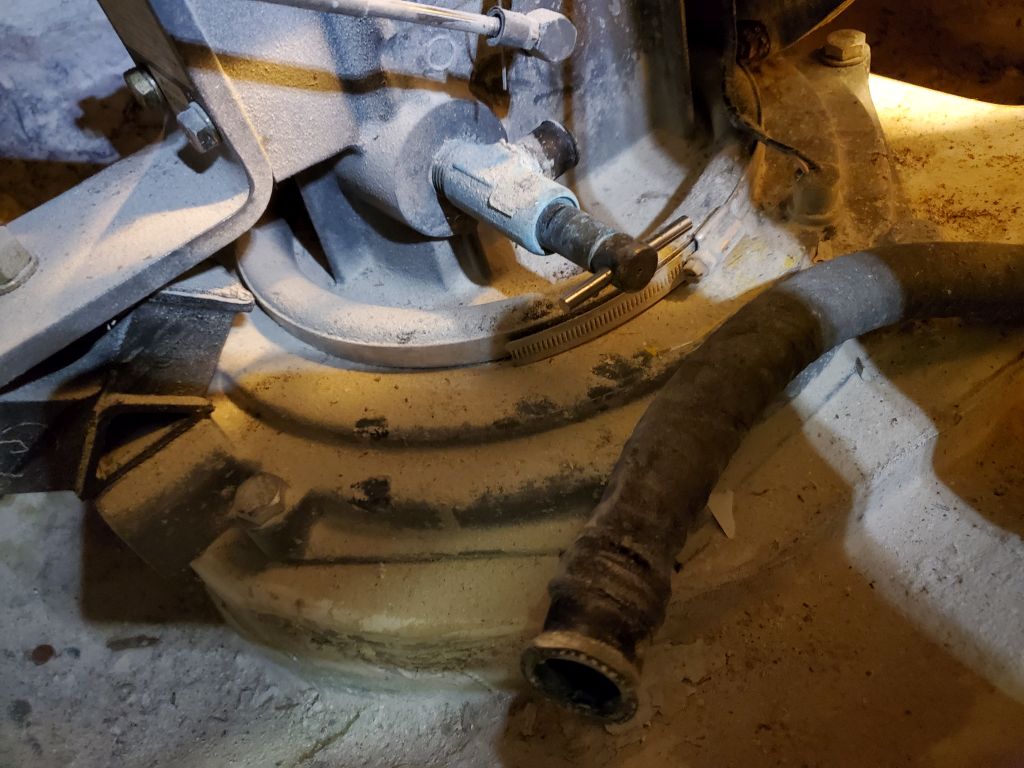
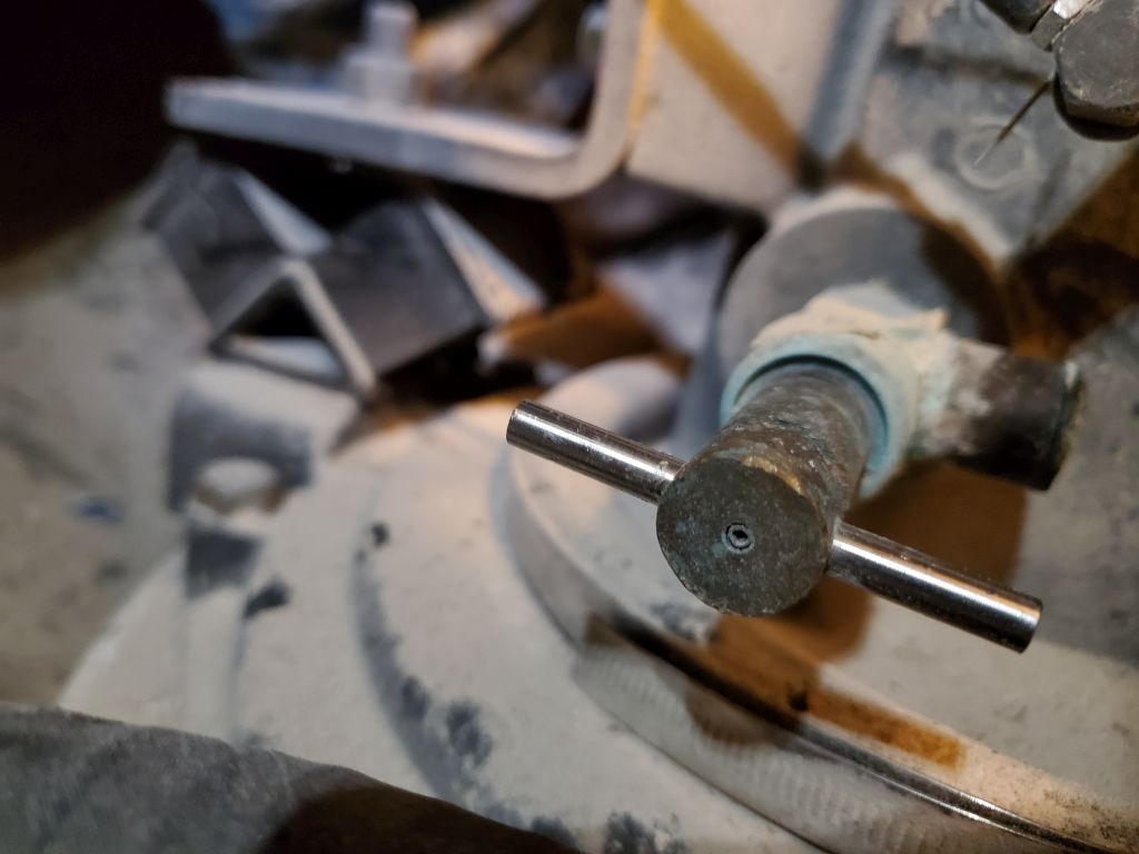
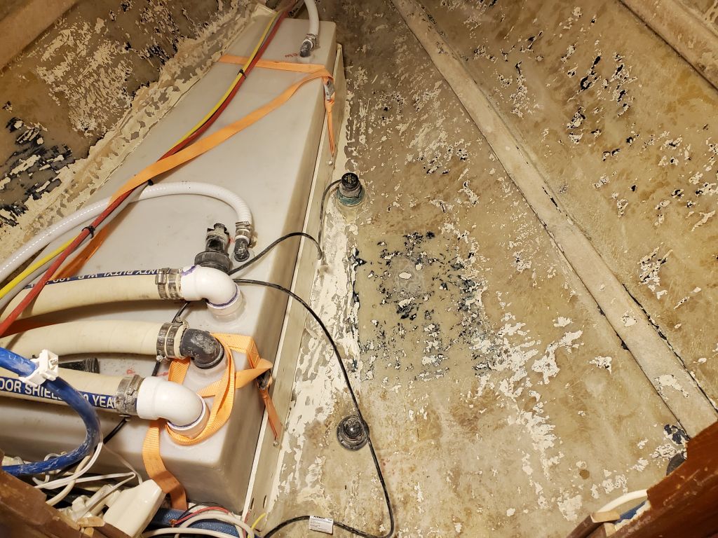
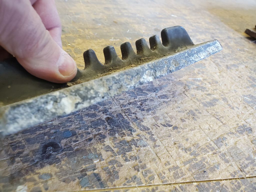
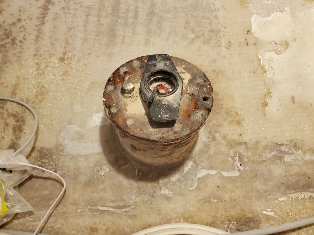
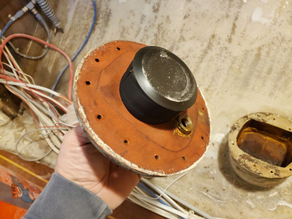
The engine intake hose connected to a valve fitting on the top of the drive leg. I removed the hose easily enough, and contemplated the fitting. The T-shaped handle suggested a valve, but it was too tight to turn by hand. Tentatively, with a wrench, I was able to turn the fitting, but, not versed on the specifics of this particular water cock, I wasn’t sure at first whether it was working correctly, so I did some research to satisfy myself. Apparently the fitting is such that it requires a large number of turns to close (it’s a gate valve), so what I had experienced was normal, and the fitting could be closed completely.
In any event, I had a better idea what I was dealing with, and a start on how to secure it going forward. I’d return to the locker soon to finish up this part of the job and also clean up the sanding dust from earlier parts of the project.