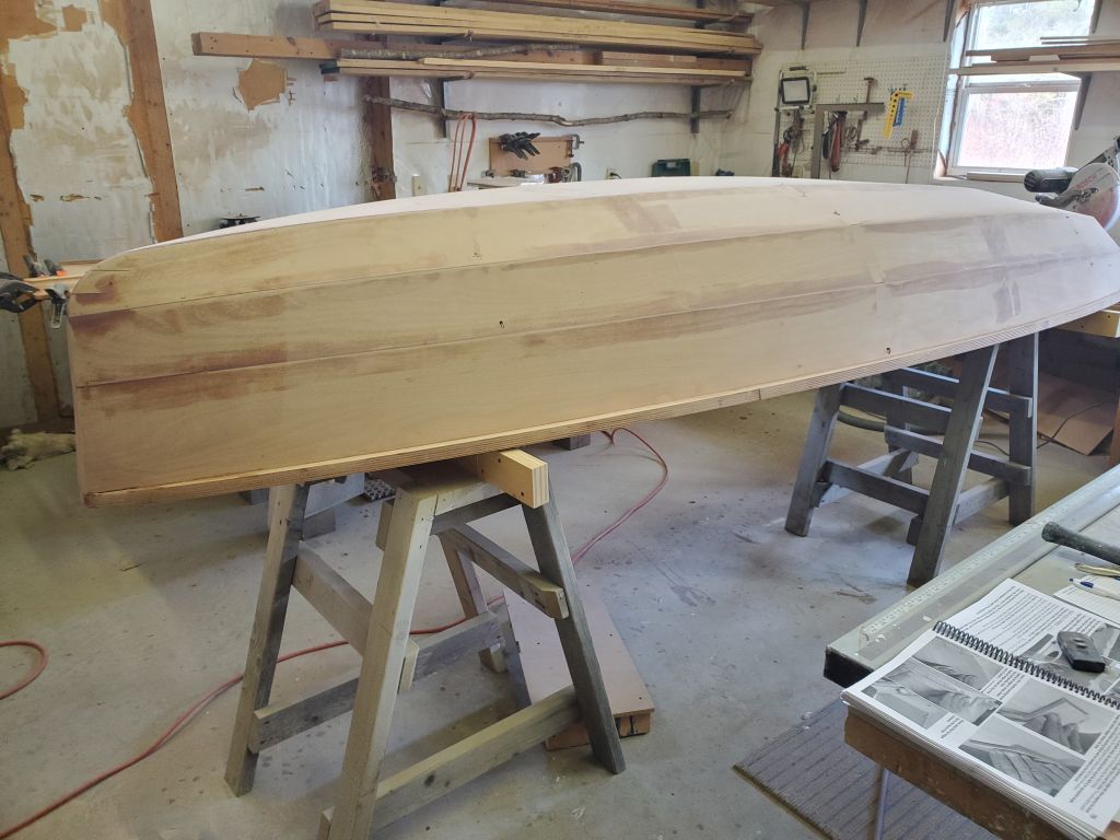
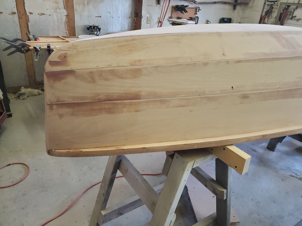
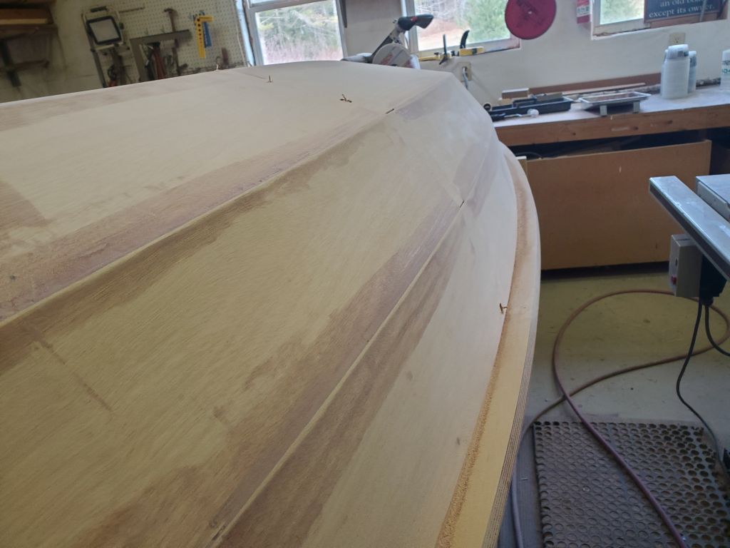
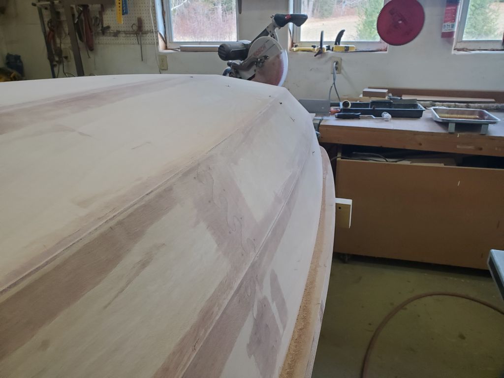
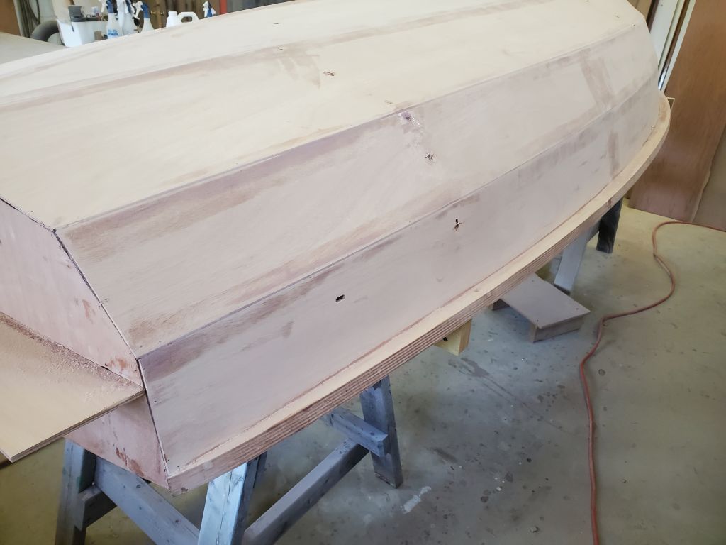
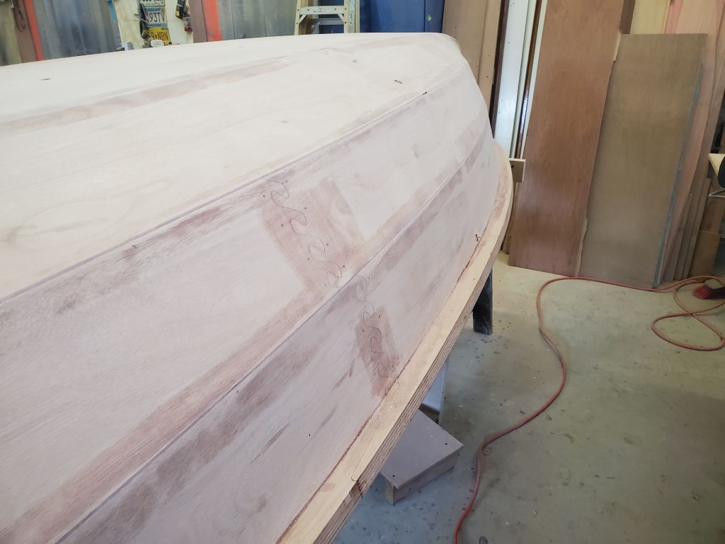
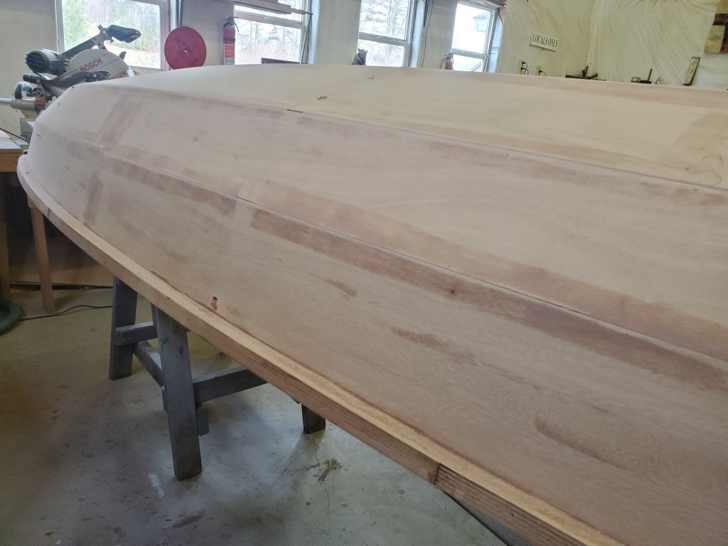
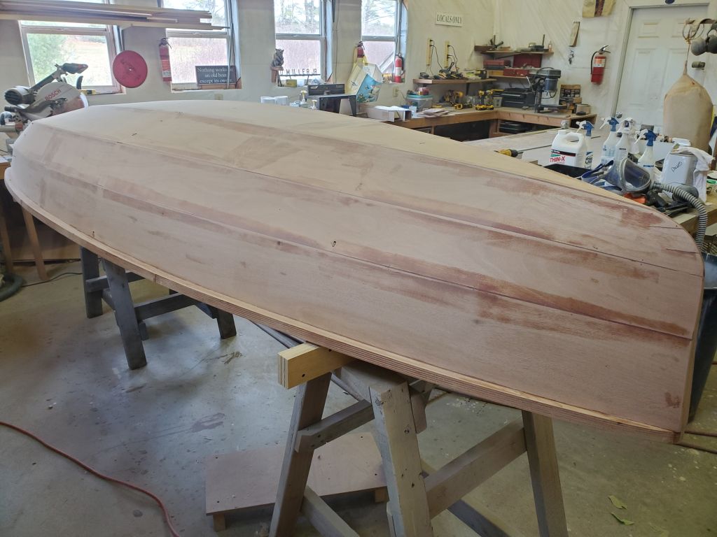
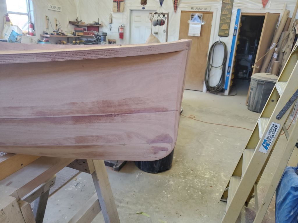
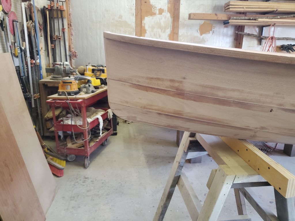
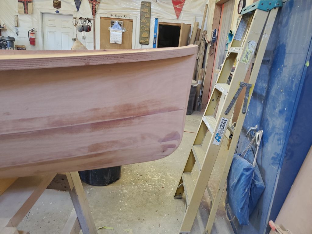
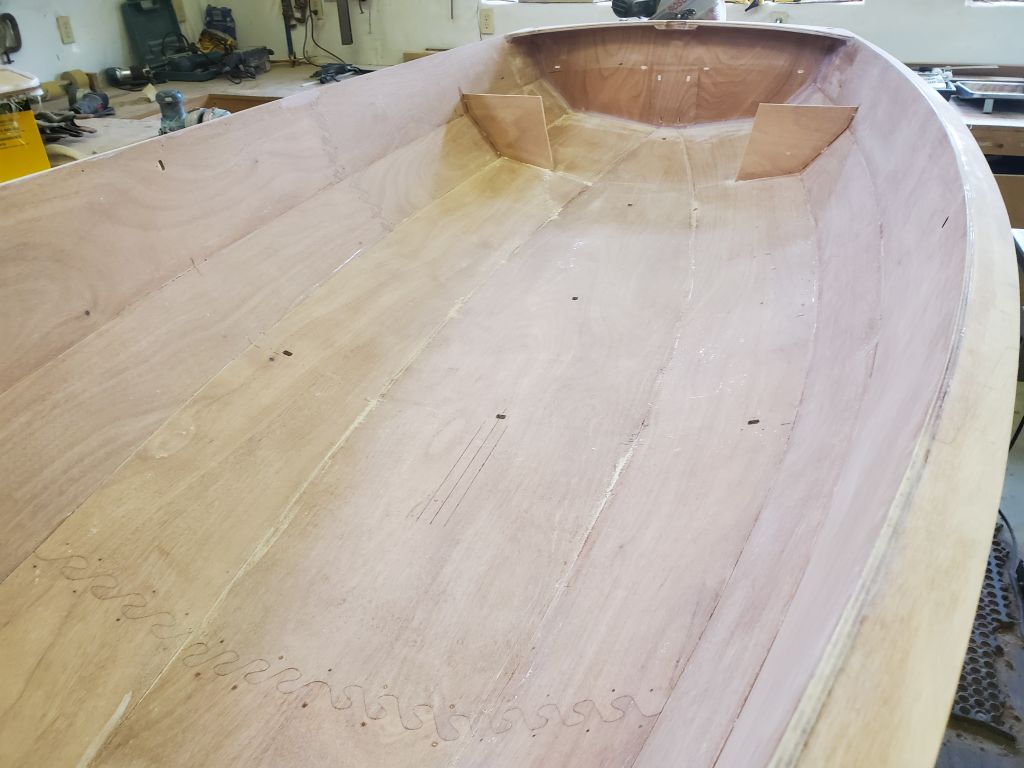
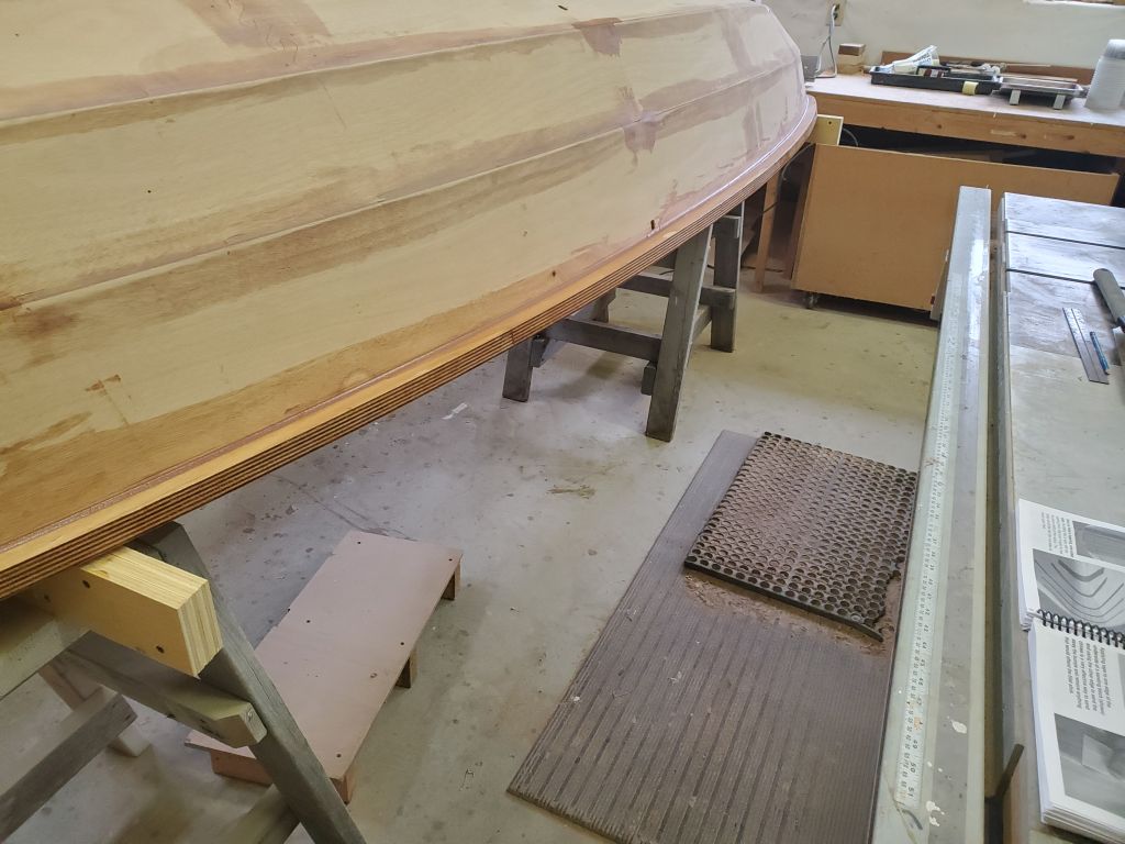
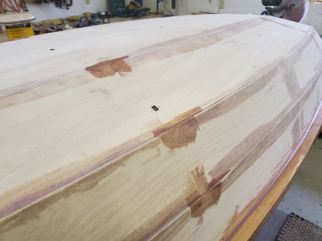
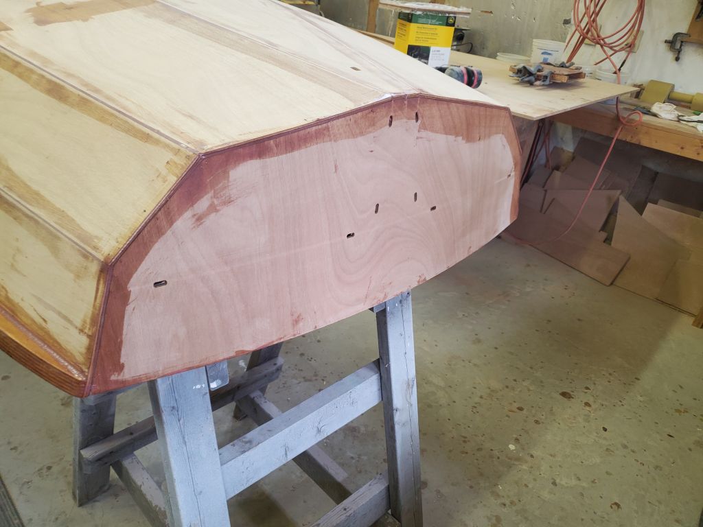
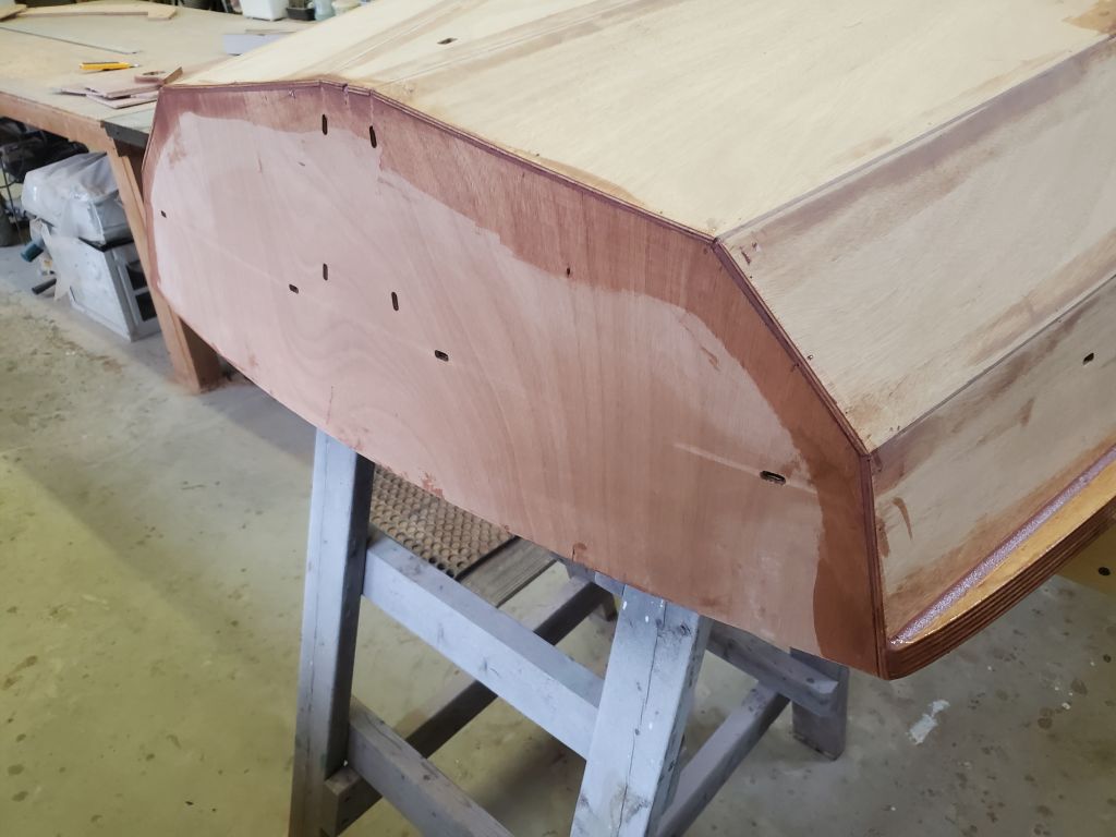
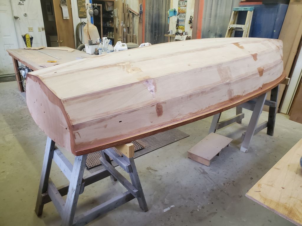
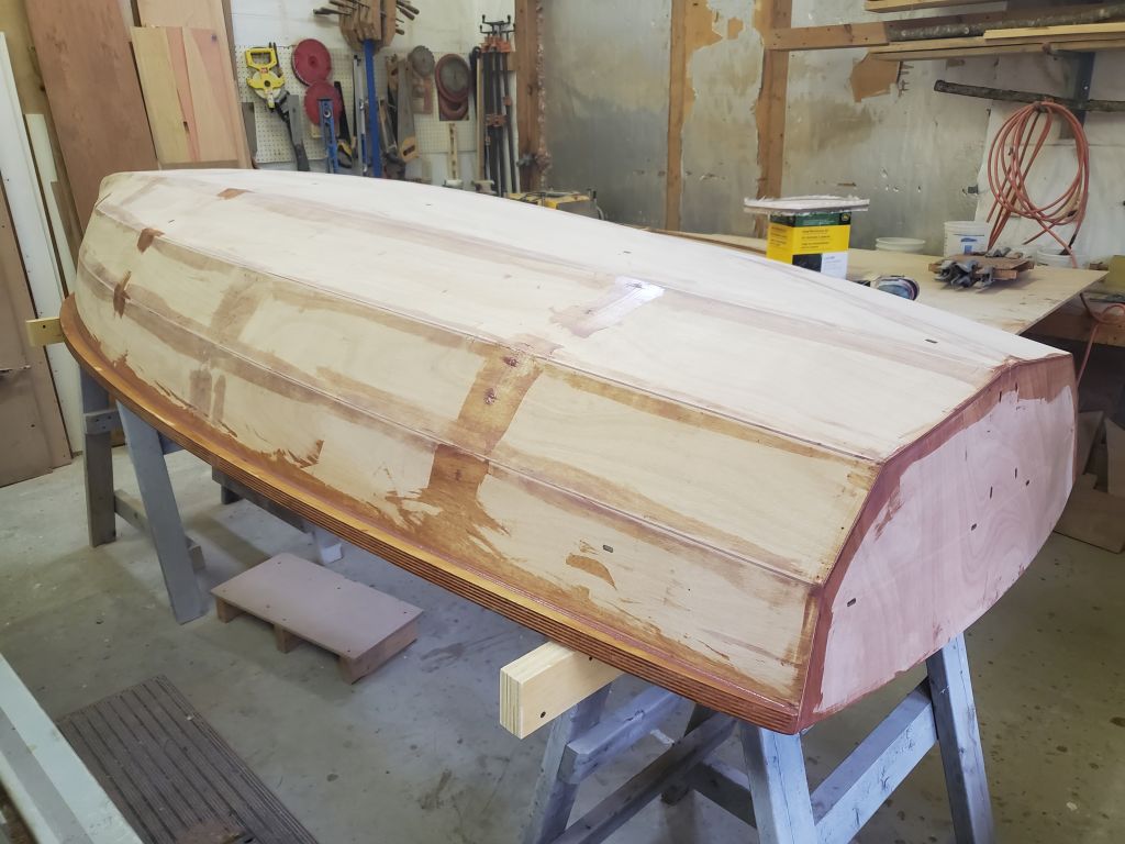
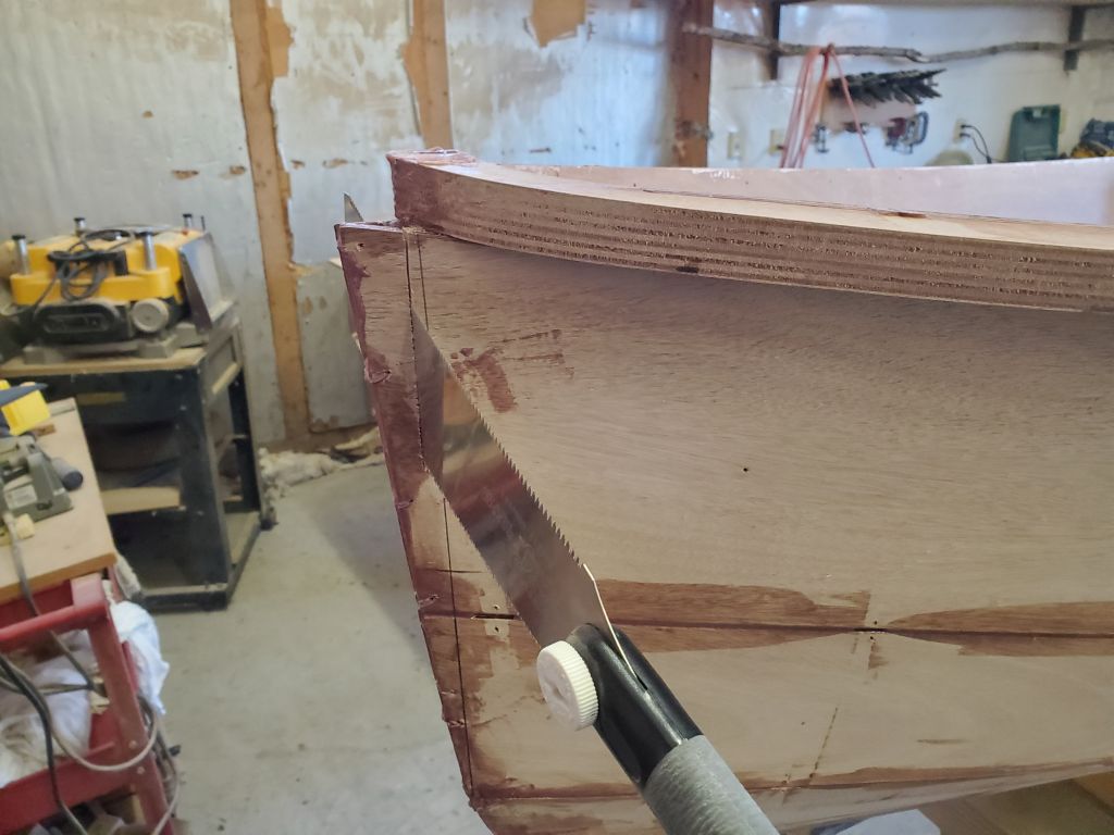
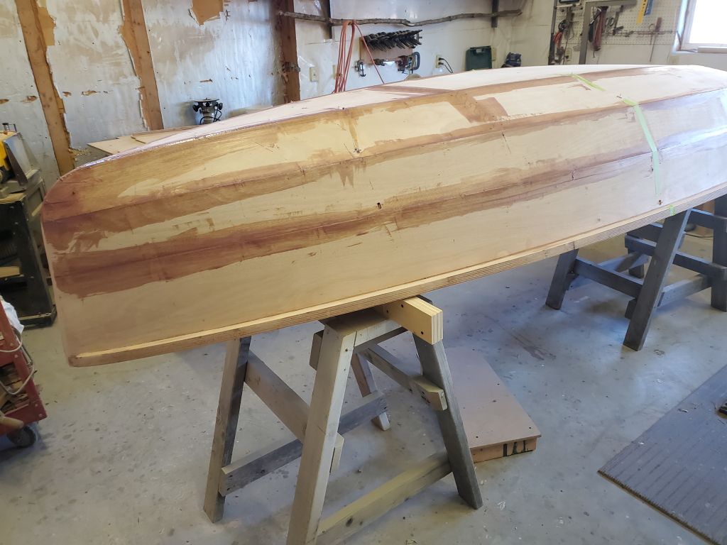
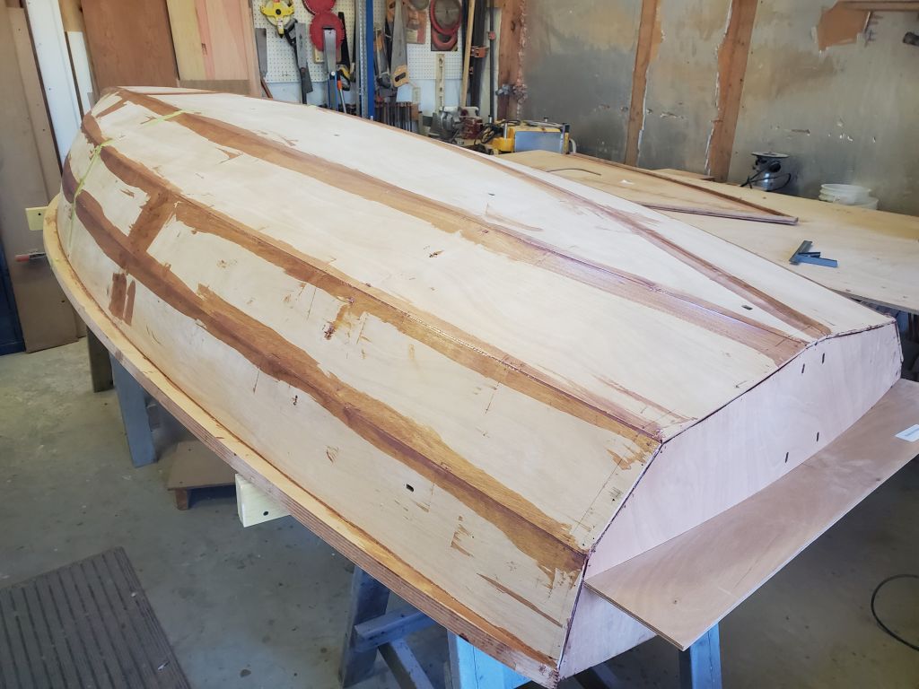
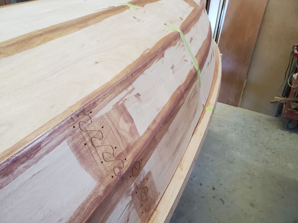
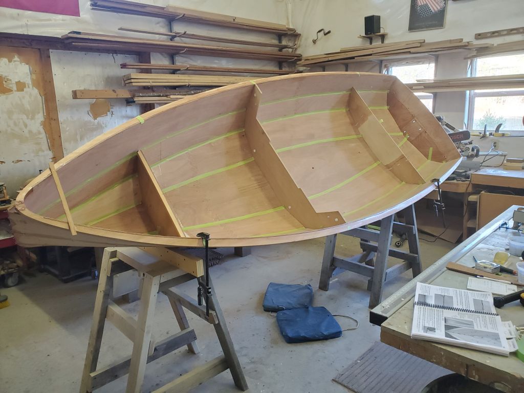
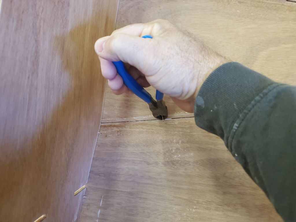
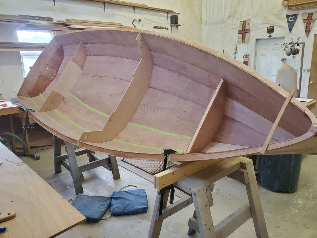
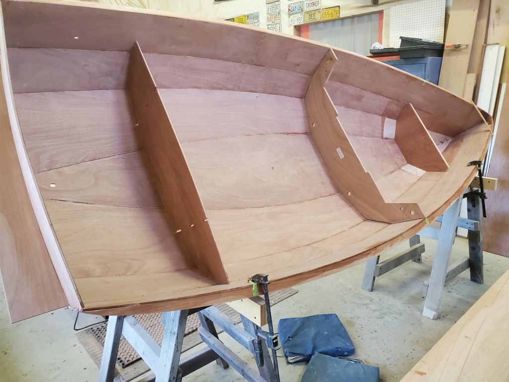
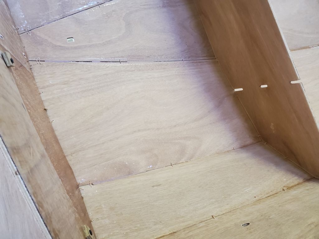
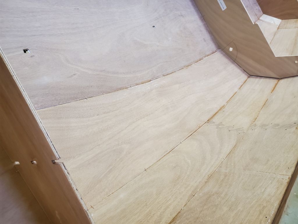
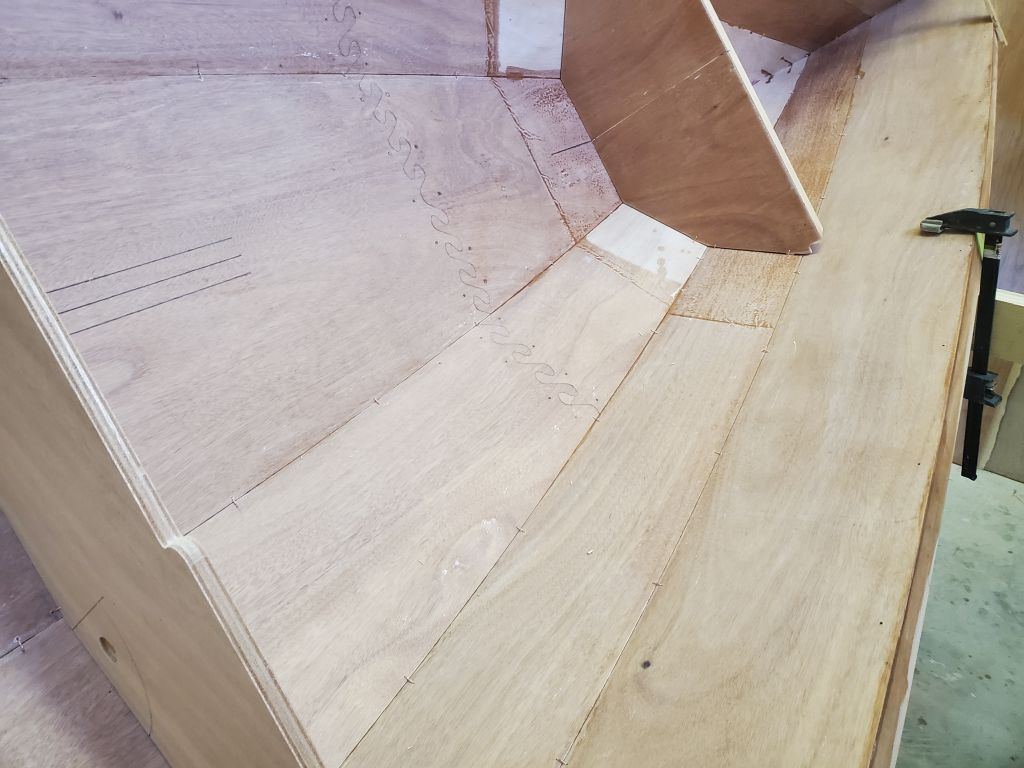
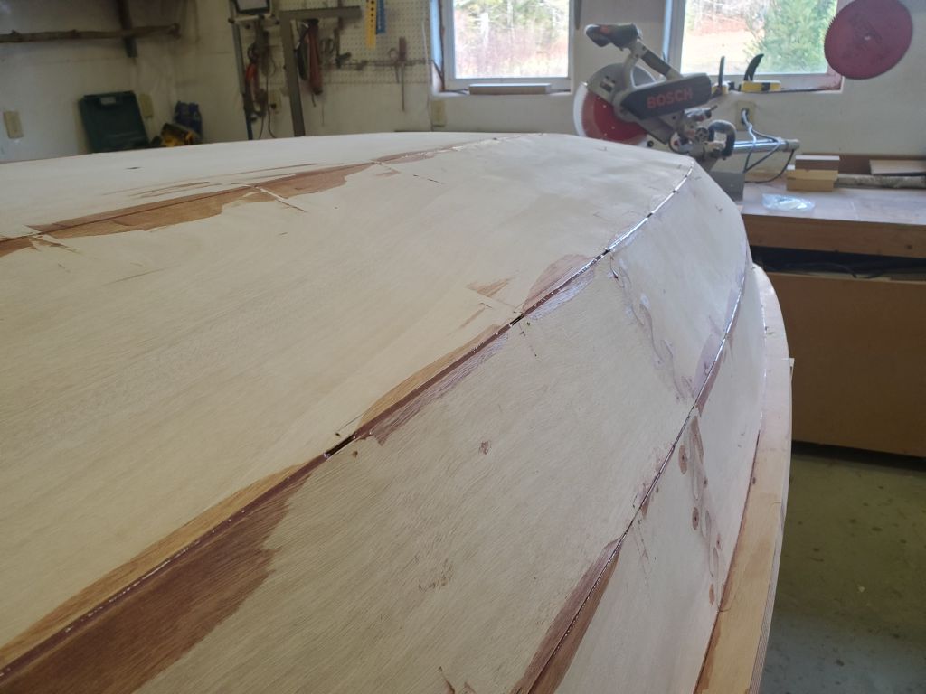
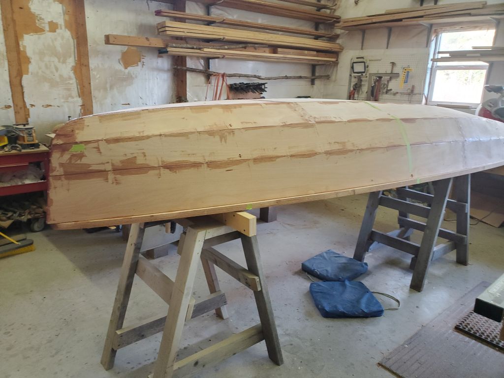
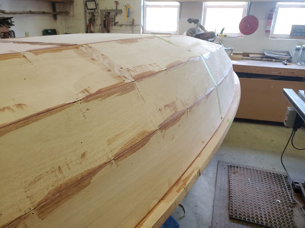
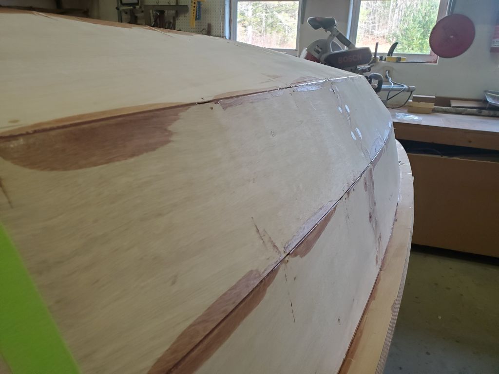
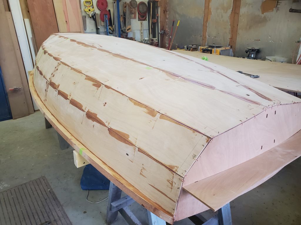
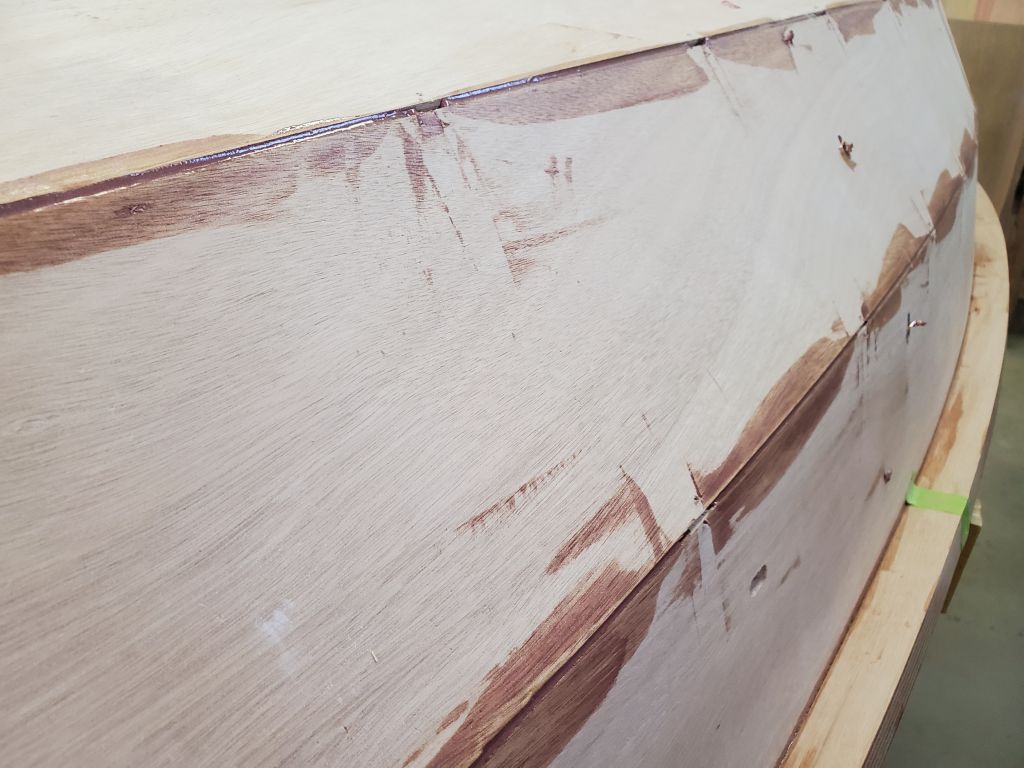
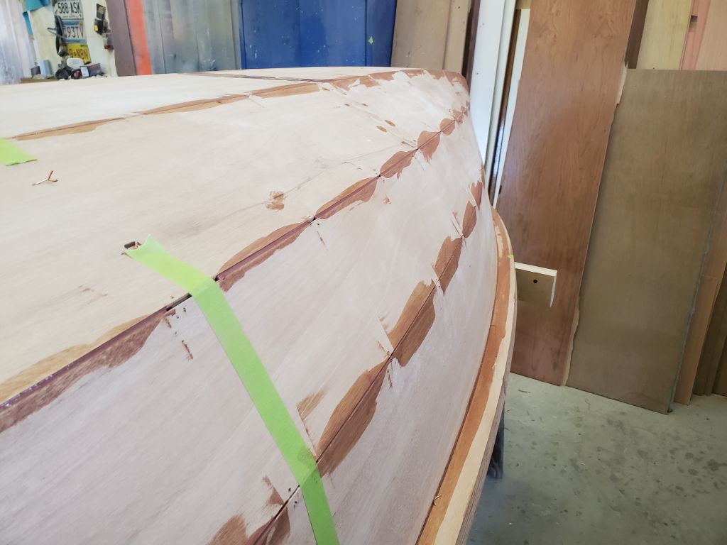
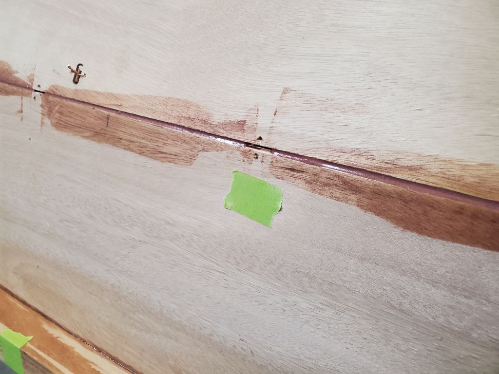
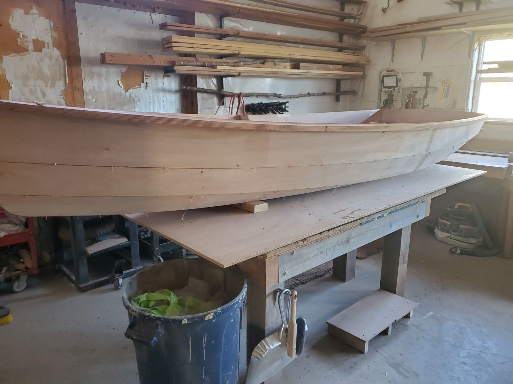
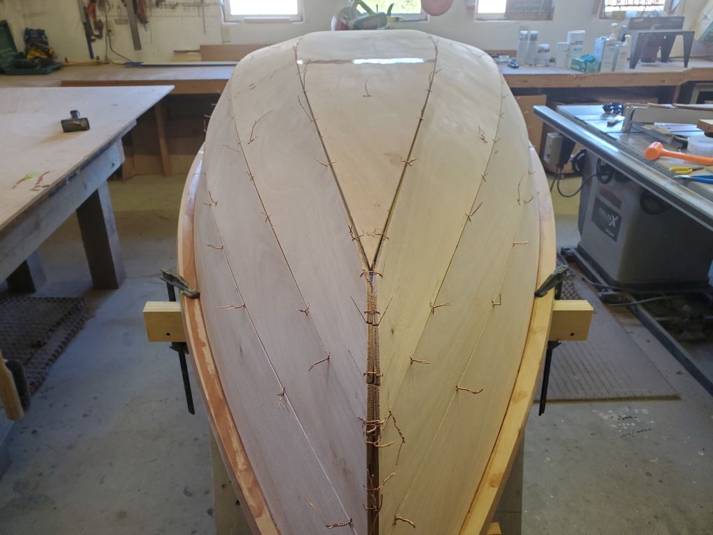
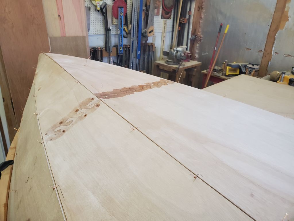
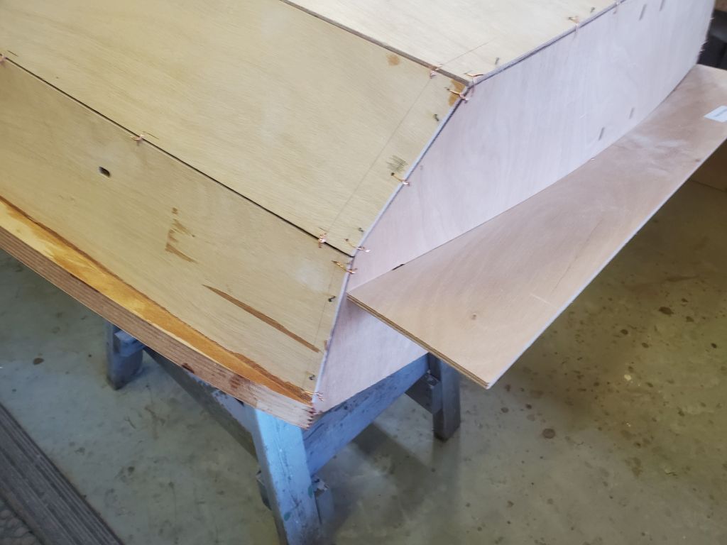
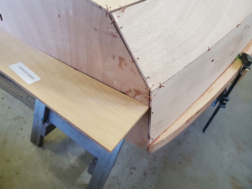
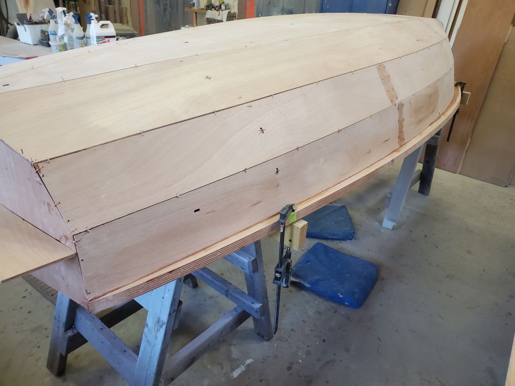
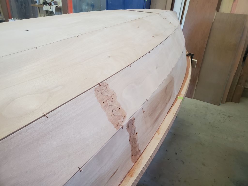
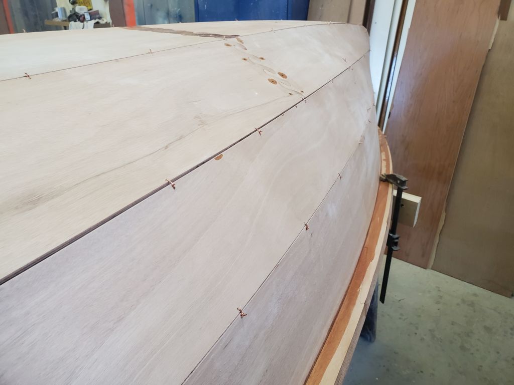
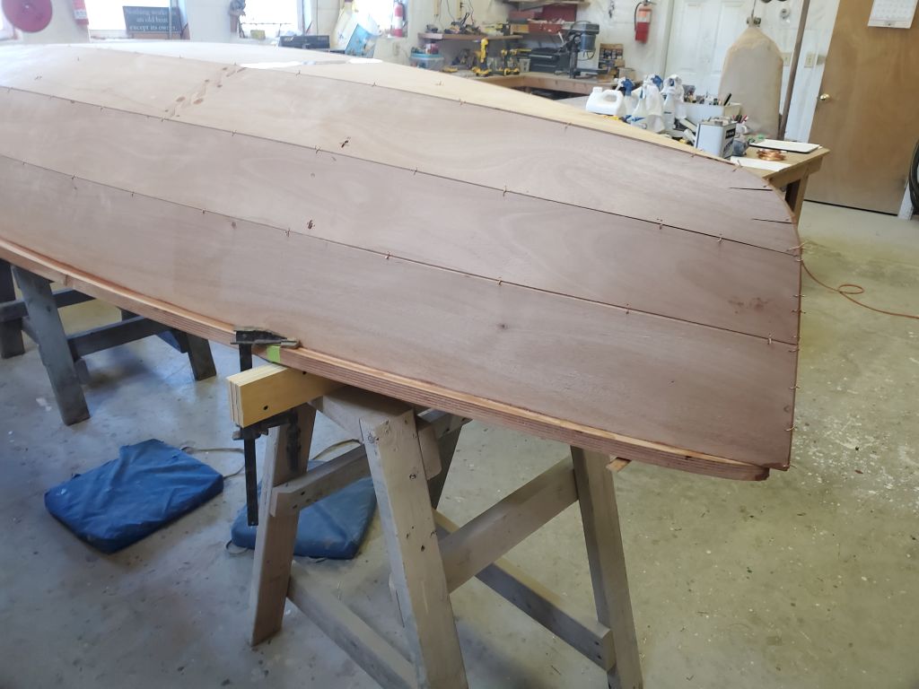
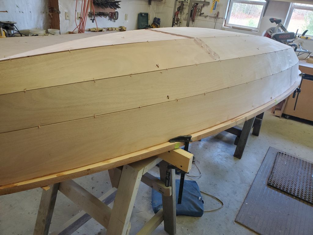
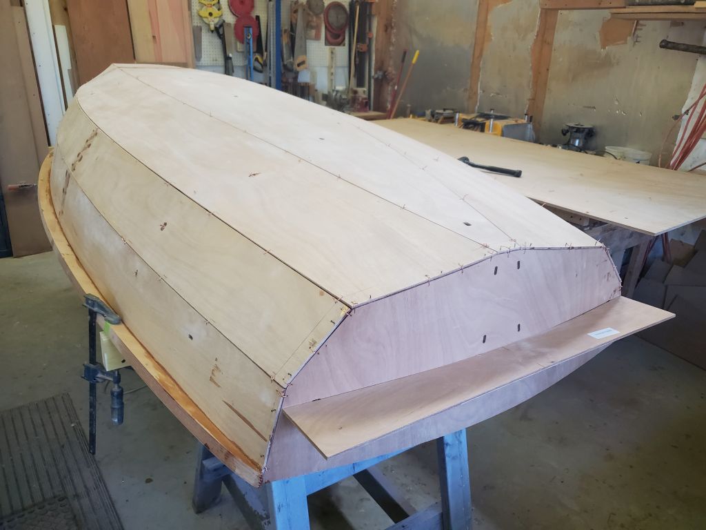
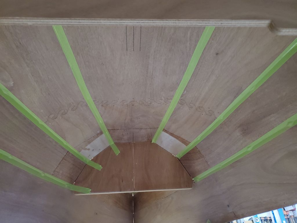
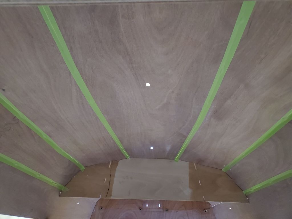
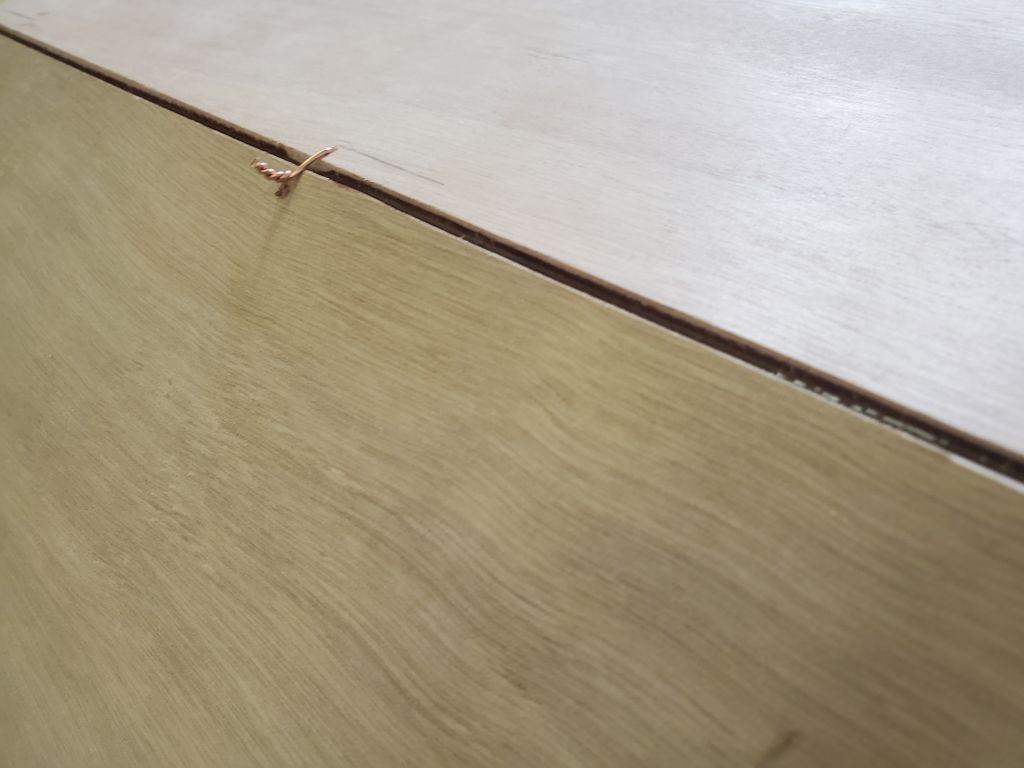
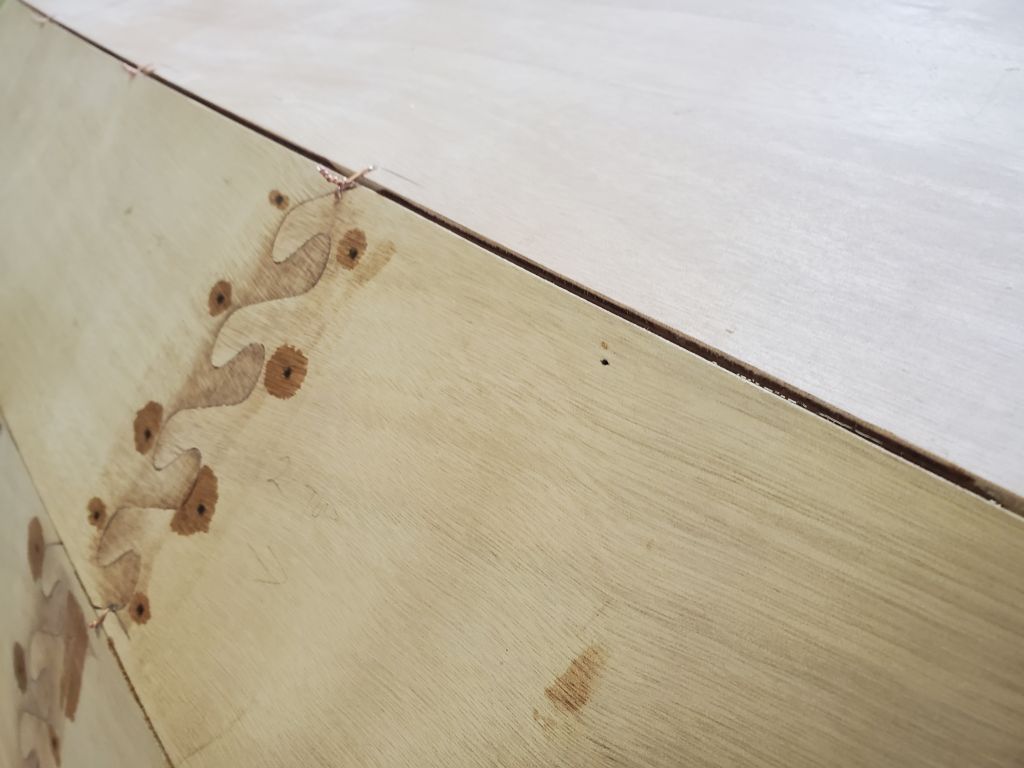
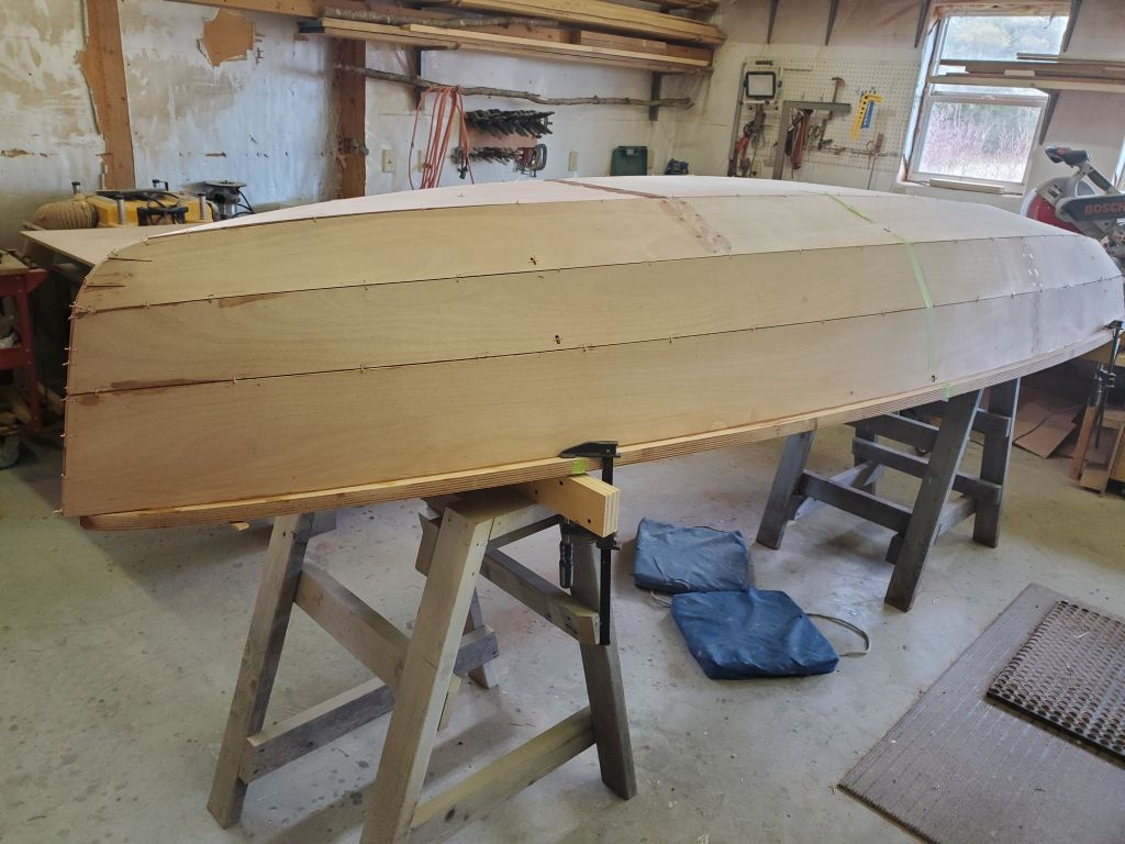
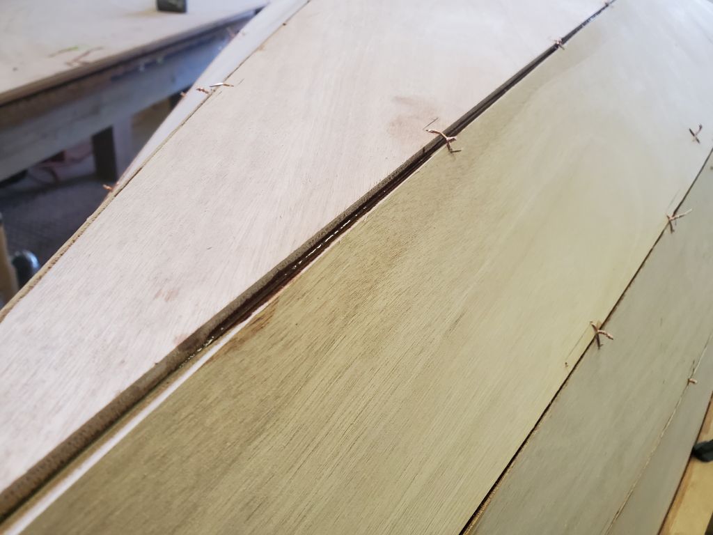
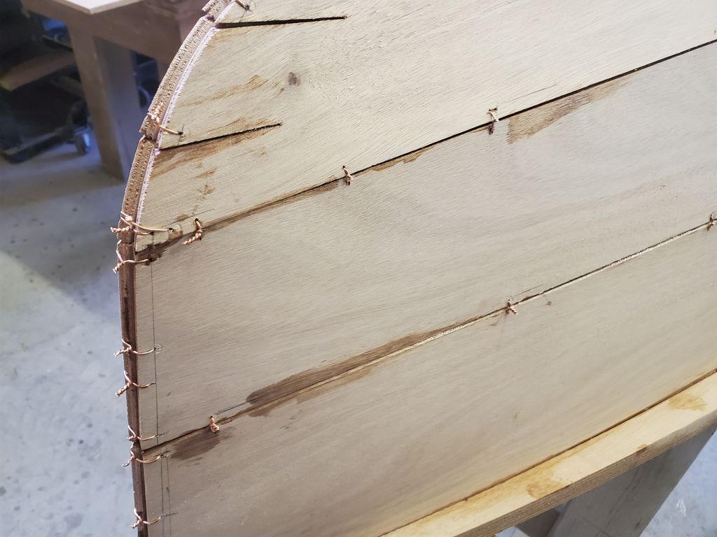
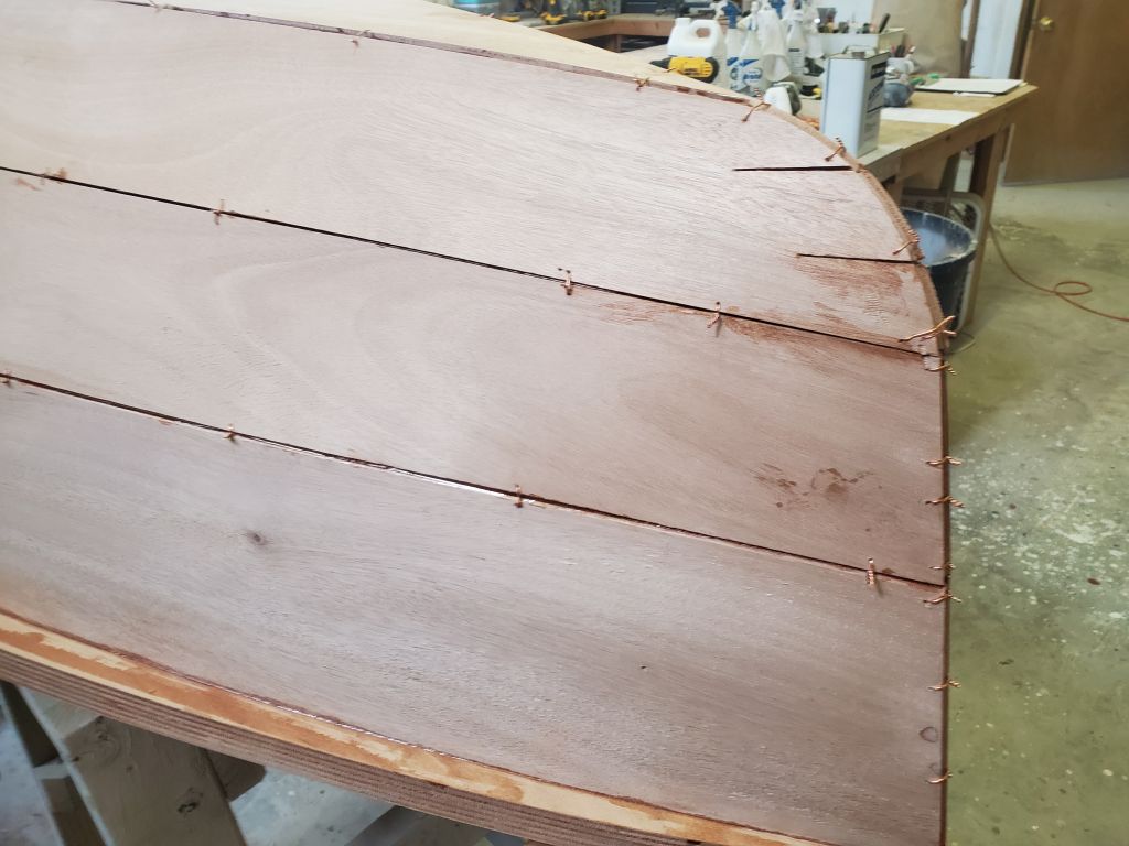
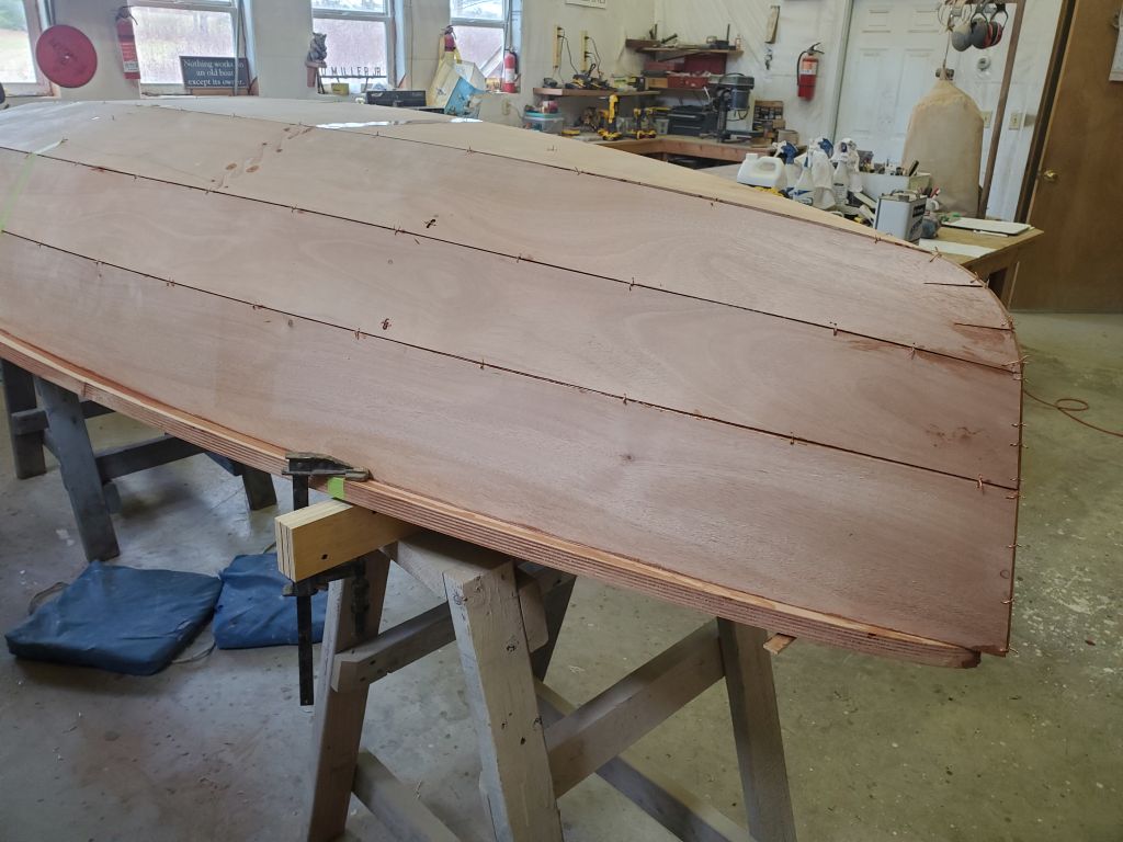
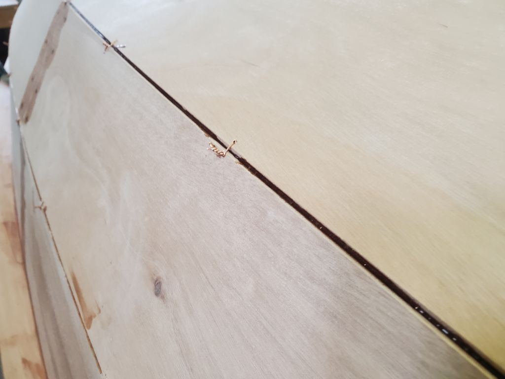
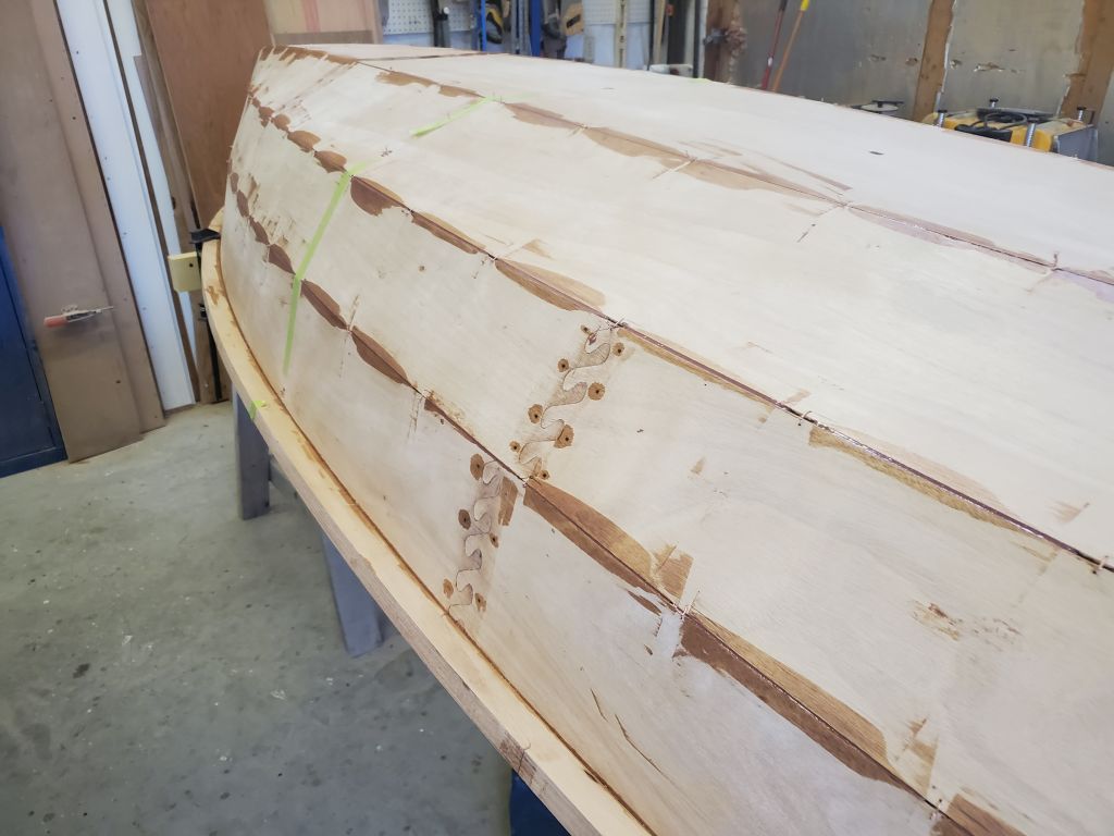
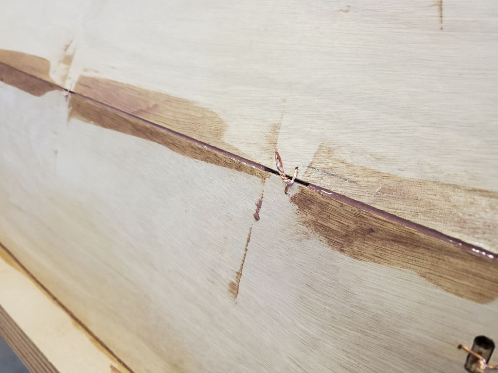
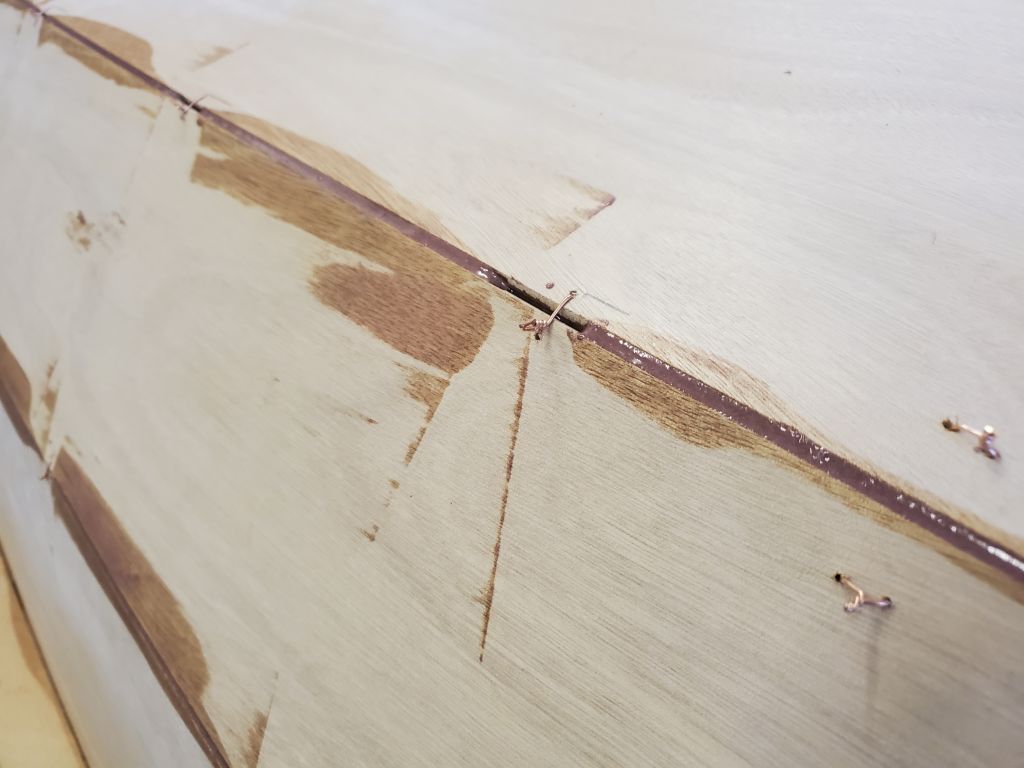
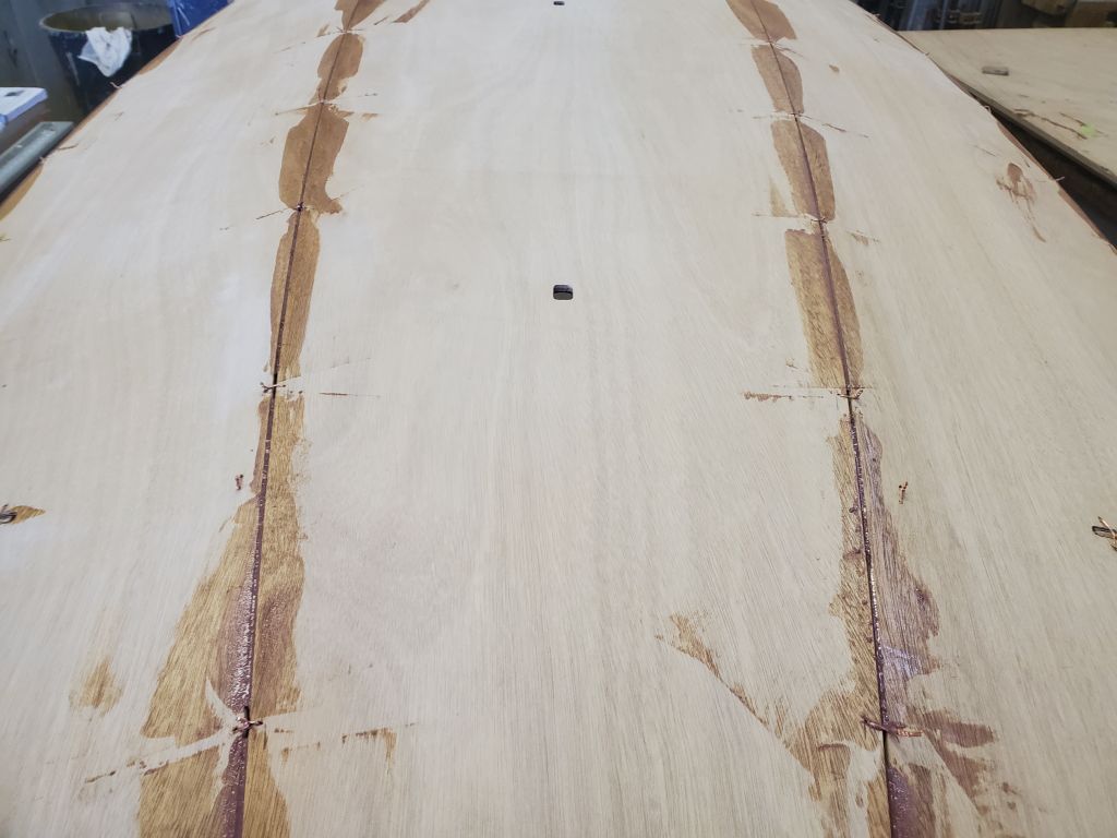
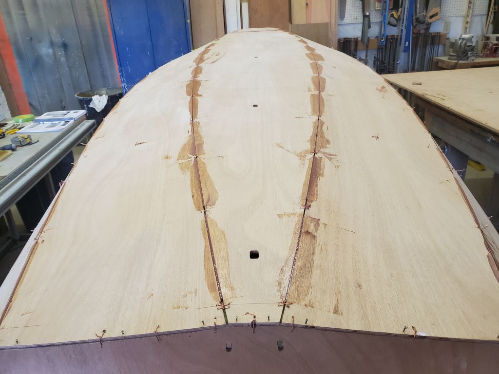
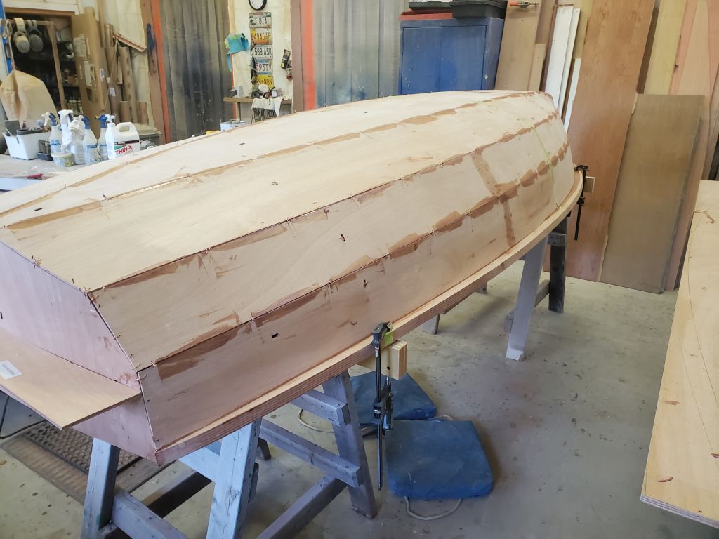
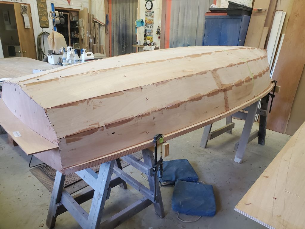
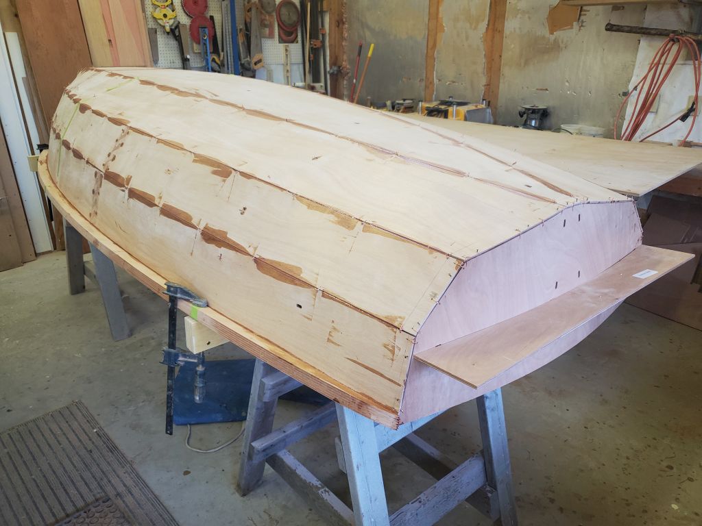
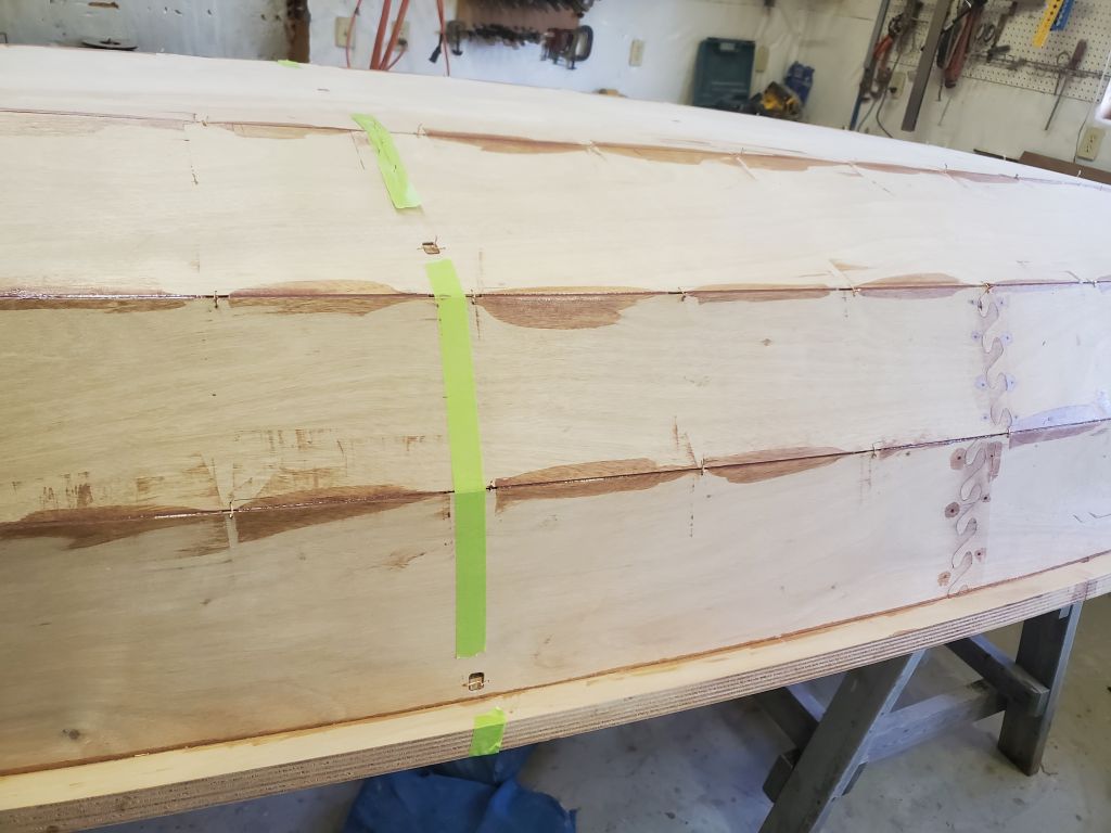
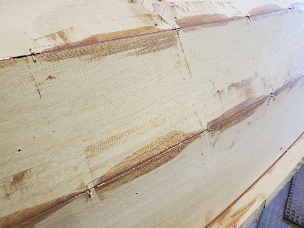
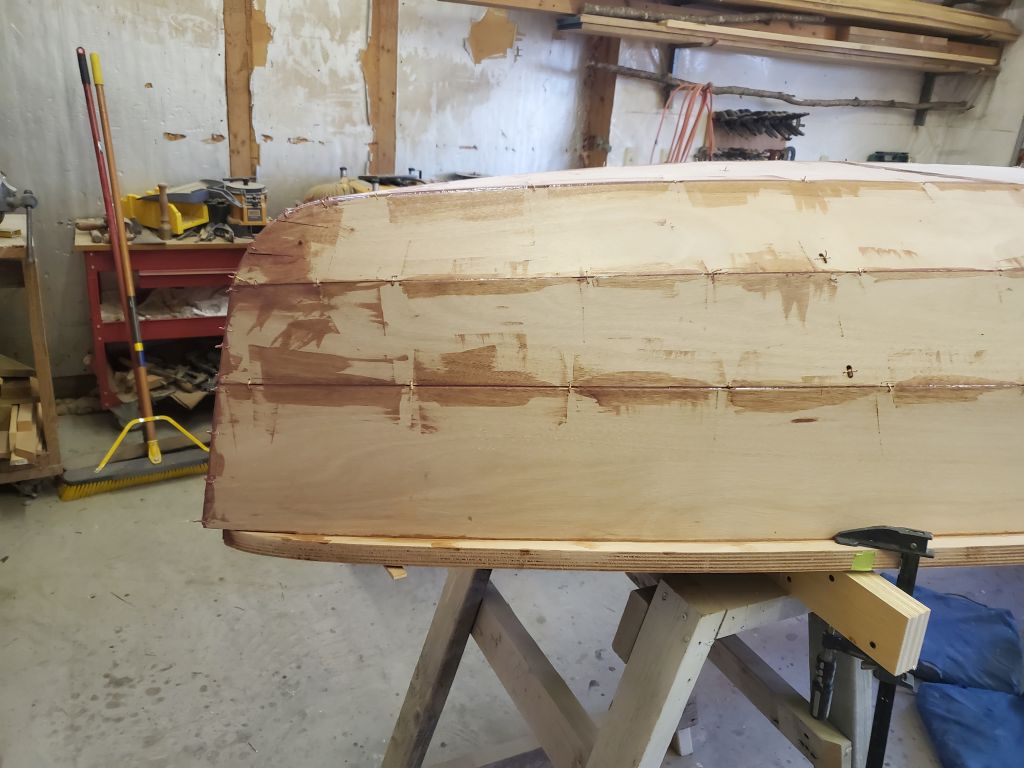
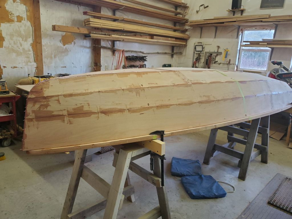
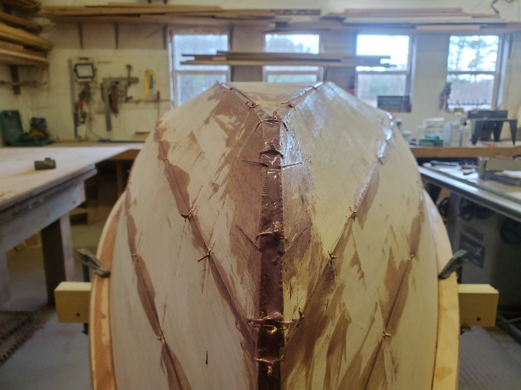
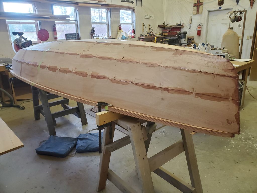
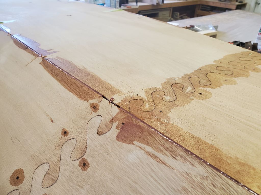
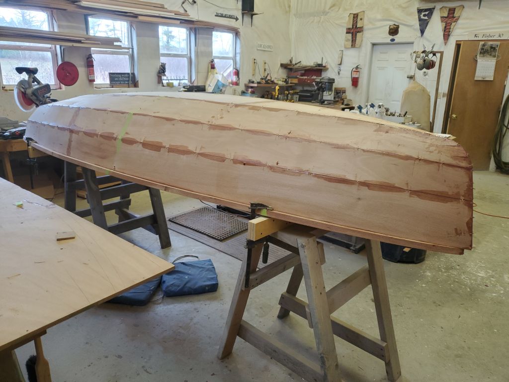
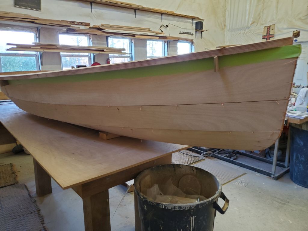
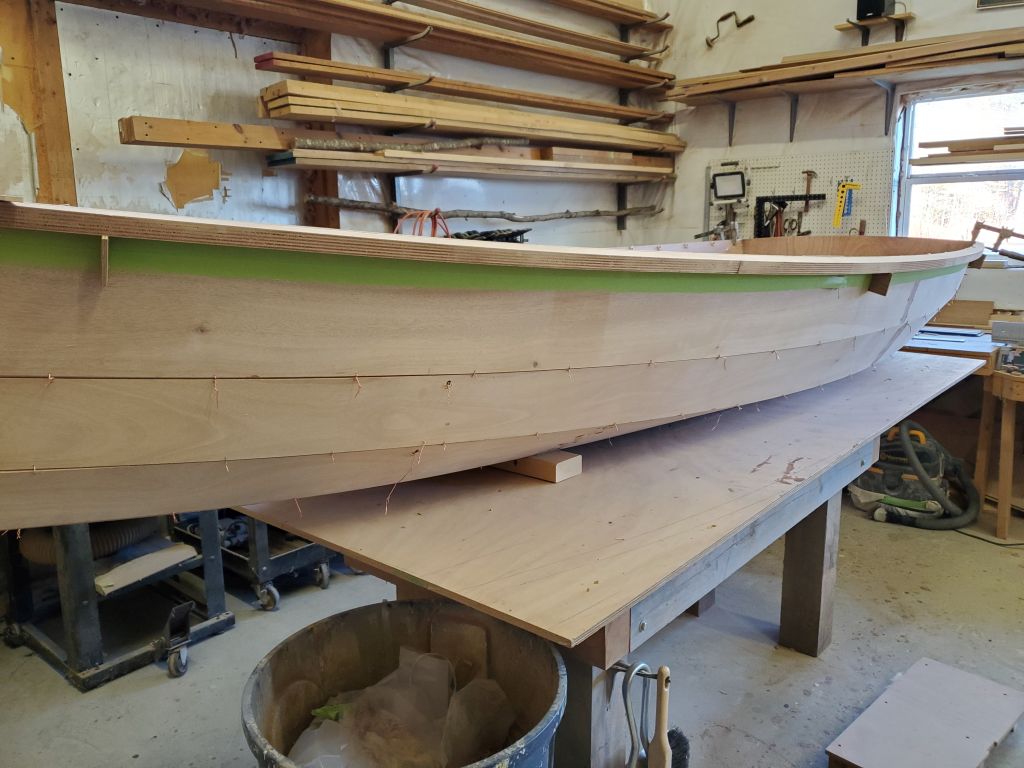
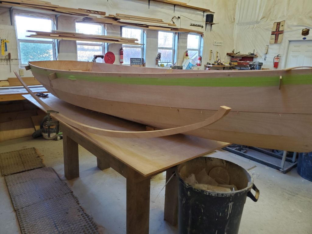
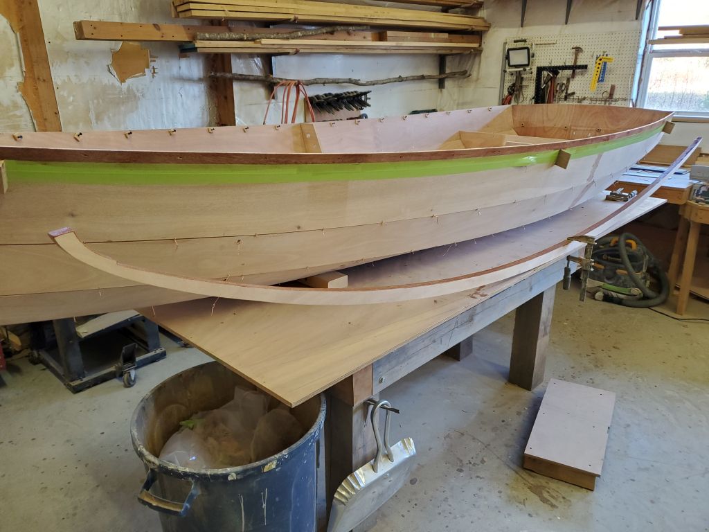
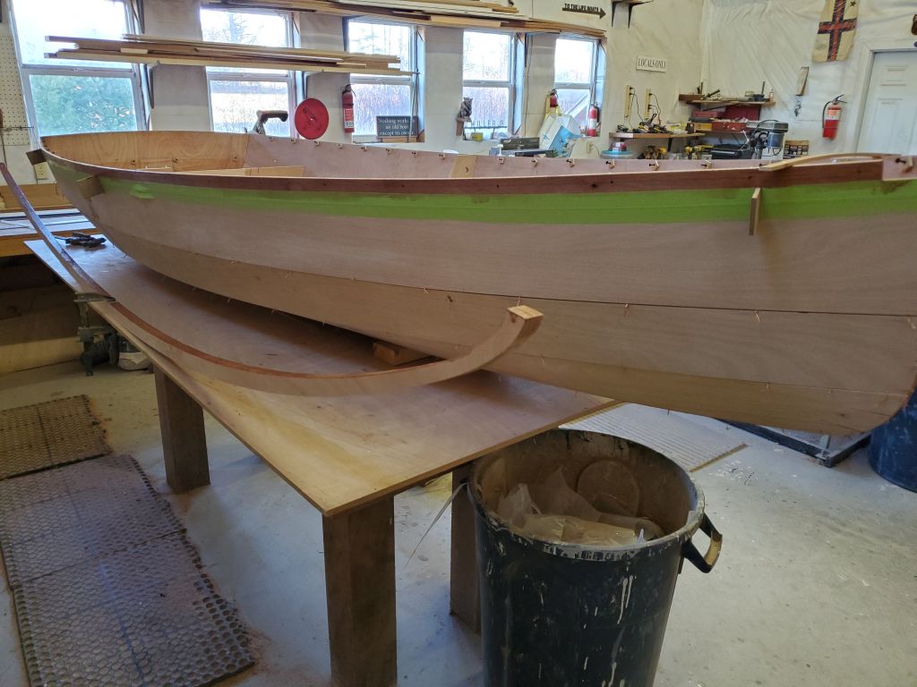
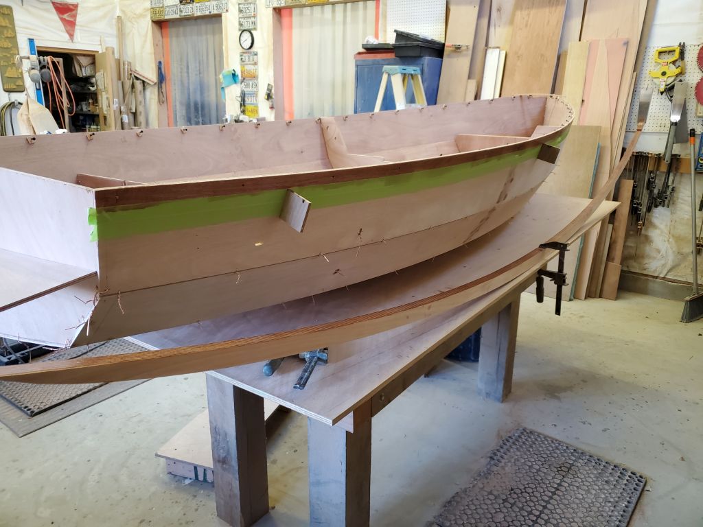
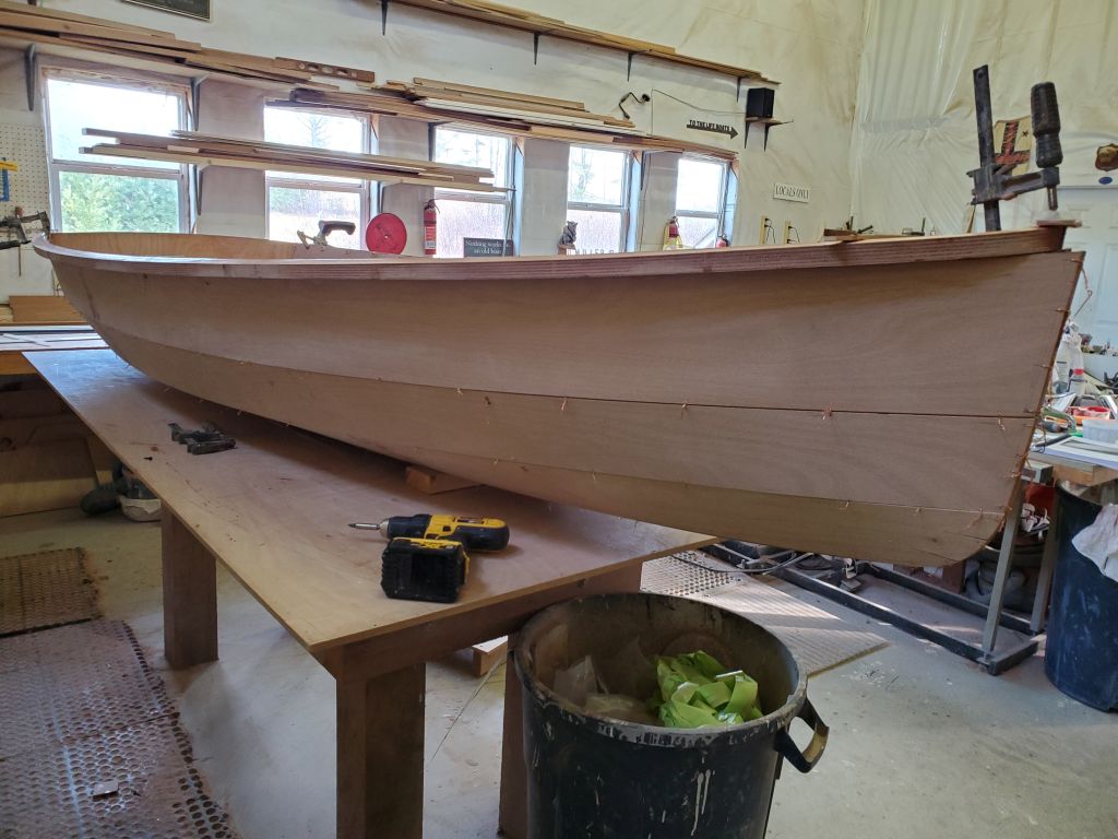
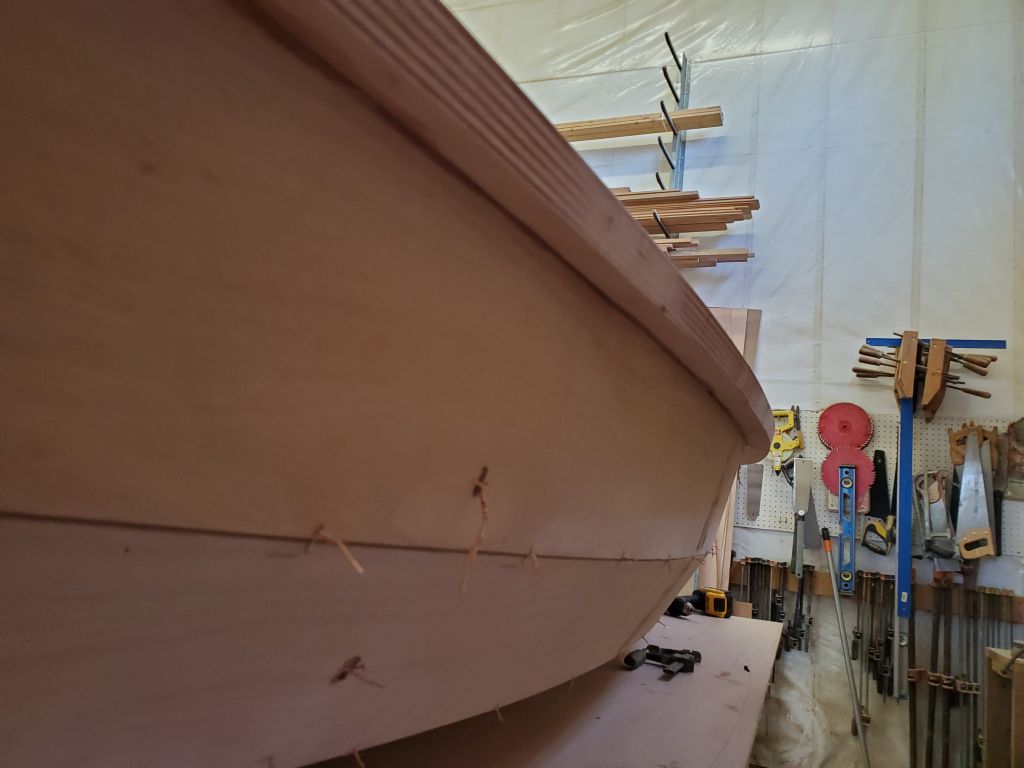
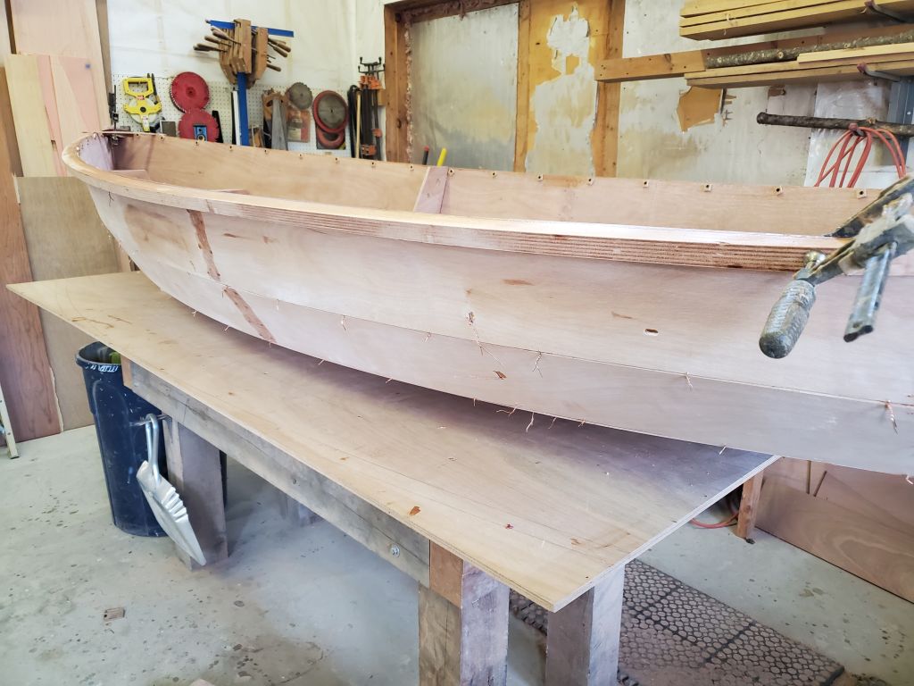
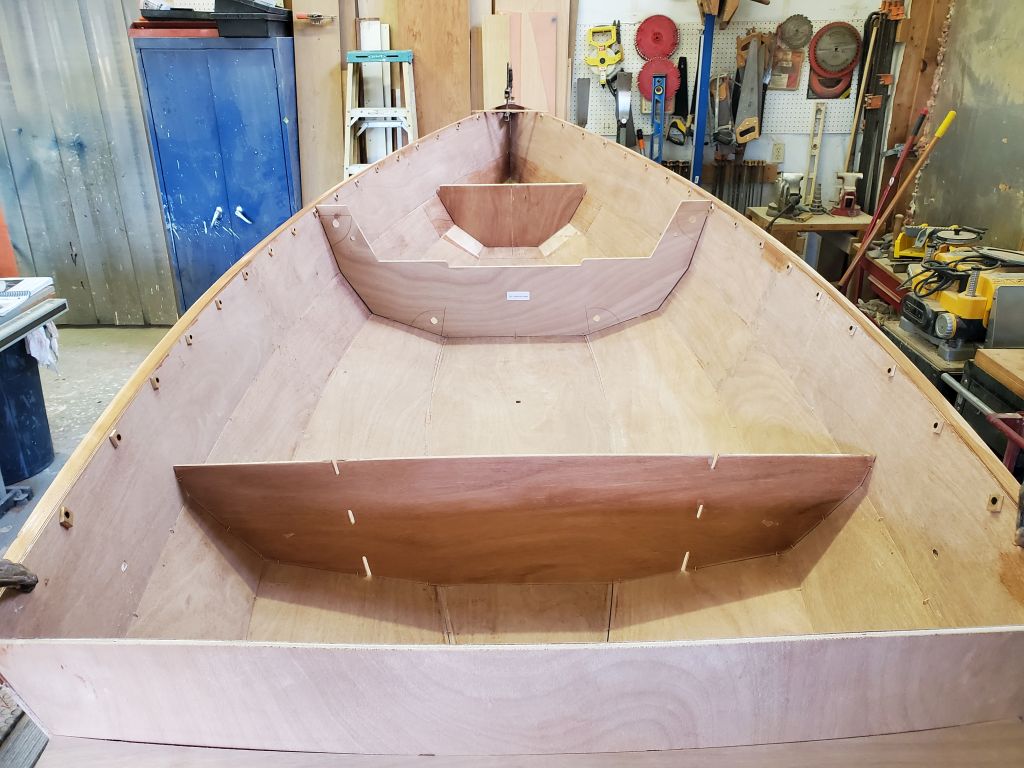
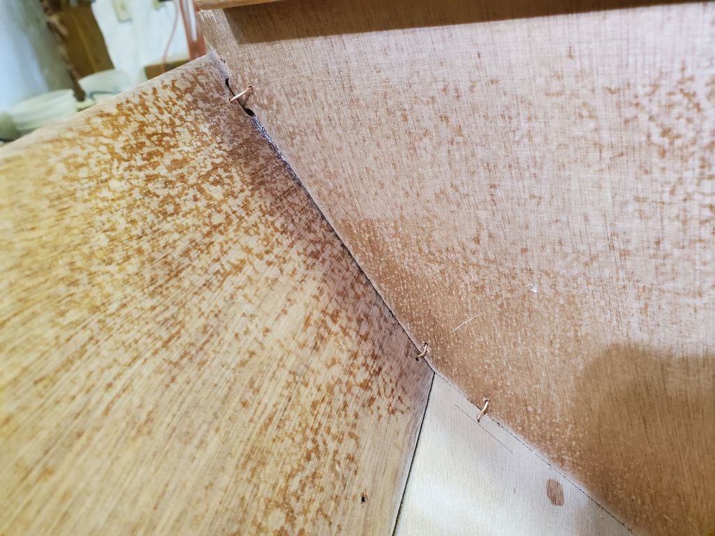
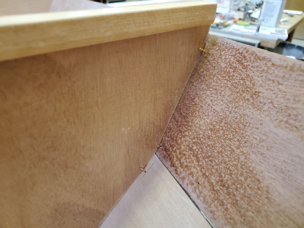
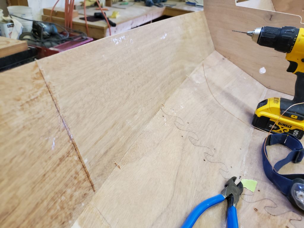
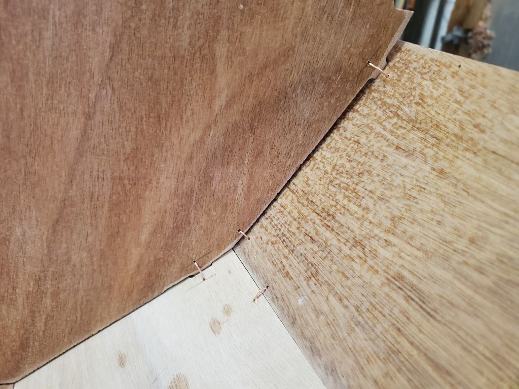
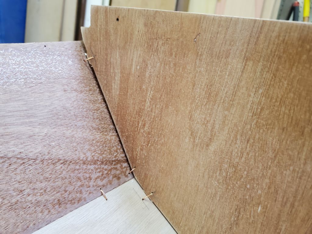
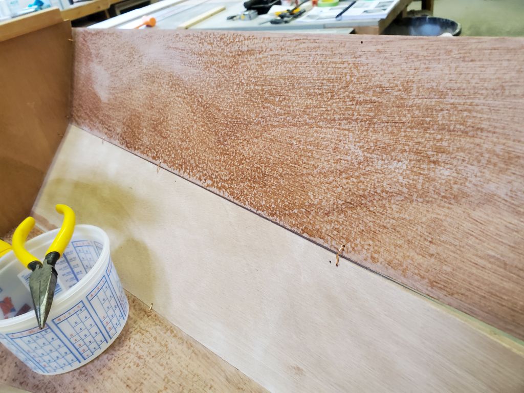
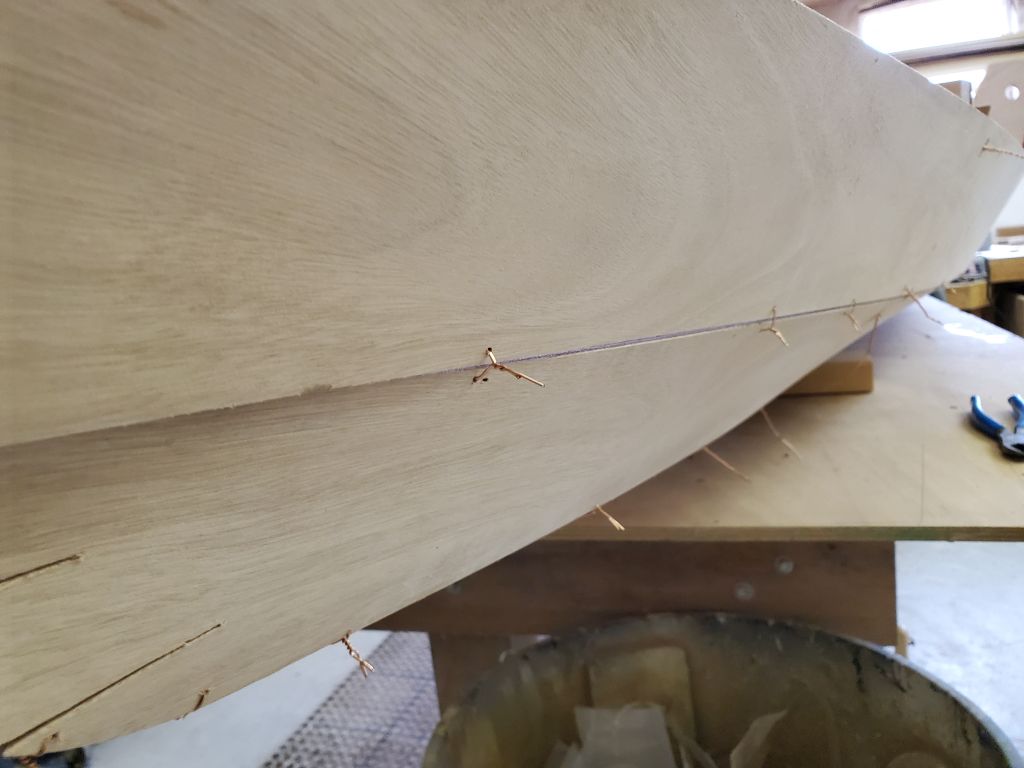
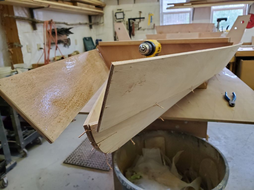
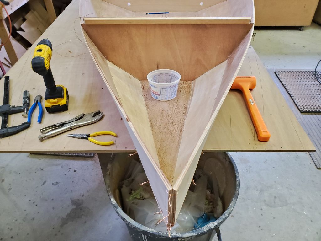
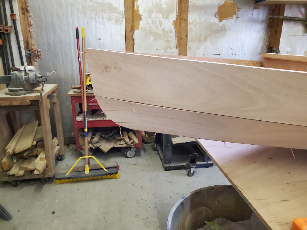
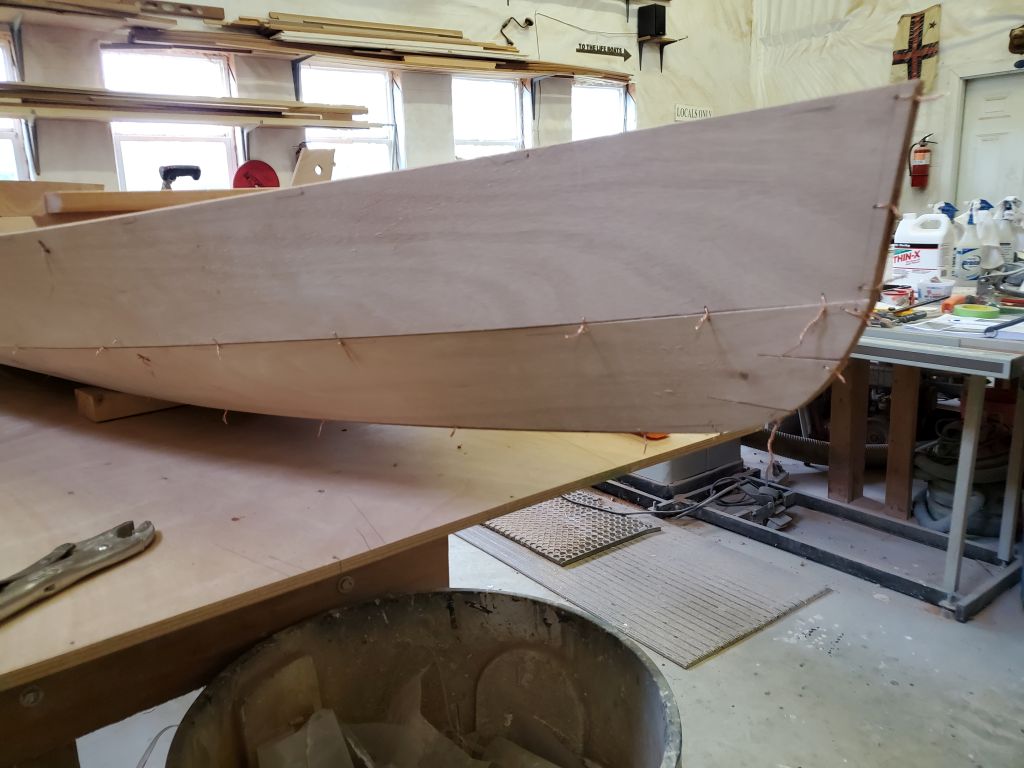
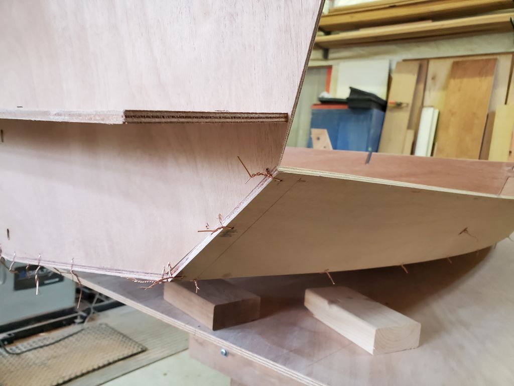
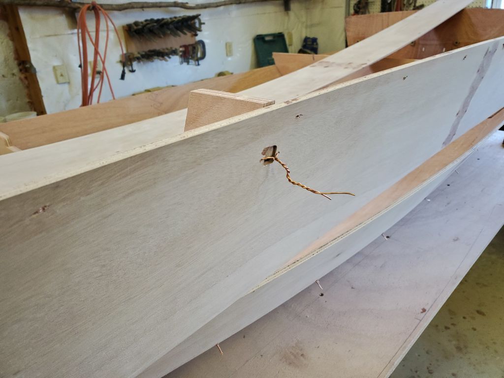
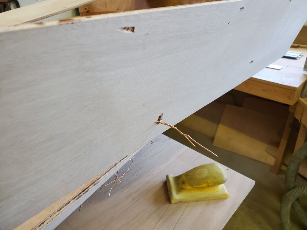
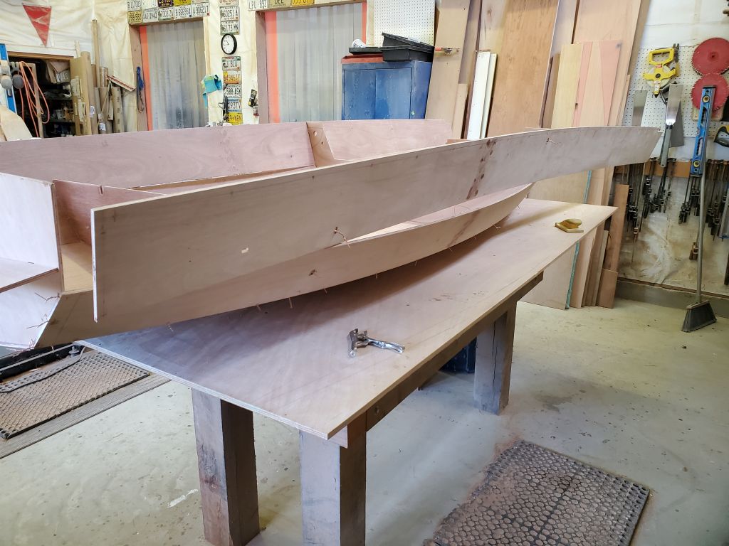
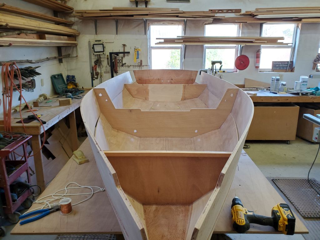
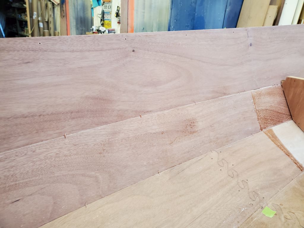
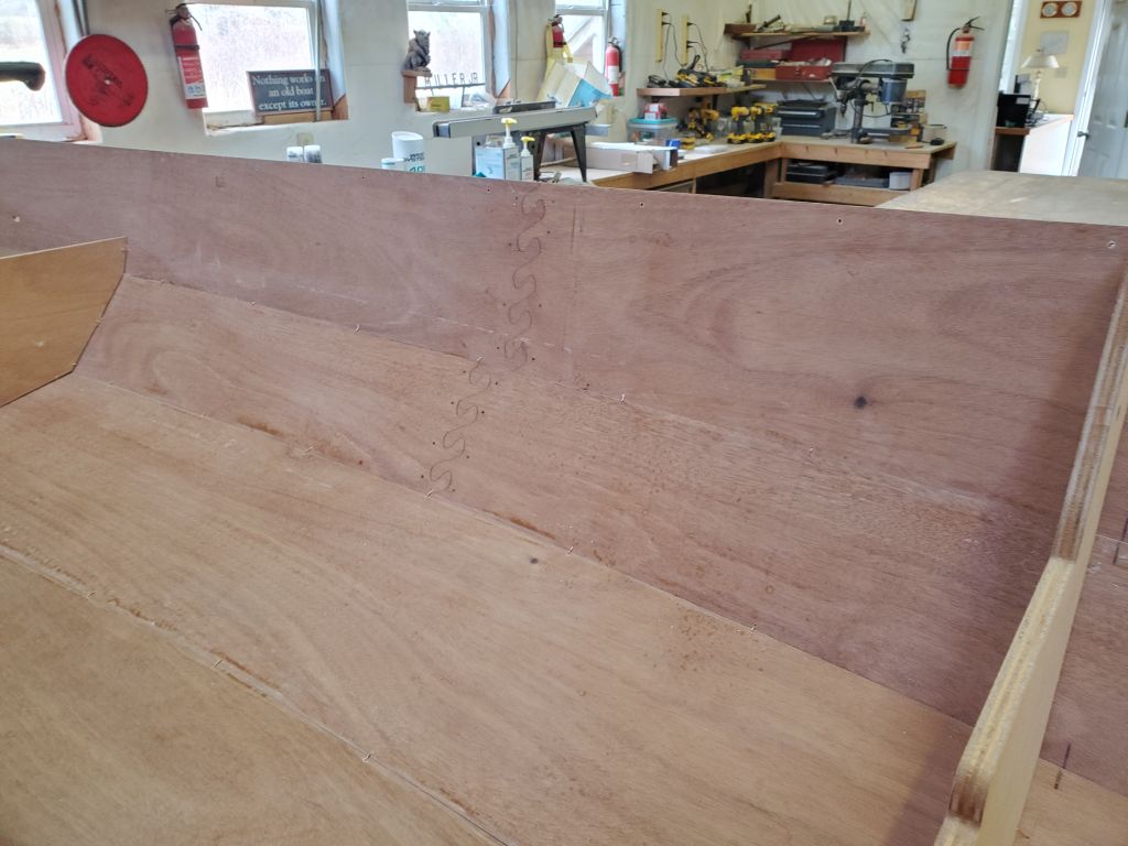
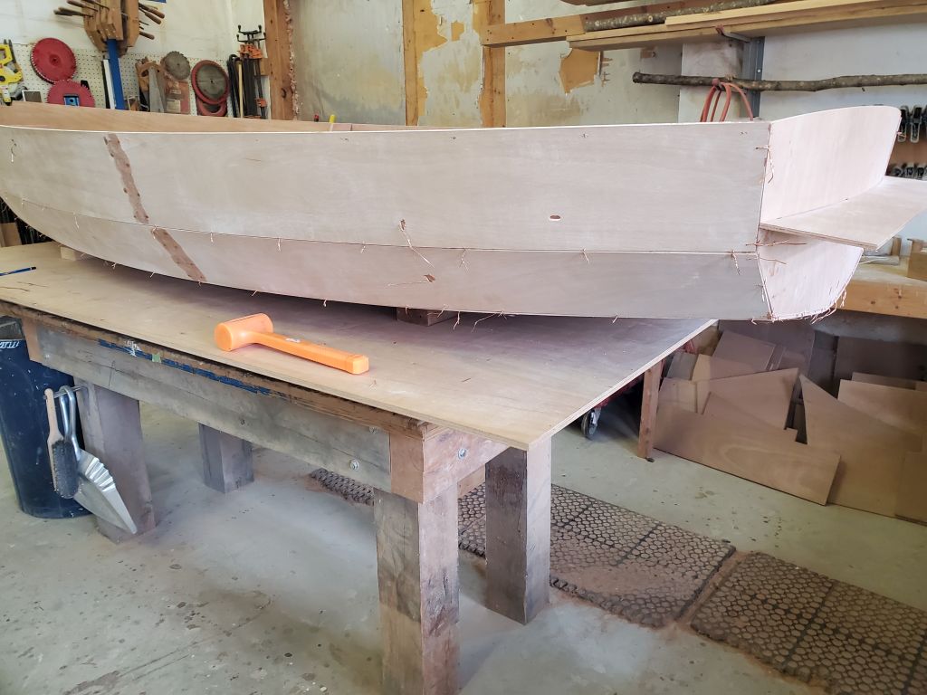
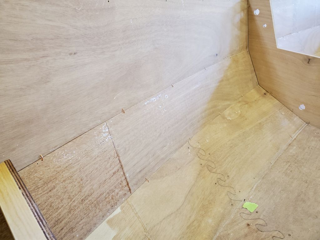
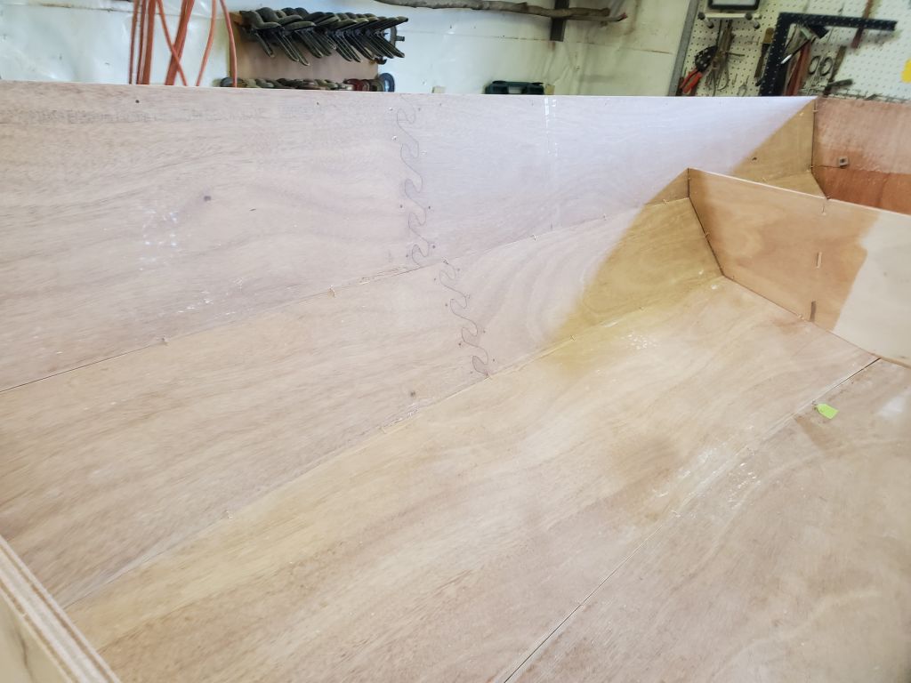
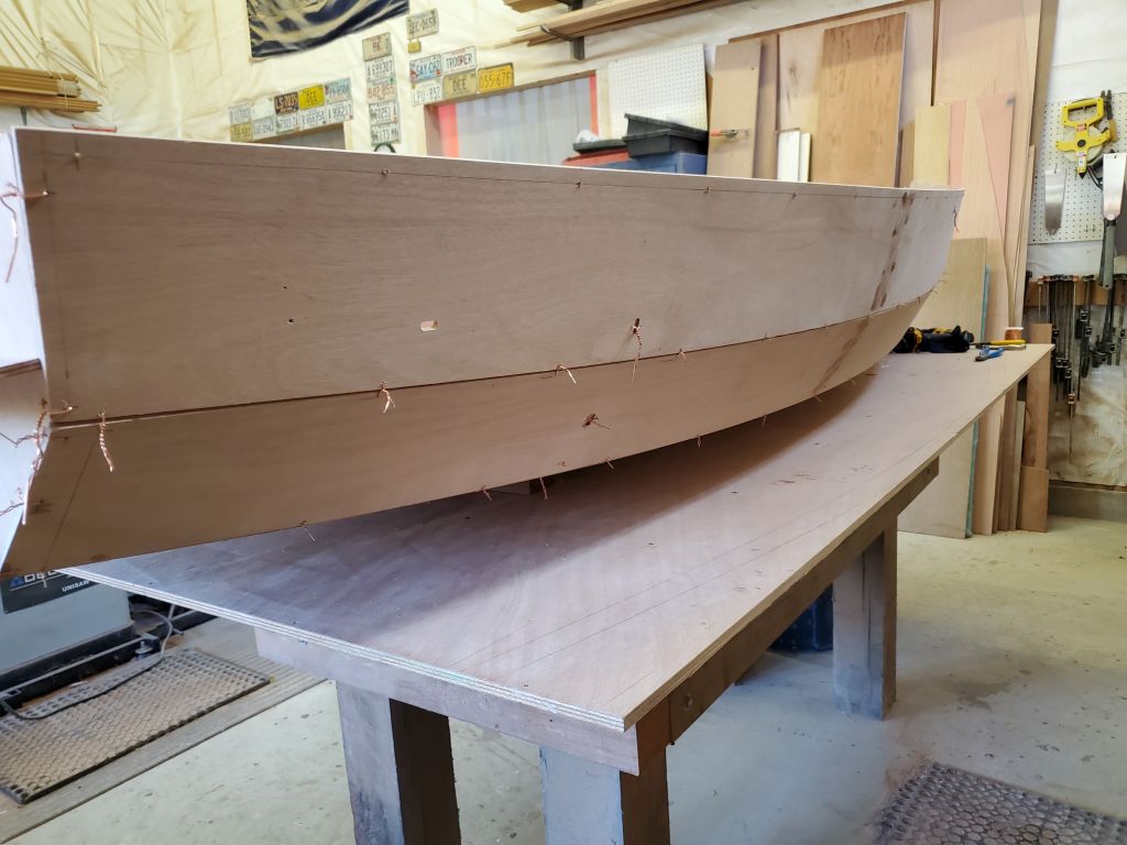
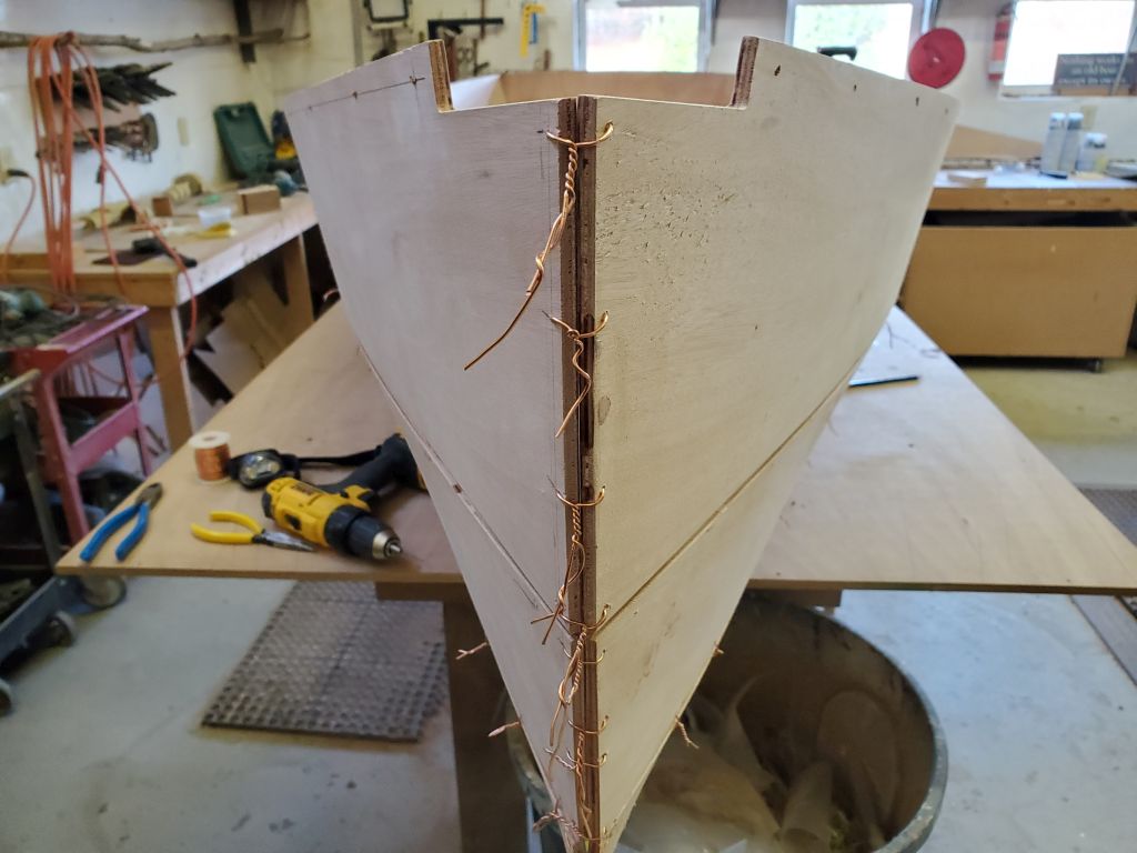
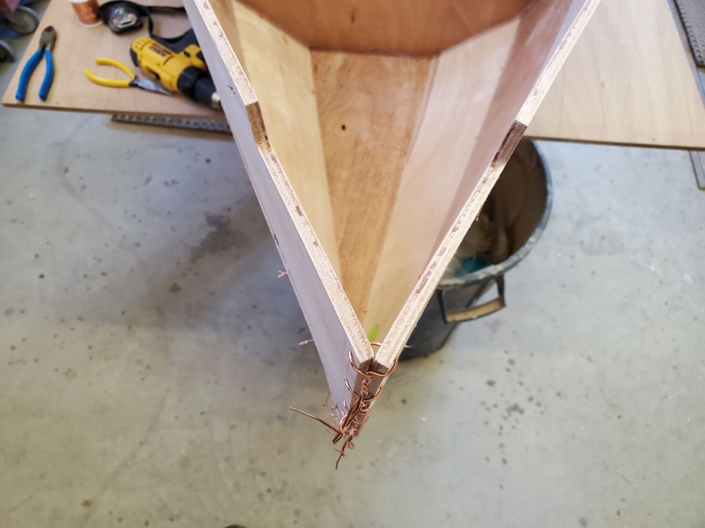
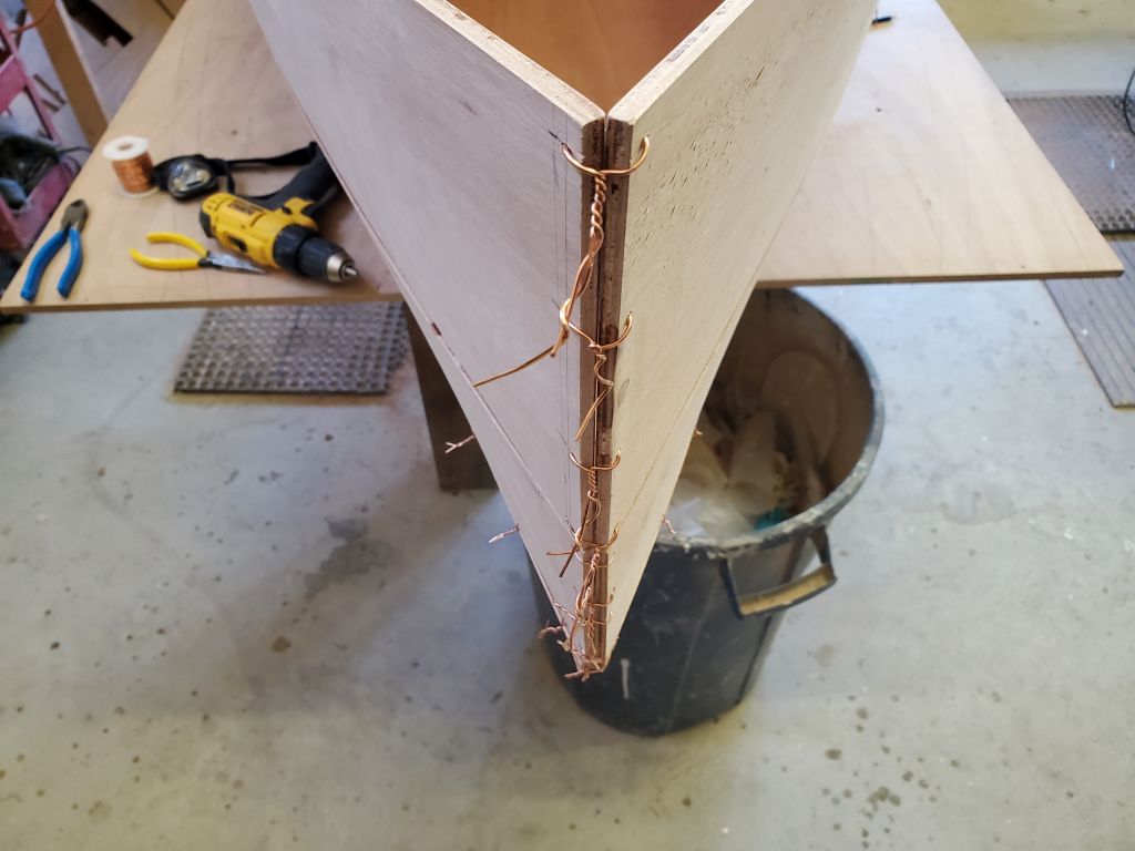
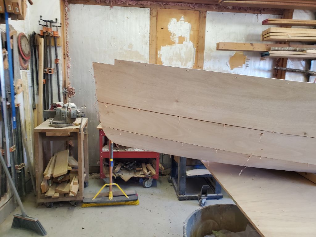
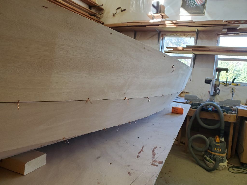
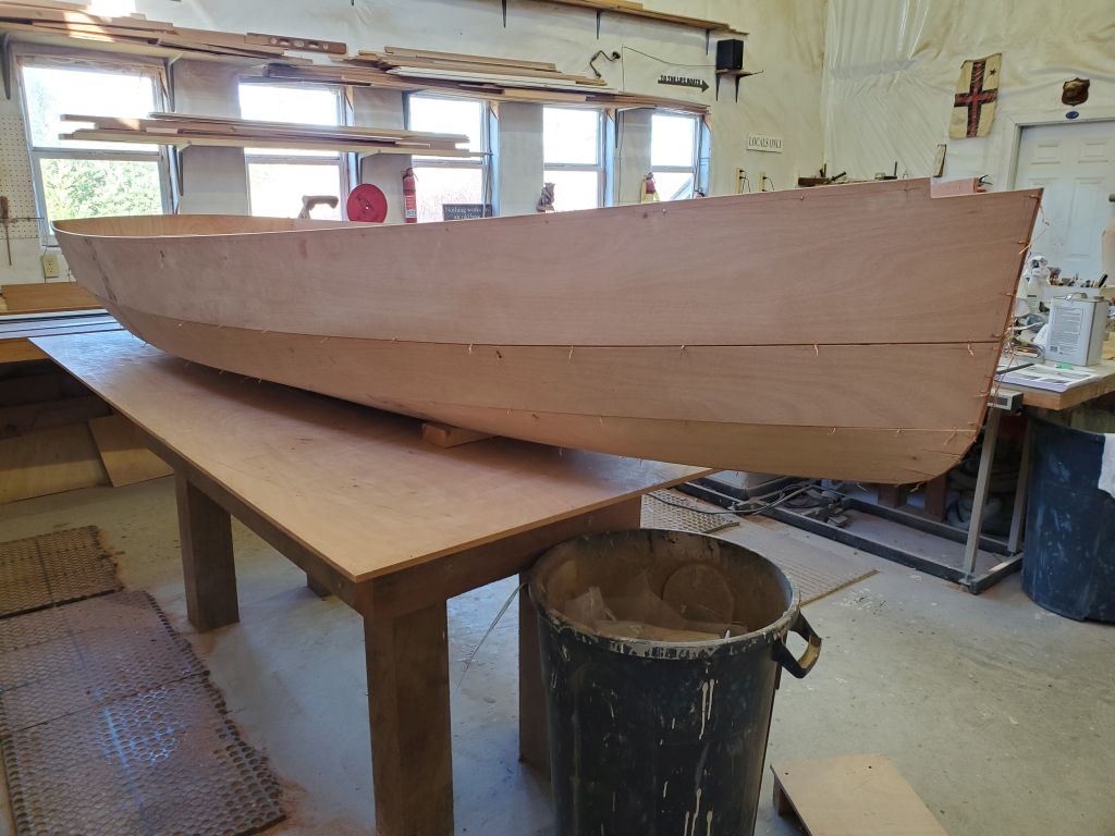
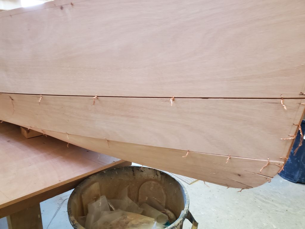
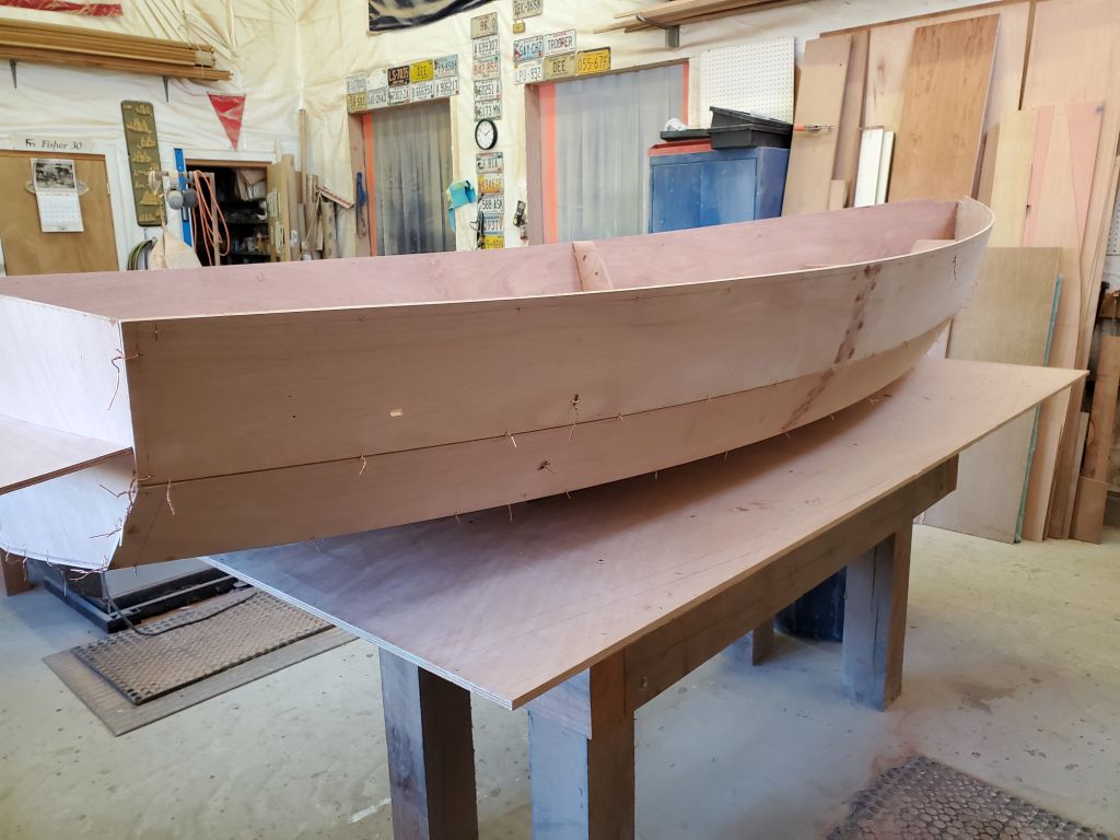
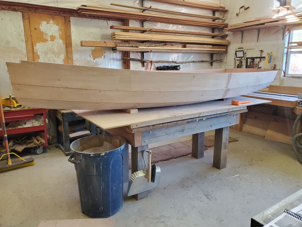
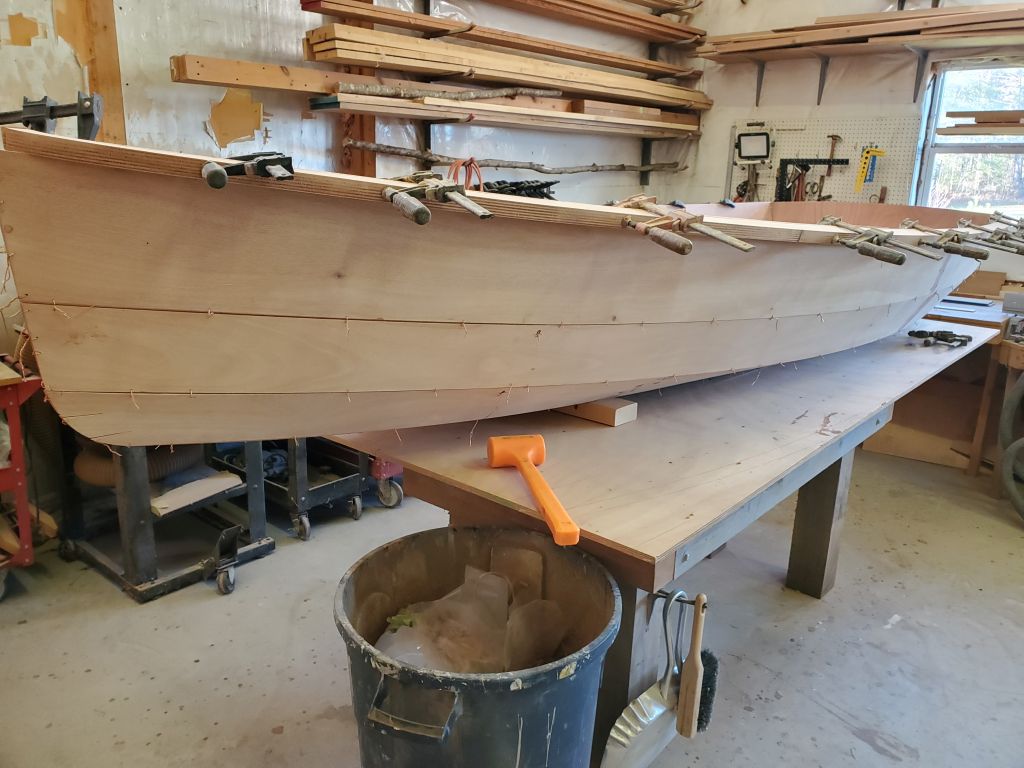
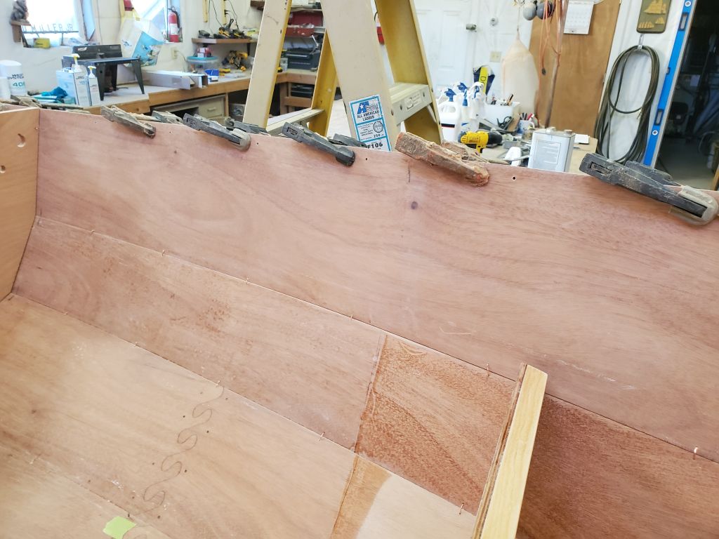
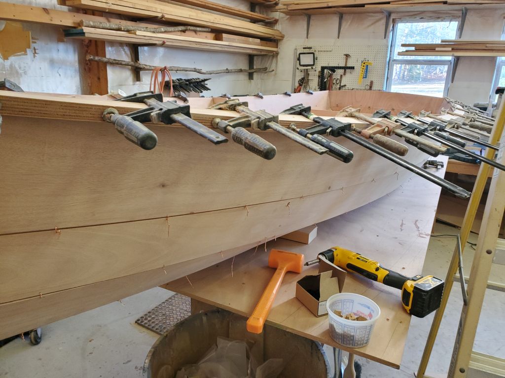
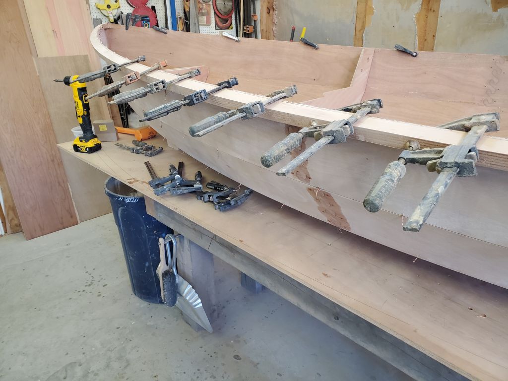
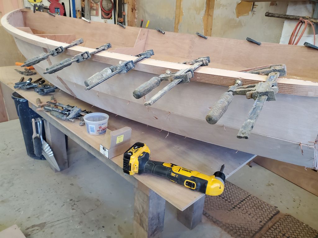
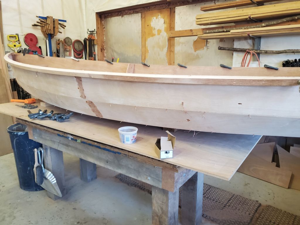
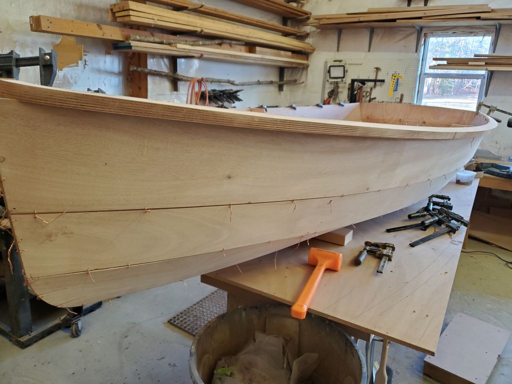
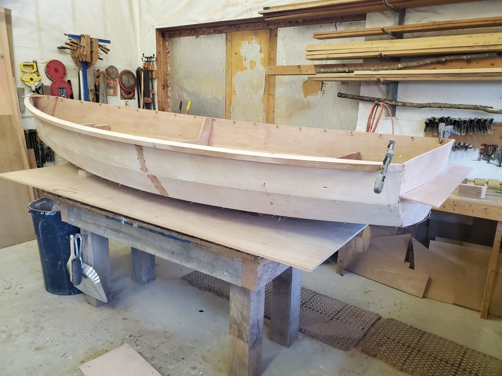
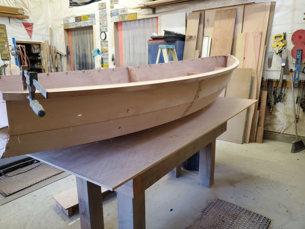
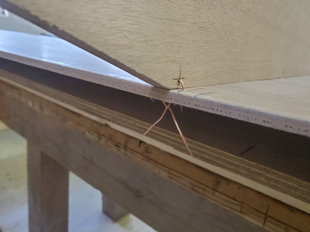
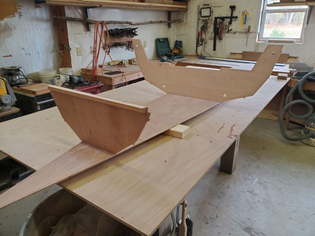
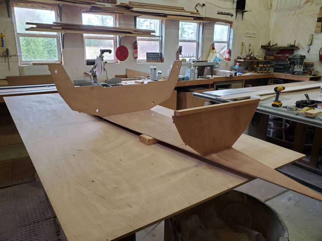
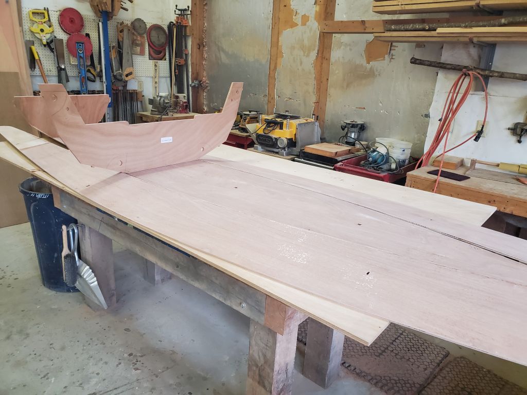
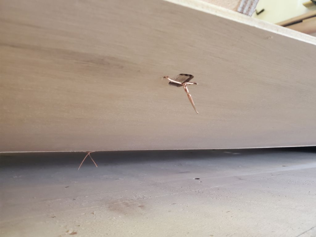
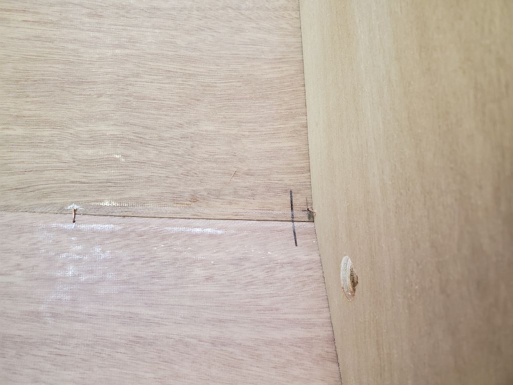
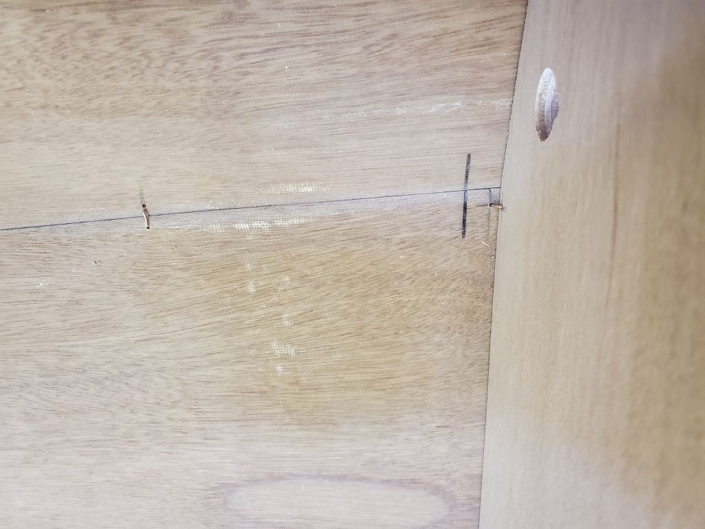
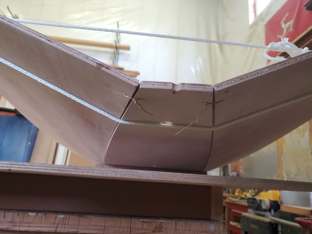
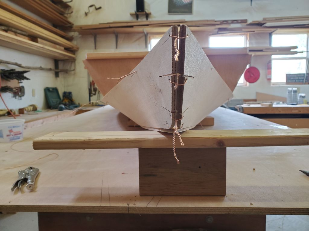
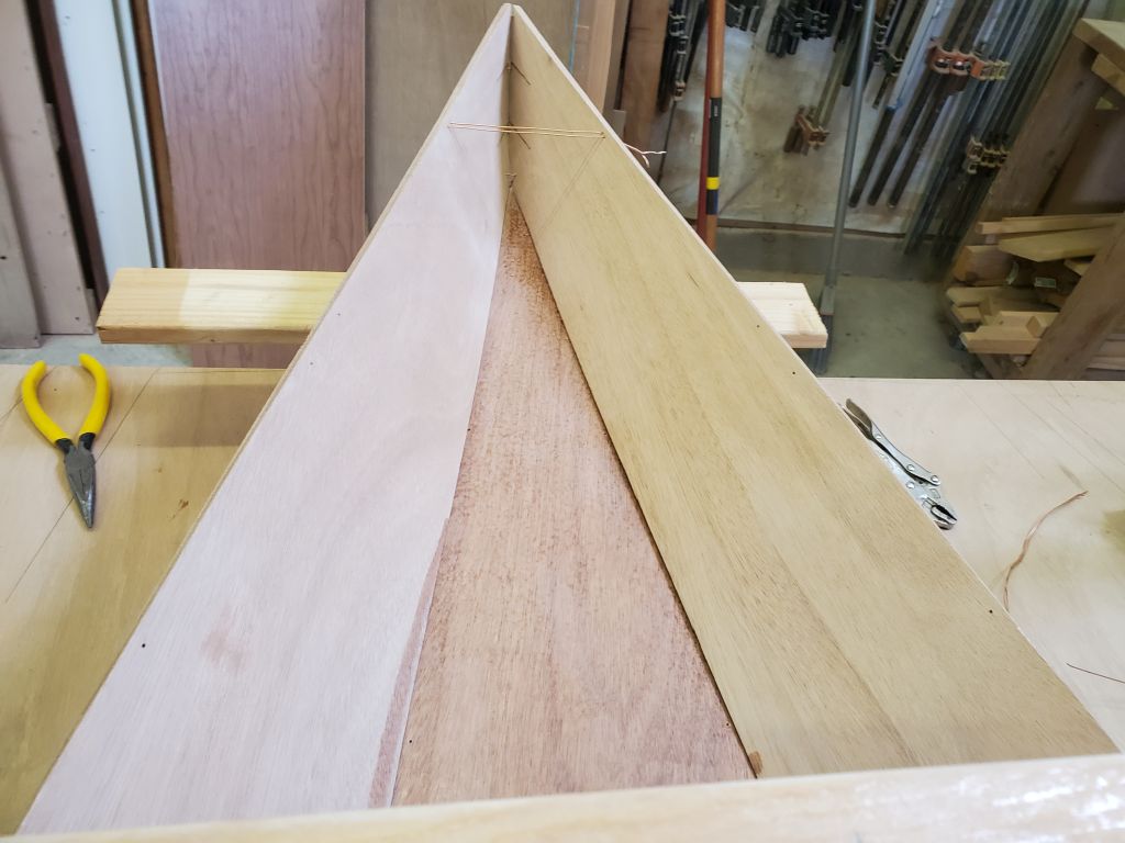
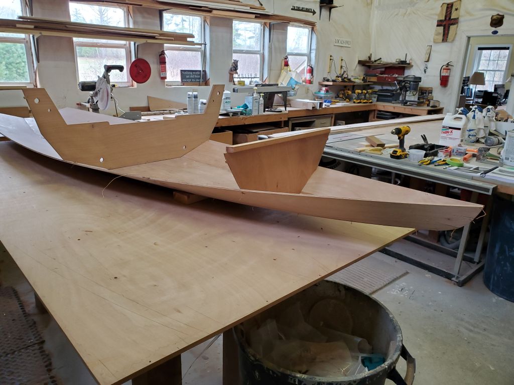
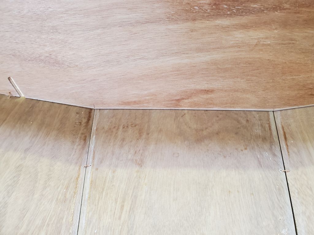
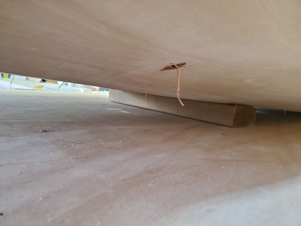
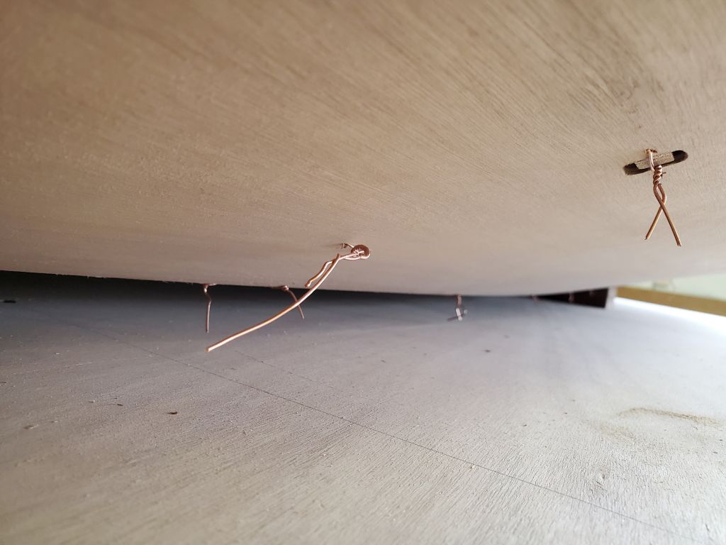
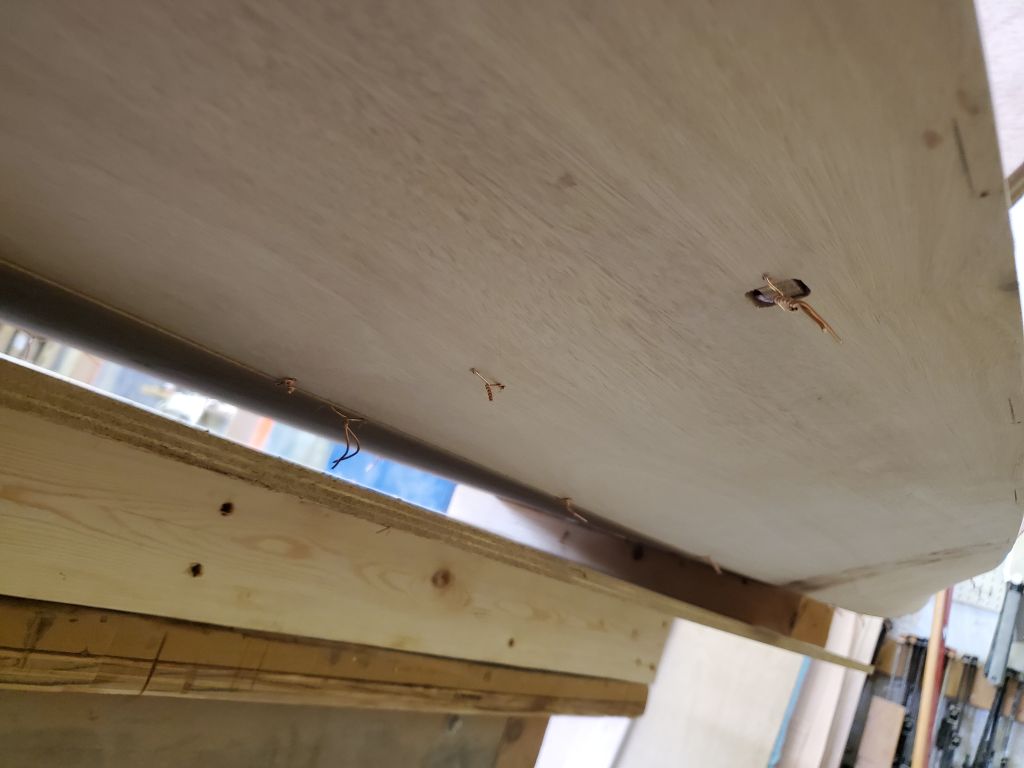
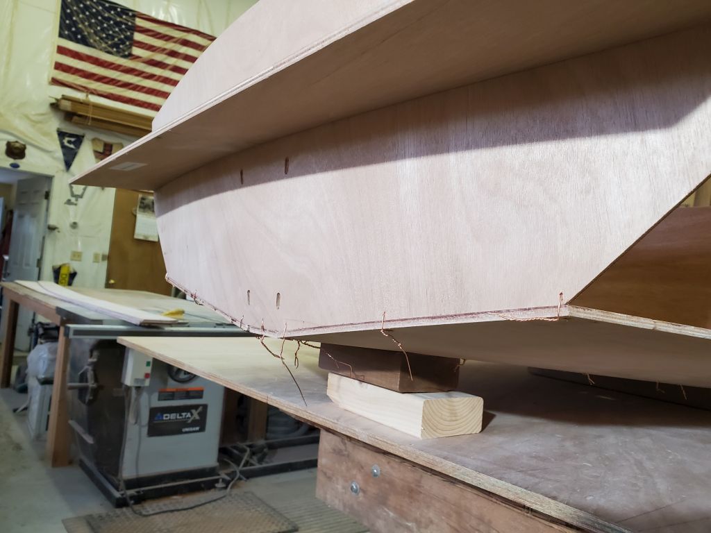
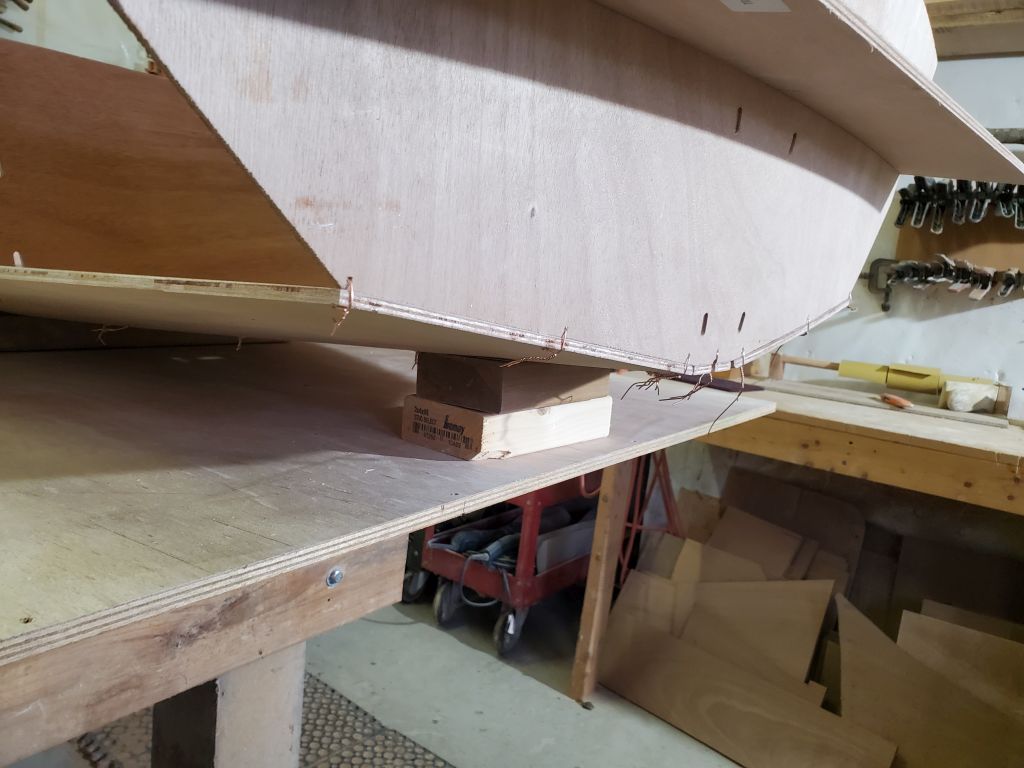
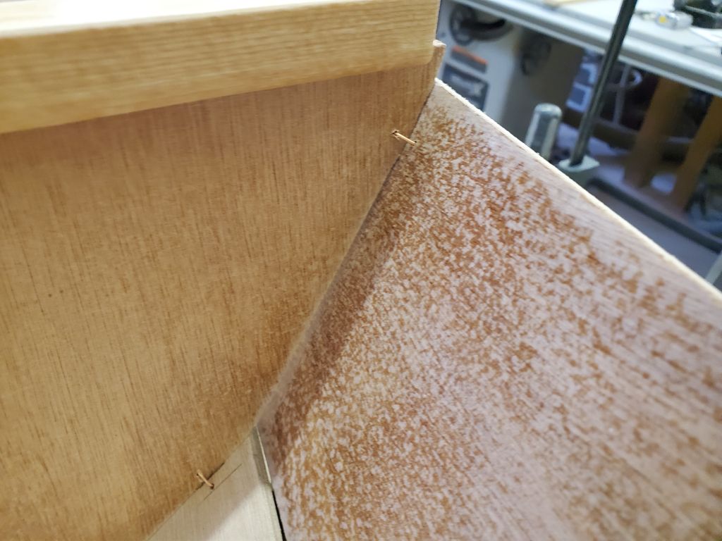
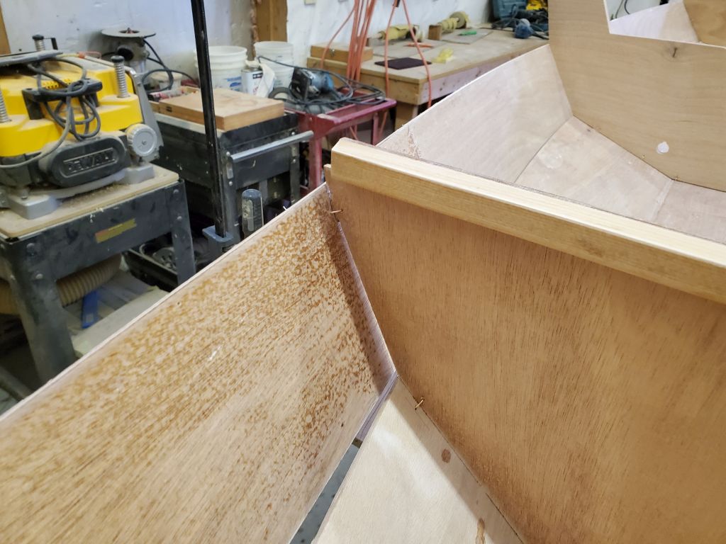
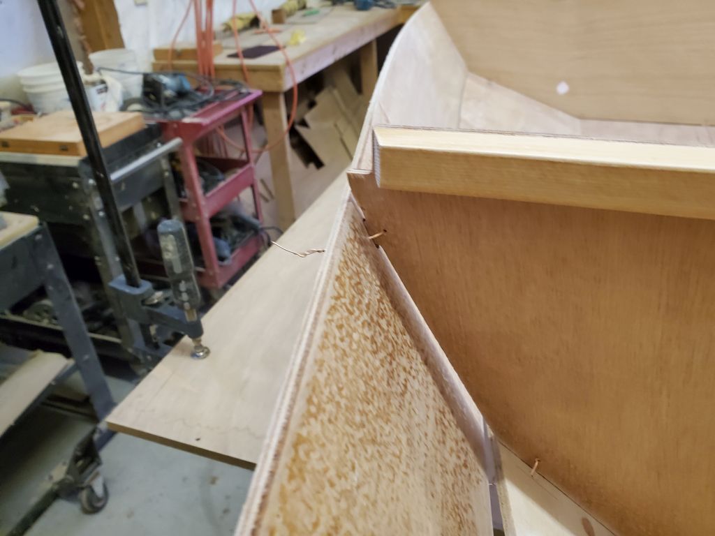
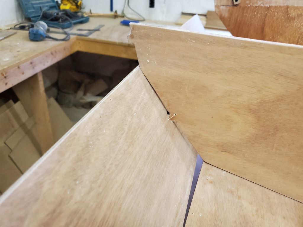
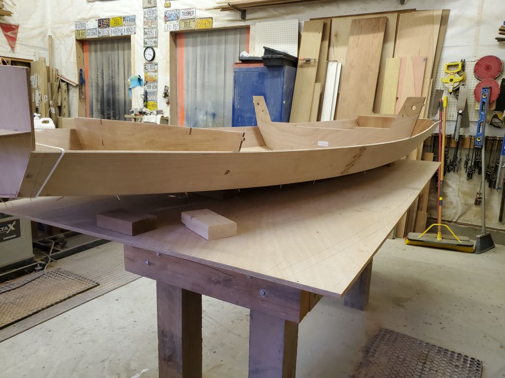
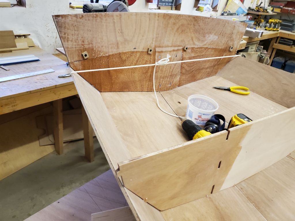
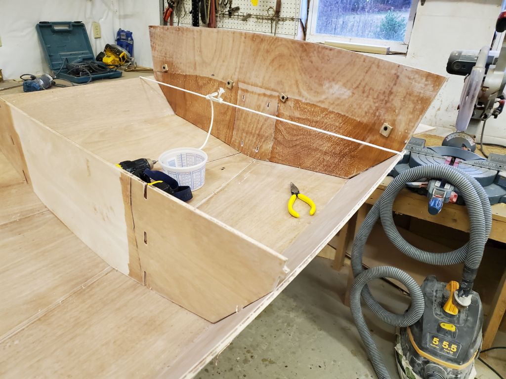
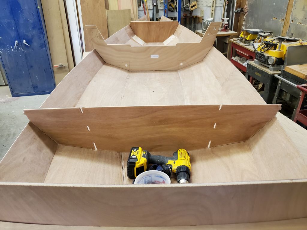
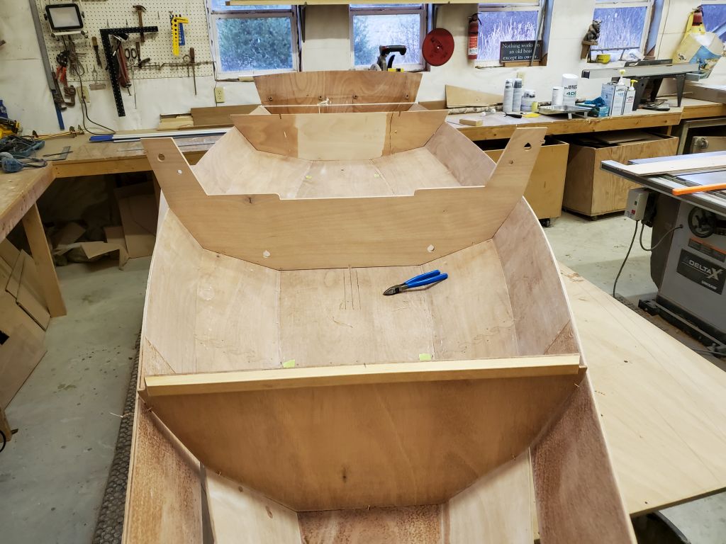
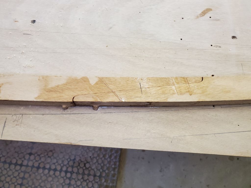
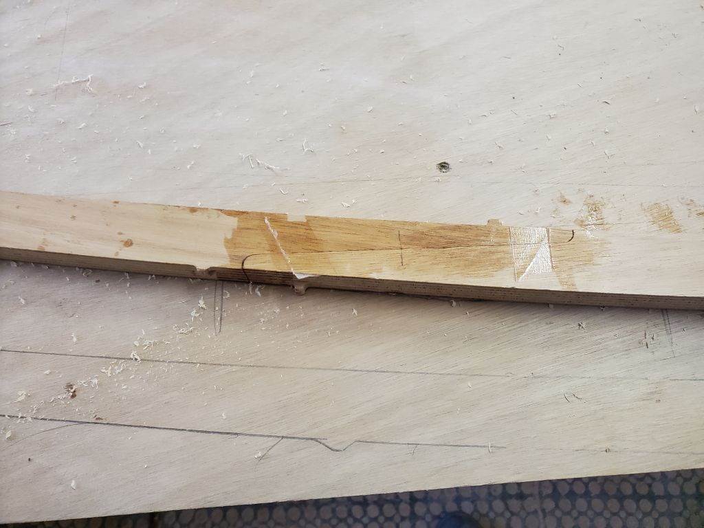
With the seams now glued and cured overnight, I flipped the boat upright on the sawhorses and, for ease of inside access, tipped it onto the second hull chine, clamping it in place temporarily. This allowed me to easily reach the insides of the seams so I could remove masking tape and then cut the stitching wires from inside. When I’d done all I could easily reach from the port side, I tipped the hull to starboard and repeated the process.
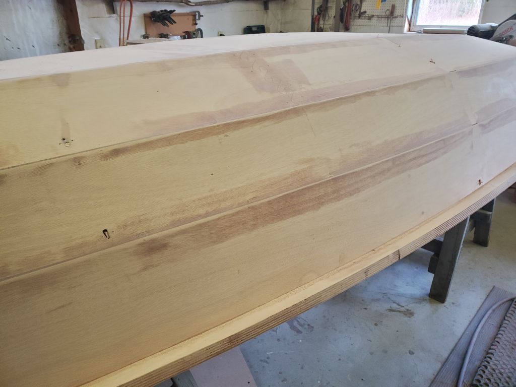
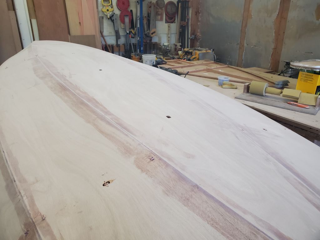
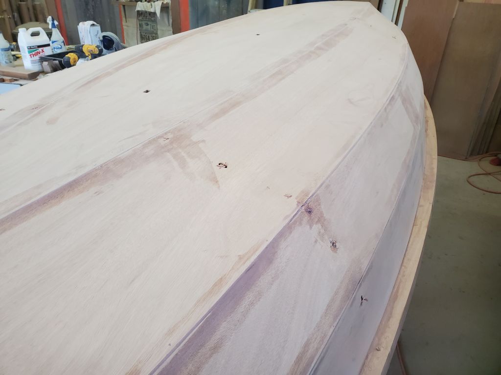
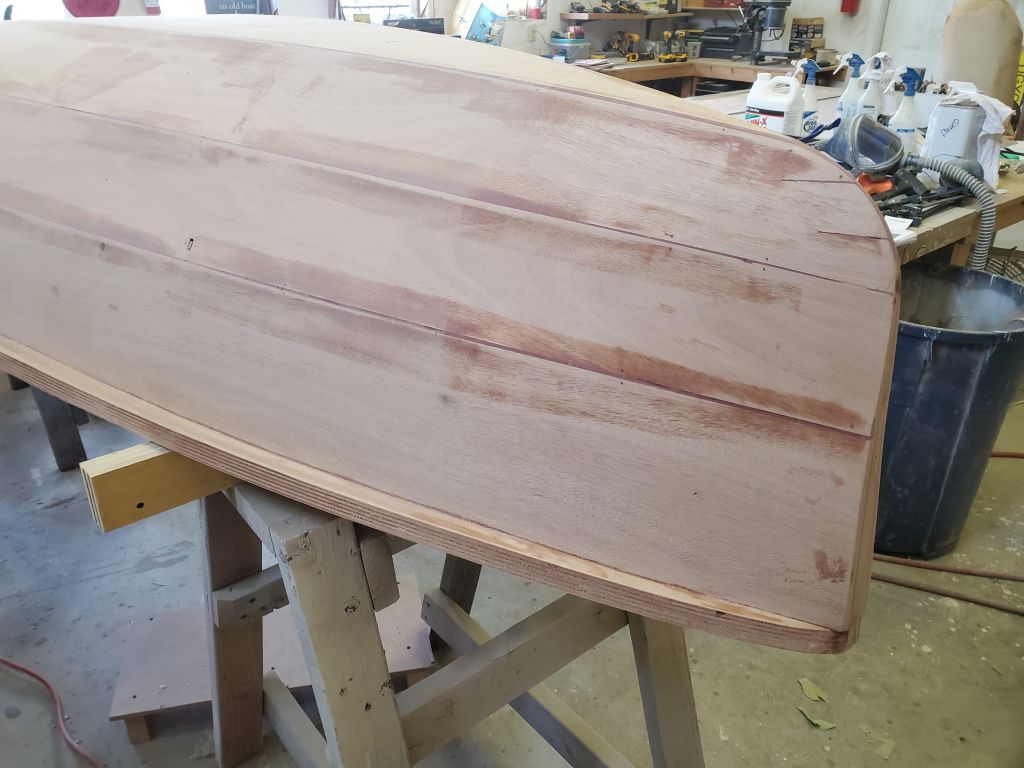
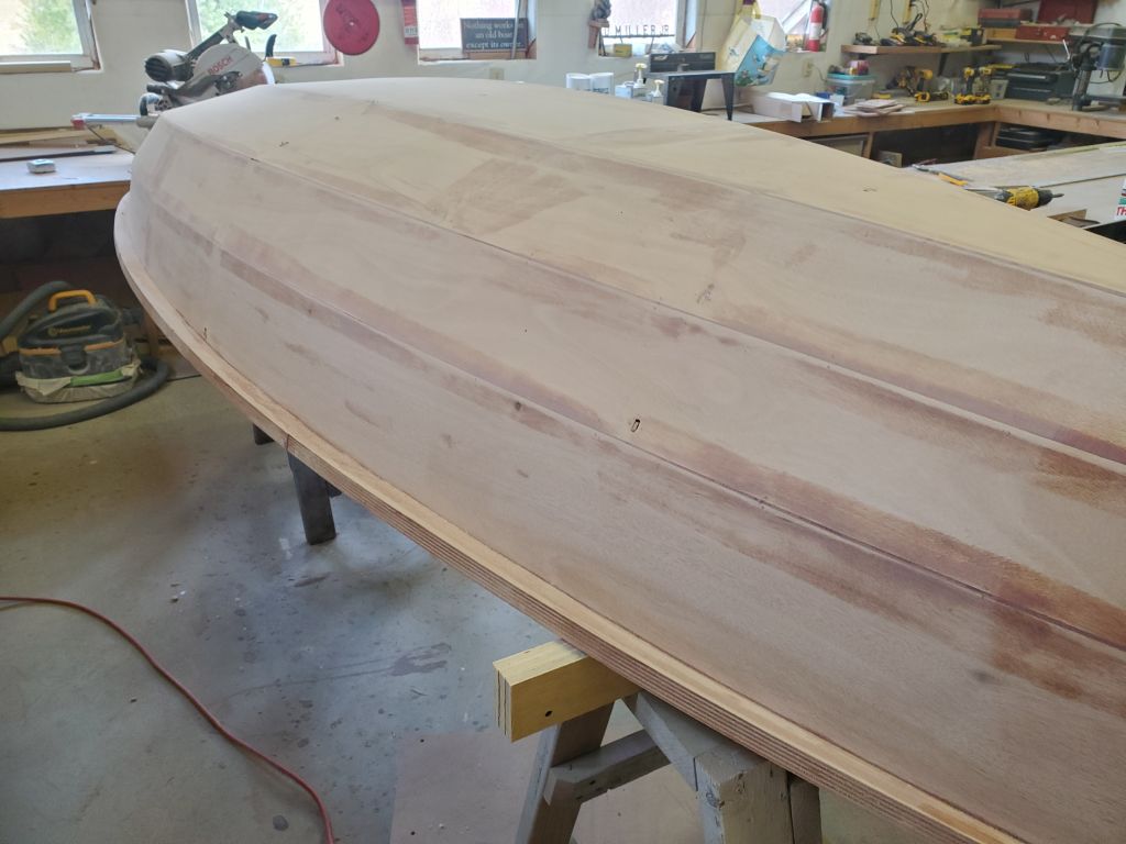
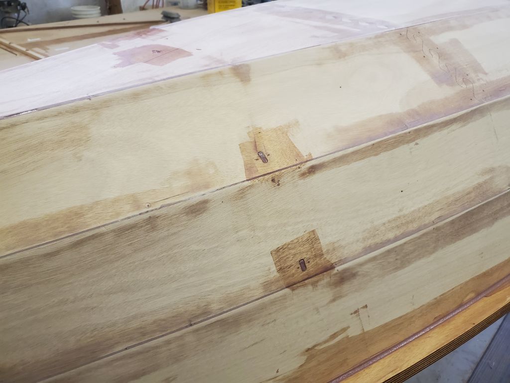
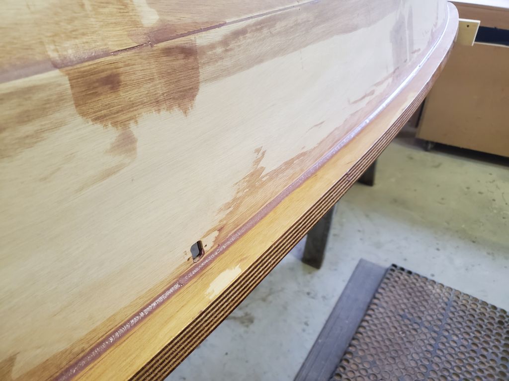
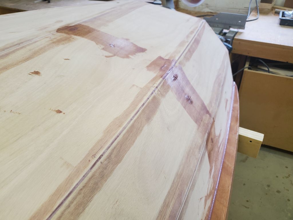
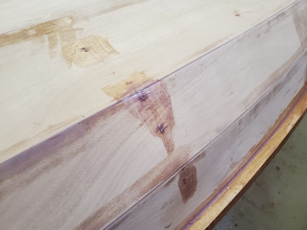
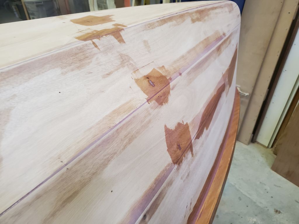
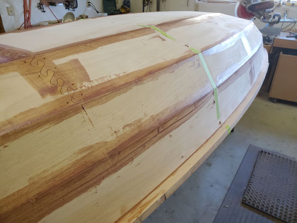
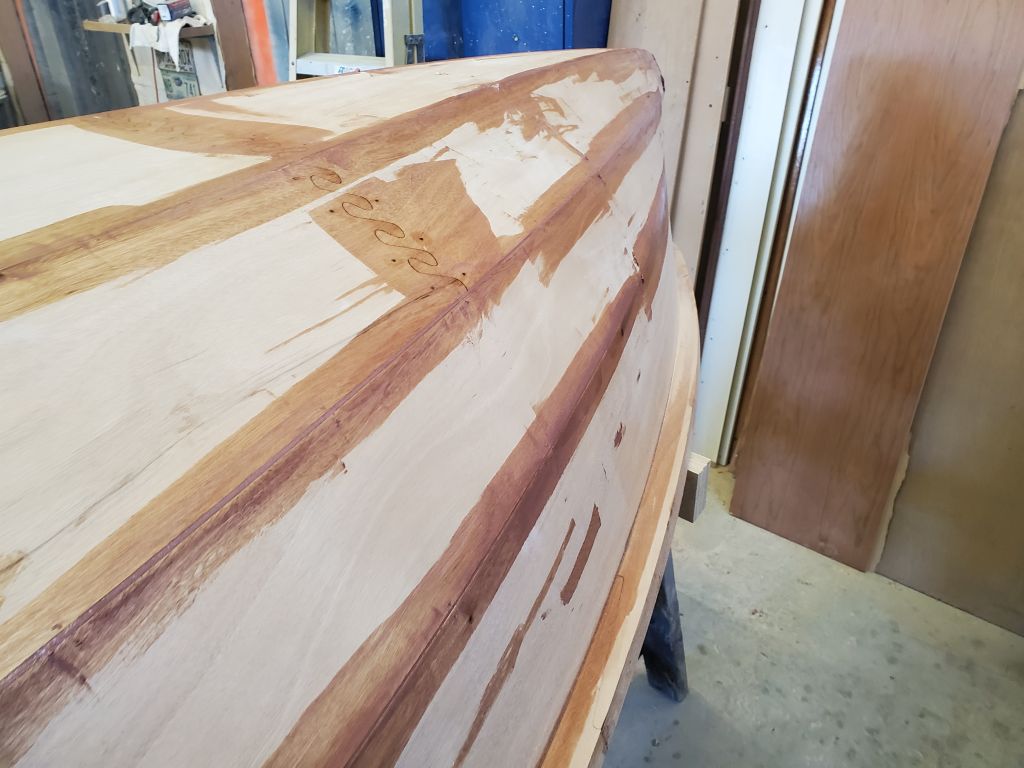
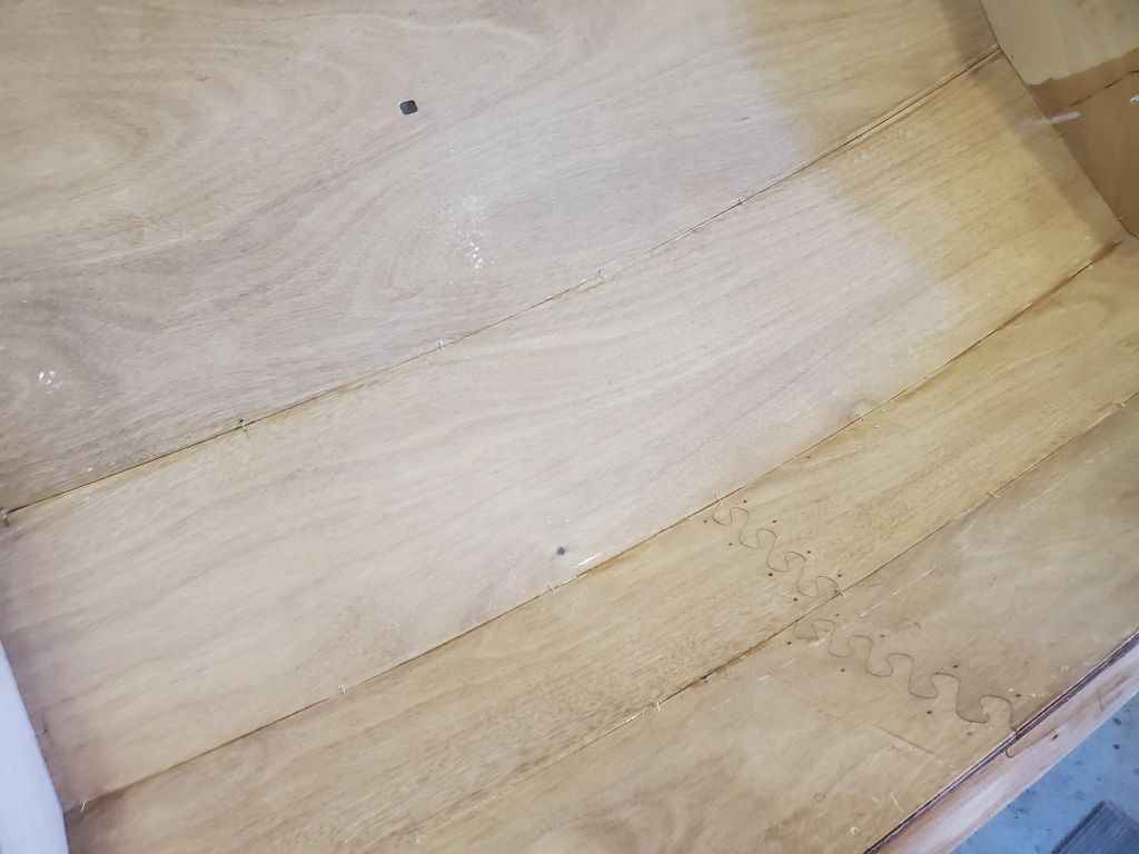
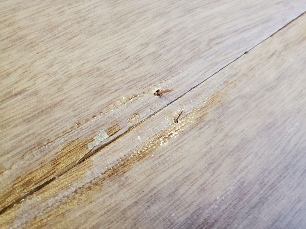
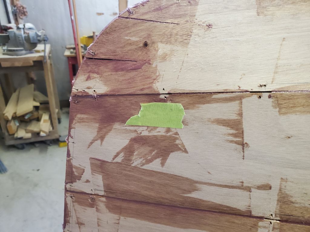
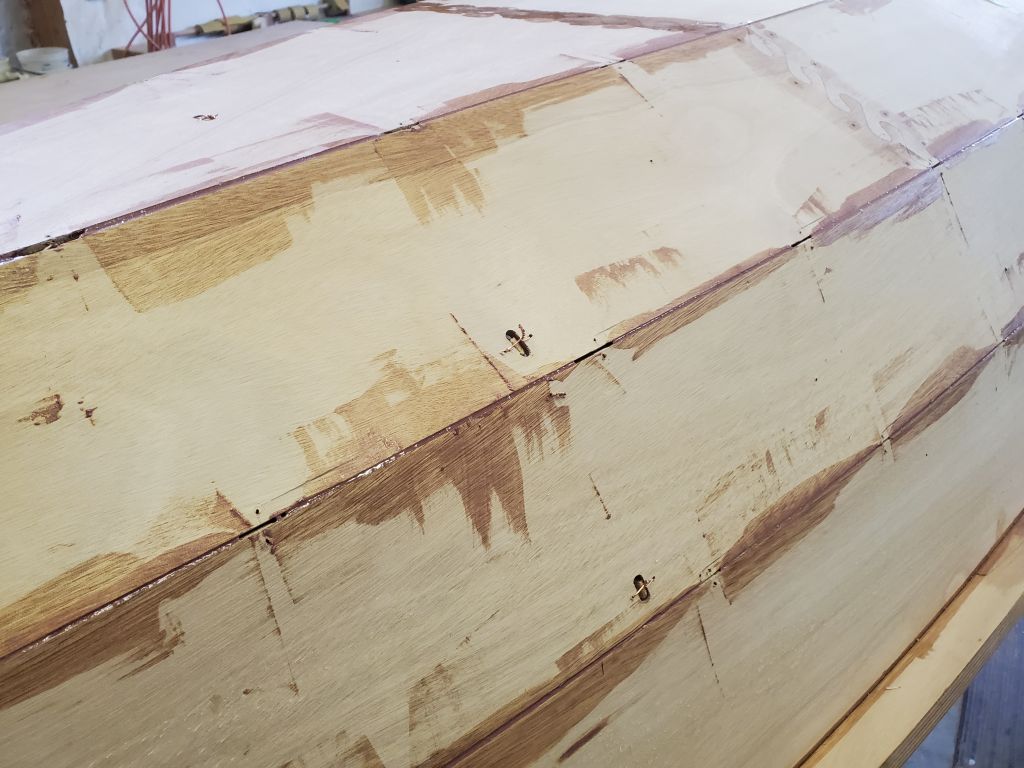
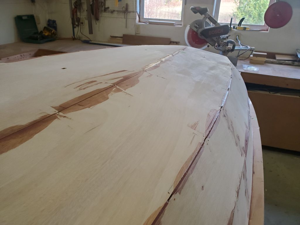
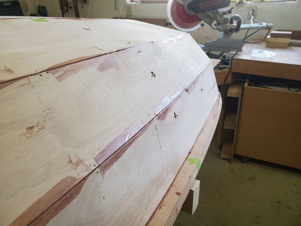
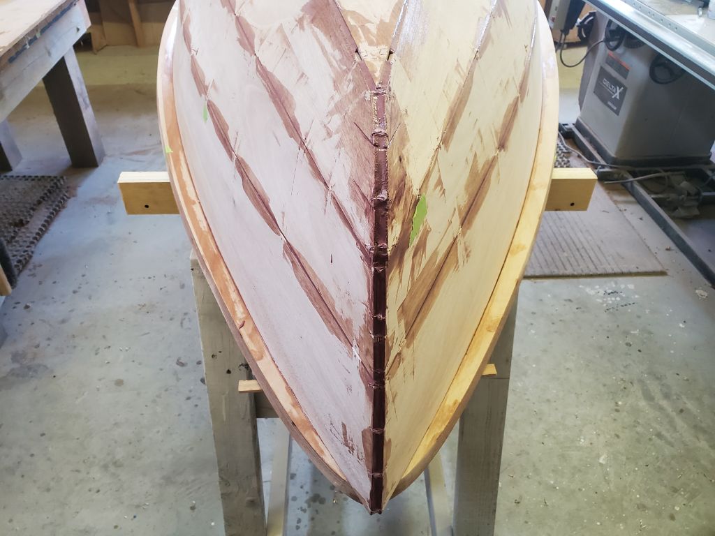
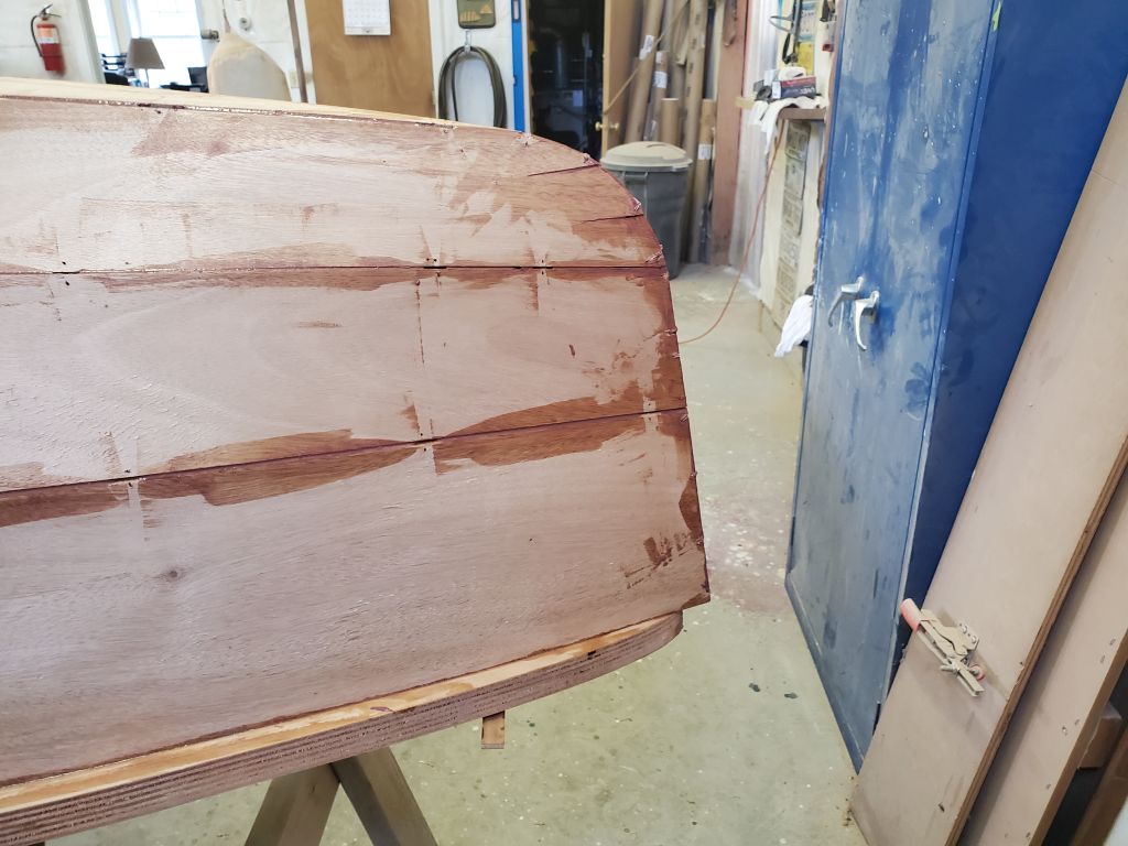
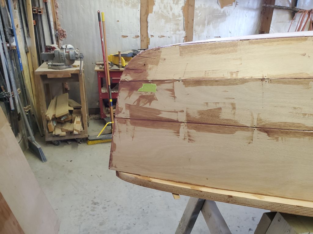
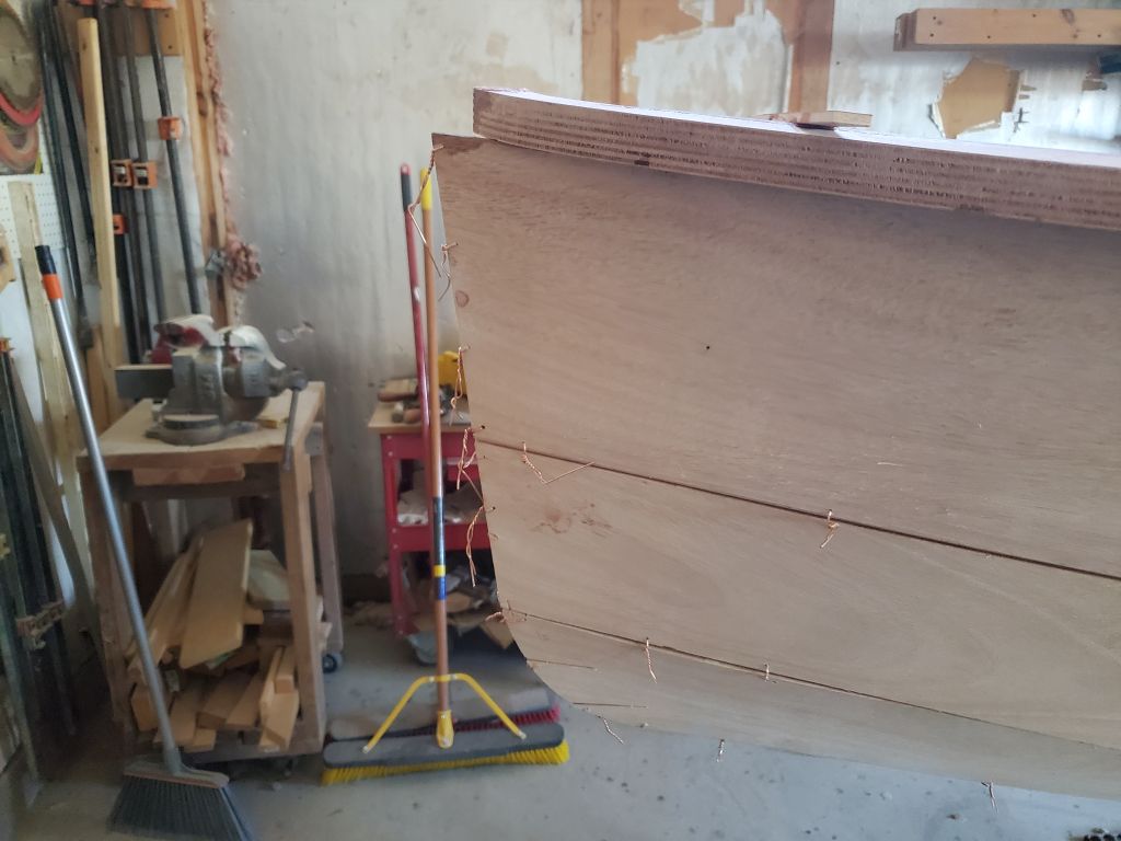
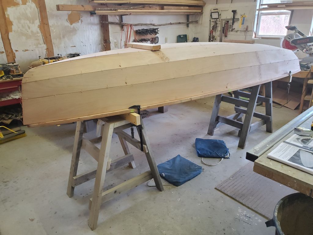
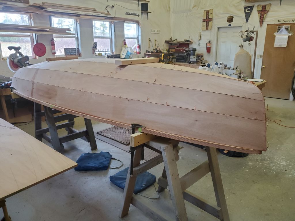
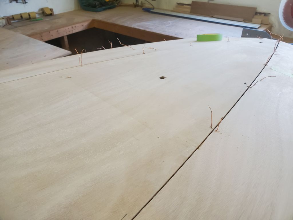
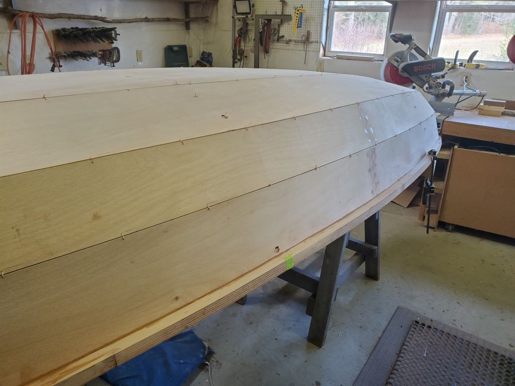
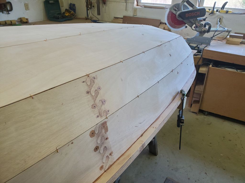
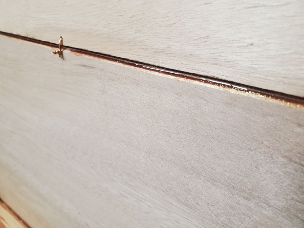
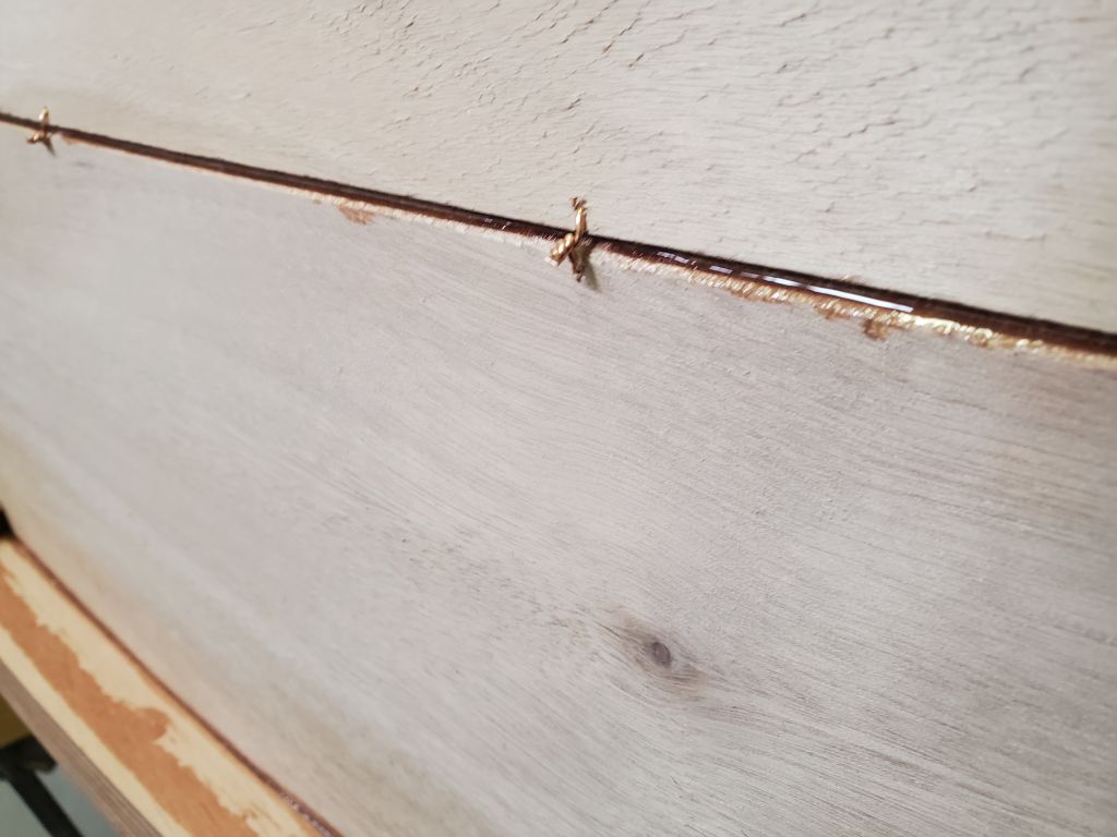
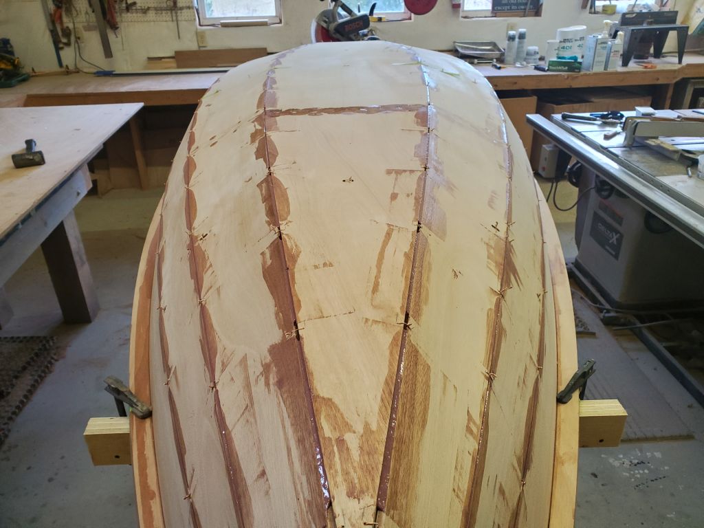
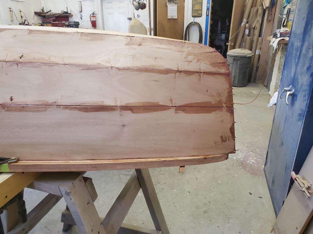
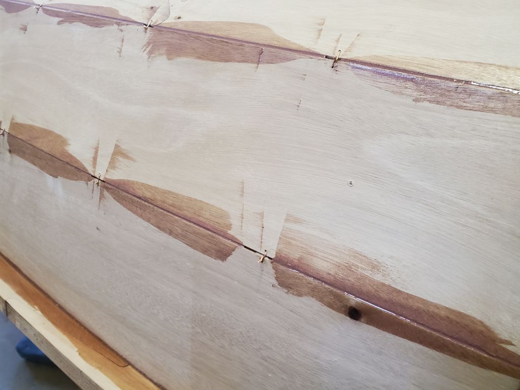
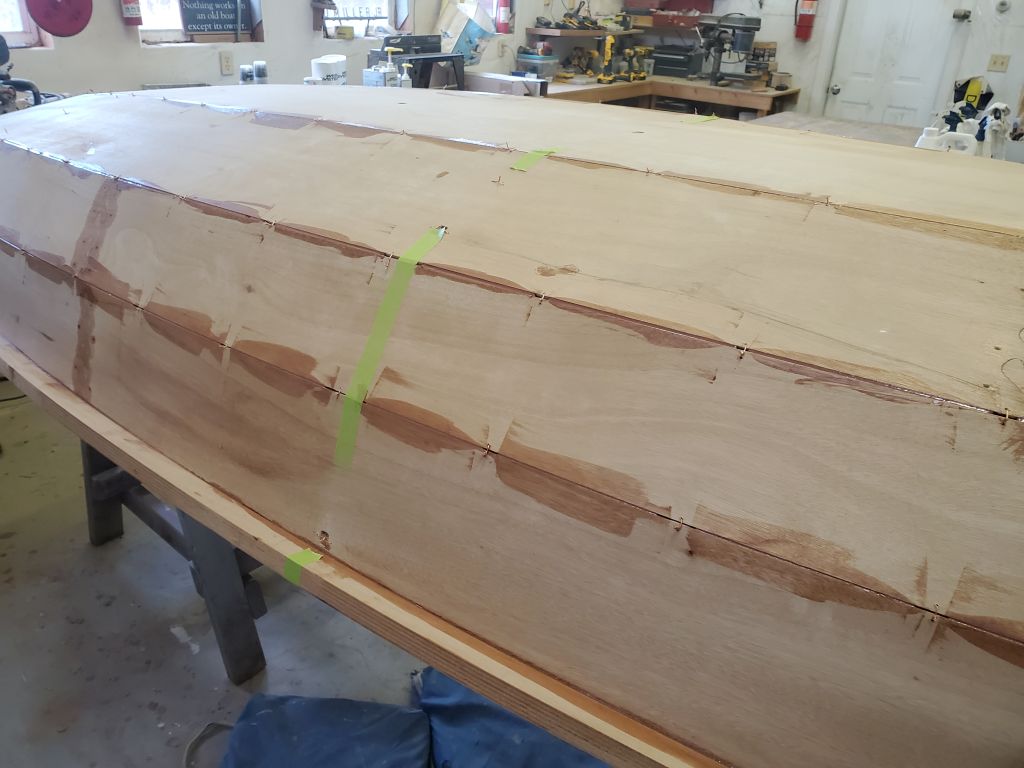
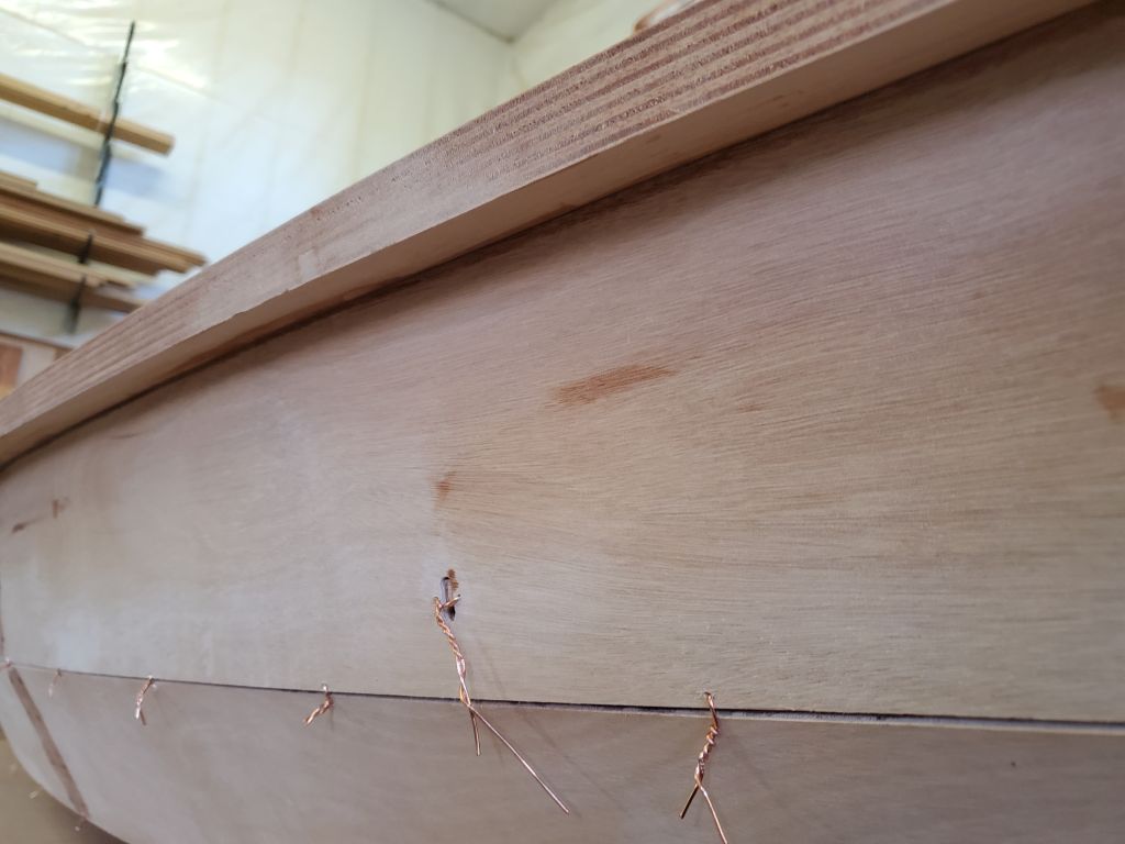
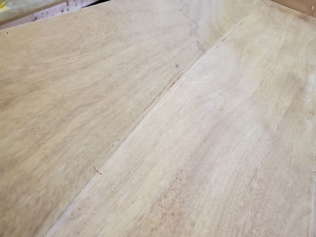
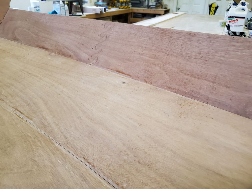
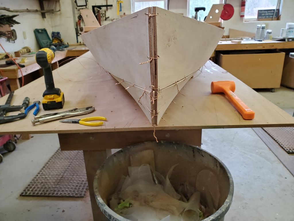
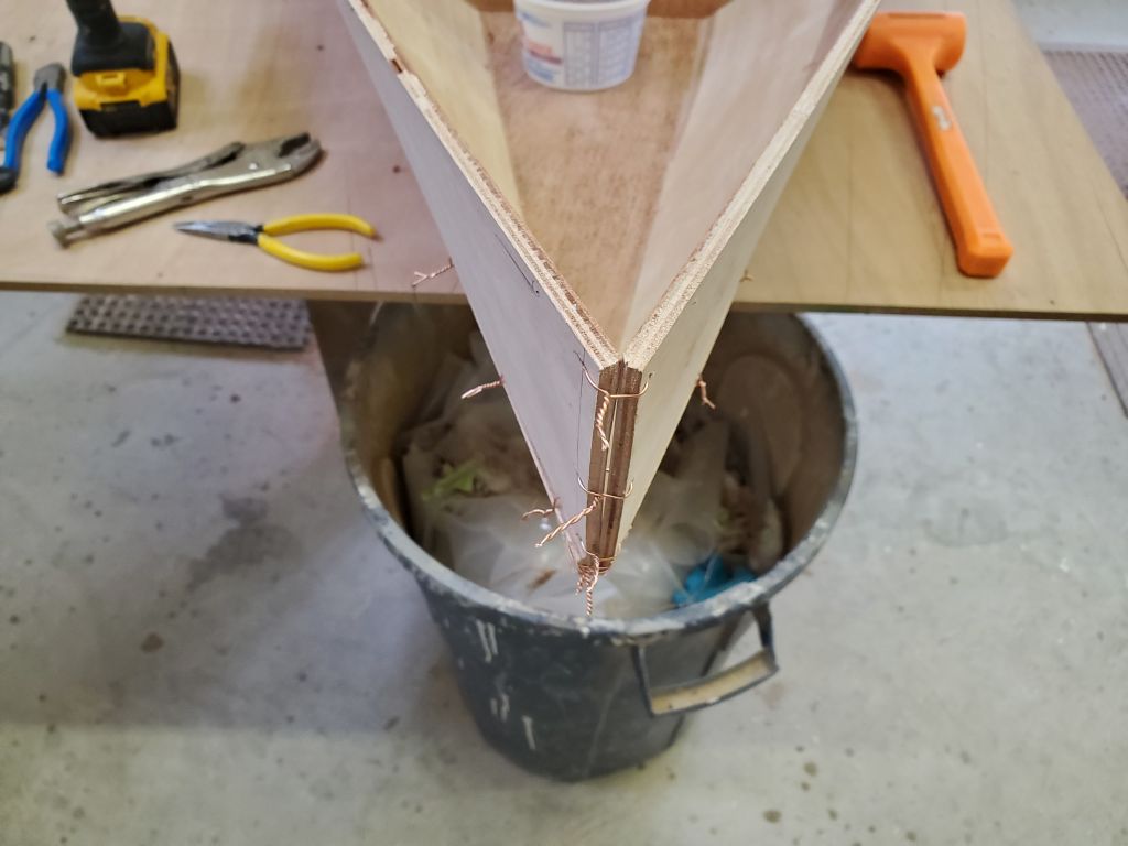
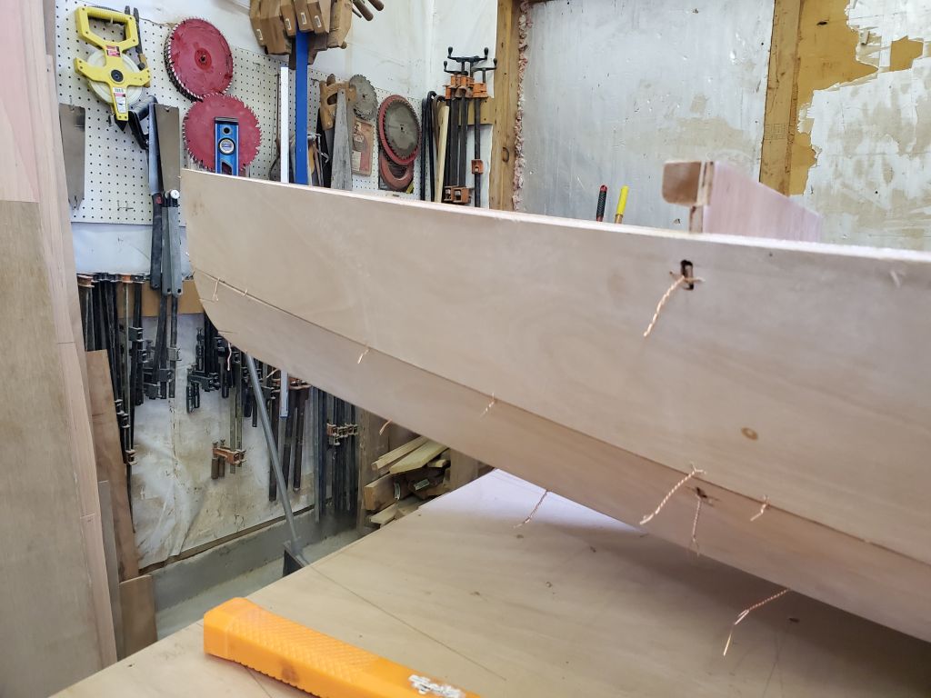
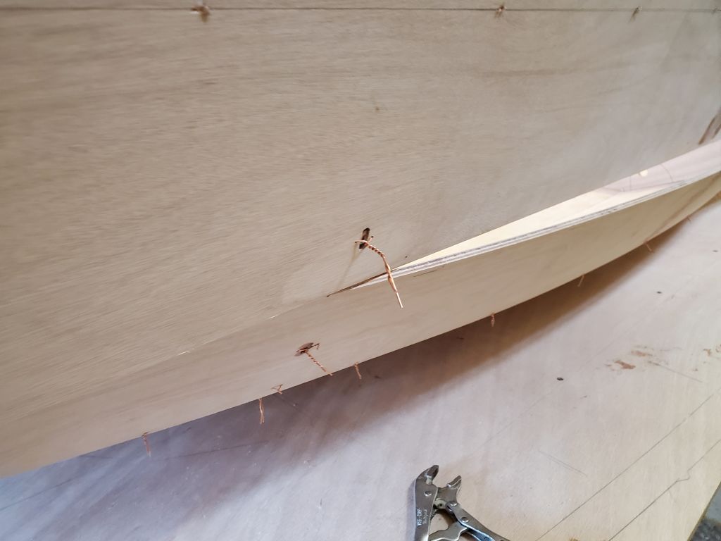
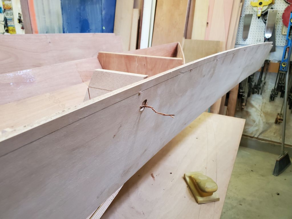
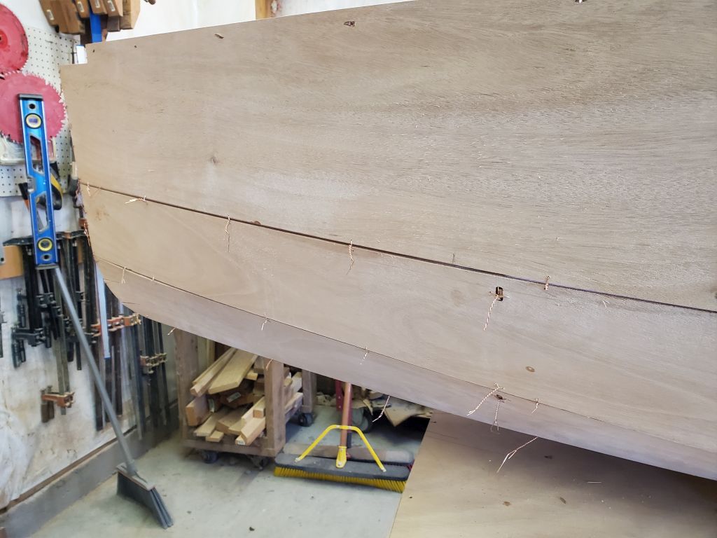
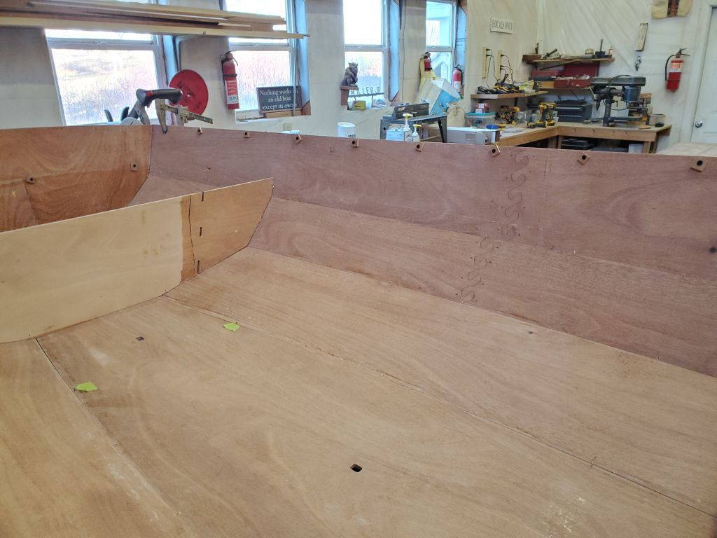
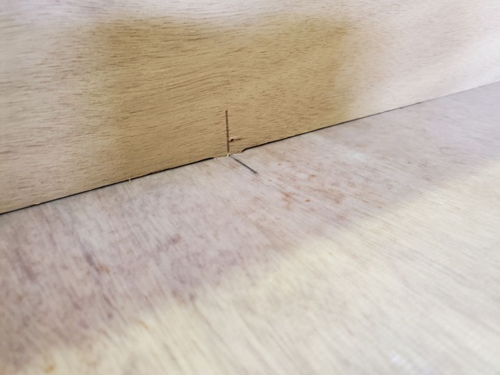
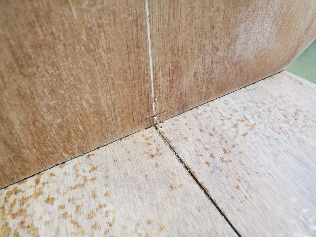
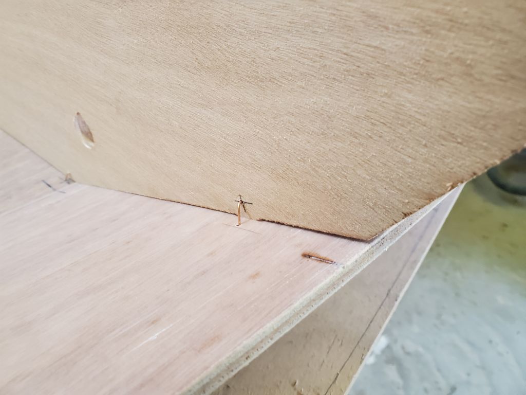
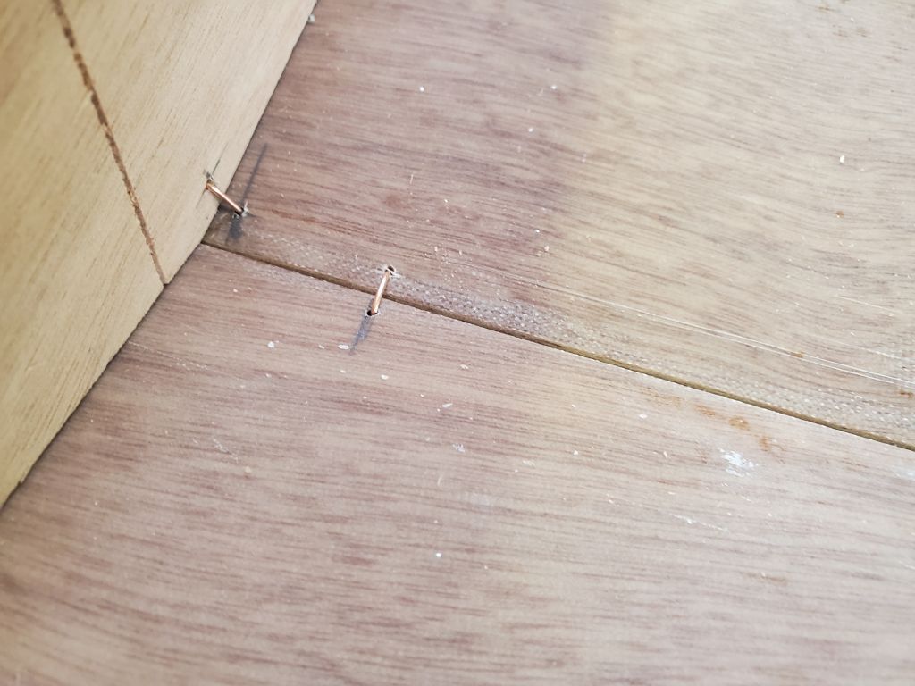
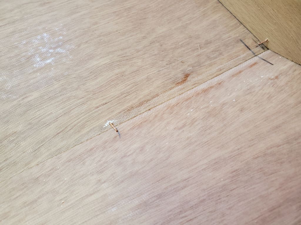
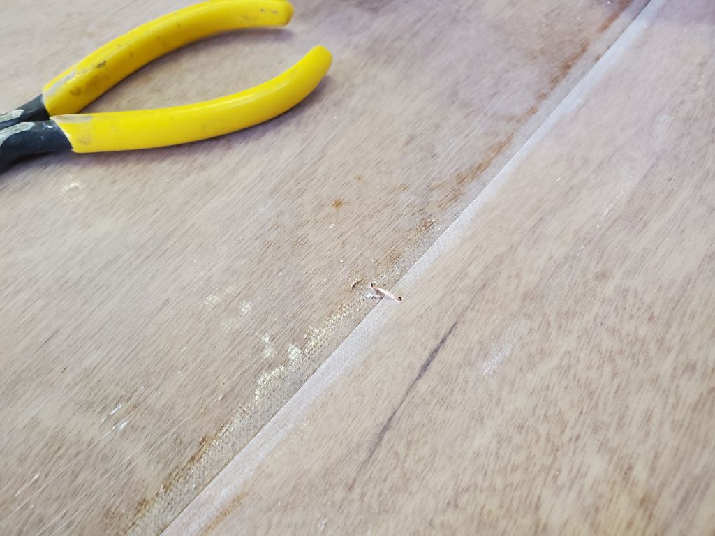
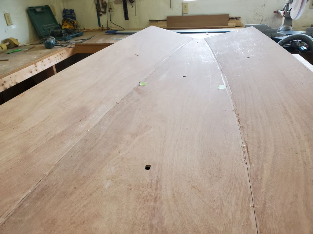
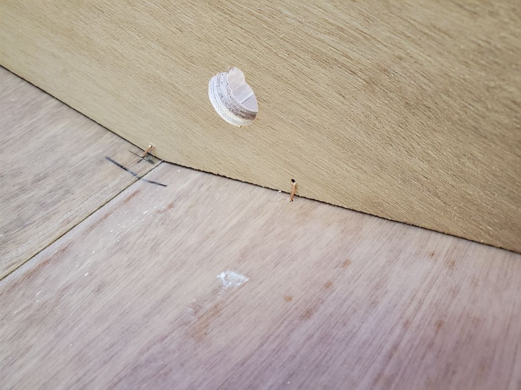
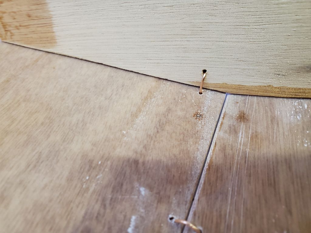
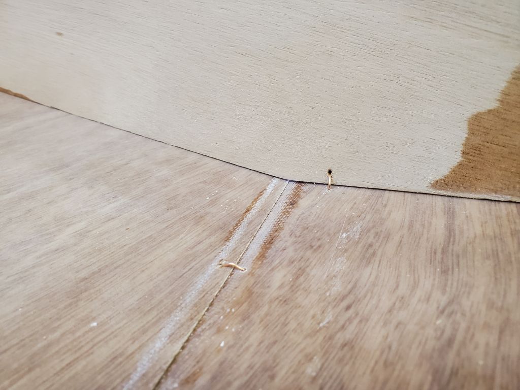
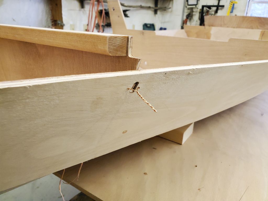
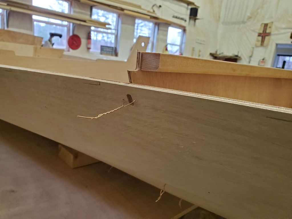
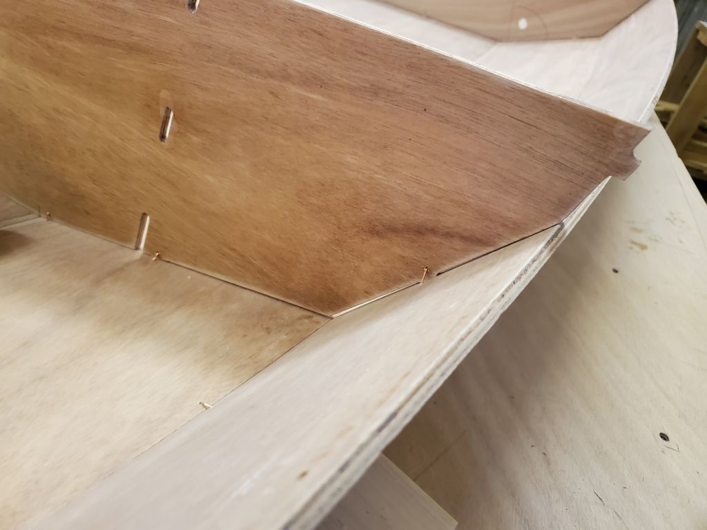
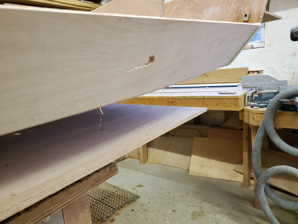
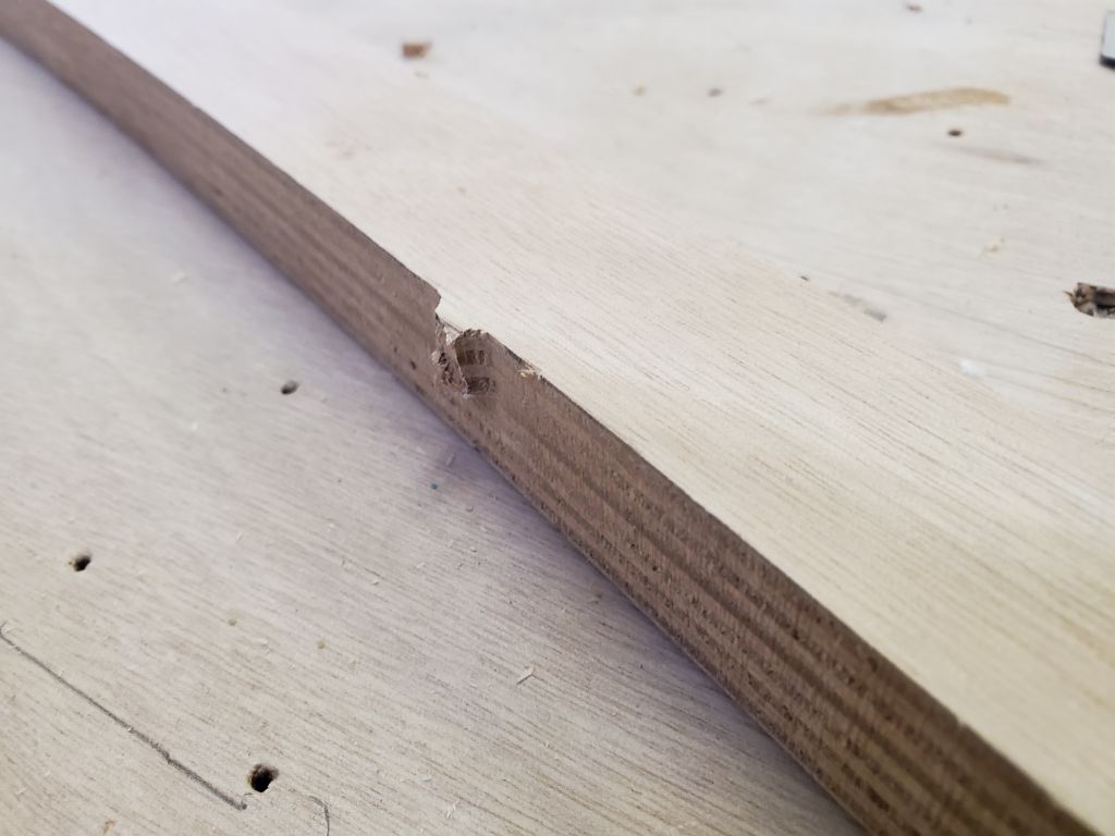
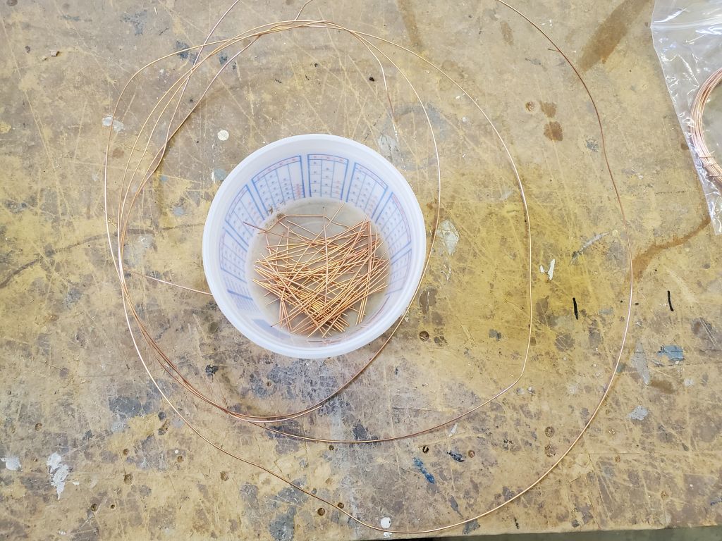
Next I flipped the boat back upside down, and pulled out all the wires from the outside. This posed no issues, though in two or three locations the wire broke off before pulling completely free, so I marked these spots with tape so I could remember to pull what remained of the wire from inside when I flipped the boat back over.
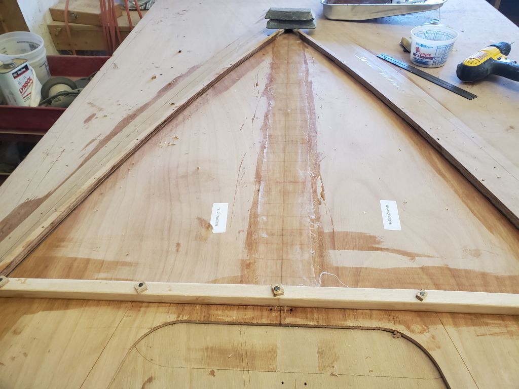
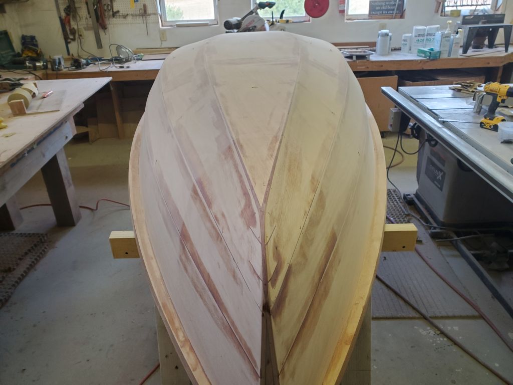
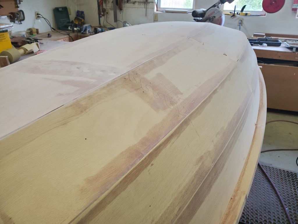
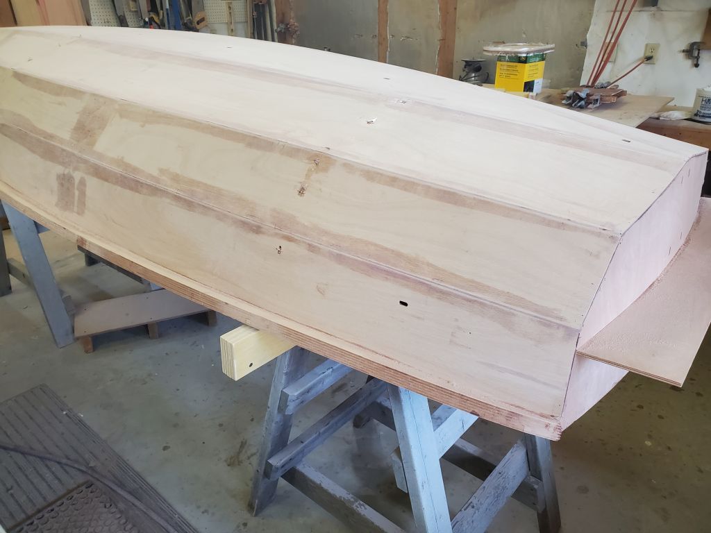
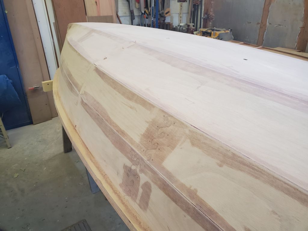
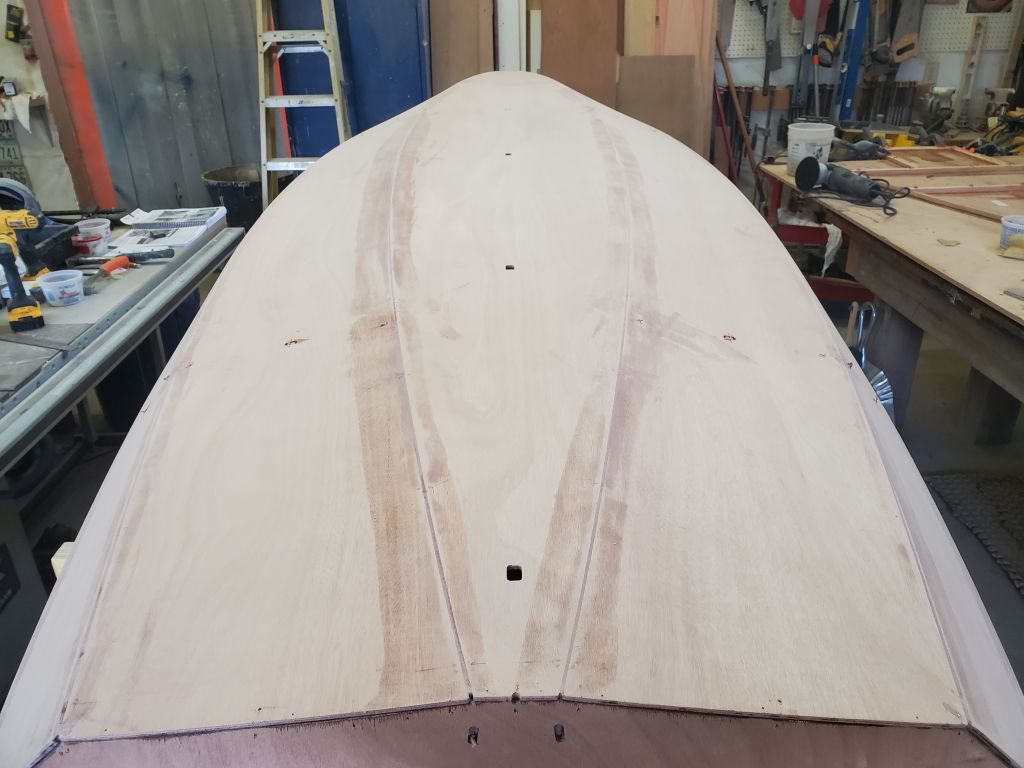
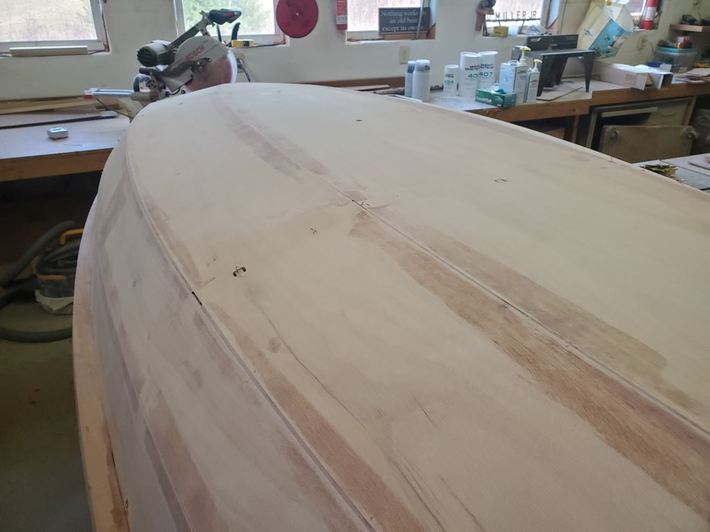
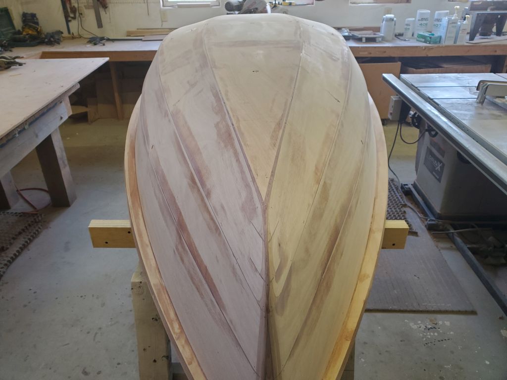
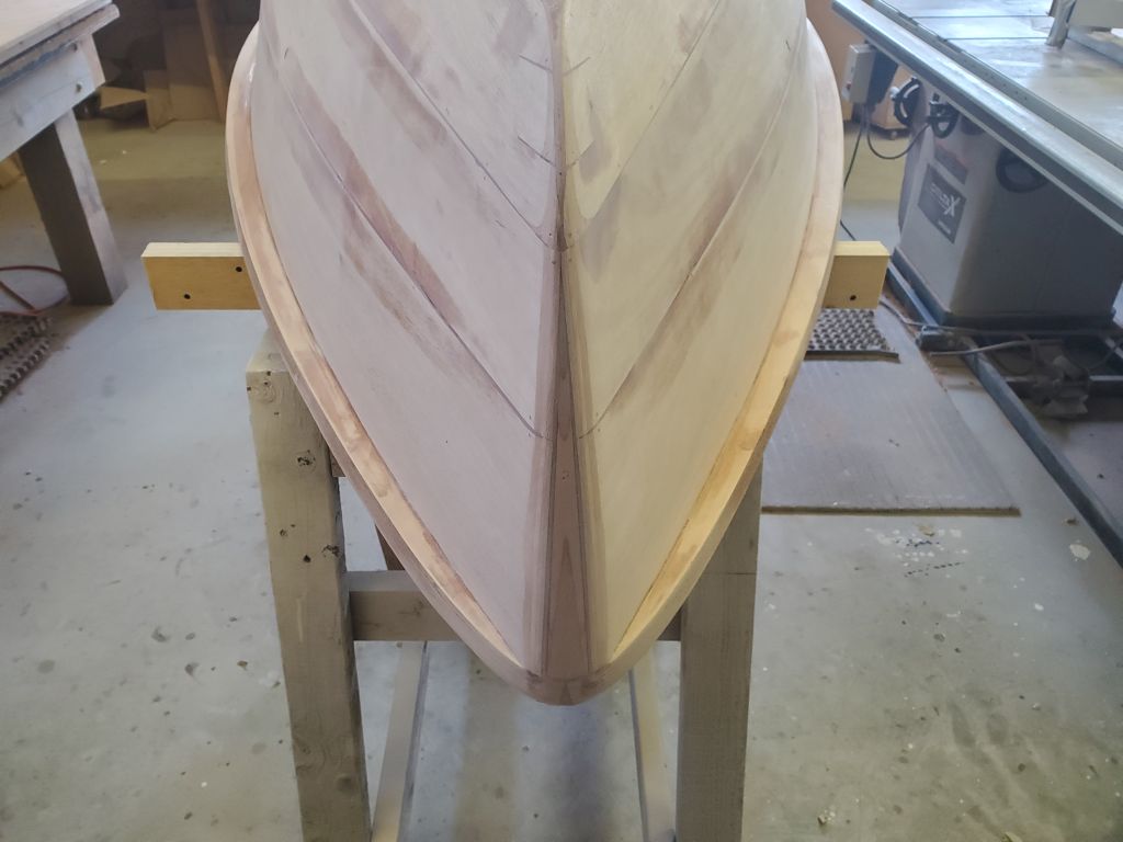
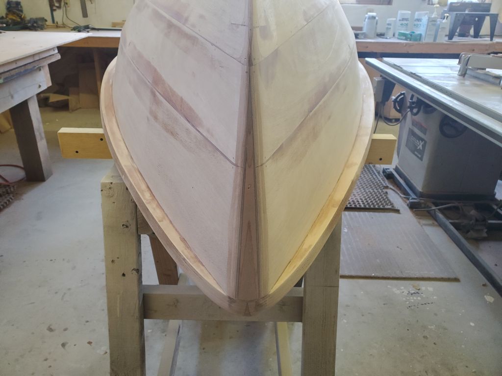
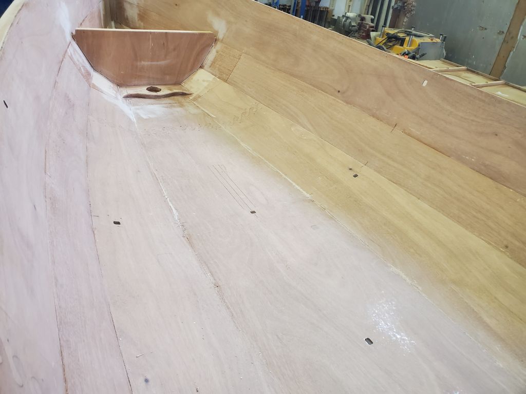
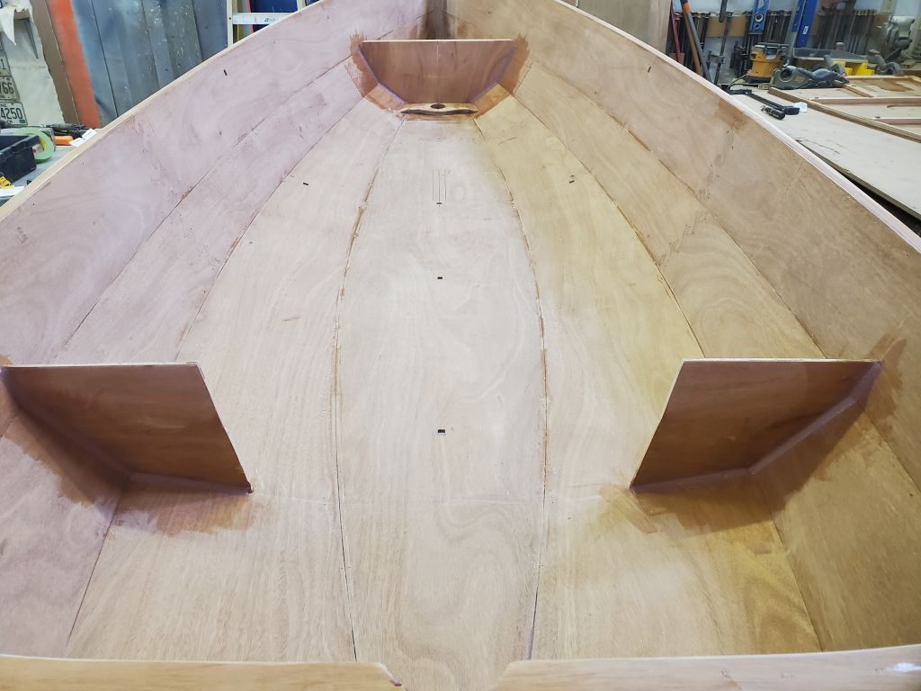
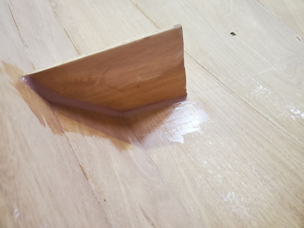
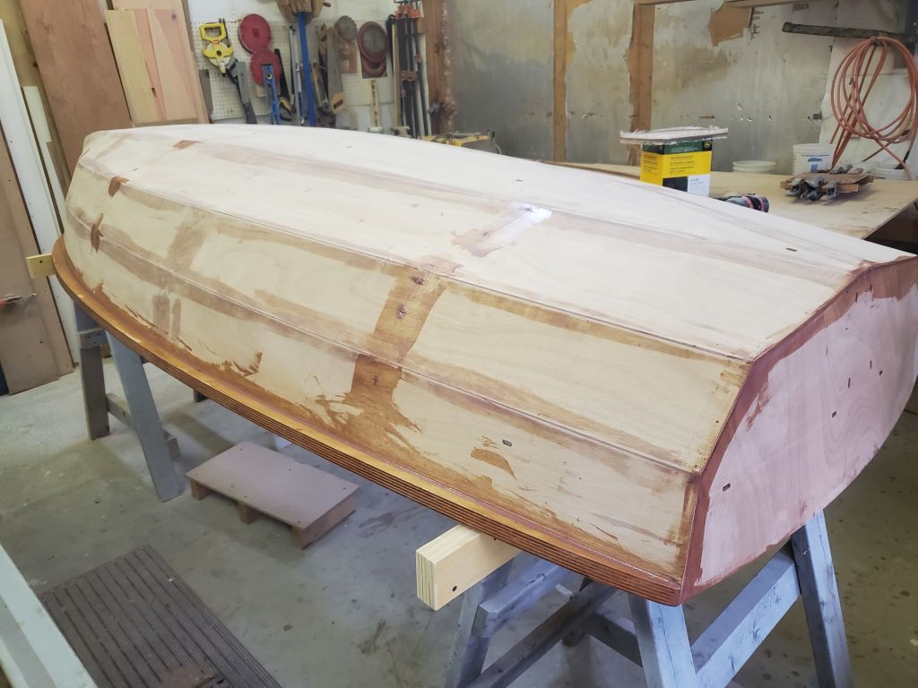
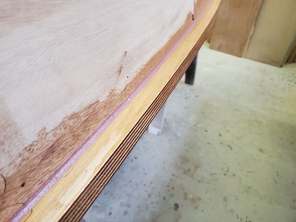
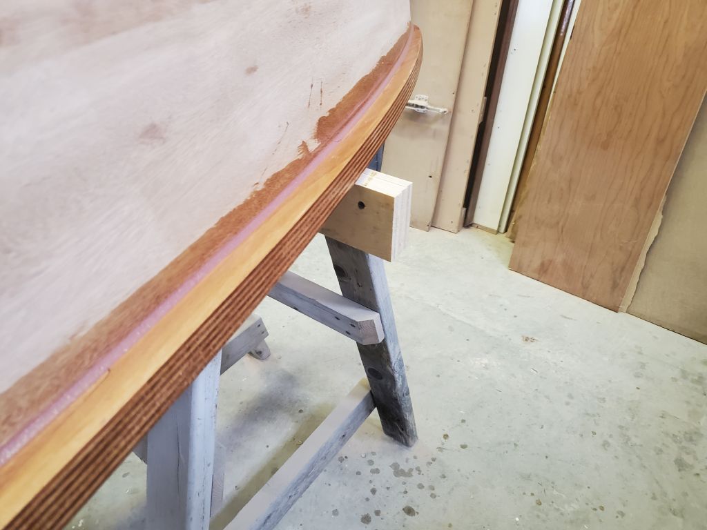
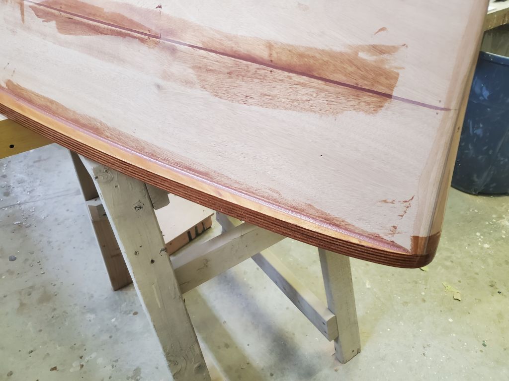
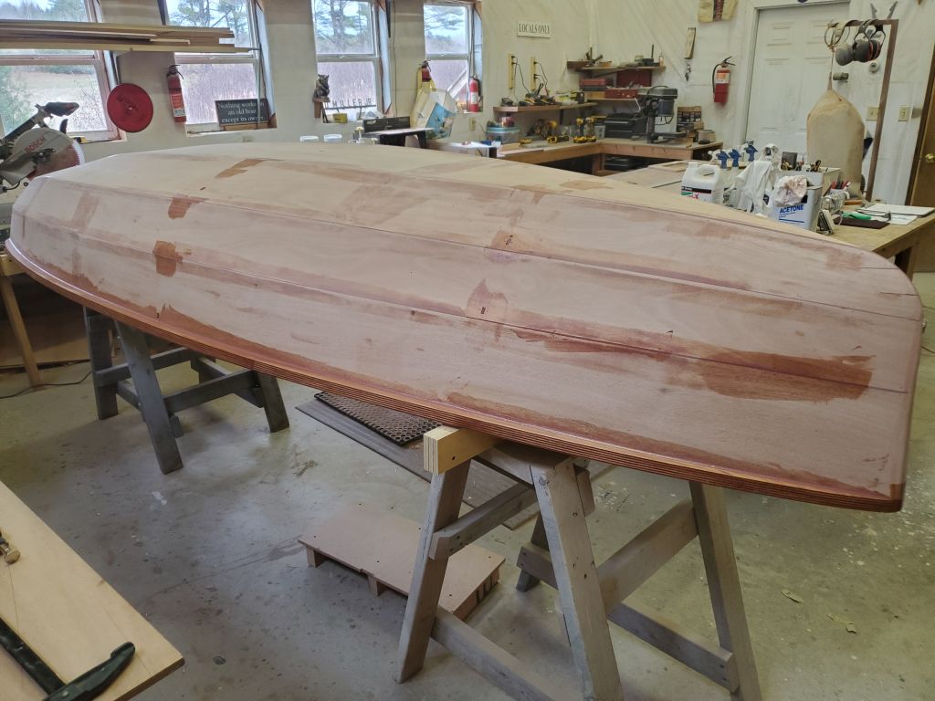
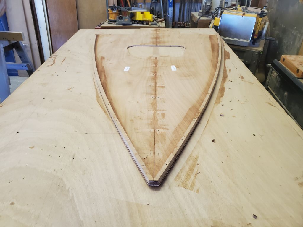
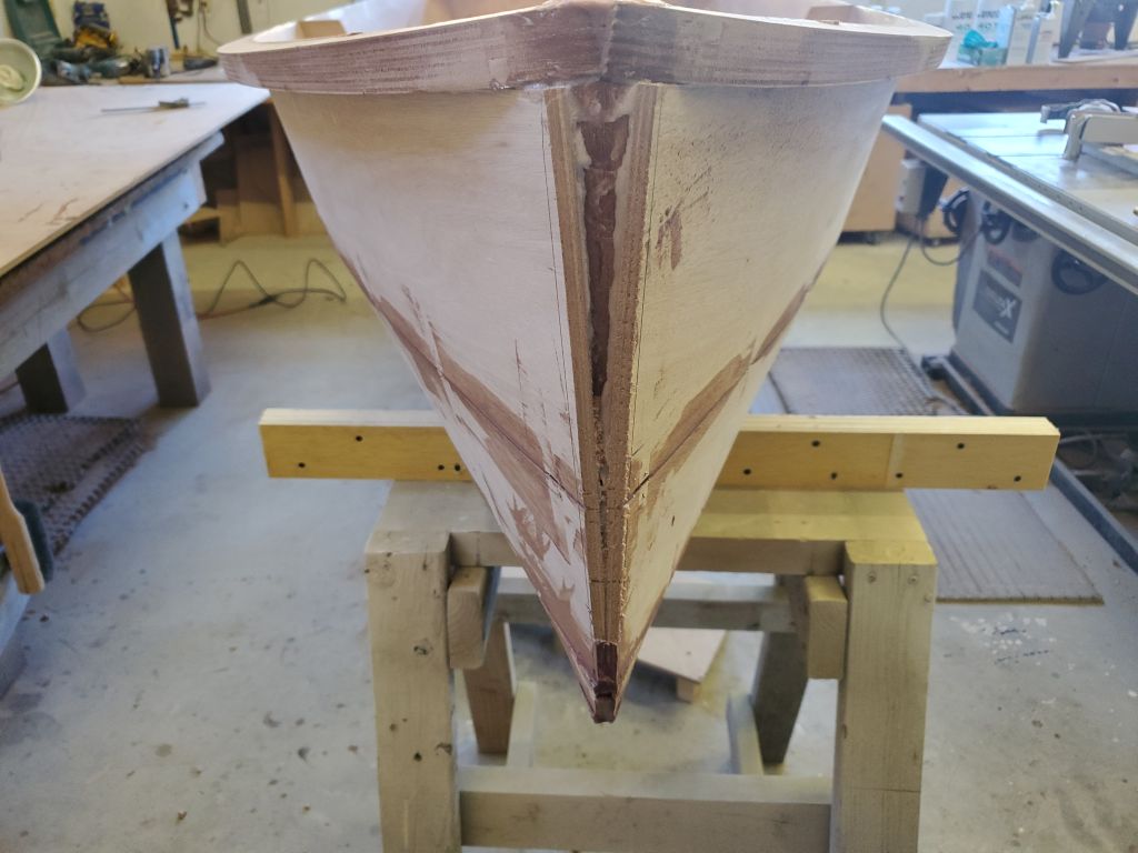
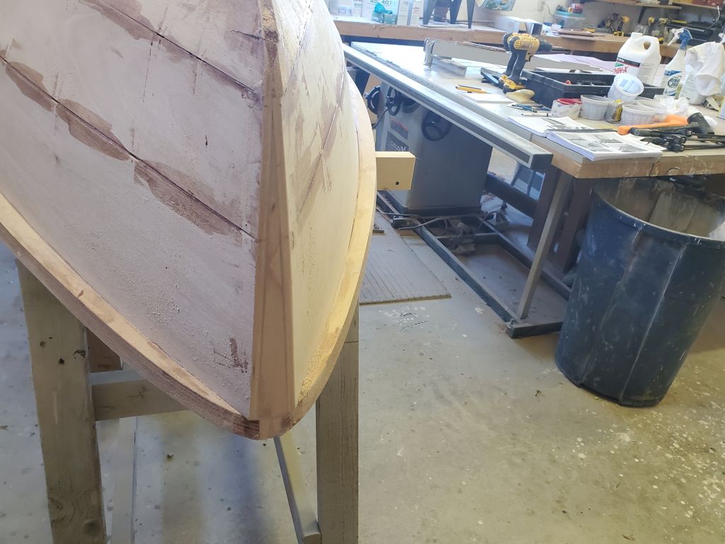
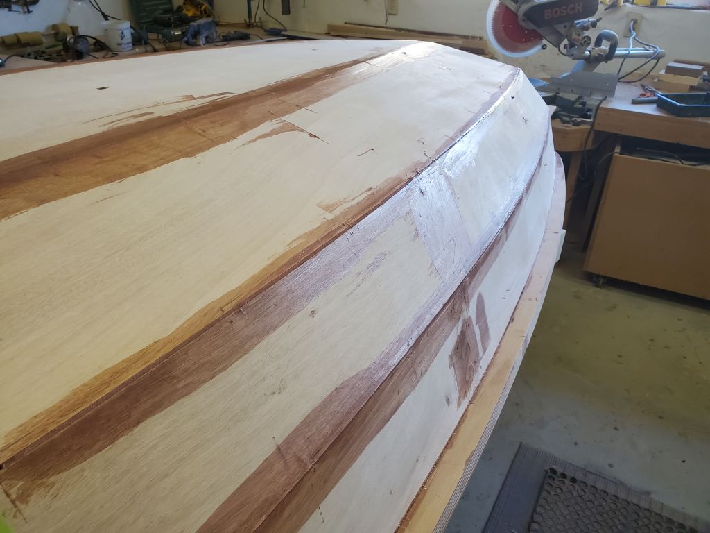
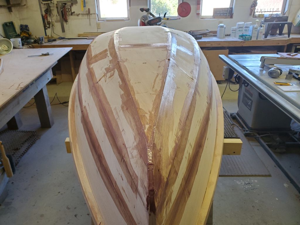
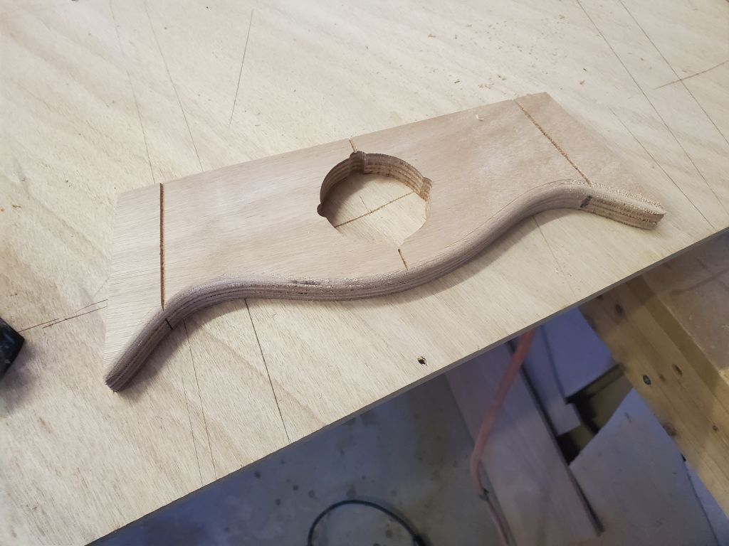
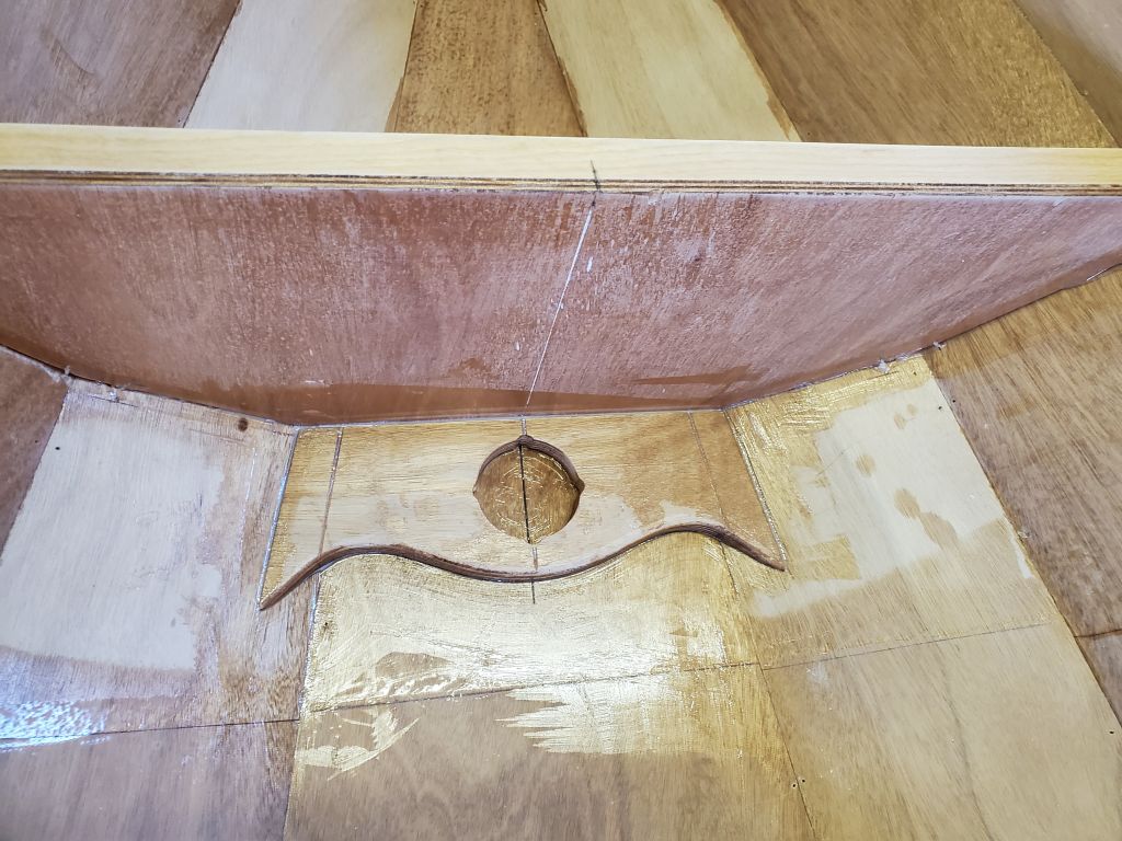
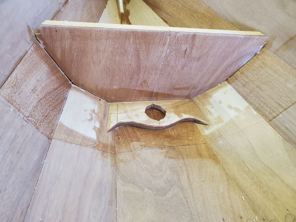
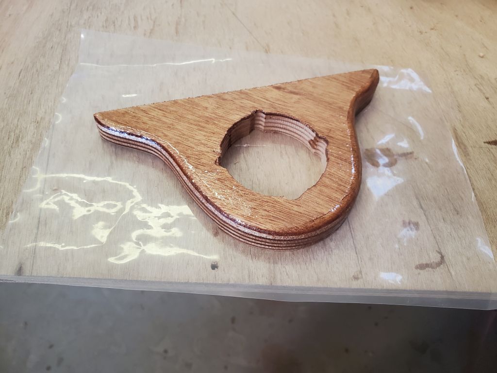
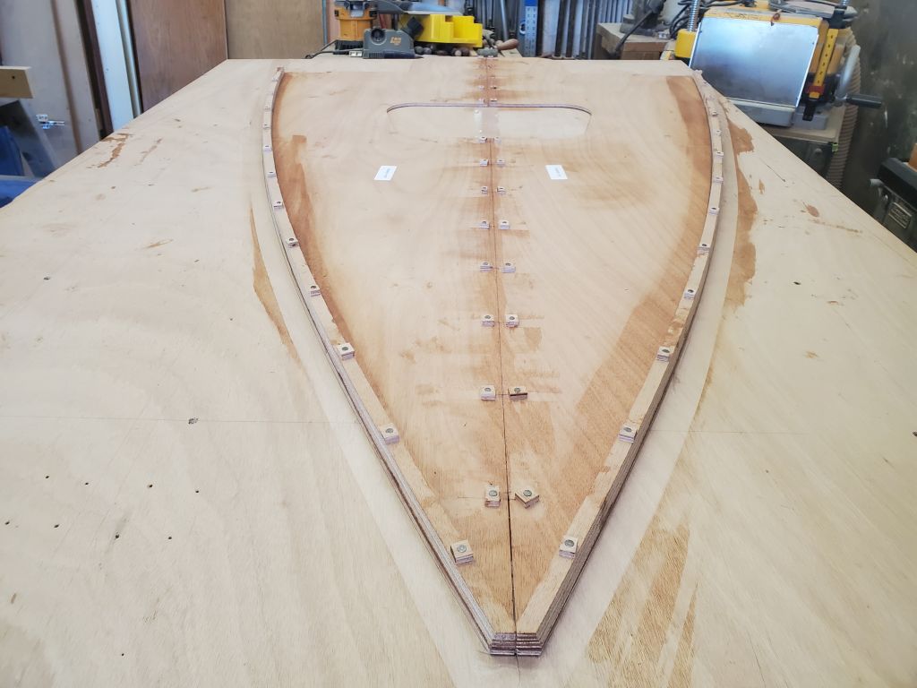
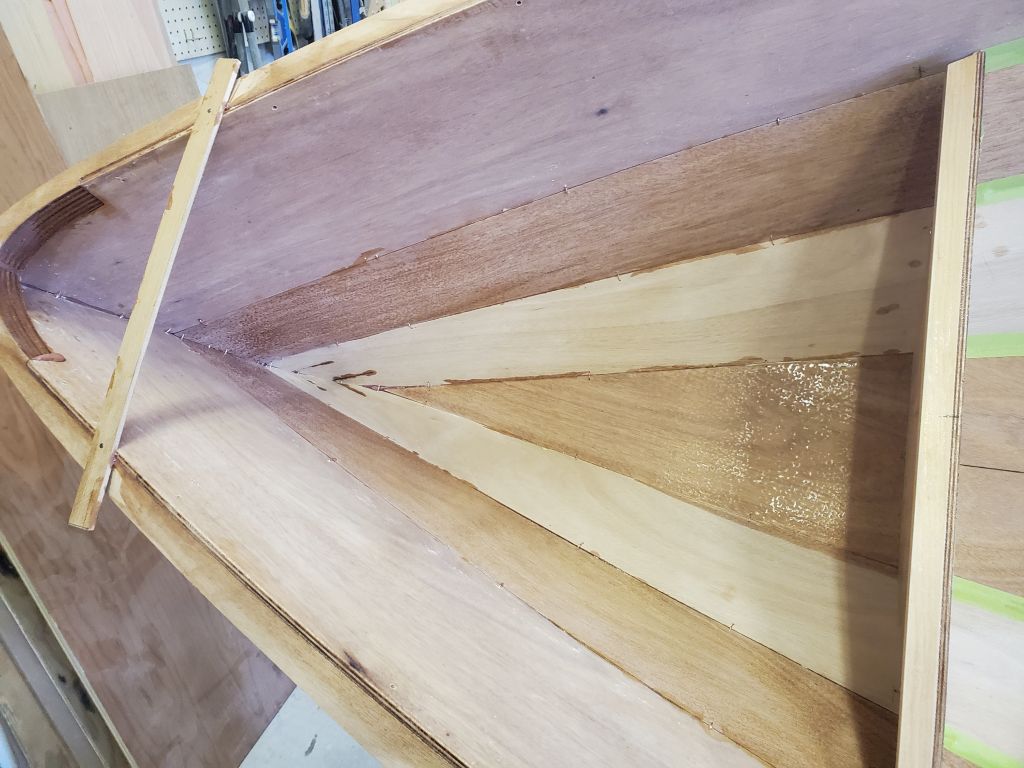
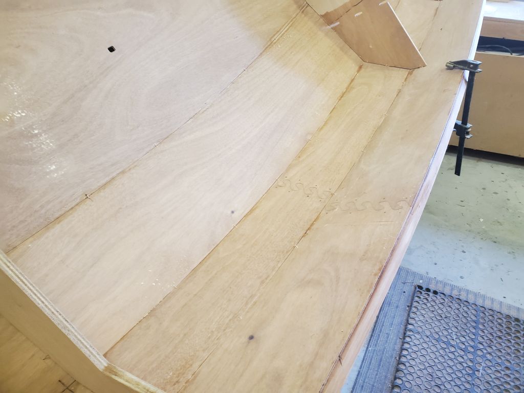
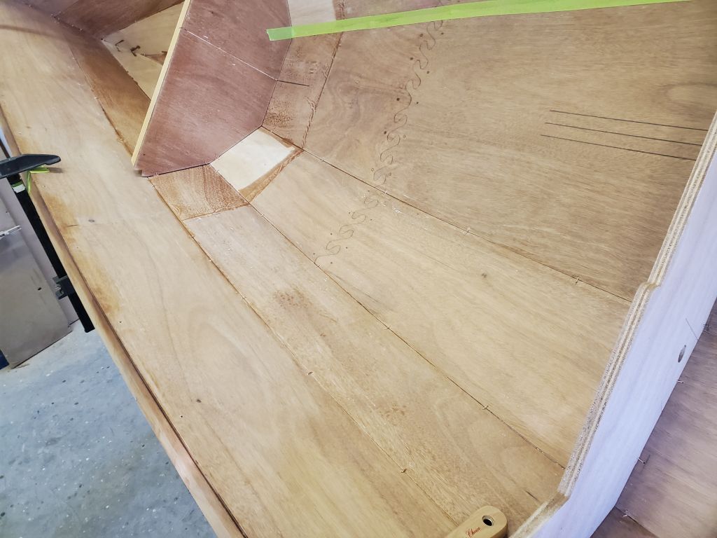
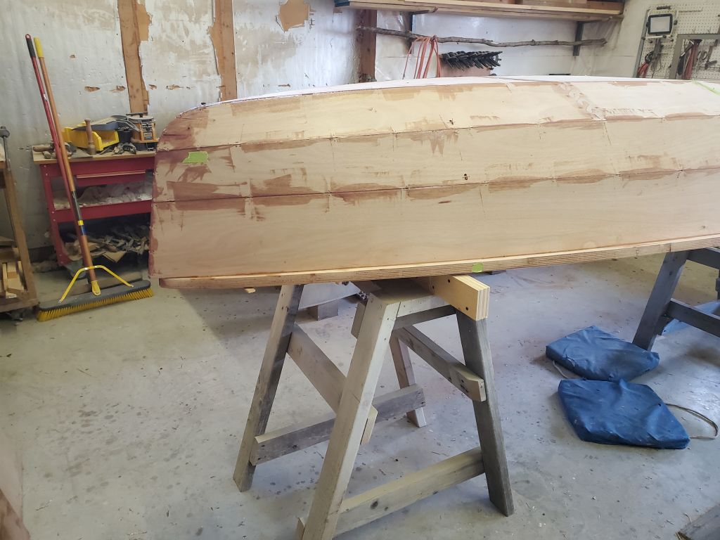
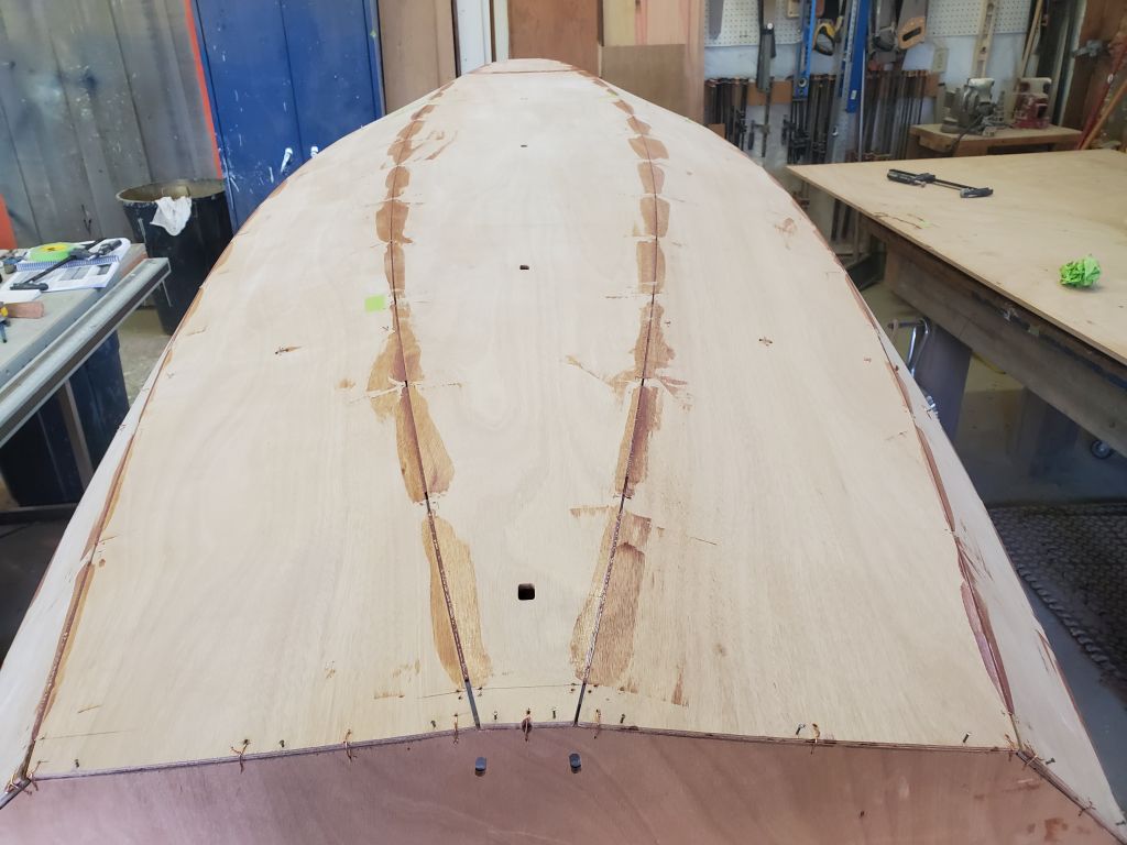
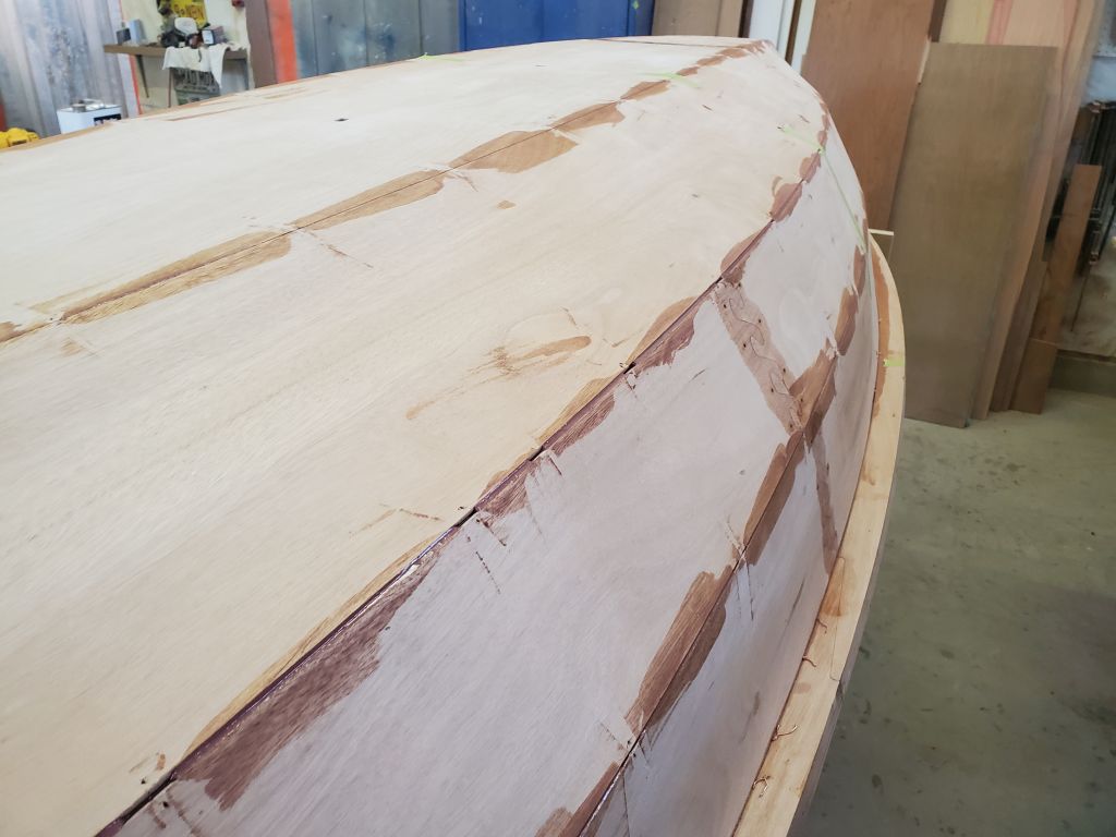
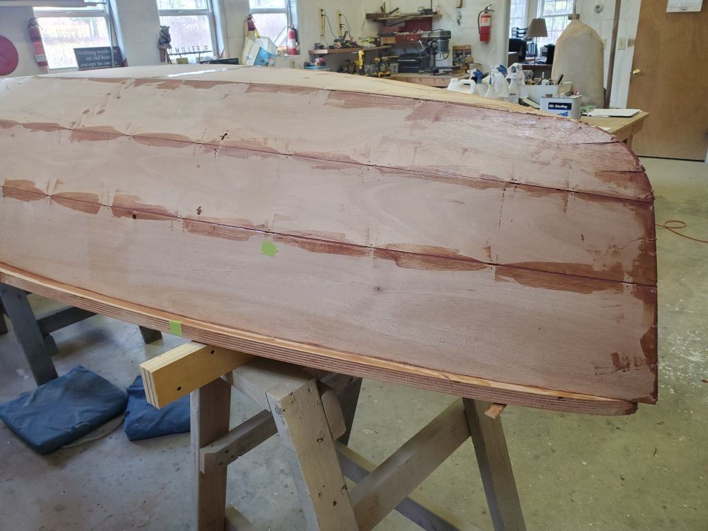
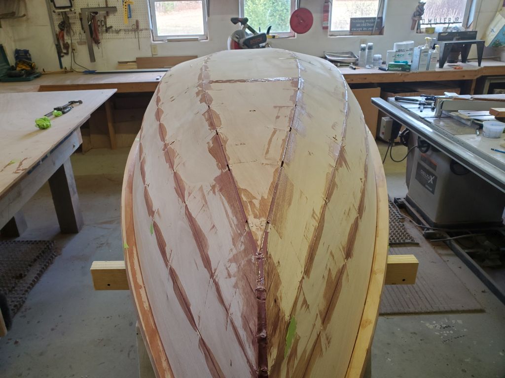
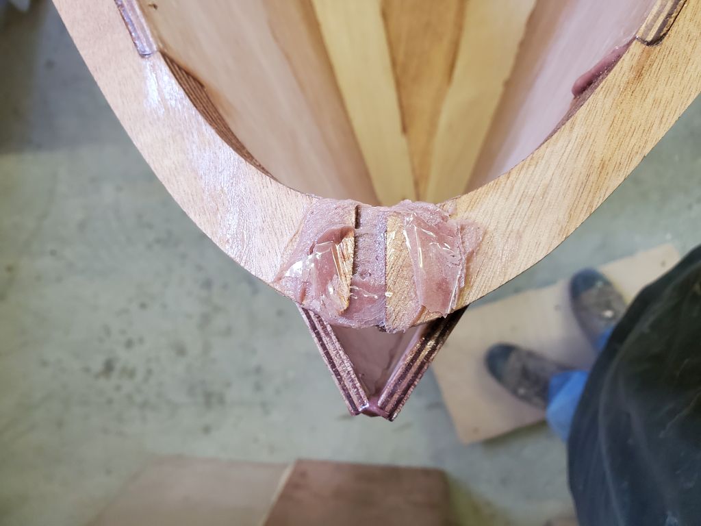
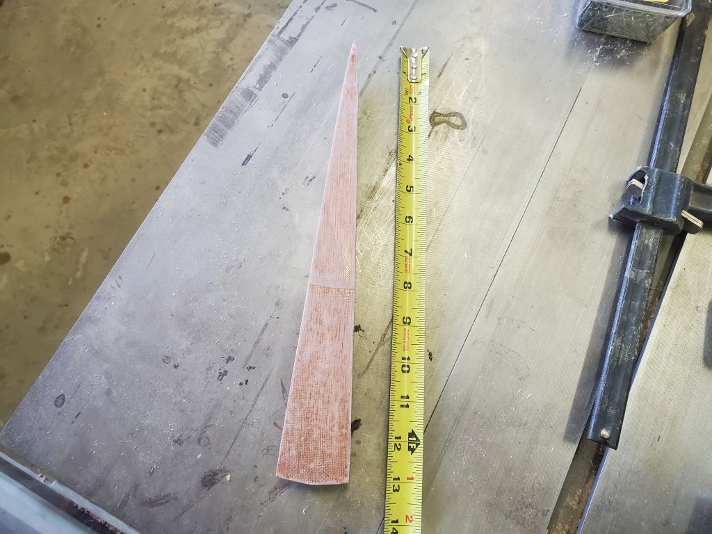
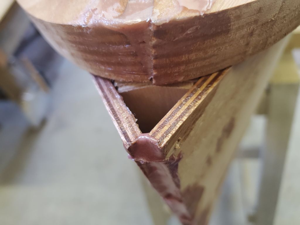
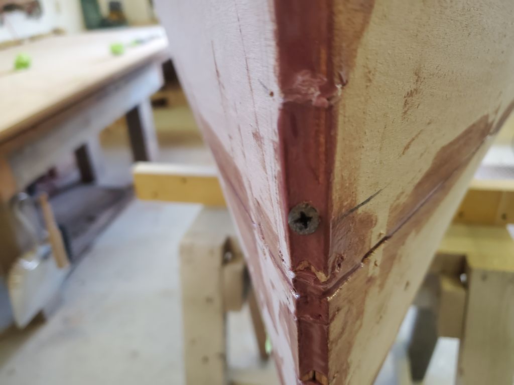
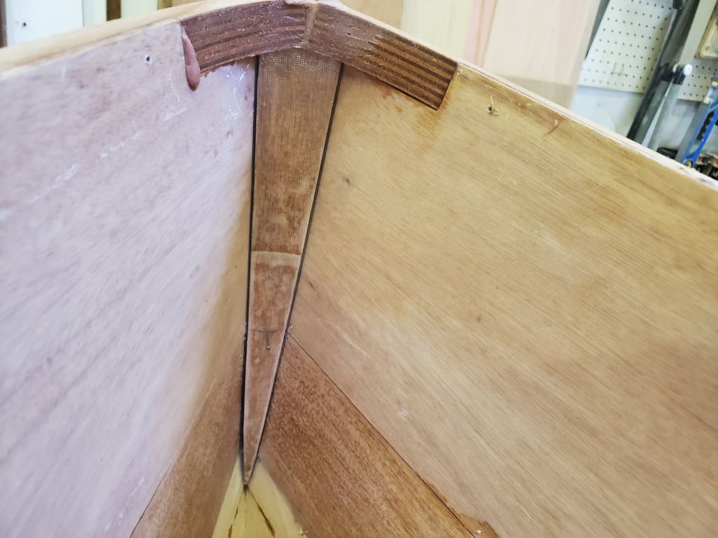
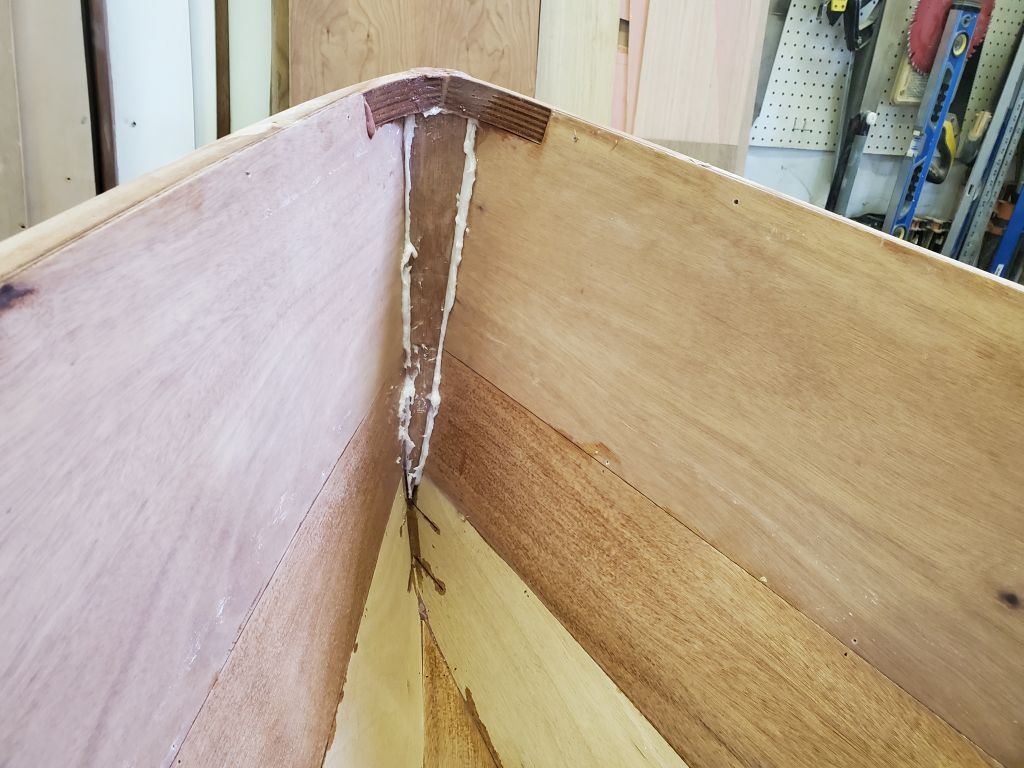
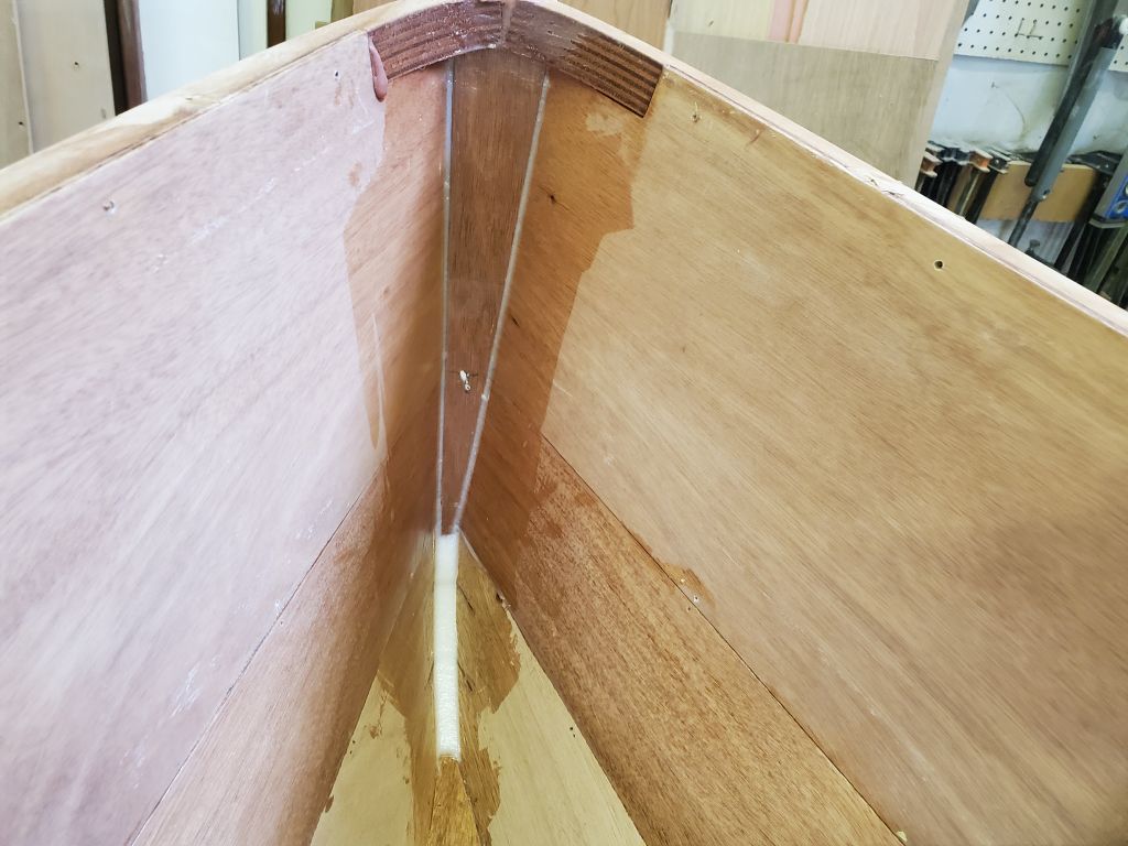
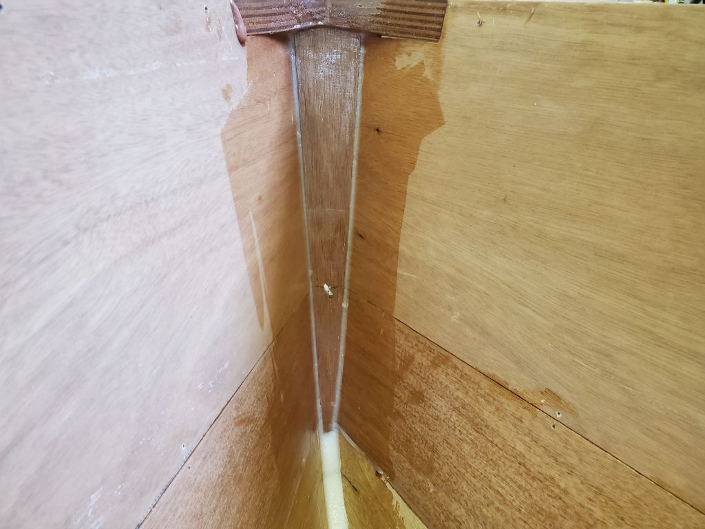
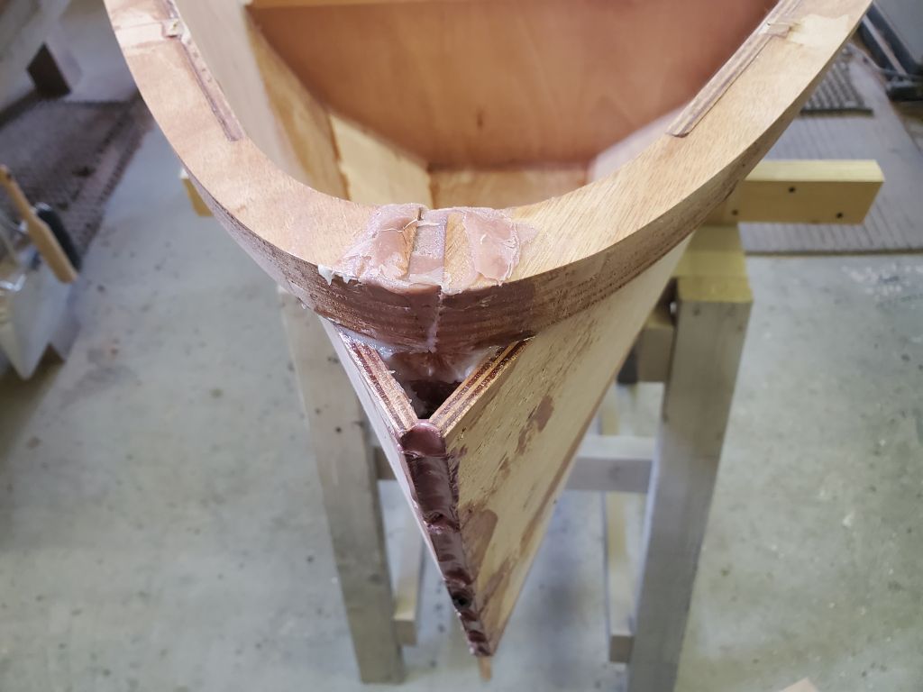
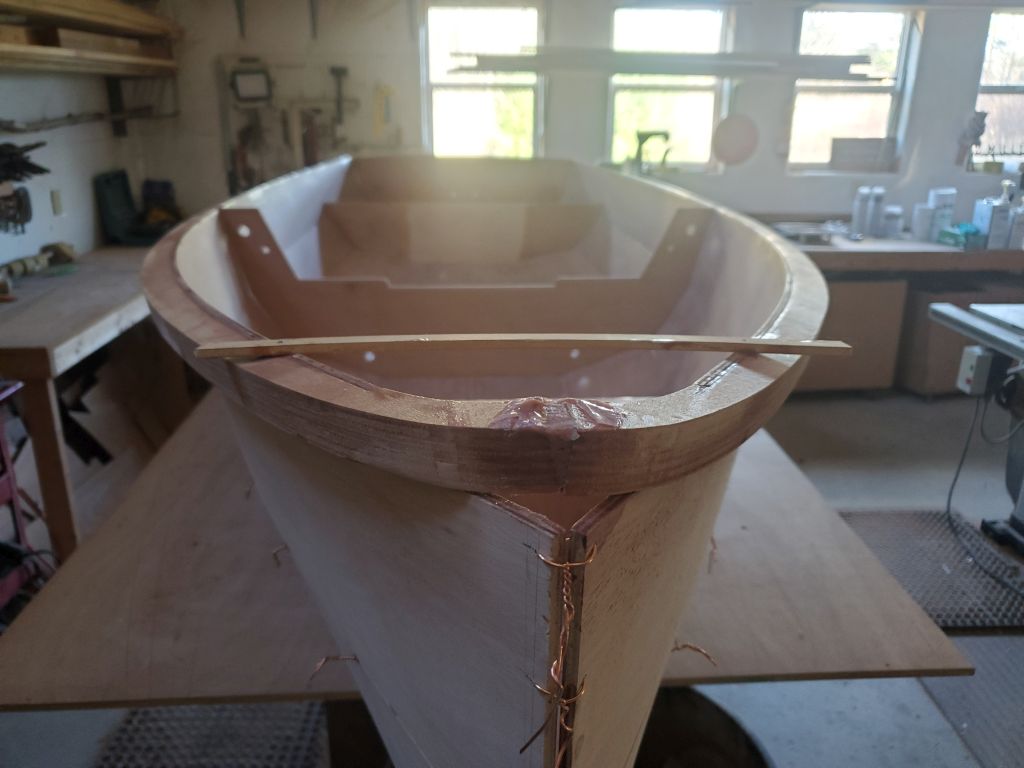
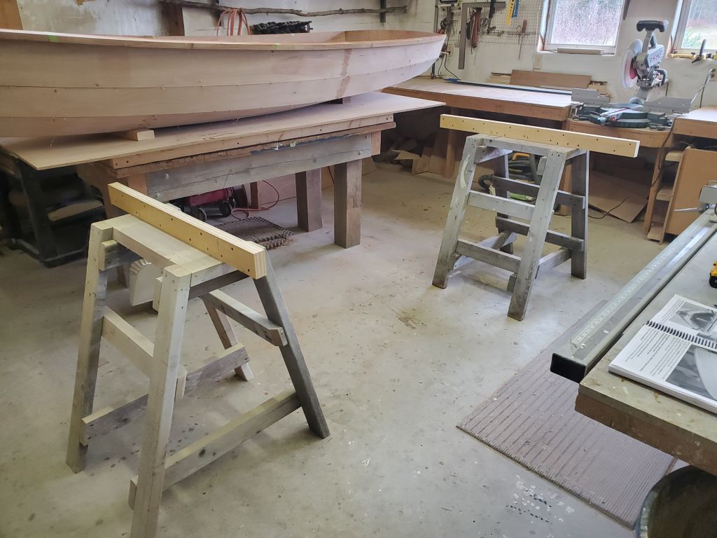
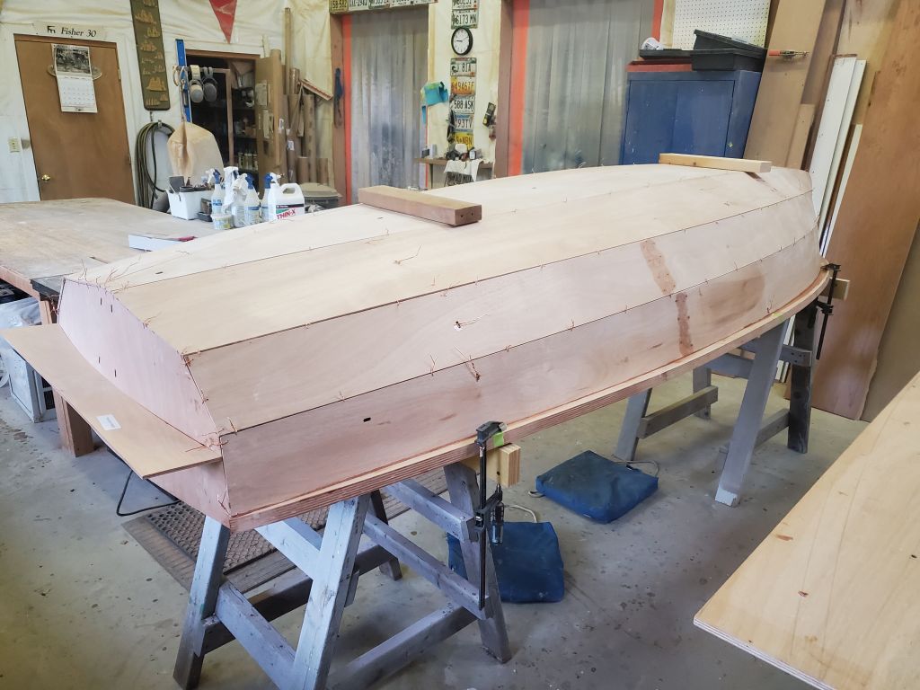
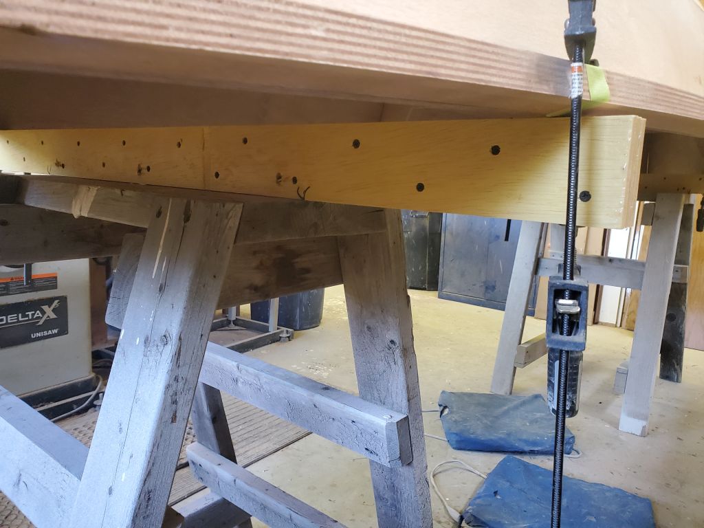
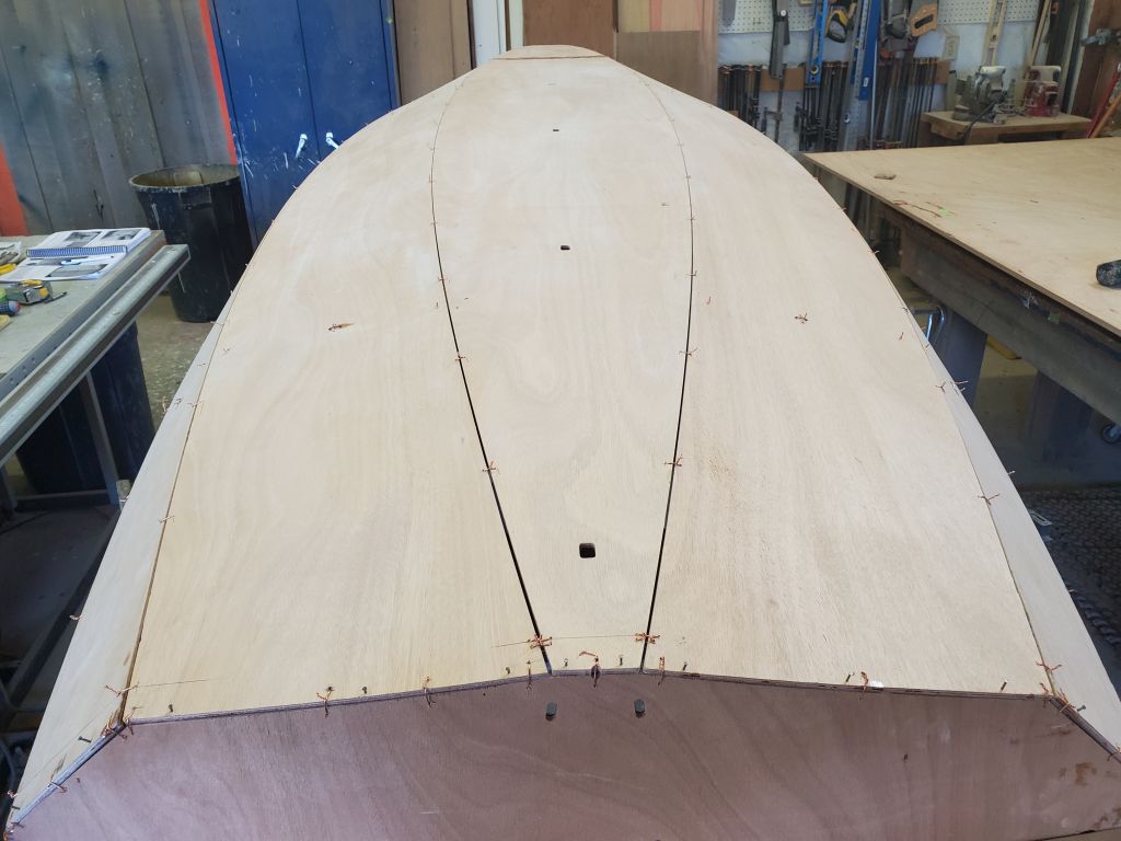
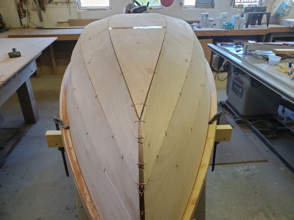
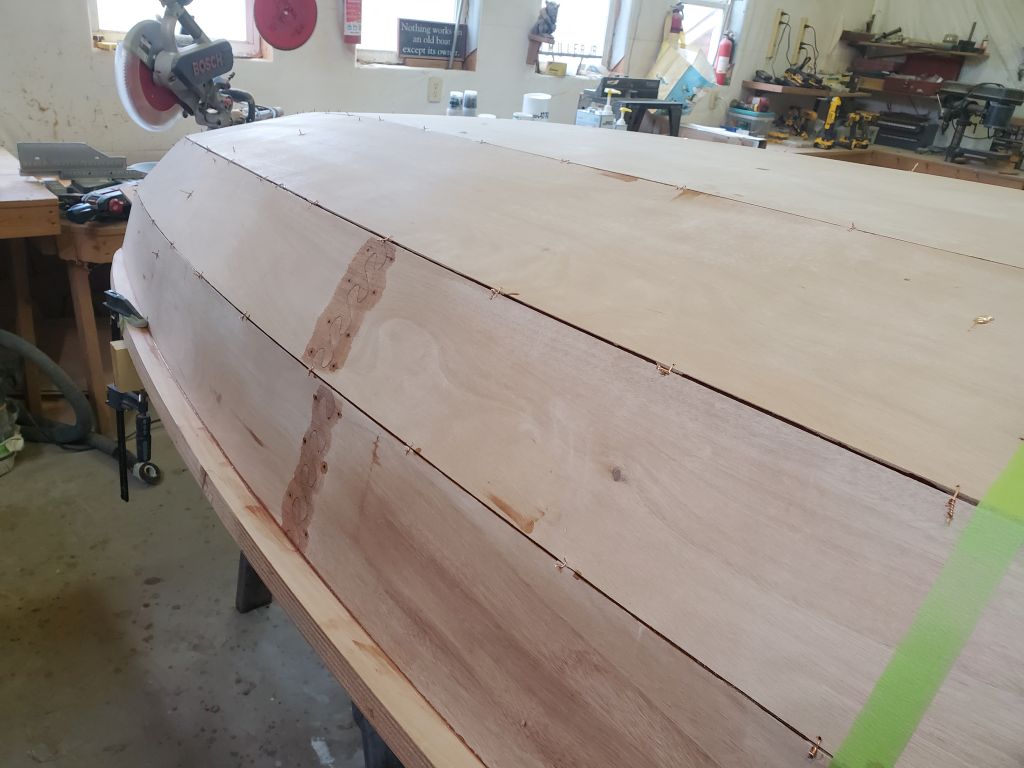
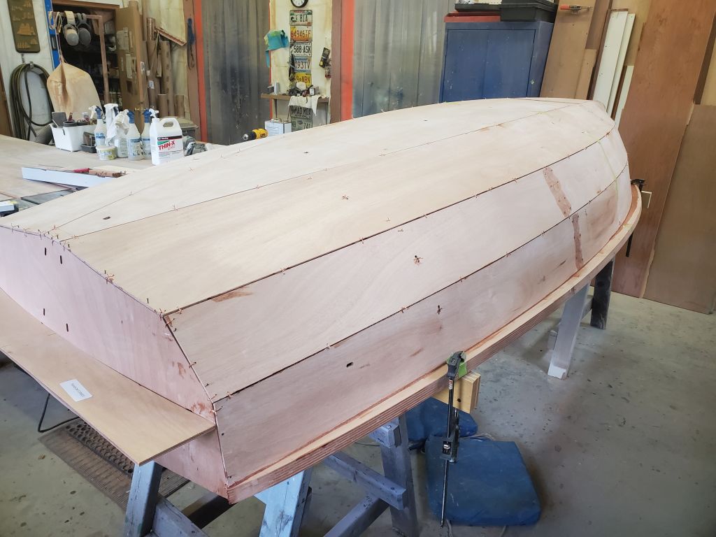
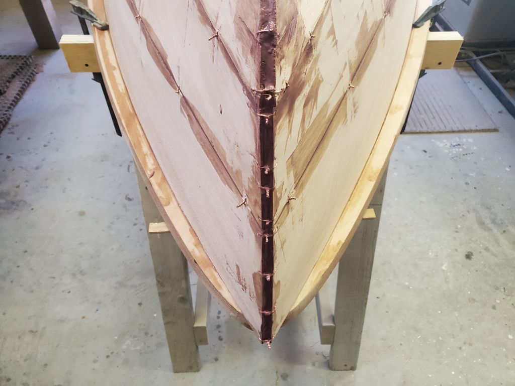
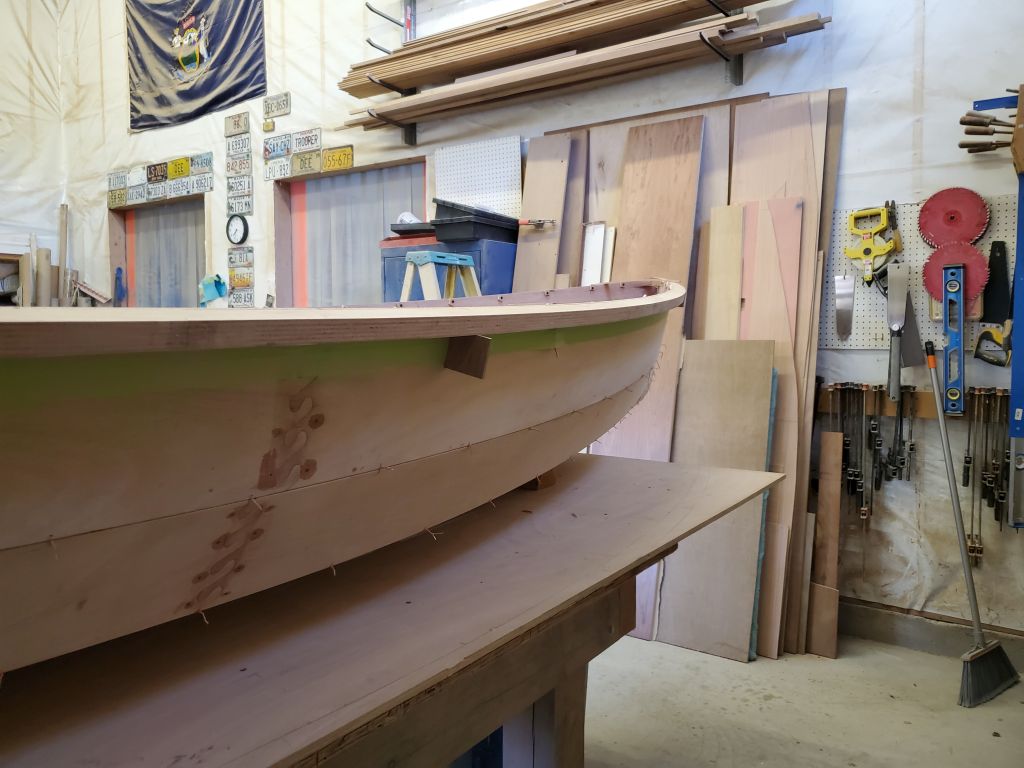
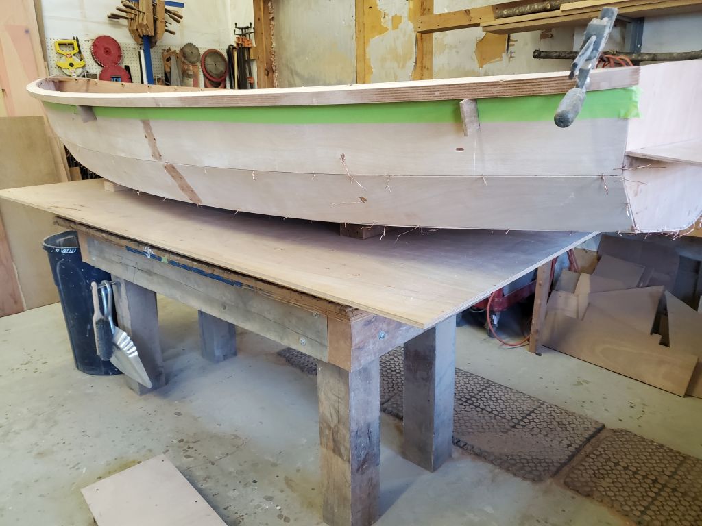
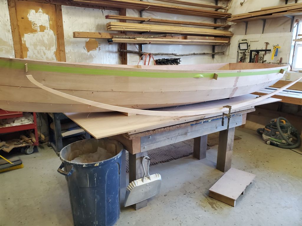
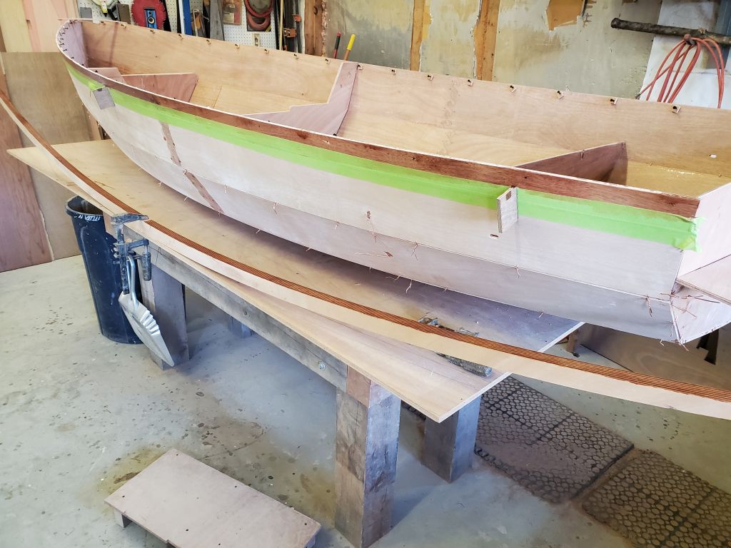
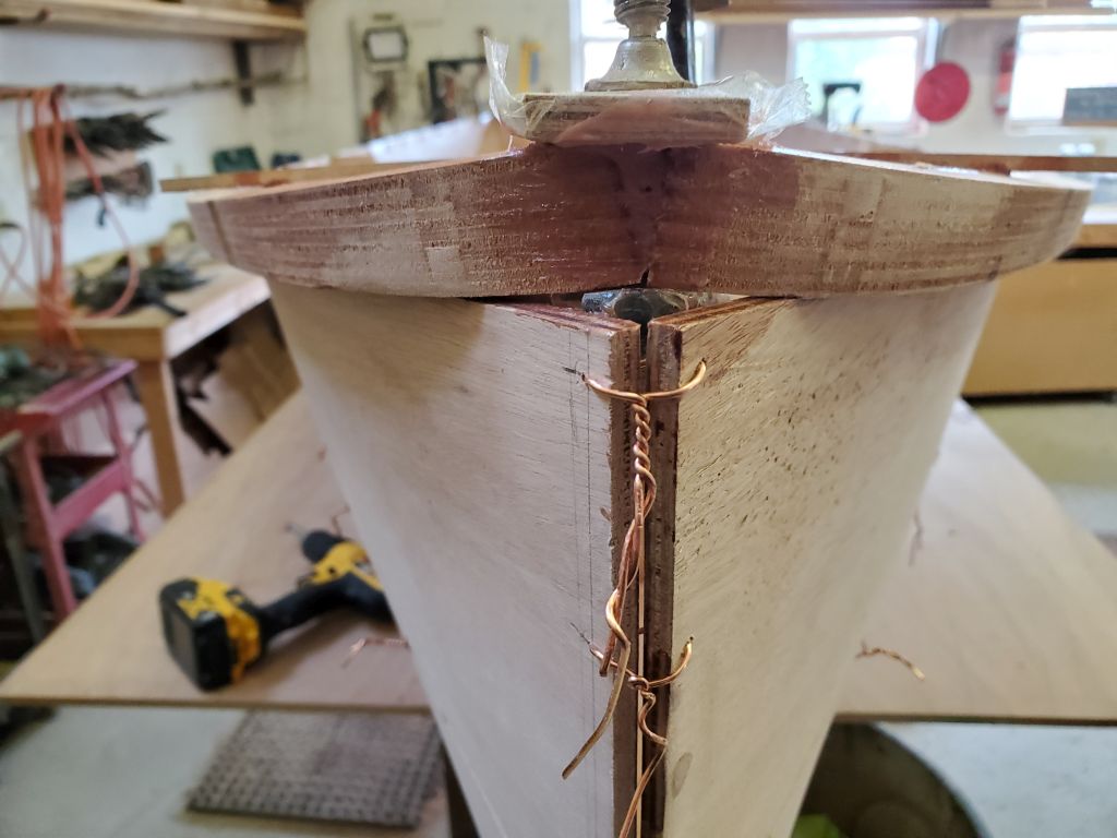
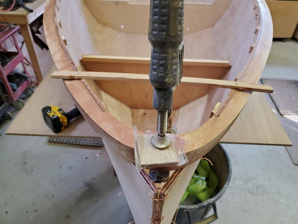
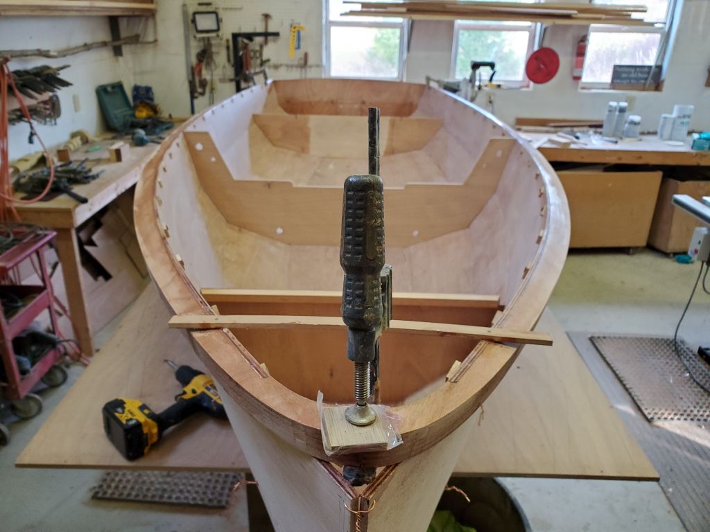
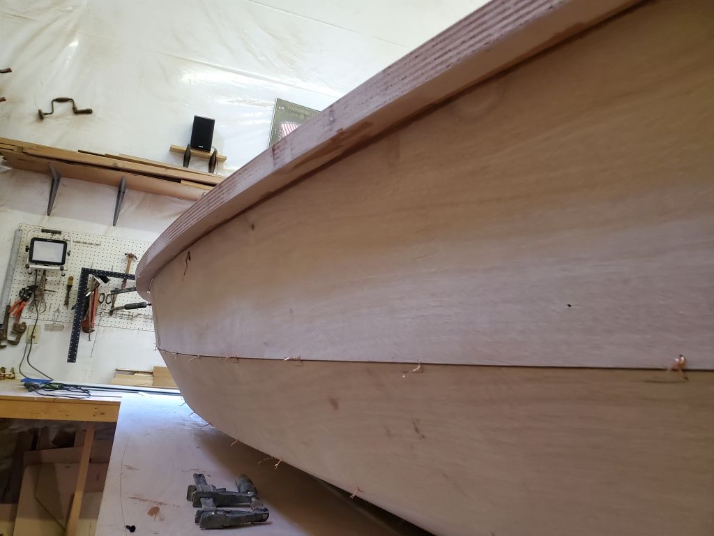
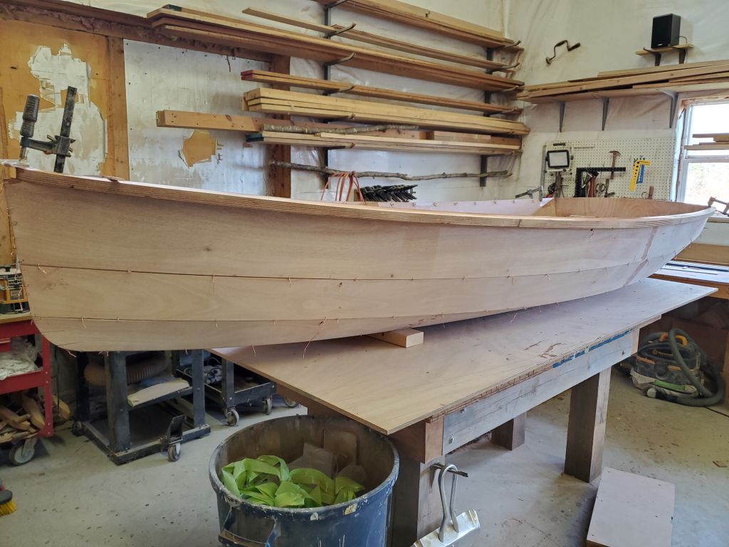
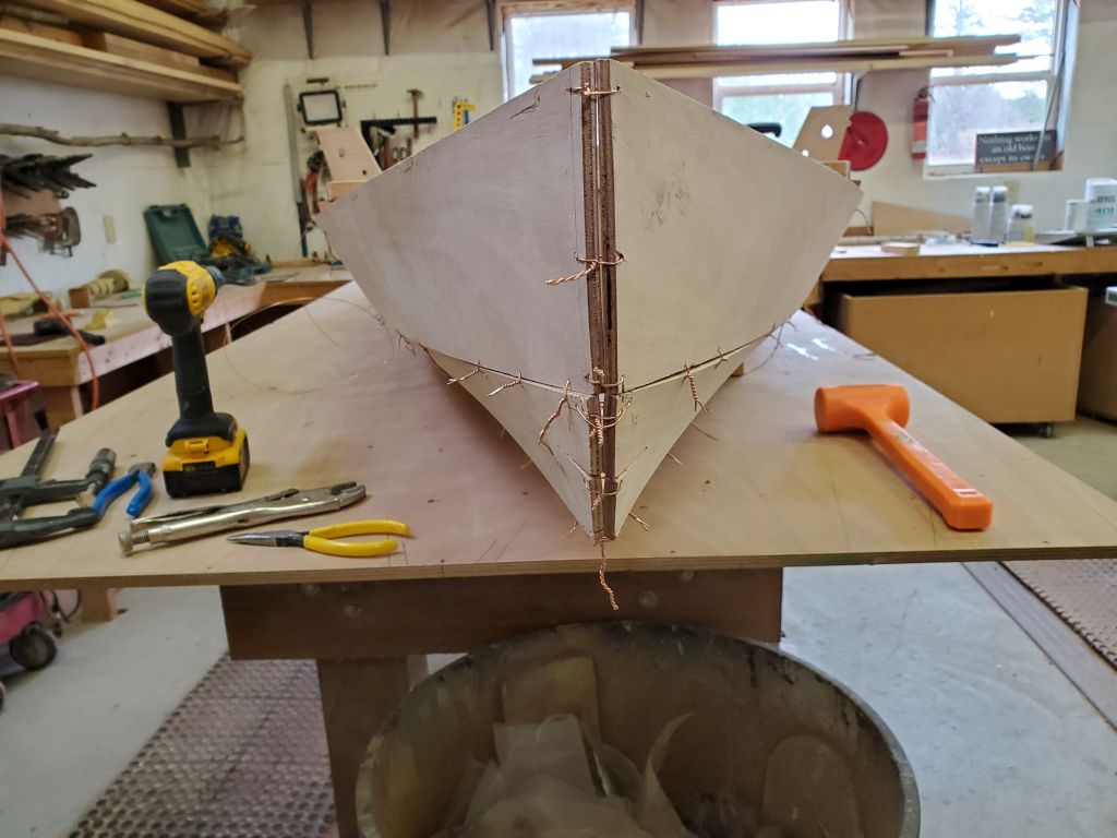
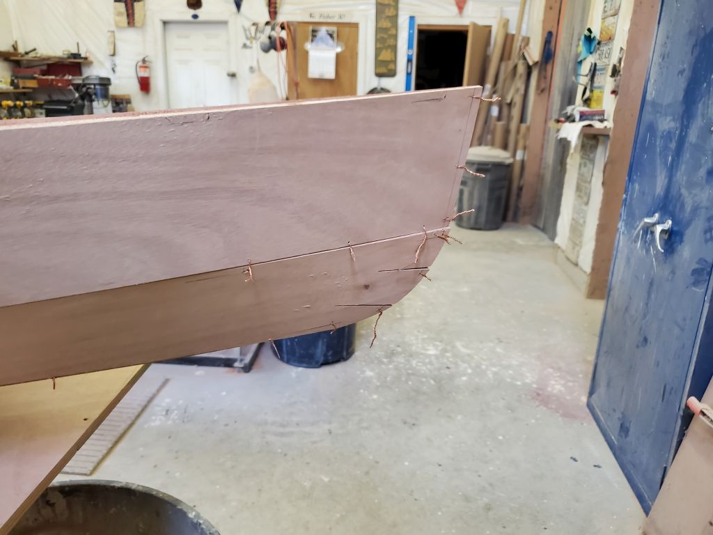
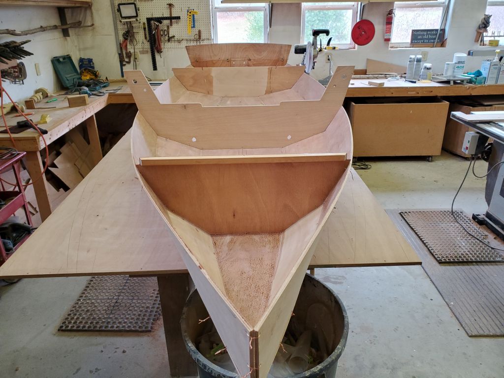
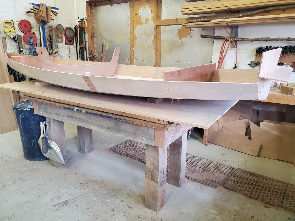
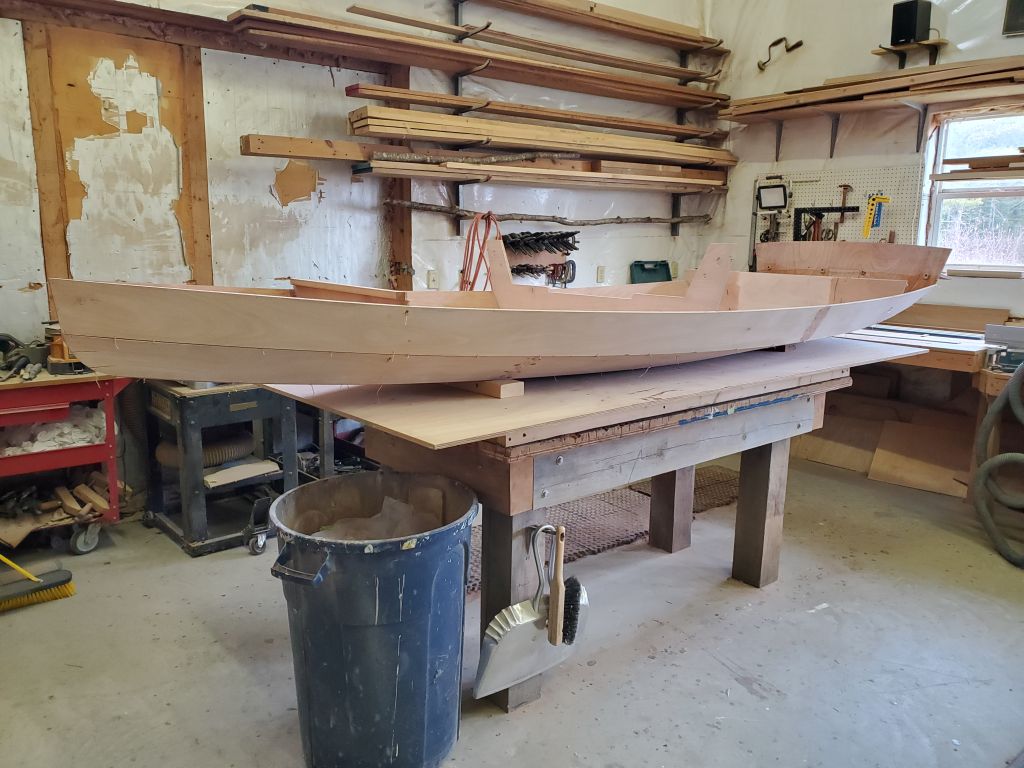
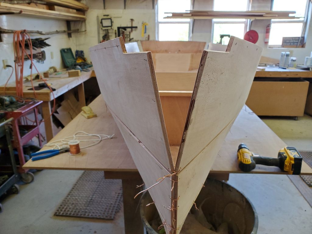
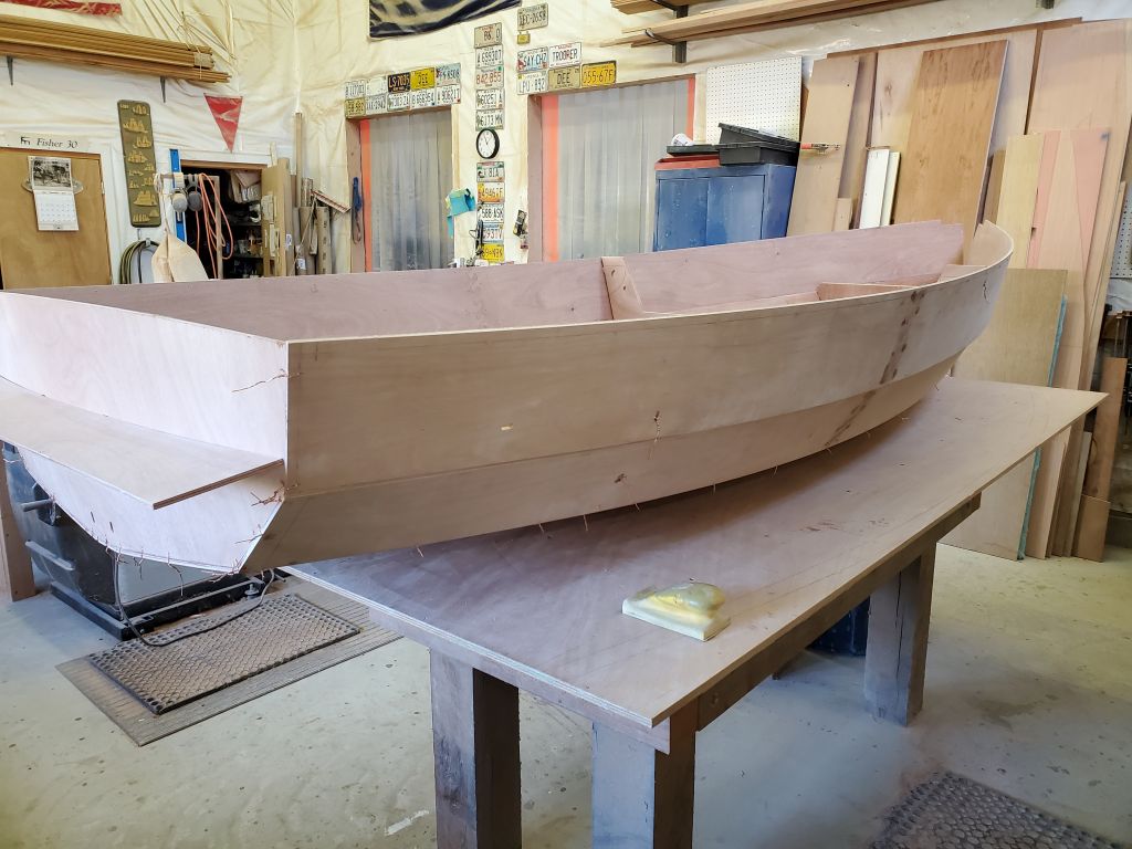
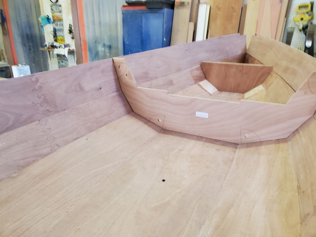
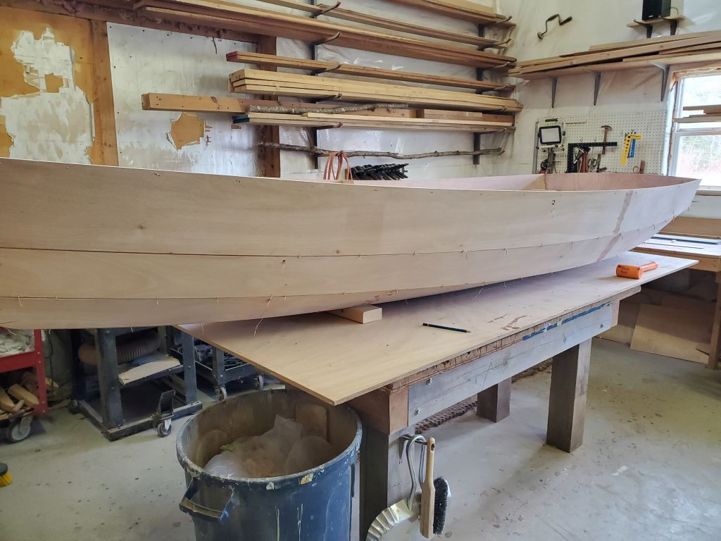
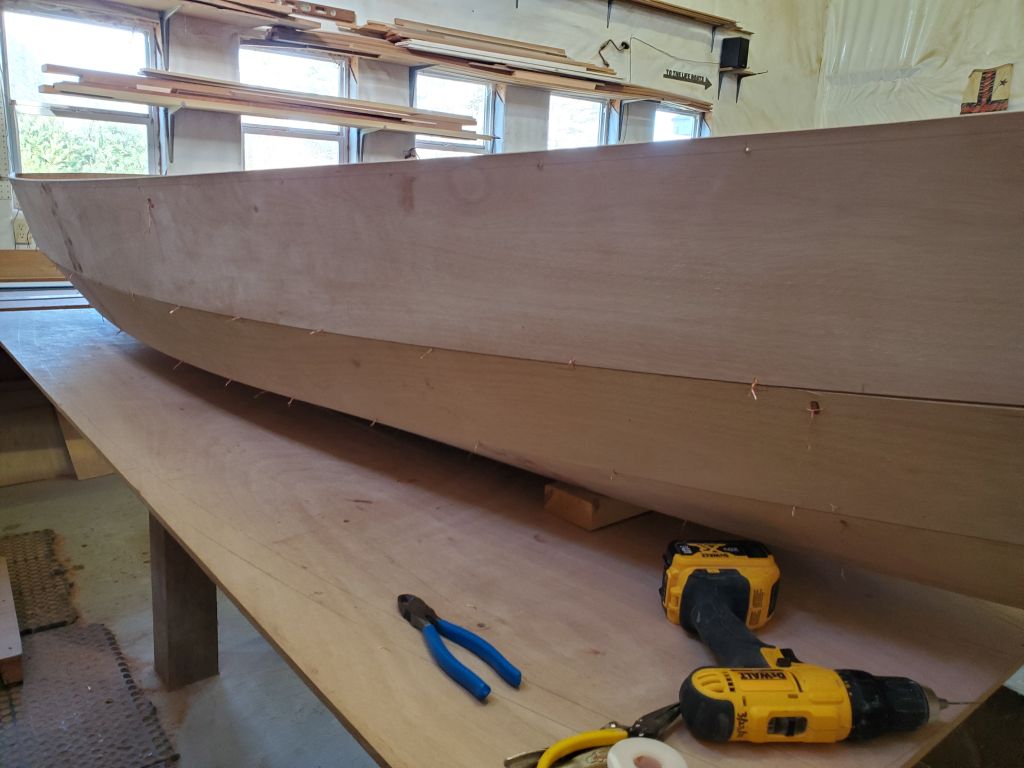
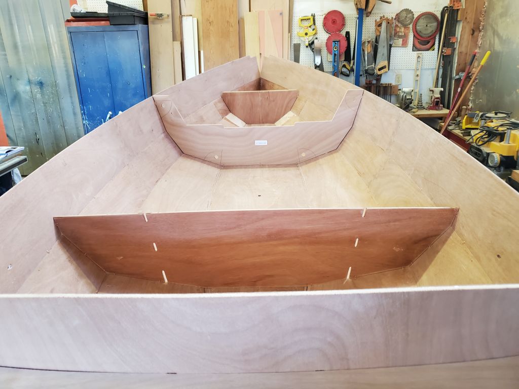
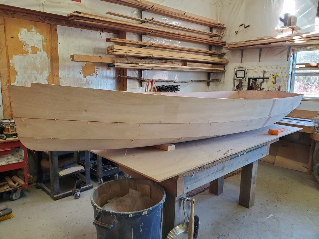
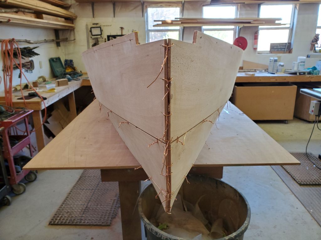
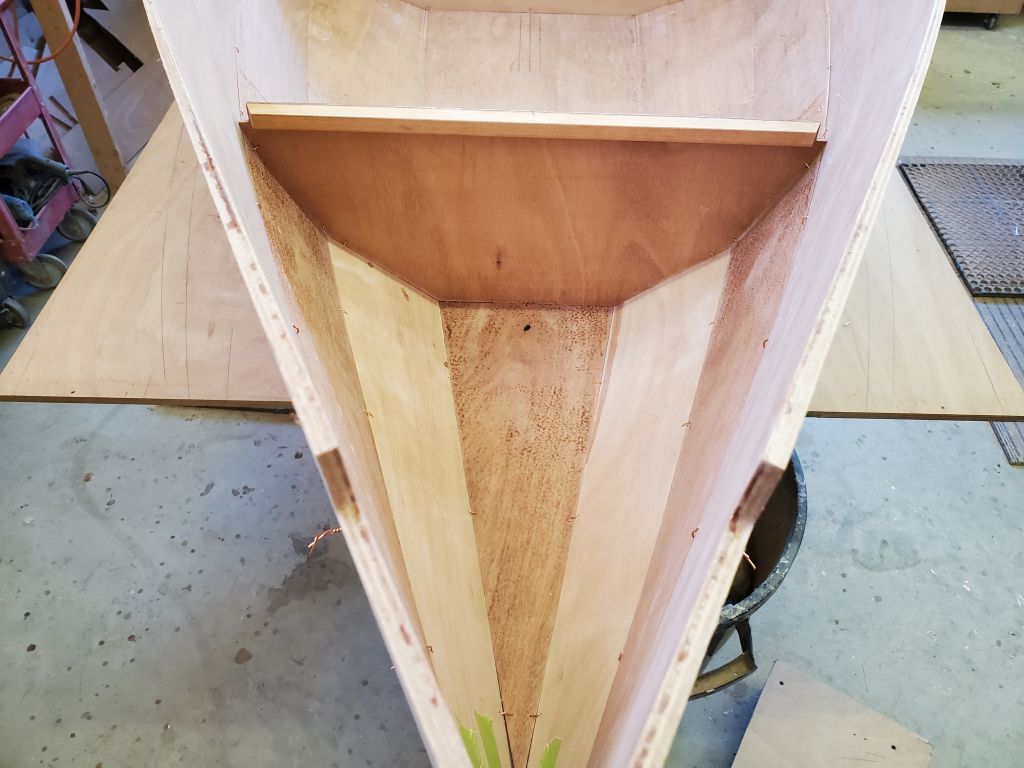
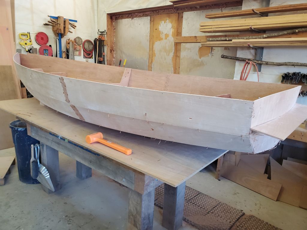
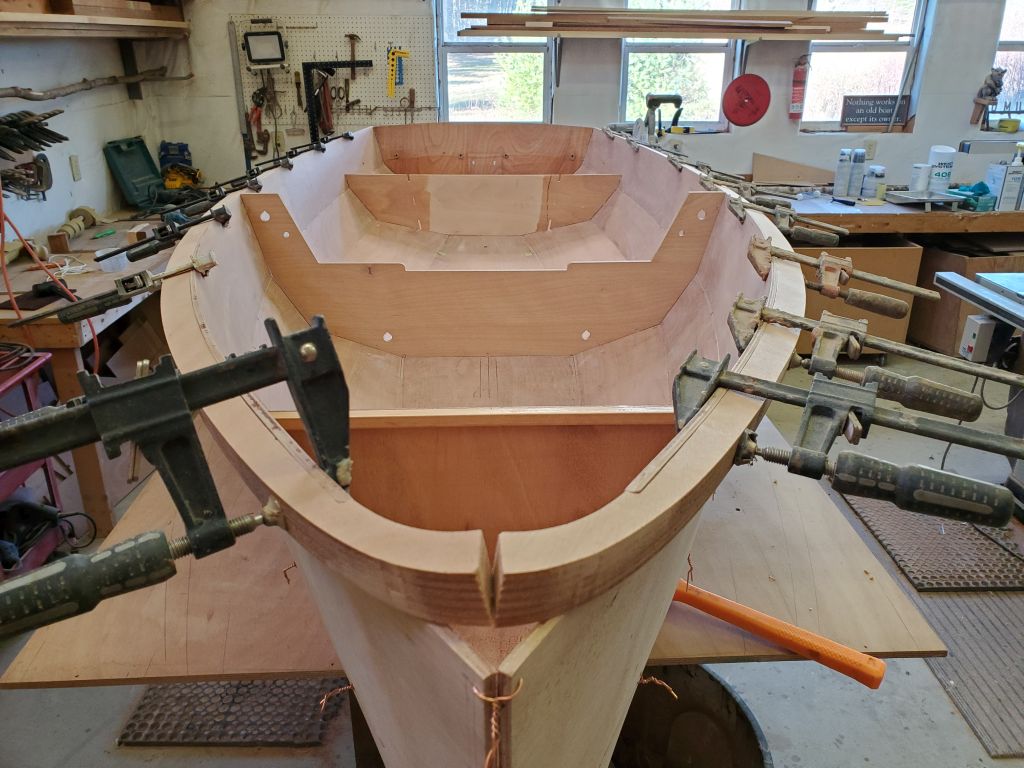
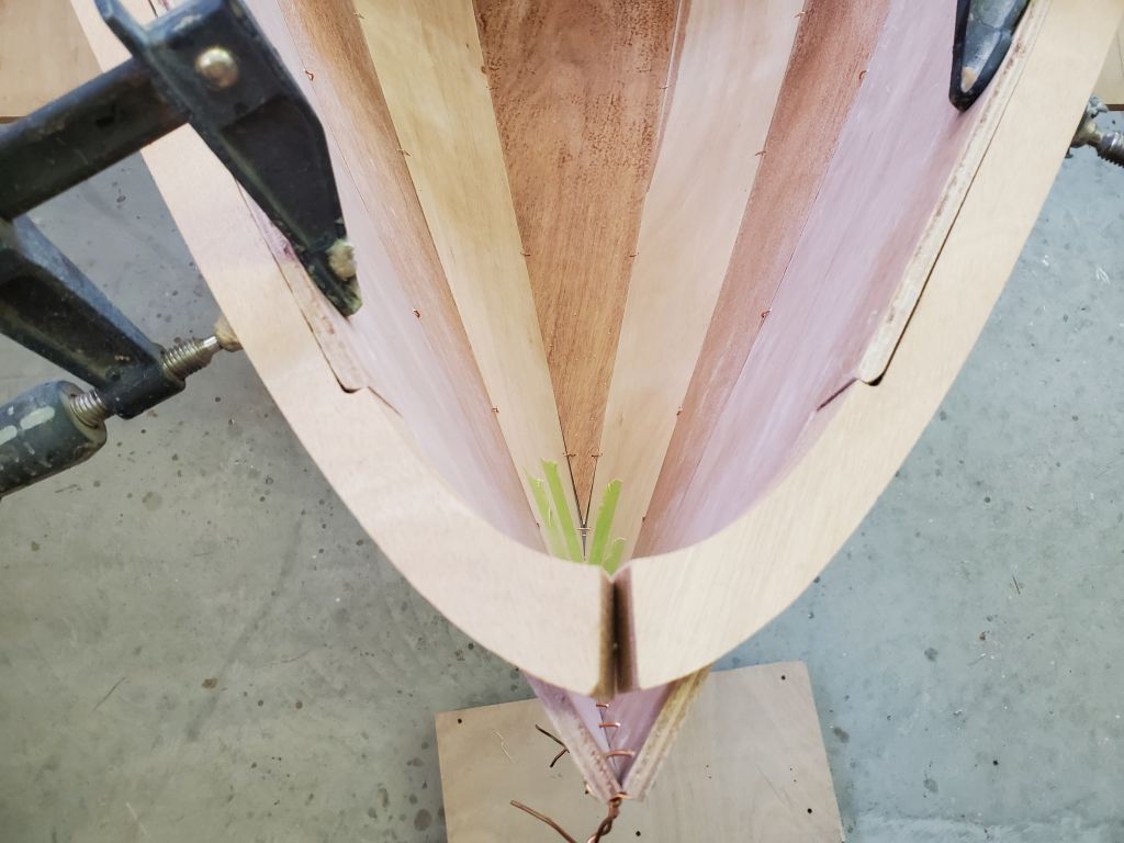
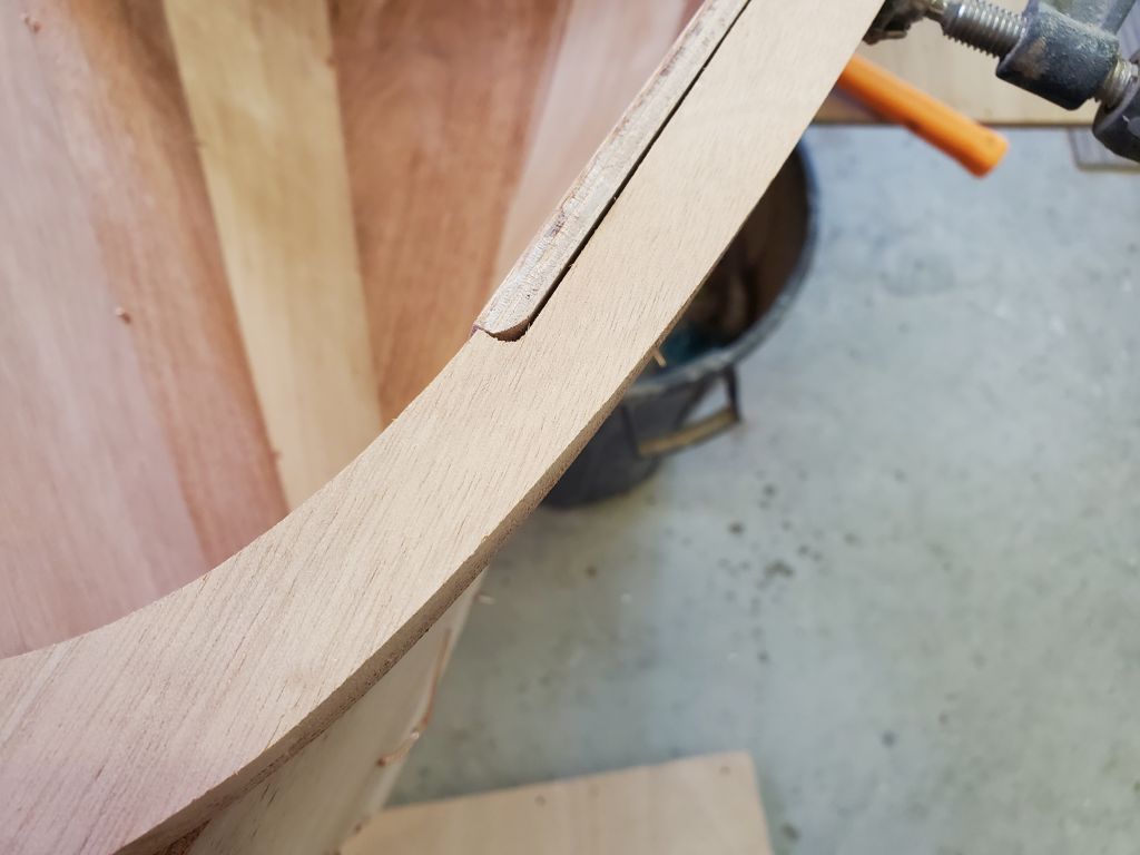
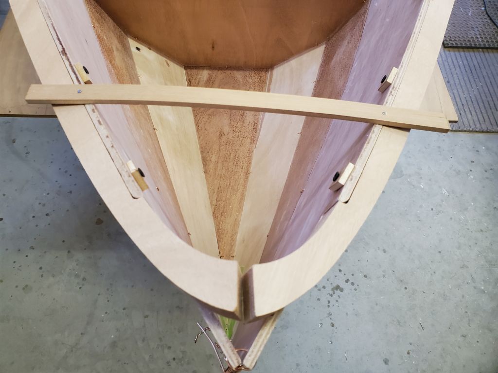
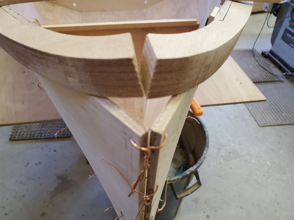
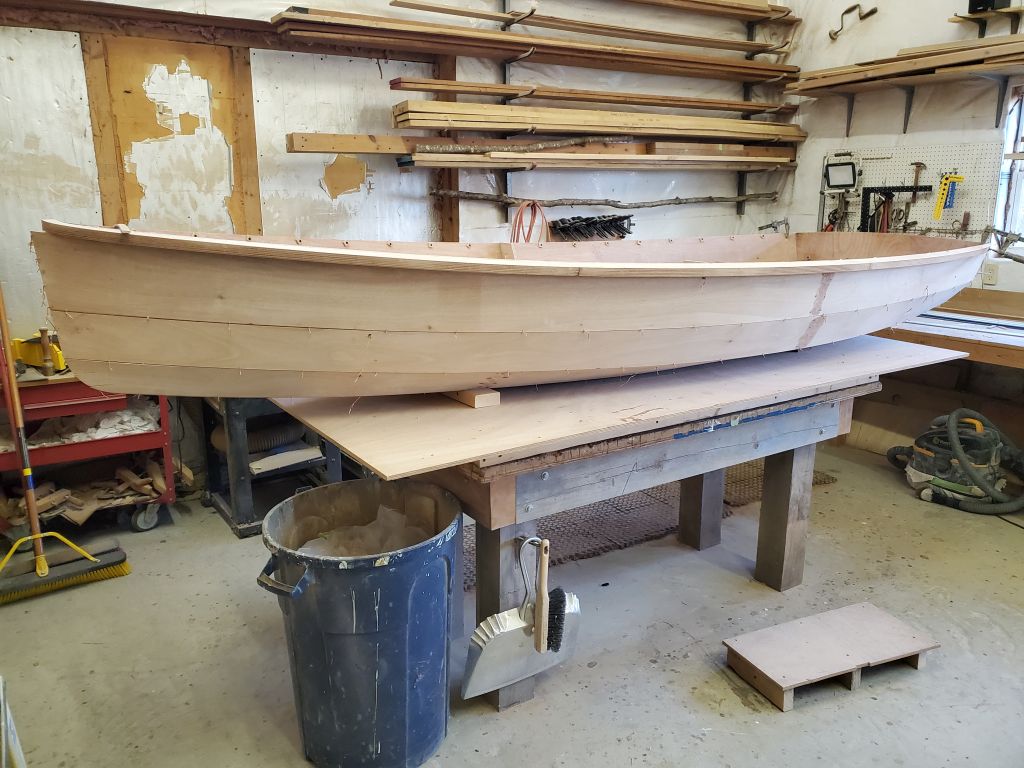
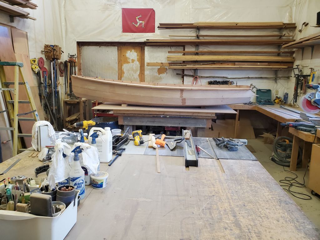
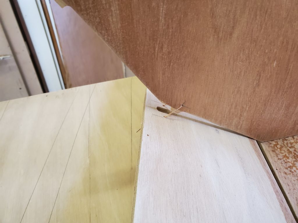
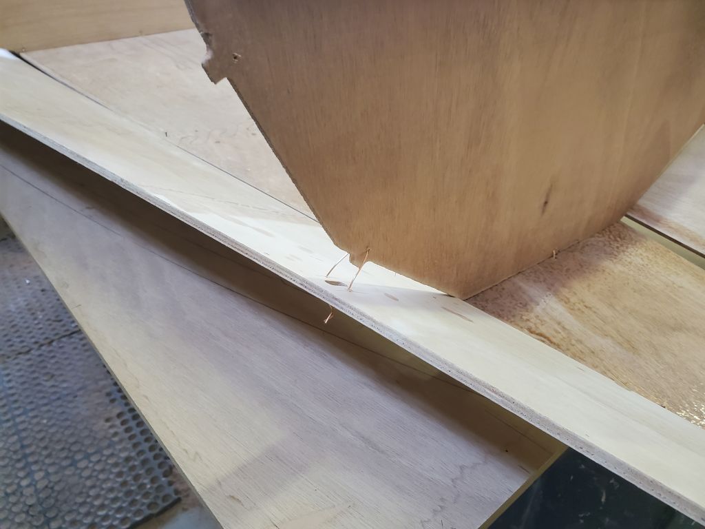
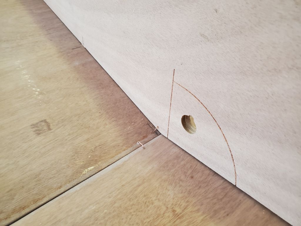
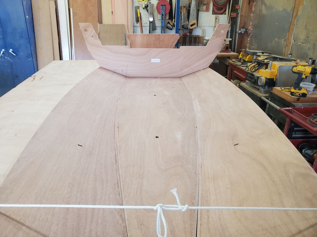
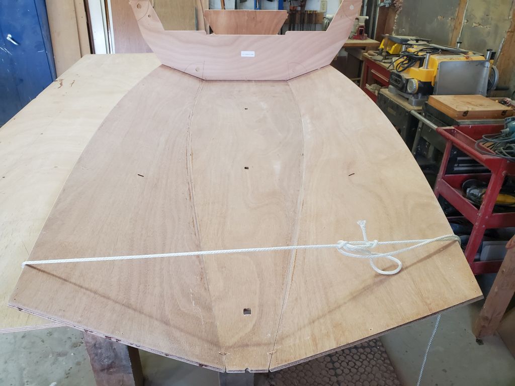
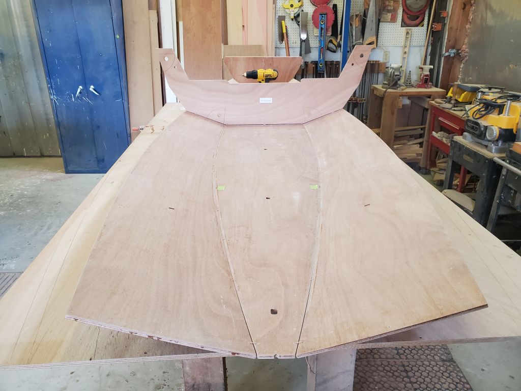
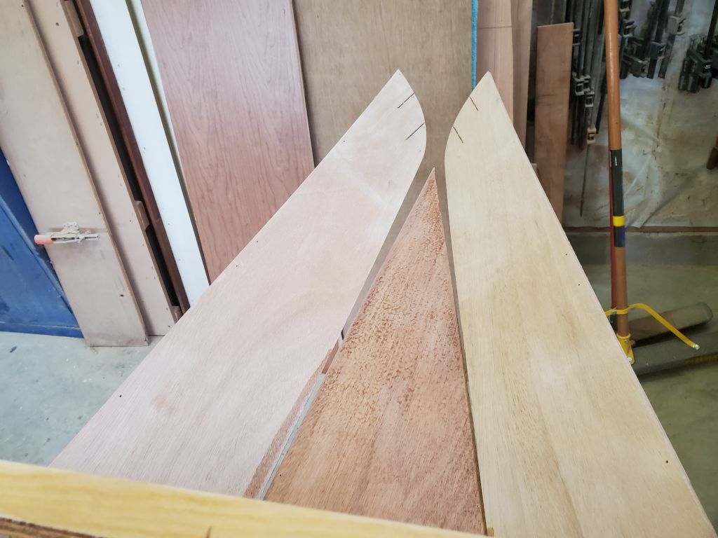
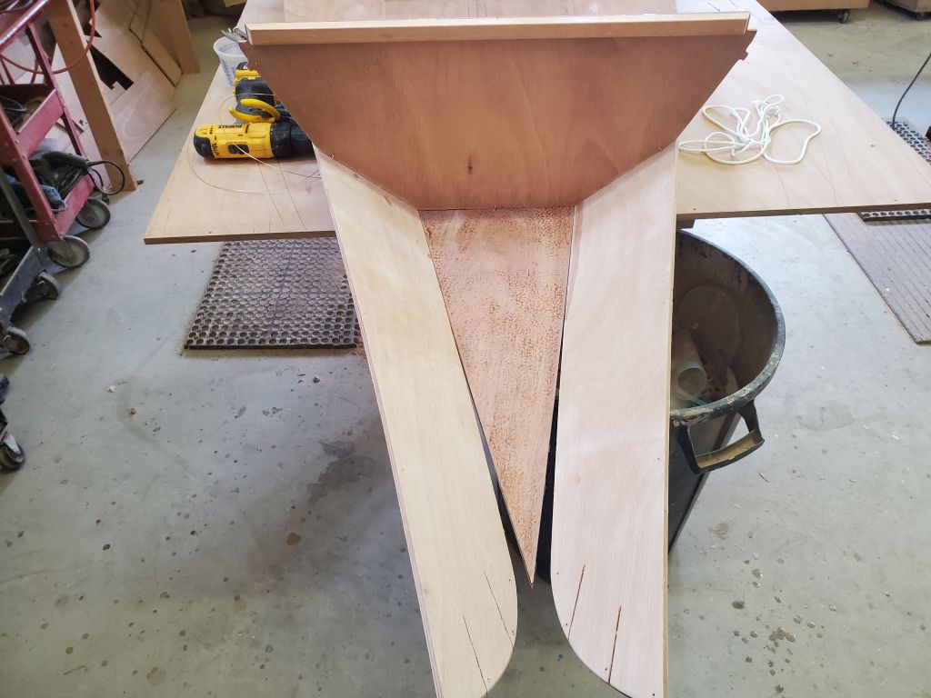
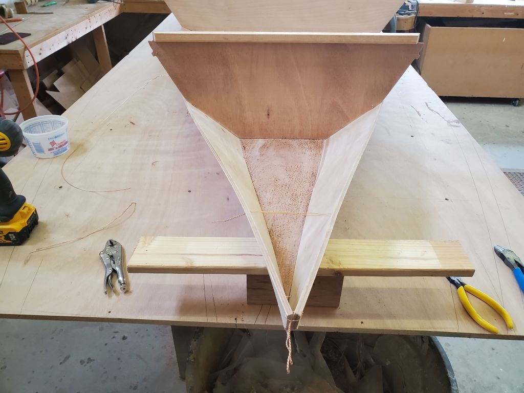
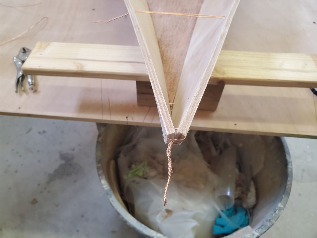
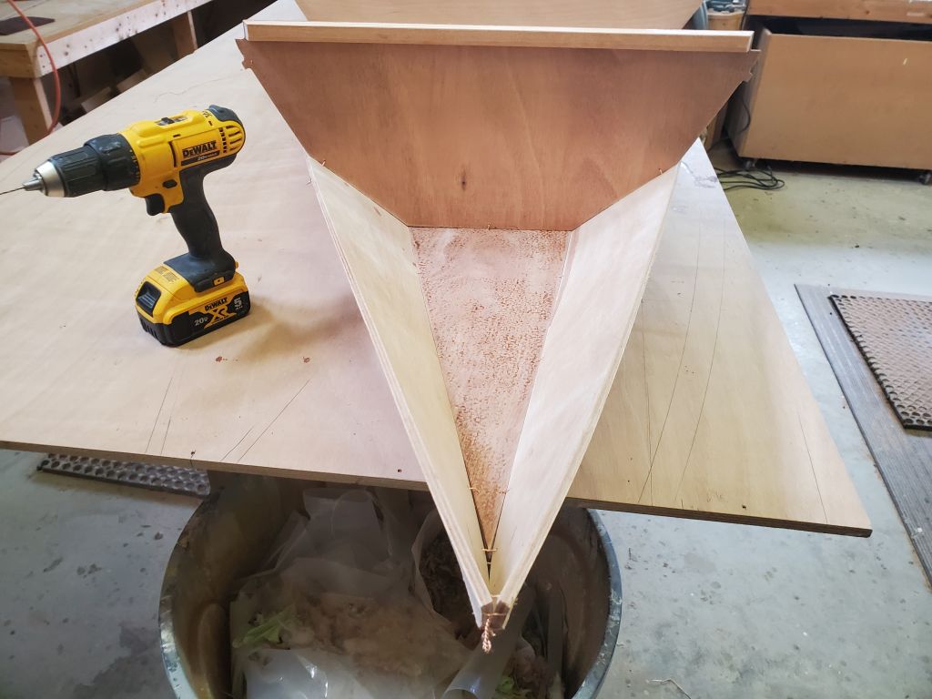
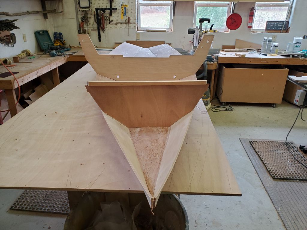
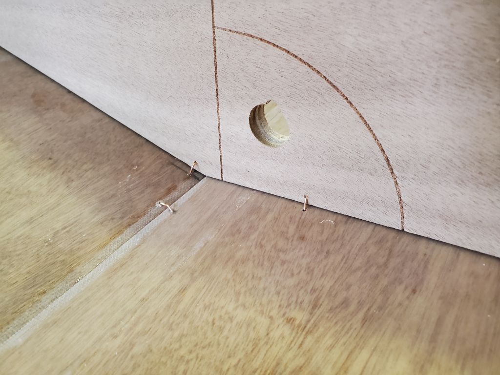
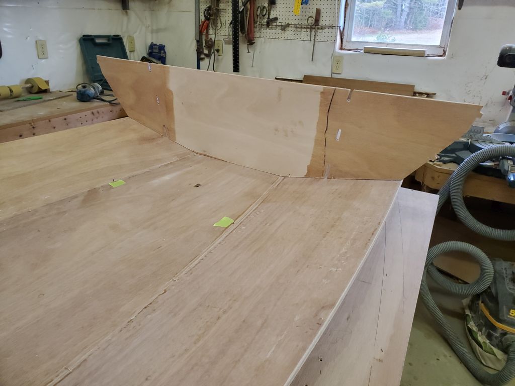
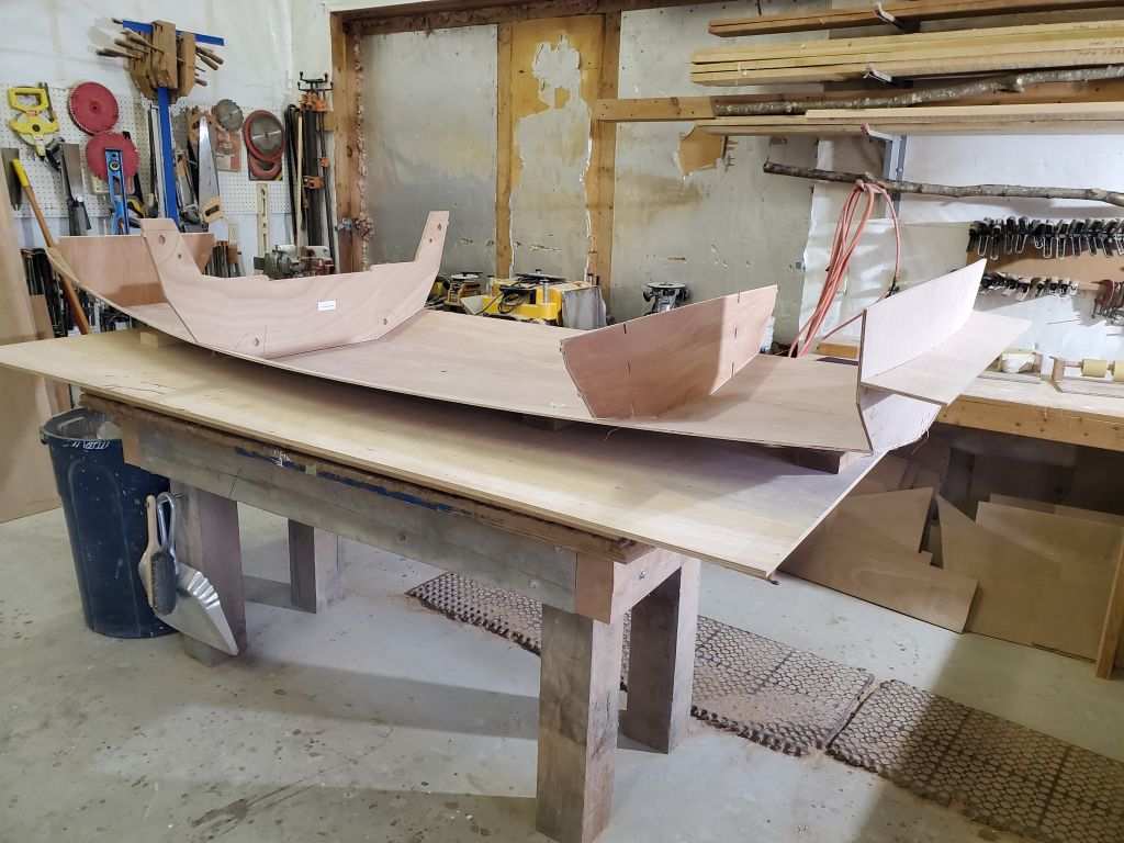
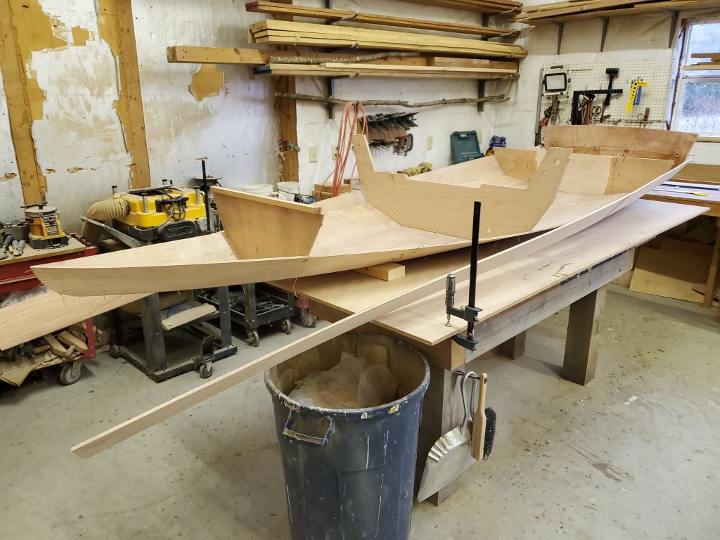
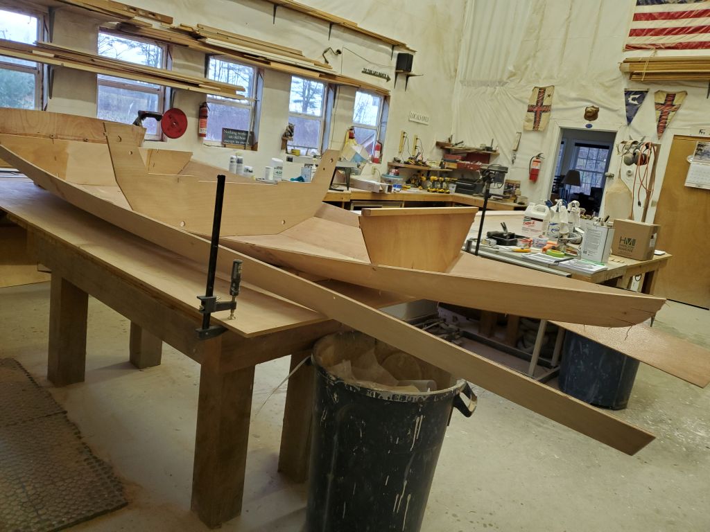
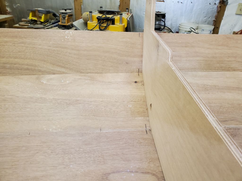
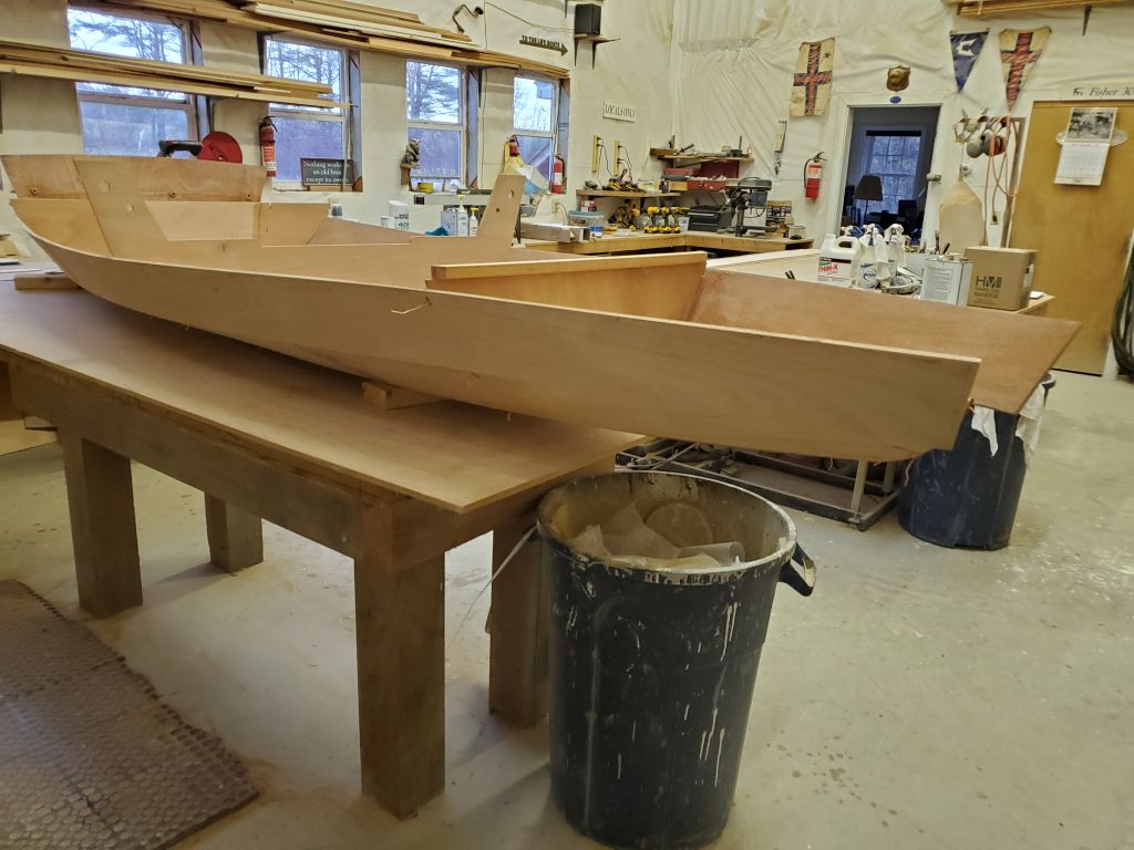
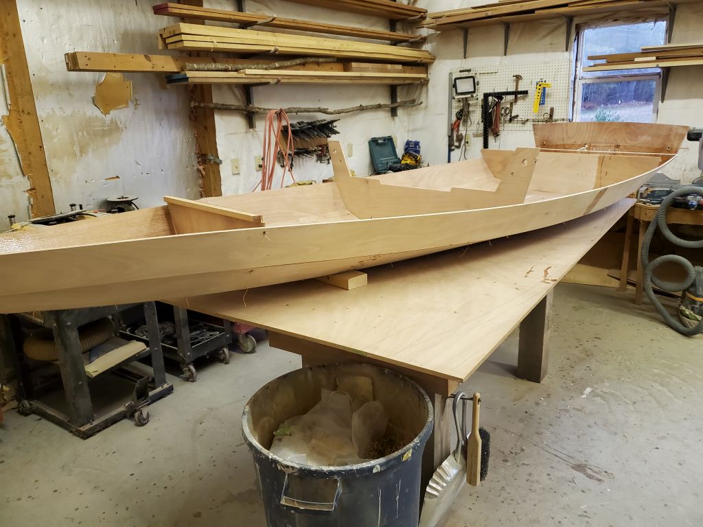
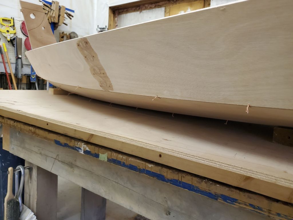
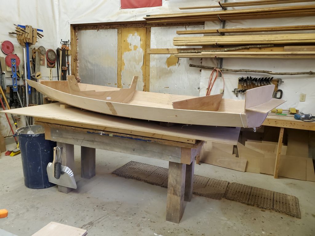
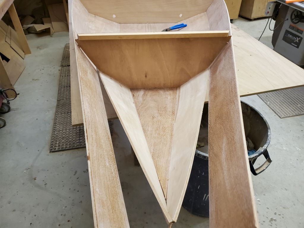
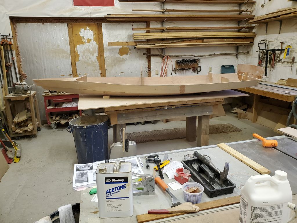
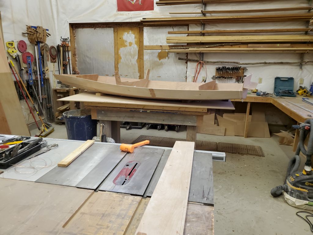
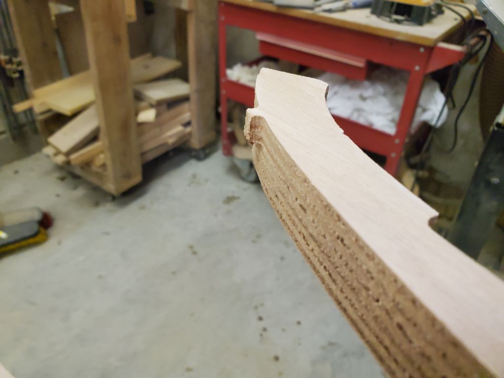
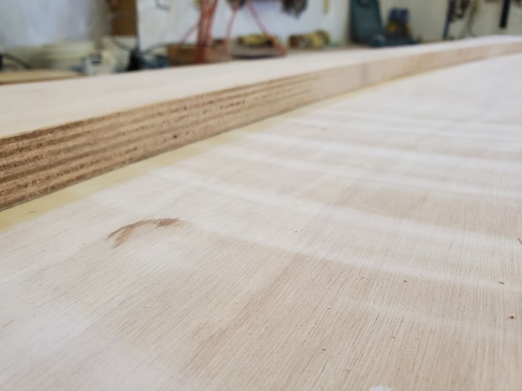
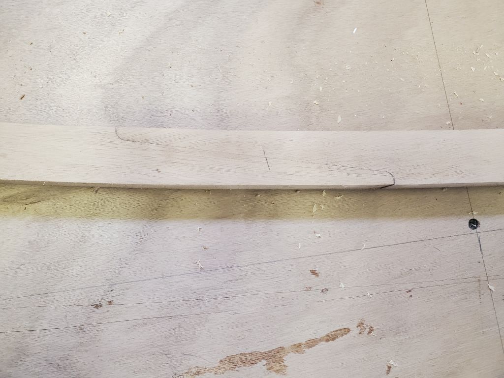
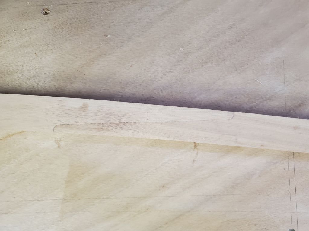
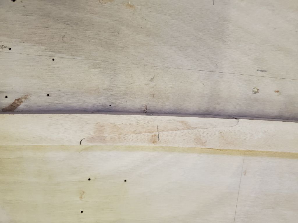
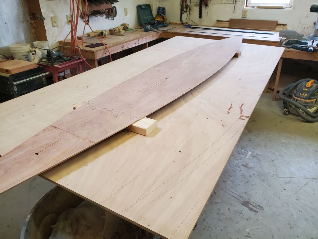
Now I turned the boat upright again, and positioned it so the sawhorses were in line with the after and mast step bulkheads (which is how they’d been spaced from the onset). My next task was to install the inner stem, a small machined plywood piece that I’d sheathed in fiberglass earlier, when I was working on the hull panels. I test-fit the piece–it required no modifications to fit as it should–then installed it in a bed of thickened epoxy all around, ensuring I used enough for plenty of squeezeout. I secured the piece with one screw through the stem from outside; the nail driven into the aft side of the stem allowed me to hold and maneuver the small part for installation. I filleted around the part with the excess epoxy, and formed a healthy filled through the point of the stem beneath to clean up and fill this area. The hull panels forward of the gunwale and this inner stem piece would later be cut away, and the remains shaped, to form the actual stem of the finished boat.
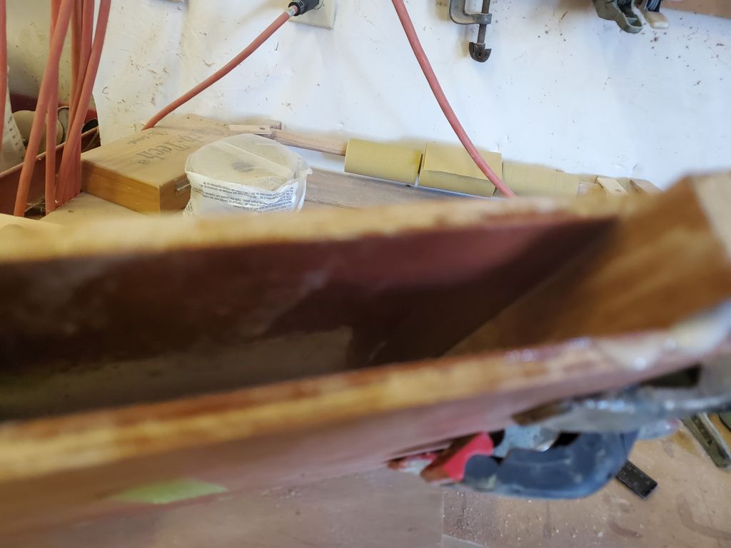
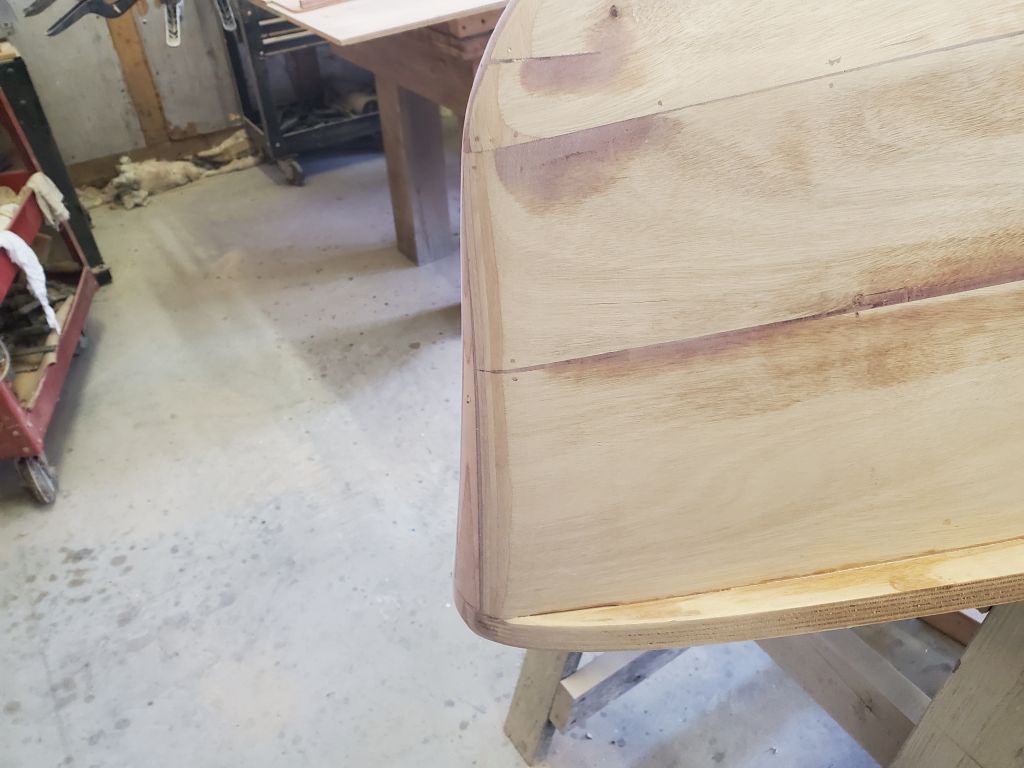
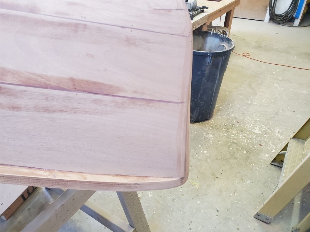
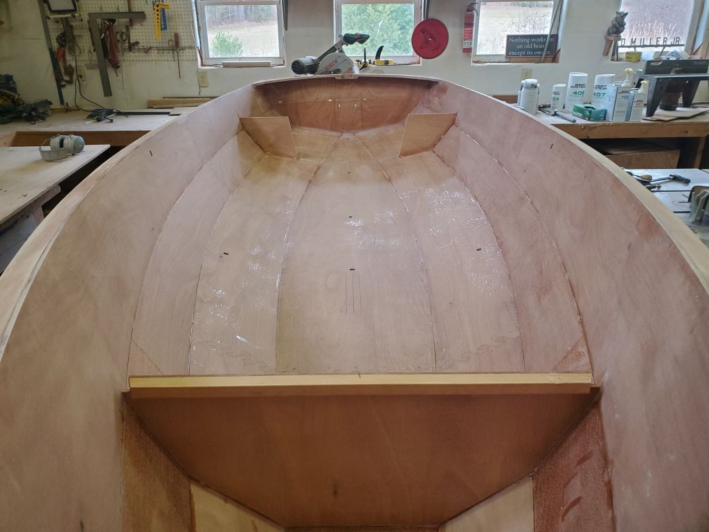
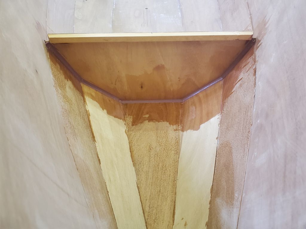
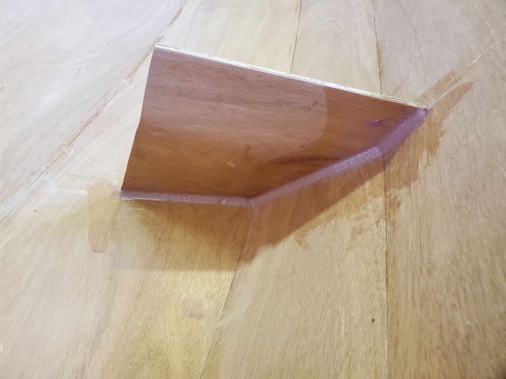
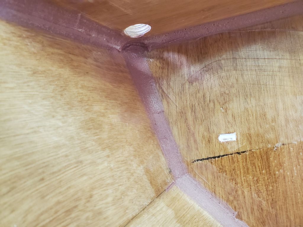
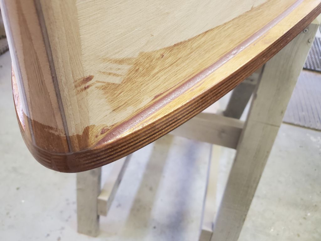
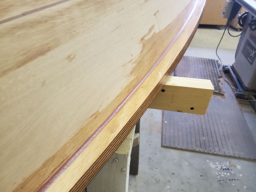
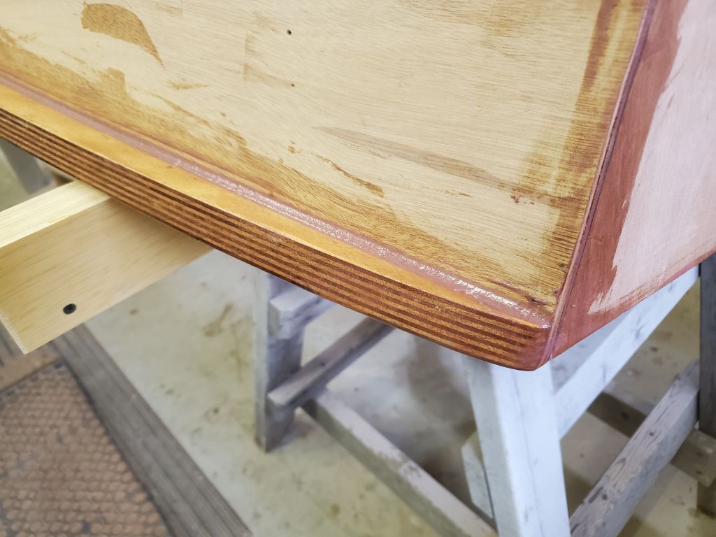
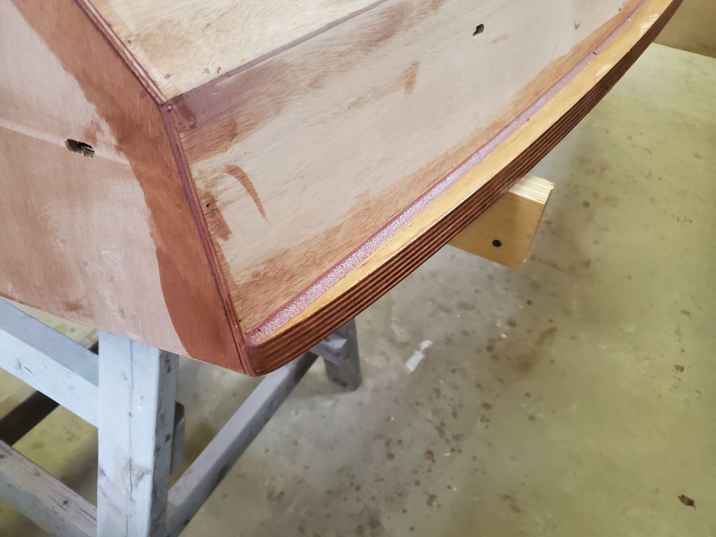
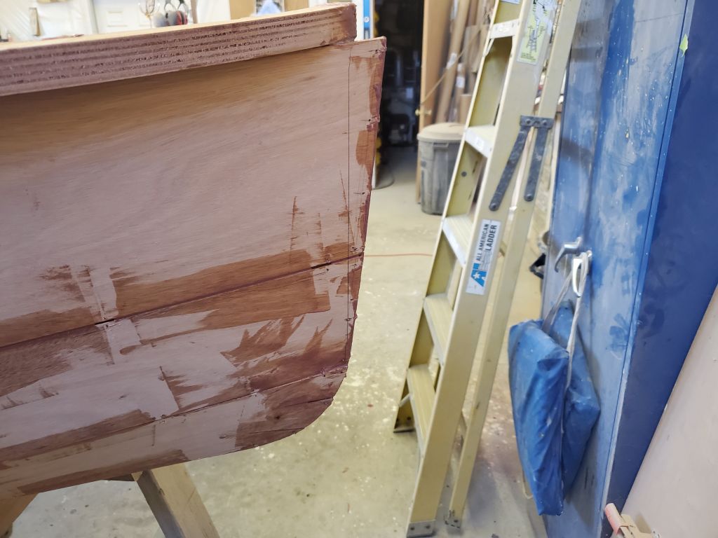
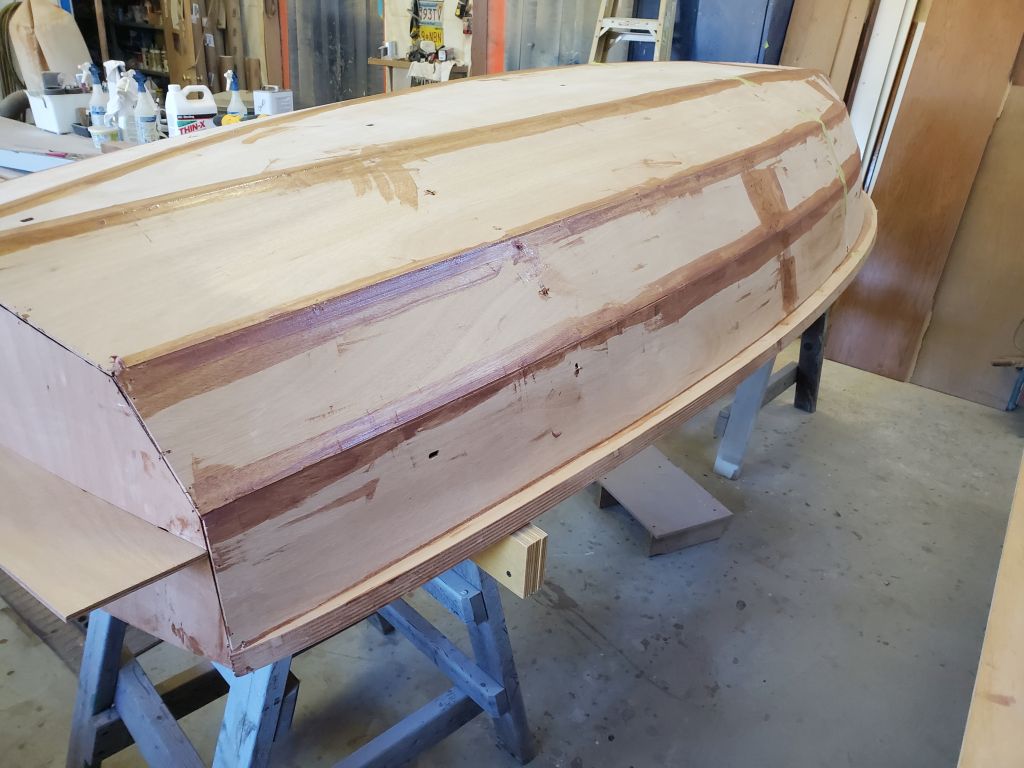
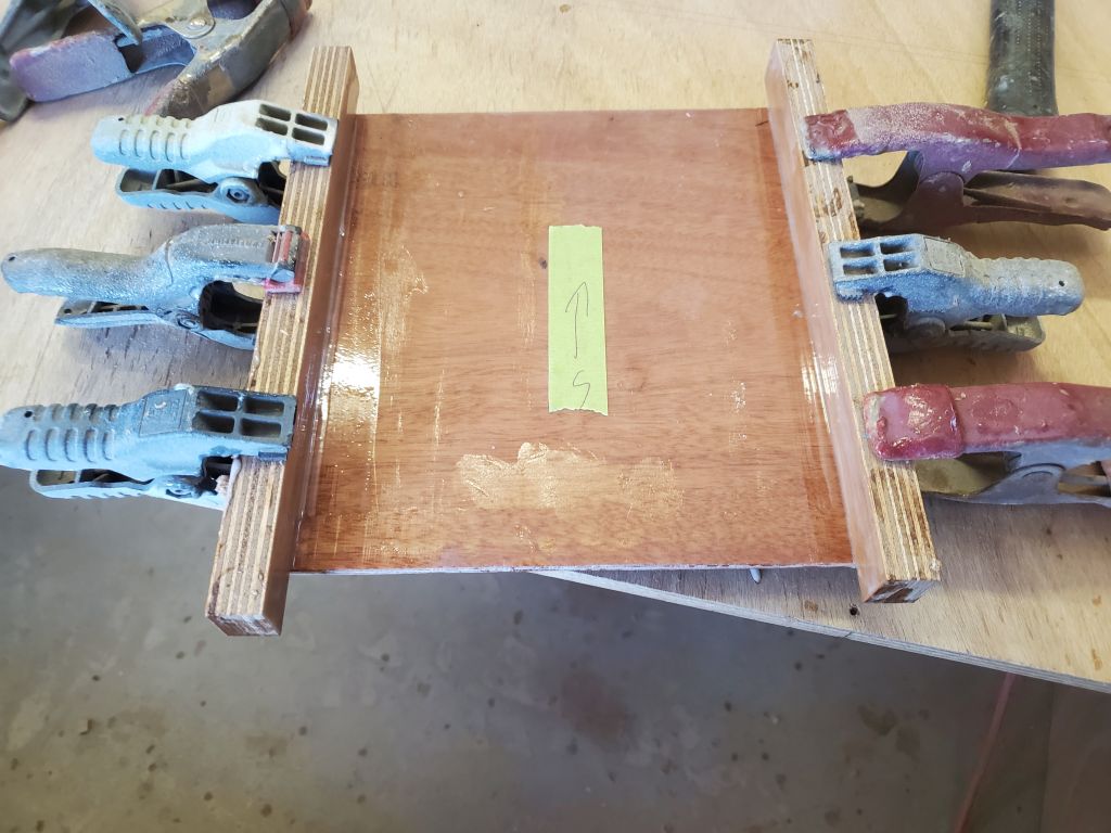
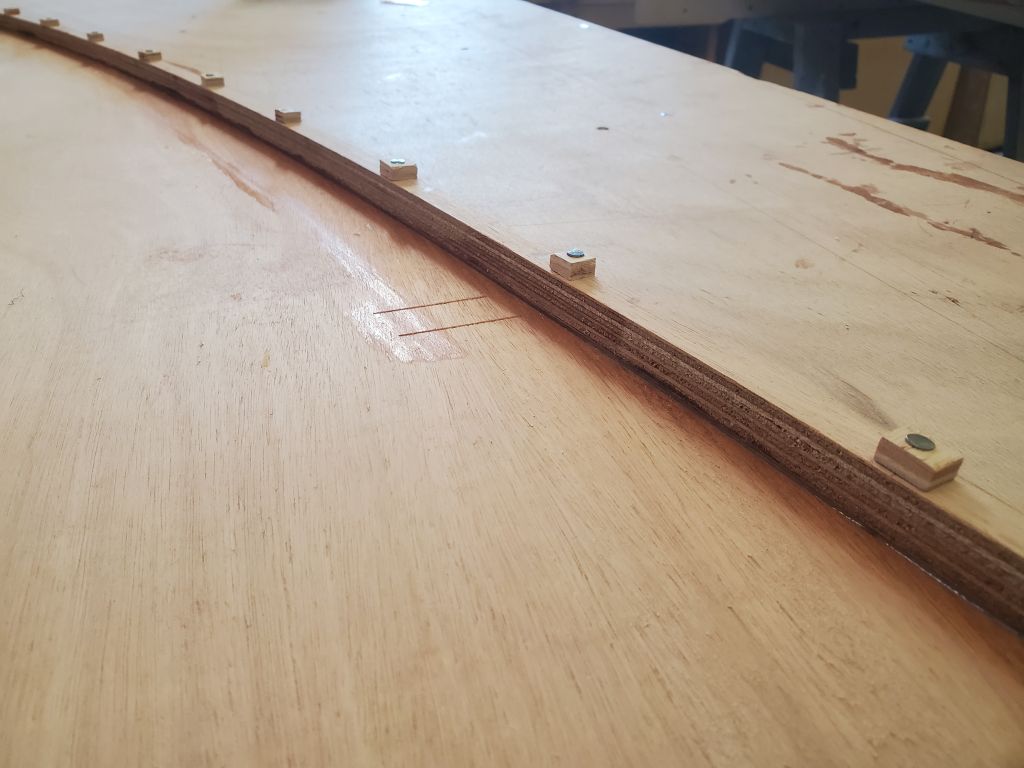
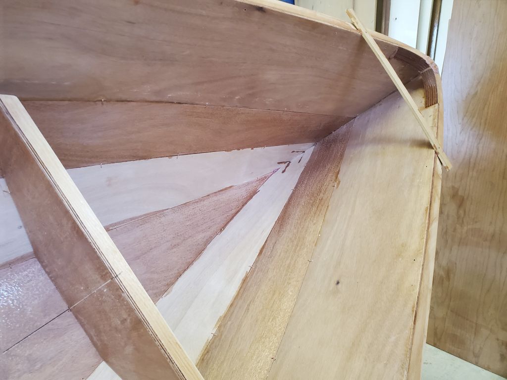
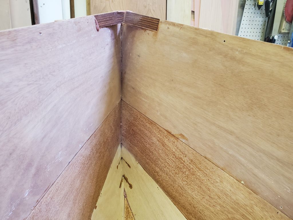
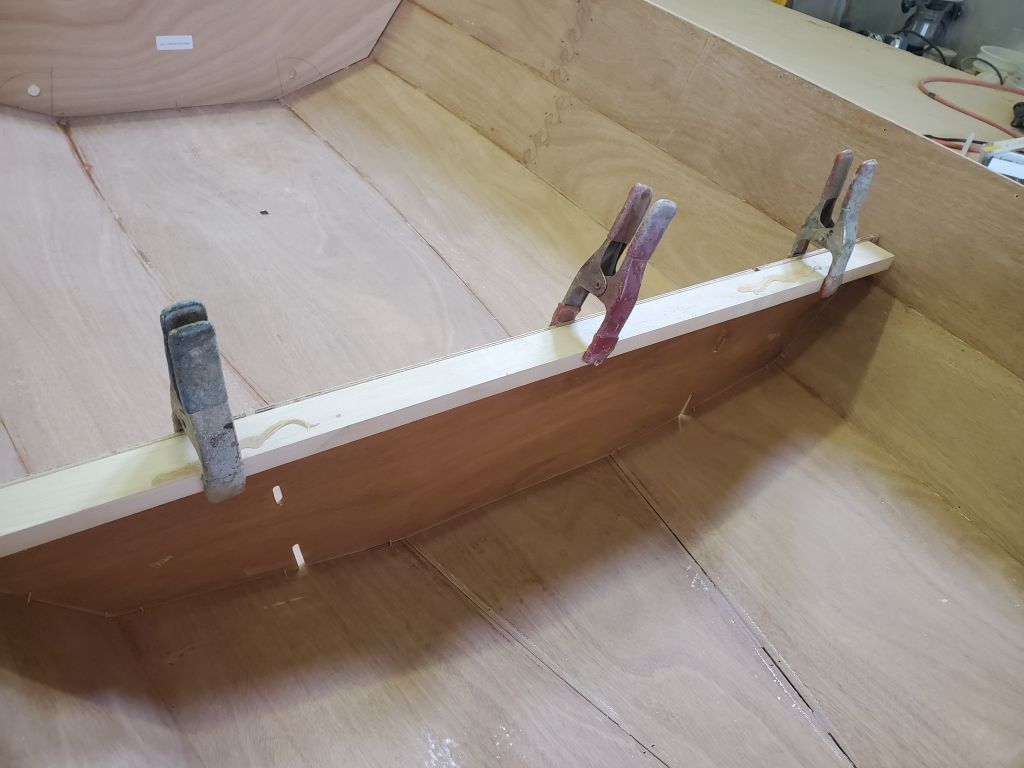
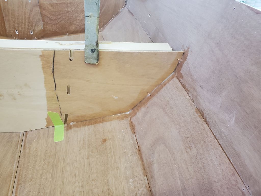
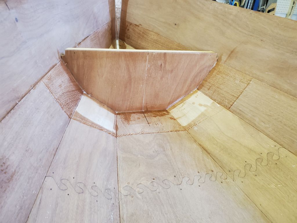
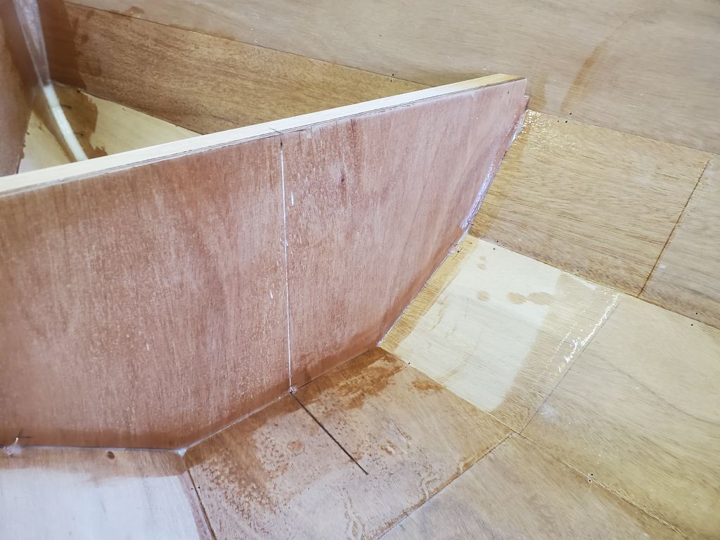
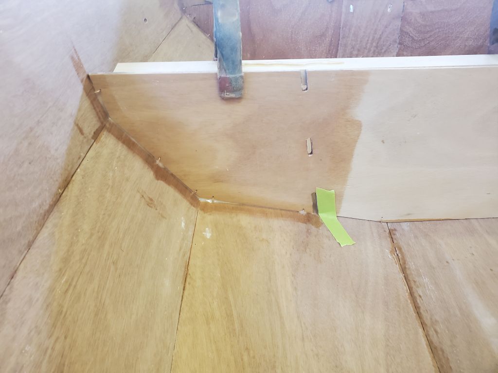
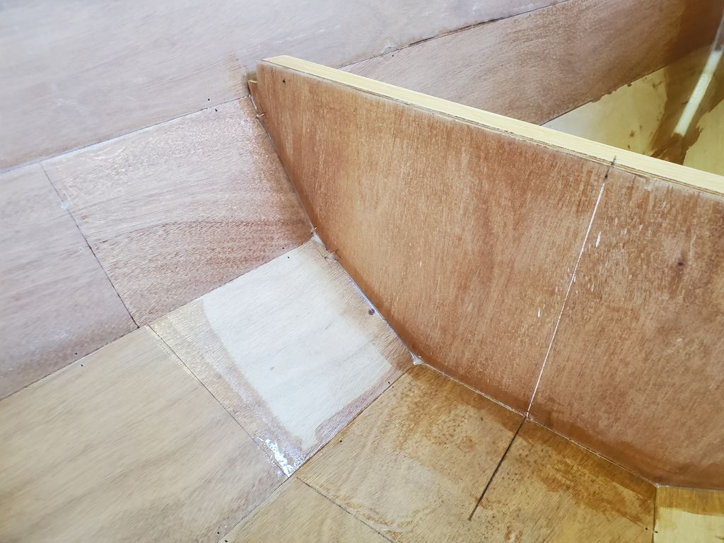
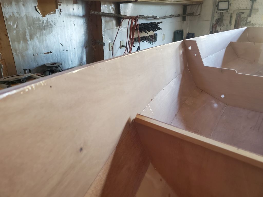
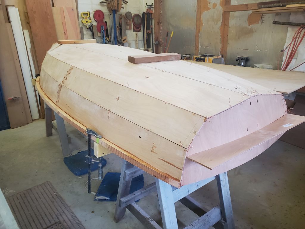
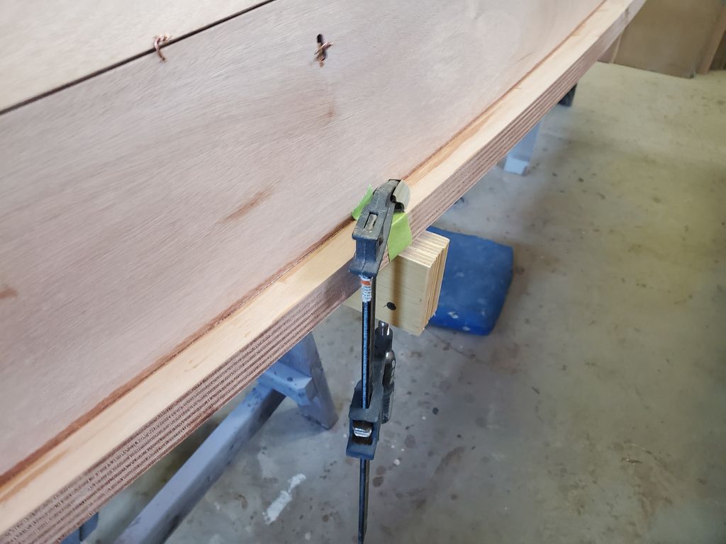
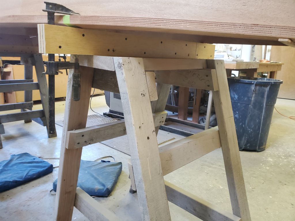
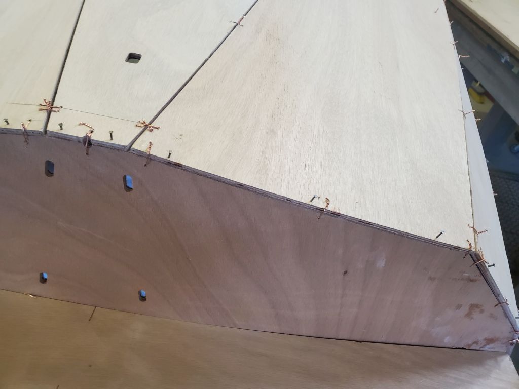
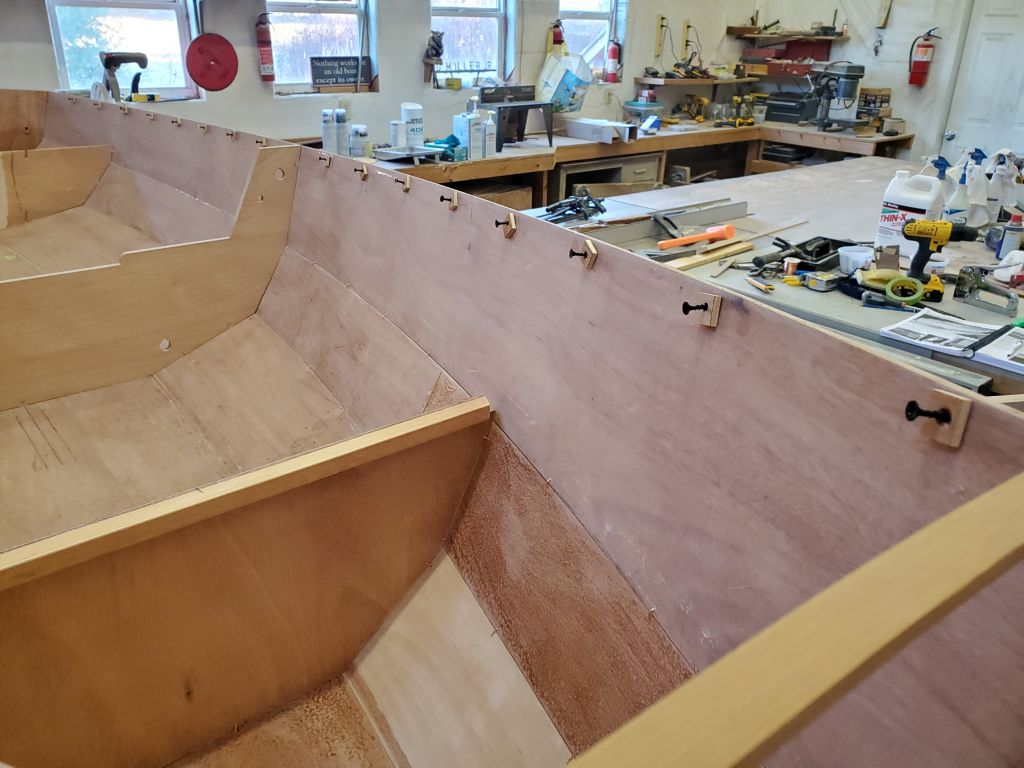
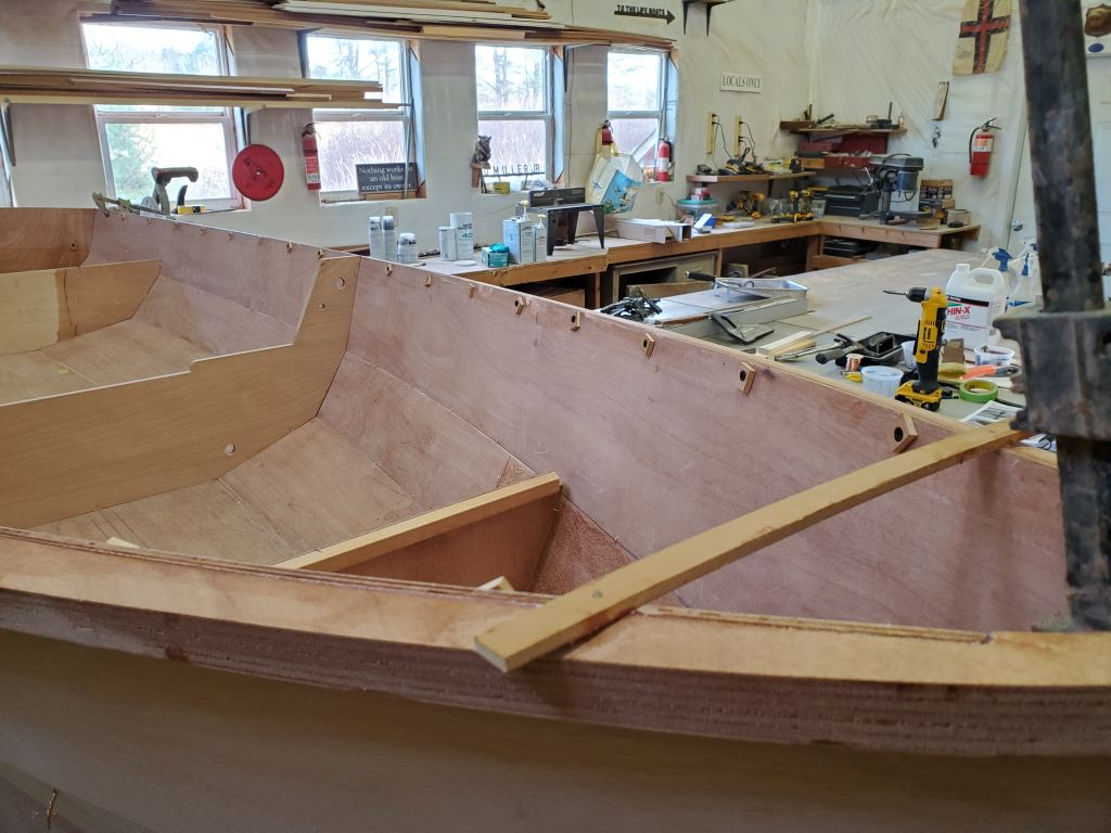
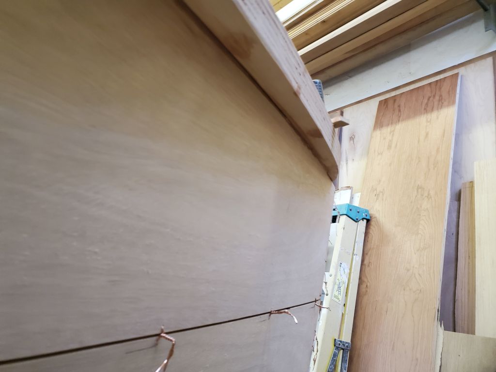
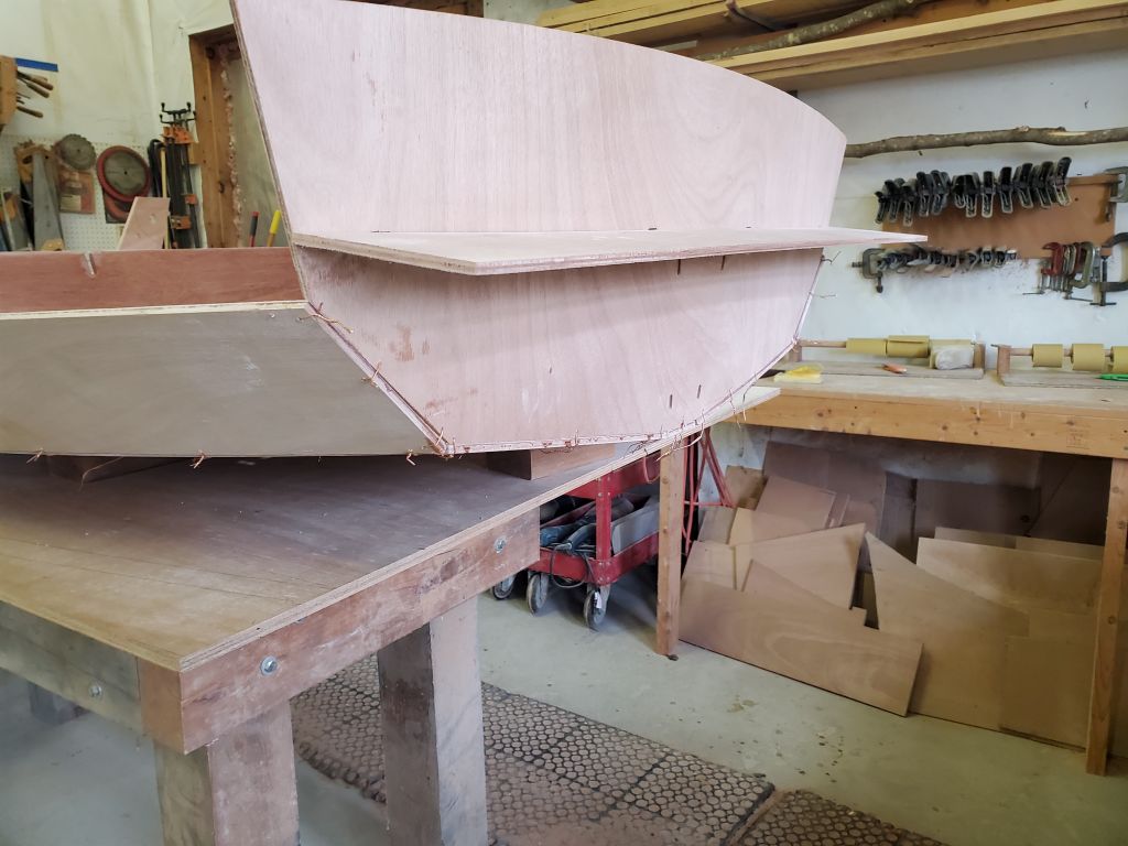
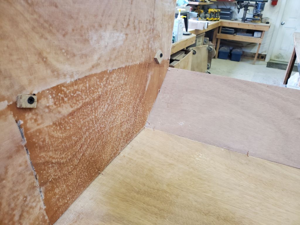
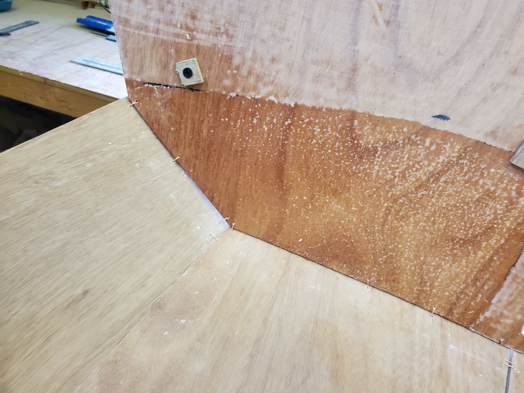
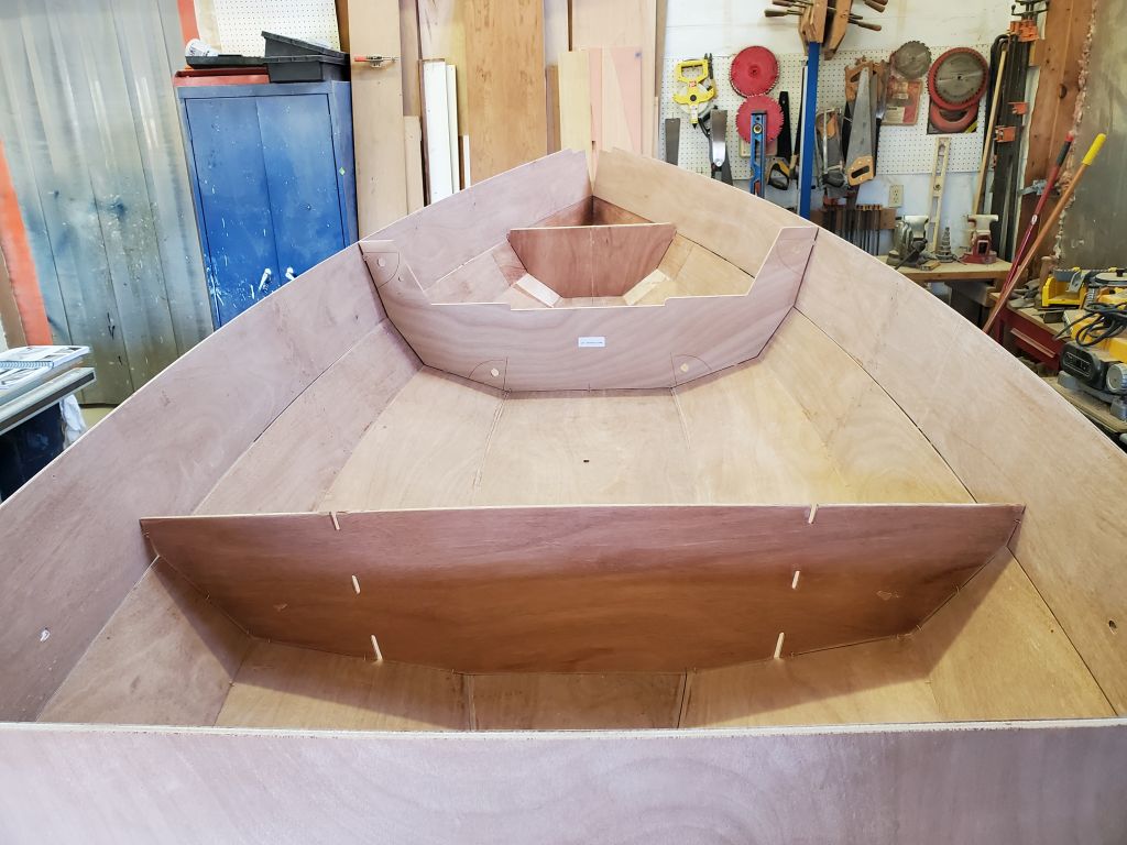
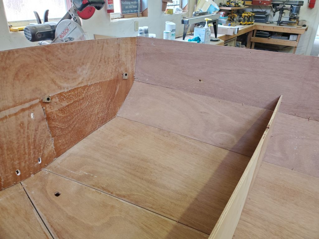
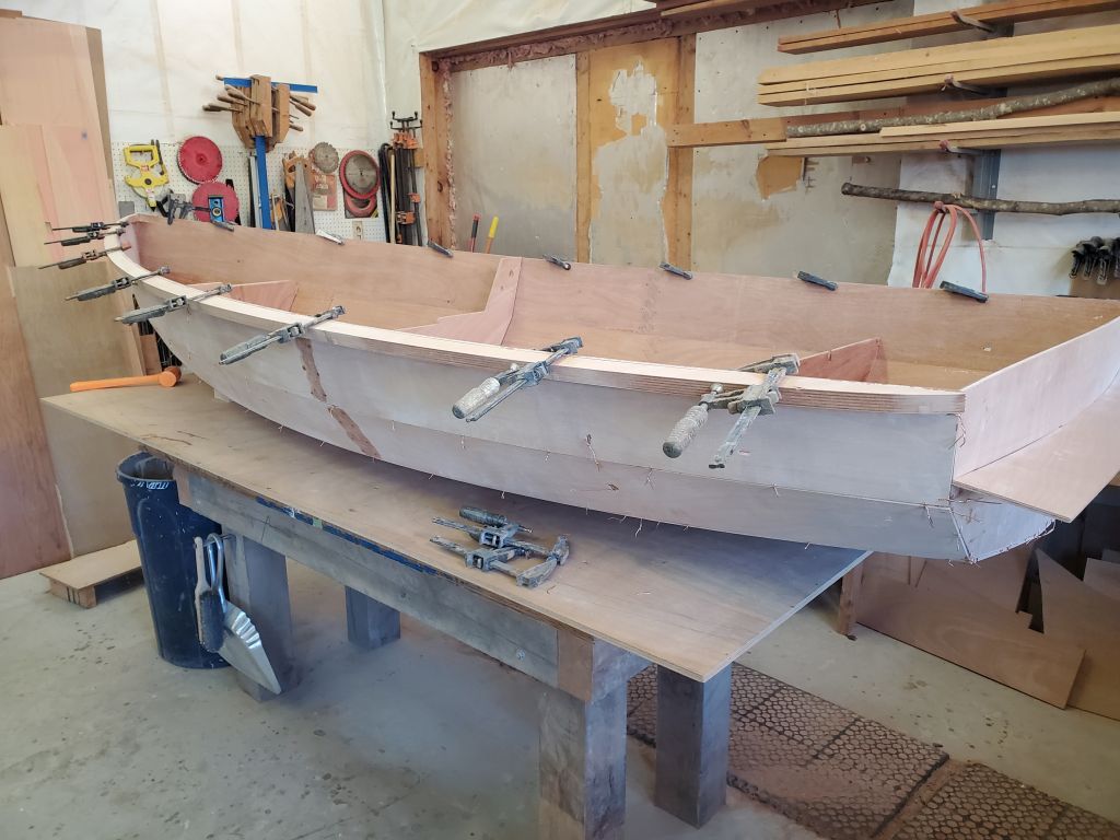
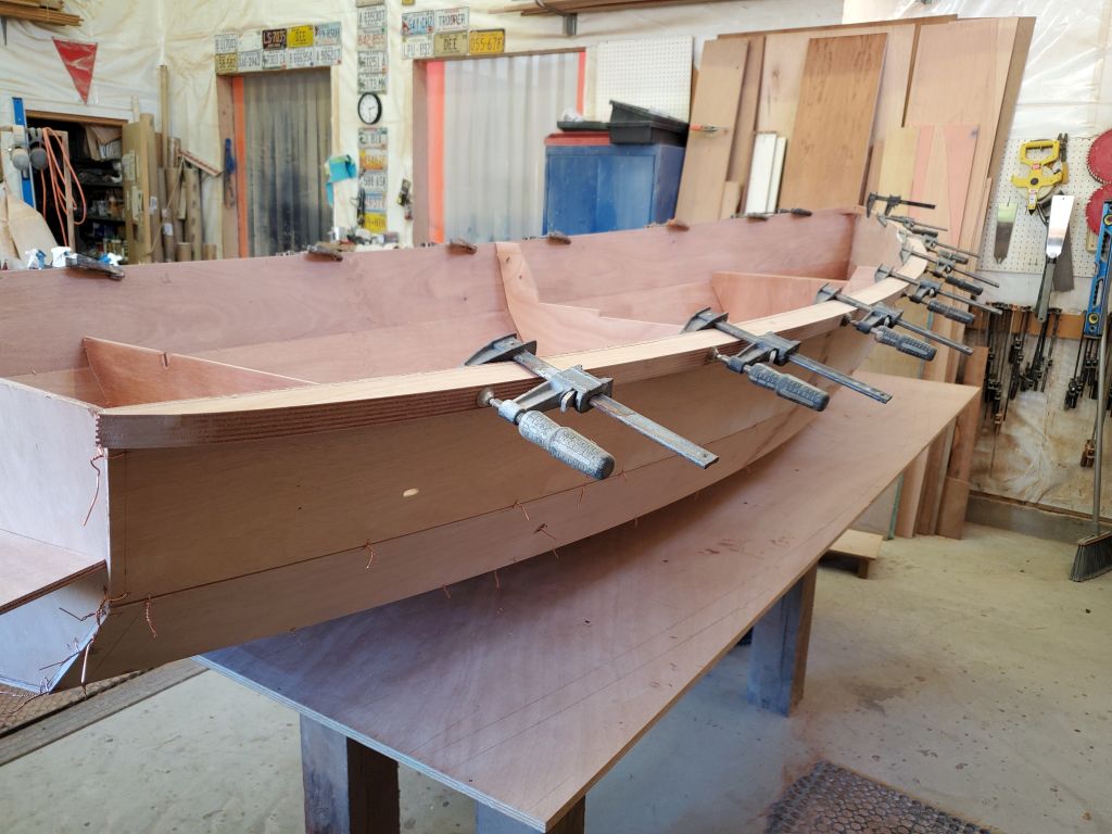
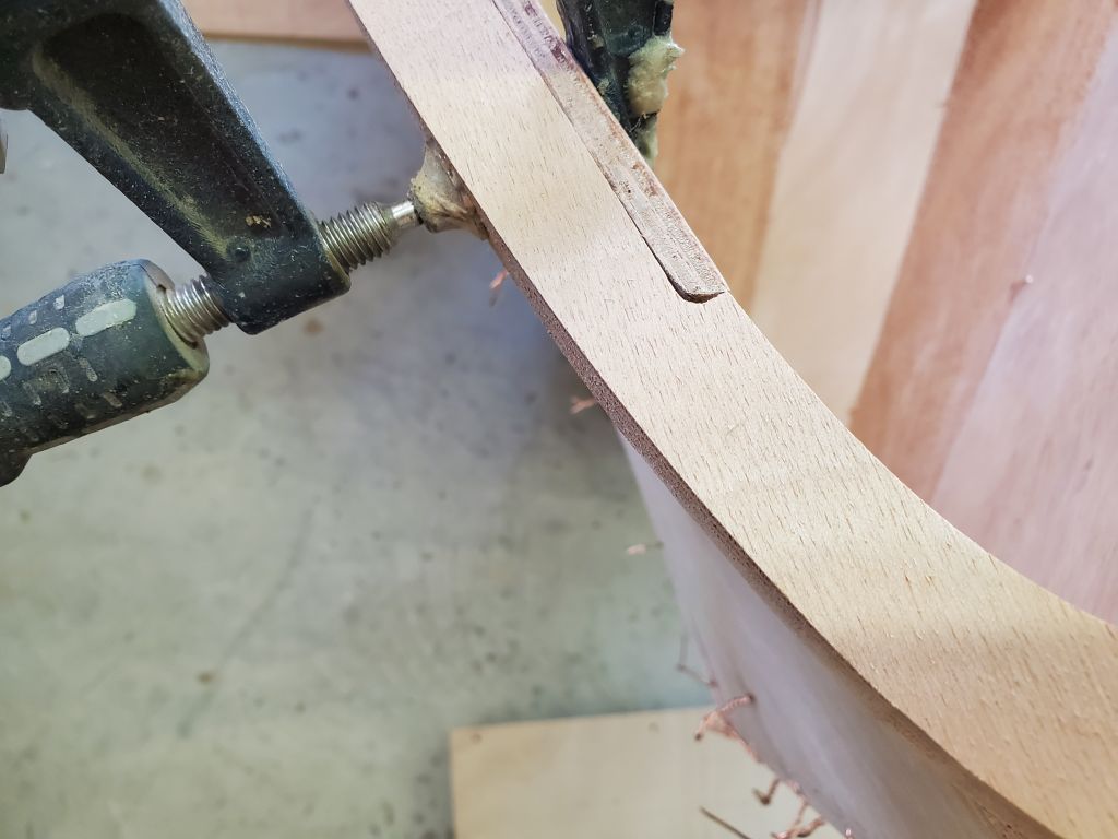
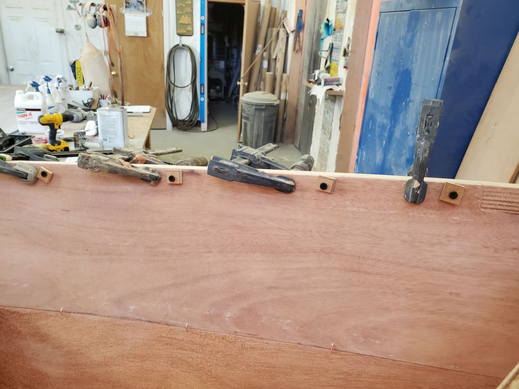
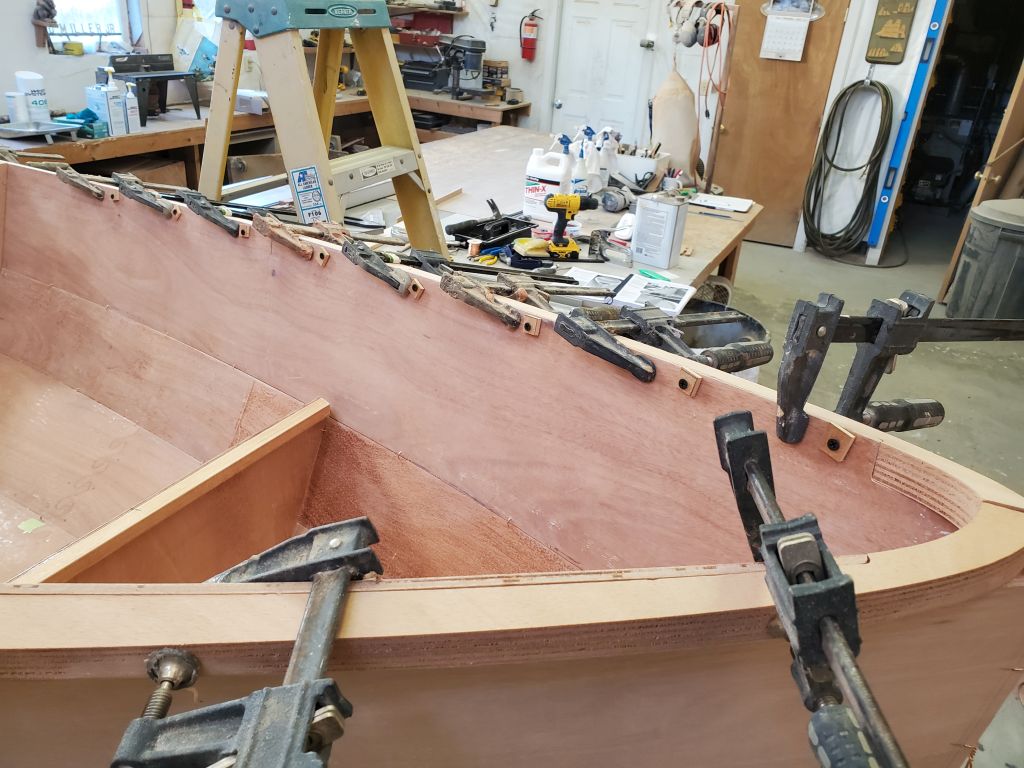
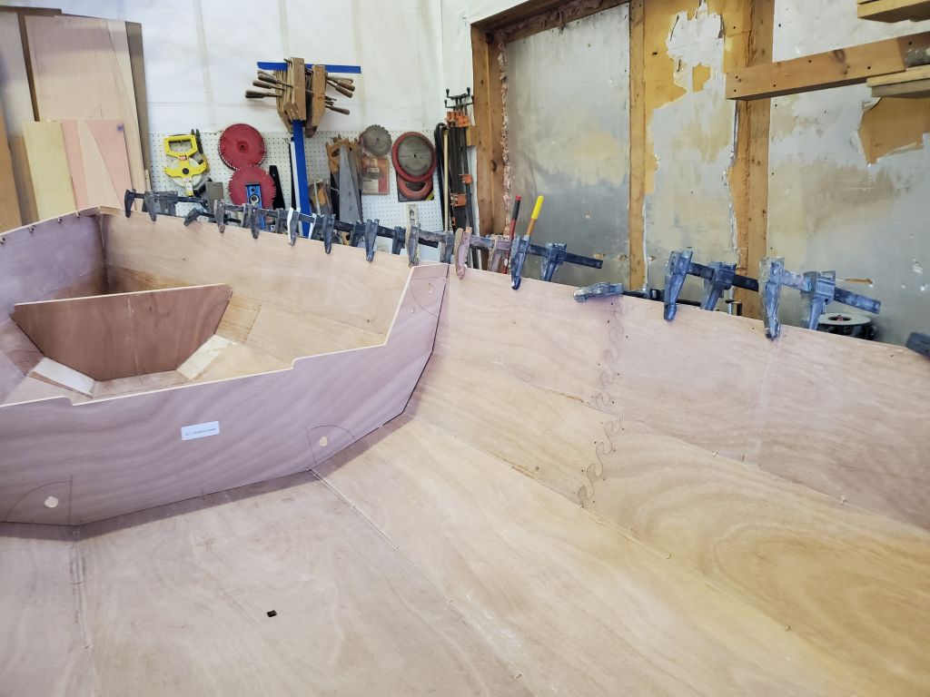
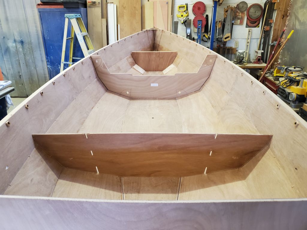
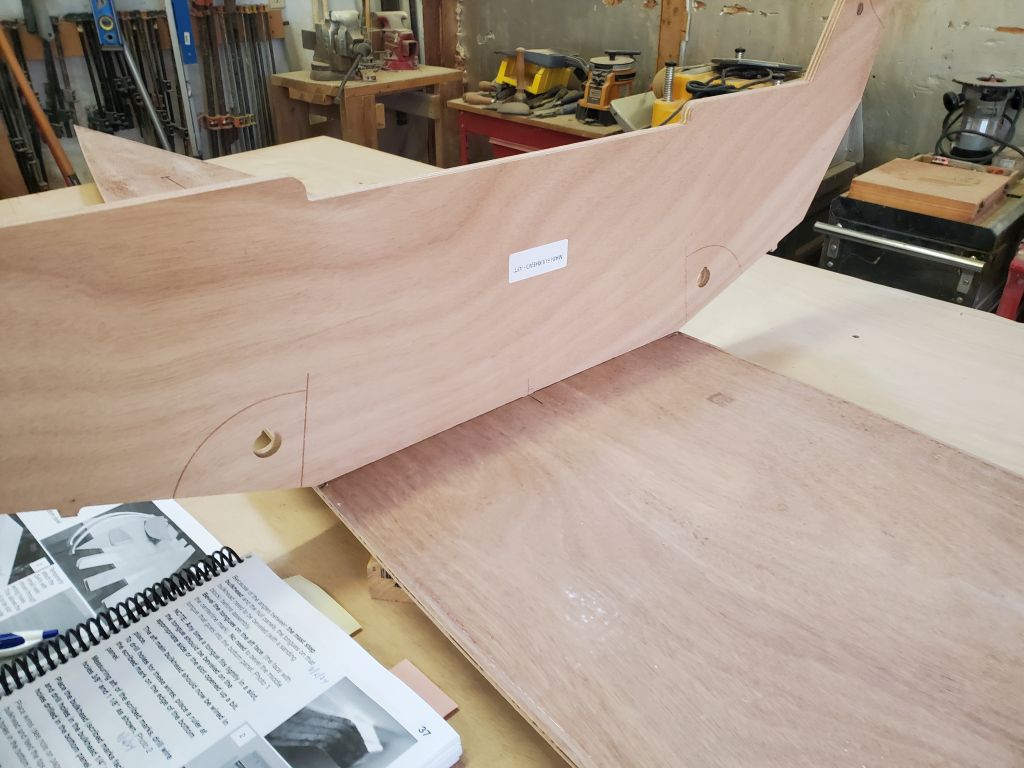
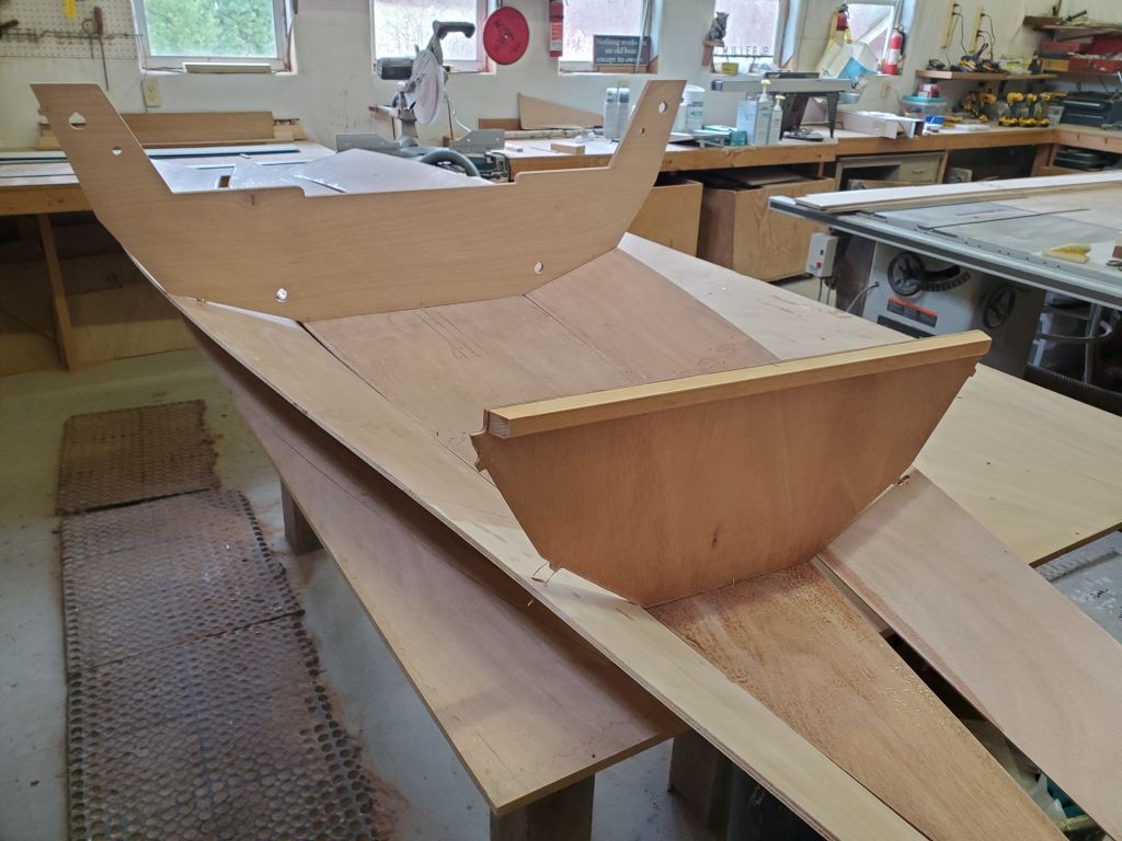
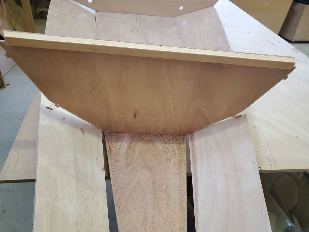
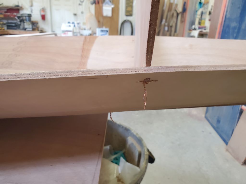
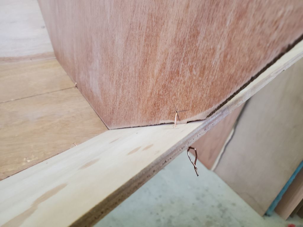
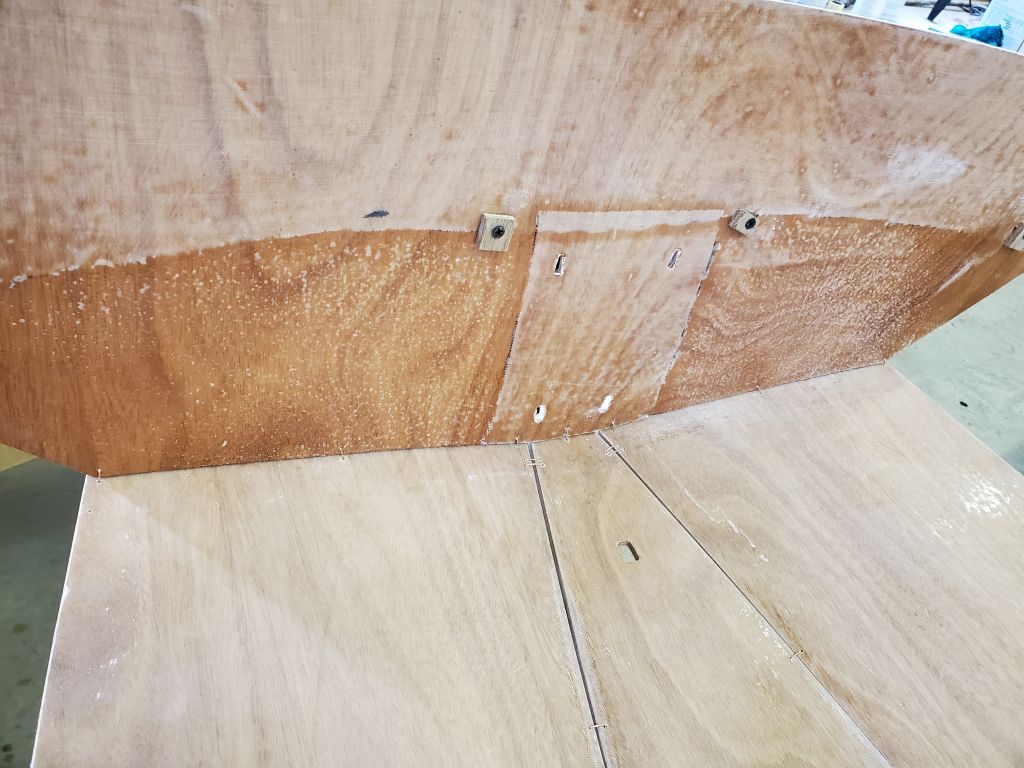
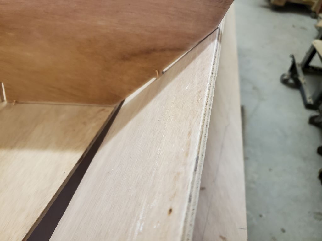
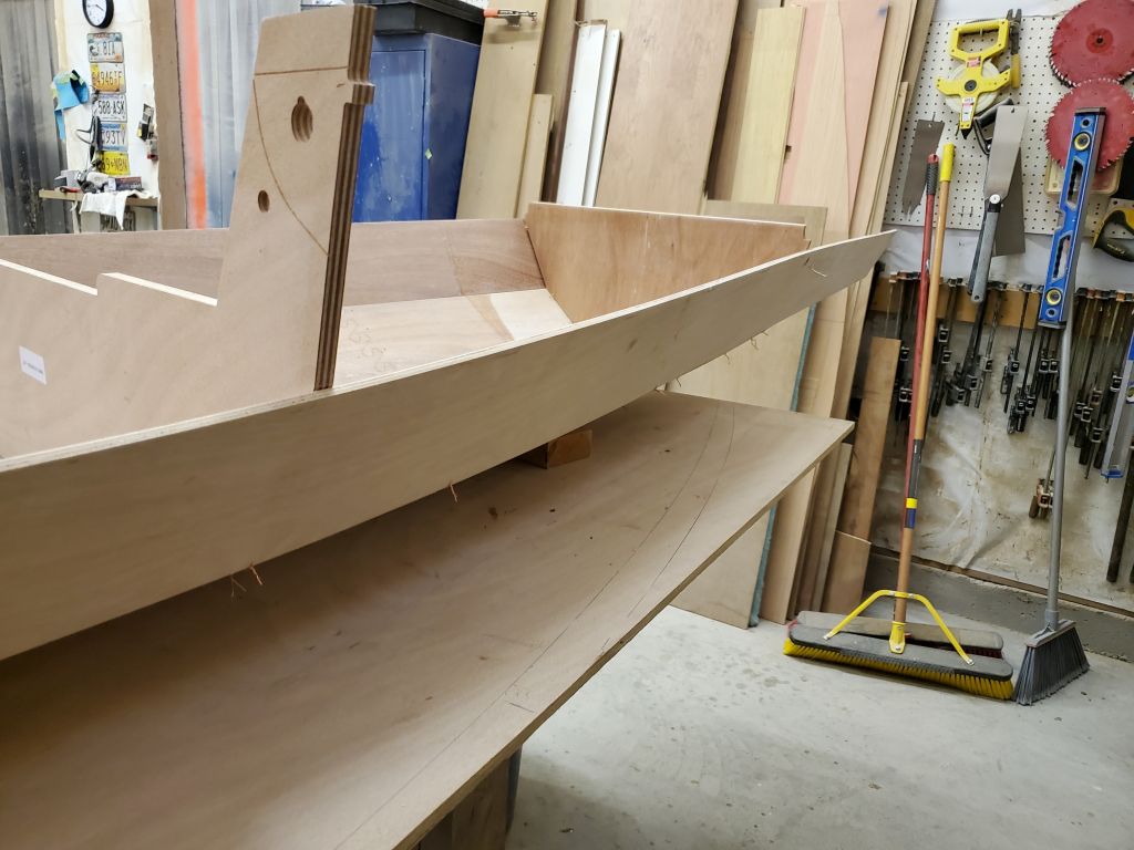
At the transom, my next step was to install the top layer of the two-part inwale, a structural member that would stiffen and reinforce the transom and aft end of the hull. To hold and align the part during installation, I installed some small blocks with hot glue then, after pulling the piece into the transom corners and aligning it as needed, nailed into the top edge of the hull through the outer part of these blocks.
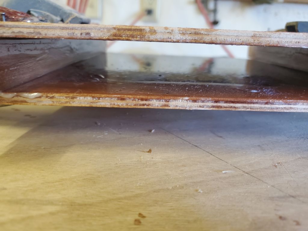
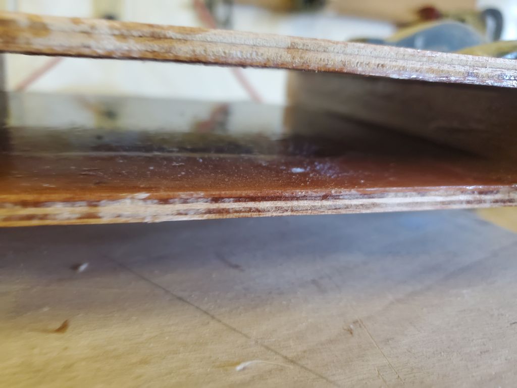
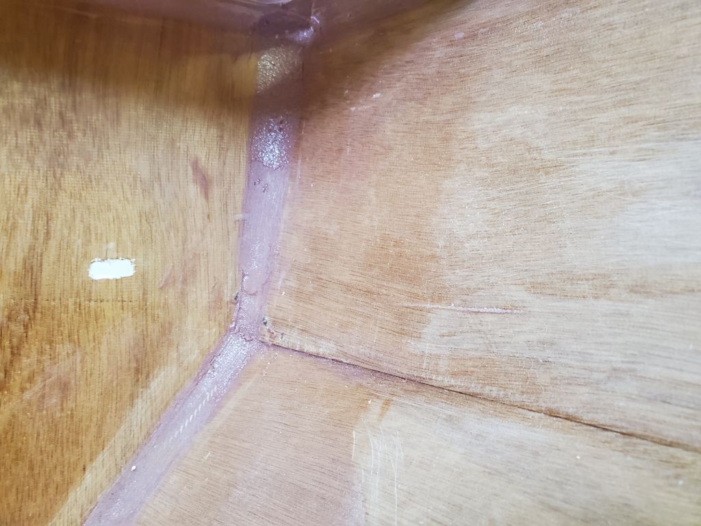
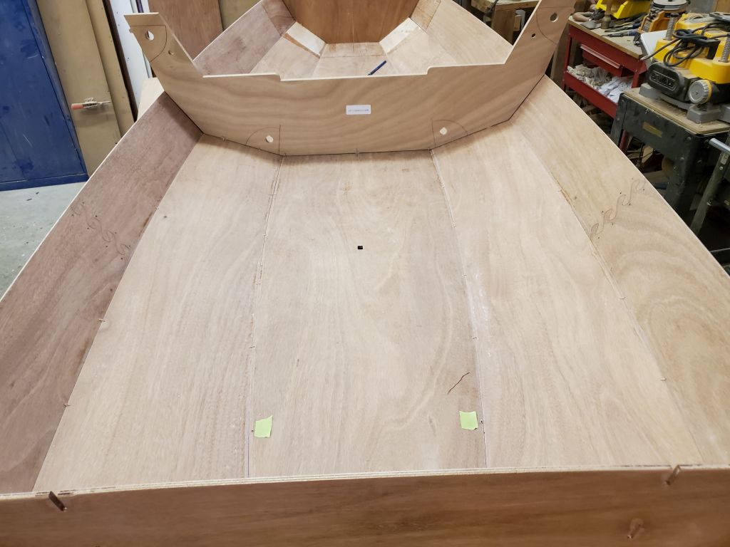
To secure the part, I injected unthickened epoxy around the edges from above, then followed with some thickened epoxy. Because the edges of the inwale were square, and the hull and transom slightly angled, this left a small open gap at top to accept this epoxy. At the same time, I epoxied the inside seams where the transom met the hull, doing my best to avoid the wires.
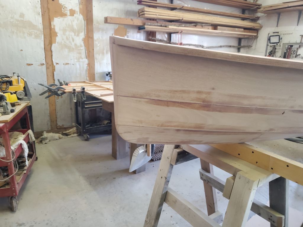
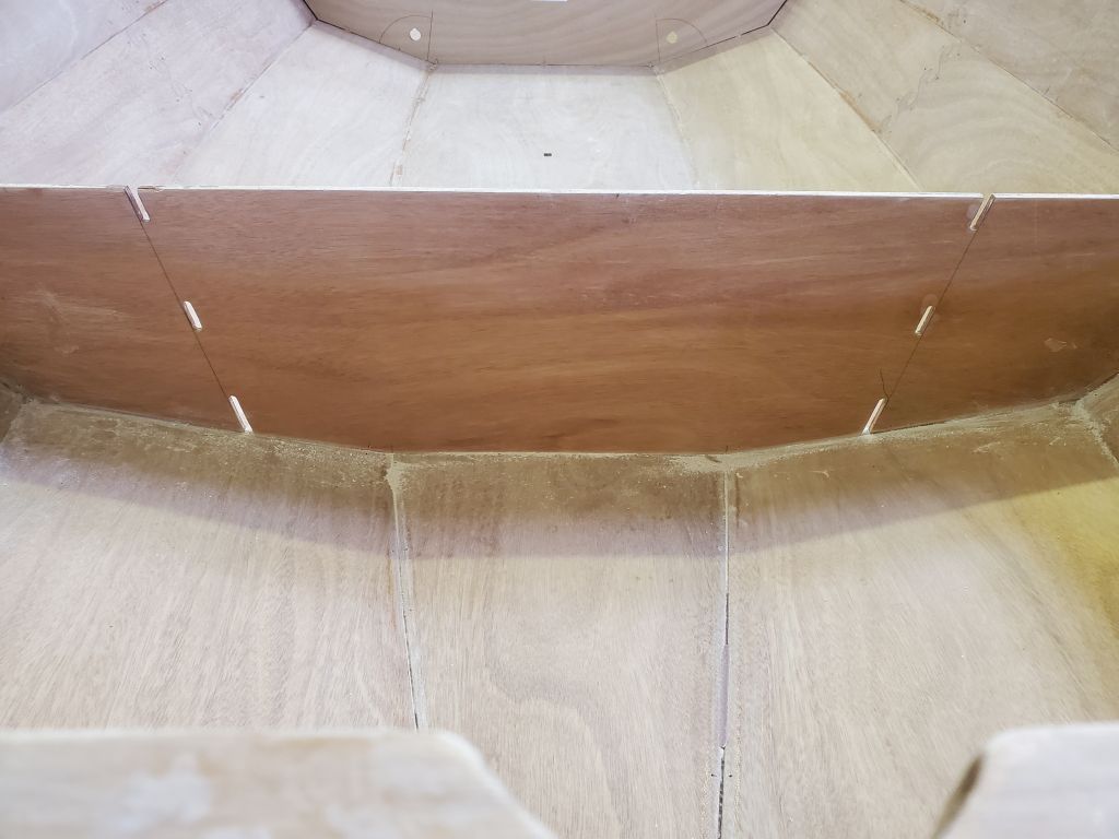
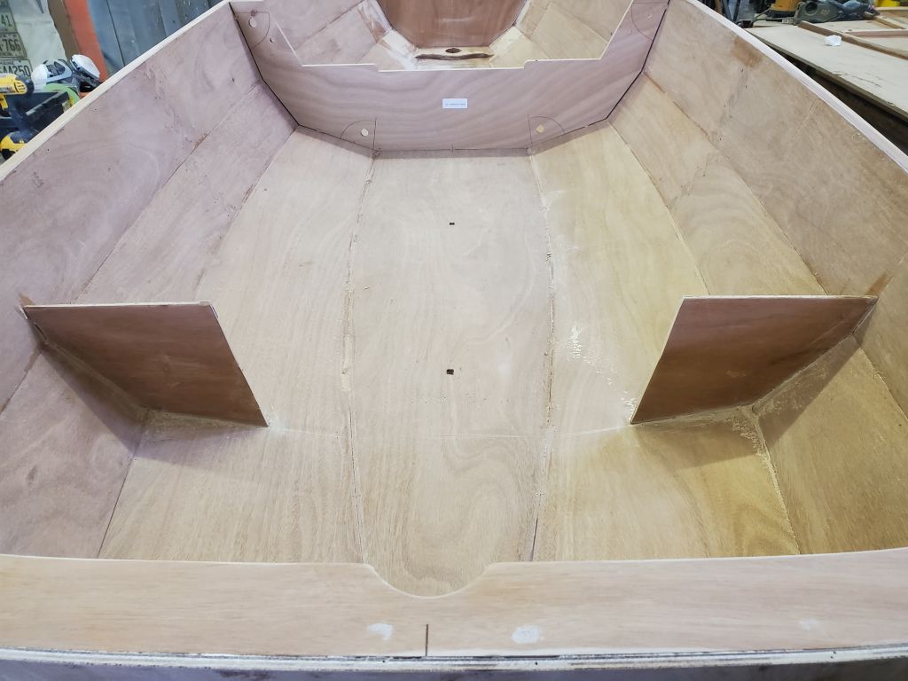
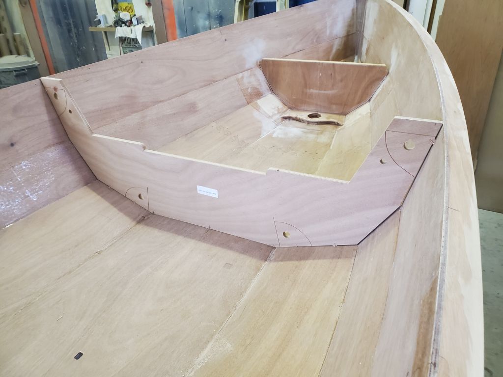
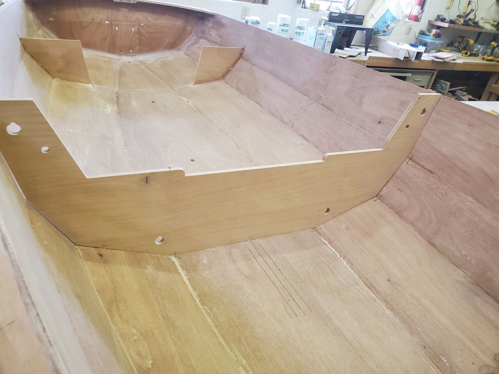
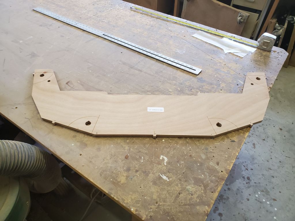
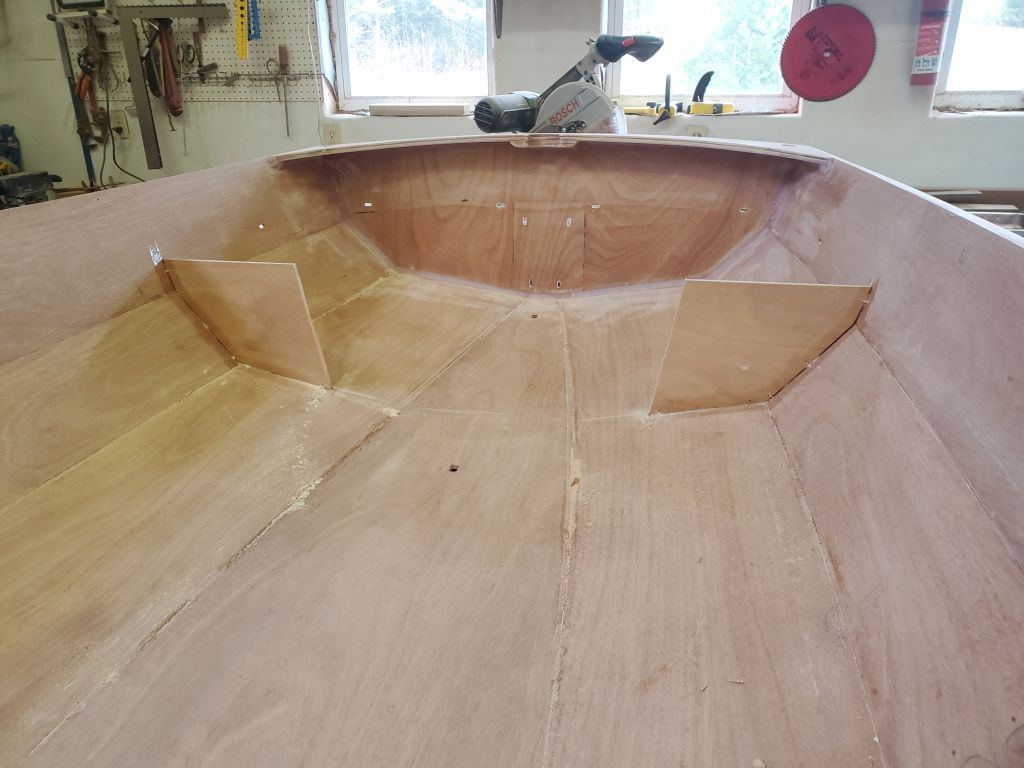
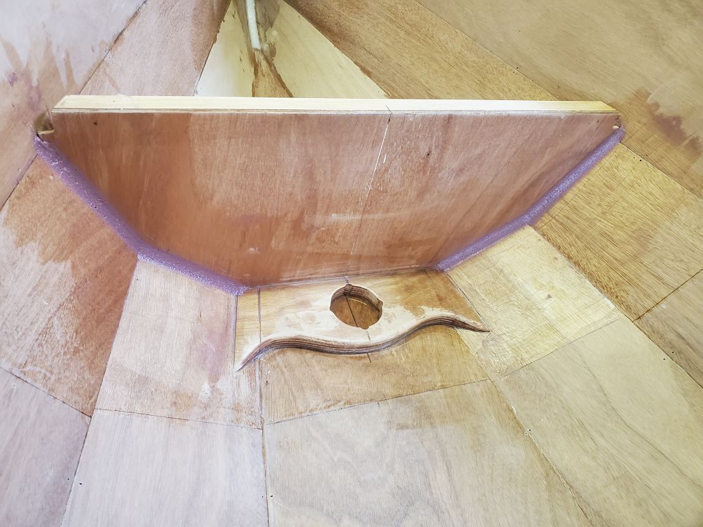
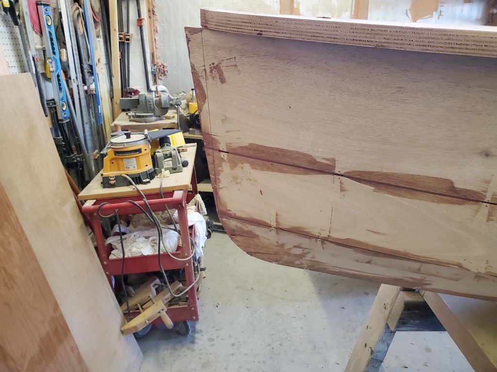
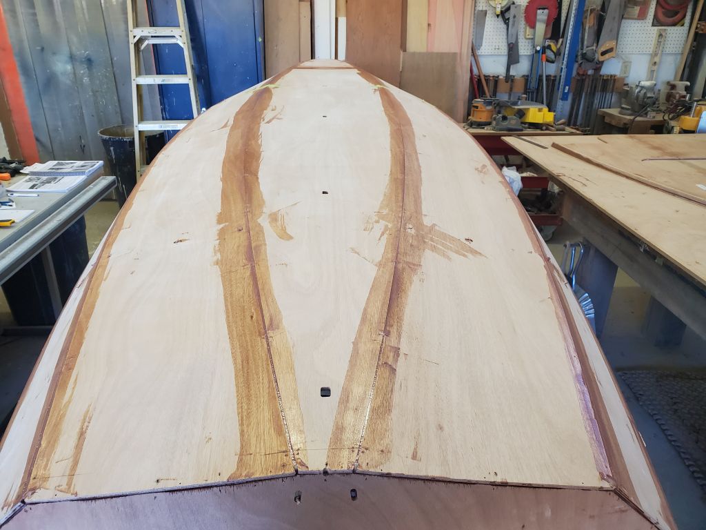
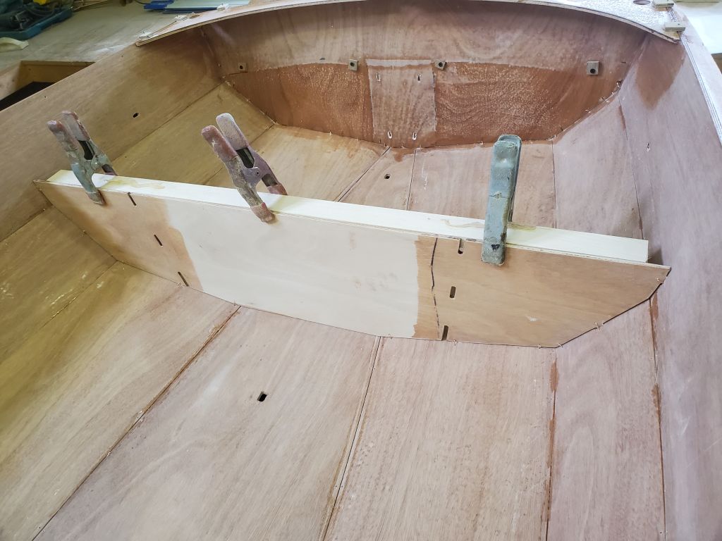
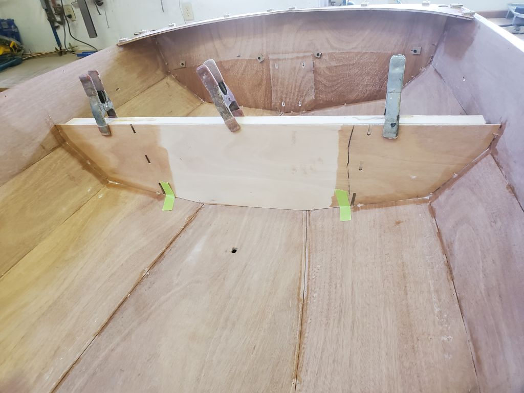
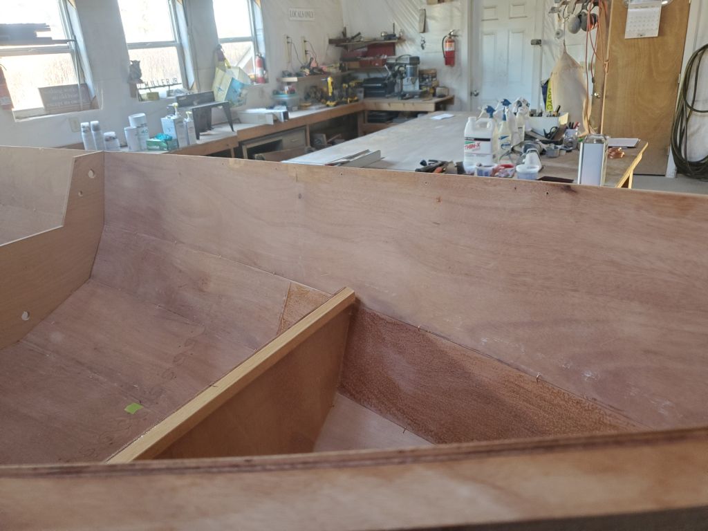
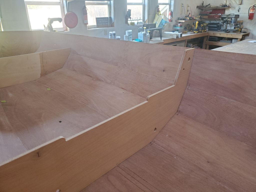
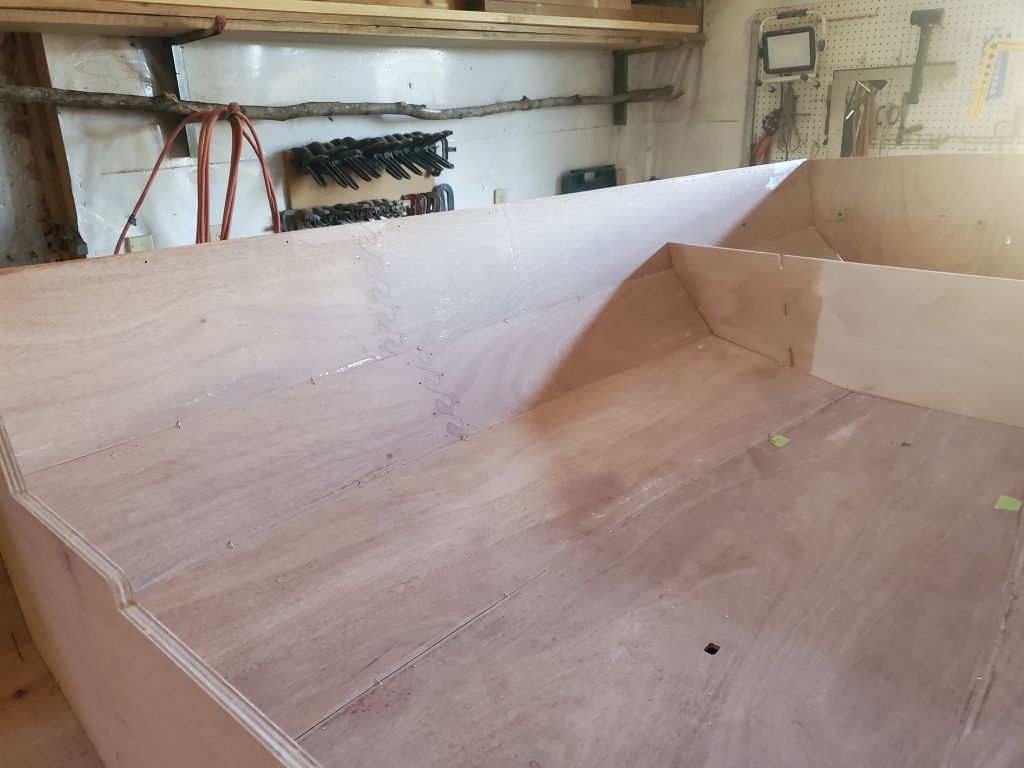
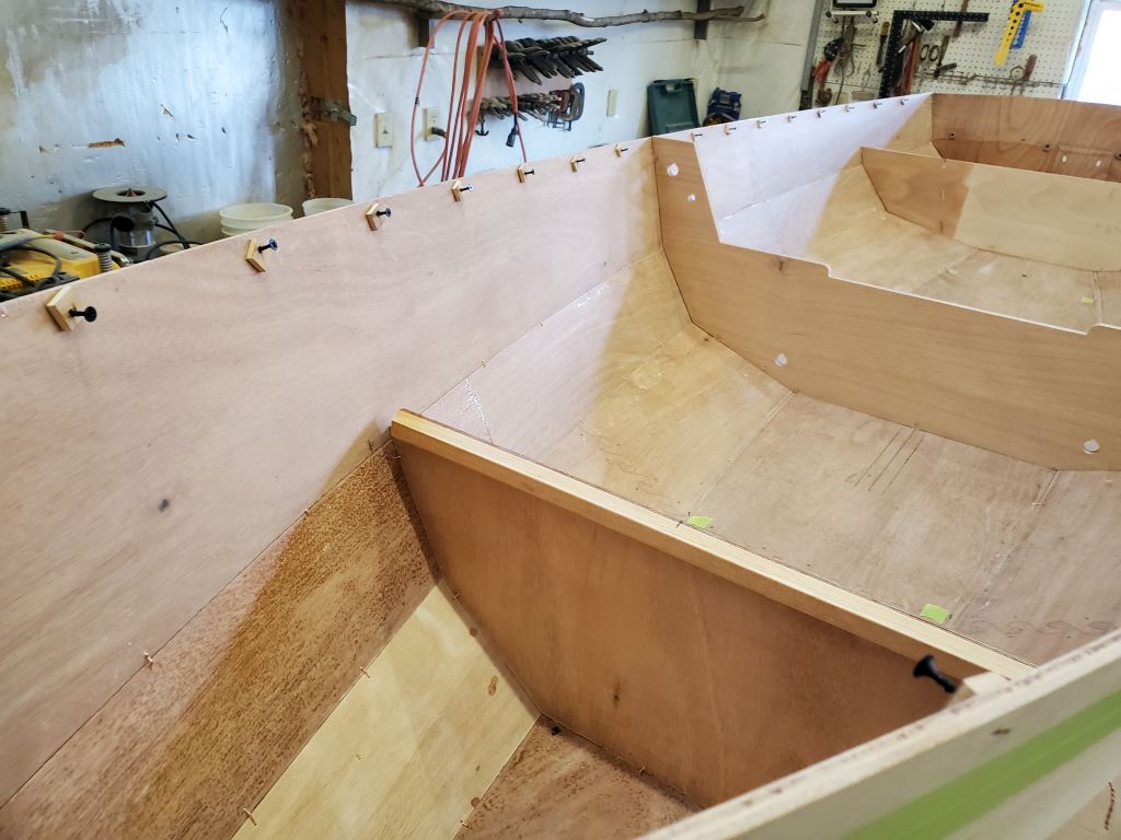
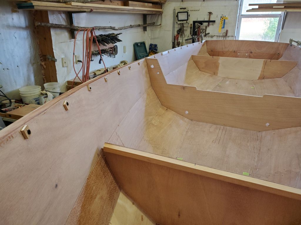
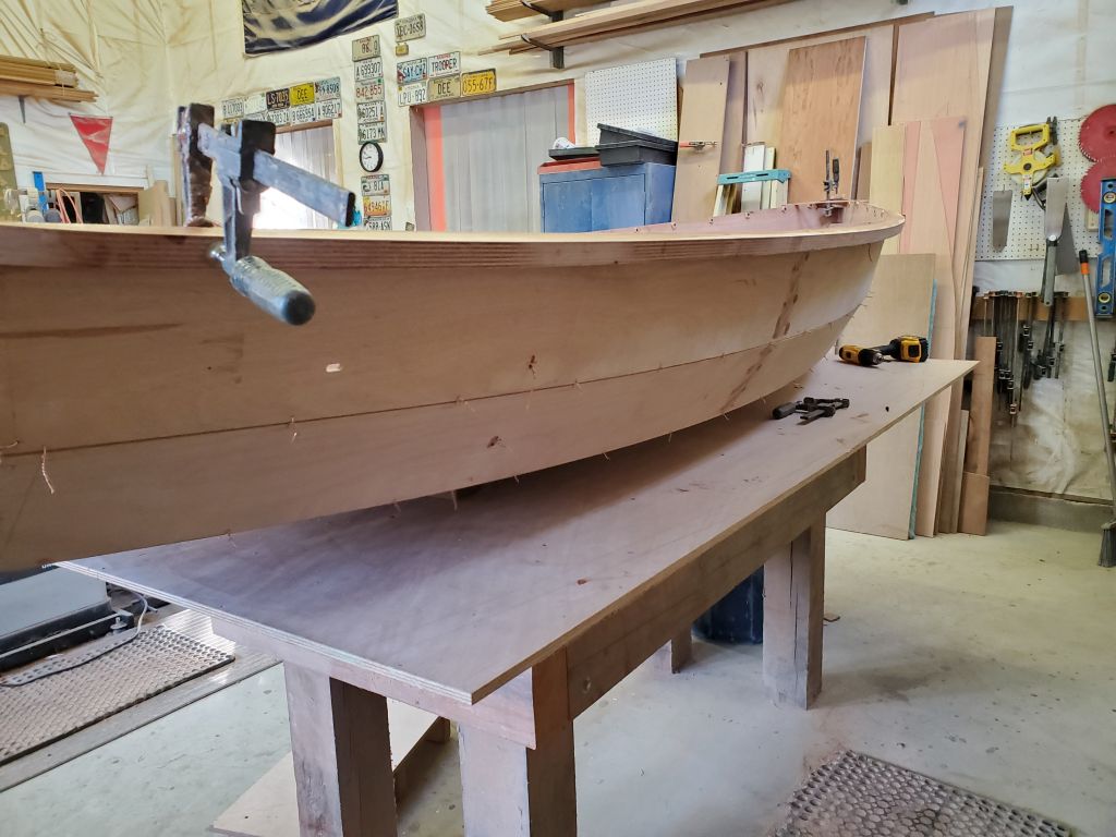
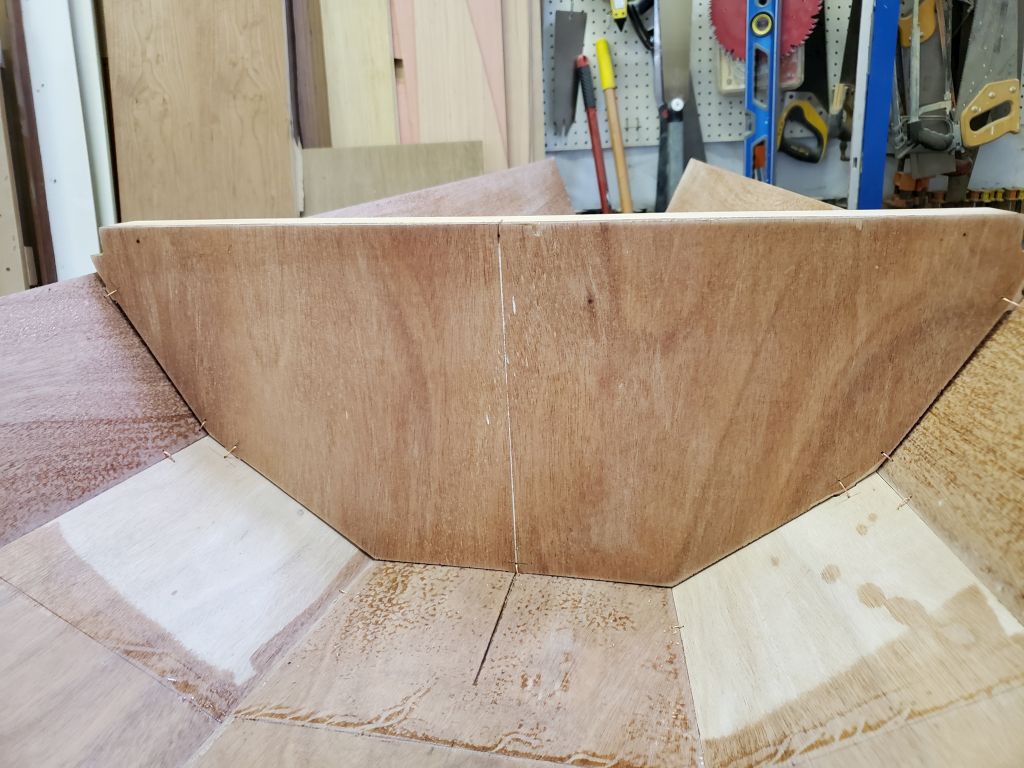
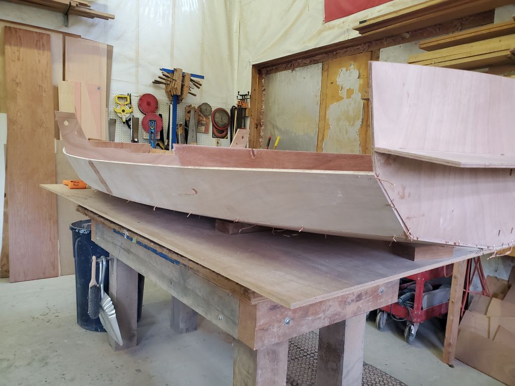
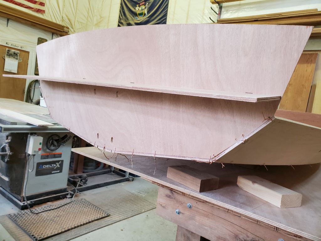
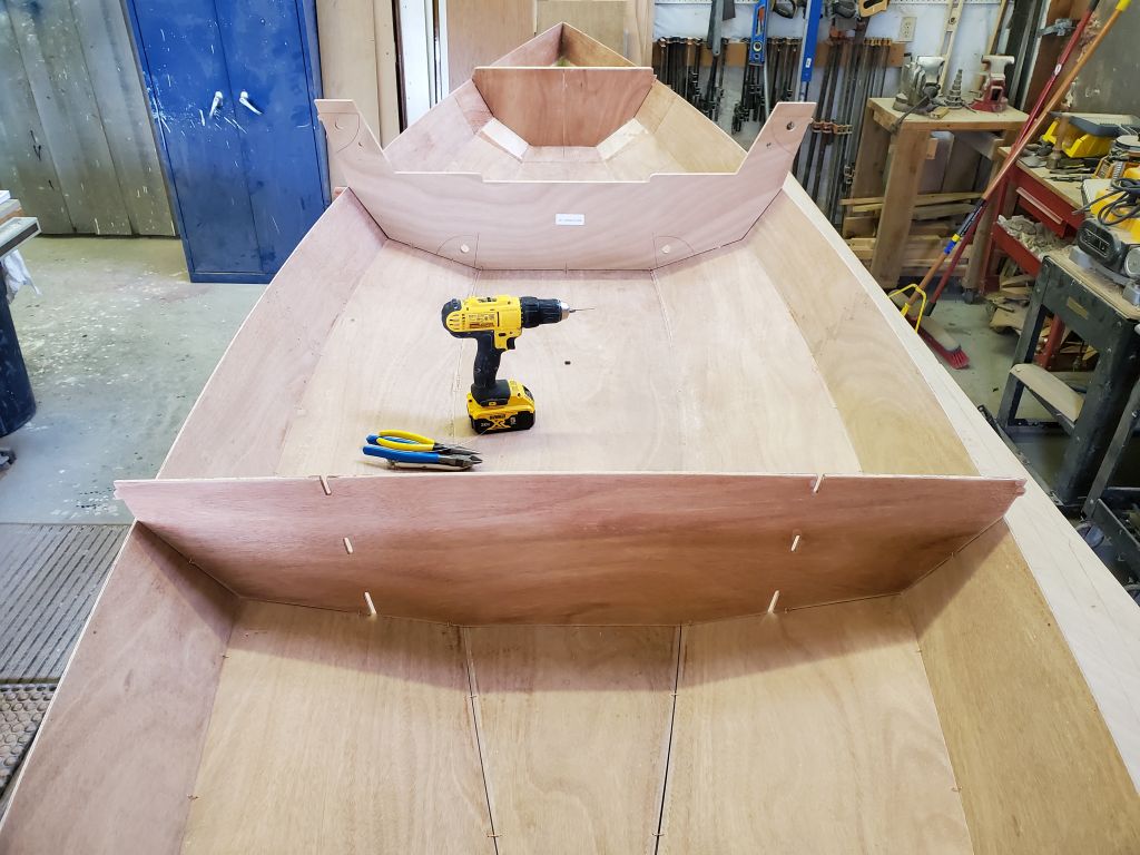
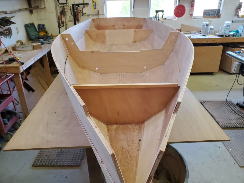
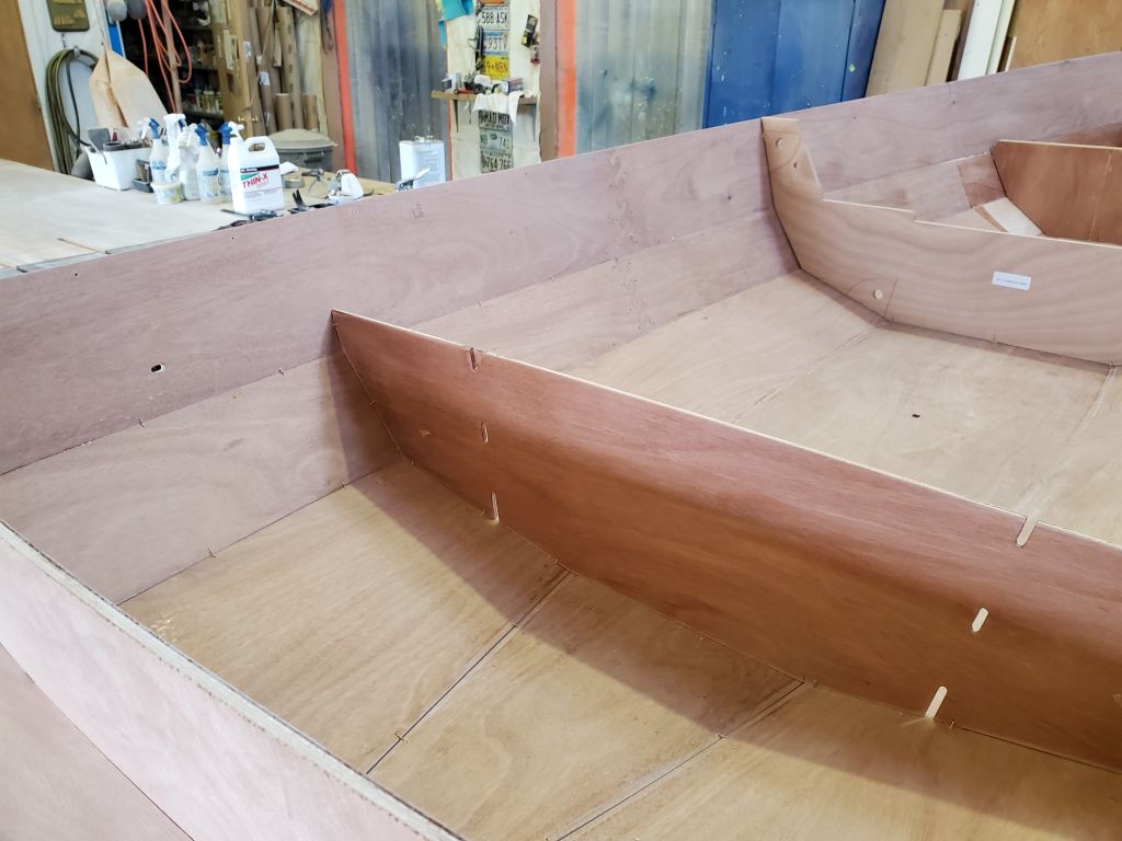
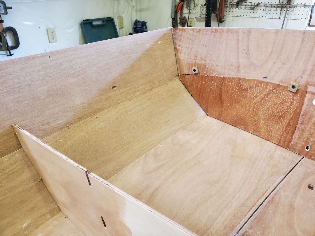
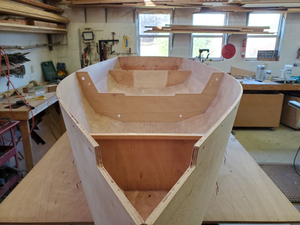
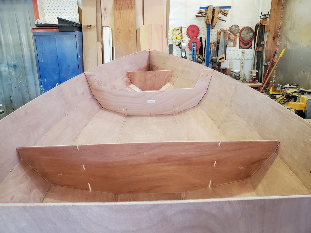
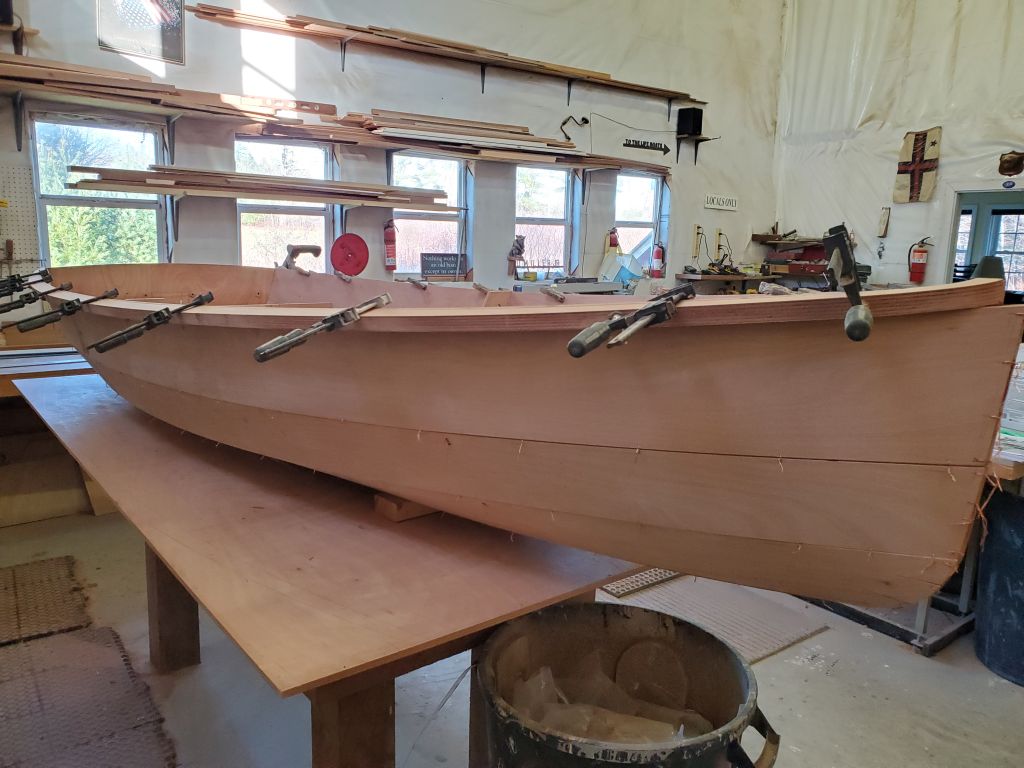
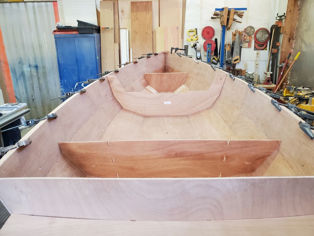
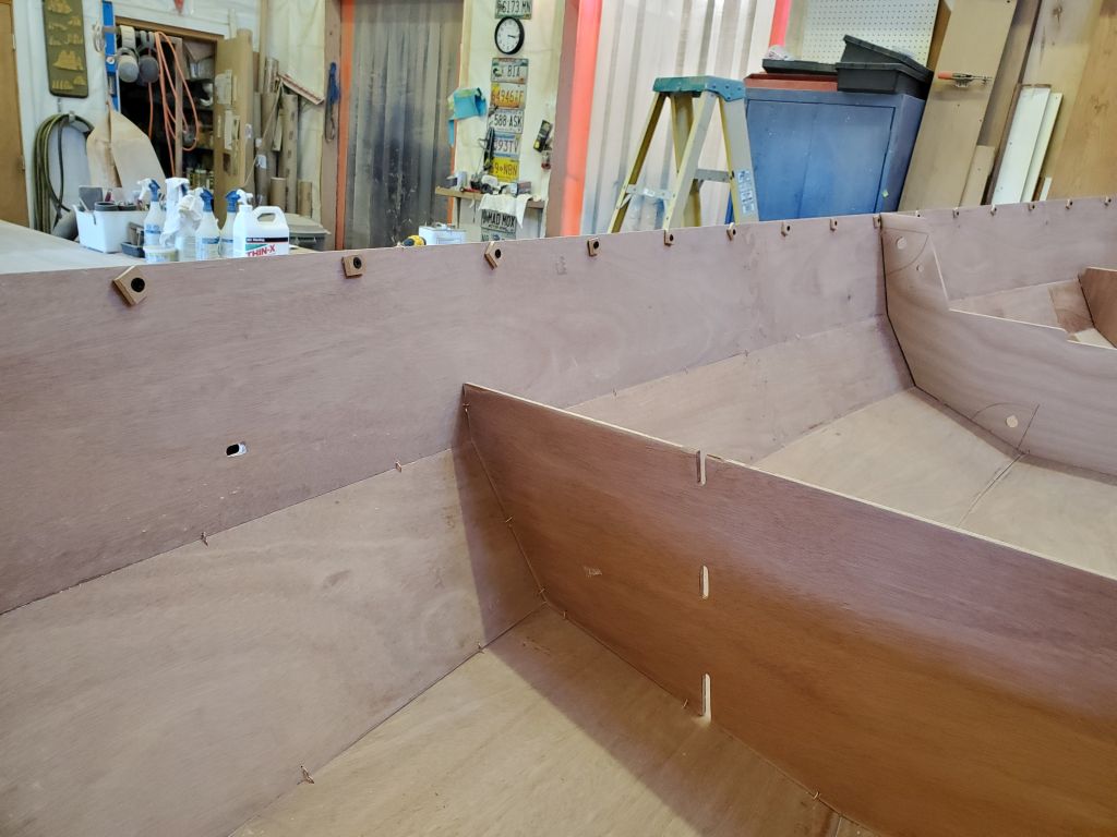
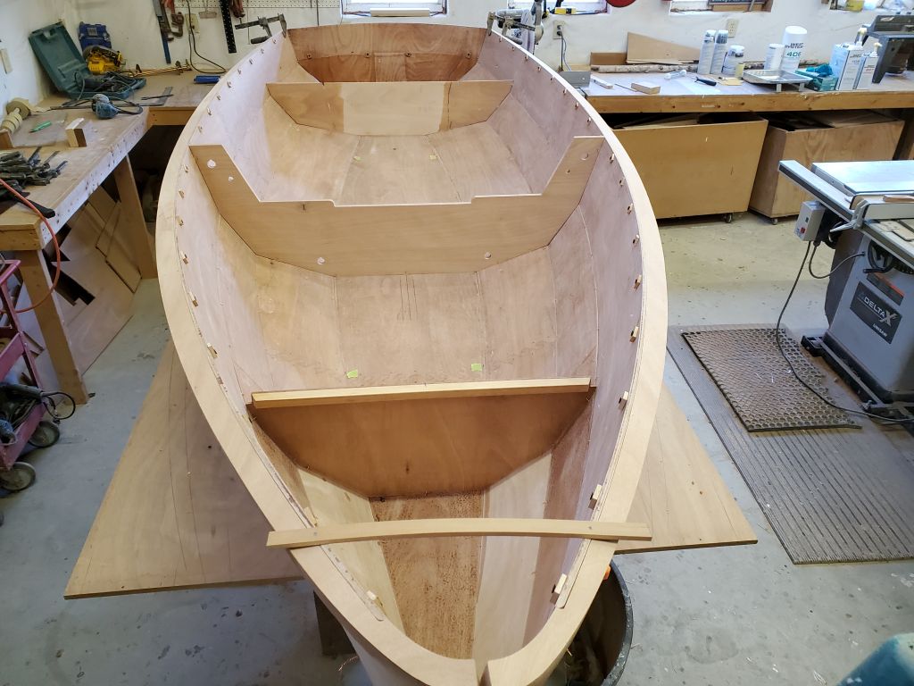
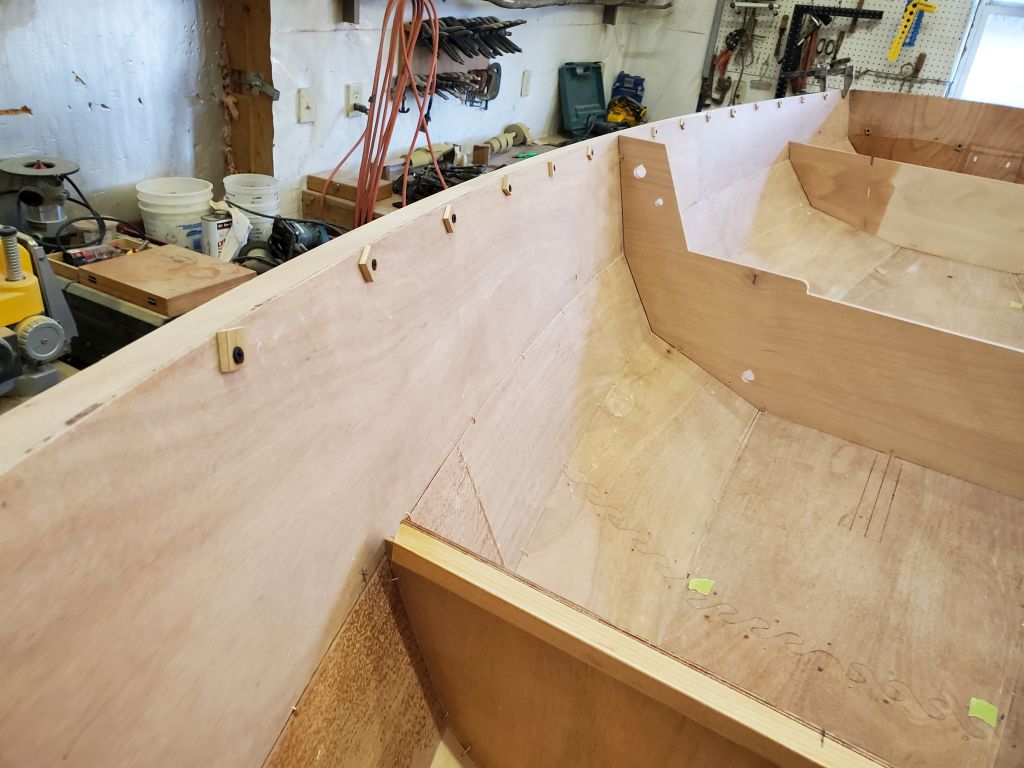
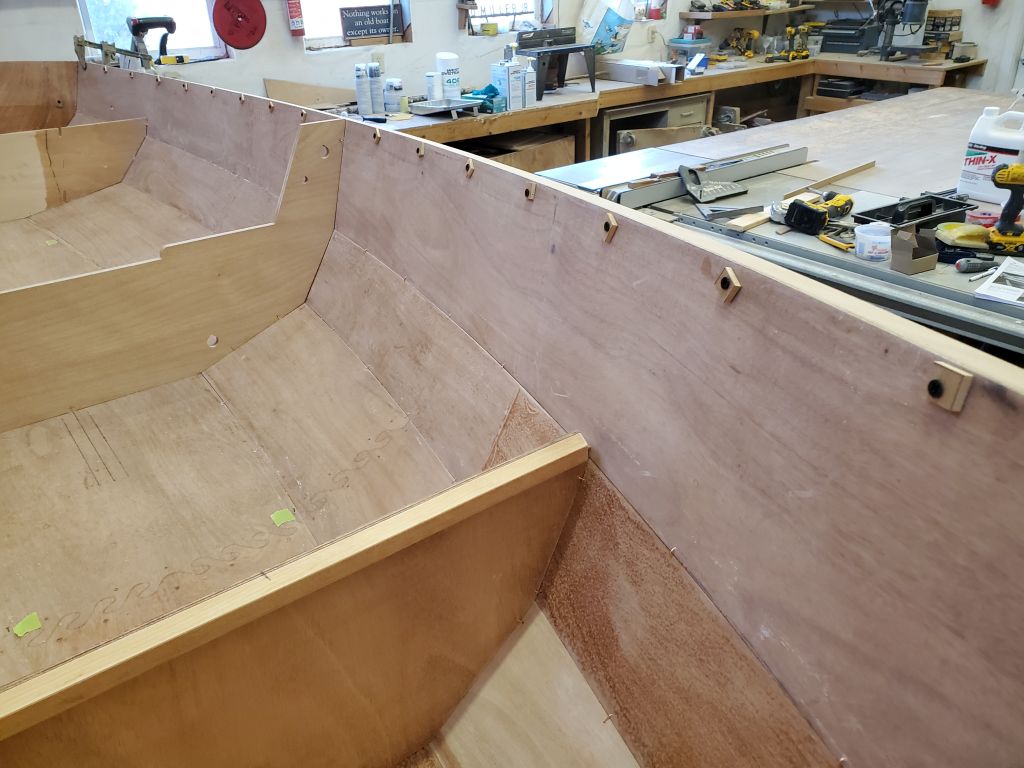
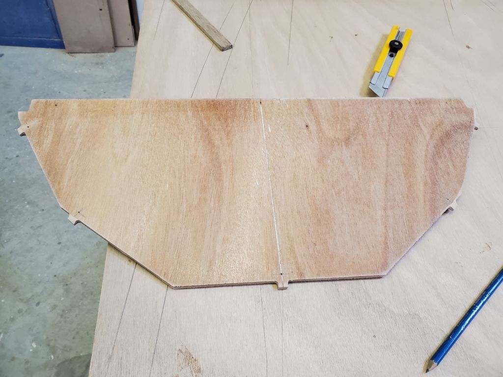
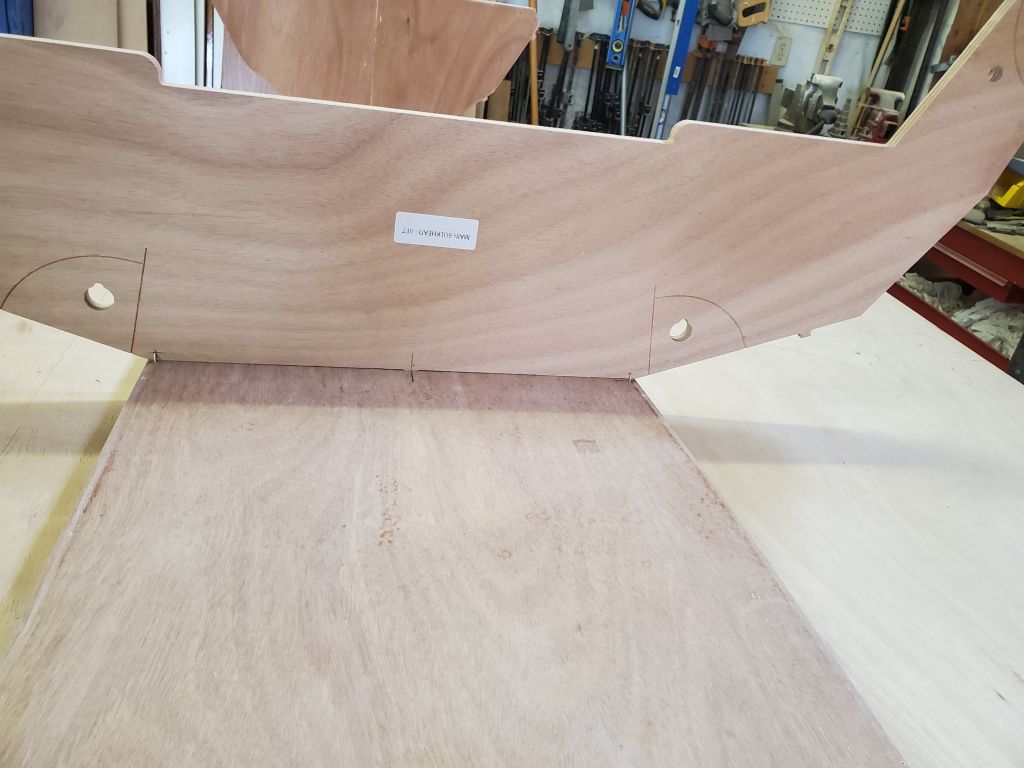
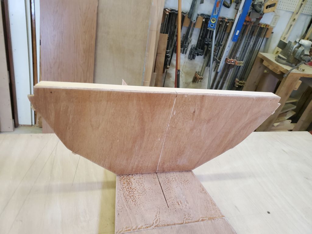
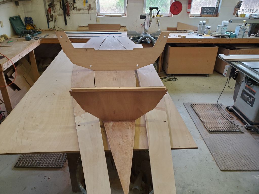
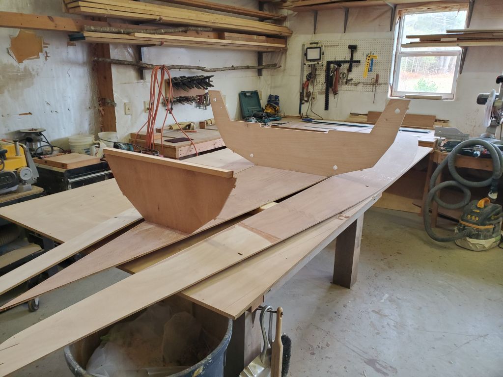
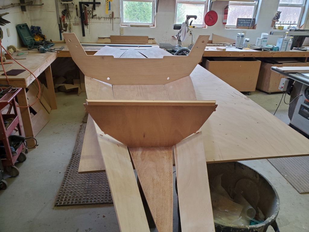
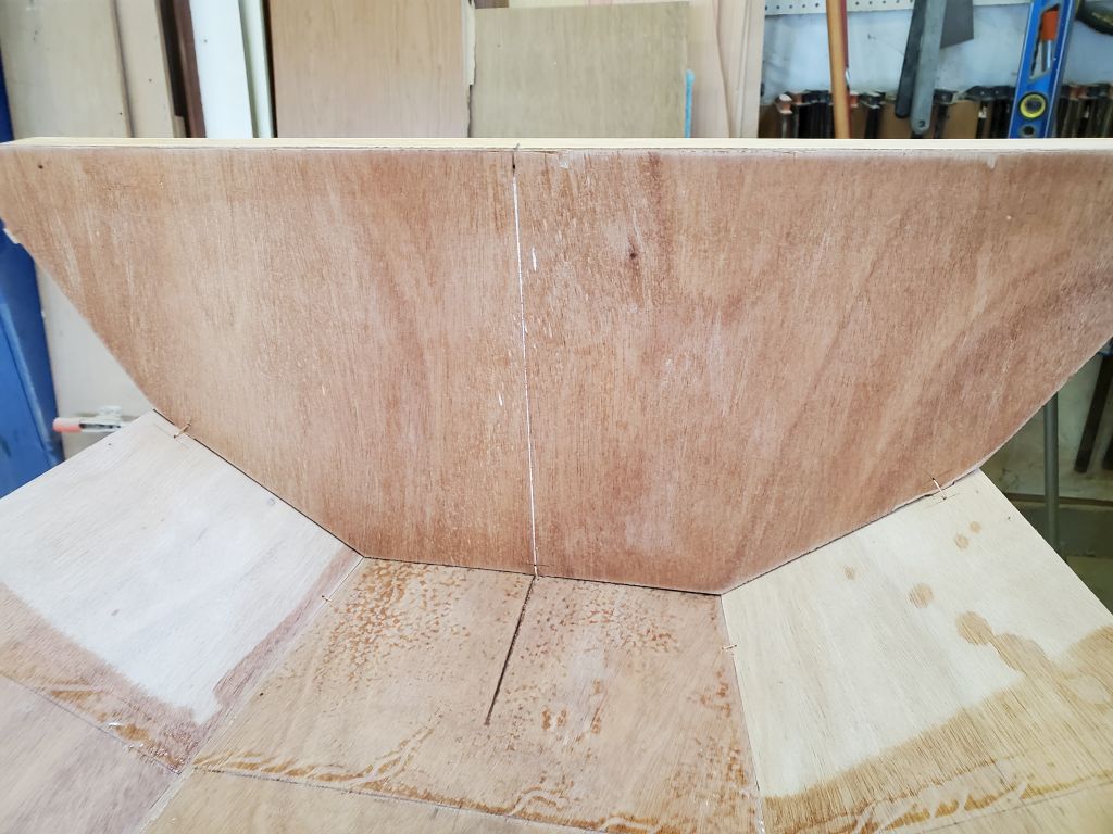
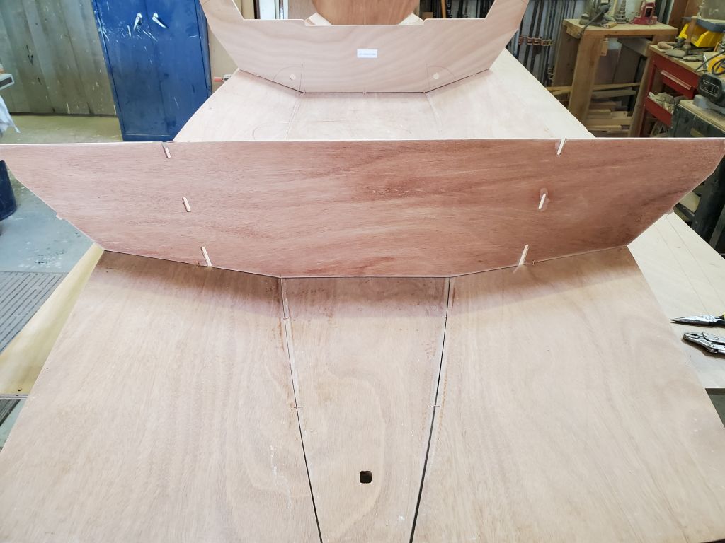
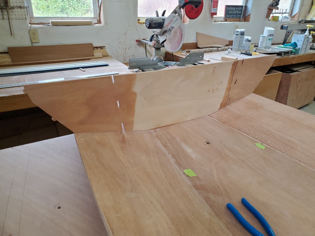
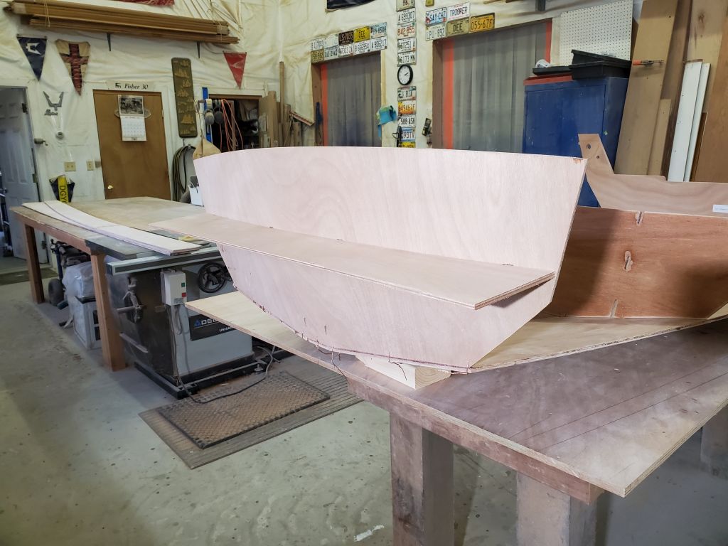
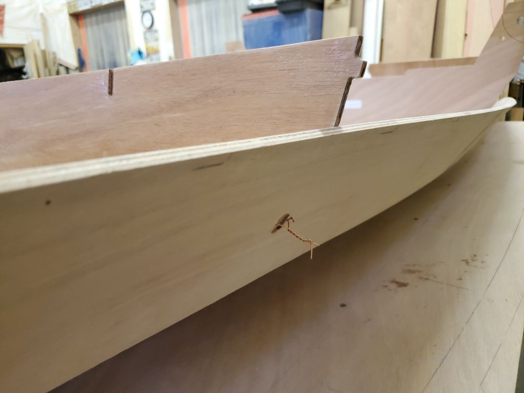
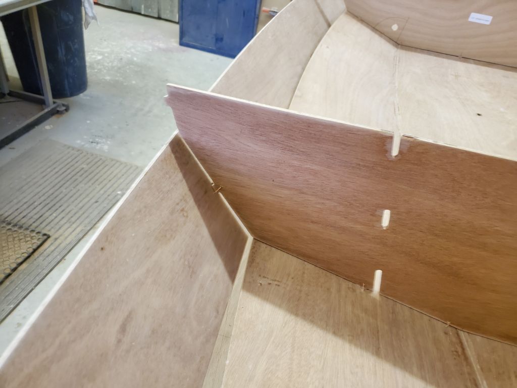
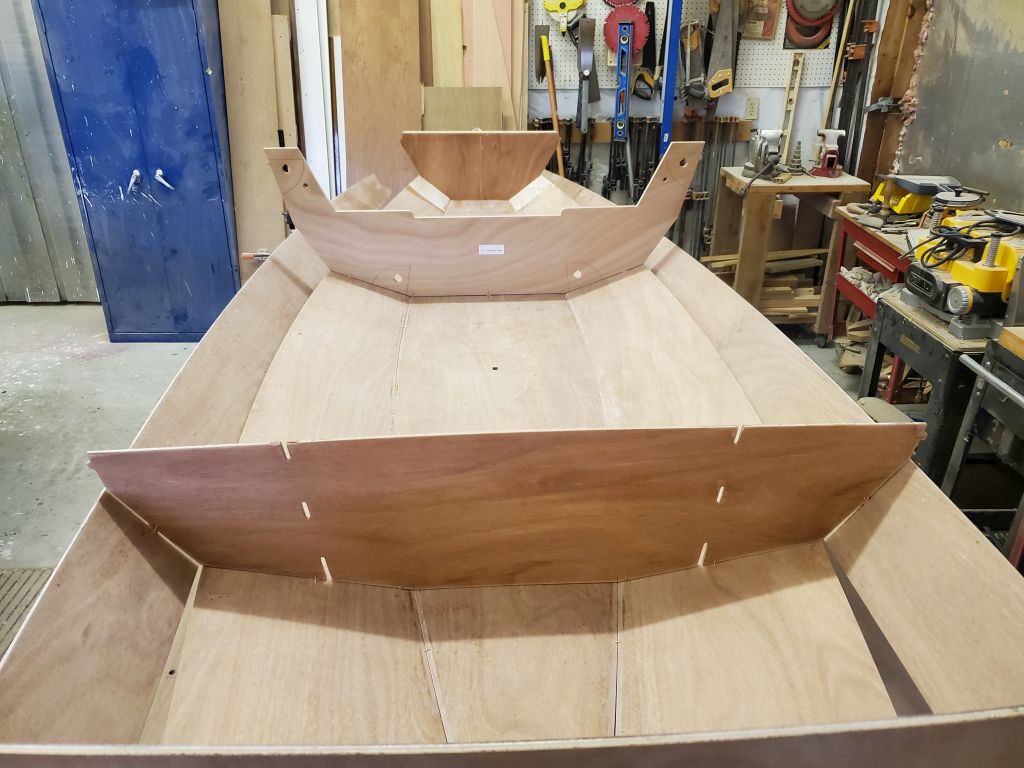
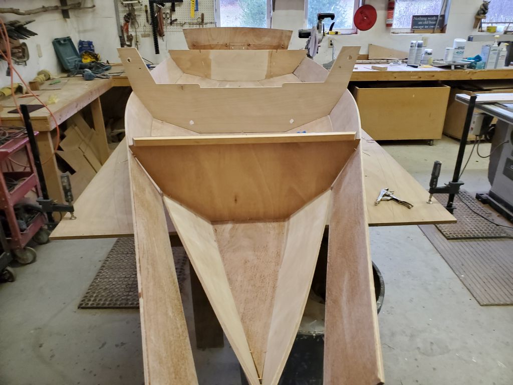
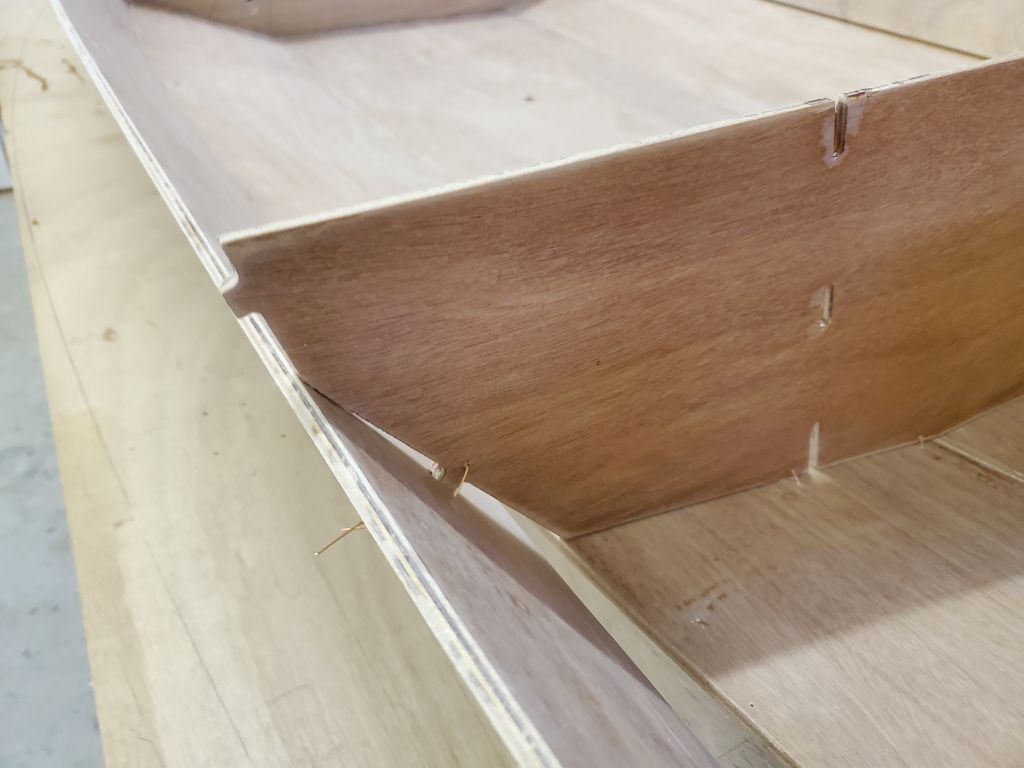
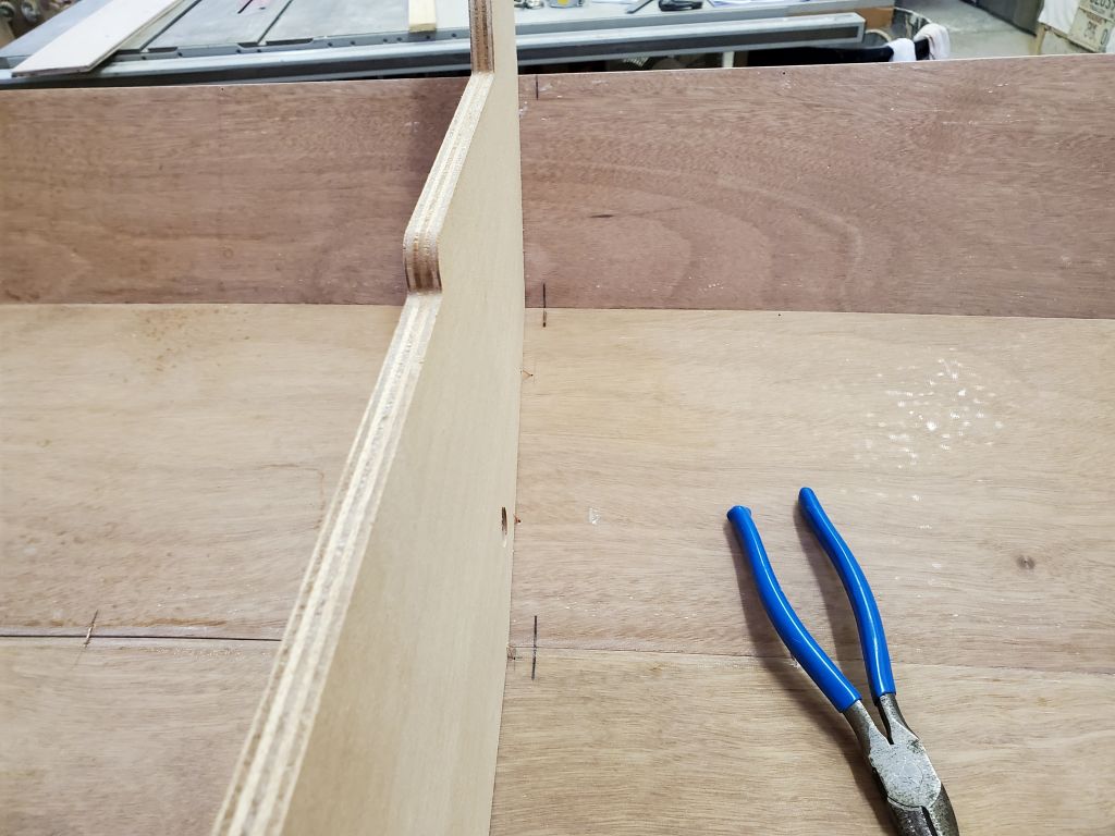
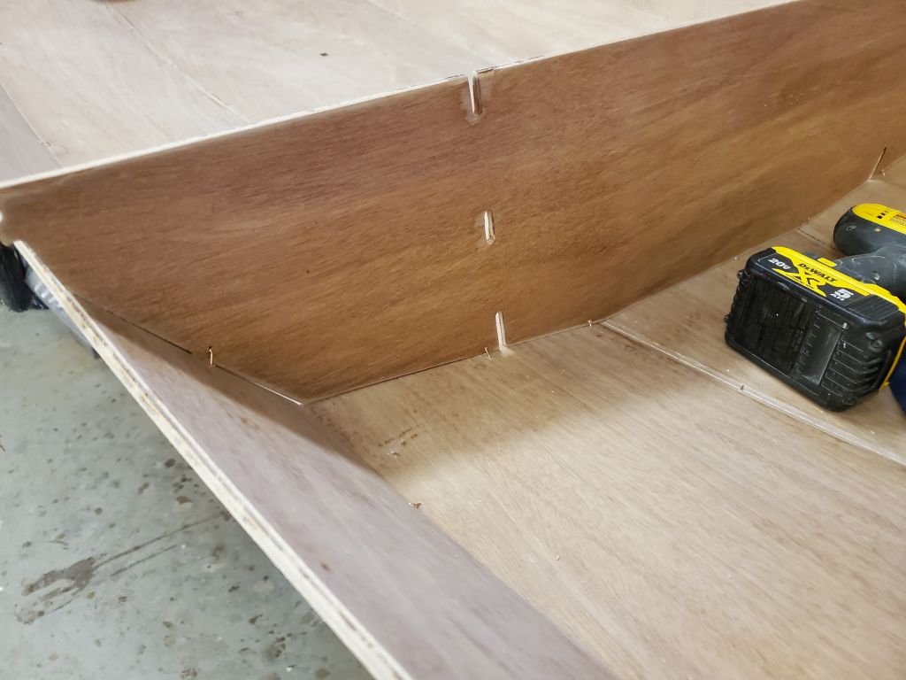
The center portion of the aftermost bulkhead would later be cut out, but for proper alignment before gluing now I clamped a piece of scrap across the top edge to straighten the bulkhead. Then, I glued the bulkhead to the hull from the forward side, where the seam was most open, following the same two-step epoxy injection process as with the hull and other parts of the boat. I also glued the mast step bulkhead. The main bulkhead amidships would be temporarily removed later in the process, when it was to be paired with a twin so that the boat could be made in to the two nesting parts later.
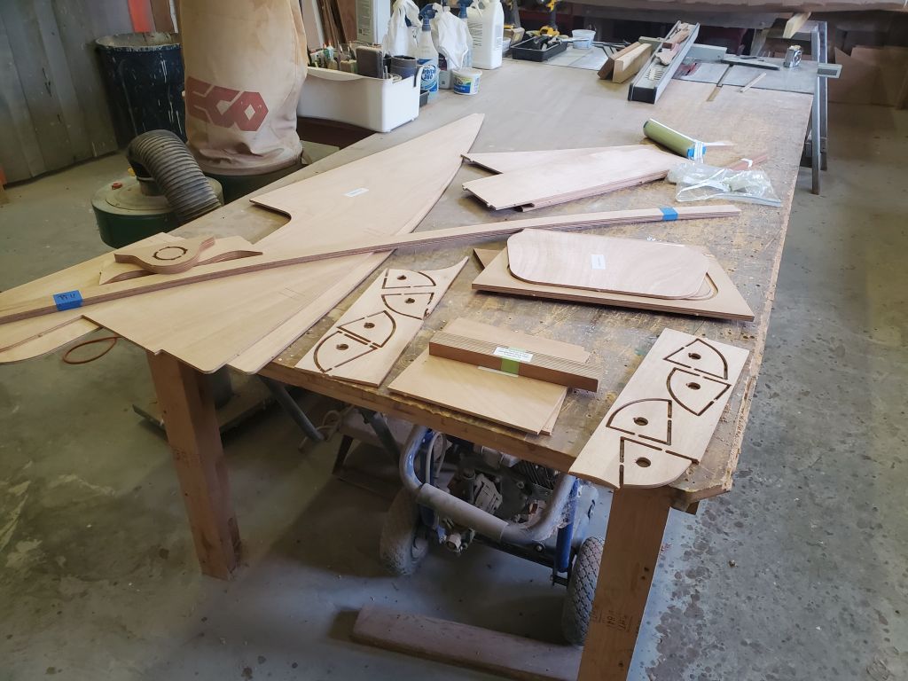
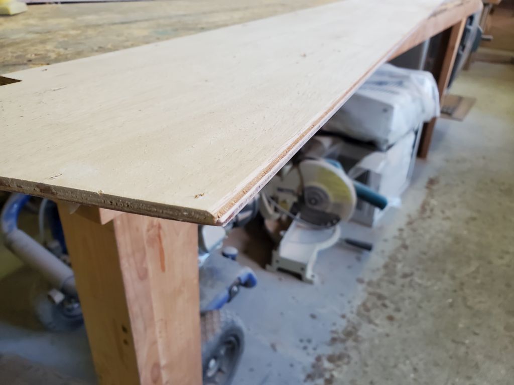
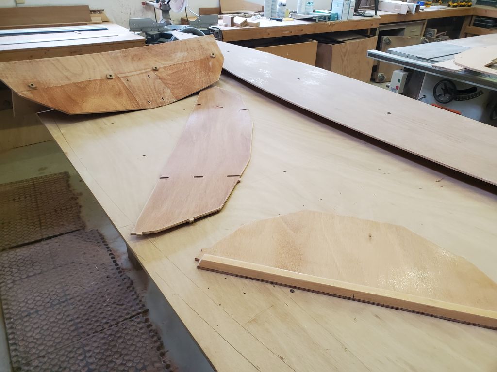
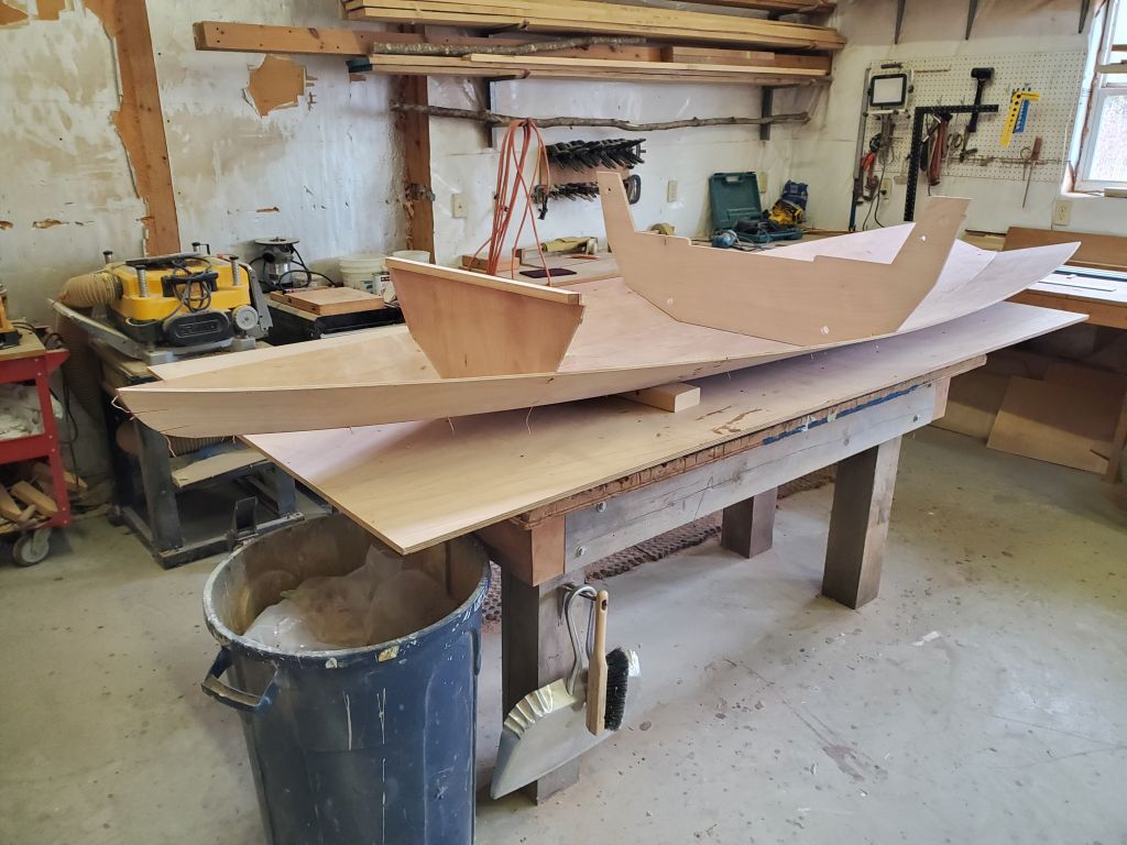
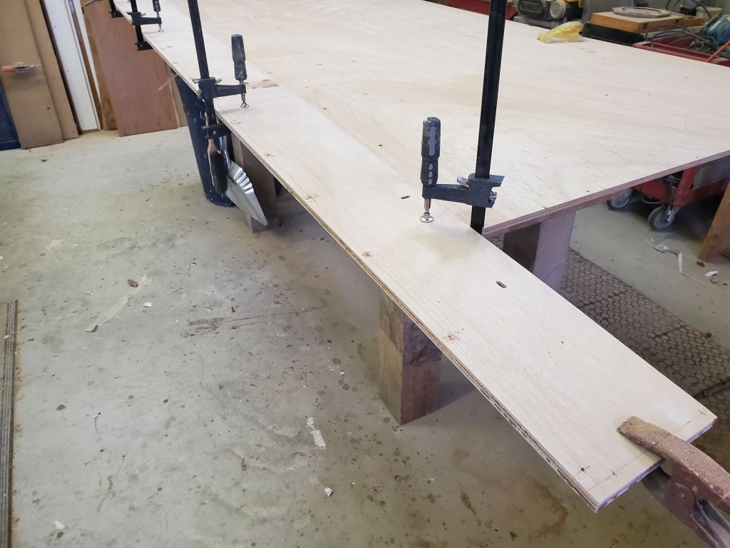
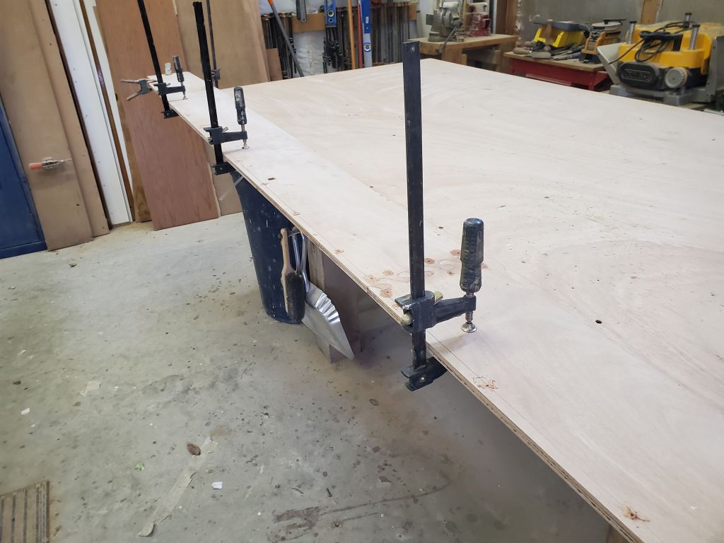
While I awaited the epoxy to cure on these new installations, there was nothing more I could do directly on the hull, so I turned to some pre-assemblies for some of the other parts of the boat, specifically the daggerboard trunk, the aft seat/air tank parts, and the foredeck. I collected all these pieces and others I knew I’d need soon from my parts shelf, leaving a pleasingly small number of pieces behind. This must be progress.
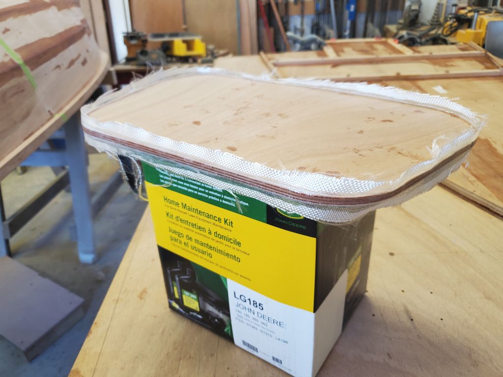
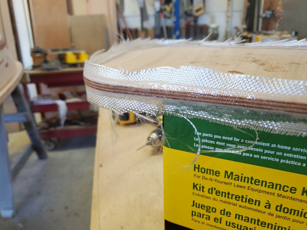
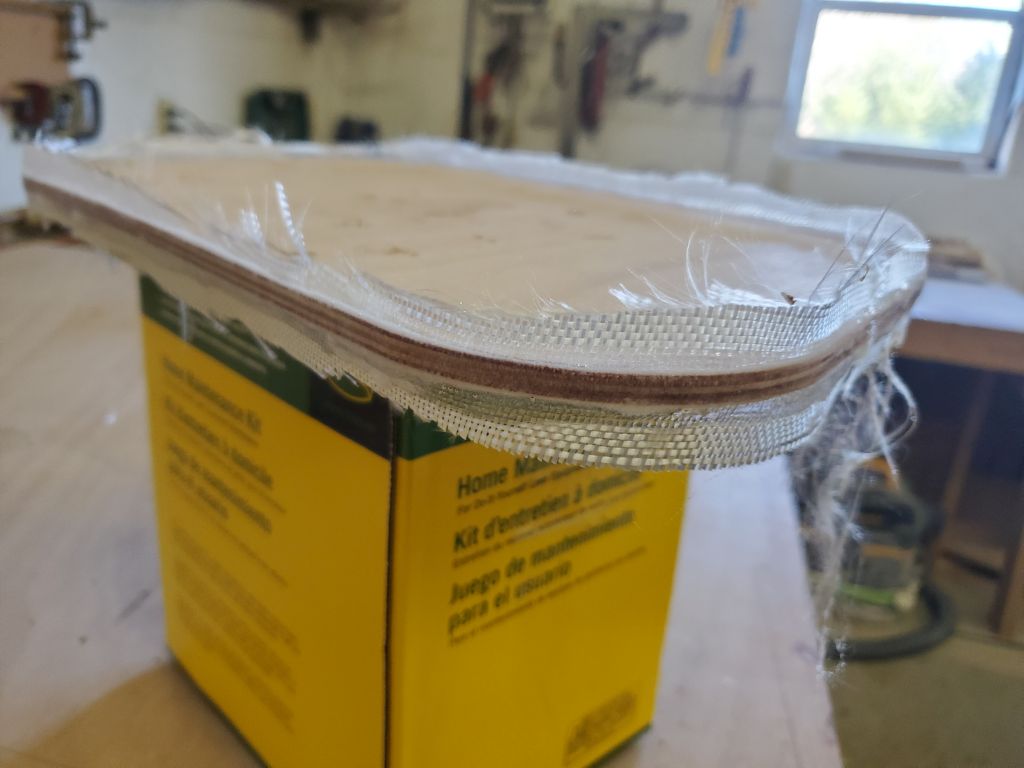
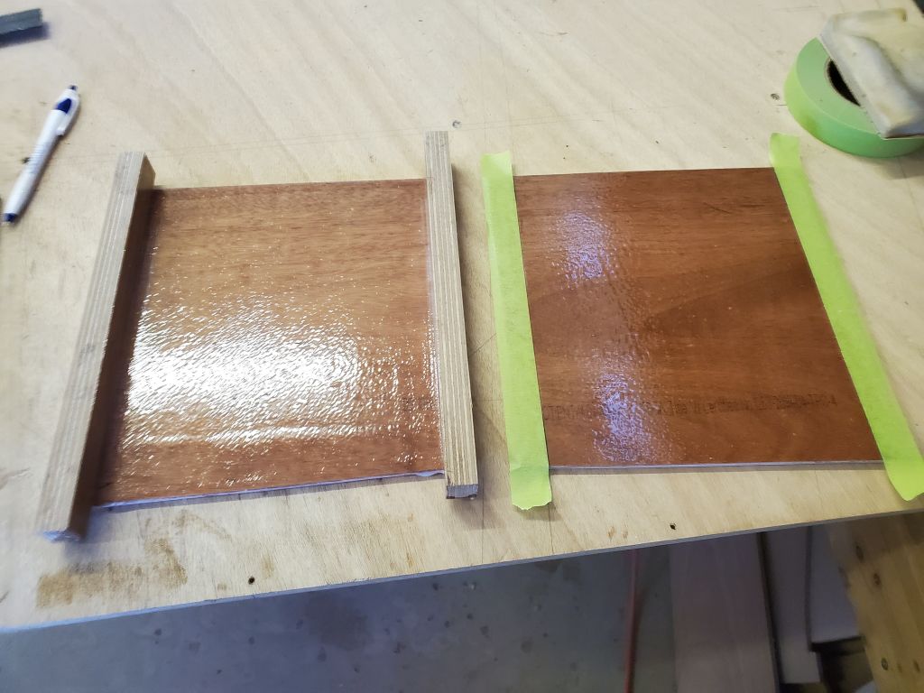
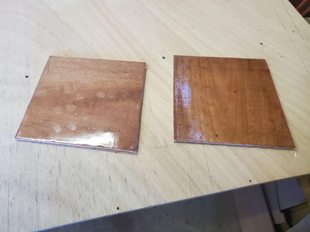
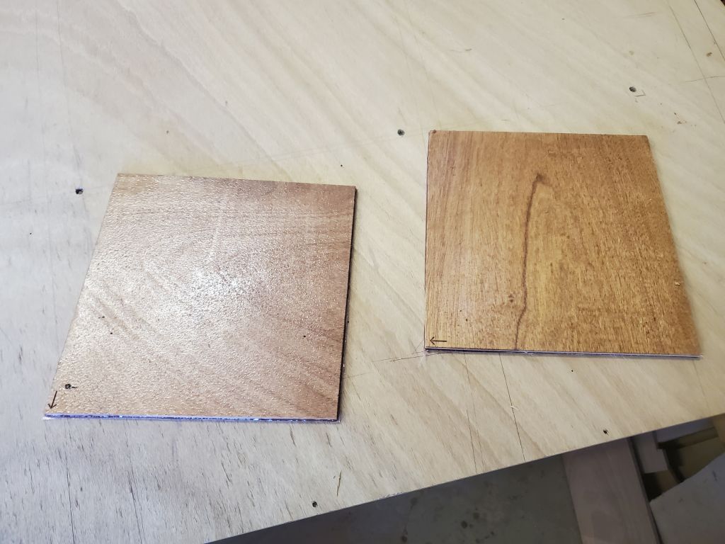
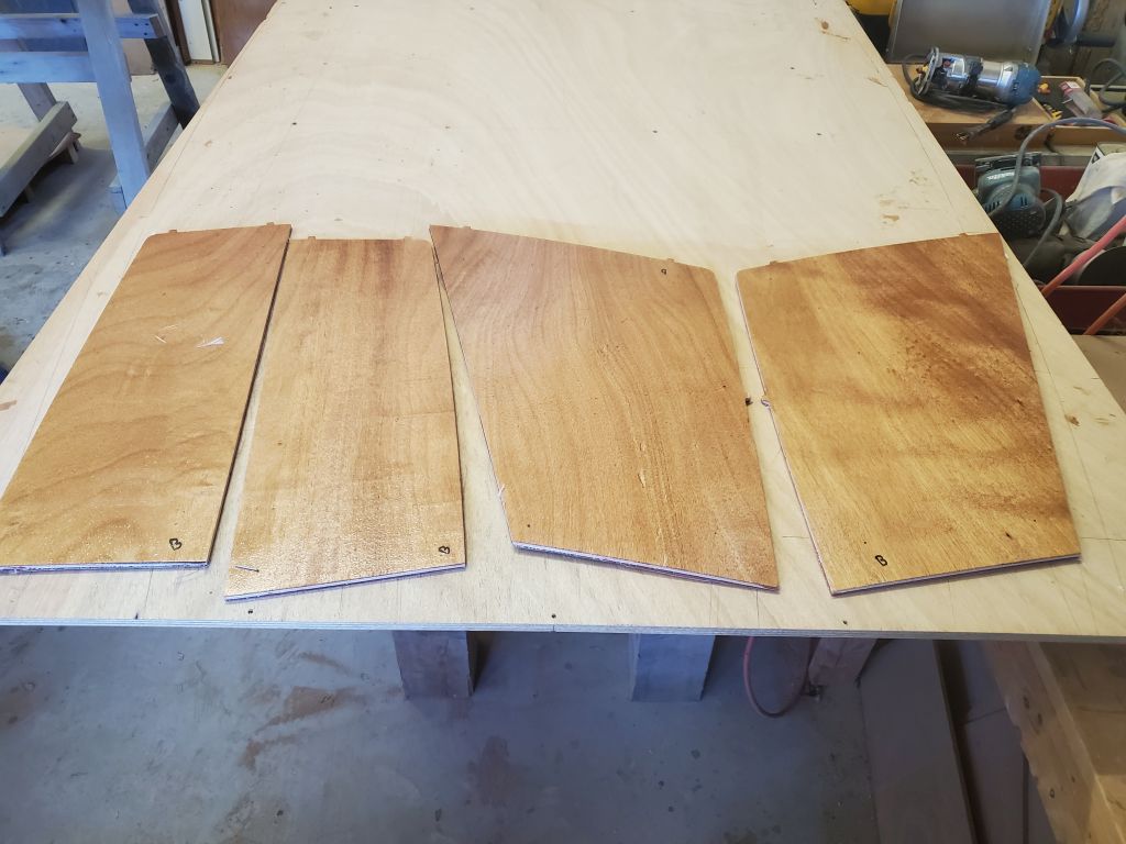
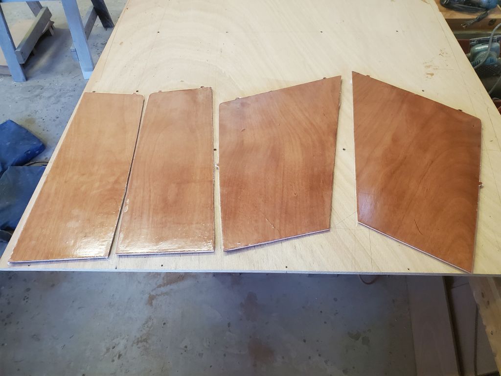
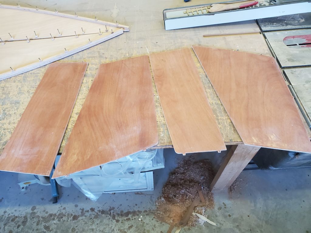
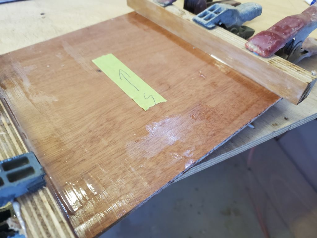
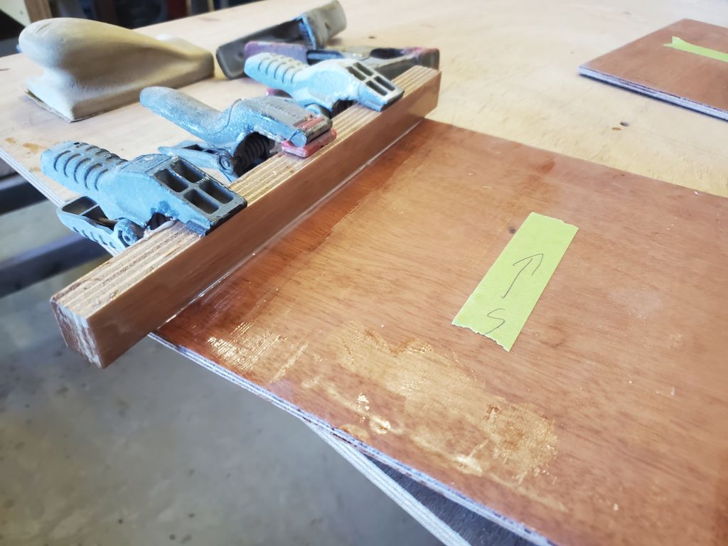
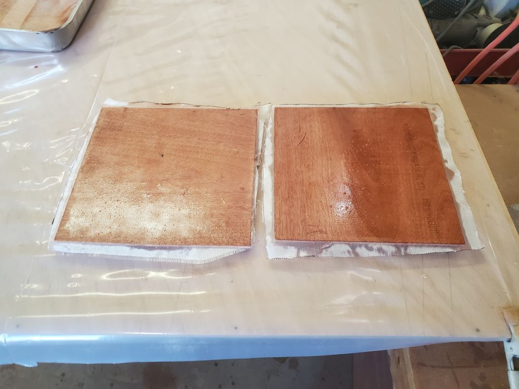
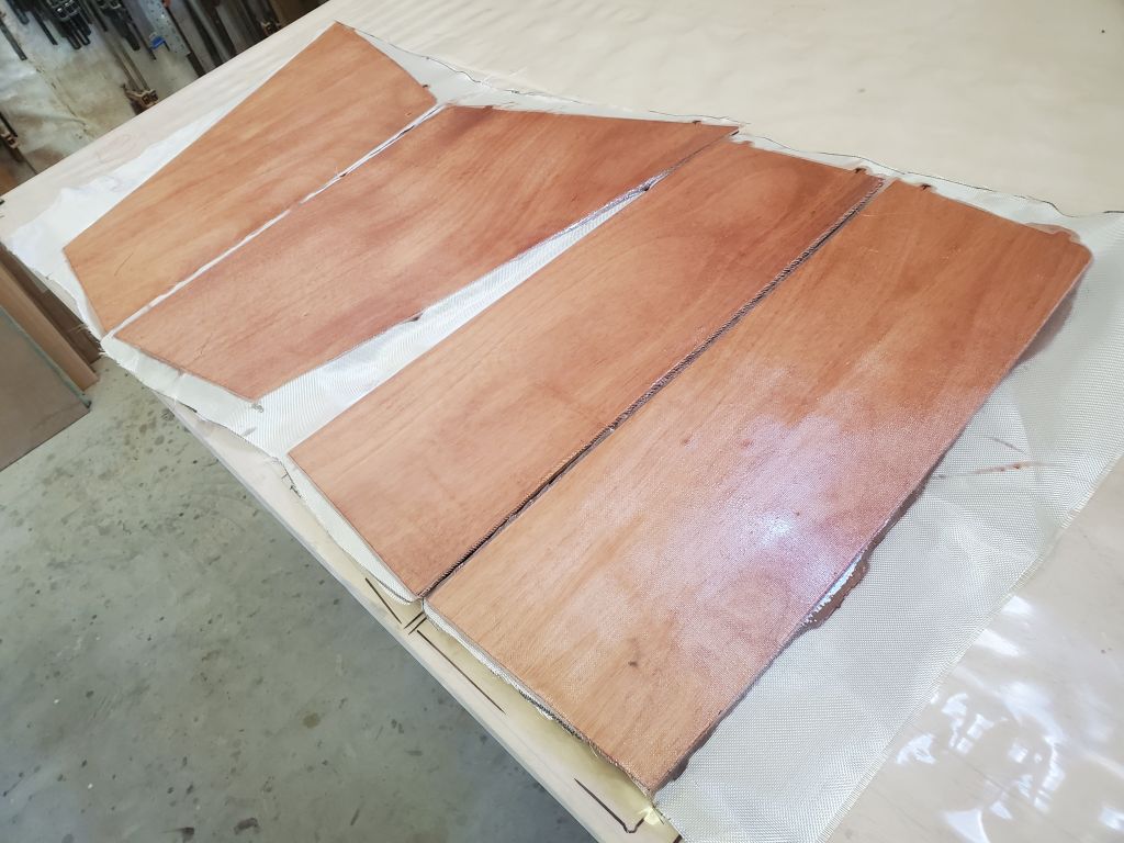
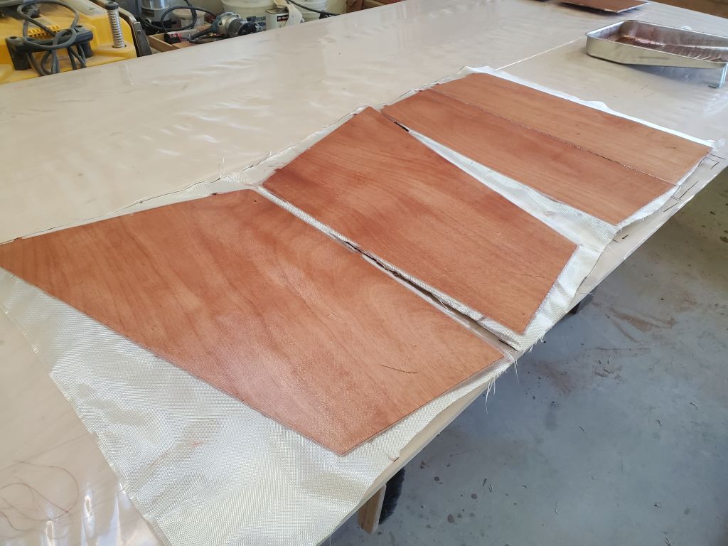
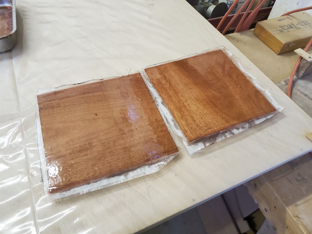
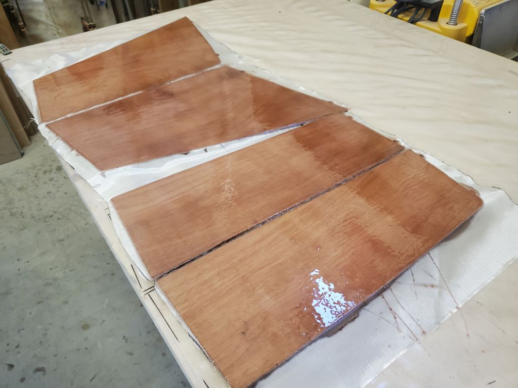
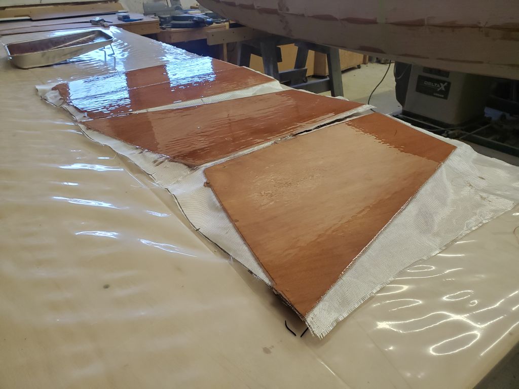
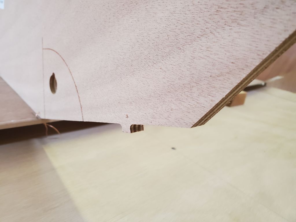
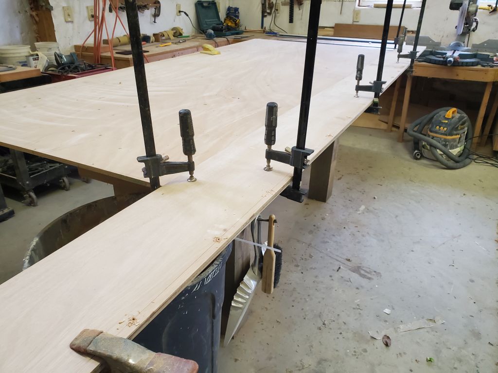
The two side panels that formed the daggerboard trunk, and the four pieces that formed the pair of aft seat assemblies, all required minor preparations (light sanding, and removal of the little nubs left from machining out of larger panels), then fiberglass sheathing on one side, and epoxy-coating on the other. As needed, I cut pieces of 4 oz. fiberglass for these parts, and set up the work table so I could epoxy both sides of these panels at once, driving nails in to the bench and cutting off the heads so I could place the epoxy-coated sides of the panels down and work on the fiberglass sides to install the layer of lightweight cloth. To provide a quicker cure so that I might apply the second, fill coat of epoxy before the end of the day, I used my “house” 105 resin and fast 205 hardener for this task, which I knew would cure more quickly than the 207 hardener included with the kit. Were the interior of this boat to be clear-finished instead of painted, I would have had to use the clear 207 hardener instead.
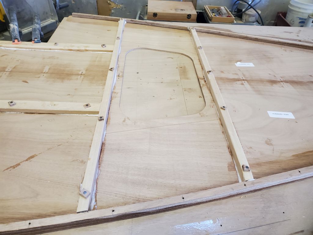
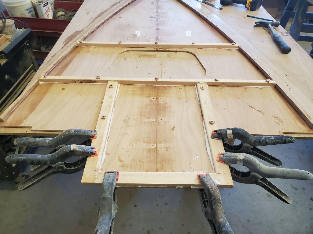
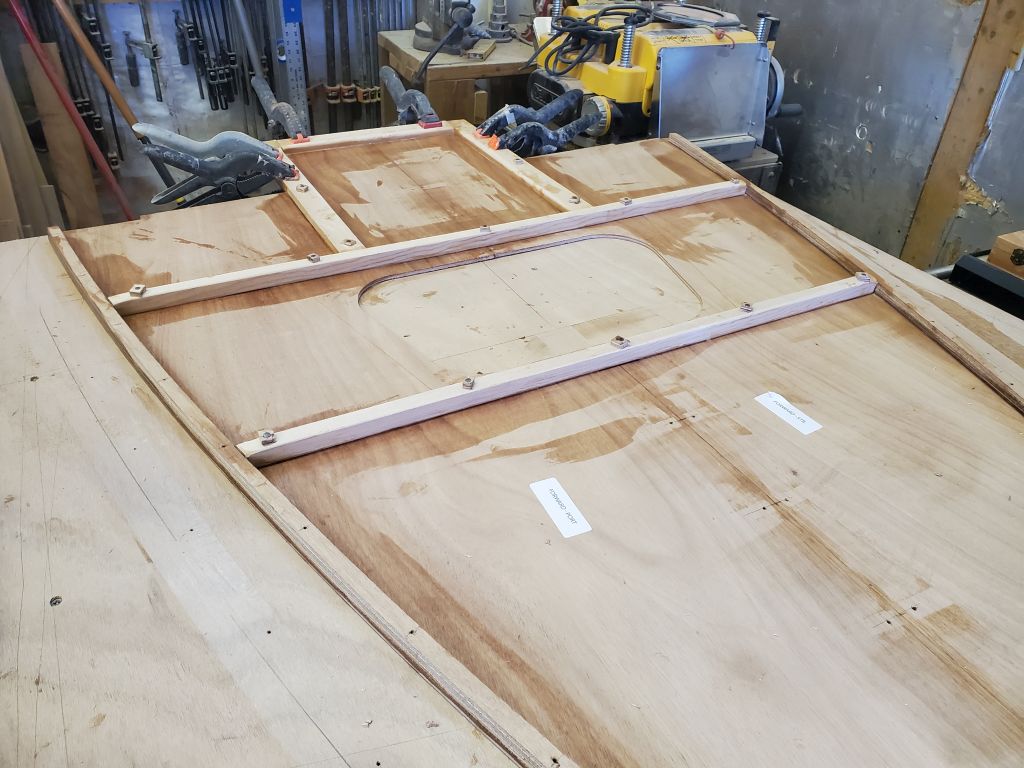
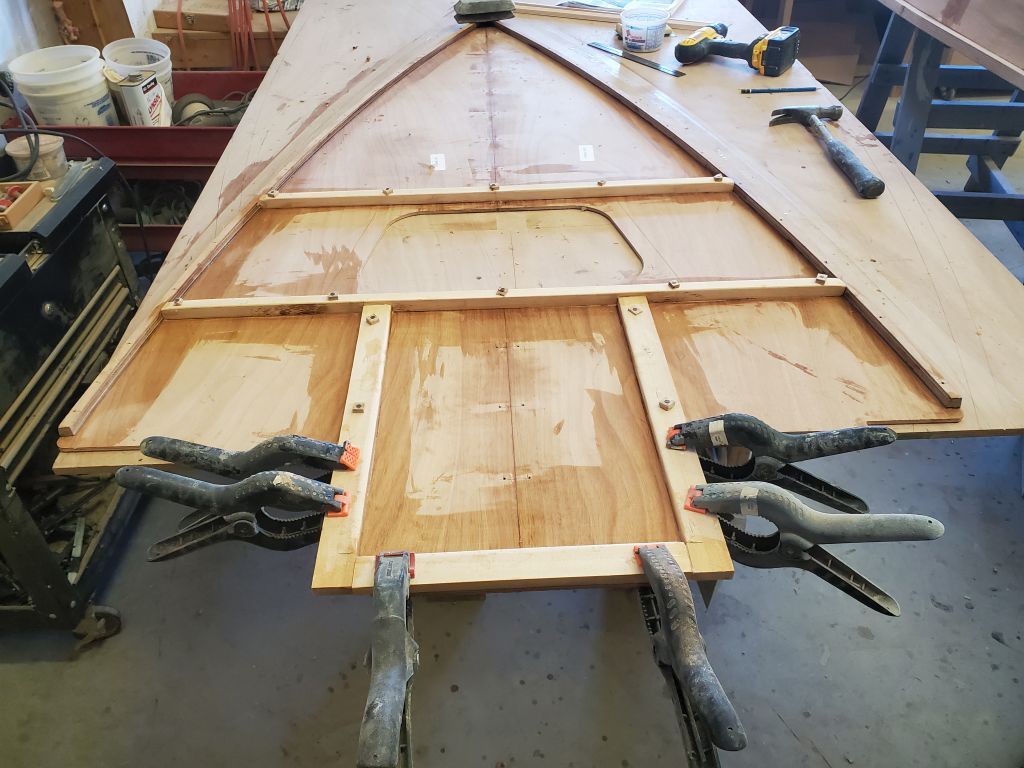
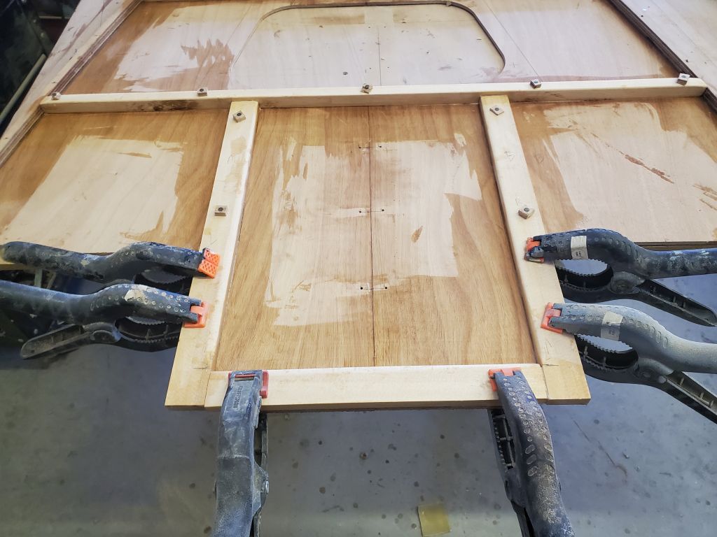
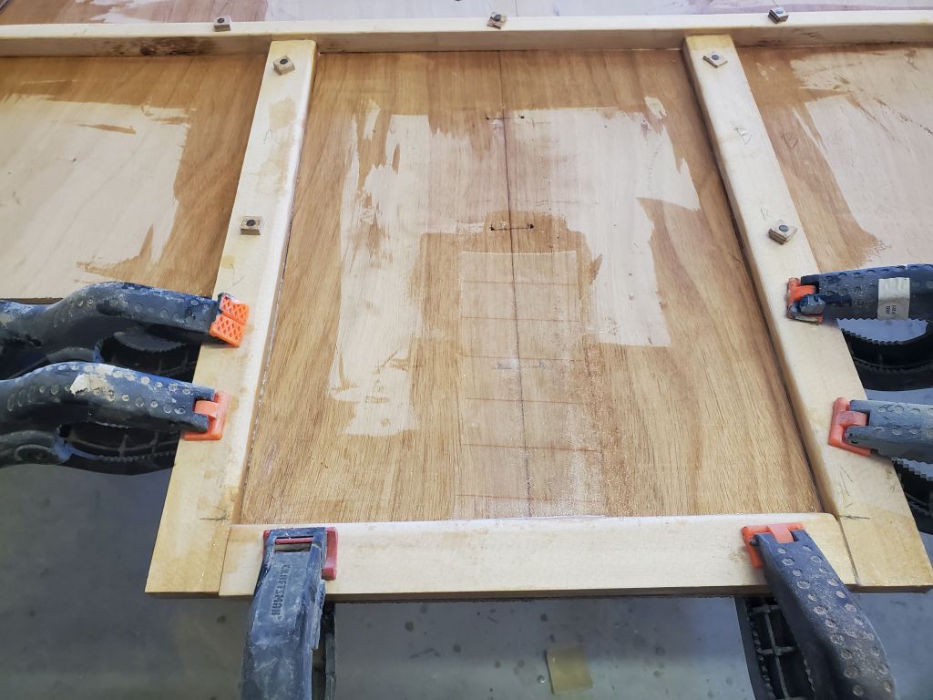
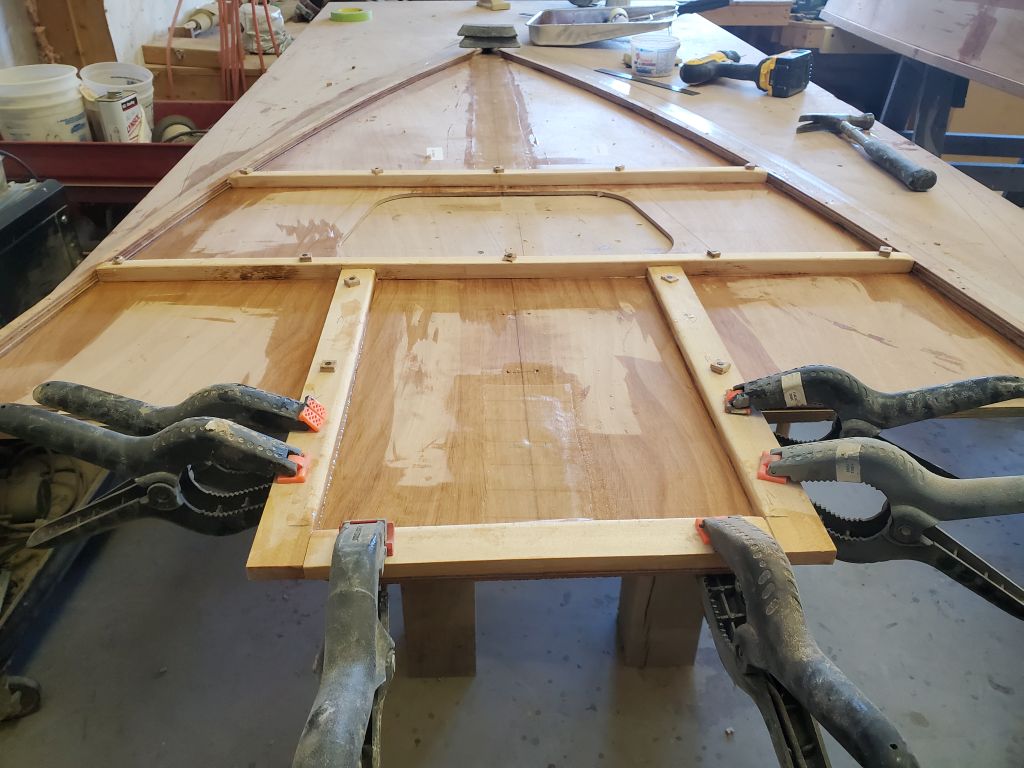
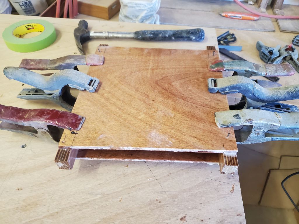
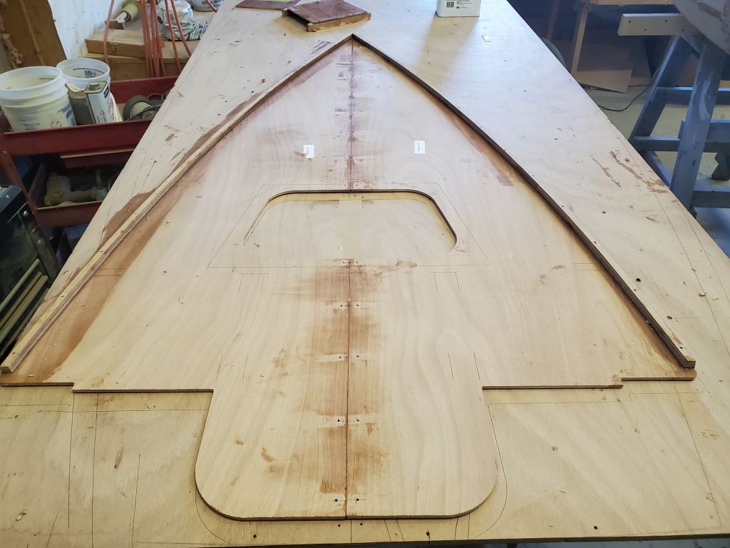
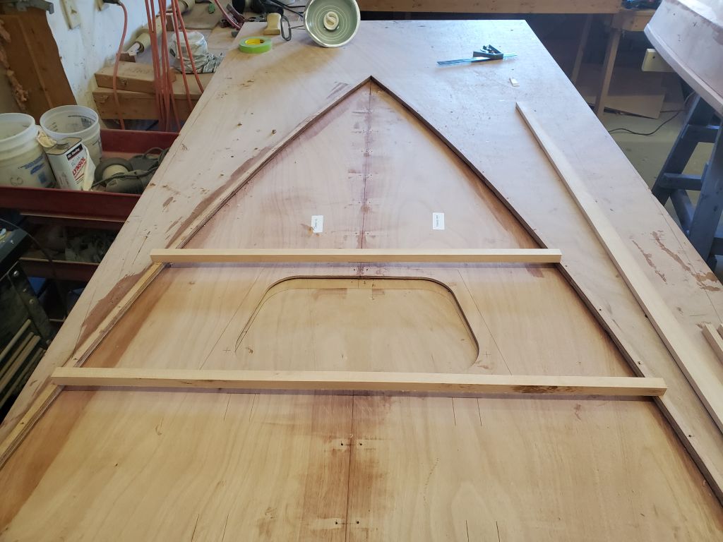
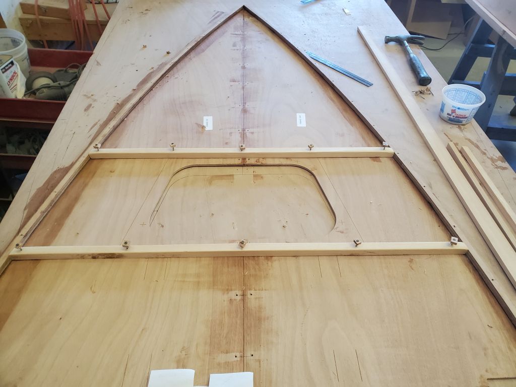
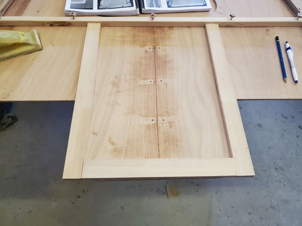
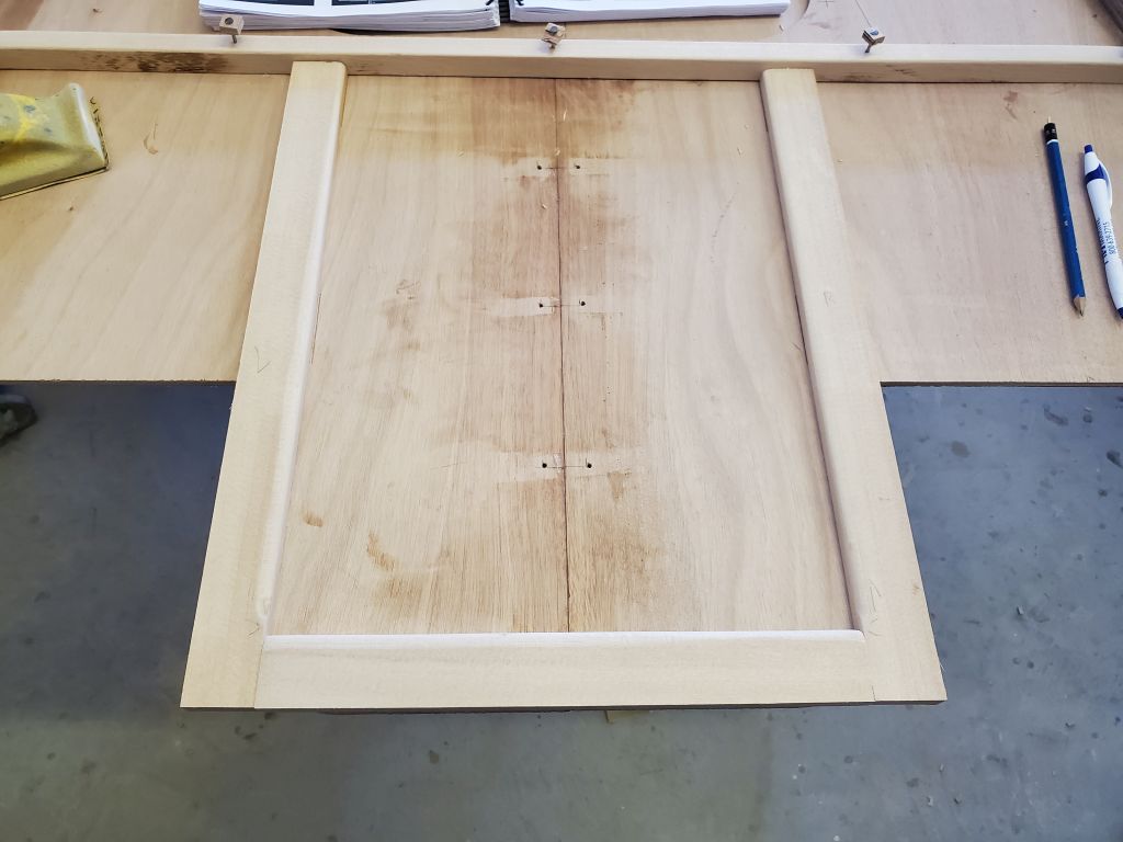
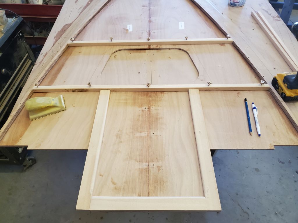
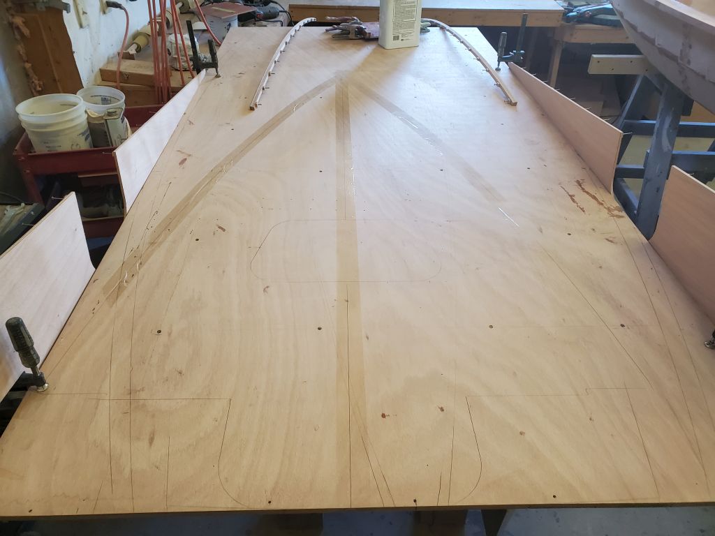
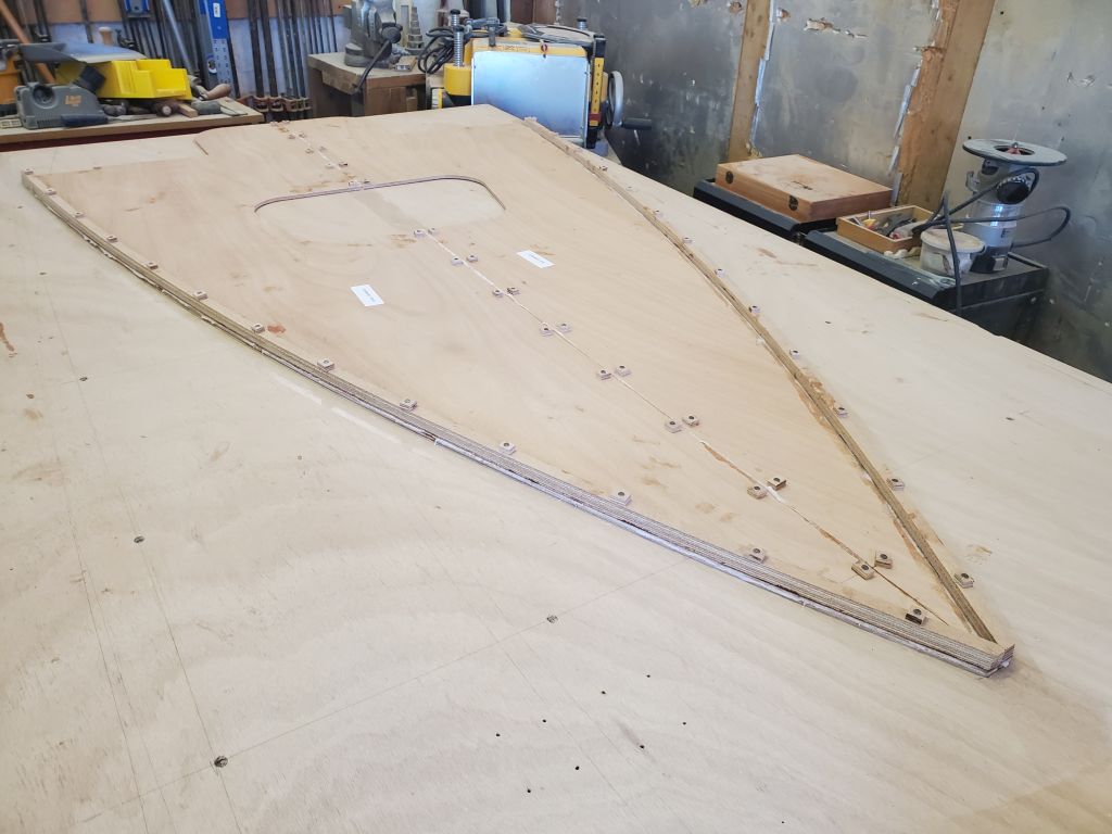
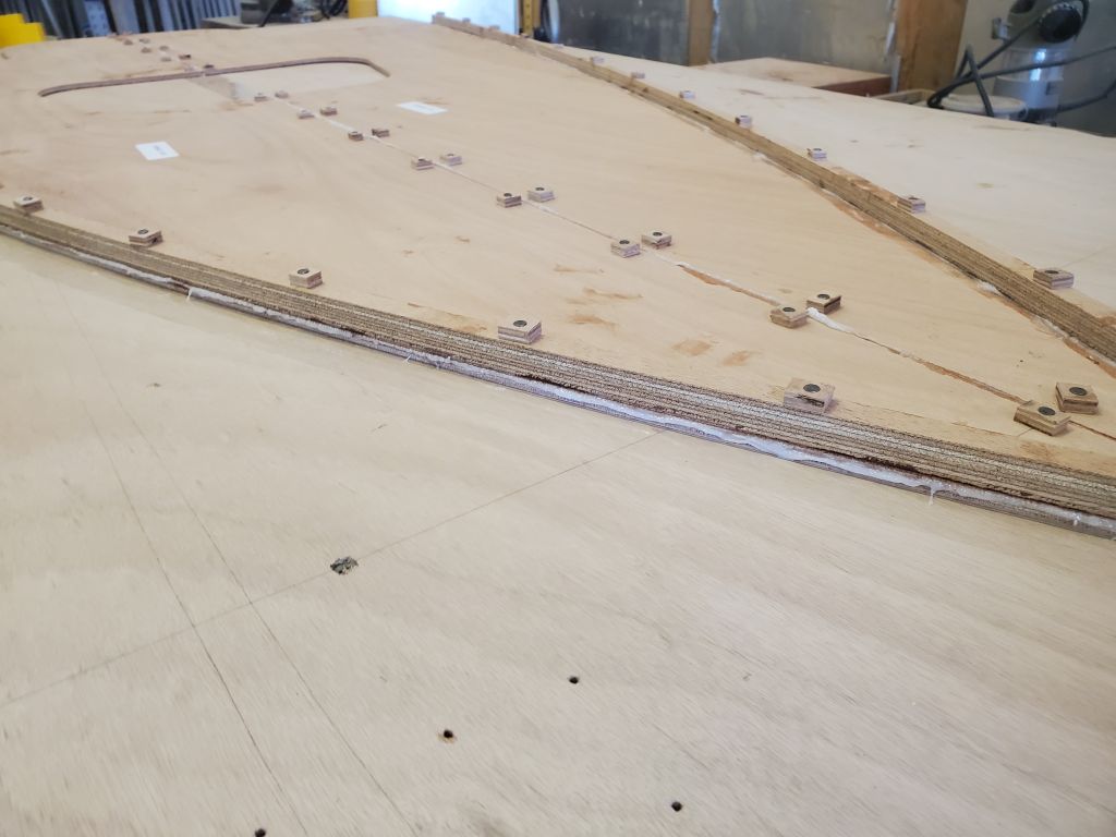
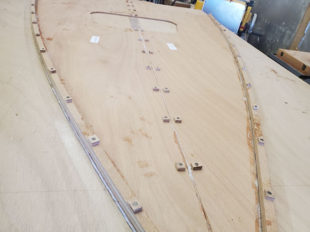
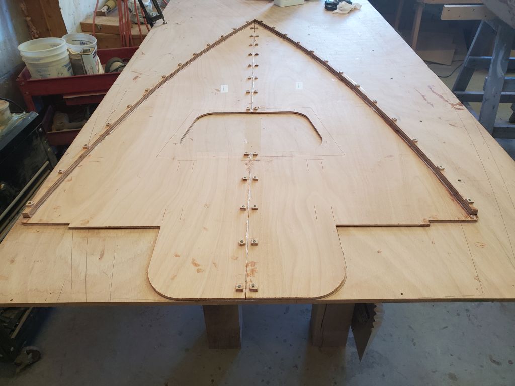
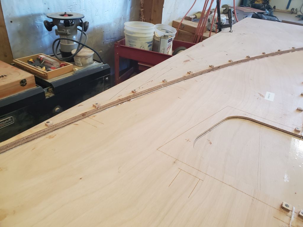
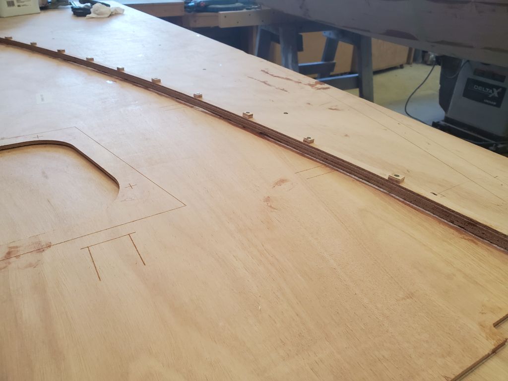
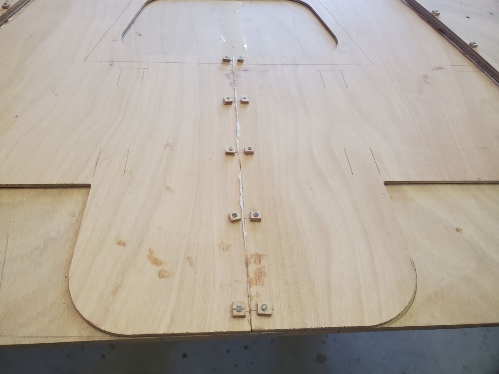
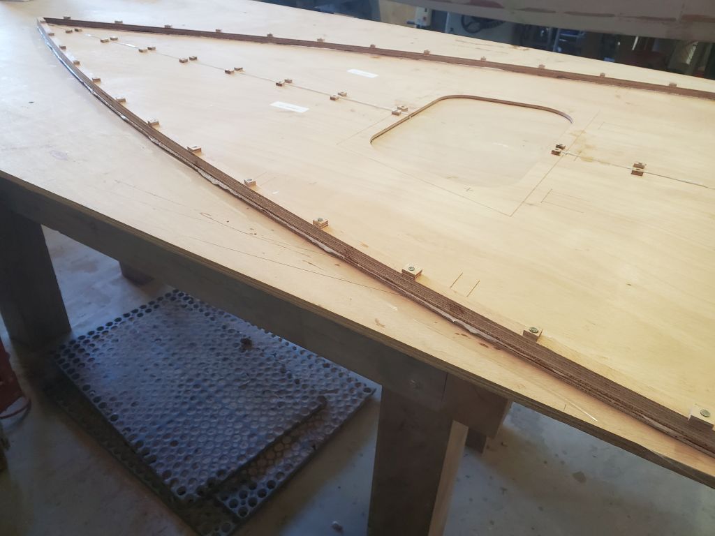
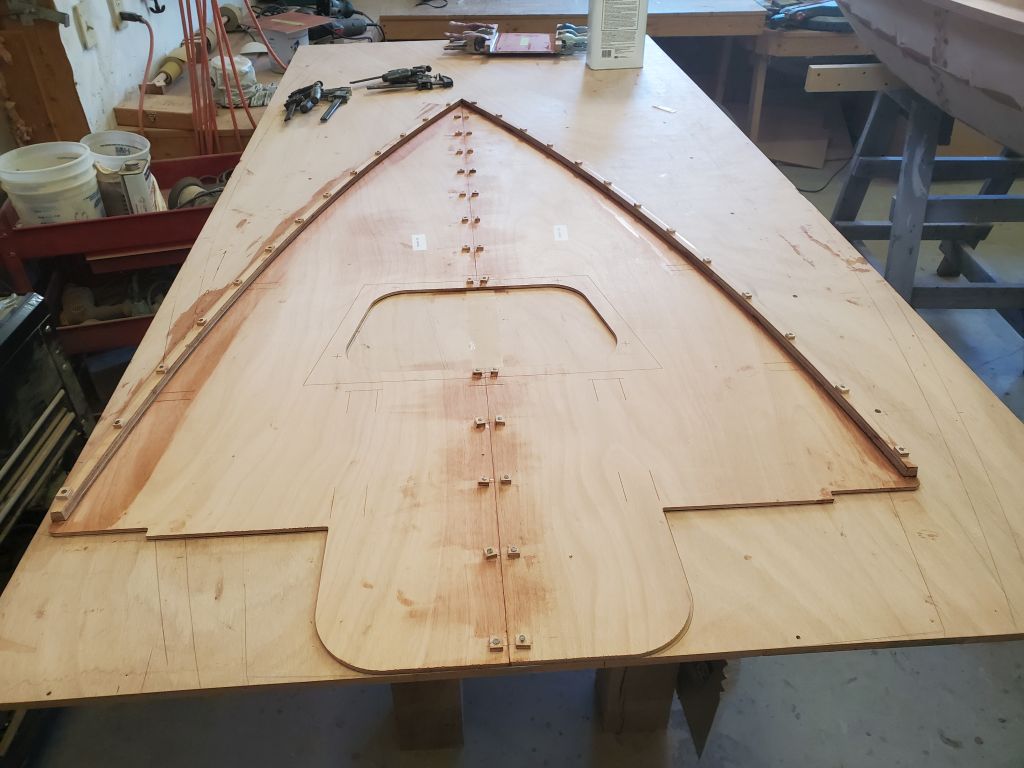
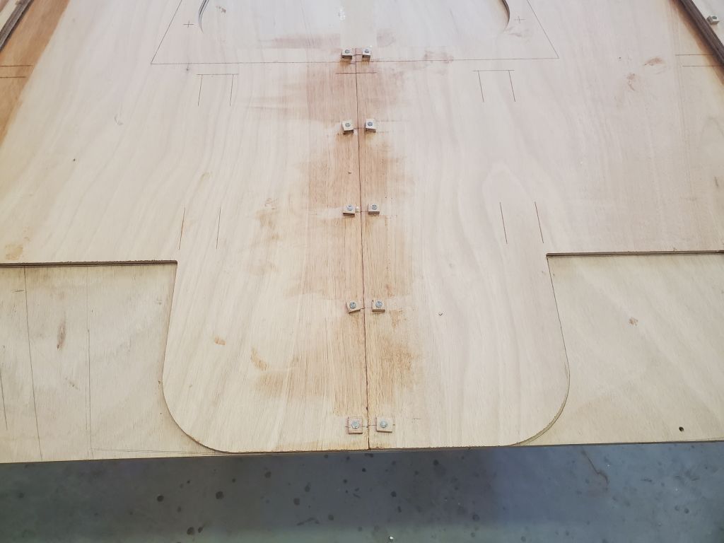
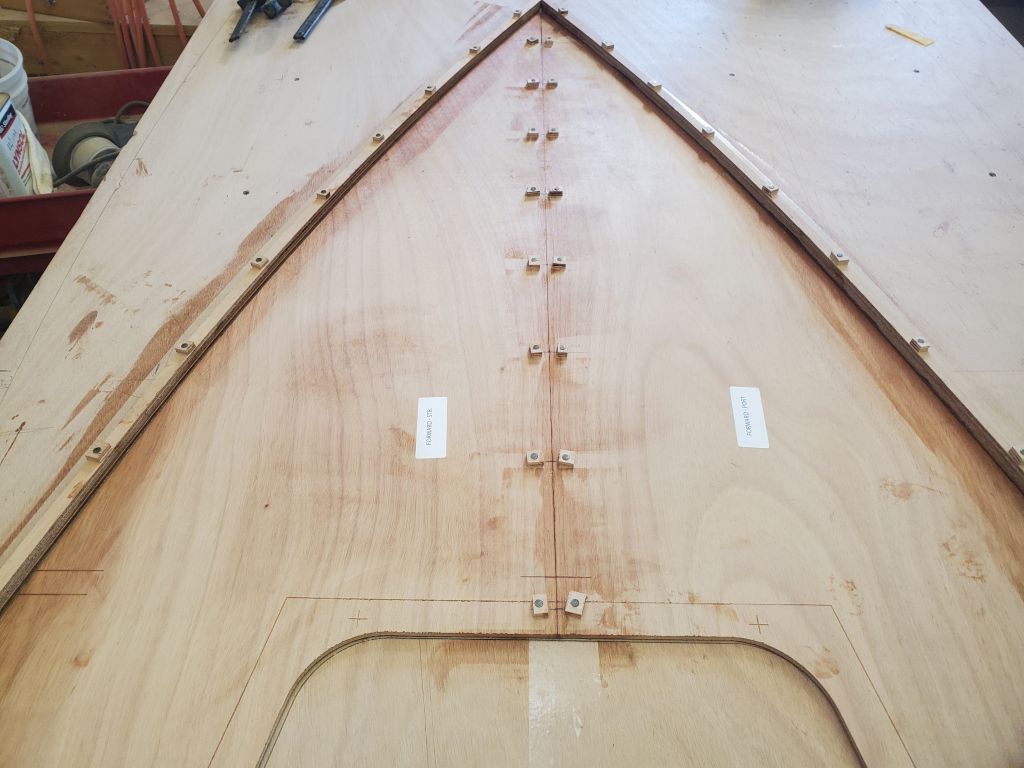
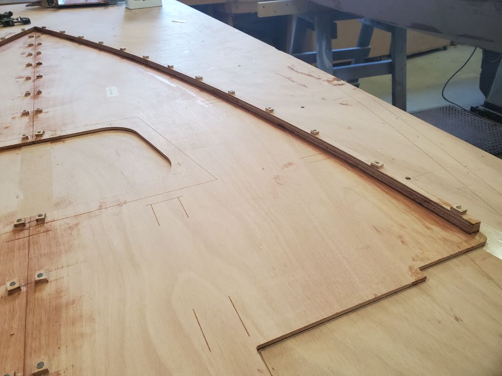
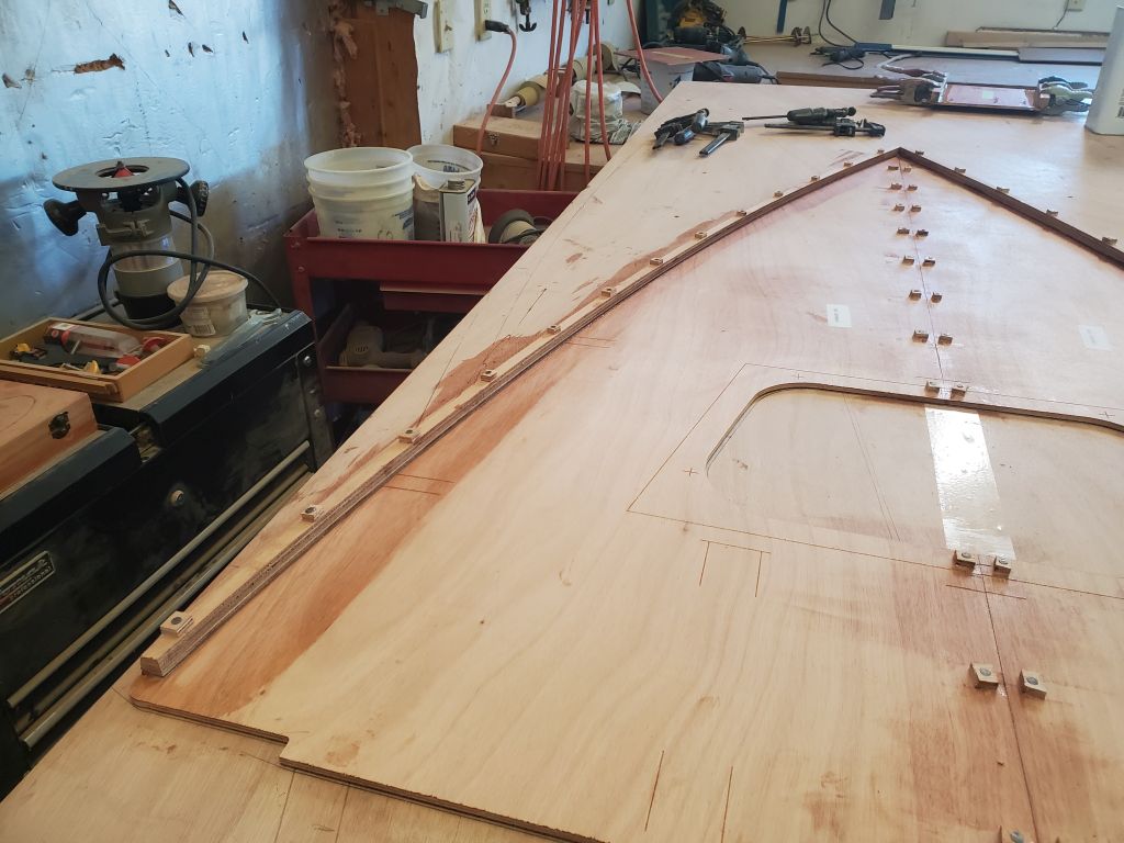
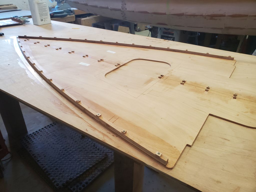
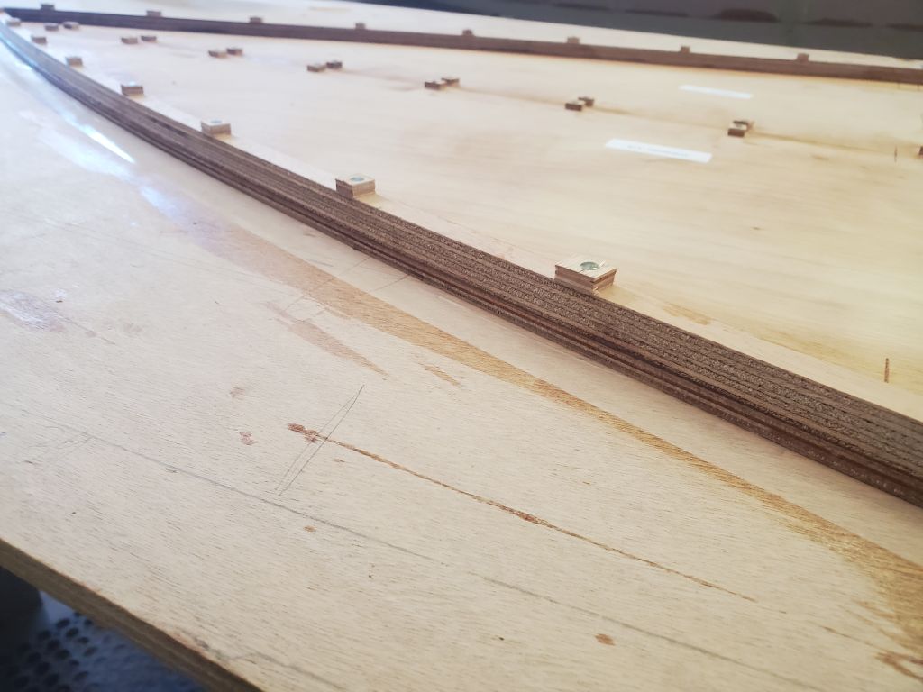
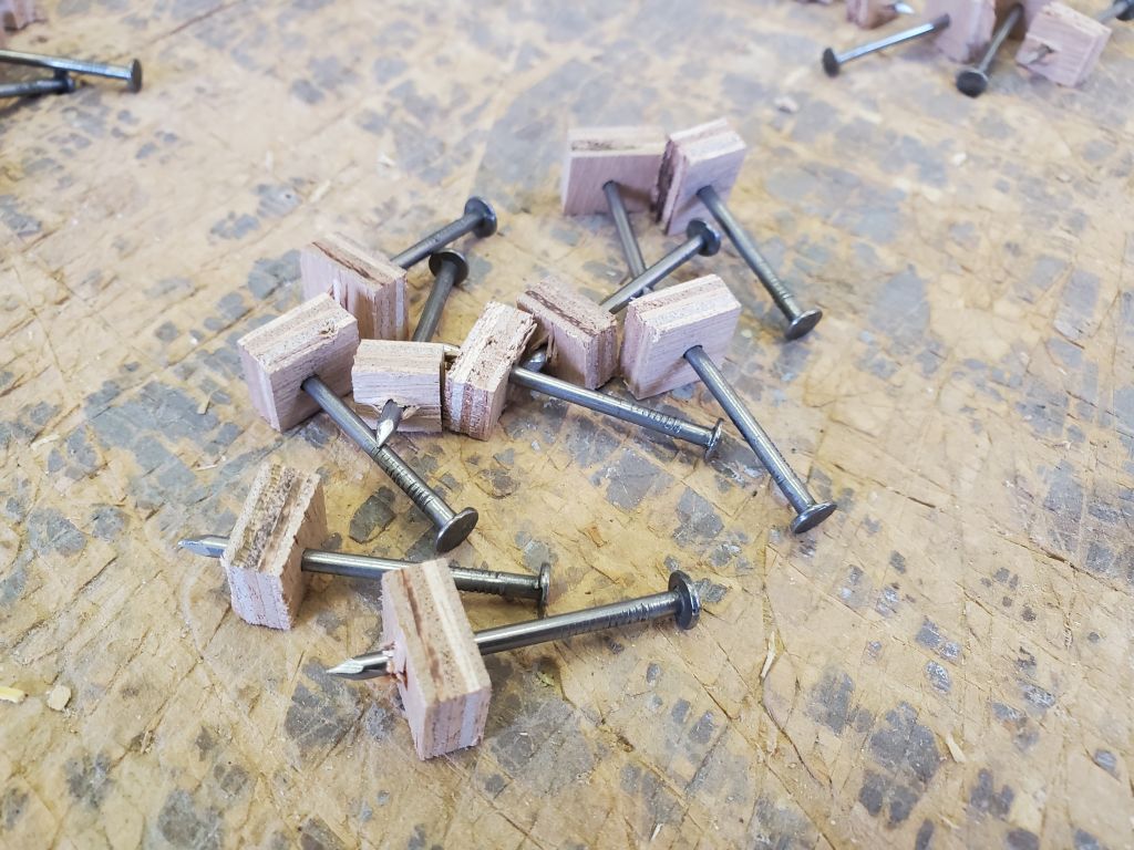
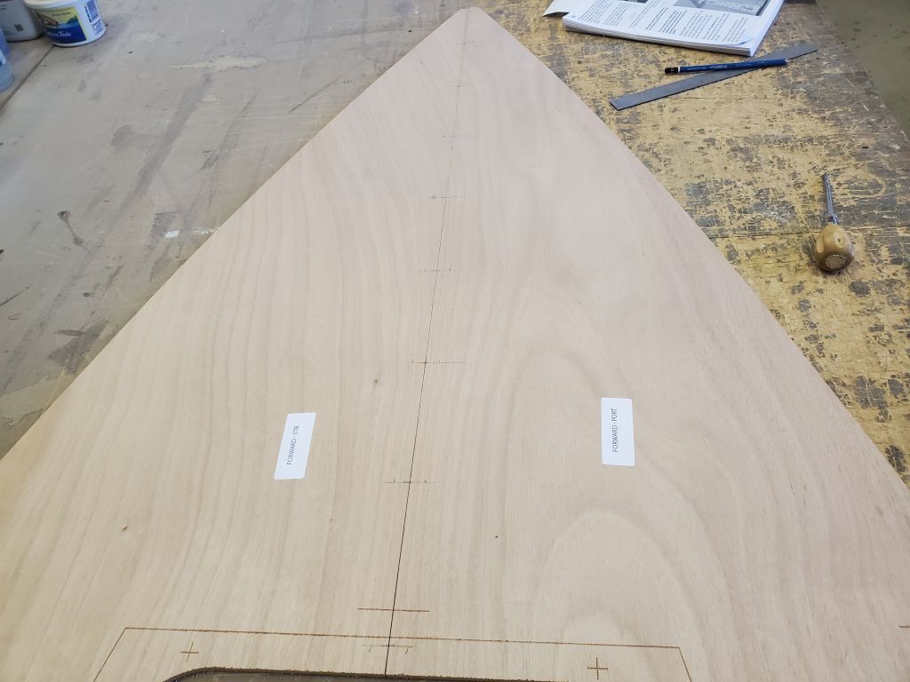
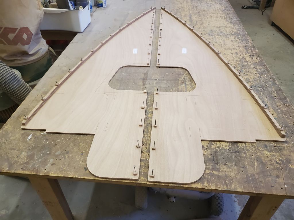
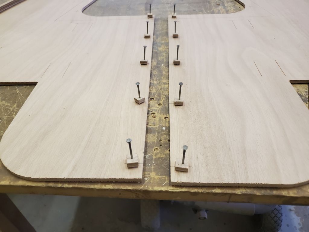
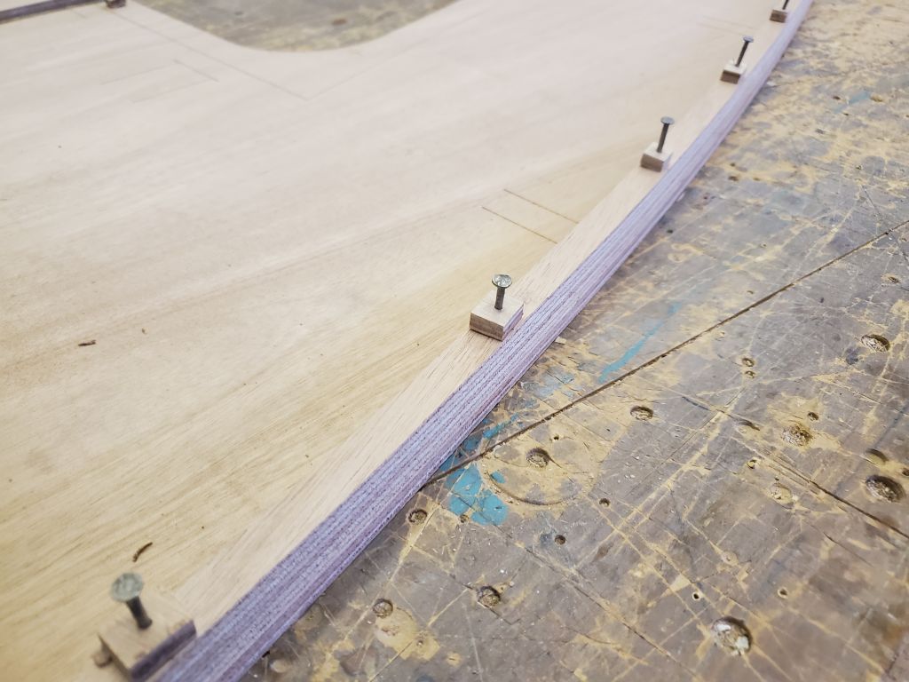
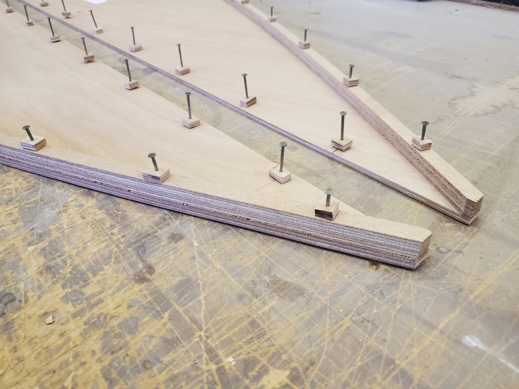
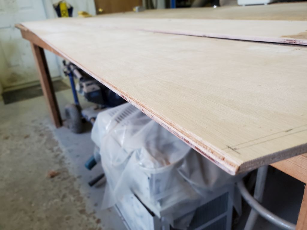
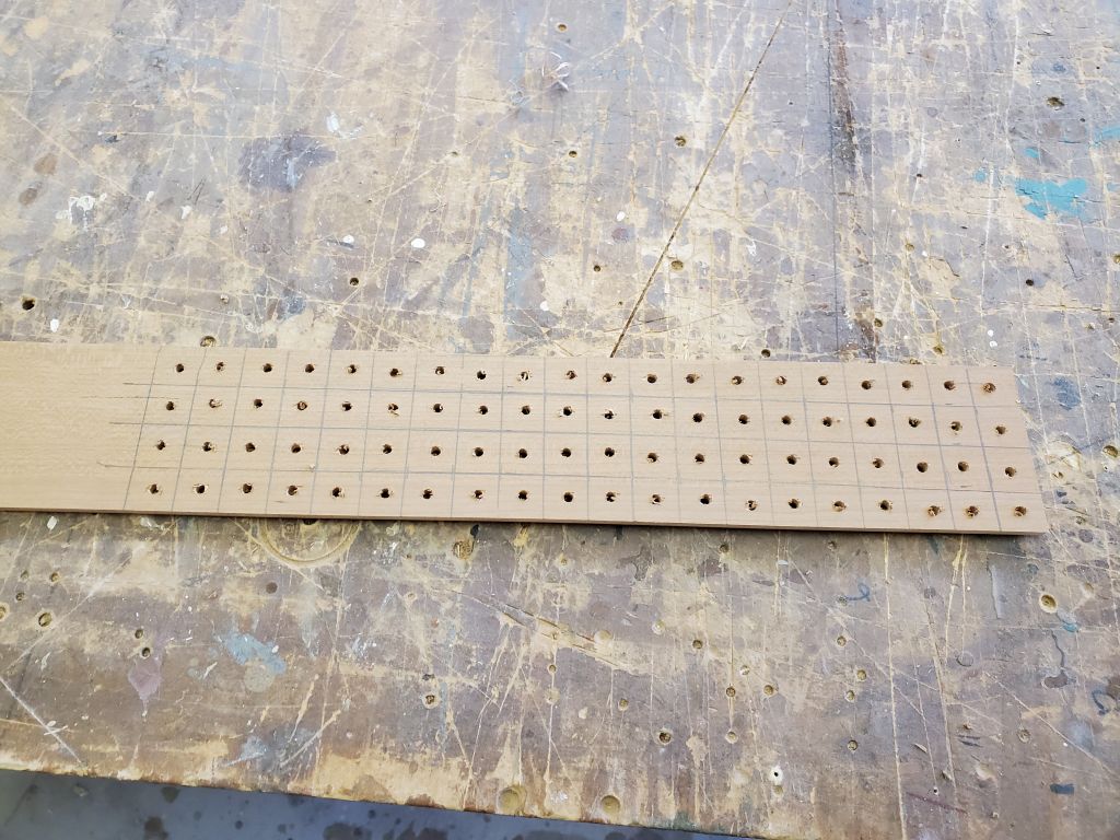
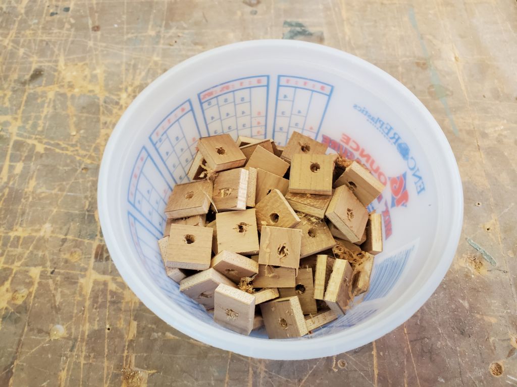
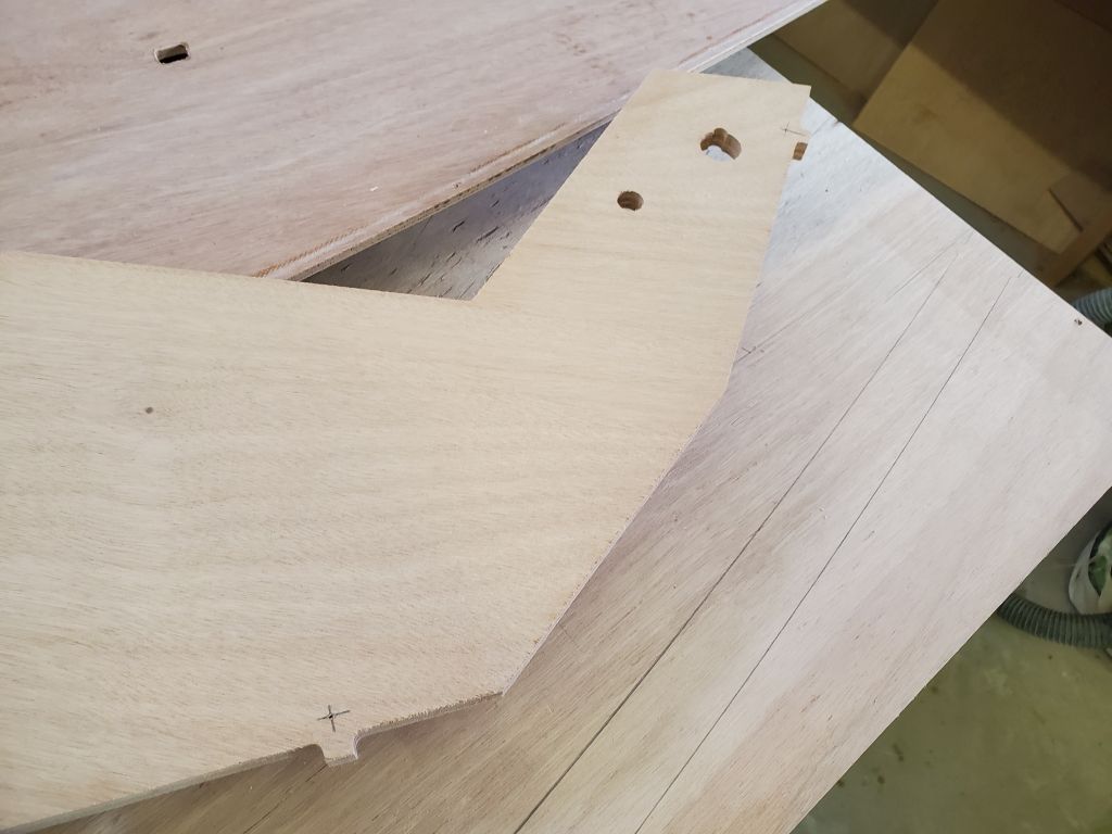
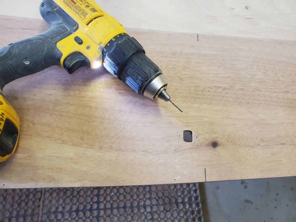
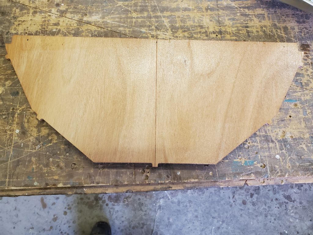
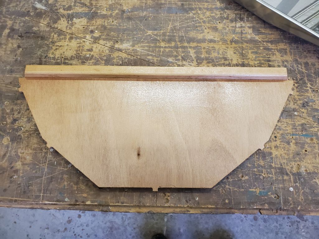
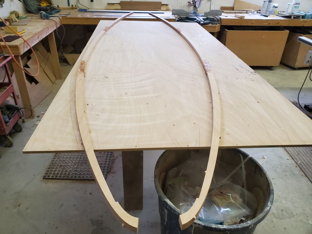
While waiting for the resin to set up sufficiently, I worked next on the foredeck, which came in two halves that needed to be conjoined, plus a couple milled doublers along the outer edges. The process enscribed in the manual required dozens of tiny plywood blocks and nails for this process, so to begin I made up the little blocks from scrap 1/4″ plywood, cutting roughly 60 1/2″ square (ish) pieces. This was tedious. Then, I pre-drove 4-penny bright nails through each of the pads till I had enough for the job, which was purported to be 56; I made 60 to be safe.
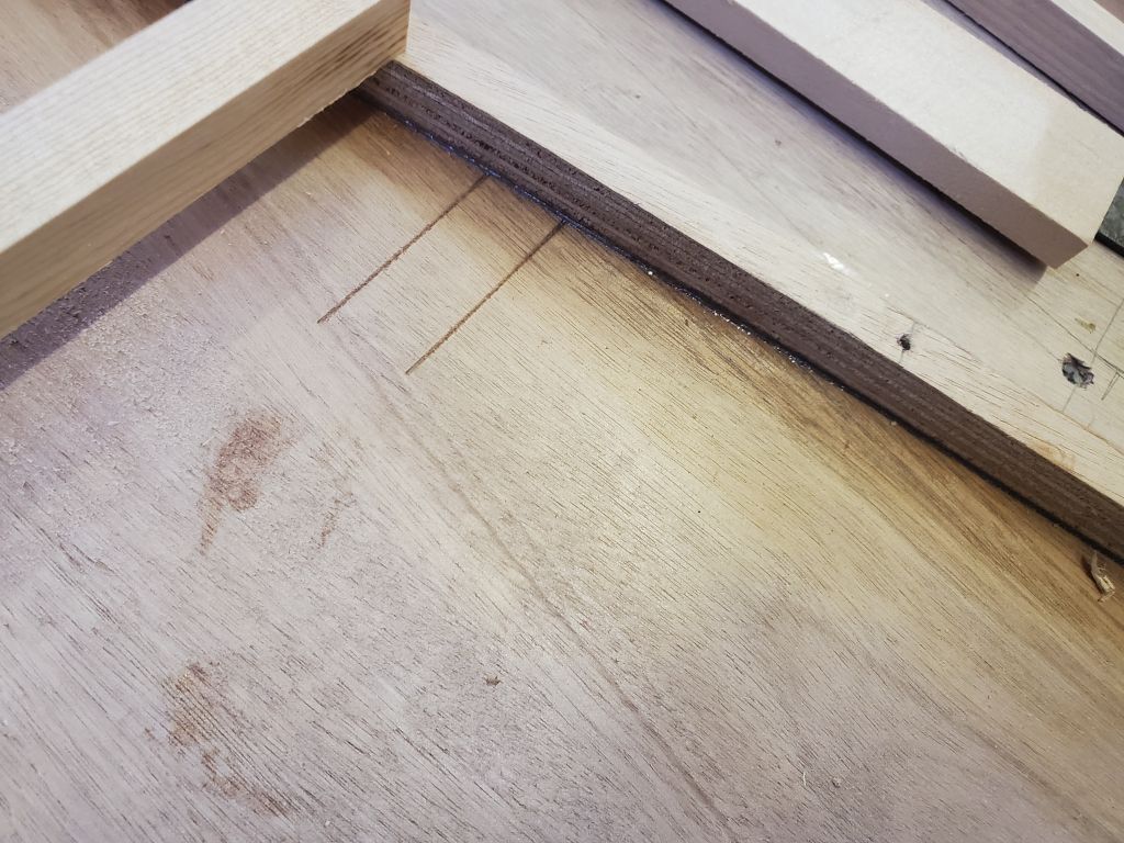
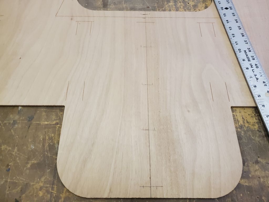
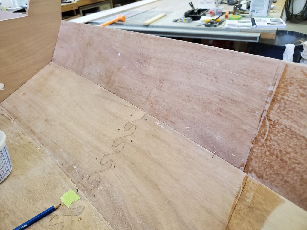
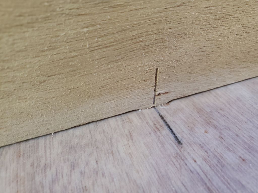
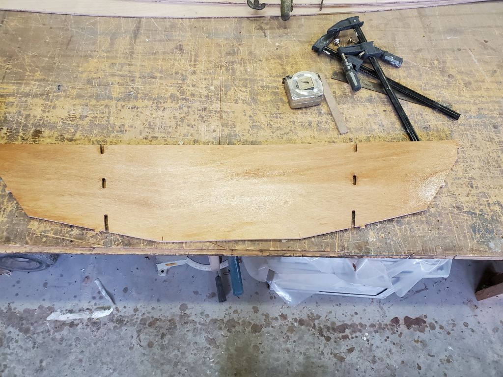
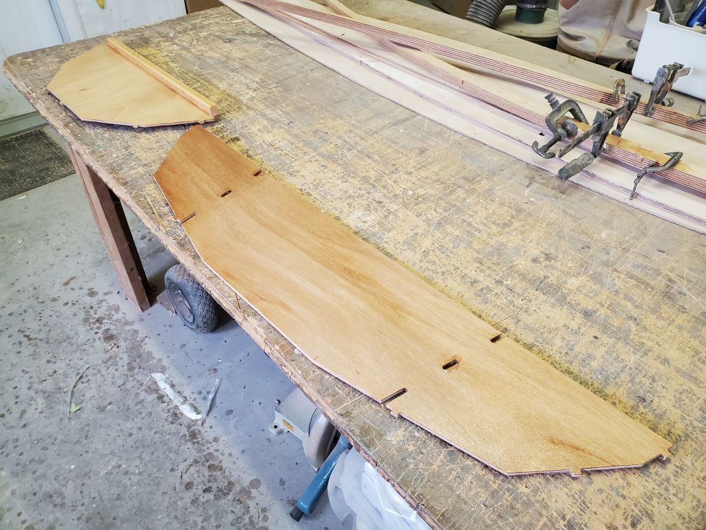
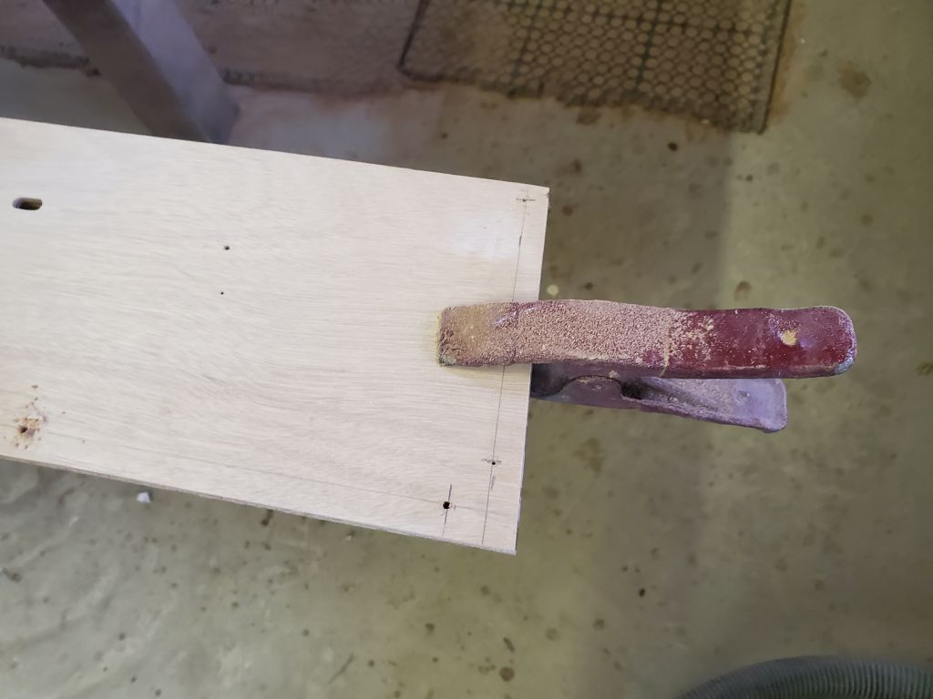
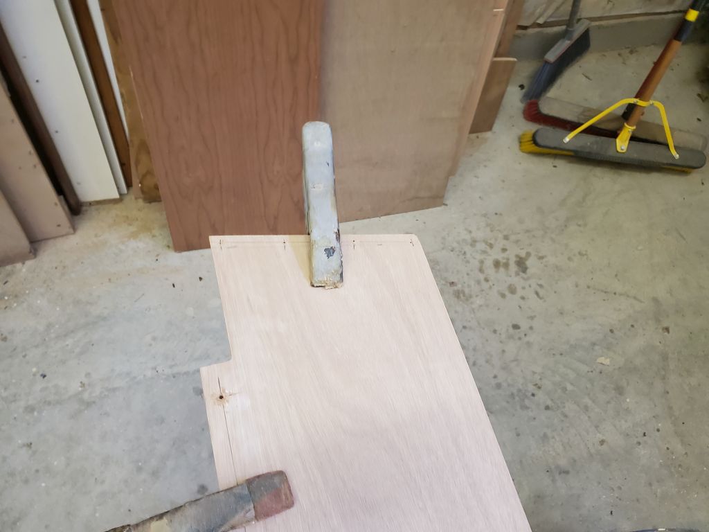
Next, with the foredeck panels upside down on the bench, I laid out the centerline of the foredeck panels as needed for the nails, measuring and marking as indicated and using an awl to pre-mark all the holes.
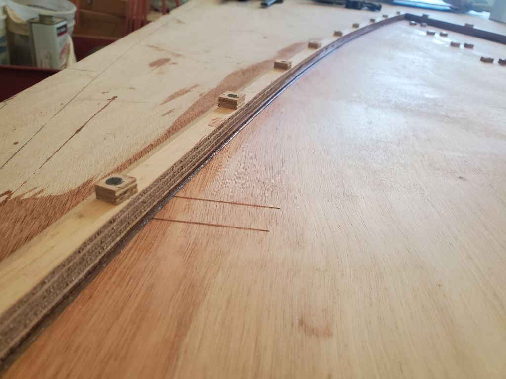
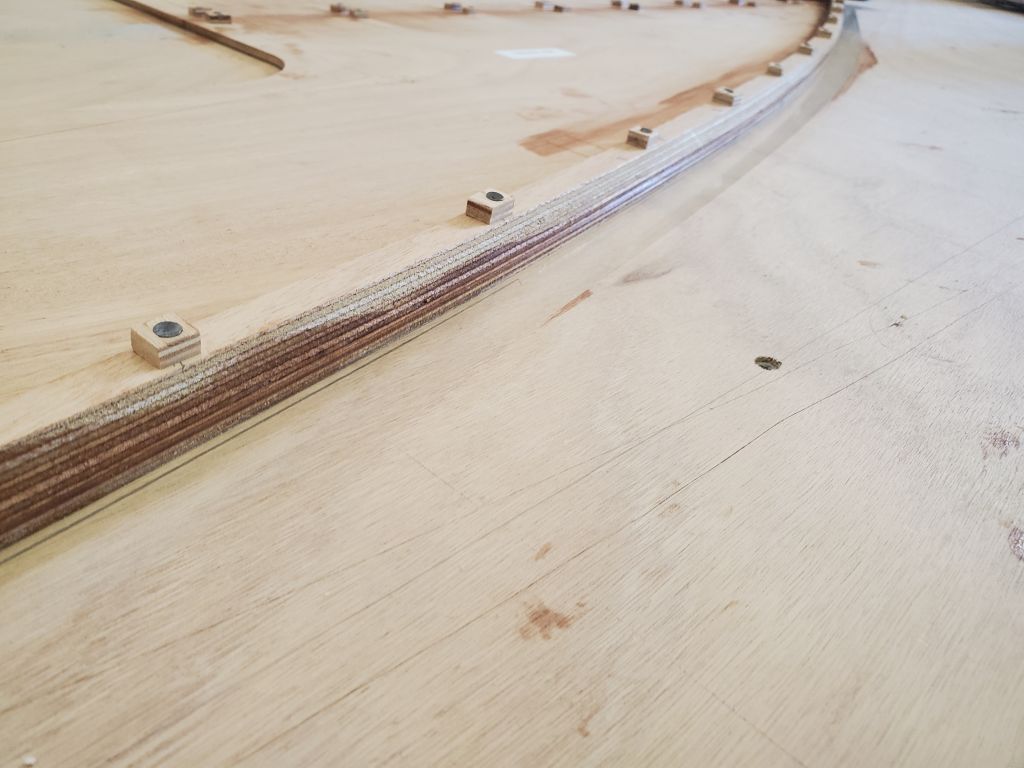
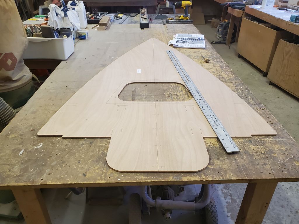
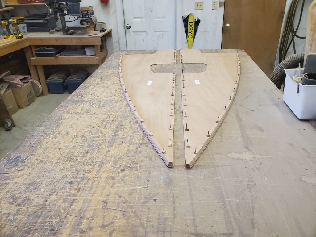
To finish up the early preparations for the foredeck, I lightly drove these nail assemblies into the foredeck panels at the marked locations, then laid out, marked, and pre-drilled the curved edge doublers to accept their nails before aligning these as needed along the edges of the foredeck panels and lightly driving the nails in. This was all just setup for the actual gluing process, with which I would have continued except it was nearly the end of the day and time to return to the fiberglassed panels I started earlier.
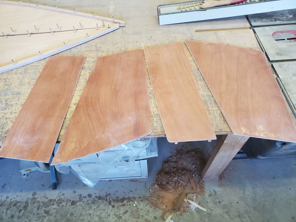
To round out the day, I applied a good fill coat of epoxy to the fiberglassed sides of the aft seats and daggerboard panels. This busy afternoon had knocked off many of the future steps required in the build, and once these parts cured they’d be ready for the next steps of assembly whenever progress on the hull dictated.