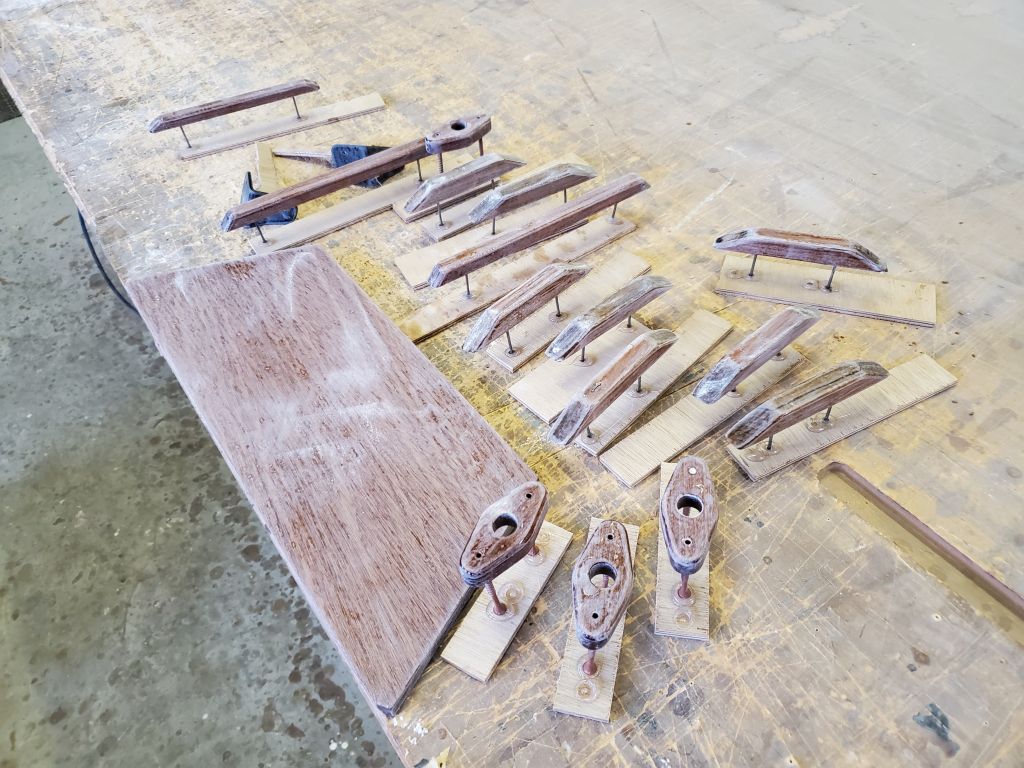
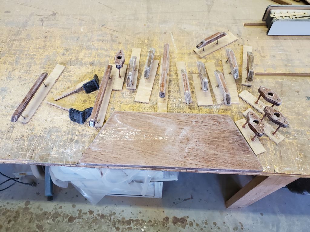
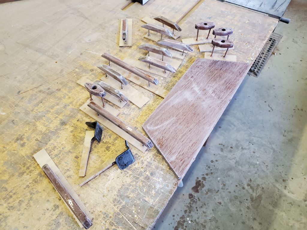
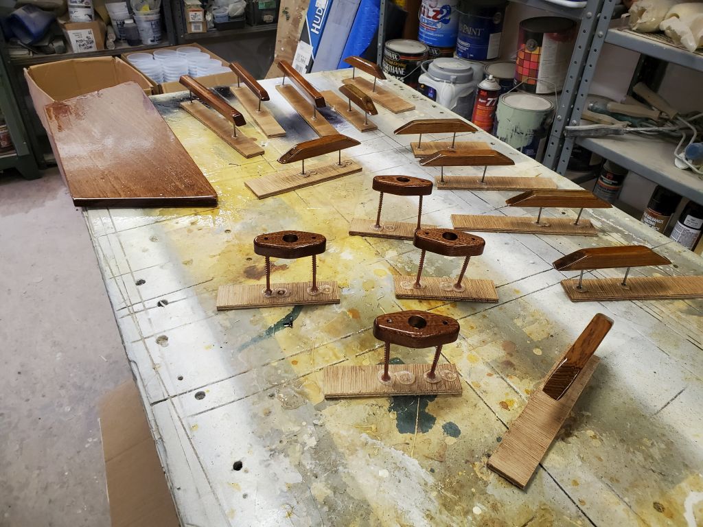
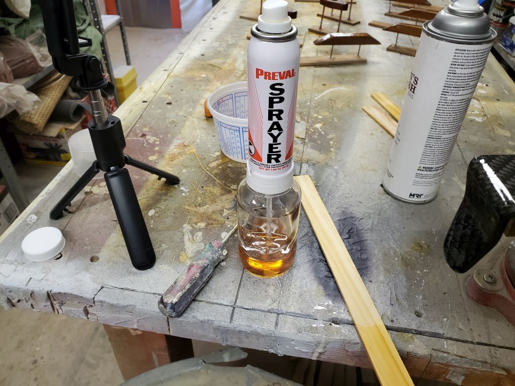
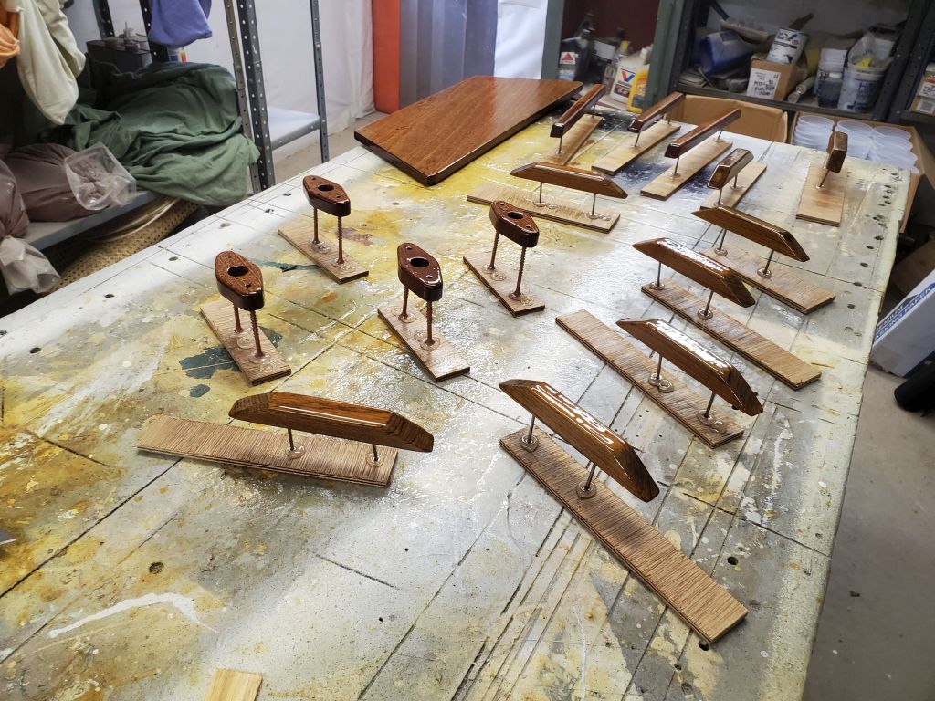
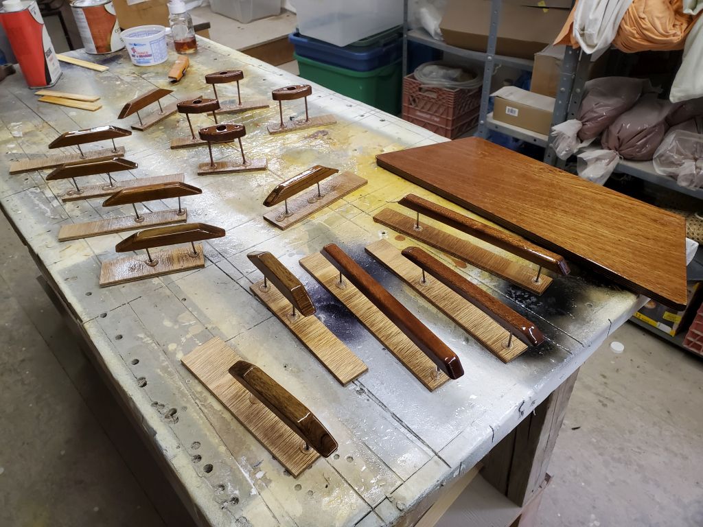
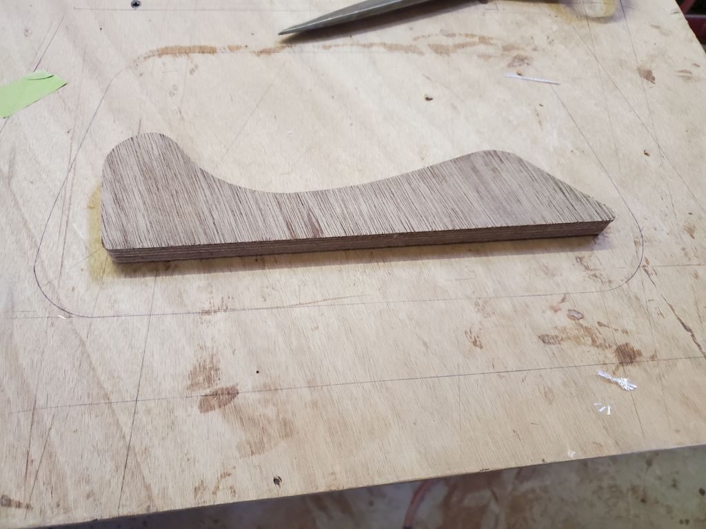
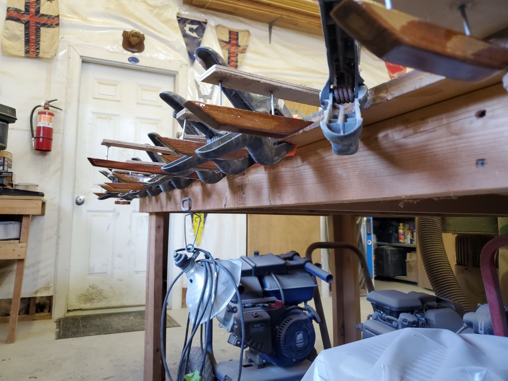
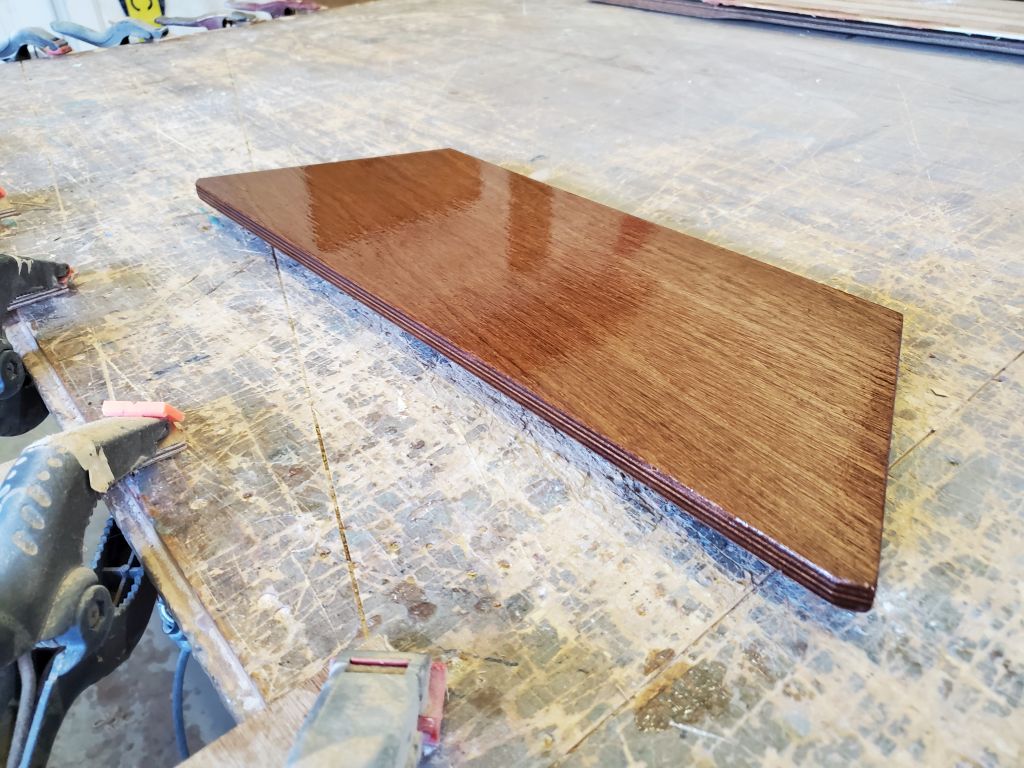
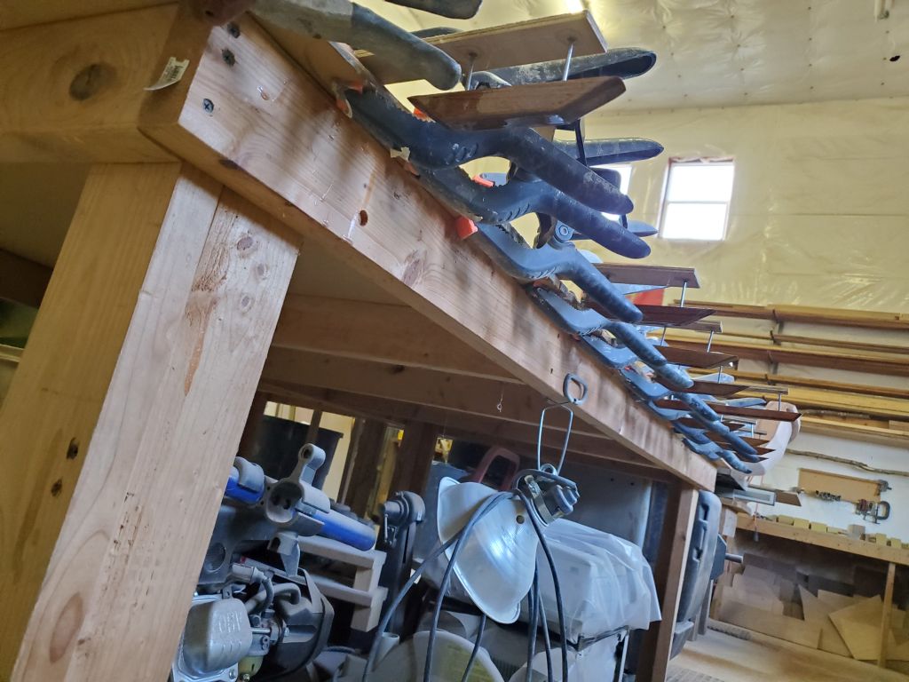
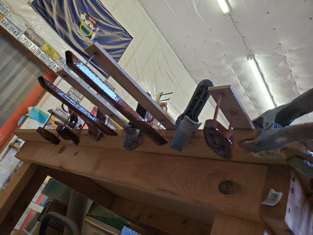
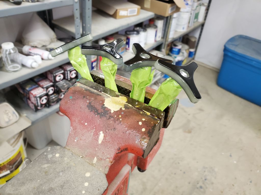
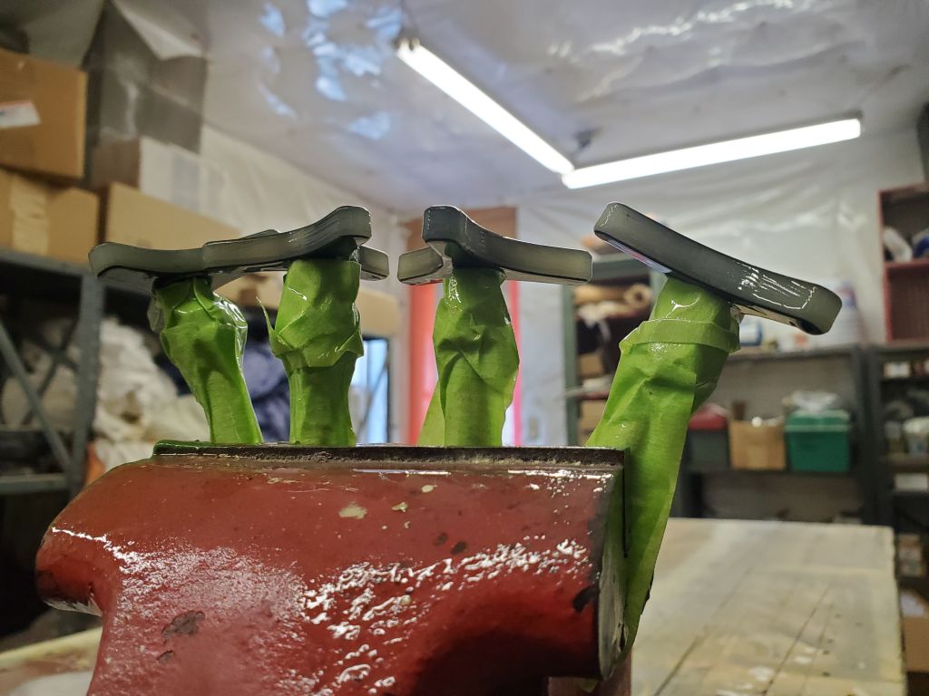
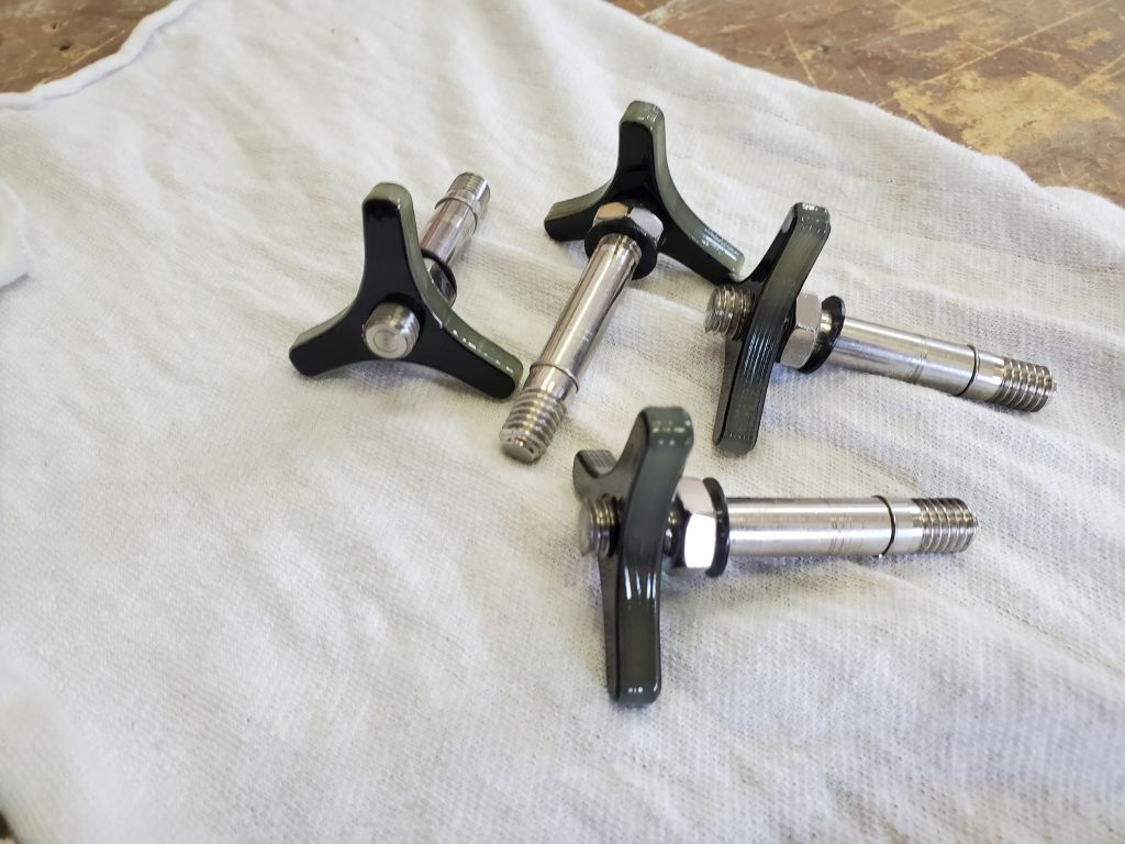
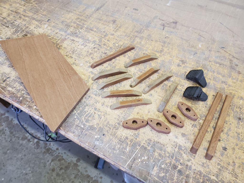
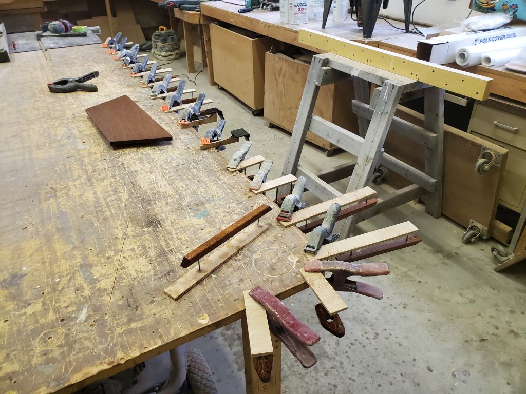
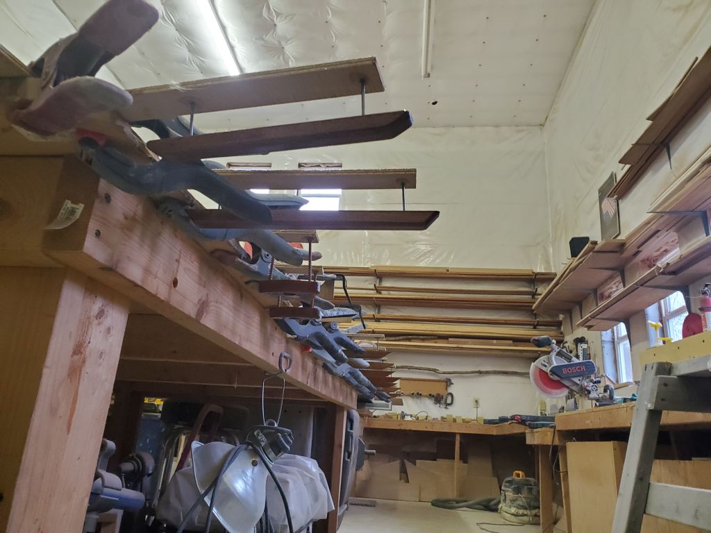
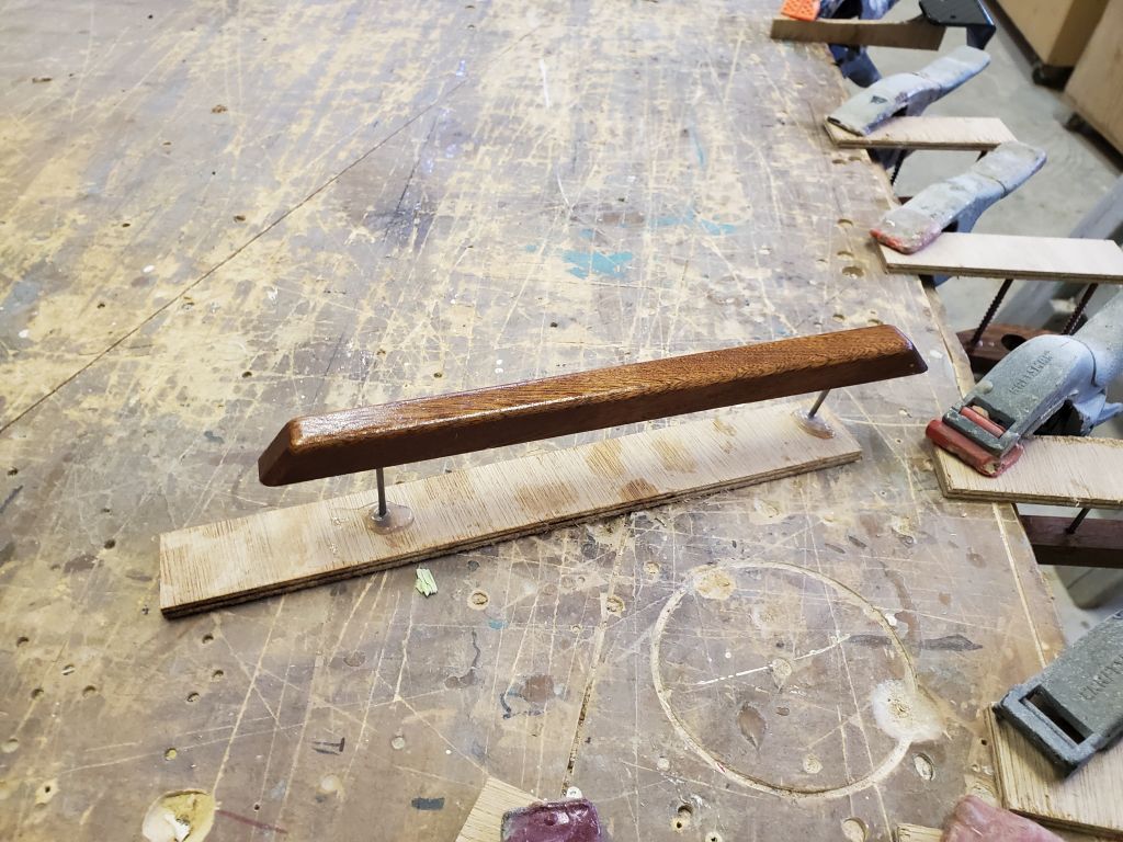
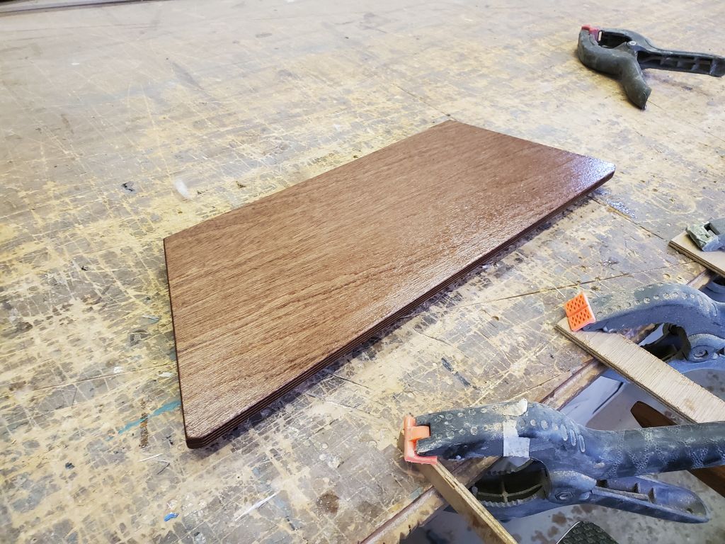
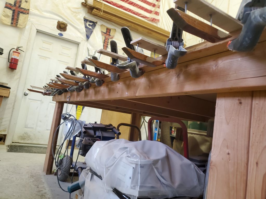
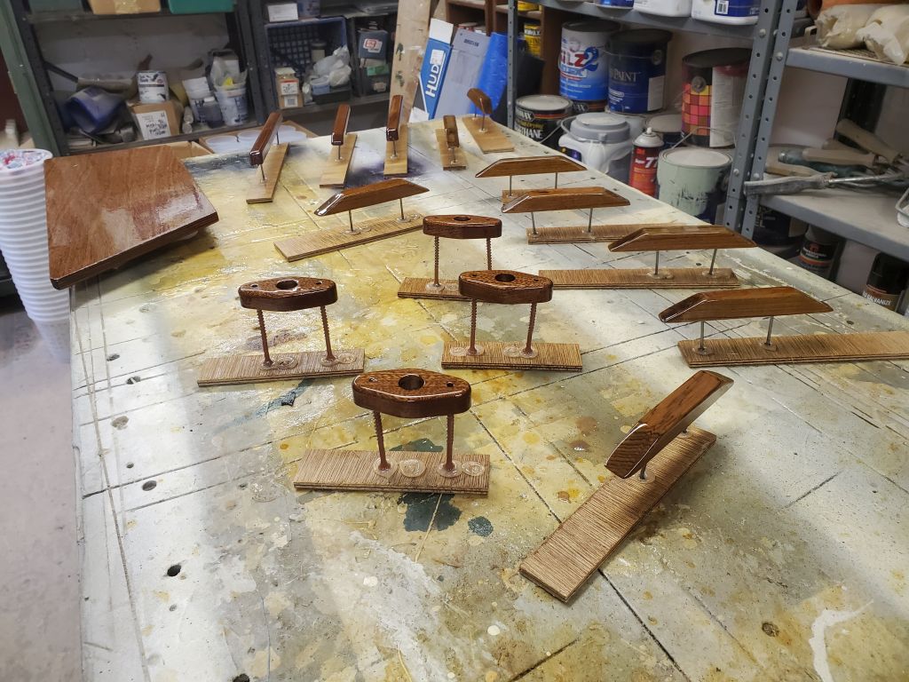
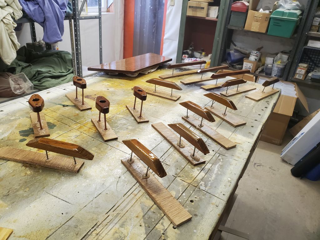
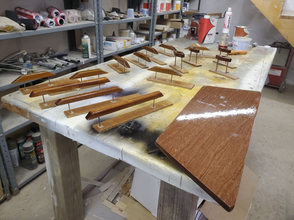
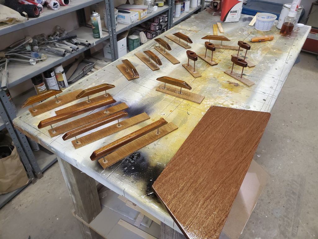
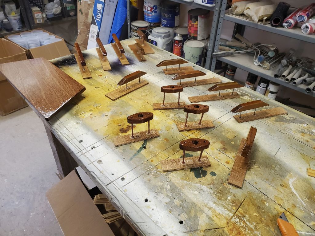
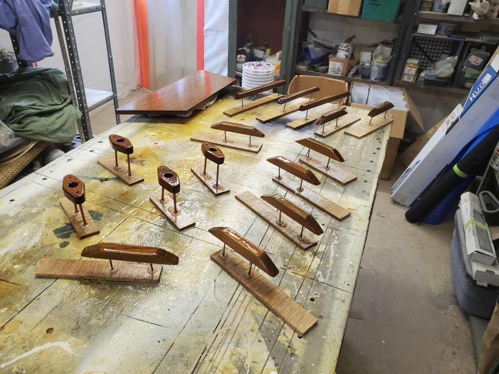
Starting first thing, and throughout the morning, I applied a few more coats of varnish to the small parts using a small sprayer; this time around, I flipped the seat blank so the final exposed side was now facing up to get some varnish, as the underside was sufficiently coated for now.
Fifth coat (first on seat blank):
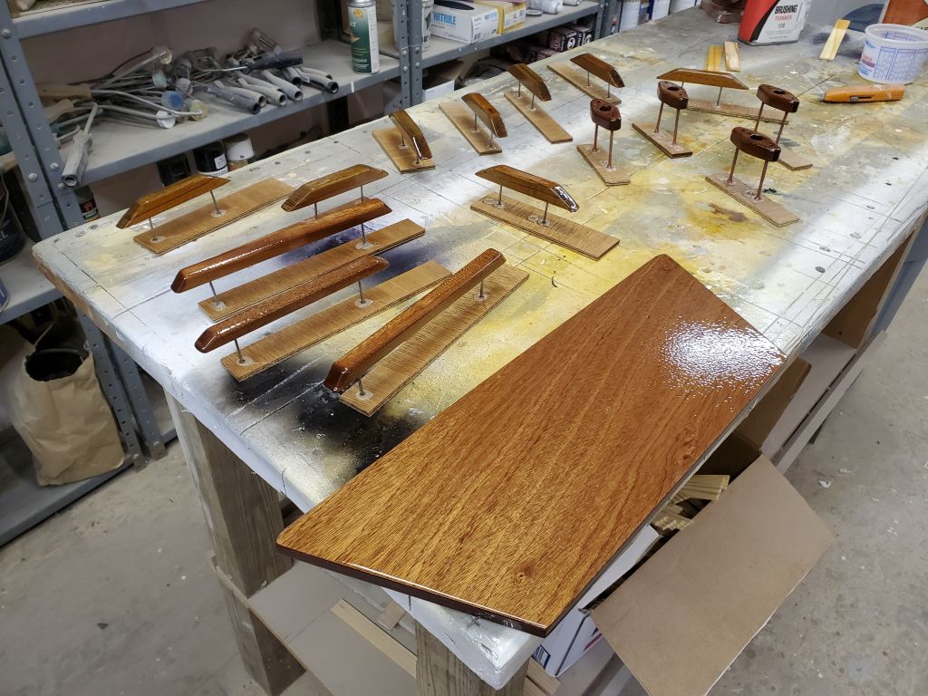
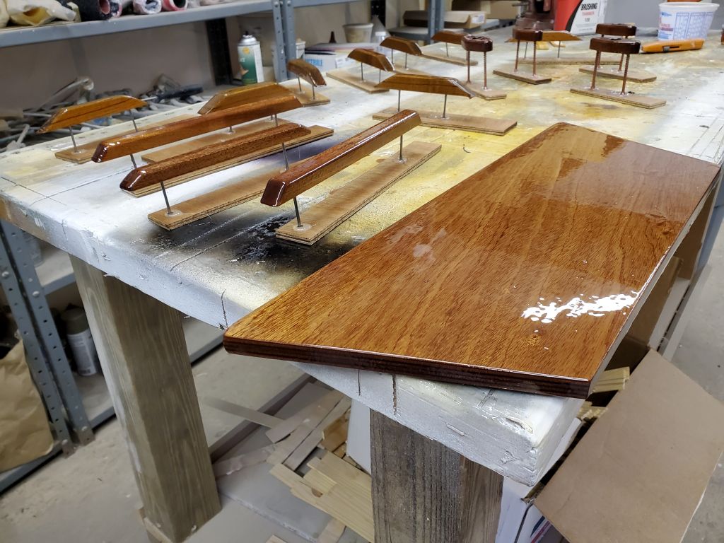
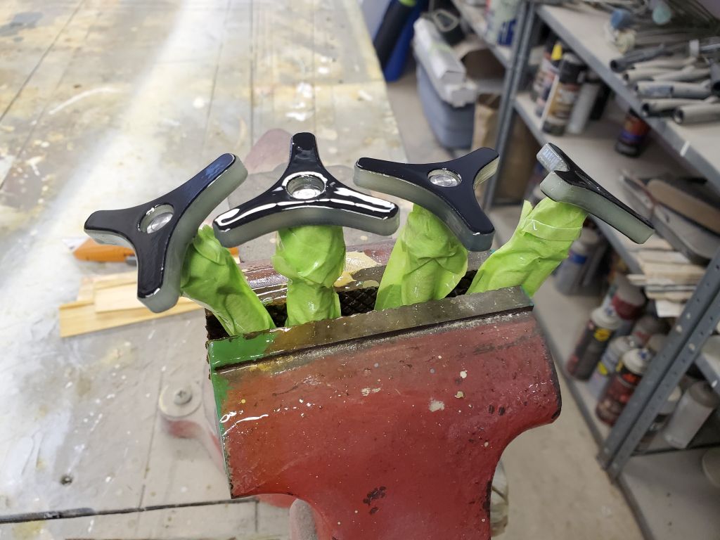
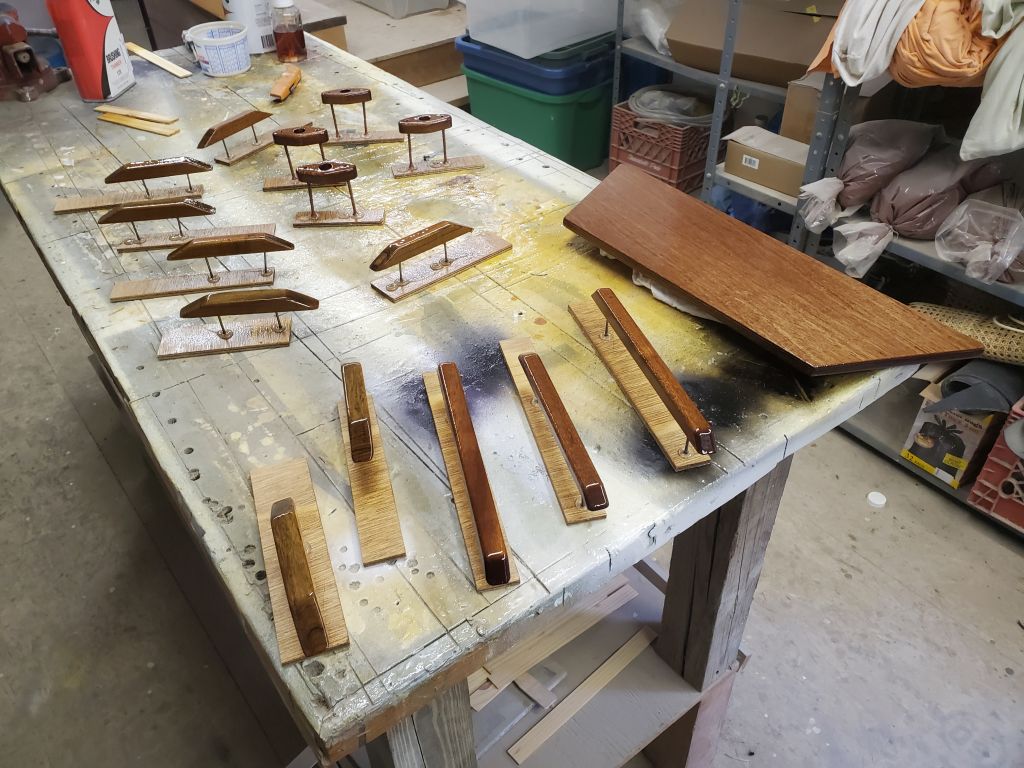
Sixth coat (second on seat blank):
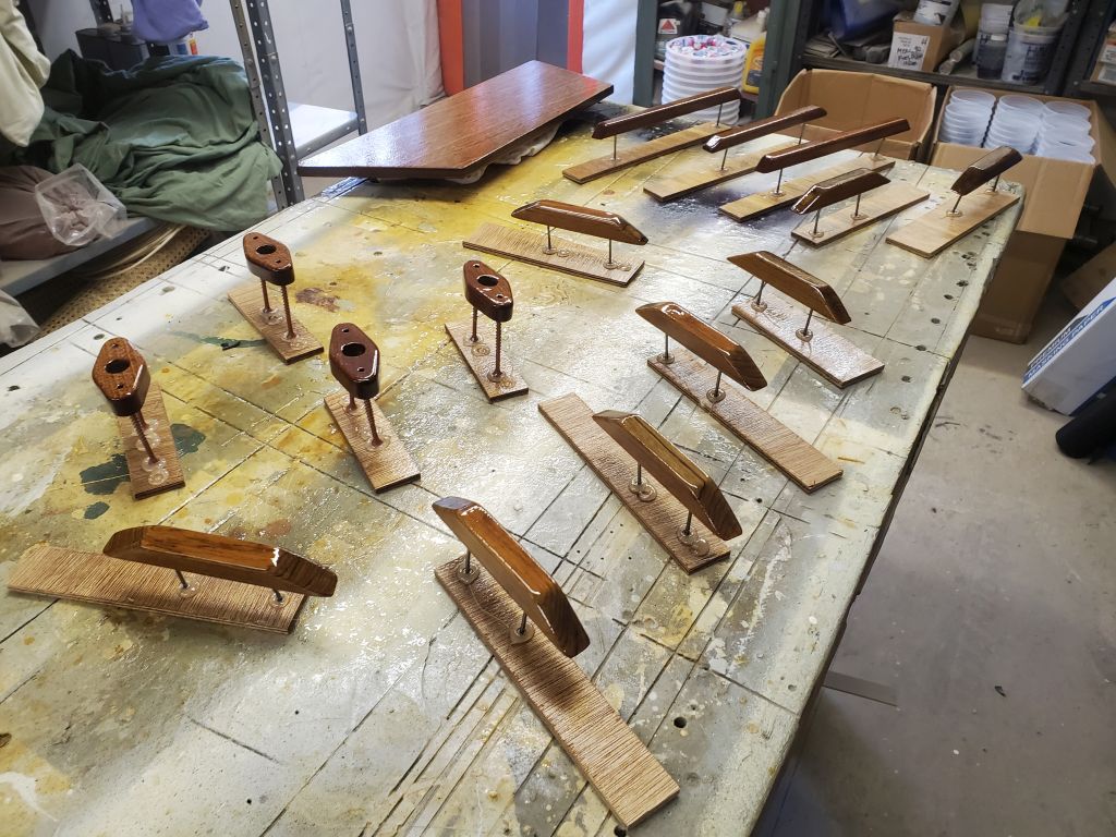
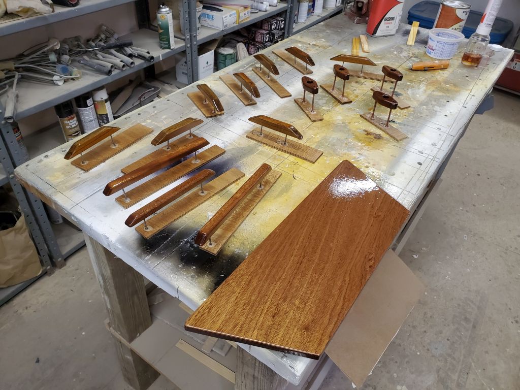
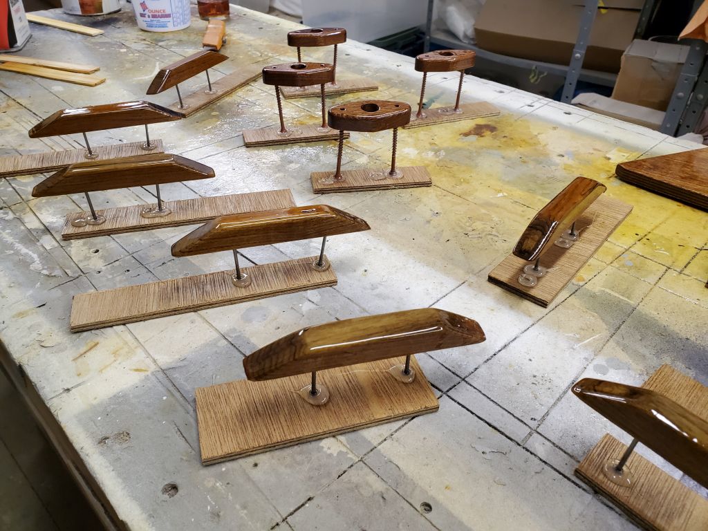
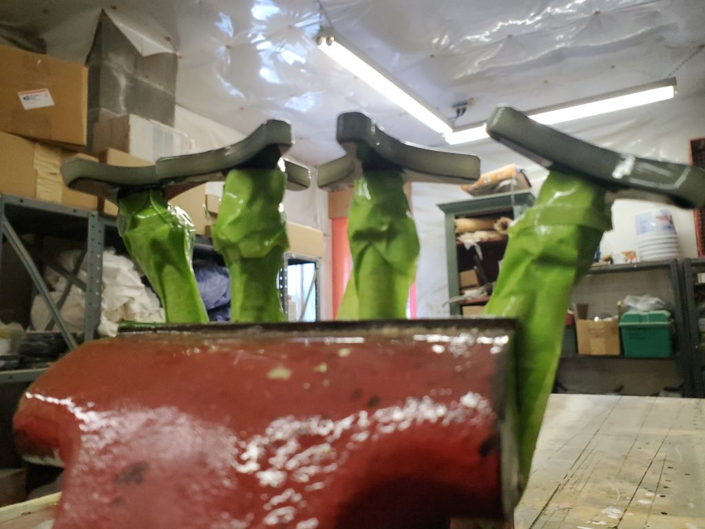
Seventh coat (third on seat blank):
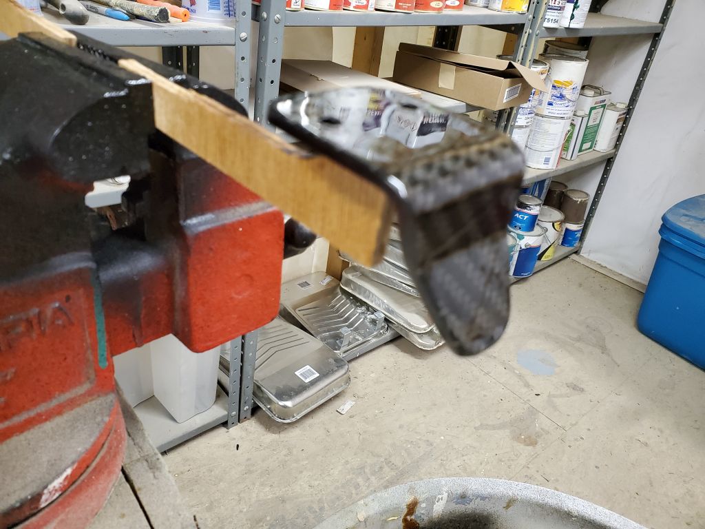
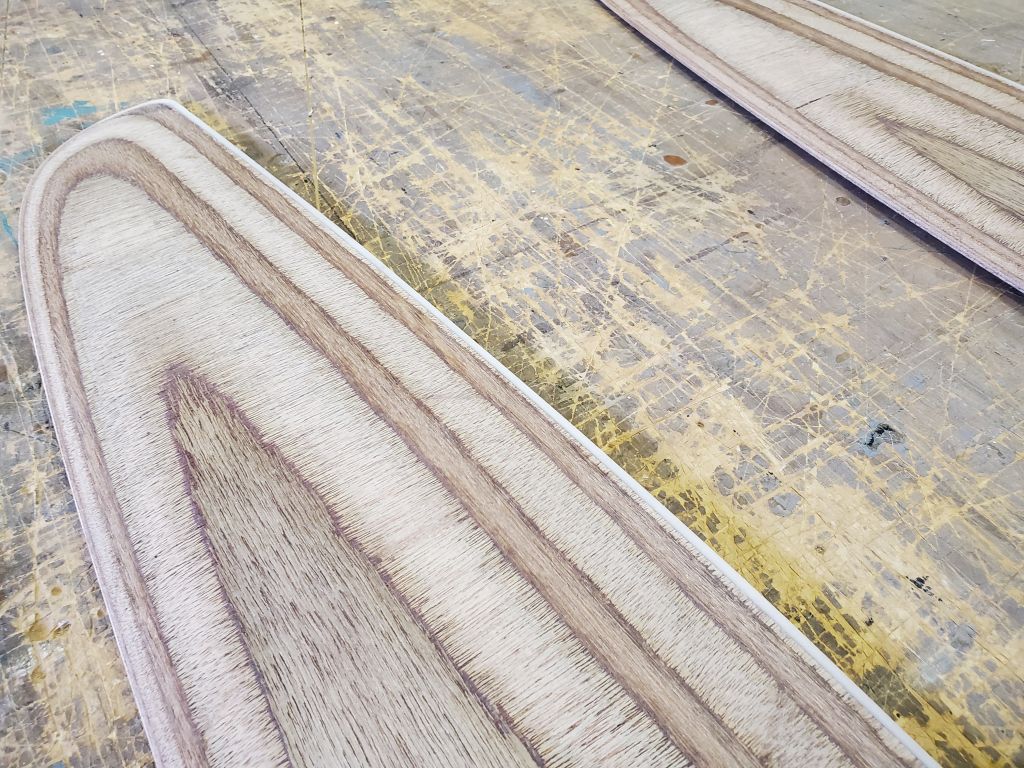
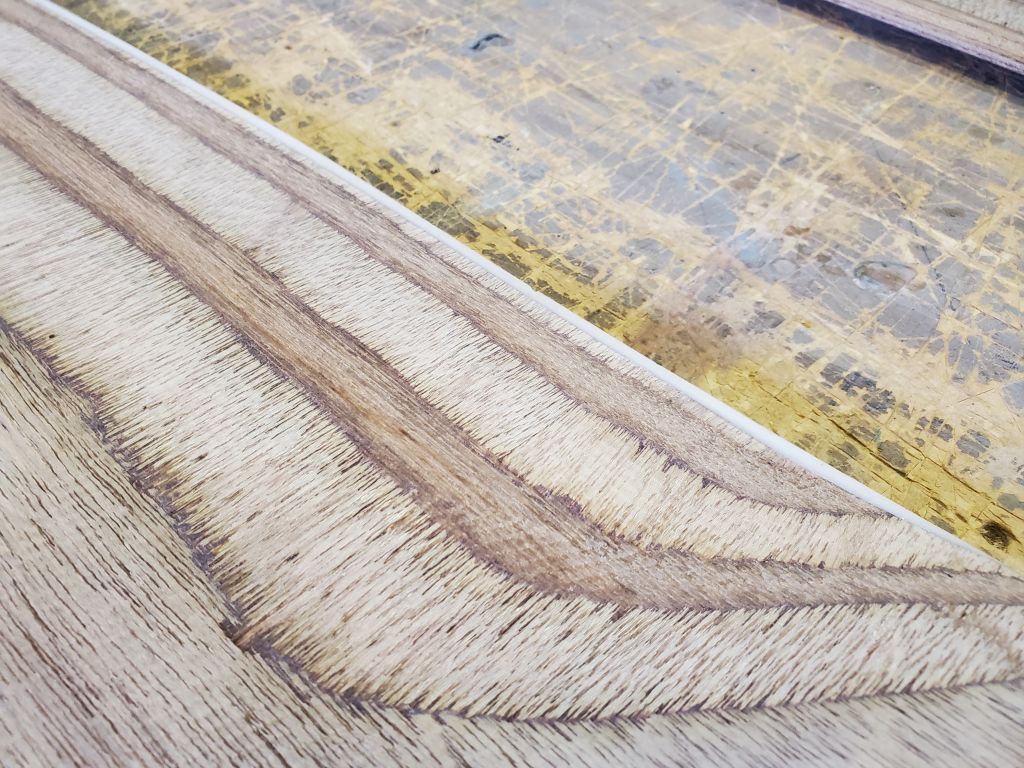
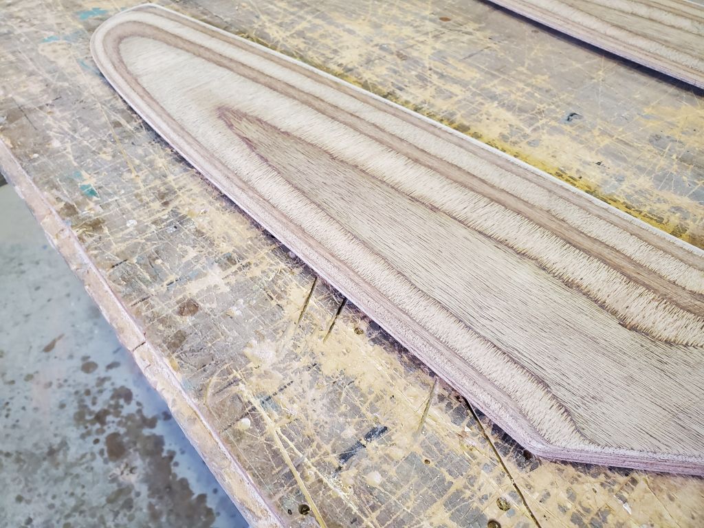
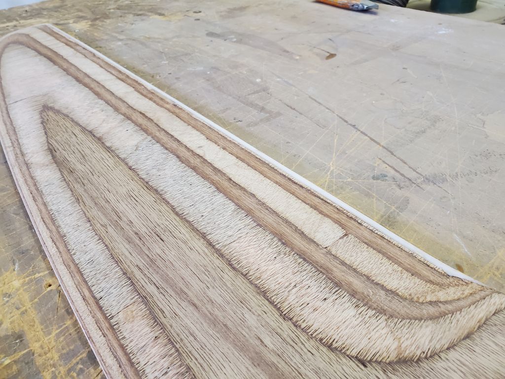
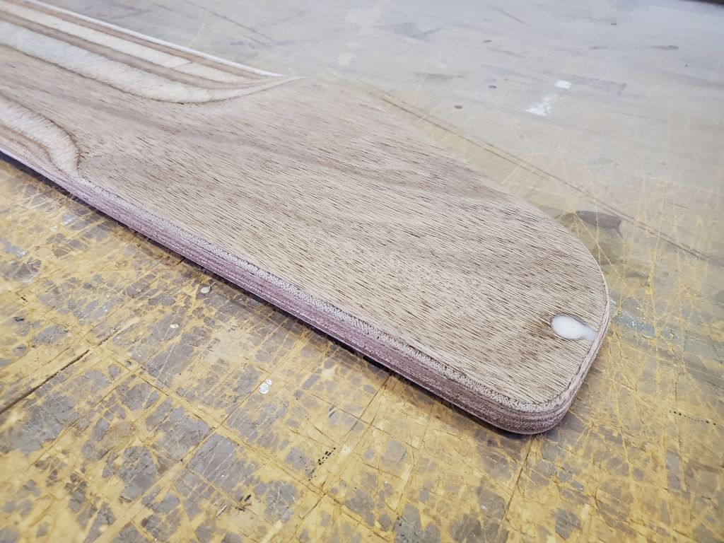
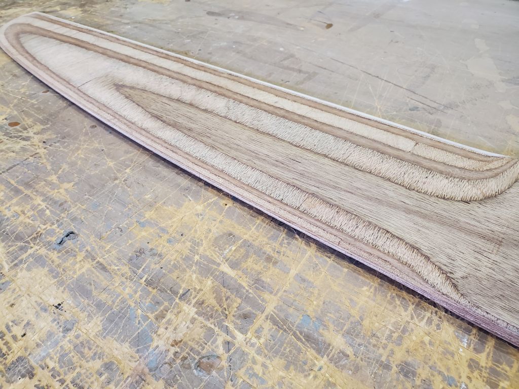
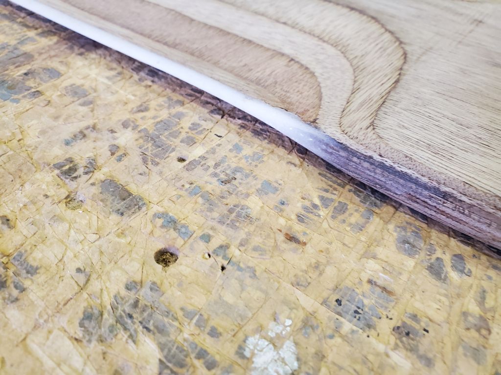
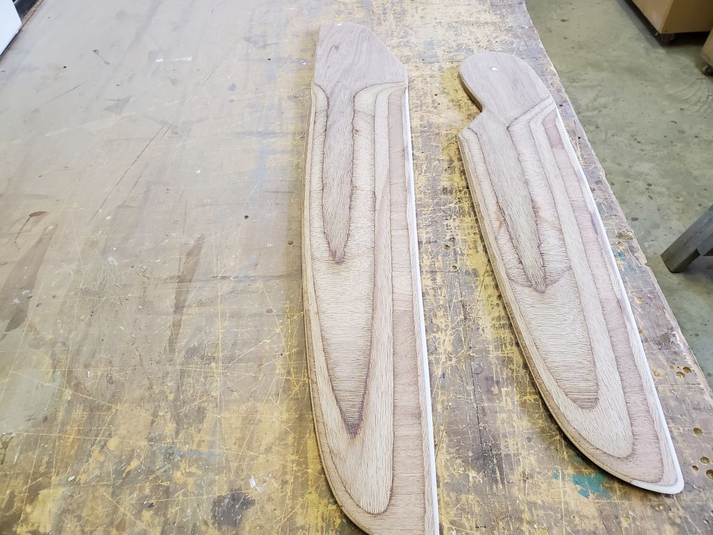
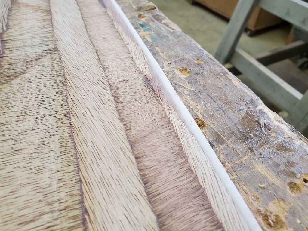
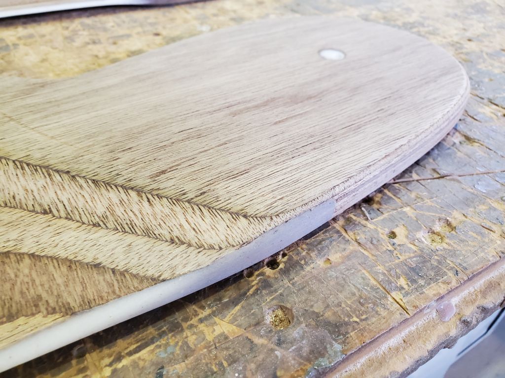
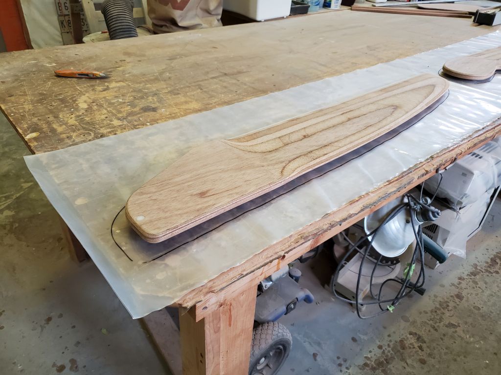
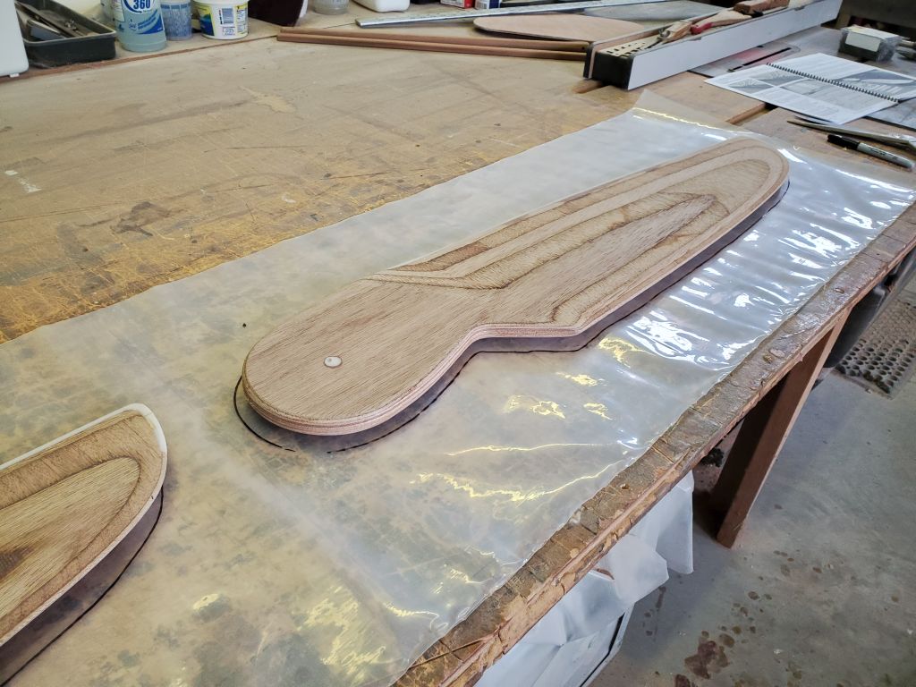
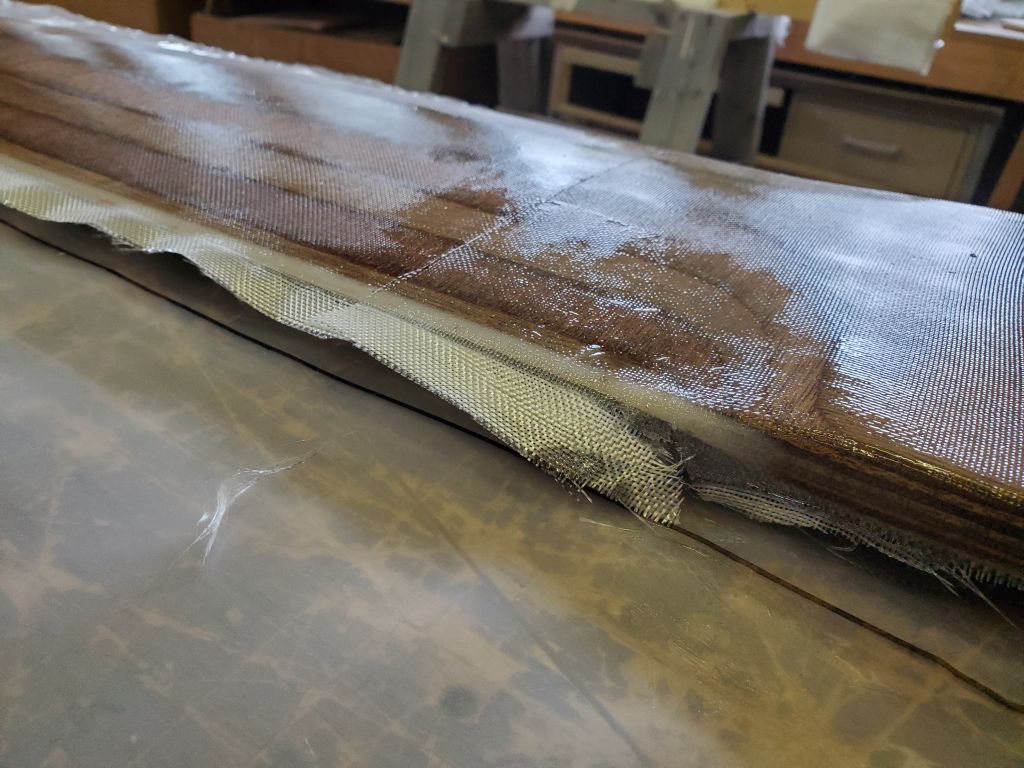
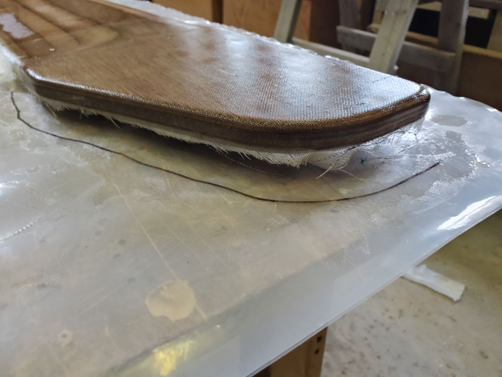
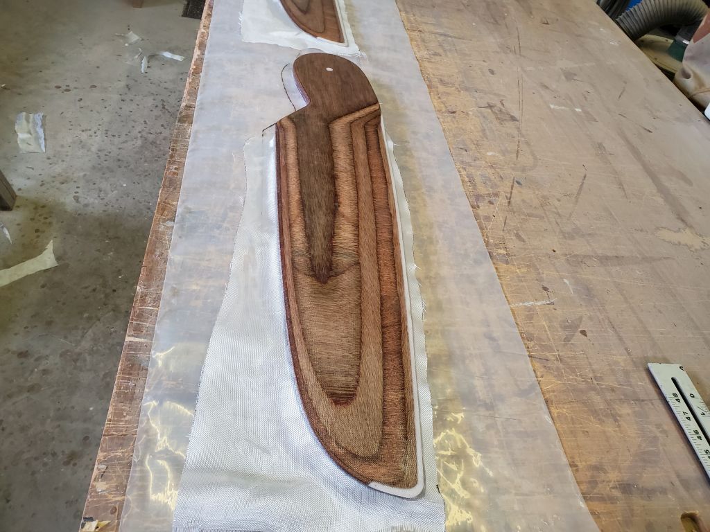
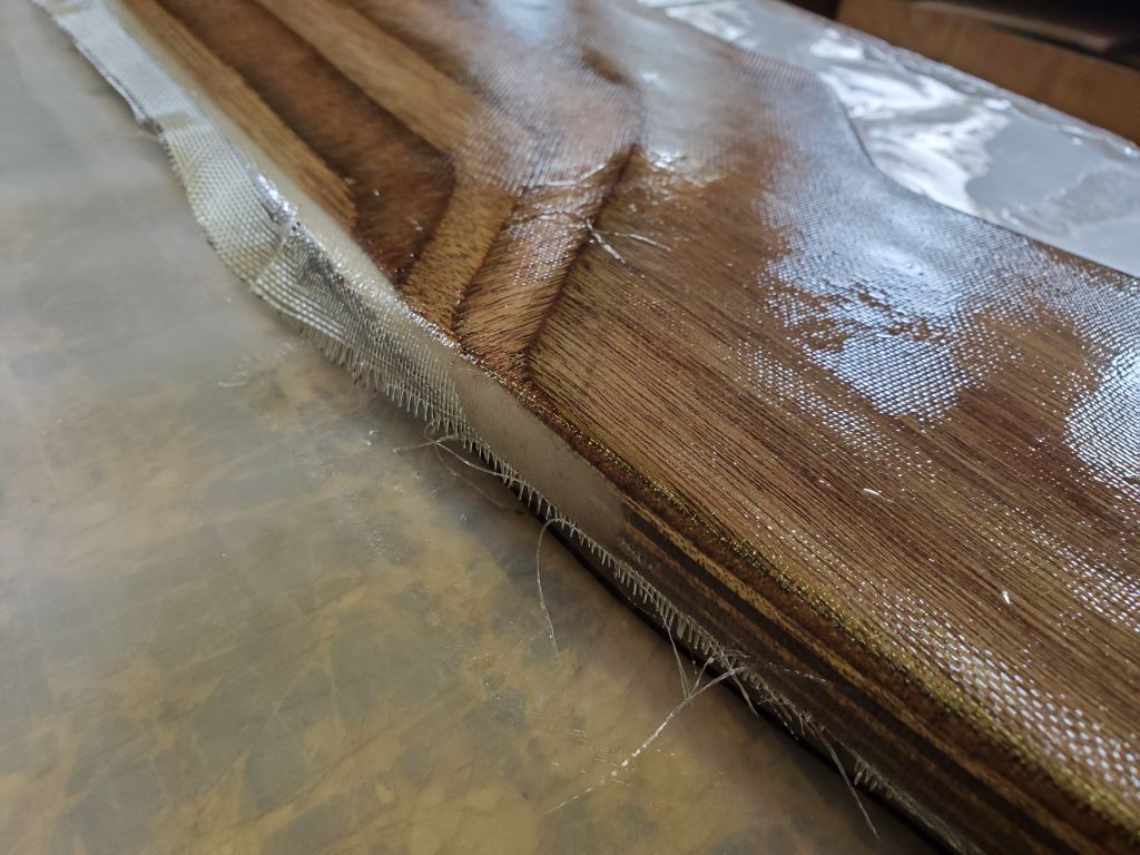
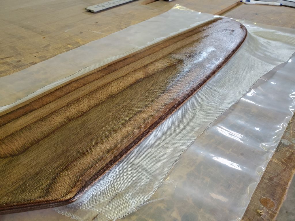
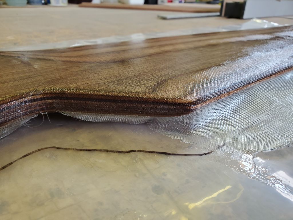
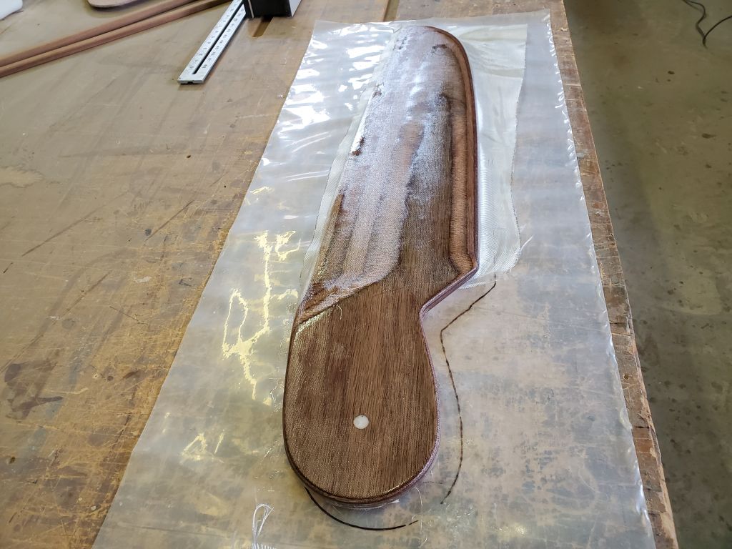
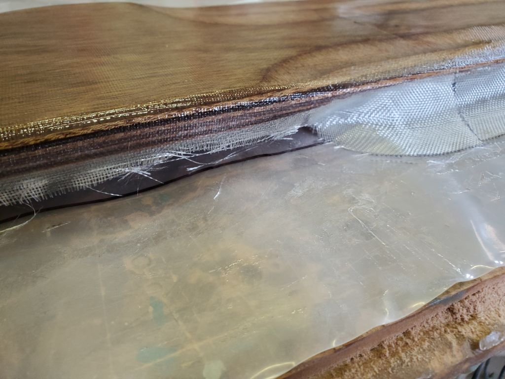
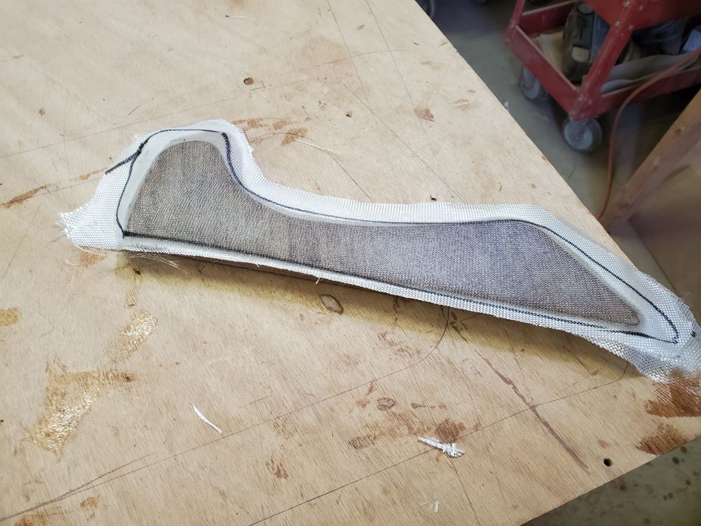
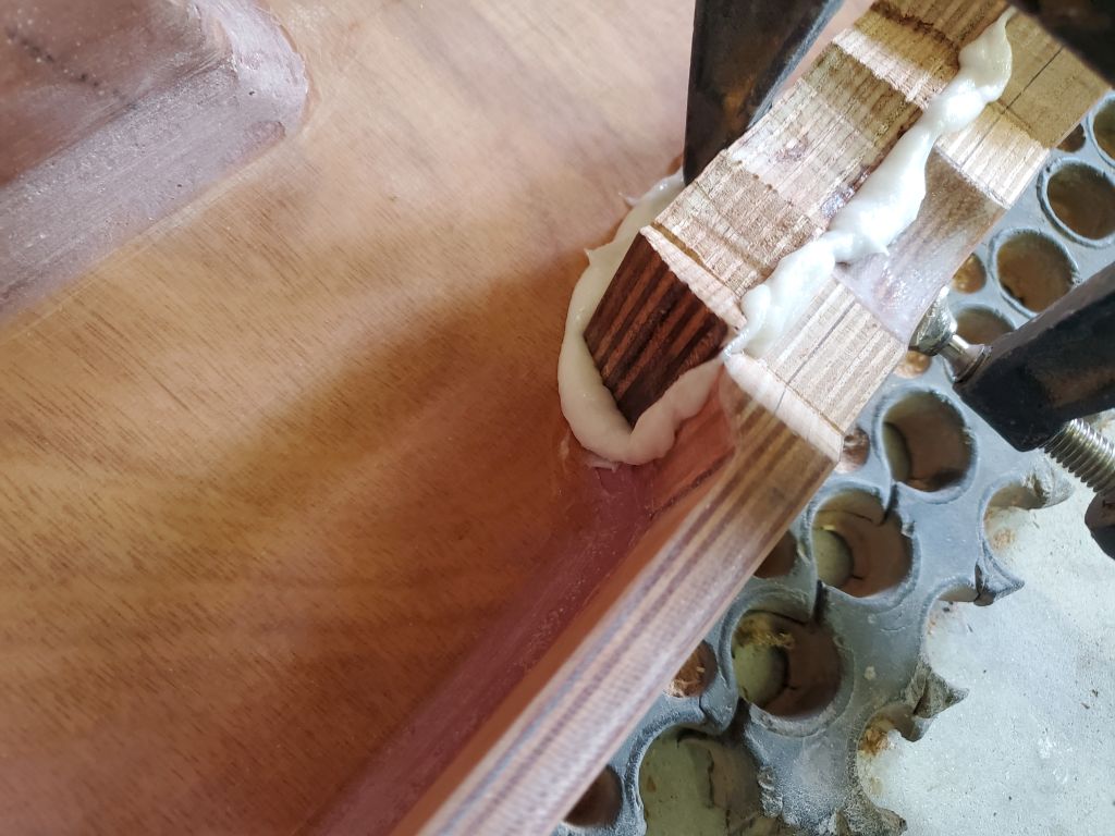
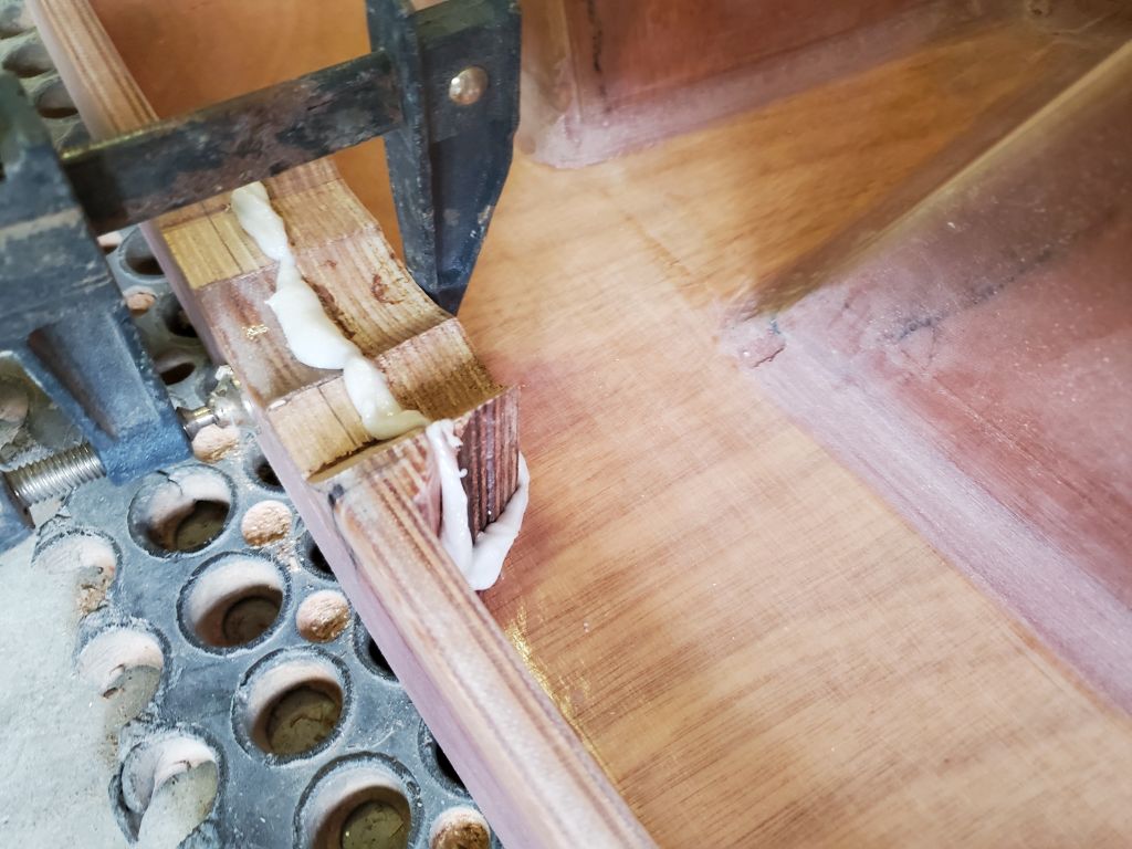
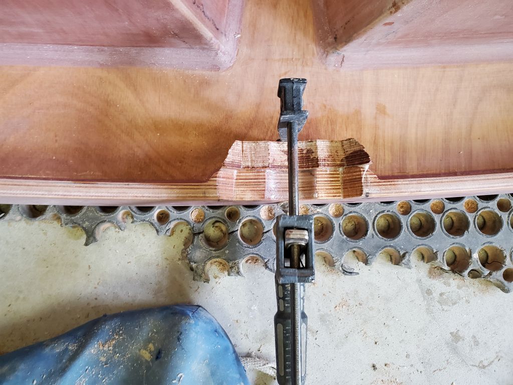
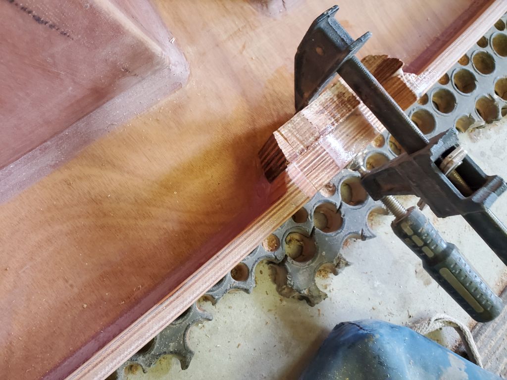
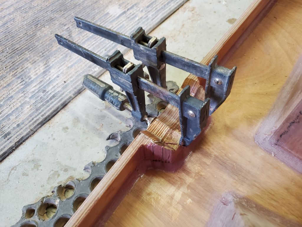
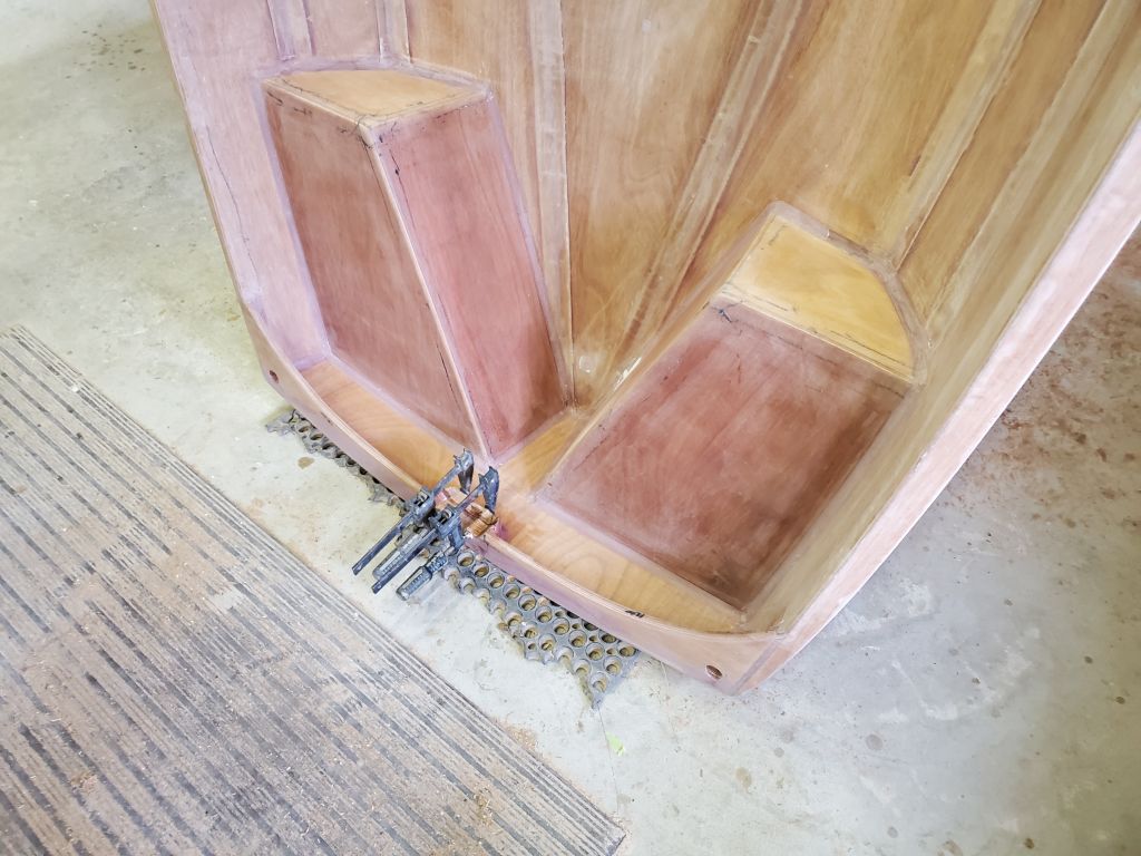
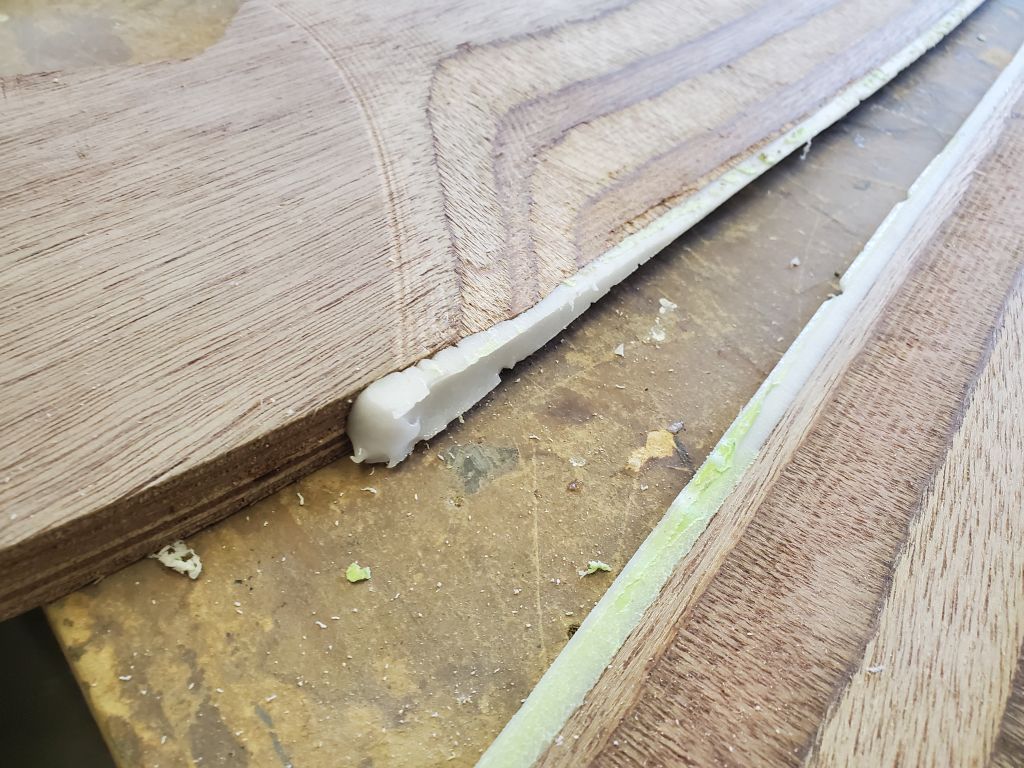
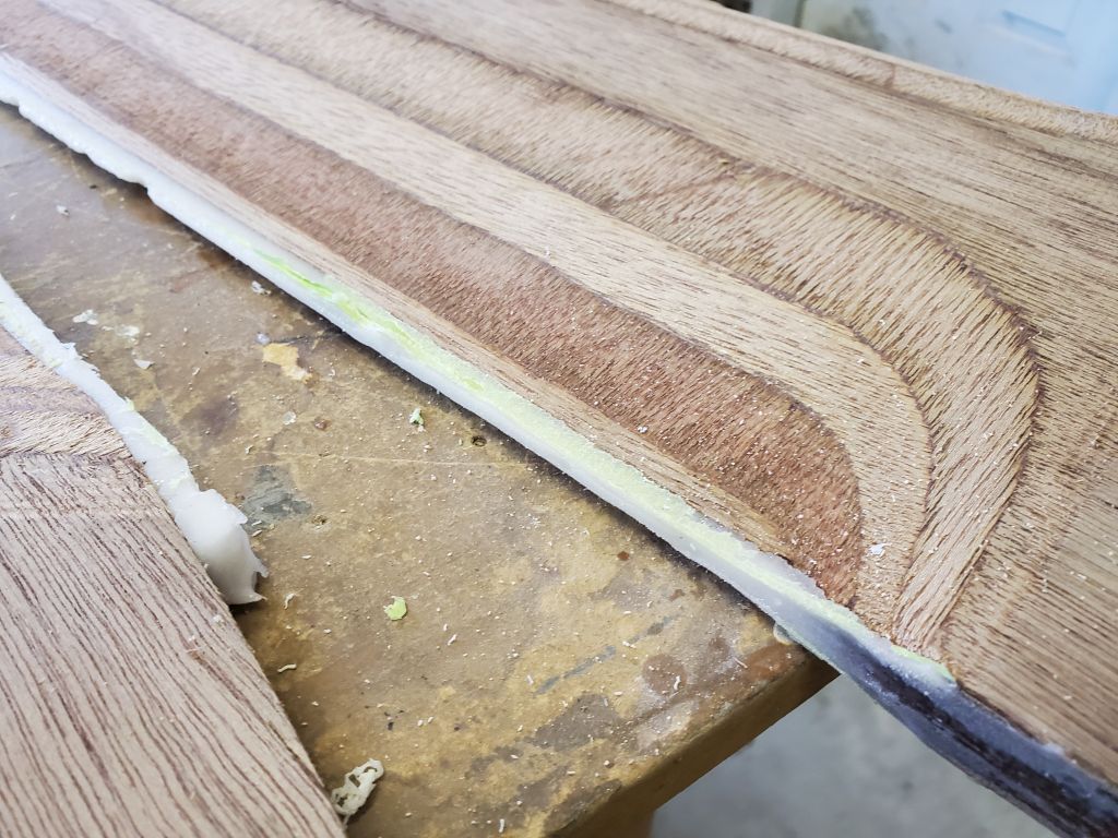
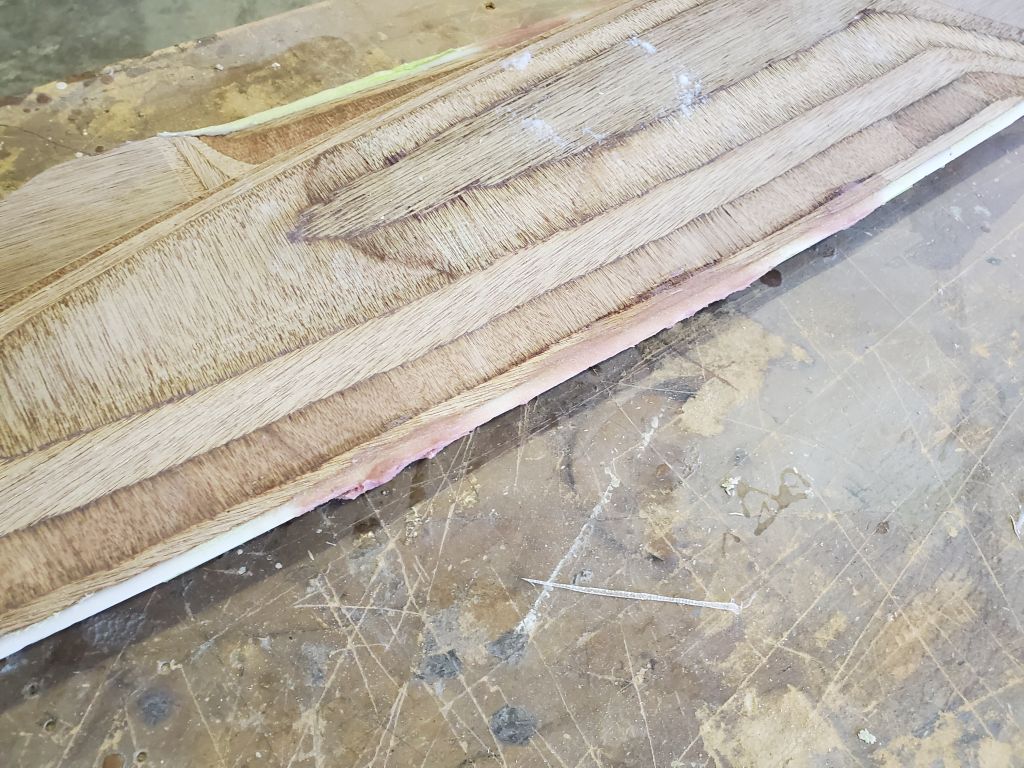
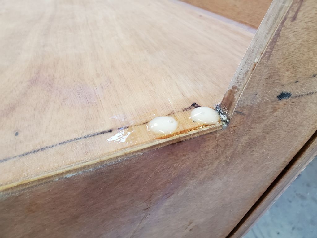
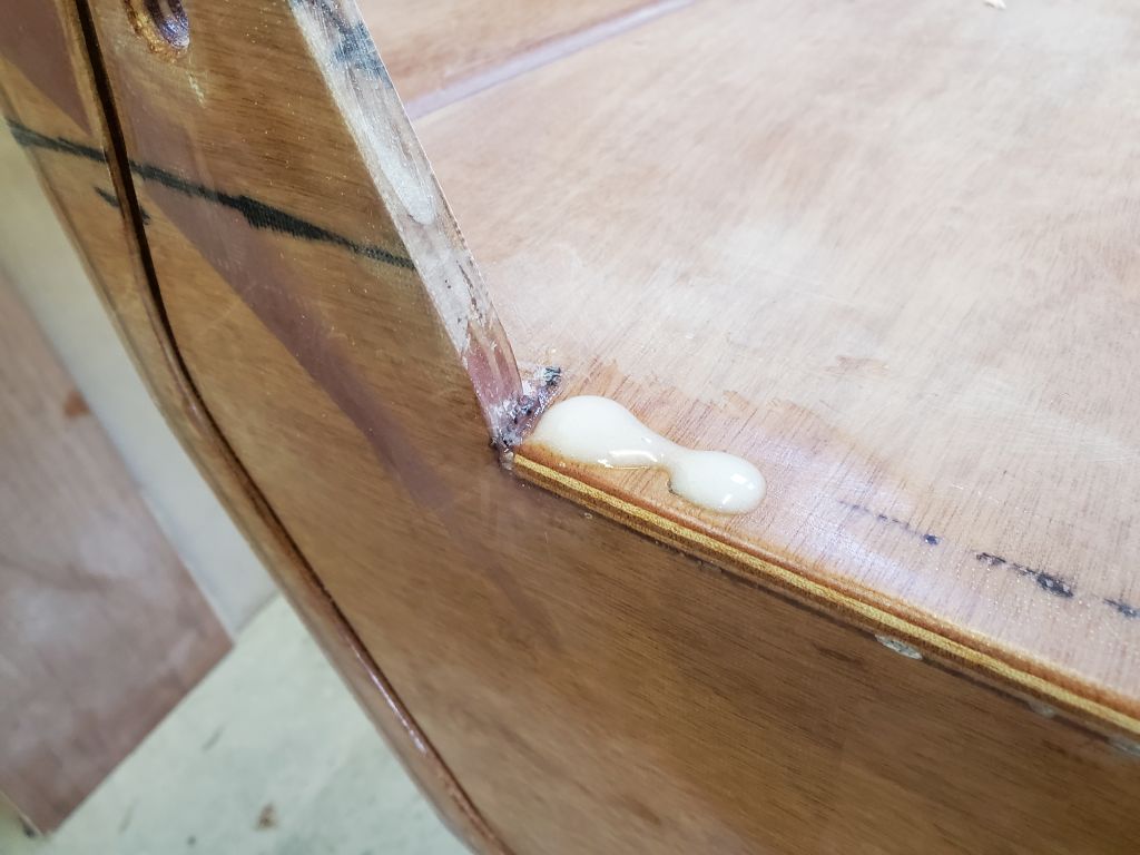
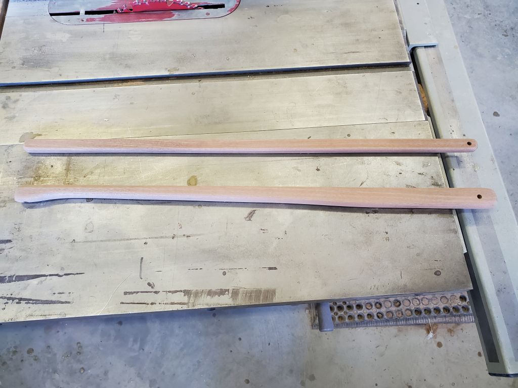
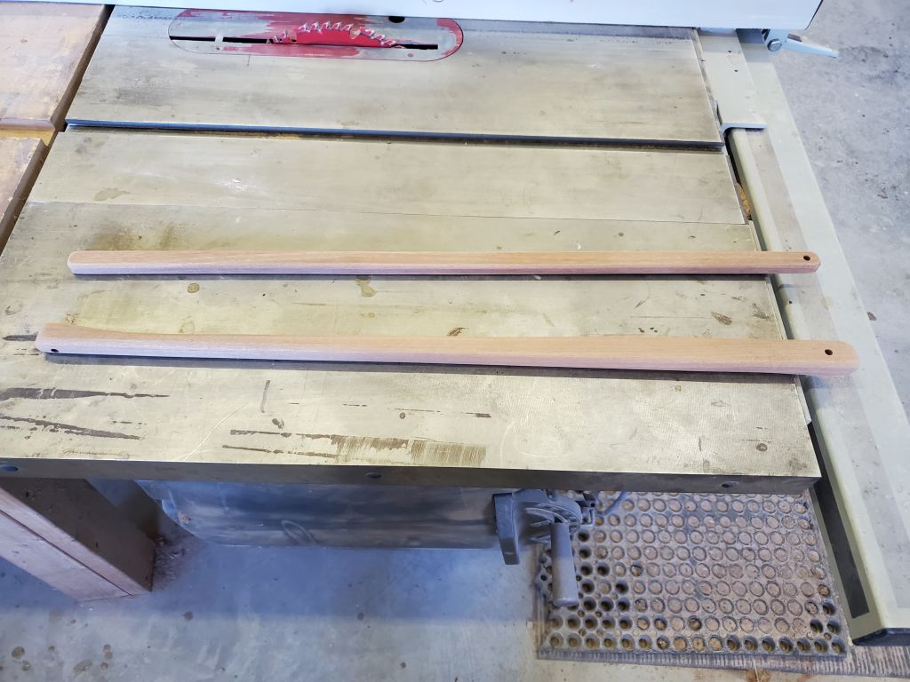
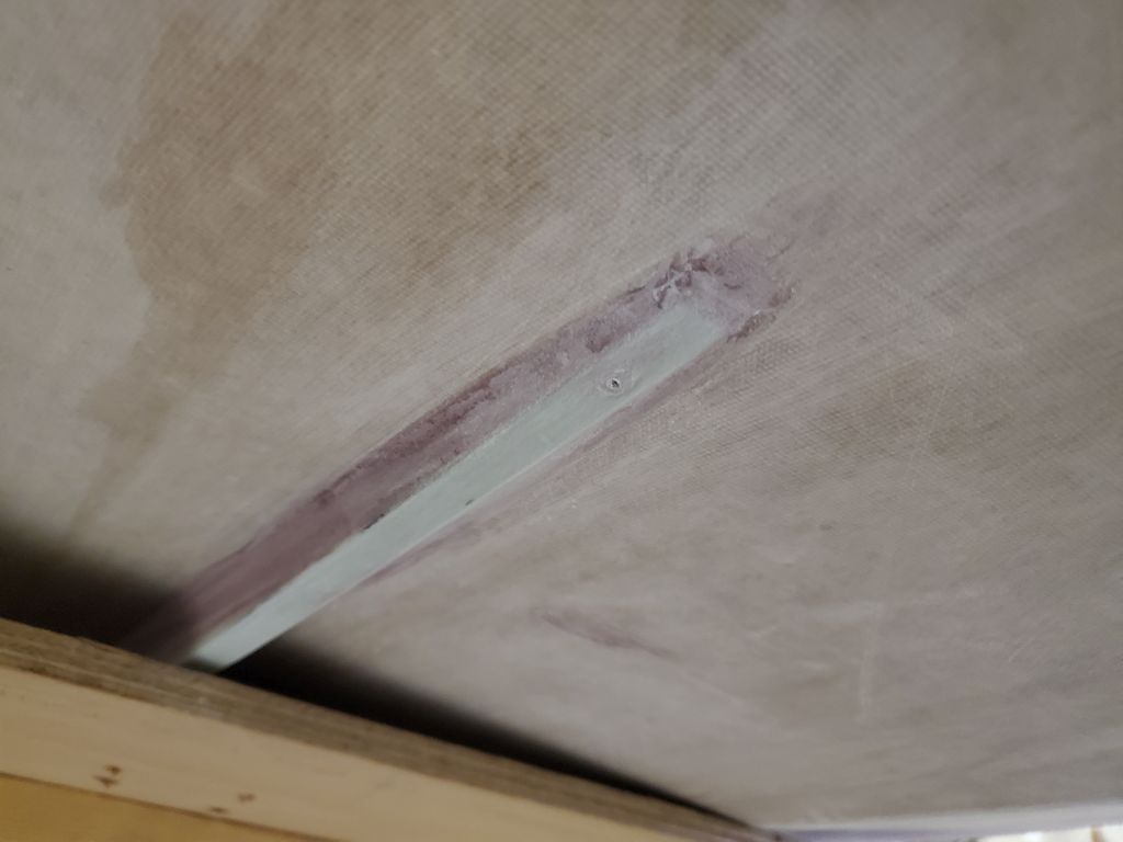
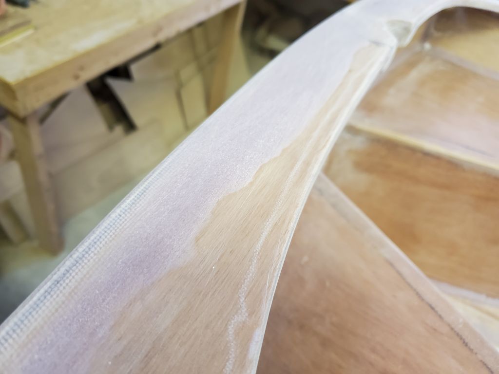
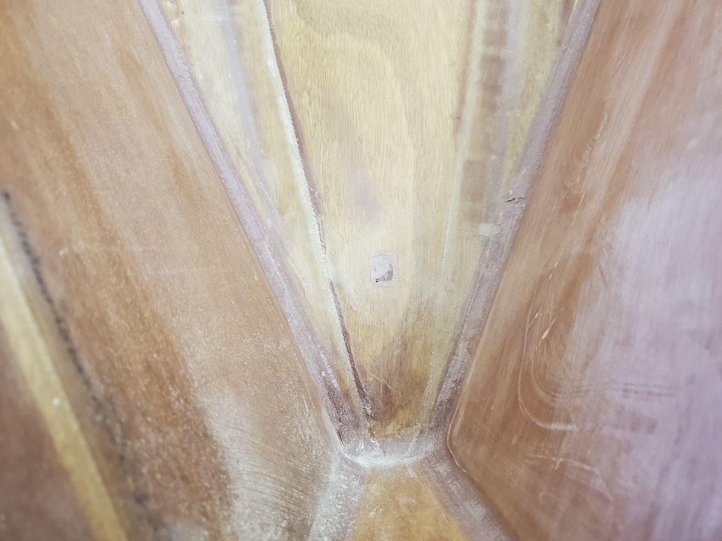
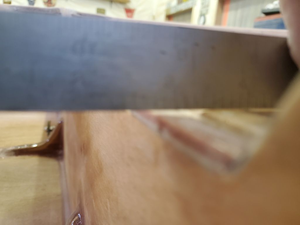
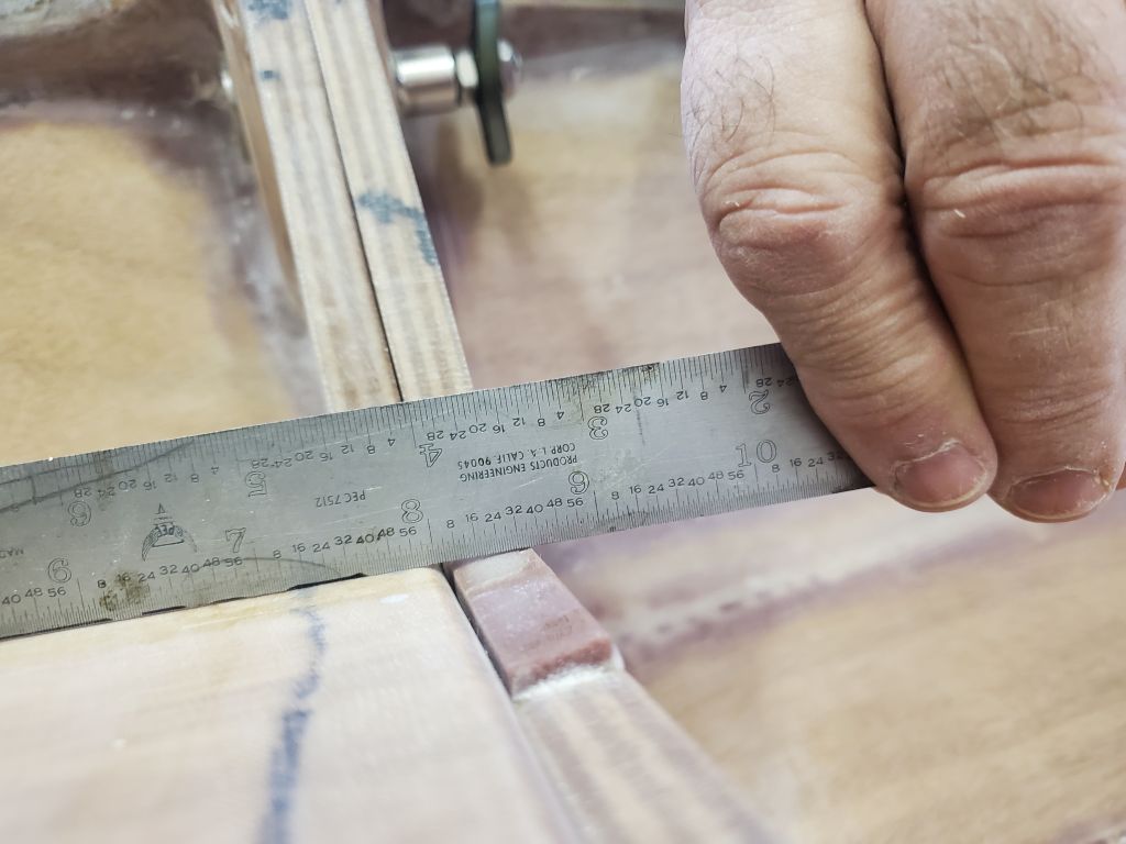
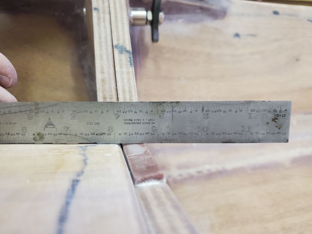
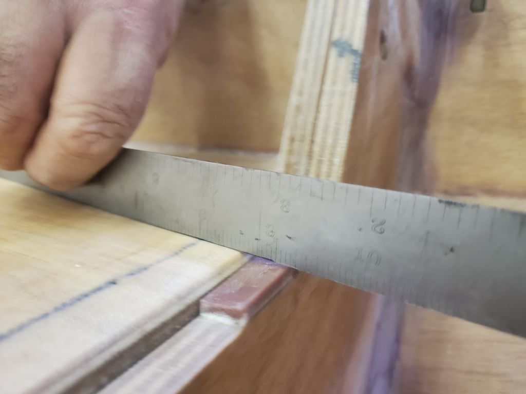
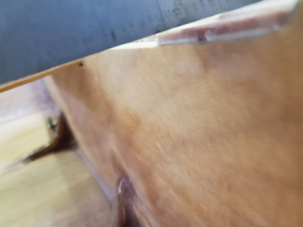
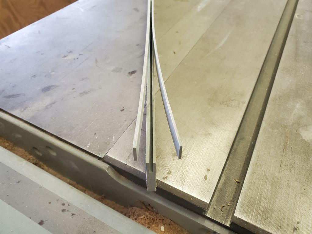
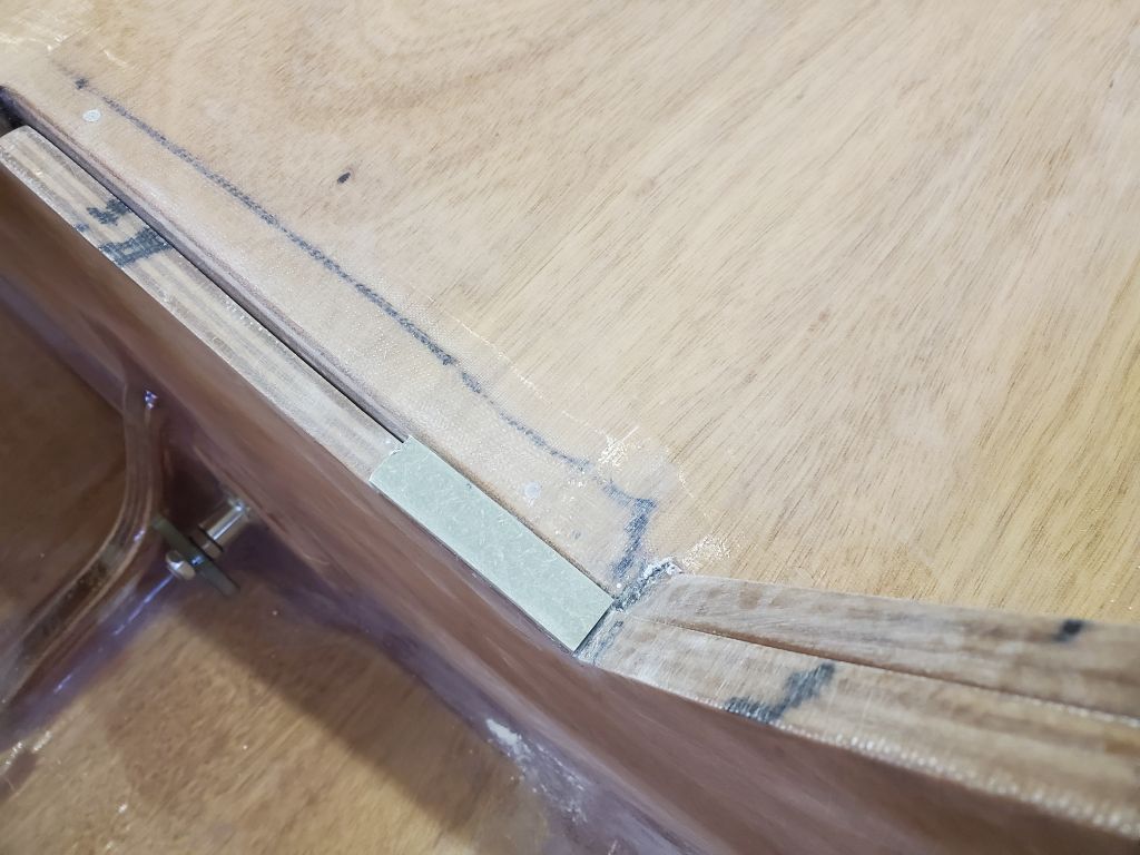
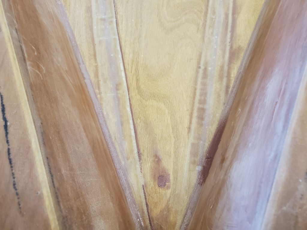
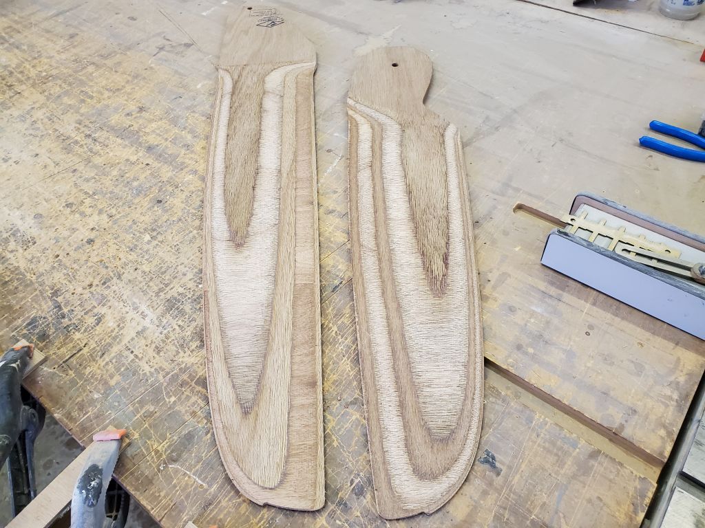
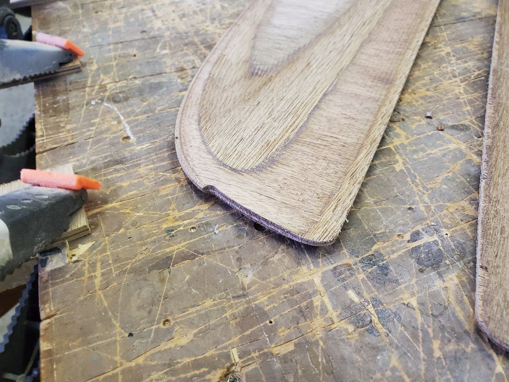
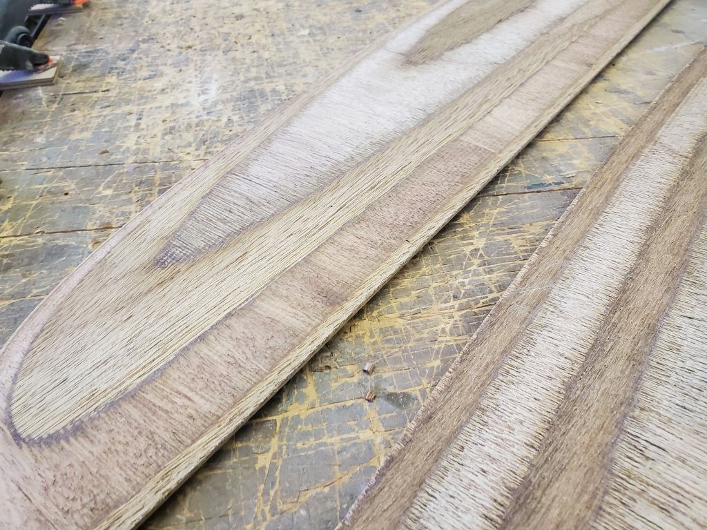
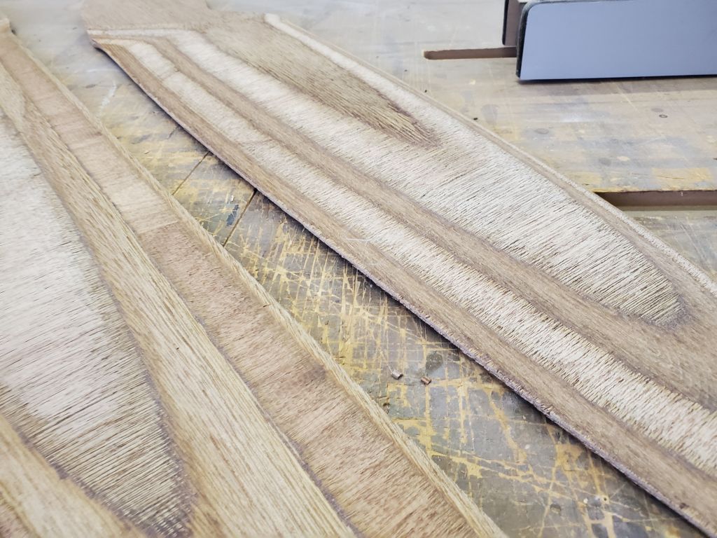
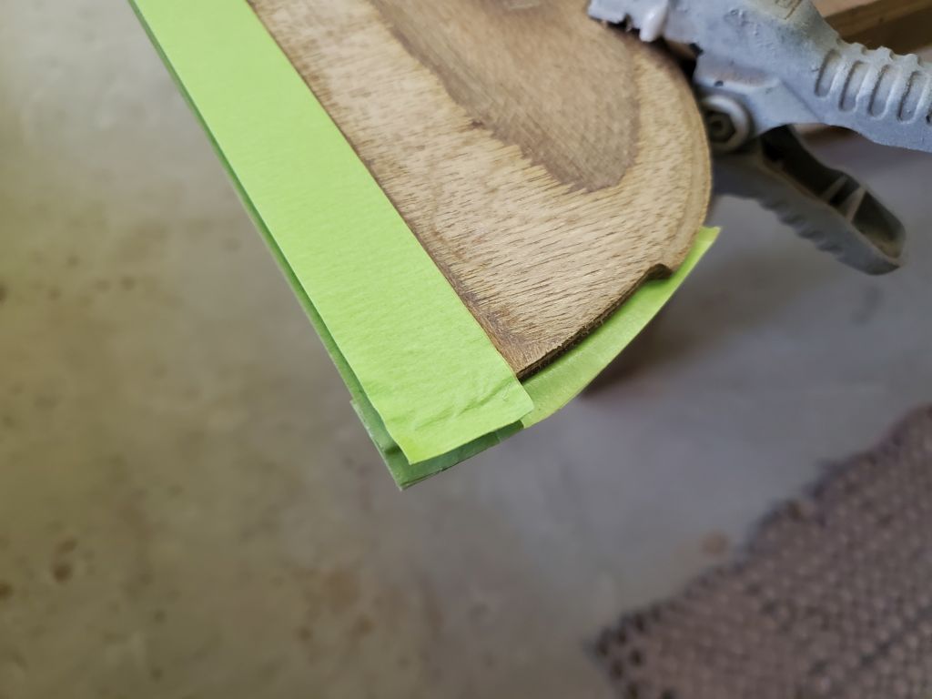
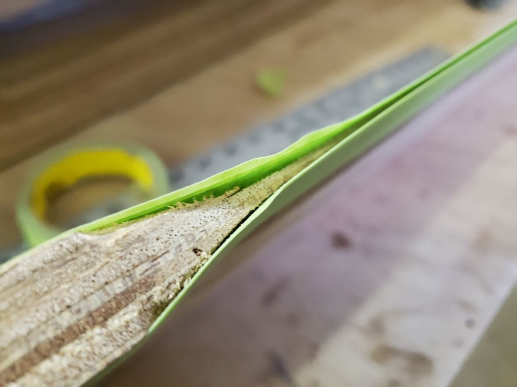
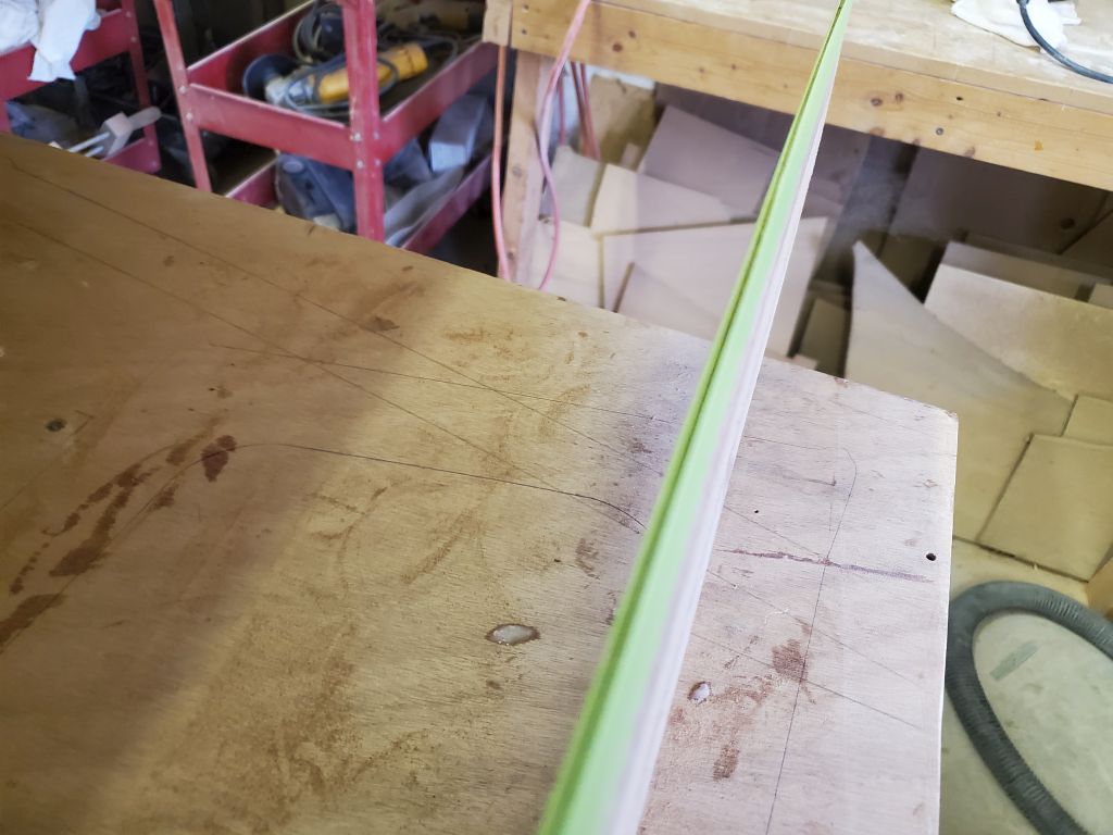
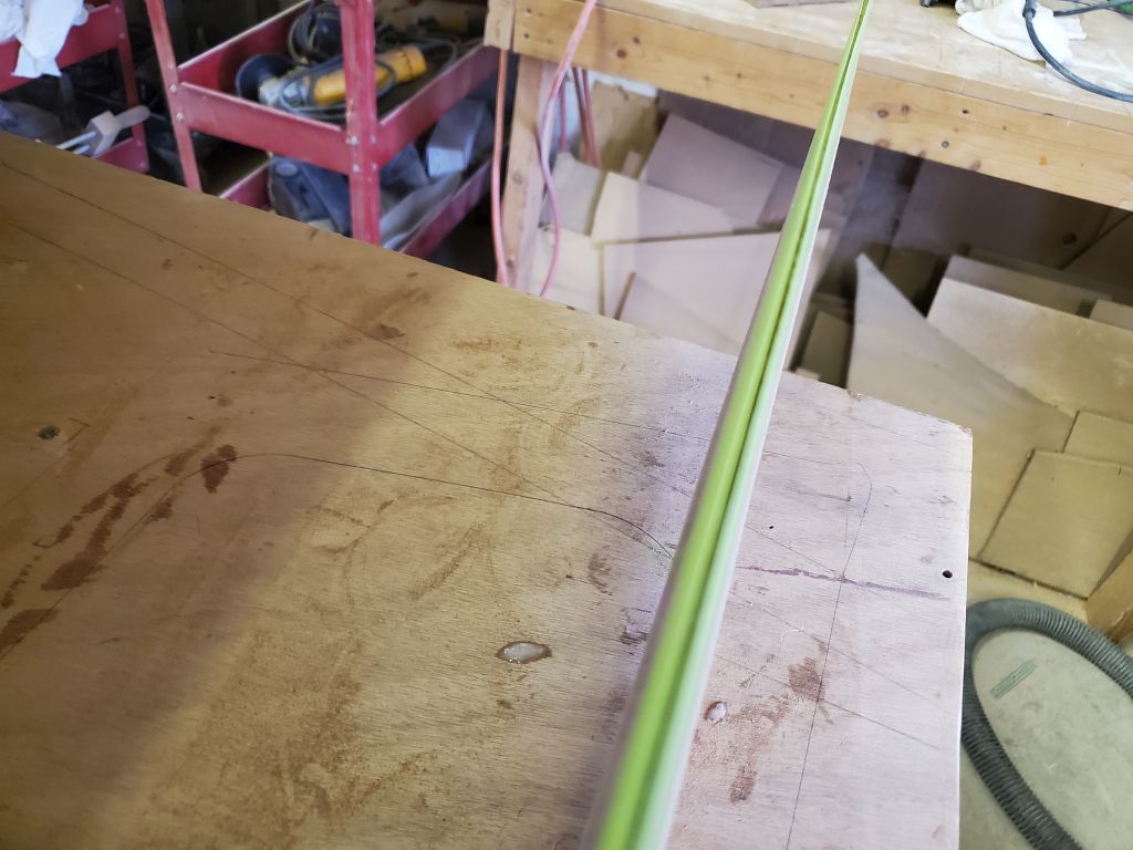
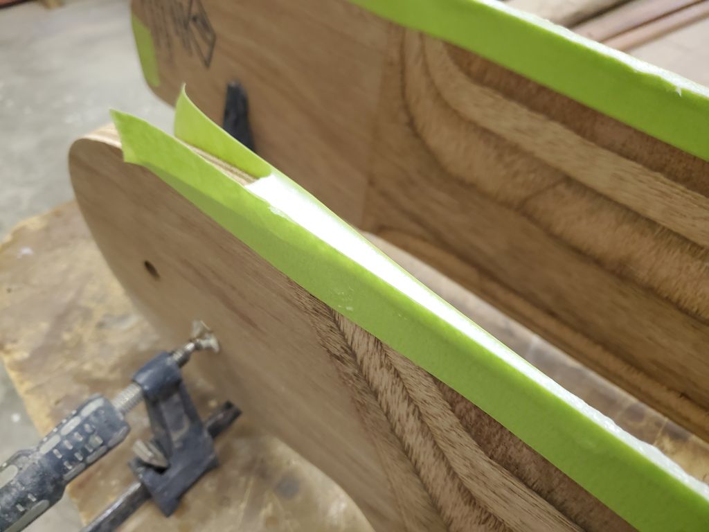
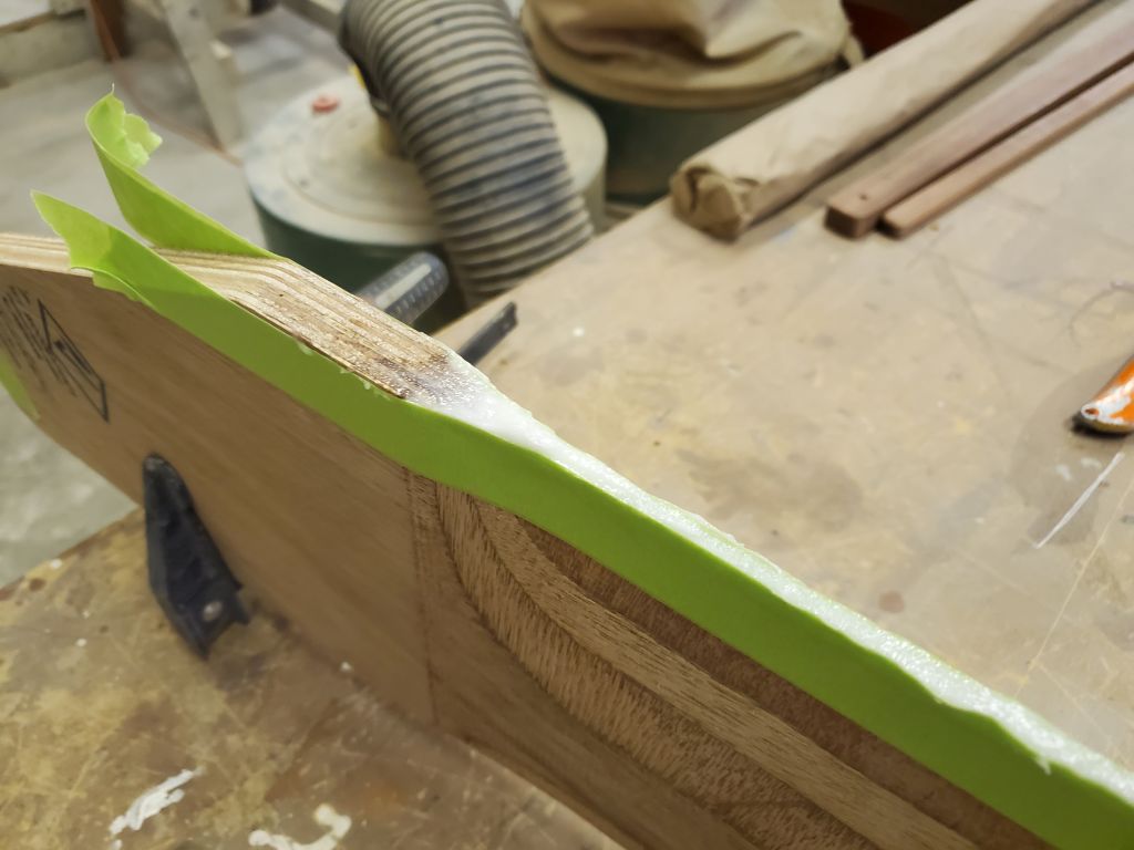
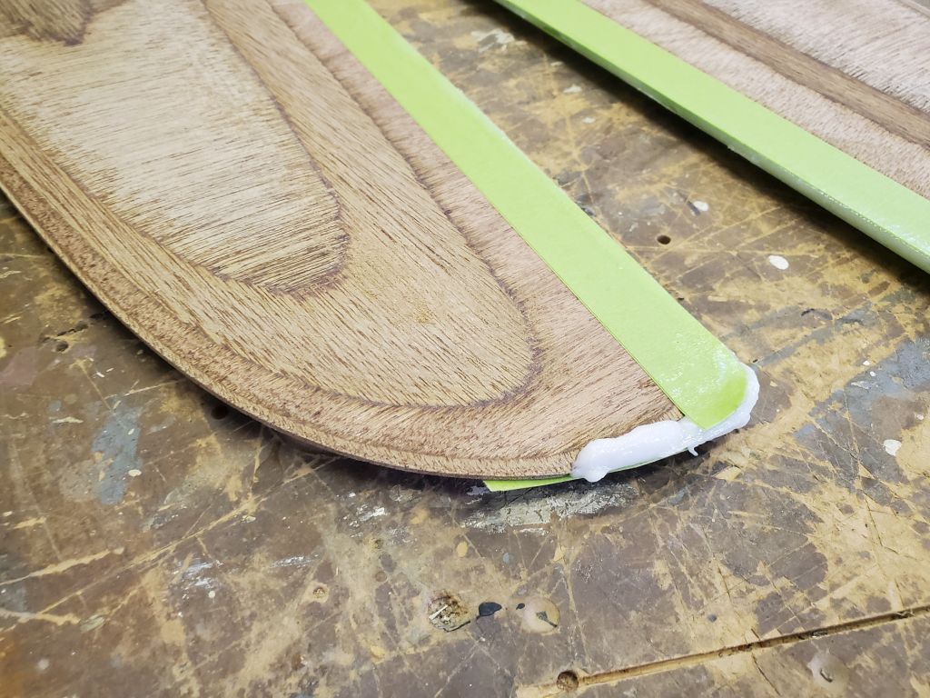
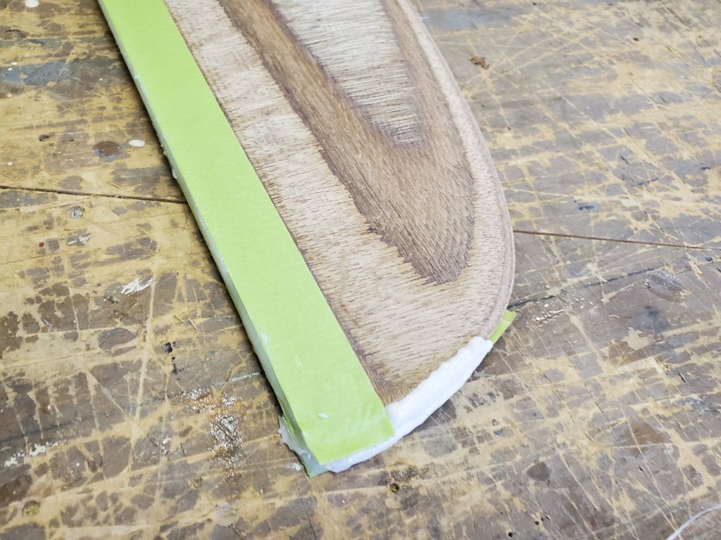
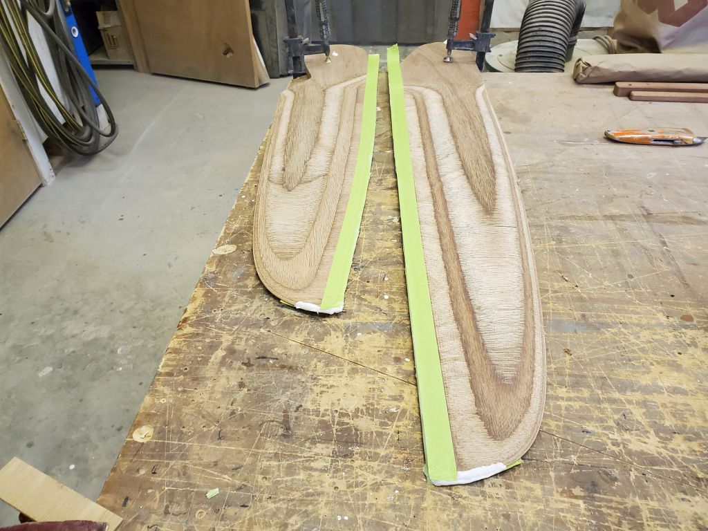
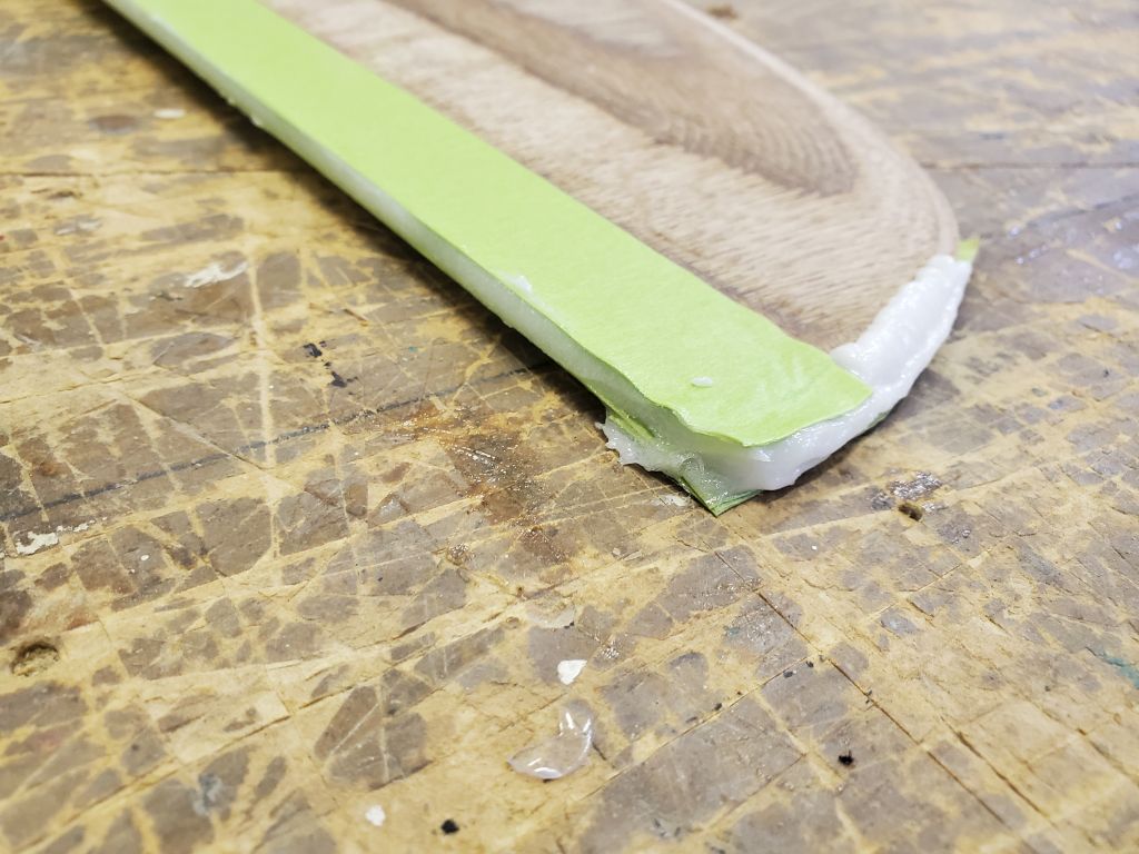
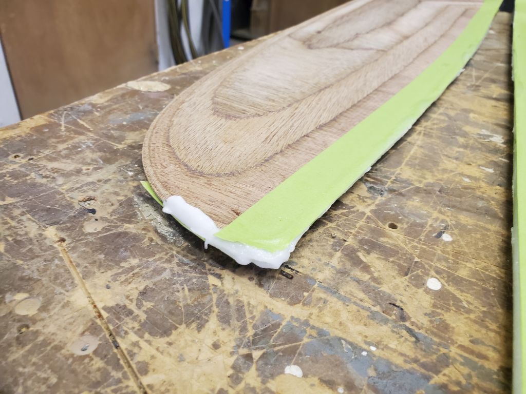
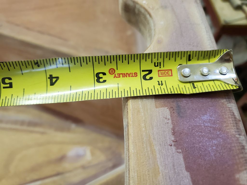
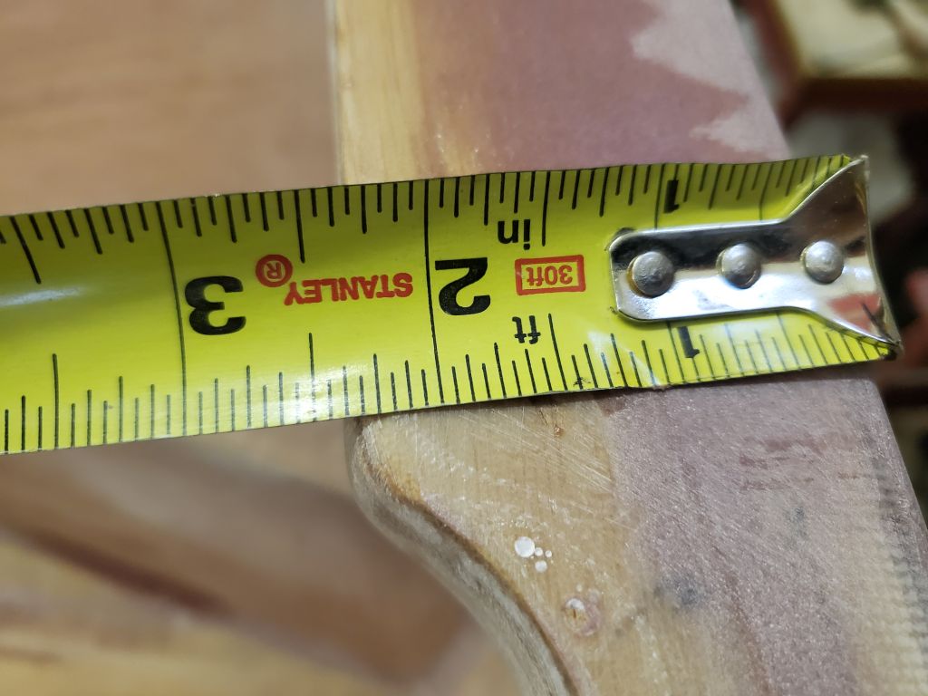
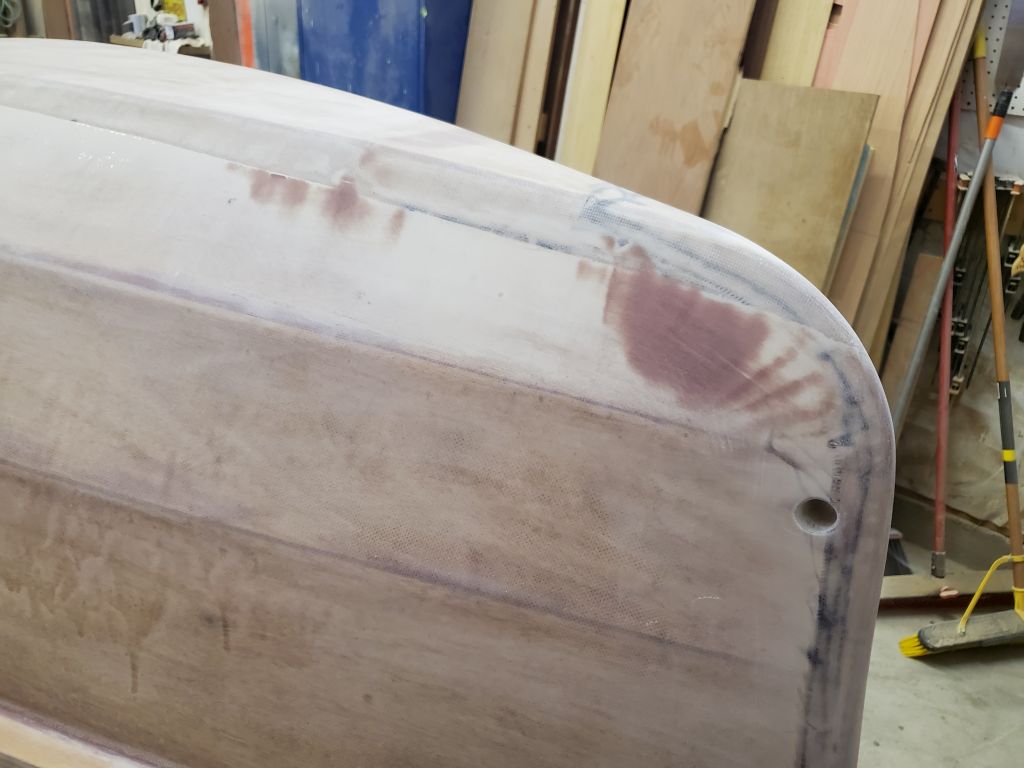
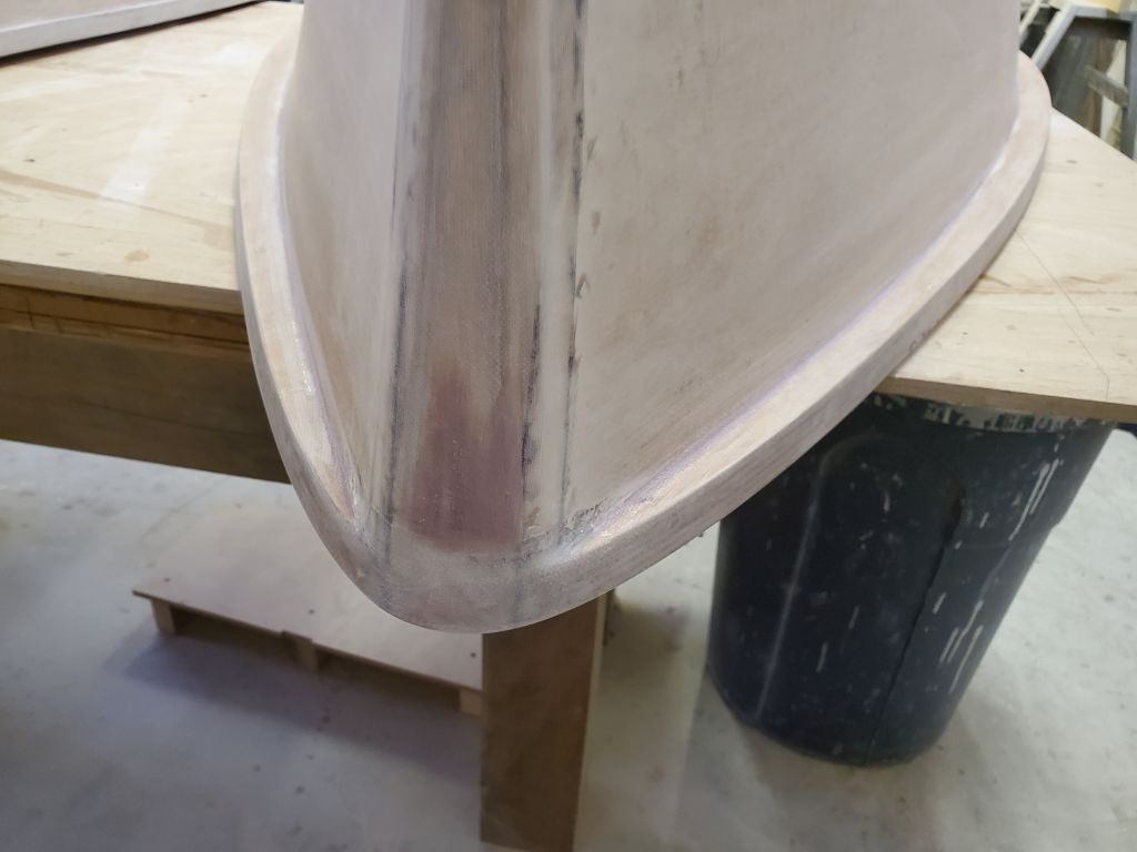
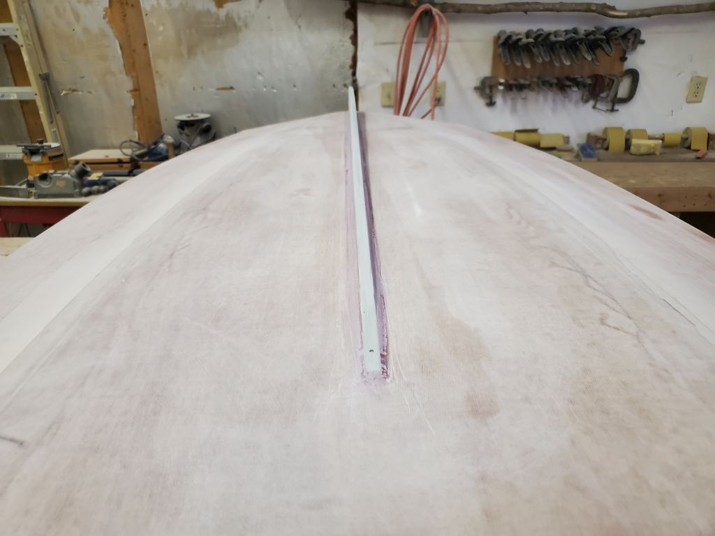
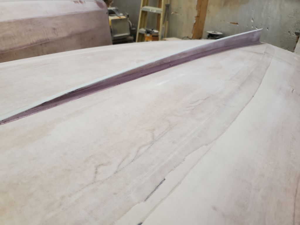
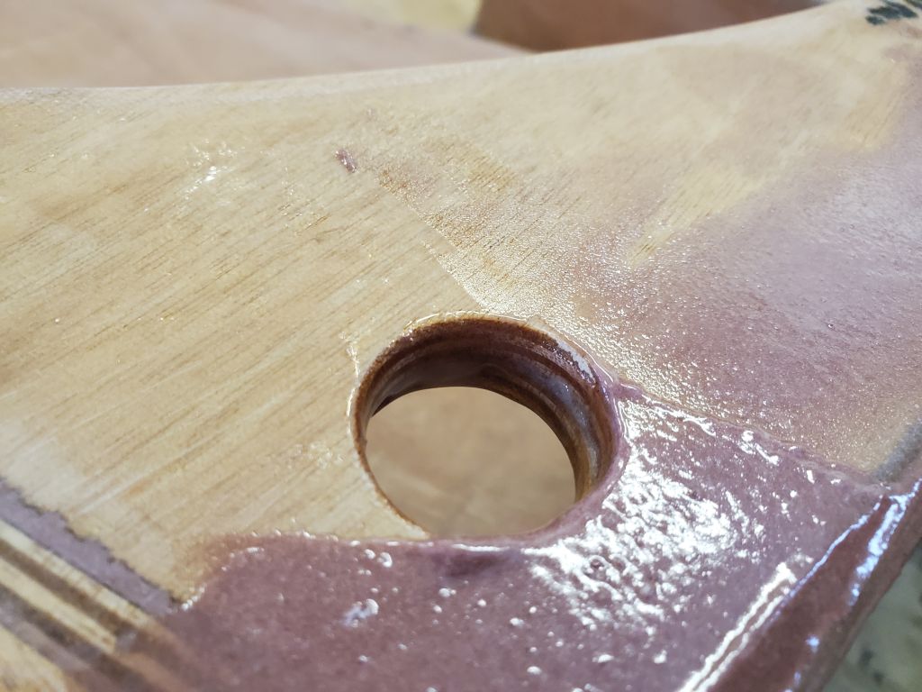
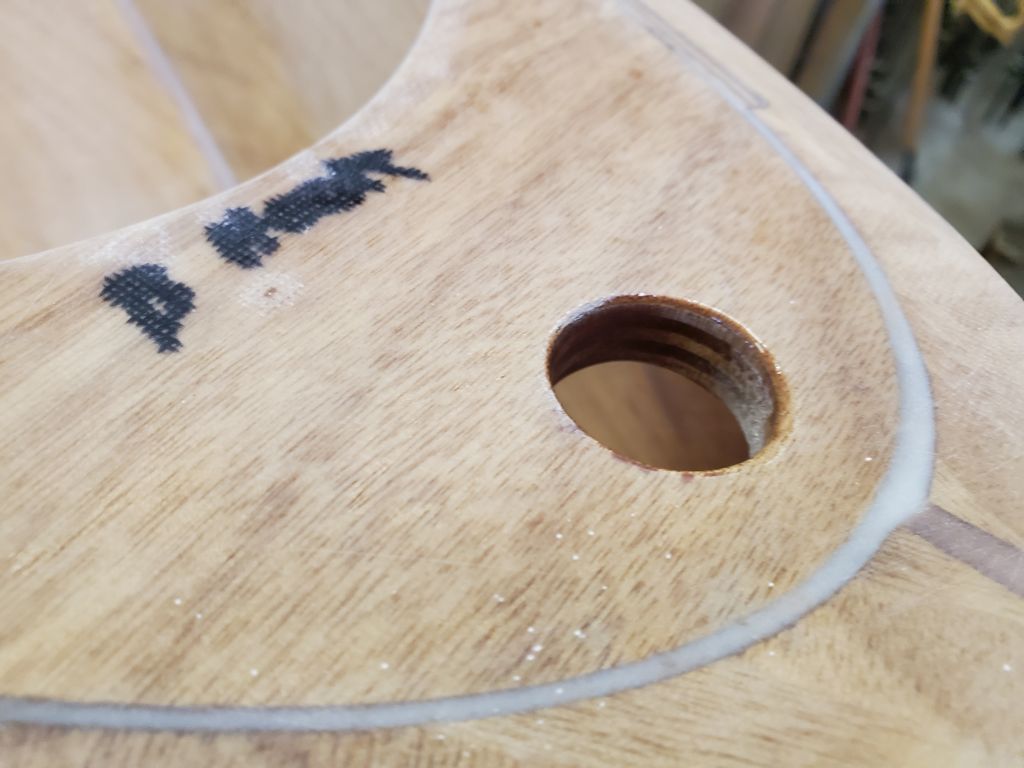
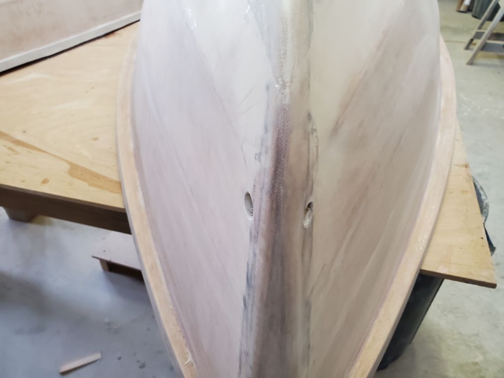
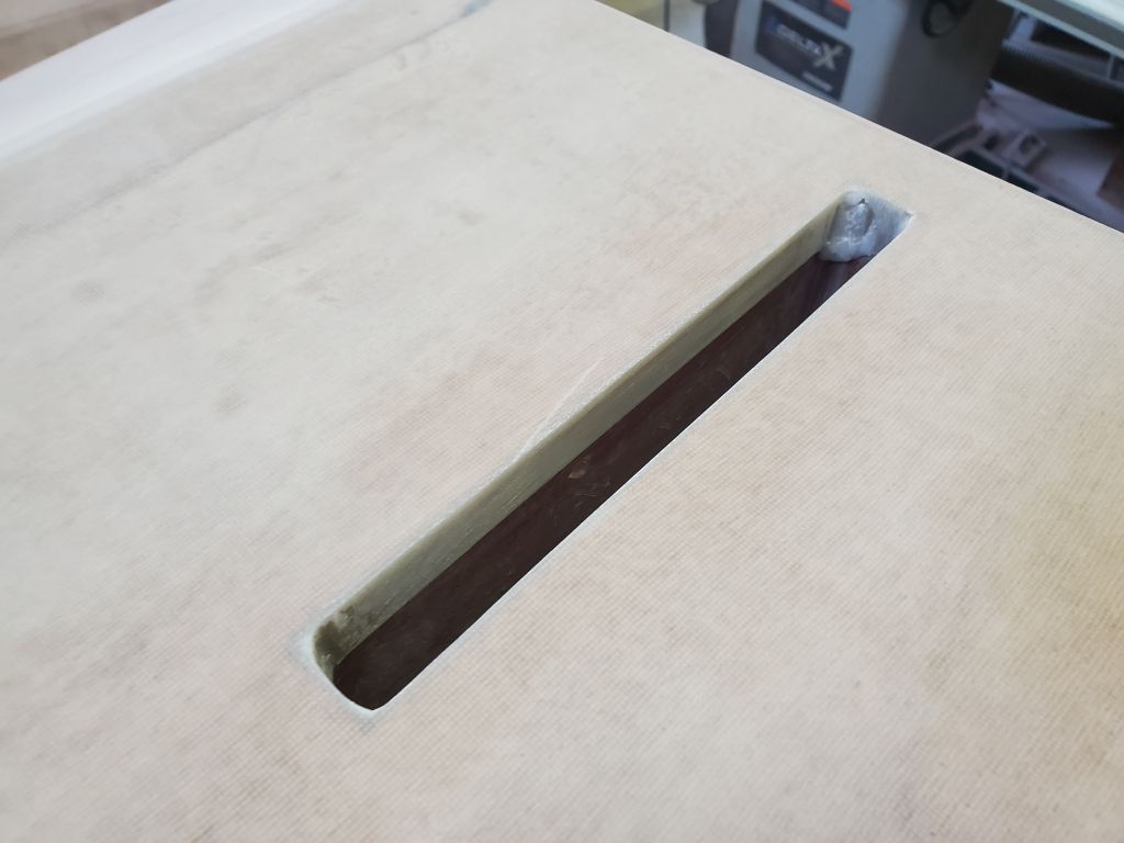
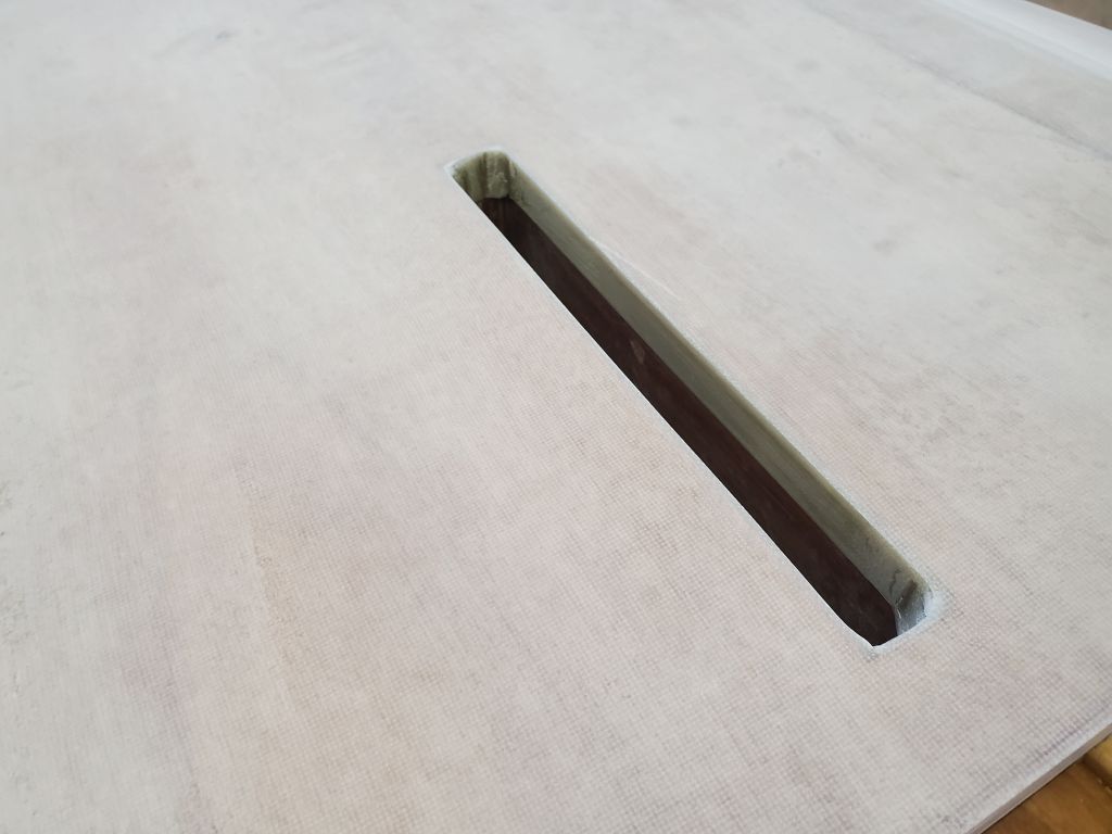
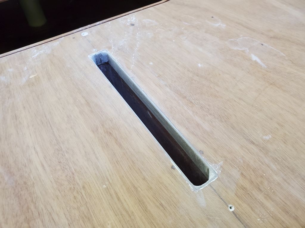
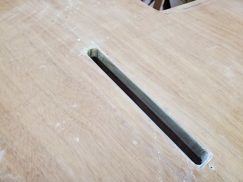
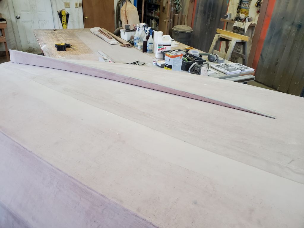
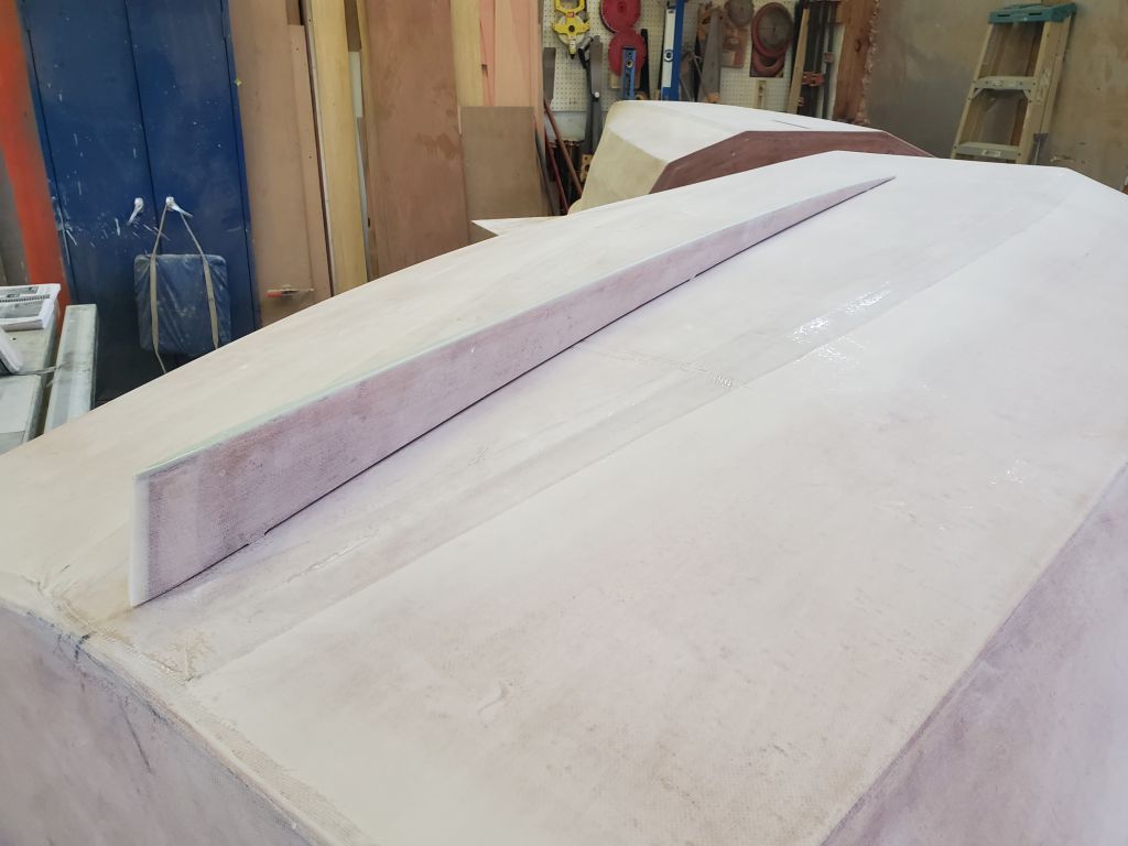
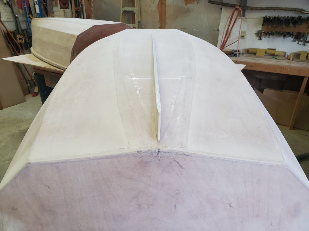
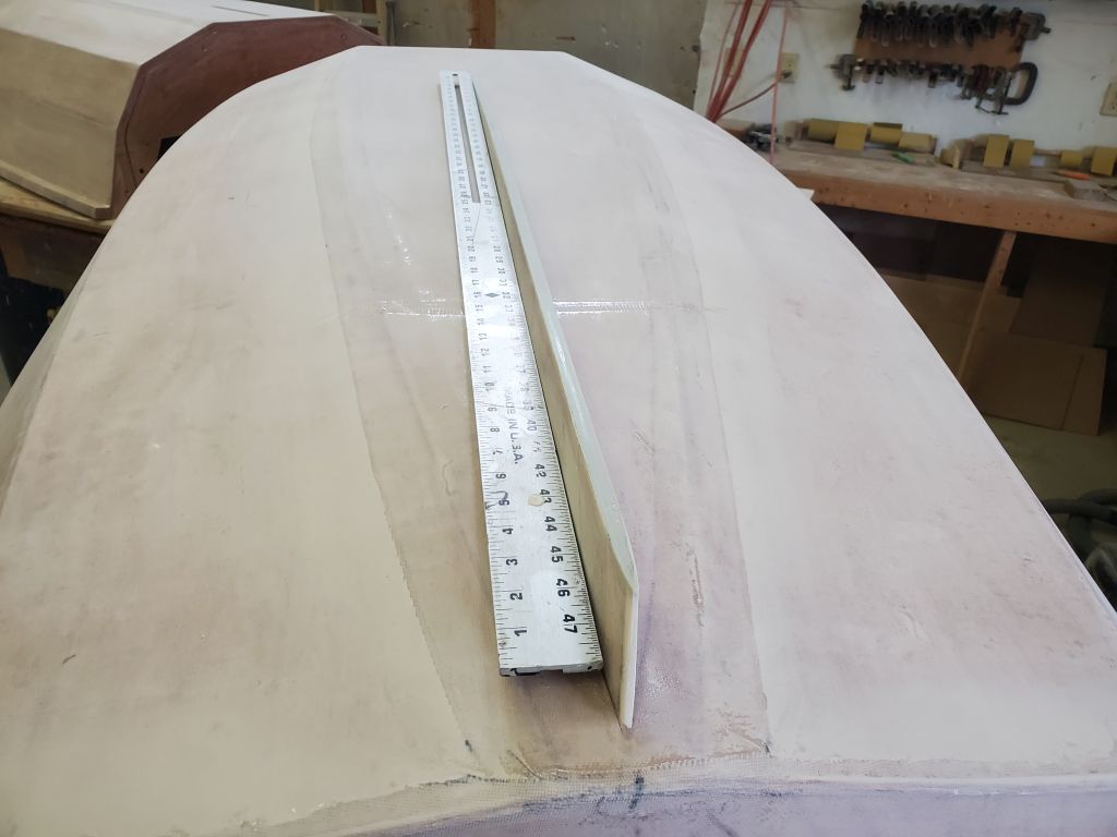
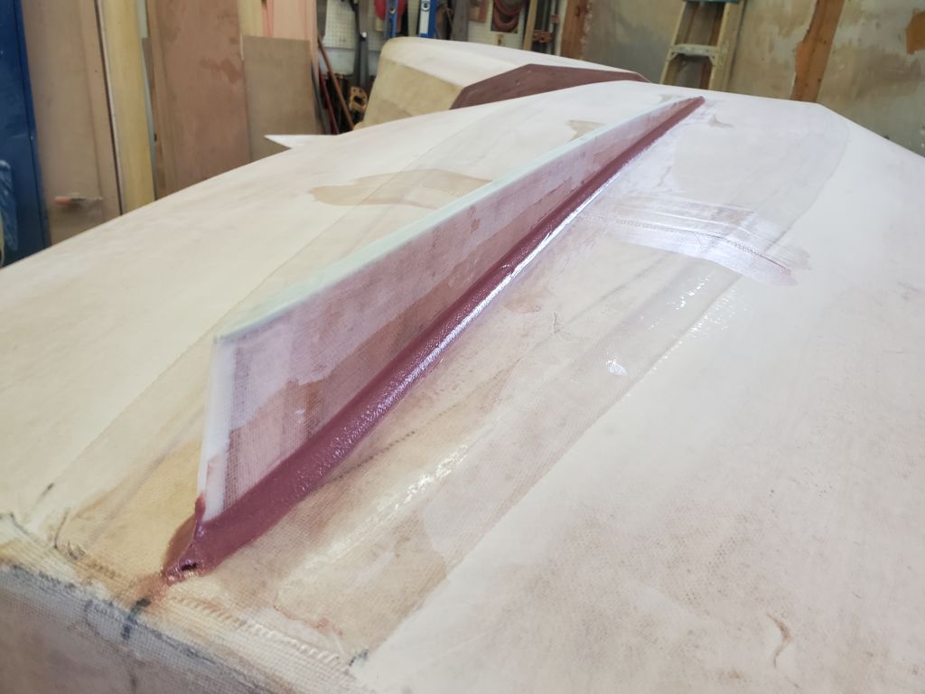
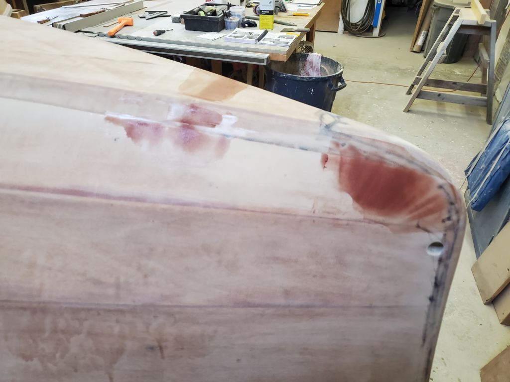
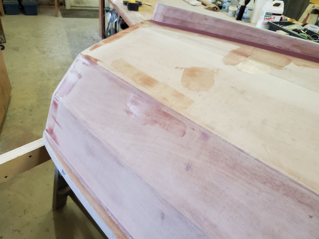
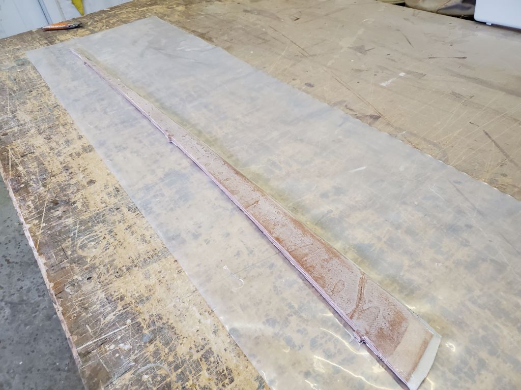
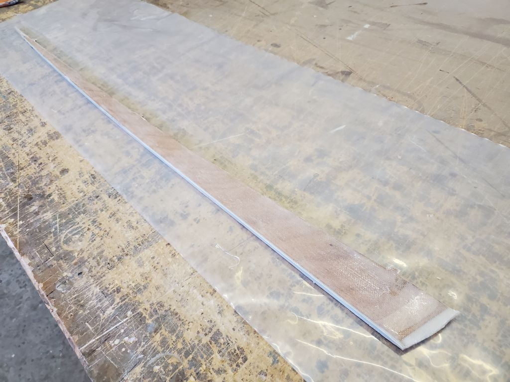
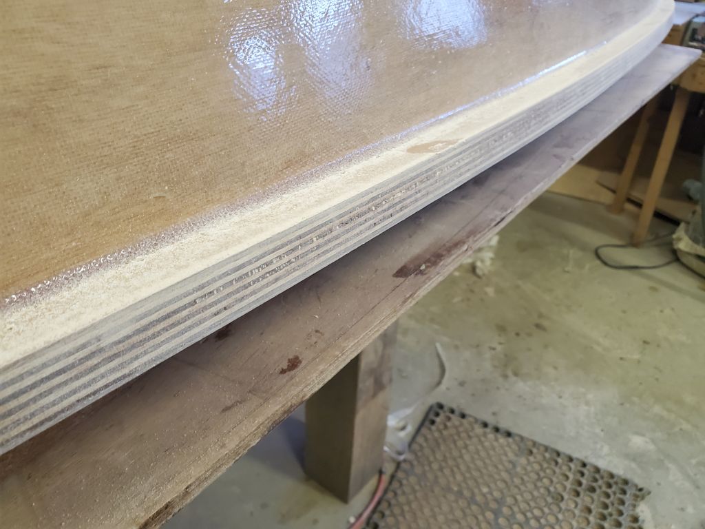
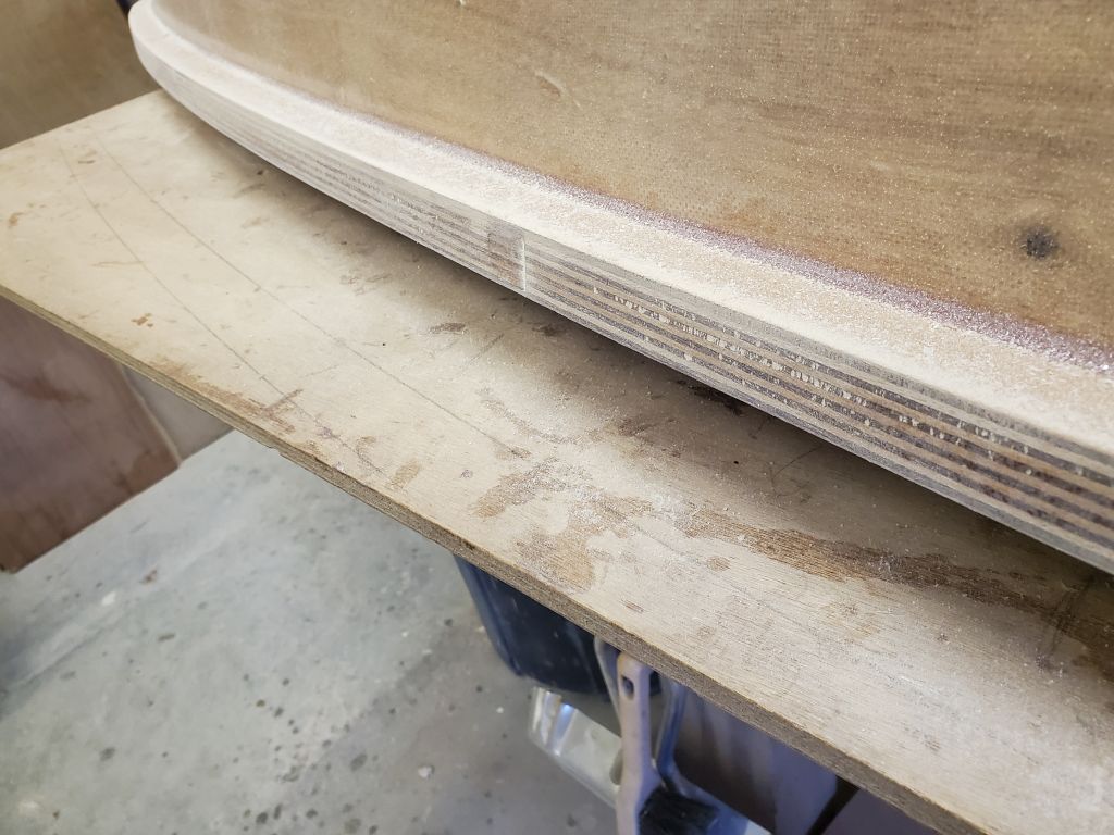
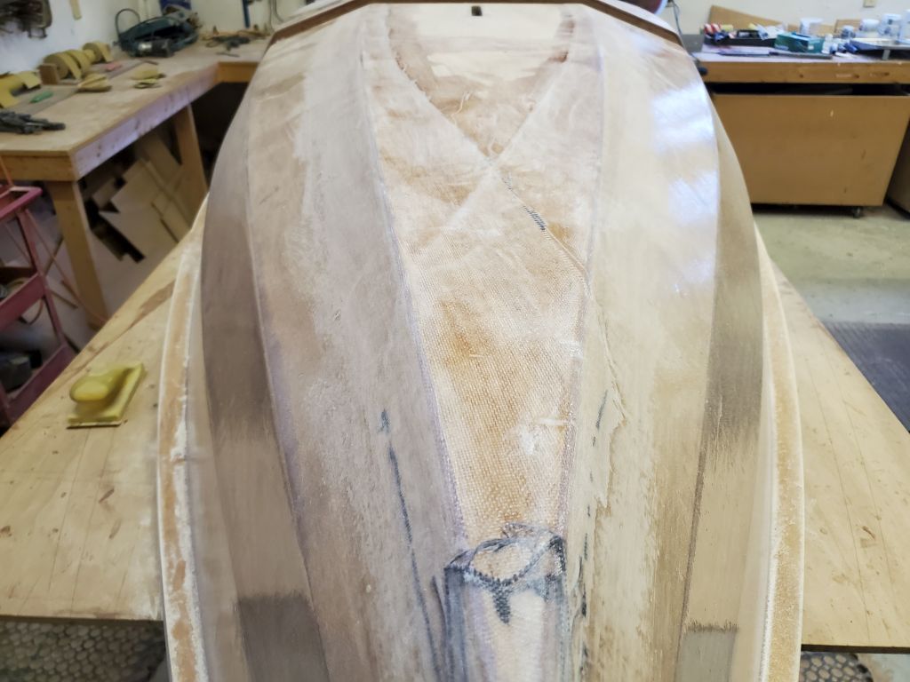
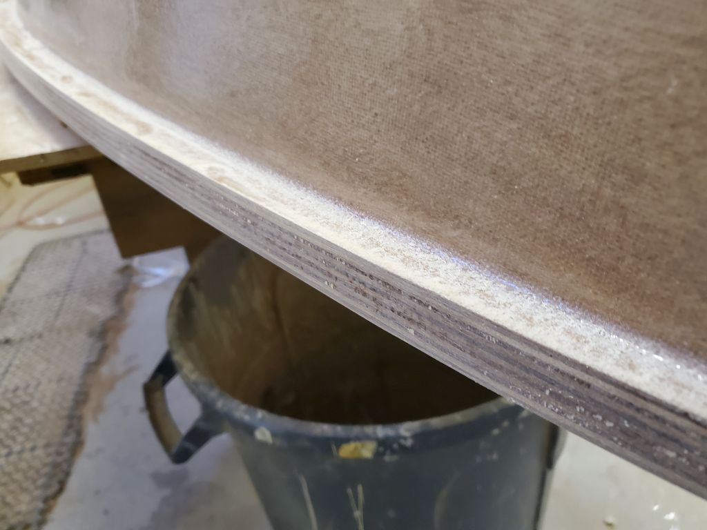
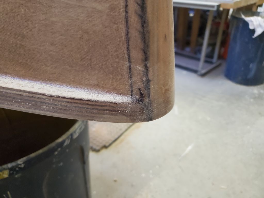
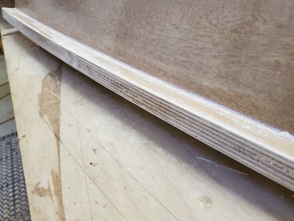
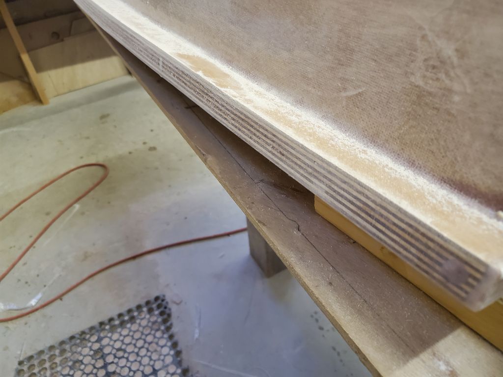
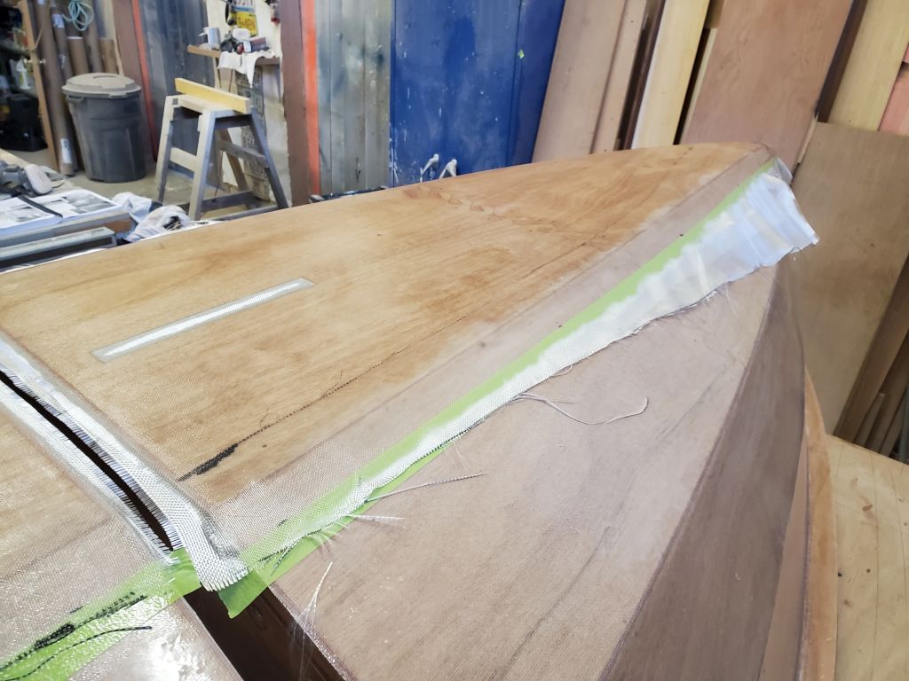
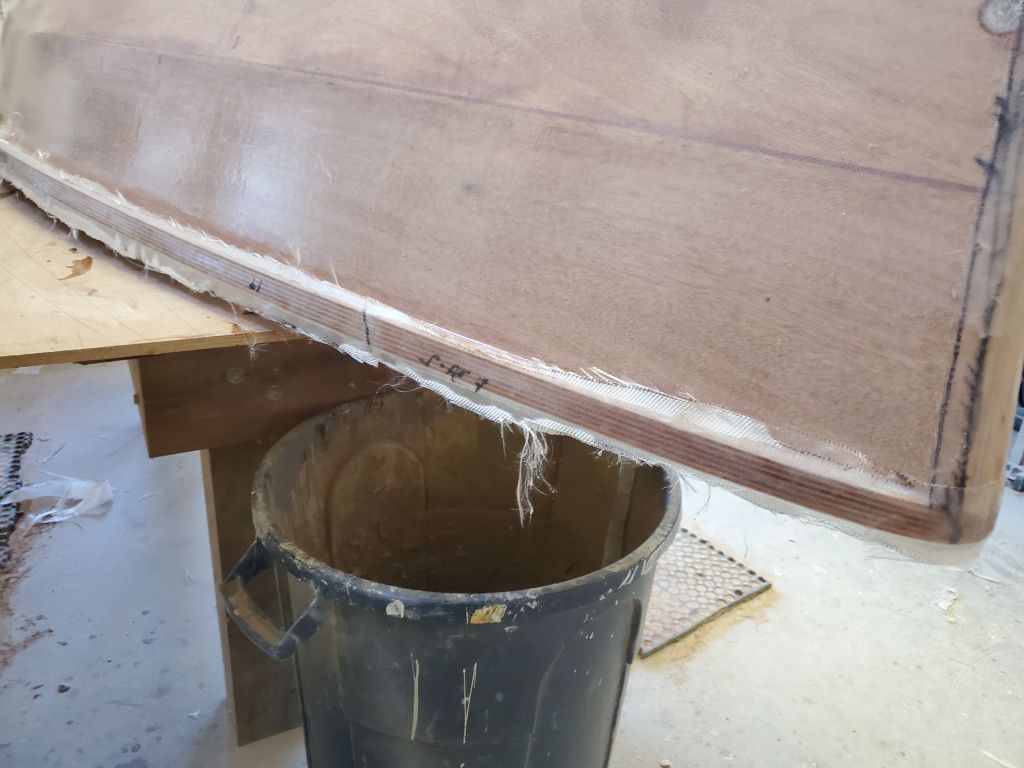
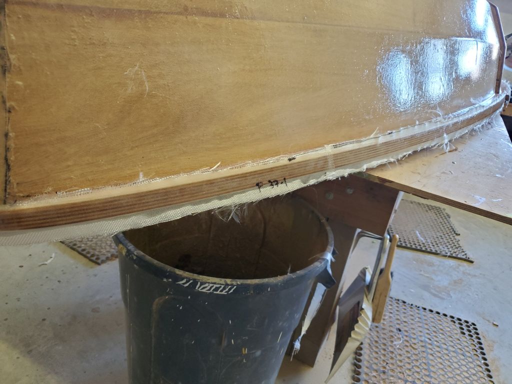
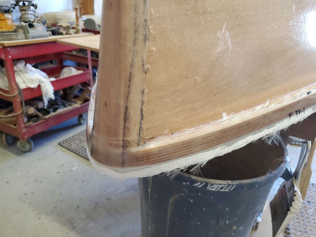
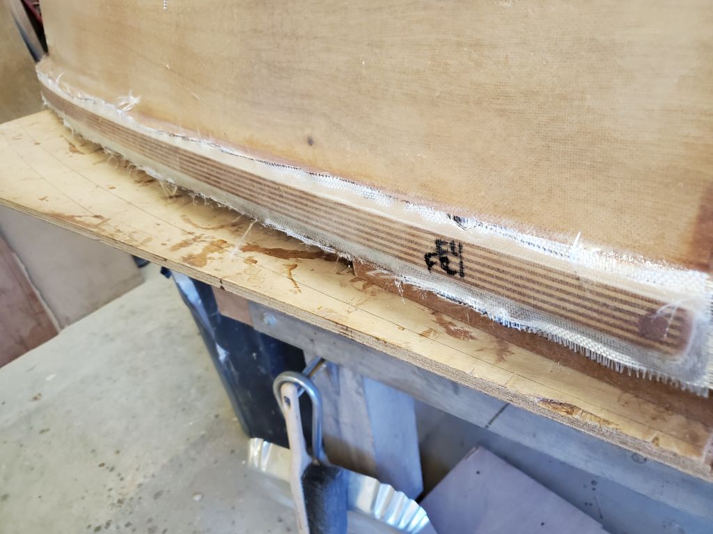
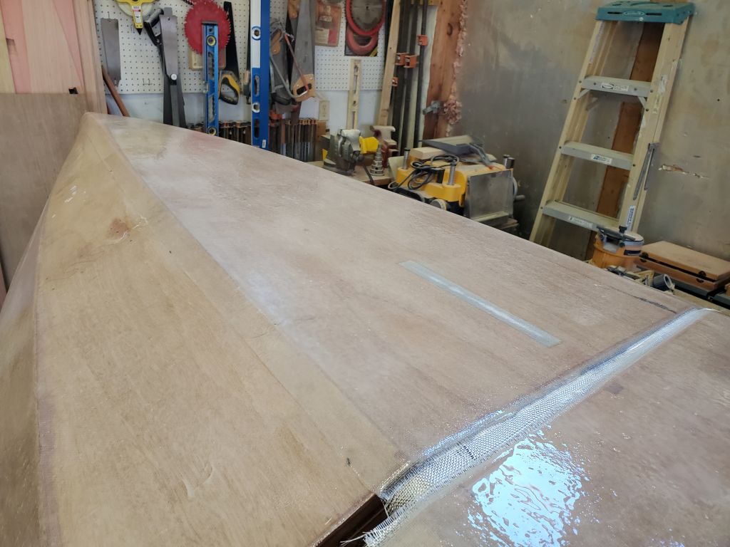
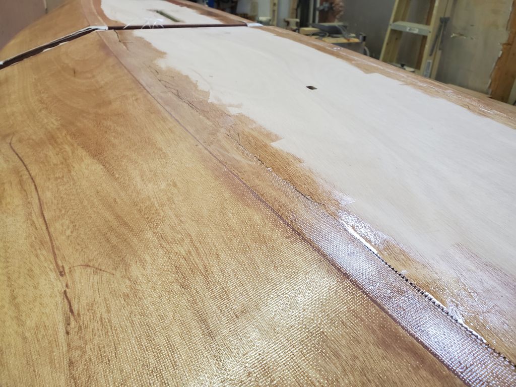
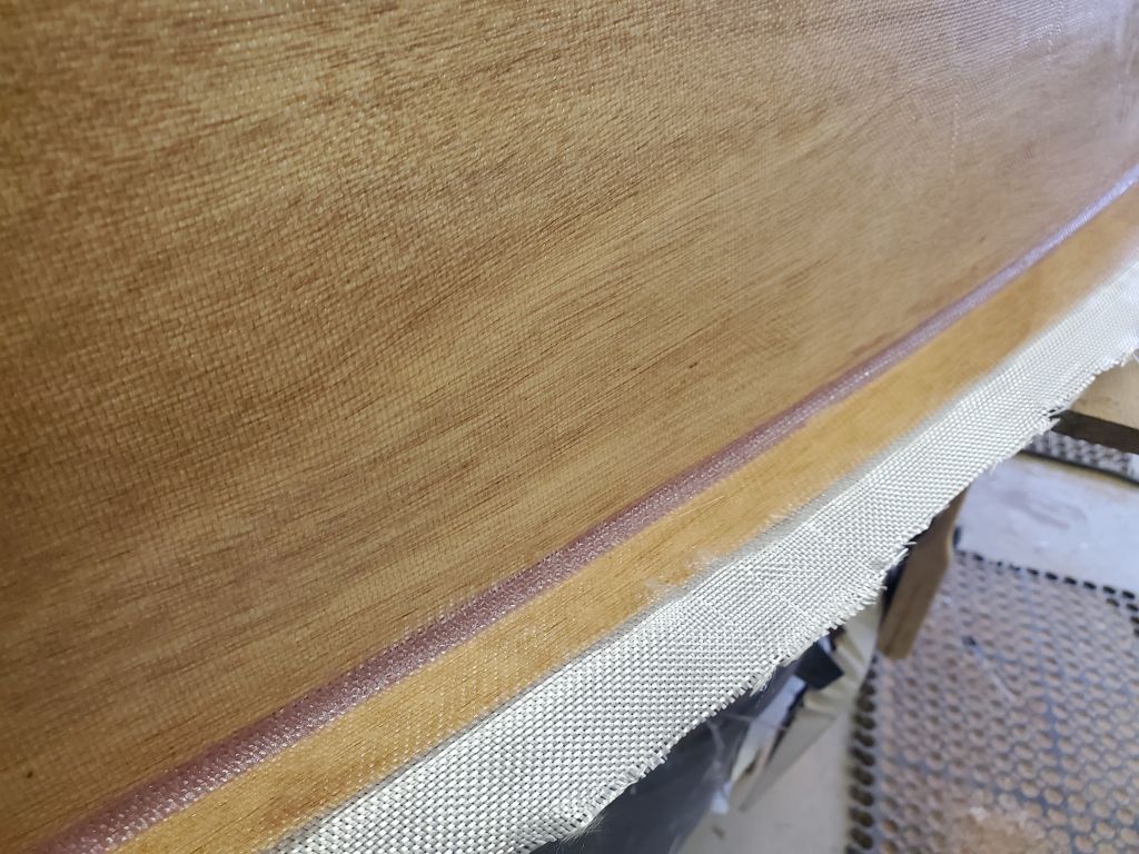
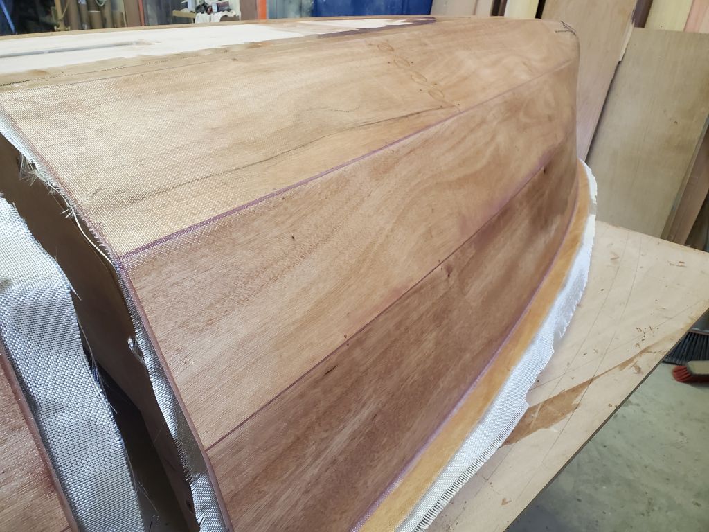
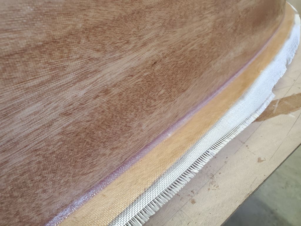
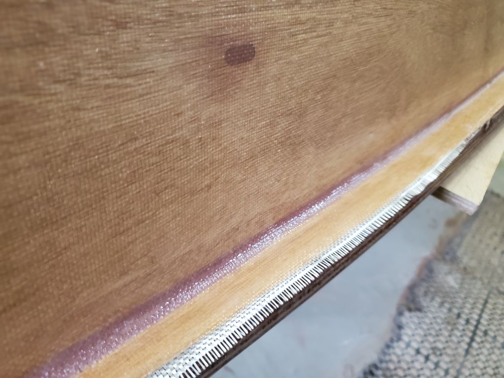
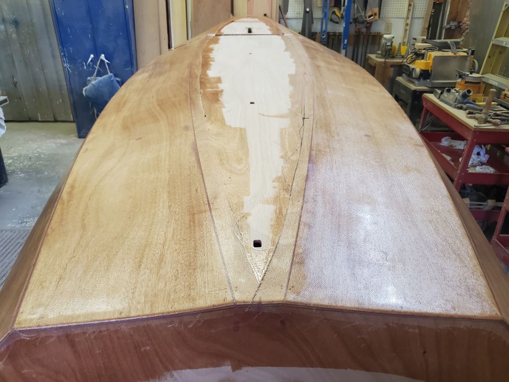
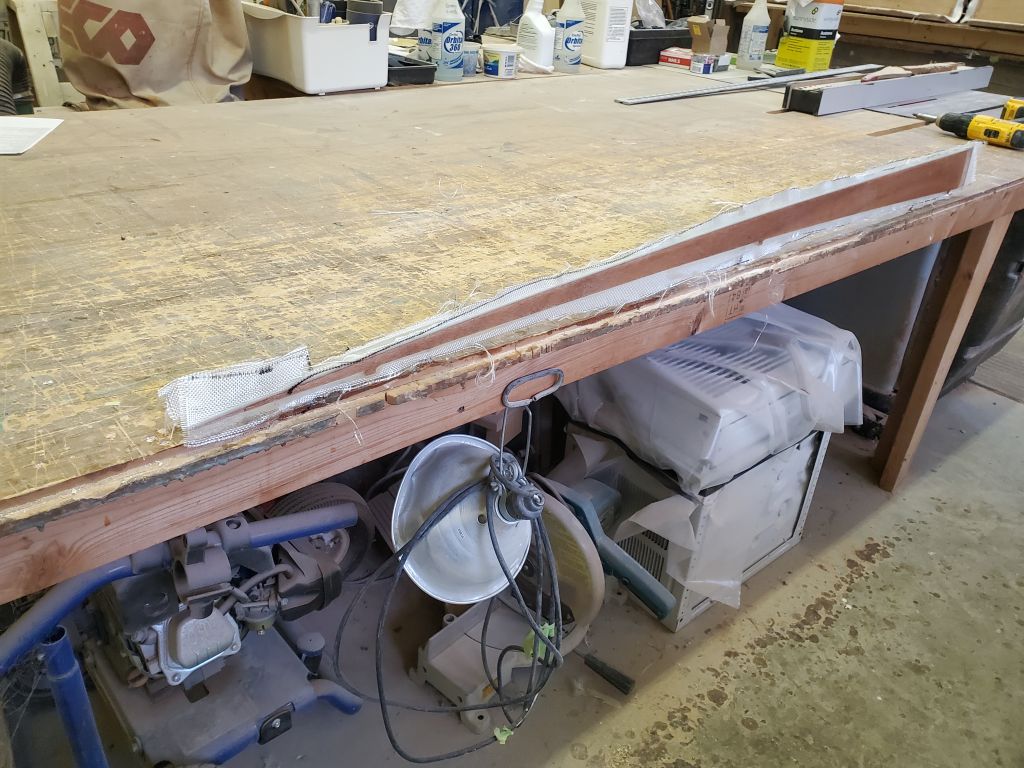
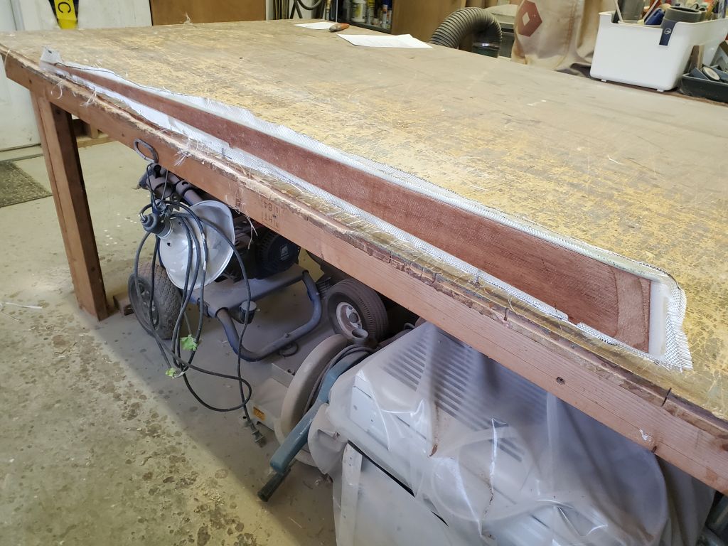
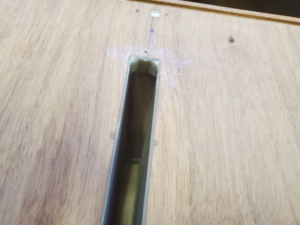
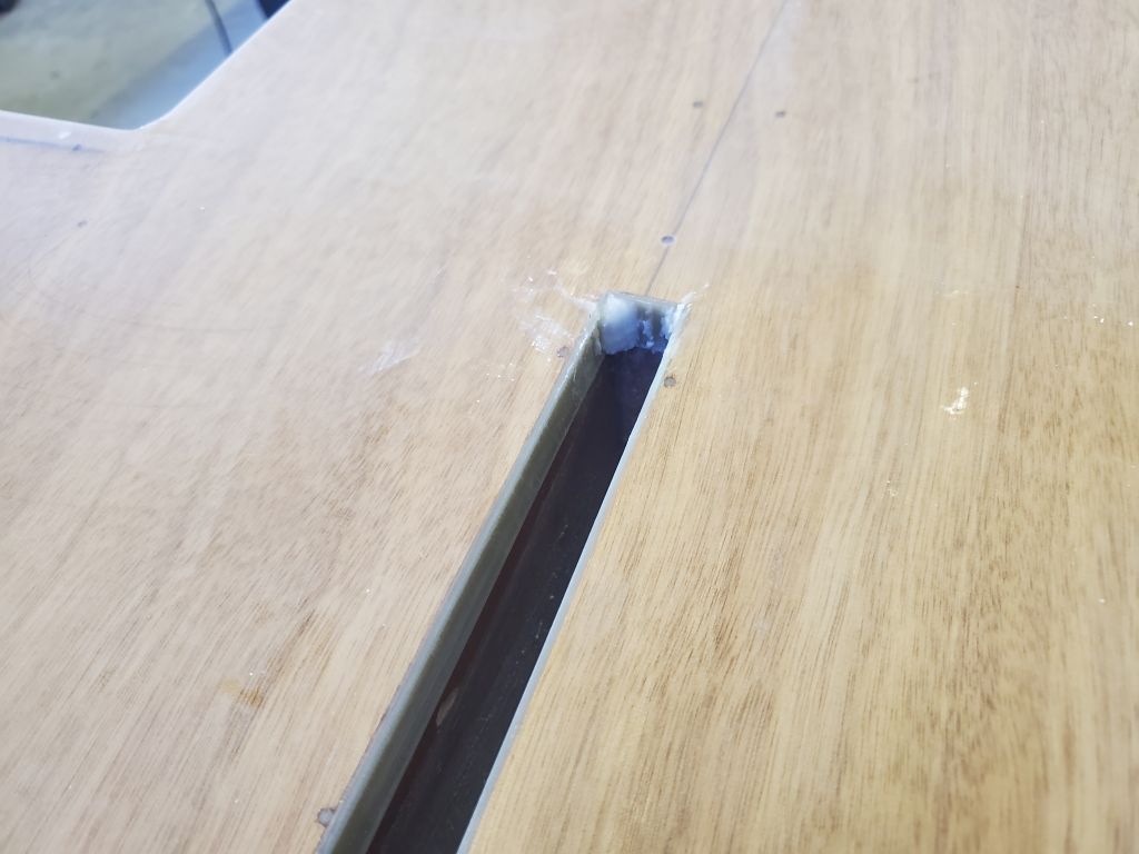
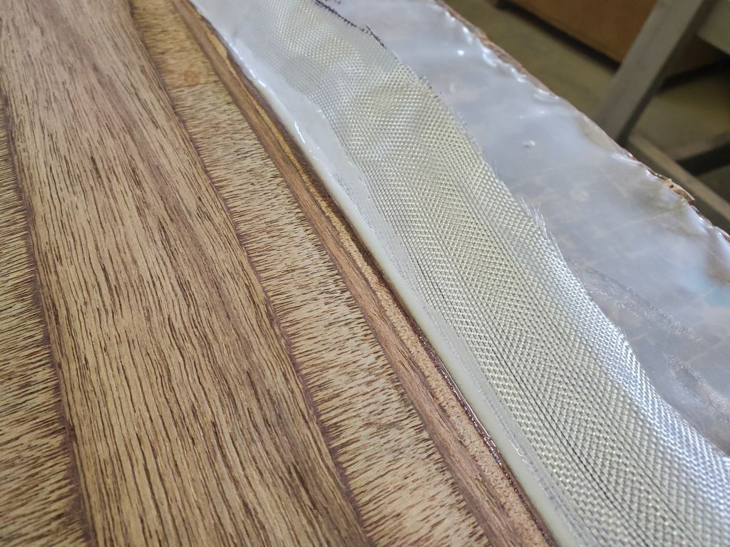
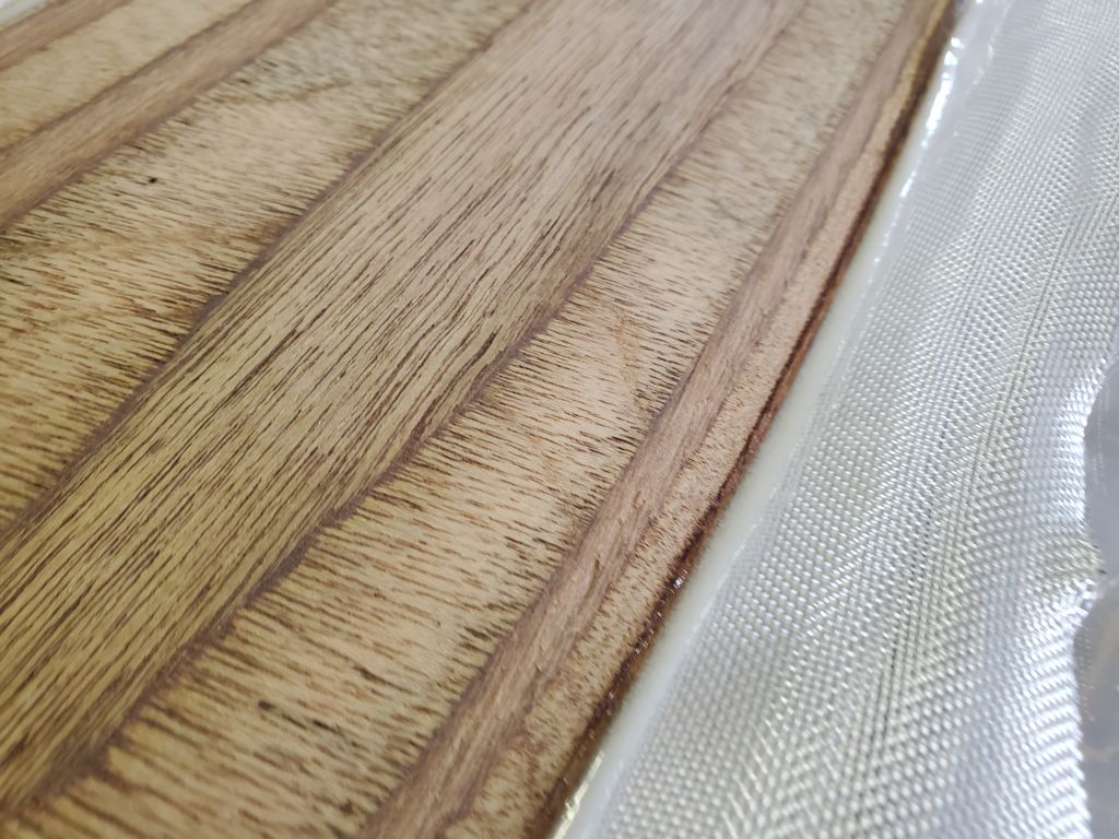
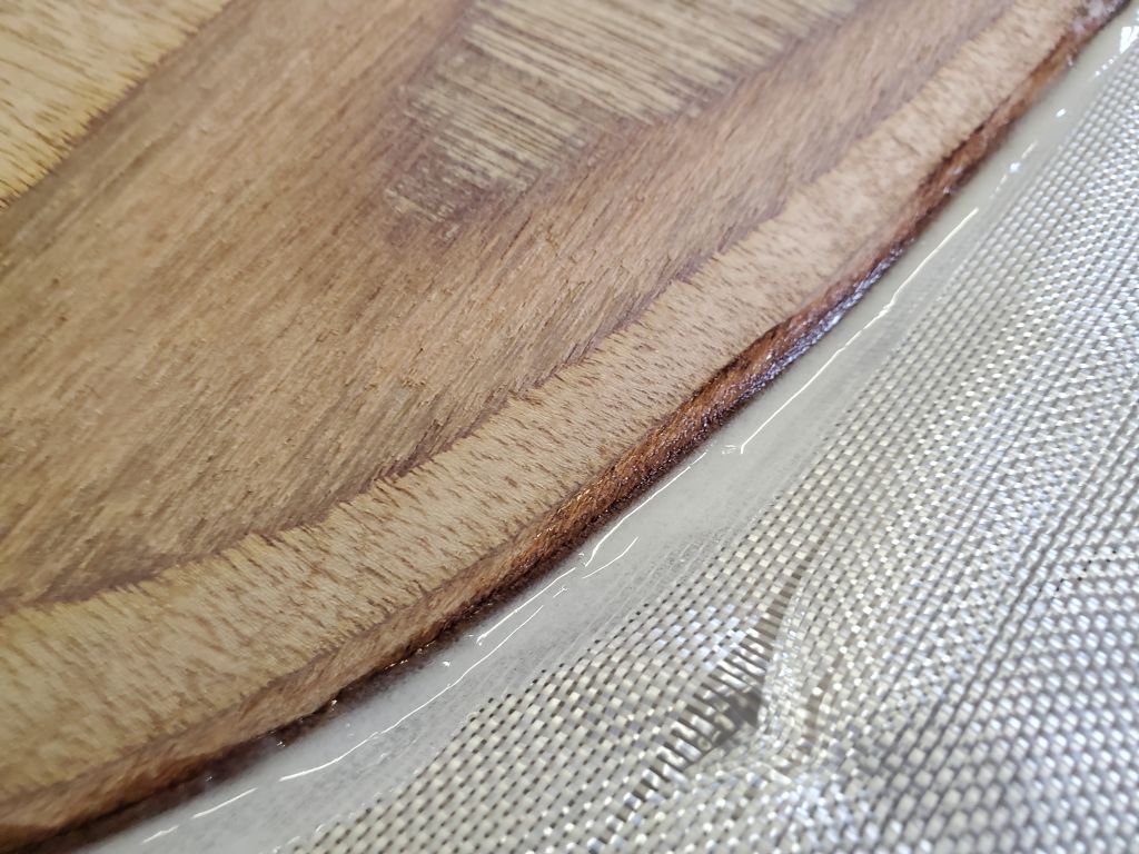
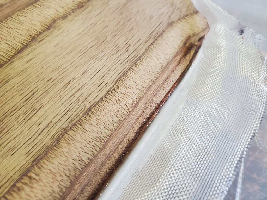
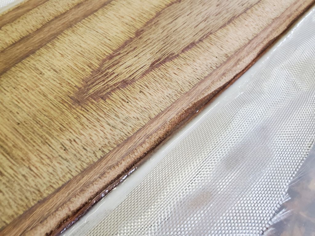
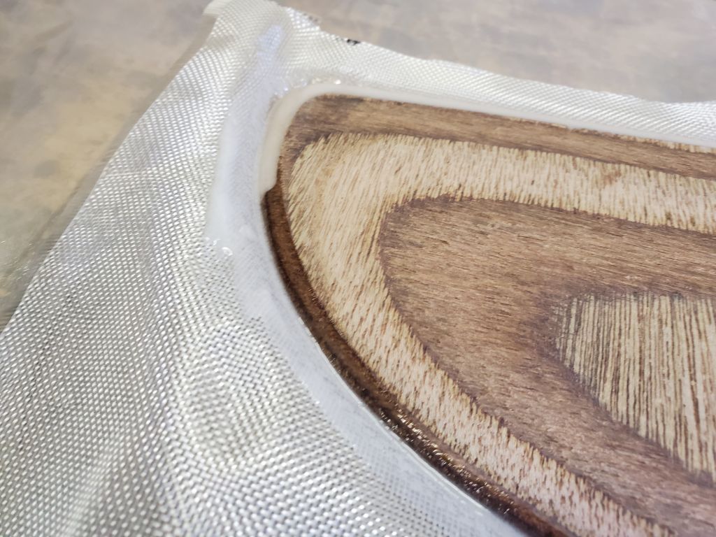
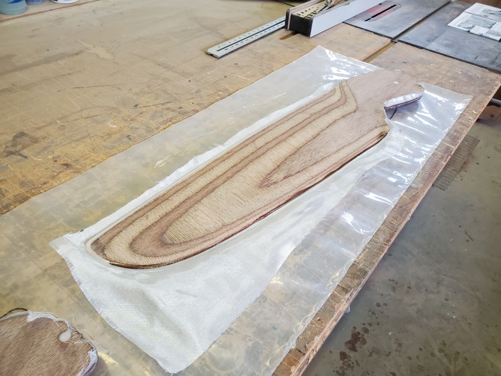
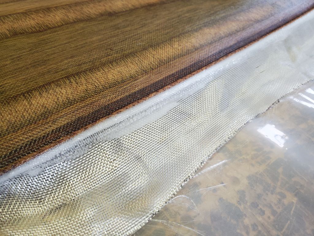
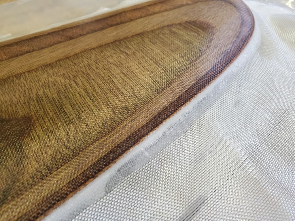
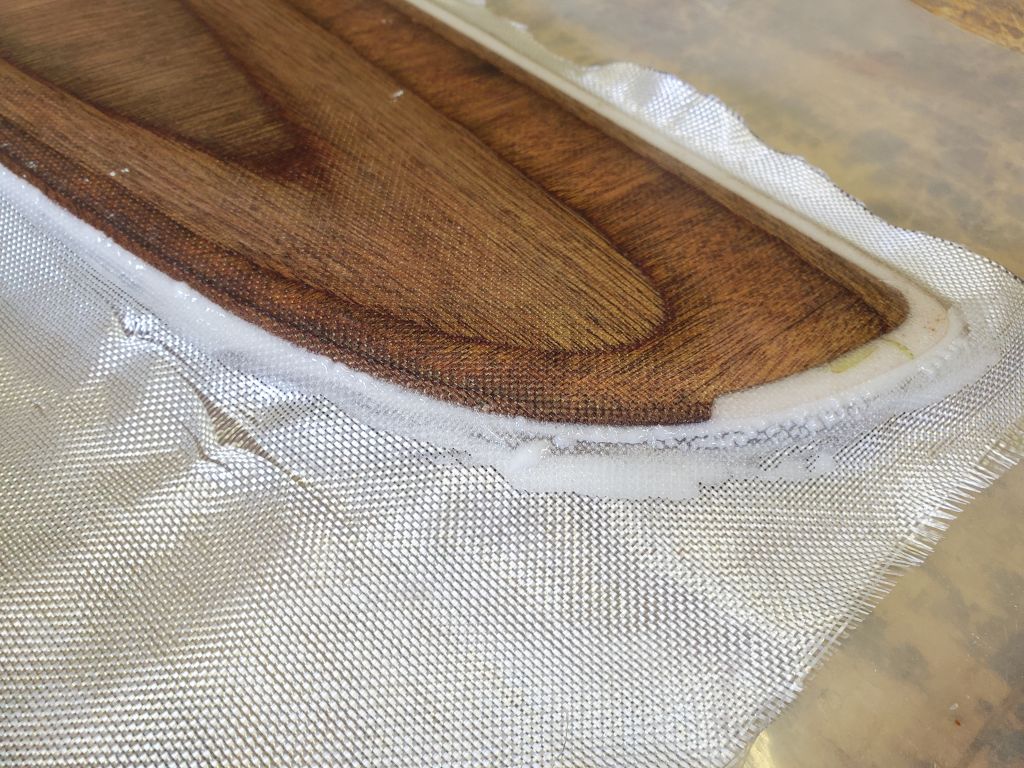
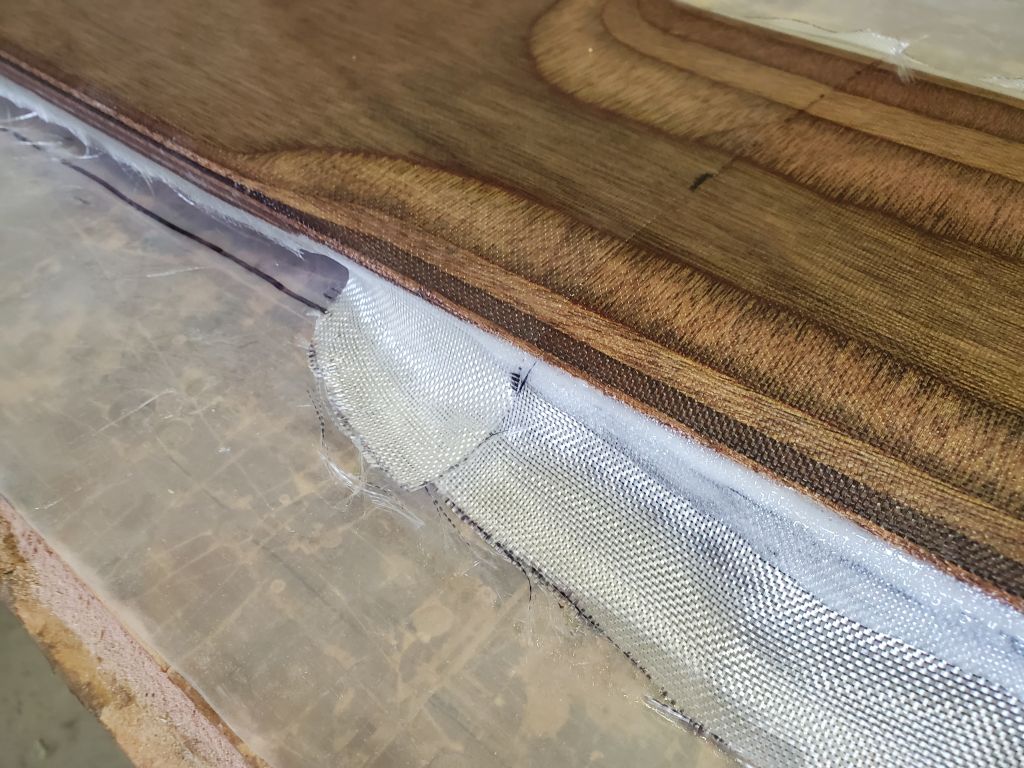
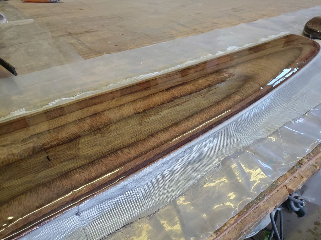
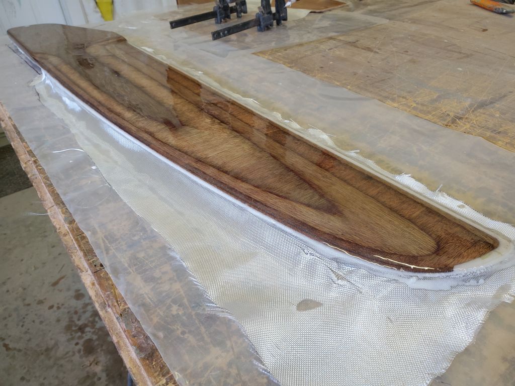
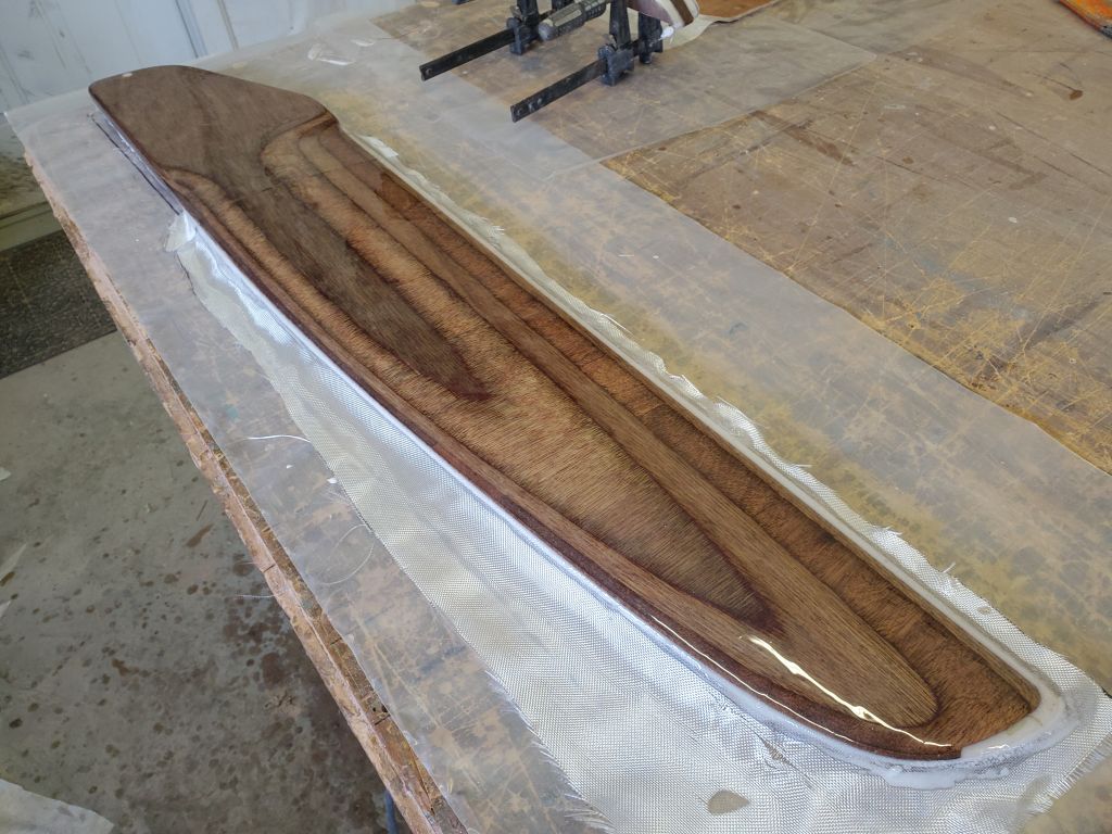
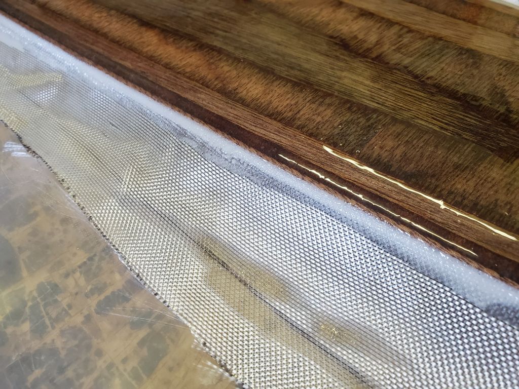
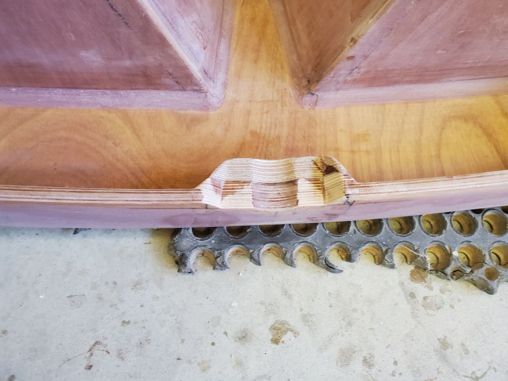
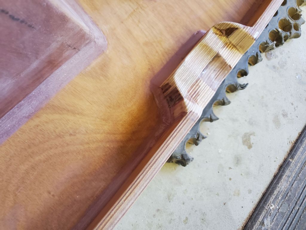
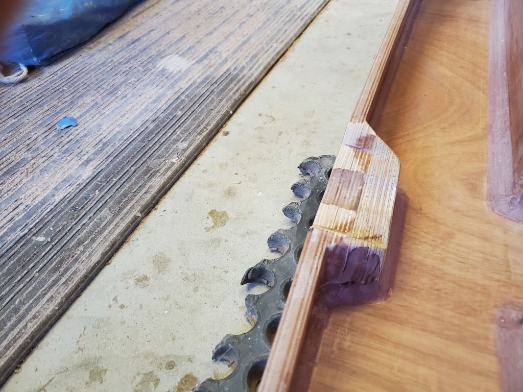
The next step for the daggerboard and rudder was to inject a bead of epoxy into the little void along the leading edges of both foils. The shape of the leading edge, and the way the fiberglass draped over the edge (with no attempts made to wrap it beneath the rounded edge) left an small open space that was visible with the foils turned over onto their recently-glassed sides.
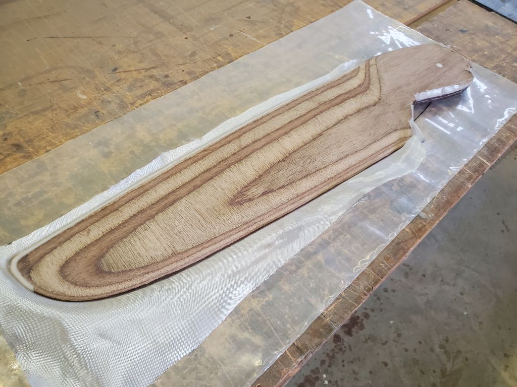
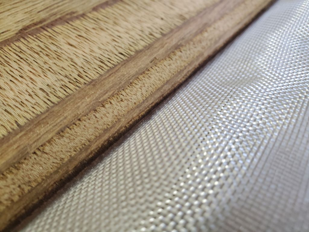
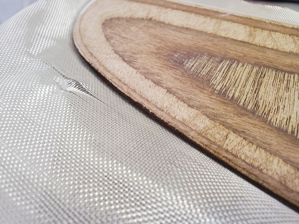
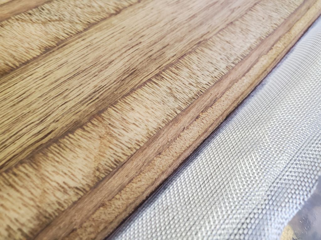
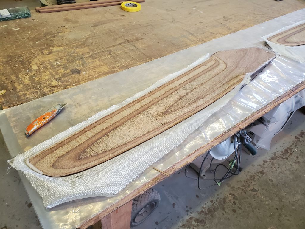
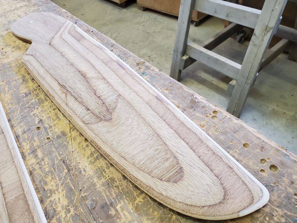
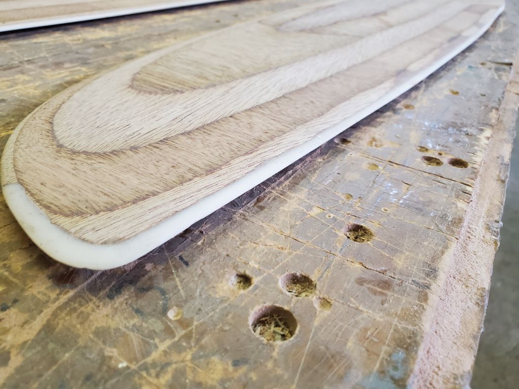
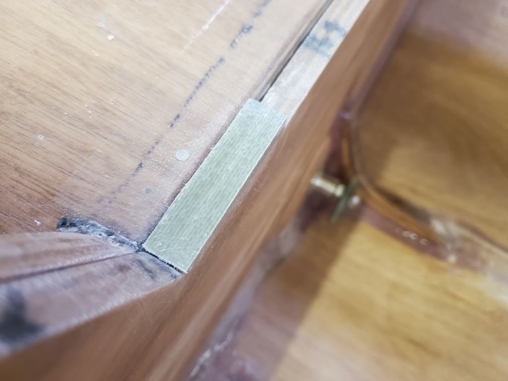
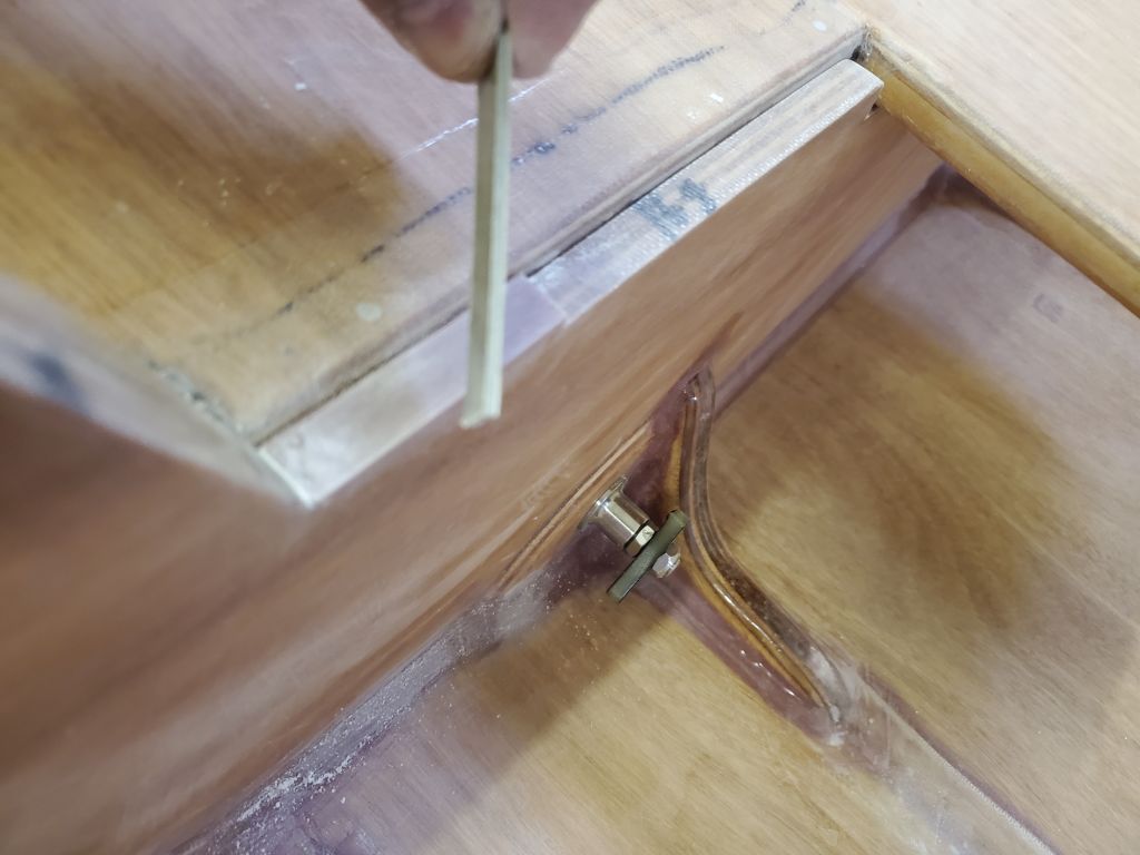
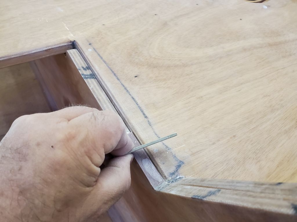
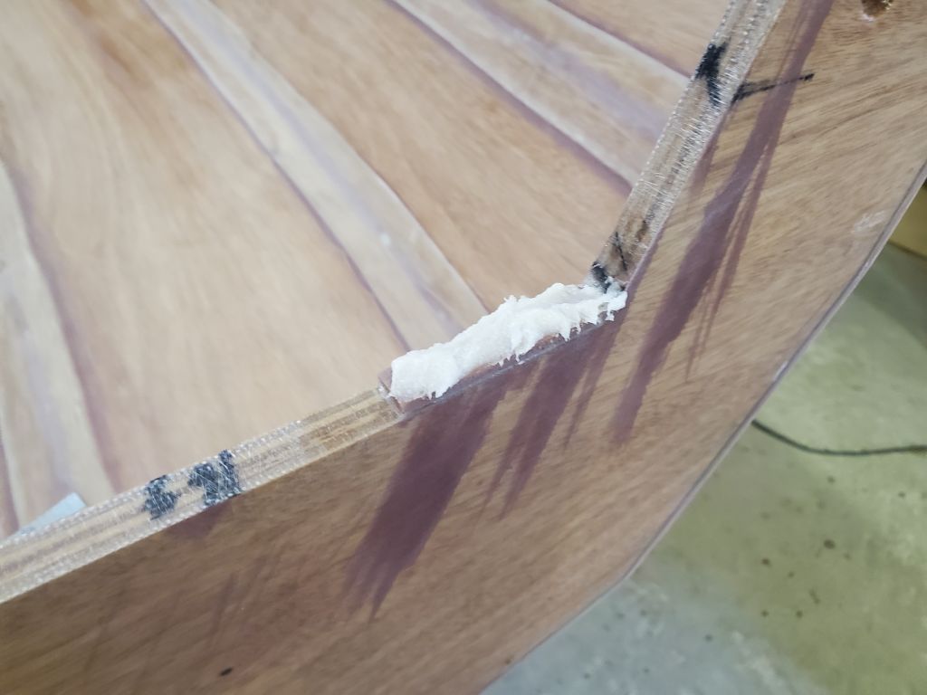
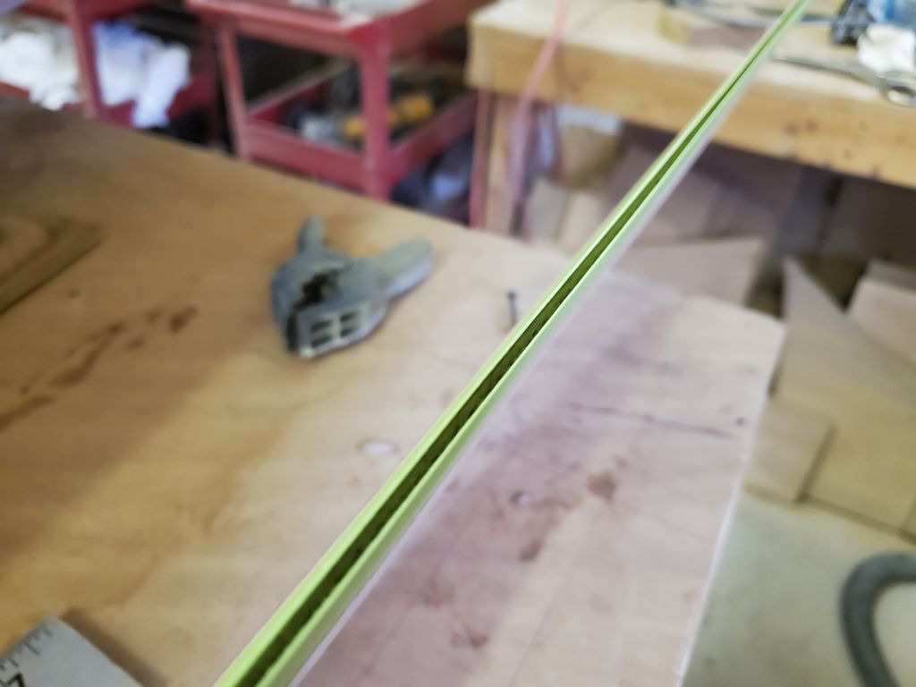
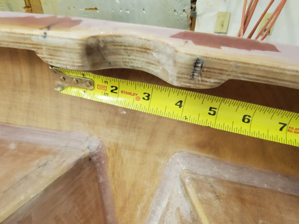
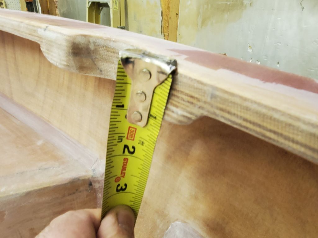
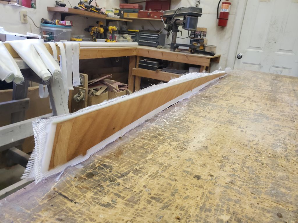
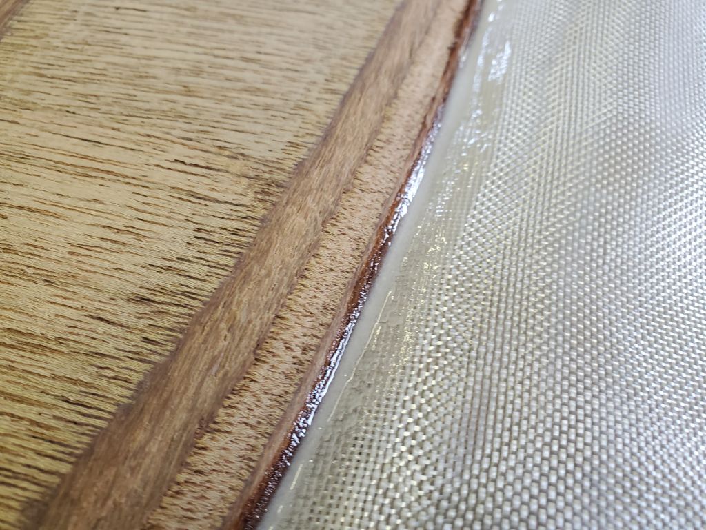
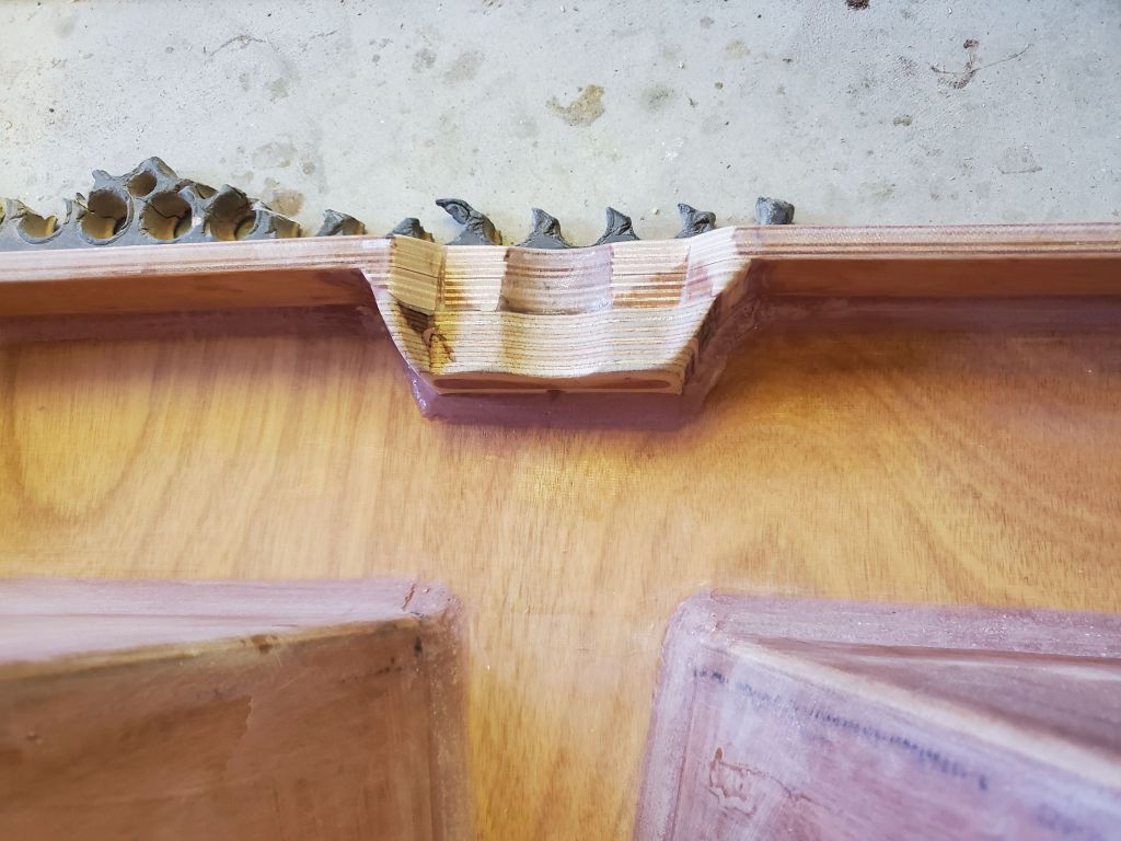
With a syringe, I injected a bead of thickened epoxy mixture into this void, including along the tips of the foils. This bead filled the small space till it was flush with the top edge of the curved leading edge. I lightly smoothed the bead with a finger to avoid leaving too much epoxy, as I’d have to sand and shape this area later, before installing fiberglass on the second side.
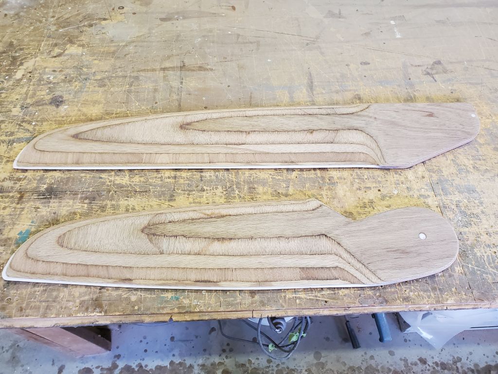
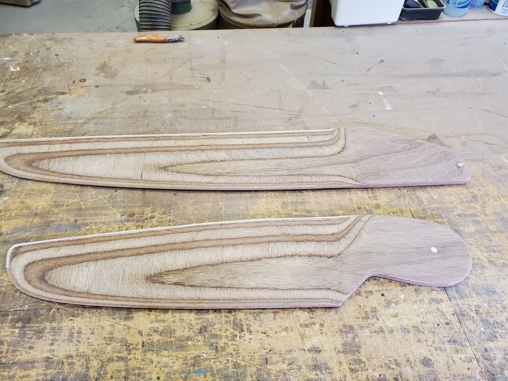
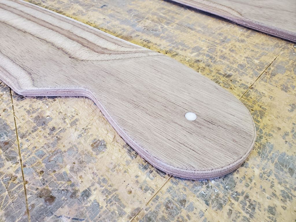
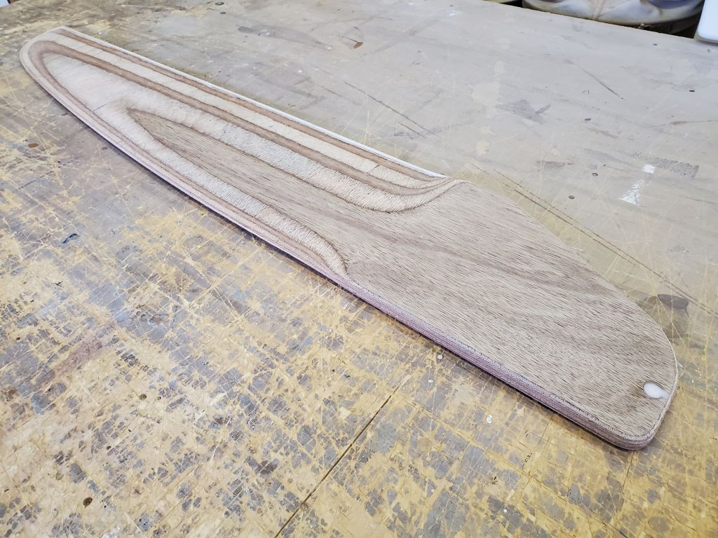
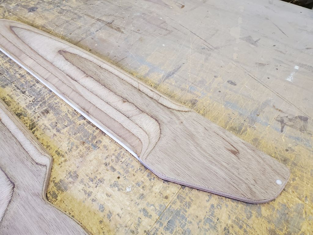
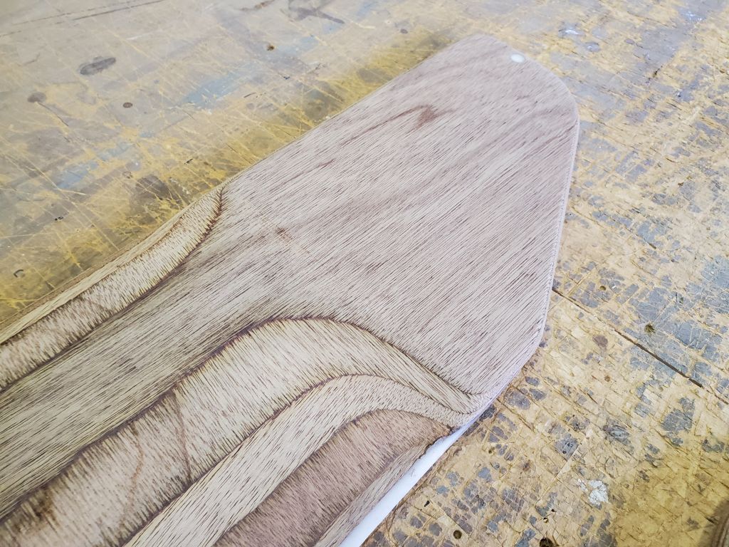
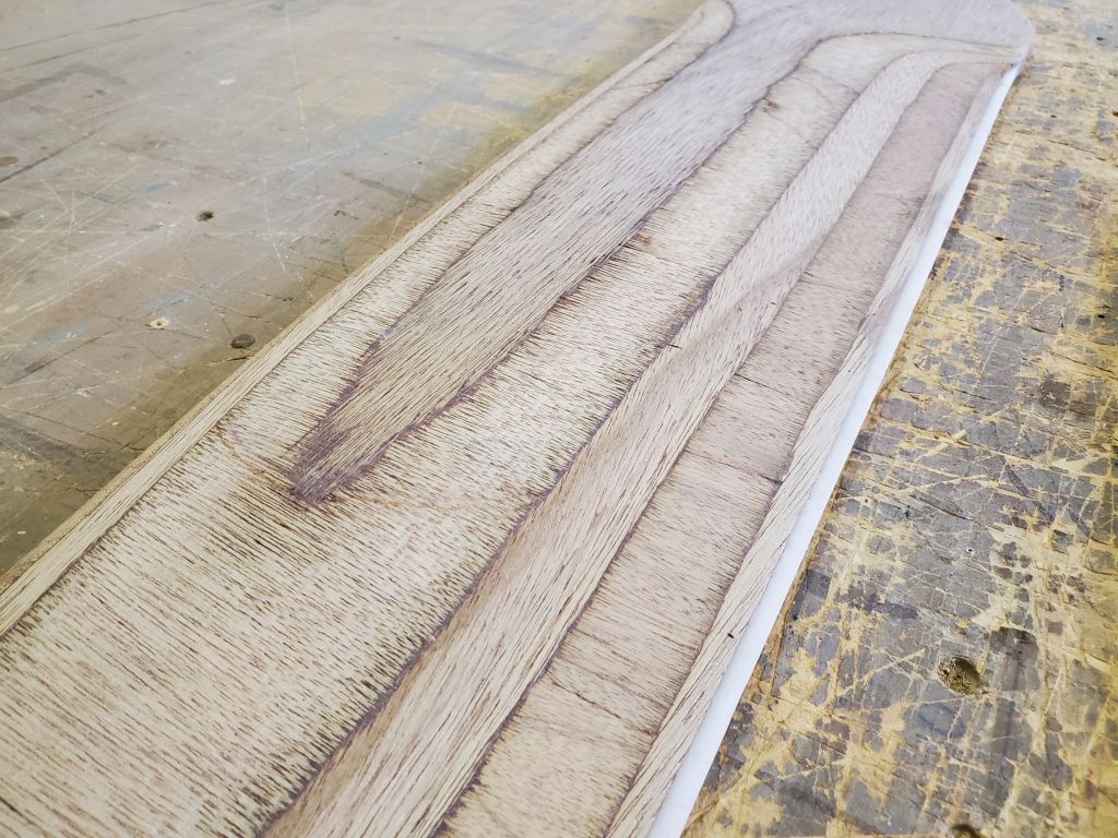
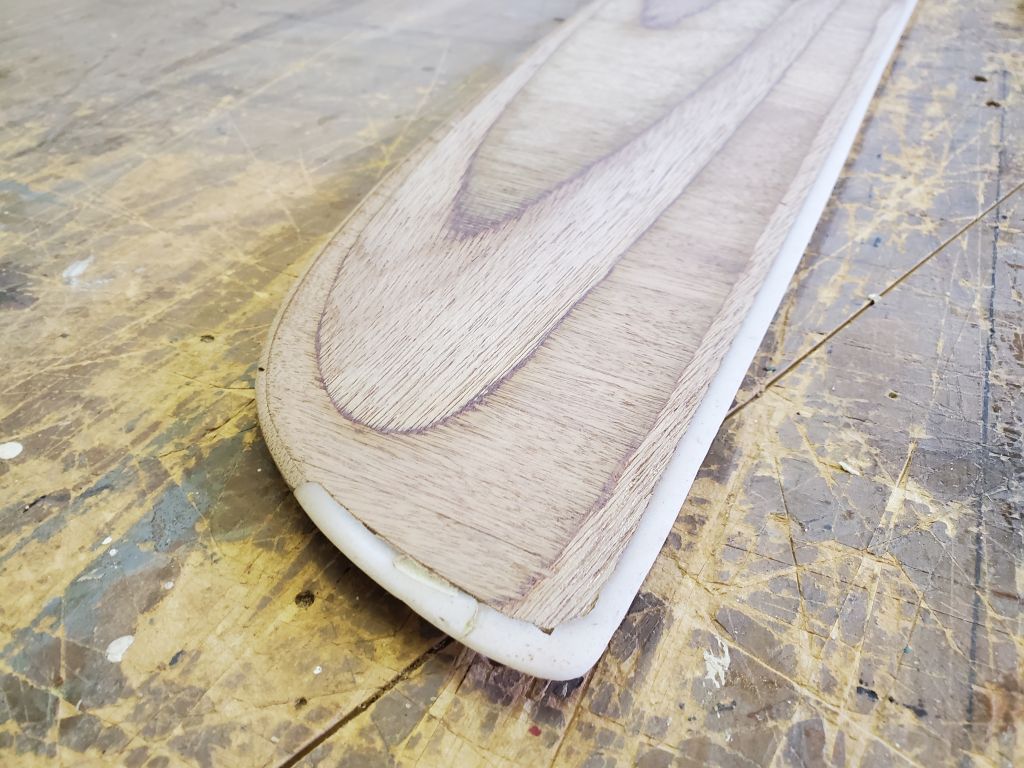
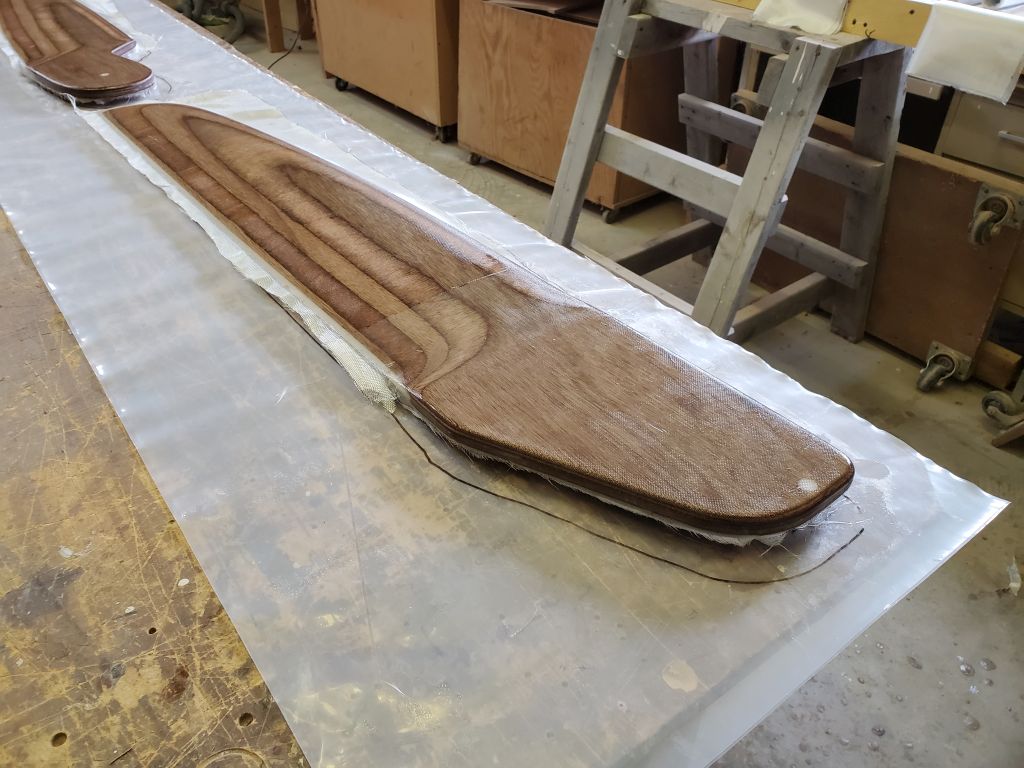
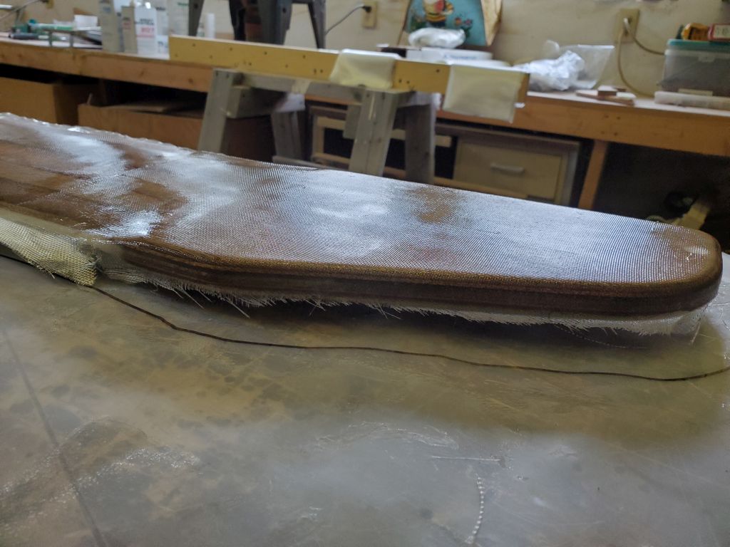
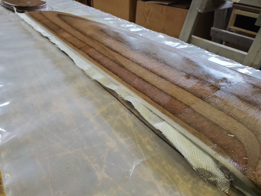
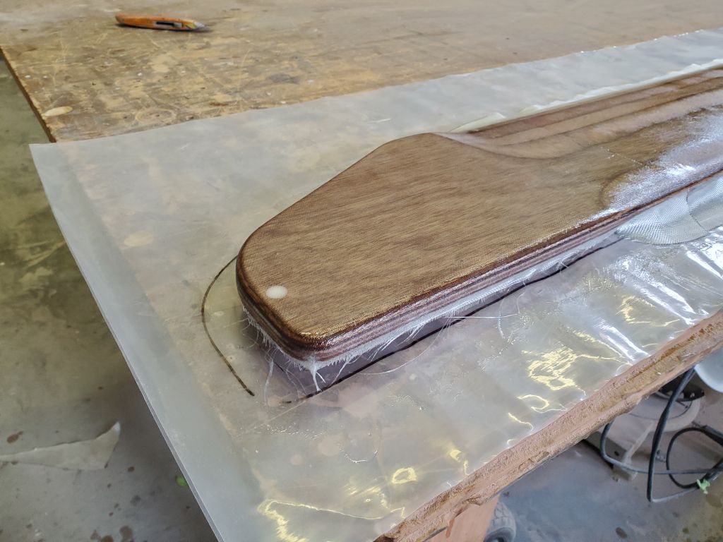
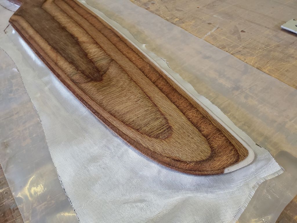
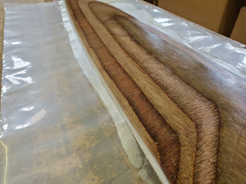
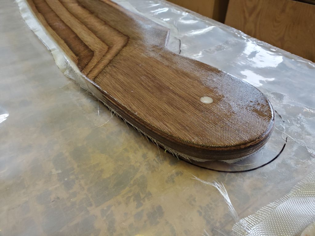
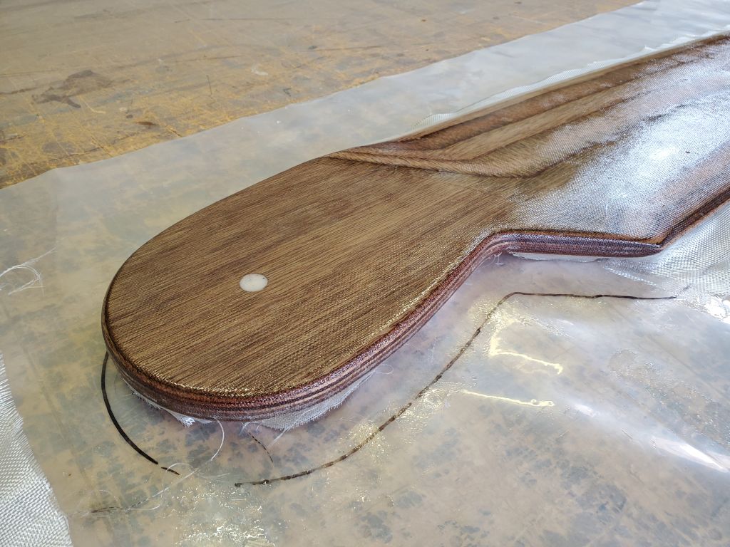
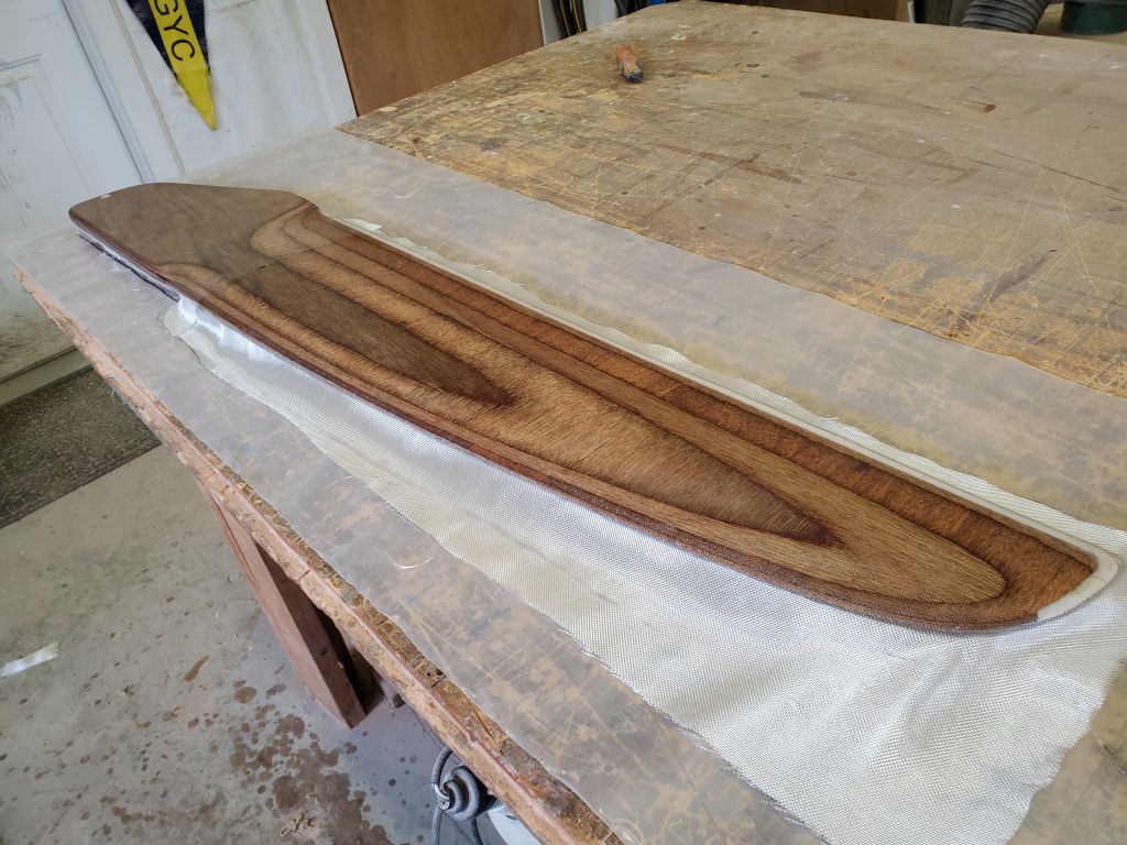
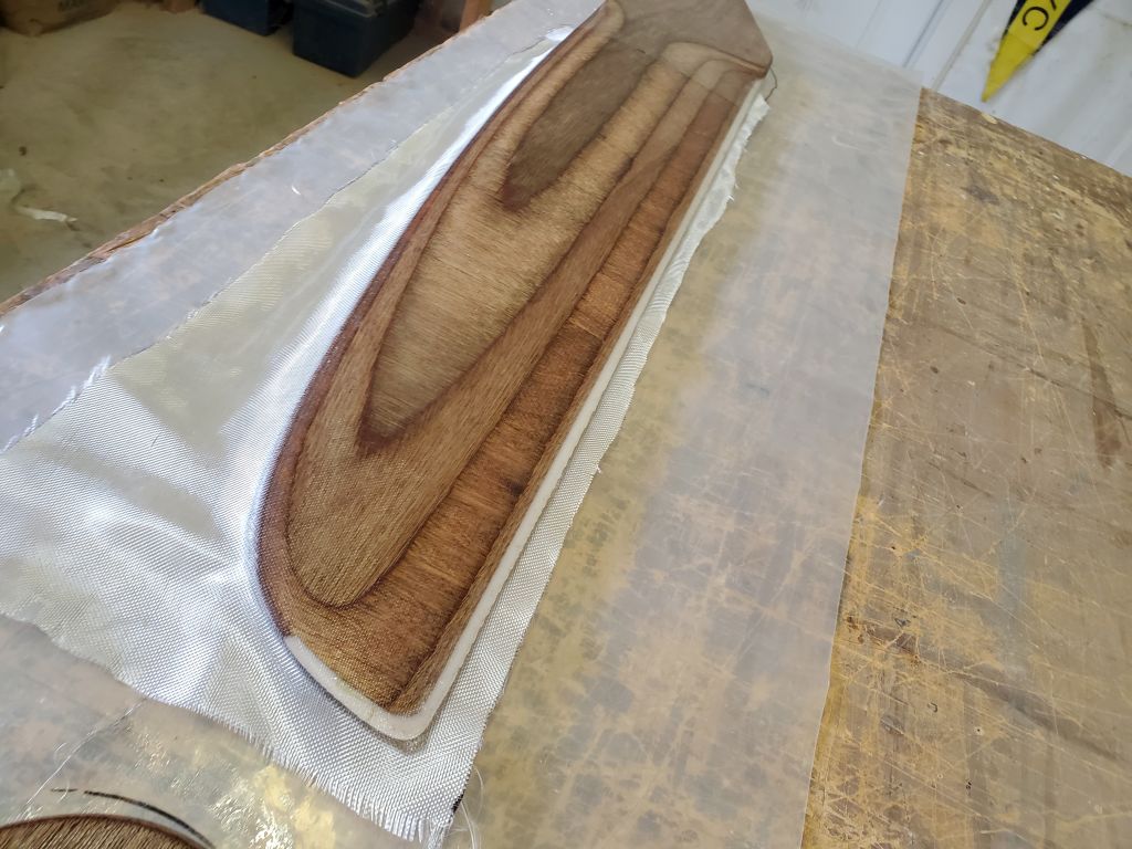
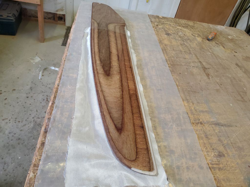
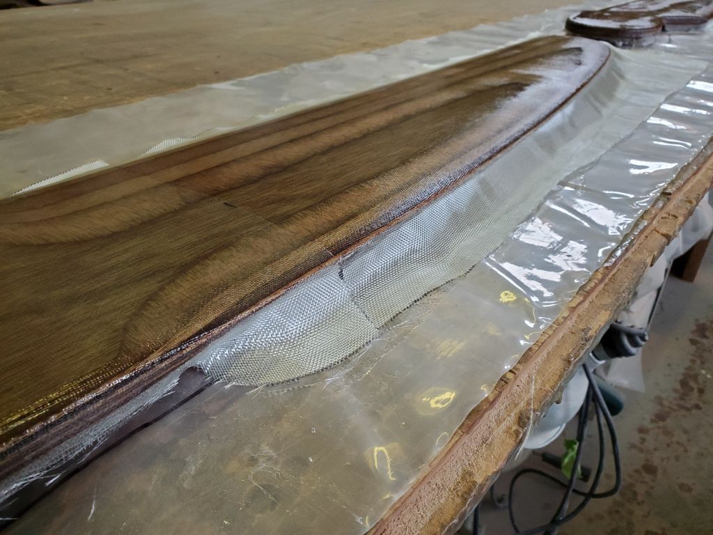
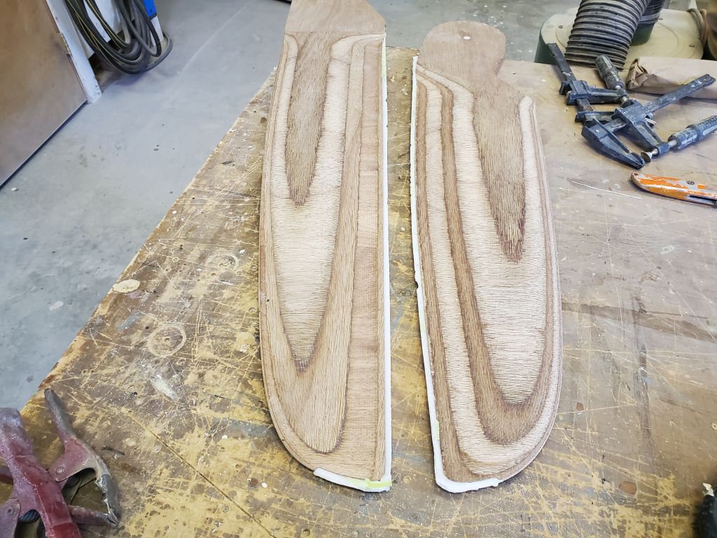
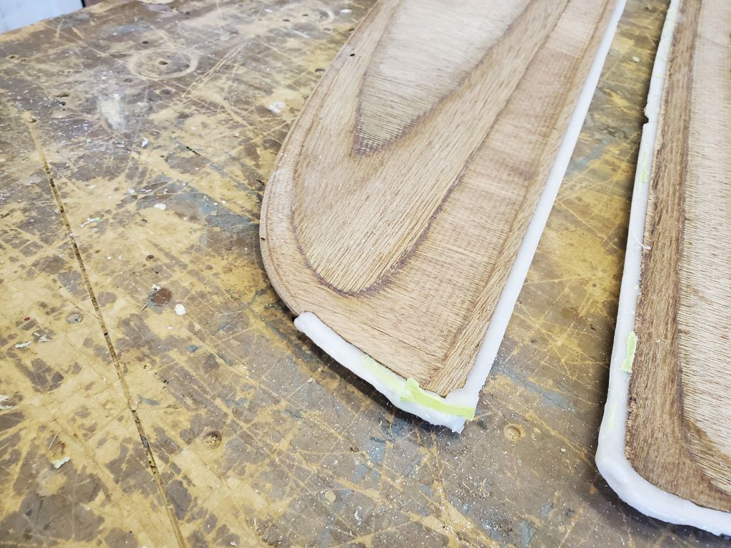
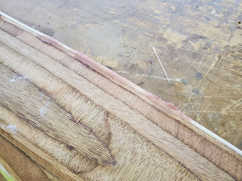
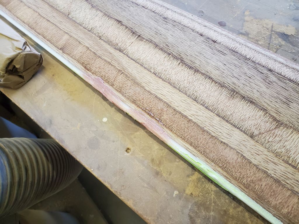
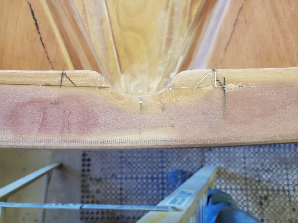
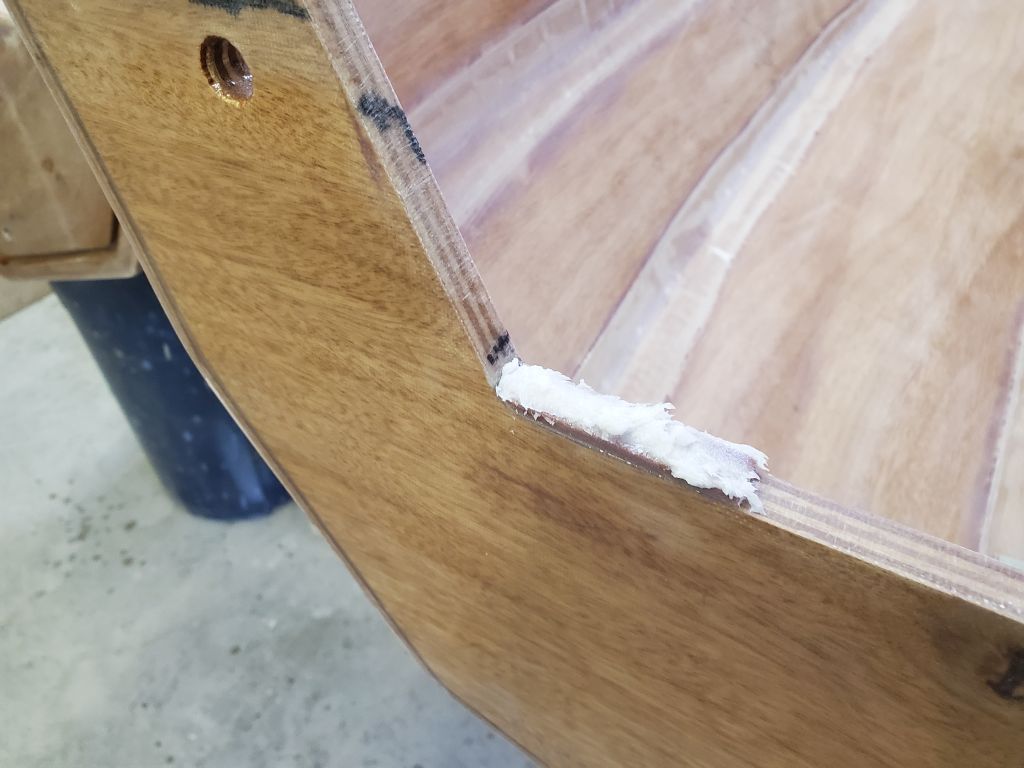
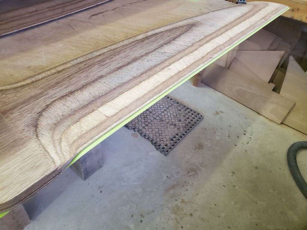
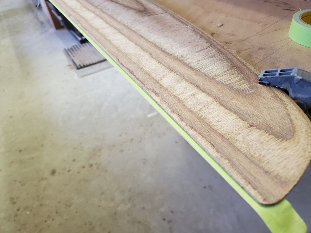
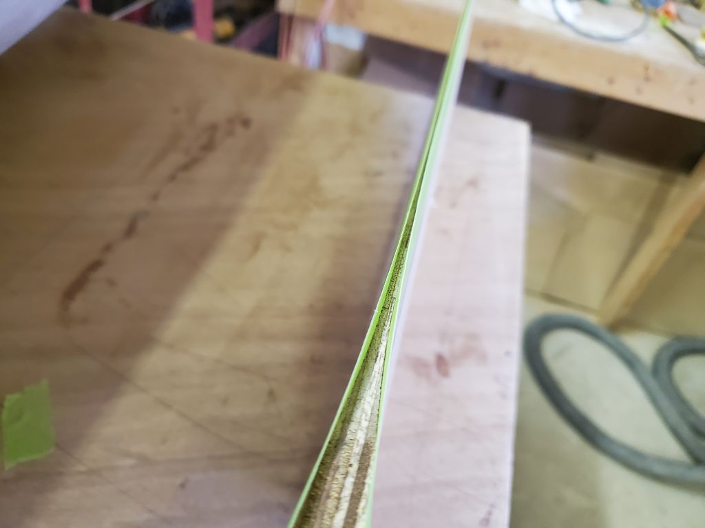
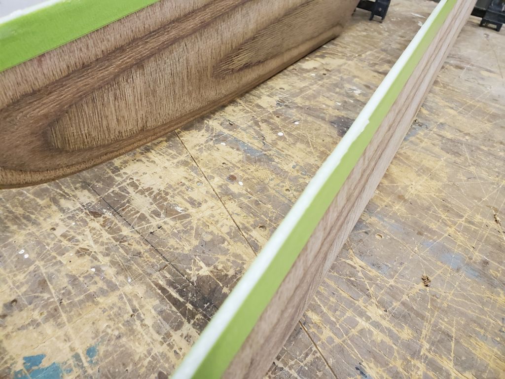
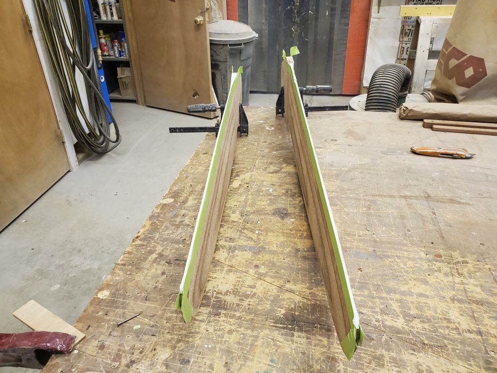
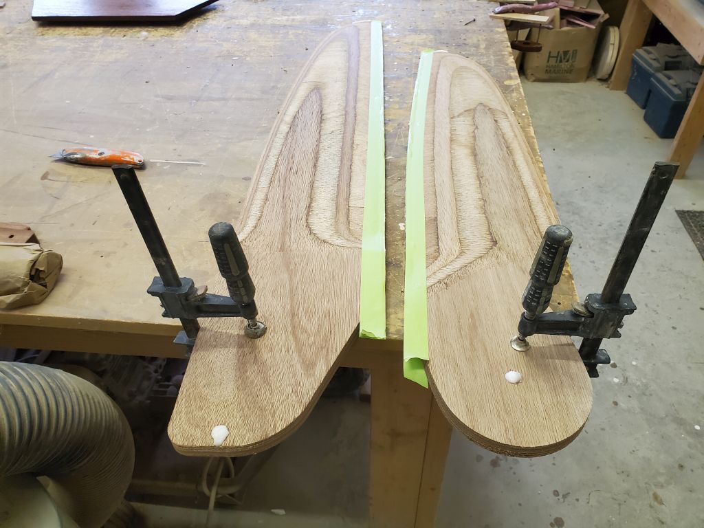
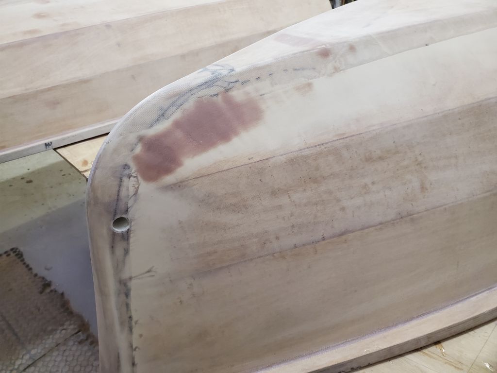
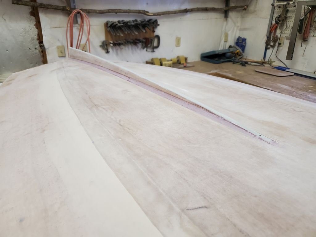
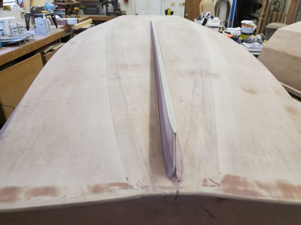
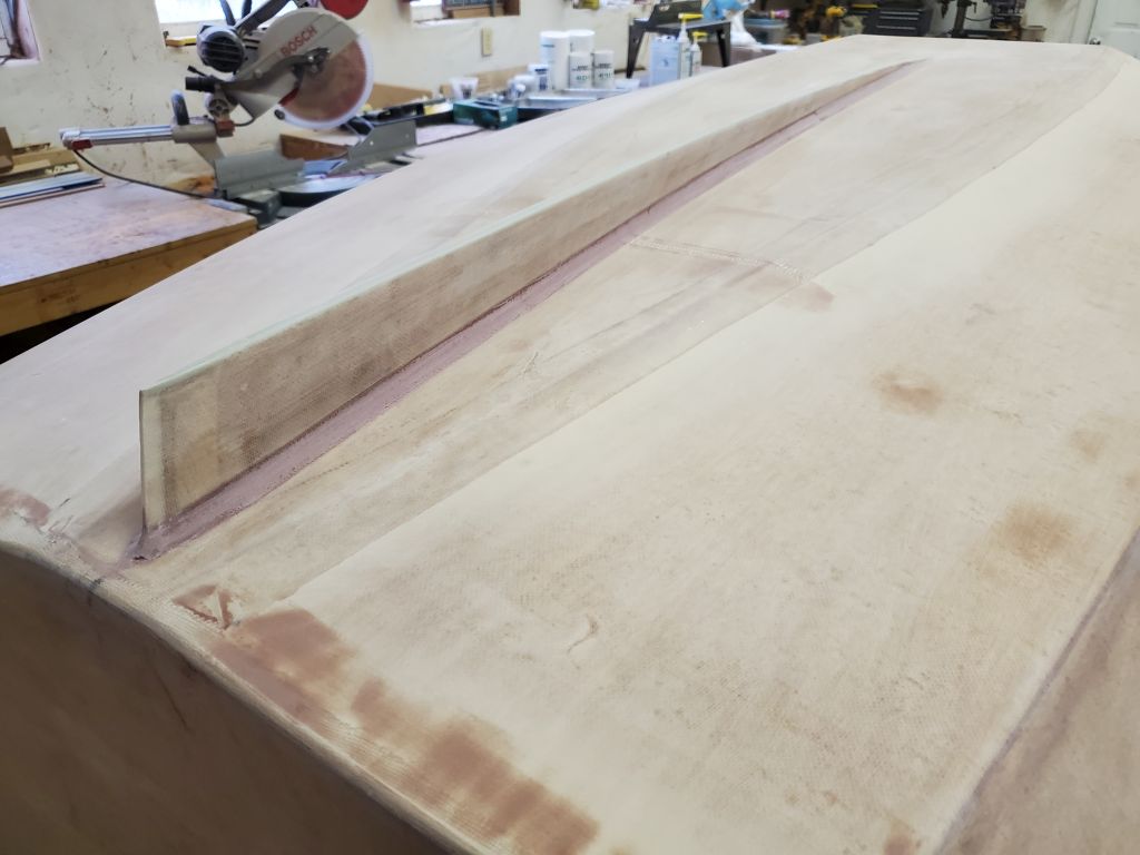
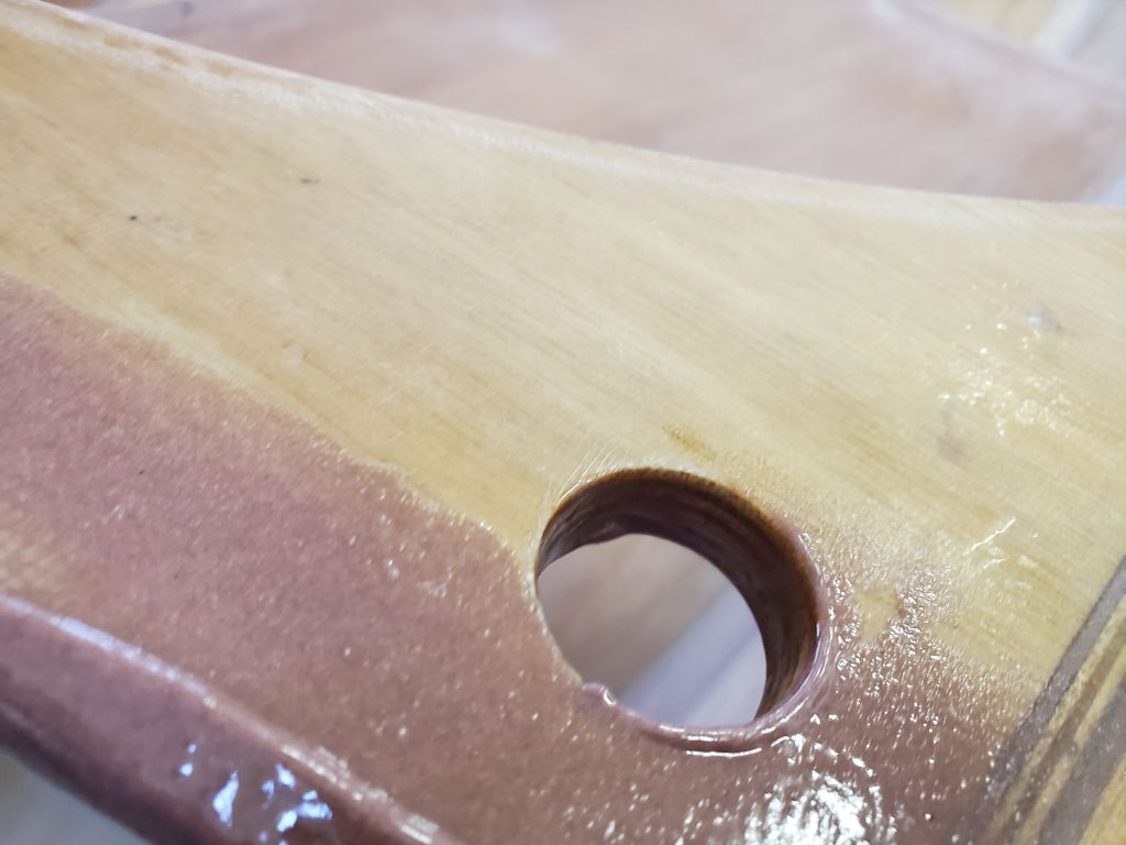
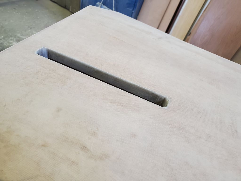
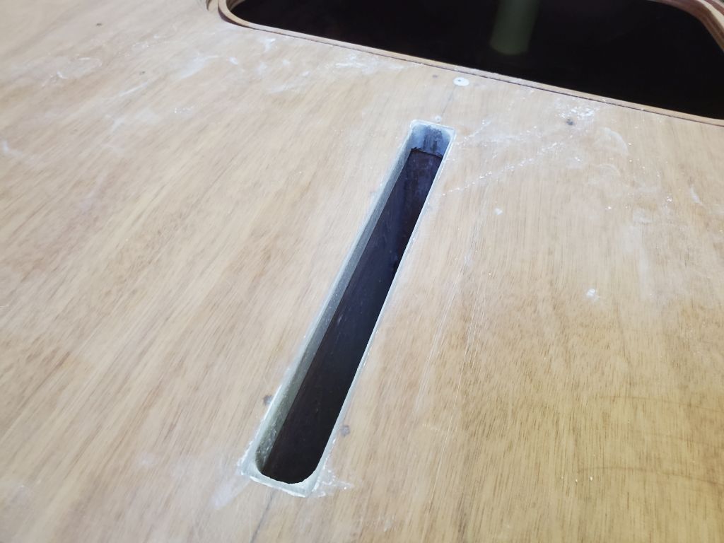
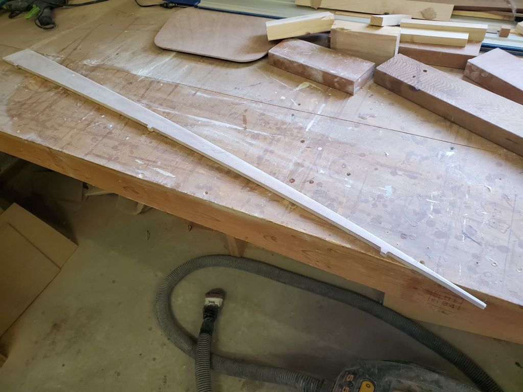
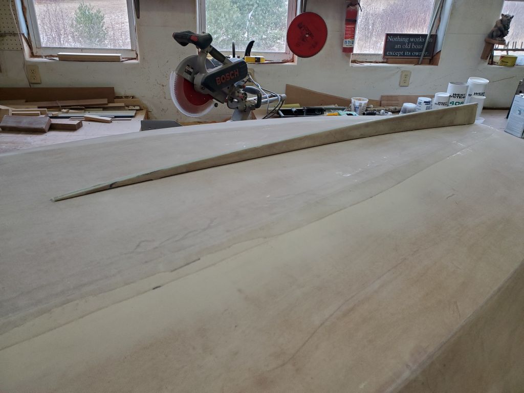
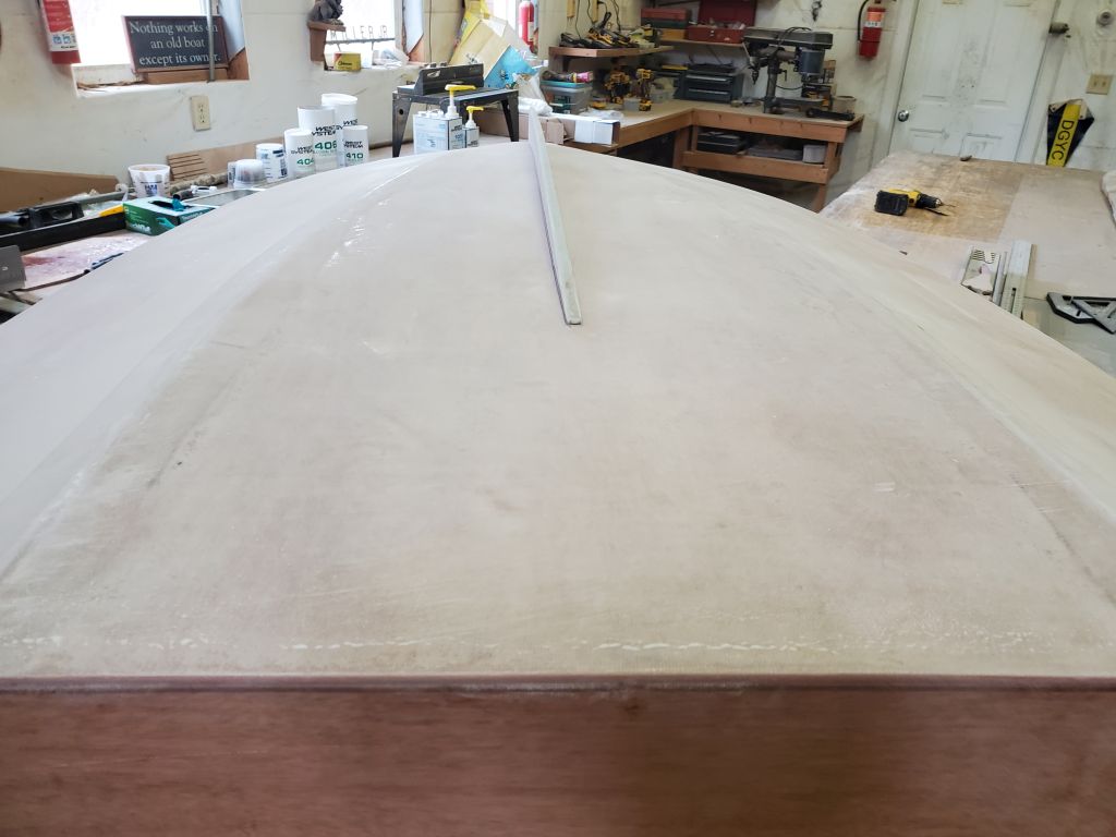
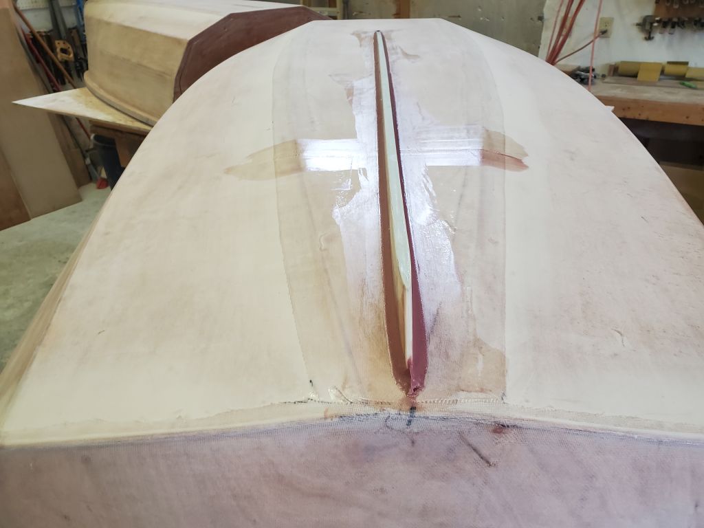
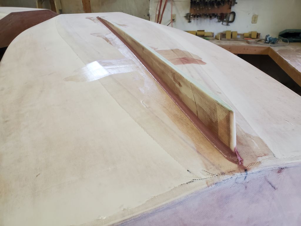
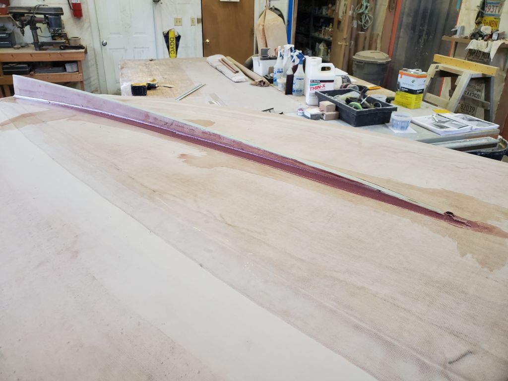
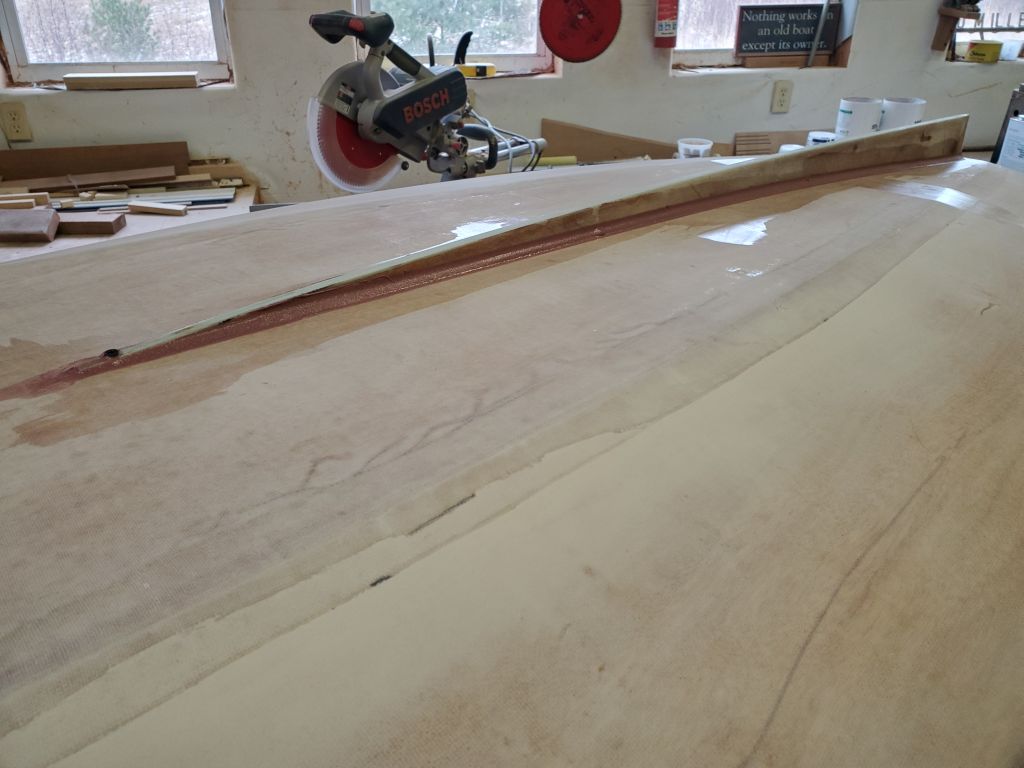
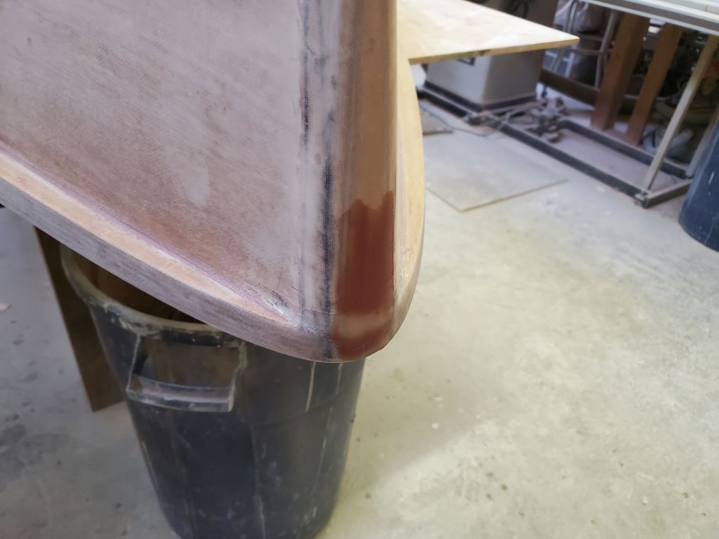
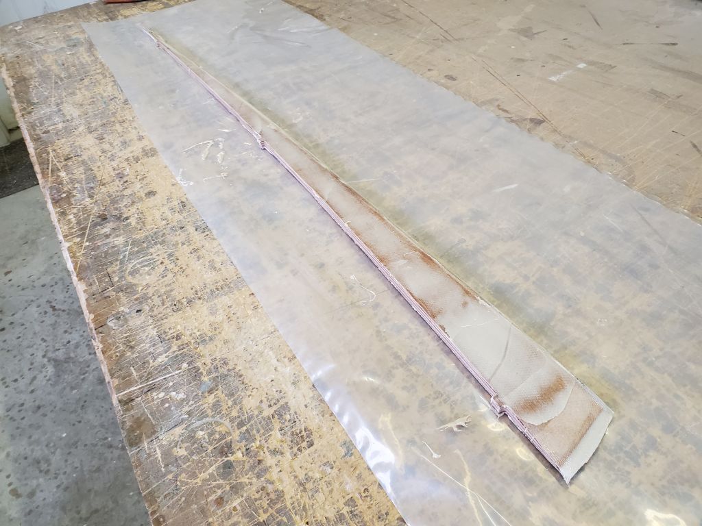
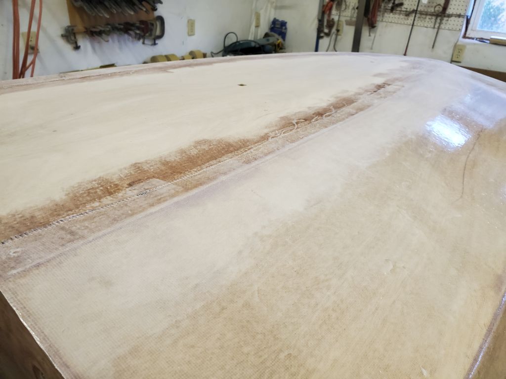
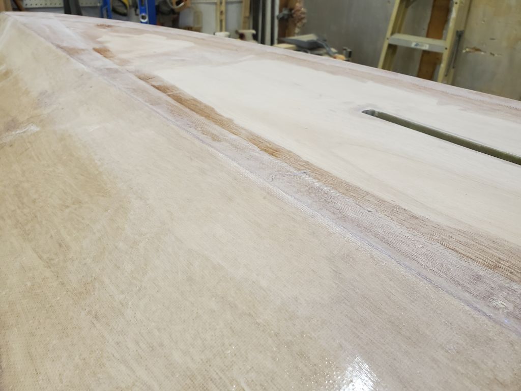
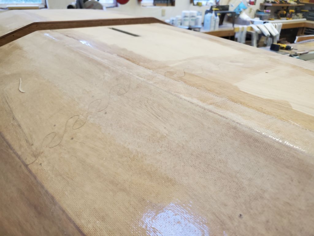
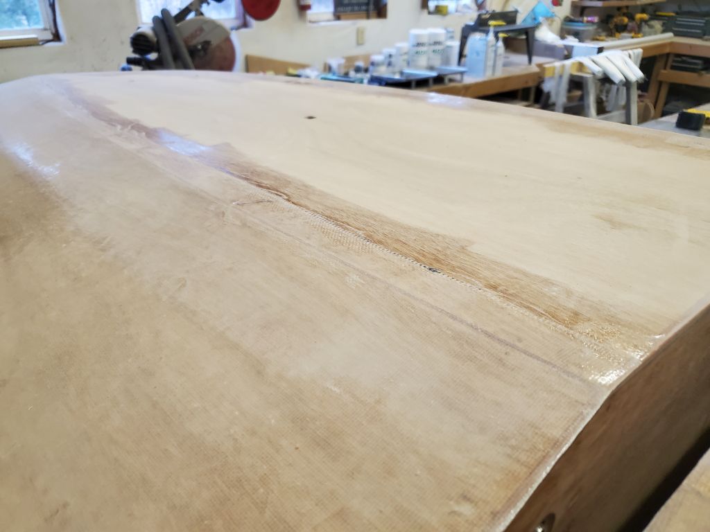
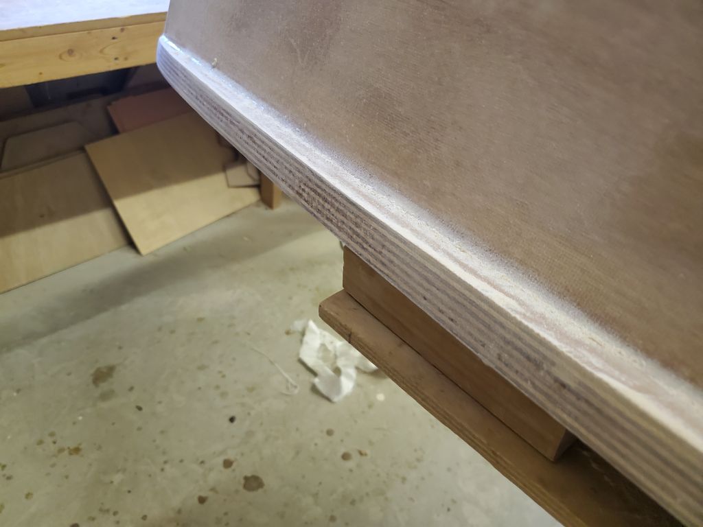
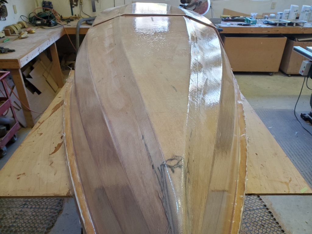
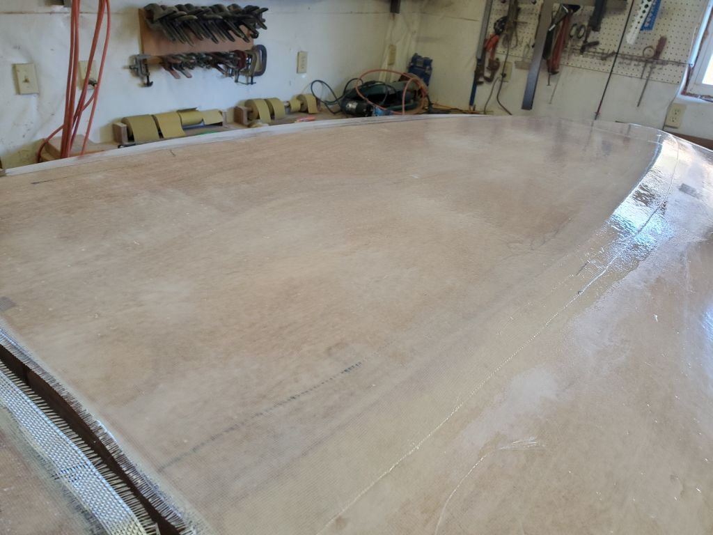
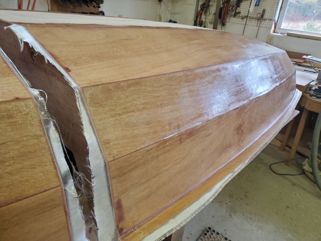
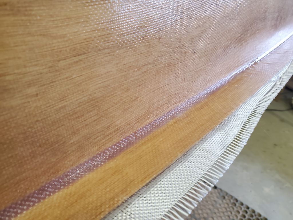
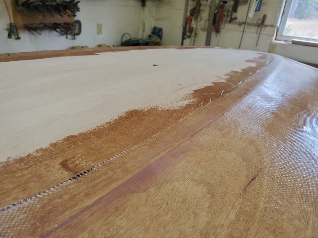
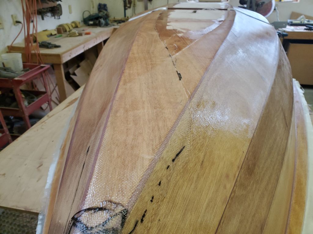
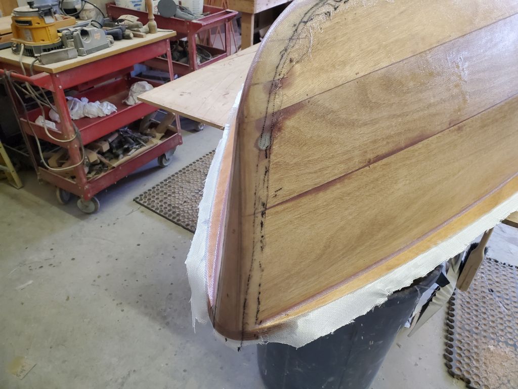
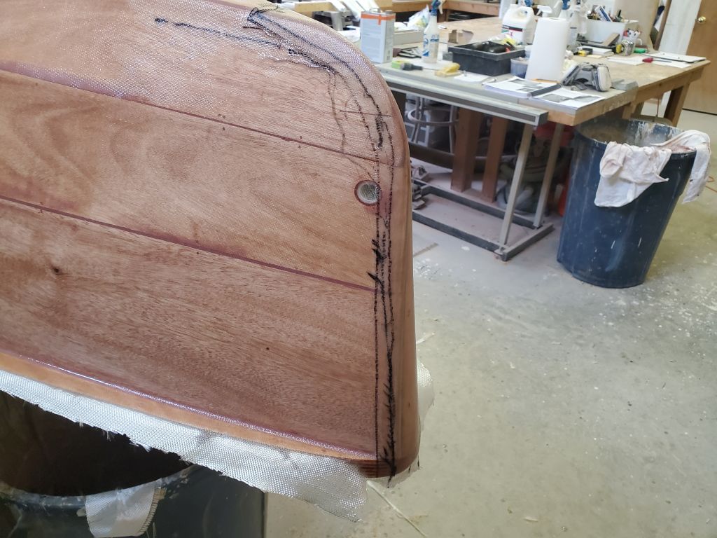
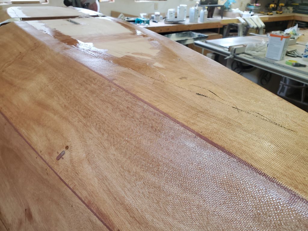
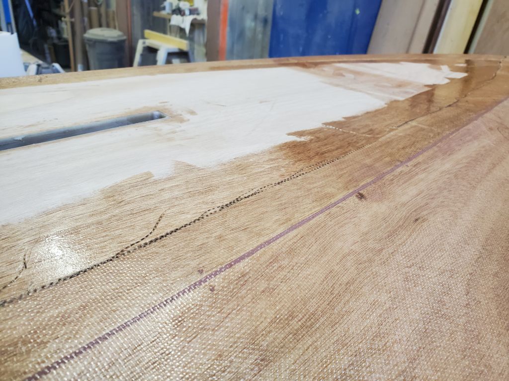
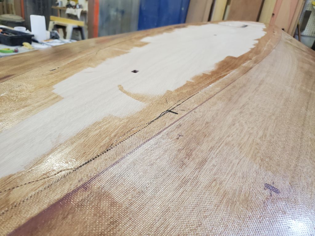
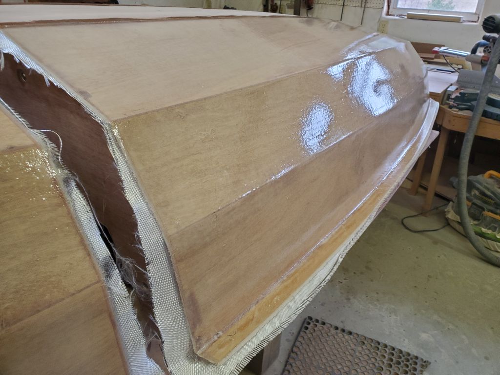
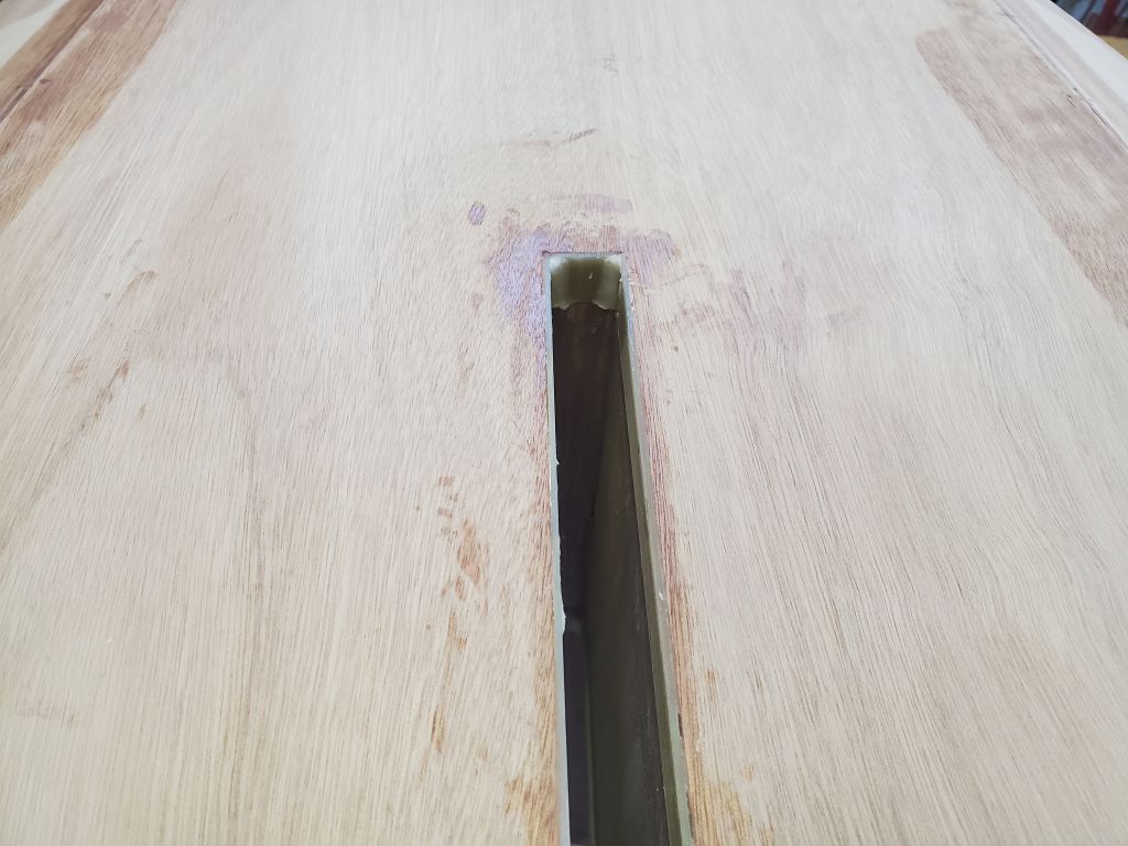
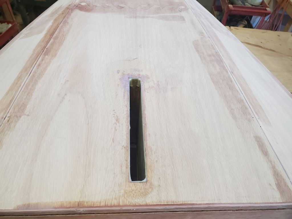
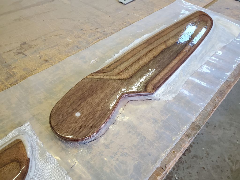
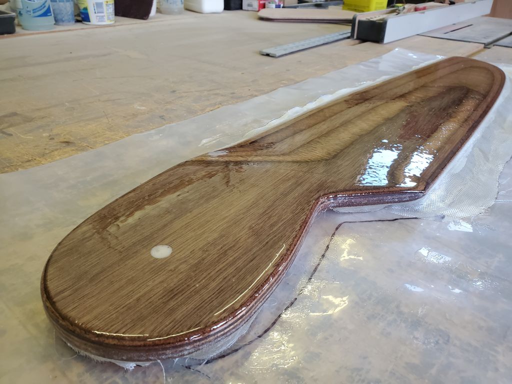
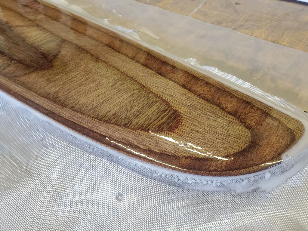
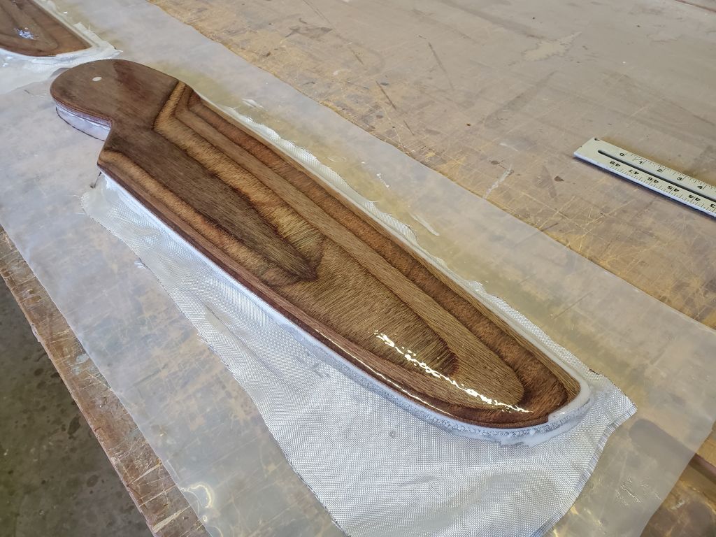
With the foils turned back over to the working side (glass side up), the purpose of the filling was made more clear.
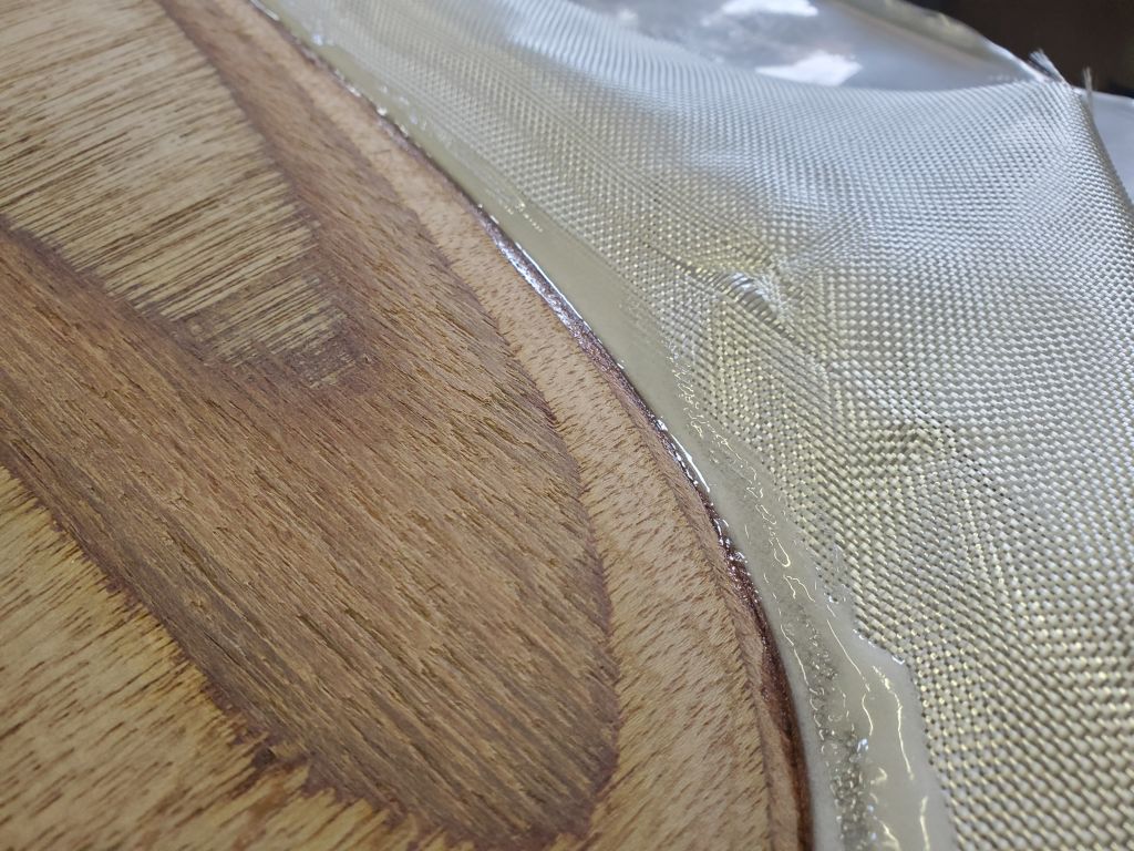

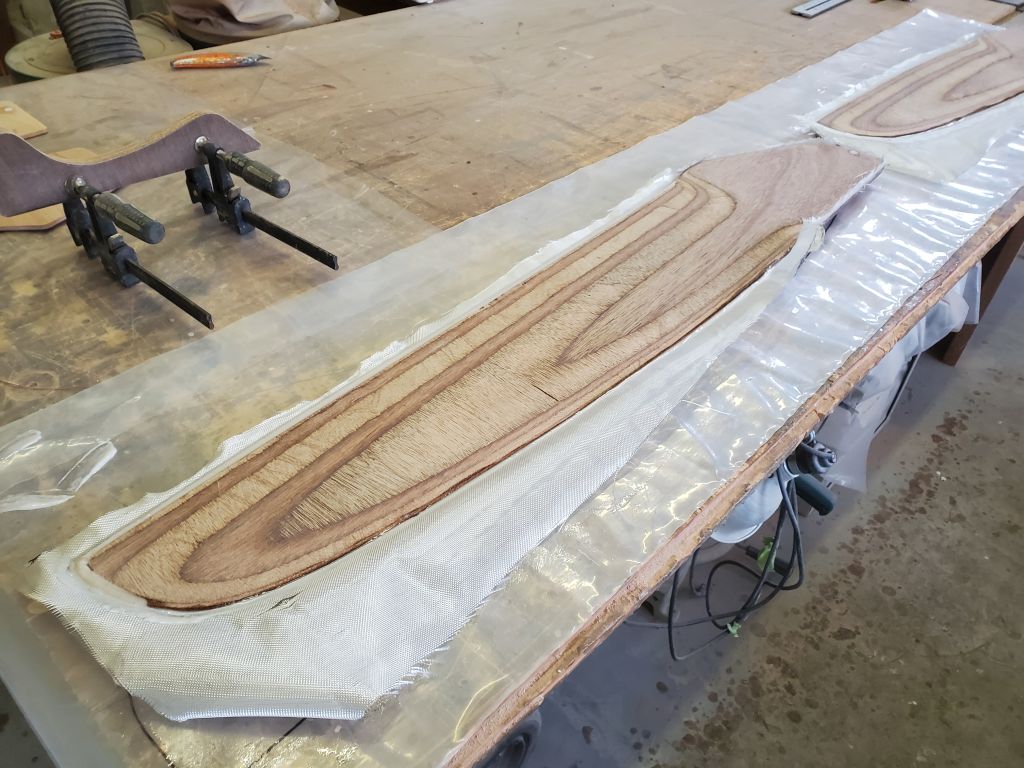

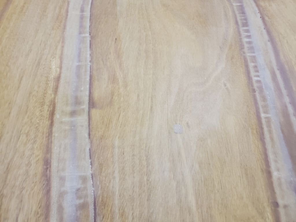
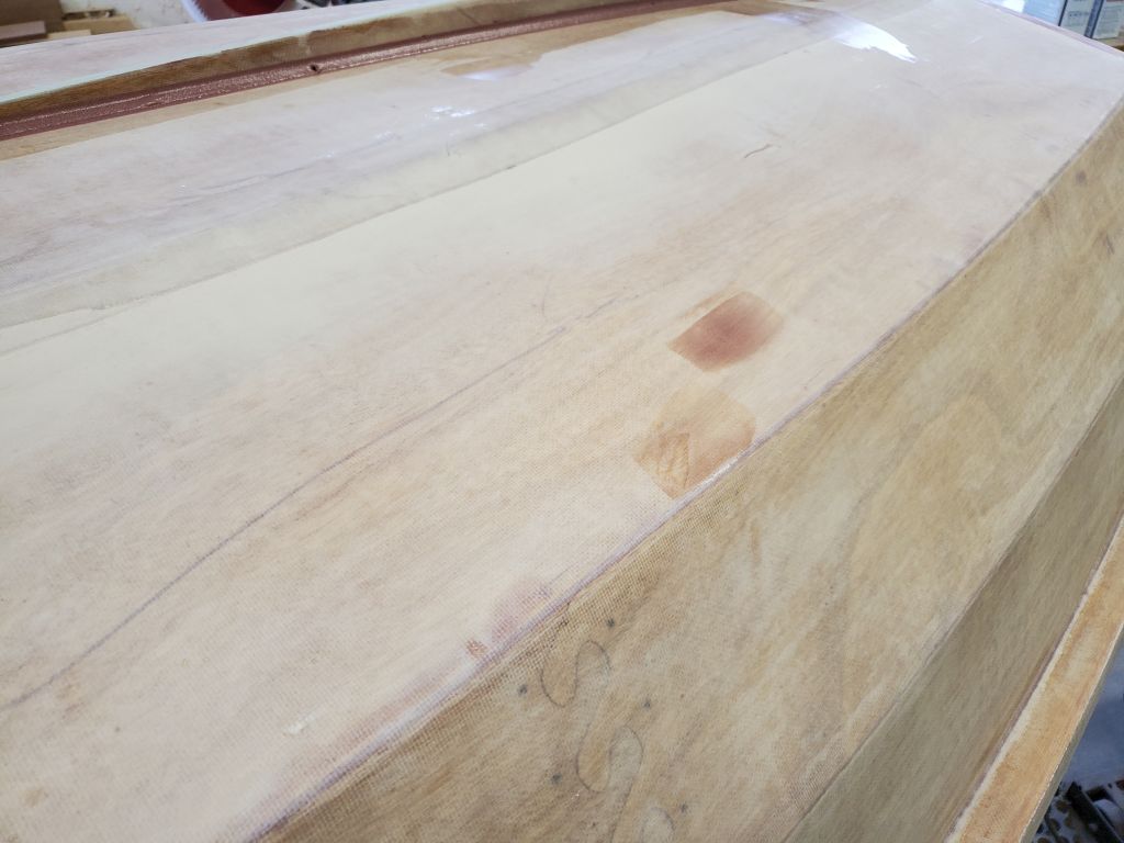
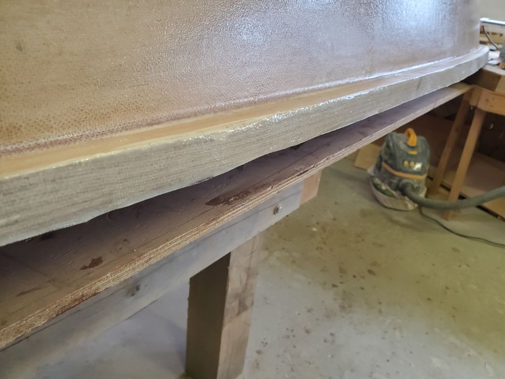
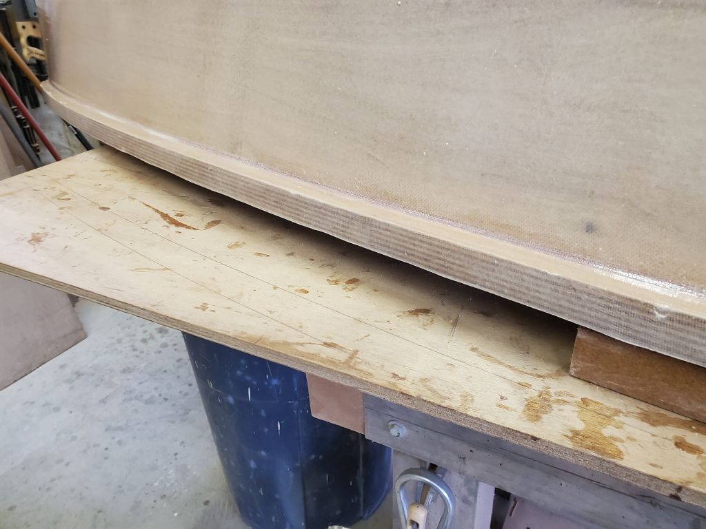
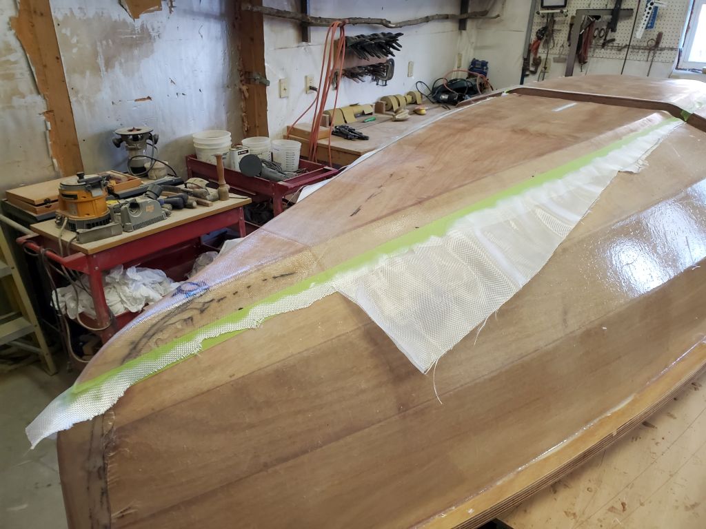
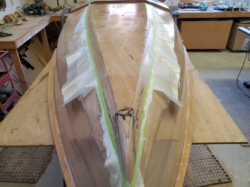
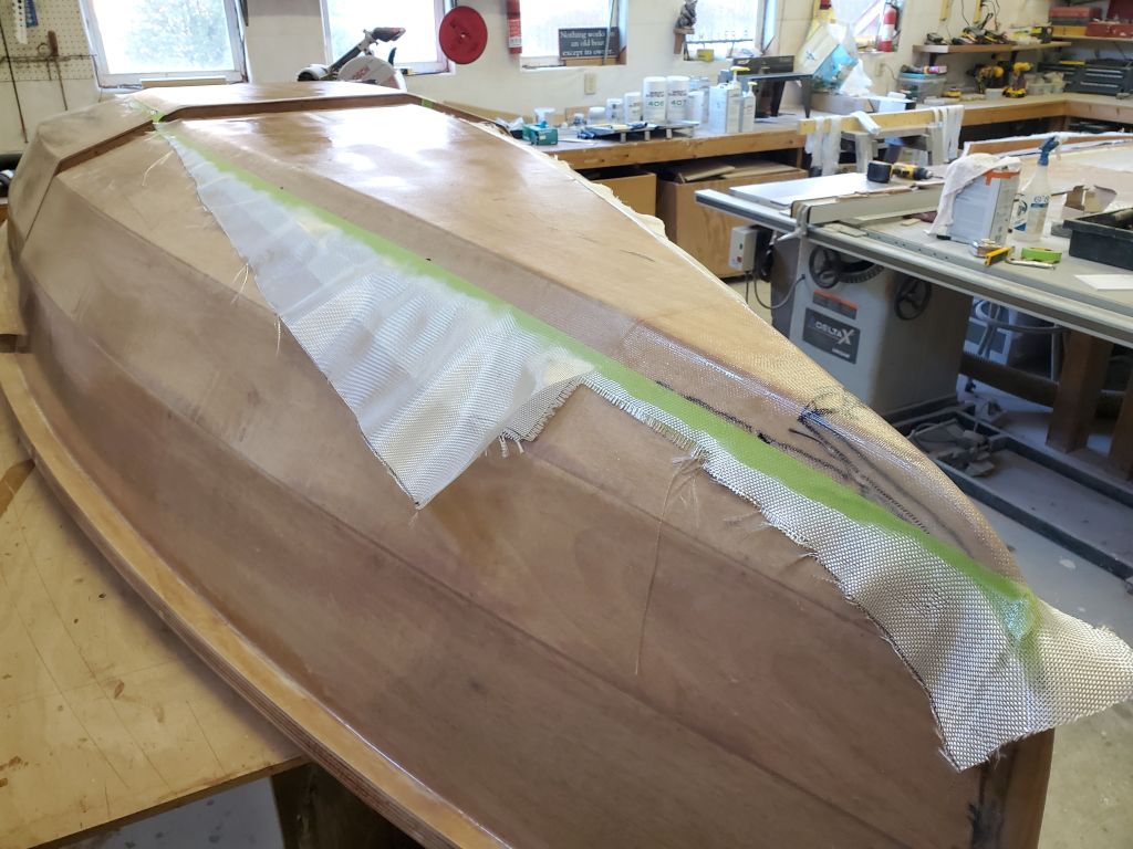
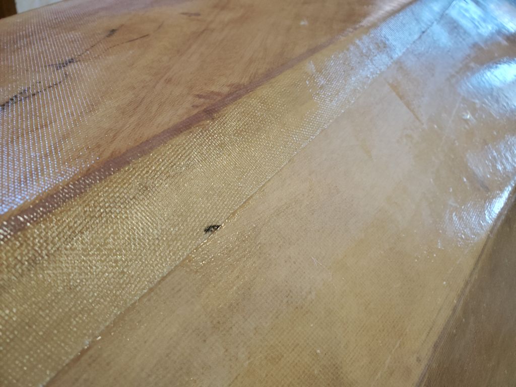
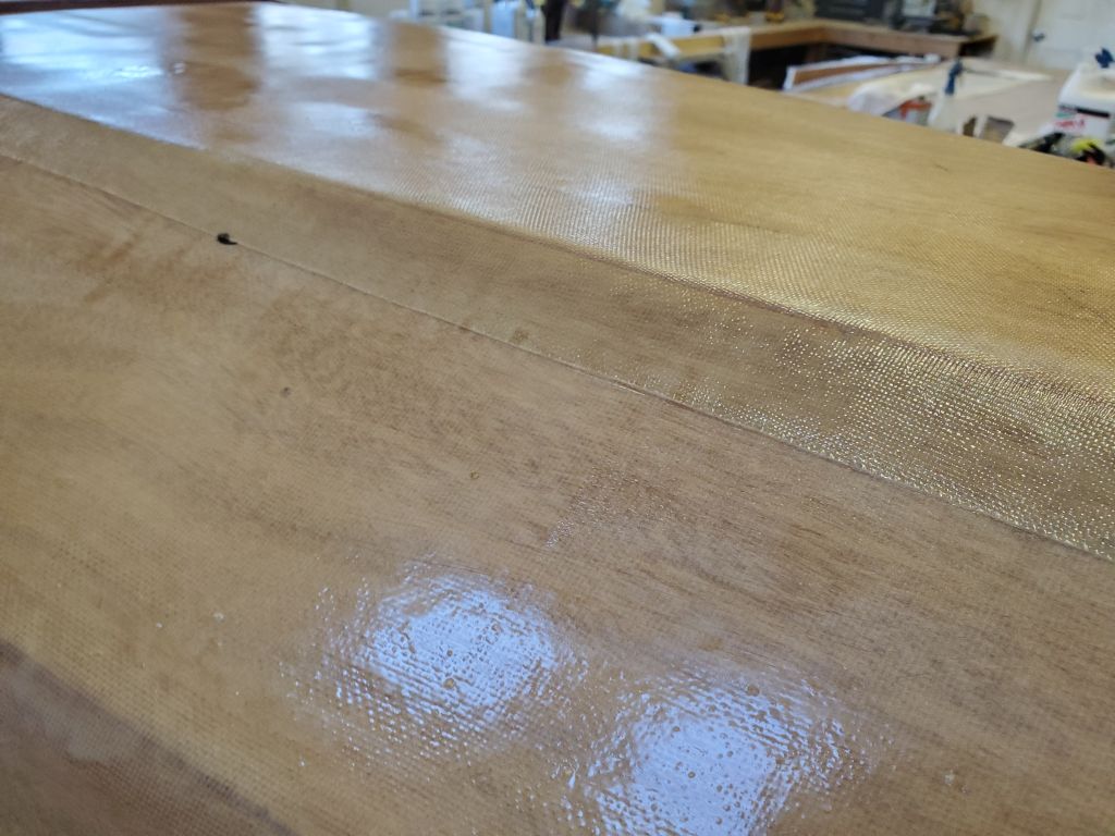
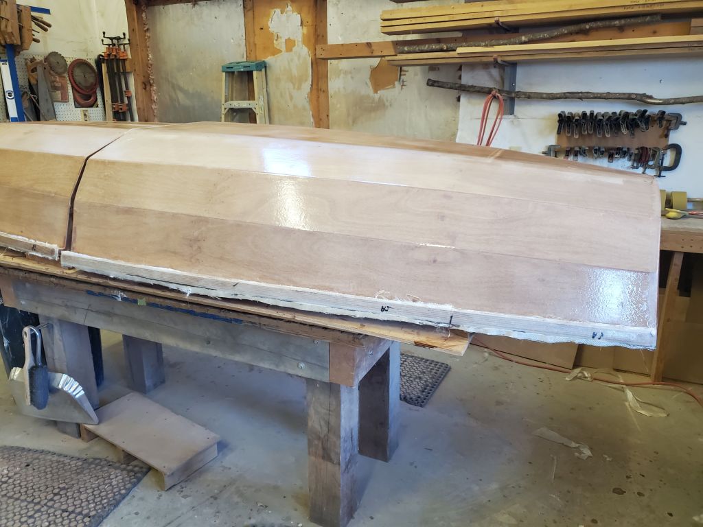
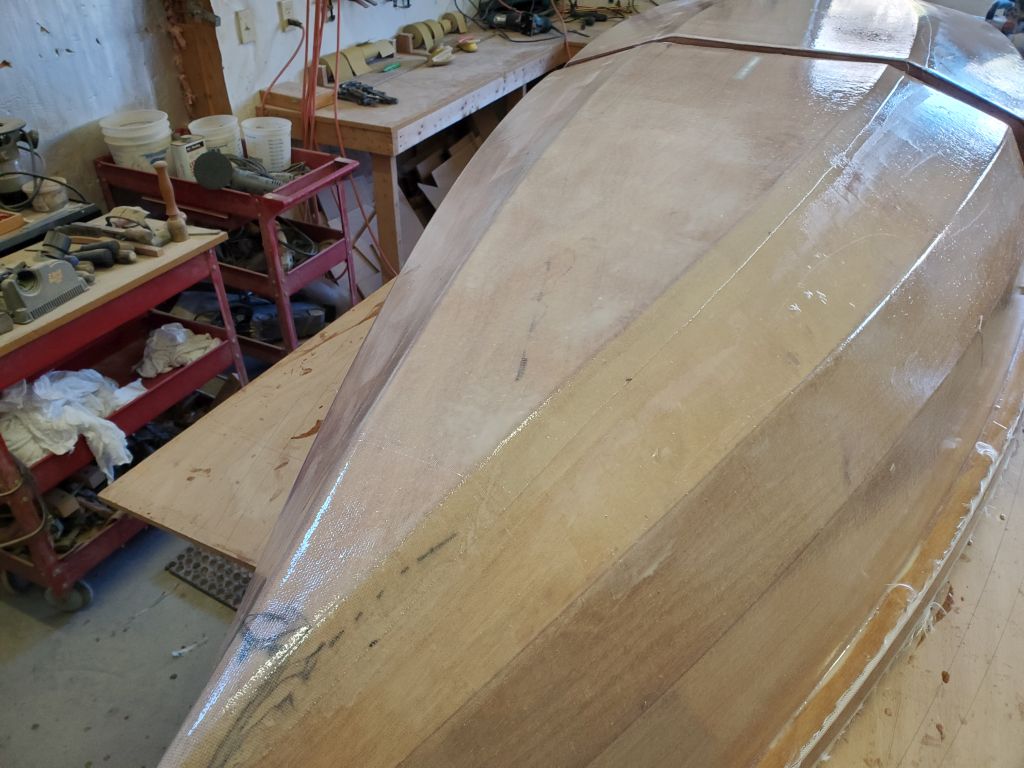
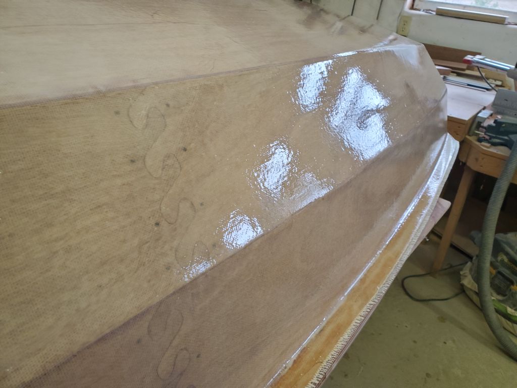
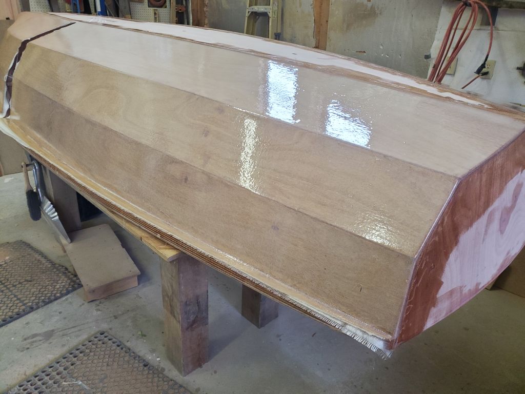
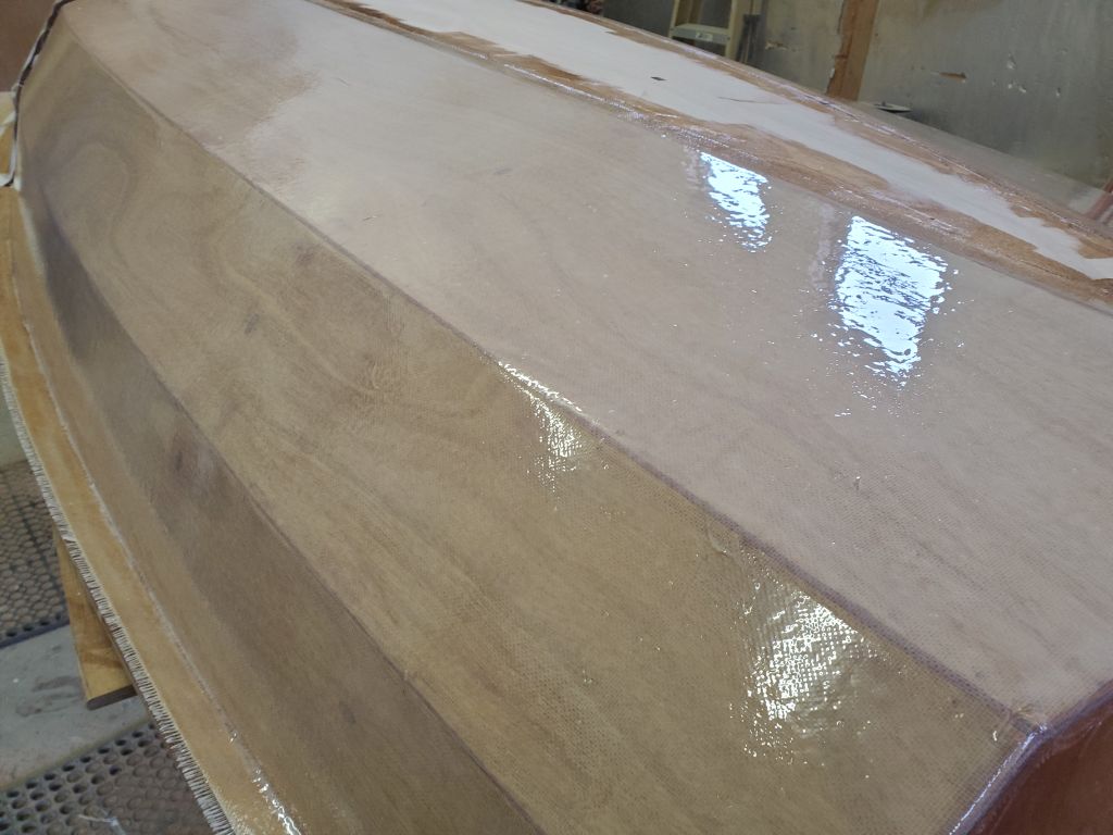
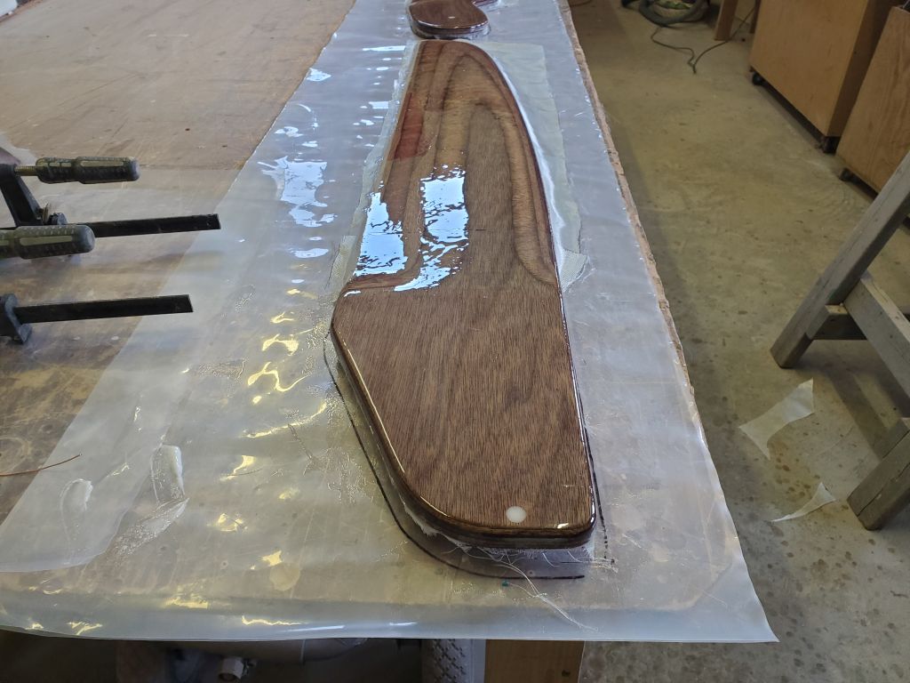
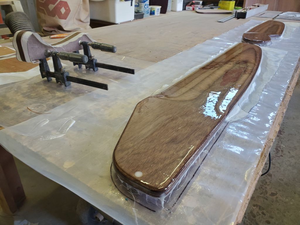
Next, I rolled on a nice fill coat on the new fiberglass, heavily enough that there’d be no problem to sand and fair the foils smooth when all was said and done.

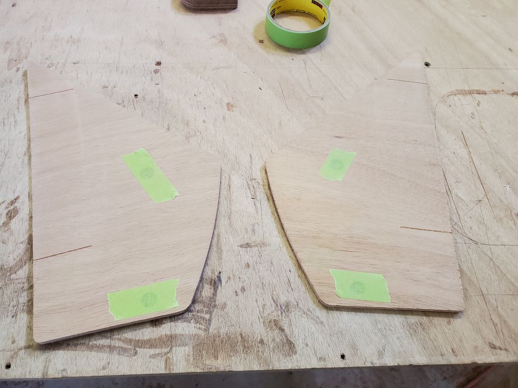
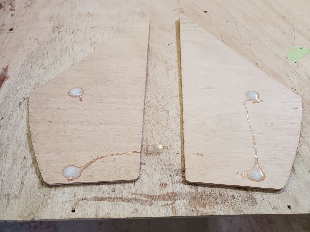
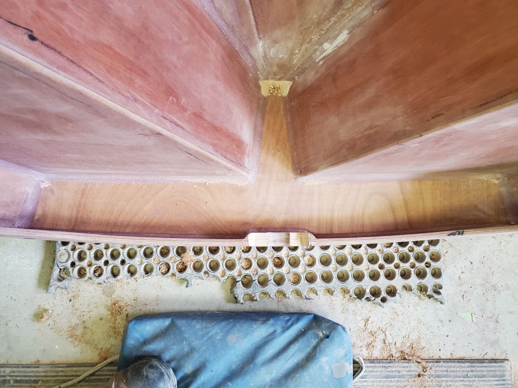
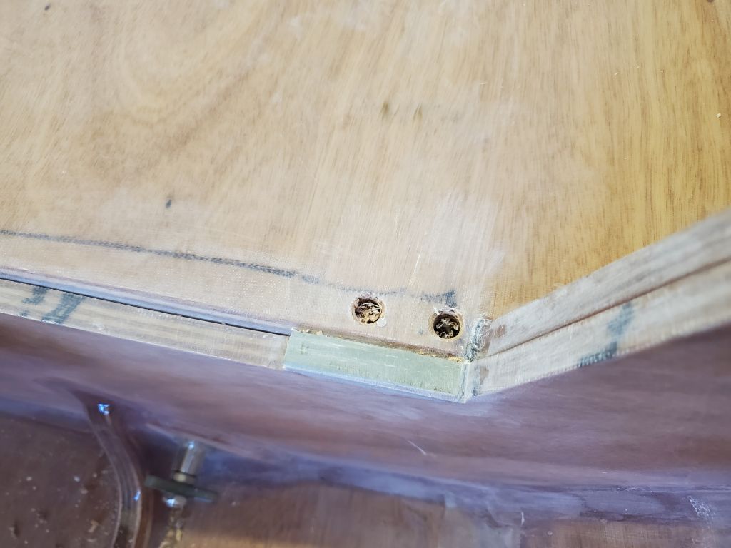
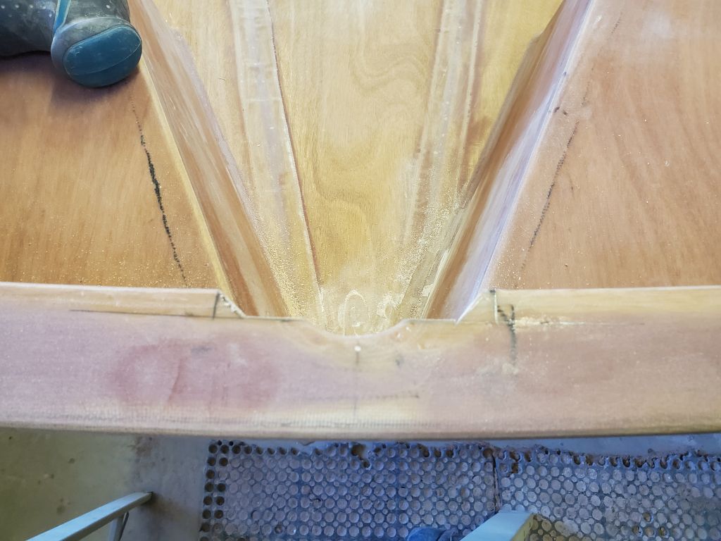
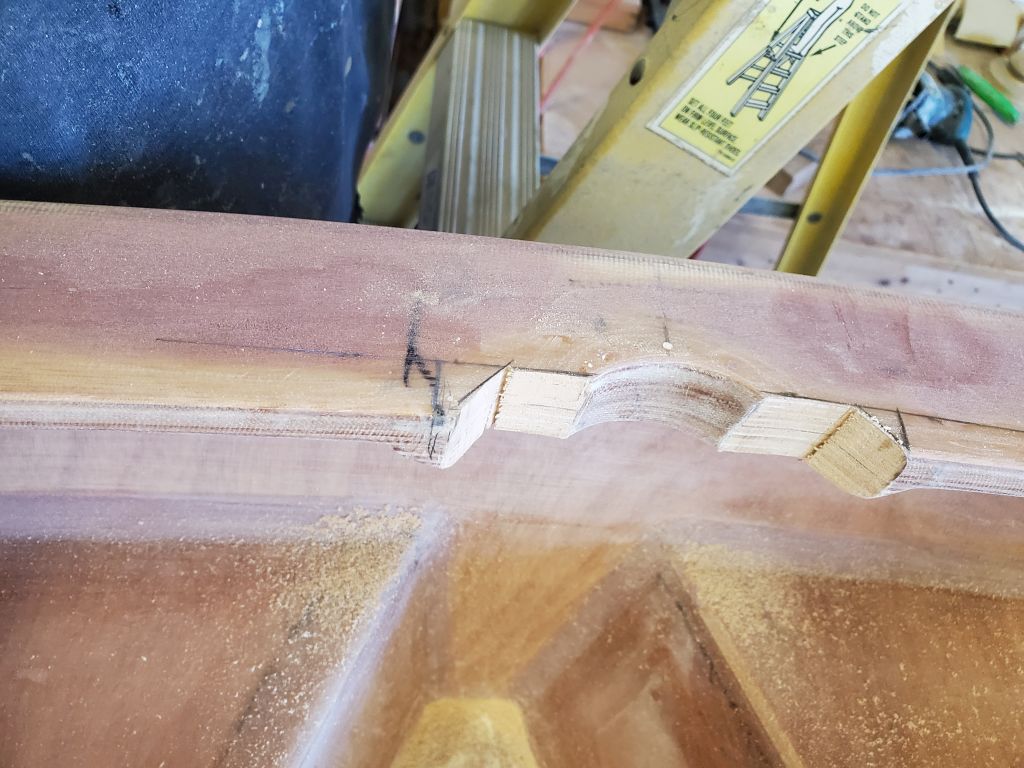
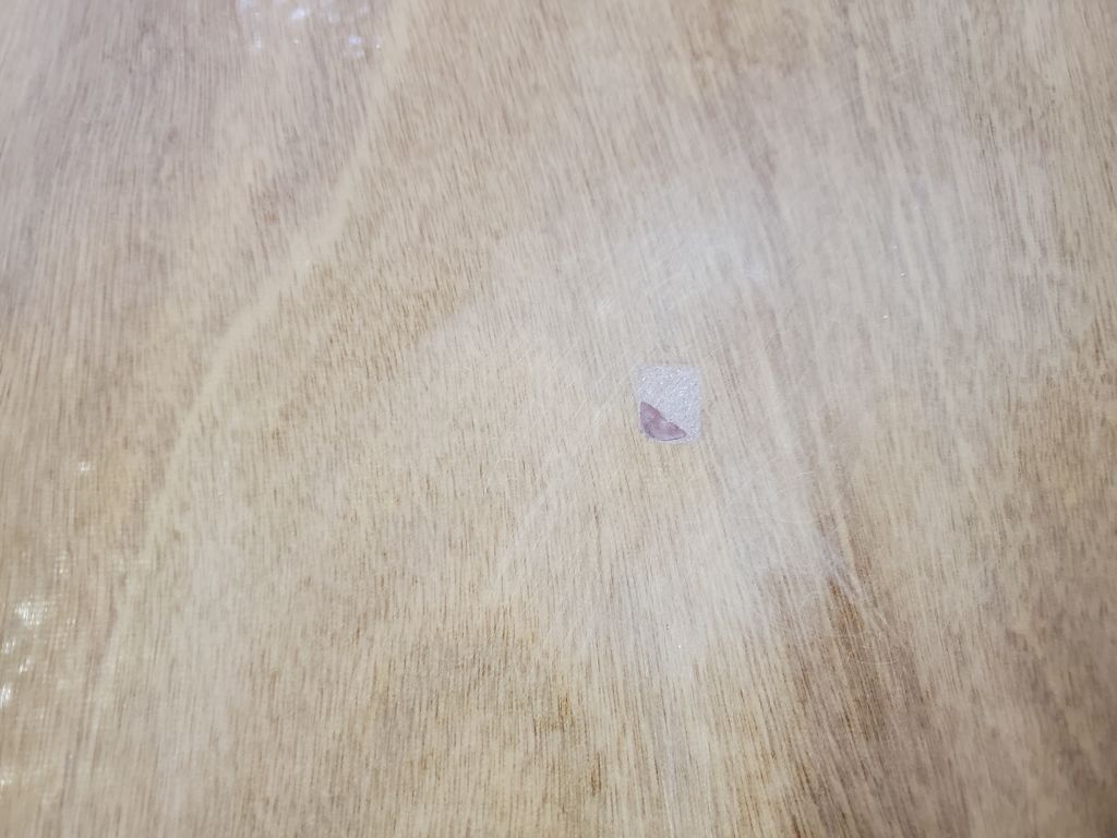
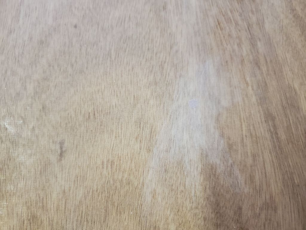
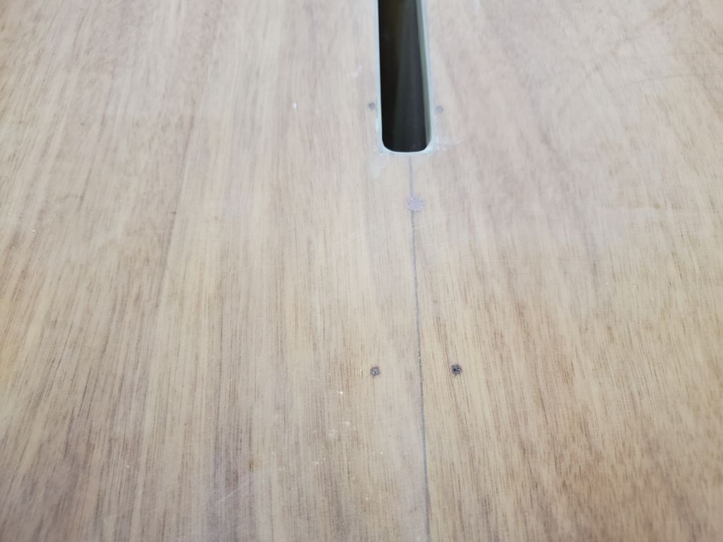
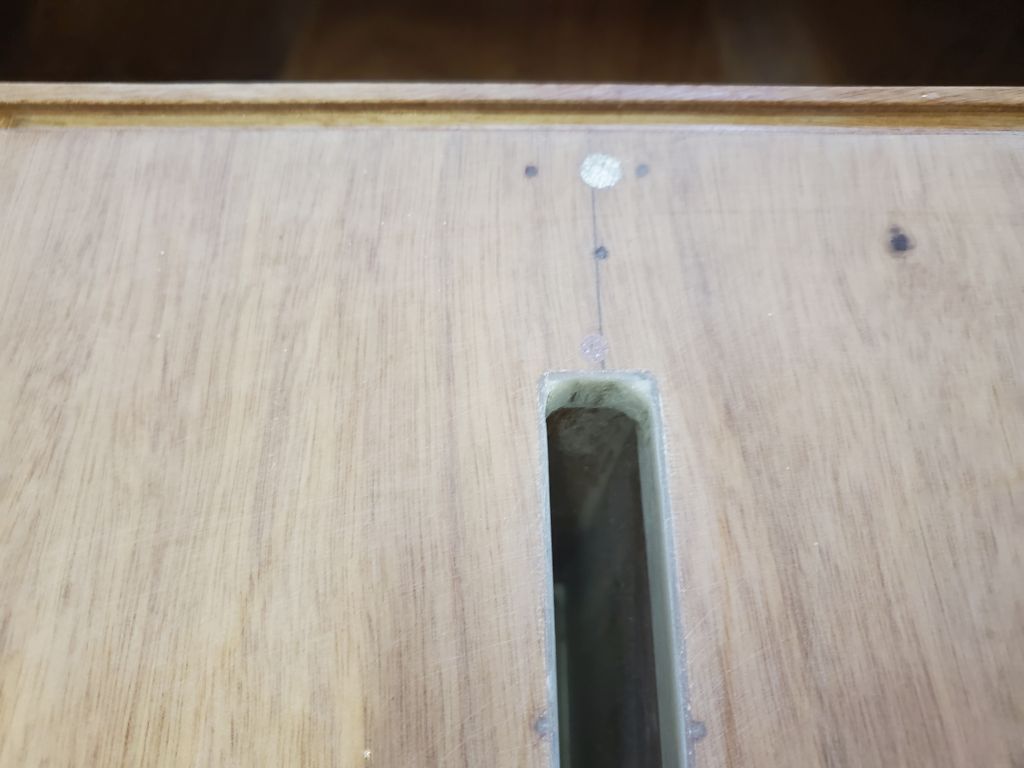
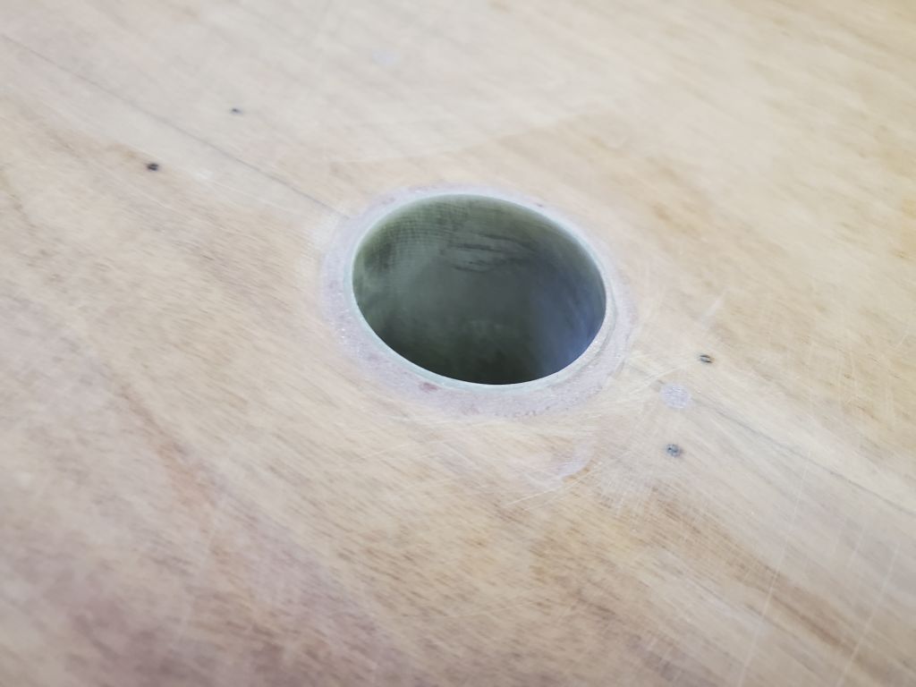
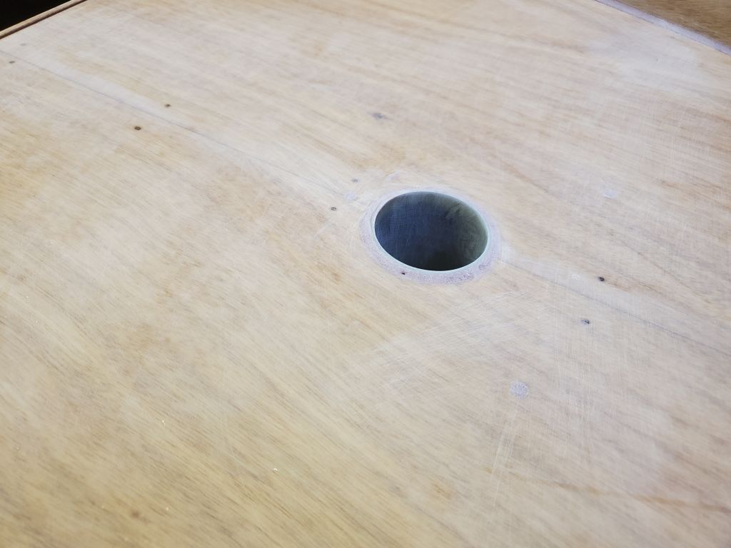
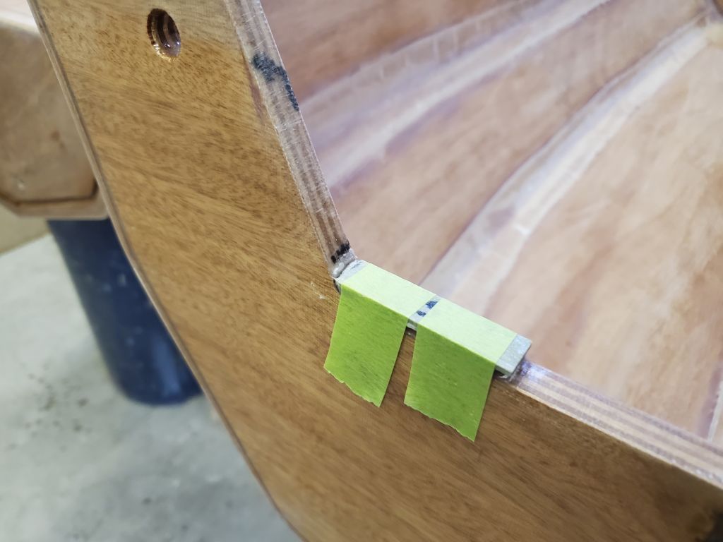
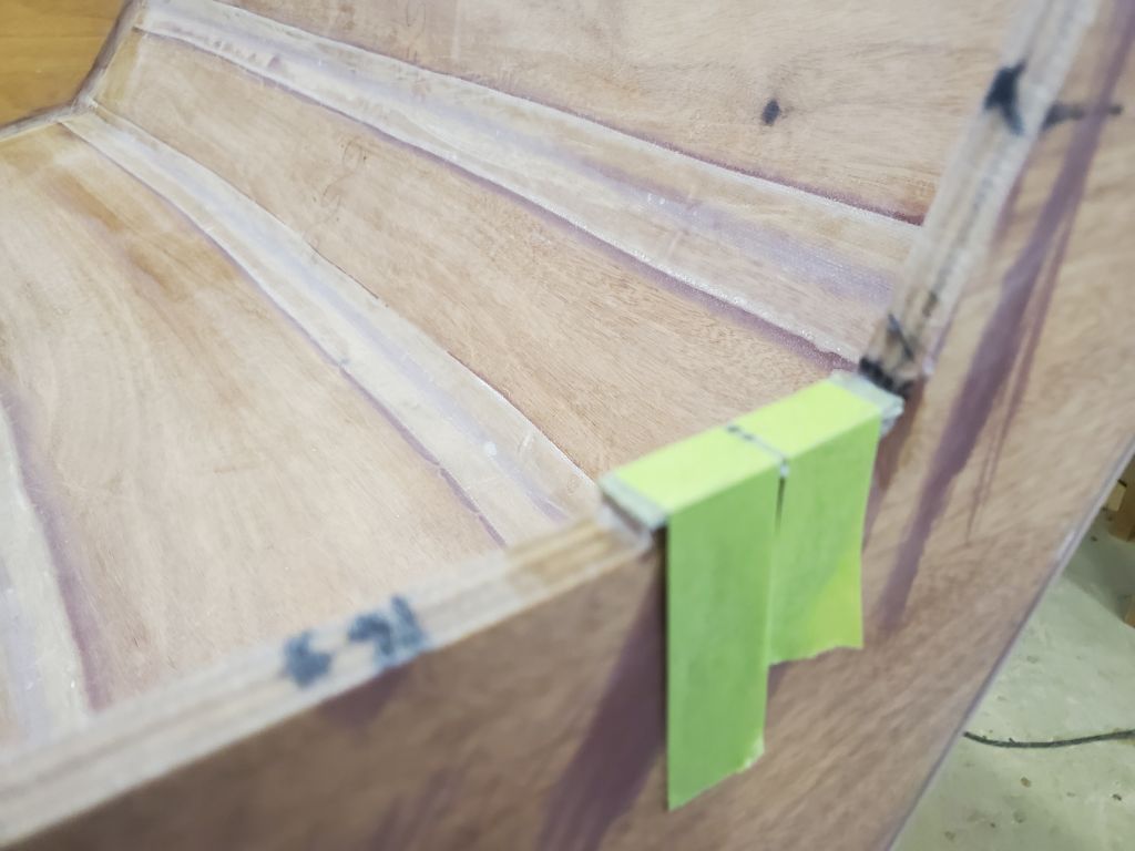
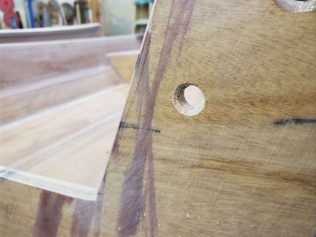
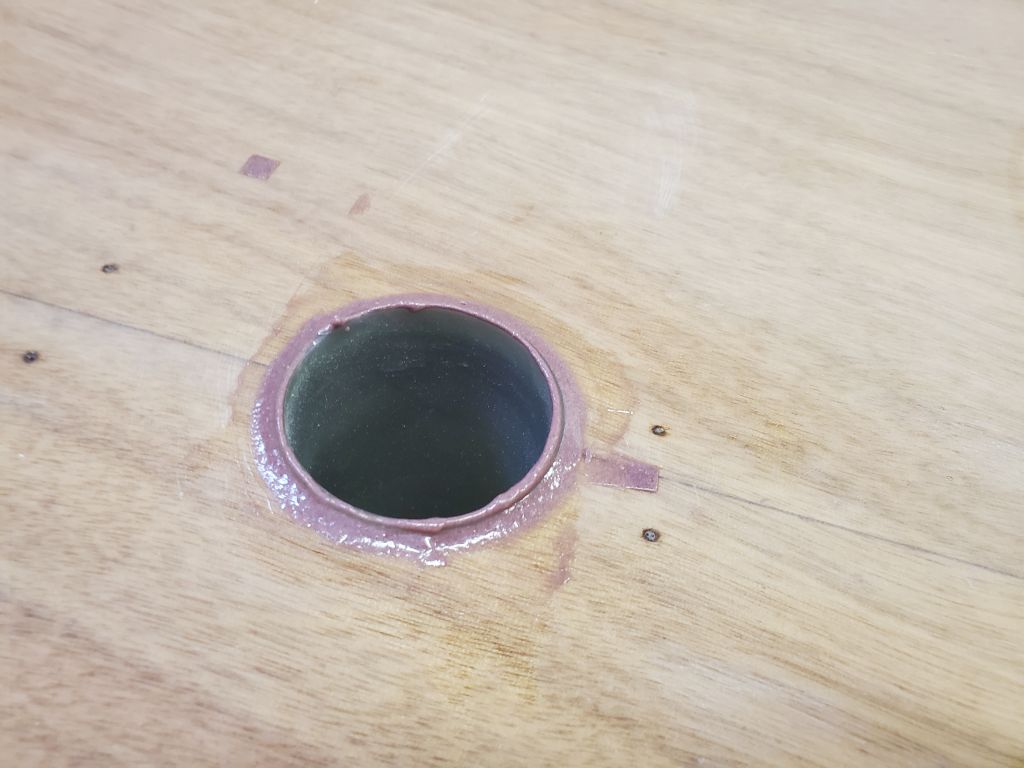
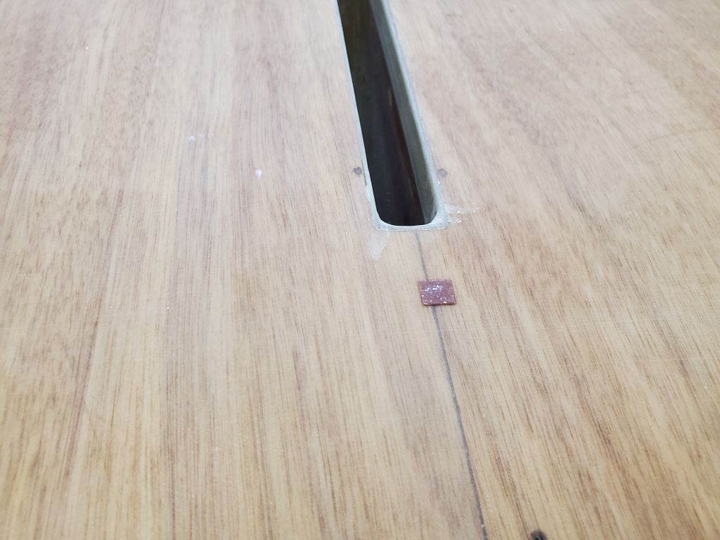
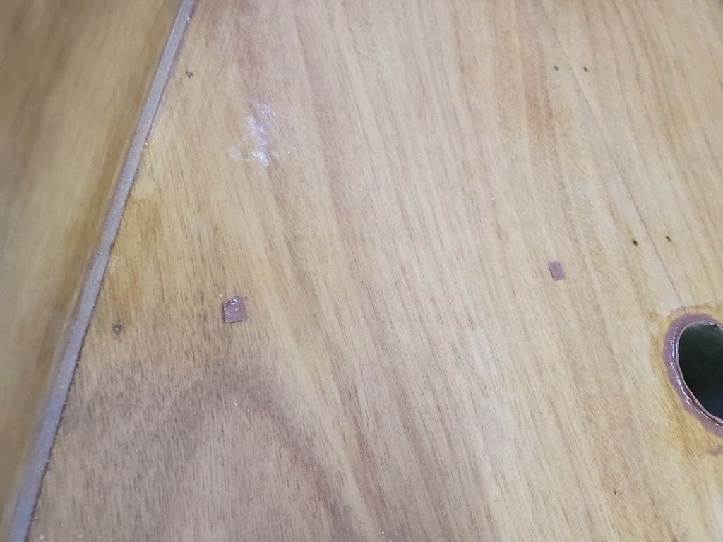
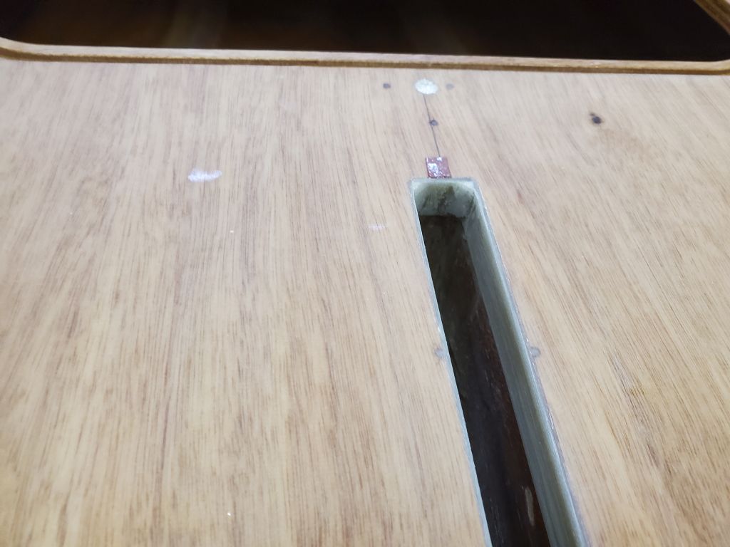
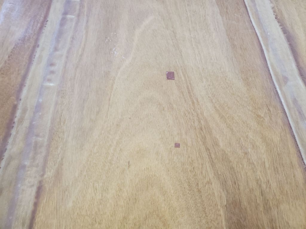
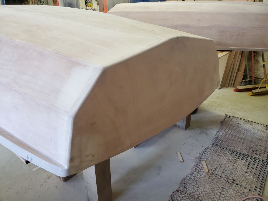
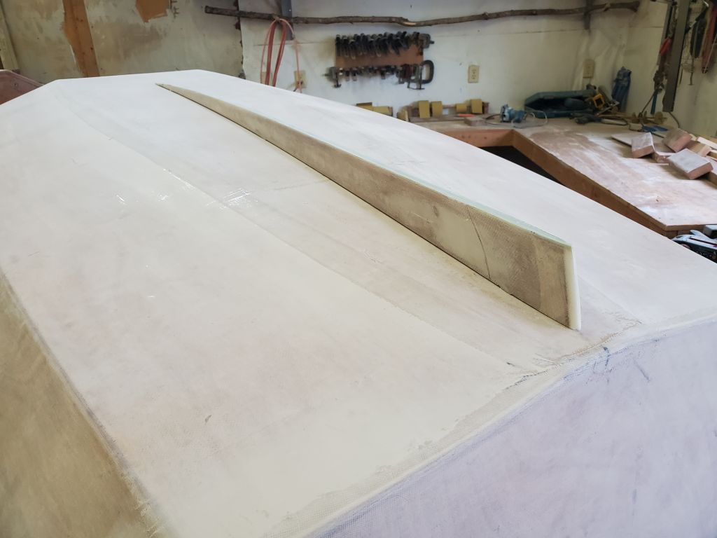
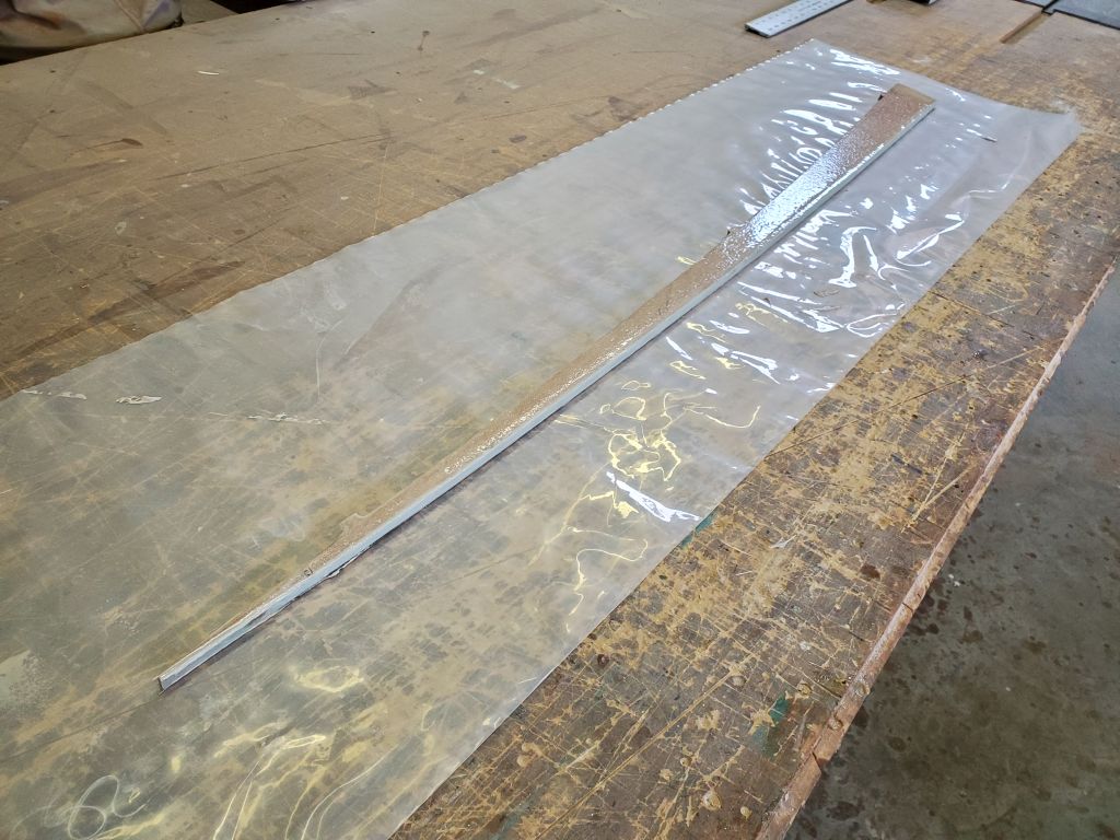
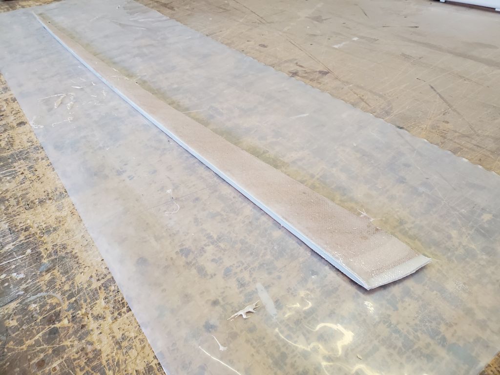
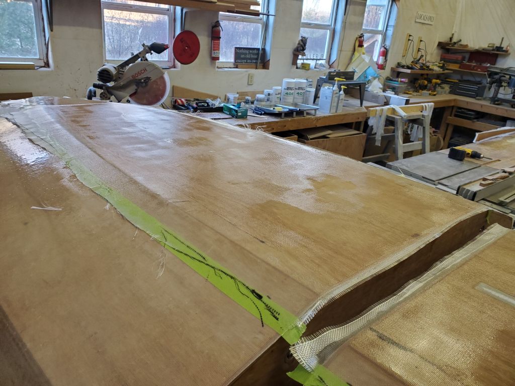
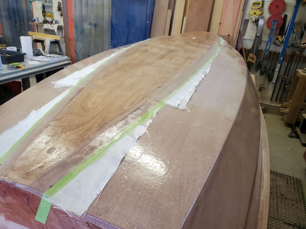
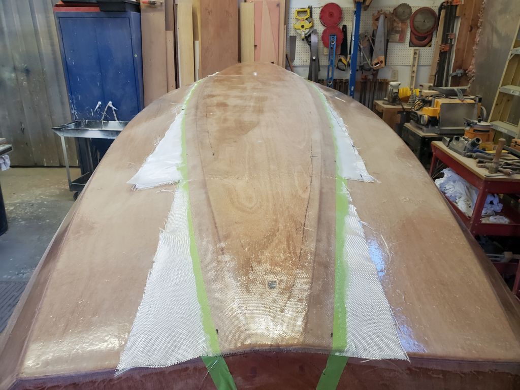
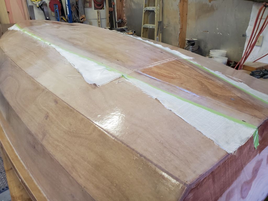
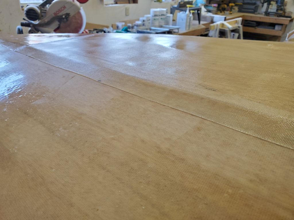
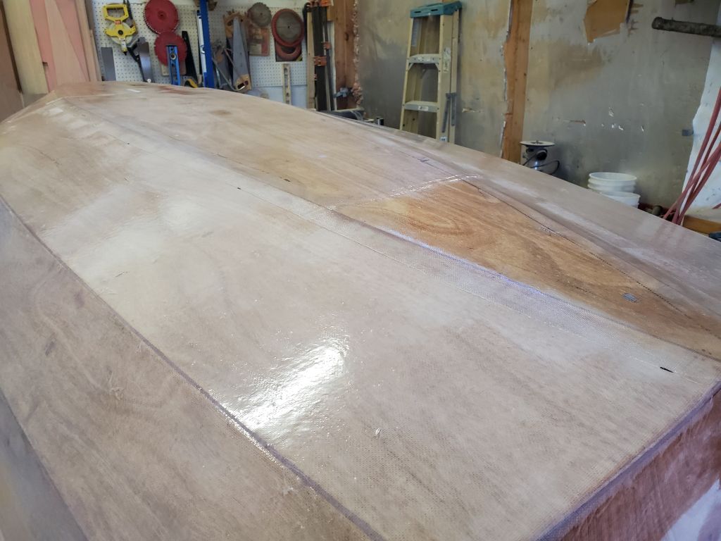
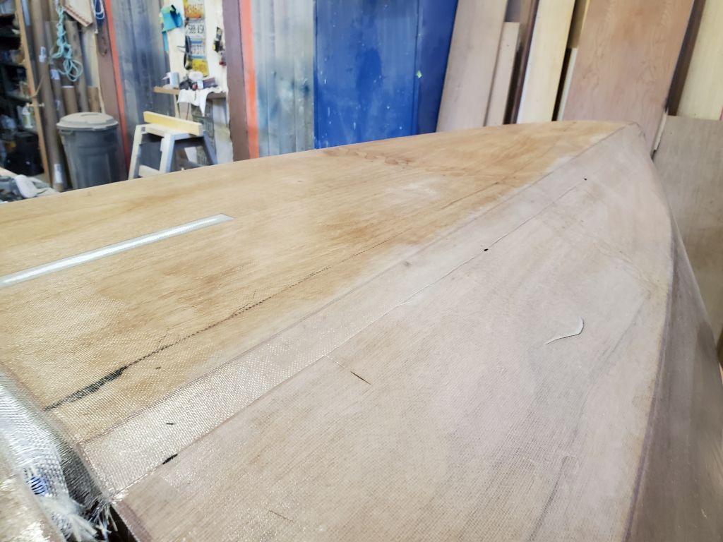
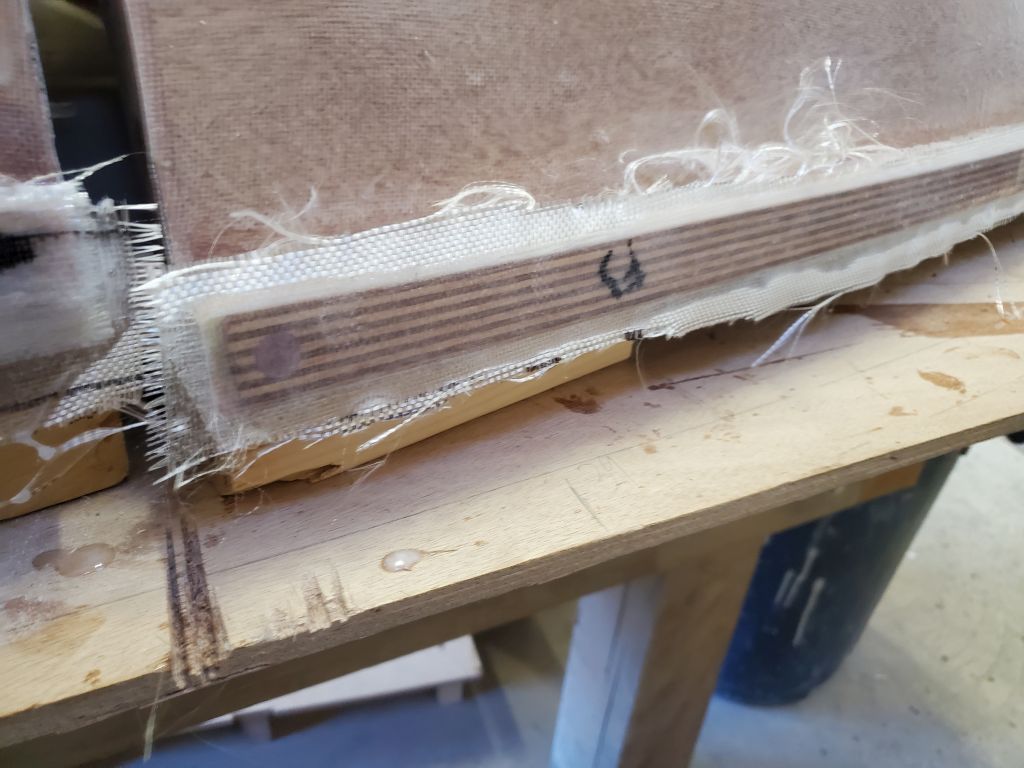
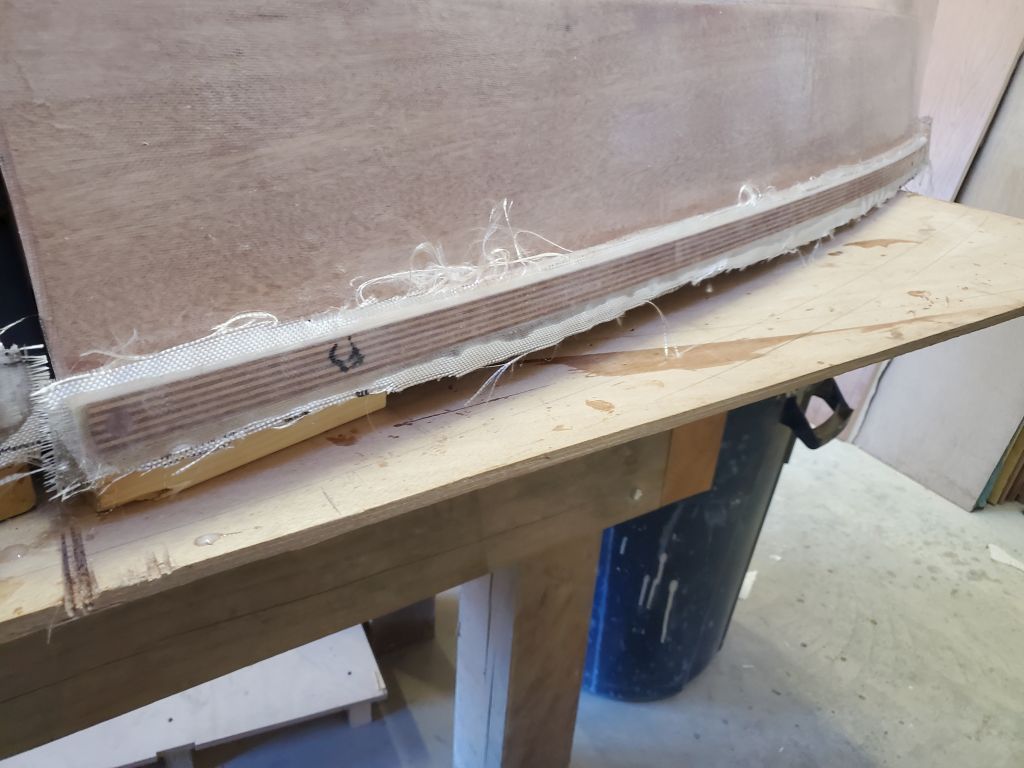
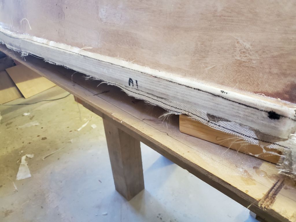
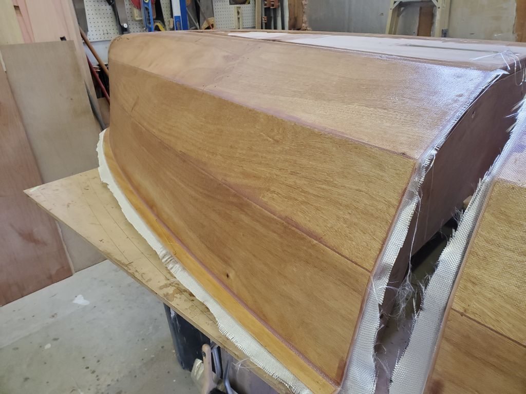
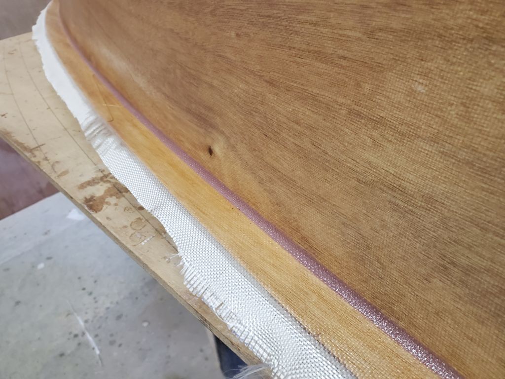
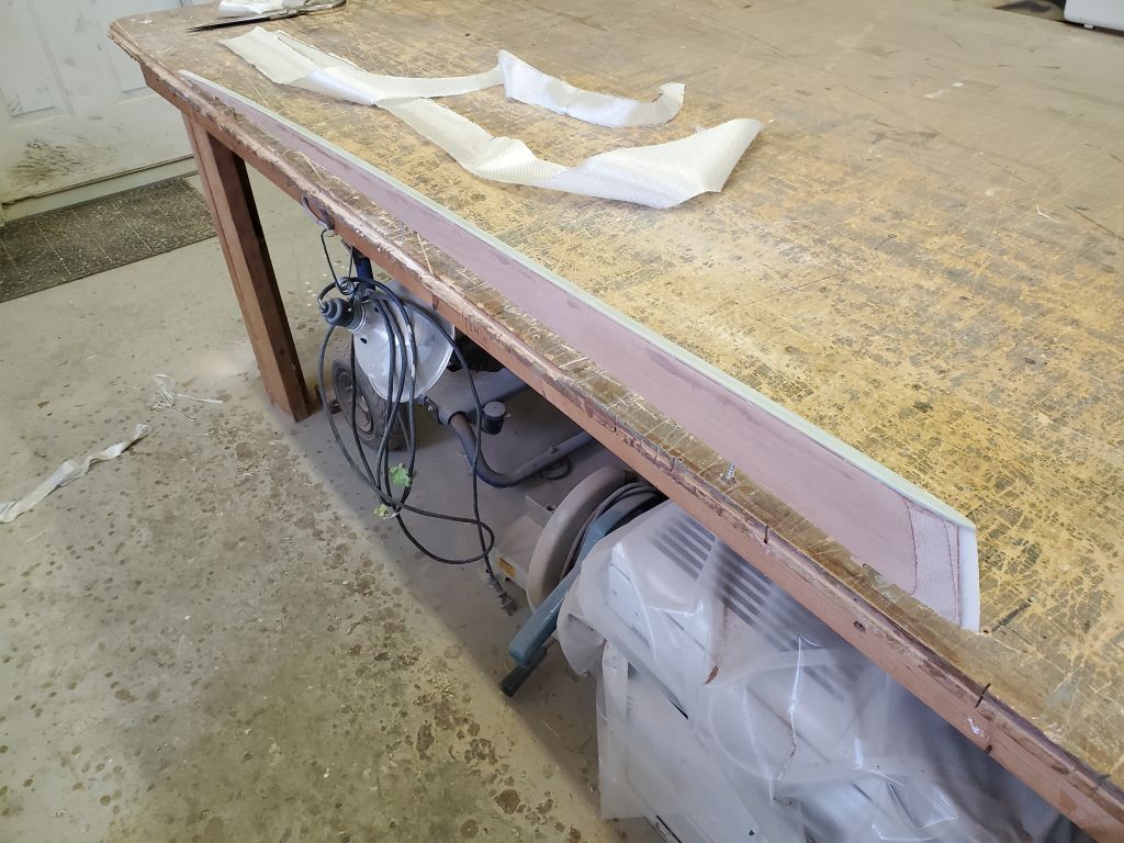
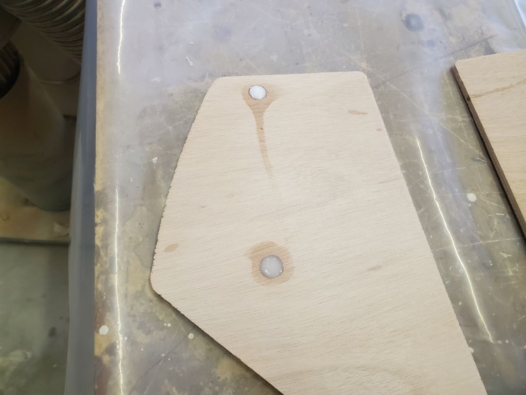
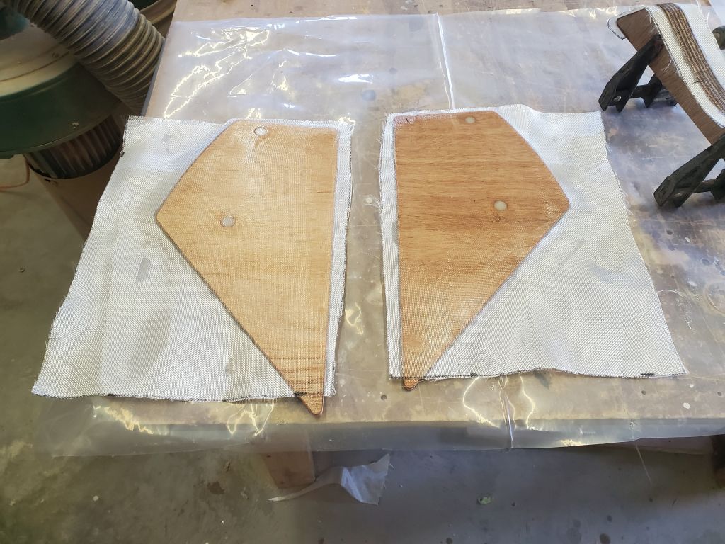
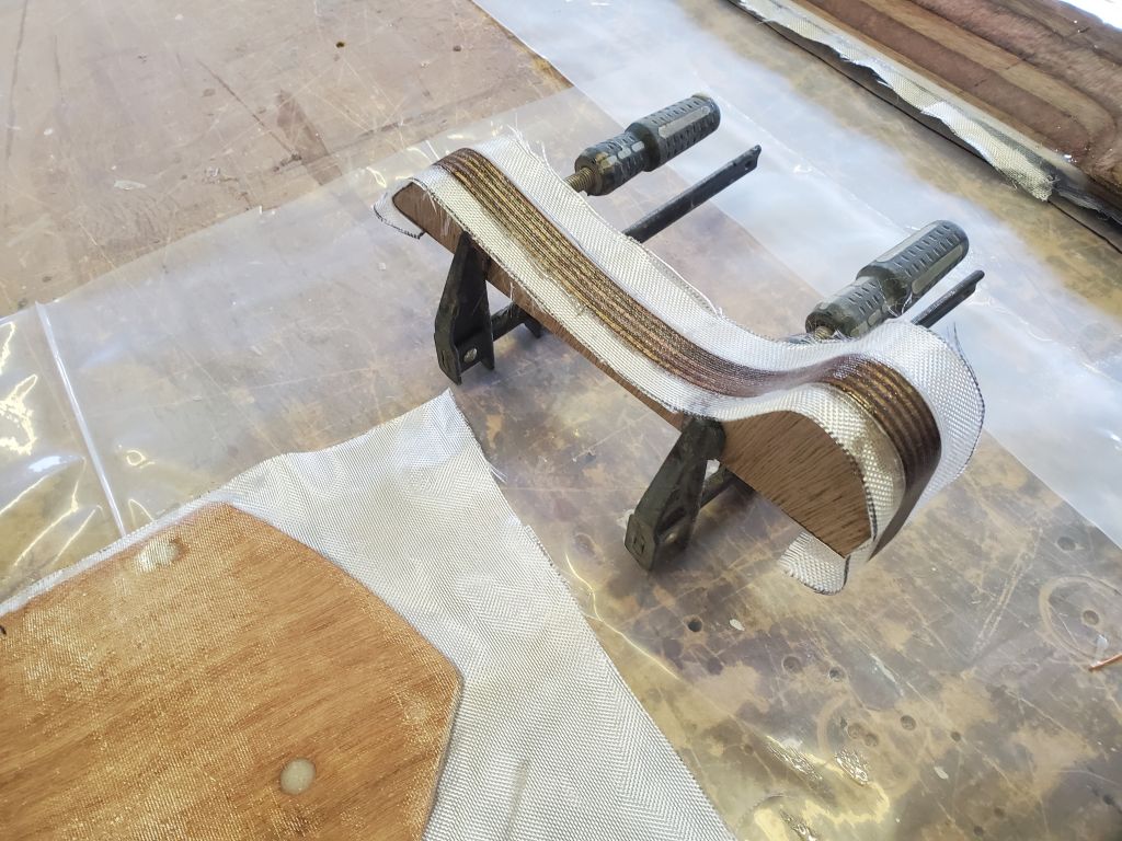
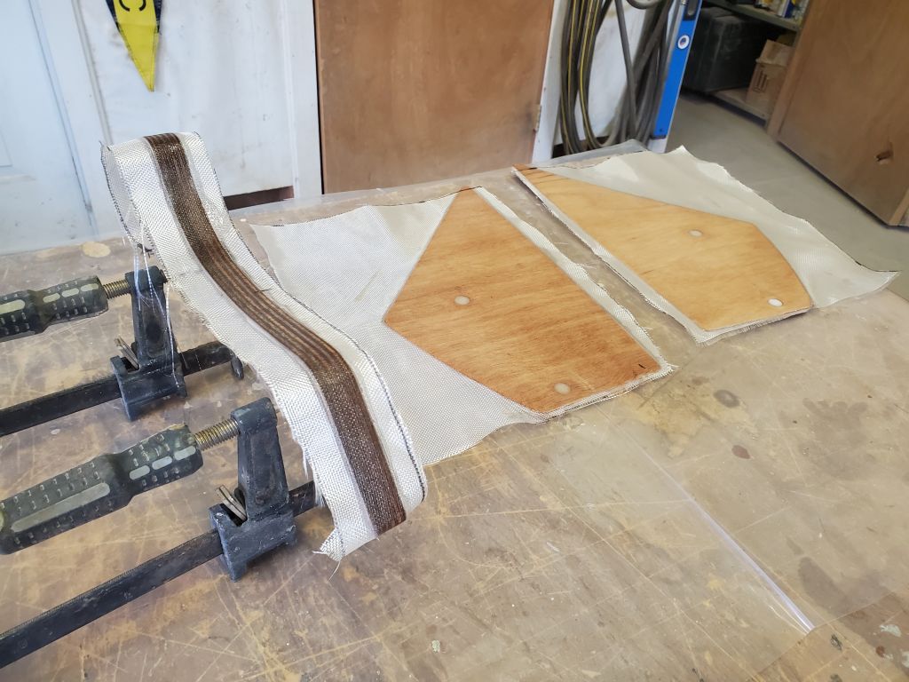
I trimmed the overhanging fiberglass from the rudder case spacer piece, and sanded flush the four filled holes in the two case sides (one hole leaked out around the tape at the bottom, so I added some extra filler now). Then, I installed a layer of 4-oz fiberglass over each plywood panel; the fiberglass as cut to the prescribed size didn’t cover the lowest parts of the case, and the book made it clear it was not necessary. I also installed a 2″ wide strip of 4 oz. cloth over the curvy edge of the spacer; this wrapped under and onto the straight edge by under an inch on each end..

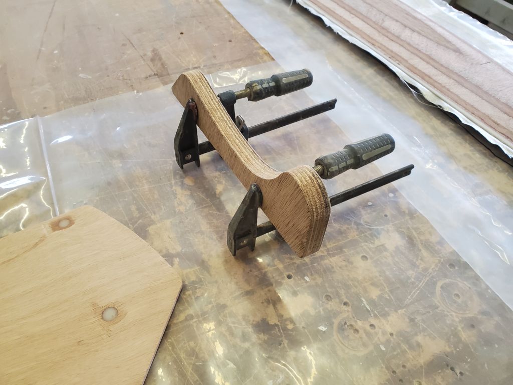
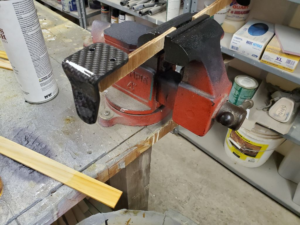
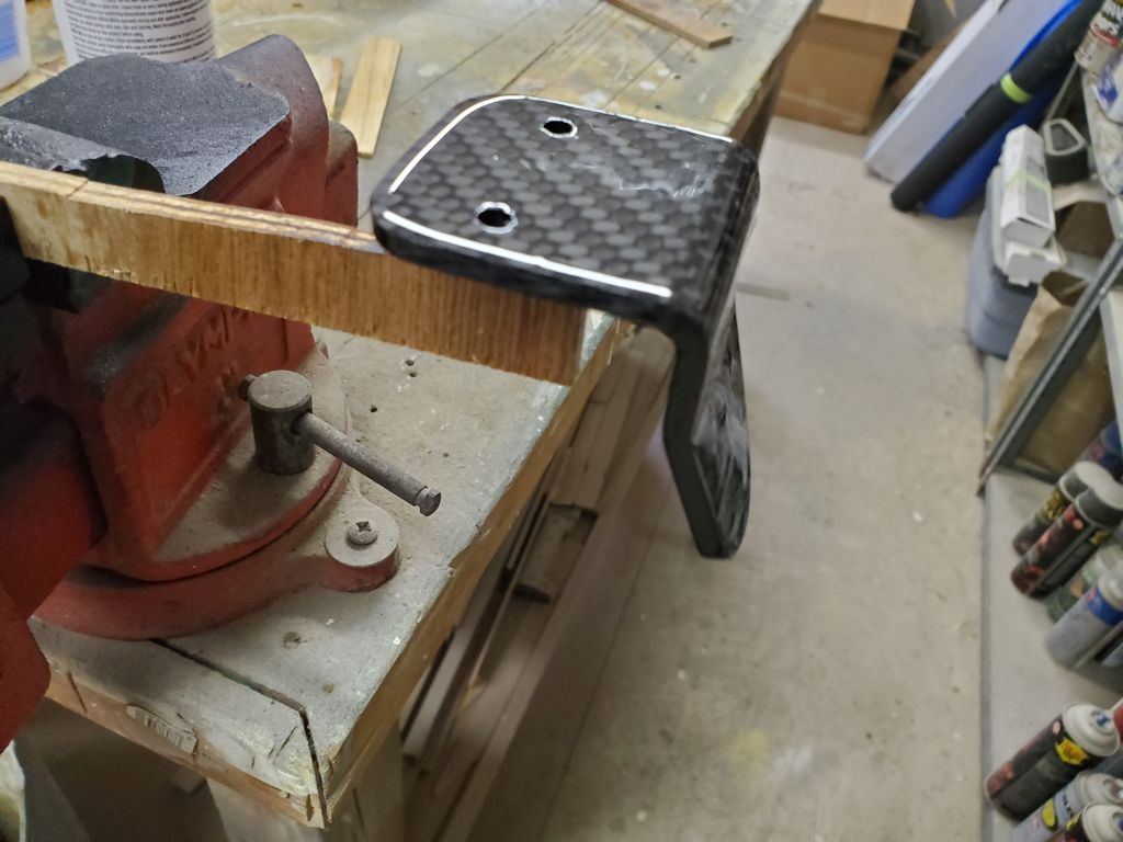
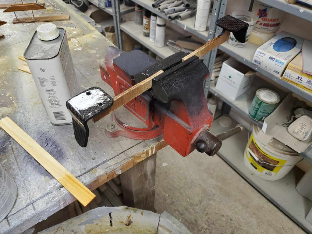
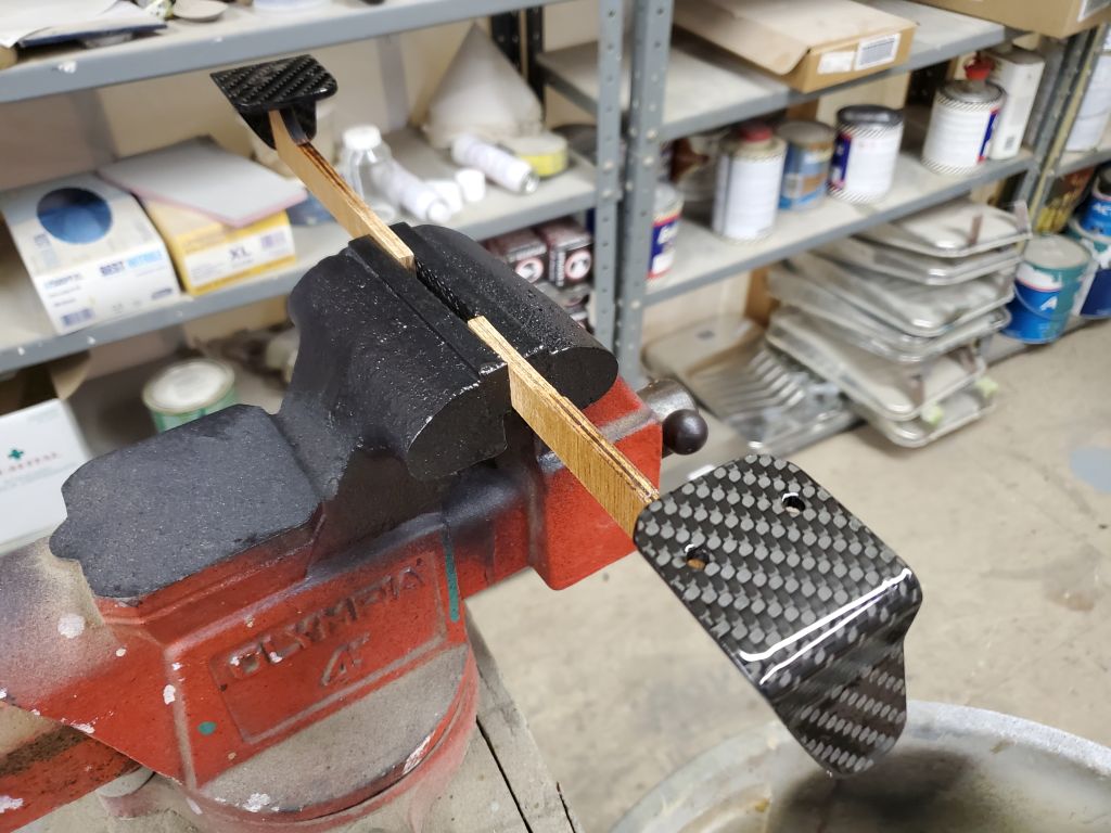
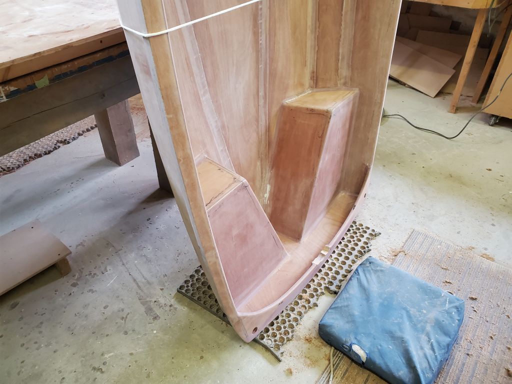
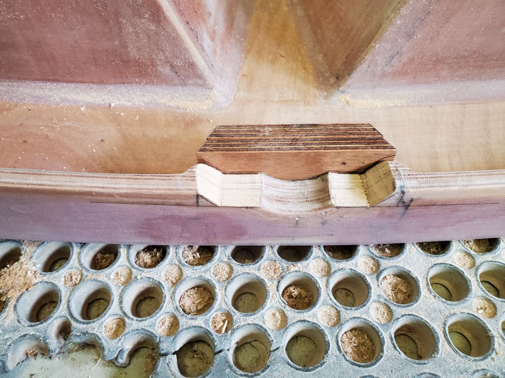
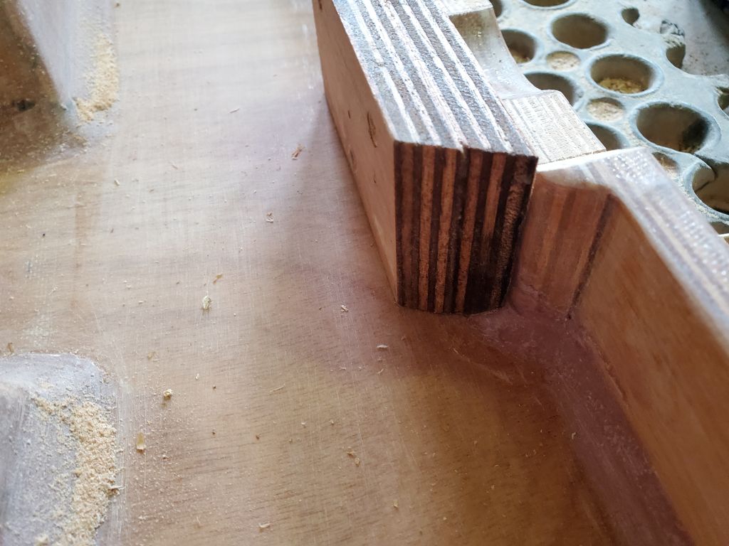
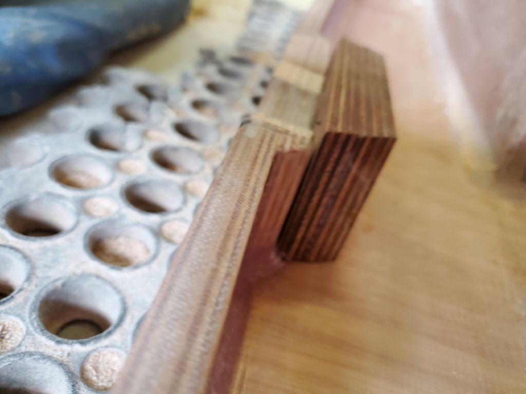
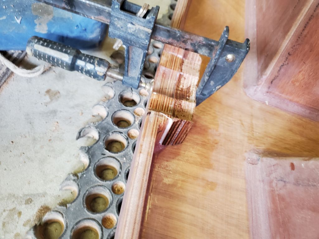
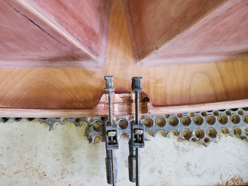
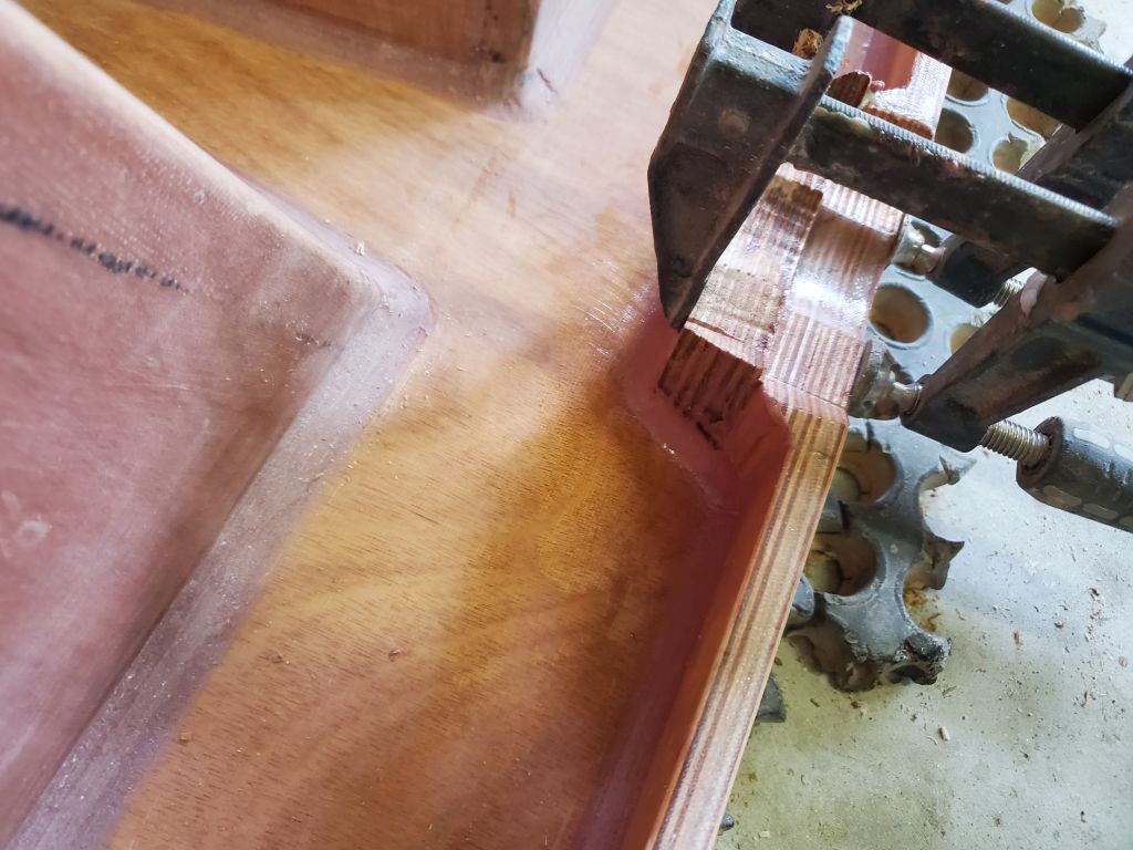
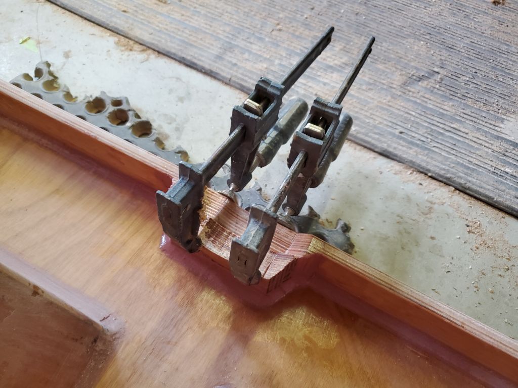
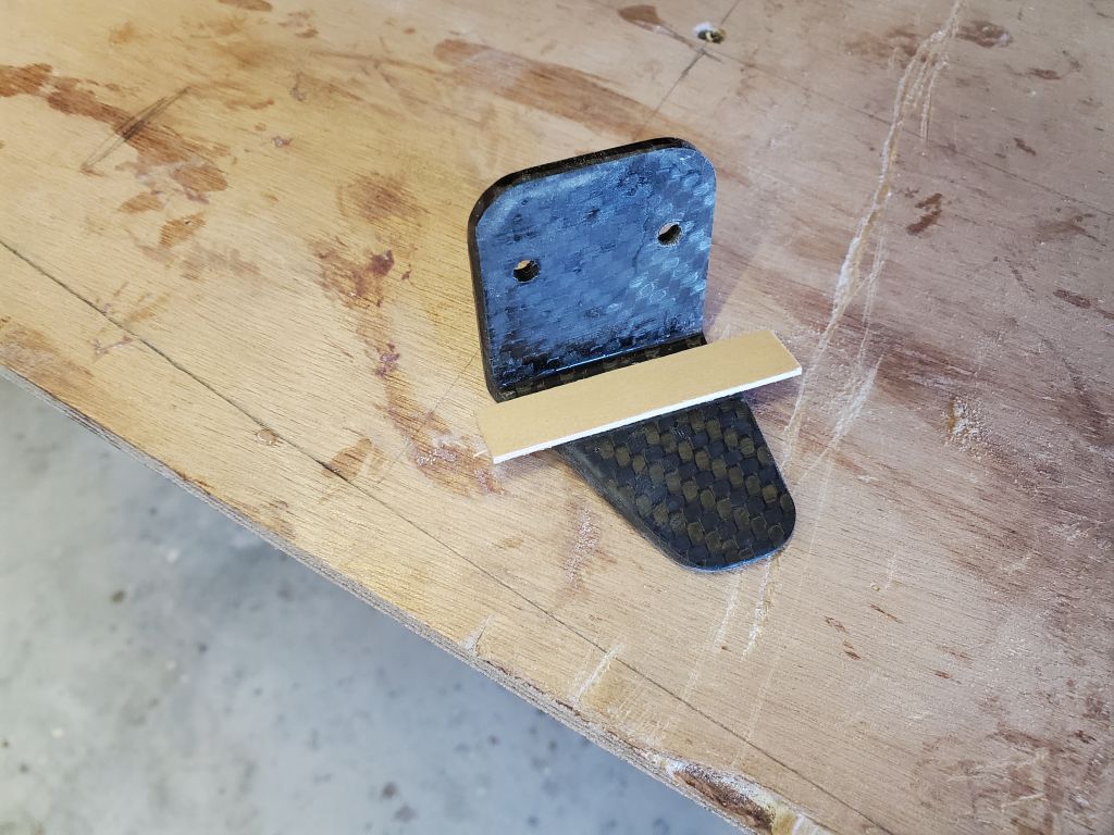
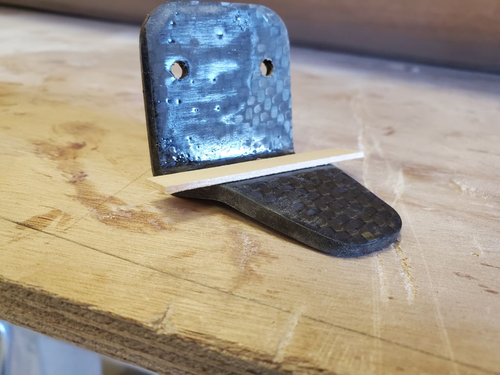
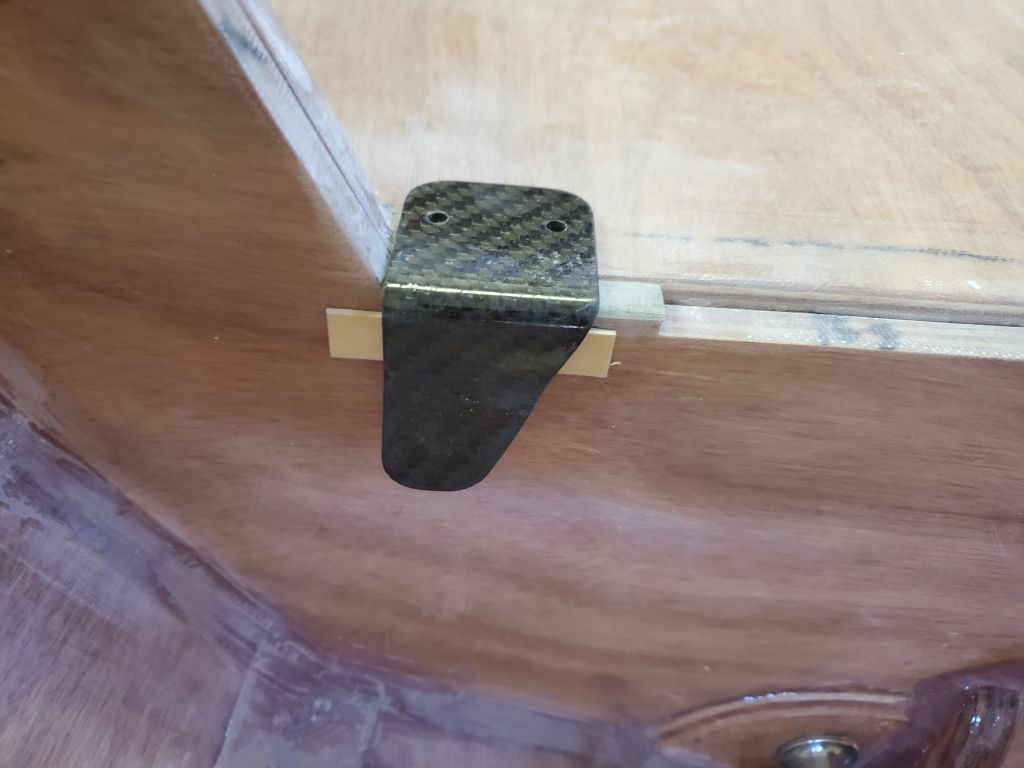
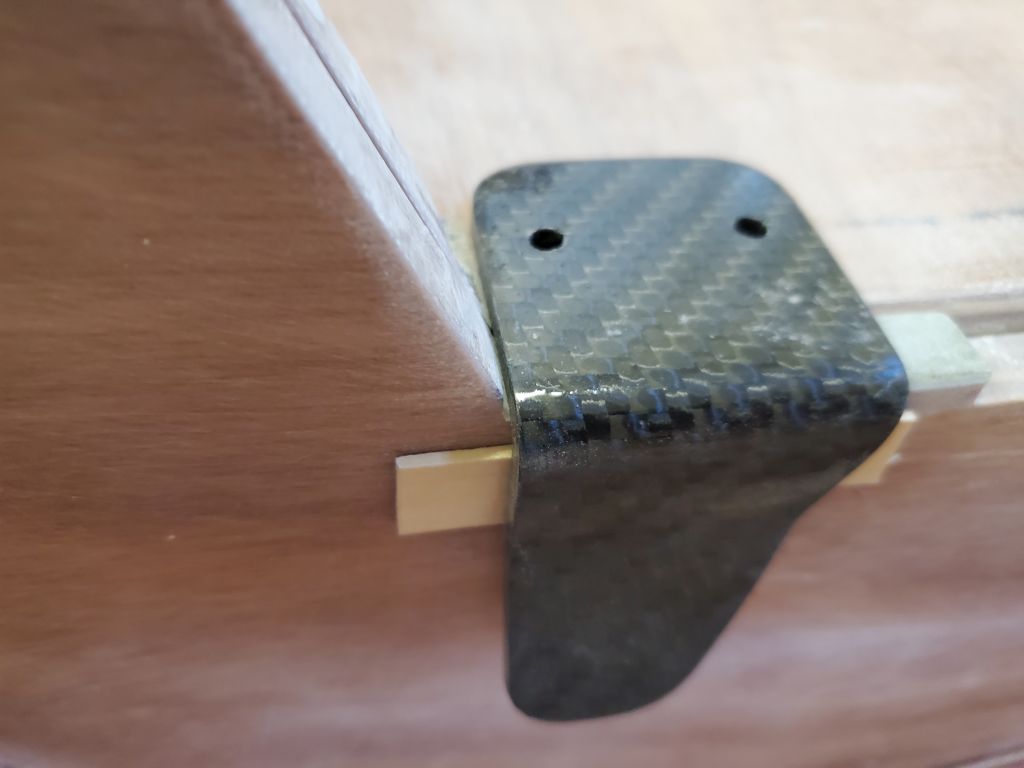
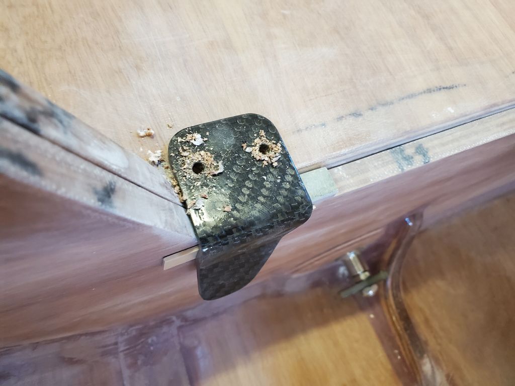
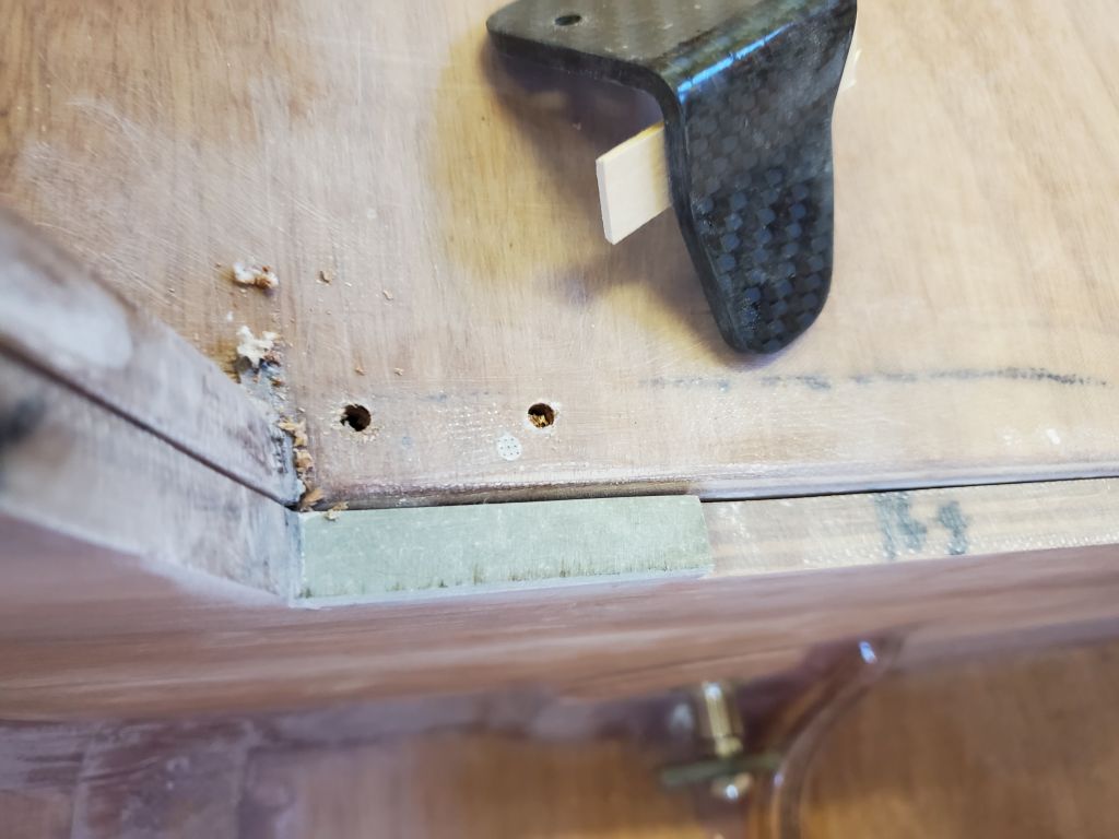
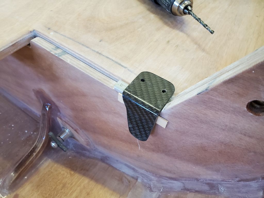
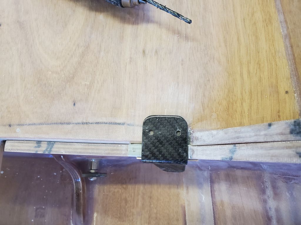
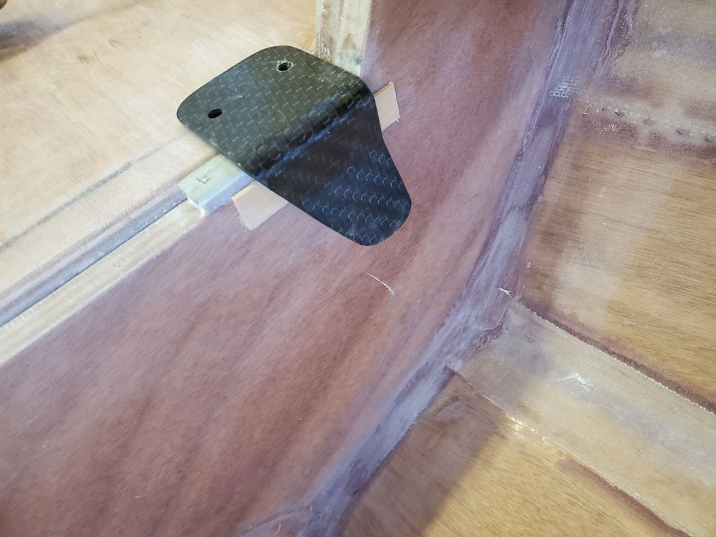
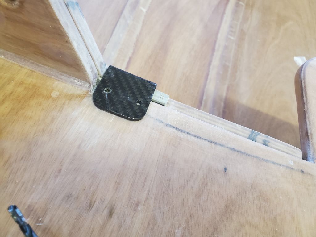
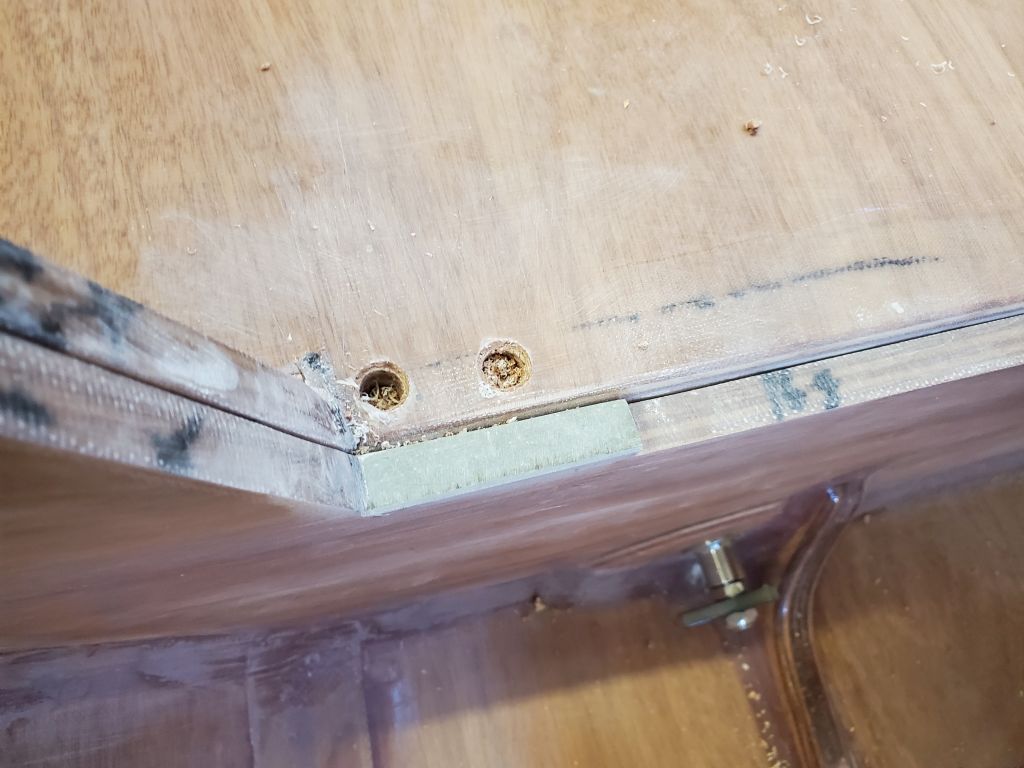
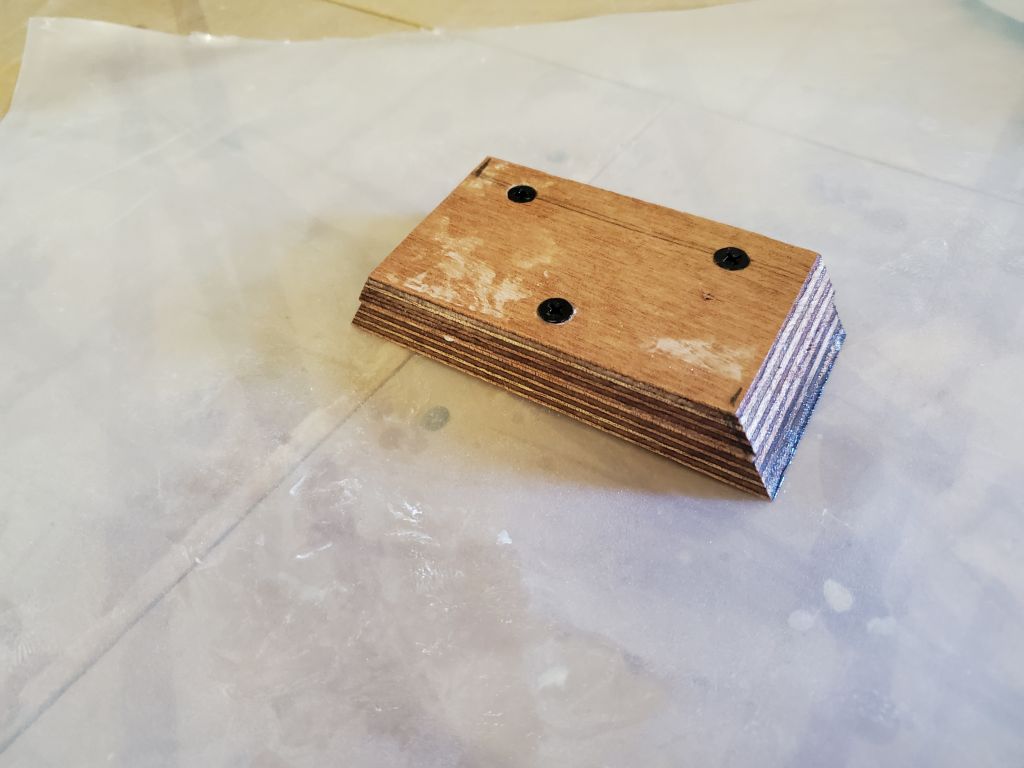
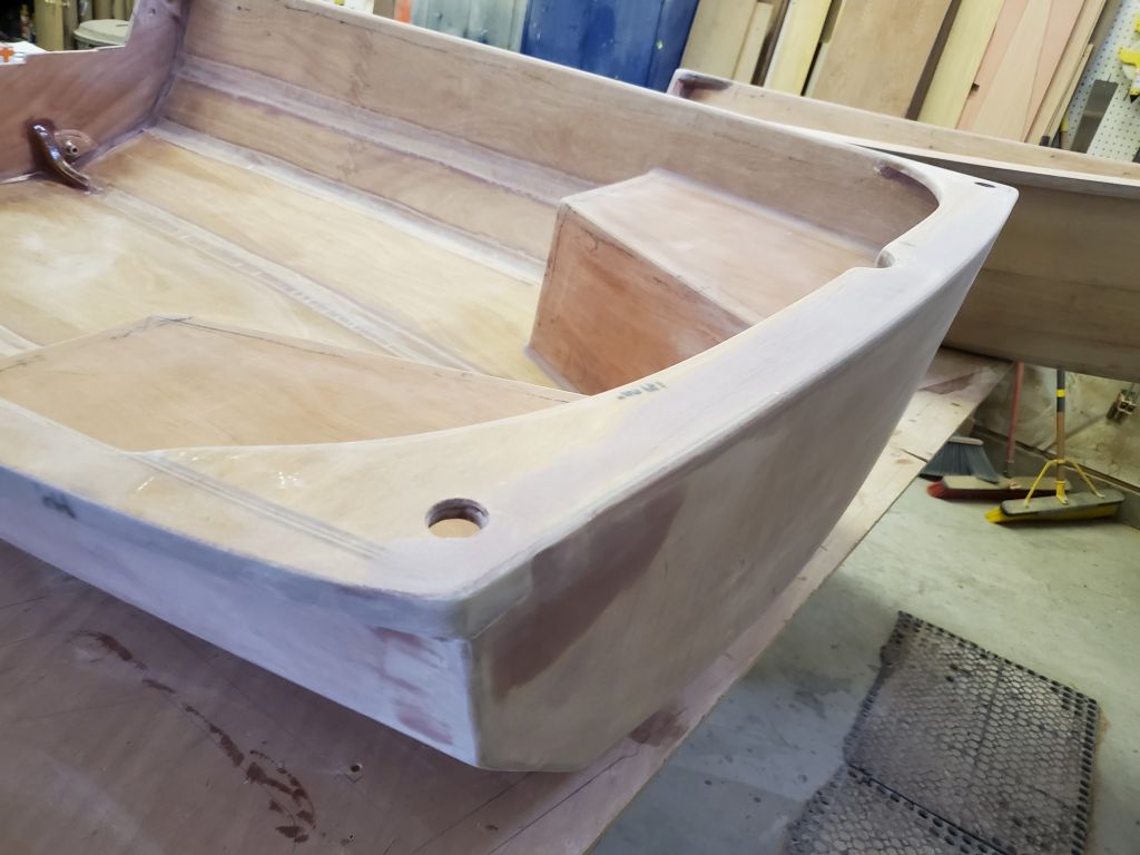
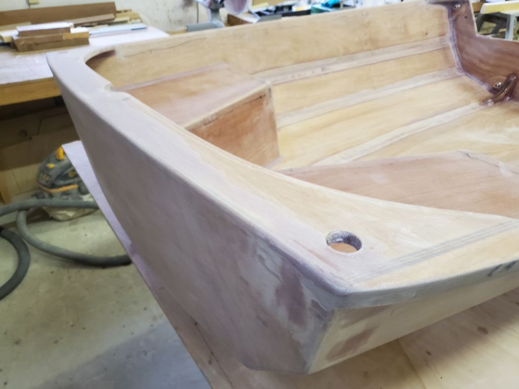
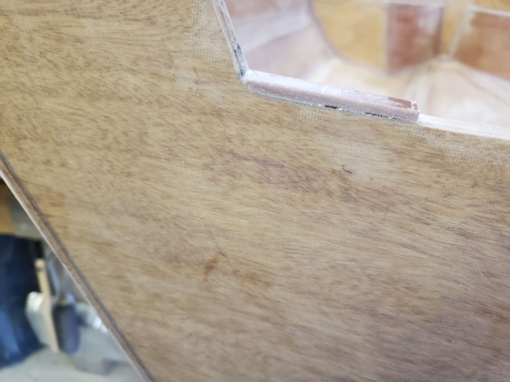
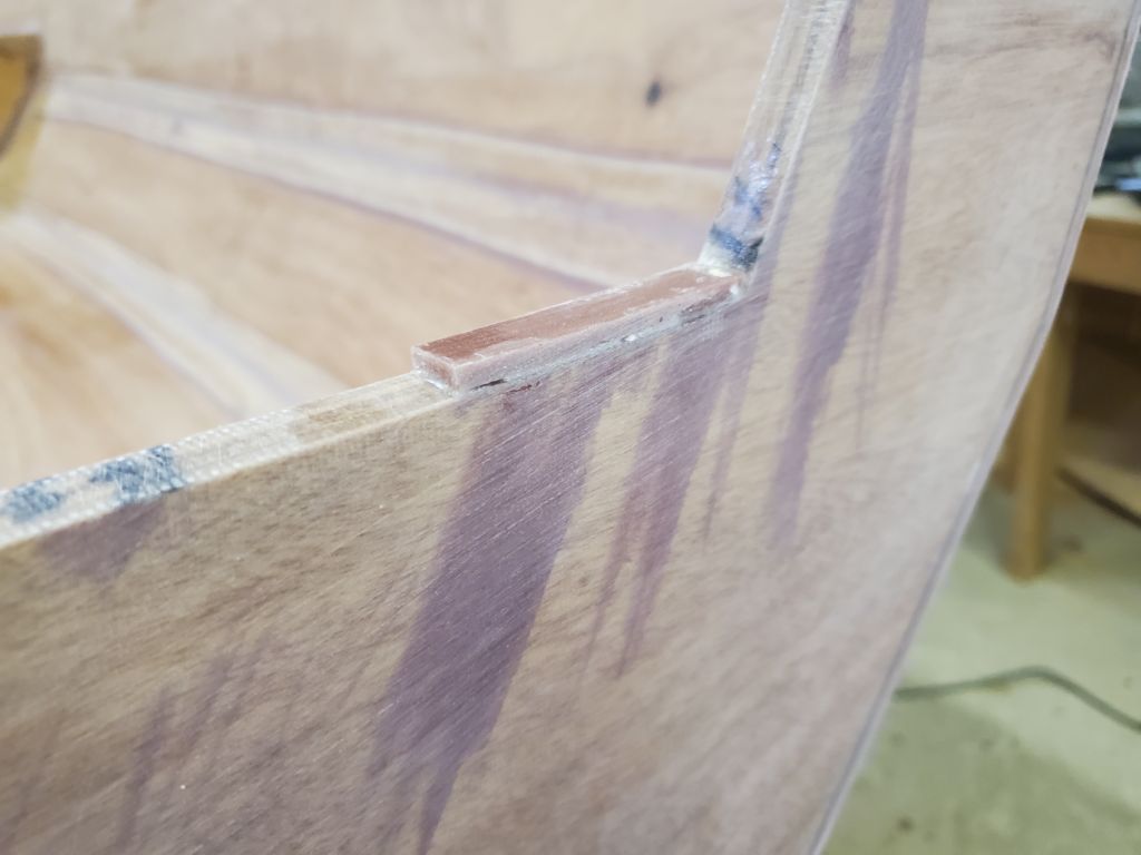
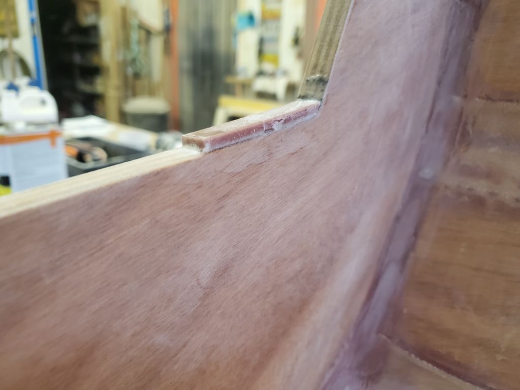
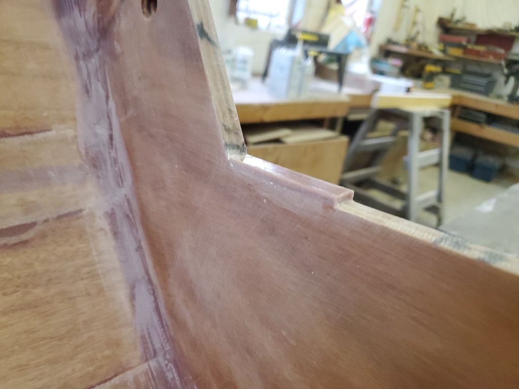
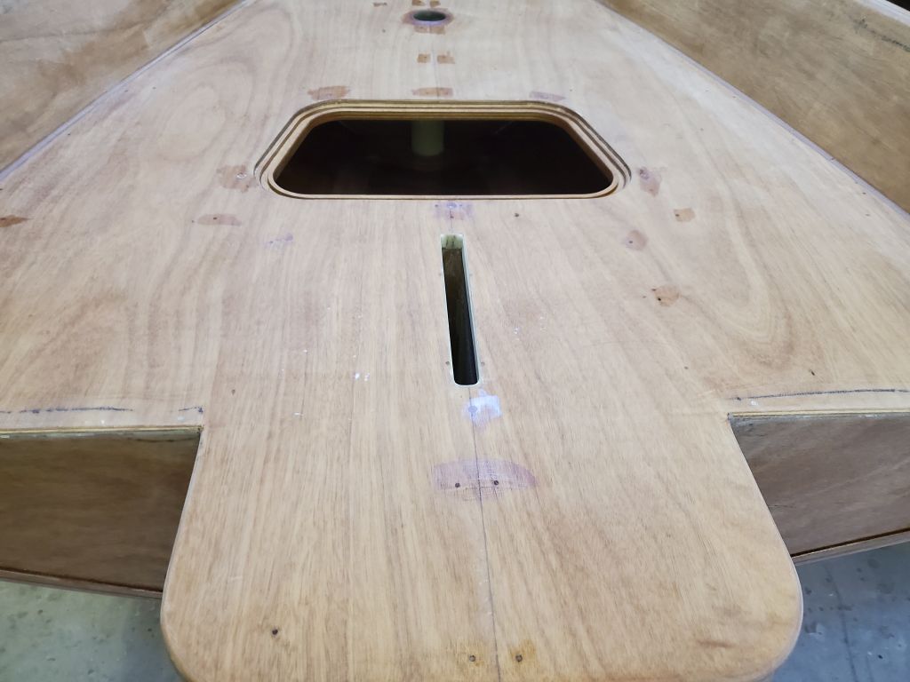
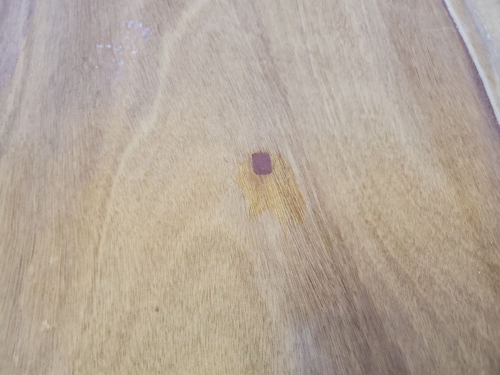
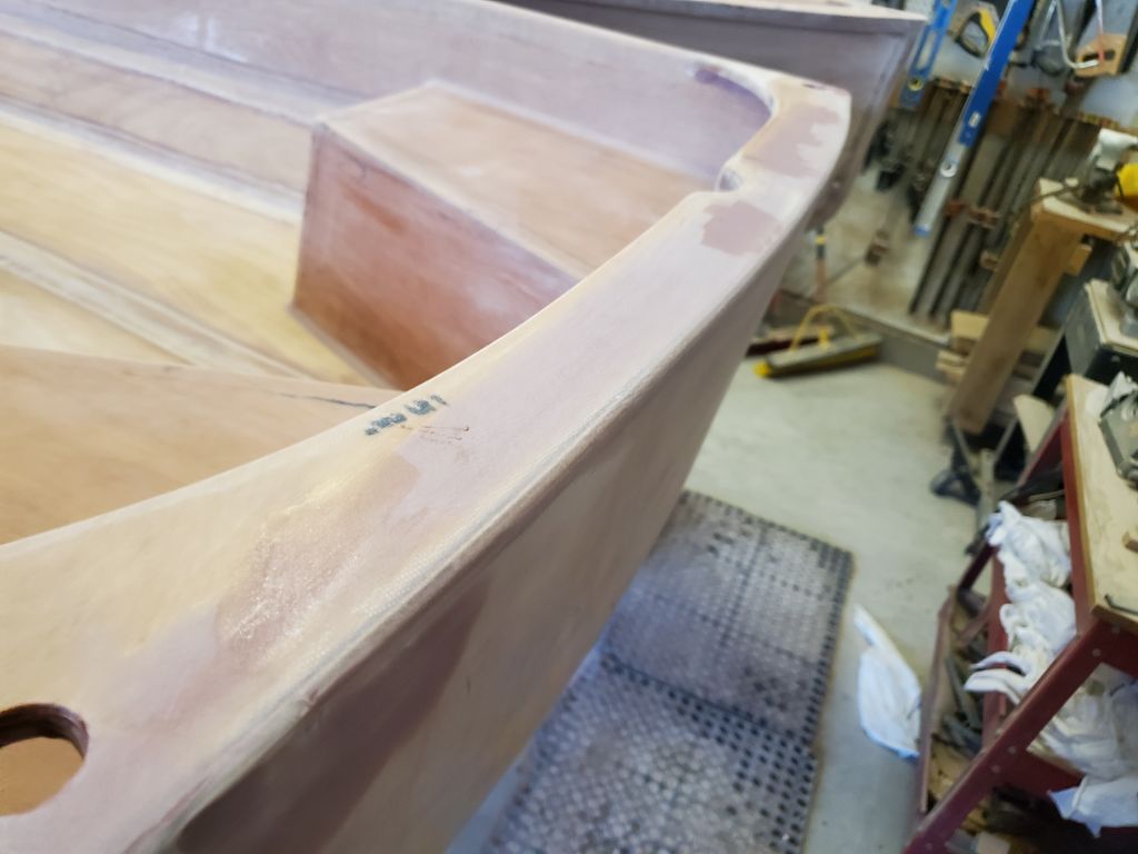
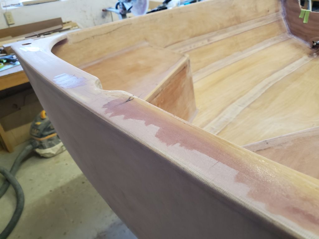
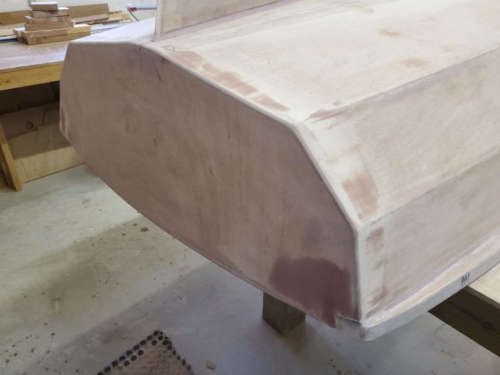
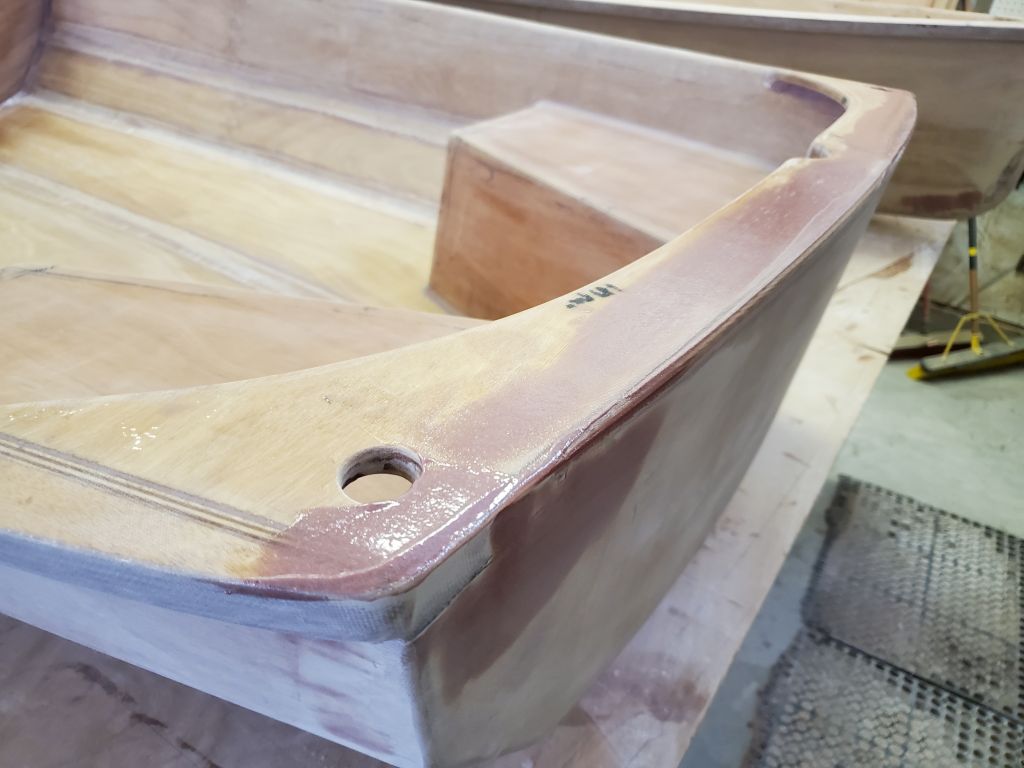
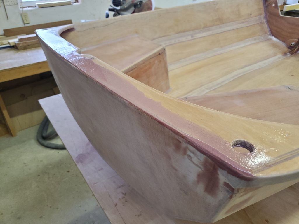
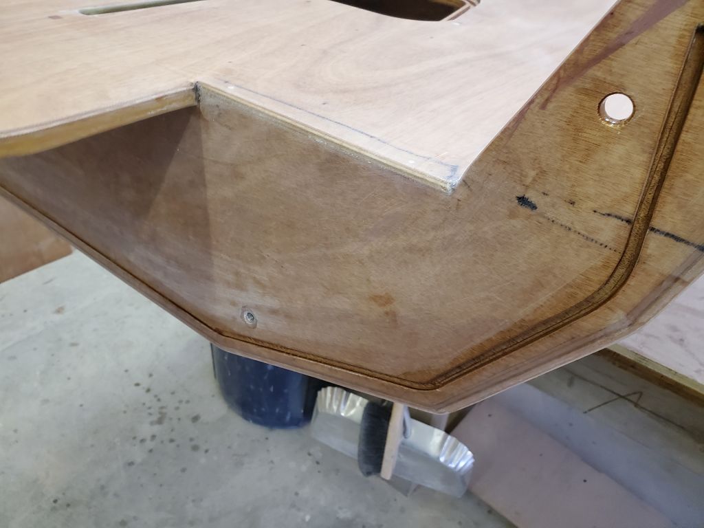
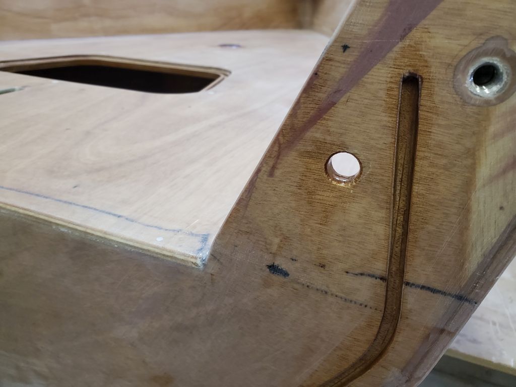
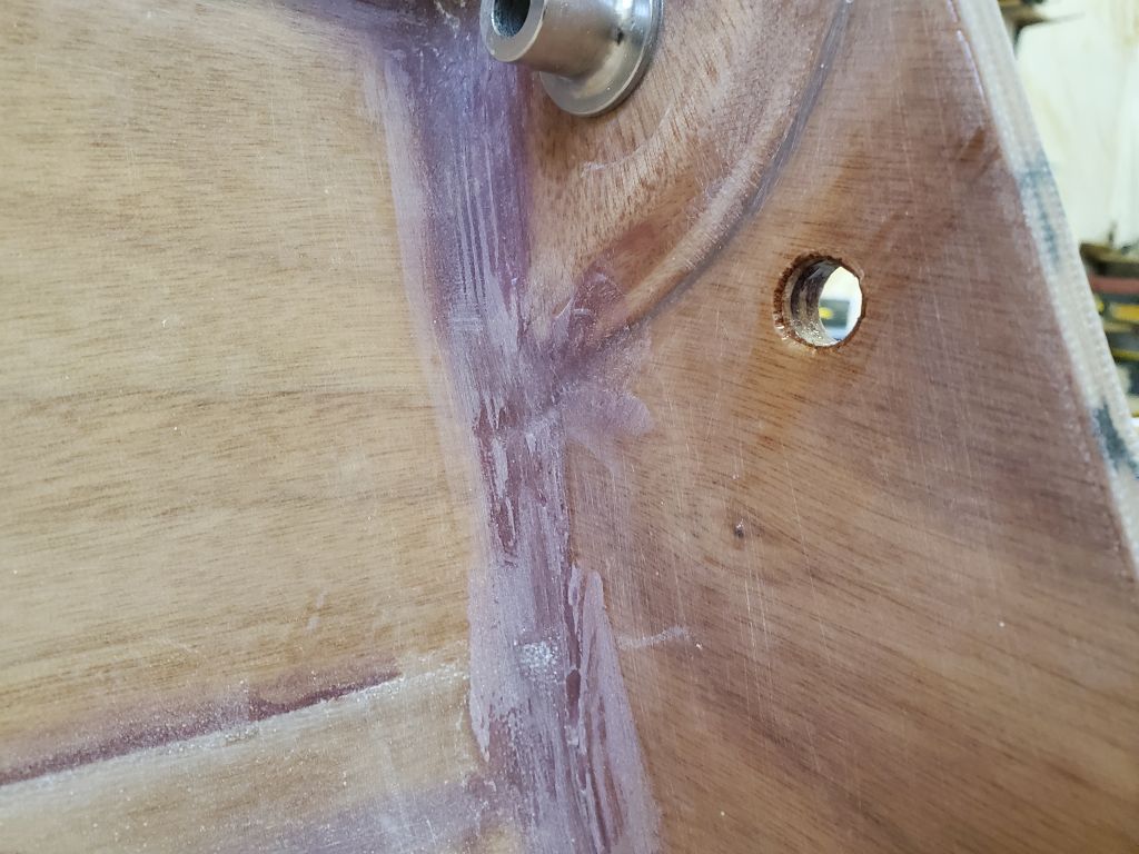
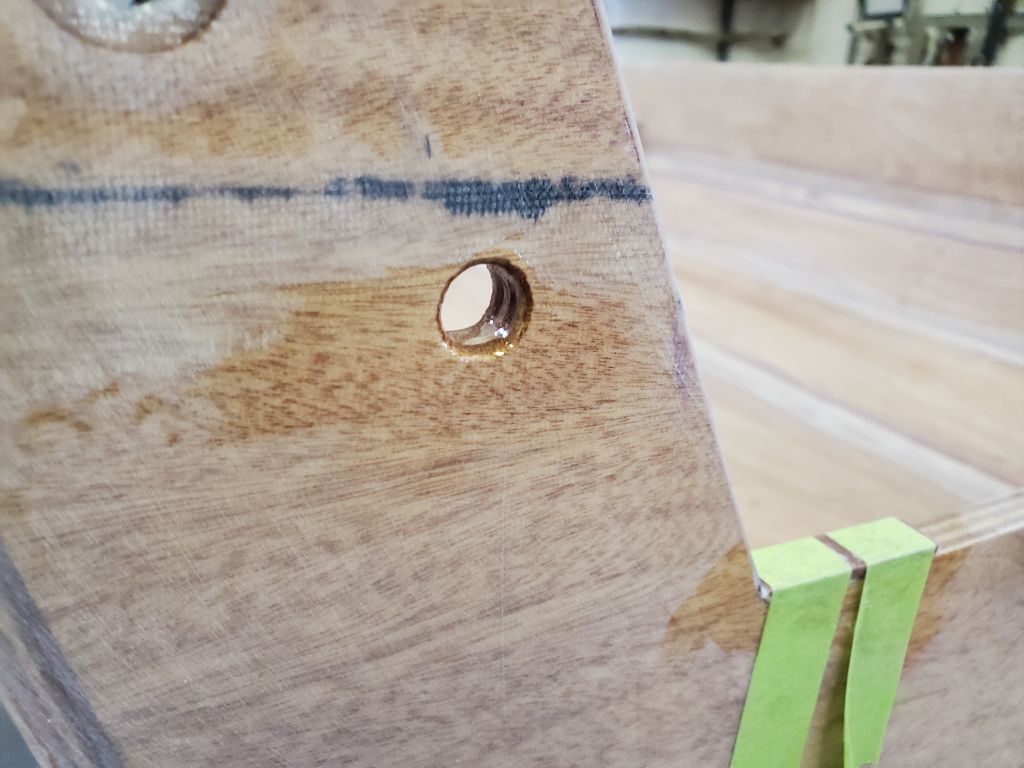
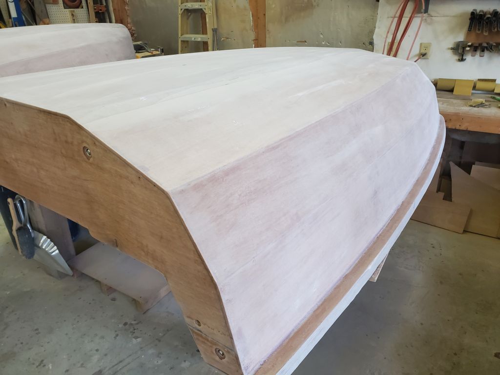
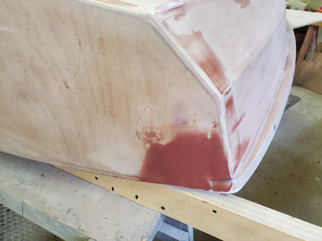
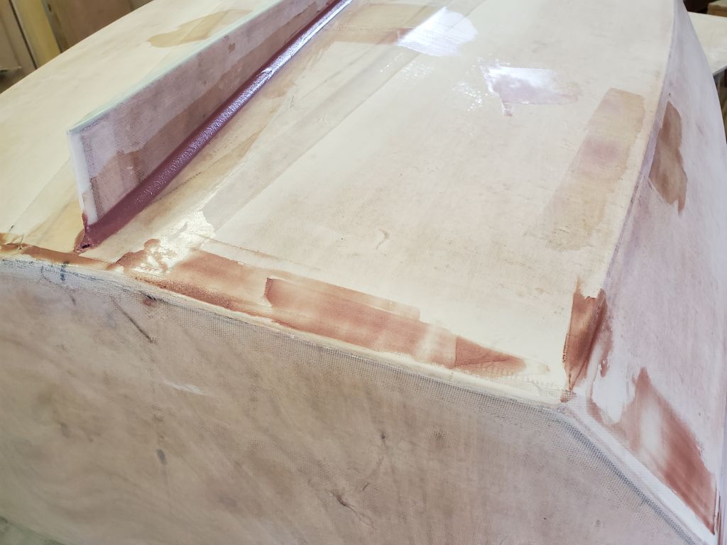
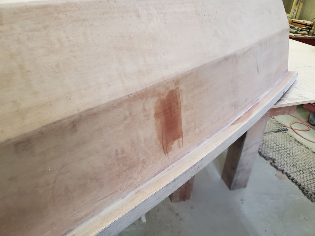
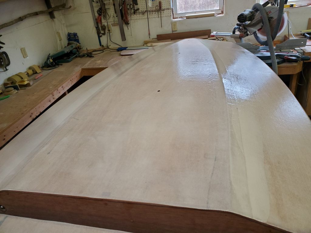
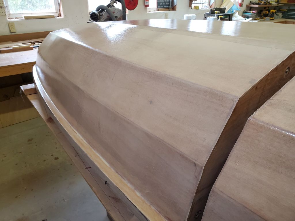
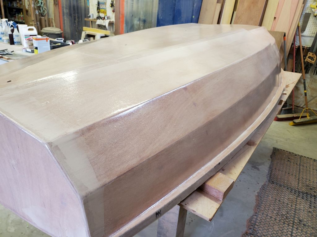
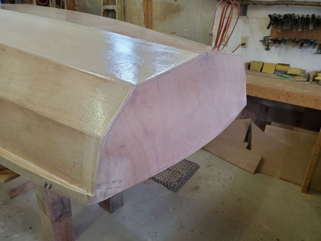
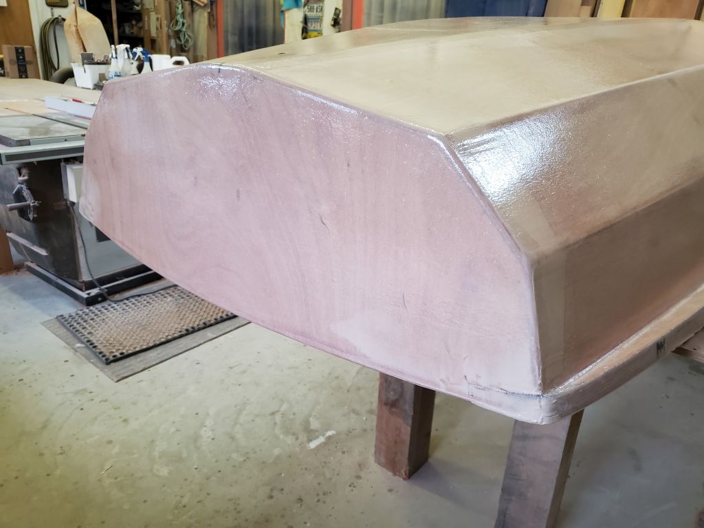
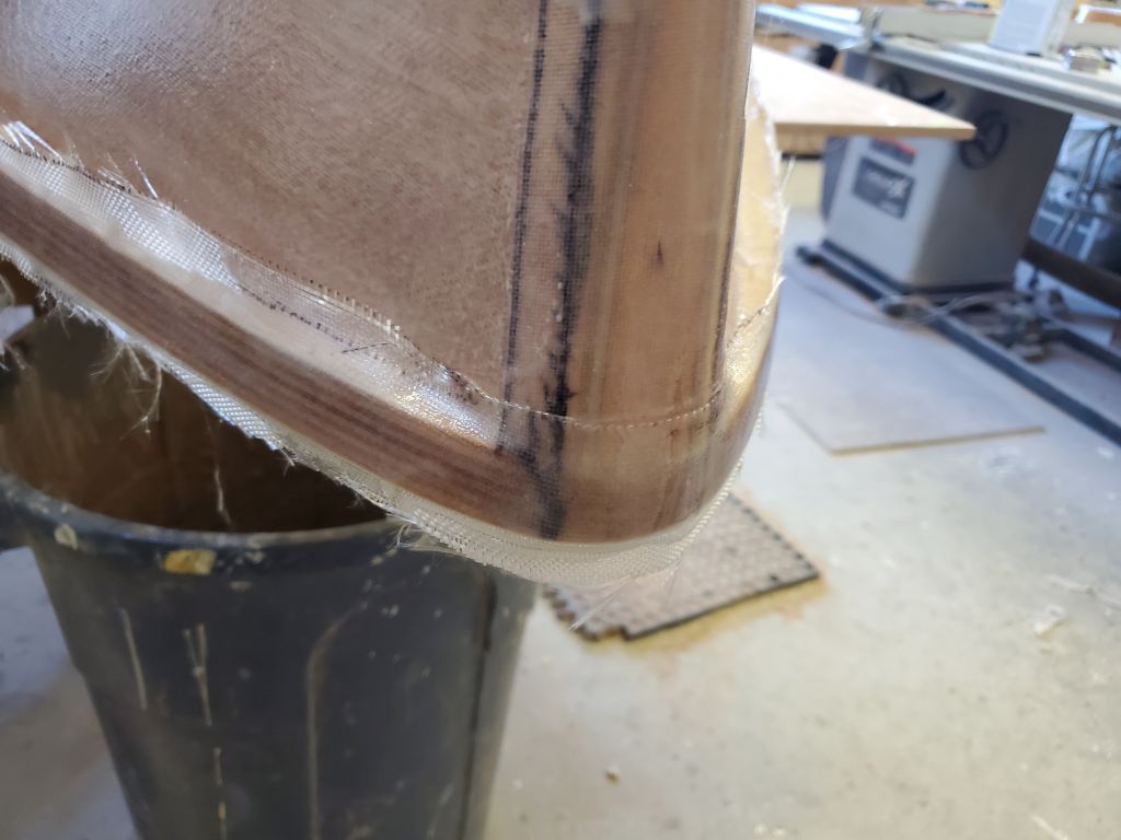
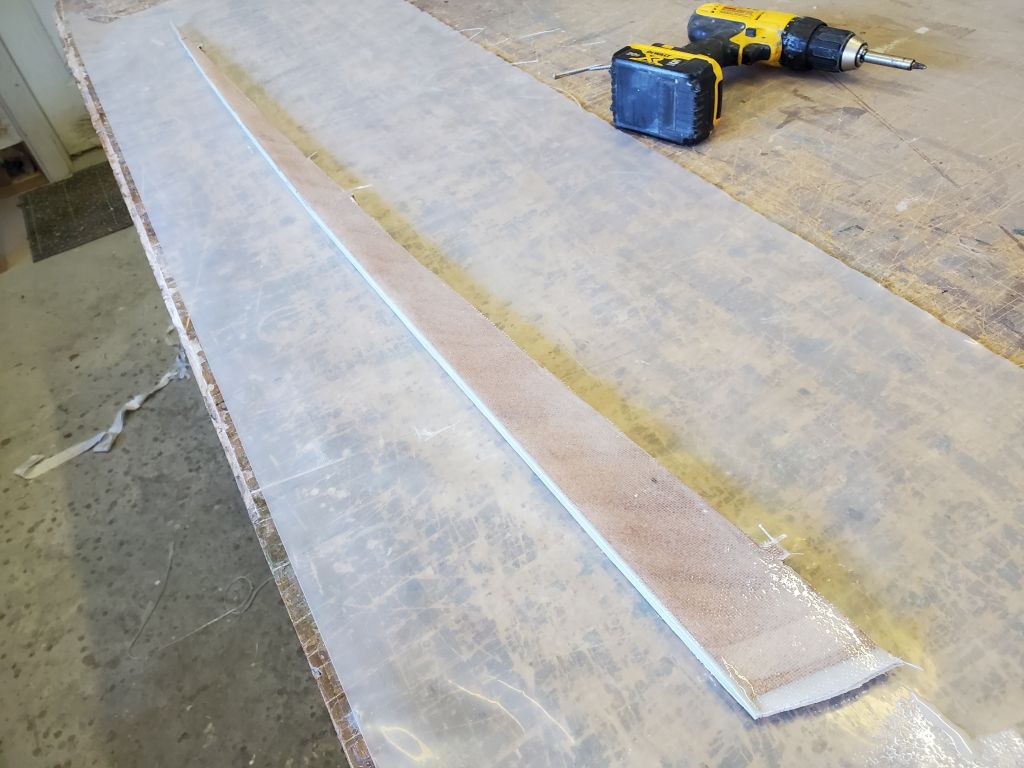
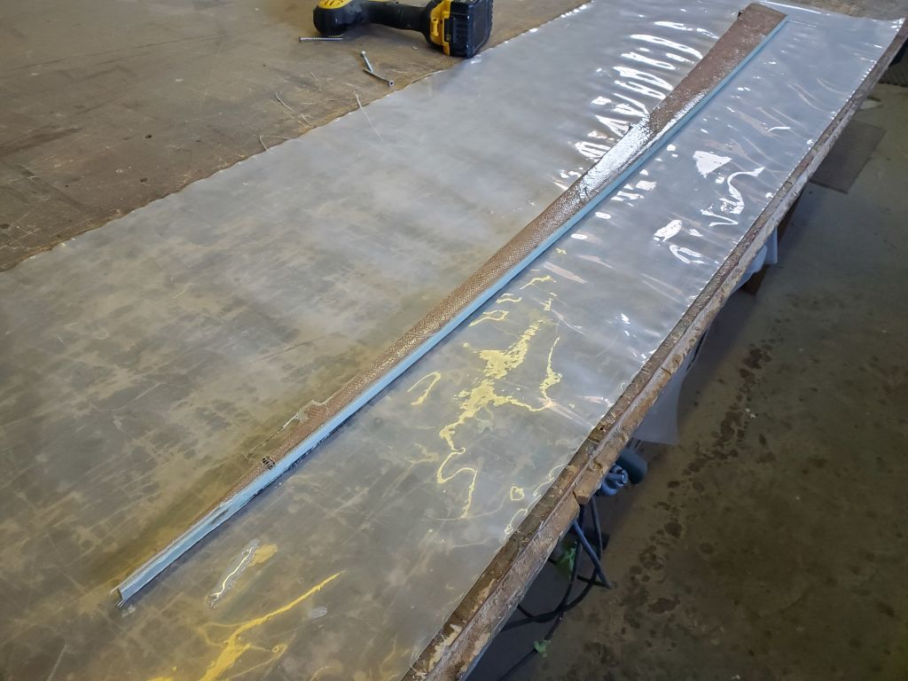
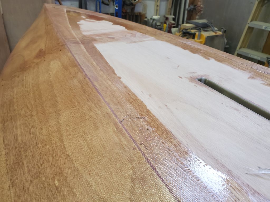
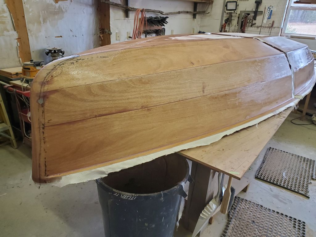
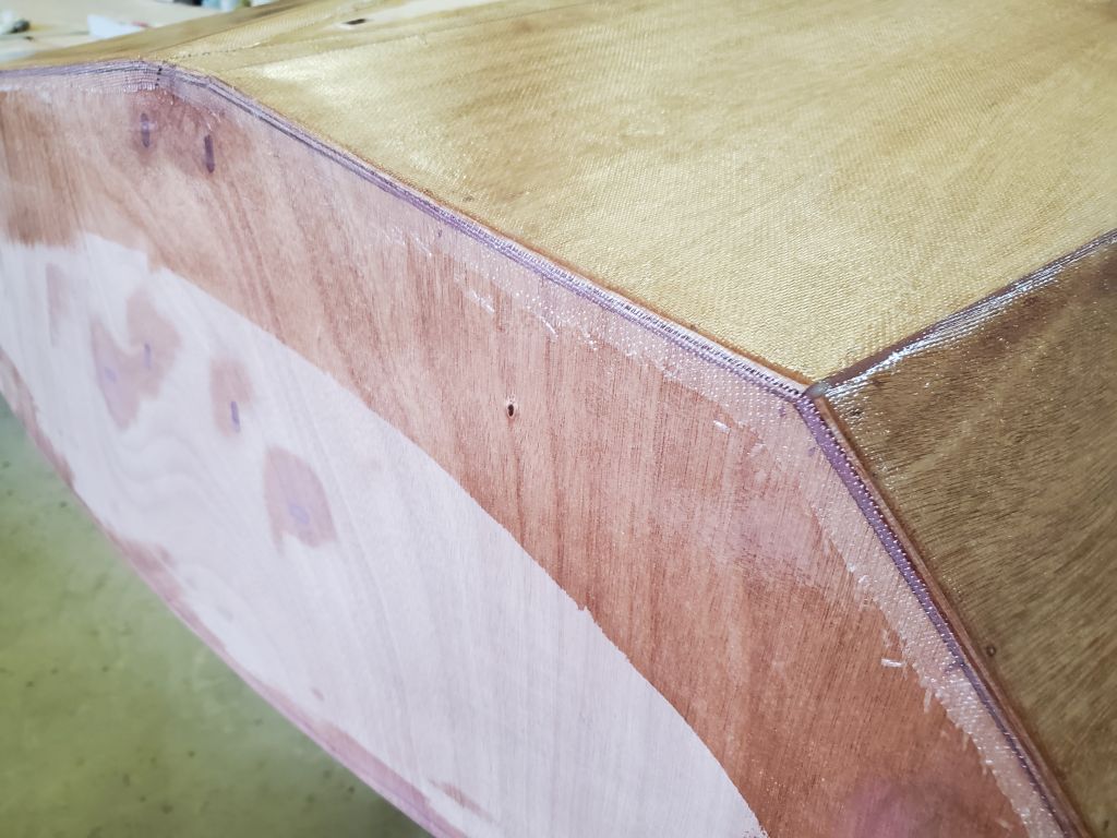
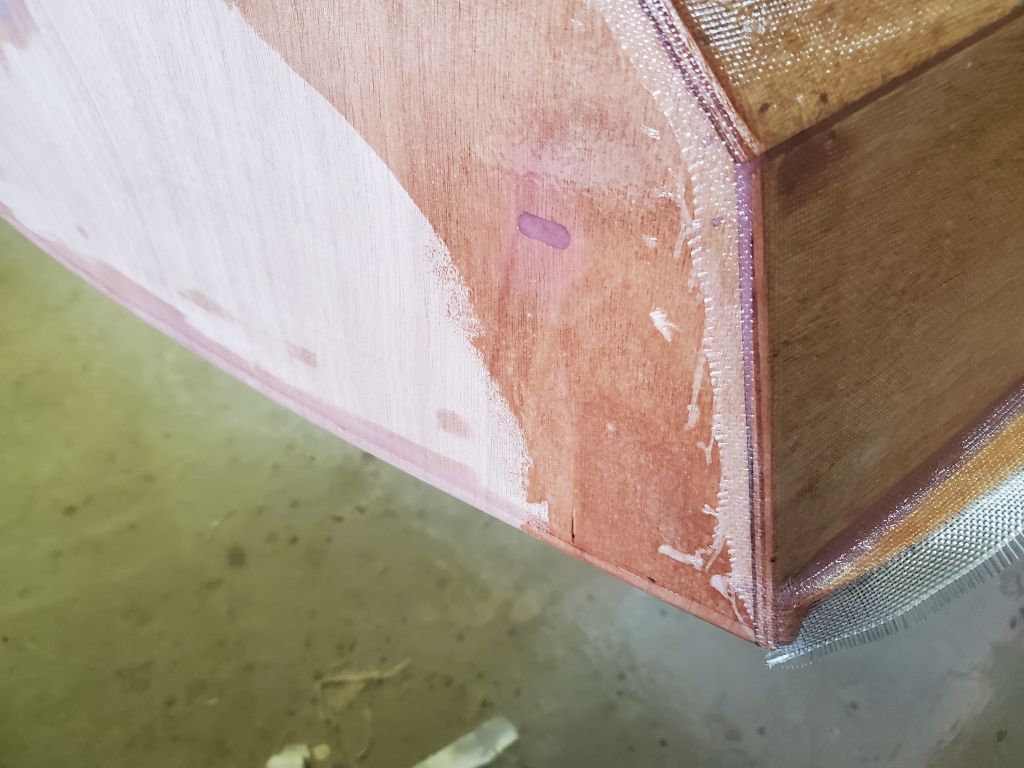
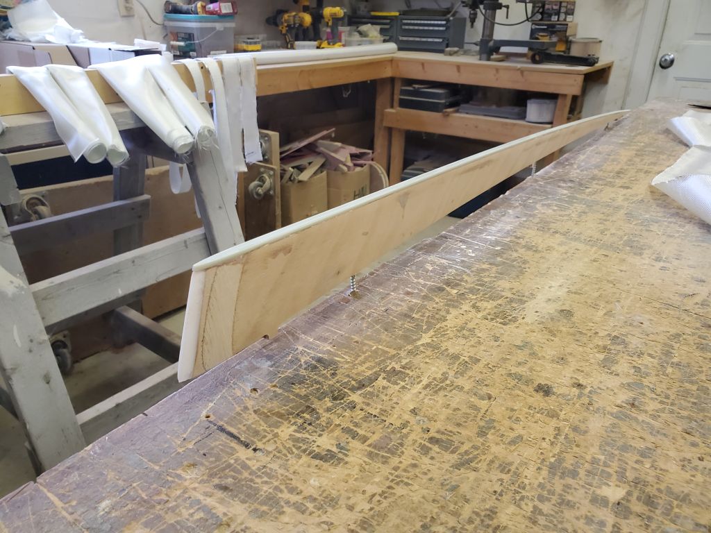
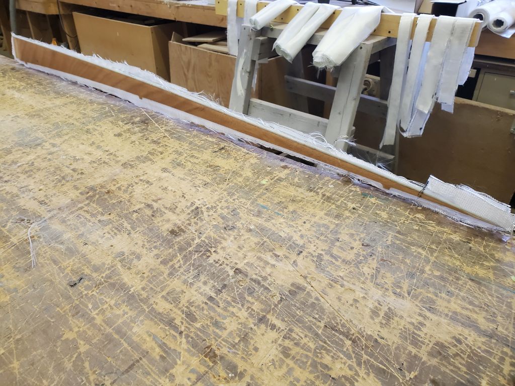
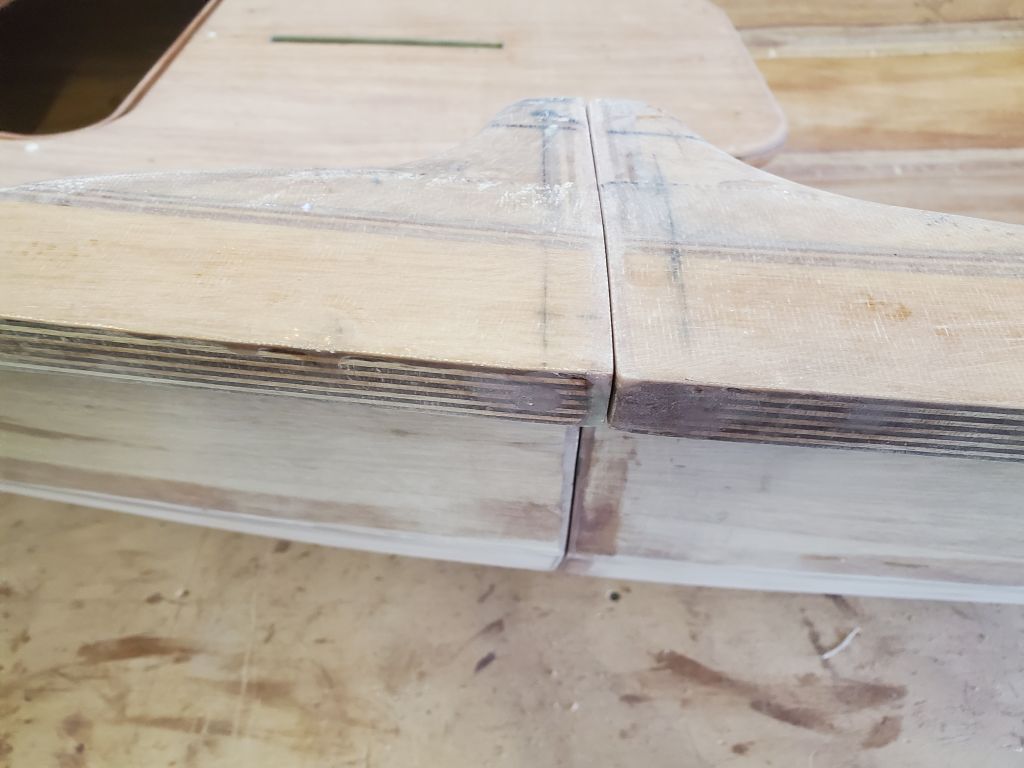
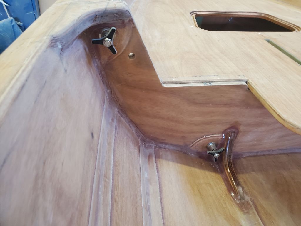
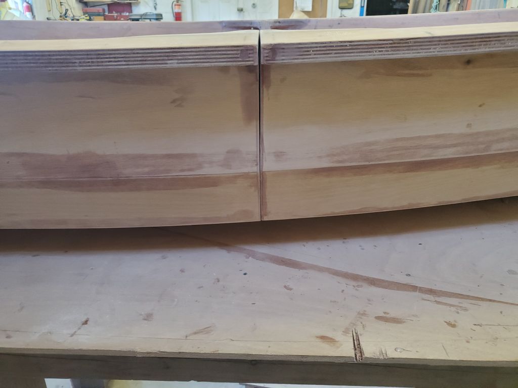
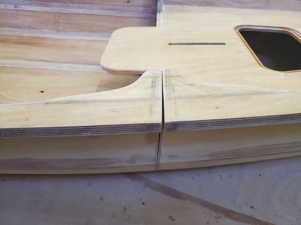
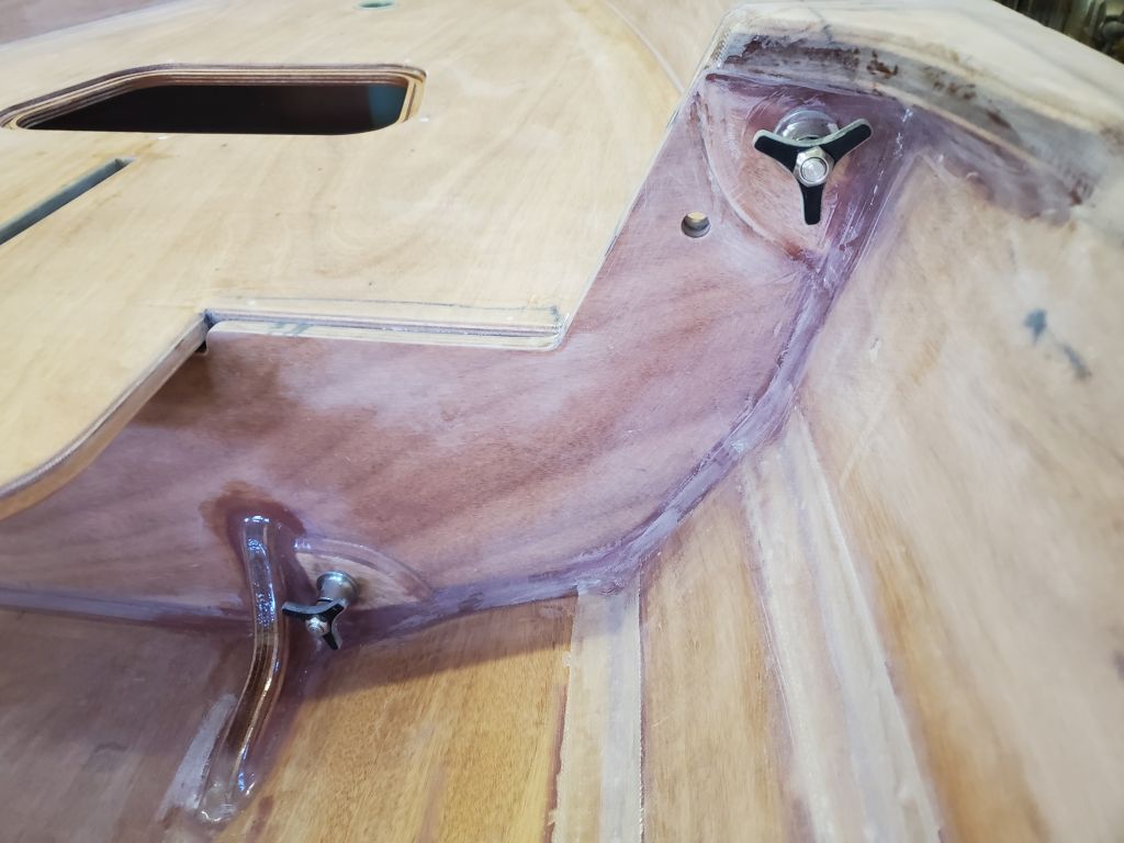
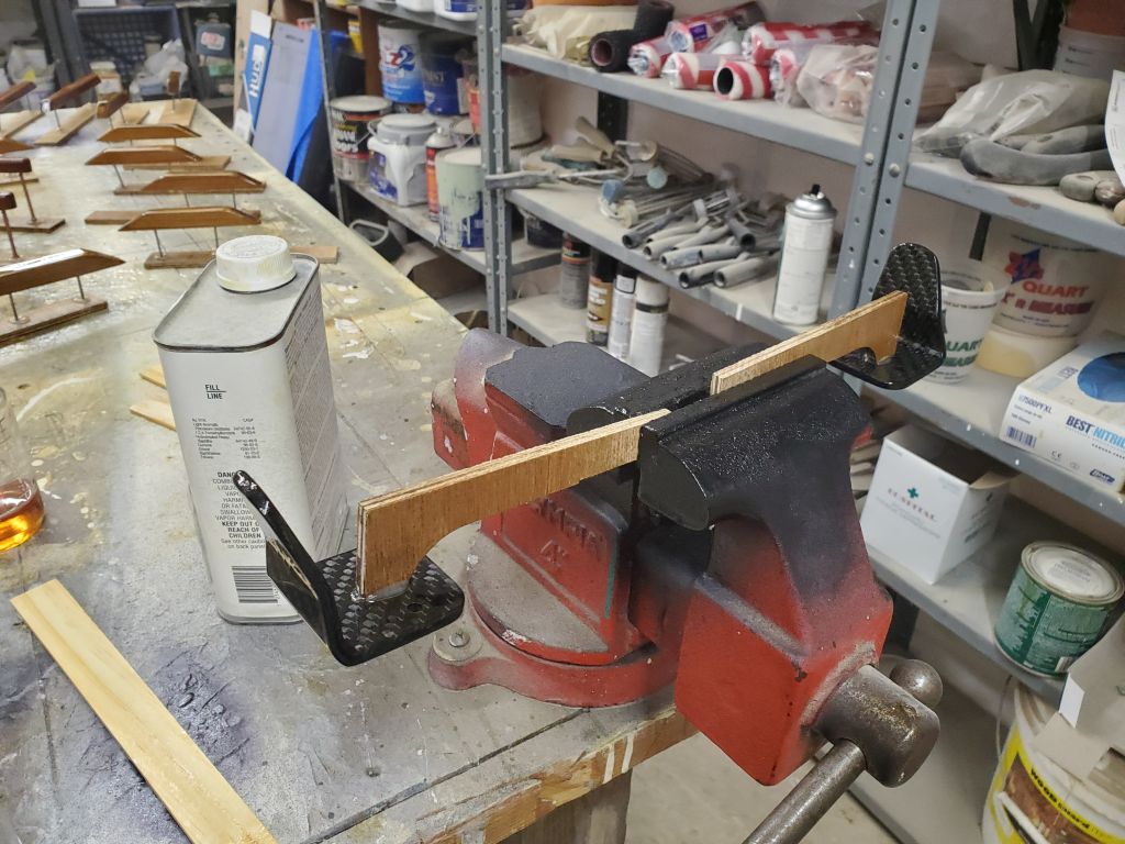
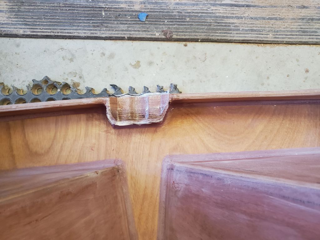
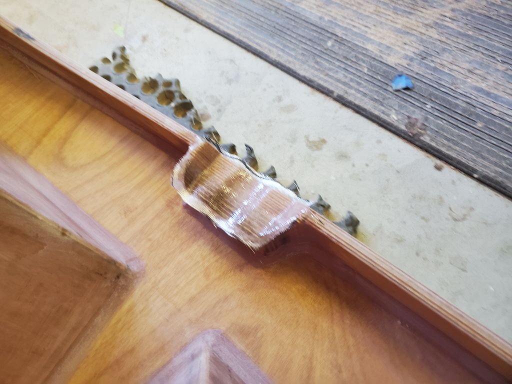
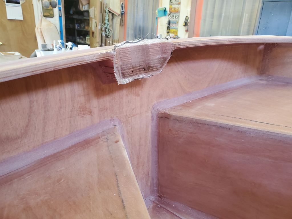
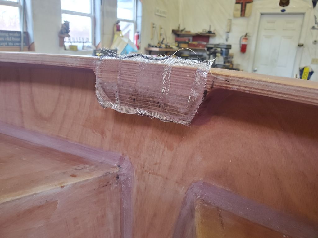
I sanded flush the newly-glued plywood outboard mounting reinforcement, and cleaned up the fillets and around the part as needed to bring things to a more finished appearance.
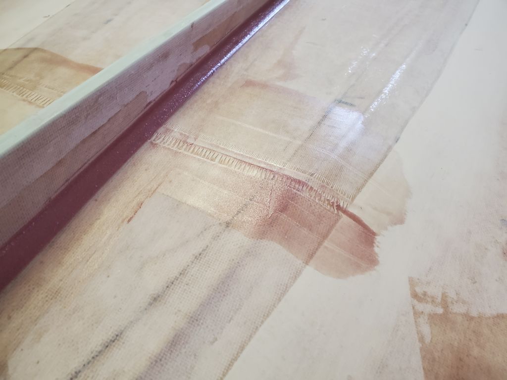
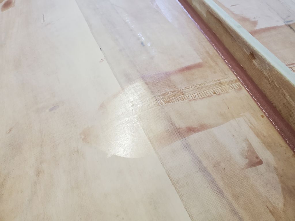
Next, I installed a layer of 4 oz. fiberglass over the vertical face, which replicated a similar piece I’d installed on the original inwale and would also help toughen and reinforce the outboard mounting area. With leftover epoxy, which I turned into a fairing mix, I cleaned up the fillets a bit to improve appearance. I let the fiberglass run over the various edges for later trimming.
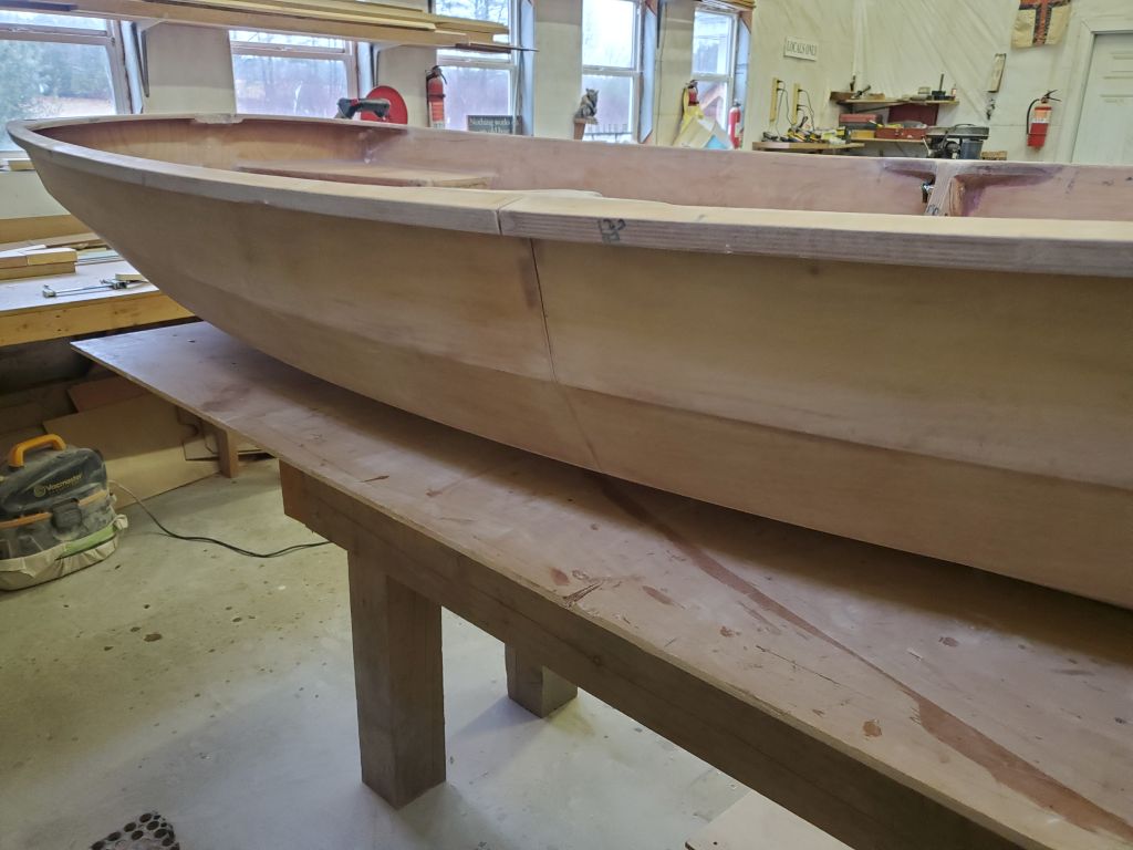
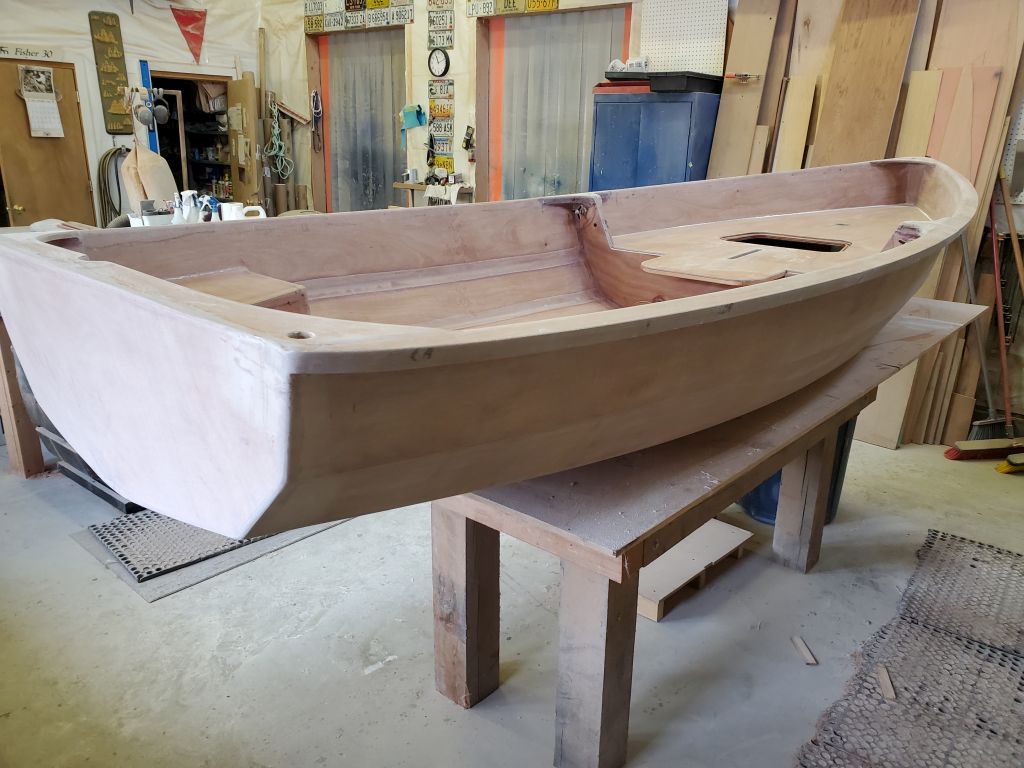
Most of the remaining parts of the boat were now in play and under some form of construction or finishing at this point, and there was literally nothing left to do while waiting for fiberglass or epoxy to cure, or varnish to dry. I planned to come in on the weekend to continue the varnish buildup as necessary, and to glass and coat the second side of the daggerboard and rudder, but there was no further project advancement possible at the moment–and I looked through both manuals for anything at all that I might be able to do right now.
I’d enjoyed being able to dedicate full-time to the building of this dinghy till now, without too many forced early departures, but the construction was now at a stage where there simply wasn’t enough left to do in order to justify full shop days’ attention. Plus, other scheduled projects in the shop loomed ahead and needed to get started, so this would be the last week dedicated entirely to the dinghy. From here on out, I’d divide my time between this and other projects as needed in order to finish the boat. This is a rough list of what remains to be done, construction-wise, vaguely in order of operation:
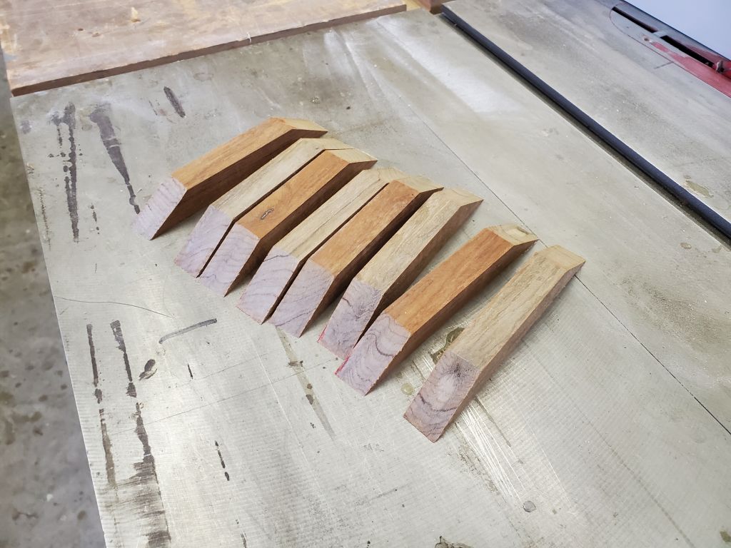
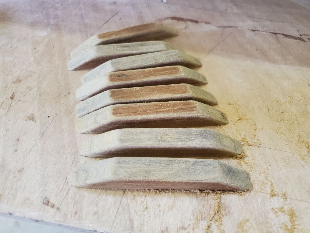
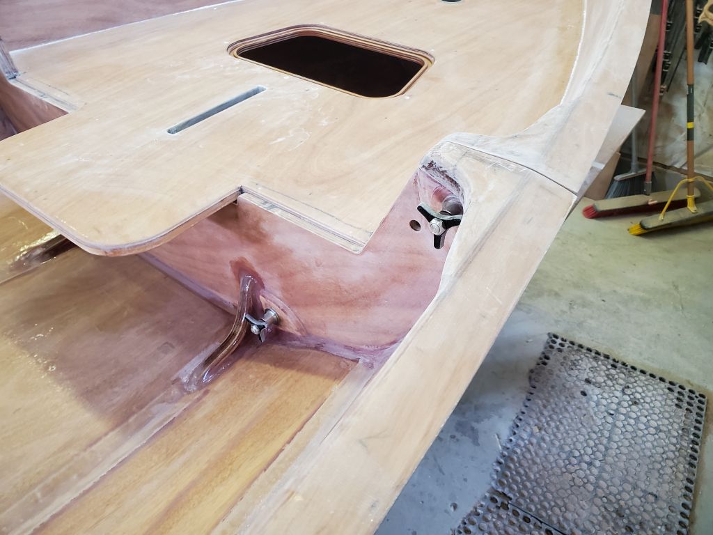
- Install rowing foot cleats and rowlock risers
- Final work on the outboard modification
- Finish glasswork and prep on the daggerboard and rudder, and associated parts
- Interior prep, primer, and paint
- Exterior prep, primer, and paint
- Rubrail
- Final details like rudder hardware, fitting the aft seat and daggerboard slot cover, protective pads for nesting, and fitting the forward hatch