< Back to Handy Cat
The switch, or controller, that I removed from the original electric motor housing was all that was needed to control the motor (located in the propeller hub) itself. My goal in this installation was to create a simple and portable means of transporting and connecting the controller switch and 12-volt battery to the wiring from the rudder, so that I could quickly install and remove the controls whenever I used the boat, and keep the battery charged up ashore in the meantime.
To this end, I hoped that a small 12-volt battery (such as the small case size often seen in lawn tractors) would provide sufficient amp-hourage for my limited motor use. Obviously a smaller battery would limit the length of time I could run the motor, but I thought my needs were minimal enough that the desire for easy portability would take precedence. The instructions that came with the motor recommended a minimum 105 amp-hour battery, which made sense for all that, but I thought/hoped I wouldn’t need such capacity since I only planned to run the motor for perhaps (thinking generously) 10 minutes total per trip.
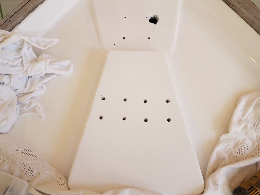
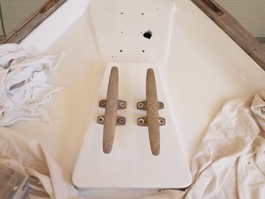
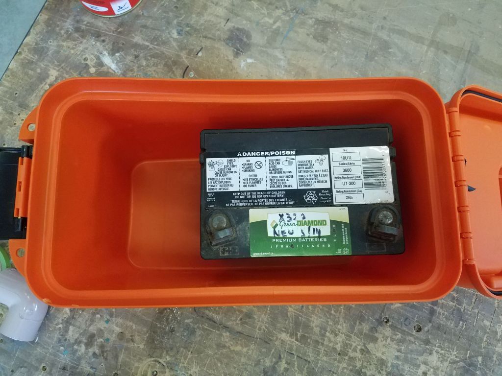
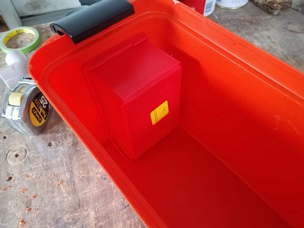
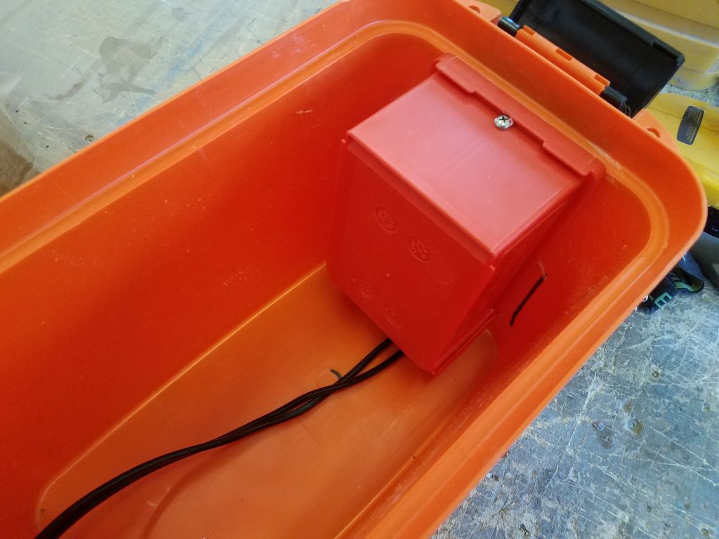
With this in mind, I found a plastic toolbox (ostensibly “waterproof” with a gasketed cover, though this wasn’t a criterion for me in this case, nor had I any illusions about the sanctity of the lid seal) that was large enough to hold a standard lawn tractor battery, and I planned this box to form the basis of my controller installation. For illustration, I used a tractor battery I had on hand. Truth be told, I’d purchased the box thinking it would also be large enough to hold a group 24 size battery if needed, as the listed dimensions suggested this, but of course the inside of the box was somewhat smaller and too tight in height and width for a regular battery.
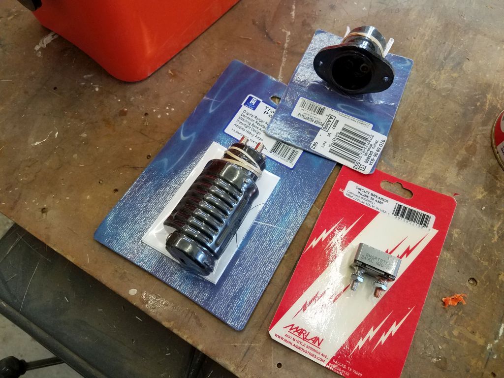
These little batteries weren’t, in the main, rated by amp hourage, as they weren’t deep cycle and, as small engine starting batteries, were rated only in cold cranking amps. Some online research revealed low amp-hour ratings (in the 18-20 amp-hour range) for these batteries from other sources, but after additional searching I located a deep cycle version rated at 45 amp-hours in a similar case size that would still fit in my controller box. My plan, once I purchased the exact battery, was to build some internal bracing to hold the battery in place at one end of the box, leaving the other end open for the wiring and controller.
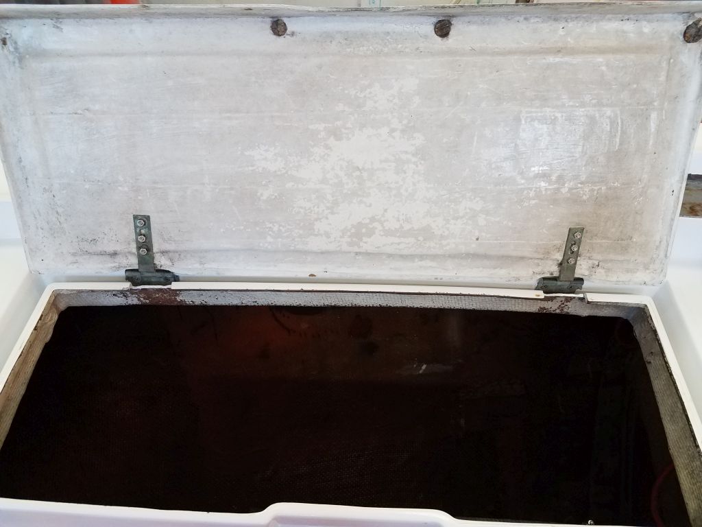
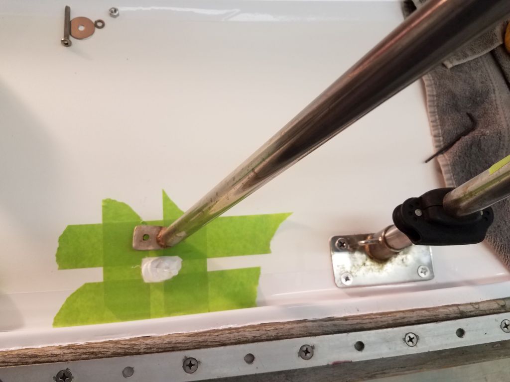
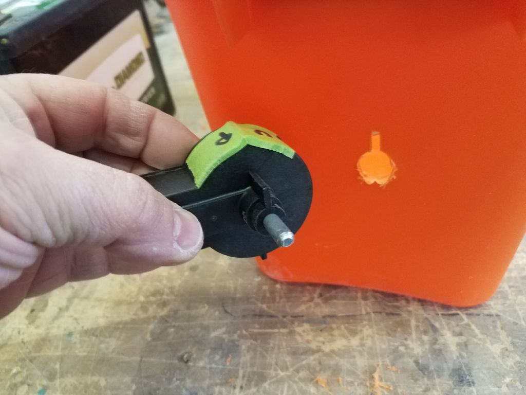
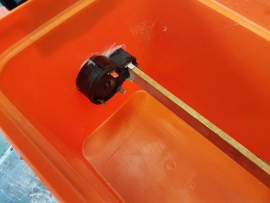
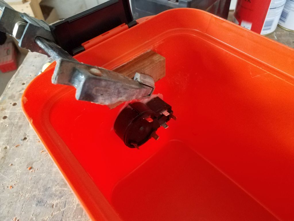
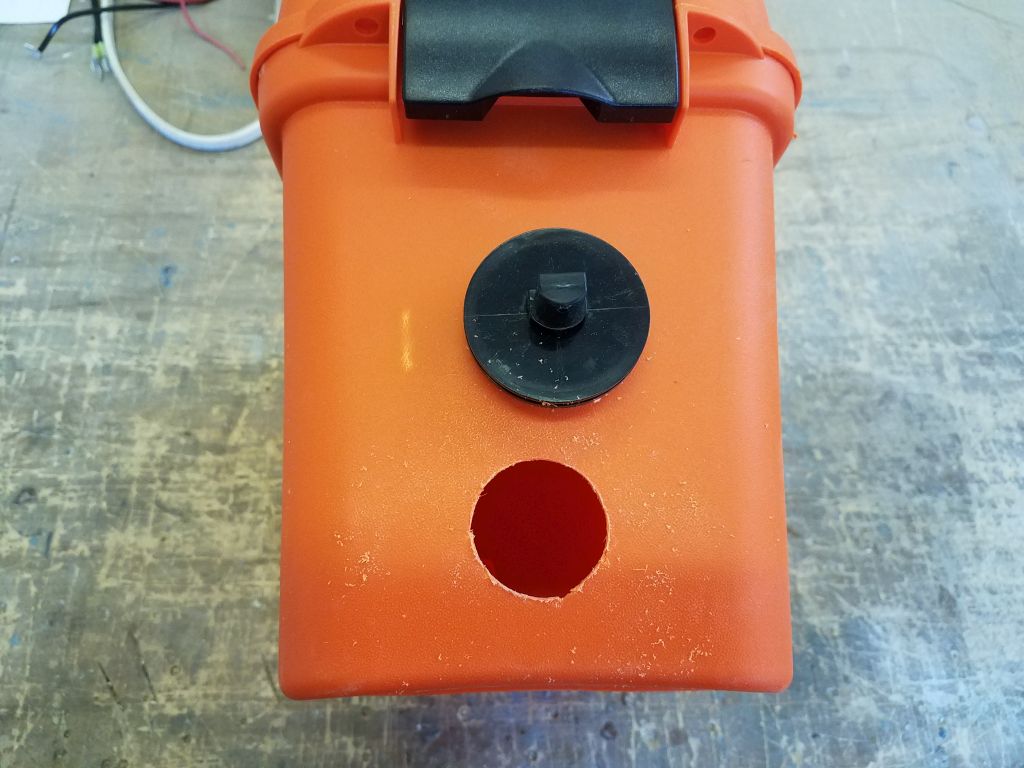
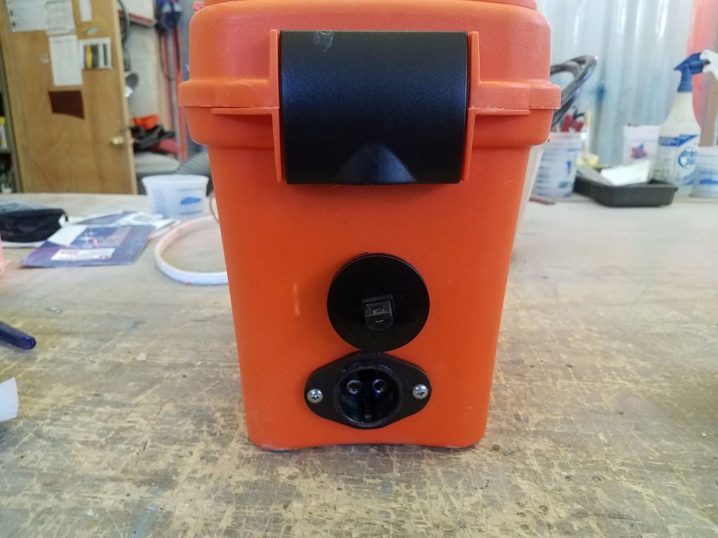
Satisfied that the box idea would work for now–only time in actual use would determine whether the small battery was enough for what I needed–I prepared to install the controller switch in the end wall of the box. I drilled a hole that fit the diameter of the housing around the control shaft, and cut by hand a small slot at the top to match the molded keyway on the switch housing. This allowed me to insert the switch from inside the box, with the control shaft outside. To hold the switch in place, in addition to the friction-fit cutout and keyway, I applied some epoxy after I scuffed up the plastic on the box. I hoped this would be sufficient for the basically light-duty use the switch would experience. I braced this in place while the epoxy cured.
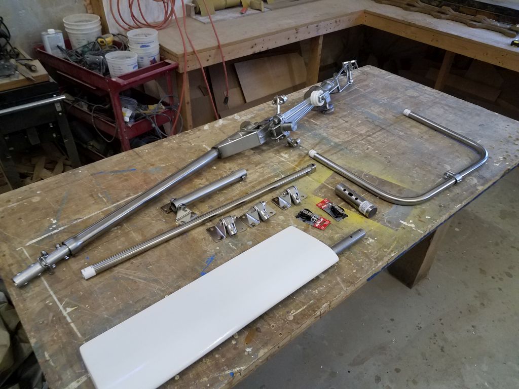
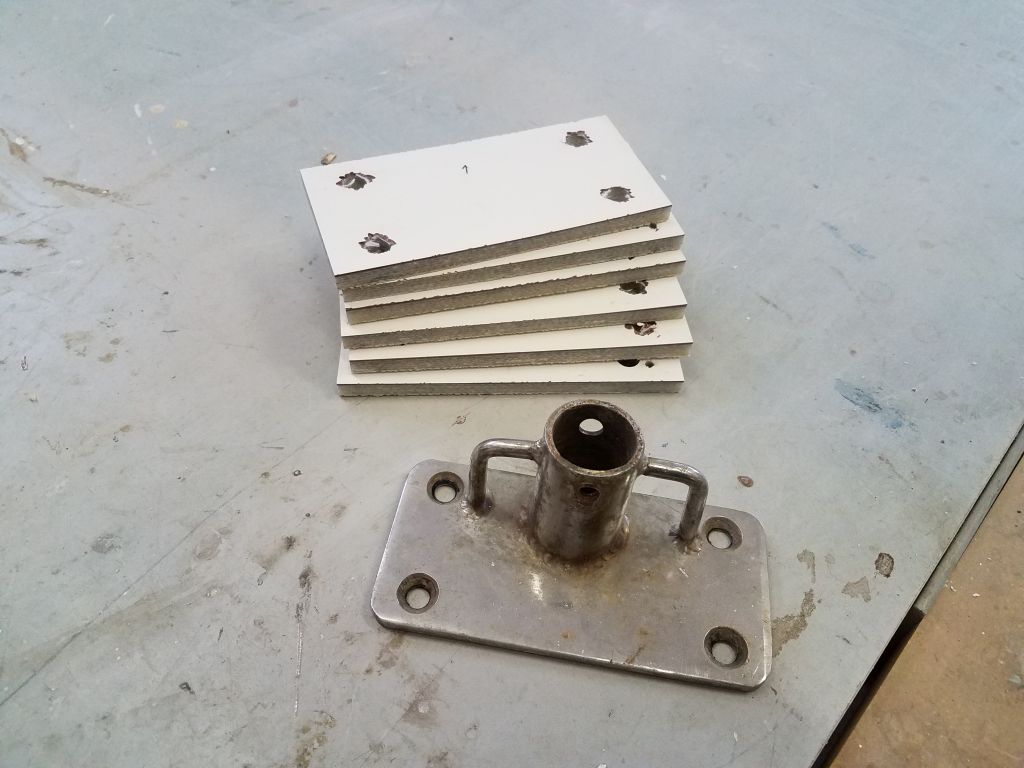
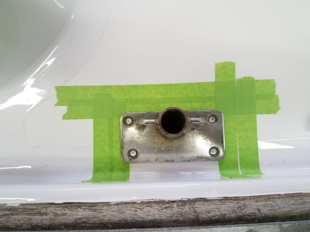
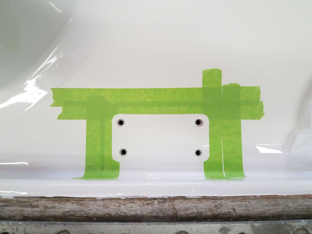
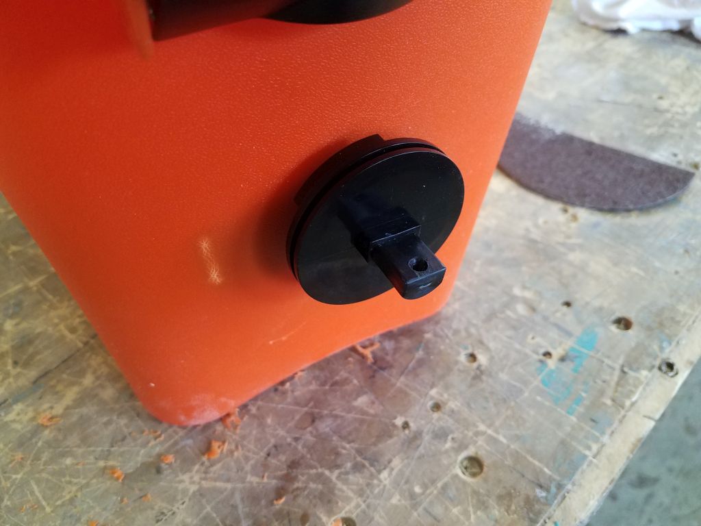
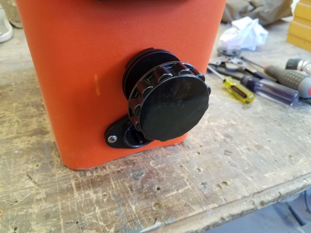
Outside the box, I used one of the plastic pieces that originally came with the motor, and which slipped right over the metal control shaft. This piece originally allowed connection of the tiller-type control handle, but I didn’t plan to use that. Instead, I found and ordered a knob for outside that would fit over the roughly 1/2″ diameter of the shaft cover. As of this writing I awaited delivery of the knob.
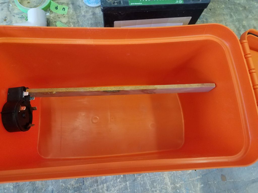
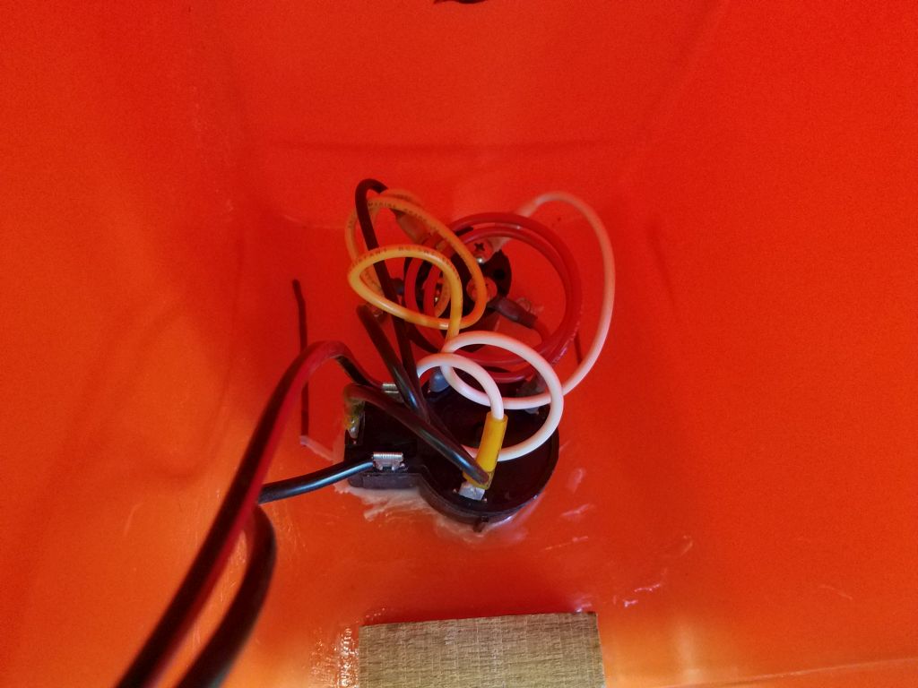
To cover the wiring connections and back side of the control switch, I purchased a plastic storage tray that I could hang over the switch, covering it completely from inside while allowing wiring to pass below the cover. As a simple means of installation, I epoxied in a wooden cleat above the switch, which, once cured, would allow the cover to hang over the switch for protection. I’d use a single screw to secure the cover to the cleat.
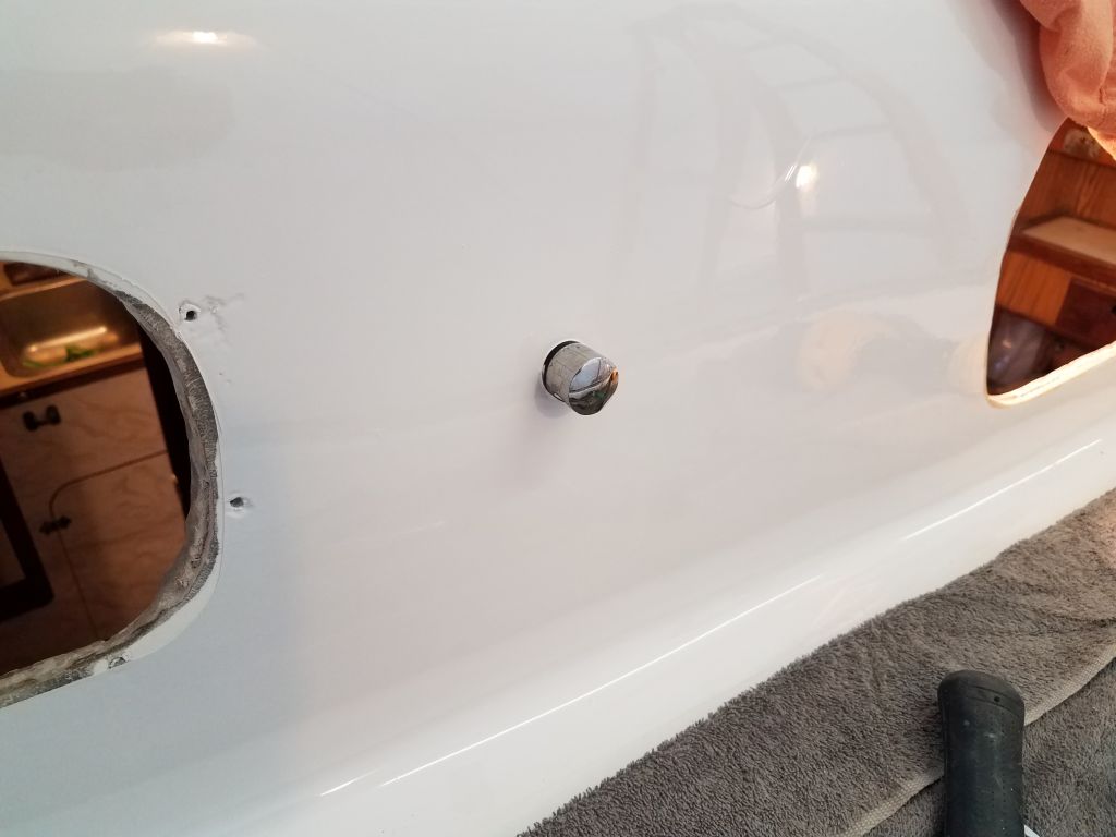
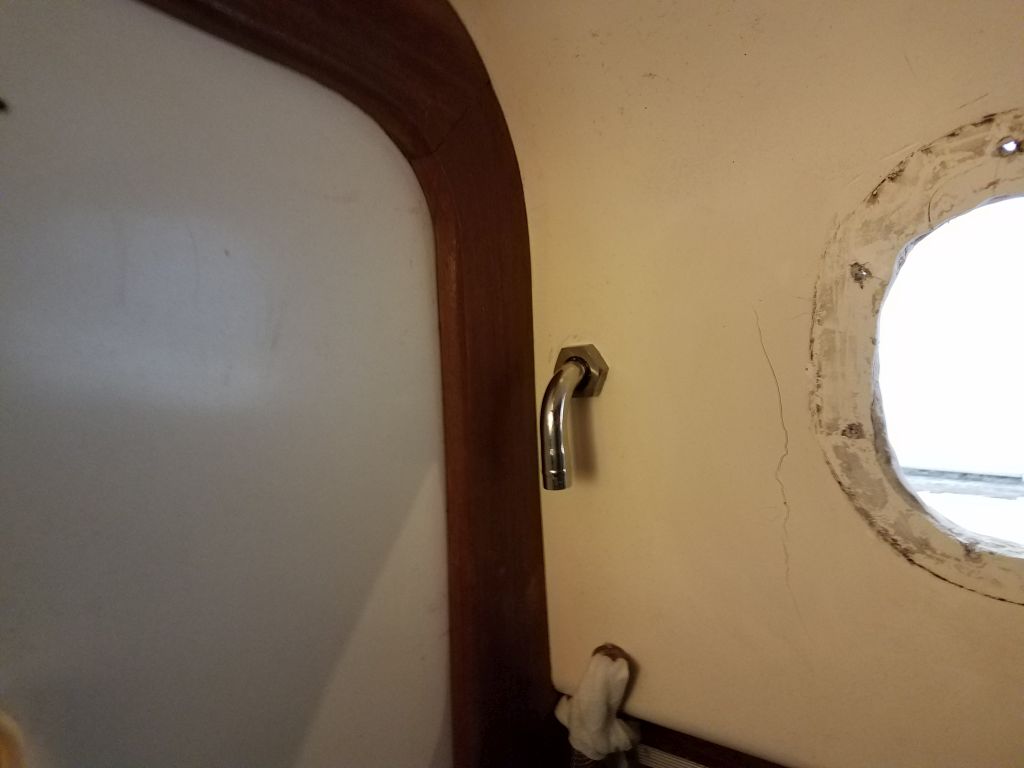
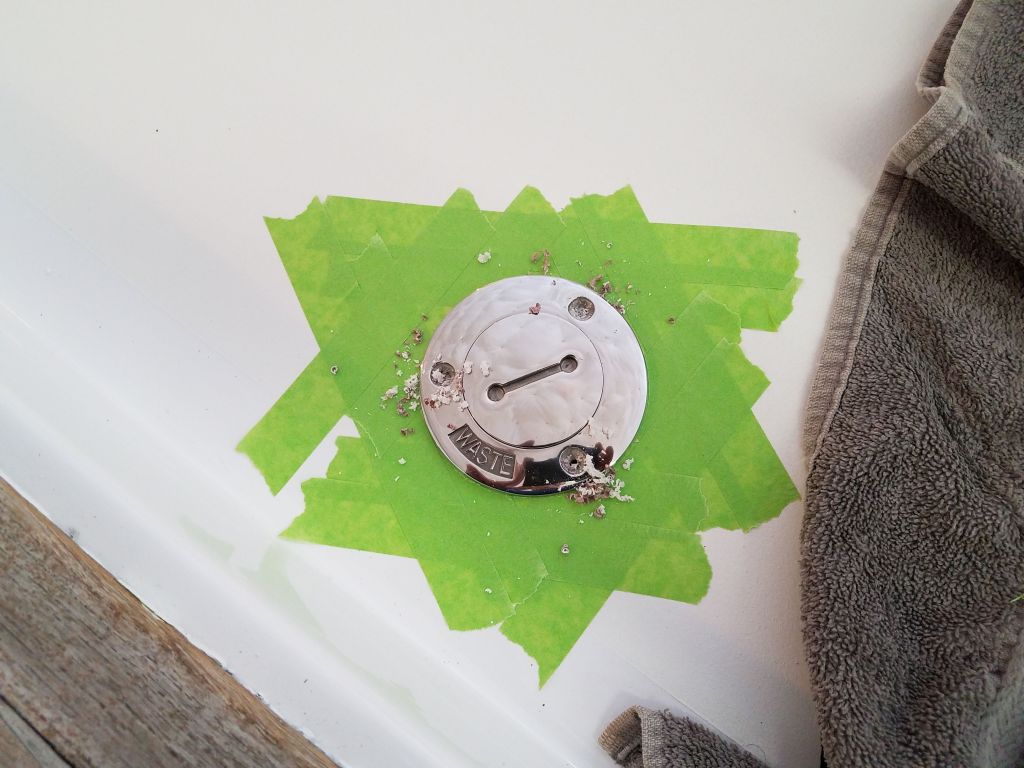
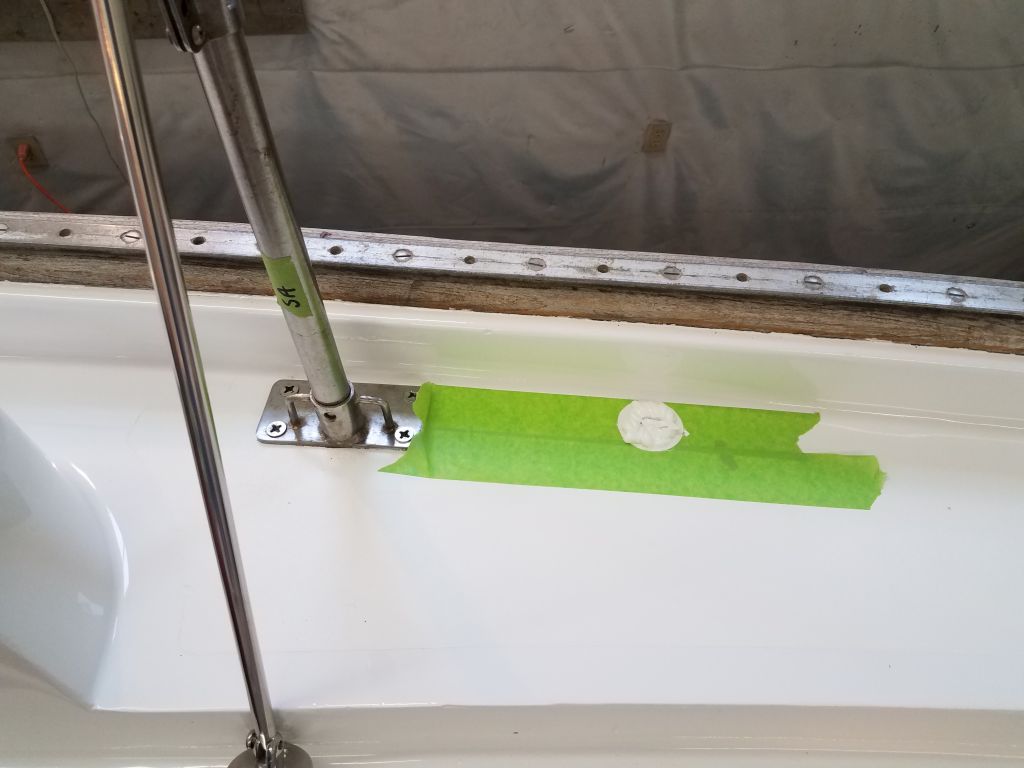
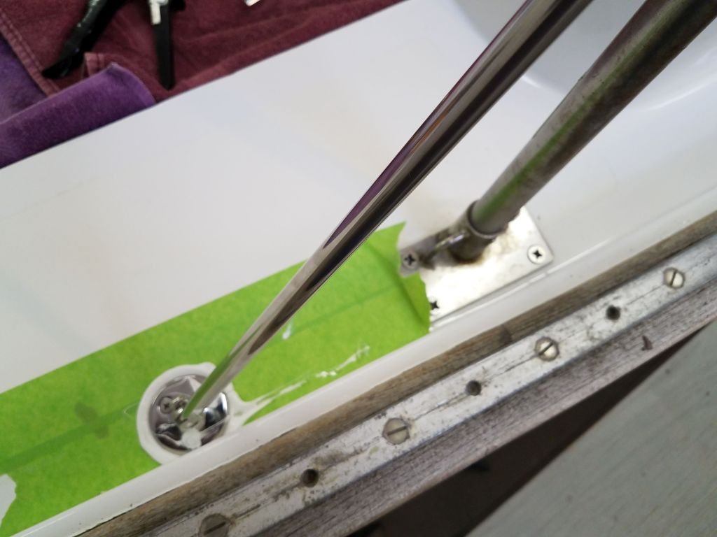
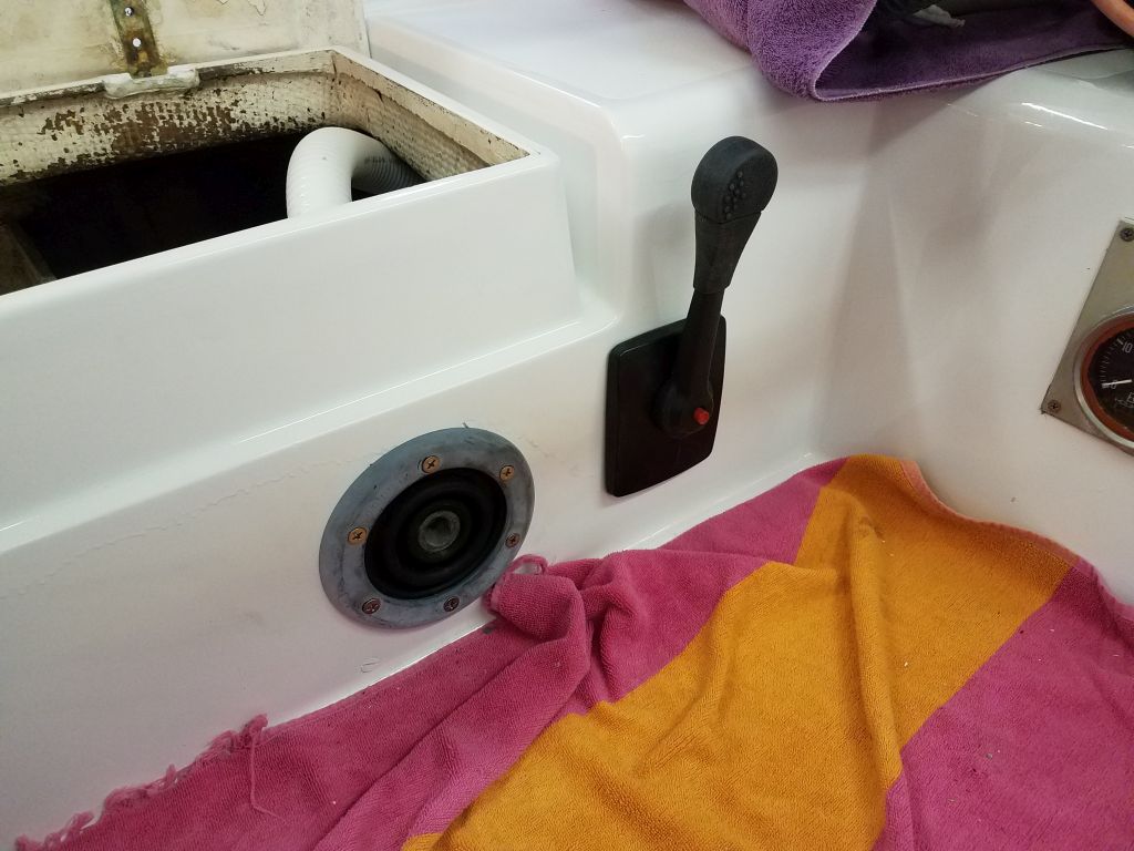
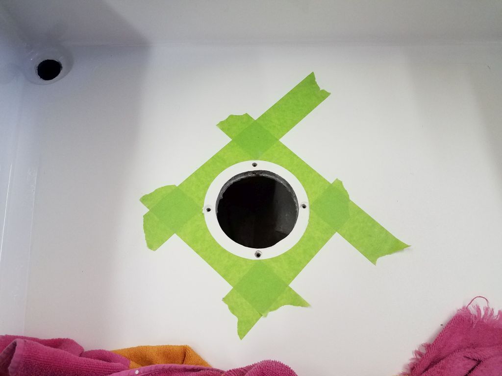
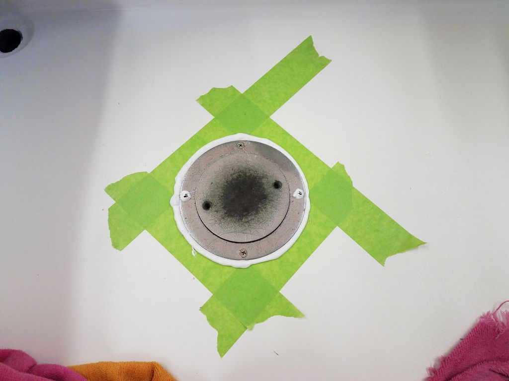
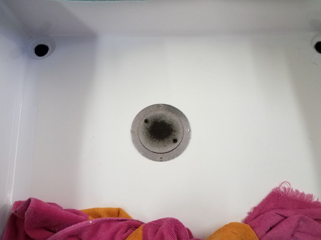
For ease of connection and disconnection and transport of the battery/controller box, I ordered a plug and receptacle for the wiring between the box and the rudder. Once the matched set–though sold separately–arrived, I set to work to install the receptacle and wire it to the controller switch. The plug and receptacle were large and fairly serious duty, perhaps more than the job called for, but this was one of the only 4-wire setups I’d found; I had four wires to connect. In any event, it looked like it would more than hold up to the continuous connection and disconnection that I had in mind, so good enough.
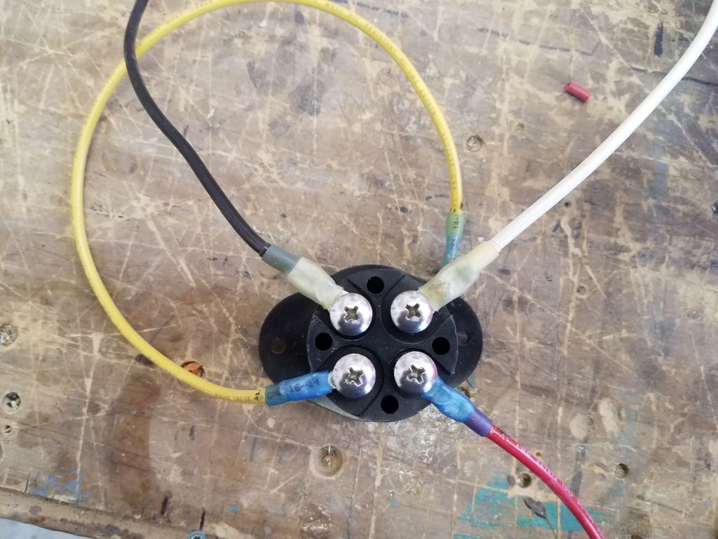
I cut a hole in my portable control box, then installed short lengths of wire–in the same colors as the motor’s original wiring–to the four terminals, choosing them arbitrarily since it didn’t matter. Then, with the receptacle installed in the box (I used small machine screws and nuts to help hold the receptacle against the pulling motion of plug disconnection), I connected the four short wires to their respective terminals on the control switch.
I finished up the box-end wiring with a 50-amp circuit breaker that I installed in the battery positive line. I protected the exposed terminals with some heat shrink tubing, just to prevent the unlikely event of a short across these terminals in the generally unprotected environment within the box. Then, I installed my simple wiring cover over the works of the switches.
To finish up the control box, I installed a large knob on the outside of the controller. This fit over the plastic piece leftover from the original motor configuration, and I secured it with an included setscrew. Later, once I tested operation, I’d make some tick marks on the knob and on the box to indicate the motor speed and direction.
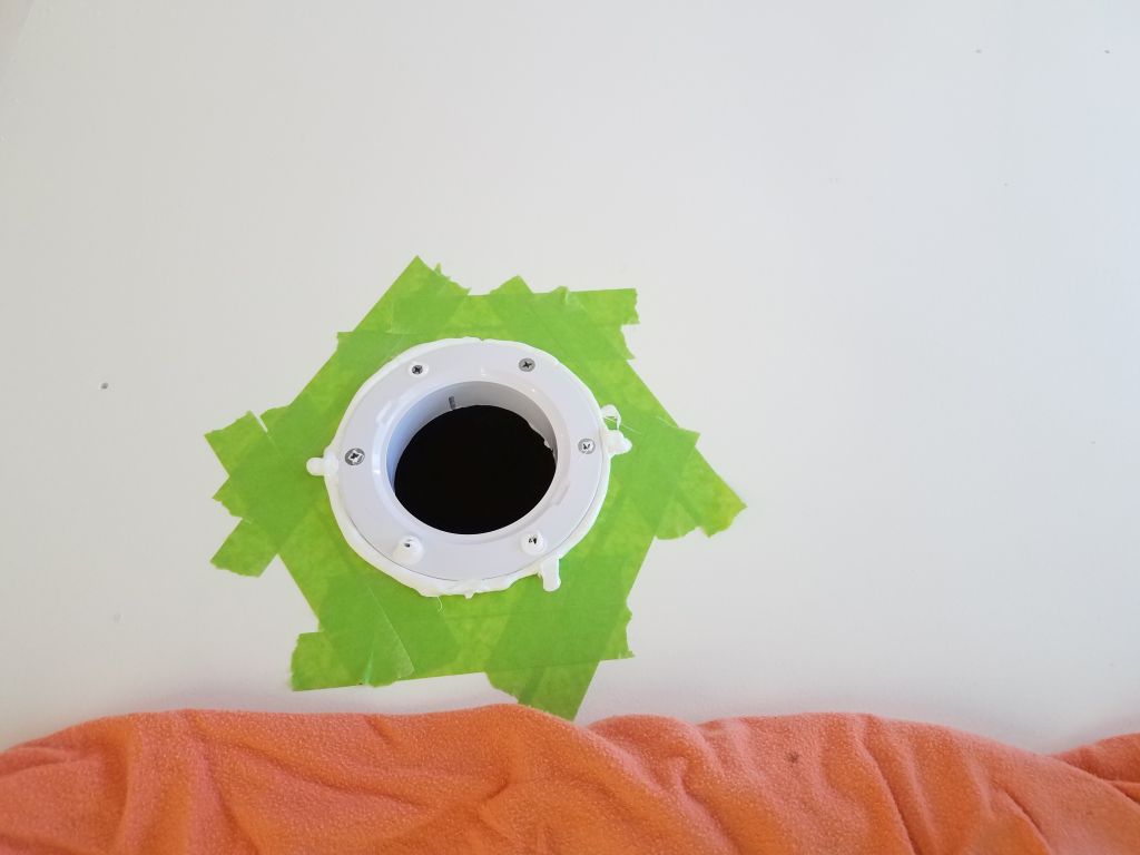
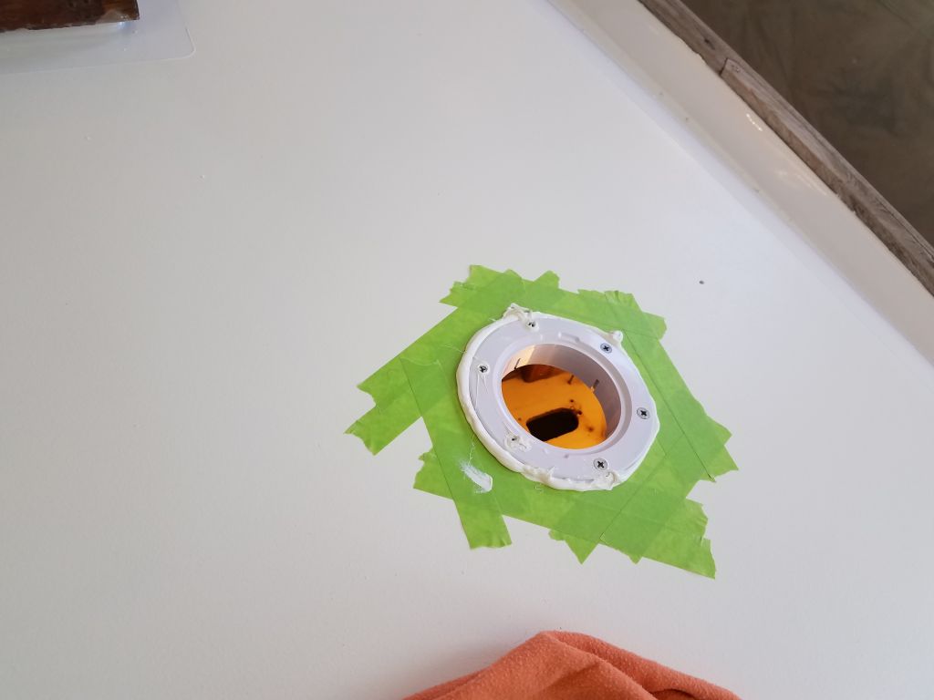
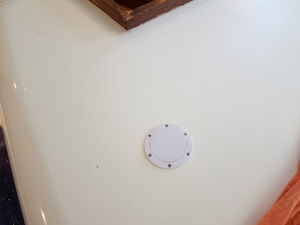
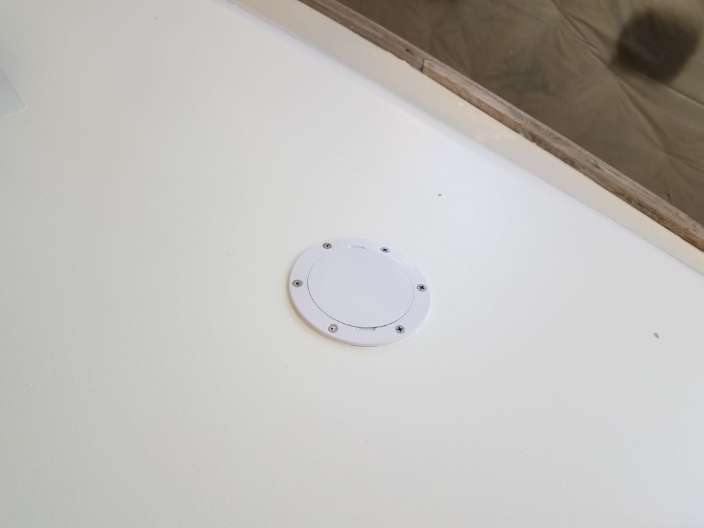
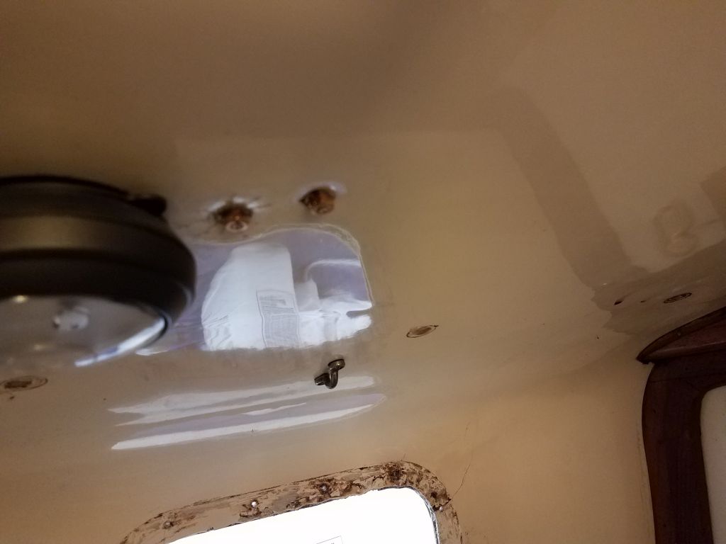
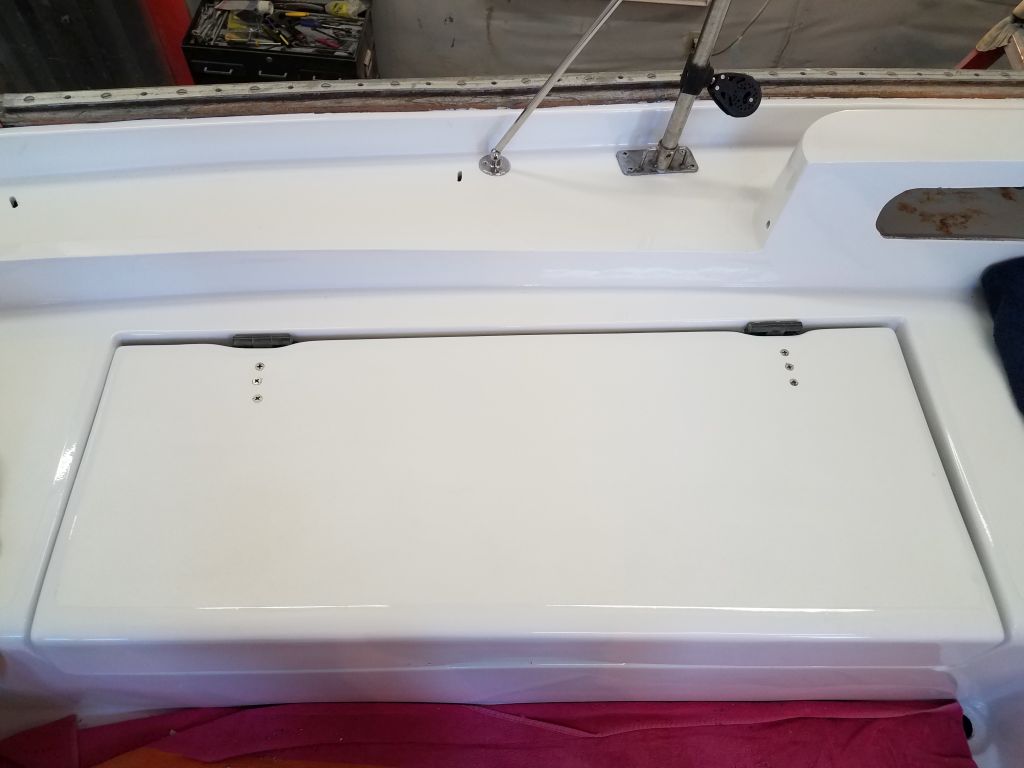
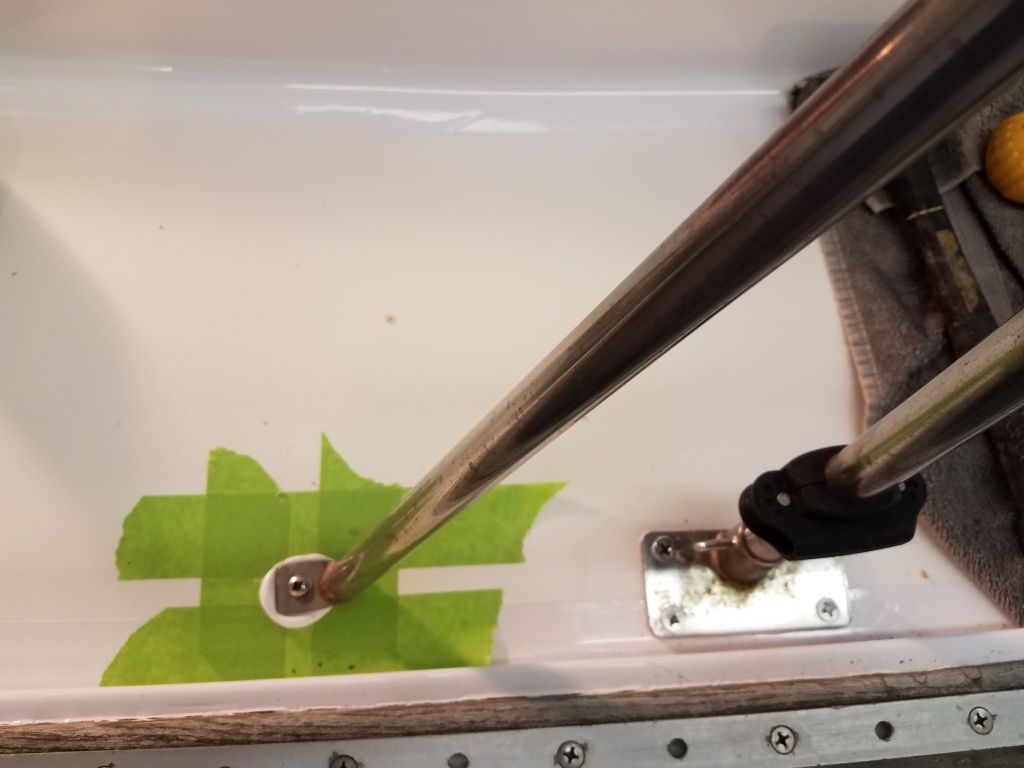
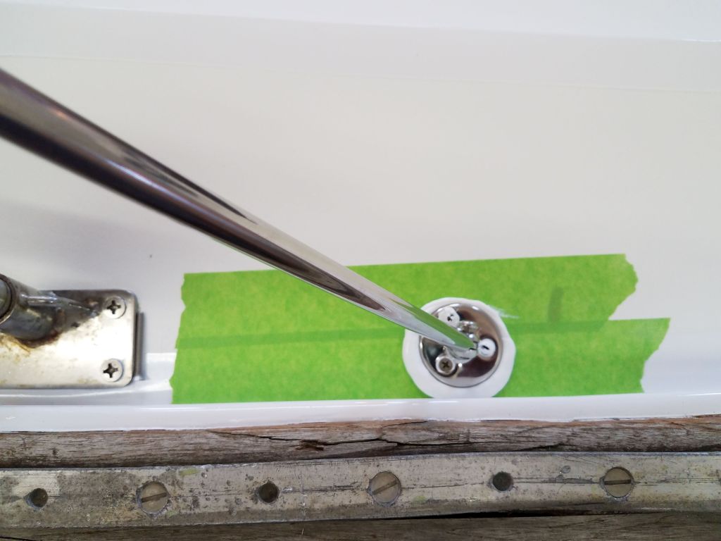
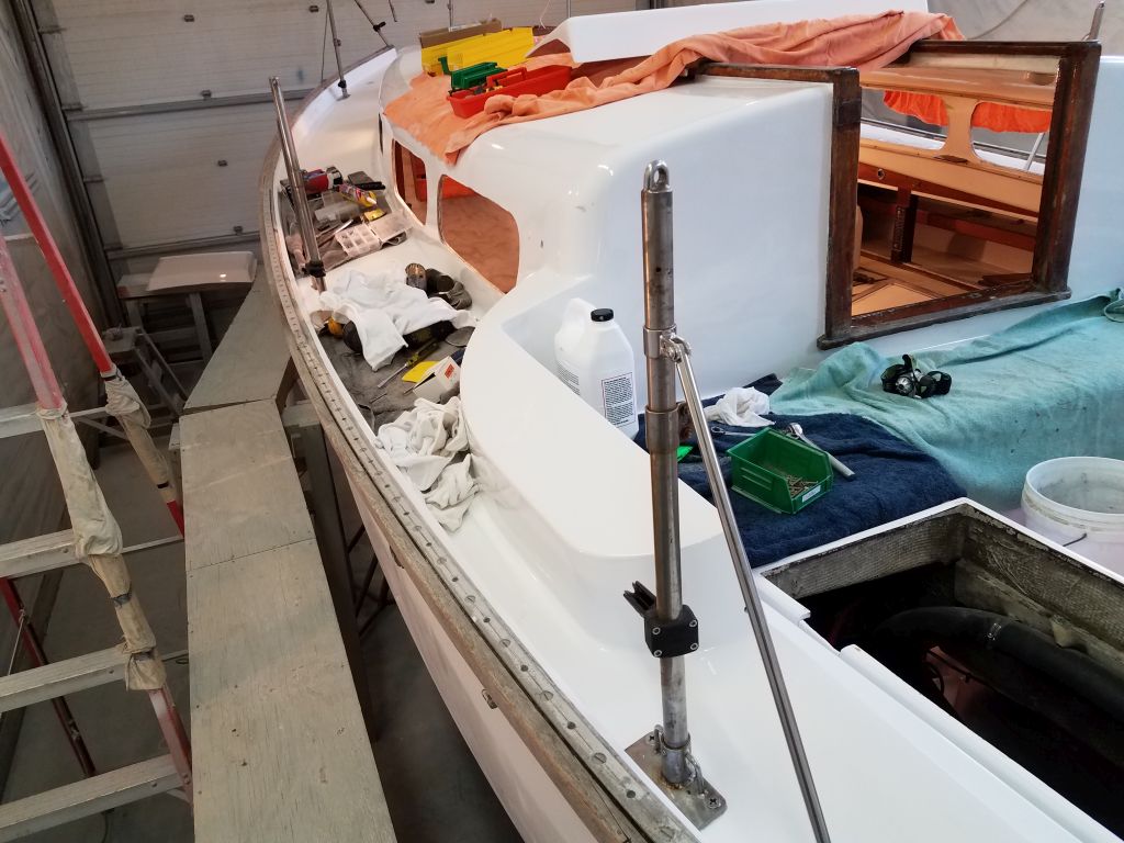
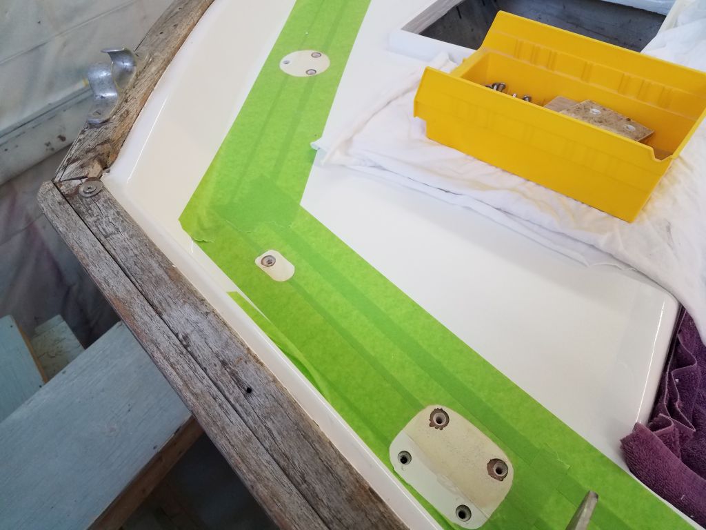
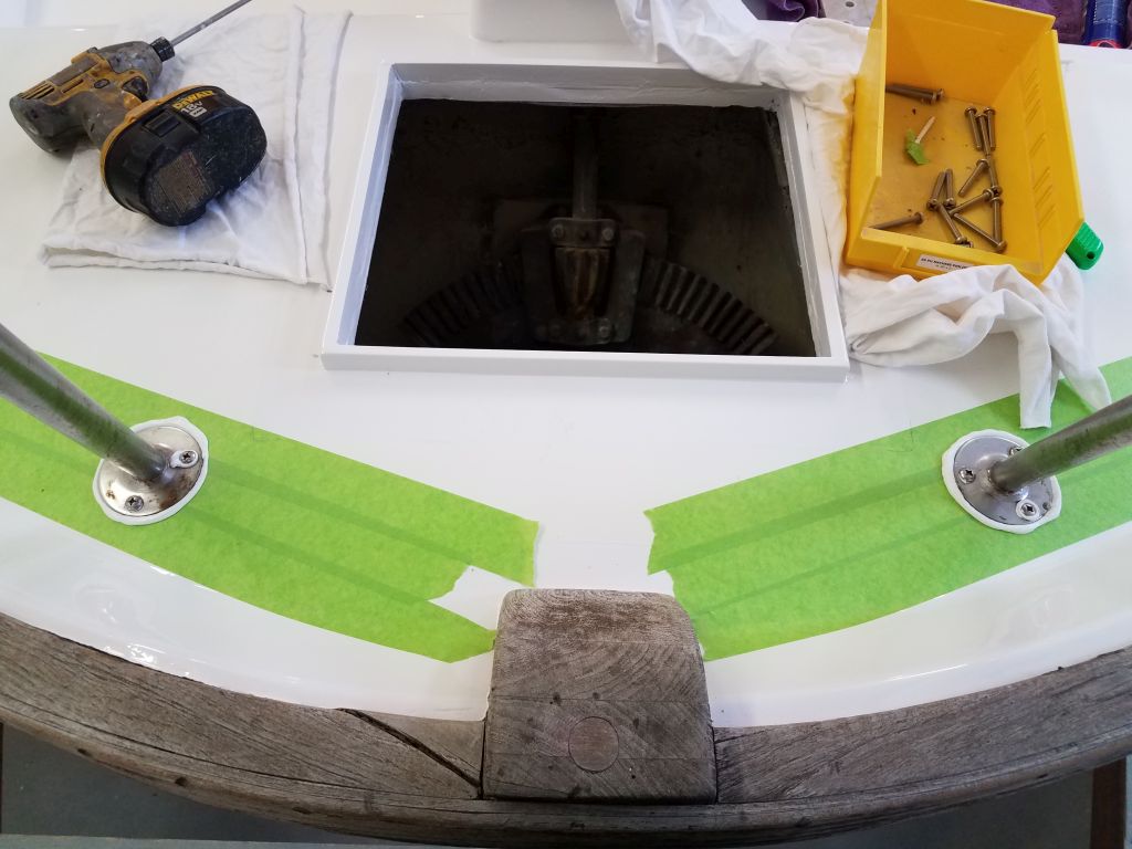
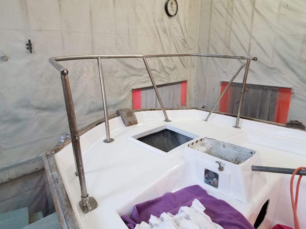
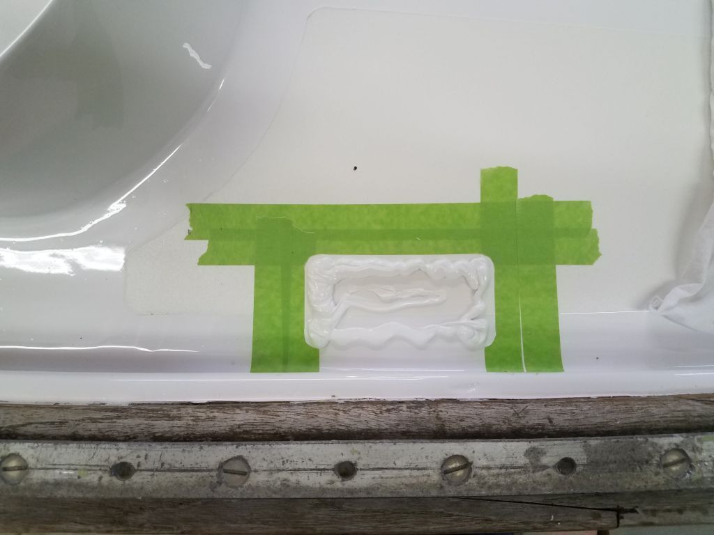
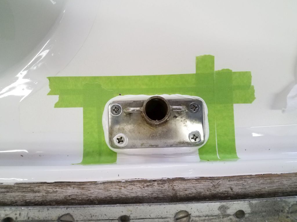
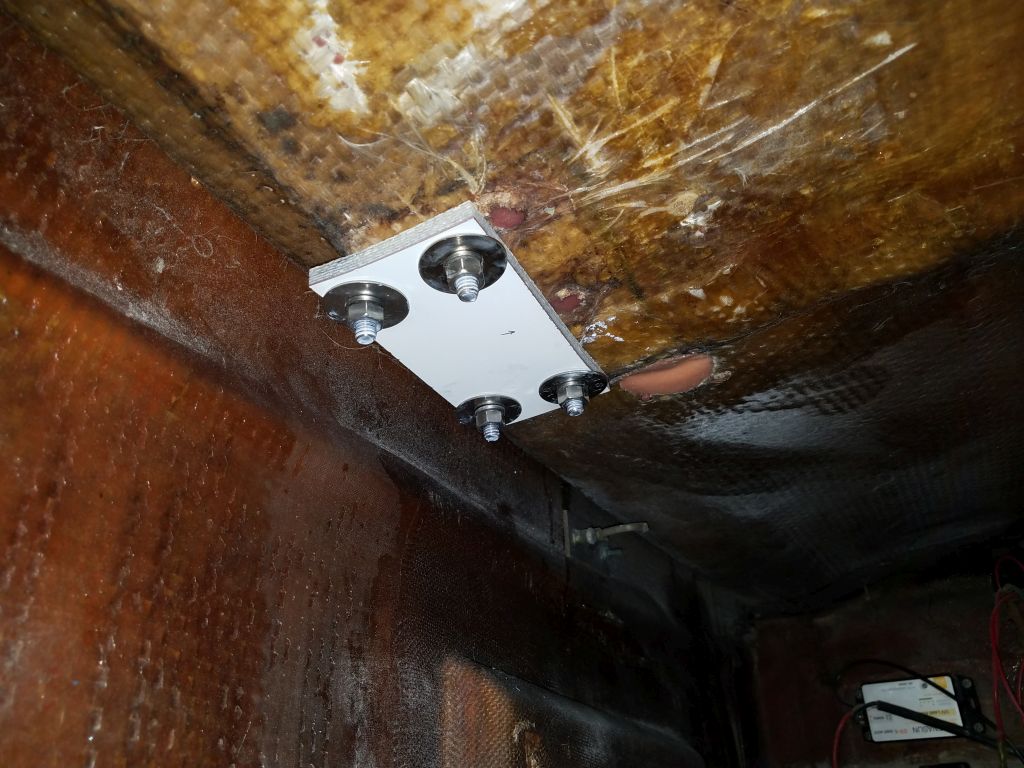
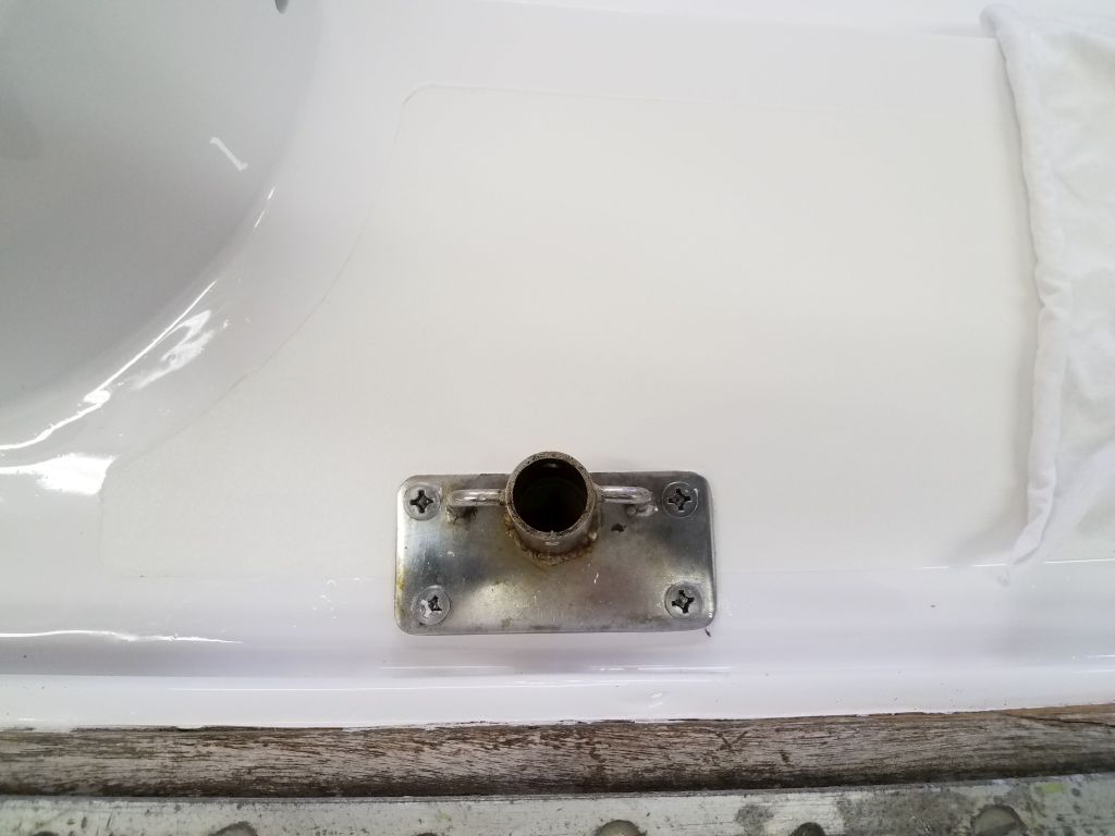
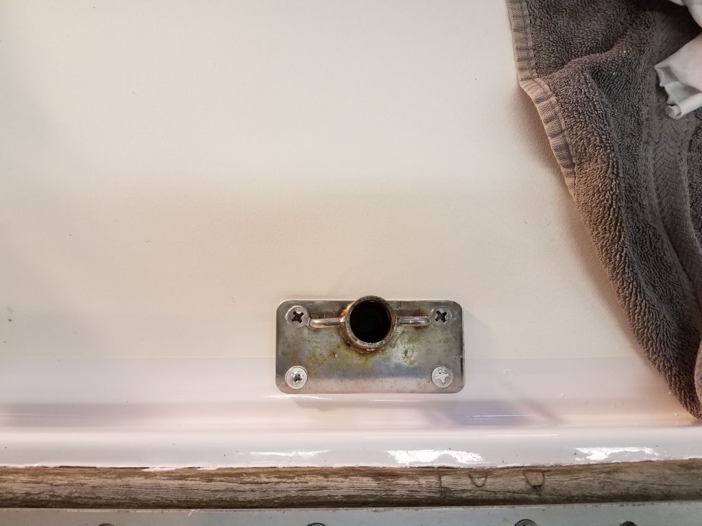
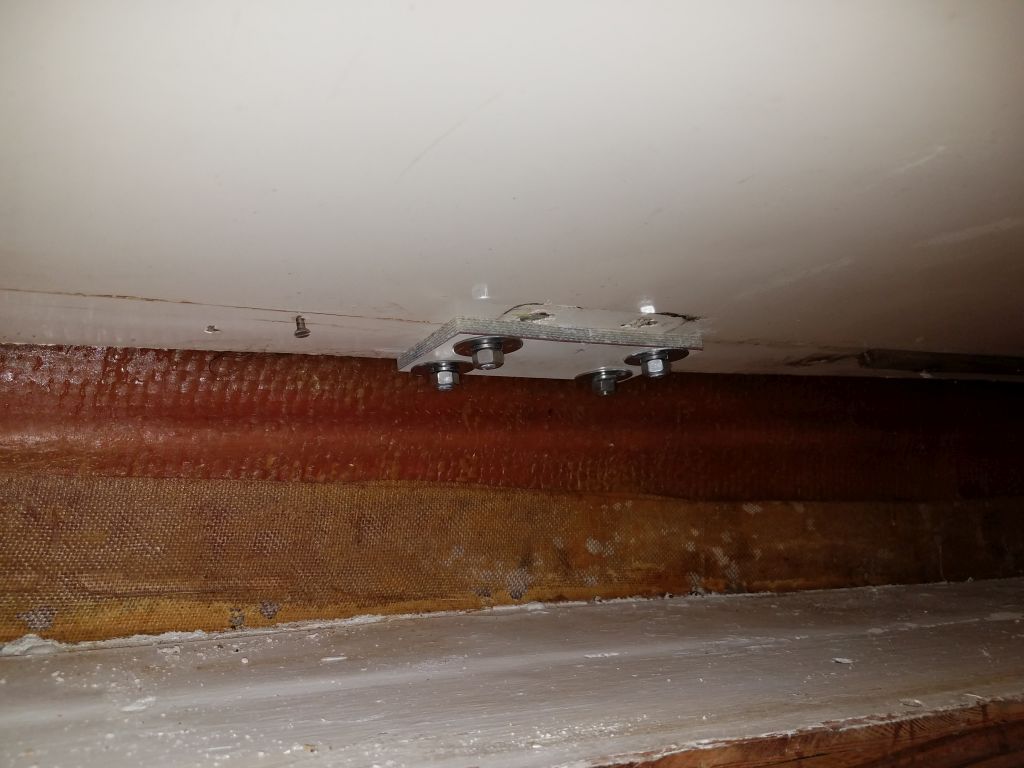
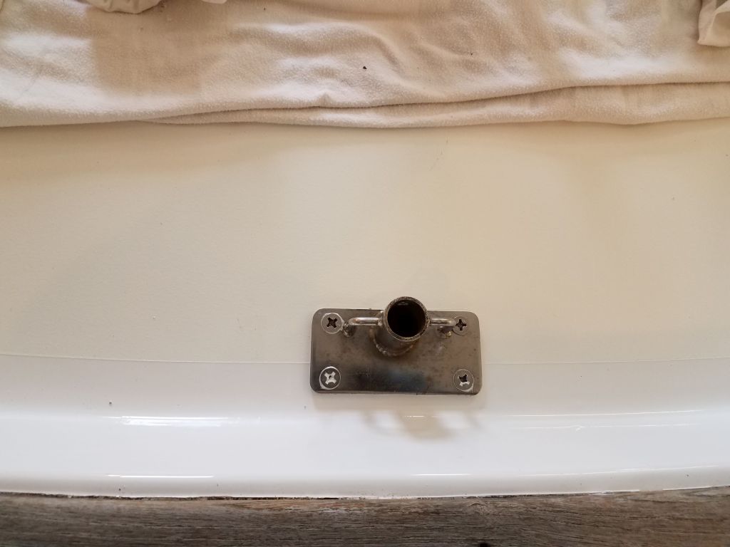
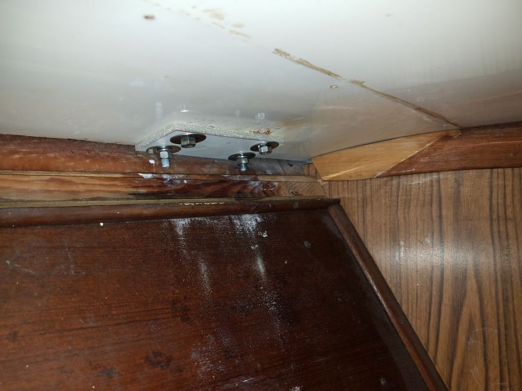
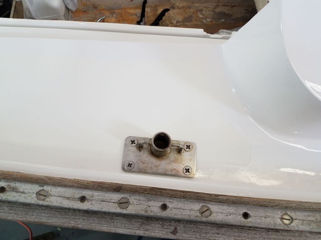
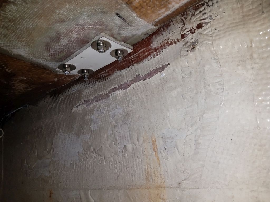
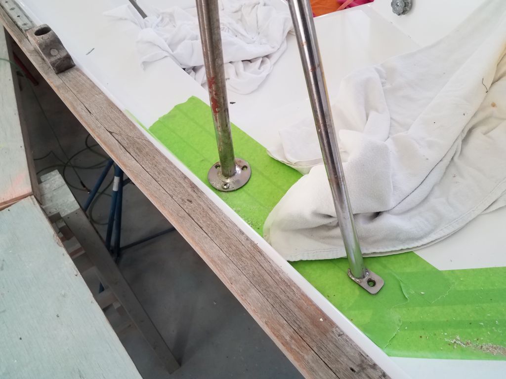
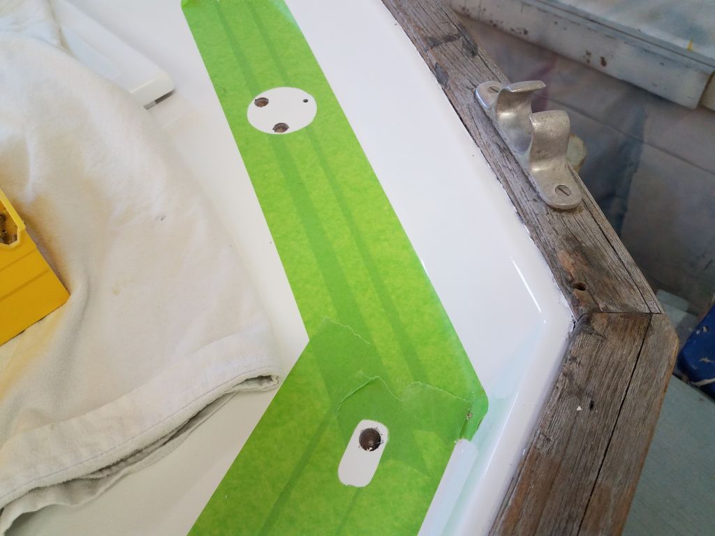
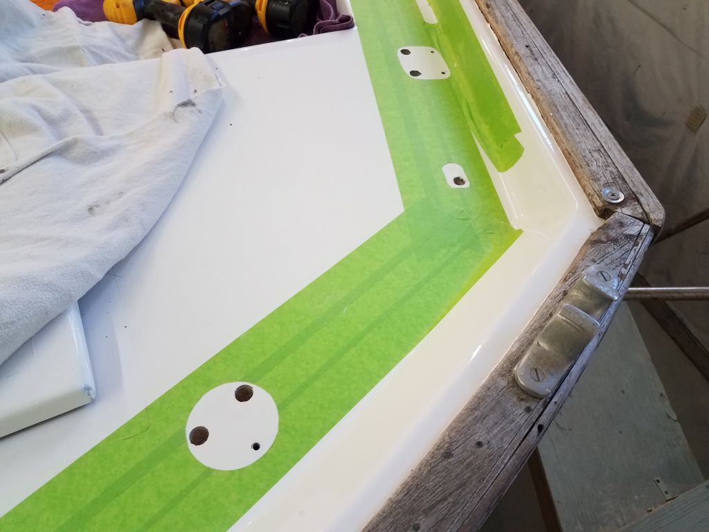
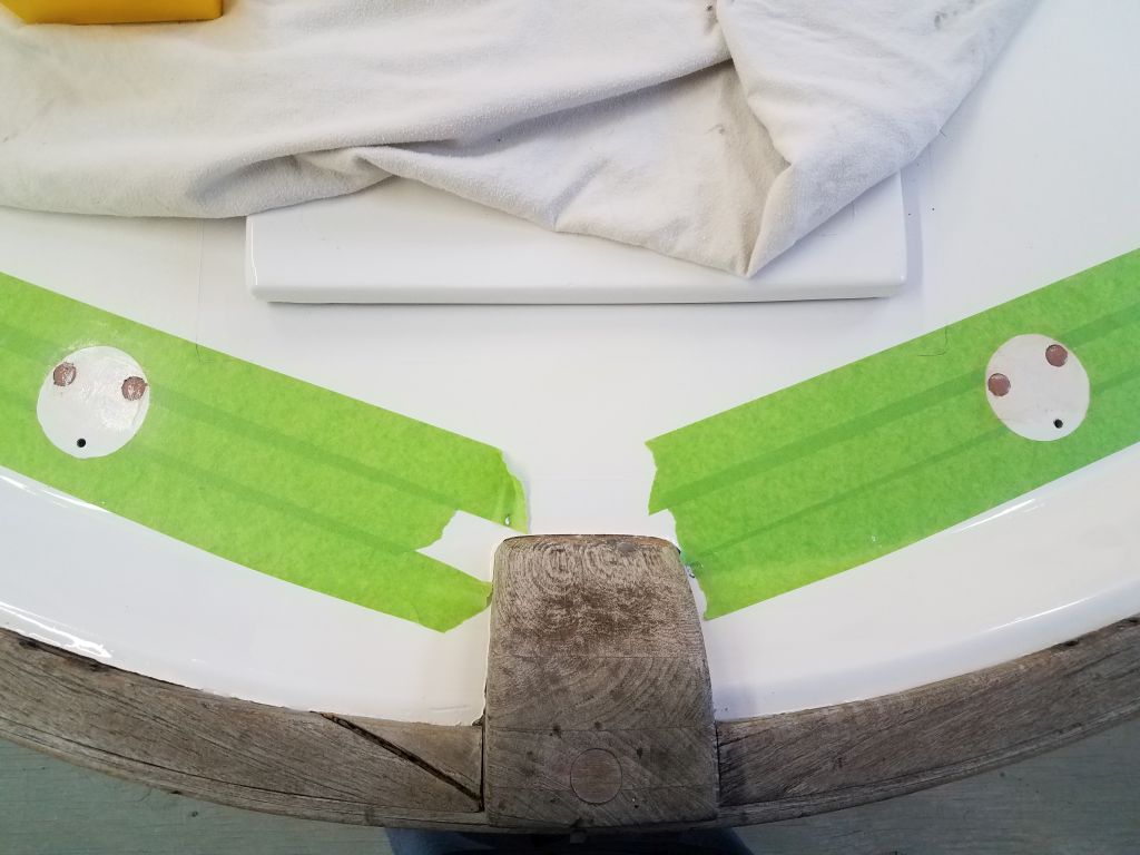
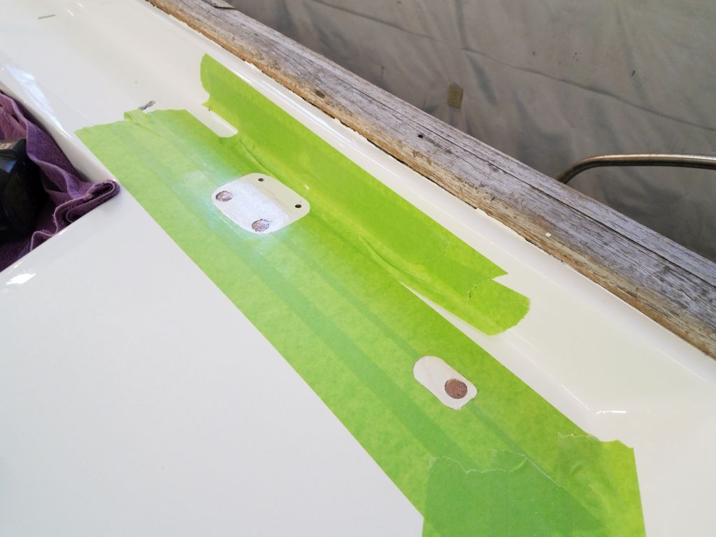
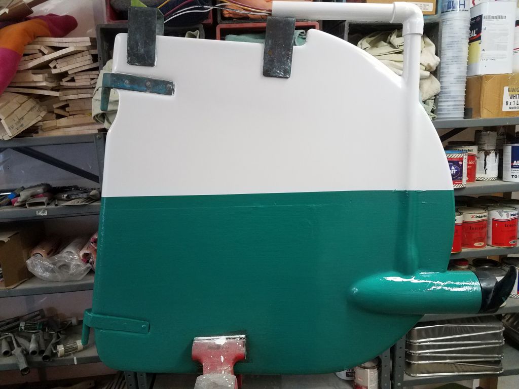
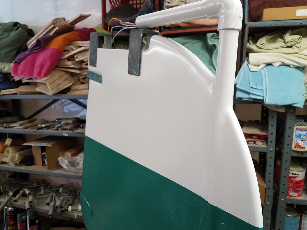
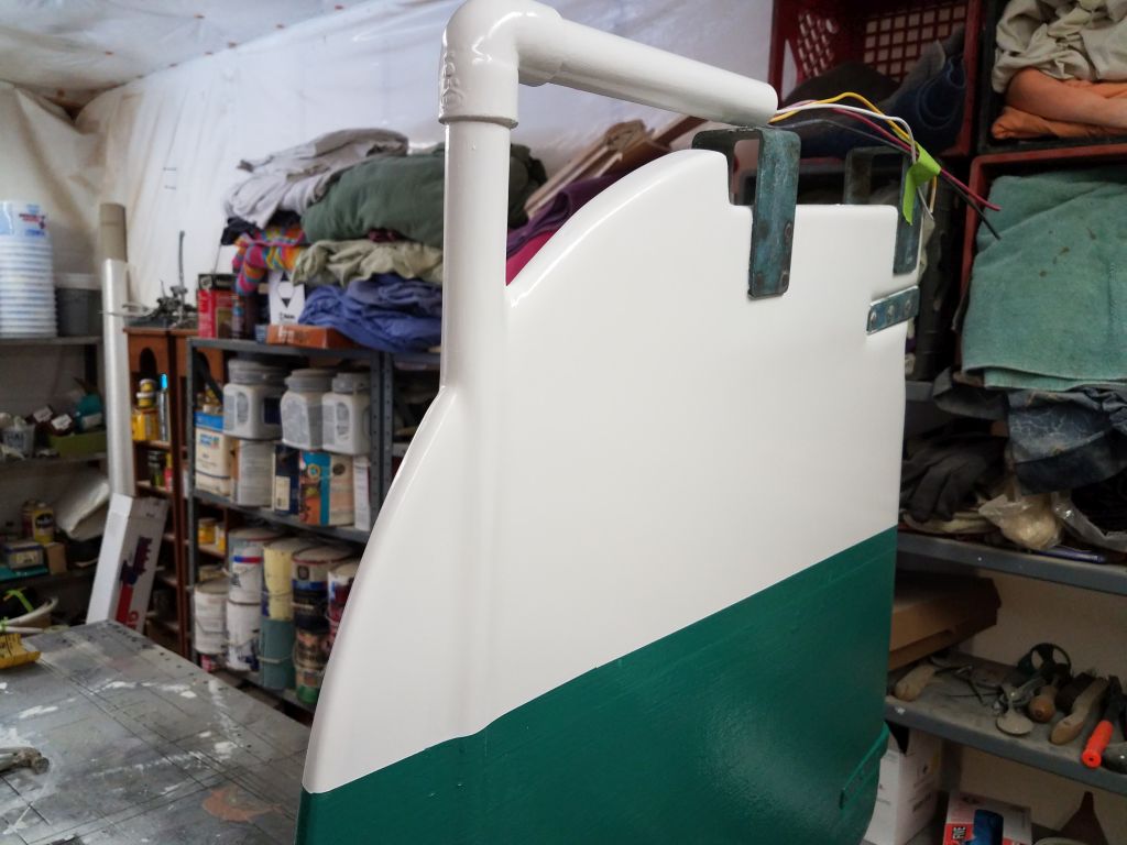
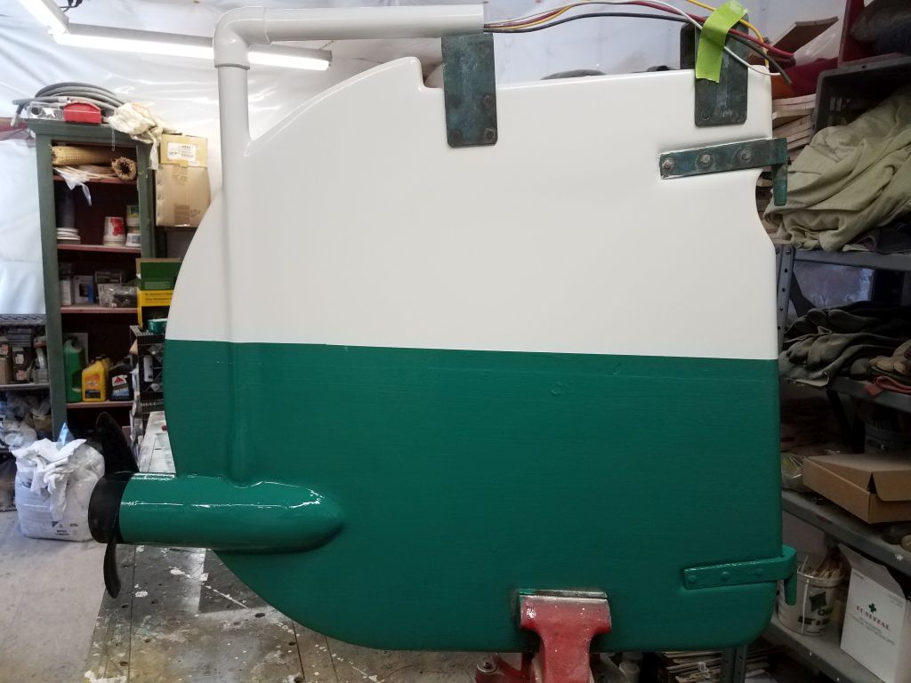
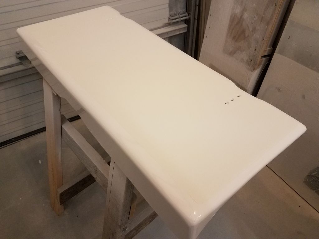
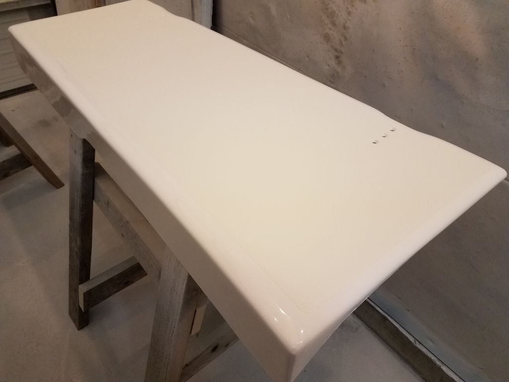
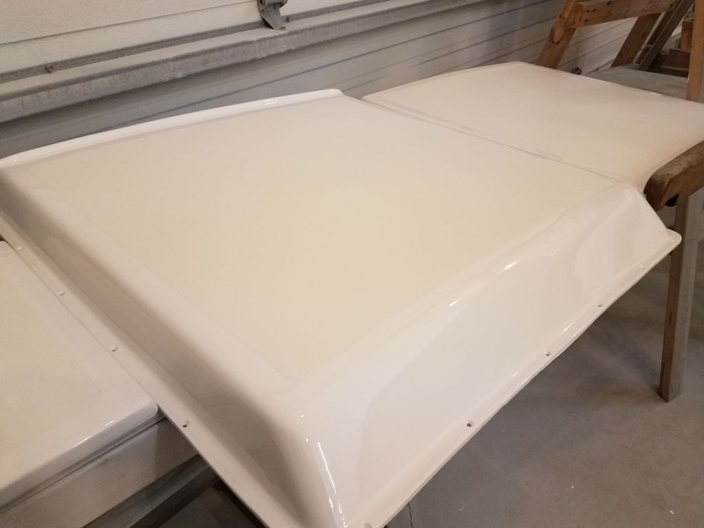
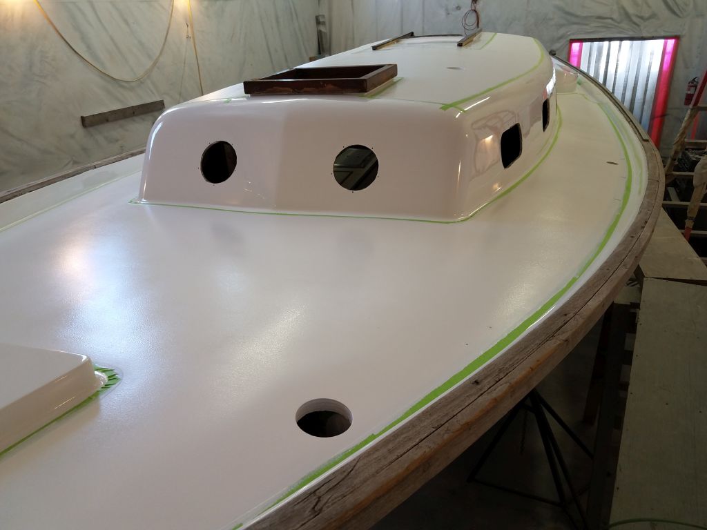
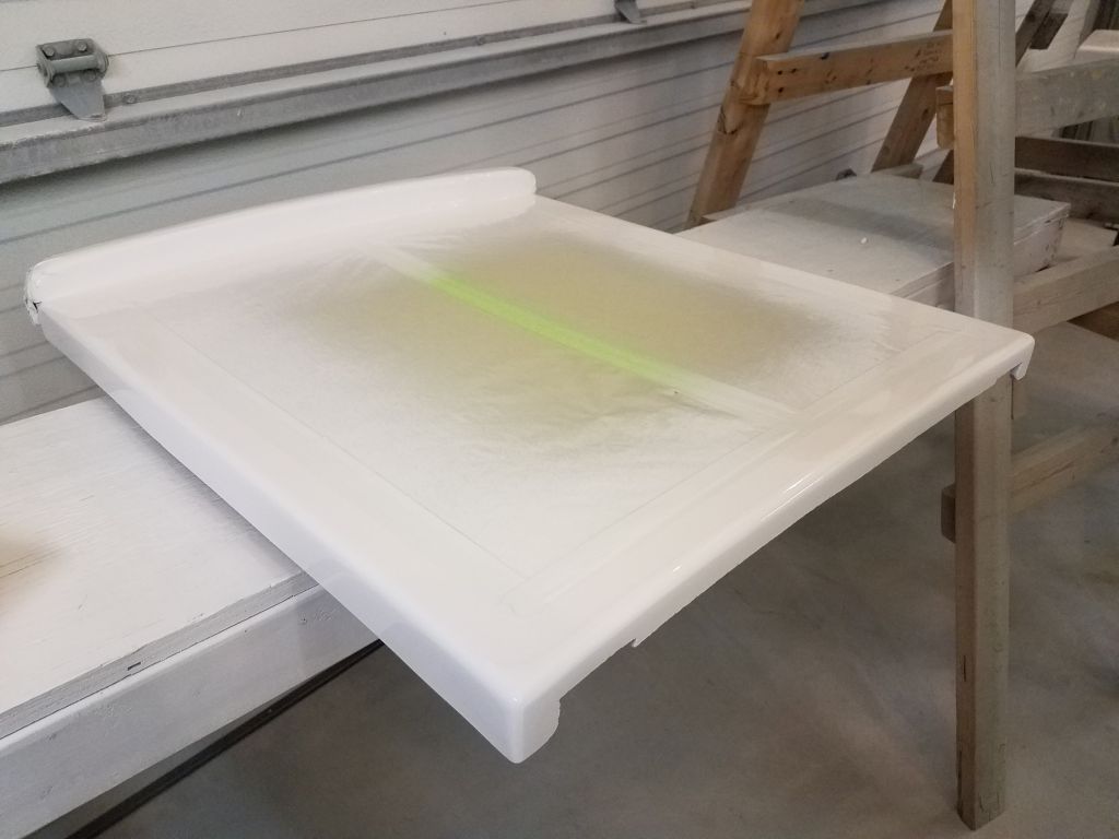
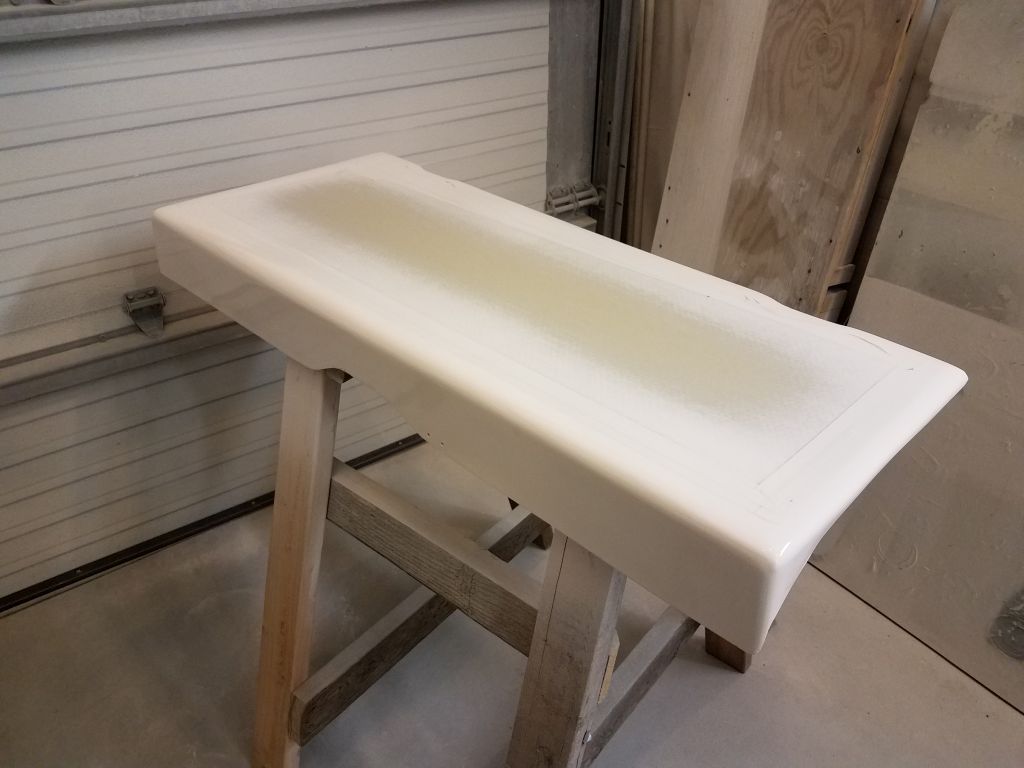
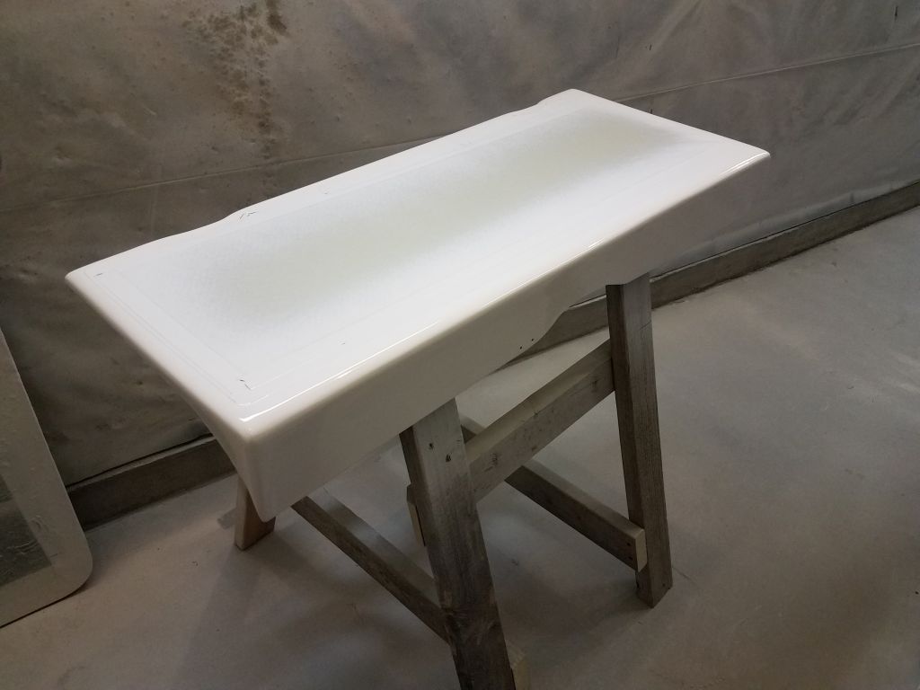
Meanwhile, over several different days, I applied two additional coats of semi-gloss white enamel to the rudder, completing the paint work. Once that was sufficiently cured, I masked off and painted the lower portion of the rudder with new bottom paint. All that remained for this project was to finish up the rudder-end wiring, including running the new flexible conduit (aka hose) and installing the plug at the end; I planned to complete this soon, and effect a bench test of the whole system shortly thereafter.
Total time on this job today: 2.75 hours (spread over several days)